Perfluorosulfonic acid-functionalized Pt/carbon nanotube catalysts with enhanced stability and...
8
This article appeared in a journal published by Elsevier. The attached copy is furnished to the author for internal non-commercial research and education use, including for instruction at the authors institution and sharing with colleagues. Other uses, including reproduction and distribution, or selling or licensing copies, or posting to personal, institutional or third party websites are prohibited. In most cases authors are permitted to post their version of the article (e.g. in Word or Tex form) to their personal website or institutional repository. Authors requiring further information regarding Elsevier’s archiving and manuscript policies are encouraged to visit: http://www.elsevier.com/copyright
Transcript of Perfluorosulfonic acid-functionalized Pt/carbon nanotube catalysts with enhanced stability and...
This article appeared in a journal published by Elsevier. The attachedcopy is furnished to the author for internal non-commercial researchand education use, including for instruction at the authors institution
and sharing with colleagues.
Other uses, including reproduction and distribution, or selling orlicensing copies, or posting to personal, institutional or third party
websites are prohibited.
In most cases authors are permitted to post their version of thearticle (e.g. in Word or Tex form) to their personal website orinstitutional repository. Authors requiring further information
regarding Elsevier’s archiving and manuscript policies areencouraged to visit:
http://www.elsevier.com/copyright
Author's personal copy
Perfluorosulfonic acid-functionalized Pt/carbon nanotubecatalysts with enhanced stability and performance for usein proton exchange membrane fuel cells
Daping He, Shichun Mu *, Mu Pan
State Key Laboratory of Advanced Technology for Materials Synthesis and Processing, Wuhan University of Technology,
Wuhan 430070, China
A R T I C L E I N F O
Article history:
Received 20 May 2010
Accepted 24 August 2010
Available online 31 August 2010
A B S T R A C T
To further improve lifetime and performance of carbon nanotube (CNT) supported Pt cata-
lysts for proton exchange membrane fuel cells, perfluorosulfonic acid (PFSA) was intro-
duced by a simple colloid route to functionalize Pt (PFSA-Pt/CNT) catalysts. Here the
PFSA is available as a binder to tightly anchor Pt nano-particles onto the CNT surfaces,
and as a proton conductor to increase the triple phase boundary zone of the catalysts.
The prepared Pt nano-particles ranging from 2 to 5 nm in diameter are uniformly deposited
on CNTs. A high catalytic activity of this novel composite catalyst was observed by both
cyclic voltammetry and oxygen reduction reaction (ORR) measurements. The loss rate of
the electrochemically active area of the PFSA-Pt/CNT catalyst decreases by a factor of
two in comparison with that of the plain Pt/CNT catalyst. Meanwhile, a lower loss rate
for the new catalyst was also observed by electrochemically-accelerated durability testing
for the ORR activity. These results indicate that the stability of the new catalyst is signifi-
cantly improved over that of the plain Pt/CNT catalyst by introduction of PFSA.
� 2010 Elsevier Ltd. All rights reserved.
1. Introduction
Proton exchange membrane fuel cells (PEMFCs) are a promis-
ing power technology for applications in portable, stationary
power sources and for automotive engines [1–3]. However, a
significant challenge hindering large-scale implementation
of PEMFCs is the performance loss during extended operation
and repeated cycling of fuel cells. Investigations have re-
vealed that the degradation of catalysts is one of the most
important reasons contributing to this performance loss
[4,5]. Currently, Pt nano-particles dispersed on high surface
area carbon (Pt/C) is the preferred catalyst in PEMFC system.
The corrosion of the carbon support leads to agglomeration
of Pt nano-particles under extremely harsh working environ-
ments, which is another important reason for catalyst deteri-
oration [4–6]. Moreover, some Pt particles get entrapped in
deep cracks in the carbon support and this causes the ab-
sence of the important triple phase boundary reaction zone
which is essential for PEMFC operation [6,7].
To solve these issues, some research groups introduced
CNTs as more effective supports of Pt catalysts. CNTs do
not have deep cracks and they possess many beneficial prop-
erties such as high electrical conductivity, high chemical sta-
bility, as well as extremely high mechanical strength and
modulus [8–10]. Several research papers reported that CNT-
supported Pt catalysts increase the catalytic activity [11–13]
and also show high electrochemical stability [14,15] compared
to conventional Pt/C catalysts. However, CNTs can also be
gradually oxidized for example in the presence of defects or
impurities at nanotube surfaces [16–18]. In addition, the inert
surface of CNTs leads to a weaker metal-support interaction
as well as a low dispersion of metal particles on CNT surfaces
0008-6223/$ - see front matter � 2010 Elsevier Ltd. All rights reserved.doi:10.1016/j.carbon.2010.08.045
* Corresponding author: Fax: +86 27 87879468.E-mail address: [email protected] (S. Mu).
C A R B O N 4 9 ( 2 0 1 1 ) 8 2 – 8 8
avai lab le at www.sc iencedi rec t .com
journal homepage: www.elsev ier .com/ locate /carbon
Author's personal copy
[19,20]. Therefore, producing well-dispersed metal particles
on CNT surfaces and further improving their electrochemical
stability remains an important challenge. Currently, an en-
hanced electrochemical stability for Pt/CNT catalyst can be
achieved for example by nitrogen doping [21,22]. Also, silica
layers were employed to prepare improved carbon nano-
tube-supported Pt metal particles [23,24]. However, more sim-
ple solutions are needed and the fundamental mechanism for
stabilizing PEMFC catalysts needs further investigation.
The perfluorosulfonic acid (PFSA) polymer, such as Nafion
as a proton conductor, can enhance the catalytic activity of Pt
catalysts by increasing the triple phase boundary reaction
zone. Addition of PFSA into the catalytic layer can be em-
ployed to improve the dispersion of Pt nano-particles on sup-
ports and to increase the ionic (protonic) conductivity of the
catalytic layer [25,26]. In previous work, we applied Nafion
to titanium diboride supported Pt catalysts, which improved
the dispersion of Pt nano-particles on inert surfaces of ceram-
ics [27]. In addition, Tian et al. [28] and our previous studies
[29] showed that SO3� end groups of Nafion act as a stabilizer
and facilitate the reaction for ORR at Pt nano-particles. They
also enhance the metal-support interaction. Thus, the PFSA
is important to improve the lifetime and performance of
CNT-supported Pt catalysts. Here, we demonstrated that Pt
nano-particles can be produced well-dispersed on the CNT
surfaces and the stability of the resulting composite catalyst
was greatly improved with additional PFSA.
2. Experimental
2.1. Preparation of PFSA-Pt/CNT and Pt/CNT catalysts
A volume of 20 ml H2PtCl6ÆH2O solution (1.5 mg ml�1), 100 ll
5 wt.% PFSA Nafion (Dupont Co.) and 200 ml ethylene glycol
were mixed and refluxed at 130 �C with the pH value of the
solution adjusted to 8–10 by adding NaOH solution. When
the color of the solution changed from yellowish to dark,
the PFSA-stabilized colloidal Pt nano-particles were formed.
Next, previously suspended single-walled carbon nanotubes
(SWCNTs) in ethylene glycol were added to the Pt colloid with
further agitation for 11 h. After filtration, washing, and drying
at 100 �C in a vacuum oven, PFSA functioned 20 wt.% Pt
loaded CNT catalysts were obtained. For comparison, the Pt/
CNT catalyst as a benchmark was prepared using the same
method except the addition of PFSA.
2.2. Characterization of the catalysts
Morphology studies of the prepared catalysts were performed
by JEOL 2010 transmission electron microscopy (TEM). The
prepared catalysts were dispersed ultrasonically in ethanol.
Energy dispersive X-ray analysis (EDX) was used to determine
the metal contents in the samples. An aliquot of this solution
was deposited on a grid and dried at room temperature. X-ray
diffraction (XRD) analysis was performed using a Rigaku X-
ray diffractometer with CuKa radiation source. The XRD scans
were investigated at 2 min�1 from 20� to 90�. The average
crystallite size (D) of Pt nano-particles can be obtained
according to the Scherrer equation [30] using the Pt (220) peak.
D ¼ kkb
cos h ð1Þ
here k = 0.89; k (the X-ray wave length for Cu radiation) =
0.1541 nm; b is the half height peak width; h is the Bragg angle
corresponding to the peak maximum; D, denotes the average
crystallite size. Infrared spectra of the prepared PFSA-Pt/CNT
catalyst were carried out to detect the presence of PFSA in Pt/
CNT catalysts by Fourier transform infrared spectroscopy
(Nicolet MAGNA-IR 560, FTIR, USA). The reference PFSA was
prepared by evaporating 5.0 wt.% PFSA liquid. The electro-
chemical performance of the catalysts was characterized with
a conventional triple electrode system. A saturated calomel
electrode (SCE) was used as reference, and a platinum wire
was used as counter electrode. The catalyst powders were
mixed with deionized water and 5 wt.% Nafion solution, and
then coated onto a mirror-polished glassy carbon disk elec-
trode (f = 3 mm) as the working electrode. The cyclic voltam-
mograms (CVs) were obtained in aqueous 0.5 M H2SO4 at the
scan rate of 50 mV s�1 in a potential window of 0–1.2 V versus
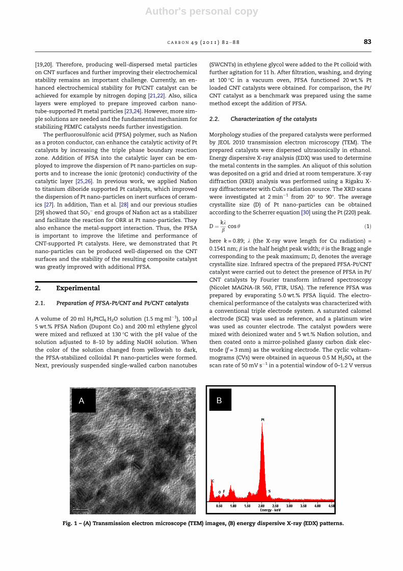
Fig. 1 – (A) Transmission electron microscope (TEM) images, (B) energy dispersive X-ray (EDX) patterns.
C A R B O N 4 9 ( 2 0 1 1 ) 8 2 – 8 8 83
Author's personal copy
reversible hydrogen electrode (RHE) at room temperature.
H2SO4 solution was saturated with pure argon in order to ex-
pel oxygen from the solution. The specific electrochemical ac-
tive area (ECA) was calculated based on the following relation
[31,32].
ECA ¼ QH
m� qH
ð2Þ
here QH is the charge for Hupd adsorption, m is the loading
amount of metal, and qH (210 lC cm�2) is the charge required
for monolayer adsorption of hydrogen on Pt surfaces. Electro-
chemically-accelerated durability testing (ADT) was em-
ployed to evaluate the long-term performance of catalysts.
ADT is an inexpensive and time-effective method for screen-
ing catalysts in terms of stability and performance [33]. Using
the same experimental system for CV testing and for ADT,
data were obtained by scanning the applied potential be-
tween 0.6 and 1.20 V versus RHE. In addition, the ORR perfor-
mance of the as-prepared catalysts was evaluated by rotating
disk electrode (RDE) techniques in 0.5 M H2SO4 electrolyte
with a sweep rate of 10 mV s�1 and a speed of 1600 rpm at
room temperature.
3. Results and discussion
In Fig. 1A, we show the high uniformity of prepared PFSA-sta-
bilized Pt nano-colloids, with an average size of 3 nm for Pt
nano-particles. EDX studies of individual metal particles
(Fig. 1B) reveal the presence of elements C, F and S on the Pt
nano-colloid derived from the PFSA molecular layers on the
outer surface of the metal particles.
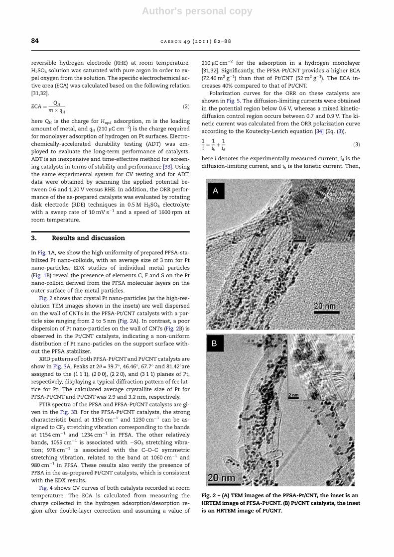
Fig. 2 shows that crystal Pt nano-particles (as the high-res-
olution TEM images shown in the insets) are well dispersed
on the wall of CNTs in the PFSA-Pt/CNT catalysts with a par-
ticle size ranging from 2 to 5 nm (Fig. 2A). In contrast, a poor
dispersion of Pt nano-particles on the wall of CNTs (Fig. 2B) is
observed in the Pt/CNT catalysts, indicating a non-uniform
distribution of Pt nano-paticles on the support surface with-
out the PFSA stabilizer.
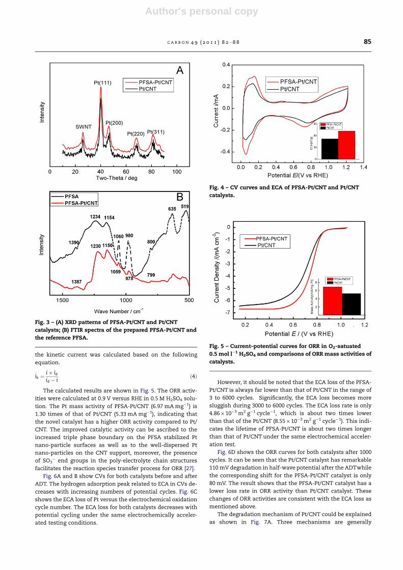
XRD patterns of both PFSA-Pt/CNTand Pt/CNT catalysts are
show in Fig. 3A. Peaks at 2h = 39.7�, 46.46�, 67.7� and 81.42�are
assigned to the (1 1 1), (2 0 0), (2 2 0), and (3 1 1) planes of Pt,
respectively, displaying a typical diffraction pattern of fcc lat-
tice for Pt. The calculated average crystallite size of Pt for
PFSA-Pt/CNT and Pt/CNT was 2.9 and 3.2 nm, respectively.
FTIR spectra of the PFSA and PFSA-Pt/CNT catalysts are gi-
ven in the Fig. 3B. For the PFSA-Pt/CNT catalysts, the strong
characteristic band at 1150 cm�1 and 1230 cm�1 can be as-
signed to CF2 stretching vibration corresponding to the bands
at 1154 cm�1 and 1234 cm�1 in PFSA. The other relatively
bands, 1059 cm�1 is associated with �SO3 stretching vibra-
tion; 978 cm�1 is associated with the C–O–C symmetric
stretching vibration, related to the band at 1060 cm�1 and
980 cm�1 in PFSA. These results also verify the presence of
PFSA in the as-prepared Pt/CNT catalysts, which is consistent
with the EDX results.
Fig. 4 shows CV curves of both catalysts recorded at room
temperature. The ECA is calculated from measuring the
charge collected in the hydrogen adsorption/desorption re-
gion after double-layer correction and assuming a value of
210 lC cm�2 for the adsorption in a hydrogen monolayer
[31,32]. Significantly, the PFSA-Pt/CNT provides a higher ECA
(72.46 m2 g�1) than that of Pt/CNT (52 m2 g�1). The ECA in-
creases 40% compared to that of Pt/CNT.
Polarization curves for the ORR on these catalysts are
shown in Fig. 5. The diffusion-limiting currents were obtained
in the potential region below 0.6 V, whereas a mixed kinetic-
diffusion control region occurs between 0.7 and 0.9 V. The ki-
netic current was calculated from the ORR polarization curve
according to the Koutecky-Levich equation [34] (Eq. (3)).
1i¼ 1
ikþ 1
idð3Þ
here i denotes the experimentally measured current, id is the
diffusion-limiting current, and ik is the kinetic current. Then,
Fig. 2 – (A) TEM images of the PFSA-Pt/CNT, the inset is an
HRTEM image of PFSA-Pt/CNT. (B) Pt/CNT catalysts, the inset
is an HRTEM image of Pt/CNT.
84 C A R B O N 4 9 ( 2 0 1 1 ) 8 2 – 8 8
Author's personal copy
the kinetic current was calculated based on the following
equation.
ik ¼i� idid � i
ð4Þ
The calculated results are shown in Fig. 5. The ORR activ-
ities were calculated at 0.9 V versus RHE in 0.5 M H2SO4 solu-
tion. The Pt mass activity of PFSA-Pt/CNT (6.97 mA mg�1) is
1.30 times of that of Pt/CNT (5.33 mA mg�1), indicating that
the novel catalyst has a higher ORR activity compared to Pt/
CNT. The improved catalytic activity can be ascribed to the
increased triple phase boundary on the PFSA stabilized Pt
nano-particle surfaces as well as to the well-dispersed Pt
nano-particles on the CNT support, moreover, the presence
of SO3� end groups in the poly-electrolyte chain structures
facilitates the reaction species transfer process for ORR [27].
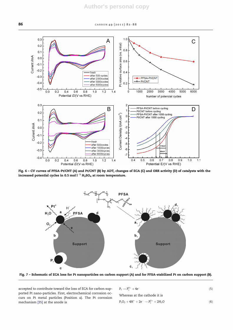
Fig. 6A and B show CVs for both catalysts before and after
ADT. The hydrogen adsorption peak related to ECA in CVs de-
creases with increasing numbers of potential cycles. Fig. 6C
shows the ECA loss of Pt versus the electrochemical oxidation
cycle number. The ECA loss for both catalysts decreases with
potential cycling under the same electrochemically acceler-
ated testing conditions.
However, it should be noted that the ECA loss of the PFSA-
Pt/CNT is always far lower than that of Pt/CNT in the range of
3 to 6000 cycles. Significantly, the ECA loss becomes more
sluggish during 3000 to 6000 cycles. The ECA loss rate is only
4.86 · 10�3 m2 g�1 cycle�1, which is about two times lower
than that of the Pt/CNT (8.55 · 10�3 m2 g�1 cycle�1). This indi-
cates the lifetime of PFSA-Pt/CNT is about two times longer
than that of Pt/CNT under the same electrochemical acceler-
ation test.
Fig. 6D shows the ORR curves for both catalysts after 1000
cycles. It can be seen that the Pt/CNT catalyst has remarkable
110 mV degradation in half-wave potential after the ADTwhile
the corresponding shift for the PFSA-Pt/CNT catalyst is only
80 mV. The result shows that the PFSA-Pt/CNT catalyst has a
lower loss rate in ORR activity than Pt/CNT catalyst. These
changes of ORR activities are consistent with the ECA loss as
mentioned above.
The degradation mechanism of Pt/CNT could be explained
as shown in Fig. 7A. Three mechanisms are generally
Fig. 3 – (A) XRD patterns of PFSA-Pt/CNT and Pt/CNT
catalysts; (B) FTIR spectra of the prepared PFSA-Pt/CNT and
the reference PFSA.
Fig. 4 – CV curves and ECA of PFSA-Pt/CNT and Pt/CNT
catalysts.
Fig. 5 – Current–potential curves for ORR in O2-satuated
0.5 mol l�1 H2SO4 and comparisons of ORR mass activities of
catalysts.
C A R B O N 4 9 ( 2 0 1 1 ) 8 2 – 8 8 85
Author's personal copy
accepted to contribute toward the loss of ECA for carbon sup-
ported Pt nano-particles. First, electrochemical corrosion oc-
curs on Pt metal particles (Position a). The Pt corrosion
mechanism [35] at the anode is
Pt ! P4þt þ 4e� ð5Þ
Whereas at the cathode it is
PtO2 þ 4Hþ þ 2e� ! P2þt þ 2H2O ð6Þ
Fig. 6 – CV curves of PFSA-Pt/CNT (A) and Pt/CNT (B) by ADT, changes of ECA (C) and ORR activity (D) of catalysts with the
increased potential cycles in 0.5 mol l�1 H2SO4 at room temperature.
Fig. 7 – Schematic of ECA loss for Pt nanoparticles on carbon support (A) and for PFSA-stabilized Pt on carbon support (B).
86 C A R B O N 4 9 ( 2 0 1 1 ) 8 2 – 8 8
Author's personal copy
Second, unsupported Pt metal particles are formed due to
the corrosion of the carbon support (Position b). The corrosion
reaction [36] is given in Eq. (7).
Cþ 2H2O! CO2 þ 4Hþ þ 4e� ð7Þ
The presence of Pt promotes this corrosion reaction (Posi-
tion c) [6]. The detached Pt particles are readily agglomerated
on the surface of supports or ionomers [37,38]. Third, Pt metal
particles or their aggregates grow through Ostwald ripening,
that is, Pt atoms with Pt particles are transported onto other
particles to form larger particles (Position d) [23,39,40]. Corre-
spondingly, the degradation mechanism of PFSA-Pt/CNT
could be well explained by Fig. 7B, where the Pt nano-particles
are stabilized with PFSA, the electrochemical corrosion of Pt
could be suppressed with the protection of PFSA (Position
a1) compared to that without PFSA protection (Position a in
Fig. 7A). Although the carbon support can be degraded, the
triple phase boundary always exits on the Pt particle surfaces,
and this slows down the loss of ECA (Position b1). In addition,
the ability of PFSA molecules to adhere to the Pt surfaces like
tentacles could anchor Pt particles on the support surfaces
although some detachment of Pt particles does take place (Po-
sition c1). Furthermore, the PFSA could effectively prevent Pt
nano-particles from aggregation on support surfaces because
of a strong steric hindrance effect of PFSA with SO3� groups
(Position d1). In the first 3000 electrochemical oxidation cy-
cles, all of these factors may be at work to some extent during
the decrease of Pt ECA for PFSA-Pt/CNT catalysts, which lead
to a lower ECA loss rate than that observed for Pt/CNT cata-
lyst. During 3000–6000 potential cycles, these factors (espe-
cially for b1, c1 and d1 positions) may play a positive role
and sharply reduce the ECA loss, which lead to a stabilization.
Also, it is important to consider support factors. Compared
to carbon black, the CNT has high chemical stability and un-
ique mechanical property [10], which could effectively de-
crease the support degradation.
4. Conclusions
A novel CNT-supported Pt catalyst has been successfully
developed to improve the lifetime and performance of Pt/
CNT catalysts. It is unique for this catalyst that the PFSA (Naf-
ion) offers (i) an extended triple phase boundary on Pt sur-
faces as a proton conductor, which enhances electro-
catalytic activity, and (ii) a strong metal-support interaction
as both a binder and a stabilizer for Pt nano-particles, which
improves the catalyst lifetime. As a result, Pt nano-particles
can be well dispersed on inert surfaces of CNTs. The novel
catalyst shows a high electro-catalytic activity and an excel-
lent electrochemical stability. This presents a simple and
effective approach to produce highly stable Pt catalysts which
have a considerable potential for application in PEMFCs and
other devices.
Acknowledgments
This work was supported by The National Natural Science
Foundation of China (NSFC) (50972112, 50632050), The New
Century Excellent Talent Program of Ministry of Education
of China (MOE) (No. NCET - 07 - 0652) and the Fundamental
Research Funds for the Central Universities.
R E F E R E N C E S
[1] Wee JH. Applications of proton exchange membrane fuel cellsystems. Renew Sust Energ 2007;11(8):1720–38.
[2] Vielstich W, Gasteiger H, Lamm A. Handbook of fuel cells,Fundamentals, Technology and Applications. WestSussex: Wiley; 2003.
[3] Mathias M, Gasteiger H, Makharia R, Kocha S, Fuller T, Xie T,et al. Can available membranes and catalysts meetautomotive polymer electrolyte fuel cell requirements? AbstrPap Am Chem Soc 2004;228:U653–7.
[4] Borup RL, Davey JR, Garzon FH, Wood DL. Inbody MA.PEM fuelcell electrocatalyst durability measurements. J Power Sources2006;163(1):76–81.
[5] Stevens DA, Dahn JR. Thermal degradation of the support incarbon-supported platinum electrocatalysts for PEM fuelcells. Carbon 2005;43(1):179–88.
[6] Roen LM, Paik CH, Jarvi TD. Electrocatalytic corrosion ofcarbon support in PEMFC cathodes. Electrochem Solid-StateLett 2004;7(1):A19–22.
[7] Matsumoto T, Komatsu T, Nakano H, Arai K, Nagashima Y,Yoo E, et al. Efficient usage of highly dispersed Pt on carbonnanotubes for electrode catalysts of polymer electrolyte fuelcells. Catal Today 2004;90(3–4):277–81.
[8] Andrews R, Jacques D, Qian D, Rantell T. Multiwalled carbonnanotubes: synthesis and applications. Acc Chem Res2002;35:1008–15.
[9] Choi YK, Sugimoto K, Sing S-M, Gotoh Y, Ohkoshi Y, Endo M.Mechanical and physical properties of epoxy compositesreinforced by vapor grown carbon nanofibers. Carbon2005;43(10):2199–208.
[10] Xing Y. Synthesis and electrochemical characterization ofuniformly-dispersed high loading Pt nanoparticles onsonochemically-treated carbon nanotubes. J Phys Chem2004;108(50):B19255–9.
[11] Li WZ, Liang CH, Zhou WJ, Qiu JS, Zhou ZH, Sun GQ, et al.Preparation and characterization of multiwalled carbonnanotube-supported platinum for cathode catalysts of directmethanol fuel cells. J Phys Chem 2003;107(26):B6292–9.
[12] Wu G, Chen YS, Xu BQ. Remarkable support effect of SWNTsin Pt catalyst for methanol electrooxidation. ElectrochemCommun 2005;7(12):1237–43.
[13] Che G, Lakshmi BB, Martin CR, Fisher ER. Metal-nanocluster-filled carbon nanotubes: catalytic properties and possibleapplications in electrochemical energy storage andproduction. Langmuir 1999;15(3):750–8.
[14] Shao YY, Yin GP, Gao YZ, Shi PF. Durability study of Pt/C andPt/CNTs catalysts under simulated PEM fuel cell conditions. JElectrochem Soc 2006;153(6):A1093–7.
[15] Wang X, Li WZ, Chen ZW, Waje M, Yan YS. Durabilityinvestigation of carbon nanotube as catalyst support forproton exchange membrane fuel cell. J Power Sources2006;158:154–9.
[16] Hou PX, Liu C, Cheng HM. Purification of carbon nanotubes.Carbon 2008;46(15):2003–25.
[17] Xing YC, Li L, Chusuei CC, Hull RV. Sonochemical oxidation ofmultiwalled carbon nanotubes. Langmuir 2005;21(9):4185–90.
[18] Mu SC, Tang HL, Qian SH, Pan M, Yuan RZ. Hydrogen storagein carbon nanotubes modified by microwave plasma etchingand Pd decoration. Carbon 2006;44(4):762–7.
[19] Lee K, Zhang JJ, Wang HJ, Wilkinson DP. Progress in thesynthesis of carbon nanotube- and nanofiber-supported Pt
C A R B O N 4 9 ( 2 0 1 1 ) 8 2 – 8 8 87
Author's personal copy
electrocatalysts for PEM fuel cell catalysis. J Appl Electrochem2006;36:507–22.
[20] Rajesh B, Thampi KR, Bonard JM, Xanthopoulos N, MathieuHJ, Viswanathan B. Carbon nanotubes generated fromtemplate carbonization of polyphenyl acetylene as thesupport for electrooxidation of methanol. J Phys Chem2003;B(107):2701–8.
[21] Sidik RA, Anderson AB, Subramanian NP, Kumaraguru SP,Popov BN. O2 reduction on graphite and nitrogen-dopedgraphite: experiment and theory. J Phys Chem2006;110(4):B1787–93.
[22] Shao Y, Sui J, Yin G, Gao YZ. Nitrogen-doped carbonnanostructures and their composites as catalytic materialsfor proton exchange membrane fuel cell. Appl Catal B:Environ 2008;79(1):89–99.
[23] Takenaka S, Matsumori H, Nakagawa K, Matsune H, TanabeE, Kishida M. Improvement in the durability of Ptelectrocatalysts by coverage with silica layers. J Phys Chem C2007;111(42):15133–6.
[24] Takenaka S, Matsumori H, Arike T, Matsune H, Kishida M.Preparation of carbon nanotube-supported pt metal particlescovered with silica layers and their application toelectrocatalysts for PEMFC. Top Catal 2009;52(6–7):731–8.
[25] Sarma LS, Lin TD, Tsai YW, Chen JM, Hwang BJ. Carbon-supported Pt–Ru catalysts prepared by the Nafion stabilizedalcohol-reduction method for application in direct methanolfuel cells. J Power Sources 2005;139(1–2):44–54.
[26] Scibioh MA, Oh IH, Lim HT, Hong SA, Ha HY. Investigation ofvarious ionomer-coated carbon supports for direct methanolfuel cell applications. Appl Catal B Environ 2008;77(3–4):373–85.
[27] Yin SB, Mu SC, L. Hf, Cheng NC, Pan M, Fu ZY. A highly stablecatalyst for PEM fuel cell based on durable titanium diboridesupport and polymer stabilization. Appl Catal B 2010;93(3–4):233–40.
[28] Tian ZQ, Jiang SP, Liu ZC, Li L. Polyelectrolyte-stabilized Ptnanoparticles as new electrocatalysts for low temperaturefuel cells. Electrochem Commun 2007;9(7):1613–8.
[29] Cheng NC, Mu SC, Pan M, Edwards PP. Improved lifetime ofPEM fuel cell catalysts through polymer stbilization.Electrochem Commun 2009;11(8):1610–4.
[30] Radmilovic V, Gasteiger HA, Ross PN. Structure and chemicalcomposition of a supported Pt–Ru electrocatalyst formethanol oxidation. J Catal 1995;154(1):98–106.
[31] Schmidt TJ, Gasteige HA, Stab GD, Urban PM, Kolb DM, BehmRJ. Characterization of high-surface-area electrocatalystsusing a rotating disk electrode configuration. J ElectrochemSoc 1998;145(7):2354–7.
[32] Ciacchi LC, Pompe W, Vita AD. Growth of platinum clustersvia addition of Pt(II) complexes: a first principlesinvestigation. J Phys Chem 2003;107(8):B1755–64.
[33] Colon-Mercado HR, Kim HS, Popov BN. Durability study ofPt3Ni1 catalysts as cathode in PEM fuel cells. ElectrochemCommun 2004;6(8):795–9.
[34] Lim B, Jiang MJ, Camargo PHC, Cho EC, Tao J, Lu XM, et al. Pd-Pt bimetallic nanodendrites with high activity for oxygenreduction. Science 2009;324(5932):1302–5.
[35] Kawahara S, Mitsushima S, Ota K, Kamiya N. Deterioration ofPt catalyst under potential cycling. ECS Trans 2006;3:625.
[36] Zhang SS, Yuan XZ, Wang HJ. Merida W, Zhu H, Shen J et al. Areview of accelerated stress tests of MEA durability in PEMfuel cells. Int J Hydrogen Energ 2009;34(1):388–404.
[37] Passalacqua E, Antonucci PL, Vivaldi M, Patti A, Antonucci V,Giordano N, et al. The influence of Pt on the electrooxidationbehaviour of carbon in phosphoric acid. Electrochim Acta1992;37(15):2725–30.
[38] Kangasniemi KH, Condit DA, Jarvi TD. Characterization ofvulcan electrochemically oxidized under simulated PEM fuelcell conditions. J Electrochem Soc 2004;151(4):E125–32.
[39] Tseung ACC, Dhara SC. Loss of surface area by platinum andsupported platinum black electrocatalyst. Electrochim Acta1975;20(9):681–3.
[40] Guilminot E, Corcella A, Charlot F, Maillard F, Chatenet M.Detection of Pt2+ Ions and Pt Nanoparticles Inside theMembrane of a Used PEMFC. J Electrochem Soc2007;154(1):B96–105.
88 C A R B O N 4 9 ( 2 0 1 1 ) 8 2 – 8 8