PEAT Smart Emergency Traffic Light System - Penerbit UTHM
11
Progress in Engineering Application and Technology Vol. 1 No. 1 (2020) 323–333 © Universiti Tun Hussein Onn Malaysia Publisher’s Office PEAT Homepage: http://penerbit.uthm.edu.my/periodicals/index.php/peat e-ISSN : 0000-0000 *Corresponding author: [email protected] 2020 UTHM Publisher. All right reserved. penerbit.uthm.edu.my/periodicals/index.php/peat Smart Emergency Traffic Light System Saffi Iswadi bin Shamsudin 1 , Lilywati binti Bakar 1 * Department of Electronic Engineering Technology, Faculty of Engineering Technogy, Universiti Tun Hussein Onn Malaysia, Hub Pendidikan Pagoh, Km1, Jalan Panchor, 84600, Pagoh Muar, Johor Darul Takzim, Malaysia. *Corresponding Author Designation DOI: https://doi.org/10.30880/peat.2020.01.01.035 Received 28 September 2020; Accepted 09 November 2020; Available online 02 Month 2020 Abstract: The aim of this study was to design a smart system on traffic light for emergency purpose. The goal of this study is to facilitate the emergency vehicle go through a busy intersection without causes any new accident due to misunderstanding of all road users. There are several objectives of this study which is provides emergency access for emergency personnel at the traffic light. Next, facilitates the journey of emergency personnel during traffic light and avoids any accidents in traffic lights due to misunderstandings and confusion regarding the siren's direction of emergency vehicle. The idea of this system by using RFID control that can interrupt the normal sequence of traffic light to change the path that emergency vehicle is travelling on into green after a few second while the other path will be all red. Thus, it may reduce the delay of emergency vehicle travel to a scene or specific place while providing their emergency service to society efficiently. This system includes transmitter (RFID card/tag) and receiver (RFID reader) part to be fully control by a RFID RC522 module. With a certain operating distance, the receiver and transmitter can communicate with each other to enable the green light on the road passed by the emergency vehicle. The transferred data and signals are read wirelessly by the reader before it is finally sent to the processor for next operation. Keywords: Traffic Light, Emergency, Smart Sytem, RFID. 1. Introduction Traffic light or signal light is a system used to facilitate the movement of traffic from one direction to the other in order to connect multiple intersections at one point. Typically, traffic lights will be installed either at road crossings, pedestrian crossings or in areas that require special attention from drivers especially at school and railroad tracks. The signal light has three basic colours namely red, yellow and green where red gives stop signal, yellow in standby while green gives street signal if no obstruction. It can be said that most of the signal lights are designed in two forms, either vertically or horizontally and mounted on special poles to allow users to see the vehicle even in long distance.
-
Upload
khangminh22 -
Category
Documents
-
view
3 -
download
0
Transcript of PEAT Smart Emergency Traffic Light System - Penerbit UTHM

Progress in Engineering Application and Technology Vol. 1 No. 1 (2020) 323–333
© Universiti Tun Hussein Onn Malaysia Publisher’s Office
PEAT
Homepage: http://penerbit.uthm.edu.my/periodicals/index.php/peat
e-ISSN : 0000-0000
*Corresponding author: [email protected] 2020 UTHM Publisher. All right reserved. penerbit.uthm.edu.my/periodicals/index.php/peat
Smart Emergency Traffic Light System
Saffi Iswadi bin Shamsudin1, Lilywati binti Bakar1*
Department of Electronic Engineering Technology, Faculty of Engineering
Technogy,
Universiti Tun Hussein Onn Malaysia, Hub Pendidikan Pagoh, Km1, Jalan Panchor,
84600, Pagoh Muar, Johor Darul Takzim, Malaysia.
*Corresponding Author Designation
DOI: https://doi.org/10.30880/peat.2020.01.01.035
Received 28 September 2020; Accepted 09 November 2020; Available online 02 Month
2020
Abstract: The aim of this study was to design a smart system on traffic light for
emergency purpose. The goal of this study is to facilitate the emergency vehicle go
through a busy intersection without causes any new accident due to misunderstanding
of all road users. There are several objectives of this study which is provides
emergency access for emergency personnel at the traffic light. Next, facilitates the
journey of emergency personnel during traffic light and avoids any accidents in traffic
lights due to misunderstandings and confusion regarding the siren's direction of
emergency vehicle. The idea of this system by using RFID control that can interrupt
the normal sequence of traffic light to change the path that emergency vehicle is
travelling on into green after a few second while the other path will be all red. Thus,
it may reduce the delay of emergency vehicle travel to a scene or specific place while
providing their emergency service to society efficiently. This system includes
transmitter (RFID card/tag) and receiver (RFID reader) part to be fully control by a
RFID RC522 module. With a certain operating distance, the receiver and transmitter
can communicate with each other to enable the green light on the road passed by the
emergency vehicle. The transferred data and signals are read wirelessly by the reader
before it is finally sent to the processor for next operation.
Keywords: Traffic Light, Emergency, Smart Sytem, RFID.
1. Introduction
Traffic light or signal light is a system used to facilitate the movement of traffic from one direction
to the other in order to connect multiple intersections at one point. Typically, traffic lights will be
installed either at road crossings, pedestrian crossings or in areas that require special attention from
drivers especially at school and railroad tracks. The signal light has three basic colours namely red,
yellow and green where red gives stop signal, yellow in standby while green gives street signal if no
obstruction. It can be said that most of the signal lights are designed in two forms, either vertically or
horizontally and mounted on special poles to allow users to see the vehicle even in long distance.

Shamsudin et al., Progress in Engineering Application and Technology Vol. 1 No. 1 (2020) p. 323-333
324
The signal lamp system was first introduced by John Peake Knight in England on 9 December 1868
at the intersection of Bridge Street and Great George Street in the London borough of Westminster. The
signal lamp system using a gas lamp and operated manually and a police officer would be stationed
next to the signals to operate them [1]. However, only one month later, a police officer controlling the
signal was badly injured when a leak in a gas main caused one of the lights to explode in his face and
the project was declared a public health hazard and immediately dropped.
Traffic signalling or traffic light are used to facilitate the flow of traffic through an intersection or
junctions of any busy area especially in urban area [2]. However, the increase in population was
followed by an increase in the number of cars causing traffic congestion and disturbing emergency
vehicles. Based on traffic studies conducted in Malaysia, it is clear that the cause of traffic congestion
on non-systematic traffic light systems [3]. Therefore, the purpose of this project is to reduce the
frequent traffic congestion and facilitate the handling of emergency vehicles.
1.1 Problem Statement
This study is focusing on the problem of existing traffic light systems cannot detect the presence of
emergency vehicles on the road, especially in emergency situations where emergency vehicles are
difficult to pass in traffic jams. The cause of the delay can affect the lives of people in need of emergency
vehicles or emergency support while providing their best services to the community. To overcome this
problem, a system is implementing to facilitate the emergency vehicle go through a busy intersection
without causes any new accident due to misunderstanding of all road users. This system is using RFID
control that can interrupt the normal sequence of traffic light to change the path that emergency vehicle
is travelling on into green after a few second while the other path will be all red.
1.2 Objectives
The specific objectives of this project are as follows:
Provides emergency access for emergency personnel at the traffic light.
Facilitates the journey of emergency personnel during traffic light.
Avoids any accidents in traffic lights due to misunderstandings and confusion regarding
the siren's direction of emergency vehicle.
2. Materials and Methods
In this part the processes towards the completion of Smart Emergency Traffic Light System are
discussed in through the project flowchart, project overview, block diagram, circuit design, and
flowchart of the program. The purpose of this methodology is to give the working standard,
improvement and technique for the entire attempts of the project works.
2.1 Materials
The right choice and economical of the hardware used are essential to complete the project and
make the RFID communication system functioning well. Some of the hardware is readily available, so
they are not listed, such as a laptop for design the coding in Arduino Uno.
Table 1: List of materials used for smart emergency traffic light system prototype
Description Picture Quantity
Arduino Uno
3
Shamsudin et al., Progress in Engineering Application and Technology Vol. 1 No. 1 (2020) p. 323-333
325
RFID RC522 Module
2 set
3-Pin Plug AC/DC Adapter
1
USB Rechargeable Battery 9V
1
Jumper Wires (Male to Male)
2 set
Jumper Wires (Female to Female)
2 set
Breadboard (Full-size)
2
9V Battery Connector to DC Jack
1
LED Traffic Light Module (5V)
4 set
Mounting Board Colour
1
Mounting Board BlackWhite
1
Impra Board Purple
1
Shamsudin et al., Progress in Engineering Application and Technology Vol. 1 No. 1 (2020) p. 323-333
326
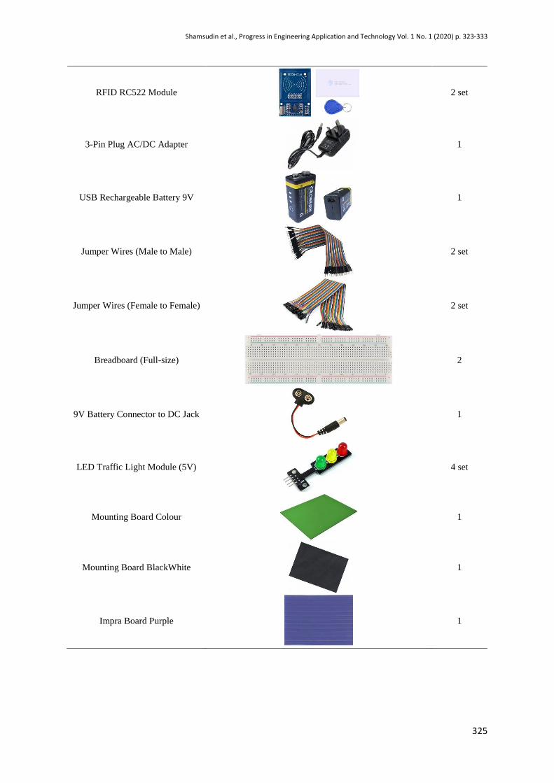
2.2 Methods
The methodology starts with the process of finding reference material or information related to the
project tittle. Furthermore, the purpose of this methodology is to give the working standard,
improvement and technique for the entire attempts of the project works. This approach encourages the
achievement of the task objectives in this project.. In order for the project to run smoothly, the
methodology should have a flow chart to guide the implementation of the project. The following Figure
1 illustrates the planning flow chart for this project.
Figure 1: Flow chart of Methodolog
Deciding Planning Project
Analysis the
Literature Review
Designing and
Finalising Materials
Building the Entire System
Testing and
Trouble-shooting
Result Analysis
and Conclusion

Shamsudin et al., Progress in Engineering Application and Technology Vol. 1 No. 1 (2020) p. 323-333
327
Figure 2: Flow chart to produce smart emergency traffic light system
3. Results and Discussion
Several testing on RFID reader receiving a data had been tested for a different card/tag to see the
details and UID of the card/tag on serial monitor of Arduino IDE. The result of this project is observed
and recorded in the form of snapshot figure for more available data analysis. Based on the result and
data analysis, the data shown in serial monitor helps the user to find out the specific UID number for
each of different card/tag before key in the UID in a full program.
3.1 Results
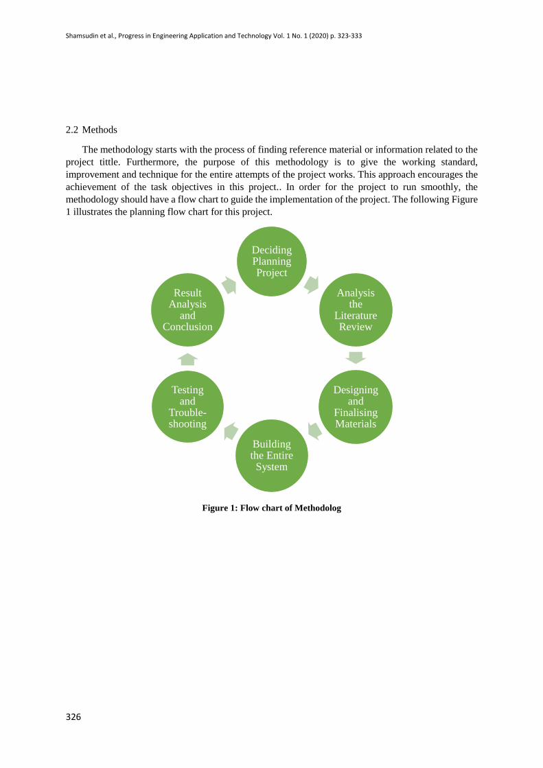
Each of card/tag have their own specific details and UID. The UID display on serial monitor need
to be copied and paste inside a full program. All the data are shows as Figure 3 below:
Coding testing and
simulation. Making four (4)
junctions of road.
Paste the road on
mounting board.
Design a traffic light
poles.
Making a housing for
RFID reader.
Labelling each lane
for easy simulation.
Rewiring circuit in
prototype.
Shamsudin et al., Progress in Engineering Application and Technology Vol. 1 No. 1 (2020) p. 323-333
328
Figure 3: Serial Monitor Arduino with RFID RC522 Reader Module
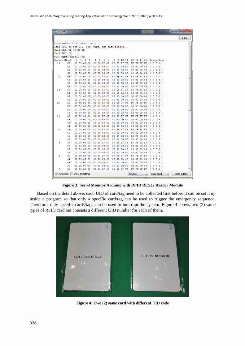
Based on the detail above, each UID of card/tag need to be collected first before it can be set it up
inside a program so that only a specific card/tag can be used to trigger the emergency sequence.
Therefore, only specific cards/tags can be used to interrupt the system. Figure 4 shows two (2) same
types of RFID card but consists a different UID number for each of them.
Figure 4: Two (2) same card with different UID code

Shamsudin et al., Progress in Engineering Application and Technology Vol. 1 No. 1 (2020) p. 323-333
329
The Serial Monitor of Arduino IDE used in this system to display the sequence taken by the program
for easy monitoring and observation. Here, the normal traffic light sequence will be running as long as
no emergency sequence are been triggered and the time taken for each lane to green, yellow and red
were reduced a bit for easier to observe. The program will keep repeating and running without any
interrupt. Figure 4 shows the output of serial monitor based on normal traffic light sequences.
Figure 5: Serial Monitor for normal traffic light sequences
Each led will take turn to light up which is green light for 10 seconds, yellow light for 1.5 seconds
and red for 0.5 seconds. However, when RFID reader received a signal for emergency purpose, the
system/sequence will be changed for a while to provide an access for the specific lane. Figure 5 and 6
are several testing shows that the details display on serial monitor when RFID reader received a signal.
Figure 6: Serial Monitor for emergency sequence on lane 2
Shamsudin et al., Progress in Engineering Application and Technology Vol. 1 No. 1 (2020) p. 323-333
330
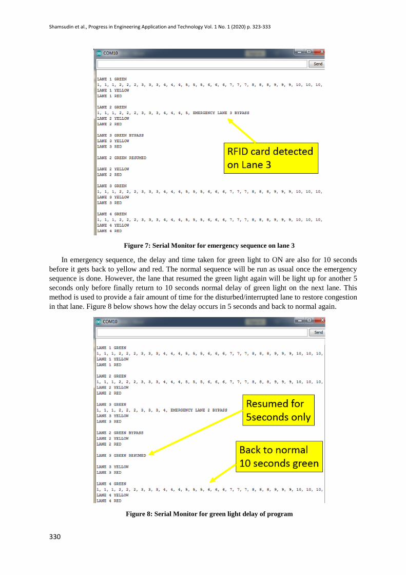
Figure 7: Serial Monitor for emergency sequence on lane 3
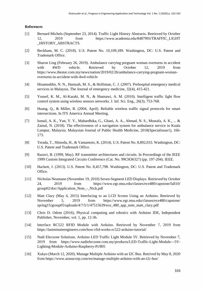
In emergency sequence, the delay and time taken for green light to ON are also for 10 seconds
before it gets back to yellow and red. The normal sequence will be run as usual once the emergency
sequence is done. However, the lane that resumed the green light again will be light up for another 5
seconds only before finally return to 10 seconds normal delay of green light on the next lane. This
method is used to provide a fair amount of time for the disturbed/interrupted lane to restore congestion
in that lane. Figure 8 below shows how the delay occurs in 5 seconds and back to normal again.
Figure 8: Serial Monitor for green light delay of program

Shamsudin et al., Progress in Engineering Application and Technology Vol. 1 No. 1 (2020) p. 323-333
331
3.2 Discussions
There are two significant elements will be discussed, which are hardware designing and software
designing. Hardware designing means needs to design the hardware with the several components that
are already studied in the literature review. The hardware involves the incorporating processing unit,
control unit and output unit. Besides that, the second element is software designing, which is needed to
write the program code for the whole system to function as desired. The software used to write the
program code is Arduino IDE because this project uses the Arduino as the processing unit. Figure 9
shows the flow of the internal system in this project.
Figure 9: Project Overview
Figure 10: Flowchart of overall system

Shamsudin et al., Progress in Engineering Application and Technology Vol. 1 No. 1 (2020) p. 323-333
332
In hardware design, the connection of each pin must be correct and tally as declare in programming.
Figure 11 shows that circuit diagram of this system.
Figure 11: Circuit diagram of overall system
4. Conclusion
In conclusion, through all the study and analysis that had been made, this prototype of Smart
Emergency Traffic Light System has been developed. The RFID RC522 module have been successfully
collecting the data of RFID card/tag wirelessly then transfer the data to the processor of Arduino. At
the meantime, the progress also has been successfully displayed on the serial monitor of Arduino IDE
for easier observation and understanding. In this project, the program is made to provides emergency
access for emergency personnel at the traffic light. Therefore, the time taken for travelling of emergency
vehicle between the scene to the emergency department (ED) can be reduce efficiently. Besides, this
module also facilitates the journey of emergency personnel during traffic light especially when it occurs
in a busy urban area. In addition, it also may avoid any accidents in traffic lights due to
misunderstandings and confusion regarding the siren's direction of emergency vehicle.
The use of RFID modules is intended to facilitate emergency personnel through very busy traffic
light areas. In addition, it is also in line with the advancement of RFID technology that is being used
now as in tolls in Malaysia. By simply setting a specific identity card/tag into the program, the system
will be more secure because any use of a card/tag with a different identity will not cause the program
to be interrupted/disturbed. In fact, only the pre-set card/tag will give further instructions to the entire
program. Eventually, this module can simply work for real life situation and may save a lot of human
life. It also can prevent any accident occur in traffic light intersections due to conflict and
misunderstanding among people. The module was successfully developed and met all the objectives.
Moreover, this implementing system has been working according to its needs. Nevertheless, there is
still some part in this module and system needed to be improved in future, so that it can be the more
reliable system produced.
Acknowledgement
The authors would also like to thank the Faculty of Engineering Technology, Universiti Tun
Hussein Onn Malaysia for its support.
Shamsudin et al., Progress in Engineering Application and Technology Vol. 1 No. 1 (2020) p. 323-333
333
References
[1] Bernard Michels (September 23, 2014). Traffic Light History Abstracts. Retrieved by October
12, 2019 from https://www.academia.edu/8487993/TRAFFIC_LIGHT
_HISTORY_ABSTRACTS.
[2] Beckham, M. C. (2018). U.S. Patent No. 10,109,189. Washington, DC: U.S. Patent and
Trademark Office.
[3] Sharon Ling (February 26, 2019). Ambulance carrying pregnant woman overturns in accident
with 4WD vehicle. Retrieved by October 12, 2019 from
https://www.thestar.com.my/news/nation/2019/02/26/ambulance-carrying-pregnant-woman-
overturns-in-accident-with-4wd-vehicle
[4] Hisamuddin, N. N., Hamzah, M. S., & Holliman, C. J. (2007). Prehospital emergency medical
services in Malaysia. The Journal of emergency medicine, 32(4), 415-421.
[5] Yousef, K. M., Al-Karaki, M. N., & Shatnawi, A. M. (2010). Intelligent traffic light flow
control system using wireless sensors networks. J. Inf. Sci. Eng., 26(3), 753-768.
[6] Huang, Q., & Miller, R. (2004, April). Reliable wireless traffic signal protocols for smart
intersections. In ITS America Annual Meeting.
[7] Ismail, A. K., Yun, Y. Y., Mahardhika, G., Ghani, A. A., Ahmad, N. S., Mustafa, A. K., ... &
Zainal, N. (2018). The effectiveness of a navigation system for ambulance service in Kuala
Lumpur, Malaysia. Malaysian Journal of Public Health Medicine, 2018(Specialissue1), 166-
173.
[8] Terada, T., Shinoda, H., & Yamamoto, K. (2014). U.S. Patent No. 8,892,033. Washington, DC:
U.S. Patent and Trademark Office.
[9] Razavi, B. (1999, May). RF transmitter architectures and circuits. In Proceedings of the IEEE
1999 Custom Integrated Circuits Conference (Cat. No. 99CH36327) (pp. 197-204). IEEE.
[10] Hackett, J. (2013). U.S. Patent No. 8,457,798. Washington, DC: U.S. Patent and Trademark
Office.
[11] Nicholas Neumann (November 19, 2010) Seven-Segment LED Displays. Retrieved by October
24, 2019 from https://www.egr.msu.edu/classes/ece480/capstone/fall10/
group02/doc/Application_Note_-_Nick.pdf
[12] Matt Clary (May 4, 2015) Interfacing to an LCD Screen Using an Arduino. Retrieved by
November 5, 2019 from https://www.egr.msu.edu/classes/ece480/capstone/
spring15/group05/uploads/4/7/5/1/47515639/ece_480_app_note_matt_clary.pdf
[13] Chris D. Odom (2016), Physical computing and robotics with Arduino IDE, Independent
Publisher, November, vol. 1, pp. 12-36.
[14] Interface RC522 RFID Module with Arduino. Retrieved by November 7, 2019 from
https://lastminuteengineers.com/how-rfid-works-rc522-arduino-tutorial/
[15] Nadi Eleczone Solutions. Arduino LED Traffic Light Module 5V. Retrieved by November 7,
2019 from https://www.nadieleczone.com.my/products/LED-Traffic-Light-Module---5V-
Lighting-Module-Arduino-Raspberry-Pi/805
[16] Xukyo (March 12, 2020). Manage Multiple Arduino with an I2C Bus. Retrived by May 8, 2020
from https://www.aranacorp.com/en/manage-multiple-arduino-with-an-i2c-bus/