Stabilization of peat by deep mixing method: A critical review of the state of practice
10
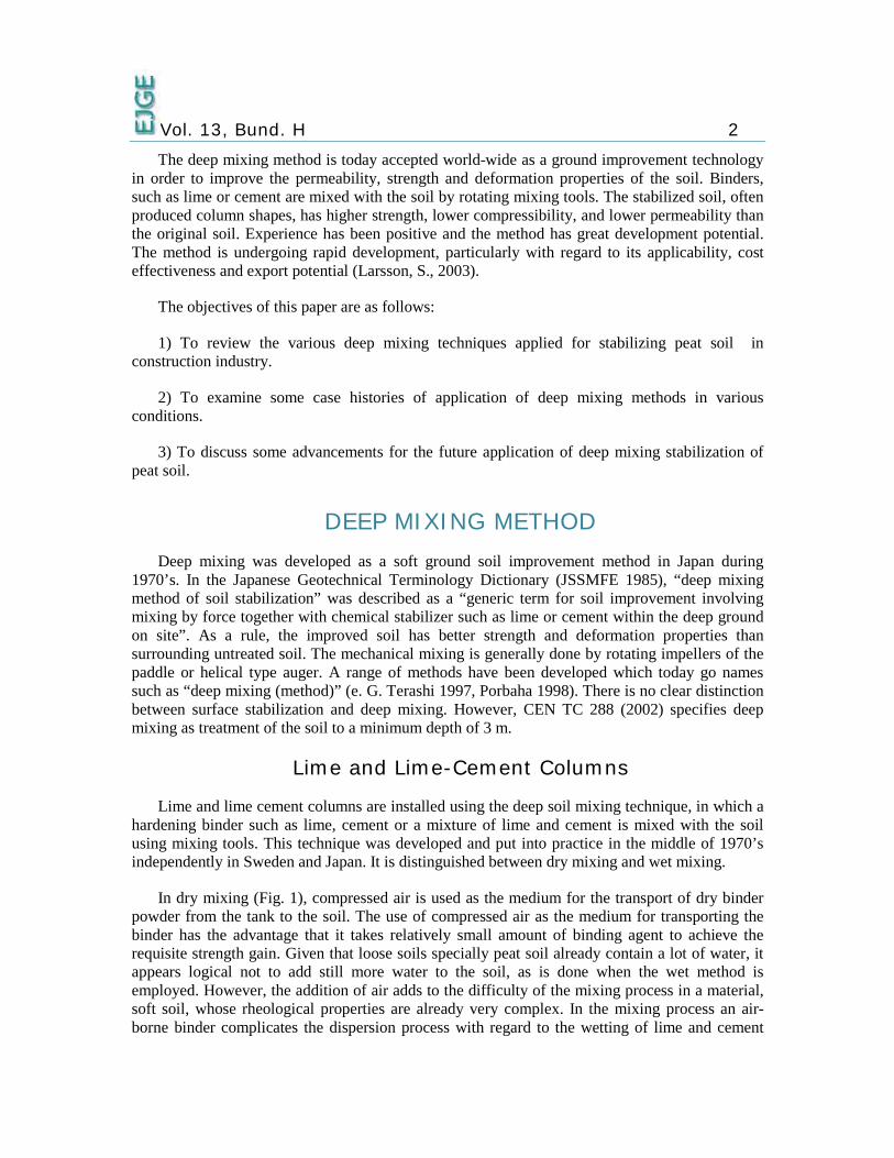
Stabilization of Peat by Deep Mixing Method: A Critical Review of the State of Practice Md. Shahidul Islam Department of Civil Engineering, University of Malaya, Malaysia E-mail: [email protected] Roslan Hashim Department of Civil Engineering, University of Malaya, Malaysia E-mail: [email protected] ABSTRACT The purpose of this paper is to advance the knowledge on peat soil stabilization by critically examining and documenting the current state of practice. Deep Mixing method is emphasised on column type techniques using lime/cement. This paper is essentially a comprehensive review of available academic literature on deep soil stabilization utilizing this approach. Deep mixing with lime or lime-cement column and combined soil stabilization with vertical columns (CSV) methods are discussed and to illustrate applications of these methods in a variety of conditions, several case histories are presented. KEYWORDS: peat soil, deep mixing method, stabilization INTRODUCTION Problematic peat soil exhibits high compressibility, medium to low permeability, low strength, and volume instability. Consequently, it is widely regarded as the worst foundation soil for supporting man-made structures. Under such circumstances, deep soil stabilization technique is often an economically attractive alternative to removal of deep peat or use of piles as deep foundation (Hebib and Farrell 2003).
Transcript of Stabilization of peat by deep mixing method: A critical review of the state of practice
Stabilization of Peat by Deep Mixing Method:
A Critical Review of the State of Practice
Md. Shahidul Islam
Department of Civil Engineering, University of Malaya, Malaysia E-mail: [email protected]
Roslan Hashim
Department of Civil Engineering, University of Malaya, Malaysia E-mail: [email protected]
ABSTRACT The purpose of this paper is to advance the knowledge on peat soil stabilization by critically examining and documenting the current state of practice. Deep Mixing method is emphasised on column type techniques using lime/cement. This paper is essentially a comprehensive review of available academic literature on deep soil stabilization utilizing this approach. Deep mixing with lime or lime-cement column and combined soil stabilization with vertical columns (CSV) methods are discussed and to illustrate applications of these methods in a variety of conditions, several case histories are presented.
KEYWORDS: peat soil, deep mixing method, stabilization
INTRODUCTION Problematic peat soil exhibits high compressibility, medium to low permeability, low
strength, and volume instability. Consequently, it is widely regarded as the worst foundation soil for supporting man-made structures. Under such circumstances, deep soil stabilization technique is often an economically attractive alternative to removal of deep peat or use of piles as deep foundation (Hebib and Farrell 2003).
Vol. 13, Bund. H 2
The deep mixing method is today accepted world-wide as a ground improvement technology in order to improve the permeability, strength and deformation properties of the soil. Binders, such as lime or cement are mixed with the soil by rotating mixing tools. The stabilized soil, often produced column shapes, has higher strength, lower compressibility, and lower permeability than the original soil. Experience has been positive and the method has great development potential. The method is undergoing rapid development, particularly with regard to its applicability, cost effectiveness and export potential (Larsson, S., 2003).
The objectives of this paper are as follows:
1) To review the various deep mixing techniques applied for stabilizing peat soil in construction industry.
2) To examine some case histories of application of deep mixing methods in various conditions.
3) To discuss some advancements for the future application of deep mixing stabilization of peat soil.
DEEP MIXING METHOD Deep mixing was developed as a soft ground soil improvement method in Japan during
1970’s. In the Japanese Geotechnical Terminology Dictionary (JSSMFE 1985), “deep mixing method of soil stabilization” was described as a “generic term for soil improvement involving mixing by force together with chemical stabilizer such as lime or cement within the deep ground on site”. As a rule, the improved soil has better strength and deformation properties than surrounding untreated soil. The mechanical mixing is generally done by rotating impellers of the paddle or helical type auger. A range of methods have been developed which today go names such as “deep mixing (method)” (e. G. Terashi 1997, Porbaha 1998). There is no clear distinction between surface stabilization and deep mixing. However, CEN TC 288 (2002) specifies deep mixing as treatment of the soil to a minimum depth of 3 m.
Lime and Lime-Cement Columns
Lime and lime cement columns are installed using the deep soil mixing technique, in which a hardening binder such as lime, cement or a mixture of lime and cement is mixed with the soil using mixing tools. This technique was developed and put into practice in the middle of 1970’s independently in Sweden and Japan. It is distinguished between dry mixing and wet mixing.
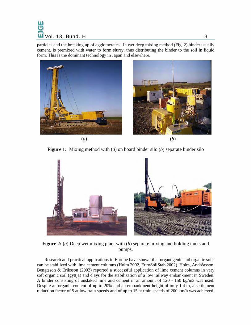
In dry mixing (Fig. 1), compressed air is used as the medium for the transport of dry binder powder from the tank to the soil. The use of compressed air as the medium for transporting the binder has the advantage that it takes relatively small amount of binding agent to achieve the requisite strength gain. Given that loose soils specially peat soil already contain a lot of water, it appears logical not to add still more water to the soil, as is done when the wet method is employed. However, the addition of air adds to the difficulty of the mixing process in a material, soft soil, whose rheological properties are already very complex. In the mixing process an air-borne binder complicates the dispersion process with regard to the wetting of lime and cement
Vol. 13, Bund. H 3
particles and the breaking up of agglomerates. In wet deep mixing method (Fig. 2) binder usually cement, is premixed with water to form slurry, thus distributing the binder to the soil in liquid form. This is the dominant technology in Japan and elsewhere.
(a) (b)
Figure 1: Mixing method with (a) on board binder silo (b) separate binder silo
Figure 2: (a) Deep wet mixing plant with (b) separate mixing and holding tanks and pumps.
Research and practical applications in Europe have shown that organogenic and organic soils can be stabilized with lime cement columns (Holm 2002, EuroSoilStab 2002). Holm, Andréasson, Bengtsson & Eriksson (2002) reported a successful application of lime cement columns in very soft organic soil (gyttja) and clays for the stabilization of a low railway embankment in Sweden. A binder consisting of unslaked lime and cement in an amount of 120 - 150 kg/m3 was used. Despite an organic content of up to 20% and an embankment height of only 1.4 m, a settlement reduction factor of 5 at low train speeds and of up to 15 at train speeds of 200 km/h was achieved.

Vol. 13, Bund. H 4
More positive experiences with lime cement columns in very soft cohesive soils with organic admixtures are reported for instance by Sondermann & Wehr (2002)
CSV-METHOD Combined soil stabilization with vertical columns (CSV) is a technique, whereby small
diameter columns consisting of a binder or binder mixture are installed in a close grid. Cement and lime are usually included as binder material. The columns with a diameter of 12 to 18 cm are arranged at a centre to centre distance of 0.5 to 1.5 m in a quadratic or triangular grid system. The CSV-method can be used in very soft to stiff cohesive soils, loose granular soils and organic soils (Scheller and Reitmeier 2001). By hardening of the stabilization material rigid columns can be formed. In Germany, a dry cement-sand-mixture as binder is used, which is installed into the soft soil by the displacement method using a continuous auger (so-called Coplan-Stabilization-Method, (Fig. 3). Basic guidelines for the calculation and design are given in DGGT (2002). For the verification of the safety against fracture of the column, it is generally assumed, that all loads are carried by the CSV columns.
Figure 3: (a) The installation process; (b) exposed auger during material transport (Courtesy: Bauer construction company)
CASE HISTORIES
Hamburg–Berlin railway line: reinforced embankment on pile like elements
As part of upgrading the railway line Hamburg-Berlin by the German Rail company, the Buechen-Hamburg and the Paulinenaue-Friesack part of the railway line were upgraded in 2003 to allow a train speed of 230 km/h. Because of the very soft organic soil (peat and mud) layer with insufficient bearing capacity, stabilization of the embankment foundation was necessary at these two parts. The part of this line with a total length of 625 m was near the railway station Buechen. The soft underground was stabilized with columns installed using Mixed-in-Place
Vol. 13, Bund. H 5
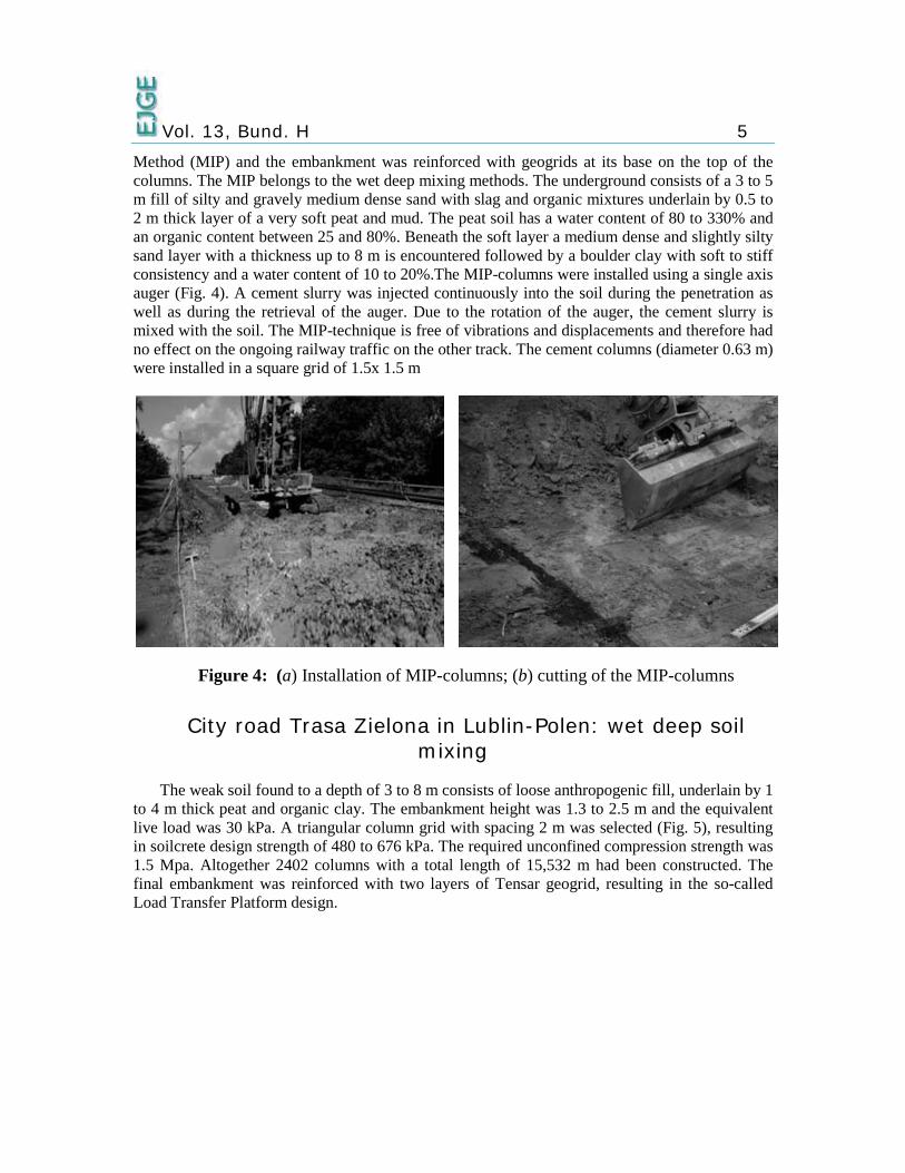
Method (MIP) and the embankment was reinforced with geogrids at its base on the top of the columns. The MIP belongs to the wet deep mixing methods. The underground consists of a 3 to 5 m fill of silty and gravely medium dense sand with slag and organic mixtures underlain by 0.5 to 2 m thick layer of a very soft peat and mud. The peat soil has a water content of 80 to 330% and an organic content between 25 and 80%. Beneath the soft layer a medium dense and slightly silty sand layer with a thickness up to 8 m is encountered followed by a boulder clay with soft to stiff consistency and a water content of 10 to 20%.The MIP-columns were installed using a single axis auger (Fig. 4). A cement slurry was injected continuously into the soil during the penetration as well as during the retrieval of the auger. Due to the rotation of the auger, the cement slurry is mixed with the soil. The MIP-technique is free of vibrations and displacements and therefore had no effect on the ongoing railway traffic on the other track. The cement columns (diameter 0.63 m) were installed in a square grid of 1.5x 1.5 m
Figure 4: (a) Installation of MIP-columns; (b) cutting of the MIP-columns
City road Trasa Zielona in Lublin-Polen: wet deep soil mixing
The weak soil found to a depth of 3 to 8 m consists of loose anthropogenic fill, underlain by 1 to 4 m thick peat and organic clay. The embankment height was 1.3 to 2.5 m and the equivalent live load was 30 kPa. A triangular column grid with spacing 2 m was selected (Fig. 5), resulting in soilcrete design strength of 480 to 676 kPa. The required unconfined compression strength was 1.5 Mpa. Altogether 2402 columns with a total length of 15,532 m had been constructed. The final embankment was reinforced with two layers of Tensar geogrid, resulting in the so-called Load Transfer Platform design.

Vol. 13, Bund. H 6
Figure 5: Road embankment supported on wet deep soil mixing columns, Lublin-Pole (Topolnicki 2003)
Tomei Highway Expansion Project
Tomei Freeway which connects Tokyo and Nagoya has been the artery of Japanese culture and economy since 17th century. Even with the addition of railroads and bullet train, rails the traffic volume along the Tomie Freeway continuous to increase. Therefore, the expansion project was carried out to expand the four-lane freeway into a six lane freeway – three lanes in each direction. The section near Isebara, located along the foothill of the Tanzawa ridge, is underlain by consecutive sections of ridges and valleys. The ridges consist of organic clays with peat. Excessive total and differential settlement and embankment instability were expected, if the new embankments were placed without improving the strength and compressibility of the organic soils.
Dry Jet Mixing (DJM) method, which has been used in numerous projects for treating organic soils and peat with satisfactory result, was selected to treat. Staged construction at 3 elevations was used for soil treatment. Two mix designs were used. Lower cement injection rates, 100 kg to 120 kg cement per m3 of target soil, were used in the existing embankment zone to maintain the strength of soil-cement 0.8 kgf/cm2 (Editor’s note: this old-metric/pre-SI unit is approximately equal to 100 kPa) – the average strength of the existing embankment soils. The higher cement injection rate, 170 kg to 230 kg cement per m3 of target soil, was used in the organic clays to obtain a minimum unconfined compressive strength of 7 kgf/cm2 after treatment.
A total of 50,215 m3 organic clays, peat, and fill were treated for use as foundations of the new embankment, retaining walls, and box culvert. Two sets of DJM rig were used. The deep

Vol. 13, Bund. H 7
mixing was commenced in April 1994 and completed in November 1994 without interrupting the use of the four-lane freeway. Staged construction procedure was used to perform the soil treatment within a limited working space. In addition to the foundation treatment for the new embankment, DJM also improved the foundation for the retaining wall and the box culvert, and eliminated the mobilization of pile driving equipment to the congested work zone parallel to an existing freeway.
A multistory building on wet deep mixing columns
A multistory building is located in a difficult heterogeneous soil conditions. Beneath a mixed fill, organic clay and some peat was encountered which extends to a depth of 3.5 to about 6.7 m below the final slab foundation level. Below the organic soil layer is fine sand and silt layers of varying thickness, making ordinary piling very expensive due to necessary pile length. Primary calculations also indicated that a direct placement of the foundation slab on the existing soil would lead to large and non-uniform settlements, ranging from 7 to about 50 cm despite of the high stiffness of the slab. For the outlined design comprising 461 DM columns with a total length of about 3.280 m, it was necessary to make a good estimate of the expected compressive strength of the soilcrete The average unit weight of the cement slurry was 1700 kg/m³ and the mean consumption rate was about 180 l/m.
Stabilization of a 5-storey building foundation and underground parking with CSV columns
The project consists of a 5-story apartment building with underground floor (20 x 14 m) and underground parking (30.5 x 17.5 m) with double parking floor in Constance city, southern Germany. The foundation of the apartment is located at a depth of 1.7 m and that of underground parking at 4.65 m below the ground surface. The construction site is surrounded by existing buildings at a distance of 0.5 to 9 m. The Constance area is known to consist a deep soft lacustrine underground and excavations and foundations in this area are always prone to excessive settlement and deformations.
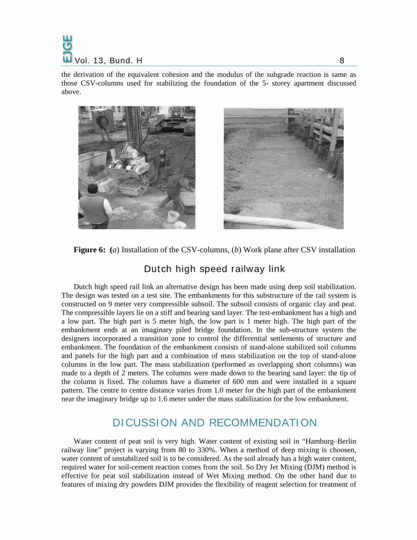
To minimise the settlement of the shallow foundation of the 5-storey apartment, a stabilising 237 CSV-columns were installed at a grid system of 1 x 1 m. The CSV-columns have a diameter of 15 cm and a length of 5m each. The mat foundation is rested on the CSV-columns. To design the mat slab, the subgrade reaction is approximated from the expected contact pressure and settlement of single columns. The settlement of a single pile is believed to consist three components: settlement and compression of a single column and settlement due to group effect. The first two components are determined from load test results and they are approximated to be 1 cm. The settlement due to group effect is calculated to be 5 cm. Hence, the total settlement is about 6 cm. Assuming a contact pressure of 100 kN/m², the modulus of subgrade reaction is calculated to be 1.7 MN/m³.
The excavation of the underground parking and the near by existing structures are also protected partly by CSV-columns at a grid of 0.5 x 0.5 m and partly by combination of sheet pile wall and CSV-columns. The CSV-columns are arranged to protect the excavation of the underground parking from overall stability failure and at the same time safe guard the safety of the existing structures. Fig. 6 also shows the installation process and the CSV-columns after installation is completed. The determination of the degree of soil improvement reached as well as
Vol. 13, Bund. H 8
the derivation of the equivalent cohesion and the modulus of the subgrade reaction is same as those CSV-columns used for stabilizing the foundation of the 5- storey apartment discussed above.
Figure 6: (a) Installation of the CSV-columns, (b) Work plane after CSV installation
Dutch high speed railway link
Dutch high speed rail link an alternative design has been made using deep soil stabilization. The design was tested on a test site. The embankments for this substructure of the rail system is constructed on 9 meter very compressible subsoil. The subsoil consists of organic clay and peat. The compressible layers lie on a stiff and bearing sand layer. The test-embankment has a high and a low part. The high part is 5 meter high, the low part is 1 meter high. The high part of the embankment ends at an imaginary piled bridge foundation. In the sub-structure system the designers incorporated a transition zone to control the differential settlements of structure and embankment. The foundation of the embankment consists of stand-alone stabilized soil columns and panels for the high part and a combination of mass stabilization on the top of stand-alone columns in the low part. The mass stabilization (performed as overlapping short columns) was made to a depth of 2 meters. The columns were made down to the bearing sand layer: the tip of the column is fixed. The columns have a diameter of 600 mm and were installed in a square pattern. The centre to centre distance varies from 1.0 meter for the high part of the embankment near the imaginary bridge up to 1.6 meter under the mass stabilization for the low embankment.
DICUSSION AND RECOMMENDATION Water content of peat soil is very high. Water content of existing soil in “Hamburg–Berlin
railway line” project is varying from 80 to 330%. When a method of deep mixing is choosen, water content of unstabilized soil is to be considered. As the soil already has a high water content, required water for soil-cement reaction comes from the soil. So Dry Jet Mixing (DJM) method is effective for peat soil stabilization instead of Wet Mixing method. On the other hand due to features of mixing dry powders DJM provides the flexibility of reagent selection for treatment of

Vol. 13, Bund. H 9
various soils that slurry type deep mixing technologies are inefficient or uneconomical to treat (Yang, D. S. et al 1998).
Organic clay and gyttja give good results when stabilized with cement by deep mixing method. But special attention should be given for peat soil. Due to its high water content, adding some sand improves strength and bearing capacity. Research findings indicated that the engineering properties of peat can be improved with the inclusion of Portland cement and ground granulated blast furnace slag (a byproduct of iron manufacturing) with siliceous sand acting as filler (Axelsson et al. 2002; EurosoilStab 2002; Ahnberg 2006). When mixed with cement in the soil, the slag, fly ash, bentonite or other secondary product which contains silica, alumina, and reactive lime is activated and this can accelerate the reactions of cement in peat and improves the stabilization effect. Siliceous sand can be used as filler to increase the number of solid particles in peat soil.
In CSV method the surrounding soil acts as a casing for the transport of the dry mix when dry binders or binder-sand mix are inserted into the ground using a continuous flight auger. If the soil is not firm enough to fulfill this task, the quantity of material input will be adjusted to create the necessary casing for a smooth and satisfactory transport of the dry material (Scheller and Reitmeier 2001). Peat soil is very soft soil with high water content and casing problem may arises, because when auger rotates surrounding soil break down and inturupt uniform soil mixing and this problem can be solved by mixing bentonite with binder which can help to build a firm layer at surrounding of the soil-cemnt column .
Ahnberg et al. conducted a laboratory experiment concerning the effect of initial loading on the strength of stabilized peat. The test results revealed that an initial loading during curing greatly influences the strength of the stabilized peat. It is important that this fact to be taken into account and utilized in the design and execution of stabilization in the field. In the field, the initial load should be applied evenly, using the same thickness of fill. This should be done after installation of column as early as possible. An even and early loading is important to improve the homogeneity as well as the strength of the stabilized soil. In case of peat soil stabilization by Deep Mixing Method, back filling work of certain height can be done after installation of soil-cement column to ensure the initial load.
CONCLUSION From above discussion one can draw following conclusion:
• Due to high water content, Dry Jet Mixing method (DJM) is effective for stabilization peat soil.
• Using fly ash, blast furnace slag, bentonite or other secondary product can accelerate reaction rate during stabilization.
• Adding some portion of well graded sand, which act as filler material, is also effective for soil-cement stabilization.
• Using some initial load after installation of soil-cement column can also increase strength of treated soil.

Vol. 13, Bund. H 10
ACKNOWLEDGMENT The authors would like to acknowledge IPPP of University of Malaya for their financial
support to conduct the research work.
REFERENCES 1. Ahnberg, H., Bengtsson, P. E., Holm, G. (2001) “Effect of initial loading on the strength of
stabilized peat”, Ground Improvement, vol 5, 35-40.
2. Barron R. F., Kramer, C., Herlache, W. A. , Wright, j., Fung, H., Liu, C., “Cement Deep Soil Mixing Remediation of Sunset Notrh Basin Dam”, www.cement.org
3. EuroSoilStab. (2002). Development of Design and Construction Methods to Stabilize Soft Organic Soils: Design Guide Soft Soil Stabilization. CT97-0351. Project No. BE 96-3177, Industrial & Materials Technologies Programme (Brite- EuRam III), European Commission.
4. Hebib, S. and Farrell, E.R. (2003). Some experiences on the stabilization of Irish peats. Canadian Geotechnical Journal, 40(1): 107-120.
5. Anz, M. and Johansson, S. E. (2002). The Function of Different Binding Agents in Deep Stabilization, 9th Report of Swedish Deep Stabilization Research Centre, Linkoping, Sweden.
6. Kempfert, H. G. Gebreselassie, B. (2006), “Excavations and Foundations in Soft Soils,” Springer Berlin Heidelberg
7. Kempfert, H. G. (2003), “Ground improvement methods with special emphasis on column-type techniques”, Int. Workshop on Geotechnics of Soft Soils-Theory and Practice. Vermeer, Schweiger, Karstunen & Cudny (eds.)
8. Kenneth B., Andromalos, P.E. and Eric W. Bahner, P.E. “The Application of Various Deep Mixing Methods foe Excavating Support System Systems”
9. Larsson, S. (2003) “Mixing Processes for Ground Improvement by Deep Mixing”, Doctoral thesis published in Royal Institute of Technology, Stockholm, Sweden.
10. Porbaha, A. (2000) “State-of-the-art in deep mixing technology: design considerations”. Ground Improvement, Vol. 4, pp111-125.
11. Taki, O., Bell, R. A. (1998) “Soil-Cement Pile/Column-A System of Deep Mixing” ASCE, Geotechnical Special Publication No. 81, 59-71
12. Yang, S. D., Yagihashi, J. N., and Yoshizawa, S. S. “Dry Jet Mixing For Stabilization of Very Soft Soils and Organic Soils” Geotechnical Special Publication No. 81, 96-110
© 2008 ejge