Slide Stabilization With Gravel Trenches - CORE
7
Missouri University of Science and Technology Missouri University of Science and Technology Scholars' Mine Scholars' Mine International Conference on Case Histories in Geotechnical Engineering (1984) - First International Conference on Case Histories in Geotechnical Engineering 08 May 1984, 10:15 am - 5:00 pm Slide Stabilization With Gravel Trenches Slide Stabilization With Gravel Trenches E. G. Wardlaw USAED Vicksburg, Vicksburg, Mississippi L. A. Cooley USAED Vicksburg, Vicksburg, Mississippi A. E. Templeton USAED Vicksburg, Vicksburg, Mississippi R. L. Fleming Jr. USAED Vicksburg, Vicksburg, Mississippi Follow this and additional works at: https://scholarsmine.mst.edu/icchge Part of the Geotechnical Engineering Commons Recommended Citation Recommended Citation Wardlaw, E. G.; Cooley, L. A.; Templeton, A. E.; and Fleming, R. L. Jr., "Slide Stabilization With Gravel Trenches" (1984). International Conference on Case Histories in Geotechnical Engineering. 33. https://scholarsmine.mst.edu/icchge/1icchge/1icchge-theme3/33 This Article - Conference proceedings is brought to you for free and open access by Scholars' Mine. It has been accepted for inclusion in International Conference on Case Histories in Geotechnical Engineering by an authorized administrator of Scholars' Mine. This work is protected by U. S. Copyright Law. Unauthorized use including reproduction for redistribution requires the permission of the copyright holder. For more information, please contact [email protected]. brought to you by CORE View metadata, citation and similar papers at core.ac.uk provided by Missouri University of Science and Technology (Missouri S&T): Scholars' Mine
-
Upload
khangminh22 -
Category
Documents
-
view
3 -
download
0
Transcript of Slide Stabilization With Gravel Trenches - CORE

Missouri University of Science and Technology Missouri University of Science and Technology
Scholars' Mine Scholars' Mine
International Conference on Case Histories in Geotechnical Engineering
(1984) - First International Conference on Case Histories in Geotechnical Engineering
08 May 1984, 10:15 am - 5:00 pm
Slide Stabilization With Gravel Trenches Slide Stabilization With Gravel Trenches
E. G. Wardlaw USAED Vicksburg, Vicksburg, Mississippi
L. A. Cooley USAED Vicksburg, Vicksburg, Mississippi
A. E. Templeton USAED Vicksburg, Vicksburg, Mississippi
R. L. Fleming Jr. USAED Vicksburg, Vicksburg, Mississippi
Follow this and additional works at: https://scholarsmine.mst.edu/icchge
Part of the Geotechnical Engineering Commons
Recommended Citation Recommended Citation Wardlaw, E. G.; Cooley, L. A.; Templeton, A. E.; and Fleming, R. L. Jr., "Slide Stabilization With Gravel Trenches" (1984). International Conference on Case Histories in Geotechnical Engineering. 33. https://scholarsmine.mst.edu/icchge/1icchge/1icchge-theme3/33
This Article - Conference proceedings is brought to you for free and open access by Scholars' Mine. It has been accepted for inclusion in International Conference on Case Histories in Geotechnical Engineering by an authorized administrator of Scholars' Mine. This work is protected by U. S. Copyright Law. Unauthorized use including reproduction for redistribution requires the permission of the copyright holder. For more information, please contact [email protected].
brought to you by COREView metadata, citation and similar papers at core.ac.uk
provided by Missouri University of Science and Technology (Missouri S&T): Scholars' Mine

Slide Stabilization with Gravel Trenches E. G. Wardlaw
Project Geotechnical Engineer, USAED Vicksburg, Vicksburg, Mississippi
L.A. Cooley Chief Foundation and Materials Branch, USAED Vicksburg, Vicksburg, Mississippi
A. E. Templeton Geotechnical Engineer, USAED Vicksburg, Vicksburg, Mississippi
R. L. Fleming, Jr. Chief Analytical Section, USAED Vicksburg, Vicksburg, Mississippi
SYNOPSIS A different method of slide stabilization using gravel trenches is described. The design, construction, and performance monitoring of the gravel trenches are discussed together with a history of the slide, description of the soils, and mechanism of failure. The applications and limitations of this method of slide stabilization are also evaluated.
INTRODUCTION
The U. S. Army Engineer District, Vicksburg, completed construction of a repair to a sliding river bank in Coahoma County at mile 175.8 on the Big Sunflower River, approximately 15 miles south of Clarksdale, Mississippi, in June 1982. The slide repair technique consisted of construction of trenches backfilled with gravel that were spaced equally across the extent of the sliding soil mass, perpendicular to the river flow, and extending below the slip surface. A number of stabilization methods were investigated but the gravel trench method of repair was determined to be the most cost effective method of stabilization. The history of the slide dates back to the late 1960's and invo·lves damage to a county road and destruction of a timber bridge.
The slide is described as a long, shallow, translatory slide with an average depth to the slip surface of 10 to 12 feet. The slide had an areal extent of approximately 200 by 250 feet. The intermittent movement of the sliding mass had been perpetuated by the continual process of dumping debris at the top of the slide and subsequent erosion of the toe bulge by the river.
This paper summarizes the nature and history of the slide, the design of the slide stabilization measures, construction of the gravel trenches, and results of the post-construction monitoring program.
BACKGROUND
The slide had been active, with intermittent movement, for twenty years or more. The slide began to gather interest in the late 1960's as translational movements and upper bank subsidence affected a road located at the crest of the riverbank and threatened a timber bridge that had been in service at the slide site for several decades. The slide extended from about 150 to 200 feet upstream of the bridge to about 50 feet downstream of the bridge. Plan and
743
profile views of the slide area are presented in Figures 1 and 2.
Approllimate Limits of Slide/'-.
,.,r--..... \ ,.,.. ..... ~ ·" £ /'" Slope
i"" '- Inclinometer /
\ _..., Timber Piles-
\
Timber Bridge \
S cal e: t:;=::E:::3 o' so'
Fig. 1. Plan View of Slide Area
It was noted originally that the slide experienced movement shortly after long periods of ra~n. This tendency changed with time to sliding occurring after every rain. Initial attempts to reestablish the shoulder of the road consisted of dumping rubble fill at the crest of the river bank. This activity aggravated the sliding problem by providing additional driving weights to an already unstable sliding soil mass. Slide movements typically would cause a bulge to occur at the toe of the riverbank which would restrict channel flow. The toe bulge would then be subjected to erosion by the river which would lead to additional sliding. In 1969 a row of 12-inch timber piling was driven through the sliding soil mass in an attempt to halt movements. The timber piles stopped the movement for a short period of time, but the slope began
First International Conference on Case Histories in Geotechnical Engineering Missouri University of Science and Technology http://ICCHGE1984-2013.mst.edu

DISTANCE IN FEET 50 100" 150 200
150 0 > (.!)
z
1-w w u.
~
::> w __J
wiOO
Fig. 2.
Highly PlastiC Clay (CH)
...... ......
S-1 I
I Inferred Failure Surface
Fine and Medium Sands
Cross-Section of Slide
to slide over the top of the piling. In early 1971, the slide tilted the piling, and movement again extended out into the river channel. The continuing movement of the slide mass caused the timber bridge to undergo distress until 1971 when the bridge was removed and replaced with a multiple culvert low water crossing.
In 1970, the Coahoma County Board of Supervisors requested the U. S. Army Engineer District Vicksburg, to investigate and repair the slide. A study was conducted in 1970-1971 which included bo7ings, installation of slope inclinometer cas~ngs and laboratory testing. The design considered three solutions all of which had estimated costs well in excess of the authorized funding level of $50,000. Due to the limit on funds, none of the ·solutions were implemented. Visual reconnaissance of the slide continued from 1971 through 1980 with continual rubble fill placement in the scarp area being observed. In 1980 authority was provided to "proceed with an appropriate solution" to repair the slide. A total of six stabilization techniques were investigated under this authority. A final recommendation for stabilization of the slide was made in September 1981 and provided for installation of trenches backfilled with gravel.
SLIDE ASSESSMENT
Geology
The slide area is located within the Yazoo River Basin physiographic subprovince of the Mississippi River Alluvial Valley. The Yazoo Basin was, within Recent geologic past, a part of the meande7 belt of the Mississippi and Ohio Rivers. Accord~ngly, Oxbow lakes,/swales and other features characteristic of flood plain and meander .be~t together are common within the area of the sl~de. Flat terrain is also characteristic of the area, with relief in excess of 10 feet being uncomm~n exce~t i~ rivers, bayous and sloughs. Geolog7c mapp~ng ~n the area indicates the slide to be ~n abandoned channel deposits (Smith 1979). Underlying the abandoned channel d~posits are approximately 60 to 70 feet of substr~tum sands in turn underlain by the Upper Cla~borne Group of the Tertiary age.
744
Exploration Program
Investigation of soil conditions in the slide consisted of making two undisturbed sample borings and installation of three slope inclinometer casings in 1971 and one undisturbed sample boring in 1982. The borings indicated the abandoned channel deposits consist of highly plastic clays (CH) interbedded with occassional thin silt lenses. The top stratum deposits extend to a depth of approximately 35 feet below the elevation of top bank and are underlain by s~bstratum fine to medium sands and silty sands w~th traces of gravel. The generalized soil and slide profile is presented in Figure 2. Also presented are the locations that the slope inclinometer casings sheared and the location of the inferred slip surface.
Laboratory Testing
Laboratory testing consisted of water content determinations, Atterberg limit tests, unconfined compression (UC) tests, unconsolidated undrained (UU) triaxial tests, consolidateddrained (CD) direct shear tests and consolidation tests. Plots of cohesion, Atterberg limits and water content versus depth are presented in Figure 3. The data was plotted versus depth because variations with depth below the surface of the slope were determined to be more significant than elevation. The UC and UU tests indicate considerable scatter in the shear strengths from the surface down to a depth of about 25 feet. The shear strengths range from a cohesion of 260 psf (pounds per square foot) to 1260 psf with an average value of 700 psf. Below 25 feet a trend of increasing cohesion with depth is indicated. The water contents also show considerable scatter, particularly in the upper 20 feet.
Three consolidated-drained, direct shear tests and two consolidation tests were run on samples from depths of 5 and 10 feet. Two of the consolidated-drained tests were run to determine peak strengths and provided average values for the applicable range of in situ stresses of c' = 110 p~f and~· = 23°. The third test was a repeated d~rect shear test performed to determine the residual strength of the soil. The residual strength was determined to be c' = 80 psf and r ~·r = 9°. The two consolidation tests indicate
First International Conference on Case Histories in Geotechnical Engineering Missouri University of Science and Technology http://ICCHGE1984-2013.mst.edu

an overconsolidation ratio of 7 and an average compression index of 0. 41.
Cohesion, psf 500 1000
Water Content .z % 20 40 6u 80 0 _(: VI
~ 0 ~ 0 w_
G -~= • r .:..
~ ~ :::
_!!_I __Q lA I!J" kit' * 0 ~ wJ ~ ':" (• . ~~
"~ F;-1 r::::: 1\i [/" '>
G) 0 ru w
:fJ) 1: 0
@ ~ \=) VI
. Legend• c: jl_ Legend• 0UC ~ 0 Llquld Limit euu . - Ill Plaatic Limit
• Natural Water Content
<; "' I I I ,:,
Fig. 3. Shear Strength and Water Content Data
Conditions Contributing to Slide
The site investigation indicated the soils in the slide to be medium to stiff, highly plastic clays that exhibited an overconsolidated crust and fissured soil structure. Fissures and slickensides were evident from examination of the undisturbed samples and from observations during trenching for installation of the gravel trenches. It was noted that the slip surface was located at the lower extent of the heavily fissured and slickensided zone. The UC's indicated considerable scatter in shear strength down to a depth of about 25 feet. Observations of the specimens during testing indicated that fissures and slickensides controlled the strength of a large number of the specimens tested. The average liquidity index was 26 percent.
Development of an overconsolidated crust is common in the Lower Mississippi River Valley and is attributed to fluctuations in the water table and seasonal wetting and drying of the surface soils. During the dry season of the year dessication can occur to depths as great as 8 to 10 feet. The water table will fluctuate from near the surface during extremely wet seasons to 25 to 30 feet deep during extremely dry seasons. The combined processes produce overconsolidation generally decreasing with depth below the surface. The soils near the surface where severe dessication has occurred usually show a dense, blocky structure with fissures and slickensides. The distinctiveness of the structure and the degree of fissuring decreases with depth. Typically the soils are normally consolidated below a depth of about 25 feet.
745
Undrained slope stability analyses using the average shear strength values of c = 700 psf and 1 = 0 along the slip surface produced safety factors in excess of 3.0. From these analyses it was determined that the failure mechanism could not be explained in terms of an undrained failure. This leads to the determination that the slope failure occurs under drained conditions with a triggering mechanism attributed to the shrink swell process which occurs in the soils near the surface. Extensive cracks develop in the highly plastic clays during dry weather and soil material from the surface falls down the cracks (Allen and Braud, 1966). When the soil is wetted following a dry season extensive swelling occurs. The swelling develops high lateral pressures (Pufahl, Fredlund and Rehardjo, 1983). Because of the sloping surface, non-uniform lateral pressures develop which cause local overstressing forming concentrations of slickensides in zones experiencing the largest strains (Templeton, Sills, Cooley, 1984). From the stresses and associated strains the soil exceeds the peak strength. In some zones the residual strength may be reached while in other zones the soil may be near the peak strength. The average drained shear strength probably lies between peak and residual. The slide is triggered when this condition has developed to a significant degree and the soil is saturated by heavy rainfall.
The slide was first observed during the late 1940's, but movements were minor until the late 1960's. The slopes were heavily vegetated until the early 1960's when the slopes were cleared and snagged. This exposure of the slope increased the severity of the wet-dry cycles and accelerated development of conditions contributing to sliding. Once movements developed to the point that the slide broke back into the road, efforts were made to reestablish the surface by dumping fill at the top of slide. Additional fill caused additional movements during the next rainy season and subsequent erosion of the toe bulge by the river. This practice was continued for about 10 years. During the period 1970-1980, observations of the top of a slope inclinometer casing indicated that portions of the slide mass moved as much as 40 feet. This same type phenomena was observed at a slide approximately 40 miles down river where a pecan tree moved down slope from top bank, a distance of about 30 feet and remained relatively undamaged.
REMEDIAL MEASURES
The selection of the gravel trench stabilization method was based on a cost analysis in which cost estimates were compared for several methods of slide stabilization. The slide stabilization methods investigated fell into four categories: (1) an anchored sheet pile bulkhead, (2) excavation and backfilling material in the failed zone, (3) in-place stabilization by either stone colums or gravel trenches, or (4) stabilization by changing the slope configuration: The.st~ilization by changing the slope conf~gurat~on ~nvolved construction of either a soil berm or rock buttress combined with relocation of the river channel. The methods which did not require relocation of the river channel were the anchored sheet pile bulkhead, stone columns, and gravel
First International Conference on Case Histories in Geotechnical Engineering Missouri University of Science and Technology http://ICCHGE1984-2013.mst.edu

trenches. The stone column and gravel trench methods of slide stabilization increase the overall shear strength along the slip surface and provide adequate factors of safety against sliding. Based on preliminary cost estimates, the gravel trench method was selected to be investigated in detail. Table I lists the various alternatives considered and the estimated construction costs.
TABLE I. Preliminary Cost Estimate for Various Alternatives
1. Anchored Sheet Pile Bulkhead $408,000
2. Excavation and Backfill $272,000
3. Soil Berm - Slope Flattening and Channel Relocation $236,000
4. Rock Buttress - Slope Flattening and Channel Relocation $236,000
5. Stone Columns $190,500
6. Gravel Trenches $150,000
Design of the remedial measures required a detailed analysis of the existing conditions to determine the existing shear strength acting along the slip surface. Figure 2 shows in cross section the slide indicating boring logs, slope inclinometer casings and the inferred slip surface utilized in the analyses.
The sheared slope inclinometer casings showed the slide to be of the long, shallow, translatory type. The average depth to the slip surface was approximately 10 feet. Spencer's method of limit equilibrium analysis was used (Wright, 1974) to analyze the slip surface assuming the sliding mass to be in a state of limiting equilibrium and a piezometric grade line coincident with the existing ground surface. Drained strength parameters of ~· = 18° c' = 0 psf were backfigured as the average strength acting on the slip surface producing a safety factor of unity.
mce the strength acting on the slip surface ·as determined, the average drained shear trength parameters of ~· = 21.4° and c' = 0 psf ere computed as the shear strength required to rovide a factor of safety of 1.2 for the
·;repaired slope. It was decided that a locally available washed gravel would be used in the trenches. The estimated strength parameters fez the washed gravel were ~· = 35 and c' = 0 psf •. The trenches were to be excavated to a depth 3 feet below the slip surface and filled to with in 3 feet of the ground surface. Figure 4 shows a typical section of the gravel trench.
With the strength parameters for the slip surface and the gravel fill known, the next step was to determine a trench width and spacing that would provide the composite shear strength required to raise the computed factor of safety to 1.2. AsSuming that a standard tractor backhoe with a 2.5 foot wide bucket would be used to excavate the trenches, it was determined that a center to center trenCh spacing of 12.0 feet would provide the rsquired average strength para meters of ~· = 21.4 and c' = 0 psf. Although the analyses for the repaired slope assumed a "saturated to shell" condition, it was felt that by placing the gravel trenches perpendicular to the slope and by providing an outlet on the down· slope end, drainage would reduce the piezometric pressures on the slip surface and the actual factor of safety would be greater than 1.2.
CONSTRUCTION
Construction of the gravel trench stabilization was accomplished by the u. s. Army Engineer District, Vicksburg, in 1982. Preliminary site preparation occurred between February 24-26, 1982. This activity included clearing and grubbing the site and excavating eight exploratory t:tenches at different locations across the ex·tent of the slide to determine the depth of the slip surface in areas of the slide in which slope inclinometer data was not available. The slide was still active at this time as noted by the propagation of new cracks and movements when the construction equipment began clearing the vegetation from the slide area.
Construction of the gravel trenches began ~arch 24, 1982. The gravel trenches were constructed beginning at top bank and proceeding toward the slide toe at th~ water's edge (see Figures 4 and 5) • The trenches were excavated to full depth in sections 20 to 30 feet long.
50 IOODISTANCE IN FEET 150 200
0 ~ 150 z
.... llJ llJ u.
~
> llJ ...1 LLI
100
Fig. 4.
Substratum Sand
Cross-Section of Gravel Trench
746
First International Conference on Case Histories in Geotechnical Engineering Missouri University of Science and Technology http://ICCHGE1984-2013.mst.edu
Trench excavation was performed using a John Deere 310A tractor-mounted backhoe. This backhoe could excavate to an effective depth of approximately 11 feet. The backfill was a washed gravel in which more than 95 percent of the particle sizes were larger than the u. s. Standard Sieve No. 4 and 100 percent of the particle sizes were smaller than 1-1/2 inches. This gravel was commercially available in the area and was transported to the construction site by truck and stockpiled. An International
"Harvester 530, rubber tired, front-end loader with a 3 cubic yard bucket capacity was used to transport the gravel from the stockpile to the trenches. The gravel backfill was not densified after it was placed. A Bucyrus-Erie, 22B, dragline with a 1 cubic yard bucket was used to do some grading of the upper bank, grading of the slide toe, and to place the riprap protection. A Caterpillar, D7, bulldozer was used to place an impervious clay cover over the backfilled trenches and to perform general slope dressing.
The first gravel trench was constructed on the downstream limit of the slide with subsequent trenches proceeding upstream on 12 foot spacings. During the excavation for the trenches all manner of debris was encountered including large pieces of concrete and timbers. The heterogeneous nature of the slide mass combined with numerous discontinuities (slickensides, fissures, and debris) made caving of the trench side walls a recurring problem. The caving problem seemed to worsen as the trench construction progressed toward the middle of the slide mass. In total, fourteen trenches were installed varying in length from 180 to 200+ feet and in depth from 0 to 15 feet. When the trench excavation depth extended beyond the reach of the backhoe a bench was excavated 2 to 3 feet deep for the backhoe to operate from.
After placement of the gravel backfill, the 3-foot thick layer of compacted clay (CH) was placed over the trenches. Figure 4 shows a section of the gravel trench indicating the impervious clay blanket and the riprap protection. After all of the gravel trenches were completed a clay fill was placed on the upper bank area to reconstruct the shoulder of the road that had been lost by slide activity. This material was spread by bulldozer and compacted with a sheep's foot roller. The toe of the slide was graded to a 1 vertical on 3.5 horizontal slope from the water's edge. The gravel at the lower end of the trenches was exposed so that the bedding gravel for the placement of the riprap toe protection would be interconnected with the trench to allow drainage through the riprap protection. The construction of the repair was completed, including turfing, in the first week of June, 1982 with a final cost of $107,000. Construction efforts were interrupted at least twice due to high water. Figure 5 shows, in plan view, the location of the gravel trenches and the riprap protection.
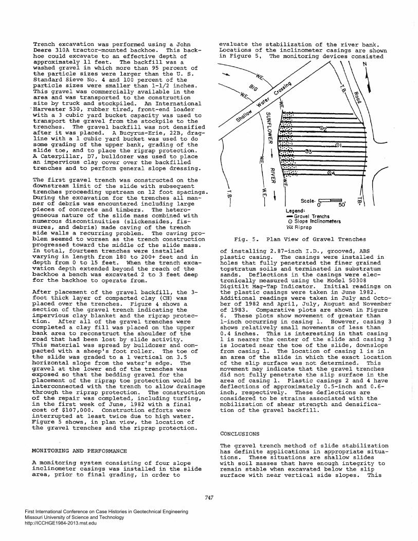
MONITORING AND PERFORMANCE
A monitoring system consisting of four slope inclinometer casings was installed in the slide area, prior to final grading, in order to
747
evaluate the Locations of in Figure 5,
--1
j
stabilization of the river bank. the inclinometer casings are shown
The monitoring devices consisted
······ ...
'• ····· ......
\ :.·.··· ·1---+ . ... .. · ....... ········ .......
Scale· 0!;,====~50•
Legend: -Grovel Trenchs 0 Slope fnclinometers W.~ Riprap
Fig •. 5. Plan View of. Gravel Trenches
of installing 2.87-inch I.D., grooved, ABS plastic casing. The casings were installed in holes that fully penetrated the finer grained topstratum soils and terminated in substratum sands. Deflections in the casings were electronically measured using the Model 50308 Digitilt Mag-Tap Indicator. Initial readings on the plastic casings were taken in June 1982. Additional readings were taken in July and October of 1982 and April, July, August and November of 1983. Comparative plots are shown in Figure 6. These plots show movement of greater than l-inch occurring in casing 1. However, casing 3 shows relatively small movements of less than 0.4 inches. This is interesting in that casing 1 is nearer the center of the slide and casing 3 is located near the toe of the slide, downslope from casing 1. The location of casing 1 is in an area of the slide in which the exact location of the slip surface was not determined. This movement may indicate that the gravel trenches did not fully penetrate the slip surface in the area of casing 1. Plastic c_asings 2 and 4 have deflections of approximately 0.5-inch and 0.6-inch, respectively. These deflections are considered to be strains associated with the mobilization of shear strength and densification of the gravel backfill.
CONCLUSIONS
The gravel trench method of slide stabilization has definite applications in appropriate situations. These situations are shallow slides with soil masses that have enough integrity to remain stable when excavated below the slip surface with near vertical side slopes. This
First International Conference on Case Histories in Geotechnical Engineering Missouri University of Science and Technology http://ICCHGE1984-2013.mst.edu

... NV
_oo 7 ,., c.s
I I ' -;:.-c ·- 0
2 ..5£ I
6
10
14
18 1-w ~22 z ; 26 1-
~30 0
34 -DOWNSLOPE
38
42
46
50 2.4 1.2 0 1.2 DEFLECTION IN INCHES
Fig. 6. Slope Inclinometer Deflections
This application has several definite advanbages when compared to other methods of stabilization. Some of the merits are relatively low construction cost, moderate level of design complexity, and can be performed with conventional, readily available construction equipment. The gravel trenches technique could potentially be extended to slip surfaces of greater depths in very stiff soils such as some clay shales. An improvement to the stabilization method would involve densifying the gravel backfill in place to minimize settlements, improve shear strength, and reduce the amount of strain necessary to mobilize .the required resistance to sliding.
The performance of the gravel trench stabilization has met the basic requirements of the project, which were to stop the sliding of the mstable soil mass and to restore the road surace and shoulder to pre-slide conditions.
'he stabilization of this slide using gravel renches serves as a prototype and provides nformation that can be used to evaluate and .opefully refine this method into a more !conomical and technically viable stabilization technique.
748
REFERENCES
Allen, J. B. and H. J. Braud, Jr. (1966), Effects of Cracks and Initial Moisture Content on the Infiltration Rate of Sharkey Clay, Louisiana State University Agricultural Experiment Station, Bulletin No. 613.
Pufahl, D. E., D. G. Fredlund, and H. Rahardjo (1983) • Lateral Earth Pressures in Expansive Clay Soils, Canadian Geotechnica: Journal, Vol. 20, No. 2, 228-241.
Smith, F. L. (1979). Geological Investigation of the Yazoo Basin, Lower Mississippi Valley. U. S. Army Engineer Waterways Experiment Station, Corps of Engineers, Vicksburg, Mississippi, Technical Report N6. 3-480.
Templeton, A. E., G. L. Sills, and L.A. Coolei (1984). Long-Term Failures in Compacted Clay Slopes. Proc., International Conference on Case Histories in Geotechnical Engineering, St. Louis, Paper No. 359.
Wright, S. G., (1974). SSTABl-A General Computer Program for Slope Stability Analyses, Department of Civil Engineering, The University of Texas at Austin.
First International Conference on Case Histories in Geotechnical Engineering Missouri University of Science and Technology http://ICCHGE1984-2013.mst.edu