Effective stress strength testing of peat
11
Environmental Geotechnics Volume 2 Issue EG1 Effective stress strength testing of peat O’Kelly Environmental Geotechnics February 2015 Issue EG1 Pages 34–44 http://dx.doi.org/10.1680/envgeo.13.00112 Paper 13.00112 Received 11/10/2013; accepted 10/03/2014 Published online 01/04/2014 Keywords: codes of practice & standards/failures/strength and testing of materials ICE Publishing: All rights reserved 34 It has been approximately 80 years since the first effective stress strength testing of peat was performed using triaxial apparatus. In light of recent unexpected failures of embankments, dykes, foundations and slopes in peat deposits, it is timely to review current laboratory practice and also provoke discussion about the best way forward for understanding and determining the effective stress strength properties of peat. Compared with fine-grained mineral soils, significant fabric and structural differences (including the porous, compressible nature of the organic solids themselves) make the direct application of classical soil mechanics strength models doubtful for peat. Uncertainties and difficulties of effective stress testing of peat using standard strength apparatus are discussed. Compared with triaxial compression, direct simple shear testing appears to provide conservative estimates of the strength parameter values, and the specimen deformation (failure) mode more closely represents that occurring in translational planar slides. It is recommended that the geotechnical profession investigates alternative theoretical frameworks to explain and predict peat strength (and compression) behaviour along with the development of new apparatus and methodologies for determining appropriate parameter values. Brendan C. O’Kelly PhD, FTCD, CEng CEnv MICE Associate Professor, Department of Civil, Structural and Environmental Engineering, Trinity College Dublin, Dublin, Ireland Effective stress strength testing of peat Notation c¢ apparent cohesion FC fibre content m scaling factor (0 £ m £ 1) z depth a orientation of the major principal stress to the vertical direction b slope angle ea axial strain f¢ effective angle of shearing resistance g bulk unit weight gw unit weight of water σ ¢ v effective vertical stress h σ ¢ effective horizontal stress (confining pressure) 1 σ ¢ effective major principal stress 3 σ ¢ effective minor principal stress (cell pressure in triaxial apparatus) t shear stress tmax maximum shear stress Introduction Peat deposits are formed by the gradual accumulation of the remains of dead plant vegetation under waterlogged conditions. The physical nature and origins of peat deposits are explained from an engineering perspective by Hobbs (1986). Morphological differences arise from the circumstances surrounding the peatland formation and its constituent plant types. The differences extend to structure, fabric, humification and proportion of non-organic constituents, factors that have a considerable impact on engineering behaviour (Hobbs, 1986). For instance, raised bogs get their nutrients from rainwater, resulting in a particular type of vegetation growth, and are made up almost entirely of organic material. Other bogs are fed from groundwater that can contain a greater proportion of inorganic particles, generally referred to as mineral particles in this context. The nature of the peat can also be affected by other external factors, for example, atmospheric dust or grazing and burning of a bog over a period of time. Organic content, generally determined by loss on ignition of the oven-dried material, can be used as a measure of the purity of the peat. For geotechnical purposes, Landva et al. (1983) defined peat as soil with an ash content of <20%. The overall fabric of peat comprises an assemblage of decaying plant cellular structures (these are the elementary structures) that are interconnected by frequent fibres (plant leaf stalks, stems and root(lets)) in a less decayed state. The reader is referred to the paper of Landva and Pheeney (1980), which presents a series of electron microscope photographs of Sphagnum and sedge peats in various stages of decomposition. The fibres, comprising a mixture
Transcript of Effective stress strength testing of peat
Environmental GeotechnicsVolume 2 Issue EG1
Effective stress strength testing of peatO’Kelly
Environmental Geotechnics February 2015 Issue EG1Pages 34–44 http://dx.doi.org/10.1680/envgeo.13.00112Paper 13.00112Received 11/10/2013; accepted 10/03/2014Published online 01/04/2014Keywords: codes of practice & standards/failures/strength and testing of materials
ICE Publishing: All rights reserved
34
It has been approximately 80 years since the first effective stress strength testing of peat was performed using triaxial
apparatus. In light of recent unexpected failures of embankments, dykes, foundations and slopes in peat deposits, it is
timely to review current laboratory practice and also provoke discussion about the best way forward for understanding
and determining the effective stress strength properties of peat. Compared with fine-grained mineral soils, significant
fabric and structural differences (including the porous, compressible nature of the organic solids themselves) make the
direct application of classical soil mechanics strength models doubtful for peat. Uncertainties and difficulties of effective
stress testing of peat using standard strength apparatus are discussed. Compared with triaxial compression, direct
simple shear testing appears to provide conservative estimates of the strength parameter values, and the specimen
deformation (failure) mode more closely represents that occurring in translational planar slides. It is recommended
that the geotechnical profession investigates alternative theoretical frameworks to explain and predict peat strength
(and compression) behaviour along with the development of new apparatus and methodologies for determining
appropriate parameter values.
Brendan C. O’Kelly PhD, FTCD, CEng CEnv MICEAssociate Professor, Department of Civil, Structural and Environmental Engineering, Trinity College Dublin, Dublin, Ireland
Effective stress strength testing of peat
Notationc¢ apparent cohesionFC fibre contentm scaling factor (0 £ m £ 1)z deptha orientation of the major principal stress to the vertical
directionb slope angleea axial strainf¢ effective angle of shearing resistanceg bulk unit weightgw unit weight of waterσ ¢v effective vertical stress
hσ ¢ effective horizontal stress (confining pressure)1σ ¢ effective major principal stress 3σ ¢ effective minor principal stress (cell pressure in triaxial
apparatus)t shear stresstmax maximum shear stress
IntroductionPeat deposits are formed by the gradual accumulation of the remains
of dead plant vegetation under waterlogged conditions. The physical
nature and origins of peat deposits are explained from an engineering
perspective by Hobbs (1986). Morphological differences arise
from the circumstances surrounding the peatland formation and its
constituent plant types. The differences extend to structure, fabric,
humification and proportion of non-organic constituents, factors
that have a considerable impact on engineering behaviour (Hobbs,
1986). For instance, raised bogs get their nutrients from rainwater,
resulting in a particular type of vegetation growth, and are made
up almost entirely of organic material. Other bogs are fed from
groundwater that can contain a greater proportion of inorganic
particles, generally referred to as mineral particles in this context.
The nature of the peat can also be affected by other external factors,
for example, atmospheric dust or grazing and burning of a bog over
a period of time. Organic content, generally determined by loss on
ignition of the oven-dried material, can be used as a measure of the
purity of the peat. For geotechnical purposes, Landva et al. (1983)
defined peat as soil with an ash content of <20%.
The overall fabric of peat comprises an assemblage of decaying
plant cellular structures (these are the elementary structures) that
are interconnected by frequent fibres (plant leaf stalks, stems and
root(lets)) in a less decayed state. The reader is referred to the
paper of Landva and Pheeney (1980), which presents a series of
electron microscope photographs of Sphagnum and sedge peats in
various stages of decomposition. The fibres, comprising a mixture
envgeo2-0034.indd 34 Manila Typesetting Company 12/22/2014 08:43PM envgeo2-0034.indd 35 Manila Typesetting Company 12/22/2014 08:43PM
Environmental GeotechnicsVolume 2 Issue EG1
Effective stress strength testing of peatO’Kelly
35
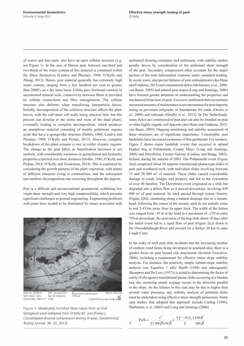
of coarse and fine parts, also have an open cellular structure (e.g.
see Figure 1). In the case of fibrous peat, between one-third and
two-thirds of the water content of this material is contained within
the fibres themselves (Landva and Pheeney, 1980; O’Kelly and
Zhang, 2013). Hence, peat material generally has extremely high
water content, ranging from a few hundred per cent to greater
than 2000% on a dry mass basis. Unlike pure frictional contacts in
uncemented mineral soils, connectivity between fibres is provided
by cellular connections and fibre entanglement. The cellular
structure also deforms when transferring interparticle forces.
Initially, decomposition of the cellulose structure affects the plant
leaves, with the soft inner cell walls being attacked first, but this
process can develop to the stems and roots of the dead plants,
eventually leading to complete decomposition, which produces
an amorphous material consisting of mainly gelatinous organic
acids that have a sponge-like structure (Hobbs, 1986; Landva and
Pheeney, 1980; O’Kelly and Pichan, 2013). However, complete
breakdown of the plant remains is rare in colder climatic regions.
The change in the peat fabric as humification increases is not
uniform, with considerable variations in geotechnical and hydraulic
properties expected over short distances (Hobbs, 1986; O’Kelly and
Pichan, 2014; O’Kelly and Sivakumar, 2014). This is explained by
considering the growth patterns of the plant vegetation, with plants
of different character living in communities, and the subsequent
non-uniform decomposition rate occurring throughout the deposit.
Peat is a difficult and unconventional geomaterial, exhibiting low
virgin shear strength and very high compressibility, which presents
significant challenges in ground engineering. Engineering problems
with peats have tended to be dominated by issues associated with
undrained shearing resistance and settlement, with stability studies
usually driven by consideration of the undrained shear strength
of the peat. Secondary compression often accounts for the major
portion of the total deformation response under sustained loading.
In recent years, unexpected failures of peat embankments (den Haan
and Feddema, 2013) and containment dykes (McInerney et al., 2006;
van Baars, 2005) and natural peat slopes (Long and Jennings, 2006)
have focused greater attention on understanding the properties and
mechanical behaviour of peat. Excessive settlement that necessitates
increased amounts of maintenance is not uncommon for peat deposits
acting as pavement subgrades or foundations for roads (Osorio et
al., 2008) and railroads (Hendry et al., 2012). In The Netherlands,
many dykes are constructed of peat and can also be founded on peat
or other highly organic soil deposits (den Haan and Feddema, 2013;
van Baars, 2005). Ongoing monitoring and stability assessment of
these structures are of significant importance. Catastrophic peat
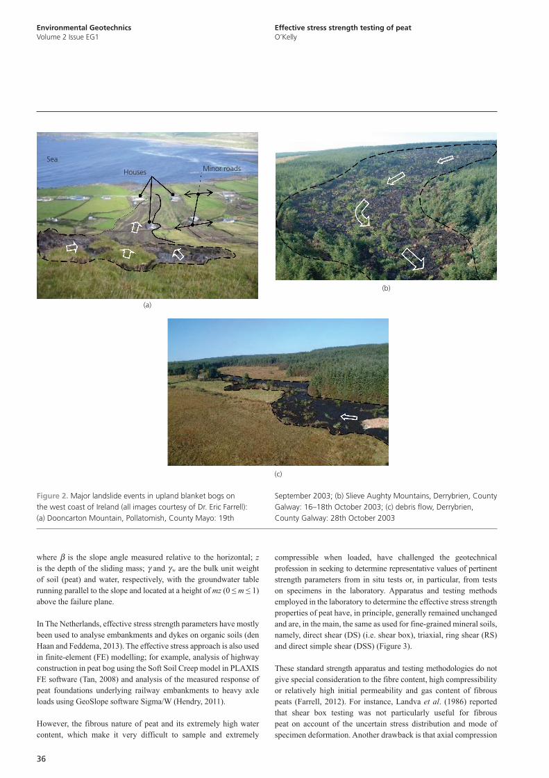
landslides have increased awareness of this geohazard. For instance,
Figure 2 shows major landslide events that occurred in upland
blanket bog at Pollatomish, County Mayo (Long and Jennings,
2006) and Derrybrien, County Galway (Lindsay and Bragg, 2005),
Ireland, during the autumn of 2003. The Pollatomish event (Figure
2(a)) comprised about 50 separate translational planar-type slides of
peat and weathered rock, with individual slides involving between
15 and 20 000 m3 of material. These slides caused considerable
damage to roads, bridges and property and led to the evacuation
of over 40 families. The Derrybrien event originated as a slide but
degraded into a debris flow as it moved downslope, involving 450
000 m3 of peat material. Its track passed through mature forestry
(Figure 2(b)), continuing along a natural drainage line to a stream-
head, following the course of the stream, until its toe initially came
to rest 2·45 km away from its upper limit. The width of the failure
scar ranged from ~45 m at the head to a maximum of ~270 m some
750 m downslope. Re-activation of the bog slide about 10 days after
the initial event led to a rapid flow of peat (Figure 2(c)) down to
the Owendalulleegh River and onward for a further 20 km to enter
Lough Cutra.
In the wake of such peat slide incidents and the increasing number
of onshore wind farms being developed in peatland sites, there is a
greater focus on peat hazard risk assessment (Scottish Executive,
2006), including a requirement for effective stress slope stability
analysis. For instance, the relatively simple infinite-slope stability
analysis (see Equation 1 after Haefli (1948) and subsequently
Skempton and De Lory (1957)) is suited to determining the factor of
safety (FoS) against translational planar slides occurring at a blanket
bog site, assuming steady seepage occurs in the direction parallel
to the slope. As the failures in this case may be due to higher than
normal water pressures, any stability analysis of potential slides
must be undertaken using effective stress strength parameters. Some
case studies that adopted this approach include Carling (1986),
Warburton et al. (2003) and Long and Jennings (2006)
1. w
( ) tanFoS
sin cos tan
c m
z
γ γ φγ β β γ β
-¢ ¢= +
Cellular connections
SEM HV: 20·00 kVSEM MAG: 193×Date(m/d/y): 08/31/11
WD: 24·6420 mmDet: BE DetectorCMA
500 µmDigital Microscopy Imaging
MIRA\\ TESCAN
Finefibre
Fine fibre
Coarse fibre
Open cellular structure
Figure 1. Moderately humified fibres taken from an Irish Sphagnum peat (adopted from O’Kelly BC and Zhang L, Consolidated-drained compression testing of peat, Geotechnical Testing Journal, 36, (3), 2013)
envgeo2-0034.indd 34 Manila Typesetting Company 12/22/2014 08:43PM
1
2
3
4
5
6
7
8
9
10
11
12
13
14
15
16
17
18
19
20
21
22
23
24
25
26
27
28
29
30
31
32
33
34
35
36
37
38
39
40
41
42
43
44
45
46
47
48
49
50
51
52
53
54
55
envgeo2-0034.indd 35 Manila Typesetting Company 12/22/2014 08:43PM
Environmental GeotechnicsVolume 2 Issue EG1
Effective stress strength testing of peatO’Kelly
36
where b is the slope angle measured relative to the horizontal; z
is the depth of the sliding mass; g and g w are the bulk unit weight
of soil (peat) and water, respectively, with the groundwater table
running parallel to the slope and located at a height of mz (0 ≤ m ≤ 1)
above the failure plane.
In The Netherlands, effective stress strength parameters have mostly
been used to analyse embankments and dykes on organic soils (den
Haan and Feddema, 2013). The effective stress approach is also used
in finite-element (FE) modelling; for example, analysis of highway
construction in peat bog using the Soft Soil Creep model in PLAXIS
FE software (Tan, 2008) and analysis of the measured response of
peat foundations underlying railway embankments to heavy axle
loads using GeoSlope software Sigma/W (Hendry, 2011).
However, the fibrous nature of peat and its extremely high water
content, which make it very difficult to sample and extremely
compressible when loaded, have challenged the geotechnical
profession in seeking to determine representative values of pertinent
strength parameters from in situ tests or, in particular, from tests
on specimens in the laboratory. Apparatus and testing methods
employed in the laboratory to determine the effective stress strength
properties of peat have, in principle, generally remained unchanged
and are, in the main, the same as used for fine-grained mineral soils,
namely, direct shear (DS) (i.e. shear box), triaxial, ring shear (RS)
and direct simple shear (DSS) (Figure 3).
These standard strength apparatus and testing methodologies do not
give special consideration to the fibre content, high compressibility
or relatively high initial permeability and gas content of fibrous
peats (Farrell, 2012). For instance, Landva et al. (1986) reported
that shear box testing was not particularly useful for fibrous
peat on account of the uncertain stress distribution and mode of
specimen deformation. Another drawback is that axial compression
September 2003; (b) Slieve Aughty Mountains, Derrybrien, County Galway: 16–18th October 2003; (c) debris flow, Derrybrien, County Galway: 28th October 2003
Figure 2. Major landslide events in upland blanket bogs on the west coast of Ireland (all images courtesy of Dr. Eric Farrell): (a) Dooncarton Mountain, Pollatomish, County Mayo: 19th
Minor roadsHouses
Sea
(a)
(b)
(c)
1
2
3
4
5
6
7
8
9
10
11
12
13
14
15
16
17
18
19
20
21
22
23
24
25
26
27
28
29
30
31
32
33
34
35
36
37
38
39
40
41
42
43
44
45
46
47
48
49
50
51
52
53
54
55
envgeo2-0034.indd 36 Manila Typesetting Company 12/22/2014 08:43PM envgeo2-0034.indd 37 Manila Typesetting Company 12/22/2014 08:43PM

Environmental GeotechnicsVolume 2 Issue EG1
Effective stress strength testing of peatO’Kelly
37
of the specimen on account of significant secondary consolidation
occurring during the drained shearing stage means that the specimen
shear plane must try and continuously realign upward with respect
to the mid-height (i.e. predetermined shear plane) of the shear box.
A major technical hurdle in evaluating peat strength is that, due to
the low bulk unit weight of peat of typically 9·5–11·5 kN/m3, the
effective stresses occurring in the field are lower than the lower
bound stress-level capabilities of most testing equipment. Bulk unit
weights are low on account of the low specific gravity of solids
and the buoyancy effect caused by trapped biogas. Hence, in situ
effective stresses are generally very low or negligible for a horizon
only constituted of peat. It is usually not possible to simulate and
measure these low levels of stress with accuracy in standard strength
apparatus. The most accurate pressure-controlling devices in state-
of-the-art triaxial setups are usually only capable of resolving
to about ±2 kPa. Rather than, or in addition to, controlling or
measuring absolute pressures, a differential pressure transducer can
be used to more accurately determine, for instance, the differential
pressure acting between cell and back-pressure controlling devices
or discrete measurement points (e.g. see O’Kelly and Naughton,
2009). Accordingly, one is usually compelled to test at stress
levels greater than the in situ values and then extrapolate the
results downward to the in situ levels. For this reason, much of
the knowledge gained about peat strength has been for effective
stress levels significantly greater than those encountered in situ.
Pore pressure measurements may be influenced by the presence of
biogas trapped within the peat test-specimens.
From a review of the literature, no comprehensive study has been
performed concerning specimen scale effects in the strength
measurement of peat or definitive conclusions drawn in this regard. In
an intact state, the peat fibres themselves have relatively high tensile
stiffness and strength and they also provide conduits for preferential
flow of water (Hobbs, 1986; O’Kelly, 2007). The orientation of the
fibres in undisturbed peat is in a predominantly horizontal direction
on account of the manner in which the dead plant vegetation was
laid down and subsequently consolidated to large strains under the
overburden and any applied loading (Hendry et al., 2012; Yamaguchi
et al., 1985). This results in undisturbed peat effectively behaving as
a cross-anisotropic material.
Although peat is a decaying mass of organic material having
extremely high water content, as described earlier in this paper,
geotechnical calculations routinely involve effective stress strength
analysis, with the general consensus that the principle of effective
stress and routinely used soil mechanics strength models correlate
with the mechanical behaviour of peat to a sufficiently high degree.
However, Zhang and O’Kelly (2014) pointed out that no complete
experimental or in situ proof or rational theoretical explanations
have been put forward to validate the appropriateness of effective
stress theories for peat. Unlike shearing at frictional contacts in
uncemented mineral soils, the strength of peat is derived from the
connectivity between elementary structures; that is, failure mostly
involves tearing of elementary structures, entangled fibres and
cellular connections (Boylan et al., 2008; Landva et al., 1986).
This led Boylan et al. (2008) to postulate that the direct application
of classical soil mechanics strength models may be doubtful for
peat. Furthermore, in common with other unsaturated soils, if the
peat test specimens are not fully saturated on account of trapped
biogas generated by ongoing decomposition, then the Mohr–
Coulomb failure envelop will have a concave curvature, becoming
less steep for higher confining pressure (O’Kelly, 2013). Hanrahan
(1954) reported that the gas content in Irish Sphagnum peats may
be considerably greater than 5%, and for this degree of saturation,
most of the gas occurs as occluded bubbles.
Hence, it is timely to review the current practice for effective stress
strength testing of peat material in standard triaxial, RS and DSS
apparatus. The aim is to provoke discussion about the best way
forward for understanding and determining the effective stress
strength properties of peat. This discussion is also pertinent to other
highly organic and (or) fibrous soils. Drained shear box testing is
not included in this discussion since, as outlined earlier in the paper,
this approach is not particularly useful for effective stress strength
determination (Landva et al., 1986). Some central questions include
the following:
(a) Are the effective stress strength parameters c¢ and f¢ (apparent cohesion and effective angle of shearing resistance
respectively) appropriate for peat and are their values stress-
level dependent?
(b) Can pertinent effective stress strength and stiffness parameter
values be obtained from element tests?
Apparatus Orientation of major principle stress
Triaxial
α = 0º 0º < α < 90º α = 90º
σv’ σ1’
σ3’σ3’σh’σh’
σ3’
σ1’ σ1’
Triaxial compression Triaxial extension
σv’ σh’σv’ σh’
N/A
N/A
N/A
N/A N/A
N/A N/A
Ring shear
Direct simple shear
σv’ σv’
σn’ σn’
τ
ττ
τ
Direct shear (shear box)
Figure 3. Specimen stress, deformation and boundary conditions for some strength apparatus (N/A: not applicable)
envgeo2-0034.indd 36 Manila Typesetting Company 12/22/2014 08:43PM
1
2
3
4
5
6
7
8
9
10
11
12
13
14
15
16
17
18
19
20
21
22
23
24
25
26
27
28
29
30
31
32
33
34
35
36
37
38
39
40
41
42
43
44
45
46
47
48
49
50
51
52
53
54
55
envgeo2-0034.indd 37 Manila Typesetting Company 12/22/2014 08:43PM

Environmental GeotechnicsVolume 2 Issue EG1
Effective stress strength testing of peatO’Kelly
38
(c) Considering the constituent peat fibres and high secondary
compression rates, are the values of c¢ and f¢ significantly
affected by scale effects (e.g. what is the significance of fibre
tensioning in relation to the nominal specimen dimension and/
or aspect ratio) and (or) strain rate effects?
Standard triaxial strength testingThe first triaxial testing device was developed by von Kármán
(1910, 1911) and was used to test brittle rocks. Westerberg (1921)
adapted the method for soft clays. Ehrenberg (Ehrenberg and
Tiedemann, 1928), working at the Department of Foundation
Engineering, Prussian Laboratory of Hydraulics and Shipbuilding,
Berlin, developed a ‘cell device’ embodying the essential features
of current triaxial apparatus, introducing the test for soil mechanics
generally. Subsequent devices for the testing of soils evolved
simultaneously in Germany (Seifert and Körner, 1933); the
Technical University Delft, The Netherlands (Buisman, 1934); the
USA (Housel, 1936; Jürgenson, 1934; Stanton and Hveem, 1934);
and von Terzaghiʼs Soil Mechanics Laboratory in Vienna, Austria
(Rendulic, 1935, 1936). Arthur Casagrande appears to be at the root
of triaxial testing in the USA, having developed triaxial apparatus,
starting in 1930 (de Boer, 2005) at the Massachusetts Institute
of Technology and subsequently when he moved to Harvard
University. Of these early triaxial studies, the paper by Buisman
(1934) reports the first triaxial testing of peat (veen), which was
performed using the Dutch Cell test apparatus. This differs from
conventional triaxial apparatus mainly by the cross section of the
loading piston being equal to that of the test specimen (see den
Haan and Feddema (2013)). Reviews of more contemporary triaxial
investigations of peat, beginning with Hanrahan (1954), have been
presented by Landva and La Rochelle (1983), Long (2005) and
O’Kelly and Zhang (2013).
For the standard triaxial apparatus, basically two methodologies can
be employed to determine the effective stress strength properties
(refer to BS1377: Part 8 (BSI, 1990)). Consolidated undrained (CU)
testing can be performed in which test specimens under different
confining pressures are allowed to consolidate to target levels of
effective stress, followed by a displacement (strain)-controlled
shearing stage, in either triaxial compression or extension, with
measurement of the specimensʼ deviatoric stress and pore water
pressure (pwp) responses against axial strain. The applied axial
strain rate is sufficiently slow for substantive equilibration of
excess pwp to occur throughout the test specimen.
Alternatively, after consolidation to different target levels of
effective stress, the specimens can be sheared in a drained
condition at a sufficiently slow rate for substantive dissipation of
excess pwp generated during the shearing stage, thereby allowing
direct measurement of the effective stress shear response, that is,
consolidated drained (CD) testing. Since, for a given material,
the shearing stage of CD triaxial tests takes significantly longer
to perform, CU triaxial testing along with pwp measurement is
generally performed instead in practice. A minimum of three triaxial
tests performed under different effective confining pressures are
necessary in order to locate the Mohr–Coulomb failure line (curve)
and hence determine the values of the effective stress parameters
c¢ and f¢ for the soil under consideration. Triaxial testing provides
close control of the specimen stress and boundary conditions,
although relatively large corrections may have to be applied to
the measured deviatoric stress values in order to account for the
restraining effect of the rubber membrane and also the reinforcing
effect of filter paper drains, if fitted around the side of the test
specimen.
Undrained triaxial compression testingDifficulties arise in performing standard triaxial testing on peat and in
the interpretation of the experimental data. During the consolidation
stage, gross changes occur in the shape and volume of the test
specimen (Edil and Wang, 2000; Long, 2005). During undrained
triaxial compression, induced pwp can build up and approximately
equal the applied cell pressure for axial strains ea > 5%−10%
(Boulanger et al., 1998; Farrell and Hebib, 1998; Yamaguchi et
al., 1985). Cola and Cortellazzo (2005) demonstrated that as the
effective minor principal stress ( 3σ ¢) approaches zero, the specimen
membrane could easily expand and the pore water move toward the
lateral boundaries of the test specimen. With the maximum strength
mobilised for ea >> 15%−20% and a small 3σ ¢ value (Hanrahan, 1954;
Marachi et al., 1983), interpretation of the experimental data from a
suite of three or more CU triaxial compression tests for the purpose
of determining the values of c¢ and f¢ is difficult and likely to result
in surprisingly high f¢ values in the range of 40°–60° (Farrell and
Hebib, 1998; Landva and La Rochelle, 1983; Long, 2005; Mesri
and Ajlouni, 2007). This compares with the measured f¢ values of
generally less than 35° for soft clay and silt compositions.
The reported f¢ values are generally greater for higher organic
content (den Haan and Feddema, 2013). It is possible that during
undrained triaxial compression, higher creep rates expected for
higher organic content soils would develop higher excess pwp and
(a)
σ1’
φ’
σ3’ » 0
(b)
For c’ = 0,
WL
ß = φ’
ß
Figure 4. Interpretations for f¢ = 90o (WL, water level): (a) drained unconfined compression; (b) submerged semi-infinite slope with face angle b at limiting equilibrium
1
2
3
4
5
6
7
8
9
10
11
12
13
14
15
16
17
18
19
20
21
22
23
24
25
26
27
28
29
30
31
32
33
34
35
36
37
38
39
40
41
42
43
44
45
46
47
48
49
50
51
52
53
54
55
envgeo2-0034.indd 38 Manila Typesetting Company 12/22/2014 08:43PM envgeo2-0034.indd 39 Manila Typesetting Company 12/22/2014 08:43PM
Environmental GeotechnicsVolume 2 Issue EG1
Effective stress strength testing of peatO’Kelly
39
hence lower (approximately zero) values of 3σ ¢ at specimen failure,
that is, analogous to unconfined compression. In this scenario, the
best-fit Mohr–Coulomb failure line would produce higher f¢. Values
of up to 90° have been reported from CU triaxial compression testing
of peat (den Haan and Feddema, 2013), although this implies one-
dimensional (1D) compression (Figure 4(a)) rather than shearing in
the conventional sense. Intuitively, it would seem that such high f¢ (i.e. angles of repose of up to 90°) cannot be mobilised, considering
for instance a semi-infinite submerged peat cutting in the field
(Figure 4(b)). Another case, for example, would be a smooth
vertical wall retaining saturated fibrous peat for which Rankine
active and passive wedge failure planes acting at 90o (i.e. 45 ± f¢/2)
have no physical meaning. It is acknowledged in reality that such
high f¢ values cannot be mobilised for peat at larger scale in the
field. For instance, den Haan and Feddema (2013) reported that
empirical methods are used to obtain acceptable, reduced values of
f¢ from triaxial tests for use in stability analysis; for example, f¢ is
determined for e a = 2%–5%, which is well below specimen failure.
Drained triaxial compression testingFor fibrous peats in CD triaxial compression, shearing in the
conventional sense usually does not occur, with the test specimen
essentially undergoing 1D consolidation. Unlike fine-grained
mineral soils, the deviatoric stress 1 3( )σ σ-¢ ¢ and principal stress
ratio ( 1 3/σ σ¢ ¢) responses continue to increase approximately linearly,
without reaching a peak value (Farrell, 2012; Hollingshead and
Raymond, 1972; O’Kelly and Zhang, 2013), that is, the f¢ value
is strain-level dependent. For the purposes of analysis, 20% axial
strain is often taken as an arbitrary failure criterion, although it is
unclear how this value relates to the field condition. There may be
scope for using relatively taller triaxial test specimens (i.e. greater
than the standard height to diameter ratio of 2:1), which along with
necessary modifications to the triaxial apparatus and instrumentation
would allow for the application of e a >> 20% while still maintaining
a reasonable specimen aspect ratio the possibility of shear failure
to occur.
Inconsistencies between results of CU and CD triaxial testing for peatPhysically identical test specimens of fine-grained mineral soil
consolidated under the same drainage conditions and effective
confining pressure would be expected to produce similar effective
stress strength responses and hence similar effective Mohr–
Coulomb failure envelopes for undrained (with pwp measurement)
and drained triaxial compression. However, in the case of fibrous
peat, significant differences may be expected to occur on account of
fibre effects, creep and the extremely high water content.
In terms of the effective stress strength response, compression of
undisturbed fibrous peat in the vertical direction mobilises internal
tensile reinforcement provided by the predominantly horizontally
orientated fibres. For the drained condition, the high frictional
resistance mobilised between the fibres and with the elementary
structures under the effective normal stress causes the specimen
to respond by undergoing approximately 1D compression instead
of general ductile bulging normally associated with fine-grained
mineral soils. As described earlier in this paper, during undrained
compression, high creep rates cause pwp values to rapidly build
up, approaching the applied cell pressure for e a > 5%–10%, thereby
mobilising low (approximately zero) values of 3σ ¢ at specimen
failure. Fibre reinforcement effects diminish under reducing
effective normal stress, with the frictional resistance between the
fibres and elementary structures only partly mobilised or not at all,
depending on the magnitude of the excess pwp developed. Hence,
these specimens deform by more general ductile bulging, with the
0
20
40
60
80
100
Axial strain: %
Dev
iato
ric s
tres
s: k
Pa
R
R
R
PPU
U
0 5 10 15
(a)
20 25 30 35
1 cm
(b)
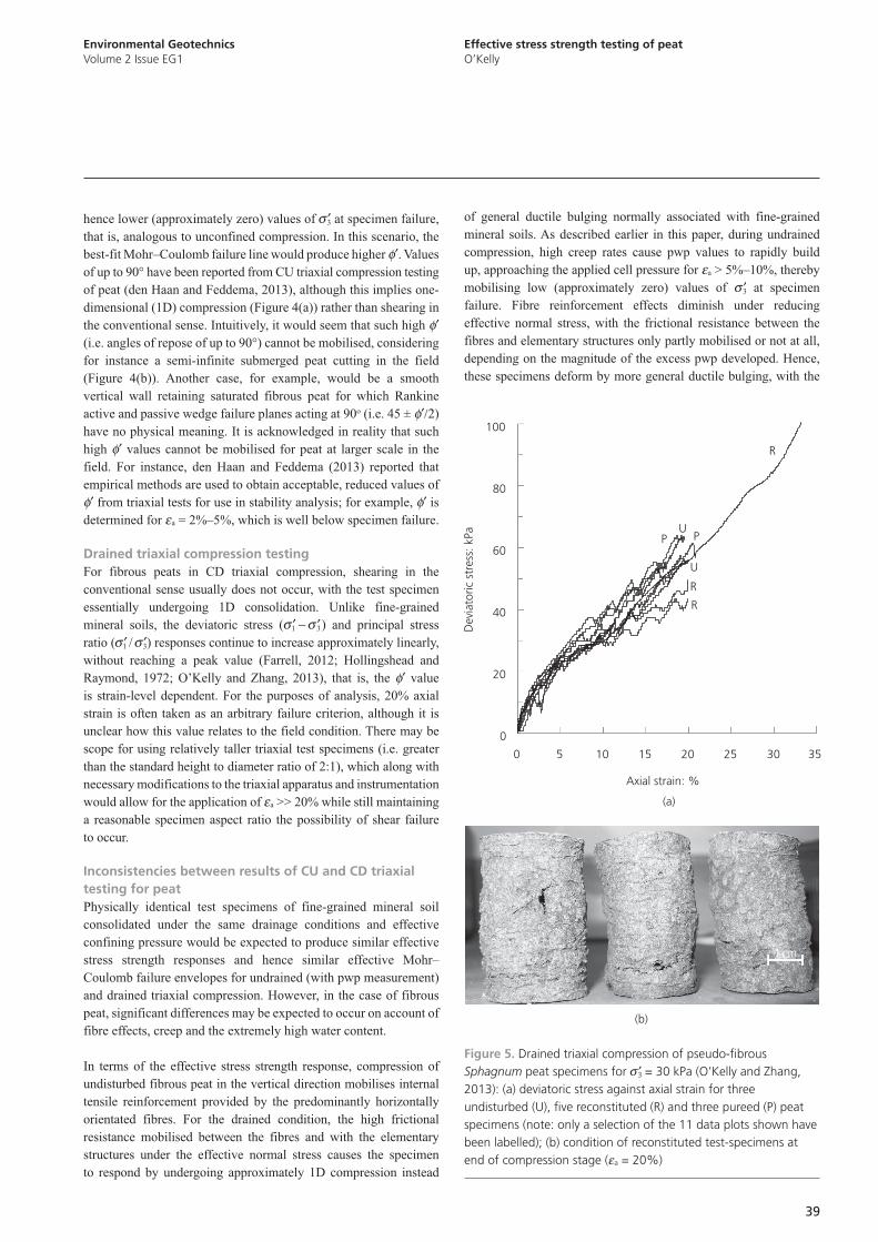
Figure 5. Drained triaxial compression of pseudo-fibrous Sphagnum peat specimens for σ ¢3 = 30 kPa (O’Kelly and Zhang, 2013): (a) deviatoric stress against axial strain for three undisturbed (U), five reconstituted (R) and three pureed (P) peat specimens (note: only a selection of the 11 data plots shown have been labelled); (b) condition of reconstituted test-specimens at end of compression stage (e a = 20%)
envgeo2-0034.indd 38 Manila Typesetting Company 12/22/2014 08:43PM
1
2
3
4
5
6
7
8
9
10
11
12
13
14
15
16
17
18
19
20
21
22
23
24
25
26
27
28
29
30
31
32
33
34
35
36
37
38
39
40
41
42
43
44
45
46
47
48
49
50
51
52
53
54
55
envgeo2-0034.indd 39 Manila Typesetting Company 12/22/2014 08:43PM

Environmental GeotechnicsVolume 2 Issue EG1
Effective stress strength testing of peatO’Kelly
40
peak deviatoric stress mobilised for e a ≈ 15%–25%. For instance,
the reported effective Poisson’s ratio values of 0·10 (Zwanenberg,
2005), 0·11 (Rowe et al., 1984) and 0·15 (Rowe and Mylleville,
1996; Tan, 2008) for undrained triaxial compression are considerably
greater than the ranges of 0·02–0·03 and 0·04–0·05 deduced from
drained triaxial compression of undisturbed and remoulded fibrous
peat respectively (O’Kelly and Zhang, 2013). The internal restraint
provided by the fibres is demonstrated by considering that the
pureed (blended) peat material had a reported effective Poisson’s
ratio range of 0·13–0·16 in drained triaxial compression. For
CU triaxial compression of fibrous peat, the usual 1 3/σ σ¢ ¢ range
encountered is 10–100, with such high values primarily arising on
account of the low 3σ ¢ values mobilised. On the other hand, the 1 3/σ σ¢ ¢ ratio is normally in single figures for drained triaxial compression;
for example, O’Kelly and Zhang (2013) found that for pseudo-
fibrous Sphagnum peat tested under 3σ ¢ = 30 kPa, this ratio increased
approximately linearly in value from unity to 3·7 for e a = 0%–30%.
Intuitively, one would also anticipate higher f¢ values for more
structured/fibrous material. However, O’Kelly and Zhang (2013)
found that testing of normally consolidated pseudo-fibrous peat
specimens of the same morphology in drained triaxial compression
produced approximately similar deviatoric stress–strain responses
for undisturbed, remoulded (FC = 64%, where FC is the fibre
content (ASTM, 2008)) and pureed (FC = 17%) materials (see
Figure 5). Similar findings have been reported for fibrous and
amorphous peats by Edil and Wang (2000).
The major difficulties of build-up of excess pwp causing 3σ ¢ to
approach zero in undrained compression, the internal restraint
provided by fibres preventing specimen shearing in the conventional
sense in drained triaxial compression and the gross changes in
specimen shape and volume occurring during triaxial testing of fibrous
peat have led many researchers, including Landva et al. (1986) and
Zhang and O’Kelly (2014), to conclude that neither standard CU nor
CD triaxial testing is of particular value in determining the effective
stress strength properties of (fibrous) peats. In an age where FE
methods and models are in common use, it is not only shear strength
that we are interested in; rather, the stress–strain behaviour in general
needs to be known. In light of inconsistencies between the effective
stress strength responses for undrained (with pwp measurement) and
drained triaxial compression highlighted earlier in this paper, it is
probable that triaxial testing of (fibrous) peat is also of limited value in
the determination of effective Young’s modulus and Poisson’s ratio
values. Further research is necessary in this regard.
Another consideration is the relative change in physical state of the
organic solids themselves occurring during undrained and drained
compression. Compared with undrained compression, further
significant reductions in volume of saturated test specimens occur
during drained compression on account of the high secondary
consolidation taking place and longer stage duration (slower rate of
shearing) required to prevent build up of excess pwp. This additional
volume change occurring during drained triaxial compression alters
the physical state of the organic solids on account of the flexible
and compressible nature of their cellular structure, that is, further
compression of the organic solids themselves occurs.
Other strength measurement approachesOther laboratory strength test-methods have been used to determine
the effective stress strength properties of fibrous peats, including
drained DS, undrained DSS with pwp measurement and drained RS
(see Figure 3). As explained earlier in this paper, drained DS (shear
box) testing is not particularly useful for fibrous peat (Landva
et al., 1986) and therefore is not discussed further. RS testing is
used to study peat at large shear strains for which fibre effects
are eliminated (Landva and La Rochelle, 1983). In the author’s
experience, it is rather difficult to prepare annular test specimens of
undisturbed fibrous peat for RS testing, with commercial apparatus
typically accommodating 100-mm outer diameter by 70-mm inner
diameter by 20-mm high specimens (McInerney et al., 2006).
DSS testing shows much promise, particularly in the determination
of the effective strength parameter values for translational planar
slides involving peat. Rather than using a split shear box, the side
walls of the simple shear apparatus are usually formed of either
plates that can rotate or a series of laminations that can move
relative to each other or are flexible. In theory, such arrangements
allow rotation of the sidewalls of the test specimen, which imposes
a pure state of simple shear. For fully saturated test specimens, the
change in vertical stress that occurs during shearing in constant
volume DSS tests is assumed to equal the change in pwp that
would have occurred had the test been performed truly undrained.
Although confirmed by Dyvik et al. (1987) for saturated normally
consolidated (Drammen) clay below 10% shear strain, according
to Boylan and Long (2009), this assumption has not been verified
experimentally for DSS testing of peat which often involves
applying significantly greater shear strains. Nevertheless, constant
volume DSS testing of peat (shearing stage maintains a constant
specimen height) with pwp measurement is routinely performed in
the same manner as for clays (den Haan and Kruse, 2007; Farrell and
Hebib, 1998) in order to determine undrained and effective stress
strength properties. Due to the strong anisotropy of undisturbed
fibrous peat, f¢ values of typically 30°–35° are obtained from
DSS testing (shearing occurs in the horizontal direction along
the predominantly horizontal-orientated fibres), compared with
40°–60° generally measured in CU triaxial compression (Farrell
and Hebib, 1998; Long, 2005). The reported DSS values were
deduced from the peak horizontal shear stress mobilised during
shearing or alternatively the shear stress measured at 15% shear
strain, whichever occurred first (Boylan and Long, 2014). Farrell
and Hebib (1998) reported that clear peak values may not be
achieved, even for shear strains > 20%. Another concern is the
non-uniform shear strain developed throughout the test specimen.
Localisation(s) (ruptures) may develop above 15% shear strain,
and hence the simple shear condition would no longer exist. A
central question therefore is how the f¢ values determined for these
‘failure’ criteria in DSS testing relate to field conditions involving,
for instance, translational planar slides. Another issue concerns
1
2
3
4
5
6
7
8
9
10
11
12
13
14
15
16
17
18
19
20
21
22
23
24
25
26
27
28
29
30
31
32
33
34
35
36
37
38
39
40
41
42
43
44
45
46
47
48
49
50
51
52
53
54
55
envgeo2-0034.indd 40 Manila Typesetting Company 12/22/2014 08:43PM envgeo2-0034.indd 41 Manila Typesetting Company 12/22/2014 08:43PM

Environmental GeotechnicsVolume 2 Issue EG1
Effective stress strength testing of peatO’Kelly
41
the interpretation of the experimental data; for example, whether
to take the strength at the peak shear stress t max or the maximum
max v/τ σ ¢ ratio (Farrell, 2012), where vσ ¢ is the corresponding
effective vertical stress.
As explained earlier in this paper, a major technical hurdle in
evaluating peat strength is that the effective stresses in the field
(often <5 kPa) are usually lower than the lower-bound stress level
capabilities of commercial DSS equipment. Consolidation of peat
specimens under these low vertical effective stresses demands much
greater accuracy in measurement and control systems. Shearing
also becomes more complicated because slippage at the interface
between the top (or bottom) cap and the specimen is more likely to
occur and is further facilitated by the materialʼs high water content
(Grognet, 2011). Slippage increases stress nonuniformity in the
test specimen and should be prevented from occurring. Corrections
related to apparatus compliance and friction can form a large
percentage of the measured strength. The device needs to have the
lowest friction possible in its carriage and measurement gauges and
also the lowest resistance possible for the boundary (i.e. membrane,
rings) enclosing the test specimen (Grognet, 2011). DSS prototypes
designed to test peat at low effective stresses have been reported by
Boylan and Long (2009) and Grognet (2011). The sidewalls of the
assemblies used to house the test specimens in these apparatus are
transparent and make possible a visual assessment of the specimen
deformation and insight into the evolving failure mechanism
during shearing using particle image velocimetry image analysis
techniques. Further research on a wide range of peats using such
devices is required to identify the criteria for assigning failure with
evolving non-uniform specimen deformation. Larger specimens
than for usual testing and also investigations for specimens having
larger height to diameter ratio are desirable to investigate the
influence of the peat structure (fibres) on the test results (Boylan
and Long, 2009; den Haan and Kruse, 2007).
Other observations
In relation to the porous and compressible nature of the organic solidsFor most mineral soils, the constituent solids are incompressible over
the stress range of engineering interest. Hence, a pertinent question
relates to the often extremely compressible nature of the organic
solids in peat. Following the two-level structure assumption of micro-
and macropores (Berry and Poskitt, 1972; Dhowian and Edil, 1980),
individual peat fibres will exist in significantly different physical
conditions for different strain levels on account of the associated flow
of micropore water (i.e. contained within the porous cellular structure
of the fibres) into the void space between the solids. As reported
earlier in this paper, between one- and two-thirds of the initial water
content of fibrous peat is contained within micropores. Given that the
solids in peat can undergo significant physical changes, especially
for the slower strain rates applied in drained triaxial compression,
the author postulates that deduced effective stress strength parameter
values may depend on the stress level during the compression stage.
Since the creep rate is a function of effective stress, with significant
differences expected between effective stress levels above and below
the apparent pre-consolidation pressure (O’Kelly, 2006), the author
postulates that f¢ is likely to be strain-rate dependent, possibly
slightly lower in value for effective stresses above the apparent pre-
consolidation pressure. Further research is warranted in this regard.
In relation to shearing rate (time to failure)It has been well documented that for triaxial consolidation, the
‘end of primary’ condition was more reliably established from
analysis of pwp dissipation against time data rather than from
volumetric strain against time (Edil and den Haan, 1994; O’Kelly
and Zhang, 2013). For peat, ‘end of primary’ refers to the soil state
corresponding to the substantive dissipation of excess pwp. In
other words, axial strain rates for the triaxial compression stage
deduced from measured volumetric strain against consolidation
time responses were unnecessarily slow (conservative). For
instance, O’Kelly and Zhang (2013) found that for pseudo-
fibrous Sphagnum peat tested under drained triaxial compression
with 3σ ¢ = 30 kPa, the estimated axial strain rates deduced from
volumetric strain data were about an order of magnitude slower
than the permissible values based on analysis of pwp dissipation
against time data. Also, as described earlier in this paper, it was
not uncommon for the resistance of fibrous peat in drained triaxial
compression to continue increasing for e a > 30% without reaching
a peak (O’Kelly and Zhang, 2013). For mainly pragmatic reasons
(e.g. limiting travel of specimen loading piston and (or) time
constraints for completing the tests), the triaxial compression
tests were often terminated at 20% axial strain, with this arbitrary
strain value selected as representing some notional specimen
failure. In other words, a conservative assumption had to be
made regarding the strain at failure before calculations could be
performed to estimate the axial strain rate subsequently applied
during the compression stage. The actual strain rate applied was
a compromise between the higher strain rates allowable with
filter paper drains fitted around the sidewall of the test specimen
(although significant corrections to the measured deviatoric stress
response were then required) or slower strain rates that would
allow greater secondary consolidation and hence a greater change
in the physical state of the organic solids to occur.
In relation to apparent cohesion c ¢Values of c¢ = 0 have been reported for normally consolidated
fibrous peat by many researchers, including Marachi et al. (1983)
and Farrell and Hebib (1998). In the case of waterlogged peat
slopes, the effective stress can be very small or negligible. Hence,
the resisting force largely depends on the apparent cohesion, if this
is present. From Equation 1, it is clear that for a typical blanket
bog site (with the bulk unit weight of the peat similar to that of
water and the groundwater table high (i.e. m ≈ 1)), the FoS value
against translational planar slides is much more sensitive to the
value of c¢ than f¢. Given that c¢ is established by projecting the
Mohr–Coulomb failure line (curve) back to the shear stress axis, its
value is intimately dependent on the interpretation of f¢. However,
as described earlier in this paper, the definition of failure for fibrous
envgeo2-0034.indd 40 Manila Typesetting Company 12/22/2014 08:43PM
1
2
3
4
5
6
7
8
9
10
11
12
13
14
15
16
17
18
19
20
21
22
23
24
25
26
27
28
29
30
31
32
33
34
35
36
37
38
39
40
41
42
43
44
45
46
47
48
49
50
51
52
53
54
55
envgeo2-0034.indd 41 Manila Typesetting Company 12/22/2014 08:43PM

Environmental GeotechnicsVolume 2 Issue EG1
Effective stress strength testing of peatO’Kelly
42
peat specimens in different strength apparatus and its relation
to field conditions are not clearly understood. Furthermore, at
microscale, shearing of (fibrous) peat involves tearing of entangled
fibres and cellular connections. Hence, it is questionable whether
c¢ = 0 is a realistic value for fibrous peat, particularly at the (very)
low effective stress values typically encountered for these deposits.
ConclusionsCompared with fine-grained mineral soils, significant fabric and
structural differences may make the direct application of classical
soil mechanics strength models doubtful for peat. Fundamental
research on peat strength and how it is derived needs to be
performed. For example, it is not clearly understood how laboratory
f¢ values determined for ʻfailureʼ criteria based on (semi) arbitrary
strain levels in different strength apparatus relate at a larger scale
in the field. Detailed investigations of the full stress–strain–time/
stress/strain rate behaviour are warranted and ideally need to be
performed at the material’s natural water content (appropriate
effective stress levels), noting the possible effects of the soil
structure and compression of the organic solids themselves. Factors
including changes in volume and pwp produced by rotation of
the stress tensor during specimen shearing (refer to Figure 3) and
anisotropy of creep rates merit investigation.
Further development of existing and new specific material models
is recommended in order to simulate more accurately the soft and
viscous nature of peat, its general cross-anisotropic fabric and the
reinforcement provided by fibres in peats with low humification.
This is likely to require a full spectrum of testing, including
element tests and physical modelling at different scales, specialist
laboratory tests and instrumented field trials. In practice, the
shearing mechanism in the field must be carefully considered in
choosing a suitable strength testing apparatus. For example, of the
current strength apparatus, DSS testing best represents the condition
occurring in translational planar slides, providing an appropriate
(and conservative) f¢ value for stability analysis.
AcknowledgementsThe images shown in Figure 2 are reproduced with the kind
permission of Dr. Eric Farrell. The author would like to thank Dr.
Evert den Haan for assistance is compiling the historical review
of triaxial testing and Ms Lin Zhang for help in preparing Figures
3 and 5(a). The author would also like to thank the reviewers for
many helpful comments.
REFEREnCEs
ASTM (2008) D1997–91: Standard test method for laboratory
determination of the fiber content of peat samples by dry
mass. ASTM International, West Conshohocken, PA, USA.
Berry PL and Poskitt TJ (1972) The consolidation of peat.
Géotechnique 22(1): 27–52.
Boulanger RW, Arulnathan R, Harder LF Jr, Torres RA and
Driller MW (1998) Dynamic properties of Sherman Island
peat. Geotechnical and Geoenvironmental Engineering
124(1): 12–20.
Boylan N and Long M (2009) Development of a direct simple
shear apparatus for peat soils. Geotechnical Testing Journal
32(2): 126–138.
Boylan N and Long M (2014) Evaluation of peat strength for
stability assessments. Proceedings of the ICE, Geotechnical
Engineering 167, http://dx.doi.org/10.1680/geng.12.00043.
E-publication ahead of print.
Boylan N, Jennings P and Long M (2008) Peat slope failure
in Ireland. Quarterly Journal of Engineering Geology and
Hydrogeology 41(1): 93–108.
BSI (1990) BS 1377: Part 8: Methods of test for soils for civil
engineering purposes: Shear strength tests (Effective stress).
British Standards Institution, Milton Keynes, UK.
Buisman AS (1934) Proefondervindelijke bepaling van de grens
van inwendig evenwicht van een grondmassa. De Ingenieur
B:49(26): 83–88.
Carling PA (1986) Peat slides in Teesdale and Weardale, Northern
Pennines, July 1983: Description and failure mechanisms.
Earth Surface Processes and Landforms 11(2): 193–206.
Cola S and Cortellazzo G (2005) The shear strength behaviour of
two peaty soils. Geotechnical and Geological Engineering
23(6): 679–695.
de Boer R (2005) The Engineer and the Scandal: A Piece of
Science History. Springer, Berlin, 293 pp.
den Haan E and Feddema A (2013) Deformation and strength
of embankments on soft Dutch soil. Proceedings of the ICE,
Geotechnical Engineering 166(3): 239–252.
den Haan EJ and Kruse GAM (2007) Characterisation and
engineering properties of Dutch peats. In Proceedings of the
Second International Workshop on Characterisation and
Engineering Properties of Natural Soils, Singapore (Tan TS,
Phoon KK, Hight DW and Leroueil S (eds)). Taylor & Francis,
London, vol. 3, pp. 2101–2133.
Dhowian AW and Edil TB (1980) Consolidation behaviour of
peats. Geotechnical Testing Journal 3(3): 105–114.
Dyvik R, Berre T, Lacasse S and Raadim B (1987) Comparison of
truly undrained and constant volume direct simple shear tests.
Géotechnique 37(1): 3–10.
Edil TB and den Haan EJ (1994) Settlement of peats and organic
soils. In Proceedings of the Speciality Conference on
Vertical and Horizontal Deformations of Foundations and
Embankments, College Station, TX, USA. American Society of
Civil Engineers, New York, NY, USA. Geotechnical Special
Publication 40, Part 2, pp. 1543–1572.
Edil TB and Wang X (2000) Shear strength and Ko of peats
and organic soils. In Geotechnics of High Water Content
Materials (Edil TB and Fox PJ (eds)). American Society
for Testing and Materials, West Conshohocken, PA, USA,
pp. 209–225.
Ehrenberg J and Tiedemann B (1928) Baugrundforschung
der Erdbauabteilung der Staatlichen Versuchsantalt
fuer Wasserbau und Schiffbau, Berlin. Zentralblatt der
Bauwerwaltung, 48, 287.
1
2
3
4
5
6
7
8
9
10
11
12
13
14
15
16
17
18
19
20
21
22
23
24
25
26
27
28
29
30
31
32
33
34
35
36
37
38
39
40
41
42
43
44
45
46
47
48
49
50
51
52
53
54
55
envgeo2-0034.indd 42 Manila Typesetting Company 12/22/2014 08:43PM envgeo2-0034.indd 43 Manila Typesetting Company 12/22/2014 08:43PM
Environmental GeotechnicsVolume 2 Issue EG1
Effective stress strength testing of peatO’Kelly
43
Farrell ER (2012) Chapter 35 — Organics/Peat soils. In ICE
Manual of Geotechnical Engineering: Volume 1, Geotechnical
Engineering Principles, Problematic Soils and Site
Investigation (Burland J, Chapman T, Skinner H and Brown M
(eds)). ICE Publishing, London, UK, pp. 463–479.
Farrell ER and Hebib S (1998) The determination of geotechnical
parameters of organic soils. In Proceedings of an International
Symposium on Problematic Soils (IS-Tohoku ’98), Sendai,
Japan (Yanagisawa E, Moroto N and Mitachi T (eds)).
Balkema, Rotterdam, vol. 1, pp. 33–36.
Grognet M (2011) The Boundary Conditions in Direct Simple
Shear Tests: Developments for Peat Testing at Low Normal
Stress. Master’s thesis, TU Delft, Delft, The Netherlands.
Haefli R (1948) The stability of slopes acted upon by parallel
seepages. Proceedings of the Second International Conference
on Soil Mechanics and Foundation Engineering, Rotterdam,
The Netherlands, Keesmaat, Haarlem, The Netherlands, vol. 1,
pp. 134–148.
Hanrahan ET (1954) An investigation of some physical properties
of peat. Géotechnique 4(3): 108–123.
Hendry MT (2011) The Geomechanical Behaviour of Peat
Foundations Below Rail-track Structures. PhD Thesis,
University of Saskatchewan, Saskatoon, Canada.
Hendry MT, Sharma JS, Martin CD and Barbour SL (2012) Effect
of fibre content and structure on anisotropic elastic stiffness
and shear strength of peat. Canadian Geotechnical Journal
49(4): 403–415.
Hobbs NB (1986) Mire morphology and the properties and
behaviour of some British and foreign peats. Quarterly
Journal of Engineering Geology 19(1): 7–80.
Hollingshead GW and Raymond GP (1972) Field loading tests on
Muskeg. Canadian Geotechnical Journal 9(3): 278–289.
Housel WS (1936) Report from the Soil Mechanics Laboratory
at the University of Michigan on testing apparatus, technique
of testing, and investigations in progress. In Proceedings of
the First International Conference on Soil Mechanics and
Foundation Engineering, Cambridge, Mass., USA, Harvard
University, Cambridge, Mass., vol. 2, pp. 24–28.
Jürgenson L (1934) The shearing resistance of soils. Journal of the
Boston Society of Civil Engineers 21(3): 184–217.
Landva AO and La Rochelle P (1983) Compressibility and shear
characteristics of Radforth peats. In Testing of Peats and
Organic Soils (Jarrett PM (ed)). American Society for Testing
and Materials, West Conshohocken, PA, USA, ASTM STP
820, pp. 157–191.
Landva AO and Pheeney PE (1980) Peat fabric and structure.
Canadian Geotechnical Journal 17(3): 416–435.
Landva AO, Korpijaakko EO and Pheeney PE (1983) Geotechnical
classification of peats and organic soils. In Testing of Peats
and Organic Soils (Jarrett PM (ed)). American Society for
Testing and Materials, West Conshohocken, PA, USA, ASTM
STP 820, pp. 37–51.
Landva AO, Pheeney PE, La Rochelle P and Briaud JL (1986)
Structures on peatland — geotechnical investigations.
Proceedings, Advances in Peatlands Engineering, Ottawa,
Canada. National Research Council of Canada, Ottawa,
Ontario, pp. 31–52.
Lindsay RA and Bragg OM (2005) Wind Farms and Blanket
Peat: The Bog Slide of 16th October 2003 at Derrybrien,
Co. Galway, Ireland, 2nd edn. Derrybrien Development
Cooperative Ltd., Gort, County Galway, Ireland.
Long M (2005) Review of peat strength, peat characterisation and
constitutive modelling of peat with reference to landslides.
Studia Geotechnica et Mechanica 27(3–4): 67–90.
Long M and Jennings P (2006) Analysis of the peat slide at
Pollatomish, County Mayo, Ireland. Landslides 3(1): 51–61.
Marachi ND, Dayton DJ and Dare CT (1983) Geotechnical
properties of peat in San Joaquin Delta. In Testing of Peats
and Organic Soils (Jarrett PM (ed)). American Society for
Testing and Materials, West Conshohocken, PA, USA, ASTM
STP 820, pp. 207–217.
McInerney GP, O’Kelly BC and Johnston PM (2006) Geotechnical
aspects of peat dams on bog land. In Proceedings of the
Fifth International Congress on Environmental Geotechnics,
Cardiff, UK (Thomas HR (ed)). Thomas Telford, London, UK,
vol. 2, pp. 934–941.
Mesri G and Ajlouni M (2007) Engineering properties of fibrous
peat. Geotechnical and Geoenvironmental Engineering
133(7): 850–866.
O’Kelly BC (2006) Compression and consolidation anisotropy of
some soft soils. Geotechnical and Geological Engineering
24(6): 1715–1728.
O’Kelly BC (2007) Compressibility and permeability anisotropy
of some peaty soils. Proceedings of the 60th Canadian
Geotechnical Conference, Ottawa, Ontario, Canada. BiTech
Publishers Ltd, Richmond, BC, Canada, vol. 3, 1934–1939.
O’Kelly BC (2013) Discussion of “Enhancement of the shear strength
of wastewater residuals using industrial waste by-products”.
ASCE Journal of Environmental Engineering 139(2): 312–315.
O’Kelly BC and Naughton PJ (2009) Study of the yielding of sand
under generalized stress conditions using a versatile hollow
cylinder torsional apparatus. Mechanics of Materials 41(3):
187–198.
O’Kelly BC and Pichan SP (2013) Effect of decomposition on the
compressibility of fibrous peat — a review. Geomechanics
and Geoengineering: An International Journal 8(4): 286–296.
O’Kelly BC and Pichan SP (2014) Effect of decomposition on
physical properties of fibrous peat. Proceedings of the ICE,
Environmental Geotechnics 1(1): 22–32.
O’Kelly BC and Sivakumar V (2014) Water content determinations
for peat and other organic soils using the oven-drying method.
Drying Technology 32, http://dx.doi.org/10.1080/07373937.
2013.849728.
O’Kelly BC and Zhang L (2013) Consolidated-drained triaxial
compression testing of peat. Geotechnical Testing Journal
36(3): 310–321.
Osorio JP, Farrell ER, O’Kelly BC and Casey T (2008) Rampart
roads in the peat lands of Ireland: genesis, development and
current performance. In Proceedings of the First International
Conference on Transportation Geotechnics, Nottingham, UK
envgeo2-0034.indd 42 Manila Typesetting Company 12/22/2014 08:43PM
1
2
3
4
5
6
7
8
9
10
11
12
13
14
15
16
17
18
19
20
21
22
23
24
25
26
27
28
29
30
31
32
33
34
35
36
37
38
39
40
41
42
43
44
45
46
47
48
49
50
51
52
53
54
55
envgeo2-0034.indd 43 Manila Typesetting Company 12/22/2014 08:43PM

44
Environmental GeotechnicsVolume 2 Issue EG1
Effective stress strength testing of peatO’Kelly
WHAT DO YOU THINK?
To discuss this paper, please submit up to 500 words to the editor at [email protected]. Your contribution will be forwarded to the author(s) for a reply and, if considered appropriate by the editorial panel, will be published as a discussion in a future issue of the journal.
(Ellis E, Yu H-S, McDowell G, Dawson AR and Thom N
(eds)). CRC Press/Balkema, Leiden, The Netherlands, vol. 1,
pp. 227–233.
Rendulic L (1935) Der hydrodynamische Spannungsausgleich
in zentral entwässerten Tonzylindern. Wasserwirtschaft 2:
250–253, 269–273.
Rendulic L (1936) Porenziffler und Porenwasserdruck in Tonen.
Bauingenieur 17: 557–564.
Rowe RK and Mylleville BLJ (1996) A geogrid reinforced
embankment on peat over organic silt: a case history.
Canadian Geotechnical Journal 33(1): 106–122.
Rowe RK, MacLean MD and Soderman KL (1984) Analysis of
a geotextile reinforced embankment constructed on peat.
Canadian Geotechnical Journal 21(3): 563–576.
Scottish Executive (2006) Chapter 5 Stability assessment, hazard
ranking and reporting requirements. In Peat Landslide Hazard
And Risk Assessments: Best Practice Guide for Proposed
Electricity Generation Developments. Scottish Executive,
Edinburgh, Scotland, pp. 29–39, http://www.scotland.gov.uk/
Publications/2006/12/21162303/5 (accessed 08/04/2014).
Seifert R and Körner B (1933) Untersuchungsmethoden, um
festzustellen, ob sich ein gegebenes Baumaterial für den Bau
eines Erddammes eignet: Erforschungen der physikalischen
Gesetze, nach welchen die Durchsickerung des Wassers
durch eine Talsperre oder durch den Untergrund stattfindet,
Volume 14 of Communications of the Prussian Laboratory
of Hydraulics and Shipbuilding, Prussian Testing Institute of
Hydraulic Engineering and Shipbuilding, Berlin, 101 pp.
Skempton AW and De Lory FA (1957) Stability of natural slopes
in London clay. Proceedings of the Fourth International
Conference on Soil Mechanics and Foundation Engineering,
London, UK. Butterworks, London, UK, vol. 2, pp. 378–381.
Stanton TE and Hveem FN (1934) Role of the laboratory in the
preliminary investigation and control of materials for low cost
bituminous pavements. In Proceedings of the 14th Annual
Meeting of the Highway Research Board, Washington, DC,
(Crum RW (ed)). Highway Research Board, Washington, DC,
Part 2, pp. 14–54.
Tan Y (2008) Finite element analysis of highway construction in
peat bog. Canadian Geotechnical Journal 45(2): 147–160.
van Baars S (2005) The horizontal failure mechanism of the Wilnis
peat dyke. Géotechnique 55(4): 319–323.
von Kármán T (1910) Mitöl függ az anyag igénybevétele?.
Magyar Mérnök-és építész-Egylet Közlönye 10: 212–226.
von Kármán T (1911) Festigkeits versuche unter allseitigem
druck. Zeitschrift des Vereins Deutscher Ingenieure 55(42):
1749–1757.
Warburton J, Higgitt D and Mills A (2003) Anatomy of a Pennine
peat slide, northern England. Earth Surface Processes and
Landforms 28(5): 457–473.
Westerberg N (1921) Jordtryck i kohesionara jordarter. Teknisk
Tidskrift 51: 25–29, 61–65.
Yamaguchi H, Ohira Y, Kogure K and Mori S (1985) Undrained
shear characteristics of normally consolidated peat
under triaxial compression and extension tests. Soils and
Foundations 25(3): 1–18.
Zhang L and O’Kelly BC (2014) The principle of effective stress
and triaxial compression testing of peat. Proceedings of the
ICE, Geotechnical Engineering 167(1): 40–50.
Zwanenberg C (2005) The Influence of Anisotropy on the
Consolidation Behaviour of Peat. PhD thesis, TU Delft, Delft,
The Netherlands.
1
2
3
4
5
6
7
8
9
10
11
12
13
14
15
16
17
18
19
20
21
22
23
24
25
26
27
28
29
30
31
32
33
34
35
36
37
38
39
40
41
42
43
44
45
46
47
48
49
50
51
52
53
54
55
envgeo2-0034.indd 44 Manila Typesetting Company 12/22/2014 08:43PM