PDHonline Course S177 (2 PDH) Petrographic Analysis of Concrete Deterioration
26
PDHonline Course S177 (2 PDH) Petrographic Analysis of Concrete Deterioration Instructor: D. Matthew Stuart, P.E., S.E., F.ASCE, F.SEI, SECB, MgtEng 2013 PDH Online | PDH Center 5272 Meadow Estates Drive Fairfax, VA 22030-6658 Phone & Fax: 703-988-0088 www.PDHonline.org www.PDHcenter.com An Approved Continuing Education Provider
-
Upload
independent -
Category
Documents
-
view
4 -
download
0
Transcript of PDHonline Course S177 (2 PDH) Petrographic Analysis of Concrete Deterioration
PDHonline Course S177 (2 PDH)
Petrographic Analysis of Concrete Deterioration
Instructor: D. Matthew Stuart, P.E., S.E., F.ASCE, F.SEI, SECB, MgtEng
2013
PDH Online | PDH Center
5272 Meadow Estates Drive Fairfax, VA 22030-6658
Phone & Fax: 703-988-0088 www.PDHonline.org www.PDHcenter.com
An Approved Continuing Education Provider

www.PDHcenter.com www.PDHonline.org
© 2013 D. Matthew Stuart, PE, SE Page 1
Petrographic Analysis of Concrete Deterioration
D. Matthew Stuart, P.E., S.E., F.ASCE, F.SEI, SECB, MgtEng
Structural Division Manager
Pennoni Associates Inc.
Introduction to the Investigation of Concrete Deterioration
When dealing with deteriorated reinforced concrete structures, it is necessary to visually assess and measure the extent of corrosion activity and damage of the reinforcing and concrete. As a part of the investigation it is also imperative that concrete core and powder samples be obtained in order to conduct petrographic and other similar material testing of the p g p gconcrete. The combination of field observations and petrographic analysis make it possible to properly determine the cause and therefore the best methods of repair to prevent further corrosion and deterioration of the concrete.
2Surface Deterioration
www.PDHcenter.com www.PDHonline.org
© 2013 D. Matthew Stuart, PE, SE Page 2
The process of investigating and developing repairs for a deteriorated concrete structure should therefore involve:
1 On Site Condition Evaluation Survey1. On-Site Condition Evaluation Survey
2. Laboratory Petrographic Analysis
3. Determination of Extent of Damage and Remaining Service Life
3
4. Assessment of Repair Materials and Coatings
5. Assessment of Galvanic or Cathodic Protection Systems
1. On-Site Condition Evaluation Survey:
An on-site condition evaluation survey includes a detailed investigation of all areas of the reinforced concrete structure and may require, depending upon the size of the structure, several hours and days to complete. Several analysis techniques can be implemented during an on-site evaluation survey, including b t t li it d t th f ll ibut not limited to the following.
1. Visual Examination - to identify surface defects.2. Chain Drag - to detect subsurface delaminations.3. Core Samples - to enable subsequent petrographic analysis.4. Phenolphthalein Tests - to determine carbonation depth.5. Powder Samples - to determine chloride content.6. Half Cell Potential Mapping - to determine potential corrosion risks.7 Li P l i ti t d t i th i t
4
7. Linear Polarization - to determine the corrosion rate.8. Continuity Checks - to determine the continuity or connectedness of the internal reinforcing.9. Stray Current Identification - to determine the stray current corrosion risks.10. Resistivity - to determine the in-situ concrete resistivity and corrosion risk.
www.PDHcenter.com www.PDHonline.org
© 2013 D. Matthew Stuart, PE, SE Page 3
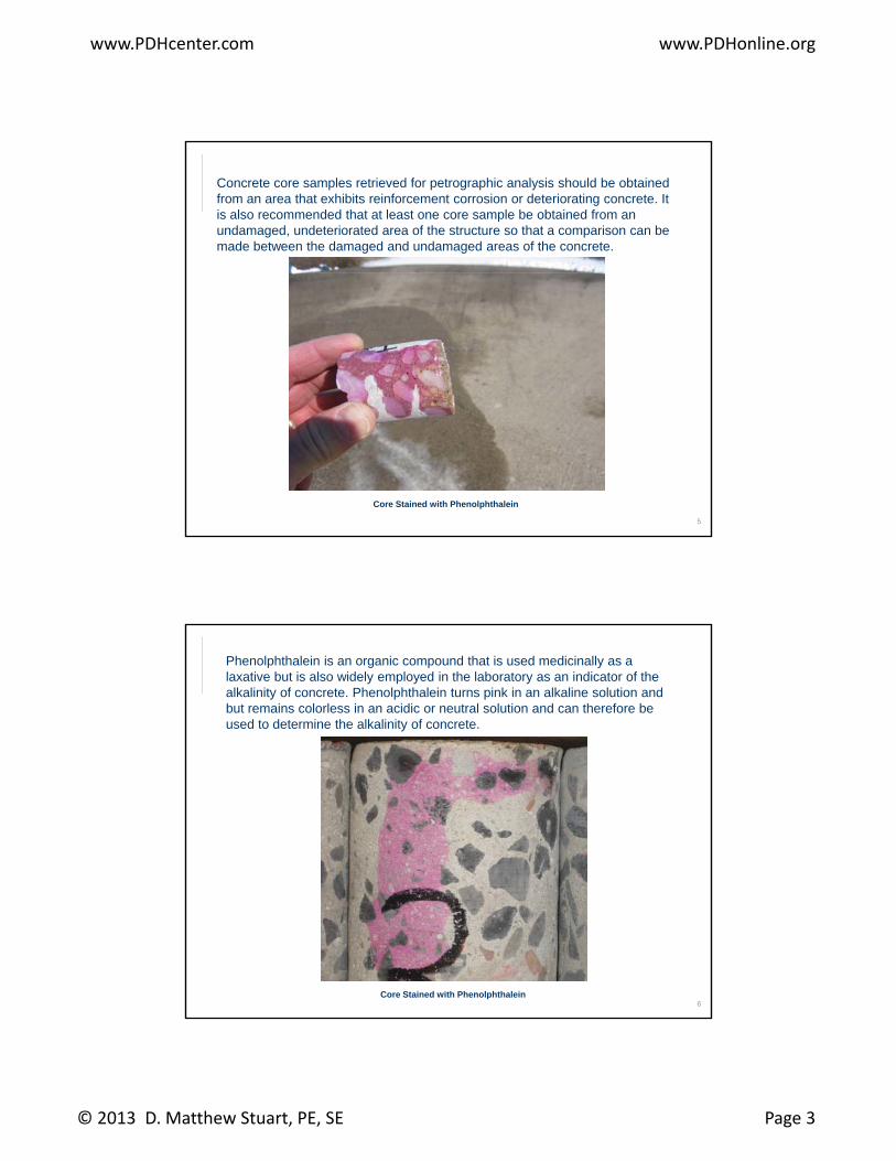
Concrete core samples retrieved for petrographic analysis should be obtained from an area that exhibits reinforcement corrosion or deteriorating concrete. It is also recommended that at least one core sample be obtained from an undamaged, undeteriorated area of the structure so that a comparison can be made between the damaged and undamaged areas of the concrete.
5
Core Stained with Phenolphthalein
Phenolphthalein is an organic compound that is used medicinally as a laxative but is also widely employed in the laboratory as an indicator of the alkalinity of concrete. Phenolphthalein turns pink in an alkaline solution and but remains colorless in an acidic or neutral solution and can therefore be used to determine the alkalinity of concrete.
6Core Stained with Phenolphthalein
www.PDHcenter.com www.PDHonline.org
© 2013 D. Matthew Stuart, PE, SE Page 4
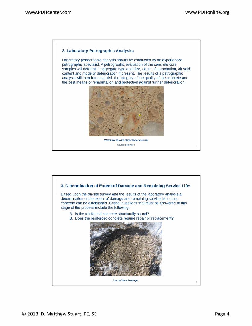
2. Laboratory Petrographic Analysis:
Laboratory petrographic analysis should be conducted by an experienced petrographic specialist. A petrographic evaluation of the concrete core samples will determine aggregate type and size, depth of carbonation, air void content and mode of deterioration if present. The results of a petrographic
l i ill th f t bli h th i t it f th lit f th t danalysis will therefore establish the integrity of the quality of the concrete and the best means of rehabilitation and protection against further deterioration.
7
Water Voids with Slight Retempering
Source: Don Dixon
3. Determination of Extent of Damage and Remaining Service Life:
Based upon the on-site survey and the results of the laboratory analysis a determination of the extent of damage and remaining service life of the concrete can be established. Critical questions that must be answered at this stage of the process include the following:
A. Is the reinforced concrete structurally sound?B. Does the reinforced concrete require repair or replacement?
8Freeze-Thaw Damage
www.PDHcenter.com www.PDHonline.org
© 2013 D. Matthew Stuart, PE, SE Page 5
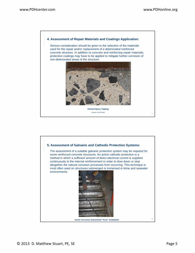
4. Assessment of Repair Materials and Coatings Application:
Serious consideration should be given to the selection of the materials used for the repair and/or replacement of a deteriorated reinforced concrete structure. In addition to concrete and reinforcing repair materials, protective coatings may have to be applied to mitigate further corrosion of non deteriorated areas of the structurenon-deteriorated areas of the structure.
9
Painted Epoxy Topping
Source: Don Dixon
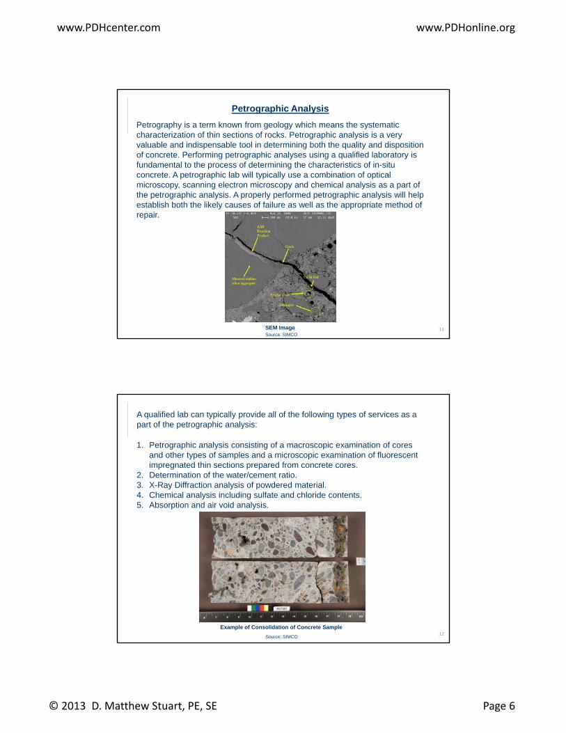
5. Assessment of Galvanic and Cathodic Protection Systems:
The assessment of a suitable galvanic protection system may be required for some reinforced concrete structures. An active cathodic protection is a method in which a sufficient amount of direct electrical current is supplied continuously to the internal reinforcement in order to slow down or stop altogether the natural corrosion processes from occurring This technique isaltogether the natural corrosion processes from occurring. This technique is most often used on structures submerged or immersed in brine and seawater environments.
10Vector Corrosion Galvashield “Puck” Installation
www.PDHcenter.com www.PDHonline.org
© 2013 D. Matthew Stuart, PE, SE Page 6
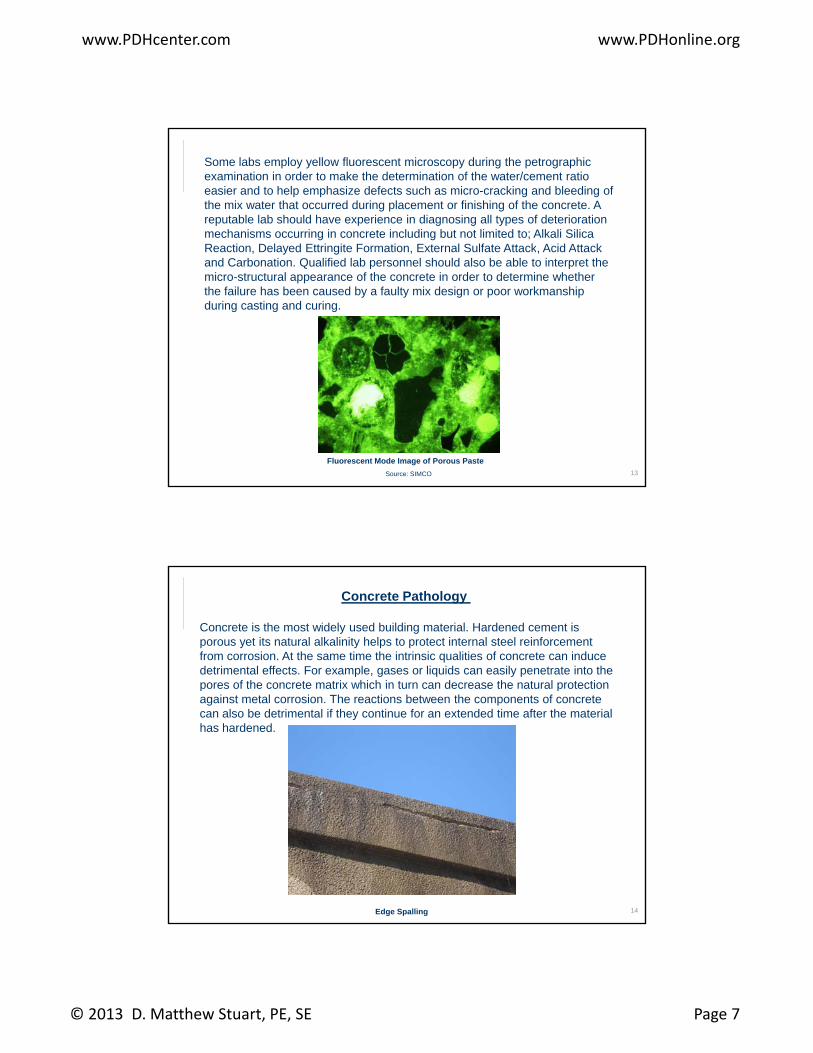
Petrographic Analysis
Petrography is a term known from geology which means the systematic characterization of thin sections of rocks. Petrographic analysis is a very valuable and indispensable tool in determining both the quality and disposition of concrete. Performing petrographic analyses using a qualified laboratory is fundamental to the process of determining the characteristics of in-situ
t A t hi l b ill t i ll bi ti f ti lconcrete. A petrographic lab will typically use a combination of optical microscopy, scanning electron microscopy and chemical analysis as a part of the petrographic analysis. A properly performed petrographic analysis will help establish both the likely causes of failure as well as the appropriate method of repair.
11SEM ImageSource: SIMCO
A qualified lab can typically provide all of the following types of services as a part of the petrographic analysis:
1. Petrographic analysis consisting of a macroscopic examination of cores and other types of samples and a microscopic examination of fluorescent impregnated thin sections prepared from concrete cores.
2 Determination of the water/cement ratio2. Determination of the water/cement ratio.3. X-Ray Diffraction analysis of powdered material.4. Chemical analysis including sulfate and chloride contents.5. Absorption and air void analysis.
12Example of Consolidation of Concrete Sample
Source: SIMCO
www.PDHcenter.com www.PDHonline.org
© 2013 D. Matthew Stuart, PE, SE Page 7
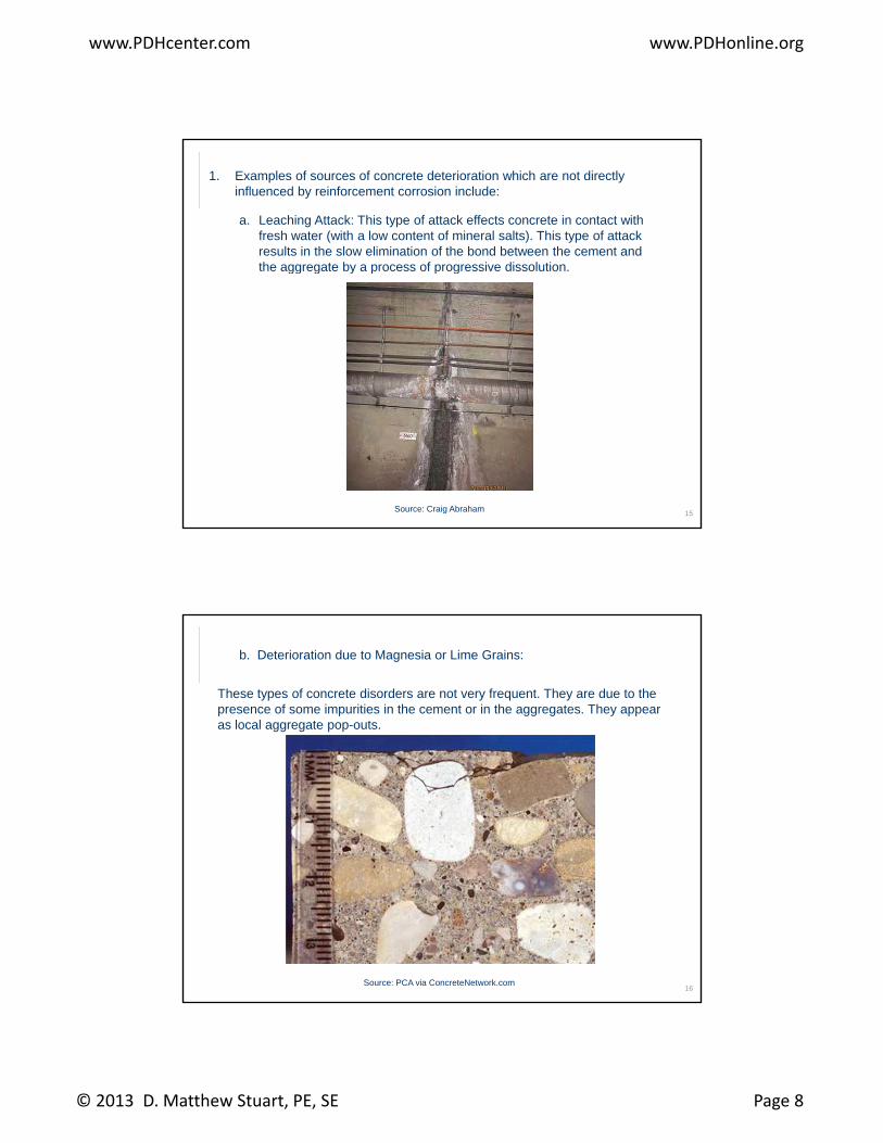
Some labs employ yellow fluorescent microscopy during the petrographic examination in order to make the determination of the water/cement ratio easier and to help emphasize defects such as micro-cracking and bleeding of the mix water that occurred during placement or finishing of the concrete. A reputable lab should have experience in diagnosing all types of deterioration mechanisms occurring in concrete including but not limited to; Alkali Silica Reaction Delayed Ettringite Formation External Sulfate Attack Acid AttackReaction, Delayed Ettringite Formation, External Sulfate Attack, Acid Attack and Carbonation. Qualified lab personnel should also be able to interpret the micro-structural appearance of the concrete in order to determine whether the failure has been caused by a faulty mix design or poor workmanship during casting and curing.
13
Fluorescent Mode Image of Porous Paste
Source: SIMCO
Concrete Pathology
Concrete is the most widely used building material. Hardened cement is porous yet its natural alkalinity helps to protect internal steel reinforcement from corrosion. At the same time the intrinsic qualities of concrete can induce detrimental effects. For example, gases or liquids can easily penetrate into the pores of the concrete matrix which in turn can decrease the natural protectionpores of the concrete matrix which in turn can decrease the natural protection against metal corrosion. The reactions between the components of concrete can also be detrimental if they continue for an extended time after the material has hardened.
14Edge Spalling
www.PDHcenter.com www.PDHonline.org
© 2013 D. Matthew Stuart, PE, SE Page 8
1. Examples of sources of concrete deterioration which are not directly influenced by reinforcement corrosion include:
a. Leaching Attack: This type of attack effects concrete in contact with fresh water (with a low content of mineral salts). This type of attack results in the slow elimination of the bond between the cement and the aggregate by a process of progressive dissolutionthe aggregate by a process of progressive dissolution.
15Source: Craig Abraham
b. Deterioration due to Magnesia or Lime Grains:
These types of concrete disorders are not very frequent. They are due to the presence of some impurities in the cement or in the aggregates. They appear as local aggregate pop-outs.
16Source: PCA via ConcreteNetwork.com
www.PDHcenter.com www.PDHonline.org
© 2013 D. Matthew Stuart, PE, SE Page 9
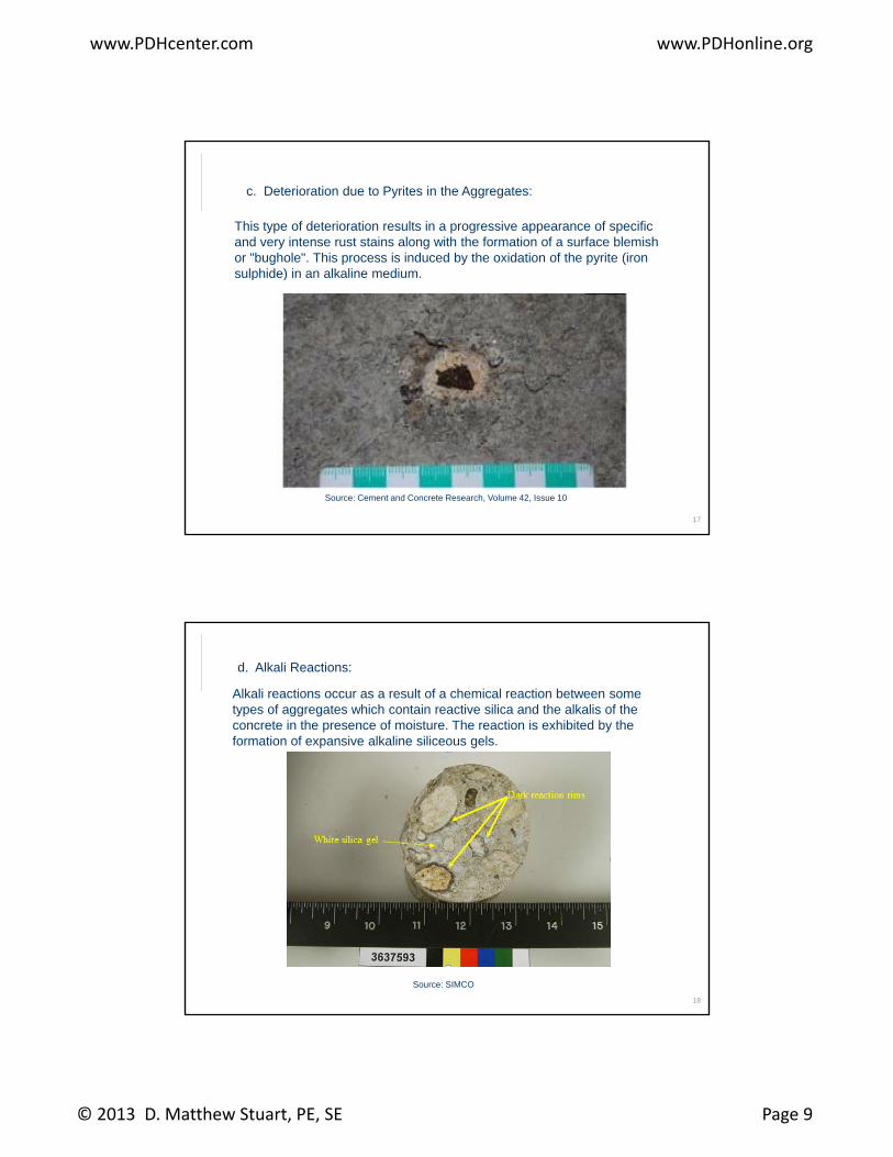
c. Deterioration due to Pyrites in the Aggregates:
This type of deterioration results in a progressive appearance of specific and very intense rust stains along with the formation of a surface blemish or "bughole". This process is induced by the oxidation of the pyrite (iron sulphide) in an alkaline mediumsulphide) in an alkaline medium.
17
Source: Cement and Concrete Research, Volume 42, Issue 10
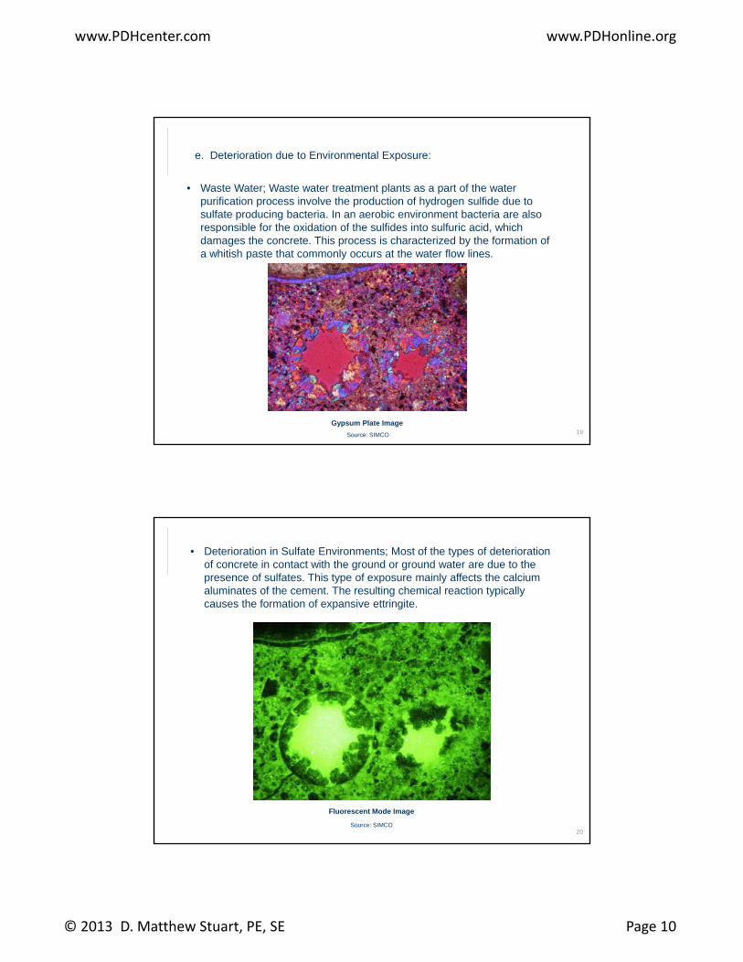
d. Alkali Reactions:
Alkali reactions occur as a result of a chemical reaction between some types of aggregates which contain reactive silica and the alkalis of the concrete in the presence of moisture. The reaction is exhibited by the formation of expansive alkaline siliceous gels.
18
Source: SIMCO
www.PDHcenter.com www.PDHonline.org
© 2013 D. Matthew Stuart, PE, SE Page 10
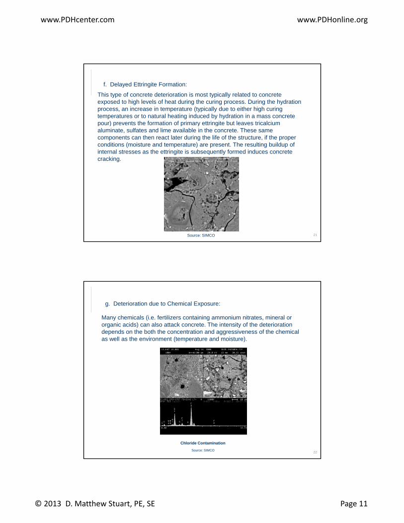
e. Deterioration due to Environmental Exposure:
• Waste Water; Waste water treatment plants as a part of the water purification process involve the production of hydrogen sulfide due to sulfate producing bacteria. In an aerobic environment bacteria are also responsible for the oxidation of the sulfides into sulfuric acid whichresponsible for the oxidation of the sulfides into sulfuric acid, which damages the concrete. This process is characterized by the formation of a whitish paste that commonly occurs at the water flow lines.
19
Gypsum Plate Image
Source: SIMCO
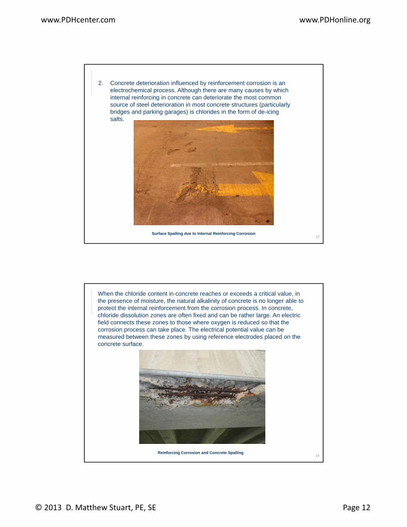
• Deterioration in Sulfate Environments; Most of the types of deterioration of concrete in contact with the ground or ground water are due to the presence of sulfates. This type of exposure mainly affects the calcium aluminates of the cement. The resulting chemical reaction typically causes the formation of expansive ettringite.
20
Fluorescent Mode Image
Source: SIMCO
www.PDHcenter.com www.PDHonline.org
© 2013 D. Matthew Stuart, PE, SE Page 11
f. Delayed Ettringite Formation:
This type of concrete deterioration is most typically related to concrete exposed to high levels of heat during the curing process. During the hydration process, an increase in temperature (typically due to either high curing temperatures or to natural heating induced by hydration in a mass concrete pour) prevents the formation of primary ettringite but leaves tricalciumpour) prevents the formation of primary ettringite but leaves tricalcium aluminate, sulfates and lime available in the concrete. These same components can then react later during the life of the structure, if the proper conditions (moisture and temperature) are present. The resulting buildup of internal stresses as the ettringite is subsequently formed induces concrete cracking.
21Source: SIMCO
g. Deterioration due to Chemical Exposure:
Many chemicals (i.e. fertilizers containing ammonium nitrates, mineral or organic acids) can also attack concrete. The intensity of the deterioration depends on the both the concentration and aggressiveness of the chemical as well as the environment (temperature and moisture)as well as the environment (temperature and moisture).
22
Chloride Contamination
Source: SIMCO
www.PDHcenter.com www.PDHonline.org
© 2013 D. Matthew Stuart, PE, SE Page 12
2. Concrete deterioration influenced by reinforcement corrosion is an electrochemical process. Although there are many causes by which internal reinforcing in concrete can deteriorate the most common source of steel deterioration in most concrete structures (particularly bridges and parking garages) is chlorides in the form of de-icing salts.
23Surface Spalling due to Internal Reinforcing Corrosion
When the chloride content in concrete reaches or exceeds a critical value, in the presence of moisture, the natural alkalinity of concrete is no longer able to protect the internal reinforcement from the corrosion process. In concrete, chloride dissolution zones are often fixed and can be rather large. An electric field connects these zones to those where oxygen is reduced so that the corrosion process can take place. The electrical potential value can be measured between these zones by using reference electrodes placed on the concrete surfaceconcrete surface.
24Reinforcing Corrosion and Concrete Spalling
www.PDHcenter.com www.PDHonline.org
© 2013 D. Matthew Stuart, PE, SE Page 13
In addition, when new conventional concrete repairs are made, in the absence of chloride extraction or an active, or passive, galvanic protection system, accelerated deterioration of the remaining existing concrete can occur due to an interruption of the Incipient Anode Effect. The Incipient Anode Effect is a phenomenon by which steel corroding under the p y ginfluence of chloride contamination dissolves causing the formation of tiny charged particles of iron. Simultaneously, electrons are released which flow along the bar and react at some point remote from the corrosion location with both air and oxygen. The corroding areas therefore supply electrons to surrounding areas of steel, which effectively provides localized cathodic protection to the adjacent steel. If you remove the corroding area and apply a repair patch, without dealing with chloride
t i ti i th dj t i d th t l th di
25
contamination in the adjacent unrepaired areas, the natural cathodic protection system is removed. As a result, new corrosion cells will rapidly occur on either side of the repair area and accelerated premature failure of the surrounding concrete will occur.
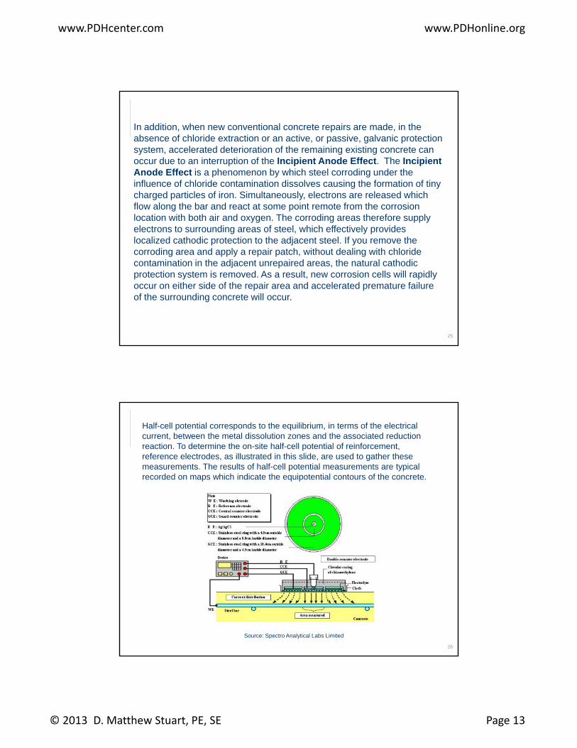
Half-cell potential corresponds to the equilibrium, in terms of the electrical current, between the metal dissolution zones and the associated reduction reaction. To determine the on-site half-cell potential of reinforcement, reference electrodes, as illustrated in this slide, are used to gather these measurements. The results of half-cell potential measurements are typical recorded on maps which indicate the equipotential contours of the concrete.
26
Source: Spectro Analytical Labs Limited
www.PDHcenter.com www.PDHonline.org
© 2013 D. Matthew Stuart, PE, SE Page 14
Examples of Deterioration that can be Established by Petrographic Analysis
1. Acid Attack of Concrete:
Concrete is susceptible to acid attack because of its alkaline nature. The components of the cement paste can breakdown when placed in contact with acids. The most pronounced deterioration is the dissolution of calcium hydroxide. Th d iti f t h tt k d b id d d th it fThe decomposition of concrete when attacked by acid depends on the porosity of the cement paste, on the concentration of the acid, the solubility of the acid calcium salts and the porosity of the concrete. When insoluble calcium salts migrate into any surface voids the acid attack can slow down. Acids such as nitric acid, hydrochloric acid and acetic acid are very aggressive as their calcium salts are readily soluble and therefore easily removed from the attack interface. Other acids such as phosphoric acid and humic acid are less harmful as their calcium salts, due to their low solubility, inhibit the attack by blocking the pathways of attack at the surface of the concrete Sulfuric acid is very damaging to concrete as
27
attack at the surface of the concrete. Sulfuric acid is very damaging to concrete as it combines an acid and a sulfate attack. An acid attack is diagnosed primarily by two main features; the absence of calcium hydroxide in the cement paste and the surface dissolution of cement paste which exposes the surface aggregates.
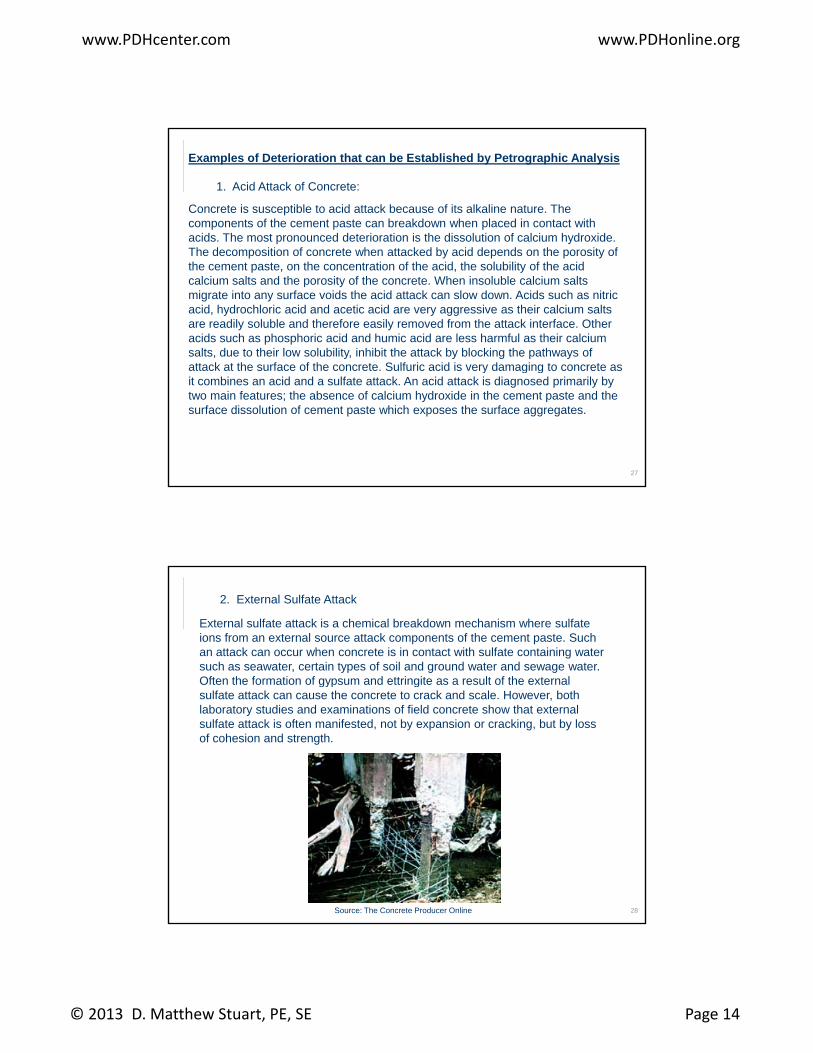
2. External Sulfate Attack
External sulfate attack is a chemical breakdown mechanism where sulfate ions from an external source attack components of the cement paste. Such an attack can occur when concrete is in contact with sulfate containing water such as seawater, certain types of soil and ground water and sewage water. Often the formation of gypsum and ettringite as a result of the external gyp gsulfate attack can cause the concrete to crack and scale. However, both laboratory studies and examinations of field concrete show that external sulfate attack is often manifested, not by expansion or cracking, but by loss of cohesion and strength.
28Source: The Concrete Producer Online
www.PDHcenter.com www.PDHonline.org
© 2013 D. Matthew Stuart, PE, SE Page 15
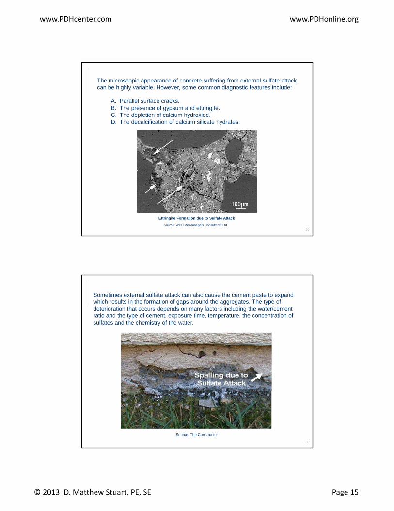
The microscopic appearance of concrete suffering from external sulfate attack can be highly variable. However, some common diagnostic features include:
A. Parallel surface cracks.B. The presence of gypsum and ettringite.C. The depletion of calcium hydroxide.D Th d l ifi ti f l i ili t h d tD. The decalcification of calcium silicate hydrates.
29
Ettringite Formation due to Sulfate Attack
Source: WHD Microanalysis Consultants Ltd
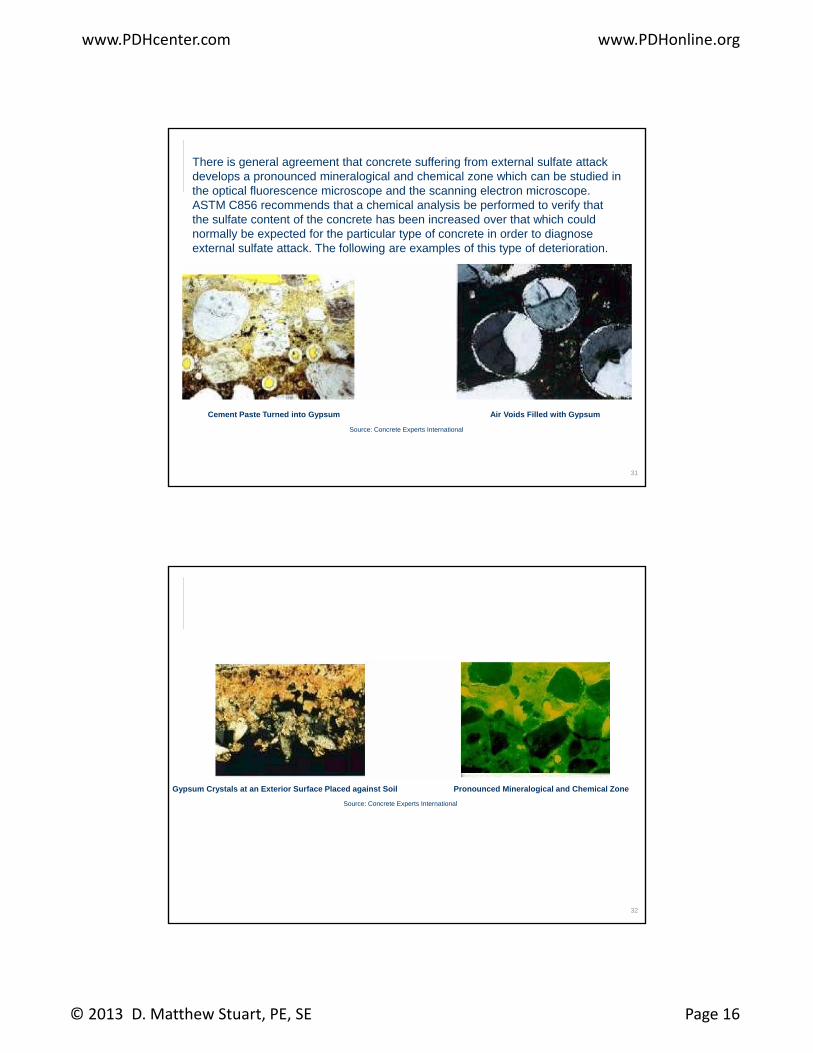
Sometimes external sulfate attack can also cause the cement paste to expand which results in the formation of gaps around the aggregates. The type of deterioration that occurs depends on many factors including the water/cement ratio and the type of cement, exposure time, temperature, the concentration of sulfates and the chemistry of the water.
30
Source: The Constructor
www.PDHcenter.com www.PDHonline.org
© 2013 D. Matthew Stuart, PE, SE Page 16
There is general agreement that concrete suffering from external sulfate attack develops a pronounced mineralogical and chemical zone which can be studied in the optical fluorescence microscope and the scanning electron microscope. ASTM C856 recommends that a chemical analysis be performed to verify that the sulfate content of the concrete has been increased over that which could normally be expected for the particular type of concrete in order to diagnose external sulfate attack The following are examples of this type of deteriorationexternal sulfate attack. The following are examples of this type of deterioration.
31
Cement Paste Turned into Gypsum Air Voids Filled with Gypsum
Source: Concrete Experts International
Gypsum Crystals at an Exterior Surface Placed against Soil Pronounced Mineralogical and Chemical Zone
Source: Concrete Experts International
32
Source: Concrete Experts International
www.PDHcenter.com www.PDHonline.org
© 2013 D. Matthew Stuart, PE, SE Page 17
33
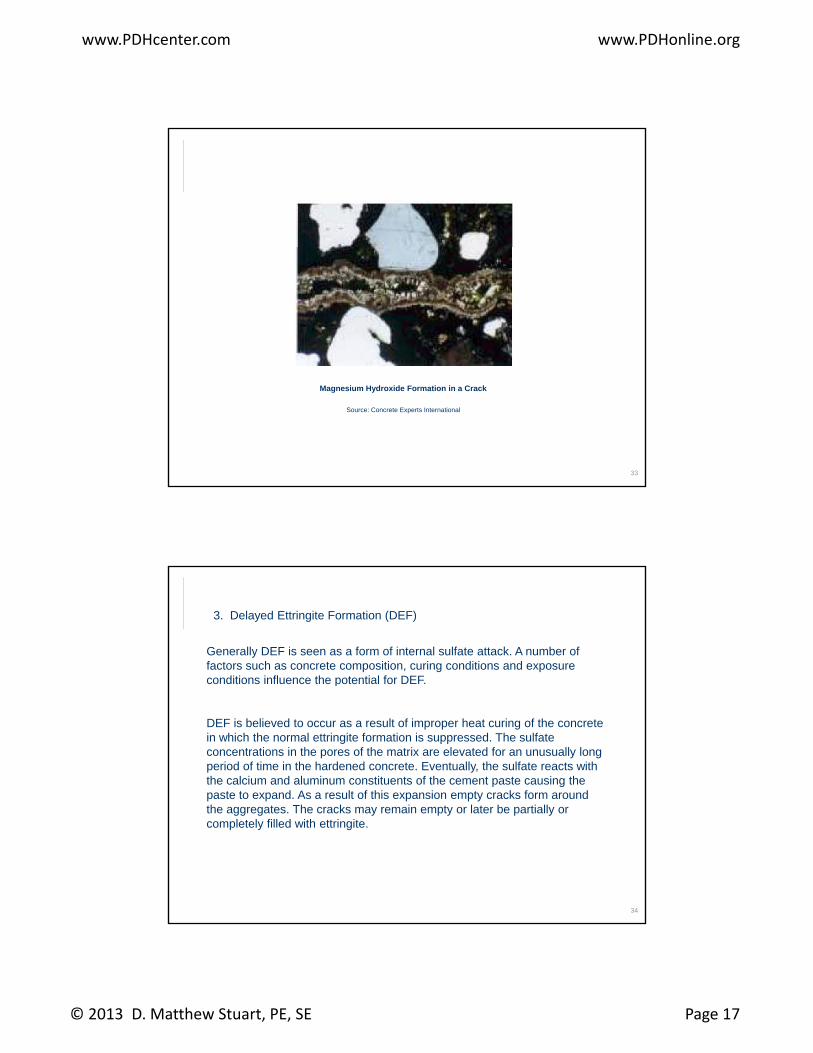
Magnesium Hydroxide Formation in a Crack
Source: Concrete Experts International
3. Delayed Ettringite Formation (DEF)
Generally DEF is seen as a form of internal sulfate attack. A number of factors such as concrete composition, curing conditions and exposure conditions influence the potential for DEF.p
DEF is believed to occur as a result of improper heat curing of the concrete in which the normal ettringite formation is suppressed. The sulfate concentrations in the pores of the matrix are elevated for an unusually long period of time in the hardened concrete. Eventually, the sulfate reacts with the calcium and aluminum constituents of the cement paste causing the paste to expand. As a result of this expansion empty cracks form around h Th k i l b i ll
34
the aggregates. The cracks may remain empty or later be partially or completely filled with ettringite.
www.PDHcenter.com www.PDHonline.org
© 2013 D. Matthew Stuart, PE, SE Page 18
DEF is diagnosed primarily by the presence of four main features which include:
a. The presence of gaps completely encircling the aggregates.
b. Wider gaps around large aggregate than around small aggregate.
c. The absence of an external sulfate source.
d. The documentation of high temperature heat during the curing phase.
35
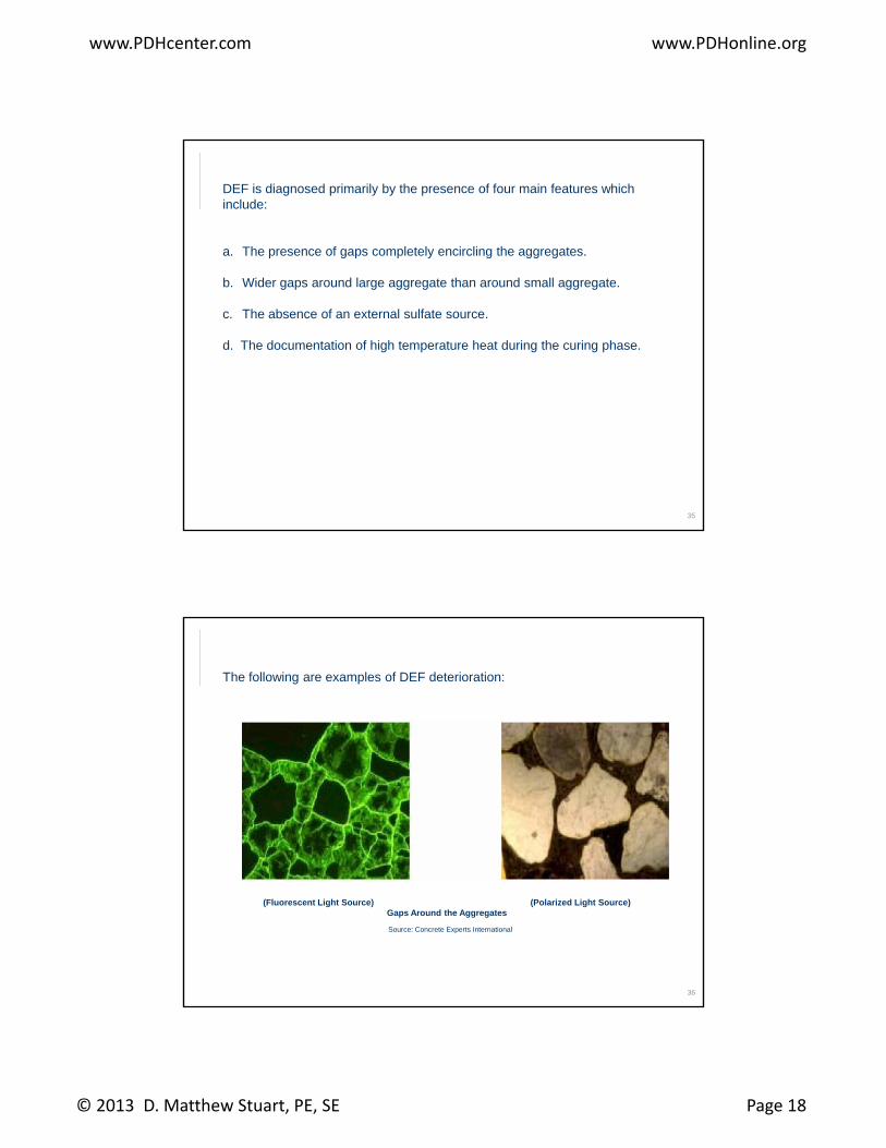
The following are examples of DEF deterioration:
36
(Fluorescent Light Source) (Polarized Light Source)Gaps Around the Aggregates
Source: Concrete Experts International
www.PDHcenter.com www.PDHonline.org
© 2013 D. Matthew Stuart, PE, SE Page 19
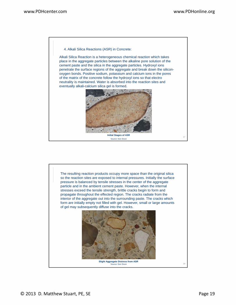
4. Alkali Silica Reactions (ASR) in Concrete:
Alkali Silica Reaction is a heterogeneous chemical reaction which takes place in the aggregate particles between the alkaline pore solution of the cement paste and the silica in the aggregate particles. Hydroxyl ions penetrate the surface regions of the aggregate and break down the silicon-oxygen bonds. Positive sodium, potassium and calcium ions in the pores of the matrix of the concrete follow the hydroxyl ions so that electro neutrality is maintained. Water is absorbed into the reaction sites and eventually alkali-calcium silica gel is formed.
37Initial Stages of ASR
Source: Don Dixon
The resulting reaction products occupy more space than the original silica so the reaction sites are exposed to internal pressures. Initially the surface pressure is balanced by tensile stresses in the center of the aggregate particle and in the ambient cement paste. However, when the internal stresses exceed the tensile strength, brittle cracks begin to form and propagate throughout the effected region. The cracks radiate from the interior of the aggregate out into the surrounding paste The cracks whichinterior of the aggregate out into the surrounding paste. The cracks which form are initially empty not filled with gel. However, small or large amounts of gel may subsequently diffuse into the cracks.
38Slight Aggregate Distress from ASR
Source: Don Dixon
www.PDHcenter.com www.PDHonline.org
© 2013 D. Matthew Stuart, PE, SE Page 20
Small particles may undergo complete reaction without cracking. In addition, formation of the alkali silica gel does not cause expansion of the aggregate. Observation of gel in a concrete sample is therefore not a positive indication that the aggregate or concrete will crack.
Alkali Silica Reaction is diagnosed primarily by the presence of four mainAlkali Silica Reaction is diagnosed primarily by the presence of four main features which include:
1. The presence of alkali silica reactive aggregates.
2. The nature of the crack pattern.
3. The presence of alkali silica gel in cracks and/or voids.
39
4. The presence of calcium hydroxide depleted paste.
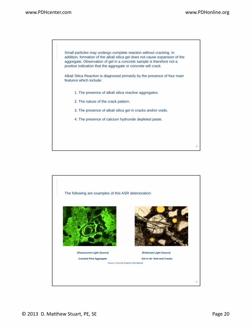
The following are examples of this ASR deterioration:
40
(Fluorescent Light Source) (Polarized Light Source)
Cracked Flint Aggregate Gel in Air Void and Cracks
Source: Concrete Experts International
www.PDHcenter.com www.PDHonline.org
© 2013 D. Matthew Stuart, PE, SE Page 21
5. Carbonation of Concrete:
Carbonation occurs in concrete because the calcium bearing constituents of the concrete are attacked by carbon dioxide and converted to calcium carbonate. Cement paste contains 25% to 50% (by weight) calcium hydroxide (Ca(OH)2) which means that the pH of fresh cement paste is at least 12.5. The pH of fully carbonated cement paste is about 7.
Concrete will become carbonated if the carbon dioxide (CO2), either from the atmosphere, water or other environmental source, enters the concrete according to:
Ca(OH)2 + CO2 =>CaCO3 + H2O (calcium carbonate + water)
41
When calcium hydroxide is removed from the paste, calcium silicate hydrates will liberate the calcium oxide which will also become carbonated. The rate of carbonation depends on the porosity and moisture content of the concrete.
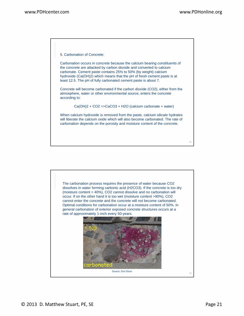
The carbonation process requires the presence of water because CO2 dissolves in water forming carbonic acid (H2CO3). If the concrete is too dry (moisture content < 40%), CO2 cannot dissolve and no carbonation will occur. If on the other hand it is too wet (moisture content >90%), CO2 cannot enter the concrete and the concrete will not become carbonated. Optimal conditions for carbonation occur at a moisture content of 50% InOptimal conditions for carbonation occur at a moisture content of 50%. In general carbonation of exterior exposed concrete structures occurs at a rate of approximately 1-inch every 50-years.
42Source: Don Dixon
www.PDHcenter.com www.PDHonline.org
© 2013 D. Matthew Stuart, PE, SE Page 22
Normal carbonation results in a decrease of the porosity making the carbonated paste stronger. Carbonation is therefore an advantage in non-reinforced concrete. However, it is a disadvantage in reinforced concrete, because as the pH of the carbonated concrete drops to about 9 the natural protection of the internal steel provided by the alkalinity of the concrete is no longer present.
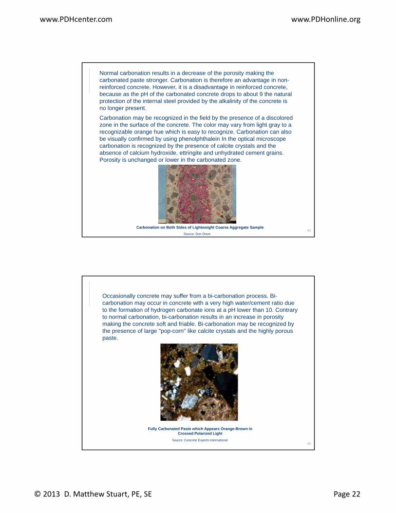
Carbonation may be recognized in the field by the presence of a discolored y g y pzone in the surface of the concrete. The color may vary from light gray to a recognizable orange hue which is easy to recognize. Carbonation can also be visually confirmed by using phenolphthalein In the optical microscope carbonation is recognized by the presence of calcite crystals and the absence of calcium hydroxide, ettringite and unhydrated cement grains. Porosity is unchanged or lower in the carbonated zone.
43Carbonation on Both Sides of Lightweight Coarse Aggregate Sample
Source: Don Dixon
Occasionally concrete may suffer from a bi-carbonation process. Bi-carbonation may occur in concrete with a very high water/cement ratio due to the formation of hydrogen carbonate ions at a pH lower than 10. Contrary to normal carbonation, bi-carbonation results in an increase in porosity making the concrete soft and friable. Bi-carbonation may be recognized by the presence of large "pop-corn" like calcite crystals and the highly porous p g p p y g y ppaste.
44
Fully Carbonated Paste which Appears Orange-Brown in Crossed Polarized Light
Source: Concrete Experts International
www.PDHcenter.com www.PDHonline.org
© 2013 D. Matthew Stuart, PE, SE Page 23
6. Freeze-Thaw Deterioration of Concrete:
Deterioration of concrete from freeze thaw actions may occur when the concrete is saturated, or approximately 90% of its pores are filled with water. When water freezes to ice it occupies approximately 10% more volume than that of water If there is no space for this volume expansion to occur in athat of water. If there is no space for this volume expansion to occur in a porous material like concrete, freezing may cause internal stresses in the concrete. Duress of concrete from freezing and thawing will start with the first freeze thaw cycle and continue throughout successive winter seasons resulting in repeated deterioration of the concrete surface. Concrete with a high water content and a high water/cement ratio is less frost resistant than concrete with a lower water content.
45
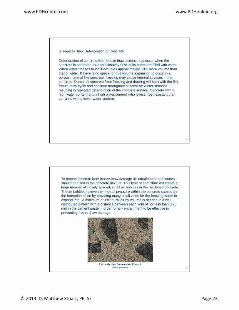
To protect concrete from freeze thaw damage air-entrainment admixtures should be used in the concrete mixture. This type of admixture will create a large number of closely spaced, small air bubbles in the hardened concrete. The air bubbles relieve the internal pressure within the concrete caused by the formation of ice by providing many small voids for the freezing water to expand into. A minimum of 4% to 5% air by volume is needed in a well p ydistributed pattern with a distance between each void of not less than 0.25 mm in the cement paste in order for air- entrainment to be effective in preventing freeze thaw damage.
46
Extremely High Entrained Air ContentSource: Don Dixon
www.PDHcenter.com www.PDHonline.org
© 2013 D. Matthew Stuart, PE, SE Page 24
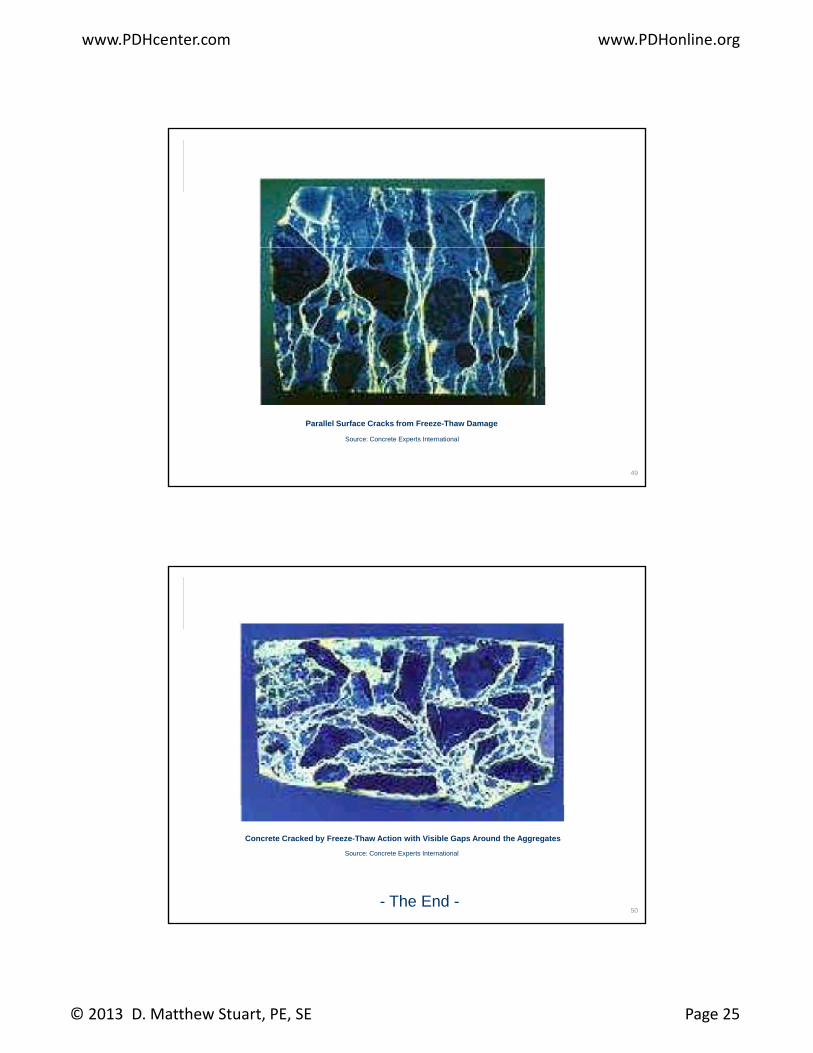
The deterioration of concrete by freeze thaw actions may be difficult to diagnose as other types of deterioration mechanisms such as ASR and Carbonation often go hand in hand with the effects of freeze thaw damage. Often it may be difficult to evaluate which mechanism caused the initial damage, however, if all other mechanisms can be excluded the typical signs of freeze thaw deterioration include:
a. Spalling and scaling of the surface.
b. Large surface delaminations.
c. Exposed aggregates.
d Parallel surface cracking
47
d. Parallel surface cracking.
e. Gaps around the aggregates.
48
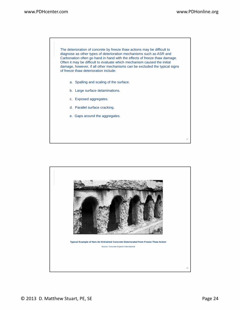
Typical Example of Non-Air-Entrained Concrete Deteriorated from Freeze-Thaw Action
Source: Concrete Experts International
www.PDHcenter.com www.PDHonline.org
© 2013 D. Matthew Stuart, PE, SE Page 25
49
Parallel Surface Cracks from Freeze-Thaw Damage
Source: Concrete Experts International
50
Concrete Cracked by Freeze-Thaw Action with Visible Gaps Around the Aggregates
Source: Concrete Experts International
- The End -