
ITU-T Rec. G.832 (10/98) Transport of SDH elements on PDH ...
25
INTERNATIONAL TELECOMMUNICATION UNION ITU-T G.832 TELECOMMUNICATION STANDARDIZATION SECTOR OF ITU (10/98) SERIES G: TRANSMISSION SYSTEMS AND MEDIA, DIGITAL SYSTEMS AND NETWORKS Digital transmission systems – Digital networks – Network capabilities and functions Transport of SDH elements on PDH networks – Frame and multiplexing structures ITU-T Recommendation G.832 (Previously CCITT Recommendations)
-
Upload
khangminh22 -
Category
Documents
-
view
3 -
download
0
Transcript of ITU-T Rec. G.832 (10/98) Transport of SDH elements on PDH ...

INTERNATIONAL TELECOMMUNICATION UNION
ITU-T G.832TELECOMMUNICATIONSTANDARDIZATION SECTOROF ITU
(10/98)
SERIES G: TRANSMISSION SYSTEMS AND MEDIA,DIGITAL SYSTEMS AND NETWORKS
Digital transmission systems – Digital networks – Networkcapabilities and functions
Transport of SDH elements on PDH networks –Frame and multiplexing structures
ITU-T Recommendation G.832(Previously CCITT Recommendations)
ITU-T G-SERIES RECOMMENDATIONS
TRANSMISSION SYSTEMS AND MEDIA, DIGITAL SYSTEMS AND NETWORKS
For further details, please refer to ITU-T List of Recommendations.
INTERNATIONAL TELEPHONE CONNECTIONS AND CIRCUITS G.100–G.199
INTERNATIONAL ANALOGUE CARRIER SYSTEM
GENERAL CHARACTERISTICS COMMON TO ALL ANALOGUE CARRIER-TRANSMISSION SYSTEMS
G.200–G.299
INDIVIDUAL CHARACTERISTICS OF INTERNATIONAL CARRIER TELEPHONESYSTEMS ON METALLIC LINES
G.300–G.399
GENERAL CHARACTERISTICS OF INTERNATIONAL CARRIER TELEPHONESYSTEMS ON RADIO-RELAY OR SATELLITE LINKS AND INTERCONNECTIONWITH METALLIC LINES
G.400–G.449
COORDINATION OF RADIOTELEPHONY AND LINE TELEPHONY G.450–G.499
TESTING EQUIPMENTS
TRANSMISSION MEDIA CHARACTERISTICS
DIGITAL TRANSMISSION SYSTEMS
TERMINAL EQUIPMENTS G.700–G.799
DIGITAL NETWORKS G.800–G.899
General aspects G.800–G.809
Design objectives for digital networks G.810–G.819
Quality and availability targets G.820–G.829
Network capabilities and functions G.830–G.839
SDH network characteristics G.840–G.849
Telecommunications management network G.850–G.859
DIGITAL SECTIONS AND DIGITAL LINE SYSTEM G.900–G.999

Recommendation G.832 (10/98) i
ITU-T RECOMMENDATION G.832
TRANSPORT OF SDH ELEMENTS ON PDH NETWORKS – FRAME ANDMULTIPLEXING STRUCTURES
Summary
This Recommendation defines frame structures and multiplexing arrangements for the transport ofSDH elements over existing PDH transport networks operating at G.702 hierarchical rates of34 368 kbit/s, 44 736 kbit/s, 97 728 kbit/s and 139 264 kbit/s. It is envisaged that these framestructures could, unless otherwise indicated, be used for the transport of other signals (e.g. ATMcells).
Source
ITU-T Recommendation G.832 was revised by ITU-T Study Group 15 (1997-2000) and wasapproved under the WTSC Resolution No. 1 procedure on the 13th of October 1998.
History
Issue Notes
02/98 Second revision: Modifications are made to subclauses 2.1.2, 2.4.2, 3.1.1 and 3.4.3 to supportthe Synchronization Status Message (SSM) instead of the timing marker in bit 8 of byte MA inthe 34 368 and 139 264 kbit/s signals.
The NR byte definition is modified and now aligned with the definition of byte N1 inAnnex D/G.707.
11/95 First revision: Terms FERF and FEBE are replaced by RDI and REI. References toRecommendations G.708 and G.709 are replaced by references to Recommendation G.707. Thetrail trace identifier specification has been modified and refers to Recommendations G.707 andG.831.
11/93 Initial version

ii Recommendation G.832 (10/98)
FOREWORD
ITU (International Telecommunication Union) is the United Nations Specialized Agency in the field oftelecommunications. The ITU Telecommunication Standardization Sector (ITU-T) is a permanent organ ofthe ITU. The ITU-T is responsible for studying technical, operating and tariff questions and issuingRecommendations on them with a view to standardizing telecommunications on a worldwide basis.
The World Telecommunication Standardization Conference (WTSC), which meets every four years,establishes the topics for study by the ITU-T Study Groups which, in their turn, produce Recommendationson these topics.
The approval of Recommendations by the Members of the ITU-T is covered by the procedure laid down inWTSC Resolution No. 1.
In some areas of information technology which fall within ITU-T’s purview, the necessary standards areprepared on a collaborative basis with ISO and IEC.
NOTE
In this Recommendation the term recognized operating agency (ROA) includes any individual, company,corporation or governmental organization that operates a public correspondence service. The termsAdministration, ROA and public correspondence are defined in the Constitution of the ITU (Geneva, 1992).
INTELLECTUAL PROPERTY RIGHTS
The ITU draws attention to the possibility that the practice or implementation of this Recommendation mayinvolve the use of a claimed Intellectual Property Right. The ITU takes no position concerning the evidence,validity or applicability of claimed Intellectual Property Rights, whether asserted by ITU members or othersoutside of the Recommendation development process.
As of the date of approval of this Recommendation, the ITU had not received notice of intellectual property,protected by patents, which may be required to implement this Recommendation. However, implementors arecautioned that this may not represent the latest information and are therefore strongly urged to consult theTSB patent database.
ITU 1999
All rights reserved. No part of this publication may be reproduced or utilized in any form or by any means,electronic or mechanical, including photocopying and microfilm, without permission in writing from the ITU.

Recommendation G.832 (10/98) iii
CONTENTS
Page
1 Introduction ................................................................................................................ 1
1.1 Scope .......................................................................................................................... 1
1.2 References .................................................................................................................. 1
1.3 Abbreviations ............................................................................................................. 1
2 Frame structures ......................................................................................................... 2
2.1 Frame structure at 34 368 kbit/s ................................................................................. 2
2.1.1 General .......................................................................................................... 2
2.1.2 Overhead allocation ...................................................................................... 3
2.2 Frame structure at 44 736 kbit/s ................................................................................. 4
2.2.1 Intermediate 500 µs frame structure ............................................................. 4
2.2.2 Overhead allocation ...................................................................................... 5
2.3 Frame structure at 97 728 kbit/s ................................................................................. 5
2.3.1 General .......................................................................................................... 5
2.3.2 Overhead allocation ...................................................................................... 6
2.4 Frame structure at 139 264 kbit/s ............................................................................... 7
2.4.1 General .......................................................................................................... 7
2.4.2 Overhead allocation ...................................................................................... 7
3 Multiplexing structures .............................................................................................. 9
3.1 Support of SDH elements in the 34 368 kbit/s frame structure.................................. 9
3.1.1 Coding of multiframe indicator for Tributary Unit multiframe indication... 10
3.2 Support of SDH elements in the 44 736 kbit/s frame structure.................................. 11
3.3 Support of SDH elements in the 97 728 kbit/s frame structure.................................. 12
3.4 Support of SDH elements in the 139 264 kbit/s frame structure................................ 13
3.4.1 Multiplexing of 20 × TUG-2......................................................................... 13
3.4.2 Multiplexing of 2 × TUG-3 and 5 × TUG-2 ................................................. 14
3.4.3 Coding of multiframe indicator for Tributary Unit multiframe indication... 15
Annex A – Description of the 16-byte frame and CRC-7 calculation..................................... 16

Recommendation G.832 (10/98) 1
Recommendation G.832
TRANSPORT OF SDH ELEMENTS ON PDH NETWORKS – FRAME ANDMULTIPLEXING STRUCTURES
(revised in 1998)
1 Introduction
1.1 Scope
The purpose of this Recommendation is to provide frame structures and multiplexing arrangementsfor the transport of SDH elements over existing PDH transport networks operating at various G.702hierarchical rates. It is also envisaged that these frame structures could, unless otherwise indicated,be used for the transport of other signals (e.g. ATM cells).
1.2 References
The following ITU-T Recommendations and other references contain provisions which, throughreference in this text, constitute provisions of this Recommendation. At the time of publication, theeditions indicated were valid. All Recommendations and other references are subject to revision; allusers of this Recommendation are therefore encouraged to investigate the possibility of applying themost recent edition of the Recommendations and other references listed below. A list of the currentlyvalid ITU-T Recommendations is regularly published.
– ITU-T Recommendation G.707 (1996), Network node interface for the Synchronous DigitalHierarchy (SDH).
– ITU-T Recommendation G.804 (1998), ATM cell mapping into Plesiochronous DigitalHierarchy (PDH).
– CCITT Recommendation T.50 (1992), International Reference Alphabet (IRA) (FormerlyInternational Alphabet No. 5 or IA5) – Information technology – 7-bit coded character setfor information interchange.
1.3 Abbreviations
This Recommendation uses the following abbreviations:
BIP-8 Bit Interleaved Parity-8
C-n Container of level n
IEC Incoming Error Count
LSB Least Significant Bit
MFI MultiFrame Indicator
MSB Most Significant Bit
PDH Plesiochronous Digital Hierarchy
POH Path Overhead
PTR PoinTeR
RDI Remote Defect Indication
REI Remote Error Indication

2 Recommendation G.832 (10/98)
SDH Synchronous Digital Hierarchy
SOH Section Overhead
TTI Trail Trace Identifier
TU-n Tributary Unit of level n
TUG-n Tributary Unit Group of level n
VC-n Virtual Container of level n
NOTE 1 – The order of transmission of information in all diagrams in this Recommendation is first from leftto right and then top to bottom. Within each byte the most significant bit is transmitted first. The mostsignificant bit (bit 1) is illustrated at the left of all diagrams.
NOTE 2 – In this Recommendation the term "SDH elements" indicates the various VCs with their associatedpointers.
2 Frame structures
The frame structures defined in this Recommendation are intended to be used in a generic way.When implementing these frame structures, care should be taken to ensure that the performance ofthe frame alignment mechanism is not compromised by the payload content.
2.1 Frame structure at 34 368 kbit/s
2.1.1 General
The basic frame structure at 34 368 kbit/s comprises 7 octets of overhead and 530 octets of payloadcapacity per 125 µs as shown in Figure 2-1.
T1302700-94
FA1FA2
EM
TR
MA
NR
GC
59 columns
530 octetpayload 9
row
s
Figure 2-1/G.832 – Frame structure at 34 368 kbit/s
Recommendation G.832 (10/98) 3
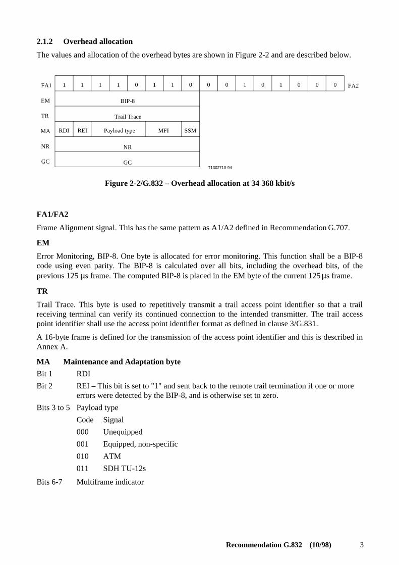
2.1.2 Overhead allocation
The values and allocation of the overhead bytes are shown in Figure 2-2 and are described below.
T1302710-94
1 1 1 1 0 1 1 0 0 0 1 0 1 0 0 0 FA2FA1
EM
TR
MA
NR
GC
BIP-8
RDI REI
NR
GC
MFI SSM
Trail Trace
Payload type
Figure 2-2/G.832 – Overhead allocation at 34 368 kbit/s
FA1/FA2
Frame Alignment signal. This has the same pattern as A1/A2 defined in Recommendation G.707.
EM
Error Monitoring, BIP-8. One byte is allocated for error monitoring. This function shall be a BIP-8code using even parity. The BIP-8 is calculated over all bits, including the overhead bits, of theprevious 125 µs frame. The computed BIP-8 is placed in the EM byte of the current 125 µs frame.
TR
Trail Trace. This byte is used to repetitively transmit a trail access point identifier so that a trailreceiving terminal can verify its continued connection to the intended transmitter. The trail accesspoint identifier shall use the access point identifier format as defined in clause 3/G.831.
A 16-byte frame is defined for the transmission of the access point identifier and this is described inAnnex A.
MA Maintenance and Adaptation byte
Bit 1 RDI
Bit 2 REI – This bit is set to "1" and sent back to the remote trail termination if one or more errors were detected by the BIP-8, and is otherwise set to zero.
Bits 3 to 5 Payload type
Code Signal
000 Unequipped
001 Equipped, non-specific
010 ATM
011 SDH TU-12s
Bits 6-7 Multiframe indicator

4 Recommendation G.832 (10/98)
Bit 8 This bit is used in a four-frame multiframe. The phase of the multiframe is determined bythe value of MA bits 6 and 7, according to:
Bit 6 Bit 7 Bit 8
0 0 SSM bit 1 (MSB)
0 1 SSM bit 2
1 0 SSM bit 3
1 1 SSM bit 4 (LSB)
The four bits of the multiframe are allocated to the Synchronization Status Message(SSM). The coding of the SSM is given in Table 5/G.707.
When interworking with "old" equipment which used bit 8 as a timing marker (non-multiframe), the"new" equipment implementing the above requirement should be capable of being configured totransmit the "old" requirement as given below:
Bit 8, Timing marker. This bit is set to "0" to indicate that the timing source is traceable to a PrimaryReference Clock, and is otherwise set to "1".
NR
Network Operator byte. This byte is allocated for maintenance purposes specific to individualNetwork Operators. Its transparency from Trail termination to Trail termination is not guaranteed. Inthe case where this byte is modified at an intermediate point in the trail, the EM byte must beappropriately corrected to ensure performance monitoring integrity. For Tandem ConnectionMaintenance, the byte is used in accordance with Annex D/G.707.
GC
General purpose communications channel (e.g. to provide data/voice channel connection formaintenance purposes).
2.2 Frame structure at 44 736 kbit/s
The basic frame structure at 44 736 kbit/s is described in Recommendation G.704.
2.2.1 Intermediate 500 µs frame structure
Since the 44 736 kbit/s frame structure is an asynchronous format with a nominal frame time of106.402 µs, an intermediate 500 µs frame structure is defined below. This frame consists of2736 bytes of payload, 4 framing bytes and 19 bytes of fixed stuff as shown in Figure 2-3.

Recommendation G.832 (10/98) 5
T1304180-95
F1F2F3
F4
23 rows
144 rows
19 columns
Fixed stuff
2736 bytes of payload capacity
Figure 2-3/G.832 – Intermediate 500 µs frame structurefor transport of SDH elements in the
44 736 kbit/s frame structure
When this intermediate frame is combined along with the 44 736 kbit/s frame level stuffing and the56 frame overhead bits of the C-bit parity format, the resultant signal will be 44 736 095 bit/s (withinthe range of the nominal 44 736 kbit/s ± 20 ppm).
2.2.2 Overhead allocation
The framing bytes and fixed stuff bytes are defined below.
• F1 – 11110110
• F2 – 00101000
• F3 – 11110110
• F4 – 00101000
• Fixed stuff – 11001100
2.3 Frame structure at 97 728 kbit/s
2.3.1 General
Using the full 97 728 kbit/s rate, there are 1537 bytes available every 125 µs. As the net capacity ofthe Container-3 needs 756 bytes every 125 µs, two Container-3s can be allocated leaving 15 bytesevery 125 µs for the overhead for the 97 728 kbit/s signal and VC-3 POH functionality and forpointers as shown in Figure 2-4.

6 Recommendation G.832 (10/98)
T1302720-94
A1A2 D HaHb
J1
B3
C2/G1
F2
H4
3 2 10
1
168
84
9
MM Ha Hb
00 H1 H1
01 H2 H2
10 H3 H3
11 B2 K1
POH
756 octet payload
1522 octet payload
A1:A2:
D:
11110110001010MM(MM = 00/01/10/11)Data Communication Channel
H1, H2, H3B2K1
PointerBIP-8RDI
Figure 2-4/G.832 – Frame structure and overhead allocation for the 97 728 kbit/s
2.3.2 Overhead allocation
The overheads and pointers are described below.
A1, A2 Frame alignment signal:
A1 11110110
A2 001010MM,
where MM (= 00/01/10/11) is multiframe indicator for Ha and Hb bytes.
D A 64 kbit/s data communication channel.
Ha, Hb These multiframe structured bytes have the following functionality:
H1, H2, H3 Reduced AU-3 pointer, which has the same function as defined inRecommendation G.707.
B2 Error monitoring, BIP-8. One byte is allocated for error monitoring ofthe 97 728 kbit/s signal. This function shall be a BIP-8 code usingeven parity. The BIP-8 is calculated over all bits of the previous500 µs multiframe. The computed BIP-8 is placed in the B2 byte ofthe current 500 µs multiframe.
K1 Bit 8 is used for RDI. Bits 1-7 are reserved for future use.
J1 VC-3 path trace as defined in Recommendation G.707.
B3 VC-3 path BIP-8 as defined in Recommendation G.707.
C2/G1 Bits 1-4 are for VC-3 path REI, bit 5 is for VC-3 RDI and bits 6-8 are for VC-3 signal label.
F2 VC-3 path user channel as defined in Recommendation G.707.
H4 VC-3 position indicator as defined in Recommendation G.707.
Recommendation G.832 (10/98) 7
2.4 Frame structure at 139 264 kbit/s
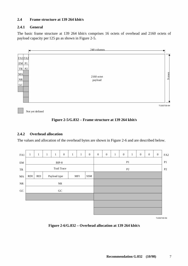
2.4.1 General
The basic frame structure at 139 264 kbit/s comprises 16 octets of overhead and 2160 octets ofpayload capacity per 125 µs as shown in Figure 2-5.
T1302730-94
FA1FA2
EM
TR
MA
NR
GC
P1
P2
240 columns
2160 octetpayload 9
row
s
Not yet defined
Figure 2-5/G.832 – Frame structure at 139 264 kbit/s
2.4.2 Overhead allocation
The values and allocation of the overhead bytes are shown in Figure 2-6 and are described below.
T1302740-94
P1
P2
1 1 1 1 0 1 1 0 0 0 1 0 1 0 0 0 FA2
P1
P2
FA1
EM
TR
MA
NR
GC
NR
GC
BIP-8
RDI REI MFI SSM
Trail Trace
Payload type
Figure 2-6/G.832 – Overhead allocation at 139 264 kbit/s

8 Recommendation G.832 (10/98)
FA1/FA2
Frame Alignment signal. This has the same pattern as A1/A2 defined in Recommendation G.707.
EM
Error Monitoring, BIP-8. One byte is allocated for error monitoring. This function shall be a BIP-8code using even parity. The BIP-8 is calculated over all bits of the previous 125 µs frame. Thecomputed BIP-8 is placed in the EM byte of the current 125 µs frame.
TR
Trail Trace. This byte is used to repetitively transmit a trail access point identifier so that a trailreceiving terminal can verify its continued connection to the intended transmitter. The trail accesspoint identifier shall use the access point identifier format as defined in clause 3/G.831.
A 16-byte frame is defined for the transmission of the access point identifier and this is described inAnnex A.
MA Maintenance and Adaptation byte
Bit 1 RDI
Bit 2 REI – This bit is set to "1" and sent back to the remote trail termination if one or moreerrors were detected by the BIP-8, and is otherwise set to zero.
Bits 3 to 5 Payload type
Code Signal
000 Unequipped
001 Equipped, non-specific
010 ATM
011 SDH elements mapping I 20 × TUG-2
100 SDH elements mapping II 2 × TUG-3 and 5 × TUG-2
Bits 6-7 Multiframe indicator
Bit 8 This bit is used in a four-frame multiframe. The phase of the multiframe is determinedby the value of MA bits 6 and 7, according to:
Bit 6 Bit 7 Bit 8
0 0 SSM bit 1 (MSB)
0 1 SSM bit 2
1 0 SSM bit 3
1 1 SSM bit 4 (LSB)
The four bits of the multiframe are allocated to the Synchronization Status Message(SSM). The coding of the SSM is given in Table 5/G.707.
When interworking with "old" equipment which used bit 8 as a timing marker (non-multiframe), the"new" equipment implementing the above requirement should be capable of being configured totransmit the "old" requirement as given below:
Bit 8, Timing marker. This bit is set to "0" to indicate that the timing source is traceable to a PrimaryReference Clock, and is otherwise set to "1".

Recommendation G.832 (10/98) 9
NR
Network Operator byte. This byte is allocated for maintenance purposes specific to individualNetwork Operators. Its transparency from Trail termination to Trail termination is not guaranteed. Inthe case where this byte is modified at an intermediate point in the trail, the EM byte must beappropriately corrected to ensure performance monitoring integrity. For Tandem ConnectionMaintenance, the byte is used in accordance with Annex D/G.707.
GC
General purpose communications channel (e.g. to provide data/voice channel connection formaintenance purposes).
P1/P2
Automatic Protection Switching.
3 Multiplexing structures
3.1 Support of SDH elements in the 34 368 kbit/s frame structure
14 × TU-12s are arranged in the 530 octets payload area as shown in Figure 3-1.
Columns one (except the first octet), thirty and thirty-one are occupied by fixed stuff, the14 × TU-12s are 1-column interleaved into this structure and have a fixed phase relationship withrespect to the frame structure. The Tributary Unit pointers occupy the octets in the first row fromcolumns 2 to 15.

10 Recommendation G.832 (10/98)
T1302750-94
00
00
01
02
03
04
05
06
07
08
09
10
11
12
13
01
02
03
04
05
06
07
08
09
10
11
12
13
00
00
01
02
03
04
05
06
07
08
09
10
11
12
13
01
02
03
04
05
06
07
08
09
10
11
12
13
OH
131313
13
TU-12# 0
TU-12# 13
OH
OHOHOHOH
OH
59 columns
9 ro
ws
Figure 3-1/G.832 – Support of 14 TU-12s in the 34 368 kbit/s frame structure
The TU-12 elements are defined in Recommendation G.707.
Figure 3-2 shows the multiplexing structure.
T1302760-94
× 1434 368 kbit/s TU-12 VC-12
Pointer processing
Multiplexing
Aligning
Figure 3-2/G.832 – Multiplexing route for the 34 368 kbit/s frame structure
3.1.1 Coding of multiframe indicator for Tributary Unit multiframe indication
Table 3-1 shows the coding of the multiframe indicator (bits 6 and 7 of the MA octet) in case ofTU-12s mapping.

Recommendation G.832 (10/98) 11
Table 3-1/G.832
Bit 6 Bit 7 TU-PTR content inthe following frame
0 0 V1
0 1 V2
1 0 V3
1 1 V4 500 ms TributaryUnit multiframe
The relation between the TU-PTR content and the coding of the payload dependent bits is shown inFigures 8-13/G.707 and 8-14/G.707.
3.2 Support of SDH elements in the 44 736 kbit/s frame structure
A TU-12 consists of 144 bytes per 500 µs. 19 × TU-12s are arranged in the 2736 octets payload areaof the intermediate 500 µs frame as shown in Figure 3-3.
The Tributary Unit pointers occupy the octets in the first row from columns 2 to 20.
Figure 3-4 shows the multiplexing structure.
T1304190-95
F1
F2
F3
F4
V1 V1 V1 V1 V1V1 V1 V1 V1 V1 V1 V1 V1 V1 V1 V1 V1 V1V1
1 19
Figure 3-3/G.832 – Multiplexing of 19 TU-12s into theintermediate 500 µs frame structure for transport
within the 44 736 kbit/s frame structure

12 Recommendation G.832 (10/98)
T1304200-95
TU-12 VC-1244 736 kbit/sDS3 signal
Intermediate500 µs frame
Pointer processing
Aligning
Mapping
Multiplexing
Figure 3-4/G.832 – Multiplexing route for the transportof SDH elements in the 44 736 kbit/s frame structure
3.3 Support of SDH elements in the 97 728 kbit/s frame structure
The 1522 octets payload capacity can be used to support two reduced VC-3s (VC-3Rs). The VC-3Rcan contain seven TUG-2s or one C-3 defined in Recommendation G.707.
Figure 3-5 shows the multiplexing structure with the relevant lower level options.
T1302770-94
× 2
× 1
× 3
× 4
× 7
97 728 kbit/s
TU-2
VC-3R
TUG-2
C-3
VC-2
VC-12
VC-11
TU-12
TU-11
C-3
Pointer processing
Multiplexing
Aligning
Mapping
Aligning and multiplexing
NOTE – The VC-3R is a VC-3 SDH element with reduced functionality as shown in Figure 2-4.
Container of level 3
Figure 3-5/G.832 – Multiplexing routes for the transport of SDH elementsin the 97 728 kbit/s frame structure

Recommendation G.832 (10/98) 13
3.4 Support of SDH elements in the 139 264 kbit/s frame structure
The 2160 octets payload capacity can be used to support the following multiplexing options:
• Option I – 20 × TUG-2;
• Option II – 2 × TUG-3 and 5 × TUG-2.
The TUG-2 and the TUG-3 are defined in Recommendation G.707.
Figure 3-6 shows the two TUG multiplexing opportunities with the relevant lower level structure.
T1302780-94
× 2
× 20
× 5 × 7
× 1
× 1
× 3
× 4
139 264 kbit/s
TUG-2
TUG-3 VC-3
TU-2
TU-12
TU-11
TU-3
VC-2
VC-12
VC-11
Pointer processing
Multiplexing of non-homogeneous signals
Multiplexing
Aligning
Figure 3-6/G.832 – Multiplexing routes for the transportof SDH elements into the 139 264 kbit/s frame structure
3.4.1 Multiplexing of 20 × TUG-2
The arrangement of 20 TUG-2s multiplexed into the 9 rows by 240 columns payload is shown inFigure 3-7. The 20 TUG-2s are one-byte interleaved into this structure and have a fixed phaserelationship with respect to the frame overhead.

14 Recommendation G.832 (10/98)
...... ... ....
T1304210-95
TUG-2 # 1 TUG-2 # 2 TUG-2 # 20
OH 1 2
1 12 1 12 1 12
.... ...........
3 4 5 18 19 20 1 2 3 18 19 20
12
34
518
1920
21 22
23238
239240
Figure 3-7/G.832 – Multiplexing of 20 × TUG-2 into the 139 264 kbit/s payload capacity
3.4.2 Multiplexing of 2 × TUG-3 and 5 × TUG-2
The arrangement of 2 TUG-3s and 5 TUG-2s multiplexed into the 9 rows by 240 columns payload isshown in Figure 3-8.
As a first step, four fixed stuff columns are added to each TUG-3 structure in the leading positions,resulting in two 90 column structures ("A" and "B"). The 5 TUG-2s are one-byte interleaved to a60 columns by 9 rows structure ("C").
These three intermediate structures are then byte interleaved in the following sequence:
[ABACBABC]1 [ABACBABC]2........................[ABACBABC]30
If further interworking flexibility is required, this arrangement could also be further demultiplexedinto one TUG-3 and 12 (7 + 5) TUG-2s or all TUG-2s in which case a maximum of 19 TUG-2s canbe carried. If only TUG-2s are required, this last situation is unlikely as the arrangement described in3.4.1 provides for 20 TUG-2s.

Recommendation G.832 (10/98) 15
T1302800-94
1 12 1 12 1 12
. . . .
8686 60
A B C
TUG-2 # 1 TUG-2 # 2 TUG-2 # 5
12
34
5
12
34
5
12
34
5
12
34
5
TUG-3 # 2TUG-3 # 1
AB
AB
C
AB
C
AB
C
AB
AB
C
AB
AB
C
AB
C
AB
C
AB
AB
C
21 3029
240
4 fixed stuffcolumns
4 fixed stuffcolumns
(8 columns)
Figure 3-8/G.832 – Multiplexing of 2 × TUG-3 and 5 × TUG-2into the 139 264 kbit/s payload capacity
3.4.3 Coding of multiframe indicator for Tributary Unit multiframe indication
Table 3-2 shows the coding of the multiframe indicator (bits 6 and 7 of the MA octet) in the case ofTU-1xs mapping.
Table 3-2/G.832
Bit 6 Bit 7 TU-PTR content inthe following frame
0 0 V1
0 1 V2
1 0 V3
1 1 V4 500 ms TributaryUnit multiframe
The relation between the TU-PTR content and the coding of the payload dependent bits is shown inFigures 8-13/G.707 and 8-14/G.707.

16 Recommendation G.832 (10/98)
ANNEX A
Description of the 16-byte frame and CRC-7 calculation
The first byte of the string is a frame start marker and includes the result of a CRC-7 calculation overthe previous frame. The following 15 bytes are used for the transport of 15 T.50 characters(international reference version) required for the access point identifier. The 16-byte frame is givenbelow:
1 C1 C C C C C C7 Frame start marker
0 X X X X X X X byte 2
• • • • • • • •
• • • • • • • •
• • • • • • • •
0 X X X X X X X byte 16
X X X X X X X T.50 character
C1 C C C C C C7 Result of the CRC-7 calculation over the previous frame
The description of the CRC-7 calculation is given below:
Multiplication/division process
A particular CRC-7 word is the remainder after multiplication by x7 and the division (modulo 2) bythe generator polynomial x7 + x3 + 1, of the polynomial representation of the previous Trail TraceIdentifier (TTI) multiframe.
When representing the contents of the block as a polynomial, the first bit in the block, i.e. byte 1,bit 1 should be taken as being the most significant bit. Similarly, C1 is defined to be the mostsignificant bit of the remainder and C7 to be the least significant bit of the remainder.
Encoding procedure
The CRC-7 word is static because the data is static (the TTI represents the source address). Thismeans that the CRC-7 checksum can be calculated either over the previous multiframe or a priori. Inthe last case this means that the 16-byte string that is loaded in a device for repetitive transmissionshould have the calculated checksum in the correct position.
The encoding procedure is as follows:
i) The CRC-7 bits in the TTI are replaced by binary 0s.
ii) The TTI is then acted upon by the multiplication/division process referred to above.
iii) The remainder resulting from the multiplication/division process is inserted into the CRC-7location.
The CRC-7 bits generated do not affect the result of the multiplication process because, as indicatedin i) above, the CRC-7 bit positions are initially set to 0 during the multiplication/division process.

Recommendation G.832 (10/98) 17
Decoding procedure
i) A received TTI is acted upon by the multiplication/division process referred to above afterhaving its CRC-7 bits extracted and replaced by 0s.
ii) The remainder resulting from the division process is then compared on a bit-by-bit basiswith the CRC-7 bits received.
iii) If the remainder calculated in the decoder exactly corresponds to the CRC-7 bits received, itis assumed that the received TTI is error free.


ITU-T RECOMMENDATIONS SERIES
Series A Organization of the work of the ITU-T
Series B Means of expression: definitions, symbols, classification
Series C General telecommunication statistics
Series D General tariff principles
Series E Overall network operation, telephone service, service operation and human factors
Series F Non-telephone telecommunication services
Series G Transmission systems and media, digital systems and networks
Series H Audiovisual and multimedia systems
Series I Integrated services digital network
Series J Transmission of television, sound programme and other multimedia signals
Series K Protection against interference
Series L Construction, installation and protection of cables and other elements of outside plant
Series M TMN and network maintenance: international transmission systems, telephone circuits,telegraphy, facsimile and leased circuits
Series N Maintenance: international sound programme and television transmission circuits
Series O Specifications of measuring equipment
Series P Telephone transmission quality, telephone installations, local line networks
Series Q Switching and signalling
Series R Telegraph transmission
Series S Telegraph services terminal equipment
Series T Terminals for telematic services
Series U Telegraph switching
Series V Data communication over the telephone network
Series X Data networks and open system communications
Series Y Global information infrastructure
Series Z Programming languages