Determination of Multipath Security Using Efficient Pattern Matching
Upload
independentCategory
view
1download
0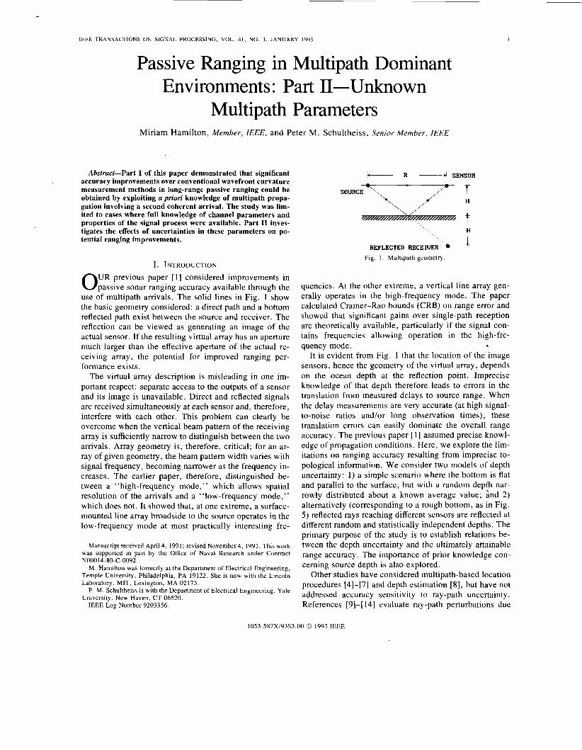
IEEE TRANSACTIONS ON SIGNAL PROCESSING, VOL. 41, NO. I ,
Passive Ranizinc v u - .
JANUARY 1993 I
in Multipath Dominant bnvironments: Part 11-Unknown
Multipath Parameters Miriam Hamilton, Member, IEEE, and Peter M. Schultheiss, Senior Member, IEEE
Abstract-Part I of this paper demonstrated that significant accuracy improvements over conventional wavefront curvature measurement methods in long-range passive ranging could be obtained by exploiting a priori knowledge of multipath propa- gation involving a second coherent arrival. The study was lim- ited to cases where full knowledge of channel parameters and properties of the signal process were available. Part I1 inves- tigates the effects of uncertainties in these parameters on po- tential ranging improvements.
I. INTRODUCTION UR previous paper [ 11 considered improvements in 0 passive sonar ranging accuracy available through the
use of multipath arrivals. The solid lines in Fig. 1 show the basic geometry considered: a direct path and a bottom reflected path exist between the source and receiver. The reflection can be viewed as generating an image of the actual sensor. If the resulting virtual array has an aperture much larger than the effective aperture of the actual re- ceiving array, the potential for improved ranging per- formance exists.
The virtual array description is misleading in one im- portant respect: separate access to the outputs of a sensor and its image is unavailable. Direct and reflected signals are received simultaneously at each sensor and, therefore, interfere with each other. This problem can clearly be overcome when the vertical beam pattern of the receiving array is sufficiently narrow to distinguish between the two arrivals. Array geometry is, therefore, critical; for an ar- ray of given geometry, the beam pattern width varies with signal frequency, becoming narrower as the frequency in- creases. The earlier paper, therefore, distinguished be- tween a “high-frequency mode,” which allows spatial resolution of the arrivals and a “low-frequency mode,” which does not. It showed that, at one extreme, a surface- mounted line array broadside to the source operates in the low-frequency mode at most practically interesting fre-
Manuscript received April 4, 1991; revised November4, 1991. This work was supported in part by the Office of Naval Research under Contract
M . Hamilton was formerly at the Department of Electrical Engineering, Temple University, Philadelphia, PA 19122. She is now with the Lincoln Laboratory, MIT, Lexington, MA 02173.
P. M. Schultheiss is with the Department of Electrical Engineering, Yale University, New Haven, CT 06520.
IEEE Log Number 9203356.
N00014-80-C-0092.
k- R -4 SENSOR
SOURCE =: H
’ , ~ , 1. REFLECTED RECE IUER
Fig. 1 . Multipath geometry.
quencies. At the other extreme, a vertical line array gen- erally operates in the high-frequency mode. The paper calculated Cramer-Rao bounds (CRB) on range error and showed that significant gains over single-path reception are theoretically available, particularly if the signal con- tains frequencies allowing operation in the high-fre- quency mode.
It is evident from Fig. 1 that the location of the image sensors, hence the geometry of the virtual array, depends on the ocean depth at the reflection point. Imprecise knowledge of that depth therefore leads to errors in the translation from measured delays to source range. When the delay measurements are very accurate (at high signal- to-noise ratios and/or long observation times), these translation errors can easily dominate the overall range accuracy. The previous paper [ 11 assumed precise knowl- edge of propagation conditions. Here, we explore the lim- itations on ranging accuracy resulting from imprecise to- pological information. We consider two models of depth uncertainty: 1) a simple scenario where the bottom is flat and parallel to the surface, but with a random depth nar- rowly distributed about a known average value; and 2) alternatively (corresponding to a rough bottom, as in Fig. 5 ) reflected rays reaching different sensors are reflected at different random and statistically independent depths. The primary purpose of the study is to establish relations be- tween the depth uncertainty and the ultimately attainable range accuracy. The importance of prior knowledge con- cerning source depth is also explored.
Other studies have considered multipath-based location procedures [4]-[7] and depth estimation [8], but have not addressed accuracy sensitivity to ray-path uncertainty. References [9]-[ 141 evaluate ray-path perturbations due
1053-587X/93$3.00 0 1993 IEEE
2 IEEE TRANSACTIONS ON SIGNAL PROCESSING, VOL. 41, NO. I , JANUARY 1993
to ocean inhomogeneities, but have not treated perturba- tions in a localization context.
As in [ l ] , we assume that the source is fixed, surface mounted, and radiates a stationary Gaussian random pro- cess s( t ) with zero mean and spectrum s ( ~ ) . The obser- vation time is sufficiently long compared with the corre- lation time of the signal and noise so that Fourier coefficients for each sensor are uncorrelated from fre- quency to frequency. The noise waveshapes received at various sensors are zero-mean Gaussian random processes with identical spectra N ( w ) , whose width is at least as large as that of S(w). They are assumed to be statistically in- dependent from sensor to sensor.
As in the earlier paper, the basic analytical tool will be the Cramer-Rao bound. The vector 8 of parameters de- fines the unknowns.
(1)
where R is the source range-the quantity of primary in- terest. cp is a vector of nuisance parameters, initially the scalar H , later the depths at all reflection points and/or the source depth. The range and (when it is unknown) the source depth are free parameters; the reflection depth or depths are random with known prior distributions. The appropriate form of the Cramer-Rao bound is therefore the hybrid form [3] with the Fisher information
(2)
where J D is the Fisher information matrix generated by treating all parameters as free variables and averaging over the available prior distributions. If the vector of received data is X and its probability density isf(X; e ) ,
e = [:I
J T = J D + J p
If the cp (nuisance parameter) distribution is sharply peaked near the mean, the cp average becomes equivalent to substituting the mean (nominal) values of the {4f} everywhere in J D . This assumption about the nuisance pa- rameter distribution of @ is physically valid for the small depth uncertainties of interest here.
The second component of (2 ) is calculated from a for- mula equivalent to (3), replacing f (X; e ) with the prior distribution f(cp) of the random parameters
(4)
It is clear that J p 1 = 0 when at least one of the indices corresponds to a parameter for which no prior distribution is available. Derivation of (2)-(4) follows the method of [15, p. 801 for a mixed parameter vector.
Since, by convention, R is the first e n t y of 8, the de- sired Cramer-Rao bound on the estimate R of R is
var ( I?) I J ; ' I I I = CRB ( I?) . ( 5 ) We are concerned with the dependence of this quantity on the nuisance parameters and their statistics. We partition
J T as follows:
J T = kR (6)
where J R is the (scalar) Fisher information when only R is unknown. JNR may be a vector.
A well-known matrix identity yields
= JRI + A CRB ( I ? ) . (8)
The first term is the Cramer-Rao bound in the absence of nuisance parameters, the second is the increment intro- duced by their presence.
We shall take as our basic data the Fourier coefficients of the various sensor outputs. The coefficient at sensor i, frequency Wk is
f , ( w k ) = f ( ~ ~ ) ( a e - ~ ~ " " + + 3 , (wk ) (9)
where S(wk) and rZ,(wk) are, respectively, the Fourier coef- ficients of the radiated signal and those of the noise at sensor i; a and b describe the relative amplitudes of the signals received over the direct and reflected paths, re- spectively; and t , and z , are the corresponding transit times.
Introducing the steering vectors
(10) 1 , (1 1) 1
uI = [ , - J W l f l , . . . , e-Jal 'M T
U, = [ e - J " J A ~ ~ , . . . e-JaAZM T
the vector of received Fourier coefficients at frequency wk assumes the form
r (wk) = s(w,)(au, + bu,) + A(w,) . (12) The obvious frequency dependence of u1 and u2 has been suppressed. The quantity I 3; 1, b 1 u:u2 I is the familiar beam pattern function describing the output power of an array steered in the direction specified by uI when a signal arrives from the direction specified by U,. 5; is, in gen- eral, a complex quantity. When the array is symmetrical about the origin, it becomes real and its magnitude simply equals the square root of the beam pattern function.
The computation of the elements of J D from (3) is al- gebraically tedious but, for the narrowly distributed cp pa- rameter postulated earlier, follows precisely the same pat- tern as in [l]. For the high-frequency mode, the result is (see the Appendix)
x (a2 (% - 2) + b2 (% - %))
HAMILTON A N D SCHULTHEISS: PASSIVE RANGING IN MULTIPATH DOMINANT ENVIRONMENTS. PART I1
The corresponding result for the low-frequency mode is
X ((3 - ”) (3 - ”) + (3 - ”) aei aei ae, ae, ae, ae,
The parameter pk is defined as
Re r k p k a2 + b2 + 2ab -*
M ’
As suggested earlier, the system operates in the high-fre- quency mode when the beam pattern is sufficiently nar- row, preventing the stronger arrival from interfering sig- nificantly with the weaker one. In quantitative terms, this mode implies
Note that only the last terms in (13) and (14) depend on the multipath delays (tr - Q). All other terms depend on delay variations across the array of one or both of the arrivals. They, therefore, measure arrival angle and cur- vature of the arriving wavefronts across the array. With a single path, only these terms contribute to ranging capa- bility. In [ l ] , they were described as “curvature terms,” which may be slightly misleading because they include range information obtainable from the arrival angle of the reflected path as well as the more traditional curvature- ranging information. The most important difference be- tween (13) and (14) is the SNR dependence of the last terms-the multipath delay terms. Once the generalized post-beam-forming signal-to-noise ratio M p k s k / N k ex- ceeds unity, the multipath terms in (14) cease to grow with SNR and eventually become small compared with “curvature terms.” In (13), the multipath terms continue to grow with SNR and their relation to the “curvature terms” remains fixed. The physical explanation is simple: in the low-frequency mode, the ability to estimate multi- path delay is limited by the simultaneous presence of two arrivals, and the effect of ambient noise becomes negli-
gible. In the high-frequency mode, by definition, the ar- ray can be steered to each arrival without interference. Accuracy depends only on the strength of the two signals relative to the ambient noise. When post-beam-forming signal-to-noise ratios exceed unity, the advantage of op- erating in the high-frequency mode becomes obvious.
The decomposition of (13) and (14) into “multipath” and “curvature” contributions will be formally written as follows:
CRB (8) = [CRB;’ + CRBib1-l. (17)
Thus, CRB;’ and CRBM& are the contributions to the Fisher information for the single parameter R in the ab- sence of depth uncertainty. Of ultimate interest to the study is the isolation of conditions under which multipath ranging offers significant performance improvements over conventional individual path measurements. The ratio CRBc/CRBMp is a measure of this performance figure. Under conditions of practical interest determined in Part I of this paper [ l ] , the ratio may be quite large. We will now show that the presence of uncertain parameters can significantly reduce these improvements.
11. EFFECT OF DEPTH UNCERTAINTY
We begin our discussion of the effects of uncertainty with the simplest case: the ocean bottom is flat and par- allel to the surface, but its depth H is a random variable with Gaussian distribution of mean Hand standard devia- tion o << H . Geometrically, the reflected array described in Fig. 1 is displaced upward or downward without any change in interelement spacing. The vector of unknown parameters is now [R , A]‘. The matrix J p of (4) now has the form
ro o 1 J p = io 1 / 2 1
The delays t, and zI in (1 3) and (14) are geometry depen- dent. We consider two array geometries of uniformly spaced sensors.
A . Vertical Array As pointed out earlier, a vertical array of reasonable
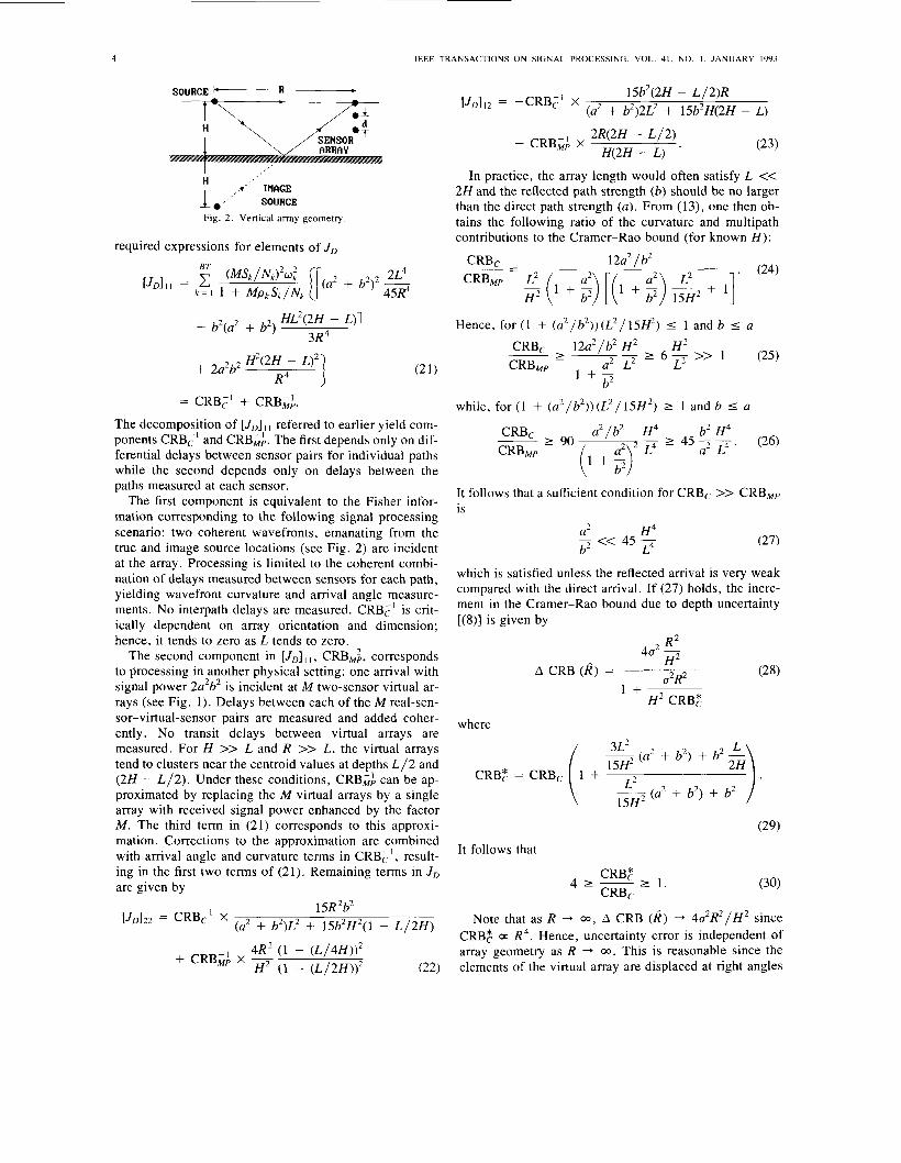
aperture would almost certainly operate in the high-fre- quency mode. Elementary geometrical considerations de- picted in Fig. 2 lead to the following expressions for the delays:
(19) 1
t , = - (R2 + (Id - L/2)2)1’2 C
M - 1 M - 1 5 1 5 -
2 2 -~
where c is the propagation velocity; and the array origin coincides with the midpoint. From (13), we obtain the
4 IEEE TRANSACTIONS ON SIGNAL PROCESSING, VOL. 41, NO. 1 , JANUARY 1993
SOURCE R - 15b2(2H - L / 2 ) R [ J D ] 1 2 = -CRBcl x
(a2 + b2)2L2 + 15b2H(2H - L)
2R(2H - L / 2 ) - C R B ~ ; x (23) H(2H - L) '
I In practice, the array length would often satisfy L << 2H and the reflected path strength (b ) should be no larger than the direct path strength (a) . From (13) , one then ob- tains the following ratio of the curvature and multipath contributions to the Cramer-Rao bound (for known H ) :
H ,*' INAGE le*^,' SOURCE
Fig. 2 . Vertical array geometry.
required expressions for elements of JD 1 2a2 / b2
. (24) -- - BT CRB,
Hence, for (1 + (a2/b2) ) (L2/15H2) I 1 and b 5 a
CRBc 12a2/b2 H2 H 2 3R4
I--- I 6 - >> 1 (25) a2 L~ L2
I + - R4 b2
CRBMP
HL2(2H - "'I + b2(a2 + b2)
(21) + 2a2b2 H2(2H - L)2]
= CRB;' + CRB~;. while, for ( 1 + ( a 2 / b 2 ) ) ( L 2 / 1 5 H 2 ) I 1 and b 5 a
CRBc a2/b2 H4 b2 H4 The decomposition of [JD] I referred to earlier yield com- ponents CRB;' and CRB,& The first depends only on dif-
while the second depends only on delays between the
- L 45 -- (26) a2 L . ~ .
I 90 ferential delays between sensor pairs for individual paths CRBMP (1 + $7 L4
paths measured at each sensor. The first component is equivalent to the Fisher infor-
mation corresponding to the following signal processing scenario: two coherent wavefronts, emanating from the true and image source locations (see Fig. 2) are incident at the array. Processing is limited to the coherent combi- nation of delays measured between sensors for each path, yielding wavefront curvature and arrival angle measure- ments. No interpath delays are measured. CRBcl is crit- ically dependent on array orientation and dimension; hence, it tends to zero as L tends to zero.
CRB,& corresponds to processing in another physical setting: one arrival with signal power 2a2b2 is incident at M two-sensor virtual ar- rays (see Fig. I ) . Delays between each of the M real-sen- sor-virtual-sensor pairs are measured and added coher- ently. No transit delays between virtual arrays are measured. For H >> L and R >> L , the virtual arrays tend to clusters near the centroid values at depths L / 2 and (2H - L / 2 ) . Under these conditions, CRB& can be ap- proximated by replacing the M virtual arrays by a single array with received signal power enhanced by the factor M. The third term in (21) corresponds to this approxi- mation. Corrections to the approximation are combined with arrival angle and curvature terms in CRB;', result- ing in the first two terms of (21). Remaining terms in JD are given by
The second component in [JD] I
15R2b2 (a2 + b2)L2 + 15b2H2(1 - L / 2 H )
[ J ~ ] ~ ~ = CRB;' x
4R2 ( 1 - ( L / 4 H ) ) 2 H 2 (1 - (L /2H))2 (22)
+ CRB& x -
It follows that a sufficient condition for CRBc >> CRBMp is
a2 H4 - << 45 - b2 L4
which is satisfied unless the reflected arrival is very weak compared with the direct arrival. If (27) holds, the incre- ment in the Cramer-Rao bound due to depth uncertainty [(S)] is given by
R2 4a2 -
H2
H~ CRB;
(28) A CRB ( R ) = G2R2 I +
where
a2 + b2) + b2 - 3L2
L2 (a2 + b2) + b2
It follows that
CRB; 4 1 - 2 1
CRBc
Note that as R --+ 03, A CRB ( R ) --f 4 2 R 2 / H 2 since CRB; 0: R 4 . Hence, uncertainty error is independent of array geometry as R -+ 00. This is reasonable since the elements of the virtual array are displaced at right angles
HAMILTON AND SCHULTHEISS: PASSIVE RANGING IN MULTIPATH DOMINANT ENVIRONMENTS, PART 11
to the array line of sight as H i s displaced from its average value. The result is that the virtual array perturbation has essentially no effect on curvature-based ranging accuracy.
Since CRB: -, 0 as SNR -+ 03, A CRB ( I?) -+ CRB: -+ 0, but CRB: still dominates overall accuracy since CRB: >> CRB,, by assumption. This is reasonable since, at near-infinite signal-to-noise ratios, a wavefront curvature measurement based only on the direct path can obtain a range estimate independent of bottom depth. At practical signal-to-noise ratios, however, the second term in the denominator of (28) is likely to be negligible and A CRB (I?) becomes independent of SNR. The incremen- tal error now depends only on U and geometrical factors. In this regime, total error [(7)] will be dominated by the effect of depth uncertainty when CRB,, < 4 d R 2 / H 2 .
Since A CRB (R)/CRBMp grows with increases in ob- servation time, SNR, and H/R, small depth errors have the greatest impact in precisely those situations where the gains from exploiting multipath are greatest in the ab- sence of uncertainty. Also observe that when (25) and (27) hold, one obtains from (22) and (18)
The condition under which total error is dominated by the effect of uncertainty (CRBMp < 402R2/H2) is equivalent to the situation where the Fisher information for depth is dominated by the data-based component. We conclude that the full gain discussed in Part I [l] can be realized only when the Fisher information for bottom depth is smaller than 1 /U’.
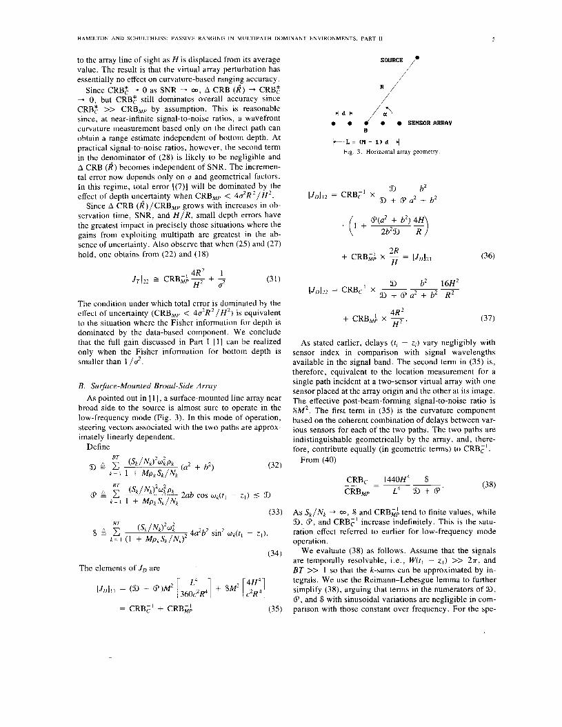
B. Surface-Mounted Broad-Side Array As pointed out in [ 11, a surface-mounted line array near
broad side to the source is almost sure to operate in the low-frequency mode (Fig. 3). In this mode of operation, steering vectors associated with the two paths are approx- imately linearly dependent.
Define BT
D A c k = i 1 + M p k S k / N k
BT
6 c (Sk’Nk)2Wk2Pk 2ab cos W k ( t l - z l ) I D k = l 1 + MpkSk/Nk
The elements of JD are
= CRBFl + CRB,&
SOURCE /.
/’
SENSOR ARRAY + d k j.-:. e *
0
k L = tH - 1) d j Fig. 3 . Horizontal array geometry.
4R H
+ C R B ~ ; x ,. (37)
As stated earlier, delays ( t , - zi) vary negligibly with sensor index in comparison with signal wavelengths available in the signal band. The second term in (35) is, therefore, equivalent to the location measurement for a single path incident at a two-sensor virtual array with one sensor placed at the array origin and the other at its image. The effective post-beam-forming signal-to-noise ratio is S M 2 . The first term in (35) is the curvature component based on the coherent combination of delays between var- ious sensors for each of the two paths. The two paths are indistinguishable geometrically by the array, and, there- fore, contribute equally (in geometric terms) to CRBcI.
From (40)
(38) CRBc 1440H4 S
CRBMMP L4 9 + 6 ’ -=--
As S k / N k -+ 03, S and CRB& tend to finite values, while 9, 6, and CRBtl increase indefinitely. This is the satu- ration effect referred to earlier for low-frequency mode operation.
We evaluate (38) as follows. Assume that the signals are temporally resolvable, i.e., W(tl - z l ) >> 2a, and BT >> 1 so that the k-sums can be approximated by in- tegrals. We use the Reimann-Lebesgue lemma to further simplify (38), arguing that terms in the numerators of D, 6, and S with sinusoidal variations are negligible in com- parison with those constant over frequency. For the spe-
6
cia1 case of flat signal and noise power spectra [ 2 ]
CRBc H 4 - 1440- --
CRBMP L4
1 ( 1 + M(a2 + b 2 ) S / N )
. I I
IEEE TRANSACTIONS ON SIGNAL PROCESSING, VOL. 41. NO. I , JANUARY 1993
( M S / N ) 2 ( a 2 + b2)2 +
(39)
2abMSIN = 1 + MS(a2 + b 2 ) / N '
Note that ( 1 /- - 1 ) does not grow indefinitely with SNR if a # b; it saturates at a finite value. For a = b , lim M S / N 4 03 [ l / m - 11 = J M S / N . For either case, CRBC/CRBMp will ultimately tend to zero at high signal-to-noise ratios. At low signal-to-noise ratios, the ratio is approximately independent of signal-to-noise ratio, and performance benefits from exploiting multipath are possible. For a # b, ( l / m - 1) 3
~ u ~ ~ ~ ( M S / N ) ~ . Therefore, for low SNR, CRBJCRB, >> 1 when
2a2b2 >> 1 . (41)
H 4 1440 -
L4 (a2 + b2)2 + 2a2b2
Under these conditions 4R2
aL 3 A CRB (fi) = (42) a24R2 '
1 +- H2 CRBc
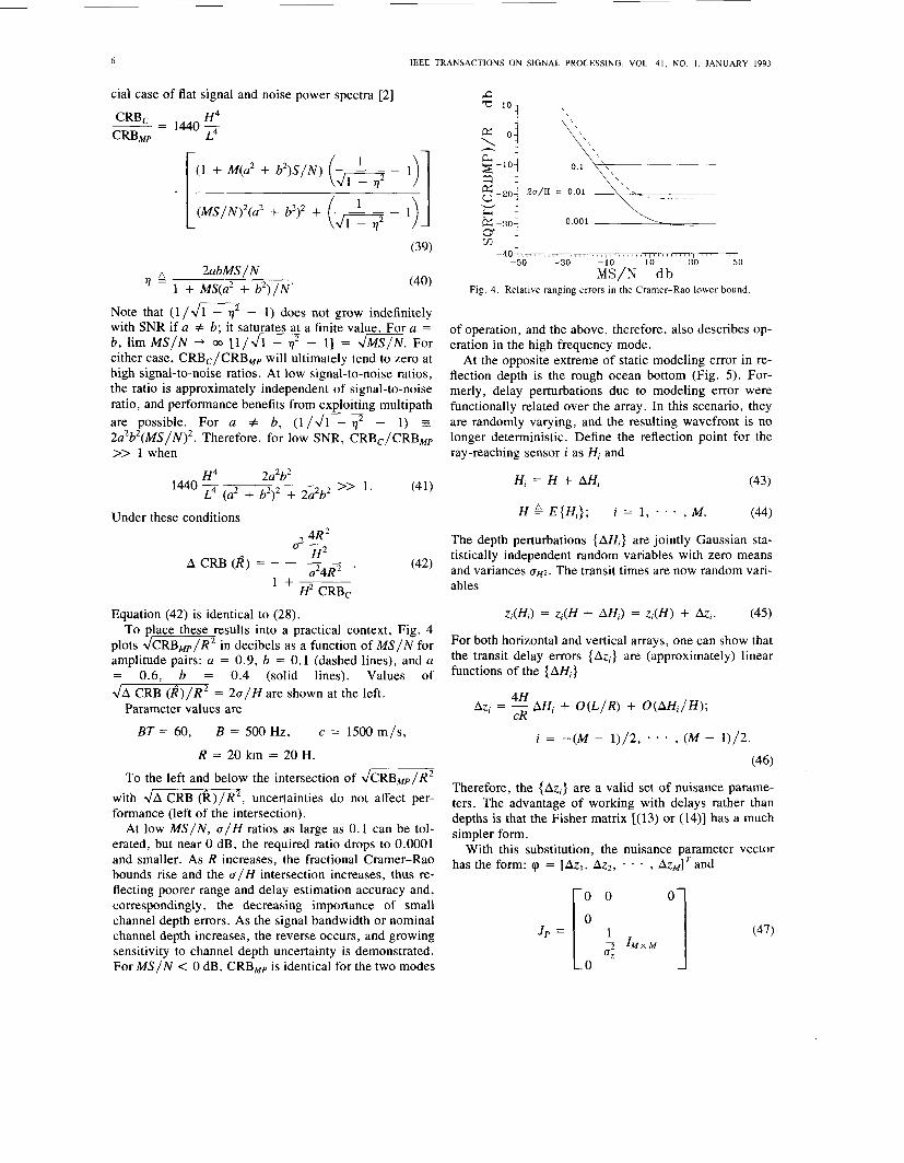
Equation (42 ) is identical to ( 2 8 ) . To place these results into a practical context, Fig. 4
plots JCRB~~/R* in decibels as a function of M S / N for amplitude pairs: a = 0.9, b = 0.1 (dashed lines), and a = 0.6, b = 0.4 (solid lines). Values of J A CRB (R)/R2 = 2 a / H are shown at the left.
B = 500 Hz,
R = 20 km = 20 H.
Parameter values are
BT = 60, c = 1500 m/s,
To the left and below the intersection of dCRBMp/lR2 with JA CRB (R) /R2, uncertainties do not affect per- formance (left of the intersection).
At low M S / N , a / H ratios as large as 0.1 can be tol- erated, but near 0 dB, the required ratio drops to 0.0001 and smaller. As R increases, the fractional Cramer-Rao bounds rise and the a / H intersection increases, thus re- flecting poorer range and delay estimation accuracy and, correspondingly, the decreasing importance of small channel depth errors. As the signal bandwidth or nominal channel depth increases, the reverse occurs, and growing sensitivity to channel depth uncertainty is demonstrated. For M S / N < 0 dB, CRBMp is identical for the two modes
e 'O3 \
g -20 z-30
2u/H = 0.01
0.001 gz -40 -50 -30 30 50
i i / N "db Fig. 4. Relative ranging errors in the Cramer-Rao lower bound.
of operation, and the above, therefore, also describes op- eration in the high frequency mode.
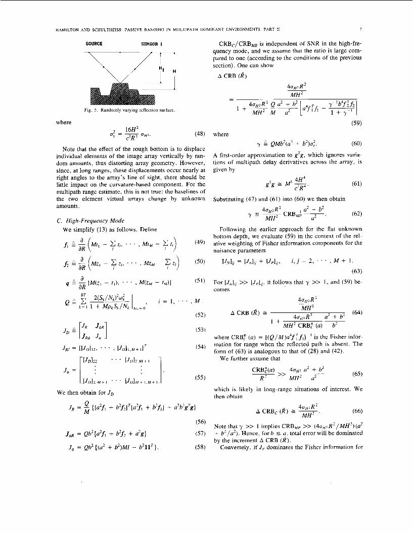
At the opposite extreme of static modeling error in re- flection depth is the rough ocean bottom (Fig. 5 ) . For- merly, delay perturbations due to modeling error were functionally related over the array. In this scenario, they are randomly varying, and the resulting wavefront is no longer deterministic. Define the reflection point for the ray-reaching sensor i as Hi and
H; = H + AH; (43)
H L E ( H , ) ; i = 1 , - , M . (44)
The depth perturbations ( A H ; ) are jointly Gaussian sta- tistically independent random variables with zero means and variances c r H 2 . The transit times are now random vari- ables
z;(H;) = zi(H + AHi) = z ; ( H ) + AZ;. (45)
For both horizontal and vertical arrays, one can show that the transit delay errors { A z i ) are (approximately) linear functions of the { A H ; }
4H AZ; = - CR AH; + O(L/R) + O ( A H j / H ) ;
i = - ( M - 1 ) / 2 , . * * , ( M - 1 ) / 2 .
(46)
Therefore, the { A z j > are a valid set of nuisance parame- ters. The advantage of working with delays rather than depths is that the Fisher matrix [(13) or (14 ) ] has a much simpler form.
With this substitution, the nuisance parameter vector has the form: cp = [ A z , , Az2 , - * , AzMITand
O l (47)
HAMILTON A N D SCHULTHEISS: PASSIVE RANGING IN MULTIPATH DOMINANT ENVIRONMENTS. PART I1 7
where
SOURCE SENSOR i CRBc/CRBMB is independent of SNR in the high-fre- quency mode, and we assume that the ratio is large com- pared to one (according to the conditions of the previous section). One can show
A CRB ( R ) 40H2R2
Fig. 5 . Randomly varying reflection surface.
Note that the effect of the rough bottom is to displace individual elements of the image array vertically by ran- dom amounts, thus distorting array geometry. However, since, at long ranges, these displacements occur nearly at right angles to the array’s line of sight, there should be little impact on the curvature-based component. For the multipath range estimate, this is not true: the baselines of the two element virtual arrays change by unknown amounts.
C. High-Frequency Mode
M H 2
(59) where
y QMb2(a2 + b2)ot. (60)
A first-order approximation to g‘g, which ignores varia- tions of multipath delay derivatives across the array, is given by
4H4 c2R4
gTg = M3 -.
Substituting (47) and (61) into (60) we then obtain
We simplify (13) as follows. Define Following the earlier approach for the flat unknown bottom depth, we evaluate (59) in the context of the rel- ative weighting of Fisher information components for the nuisance parameters
(49) t i , * . . , M t M - c t i
(53 )
We then obtain for J D
Q 2 2 T JR = {[a2fl + b2f21T[a2fl + b2f21 + g
For [J&, >> [Jp],,, it follows that y >> 1, and (59) be- comes
4 0 ~ 2 R
1 + MH2 CRB: (a) b2
where CRB: ( a ) = [ ( Q / M ) a 4 f T f I ] - ’ is the Fisher infor- mation for range when the reflected path is absent. The form of (63) is analogous to that of (28) and (42).
We further assume that
CRB:(a) 40H2 a* + b2 >> ~ ~
R 2 M H ~ a2
which is likely in long-range situations of interest. We then obtain
A 40H?R2 A CRBc ( R ) E ~ M H ~
(56)
(57)
(58)
Note that y >> 1 implies CRBMp >> (4aHzR2/MH2) (a2 + b2/a2) . Hence, forb 5 f , total error will be dominated by the increment A CRB ( R ) .
Conversely, if J p dominates the Fisher information for
J m R = Qb’{a2fi + b2f2 + a2g}
Jm = Qb2 {(a’ + b2)MZ - b 2 1 l T } .
8 lEEE TRANSACTIONS ON SIGNAL PROCESSING, VOL. 41, NO. I , JANUARY 1993
the nuisance parameters, y << 1. Note that in any case, (59) can be bounded
402R2 A CRB ( R ) I -
MH2
Then y << 1 implies
(67)
F o r b I a , J R + A CRCB (I?) I CRBMp + 4 $ R 2 / M H 2 z CRBMP, and accuracy is therefore unaffected by un- certainty.
Comparing (68) to (28), static depth errors and ran- domly varying perturbations will dominate accuracy for the same range of CRBMp (combination of observation time, signal-to-noise ratio, channel depth, array geome- try, and signal bandwidth) when
Clearly, since b I a by assumption, for U , = U , depth errors associated with a rough ocean bottom are less dam- aging to ranging accuracy than a static depth error uni- form over the reflection area for the entire array since a larger range of U , can be tolerated before incremental er- rors begin to dominate accuracy. As noted in the rough bottom scenario, the image array has random vertical per- turbations, which lead to changes in element separation for sensor pairs in the dominant multipath terms and hence to incremental errors. Since these changes are random and independent with zero mean, they tend to average out. We further note that incremental errors (A CRB ( R ) ) for the static and randomly perturbed channels are equal when U,/& = U , which clearly shows the advantage of the random error distribution.
D. Low-Frequency Mode Steering vectors are almost linearly dependent so that
fl z f 2 . (70)
J D is given by
J , = 2 [ 9 m M I - b2
(73)
where, as before 4H4 c2R4
g'g M3-. (74)
When conditions leading to (64) are satisfied and then in- terpreted for the low-frequency mode, A CRB (&) be-
comes:
(75)
which is identical to (66) . Note that Q and S differ only at post-beam-forming signal-to-noise ratios above one. Hence, performance in the presence of random depth er- rors is identical for the two modes at low SNR.
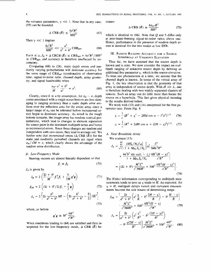
111. PASSIVE RANGING ACCURACY FOR A SOURCE SUBMERGED AT UNKNOWN ELEVATION
Thus far, we have assumed that the source depth is known and is zero. We now consider the impact on mul- tipath ranging of unknown source depth by defining an additional free parameter x, which is the source elevation. To treat one phenomenon at a time, we assume that the channel depth is known. In terms of the virtual array of Fig. 1, the key observation is that the geometry of that array is independent of source depth. With H >> L, one is therefore dealing with two widely separated clusters of sensors. Such an array can do little more than locate the source on a hyperbola. This fact gives physical meaning to the results derived below.
We work with (13) and (14) interpreted for the free pa- rameter case. From Fig. 6
1 t, = - ( R 2 + x 2 + 2Rld COS CY + l2d2) ' l2 (76)
1 Z / = - ( R 2 + 2dRl COS CY + (2H - x ) ~ ) " ~ . (77)
A. Near Broadside Array We evaluate (1 3)
4H2(H c?R4 - M2L4
(78) The Fisher information corresponding to multipath mea- surements tends to zero as x tends to H. As expected, for x = H , multipath delays vanish and curvature measure- ments become the sole means of determining range.
a, E X ) - 6 1 H - J N R = [y a + b2 (a2: - b2 R
.- M2L4 + S M 2 4 H 2 W - X I c2360R4 c2R3
(79)
4H2 - 6 x(2:F ''1 & + S M 2 -. c2R4 (80)
HAMILTON AND SCHULTHEISS: PASSIVE RANGING IN MULTIPATH DOMINANT ENVIRONMENTS. PART 11 9
SOURCE (BELOW SURFACE)
/ /\ ’\ VIEW FOR
F I G . 6 B e .
d cosa 8
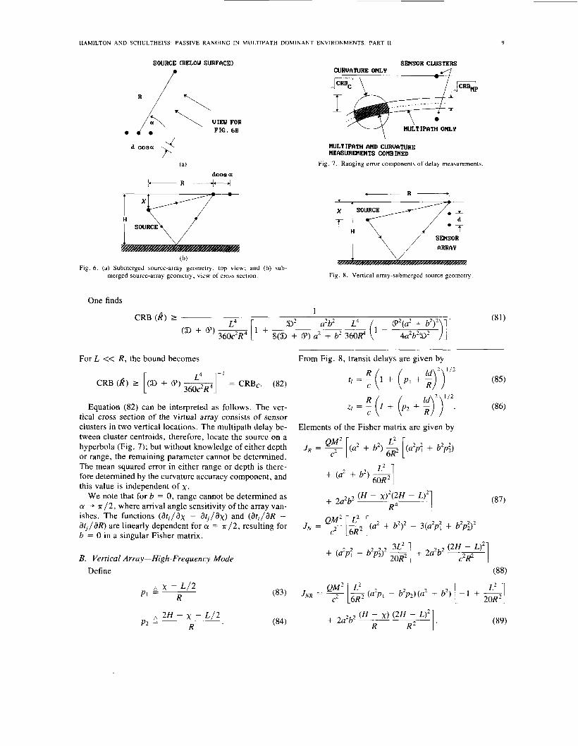
(b) Fig. 6 . (a) Submerged source-array geometry, top view; and (b) sub-
merged source-array geometry, view of cross section.
SENSOR CLUSTERS & Y T R p
HULTIPATH AND CURUATURE HEASUREHENTS COHBINED
Fig. 7. Ranging error components of delay measurements
SENSOR
ARRAY
Fig. 8. Vertical array-submerged source geometry
One finds
For L << R , the bound becomes
CRB (I?) 2 (9 + 6) ~ = CRBc. (82)
Equation (82) can be interpreted as follows. The ver- tical cross section of the virtual array consists of sensor clusters in two vertical locations. The multipath delay be- tween cluster centroids, therefore, locate the source on a hyperbola (Fig. 7); but without knowledge of either depth or range, the remaining parameter cannot be determined. The mean squared error in either range or depth is there- fore determined by the curvature accuracy component, and this value is independent of x.
We note that for b = 0, range cannot be determined as CY -+ ~ / 2 , where arrival angle sensitivity of the array van- ishes. The functions (dt,/dx - &,/ax) and (dt , /dR - dtj /dR) are linearly dependent for CY = ~ / 2 , resulting for b = 0 in a singular Fisher matrix.
[ 360c2R4 L4 I-’
B. Vertical Array-High-Frequency Mode Define
- L / 2 PI 2 x R
a 2H - x - L / 2 (84) R P2 =
From Fig. 8, transit delays are given by
t / = !! (1 + + (85)
(86) C
Elements of the Fisher matrix are given by
QM2 L2 J R = 7 [(a2 f b2> [(a2p: + b‘p;)
+ (U’ + b2) 7 60R L2 1
1 + (a2p; - b’p:)’ cl + 2~
2 2 (H - xI2(2fJ - o2 R 4
+ 2a b
Q M 2 L2 J N = 7 [z [(a2 + b2)2 - 3(a2p; + b2pi)2
20R2 (88)
J N R = 7 [s (a2p, - b’pd(a’ + b2) [ - 1 + &] (89)
Q M 2 L2
R 2 I . 2 2 (H - x> (2H - L>* + 2 a b ~
R
(87)
IEEE TRANSACTIONS O N SIGNAL PROCESSING, VOL. 41, N O . I , JANUARY 1993 IO
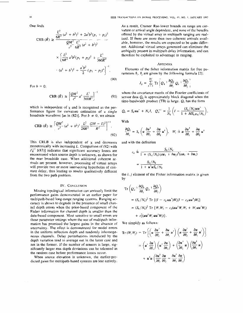
One finds As a result, Cramer-Rao lower bounds on range are cur- vature or arrival angle dependent, and none of the benefits offered by the virtual array in multipath ranging are real- ized. If there are more than two coherent arrivals avail- able, however, the results are expected to be quite differ-
c2 6R ent. Additional virtual arrays generated can eliminate the ambiguity present in multipath delay information, and can
L2 --j (a2 + b2)2 + 2a2b2(p, + p2)2
- 2 (a2 + b2)2
6R QM2 L2
CRB (2) 2
L4 360R4
x [g a2b2(p, + p2)2 + - therefore be exploited to advantage in ranging.
APPENDIX Elements of the fisher information matrix for free pa-
rameters Bit 0, are given by the following formula [2]: a2b2
(a2 + b212 + (p l + p2)4
F o r b = 0:
where the covariance matrix of the Fourier coefficients of sensor data Qk is approximately block diagonal when the time-bandwidth product (TB) is large. Qk has the form
2 L4 - 1
CRB (2) 1 [y a4 (91)
which is independent of x and is recognized as the per- formance figure for curvature estimation of a single Qk = SkuU' + NkI, Qil = - (I- broadside wavefront [as in (82)]. For b # 0, we obtain N k
With CRB (8) I [T (a2 + b2)2
This CRLB is also independent of x and decreases monotonically with increasing L. Comparison of (92) with JRI [(87)] indicates that significant accuracy losses are
the near broadside case. When additional coherent ar-
and with the definition
sk / Nk
1 + (sk/Nk)(auI + b u ~ ) ~ ( a u l + bud ck encountered when source depth is unknown, as shown for
rivals are present, however, processing of virtual arrays will provide two or more intersecting hyperbolas of con-
- - sk / N k
1 + UtUsk/Nk stant delay, thus leading to results qualitatively different from the two path problem. the i, j element of the Fisher information matrix is given
by
IV. CONCLUSION Missing topological information can seriously limit the
performance gains demonstrated in an earlier paper for multipath-based long-range ranging systems. Ranging ac- curacy is shown to degrade in the presence of small chan- nel depth errors when the prior-based component of the Fisher information for channel depth is smaller than the data-based component. Most sensitive to small errors are those parameter settings where the use of multipath infor- mation has promised the largest gains in the absence of uncertainty. The effect is demonstrated for model errors in the uniform reflection depth and randomly inhomoge- neous channels. Delay perturbations introduced by the depth variation tend to average out in the latter case and not in the former. If the number of sensors is large, sig- nificantly larger rms depth deviations can be tolerated in the random case before performance losses occur.
When source elevation is unknown, the earlier-pre- dicted gains for multipath-based systems are lost entirely.
+ C:(UU+W u u f W J }
We simplify as follows:
aut au aut au
aei aei ae, ae, Tr (W,W,) = Tr [(U - + - U') (U - + - U')]
ae
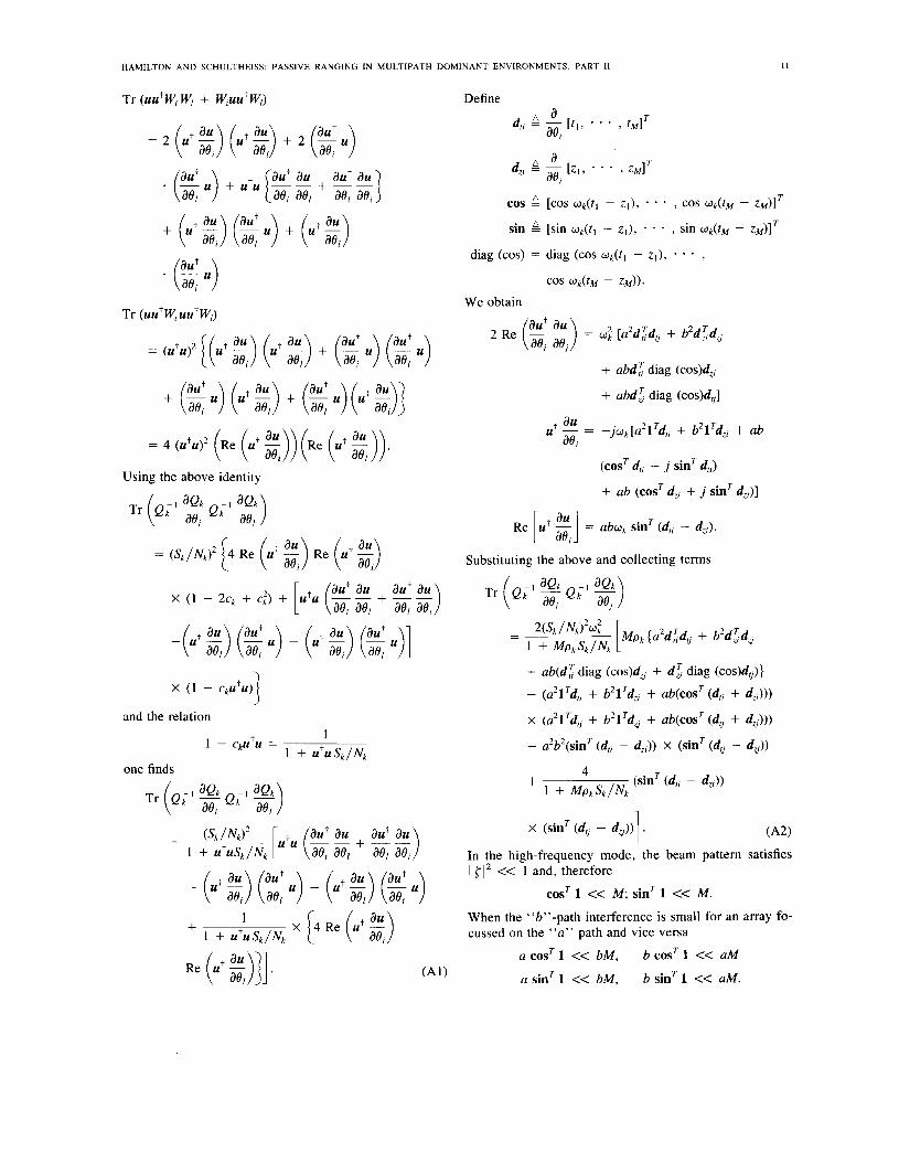
HAMILTON AND SCHULTHEISS: PASSIVE RANGING IN MULTIPATH DOMINANT ENVIRONMENTS. PART 11
Tr (uutW, W, + W,uutWl)
Tr (uutW,uutWl)
= {(U' g) (ut g) + ($ .) (% .)
Using the above identity
Define
2 Re - - = W: [a2d:drj + b*d;d, (;: aa;) + a b d i diag (cos&
+ abd; diag COS)^,.]
au ae; ut - = -jWk[a21Td,; + b2lTd,; + ab
(cosT d,, - j sinT d,;)
+ ab (cosT dzj + j sinT d,;)]
Re U+ - = abwk sinT (dlf - d,;). L :;;I Substituting the above and collecting terms
+ ab(d: diag (cos)d, + d ; diag (cos)dG)}
- (a21Tdti + b21Td,; + ab(cosT (d,; + d,;)))
x (a21TdG + b21Td,. + ab(cosT(dG + d,)))
- a2b2(sinT (d,; - d,;)) X (sinT (dG - d,))
(sinT (d,; - 4;)) 4 + 1 + Mpksk/Nk
x (sinT(d,, - d,)) 1 . ( A 2 )
In the high-frequency mode, the beam pattern satisfies 1 { I 2 << 1 and, therefore
cosT 1 << M; sinT 1 << M. When the "b"-path interference is small for an array fo- cussed on the "a" path and vice versa
a cosT 1 << bM, b cosT 1 << aM ('41) a sinT 1 << bM. b sinT 1 << aM.
12 IEEE TRANSACTIONS ON SIGNAL PROCESSING. VOL. 41, NO. 1 . JANUARY 1993
If the fractional change of at,/ae, and &,/de, over the array is small (at long ranges this will be very likely) then
ad; COS << bd:l,
ad: sin << bd l l ,
bdl’, cos << adcl
bdl‘, sin << adg1.
Then Pk z a2 + b2. Substituting the above into (A2) and carrying out indicated operations, we obtain
+ b2 (2 - $)) X (a2 (: - 2) + b2 ($ - %)) -k 2a2b2 ($ - 2) (2 - (A3)
In the low-frequency mode, multipath delays differ over the extent of the array by factors smaller than a signal wavelength so that
cos = cos Wk(t1 - ZJl,
sin G sin uk(tl - z l ) l
diag (cos) z cos uk(tl - z l ) l .
We then obtain
+ ab cos uk(tl - zl) x - - - [(:; a,;)
The delays (t l , zI) are implicit functions of range and the nuisance parameters cp. To obtain the elements of JD [(13) and (14)], the cp average in (A3) and (A4) must be carried out. For cp distributions sharply peaked about the nominal values of delay, this amounts to replacing the random variables (t,, z,) of (A3) and (A4) by their means or nom- inal values.
REFERENCES
[ I ] M. Hamilton and P. M. Schultheiss, “Passive ranging in multipath dominated environments, part I: known multipath parameters,” IEEE Trans. Acous t . , Speech, Signal Processing, vol. 40, no. I , pp. 1-12, Jan. 1992.
[21 M. Hamilton, “Exploitation of multipath arrivals in passive rang- ing,” Ph.D. dissertation, Yale Univ., New Haven, CT, 1986.
[3] Y. Rockah, “Array processing in the presence of uncertainty,” Ph.D. dissertation, Yale Univ., New Haven, CT, 1986.
[4] B. Friedlander, “Accuracy of source localization using multipath de- lays,” IEEE Trans. Aerosp. Electron. Sysr., vol. 24, no. 4 , pp. 346- 359, July, 1988.
[SI K . F. Gong and J. S. Davis, “Evaluation of target motion analysis in a multipath environment,” Naval Underwater, Technical Report 4814 Naval Underwater Systems Center, Newport, RI, Mar. 1976.
[61 R. L. Moose and T. E. Dailey. “Adaptive underwater target-tracking using multipath time-delay measurements,” IEEE Trans. Acousr., Speech, Signal Processing, vol. ASSP-33, no. 4, pp. 777-787, Aug. 1985.
[7] N. L. Owsley and G. R. Swope, “Time delay estimation in a sensor array,” IEEE Trans. Acous t . , Speech, Signal Processing, vol. ASSP- 29, no. 3, pp. 519-523, June 1981.
(XJ B . kriedlander, ”Depth estimation from multipath delay measure- ments,” Systems Control Tech. Technical Report, June 1985.
[9] R. N. Baer and M. J. Jacobson, “Sound transmission in a channel with bilinear sound speed and environmental variations,” J . Acoust. Soc. Amer. , vol. 54, no. I . pp. 80-91, 1973.
[ I O ] K . G. Hamilton, W. L. Siegmann, and M. J. Jacobson, “Effects of tidally varying sound speed on acoustic propagation over a sloping ocean bottom,” J . Acoust. Soc. A m e r . , vol. 66, no. 4, pp. 1108- 1 1 19, Oct. 1979.
[ I I ] B. K . Newhall, M. J . Jacobson, and W. L. Siegmann, “Effect of a random ocean current on acoustic transmission in an isospeed chan- nel,” J . Acoust. Soc. A m e r . , vol. 62, no. 5 , pp. 1165-1 175, Nov. 1977.
(121 E. R. Franchi and M. J. Jacobson, “Ray propagation in a channel with depth-variable sound speed and current, part 2 ,” J . Acoust. Soc. Amer. , vol. 52, no. I , pp. 316-331, 1972.
[I31 J. A. Widtfeldt and M . J . Jacobson, “Acoustic phase and amplitude of a signal transmitted through a uniform flow in the deep ocean.” J . Acoust. Soc. A m e r . , vol. 59, no. 4, pp. 852-860, Apr. 1976.
1141 L. A. Stallworth and M. J . Jacobson, “Acoustic propagation in a uniformly moving ocean channel with depth-dependent sound speed, part 2,” J . Acousr. Soc. A m e r . , vol. 52, no. I , pp. 344-355, 1972.
1151 H. L. Van Trees, Detecrion, Estimation and Modulation Theory, Part I . New York: Wiley, 1968. pp. 74-84.
Miriam Hamilton (S’82-M’84) received the B.E. degree in electrical engineering from Stevens In- stitute of Technology, Hoboken, NJ, in 1977, and the M.S. and Ph.D. degrees in electrical engi- neering from Yale University, New Haven, CT, in 1981 and 1986, respectively.
From 1986 to 1987 she was a Postdoctoral Fel- low at the Naval Underwater Systems Center, New London, CT. From 1987 to 1991 she was at Tem- ple University, Philadelphia, PA, as Assistant Professor of Electrical Engineering. Since 1992,
she has been with the Lincoln Laboratory, MIT, Lexington, MA, as a Staff Member. Her research interests include array processing and communica- tion theory.
Peter M. Schultheiss (M’86-SM’90) was born in Munich, Germany, in 1924. He received the B.E. and Ph.D. degrees from Yale University, New Haven, CT, in 1945 and 1952, respectively.
Since 1947 he has been on the faculty of Yale University, where he is currently a Professor of Electrical Engineering. His research interests have centered on problems in detection and estimation theory with recent emphasis on the use of sensor arrays for the localization of radiating sources.
Copyright © 2022 FDOKUMEN