
unknown, 3, en_GB - Hemeltron
28
Electrical wiring Read the instructions prior to performing any task! REMKO series WKF NEO-compact WKF NEO-compact 70, WKF NEO-compact 120, WKF NEO-compact 180 Smart heat pumps 0188-2019-04 Edition 3, en_GB Instructions for Technicians Air/water system for heating or cooling
-
Upload
khangminh22 -
Category
Documents
-
view
0 -
download
0
Transcript of unknown, 3, en_GB - Hemeltron

Electrical wiring
Read the instructions prior to performing any task!
REMKO series WKF NEO-compact
WKF NEO-compact 70, WKF NEO-compact 120, WKF NEO-compact 180
Smart heat pumps
0188-2019-04 Edition 3, en_GB
Instructions for Technicians
Air/water system for heating or cooling

R410ARefrigerant
Translation of the original
Read these operating instructions carefully before commis-sioning / using this device!These instructions are an integral part of the system and mustalways be kept near or on the device.Subject to modifications; No liability accepted for errors or mis-prints!

Table of contents1 Safety and usage instructions............................................................................................................. 4
1.1 General safety notes....................................................................................................................... 41.2 Identification of notes...................................................................................................................... 41.3 Personnel qualifications.................................................................................................................. 41.4 Dangers of failure to observe the safety notes................................................................................ 41.5 Safety-conscious working............................................................................................................... 41.6 Safety notes for the operator........................................................................................................... 51.7 Safety notes for installation, maintenance and inspection.............................................................. 51.8 Unauthorised modification and changes......................................................................................... 51.9 Intended use................................................................................................................................... 51.10 Warranty........................................................................................................................................ 51.11 Transport and packaging............................................................................................................... 61.12 Environmental protection and recycling........................................................................................ 6
2 Electrical wiring..................................................................................................................................... 72.1 System layout WKF NEO 70........................................................................................................... 72.2 System layout WKF NEO 120......................................................................................................... 82.3 System layout WKF NEO 180......................................................................................................... 92.4 Overview of electrical cables......................................................................................................... 102.5 Electrical connection general notes.............................................................................................. 122.6 Electrical connection - indoor unit................................................................................................. 132.7 Electrical connection - outdoor unit............................................................................................... 132.8 Electrical configuration - I/O module - WKF NEO compact 70/120/180........................................ 162.9 Terminal assignment / legend - WKF NEO compact 70/120/180.................................................. 172.10 Circuit diagrams - WKF NEO compact 70/120/180..................................................................... 19
3 Index..................................................................................................................................................... 25
3

1 Safety andusage instructions
1.1 General safety notesCarefully read the operating manual before com-missioning the units for the first time. It containsuseful tips and notes such as hazard warnings toprevent personal injury and material damage.Failure to follow the directions in this manual notonly presents a danger to people, the environmentand the system itself, but will void any claims forliability.Keep this operating manual and the refrigerantdata sheet near to the units.
1.2 Identification of notesThis section provides an overview of all importantsafety aspects for proper protection of people andsafe and fault-free operation.The instructions andsafety notes contained within this manual must beobserved in order to prevent accidents, personalinjury and material damage.Notes attached directly to the units must beobserved in their entirety and be kept in a fullylegible condition.Safety notes in this manual are indicated by sym-bols. Safety notes are introduced with signal wordswhich help to highlight the magnitude of the dangerin question.
DANGER!
Contact with live parts poses an immediatedanger of death due to electric shock. Damageto the insulation or individual components maypose a danger of death.
DANGER!This combination of symbol and signal wordwarns of a situation in which there is immediatedanger, which if not avoided may be fatal orcause serious injury.
WARNING!This combination of symbol and signal wordwarns of a potentially hazardous situation,which if not avoided may be fatal or causeserious injury.
CAUTION!This combination of symbol and signal wordwarns of a potentially hazardous situation,which if not avoided may cause injury or mate-rial and environmental damage.
NOTICE!This combination of symbol and signal wordwarns of a potentially hazardous situation,which if not avoided may cause material andenvironmental damage.
This symbol highlights useful tips and recom-mendations as well as information for efficientand fault-free operation.
1.3 Personnel qualificationsPersonnel responsible for commissioning, opera-tion, maintenance, inspection and installation mustbe able to demonstrate that they hold a qualifica-tion which proves their ability to undertake thework.
1.4 Dangers of failure to observethe safety notes
Failure to observe the safety notes may pose a riskto people, the environment and the units. Failure toobserve the safety notes may void any claims fordamages.In particular, failure to observe the safety notesmay pose the following risks:n The failure of important unit functions.n The failure of prescribed methods of mainte-
nance and repair.n Danger to people on account of electrical and
mechanical effects.
1.5 Safety-conscious workingThe safety notes contained in this manual, theexisting national regulations concerning accidentprevention as well as any internal companyworking, operating and safety regulations must beobserved.
REMKO series WKF NEO-compact
4

1.6 Safety notes for the operatorThe operational safety of the units and compo-nents is only assured providing they are used asintended and in a fully assembled state.n The units and components may only be set up,
installed and maintained by qualified per-sonnel.
n Protective covers (grille) over moving partsmust not be removed from units that are inoperation.
n Do not operate units or components withobvious defects or signs of damage.
n Contact with certain unit parts or componentsmay lead to burns or injury.
n The units and components must not beexposed to any mechanical load, extremelevels of humidity or extreme temperature.
n Spaces in which refrigerant can leak sufficientto load and vent. Otherwise there is danger ofsuffocation.
n All housing parts and device openings, e.g. airinlets and outlets, must be free from foreignobjects, fluids or gases.
n The units must be inspected by a service tech-nician at least once annually. Visual inspec-tions and cleaning may be performed by theoperator when the units are disconnected fromthe mains.
1.7 Safety notes for installation,maintenance and inspection
n Appropriate hazard prevention measures mustbe taken to prevent risks to people when per-forming installation, repair, maintenance orcleaning work on the units.
n The setup, connection and operation of theunits and its components must be undertakenin accordance with the usage and operatingconditions stipulated in this manual and complywith all applicable regional regulations.
n Local regulations and laws such as WaterEcology Act must be observed.
n The power supply should be adapted to therequirements of the units.
n Units may only be mounted at the points pro-vided for this purpose at the factory. The unitsmay only be secured or mounted on stablestructures, walls or floors.
n Mobile units must be set up securely on suit-able surfaces and in an upright position. Sta-tionary units must be permanently installed foroperation.
n The units and components should not be oper-ated in areas where there is a heightened riskof damage. Observe the minimum clearances.
n The units and components must be kept at anadequate distance from flammable, explosive,combustible, abrasive and dirty areas oratmospheres.
n Safety devices must not be altered orbypassed.
1.8 Unauthorised modificationand changes
Modifications or changes to units and componentsare not permitted and may cause malfunctions.Safety devices may not be modified or bypassed.Original replacement parts and accessoriesauthorised by the manufactured ensure safety. Theuse of other parts may invalidate liability forresulting consequences.
1.9 Intended useDepending on the model, the equipment and theadditional fittings with which it is equipped is onlyintended to be used as an air-conditioner for thepurpose of cooling or heating the air in anenclosed room.Any different or additional use shall be classed asnon-intended use. The manufacturer/supplierassumes no liability for damages arising from suchuse. The user bears the sole risk in such cases.Intended use also includes working in accordancewith the operating and installation instructions andcomplying with the maintenance requirements.
Under no circumstances should the thresholdvalues specified in the technical data be exceeded.
1.10 WarrantyFor warranty claims to be considered, it is essentialthat the ordering party or its representative com-plete and return the "certificate of warranty" toREMKO GmbH & Co. KG at the time when theunits are purchased and commissioned.The warranty conditions are detailed in the "Gen-eral business and delivery conditions". Further-more, only the parties to a contract can concludespecial agreements beyond these conditions. Inthis case, contact your contractual partner in thefirst instance.
5

1.11 Transport and packagingThe devices are supplied in a sturdy shipping con-tainer. Please check the equipment immediatelyupon delivery and note any damage or missingparts on the delivery and inform the shipper andyour contractual partner. For later complaints cannot be guaranteed.
WARNING!Plastic films and bags etc. are dangeroustoys for children!Why:- Leave packaging material are not around.- Packaging material may not be accessible tochildren!
1.12 Environmental protectionand recycling
Disposal of packagingAll products are packed for transport in environ-mentally friendly materials. Make a valuable contri-bution to reducing waste and sustaining raw mate-rials. Only dispose of packaging at approvedcollection points.
Disposal of equipment and componentsOnly recyclable materials are used in the manufac-ture of the devices and components. Help protectthe environment by ensuring that the devices orcomponents (for example batteries) are not dis-posed in household waste, but only in accordancewith local regulations and in an environmentallysafe manner, e.g. using certified firms and recy-cling specialists or at collection points.
REMKO series WKF NEO-compact
6

2 Electrical wiring2.1 System layout WKF NEO 70
B
A
4
3
2a
2b
2c
1c
1d
1b1a
1
2
Fig. 1: System layout WKF NEO 70
A: Outdoor areaB: Indoor area1: Indoor unit1a: Heating inlet flow (11/4" AG)1b: Heating return flow (11/4" AG)1c: Power supply, indoor unit
= 230V/1~/50Hz, 10A (e.g. 3 x 1.5 mm2)1d: Mains supply line, electrical auxiliary heater
(e.g. 5 x 1.5 mm2)
2: Outdoor unit2a: Fan2b: Power supply, outdoor unit
= 230V/1~/50Hz, 16A (e.g. 3 x 2.5 mm2)2c: Condensate tray, outdoor unit
(drain must be designed to be frost proof!)3: Control line, sheathed (e.g. 2 x 1 mm2)4: Refrigerant lines 3/8" and 5/8“
7

2.2 System layout WKF NEO 120
B
4
31c
1d
1
2
2a2b
2c
A
1b1a
Fig. 2: System layout WKF NEO 120
A: Outdoor areaB: Indoor area1: Indoor unit1a: Heating inlet flow (11/4" AG)1b: Heating return flow (11/4" AG)1c: Power supply, indoor unit
= 230V/1~/50Hz, 10A (e.g. 3 x 1.5 mm2)1d: Mains supply line, electrical auxiliary heater
(e.g. 5 x 1.5 mm2)
2: Outdoor unit2a: Fan2b: Power supply, outdoor unit
= 230V/1~/50Hz, 20A (e.g. 3 x 2.5 mm2)2c: Condensate tray, outdoor unit
(drain must be designed to be frost proof!)3: Control line, sheathed (e.g. 2 x 1 mm2)4: Refrigerant lines 3/8" and 5/8“
REMKO series WKF NEO-compact
8

2.3 System layout WKF NEO 180
B
5
41c
1d
1
2
A
2a
2b
2c
2a
1b1a
Fig. 3: System layout WKF NEO 180
A: Outdoor areaB: Indoor area1: Indoor unit1a: Heating inlet flow (11/4" AG)1b: Heating return flow (11/4" AG)1c: Power supply, indoor unit
= 230V/1~/50Hz, 10A (e.g. 3 x 1.5 mm2)1d: Mains supply line, electrical auxiliary heater
(e.g. 5 x 1.5 mm2)
2: Outdoor unit2a: Fan2b: Power supply, outdoor unit
= 400V/3~/50Hz, 3 x 16A (e.g. 5 x 1.5 mm2)2c: Condensate tray, outdoor unit
(drain must be designed to be frost proof!)3: Control line, sheathed (e.g. 2 x 1 mm2)4: Refrigerant lines 3/8" and 5/8“
9

The indoor and outdoor units have to be connectedwith refrigerant lines of dimensions (outer diam-eter) 3/8"(=9.52 mm) and 5/8"(=15.88 mm). At leasta two-wire control line has to be laid between thetwo modules. Both the indoor and outdoor unitsrequire a separate power supply.
WARNING!
All electric lines are in accordance VDE regula-tions to dimension and to lay.
2.4 Overview of electrical cablesWKF NEO 70 and WKF NEO 120
1A B C D
230V~/N/Pe
230V~/N/PeL1 N Pe L1 N Pe
400V/3~/N/PeL1 L2 L3 N Pe
E
Fig. 4: Overview of electrical cables
1: Main distributionA: Power supply outdoor unitB: Power supply indoor unitC: Power utility disable signal, potential-free /
open = lockedD: Power supply heating coil, 6 kW indoor unitE: Communication F1/F2 outdoor unit / indoor unit
2 x 1 mm2 sheathed
REMKO series WKF NEO-compact
10
WKF NEO 180
1A B C D
230V~/N/PeL1 N Pe
400V/3~/N/PeL1 L2 L3 N Pe
E
L1 L2 L3 N Pe400V/3~/N/Pe
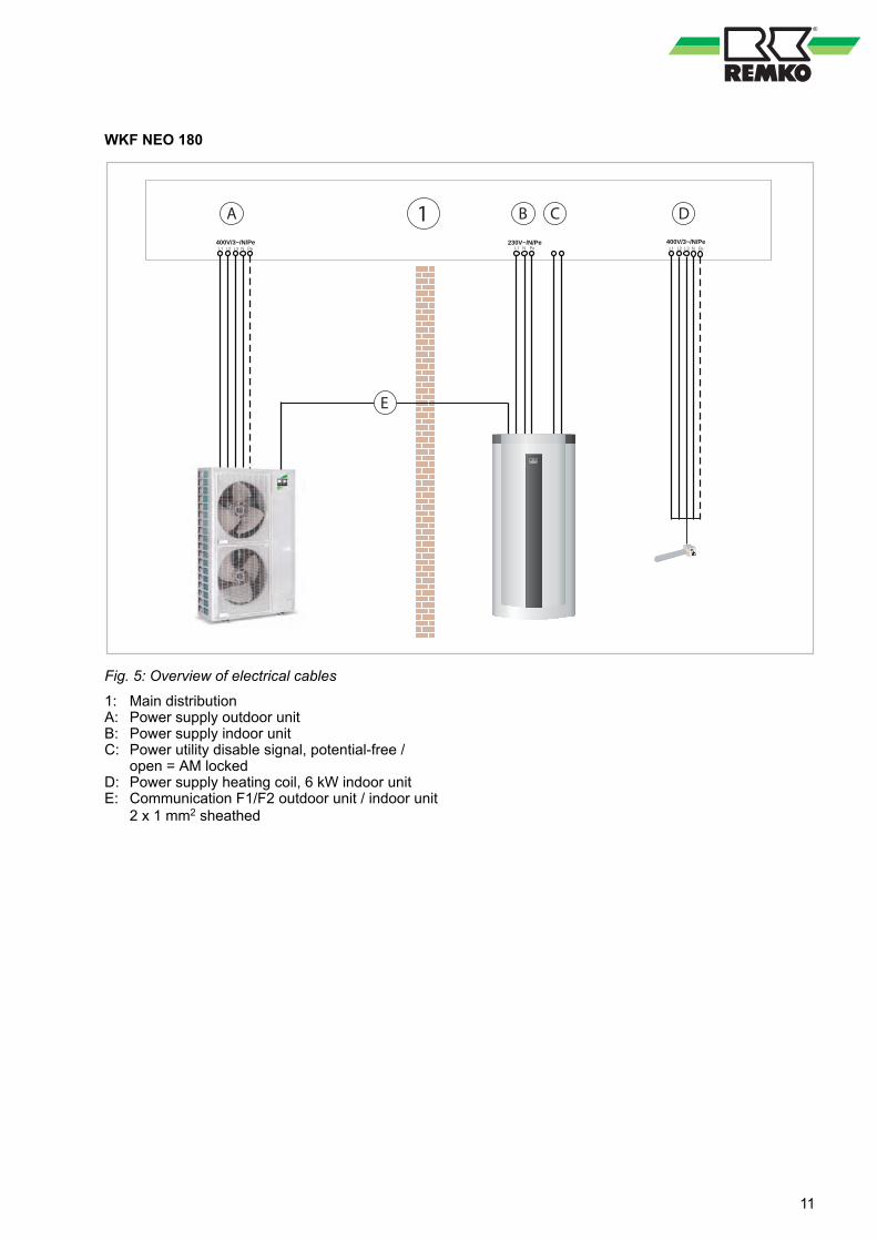
Fig. 5: Overview of electrical cables
1: Main distributionA: Power supply outdoor unitB: Power supply indoor unitC: Power utility disable signal, potential-free /
open = AM lockedD: Power supply heating coil, 6 kW indoor unitE: Communication F1/F2 outdoor unit / indoor unit
2 x 1 mm2 sheathed
11
2.5 Electrical connectiongeneral notes
n It is necessary to lay a mains cable both to theoutdoor unit and, separately, to the indoor unit.
n Power to the indoor units may not be discon-nected by the power company when fitted withan off-period circuit (anti-freeze protection).
n The indoor unit requires a single-phase 230V /50Hz power supply.The outdoor units of the WKF NEO 70and WKF NEO 120 require a 230V / 50Hzpower supply.The outdoor unit of the WKF NEO 180 requiresa three-phase 400V / 50Hz power supply.
n The electrical connection between outdoor andindoor units is made using a sheathed three-wire control line.
n Where applicable, a separate power supplyshall be provided to the indoor unit for the aux-iliary heater.
n The heat-pump manager needs to knowwhether a power-company enable or off-periodis in effect. A potential-free switch must be pro-vided by the customer for this purpose. (Con-tact closed signifies enabled, while contactopen signifies a blocking period).
n A connection schematic along with corre-sponding circuit diagrams can be found in the“Electrical layout” and “Circuit plans” chaptersof this manual.
n Special rates for the operation of heat pumpsmay be offered by the power-company (utility).
n Ask your local power utility about the details ofany rates that might be available.
DANGER!
All electrical installation work must be done byan electrician.
WARNING!
Always note the currently applicable VDEguidelines and the notes in TAB 2007. The sizeand type of the fuse are to be taken from thetechnical data.
WARNING!
All cable sizes are to be selected according toVDE 0100. Special attention should be given tocable lengths, cable type and the kind of instal-lation. The information in the connection dia-gram and in the system overview are to beseen as an acceptable installation possibilityonly in a standard case!
NOTICE!
Make sure to connect the outdoor unit neutralconnector properly, otherwise the varistors onthe line-filter circuit board will be destroyed.
NOTICE!The electrical connection for the units must bemade at a separate feedpoint with a residualcurrent device in accordance with local regula-tions and should be laid out by an electrician.
Check all plugged and clamped terminals toverify that they are seated correctly and makepermanent contact. Tighten as required.
REMKO series WKF NEO-compact
12

2.6 Electrical connection -indoor unit
The following instructions describe the electricalconnection of the indoor units.1. Remove the housing from the upper section
by pressing it upwards and pulling it forwardsout of the rear groove.
2. Guide the supply cable to the indoor unitsthrough the cable openings, and also routethe control line between indoor and outdoorunits and the cables for external devices andprobes into the indoor unit. Note that thecable openings in the WKF NEO 120 seriesare located above rather than below.
3. Connect the mains cable line of the indoorunits to the terminals.
4. Connect all secondary consumers(HGM,HGU, changeover valves etc.) to theI/O module.
NOTICE!
Attach cables in accordance with the connec-tion schematic and/or the circuit diagram in thecontrol box.
NOTICE!
Ensure correct polarity when connecting theelectrical leads, especially the control cable.
The number of lines and the sensors isdependent on the configuration of the heatingsystem and the components.
Make sure to use enough cable when installingthe indoor unit so that the control box can befully lowered for future maintenance.
At the site, avoid adding cable inlets.
2.7 Electrical connection -outdoor unit
n To connect up the electrics, remove the rightcladding panel after unfastening the screws.
1
Fig. 6: Series WKF NEO 70 and WKF NEO 120 -remove the cover by unfastening the screw
1: Screw
1
Fig. 7: Series WKF NEO 180 - remove the trimpanel by unfastening the screws
1: Screw
n Electrical protection for the system is imple-mented in accordance with the information inthe Technical Data. Observe the required con-ductor cross-sections!
n All cables must be connected with the correctpolarity and strain relief.
n Follow the connection schematic and the circuitdiagrams.
n The two-wire control line is to be connected toterminals F1, F2 and the earth terminal.
13
n When connecting the control line, make surethat polarity is correct.
n If the outdoor unit is installed on a roof, it andthe supporting structure must be earthed sepa-rately (connection to lightning conductors orfoundation earth/ground feature).
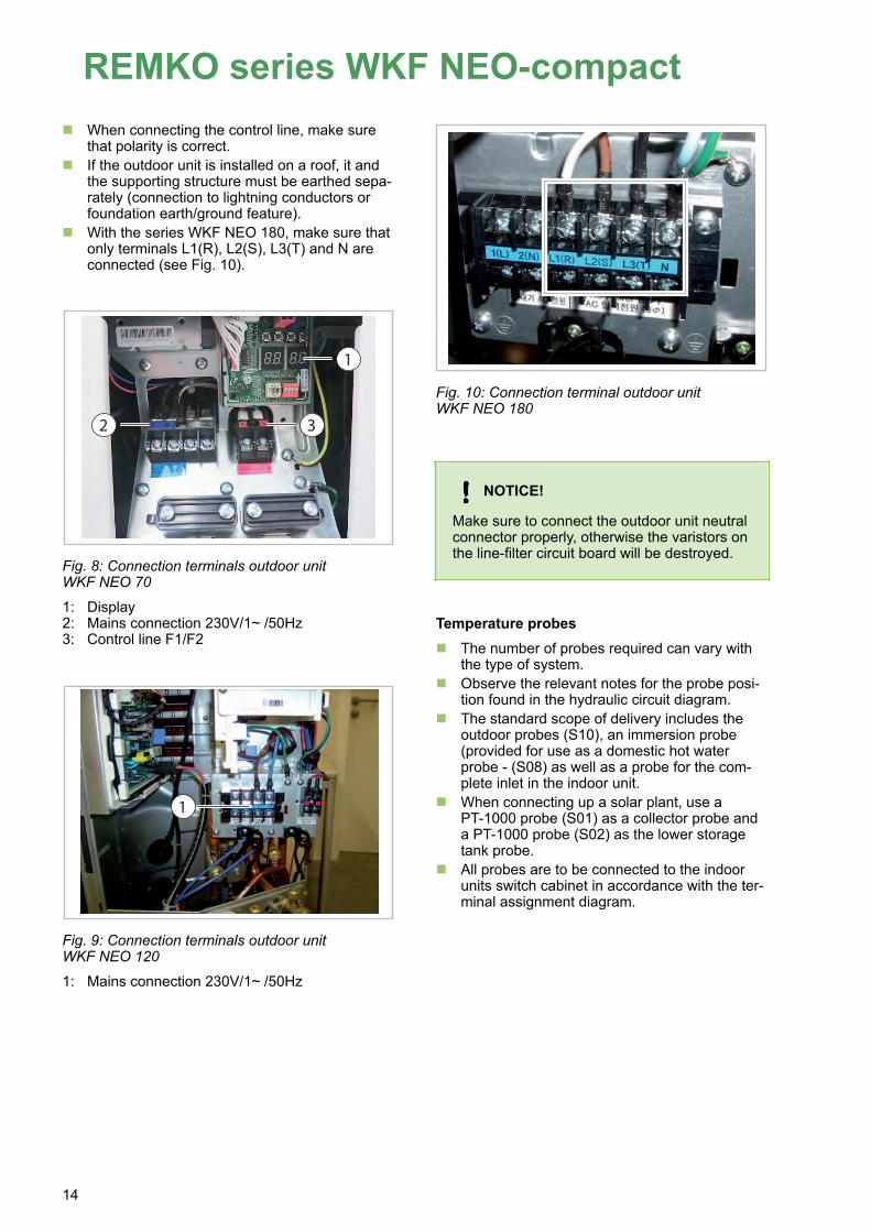
n With the series WKF NEO 180, make sure thatonly terminals L1(R), L2(S), L3(T) and N areconnected (see Fig. 10).
1
32
Fig. 8: Connection terminals outdoor unitWKF NEO 70
1: Display2: Mains connection 230V/1~ /50Hz3: Control line F1/F2
1
Fig. 9: Connection terminals outdoor unitWKF NEO 120
1: Mains connection 230V/1~ /50Hz
Fig. 10: Connection terminal outdoor unitWKF NEO 180
NOTICE!
Make sure to connect the outdoor unit neutralconnector properly, otherwise the varistors onthe line-filter circuit board will be destroyed.
Temperature probesn The number of probes required can vary with
the type of system.n Observe the relevant notes for the probe posi-
tion found in the hydraulic circuit diagram.n The standard scope of delivery includes the
outdoor probes (S10), an immersion probe(provided for use as a domestic hot waterprobe - (S08) as well as a probe for the com-plete inlet in the indoor unit.
n When connecting up a solar plant, use aPT-1000 probe (S01) as a collector probe anda PT-1000 probe (S02) as the lower storagetank probe.
n All probes are to be connected to the indoorunits switch cabinet in accordance with the ter-minal assignment diagram.
REMKO series WKF NEO-compact
14
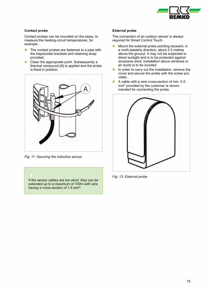
Contact probeContact probes can be mounted on the pipes, tomeasure the heating-circuit temperatures, forexample.n The contact probes are fastened to a pipe with
the trapezoidal brackets and retaining strapprovided.
n Clean the appropriate point. Subsequently athermal compound [A] is applied and the probeis fixed in position.
A
Fig. 11: Securing the inductive sensor
If the sensor cables are too short, they can beextended up to a maximum of 100m with wirehaving a cross-section of 1.5 mm².
External probeThe connection of an outdoor sensor is alwaysrequired for Smart Control Touch.n Mount the external probe pointing skyward, in
a north-easterly direction, about 2.5 metresabove the ground. It may not be subjected todirect sunlight and is to be protected againstexcessive wind. Installation above windows orair ducts is to be avoided.
n In order to carry out the installation, remove thecover and secure the probe with the screw pro-vided.
n A cable with a wire cross-section of min. 0.5mm2 provided by the customer is recom-mended for connecting the probe.
Fig. 12: External probe
15

2.8 Electrical configuration - I/O module - WKF NEO compact 70/120/180Use wire gauge corresponding with the connection cable supplied!Lay load lines separately to measuring lines!
2nd mixed cycleMixing valve 230 V
Closed
Open
Closed
Open
Closed
Open
Bypass valveIndoor unit 230 V
1st mixed cycleMixing valve 230 V
Circulation pumpHot water 230 V
Unmixed cyclePump 230 V (optional)
1st mixed cyclePump 230 V
Pump solar 230 V unregulated
Changeover valvePump, cooling
Pump 230 V 2nd mixed cycle
Not assigned
Changeover valve2. Heat generator (BVT)
Changeover valveHot water preparation
Power supply230 V
Power supplyInternal pump - indoor unit
Power supply I/0 module
Mains voltage connection provided by the customer from sub-distribution!
Outdoor unitWKF NEO 70 / 120230V/1~/N/PeE.g. 3 x 2.5 mm2
Outdoor unitWKF NEO 180400V/3~/N/PeE.g. 5 x 1.5 mm2
Potential-freeA34 Generalalarm signalA33 nofunctionA32 enable2. WE Smart BVT/Serv
A31 nofunctionA30 nofunction
Refrigerant
A24/25
S07
Solar return flow
S04
Solar storage tank, bottomS02
Solar collectorS01
Medium flow rate HPS24
Medium flow rate solarS23
Not
con
nect
ed
A22/23
A20/21
A04
A03
A02
A01
A14
A13
A12
A11
A10
NOTE: without blocking contactor, jumper must be insertedClosed = enableEnergy supply provider contact S16
Heat pump RF S152nd mixed cycle RF S14
Coding resistor RCHeat pump inlet S13
Communication Com-Kit 1 B2/A2
1st mixed cycle RF S111st mixed cycle inlet S12
Operating module SMT 1 B1/A1Outside temperature S10Storage tank, centre S09
Hot water probe S082nd mixed cycle inlet S06
Pump 0-10V A462nd mixed cycleCirculation S05Temperature or impulseSolar probe inlet S03
Pump PWM (indoor unit) A43Pump 0-10V (HGU) A42
Unmixed cyclePump 0-10V (HGM) A41
1st mixed cycleSpeed setting PWM A40
Solar pump
S29/GND
S28/GND
S27/GND
S26/GND
S25/GND
S0 PV feed-in(min. 500 lmp./kWh)
S0 PV yield(min. 500 lmp./kWh)
S0 household meter(min. 500 lmp./kWh)
S0 HP electricity meter(min. 500 lmp./kWh)
Sensor flow rate
SMT I/O
Power supply
Indoor module3 x 1,5 mm²
Assigned
AssignedAssignedAssignedAssigned
AssignedAssignedAssignedAssigned
AssignedAssigned
AssignedAssigned
EP
N
N
N
L
L
L
F1
F2
EP
N
N
N
1A 2A
ON
L3
L2
L1
T3
T2
T1
0
1
AssignedAssignedAssignedAssignedAssigned
Power supply
Electric heating coil 5 x 1,5 mm²
CommunicationOutdoor module
2 x 1,5 mm²
1A 2A
ON
L3
L2
L1
T3
T2
T1
0
1
REMKO series WKF NEO-compact
16

2.9 Terminal assignment / legend - WKF NEO compact 70/120/180
Designation Input Output Signal Description
PW X Power supply I/O module 230V
PP X Power supply primary pump, indoor unit
S01 X Solar probe collector
S02 X Solar probe storage tank, bottom
S03 X Solar probe inlet HM solar
S04 X Solar probe RF HM solar
S05 X Circulation RF temp./impulse
S06 X 2nd mixed cycle inlet probe
S07 X Probe refrigerant piping
S08 X Domestic hot-water tank
S09 X Probe storage tank centre(storage energy acquisition)
S10 X External probe
S11 X 1st mixed cycle return flow probe
S12 X 1st mixed cycle inlet probe
S13 X Heat pump inlet
S14 X 2nd mixed cycle return flow probe
S15 X Heat pump RF
S16 X Energy supplier contact (NC) / dew point monitoring(external)
S20 X Not connected
S21 X Not connected
S22 X Not connected
S23 X Ultrasonic flow rate meter Solar, pulse rate
S24 X Ultrasonic flow rate meter HP, impulse rate
S25 X HP electricity meter S0
S26 X Household electricity S0
S27 X Flow probe
S28 X PV yield electricity meter S0
S29 X PV in-feed electricity meter S0
A01 X Solar pump unregulated (230 V)
A02 X 1st mixed cycle, pump (230 V) switched
A03 X Unmixed cycle, pump (230 V) switched
A04 X Circulation pump
A10 X Changeover valve, drinking water
17
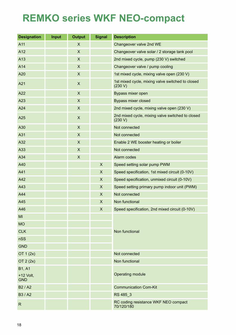
Designation Input Output Signal Description
A11 X Changeover valve 2nd WE
A12 X Changeover valve solar / 2 storage tank pool
A13 X 2nd mixed cycle, pump (230 V) switched
A14 X Changeover valve / pump cooling
A20 X 1st mixed cycle, mixing valve open (230 V)
A21 X 1st mixed cycle, mixing valve switched to closed(230 V)
A22 X Bypass mixer open
A23 X Bypass mixer closed
A24 X 2nd mixed cycle, mixing valve open (230 V)
A25 X 2nd mixed cycle, mixing valve switched to closed(230 V)
A30 X Not connected
A31 X Not connected
A32 X Enable 2 WE booster heating or boiler
A33 X Not connected
A34 X Alarm codes
A40 X Speed setting solar pump PWM
A41 X Speed specification, 1st mixed circuit (0-10V)
A42 X Speed specification, unmixed circuit (0-10V)
A43 X Speed setting primary pump indoor unit (PWM)
A44 X Not connected
A45 X Non functional
A46 X Speed specification, 2nd mixed circuit (0-10V)
MI
Non functional
MO
CLK
nSS
GND
OT 1 (2x) Not connected
OT 2 (2x) Non functional
B1, A1+12 Volt,GND
Operating module
B2 / A2 Communication Com-Kit
B3 / A2 RS 485_3
R RC coding resistance WKF NEO compact70/120/180
REMKO series WKF NEO-compact
18

2.10 Circuit diagrams - WKF NEO compact 70/120/180
PE
-X1/X2Spannungsversorgung 230V-> SMT I/O - Pin
PE
-X1/X2Spannungsv. 230VBauseits
NN
LL
3 -X1/X2Spannungsversorgung 230V-> ComKit - CN71
11 -X3
Kommunikation-> ComKit - CN31
2
Klemmblock
K1
X1.1
X1.2
X1.3
X1.4
X2.1
X2.2
X2.3
X3.1
X3.2
X4.1
X4.2
X4.3
X4.4
PE
N
N
N
L
L
L
F1
F2
PE
N
N
N
A2
14
6/T3
4/T2
2/T1
PE
N
N
N
L
L
L
F1
F2
PE
N
N
N
A1
13
5/L3
3/L2
1/L1
-XKlem
mblock
PE
-X4PE - Elektro HeizstabBauseits
In-K1Freigabe E-Heizer-> SMT I/O - A32 A32
L3
-K1Spannungsv. 400VBauseits
L2L1
STB 98°C�
Elektro Heizstab
-EHZ
Elektro Heizstab
WIC
HTIG
!
Bei einphasigem
Anschluss des Elektro H
eizstabs (3 x 230V)m
uss die Brücke zw
ischen X4.2, X4.3 und X4.4 entfernt und
jeweils ein N
eutralleiter angeschlossen werden.
Bei einphasigem
Anschluss des Elektro H
eizstabs (3 x 230V)m
uss die Brücke zw
ischen X4.2, X4.3 und X4.4 entfernt und
jeweils ein N
eutralleiter angeschlossen werden.
01
23
45
67
89
1011 1/5
WK
F NEO
01
23
45
67
89
1011
7/4/2018
Projekt Titel:
Terminal block
Electric heating element
Power supply 230V
Power supply 400V
Enable E-heater
PE - electric heating element
Terminal
block
STB 98°C
Electric heating element
-EHZ
Project title: W
KF N
EO
IMPO
RTAN
T!
With a single-phase connection of the electric heating elem
ent (3 x 230V), the jum
per between X4.2, X4.3 and X4.4 must be
removed and a neutral conductor m
ust be connected respectively.
Communication
Power supply 230V
Power supply 230VProvided by the customer
Provided by the customer
-> SMT I/O - A32
Provided by the customer
-> ComKit - CN31
-> ComKit - CN71
-> SMT I/O - Pin
19

PE-PinSpannungsv. 230V-> Klemmblock - X1/X2
NL
S0
Imp/kW
h
+
-
-S25Stromzähler S0Wärmepumpe 1 MPE
NL
-Pout1Versorgung 230VInterne Pumpe A43S0
Imp/kW
h
+
-
-S26Stromzähler S0Haushalt
13
1
4-S27Volumenstrom, Imp.Warmwasser
MNSPDP
-A10Umschaltventil 230VWarmwasserbereitung
S0
Imp/kW
h
+
-
-S28Stromzähler S0PV Ertrag
S0
Imp/kW
h
+
-
-S29Stromzähler S0PV Einspeisung
MNSPDP
-A11Umschaltventil 230V2. Wärmeerzeuger
U
t
-+
-A40Signal PWMSolarkreis
U
t
-+
-A41Signal 0-10V / PWM1. gem. Kreis
U
t
-+
-A42Signal 0-10V / PWMungem. Kreis
1 MPENL
-A13Pumpe 230V2. gem. Kreis
U
t
-+
-A43Signal PWMInterne Pumpe
Power
Actuator Output
Actuator Output
Actuator O
utputA
ctuator SupplySensor InputsActuator S
ignalActuator Signal
SPIO
T InterfacesBus Interfaces
Rc
Systemregler SM
T I/O
PENL
PENL
PENL
PENA10L
PENA11L
PENA12L
PENA13L
PENA14L
PENA01
PENA02
PENA03
PENA04
PENA20A21
PENA22A23
PENA24A25
S25+5VGND
S26+5VGND
S27+5VGND
S28+5VGND
S29+5VGND
GNDA40
GNDA41
GNDA42
GNDA43
GNDA44
GNDA45
GNDA46
MIMOCLKnSSGND
OT1OT1
OT2OT2
+12VB1A1GND
B2A2
B3A3
RGND
-SMT_I/O
_UN
TENSystem
regler
MNSPDP
-A14Umschaltventil 230VSeparater Kühlkreis
1 MPENL
-A01Pumpe 230VSolarkreisU
t
-+
-A46Signal 0-10V / PWM2. gem. Kreis 1 M
PENL
-A02Pumpe 230V1. gem. Kreis
1 MPENL
-A03Pumpe 230Vungem. Kreis
1 M
PENL
-A04Pumpe 230VTrinkwasser Zirkulation
+12V-12VSpannungsvers.-> SMT Touch - 12V GND
MNAufZu
-A20/A21Mischventil 230V1. gem. Kreis
2-B2/A2Kommunikation-> ComKit - CN33
1
MNAufZu
-A22/A23Ventil 230VBypass
B-B3/A3Kommunikation-> Raumsensor - B/A
A
12-RCKodierwiderstandGeräteabhängig
MNAufZu
-A24/A25Mischventil 230V2. gem. Kreis
Kodierwiderstände
WKF 70 -> 51 OhmWKF 120 -> 130 OhmWKF 180 -> 110 Ohm
WKF 70 -> 51 OhmWKF 120 -> 130 OhmWKF 180 -> 110 Ohm
01
23
45
67
89
1011 2/5
WK
F NEO
01
23
45
67
89
1011
7/4/2018
Projekt Titel:Project title:
WK
F NEO
7/4/2018
System controller SM
T I/O
Electricity meter S0
Power supply 230V
Power supply 230V
Changeover valve 230V
Changeover valve 230V
Pump 230V
Pump 230V
Pump 230V
Pump 230V
Pump 230V
Mixed valve 230V
Mixed valve 230V
Valve 230V
Changeover valve 230V
-Pin
-Pout1
Probe Inputs
Power
Actuator SupplyActuator O
utputActuator O
utputActuator O
utput
Actuator SignalActuator Signal
SPIO
T InterfacesBus Interfaces
Rc
Electricity meter S0
Electricity meter S0
Electricity meter S0
Signal PWM
Signal 0-10V / PWM
Signal 0-10V / PWM
Communication
Communication
Coding resistor
Coding resistorsWKF 70 -> 51 OhmWKF 120 -> 130 OhmWKF 180 -> 110 Ohm
Power supply
Signal 0-10V / PWM
Signal PWM
Medium flow rate, Imp.
Heat pump
-> Terminal block - X1/X2
Internal pump A43
Hot water preparation
2. Heat generator
2nd mixed circuit
Solar circuit
1st mixed circuit
Unmixed circuit
Drinking water circulation
1st mixed circuit
2nd mixed circuit
Bypass
Separate cooling circuit
Household
PV yield
PV feed-in
Solar circuit
1st mixed circuit
2nd mixed circuit
-> ComKit - CN33
-> Room sensor - B/A
Device-dependent
-> SMT Touch - 12V
Unmixed circuit
Internal pump
Hot water
System controller
-SMT_I/O
_BOTTO
M
GND
SP
Open
Open
Open
Closed
Closed
Closed
DP
N
MIMOCLKnSSGND
OT1
REMKO series WKF NEO-compact
20

13
1
4-S23Volumenstrom, Imp.Solarkreis
�
31
42
5
-S13/S24PT1000 / Vol. Imp.VL / Vol. Wärmep.
� 12-S01PT1000Kollektorfühler
� 12-S02PT1000Speicherfühler, Solar
RJ45-RJ45Kommunikation-> SMT Touch - RJ45
� 12-S03PT1000Vorlauf, Solar
� 12-S04PT1000Rücklauf, Solar
� 12-S05PT1000 / ImpulsZirkulation
� 12-S06PT1000Vorlauf, 2. gem. Kreis
� 12-S07PT1000Kältemittel Temperatur
� 12-S08PT1000Warmwasserspeicher
� 12-S09PT1000Pufferspeicher
� 12-S10PT1000Außentemperatur
� 12-S11PT1000Rücklauf, 1. gem. Kreis
� 12-S12PT1000Vorlauf, 1. gem. Kreis
A1
-A32Freigabe E-Heizer-> Klemmblock - K1
Potential Free Outputs
Sensor InputsSensor Inputs
Sensor InputsS
ensor Inputs
Systemregler SM
T I/O
InA30
InA31
InA32
InA33
InA34
S20+5VGNDS40S41
S21+5VGNDS42S43
S22+5VGNDS44S45
S23+5VGNDS46S47
S24+5VGNDS48S49
S01GND
S02GND
RJ45
S03GND
S04GND
S05GND
S06GND
S07GND
S08GND
S09GND
S10GND
S11GND
S12GND
S13GND
S14GND
S15GND
S16GND
-SMT_I/O
_OBEN
Systemregler
N
� 12-S14PT1000Rücklauf, 2. gem. Kreis
� 12-S15PT1000Rücklauf, Wärmepumpe
In -A34Potentialfreier KontaktSammelstörmeldungA34
S16-S16Brücke / Öffner-K.EVU Sperre GND
WICHTIG!
Bei Verwendung einerEVU Sperre darf nur derVerdichter Spannungslosgeschaltet werden!
Bei Verwendung einerEVU Sperre darf nur derVerdichter Spannungslosgeschaltet werden!
01
23
45
67
89
1011 3/5
WK
F NEO
01
23
45
67
89
1011
7/4/2018
Projekt Titel:Project title:
WK
F NEO
7/4/2018
System controller SM
T I/OProbe Inputs
Probe InputsProbe Inputs
Probe Inputs
Potential-Free Outputs
In
IMPORTANT!When using a power utility block, only power to compressor may be switched off!
System controller
-SMT_I/O
_TOP
Medium flow rate, Imp.
PT1000 / Vol. Imp.
PT1000
PT1000
PT1000
PT1000
PT1000
PT1000
PT1000
PT1000
PT1000
PT1000
PT1000
Jumper / NC terminal
Potential-free contact
Enable E-heater
PT1000 / Impulse
Communication
Solar circuit
LF / Vol. Heat Pump
Collector probe
Storage tank probe, Solar
Inlet, Solar
Return flow, Solar
Inlet, 2nd mixed circuit
Refrigerant temperature
Hot water storage tank
Buffer tank
Outside temperature
Return flow, 1st mixed circuit
Inlet, 1st mixed circuit
Return flow, 2nd mixed circuit
Heat pump return flow
Power utility block
General alarm signal
-> Terminal block - K1
Circulation
-> SMT Touch - RJ45
21
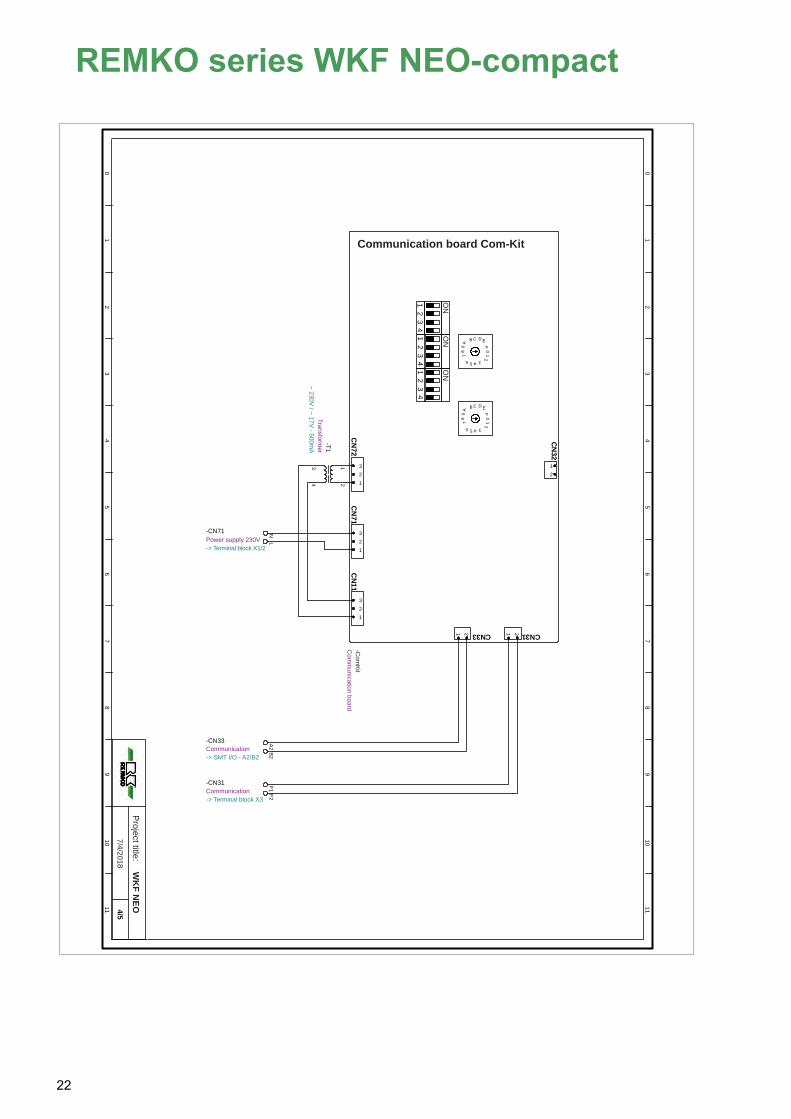
Kommunikationsplatine Com-Kit
CN
72C
N71
CN11
CN33 CN31
CN32
12
34
ON
ON
43
21
ON
43
21
0
4
8
C
26
A E
1
35
79
B D
FF
DB
97
5 3
1
EA
6 2
C
8
4
0
12
321
321
321
2121
-Com
KitKom
munikationsplatine
12
34
-T1Transform
ator~ 230V / ~ 17V - 500m
A
N-CN71Spannungsv. 230V-> Klemmblock X1/2
LA2
-CN33Kommunikation-> SMT I/O - A2/B2
B2F1
-CN31Kommunikation-> Klemmblock X3
F2
01
23
45
67
89
1011 4/5
WK
F NEO
01
23
45
67
89
1011
7/4/2018
Projekt Titel:Project title:
WK
F NEO
7/4/2018
Communication board Com-Kit
Transformer
ON
ON
ON
~ 230V / ~ 17V - 500mA
Power supply 230V
Communication
Communication
Com
munication board
-> Terminal block X1/2
-> SMT I/O - A2/B2
-> Terminal block X3
-Com
Kit
REMKO series WKF NEO-compact
22

USB-USBKommunikation-> LAN - / WLAN Adapter
Smart-Control TouchUSB
RJ45
GND+12V
-SMT_Touch
Bedienteil
RJ45-RJ45Kommunikation-> SMT I/O - RJ45
GND-12VSpannungsvers.-> SMT I/O - 12V +12V
Raumsensor
AV+V-B
-RS1
Raum
sensorungem
. Kreis
Raumsensor
AV+V-B
-RS2
Raum
sensor1. gem
. Kreis
Raumsensor
AV+V-B
-RS3
Raum
sensor2. gem
. Kreis
B3
-B/AKommunikation-> SMT I/O - B3/A3
A3
WIC
HTIG
!
Jeder Raum
sensor benötigt eine eindeutige Geräteadresse!
-> Siehe Bedienungsanleitung des R
aumsensors.
Jeder Raum
sensor benötigt eine eindeutige Geräteadresse!
-> Siehe Bedienungsanleitung des R
aumsensors.
01
23
45
67
89
1011 5/5
WK
F NEO
01
23
45
67
89
1011
7/4/2018
Projekt Titel:
Smart Control Touch
Room sensor
Room sensor
Room sensorProject title: W
KF N
EO7/4/2018
IMPO
RTAN
T!
Each room sensor requires a unique device address!
-> See the operating instructions for the room sensor.
Communication
Communication
Power supply
Communication
Room
sensorR
oom sensor
Room
sensor
Control elem
ent
-> LAN - / WLAN adapter
-> SMT I/O - RJ45
-> SMT I/O - 12V
-> SMT I/O - B3/A3
Unm
ixed circuit
1st mixed
circuit2nd m
ixed circuit
-SMT_Touch
23

Legend for the circuit diagrams
Abbreviations:EVU: Electrical power company /
power utilityGem.: MixedImp.: ImpulseÖffner-K. NC contactPV: PhotovoltaicPWM: Pulse width modulationRL: Return flowUngem.: UnmixedVL: InletVol. Medium flow rate
REMKO series WKF NEO-compact
24

3 IndexCCircuit diagrams
WKF NEO 70 . . . . . . . . . . . . . . . . . . . . . . . . 19WKF NEO 120 . . . . . . . . . . . . . . . . . . . . . . . 19WKF NEO 180 . . . . . . . . . . . . . . . . . . . . . . . 19
Contact probe . . . . . . . . . . . . . . . . . . . . . . . . . . 15
DDisposal of equipment . . . . . . . . . . . . . . . . . . . . . 6
EElectrical cables – overview
WKF NEO 70 . . . . . . . . . . . . . . . . . . . . . . . . 10WKF NEO 120 . . . . . . . . . . . . . . . . . . . . . . . 10WKF NEO 180 . . . . . . . . . . . . . . . . . . . . . . . 11
Electrical connection - indoor unitWKF NEO 70 . . . . . . . . . . . . . . . . . . . . . . . . 13WKF NEO 120 . . . . . . . . . . . . . . . . . . . . . . . 13WKF NEO 180 . . . . . . . . . . . . . . . . . . . . . . . 13
Electrical connection - outdoor unitWKF NEO 70 . . . . . . . . . . . . . . . . . . . . . . . . 13WKF NEO 120 . . . . . . . . . . . . . . . . . . . . . . . 13WKF NEO 180 . . . . . . . . . . . . . . . . . . . . . . . 13
Electrical system layoutWKF NEO 70 . . . . . . . . . . . . . . . . . . . . . . . . 16WKF NEO 120 . . . . . . . . . . . . . . . . . . . . . . . 16WKF NEO 180 . . . . . . . . . . . . . . . . . . . . . . . 16
Environmental protection . . . . . . . . . . . . . . . . . . . 6External probe . . . . . . . . . . . . . . . . . . . . . . . . . . 15
IIntended use . . . . . . . . . . . . . . . . . . . . . . . . . . . . 5
SSafety
Dangers of failure to observe the safetynotes . . . . . . . . . . . . . . . . . . . . . . . . . . . . . . . 4General . . . . . . . . . . . . . . . . . . . . . . . . . . . . . 4Identification of notes . . . . . . . . . . . . . . . . . . . 4Notes for inspection . . . . . . . . . . . . . . . . . . . . 5Notes for installation . . . . . . . . . . . . . . . . . . . . 5Notes for maintenance . . . . . . . . . . . . . . . . . . 5Personnel qualifications . . . . . . . . . . . . . . . . . 4Safety notes for the operator . . . . . . . . . . . . . 5Safety-conscious working . . . . . . . . . . . . . . . . 4Unauthorised modification . . . . . . . . . . . . . . . 5Unauthorised replacement part manufacture . 5
System layout . . . . . . . . . . . . . . . . . . . . . . . 7, 8, 9
TTemperature probes . . . . . . . . . . . . . . . . . . . . . 14Terminal assignment
WKF NEO 70 . . . . . . . . . . . . . . . . . . . . . . . . 17WKF NEO 120 . . . . . . . . . . . . . . . . . . . . . . . 17WKF NEO 180 . . . . . . . . . . . . . . . . . . . . . . . 17
WWarranty . . . . . . . . . . . . . . . . . . . . . . . . . . . . . . . 5
25

REMKO series WKF NEO-compact
26


REMKO QUALITY WITH SYSTEMSAir-Conditioning | Heating | New Energies
Telephone +49 (0) 5232 606-0 Telefax +49 (0) 5232 606-260
E-mail [email protected] URL www.remko.de
REMKO GmbH & Co. KG Klima- und Wärmetechnik
Im Seelenkamp 12 32791 Lage
Hotline within Germany +49 (0) 5232 606-0
Hotline International +49 (0) 5232 606-130
We
rese
rve
the
right
to
mak
e te
chni
cal c
hang
es, a
nd p
rovi
de n
o gu
aran
tee
as t
o th
e ac
cura
cy o
f th
is d
ata!


!['Pie Memorie' [An Unknown Motet by Noel Bauldeweyn]](https://static.fdokumen.com/doc/165x107/6334bb0b6c27eedec605dd06/pie-memorie-an-unknown-motet-by-noel-bauldeweyn.jpg)