Autonomous Robot Navigation in Unknown Maze Environment
44
Autonomous Robot Navigation in Unknown Maze Environment by Nur Aqilah binti Mustafa Dissertation submitted in partial fulfillment of the requirements for the Bachelor of Technology (Hons) (Information Communication Technology) MAY 2012 UniversitiTeknologi PETRONAS Bandar Seri Iskandar, 31750 Tronoh Perak Darul Ridzuan CERTIFICATION OF APPROVAL Autonomous Robot Navigation in Unknown Maze Environment
-
Upload
khangminh22 -
Category
Documents
-
view
4 -
download
0
Transcript of Autonomous Robot Navigation in Unknown Maze Environment

Autonomous Robot Navigation in Unknown Maze Environment
by
Nur Aqilah binti Mustafa
Dissertation submitted in partial fulfillment of
the requirements for the
Bachelor of Technology (Hons)
(Information Communication Technology)
MAY 2012
UniversitiTeknologi PETRONAS
Bandar Seri Iskandar,
31750 Tronoh
Perak Darul Ridzuan
CERTIFICATION OF APPROVAL
Autonomous Robot Navigation in Unknown Maze Environment

by
Nur Aqilah binti Mustafa
12131
A project dissertation submitted to the
Information and Communication Technology Programme
Universiti Teknologi PETRONAS
in partial fulfilment of the requirement for the
BACHELOR OF TECHNOLOGY (Hons)
(INFORMATION AND COMMUNICATION TECHNOLOGY)
Approved by,
_____________________(Dr. Jafreezal bin Jaafar)
UNIVERSITI TEKNOLOGI PETRONAS
TRONOH, PERAK
MAY 2012
CERTIFICATION OF ORIGINALITY

This is to certify that I am responsible for the work submitted in this project, that the original work is myown except as specified in the references and acknowledgements, and that the original work containedherein have not been undertaken or done by unspecified sources or persons.
____________________________NUR AQILAH BINTI MUSTAFA
Abstract
An autonomous robot navigation that is able to navigate itself in unknown maze environment. The objective
of this project is to design and develop an autonomous robot navigation using a selected algorithm which is
pledge algorithm by using the concept of obstacle avoidance besides studying its accuracy to solve the given
environment. The result of the chosen algorithm then is compared to Wall Following algorithm, a typical

algorithm used to solve obstacle avoidance maze. This project covers artificial intelligence field of study
and it is designed to solve the issue of robot limitation in feeling its surrounding and to make any decision
by its own. Thus, by using evolutionary prototyping, the author coded the chosen algorithm and tested on
the robot to see how it is going to react in the given environment especially when the walls are
disconnected. At the end of the report, the author concluded the project and recommends some improvement
or expansion that can be done in the future.
Acknowledgements
First and foremost, the author would like to thank Allah the Almighty for His bless and pleasure so that the
author can finish the project within the time frame with the given strength and health.
A big thanks to the author’s parents and family for all the support and courage materially and spiritually,
that contribute a lot along the way of doing this project. All the given motivation and prayers are the main
drive force for the author to always keep on moving.
Not to be forgotten, a special appreciation to the author’s supervisor, Dr. Jafreezal Jaafar for all the guidance
and advices to the author throughout the whole stages of the project. His undoubted dedication and
sacrifices have become the author’s inspiration especially during her hard times.
A big gratitude goes to the author’s Embedded System lecturer, Dr. Low Yan Jung and the author’s friend
from Electrical and Engineering department, Mr. Hazwan Syahmi Waginoh for their advices and ideas
especially in the hardware part. Special thanks also goes to Petrobots UTP club for their help and support to
the author along the way of finishing the project.
Last but not least the author would like to thank all her friends and those who are involved directly or
indirectly in this project for all the hands and prayers.
TABLE OF CONTENT
CHAPTER 1: INTRODUCTION . . . . . 1
1.1 Background of Study . . . . . 11.2 Problem Statement . . . . . 21.3 Objectives . . . . . 31.4 Scope of Study . . . . . 41.4 Related Research Questions . . . . 41.5 Relevancy of The Project . . . . 41.6 Feasibility of the Project . . . . 41.7 Conclusion . . . . . . 5
CHAPTER 2: LITERATURE REVIEW. . . . . 62.1 Definition and Types of Algorithm . . . 62.2 Algorithm for Robot Navigation . . . 7
CHAPTER 3: METHODOLOGY . . . . . 113.1 Research Methodology . . . 113.2 Project Activities . . . . . 123.3 Gantt Chart . . . . . . 14

3.4 Tools . . . . . . . 16
CHAPTER 4: RESULT AND DISCUSSION . . . 174.1 Findings . . . . . . 174.2 Data Gathering & Analysis . . . . 244.2 Experimentation/Modeling . . . . 32
CHAPTER 5: CONCLUSION AND RECOMMENDATIONS . 355.1 Conclusion. . . . . . . 355.2 Recommendation. . . . . . 35
REFERENCES. . . . . . . . 36
LIST OF FIGURES
Figure 2.1: The measurement of the angle of turn in the pledge algorithm
Figure 3.1: Phases in project planning
Figure 4.1: Example of wall maze with disjoint wall
Figure 4.2: General features of Pololu 3pi Robot, front view
Figure 4.3: General features of Pololu 3pi Robot, bottom view
Figure 4.4: Analog Distance Sensor
Figure 4.5: 3pi Simplified Schematic Diagram
Figure 4.6: 3pi Pololu with distance Sensor
Figure 4.7: Pledge algorithm concept
Figure 4.8: Path taken by using pledge algorithm
Figure 4.9: Path taken by using wall following algorithm
LIST OF TABLES
Table 3.1 Timeline for FYP I

Table 3.2 Timeline for FYP II
Table 4.1: Probability when Counter is zero
Table 4.2: Probability when Counter is not zero
Table 4.3: Effect of algorithm at disjoint maze
CHAPTER 1
INTRODUCTION
1.1 Background of Study
Exploration, also known as geographic expedition [1] is the act of exploring, penetrating, or ranging over
for purposes of discovery, especially of geographical discovery [2]. Land exploration, sea exploration and
space exploration have been very familiar to human being nowadays. New places are identified and
civilized, natural resources are detected and exploited, and more and more information about the outer space
world is gathered as the result of exploration.
Human explorers have begun land exploration since thousands of years ago as they have been fascinated by
the land beyond what they know [3].However, sending human to explore a new ‘untouched’ terrain like
dense forest is not necessarily a good option. They might be exposed to unforeseen dangerous and risks such
as wild animals attack, insufficient food supply, unknown infection, physical damage or even lost in the
deep jungle. Thus, sending robot instead of human to do exploration can be a better alternative since they
are more durable and resilient. Robot will not have problem neither on food supply nor infection and they
can withstand in a long duration mission.

Nevertheless, for a robot to discover a new place, it has to be intelligent enough to react with the
environment that it never been before. How it is going to navigate itself? What if it meets obstacle along the
way of its navigation? Which way it is going to choose? Obstacle can be defined as something immaterial
that stands in the way and must be circumvented or surmounted [4]. Consequently, robot needs to be
equipped with sensor for it to detect any input from the surroundings. A sensor is a device that measures a
physical quantity and converts it into a signal which can be read by an observer or by an instrument [5].
Plus, how the robot makes any decision will be based on the algorithm chosen. An algorithm is any set of
detailed instructions which results in a predictable end-state from a known beginning [6]. Therefore,
combination of sensor as the detector and algorithm as the decision making’s rule will help a robot to think
like a human and respond to the surrounding accordingly.
Though, what is the best algorithm to be applied for a robot to avoid any obstructions? Which algorithm will
result to the fastest and the smartest solution? Is the physical demography factors affect the algorithm
chosen? How the chosen algorithms have an effect on the robot’s way of thinking? All of the questions
arose will be the basis of the author’s work of research. Comparison on a few algorithms will be done to
find the best algorithm to be applied on the robot. The findings will be a beneficial reference for a new era
of robotic exploration and will assist others to understand the art of autonomous robot navigation in
unknown environment.
1.2 Problem Statement
1.2.1 Problem Identification
Sending a robot instead of human to do exploration will benefits people a lot especially in the area that is
not accessible by human due to safety and cost factor. However, robot naturally does not have capability to
feel its surrounding and to make any decision by its own specifically when having obstacle in front of it.
Thus, a right sensor should be used and plug in to the robot so that it can be eyes and ears for the robot. For
the robot to think diligently and react accordingly to what it feels in a very efficient way, the best algorithm
needs to be applied so that robot can compete human in the ability to reason and solve whatever problems
may arise.
1.2.2 Significant of the Project

Autonomous robot navigation in exploration brings a lot of positive impacts to human being. More
information about the place can be gathered without putting human on risk and even saving more money.
Besides, research on the best algorithm for a robot to navigate itself when facing obstacles can be a real
representation on how the robot will react in the actual unknown environment. The result will help on
determining the most applicable algorithm depending on the variation of variables and factors.
1.2.3 Proposed Solution
A few algorithms will be studied to know how they affect robot’s way of thinking. Then, the best algorithm
will be chosen and translated into programming language. The coded programming will be tested into the
robot to see how it solves a given maze by avoiding obstacles concept.
1.3 Objective
a) To investigate the use of chosen algorithm, pledge algorithm for robot navigation and obstacle
avoidance in unknown maze environment
b) To design and develop autonomous robot navigation using pledge algorithm for obstacle avoidance
c) To test and evaluate the accuracy of pledge algorithm in autonomous robot navigation
1.4 Scope of Study
The focus of this project is to study and choose the best algorithm to be implemented on the autonomous
robot navigation in obstacle avoidance focusing in disjoint wall maze. Thus, artificial intelligence
knowledge will be the main scope of study. Artificial intelligence is the branch of computer
science concerned with making computers behave like humans [7]. In this project, the robot will be
programmed based on the algorithm chosen to think and make its own decision on solving any problem
arises.
1.5 Related Research Question
a) How pledge algorithm can be used in autonomous robot navigation on unknown maze environment
b) What are the advantages of pledge algorithm over other algorithms?
1.6 Relevancy of the Project

This project covers study of algorithm and choosing the best one to solve autonomous robot navigation in
obstacles avoidance. This project will prove whether the chosen algorithm is able to solve unknown maze
environment by avoiding obstacles. Granting robot responsibility to explore new places and letting them
react and think like human being will surely open more good opportunity in exploration history.
1.7 Feasibility of the Project within the Scope and Time Frame
The narrow scope of the project makes it feasible to be achieved in the given time frame. A simple analysis
will be done on maximum three algorithms to see how they affect the robot’s decision in navigating in
unknown maze environment by avoiding obstacles. The best algorithm will be tested on the robot to see the
accuracy and the efficiency of the robot.
1.8 Conclusion
In conclusion, this project is designed to investigate the best algorithm to be implemented into autonomous
robot navigation in exploring unknown maze environment. A simple wall maze will be designed and
algorithms will be tested on the robot to see how it thinks and react whenever it confronts any physical
obstacles. The author hopes this project can contribute to the advancement of a new era of exploration.
Robot will be fully utilized to discover new untouched places without putting aside the benefit of the
exploration to the human being.
CHAPTER 2
LITERATURE REVIEW
2.1 Definition and Types of Algorithm
An algorithm is a specific set of instructions for carrying out a procedure or solving a problem, usually with
the requirement that the procedure terminate at some point[8]. Specific algorithms sometimes also go by the
name method, procedure, or technique. The word "algorithm" is a distortion of al-Khwarizmi, a Persian
mathematician who wrote an influential treatise about algebraic methods. The process of applying an
algorithm to an input to obtain an output is called a computation.
There are a few types of algorithms available. All these algorithms represent many ways of attacking a
problem. Algorithm type can be considered includes simple recursive algorithm, backtracking algorithm,

divide and conquer algorithm, dynamic programming algorithm, greedy algorithm, branch and band
algorithm, brute force algorithm and randomized algorithm[9]. They can be further defined as per below:
Dynamic Programming Algorithms: This class remembers older results and attempts to use this tospeed the process of finding new results.
Greedy Algorithms: Greedy algorithms attempt not only to find a solution, but to find the idealsolution to any given problem.
Brute Force Algorithms: The brute force approach starts at some random point and iterates throughevery possibility until it finds the solution.
Randomized Algorithms: This class includes any algorithm that uses a random number at any pointduring its process.
Branch and Bound Algorithms: Branch and bound algorithms form a tree of subproblems to theprimary problem, following each branch until it is either solved or lumped in with another branch.
Simple Recursive Algorithms: This type goes for a direct solution immediately, then backtracks tofind a simpler solution.
Backtracking Algorithms: Backtracking algorithms test for a solution; if a solution is found thealgorithm has solved, if not it recurs once and tests again, continuing until a solution is found[6].
Divide and Conquer Algorithms: A divide and conquer algorithm is similar to a branch and boundalgorithm, except it uses the backtracking method of recurring while dividing a problem intosubproblems.
2.2 Algorithm for Robot Navigation in Unknown Maze Environment
2.2.1 Random Mouse Algorithm
It is the simplest algorithm and does not require extra memory to implement. The robot will simply proceed
in a straight line until it reached an obstacle, which it will make a random decision about the next direction
to follow[10]. This algorithm simulate how a human randomly roaming a maze without memorizing where
he has been. It is the most inefficient maze solving method and the slowest solution ever as it is not
guaranteed to terminate or solve a maze. The pseudo code of this algorithm is per below:
Do{
If (topLeftSensor && topRightSensor != 1)Move forward;
Elserandomly choose any direction
}While ( All sensors != 1 )

2.2.2 Wall Following Algorithm
Wall Following Algorithm is a simple and the best-known rule for transverse maze, is also known as left-
hand rule or right-hand rule. In this algorithm, a robot will follow either the left or right wall as a guide
around the maze. If it encounters an opening in any of the walls picked up by its sensors, it will stop and
take a turn in that direction and then move forward sensing the walls again and keeping the wall as a guide.
The pseudo code for right-hand wall following algorithm as per below:
Upon arriving in a cell{
If there is an opening to the rightRotate right
Else if there is an opening aheadDo nothing
Else if there is an opening to the leftRotate left
ElseTurn around
}End If
Move forward one cell
However, this algorithm only best works if the maze is simply connected, that is, all the walls are connected
together or to the maze’s outer boundary. Then by keeping one hand in contact with one wall, the robot is

guaranteed not to get lost and will reach a different exit if there is one; otherwise it will return to the
entrance. Else, if the maze is not simply connected which for example the start and endpoints are in the
center of the structure or the pathways cross over and under each other, this method will not guaranteed to
help the goal to be reached[10].
2.2.3 Pledge Algorithm
Pledge algorithm is quite similar to Wall Following algorithm, and it includes wall following as part of its
solution. It is able to jump between islands that wall following cannot do. Besides, it is a non-heuristic
procedure for a point automaton to escape an unknown maze. It requires an arbitrarily fixed reference
direction to go toward for example north direction, not any position or distance information. Using this
reference direction, the robot measures its angle of turn while following a wall in the maze. When an
obstacle is made, one hand is kept along the obstacle while the angles turned are counted. When the robot is
facing the reference direction again, and the angular sum of turns made is 0, it will leaves the obstacle and
continues moving towards the reference direction[10].
Figure 2.1: The measurement of the angle of turn in the pledge algorithm
The measurement of the angle of turn is explained through the example in Figure 2.1. At location 1, the
robot is moving along a straight line towards the north. Here, let the cumulative angle of turn 0, measured

with respect to a north-south line, be zero. At location 4, the robot has completed a rotation in the counter-
clockwise direction and B is now +360 deg. At location 7, after a clockwise rotation the angle B becomes
zero again[10][11]. The pseudo code of this algorithm as per below:
Initialize a counter C to zero.
Do
{
If(topLeftSensor&& topRightSensor !=1)
Move Forward;
If(obstacle is detected)
{
wallFollowing Algorithm;
Increment counter C by +1 whenever the robot has made +360 degree angle of turn
(i.e. counter clockwise rotation), and -1 if the angle of turn is -360 degree
If(topLeftSensor&& topRightSensor !=1 && Counter==0)
Leave the wall
}
}
CHAPTER 3

METHODOLOGY
3.1 Research Methodology
The author has done some research on the best algorithm to be applied in this autonomous robot navigation
in unknown maze environment project and she find out that there are a lot of considerations have to be taken
in choosing the most suitable and appropriate algorithm. Besides, there are uncertainties on how the
algorithm will affect the robot’s way of thinking especially when it comes to the stage of coding the chosen
algorithm. Thus, the author has chosen Evolutionary Prototyping as the software lifecycle model to run this
project.
Evolutionary Prototyping is a lifecycle model in which a system is developed in increment so it can be
readily be modified in response to feedback or result collected. This project basically will involve a lot of
testing and simulating activities, where the aim is to ensure that the code tallies with the specified algorithm
chosen. Thus, by choosing this methodology, the author able to implement any result collected from every
testing with the code changes without disturbing any other activities planned in the methodology.
3.2 Project Activities
System PrototypeDesignAnalysisPlanning
Implementationand testing
System

Figure 3.1: Phases in project planning
3.2.1 Planning
Planning is the phase where the author makes initial identification on what is the real problem regarding
autonomous robot navigation in unknown maze environment and in what aspect the project should cover to
solve the issue. After identifying the purpose and the objective of the project, the methodology is chosen to
plan how the project will be run and what are the main activities involves, as well as the time line for every
activities so that this project will always be on track. The software and hardware involves are also defined in
this stage to make sure the project is really feasible and realistic.
3.2.2 Analysis
In the analysis phase, the background of the study is thoroughly identified, and study on the available
algorithm is also conducted. The limitations of the algorithms as well as the how it is going to affect
decision making made by the robot later on is analysed. Based on the analysis result, the best algorithm is
chosen to be implemented in design phase.
3.2.3 Design
Test case which defined how the simulation will be done to test the success rate of the robot solving maze
and also the design of the algorithm is being conducted in this phase. Data collected from analysis phase
before will be taken into account to make sure the project run in the desired manner. Designation phase will
produce system prototype which defined how the simulation of the autonomous robot navigation will be
done.

3.2.4 Implementation and Testing
In this phase, the selected algorithm will be coded into programming language and will be run into the robot
to test how it reacts in the system prototype. If the result does not meet the expectation, the author can
always come back to the design phase to verify any fault made earlier. This situation will loop until the
targeted result has been achieved.
3.3 Gantt Chart
Weeks 1 2 3 4 5 6 7 8 9 10 11 12 13 14
Selection
of Project
Topic
x x
Preliminary
Research
Work
x x x x
Submission
of
Extended
Proposal
Defence
x
Proposal
Defence
x
Project
Work
x x x x x

Continues
Submission
of Interim
Draft
Report
x
Submission
of Interim
Report
x x
Table 3.1 Timeline for FYP I
Weeks 1 2 3 4 5 6 7 8 9 10 11 12 13 14
Project Work
Continues
x x x x x x x
Submission of
Progress
Report
x
Project Work
Continues
x x x x
Pre-EDX x
Submission of
Draft Report
x x
Submission of
Dissertation
(softbound)
x
Oral
Presentation
x x
Submission of
Technical
Report
x

Submission of
Project
Dissertation
(hardbound)
x
Table 3.2 Timeline for FYP II
3.4 Tools
3.3.1 Hardware
- Laptop or desktop that support USB technology
- 4 or more AAA batteries
- AVR ISP programmer with 6 pin connector
- Pololu 3pi robot
- Sharp GP2D120XJ00F Analog Distance Sensor
- white card board
- ¾” black tape
- pencil and other drawing tools
3.3.2 Software
-WinAVR : a free open suite of development tools for the AVR family of microcontroller,
including the GNU GCC compiler for C and C++
-AVR Studio: Atmel free development environment(IDE) that natively works with
WnAVR’s free GCC or C++ compiler. Include AVR ISP software to let upload programs to
3pi

CHAPTER 4
RESULT AND DISCUSSIONS
4.1 Findings
Based on a few researches and studies on almost similar project before, the author found out a few
important components that should be given high attention to ensure the successful of the project. The
components are:
4.1.1 Maze
The wall maze was constructed to test the 3pi robot ability to detect the wall as the obstacles meanwhile
black line are added to the maze to enable the robot to follow wall following algorithm by using Integrated
QTR-RC Reflectance Sensors available on the robot due to limited number of distance sensor. The disjoint
maze was purposely design to see the robot ability and behavior while facing it. The example of the wall
maze is per below:
End

Figure 4.1: Example of wall maze with disjoint wall
4.1.2 Robot
Since this project combine both pledge algorithm and wall following algorithm by the means of line
following, the robot need to meet both requirement which is able to detect obstacles and line at the same
time. Thus, 3pi Pololu designed by Pololu Robotics and Electronics are chosen to complete the project
based on the specification and the ability of robot that was purposely constructed to solve both line
following and maze solving competition. However, since distance sensor which responsible to detect
obstacle is not mounted naturally to the 3pi robot, the author need to setup the sensor according to the
analog input ports available on the robot so that it can function wells. Subsections in this part will describe
more on the specification of 3pi and how the analog distance sensor is added.
4.1.2.1 3pi Pololu Specification
The Pololu 3pi robot is a small, high-performance, autonomous robot designed to excel in line-following
and line-mazesolving competitions. Powered by four AAA batteries and a unique power system that runs
the motors at a regulated 9.25 V, 3pi is capable of speeds up to 100 cm/second while making precise turns
and spins that don’t vary with the battery voltage. This results in highly consistent and repeatable
performance of well-tuned code even as the batteries run low. The robot comes fully assembled with two
micro metal gear motors, five reflectance sensors, an 8×2 character LCD, a buzzer, three user pushbuttons,
Start

and more, all connected to a user-programmable AVR microcontroller. The 3pi measures approximately 3.7
inches (9.5 cm) in diameter and weighs 2.9 oz (83 g) without batteries.
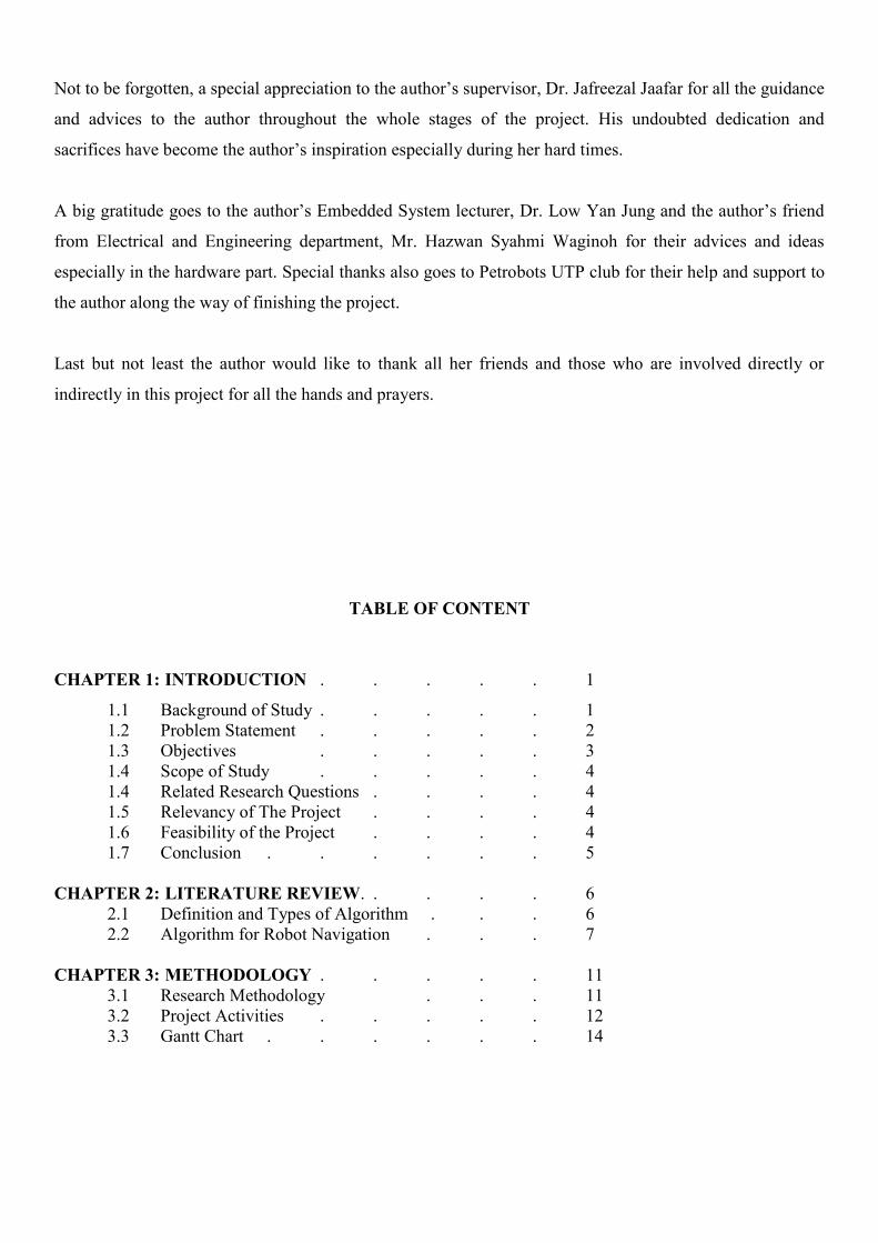
The 3pi is based on an Atmel ATmega168 or ATmega328 microcontroller, henceforth referred to as the
“ATmegaxx8”, running at 20 MHz. ATmega168-based 3pi robots feature 16 KB of flash program memory
and 1 KB RAM, and 512 bytes of persistent EEPROM memory; ATmega328-based 3pi robots feature 32
KB of flash program memory, 2 KB RAM, and 1 KB of persistent EEPROM memory[12]. Below are the
top and bottom view of Pololu 3pi robot:
Figure 4.2: General features of Pololu 3pi Robot, front view
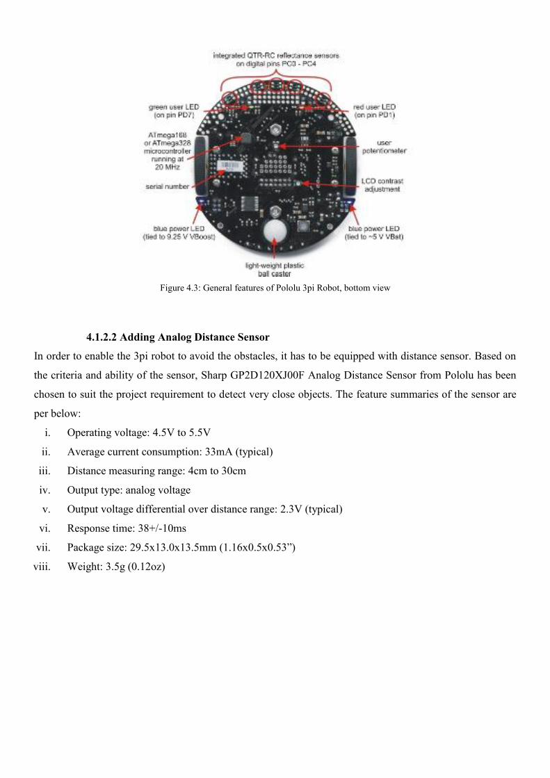
Figure 4.3: General features of Pololu 3pi Robot, bottom view
4.1.2.2 Adding Analog Distance Sensor
In order to enable the 3pi robot to avoid the obstacles, it has to be equipped with distance sensor. Based on
the criteria and ability of the sensor, Sharp GP2D120XJ00F Analog Distance Sensor from Pololu has been
chosen to suit the project requirement to detect very close objects. The feature summaries of the sensor are
per below:
i. Operating voltage: 4.5V to 5.5V
ii. Average current consumption: 33mA (typical)
iii. Distance measuring range: 4cm to 30cm
iv. Output type: analog voltage
v. Output voltage differential over distance range: 2.3V (typical)
vi. Response time: 38+/-10ms
vii. Package size: 29.5x13.0x13.5mm (1.16x0.5x0.53”)
viii. Weight: 3.5g (0.12oz)

Figure 4.4: Analog Distance Sensor
Port ADC7 at the 3pi circuit board has been recognized as the best analog input port for the distance sensor
based on the 3pi simplified schematic diagram below:
Figure 4.5: 3pi Simplified Schematic Diagram
To complete the connection of the distance sensor, the power and the ground port are connected to the
battery charger connector available on the robot. Figure 4.6 shows 3pi Pololu with distance sensor.

Figure 4.6: 3pi Pololu with distance Sensor
4.1.3 The Algorithm
Since the maze is a disjoint maze, two algorithms will be applied and hybrid to help the robot in making the
best decision which are wall following algorithm and pledge algorithm. Both algorithms will be applied by
using line following method instead of using the original wall following method, which distance sensor is
used to always detecting and keep the wall in a predefined distance. The two algorithms will be compared
and analysed to measure which algorithm apply best on a disjoint maze. As the wall following algorithm
can be divided into two types, right wall following and left wall following algorithm, the right wall
following is chosen randomly to be combined with pledge algorithm. The concept of pledge algorithm is as
per below diagram:

Figure 4.7: Pledge algorithm concept
4.2 Data Gathering/ Data Analysis
4.2.1 Wall Maze with Black Line
The author has decided to use combination of wall maze and line maze to achieve the project objective
which is to test robot ability to avoid distance and follow the wall by detecting line maze at the same time.
Wall maze is a maze that consisted of a few walls connected together to build a route that can be passed
through by the robot. Meanwhile, in this project, black line are stretched at the wall maze only at the
direction other than the ‘preferred’ direction to replace robot capability to follow the wall by using distance
sensor with only detecting the line maze through reflectance sensor. The maze is purposely designed to have
disjoint wall and “G-shaped” area to compare how both wall following algorithm and pledge algorithm has
an impact on the robot’s ways of thinking.
Building Wall Maze with Black Line
Initialize a counter C to zero
Move straight towards the North until anobstacle is met
On meeting an obstacle, turn left and followthe obstacle boundary. Increment counter by+90 whenever the robot has made a 90degclockwise rotation and vice versa
Leave an obstacle if(1) it is possible to movestraight towards the north and (2) the counter Creads zero
Figure 4.7: Pledge algorithm concept
4.2 Data Gathering/ Data Analysis
4.2.1 Wall Maze with Black Line
The author has decided to use combination of wall maze and line maze to achieve the project objective
which is to test robot ability to avoid distance and follow the wall by detecting line maze at the same time.
Wall maze is a maze that consisted of a few walls connected together to build a route that can be passed
through by the robot. Meanwhile, in this project, black line are stretched at the wall maze only at the
direction other than the ‘preferred’ direction to replace robot capability to follow the wall by using distance
sensor with only detecting the line maze through reflectance sensor. The maze is purposely designed to have
disjoint wall and “G-shaped” area to compare how both wall following algorithm and pledge algorithm has
an impact on the robot’s ways of thinking.
Building Wall Maze with Black Line
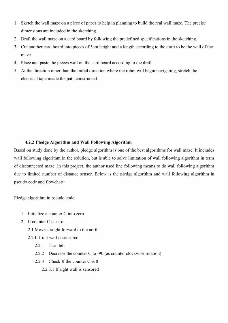
1. Sketch the wall maze on a piece of paper to help in planning to build the real wall maze. The precise
dimensions are included in the sketching.
2. Draft the wall maze on a card board by following the predefined specifications in the sketching.
3. Cut another card board into pieces of 5cm height and a length according to the draft to be the wall of the
maze.
4. Place and paste the pieces wall on the card board according to the draft.
5. At the direction other than the initial direction where the robot will begin navigating, stretch the
electrical tape inside the path constructed.
4.2.2 Pledge Algorithm and Wall Following Algorithm
Based on study done by the author, pledge algorithm is one of the best algorithms for wall maze. It includes
wall following algorithm in the solution, but is able to solve limitation of wall following algorithm in term
of disconnected maze. In this project, the author used line following means to do wall following algorithm
due to limited number of distance sensor. Below is the pledge algorithm and wall following algorithm in
pseudo code and flowchart:
Pledge algorithm in pseudo code:
1. Initialize a counter C into zero
2. If counter C is zero
2.1 Move straight forward to the north
2.2 If front wall is sensored
2.2.1 Turn left
2.2.2 Decrease the counter C to -90 (as counter clockwise rotation)
2.2.3 Check If the counter C is 0
2.2.3.1 If right wall is sensored

2.2.3.1.1 Turn 180deg to the back
2.2.3.1.2 Increase the counter C to +180 (as clockwise rotation)
2.2.3.1.3 Check If the counter C is 0
2.2.3.2 Else
2.2.3.2.1 Move forward
2.2.3.2.2 Check If the counter C is 0
2.2.4 Else
2.2.4.1 Move forward
2.2.4.2 Check If the counter C is 0
2.3 Else
2.3.1 Move forward
2.3.2 Check If the counter C is 0
3. Else
3.1 Move forward according to the line
3.2 If preferred side is open
3.2.1 Turn to the right
3.2.2 Increase the counter C to +90 (as clockwise rotation)
3.2.3 Check If the counter C is 0
3.3 Else
3.3.1 Turn to the left
3.3.2 Decrease the counter C to -90 (as counter clockwise rotation)
3.3.3 Check If the counter C is 0
4. If the end point is reached
4.1 Stop

Wall Following Algorithm in pseudo code
1. Move forward
2. Check for collision on the front and both side of the robot
3. If the preferred side is open(right)
3.1 Turn right
3.2 Go to step 1
4. If the front is blocked
4.1 Check which side is open(left or right)
4.2 If the preferred side is open
4.2.1 Turn right
4.2.2 Go to step 1
4.3 If the preferred side is block
4.3.1 Turn left
4.3.2 Go to step 1
4.4 If both sides are blocked
4.4.1 Turn 180 degree
4.4.2 Go to step 1
5. If the end point is reached
5.1 Stop

Pledge algorithm’s flow chart
Start
Turn left
Move forward to the northMove forward according tothe line
Set Counter C to Zero
If CounterC Is Zero
If front wallis sensored
Counter -90
If left wallis sensored
Turn right
If left wallis sensored
Turn back
Counter +180
Move forwardto the north
Move forwardto the north
Move forwardto the north
If preferredside is open
Turn right
Counter +90
Turn left
Counter -90
Yes
Yes
Yes
Yes
Yes
No
No
No
No
No

Wall following algorithm’s flow chart
Counter +180
If goal ismet
No Yes
Start
Move forward
If preferredis open
Turn rightIf front isblocked Move forward
If preferredside is open
Turn rightTurn back
If goal ismet
Yes
Yes
No
No
No Yes
Check for collision
Move forward
Move forward Move forward
YesNo
Check side (not preferredside)
Stop moving End

4.2.3 Probability Sets
There are a few possible situations that will be encountered by the robot while navigating itself within the
wall maze. However, it can be divided into two major situations which are:
i. Counter is zero
ii. Counter is not zero
4.2.3.1 Counter is zero
Condition Description
Condition: Counter is zero
Action: The current direction is defined as ‘favorite’
direction and robot will move forward freely until it
bounds to any obstacle
Table 4.1: Probability when Counter is zero
4.2.3.2 Counter is not zero
Since line following is just a replacement of wall following in this project, there are only a few probabilities
of line following conditions that will be faced by the robot according to the design of the maze. They are:
Stop moving
End

Condition Description
Condition: Straight line
Action: The robot will move forward according to
the line
Condition: Right turn is open, the front and left side
are blocked
Action: The robot will turn 90 degrees to the
right(preferred turning side) and follow along the
line
Condition: Left turn is open, the front and right side
are blocked
Action: The robot will turn 90 degrees to the
left(opposite preferred turning side) and follow along
the line
Table 4.2: Probability when Counter is not zero
4.3 Experimentation/ Modelling

4.3.1 Implementation
The robot is tested to run on the designed maze by using both pledge algorithm and wall following
algorithm. The results are compared to analyse which algorithm works well in a disjoint wall maze. Other
variables such as surface of the maze and battery power are made constant in both tests to get a valid result.
4.3.2 Result and Discussion
The results for both algorithms are recorded as per below. The path taken by the robot is identified by the
red line.
Figure 4.8: Path taken by using pledge algorithm
Figure 4.9: Path taken by using wall following algorithm

Based on the result, robot with pledge algorithm is able to finish the maze as compared to robot with wall
following algorithm. The main part that differentiates the results is the area where the wall is disconnected.
The different path taken by robot at the disjoint maze with both algorithms is described as per below table:
Path Taken Explanation
Pledge Algorithm
As robot will move forward freely everytime it
faces its “favorite” direction, the robot will not
turn right to follow the disjoint maze. Instead,
it will move towards the front wall and follow
it accordingly.
Wall Following Algorithm
At the disjoint maze, robot will turn right to
follow the wall and finally leave the maze
without solving it.
Table 4.3: Effect of algorithms at disjoint maze
CHAPTER 5
Conclusion and Recommendation
5.1 Relevancy to the objectives
In conclusion, pledge algorithm is able to solve wall following algorithm‘s limitation in solving autonomous
robot navigation in disjoint wall maze. The ability of pledge algorithm to make a robot not fully depending
on the wall to do navigating, making the learning process of the environment become much more practical
and easier.
Besides, autonomous robot navigation has a bright future to be discovered as the rule of robot in human life
is expanding as technology evolves. A lot of benefits can be gained by exploring this field of study as robot
can do things that human cannot or human might be exposed to danger if they are doing it. Besides, artificial
intelligence is a scope of knowledge that is very interesting and able to bring a lot of big impact to the
society. Thus, this field should be further explored by every potential bright technologist.
5.2 Suggested Future Work for Expansion and Continuation
This project does not cover how the robot should solve the unknown maze in the shortest path and time.
Thus, for future expansion, there is a need to solve this issue in order to make sure the exploration made by
a robot able to think the shortest way to come to a determine destination on the maze for certain purpose so
that the function of robot navigation can be expanded not only in exploring purpose but also other
functionality such as putting out a fire.
REFERENCES
[1] Webster dictionary. (n.d). Definitions of explorations. retrieved November 1, 2011 fromhttp://www.definitions.net/definition/exploration
[2] Definition of exploration. (2001). Brainy Quote. retrieved November 1, 2011 fromhttp://www.brainyquote.com/words/ex/exploration162939.html#ixzz1cTqilHEp
[3] Briney, A. (2008, September 23). Age of exploration. About.com. retrieved November 1, 2011 fromhttp://geography.about.com/od/historyofgeography/a/ageexploration.htm
[4] What does obstacle means. (n.d). Dictionary.net. retrieved November 1, 2011 fromhttp://definitions.dictionary.net/Obstacle
[5] Sensor. (2011). Wikipedia. retrieved November 1, 2011 from http://en.wikipedia.org/wiki/Sensor
[6] Corporation, C. (2003) What is an Algorithm? WiseGeek retrieved November 1, 2011 fromhttp://www.wisegeek.com/what-is-an-algorithm.htm
[7] Artificial Intelligence. (n.d). Wikipedia. retrieved November 1, 2011 fromhttp://en.wikipedia.org/wiki/Artificial_intelligence
[8] Weisstein, E. W (n.d). Algorithm, Wolfram MathWorld retrieved November 11, 2011 fromhttp://mathworld.wolfram.com/Algorithm.html
[9] Types of Algorithm [Power Point Slide] retrieved from www.cs.fit.edu
[10] Nour Eddin Abboud, Saleem Badreddine, Rida Nasser Eddin,Zaher Abdallah. (2008). Obstacleavoidance robot & navigation., 23-24.

[11] Sankaranarayanan, A., & Masuda, I. (1992). A new algorithm for robot curve-following amidstunknown obstacles, and a generalization of maze-searching. Robotics and Automation, 1992. Proceedings.,1992 IEEE International Conference on, pp. 2487-2494 vol.3.
[12] Corporation, P. (2001-2011). Pololu 3pi Robot User’s Guide. [PDF document] retrieved fromhttp://www.pololu.com/catalog/product/975/resources
Autonomous Robot Navigationin Unknown Maze Environment
Nur Aqilah MustafaBachelor of Technology(Hons) in Information and Communication Technology
Universiti Teknologi PETRONASTronoh, Perak, [email protected]
Abstract— An autonomous robot navigation is a robot that is ableto navigate itself in unknown maze environment by implementingArtificial Intelligence(AI). The objective of this project is todesign and develop an autonomous robot navigation using aselected algorithm which is pledge algorithm by using the conceptof obstacle avoidance besides studying its accuracy to solve thegiven environment. This paper explains the type of maze built,the robot used and its specifications, the algorithm chosen andhow its functions, the probability that the robot will face and itsaction selections. The paper ends with some conclusion andrecommendation for the future.
I. INTRODUCTION
Exploration, also known as geographic expedition [1] is theact of exploring, penetrating, or ranging over for purposes ofdiscovery, especially of geographical discovery [2]. Humanexplorers have begun land exploration since thousands of yearsago. However, sending human to explore a new ‘untouched’terrain is not a good option as they might be exposed tounforeseen dangerous and risks. Thus, sending robot to doexploration can be a better alternative since they are moredurable and resilient.
A. Problem Statement
Robot naturally does not have capability to feel itssurrounding and to make decision by its own especially whenhaving obstacle in front of it. Right sensor should be plugged inso that it can be eyes and ears for the robot. For the robot tothink diligently and react accordingly to what it feels, the bestalgorithm needs to be applied so that it can compete human inthe ability to reason and solve whatever problems may arise.
B. Objective To investigate the use of chosen algorithm, pledge
algorithm for robot navigation and obstacle avoidance inunknown maze environment
To design and develop autonomous robot navigation usingpledge algorithm for obstacle avoidance
To test and evaluate the accuracy of pledge algorithm inautonomous robot navigation
C. Scope of StudyThe focus of this project is to study and choose the bestalgorithm to be implemented on the autonomous robotnavigation in obstacle avoidance focusing in disjointwall maze. Thus, artificial intelligence knowledge will bethe main scope of study. Artificial intelligence is the

branch of computer science concerned withmaking computers behave like humans [3]. In thisproject, the robot will be programmed based on thealgorithm chosen to think and make its own decision onsolving any problem arises.
II. LITERATURE REVIEW
A. Definition and Types of AlgorithmAlgorithm is a specific set of instructions for carrying out a
procedure or solving a problem, usually with the requirementthat the procedure terminate at some point[4]. Algorithm typecan be considered includes simple recursive algorithm,backtracking algorithm, divide and conquer algorithm,dynamic programming algorithm, greedy algorithm, branchand band algorithm, brute force algorithm and randomizedalgorithm[5].
B. Algorithm for Robot Navigation in Unknown MazeEnvironmenta) Random Mouse Algorithm
It is the simplest algorithm and does not requireextra memory to implement. The robot will simplyproceed in a straight line until it reached an obstacle,which it will make a random decision about the nextdirection to follow[6].
b) Line Following AlgorithmA simple and the best-known rule for transversemaze, is also known as left-hand rule or right-handrule. In this algorithm, a robot will follow either theleft or right wall as a guide around the maze. If itencounters an opening in any of the walls picked upby its sensors, it will stop and take a turn in thatdirection and then move forward sensing the wallsagain and keeping the wall as a guide. However, itonly best works if the wall maze is simply connected[6].
c) Pledge AlgorithmQuite similar to Wall Following algorithm, andincludes it as part of its solution. It requires anarbitrarily fixed reference direction to go toward forexample north direction, not any position or distance
information. Using this reference direction, therobot measures its angle of turn while following awall in the maze. When an obstacle is made, onehand is kept along the obstacle while the anglesturned are counted. When the robot is facing thereference direction again, and the angular sum ofturns made is 0, it will leaves the obstacle andcontinues moving towards the referencedirection[6].
III. METHODOLOGYSince the maze is a disjoint maze, two algorithms will be
applied and hybrid to help the robot in making the bestdecision which are wall following algorithm and pledgealgorithm. Both algorithms will be applied by using linefollowing method instead of using the original wall followingmethod, which distance sensor is used to always detecting andkeep the wall in a predefined distance. Then, the twoalgorithms are studied and analysed to discover which oneworks better in solving a disconnected wall maze. Theflowchart for both algorithms is per below:
A. Flow Chart for Wall Following Algorithm

Figure 1: Wall Following in Flow Chart Form
B. Flow Diagram and Flow Chart for Pledge Algorithm
Figure 2: Pledge Algorithm in Flow Diagram
Figure 3: Pledge Algorithm in Flow Chart Form
IV. IMPLEMENTATION
A. The Robota) Pololu 3piThe Pololu 3pi robot is a small, high-performance,autonomous robot designed to excel in line-following and line-mazesolving competitions. It ispowered by four AAA batteries and a unique powersystem that runs the motors at a regulated 9.25 V.
b) Important SpecificationsThe robot comes fully assembled with two micro metalgear motors, five reflectance sensors, an 8×2 characterLCD, a buzzer, three user pushbuttons, and more, allconnected to a user-programmable AVR microcontroller.It measures approximately 3.7 inches (9.5 cm) in diameterand weighs 2.9 oz (83 g) without batteries. All thecomponents are connected to a user programmable AVRmicrocontroller (ATmega328 running at 20 MHz).
Figure 4: Top View of Pololu 3pi Robot
Initialize a counter C to zeroMove straight towards theNorth until an obstacle ismetOn meeting an obstacle,
turn left and follow theobstacle boundary.Increment counter by +90whenever the robot hasmade a 90deg clockwiserotation and vice versaLeave an obstacle if(1) it is
possible to move straighttowards the north and (2)the counter C reads zero
Figure 1: Wall Following in Flow Chart Form
B. Flow Diagram and Flow Chart for Pledge Algorithm
Figure 2: Pledge Algorithm in Flow Diagram
Figure 3: Pledge Algorithm in Flow Chart Form
IV. IMPLEMENTATION
A. The Robota) Pololu 3piThe Pololu 3pi robot is a small, high-performance,autonomous robot designed to excel in line-following and line-mazesolving competitions. It ispowered by four AAA batteries and a unique powersystem that runs the motors at a regulated 9.25 V.
b) Important SpecificationsThe robot comes fully assembled with two micro metalgear motors, five reflectance sensors, an 8×2 characterLCD, a buzzer, three user pushbuttons, and more, allconnected to a user-programmable AVR microcontroller.It measures approximately 3.7 inches (9.5 cm) in diameterand weighs 2.9 oz (83 g) without batteries. All thecomponents are connected to a user programmable AVRmicrocontroller (ATmega328 running at 20 MHz).
Figure 4: Top View of Pololu 3pi Robot

Figure 5: Bottom View of Pololu 3pi Robot
c) Additional RequirementsSince this project combine both pledge algorithmand wall following algorithm by the means of linefollowing, the robot need to meet bothrequirement which is able to detect obstacles andline at the same time. Since, distance sensor whichresponsible to detect obstacle is not mountednaturally to the 3pi robot, the author need to setupthe sensor according to the analog input portsavailable on the robot so that it can function wells.
Based on the criteria and ability of the sensor,Sharp GP2D120XJ00F Analog Distance Sensor fromPololu has been chosen to suit the projectrequirement to detect very close objects. PortADC7 at the 3pi circuit board has been recognizedas the best analog input port for the distancesensor. The feature summaries of the sensor areper below:
i.Operating voltage: 4.5V to 5.5Vii.Average current consumption: 33mA (typical)
iii.Distance measuring range: 4cm to 30cmiv.Output type: analog voltage
v.Output voltage differential over distance range:2.3V (typical)
vi.Response time: 38+/-10ms
d) Hardware ToolsThe following tools are required when using 3piPololu robot:
4 AAA batteries AVR ISP Programmer with 6 pin connector (to
connect the robot to the computer) A desktop or computer laptop
e) Sofware ToolsBelow are the software needed to code n uploadingthe code into Pololu 3pi:
WinAVR : a free open suite of developmenttools for the AVR family of microcontroller,including the GNU GCC compiler for C and C++ AVR Studio: Atmel free development
environment(IDE) that natively works withWnAVR’s free GCC or C++ compiler. Include AVRISP software to let upload programs to 3pi
B. The Mazea) Wall MazeType
The wall maze was constructed to test the 3pi robot abilityto detect the wall as the obstacles meanwhile black line areadded to the maze to enable the robot to follow wallfollowing algorithm by using Integrated QTR-RCReflectance Sensors available on the robot due to limitednumber of distance sensor. The disjoint maze waspurposely design to see the robot ability and behaviorwhile facing it. The example of the wall maze is perbelow:

Figure 6: Example of Wall Maze
b) Tools for Wall MazeWhite card board ¾ inch (1.8cm) black electrical tape Pencil Other drawing tools
c) Building the Wall Mazei.Sketch the wall maze on a piece of paper to
help in planning to build the real wall maze. Theprecise dimensions are included in thesketching.
ii.Draft the wall maze on a card board byfollowing the predefined specifications in thesketching.
iii.Cut another card board into pieces of 5cmheight and a length according to the draft to bethe wall of the maze.
iv.Place and paste the pieces wall on the cardboard according to the draft.
v.At the direction other than the initial directionwhere the robot will begin navigating, stretchthe electrical tape inside the path constructed.
C. Probability Sets and Path Takena) Probability SetsThere are a few possible situations that will beencountered by the robot while navigating itself withinthe wall maze. However, it can be divided into two majorsituations which are:
iii. Counter is zeroCondition Description
Condition: Counter is zero
Action: The currentdirection is defined as‘favorite’ direction androbot will move forwardfreely until it bounds toany obstacle
Table 1: Probability when Counter is zero
ii.Counter is not zero
Since line following is just a replacement of wallfollowing in this project, there are only a fewprobabilities of line following conditions that will befaced by the robot according to the design of themaze. They are:
Condition Description
Condition: Straight line
Action: The robot willmove forward accordingto the line
Condition: Right turn isopen, the front and leftside are blocked
Action: The robot willturn 90 degrees to theright(preferred turningside) and follow along theline
Condition: Left turn isopen, the front and rightside are blocked
Action: The robot willturn 90 degrees to theleft(opposite preferredturning side) and followalong the line
Table 2: Probability when Counter is not zero
b) Path Taken by Robot

The results for both algorithms are recorded as perbelow. The path taken by the robot is identified bythe red line.
Figure 7: Path Taken by Using Pledge Algorithm
Figure 8: Path Taken by Using Wall Following Algorithm
Based on the result, robot with pledge algorithm isable to finish the maze as compared to robot with wallfollowing algorithm. The main part that differentiatesthe results is the area where the wall is disconnected.The different path taken by robot at the disjoint mazewith both algorithms is described as per below table:
Path Taken Explanation
As robot will move forwardfreely everytime it faces its“favorite” direction, the
Pledge Algorithm
robot will not turn right tofollow the disjoint maze.Instead, it will movetowards the front wall andfollow it accordingly.
Wall FollowingAlgorithm
At the disjoint maze, robotwill turn right to follow thewall and finally leave themaze without solving it.
Table 3: Effect of algorithms at disjoint maze
V. CONCLUSION
In conclusion, pledge algorithm is able to solve wallfollowing algorithm‘s limitation in solving autonomousrobot navigation in disjoint wall maze. The ability ofpledge algorithm to make a robot not fully dependingon the wall to do navigating, making the learningprocess of the environment become much morepractical and easier.
Besides, autonomous robot navigation has a bright future tobe discovered as the rule of robot in human life is expanding astechnology evolves. A lot of benefits can be gained byexploring this field of study as robot can do things that humancannot or human might be exposed to danger if they are doingit.
REFERENCES
[1] Webster dictionary. (n.d). Definitions of explorations. retrieved November1, 2011 from http://www.definitions.net/definition/exploration

[2] Definition of exploration. (2001). Brainy Quote. retrieved November 1,2011fromhttp://www.brainyquote.com/words/ex/exploration162939.html#ixzz1cTqilHEp
[3] Artificial Intelligence. (n.d). Wikipedia. retrieved November 1, 2011 fromhttp://en.wikipedia.org/wiki/Artificial_intelligence
[4] Weisstein, E. W (n.d). Algorithm, Wolfram MathWorld retrievedNovember 11, 2011 fromhttp://mathworld.wolfram.com/Algorithm.html
[5] Types of Algorithm [Power Point Slide] retrieved from www.cs.fit.edu
[6] Nour Eddin Abboud, Saleem Badreddine, Rida Nasser Eddin,ZaherAbdallah. (2008). Obstacle avoidance robot & navigation., 23-24.