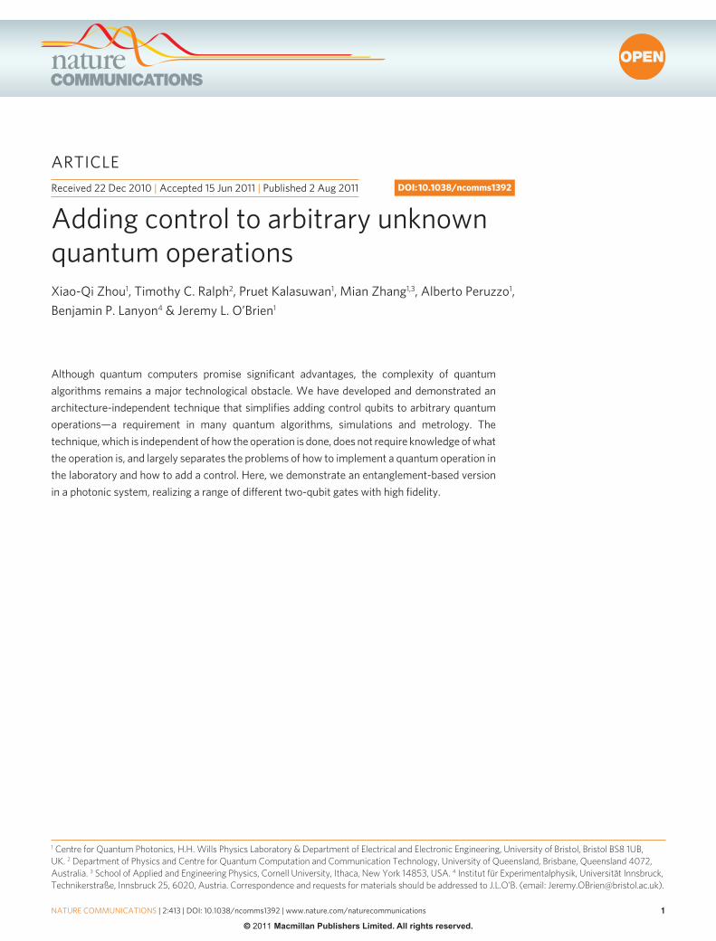
Adding control to arbitrary unknown quantum operations
8
ARTICLE NATURE COMMUNICATIONS | 2:413 | DOI: 10.1038/ncomms1392 | www.nature.com/naturecommunications © 2011 Macmillan Publishers Limited. All rights reserved. Received 22 Dec 2010 | Accepted 15 Jun 2011 | Published 2 Aug 2011 DOI: 10.1038/ncomms1392 Although quantum computers promise significant advantages, the complexity of quantum algorithms remains a major technological obstacle. We have developed and demonstrated an architecture-independent technique that simplifies adding control qubits to arbitrary quantum operations—a requirement in many quantum algorithms, simulations and metrology. The technique, which is independent of how the operation is done, does not require knowledge of what the operation is, and largely separates the problems of how to implement a quantum operation in the laboratory and how to add a control. Here, we demonstrate an entanglement-based version in a photonic system, realizing a range of different two-qubit gates with high fidelity. 1 Centre for Quantum Photonics, H.H. Wills Physics Laboratory & Department of Electrical and Electronic Engineering, University of Bristol, Bristol BS8 1UB, UK. 2 Department of Physics and Centre for Quantum Computation and Communication Technology, University of Queensland, Brisbane, Queensland 4072, Australia. 3 School of Applied and Engineering Physics, Cornell University, Ithaca, New York 14853, USA. 4 Institut für Experimentalphysik, Universität Innsbruck, Technikerstraße, Innsbruck 25, 6020, Austria. Correspondence and requests for materials should be addressed to J.L.O’B. (email: [email protected]). Adding control to arbitrary unknown quantum operations Xiao-Qi Zhou 1 , Timothy C. Ralph 2 , Pruet Kalasuwan 1 , Mian Zhang 1,3 , Alberto Peruzzo 1 , Benjamin P. Lanyon 4 & Jeremy L. O’Brien 1
Transcript of Adding control to arbitrary unknown quantum operations
ARTICLE
�nATuRE CommunICATIons | 2:413 | DoI: 10.1038/ncomms1392 | www.nature.com/naturecommunications
© 2011 Macmillan Publishers Limited. All rights reserved.
Received 22 Dec 2010 | Accepted 15 Jun 2011 | Published 2 Aug 2011 DOI: 10.1038/ncomms1392
Although quantum computers promise significant advantages, the complexity of quantum algorithms remains a major technological obstacle. We have developed and demonstrated an architecture-independent technique that simplifies adding control qubits to arbitrary quantum operations—a requirement in many quantum algorithms, simulations and metrology. The technique, which is independent of how the operation is done, does not require knowledge of what the operation is, and largely separates the problems of how to implement a quantum operation in the laboratory and how to add a control. Here, we demonstrate an entanglement-based version in a photonic system, realizing a range of different two-qubit gates with high fidelity.
1 Centre for Quantum Photonics, H.H. Wills Physics Laboratory & Department of Electrical and Electronic Engineering, University of Bristol, Bristol BS8 1UB, UK. 2 Department of Physics and Centre for Quantum Computation and Communication Technology, University of Queensland, Brisbane, Queensland 4072, Australia. 3 School of Applied and Engineering Physics, Cornell University, Ithaca, New York 14853, USA. 4 Institut für Experimentalphysik, Universität Innsbruck, Technikerstraße, Innsbruck 25, 6020, Austria. Correspondence and requests for materials should be addressed to J.L.O’B. (email: [email protected]).
Adding control to arbitrary unknown quantum operationsXiao-Qi Zhou1, Timothy C. Ralph2, Pruet Kalasuwan1, mian Zhang1,3, Alberto Peruzzo1, Benjamin P. Lanyon4 & Jeremy L. o’Brien1

ARTICLE
��
nATuRE CommunICATIons | DoI: 10.1038/ncomms1392
nATuRE CommunICATIons | 2:413 | DoI: 10.1038/ncomms1392 | www.nature.com/naturecommunications
© 2011 Macmillan Publishers Limited. All rights reserved.
Perhaps the most notable future application of quantum science is quantum information processing, which promises secure communication1 and greatly increased speeds for solving cer-
tain problems such as database searching2, factoring3 and quantum simulation4. The excitement surrounding quantum computers lies in the fact that the number of elementary operations that they require to solve these problems scales only polynomially with the size of the input, in contrast to exponential scaling on a conventional compu-ter. However, even a polynomial scaling of quantum computational resources still presents an enormous obstacle to practical realiza-tion. It may well be that although a quantum computer could, in principle, efficiently solve these important problems, it will remain practically infeasible to build one that can implement a sufficient number of operations, on enough qubits and with sufficient preci-sion, to do anything useful. This motivates developing methods to reduce the resource overhead required to implement key quantum algorithms.
Quantum algorithms rely on the decomposition of a functional quantum circuit into an elementary logic gate set, such as that formed by single-qubit and two-qubit controlled-NOT (CNOT) gates5; there have been several experiments to demonstrate univer-sal quantum gate sets in different physical architectures6 including ion traps7,8, linear optics9–13, superconductor14–15, atoms16,17, and even small-scale algorithms18–21. However, the large number of elemen-tary gates required to implement even the modest-sized circuits presents a significant challenge. This complexity is due to not only the sheer number of elementary operations required but also the structure in which these gates are combined.
Controlled-unitary (CU) gates are a particularly important class of circuits, where one ‘control’ qubit turns on or off a unitary opera-tion U acting on a register of ‘target’ qubits (Fig. 1a). These circuits feature heavily in Kitaev’s phase estimation algorithm22 that under-pins Shor′s factoring algorithm3 and quantum simulation4. In the context of quantum simulation, U could represent a simulation of the time-evolution operator of some physical system, and the abil-ity to add control qubits allows energy eigenvalues to be read out through the phase estimation algorithm23. Phase estimation is also a fundamental tool in quantum metrology. However, the current standard method of realizing CU gates, which relies on the decom-position of U into an elementary gate set, may not be suitable for these applications: in Kitaev’s phase estimation algorithm U may be an unknown ‘black box’ that cannot be decomposed at all.
Here we present and demonstrate a simple method for realizing controlled quantum operations (CO), of which CU gates are a sub-set. In the following we first explain the technique in a way that is independent of any particular physical system, before describing a
conceptual example in a photonic system. We then show that the equivalent operation can be achieved by exploiting an entangled initial state—reminiscent, but distinct from, cluster state quantum computing24,25. Finally, we apply this approach in a series of proof-of-principle experiments implementing various two-qubit gates which include a CNOT, a number of other CU gates, as well as ‘entangle-ment-filter’ and ‘entanglement-splitter’ gates.
ResultsExplanation of the general technique. Our approach for adding a control qubit to an arbitrary quantum operation O is shown conceptually in Figure 1b. In summary, conditional on the logical state of the control, the quantum state of the target register () is temporarily shifted into a part of an extended Hilbert space on which O does not act (imparts the identity operation). In this way the evolution of is dependent on the control qubit state, if it is |0⟩ (|1⟩) then → (→O). The Hilbert space is extended by employing an extra two levels in each quantum information carrier in the target register, making each a four-level system with logical states |0⟩,|1⟩,|2⟩ and |3⟩. The action of each Xa gate is to swap information between the bottom two ‘qubit’ levels (|0⟩, |1⟩) and the expanded Hilbert space (|2⟩, |3⟩), that is,
Xa =
0 0 1 00 0 0 11 0 0 00 1 0 0
X XX X
a a
a a
| | , | || | , | |0 2 1 32 0 3 1⟩ = ⟩ ⟩ = ⟩⟩ = ⟩ ⟩ = ⟩
In spite of its conceptual simplicity, the technique has significant practical benefits: it largely separates the experimental problems of how to implement any given quantum operation in the laboratory and how to add a control qubit. This is relevant in many experimental cases where it is not at all clear how to directly add a control to a quantum operation, for example, when O can be realized in analogue fashion by turning on an experimental hamiltonian, or when O is a non-unitary operation implemented by directly coupling to a bath. Even in the case where O can be constructed with a universal gate set, the number of additional operations required to add a control will generally be far less following our approach. Furthermore, in situations where O is unknown, our method may be the only way to add control. This is relevant in quantum metrology where the goal is to measure properties of O.
The method can be straightforwardly extended to realize the conditional implementation of two different operations O1 or O2 based on the state of the control qubit. Here whereas the compo-nent of the state that is unmoved undergoes O1 , the component of the state moved into the expanded Hilbert space undergoes O2. A further extension would be to add multiple control qubits to imple-ment one of several quantum operations, based on the state of all of the control qubits. For example, with two control qubits, four opera-tions O1, O2, O3, or O4 could be implemented depending on the state of the control qubits.
An alternative approach to extending the Hilbert space would be to use another register of qubits and controlled-swap operations to move information between the registers. However, whereas adding more qubits has proved to be a significant experimental challenge, multi-dimensional quantum information carriers are readily availa-ble in most physical systems currently being investigated or used for quantum information processing. Trapped ions systems, for exam-ple, offer a large number of precisely controllable internal electronic and external vibrational degrees of freedom. Our technique could be implemented by conditionally moving quantum information
(1)(1)
(2)(2)
O
a bXa
Xa
Xa Xa
Xa
Xa
O
Figure 1 | Controlling arbitrary quantum operations using additional degrees of freedom. (a) Logic circuit in which quantum operation o is implemented on a register of qubits (target register), conditional on the logical state of a single control qubit. (b) our approach to implementing the circuit in (a). The target information carriers are four dimensional systems with logical states |0⟩,|1⟩,|2⟩ and |3⟩. Initially and finally, only the bottom two ‘qubit’ levels (|0⟩ and |1⟩) are populated. Controlled-Xa gates (equations 1 and 2) swap information between the qubit levels and the upper levels (|2⟩ and |3⟩), on which o does not act. In this way, conditional on the state of the control qubit, the entire quantum state of the target register is temporarily moved into an effective quantum memory on which o does not act.

ARTICLE
�
nATuRE CommunICATIons | DoI: 10.1038/ncomms1392
nATuRE CommunICATIons | 2:413 | DoI: 10.1038/ncomms1392 | www.nature.com/naturecommunications
© 2011 Macmillan Publishers Limited. All rights reserved.
between different electronic transitions, on which subsequent oper-ations do not operate, or operate differently, on. We note that in previous work it was shown how moving part of the state of a target qubit into an expanded Hilbert space can simplify adding control qubits26. However, this only works in the case where the target is a single-qubit unitary and is at the expense of changing how the uni-tary must be implemented.
Optical version of the scheme. Although our technique is inde-pendent of the particular physical system and degree of freedom employed, it is particularly well suited to an optical version in terms of the polarization and spatial degrees of freedom of phot-onic qubits. As shown in Figure 2a, the controlled-path (CP) gate substitutes the CXa in Figure 1b. The CP is a two-photon gate that changes the target photon’s path if the control is vertically polarized. We note that the CP gate has previously been proposed for imple-menting controlled gates in the context of weak optical cross-Kerr nonlinearities27,28.
To understand how the CP gate works, let’s examine its structure shown in Figure 2b. Assume the inputs are two polarization-encoded photonic qubits, α|H⟩1 + β|V⟩1 (control photon 1) and γ|H⟩2 + δ|V⟩2 (target photon 2). The first polarizing beamsplitter (PBS) will con-vert the target state from γ|H⟩2 + δ|V⟩2 to γ|H⟩2b + δ|V⟩2r where 2r and 2b denote the red and blue spatial modes of the target photon, respectively. The subsequent two CNOT gates flip the polarization of the target photon, if the first photon is vertically polarized. (It is assumed that if a CNOT acts on an unoccupied spatial mode, the identity is enacted.) Thus, the two-photon state becomes α|H⟩1 (γ|H⟩2b + δ|V⟩2r) + β|V⟩1(γ|V⟩2b + δ|H⟩2r). Then the two spatial modes 2r and 2b of the target photon are mixed on the second PBS which converts the two-photon state to α|H⟩1(γ|H⟩2r + δ|V⟩2r) + β|V⟩1(γ|V⟩2b + δ|H⟩2b). Finally, a half-waveplate (HWP) flips the polarization in
spatial mode 2b and thus converts the state to α|H⟩1(γ|H⟩2r + δ|V⟩2r) + β|V⟩1(γ|H⟩2b + δ|V⟩2b): the result is that the target polarization qubit is to be found in one of two orthogonal spatial modes, depending on the logical state of the control qubit. By defining |H⟩2b, |V⟩2b, |H⟩2r and |V⟩2r as |0⟩, |1⟩, |2⟩ and |3⟩, respectively, one can easily find that a CP exactly realizes the function of a CXa gate.
Returning to Figure 2a, suppose that the control photon is again initially in the arbitrary polarization-qubit state α|H⟩ + β|V⟩ and the target photons are initially in the multi-qubit state |⟩. The photons pass through a sequence of CPs which changes the path of all target photons if the control photon is vertically polarized, thus the state is converted to α|H⟩|⟩r + β|V⟩|⟩b where r and b denote the collec-tive red and blue spatial modes, respectively. Next, the blue spatial modes b of the target photons are acted upon by U, whereas the red spatial modes r do not pass through the unitary, as indicated by the dotted lines. The state is therefore converted to α|H⟩|⟩r + β|V⟩U|⟩b. Finally, by repeating the sequence of CPs, we obtain the desired state α|H⟩|⟩ + β|V⟩U|⟩ at the output.
There is a clear advantage over the conventional quantum compu-tational approach to adding control qubits, in terms of the number of logic gates required. Assuming that U, which is a unitary acting on n qubits, can be decomposed into a circuit of p CNOTs and q single- qubit gates, one would use p Toffoli gates and q two-qubit control-led gates to build the corresponding CU gate, which can further be decomposed into (3p + q) to (6p + 2q) CNOTs and even more single-qubit gates29. Although 4n more CNOTs suffice to add a control to the n-qubit unitary U by using our method, at least (2p + q) more CNOTs are needed if one sticks to the traditional scheme. For most quantum algorithm applications, such as Shor′s algorithm where U is a modular exponentiation gate, the typical value of (p + q) is about 72n3 which is on the order of O(n3) and thus (2p + q) is much larger than 4n when n becomes large29,30. Furthermore, if U is a non-uni-tary operation, then the conventional approach is to rewrite this as a unitary on a larger Hilbert space, at a significant cost to the number of gates required. There is no additional cost to add controls to non-unitary operations following our approach.
Entanglement-based scheme. Even a two-qubit demonstration of our scheme would require two CP gates and subsequently four CNOT gates, which is presently out of reach using current linear-optical quantum information processing technology. However, the effect of the CP gate is to generate entanglement between the con-trol qubit and target register, and this kind of entanglement can be generated directly from existing photon sources. We now present an alternative entanglement-based version of our scheme which is feasible with current technology.
Consider the optical circuit schematic shown in Figure 2c. At the input, a spatially-entangled n-photon state is injected that is an equal superposition of finding one photon in each of the n red modes and one photon in each of the n blue modes. In the case where the polar-ization of the n-photon input state is |φ⟩ = (α|H⟩ + β|V⟩)|⟩, where α|H⟩ + β|V⟩ is the upper control qubit and |⟩ is the joint state of the lower (n–1) target register qubits, then the initial state can be written as
12
(| | | | )f f⟩ ⟩ + ⟩ ⟩⊗ ⊗r b
nr
nbvac vac
where r and b label the collective red and blue spatial modes, respectively, and |vac⟩ represents an unoccupied mode. From now on we will drop the unoccupied vacuum modes from the nota-tion. Note that, as we will show, it is possible to create such a state from a spontaneous parametric down conversion photon source. The quantum operation U acts only on photons in the blue spa-tial modes of the target register. The information about whether the target state does or does not undergo the operation U is therefore encoded in the spatial mode of the control photon.
(3)(3)
U
P
a b
c d
P
P
P
P
P
U
PBS
HWP
PBS2r
2b
1
2 2r
2b
1
2P
BS1r
2r
1b
2b
BS
1
1′
2
2′
PBS
BS
A
B
2r
2b
Figure 2 | Optical implementation of the scheme. (a) Implementation of a Cu gate. The circuit is composed of three parts: controlled-path gates (CP) at the beginning, which move the target qubits from upper spatial modes (labelled red) to lower spatial modes (labelled blue) if the control qubit is in the logical state |1⟩; the unitary gate u in the middle is implemented on the lower spatial modes; and CPs at the end, which combine the upper and lower spatial modes. (b) Construction of a CP gate. When the control is in the logical state |0⟩, nothing is applied on the target and the photon exits in the red mode. When the control is |1⟩, the polarization of the target flips and the photon exits in the blue mode. HWP flips back the polarization of the target photon in the blue mode. (c) Entanglement-based scheme. Instead of implementing CPs before the unitary gate u, one sets the input state in an equal superposition of photons either all in the red modes or all in the blue modes. The CPs after u are substituted by a series of non-polarization Bs. (d) Linear combinations of quantum operations . The two photons are either in the red modes 1r,2r or in the blue modes 1b,2b which pass through quantum operations A and B, respectively. Then two spatial modes 1r,1b (2r,2b) of photon 1 (2) are combined at a Bs. By postselecting two photons at ports 1,2 or 1′,2′ (1,2′ or 1′,2), one can effectively realize the quantum operation A + B (A − B).

ARTICLE
��
nATuRE CommunICATIons | DoI: 10.1038/ncomms1392
nATuRE CommunICATIons | 2:413 | DoI: 10.1038/ncomms1392 | www.nature.com/naturecommunications
© 2011 Macmillan Publishers Limited. All rights reserved.
Mixing the two control modes on a PBS and postselecting on finding the control photon in the lower spatial mode move this information into the polarization of the control photon, yielding the state:
12
( | | | | )a y b yH V Ur b⟩ ⟩ + ⟩ ⟩
Finally, the red and blue modes of each target qubit are mixed on non-polarising beamsplitters (BS) to remove the path information. In the case where all photons exit in the lower paths, the output state is
1
2nH V U( | | | | )a y b y⟩ ⟩ + ⟩ ⟩
as required. The probability of success is (1/2)n, however all combi-nations of the control photon arriving in lower spatial mode and an even number of target photons arriving in lower spatial modes will give a state with the same form as in equation 5. There are 2n–2 such combinations that the total probability of success is 1/4, regardless of the number of qubits U acts on. The important feature of our approach —that any operation (known or unknown) can be con-trolled without changing the way the operation is done—is retained in the entanglement-based approach.
This approach can be reformulated in a more general way as shown in Figure 2d. Here we consider the two-photon case for simplicity. Beginning with the two-photon input state of equation 3, the red and blue modes pass through quantum operations A and B respectively. The state ( / )( | | )1 2 A Br bf f⟩ + ⟩ is obtained. After mixing the spa-tial modes on the two BSs, one would get (A + B)|φ⟩ if the two photons exit at ports 1 and 2 or 1′ and 2′. Otherwise, if the two photons exit at ports 1 and 2′ or 1′ and 2, (A–B)|φ⟩ would be obtained. To realize the CU gate, one just needs to set A = |H⟩⟨H|I and B = |V⟩⟨V|U, where |H⟩⟨H| and |V⟩⟨V| denote projectors onto |H⟩ and |V⟩, respectively.
This approach provides a new perspective on constructing quan-tum gates: Whereas the traditional decomposition method can be regarded as performing multiplication, which corresponds to rewriting the target gate matrix as the product of several gate matri-ces, our method is performing linear combination, which means rewriting the target gate matrix as the sum of several gate matrices. This entanglement-based scheme would be useful for small-scale applications as well as subroutines in larger calculations, and it could be made deterministic, following the original prescription for linear optical quantum computation31. Introducing nonlinearities is another way to approach a unit success probability27.
Experimental demonstration. We now present experimental demonstrations of several two-qubit CU gates using this general entanglement-based method (specifically corresponds to Fig. 2d). Figure 3 shows a schematic diagram of our experiment. Note the
(4)(4)
(5)(5)
simplicity of this scheme relative to the previous demonstration of photonic CU gates26, in particular, the fact that it requires no quantum interference. A continuous-wave laser is focused onto a BiBO crystal and thus produces photon pairs through the type-I spontaneous parametric-down conversion (SPDC) process. We collect two photons from four points from the SPDC cone, as shown, resulting in a two-photon four-mode state32 of the form ( / )(| | | | )1 2 1 2 1 2H H H Hr r b b⟩ ⟩ + ⟩ ⟩ . By passing each mode through several waveplates, we prepare a state ( / )(| | ), ,1 2 1 2 1 2f f⟩ + ⟩r r b b , where |φ⟩ can be an arbitrary two-qubit separable state. Here we designate photon 1 as the control, which is in modes 1r and 1b, and photon 2 as the target, which is in modes 2r and 2b. Before modes 1r (2r) and 1b (2b) are combined at a BS, we let the four modes pass through four single-qubit gates A1, B1, A2 and B2 that are constructed from waveplates or PBSs. Then, by measuring the two-photon coincidences between detectors at ports 1 and 2, we get the state (A + B)|φ⟩, where A = A1A2 and B = B1B2. As explained above , by setting A1 = |H⟩⟨H|, A2 = I, B1 = |V⟩⟨V| and B2 = U, the corresponding CU gate is obtained.
We constructed a series of CU gates, including CNOT, C-Hadamard (CH), CPhase (CZ), CZ(π/2) and CZ(π/4) gate, by set-ting B2 = X,H,Z,Zπ/2 and Zπ/4, respectively. To evaluate the perform-ance of these gates, we adopted the method introduced in ref. 33. For each gate, two truth tables are measured in complimentary bases. The bases we chose are shown in Figure 4. The fidelity of these truth tables with the ideal (F1 and F2) bound the process fidelity of the gate via:
( ) ( , )F F F F F1 2 1 21+ − ≤ ≤P Min
We have also performed full-process tomography on one of these gates (see Methods section). From FP we can calculate the output state fidel-ity averaged over all input states through the average gate fidelity:
F dFd
= ++
P 11
,
where d is the dimension of the gate (d = 4 for a two-qubit gate). The results are shown in Figure 4.
This method is not limited to realizing CU gates. By changing the values of A1, A2, B1, and B2, one can implement various two-qubit quantum operations. For example, by setting A1 = A2 = |H⟩⟨H| and B1 = B2 = |V⟩⟨V|, one can realize a very useful quantum gate known as entanglement filter (EF)34,35. An EF is a special (non- unitary) quantum gate which filters multi-qubit states on the basis of correlations. Here our two-photon EF transmits photon pairs, only if they share the same horizontal or vertical polarization, without meas-uring the polarization state. Compared with the previous method34,35,
(6)(6)
(7)(7)
f=400mm
BiBO DMFilter
1b
Toptica iBeamcw 404 nm
A1
B1
A2
1
1′2′
2
Fibre coupler
50:50Beam splitter
Polarization-maintainingsingle-mode fibre
APDPrism
PolarizationBeam splitter
2b2b
1b
B2Quarter-waveplateHalf-waveplate
2r1r
2r1r
Figure 3 | Experimental setup for realizing CU gates. A 60 mW continuous-wave (CW) laser beam with a central wavelength of 404 nm is focused onto a BiBo crystal to create photon pairs. Both the horizontal (modes 1r and 2r) and vertical (modes 1b and 2b) photon pairs are collected. Before collection into polarization-maintaining fibres (PmF), the photons are spectrally filtered by narrow-band filters (∆λFWHW = 3.2 nm). A1, B1, A2 and B2 are four single-qubit gates. By post-selecting the case the two photons exit at ports 1 and 2, one would effectively realize a two-qubit quantum gate (A1A2 + B1B2). The phase between the two components is stabilized by monitoring the coincidence count rates between detectors 1′ and 2′.

ARTICLE
�
nATuRE CommunICATIons | DoI: 10.1038/ncomms1392
nATuRE CommunICATIons | 2:413 | DoI: 10.1038/ncomms1392 | www.nature.com/naturecommunications
© 2011 Macmillan Publishers Limited. All rights reserved.
our method is simpler and more intuitive. We implement this two-photon EF using the setup shown in Figure 3 where A1 = A2 = |H⟩⟨H| and B1 = B2 = |V⟩⟨V| and the results are shown in Figure 5a.
Another interesting feature of our approach is that the method of realizing a quantum gate is not unique: one can choose differ-ent sets of A and B to get the same A + B. Take the two-photon EF, for example. We can realize it in another way by setting A1 = A2 = I and B1 = B2 = Z. This can be verified by comparing the matrix of II + ZZ with |H⟩⟨H||H⟩⟨H| + |V⟩⟨V||V⟩⟨V| that are equivalent up to a constant of order unity. Unlike the first way of realizing an EF, one does not use any projection but only unitary operators,
which means that in fact no components are filtered out: Whereas the |H⟩|H⟩ and |V⟩|V⟩ components would exit at 1 and 2 or 1′ and 2′ that corresponds to realizing the quantum gate A + B, the |H⟩|V⟩ and |V⟩|H⟩ components would exit at 1 and 2′ or 1′ and 2 which corresponds to realizing A–B. As the |H⟩|V⟩ and |V⟩|H⟩ components are not filtered out in this case, we call the device an entanglement splitter (ES). The ES operation is deterministic and the experimental data from this gate are shown in Figure 5b and c.
Interestingly, the mechanics of the ES can be understood in a dif-ferent way. The following equations always hold
Z Z I I Z Z I I Z ZZ Z I I Z Z I I Z Z
⊗ ⊗ + ⊗ ⟩ = + ⊗ + ⊗ ⟩⊗ ⊗ − ⊗ ⟩ = − ⊗ − ⊗ ⟩
( ) | ( ) |( ) | ( ) |
f ff f
which means (II + ZZ)|φ⟩ (or (II − ZZ)|φ⟩) is always the eigen-state of operator ZZ with eigenvalue + 1 (or − 1) no matter what the two-qubit state |φ⟩ is. Then one can deduce that II + ZZ (or II − ZZ) must be a projector that projects any input state to the eigenstate of ZZ with eigenvalue + 1 (or − 1). As our circuit real-izes II + ZZ and II − ZZ simultaneously, it can be regarded as an eigenstate generator of, or eigenvalue measuring device for, opera-tor ZZ. One can easily find the above reasoning would hold when replacing ZZ with any two-qubit operator W that fulfill W2 = II. This example nicely illustrates the power of linear combination of quantum gates. Although an alternative implementation of an EF has previously been reported35 (the ES has not been realized), as far as we know, our method is the only solution for constructing these kinds of entangling gates.
The imperfections of our experimental results are mainly due to three effects. First, the photons generated in the SPDC source are
(8)(8)
CNOT CH
InputOutput
InputOutput
1.0
0.5
0.0
1.0
0.5
0.0
1.0
0.5
0.0
VV
VV
VHVH HV
HV
HH
HH
InputOutput
1.0
0.5
0.0VK
VK
VJVJ HK
HK
HJ
HJ
InputOutput
1.0
0.5
0.0V –
V –
V +V – V –
H +
H +
H +
InputOutput
1.0
0.5
0.0V–VR
V –
V+VLV + H –HR
H –
H +HL
H +
InputOutput
1.0
0.5
0.0V–VT
V –
V+VSV + H –HT
H –
H +HS
H +
+ M
+ M
+ N + N– M– N
– N
– N
InputOutput
1.0
0.5
0.0+ +
+ +
+ – + –– +– +
– –
– –
InputOutput
+ H
+ H
+ V + V– H– H
– V
– V
1.0
0.5
0.0
InputOutput
+ H
+ HLH
+ V+ VLV– H
– HRH
– V
– VRV
1.0
0.5
0.0
InputOutput
+ H
+ HSH
+ V+ VSV– H
– HTH
– V
– VTV
Input basis: �x �z Input basis: �x �zInput basis: �x �x
F1 = 93.60 ± 0.27% F1 = 97.83 ± 0.27% F1 = 97.63 ± 0.27%
CZ(�) CZ(�/2) CZ(�/4)
Input basis: �x (�z + �x)
F1 = 93.68 ± 0.27%
Input basis: �x �x
F1 = 97.25 ± 0.19%
90.85% ≤ FP ≤ 93.60%
Input basis: �x (�z + �x)
F1 = 96.05 ± 0.21%
89.71% ≤ FP ≤ 93.68%
Input basis: �x �z
F1 = 97.63 ± 0.27%
Input basis: �x �z
F1 = 95.13 ± 0.24%
92.75% ≤ FP ≤ 95.13%
Input basis: �z �x
F1 = 95.57 ± 0.24%
93.40% ≤ FP ≤ 95.57%
Input basis: �z �x
F1 = 94.17 ± 0.25%
91.80% ≤ FP ≤ 94.17%
92.68% ≤ F ≤ 94.88% 91.77% ≤ F ≤ 94.94% 94.20% ≤ F ≤ 96.10% 94.72% ≤ F ≤ 96.46% 93.44% ≤ F ≤ 95.33%
Figure 4 | Implementing two-qubit controlled-unitary operations by harnessing entanglement in a larger Hilbert space. (a–e) Experimentally measured ‘truth tables’ for several Cu gates. For the inputs of the CH gate |M⟩ and |N⟩ (|J⟩ and |K⟩) are the eigenstates of ( / )( )(( / )( ))1 2 1 2s s s sz x z x+ − with + 1 and − 1 eigenvalues respectively: that is |M⟩ = cos(π/8)|H⟩ + sin(π/8)|V⟩; |N⟩ = sin(π/8)|H⟩ − cos(π/8)|V⟩; |J⟩ = cos(5π/8)|H⟩ + sin(5π/8)|V⟩; |K⟩ = sin(5π/8)|H⟩ − cos(5π/8)|V⟩. note that two different output measurement bases are applied for each truth table of CPhase(π/2) and CPhase(π/4). The red columns correspond to red output labels whereas the blue columns correspond to blue output labels, which include states such as |HL⟩, |HR⟩, |HS⟩ and |HT⟩ where | / ( / )(| | )R L H i V⟩ = ⟩ ± ⟩1 2 and | / ( / )(| | )/T S H e Vi⟩ = ⟩ ± ⟩1 2 4p . Bounds on the process fidelities FP and average fidelities F are calculated from the classical fidelities shown under the truth tables. Each truth table requires 16 measurements and each measurement takes 1 s. The count of each high column is around 2,000. note that for probabilities near zero in the truth tables, we increased the integration time from 1 s to 10 s to improve the statistics.
HH
HHHV
VHVV
HVVH
VV
Input
Output
01,0002,0003,000
HH
HHHV
VHVV
HVVH
VV
Input
Output
0
1,000
2,000
3,000
HH
HHHV
VHVV
HVVH
VV
Input
Output
0
1,000
2,000
3,000
Figure 5 | An entanglement filter and entanglement splitter. (a) Logical basis truth table for an entanglement filter; the classical fidelity is 98.03 ± 0.17%. (b, c) Logical truth tables for the entanglement splitter. The entanglement splitter’s two outputs correspond to two complementary entanglement filters: one transmits |HH⟩ and |VV⟩ components (b); and the other transmits |HV⟩ and |VH⟩ components whose truth table is shown in (c); their classical fidelities in H/V basis are 90.27 ± 0.37% and 87.38 ± 0.42%, respectively. Here the classical fidelity is defined as the ratio of correctly transmitted photon pairs to the total number of transmitted photon pairs. The data of each column corresponds to 1 s of measurement.

ARTICLE
��
nATuRE CommunICATIons | DoI: 10.1038/ncomms1392
nATuRE CommunICATIons | 2:413 | DoI: 10.1038/ncomms1392 | www.nature.com/naturecommunications
© 2011 Macmillan Publishers Limited. All rights reserved.
not completely indistinguishable; second, the phase between the two spatial modes is not perfectly stabilized (to zero); third, the optical components are not perfectly set to the desired values (for example,
waveplates’ angles). For the EF experiment, A1, B1, A2 and B2 are all projectors, and implemented with PBS. In this case, the |H⟩|V⟩ and |V⟩|H⟩ components are nearly completely filtered out and this is not
BBO
B2
A2
PBSBS
PBSBS
A1
B1
1Half-waveplate
Quarter-waveplate
2r2b21
b1r1
2
Figure 6 | Experimental setup in a Sagnac structure. A 60 mW continuous-wave (CW) laser beam with a central wavelength of 404 nm is focused onto a type-II BBo crystal to create entangled photon pairs. The PBs part of the cubes convert the polarization-entangled state to spatial-entangled state. A1, B1, A2 and B2 are four single-qubit gates. By post-selecting the case where the two photons exit at ports 1 and 2, one would effectively realize a two-qubit quantum gate (A1A2 + B1B2). The displaced-sagnac structure makes the phase between modes r1 and b1 (r2 and b2) inherently stable.
00 45 90
|++> Measurement
1,600
Co
inci
de
nce
co
un
ts (
5 s
)
1,200
800
400
135Phase � (deg)
225180 270 315 360
|+ –> Measurement
Figure 7 | Coincidence rates as a function of the phase between spatial modes r and b. The two-photon output state would be ( / )(| | | | )1 2 1 2 1 2H V e V Hr r
ib b⟩ ⟩ + ⟩ ⟩q , where θ is the relative phase between
spatial modes r and b. The coincidence rates of | + ⟩| + ⟩ (or | + ⟩| − ⟩) would be C(1 + cosθ)/2 (or C(1 − cosθ)/2) where C is the maximum count rate of | + ⟩| + ⟩ (or | + ⟩| − ⟩).
0.25
0
0.25
0.25
0
0.25IIIX
IX
IY
IY
IZ
IZ
XI
XI
XX
XX
XY
XY
XZ
XZ
YI
YI
YX
YX
YY
YY
YZ
YZ
ZI
ZIZX
ZXZY ZYZZ
ZZ
II
II
IIIX
IX
IY
IY
IZ
IZ
XI
XI
XX
XX
XY
XY
XZ
XZ
YI
YI
YX
YX
YY
YY
YZ
YZ
ZI
ZIZX ZXZY ZY
ZZ
ZZ
II
IIIX
IX
IY
IY
IZ
IZ
XI
XI
XX
XX
XY
XY
XZ
XZ
YI
YI
YX
YX
YY
YY
YZ
YZZI
ZIZX ZXZYZY
ZZ
ZZ
II
IX
IX
IY
IY
IZ
IZ
XI
XI
XX
XX
XY
XY
XZ
XZ
YI
YI
YX
YX
YY
YY
YZ
YZ
ZI
ZIZX ZXZY ZY
ZZ
ZZ
II
0.25
0
0.25
0.25
0
0.25
ia
b
ii
i ii
Figure 8 | Process matrix of the CNOT gate. (a) Ideal process matrix. (b) maximum-likelihood experimentally reconstructed process matrix. (i) Real and (ii) imaginary parts are shown. We observe a high process fidelity of 96.13 ± 0.17% with the ideal case. The error estimate is obtained by performing many reconstructions with random noise added to the raw data in each case. matrices are presented in the standard Pauli basis38.

ARTICLE
�
nATuRE CommunICATIons | DoI: 10.1038/ncomms1392
nATuRE CommunICATIons | 2:413 | DoI: 10.1038/ncomms1392 | www.nature.com/naturecommunications
© 2011 Macmillan Publishers Limited. All rights reserved.
affected by phase errors between the two spatial modes. However in the ES experiment, no component is filtered out, the suppression of |H⟩|V⟩ and |V⟩|H⟩ is all based on interference, which is very sensi-tive to phase errors between the two spatial modes. The implemen-tation of the CU gates is in between of the two previous cases, where A1, B1 are projectors and A2, B2 are unitaries. This explains why the fidelity values of the CU gates are higher than those of the ES and lower than those of the EF.
DiscussionOur method will allow simplification of small-scale linear opti-cal circuits. For example, the CNOT gate (or other entangling gates) demonstrated above could be combined with a postselected version of the same gate to perform a sequence of two entangling gates on two photonic qubits. This would require two photons rather than four—which would normally be required for the first gate to be heralded. This type of approach is likely to be of great benefit in circuits of up to 6–10 photons where the appropriate entangled states can be generated32 and where one can rely on inefficient measurement.
This new approach to realizing quantum circuits also enables a quantum state to control the implementation of a quantum gate, thereby opening up the possibility to have truly quantum inputs to quantum information processors. As shown in Figure 2a, if we set the control to be ( / )(| | )1 2 0 1⟩+ ⟩ and let the red and blue spatial modes of the target pass through gate O1 and O2 instead of I and U respectively, where O1 and O2 repre-sent two arbitrary quantum gates, the output state would be ( / )(| | | | ) ( / )(| | ) |1 2 0 1 1 2 0 11 2 1 2⟩ ⟩+ ⟩ ⟩ = ⟩ + ⟩ ⟩O O O Oy y y , where |⟩ is the initial target state. In some sense, our circuit realizes a peculiar entangled ‘state’ ( / )(| | )1 2 0 11 2⟩ + ⟩O O in which a quan-tum bit and a quantum gate are entangled (without needing to know what the gate is). This peculiar entanglement connecting a qubit with quantum gates may have some useful implications. An immediate application is to teleport a qubit onto a quantum gate by using this entangled ‘state’. In this sense, one can get a quantum gate αO1 + βO2 by teleporting a qubit α|0⟩ + β|1⟩. This is a novel way to control a quantum gate by using a quantum bit that is related to ideas of programmable quantum gate arrays36.
In summary, we have proposed a different approach to realiz-ing the controlled operations that are at the heart of the majority of important quantum algorithms. With this method, one can directly integrate an arbitrary operation into the circuit to build the cor-responding CU gate even if the unitary U is unknown. This is in contrast to other methods that harness extra degrees of freedom26,37 that work only for known single-target qubit unitaries. Our method is not limited to CU gates but can be extended to realize more gen-eral entangling gates. We demonstrated the power of this approach by experimentally implementing several high-fidelity two-qubit gates. In each case, the implementation of the control circuit was completely independent of the choice of quantum operation. This method has the potential to change the way we implement quantum circuits for all algorithms and will find a wide range of applications across quantum information science and technology as the com-plexity of the quantum circuits implemented grows to include more sophisticated algorithms.
MethodsAn alternative experimental demonstration. In the experiments described in the main text, we prepared the spatial entangled state ( / )(| | ), ,1 2 1 2 1 2f f⟩ + ⟩r r b b as the input (Fig. 3) for implementing the various two-qubit quantum gates, where |φ⟩ is an arbitrary polarization-encoded two-qubit separable state. Here we want to point out that the phase between the two components |φ⟩1r,2r and |φ⟩1b,2b was stabilized by using monitoring and feedback method. Although the phase-stabilizing approach is good enough to construct these quantum gates, for application such as the phase estimation algorithm, where phase itself is the target to be measured, a setup with inherent phase stability is required.
Here we present an experimental demonstration of the same scheme by using a setup which is inherently phase-stable. Instead of using a type-I SPDC source to produce the spatial entangled photon pairs, we use a type-II SPDC source to get polarization-entangled photon pairs first and then convert them to spatial entan-gled photons. In this way, we can build a displaced-Sagnac structure in the setup to make the phase stable. Figure 6 shows the schematic diagram of our experiment. We use the same continuous wave laser to pump a BBO cystal cut for type-II SPDC and get the two-photon state ( / )(| | | | )1 2 1 2 1 2H V V H⟩ ⟩ + ⟩ ⟩ .
By placing PBS/BS cubes (half-PBS, half-BS) in both arms and by letting the photons pass through the PBS part of the cubes, we get the state ( / )(| | | | )1 2 1 2 1 2H V V Hr r b b⟩ ⟩ + ⟩ ⟩ . Th e HWP and quarter-waveplate (QWP) on each path convert the state to ( / )(| , | , )1 2 1 2 1 2f f⟩ + ⟩r r b b that is exactly the same as the spatial entangled state in the original experiments. We let the four spatial modes 1r, 2r, 1b and 2b pass through four single-qubit gates A1, A2, B1 and B2, respectively, and then mix the spatial modes 1r and 2r (1b and 2b) on the BS part of the cube. By postselecting the case when two photons exit at ports 1 and 2, the quantum operation A + B is obtained. Here we set A1 = |H⟩⟨H|, B1 = |V⟩⟨V|, A2 = I, B2 = X and thus realize a CNOT gate.
As the phase θ between r and b modes is inherently stable in this setup, we can now show the variation of the coincidence rates with θ. By setting |φ⟩ to be | + ⟩|H⟩, the state ( / )(| | | | )1 2 H H V V⟩ ⟩+ ⟩ ⟩ is obtained. We then place a set of waveplates (QWP, HWP and QWP) in the path of photon 2, as shown, to continuously tune the phase between the spatial modes r and b and measure the | + ⟩| + ⟩ and | + ⟩| − ⟩ two-photon coincidence rates at the output, where | ( / )(| | )±⟩ = ⟩± ⟩1 2 H V . As shown in Figure 7, two complementary cosine curves are obtained as expected.
We fully characterize the CNOT gate through quantum process tomography, and the experimentally reconstructed process matrices are shown in Figure 8. We observe a high process fidelity of 96.13 ± 0.17% with the ideal case.
References1. Gisin, N., Ribordy, G., Tittel, W. & Zbinden, H. Quantum cryptography. Rev.
Mod. Phys. 74, 145 (2002).2. Grover, L. Quantum mechanics helps in searching for a needle in a haystack.
Phys. Rev. Lett. 79, 325 (1997).3. Shor, P. W. Algorithms for quantum computation: discrete logarithms
and factoring. Proc. 35th Annu. Symp. Foundations of Computer Science (ed. S. Goldwasser.) 124–134 (IEEE Computer Society Press, 1994).
4. Feynman, R. P. Simulating physics with computers. Int. J. Thy. Phys. 21, 467 (1982).5. Nielsen, M. A. & Chuang, I. L. Quantum Computation and Quantum
Information, Cambridge University Press, (2000).6. Ladd, T. D., Jelezko, F., Laflamme, R., Nakamura, Y., Monroe, C. & O’Brien, J. L.
Quantum computers. Nature 464, 45 (2010).7. Schmidt-Kaler, F. et al. Realization of the Cirac-Zoller controlled-NOT
quantum gate. Nature 422, 408–411 (2003).8. Leibfried, D. et al. Experimental demonstration of a robust and high-fidelity
geometric two ion-qubit phase gate. Nature 422, 412–415 (2003).9. Pittman, T. B., Fitch, M. J., Jacobs, B. C. & Franson, J. D. Experimental
controlled-not logic gate for single photons in the coincidence basis. Phys. Rev. A 68, 032316 (2003).
10. O’Brien, J. L., Pryde, G. J., White, A. G., Ralph, T. C. & Branning, D. Demonstration of an all-optical quantum controlled-NOT gate. Nature 426, 264–267 (2003).
11. Gasparoni, S., Pan, J- W., Walther, P., Rudolph, T. & Zeilinger, A. Realization of a photonic controlled-NOT gate sufficient for quantum computation. Phys. Rev. Lett. 93, 020504 (2004).
12. Bao, X- H. et al. Optical nondestructive controlled-not gate without using entangled photons. Phys. Rev. Lett. 98, 170502 (2007).
13. Gao, W- B. et al. Experimental realization of a controlled-not gate with four-photon six-qubit cluster states. Phys. Rev. Lett. 104, 20501 (2010).
14. Steffen, M. et al. Measurement of the Entanglement of Two Superconducting Qubits via State Tomography. Science 313, 1423–1425 (2006).
15. Plantenberg, J. H., de Groot, P. C., Harmans, C.J.P.M. & Mooij, J. E. Demonstration of controlled-not quantum gates on a pair of superconducting quantum bits. Nature 447, 836–839 (2007).
16. Mandel, O., Greiner, M., Widera, A., Rom, T., Hänsch, T. W. & Bloch, I. Controlled collisions for multi-particle entanglement of optically trapped atoms. Nature 425, 937–940 (2003).
17. Anderlini, M., Lee, P. J., Brown, B. L., Sebby-Strabley, J., Phillips, W. D. & Porto, J. V. Controlled exchange interaction between pairs of neutral atoms in an optical lattice. Nature 448, 452–456 (2007).
18. Lanyon, B. P. et al. Experimental demonstration of a compiled version of shor′s algorithm with quantum entanglement. Phys. Rev. Lett. 99, 250505 (2007).
19. Lu, C- Y., Browne, D. E., Yang, T. & Pan, J.- W. Demonstration of a compiled version of shor′s quantum factoring algorithm using photonic qubits. Phys. Rev. Lett. 99, 250504 (2007).
20. Politi, A., Matthews, J. C. F. & O’Brien, J. L. Shor’s Quantum Factoring Algorithm on a Photonic Chip. Science 325, 1221 (2009).

ARTICLE
��
nATuRE CommunICATIons | DoI: 10.1038/ncomms1392
nATuRE CommunICATIons | 2:413 | DoI: 10.1038/ncomms1392 | www.nature.com/naturecommunications
© 2011 Macmillan Publishers Limited. All rights reserved.
21. Lanyon, B. P. et al. Towards quantum chemistry on a quantum computer. Nat. Chem 2, 106 (2010).
22. Kitaev, A. Y., Shen, A. H., Shen, A., Vyalyi, M. N. & Vyalyi, M. N. Classical and Quantum Computation, American Mathematical Society, (2002).
23. Aspuru-Guzik, A., Dutoi, A. D., Love, P. J. & Head-Gordon, M. Simulated Quantum Computation of Molecular Energies. Science 309, 1704–1707 (2005).
24. Raussendorf, R. & Briegel, H. J. A one-way quantum computer. Phys. Rev. Lett. 86, 5188–5191 (2001).
25. Walther, P. et al. Experimental one-way quantum computing. Nature 434, 169–176 (2005).
26. Lanyon, B. P. et al. Simplifying quantum logic using higher-dimensional hilbert spaces. Nat. Phys. 5, 134–140 (2009).
27. Lin, Q. & He, B. Single-photon logic gates using minimal resources. Phys. Rev. A 80, 042310 (2009).
28. Lin, Q., He, B., Bergou, J. A. & Ren, Y. Processing multiphoton states through operation on a single photon: Methods and applications. Phys. Rev. A 80, 042311 (2009).
29. Vedral, V., Barenco, A. & Ekert, A. Quantum networks for elementary arithmetic operations. Phys. Rev. A 54, 147–153 (1996).
30. Beckman, D., Chari, A. N., Devabhaktuni, S. & Preskill, J. Efficient networks for quantum factoring. Phys. Rev. A 54, 1034–1063 (1996).
31. Knill, E., Laflamme, R. & Milburn, G. J. A scheme for efficient quantum computation with linear optics. Nature 409, 46–52 (2001).
32. Rossi, A., Vallone, G., Chiuri, A., De Martini, F. & Mataloni, P. Multipath entanglement of two photons. Phys. Rev. Lett. 102, 153902 (2009).
33. Hofmann, H. F. Complementary classical fidelities as an efficient criterion for the evaluation of experimentally realized quantum operations. Phys. Rev. Lett. 94, 160504 (2005).
34. Hofmann, H. F. & Takeuchi, S. Quantum Filter for Nonlocal Polarization Properties of Photonic Qubits. Phys. Rev. Lett. 88, 147901 (2002).
35. Okamoto, R., O’Brien, J. L., Hofmann, H. F., Nagata, T., Sasaki, K. & Takeuchi, S. An Entanglement Filter. Science 323, 483–485 (2009).
36. Nielsen, M. A. & Chuang, I. L. Programmable quantum gate arrays. Phys. Rev. Lett. 79, 321–324 (1997).
37. Ralph, T. C., Resch, K. J. & Gilchrist, A. Efficient toffoli gates using qudits. Phys. Rev. A 75, 022313 (2007).
38. O’Brien, J. L. et al. Quantum process tomography of a controlled-NOT gate. Phys. Rev. Lett. 93, 080502 (2004).
AcknowledgementsWe thank P.J. Shadbolt for writing the code for reconstructing the process matrix and H.F. Hofmann, A. Laing, J.C.F. Matthews and A. Politi for helpful discussions. This work was supported by ERC, EPSRC, PHORBITECH, NOKIA, IARPA, the Leverhulme Trust, and NSQI. J.L.O’B. acknowledges a Royal Society Wolfson Merit Award.
Author contributionsAll authors contributed extensively to the work presented in this paper.
Additional informationCompeting financial interests: The authors declare no competing financial interests.
Reprints and permission information is available online at http://npg.nature.com/reprintsandpermissions/
How to cite this article: Zhou, X.Q. et al. Adding control to arbitrary unknown quantum operations. Nat. Commun. 2:413 doi: 10.1038/ncomms1392 (2011).
License: This work is licensed under a Creative Commons Attribution-NonCommercial-NoDerivative Works 3.0 Unported License. To view a copy of this license, visit http://creativecommons.org/licenses/by-nc-nd/3.0/