Adding Attribute Links to Text - TaiLieu.VN
20
Adding Attribute Links to Text Adding Attribute Links to Text This task shows you how to add one or more attribute links to text. In a first example, we will create an attribute link between a hole on the 3D part and the corresponding text in a CATDrawing view. In a second example, we will assign an attribute an attribute link to a view. Open the GenDrafting_part.CATPart document and the GenDrafting_part_02. CATDrawing document. 1. Double-click the text to which you want to add a link. 2. Right-click on the text in the drawing and select the Attribute Link option from the contextual menu. 3. Select the object which you want the text to be linked to, from the specification tree (either from the 3D or from the CATDrawing document). http://pop.dia.uniroma3.it/catia/online/driug_C2/driugat0103.htm (1 of 6)10/19/2004 4:18:31 PM
-
Upload
khangminh22 -
Category
Documents
-
view
0 -
download
0
Transcript of Adding Attribute Links to Text - TaiLieu.VN
Adding Attribute Links to Text
Adding Attribute Links to Text
This task shows you how to add one or more attribute links to text.
In a first example, we will create an attribute link between a hole on the 3D part and the corresponding text in a CATDrawing view.
In a second example, we will assign an attribute an attribute link to a view.
Open the GenDrafting_part.CATPart document and the GenDrafting_part_02.CATDrawing document.
1. Double-click the text to which you want to add a link.
2. Right-click on the text in the drawing and select the Attribute Link option from the contextual menu.
3. Select the object which you want the text to be linked to, from the specification tree (either from the 3D or from the CATDrawing document).
http://pop.dia.uniroma3.it/catia/online/driug_C2/driugat0103.htm (1 of 6)10/19/2004 4:18:31 PM
Adding Attribute Links to Text
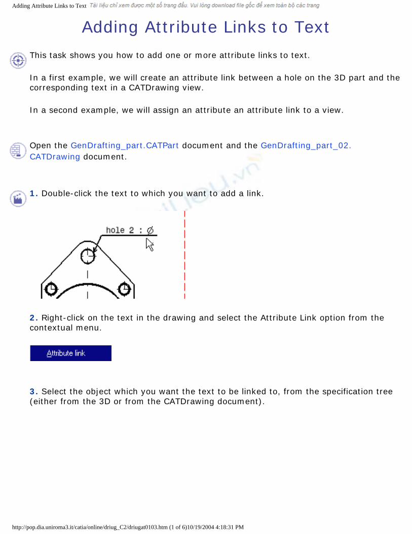
For example, select Hole 2 from the CATPart specification tree.
The Attribute Link Panel dialog box appears:
4. Select the "Part1\PartBody\Hole.2\Diameter 8.5mm" attribute from the list displayed.
The 8.5mm attribute automatically appears both in the Text Editor dialog box and on the CATDrawing.
http://pop.dia.uniroma3.it/catia/online/driug_C2/driugat0103.htm (2 of 6)10/19/2004 4:18:31 PM

Adding Attribute Links to Text
5. Modify the diameter of Hole 2 on the CATPart. For example, modify the hole diameter into 13.5mm.
This modification is automatically updated on both the views generated on the CATDrawing and the linked text attribute inserted inside the text, on the condition you select automatic update mode in the Options dialog box (Tools->Options->Mechanical Design-> Part Design options, General tab).
At this step, you can perform a query on the link (s) you just created. For this, click the view and select the Query Objects Links option from the contextual menu.
The Query Link Panel appears which displays a list with the existing links.
Of course, you can only modify the text that is not text attribute type. To modify the text attribute, you need to isolate this text.For this:
6. Right-click the text attribute.
7. Select the Isolate Text option from the contextual menu.
http://pop.dia.uniroma3.it/catia/online/driug_C2/driugat0103.htm (3 of 6)10/19/2004 4:18:31 PM

Adding Attribute Links to Text
Open the GenDrafting_part_02.CATDrawing document.
Create the formula:
1. Click the Formula icon from the Standard toolbar.
The Formulas: Drawing dialog box appears:
2. Create a parameter called NameOfUser.
http://pop.dia.uniroma3.it/catia/online/driug_C2/driugat0103.htm (4 of 6)10/19/2004 4:18:31 PM

Adding Attribute Links to Text
Define the Text Attribute:
3. Click the Text icon from the Annotations toolbar and click in the free space.
4. Right-click the empty text and select the Attribute Link option from the contextual menu.
5. Select the object which you want the text to be linked to, from the specification tree. For example, select the CATDrawing document (very top of the specification tree).
Modify the Text Attribute:
The attribute appears on the drawing:
6. Modify the parameter by clicking the Formula icon from the Standard toolbar, double-clicking the parameter and editing it.
7. Enter the new value for the username attribute. For example, NewNameOfUser.
http://pop.dia.uniroma3.it/catia/online/driug_C2/driugat0103.htm (5 of 6)10/19/2004 4:18:31 PM

Adding Attribute Links to Text
8. Click OK.
The linked attribute now appears. In other words, it is automatically updated.
[ Back ] [ Up ] [ Next ]
http://pop.dia.uniroma3.it/catia/online/driug_C2/driugat0103.htm (6 of 6)10/19/2004 4:18:31 PM
Setting Relations Between Dimensional Constraints
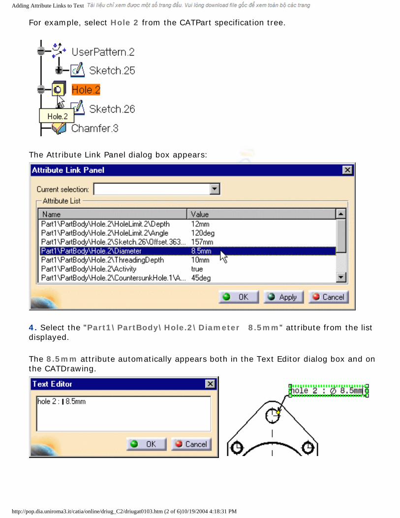
Setting Relations Between Dimensional ConstraintsThis task shows you how to set constraints between dimension using formulas. As a result, if you modify one of these dimensions (the driving dimension), all the other dimensions as well as the geometry will be modified accordingly.
Open the Brackets_views04.CATDrawing document.
1. Click the Formula icon from the Standard toolbar.
The Formulas dialog box appears.
You will now select, one after the other, the dimensions to be constrained and then enter in the dialog box the formulas to be used.
http://pop.dia.uniroma3.it/catia/online/driug_C2/driugat0104.htm (1 of 4)10/19/2004 4:18:44 PM

Setting Relations Between Dimensional Constraints
2. Select a first dimension (1).
3. Press the Add Formula switch in the Formulas dialog box.
The Formula Editor dialog box appears.
4. Select a second dimension (3) and add "/4". Then, click OK (Formula Editor dialog box).
5. Select a first dimension (2).
6. Press the Add Formula switch in the Formulas dialog box.
The Formula Editor dialog box appears.
7. Select a second dimension (3) and add "*3 /4". Then, click OK (Formula Editor dialog box).
8. Select a first dimension (4).
9. Press the Add Formula switch in the Formulas dialog box.
The Formula Editor dialog box appears.
http://pop.dia.uniroma3.it/catia/online/driug_C2/driugat0104.htm (2 of 4)10/19/2004 4:18:44 PM

Setting Relations Between Dimensional Constraints
10. Select a second dimension (1) and then, click OK (Formula Editor dialog box).
11. Select a first dimension (5).
12. Press the Add Formula switch in the Formulas dialog box.
The Formula Editor dialog box appears.
13. Select a second dimension (2) and then, click OK (Formula Editor dialog box).
14. Click OK ( Formulas dialog box).
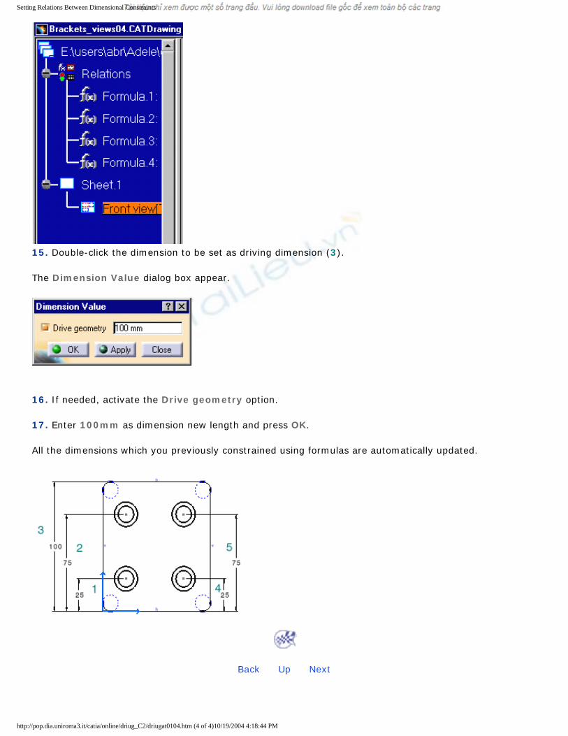
Note that the specification tree is modified accordingly.
http://pop.dia.uniroma3.it/catia/online/driug_C2/driugat0104.htm (3 of 4)10/19/2004 4:18:44 PM
Setting Relations Between Dimensional Constraints
15. Double-click the dimension to be set as driving dimension (3).
The Dimension Value dialog box appear.
16. If needed, activate the Drive geometry option.
17. Enter 100mm as dimension new length and press OK.
All the dimensions which you previously constrained using formulas are automatically updated.
[ Back ] [ Up ] [ Next ]
http://pop.dia.uniroma3.it/catia/online/driug_C2/driugat0104.htm (4 of 4)10/19/2004 4:18:44 PM
Text Templates
Text Templates
The Interactive Drafting workbench lets you define and store text templates to be used when creating texts associated to features. Text templates rely on attributes defined in the 3D for these features.
Create text templatesDefine text templates associated to feature attributes defined in the 3D.
Store text templates in a catalog Store in a catalog previously-defined text templates.
Annotate drawings using text templatesUse text templates stored in a catalog to annotate drawings.
http://pop.dia.uniroma3.it/catia/online/cfyugdr_C2/cfyugtexttemplate00.htm10/19/2004 4:18:56 PM

Creating Text Templates
Creating Text Templates
This task will show you how to create text templates.
Before you begin, you need to make sure that the package corresponding to the type of object for which you want to create a template is correctly loaded. For the purpose of this scenario, you will load the Product package. Go to Tools -> Options -> General -> Parameters and Measure and click on the Language tab. Check Load extended language libraries and uncheck All packages. From the Available Packages list, select ProductPackage and click on the right arrow to add it to the Packages to load list. Click OK, and then exit and re-start the software.
Create a new drawing.
1. Click the Text icon from the Annotations toolbar.
2. Click anywhere in the drawing. A green frame appears, as well as the Text
Editor dialog box.
3. In the Text Editor dialog box, type Part number:.
4. Without closing the Text Editor dialog box, right-click the frame and select Insert link template from the contextual menu which is displayed.
http://pop.dia.uniroma3.it/catia/online/cfyugdr_C2/cfyugtexttemplate01.htm (1 of 3)10/19/2004 4:19:10 PM
Creating Text Templates
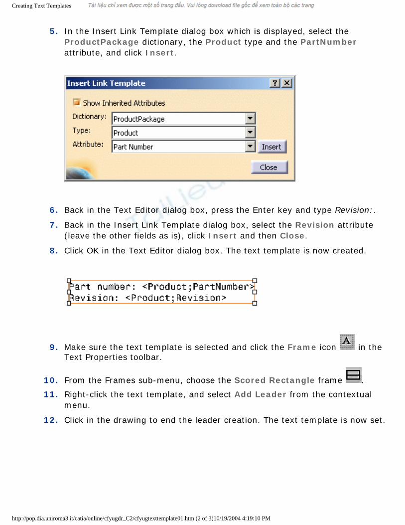
5. In the Insert Link Template dialog box which is displayed, select the
ProductPackage dictionary, the Product type and the PartNumber attribute, and click Insert.
6. Back in the Text Editor dialog box, press the Enter key and type Revision:.
7. Back in the Insert Link Template dialog box, select the Revision attribute (leave the other fields as is), click Insert and then Close.
8. Click OK in the Text Editor dialog box. The text template is now created.
9. Make sure the text template is selected and click the Frame icon in the Text Properties toolbar.
10. From the Frames sub-menu, choose the Scored Rectangle frame .
11. Right-click the text template, and select Add Leader from the contextual menu.
12. Click in the drawing to end the leader creation. The text template is now set.
http://pop.dia.uniroma3.it/catia/online/cfyugdr_C2/cfyugtexttemplate01.htm (2 of 3)10/19/2004 4:19:10 PM

Creating Text Templates
13. Right-click the text template, and select Properties from the contextual
menu.
14. Click the Feature Properties tab in the Properties dialog box which is displayed.
15. In the Feature Name field, type Part number & Revision and click OK. You will use this feature name to identify this text template in the future.
16. Create another text by repeating steps 1 to 3, this time typing Part name: in the Text Editor dialog box.
17. Repeat steps 4 and 5, this time selecting the Name attribute in the Insert Link Template dialog box.
18. Click Close in the Insert Link Template dialog box and then OK in the Text Editor dialog box. The text template is now created.
19. Make sure the text template is selected and in the Graphic Properties toolbar, choose green from the Color list. The text template is now set.
20. Repeat steps 13 to 15, this time typing Part name in the Feature Name field.
You will use this feature name to identify this text template in the future.
21. Select File -> Save As and save the drawing as a .CATDrawing document.
Now that your text templates are defined, you need to store them in a catalog.
[ Up ] [ Next ]
http://pop.dia.uniroma3.it/catia/online/cfyugdr_C2/cfyugtexttemplate01.htm (3 of 3)10/19/2004 4:19:10 PM

Storing Text Templates in a Catalog
Storing Text Templates in a Catalog
This task will show you how to store text templates in a catalog.
For more information on catalogs, refer to the Using Catalogs chapter in the Infrastructure User's Guide.
Open the TextTemplates.CATDrawing document.
1. Select File -> New.
2. In the New dialog box, select CatalogDocument from the list of types and click OK. The Catalog Editor workbench is launched and a new catalog is created.
3. In the left-hand pane, double-click Chapter.1 to activate it.
4. Select Insert -> Add Family.... The Component Family Definition dialog box is displayed.
5. Type Text templates in the Name field.
6. Make sure Standard is selected in the Type field, and click OK. The family is created.
7. For more convenience, select Window -> Tile Horizontally to display your Catalog
Editor and Drafting windows at once.
8. In the Drafting window, select one of the text templates, e.g. Part number & Revision.
9. In the left-hand pane of the Catalog Editor window, double-click Text templates to activate it.
10. Select Insert -> Add Component.... The Description Definition dialog box is displayed.
11. On the Reference tab, click the Select external feature button. The dialog box is updated with information about the selected text template, i.e. Part number & Revision.
http://pop.dia.uniroma3.it/catia/online/cfyugdr_C2/cfyugtexttemplate02.htm (1 of 3)10/19/2004 4:19:19 PM

Storing Text Templates in a Catalog
12. Click OK. The selected text template is listed on the Reference tab, in the right-hand
pane of the Catalog Editor window.
13. Go back to the Drafting window and select the other text templates, e.g. Part name.
14. Return to the Catalog Editor window and repeat steps 10 and 11. The dialog box is now updated with information about the Part name text template.
15. Click OK. Both selected text templates are now listed on the Reference tab, in the right-hand pane of the Catalog Editor window.
16. Select File -> Save As and save the catalog as a .catalog document.
http://pop.dia.uniroma3.it/catia/online/cfyugdr_C2/cfyugtexttemplate02.htm (2 of 3)10/19/2004 4:19:19 PM

Storing Text Templates in a Catalog
[ Back ] [ Up ] [ Next ]
http://pop.dia.uniroma3.it/catia/online/cfyugdr_C2/cfyugtexttemplate02.htm (3 of 3)10/19/2004 4:19:19 PM
Annotating Drawings Using Text Templates
Annotating Drawings Using Text Templates
This task will show you how to annotate drawings using text templates stored in a catalog.
Before you begin, you need to make sure that the package corresponding to the type of object for which you want to create a template is correctly loaded. For the purpose of this scenario, you will load the Product package. Go to Tools -> Options -> General -> Parameters and Measure and click on the Language tab. Check Load extended language libraries and uncheck All packages. From the Available Packages list, select ProductPackage and click on the right arrow to add it to the Packages to load list. Click OK, and then exit and re-start the software.
Open the GEAR-REDUCER.CATDrawing document.
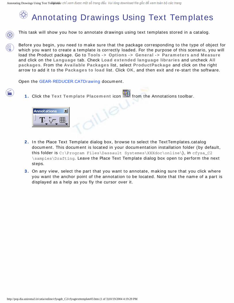
1. Click the Text Template Placement icon from the Annotations toolbar.
2. In the Place Text Template dialog box, browse to select the TextTemplates.catalog document. This document is located in your documentation installation folder (by default, this folder is C:\Program Files\Dassault Systemes\XXXdoc\online\), in cfysa_C2\samples\Drafting. Leave the Place Text Template dialog box open to perform the next steps.
3. On any view, select the part that you want to annotate, making sure that you click where you want the anchor point of the annotation to be located. Note that the name of a part is displayed as a help as you fly the cursor over it.
http://pop.dia.uniroma3.it/catia/online/cfyugdr_C2/cfyugtexttemplate03.htm (1 of 3)10/19/2004 4:19:29 PM

Annotating Drawings Using Text Templates
The Place Text Template dialog box now lists all the templates available in the selected catalog and which can be applied to the selected object.
http://pop.dia.uniroma3.it/catia/online/cfyugdr_C2/cfyugtexttemplate03.htm (2 of 3)10/19/2004 4:19:29 PM
Annotating Drawings Using Text Templates
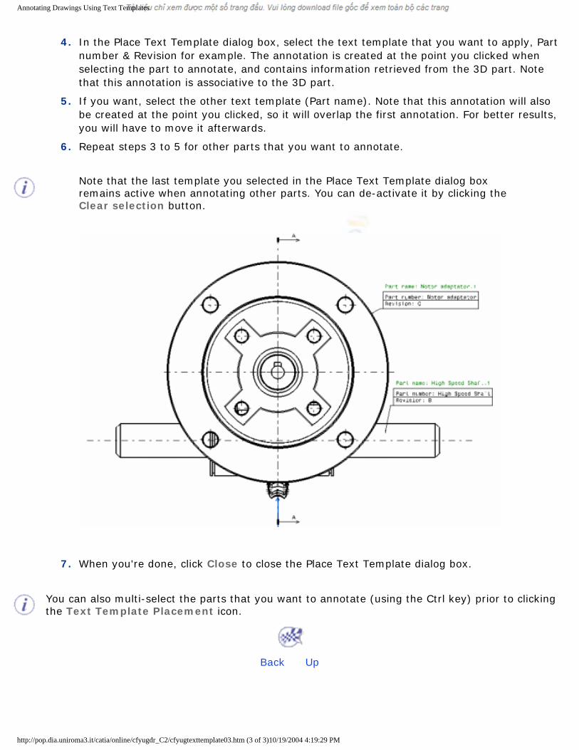
4. In the Place Text Template dialog box, select the text template that you want to apply, Part
number & Revision for example. The annotation is created at the point you clicked when selecting the part to annotate, and contains information retrieved from the 3D part. Note that this annotation is associative to the 3D part.
5. If you want, select the other text template (Part name). Note that this annotation will also be created at the point you clicked, so it will overlap the first annotation. For better results, you will have to move it afterwards.
6. Repeat steps 3 to 5 for other parts that you want to annotate.
Note that the last template you selected in the Place Text Template dialog box remains active when annotating other parts. You can de-activate it by clicking the Clear selection button.
7. When you're done, click Close to close the Place Text Template dialog box.
You can also multi-select the parts that you want to annotate (using the Ctrl key) prior to clicking the Text Template Placement icon.
[ Back ] [ Up ]
http://pop.dia.uniroma3.it/catia/online/cfyugdr_C2/cfyugtexttemplate03.htm (3 of 3)10/19/2004 4:19:29 PM