Spazi per vendere e spazi per abitare: i casi di Anversa, Londra e Siviglia
Upload
khangminh22Category
view
0download
0
®
201
6
Cat
alog
o g
ener
ale
Gen
eral
cat
alog
ue
Trunking and cable trays for the conveyance of electric cables
Passerelle e canaline metalliche per posa cavi elettrici
Ediz
ion
eEd
itio
n

Sistemi di sospensione e bulloneriaFixing systems and bolts
221Applicazioni in dettaglioApplications in detail
ApplicAzioni bordo mAcchinAApplicAtions Around mAchine
indice completotable of contents
Sommariosummary
283
335
25
91
123
301
245
143
183
195
209
2016 .2

FAX
Sede e Stabilimento Address
zAmET S.p.A - Via Torino, 10910088 Volpiano (To) - italy
Centralino / switchboard
0039 011 98 22 601
Ufficio commerciale sales department
0039 011 99 53 778
Ufficio acquisti, Amministrazione, Ufficio tecnico purchase department, Administration, engineering department
0039 011 99 53 756
web
www.zamet.it
®
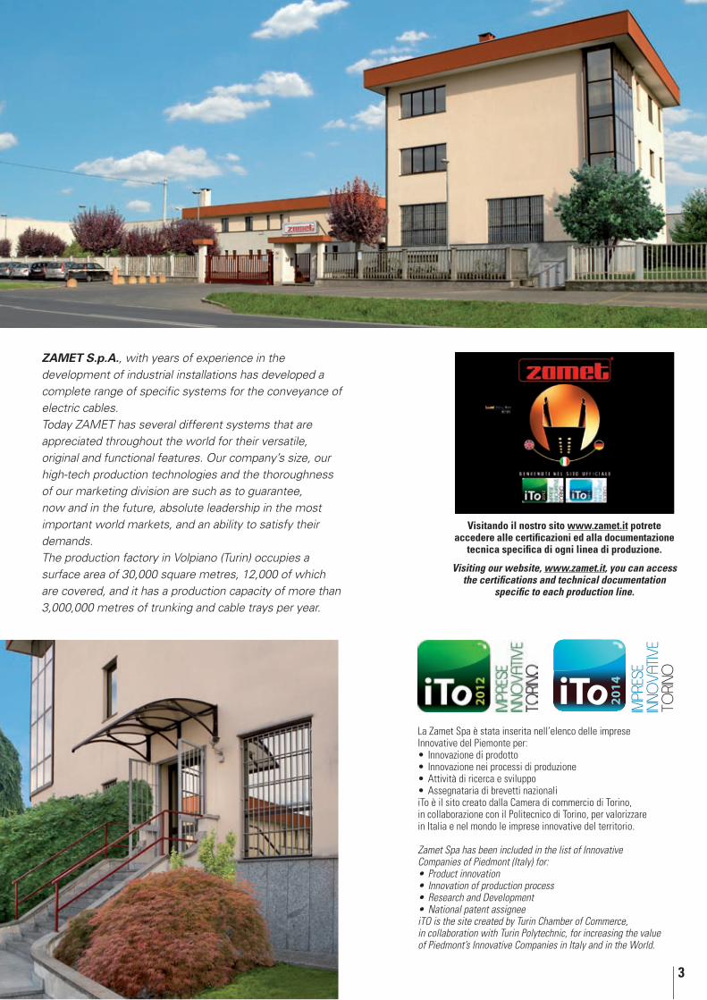
La zAmET S.p.A., da anni impegnata nello sviluppo dell’impiantistica industriale ha ideato una linea completa di specifici sistemi di trasporto per cavi elettrici.Attualmente la produzione ZAMET S.p.A. si articola in differenti sistemi, apprezzati in tutto il mondo per le loro caratteristiche di versatilità, originalità e funzionalità. La dimensione aziendale, le avanzate tecniche produttive e la serietà commerciale sono tali da garantire anche in futuro caratteristiche di assoluta avanguardia, per soddisfare le esigenze dei maggiori mercati mondiali.Lo stabilimento di produzione è situato a Volpiano (To) su di una superficie di 30.000 mq di cui 12.000 coperti ed ha una capacità produttiva di oltre 3.000.000 di metri lineari all’anno di canaline e passerelle metalliche.
3
20
14
impr
ese
inno
vativ
eto
rino
Visitando il nostro sito www.zamet.it potrete accedere alle certificazioni ed alla documentazione
tecnica specifica di ogni linea di produzione.
Visiting our website, www.zamet.it, you can access the certifications and technical documentation
specific to each production line.
La Zamet Spa è stata inserita nell’elenco delle imprese Innovative del Piemonte per:
Innovazione di prodotto•Innovazione nei processi di produzione•Attività di ricerca e sviluppo•Assegnataria di brevetti nazionali•
iTo è il sito creato dalla Camera di commercio di Torino, in collaborazione con il Politecnico di Torino, per valorizzare in Italia e nel mondo le imprese innovative del territorio.
Zamet Spa has been included in the list of Innovative Companies of Piedmont (Italy) for:
Product innovation•Innovation of production process•Research and Development•National patent assignee•
iTO is the site created by Turin Chamber of Commerce, in collaboration with Turin Polytechnic, for increasing the value of Piedmont’s Innovative Companies in Italy and in the World.
ZAMET S.p.A., with years of experience in the development of industrial installations has developed a complete range of specific systems for the conveyance of electric cables.Today ZAMET has several different systems that are appreciated throughout the world for their versatile, original and functional features. Our company’s size, our high-tech production technologies and the thoroughness of our marketing division are such as to guarantee, now and in the future, absolute leadership in the most important world markets, and an ability to satisfy their demands. The production factory in Volpiano (Turin) occupies a surface area of 30,000 square metres, 12,000 of which are covered, and it has a production capacity of more than 3,000,000 metres of trunking and cable trays per year.

4
l’aziendathe company
Ricevimento / Reception
Sala esposizioni / Showroom
Uffici / Offices
Sala riunioni / Meeting room

5
Produzione componentiComponent production
Magazzino prodotti finiti Finished products warehouse
Magazzino materie prime Raw materials warehouse
Officina manutenzione e costruzione stampi Maintenance and mould construction workshop
Impianto di profilatura per sistemi di sospensione e staffaggioPlant for forming fixing and supporting systems
Impianto di profilatura per canaline e passerellePlant for trunking and cable tray forming
6
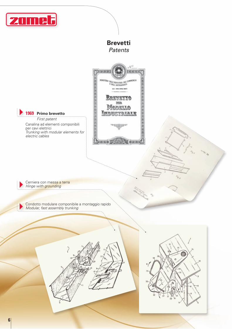
1969 primo brevetto First patent
Cerniera con messa a terra Hinge with grounding
Canalina ad elementi componibili per cavi elettrici Trunking with modular elements for electric cables
Condotto modulare componibile a montaggio rapido Modular, fast assembly trunking
brevettipatents

7
Canalina ad incastro perfezionata per il contenimento caviQuick click trunking improved to contain cables
Serie ZE: sistema di fissaggio per impianti pannelli fotovoltaiciZE series: fixing systems for photovoltaic systems (solar panels)
Giunzione con viti mobiliJoint with movable screw
Giunzione rapida ad incastro Quick click joint
Passerelle a traversine ad incastroQuick click cable ladders
Condotto modulare componibile perfezionato per ermeticizzazione del sistema
Modular trunking improved to make the system airtight.

8
certificazioni prodottoproduct certifications

9
Prove sismiche - Disposizione canaline e traversine su tavola vibranteSeismic tests - Arrangement of the trunking and the cable ladders on the shaking table

10
certificazione di sistema iSo 9001:2008iso 9001:2008 system certification
zAmET S.p.A., ha raggiunto nel 2001 un obiettivo importante: il conseguimento della doppia certificazione in base alle norme internazionali ISO 9001, che attestano all’azienda le caratteristiche di qualità e affidabilità totale prima, durante e dopo la costruzione del prodotto.
Già da molti anni l’azienda si era imposta sui mercati di tutta Europa e del mondo per l’alto livello di qualità nella progettazione e costruzione di canaline metalliche portacavi. Come però è ampiamente noto a tutti gli operatori del settore, l’unificazione dei mercati europei e la crescente concorrenza internazionale, hanno imposto a tutte le aziende un notevole adeguamento qualitativo del loro processo industriale. Ciò comporta, in concreto, l’uniformarsi a standards operativi contenuti, appunto, nelle normative ISO 9000.
Nel piano generale delle normative ISO 9000 sono contemplati tre modelli di certificazione: ISO 9001, ISO 9002 e ISO 9003. la norma iSo 9001 è la più completa, essa infatti garantisce la qualità del prodotto a tutti i livelli del processo produttivo, ma ciò che forse più conta, comprende anche l’assistenza al cliente.
Il concetto di assistenza nel nostro caso si concretizza nel rapporto stretto col cliente e parte ancor prima della commessa, attraverso lo scambio d’informazioni tecniche basilari che nel corso del rapporto di lavoro si traduce in un feedback costante di risultati e consigli operativi.
In 2001, ZAMET S.p.A. achieved an important aim: double certification under the international ISO 9001 standards, certifying the company’s quality and total reliability before, during and after the manufacturing of the product.
The company has long been known on all European and world markets for its high quality design and construction of trunking, cable trays and cable ladders. However, it is widely known to all of the operators in the industry that the unification of the European markets and growing international competition have forced all companies to significantly modify their industrial processes in terms of quality. Essentially, this entails conforming to the operational standards contained in the ISO 9000 standards.
Three certification models are contemplated in the general plan of the ISO 9000 standards: ISO 9001, ISO 9002 and ISO 9003. The most complete is the ISO 9001 standard. In fact, this standard guarantees the product quality at every level of the production process, but perhaps more importantly, it also includes customer service.
In our case, the concept of service is embodied in a close relationship with the client, and starts even before the order arrives, with the exchange of basic technical information which, in the course of the work relationship, is translated into a constant feedback of operating results and consultation.

11
UNI EN 10111 Ottobre 2008 Lamiere e nastri a basso tenore di carbonio laminati a caldo in continuo per formatura a freddo
Lamiera grezza nera
UNI EN 10346 Ottobre 2015 Prodotti piani di acciaio rivestiti per immersione a caldo in continuo
Lamiera zincata
UNI EN 10143 Dicembre 2006 Lamiere sottili e nastri di acciaio con rivestimento applicato per immersione a caldo in continuo. Tolleranze sulla dimensione e sulla forma
Lamiera zincata
UNI EN ISO 1461 CEI 7.6 a richiesta
Luglio 2009 Rivestimenti di zincatura per immersione a caldo su prodotti finiti ferrosi e articoli di acciaio
Lamiera zincata caldo
UNI EN 10088-2 Settembre 2005 Acciai inossidabili - Parte 2: Condizioni tecniche di fornitura delle lamiere, dei fogli e dei nastri di acciaio resistente alla corrosione per impieghi generali
Lamiera acciaio inox
EN 61537 Novembre 2007 Sistemi di canalizzazioni e accessori per cavi - Sistemi di passerelle porta cavi a fondo continuo e a traversini
UNI 3740-1:1999 Gennaio 1999 Bulloneria di acciaio. Prescrizioni tecniche - Generalità BulloneriaUNI EN 10130 Marzo 2007 Prodotti piani laminati a freddo, di acciaio a basso
tenore di carbonio per imbutitura o piegamento a freddoLamiera grezza nera
EN 50085-1:2005 Marzo 2006 Sistemi di canali e di condotti per installazioni elettriche - Prescrizioni generali
EN 50085-2-1:2006 Aprile 2007 Sistemi di canali e di condotti per installazioni elettriche per montaggio a parete ed a soffitto
Marchio UL Codice categoria: CYNW.E471266 - CYNW7.E471266
UNI EN 10111 October 2008 Continuously hot-rolled low carbon steel sheet and strip for cold forming
Rough black sheet
UNI EN 10346 October 2015 Continuously hot-dip steel flat products Galvanized sheet metal UNI EN 10143 December 2006 Continuously hot-dip metal coated steel sheet and strip.
Tolerances on dimensions and shapeGalvanized sheet
UNI EN ISO 1461 CEI 7.6 upon demand
July 2009 Hot dip galvanized coatings on fabricated iron and steel articles
Hot- galvanized sheet
UNI EN 10088-2 September 2005 Stainless steels - Technical delivery conditions for sheet/plate and strip of corrosion resistant steels for general purposes
Stainless steel sheet
UNI EN 61537 November 2007 Cable tray systems and cable ladder systems for cable management
UNI 3740-1:1999 January 1999 Steel fasteners - Technical specifications - General Information
Bolts
UNI EN 10130 March 2007 Cold rolled low carbon steel flat products for cold forming Rough black sheetEN 50085-1:2005 March 2006 Cable trunking systems and cable ducting systems for
electrical installations - General requirementsEN 50085-2-1:2006 April 2007 Cable trunking systems and cable ducting systems
intended for mounting on walls and ceilingsUL Mark Category code: CYNW.E471266 - CYNW7.E471266
norme applicabili alle passerellestandards applying to cable trays
General standards“Standards for the prevention of accidents at work” under Italian Law no. 51 dated 12.2.1955, Italian Presidential Decree no. 547 dated 27.4.1955 and subsequent amendments.
Special standards
normativa generale“Norme per la prevenzione degli infortuni sul lavoro” di cui alla legge 12.2.1955 n° 51, al D.P.R. 27.4.1955 n° 547 ed alle sue successive integrazioni e modifiche.
normative particolari

12
01
03Zincatura a caldo per immersioneIl processo di zincatura a caldo per immersione consiste nell’immergere l’acciaio in una vasca di zinco fuso a circa 450 °C la cui superficie è stata opportunamente prepa-rata, in modo che si inneschi la reazione Zn-Fe e si formino le diverse fasi di lega che costituiscono il rivestimento, per uno spessore, normalmente, di 50÷65 micron. I prodotti della ZAMET S.p.A. zincati a caldo dopo lavorazione vengono realizzati se-condo le normative UNI EN ISO 1461. Terminato il processo di zincatura si evidenzia, con il tempo, la formazione di una patina bianca; questo fenomeno, del tutto naturale, è causato dalla reazione tra l’ossigeno e lo strato superficiale di zinco che non pregiu-dica la resistenza alla corrosione.La presenza della patina bianca può essere accentuata se il materiale sosta ancora imballato e per un lungo periodo a causa della formazione di condensa e l’assenza di areazione tra le superfici a contatto. La norma UNI EN ISO 1461, come peraltro tutte le principali norme internazionali, prevede che questo fenomeno di ossidazione non può essere oggetto di contestazione né causa di scarto.La ZAMET S.p.A., nell’ottica di fornire un prodotto di qualità elevata, anche se non richiesto, fa realizzare un ulteriore trattamento di passivazione al fine di ritardare la formazione di questo fenomeno.
Zincatura a caldo processo SendzimirConsiste nel rivestire di zinco nastri in acciaio laminati a freddo. Dopo aver norma-lizzato l’acciaio ed accuratamente preparato le superfici si ottiene una perfetta ade-sione dello zinco al metallo base con la formazione di uno strato di lega ferro-zinco uniforme e sottilissimo. In queste condizioni è possibile eseguire sul materiale lavo-razioni plastiche senza che ciò determini il distacco o lo sfaldamento della ricoper-tura. Nelle zone di tranciatura del metallo la protezione anticorrosiva è ugualmente assicurata grazie allo zinco che funzionando da anodo si sacrifica solubilizzandosi sotto forma di ossido di zinco, ciò permette la protezione dell’acciaio di base.
Articolo e suo spessore Rivestimento locale (min) (a) Rivestimento medio (min) (b)
g/m2 µm g/m2 µmAcciaio >6mm 505 70 610 85Acciaio >3mm fino a ≤6mm 395 55 505 70Acciaio ≥1,5mm fino a ≤3mm 325 45 395 55Acciaio <1,5 mm 250 35 325 45Fusioni di ghisa ≥6mm 505 70 575 80Fusioni di ghisa <6mm 430 60 505 70
Masse minime di rivestimento (in relazione agli spessori) su campioni non centrifugati
Il prospetto è per uso generale, norme per i singoli prodotti possono includere differenti requisiti, com-prese diverse categorie di spessore. Si possono aggiungere un requisito per rivestimenti più spessi o per requisiti aggiuntivi, senza per questo influenzare la conformità alla presente norma.(a) Massa locale del rivestimento: valore della massa del rivestimento ottenuto tramite una singola prova gravimetrica(b) Massa media del rivestimento: valore medio delle masse del rivestimento determinato sia utilizzando un campione per il controllo o per conversione dello spessore medio del rivestimento (vedere punto 5 della relativa norma).
materiali e rivestimenti protettiviprotective materials and coatings
Hot dip galvanizingThe hot dip galvanizing process consists in dipping the steel into a tank of molten zinc at a temperature of about 450° C, after its surface has been ap-propriately prepared, to trigger the Zn-Fe reaction and the series alloy phases that form the coating, which is usually 50-60 microns thick. After processing, the ZAMET S.p.A. hot-dip galvanized products are manufac-tured in compliance with UNI EN ISO 1461 standards. Once the zinc plating process is complete, a white film forms over time; this natural phenomenon is caused by the reaction between oxygen and the surface layer of zinc, and does not compromise resistance to corrosion. If the material remains inside the packaging for a long time, the presence of the white film may be accentuated due to the formation of condensation and the lack of aeration between the surfaces in contact. Under UNI EN ISO 1461 and all the main international standards, this oxidation phenomenon cannot be considered as grounds for contention or for rejection.Although not required to do so, in order to supply a high quality product, ZAMET S.p.A subjects its products to an additional passivation treatment to delay the formation of oxidation.
Galvanization (Sendzimir method)For zinc plating cold-rolled steel strips. After normalising the steel and through preparation of its surfaces, complete adhesion of the zinc to the basic metal is achieved and a very thin uniform layer of iron-zinc alloy is formed. The result is that plastic machining operations can be carried out on the material without the removal or flaking of its coating. Anti corrosion protection is also ensured in places where the metal is cut, as the zinc acts as an anode, solubilising into zinc oxide, protecting the steel base.
Item and its thickness Local coating (min) (a) Average coating (min) (b)
g/m2 µm g/m2 µmSteel >6mm 505 70 610 85Steel >3mm up to ≤6mm 395 55 505 70Steel ≥1.5mm up to ≤3mm 325 45 395 55Steel <1.5 mm 250 35 325 45Iron castings ≥6mm 505 70 575 80Iron castings <6mm 430 60 505 70
Minimum coating masses (in relation to the thickness) on non-centrifuged samples
The table is for general use, regulations for the single products may include different requirements, comprising various thickness categories. A requirement may be added for thicker coatings or for addi-tionally requisites, without influencing conformity to this standard.(a) Local mass of the coating: value of the coating mass obtained through a single gravimetric test.(b) Average mass of the coating: average value of the coating masses determined through either the use of a control sample or by conversion of the average coating thickness (see point 5 of the relevant standard).
13
25
15
11
47
45
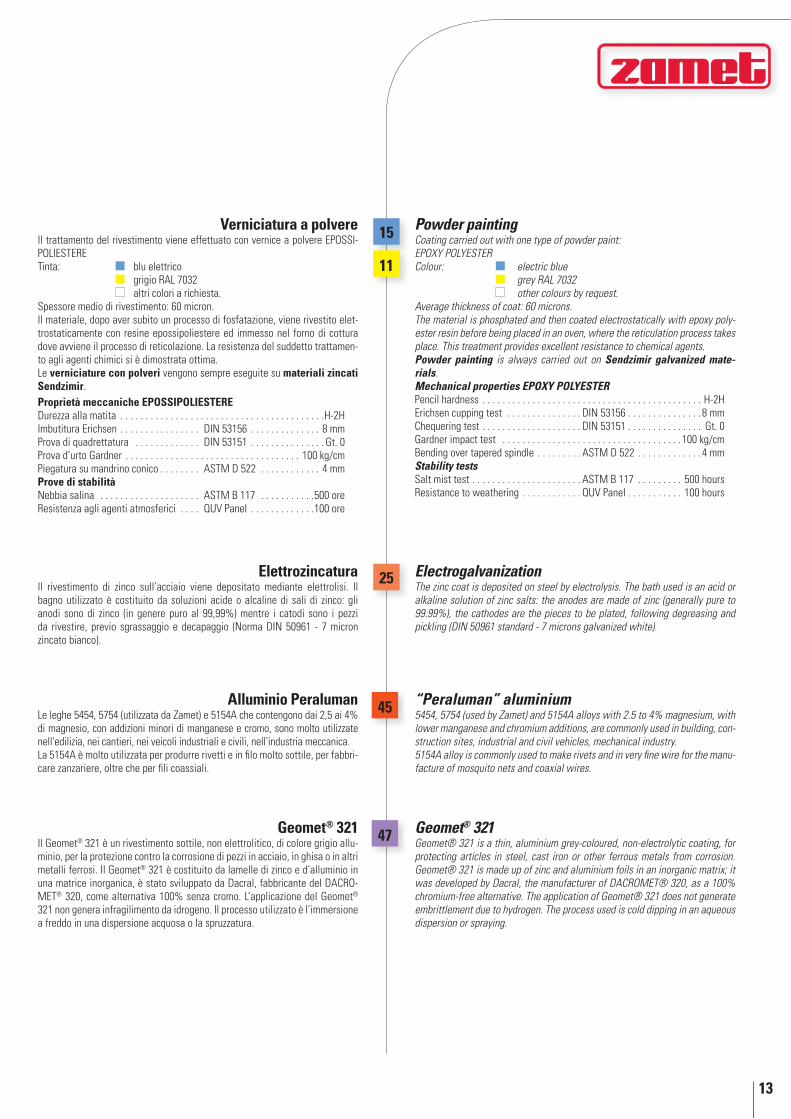
Verniciatura a polvereIl trattamento del rivestimento viene effettuato con vernice a polvere EPOSSI-POLIESTERE Tinta: blu elettrico grigio RAL 7032 altri colori a richiesta.Spessore medio di rivestimento: 60 micron.Il materiale, dopo aver subito un processo di fosfatazione, viene rivestito elet-trostaticamente con resine epossipoliestere ed immesso nel forno di cottura dove avviene il processo di reticolazione. La resistenza del suddetto trattamen-to agli agenti chimici si è dimostrata ottima.Le verniciature con polveri vengono sempre eseguite su materiali zincati Sendzimir.Proprietà meccaniche EPOSSIPOlIEStEREDurezza alla matita . . . . . . . . . . . . . . . . . . . . . . . . . . . . . . . . . . . . . . . . .H-2HImbutitura Erichsen . . . . . . . . . . . . . . . . DIN 53156 . . . . . . . . . . . . . . 8 mmProva di quadrettatura . . . . . . . . . . . . . DIN 53151 . . . . . . . . . . . . . . . Gt. 0Prova d’urto Gardner . . . . . . . . . . . . . . . . . . . . . . . . . . . . . . . . . . . 100 kg/cmPiegatura su mandrino conico . . . . . . . . ASTM D 522 . . . . . . . . . . . . 4 mmProve di stabilitàNebbia salina . . . . . . . . . . . . . . . . . . . . ASTM B 117 . . . . . . . . . . .500 oreResistenza agli agenti atmosferici . . . . QUV Panel . . . . . . . . . . . . .100 ore
ElettrozincaturaIl rivestimento di zinco sull’acciaio viene depositato mediante elettrolisi. Il bagno utilizzato è costituito da soluzioni acide o alcaline di sali di zinco: gli anodi sono di zinco (in genere puro al 99,99%) mentre i catodi sono i pezzi da rivestire, previo sgrassaggio e decapaggio (Norma DIN 50961 - 7 micron zincato bianco).
Powder painting Coating carried out with one type of powder paint: EPOXY POLYESTER Colour: electric blue grey RAL 7032 other colours by request. Average thickness of coat: 60 microns. The material is phosphated and then coated electrostatically with epoxy poly-ester resin before being placed in an oven, where the reticulation process takes place. This treatment provides excellent resistance to chemical agents.Powder painting is always carried out on Sendzimir galvanized mate-rials.Mechanical properties EPOXY POLYESTERPencil hardness . . . . . . . . . . . . . . . . . . . . . . . . . . . . . . . . . . . . . . . . . . . . H-2HErichsen cupping test . . . . . . . . . . . . . . . DIN 53156 . . . . . . . . . . . . . . . 8 mmChequering test . . . . . . . . . . . . . . . . . . . . DIN 53151 . . . . . . . . . . . . . . . Gt. 0Gardner impact test . . . . . . . . . . . . . . . . . . . . . . . . . . . . . . . . . . . . 100 kg/cmBending over tapered spindle . . . . . . . . . ASTM D 522 . . . . . . . . . . . . . 4 mmStability testsSalt mist test . . . . . . . . . . . . . . . . . . . . . . ASTM B 117 . . . . . . . . . 500 hoursResistance to weathering . . . . . . . . . . . . QUV Panel . . . . . . . . . . . 100 hours
ElectrogalvanizationThe zinc coat is deposited on steel by electrolysis. The bath used is an acid or alkaline solution of zinc salts: the anodes are made of zinc (generally pure to 99.99%), the cathodes are the pieces to be plated, following degreasing and pickling (DIN 50961 standard - 7 microns galvanized white).
Geomet® 321Il Geomet® 321 è un rivestimento sottile, non elettrolitico, di colore grigio allu-minio, per la protezione contro la corrosione di pezzi in acciaio, in ghisa o in altri metalli ferrosi. Il Geomet® 321 è costituito da lamelle di zinco e d’alluminio in una matrice inorganica, è stato sviluppato da Dacral, fabbricante del DACRO-MET® 320, come alternativa 100% senza cromo. L’applicazione del Geomet® 321 non genera infragilimento da idrogeno. Il processo utilizzato è l’immersione a freddo in una dispersione acquosa o la spruzzatura.
Alluminio PeralumanLe leghe 5454, 5754 (utilizzata da Zamet) e 5154A che contengono dai 2,5 ai 4% di magnesio, con addizioni minori di manganese e cromo, sono molto utilizzate nell'edilizia, nei cantieri, nei veicoli industriali e civili, nell'industria meccanica.La 5154A è molto utilizzata per produrre rivetti e in filo molto sottile, per fabbri-care zanzariere, oltre che per fili coassiali.
“Peraluman” aluminium5454, 5754 (used by Zamet) and 5154A alloys with 2.5 to 4% magnesium, with lower manganese and chromium additions, are commonly used in building, con-struction sites, industrial and civil vehicles, mechanical industry.5154A alloy is commonly used to make rivets and in very fine wire for the manu-facture of mosquito nets and coaxial wires.
Geomet® 321Geomet® 321 is a thin, aluminium grey-coloured, non-electrolytic coating, for protecting articles in steel, cast iron or other ferrous metals from corrosion. Geomet® 321 is made up of zinc and aluminium foils in an inorganic matrix; it was developed by Dacral, the manufacturer of DACROMET® 320, as a 100% chromium-free alternative. The application of Geomet® 321 does not generate embrittlement due to hydrogen. The process used is cold dipping in an aqueous dispersion or spraying.

14
40
41
Acciaio inoxAISI 304 - Acciaio al Cr-Ni a basso tasso di C, austenitico, non temprabile, resi-stente alla corrosione. Amagnetico allo stato ricotto, leggermente magnetico se lavorato a freddo. Buona saldabilità e discreta resistenza alla corrosione intercri-stallina. Ottima tenacità fino a bassissime temperature.X5CrNi18-10 • D.num. 1.4301• Pmax = 0,045 • C 0,07 • Si 1,0 • Mn 2,0 S 0,015 • N 0,11 • Cr da 17,5 a 19,5 • Ni da 8,0 a 10,5
AISI 316L - Ottima resistenza alla corrosione in atmosfera ed in una grande varietà di sali, acidi organici e sostanze alimentari, discreta nei confronti delle soluzioni deboli di acidi riducenti, migliore rispetto agli altri acciai austenitici non contenenti Mo, verso gli alogenuri e l’acqua marina.X5CrNiMo17-12-2 • D.num. 1.4401 • Pmax = 0,045 • C 0,07 • Si 1,0 • Mn 2,0 S 0,015 • N 0,11 • Cr da 16,5 a 18,5 • Mo da 2,0 a 2,5 • Ni da 10,0 a 13,0
L’AISI 430 è senza dubbio il tipo di acciaio ferritico più diffuso e di maggior impiego; facilmente lavorabile a freddo presenta un incrudimento inferiore a quello degli acciai austenitici.Possiede buone caratteristiche di resistenza alla corrosione (inferiore a quelle degli acciai austenitici) sia a temperatura ambiente, sia a temperature più ele-vate e resiste a caldo ed ai gas solforosi secchi.Impiegato nell’industria automobilistica, in quella degli elettrodomestici ed in quella chimica.
- Il codice 73 corrisponde al trattamento AISI 430.- Il codice 75 corrisponde al trattamento AISI 430 con spessore 1,50 mm.
Stainless steelAISI 304 - Cr-Ni steel with low percentage of C, austenitic, not hardenable, corrosion-resistant. Non-magnetic when annealed, slightly magnetic when cold processed. Good weldability and fairly good resistance to intercrystalline corro-sion. Excellent toughness up to very low temperatures.X5CrNi18-10•D no.1.4301•Pmax=0.045•C≤0.07•Si≤1.0•Mn≤ 2.0 S ≤0.015•N≤0.11•Cr17.5to19.5•Ni8.0to10.5
AISI 316L - Excellent corrosion resistance in atmosphere and in a wide variety of salts, organic acids and foodstuffs, discreet with regard to weak acid reduc-tant solutions, better than other austenitic steels that do not contain Mo, in relation to halides and sea water.X5CrNiMo17-12-2•D no.1.4401•Pmax=0.045•C≤0.07•Si≤1.0•Mn≤ 2.0 S ≤0.015•N≤0.11•Cr16.5to18.5•Mo2.0to2.5•Ni10.0to13.0
AISI 430 is doubtlessly the most common type of ferritic steel and the most used; it is easy to process when cold, with a lower hardening level than aus-tenitic steels. It has good corrosion resistance characteristics (lower than austenitic steels) both at ambient temperature and at higher temperatures, and resists heat and dry sulphurous gases. Used in the automobile, household appliance and chemical industries.
- Code 73 refers to AISI 430 treatment.- Code 75 refers to AISI 430 treatment with a thickness of 1.50 mm.
73
75
materiali e rivestimenti protettiviprotective materials and coatings
Fasi di lavorazione della verniciatura a polverePowder painting process phases
Fasi di lavorazione della zincatura a caldo per immersione dopo lavorazione
Hot dip galvanization phases following processing
15
76
76
NE
W
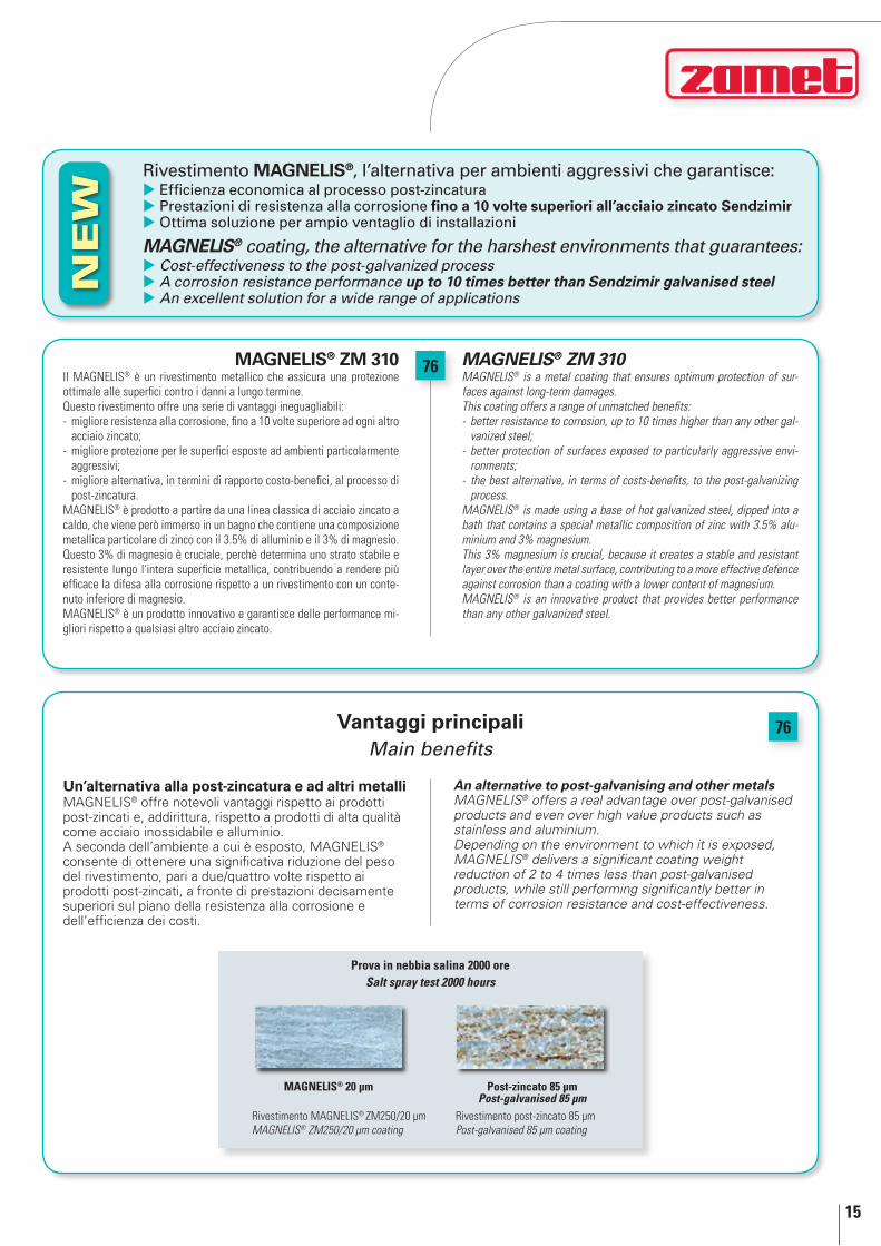
MAGnElIS® ZM 310MAGNELIS® is a metal coating that ensures optimum protection of sur-faces against long-term damages.This coating offers a range of unmatched benefits:- better resistance to corrosion, up to 10 times higher than any other gal-
vanized steel;- better protection of surfaces exposed to particularly aggressive envi-
ronments;- the best alternative, in terms of costs-benefits, to the post-galvanizing
process.MAGNELIS® is made using a base of hot galvanized steel, dipped into a bath that contains a special metallic composition of zinc with 3.5% alu-minium and 3% magnesium.This 3% magnesium is crucial, because it creates a stable and resistant layer over the entire metal surface, contributing to a more effective defence against corrosion than a coating with a lower content of magnesium.MAGNELIS® is an innovative product that provides better performance than any other galvanized steel.
mAgnEliS® zm 310Il MAGNELIS® è un rivestimento metallico che assicura una protezione ottimale alle superfici contro i danni a lungo termine.Questo rivestimento offre una serie di vantaggi ineguagliabili:- migliore resistenza alla corrosione, fino a 10 volte superiore ad ogni altro
acciaio zincato;- migliore protezione per le superfici esposte ad ambienti particolarmente
aggressivi;- migliore alternativa, in termini di rapporto costo-benefici, al processo di
post-zincatura.MAGNELIS® è prodotto a partire da una linea classica di acciaio zincato a caldo, che viene però immerso in un bagno che contiene una composizione metallica particolare di zinco con il 3.5% di alluminio e il 3% di magnesio. Questo 3% di magnesio è cruciale, perchè determina uno strato stabile e resistente lungo l'intera superficie metallica, contribuendo a rendere più efficace la difesa alla corrosione rispetto a un rivestimento con un conte-nuto inferiore di magnesio.MAGNELIS® è un prodotto innovativo e garantisce delle performance mi-gliori rispetto a qualsiasi altro acciaio zincato.
Un’alternativa alla post-zincatura e ad altri metalliMAGNELIS® offre notevoli vantaggi rispetto ai prodotti post-zincati e, addirittura, rispetto a prodotti di alta qualità come acciaio inossidabile e alluminio.A seconda dell’ambiente a cui è esposto, MAGNELIS® consente di ottenere una significativa riduzione del peso del rivestimento, pari a due/quattro volte rispetto ai prodotti post-zincati, a fronte di prestazioni decisamente superiori sul piano della resistenza alla corrosione e dell’efficienza dei costi.
An alternative to post-galvanising and other metalsMAgnELIS® offers a real advantage over post-galvanised products and even over high value products such as stainless and aluminium.Depending on the environment to which it is exposed, MAgnELIS® delivers a significant coating weight reduction of 2 to 4 times less than post-galvanised products, while still performing significantly better in terms of corrosion resistance and cost-effectiveness.
Rivestimento mAgnEliS®, l’alternativa per ambienti aggressivi che garantisce: Efficienza economica al processo post-zincatura Prestazioni di resistenza alla corrosione fino a 10 volte superiori all’acciaio zincato Sendzimir Ottima soluzione per ampio ventaglio di installazioni
MAGnElIS® coating, the alternative for the harshest environments that guarantees: cost-effectiveness to the post-galvanized process A corrosion resistance performance up to 10 times better than Sendzimir galvanised steel An excellent solution for a wide range of applications
Vantaggi principalimain benefits
Prova in nebbia salina 2000 oreSalt spray test 2000 hours
Rivestimento MAGNELIS® ZM250/20 µmMAGNELIS® ZM250/20 µm coating
Rivestimento post-zincato 85 µmPost-galvanised 85 µm coating
MAGnElIS® 20 µm Post-zincato 85 µm Post-galvanised 85 µm
16
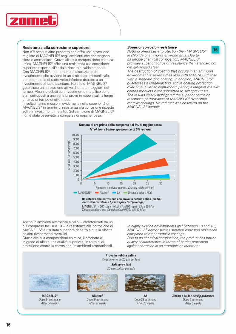
76resistenza alla corrosione superioreNon c’è nessun altro prodotto che offra una protezione migliore di MAGNELIS® negli ambienti che contengono cloro o ammoniaca. Grazie alla sua composizione chimica unica, MAGNELIS® offre una resistenza alla corrosione superiore rispetto all’acciaio zincato a caldo standard.Con MAGNELIS®, il fenomeno di distruzione del rivestimento che avviene in un ambiente ammoniacale, per esempio, è di sette volte inferiore rispetto a un rivestimento zincato standard. Non solo: MAGNELIS® garantisce una protezione attiva di durata maggiore nel tempo. Alcuni prodotti con rivestimento metallico sono stati sottoposti a una serie di prove in nebbia salina lungo un arco di tempo di otto mesi.I risultati hanno messo in evidenza la netta superiorità di MAGNELIS® in termini di resistenza alla corrosione rispetto agli altri rivestimenti metallici. Sul campione di MAGNELIS® non è stata osservata la comparsa di ruggine rossa.
Anche in ambienti altamente alcalini – caratterizzati da un pH compreso tra 10 e 13 – la resistenza alla corrosione di MAGNELIS® è risultata superiore rispetto a quella offerta da altri rivestimenti metallici.Grazie alla sua composizione chimica, il prodotto è in grado di offrire una qualità superiore, in termini di protezione contro la corrosione, in ambienti ammoniacali.
Superior corrosion resistancenothing offers better protection than MAgnELIS® in chloride or ammonia environments. Due to its unique chemical composition, MAgnELIS® provides superior corrosion resistance than standard hot dip galvanised steel.The destruction of coating that occurs in an ammonia environment is seven times less with MAgnELIS® than with a standard zinc coating. In addition, MAgnELIS® guarantees a longer-lasting, active coating protection over time. Over an eight-month period, a range of metallic coated products were submitted to salt spray tests. The results clearly highlighted the superior corrosion resistance performance of MAgnELIS® over other metallic coatings. no red rust was observed on the MAgnELIS® sample.
In highly alkaline environments (pH between 10 and 13), MAgnELIS® demonstrates superior corrosion resistance compared to other metallic coatings.Due to its chemical composition, the product has better quality characteristics in terms of barrier protection against corrosion in an ammonia environment.
Prova in nebbia salinaRivestimento da 20 µm per lato
Salt spray test20 µm coating per side
MAGnElIS®
Dopo 34 settimaneAfter 34 weeks
Aluzinc®
Dopo 34 settimaneAfter 34 weeks
ZA Dopo 28 settimane
After 28 weeks
Zincato a caldo / Hot dip galvanisedDopo 6 settimane
After 6 weeks
50 10 15 20 25 30
10000900080007000600050004000300020001000
0
N°
di o
re /
N°
of h
ours
(h)
Spessore del rivestimento / Coating thickness (µm)
MAGNELIS® Aluzinc® ZA Zincato a caldo / HDG
Resistenza alla corrosione con prova in nebbia salina (media)Corrosion resistance by salt spray test (average)MAGNELIS®: > 200 h/µm - Aluzinc®: ±100 h/µm - ZA: ± 25 h/µm Zincato a caldo / Hot dip galvanised (HDG): ± 8-10 h/µm
numero di ore prima della comparsa del 5% di ruggine rossaN° of hours before appearance of 5% red rust

17
76
protezione auto-cicatrizzante sui bordi tagliatiOltre ad essere rafforzato da una protezione catodica equivalente al rivestimento in zinco, MAGNELIS® protegge i bordi tagliati esposti grazie a un sottile film protettivo a base di zinco contenente magnesio, che previene l’insorgenza di reazioni corrosive.La natura di questa pellicola varia in funzione dell’ambiente e le sue proprietà variano a seconda del contenuto di alluminio e magnesio.
Attento all’ambienteL’applicazione di MAGNELIS® garantisce la conservazione delle risorse naturali, dato che utilizza un quantitativo di zinco inferiore rispetto ai rivestimenti in zinco puro. Inoltre, come Aluzinc®, MAGNELIS® riduce in misura consistente il tasso di deflusso* dello zinco nel suolo.
* Per tasso di deflusso si intende il passaggio di un materiale dalla sua superficie all’ambiente esterno (in g/m2/anno). Nel nostro caso: la quantità di zinco rimossa dalla su-perficie dalla pioggia che si riversa nell’ambiente esterno.
Self-repairing protection on cut edgesIn addition to being fortified by a cathodic protection equivalent to zinc coating, MAgnELIS® protects exposed cut edges with a thin zinc-based protective film with magnesium, which prevents corrosive reactions.The nature of this film varies depending on the environment and the properties according to the aluminium and magnesium content.
Environmentally responsibleThe application of MAgnELIS® ensures the preservation of natural resources since it uses less zinc than pure zinc coatings. Moreover, like Aluzinc®, MAgnELIS® reduces considerably the zinc runoff* in soils.
* Runoff rate: the rate of dissolution of a material from its surface into the external environment (in g/m2/year). In our case: the quantity of zinc washed from the surface by falling rain water.
Esposizione all’aperto in diversi periodi di tempo di MAGnElIS® ZM250 con uno spessore di 2 mm a Brest (Francia)
Outdoor exposure over different time periods of MaGNELiS® ZM250 with 2 mm thickness in Brest (France)
Categoria marina C5-M (la più severa) Marine category C5-M (the most severe)Institut Français de la Corrosion
6 mesi / 6 months30-40% ruggine rossa / red rust60% ruggine bianca / white rust
16 mesi / 16 months10% ruggine rossa / red rust70% ruggine bianca / white rust
0,8
0,6
0,4
0,2
0
g/m
2
MAGNELIS® Aluzinc® ZA Zincato a caldo / HDG
Misurazione della perdita di massa / Measurement of mass losspH: 11,7 - Soluzione con 5% NH3 - T: 20° C - Durata del test 24 orepH: 11.7 - Solution with 5% NH3 - T: 20° C - Test duration 24 h
perdita di peso negli ambienti più impegnativiWeight loss in harshest environments
4
3,5
3
2,5
2
1,5
1
0,5
0
g/m
2 /ann
o / g
/m2 /y
ear
MAGNELIS® Aluzinc® Zinco / Zinc
Brest (Francia) - Categoria marina C3 (media)Brest (France) - Maritime category C3 (average)Institut Français de la Corrosion
tasso di deflusso dello zincoZinc runoff rate

18
76confronto tra le caratteristiche dei rivestimenti metalliciMetallic coatings features comparison
InferioreInferior
EquivalenteEquivalent
Superiore Superior
Caratteristiche del prodottoProduct features HDG Zn ZA Aluzinc® MAGnElIS®
Proprietà anti-corrosioneanti-corrosion properties
In un ambiente contenente cloro (zona marittima, piscina)In a chloride environment (marine site, swimming pool)
RiferimentoReference
In un ambiente contenente ammoniaca (stalla, fattoria, serra)In an ammonia environment (stable, farm, greenhouse)
RiferimentoReference
In un ambiente contenente SO2 (ambiente industriale acido)In an SO2 environment (acid industrial environment)
RiferimentoReference
Protezione temporanea (trasporto, stoccaggio)Temporary protection (transport, storage)
RiferimentoReference
Protezione dei bordi (a forte spessore, lamiera forata)Edge protection (heavy gauge, perforated sheet)
RiferimentoReference
Corrosione di una parte deformata (piegata o stampata)Corrosion of a deformed part (bent or stamped)
RiferimentoReference
Proprietà di formaturaForming properties
Piegatura & profilaturaBending & roll-forming
RiferimentoReference
StampaggioDrawing
RiferimentoReference
Proprietà di assemblaggioassembling properties
Saldatura a punti (spessore equivalente)Spot welding (equivalent thickness)
RiferimentoReference
Aspettoaspect
Aspetto visivoVisual appearance
RiferimentoReference
proprietà del rivestimento
MAGnElIS® ZM310
Peso del rivestimento - su entrambi i lati (g/m²) 310
Spessore del rivestimento (µm per lato) 25
La densità del rivestimento MAGNELIS® è di 6,2 g/cm3, a causa della sua composizione chimica.
MAGNELIS® ZM310 è il primo rivestimento metallico a ricevere la certificazione C5. L’istituto tecnico di ricerca svedese “Technical Research Institute of Sweden (SP)” ha dichiarato che MAGNELIS® ZM310 rientra nella classe di corrosività C5, secondo la norma SS-EN ISO 12944 - 2.
mAgnEliS® è un marchio commerciale di MAGnElIS® is a trademark of
Coating properties
MAGnElIS® ZM310
Coating weight - double sided (g/m²) 310
Coating thickness (µm per side) 25
The density of the MAGNELIS® coating is 6.2 g/cm3, due to its chemical composition.
MAgnELIS® ZM310 is the first metallic coating that received a C5 certification. The Technical Research Institute of Sweden (SP) states that MAgnELIS® ZM310 is suitable for corrosivity class C5, according to the SS-En ISO 12944 - 2 norm.

19
Gli acciai inossidabili sono delle leghe a base di Ferro, Cromo e Carbonio, contenenti eventualmente altri elementi come Nichel, Molibdeno, Silicio, Titanio ecc.Sono definiti inossidabili perché alla presenza di un ambiente ossidante (quindi anche l’aria) si forma sulla loro superficie una strato protettivo costituito da Ossigeno adsorbito.Questo strato invisibile, costituisce una barriera al proseguimento dell’ossidazione e quindi della corrosione. Condizione indispensabile perché tale strato protettivo si formi è la presenza di una quantità sufficiente di Cromo; l’Euronorm 88-71 definisce acciai inossidabili quelle leghe ferrose che contengono Cromo in ragione di almeno l’11%.In relazione al loro comportamento strutturale gli acciai inossidabili si possono dividere in tre categorie fondamentali:• Martensitici,astrutturavariabileinfunzionedella
temperatura e quindi induribili per trattamento termico. I tipi caratteristici contengono circa il 13% di Cromo e piccole quantità di altri elementi in lega quali il Nichel ad esempio, in quantità mai superiore al 2,5%.
• Ferritici,astrutturaferriticastabileindipendentedallatemperatura. I tipi caratteristici contengono circa il 17% di Cromo e tenori di Carbonio molto bassi, solitamente al di sotto dello 0,1%.
• Austenitici,astrutturaausteniticastabileindipendentedallatemperatura. I tipi caratteristici contengono Cromo in quantità superiore al 17% e Nichel in quantità superiore al 7%.
i sistemi di canaline metalliche in acciaio inox della zamet S.p.A. trovano largo impiego nel settore alimentare, navale, gallerie autostradali, chimico, farmaceutico ed allevamento.
Stainless steels are Iron, Chromium and Carbon based alloys, possibly containing other elements like nickel, Molybdenum, Silicon, Titanium, etc.They are described as stainless because, in the presence of an oxidising environment (which could also be air), a protective layer made up of adsorbed Oxygen forms on their surface.This invisible layer forms a barrier against the continuation of oxidation and, therefore, of corrosion. In order for this protective layer to form, a sufficient quantity of Chromium is indispensable. Euronorm 88-71 defines stainless steels as those ferrous alloys which contain at least 11% Chromium. In relation to their structural behaviour, stainless steels may be divided into three basic categories:• Martensitics,withastructurethatvariesaccordingto
temperature and can, therefore, be hardened by heat-treating. The characteristic types contain about 13% Chromium and small quantities of other elements in alloy, such as nickel, in quantities that never exceed 2.5%.
• Ferritics,withastableferriticstructureregardlessofthetemperature. The characteristic types contain about 17% Chromium and very low levels of Carbon, usually less than 0.1%.
• Austenitics,withastableausteniticstructureregardlessofthe temperature. The characteristic types contain about 17% Chromium and nickel in quantities greater than 7%.
Zamet S.p.A. stainless steel trunking and cable trays are widely used in the food, naval, road tunnel, chemical, pharmaceutical and animal breeding industries.
che cosa sono gli acciai inossidabiliWhat are stainless steels

20
caratteristiche degli acciai austenitici serie A 300characteristics of series A 300 austenitic steels
Gli AcciAi AUSTEniTici serie A300 sono quelli che attualmente Zamet S.p.A. utilizza per le linee di canaline metalliche attualmente in produzione. In funzione della loro composizione chimica e delle caratteristiche d’impiego si possono dividere questi acciai in tre gruppi:
Austenitici al cr-ni caratterizzati dalla presenza del 16-20% di Cr e 7-12% di Ni con possibilità aggiunta d’altri elementi tipo Zolfo o Selenio che ne facilitano la lavorazione per asportazione di truciolo, oppure Titanio o Nobio quali stabilizzanti del Carbonio ad evitare la formazione di Carburi di Cromo. Posseggono caratteristiche meccaniche non elevate a temperatura ambiente ma che restano notevoli anche a temperature molto basse ed una buona resistenza alla corrosione in quasi tutti gli ambienti aggressivi.
Austenitici al cr-ni-mo caratterizzati nella composizione chimica dal Cr (16-18%) dal Ni (10-18%) e dal Mo (2-6%) ed è proprio la presenza di quest’ultimo elemento che dà a questi acciai una particolare resistenza alla corrosione sotto tensione ed alla corrosione per vaiolatura, consentendone quindi l’impiego anche in ambiente di forte aggressività chimica ed anche alla presenza di soluzioni contenenti ioni Cloro. Come nel caso precedente anche tra questi esistono i tipi a basso Carbonio ed i tipi stabilizzati con aggiunte di Titanio per consentirne anche l’impiego nell’intervallo di temperatura tra i 450 e gli 800 °C.
Austenitici resistenti alle alte temperature chiamati anche “refrattari” per indicare le elevate caratteristiche di resistenza meccanica ed alla corrosione che vengono mantenute anche a temperature piuttosto elevate. Caratterizzati nella composizione chimica da tenori d’elementi leganti superiori a quelli dei tipi precedenti: il Cromo è spesso superiore al 20%, anche il Nichel in alcuni casi può raggiungere o anche superare il 20%, il Silicio è spesso superiore all’1% ed il Carbonio è di solito presente in tenori piuttosto elevati rispetto agli inossidabili tradizionali.
Secondo i tipi possono essere impiegati a temperature superiori ai 700 °C fino a 1150 °C mantenendo buone caratteristiche d’inossidabilità e sufficienti caratteristiche meccaniche.
Series A300 AUSTEnITIC STEElS are those that Zamet S.p.A. uses for the metal cable trays currently in production. These steels may be divided into three groups depending on their chemical composition and characteristics:
Cr-ni Austenitic steels Characterised by 16-20% Cr and 7-12% ni with the possible addition of other elements like Sulphur or Selenium that facilitate removal of shavings in machining, or Titanium or niobium as Carbon stabilisers to prevent the formation of Chromium carbides. They possess mechanical characteristics that are of little importance at ambient temperature but remain significant at very low temperatures, and offer good resistance to corrosion in almost all aggressive environments.
Cr-ni-Mo Austenitic steels Their chemical composition is characterised by Cr (16-18%) and ni (10-18%) and by Mo (2-6%), and it is the presence of this last element that gives these steels particular resistance to corrosion under tension and to corrosion due to pitting. This makes it suitable for use in the presence of strong chemical aggression and also in the presence of solutions containing Chlorine ions. As in the previous case, there are low carbon types and stabilised types with the addition of Titanium, to allow use at temperatures between 450 and 800 °C.
Austenitic steels resistant to high temperatures Also called “refractory steels”, indicating their characteristics of high mechanical and corrosion resistance which are maintained even at rather high temperatures. Their chemical composition is characterised by higher levels of binding elements than those of the previous types. Chromium is frequently present in percentages higher than 20%. In some cases nickel may also reach, and even exceed, 20%. Silicon is frequently present in percentages greater than 1% and Carbon is usually present at rather high levels compared to traditional stainless steels.
Depending on the type, they may be used at temperatures higher than 700 °C and up to 1150 °C, and maintain good stainless characteristics and acceptable mechanical characteristics.
21
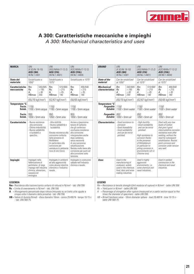
A 300: caratteristiche meccaniche e impieghiA 300: mechanical characteristics and uses
lEGEnDARm = Resistenza alla trazione (carico unitario di rottura) in N/mm2 - tab. UNI 556Rs = Limite di snervamento in N/mm2 - tab. UNI 556A = Allungamento percentuale dopo rottura (misurato su un tratto utile uguale a
cinque volte il diametro della provetta) - tab. UNI 556HB = Valore di durezza Brinell - sfera diametro 10mm - carico 29.400 N - tempo 10-15 s
- tab. UNI 560-75
MARCA UNI(X 5CrNi 18-10) AISI (304)W.Nr.1.4301
UNI (X5CrNiMo17-12-2) AISI (316)(W.Nr.1.4401)
UNI (X2CrNiMo17-12-2) AISI (316l) (W.Nr.1.4404)
Stato del materiale
Solubilizzato a 1050°
Solubilizzato a 1075°
Solubilizzato a 1075°
Caratteristichemeccaniche
Rm Rs AHBmax
540/685> 195> 40200
Rm Rs AHBmax
510/660> 215> 45190
Rm Rs AHBmax
490/640> 215> 45180
(55/70 kgf/mm2) (52/67 kgf/mm2) (50/65 kgf/mm2)temperature °C
Fucin.Solub.
Fucin.Solub.
11501100 > 5mm acqua
9501050 > 5mm aria
11501100 > 5mm acqua
9501050 > 5mm aria
11501100 > 5mm acqua
9501050 > 5mm aria
Caratteristiche - Buona resistenza alla corrosione
- Ottima imbutibilità- Buona saldabilità
e lucidabili a specchio.
- Alta duttilità- Buona saldabilità e
lucidabilità
Elevata resistenza alla corrosione conferita dalla presenza di Molibdeno (in particolare alla corrosione per vaiolatura in ambiente ricco di ioni Cloro).
Acciaio a bassissimo tenore di Carbonio che gli conferisce una buona resistenza alla corrosione intergranulare anche dopo saldatura, senza necessità di una successiva solubilizzazione. Resiste molto bene alla corrosione per punti ed alla corrosione sotto tensione.
Impieghi Impiegati nella fabbricazione di pentolame, di largo impiego nell’industria chimica, alimentare, casearia ed enologica.
Impiegato in ambienti ad alta aggressività come alcune industrie chimiche e l’industria navale.
Impiegato in costruzioni saldate nell’industria chimica e navale.
lEGEnDRm=Resistancetotensilestrength(Unitmodulusofrupture)inN/mm2 - table UNI 556Rs =YieldpointinN/mm2 - table UNI 556A =Percentageofelongationafterrupture(measuredonausefulsectionequaltofive
times the diameter of specimen) - table UNI 556HB=Brinellhardnessvalue-10mmdiametersphere-load29,400N-time10-15s-
table UNI 560-75
BRaND UNI(X 5CrNi 18-10) aiSi (304)W.No.1.4301
UNI (X5CrNiMo17-12-2) aiSi (316)(W.No.1.4401)
UNI (X2CrNiMo17-12-2) aiSi (316L) (W.N0.1.4404)
State of the material
Can be solubilized at 1050°
Can be solubilized at 1075°
Can be solubilized at 1075°
Mechanical characteristics
Rm Rs AHBmax
540/685> 195> 40200
Rm Rs AHBmax
510/660> 215> 45190
Rm Rs AHBmax
490/640> 215> 45180
(55/70 kgf/mm2) (52/67 kgf/mm2) (50/65 kgf/mm2)Temperature °C
ForgeableSoluble
ForgeableSoluble
11501100 > 5mm water
9501050 > 5mm air
11501100 > 5mm water
9501050 > 5mm air
11501100 > 5mm water
9501050 > 5mm air
Characteristics - Good resistance to corrosion
- Good drawability- Good weldability
and can be mirror polished
- High ductility- Good weldability
and can be mirror polished
High resistance to corrosion thanks to the presence of Molybdenum (in particular to pitting corrosion in environments rich in Chlorine ions).
Steel with very low levels of Carbon that give it good intercrystalline corrosion resistance even after welding, without the need for subsequent solubilization. Resists point corrosion and corrosion under tension very well.
Uses Used in the manufacturing of cookware, widely used in the chemical, food, dairy and wine-making industries.
Used in highly aggressive environments, i.e. some chemical and naval industries..
Used in welded construction in the chemical and naval industries.

22
A 400: caratteristiche meccaniche ed impieghiA 400: mechanical characteristics and uses
legendaRm = Resistenza alla trazione (carico unitario di rottura) in N/mm2 (tab. UNI 556)Rs = Limite di snervamento in N/mm2 (tab. UNI 556)A = Allungamento percentuale dopo rottura (tab. UNI 556)HB = Valore di durezza Brinell in N/mm2 (tab. UNI 560-75)
LegendRm=Resistancetotensilestrength(Unitmodulusofrupture)inN/mm2 (table UNI 556)Rs =YieldpointinN/mm2 (table UNI 556)a =Percentageofelongationafterrupture(tableUNI556)HB =BrinellhardnessvalueinN/mm2 (table UNI 560-75)
Euro norm
1.4016UNI EN 10088-2
AISI UnI
430 X6 Cr 17
Stato del materiale
Ricristallizzato a 780-820 °C
Caratteristichemeccaniche
Rm 450/600 Rs 0,2min. 260 A min. 20 HBmax 200
Caratteristiche Acciaio inoss. ferritico con il 17% di Cr
Discreta saldabilità e resistenza all’ossidazione a caldo
Resistenza alla corrosione decisamente superiore a quella offerta da altri inossidabili con il 13% di Cr
Impieghi Decorazioni ed architettura di interni, contenitori alimentari, sistemi di staffaggio pannelli solari, cisterne, autoclavi, industria automobilistica, bulloneria e viteria, coniatura di monete, industria chimica e petrolchimica
Euro Norm
1.4016UNI EN 10088-2
aiSi UNi
430 X6 Cr 17
State of the material
Recrystallized at 780-820 °C
Mechanical characteristics
Rm 450/600 Rs 0.2min. 260 A min. 20 HBmax 200
Characteristics Ferritic stainless steel with 17% Cr.
Moderate weldability and resistance to hot oxidation
Its resistance to corrosion is much higher than that offered by other stainless steels with 13% Cr
Uses Interior architecture and decorations, food containers, bracketing systems for solar panels, cisterns, autoclaves, automobile industry, nuts, bolts and screws, minting coins, chemical and petrochemical industries
caratteristiche degli acciai inossidabili ferritici serie A 400characteristics of A 400 series ferritic stainless steels
Gli acciai ferritici sono quelli aventi indicativamente un tenore di Cromo compreso tra 16-18% e tenori di Carbonio molto bassi, solitamente al di sotto dello 0,1%.
Secondo la classificazione AISI gli acciai ferritici (compresi i martensitici al solo Cromo) sono designati da un numero di tre cifre la prima è il 4 seguita da una coppia di cifre che non ha nessun riferimento con l’analisi del materiale, ma semplicemente serve a distinguere un tipo da un altro.
L’AiSi 430 è senza dubbio il tipo di acciaio ferritico più diffuso e di maggior impiego; facilmente lavorabile a freddo presenta un incrudimento inferiore a quello degli acciai austenitici.Possiede buone caratteristiche di resistenza alla corrosione (inferiore a quelle degli acciai austenitici) sia a temperatura ambiente, sia a temperature più elevate e resiste a caldo ed ai gas solforosi secchi.Impiegato nell’industria automobilistica, in quella degli elettrodomestici ed in quella chimica.
Ferritic steels are those steels with a Chromium content of between 16 and 18%, indicatively, and a very low Carbon content, usually less than 0.1%.
According to the AISI classification, ferritic steels (including Chromium martensitics) are identified by a 3-digit number: the first digit is 4, followed by a pair of digits that has no reference to the analysis of the material, but which simply serves to distinguish one type from another.
AISI 430 is doubtlessly the most common type of ferritic steel and the most used; it is easy to process when cold, with a lower hardening level than that of austenitic steels. It has good corrosion resistance characteristics (lower thanaustenitic steels) both at ambient temperature and at higher temperatures, and resists heat and dry sulphurous gases. Used in the automobile, househould appliance and chemical industries.

23
materiali e rivestimenti protettivi: campi di applicazioneprotective materials and coatings: fields of application
Zinc
atur
a Se
ndzim
irSe
ndzim
ir Ga
lvan
izatio
n
Zinc
atur
a a
cald
o pe
r im
mer
sion
eHo
t dip
gal
vani
zatio
n
Vern
icia
tura
a p
olve
ri - B
lu e
lettr
ico
Pow
der p
aint
ing
- Ele
ctric
blu
e
Vern
icia
tura
a p
olve
ri - G
rigio
RAL
703
2Po
wde
r pai
ntin
g- G
rey
RAL
7032
Elet
trozin
catu
raEl
ectro
galv
aniza
tion
Acci
aio
INOX
AIS
I 304
Stai
nles
s st
eel A
ISI 3
04
Acci
aio
INOX
AIS
I 31
6LSt
ainl
ess
stee
l AIS
I 316
L
Acci
aio
INOX
AIS
I 430
Stai
nles
s st
eel A
ISI 4
30
Geom
et®
321
Mag
nelis
® Z
M 3
10
01 03 15 11 25 40 41 73-75 47 76
Installazione interna in ambiente normale Indoor installation, normal environment
Installazione esterna in ambiente normale Outdoor installation, normal environment
Ambiente marino Marine environment
Aggressivo solforoso (bassa concentrazione) Sulphurous aggressive (low concentration)
Industrie chimiche, esplosivi nitrati, fotografia, arredamento Chemical industries, nitrate explosives, photography, furnishing
Ambiente acido Acid environment
Ambiente alcalino Alkaline environment
Ambiente alogeno (fluoro-cloro) Halogen environment (fluorine-chlorine)
Ambiente alimentare Foodstuffs environment
SerieSeries
Famiglia Family
Misura H x B Dimension H x B
Trattamento Treatment
t 0 0 0 3 1 0 1 0 0 1
ZAMET Canalina e passerella
metallicaTrunking
and cable tray
Sistema ZTZT system
Canalina e passerella da 3 metri
Trunking and cable tray 3 metres
100 mm x 100 mm
materiali e rivestimenti protettivi: esempio codiceprotective materials and coatings: code sample
Ottima tenuta / Excellent resistance
Buona tenuta / Good resistance
Sconsigliato / No resistance
le specifiche tecniche possono subire variazioni senza preavvisoTechnical specifications are subject to change without notice


zTcanaline e passerelle metallichetrunking and cable trays

26
Quattro buoni motivi per scegliere zT…Four good reasons for choosing Zt…
Grazie al particolare profilo del canale i componenti del sistema sono facilmente maneggiabili e sicuri: non tagliano le mani e non tagliano i cavi elettrici.Il profilo garantisce una assoluta rigidità anche a bassi spessori.
Thanks to its special profile, both the straight part and the components of the system are easily handled and safe: they do not cut hands or electrical wires.The profile guarantees absolute rigidity, even with low thicknesses.
1 proFilo AnTinForTUniSTicoAccident prevention proFile
H 50 75 100
B 50 ÷ 600

27
caratteristiche del sistema system characteristics
2 FAciliTà di monTAggioeAsy to instAll
I componenti sono facilmente smontabili. Gli elementi piani hanno il raggio interno identico al raggio esterno in tal modo aumentano lo spazio di utilizzo e permettono l’affiancamento dei canali.
The components are easily dismantled. The internal radius of the flat elements is identical to the external radius, increasing the available space and allowing the trays to be placed side by side.
3 ingombro limiTAToreduced dimensions
Tutti i componenti del sistema sono comuni sia per il canale chiuso sia per la passerella asolata.
All of the system components are common both for the trunking and for the perforated cable trays.
4 FlESSibiliTà E VErSATiliTàFlexibility And versAtility
n.B. Tutte le misure sono espresse in millimetri salvo diversa indicazione, e sono da intendersi nominali.Note: All the dimensions are in millimetres unless otherwise stated. Dimensions are nominal.
Il profilo permette la sospensione a soffitto utilizzando il bordo del canale quale aggancio.
The profile allows suspension from the ceiling, using the edge of the cable tray as a hook.
coperchi a scatto autobloccanti anche per tutti i componenti, progettati per ricevere, eventualmente, cerniere e fermagli.
The snap-on covers are self-locking for all of the components and are designed for the use of hinges and clamps, if necessary.
Giunzione meccanica brevettata ad innesto rapido con viti mobili e garanzia di continuità elettrica.
The patented quick click mechanical joint has movable screws and ensures electric continuity.

28
i nostri prodotti sono certificatiour products are certified
Significa che il prodotto ha ottenuto la certificazione IMQ ed è costantemente controllato e provato dall’Istituto del Marchio di Qualità.
the quality mark means that the product has obtained imQ certification and is constantly checked and tested by the Quality mark institute.
Per garantire la piena rispondenza al DL 626 del 25.11.96 la nostra Azienda marca CE i propri prodotti e quindi risponde ai requisiti essenziali della direttiva 2006/95/CE. Tuttavia tale marcatura non comporta alcun controllo di conformità alle Norme da parte di un Ente terzo e pertanto non è sostitutiva del marchio di qualità.
grado di protezione ip 20/40 riferimento norma: cEi En 60529/A2
IP 20/40 è il massimo grado di protezione raggiungibile spontaneamente dal prodotto quando viene correttamente installato/inserito nel proprio sistema.
IP20/40 protection degree Reference standard: CEI En 60529/A2
ip 20/40 is the maximum degree of protection that can be spontaneously reached by the product when it is correctly installed/included in its own system.
Prima cifra: PROtEZIOnE COntRO lA PEnEtRAZIOnE DI CORPI SOlIDI EStRAnEIFirst digit: PROTECTiON aGaiNST PENETRaTiON BY SOLiD FOREiGN OBJECTS
IP Protezione apparecchiatura Protection of equipment
Protezione persone Protection of people
0 Nessuna protezioneNo protection
Nessuna protezioneNo protection
1 Protezione contro i corpi solidi > 50 mmProtection from solid objects > 50 mm
Dorso della manoBack of hand
2Protezione contro i corpi solidi > 12 mmProtection from solid objects > 12 mm
DitoFinger
3Protezione contro i corpi solidi > 2,5 mmProtection from solid objects > 2.5 mm
AttrezzoTool
4 Protezione contro i corpi solidi > 1 mmProtection from solid objects > 1 mm
FiloWire
Seconda cifra: PROtEZIOnE COntRO lA PEnEtRAZIOnE DI ACQUA COn EFFEttI DAnnOSISecond digit: aGaiNST PENETRaTiON BY WaTER WiTH HaRMFUL EFFECTS
IP Protezione apparecchiatura Equipment protection
0 Nessuna protezioneNo protection
1 Protetto contro cadute verticali di gocce d’acquaProtection from vertically dripping water
2Protetto contro cadute di gocce d’acqua verticali o inclinate fino a 15° dalla verticaleProtection from vertically dripping water or tilted up to 15°
3Protetto contro cadute di gocce d’acqua verticali o inclinate fino a 60° dalla verticaleProtection from vertically dripping water or tilted up to 60°
4 Protetto contro i getti d’acqua in tutte le direzioniProtection from water jets in all directions
certificazioni certifications
to guarantee full compliance with ld 626 dated 25.11.96, our products are marked ce, in agreement with the essential requirements of the lv directive 73/23+93/68 eec. however, this marking does not require any checks for conformity to standards by an independent body and therefore does not replace the quality mark.
E471266
La Zamet S.p.A ha ottenuto un altra prestigiosa certificazione: il marchio Ul.Ampiamente riconosciuto e fidato per i consumatori, rappresenta la maggiore garanzia per i prodotti conformi ai requisiti di sicurezza USA e messico.Zamet s.p.A. has attained another prestigious certification: the Ul mark.Widely recognized and trusted by consumers, it is the best guarantee for products which comply with US and Mexican safety requirements.

29
IP40 IP20
certificazioni certifications
En 50085-1:2005 – En 50085-2-1:2006
En 61537-1 ed.2007

30
certificazioni certifications
prescrizioni delle norme En 50085-1:2005 ed En 50085-2-1:2006
La Zamet Spa informa che, al fine della conformità alle nuove norme EN 50085-1:2005 ed EN 50085-2-1:2006, le seguenti nuove istruzioni devono essere tenute in conto sia per quanto riguarda il canale rettilineo sia per quanto riguarda gli accessori, durante l’installazione:
I tratti rettilinei di canale sono certificati da IMQ e giudicati conformi alle prescrizioni delle •norme solo quando equipaggiati del relativo coperchio.I Componenti sono certificati da IMQ e giudicati conformi alle prescrizioni delle norme •solo quando muniti di coperchio.E’ indicato il valore di impedenza lineare di ciascun tratto rettilineo di canale che è stato •rilevato nella misura non superiore a 5mΩ/m.I tratti rettilinei di canale realizzati in acciaio verniciato • non garantiscono continuità elettrica tra canale e coperchio; la continuità è garantita solo se viene utilizzato l’accessorio T0 602 0000 01 “Cerniera con treccia di messa a terra”.
Il valore dell’impedenza di ogni giunzione tratto rettilineo-tratto rettilineo e tratto rettilineo-componente è al di sotto del massimo valore ammesso dalle norme EN 50085-1:2005 ed EN 50085-2-1:2006 (50 mΩ) solo se, per la giunzione, si utilizza almeno uno dei seguenti accessori:
T0 200 0007 01• o T0 200 0010 01 - Piastrina di giunzione con viti mobili di fissaggioT0 240 0045 33• - Piastrina di messa a terraT0 240 0048 33• - Piastrina di messa a terra per giunzione interna ad “U”
prescription of standards en 50085-1:2005 and en 50085-2-1:2006
ZAmet s.p.A. informs you that, in order to comply with the new standards en 50085-1:2005 and en 50085-2-1:2006, new instructions have to be followed during the installation of the product both for straight elements and accessories:
the straight sections of the channel are certified by imQ and comply with standards • only when equipped with the relevant cover.the components are certified by imQ and comply with standards • only when equipped with the relevant cover. the value of linear impedance is marked for each straight section when below 5m• Ω/m. the straight sections made of painted steel • do not guarantee electrical continuity between channel and cover. continuity is guaranteed only when accessory T0 602 0000 01 “hinge with earthing device” is used.
the impedance value of each straight section+straight section and straight section+component junction is below the maximum allowed by en 50085-1:2005 and en 50085-2-1:2006 (50 mΩ) only when at least one of the following accessories is used for joining:
T0 200 0007 01• or T0 200 0010 01 - Junction plate with movable fixing screws T0 240 0045 33• – earthing device plate T0 240 0048 33• – earthing device plate for “u-shaped” internal joint

31
prescrizioni della norma En 61537-1 ed.2007
La Zamet Spa informa che, al fine della conformità alla nuova norma EN 61537-1 ed.2007, le seguenti nuove istruzioni devono essere tenute in conto sia per quanto riguarda il canale rettilineo sia per quanto riguarda gli accessori, durante l’installazione.
La Serie ZT è stata certificata nelle seguenti versioni:• Corrispondenteresistenzaallacorrosionesecondoilparagrafo 6.5.2: - Acciaio zincato sendzimir (codice 01): classe 3 - Acciaio zincato a caldo (codice 03): classe 6 - Acciaio inossidabile AISI 304 – AISI 316 – AISI 316L (codice 40 - 41): classe 9A - 9B - Acciaio zincato e Verniciato (codice 15 – 11): classe 3• Perforazionedellasuperficiesecondoilparagrafo 6.7: - Classificazione B (oltre il 2% e fino al 15%)• Dimensionesecondoilparagrafo 8: - La conformità si verifica mediante esame a vista
L’SWL dei tratti rettilinei di ogni larghezza in funzione della campata e dei dispositivi di supporto è indicata nelle tabelle corrispondenti.Il sistema è adatto ad essere montato su campata singola e su campate multiple (prova di tipo IV 10.3.4 - figura 3). Le giunzioni sono da considerarsi zone localizzate di resistenza meccanica inferiore pertanto è previsto in prossimità della giunzione, un dispositivo di supporto tra quelli certificati. In corrispondenza di ogni componente del sistema può essere posizionato un dispositivo di supporto tra quelli certificati.La bulloneria utilizzata per l’assemblaggio dei componenti nei quali è previsto l’alloggiamento dei cavi deve essere posizionata in modo tale che la testa tonda sia rivolta verso l’interno della passerella o del componente; tale precauzione è necessaria per garantire la piena conformità alle prescrizioni del paragrafo 9.3.La coppia di torsione con la quale viti, dadi e bulloni M6 ed M8 sono serrati deve essere 6Nm.
prescription of standard en 61537-1 ed.2007
Zamet spa informs you that, for compliance with the new standard en 61537-1 ed.2007, the following new instructions must be taken into account during the installation of the straight cable tray section and accessories.
the Zt series was certified in the following versions:• Resistanceagainstcorrosionaccordingtoparagraph 6.5.2: - sendzimir galvanized steel (code 01): class 3 - hot dip galvanized steel (code 03): class 6 - stainless steel Aisi 304 - Aisi 316 - Aisi 316l (code 40-41): class 9A - 9b - Galvanized and painted steel (code 15-11): class 3• Perforationofthesurfaceaccordingtoparagraph 6.7: - classification b (over 2% and up to 15%)• Dimensionsaccordingtoparagraph 8: - compliance checked by visual inspection
the sWl of the straight section for each width, depending on the span and of the supporting devices, is shown in the corresponding tables. the system is suitable for mounting on a single span and on multiple spans (type test iv 10.3.4 - Figure 3).the joints are to be considered as localized areas with a lower mechanical strength, therefore, one of the certified supporting devices is provided near the joint. A certified supporting device can be positioned for each component of the system.bolts and nuts used for the assembly of the components housing the cables must be positioned in such a way that the round head faces the inside of the cable ladder or component. this precaution is necessary to ensure full compliance with the requirements of paragraph 9.3. the m6 and m8 screw, nut and bolt torque must be equal to 6nm.
certificazioni certifications

32
canaline metalliche trunking
50H
75H
100H
3000
50 7
10
3000
100
7
10
3000
10
757
* Gli spessori si intendono nominali / The thicknesses are nominal - ** Sezione intesa come conduttore*** In funzione della distanza tra i supporti (fino a 1,5-4 m) / On the basis of distance among supports (up to 1,5-4 m)
A richiesta si possono fornire spessori diversi / Other thicknesses are available upon request
01 Zincato Sendzimir / Sendzimir galvanized 03 Zincato a caldo per immersione / Hot dip galvanized 15 Verniciato blu elettrico / Electric blue varnished 11 Verniciato grigio RAL 7032 / Grey RAL 7032 varnished 40 Acciaio INOX AISI 304 / Stainless steel AISI 304 41 Acciaio INOX AISI 316L / Stainless steel AISI 316L
Dimensione Dimension
Codice Code
Spessore* Thickness*
Sezione utile del canale [mm2] *** Usable section of channel [mm2] ***
Sezione cond. ** Conductor section
Peso Weight
B [mm] 1,5 m 2 m 2,5 m 3 m 3,5 m 4 m [mm2] [Kg/m]
50 t0 003 0505 01 03 15 11 40 41 0,60 2400 2400 1250 1250 1250 1250 100,80 0,79
100 t0 003 0510 01 03 15 11 40 41 0,60 4800 4800 2500 2500 2500 1750 130,80 1,03
150 t0 003 0515 01 03 15 11 40 41 0,60 7200 7200 3750 3750 3142 2000 160,80 1,26
200 t0 003 0520 01 03 15 11 40 41 0,80 9600 9600 5000 5000 4285 3000 254,40 2,00
300 t0 003 0530 01 03 15 11 40 41 0,80 14400 14400 7500 7000 4571 3000 334,40 2,63
400 t0 003 0540 01 03 15 11 40 41 1,00 19200 19200 10000 9000 5714 3750 518,00 4,07
500 t0 003 0550 01 03 15 11 40 41 1,00 24000 24000 12500 9000 5714 4000 618,00 4,85
600 t0 003 0560 01 03 15 11 40 41 1,20 28800 28800 15000 11000 6857 4750 859,20 6,74
Dimensione Dimension
Codice Code
Spessore* Thickness*
Sezione utile del canale [mm2] *** Usable section of channel [mm2] ***
Sezione cond. ** Conductor section
Peso Weight
B [mm] 1,5 m 2 m 2,5 m 3 m 3,5 m 4 m [mm2] [Kg/m]
75 t0 003 0707 01 03 15 11 40 41 0,60 5400 5400 2810 2810 2810 2810 145,80 1,14
100 t0 003 0710 01 03 15 11 40 41 0,60 7200 7200 3750 3750 3750 3750 160,80 1,26
150 t0 003 0715 01 03 15 11 40 41 0,80 10800 10800 5625 5625 5625 5625 254,40 2,00
200 t0 003 0720 01 03 15 11 40 41 0,80 14400 14400 7500 7500 7500 6000 294,40 2,31
300 t0 003 0730 01 03 15 11 1,00 21600 21600 11250 11250 11250 7500 468,00 3,67
300 t0 003 0730 40 41 0,80 11250 11250 11250 11250 11250 9750 468,00 3,00
400 t0 003 0740 01 03 15 11 40 41 1,00 28800 28800 15000 15000 11428 7750 568,00 4,46
500 t0 003 0750 01 03 15 11 40 41 1,20 36000 36000 18750 18750 14000 9500 799,20 6,27
600 t0 003 0760 01 03 15 11 40 41 1,20 43200 43200 22500 22333 14000 9500 919,20 7,22
Dimensione Dimension
Codice Code
Spessore* Thickness*
Sezione utile del canale [mm2] *** Usable section of channel [mm2] ***
Sezione cond. ** Conductor section
Peso Weight
B [mm] 1,5 m 2 m 2,5 m 3 m 3,5 m 4 m [mm2] [Kg/m]
100 t0 003 1010 01 03 15 11 40 41 0,80 9600 9600 5000 5000 5000 5000 254,40 2,00
150 t0 003 1015 01 03 15 11 40 41 0,80 14400 14400 7500 7500 7500 7500 294,40 2,31
200 t0 003 1020 01 03 15 11 40 41 0,80 19200 19200 10000 10000 10000 9500 334,40 2,63
300 t0 003 1030 01 03 15 11 40 41 1,00 28800 28800 15000 15000 15000 12500 518,00 4,07
400 t0 003 1040 01 03 15 11 40 41 1,00 38400 38400 20000 20000 19142 12750 618,00 4,85
500 t0 003 1050 01 03 15 11 40 41 1,20 48000 48000 25000 25000 23428 15750 859,20 6,74
600 t0 003 1060 01 03 15 11 40 41 1,20 57600 57600 30000 30000 23714 15750 979,20 7,69
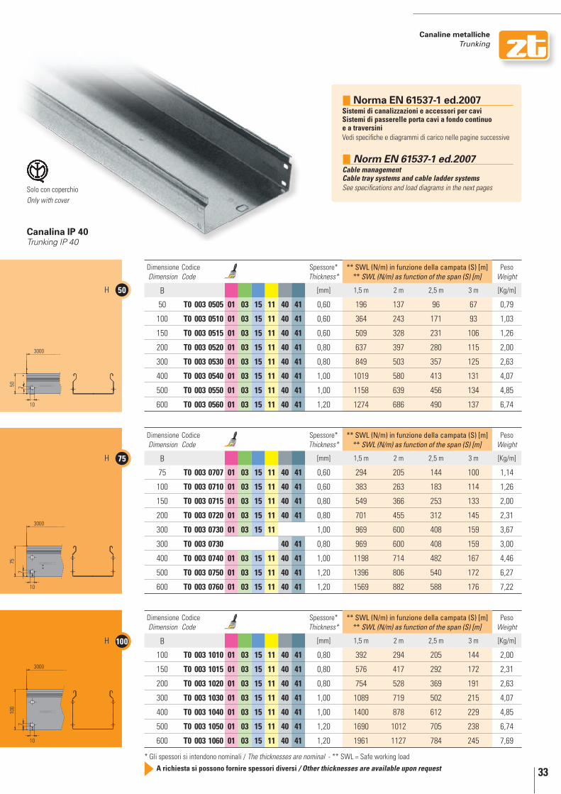
canalina ip 40Trunking IP 40
canaline metalliche trunking
Solo con coperchioOnly with cover
norma En 50085-2-1Sistemi di canali e di condotti per installazioni elettricheParte 2-1: Sistemi di canali e di condotti per montaggio a parete ed a soffitto
10.4 Prova di flessione lineareL’esemplare in prova è sottoposto ad un carico, distribuito uniformemente, di 1 g/mm2 per metro di lunghezza dell’area dichiarata utilizzabile per i cavi.
norm En 50085-2-1Cable trunking systems and cable ducting systems for electrical installationsPart 2-1: Cable trunking systems and cable ducting systems intended for mounting on walls and ceilings.10.4 Linear deflection testThe test sample is subjected to an evenly distributed load of 1 g/mm2 metre length of the declared usable area for cables.
33
canaline metalliche trunking
* Gli spessori si intendono nominali / The thicknesses are nominal - ** SWL = Safe working load
A richiesta si possono fornire spessori diversi / Other thicknesses are available upon request
50H
75H
100H
3000
50 7
10
3000
100
7
10
3000
10
757
Dimensione Dimension
Codice Code
Spessore* Thickness*
** SWL (N/m) in funzione della campata (S) [m] ** SWL (N/m) as function of the span (S) [m]
Peso Weight
B [mm] 1,5 m 2 m 2,5 m 3 m [Kg/m]
50 t0 003 0505 01 03 15 11 40 41 0,60 196 137 96 67 0,79
100 t0 003 0510 01 03 15 11 40 41 0,60 364 243 171 93 1,03
150 t0 003 0515 01 03 15 11 40 41 0,60 509 328 231 106 1,26
200 t0 003 0520 01 03 15 11 40 41 0,80 637 397 280 115 2,00
300 t0 003 0530 01 03 15 11 40 41 0,80 849 503 357 125 2,63
400 t0 003 0540 01 03 15 11 40 41 1,00 1019 580 413 131 4,07
500 t0 003 0550 01 03 15 11 40 41 1,00 1158 639 456 134 4,85
600 t0 003 0560 01 03 15 11 40 41 1,20 1274 686 490 137 6,74
Dimensione Dimension
Codice Code
Spessore* Thickness*
** SWL (N/m) in funzione della campata (S) [m] ** SWL (N/m) as function of the span (S) [m]
Peso Weight
B [mm] 1,5 m 2 m 2,5 m 3 m [Kg/m]
75 t0 003 0707 01 03 15 11 40 41 0,60 294 205 144 100 1,14
100 t0 003 0710 01 03 15 11 40 41 0,60 383 263 183 114 1,26
150 t0 003 0715 01 03 15 11 40 41 0,80 549 366 253 133 2,00
200 t0 003 0720 01 03 15 11 40 41 0,80 701 455 312 145 2,31
300 t0 003 0730 01 03 15 11 1,00 969 600 408 159 3,67
300 t0 003 0730 40 41 0,80 969 600 408 159 3,00
400 t0 003 0740 01 03 15 11 40 41 1,00 1198 714 482 167 4,46
500 t0 003 0750 01 03 15 11 40 41 1,20 1396 806 540 172 6,27
600 t0 003 0760 01 03 15 11 40 41 1,20 1569 882 588 176 7,22
Dimensione Dimension
Codice Code
Spessore* Thickness*
** SWL (N/m) in funzione della campata (S) [m] ** SWL (N/m) as function of the span (S) [m]
Peso Weight
B [mm] 1,5 m 2 m 2,5 m 3 m [Kg/m]
100 t0 003 1010 01 03 15 11 40 41 0,80 392 294 205 144 2,00
150 t0 003 1015 01 03 15 11 40 41 0,80 576 417 292 172 2,31
200 t0 003 1020 01 03 15 11 40 41 0,80 754 528 369 191 2,63
300 t0 003 1030 01 03 15 11 40 41 1,00 1089 719 502 215 4,07
400 t0 003 1040 01 03 15 11 40 41 1,00 1400 878 612 229 4,85
500 t0 003 1050 01 03 15 11 40 41 1,20 1690 1012 705 238 6,74
600 t0 003 1060 01 03 15 11 40 41 1,20 1961 1127 784 245 7,69
canalina ip 40Trunking IP 40
Solo con coperchioOnly with cover
norma En 61537-1 ed.2007Sistemi di canalizzazioni e accessori per cavi Sistemi di passerelle porta cavi a fondo continuo e a traversiniVedi specifiche e diagrammi di carico nelle pagine successive
norm En 61537-1 ed.2007Cable management Cable tray systems and cable ladder systemsSee specifications and load diagrams in the next pages

34
canaline metalliche trunking
diagrammi di carico norma En 61537-1 ed.2007load diagrams norm en 61537-1 ed.2007
T0 003 - Altezza 50 mm / height 50 mm
T0 003 - Altezza 75 mm / height 75 mm
1,5 2 2,5 3
20001900180017001600150014001300120011001000
900800700600500400300200100
0
1,5 2 2,5 3
20001900180017001600150014001300120011001000
900800700600500400300200100
0
B = 600B = 500B = 400B = 300B = 200B = 150B = 100B = 75B = 50
Caric
o m
assi
mo
/ Max
load
(N
/m)
Caric
o m
assi
mo
/ Max
load
(N
/m)
Distanza appoggi / Distance between supports (m)
Distanza appoggi / Distance between supports (m)
L Fmax =L/100
Carico uniforme Uniform load
L Fmax =L/100
Carico uniforme Uniform load

35
canaline metalliche trunking
diagrammi di carico norma En 61537-1 ed.2007load diagrams norm en 61537-1 ed.2007
En 6153710.4 - Prova per il SWl (safe working load) di tratti di passerelle porta cavi a fondo continuo e a traversini, montati sul piano orizzontale e con percorso orizzontale su un'installazione a campata singola.
La flessione effettiva di metà campata al SWL non deve superare 1/100 della campata. La flessione trasversale al SWL non deve superare 1/20 della larghezza dei campioni.
En 6153710.4 - Test for SWL (safe working load) of cable tray lengths and cable ladder lengths mounted in the horizontal plane running horizontally on a single span installation.
The practical mod-span deflection at the SWL shall not exceed 1/100th of the span. The transverse deflection at the SWL shall not exceed 1/20th of the width of the samples.
T0 003 - Altezza 100 mm / height 100 mm
1,5 2 2,5 3
20001900180017001600150014001300120011001000
900800700600500400300200100
0
B = 600B = 500B = 400B = 300B = 200B = 150B = 100B = 75B = 50
Caric
o m
assi
mo
/ Max
load
(N
/m)
Distanza appoggi / Distance between supports (m)
L Fmax =L/100
Carico uniforme Uniform load

36
50H
75H
100H
3000
50 7
10
3000
100
7
10
3000
10
757
* Gli spessori si intendono nominali / The thicknesses are nominal - ** Sezione intesa come conduttore*** In funzione della distanza tra i supporti (fino a 1,5-4 m) / On the basis of distance among supports (up to 1,5-4 m)
A richiesta si possono fornire spessori diversi / Other thicknesses are available upon request
01 Zincato Sendzimir / Sendzimir galvanized 03 Zincato a caldo per immersione / Hot dip galvanized 15 Verniciato blu elettrico / Electric blue varnished 11 Verniciato grigio RAL 7032 / Grey RAL 7032 varnished 40 Acciaio INOX AISI 304 / Stainless steel AISI 304 41 Acciaio INOX AISI 316L / Stainless steel AISI 316L
Dimensione Dimension
Codice Code
Spessore* Thickness*
Sezione utile del canale [mm2] *** Usable section of channel [mm2] ***
Sezione cond. ** Conductor section
Peso Weight
B [mm] 1,5 m 2 m 2,5 m 3 m 3,5 m 4 m [mm2] [Kg/m]
50 t0 013 0505 01 03 15 11 40 41 0,60 2400 2400 1250 1250 1250 1250 100,80 0,78
100 t0 013 0510 01 03 15 11 40 41 0,60 4800 4800 2500 2500 2500 1750 130,80 0,99
150 t0 013 0515 01 03 15 11 40 41 0,60 7200 7200 3750 3750 3142 2000 160,80 1,20
200 t0 013 0520 01 03 15 11 40 41 0,80 9600 9600 5000 5000 4285 2750 254,40 1,85
300 t0 013 0530 01 03 15 11 40 41 0,80 14400 14400 7500 7000 4571 3000 334,40 2,39
400 t0 013 0540 01 03 15 11 40 41 1,00 19200 19200 10000 9000 5714 3750 518,00 3,67
500 t0 013 0550 01 03 15 11 40 41 1,00 24000 24000 12500 9000 5714 3750 618,00 4,35
600 t0 013 0560 01 03 15 11 40 41 1,20 28800 28800 15000 10666 6857 4500 859,20 6,04
Dimensione Dimension
Codice Code
Spessore* Thickness*
Sezione utile del canale [mm2] *** Usable section of channel [mm2] ***
Sezione cond. ** Conductor section
Peso Weight
B [mm] 1,5 m 2 m 2,5 m 3 m 3,5 m 4 m [mm2] [Kg/m]
75 t0 013 0707 01 03 15 11 40 41 0,60 5400 5400 2810 2810 2810 2810 145,80 1,11
100 t0 013 0710 01 03 15 11 40 41 0,60 7200 7200 3750 3750 3750 3750 160,80 1,23
150 t0 013 0715 01 03 15 11 40 41 0,80 10800 10800 5625 5625 5625 5500 254,40 1,90
200 t0 013 0720 01 03 15 11 40 41 0,80 14400 14400 7500 7500 7500 5750 294,40 2,17
300 t0 013 0730 01 03 15 11 1,00 21600 21600 11250 11250 11142 7500 468,00 3,39
300 t0 013 0730 40 41 0,80 11250 11250 11250 11250 11250 9750 468,00 2,73
400 t0 013 0740 01 03 15 11 40 41 1,00 28800 28800 15000 15000 11428 7500 568,00 4,07
500 t0 013 0750 01 03 15 11 40 41 1,20 36000 36000 18750 18750 13714 9250 799,20 5,70
600 t0 013 0760 01 03 15 11 40 41 1,20 43200 43200 22500 22000 14000 9250 919,20 6,51
Dimensione Dimension
Codice Code
Spessore* Thickness*
Sezione utile del canale [mm2] *** Usable section of channel [mm2] ***
Sezione cond. ** Conductor section
Peso Weight
B [mm] 1,5 m 2 m 2,5 m 3 m 3,5 m 4 m [mm2] [Kg/m]
100 t0 013 1010 01 03 15 11 40 41 0,80 9600 9600 5000 5000 5000 5000 254,40 1,95
150 t0 013 1015 01 03 15 11 40 41 0,80 14400 14400 7500 7500 7500 7500 294,40 2,22
200 t0 013 1020 01 03 15 11 40 41 0,80 19200 19200 10000 10000 10000 9250 334,40 2,48
300 t0 013 1030 01 03 15 11 40 41 1,00 28800 28800 15000 15000 15000 12250 518,00 3,79
400 t0 013 1040 01 03 15 11 40 41 1,00 38400 38400 20000 20000 18571 12500 618,00 4,46
500 t0 013 1050 01 03 15 11 40 41 1,20 48000 48000 25000 25000 22857 15250 859,20 6,17
600 t0 013 1060 01 03 15 11 40 41 1,20 57600 57600 30000 30000 23142 15500 979,20 6,98
canaline metalliche trunking
passerella asolata ip 20Perforated cable tray IP 20
Nervatura sul fondo: dalla B 300 Rib at the bottom: from B 300 and up
Solo con coperchioOnly with cover
norma En 50085-2-1Sistemi di canali e di condotti per installazioni elettricheParte 2-1: Sistemi di canali e di condotti per montaggio a parete ed a soffitto
10.4 Prova di flessione lineareL’esemplare in prova è sottoposto ad un carico, distribuito uniformemente, di 1 g/mm2 per metro di lunghezza dell’area dichiarata utilizzabile per i cavi.
norm En 50085-2-1Cable trunking systems and cable ducting systems for electrical installationsPart 2-1: Cable trunking systems and cable ducting systems intended for mounting on walls and ceilings.10.4 Linear deflection testThe test sample is subjected to an evenly distributed load of 1 g/mm2 metre length of the declared usable area for cables.
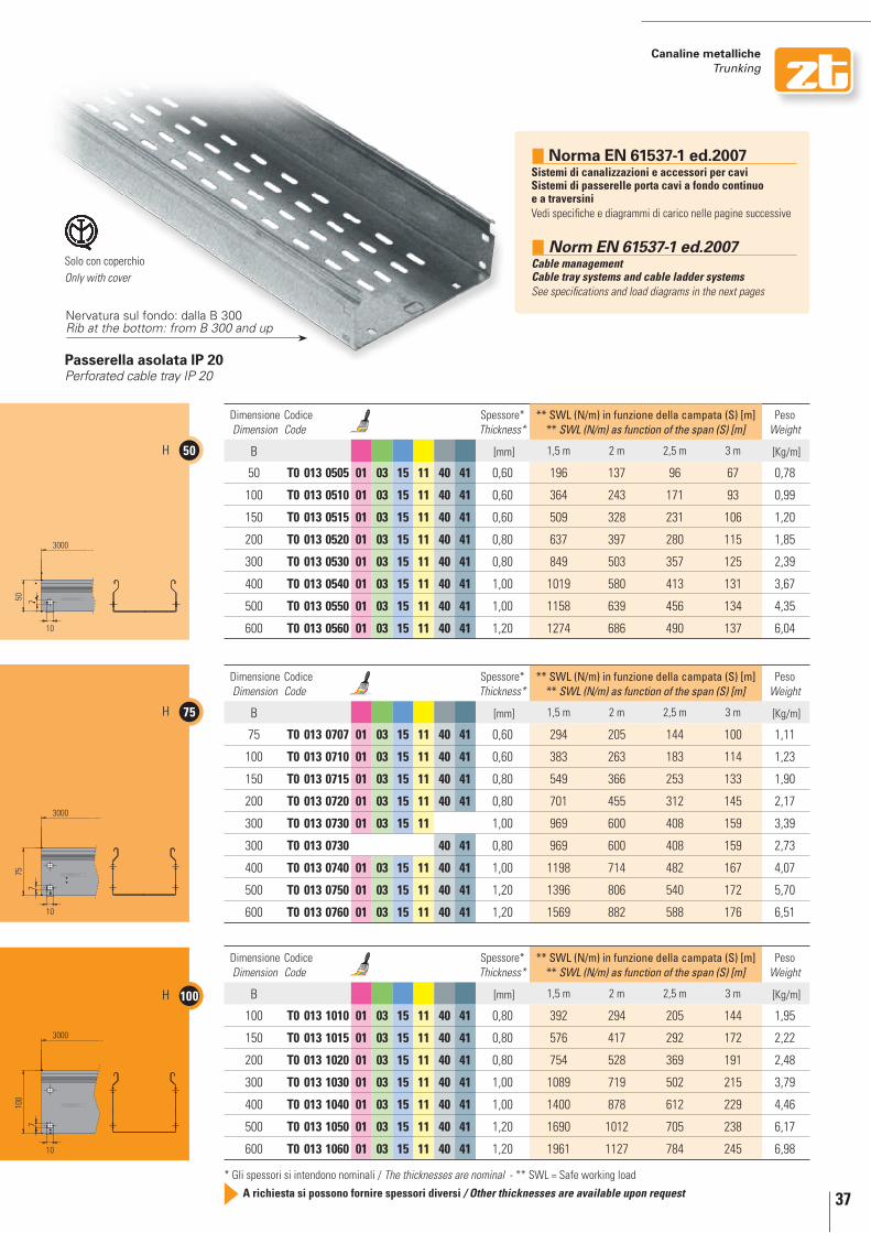
37
canaline metalliche trunking
* Gli spessori si intendono nominali / The thicknesses are nominal - ** SWL = Safe working load
A richiesta si possono fornire spessori diversi / Other thicknesses are available upon request
50H
75H
100H
3000
50 7
10
3000
100
7
10
3000
10
757
Dimensione Dimension
Codice Code
Spessore* Thickness*
** SWL (N/m) in funzione della campata (S) [m] ** SWL (N/m) as function of the span (S) [m]
Peso Weight
B [mm] 1,5 m 2 m 2,5 m 3 m [Kg/m]
50 t0 013 0505 01 03 15 11 40 41 0,60 196 137 96 67 0,78
100 t0 013 0510 01 03 15 11 40 41 0,60 364 243 171 93 0,99
150 t0 013 0515 01 03 15 11 40 41 0,60 509 328 231 106 1,20
200 t0 013 0520 01 03 15 11 40 41 0,80 637 397 280 115 1,85
300 t0 013 0530 01 03 15 11 40 41 0,80 849 503 357 125 2,39
400 t0 013 0540 01 03 15 11 40 41 1,00 1019 580 413 131 3,67
500 t0 013 0550 01 03 15 11 40 41 1,00 1158 639 456 134 4,35
600 t0 013 0560 01 03 15 11 40 41 1,20 1274 686 490 137 6,04
Dimensione Dimension
Codice Code
Spessore* Thickness*
** SWL (N/m) in funzione della campata (S) [m] ** SWL (N/m) as function of the span (S) [m]
Peso Weight
B [mm] 1,5 m 2 m 2,5 m 3 m [Kg/m]
75 t0 013 0707 01 03 15 11 40 41 0,60 294 205 144 100 1,11
100 t0 013 0710 01 03 15 11 40 41 0,60 383 263 183 114 1,23
150 t0 013 0715 01 03 15 11 40 41 0,80 549 366 253 133 1,90
200 t0 013 0720 01 03 15 11 40 41 0,80 701 455 312 145 2,17
300 t0 013 0730 01 03 15 11 1,00 969 600 408 159 3,39
300 t0 013 0730 40 41 0,80 969 600 408 159 2,73
400 t0 013 0740 01 03 15 11 40 41 1,00 1198 714 482 167 4,07
500 t0 013 0750 01 03 15 11 40 41 1,20 1396 806 540 172 5,70
600 t0 013 0760 01 03 15 11 40 41 1,20 1569 882 588 176 6,51
Dimensione Dimension
Codice Code
Spessore* Thickness*
** SWL (N/m) in funzione della campata (S) [m] ** SWL (N/m) as function of the span (S) [m]
Peso Weight
B [mm] 1,5 m 2 m 2,5 m 3 m [Kg/m]
100 t0 013 1010 01 03 15 11 40 41 0,80 392 294 205 144 1,95
150 t0 013 1015 01 03 15 11 40 41 0,80 576 417 292 172 2,22
200 t0 013 1020 01 03 15 11 40 41 0,80 754 528 369 191 2,48
300 t0 013 1030 01 03 15 11 40 41 1,00 1089 719 502 215 3,79
400 t0 013 1040 01 03 15 11 40 41 1,00 1400 878 612 229 4,46
500 t0 013 1050 01 03 15 11 40 41 1,20 1690 1012 705 238 6,17
600 t0 013 1060 01 03 15 11 40 41 1,20 1961 1127 784 245 6,98
passerella asolata ip 20Perforated cable tray IP 20
Nervatura sul fondo: dalla B 300 Rib at the bottom: from B 300 and up
Solo con coperchioOnly with cover
norma En 61537-1 ed.2007Sistemi di canalizzazioni e accessori per cavi Sistemi di passerelle porta cavi a fondo continuo e a traversiniVedi specifiche e diagrammi di carico nelle pagine successive
norm En 61537-1 ed.2007Cable management Cable tray systems and cable ladder systemsSee specifications and load diagrams in the next pages

38
canaline metalliche trunking
diagrammi di carico norma En 61537-1 ed.2007load diagrams norm en 61537-1 ed.2007
T0 013 - Altezza 50 mm / height 50 mm
T0 013 - Altezza 75 mm / height 75 mm
1,5 2 2,5 3
20001900180017001600150014001300120011001000
900800700600500400300200100
0
1,5 2 2,5 3
20001900180017001600150014001300120011001000
900800700600500400300200100
0
B = 600B = 500B = 400B = 300B = 200B = 150B = 100B = 75B = 50
Caric
o m
assi
mo
/ Max
load
(N
/m)
Caric
o m
assi
mo
/ Max
load
(N
/m)
Distanza appoggi / Distance between supports (m)
Distanza appoggi / Distance between supports (m)
L Fmax =L/100
Carico uniforme Uniform load
L Fmax =L/100
Carico uniforme Uniform load

39
canaline metalliche trunking
diagrammi di carico norma En 61537-1 ed.2007load diagrams norm en 61537-1 ed.2007
En 6153710.4 - Prova per il SWl (safe working load) di tratti di passerelle porta cavi a fondo continuo e a traversini, montati sul piano orizzontale e con percorso orizzontale su un'installazione a campata singola.
La flessione effettiva di metà campata al SWL non deve superare 1/100 della campata. La flessione trasversale al SWL non deve superare 1/20 della larghezza dei campioni.
En 6153710.4 - Test for SWL (safe working load) of cable tray lengths and cable ladder lengths mounted in the horizontal plane running horizontally on a single span installation.
The practical mod-span deflection at the SWL shall not exceed 1/100th of the span. The transverse deflection at the SWL shall not exceed 1/20th of the width of the samples.
T0 013 - Altezza 100 mm / height 100 mm
1,5 2 2,5 3
20001900180017001600150014001300120011001000
900800700600500400300200100
0
B = 600B = 500B = 400B = 300B = 200B = 150B = 100B = 75B = 50
Caric
o m
assi
mo
/ Max
load
(N
/m)
Distanza appoggi / Distance between supports (m)
L Fmax =L/100
Carico uniforme Uniform load

40
50H
75H
100H
3000
50 7
25
3000
757
25
100
7
25
3000
* Gli spessori si intendono nominali / The thicknesses are nominal - ** Sezione intesa come conduttore*** In funzione della distanza tra i supporti (fino a 1,5-4 m) / On the basis of distance among supports (up to 1,5-4 m)
A richiesta si possono fornire spessori diversi / Other thicknesses are available upon request
01 Zincato Sendzimir / Sendzimir galvanized 03 Zincato a caldo per immersione / Hot dip galvanized 15 Verniciato blu elettrico / Electric blue varnished 11 Verniciato grigio RAL 7032 / Grey RAL 7032 varnished 40 Acciaio INOX AISI 304 / Stainless steel AISI 304 41 Acciaio INOX AISI 316L / Stainless steel AISI 316L
Dimensione Dimension
Codice Code
Spessore* Thickness*
Sezione utile del canale [mm2] *** Usable section of channel [mm2] ***
Sezione cond. ** Conductor section
Peso Weight
B [mm] 1,5 m 2 m 2,5 m 3 m 3,5 m 4 m [mm2] [Kg/m]
50 t0 018 0505 01 03 15 11 40 41 0,60 2400 2400 1250 1250 1250 1250 100,80 0,74
100 t0 018 0510 01 03 15 11 40 41 0,60 4800 4800 2500 2500 2500 1750 130,80 0,96
150 t0 018 0515 01 03 15 11 40 41 0,60 7200 7200 3750 3750 3142 2000 160,80 1,17
200 t0 018 0520 01 03 15 11 40 41 0,80 9600 9600 5000 5000 4285 2750 254,40 1,81
300 t0 018 0530 01 03 15 11 40 41 0,80 14400 14400 7500 7000 4571 3000 334,40 2,34
400 t0 018 0540 01 03 15 11 40 41 1,00 19200 19200 10000 9000 5714 3750 518,00 3,62
500 t0 018 0550 01 03 15 11 40 41 1,00 24000 24000 12500 9000 5714 3750 618,00 4,29
600 t0 018 0560 01 03 15 11 40 41 1,20 28800 28800 15000 10666 6857 4500 859,20 5,98
Dimensione Dimension
Codice Code
Spessore* Thickness*
Sezione utile del canale [mm2] *** Usable section of channel [mm2] ***
Sezione cond. ** Conductor section
Peso Weight
B [mm] 1,5 m 2 m 2,5 m 3 m 3,5 m 4 m [mm2] [Kg/m]
75 t0 018 0707 01 03 15 11 40 41 0,60 5400 5400 2810 2810 2810 2810 145,80 1,05
100 t0 018 0710 01 03 15 11 40 41 0,60 7200 7200 3750 3750 3750 3750 160,80 1,17
150 t0 018 0715 01 03 15 11 40 41 0,80 10800 10800 5625 5625 5625 5500 254,40 1,81
200 t0 018 0720 01 03 15 11 40 41 0,80 14400 14400 7500 7500 7500 5750 294,40 2,07
300 t0 018 0730 01 03 15 11 1,00 21600 21600 11250 11250 11142 7500 468,00 3,28
300 t0 018 0730 40 41 0,80 11250 11250 11250 11250 11250 9750 468,00 2,63
400 t0 018 0740 01 03 15 11 40 41 1,00 28800 28800 15000 15000 11428 7500 568,00 3,95
500 t0 018 0750 01 03 15 11 40 41 1,20 36000 36000 18750 18750 13714 9250 799,20 5,57
600 t0 018 0760 01 03 15 11 40 41 1,20 43200 43200 22500 22000 14000 9250 919,20 6,38
Dimensione Dimension
Codice Code
Spessore* Thickness*
Sezione utile del canale [mm2] *** Usable section of channel [mm2] ***
Sezione cond. ** Conductor section
Peso Weight
B [mm] 1,5 m 2 m 2,5 m 3 m 3,5 m 4 m [mm2] [Kg/m]
100 t0 018 1010 01 03 15 11 40 41 0,80 9600 9600 5000 5000 5000 5000 254,40 1,81
150 t0 018 1015 01 03 15 11 40 41 0,80 14400 14400 7500 7500 7500 7500 294,40 2,07
200 t0 018 1020 01 03 15 11 40 41 0,80 19200 19200 10000 10000 10000 9250 334,40 2,34
300 t0 018 1030 01 03 15 11 40 41 1,00 28800 28800 15000 15000 15000 12250 518,00 3,62
400 t0 018 1040 01 03 15 11 40 41 1,00 38400 38400 20000 20000 18571 12500 618,00 4,29
500 t0 018 1050 01 03 15 11 40 41 1,20 48000 48000 25000 25000 22857 15250 859,20 5,98
600 t0 018 1060 01 03 15 11 40 41 1,20 57600 57600 30000 30000 23142 15500 979,20 6,79
passerella con asolatura continua Fully perforated cable tray
Nervatura sul fondo: dalla B 300 Rib at the bottom: from B 300 and up
canaline metalliche trunking
norma En 50085-2-1Sistemi di canali e di condotti per installazioni elettricheParte 2-1: Sistemi di canali e di condotti per montaggio a parete ed a soffitto
10.4 Prova di flessione lineareL’esemplare in prova è sottoposto ad un carico, distribuito uniformemente, di 1 g/mm2 per metro di lunghezza dell’area dichiarata utilizzabile per i cavi.
norm En 50085-2-1Cable trunking systems and cable ducting systems for electrical installationsPart 2-1: Cable trunking systems and cable ducting systems intended for mounting on walls and ceilings.10.4 Linear deflection testThe test sample is subjected to an evenly distributed load of 1 g/mm2 metre length of the declared usable area for cables.

41
canaline metalliche trunking
* Gli spessori si intendono nominali / The thicknesses are nominal - ** SWL = Safe working load
A richiesta si possono fornire spessori diversi / Other thicknesses are available upon request
50H
75H
100H
3000
50 7
25
3000
757
25
100
7
25
3000
Dimensione Dimension
Codice Code
Spessore* Thickness*
** SWL (N/m) in funzione della campata (S) [m] ** SWL (N/m) as function of the span (S) [m]
Peso Weight
B [mm] 1,5 m 2 m 2,5 m 3 m [Kg/m]
50 t0 018 0505 01 03 15 11 40 41 0,60 156 109 76 53 0,74
100 t0 018 0510 01 03 15 11 40 41 0,60 291 194 136 74 0,96
150 t0 018 0515 01 03 15 11 40 41 0,60 407 262 185 85 1,17
200 t0 018 0520 01 03 15 11 40 41 0,80 509 317 224 92 1,81
300 t0 018 0530 01 03 15 11 40 41 0,80 679 402 285 100 2,34
400 t0 018 0540 01 03 15 11 40 41 1,00 815 464 330 104 3,62
500 t0 018 0550 01 03 15 11 40 41 1,00 927 511 365 107 4,29
600 t0 018 0560 01 03 15 11 40 41 1,20 1019 549 392 109 5,98
Dimensione Dimension
Codice Code
Spessore* Thickness*
** SWL (N/m) in funzione della campata (S) [m] ** SWL (N/m) as function of the span (S) [m]
Peso Weight
B [mm] 1,5 m 2 m 2,5 m 3 m [Kg/m]
75 t0 018 0707 01 03 15 11 40 41 0,60 235 164 115 80 1,05
100 t0 018 0710 01 03 15 11 40 41 0,60 306 210 147 91 1,17
150 t0 018 0715 01 03 15 11 40 41 0,80 439 293 202 106 1,81
200 t0 018 0720 01 03 15 11 40 41 0,80 560 364 250 116 2,07
300 t0 018 0730 01 03 15 11 1,00 775 480 326 127 3,28
300 t0 018 0730 40 41 0,80 775 480 326 127 2,63
400 t0 018 0740 01 03 15 11 40 41 1,00 958 571 385 134 3,95
500 t0 018 0750 01 03 15 11 40 41 1,20 1116 645 432 138 5,57
600 t0 018 0760 01 03 15 11 40 41 1,20 1255 706 470 141 6,38
Dimensione Dimension
Codice Code
Spessore* Thickness*
** SWL (N/m) in funzione della campata (S) [m] ** SWL (N/m) as function of the span (S) [m]
Peso Weight
B [mm] 1,5 m 2 m 2,5 m 3 m [Kg/m]
100 t0 018 1010 01 03 15 11 40 41 0,80 313 219 153 107 1,81
150 t0 018 1015 01 03 15 11 40 41 0,80 461 311 218 128 2,07
200 t0 018 1020 01 03 15 11 40 41 0,80 603 394 275 142 2,34
300 t0 018 1030 01 03 15 11 40 41 1,00 871 537 375 160 3,62
400 t0 018 1040 01 03 15 11 40 41 1,00 1120 656 457 171 4,29
500 t0 018 1050 01 03 15 11 40 41 1,20 1352 756 526 178 5,98
600 t0 018 1060 01 03 15 11 40 41 1,20 1569 902 627 196 6,79
T0 053 passerella per gallerie autostradaliRichiedere catalogo specifico per gallerie autostradali e ferroviarie
T0 053 Cable tray for motorway tunnelsThe specific catalogue for motorway and railway tunnels (Inox) is available on request
passerella con asolatura continua Fully perforated cable tray
Nervatura sul fondo: dalla B 300 Rib at the bottom: from B 300 and up
norma En 61537-1 ed.2007Sistemi di canalizzazioni e accessori per cavi Sistemi di passerelle porta cavi a fondo continuo e a traversiniVedi specifiche e diagrammi di carico nelle pagine successive
norm En 61537-1 ed.2007Cable management Cable tray systems and cable ladder systemsSee specifications and load diagrams in the next pages

42
canaline metalliche trunking
diagrammi di carico norma En 61537-1 ed.2007load diagrams norm en 61537-1 ed.2007
T0 018 - Altezza 50 mm / height 50 mm
T0 018 - Altezza 75 mm / height 75 mm
1,5 2 2,5 3
1600
1500
1400
1300
1200
1100
1000
900
800
700
600
500
400
300
200
100
0
1,5 2 2,5 3
1600
1500
1400
1300
1200
1100
1000
900
800
700
600
500
400
300
200
100
0
B = 600B = 500B = 400B = 300B = 200B = 150B = 100B = 75B = 50
Caric
o m
assi
mo
/ Max
load
(N
/m)
Caric
o m
assi
mo
/ Max
load
(N
/m)
Distanza appoggi / Distance between supports (m)
Distanza appoggi / Distance between supports (m)
L Fmax =L/100
Carico uniforme Uniform load
L Fmax =L/100
Carico uniforme Uniform load

43
canaline metalliche trunking
diagrammi di carico norma En 61537-1 ed.2007load diagrams norm en 61537-1 ed.2007
En 6153710.4 - Prova per il SWl (safe working load) di tratti di passerelle porta cavi a fondo continuo e a traversini, montati sul piano orizzontale e con percorso orizzontale su un'installazione a campata singola.
La flessione effettiva di metà campata al SWL non deve superare 1/100 della campata. La flessione trasversale al SWL non deve superare 1/20 della larghezza dei campioni.
En 6153710.4 - Test for SWL (safe working load) of cable tray lengths and cable ladder lengths mounted in the horizontal plane running horizontally on a single span installation.
The practical mod-span deflection at the SWL shall not exceed 1/100th of the span. The transverse deflection at the SWL shall not exceed 1/20th of the width of the samples.
T0 018 - Altezza 100 mm / height 100 mm
1,5 2 2,5 3
1600
1500
1400
1300
1200
1100
1000
900
800
700
600
500
400
300
200
100
0
B = 600B = 500B = 400B = 300B = 200B = 150B = 100B = 75B = 50
Caric
o m
assi
mo
/ Max
load
(N
/m)
Distanza appoggi / Distance between supports (m)
L Fmax =L/100
Carico uniforme Uniform load

44
canaline metalliche trunking
Dimensione Dimension
Codice Code
L Spessore* Thickness*
Peso Weight
B [mm] [mm] [Kg/m]
50 t0 023 0005 01 03 15 11 40 41 3000 0,60 0,36
75 t0 023 0007 01 03 15 11 40 41 3000 0,60 0,48
100 t0 023 0010 01 03 15 11 40 41 3000 0,60 0,60
150 t0 023 0015 01 03 15 11 40 41 3000 0,60 0,83
200 t0 023 0020 01 03 15 11 40 41 3000 0,60 1,07
300 t0 023 0030 01 03 15 11 40 41 3000 0,60 1,54
400 t0 023 0040 01 03 15 11 40 41 3000 0,60 2,01
500 t0 023 0050 01 03 15 11 40 41 3000 0,80 3,31
600 t0 023 0060 01 03 15 11 40 41 3000 0,80 3,94
Dimensione* Dimension*
Codice Code
Spessore* Thickness*
Peso Weight
H a b [mm] [Kg/m]
50 t0 034 0005 01 03 15 11 40 41 45 25 0,80 0,45
75 t0 034 0007 01 03 15 11 40 41 70 25 0,80 0,60
100 t0 034 0010 01 03 15 11 40 41 95 25 0,80 0,76
Separatore ribordato in testaSeparator with bent top edge
coperchioCover
B
L
* Dimensioni e spessori sono da intendersi nominali The dimensions and the thicknesses are nominal
* Gli spessori si intendono nominali / The thicknesses are nominal
Nervatura sul coperchio: dalla B 300Rib on the cover: from B 300 and up
Solo con canalinaOnly with trunking
01 Zincato Sendzimir / Sendzimir galvanized 03 Zincato a caldo per immersione / Hot dip galvanized 15 Verniciato blu elettrico / Electric blue varnished 11 Verniciato grigio RAL 7032 / Grey RAL 7032 varnished 40 Acciaio INOX AISI 304 / Stainless steel AISI 304 41 Acciaio INOX AISI 316L / Stainless steel AISI 316L

com
pone
nti /
com
pone
nts
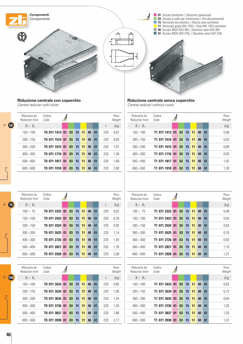
46
50H
75H
100H
componenti components
01 Zincato Sendzimir / Sendzimir galvanized 03 Zincato a caldo per immersione / Hot dip galvanized 15 Verniciato blu elettrico / Electric blue varnished 11 Verniciato grigio RAL 7032 / Grey RAL 7032 varnished 40 Acciaio INOX AISI 304 / Stainless steel AISI 304 41 Acciaio INOX AISI 316L / Stainless steel AISI 316L
riduzione centrale con coperchio Central reducer with cover
riduzione centrale senza coperchioCentral reducer without cover
Riduzione da Reduction from
Codice Code
Peso Weight
B ÷ B1 L [Kg]
150 ÷ 100 t0 071 1413 01 03 15 11 40 41 220 0,67
200 ÷ 150 t0 071 1514 01 03 15 11 40 41 220 0,83
300 ÷ 200 t0 071 1615 01 03 15 11 40 41 220 1,07
400 ÷ 300 t0 071 1716 01 03 15 11 40 41 220 1,38
500 ÷ 400 t0 071 1817 01 03 15 11 40 41 220 1,69
600 ÷ 500 t0 071 1918 01 03 15 11 40 41 220 2,00
Riduzione da Reduction from
Codice Code
Peso Weight
B ÷ B1 [Kg]
150 ÷ 100 t1 071 1413 01 03 15 11 40 41 0,46
200 ÷ 150 t1 071 1514 01 03 15 11 40 41 0,55
300 ÷ 200 t1 071 1615 01 03 15 11 40 41 0,68
400 ÷ 300 t1 071 1716 01 03 15 11 40 41 0,85
500 ÷ 400 t1 071 1817 01 03 15 11 40 41 1,02
600 ÷ 500 t1 071 1918 01 03 15 11 40 41 1,20
Riduzione da Reduction from
Codice Code
Peso Weight
B ÷ B1 L [Kg]
100 ÷ 75 t0 071 2322 01 03 15 11 40 41 220 0,62
150 ÷ 100 t0 071 2423 01 03 15 11 40 41 220 0,76
200 ÷ 150 t0 071 2524 01 03 15 11 40 41 220 0,92
300 ÷ 200 t0 071 2625 01 03 15 11 40 41 220 1,14
400 ÷ 300 t0 071 2726 01 03 15 11 40 41 220 1,45
500 ÷ 400 t0 071 2827 01 03 15 11 40 41 220 1,76
600 ÷ 500 t0 071 2928 01 03 15 11 40 41 220 2,08
Riduzione da Reduction from
Codice Code
Peso Weight
B ÷ B1 [Kg]
100 ÷ 75 t1 071 2322 01 03 15 11 40 41 0,48
150 ÷ 100 t1 071 2423 01 03 15 11 40 41 0,55
200 ÷ 150 t1 071 2524 01 03 15 11 40 41 0,63
300 ÷ 200 t1 071 2625 01 03 15 11 40 41 0,76
400 ÷ 300 t1 071 2726 01 03 15 11 40 41 0,93
500 ÷ 400 t1 071 2827 01 03 15 11 40 41 1,10
600 ÷ 500 t1 071 2928 01 03 15 11 40 41 1,27
Riduzione da Reduction from
Codice Code
Peso Weight
B ÷ B1 L [Kg]
150 ÷ 100 t0 071 3433 01 03 15 11 40 41 220 0,85
200 ÷ 150 t0 071 3534 01 03 15 11 40 41 220 1,00
300 ÷ 200 t0 071 3635 01 03 15 11 40 41 220 1,24
400 ÷ 300 t0 071 3736 01 03 15 11 40 41 220 1,55
500 ÷ 400 t0 071 3837 01 03 15 11 40 41 220 1,86
600 ÷ 500 t0 071 3938 01 03 15 11 40 41 220 2,17
Riduzione da Reduction from
Codice Code
Peso Weight
B ÷ B1 [Kg]
150 ÷ 100 t1 071 3433 01 03 15 11 40 41 0,63
200 ÷ 150 t1 071 3534 01 03 15 11 40 41 0,72
300 ÷ 200 t1 071 3635 01 03 15 11 40 41 0,85
400 ÷ 300 t1 071 3736 01 03 15 11 40 41 1,03
500 ÷ 400 t1 071 3837 01 03 15 11 40 41 1,20
600 ÷ 500 t1 071 3938 01 03 15 11 40 41 1,37

47
50 H
75 H
100 H
componenti components
riduzione destra con coperchioRight reducer with cover
riduzione destra senza coperchioRight reducer without cover
Riduzione da Reduction from
Codice Code
Peso Weight
B ÷ B1 L [Kg]
150 ÷ 100 t0 073 1413 01 03 15 11 40 41 220 0,67
200 ÷ 150 t0 073 1514 01 03 15 11 40 41 220 0,83
300 ÷ 200 t0 073 1615 01 03 15 11 40 41 220 1,07
400 ÷ 300 t0 073 1716 01 03 15 11 40 41 220 1,38
500 ÷ 400 t0 073 1817 01 03 15 11 40 41 220 1,69
600 ÷ 500 t0 073 1918 01 03 15 11 40 41 220 2,00
Riduzione da Reduction from
Codice Code
Peso Weight
B ÷ B1 [Kg]
150 ÷ 100 t1 073 1413 01 03 15 11 40 41 0,46
200 ÷ 150 t1 073 1514 01 03 15 11 40 41 0,55
300 ÷ 200 t1 073 1615 01 03 15 11 40 41 0,68
400 ÷ 300 t1 073 1716 01 03 15 11 40 41 0,85
500 ÷ 400 t1 073 1817 01 03 15 11 40 41 1,02
600 ÷ 500 t1 073 1918 01 03 15 11 40 41 1,20
Riduzione da Reduction from
Codice Code
Peso Weight
B ÷ B1 L [Kg]
100 ÷ 75 t0 073 2322 01 03 15 11 40 41 220 0,62
150 ÷ 100 t0 073 2423 01 03 15 11 40 41 220 0,76
200 ÷ 150 t0 073 2524 01 03 15 11 40 41 220 0,92
300 ÷ 200 t0 073 2625 01 03 15 11 40 41 220 1,14
400 ÷ 300 t0 073 2726 01 03 15 11 40 41 220 1,45
500 ÷ 400 t0 073 2827 01 03 15 11 40 41 220 1,76
600 ÷ 500 t0 073 2928 01 03 15 11 40 41 220 2,08
Riduzione da Reduction from
Codice Code
Peso Weight
B ÷ B1 [Kg]
100 ÷ 75 t1 073 2322 01 03 15 11 40 41 0,48
150 ÷ 100 t1 073 2423 01 03 15 11 40 41 0,55
200 ÷ 150 t1 073 2524 01 03 15 11 40 41 0,63
300 ÷ 200 t1 073 2625 01 03 15 11 40 41 0,76
400 ÷ 300 t1 073 2726 01 03 15 11 40 41 0,93
500 ÷ 400 t1 073 2827 01 03 15 11 40 41 1,10
600 ÷ 500 t1 073 2928 01 03 15 11 40 41 1,27
Riduzione da Reduction from
Codice Code
Peso Weight
B ÷ B1 L [Kg]
150 ÷ 100 t0 073 3433 01 03 15 11 40 41 220 0,85
200 ÷ 150 t0 073 3534 01 03 15 11 40 41 220 1,00
300 ÷ 200 t0 073 3635 01 03 15 11 40 41 220 1,24
400 ÷ 300 t0 073 3736 01 03 15 11 40 41 220 1,55
500 ÷ 400 t0 073 3837 01 03 15 11 40 41 220 1,86
600 ÷ 500 t0 073 3938 01 03 15 11 40 41 220 2,17
Riduzione da Reduction from
Codice Code
Peso Weight
B ÷ B1 [Kg]
150 ÷ 100 t1 073 3433 01 03 15 11 40 41 0,63
200 ÷ 150 t1 073 3534 01 03 15 11 40 41 0,72
300 ÷ 200 t1 073 3635 01 03 15 11 40 41 0,85
400 ÷ 300 t1 073 3736 01 03 15 11 40 41 1,03
500 ÷ 400 t1 073 3837 01 03 15 11 40 41 1,20
600 ÷ 500 t1 073 3938 01 03 15 11 40 41 1,37

48
50H
75H
100H
componenti components
01 Zincato Sendzimir / Sendzimir galvanized 03 Zincato a caldo per immersione / Hot dip galvanized 15 Verniciato blu elettrico / Electric blue varnished 11 Verniciato grigio RAL 7032 / Grey RAL 7032 varnished 40 Acciaio INOX AISI 304 / Stainless steel AISI 304 41 Acciaio INOX AISI 316L / Stainless steel AISI 316L
riduzione sinistra con coperchioLeft reducer with cover
riduzione sinistra senza coperchioLeft reducer without cover
Riduzione da Reduction from
Codice Code
Peso Weight
B ÷ B1 [Kg]
150 ÷ 100 t1 075 1413 01 03 15 11 40 41 0,46
200 ÷ 150 t1 075 1514 01 03 15 11 40 41 0,55
300 ÷ 200 t1 075 1615 01 03 15 11 40 41 0,68
400 ÷ 300 t1 075 1716 01 03 15 11 40 41 0,85
500 ÷ 400 t1 075 1817 01 03 15 11 40 41 1,02
600 ÷ 500 t1 075 1918 01 03 15 11 40 41 1,20
Riduzione da Reduction from
Codice Code
Peso Weight
B ÷ B1 L [Kg]
150 ÷ 100 t0 075 1413 01 03 15 11 40 41 220 0,67
200 ÷ 150 t0 075 1514 01 03 15 11 40 41 220 0,83
300 ÷ 200 t0 075 1615 01 03 15 11 40 41 220 1,07
400 ÷ 300 t0 075 1716 01 03 15 11 40 41 220 1,38
500 ÷ 400 t0 075 1817 01 03 15 11 40 41 220 1,69
600 ÷ 500 t0 075 1918 01 03 15 11 40 41 220 2,00
Riduzione da Reduction from
Codice Code
Peso Weight
B ÷ B1 L [Kg]
100 ÷ 75 t0 075 2322 01 03 15 11 40 41 220 0,62
150 ÷ 100 t0 075 2423 01 03 15 11 40 41 220 0,76
200 ÷ 150 t0 075 2524 01 03 15 11 40 41 220 0,92
300 ÷ 200 t0 075 2625 01 03 15 11 40 41 220 1,14
400 ÷ 300 t0 075 2726 01 03 15 11 40 41 220 1,45
500 ÷ 400 t0 075 2827 01 03 15 11 40 41 220 1,76
600 ÷ 500 t0 075 2928 01 03 15 11 40 41 220 2,08
Riduzione da Reduction from
Codice Code
Peso Weight
B ÷ B1 L [Kg]
150 ÷ 100 t0 075 3433 01 03 15 11 40 41 220 0,85
200 ÷ 150 t0 075 3534 01 03 15 11 40 41 220 1,00
300 ÷ 200 t0 075 3635 01 03 15 11 40 41 220 1,24
400 ÷ 300 t0 075 3736 01 03 15 11 40 41 220 1,55
500 ÷ 400 t0 075 3837 01 03 15 11 40 41 220 1,86
600 ÷ 500 t0 075 3938 01 03 15 11 40 41 220 2,17
Riduzione da Reduction from
Codice Code
Peso Weight
B ÷ B1 [Kg]
100 ÷ 75 t1 075 2322 01 03 15 11 40 41 0,48
150 ÷ 100 t1 075 2423 01 03 15 11 40 41 0,55
200 ÷ 150 t1 075 2524 01 03 15 11 40 41 0,63
300 ÷ 200 t1 075 2625 01 03 15 11 40 41 0,76
400 ÷ 300 t1 075 2726 01 03 15 11 40 41 0,93
500 ÷ 400 t1 075 2827 01 03 15 11 40 41 1,10
600 ÷ 500 t1 075 2928 01 03 15 11 40 41 1,27
Riduzione da Reduction from
Codice Code
Peso Weight
B ÷ B1 [Kg]
150 ÷ 100 t1 075 3433 01 03 15 11 40 41 0,63
200 ÷ 150 t1 075 3534 01 03 15 11 40 41 0,72
300 ÷ 200 t1 075 3635 01 03 15 11 40 41 0,85
400 ÷ 300 t1 075 3736 01 03 15 11 40 41 1,03
500 ÷ 400 t1 075 3837 01 03 15 11 40 41 1,20
600 ÷ 500 t1 075 3938 01 03 15 11 40 41 1,37

49
50 H
75 H
100 H
componenti components
curva piana 90° con coperchioFlat 90° elbow with cover
curva piana 90° senza coperchioFlat 90° elbow without cover
Dimensione Dimension
Codice Code
Peso Weight
B a R [Kg]
50 t0 083 0505 01 03 15 11 40 41 180 100 0,56
100 t0 083 0510 01 03 15 11 40 41 230 100 0,91
150 t0 083 0515 01 03 15 11 40 41 280 100 1,34
200 t0 083 0520 01 03 15 11 40 41 330 100 1,83
300 t0 083 0530 01 03 15 11 40 41 430 100 3,03
400 t0 083 0540 01 03 15 11 40 41 530 100 4,52
500 t0 083 0550 01 03 15 11 40 41 630 100 6,28
600 t0 083 0560 01 03 15 11 40 41 730 100 8,33
Dimensione Dimension
Codice Code
Peso Weight
B a R [Kg]
75 t0 083 0707 01 03 15 11 40 41 205 100 0,85
100 t0 083 0710 01 03 15 11 40 41 230 100 1,04
150 t0 083 0715 01 03 15 11 40 41 280 100 1,48
200 t0 083 0720 01 03 15 11 40 41 330 100 2,00
300 t0 083 0730 01 03 15 11 40 41 430 100 3,24
400 t0 083 0740 01 03 15 11 40 41 530 100 4,76
500 t0 083 0750 01 03 15 11 40 41 630 100 6,57
600 t0 083 0760 01 03 15 11 40 41 730 100 8,66
Dimensione Dimension
Codice Code
Peso Weight
B a R [Kg]
100 t0 083 1010 01 03 15 11 40 41 230 100 1,17
150 t0 083 1015 01 03 15 11 40 41 280 100 1,63
200 t0 083 1020 01 03 15 11 40 41 330 100 2,16
300 t0 083 1030 01 03 15 11 40 41 430 100 3,44
400 t0 083 1040 01 03 15 11 40 41 530 100 5,00
500 t0 083 1050 01 03 15 11 40 41 630 100 6,85
600 t0 083 1060 01 03 15 11 40 41 730 100 8,97
Dimensione Dimension
Codice Code
Peso Weight
B [Kg]
50 t1 083 0505 01 03 15 11 40 41 0,42
100 t1 083 0510 01 03 15 11 40 41 0,64
150 t1 083 0515 01 03 15 11 40 41 0,89
200 t1 083 0520 01 03 15 11 40 41 1,19
300 t1 083 0530 01 03 15 11 40 41 1,89
400 t1 083 0540 01 03 15 11 40 41 2,76
500 t1 083 0550 01 03 15 11 40 41 3,78
600 t1 083 0560 01 03 15 11 40 41 4,96
Dimensione Dimension
Codice Code
Peso Weight
B [Kg]
75 t1 083 0707 01 03 15 11 40 41 0,64
100 t1 083 0710 01 03 15 11 40 41 0,76
150 t1 083 0715 01 03 15 11 40 41 1,04
200 t1 083 0720 01 03 15 11 40 41 1,35
300 t1 083 0730 01 03 15 11 40 41 2,10
400 t1 083 0740 01 03 15 11 40 41 3,00
500 t1 083 0750 01 03 15 11 40 41 4,06
600 t1 083 0760 01 03 15 11 40 41 5,28
Dimensione Dimension
Codice Code
Peso Weight
B [Kg]
100 t1 083 1010 01 03 15 11 40 41 0,89
150 t1 083 1015 01 03 15 11 40 41 1,19
200 t1 083 1020 01 03 15 11 40 41 1,52
300 t1 083 1030 01 03 15 11 40 41 2,30
400 t1 083 1040 01 03 15 11 40 41 3,25
500 t1 083 1050 01 03 15 11 40 41 4,34
600 t1 083 1060 01 03 15 11 40 41 5,60
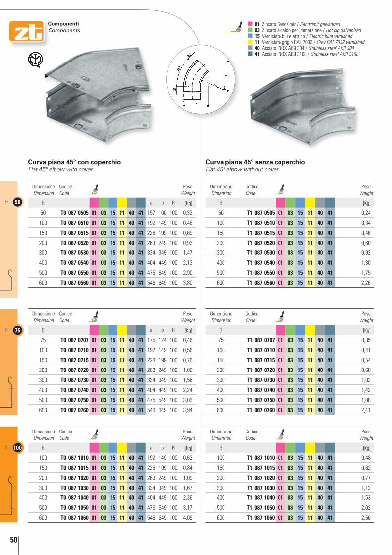
50
50H
75H
100H
componenti components
01 Zincato Sendzimir / Sendzimir galvanized 03 Zincato a caldo per immersione / Hot dip galvanized 15 Verniciato blu elettrico / Electric blue varnished 11 Verniciato grigio RAL 7032 / Grey RAL 7032 varnished 40 Acciaio INOX AISI 304 / Stainless steel AISI 304 41 Acciaio INOX AISI 316L / Stainless steel AISI 316L
curva piana 45° con coperchioFlat 45° elbow with cover
curva piana 45° senza coperchioFlat 45° elbow without cover
Dimensione Dimension
Codice Code
Peso Weight
B a b R [Kg]
50 t0 087 0505 01 03 15 11 40 41 157 100 100 0,32
100 t0 087 0510 01 03 15 11 40 41 192 149 100 0,48
150 t0 087 0515 01 03 15 11 40 41 228 199 100 0,69
200 t0 087 0520 01 03 15 11 40 41 263 249 100 0,92
300 t0 087 0530 01 03 15 11 40 41 334 349 100 1,47
400 t0 087 0540 01 03 15 11 40 41 404 449 100 2,13
500 t0 087 0550 01 03 15 11 40 41 475 549 100 2,90
600 t0 087 0560 01 03 15 11 40 41 546 649 100 3,80
Dimensione Dimension
Codice Code
Peso Weight
B a b R [Kg]
75 t0 087 0707 01 03 15 11 40 41 175 124 100 0,46
100 t0 087 0710 01 03 15 11 40 41 192 149 100 0,56
150 t0 087 0715 01 03 15 11 40 41 228 199 100 0,76
200 t0 087 0720 01 03 15 11 40 41 263 249 100 1,00
300 t0 087 0730 01 03 15 11 40 41 334 349 100 1,56
400 t0 087 0740 01 03 15 11 40 41 404 449 100 2,24
500 t0 087 0750 01 03 15 11 40 41 475 549 100 3,03
600 t0 087 0760 01 03 15 11 40 41 546 649 100 3,94
Dimensione Dimension
Codice Code
Peso Weight
B a b R [Kg]
100 t0 087 1010 01 03 15 11 40 41 192 149 100 0,63
150 t0 087 1015 01 03 15 11 40 41 228 199 100 0,84
200 t0 087 1020 01 03 15 11 40 41 263 249 100 1,09
300 t0 087 1030 01 03 15 11 40 41 334 349 100 1,67
400 t0 087 1040 01 03 15 11 40 41 404 449 100 2,36
500 t0 087 1050 01 03 15 11 40 41 475 549 100 3,17
600 t0 087 1060 01 03 15 11 40 41 546 649 100 4,09
Dimensione Dimension
Codice Code
Peso Weight
B [Kg]
50 t1 087 0505 01 03 15 11 40 41 0,24
100 t1 087 0510 01 03 15 11 40 41 0,34
150 t1 087 0515 01 03 15 11 40 41 0,46
200 t1 087 0520 01 03 15 11 40 41 0,60
300 t1 087 0530 01 03 15 11 40 41 0,92
400 t1 087 0540 01 03 15 11 40 41 1,30
500 t1 087 0550 01 03 15 11 40 41 1,75
600 t1 087 0560 01 03 15 11 40 41 2,26
Dimensione Dimension
Codice Code
Peso Weight
B [Kg]
75 t1 087 0707 01 03 15 11 40 41 0,35
100 t1 087 0710 01 03 15 11 40 41 0,41
150 t1 087 0715 01 03 15 11 40 41 0,54
200 t1 087 0720 01 03 15 11 40 41 0,68
300 t1 087 0730 01 03 15 11 40 41 1,02
400 t1 087 0740 01 03 15 11 40 41 1,42
500 t1 087 0750 01 03 15 11 40 41 1,88
600 t1 087 0760 01 03 15 11 40 41 2,41
Dimensione Dimension
Codice Code
Peso Weight
B [Kg]
100 t1 087 1010 01 03 15 11 40 41 0,48
150 t1 087 1015 01 03 15 11 40 41 0,62
200 t1 087 1020 01 03 15 11 40 41 0,77
300 t1 087 1030 01 03 15 11 40 41 1,12
400 t1 087 1040 01 03 15 11 40 41 1,53
500 t1 087 1050 01 03 15 11 40 41 2,02
600 t1 087 1060 01 03 15 11 40 41 2,56

51
50 H
75 H
100 H
componenti components
curva piana 30° con coperchioFlat 30° elbow with cover
curva piana 30° senza coperchioFlat 30° elbow without cover
Dimensione Dimension
Codice Code
Peso Weight
B a b R [Kg]
50 t0 089 0505 01 03 15 11 40 41 131 77 100 0,25
100 t0 089 0510 01 03 15 11 40 41 156 127 100 0,37
150 t0 089 0515 01 03 15 11 40 41 181 177 100 0,52
200 t0 089 0520 01 03 15 11 40 41 206 227 100 0,68
300 t0 089 0530 01 03 15 11 40 41 256 327 100 1,06
400 t0 089 0540 01 03 15 11 40 41 306 427 100 1,52
500 t0 089 0550 01 03 15 11 40 41 356 527 100 2,05
600 t0 089 0560 01 03 15 11 40 41 406 627 100 2,67
Dimensione Dimension
Codice Code
Peso Weight
B a b R [Kg]
75 t0 089 0707 01 03 15 11 40 41 143 102 100 0,36
100 t0 089 0710 01 03 15 11 40 41 156 127 100 0,43
150 t0 089 0715 01 03 15 11 40 41 181 177 100 0,58
200 t0 089 0720 01 03 15 11 40 41 206 227 100 0,76
300 t0 089 0730 01 03 15 11 40 41 256 327 100 1,15
400 t0 089 0740 01 03 15 11 40 41 306 427 100 1,60
500 t0 089 0750 01 03 15 11 40 41 356 527 100 2,15
600 t0 089 0760 01 03 15 11 40 41 406 627 100 2,78
Dimensione Dimension
Codice Code
Peso Weight
B a b R [Kg]
100 t0 089 1010 01 03 15 11 40 41 156 127 100 0,49
150 t0 089 1015 01 03 15 11 40 41 181 177 100 0,64
200 t0 089 1020 01 03 15 11 40 41 206 227 100 0,82
300 t0 089 1030 01 03 15 11 40 41 256 327 100 1,22
400 t0 089 1040 01 03 15 11 40 41 306 427 100 1,70
500 t0 089 1050 01 03 15 11 40 41 356 527 100 2,25
600 t0 089 1060 01 03 15 11 40 41 406 627 100 2,89
Dimensione Dimension
Codice Code
Peso Weight
B [Kg]
50 t1 089 0505 01 03 15 11 40 41 0,19
100 t1 089 0510 01 03 15 11 40 41 0,26
150 t1 089 0515 01 03 15 11 40 41 0,35
200 t1 089 0520 01 03 15 11 40 41 0,44
300 t1 089 0530 01 03 15 11 40 41 0,67
400 t1 089 0540 01 03 15 11 40 41 0,93
500 t1 089 0550 01 03 15 11 40 41 1,24
600 t1 089 0560 01 03 15 11 40 41 1,59
Dimensione Dimension
Codice Code
Peso Weight
B [Kg]
75 t1 089 0707 01 03 15 11 40 41 0,28
100 t1 089 0710 01 03 15 11 40 41 0,32
150 t1 089 0715 01 03 15 11 40 41 0,41
200 t1 089 0720 01 03 15 11 40 41 0,51
300 t1 089 0730 01 03 15 11 40 41 0,74
400 t1 089 0740 01 03 15 11 40 41 1,02
500 t1 089 0750 01 03 15 11 40 41 1,34
600 t1 089 0760 01 03 15 11 40 41 1,70
Dimensione Dimension
Codice Code
Peso Weight
B [Kg]
100 t1 089 1010 01 03 15 11 40 41 0,37
150 t1 089 1015 01 03 15 11 40 41 0,47
200 t1 089 1020 01 03 15 11 40 41 0,57
300 t1 089 1030 01 03 15 11 40 41 0,82
400 t1 089 1040 01 03 15 11 40 41 1,10
500 t1 089 1050 01 03 15 11 40 41 1,43
600 t1 089 1060 01 03 15 11 40 41 1,80
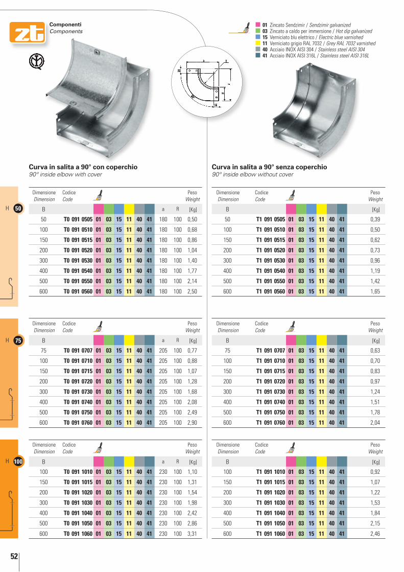
52
50H
75H
100H
componenti components
01 Zincato Sendzimir / Sendzimir galvanized 03 Zincato a caldo per immersione / Hot dip galvanized 15 Verniciato blu elettrico / Electric blue varnished 11 Verniciato grigio RAL 7032 / Grey RAL 7032 varnished 40 Acciaio INOX AISI 304 / Stainless steel AISI 304 41 Acciaio INOX AISI 316L / Stainless steel AISI 316L
curva in salita a 90° con coperchio90° inside elbow with cover
curva in salita a 90° senza coperchio90° inside elbow without cover
Dimensione Dimension
Codice Code
Peso Weight
B a R [Kg]
50 t0 091 0505 01 03 15 11 40 41 180 100 0,50
100 t0 091 0510 01 03 15 11 40 41 180 100 0,68
150 t0 091 0515 01 03 15 11 40 41 180 100 0,86
200 t0 091 0520 01 03 15 11 40 41 180 100 1,04
300 t0 091 0530 01 03 15 11 40 41 180 100 1,40
400 t0 091 0540 01 03 15 11 40 41 180 100 1,77
500 t0 091 0550 01 03 15 11 40 41 180 100 2,14
600 t0 091 0560 01 03 15 11 40 41 180 100 2,50
Dimensione Dimension
Codice Code
Peso Weight
B a R [Kg]
75 t0 091 0707 01 03 15 11 40 41 205 100 0,77
100 t0 091 0710 01 03 15 11 40 41 205 100 0,88
150 t0 091 0715 01 03 15 11 40 41 205 100 1,07
200 t0 091 0720 01 03 15 11 40 41 205 100 1,28
300 t0 091 0730 01 03 15 11 40 41 205 100 1,68
400 t0 091 0740 01 03 15 11 40 41 205 100 2,08
500 t0 091 0750 01 03 15 11 40 41 205 100 2,49
600 t0 091 0760 01 03 15 11 40 41 205 100 2,90
Dimensione Dimension
Codice Code
Peso Weight
B a R [Kg]
100 t0 091 1010 01 03 15 11 40 41 230 100 1,10
150 t0 091 1015 01 03 15 11 40 41 230 100 1,31
200 t0 091 1020 01 03 15 11 40 41 230 100 1,54
300 t0 091 1030 01 03 15 11 40 41 230 100 1,98
400 t0 091 1040 01 03 15 11 40 41 230 100 2,42
500 t0 091 1050 01 03 15 11 40 41 230 100 2,86
600 t0 091 1060 01 03 15 11 40 41 230 100 3,31
Dimensione Dimension
Codice Code
Peso Weight
B [Kg]
50 t1 091 0505 01 03 15 11 40 41 0,39
100 t1 091 0510 01 03 15 11 40 41 0,50
150 t1 091 0515 01 03 15 11 40 41 0,62
200 t1 091 0520 01 03 15 11 40 41 0,73
300 t1 091 0530 01 03 15 11 40 41 0,96
400 t1 091 0540 01 03 15 11 40 41 1,19
500 t1 091 0550 01 03 15 11 40 41 1,42
600 t1 091 0560 01 03 15 11 40 41 1,65
Dimensione Dimension
Codice Code
Peso Weight
B [Kg]
75 t1 091 0707 01 03 15 11 40 41 0,63
100 t1 091 0710 01 03 15 11 40 41 0,70
150 t1 091 0715 01 03 15 11 40 41 0,83
200 t1 091 0720 01 03 15 11 40 41 0,97
300 t1 091 0730 01 03 15 11 40 41 1,24
400 t1 091 0740 01 03 15 11 40 41 1,51
500 t1 091 0750 01 03 15 11 40 41 1,78
600 t1 091 0760 01 03 15 11 40 41 2,04
Dimensione Dimension
Codice Code
Peso Weight
B [Kg]
100 t1 091 1010 01 03 15 11 40 41 0,92
150 t1 091 1015 01 03 15 11 40 41 1,07
200 t1 091 1020 01 03 15 11 40 41 1,22
300 t1 091 1030 01 03 15 11 40 41 1,53
400 t1 091 1040 01 03 15 11 40 41 1,84
500 t1 091 1050 01 03 15 11 40 41 2,15
600 t1 091 1060 01 03 15 11 40 41 2,46
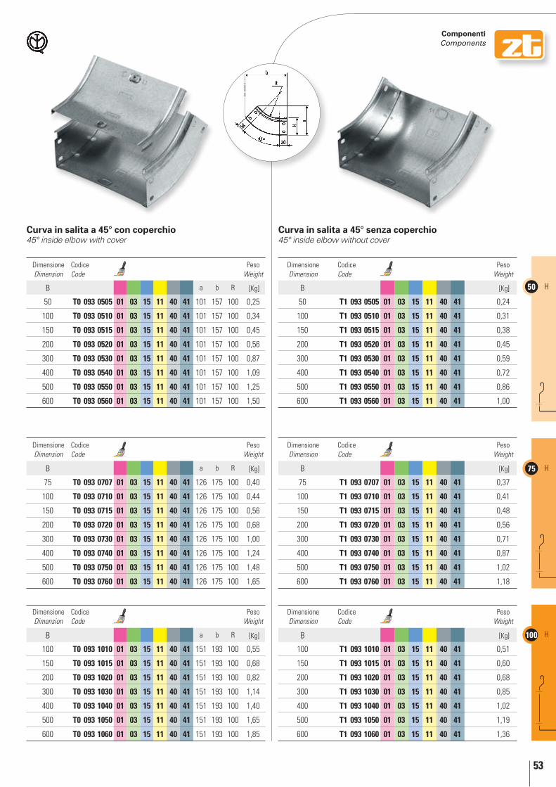
53
50 H
75 H
100 H
componenti components
curva in salita a 45° con coperchio45° inside elbow with cover
curva in salita a 45° senza coperchio45° inside elbow without cover
Dimensione Dimension
Codice Code
Peso Weight
B a b R [Kg]
50 t0 093 0505 01 03 15 11 40 41 101 157 100 0,25
100 t0 093 0510 01 03 15 11 40 41 101 157 100 0,34
150 t0 093 0515 01 03 15 11 40 41 101 157 100 0,45
200 t0 093 0520 01 03 15 11 40 41 101 157 100 0,56
300 t0 093 0530 01 03 15 11 40 41 101 157 100 0,87
400 t0 093 0540 01 03 15 11 40 41 101 157 100 1,09
500 t0 093 0550 01 03 15 11 40 41 101 157 100 1,25
600 t0 093 0560 01 03 15 11 40 41 101 157 100 1,50
Dimensione Dimension
Codice Code
Peso Weight
B a b R [Kg]
75 t0 093 0707 01 03 15 11 40 41 126 175 100 0,40
100 t0 093 0710 01 03 15 11 40 41 126 175 100 0,44
150 t0 093 0715 01 03 15 11 40 41 126 175 100 0,56
200 t0 093 0720 01 03 15 11 40 41 126 175 100 0,68
300 t0 093 0730 01 03 15 11 40 41 126 175 100 1,00
400 t0 093 0740 01 03 15 11 40 41 126 175 100 1,24
500 t0 093 0750 01 03 15 11 40 41 126 175 100 1,48
600 t0 093 0760 01 03 15 11 40 41 126 175 100 1,65
Dimensione Dimension
Codice Code
Peso Weight
B a b R [Kg]
100 t0 093 1010 01 03 15 11 40 41 151 193 100 0,55
150 t0 093 1015 01 03 15 11 40 41 151 193 100 0,68
200 t0 093 1020 01 03 15 11 40 41 151 193 100 0,82
300 t0 093 1030 01 03 15 11 40 41 151 193 100 1,14
400 t0 093 1040 01 03 15 11 40 41 151 193 100 1,40
500 t0 093 1050 01 03 15 11 40 41 151 193 100 1,65
600 t0 093 1060 01 03 15 11 40 41 151 193 100 1,85
Dimensione Dimension
Codice Code
Peso Weight
B [Kg]
50 t1 093 0505 01 03 15 11 40 41 0,24
100 t1 093 0510 01 03 15 11 40 41 0,31
150 t1 093 0515 01 03 15 11 40 41 0,38
200 t1 093 0520 01 03 15 11 40 41 0,45
300 t1 093 0530 01 03 15 11 40 41 0,59
400 t1 093 0540 01 03 15 11 40 41 0,72
500 t1 093 0550 01 03 15 11 40 41 0,86
600 t1 093 0560 01 03 15 11 40 41 1,00
Dimensione Dimension
Codice Code
Peso Weight
B [Kg]
75 t1 093 0707 01 03 15 11 40 41 0,37
100 t1 093 0710 01 03 15 11 40 41 0,41
150 t1 093 0715 01 03 15 11 40 41 0,48
200 t1 093 0720 01 03 15 11 40 41 0,56
300 t1 093 0730 01 03 15 11 40 41 0,71
400 t1 093 0740 01 03 15 11 40 41 0,87
500 t1 093 0750 01 03 15 11 40 41 1,02
600 t1 093 0760 01 03 15 11 40 41 1,18
Dimensione Dimension
Codice Code
Peso Weight
B [Kg]
100 t1 093 1010 01 03 15 11 40 41 0,51
150 t1 093 1015 01 03 15 11 40 41 0,60
200 t1 093 1020 01 03 15 11 40 41 0,68
300 t1 093 1030 01 03 15 11 40 41 0,85
400 t1 093 1040 01 03 15 11 40 41 1,02
500 t1 093 1050 01 03 15 11 40 41 1,19
600 t1 093 1060 01 03 15 11 40 41 1,36

54
50H
75H
100H
componenti components
01 Zincato Sendzimir / Sendzimir galvanized 03 Zincato a caldo per immersione / Hot dip galvanized 15 Verniciato blu elettrico / Electric blue varnished 11 Verniciato grigio RAL 7032 / Grey RAL 7032 varnished 40 Acciaio INOX AISI 304 / Stainless steel AISI 304 41 Acciaio INOX AISI 316L / Stainless steel AISI 316L
curva in salita a 30° con coperchio30° inside elbow with cover
curva in salita a 30° senza coperchio30° inside elbow without cover
Dimensione Dimension
Codice Code
Peso Weight
B a b R [Kg]
50 t0 095 0505 01 03 15 11 40 41 80 131 100 0,27
100 t0 095 0510 01 03 15 11 40 41 80 131 100 0,35
150 t0 095 0515 01 03 15 11 40 41 80 131 100 0,43
200 t0 095 0520 01 03 15 11 40 41 80 131 100 0,51
300 t0 095 0530 01 03 15 11 40 41 80 131 100 0,67
400 t0 095 0540 01 03 15 11 40 41 80 131 100 0,82
500 t0 095 0550 01 03 15 11 40 41 80 131 100 1,02
600 t0 095 0560 01 03 15 11 40 41 80 131 100 1,20
Dimensione Dimension
Codice Code
Peso Weight
B a b R [Kg]
75 t0 095 0707 01 03 15 11 40 41 105 144 100 0,41
100 t0 095 0710 01 03 15 11 40 41 105 144 100 0,45
150 t0 095 0715 01 03 15 11 40 41 105 144 100 0,52
200 t0 095 0720 01 03 15 11 40 41 105 144 100 0,60
300 t0 095 0730 01 03 15 11 40 41 105 144 100 0,76
400 t0 095 0740 01 03 15 11 40 41 105 144 100 0,92
500 t0 095 0750 01 03 15 11 40 41 105 144 100 1,15
600 t0 095 0760 01 03 15 11 40 41 105 144 100 1,33
Dimensione Dimension
Codice Code
Peso Weight
B a b R [Kg]
100 t0 095 1010 01 03 15 11 40 41 130 156 100 0,53
150 t0 095 1015 01 03 15 11 40 41 130 156 100 0,61
200 t0 095 1020 01 03 15 11 40 41 130 156 100 0,69
300 t0 095 1030 01 03 15 11 40 41 130 156 100 0,85
400 t0 095 1040 01 03 15 11 40 41 130 156 100 1,01
500 t0 095 1050 01 03 15 11 40 41 130 156 100 1,30
600 t0 095 1060 01 03 15 11 40 41 130 156 100 1,50
Dimensione Dimension
Codice Code
Peso Weight
B [Kg]
50 t1 095 0505 01 03 15 11 40 41 0,22
100 t1 095 0510 01 03 15 11 40 41 0,26
150 t1 095 0515 01 03 15 11 40 41 0,31
200 t1 095 0520 01 03 15 11 40 41 0,35
300 t1 095 0530 01 03 15 11 40 41 0,44
400 t1 095 0540 01 03 15 11 40 41 0,53
500 t1 095 0550 01 03 15 11 40 41 0,61
600 t1 095 0560 01 03 15 11 40 41 0,70
Dimensione Dimension
Codice Code
Peso Weight
B [Kg]
75 t1 095 0707 01 03 15 11 40 41 0,34
100 t1 095 0710 01 03 15 11 40 41 0,36
150 t1 095 0715 01 03 15 11 40 41 0,40
200 t1 095 0720 01 03 15 11 40 41 0,45
300 t1 095 0730 01 03 15 11 40 41 0,53
400 t1 095 0740 01 03 15 11 40 41 0,62
500 t1 095 0750 01 03 15 11 40 41 0,71
600 t1 095 0760 01 03 15 11 40 41 0,80
Dimensione Dimension
Codice Code
Peso Weight
B [Kg]
100 t1 095 1010 01 03 15 11 40 41 0,44
150 t1 095 1015 01 03 15 11 40 41 0,49
200 t1 095 1020 01 03 15 11 40 41 0,53
300 t1 095 1030 01 03 15 11 40 41 0,62
400 t1 095 1040 01 03 15 11 40 41 0,71
500 t1 095 1050 01 03 15 11 40 41 0,79
600 t1 095 1060 01 03 15 11 40 41 0,88
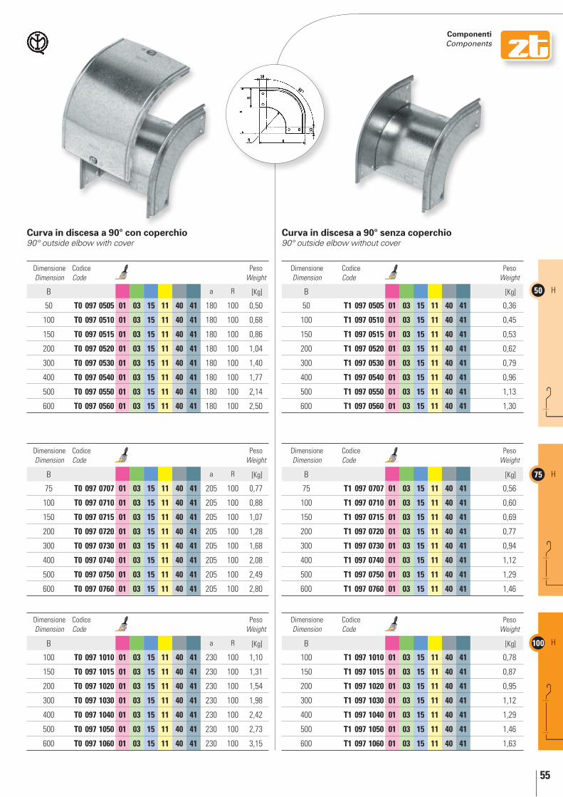
55
50 H
75 H
100 H
componenti components
curva in discesa a 90° con coperchio90° outside elbow with cover
curva in discesa a 90° senza coperchio90° outside elbow without cover
Dimensione Dimension
Codice Code
Peso Weight
B a R [Kg]
50 t0 097 0505 01 03 15 11 40 41 180 100 0,50
100 t0 097 0510 01 03 15 11 40 41 180 100 0,68
150 t0 097 0515 01 03 15 11 40 41 180 100 0,86
200 t0 097 0520 01 03 15 11 40 41 180 100 1,04
300 t0 097 0530 01 03 15 11 40 41 180 100 1,40
400 t0 097 0540 01 03 15 11 40 41 180 100 1,77
500 t0 097 0550 01 03 15 11 40 41 180 100 2,14
600 t0 097 0560 01 03 15 11 40 41 180 100 2,50
Dimensione Dimension
Codice Code
Peso Weight
B a R [Kg]
75 t0 097 0707 01 03 15 11 40 41 205 100 0,77
100 t0 097 0710 01 03 15 11 40 41 205 100 0,88
150 t0 097 0715 01 03 15 11 40 41 205 100 1,07
200 t0 097 0720 01 03 15 11 40 41 205 100 1,28
300 t0 097 0730 01 03 15 11 40 41 205 100 1,68
400 t0 097 0740 01 03 15 11 40 41 205 100 2,08
500 t0 097 0750 01 03 15 11 40 41 205 100 2,49
600 t0 097 0760 01 03 15 11 40 41 205 100 2,80
Dimensione Dimension
Codice Code
Peso Weight
B a R [Kg]
100 t0 097 1010 01 03 15 11 40 41 230 100 1,10
150 t0 097 1015 01 03 15 11 40 41 230 100 1,31
200 t0 097 1020 01 03 15 11 40 41 230 100 1,54
300 t0 097 1030 01 03 15 11 40 41 230 100 1,98
400 t0 097 1040 01 03 15 11 40 41 230 100 2,42
500 t0 097 1050 01 03 15 11 40 41 230 100 2,73
600 t0 097 1060 01 03 15 11 40 41 230 100 3,15
Dimensione Dimension
Codice Code
Peso Weight
B [Kg]
50 t1 097 0505 01 03 15 11 40 41 0,36
100 t1 097 0510 01 03 15 11 40 41 0,45
150 t1 097 0515 01 03 15 11 40 41 0,53
200 t1 097 0520 01 03 15 11 40 41 0,62
300 t1 097 0530 01 03 15 11 40 41 0,79
400 t1 097 0540 01 03 15 11 40 41 0,96
500 t1 097 0550 01 03 15 11 40 41 1,13
600 t1 097 0560 01 03 15 11 40 41 1,30
Dimensione Dimension
Codice Code
Peso Weight
B [Kg]
75 t1 097 0707 01 03 15 11 40 41 0,56
100 t1 097 0710 01 03 15 11 40 41 0,60
150 t1 097 0715 01 03 15 11 40 41 0,69
200 t1 097 0720 01 03 15 11 40 41 0,77
300 t1 097 0730 01 03 15 11 40 41 0,94
400 t1 097 0740 01 03 15 11 40 41 1,12
500 t1 097 0750 01 03 15 11 40 41 1,29
600 t1 097 0760 01 03 15 11 40 41 1,46
Dimensione Dimension
Codice Code
Peso Weight
B [Kg]
100 t1 097 1010 01 03 15 11 40 41 0,78
150 t1 097 1015 01 03 15 11 40 41 0,87
200 t1 097 1020 01 03 15 11 40 41 0,95
300 t1 097 1030 01 03 15 11 40 41 1,12
400 t1 097 1040 01 03 15 11 40 41 1,29
500 t1 097 1050 01 03 15 11 40 41 1,46
600 t1 097 1060 01 03 15 11 40 41 1,63

56
50H
75H
100H
componenti components
01 Zincato Sendzimir / Sendzimir galvanized 03 Zincato a caldo per immersione / Hot dip galvanized 15 Verniciato blu elettrico / Electric blue varnished 11 Verniciato grigio RAL 7032 / Grey RAL 7032 varnished 40 Acciaio INOX AISI 304 / Stainless steel AISI 304 41 Acciaio INOX AISI 316L / Stainless steel AISI 316L
curva in discesa a 45° con coperchio45° outside elbow with cover
curva in discesa a 45° senza coperchio45° outside elbow without cover
Dimensione Dimension
Codice Code
Peso Weight
B a b R [Kg]
50 t0 099 0505 01 03 15 11 40 41 101 157 100 0,24
100 t0 099 0510 01 03 15 11 40 41 101 157 100 0,40
150 t0 099 0515 01 03 15 11 40 41 101 157 100 0,35
200 t0 099 0520 01 03 15 11 40 41 101 157 100 0,56
300 t0 099 0530 01 03 15 11 40 41 101 157 100 0,78
400 t0 099 0540 01 03 15 11 40 41 101 157 100 1,09
500 t0 099 0550 01 03 15 11 40 41 101 157 100 1,22
600 t0 099 0560 01 03 15 11 40 41 101 157 100 1,44
Dimensione Dimension
Codice Code
Peso Weight
B a b R [Kg]
75 t0 099 0707 01 03 15 11 40 41 126 175 100 0,40
100 t0 099 0710 01 03 15 11 40 41 126 175 100 0,45
150 t0 099 0715 01 03 15 11 40 41 126 175 100 0,64
200 t0 099 0720 01 03 15 11 40 41 126 175 100 0,76
300 t0 099 0730 01 03 15 11 40 41 126 175 100 1,00
400 t0 099 0740 01 03 15 11 40 41 126 175 100 1,22
500 t0 099 0750 01 03 15 11 40 41 126 175 100 1,46
600 t0 099 0760 01 03 15 11 40 41 126 175 100 1,69
Dimensione Dimension
Codice Code
Peso Weight
B a b R [Kg]
100 t0 099 1010 01 03 15 11 40 41 151 193 100 0,56
150 t0 099 1015 01 03 15 11 40 41 151 193 100 0,68
200 t0 099 1020 01 03 15 11 40 41 151 193 100 0,88
300 t0 099 1030 01 03 15 11 40 41 151 193 100 1,12
400 t0 099 1040 01 03 15 11 40 41 151 193 100 1,30
500 t0 099 1050 01 03 15 11 40 41 151 193 100 1,55
600 t0 099 1060 01 03 15 11 40 41 151 193 100 1,86
Dimensione Dimension
Codice Code
Peso Weight
B [Kg]
50 t1 099 0505 01 03 15 11 40 41 0,23
100 t1 099 0510 01 03 15 11 40 41 0,28
150 t1 099 0515 01 03 15 11 40 41 0,33
200 t1 099 0520 01 03 15 11 40 41 0,39
300 t1 099 0530 01 03 15 11 40 41 0,50
400 t1 099 0540 01 03 15 11 40 41 0,61
500 t1 099 0550 01 03 15 11 40 41 0,72
600 t1 099 0560 01 03 15 11 40 41 0,82
Dimensione Dimension
Codice Code
Peso Weight
B [Kg]
75 t1 099 0707 01 03 15 11 40 41 0,33
100 t1 099 0710 01 03 15 11 40 41 0,36
150 t1 099 0715 01 03 15 11 40 41 0,41
200 t1 099 0720 01 03 15 11 40 41 0,47
300 t1 099 0730 01 03 15 11 40 41 0,58
400 t1 099 0740 01 03 15 11 40 41 0,69
500 t1 099 0750 01 03 15 11 40 41 0,80
600 t1 099 0760 01 03 15 11 40 41 0,90
Dimensione Dimension
Codice Code
Peso Weight
B [Kg]
100 t1 099 1010 01 03 15 11 40 41 0,45
150 t1 099 1015 01 03 15 11 40 41 0,50
200 t1 099 1020 01 03 15 11 40 41 0,56
300 t1 099 1030 01 03 15 11 40 41 0,67
400 t1 099 1040 01 03 15 11 40 41 0,78
500 t1 099 1050 01 03 15 11 40 41 0,88
600 t1 099 1060 01 03 15 11 40 41 0,99
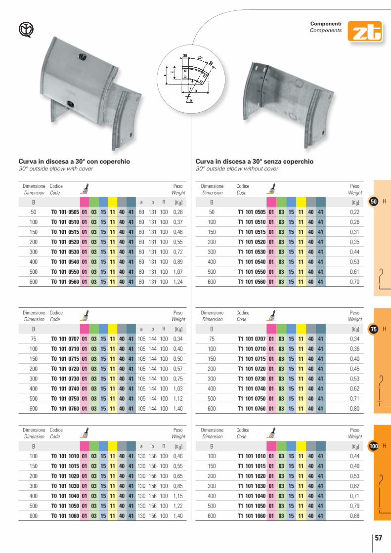
57
50 H
75 H
100 H
componenti components
curva in discesa a 30° senza coperchio30° outside elbow without cover
curva in discesa a 30° con coperchio30° outside elbow with cover
Dimensione Dimension
Codice Code
Peso Weight
B a b R [Kg]
50 t0 101 0505 01 03 15 11 40 41 80 131 100 0,28
100 t0 101 0510 01 03 15 11 40 41 80 131 100 0,37
150 t0 101 0515 01 03 15 11 40 41 80 131 100 0,46
200 t0 101 0520 01 03 15 11 40 41 80 131 100 0,55
300 t0 101 0530 01 03 15 11 40 41 80 131 100 0,72
400 t0 101 0540 01 03 15 11 40 41 80 131 100 0,89
500 t0 101 0550 01 03 15 11 40 41 80 131 100 1,07
600 t0 101 0560 01 03 15 11 40 41 80 131 100 1,24
Dimensione Dimension
Codice Code
Peso Weight
B a b R [Kg]
75 t0 101 0707 01 03 15 11 40 41 105 144 100 0,34
100 t0 101 0710 01 03 15 11 40 41 105 144 100 0,40
150 t0 101 0715 01 03 15 11 40 41 105 144 100 0,50
200 t0 101 0720 01 03 15 11 40 41 105 144 100 0,57
300 t0 101 0730 01 03 15 11 40 41 105 144 100 0,75
400 t0 101 0740 01 03 15 11 40 41 105 144 100 1,03
500 t0 101 0750 01 03 15 11 40 41 105 144 100 1,12
600 t0 101 0760 01 03 15 11 40 41 105 144 100 1,40
Dimensione Dimension
Codice Code
Peso Weight
B a b R [Kg]
100 t0 101 1010 01 03 15 11 40 41 130 156 100 0,46
150 t0 101 1015 01 03 15 11 40 41 130 156 100 0,55
200 t0 101 1020 01 03 15 11 40 41 130 156 100 0,65
300 t0 101 1030 01 03 15 11 40 41 130 156 100 0,85
400 t0 101 1040 01 03 15 11 40 41 130 156 100 1,15
500 t0 101 1050 01 03 15 11 40 41 130 156 100 1,22
600 t0 101 1060 01 03 15 11 40 41 130 156 100 1,40
Dimensione Dimension
Codice Code
Peso Weight
B [Kg]
50 t1 101 0505 01 03 15 11 40 41 0,22
100 t1 101 0510 01 03 15 11 40 41 0,26
150 t1 101 0515 01 03 15 11 40 41 0,31
200 t1 101 0520 01 03 15 11 40 41 0,35
300 t1 101 0530 01 03 15 11 40 41 0,44
400 t1 101 0540 01 03 15 11 40 41 0,53
500 t1 101 0550 01 03 15 11 40 41 0,61
600 t1 101 0560 01 03 15 11 40 41 0,70
Dimensione Dimension
Codice Code
Peso Weight
B [Kg]
75 t1 101 0707 01 03 15 11 40 41 0,34
100 t1 101 0710 01 03 15 11 40 41 0,36
150 t1 101 0715 01 03 15 11 40 41 0,40
200 t1 101 0720 01 03 15 11 40 41 0,45
300 t1 101 0730 01 03 15 11 40 41 0,53
400 t1 101 0740 01 03 15 11 40 41 0,62
500 t1 101 0750 01 03 15 11 40 41 0,71
600 t1 101 0760 01 03 15 11 40 41 0,80
Dimensione Dimension
Codice Code
Peso Weight
B [Kg]
100 t1 101 1010 01 03 15 11 40 41 0,44
150 t1 101 1015 01 03 15 11 40 41 0,49
200 t1 101 1020 01 03 15 11 40 41 0,53
300 t1 101 1030 01 03 15 11 40 41 0,62
400 t1 101 1040 01 03 15 11 40 41 0,71
500 t1 101 1050 01 03 15 11 40 41 0,79
600 t1 101 1060 01 03 15 11 40 41 0,88

58
50H
75H
100H
componenti components
01 Zincato Sendzimir / Sendzimir galvanized 03 Zincato a caldo per immersione / Hot dip galvanized 15 Verniciato blu elettrico / Electric blue varnished 11 Verniciato grigio RAL 7032 / Grey RAL 7032 varnished 40 Acciaio INOX AISI 304 / Stainless steel AISI 304 41 Acciaio INOX AISI 316L / Stainless steel AISI 316L
curva verticale a 90° con ribaltamento di piano con coperchio90° vertical inside/outside elbow with cover
curva verticale a 90° con ribaltamento di piano senza coperchio90° vertical inside/outside elbow without cover
Dimensione Dimension
Codice Code
Peso Weight
B a R [Kg]
50 t0 103 0505 01 03 15 11 40 41 180 100 0,33
100 t0 103 0510 01 03 15 11 40 41 180 100 0,53
150 t0 103 0515 01 03 15 11 40 41 180 100 0,78
200 t0 103 0520 01 03 15 11 40 41 180 100 1,07
300 t0 103 0530 01 03 15 11 40 41 180 100 1,31
400 t0 103 0540 01 03 15 11 40 41 180 100 1,70
500 t0 103 0550 01 03 15 11 40 41 180 100 2,22
600 t0 103 0560 01 03 15 11 40 41 180 100 2,49
Dimensione Dimension
Codice Code
Peso Weight
B a R [Kg]
75 t0 103 0707 01 03 15 11 40 41 205 100 0,70
100 t0 103 0710 01 03 15 11 40 41 205 100 0,79
150 t0 103 0715 01 03 15 11 40 41 205 100 1,09
200 t0 103 0720 01 03 15 11 40 41 205 100 1,30
300 t0 103 0730 01 03 15 11 40 41 205 100 1,60
400 t0 103 0740 01 03 15 11 40 41 205 100 2,30
500 t0 103 0750 01 03 15 11 40 41 205 100 2,57
600 t0 103 0760 01 03 15 11 40 41 205 100 3,00
Dimensione Dimension
Codice Code
Peso Weight
B a R [Kg]
100 t0 103 1010 01 03 15 11 40 41 230 100 1,09
150 t0 103 1015 01 03 15 11 40 41 230 100 1,33
200 t0 103 1020 01 03 15 11 40 41 230 100 1,56
300 t0 103 1030 01 03 15 11 40 41 230 100 2,02
400 t0 103 1040 01 03 15 11 40 41 230 100 2,49
500 t0 103 1050 01 03 15 11 40 41 230 100 2,95
600 t0 103 1060 01 03 15 11 40 41 230 100 3,41
Dimensione Dimension
Codice Code
Peso Weight
B [Kg]
50 t1 103 0505 01 03 15 11 40 41 0,44
100 t1 103 0510 01 03 15 11 40 41 0,60
150 t1 103 0515 01 03 15 11 40 41 0,76
200 t1 103 0520 01 03 15 11 40 41 0,92
300 t1 103 0530 01 03 15 11 40 41 1,24
400 t1 103 0540 01 03 15 11 40 41 1,56
500 t1 103 0550 01 03 15 11 40 41 1,88
600 t1 103 0560 01 03 15 11 40 41 2,20
Dimensione Dimension
Codice Code
Peso Weight
B [Kg]
75 t1 103 0707 01 03 15 11 40 41 0,71
100 t1 103 0710 01 03 15 11 40 41 0,80
150 t1 103 0715 01 03 15 11 40 41 0,98
200 t1 103 0720 01 03 15 11 40 41 1,16
300 t1 103 0730 01 03 15 11 40 41 1,52
400 t1 103 0740 01 03 15 11 40 41 1,88
500 t1 103 0750 01 03 15 11 40 41 2,24
600 t1 103 0760 01 03 15 11 40 41 2,60
Dimensione Dimension
Codice Code
Peso Weight
B [Kg]
100 t1 103 1010 01 03 15 11 40 41 1,01
150 t1 103 1015 01 03 15 11 40 41 1,21
200 t1 103 1020 01 03 15 11 40 41 1,41
300 t1 103 1030 01 03 15 11 40 41 1,81
400 t1 103 1040 01 03 15 11 40 41 2,21
500 t1 103 1050 01 03 15 11 40 41 2,61
600 t1 103 1060 01 03 15 11 40 41 3,10
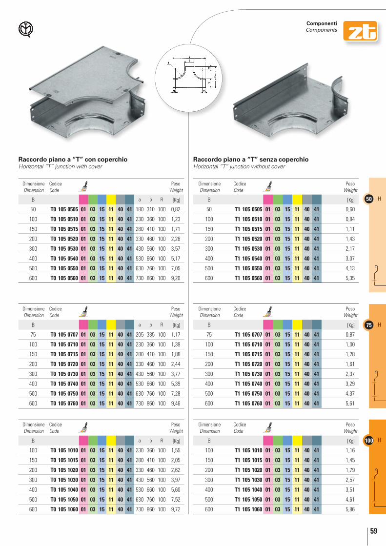
59
50 H
75 H
100 H
componenti components
raccordo piano a “T” con coperchioHorizontal “T” junction with cover
raccordo piano a “T” senza coperchioHorizontal “T” junction without cover
Dimensione Dimension
Codice Code
Peso Weight
B a b R [Kg]
50 t0 105 0505 01 03 15 11 40 41 180 310 100 0,82
100 t0 105 0510 01 03 15 11 40 41 230 360 100 1,23
150 t0 105 0515 01 03 15 11 40 41 280 410 100 1,71
200 t0 105 0520 01 03 15 11 40 41 330 460 100 2,26
300 t0 105 0530 01 03 15 11 40 41 430 560 100 3,57
400 t0 105 0540 01 03 15 11 40 41 530 660 100 5,17
500 t0 105 0550 01 03 15 11 40 41 630 760 100 7,05
600 t0 105 0560 01 03 15 11 40 41 730 860 100 9,20
Dimensione Dimension
Codice Code
Peso Weight
B a b R [Kg]
75 t0 105 0707 01 03 15 11 40 41 205 335 100 1,17
100 t0 105 0710 01 03 15 11 40 41 230 360 100 1,39
150 t0 105 0715 01 03 15 11 40 41 280 410 100 1,88
200 t0 105 0720 01 03 15 11 40 41 330 460 100 2,44
300 t0 105 0730 01 03 15 11 40 41 430 560 100 3,77
400 t0 105 0740 01 03 15 11 40 41 530 660 100 5,39
500 t0 105 0750 01 03 15 11 40 41 630 760 100 7,28
600 t0 105 0760 01 03 15 11 40 41 730 860 100 9,46
Dimensione Dimension
Codice Code
Peso Weight
B a b R [Kg]
100 t0 105 1010 01 03 15 11 40 41 230 360 100 1,55
150 t0 105 1015 01 03 15 11 40 41 280 410 100 2,05
200 t0 105 1020 01 03 15 11 40 41 330 460 100 2,62
300 t0 105 1030 01 03 15 11 40 41 430 560 100 3,97
400 t0 105 1040 01 03 15 11 40 41 530 660 100 5,60
500 t0 105 1050 01 03 15 11 40 41 630 760 100 7,52
600 t0 105 1060 01 03 15 11 40 41 730 860 100 9,72
Dimensione Dimension
Codice Code
Peso Weight
B [Kg]
50 t1 105 0505 01 03 15 11 40 41 0,60
100 t1 105 0510 01 03 15 11 40 41 0,84
150 t1 105 0515 01 03 15 11 40 41 1,11
200 t1 105 0520 01 03 15 11 40 41 1,43
300 t1 105 0530 01 03 15 11 40 41 2,17
400 t1 105 0540 01 03 15 11 40 41 3,07
500 t1 105 0550 01 03 15 11 40 41 4,13
600 t1 105 0560 01 03 15 11 40 41 5,35
Dimensione Dimension
Codice Code
Peso Weight
B [Kg]
75 t1 105 0707 01 03 15 11 40 41 0,87
100 t1 105 0710 01 03 15 11 40 41 1,00
150 t1 105 0715 01 03 15 11 40 41 1,28
200 t1 105 0720 01 03 15 11 40 41 1,61
300 t1 105 0730 01 03 15 11 40 41 2,37
400 t1 105 0740 01 03 15 11 40 41 3,29
500 t1 105 0750 01 03 15 11 40 41 4,37
600 t1 105 0760 01 03 15 11 40 41 5,61
Dimensione Dimension
Codice Code
Peso Weight
B [Kg]
100 t1 105 1010 01 03 15 11 40 41 1,16
150 t1 105 1015 01 03 15 11 40 41 1,45
200 t1 105 1020 01 03 15 11 40 41 1,79
300 t1 105 1030 01 03 15 11 40 41 2,57
400 t1 105 1040 01 03 15 11 40 41 3,51
500 t1 105 1050 01 03 15 11 40 41 4,61
600 t1 105 1060 01 03 15 11 40 41 5,86

60
50H
75H
100H
componenti components
01 Zincato Sendzimir / Sendzimir galvanized 03 Zincato a caldo per immersione / Hot dip galvanized 15 Verniciato blu elettrico / Electric blue varnished 11 Verniciato grigio RAL 7032 / Grey RAL 7032 varnished 40 Acciaio INOX AISI 304 / Stainless steel AISI 304 41 Acciaio INOX AISI 316L / Stainless steel AISI 316L
Uscita laterale “T” con coperchio“T” side outlet with cover
Uscita laterale “T” senza coperchio“T” side outlet without cover
Dimensione Dimension
Codice Code
Peso Weight
B a b R [Kg]
50 t0 109 0505 01 03 15 11 40 41 160 310 100 0,56
100 t0 109 0510 01 03 15 11 40 41 160 360 100 0,68
150 t0 109 0515 01 03 15 11 40 41 160 410 100 0,79
200 t0 109 0520 01 03 15 11 40 41 160 460 100 0,90
300 t0 109 0530 01 03 15 11 40 41 160 560 100 1,13
400 t0 109 0540 01 03 15 11 40 41 160 660 100 1,36
500 t0 109 0550 01 03 15 11 40 41 160 760 100 1,58
600 t0 109 0560 01 03 15 11 40 41 160 860 100 1,80
Dimensione Dimension
Codice Code
Peso Weight
B a b R [Kg]
75 t0 109 0707 01 03 15 11 40 41 160 335 100 0,71
100 t0 109 0710 01 03 15 11 40 41 160 360 100 0,77
150 t0 109 0715 01 03 15 11 40 41 160 410 100 0,88
200 t0 109 0720 01 03 15 11 40 41 160 460 100 1,00
300 t0 109 0730 01 03 15 11 40 41 160 560 100 1,22
400 t0 109 0740 01 03 15 11 40 41 160 660 100 1,45
500 t0 109 0750 01 03 15 11 40 41 160 760 100 1,67
600 t0 109 0760 01 03 15 11 40 41 160 860 100 1,90
Dimensione Dimension
Codice Code
Peso Weight
B a b R [Kg]
100 t0 109 1010 01 03 15 11 40 41 160 360 100 0,86
150 t0 109 1015 01 03 15 11 40 41 160 410 100 0,97
200 t0 109 1020 01 03 15 11 40 41 160 460 100 1,08
300 t0 109 1030 01 03 15 11 40 41 160 560 100 1,31
400 t0 109 1040 01 03 15 11 40 41 160 660 100 1,54
500 t0 109 1050 01 03 15 11 40 41 160 760 100 1,76
600 t0 109 1060 01 03 15 11 40 41 160 860 100 1,99
Dimensione Dimension
Codice Code
Peso Weight
B [Kg]
50 t1 109 0505 01 03 15 11 40 41 0,41
100 t1 109 0510 01 03 15 11 40 41 0,47
150 t1 109 0515 01 03 15 11 40 41 0,54
200 t1 109 0520 01 03 15 11 40 41 0,60
300 t1 109 0530 01 03 15 11 40 41 0,72
400 t1 109 0540 01 03 15 11 40 41 0,85
500 t1 109 0550 01 03 15 11 40 41 0,98
600 t1 109 0560 01 03 15 11 40 41 1,10
Dimensione Dimension
Codice Code
Peso Weight
B [Kg]
75 t1 109 0707 01 03 15 11 40 41 0,53
100 t1 109 0710 01 03 15 11 40 41 0,56
150 t1 109 0715 01 03 15 11 40 41 0,63
200 t1 109 0720 01 03 15 11 40 41 0,69
300 t1 109 0730 01 03 15 11 40 41 0,81
400 t1 109 0740 01 03 15 11 40 41 0,94
500 t1 109 0750 01 03 15 11 40 41 1,07
600 t1 109 0760 01 03 15 11 40 41 1,19
Dimensione Dimension
Codice Code
Peso Weight
B [Kg]
100 t1 109 1010 01 03 15 11 40 41 0,65
150 t1 109 1015 01 03 15 11 40 41 0,72
200 t1 109 1020 01 03 15 11 40 41 0,78
300 t1 109 1030 01 03 15 11 40 41 0,90
400 t1 109 1040 01 03 15 11 40 41 1,03
500 t1 109 1050 01 03 15 11 40 41 1,16
600 t1 109 1060 01 03 15 11 40 41 1,28
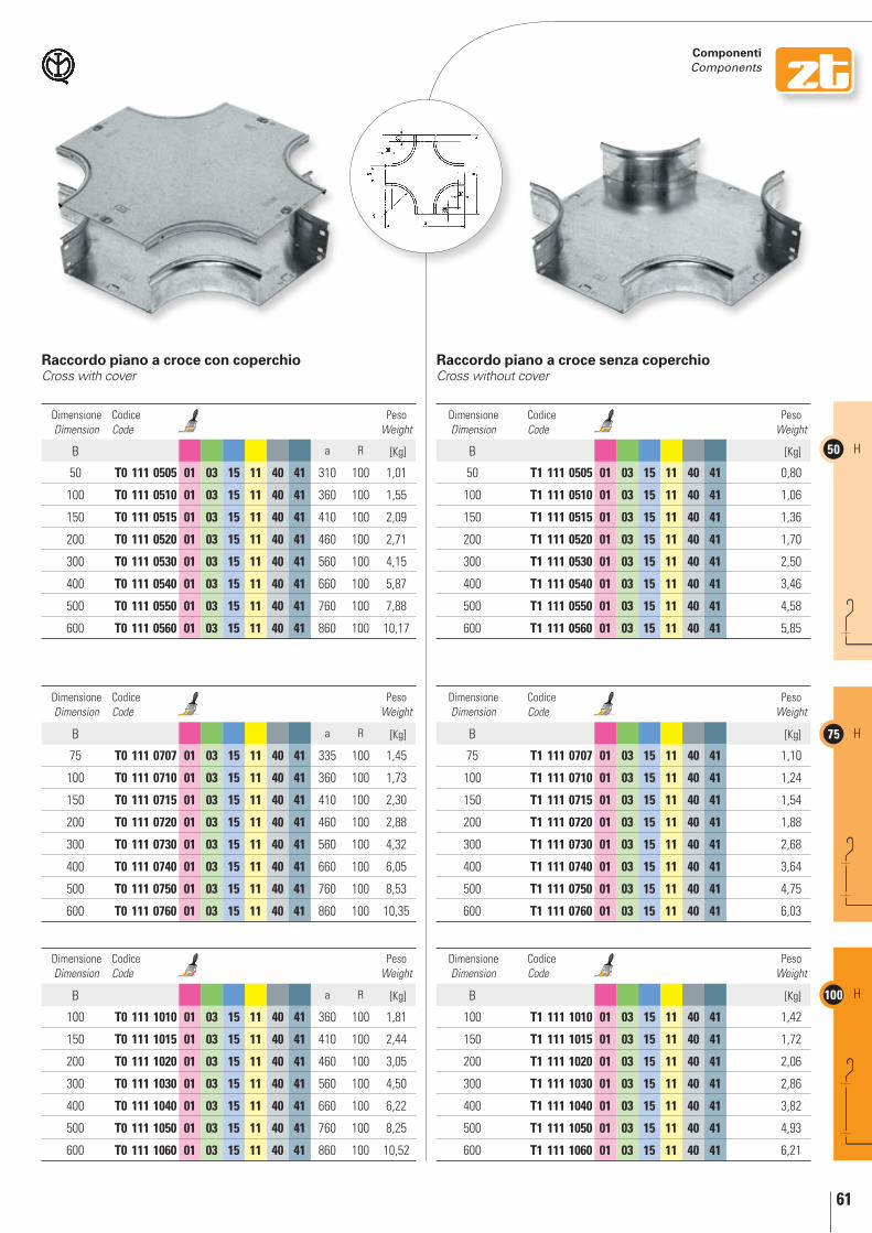
61
50 H
75 H
100 H
componenti components
raccordo piano a croce con coperchioCross with cover
raccordo piano a croce senza coperchioCross without cover
Dimensione Dimension
Codice Code
Peso Weight
B a R [Kg]
50 t0 111 0505 01 03 15 11 40 41 310 100 1,01
100 t0 111 0510 01 03 15 11 40 41 360 100 1,55
150 t0 111 0515 01 03 15 11 40 41 410 100 2,09
200 t0 111 0520 01 03 15 11 40 41 460 100 2,71
300 t0 111 0530 01 03 15 11 40 41 560 100 4,15
400 t0 111 0540 01 03 15 11 40 41 660 100 5,87
500 t0 111 0550 01 03 15 11 40 41 760 100 7,88
600 t0 111 0560 01 03 15 11 40 41 860 100 10,17
Dimensione Dimension
Codice Code
Peso Weight
B a R [Kg]
75 t0 111 0707 01 03 15 11 40 41 335 100 1,45
100 t0 111 0710 01 03 15 11 40 41 360 100 1,73
150 t0 111 0715 01 03 15 11 40 41 410 100 2,30
200 t0 111 0720 01 03 15 11 40 41 460 100 2,88
300 t0 111 0730 01 03 15 11 40 41 560 100 4,32
400 t0 111 0740 01 03 15 11 40 41 660 100 6,05
500 t0 111 0750 01 03 15 11 40 41 760 100 8,53
600 t0 111 0760 01 03 15 11 40 41 860 100 10,35
Dimensione Dimension
Codice Code
Peso Weight
B a R [Kg]
100 t0 111 1010 01 03 15 11 40 41 360 100 1,81
150 t0 111 1015 01 03 15 11 40 41 410 100 2,44
200 t0 111 1020 01 03 15 11 40 41 460 100 3,05
300 t0 111 1030 01 03 15 11 40 41 560 100 4,50
400 t0 111 1040 01 03 15 11 40 41 660 100 6,22
500 t0 111 1050 01 03 15 11 40 41 760 100 8,25
600 t0 111 1060 01 03 15 11 40 41 860 100 10,52
Dimensione Dimension
Codice Code
Peso Weight
B [Kg]
50 t1 111 0505 01 03 15 11 40 41 0,80
100 t1 111 0510 01 03 15 11 40 41 1,06
150 t1 111 0515 01 03 15 11 40 41 1,36
200 t1 111 0520 01 03 15 11 40 41 1,70
300 t1 111 0530 01 03 15 11 40 41 2,50
400 t1 111 0540 01 03 15 11 40 41 3,46
500 t1 111 0550 01 03 15 11 40 41 4,58
600 t1 111 0560 01 03 15 11 40 41 5,85
Dimensione Dimension
Codice Code
Peso Weight
B [Kg]
75 t1 111 0707 01 03 15 11 40 41 1,10
100 t1 111 0710 01 03 15 11 40 41 1,24
150 t1 111 0715 01 03 15 11 40 41 1,54
200 t1 111 0720 01 03 15 11 40 41 1,88
300 t1 111 0730 01 03 15 11 40 41 2,68
400 t1 111 0740 01 03 15 11 40 41 3,64
500 t1 111 0750 01 03 15 11 40 41 4,75
600 t1 111 0760 01 03 15 11 40 41 6,03
Dimensione Dimension
Codice Code
Peso Weight
B [Kg]
100 t1 111 1010 01 03 15 11 40 41 1,42
150 t1 111 1015 01 03 15 11 40 41 1,72
200 t1 111 1020 01 03 15 11 40 41 2,06
300 t1 111 1030 01 03 15 11 40 41 2,86
400 t1 111 1040 01 03 15 11 40 41 3,82
500 t1 111 1050 01 03 15 11 40 41 4,93
600 t1 111 1060 01 03 15 11 40 41 6,21
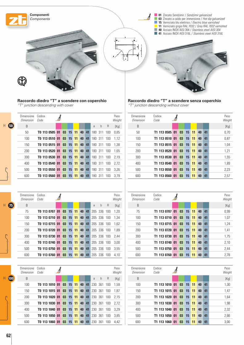
62
50H
75H
100H
componenti components
01 Zincato Sendzimir / Sendzimir galvanized 03 Zincato a caldo per immersione / Hot dip galvanized 15 Verniciato blu elettrico / Electric blue varnished 11 Verniciato grigio RAL 7032 / Grey RAL 7032 varnished 40 Acciaio INOX AISI 304 / Stainless steel AISI 304 41 Acciaio INOX AISI 316L / Stainless steel AISI 316L
raccordo diedro “T” a scendere con coperchio“T” junction descending with cover
raccordo diedro “T” a scendere senza coperchio“T” junction descending without cover
Dimensione Dimension
Codice Code
Peso Weight
B a b R [Kg]
50 t0 113 0505 01 03 15 11 40 41 180 311 100 0,85
100 t0 113 0510 01 03 15 11 40 41 180 311 100 1,12
150 t0 113 0515 01 03 15 11 40 41 180 311 100 1,38
200 t0 113 0520 01 03 15 11 40 41 180 311 100 1,65
300 t0 113 0530 01 03 15 11 40 41 180 311 100 2,19
400 t0 113 0540 01 03 15 11 40 41 180 311 100 2,72
500 t0 113 0550 01 03 15 11 40 41 180 311 100 3,26
600 t0 113 0560 01 03 15 11 40 41 180 311 100 3,79
Dimensione Dimension
Codice Code
Peso Weight
B a b R [Kg]
75 t0 113 0707 01 03 15 11 40 41 205 336 100 1,20
100 t0 113 0710 01 03 15 11 40 41 205 336 100 1,34
150 t0 113 0715 01 03 15 11 40 41 205 336 100 1,62
200 t0 113 0720 01 03 15 11 40 41 205 336 100 1,89
300 t0 113 0730 01 03 15 11 40 41 205 336 100 2,44
400 t0 113 0740 01 03 15 11 40 41 205 336 100 3,00
500 t0 113 0750 01 03 15 11 40 41 205 336 100 3,55
600 t0 113 0760 01 03 15 11 40 41 205 336 100 4,10
Dimensione Dimension
Codice Code
Peso Weight
B a b R [Kg]
100 t0 113 1010 01 03 15 11 40 41 230 361 100 1,59
150 t0 113 1015 01 03 15 11 40 41 230 361 100 1,87
200 t0 113 1020 01 03 15 11 40 41 230 361 100 2,15
300 t0 113 1030 01 03 15 11 40 41 230 361 100 2,72
400 t0 113 1040 01 03 15 11 40 41 230 361 100 3,29
500 t0 113 1050 01 03 15 11 40 41 230 361 100 3,85
600 t0 113 1060 01 03 15 11 40 41 230 361 100 4,42
Dimensione Dimension
Codice Code
Peso Weight
B [Kg]
50 t1 113 0505 01 03 15 11 40 41 0,70
100 t1 113 0510 01 03 15 11 40 41 0,87
150 t1 113 0515 01 03 15 11 40 41 1,04
200 t1 113 0520 01 03 15 11 40 41 1,21
300 t1 113 0530 01 03 15 11 40 41 1,55
400 t1 113 0540 01 03 15 11 40 41 1,89
500 t1 113 0550 01 03 15 11 40 41 2,23
600 t1 113 0560 01 03 15 11 40 41 2,57
Dimensione Dimension
Codice Code
Peso Weight
B [Kg]
75 t1 113 0707 01 03 15 11 40 41 0,99
100 t1 113 0710 01 03 15 11 40 41 1,07
150 t1 113 0715 01 03 15 11 40 41 1,24
200 t1 113 0720 01 03 15 11 40 41 1,41
300 t1 113 0730 01 03 15 11 40 41 1,75
400 t1 113 0740 01 03 15 11 40 41 2,10
500 t1 113 0750 01 03 15 11 40 41 2,44
600 t1 113 0760 01 03 15 11 40 41 2,78
Dimensione Dimension
Codice Code
Peso Weight
B [Kg]
100 t1 113 1010 01 03 15 11 40 41 1,30
150 t1 113 1015 01 03 15 11 40 41 1,47
200 t1 113 1020 01 03 15 11 40 41 1,64
300 t1 113 1030 01 03 15 11 40 41 1,98
400 t1 113 1040 01 03 15 11 40 41 2,32
500 t1 113 1050 01 03 15 11 40 41 2,66
600 t1 113 1060 01 03 15 11 40 41 3,00

63
50 H
75 H
100 H
componenti components
raccordo diedro “T” a salire con coperchio“T” junction rising with cover
raccordo diedro “T” a salire senza coperchio“T” junction rising without cover
Dimensione Dimension
Codice Code
Peso Weight
B a b R [Kg]
50 t0 115 0505 01 03 15 11 40 41 180 311 100 0,84
100 t0 115 0510 01 03 15 11 40 41 180 311 100 1,11
150 t0 115 0515 01 03 15 11 40 41 180 311 100 1,39
200 t0 115 0520 01 03 15 11 40 41 180 311 100 1,66
300 t0 115 0530 01 03 15 11 40 41 180 311 100 2,21
400 t0 115 0540 01 03 15 11 40 41 180 311 100 2,76
500 t0 115 0550 01 03 15 11 40 41 180 311 100 3,31
600 t0 115 0560 01 03 15 11 40 41 180 311 100 3,85
Dimensione Dimension
Codice Code
Peso Weight
B a b R [Kg]
75 t0 115 0707 01 03 15 11 40 41 205 336 100 1,20
100 t0 115 0710 01 03 15 11 40 41 205 336 100 1,34
150 t0 115 0715 01 03 15 11 40 41 205 336 100 1,62
200 t0 115 0720 01 03 15 11 40 41 205 336 100 1,91
300 t0 115 0730 01 03 15 11 40 41 205 336 100 2,47
400 t0 115 0740 01 03 15 11 40 41 205 336 100 3,04
500 t0 115 0750 01 03 15 11 40 41 205 336 100 3,61
600 t0 115 0760 01 03 15 11 40 41 205 336 100 4,18
Dimensione Dimension
Codice Code
Peso Weight
B a b R [Kg]
100 t0 115 1010 01 03 15 11 40 41 230 361 100 1,58
150 t0 115 1015 01 03 15 11 40 41 230 361 100 1,88
200 t0 115 1020 01 03 15 11 40 41 230 361 100 2,17
300 t0 115 1030 01 03 15 11 40 41 230 361 100 2,76
400 t0 115 1040 01 03 15 11 40 41 230 361 100 3,35
500 t0 115 1050 01 03 15 11 40 41 230 361 100 3,93
600 t0 115 1060 01 03 15 11 40 41 230 361 100 4,52
Dimensione Dimension
Codice Code
Peso Weight
B [Kg]
50 t1 115 0505 01 03 15 11 40 41 0,73
100 t1 115 0510 01 03 15 11 40 41 0,94
150 t1 115 0515 01 03 15 11 40 41 1,14
200 t1 115 0520 01 03 15 11 40 41 1,35
300 t1 115 0530 01 03 15 11 40 41 1,76
400 t1 115 0540 01 03 15 11 40 41 2,18
500 t1 115 0550 01 03 15 11 40 41 2,59
600 t1 115 0560 01 03 15 11 40 41 3,00
Dimensione Dimension
Codice Code
Peso Weight
B [Kg]
75 t1 115 0707 01 03 15 11 40 41 1,05
100 t1 115 0710 01 03 15 11 40 41 1,16
150 t1 115 0715 01 03 15 11 40 41 1,38
200 t1 115 0720 01 03 15 11 40 41 1,60
300 t1 115 0730 01 03 15 11 40 41 2,03
400 t1 115 0740 01 03 15 11 40 41 2,46
500 t1 115 0750 01 03 15 11 40 41 2,89
600 t1 115 0760 01 03 15 11 40 41 3,33
Dimensione Dimension
Codice Code
Peso Weight
B [Kg]
100 t1 115 1010 01 03 15 11 40 41 1,41
150 t1 115 1015 01 03 15 11 40 41 1,63
200 t1 115 1020 01 03 15 11 40 41 1,86
300 t1 115 1030 01 03 15 11 40 41 2,31
400 t1 115 1040 01 03 15 11 40 41 2,76
500 t1 115 1050 01 03 15 11 40 41 3,22
600 t1 115 1060 01 03 15 11 40 41 3,67

64
50H
75H
100H
componenti components
01 Zincato Sendzimir / Sendzimir galvanized 03 Zincato a caldo per immersione / Hot dip galvanized 15 Verniciato blu elettrico / Electric blue varnished 11 Verniciato grigio RAL 7032 / Grey RAL 7032 varnished 40 Acciaio INOX AISI 304 / Stainless steel AISI 304 41 Acciaio INOX AISI 316L / Stainless steel AISI 316L
raccordo “T” a scendere con variazione di piano con coperchioDescending skewed “T” junction with cover
raccordo “T” a scendere con variazione di piano senza coperchioDescending skewed “T” junction without cover
Dimensione Dimension
Codice Code
Peso Weight
B a b R [Kg]
50 t0 117 0505 01 03 15 11 40 41 200 310 100 0,90
100 t0 117 0510 01 03 15 11 40 41 250 360 100 1,50
150 t0 117 0515 01 03 15 11 40 41 300 410 100 2,25
200 t0 117 0520 01 03 15 11 40 41 350 460 100 3,15
300 t0 117 0530 01 03 15 11 40 41 450 560 100 5,43
400 t0 117 0540 01 03 15 11 40 41 550 660 100 8,32
500 t0 117 0550 01 03 15 11 40 41 650 760 100 11,83
600 t0 117 0560 01 03 15 11 40 41 750 860 100 15,96
Dimensione Dimension
Codice Code
Peso Weight
B a b R [Kg]
75 t0 117 0707 01 03 15 11 40 41 225 335 100 1,27
100 t0 117 0710 01 03 15 11 40 41 250 360 100 1,58
150 t0 117 0715 01 03 15 11 40 41 300 410 100 2,33
200 t0 117 0720 01 03 15 11 40 41 350 460 100 3,23
300 t0 117 0730 01 03 15 11 40 41 450 560 100 5,50
400 t0 117 0740 01 03 15 11 40 41 550 660 100 8,39
500 t0 117 0750 01 03 15 11 40 41 650 760 100 11,89
600 t0 117 0760 01 03 15 11 40 41 750 860 100 16,00
Dimensione Dimension
Codice Code
Peso Weight
B a b R [Kg]
100 t0 117 1010 01 03 15 11 40 41 250 360 100 1,66
150 t0 117 1015 01 03 15 11 40 41 300 410 100 2,40
200 t0 117 1020 01 03 15 11 40 41 350 460 100 3,30
300 t0 117 1030 01 03 15 11 40 41 450 560 100 5,57
400 t0 117 1040 01 03 15 11 40 41 550 660 100 8,44
500 t0 117 1050 01 03 15 11 40 41 650 760 100 11,94
600 t0 117 1060 01 03 15 11 40 41 750 860 100 16,05
Dimensione Dimension
Codice Code
Peso Weight
B [Kg]
50 t1 117 0505 01 03 15 11 40 41 0,65
100 t1 117 0510 01 03 15 11 40 41 0,99
150 t1 117 0515 01 03 15 11 40 41 1,41
200 t1 117 0520 01 03 15 11 40 41 1,91
300 t1 117 0530 01 03 15 11 40 41 3,14
400 t1 117 0540 01 03 15 11 40 41 4,68
500 t1 117 0550 01 03 15 11 40 41 6,54
600 t1 117 0560 01 03 15 11 40 41 8,71
Dimensione Dimension
Codice Code
Peso Weight
B [Kg]
75 t1 117 0707 01 03 15 11 40 41 0,90
100 t1 117 0710 01 03 15 11 40 41 1,09
150 t1 117 0715 01 03 15 11 40 41 1,50
200 t1 117 0720 01 03 15 11 40 41 2,00
300 t1 117 0730 01 03 15 11 40 41 3,23
400 t1 117 0740 01 03 15 11 40 41 4,78
500 t1 117 0750 01 03 15 11 40 41 6,64
600 t1 117 0760 01 03 15 11 40 41 8,81
Dimensione Dimension
Codice Code
Peso Weight
B [Kg]
100 t1 117 1010 01 03 15 11 40 41 1,17
150 t1 117 1015 01 03 15 11 40 41 1,59
200 t1 117 1020 01 03 15 11 40 41 2,09
300 t1 117 1030 01 03 15 11 40 41 3,32
400 t1 117 1040 01 03 15 11 40 41 4,86
500 t1 117 1050 01 03 15 11 40 41 6,72
600 t1 117 1060 01 03 15 11 40 41 8,89

65
50 H
75 H
100 H
componenti components
raccordo “T” a salire con variazione di piano con coperchioRising skewed “T” junction with cover
raccordo “T” a salire con variazione di piano senza coperchioRising skewed “T” junction without cover
Dimensione Dimension
Codice Code
Peso Weight
B a b R [Kg]
50 t0 119 0505 01 03 15 11 40 41 200 310 100 0,90
100 t0 119 0510 01 03 15 11 40 41 250 360 100 1,54
150 t0 119 0515 01 03 15 11 40 41 300 410 100 2,33
200 t0 119 0520 01 03 15 11 40 41 350 460 100 3,30
300 t0 119 0530 01 03 15 11 40 41 450 560 100 5,70
400 t0 119 0540 01 03 15 11 40 41 550 660 100 8,61
500 t0 119 0550 01 03 15 11 40 41 650 760 100 12,28
600 t0 119 0560 01 03 15 11 40 41 750 860 100 16,60
Dimensione Dimension
Codice Code
Peso Weight
B a b R [Kg]
75 t0 119 0707 01 03 15 11 40 41 225 335 100 1,25
100 t0 119 0710 01 03 15 11 40 41 250 360 100 1,57
150 t0 119 0715 01 03 15 11 40 41 300 410 100 2,42
200 t0 119 0720 01 03 15 11 40 41 350 460 100 3,27
300 t0 119 0730 01 03 15 11 40 41 450 560 100 5,70
400 t0 119 0740 01 03 15 11 40 41 550 660 100 8,80
500 t0 119 0750 01 03 15 11 40 41 650 760 100 12,50
600 t0 119 0760 01 03 15 11 40 41 750 860 100 16,83
Dimensione Dimension
Codice Code
Peso Weight
B a b R [Kg]
100 t0 119 1010 01 03 15 11 40 41 250 360 100 1,65
150 t0 119 1015 01 03 15 11 40 41 300 410 100 2,43
200 t0 119 1020 01 03 15 11 40 41 350 460 100 3,36
300 t0 119 1030 01 03 15 11 40 41 450 560 100 5,73
400 t0 119 1040 01 03 15 11 40 41 550 660 100 8,74
500 t0 119 1050 01 03 15 11 40 41 650 760 100 12,40
600 t0 119 1060 01 03 15 11 40 41 750 860 100 16,87
Dimensione Dimension
Codice Code
Peso Weight
B [Kg]
50 t1 119 0505 01 03 15 11 40 41 0,77
100 t1 119 0510 01 03 15 11 40 41 1,27
150 t1 119 0515 01 03 15 11 40 41 1,89
200 t1 119 0520 01 03 15 11 40 41 2,62
300 t1 119 0530 01 03 15 11 40 41 4,45
400 t1 119 0540 01 03 15 11 40 41 6,74
500 t1 119 0550 01 03 15 11 40 41 9,51
600 t1 119 0560 01 03 15 11 40 41 12,75
Dimensione Dimension
Codice Code
Peso Weight
B [Kg]
75 t1 119 0707 01 03 15 11 40 41 1,10
100 t1 119 0710 01 03 15 11 40 41 1,36
150 t1 119 0715 01 03 15 11 40 41 1,98
200 t1 119 0720 01 03 15 11 40 41 2,72
300 t1 119 0730 01 03 15 11 40 41 4,54
400 t1 119 0740 01 03 15 11 40 41 6,84
500 t1 119 0750 01 03 15 11 40 41 9,61
600 t1 119 0760 01 03 15 11 40 41 12,85
Dimensione Dimension
Codice Code
Peso Weight
B [Kg]
100 t1 119 1010 01 03 15 11 40 41 1,45
150 t1 119 1015 01 03 15 11 40 41 2,07
200 t1 119 1020 01 03 15 11 40 41 2,80
300 t1 119 1030 01 03 15 11 40 41 4,63
400 t1 119 1040 01 03 15 11 40 41 7,15
500 t1 119 1050 01 03 15 11 40 41 9,69
600 t1 119 1060 01 03 15 11 40 41 12,93

66
50H
75H
100H
componenti components
01 Zincato Sendzimir / Sendzimir galvanized 03 Zincato a caldo per immersione / Hot dip galvanized 15 Verniciato blu elettrico / Electric blue varnished 11 Verniciato grigio RAL 7032 / Grey RAL 7032 varnished 40 Acciaio INOX AISI 304 / Stainless steel AISI 304 41 Acciaio INOX AISI 316L / Stainless steel AISI 316L
curva a 90° sinistra a scendere con variazione di piano con coperchio90° left descending skewed elbow with cover
curva a 90° sinistra a scendere con variazione di piano senza coperchio90° left descending skewed elbow without cover
Dimensione Dimension
Codice Code
Peso Weight
B a b R [Kg]
50 t0 121 0505 01 03 15 11 40 41 200 180 100 0,65
100 t0 121 0510 01 03 15 11 40 41 250 230 100 1,19
150 t0 121 0515 01 03 15 11 40 41 300 280 100 1,88
200 t0 121 0520 01 03 15 11 40 41 350 330 100 2,74
300 t0 121 0530 01 03 15 11 40 41 450 430 100 4,90
400 t0 121 0540 01 03 15 11 40 41 550 530 100 7,68
500 t0 121 0550 01 03 15 11 40 41 650 630 100 11,10
600 t0 121 0560 01 03 15 11 40 41 750 730 100 15,10
Dimensione Dimension
Codice Code
Peso Weight
B a b R [Kg]
75 t0 121 0707 01 03 15 11 40 41 225 205 100 0,95
100 t0 121 0710 01 03 15 11 40 41 250 230 100 1,24
150 t0 121 0715 01 03 15 11 40 41 300 280 100 1,95
200 t0 121 0720 01 03 15 11 40 41 350 330 100 2,80
300 t0 121 0730 01 03 15 11 40 41 450 430 100 5,02
400 t0 121 0740 01 03 15 11 40 41 550 530 100 7,78
500 t0 121 0750 01 03 15 11 40 41 650 630 100 11,25
600 t0 121 0760 01 03 15 11 40 41 750 730 100 15,30
Dimensione Dimension
Codice Code
Peso Weight
B a b R [Kg]
100 t0 121 1010 01 03 15 11 40 41 250 230 100 1,29
150 t0 121 1015 01 03 15 11 40 41 300 280 100 2,00
200 t0 121 1020 01 03 15 11 40 41 350 330 100 2,86
300 t0 121 1030 01 03 15 11 40 41 450 430 100 5,05
400 t0 121 1040 01 03 15 11 40 41 550 530 100 7,86
500 t0 121 1050 01 03 15 11 40 41 650 630 100 11,28
600 t0 121 1060 01 03 15 11 40 41 750 730 100 15,32
Dimensione Dimension
Codice Code
Peso Weight
B [Kg]
50 t1 121 0505 01 03 15 11 40 41 0,46
100 t1 121 0510 01 03 15 11 40 41 0,79
150 t1 121 0515 01 03 15 11 40 41 1,19
200 t1 121 0520 01 03 15 11 40 41 1,67
300 t1 121 0530 01 03 15 11 40 41 2,88
400 t1 121 0540 01 03 15 11 40 41 4,39
500 t1 121 0550 01 03 15 11 40 41 6,22
600 t1 121 0560 01 03 15 11 40 41 8,37
Dimensione Dimension
Codice Code
Peso Weight
B [Kg]
75 t1 121 0707 01 03 15 11 40 41 0,67
100 t1 121 0710 01 03 15 11 40 41 0,85
150 t1 121 0715 01 03 15 11 40 41 1,26
200 t1 121 0720 01 03 15 11 40 41 1,76
300 t1 121 0730 01 03 15 11 40 41 2,98
400 t1 121 0740 01 03 15 11 40 41 4,52
500 t1 121 0750 01 03 15 11 40 41 6,37
600 t1 121 0760 01 03 15 11 40 41 8,53
Dimensione Dimension
Codice Code
Peso Weight
B [Kg]
100 t1 121 1010 01 03 15 11 40 41 0,90
150 t1 121 1015 01 03 15 11 40 41 1,33
200 t1 121 1020 01 03 15 11 40 41 1,83
300 t1 121 1030 01 03 15 11 40 41 3,07
400 t1 121 1040 01 03 15 11 40 41 4,62
500 t1 121 1050 01 03 15 11 40 41 6,49
600 t1 121 1060 01 03 15 11 40 41 8,67

67
50 H
75 H
100 H
componenti components
curva a 90° destra a scendere con variazione di piano con coperchio90° right descending skewed elbow with cover
curva a 90° destra a scendere con variazione di piano senza coperchio90° right descending skewed elbow without cover
Dimensione Dimension
Codice Code
Peso Weight
B a b R [Kg]
50 t0 123 0505 01 03 15 11 40 41 200 180 100 0,65
100 t0 123 0510 01 03 15 11 40 41 250 230 100 1,19
150 t0 123 0515 01 03 15 11 40 41 300 280 100 1,88
200 t0 123 0520 01 03 15 11 40 41 350 330 100 2,74
300 t0 123 0530 01 03 15 11 40 41 450 430 100 4,90
400 t0 123 0540 01 03 15 11 40 41 550 530 100 7,68
500 t0 123 0550 01 03 15 11 40 41 650 630 100 11,15
600 t0 123 0560 01 03 15 11 40 41 750 730 100 15,16
Dimensione Dimension
Codice Code
Peso Weight
B a b R [Kg]
75 t0 123 0707 01 03 15 11 40 41 225 205 100 0,95
100 t0 123 0710 01 03 15 11 40 41 250 230 100 1,24
150 t0 123 0715 01 03 15 11 40 41 300 280 100 1,95
200 t0 123 0720 01 03 15 11 40 41 350 330 100 2,80
300 t0 123 0730 01 03 15 11 40 41 450 430 100 5,02
400 t0 123 0740 01 03 15 11 40 41 550 530 100 7,78
500 t0 123 0750 01 03 15 11 40 41 650 630 100 11,19
600 t0 123 0760 01 03 15 11 40 41 750 730 100 15,22
Dimensione Dimension
Codice Code
Peso Weight
B a b R [Kg]
100 t0 123 1010 01 03 15 11 40 41 250 230 100 1,29
150 t0 123 1015 01 03 15 11 40 41 300 280 100 2,00
200 t0 123 1020 01 03 15 11 40 41 350 330 100 2,86
300 t0 123 1030 01 03 15 11 40 41 450 430 100 5,05
400 t0 123 1040 01 03 15 11 40 41 550 530 100 7,86
500 t0 123 1050 01 03 15 11 40 41 650 630 100 11,28
600 t0 123 1060 01 03 15 11 40 41 750 730 100 15,32
Dimensione Dimension
Codice Code
Peso Weight
B [Kg]
50 t1 123 0505 01 03 15 11 40 41 0,46
100 t1 123 0510 01 03 15 11 40 41 0,79
150 t1 123 0515 01 03 15 11 40 41 1,19
200 t1 123 0520 01 03 15 11 40 41 1,67
300 t1 123 0530 01 03 15 11 40 41 2,88
400 t1 123 0540 01 03 15 11 40 41 4,39
500 t1 123 0550 01 03 15 11 40 41 6,22
600 t1 123 0560 01 03 15 11 40 41 8,37
Dimensione Dimension
Codice Code
Peso Weight
B [Kg]
75 t1 123 0707 01 03 15 11 40 41 0,67
100 t1 123 0710 01 03 15 11 40 41 0,85
150 t1 123 0715 01 03 15 11 40 41 1,26
200 t1 123 0720 01 03 15 11 40 41 1,76
300 t1 123 0730 01 03 15 11 40 41 2,98
400 t1 123 0740 01 03 15 11 40 41 4,52
500 t1 123 0750 01 03 15 11 40 41 6,37
600 t1 123 0760 01 03 15 11 40 41 8,53
Dimensione Dimension
Codice Code
Peso Weight
B [Kg]
100 t1 123 1010 01 03 15 11 40 41 0,90
150 t1 123 1015 01 03 15 11 40 41 1,33
200 t1 123 1020 01 03 15 11 40 41 1,83
300 t1 123 1030 01 03 15 11 40 41 3,07
400 t1 123 1040 01 03 15 11 40 41 4,62
500 t1 123 1050 01 03 15 11 40 41 6,49
600 t1 123 1060 01 03 15 11 40 41 8,67

68
50H
75H
100H
componenti components
01 Zincato Sendzimir / Sendzimir galvanized 03 Zincato a caldo per immersione / Hot dip galvanized 15 Verniciato blu elettrico / Electric blue varnished 11 Verniciato grigio RAL 7032 / Grey RAL 7032 varnished 40 Acciaio INOX AISI 304 / Stainless steel AISI 304 41 Acciaio INOX AISI 316L / Stainless steel AISI 316L
curva a 90° sinistra a salire con variazione di piano con coperchio90° left rising skewed elbow with cover
curva a 90° sinistra a salire con variazione di piano senza coperchio90° left rising skewed elbow without cover
Dimensione Dimension
Codice Code
Peso Weight
B a b R [Kg]
50 t0 125 0505 01 03 15 11 40 41 200 180 100 0,65
100 t0 125 0510 01 03 15 11 40 41 250 230 100 1,19
150 t0 125 0515 01 03 15 11 40 41 300 280 100 1,90
200 t0 125 0520 01 03 15 11 40 41 350 330 100 2,78
300 t0 125 0530 01 03 15 11 40 41 450 430 100 5,02
400 t0 125 0540 01 03 15 11 40 41 550 530 100 7,91
500 t0 125 0550 01 03 15 11 40 41 650 630 100 11,57
600 t0 125 0560 01 03 15 11 40 41 750 730 100 15,78
Dimensione Dimension
Codice Code
Peso Weight
B a b R [Kg]
75 t0 125 0707 01 03 15 11 40 41 225 205 100 0,95
100 t0 125 0710 01 03 15 11 40 41 250 230 100 1,24
150 t0 125 0715 01 03 15 11 40 41 300 280 100 1,96
200 t0 125 0720 01 03 15 11 40 41 350 330 100 2,85
300 t0 125 0730 01 03 15 11 40 41 450 430 100 5,10
400 t0 125 0740 01 03 15 11 40 41 550 530 100 8,00
500 t0 125 0750 01 03 15 11 40 41 650 630 100 11,70
600 t0 125 0760 01 03 15 11 40 41 750 730 100 15,90
Dimensione Dimension
Codice Code
Peso Weight
B a b R [Kg]
100 t0 125 1010 01 03 15 11 40 41 250 230 100 1,32
150 t0 125 1015 01 03 15 11 40 41 300 280 100 2,00
200 t0 125 1020 01 03 15 11 40 41 350 330 100 2,90
300 t0 125 1030 01 03 15 11 40 41 450 430 100 5,17
400 t0 125 1040 01 03 15 11 40 41 550 530 100 8,09
500 t0 125 1050 01 03 15 11 40 41 650 630 100 11,75
600 t0 125 1060 01 03 15 11 40 41 750 730 100 16,02
Dimensione Dimension
Codice Code
Peso Weight
B [Kg]
50 t1 125 0505 01 03 15 11 40 41 0,53
100 t1 125 0510 01 03 15 11 40 41 0,96
150 t1 125 0515 01 03 15 11 40 41 1,51
200 t1 125 0520 01 03 15 11 40 41 2,19
300 t1 125 0530 01 03 15 11 40 41 3,88
400 t1 125 0540 01 03 15 11 40 41 6,05
500 t1 125 0550 01 03 15 11 40 41 8,68
600 t1 125 0560 01 03 15 11 40 41 11,79
Dimensione Dimension
Codice Code
Peso Weight
B [Kg]
75 t1 125 0707 01 03 15 11 40 41 0,79
100 t1 125 0710 01 03 15 11 40 41 1,03
150 t1 125 0715 01 03 15 11 40 41 1,59
200 t1 125 0720 01 03 15 11 40 41 2,27
300 t1 125 0730 01 03 15 11 40 41 3,98
400 t1 125 0740 01 03 15 11 40 41 6,17
500 t1 125 0750 01 03 15 11 40 41 8,83
600 t1 125 0760 01 03 15 11 40 41 11,95
Dimensione Dimension
Codice Code
Peso Weight
B [Kg]
100 t1 125 1010 01 03 15 11 40 41 1,08
150 t1 125 1015 01 03 15 11 40 41 1,65
200 t1 125 1020 01 03 15 11 40 41 2,34
300 t1 125 1030 01 03 15 11 40 41 4,07
400 t1 125 1040 01 03 15 11 40 41 6,28
500 t1 125 1050 01 03 15 11 40 41 8,95
600 t1 125 1060 01 03 15 11 40 41 12,10
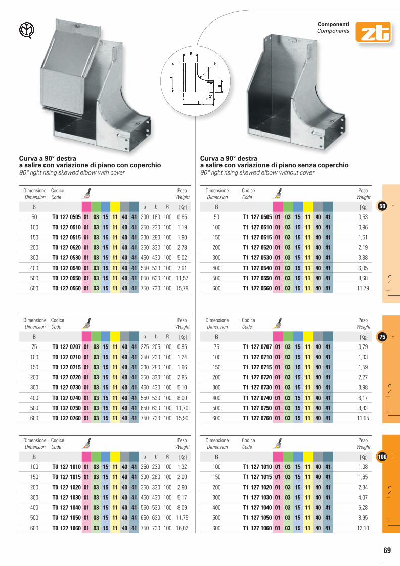
69
50 H
75 H
100 H
componenti components
curva a 90° destra a salire con variazione di piano con coperchio90° right rising skewed elbow with cover
curva a 90° destra a salire con variazione di piano senza coperchio90° right rising skewed elbow without cover
Dimensione Dimension
Codice Code
Peso Weight
B a b R [Kg]
50 t0 127 0505 01 03 15 11 40 41 200 180 100 0,65
100 t0 127 0510 01 03 15 11 40 41 250 230 100 1,19
150 t0 127 0515 01 03 15 11 40 41 300 280 100 1,90
200 t0 127 0520 01 03 15 11 40 41 350 330 100 2,78
300 t0 127 0530 01 03 15 11 40 41 450 430 100 5,02
400 t0 127 0540 01 03 15 11 40 41 550 530 100 7,91
500 t0 127 0550 01 03 15 11 40 41 650 630 100 11,57
600 t0 127 0560 01 03 15 11 40 41 750 730 100 15,78
Dimensione Dimension
Codice Code
Peso Weight
B a b R [Kg]
75 t0 127 0707 01 03 15 11 40 41 225 205 100 0,95
100 t0 127 0710 01 03 15 11 40 41 250 230 100 1,24
150 t0 127 0715 01 03 15 11 40 41 300 280 100 1,96
200 t0 127 0720 01 03 15 11 40 41 350 330 100 2,85
300 t0 127 0730 01 03 15 11 40 41 450 430 100 5,10
400 t0 127 0740 01 03 15 11 40 41 550 530 100 8,00
500 t0 127 0750 01 03 15 11 40 41 650 630 100 11,70
600 t0 127 0760 01 03 15 11 40 41 750 730 100 15,90
Dimensione Dimension
Codice Code
Peso Weight
B a b R [Kg]
100 t0 127 1010 01 03 15 11 40 41 250 230 100 1,32
150 t0 127 1015 01 03 15 11 40 41 300 280 100 2,00
200 t0 127 1020 01 03 15 11 40 41 350 330 100 2,90
300 t0 127 1030 01 03 15 11 40 41 450 430 100 5,17
400 t0 127 1040 01 03 15 11 40 41 550 530 100 8,09
500 t0 127 1050 01 03 15 11 40 41 650 630 100 11,75
600 t0 127 1060 01 03 15 11 40 41 750 730 100 16,02
Dimensione Dimension
Codice Code
Peso Weight
B [Kg]
50 t1 127 0505 01 03 15 11 40 41 0,53
100 t1 127 0510 01 03 15 11 40 41 0,96
150 t1 127 0515 01 03 15 11 40 41 1,51
200 t1 127 0520 01 03 15 11 40 41 2,19
300 t1 127 0530 01 03 15 11 40 41 3,88
400 t1 127 0540 01 03 15 11 40 41 6,05
500 t1 127 0550 01 03 15 11 40 41 8,68
600 t1 127 0560 01 03 15 11 40 41 11,79
Dimensione Dimension
Codice Code
Peso Weight
B [Kg]
75 t1 127 0707 01 03 15 11 40 41 0,79
100 t1 127 0710 01 03 15 11 40 41 1,03
150 t1 127 0715 01 03 15 11 40 41 1,59
200 t1 127 0720 01 03 15 11 40 41 2,27
300 t1 127 0730 01 03 15 11 40 41 3,98
400 t1 127 0740 01 03 15 11 40 41 6,17
500 t1 127 0750 01 03 15 11 40 41 8,83
600 t1 127 0760 01 03 15 11 40 41 11,95
Dimensione Dimension
Codice Code
Peso Weight
B [Kg]
100 t1 127 1010 01 03 15 11 40 41 1,08
150 t1 127 1015 01 03 15 11 40 41 1,65
200 t1 127 1020 01 03 15 11 40 41 2,34
300 t1 127 1030 01 03 15 11 40 41 4,07
400 t1 127 1040 01 03 15 11 40 41 6,28
500 t1 127 1050 01 03 15 11 40 41 8,95
600 t1 127 1060 01 03 15 11 40 41 12,10

70
50H
75H
100H
componenti components
Dimensione Dimension
Codice Code
L Peso Weight
B [mm] [Kg]
50 t0 129 0505 01 03 15 11 40 41 268 0,32
100 t0 129 0510 01 03 15 11 40 41 268 0,39
150 t0 129 0515 01 03 15 11 40 41 268 0,47
200 t0 129 0520 01 03 15 11 40 41 268 0,55
300 t0 129 0530 01 03 15 11 40 41 268 0,71
400 t0 129 0540 01 03 15 11 40 41 268 0,87
500 t0 129 0550 01 03 15 11 40 41 268 1,02
600 t0 129 0560 01 03 15 11 40 41 268 1,77
Dimensione Dimension
Codice Code
L Peso Weight
B [mm] [Kg]
75 t0 129 0707 01 03 15 11 40 41 308 0,53
100 t0 129 0710 01 03 15 11 40 41 308 0,57
150 t0 129 0715 01 03 15 11 40 41 308 0,66
200 t0 129 0720 01 03 15 11 40 41 308 0,75
300 t0 129 0730 01 03 15 11 40 41 308 0,92
400 t0 129 0740 01 03 15 11 40 41 308 1,09
500 t0 129 0750 01 03 15 11 40 41 308 1,26
600 t0 129 0760 01 03 15 11 40 41 308 1,43
Dimensione Dimension
Codice Code
L Peso Weight
B [mm] [Kg]
100 t0 129 1010 01 03 15 11 40 41 348 0,73
150 t0 129 1015 01 03 15 11 40 41 348 0,81
200 t0 129 1020 01 03 15 11 40 41 348 0,89
300 t0 129 1030 01 03 15 11 40 41 348 1,05
400 t0 129 1040 01 03 15 11 40 41 348 1,20
500 t0 129 1050 01 03 15 11 40 41 348 1,36
600 t0 129 1060 01 03 15 11 40 41 348 1,52
raccordo a quattro vie con variazione di piano con coperchioSkewed cross with cover
Dimensione Dimension
Codice Code
Peso Weight
B a b R [Kg]
50 t0 131 0505 01 03 15 11 350 310 100 1,19
100 t0 131 0510 01 03 15 11 450 360 100 2,07
150 t0 131 0515 01 03 15 11 550 410 100 3,19
200 t0 131 0520 01 03 15 11 650 460 100 4,56
300 t0 131 0530 01 03 15 11 850 560 100 8,03
400 t0 131 0540 01 03 15 11 1050 660 100 12,48
500 t0 131 0550 01 03 15 11 1250 760 100 17,92
600 t0 131 0560 01 03 15 11 1450 860 100 24,35
Dimensione Dimension
Codice Code
Peso Weight
B a b R [Kg]
75 t0 131 0707 01 03 15 11 375 335 100 1,64
100 t0 131 0710 01 03 15 11 425 360 100 2,09
150 t0 131 0715 01 03 15 11 525 410 100 3,19
200 t0 131 0720 01 03 15 11 625 460 100 4,54
300 t0 131 0730 01 03 15 11 825 560 100 7,96
400 t0 131 0740 01 03 15 11 1025 660 100 12,37
500 t0 131 0750 01 03 15 11 1225 760 100 16,17
600 t0 131 0760 01 03 15 11 1425 860 100 24,13
Dimensione Dimension
Codice Code
Peso Weight
B a b R [Kg]
100 t0 131 1010 01 03 15 11 400 360 100 2,10
150 t0 131 1015 01 03 15 11 500 410 100 3,18
200 t0 131 1020 01 03 15 11 600 460 100 4,50
300 t0 131 1030 01 03 15 11 800 560 100 7,87
400 t0 131 1040 01 03 15 11 1000 660 100 12,23
500 t0 131 1050 01 03 15 11 1200 760 100 17,57
600 t0 131 1060 01 03 15 11 1400 860 100 23,90
curva snodata verticale (sino a 90°)Articulated vertical elbow (up to 90°)
Solo su richiestaOnly upon request
Tempi di consegna e prezzi: chiedere all'ufficio commercialeDelivery times and prices: call our sales department

71
50 H
75 H
100 H
componenti components
n. 8 M6x10 t0 620 0610
n. 8 M6 t0 621 0600
L
c
b
Montaggio / assembly
Foratura da eseguire in operaThe drilling must be carried out during the assembly
Dimensione Dimension
Codice Code
Peso Weight
B b c L [Kg]
50 t0 140 0505 01 03 15 11 40 41 47 48 400 0,46
100 t0 140 0510 01 03 15 11 40 41 97 48 400 0,61
150 t0 140 0515 01 03 15 11 40 41 147 48 400 0,77
200 t0 140 0520 01 03 15 11 40 41 197 48 400 0,93
300 t0 140 0530 01 03 15 11 40 41 297 48 400 1,24
Dimensione Dimension
Codice Code
Peso Weight
B b c L [Kg]
75 t0 140 0707 01 03 15 11 40 41 72 73 400 0,69
100 t0 140 0710 01 03 15 11 40 41 97 73 400 0,77
150 t0 140 0715 01 03 15 11 40 41 147 73 400 0,93
200 t0 140 0720 01 03 15 11 40 41 197 73 400 1,08
300 t0 140 0730 01 03 15 11 40 41 297 73 400 1,40
Dimensione Dimension
Codice Code
Peso Weight
B b c L [Kg]
100 t0 140 1010 01 03 15 11 40 41 97 98 400 0,93
150 t0 140 1015 01 03 15 11 40 41 147 98 400 1,08
200 t0 140 1020 01 03 15 11 40 41 197 98 400 1,24
300 t0 140 1030 01 03 15 11 40 41 297 98 400 1,55
giunto telescopico di dilatazioneTelescopic expansion joint
Solo con coperchioOnly with cover
01 Zincato Sendzimir / Sendzimir galvanized 03 Zincato a caldo per immersione / Hot dip galvanized 15 Verniciato blu elettrico / Electric blue varnished 11 Verniciato grigio RAL 7032 / Grey RAL 7032 varnished 40 Acciaio INOX AISI 304 / Stainless steel AISI 304 41 Acciaio INOX AISI 316L / Stainless steel AISI 316L

72
Assemblaggio con due tipologie differenti di componenti: Serie Zt e Serie ZR, perfettamente compatibili tra loro.
assembly with two different types of components: ZT Series and ZR Series, perfectly compatible with each other.

acce
ssor
i / fi
tting
s
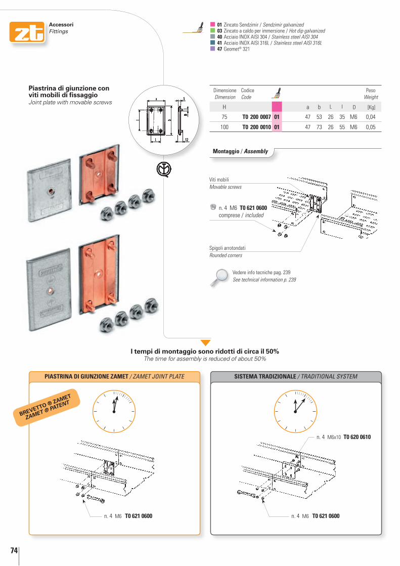
74
AccessoriFittings
SIStEMA tRADIZIOnAlE / TRADITIONAL SYSTEM
Dimensione Dimension
Codice Code
Peso Weight
H a b L I D [Kg]
75 t0 200 0007 01 47 53 26 35 M6 0,04
100 t0 200 0010 01 47 73 26 55 M6 0,05
piastrina di giunzione con viti mobili di fissaggioJoint plate with movable screws
Montaggio / assembly
Viti mobiliMovable screws
Spigoli arrotondatiRounded corners
PIAStRInA DI GIUnZIOnE ZAMEt / ZAMET JOINT PLATE
01 Zincato Sendzimir / Sendzimir galvanized 03 Zincato a caldo per immersione / Hot dip galvanized 40 Acciaio INOX AISI 304 / Stainless steel AISI 304 41 Acciaio INOX AISI 316L / Stainless steel AISI 316L 47 Geomet® 321
brEVETTo ® zAmET
ZAMET ® PATEnT
n. 4 M6 t0 621 0600comprese / included
n. 4 M6 t0 621 0600 n. 4 M6 t0 621 0600
n. 4 M6x10 t0 620 0610
i tempi di montaggio sono ridotti di circa il 50% The time for assembly is reduced of about 50%
Vedere info tecniche pag. 239See technical information p. 239

75
AccessoriFittings
Dimensione Dimension
Codice Code
Peso Weight
H a b [Kg]
50 t0 200 0005 01 40 35 52 0,04
piastrina di giunzione con perni filettati fissiJoint plate with threaded pins
piastrina di giunzioneJoint plate
giunzione esterna/interna ad “l”Outside/inside angle plate
Montaggio / assembly
Montaggio / assembly
Montaggio / assembly
Dimensione Dimension
Codice Code
Peso Weight
H a L [Kg]
50 t0 201 0005 01 47 40 41 37 52 0,02
75 t0 201 0007 01 47 40 41 62 52 0,04
100 t0 201 0010 01 47 40 41 87 52 0,05
Dimensione Dimension
Codice Code
Peso Weight
H a b L [Kg]
50 t0 212 0005 01 03 40 41 27 28,5 180 0,09
75 t0 212 0007 01 03 40 41 54 28,5 180 0,13
100 t0 212 0010 01 03 40 41 77 28,5 180 0,17
H 50 n. 2 M6x10 t0 620 0610
n. 2 M6 t0 621 0600
H 50 n. 2 M6x10 t0 620 0610
n. 2 M6 t0 621 0600
H 75-100 n. 4 M6x10 t0 620 0610
n. 4 M6 t0 621 0600
H 75-100 n. 4 M6x10 t0 620 0610
n. 4 M6 t0 621 0600
a
b
La
b
n. 2 M6 t0 621 0600comprese / included

76
AccessoriFittings
giunzione interna ad “U”Inside “U” joint
Dimensione Dimension
Codice Code
Peso Weight
B a b L [Kg]
H50
50 t0 203 0505 01 03 15 11 40 45 47 52 0,08
100 t0 203 0510 01 03 15 11 40 45 97 52 0,11
150 t0 203 0515 01 03 15 11 40 45 147 52 0,15
200 t0 203 0520 01 03 15 11 40 45 197 52 0,18
300 t0 203 0530 01 03 15 11 40 45 296 52 0,24
400 t0 203 0540 01 03 15 11 40 45 396 52 0,30
500 t0 203 0550 01 03 15 11 40 45 496 52 0,36
600 t0 203 0560 01 03 15 11 40 45 596 52 0,42
H75
75 t0 203 0707 01 03 15 11 40 70 72 52 0,13
100 t0 203 0710 01 03 15 11 40 70 97 52 0,15
150 t0 203 0715 01 03 15 11 40 70 147 52 0,18
200 t0 203 0720 01 03 15 11 40 70 197 52 0,21
300 t0 203 0730 01 03 15 11 40 70 296 52 0,27
400 t0 203 0740 01 03 15 11 40 70 396 52 0,33
500 t0 203 0750 01 03 15 11 40 70 496 52 0,39
600 t0 203 0760 01 03 15 11 40 70 596 52 0,45
H100
100 t0 203 1010 01 03 15 11 40 95 97 52 0,18
150 t0 203 1015 01 03 15 11 40 95 147 52 0,21
200 t0 203 1020 01 03 15 11 40 95 197 52 0,24
300 t0 203 1030 01 03 15 11 40 95 296 52 0,30
400 t0 203 1040 01 03 15 11 40 95 396 52 0,36
500 t0 203 1050 01 03 15 11 40 95 496 52 0,42
600 t0 203 1060 01 03 15 11 40 95 596 52 0,48
Montaggio / assembly
01 Zincato Sendzimir / Sendzimir galvanized 03 Zincato a caldo per immersione / Hot dip galvanized 15 Verniciato blu elettrico / Electric blue varnished 11 Verniciato grigio RAL 7032 / Grey RAL 7032 varnished 40 Acciaio INOX AISI 304 a richiesta / Stainless steel AISI 304 on request
In the case of the installation of internal “U” joints on coated items, preparation with equipotential plates is foreseen.
Nell’eventualità di montaggio di giunzione interna ad “U” su particolari verniciati, è prevista la predisposizione con piastrina equipotenziale
a
H 50 n. 4 M6x10 t0 620 0610
n. 4 M6 t0 621 0600
H 75-100 n. 8 M6x10 t0 620 0610
n. 8 M6 t0 621 0600
b L

77
AccessoriFittings
giunto snodato orizzontaleArticulated horizontal joint
giunto snodato verticaleArticulated vertical joint
Montaggio / assembly
Montaggio / assembly
Dimensione Dimension
Codice Code
Peso Weight
H a L [Kg]
50 t0 204 0005 01 03 40 28 200 0,08
75 t0 204 0007 01 03 40 52 200 0,13
100 t0 204 0010 01 03 40 78 200 0,18
Montaggio / assembly
Dimensione Dimension
Codice Code
Peso Weight
H a L [Kg]
50 t0 205 0005 01 03 40 28 113 0,05
75 t0 205 0007 01 03 40 52 138 0,12
100 t0 205 0010 01 03 40 74 160 0,21
H 50 n. 2 M6x10 t0 620 0610
n. 2 M6 t0 621 0600
H 50 n. 2 M6x10 t0 620 0610
n. 2 M6 t0 621 0600
H 75-100 n. 4 M6x10 t0 620 0610
n. 4 M6 t0 621 0600
H 75-100 n. 4 M6x10 t0 620 0610
n. 4 M6 t0 621 0600
L
a
L
a
giunzione rapida ad incastro Quick click joint
Dimensione Dimension
Codice Code
Spessore Thickness
Peso Weight
H a b [mm] [Kg]
75 t0 213 0007 01 40 44 206 1,20 0,074
100 t0 213 0010 01 40 69 206 1,20 0,117
n. 2 M6x10 t0 620 0610
n. 2 M6 t0 621 0600
brEVETTo ® zAmET
ZAMET ® PATEnT
b
a
Installazione solo con cod.t0 053 - Richiedere catalogo specifico per gallerie autostradali e ferroviarie (Inox)To be installed only with item T0 053 - The specific catalogue for motorway and railway tunnels (Inox) is available on request

78
AccessoriFittings
01 Zincato Sendzimir / Sendzimir galvanized 40 Acciaio INOX AISI 304 / Stainless steel AISI 304
Codice Code
Peso Weight
[Kg]
t0 601 0000 01 0,02
cerniera senza treccia di messa a terraHinge without equipotential connection
Montaggio / assembly
Codice Code
Peso Weight
[Kg]
t0 602 0000 01 0,03
Montaggio / assembly
cerniera con treccia di messa a terraHinge with equipotential connection
1
Inserire il particolare “A” sotto il risbordo del fianco della canalina.Add part “A” under trunking side flap
Chiudere la parte mobile superiore facendo coincidere la nervatura della cerniera con la nervatura del coperchio.Block upper mobile part by making hinge rib and cover rib coincide
Forare la canalina utilizzando come dima il foro “B” della cerniera ed inserire un rivetto 4.Forare il coperchio utilizzando come dima il foro superiore “C” della cerniera ed inserire un rivetto 4.Use hole “B” in hinge as a template to drill trunking and add a 4 rivet.Use upper hinge hole “C” as a template to drill cover and add a 4 rivet
2 3
B
C
A
brEVETTo ® zAmET
ZAMET ® PATEnT
n. 2 4x7 t0 652 0407
n. 2 4x7 t0 652 0407
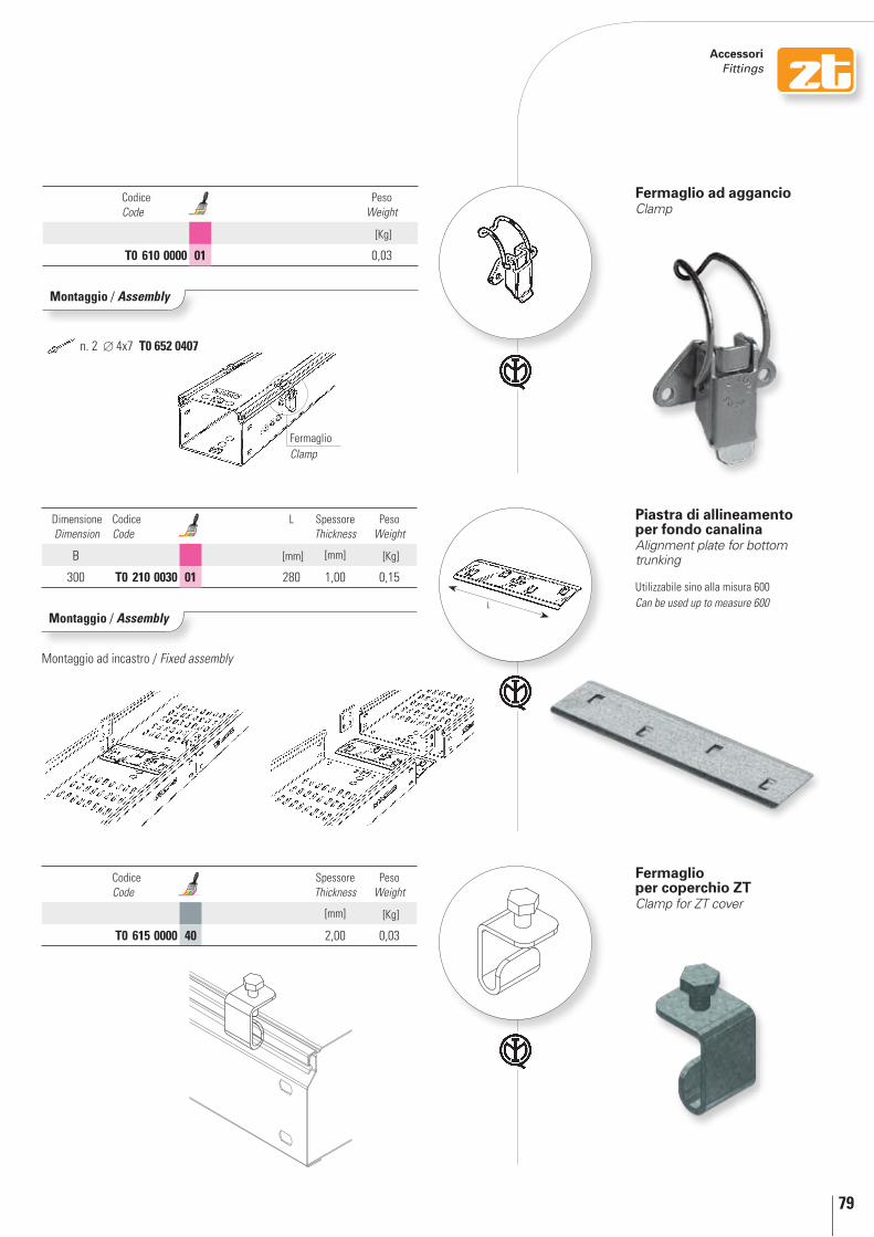
79
AccessoriFittings
Dimensione Dimension
Codice Code
L Spessore Thickness
Peso Weight
B [mm] [mm] [Kg]
300 t0 210 0030 01 280 1,00 0,15
Codice Code
Spessore Thickness
Peso Weight
[mm] [Kg]
t0 615 0000 40 2,00 0,03
Montaggio / assembly
piastra di allineamento per fondo canalinaAlignment plate for bottom trunking
Utilizzabile sino alla misura 600Can be used up to measure 600
Fermaglio per coperchio zTClamp for ZT cover
Codice Code
Peso Weight
[Kg]
t0 610 0000 01 0,03
Fermaglio ad aggancioClamp
Montaggio / assembly
FermaglioClamp
n. 2 4x7 t0 652 0407
Montaggio ad incastro / Fixed assembly
L

80
AccessoriFittings
01 Zincato Sendzimir / Sendzimir galvanized 03 Zincato a caldo per immersione / Hot dip galvanized 15 Verniciato blu elettrico / Electric blue varnished 11 Verniciato grigio RAL 7032 / Grey RAL 7032 varnished 40 Acciaio INOX AISI 304 a richiesta / Stainless steel AISI 304 on request
Dimensione Dimension
Codice Code
Peso Weight
B a b [Kg]
H50
50 t0 250 0505 01 03 15 11 40 51 53 0,03
100 t0 250 0510 01 03 15 11 40 51 103 0,05
150 t0 250 0515 01 03 15 11 40 51 153 0,08
200 t0 250 0520 01 03 15 11 40 51 203 0,10
300 t0 250 0530 01 03 15 11 40 51 303 0,15
400 t0 250 0540 01 03 15 11 40 51 403 0,19
500 t0 250 0550 01 03 15 11 40 51 503 0,24
600 t0 250 0560 01 03 15 11 40 51 603 0,29
H75
75 t0 250 0707 01 03 15 11 40 76 78 0,07
100 t0 250 0710 01 03 15 11 40 76 103 0,08
150 t0 250 0715 01 03 15 11 40 76 153 0,12
200 t0 250 0720 01 03 15 11 40 76 203 0,15
300 t0 250 0730 01 03 15 11 40 76 303 0,22
400 t0 250 0740 01 03 15 11 40 76 403 0,28
500 t0 250 0750 01 03 15 11 40 76 503 0,35
600 t0 250 0760 01 03 15 11 40 76 603 0,42
H100
100 t0 250 1010 01 03 15 11 40 101 103 0,11
150 t0 250 1015 01 03 15 11 40 101 153 0,16
200 t0 250 1020 01 03 15 11 40 101 203 0,20
300 t0 250 1030 01 03 15 11 40 101 303 0,29
400 t0 250 1040 01 03 15 11 40 101 403 0,37
500 t0 250 1050 01 03 15 11 40 101 503 0,46
600 t0 250 1060 01 03 15 11 40 101 603 0,54
Montaggio / assembly
chiusura estremitàEnd closure
H 50 n. 2 M6x10 t0 620 0610
n. 2 M6 t0 621 0600per ogni giunto / for each end closure
H 75-100 n. 4 M6x10 t0 620 0610
n. 4 M6 t0 621 0600per ogni giunto / for each end closure

81
AccessoriFittings
Montaggio / assembly
Dimensione Dimension
Codice Code
Peso Weight
H a L [Kg]
50 t0 251 0005 01 15 11 40 50 1000 0,38
75 t0 251 0007 01 15 11 40 75 1000 0,55
100 t0 251 0010 01 15 11 40 100 1000 0,74
chiusura riduzione grado di protezione ip 20End closure/reduction plates protection level IP 20
H 50 n. 2 M6x10 t0 620 0610
n. 2 M6 t0 621 0600
H 75-100 n. 4 M6x10 t0 620 0610
n. 4 M6 t0 621 0600
L
a

82
AccessoriFittings
Asola / Slot
Dimensione Dimension
Codice Code
Peso Weight
B a b c d [Kg]
H50
50 t0 260 0505 01 03 15 11 40 100 100 75 75 0,11
100 t0 260 0510 01 03 15 11 40 100 150 125 75 0,15
150 t0 260 0515 01 03 15 11 40 100 200 175 75 0,19
200 t0 260 0520 01 03 15 11 40 100 250 225 75 0,22
300 t0 260 0530 01 03 15 11 40 100 350 325 75 0,30
400 t0 260 0540 01 03 15 11 40 100 450 425 75 0,38
500 t0 260 0550 01 03 15 11 40 100 550 525 75 0,45
600 t0 260 0560 01 03 15 11 40 100 650 625 75 0,53
H75
75 t0 260 0707 01 03 15 11 40 125 125 100 100 0,16
100 t0 260 0710 01 03 15 11 40 125 150 125 100 0,18
150 t0 260 0715 01 03 15 11 40 125 200 175 100 0,22
200 t0 260 0720 01 03 15 11 40 125 250 225 100 0,25
300 t0 260 0730 01 03 15 11 40 125 350 325 100 0,33
400 t0 260 0740 01 03 15 11 40 125 450 425 100 0,41
500 t0 260 0750 01 03 15 11 40 125 550 525 100 0,48
600 t0 260 0760 01 03 15 11 40 125 650 625 100 0,56
H100
100 t0 260 1010 01 03 15 11 40 150 150 125 125 0,21
150 t0 260 1015 01 03 15 11 40 150 200 175 125 0,25
200 t0 260 1020 01 03 15 11 40 150 250 225 125 0,29
300 t0 260 1030 01 03 15 11 40 150 350 325 125 0,36
400 t0 260 1040 01 03 15 11 40 150 450 425 125 0,44
500 t0 260 1050 01 03 15 11 40 150 550 525 125 0,52
600 t0 260 1060 01 03 15 11 40 150 650 625 125 0,59
Flangia per attacco a quadroFlange for panel mount
Montaggio / assembly
01 Zincato Sendzimir / Sendzimir galvanized 03 Zincato a caldo per immersione / Hot dip galvanized 15 Verniciato blu elettrico / Electric blue varnished 11 Verniciato grigio RAL 7032 / Grey RAL 7032 varnished 40 Acciaio INOX AISI 304 a richiesta / Stainless steel AISI 304 on request
H 50 n. 2 M6x10 t0 620 0610
n. 2 M6 t0 621 0600per ogni flangia / for each flange
H 75-100 n. 4 M6x10 t0 620 0610
n. 4 M6 t0 621 0600per ogni flangia / for each flange

83
AccessoriFittings
Flangia di riduzione per attacco a quadroFlange for reducer for panel mount
Dimensione Dimension
Codice Code
Peso Weight
B a b c d [Kg]
H50
50 t0 261 0505 01 03 15 11 40 75 100 75 50 0,07
100 t0 261 0510 01 03 15 11 40 75 150 125 50 0,09
150 t0 261 0515 01 03 15 11 40 75 200 175 50 0,11
200 t0 261 0520 01 03 15 11 40 75 250 225 50 0,13
300 t0 261 0530 01 03 15 11 40 75 350 325 50 0,17
400 t0 261 0540 01 03 15 11 40 75 450 425 50 0,21
500 t0 261 0550 01 03 15 11 40 75 550 525 50 0,25
600 t0 261 0560 01 03 15 11 40 75 650 625 50 0,29
H75
75 t0 261 0707 01 03 15 11 40 100 125 100 75 0,11
100 t0 261 0710 01 03 15 11 40 100 150 125 75 0,12
150 t0 261 0715 01 03 15 11 40 100 200 175 75 0,14
200 t0 261 0720 01 03 15 11 40 100 250 225 75 0,16
300 t0 261 0730 01 03 15 11 40 100 350 325 75 0,20
400 t0 261 0740 01 03 15 11 40 100 450 425 75 0,24
500 t0 261 0750 01 03 15 11 40 100 550 525 75 0,28
600 t0 261 0760 01 03 15 11 40 100 650 625 75 0,32
H100
100 t0 261 1010 01 03 15 11 40 125 150 125 100 0,16
150 t0 261 1015 01 03 15 11 40 125 200 175 100 0,17
200 t0 261 1020 01 03 15 11 40 125 250 225 100 0,19
300 t0 261 1030 01 03 15 11 40 125 350 325 100 0,23
400 t0 261 1040 01 03 15 11 40 125 450 425 100 0,27
500 t0 261 1050 01 03 15 11 40 125 550 525 100 0,31
600 t0 261 1060 01 03 15 11 40 125 650 625 100 0,35
Montaggio / assembly
H 50 n. 2 M6x10 t0 620 0610
n. 2 M6 t0 621 0600per ogni flangia / for each flange
H 75-100 n. 4 M6x10 t0 620 0610
n. 4 M6 t0 621 0600per ogni flangia / for each flange
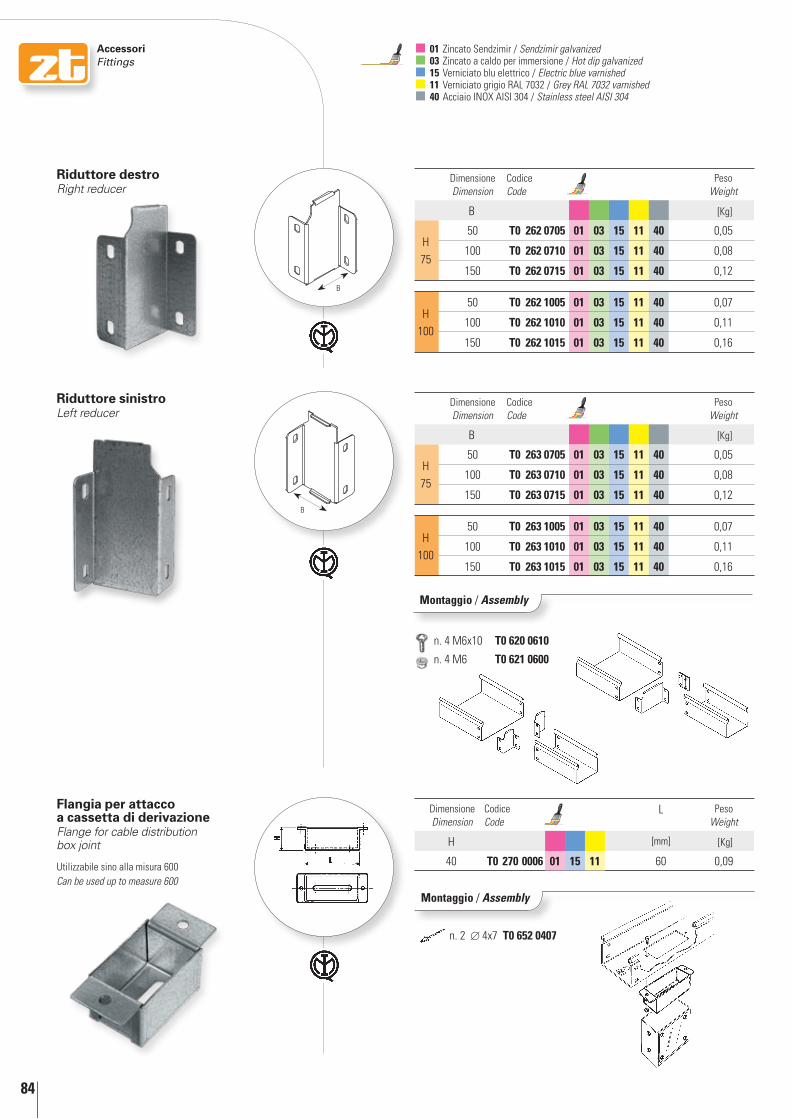
84
AccessoriFittings
Flangia per attacco a cassetta di derivazioneFlange for cable distribution box joint
Utilizzabile sino alla misura 600Can be used up to measure 600
Dimensione Dimension
Codice Code
L Peso Weight
H [mm] [Kg]
40 t0 270 0006 01 15 11 60 0,09
Montaggio / assembly
riduttore destro Right reducer
Dimensione Dimension
Codice Code
Peso Weight
B [Kg]
H75
50 t0 262 0705 01 03 15 11 40 0,05
100 t0 262 0710 01 03 15 11 40 0,08
150 t0 262 0715 01 03 15 11 40 0,12
H100
50 t0 262 1005 01 03 15 11 40 0,07
100 t0 262 1010 01 03 15 11 40 0,11
150 t0 262 1015 01 03 15 11 40 0,16
01 Zincato Sendzimir / Sendzimir galvanized 03 Zincato a caldo per immersione / Hot dip galvanized 15 Verniciato blu elettrico / Electric blue varnished 11 Verniciato grigio RAL 7032 / Grey RAL 7032 varnished 40 Acciaio INOX AISI 304 / Stainless steel AISI 304
Dimensione Dimension
Codice Code
Peso Weight
B [Kg]
H75
50 t0 263 0705 01 03 15 11 40 0,05
100 t0 263 0710 01 03 15 11 40 0,08
150 t0 263 0715 01 03 15 11 40 0,12
H100
50 t0 263 1005 01 03 15 11 40 0,07
100 t0 263 1010 01 03 15 11 40 0,11
150 t0 263 1015 01 03 15 11 40 0,16
riduttore sinistro Left reducer
Montaggio / assembly
B
B
n. 2 4x7 t0 652 0407
n. 4 M6x10 t0 620 0610
n. 4 M6 t0 621 0600
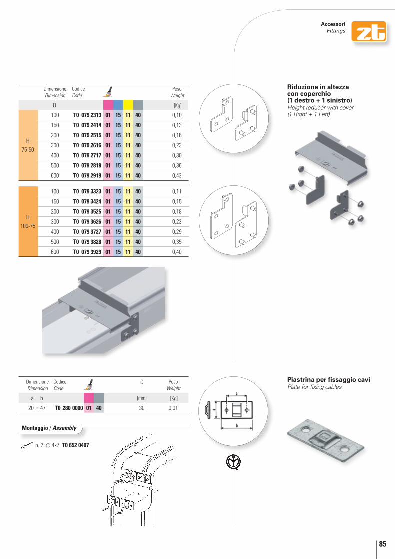
85
AccessoriFittings
Dimensione Dimension
Codice Code
C Peso Weight
a b [mm] [Kg]
20 47 T0 280 0000 01 40 30 0,01
Montaggio / Assembly
Piastrina per fissaggio caviPlate for fixing cables
Dimensione Dimension
Codice Code
Peso Weight
B [Kg]
H75-50
100 T0 079 2313 01 15 11 40 0,10
150 T0 079 2414 01 15 11 40 0,13
200 T0 079 2515 01 15 11 40 0,16
300 T0 079 2616 01 15 11 40 0,23
400 T0 079 2717 01 15 11 40 0,30
500 T0 079 2818 01 15 11 40 0,36
600 T0 079 2919 01 15 11 40 0,43
H100-75
100 T0 079 3323 01 15 11 40 0,11
150 T0 079 3424 01 15 11 40 0,15
200 T0 079 3525 01 15 11 40 0,18
300 T0 079 3626 01 15 11 40 0,23
400 T0 079 3727 01 15 11 40 0,29
500 T0 079 3828 01 15 11 40 0,35
600 T0 079 3929 01 15 11 40 0,40
Riduzione in altezza con coperchio (1 destro + 1 sinistro)Height reducer with cover (1 Right + 1 Left)
n. 2 4x7 T0 652 0407

86
AccessoriFittings
CONTINUITÀ ELETTRICA / ELECTRIC CONTINUITY
Piastrina di messa a terra per giunzione interna ad “U”Copperplate for inside “U” joint
Dimensione Dimension
Codice Code
Peso Weight
a b Ramato / Copper-coated [Kg]
48 x 16 T0 240 0048 33 0,01
Montaggio / Assembly
Piastrina di messa a terraCopperplate
Dimensione Dimension
Codice Code
Peso Weight
a b Ramato / Copper-coated [Kg]
45 x 16 T0 240 0045 33 0,02
Montaggio / Assembly
Gli accessori articolo T0 200 0007 01, T0 200 0010 01, T0 602 0000 01, T0 240 0048 33 e T0 240 0045 33 garantiscono il collegamento equipotenziale degli elementi tramite essi collegati.Il loro utilizzo rende l’intero sistema utilizzabile come collegamento equipotenziale, tenendo presente che, ai fini delle prescrizioni e dei calcoli richiesti dalle norme CEI 64-8 per determinare se esso è idoneo ad essere utilizzato in un dato impianto, il valore di riferimento dell’impedenza elettrica è, per tutte le dimensioni, 5mΩ/m. La continuità elettrica per i canali in acciaio verniciato è garantita solo se viene utilizzato l’accessorio T0 602 0000 01 “Cerniera con treccia di messa a terra”.
Accessory references T0 200 0007 01, T0 200 0010 01, T0 602 0000 01, T0 240 0048 33 and T0 240 0045 33 guarantee the equipotential connection of the elements connected through them. Their use makes the whole system usable as equipotential connection, considering that, for the prescriptions and computations required by CEI 64-8 to check if it is suitable for use in a specific system, the reference value of electrical impedance is, for all dimensions, 5mΩ/m. Electrical continuity for painted steel sections is guaranteed only when accessory T0 602 0000 01 “Hinge with equipotential connection” is used.
Ai fini delle prescrizioni del paragrafo 11 (“Proprietà elettriche”) delle norme EN 50085-1:2005 ed EN 50085-2-1:2006According to Paragraph 11 requirements (“Electrical Properties”) of EN 50085-1:2005 and EN 50085-2-1:2006 regulations
01 Zincato Sendzimir / Sendzimir galvanized 15 Verniciato blu elettrico / Electric blue varnished 11 Verniciato grigio RAL 7032 / Grey RAL 7032 varnished 33 Ramato / Copper-coated
a
b
a
b
n. 2 M6x6 T0 622 0606
n. 2 M6x6 T0 622 0606
Nell’eventualità di montaggio di giunzione interna ad “U” su particolari verniciati, è prevista la predisposizione con piastrina equipotenziale
In the case of the installation of internal “U” joints on coated items, preparation with equipotential plates is required
Vedere info tecniche pag. 240See technical information p. 240
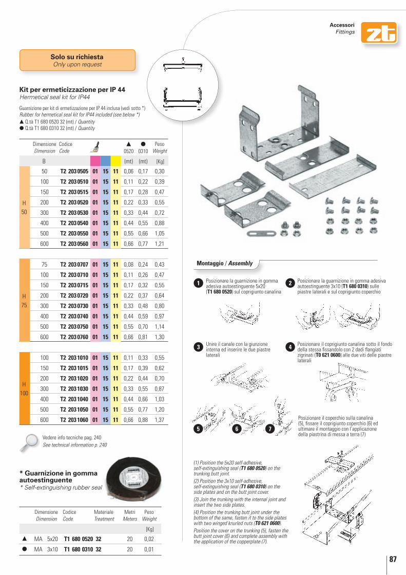
87
AccessoriFittings
Solo su richiestaOnly upon request
Montaggio / Assembly
Posizionare la guarnizione in gomma adesiva autoestinguente 5x20 (T1 680 0520) sul coprigiunto canalina
(1) Position the 5x20 self-adhesive, self-extinguishing seal (T1 680 0520) on the trunking butt joint. (2) Position the 3x10 self-adhesive, self-extinguishing seal (T1 680 0310) on the side plates and on the butt joint cover. (3) Join the trunking with the internal joint and insert the two side plates. (4) Position the trunking butt joint under the bottom of the same, fasten it to the side plates with two winged knurled nuts (T0 621 0600).Position the cover on the trunking (5), fasten the butt joint cover (6) and complete assembly with the application of the copperplate (7).
Posizionare la guarnizione in gomma adesiva autoestinguente 3x10 (T1 680 0310) sulle piastre laterali e sul coprigiunto coperchio
Unire il canale con la giunzione interna ed inserire le due piastre laterali
1 2
3 Posizionare il coprigiunto canalina sotto il fondo della stessa fissandolo con 2 dadi flangiati zigrinati (T0 621 0600) alle due viti delle piastre laterali
Posizionare il coperchio sulla canalina (5), fissare il coprigiunto coperchio (6) ed ultimare il montaggio con l’applicazione della piastrina di messa a terra (7)
4
6 75
Kit per ermeticizzazione per IP 44Hermetical seal kit for IP44
Dimensione Dimension
Codice Code
0520
0310
Peso Weight
B (mt) (mt) [Kg]
H50
50 T2 203 0505 01 15 11 0,06 0,17 0,30
100 T2 203 0510 01 15 11 0,11 0,22 0,39
150 T2 203 0515 01 15 11 0,17 0,28 0,47
200 T2 203 0520 01 15 11 0,22 0,33 0,55
300 T2 203 0530 01 15 11 0,33 0,44 0,72
400 T2 203 0540 01 15 11 0,44 0,55 0,88
500 T2 203 0550 01 15 11 0,55 0,66 1,05
600 T2 203 0560 01 15 11 0,66 0,77 1,21
H75
75 T2 203 0707 01 15 11 0,08 0,24 0,43
100 T2 203 0710 01 15 11 0,11 0,26 0,47
150 T2 203 0715 01 15 11 0,17 0,32 0,55
200 T2 203 0720 01 15 11 0,22 0,37 0,64
300 T2 203 0730 01 15 11 0,33 0,48 0,80
400 T2 203 0740 01 15 11 0,44 0,59 0,97
500 T2 203 0750 01 15 11 0,55 0,70 1,14
600 T2 203 0760 01 15 11 0,66 0,81 1,30
H100
100 T2 203 1010 01 15 11 0,11 0,33 0,55
150 T2 203 1015 01 15 11 0,17 0,39 0,62
200 T2 203 1020 01 15 11 0,22 0,44 0,70
300 T2 203 1030 01 15 11 0,33 0,55 0,87
400 T2 203 1040 01 15 11 0,44 0,66 1,03
500 T2 203 1050 01 15 11 0,55 0,77 1,20
600 T2 203 1060 01 15 11 0,66 0,88 1,37
Guarnizione per kit di ermetizzazione per IP 44 inclusa (vedi sotto *)Rubber for hermetical seal kit for IP44 included (see below *) Q.tà T1 680 0520 32 (mt) / Quantity Q.tà T1 680 0310 32 (mt) / Quantity
* Guarnizione in gomma autoestinguente* Self-extinguishing rubber seal
Dimensione Dimension
Codice Code
Materiale Treatment
Metri Meters
Peso Weight
[Kg]
MA 5x20 T1 680 0520 32 20 0,02
MA 3x10 T1 680 0310 32 20 0,01
Vedere info tecniche pag. 240See technical information p. 240

88
Esempi di installazioneexamples of installation
2. All of the system components are common both
for the trunking and for the cable tray.
1. The perfect alignment of the various
components is guaranteed by the particular joints
inserted into a compulsory
housing.
3. Earthing diagrams available
on all of the elements and respective
covers.
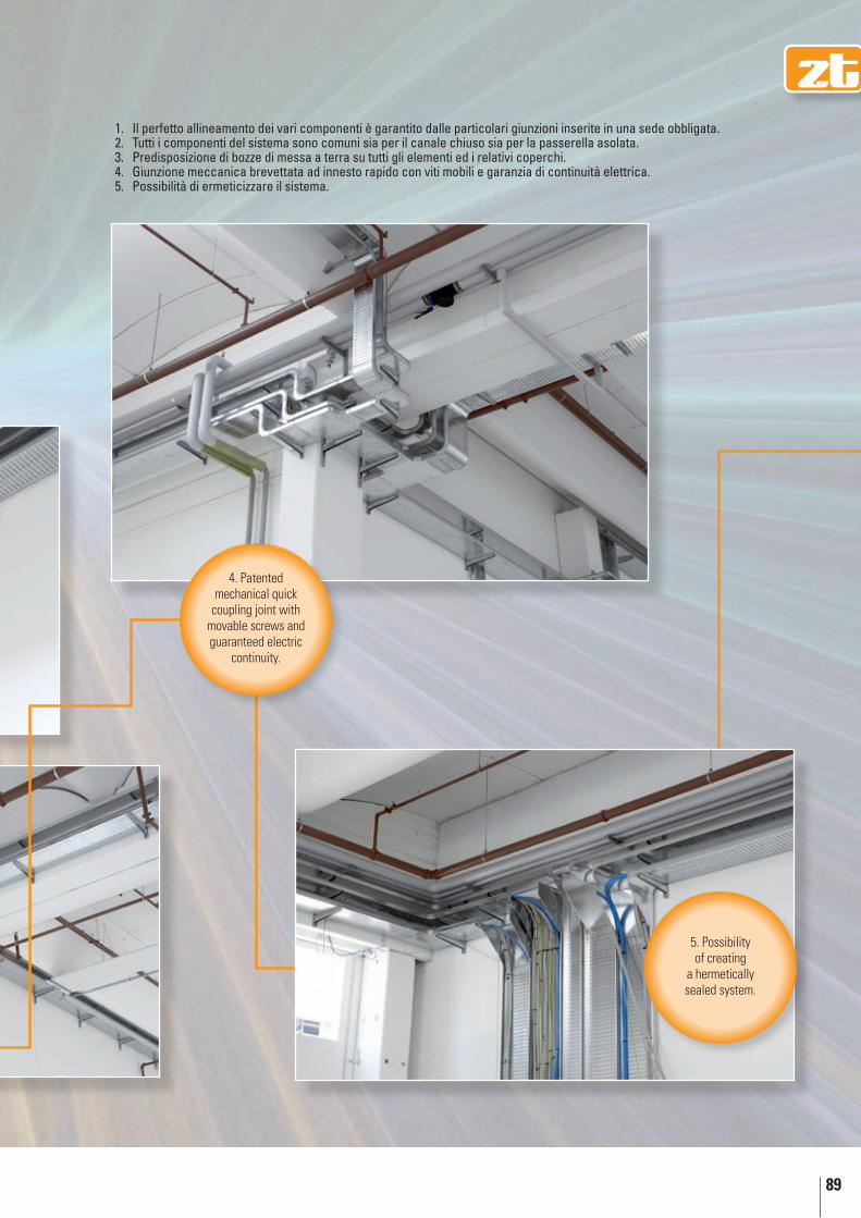
89
4. Patented mechanical quick
coupling joint with movable screws and guaranteed electric
continuity.
5. Possibility of creating
a hermetically sealed system.
Il perfetto allineamento dei vari componenti è garantito dalle particolari giunzioni inserite in una sede obbligata.1. Tutti i componenti del sistema sono comuni sia per il canale chiuso sia per la passerella asolata.2. Predisposizione di bozze di messa a terra su tutti gli elementi ed i relativi coperchi.3. Giunzione meccanica brevettata ad innesto rapido con viti mobili e garanzia di continuità elettrica.4. Possibilità di ermeticizzare il sistema. 5.


zTcanaline e passerelle incernierate a bordo macchinahinged trunking and cable trays around the machine

204
perché scegliere zT a bordo macchina…Why choose Zt around the machine…
H 5075100
B 50600
1 poSSibiliTà di incErniErArE il SiSTEmAAnche ad impianto ultimato è possibile inserire le apposite cerniere che sono fornite con / senza messa a terra. Grado di protezione IP20/IP40
possibility For hinGinG the systemEven after the system has been completed, it is possible to insert special hinges supplied with or without grounding. IP20/40 degree of protection
cerniera con treccia di messa a terraHinge with equipotential connection
cerniera senza treccia di messa a terraHinge without equipotential connection

205
FAciliTà di monTAggioeAsy to instAll3
2 progETTATA AppoSiTAmEnTE pEr mAcchinE UTEnSilidesiGned especiAlly For mAchine tools
coperchi a scatto autobloccanti anche per tutti i componenti, progettati per ricevere, eventualmente, cerniere e fermagli.
The snap-on covers are self-locking for all of the components and are designed for the use of hinges and clamps, if necessary.
Vedere info tecniche pag. 237-240See technical information p. 237-240
n.B. Tutte le misure sono espresse in millimetri salvo diversa indicazione, e sono da intendersi nominali.Note: All the dimensions are in millimetres unless otherwise stated. Dimensions are nominal.
Giunzione meccanica brevettata ad innesto rapido con viti mobili e garanzia di continuità elettrica.
The patented quick click mechanical joint has movable screws and ensures electric continuity.
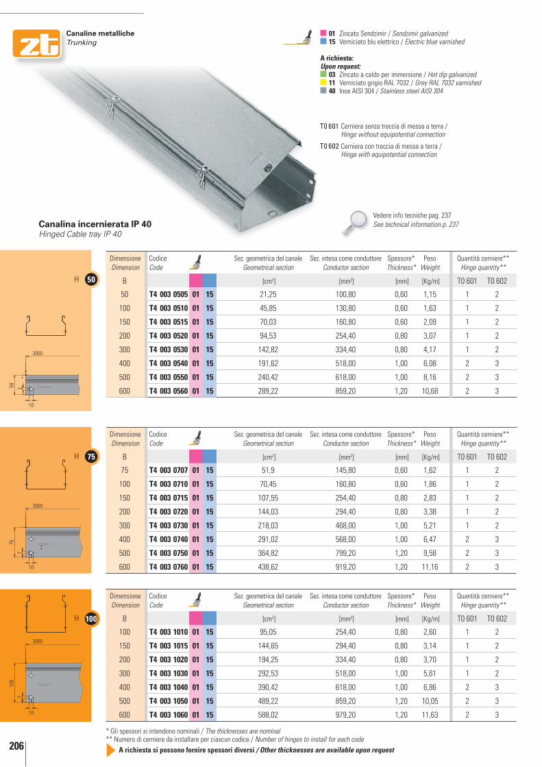
206
canaline metalliche trunking
50H
75H
100H
3000
50 7
10
3000
10
757
3000
100
7
10
Dimensione Dimension
Codice Code
Sez. geometrica del canale Geometrical section
Sez. intesa come conduttore Conductor section
Spessore* Thickness*
Peso Weight
Quantità cerniere** Hinge quantity**
B [cm2] [mm2] [mm] [Kg/m] T0 601 T0 602
50 t4 003 0505 01 15 21,25 100,80 0,60 1,15 1 2
100 t4 003 0510 01 15 45,85 130,80 0,60 1,63 1 2
150 t4 003 0515 01 15 70,03 160,80 0,60 2,09 1 2
200 t4 003 0520 01 15 94,53 254,40 0,80 3,07 1 2
300 t4 003 0530 01 15 142,82 334,40 0,80 4,17 1 2
400 t4 003 0540 01 15 191,62 518,00 1,00 6,08 2 3
500 t4 003 0550 01 15 240,42 618,00 1,00 8,16 2 3
600 t4 003 0560 01 15 289,22 859,20 1,20 10,68 2 3
canalina incernierata ip 40Hinged Cable tray IP 40
01 Zincato Sendzimir / Sendzimir galvanized 15 Verniciato blu elettrico / Electric blue varnished
A richiesta: Upon request:
03 Zincato a caldo per immersione / Hot dip galvanized 11 Verniciato grigio RAL 7032 / Grey RAL 7032 varnished 40 Inox AISI 304 / Stainless steel AISI 304
Dimensione Dimension
Codice Code
Sez. geometrica del canale Geometrical section
Sez. intesa come conduttore Conductor section
Spessore* Thickness*
Peso Weight
Quantità cerniere** Hinge quantity**
B [cm2] [mm2] [mm] [Kg/m] T0 601 T0 602
75 t4 003 0707 01 15 51,9 145,80 0,60 1,62 1 2
100 t4 003 0710 01 15 70,45 160,80 0,60 1,86 1 2
150 t4 003 0715 01 15 107,55 254,40 0,80 2,83 1 2
200 t4 003 0720 01 15 144,03 294,40 0,80 3,38 1 2
300 t4 003 0730 01 15 218,03 468,00 1,00 5,21 1 2
400 t4 003 0740 01 15 291,02 568,00 1,00 6,47 2 3
500 t4 003 0750 01 15 364,82 799,20 1,20 9,58 2 3
600 t4 003 0760 01 15 438,62 919,20 1,20 11,16 2 3
Dimensione Dimension
Codice Code
Sez. geometrica del canale Geometrical section
Sez. intesa come conduttore Conductor section
Spessore* Thickness*
Peso Weight
Quantità cerniere** Hinge quantity**
B [cm2] [mm2] [mm] [Kg/m] T0 601 T0 602
100 t4 003 1010 01 15 95,05 254,40 0,80 2,60 1 2
150 t4 003 1015 01 15 144,65 294,40 0,80 3,14 1 2
200 t4 003 1020 01 15 194,25 334,40 0,80 3,70 1 2
300 t4 003 1030 01 15 292,53 518,00 1,00 5,61 1 2
400 t4 003 1040 01 15 390,42 618,00 1,00 6,86 2 3
500 t4 003 1050 01 15 489,22 859,20 1,20 10,05 2 3
600 t4 003 1060 01 15 588,02 979,20 1,20 11,63 2 3
Vedere info tecniche pag. 237See technical information p. 237
Cerniera senza treccia di messa a terra / Hinge without equipotential connection
T0 601
T0 602 Cerniera con treccia di messa a terra / Hinge with equipotential connection
* Gli spessori si intendono nominali / The thicknesses are nominal** Numero di cerniere da installare per ciascun codice / Number of hinges to install for each code
A richiesta si possono fornire spessori diversi / Other thicknesses are available upon request

207
canaline metalliche trunking
passerella asolata incernierata ip 20Hinged perforated cable tray IP 20
Dimensione Dimension
Codice Code
Sez. geometrica del canale Geometrical section
Sez. intesa come conduttore Conductor section
Spessore* Thickness*
Peso Weight
Quantità cerniere** Hinge quantity**
B [cm2] [mm2] [mm] [Kg/m] T0 601 T0 602
50 t4 013 0505 01 15 21,25 100,80 0,60 1,14 1 2
100 t4 013 0510 01 15 45,85 130,80 0,60 1,59 1 2
150 t4 013 0515 01 15 70,03 160,80 0,60 2,03 1 2
200 t4 013 0520 01 15 94,53 254,40 0,80 2,92 1 2
300 t4 013 0530 01 15 142,82 334,40 0,80 3,93 1 2
400 t4 013 0540 01 15 191,62 518,00 1,00 5,68 2 3
500 t4 013 0550 01 15 240,42 618,00 1,00 7,66 2 3
600 t4 013 0560 01 15 289,22 859,20 1,20 9,98 2 3
Dimensione Dimension
Codice Code
Sez. geometrica del canale Geometrical section
Sez. intesa come conduttore Conductor section
Spessore* Thickness*
Peso Weight
Quantità cerniere** Hinge quantity**
B [cm2] [mm2] [mm] [Kg/m] T0 601 T0 602
75 t4 013 0707 01 15 51,9 145,80 0,60 1,59 1 2
100 t4 013 0710 01 15 70,45 160,80 0,60 1,83 1 2
150 t4 013 0715 01 15 107,55 254,40 0,80 2,73 1 2
200 t4 013 0720 01 15 144,03 294,40 0,80 3,24 1 2
300 t4 013 0730 01 15 218,03 468,00 1,00 4,93 1 2
400 t4 013 0740 01 15 291,02 568,00 1,00 6,08 2 3
500 t4 013 0750 01 15 364,82 799,20 1,20 9,01 2 3
600 t4 013 0760 01 15 438,62 919,20 1,20 10,45 2 3
Dimensione Dimension
Codice Code
Sez. geometrica del canale Geometrical section
Sez. intesa come conduttore Conductor section
Spessore* Thickness*
Peso Weight
Quantità cerniere** Hinge quantity**
B [cm2] [mm2] [mm] [Kg/m] T0 601 T0 602
100 t4 013 1010 01 15 95,05 254,40 0,80 2,55 1 2
150 t4 013 1015 01 15 144,65 294,40 0,80 3,05 1 2
200 t4 013 1020 01 15 194,25 334,40 0,80 3,55 1 2
300 t4 013 1030 01 15 292,53 518,00 1,00 5,33 1 2
400 t4 013 1040 01 15 390,42 618,00 1,00 6,47 2 3
500 t4 013 1050 01 15 489,22 859,20 1,20 9,48 2 3
600 t4 013 1060 01 15 588,02 979,20 1,20 10,92 2 3
Vedere info tecniche pag. 237See technical information p. 237
* Gli spessori si intendono nominali / The thicknesses are nominal** Numero di cerniere da installare per ciascun codice / Number of hinges to install for each code
A richiesta si possono fornire spessori diversi / Other thicknesses are available upon request

Applicazioni in dettaglio
Applications in detail

237
Ap
plic
azio
ni i
n d
etta
glio
A
pp
licat
ion
s in
det
ail
250 1250 1250 250
3000
250 625 625 625 625 250
3000
system
cod. / code T4 003 - T4 013 – pag. / page 206-207
FermaglioClamp 1
cAnAlinE incErniErATEIl nostro sistema “ZT” prevede la possibilità di incernierare i coperchi, permettendo una ispezione frequente senza asportare il coperchio.
La cerniera, brevetto Zamet, è facilmente applicabile anche successivamente all’installazione dell’impianto di canalizzazione. Si tenga conto delle possibilità di avere cerniere con apposita treccia di rame per un collegamento equipotenziale della canalina/coperchio.
HInGED TRUnKInG Our ZT system is preset for hinged covers, allowing frequent inspections without removing the cover.
The hinge is a Zamet patent. It is easy to install also after installing the trunking system. We are able to supply hinges with special copper earthing plait for an equipotential connection between trunking and cover.
Schema per montaggio cerniere in opera / Hinge assembly installation scheme
Tipo A: H. 50-75-100 sino alla B.300 / Type A: H. 50-75-100 up until B.300
Tipo B: H. 50-75-100 dalla B.400 / Type B: H. 50-75-100 from B.400 up
A richiesta è possibile fornire la canalina incernierata, con Fermagli ad aggancio (cod. T0 610 - pag. 79) (1) fissati in corrispondenza delle cerniere.
upon request, we are able to supply hinged trunking, with hook clamps (cod. T0 610 - page 79) (1) fixed by the hinges.
T0 602
T0 602 T0 602
T0 601
T0 601 T0 601
T0 602
T0 602
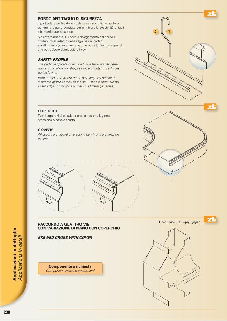
238
Ap
plic
azio
ni i
n d
etta
glio
A
pp
licat
ion
s in
det
ail
12
cod. / code T0 131 – pag. / page 70
componente a richiestaComponent available on demand
bordo AnTiTAglio di SicUrEzzA Il particolare profilo delle nostre canaline, uniche nel loro genere, è stato progettato per eliminare la possibilità di tagli alle mani durante la posa.
Sia esternamente, (1) dove il ripiegamento dal bordo è contenuto all’interno della sagoma del profilo sia all’interno (2) ove non esistono bordi taglienti o asperità che potrebbero danneggiare i cavi.
SAFETY PROFIlE The particular profile of our exclusive trunking has been designed to eliminate the possibility of cuts to the hands during laying.
Both outside (1), where the folding edge is contained insidethe profile as well as inside (2) where there are no sharp edges or roughness that could damage cables.
copErchi Tutti i coperchi si chiudono praticando una leggera pressione e sono a scatto.
COVERS All covers are closed by pressing gently and are snap on covers.
rAccordo A QUATTro ViE con VAriAzionE di piAno con copErchio
SKEWED CROSS WITH COVER

239
Ap
plic
azio
ni i
n d
etta
glio
A
pp
licat
ion
s in
det
ail
cod. / code T0 200 – pag. / page 74
1
1
rAggi di cUrVATUrA Tutte le curve, i raccordi ed i componenti in genere, sono realizzati con un raggio di curvatura interna/esterna di 100 mm.
Questa soluzione permette di ottenere un maggior spazio all’interno della curva per eseguire raggiature dei cavi più ampie (1).
BEnDInG RADII All elbows, “Ts” and components in general have an internal/external bending radius of 100 mm.
This solution makes it possible to obtain more space inside the elbow in order to createe wider radii than usual (1).
giUnzioni A ViTi mobiliEstremamente utile il nostro sistema di giunzioni a viti mobili. Una grande innovazione che unisce alla rapidità di montaggio, il sistema equipotenziale di collegamento fra i vari elementi del sistema ZT.
All’interno dei canali, le teste dei bulloni sono incassate e protette da una piastrina (1) che permette di tirare i cavi elettrici senza timore di danneggiarli.
JOInTS WITH MOVABlE SCREWS Our movable screw joint system is extremely useful. It is a great innovation that combines quick assembly and equipotential connection of the elements of the ZT system.
Inside the trunking, the heads of the bolts are recessed and protected by a plate (1) which makes it possible to pull electric cables without fear of damaging them.

240
Ap
plic
azio
ni i
n d
etta
glio
A
pp
licat
ion
s in
det
ail
cod. / code T0 240 – pag. / page 86
cod. / code T2 203 – pag. / page 87
1
2
Solo su richiestaOnly upon request
conTinUiTà ElETTricASia sui coperchi sia sulle canaline verniciate, è prevista una bozza filettata elettrosaldata (1) atta a ricevere le piastrine di messa a terra (2) per un perfetto collegamento equipotenziale fra i vari elementi del sistema ZT.
ElECTRIC COnTInUITY Both covers and trunking have a threaded electro-welding indentation (1) for receiving the earthing devices (2) in order to guarantee the perfect equipotential connection of the various components of the ZT system.
grAdo di proTEzionE ip 44 Il sistema ZT può essere ermeticizzato IP 44 utilizzando il previsto KIT visualizzato a pag. 87.
ip 44 proTEcTionThe ZT System can be hermetically sealed to provide IP 44 protection, using the Kit shown on page 87.


Sistemi di sospensione e bulloneria
Fixing systems and bolts

284
Tutti i sistemi di staffaggio sono certificati: All the supporting systems are certified:
En 50085-1:2005 - En 50085-2-1:2006En 61537-1:2007
/ safe Working load (sWl)carico utile di sicurezzaCodiceCode
Momento flettente del pendente alla piastra a
soffitto (Nm)Bending moment of the pendant bracket at the
ceiling plate (Nm)
Resistenza alla trazione del pendente (N)
Tensile strength of the pendant bracket (N)
T0 300 0000 ... 60 Nm (2) 2210 N (3)
T0 301 0000 03 120 Nm (9) 3440 N (10)
T0 302 0000 03 120 Nm (9) 6880 N (10)
T0 303 0000 ... 65 Nm (2) 2210 N (3)
T0 304 0000 ... 60 Nm (9) 6880 N (10)
T0 304 0202 ... 40 Nm (9) 3440 N (10)
T0 366 0008 ... – 200 N (3)
T0 366 0010 ... – 300 N (3)
T0 366 0015 ... – 440 N (3)
T0 366 0020 ... – 610 N (3)
T0 366 0030 ... – 720 N (3)
T0 370 0000 ... – 1110 N (3)
CodiceCode
Carico utile di sicurezza del pendente con staffa sostenuta al centro (N)
SWL of the pendant bracket with bracket sup-ported at the centre (N)
T0 311 1010 ... 1800 N T0 311 1515 ... 1800 N T0 311 2020 ... 1800 N T0 311 2525 ... 1800 N T0 311 3030 ... 1800 N T0 312 1010 ... 2210 N T0 312 2020 ... 2210 N T0 312 3030 ... 2210 N T0 365 0008 ... 200 N T0 365 0010 ... 310 N T0 365 0015 ... 450 N T0 365 0020 ... 620 N T0 365 0030 ... 735 N
CodiceCode
Carico utile di sicurezza della staffa a mensola (N)
Safe Working Load of the supporting bracket (N)
Momento flettente del pendente alla staffa a
mensola (Nm)Bending moment of the pendant bracket at the
supporting bracket (Nm) T0 310 0010 ... – 200 Nm (6)
T0 310 0015 ... – 200 Nm (6)
T0 310 0020 ... – 200 Nm (6)
T0 310 0030 ... – 200 Nm (6)
T0 311 0010 ... – 100 Nm (7)
T0 311 0015 ... – 100 Nm (7)
T0 311 0020 ... – 100 Nm (7)
T0 311 0025 ... – 100 Nm (7)
T0 311 0030 ... – 100 Nm (7)
T0 312 0020 ... – 200 Nm (8)
T0 312 0030 ... – 200 Nm (8)
T0 320 0015 ... – 120 Nm (8)
T0 320 0020 ... – 120 Nm (8)
T0 320 0030 ... – 120 Nm (8)
T0 320 0040 ... – 120 Nm (8)
T0 320 0050 ... – 120 Nm (8)
T0 320 0060 ... – 120 Nm (8)
T0 330 0015 ... 520 N (1) 120 Nm (8)
T0 330 0020 ... 1040 N (1) 120 Nm (8)
T0 330 0030 ... 1560 N (1) 120 Nm (8)
T0 330 0040 ... 2080 N (1) 120 Nm (8)
T0 330 0050 ... 2610 N (1) 120 Nm (8)
T0 330 0060 ... 3130 N (1) 120 Nm (8)
T0 350 0008 ... 320 N (1) –
T0 350 0010 ... 480 N (1) –
T0 350 0015 ... 690 N (1) –
T0 350 0020 ... 950 N (1) –
T0 350 0030 ... 1110 N (1) –
T0 355 0008 ... – 60 Nm (4) / 260 Nm (5)
T0 355 0010 ... – 60 Nm (4) / 260 Nm (5)
T0 355 0015 ... – 60 Nm (4) / 260 Nm (5)
T0 355 0020 ... – 60 Nm (4) / 260 Nm (5)
T0 355 0030 ... – 60 Nm (4) / 260 Nm (5)
Staffaggio standard / Standard support Staffaggio alte portate / High load capacity brackets
Sistemi di sospensioneFixing systems

285285
Supporto per staffaggio a soffitto Support for ceiling brackets
Profilato a “C” asolato Slotted “C” section
Mensola Bracket
Attacco a soffitto regolabile Adjustable ceiling junction
Staffa a soffitto Ceiling bracket
Staffa da parete Wall bracket
Attacco a soffitto semplice High capacity ceiling support
1
2
3
4
5
6
7
(1) F secondo il paragrafo 10.8.1 della norma EN 61537:2007, verificato con la configurazione di prova di figura 6b
(2) M1 secondo il paragrafo 10.8.2.1 della norma EN 61537:2007, verificato con la configurazione di prova di figura 7a condotta sull’articolo in oggetto provvisto di profilato a “C” asolato art. T0 041 2000 di lunghezza 0,8 m
(3) F secondo il paragrafo 10.8.2.2 della norma EN 61537:2007, verificato con la configurazione di prova di figura 7b condotta sull’articolo in oggetto provvisto di profilato a “C” asolato art. T0 041 2000 di lunghezza 0,8 m
(4) M2 secondo il paragrafo 10.8.2.3 della norma EN 61537:2007, verificato con la configurazione di prova di figura 7c condotta sull’articolo in oggetto provvisto di profilato a “C” asolato art. T0 041 2000 e in modo tale che il piano di appoggio per la passerella non sia distante meno di 200 mm dalla superficie di fissaggio
(5) M2 secondo il paragrafo 10.8.2.3 della norma EN 61537:2007, verificato con la configurazione di prova di figura 7c condotta sull’articolo in oggetto montato su staffa a seggiola art. T0 360 0000 01 (eventualmente collegata al profilato a “C” asolato art. T0 041 2000) e in modo tale che il piano di appoggio per la passerella non sia distante meno di 500 mm dalla superficie di fissaggio
(6) Quando montato su barra filettata di diametro 20 mm art. R0 315 2000 in modo tale che il piano di appoggio per la passerella non sia distante meno di 500 mm dalla superficie di fissaggio
(7) Quando montato su barra filettata di diametro 20 mm art. R0 315 2000 in modo tale che il piano di appoggio per la passerella non sia distante meno di 200 mm dalla superficie di fissaggio
(8) Quando montato su profilato per alte portate art. T0 042 2000 e in modo tale che il piano di appoggio per la passerella non sia distante meno di 200 mm dalla superficie di fissaggio
(9) M1 secondo il paragrafo 10.8.2.1 della norma EN 61537:2007, verificato con la configurazione di prova di figura 7a condotta sull’articolo in oggetto provvisto di profilato per alte portate art. T0 042 2000 di lunghezza 0,8 m
(10) F secondo il paragrafo 10.8.2.2 della norma EN 61537:2007, verificato con la configurazione di prova di figura 7b condotta sull’articolo in oggetto provvisto di profilato per alte portate art. T0 042 2000 di lunghezza 0,8 m
(1) F according to the paragraph 10.8.1 of the standard EN 61537:2007, verified with the test configuration shown in figure 6b
(2) M1 according to the paragraph 10.8.2.1 of the standard EN 61537:2007, verified with the test configuration shown in figure 7a carried out on the item equipped with a slotted “C” section item no. T0 041 2000 0.8 m long
(3) F according to the paragraph 10.8.2.2 of the standard EN 61537:2007, verified with the test configuration shown in figure 7b carried out on the item equipped with a slotted “C” section item no. T0 041 2000 0.8 m long
(4) M2 according to the paragraph 10.8.2.3 of the standard EN 61537:2007, verified with test configuration shown in figure 7c carried out on the item equipped with a slotted “C” section item no. T0 041 2000 and in such way that the distance between the ladder supporting surface and the anchoring surface is not less than 200 mm
(5) M2 according to the paragraph 10.8.2.3 of the standard EN 61537:2007, verified with the test configuration shown in figure 7c carried out on the item mounted on a stirrup bracket item no. T0 360 0000 01 (possibly connected to slotted “C” section item T0 041 2000) and in such a way that the distance between the ladder supporting surface and the anchoring surface is not less than 500 mm
(6) When it is mounted on the threaded rod (diameter 20 mm) item no. R0 315 2000 in such a way that the distance between the ladder supporting surface and the anchoring surface is not less than 500 mm
(7) When it is mounted on the threaded rod (diameter 20 mm) item no. R0 315 2000 in such a way that the distance between the ladder supporting surface and the anchoring surface is not less than 200 mm
(8) When it is mounted on the high load capacity section item no. T0 042 2000 and in such a way that the distance between the ladder supporting surface and the anchoring surface is not less than 200 mm
(9) M1 according to the paragraph 10.8.2.1 of the standard EN 61537:2007, verified with the test configuration shown in figure 7a carried out on the item equipped with a high load capacity section item no. T0 042 2000 0.8 m long
(10) F according to the paragraph 10.8.2.2 of the standard EN 61537:2007, verified with the test configuration shown in figure 7b carried out on the item equipped with a high load capacity section item no. T0 042 2000 0.8 m long
Sistemi di sospensione Fixing systems
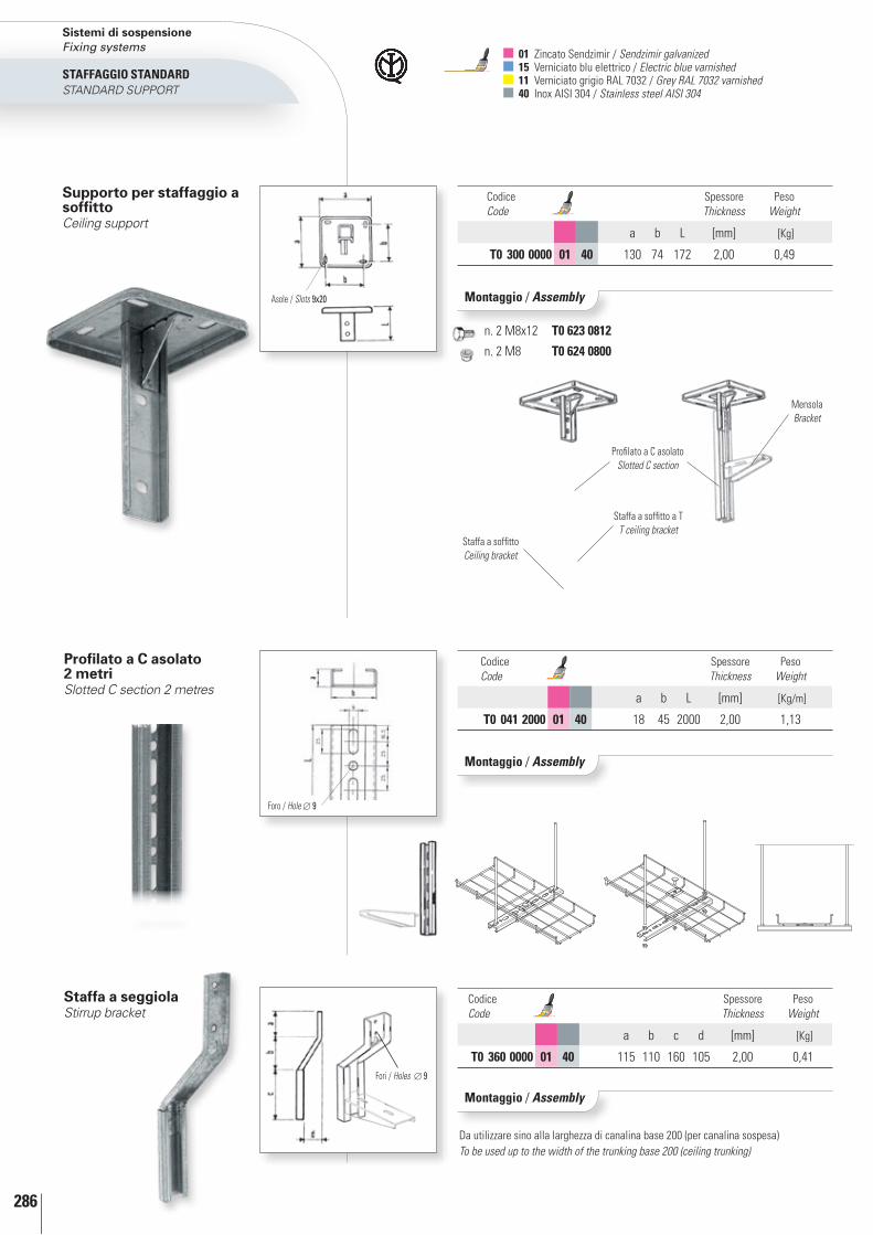
286
StAFFAGGIO StAnDARDSTAnDARD SUPPORT
Asole / Slots 9x20
MensolaBracket
Profilato a C asolatoSlotted C section
Staffa a soffitto a TT ceiling bracket
Staffa a soffittoCeiling bracket
profilato a c asolato 2 metriSlotted C section 2 metres
Staffa a seggiola Stirrup bracket
Montaggio / assembly
Codice Code
Spessore Thickness
Peso Weight
a b L [mm] [Kg]
t0 300 0000 01 40 130 74 172 2,00 0,49
Supporto per staffaggio a soffittoCeiling support
Codice Code
Spessore Thickness
Peso Weight
a b L [mm] [Kg/m]
t0 041 2000 01 40 18 45 2000 2,00 1,13
Montaggio / assembly
Foro / Hole 9
Codice Code
Spessore Thickness
Peso Weight
a b c d [mm] [Kg]
t0 360 0000 01 40 115 110 160 105 2,00 0,41
Montaggio / assembly
Da utilizzare sino alla larghezza di canalina base 200 (per canalina sospesa)To be used up to the width of the trunking base 200 (ceiling trunking)
Fori / Holes 9
01 Zincato Sendzimir / Sendzimir galvanized 15 Verniciato blu elettrico / Electric blue varnished 11 Verniciato grigio RAL 7032 / Grey RAL 7032 varnished 40 Inox AISI 304 / Stainless steel AISI 304
n. 2 M8x12 t0 623 0812
n. 2 M8 t0 624 0800
Sistemi di sospensione Fixing systems
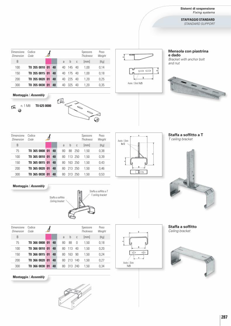
287
mensola con piastrina e dadoBracket with anchor bolt and nut
Staffa a soffitto a TT ceiling bracket
Asole / Slots 7x25
Dimensione Dimension
Codice Code
Spessore Thickness
Peso Weight
B a b c [mm] [Kg]
100 t0 355 0010 01 40 40 145 40 1,00 0,14
150 t0 355 0015 01 40 40 175 40 1,00 0,18
200 t0 355 0020 01 40 40 225 40 1,20 0,25
300 t0 355 0030 01 40 40 325 40 1,20 0,35 Asole / Slots 7x25
Dimensione Dimension
Codice Code
Spessore Thickness
Peso Weight
B a b c [mm] [Kg]
75 t0 365 0008 01 40 80 88 250 1,50 0,38
100 t0 365 0010 01 40 80 113 250 1,50 0,39
150 t0 365 0015 01 40 80 163 250 1,50 0,43
200 t0 365 0020 01 40 80 213 250 1,50 0,46
300 t0 365 0030 01 40 80 313 250 1,50 0,53
Asole / Slots 9x12
Staffa a soffittoCeiling bracket
Dimensione Dimension
Codice Code
Spessore Thickness
Peso Weight
B a b c [mm] [Kg]
75 t0 366 0008 01 40 80 88 0 1,50 0,18
100 t0 366 0010 01 40 80 113 40 1,50 0,20
150 t0 366 0015 01 40 80 163 90 1,50 0,24
200 t0 366 0020 01 40 80 213 140 1,50 0,27
300 t0 366 0030 01 40 80 313 240 1,50 0,34
Montaggio / assembly
Montaggio / assembly
Montaggio / assembly
n. 1 M8 t0 625 0000
Staffa a soffitto a TT ceiling bracket
Staffa a soffittoCeiling bracket
StAFFAGGIO StAnDARDSTAnDARD SUPPORT
Sistemi di sospensione Fixing systems

288
Staffa da pareteWall bracket
Supporto a T per profilato a cT Ceiling support for C section
Dimensione Dimension
Codice Code
Spessore Thickness
Peso Weight
B a b c d [mm] [Kg]
100 t0 350 0010 01 40 200 130 45 150 1,00 0,26
150 t0 350 0015 01 40 200 160 45 150 1,00 0,30
200 t0 350 0020 01 40 200 210 45 150 1,00 0,45
300 t0 350 0030 01 40 200 310 45 150 1,00 0,56
Dimensione Dimension
Codice Code
Spessore Thickness
Peso Weight
H x B a b [mm] [Kg]
160 x 142 t0 303 0000 01 40 75 49 2,00 0,42
MensolaBracket
Profilato a C asolatoSlotted C section
Profilato a C asolatoSlotted C section
Montaggio / assembly
Montaggio / assembly
Asole / Slots 9x25
b
d a
c
Asole / Slots 8x30
Asole / Slots 7x25
01 Zincato Sendzimir / Sendzimir galvanized 15 Verniciato blu elettrico / Electric blue varnished 11 Verniciato grigio RAL 7032 / Grey RAL 7032 varnished 40 Inox AISI 304 / Stainless steel AISI 304
n. 2 M8x12 t0 623 0812 Profilato singolo / Single section
n. 2 M8x20 t0 623 0820 Profilato doppio / Double section
n. 2 M8 t0 624 0800
Montaggio con n. 1 profilato Assembly with no. 1 section
Montaggio con n. 2 profilati Assembly with no. 2 sections
n. 1 M6x10 t0 620 0610
n. 1 M6 t0 621 0600Per fissaggio sul canaleFor mounting on the trunking
Sistemi di sospensione Fixing systems
StAFFAGGIO StAnDARDSTAnDARD SUPPORT

289
bandella di supportoPunched tape
BandellaPunched tape
Staffa da parete e a montanteWall or mounted bracket
Montaggio / assembly
Dimensione Dimension
Codice Code
Spessore Thickness
Peso Weight
b x L [mm] [Kg]
25 x 2000 t0 049 0025 01 40 2,00 0,34
Attacco a soffitto regolabileAdjustable ceiling junction
Codice Code
Spessore Thickness
Peso Weight
[mm] [Kg]
t0 370 0000 01 1,50 0,10
Montaggio / assembly
Lb
Asole / Slots 7x25
n. 1 M6x10 t0 620 0610
n. 1 M6 t0 621 0600
Flangia rettangolare per barra filettataRectangular flange for threaded bar
Codice Code
Spessore Thickness
Peso Weight
[mm] [Kg]
M6 R0 316 0600 01 40 3,00 0,04
M8 R0 316 0800 01 40 3,00 0,06
StAFFAGGIO StAnDARDSTAnDARD SUPPORT
Sistemi di sospensione Fixing systems

290
StAFFAGGIO AltE PORtAtEHIgH LOAD CAPACITy BRACKETS
Codice Code
Spessore Thickness
Peso Weight
a b L [mm] [Kg]
t0 301 0000 03 150 110 153 3,00 0,92
Montaggio / assembly
Asole / Slots 13x25
Asole / Slots 15x9
Foro / Hole 25
Attacco a soffitto semplice zincato a caldoHigh capacity ceiling support hot galvanized
01 Zincato Sendzimir / Sendzimir galvanized 03 Zincato a caldo per immersione / Hot dip galvanized 15 Verniciato blu elettrico / Electric blue varnished 11 Verniciato grigio RAL 7032 / Grey RAL 7032 varnished 40 Inox AISI 304 / Stainless steel AISI 304
Attacco a soffitto doppio zincato a caldoDouble high capacity ceiling support hot galvanized
Codice Code
Spessore Thickness
Peso Weight
a b L [mm] [Kg]
t0 302 0000 03 150 110 153 3,00 1,36
Montaggio / assembly
Asole / Slots 13x25
Foro / Hole 25
Asole / Slots 15x9
Attacco a soffitto a inclinazione variabileVariable angle ceiling support
Codice Code
Spessore Thickness
Peso Weight
a b D [mm] [Kg]
t0 304 0000 01 03 40 150 60 100 2,00 0,48
Montaggio / assembly
a
a
aa
LL
bb
Asole / Slots 9x25
a
D
b
b
b
n. 2 M8x70 t0 623 0870
n. 4 M8x20 t0 623 0820
n. 2/4 M8 t0 624 0800
n. 4 M8x70 t0 623 0870
n. 8 M8x20 t0 623 0820
n. 4/8 M8 t0 624 0800
n. 2 M8x70 t0 623 0870
n. 4 M8x20 t0 623 0820
n. 2/4 M8 t0 624 0800
Sistemi di sospensione Fixing systems
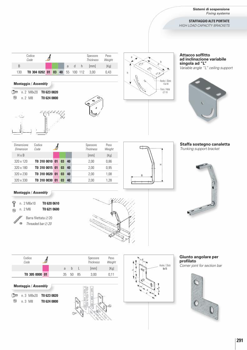
291
StAFFAGGIO AltE PORtAtEHIgH LOAD CAPACITy BRACKETS
Montaggio / assembly
Asole / Slots 9x15
Codice Code
Spessore Thickness
Peso Weight
a b L [mm] [Kg]
t0 305 0000 01 35 50 85 3,00 0,11
Montaggio / assembly
giunto angolare per profilatoCorner joint for section bar
n. 3 M8x20 t0 623 0820
n. 3 M8 t0 624 0800
n. 2 M8x20 t0 623 0820
n. 2 M8 t0 624 0800
Staffa sostegno canalettaTrunking support bracket
Dimensione Dimension
Codice Code
Spessore Thickness
Peso Weight
H x B [mm] [Kg]
320 x 120 t0 310 0010 01 03 40 2,00 0,86
320 x 180 t0 310 0015 01 03 40 2,00 0,95
320 x 230 t0 310 0020 01 03 40 2,00 1,08
320 x 330 t0 310 0030 01 03 40 2,00 1,28
Montaggio / assembly
B
H
Codice Code
Spessore Thickness
Peso Weight
B a d h [mm] [Kg]
130 t0 304 0202 01 03 40 55 100 112 3,00 0,43
Attacco soffitto ad inclinazione variabile singola ad “l” Variable angle “L” ceiling support
b
a
h
d
Asole / Slots 13x18
Foro / Hole 10
n. 2 M6x10 t0 620 0610
n. 2 M6 t0 621 0600
Barra filettata 20
Threaded bar 20
Sistemi di sospensione Fixing systems

292
01 Zincato Sendzimir / Sendzimir galvanized 03 Zincato a caldo per immersione / Hot dip galvanized 15 Verniciato blu elettrico / Electric blue varnished 11 Verniciato grigio RAL 7032 / Grey RAL 7032 varnished 40 Inox AISI 304 / Stainless steel AISI 304
90°
piastrina a l a 90°90° angular plate
Asole / Slots 9x15
Codice Code
Spessore Thickness
Peso Weight
a b [mm] [Kg]
t0 306 0000 01 48 35 3,00 0,07
StAFFAGGIO AltE PORtAtEHIgH LOAD CAPACITy BRACKETS
piastrina a l a 135°135° angular plate
135° 135°
Codice Code
Spessore Thickness
Peso Weight
a b [mm] [Kg]
t0 307 0000 01 48 35 3,00 0,07
Montaggio / assembly
Montaggio / assembly
Asole / Slots 9x15
n. 2 M8x20 t0 623 0820
n. 2 M8 t0 624 0800
n. 2 M8x20 t0 623 0820
n. 2 M8 t0 624 0800
Sistemi di sospensione Fixing systems

293
Codice Code
Spessore Thickness
Peso Weight
a b L [mm] [Kg/m]
t0 042 2000 01 03 35 55 2000 2,50 1,94
t0 042 2000 40 35 55 2000 2,00 1,58
profilato per alte portate High load capacity section
StAFFAGGIO AltE PORtAtEHIgH LOAD CAPACITy BRACKETS
Montaggio / assembly
n. 8 M8x20 t0 623 0820
n. 8 M8 t0 624 0800
giunto di unione per prolungamento profilatoBeam extension joint
L
Codice Code
Spessore Thickness
Peso Weight
L [mm] [Kg]
t0 308 0000 01 03 180 2,00 0,33
L
Asole / Slots 9x25 - Passo / Pitch 50 mm
Sistemi di sospensione Fixing systems

294
StAFFAGGIO AltE PORtAtEHIgH LOAD CAPACITy BRACKETS
Staffa da parete ed a montante Wall or upright bracket
9x20
Asole / Slots9x1575x7
Montaggio / assembly
Dimensione Dimension
Codice Code
Spessore Thickness
Peso Weight
B a b c d [mm] [Kg]
150 t0 330 0015 01 03 40 190 190 48 32 1,50 0,66
200 t0 330 0020 01 03 40 240 190 48 32 1,50 0,76
300 t0 330 0030 01 03 40 340 190 48 32 1,50 0,95
400 t0 330 0040 01 03 40 440 190 48 32 1,50 1,14
500 t0 330 0050 01 03 40 540 190 48 32 2,00 1,68
600 t0 330 0060 01 03 40 640 190 48 32 2,00 1,93
01 Zincato Sendzimir / Sendzimir galvanized 03 Zincato a caldo per immersione / Hot dip galvanized 15 Verniciato blu elettrico / Electric blue varnished 11 Verniciato grigio RAL 7032 / Grey RAL 7032 varnished 40 Inox AISI 304 / Stainless steel AISI 304
Staffa a montante Upright bracket
Dimensione Dimension
Codice Code
Spessore Thickness
Peso Weight
B a b c [mm] [Kg]
150 t0 320 0015 01 03 40 190 90 48 1,50 0,35
200 t0 320 0020 01 03 40 240 90 48 1,50 0,44
300 t0 320 0030 01 03 40 340 90 48 1,50 0,63
400 t0 320 0040 01 03 40 440 90 48 1,50 0,82
500 t0 320 0050 01 03 40 540 90 48 2,00 1,35
600 t0 320 0060 01 03 40 640 90 48 2,00 1,60
Montaggio / assembly
n. 4 M8x20 t0 623 0820
n. 4 M8 t0 624 0800
n. 2 M8x70 t0 623 0870
n. 2 M8 t0 624 0800
n. 2 M8x70 t0 623 0870
n. 4 M8x20 t0 623 0820
n. 2/4 M8 t0 624 0800
Sistemi di sospensione Fixing systems

295
StAFFAGGIO AltE PORtAtEHIgH LOAD CAPACITy BRACKETS
Montaggio / assembly
Montaggio / assembly
mensola singola per barra filettata diametro 20Single bracket for diameter 20 threaded bar
Codice Code
Spessore Thickness
Peso Weight
L h [mm] [Kg]
100 t0 311 0010 01 03 40 45 2,00 0,18
150 t0 311 0015 01 03 40 45 2,00 0,27
200 t0 311 0020 01 03 40 45 2,00 0,32
250 t0 311 0025 01 03 40 45 2,00 0,38
300 t0 311 0030 01 03 40 45 2,00 0,44
mensola doppia per barra filettata diametro 20Double bracket for diameter 20 threaded bar
Codice Code
Spessore Thickness
Peso Weight
L h [mm] [Kg]
100 x 100 t0 311 1010 01 03 40 45 2,00 0,38
150 x 150 t0 311 1515 01 03 40 45 2,00 0,43
200 x 200 t0 311 2020 01 03 40 45 2,00 0,66
250 x 250 t0 311 2525 01 03 40 45 2,00 0,82
300 x 300 t0 311 3030 01 03 40 45 2,00 0,99
L
h
h
L
L
Sistemi di sospensione Fixing systems

296
StAFFAGGIO AltE PORtAtEHIgH LOAD CAPACITy BRACKETS
mensola doppiaDouble bracket
10x15
B
B
Asole / Slots 7x25
Codice Code
Spessore Thickness
Peso Weight
B [mm] [Kg]
100 x 100 t0 312 1010 01 03 40 2,00 0,42
200 x 200 t0 312 2020 01 03 40 2,00 0,67
300 x 300 t0 312 3030 01 03 40 2,00 1,01
B
Asole / Slots 7x25
Codice Code
Spessore Thickness
Peso Weight
B [mm] [Kg]
200 t0 312 0020 01 03 40 2,00 0,33
300 t0 312 0030 01 03 40 2,00 0,46
mensola singolaSingle bracket
01 Zincato Sendzimir / Sendzimir galvanized 03 Zincato a caldo per immersione / Hot dip galvanized 40 Inox AISI 304 / Stainless steel AISI 304
Montaggio / assembly
Montaggio / assembly
n. 2 M8x20 t0 623 0820
n. 2 M8 t0 624 0800
n. 3 M8x20 t0 623 0820
n. 3 M8 t0 624 0800
Sistemi di sospensione Fixing systems
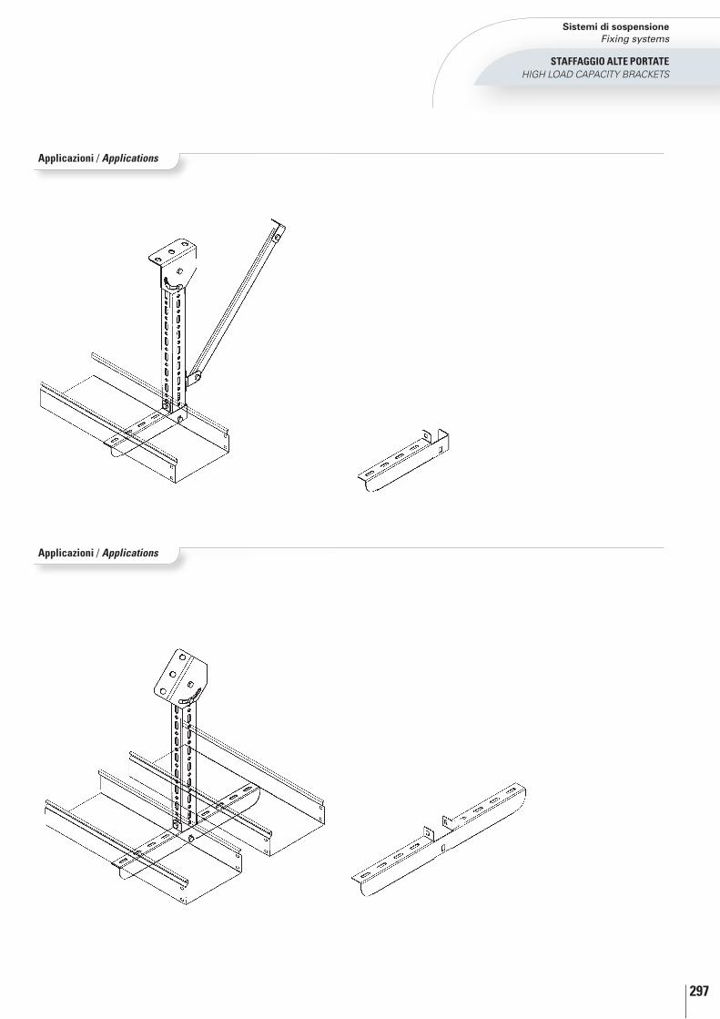
297
StAFFAGGIO AltE PORtAtEHIgH LOAD CAPACITy BRACKETS
Applicazioni / applications
Applicazioni / applications
Sistemi di sospensione Fixing systems
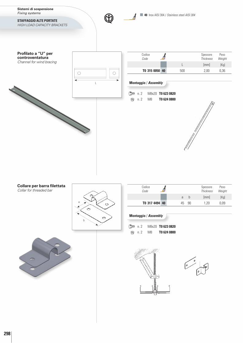
298
StAFFAGGIO AltE PORtAtEHIgH LOAD CAPACITy BRACKETS
collare per barra filettataCollar for threaded bar
Codice Code
Spessore Thickness
Peso Weight
a b [mm] [Kg]
t0 317 4494 40 45 90 1,20 0,09a
b
40 Inox AISI 304 / Stainless steel AISI 304
Codice Code
Spessore Thickness
Peso Weight
L [mm] [Kg]
t0 315 0050 40 500 2,00 0,36
profilato a “U” per controventaturaChannel for wind bracing
Montaggio / assembly
Montaggio / assembly
n. 2 M8x20 t0 623 0820
n. 2 M8 t0 624 0800
n. 2 M8x20 t0 623 0820
n. 2 M8 t0 624 0800
L
Sistemi di sospensione Fixing systems
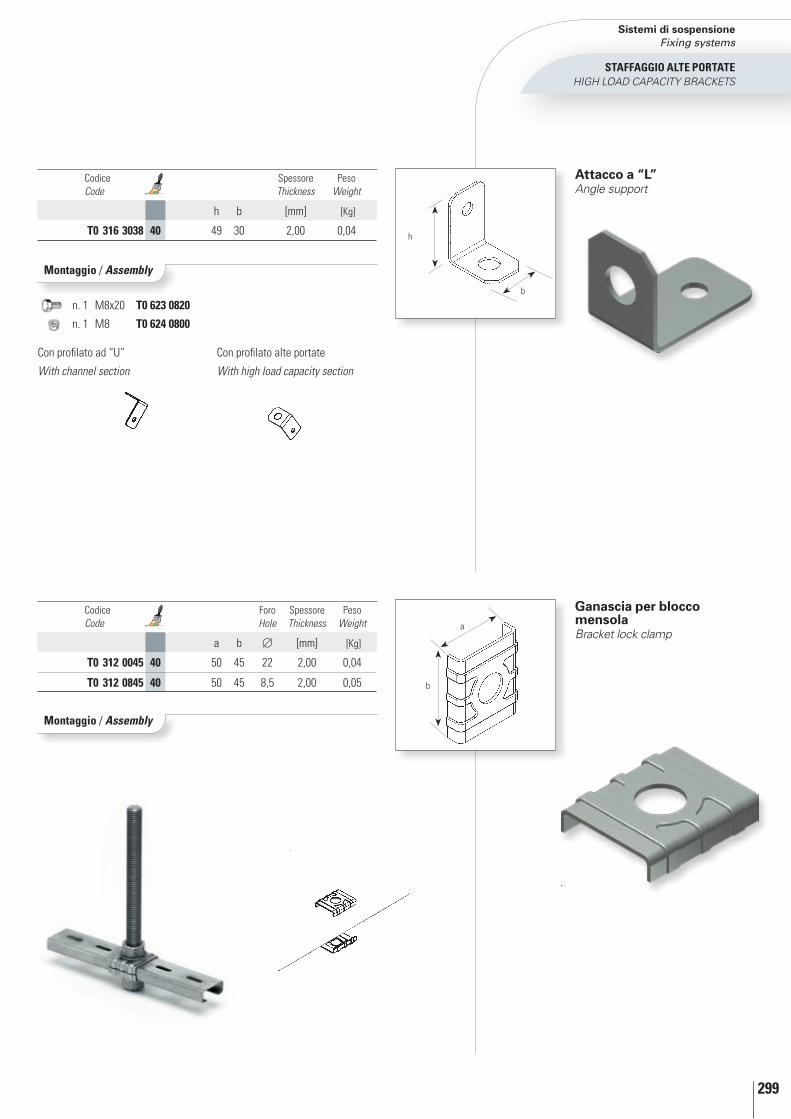
299
StAFFAGGIO AltE PORtAtEHIgH LOAD CAPACITy BRACKETS
Attacco a “l”Angle support
Codice Code
Spessore Thickness
Peso Weight
h b [mm] [Kg]
t0 316 3038 40 49 30 2,00 0,04
ganascia per blocco mensolaBracket lock clamp
Codice Code
Foro Hole
Spessore Thickness
Peso Weight
a b [mm] [Kg]
t0 312 0045 40 50 45 22 2,00 0,04
t0 312 0845 40 50 45 8,5 2,00 0,05
a
b
Montaggio / assembly
n. 1 M8x20 t0 623 0820
n. 1 M8 t0 624 0800
Montaggio / assembly
b
h
Con profilato ad “U”
With channel section
Con profilato alte portate
With high load capacity section
Sistemi di sospensione Fixing systems
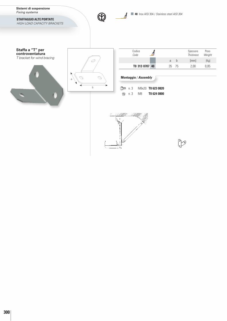
300
n. 3 M8x20 t0 623 0820
n. 3 M8 t0 624 0800
40 Inox AISI 304 / Stainless steel AISI 304
Codice Code
Spessore Thickness
Peso Weight
a b [mm] [Kg]
t0 313 0707 40 35 75 2,00 0,05
Montaggio / assembly
StAFFAGGIO AltE PORtAtEHIgH LOAD CAPACITy BRACKETS
Staffa a “T” per controventaturaT bracket for wind bracing
b
a
Sistemi di sospensione Fixing systems

bullo
neria
/ bo
lts

328
bullone testa tonda con quadro sottotestaRound-headed bolt with square subhead
bullone per staffe alta portataBolt for high load capacity stirrups
Dimensione Dimension
Codice Code
Peso Weight
conf/100*
M6 x 10 t0 620 0610 01 0,40
M6 x 12 t0 620 0612 40 47 0,32
M6 x 20 t0 620 0620 01 40 47 0,79
M8 x 14 t0 620 0814 01 0,80
Dimensione Dimension
Codice Code
Peso Weight
conf/100*
M6 x 25 t0 623 0625 01 40 0,90
M8 x 12 t0 623 0812 01 40 0,90
M8 x 20 t0 623 0820 01 40 1,17
M8 x 25 t0 623 0825 01 40 1,17
M8 x 30 t0 623 0830 01 40 1,80
M8 x 40 t0 623 0840 01 40 2,20
M8 x 50 t0 623 0850 01 40 2,60
M8 x 70 t0 623 0870 01 40 3,10
M10 x 20 t0 623 1020 01 40 2,40
M10 x 25 t0 623 1025 01 40 2,70
M10 x 30 t0 623 1030 01 40 3,00
M10 x 40 t0 623 1040 01 40 3,60
M10 x 50 t0 623 1050 01 40 4,30
M12 x 20 t0 623 1220 01 40 3,50
M12 x 25 t0 623 1225 01 40 4,00
M12 x 30 t0 623 1230 01 40 4,40
M12 x 40 t0 623 1240 01 40 5,30
M12 x 50 t0 623 1250 01 40 6,20
bulloneriabolts 01 Zincato Sendzimir / Sendzimir galvanized
40 Inox AISI 304 / Stainless steel AISI 304 47 Geomet® 321 a richiesta / Geomet® 321 on demand
* per confezione 100 pezzi* for 100 pieces pack

329
dado flangiato zigrinatoKnurled flanged nut
Vite esagonale flangiata dentellatanotched flanged hexagonal head screw
Elemento per fissaggio sistema zT/zESecuring element for ZT/ZE system
dado esagonaleHexagonal nut
bulloneriabolts
Dimensione Dimension
Codice Code
Peso Weight
[Kg]
M8 t0 625 0000 01 40 0,04
Dimensione Dimension
Codice Code
Peso Weight
conf/100*
M6 x 6 t0 622 0606 01 0,40
Dimensione Dimension
Codice Code
Peso Weight
conf/100*
M6 t0 624 0600 01 40 47 0,30
M8 t0 624 0800 01 40 47 0,47
M10 t0 624 1000 01 40 47 1,10
M12 t0 624 1200 01 40 47 1,70
M20 t0 624 2000 01 40 47 6,42
Dimensione Dimension
Codice Code
Peso Weight
conf/100*
M6 t0 621 0600 01 40 47 0,30
* per confezione 100 pezzi* for 100 pieces pack

330
* per confezione 100 pezzi ** per confezione 50 pezzi* for 100 pieces pack ** for 50 pieces pack
bulloneriabolts 01 Zincato Sendzimir / Sendzimir galvanized
40 Inox AISI 304 / Stainless steel AISI 304
rondella pianaWasher
rondella piana dentellataFan-edged washer
barra filettataThreaded bar
manicottoSleeve
Dimensione Dimension
Codice Code
L Peso Weight
[mm] conf/100*
M6 R0 325 0600 01 40 30 0,01
M8 R0 325 0800 01 40 30 0,02
M10 R0 325 1000 01 40 45 0,02
M12 R0 325 1200 01 40 50 0,08
M16 R0 325 1600 01 40 60 0,08
Dimensione Dimension
Codice Code
L Peso Weight
[mm] conf/50**
M6 R0 315 0600 01 40 1000 0,20
M8 R0 315 0800 01 40 1000 0,31
M10 R0 315 1000 01 40 1000 0,48
M12 R0 315 1200 01 40 1000 0,70
M20 R0 315 2000 01 40 1000 2,01
Dimensione Dimension
Codice Code
Peso Weight
conf/100*
6 t0 651 0600 01 40 0,04
8 t0 651 0800 01 40 0,05
10 t0 651 1000 01 40 0,06
12 t0 651 1200 01 40 0,07
Dimensione Dimension
Codice Code
Peso Weight
conf/100*
6 t0 650 0600 01 40 0,08
8 t0 650 0800 01 40 0,18
10 t0 650 1000 01 40 0,40
12 t0 650 1200 01 40 0,63

331
* per confezione 100 pezzi* for 100 pieces pack
pinza fora lamiera universaleUniversal sheet - metal hole punch
Vernice per ritocchi blu elettricoTouch-up paint electric blue
Codice Code
t1 671 0000 01
Dimensione Dimension
Codice Code
Peso Weight
conf/100*
3,4 x 7 t0 652 0307 01 0,10
4 x 7 t0 652 0407 01 0,10
rivettoRivet
Dimensione Dimension
Codice Code
6 t1 670 0600 01
Codice Code
R0 335 0000 01
rivettatriceRiveting machine
Codice Code
Peso Weight
[Kg]
t1 660 1000 15 0,50
cesoia per passerelle a filo (con lame asimmetriche)Shears for basket trays (with asymmetric blades)
bulloneriabolts

332
UNI EN ISO 9001:2008
zAmET S.p.A. adotta diverse soluzioni per l’imballaggio dei suoi prodotti al fine di garantire la perfetta integrità dei materiali durante il trasporto.A richiesta vengono fornite tipologie di imballo diverse dallo standard.
ZAMET S.p.A. uses different methods for packaging its products in order to guarantee that the materials are not damaged during shipping.non-standard types of packaging are available upon request.Im
balla
ggio
Pack
agin
g/
Pedana cartonata Cardboard wrapped pallet
Imballi per profilato a C asolatoPackaging for slotted C section
Imballo standard per elementi rettilinei metalliciStandard packaging for straight metal elements
L’imballo del materiale rettilineo è realizzato utilizzando appositi listelli in legno, tagliati su misura e successivamente reggettati.
Straight materials is packaged using special wooden slats, cut to size and strapped together.
L’imballo del materiale rettilineo è realizzato utilizzando appositi listelli in legno, tagliati su misura e successivamente reggettati.
Straight materials is packaged using special wooden slats, cut to size and strapped together.
Questo tipo di imballo, in robusto cartone, è sovrapponibile ed ideale per evadere grosse quantità di merce.
This kind of packaging, made of strong cardboard, can be stacked and is ideal for large quantities of goods.
Codice identificativoIdentification code
Rivestimento Coating
Dimensione Size
SerieSeries
Quantità imballate Quantity packaged
Marchio di qualità Quality mark
Descrizione prodotto Product description

333
Imballo standard zincato Sendzimir e zincato a caldoStandard Sendzimir and hot-dip galvanized packaging
Imballi per canale serie ZCPackaging for series ZC cable tray
Imballo standard verniciato ed Inox Standard painted and stainless steel packaging
Confezione standard componenti Standard component package
Film estensibileExtensible film
Il materiale rettilineo verniciato ed Inox è cartonato al fine di proteggerlo durante il trasporto, successivamente, chiuso da listelli in legno e reggettati.
Straight painted material and stainless steel elements are wrapped in cardboard to protect them during transport and then packaged with wooden slats and strapped together.
L’imballo del materiale rettilineo è realizzato utilizzando appositi listelli in legno, tagliati su misura e successivamente reggettati.
Straight materials is packaged using special wooden slats, cut to size and strapped together.
I componenti della serie ZT sono confezionati in pacchi termoretratti ed etichettati per una facile identificazione.
Components of the ZT series are packaged in heatshrink bags and marked for easy identification.
L’imballo con film estensibile non è sovrapponibile ma ideale per piccole quantità di merce.
Extensible film packaging cannot be stacked but is ideal for small quantities of goods.
L’imballo in scatole di cartone è appositamente studiato per contenere e proteggere il canale durante il trasporto.
The packaging in cardboard boxes, is designed especially to contain and protect cable trays during transport.

Per tutte le tipologie di materiali e rivestimenti (acciaio zincato a caldo, acciaio zincato Sendzimir e verniciato) i prodotti devono essere immagazzinati in ambienti chiusi ed aerati, non devono essere coperti da teloni in quanto favoriscono la formazione di condensa.
Nel caso in cui i prodotti rettilinei vengano esposti, anche per breve periodo, ad eventi atmosferici (pioggia, neve, ecc.).Zamet S.p.A. consiglia di ritirare gli imballi al coperto, po-nendoli in posizione inclinata al fine di evitare il ristagno dei liquidi.
Per ciò che concerne i prodotti realizzati con trattamenti di zincatura a caldo per immersione (UNI EN ISO 1461), si può verificare la formazione di una patina bianca causata dalla normale reazione tra ossigeno e lo strato di zinco su-perficiale. Tale fenomeno, del tutto normale, non pregiudi-ca la resistenza alla corrosione.Zamet S.p.A., nell’ottica di fornire un prodotto di eccellenza, anche se non richiesto, fa realizzare un trattamento di passiva-zione al fine di ritardare la formazione di questo fenomeno.
La norma UNI EN ISO 1461, come peraltro tutte le princi-pali norme internazionali, prevede che questo fenomeno di ossidazione non può essere oggetto di contestazione né causa di scarto.
Avvertenze per trasporto ed installazioneZamet S.p.A. declina ogni responsabilità in caso di traspor-to ed installazione non conformi alle istruzioni ed alle avver-tenze sopra indicate.
For all types of materials and coatings (hot galvanized steel, sendzimir galvanized steel and painted steel), all products must be stored in closed, ventilated rooms; they must not be covered with tarpaulins because they favour the formation of condensation.
If straight products are exposed, even for a short period of time, to atmospheric elements (rain, snow, etc.), Zamet S.p.A. recommends bringing the packages under cover and placing them in a slanted position to prevent the accumulation of liquids.
With regard to products subject to hot-dip galvanization treat-ments (UnI En ISO 1461), a white film may form, caused by the normal reaction between oxygen and the surface layer of zinc. This phenomenon is normal and does not compromise resistance to corrosion.With a view to supplying a product of excellence, Zamet S.p.A. subjects its products, even when not expressly requi-red, to a passivation treatment in order to delay the formation of oxidation.
Under UnI En ISO 1461 and all the main international stan-dards, this oxidation phenomenon cannot be considered as grounds for contention or for rejection.
Warnings regarding shipping and installationZamet S.p.A. declines all responsibility in the case of shipping and installation which is non-compliant with the instructions and warnings given above.
raccomandazioni per lo stoccaggio dei prodotti zametrecommendations for the storage of Zamet products

Soluzioni su misura per ogni esigenzaSolutions tailored to suit every need

336

337
Soluzioni “ad hoc”...La Zamet è in grado di soddisfare le molteplici esigenze di impiantistica industriale a disegno, progettando soluzioni specifiche applicabili sia al canale rettilineo che ai componenti. A tal proposito propone sagomature (tonde, quadre, rettangolari, ecc.) tranciature particolari, tagli di piegatura ed altre lavorazioni a richiesta.
“Ad hoc” solutions...Zamet is capable of meeting the varied needs of industrial installations made to design, designing specific solutions applicable to both straight cable trays and components. To this end, it proposes profiles (round, square, rectangular, etc.), special cutting, folding cuts and other specifically required processes.
Kit giunzione tra serie ZR ed accessori serie ZTJunction kit between ZR system and ZT system’s accessories

338
A ( 1 : 4 )
B ( 1 : 4 )
C ( 1 : 2 )
A
B
C
L’ultima importante sfida riguarda...The latest important challenge concerns...
Studio, progettazione e realizzazione del blocco aereo di distribuzione con aggancio a scatto su canaleResearch, design and construction of overhead block with snap hook onto trunking
Studio, progettazione e realizzazione delle passerelle sotto cassaResearch, design and construction of cable trays under the body

Sede e Stabilimento / Company addressZAMET S.p.A. - Via Torino, 109 - 10088 Volpiano (TO) ItalyCentralino / Switchboard0039 011 98 22 601FAX Ufficio commerciale / FAX Sales department0039 011 99 53 778FAX Ufficio acquisti, Amministrazione, Ufficio tecnico FAX Purchase department, Administration, Engineering department0039 011 99 53 756E-mail aziendale / Company [email protected] Ufficio commerciale / Sales department [email protected]
Copyright © 2022 FDOKUMEN