Parts & Maintenance Manual - Ransomes Jacobsen
118
Parts & Maintenance Manual GB Tri King ® Triplex Mower 67042 – 1800G Briggs Vanguard Engine 67043 – 1900D Kubota D662-EB Engine 2810632-Rev F
-
Upload
khangminh22 -
Category
Documents
-
view
2 -
download
0
Transcript of Parts & Maintenance Manual - Ransomes Jacobsen

Parts & MaintenanceManual
19
17
18
13
6
5
9
15
16
7 8
10
4
3
11
1 - INCLUDES ITEMS 3 - 16
GB
Tri King® Triplex Mower
67042 – 1800G Briggs Vanguard Engine67043 – 1900D Kubota D662-EB Engine
2810632-Rev F

Copyright 2000 Textron Inc. “All rights reserved, including the right to reproduce this material or portions thereof in any form.”
To Order Parts
1. Write your full name and complete address on the order.
2. Explain where and how to make shipment.3. Give product number, name and serial number that is
stamped on the name plate or serial plate of your prod-uct.
4. Order by the quantity desired, the part number, paint code, and description of the part as given in the parts list.
5. Send or bring the order to an authorized Jacobsen Dealer.
6. Inspect all shipments on receipt. If any parts are dam-aged or missing, file a claim with the carrier before accepting.
7. Do not return material without a letter of explanation, listing the parts being returned. Transportation charges must be prepaid.
Use of other than authorized parts will void the warranty.
This manual is designed for the Maintenance and Adjustment of this equipment.Use the maintenance and adjustment instructions included in this manual and the operatinginstructions included in the Safety and Operation Manual to service the machine.
The Safety and Operation Manual must be kept in the pouch on the back of the seat at all timesfor reference by the operator.
Table of Contents1 Safety1.1 Operating Safety................................................. 41.2 Important Safety Notes .......................................52 Specifications2.1 Product Identification .......................................... 62.2 Engine .................................................................62.3 Cutting Units: ......................................................62.4 Tractor ................................................................72.5 Weights and Dimensions ....................................72.6 Accessories & Support Literature .......................73 Adjustments3.1 General ............................................................... 83.2 Fan Belt (Diesel Engines) ...................................83.3 Pump Drive Belt ..................................................83.4 Neutral and 3WD Switches .................................93.5 Parking Brake Switches ......................................93.6 Lift Limit Switch ...................................................93.7 Traction Pedal Neutral ......................................103.8 Traction Pedal Forward Stop ............................103.9 Lift / Lower Pedal Stop ......................................103.10 Parking Brake ...................................................113.11 Rear Lift Arm .....................................................113.12 Down Pressure .................................................113.13 Reel To Bedknife ..............................................123.14 Reel to Bedknife Adjustment ............................123.15 Cutting Modes ...................................................133.16 Cutting Height Adjustment ................................133.17 Removing the Cutting Unit ................................143.18 Cutting Height - Fixed Mode .............................143.19 Cutting Height - Floating Mode .........................153.20 Torque Specification .........................................163.21 Specific Torque .................................................16
4 Maintenance4.1 General ............................................................ 174.2 Engine .............................................................. 174.3 Engine Oil ......................................................... 184.4 Gas Engine Air Filter ........................................ 184.5 Diesel Air Filter ................................................. 194.6 Fuel .................................................................. 194.7 Fuel System ..................................................... 194.8 Battery .............................................................. 204.9 Jump Starting ................................................... 204.10 Charging Battery .............................................. 204.11 Hydraulic Hoses ............................................... 214.12 Hydraulic Oil ..................................................... 214.13 Hydraulic Oil Filters .......................................... 224.14 Electrical System .............................................. 224.15 Muffler and Exhaust ......................................... 224.16 Tires ................................................................. 224.17 Wheel Mounting Procedure .............................. 234.18 Care and Cleaning ........................................... 234.19 Radiator ............................................................ 234.20 Backlapping ...................................................... 244.21 Storage ............................................................. 255 Troubleshooting5.1 General ............................................................ 266 Maintenance & Lubrication Charts6.1 General ............................................................ 276.2 Lubrication Chart .............................................. 276.3 Maintenance Charts ......................................... 287 Parts Catalog7.1 Table Of Contents ............................................ 29
LITHO IN U.S.A. 5-2006

3
Suggested Stocking Guide
To Keep your Equipment fully operational and productive, Jacobsen suggests you maintain a stock of the morecommonly used maintenance items. We have included part numbers for additional support materials and trainingaids.
To order any of the following material:
1. Write your full name and complete address on your order form.
2. Explain where and how to make shipment:
❑ UPS ❑ Regular Mail
❑ Overnight ❑ 2nd Day
3. Order by the quantity desired, the part number, and the description of the part.
4. Send or bring the order to your authorized Jacobsen Dealer.
How To Use This Manual
Abbreviations
N/S - Not serviced separately, can only be obtained by ordering main component or kit.AR -Variable quantity or measurement is required to obtain correct adjustment.Symbols such as ▲, next to the item number, indicate that a note exists which contain additional informationimportant in ordering that part.
Indented ItemsBulleted items indicate component parts that are included as part of an assembly or another component. These partscan be ordered separately or as part of the main component.
Item Part No. Qty Description Serial Numbers/Notes▲ 1 123456 1 Mount, Valve Indicates a piece part
2 789012 1 Valve, Lift Includes Items 2 and 33 345678 1 • Handle Serviced part included with Item 24 N/S 1 • Seal Kit Non serviced part included with Item 25 901234 1 Screw, 1/4-20 x 2” Hex Head
Service Parts
Service Support Material
Qty. Part No. Description Qty. Part No. Description5000436 Fuel Filter, Gas Engine 549579 Hydraulic Oil Filter (2 Req’d)5000441 Air Filter, Gas Engine 3001950 Pump Drive Belt5000440 Oil Filter, Gas Engine 1001958 Ignition Key Switch550489 Fuel Filter, Diesel Engine5000913 Air Filter, Diesel Engine502644 Oil Filter, Diesel Engine
Qty. Part No. Description2810631 Safety & Operation Manual2810632 Parts & Maintenance3004386 Engine Parts Catalog2810628 Video, Operator Training
Qty. DescriptionService Manual

1 SAFETY
1 SAFETY1.1 OPERATING SAFETY ______________________________________________________
1. Safety is dependent upon the awareness, concern andprudence of those who operate or service the equip-ment. Never allow minors to operate any equipment.
2. It is your responsibility to read this manual and allpublications associated with this equipment (Safetyand operation manual, engine manual, accessoriesand attachments). If the operator can not read Englishit is the owner’s responsibility to explain the materialcontained in this manual to them.
3. Learn the proper use of the machine, the location andpurpose of all the controls and gauges before youoperate the equipment. Working with unfamiliarequipment can lead to accidents.
4. Never allow anyone to operate or service the machineor its attachments without proper training andinstructions; or while under the influence of alcohol ordrugs.
5. Wear all the necessary protective clothing andpersonal safety devices to protect your head, eyes,ears hands and feet. Operate the machine only indaylight or in good artificial light.
6. Evaluate the terrain to determine what accessories andattachments are needed to properly and safely performthe job. Only use accessories and attachmentsapproved by Jacobsen.
7. Stay alert for holes in the terrain and other hiddenhazards.
8. Inspect the area where the equipment will be used.Pick up all the debris you can find before operating.Beware of overhead obstructions (low tree limbs,electrical wires, etc.) and also underground obstacles(sprinklers, pipes, tree roots, etc.) Enter a new areacautiously. Stay alert for hidden hazards.
9. Never direct discharge of material toward bystanders,nor allow anyone near the machine while in operation.The owner/operator can prevent and is responsible forinjuries inflicted to themselves, to bystanders anddamage to property.
10. Do not carry passengers. Keep bystanders and pets asafe distance away.
11. Never operate equipment that is not in perfect workingorder or is without decals, guards, shields, dischargedeflectors or other protective devices securely fastenedin place.
12. Never disconnect or bypass any switch.
13. Do not change the engine governor setting oroverspeed the engine
14. Carbon monoxide in the exhaust fumes can be fatalwhen inhaled. Never operate the engine without properventilation or in an enclosed area.
15. Fuel is highly flammable, handle with care.
16. Keep the engine clean. Allow the engine to cool beforestoring and always remove the ignition key.
17. Disengage all drives and engage parking brake beforestarting the engine (motor). Start the engine only whensitting in operator’s seat, never while standing besidethe unit.
18. Equipment must comply with the latest federal, state,and local requirements when driven or transported onpublic roads. Watch out for traffic when crossing oroperating on or near roads.
19. Local regulations may restrict the age of the operator.
20. Never use your hands to search for oil leaks. Hydraulicfluid under pressure can penetrate the skin and causeserious injury.
21. Operate the machine up and down the face of theslopes (vertically), not across the face (horizontally).
22. To prevent tipping or loss of control, do not start orstop suddenly on slopes. Reduce speed when makingsharp turns. Use caution when changing directions.
23. Always use the seat belt when operating tractorsequipped with a ROPS.
Never use a seat belt when operating tractorswithout a ROPS.
24. Keep legs, arms and body inside the seatingcompartment while the vehicle is in motion.
This machine is to be operated and maintained as specified in this manual and is intended for the professionalmaintenance of specialized turf grasses. It is not intended for use on rough terrain or long grasses.
WARNINGEQUIPMENT OPERATED IMPROPERLY OR BY UNTRAINED PERSONNEL CAN BE DANGEROUS.
Familiarize yourself with the location and proper use of all controls. Inexperienced operator’s should receive instruction from someone familiar with the equipment before being allowed to operate the machine.
!
4

SAFETY 1
1.2 IMPORTANT SAFETY NOTES ________________________________________________
This safety alert symbol is used to alert you to potential hazards.
DANGER - Indicates an imminently hazardous situation which, if not avoided, WILL result in death or serious injury.
WARNING - Indicates a potentially hazardous situation which, if not avoided, COULD result in death or seriousinjury.
CAUTION - Indicates a potentially hazardous situation which, if not avoided, MAY result in minor or moderate injuryand property damage. It may also be used to alert against unsafe practices.
For pictoral clarity, some illustrations in this manual may show shields, guards or plates open or removed. Under nocircumstances should this equipment be operated without these devices securely fastened in place
By following all instructions in this manual, you will prolong the life of your machine and maintain its maximumefficiency. Adjustments and maintenance should always be performed by a qualified technician.
If additional information or service is needed, contact your Authorized Jacobsen Dealer who is kept informed of thelatest methods to service this equipment and can provide prompt and efficient service. Use of other than original orauthorized Jacobsen parts and Accessories will void the warranty.
WARNINGThe operator back-up system on this tractor prevents the tractor from startingunless the brake lever is engaged, mower switch is off and traction pedal is inneutral. The system will stop the engine if the operator leaves the seatwithout engaging the parking brake or setting the mower switch off.
NEVER operate tractor unless the operator back-up system is working.
!
!
WARNING1. Before leaving the operator’s position for any reason:
a. Return traction pedal to neutral.b. Disengage all drives.c. Lower all implements to the ground.d. Engage parking brake.e. Stop engine and remove the ignition key.
2. Keep hands, feet, and clothing away from moving parts. Wait for allmovement to stop before you clean, adjust or service the machine.
3. Keep the area of operation clear of all bystanders and pets.
4. Never carry passengers, unless a seat is provided for them.
5. Never operate mowing equipment without the discharge deflectorsecurely fastened in place.
!
5

2 SPECIFICATIONS
2 SPECIFICATIONS2.1 PRODUCT IDENTIFICATION_________________________________________________
67042.............................. Tri-King 1800G Tractor, 3-WD, 18 hp gasoline engine. Without front lift arms, mowers or battery.
67043.............................. Tri-King 1900D Tractor, 3-WD, 18.5 hp diesel engine. Without front lift arms, mowers or battery.
Serial Number ................ An identification plate, like the one shown, listing the serial number, is attached to the frame of the tractor and is located to the operator’s left just behind the front wheel motor. Always provide the serial number of the unit when ordering replacement parts or requesting service information.
2.2 ENGINE__________________________________________________________________
1800G Gasoline EngineMake ............................... Briggs &StrattonModel .............................. Vanguard V-Twin OHVHorsepower .................... 18 hp (13.5 kW) @3600 rpmNote: Actual sustained horsepower will likely be lowerthan listed in specifications due to operating limitationsand environmental factor
Displacement .................. 34.8 cu. in. (570 cc)Torque ............................ 26 ft. lbs. (35 Nm) @ 2600 rpmFuel:
Type.......................... Unleaded GasolineRating ....................... Min. 85 OctaneCapacity.................... 6.5 U.S. Gal. (24.6 liters)
Governor......................... Flyweight MechanicalLubrication:
Capacity.................... 3.5 pints (1.6 liters) Type.......................... SAE 30WAPI Classification ..... SF, SG, SH
Air Filter .......................... Replacable Dual Element.Alternator ........................ 16 amp
1900D Diesel EngineMake............................... KubotaModel.............................. D662-EHorsepower .................... 18.5 hp (13.9 kW) @3600 rpmNote: Actual sustained horsepower will likely be lowerthan listed in specifications due to operating limitationsand environmental factors
Displacement.................. 40.03 cu. in. (656 cc)Torque ............................ 26 ft. lbs. (35 Nm) @ 2600 rpmFuel:
Type.......................... No. 2 DieselRating ....................... Min. Cetane rating 45Capacity.................... 6.5 U.S. Gal. (24.6 liters)
Governor......................... Ball Type GovernorLow Idle ................... 1100 RPMHigh Idle ................... 3400 RPM
Lubrication:Capacity.................... 3.4 quarts (3.2 liter) with filter Type.......................... SAE 20W, SAE 30WAPI Classification ..... CD, CE
Air Filter .......................... Dry type with evacuator valve and service indicator.
Alternator ........................ 40 amp
2.3 CUTTING UNITS: __________________________________________________________
Reel ................................ 3 Reels, 26 in. (660 mm) wide or, 3 Reels, 30 in. (762 mm) wide.
Reel Diameter................. 7 in. (178 mm)Bearings.......................... Self adjusting tapered roller
bearingsBlade Options ................. 7 bladesCutting Width:
26 in. Reels............... 72 in. (1828 mm)30 in. Reels............... 84 in. (2134 mm)
Overall Width:26 in. Reels............... 78.5 in. (1994 mm)30 in. Reels............... 90.5 in. (2298 mm)
Cutting Frequency:7 Blade ..................... 0.151 in./mph (3.8 mm/kph)
Product EEC Sound Power
Sound Pressure Level
Operator Ear
Vibration M/S2
Arms Body
6704267043
99.4 dba101 dba
83.7 dba87 dba
1.41.4
1.61<0.08
CHARLOTTE, NC
YEAR OFPRODUCTION:
MADE IN U.S.A.
®
A Textron Company
67042 1601
6
SPECIFICATIONS 2
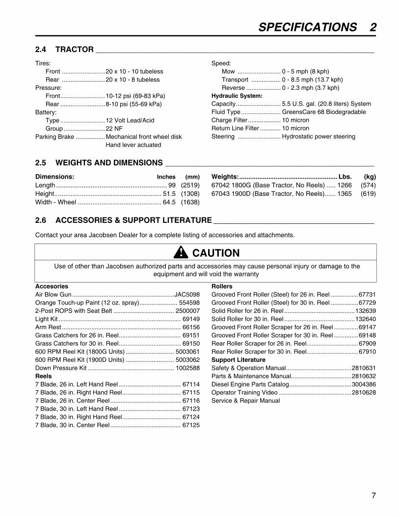
2.4 TRACTOR ________________________________________________________________
Tires:Front .........................20 x 10 - 10 tubelessRear .........................20 x 10 - 8 tubeless
Pressure:Front..........................10-12 psi (69-83 kPa)Rear ..........................8-10 psi (55-69 kPa)
Battery:Type ..........................12 Volt Lead/AcidGroup ........................22 NF
Parking Brake .................Mechanical front wheel diskHand lever actuated
Speed:Mow ......................... 0 - 5 mph (8 kph)Transport ................. 0 - 8.5 mph (13.7 kph)Reverse .................... 0 - 2.3 mph (3.7 kph)
Hydraulic System:Capacity.......................... 5.5 U.S. gal. (20.8 liters) SystemFluid Type....................... GreensCare 68 BiodegradableCharge Filter ................... 10 micronReturn Line Filter ............ 10 micronSteering ......................... Hydrostatic power steering
2.5 WEIGHTS AND DIMENSIONS ________________________________________________
Dimensions: Inches (mm)Length ............................................................. 99 (2519)Height........................................................... 51.5 (1308)Width - Wheel .............................................. 64.5 (1638)
Weights:...................................................... Lbs. (kg)67042 1800G (Base Tractor, No Reels) ..... 1266 (574)67043 1900D (Base Tractor, No Reels)...... 1365 (619)
2.6 ACCESSORIES & SUPPORT LITERATURE _____________________________________
Contact your area Jacobsen Dealer for a complete listing of accessories and attachments.
AccesoriesAir Blow Gun ...........................................................JAC5098Orange Touch-up Paint (12 oz. spray)...................... 5545982-Post ROPS with Seat Belt ................................... 2500007Light Kit ....................................................................... 69149Arm Rest ..................................................................... 66156Grass Catchers for 26 in. Reel.................................... 69151Grass Catchers for 30 in. Reel.................................... 69150600 RPM Reel Kit (1800G Units) ............................ 5003061600 RPM Reel Kit (1900D Units) ............................ 5003062Down Pressure Kit .................................................. 1002588Reels7 Blade, 26 in. Left Hand Reel .................................... 671147 Blade, 26 in. Right Hand Reel.................................. 671157 Blade, 26 in. Center Reel......................................... 671167 Blade, 30 in. Left Hand Reel .................................... 671237 Blade, 30 in. Right Hand Reel.................................. 671247 Blade, 30 in. Center Reel......................................... 67125
RollersGrooved Front Roller (Steel) for 26 in. Reel ................67731Grooved Front Roller (Steel) for 30 in. Reel ................67729Solid Roller for 26 in. Reel .........................................132639Solid Roller for 30 in. Reel .........................................132640Grooved Front Roller Scraper for 26 in. Reel ..............69147Grooved Front Roller Scraper for 30 in. Reel ..............69148Rear Roller Scraper for 26 in. Reel..............................67909Rear Roller Scraper for 30 in. Reel..............................67910Support LiteratureSafety & Operation Manual......................................2810631Parts & Maintenance Manual...................................2810632Diesel Engine Parts Catalog....................................3004386Operator Training Video ..........................................2810628Service & Repair Manual
CAUTION Use of other than Jacobsen authorized parts and accessories may cause personal injury or damage to the
equipment and will void the warranty
!
7

3 ADJUSTMENTS
3 ADJUSTMENTS3.1 GENERAL________________________________________________________________
1. Adjustments and maintenance should always beperformed by a qualified technician. If proper
adjustment cannot be made, contact an authorizedJacobsen Dealer.
2. Replace, do not adjust, worn or damagedcomponents.
3. Long hair, jewelry or loose fitting clothing may gettangled in moving parts.
4. Do not change governor settings or overspeed theengine.
3.2 FAN BELT (DIESEL ENGINES) _______________________________________________
Inspect and adjust new belt after first ten hours ofoperation. Adjust every 100 hours thereafter.
1. Adjust alternator pulley so belt (B) deflects 9/32 to11/32 in. (7 to 9 mm) with a 22 lb. (10 kgf) push atmidspan between pulleys.
2. If tension is incorrect, loosen alternator mountingbolts (A) and adjust alternator until proper belttension is achieved. Tighten hardware (A)
Figure 3A
3.3 PUMP DRIVE BELT ________________________________________________________
Adjust reel pump belt (C) to deflect 1/4 in. (6 mm) with aforce of 5-7 lb. (2-3 kgf) applied at midspan.
1. Loosen hardware (D and E).
2. Move pump/clutch assembly down to increasetension on belt (C) then tighten hardware (D and E).
3. Torque hardware (D and E) to 27 - 33 ft-lb. (37-45Nm).
Figure 3B
WARNINGTo prevent injury, lower implements to the ground,disengage all drives, engage parking brake, stop engineand remove key from ignition switch before making anyadjustments or performing maintenance.
Make sure the tractor is parked on a solid and levelsurface. Never work on a tractor that is supported onlyby the jack. Always use jack stands.
If only the front or rear of the tractor is raised, placechocks in front of and behind the wheels that are notraised.
!
CAUTION Be careful to prevent entrapment of the hands and
fingers between moving and fixed components of the machine.
!
A
B
D
DE E
CC
Diesel Engine Gasoline Engine
8

ADJUSTMENTS 3
3.4 NEUTRAL AND 3WD SWITCHES _____________________________________________
1. Check traction pedal adjustment.
2. Use a volt/ohm meter to determine when switchopens or closes.
a. Adjust switch (G) so “finger” of actuating arm (F)is centered over sensing portion of switch.Switch contacts should be closed with tractionpedal in neutral and open with minimal pedaltravel in forward or reverse direction.
b. Adjust 3WD switch (H) so contacts are open withtraction pedal in neutral, and contacts close withminimal pedal travel in forward direction.
Figure 3C
3.5 PARKING BRAKE SWITCHES________________________________________________
Loosen screws (K) and adjust both switches so contactsjust close as the brake lever is moved to the engagedposition then tighten screws.
Figure 3D
3.6 LIFT LIMIT SWITCH ________________________________________________________
The lift limit switch must be adjusted so the reels stopturning before the cutting plane between the reel andground reach 15-3/4 in. (400 mm). To adjust, loosenscrew (L) and adjust arm (M).
Figure 3E
G
H
F
K
L
M
9

3 ADJUSTMENTS
3.7 TRACTION PEDAL NEUTRAL _______________________________________________
1. If the tractor “creeps” in either direction when theengine is running but the traction pedal is notdepressed, adjust spring tension so that the pedalalways returns to neutral when released.
Note: The tractor may “creep” when the hydraulic oilis cold. Operate the tractor for 15 minutes beforedetermining if adjustment is required.
2. Use extreme caution when making this adjustmentas the wheels will be off the ground and the enginewill be running.
3. Engage parking brake, stop the engine, open hoodsthen lubricate all linkage pivot points.
4. Chock the rear wheel, and place the front of thetractor on jackstands.
5. Loosen all nuts (N) and adjust rear spring toposition traction arm in neutral.
a. Lock rear nuts and adjust front nuts (N) tomaintain 3/8 in. (9 mm) of extension in spring(O).
b. Start the engine and check for “creep” thenrepeat the process if necessary.
Figure 3F
3.8 TRACTION PEDAL FORWARD STOP _________________________________________
Loosen nuts (P) move the traction pedal to its maximumforward position. Adjust screw (Q) until the head justtouches the traction pedal arm. Return traction pedal toneutral and turn screw (Q) out one full turn. Tighten nuts(P).
Important: Screw (Q) must stop traction pedal before theinternal stops in the hydrostatic transmission arecontacted.
Figure 3G
3.9 LIFT / LOWER PEDAL STOP ________________________________________________
Adjust bolts (R and S) to stop spool valve from hitting theinternal stops, while maintaining the full stroke of thespool.
Figure 3H
O
N N
Front
P
PQ
S
R
10

ADJUSTMENTS 3
3.10 PARKING BRAKE__________________________________________________________
1. Check linkage cables and pivots to ensure they areoperating smoothly.
2. Park the tractor on a 30% slope (16.7°) near thebottom of the hill, with the front of the tractor facingdownhill. Engage the parking brake and stop theengine.
a. The tractor should stay on the hill withoutcreeping.
b. If the brakes do not hold, start the engine,disengage the brake and drive to the bottom ofthe hill.
3. With parking brake disengaged, turn adjusting knobin a clockwise direction, applying and releasingbrake every quarter turn until a definite “snap overcenter” action is achieved.
4. Repeat the test on the hill if required.
Note: Over adjustment causes hard lever action, butdoes not increase brake efficiency.
3.11 REAR LIFT ARM ___________________________________________________________
1. Rear lift arm position is properly adjusted when therear mower bumpers are putting slight pressureagainst the underside of the foot rests.
2. Disconnect lift chain (T) from crank and adjust balljoint (U) as required.
Figure 3I
3.12 DOWN PRESSURE_________________________________________________________
1. Place mowers in the “fixed” mode (Section 3.18) andlower the mowers onto a scale, capable of weighing250 lb. (113 kg). The rear roller of the mower mustrest on the scale.
2. To adjust pressure on rear mower loosen nuts (V)and adjust to obtain the desired pressure.
3. To adjust pressure on front mowers, loosen nut (W)and adjust bolt (X). Minimum thread engagementshould be 1/2 in. (13 mm).
4. To maintain a consistent height of cut, the downpressure should be adjusted evenly on all threemowers.
5. Jacobsen, recommends the mower weight for“Floating” mode at 60 lb. (27 kg), and for “Fixed”mode at 90 lb. (41 kg).
Figure 3J
Figure 3K
CAUTION DO NOT disengage the brakes with the engine off.
!
T
U
V
X
W
11

3 ADJUSTMENTS
3.13 REEL TO BEDKNIFE _______________________________________________________
(Pre-adjustment Check)1. Check the reel bearings for end play or radial play. If
there is any abnormal movement of the reel, up anddown or side to side, adjust or replace components asneeded.
2. Inspect the reel blades and bedknife to insure goodsharp edges without bends or nicks.
a. The cutting edges of the reel blades and bedknifemust be sharp, free of burrs and show no signs ofrounding off.
b. The bedknife and bedknife backing must besecurely tightened. The bedknife must be straightand sharp.
c. A flat surface of 5/32 in. (4 mm) minimum must bemaintained on the front face of the bedknife. Use astandard flat file to dress the bedknife.
3. If wear or damage is beyond the point where the reelor bedknife can be corrected by the lapping process,they must be reground.
4. Proper reel-to-bedknife adjustment is critical. A gap of0.001 to 0.003” (0.025 to 0.076 mm) must be
maintained across the entire length of the reel andbedknife.
5. The reel must be parallel to the bedknife. Animproperly adjusted reel will lose its sharp edgesprematurely and may result in serious damage to thereel and bedknife.
6. Grass conditions will also affect the adjustment.
a. Dry, sparse conditions will require a wider gap toprevent heat buildup and damage to the reel andbedknife.
b. High quality grass with a good moisture contentrequires a closer gap (near zero).
Figure 3L
3.14 REEL TO BEDKNIFE ADJUSTMENT __________________________________________
1. Read Section 3.13 before making the adjustment.
2. Start adjustment at the leading edge of the reel,followed by the trailing end. The leading end of theblade is the end that passes over the bedknife firstduring normal rotation.
3. Loosen nut (C) 1/4 turn on both ends of the cuttingunit.
a. Turn adjuster (A) in 1/16 to 1/8 turn increments.
b. Slide a feeler gauge or shim stock.001 in. (.025mm) between the reel blade and the bedknife.Do not turn reel.
c. Adjust the trailing end of the reel in the samemanner then recheck the adjustment at theleading end.
d. Tighten all hardware and recheck the adjustment
e. When properly adjusted, the reel will spin freelyand you should be able to cut a piece ofnewspaper, along the full length of the reel, whenthe paper is held at 90°.
Figure 3N
CAUTION To prevent personal injury and damage to the cutting
edges, handle the reel with extreme care.
!
5 -6
93
5/32 in.
°
°
LeadingEdge of Reel
NormalRotation
A
B
C
E
D
FG
12

ADJUSTMENTS 3
3.15 CUTTING MODES__________________________________________________________
1. The mower may be operated in the fixed mode orthe floating mode.
2. Fixed mode is generally used for cutting heightsgreater than 1 in. (25 mm) and the mower does notrequire a front roller unless the terrain is rough anduneven.
If a front roller is required, the roller should be raised1/4 in. (6 mm) higher than the rear roller and used foranti-scalp purposes only.
3. Floating mode is generally used for cutting heightsless than one inch (25 mm) and a front roller isrequired.
If a 2-1/2 in. (63 mm) solid front roller is used, thecutting height will range from 3/8 to 2-1/8 in. (9 to54 mm).
If a 3 in. (76 mm) grooved front roller is used, thecutting height will range from 3/8 to 2-1/4 in. (9 to57 mm).
4. To convert the mower from fixed to floating mode,remove hardware (H) from each side of the threemower frames.
Install a front roller and store hardware (H) for futureconversion to fixed mode.
5. To convert the mower from floating to fixed mode,assemble hardware (H) as shown and remove thefront roller or raise the roller.
Figure 3O
3.16 CUTTING HEIGHT ADJUSTMENT_____________________________________________
1. Raise and lock the lift arms in transport mode.
2. For easier access to the height adjusters on themotor end of the front reels, Jacobsen recommendsraising the front end of the tractor just a few inchesoff the ground then, being careful not to damage thehydraulic hoses, tilt the front mowers 90 degreesand tether the mowers together.
3. On the rear mower (center) remove the pin andcollar on the shaft and slide the mower backwards.
4. Always make the reel-to bedknife adjustment(Sections 3.13 and 3.14) before making the cuttingheight adjustment.
5. Select fixed or floating mode and convert themower accordingly.
6. Loosen skid mounting hardware (D - Figure 3N)then adjust the cutting height. (A special tool isprovided with the mowers. A 5/8 in. socket andratchet are required).
Figure 3P
H
HH
Tether
13

3 ADJUSTMENTS
3.17 REMOVING THE CUTTING UNIT _____________________________________________
1. To prevent contamination of the hydraulic system, aswell as loss of oil, do not disconnect the hoses fromthe motor.
2. Raise and lock the lift arms in transport mode(Section 3.4) and disconnect the down pressuresprings.
3. Remove transport pin then lower the lift arms to theground.
4. Remove hardware securing motor to drive housingand carefully pull the motor away.
5. Place motor in a clean plastic bag and cover theopening in the gear box.
6. Remove pin and collar from center (rear) lift armand pull the center cutting unit away from thetractor.
7. Remove the hardware securing the front lift arms tothe cutting units, and slide the mowers out of theway.
3.18 CUTTING HEIGHT - FIXED MODE ____________________________________________
Follow the procedures outlined in Section 3.16.1. Reposition the rear roller adjuster.
a. For cutting heights from 3/8 to 1-3/4 in. (9 to44 mm) use holes (M) on the mower frame andtwo holes (shown in black) of the height adjuster(F) as shown.
b. For cutting heights greater than 1-3/4 inches(44 mm) disassemble adjuster (F) and turn themounting bracket upside down; then use holes(N) of the frame and the two holes (shown inblack) of the adjuster (F).
2. Remove the tether, and lower the cutting units tothe ground.
3. Place spacers of the desired height (J) under eachend of the reel, adjacent to the front edge of thebedknife.
4. Loosen nut (G) and lower rear roller to the ground.Tighten nut (E) against the adjuster then recheckthe setting on both side of the reel. Readjust ifnecessary.
5. Assemble the front roller adjuster (B) (If a roller isrequired) to holes number 2 and 4 only of themower frame. Do not use holes number 1 and 3.Set roller to 1/4 in. (6 mm) above rear roller.
Figure 3Q
Figure 3R
CAUTIONDisconnect lift springs before removing mowers.
!
1234
56
78
NMNM
UTSR
B
E
FG
G
J
F
E
A
B
14

ADJUSTMENTS 3
3.19 CUTTING HEIGHT - FLOATING MODE _________________________________________
Follow the procedures outlined in Section 3.16.1. Assemble the front roller adjuster (B) to holes num-
ber 2 and 4 only of the mower frame. Do not use holenumbers 1 and 3. Refer to the chart below for correcthole of front roller adjuster to use.
2. Reposition the rear roller adjusters (F).
a. For cutting heights from 3/8 to 1-3/4 in. (9 to44 mm) use holes (M) on the mower frame andtwo holes (shown in black) of adjuster (F) asshown.
b. For cutting heights greater than 1-3/4 in.(44 mm), disassemble adjuster (F) and turn themounting bracket upside down; then use holes(N) of the frame and the two holes (shown inblack) of adjuster (F).
3. Loosen nut (L) and adjust screw (K) to obtaindesired cutting height (X) then lock nut (L) againstgauge (P).
4. Place one end of the gauge under the front roller ateither end of the reel, and slide the head of screw(K) over the bedknife.
a. Adjust nut (G) to lower the rear roller to thegauge, then tighten nut (E) against the adjuster.
b. Move the gauge to the other end of the reel andrepeat Steps 4a and 4b.
Figure 3S
Figure 3T
Range of Cut
Grooved Roller Inches Millimeters
Solid Roller Inches Millimeters Fr
ont
Rea
r
3/8 - 3/4 10 - 19 3/8 - 5/8 10 - 16 R M3/4 - 1-1/4 19 - 32 5/8 - 1-1/8 16 - 29 S M
1-1/4 - 1-3/4 32 - 44 1-1/8 - 1-5/8 29 - 41 T M1-3/4 - 2-1/4 44 - 57 1-5/8 - 2-1/8 41 - 54 U N
1234
56
78
NMNM
UTSR
B
E
FG
Front Roller
P
Rear RollerX-Cutting Height
K L
15

3 ADJUSTMENTS
3.20 TORQUE SPECIFICATION __________________________________________________
Jacobsen uses Grade 5 Plated bolts as standard, unless otherwise noted. For tightening plated bolts, use the valuegiven for lubricated.
3.21 SPECIFIC TORQUE ________________________________________________________
1. Tie rod ball joints: (2) 30 - 35 ft. lb. (41 - 47 Nm).
2. Engine drain plugs: 22 ft. lb. (30 Nm).
3. Steering ball joints: 50 - 55 ft. lb. (68 - 75 Nm).
4. Steering wheel nut 30-40 ft-lb (41 - 51 Nm)
5. Wheel hardware:65 - 85 ft. lb. (88 - 116 Nm).
CAUTION All torque values included in these charts are approximate and are for reference only. Use of these torque values is
at your sole risk. Jacobsen is not responsible for any loss, claim, or damage arising from the use of these charts. Extreme caution should always be used when using any torque value.
AMERICAN NATIONAL STANDARD FASTENERS
SIZE UNITS GRADE 5 GRADE 8 SIZE UNITS GRADE 5 GRADE 8
Lubricated Dry Lubricated Dry Lubri-
cated
Dry Lubri-
cated
Dry
#6-32 in-lb (Nm) – 20 (2.3) – – 7/16-14 ft-lb (Nm) 37 (50.1) 50 (67.8) 53 (71.8) 70 (94.9)
#8-32 in-lb (Nm) – 24 (2.7) – 30 (3.4) 7/16-20 ft-lb (Nm) 42 (56.9) 55 (74.6) 59 (80.0) 78 (105)
#10-24 in-lb (Nm) – 35 (4.0) – 45 (5.1) 1/2-13 ft-lb (Nm) 57 (77.2) 75 (101) 80 (108) 107 (145)
#10-32 in-lb (Nm) – 40 (4.5) – 50 (5.7) 1/2-20 ft-lb (Nm) 64 (86.7) 85 (115) 90 (122) 120 (162)
#12-24 in-lb (Nm) – 50 (5.7) – 65 (7.3) 9/16-12 ft-lb (Nm) 82 (111) 109 (148) 115 (156) 154 (209)
1/4-20 in-lb (Nm) 75 (8.4) 100 (11.3) 107 (12.1) 143 (16.1) 9/16-18 ft-lb (Nm) 92 (124) 122 (165) 129 (174) 172 (233)
1/4-28 in-lb (Nm) 85 (9.6) 115 (13.0) 120 (13.5) 163 (18.4) 5/8-11 ft-lb (Nm) 113 (153) 151 (204) 159 (215) 211 (286)
5/16-18 in-lb (Nm) 157 (17.7) 210 (23.7) 220 (24.8) 305 (34.4) 5/8-18 ft-lb (Nm) 128 (173) 170 (230) 180 (244) 240 (325)
5/16-24 in-lb (Nm) 173 (19.5) 230 (26.0) 245 (27.6) 325 (36.7) 3/4-10 ft-lb (Nm) 200 (271) 266 (360) 282 (382) 376 (509)
3/8-16 ft-lb (Nm) 23 (31.1) 31 (42.0) 32 (43.3) 44 (59.6) 3/4-16 ft-lb (Nm) 223 (302) 298 404 315 (427) 420 (569)
3/8-24 ft-lb (Nm) 26 (35.2) 35 (47.4) 37 (50.1) 50 (67.8) 7/8-14 ft-lb (Nm) 355 (481) 473 (641) 500 (678) 668 (905)
METRIC FASTENERS
SIZE UNITS
Non Critical Fasteners
into Aluminum
Lubricated Dry Lubricated Dry Lubricated Dry Lubricated Dry
M4 Nm (in-lb) – – – – – – 3.83 (34) 5.11 (45) 2.0 (18)
M5 Nm (in-lb) 1.80 (16) 2.40 (21) 4.63 (41) 6.18 (54) 6.63 (59) 8.84 (78) 7.75 (68) 10.3 (910 4.0 (35)
M6 Nm (in-lb) 3.05 (27) 4.07 (36) 7.87 (69) 10.5 (93) 11.3 (102) 15.0 (133) 13.2 (117) 17.6 (156) 6.8 (60)
M8 Nm (in-lb) 7.41 (65) 9.98 (88) 19.1 (69) 25.5 (226) 27.3 (241) 36.5 (323) 32.0 (283) 42.6 (377) 17.0 (150)
M10 Nm (ft-lb) 14.7 (11) 19.6 (14) 37.8 (29) 50.5 (37) 54.1 (40) 72.2 (53) 63.3 (46) 84.4 (62) 33.9 (25)
M12 Nm (ft-lb) 25.6 (19) 34.1 (25) 66.0 (48) 88.0 (65) 94.5 (70) 125 (92) 110 (81) 147 (108) 61.0 (45)
M14 Nm (ft-lb) 40.8 (30) 54.3 (40) 105 (77) 140 (103) 150 (110) 200 (147) 175 (129) 234 (172) 94.9 (70)
4.6 8.8 10.9 12.9
16
MAINTENANCE 4
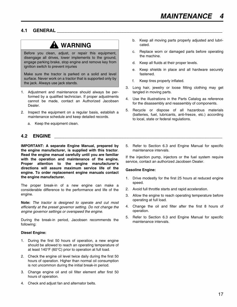
4 MAINTENANCE4.1 GENERAL ________________________________________________________________
1. Adjustment and maintenance should always be per-formed by a qualified technician. If proper adjustmentscannot be made, contact an Authorized JacobsenDealer.
2. Inspect the equipment on a regular basis, establish amaintenance schedule and keep detailed records.
a. Keep the equipment clean.
b. Keep all moving parts properly adjusted and lubri-cated.
c. Replace worn or damaged parts before operatingthe machine.
d. Keep all fluids at their proper levels.
e. Keep shields in place and all hardware securelyfastened.
f. Keep tires properly inflated.
3. Long hair, jewelry or loose fitting clothing may gettangled in moving parts.
4. Use the illustrations in the Parts Catalog as referencefor the disassembly and reassembly of components.
5. Recycle or dispose of all hazardous materials(batteries, fuel, lubricants, anti-freeze, etc.) accordingto local, state or federal regulations.
4.2 ENGINE _________________________________________________________________
IMPORTANT: A separate Engine Manual, prepared bythe engine manufacturer, is supplied with this tractor.Read the engine manual carefully until you are familiarwith the operation and maintenance of the engine.Proper attention to the engine manufacturer’sdirections will assure maximum service life of theengine. To order replacement engine manuals contactthe engine manufacturer.
The proper break-in of a new engine can make aconsiderable difference to the performance and life of theengine.
Note: The tractor is designed to operate and cut mostefficiently at the preset governor setting. Do not change theengine governor settings or overspeed the engine.
During the break-in period, Jacobsen recommends thefollowing:
Diesel Engine:
1. During the first 50 hours of operation, a new engineshould be allowed to reach an operating temperature ofat least 140°F (60°C) prior to operation at full load.
2. Check the engine oil level twice daily during the first 50hours of operation. Higher than normal oil consumptionis not uncommon during the initial break-in period.
3. Change engine oil and oil filter element after first 50hours of operation.
4. Check and adjust fan and alternator belts.
5. Refer to Section 6.3 and Engine Manual for specificmaintenance intervals.
If the injection pump, injectors or the fuel system requireservice, contact an authorized Jacobsen Dealer.
Gasoline Engine:
1. Drive modestly for the first 25 hours at reduced enginespeed.
2. Avoid full throttle starts and rapid acceleration.
3. Allow the engine to reach operating temperature beforeoperating at full load.
4. Change the oil and filter after the first 8 hours ofoperation.
5. Refer to Section 6.3 and Engine Manual for specificmaintenance intervals.
WARNINGBefore you clean, adjust, or repair this equipment,disengage all drives, lower implements to the ground,engage parking brake, stop engine and remove key fromignition switch to prevent injuries
Make sure the tractor is parked on a solid and levelsurface. Never work on a tractor that is supported only bythe jack. Always use jack stands.
!
17

4 MAINTENANCE
4.3 ENGINE OIL ______________________________________________________________
Check the engine oil at the start of each day, before startingthe engine. If the oil level is low, remove oil filler cap and addoil as required.
Diesel Engine:
Perform initial oil change after first 50 hours of operation andevery 100 hours thereafter. See Engine Manual.
Use only engine oils with API classification CD/CE.
Gas Engine:
Perform initial oil change after the first 8 hours of operation.Change oil every 50 hours thereafter.
See the engine manufacturer’s Owners’s Manual fordetailed service information.
After adding or changing oil, start and run engine at idle withall drives disengaged for 30 seconds. Shut engine off. Wait30 seconds and check oil level. Add oil to bring up to FULLmark on dipstick.
Use only engine oils with API classification SF, SG,SH.
Figure 4A
Figure 4B
4.4 GAS ENGINE AIR FILTER ___________________________________________________
1. Remove and service the foam pre-cleaner (A) every 25hours. Replace if dirty or damaged.
To service pre-cleaner, wash in a liquid detergent andwater. Squeeze dry in a clean cloth. Saturate in cleanengine oil and squeeze out excess oil in a clean,absorbent cloth.
2. Replace the air cleaner cartridge (B) every 100 hours,more often when operating in dusty conditions.
Note: Do not use petroleum solvents such as keroseneto clean cartridge. Do not use pressurized air to cleancartridge.
See the engine manufacturer’s Owners’s Manual fordetailed service information.
Figure 4C
Above 77°F (25°C) SAE 30W or SAE10W30/10W40
32 to 77°F (0 to 25°C) SAE 20W or SAE 10W30/10W40
Below 32° (0°C) SAE10W or SAE 10W30/10W40
Above 40° F (5° C) SAE 30W
0 to 40° F (-18 to 5° C) SAE 5W30 or SAE 10W30
Safe Operating Range⎧⎨ ⎪ ⎪⎪⎪⎩
Diesel Engine Dipstick
AD
DF
ULL
Gas Engine Dipstick
A
B
18

MAINTENANCE 4
4.5 DIESEL AIR FILTER ________________________________________________________
Check the service indicator daily. If red band appears in thewindow (C) replace the element.
Do not remove the element for inspection or cleaning.Unnecessary removal of the filter increases the risk ofinjecting dust and other impurities into the engine.
When service is required, first clean the outside of the filterhousing; then remove the old element as gently as possibleand discard.
1. Carefully clean the inside of the filter housing withoutallowing dust into the air intake.
2. Inspect the new element. Do not use a damagedelement and never use an incorrect element.
3. Assemble the new element and make sure it seatsproperly. Reset the indicator by depressing button (D).
4. Reassemble cap making sure it seals completelyaround the filter housing. Dust evacuator (E) must befacing down.
5. Check all hoses and air ducts. Tighten hose clamps.
Figure 4D
4.6 FUEL ____________________________________________________________________
Handle fuel with care - it is highly flammable. Use anapproved container, the spout must fit inside the fuel fillerneck. Avoid using cans and funnels to transfer fuel.
• Fill the fuel tank to within 1 in. (25 mm) of the bottom ofthe filler neck.
• Store fuel according to local, state or federal ordinancesand recommendations from your fuel supplier.
• Never overfill or allow the tank to become empty.
• Check fuel lines and clamps every 50 hours. Replace fuellines and clamps at the first sign of damage.
Diesel Engine:
• Use clean, fresh, #2 Diesel fuel. Minimum Cetane rating45. Refer to Engine Manual for additional information.
Gas Engine:
• Use clean, fresh, regular grade, unleaded gasolineminimum 85 Octane.
• Do not use hi-test gasoline or an oil-gasoline mixture.When using blended fuel, do not use a blend with morethan 10% ethanol. Under no circumstances should youuse a blend with methanol.
4.7 FUEL SYSTEM ____________________________________________________________
Refer to Section 6.3 for specific maintenance intervals.
Before replacing any filter, thoroughly clean the filterhousing and the area around the filter. Dirt must not beallowed to enter into fuel system.
For diesel engines, bleed the fuel system after the fuel filterand lines have been removed, or the fuel tank has becomeempty. See Engine Manual.
C
D
E
WARNINGNever remove the fuel cap from the fuel tank, or add fuel,when the engine is running or while the engine is hot.
Do not smoke when handling fuel. Never fill or drain thefuel tank indoors.
Do not spill fuel and clean spilled fuel immediately.
Never handle or store fuel containers near an open flameor any device that may create sparks and ignite the fuelor fuel vapors.
Be sure to reinstall and tighten fuel cap securely.
!
19

4 MAINTENANCE
4.8 BATTERY ________________________________________________________________
Make absolutely certain the ignition switch is “Off” and thekey has been removed before servicing the battery.
Tighten cables securely to battery terminals and apply alight coat of silicone dielectric grease to terminals and cableends to prevent corrosion. Keep vent caps and terminalcovers in place
Check the electrolyte level every 100 hours. Keep the cableends, battery and battery posts clean.
Verify battery polarity before connecting or disconnectingthe battery cables.
1. When installing the battery, always assemble the RED,positive (+) battery cable first and the ground, BLACK,negative (-) cable last.
2. When removing the battery, always remove theground, BLACK, negative (-) cable first and the RED,positive (+) cable last.
3. Make sure battery is properly installed and secured tothe battery tray.
4.9 JUMP STARTING __________________________________________________________
Before attempting to “jump start” the tractor, check thecondition of the discharged battery. Section 4.8
When connecting jumper cables:
1. Stop the engine on the vehicle with a good battery.
2. Connect RED jumper cable to the positive (+) terminalon the good battery and to the positive (+) terminal onthe “discharged” battery.
3. Connect the BLACK jumper cable from the negative(-) terminal on the good battery to the frame of thetractor with the discharged battery.
After cables have been connected, start the engine on thevehicle with the good battery then start the tractor.
4.10 CHARGING BATTERY _____________________________________________________
1. Refer to Section 4.8. Read the Battery and Charger’smanual for specific instructions.
2. Whenever possible, remove the battery from the tractorbefore charging. If battery is not sealed, check that theelectrolyte covers the plates in all the cells.
3. Make sure the charger is “Off”. Then connect thecharger to the battery terminals as specified in thecharger’s manual.
4. Always turn the charger “Off” before disconnectingcharger from the battery terminals.
CAUTIONAlways use insulated tools, wear protective glasses orgoggles and protective clothing when working withbatteries. You must read and obey all batterymanufaturer’s instructions.
!
WARNINGBattery posts, terminals and related accessoriescontain lead and lead compounds, chemicals knownto the State of California to cause cancer andreproductive harm. Wash your hands afterhandling.
!
WARNINGBatteries generate explosive hydrogen gas. To reducethe chance of an explosion, avoid creating sparks nearbattery. Always connect the negative jumper cable to theframe of the tractor with the discharged battery, awayfrom the battery.
!
WARNINGCharge battery in a well ventilated area. Batteriesgenerate explosive gases. To prevent an explosion, keepany device that may create sparks or flames away fromthe battery.
To prevent injury, stand away from battery when thecharger is turned on. A damaged battery could explode.
!
20
MAINTENANCE 4
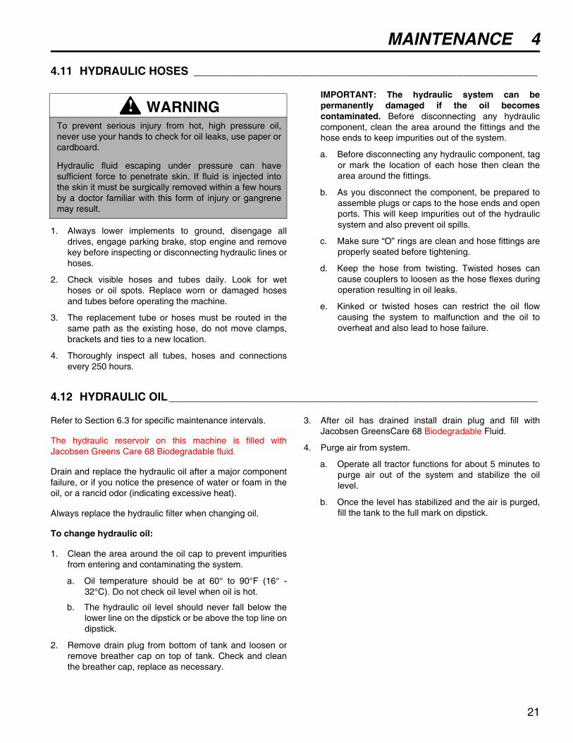
4.11 HYDRAULIC HOSES _______________________________________________________
1. Always lower implements to ground, disengage alldrives, engage parking brake, stop engine and removekey before inspecting or disconnecting hydraulic lines orhoses.
2. Check visible hoses and tubes daily. Look for wethoses or oil spots. Replace worn or damaged hosesand tubes before operating the machine.
3. The replacement tube or hoses must be routed in thesame path as the existing hose, do not move clamps,brackets and ties to a new location.
4. Thoroughly inspect all tubes, hoses and connectionsevery 250 hours.
IMPORTANT: The hydraulic system can bepermanently damaged if the oil becomescontaminated. Before disconnecting any hydrauliccomponent, clean the area around the fittings and thehose ends to keep impurities out of the system.
a. Before disconnecting any hydraulic component, tagor mark the location of each hose then clean thearea around the fittings.
b. As you disconnect the component, be prepared toassemble plugs or caps to the hose ends and openports. This will keep impurities out of the hydraulicsystem and also prevent oil spills.
c. Make sure “O” rings are clean and hose fittings areproperly seated before tightening.
d. Keep the hose from twisting. Twisted hoses cancause couplers to loosen as the hose flexes duringoperation resulting in oil leaks.
e. Kinked or twisted hoses can restrict the oil flowcausing the system to malfunction and the oil tooverheat and also lead to hose failure.
4.12 HYDRAULIC OIL___________________________________________________________
Refer to Section 6.3 for specific maintenance intervals.
The hydraulic reservoir on this machine is filled withJacobsen Greens Care 68 Biodegradable fluid.
Drain and replace the hydraulic oil after a major componentfailure, or if you notice the presence of water or foam in theoil, or a rancid odor (indicating excessive heat).
Always replace the hydraulic filter when changing oil.
To change hydraulic oil:
1. Clean the area around the oil cap to prevent impuritiesfrom entering and contaminating the system.
a. Oil temperature should be at 60° to 90°F (16° -32°C). Do not check oil level when oil is hot.
b. The hydraulic oil level should never fall below thelower line on the dipstick or be above the top line ondipstick.
2. Remove drain plug from bottom of tank and loosen orremove breather cap on top of tank. Check and cleanthe breather cap, replace as necessary.
3. After oil has drained install drain plug and fill withJacobsen GreensCare 68 Biodegradable Fluid.
4. Purge air from system.
a. Operate all tractor functions for about 5 minutes topurge air out of the system and stabilize the oillevel.
b. Once the level has stabilized and the air is purged,fill the tank to the full mark on dipstick.
WARNINGTo prevent serious injury from hot, high pressure oil,never use your hands to check for oil leaks, use paper orcardboard.
Hydraulic fluid escaping under pressure can havesufficient force to penetrate skin. If fluid is injected intothe skin it must be surgically removed within a few hoursby a doctor familiar with this form of injury or gangrenemay result.
!
21

4 MAINTENANCE
22
4.13 HYDRAULIC OIL FILTERS __________________________________________________
The hydraulic system is protected by two 10 micron filters.
To replace hydraulic oil filter:
1. Remove the old filters.
2. Fill new filter with oil then install new filter. Handtighten only.
3. Operate engine at idle speed with hydraulic system inneutral for five minutes.
4. Check hydraulic oil level in reservoir and fill to full markon dipstick.
4.14 ELECTRICAL SYSTEM _____________________________________________________
General precautions that can be taken to reduce electricalproblems are listed below.
1. Make certain all terminals and connections are cleanand properly secured.
2. Check the operator backup system, fuses and circuitbreakers regularly.
If the operator backup does not function properly andthe problem cannot be corrected, contact an authorizedJacobsen Dealer.
3. Keep the wire harness and all individual wires awayfrom moving parts to prevent damage.
4. Make sure the seat switch harness is connected to themain wire harness.
5. Check the battery and battery charging circuit.
6. Do not wash or pressure spray around electricalconnections and components.
4.15 MUFFLER AND EXHAUST __________________________________________________
To protect from carbon monoxide poisoning, inspect thecomplete exhaust system regularly and always replace adefective muffler.
If you notice a change in the color or sound of the exhaust,stop the engine immediately. Identify the problem and havethe system repaired.
Torque all exhaust manifold hardware evenly. Tighten orreplace exhaust clamps.
4.16 TIRES ___________________________________________________________________
1. Keep tires properly inflated to prolong tire life. Checkinflation pressure while the tires are cool. Inspect treadwear.
6. Check the pressure with an accurate, low pressure tiregauge.
7. Keep tires inflated to:
Front - 10-12 psi - (69-83 kPa)
Rear - 8-10 psi (55-69 kPa)
CAUTIONAlways turn the ignition switch off and remove thenegative battery cable (Black) before inspecting orworking on the electrical system.
!
WARNINGExhaust fumes contain carbon monoxide that is toxic andcan be fatal when inhaled.
NEVER operate an engine without proper ventilation.
!
CAUTIONUnless you have the proper training, tools andexperience, DO NOT attempt to mount a tire on a rim.Improper mounting can produce an explosion whichmay result in serious injury.
!
MAINTENANCE 4
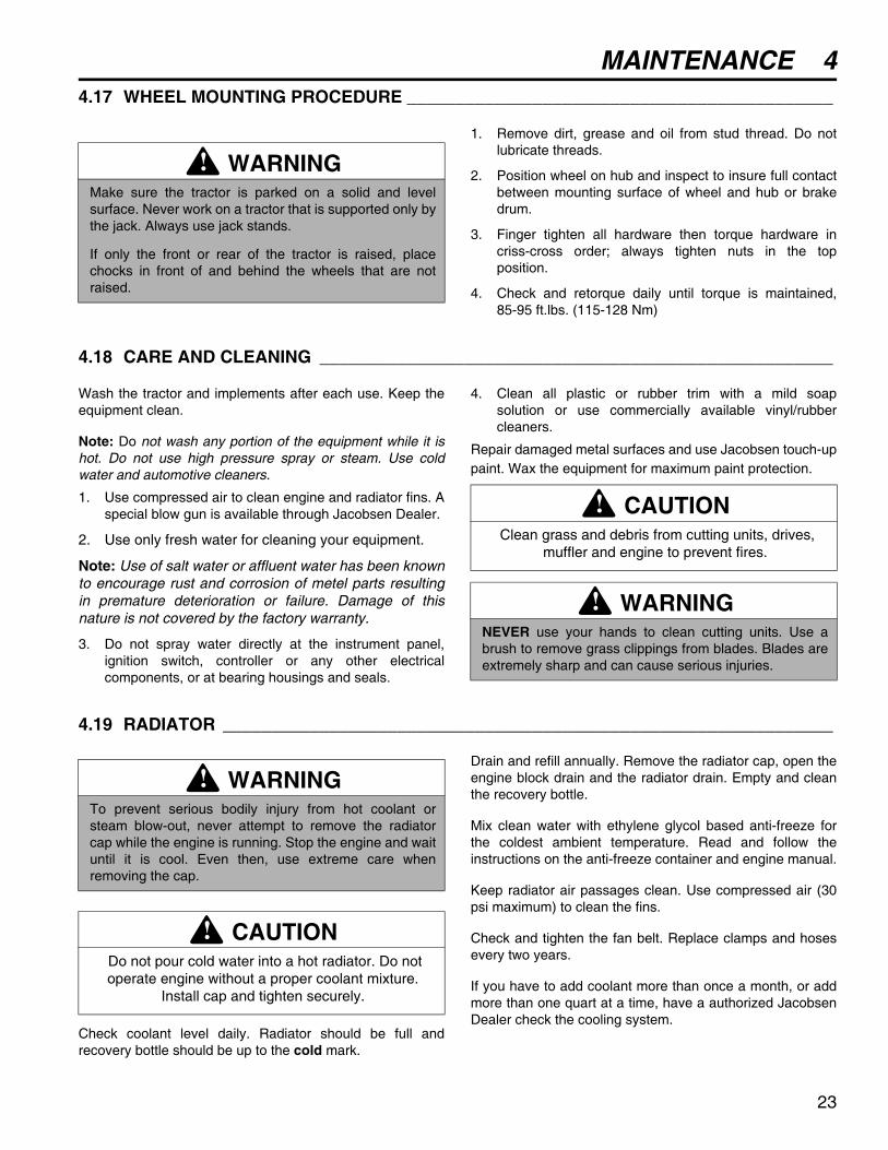
4.17 WHEEL MOUNTING PROCEDURE ____________________________________________1. Remove dirt, grease and oil from stud thread. Do notlubricate threads.
2. Position wheel on hub and inspect to insure full contactbetween mounting surface of wheel and hub or brakedrum.
3. Finger tighten all hardware then torque hardware incriss-cross order; always tighten nuts in the topposition.
4. Check and retorque daily until torque is maintained,85-95 ft.lbs. (115-128 Nm)
4.18 CARE AND CLEANING _____________________________________________________
Wash the tractor and implements after each use. Keep theequipment clean.
Note: Do not wash any portion of the equipment while it ishot. Do not use high pressure spray or steam. Use coldwater and automotive cleaners.
1. Use compressed air to clean engine and radiator fins. Aspecial blow gun is available through Jacobsen Dealer.
2. Use only fresh water for cleaning your equipment.
Note: Use of salt water or affluent water has been knownto encourage rust and corrosion of metel parts resultingin premature deterioration or failure. Damage of thisnature is not covered by the factory warranty.
3. Do not spray water directly at the instrument panel,ignition switch, controller or any other electricalcomponents, or at bearing housings and seals.
4. Clean all plastic or rubber trim with a mild soapsolution or use commercially available vinyl/rubbercleaners.
Repair damaged metal surfaces and use Jacobsen touch-uppaint. Wax the equipment for maximum paint protection.
4.19 RADIATOR _______________________________________________________________
Check coolant level daily. Radiator should be full andrecovery bottle should be up to the cold mark.
Drain and refill annually. Remove the radiator cap, open theengine block drain and the radiator drain. Empty and cleanthe recovery bottle.
Mix clean water with ethylene glycol based anti-freeze forthe coldest ambient temperature. Read and follow theinstructions on the anti-freeze container and engine manual.
Keep radiator air passages clean. Use compressed air (30psi maximum) to clean the fins.
Check and tighten the fan belt. Replace clamps and hosesevery two years.
If you have to add coolant more than once a month, or addmore than one quart at a time, have a authorized JacobsenDealer check the cooling system.
WARNINGMake sure the tractor is parked on a solid and levelsurface. Never work on a tractor that is supported only bythe jack. Always use jack stands.
If only the front or rear of the tractor is raised, placechocks in front of and behind the wheels that are notraised.
!
CAUTION Clean grass and debris from cutting units, drives,
muffler and engine to prevent fires.
WARNINGNEVER use your hands to clean cutting units. Use abrush to remove grass clippings from blades. Blades areextremely sharp and can cause serious injuries.
!
!
WARNINGTo prevent serious bodily injury from hot coolant orsteam blow-out, never attempt to remove the radiatorcap while the engine is running. Stop the engine and waituntil it is cool. Even then, use extreme care whenremoving the cap.
CAUTION Do not pour cold water into a hot radiator. Do not operate engine without a proper coolant mixture.
Install cap and tighten securely.
!
!
23

4 MAINTENANCE
4.20 BACKLAPPING ___________________________________________________________
Check the reel and bedknife to determine if backlapping orgrinding will restore the cutting edge.
If wear or damage is beyond the point where the cuttingedges can be corrected by the lapping process, they mustbe reground.
To Backlap:
1. Adjust reel to bedknife as described in Sections 3.13and 3.14.
2. Obtain and engage the mechanics (backlap) key.
a. Make absolutely certain your feet and clothing arefar away from the reel.
b. Make sure the parking brake is “ENGAGED”, reelswitch is “OFF”, backlap switch is “OFF” and thetraction pedal is in neutral.
c. Start the engine, turn the mechanics key to“BACKLAP” then engage the reel switch. If any ofthe reels turn, adjust nut (A) to stop the reel.
3. Turn nut (A) on the reel to be backlapped so the reelturns in reverse. Adjust the reel speed to 100-150RPM.
a. Apply lapping compound with a long handle brushto high spots first then along entire length of thereel.
b. Continue lapping and at the same time make aslight adjustment on the reel until there is a uniformclearance along the full length of the cutting edges.
c. When the blades have been evenly honed, turnadjusting nut (A) to neutral. Carefully andthoroughly remove all lapping compound from reelsand bedknife before running the reel in forwarddirection.
d. Disengage reel switch and turn backlap switch to“OFF”.
4. Reset reel motors to forward rotation. If reel speedsvary, check nut (A) to insure it is turned completely tofull forward rotation.
5. Remove and store the backlap key.
Figure 4E
WARNINGTo prevent injury, keep hands, feet and clothing awayfrom rotating reels.
When the backlap switch is in the BACKLAP position, thereels will turn without the operator in the seat.
Carbon Monoxide in exhaust fumes can be fatal wheninhaled, never operate an engine without properventilation.
!
A
24

MAINTENANCE 4
4.21 STORAGE ________________________________________________________________
General
1. Wash the tractor thoroughly and lubricate. Repair andpaint damaged or exposed metal.
2. Inspect the tractor, tighten all hardware, replace wornor damaged components.
3. Drain and refill radiator.
4. Clean the tires thoroughly and store the tractor so theload is off the tires. If tractor is not on jack stands,check tires at regular intervals and reinflate asnecessary.
5. Keep the machine and all its accessories clean, dryand protected from the elements during storage. Neverstore equipment near an open flame or spark whichcould ignite fuel or fuel vapors.
Battery
1. Remove, clean and store battery in upright position in acool, dry place.
2. Check and recharge battery every 60 to 90 days whilein storage.
3. Store batteries in a cool, dry place. To reduce the selfdischarge rate, room temperature should not be above80°F (27°C) or fall below 20°F (-7°C) to preventelectrolyte from freezing.
Engine (General)
1. While the engine is warm, remove the drain plug, drainthe oil from the crankcase and change oil filter. Installdrain plug and refill with fresh oil. Let engine cool beforestarting.
2. Clean exterior of engine. Paint exposed metal, or applya light coat of rust preventative oil.
Diesel Engine - Add a fuel conditioner or biocide to preventgelling or bacterial growth in fuel. See your local fuelsupplier.
Gas Engine - For engine protection Jacobsen recommendsthe use of a fuel additive such as STABIL®. Mix additivefollowing instructions on container. Run engine for a shorttime to circulate additive through carburetor.
Remove spark plugs and pour 1 oz. (30 ml) of engine oil intoeach cylinder. Replace spark plugs and crank slowly (do notstart) to distribute oil in cylinder.
If storing indoors, drain fuel from tank.
Note: Do not use fuel with ethanol during storage.
Cutting Units
1. Wash the cutting units thoroughly, then repair and paintany damaged or exposed metal.
2. Lubricate all fittings and friction points.
3. Backlap the reels then back the reel away from thebedknife. Apply a light coat of rust preventative oil tothe sharpened edges of the reel and bedknife.
After Storage
1. Check and reinstall battery
2. Check or service fuel filter and air cleaner.
3. Check the radiator coolant level.
4. Check oil level in the engine crankcase and hydraulicsystem.
5. Fill the fuel tank with fresh fuel. Bleed the fuel system.
6. Make certain that the tires are properly inflated.
7. Remove all oil from the reels and bedknife. Adjustbedknife and cutting height.
8. Start and operate the engine at 1/2 throttle. Allowenough time for the engine to become properlywarmed and lubricated.
CAUTION To prevent personal injury and damage to the cutting
edges, handle the reel with extreme care
WARNINGNever operate the engine without proper ventilation;exhaust fumes can be fatal when inhaled.
!
!
25

5 TROUBLESHOOTING
26
5 TROUBLESHOOTING
5.1 GENERAL________________________________________________________________
The troubleshooting chart below lists basic problems that may occur during start-up and operation. For more detailedinformation regarding the hydraulic and electrical systems contact your area Jacobsen Dealer.
Symptoms Possible Causes ActionEngine will not start. 1. Parking brake disengaged, trac-
tion pedal not in neutral or reel/3WD switch on.
1. Check operator back-up system and start-up proce-dure.
2. Battery low on charge or defective.
2. Inspect condition of battery and battery connections.
3. Fuel tank empty or dirty. 3. Fill with fresh fuel. Change fuel filter. Bleed fuel lines.
4. Fuse blown. 4. Replace fuse.
Engine hard to start or runs poorly.
1. Fuel level low, fuel or fuel filter dirty.
1. Fill with fresh fuel. Change fuel filter. Bleed fuel lines.
2. Air cleaner dirty. 2. Inspect and replace air filter.
3. Injectors, fuel pump 3. Consult engine manual.
4. Engine problem. 4. Consult engine manual
Engine stops. 1. Fuel tank empty. 1. Fill with fresh fuel and bleed fuel lines.
2. Interlocks not set before leaving operator’s seat.
2. Engage parking brake, move traction lever to “N” and set reel control to OFF.
Engine overheating 1. Coolant level low.(Diesel) 1. Inspect and add coolant.
2. Air intake restricted. 2. Clean cooling air intake.
3. Water pump belt broken or loose.(Diesel)
3. Tighten or replace belt.
4. Engine overload 4. Reduce forward speed
Battery not holding charge.
1. Loose or corroded battery termi-nals.
1. Inspect and clean terminals
2. Low electrolyte. 2. Refill to correct level.
3. Alternator belt loose or broken. 3. Tighten or replace belt
4. Charging system defective. 4. See engine manual
Reels cut unevenly 1. Bedknife-to-reel not adjusted cor-rectly.
Inspect bedknife-to-reel adjustment.
2. Engine speed too low. Check engine speed. Run engine at full throttle.
3. Low hydraulic oil Check reservoir level and fill if needed.
Tractor does not reactto traction pedal
1. Parking brake engaged Disengage parking brake.
2. Tow Valve Open Close Tow Valve
3. Low hydraulic oil Check reservoir level and fill if needed
Implement does notraise or lower
1. Low hydraulic oil Check reservoir level and fill as needed
Gauges/Indicator notoperating
1. Circuit Breaker Reset circuit breaker, check bulb
2. Loose wiring Check electrical connections.

MAINTENANCE & LUBRICATION CHARTS 6
6 MAINTENANCE & LUBRICATION CHARTS6.1 GENERAL ________________________________________________________________
1. Always clean the grease fitting before and afterlubricating.
2. Lubricate with grease that meets or exceeds NLGIGrade 2 LB specifications. Apply grease with amanual grease gun and fill slowly until grease beginsto seep out. Do not use compressed air guns.
3. Periodically apply a small amount of lithium basedgrease to the seat runners.
4. For smooth operation of all levers, pivot points andother friction points that are not shown on thelubrication chart apply several drops of SAE 30 oilevery 40 hours or as required.
5. Grease fittings (A - F) every 50 hours and fittings (G -K) every 100 hours.
6.2 LUBRICATION CHART______________________________________________________
WARNINGBefore you clean, adjust, or repair this equipment,disengage all drives, lower implements to the ground,engage parking brake, stop engine and remove keyfrom ignition switch to prevent injuries
!
A. Mower Pivot (3 Fittings)B. Front Lift Arms (2 Fittings)C. Crank HubD. Hydraulic CylinderE. Center Lift Arm
F. Control Pedal Pivot (2 Fittings)G. Steering YokeH. Drive Shaft Bearings (2 Fittings)J. Reel Bearings (6 Fittings)K. Rollers (As Required)
A
BC
D
EF
G
H
J
J
J
J
A
B
F
27

6 MAINTENANCE & LUBRICATION CHARTS
28
6.3 MAINTENANCE CHARTS ___________________________________________________
A - Add or Adjust C - Clean I - Inspect L- Lubricate R - Replace AR - As Required * Indicates initial service for new machines.
** Every 250 hours, or yearly whichever comes first.
*** Inspect visible hoses and tubes for leaks or oil marks.
I - Manual grease gun with NLGI Grade 2 (Service Class LB).
II - Engine Oil - See Section 4.3
III - Use Jacobsen GreensCare 68 Biodegradable fluid: Capacity: 5 gallons (19 Liters). Order Part No. 5003103 containing 5 gal. (19 l), pail or Part No. 5003102, 55 gal. (208 l) Drum.
IV - Capacity: 3qt. (2.8 l) 50/50 water ethylene glycol mix
Recommended Service and Lubrication Intervals
Every8-10
Hours
Every50
Hours
Every100
Hours
Every250
Hours
Every 400
Hours
Every500
Hours
Every1000
Hours
Yearly See Section
LubricantType
Air Filter (Diesel) I AR R 4.5Air Filter (Gas) I C R R 4.4Battery Charge I 4.8Belts I-A* I-A R 3.2,
3.3Brake I-A* A 3.10Cooling System (Diesel) I-C-A R 4.19 IVElectrical System I* I 4.14Engine Oil (Diesel) I R* R 4.3 IIEngine Oil (Gas) I-R* R 4.3 IIEngine Oil Filter R* RFuel System I 4.7Fuel Filter R 4.7Grease Fittings - All L L L L 6.2 IHydraulic Hoses and Tubes I*** I 4.11Hydraulic Oil I-A R** R** 4.12 IIIHydraulic Oil Filter I R* R 4.13Muffler and Exhaust I I 4.15Radiator Screens I-C/AR 4.19Tires I-A 4.16

PARTS CATALOG 7
29
7 PARTS CATALOG
7.1 TABLE OF CONTENTS
1.1.................................................................................Decals..................................................................................................... 302.1.................................................................................Hood and Cowlings............................................................................... 323.1.................................................................................Seat and Base........................................................................................ 343.2.................................................................................Seat and Base........................................................................................ 364.1.................................................................................Dash Installation.................................................................................... 385.1.................................................................................Instrument Panel ................................................................................... 406.1.................................................................................Hydro Control Linkage.......................................................................... 427.1.................................................................................Front Motors and Brakes...................................................................... 448.1.................................................................................Parking Brake, Neutral Start and 3WD Switches................................ 469.1.................................................................................Fuel Control ........................................................................................... 4810.1............................................................................... Fuel Control .......................................................................................... 5011.1...............................................................................Frame...................................................................................................... 5212.1...............................................................................Frame...................................................................................................... 5313.1...............................................................................Rear Steering ......................................................................................... 5414.1...............................................................................Engine and Pump .................................................................................. 5615.1...............................................................................Engine and Exhaust .............................................................................. 5816.1...............................................................................Air Intake ................................................................................................ 6017.1...............................................................................Engine and Pump .................................................................................. 6218.1...............................................................................Diesel Engine Mounting........................................................................ 6419.1...............................................................................Diesel Engine Exhaust.......................................................................... 6620.1...............................................................................Radiator Installation.............................................................................. 6820.2...............................................................................Radiator Installation.............................................................................. 7021.1...............................................................................Air Filter and Circuit Breaker ............................................................... 7222.1...............................................................................Tanks ...................................................................................................... 7423.1...............................................................................Hydro Pump and Charge Filter ............................................................ 7624.1...............................................................................Pump Suction and Return Hydraulics................................................. 7825.1...............................................................................Pump Suction and Return Hydraulics................................................. 8026.1...............................................................................Traction Hydraulics............................................................................... 8226.2...............................................................................Steering and Lift Hydraulics................................................................. 8427.1...............................................................................Reel Hydraulics ..................................................................................... 8628.1...............................................................................Reel Lift .................................................................................................. 8829.1...............................................................................Rear Lift Arm.......................................................................................... 9030.1...............................................................................Reels....................................................................................................... 9231.1...............................................................................Roller Brackets and Skids .................................................................... 9332.1...............................................................................Reel Bearing Housing ........................................................................... 9433.1...............................................................................Shields and Center Pivot Arm.............................................................. 9634.1...............................................................................Side Pivot and Lift Arms....................................................................... 9835.1...............................................................................Down Pressure Kit .............................................................................. 10036.1...............................................................................Reel Pump............................................................................................ 10137.1...............................................................................Reel Motor............................................................................................ 10238.1...............................................................................Traction Pump ..................................................................................... 10439.1...............................................................................3WD Valve ............................................................................................ 10640.1...............................................................................Brake Calipers ..................................................................................... 10741.1...............................................................................Electrical Schematics ......................................................................... 10842.1...............................................................................Hydraulic Schematic ........................................................................... 11043.1...............................................................................O-Ring Chart ........................................................................................ 112

TRI-KING
30
Tri-King xxxx
with GreensCare
Tri-King 1800GTri-King 1900D
IMPORTANTThis machine uses GreensCare 68,
biodegrable hydraulic fluid.(Order 5003103 for 5 gal. pail)
IMPORTANTDo not overfill or spill oil Always lower lift arms to check oradd oil.
To prevent burns, do not touchmuffler or muffler shield.
Temperatures may exceed 150¡F (66¡C)
! WARNING
To prevent injury:
● Always connect red battery cable to the positive (+) post FIRST and the black cable to negative (–) post LAST.● When removing the battery always remove negative (–) cable FIRST and positive (+) cable LAST.● Avoid contact with battery acid.● Keep sparks and flames away from the battery.● Do not short circuit battery posts. Do not touch frame or negative terminal when working on positive terminal.
! DANGER
To Install the battery1. Install the battery with terminals toward rear.2. Secure battery to support.3. Connect positive (+) (red) FIRST.4. Connect negative (–) (black) LAST.
To use jumper cablee:1. Stop the engine on vehicle with good battery.2. Connect RED cable to positive (+) terminal on good battery and positive (+) terminal on "discharged" battery.3. Connect the BLACK cable from negative (–) terminal on good battery to frame of vechile with discharged battery.4. Start the engine.
! CAUTION
Gas Units
Diesel Units
Diesel Units Diesel Units
THIS RADIATOR CONTAINS
ANTI-FREEZEPROTECTED TO -26 F (-32 C)
Mix equal parts of clean water and a premiumquality ethylene glycol based anti-freeze tomaintain the boil over, rust and corrosionprotection.
Drain and discard coolant yearly. Read manualfor additional instructions.
Radiator is under pressure. Removecap slowly to avoid personal injury
! WARNING
OPERATIONREAD MANUAL BEFORE OPERATING.
MANUALS AVAILABLE FROM: JACOBSEN/TEXTRON, RACINE WI.
To Start
To Drive / Transport
To Stop
To Mow
To Backlap
Parking Brake
1. Parking brake........On2. Hydro pedal.....Neutral3. Reel switch.........Off4. Depress glow plug switch for 3 to 5 seconds.5. Start Engine.
1. Parking brake....Off2. Reel switch.......On3. Slowly depress hydro pedal.4. Depress top of mow pedal to lower and engage reels. Lift mow pedal to raise and stop reels.
1. Engage parking brake2. Turn backlap lockout key to backlap position3. Turn all 3 backlapping nuts to neutral position.4. Start engine. Set throttle to minimum idle speed.5. Engage reels. Turn backlap nut on one reel to backlap at desired speed.6. With extreme caution apply lapping compound with a long handled brush.7. Turn backlap nut to neutral position after backlapping is complete.8. Repeat above steps on remaining reels.
1. Parking brake....Off2. Slowly depress hydro pedal.
1. Remove foor from hydro pedal.2. Engage parking brake.3. Turn ignition to off.4. Remove key.
Important: When operating on inclines maintain engine speed and reduce forwardspeed. Warranty is void if tractor is used for towing. Do not use start assist fluids.Use of such fluids in the air intake system may be potentially explosiveor cause a 'runaway' engine condition that would result is serious engine damage.
Vehicle weight wet: 1720 lbs. - 780 kg.Vehicle horsepower: 19 hp. - 14.2 kw. at 3400 r.p.m.
1
2
3
4
5 / 6
7 / 89
29
10
11
12
13
24
14
15
27
15
16
17
18
19
22
23
20
21
28
26
25
BIODEGRADABLE FLUID
105dB
LWA
11
1. Leer el manual del operador. No permitir que personas no capacitadas para ello usen la maquina2. Mantenae los escudos en su lugar y la tornilleria debidamente fijada.3. Antes de limpiar, ajustar o reparar este equipo, desengranar todas los mandos, aplicar el freno de estacionamiento y apagar el motor.4. Mantener las manos, los pies y la ropa alejados de las piezas en movimiento.5. No viajar como pasajeros ni llevar pasajeros en maquinas sin asiento para ellos.6. Mantener a las demas personas alejadas7. Si no sabe leer ingles, solicitarle a otra persona que le lea y explique el contenido de las etiquetas y del manual de la maquina.
! ADVERTENCIA
1
4
3
2
CHARLOTTE, NC
YEAR OFPRODUCTION:
MADE IN U.S.A.
®
A Textron Company
Manufactured under one or moreof the following U.S. Patents:
53096995941057
6698171
58967346412258
1.1 Decals Serial No. All

TRI-KING
31
> Change from previous revision
Item Part No. Qty. Description Serial Numbers/Notes
1 367160 1 Decal, Battery Caution2 367159 1 Decal, Battery Danger3 2812032 1 Decal, Hydraulic Fluids4 361615 1 Decal, Oil Overfill5 4124358 1 Decal, Right Side Stripe6 4124357 1 Decal, Left Side Stripe7 4124790 1 Decal, Jacobsen 12”8 4125789 1 Decal, Jacobsen 10”9 3004653 1 Decal, Operating Instructions Gas9 3003590 1 Decal, Operating Instructions Diesel
10 3002053 1 Decal, Backlap Switch11 340623 1 Decal, Spanish Caution12 3003349 1 Decal, Lift/Lower13 3003594 1 Decal, Caution14 3003348 1 Decal, Forward/Reverse15 3004983 1 Decal, Dash Overlay Gas15 3003350 1 Decal, Dash Overlay Diesel16 3003606 1 Decal, Fuse Panel17 363995 1 Decal, Antifreeze Diesel18 339237 1 Decal, Heat Warning Located on Hood Pivot19 365956 1 Decal, Radiator Warning Diesel - Located on Radiator20 4124759 1 Decal, Jacobsen Emblem21 4111408 1 Decal, Biodegradable Fluids22 4124690 2 Decal, Tri-King 1800G Gas22 4124691 2 Decal, Tri-King 1900D Diesel23 3004207 1 Decal, Opening Hood24 REF 1 Serial Plate On Left Front Wheel Motor Mount25 4125772 1 Decal, Patent26 4117468 1 Decal, Noise 105 dB27 2811597 1 Decal, Parking Brake Light28 4124721 1 Decal, GreensCare
> 29 4141266 1 Decal, Oil
Read manual before operating machine.Use caution while operating on slopes, especially when grassis wet. Wet grass reduces traction and steering control● Do not use this machine on slopes greater than 16.2● Always keep reels in mow position when operating on slopes and travel at reduced speeds.● Do not make sharp maneuvers when on slopes.● Keep shields in place and hardware securely fastened.● Before you clean, adjust or repair this equipment, disengage all drives, stop engine and apply brake.● Keep hands, feet and clothing away from moving parts.● Never carry passengers.● Keep bystanders away.
! WARNING FUSE PANEL
SPARE
SPARE
SPARE
SPARE
3
3
7.5
7.5
GAGES
3WDVALVE
REELCLUTCH
LIGHTS(OPTIONAL)
12
13
14
10
16
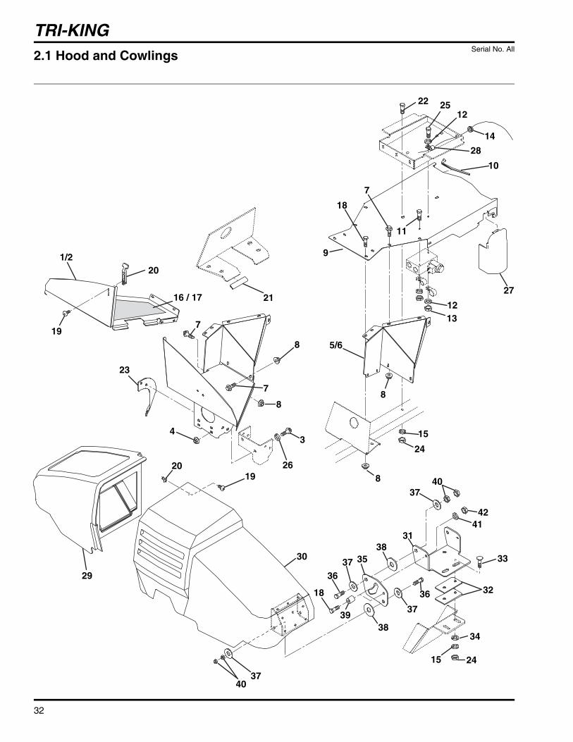
TRI-KING
32
1/2
34
5/6
7
8
26
8
7
19
20
1920
23
29
30
25
27
7
18
11
10
22
28
14
1213
9
12
8
8
24
15
2116 / 17
3740
18
39
3835
15 24
34
32
33
4142
31
38
40
3736
37
36
37
2.1 Hood and Cowlings Serial No. All
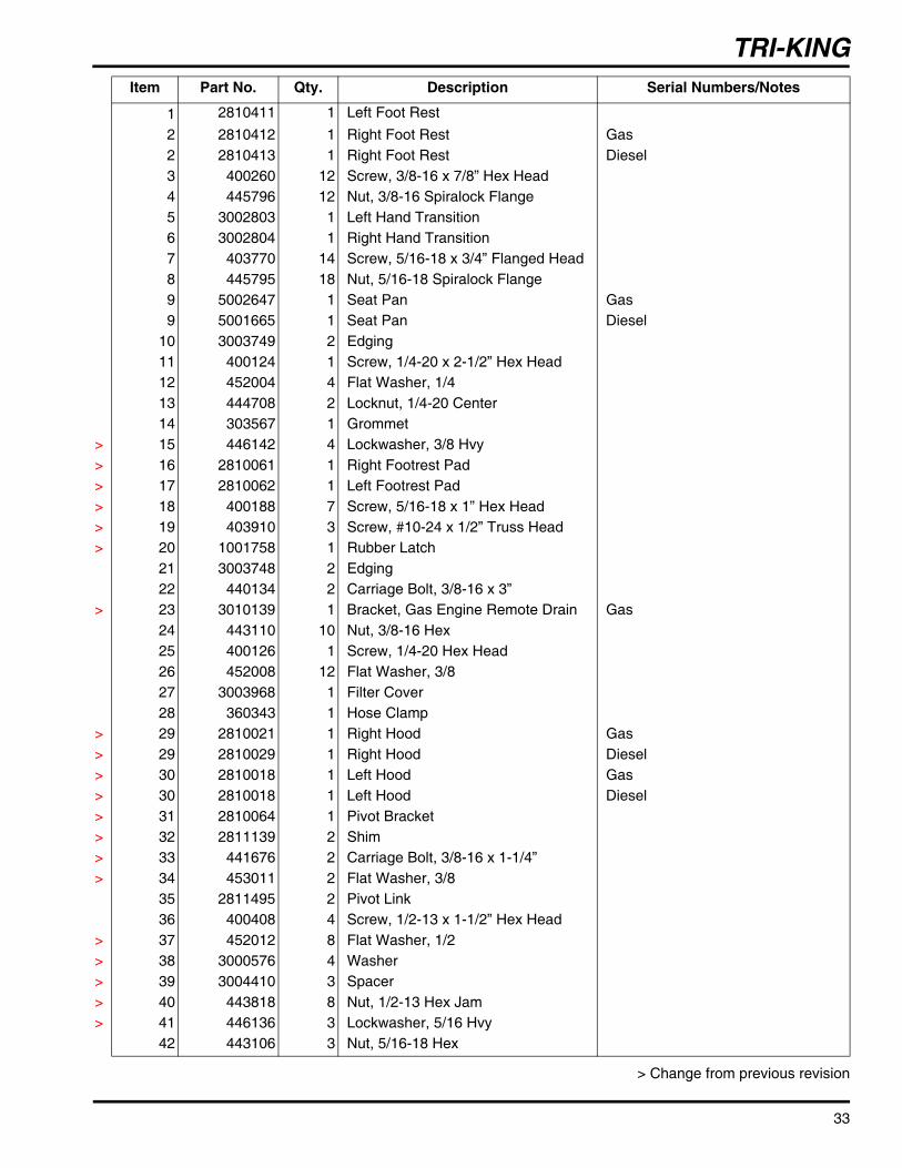
TRI-KING
33
> Change from previous revision
Item Part No. Qty. Description Serial Numbers/Notes
1 2810411 1 Left Foot Rest2 2810412 1 Right Foot Rest Gas2 2810413 1 Right Foot Rest Diesel3 400260 12 Screw, 3/8-16 x 7/8” Hex Head4 445796 12 Nut, 3/8-16 Spiralock Flange5 3002803 1 Left Hand Transition6 3002804 1 Right Hand Transition7 403770 14 Screw, 5/16-18 x 3/4” Flanged Head8 445795 18 Nut, 5/16-18 Spiralock Flange9 5002647 1 Seat Pan Gas9 5001665 1 Seat Pan Diesel
10 3003749 2 Edging11 400124 1 Screw, 1/4-20 x 2-1/2” Hex Head12 452004 4 Flat Washer, 1/413 444708 2 Locknut, 1/4-20 Center14 303567 1 Grommet
> 15 446142 4 Lockwasher, 3/8 Hvy> 16 2810061 1 Right Footrest Pad> 17 2810062 1 Left Footrest Pad> 18 400188 7 Screw, 5/16-18 x 1” Hex Head> 19 403910 3 Screw, #10-24 x 1/2” Truss Head> 20 1001758 1 Rubber Latch
21 3003748 2 Edging22 440134 2 Carriage Bolt, 3/8-16 x 3”
> 23 3010139 1 Bracket, Gas Engine Remote Drain Gas24 443110 10 Nut, 3/8-16 Hex25 400126 1 Screw, 1/4-20 Hex Head26 452008 12 Flat Washer, 3/827 3003968 1 Filter Cover28 360343 1 Hose Clamp
> 29 2810021 1 Right Hood Gas> 29 2810029 1 Right Hood Diesel> 30 2810018 1 Left Hood Gas> 30 2810018 1 Left Hood Diesel> 31 2810064 1 Pivot Bracket> 32 2811139 2 Shim> 33 441676 2 Carriage Bolt, 3/8-16 x 1-1/4”> 34 453011 2 Flat Washer, 3/8
35 2811495 2 Pivot Link36 400408 4 Screw, 1/2-13 x 1-1/2” Hex Head
> 37 452012 8 Flat Washer, 1/2> 38 3000576 4 Washer> 39 3004410 3 Spacer> 40 443818 8 Nut, 1/2-13 Hex Jam> 41 446136 3 Lockwasher, 5/16 Hvy
42 443106 3 Nut, 5/16-18 Hex
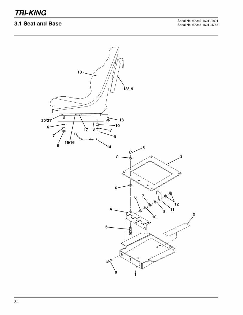
TRI-KING
34
1
2
3
3
4
5
6
6
6
7
7
77
18
8
8
8
9
10
10
1112
13
18/19
1415/16
20/21
8
17
3.1 Seat and Base Serial No. 67042-1601~1891Serial No. 67043-1601~4743

TRI-KING
35
> Change from previous revision
Item Part No. Qty. Description Serial Numbers/Notes
1 3003301 1 Seat Base2 558012 2 Pad3 3003368 1 Plate4 3003299 1 Hinge5 440078 5 Carriage Bolt, 5/16-18 x 3/4”6 452006 10 Flat Washer, 5/167 446136 10 Lockwasher, 5/16 Hvy8 443106 10 Nut, 5/16 Hex9 440088 1 Carriage Bolt, 5/16-18 x 1-3/4”
10 3004410 2 Spacer11 3003402 1 Seat Latch12 443806 2 Nut, 5/16-18 Hex Jam13 66172 1 Seat14 163583 1 • Seat Switch Wire Harness15 434011 2 • Screw, 1/4-20 x 5/8” Soc. Hd.16 446130 2 • Lockwasher, 1/417 554390 1 • Switch, Seat Reference SW618 3001328 6 Screw, 5/16-18 x 5/8” Wsh Head19 3003928 1 Literature Pouch20 3006988 1 Seat Adjuster21 3006991 1 Seat Adjuster with Handle

TRI-KING
36
1
2
3
4
5
6
6
6
7
7
7 7
18
18
18
8
8 8
9
10
10
1112
13
19
14
1615
8
17
3.2 Seat and Base Serial No. 67042-1892 and UpSerial No. 67043-4744 and Up
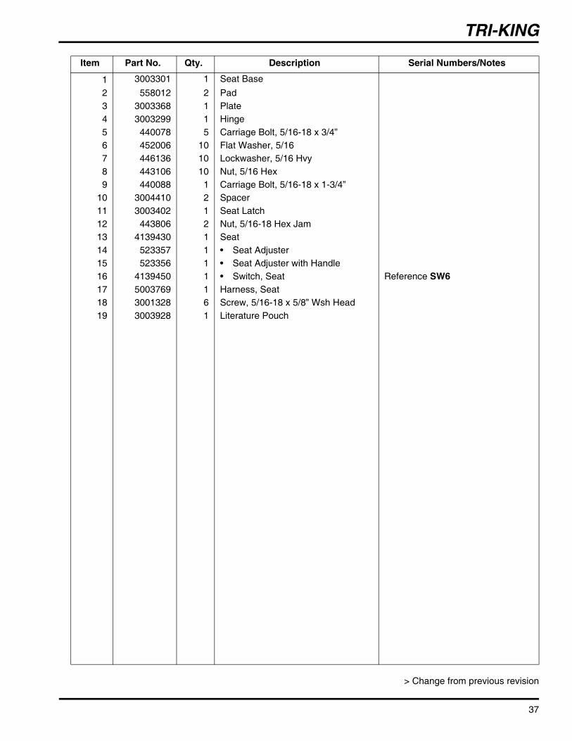
TRI-KING
37
> Change from previous revision
Item Part No. Qty. Description Serial Numbers/Notes
1 3003301 1 Seat Base2 558012 2 Pad3 3003368 1 Plate4 3003299 1 Hinge5 440078 5 Carriage Bolt, 5/16-18 x 3/4”6 452006 10 Flat Washer, 5/167 446136 10 Lockwasher, 5/16 Hvy8 443106 10 Nut, 5/16 Hex9 440088 1 Carriage Bolt, 5/16-18 x 1-3/4”
10 3004410 2 Spacer11 3003402 1 Seat Latch12 443806 2 Nut, 5/16-18 Hex Jam13 4139430 1 Seat14 523357 1 • Seat Adjuster15 523356 1 • Seat Adjuster with Handle16 4139450 1 • Switch, Seat Reference SW617 5003769 1 Harness, Seat18 3001328 6 Screw, 5/16-18 x 5/8” Wsh Head19 3003928 1 Literature Pouch

TRI-KING
38
1
2
4
5
8
9
10
4
12
12
13
1415
16
17
1819
2021
1718
19
26
27
28
22
25
24
23
Fuse Block(Part of Wire Harness)
3
7
6
11
4.1 Dash Installation Serial No. All

TRI-KING
39
> Change from previous revision
Item Part No. Qty. Description Serial Numbers/Notes
1 1002264.7 1 Angle Bracket2 441602 4 Carriage Bolt, 5/16-18 x 3/4”3 1002898 1 Steering Valve
557738 1 • Seal Kit502924 1 • Spring Kit
4 444718 4 Locknut, 5/16-18 Center5 362469 1 U-Bolt Clamp6 444754 4 Nut, 5/16-24 Hex Lock7 453009 2 Washer, 5/16 Flat8 444310 4 Nut, #10-24 Hex9 403914 4 Screw, #10-24 x 3/4” Truss Head
10 446116 4 Lockwasher, #1011 403770 2 Screw, 5/16-18 x 3/4 Hex Flange12 3003540.7 1 Mounting Bracket13 3002098 2 Latch14 404016 4 Screw, 1/4-20 x 5/8” Truss Head15 3003468 2 Plastic Plate16 2810209 1 Console Cover17 452004 8 Flat Washer, 1/418 446130 8 Lockwasher, 1/4 Hvy19 443102 8 Nut, 1/4-20 Hex20 3003541 2 Latch Bracket21 441664 4 Screw, 1/4-20 x 5/8” Round Head22 2811364 1 Steering Wheel23 2811365 1 • Steering Wheel Cap24 3002861 1 Nut, M16-1.5 Hex Jam
> 25 447224 1 Lockwasher, 5/8 Internal Tooth26 2811547 1 Washer
> 27 454001 2 Wave Washer, 3/4> 28 455048 2 Flat Washer, 3/4
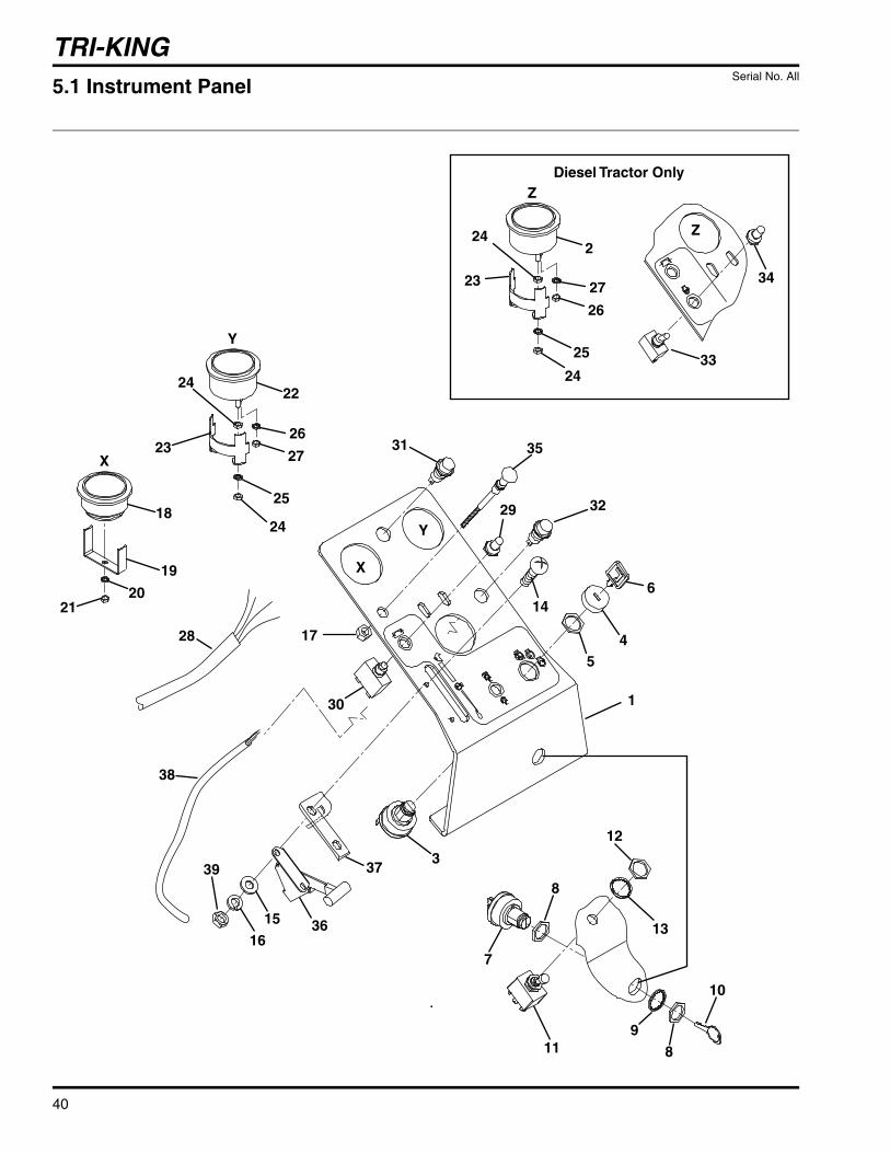
TRI-KING
40
17
30
3
1
29
31
32
6
54
X
Y
X
Y
18
19
2021
22
23
24
24
25
27
26
7
8
98
10
11
12
13
33
34
Z
35
28
Z
2
23
24
24
25
26
27
Diesel Tractor Only
14
39
16
15 36
37
38
5.1 Instrument Panel Serial No. All

TRI-KING
41
> Change from previous revision
Item Part No. Qty. Description Serial Numbers/Notes
1 2811436 1 Dash Panel Gas 1 2811437 1 Dash Panel Diesel2 162720 1 Water Gauge Diesel, Reference U43 1001958 1 Ignition Switch Reference SW94 5002101 1 • Bezel5 5002102 1 • Nut6 5000039 1 • Ignition Key7 1001010 1 Backlap Switch Reference SW108 558036 2 • Nut9 N/S 1 • Lockwasher
10 5001428 1 • Mechanics Key11 3001780 1 PTO Switch Reference SW212 361862 2 • Nut13 447220 2 • Lockwasher14 403912 2 Screw, #10-24 x 5/8” Tr. Hd.15 452002 2 Washer, #10 Flat16 446118 2 Lockwasher, #1017 443112 1 Nut, 3/8-24 Hex Gas18 162723 1 Hour Meter Reference U319 N/S 1 • Bracket20 447006 1 • Lockwasher21 444310 1 • Nut, #10-24 Hex22 162721 1 Volt Meter Reference U223 N/S 1 • Bracket24 444306 4 • Nut, #8-32 Hex25 447206 2 • Lockwasher, #826 447002 2 • Lockwasher, #627 444304 2 • Nut, #6
● 28 1004796 1 Wire Harness Gas, See Note ●● 28 1004795 1 Wire Harness Diesel, See Note ●
29 364774 1 Circuit Breaker Boot30 338601 1 10 Amp Circuit Breaker Reference CB231 164194 1 Oil Pressure Light Reference L332 366751 1 Light, Parking Brake Reference L433 363961 1 Toggle Switch Diesel, Reference SW134 363962 1 Toggle Boot Diesel35 1002272 1 Choke Cable Gas36 1004339 1 Throttle Cable Gas36 1004340 1 Throttle Cable Diesel37 3008433 1 Plate, Stop38 2811632 1 Harness, Brake Light39 444310 2 Nut, #10-24 Hex
● Serial Number 67042-1601~1891 and 67043-1601~4743Seat Harness 5003769 will be required when replacing main wire harness.

TRI-KING
42
1
24
5
6
7
8
9
10
3
4
4
67
11
12
1314
16
17
12
17
18
10
3
4
24
19
20
21
22
23
23
25
26
26
15
2123
23
Diesel
Gas
6.1 Hydro Control Linkage Serial No. All

TRI-KING
43
> Change from previous revision
Item Part No. Qty. Description Serial Numbers/Notes
1 3006746 1 Extension Spring2 3006745 1 Extension Spring3 3002372 2 Spring Bolt4 443110 2 Nut, 3/8-16 Hex5 3002399 1 Traction Rod6 443108 4 Nut, 5/16-24 Hex7 343398 2 Ball Joint8 2811387 1 Traction Pedal9 3003475 1 Pedal Grip
10 444754 2 Locknut, 5/16-24 Center11 400192 1 Screw, 5/16-18 x 1-1/2” Hex Head12 443106 2 Nut, 5/16-18 Hex13 453017 1 Flat Washer, 1/214 460028 1 Cotter Pin, 1/8 x 1”15 444708 1 Locknut, 1/4-20 Center16 400264 1 Screw, 3/8-16 x 1-1/4” Hex Head17 443810 2 Nut, 3/8-16 Hex Jam18 471214 1 Grease Fitting19 446142 4 Lockwasher, 3/8 Hvy20 3004881.7 2 Bracket Gas20 3002673.7 2 Bracket Diesel21 354989 2 Rubber Stop22 400260 4 Screw, 3/8-16 x 7/8 Hex Hd23 443812 4 Nut, 3/8-24 Jam24 443110 4 Nut, 3/8-16 Hex25 441606 1 Carriage Bolt, 1/4-20 x 3/4”26 452006 4 Flat Washer, 1/4

TRI-KING
44
16 17
1211
10
19
14/15
13
6
7 21
18
9
24
24
25
25
5 23
4
10
1
2/3
22
20
8
4
7.1 Front Motors and Brakes Serial No. All

TRI-KING
45
> Change from previous revision
Item Part No. Qty. Description Serial Numbers/Notes
1 2500127 1 Brake Lever2 3002628 1 R.H. Brake Cable3 3002627 1 L.H. Brake Cable4 545237 2 Spacer5 – 2 Tire and Wheel Assembly
5001348 1 • Tire, 20 x 10 x 105002906 1 • Rim
360111 1 • Valve Stem6 352204 2 Spring7 447030 2 Lockwasher, 1 External Tooth8 395388 2 Wheel Hub9 400410 4 Screw, 1/2-13 x 1-3/4” Hex Head
10 338383 4 Pulley11 453020 4 Washer, 5/812 460028 4 Cotter Pin, 1/8 x 1”13 346771 2 Pin, 5/1614 1001634 1 L.H. Caliper See 40.1 for Service Parts
15 1001635 1 R.H. Caliper See 40.1 for Service Parts
16 453009 2 Flat Washer, 5/1617 460008 2 Cotter Pin, 5/64 x 3/4” Plated18 5003218 2 Wheel Motor, Front Gas Units18 5003218 1 Wheel Motor, Left Front Diesel Units18 2810623 1 Wheel Motor, Right Front Diesel Units
5003385 1 • Seal Kit19 400414 4 • Screw, 1/2-13 x 2-1/4” Hex Head20 3008482 2 • Spacer21 554779 2 • Nut22 554780 2 • Key23 353914 8 Wheel Bolt24 446154 8 Lockwasher, 1/2 Hvy25 443118 8 Nut, 1/2-13 Hex

TRI-KING
46
1
A2
345
6
23
89
10
11
12
13
1516
17
18
19
26
25
28
29
20
21
22
27
25
15
16
24
17
14
7
A
B
B
30
30
31
16
16
8.1 Parking Brake, Neutral Start and 3WD Switches Serial No. All
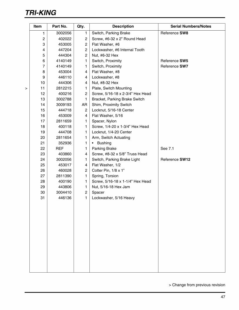
TRI-KING
47
> Change from previous revision
Item Part No. Qty. Description Serial Numbers/Notes
1 3002056 1 Switch, Parking Brake Reference SW82 402022 2 Screw, #6-32 x 2” Round Head3 453005 2 Flat Washer, #64 447204 2 Lockwasher, #6 Internal Tooth5 444304 2 Nut, #6-32 Hex6 4140149 1 Switch, Proximity Reference SW57 4140149 1 Switch, Proximity Reference SW78 453004 4 Flat Washer, #89 446110 4 Lockwasher, #8
10 444306 4 Nut, #8-32 Hex> 11 2812215 1 Plate, Switch Mounting
12 400216 2 Screw, 5/16-18 x 2-3/4” Hex Head13 3002788 1 Bracket, Parking Brake Switch14 3009193 AR Shim, Proximity Switch15 444718 2 Locknut, 5/16-18 Center16 453009 4 Flat Washer, 5/1617 2811659 1 Spacer, Nylon18 400118 1 Screw, 1/4-20 x 1-3/4” Hex Head19 444708 1 Locknut, 1/4-20 Center20 2811654 1 Arm, Switch Actuating21 352936 1 • Bushing22 REF 1 Parking Brake See 7.123 403860 4 Screw, #8-32 x 5/8” Truss Head24 3002056 1 Switch, Parking Brake Light Reference SW1225 453017 4 Flat Washer, 1/226 460028 2 Cotter Pin, 1/8 x 1”27 2811390 1 Spring, Torsion28 400190 1 Screw, 5/16-18 x 1-1/4” Hex Head29 443806 1 Nut, 5/16-18 Hex Jam30 3004410 2 Spacer31 446136 1 Lockwasher, 5/16 Heavy
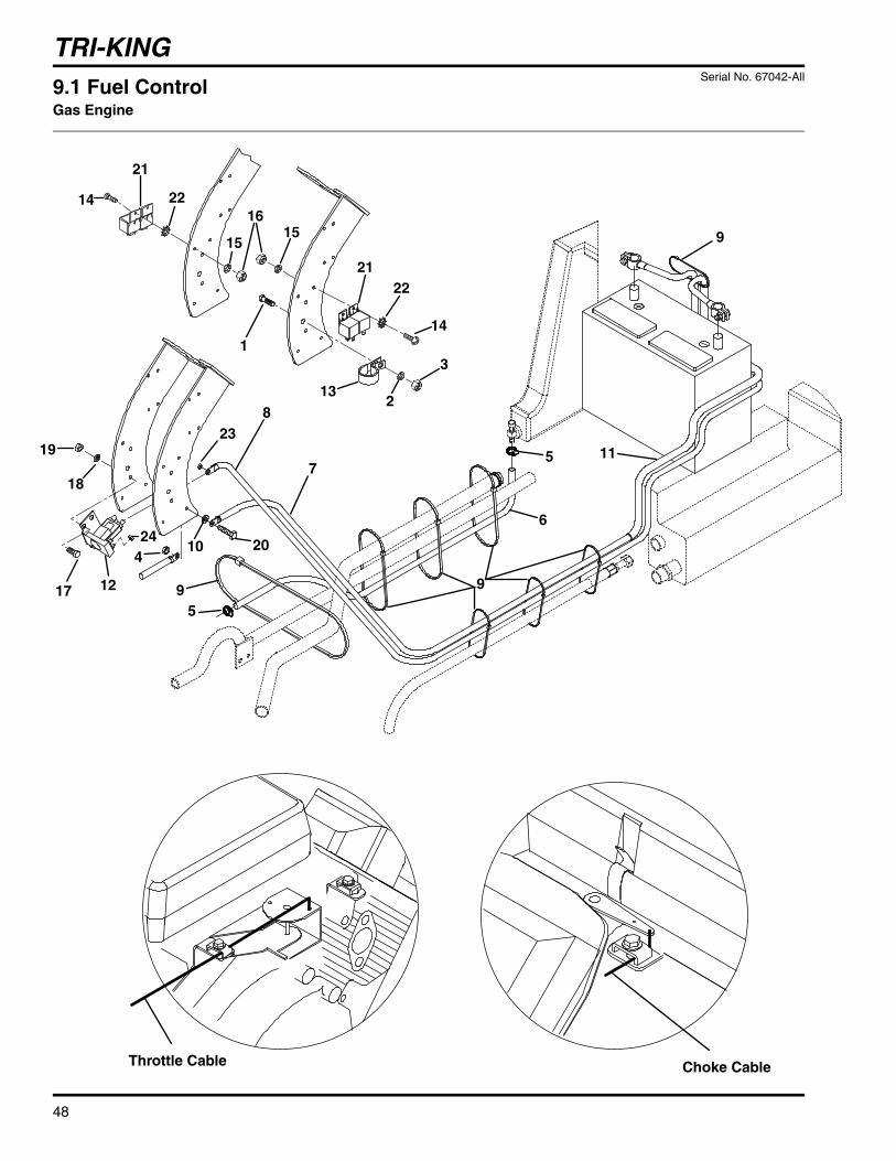
1
TRI-KING
48
9
244
5
6
7
8
9
10
11
12
1516
17
18
9
20
2122
3
23
13
1
2
14
9
5
Choke CableThrottle Cable
15
2214
21
9.1 Fuel ControlGas Engine
Serial No. 67042-All

TRI-KING
49
> Change from previous revision
Item Part No. Qty. Description Serial Numbers/Notes
1 400186 1 Screw, 5-16 x 7/8” Hex Head2 446136 1 Lockwasher, 5/16 Hvy3 443106 1 Nut, 5/16-18 Hex4 443102 1 Nut, 1/4-20 Hex5 366526 2 Hose Clamp6 554748 1 Fuel Line Cut to 76”7 3003523 1 Negative Battery Cable8 3004965 1 Positive Battery Cable9 473142 14 Nylon Tie
10 447010 1 Star Washer, 1/411 3004539 1 Conduit12 131905 1 Starter Solenoid Reference K213 361064 1 Hose Clamp14 403912 2 Screw, #10-24 x 5/8” Truss Head15 446118 2 Lockwasher, #10 Hvy16 444310 2 Nut, #10-24 Hex17 400108 2 Screw, 1/4-20 x 3/4” Hex18 446130 2 Lockwasher, 1/4 Hvy19 443102 2 Nut, 1/4-20 Hex20 400112 1 Screw, 1/4-20 x 1” Hex Head21 3001307 4 Relay Reference K3, K4, K7 and K822 447006 2 Lockwasher, #10 External Tooth23 443108 2 Nut, 5/16-24 Hex24 444312 2 Nut, #10-32 Hex25

TRI-KING
50
EngineThrottleLever
9
25
619
21
22
31
141518
18
18
28
20
17
24
23
24
24
16
18
28
2324
21
1
12
29
9
9
8
8
6
6
1113
12
7
To Motor
ToControlPanel
3
32
6
10
2
4
30 8
9
8
EngineStopLever
26
ToMotor
9
5
36
3733
35
34
10.1 Fuel ControlDiesel Engine
Serial No. 67043-All
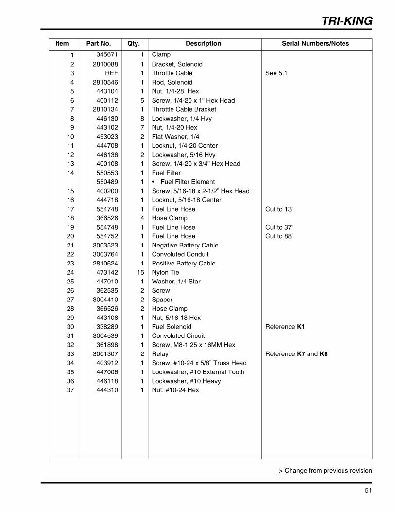
TRI-KING
51
> Change from previous revision
Item Part No. Qty. Description Serial Numbers/Notes
1 345671 1 Clamp2 2810088 1 Bracket, Solenoid3 REF 1 Throttle Cable See 5.14 2810546 1 Rod, Solenoid5 443104 1 Nut, 1/4-28, Hex6 400112 5 Screw, 1/4-20 x 1” Hex Head7 2810134 1 Throttle Cable Bracket8 446130 8 Lockwasher, 1/4 Hvy9 443102 7 Nut, 1/4-20 Hex
10 453023 2 Flat Washer, 1/411 444708 1 Locknut, 1/4-20 Center12 446136 2 Lockwasher, 5/16 Hvy13 400108 1 Screw, 1/4-20 x 3/4” Hex Head14 550553 1 Fuel Filter
550489 1 • Fuel Filter Element15 400200 1 Screw, 5/16-18 x 2-1/2” Hex Head16 444718 1 Locknut, 5/16-18 Center17 554748 1 Fuel Line Hose Cut to 13”18 366526 4 Hose Clamp19 554748 1 Fuel Line Hose Cut to 37”20 554752 1 Fuel Line Hose Cut to 88”21 3003523 1 Negative Battery Cable22 3003764 1 Convoluted Conduit23 2810624 1 Positive Battery Cable24 473142 15 Nylon Tie25 447010 1 Washer, 1/4 Star26 362535 2 Screw27 3004410 2 Spacer28 366526 2 Hose Clamp29 443106 1 Nut, 5/16-18 Hex30 338289 1 Fuel Solenoid Reference K131 3004539 1 Convoluted Circuit32 361898 1 Screw, M8-1.25 x 16MM Hex33 3001307 2 Relay Reference K7 and K834 403912 1 Screw, #10-24 x 5/8” Truss Head35 447006 1 Lockwasher, #10 External Tooth36 446118 1 Lockwasher, #10 Heavy37 444310 1 Nut, #10-24 Hex

TRI-KING
Serial No. 67042-All 11.1 FrameGas Engine
52
> Change from previous revision
2
2
9
9
8
7
6
2
7
8
9
5
4 3
Serial Plate
1
Item Part No. Qty. Description Serial Numbers/Notes
1 2811396 1 Frame2 328133 4 • Bushing3 3002170 4 • Bushing4 365106 2 • Bushing5 471216 1 • Grease Fitting6 2811393 1 Column Assembly7 400188 2 Screw. 5/16-18 x 1” Hex Head8 445781 2 Nut, 5/16-18 Whizlock Flange9 452006 2 Flat Washer, 5/16
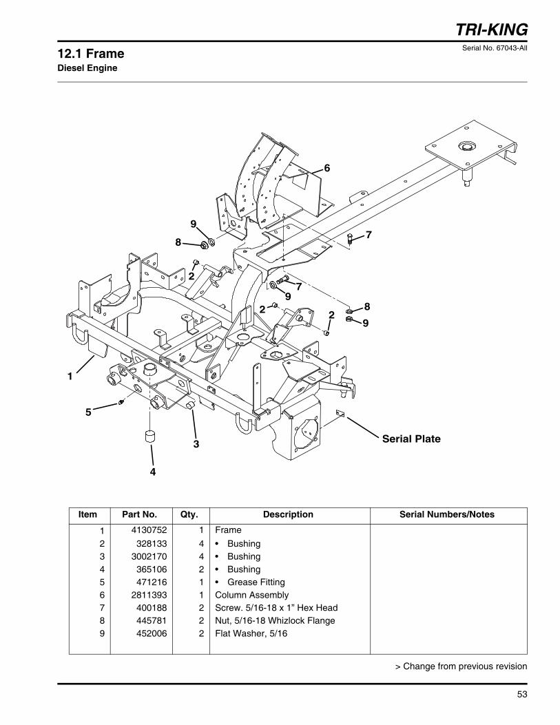
TRI-KING
Serial No. 67043-All 12.1 FrameDiesel Engine
53
> Change from previous revision
Item Part No. Qty. Description Serial Numbers/Notes
1 4130752 1 Frame2 328133 4 • Bushing3 3002170 4 • Bushing4 365106 2 • Bushing5 471216 1 • Grease Fitting6 2811393 1 Column Assembly7 400188 2 Screw. 5/16-18 x 1” Hex Head8 445781 2 Nut, 5/16-18 Whizlock Flange9 452006 2 Flat Washer, 5/16
Serial Plate
2
2 2
5
4
3
1
7
8
6
9
9
9
8
7

TRI-KING
54
113
3
82
23
8
6
9
722
21 12
11
10
9
5
14
151920
18
4
23
1716
13.1 Rear Steering Serial No. All

TRI-KING
55
> Change from previous revision
Item Part No. Qty. Description Serial Numbers/Notes
1 4138501 1 Steering Cylinder (Includes 1A)4137139 1 • Seal Kit
2 443820 2 Nut, 1/2-20 Hex3 3010485 2 Ball Joint4 353914 4 Wheel Bolt5 1001129.7 1 Steering Fork6 471231 1 Grease Fitting7 400414 1 Screw, 1/2-13 x 2-1/4” Hex Head8 444758 2 Locknut, 1/2-13 Center9 5002916 2 Bearing, Cup and Cone with Seal
10 452018 1 Flat Washer, 3/411 445676 1 Nut, 3/4-16 Slotted12 460054 1 Cotter Pin, 3/16 x 1-3/4”13 400408 1 Screw, 1/2-13 x 1-1/2” Hex Head14 5003218 1 Wheel Motor
5003385 1 • Seal Kit15 400414 4 • Screw, 1/2-13 x 2-1/4” Hex Head16 3008482 2 • Spacer17 554780 1 • Key18 554779 1 • Nut19 220290.7 1 Rear Wheel Hub20 447030 1 Lockwasher, 1 External Tooth21 446154 4 Lockwasher, 1/2 Hvy22 443118 4 Nut, 1/2-13 Hex23 – 1 Tire and Wheel Assembly
366790 1 • Tire, 20 x 10 x 81003638 1 • Rim
360111 1 • Valve Stem
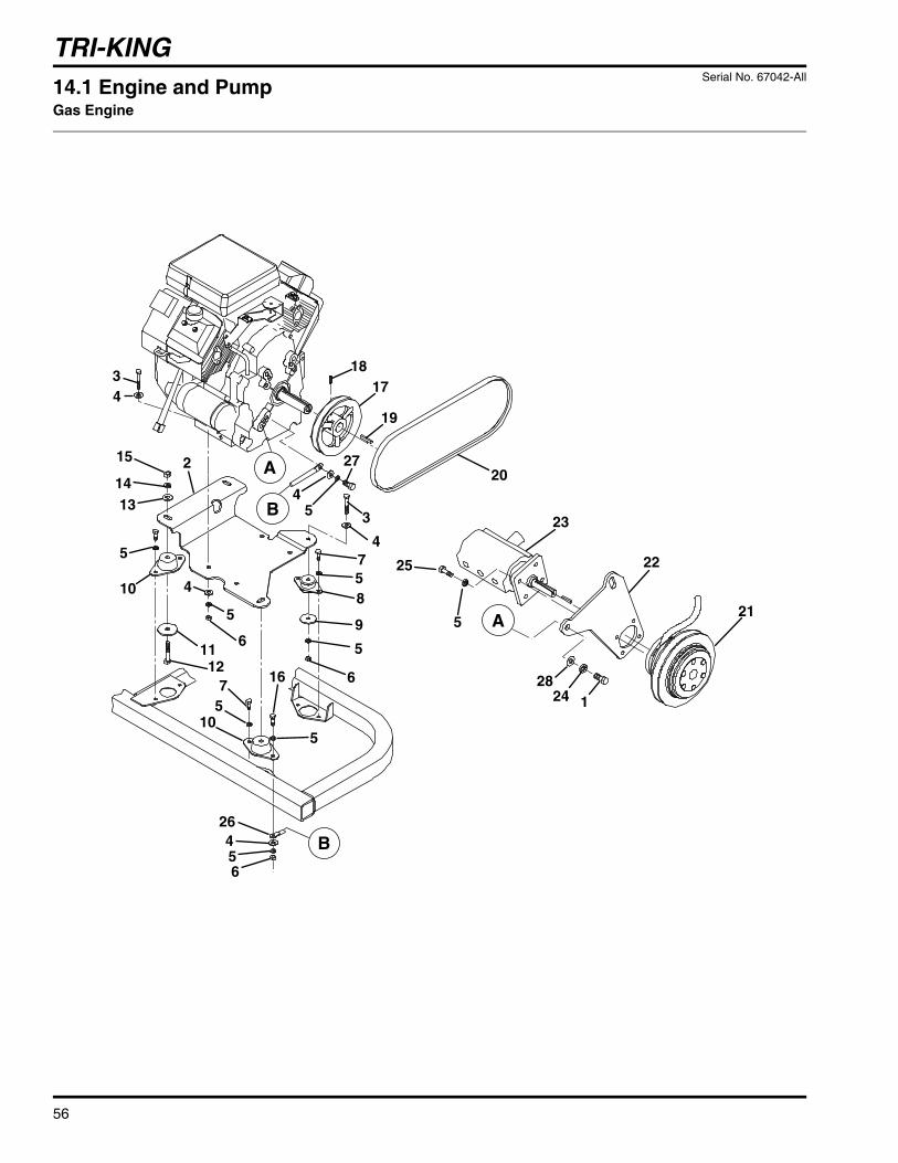
TRI-KING
56
45
27
4
3
20
19
1718
9
5
6
8
75
456
7
10
16
4
5
2
10
1112
5
6
1314
15
43
26
2824 1
25
23
22
215
5
5
A
A
B
B
14.1 Engine and PumpGas Engine
Serial No. 67042-All

TRI-KING
57
> Change from previous revision
Item Part No. Qty. Description Serial Numbers/Notes
1 400334 2 Screw, 7/16-14 x 1” Hex Head2 3004560.7 1 Plate3 400196 5 Screw, 5/16-18 Hex4 452006 11 Flat Washer, 5/165 446136 21 Lockwasher, 5/16 Hvy6 443106 6 Nut, 5/16-18 Hex7 400186 7 Screw, 5/16-18 x 7/8” Hex Head8 367558 1 Iso-Mount9 367559 1 Washer
10 3004523 3 Iso-Mount11 3004526 3 Washer12 400272 3 Screw, 3/8-16 x 2-1/4” Hex Head13 452008 3 Flat Washer, 3/814 446142 3 Lockwasher, 3/8 Hvy15 443110 3 Lockwasher, 3/8 Hvy16 400190 1 Screw, 5/16-18 x 1-1/4” Hex Head17 340654 1 Pulley18 415527 2 Set Screw19 362320 1 Key, 1/4 Sq. x 1-1/220 3001950 1 V-Belt21 2809727 1 Clutch Assembly22 2810394.7 1 Bracket23 1000970 1 Reel Pump See 36.1 for Service Parts
24 446148 2 Lockwasher, 7/16 Hvy25 400226 4 Screw, 5/16-24 x 1” Hex Head26 346006 1 Engine Ground Cable27 400224 1 Screw, 5/16-24 x 7/8” Hex Head28 453013 2 Flat Washer, 7/16

TRI-KING
58
14
30
31
11
293 1
259
24
15
38
3940
1828
6
7
8
12
12
11
11
10
1032
22
32
16
17
4
1032
10
11
12
20
35
3613
21
37
19
1933
23
37 5
24
51
2
26
27
4142
4344
45
15.1 Engine and ExhaustGas Engine
Serial No. 67042-All

TRI-KING
59
> Change from previous revision
Item Part No. Qty. Description Serial Numbers/Notes
1 1002804 1 Engine2 5000440 1 • Oil Filter3 5000441 1 • Air Filter4 5000436 1 • Fuel Filter5 N/S 1 • Adapter, Remote6 N/S 2 • Gasket7 N/S 4 • Screw8 N/S 1 • Plug9 3008600 1 Oil Pressure Sender Reference SW3
10 452006 10 Flat Washer, 5/1611 446136 6 Lockwasher, 5/16 Hvy12 443106 4 Nut, 5/16-18 Hex13 3005472 1 Adapter, Remote Base14 443102 1 Nut, 1/4-20 Hex15 1002692 1 Muffler16 3005920 1 Exhaust Pipe17 1002033 1 Clamp18 1003994.7 1 Heat Shield19 1004022 2 Engine Oil Filter Hose20 3005513.7 1 Bracket21 358949 1 Adapter, 90°22 3005172.7 1 Bracket23 358949 1 Adapter, 90°24 366418 2 Adapter, Straight25 3004933 1 Fitting, 90°26 403770 2 Screw, 5/16-18 x 3/4” Hex Flange27 445795 2 Nut, 5/16-18 Spiralock Flange28 361028 1 Fitting, 90° Street29 3004427 1 Grommet30 2000116 1 Stub Shaft31 400192 2 Screw, 5/16-18 x 1-1/2” Hex Head32 400188 4 Screw, 5/16-18 x 1” Hex Head33 3005509 1 Adapter, 90° Bulkhead34 1002671 1 Tube, Engine Oil Filter35 2811340 1 Shield, Heat Reflect36 444306 1 Nut, #8-32 Hex37 353008 2 Fitting38 453013 1 Washer, 7/16 Flat39 446148 1 Lockwasher, 7/16 Hvy40 400334 1 Screw, 7/16-14 x 1 Hex41 355064 1 Adapter, 90°42 1004687 1 Hose, Remote Oil Drain43 339960 1 Locknut, Bulkhead44 362078 1 Adapter, Straight Bulkhead45 354077 1 Cap, 37° Flare

TRI-KING
60
31
2
45
6
7
8
9
16
10
11
1112
13
13
14
14
15
15
12
16.1 Air IntakeGas Eninge
Serial No. 67042-All

TRI-KING
61
> Change from previous revision
Item Part No. Qty. Description Serial Numbers/Notes
1 3004995.7 1 Bracket2 3004927.7 1 Bracket3 400260 4 Screw, 3/8-16 x 7/8” Hex Head4 446142 4 Lockwasher, 3/8 Hvy5 443110 4 Nut, 3/8-16 Hex6 3004187 1 Weather Strip Cut to Length7 1002241 1 Air Intake Shield8 3005852 4 Stud, Special9 452002 4 Flat Washer, 1/4
10 445770 4 Nut, 1/4-20 Nylock11 3004962 1 Trim Seal12 400184 1 Screw, 5/16-18 x 3/4” Hex Head13 452006 2 Flat Washer, 5/1614 446136 2 Lockwasher, 5/16 Hvy15 443106 2 Nut, 5/16-18 Hex16 446130 4 Lockwasher, 1/4 Heavy

TRI-KING
62
5
6
31
2
4
78
15
910
11
12
17
18
16
14
13
9
19
20
21 22 23
17.1 Engine and PumpDiesel Engine
Serial No. 67043-All ●
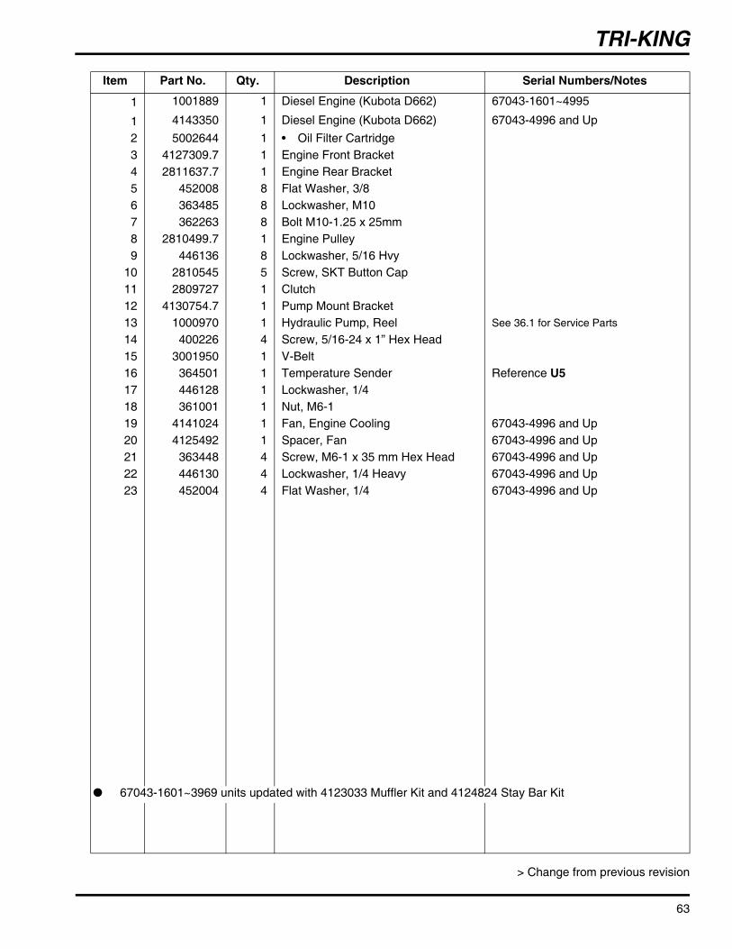
TRI-KING
63
> Change from previous revision
Item Part No. Qty. Description Serial Numbers/Notes
1 1001889 1 Diesel Engine (Kubota D662) 67043-1601~4995
1 4143350 1 Diesel Engine (Kubota D662) 67043-4996 and Up2 5002644 1 • Oil Filter Cartridge3 4127309.7 1 Engine Front Bracket4 2811637.7 1 Engine Rear Bracket5 452008 8 Flat Washer, 3/86 363485 8 Lockwasher, M107 362263 8 Bolt M10-1.25 x 25mm8 2810499.7 1 Engine Pulley9 446136 8 Lockwasher, 5/16 Hvy
10 2810545 5 Screw, SKT Button Cap11 2809727 1 Clutch12 4130754.7 1 Pump Mount Bracket13 1000970 1 Hydraulic Pump, Reel See 36.1 for Service Parts
14 400226 4 Screw, 5/16-24 x 1” Hex Head15 3001950 1 V-Belt16 364501 1 Temperature Sender Reference U517 446128 1 Lockwasher, 1/418 361001 1 Nut, M6-119 4141024 1 Fan, Engine Cooling 67043-4996 and Up20 4125492 1 Spacer, Fan 67043-4996 and Up21 363448 4 Screw, M6-1 x 35 mm Hex Head 67043-4996 and Up22 446130 4 Lockwasher, 1/4 Heavy 67043-4996 and Up23 452004 4 Flat Washer, 1/4 67043-4996 and Up
● 67043-1601~3969 units updated with 4123033 Muffler Kit and 4124824 Stay Bar Kit
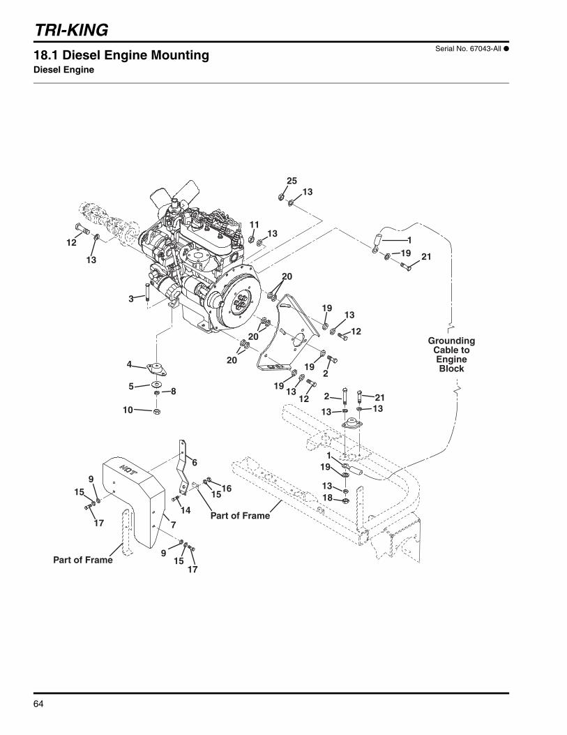
TRI-KING
64
12
13
5 8
10
4
3
2513
20
20
13
19
12
19
1912
13
2
1311
20
13 132
1
21
21
119
1318
19
GroundingCable toEngineBlock
15
15
17
17
9
916
15
Part of Frame
Part of Frame
14
7
6
18.1 Diesel Engine MountingDiesel Engine
Serial No. 67043-All ●

TRI-KING
65
> Change from previous revision
Item Part No. Qty. Description Serial Numbers/Notes
1 346006 1 Cable, Grounding2 400190 2 Screw, 5/16-18 x 1-1/4” Hex Head3 400272 4 Screw, 3/8-16 x 2-1/4” Hex Head4 3004523 4 Mount, Isolation5 3004526 4 Washer, Mount Isolator6 4121872.7 1 Bracket, Heat Shield7 4121856.7 1 Muffler Shield8 446142 4 Lockwasher, 3/8 Hvy9 452004 4 Flat Washer, 1/4
10 443110 4 Nut, 3/8-16 Hex11 444718 2 Locknut, 5/16-18 Center12 361005 3 Bolt, M8-1.25 x 25mm13 446136 13 Lockwasher, 5/16 Hvy14 400108 2 Screw, 1/4-20 x 3/4” Hex Head15 446130 6 Lockwasher, 1/4 Heavy16 443102 2 Nut, 1/4-20 Hex17 400106 4 Screw, 5/16-18 x 5/8” Hex Head18 443106 1 Nut, 5/16 Hex19 452006 5 Flat Washer, 5/1620 457016 6 Washer, 5/16 x 1/16”21 400186 8 Screw, 5/16-18 x 3/4” Hex Head
● 67043-1601~3969 units updated with 4123033 Muffler Kit and 4124824 Stay Bar Kit
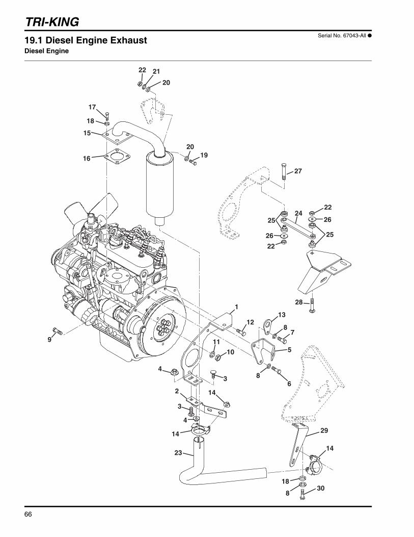
TRI-KING
66
4
4
3
3
2
1
14
14
14
5
6
78
8
8
9
10
11
1213
15
16
17
18
18
1920
20
2122
22
22
23
24
27
28
29
30
25
2526
26
19.1 Diesel Engine ExhaustDiesel Engine
Serial No. 67043-All ●

TRI-KING
67
> Change from previous revision
Item Part No. Qty. Description Serial Numbers/Notes
1 4130755 1 Bracket, Muffler2 4130753 1 Bracket, Muffler3 441602 2 Carriage Bolt, 5/16-18 x 3/4”4 445795 2 Nut, 5/16-18 Spiralock Flange5 4121007.7 1 Bracket, Muffler6 361005 1 Screw, M8-1.25 x 25 mm Hex Head7 363586 1 Screw, M8-1.25 x 20 mm Hex Head8 446136 10 Lockwasher, 5/16 Heavy9 550383 2 Bolt, Starter Included with Engine
10 550398 2 Nut Included with Engine11 550409 2 Washer, Spring Included with Engine12 550376 1 Bolt Included with Engine13 553934 1 Hook, Engine Included with Engine14 1002033 2 Exhaust Clamp15 4121920 1 Muffler16 553020 1 Gasket, Exhaust Included with Engine17 594331 4 Bolt, Muffler Included with Engine18 452006 6 Flat Washer, 5/1619 400264 1 Screw, 3/8-16 x 1-1/4” Hex Head20 452008 2 Flat Washer, 3/821 446142 1 Lockwasher, 3/8 Heavy22 444762 3 Locknut, 3/8-16 Center23 4123003 1 Pipe, Exhaust24 4130756 1 Stay Bar, Engine25 4124806 2 Mount, Bonded Tube Isolator26 319755 2 Washer27 400270 1 Screw, 3/8-16 x 2” Hex Head28 441630 1 Carriage Bolt, 3/8-16 x 2”29 4130757 1 Bracket, Tailpipe30 400186 2 Screw, 5/16-18 x 7/8” Hex Head
● 67043-1601~3969 units updated with 4123033 Muffler Kit and 4124824 Stay Bar Kit

TRI-KING
68
8
8
7
6
5
4
3
2
1
9
10
11
1213
14
15
1617
17
17
4
5
19
18
21
21
6
5
6
4
20
5
5
20.1 Radiator InstallationDiesel Engine
Serial No. 67043-1601~4995

TRI-KING
69
> Change from previous revision
Item Part No. Qty. Description Serial Numbers/Notes
1 554896 1 Radiator2 1002101.7 1 Front Shroud3 5001666 1 Rear Shroud4 355174 8 Bolt, M6-1 x 12mm5 446130 10 Lockwasher, 1/4 Hvy6 452004 8 Flat Washer, 1/47 1001964.7 7 Front Slide Shroud8 3004187 AR Weather Strip9 557578 1 Lower Hose
10 557563 1 Hose Clamp11 554244 2 Bolt12 553887 4 Cup Washer13 553886 2 Cushion14 452008 AR Flat Washer, 3/815 553859 2 Snap Pin16 554241 1 Upper Hose17 554083 3 Hose Clamp18 2810662 1 Radiator Support19 3006127 1 Iso-Mount, Radiator20 REF 1 Bracket, Solenoid See 10.121 443102 2 Nut, 1/4-20 Hex

TRI-KING
70
1
2
3
4
4
4
4
5
5
56
6
6
7
8
9
10
10
11
13
13
14
14
15
18
19
6
56
15
1617
17
17
1720
20
20
12
12
20.2 Radiator InstallationDiesel Engine
Serial No. 67043-4996 and Up

TRI-KING
71
> Change from previous revision
Item Part No. Qty. Description Serial Numbers/Notes
1 4141036 1 Radiator2 4150417 1 Bracket, Radiator Mount3 4140846 1 Fan Shroud4 362535 9 Bolt, M6-1 x 16mm5 446130 9 Lockwasher, 1/4 Hvy6 452004 10 Flat Washer, 1/47 444708 1 Locknut, 1/4-20 Hex Center8 400108 1 Screw, 1/4-20 x 3/4” Hex Head9 4150418 1 Bracket, Radiator Mount
10 4149217 AR Weather Strip11 4140788 1 Bracket, Upper Radiator Mount12 553887 4 Washer, Cup13 443810 2 Nut, 3/8-16 Hex Jam14 460312 2 Hain Pin15 4150598 2 Screw, 3/8-16 x 2” Hex Head Hole in end for hairpin16 553886 2 Cushion, Radiator17 452008 6 Flat Washer, 3/8
4141392 1 Radiator Hose Kit18 N/S 1 • Lower Hose19 N/S 1 • Upper Hose20 319914 4 • Hose Clamp

TRI-KING
72
13
89
4
173
4
A
1415
1
2
56
7
1122
21
20
19
18
1610
12
A
21.1 Air Filter and Circuit BreakerDiesel Engine
Serial No. 67043-All

TRI-KING
73
> Change from previous revision
Item Part No. Qty. Description Serial Numbers/Notes
1 1001354 1 Air Cleaner5000913 1 • Air Cleaner Element5000912 1 • Cover5000914 1 • Valve
2 3002862 1 Foam Ring3 3002863 1 Air Intake Hose4 326112 2 Hose Clamp5 361005 2 Bolt, M8-1.25 x 25mm6 446136 2 Lockwasher, 5/16 Hvy7 452006 2 Flat Washer, 5/168 3000359 1 Circuit Breaker, 50 Amp Reference CB19 364774 1 Protector Boot
10 3004256 1 Bracket11 364703 1 Over Flow Hose, 30” Long12 1001752 1 Air Cleaner Indicator/Adapter13 REF 1 Bracket, Circuit Breaker See 18.114 3004253 1 Male Elbow15 5002126 1 Tube16 3004333 1 Bulkhead Fitting17 473142 1 Nylon Tie18 400260 2 Screw, 3/8-16 x 7/8” Hex Head19 557580 1 Tank Support20 553926 1 Reserve Tank21 446142 2 Lockwasher, 3/8 Hvy22 443110 2 Nut, 3/8-16 Hex

TRI-KING
74
1
2
3
7
8
9
8
10
11
12
13
14
15
16
1617
18 19
20
21 6
22
5
4 171
5
711
22.1 Tanks Serial No. All

TRI-KING
75
> Change from previous revision
Item Part No. Qty. Description Serial Numbers/Notes
1 452004 3 Flat Washer, 1/42 1002019.6 1 Hydraulic Oil Tank3 3002397 1 Magnetic Plug4 445612 2 Nut, 1/4-20 Wing5 446154 4 Lockwasher, 1/2 Hvy6 2809688 1 Fill Breather Cap
5003624 1 • Gasket7 344132 4 Flat Washer8 443118 4 Nut, 1/2-13 Hex9 1002127 1 Fuel Tank Gas9 1001134 1 Fuel Tank Diesel
> 10 1003477 1 Fuel Cap Gas> 10 4106900 1 Fuel Cap Diesel
11 361117 1 Fuel Tank Bushing Gas11 361117 2 Fuel Tank Bushing Diesel12 346361 2 Battery Hold Down13 325822 1 Fuel Line, 14” x 1/4” I.D.14 1001311 1 Fuel Shut Off Valve15 1000973 1 Battery Bracket16 400424 4 Screw, 1/2-13 x 4-1/2” Hex Head17 446130 3 Lockwasher, 1/4 Hvy18 443102 3 Nut, 1/4-20 Hex19 3003473 1 Hose Clamp20 3003665 1 Stud, 1/4-20 x 2-3/4”21 3003444 1 Battery Retainer22 361748 1 Valve Overflow Diesel
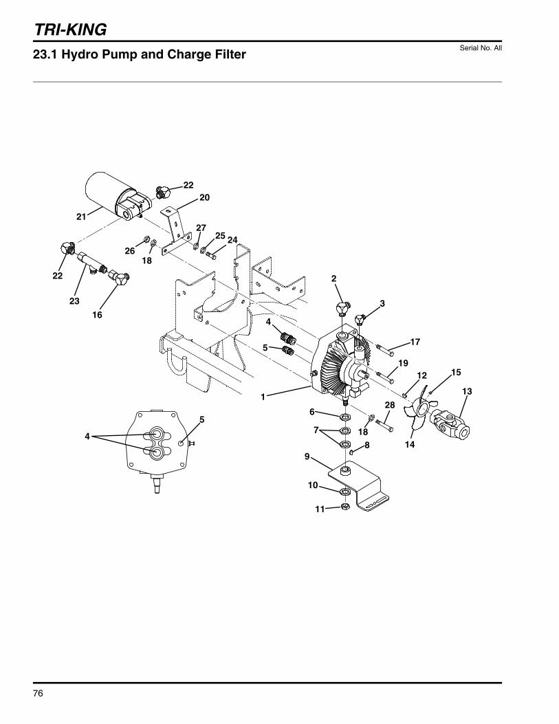
TRI-KING
76
1
2
3
4
4
5
6
7
89
10
5
11
12
13
14
1519
20
17
28
18
18
21
22
22
23
2425
26
27
16
23.1 Hydro Pump and Charge Filter Serial No. All
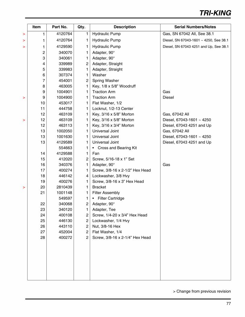
TRI-KING
77
> Change from previous revision
Item Part No. Qty. Description Serial Numbers/Notes
> 1 4120764 1 Hydraulic Pump Gas, SN 67042 All, See 38.1
> 1 4120764 1 Hydraulic Pump Diesel, SN 67043-1601 ~ 4250, See 38.1
> 1 4129590 1 Hydraulic Pump Diesel, SN 67043 4251 and Up, See 38.1
2 340070 1 Adapter, 90°3 340061 1 Adapter, 90°4 339989 2 Adapter, Straight5 339983 1 Adapter, Straight6 307374 1 Washer7 454001 2 Spring Washer8 463005 1 Key, 1/8 x 5/8” Woodruff9 1004901 1 Traction Arm Gas
> 9 1004900 1 Traction Arm Diesel10 453017 1 Flat Washer, 1/211 444758 1 Locknut, 1/2-13 Center12 463109 1 Key, 3/16 x 5/8” Morton Gas, 67042 All
> 12 463109 1 Key, 3/16 x 5/8” Morton Diesel, 67043-1601 ~ 425012 463113 1 Key, 3/16 x 3/4” Morton Diesel, 67043 4251 and Up13 1002050 1 Universal Joint Gas, 67042 All13 1001630 1 Universal Joint Diesel, 67043-1601 ~ 425013 4129589 1 Universal Joint Diesel, 67043 4251 and Up
554663 1 • Cross and Bearing Kit14 4129588 1 Fan15 412020 2 Screw, 5/16-18 x 1” Set16 340376 1 Adapter, 90° Gas17 400274 1 Screw, 3/8-16 x 2-1/2” Hex Head18 446142 4 Lockwasher, 3/8 Hvy19 400276 1 Screw, 3/8-16 x 3” Hex Head
> 20 2810439 1 Bracket21 1001148 1 Filter Assembly
549597 1 • Filter Cartridge22 340068 2 Adapter, 90°23 340120 1 Adapter, Tee24 400108 2 Screw, 1/4-20 x 3/4” Hex Head25 446130 2 Lockwasher, 1/4 Hvy26 443110 2 Nut, 3/8-16 Hex27 452004 2 Flat Washer, 1/428 400272 2 Screw, 3/8-16 x 2-1/4” Hex Head

TRI-KING
78
B
A
A
C
C
B
D
D
Rear View ofHydraulic Pump
1115
13
1426
27
282910
12
11
14
16
32
37
19
19
8
18
16
34
3336
38
4040
40
31
20
39
20
25
21
22
2321
1
35
34
14
14
17
67
39
24
54
19
2
40
24.1 Pump Suction and Return HydraulicsGas Engine
Serial No. 67042-All

TRI-KING
79
> Change from previous revision
Item Part No. Qty. Description Serial Numbers/Notes
1 1001372 1 Tube, Filter to Pump2 1002047 1 Tube, Pump Return3 3004182.7 1 Angle4 400190 1 Screw, 5/16-18 x 1-1/4” Hex5 452006 2 Flat Washer, 5/166 446136 2 Lockwasher, 5/16 Hvy7 443106 2 Nut, 5/16-18 Hex8 1001147 1 Tube, Reel Motor Return9 339963 1 ORS Bulkhead Locknut
10 3003218 1 Hose11 108094-02 4 Clamp12 345671 1 Hose Clamp13 3003113 1 Hose14 367458 4 Hose Clamp15 3003115 1 Tube, Suction16 354080 3 Hose Clamp17 3004655 1 Formed Hose 18 3003219 1 Hose, Suction19 473142 4 Nylon Tie20 443810 2 Nut, 3/8-16 Hex Jam21 452008 2 Flat Washer, 3/822 3003223 1 Drain Shield23 444762 1 Locknut, 3/8-16 Center24 3004410 1 Spacer25 361723 1 Rubber Stop26 339900 1 O-Ring27 1001148 1 Filter28 549597 1 • Filter Element29 3003256 1 Adapter, Beaded Tube3031 453011 2 Washer, 3/8 Flat32 1001503 1 Hydro Return Hose33 1002263 1 L. Traction Motor Drain Hose34 1001487 1 R. Traction Motor Drain Hose35 340055 3 Adapter, 90°36 339972 1 Adapter Straight 37 339989 1 Adapter, Straight38 339908 2 O-Ring, #4 ORFS39 339910 2 O-Ring, #8 ORFS40 339912 5 O-Ring, #10 ORFS

TRI-KING
80
B
A
A
B
D
C
1115
13
1426
27
282910
12
11
14
16
32
33
19
19
8
18
16
33
34
31
20
20
25
21
22
2321
1
35
34
14
14
17
67
39
24
54
19
2
30
36
36
3838
38
37
38
Rear View ofHydraulic Pump
25.1 Pump Suction and Return HydraulicsDiesel Engine
Serial No. 67043-All

TRI-KING
81
> Change from previous revision
Item Part No. Qty. Description Serial Numbers/Notes
1 1001372 1 Tube, Filter to Pump2 2809725 1 Tube, Pump Return3 3004182 1 Angle4 400188 2 Screw, 5/16-18 x 1” Hex Head5 452006 2 Flat Washer, 5/166 446136 2 Lockwasher, 5/16 Hvy7 443106 2 Nut, 5/16-18 Hex8 1001147 1 Tube, Reel Motor Return9 339963 1 ORS Bulkhead Locknut
10 3003218 1 Hose> 11 108094-02 4 Clamp
12 345671 1 Hose Clamp13 3003113 1 Hose14 367458 4 Hose Clamp15 3003115 1 Tube, Suction16 354080 3 Hose Clamp17 3003114 1 Formed Hose18 3003219 1 Hose, Suction19 473142 4 Nylon Tie20 443810 2 Nut, 3/8-16 Hex Jam21 452008 2 Flat Washer, 3/822 3003223 1 Drain Shield23 444762 1 Locknut, 3/8-16 Center24 3004410 1 Spacer25 361723 1 Rubber Stop26 339900 1 O-Ring27 1001148 1 Filter28 549597 1 • Filter Element29 3003256 1 Adapter, Beaded Tube30 361064 1 Clamp Hose 31 453011 2 Washer, 3/8 Flat32 1001503 1 Hydro Return Hose33 1001488 2 Traction Motor Drain Hose34 340055 4 Adaptor, 90°35 339989 1 Adaptor, Straight36 339908 2 O-Ring, #4 ORFS37 339910 2 O-Ring, #8 ORFS38 339912 5 O-Ring, #10 ORFS
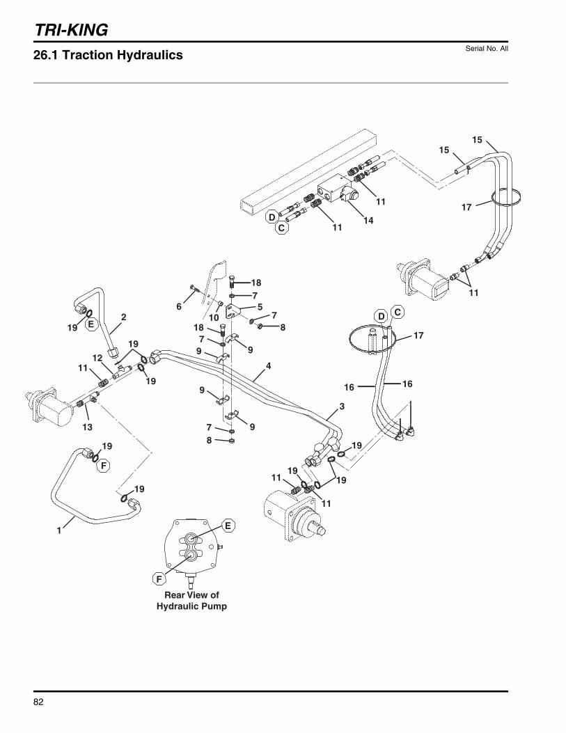
TRI-KING
82
F
F
E
E
CD
CD
11
11
14
1515
11
17
17
1616
11
11
4
3
9
9
78
997
18 87
5718
6102
12
19
19
19
19
19
11
13
1
19
1919
Rear View ofHydraulic Pump
26.1 Traction Hydraulics Serial No. All

TRI-KING
83
> Change from previous revision
Item Part No. Qty. Description Serial Numbers/Notes
1 1002045 1 Tube, Pump to Motor Gas1 2810603 1 Tube, Pump to Motor Diesel2 1002046 1 Tube, Pump to Motor Gas2 2810604 1 Tube, Pump to Motor Diesel3 1001370 Tube, R. Motor to L. Motor Gas3 2810602 1 Tube, R. Motor to L. Motor Diesel4 1001369 Tube, R. Motor to L. Motor Gas4 2810601 1 Tube, R. Motor to L. Motor Diesel5 3004531.7 1 Bracket Gas5 3003242.7 1 Bracket Diesel6 441668 2 Carriage Bolt, 1/4-20 x 1-1/4”7 452004 6 Flat Washer, 1/48 444708 4 Locknut, 1/4-20 Center9 3003110 2 Clamp
10 3004410 1 Spacer11 339989 11 Adapter, Straight12 340121 1 Fitting Tee13 340265 1 Adapter, Tee14 4111942 1 3WD Valve See 39.1 for Service Parts15 1001496 2 Rear Motor Hose16 1001495 2 Traction Hose17 473142 4 Nylon Tie18 400116 2 Screw, 1/4-20 x 1-1/2” Hex Head19 339911 10 O-Ring, #10 ORFS

TRI-KING
84
Steering Valve Asm. Bottom View
Aux
InOut
LT RTA
A
B
B
C
C
D
D
E
E
1
2
3
345
56
7
8
9
10
11
12
13
13
13
14
14
15
15
15
15
16
17
18
19
20
20
20
2122
23
24
24
24
25
26.2 Steering and Lift Hydraulics Serial No. All

TRI-KING
85
> Change from previous revision
Item Part No. Qty. Description Serial Numbers/Notes
1 1002939 2 Tube, Steering Valve to Filter Gas1 1002944 1 Tube, Steering Valve to Filter Diesel2 1002938 1 Tube, Steering Valve to Pump Gas2 2811063 1 Tube, Steering Valve to Pump Diesel3 364221 1 Clamp4 400114 1 Screw, 1/4-20 x 1-1/4” Hex Head5 452004 2 Flat Washer, 1/46 444708 1 Locknut, 1/4-20 Center7 1002942 1 Left Steering Hose8 1002941 1 Right Steering Hose9 354080 2 Hose Clamp
10 446136 1 Lockwasher, 5/16 Hvy11 443106 1 Nut, 5/16-18 Hex12 473142 4 Nylon Tie13 339974 3 Adapter Straight14 340057 2 Adapter, 90°15 340061 4 Adapter, 90°16 1002943 1 Lift Cylinder Hose Gas16 1002940 1 Lift Cylinder Hose Diesel17 1001500 1 Lift Cylinder Hose18 1001502 1 Lift Valve Hose19 1001501 1 Lift Valve Hose20 339979 3 Adapter Straight21 340088 1 Adapter, 90°22 1001356 1 Lift Valve
5001419 1 • Seal Kit23 122759 1 Hydraulic Cylinder
554331 1 • Seal Kit24 339909 3 O-Ring, #6 ORFS25 339910 1 O-Ring, #10 ORFS

TRI-KING
86
16
16
3
16
16
2
12
13
14
15
1
1 1
1
6
7
15
9
10
8
11
216
16
4
3
13
14
15
5
18
17
11
11
8
10
6
9
85
27.1 Reel Hydraulics Serial No. All

TRI-KING
87
> Change from previous revision
Item Part No. Qty. Description Serial Numbers/Notes
1 473142 8 Nylon Tie2 400120 3 Screw, 1/4-20 x 2” Hex Hd3 444708 3 Locknut, 1/4-20 Center4 3003323.7 1 Bracket5 1001491 1 Center Reel Motor Return Hose6 1001490 1 Right Reel Motor Return Hose7 1001489 1 Left Reel Motor Return Hose8 1001493 1 Center Reel Motor Pressure Hose9 1001494 1 Right Reel Motor Pressure Hose
10 1001492 1 Left Reel Motor Pressure Hose11 2810171 3 Snap Ring12 340062 1 Adapter, 90°13 339980 2 Adapter, Straight14 340070 2 Adapter, 90°15 1002603 3 Reel Motor See 37.1 for Service Parts
16 3003473 3 Clamp17 339979 3 Adapter Straight18 339989 1 Adapter, Straight

TRI-KING
88
1615 32
3534
26
1
37
9
33
3536
36
28
29
27
13213
10
15
30
32
31
3
4
5
6
7
8
11
12
17
18
1920
21
22
23
24
25
26
19
19
2
38
28.1 Reel Lift Serial No. All

TRI-KING
89
> Change from previous revision
Item Part No. Qty. Description Serial Numbers/Notes
1 400108 3 Screw, 1/4-20 x 3/4” Hex Head2 554330 1 Bronze Bushing Included with cylinder3 3004410 2 Spacer Gas4 307374 1 Washer5 458038 1 Retaining Ring6 345700 6 Washer7 364238 1 Cylinder Pin8 460052 1 Cotter Pin, 3/16 x 1-1/2”9 400264 2 Screw, 3/8-16 x 1-1/4” Hex Head
10 446128 1 Lockwasher, 1/411 3002234.7 1 Plate12 461379 1 Roll Pin, 3/16 x 1/2”13 345671 1 Hose Clamp14 473142 11 Nylon Tie Not Shown15 443102 5 Nut, 1/4-20 Hex16 446130 2 Lockwasher, 1/4 Hvy17 471214 2 Grease Fitting18 400192 1 Screw, 5/16-18 x 1-1/2” Hex Head19 443106 4 Nut, 5/16-18 Hex20 400190 1 Screw, 5/16-18 x 1-1/4” Hex Head21 1002606.7 1 Lift Pedal22 3003474 1 Pedal Grip23 453017 1 Flat Washer, 1/224 460028 1 Cotter Pin, 1/8 x 1”25 400120 2 Screw, 1/4-20 x 2” Hex Head Gas25 400118 2 Screw, 1/4-20 x 1-3/4” Hex Head Diesel26 444708 4 Locknut, 1/4-20 Center27 3003035 1 Pin28 461418 1 Roll Pin, 1/4-20 x 3-1/2”29 460335 1 Spring Clip Pin, 1/830 3004679 2 Hood Centering Bracket31 400112 2 Screw, 1/4-20 x 1” Hex Head32 452004 5 Flat Washer, 1/433 1001176.7 1 Tab Spring Mount34 400264 2 Screw, 3/8-16 x 1-1/4” Hex Head35 446142 4 Lockwasher, 3/8 Hvy36 443110 4 Nut, 3/8-16 Hex37 3002630.7 1 Hose Bracket38 452006 2 Flat Washer, 3/8

TRI-KING
90
12
34
5
6
7
8
9
10
11
12
13
14
15
18
17
16
19
20
21
22
2324
25
26/27
28
29
30
31
32
35
34
33
18
18
29.1 Rear Lift Arm Serial No. All
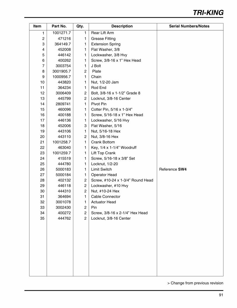
TRI-KING
91
> Change from previous revision
Item Part No. Qty. Description Serial Numbers/Notes
1 1001271.7 1 Rear Lift Arm2 471216 1 Grease Fitting3 364149.7 1 Extension Spring4 452008 1 Flat Washer, 3/85 446142 1 Lockwasher, 3/8 Hvy6 400262 1 Screw, 3/8-16 x 1” Hex Head7 3003754 1 J Bolt8 3001905.7 2 Plate9 1000956.7 1 Chain
10 443820 1 Nut, 1/2-20 Jam11 364234 1 Rod End12 3006409 2 Bolt, 3/8-16 x 1-1/2” Grade 813 445799 2 Locknut, 3/8-16 Center14 2809741 1 Pivot Pin15 460096 1 Cotter Pin, 5/16 x 1-3/4”16 400188 1 Screw, 5/16-18 x 1” Hex Head17 446136 1 Lockwasher, 5/16 Hvy18 452006 3 Flat Washer, 5/1619 443106 1 Nut, 5/16-18 Hex20 443110 2 Nut, 3/8-16 Hex21 1001258.7 1 Crank Bottom22 463040 1 Key, 1/4 x 1-1/4” Woodruff23 1001259.7 1 Lift Top Crank24 415519 1 Screw, 5/16-18 x 3/8” Set25 444780 1 Locknut, 1/2-2026 5000183 1 Limit Switch Reference SW427 5000184 1 Operator Head28 402132 2 Screw, #10-24 x 1-3/4” Round Head29 446118 2 Lockwasher, #10 Hvy30 444310 2 Nut, #10-24 Hex31 364694 1 Cable Connector32 3001078 1 Actuator Head33 3002430 2 Pin34 400272 2 Screw, 3/8-16 x 2-1/4” Hex Head35 444762 2 Locknut, 3/8-16 Center

>>
TRI-KING
Serial No. All 30.1 Reels92
> Change from previous revision
Reel
Bedknife
Bedknife Backing
MowerFrame
Rear Roller Assembly
Shaft
Tube
ProductNumber
Size InInches
No. ofBlades Bedknife Bedknife
BackingRear Roller Location Reel
Part No.MowerFrameComplete Tube Shaft Left Center Right
6711426” 7 554284 5000616 132639 5002831 3003415
✔ 5002087 100164367115 ✔ 5002088 100164367116 ✔ 5002087 100164367123
30” 7 503550 5000617 132640 5002832 3003414✔ 5002089 1001642
67124 ✔ 5002090 100164267125 ✔ 5002089 1001642
>
>>>

TRI-KING
Serial No. All 31.1 Roller Brackets and Skids93
> Change from previous revision
11
13
20/21
12
10
108
18/19
9
17
1517
12
10
14
22
16
7
4
1
5
2
63
Item Part No. Qty. Description Serial Numbers/Notes
1 REF 1 Rear Roller2 3005156 2 • Wear Sleeve3 3004882 2 • Oil Seal4 338647 2 • Oil Seal5 500534 2 • Bearing, Cup and Cone6 367029 2 • Nut7 471214 2 • Grease Fitting8 366653 2 Washer9 400264 8 Screw, 3/8-16 x 1-1/4” Hex Head
10 446142 8 Lockwasher, 3/8 Hvy11 446174 4 Lockwasher, 3/4 Light12 443110 8 Nut, 3/8-16 Hex13 434002 4 Screw, 3/4-16 x 1-1/4” Socket Head14 471214 2 Grease Fitting15 3007673 2 Housing16 132680 2 Rear Roller Adjuster17 3000313 4 Adjusting Nut18 3008359 1 L.H. Front Roller Bracket19 3008360 1 R.H. Front Roller Bracket20 207473 1 R.H. Skid21 207474 1 L.H. Skid22 412015 2 Set Screw, 5/16-18 x 5/8”23 554723 1 Skid Shoe Wrench
23

TRI-KING
94
4
3
2
38
33
34
24
30
31
8
7
9
5
2922
23
2619
35
2032
18
25
21
28
12
13
11
102
3
4
6
5 1
14
15
16
17
27
13
36
37
32.1 Reel Bearing Housing Serial No. All
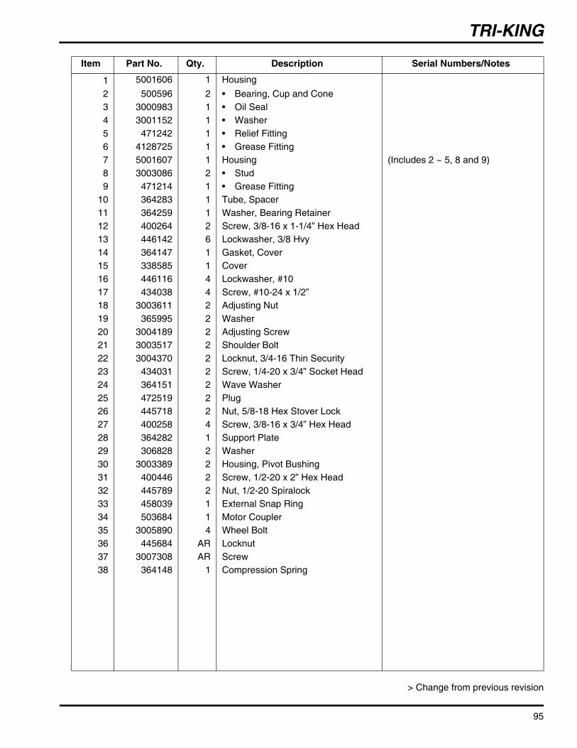
TRI-KING
95
> Change from previous revision
Item Part No. Qty. Description Serial Numbers/Notes
1 5001606 1 Housing2 500596 2 • Bearing, Cup and Cone3 3000983 1 • Oil Seal4 3001152 1 • Washer5 471242 1 • Relief Fitting6 4128725 1 • Grease Fitting7 5001607 1 Housing (Includes 2 ~ 5, 8 and 9)8 3003086 2 • Stud9 471214 1 • Grease Fitting
10 364283 1 Tube, Spacer11 364259 1 Washer, Bearing Retainer12 400264 2 Screw, 3/8-16 x 1-1/4” Hex Head13 446142 6 Lockwasher, 3/8 Hvy14 364147 1 Gasket, Cover15 338585 1 Cover16 446116 4 Lockwasher, #1017 434038 4 Screw, #10-24 x 1/2”18 3003611 2 Adjusting Nut19 365995 2 Washer20 3004189 2 Adjusting Screw21 3003517 2 Shoulder Bolt22 3004370 2 Locknut, 3/4-16 Thin Security23 434031 2 Screw, 1/4-20 x 3/4” Socket Head24 364151 2 Wave Washer25 472519 2 Plug26 445718 2 Nut, 5/8-18 Hex Stover Lock27 400258 4 Screw, 3/8-16 x 3/4” Hex Head28 364282 1 Support Plate29 306828 2 Washer30 3003389 2 Housing, Pivot Bushing31 400446 2 Screw, 1/2-20 x 2” Hex Head32 445789 2 Nut, 1/2-20 Spiralock33 458039 1 External Snap Ring34 503684 1 Motor Coupler35 3005890 4 Wheel Bolt36 445684 AR Locknut37 3007308 AR Screw38 364148 1 Compression Spring

TRI-KING
96
1211
10
28 13
24
108
8
76
4
1211
10
9
19
18
18
1720
21
65
15/16
27
26
26
22/23
2025
13 11
3
2
29
11
32
11
12
14
1
1
30
31
33
33
3333
33.1 Shields and Center Pivot Arm Serial No. All

TRI-KING
97
> Change from previous revision
Item Part No. Qty. Description Serial Numbers/Notes
1 4113759 1 Center Pivot Arm 67116 Only1 4113756 1 Center Pivot Arm 67125 Only
364140 2 • Bushing2 338561 1 Reel Pivot Bracket3 338562 1 Reel Pivot Bracket4 366827 2 Pivot Spacer5 400442 2 Screw, 1/2-20 x 1-1/2” Hex Head6 452012 4 Flat Washer, 1/27 445789 2 Nut, 1/2-20 Spiralock Flange8 3002379 2 Decal, Tight9 400264 2 Screw, 3/8-16 x 1-1/4” Hex Head
10 453011 AR Washer, 3/811 446142 12 Lockwasher, Hvy12 443110 6 Nut, 3/8-16 Hex13 400260 6 Screw, 3/8-16 x 7/8” Hex Head14 471214 1 Grease Fitting15 3002813 1 Reel Bumper Bracket 67116 & 67125 Only16 3002814 1 Reel Bumper Bracket 67116 & 67125 Only17 361723 2 Rubber Bumper 67116 & 67125 Only18 443810 4 Nut, 3/8-16 Jam 67116 & 67125 Only19 400190 4 Screw, 5/16-18 x 1-1/4” Hex Head 67116 & 67125 Only20 446136 AR Lockwasher, 5/16 Hvy21 443106 4 Nut, 5/16-18 Hex 67116 & 67125 Only22 122875.6 1 Rear Shield 67114 & 67115 Only22 122769.6 1 Rear Shield 67123 & 67124 Only23 1003056.6 1 Rear Shield 67116 Only23 1003057.6 1 Rear Shield 67125 Only24 5003650 1 Shield 26 Inch Reels (Includes Decals)24 5003648 1 Shield 30 Inch Reels (Includes Decals)25 400186 4 Screw, 5/16-18 x 7/8” Hex Head26 3000718 2 Shield Shim27 364281 2 Backup Nut28 364150 2 Clamp29 364777 1 Gasket30 3002718 1 Collar 67116 & 67125 Only31 3005435 1 Spring Lock Pin 67116 & 67125 Only32 400258 2 Screw, 3/8-16 x 3/4” Hex Head33 361877 1 Decal, Danger 2 Used on 67116 & 67125

TRI-KING
98
22 2122
2326
27
1730
19
18
20
19
1824
20
10
13/14
259
7
8
6
2/153
15
10
19
18 20
17
30
11/12
23
22
21
22
16
9
7
6
8 1/4
15
3
3
26" Reels
30" Reels
28
28
29
29
7
167
34.1 Side Pivot and Lift Arms Serial No. All

TRI-KING
99
> Change from previous revision
Item Part No. Qty. Description Serial Numbers/Notes
1 4113757 1 Right Pivot Arm 67115 Only2 4113754 1 Right Pivot Arm 67124 Only3 364156 2 • Bushing4 4113758 1 Left Pivot Arm 67114 Only5 4113755 1 Left Pivot Arm 67123 Only6 400260 2 Screw, 3/8-16 x 7/8” Hex Head7 446142 AR Lockwasher, 3/8 Hvy8 364781 2 Retainer Washer9 471214 2 Grease Fitting
10 443118 AR Nut, 1/2-13 Hex11 2811280 1 R.H. Lift Arm (Includes 15 & 28) - 6711512 2811281 1 L.H. Lift Arm (Includes 15 & 28) - 6711413 2811278 1 R.H. Lift Arm (Includes 15 & 25 ~ 28) - 6712414 2811279 1 L.H. Lift Arm (Includes 15 & 25 ~ 28) - 6712315 3007694 2 • Bushing16 400262 AR Screw, 3/8-16 x 1” Hex Head17 441904 2 Screw, 1/2-13 x 10” Full Thread Hex18 364157 AR Spring19 3007908 AR Plug20 364160 AR Shackle21 3004065 2 Lift Chain22 1001854 4 Shackle23 471214 2 Grease Fitting24 3005219 2 Bracket 67123, 67124 & 67125 Only25 3003041 2 Shaft 67123, 67124 & 67125 Only26 400272 2 Screw, 3/6-16 x 2-1/4” Hex Hd 67123, 67124 & 67125 Only27 444762 2 Locknut, 3/8-16 67123, 67124 & 67125 Only28 361947 2 Decal, Mower Removal29 2811128 1 Plate, Spring Mounting 67114, 67115 & 67116 Only29 2811127 1 Plate, Spring Mounting 67123, 67124 & 67125 Only30 452012 2 Washer, 1/2
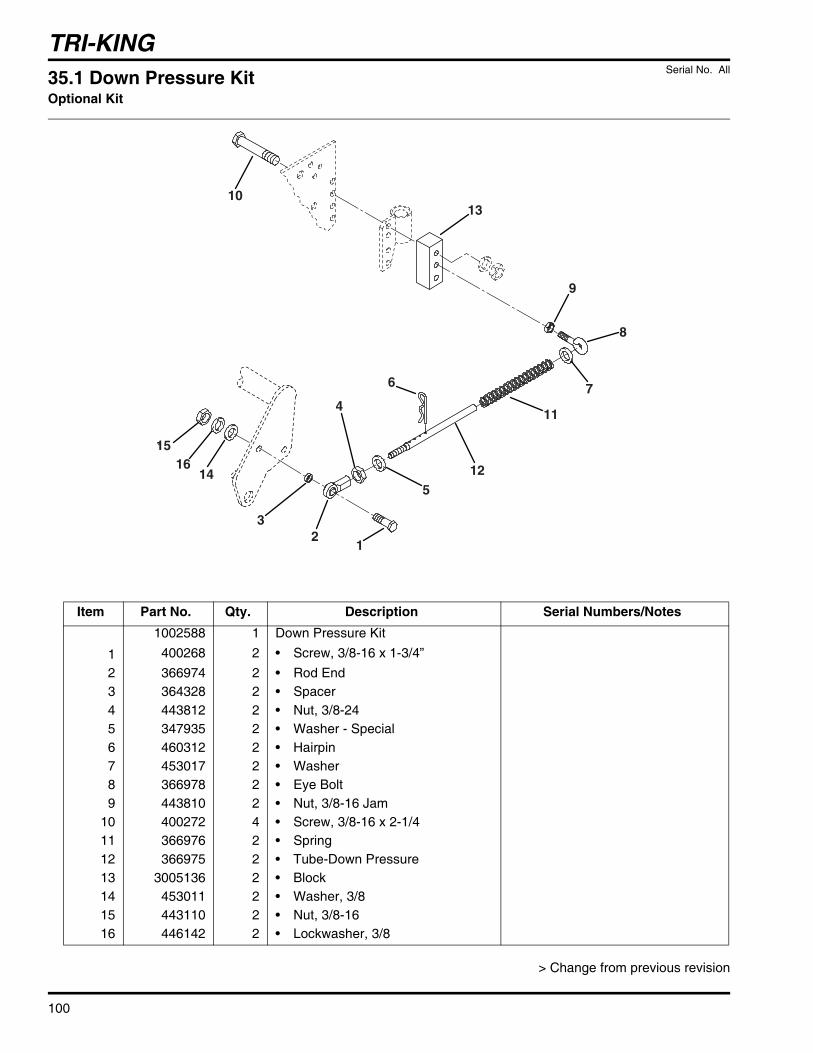
TRI-KING
Serial No. All 35.1 Down Pressure KitOptional Kit
100
> Change from previous revision
1013
9
8
7
11
125
12
3
6
4
1416
15
Item Part No. Qty. Description Serial Numbers/Notes1002588 1 Down Pressure Kit
1 400268 2 • Screw, 3/8-16 x 1-3/4”2 366974 2 • Rod End3 364328 2 • Spacer4 443812 2 • Nut, 3/8-245 347935 2 • Washer - Special6 460312 2 • Hairpin7 453017 2 • Washer8 366978 2 • Eye Bolt9 443810 2 • Nut, 3/8-16 Jam
10 400272 4 • Screw, 3/8-16 x 2-1/411 366976 2 • Spring12 366975 2 • Tube-Down Pressure13 3005136 2 • Block14 453011 2 • Washer, 3/815 443110 2 • Nut, 3/8-1616 446142 2 • Lockwasher, 3/8

TRI-KING
Serial No. All 36.1 Reel PumpPart No. 1000970
101
> Change from previous revision
12 3
4
56
7
89
Item Part No. Qty. Description Serial Numbers/Notes
1 N/S 3 Shear Pin (Included in A)2 N/S 4 Snap Ring (Included in A)3 N/S 1 Oil Seal (Included in A)4 5001435 1 Driveshaft5 N/S 3 Seal Plate (Included in A)6 590286 6 Alignment Pin7 5001437 1 Drive Key8 N/S 3 Wear Plate (Included in A)9 N/S 3 Diamond O-Ring (Included in A)A 5001436 1 Repair Kit Includes 1~3, 5, 8 & 9

TRI-KING
102
16 17
14
1531
30
29
28
27
26
12 8 1125
24 9 32 10
5
613
7
18
20
1921
22
23
37.1 Reel MotorPart No. 1002603
Serial No. All

TRI-KING
103
> Change from previous revision
Item Part No. Qty. Description Serial Numbers/NotesA 5002657 1 Seal Kit Includes 6, 10, 18, 21, 24, 26 & 28B 503502 1 Relief Cap Kit Includes 20 & 21C 503503 1 Relief Valve Kit Includes 19 ~ 23D 503504 1 Valve Stem Kit Includes 28 ~ 305 5001442 4 Snap Ring6 555822 1 O-Ring (Included in A)7 5001443 1 Driveshaft8 5001444 1 Lee Plug9 5001445 2 Gear, 1-3/8” Wide
10 N/S 1 .00050 (Silver) Gasket (Included in A)10 N/S 1 .00100 (Amber) Gasket (Included in A)10 N/S 1 .00075 (Gold) Gasket (Included in A)11 5001446 4 Sleeve Bearing12 5001447 1 Idler Shaft13 5001448 1 Stator14 555828 4 Screw, 1/4-2015 5001449 2 Alignment Pin16 5001450 1 Shipping Plug17 5001451 1 Shipping Plug18 555830 1 Snap Ring (Included in A)19 N/S 1 Adjustment Screw (Included in C)20 N/S 1 Cap (Included in B and C)21 N/S 1 Copper Gasket (Included in A, B and C)22 N/S 1 Spring (Included in C)23 N/S 2 Poppet (Included in C)24 5002141 1 O-Ring (Included in A)25 N/S 1 Steel Ball26 555836 1 O-Ring (Included in A)
> 27 2501165 1 Valve Plate28 555833 2 O-Ring (Included in A and D)29 N/S 1 Valve Stem (Included in D)30 N/S 1 Shear Pin (Included in D)31 N/S 4 Screw, 1/4-2032 5001441 1 Shear Pin

TRI-KING
104
8
9
6/137
14
134
1
16
3
11
2
15
5/12
9
6/137
14
134
10
10
1
16
3
115/12
Part Number4129590
Part Number4120764
38.1 Traction PumpPart No. 4120764 and 4129590
Serial No. All

TRI-KING
105
> Change from previous revision
Item Part No. Qty. Description Serial Numbers/Notes> A 502664 1 Charge Pump Kit Part Number 4120764
A 4132078 1 Charge Pump Kit Part Number 4129590> 1 N/S 1 • Charge Pump> 2 N/S 4 • Screw, Socket Head> 3 N/S 1 • Screw, Socket Head> 4 4120217 1 • Drive Pin> 5 N/S 1 • Square Cut Seal Also included in B> 6 N/S 1 • Square Cut Seal Also included in B> 7 N/S 1 • Pump Plate> 8 546416 1 • Grass Shield Part Number 4120764 Only> 9 N/S 2 • Snap Ring
10 4120216 1 • Carrier> B 2500620 1 Oil Seal Kit (Included in B)> 11 N/S 1 • Square Cut Seal (Included in B)> 12 N/S 1 • Square Cut Seal (Included in B)> 13 N/S 1 • Square Cut Seal (Included in B)> 14 N/S 2 • Oil Seal Includes 11 ~ 14> 15 361631 1 Fitting, 90° Barb> 16 4112141 1 Input Shaft Part Number 4120764
16 N/S 1 Input Shaft Part Number 4129590

TRI-KING
Serial No. All 39.1 3WD ValvePart No. 4111942
106
> Change from previous revision
1/4
1/4
8
2/3/5
6 7
6
Item Part No. Qty. Description Serial Numbers/Notes
1 4113025 2 Check Valve2 4113026 1 Spool Valve3 4113027 1 Solenoid Coil Reference K64 5003578 2 Seal Kit, Check Valve5 5003579 1 Seal Kit, Spool Valve6 5002157 2 Port Plug7 5001065 2 Port Plug8 4113028 1 Nut, Coil

TRI-KING
Serial No. All 40.1 Brake CalipersPart No. 1001634 L.H.Part No. 1001635 R.H.
107
> Change from previous revision
1
2
3
4
5
7
6
Item Part No. Qty. Description Serial Numbers/Notes
1 N/S 1 Cam R.H.1 N/S 1 Cam L.H.2 557823 1 Pivot Pin3 503660 1 Carrier Side Pad4 557824 1 Pad Support5 557825 1 Lever Retainer Spring6 557826 1 Pad Support7 503660 1 Cam Side Pad

TRI-KING
108
S AI
B
B G
M L
OFF-NONERUN - B+I+A; X+Y
OFF-G+MRUN - B+L
Optional Light Kit
START - B+I+S
RDRD
YX
RD
RD
BK
BK
BK
+
-B1
M1
K1
S
RD
OR
OR
OR
CB2
1 2
E11 2 3
4 5 6
G
B
87A
8730
868587A
8730
8685
87A
8730
8685
87A
8730
8685
G
B+
G
I
S AI
B B G
M L
BN
OFF-NONERUN - B+I+A; X+Y
OFF-G+MRUN - B+L
Optional Light Kit
START - B+I+S
RD
RD
YX
RD
BK
+
-B1
M1
G
GK1
B S P
P
CB1
1 2RD
BN BN/BK
BN/YE
BN/GY
BN/RD
BN/RD
RD/WH RD/WH
RD/YE
RD/YE
RD
/GN
RD
/GN
RD
/GN
RD/GN
OR/GN
OR/GN
OR/GN
OR/BN OR/BN
OR/YE
OR/BUOR/YEOR/WH
OR/WH
OR/WH
OR/WH
YE/GY
RD/YE RD/BK GY
BK
BK
BK
BK
BK
BK
BK
BK
BK
RD
/WH
RD
/YE
RD
/BU
GY
GY
BK
BK
RD
/YE
GY
/BK
GY
/RD
RD/OR
RD/OR
RD/OR RD/BU
RD/OR
RD
/OR
OR
/GN
OR
/GN
OR
/YE
BK
/WH
BK
/WH
BK
/WH
BK/WH BK
/WH
BK
/WH
OR
/YE
OR/YE
OR/YE
OR
/YE
OR
/YE
OR/YE
OR
/YE
OR
/YE
OR
/GN
OR
/GY
OR
/GY
OR
/GY
OR
/BK
OR
/BK
RD
/OR
RD
/OR
RDRD RD
RDH
RD
OR
/RD
RD
BN
RD
/OR
RD
CB1
1 2
1 2 3
4 5 6
GIg
B
87A
8730
8685
87A
8730
8685
G
B+
G
I
G
IS
SW1SW2
RDRD/WH
RD
/YE
RD/OR
SW2
SW3
SW4
SW5
BN/RDRD/OR
SW5
SW6SW7
SW8
BN
RDOR
BN/BK
BN/YE
RD/WH
RD/OR
RD/OR
RD/OR
SW8
SW9SW10
SW11
K2
K3
K4
K5
K6
K7
K8
SW7K8
L1
L2
YE/GY
SW11 L1
L2
L3
D1
GY
GY
BK
BK
K5
D1
D2
RD
/OR
D2
D3
RD
/WH
GY
/BK
GY
/RD
RD
/OR
SW6
SW10
D3
F1
SW3
SW12
L3
L4
F1
F2
F3
BN/GY
BN/RD
RD/YE RD/BK GY
BK
BK
RD
/BU
RD
/YE
RD/BU
SW4
K7F2
F3
F4
U1
K6
U1
R1
U2 U3
U2 U3
U4
U5
Electrical Schematic-Gas Units
Electrical Schematic-Diesel Units
BKBK/WH
OR
/YE
OR/YERDOR
SW12L4
41.1 Electrical Schematics Serial No. All
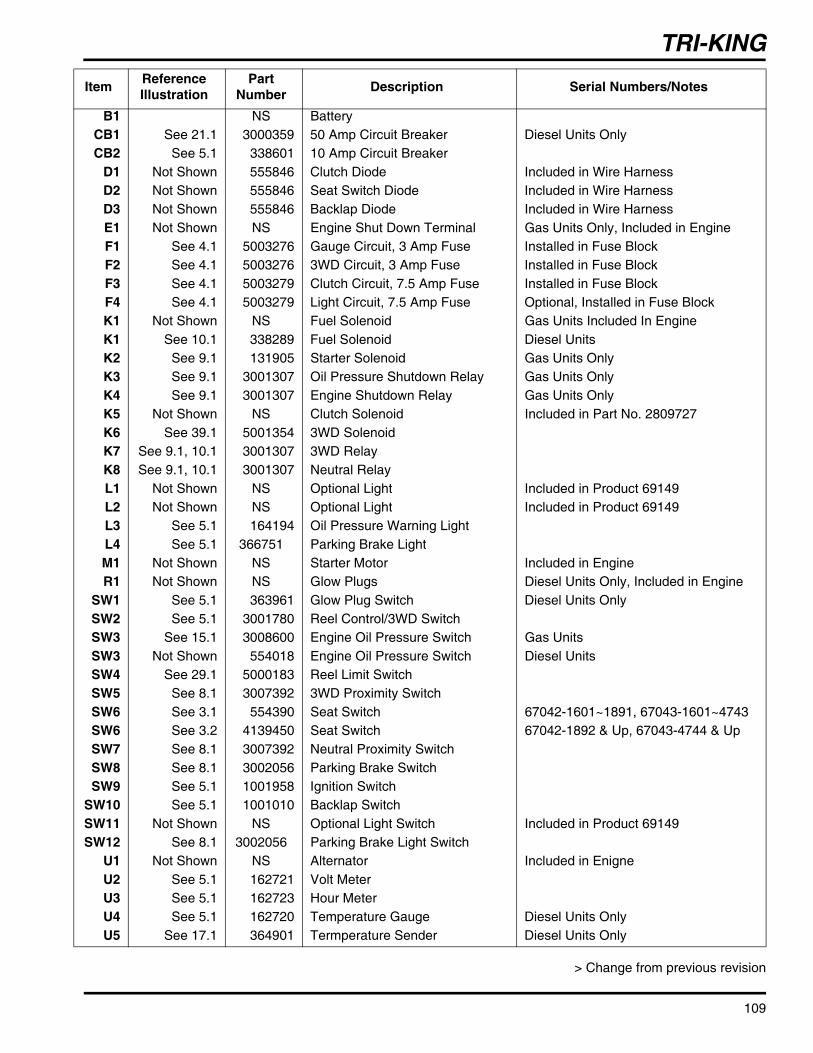
TRI-KING
109
> Change from previous revision
Item Reference Illustration
Part Number Description Serial Numbers/Notes
B1 NS BatteryCB1 See 21.1 3000359 50 Amp Circuit Breaker Diesel Units OnlyCB2 See 5.1 338601 10 Amp Circuit Breaker
D1 Not Shown 555846 Clutch Diode Included in Wire HarnessD2 Not Shown 555846 Seat Switch Diode Included in Wire HarnessD3 Not Shown 555846 Backlap Diode Included in Wire HarnessE1 Not Shown NS Engine Shut Down Terminal Gas Units Only, Included in EngineF1 See 4.1 5003276 Gauge Circuit, 3 Amp Fuse Installed in Fuse BlockF2 See 4.1 5003276 3WD Circuit, 3 Amp Fuse Installed in Fuse BlockF3 See 4.1 5003279 Clutch Circuit, 7.5 Amp Fuse Installed in Fuse BlockF4 See 4.1 5003279 Light Circuit, 7.5 Amp Fuse Optional, Installed in Fuse BlockK1 Not Shown NS Fuel Solenoid Gas Units Included In EngineK1 See 10.1 338289 Fuel Solenoid Diesel UnitsK2 See 9.1 131905 Starter Solenoid Gas Units OnlyK3 See 9.1 3001307 Oil Pressure Shutdown Relay Gas Units OnlyK4 See 9.1 3001307 Engine Shutdown Relay Gas Units OnlyK5 Not Shown NS Clutch Solenoid Included in Part No. 2809727 K6 See 39.1 5001354 3WD SolenoidK7 See 9.1, 10.1 3001307 3WD RelayK8 See 9.1, 10.1 3001307 Neutral RelayL1 Not Shown NS Optional Light Included in Product 69149L2 Not Shown NS Optional Light Included in Product 69149L3 See 5.1 164194 Oil Pressure Warning LightL4 See 5.1 366751 Parking Brake LightM1 Not Shown NS Starter Motor Included in EngineR1 Not Shown NS Glow Plugs Diesel Units Only, Included in Engine
SW1 See 5.1 363961 Glow Plug Switch Diesel Units OnlySW2 See 5.1 3001780 Reel Control/3WD SwitchSW3 See 15.1 3008600 Engine Oil Pressure Switch Gas UnitsSW3 Not Shown 554018 Engine Oil Pressure Switch Diesel UnitsSW4 See 29.1 5000183 Reel Limit SwitchSW5 See 8.1 3007392 3WD Proximity SwitchSW6 See 3.1 554390 Seat Switch 67042-1601~1891, 67043-1601~4743SW6 See 3.2 4139450 Seat Switch 67042-1892 & Up, 67043-4744 & UpSW7 See 8.1 3007392 Neutral Proximity SwitchSW8 See 8.1 3002056 Parking Brake SwitchSW9 See 5.1 1001958 Ignition Switch
SW10 See 5.1 1001010 Backlap SwitchSW11 Not Shown NS Optional Light Switch Included in Product 69149SW12 See 8.1 3002056 Parking Brake Light Switch
U1 Not Shown NS Alternator Included in EnigneU2 See 5.1 162721 Volt MeterU3 See 5.1 162723 Hour MeterU4 See 5.1 162720 Temperature Gauge Diesel Units OnlyU5 See 17.1 364901 Termperature Sender Diesel Units Only

110
RearWheelMotor
LeftWheelMotor
RightWheelMotor
Traction Pump
EngineDirectDrive3400 RPM
Reel Motors
RightCenterLeft
ElectricClutch
Filter
Tank5.5 Gals. in System
SteeringCylinder
Steering Valve
Filter LiftCylinder
Lift Valve
3WDValve
A
T
B P
PBT
P
L
R
12
A1AB1B
A B
TRI-KING42.1 Hydraulic Schematic Serial No. All

Fluids and Compounds
* Refer to the Operator’s manual or the Parts & Maintenance Manual for the correct hydraulic oil requirements for your machine.Jacobsen offers a High Usage Parts Catalog illustrating commonly used Parts through easy to read line Drawings. See your local Jacobsen Dealer for a copy.
Hydraulic Fluid*5001405 Two 2-1/2 Gallon Container of ISO VG68 Oil5001404 One 5 Gallon Pail of ISO VG68 Oil2500548 Two 2-1/2 Gallon Container of 10W30 Oil2500546 One 5 Gallon Pail of 10W30 Oil
503409 Two 2-1/2 Gallon Container of ATF Fluid503407 One 5 Gallon Pail of ATF Fluid
2-Cycle Oil554600 Twenty Four 16 Ounce Plastic Container
554599 Twenty Four 8 Ounce Plastic Container
Grease5000067 One 5 Gallon Pail OO-Grease
5000068 Twenty Four 8 Ounce Tube OO-Grease
Paint5003469 16 Ounce Gray Aerosol
554598 Six 12 Ounce Orange Aerosol2500789 Twelve 1 Quart Can Orange
546409 Two 1 Gallon Can Orange
Lapping Compound5002488 One 10 Pound Pail of 80 Grit5002490 One 25 Pound Pail of 80 Grit5002489 One 10 Pound Pail of 120 Grit5002491 One 25 Pound Pail of 120 Grit
Specialty Compound365422 5.3 Ounce Tube of Electrical Insulating Gel
5001581 14 Ounce Can of Lubriplate Multi Lube A
Biodegradable Hydraulic Fluid*5003102 One 55 Gallon Drum Jacobsen GreensCare 685003103 One 5 Gallon Pail Jacobsen GreensCare 685003105 One 55 Gallon Drum Jacobsen GreensCare 465003104 One 5 Gallon Pail Jacobsen GreensCare 464115976 One 55 Gallon Drum Jacobsen GreensCare 324115977 One 5 Gallon Pail Jacobsen Greens Care 325003106 Twenty Four 14 Ounce Tube Greens Care Grease
O-Ring Kit5002452 SAE O-Ring Boss (3/32 ~ 2” Tube O.D.)5002453 Common O-Ring Kit5002454 O-Ring Face Seal ORFS (-4 ~ -24 ORS Tube Size)
Right Start Kit for New MachinesSee your local Jacobsen Dealer
On-Time Maintenance KitSee your local Jacobsen Dealer
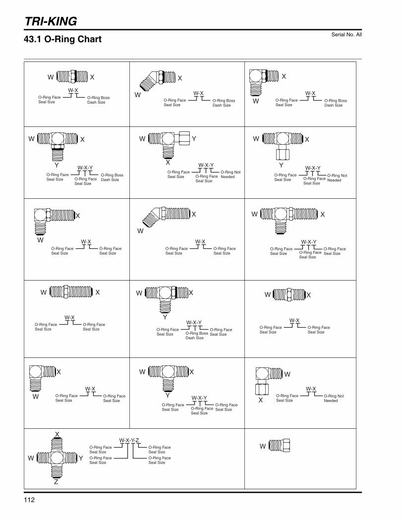
TRI-KING
112
XW
WW
X
W
X
W W-XO-Ring FaceSeal Size
O-Ring BossDash Size
W-XO-Ring FaceSeal Size
O-Ring BossDash Size
W-XO-Ring FaceSeal Size
W-XO-Ring FaceSeal Size
O-Ring FaceSeal Size
W-XO-Ring FaceSeal Size
O-Ring FaceSeal Size
O-Ring FaceSeal Size
W-XO-Ring FaceSeal Size
O-Ring FaceSeal Size
O-Ring FaceSeal Size
W-XO-Ring FaceSeal Size
O-Ring BossDash Size
X
W
X X
WW-X
O-Ring FaceSeal Size
O-Ring NotNeeded
W-XO-Ring FaceSeal Size
X
X X
W
X
Y
W
W-X-YO-Ring FaceSeal Size O-Ring Face
Seal Size
O-Ring BossDash Size
X
YW
W
X
Y
W
X
Y
W
W-X-YO-Ring FaceSeal Size
O-Ring FaceSeal SizeO-Ring Boss
Dash Size
W-X-YO-Ring FaceSeal Size O-Ring Face
Seal Size
W-X-YO-Ring FaceSeal Size
O-Ring NotNeeded O-Ring Not
NeededO-Ring FaceSeal Size
W-X-YO-Ring FaceSeal Size
O-Ring FaceSeal SizeO-Ring Face
Seal Size
W-X-YO-Ring FaceSeal Size
O-Ring FaceSeal SizeO-Ring Face
Seal Size
W-X-Y-ZO-Ring FaceSeal Size
O-Ring FaceSeal Size
O-Ring FaceSeal Size
O-Ring FaceSeal Size
X
Y
X
W
Z
Y
W
W
X
W
43.1 O-Ring Chart Serial No. All
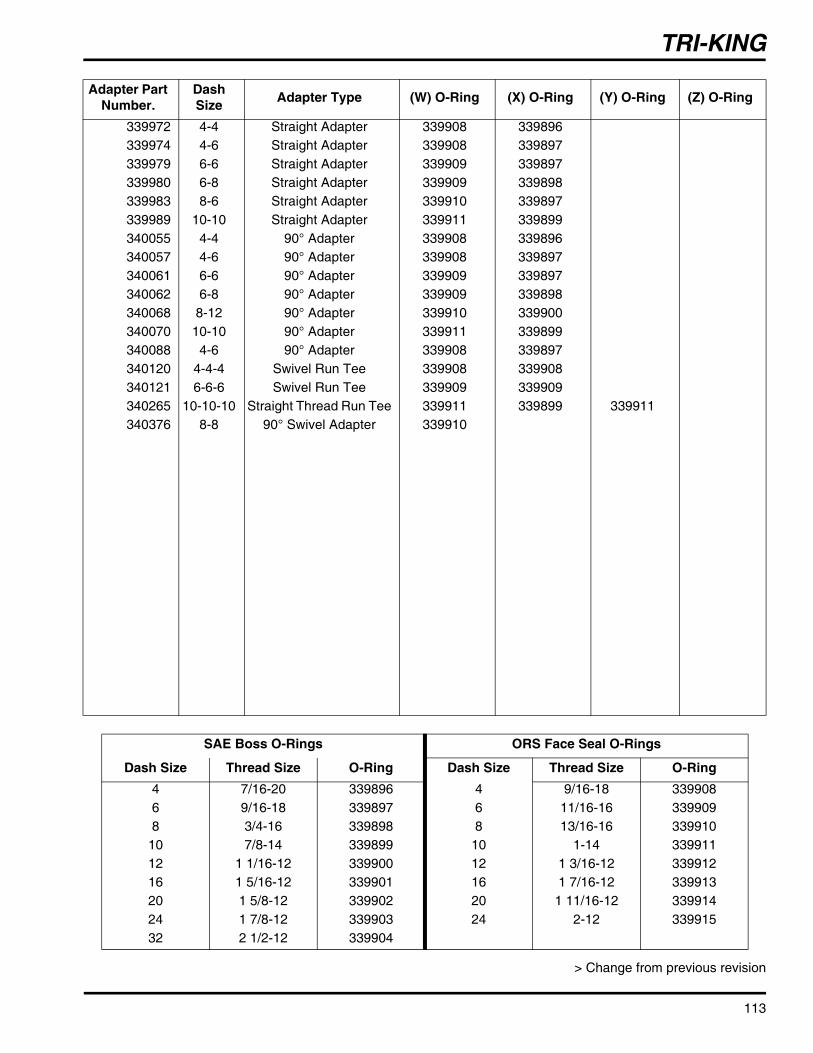
TRI-KING
113
> Change from previous revision
Adapter Part Number.
Dash Size Adapter Type (W) O-Ring (X) O-Ring (Y) O-Ring (Z) O-Ring
339972 4-4 Straight Adapter 339908 339896339974 4-6 Straight Adapter 339908 339897339979 6-6 Straight Adapter 339909 339897339980 6-8 Straight Adapter 339909 339898339983 8-6 Straight Adapter 339910 339897339989 10-10 Straight Adapter 339911 339899340055 4-4 90° Adapter 339908 339896340057 4-6 90° Adapter 339908 339897340061 6-6 90° Adapter 339909 339897340062 6-8 90° Adapter 339909 339898340068 8-12 90° Adapter 339910 339900340070 10-10 90° Adapter 339911 339899340088 4-6 90° Adapter 339908 339897340120 4-4-4 Swivel Run Tee 339908 339908340121 6-6-6 Swivel Run Tee 339909 339909340265 10-10-10 Straight Thread Run Tee 339911 339899 339911340376 8-8 90° Swivel Adapter 339910
SAE Boss O-Rings ORS Face Seal O-Rings
Dash Size Thread Size O-Ring Dash Size Thread Size O-Ring4 7/16-20 339896 4 9/16-18 3399086 9/16-18 339897 6 11/16-16 3399098 3/4-16 339898 8 13/16-16 339910
10 7/8-14 339899 10 1-14 33991112 1 1/16-12 339900 12 1 3/16-12 33991216 1 5/16-12 339901 16 1 7/16-12 33991320 1 5/8-12 339902 20 1 11/16-12 33991424 1 7/8-12 339903 24 2-12 33991532 2 1/2-12 339904
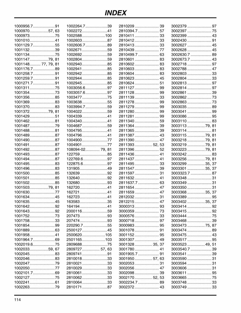
INDEX
1000956.7....................911000970.................57, 631000973.......................751001010.......................411001129.7....................551001132.......................391001134.......................751001147.................79, 811001148.......... 77, 79, 811001176.7....................891001258.7....................911001259.7....................911001271.7....................911001311.......................751001354.......................731001356.......................851001369.......................831001370.......................831001372.................79, 811001429.......................511001462.......................811001487.......................791001488.......................811001489.......................871001490.......................871001491.......................871001492.......................871001493.......................871001494.......................871001495.......................831001496.......................831001500.......................851001501.......................851001502.......................851001503.................79, 811001630.......................771001634.......................451001635.......................451001642.......................921001643.......................921001752.......................731001758.......................331001854.......................991001889.......................631001958.......................411001964.7....................691002019.6....................751002033.................59, 671002045.......................831002046.......................831002047.......................791002050.......................771002101.7....................691002127.......................751002241.......................611002263.......................79
1002264.7....................391002272.......................411002588.....................1001002603.......................871002606.7....................891002671.......................591002692.......................591002804.......................591002940.......................851002941.......................851002942.......................851002944.......................851002945.......................851003056.6....................971003057.6....................971003477.......................751003638.......................551003994.7....................591004022.......................591004339.......................411004340.......................411004687.......................591004795.......................411004796.......................411004900.......................771004901.......................77108094-02............. 79, 81122759.........................85122769.6......................97122875.6......................97131905.........................49132639.........................92132640.........................92132680.........................93162720.........................41162721.........................41162723.........................41163583.........................35164194.........................412000116.......................59207473.........................93207474.........................93220290.7......................552500127.......................452500620.....................1052501165.....................1032809688.......................752809727................ 57, 632809741.......................912810018.......................332810021.......................332810029.......................332810061.......................332810062.......................332810064.......................332810171.......................87
2810209 ...................... 392810394.7 ................... 572810411 ...................... 332810412 ...................... 332810413 ...................... 332810439 ...................... 772810499.7 ................... 632810601 ...................... 832810602 ...................... 832810603 ...................... 832810604 ...................... 832810623 ...................... 452810624 ...................... 512811127 ...................... 992811128 ...................... 992811139 ...................... 332811278 ...................... 992811279 ...................... 992811280 ...................... 992811281 ...................... 992811340 ...................... 592811364 ...................... 392811365 ...................... 392811387 ...................... 432811390 ...................... 472811393 ................ 52, 532811396 ...................... 522811436 ...................... 412811437 ...................... 412811495 ...................... 332811547 ...................... 392811597 ...................... 312811632 ...................... 412811637.7 ................... 632811654 ...................... 472811659 ...................... 472812032 ...................... 312812215 ...................... 473000313 ...................... 933000359 ...................... 733000576 ...................... 333000718 ...................... 973000983 ...................... 953001078 ...................... 913001152 ...................... 953001307 ...................... 493001328 ................ 35, 373001780 ...................... 413001905.7 ................... 913001950 ................ 57, 633002053 ...................... 313002056 ...................... 473002098 ...................... 393002170 ................ 52, 533002234.7 ................... 893002372 ...................... 43
3002379 ...................... 973002397 ...................... 753002399 ...................... 433002430 ...................... 913002627 ...................... 453002628 ...................... 453002630.7 ................... 893002673.7 ................... 433002718 ...................... 973002788 ...................... 473002803 ...................... 333002804 ...................... 333002813 ...................... 973002814 ...................... 973002861 ...................... 393002862 ...................... 733002863 ...................... 733003035 ...................... 893003041 ...................... 993003086 ...................... 953003110 ...................... 833003113 ................ 79, 813003114 ...................... 813003115 ................ 79, 813003218 ................ 79, 813003219 ................ 79, 813003223 ................ 79, 813003242 ...................... 833003256 ................ 79, 813003299 ................ 35, 373003301 ................ 35, 373003323.7 ................... 873003348 ...................... 313003349 ...................... 313003350 ...................... 313003368 ................ 35, 373003389 ...................... 953003402 ................ 35, 373003414 ...................... 923003415 ...................... 923003444 ...................... 753003468 ...................... 393003473 ................ 75, 873003474 ...................... 893003475 ...................... 433003517 ...................... 953003523 ................ 49, 513003540.7 ................... 393003541 ...................... 393003590 ...................... 313003594 ...................... 313003606 ...................... 313003611 ...................... 953003665 ...................... 753003748 ...................... 333003749 ...................... 33
114

INDEX
3003754...................... 913003764...................... 513003928................ 35, 373003968...................... 333004065...................... 993004182.7............. 79, 813004187................ 61, 693004189...................... 953004207...................... 313004253...................... 733004256...................... 733004333...................... 733004370...................... 953004410...33, 35, 37, 47,
51, 79, 81, 83, 893004427...................... 593004523................ 57, 653004526................ 57, 653004531...................... 833004539................ 49, 513004560.7................... 573004653...................... 313004655...................... 793004679...................... 893004881.7................... 433004882...................... 933004927.7................... 613004933...................... 593004962...................... 613004965...................... 493004983...................... 313004995.7................... 613005136.................... 1003005156...................... 933005172.7................... 593005219...................... 993005435...................... 973005472...................... 593005509...................... 593005513.7................... 593005852...................... 613005890...................... 953005920...................... 593006409...................... 913006745...................... 433006746...................... 433006988...................... 353006991...................... 353007308...................... 953007673...................... 933007694...................... 993007908...................... 993008359...................... 933008360...................... 933008433...................... 413008482................ 45, 55
3008600 ...................... 593009193 ...................... 473010139 ...................... 333010485 ...................... 55303567 ........................ 33306828 ........................ 95307374 .................. 77, 89319755 ........................ 67319914 ........................ 71325822 ........................ 75326112 ........................ 73328133 .................. 52, 53338289 ........................ 51338383 ........................ 45338561 ........................ 97338562 ........................ 97338585 ........................ 95338601 ........................ 41338647 ........................ 93339237 ........................ 31339900 .................. 79, 81339908 .................. 79, 81339910 .................. 79, 81339911 ........................ 83339912 .................. 79, 81339960 ........................ 59339963 .................. 79, 81339972 ........................ 79339974 ........................ 85339979 .................. 85, 87339980 ........................ 87339983 ........................ 77339989 77, 79, 81, 83, 87340055 .................. 79, 81340057 ........................ 85340061 .................. 77, 85340062 ........................ 87340068 ........................ 77340070 .................. 77, 87340088 ........................ 85340120 ........................ 77340121 ........................ 83340265 ........................ 83340376 ........................ 77340623 ........................ 31340654 ........................ 57343398 ........................ 43344132 ........................ 75345671 ......51, 79, 81, 89345700 ........................ 89346006 .................. 57, 65346361 ........................ 75346771 ........................ 45347935 ...................... 100352204 ........................ 45352936 ........................ 47
353008 ........................ 59353914 ..................45, 55354077 ........................ 59354080 ............79, 81, 85354989 ........................ 43355064 ........................ 59355174 ........................ 69358949 ........................ 59360111 ..................45, 55360343 ........................ 33361001 ........................ 63361005 ............65, 67, 73361028 ........................ 59361064 ..................49, 81361117 ........................ 75361615 ........................ 31361631 ...................... 105361681 ........................ 63361723 ............79, 81, 97361748 ........................ 75361862 ........................ 41361877 ........................ 97361947 ........................ 99362078 ........................ 59362263 ........................ 63362320 ........................ 57362469 ........................ 39362535 ........................ 71363448 ........................ 63363485 ........................ 63363586 ........................ 67363961 ........................ 41363962 ........................ 41363995 ........................ 31364140 ........................ 97364147 ........................ 95364148 ........................ 95364149.7 ..................... 91364150 ........................ 97364151 ........................ 95364156 ........................ 99364157 ........................ 99364160 ........................ 99364221 ........................ 85364234 ........................ 91364238 ........................ 89364259 ........................ 95364281 ........................ 97364282 ........................ 95364283 ........................ 95364328 ...................... 100364501 ........................ 63364694 ........................ 91364703 ........................ 73364774 ..................41, 73364777 ........................ 97
364781 ........................99365106 ..................52, 53365956 ........................31365995 ........................95366418 ........................59366526 ..................49, 51366653 ........................93366751 ........................41366790 ........................55366827 ........................97366974 ......................100366975 ......................100366976 ......................100366978 ......................100367029 ........................93367159 ........................31367160 ........................31367458 ..................79, 81367558 ........................57367559 ........................57395388 ........................454106900 ......................754111408 ......................314111942 ......................834112141 ....................1054113754 ......................994113755 ......................994113756 ......................974113757 ......................994113758 ......................994113759 ......................974117468 ......................314121007.7 ...................674121856.7 ...................654121872.7 ...................654121920 ......................674123003 ......................674124357 ......................314124358 ......................314124690 ......................314124691 ......................314124721 ......................314124759 ......................314124790 ......................314124806 ......................674125492 ......................634125772 ......................314125789 ......................314127309.7 ...................634128725 ......................954130752 ......................534130753 ......................674130754.7 ...................634130755 ......................674130756 ......................674130757 ......................67
115

INDEX
4137139.......................554138501.......................554139430.......................374139450.......................374140149.......................474140788.......................714140846.......................714141024.......................634141036.......................714141266.......................314141392.......................714143350.......................634149217.......................714150417.......................714150418.......................714150598.......................715000039.......................415000183.......................915000184.......................915000436.......................595000440.......................595000441.......................595000616.......................925000617.......................925000912.......................735000913.......................735000914.......................735001065.....................1065001348.......................455001419.......................855001428.......................415001435.....................1015001436.....................1015001437.....................1015001441.....................1035001442.....................1035001443.....................1035001444.....................1035001445.....................1035001446.....................1035001447.....................1035001448.....................1035001449.....................1035001450.....................1035001451.....................1035001606.......................955001607.......................955001665.......................335001666.......................695002087.......................925002088.......................925002089.......................925002090.......................925002101.......................415002102.......................415002126.......................73
5002141.....................1035002157.....................1065002644.......................635002647.......................335002657.....................1035002831.......................925002832.......................925002906.......................455002916.......................555003218................ 45, 555003385................ 45, 555003578.....................1065003579.....................1065003648.......................975003650.......................975003769.......................37500534.........................93500596.........................95502664.......................105502924.........................39503502.......................103503503.......................103503504.......................103503550.........................92503660.......................107503684.........................95523356.........................37523357.........................37545237.........................45546416.......................105549597............ 77, 79, 81550376.........................67550383.........................67550398.........................67550409.........................67550489.........................51550553.........................51553020.........................67553859.........................69553886.................. 69, 71553887.................. 69, 71553926.........................73553934.........................67554083.........................69554241.........................69554244.........................69554284.........................92554330.........................89554331.........................85554390.........................35554663.........................77554723.........................93554748.................. 49, 51554752.........................51554779.................. 45, 55554780.................. 45, 55
554896 ........................ 69555822 ...................... 103555828 ...................... 103555830 ...................... 103555833 ...................... 103555836 ...................... 103557563 ........................ 69557578 ........................ 69557580 ........................ 73557738 ........................ 39557823 ...................... 107557824 ...................... 107557825 ...................... 107557826 ...................... 107558012 .................. 35, 37558036 ........................ 41590286 ...................... 101594331 ........................ 6766172 .......................... 35
116

1.1.................................................................................Decals..................................................................................................... 302.1.................................................................................Hood and Cowlings............................................................................... 323.1.................................................................................Seat and Base........................................................................................ 343.2.................................................................................Seat and Base........................................................................................ 364.1.................................................................................Dash Installation.................................................................................... 385.1.................................................................................Instrument Panel ................................................................................... 406.1.................................................................................Hydro Control Linkage.......................................................................... 427.1.................................................................................Front Motors and Brakes...................................................................... 448.1.................................................................................Parking Brake, Neutral Start and 3WD Switches................................ 469.1.................................................................................Fuel Control ........................................................................................... 4810.1............................................................................... Fuel Control .......................................................................................... 5011.1...............................................................................Frame...................................................................................................... 5212.1...............................................................................Frame...................................................................................................... 5313.1...............................................................................Rear Steering ......................................................................................... 5414.1...............................................................................Engine and Pump .................................................................................. 5615.1...............................................................................Engine and Exhaust .............................................................................. 5816.1...............................................................................Air Intake ................................................................................................ 6017.1...............................................................................Engine and Pump .................................................................................. 6218.1...............................................................................Diesel Engine Mounting........................................................................ 6419.1...............................................................................Diesel Engine Exhaust.......................................................................... 6620.1...............................................................................Radiator Installation.............................................................................. 6820.2...............................................................................Radiator Installation.............................................................................. 7021.1...............................................................................Air Filter and Circuit Breaker ............................................................... 7222.1...............................................................................Tanks ...................................................................................................... 7423.1...............................................................................Hydro Pump and Charge Filter ............................................................ 7624.1...............................................................................Pump Suction and Return Hydraulics................................................. 7825.1...............................................................................Pump Suction and Return Hydraulics................................................. 8026.1...............................................................................Traction Hydraulics............................................................................... 8226.2...............................................................................Steering and Lift Hydraulics................................................................. 8427.1...............................................................................Reel Hydraulics ..................................................................................... 8628.1...............................................................................Reel Lift .................................................................................................. 8829.1...............................................................................Rear Lift Arm.......................................................................................... 9030.1...............................................................................Reels....................................................................................................... 9231.1...............................................................................Roller Brackets and Skids .................................................................... 9332.1...............................................................................Reel Bearing Housing ........................................................................... 9433.1...............................................................................Shields and Center Pivot Arm.............................................................. 9634.1...............................................................................Side Pivot and Lift Arms....................................................................... 9835.1...............................................................................Down Pressure Kit .............................................................................. 10036.1...............................................................................Reel Pump............................................................................................ 10137.1...............................................................................Reel Motor............................................................................................ 10238.1...............................................................................Traction Pump ..................................................................................... 10439.1...............................................................................3WD Valve ............................................................................................ 10640.1...............................................................................Brake Calipers ..................................................................................... 10741.1...............................................................................Electrical Schematics ......................................................................... 10842.1...............................................................................Hydraulic Schematic ........................................................................... 11043.1...............................................................................O-Ring Chart ........................................................................................ 112

Textron Golf, Turf & Specialty ProductsPO Box 7708, Charlotte, NC 28241-7708www.ttcsp.com
Equipment from Jacobsen is built to exactingstandards ensured by ISO 9001 and ISO 14001
registration at all of our manufacturing locations.
A worldwide dealer network and factory trainedtechnicians backed by Textron Parts Xpress
provide reliable, high-quality product support.