
Measuring dynamic efficiency of highway maintenance operations
Upload
khangminh22Category
view
0download
0
Highway Maintenance ManualLast upated: 2010

GOVERNMENT OF THE NORTHWEST TERRITORIES DEPARTMENT OF TRANSPORTATION
HIGHWAY OPERATIONS
List of Highway Maintenance Activities
Revised 2010-04-15 016 Activity Summary rev 10.docx Page 1 of 5
ROAD SURFACES AND SHOULDERS – Section 100 Code Description/Comment Daily Work Measure
10112 Wet Blading Not CHL, Cat. 1 & 2 76 Pass kms 10113 Wet Blading Not CHL, Cat. 3 & Others 76 Pass kms 10312 Wet Blading CHL. Cat. 1 & 2 76 Pass kms 10313 Wet Blading CHL. Cat. 3 76 Pass kms 10314 Wet Blading CHL. Cat. 4 & 5 76 Pass kms
10512 Wet Blading DL-10 Cat. 1 & 2 76 Pass kms 10513 Wet Blading DL- 10 Cat. 3 76 Pass kms 10514 Wet Blading DL-10 Cat. 4 & 5 76 Pass kms 10713 Dry Blading - Cat. 3 32 Pass kms 10714 Dry Blading - Cat. 4 32 Pass kms
10715 Dry Blading - Cat. 5 & others 32 Pass kms 11411 Gravel Surfacing 600 Cubic Meters 11611 Spot Gravelling 42 Cubic Meters 12011 Grade Repairs - Gravel Surfaces 75 Cubic Meters 12211 Grade Repairs - Paved Surfaces 75 Cubic Meters
15111 Dust Treatment - CaCl 3 to 5 Tonnes 15411 Deleted - Dust Treatment - Oil NA 16111 Permanent Hand Patch - Pavement 4 Cubic Meters 16112 Permanent Hand Patch A.S.T 4 Cubic Meters 16211 Chipseal Patch- Pavement 2,800 Square Meters
16212 Chipseal Patch A.S.T. 2,800 Square Meters 16311 Crack Sealing - Pavement 500 Litres 16411 Level with Premix – Pavement, See 841 50 Cubic Meters 16611 Rout and Seal Lineal 750 Meters 16711 Mix & Patch Asphalt Surface 10 Cubic Meters
16811 Asphalt Surface Repair - Other As Required 16911 Recycle A.S.T. 4,000 Square Meters 17011 Shoulder Blading 12 Shoulder kms 17200 Shoulder Repair 60 Cubic Meters 17411 Sweeping Hours, As Required

GOVERNMENT OF THE NORTHWEST TERRITORIES DEPARTMENT OF TRANSPORTATION
HIGHWAY OPERATIONS
List of Highway Maintenance Activities
Revised 2010-04-15 016 Activity Summary rev 10.docx Page 2 of 5
DRAINAGE and BRIDGES – Section 200 Code Description/Comment Daily Work Measure 20211 Clean & Inspect Culverts 24 Culverts 20311 Culvert Repair/Replacement 3 Culverts 21011 Ditch Cleaning 32 Hours 21111 Ditch Reclamation 32 Hours 24111 Beaver Dam Removal Hours. As Required 25111 Bridge Inspection Bridge 25511 Bridge Cleaning Bridge 25811 Bridge Maintenance Hours 27111 Winter Road Bridges Hours ROAD SIDE – Section 300 Code Description/Comment Daily Work Measure 30111 Machine Mowing 10 Hectares 31011 Brush & Debris Removal 16 Hours 31111 Machine Cutting Brush & Trees 22 Swath kms 31211 Hand Brushing Hours, As Required 31411 Deleted - Chemical Vegetation Control NA 32011 Litter Pickup 24 Hours 32111 Rest Stops/ Litter Barrels Site 32211 Survival Cabins Site 33011 Weight Scales/ Compliance Hours, As Required 34111 Park & Campsite Maintenance 24 Hours WINTER OPERATIONS – Section 400 Code Description/Comment Daily Work Measure 40111 Snow Plowing (Grader) 86 Pass kms 40211 Snow Plowing (Truck) 192 Pass kms 40511 Snow Clearance (Cuts) 200 Hours/Cut 40711 Snow Removal Hours, As Required 41011 Ice Blading 60 Pass kms 41111 Ice Removal - Chemical 40 Kilometres 41211 Sanding 16 Cubic Meters 41511-NEW Stockpile Winter Sand – Chemical Added 150 Cubic Meters, Replaces 91511 41512-NEW Stockpile Winter Sand - Freeze Dried 150 Cubic Meters, Replaces 91512 42111 Ice Bridge Construction 40 Hours

GOVERNMENT OF THE NORTHWEST TERRITORIES DEPARTMENT OF TRANSPORTATION
HIGHWAY OPERATIONS
List of Highway Maintenance Activities
Revised 2010-04-15 016 Activity Summary rev 10.docx Page 3 of 5
WINTER OPERATIONS – Section 400 (continued) Code Description/Comment Daily Work Measure 42311 Ice Bbridge Maintenance 16 Hours 42611 Ice Spray 96 Hours 43111 Snow Road Construction 10 Kilometres 43211 Snow Road Maintenance 100 Pass kms 43311 Ice Road Construction 8 Kilometres 43411 Ice Road Maintenance 200 Pass kms 44111 Snowfences 16 Hours 45111 Culvert Steaming 2 Culverts 45511 Glaciation/ Overflow Control 16 Hours TRAFFIC SERVICES – Section 500 Code Description/Comment Daily Work Measure 50311 Guiderail Maintenance 32 Metres 51011 Erect New Signs 4 Signs 51411 Sign Maintenance 16 Hours 51811 Temporary & Seasonal Signs 16 Hours 52111 Asphalt Surface Pre Marking 12 Kilometres 52411 Asphalt Surface Marking, By Contract 36 Line kms 52611 Asphalt Surface Marking - Other 36 Line kms 56011 Traffic Counting Under Review 56211 Surface Deflection Testing, By Contract 8 Hours AIRPORT SERVICES – Section 600 (Under Review). All work requests require prior authorization from the Director, Airport Operations or his designate. Code Description/Comment Daily Work Measure 65011 Airports Hours MARINE SERVICES – SECTION 700 (Under Review). All work requests require prior authorization from the director, Marine Operations, or his designate Code Description/Comment Daily Work Measure 71011 Launching Hours 71111 Haul Out Hours 71211 Haul Out Way Repair Hours 72011 Approach Reconditioning Hours 72111 Ice Removal Hours

GOVERNMENT OF THE NORTHWEST TERRITORIES DEPARTMENT OF TRANSPORTATION
HIGHWAY OPERATIONS
List of Highway Maintenance Activities
Revised 2010-04-15 016 Activity Summary rev 10.docx Page 4 of 5
MARINE SERVICES – SECTION 700 (Under Review, continued) Code Description/Comment Daily Work Measure 72311 Approach Maintenance Hours 78011 Shore Facility - Maintenance Hours 78211 Shore Facility - Operation Hours 78311 Shore Facility - Snow Removal Hours 78611 Stockpiling Materials Hours 79511 Marine Recoverable Dollars PROJECTS – SECTION 800 (approved with funding from the Capital Budget). Code Description/Comment Daily Work Measure 80311 Culvert Installation 0.5 Culverts 80411 Binder Application 2 Kilometres 80611 Gravel Surface Rehabilitation 600 Cubic Meters 81011 Major Grade Repairs, By Contract Hours 82011 Paint Bridges, By Contract Hours 82111 Major Bridge Repair, By Contract Hours 83011 Crush- Surface Aggregate, By Contract Cubic Meters 83013 Crush- Chipseal Aggregate, By Contract Cubic Meters 83014 Quality/Quantity Control, By Contract Hours 84011 Chipsealing 7 Lane kms 84013 Chipsealing- Transport Hours, As Required 84111 Resurfacing with Premix 380 Cubic Meters 85111 Drainage Channel Improvement Hours, As Required 85511 Right of Way Improvement Hours, As Required 87011 Transportation Engineering Projects Hours, As Required 87012 Transportation Engineering Recoveries Dollars, As Required 87211 Operations Capital Projects Hours, As Required 87212 Operations Capital Projects Recoveries Dollars, As Required DISASTER AND MISCELLANEOUS – SECTION 800 Code Description/Comment Daily Work Measure 88811 Disaster Hours, As Required 88812 Disaster Recoveries Dollars, As Required 89911 Miscellaneous 8 Hours

GOVERNMENT OF THE NORTHWEST TERRITORIES DEPARTMENT OF TRANSPORTATION
HIGHWAY OPERATIONS
List of Highway Maintenance Activities
Revised 2010-04-15 016 Activity Summary rev 10.docx Page 5 of 5
SERVICE FUNCTIONS & OVERHEADS – Section 900 Code Description/Comment Daily Work Measure 90011 Highway Patrol 8 Hours 90111 Equipment Servicing/Repair Less than One Hour 90112 Equip. Service/ Repair- Assist Mechanic More than One Hour 90211 Leave Hours 0.25 Hours 90311 Stockpiling material 8 Hours 90411 Field Supervision 8 Hours 90611 Inclement Weather/Standby Hours, As Required 90711 Training & Meetings Hours, As Scheduled 90712 Building/ Grounds Maintenance 16 Hours 90811 Camp Operations Dollars, As Approved by RM 90911 Radio Network Dollars, As Required 91011 Hay River Administration Days, As Required 91111 Travel and Relocation Dollars, As Approved by RM 91311 Camp Administration 1 Day 91444 Stockpiling Premix 600 Cubic Meters 91511-415 (Stockpile Winter Sand - Chemical Added) Replaced by 415 91512-415 (Stockpile Winter Sand - Freeze Dried) Replaced by 415 91611 Sundry Equipment Hours, As Approved by RM 91711 Transport 8 Hours 91811 Material Suspense Dollars, As Approved by RM 91911 Contract Equipment Suspense Dollars, As Approved by RM 92511 Work Done for Others Hours, As Approved by RM 92512 Work for Others – Recovery (Admin use) Dollars, As Approved by RM 95011 Admin/Contract Adjustment Dollars, As Approved by RM

GOVERNMENT OF THE NORTHWEST TERRITORIES
DEPARTMENT OF TRANSPORTATION HIGHWAY OPERATIONS
CODE ACTIVITY LIST – SUMMARY DESCRIPTION DAILY WORK
MEASURE
Revised 2010-04-22 Activity List-Summary Description rev 10.docx Page 1 of 27
ROAD SURFACES AND SHOULDERS
10112 10113 10312 10313 10314 10512 10513 10514
WET BLADING - Not Chlorided. (Cat. 1 & 2) WET BLADING - Not Chlorided. (Cat. 3 & others) WET BLADING - Chlorided (Cat. 1 & 2) WET BLADING - Chlorided (Cat. 3) WET BLADING - Chlorided (Cat. 4 & 5) WET BLADING - DL-10 (Cat. 1 & 2) – under review WET BLADING - DL-10 (Cat. 3) – under review WET BLADING - DL-10 (Cat 4 & 5) – under review Blade and reshape gravel roads with the addition of water unless optimum surface moisture conditions exists, to correct deficiencies such as:
- Inadequate crown or superelevation. - Potholed, rutted or corrugated conditions. - Windrows or loose gravel.
This operation includes scarifying the road surface when necessary and recovering lost gravel from the grade sideslopes (Shoulder Robbing) when done in conjunction with the blading and reshaping of the surface.
76 Pass Kilometres
10713 10714 10715
DRY BLADING (Cat. 3) DRY BLADING (Cat. 4) DRY BLADING (Cat. 5 & Others) Blading Gravel roads, without application of water to correct such deficiencies as:
- Inadequate crown or superelevation. - Potholed, rutted or corrugated conditions. - Windrows or loose gravel.
This operation includes recovering lost gravel from the grade sideslopes (Shoulder Robbing) when done in conjunction with the surface blading.
32 Pass Kilometres
11411
GRAVEL SURFACING Involves the gravel surfacing of continuous sections of gravel surfaced roads by the annual replacement of lost material. Includes hauling, watering, checking and spreading of the applied material. For an extensive rehabilitation effort for gravel road surfaces that is approved with funding by the Regional Manager, use the Activity 80611.
600 Cubic Meters

GOVERNMENT OF THE NORTHWEST TERRITORIES
DEPARTMENT OF TRANSPORTATION HIGHWAY OPERATIONS
CODE ACTIVITY LIST – SUMMARY DESCRIPTION DAILY WORK
MEASURE
Revised 2010-04-22 Activity List-Summary Description rev 10.docx Page 2 of 27
11611
SPOT GRAVELLING Spot patching of short (less than 200 metres) sections if the gravel surfaces to correct such deficiencies as:
- Localized road depressions. - Settlement at utility cuts or culverts. - Potholes and minor unstable areas. - Areas lacking gravel.
42 Cubic Meters
12011
GRADE REPAIRS- GRAVEL SURFACES The repair of the grade including shoulders and graded sideslopes using selected clays, pit run gravel, crush or other suitable materials to correct deficiencies such as:
- Unstable areas/frost upheaval. - Settlement (including problems relating to permafrost). - Grade washout/erosion. - Grade slippage. - Loss of surface cross section.
This operation includes the excavation beyond the failure zone. For major grade repairs approved with funding by the Regional Manager, use Activity 81011.
75 Cubic Metres
12211 GRADE REPAIRS- PAVED SURFACES The repair of the grade including shoulder, graded sideslopes and the pavement base using selected clay, pit run gravel, crush or other suitable fill material to correct deficiencies such as:
- Unstable areas/frost upheaval. - Settlement (including problems relating to permafrost). - Grade washout/erosion. - Grade slippage.
This operation includes the excavation to 300 mm beyond the failure zone (to the maximum depth of 1.5 metres) and 100 metres in length, and disposal of the unstable material. For major grade repairs approved with funding by Regional Manager, use Activity 81011. Note: Replacement of the asphalt surface is to be reported to the 161-164 series of activities.
75 Cubic Meters

GOVERNMENT OF THE NORTHWEST TERRITORIES
DEPARTMENT OF TRANSPORTATION HIGHWAY OPERATIONS
CODE ACTIVITY LIST – SUMMARY DESCRIPTION DAILY WORK
MEASURE
Revised 2010-04-22 Activity List-Summary Description rev 10.docx Page 3 of 27
15111
DUST TREATMENT- CHLORIDE, NORMAL Application of the calcium chloride on gravel surfaces for dust abatement and surface stabilization.
3 to 5 Tonnes/Kilometre
15411
DELETED – DUST TREATMENT- OIL Application of special road oils/asphalt on gravel surfaces for dust abatement and surface stabilization.
Tonnes (Not Applicable)
16111 16112
PERMANENT HAND PATCH- PAVEMENT PERMANENT HAND PATCH- A.S.T. Patching of asphaltic surfaces using premix to repair deficiencies such as:
- Potholes/surface breaks. - Frost related bumps. - Alligator & map cracking. - Shoved or rippled areas.
4 Cubic Metres
16211 16212
CHIPSEAL PATCH- PVEMENT CHIPSEAL PATCH- A.S.T. Chipseal patch is the application of a liquid asphalt with a hand wand or spray bar and the subsequent application of an aggregate wearing surface to correct deficiencies such as:
- Sealing alligator and map cracking. - Raveling/segregation. - Minor wheel rutting.
For repairs to extensive sections that are approved with funding by the Regional Manager, use Activity 84011.
2,800 Square Metres
16311
CRACKSEALING- PAVEMENT The preparation and filling of cracks with cut backs/emulsion or liquid rubberized asphalt, (cold pours) and the blotting with stone chips or sand. Include minor applications of these asphaltic and aggregate materials to small areas of the distressed pavement, when performed during the major crack sealing operation.
500 Litres

GOVERNMENT OF THE NORTHWEST TERRITORIES
DEPARTMENT OF TRANSPORTATION HIGHWAY OPERATIONS
CODE ACTIVITY LIST – SUMMARY DESCRIPTION DAILY WORK
MEASURE
Revised 2010-04-22 Activity List-Summary Description rev 10.docx Page 4 of 27
16411
LEVEL WITH PREMIX- PAVEMENT The placing of premix on an existing asphalt surface and spreading the material with a grader to level depressions and strengthen the surface. For overlays (exceeding 100 metres in length) when approved with funding by the Regional Manager, use Activity 84111.
50 Cubic Metres
16611
ROUT AND SEAL Rout and Seal is a semi-permanent process to seal cracks that have been routed and then filled with a special hot rubberized product to reduce the possibility of the cracks reappearing during the winter months. This procedure is usually limited to following:
- Longitudinal Cracks - Transverse Cracks - Map Cracks
750 Lineal Metres
16711 MIX AND PATCH ASPHALT SURFACES The use of a mobile asphalt plant is to mix aggregate and a liquid asphalt or preferably rejuvenate premix either at the stockpile or the worksite to provide hot premix for immediate use in conjunction with the repair of asphaltic surfaces to correct such deficiencies as:
- Potholes - Depressions - Shoved or slippage areas - Alligator and map cracking
10 Cubic Metres
16811
ASPHALT SURFACE REPAIR- OTHER Includes surface maintenance procedures that are not otherwise covered in the main Maintenance Activities to correct deficiencies such as:
- Bleeding pavement treatment. - Scarifying asphalt surfaces which are beyond repair. - Surface planing. - Temporary patching of potholes/surface breaks with gravel
and calcium chloride etc.
Hours (As Required)

GOVERNMENT OF THE NORTHWEST TERRITORIES
DEPARTMENT OF TRANSPORTATION HIGHWAY OPERATIONS
CODE ACTIVITY LIST – SUMMARY DESCRIPTION DAILY WORK
MEASURE
Revised 2010-04-22 Activity List-Summary Description rev 10.docx Page 5 of 27
16911
RECYCLE A.S.T. The restoration of an AST or Asphaltic Surface Treatment surface on a sound grade by lifting and breaking down of the existing mat to a workable size, adding material as required and then relaying the blend to correct deficiencies on a designated section when conditions exist such as:
- Severe surface distortions that cover more than 30% of the surface area.
- Sever potholed conditions which are generally deeper than 50 mm and cover more than 30% of the surface.
4,000 Square Metres
17011
SHOULDER BLADING Blading of the gravel shoulders on paved sections to maintain proper cross section and to remove pavement edge drop-off.
12 Shoulder Kilometres
17211
SHOULDER REPAIR The repair with gravel of non paved shoulders on asphalted sections of highway to correct:
- Minor settlements, low spots and small eroded areas. - Severe drop-offs from pavement when shoulder blading
will not correct problem. Note: Repair of major settlements and erosion to be charged to Activity 12211.
60 Cubic Meters
17411
SWEEPING Machine sweeping of asphalt surfaces to:
- Provide a safe clean dust free asphaltic surface. - Prevent markings from becoming obscured.
Hours (As Required)
GOVERNMENT OF THE NORTHWEST TERRITORIES
DEPARTMENT OF TRANSPORTATION HIGHWAY OPERATIONS
CODE ACTIVITY LIST – SUMMARY DESCRIPTION DAILY WORK
MEASURE
Revised 2010-04-22 Activity List-Summary Description rev 10.docx Page 6 of 27
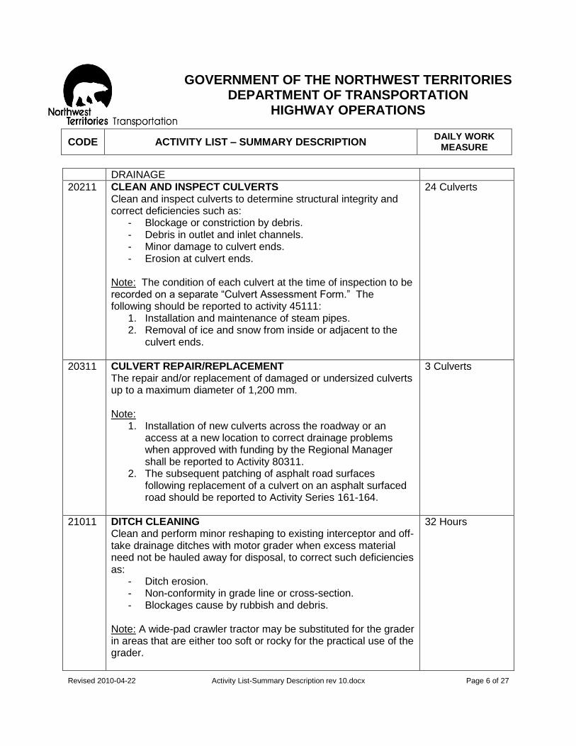
DRAINAGE
20211
CLEAN AND INSPECT CULVERTS Clean and inspect culverts to determine structural integrity and correct deficiencies such as:
- Blockage or constriction by debris. - Debris in outlet and inlet channels. - Minor damage to culvert ends. - Erosion at culvert ends.
Note: The condition of each culvert at the time of inspection to be recorded on a separate “Culvert Assessment Form.” The following should be reported to activity 45111:
1. Installation and maintenance of steam pipes. 2. Removal of ice and snow from inside or adjacent to the
culvert ends.
24 Culverts
20311
CULVERT REPAIR/REPLACEMENT The repair and/or replacement of damaged or undersized culverts up to a maximum diameter of 1,200 mm. Note:
1. Installation of new culverts across the roadway or an access at a new location to correct drainage problems when approved with funding by the Regional Manager shall be reported to Activity 80311.
2. The subsequent patching of asphalt road surfaces following replacement of a culvert on an asphalt surfaced road should be reported to Activity Series 161-164.
3 Culverts
21011
DITCH CLEANING Clean and perform minor reshaping to existing interceptor and off-take drainage ditches with motor grader when excess material need not be hauled away for disposal, to correct such deficiencies as:
- Ditch erosion. - Non-conformity in grade line or cross-section. - Blockages cause by rubbish and debris.
Note: A wide-pad crawler tractor may be substituted for the grader in areas that are either too soft or rocky for the practical use of the grader.
32 Hours

GOVERNMENT OF THE NORTHWEST TERRITORIES
DEPARTMENT OF TRANSPORTATION HIGHWAY OPERATIONS
CODE ACTIVITY LIST – SUMMARY DESCRIPTION DAILY WORK
MEASURE
Revised 2010-04-22 Activity List-Summary Description rev 10.docx Page 7 of 27
21111
DITCH RECLAMATION The reclamation of the existing roadside, interceptor and off-take drainage ditches by excavating, loading, hauling and disposing of material removed to correct deficiencies such as:
- Non-conformity in guideline or cross-section. - Blockages caused by rubbish or debris. - Water flow restricted by trees and brush. - Ditch erosion.
32 Hours
24111
BEAVER DAM REMOVAL The removal of obstruction caused by beaver or other animals in culverts, natural waterways, interceptor and off-take ditches to correct drainage deficiencies that effect the grade.
Hours (As Required)

GOVERNMENT OF THE NORTHWEST TERRITORIES
DEPARTMENT OF TRANSPORTATION HIGHWAY OPERATIONS
CODE ACTIVITY LIST – SUMMARY DESCRIPTION DAILY WORK
MEASURE
Revised 2010-04-22 Activity List-Summary Description rev 10.docx Page 8 of 27
BRIDGES
25111
BRIDGE INSPECTION Routine inspection and the reporting of structural conditions of bridges and large culverts (1,500 mm and over).
Bridge
25511
BRIDGE CLEANING This is to be performed to remove all dirt and debris, de-icing chemicals, winter sand or any other material with a harmful effect on the bridge.
Bridge
25811
BRIDGE MAINTENANCE All timber, concrete and/or steel repairs carried out on bridges including minor structural repairs, repair or replacement of bridge rails, lubrication of bearings, repair or replacement of timber decking etc.
Hours
27111
WINTER ROAD BRIDGES The installation, repair and removal of portable bridges on winter roads.
Hours

GOVERNMENT OF THE NORTHWEST TERRITORIES
DEPARTMENT OF TRANSPORTATION HIGHWAY OPERATIONS
CODE ACTIVITY LIST – SUMMARY DESCRIPTION DAILY WORK
MEASURE
Revised 2010-04-22 Activity List-Summary Description rev 10.docx Page 9 of 27
ROADSIDE
30111
MACHINE MOWING Machine mowing of grass, small brush and other vegetation within the highway right-of-way to:
- Control unwanted growth. - Maintain visibility for safety. - Improve roadside appearance. - Minimize formation of snowdrifts.
10 Hectares
31011
BRUSH AND DEBRIS REMOVAL Clearing of right-of-way of trees, brush, stones and debris using heavy equipment such as crawler tractors or motor graders. The cleared areas will be finished in such a manner that will permit the use of mowers or rotary brush cutters to maintain the right-of-way in the future, using Activities such as 30111 and 31111.
16 Hours
31111
MACHINE CUTTING BRUSH AND TREES The cutting of undesirable brush and trees with a hydraulically operated brush cutter mounted either on a grader or a skidder.
22 Swath Kilometres
31211
HAND BRUSHING The use of labour (when it is either impractical or impossible to use equipment) with hand tools to:
- Cut and dispose of brush from areas adjacent to sign posts.
- Cut and dispose of brush from areas such as rock cuts, steep slopes and swampy areas.
- To provide a view or a vista at specific locations. - Clean-up and disposal of windfall.
Hours (As Required)
31411
DELETED – CHEMICAL VEGETATION CONTROL Application of an herbicide to control weeds and brush. Note: Type of herbicide used and locations to be sprayed must be approved in advance by Regional Manager.
Hectares (Not Applicable)

GOVERNMENT OF THE NORTHWEST TERRITORIES
DEPARTMENT OF TRANSPORTATION HIGHWAY OPERATIONS
CODE ACTIVITY LIST – SUMMARY DESCRIPTION DAILY WORK
MEASURE
Revised 2010-04-22 Activity List-Summary Description rev 10.docx Page 10 of 27
32011
LITTER PICK-UP Pick up, hauling and disposal of roadside litter, debris, objects and unwanted materials from the highway travel lanes, highway right-of-way and shoulders and the general cleanup of ditches including:
- Removal of objects or litter which may present a hazard to the highway user.
- Removal of objects or litter which could harm maintenance forces personnel or damage equipment during normal maintenance operations.
- To give the highway a generally neat and tidy appearance.
24 Hours
32111
REST STOPS/LITTER BARRELS All work associated with rest stops and litter barrel sites such as:
- Installation and maintenance of litter barrels. - Emptying of litter barrels. - Pick up of litter adjacent to the litter barrels. - Disposal of litter.
For the surface maintenance of the ramps and the parking areas adjacent to the litter barrel sites, use the appropriate activity such as 10714, 11611, 40111, etc.
All Sites to be visited weekly in Winter and can be twice a week in Summer.
32211
SURVIVAL CABINS Clean up and maintenance of survival cabins, adjacent toilet facilities and the supply of wood for the cabin stove. Note: Any work associated with litter barrels to be charged to Activity 32111.
One Site (As Required)

GOVERNMENT OF THE NORTHWEST TERRITORIES
DEPARTMENT OF TRANSPORTATION HIGHWAY OPERATIONS
CODE ACTIVITY LIST – SUMMARY DESCRIPTION DAILY WORK
MEASURE
Revised 2010-04-22 Activity List-Summary Description rev 10.docx Page 11 of 27
33011
WEIGH SCALE/COMPLIANCE Includes:
- Work directly related to weight scale repair and maintenance procedures.
- Expenses directly chargeable to weigh scale/traffic operations, such as the use of rental vehicles.
Note: Any work performed in the maintenance of the driving surfaces at the weigh scales will be charged to actual Activities such as 12011, 12211, 40111, 40211 etc.
Hours (As Required)
34111 PARK & CAMPSITE MAINTENANCE All work associated with road maintenance in the parks or campsites such as:
- Blading. - Surface repair. - Drainage. - Installation/repair of onsite traffic control devices.
24 Hours

GOVERNMENT OF THE NORTHWEST TERRITORIES
DEPARTMENT OF TRANSPORTATION HIGHWAY OPERATIONS
CODE ACTIVITY LIST – SUMMARY DESCRIPTION DAILY WORK
MEASURE
Revised 2010-04-22 Activity List-Summary Description rev 10.docx Page 12 of 27
WINTER
40111
SNOW PLOWING (Grader) Plowing Snow from the surface of the road using the moldboard or other snow plowing attachments mounted on a grader. Includes winging.
86 Pass Kilometres
40211
SNOW PLOWING (Truck) Plowing of snow from the surface of the road using one-way, reversible or underbody plow mounted on a truck.
192 Pass Kilometres
40511
SNOW CLEARANCE (Cuts) Removal of snow from cut areas in hilly or mountainous areas using a crawler tractor and/or loader c/w bucket or snow blower.
200 Hours/Cut
40711
SNOW REMOVAL Removal of snow from guardrails, bridge decks, railroad crossings, intersections, and other critical areas where snow cannot be simply bladed off the road surface during the snowplowing operation. Includes:
- Plowing snow to the nearest area where it can be deposited over the shoulder.
- Loading and hauling to a disposal site. - Hand shovelling.
Hours (As Required)
41011
ICE BLADING Spot or continuous removal of sheet ice from gravel surfaces using a grader equipped with ice or carbide tipped scarifier blades. Tandem truck c/w underblade equipped with ice blades may be substituted for a grader.
60 Pass Kilometres
41111
ICE REMOVAL (Chemical) Removal of spot or continuous ice cover using chemical. This applies normally to asphalt surfaces only.
40 Kilometres
41211
SANDING Spreading of sand on slippery road surfaces using a truck equipped with a mechanical spreader to provide traction for vehicles when other methods to correct the condition are neither timely nor practical.
16 Cubic Metres

GOVERNMENT OF THE NORTHWEST TERRITORIES
DEPARTMENT OF TRANSPORTATION HIGHWAY OPERATIONS
CODE ACTIVITY LIST – SUMMARY DESCRIPTION DAILY WORK
MEASURE
Revised 2010-04-22 Activity List-Summary Description rev 10.docx Page 13 of 27
41511 STOCKPILING WINTER SAND- CHEMICAL ADDED The screening of the aggregate if necessary, hauling, blending with chemicals and stockpiling.
150 Cubic Metres
41512 STOCKPILE WINTER SAND- FREEZE DRIED Includes screening of aggregate if necessary, hauling, freeze drying & stockpiling.
150 Cubic Metres
42111
ICE BRIDGE CONSTRUCTION All work relating to the construction of ice bridges without the use of spray. Includes route selection, levelling rough ice, removal or compaction of snow, ice thickness testing, flooding with pumps, delineation and re-routing due to overflow. This work is done prior to official public opening.
40 Hours
42311
ICE BRIDGE MAINTENANCE All work relating to the maintenance of ice bridges without the use of spray. Includes snowplowing, snow removal, ice thickness testing and flooding with pumps. This work is done after official public opening.
16 Hours
42611
ICE SPRAY The construction of an ice bridge using primarily spray technology to develop an ice thickness which will permit the use of vehicles with a GVW of up to 64,000 kilograms. Includes all incidental work such as route selection, ice testing, any levelling of rough ice or required removal of snow and mobilization & demobilization of camp and equipment.
96 Hours
43111
SNOW ROAD CONSTRUCTION Construction of winter roads along a predetermined route primarily over land surface with little or no traverse over ice surface.
10 Kilometres
43211
SNOW ROAD MAINTENANCE Maintenance of winter roads built primarily over land.
100 Pass Kilometres

GOVERNMENT OF THE NORTHWEST TERRITORIES
DEPARTMENT OF TRANSPORTATION HIGHWAY OPERATIONS
CODE ACTIVITY LIST – SUMMARY DESCRIPTION DAILY WORK
MEASURE
Revised 2010-04-22 Activity List-Summary Description rev 10.docx Page 14 of 27
43311
ICE ROAD CONSTRUCTION Construction of winter roads along a predetermined route primarily over ice surface with little or no traverse over land surface.
8 Kilometres
43411
ICE ROAD MAINTENANCE Maintenance of winter roads built primarily on ice surfaces.
200 Pass Kilometres
44111
SNOWFENCES Snowfencing includes the installation, annual inspections, repairs and removal when required.
16 Hours
45111
CULVERT STEAMING Opening frozen culverts using portable steam generators. Includes:
- Installation and maintenance of steam pipes. - Removal of ice and snow from inside or adjacent to culvert
ends.
Note: Only the number of culverts that are steamed will be reported in the accomplishment.
2 Culverts
45511
GLACIATION/OVERFLOW CONTROL All work relating to the problems created by below freezing temperatures that cause ponding of water or a build-up of ice either adjacent to or on the highway and in drainage structures. Includes:
- Cutting off or diverting the water source. - Building berms of snow, ice, etc. to prevent or reduce the
build-up of ice in culverts and ditches or on the road surface.
16 Hours

GOVERNMENT OF THE NORTHWEST TERRITORIES
DEPARTMENT OF TRANSPORTATION HIGHWAY OPERATIONS
CODE ACTIVITY LIST – SUMMARY DESCRIPTION DAILY WORK
MEASURE
Revised 2010-04-22 Activity List-Summary Description rev 10.docx Page 15 of 27
TRAFFIC SERVICES
50311
GUIDERAIL SERVICES Includes the repair, replacement, cleaning, etc. of flexible beam, bow beam and concrete barrier type Guiderail to correct deficiencies such as:
- Broken, rotted posts. - Posts out of alignment. - Incorrect height of posts. - Loose bolts, broken offset blocks. - Bent or damaged guiderail. - Removal of debris and vegetation under the guiderail. - Dirty guiderail.
32 Metres
51011
ERECT NEW SIGNS Erect permanent signs at new locations, as authorized by Regional Manager.
4 Signs
51411
SIGN MAINTENANCE Includes straightening, repair, cleaning and the replacement of permanent highway signs, markers, delineators, posts and this activity also includes reflectivity testing of signs and all corrective work relating to culvert markers and kilometre posts such as:
- Damage to signs, markers, delineators and posts. - Sign illegibility. - Paint deterioration. - Obstructed visibility. - Acts of vandalism. - Poor reflectivity. - Replacement of obsolete signs.
16 Hours
51811
TEMPORARY AND SEASONAL SIGNS Includes the erection, maintenance and removal of:
- Temporary signs on all weather highways. - Signs on snow and ice roads. - Barricading, detour and emergency signing and traffic
control staff when not directly chargeable to other activities.
- Traffic control activities not otherwise covered.
16 Hours
GOVERNMENT OF THE NORTHWEST TERRITORIES
DEPARTMENT OF TRANSPORTATION HIGHWAY OPERATIONS
CODE ACTIVITY LIST – SUMMARY DESCRIPTION DAILY WORK
MEASURE
Revised 2010-04-22 Activity List-Summary Description rev 10.docx Page 16 of 27
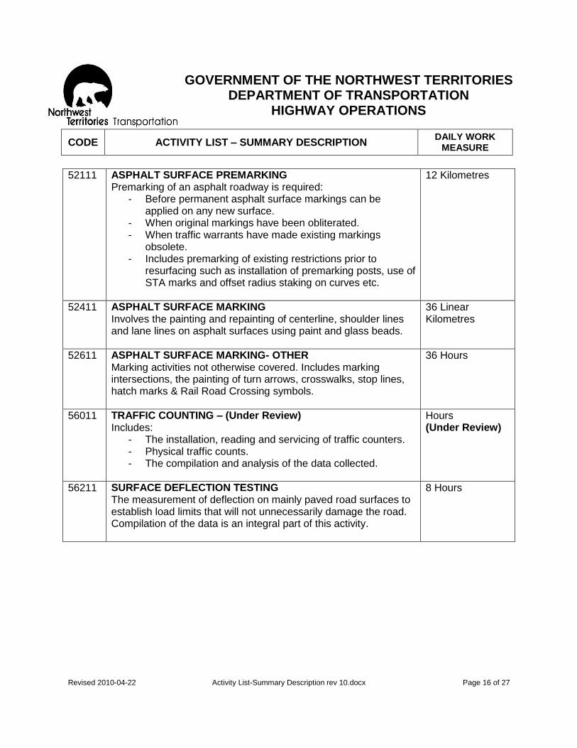
52111
ASPHALT SURFACE PREMARKING Premarking of an asphalt roadway is required:
- Before permanent asphalt surface markings can be applied on any new surface.
- When original markings have been obliterated. - When traffic warrants have made existing markings
obsolete. - Includes premarking of existing restrictions prior to
resurfacing such as installation of premarking posts, use of STA marks and offset radius staking on curves etc.
12 Kilometres
52411
ASPHALT SURFACE MARKING Involves the painting and repainting of centerline, shoulder lines and lane lines on asphalt surfaces using paint and glass beads.
36 Linear Kilometres
52611
ASPHALT SURFACE MARKING- OTHER Marking activities not otherwise covered. Includes marking intersections, the painting of turn arrows, crosswalks, stop lines, hatch marks & Rail Road Crossing symbols.
36 Hours
56011
TRAFFIC COUNTING – (Under Review) Includes:
- The installation, reading and servicing of traffic counters. - Physical traffic counts. - The compilation and analysis of the data collected.
Hours (Under Review)
56211
SURFACE DEFLECTION TESTING The measurement of deflection on mainly paved road surfaces to establish load limits that will not unnecessarily damage the road. Compilation of the data is an integral part of this activity.
8 Hours

GOVERNMENT OF THE NORTHWEST TERRITORIES
DEPARTMENT OF TRANSPORTATION HIGHWAY OPERATIONS
CODE ACTIVITY LIST – SUMMARY DESCRIPTION DAILY WORK
MEASURE
Revised 2010-04-22 Activity List-Summary Description rev 10.docx Page 17 of 27
AIRPORT SURFACES All work requests require prior authorization from the Director, Airports Division or his designate.
(As Approved by the Regional Manager)
65011
AIRPORTS All work associated with the maintenance of airports.
Hours
MARINE SERVICES All requests for work to be charged to Marine Management System Activities require prior authorization from the Director of Highway and Marine Services, or his designate.
(As Approved by the Regional Manager)
71011
LAUNCHING All work associated in the launching of a ferry.
Hours
71111
HAUL OUT All work associated in the haul out of a ferry.
Hours
71211
HAUL OUT WAY REPAIR
Hours
72011
APPROACH RECONDITIONING The lowering, raising or repair of the earth filled ferry landing using Pit Run gravel or other suitable material when necessary to correct deficiencies such as:
- Wash out/erosion. - Unstable areas. - Mismatch of ferry ramp to ferry landing due to water level
fluctuations. - Includes the removal of underwater rocks adjacent to end
of landing that may damage the hull of the ferry. For all surface maintenance over 10 metres from water edge, use activities such as 11611, 12011, etc.
Hours
72111
ICE REMOVAL The disposal of ice that has accumulated on the ferry landings during spring break up. Ice removal is normally accomplished by pushing the ice back into the water as the water recedes.
Hours

GOVERNMENT OF THE NORTHWEST TERRITORIES
DEPARTMENT OF TRANSPORTATION HIGHWAY OPERATIONS
CODE ACTIVITY LIST – SUMMARY DESCRIPTION DAILY WORK
MEASURE
Revised 2010-04-22 Activity List-Summary Description rev 10.docx Page 18 of 27
72311 APPROACH MAINTENANCE Levelling of the ferry landing including the addition of aggregate when necessary to correct deficiencies such as:
- Minor mismatch of ferry ramps to ferry landings due to water level fluctuations.
- Unstable surface. - Rutted or potholed condition.
For all surface maintenance over 10 metres from water edge use activities such as 11611, 12011 etc.
Hours
78011
SHORE FACILITY (Maintenance) All work performed in the maintenance of the ferry camp or other shore facilities such as:
- Cleaning of facilities and buildings. - Routine repairs, servicing of the buildings and group
facilities. - Landscaping and grounds maintenance. - Sweeping and tidying up.
Hours
78211
SHORE FACILITY (Operation)
Hours
78311
SHORE FACILITY (Snow Removal) All work related to snow removal in the ferry camp or at other shore facilities.
Hours
78611
STOCKPILING MATERIALS The hauling and stockpiling of materials in a storage area provided by Marine Operations and will include such materials as:
- Shales - Gravel and sand - Rock - Timber
Hours
79511 MARINE RECOVERABLES Monies recovered by Regional Manager’s Office through the journal vouchering process for authorized work done in Marine activities.
Dollars
GOVERNMENT OF THE NORTHWEST TERRITORIES
DEPARTMENT OF TRANSPORTATION HIGHWAY OPERATIONS
CODE ACTIVITY LIST – SUMMARY DESCRIPTION DAILY WORK
MEASURE
Revised 2010-04-22 Activity List-Summary Description rev 10.docx Page 19 of 27
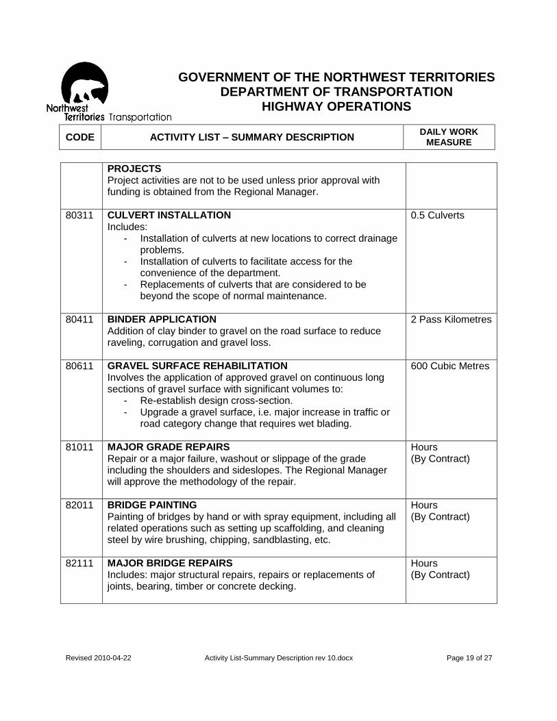
PROJECTS Project activities are not to be used unless prior approval with funding is obtained from the Regional Manager.
80311 CULVERT INSTALLATION Includes:
- Installation of culverts at new locations to correct drainage problems.
- Installation of culverts to facilitate access for the convenience of the department.
- Replacements of culverts that are considered to be beyond the scope of normal maintenance.
0.5 Culverts
80411
BINDER APPLICATION Addition of clay binder to gravel on the road surface to reduce raveling, corrugation and gravel loss.
2 Pass Kilometres
80611
GRAVEL SURFACE REHABILITATION Involves the application of approved gravel on continuous long sections of gravel surface with significant volumes to:
- Re-establish design cross-section. - Upgrade a gravel surface, i.e. major increase in traffic or
road category change that requires wet blading.
600 Cubic Metres
81011
MAJOR GRADE REPAIRS Repair or a major failure, washout or slippage of the grade including the shoulders and sideslopes. The Regional Manager will approve the methodology of the repair.
Hours (By Contract)
82011
BRIDGE PAINTING Painting of bridges by hand or with spray equipment, including all related operations such as setting up scaffolding, and cleaning steel by wire brushing, chipping, sandblasting, etc.
Hours (By Contract)
82111
MAJOR BRIDGE REPAIRS Includes: major structural repairs, repairs or replacements of joints, bearing, timber or concrete decking.
Hours (By Contract)

GOVERNMENT OF THE NORTHWEST TERRITORIES
DEPARTMENT OF TRANSPORTATION HIGHWAY OPERATIONS
CODE ACTIVITY LIST – SUMMARY DESCRIPTION DAILY WORK
MEASURE
Revised 2010-04-22 Activity List-Summary Description rev 10.docx Page 20 of 27
83011
CRUSH- SURFACE AGGREGATE Crushing pit run gravel or quarry stone including blasting, the addition of binder, preparation and clean up of the pit/quarry site and the loading, hauling and stockpiling of aggregate to selected sites.
Cubic Meters (By Contract)
83013 CRUSH- CHIPSEAL AGGREGATE Same as above except:
- Excludes the addition of binder - Includes additional screening when necessary
Cubic Meters (By Contract)
83014
CRUSH- QUALITY/QUANTITY CONTROL Includes quality control during the crushing operations and measurement of quantities produced. Also includes search for additional sources of aggregate and the initial development of the site when necessary.
Cubic Meters (By Contract)
84011
CHIP SEALING Chips sealing is the application of liquid asphalt and a cover aggregate to preserve and strengthen the surface, improve skid-resistance and to prevent surface entry of moisture into the sub grade when the following occurs or preferably just beginning:
- Surface reveling or wearing thin due to loss of aggregate. - Alligator cracking without grade failure. - Polishing aggregate. - Damage due to maintenance, i.e. ice blading with serrated
blades and where an alternative premix overlay is too costly.
7 Lane kms
84013
CHIP SEALING- TRANSPORT Includes the moves from the shop, between the worksites and the mobilization/demobilization.
Hours (As Required)
84111
RESURFACING WITH PREMIX Involves the surfacing of sections of asphalt pavement that are in the excess of 100 metres in length using a premixed asphaltic material to correct deficiencies such as:
- Repairing broken sections. - Overlaying distorted areas. - Re-levelling of rutted sections. - Levelling prior to Chipsealing.
380 Cubic Meters

GOVERNMENT OF THE NORTHWEST TERRITORIES
DEPARTMENT OF TRANSPORTATION HIGHWAY OPERATIONS
CODE ACTIVITY LIST – SUMMARY DESCRIPTION DAILY WORK
MEASURE
Revised 2010-04-22 Activity List-Summary Description rev 10.docx Page 21 of 27
85111
DRAINAGE CHANNEL IMPROVEMENT Includes:
- Major rehabilitation or realignment of drainage ditches and steam channels.
- Extensive rip-rap installations. - Construction of new drainage ditches or channels. - Diversion or control of water which causes glaciation.
Hours (As Required)
85511
RIGHT OF WAY IMPROVEMENT Major improvement of the right of way such as:
- The removal of brush, trees, rocks & debris and landscaping to enhance safety, improve aesthetics or to permit routine right of way maintenance activities.
- To reshape or flatten cuts or slopes to reduce or eliminate snow problems.
Hours (As Required)
87011
TRANSPORTATION ENGINEERING PROJECTS All work on projects requested by the Director, Highway and Marine Services or his designate and approved by the Regional Manager. Note: Clearly identify all overtime of permanent employees, casual employees timesheet, or hired equipment invoices that have charged to the projects in order that costs may be coded directly to such projects.
Hours (As Required)
87012
TRANSPORTATION ENGINEERING PROJECTS RECOVERIES Involves a process to recover the costs by Regional Manager’s office for certain work completed on behalf of a Highway and Marine Services Division Project through a direct coding voucher procedure.
Dollars (As Required)
87211
OPERATIONS CAPITAL PROJECT WORK Work described within any of the Highway Operations Capital Projects with approved delivery of the program by the Regional Manager.
Hours (As Required)

GOVERNMENT OF THE NORTHWEST TERRITORIES
DEPARTMENT OF TRANSPORTATION HIGHWAY OPERATIONS
CODE ACTIVITY LIST – SUMMARY DESCRIPTION DAILY WORK
MEASURE
Revised 2010-04-22 Activity List-Summary Description rev 10.docx Page 22 of 27
87212
OPERATIONS CAPITAL PROJECT WORK RECOVERIES Involves a process to recover costs by the Regional Manager’s office for certain work completed on the capital project through the direct coding voucher procedure.
Dollars (As Required)
88811
DISASTER All work relating to major problems caused by high water, exceptionally heavy rains, major slides, forest fires or other unusual events. The work would include:
- Pre-flood preparation such as dyking, rip-rap, sandbagging or emergency off-take ditches.
- Dislodging ice jams. - Cutting of grades to reduce overall damage. - Usage of temporary drainage structures such as bailey
bridges etc. - Disposal of ice on road surfaces or other debris within the
highway right-of-way deposited by flood waters. - All work related to closure of roads due to flooding,
washouts or forest fire. - Restoration.
Hours (As Required)
88812
DISASTER- RECOVERIES Involves a process to recover cost by the Regional Manager’s office for work completed on any recoverable phase of Disaster Projects through direct coding vouchering procedure.
Dollars (As Required)
89911
MISCELLANEOUS All maintenance activities not covered by the previously listed activities. Description of the type of work completed must be included in the activity reporting.
8 Hours
GOVERNMENT OF THE NORTHWEST TERRITORIES
DEPARTMENT OF TRANSPORTATION HIGHWAY OPERATIONS
CODE ACTIVITY LIST – SUMMARY DESCRIPTION DAILY WORK
MEASURE
Revised 2010-04-22 Activity List-Summary Description rev 10.docx Page 23 of 27
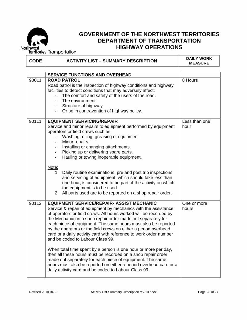
SERVICE FUNCTIONS AND OVERHEAD
90011
ROAD PATROL Road patrol is the inspection of highway conditions and highway facilities to detect conditions that may adversely affect:
- The comfort and safety of the users of the road. - The environment. - Structure of highway. - Or be in contravention of highway policy.
8 Hours
90111
EQUIPMENT SERVICING/REPAIR Service and minor repairs to equipment performed by equipment operators or field crews such as:
- Washing, oiling, greasing of equipment. - Minor repairs. - Installing or changing attachments. - Picking up or delivering spare parts. - Hauling or towing inoperable equipment.
Note:
1. Daily routine examinations, pre and post trip inspections and servicing of equipment, which should take less than one hour, is considered to be part of the activity on which the equipment is to be used.
2. All parts used are to be reported on a shop repair order.
Less than one hour
90112
EQUIPMENT SERVICE/REPAIR- ASSIST MECHANIC Service & repair of equipment by mechanics with the assistance of operators or field crews. All hours worked will be recorded by the Mechanic on a shop repair order made out separately for each piece of equipment. The same hours must also be reported by the operators or the field crews on either a period overhead card or a daily activity card with reference to work order number and be coded to Labour Class 99. When total time spent by a person is one hour or more per day, then all these hours must be recorded on a shop repair order made out separately for each piece of equipment. The same hours must also be reported on either a period overhead card or a daily activity card and be coded to Labour Class 99.
One or more hours

GOVERNMENT OF THE NORTHWEST TERRITORIES
DEPARTMENT OF TRANSPORTATION HIGHWAY OPERATIONS
CODE ACTIVITY LIST – SUMMARY DESCRIPTION DAILY WORK
MEASURE
Revised 2010-04-22 Activity List-Summary Description rev 10.docx Page 24 of 27
90211 LEAVE Includes all forms of paid leave to personnel, such as:
- Annual leave and travel time - Statutory holiday - Sick or special leave - Civic leave, etc.
All hours reported are to be coded to Labour Class 99.
0.25 Hours
90311
STOCKPILING MATERIALS Stockpiling and hauling at or to storage areas of such maintenance material as:
- Gravel and sand - Culvert material - Dust inhibitors - Signs and sign posts - Ice removal chemicals - Bridge materials
Note: Materials being stockpiled or hauled for a specific activity should be charged directly to that activity.
8 Hours
90411
FIELD SUPERVISION The supervision of the maintenance operation when no manual work is performed by the supervisor or his designate.
8 Hours
90611
INCLEMENT WEATHER/STANDBY TIME Is the unproductive crew time as the result of inclement weather and winter standby, or when other activities are impossible or impractical. Includes non-productive time resulting from a major equipment breakdown due to camp or crew neglect.
Hours (As Required)
90711
TRAINING AND MEETINGS- Highways Maintenance Supervisor
Hours (As Required)
90712
TRAINING AND MEETINGS- Operators Time spent by the Highways Maintenance Supervisors and field crews attending training courses, safety meetings, conferences and conventions.
Hours (As Required)

GOVERNMENT OF THE NORTHWEST TERRITORIES
DEPARTMENT OF TRANSPORTATION HIGHWAY OPERATIONS
CODE ACTIVITY LIST – SUMMARY DESCRIPTION DAILY WORK
MEASURE
Revised 2010-04-22 Activity List-Summary Description rev 10.docx Page 25 of 27
90811
BUILDINGS AND GROUNDS Includes all the work performed in the maintenance of camp or grader shelter buildings and yards such as:
- Cleaning of buildings and facilities, including sweeping and tidying up.
- Repairing or servicing buildings and facilities when damage is due to neglect or abuse by Department of Transportation employees or assigned contractors.
- Sweeping and tidying up. - Snow removal.
16 Hours
90911
CAMP OPERATIONS Includes all operating expenses of permanent maintenance camps including such items as:
- Bid item in major road maintenance contract. - Self generated electrical energy. - Heating fuels (used by remote camps only). - Sewer and water (remote camps only). - Propane (not chargeable to other activities). - Groceries, small non-capital or expandable items not
directly chargeable to other activities.
Dollars (As approved by the Regional Manager)
91011
RADIO NETWORK Expenses involved in operating and maintaining a radio communication system including land line, cellular and satellite telephone accounts.
Dollars (As Required)
91111
HAY RIVER MANAGEMENT Accounting purposes only.
Days (As Required)
91211 TRAVEL AND RELOCATION Travel expenses (meals, lodging, etc.) of Highways Maintenance Supervisors, operators and labourers. Includes commuting and living allowance at temporary camps.
Dollars (As approved by the Regional Manager)
91311
CAMP ADMINISTRATION All charges for administering camp activities, primarily to identify clerk/custodian time.
8 Hours

GOVERNMENT OF THE NORTHWEST TERRITORIES
DEPARTMENT OF TRANSPORTATION HIGHWAY OPERATIONS
CODE ACTIVITY LIST – SUMMARY DESCRIPTION DAILY WORK
MEASURE
Revised 2010-04-22 Activity List-Summary Description rev 10.docx Page 26 of 27
91411 STOCKPILING PREMIX Is the mixing of a liquid asphalt with an aggregate. Includes:
- Road mix process of mixing with camp staff and equipment.
- Purchase of premix. - Hauling from remote sites and stockpiling. - Stockpiling of premix using a pug mill.
600 Cubic Meters
91511 See 41511
STOCKPILING WINTER SAND- CHEMICAL ADDED The screening of the aggregate if necessary hauling, blending with chemicals and stockpiling.
Cubic Meters Replaced by 41511
91512 See 41512
STOCKPILE WINTER SAND- FREEZE DRIED Includes screening of aggregate if necessary hauling freeze drying & stockpiling.
Cubic Meters Replaced by 41511
91611
SUNDRY EQUIPMENT All charges for servicing and repairing of equipment that does not have a classification code.
Hours (As approved by the Regional Manager)
91711
TRANSPORT All expenses incurred in connection with the transportation of supplies and equipment not directly chargeable to a single activity. Transfer of equipment or supplies for a specific activity should be charged directly to the activity.
8 Hours
91811
MATERIAL SUSPENSE- Accounting measure only. Materials purchased in quantity that cannot be charged directly to an activity or a piece of equipment are charged to the suspense account. When the material is used, the cost price is charged to the appropriate activity or equipment and a corresponding credit is made to the suspense account.
Dollars (As approved by the Regional Manager)
91911 CONTRACT EQUIPMENT SUSPENSE Is to provide a single activity charge for rental or contract equipment which is intended to be used on several different road maintenance activities and at this time it is not realistic to charge against another activity. When the equipment is used, the cost can be allocated against the appropriate activity and a corresponding credit made to this activity.
Dollars (As approved by the Regional Manager)

GOVERNMENT OF THE NORTHWEST TERRITORIES
DEPARTMENT OF TRANSPORTATION HIGHWAY OPERATIONS
CODE ACTIVITY LIST – SUMMARY DESCRIPTION DAILY WORK
MEASURE
Revised 2010-04-22 Activity List-Summary Description rev 10.docx Page 27 of 27
92511
WORK DONE FOR OTHERS Includes work done for other agencies or functions such as:
- Other departments or agencies of the Territorial Government.
- Other government departments or agencies (i.e. Parks Canada, Ministry of Transport, Northwestel, etc.).
- Private persons or companies (i.e. the snowplowing of private driveways).
Note: Only work approved by the Regional Manager, or designates may be charged to this activity.
Hours (As approved by the Regional Manager)
92512
WORK DONE FOR OTHERS- RECOVERIES Involves a process to recover costs by the Regional Manager’s office for work completed on a recoverable basis from other agencies. Note: For Administration use only.
Dollars (As approved by the Regional Manager)
95011 ADMINISTRATION/CONTRACT ADJUSTMENT Accounting purposes only. To provide for single coding for the adjustment between own force unit costing and the actual contract value. Includes administration fees.
Dollars (As approved by the Regional Manager)

GOVERNMENT OF THE NORTHWEST TERRITORIES
DEPARTMENT OF TRANSPORTATION HIGHWAY OPERATIONS
Revised 2010-04-15 Road PRI Categories.docx Page 1 of 1
ROAD MAINTENANCE CATEGORIES
PRIORITY TRAFFIC VOLUME (VEHICLES/DAY)
1 PSADT > 500
2 250 < PSADT < 500
3 150 < PSADT < 250
4 80 < PSADT < 150
5 PSADT < 80
CARETAKER Not related to traffic volume
NOTES:
1. PSADT = Peak Summer Average Daily Traffic
2. Caretaker category is not tied to traffic volume of road classification. It is a “holding action” level of service only to protect an investment.
3. Where roads are built to DCU 90 standard or higher, a minimum level of
service of category 4 is required.
4. Categories are also tied to Northern Roads Paving Policy (under review):
a. PSADT > 1,000 = Asphalt Pavement b. PSADT > 500 = Asphaltic Surface Treatment c. PSADT > 250 = Surface Stabilization
5. Maintenance categories are not related to Road Classifications, which are
based on purpose or function:
i. Arterial – interurban ii. Collector – urban or land access connection to Arterial class iii. Local – land access iv. Recreational – sub-classification of Local class giving access primarily
to recreational property or facilities

GOVERNMENT OF THE NORTHWEST TERRITORIES
DEPARTMENT OF TRANSPORTATION HIGHWAY OPERATIONS
Revised 2010-04-15 HMM 101 to 107 Rev10.docx Page 1 of 14
101- 105- WET BLADING
OBJECTIVE
To maintain gravel road surfaces f ree of def iciencies that wi l l impede the safe and comfortable use of the road and to maintain intended design standards as pract icable with the given avai lable maintenance resources.
DESCRIPTION:
Blade and reshape gravel roads including scar ifying as required to correct def iciencies such as: - Inadequate crown or super elevat ion ; - Potholed, rutted or corrugated condit ions ; - Windrows or loose gravel ; and - To recover the lost gravel f rom grade side slopes.
RESPONSIBILITY:
Highway Maintenance Supervisor with guidance as required f rom the Regional Manager. Refer to Highway Maintenance Operating Instruct ions for Product ivity Guidel ines, Resource Guidel ines, Scheduling and Recommended Method.
LEVEL-OF-SERVICE
Category Surface Type Suggested
Frequency/Yr Remarks
1 & 2 Not chlor ided 12
3 (and others)
Not chlor ided 3 Plus 4 bladings/yr using
act ivity 107
1 & 2 Chloride /DL 10 8
3 Chloride /DL 10 6
4 & 5 Chloride /DL 10 5

GOVERNMENT OF THE NORTHWEST TERRITORIES
DEPARTMENT OF TRANSPORTATION HIGHWAY OPERATIONS
Revised 2010-04-15 HMM 101 to 107 Rev10.docx Page 2 of 14
101- 105- WET BLADING
PRODUCTIVITY GUIDELINES: RESOURCE GUIDELINES:
Quantity Standard – Crew -
(See Level of Service in Standard 4- Heavy Equipment Operators for Activity 101-105- Wet Blading) Optional
2- Laborers 2- Traff ic Control Staff
Average Daily Production - Equipment – 76 pass ki lometers 2- Motor Graders (class 2304)
2- Tandem Axle Tractors (class 1109) 1- Tank Semi-Trailers (class 1304) 1- Water Pumps (10 cm) (class 5801) 1- Crew Cab (class 1823) Optional 1- Packer (class 2600) Material Water (990) when appl icable

GOVERNMENT OF THE NORTHWEST TERRITORIES
DEPARTMENT OF TRANSPORTATION HIGHWAY OPERATIONS
Revised 2010-04-15 HMM 101 to 107 Rev10.docx Page 3 of 14
101- 105- WET BLADING
SCHEDULING:
1. Spring – Init ia l blading of road af ter spr ing breakup should be carr ied out to reshape road.
2. Summer – Blading should be performed only when necessary and not
in a repetit ious routine schedule.
3. Fal l – Special attent ion should be given to blading immediately prior to f reeze-up to shape the road and incorporate any loose gravel into the surface.
4. Category 3 roads are planned to have 3 wet bladings and 4 dry
bladings. The wet bladings should be done once each in the months of June, July and August or as condit ions warrant.
Special Notes:
a. Blading without water during dry periods only loosens part ic les to
be blown away by the wind or k icked off by traff ic. No blading should be carr ied out on roads designated for wet blading unless a water truck is available to supply water dur ing per iods of dry weather.
b. Blading should also be done ASAP af ter periods of wet weather to take advantage of the moisture present. When the surface has deteriorated to a rut ted or washboard condit ion or the crown has been lost, the surface should be cut to remove depressions and reshaped to proper crown or cross-sect ion.
c. Blading to excessive depths can cause contaminat ion of the surface granular material .
RECOMMENDED METHOD:
1. SET OUT WARNING SIGNS.
2. TURN ON FLASHLIGHTS.

GOVERNMENT OF THE NORTHWEST TERRITORIES
DEPARTMENT OF TRANSPORTATION HIGHWAY OPERATIONS
Revised 2010-04-15 HMM 101 to 107 Rev10.docx Page 4 of 14
101- 105- WET BLADING
RECOMMENDED METHOD (continued):
The motor grading being a slow moving vehicle, shall have the f lashl ight l ight operating at al l t imes during work or travel to and from work areas. All other equipment should have the l ights f lashing only when working but not during transit .
3. BLADING SIDESLOPES OF GRADE (PULLING SHOULDERS)
Whenever road condit ions require/permit, the f irst pass should be made along the grade slope to:
Redef ine slope and shoulder l ine
Pul l up lost gravel Under no circumstances should the shoulder be cut as this wi l l reduce overa l l surface width.
4. NUMBER OF PASSES
Surface Width Remarks
f rom 8.2m to less than 10m 7 Passes
f rom 5.5m to less than 8.2m 5 Passes
less than 5.5m 4 Passes
The grade side slope pass is not included in the above .
5. CUT AND REMOVE DEPRESSIONS
When optimum moisture condit ions do not exist on the road surface, water should be appl ied uniformly over the entire surface in suf f icient quantity to enable cutt ing. Start ing the water truck at least one hour before the graders may result in a more eff icient operation. Blade deep enough to remove ruts, holes and depressions. The f ine material cut f rom the surface and mixed with the loose gravel wi l l provide a wel l graded mater ial. Remove the stones in excess of 75 mm from the roadway which could damage a vehicle and dispose of them beyond the toe of the side slope. The ult imate removal of the stones wi l l normally be done under act ivity ser ies 310.

GOVERNMENT OF THE NORTHWEST TERRITORIES
DEPARTMENT OF TRANSPORTATION HIGHWAY OPERATIONS
Revised 2010-04-15 HMM 101 to 107 Rev10.docx Page 5 of 14
101- 105- WET BLADING
6. SPREAD MATERIAL BACK OVER ROAD SURFACE
Apply water if necessary and then spread the material to restore proper crown or cross-sect ion to provide adequate surface drainage. The correct amount of crown (crossfal l) is approximately 4 cm per meter (12 to 15 cm for a surface width of 3 to 3.6 meters f rom centre l ine to shoulder on tangents). Curves should have a uniform slope (superelevation) across the full width of surface (no crown). See page 5 for typical cross sections. Compact ion may be required where there is insuf f icient traff ic or an addit ional l ight applicat ion of water may be necessary to obtain smooth t ight surface.
7. COMPLETE OPERATION
The work area should range from 2 to 4 kilometers, to minimize traff ic interference, however, never select more roadway than can be f inished dur ing that shif t . Special Note: Berms or windrows are a hazard to traffic and create drainage problems. They are not to be left after the operation is complete under any circumstances.
8. REMOVE WARNING SIGNS
Special Note: NEVER blade material across bridge decks. When the material on the blade reaches the end of the deck, stop the grader, l i f t the blade clear, move ahead, lower the blade to just contact the deck, and back off spreading material uniformly on the approach road. The blade angle must be adjusted to meet the slope of the deck before backing off . Keep aggregate and blade away from expansion joints as the joints are easily damaged.

GOVERNMENT OF THE NORTHWEST TERRITORIES
DEPARTMENT OF TRANSPORTATION HIGHWAY OPERATIONS
Revised 2010-04-15 HMM 101 to 107 Rev10.docx Page 6 of 14
101- 105- WET BLADING
RECOMMENDED METHOD (Cont’d)
TYPICAL BLADING PATTERN USING TWO GRADERS Blading coverage for 8.2 to 10.0 meter road surface that requires 7 passes. Does not include side slope.
Note: Reverse Pattern with every second blading. Straight blading (moldboard at approximate right angle to the roadway) while spreading will cause material in windrow to segregate and increase the tendency of a corrugating action.

GOVERNMENT OF THE NORTHWEST TERRITORIES
DEPARTMENT OF TRANSPORTATION HIGHWAY OPERATIONS
Revised 2010-04-15 HMM 101 to 107 Rev10.docx Page 7 of 14
101- 105- WET BLADING
RECOMMENDED METHOD (Cont’d)

GOVERNMENT OF THE NORTHWEST TERRITORIES
DEPARTMENT OF TRANSPORTATION HIGHWAY OPERATIONS
Revised 2010-04-15 HMM 101 to 107 Rev10.docx Page 8 of 14
107- DRY BLADING
OBJECTIVE
To maintain gravel road surfaces f ree of def iciencies that wi l l impede the safe and comfortable use of the road and to maintain intended design standards as pract icable with the given avai lable maintenance resources.
DESCRIPTION:
Blade and reshape gravel roads including scarifying as required to correct def iciencies such as: - Inadequate crown or super elevat ion; - Potholed, rutted or corrugated condit ions ; - Windrows or loose gravel ; and - To recover the lost gravel f rom grade side slopes.
LEVEL-OF-SERVICE
Category Suggested Frequency/Yr
Remarks
3 4 plus 3/yr using wet blading
4 6
5 4
RESPONSIBILITY: Highway Maintenance Supervisor with guidance, as required, f rom Regional Manager . Refer to Highway Maintenance Operating Instruct ions for
Product ivity Guidelines Resource Guidel ines Scheduling Recommended Method.

GOVERNMENT OF THE NORTHWEST TERRITORIES
DEPARTMENT OF TRANSPORTATION HIGHWAY OPERATIONS
Revised 2010-04-15 HMM 101 to 107 Rev10.docx Page 9 of 14
107- DRY BLADING
PRODUCTIVITY GUIDELINES: RESOURCE GUIDELINES:
Quantity Standard – Crew –
(See Level of Service) 1- Heavy Equipment Operator
Average Daily Production - Equipment –
32 pass ki lometers 1- Motor Grader (c lass 2304)
Material
Not appl icable
SCHEDULING:
1. Wet periods (usual ly spring or fal l) or af ter summer rains - blade
to correct surface deteriorat ion and cross -section. Considerat ion
to be given to weekend blading if moisture condit ions warrant.
2. Dry per iods (usually June, July and August) bla ding when
selected surfaces cannot be cut or material compacted - blade to
smooth windrows and corrugated loose gravel
3. Category 3 roads are planned to have three wet bladings and
four dry bladings. The wet blading should normally be done once
each in the months of June, July and August or as condit ions
warrant.

GOVERNMENT OF THE NORTHWEST TERRITORIES
DEPARTMENT OF TRANSPORTATION HIGHWAY OPERATIONS
Revised 2010-04-15 HMM 101 to 107 Rev10.docx Page 10 of 14
107- DRY BLADING
Special Notes:
a. Roads should be bladed only when required and not in a repetit ious routine schedule.
b. Blading to correct surface deteriorat ion and to obtain a smooth compacted road surface can usual ly only be accomplished when suf f icient moisture is present. The surface must be cut to remove ruts or uneven spots and then the material re - laid across the surface to restore proper crown or superelevat ion.
c. Traff ic wear on gravel surfaces dur ing periods of dry weather results in accumulat ions of loose aggregate in windrows between vehicle tracks and along shoulder edges. These are hazardous to vehicle operators, and induce ponding and rutt ing during subsequent wet weather. Material in these windrows should be distr ibuted over the road surface without disturbing the sealed surface. Blading operations which disturb the under lying sealed surface wil l s imply aggravate the situat ion.
d. Special attent ion is required prior to f reeze -up to shape the road surface and incorporate any loose gravel into the surface.
RECOMMENDED METHOD:
1. SET OUT WARNING SIGNS.
2. TURN ON FLASHLIGHTS.
The motor grading being a slow moving vehicle, shall have the f lashl ight l ight operating at all t imes during work or travel to and from work areas. Al l other equipment should have the l ights f lashing only when working but not during transit .

GOVERNMENT OF THE NORTHWEST TERRITORIES
DEPARTMENT OF TRANSPORTATION HIGHWAY OPERATIONS
Revised 2010-04-15 HMM 101 to 107 Rev10.docx Page 11 of 14
107- DRY BLADING
3. BLADING SIDESLOPES OF GRADE
(PULLING SHOULDERS)
Whenever road condit ions require/permit, the f irst pass should be made along the grade slope to:
Redef ine slope and shoulder l ine
Pul l up lost gravel
Under no circumstances should the shoulder be cut as this wi l l reduce overal l surface width
4. NUMBER OF PASSES
Surface Width Remarks
f rom 8.2m to less than 10m 7 Passes
f rom 5.5m to less than 8.2m 5 Passes
less than 5.5m 4 Passes
The grade side slope pass is not included in the above
5. BLADE & SPREAD WINDROWED MATERIAL OVER ROAD
SURFACE
A. SURFACE WET- Blade surface deep enough to remove ruts and uneven spots to produce a smooth surface. The f ine materials cut f rom the surface are blended with the loose gravel to provide a well graded material in the windrow during this operation. The second step is to spread the mater ial over the road to restore proper crown or superelevation.

GOVERNMENT OF THE NORTHWEST TERRITORIES
DEPARTMENT OF TRANSPORTATION HIGHWAY OPERATIONS
Revised 2010-04-15 HMM 101 to 107 Rev10.docx Page 12 of 14
107- DRY BLADING
Note: The correct amount of crown (crossfall) is approximately 4 cm per meter (12 to 15 cm for a surface width of 3 to 3.6 meters f rom centre l ine to shoulder on tangents). Curves should have a uniform slope (superelevation) across the ful l width of surface (no crown). See page 5 for typical cross sections.
B. SURFACE DRY- Blade with only suff icient pressure to
remove al l r idges and washboard but do not cut the sealed surface. Then spread the windrowed mater ial evenly over the road
6. COMPLETE OPERATION
The work area should range from 2 to 4 kilometers, to minimize traff ic interference, however, never select more roadway than can be f inished during that shif t . Ensure that the finished surface is left in a smooth safe driving condition without any windrows or berms. These are a hazard to traffic and can cause drainage problems and as such, windrows and berms must not remain, under any circumstances, after the operation is complete.
7. REMOVE WARNING SIGNS
Special Note: (a) NEVER blade material across bridge decks.
When the mater ial on the blade reaches the end of the deck, stop the grader, l i f t the blade clear, move ahead, lower the blade to just contact the deck, and back off spreading mater ial uniformly on the approach road. The blade angle must be adjusted to meet the slope of the deck before backing off . Keep aggregate and blade away from expansion joints as the joints are easi ly damaged.
(b) Blading to excessive depths can cause contaminat i on of surface granular material.

GOVERNMENT OF THE NORTHWEST TERRITORIES
DEPARTMENT OF TRANSPORTATION HIGHWAY OPERATIONS
Revised 2010-04-15 HMM 101 to 107 Rev10.docx Page 13 of 14
107- DRY BLADING
RECOMMENDED METHOD (Cont’d)
TYPICAL BLADING PATTERN USING TWO GRADERS Blading coverage for 8.2 to 10.0 meter road surface that requires 7 passes. Does not include side slope.
Note: Reverse pattern with every second blading Straight blading (moldboard at approx. r ight angle to roadway) While spreading wil l cause material in windrow to segregate and increase the tendency of corrugation act ion.

GOVERNMENT OF THE NORTHWEST TERRITORIES
DEPARTMENT OF TRANSPORTATION HIGHWAY OPERATIONS
Revised 2010-04-15 HMM 101 to 107 Rev10.docx Page 14 of 14
107- DRY BLADING
RECOMMENDED METHOD (Cont’d)

GOVERNMENT OF THE NORTHWEST TERRITORIES
DEPARTMENT OF TRANSPORTATION HIGHWAY OPERATIONS
Revised 2010-04-15 HMM 114 A and reference.docx Page 1 of 22
114- GRAVEL SURFACING
Special NOTE:
This activity has been assigned to contract forces due to changes essential for increased efficiency. End dump trucks can be supplied by contractors are larger thus providing greater economy of scale. The notes attached are for reference purposes. Ple ase contact the Highway Operations Office in Hay River for added information or calculat ion examples as shown on page 8 on the previous revision of the HMM. Some diagrams from the original standards are not available for direct transfer to this reference, see PDFs attached.
OBJECTIVE:
To maintain a safe driving surface on gravel roads by the ANNUAL replacement of lost material to avoid major and extensive rehabil itat ion and preserve the surface in a cost -ef fect ive manner.
DESCRIPTION:
Gravel surfacing of continuous sect ions of gravel surfaced roads by the annual replacement of lost material through normal road use (traff ic k ick-off , erosion, grade absorption, snowplowing, etc.) The quantit ies in the annual gravel replacement program should not be confused with major gravel l ing that could be required to re -establish a specif ic sect ion of highway or upgrade a highway to a certain level. For these major projects with funding approved by the Regional Manager, use Act ivity 806 (Surface Rehabi l itat ion)
LEVEL OF SERVICE:
The planned annual quantit ies per kilomet re are based on - category of gravel highway - road width - untreated surface or dust treatment

GOVERNMENT OF THE NORTHWEST TERRITORIES
DEPARTMENT OF TRANSPORTATION HIGHWAY OPERATIONS
Revised 2010-04-15 HMM 114 A and reference.docx Page 2 of 22
114- GRAVEL SURFACING
LEVEL OF SERVICE: (cont’d)
The annual quant it ies in cubic meters per kilometr e are as fol lows:
Category Road Width in Meters
<5.5 5.5- 8.2 8.2- 10
untreated treated untreated treated untreated
treated
1 - - - 80 55 115 80
2 - - - 70 50 110 75
3 - - - 60 40 85 60
4 40 30 50 35 70 50
5 30 20 40 30 55 40
Caretaker 25 20 30 20 40 30
The actual quantit ies appl ied under this act ivity should not exceed 150 cubic
meters/kilometre.
RESPONSIBILITY:
The Regional Manager, in col laborat ion with the local Highway Maintenance Supervisor wi l l select the annual surfacing areas based on their need. Funding for major gravel l ing projects wil l require the approval of the Regional Manager. Everyone connected with highway maintenance had the responsibi l i ty for pract icing good gravel conservat ion habits as gravel is a non -renewable resource that is continual ly being depleted. Highway Maintenance Supervisors and Regional Managers are to ensure that unnecessary waste does not take place, especially dur ing blading and snowplowing operations.

GOVERNMENT OF THE NORTHWEST TERRITORIES
DEPARTMENT OF TRANSPORTATION HIGHWAY OPERATIONS
Revised 2010-04-15 HMM 114 A and reference.docx Page 3 of 22
114- GRAVEL SURFACING
Refer to Highway Maintenance Operating Instruct ions for:
- Product ivity guidel ines
- Resource Guidel ines
- Scheduling
- Recommended Method
APPENDIX TO ACTIVITY 114 (GRAVEL SURFACING)
Special NOTE:
For ongoing activit ies with gravel application quantities the table shown above will be revised. This is due to increased traffic flows in some areas and to assist with planning activities for crushing operations. AGAIN: The notes attached are for reference purposes. Some diagrams from the original standards are not avai lable for direct transfer to this reference, see PDFs attached.

GOVERNMENT OF THE NORTHWEST TERRITORIES
DEPARTMENT OF TRANSPORTATION HIGHWAY OPERATIONS
Revised 2010-04-15 HMM 114 A and reference.docx Page 4 of 22
114- GRAVEL SURFACING
PRODUCTIVITY GUIDELINES: RESOURCE GUIDELINES:
Quantity Standard – Crew –
For the planned annual quant it ies 2- Heavy Equipment Operator See Level of Service in Standard for Activity 114- Gravel Surfacing. 2- Gravel Checkers (class 05) Average Daily Production - Equipment – 600 cubic meters Own Force Note: Contractors should have 1- Motor Grader (c lass 2304) suff icient trucks to haul 20,000 1- Tandem Axle Tractor tonne-km/12,000 m3-km (class 1109) 1- Tank Semi-Trailer (class 1304)
1- 102 mm Water Pump (class 5801) 1- Crew Cabs (class 1823) Optional 1- Packer (class 2600) Hired/Contract equipment 6- Tandem Axle Tractor c/w bel ly dumps 1- Loader (over 3.5 m 3) Materials Crushed Gravel (code 110) Water (code 990)
SCHEDULING: Applicat ion period- late May to late July
Gravel surfacing should begin as soon as road condit ions have returned to normal fol lowing spring breakup condit ion and completed prior to the f inal appl icat ion of chemical dust treatment.

GOVERNMENT OF THE NORTHWEST TERRITORIES
DEPARTMENT OF TRANSPORTATION HIGHWAY OPERATIONS
Revised 2010-04-15 HMM 114 A and reference.docx Page 5 of 22
114- GRAVEL SURFACING
RECOMMENDED METHOD- General Approach
1. Before any gravel is placed, the road must be properly prepared to ensure that the base is stable, and the surface is smooth and uniform with proper cross-sect ion.
2. The Highway Maintenance Supervisor is responsible for the
gravel surfacing projects. Prior to start-up of gravel surfacing, he must:
a. Check actual contract for accuracy b. Have name of proposed contractor, start ing date and
l ist of trucks, loaders and other equipment to be used. The following information wi l l be required for al l trucks used on the haul- License number, maximum allowable gross weight and tare weight per unit
c. Ensure that the checkers are trained d. I f required by the contract, determine the volume
capacity allowable for each truck e. Ensure that the maintenance forces and the gravel
hauling operation is proper ly coordinated. RECOMMENDED METHOD- Details
1. PLACE SAFETY DEVICES AND SIGNS
2. HAUL AND DUMP GRAVEL ALONG ROADWAY
Checker should ensure a uniform spread on road surface, if
done proper ly, it greatly reduces the amount of blading required.
3. WINDROW AND MIX MOTOR GRADER
Blade unt i l mixing provides a uniformly grader material, apply
water if required
4. SPREAD WITH MOTOR GRADER
Ensure proper cross sect ion is attained. Apply addit ional water
if required

GOVERNMENT OF THE NORTHWEST TERRITORIES
DEPARTMENT OF TRANSPORTATION HIGHWAY OPERATIONS
Revised 2010-04-15 HMM 114 A and reference.docx Page 6 of 22
RECOMMENDED METHOD- Details (continued):
5. COMPACT WITH PNEUMATIC TIRED ROLLER IF REQUIRED
6. REMOVE SAFETY DEVICES AND SIGNS.
GRAVEL SURFACING CONTRACTS:
Check l ist for the Highway Maintenance Supervisor responsible for
gravel surfacing projects.
1. Obtain a copy of the actual contract and check for accuracy
a) Project l imits (km to km)
b) Applicat ion rate(s)
c) Location of stockpile(s)
d) Contract quant it ies, i.e. cubic meters and cubic meter -
kilometres (dead haul distance needed to do
calculat ions. Obtain these from the Regional Manager
and check)
e) Estimate if the required mater ial is available in the
stockpile(s)
Report any discrepancies immediately
2. Upon contract award you wil l receive f rom the Regional Manager:
a) Name of Contractor
b) Proposed start ing date.
c) List of trucks to be used, indicat ing identif icat ion
number, l icense number, and maximum al lowable gross
weight per unit (as per vehicle registrat ion).

GOVERNMENT OF THE NORTHWEST TERRITORIES
DEPARTMENT OF TRANSPORTATION HIGHWAY OPERATIONS
Revised 2010-04-15 HMM 114 A and reference.docx Page 7 of 22
GRAVEL SURFACING CONTRACTS (cont’d)
3. Prepar ing for start -up:
a) Checkers should be hired, trained and shown job site at
least two days prior to actual start
b) Ensure the checkers know:
- wage rate per hour
- hours of work
- transportat ion and accommodat ion arrangements
c) Have all equipment and signs inspected and ready to go
on proposed start ing date.
4. Start ing Day:
a) Place traf f ic control devices on highway in proper
location.
b) I f required, have a water truck start earl ier to alleviate
dusty condit ions
c) Have other equipment, grader(s), etc. on job site
d) Be at the stockpi le to ensure the checker has no
problems and remain there unti l:
i . The tare weight of each truck has been obtained
i i . Ensure that the checker at the stockpile knows the
maximum gross vehicle weight (M.G.V.W)
al lowable for each truck. This is the lesser of
either the l icensed M.G.V.W. or the M.G.V.W.
al lowable by the regulat ions

GOVERNMENT OF THE NORTHWEST TERRITORIES
DEPARTMENT OF TRANSPORTATION HIGHWAY OPERATIONS
Revised 2010-04-15 HMM 114 A and reference.docx Page 8 of 22
GRAVEL SURFACING CONTRACTS (cont’d)
i i i . The Highway Maintenance Supervisor and checker
wi l l calculate cubic meters capacity on each truck
using 1.7 tonnes (1700 kgs) = 1 cubic meter of
gravel.
a) Based on Weight:
M.G.V.W. allowable less tare weight
equals maximum net vehicle weight
(M.N.V.W.) allowable
Example: 36,576 kgs (M.G.V.W.) – 13,476
kgs (tare weight) = 23,120 kgs (M.N.V.W).
T h e M a x i m u m c u b i c m e t e r l o a d
a l l o w a b l e o n w e i g h t w o u l d b e
M . N . V . W . d i v i d e d b y 1 . 7 t o n n e s
( 1 7 0 0 k g s ) e q u a l s c u b i c m e t e r s .
E x a m p l e : 2 3 , 1 2 0 ( M . N . V . W . )
1 7 0 0 k g s = 1 3 . 6 m 3
b) Based on box measurement
Measure truck box using Vehicle
Measurement Sheet. Rated capacity f rom
sheet: 14m 3
c) The maximum al lowable cubic meters
payable for haul by this t ruck would be the
lesser of a) 13.6m 3

GOVERNMENT OF THE NORTHWEST TERRITORIES
DEPARTMENT OF TRANSPORTATION HIGHWAY OPERATIONS
Revised 2010-04-15 HMM 114 A and reference.docx Page 9 of 22
GRAVEL SURFACING CONTRACTS (cont’d)
iv. The Highway Maintenance Supervisor and checker
wi l l assign the load capacity for each truck before
loading takes place.
v. The Highway Maintenance Supervisor and checker
at the pit are to joint ly watch the loading of the
f irst truck to satisfy themselves that the correct
quantit ies have been loaded. When the checker
has completed the weight cert if icate proper ly,
including spread distance for the f irst truck, the
Highway Maintenance Supervisor should leave
ahead of this truck so as to be at the dumping site
f irst
vi. Ensure the gravel checker at the dumping site
obtains the weight cert if icate, signs it , returns a
copy to the trucker and lays out the proper spread
distance
vi i. Remain at dumping site for approximately one
round of the trucks, to ensure checker understands
the procedure.
Note: Checkers tend to become confused when the trucks spread their load
too long or too short. Make it c lear that the actual spread by the trucks does
not effect the locat ion of the marker as posit ioned according to the spread
distance on the weight cert if icate.

GOVERNMENT OF THE NORTHWEST TERRITORIES
DEPARTMENT OF TRANSPORTATION HIGHWAY OPERATIONS
Revised 2010-04-15 HMM 114 A and reference.docx Page 10 of 22
GRAVEL SURFACING CONTRACTS (cont’d)
Long or short spreads by the trucks increase the amount of grader work i.e. it
wi l l take longer to even out the windrow and/or an uneven spread of material
on the road surface. The checker should be aware of this situat ion and
should inform you if this s ituation continues, also the checker should be able
to tel l you which truck(s) are not spreading proper ly. You sh ould verbal ly
inform the contractor or his representat ives of the situation. I f i t does not
improve, notify your Regional Manager for further act ion.
The quantit ies should be calculated each night or at the latest, the fol lowing
morning. I f both checkers are assigned this duty they should do the
calculat ions each night (approximately one hour required). I f the calculat ions
are to be performed by someone during the day, arrangements should be
made to deliver the t ickets each night or f irst thing each mornin g.
The contractor is required under terms of most contracts to haul a minimum
quantity of cubic meter k ilometres per day. The daily calculat ions wi l l enable
you to determine the following:
- Is the contractor meeting his daily minimum haul
- Is the proper amount of material being placed per kilometr e
- Progress rate, for est imating complet ion date

GOVERNMENT OF THE NORTHWEST TERRITORIES
DEPARTMENT OF TRANSPORTATION HIGHWAY OPERATIONS
Revised 2010-04-15 HMM 114 A and reference.docx Page 11 of 22
GRAVEL SURFACING CONTRACTS (cont’d)
The Regional Manager in charge of the highway -resurfacing program shall be
responsible for the fol lowing:
1. Ensure the contract is correct in all respects prior to being
advert ised
2. review bids received and make recommendat ions as to contract
award
3. request f rom the Contractor in wr it ing:
a) Proposed start ing date
b) List of trucks to be used, which should include: License
number (P. S. plates are normally required), identif icat ion
number, and maximum legal load (as per regulat ion)
4. Inform the Contractor that you are the Government representat ive
on this project and al l queries of whatever nature shal l go
through you, not the people in the f ield.
5. Remind the Contractor that legal loads wi l l be str ict ly enforced
Gravel Guidel ines:
Establish def inite l ines of report ing and communication, i.e. make
it absolutely clear to everyone concerned who they report to and
from whom they wi l l receive instruct ions.
Be on the job site at the beginning of the project, i.e. be
available, if problems are going to arise they tend to do so on the
f irst day.

GOVERNMENT OF THE NORTHWEST TERRITORIES
DEPARTMENT OF TRANSPORTATION HIGHWAY OPERATIONS
Revised 2010-04-15 HMM 114 A and reference.docx Page 12 of 22
GRAVEL SURFACING CONTRACTS (cont’d)
Check the quantity of material placed in the f irst one or two
kilometres and compare it to the design quantity, this is the f irst
check as to the accuracy of your spread chart.
OFFICE PROCEDURE FOR WEIGHT CERTIFICATES:
The Highway Maintenance Supervisor wi l l delegate one or more of his
staff with the responsibil i ty of compil ing the weight cert i f icate and
recording dai ly in a ledger the information on each t icket for a days
product ion. When the total mater ial is placed on a ki lometr e this should
be recorded separately as the total per k ilometr e. In this way the totals
can be easily and quickly used to est imate, and also show if any
irregular amounts are being p laced per meter and per kilomet re.
OFFICE PROCEDURE FOR WEIGHT CERTIFICATES (cont’d)
In compil ing these t ickets in the f ield the off ice person should see that:
1. Missing t ickets are accounted for
2. Cancel led t ickets are explained and not recorded in total
3. The stat ions kilomet res are shown as required on the
checkers t ickets correct ly
4. The weight cert if icates are being completed properly
The method shown above, if followed should establ ish controls which wi l l
result in accurate quantit ies of materials and a minimum of irregularit ies,
which has been a major problem in the past.

GOVERNMENT OF THE NORTHWEST TERRITORIES
DEPARTMENT OF TRANSPORTATION HIGHWAY OPERATIONS
Revised 2010-04-15 HMM 114 A and reference.docx Page 13 of 22
GRAVEL RESURFACING CONTRACT QUANTITIES:
The following is an example of the procedure used i n the preparat ion
of a gravel resurfacing contract. You must have the following
information:
a. Appl icat ion rate
b. Stockpi le(s) locat ion
c. Dead haul distance
d. Weight of one (1) cubic meter of material to be used
Note: From past experience we have been using 1.7 to nne (1700
kgs) per cubic meter.
1. The Requirement (Hwy 3 Example f rom f ield descr ipt ion)
Highway #3 ki lometre 100 to ki lometre 200, requires surfacing.
The quantity of material required:
100 kilometres x 100 m 3 /km = 10,000 m3
2. Calculat ions
a) Appl icat ion rate = 100 m3 /km
b) Stockpi les located at :
i . Km 122
i i . Km 157
i i i . Km 200
c) Dead haul Distances , see Figure 144-3-1:
i. 0.5 km
ii. 1.0 km
ii i . 0.5 km
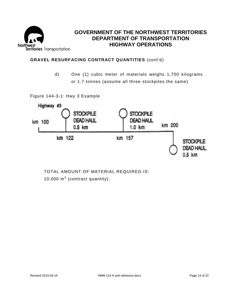
GOVERNMENT OF THE NORTHWEST TERRITORIES
DEPARTMENT OF TRANSPORTATION HIGHWAY OPERATIONS
Revised 2010-04-15 HMM 114 A and reference.docx Page 14 of 22
GRAVEL RESURFACING CONTRACT QUANTITIES (cont ’d)
d) One (1) cubic meter of materials weighs 1,700 ki lograms
or 1.7 tonnes (assume al l three stockpi les the same)
Figure 144-3-1: Hwy 3 Example
TOTAL AMOUNT OF MATERIAL REQUIRED IS:
10,000 m 3 (contract quantity).

GOVERNMENT OF THE NORTHWEST TERRITORIES
DEPARTMENT OF TRANSPORTATION HIGHWAY OPERATIONS
Revised 2010-04-15 HMM 114 A and reference.docx Page 15 of 22
MATERIAL REQUIRED FROM EACH STOCKPILE: Stockpi le km 122 wil l do:
1) Km 100 to km 122 = 22.0 km
2) Km 122 to (half way to km 157), km 139.5 = 17.5 km
TOTAL 39.5 km
Mater ial required = 100 m 3 /km x 39.5 = 3,950 m3
Stockpi le km 157 wil l do:
1) Km 139.5 to km 157 = 17.5
2) Km 157 to (halfway to km 200), km 178.5 = 21.5
TOTAL 39.0
Mater ial required = 100 m 3 /km x 39.0 km = 3,900 m3
Stockpi le km 200 wil l do:
1) Km 178.5 to km 200 = 21.5
Mater ial required = 100 m 3 /km x 21.5 = 2,150 m3
Note: At this point, ensure that there is suf f icient material in each
stockpile.
T O N N E - K I L O M E T R E S
S t o c k p i l e k m 1 2 2
1) Deal Haul: 3.950 m3 x 0.5 km = 1,975.0 m3-km
2) Km 100 to km 122= 100 m 3 /km x 22 km x 22 /2 = 24,200.0 m3-km
3) Km 122 to km 139.5= 100m 3 /km x 17.5 x 17 . 5 /2= 15,312.5 m3-km
TOTAL 41,487.5 m3-km

GOVERNMENT OF THE NORTHWEST TERRITORIES
DEPARTMENT OF TRANSPORTATION HIGHWAY OPERATIONS
Revised 2010-04-15 HMM 114 A and reference.docx Page 16 of 22
Stockpi le km157
1) Dead haul: 3,900 m3 x 1.0 km = 3,900.0 m3-km
2) Km139.5 to km 157= 100m3/km x 17.5 x 1 7 . 5 /2 = 15,312.5 m3-km
3) Km 157 to km 178.5= 100m3/km x 21/5 x 21 . 5 /2 = 23,112.5 m3-km
TOTAL 42,325.0 m3-km
Stockpi le km 200
1) Dead haul 2,150m3 x 0.5km = 1,075.0 m3-km
2) Km 178 to km 200= 100m3/km x 21.5 x 2 1 . 5 /2 = 23,112.5 m3-km
TOTAL 24,187.5 m3-km
GRAND TOTAL: 108,000 m3-km (contract quantity)
SPREAD CHART (Gravel Resurfacing)
A spread chart for gravel distr ibut ion on the highway is essential to
ensure that the proper amount of gravel is being appl ied.
Preparing a Spread Chart , refer to Figure 114-3-2:
In order to prepare a spread chart, the following must be known:
1. Applicat ion rate per kilometre.
2. Maximum allowance of volume in cubic metres that can be hauled by
the truck.
3. The maximum allowable volume in cubic metres that can be hauled
is calculated by using the truck measurement sheet.
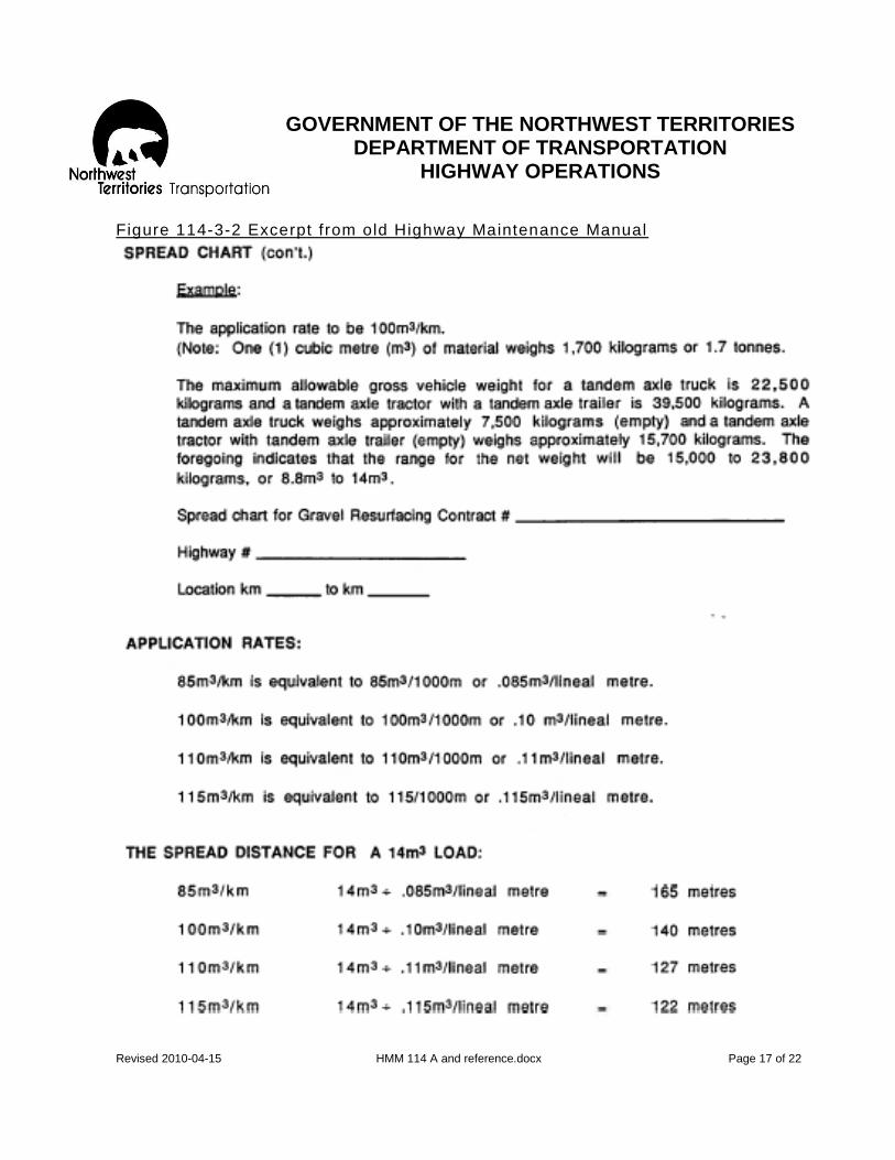
GOVERNMENT OF THE NORTHWEST TERRITORIES
DEPARTMENT OF TRANSPORTATION HIGHWAY OPERATIONS
Revised 2010-04-15 HMM 114 A and reference.docx Page 17 of 22
Figure 114-3-2 Excerpt from old Highway Maintenance Manual

GOVERNMENT OF THE NORTHWEST TERRITORIES
DEPARTMENT OF TRANSPORTATION HIGHWAY OPERATIONS
Revised 2010-04-15 HMM 114 A and reference.docx Page 18 of 22
SPREAD CHART (Gravel Resurfacing)
A spread chart for gravel distr ibut ion on the highway is
essent ial to ensure that the proper amount of gravel is
being appl ied
Prepar ing Spread Chart
In order to prepare the spread chart, the following must be
known:
1. Appl icat ion rate per kilometre
2. Maximum al lowable cubic meters that can be hauled
by the truck. The maximum al lowable cubic meters
that can be hauled is calculated by using the truck
measurement sheet.
DUTIES AND RESPONSIBILITIES OF THE CHECKER AT THE STOCKPILE:
1. Enters the volume measure of each load in cubic meters on the
standard government weight cert if icate and also enters other
required information as instructed by the Highway Maintenance
Supervisor.
2. The checker must sign his regular signature not his init ia ls to
every weight cert if icate
3. The checker, af ter each truck is loaded and the information
recorded, obtains the truck driver ’s ini t ia ls. Retains one copy
(trucker) and gives the rest to the truck driver for presentat ion at
the dumping site
4. On temporary shutdown the checker performs such o ther work as
may be assigned by the Highway Maintenance Supervisor.
5. The checker at the stockpile wil l receive ALL instruct ions from
the Highway Maintenance Supervisor, not f rom the contractor or
truck driver.
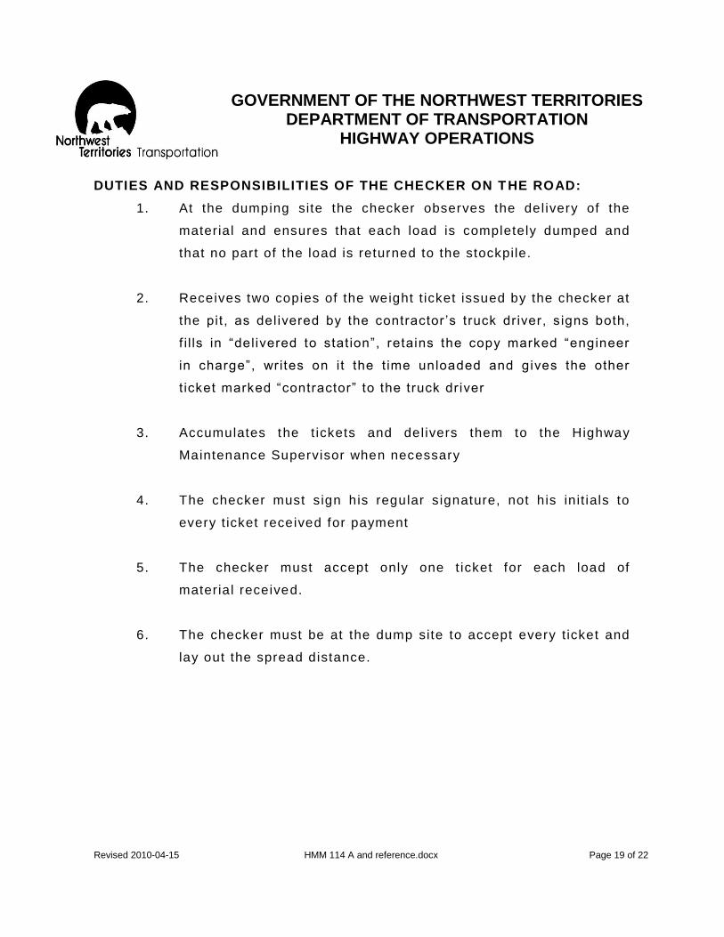
GOVERNMENT OF THE NORTHWEST TERRITORIES
DEPARTMENT OF TRANSPORTATION HIGHWAY OPERATIONS
Revised 2010-04-15 HMM 114 A and reference.docx Page 19 of 22
DUTIES AND RESPONSIBILITIES OF THE CHECKER ON T HE ROAD:
1. At the dumping site the checker observes the del ivery of the
material and ensures that each load is completely dumped and
that no part of the load is returned to the stockpile.
2. Receives two copies of the weight t icket issued by the checker at
the pit, as del ivered by the contractor ’s truck driver, s igns both,
f i l ls in “delivered to stat ion”, retains the copy marked “engineer
in charge”, writes on it the t ime unloaded and gives the other
t icket marked “contractor” to the truck driver
3. Accumulates the t ickets and del ivers them to the Highway
Maintenance Supervisor when necessary
4. The checker must s ign his regular s ignature, not his init ials to
every t icket received for payment
5. The checker must accept only one t icket for each load of
material received.
6. The checker must be at the dump site to accept every t icket and
lay out the spread distance.

GOVERNMENT OF THE NORTHWEST TERRITORIES
DEPARTMENT OF TRANSPORTATION HIGHWAY OPERATIONS
Revised 2010-04-15 HMM 114 A and reference.docx Page 20 of 22
DUTIES AND RESPONSIBILITIES OF THE CHECKER AT THE PIT
7. The weight Cert if icate: (see attached example t icket)
a) Two (2) spaces must be f i l led in:
1. Delivered to stat ion (kilometre)
2. Checker
b) The circ led number (example 122) means that the truck
driver is required to spread the load of gravel 122 metres
(spread distance)
8. Using a tape measure or a rope measure, the checker measures
the spread distance along the shoulder of the road and marks
the beginning and end of the spread with a marker (survey stake
with f lagging),
9. The checkers which are on temporary shutdown of hauling
operat ions wi l l perform such other work as assigned by the
Highway Maintenance Supervisor
10. The checker wil l receive ALL instruct ions f rom the Highway
Maintenance Supervisor, not f rom the Contractor or the truck
drivers.

GOVERNMENT OF THE NORTHWEST TERRITORIES
DEPARTMENT OF TRANSPORTATION HIGHWAY OPERATIONS
Revised 2010-04-15 HMM 114 A and reference.docx Page 21 of 22
SAFETY EQUIPMENT
1. You are required to wear a safety vest at al l t imes
2. You are required to wear safety boots at a l l t imes
3. Do not stand beside the truck when dumping
4. I f you have a vehicle, it must be parked off the driving surface
of the highway.
5. Stand on the shoulder of the road not in the middle, dusty
condit ions impair vis ibil i ty for all.
SPECIAL NOTES:
Attached is an example calculat ion for “spread rate chart and a truck
measurement worksheet.
The previous version of the Weight Certif icate format used for these types of
project has been discontinued.
Gross Vehicle Weights can be obtained from the L arge Vehicle Control
Regulat ions or f rom the Enterpr ise Weigh Scale Staf f .
For more information please contact the Highway Operat ions Off ice in Hay
River.

GOVERNMENT OF THE NORTHWEST TERRITORIES
DEPARTMENT OF TRANSPORTATION HIGHWAY OPERATIONS
Revised 2010-04-15 HMM 114 A and reference.docx Page 22 of 22
EXAMPLE Vehic le Measurement Sheet .
P ro jec t Number
Date
Box No. Given
Rated Capac i t y m3
(see note be low)
Please PRINT Al l In fo rmat ion
Name of Owner ( In fu l l ) Address of Owner
Truck L icense No.
L icensed Gross W eight
Where Measured
Make Cheques Payable To
Address
S igned
(Truck Dr ive r) TIRES
Steer ing Axle
Dr i ve Axle(s )
Tra i ler Axle (s) ( I f semi - t ra i le r) RATED CAPACITY
Max Gross W eight Permiss ib le under
Large Vehic le Contro l Regulat ions kg
Tare weigh t kg
Max. Net W ight Permiss ib le kg
RATED CAPACITY m3
N o t e : a ) R A T E D C A P A C I T Y i s m a x i m u m v o l u me p e r m i s s i b l e b a s e d o n t h e a s s u m p t i o n t h a t g r a v e l we i g h s 1 7 0 0 k g / m a n d t h a t t h e l o a d i s
p r o p e r l y d i s t r i b u t e d o n t h e a x l e g r o u p s . b ) T h e s e m e a s u r e m e n t s , c a l c u l a t i o n s a n d a s s u m p t i o n s i n n o w a y a b s o l v e t h e t r u c k o w n e r f r o m c o m p l y i n g w i t h L a r g e V e h i c l e
C o n t r o l R e g u l a t i o n s c ) M e a s u r e m e n t s t o b e m a d e i n m e t e r a n d o n e h u n d r e d t h o f a m e t e r d ) B o xe s w i l l b e r a t e d t o t h e n e a r e s t o n e - t e n t h m 3
C a p a c i t y a n d o n c e s o r a t e d s h a l l n o t b e C h a n g e d w i t h o u t c o n s e n t o f t h e E n g i n e e r T h e M e a s u r e m e n t s o f B o x a n d R A T E D C A P A C I T Y a s s h o wn a b o v e a r e a c c e p t e d a s c o r r e c t
M e a s u r e d B y S i g n e d
( I n s p e c t o r ) ( T r u c k D r i v e r )

GOVERNMENT OF THE NORTHWEST TERRITORIES
DEPARTMENT OF TRANSPORTATION HIGHWAY OPERATIONS
Revised 2010-04-15 HMM 116 to 122 REV 10.docx Page 1 of 11
116- GRAVEL SPOT SURFACING
OBJECTIVE:
To ensure the traveled surface of gravel highways is maintain ed to the intended cross-sect ion.
DESCRIPTION:
Spot patching of short ( less than 0.2 km) sections of the highway and gravel surfaces to correct such def ic iencies as:
- local ized road depressions , - sett lement at ut i l i ty cuts or culverts , - potholes and minor unstable areas , and - areas lacking gravel .
LEVEL OF SERVICE:
All categories of road qual ity for this act ivity. The extent of appl icat ion of this act ivity wi l l be over relat ively larger areas of failure for higher category roads.
RESPONSIBILITY: Highway Maintenance Supervisor to co -ordinate this work schedule. PRODUCTIVITY GUIDELINES: RESOURCE GUIDELINES:
Quantity Standard- Crew-
0.5 m3 /bladed pass 2- Heavy Equipment Operator
(class 02)
Average Daily Production- Equipment-
Varies depending on stock haul 1-Dump Truck (class 1504)
distances. 1-Truck Mounted Underblade
(class 5377)
AVG= 42 cubic meters 1- Loader (class 2109)
1- Tilt Deck (class 1211)

GOVERNMENT OF THE NORTHWEST TERRITORIES
DEPARTMENT OF TRANSPORTATION HIGHWAY OPERATIONS
Revised 2010-04-15 HMM 116 to 122 REV 10.docx Page 2 of 11
116- GRAVEL SPOT SURFACING
SCHEDULING:
Mid Apr i l to mid October Highway Maintenance Supervisor wi l l , where possible, co -ordinate this act ivity in conjunction with Wet or Dry Blading Act ivit ies to permit the use of the motor grader for spreading over larger areas as the grader wi l l not normally be charged to this act ivity. Correct ing def iciencies such as potholes, minor unstable areas and sett lements at ut i l i ty cuts or culverts are usual ly of an emergency nature and therefore spreading wi l l be done with the underblade where possible.
RECOMMENDED METHOD:
1. Place signs, safety devices and traf f ic control personnel as required
2. Truck driver self - loads 3. Dump gravel into depressions and sof t spots or on longer
sections use spreader chains. 4. Spread evenly with underbody blade or grader when avai lable 5. Compact small holes or depressions, using the truck t ires to rol l
the repaired surface 6. Remove signs and safety devices, if wor king independently
Special Notes: a. Major sof t, wet areas, which are unstable, should be repaired
using Activity 120 and then surfaced using Activity 116. b. Drainage problems related to the grade fai lure should be
corrected using the appropr iate drainage activit ies such as 202, 203, 210 and 211.
c. In areas of excess loss of wear ing surfaces ( i.e. over 0.2 km) use Act ivity 114.

GOVERNMENT OF THE NORTHWEST TERRITORIES
DEPARTMENT OF TRANSPORTATION HIGHWAY OPERATIONS
Revised 2010-04-15 HMM 116 to 122 REV 10.docx Page 3 of 11
120- GRADE REPAIR- GRAVEL SURFACES
OBJECTIVE:
To maintain the cross sect ion integrity of the gravel road to preserve the original design standard, given avai lable maintenance resources.
DESCRIPTION: The repair of the grade including shoulders and grade side slopes using selected clay, pit run gravel, crush or other suitable materials to correct def iciencies such as: - Unstable areas/f rost upheaval - Sett lement ( including problems relat ing to permafrost) - Grade washout/erosion - Grade sl ippage - Loss of surface cross-section
This operat ion includes the excavat ion beyond the fai lure zone
LEVEL OF SERVICE:
The frequency and extent of this repair is to be based on the best judgment of the Highway Maintenance Supervisor and Regional Manager taking into account the need to preserve the road and provide safe and comfortable service to the users.
RESPONSIBILITY:
The Highway Maintenance Supervisor and Regional Manager wi l l assess the problem, analyze the cause and determine the correct act ion for this act ivity . Special Note: For major grade repairs approved with funding by Regional Manager, use Activity 810 Refer to Highway Maintenance Operating Instruct ions for:
- Product ivity Guidelines - Resource Guidel ines - Scheduling - Recommended Method

GOVERNMENT OF THE NORTHWEST TERRITORIES
DEPARTMENT OF TRANSPORTATION HIGHWAY OPERATIONS
Revised 2010-04-15 HMM 116 to 122 REV 10.docx Page 4 of 11
120- GRADE REPAIR- GRAVEL SURFACES
PRODUCTIVITY GUIDELINES: RESOURCE GUIDELINES:
Quantity Standard- Crew-
3 . 0 m 3 / k m o f g r a v e l r o a d 5 - H e a v y E q u i p m e n t O p e r a t o r s ( c l a s s 0 3 ) 2 - L a b o u r e r s ( c l a s s 0 5 ) 2 - T r a f f i c C o n t r o l P e r s o n n e l ( c l a s s 0 5 )
Daily Production Range- Equipment-
A s r e q u i r e d 1 - c r a w l e r T r a c t o r c / w D o z e r ( c l a s s 2 4 0 4 )
1 - M o t o r G r a d e r w i t h S c a r i f i e r ( c l a s s 2 3 0 4 )
1 - T r a c t o r M o u n t e d L o a d e r B a c k h o e ( c l a s s 2 8 0 9 )
2 - D u m p T r u c k s ( c l a s s 1 5 0 4 )
1 - P a c k e r ( c l a s s 2 6 0 0 ) 1 - P i c k u p ( c l a s s 1 8 2 3 ) 1 - T i l t D e c k ( c l a s s 1 2 1 1 )
M a t e r i a l
P i t R u n G r a v e l ( c o d e 1 0 8 ) C l a y / S h a l e ( c o d e 1 0 4 ) C r u s h e d A g g r e g a t e
( c o d e 1 1 0 )
S C H E D U L I N G :
Grade failures should be dealt with in a t imely fashion. (Normally scheduled from Mid-May to Mid-September when condit ions are dry.)

GOVERNMENT OF THE NORTHWEST TERRITORIES
DEPARTMENT OF TRANSPORTATION HIGHWAY OPERATIONS
Revised 2010-04-15 HMM 116 to 122 REV 10.docx Page 5 of 11
120- GRADE REPAIR- GRAVEL SURFACES
RECOMMENDED METHOD- General Approach
Base fai lures are usually caused by the presence of the f ine, f rost suscept ible si lts or clays and a source of water. Removing either the poor mater ial or the water wi l l reduce the problem however both condit ions must be remedied if a strong and stable grade condit ion with a smooth surface is to be attained. Grade sl ippage or sett lement can be due to permafrost melt. Knowing the cause of failure, the nature of the grade materials and other factors, a solut ion is usual ly evident and the method of correct ion can be devised. Special Note:
Correct ion of drainage problems such as cleaning and deepening drainage ditches wi l l be charged to act ivi t ies such as 210, 211 or 851.
RECOMMENDED METHOD- Details
1. PLACE SIGNS AND SAFETY DEVICES 2. STATION FLAG PERSONS WHEN NECESSARY 3. SALVAGE ALL USABLE GRAVEL 4. a) FAILURE
i. Excavate beyond the boundary of the failure by 300 mil l imeters into the sound grade. Depth of excavation wi l l be governed by the extent of the failure or deeper as determined by the fai lure mechanism. Trenching f rom edge of excavation to grade side slope may be desirable to provide sub-grade drainage.
i i . Backf i l l the excavation and the trench where appl icable with 15 cm l if ts of wel l graded pit run gravel with suff icient sand content to prevent pumping a contamination into main body of f i l l mater ial. An alternative is to f irst backf i l l with a 15 cm lif t of sand or use a geotext i le to act as a f i l ter and then continue to back f i l l to grade level with clean pit run or crushed gravel in 15 cm l if ts. Af ter every l i f t , compact before proceeding with the next lef t .

GOVERNMENT OF THE NORTHWEST TERRITORIES
DEPARTMENT OF TRANSPORTATION HIGHWAY OPERATIONS
Revised 2010-04-15 HMM 116 to 122 REV 10.docx Page 6 of 11
120- GRADE REPAIR- GRAVEL SURFACES
RECOMMENDED METHOD- Details (cont ’d)
b) GRADE SLIPPAGE i. Bench if necessary to reduce the possibi l i t ies of future
sl ides. i i . Backf i l l to grade level with good clay or granular mater ial in
15 cm l if ts if possible and compact to reduce sett lement r isk.
c) WASHOUT
i. Backf i l l to grade level with good clay or granular mater ial in 15 cm lif ts if possible and compact to reduce sett lement r isk. Try to el iminate the cause of the washout
d) SETTLEMENT OR LOSS OF CROSS-SECTION When only scarifying and reshaping wi l l correc t the problem.
i. Scar ify the area to ensure that the f i l l wi l l bond.
i i . Add suff icient c lay or granular material with a high binder content and then reshape to the desired grade l ine and cross-sect ion
5. DISPOSAL OF WASTE MATERIAL
When the undesirable material must be excavated, use a motor grader with a scarif ier, a crawler tractor or a tractor mounted backhoe for excavation and, when practical, dispose of the waste material with the r ight -of-way using a crawler tractor. Otherwise, the excavated mater ial must be loaded onto trucks and hauled to a suitable disposable site. In al l cases, care must be taken in order that waste mater ial does not impede the f low of water in the roadside ditch. Final ly ensure that the road shoulders are properly stabi l ized and the grad e slopes are lef t in a neat and clean condit ion.
6. RESURFACE REPAIRED AREA WITH TRAFFIC GRAVEL
7. REMOVE ALL SIGNS AND SAFETY DEVICES

GOVERNMENT OF THE NORTHWEST TERRITORIES
DEPARTMENT OF TRANSPORTATION HIGHWAY OPERATIONS
Revised 2010-04-15 HMM 116 to 122 REV 10.docx Page 7 of 11
122- GRADE REPAIR- PAVED SURFACES
OBJECTIVE:
To maintain the integrity of the cross section of the asphalt ic surfaced road including shoulder and side slopes and to preserve the or iginal design given avai lable maintenance resources.
DESCRIPTION:
The repair of the grade including shoulders, grade side slopes and the pavement base using selected clay, pit run gravel, crush or o ther suitable f i l l mater ial to correct def iciencies such as: - Unstable areas (f rost upheaval) - Sett lement ( including problems relat ing to permafrost) - Grade washout (erosion) - Grade sl ippage This operat ion includes the excavat ion of the failures to a maximum depth of 1.5 meters and a maximum length of 100 meters.
LEVEL OF SERVICE:
The urgency and extent of this repair is to be based on the best judgment of the Highway Maintenance Supervisor and Regional Manager, taking into account the need to preserve the road and provide safe and comfortable service to the users.
RESPONSIBILITY:
The Highway Maintenance Supervisor and Regional Manager wil l assess the problem, analyze the cause and determine the correct act ion for this act ivity. S p e c i a l N o t e : F o r r e p a i r s o f a l a r g e r s i z e t h a n 1 . 5 m e t e r s i n d e p t h o r 1 0 0 m e t e r s i n l e n g t h a p p r o v e d w i t h f u n d i n g b y R e g i o n a l M a n a g e r , u s e A c t i v i t y 8 1 0 . R e f e r t o H i g h w a y M a i n t e n a n c e O p e r a t i n g I n s t r u c t i o n s f o r : - Product ivity Guidelines - Resource Guidel ines - Scheduling - Recommended Method

GOVERNMENT OF THE NORTHWEST TERRITORIES
DEPARTMENT OF TRANSPORTATION HIGHWAY OPERATIONS
Revised 2010-04-15 HMM 116 to 122 REV 10.docx Page 8 of 11
122- GRADE REPAIR- PAVED SURFACES
PRODUCTIVITY GUIDELINES: RESOURCE GUIDELINES:
Quantity Standard- Crew-
1 . 5 m 3 / k m o f p a v e d r o a d 3 - H e a v y E q u i p m e n t O p e r a t o r s ( c l a s s 0 3 ) 2 - L a b o r e r s ( c l a s s 0 5 )
Average Daily Production- Equipment-
V a r i e s d e p e n d i n g o n s t o c k 1 - c r a w l e r T r a c t o r
h a u l d i s t a n c e d c / w D o z e r ( c l a s s 2 4 0 4 )
1 - M o t o r G r a d e r
T y p i c a l t o 7 5 c u b i c m e t e r s ( c l a s s 2 3 0 4 )
1 - T r a c t o r M o u n t e d L o a d e r
B a c k h o e ( c l a s s 2 8 0 9 )
2 - D u m p T r u c k s
( c l a s s 1 5 0 4 )
1 - P a c k e r ( c l a s s 2 6 0 0 )
1 - P i c k u p ( c l a s s 1 8 2 3 )
1 - T i l t D e c k ( c l a s s 1 2 1 1 )
M a t e r i a l
P i t R u n G r a v e l ( c o d e 1 0 8 )
C r u s h e d G r a v e l ( c o d e 1 1 0 )
O p t i o n a l
C l a y / S h a l e ( c o d e 1 0 4 )
S C H E D U L I N G :
Grade failures should be dealt with in a t imely fashion. (Normally scheduled from Mid-May to Mid-September when condit ions are dry.)
GOVERNMENT OF THE NORTHWEST TERRITORIES
DEPARTMENT OF TRANSPORTATION HIGHWAY OPERATIONS
Revised 2010-04-15 HMM 116 to 122 REV 10.docx Page 9 of 11
122- GRADE REPAIR- PAVED SURFACES
RECOMMENDED METHOD- General Approach
Serious breaks in the road surface that pose a hazard to traff ic should be brought to the immediate attention of the Regional Managers for their recommendations regarding a t imely correct ive act ion. However, al l problem areas should be investigated be Regional Managers and Highway Maintenance Supervisors and the problem analyzed as to the cause. Road base failures are usually tr iggered by the f low or percolat ion of ground water into the sub -grade, especially when the grade contains f rost suscept ible, f ine clays or sl its. Where pract ical, necessary dewatering or draining of the road base should be carr ied out before excavat ing the failure.
Removing either the water or the poor material wi l l reduce the problem however, both condit ions must be remedied to restore the base to a strong and stable condit ion, thereby restoring a smooth road surface. Knowing the cause of the failure, the nature of t he grade materials and other factors, a solut ion is usual ly evident and the method of correct ion can be devised. Grade slippage or sett lement can be due to permafrost melt In the case of grade erosion or washout the cause of the problem should be corrected if possible, to prevent a reoccurrence. Normally the material used for the repair of the grade can be similar to the previous grade material providing it was stable and did not contr ibute to the failure.

GOVERNMENT OF THE NORTHWEST TERRITORIES
DEPARTMENT OF TRANSPORTATION HIGHWAY OPERATIONS
Revised 2010-04-15 HMM 116 to 122 REV 10.docx Page 10 of 11
122- GRADE REPAIR- PAVED SURFACES
RECOMMENDED METHOD- Details
1. PLACE SIGNS AND SAFETY DEVICES
2. STATION FLAG PERSONS
3. a) FAILURE
i. The boundaries of the unstable area should be clearly def ined. Most base failures wi l l be clear ly vis ible as depressions causing all igator cracking of the asphalt surface or with heaving associated with f rost boi ls. The outl ine of the area to be excavated 300 mil l imeters beyond the outer edges of the fai lure to ensure that all the unstable material wil l be removed.
i i . Excavate the out l ined area to the bottom of the unstable material with a machine suitable for the size of the base failure. Depth of excavation wi l l be governed by the extent of the failure or deeper as determined by the fai lure mechanism. I t may be desirable to provide sub-grade drainage by trenching f rom the edge of the excavat ion to the grade slope at the same depth as the excavat ion of the failure
i i i . Backf i l l the excavat ion and the trench where applicable with 15 cm lif ts of wel l graded pit run gravel with suf f icient sand content to prevent pumping a contamination into main body of f i l l mater ial. An alternative is to f irst backf i l l with a 15 cm lif t of sand or use a geotext i le to act as a f i l ter and then continue to back f i l l to grade level with clean pit run or crushed gravel in 15 cm l if ts. Af ter every l i f t , compact before proceeding with the next lef t .

GOVERNMENT OF THE NORTHWEST TERRITORIES
DEPARTMENT OF TRANSPORTATION HIGHWAY OPERATIONS
Revised 2010-04-15 HMM 116 to 122 REV 10.docx Page 11 of 11
122- GRADE REPAIR- PAVED SURFACES
RECOMMENDED METHOD- Details
b) GRADE SLIPPAGE
i. Bench if necessary to reduce the possibi l i ty of future slides i i . Backf i l l to grade level with good clay or granular mater ial in
15 cm l if ts if possible and compact to reduce sett lement r isk.
c) WASHOUT/EROSION
ii i . Backf i l l to grade level with good clay or granular mater ial in 15 cm l if ts if possible and compact to reduce sett lement r isk. Try to eliminate the cause of wash-out
4. Dispose of any waste material in such a manner that it wi l l not interfere with the drainage or other roadside act ivit ies
5. Surface the repaired area with an asphalt material s imilar to or better than the adjacent asphalt surface and report this work to the appropriate asphalt surface act ivity.
6. REMOVE ALL SIGNS, SAFETY DEVICES AND FLAG PERSONS

GOVERNMENT OF THE NORTHWEST TERRITORIES
DEPARTMENT OF TRANSPORTATION HIGHWAY OPERATIONS
Revised 2010-04-15 HMM 151 to 169 Rev10.docx Page 1 of 35
151- DUST TREATMENT- CALCIUM CHLORIDE
OBJECTIVE:
The use of a dust abatement chemical to provide a safer more comfortable service while preserving the integrity of the road surface by retaining surface material.
DESCRIPTION:
The appl icat ion of calcium chlor ide to gravel road surfaces for dust abatement and surface stabil izat ion.
LEVEL OF SERVICE
Calcium chloride wil l be appl ied only on continuous sections of highway or at specif ic locat ions, which have been approved by the Regional Manager .
RESPONSIBILITY
The Highway Maintenance Supervisor or representat ive should accompany the calcium chlor ide appl icat ion truck over the predetermined rout to ensure that only approved areas receive treatment at the planned appl icat ion rate.
PRODUCTIVITY GUIDELINES: RESOURCE GUIDELINES:
Quantity Standard- Crew-
N e w l o c a t i o n s - 5 t / k m 2 - H e a v y E q u i p m e n t O p e r a t o r s
( c l a s s 0 3 ) P r e v i o u s l y t r e a t e d l o c a t i o n s - C a t 1 & 2 h w y - 5 t / k m - C a t 3 & 4 h w y - 4 t / k m - C a t 5 h w y - 3 t / k m SPECIAL NOTE for all of Section 151: This activity has been assigned to contractors over the last few years. This section will serve as a reference. Recommend that all staff assigned to monitor the contractor have a copy of the contract documents available for their review and to present any changes in specifications and operational requirements. Please contact the Highway Operations Office in Hay River for contractor schedules or for more information.

GOVERNMENT OF THE NORTHWEST TERRITORIES
DEPARTMENT OF TRANSPORTATION HIGHWAY OPERATIONS
Revised 2010-04-15 HMM 151 to 169 Rev10.docx Page 2 of 35
151- DUST TREATMENT- CALCIUM CHLORIDE
PRODUCTIVITY GUIDELINES, continued: RESOURCE GUIDELINES, continued: Average Daily Production- Equipment- 1 - S e m i T r a i l e r 1 - T a n d e m T r a c t o r
1 0 0 t o n n e s ( c l a s s 1 1 0 9 )
1 - S e m i T r a i l e r
( c l a s s 1 3 0 4 )
1 - P u m p ( c l a s s 5 8 0 1 )
1 - G r a d e r ( c l a s s 2 3 0 4 )
Equipment- Optional
1 - W a t e r T r u c k
M a t e r i a l
C a l c i u m C h l o r i d e - B u l k
( c o d e 3 3 4 )
SCHEDULING: Calcium chlor ide wil l be appl ied for dust abatement purposes on Category 1, 2, 3 & 4 highways in two appl icat ions; Category 5 highways in one applicat ion. The f irst appl icat ion should be scheduled as soon as condit ions wil l al low in late spring ( i.e. May) with the second applicat ion for Category 1 through 4 highways scheduled for mid-summer ( i.e. July/August). Note: If it is raining or rain is anticipated within 2 hours, delay application until the weather clears.

GOVERNMENT OF THE NORTHWEST TERRITORIES
DEPARTMENT OF TRANSPORTATION HIGHWAY OPERATIONS
Revised 2010-04-15 HMM 151 to 169 Rev10.docx Page 3 of 35
151- DUST TREATMENT- CALCIUM CHLORIDE
Recommended Method- General Approach
Calcium chloride wi l l be appl ied as follows: a. Dust control led passing zones, 6 to 8 kilometers in length, at
strategical ly placed intervals of 50 kilometers (approximately ½ hour driving t ime) .
b. Major intersect ions, one half k i lometer along each branch of intersection.
c. Approaches to major bridge structures 0.5 kilometers both sides.
d. Ferry approaches, minimum 0.5 kilometers each approach e. Residential areas and industr ial s ites . f . 0.5 kilometers both sides of park accesses . g. Al l highways with traff ic counts exceeding 250 vehicles per
day, PSADT (Peak Summer Average Daily Traff ic). h. On sections that require art if ic ial binding to stabil ize the
surface when other methods are not pract ical . i . Other areas in the opinion of the Director of Highways or the
Regional Manager, where the applicat ion would enhance safety to the traveling public.
RECOMMENDED METHOD- Details
1. PLACE NECESSARY SIGNS AND SAFETY DEVICES. 2. Road surfaces should be bladed immediately prior to applicat ion
of calcium chloride to ensure a smooth r iding surface and proper cross-sect ion and a minimum of loose material .
3. surface should be damp at the t ime of the calcium chloride applicat ion. I f not, the surface should be watered immediately before the applicat ion.
4. The supplier wil l normally be responsible for the appl icat ion of the calcium chloride ( l iquid or f lake) .
5. I f f lake calcium chloride is used and all the product is not all dissolved within 24 hours, an addit ional applicat ion of water wi l l be required. However excess water could wash the chemical in to the ditch.
6. REMOVE SIGNS AND SAFETY DEVICES.

GOVERNMENT OF THE NORTHWEST TERRITORIES
DEPARTMENT OF TRANSPORTATION HIGHWAY OPERATIONS
Revised 2010-04-15 HMM 151 to 169 Rev10.docx Page 4 of 35
151- DUST TREATMENT- CALCIUM CHLORIDE
OBJECTIVE:
The use of a dust abatement chemical to provide a safer more comfortable service while preserving the integrity of the road surface by retaining surface material.
DESCRIPTION:
The appl icat ion of oi l and surface stabi l izat ion on gravel road surfaces for dust abatement .
LEVEL OF SERVICE
This standard covers the pressure-spray appl icat ion of oil for dust abatement. I t is not intended as a method of building up a type of paved surface. The asphalt content of the oil should be determined before consider ing applicat ion since oil without or low in asphalt content wi l l only give an effect ive dust treatment for a relat ively short period of t ime. Oils wi l l be appl ied only on cont inuous sections of highway or at specif ic locat ions, which have been approved by the Director of Highways or the Regional Manager .
RESPONSIBILITY
The Highway Maintenance Supervisor with guidance from the Regional Manager.
PRODUCTIVITY GUIDELINES: RESOURCE GUIDELINES:
Quantity Standard- Crew-
I n i t i a l - 1 . 5 p e r m 2 / t w i c e a 1 - H e a v y E q u i p m e n t y e a r . S e c o n d y r - 1 . 0 l i t e r p e r O p e r a t o r m 2 / t w i c e a y e a r . S u b s e q u e n t 4 - l a b o u r e r s y e a r s - 0 . 5 l i t e r p e r s i n g l e a p p l i c a t i o n . O p t i o n a l 1 - H e a v y E q u i p m e n t
O p e r a t o r

GOVERNMENT OF THE NORTHWEST TERRITORIES
DEPARTMENT OF TRANSPORTATION HIGHWAY OPERATIONS
Revised 2010-04-15 HMM 151 to 169 Rev10.docx Page 5 of 35
154- DUST TREATMENT - OIL
THIS ACTIVITY HAS BEEN REMOVED DUE TO ENVIRONMENTAL CONCERNS.
The use of oi l as a dust abatement product is under review and has been removed from the Highway Maintenance Manual. This is due to environmental concerns. Other products and procedures wi l l be examined to determine the upgrading potential for this act ivity. Please contact the Highway Operations Off ice in Hay River for further information. .

GOVERNMENT OF THE NORTHWEST TERRITORIES
DEPARTMENT OF TRANSPORTATION HIGHWAY OPERATIONS
Revised 2010-04-15 HMM 151 to 169 Rev10.docx Page 6 of 35
161- PERMANENT HANDPATCHING
OBJECTIVE:
To eliminate surface def iciencies causing traff ic hazards and restore r iding qualit ies to design standards on asphalt surfaces .
DESCRIPTION:
The hand patching of asphalt ic surfaces using premix mainly to repair def iciencies such as: - Potholes/surface breaks - Frost related bumps - Shoved or r ippled areas - Al l igator and map cracking
LEVEL OF SERVICE:
Pavement patching is performed to provide the travel ing public with a safe, smooth r iding surface and to either prevent rapid or progressive deteriorat ion. Patching is a top priority act ivity. The Highway Maintenance Supervisor should be especial ly alert, during the spring months when break -up is most severe to ident i fy and correct these def iciencies. Potholes should be repaired immediately as they can becom e a hazardous situat ion. Grade failures due to faulty soils or the presence of water should be repaired using act ivit ies such as 122 and 211 to correct sub grade condit ions pr ior to surface repair when possible .
RESPONSIBILITY:
The Highway Maintenance Supervisor to schedule.
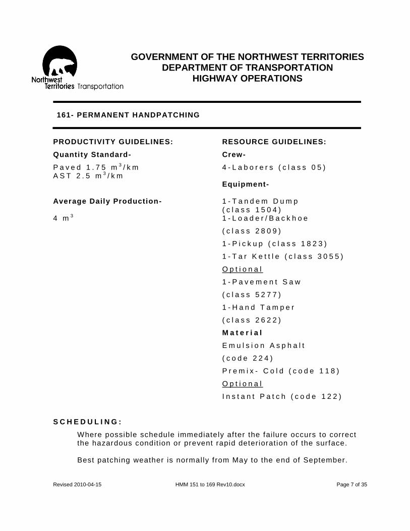
GOVERNMENT OF THE NORTHWEST TERRITORIES
DEPARTMENT OF TRANSPORTATION HIGHWAY OPERATIONS
Revised 2010-04-15 HMM 151 to 169 Rev10.docx Page 7 of 35
161- PERMANENT HANDPATCHING
PRODUCTIVITY GUIDELINES: RESOURCE GUIDELINES:
Quantity Standard- Crew-
P a v e d 1 . 7 5 m 3 / k m 4 - L a b o r e r s ( c l a s s 0 5 ) A S T 2 . 5 m 3 / k m Equipment- Average Daily Production- 1 - T a n d e m D u m p
( c l a s s 1 5 0 4 ) 4 m 3 1 - L o a d e r / B a c k h o e
( c l a s s 2 8 0 9 )
1 - P i c k u p ( c l a s s 1 8 2 3 )
1 - T a r K e t t l e ( c l a s s 3 0 5 5 )
O p t i o n a l
1 - P a v e m e n t S a w
( c l a s s 5 2 7 7 )
1 - H a n d T a m p e r
( c l a s s 2 6 2 2 )
M a t e r i a l
E m u l s i o n A s p h a l t
( c o d e 2 2 4 )
P r e m i x - C o l d ( c o d e 1 1 8 )
O p t i o n a l
I n s t a n t P a t c h ( c o d e 1 2 2 )
S C H E D U L I N G :
Where possible schedule immediately af ter the failure occurs to correct the hazardous condit ion or prevent rapid deteriorat ion of the surface.
Best patching weather is normally f rom May to the end of September.

GOVERNMENT OF THE NORTHWEST TERRITORIES
DEPARTMENT OF TRANSPORTATION HIGHWAY OPERATIONS
Revised 2010-04-15 HMM 151 to 169 Rev10.docx Page 8 of 35
161- PERMANENT HAND PATCHING
RECOMMENDED METHOD- General Approach
The Highway Maintenance Supervisor is to determine where act ivity 161 should be undertaken to correct a specif ic asphalt surface distress using guidel ines in the Highway Maintenance Operat ing Instruct ions for Activity 161 to 169 (Maintenance Treatment for Asphalt Surfaces) .
RECOMMENDED METHOD- Details
1. PLACE SIGNS AND SAFETY DEVICES.
2. STATION FLAGPERSONS AS REQUIRED.
3. Use method required to address the repair. Repair methods include: A) Depressions and Surface Breaks and B) Deep Patching.
A. DEPRESSIONS AND SURFACE BREAKS.
a. Remove all loose material, tr im the sides of the patch area straight down if necessary and sweep out all the remaining dust and debris.
b. Apply an asphalt tack coat to provide a bond between the exist ing asphalt surface and the patching material. On breaks ensure that edges are tacked.
c. Shovel the premix in to the patch area in l i f ts of not more than 50 mm.
d. When required place addit ional l i f ts of 50 mm thickness to bring the patch up to the level of the surrounding surface, when compacted. Level the patch with hand tools. Al l repairs to depressions should be raked to “feather” the edges and remove course part ic les.
e. Compact the patch using a portable packer, hand tamper or truck wheels.

GOVERNMENT OF THE NORTHWEST TERRITORIES
DEPARTMENT OF TRANSPORTATION HIGHWAY OPERATIONS
Revised 2010-04-15 HMM 151 to 169 Rev10.docx Page 9 of 35
161- PERMANENT HAND PATCHING
B. DEEP PATCHING: This wi l l be done primari ly to surfaces with pavement .
a. Remove the surface and base as deep as necessary to reach f irm support. Extend at least 30 cm into good pavement outside the cracked area. This may mean that some of the sub grade wil l also have to be removed. Make the cut square o r rectangle with faces straight and vert ical. One pair of faces should be at r ight angles to the direct ion of traff ic. A pavement saw makes a fast neat cut.
b. I f ground water is the cause of failure, instal l granular drainage layer extending to the side slope, i.e. French drain.
c. Backf i l l in 100 mm lif ts with well graded granular mater ial. Compact af ter each l if t . Continue unt i l f i l l matches level of sub grade surface. (Note: Removed reference to bill ing steps a, b and c to Activity 122 – all efforts in this activity will be billed to Activity 161).
d. Apply tack coat to compacted base and the vert ical faces of exist ing pavement .
e. Backf i l l the reminder of the excavation with l i f ts of cold premix. Spread careful ly to prevent segregation of the mixture. Compact the premix in l i f ts of not more than 50 mm to the same elevation as the adjacent surface, using a vibratory tamper for small patches or self -propel led rol ler for larger patches .
f . Spread the waste sub grade material on the slope of the road or haul to approaches to f latten the side slopes using act ivity 122.
g. I t may be necessary to chip seal later using act ivity 162 .
4. REMOVE ALL SIGNS, SAFETY DEVISES AND FLAGPERSONS.

GOVERNMENT OF THE NORTHWEST TERRITORIES
DEPARTMENT OF TRANSPORTATION HIGHWAY OPERATIONS
Revised 2010-04-15 HMM 151 to 169 Rev10.docx Page 10 of 35
162- CHIPSEAL PATCH
OBJECTIVE:
To prevent moisture f rom entering the asphalt and/or sub grade which can cause ser ious deteriorat ion of the asphalt mat.
DESCRIPTION:
Chipseal patch is the appl icat ion of l iquid asphalt with a hand wand or spray bar and the subsequent appl icat ion of an aggregate wearing surface to correct def iciencies such as: - Seal ing al l igator and map cracking on pavement - Revel ing/segregation - Minor wheel rutt ing etc. For repairs to extensive sect ions that are approved with funding by the Director of Highway or the Regional Manager using Activity 840.
LEVEL OF SERVICE:
The intensity with which this act ivity wi l l have to be carr ied out on the surface wi l l vary greatly k ilometer to kilometer. Specif ic sections may vary substantial ly throughout the year depending on how weather condit ions af fect the segregate . The chipseal patch is the most important preventat ive maintenance act ivity on ( A . S . T . ) , A s p h a l t S u r f a c e T r e a t m e n t . This act ivity must be concentrated on and completed before other surface act ivit ies are carr ied out, especial ly in the spring when the sub gr ades are sof t. Chipseal patching wi l l seal the small cracks and breakouts in the asphalt mat to prevent moisture inf i l t rat ion onto the sub grade. Chipseal patch wil l act as a temporary repair by keeping the damaged area f rom spreading unti l permanent repair can be made. Also, a chipseal patch is usual ly appl ied to permanent repairs once they have cured. Prevention of moisture inf i l t rat ion is cr it ical as sub grade strength drops of f dramatical ly with an increase in moisture. This loss in strength results in rutt ing usually in the outer wheel path and may lead to shear failure.

GOVERNMENT OF THE NORTHWEST TERRITORIES
DEPARTMENT OF TRANSPORTATION HIGHWAY OPERATIONS
Revised 2010-04-15 HMM 151 to 169 Rev10.docx Page 11 of 35
162- CHIPSEAL PATCH
RESPONSIBILITY:
Highway Maintenance Supervisor with guidance from Regional Manager.
PRODUCTIVITY GUIDELINES: RESOURCE GUIDELINES:
Quantity Standard- Crew-
P a v e m e n t 4 0 m 2 / k m 4 - L a b o r e r s ( c l a s s 0 5 ) A S T 2 4 0 m 2 / k m Average Daily Production- Equipment- 2 , 8 0 0 m 3 1 - A s p h a l t D i s t r i b u t o r
( c l a s s 3 0 6 6 ) 1 - T a n d e m T r u c k ( c l a s s 1 5 0 4 ) 1 - H y d r o D r u m ( c l a s s 5 4 0 0 ) 1 - R o l l e r ( c l a s s 2 6 0 0 ) 1 - S w e e p e r ( c l a s s 5 2 4 4 ) 1 - F r o n t E n d L o a d e r
( c l a s s 5 2 7 7 ) 1 - P i c k u p ( c l a s s 2 6 2 2 )
M a t e r i a l
E m u l s i o n A s p h a l t ( c o d e 2 2 4 )
C h i p s ( c o d e 1 1 0 )
S C H E D U L I N G :
May to end of September preferably in early summer to reduce surface deteriorat ion.
SPECIAL NOTE for all of Section 162: This activity has been coordinated with contractors over the last few years. This section will serve as an added reference. Recommend that all staff assigned to complete activities in coordination with the efforts of contractor have a copy of the contract documents available for their review – to present any changes in specifications and operational requirements. Please contact the Highway Operations Office in Hay River for more information.

GOVERNMENT OF THE NORTHWEST TERRITORIES
DEPARTMENT OF TRANSPORTATION HIGHWAY OPERATIONS
Revised 2010-04-15 HMM 151 to 169 Rev10.docx Page 12 of 35
162- CHIPSEAL PATCH
R E C O M M E N D E D M E T H O D - G e n e r a l A p p r o a c h
1. The Highway Maintenance Supervisor is to determine when Activity 162 should be undertaken to correct a specif ic asphalt surface when distressed, as out l ined in the Highway Maintenance Operating Instruct ions for Activity 161 -169 (Maintenance Treatment for Asphalt Surfaces) .
2. The Highway Maintenance Supervisor is to predetermine the area(s) requir ing this procedure and clear ly Premark the selected areas.
RECOMMENDED METHOD- Detail
1. PLACE SIGNS AND SAFETY DEVICES.
2. STATION FLAG PERSONS.
3. SWEEP AS NECESSARY- SURFACE TO BE CLEAN AND DRY.
4. Spray the necessary amount of emulsion asphalt on the cleaned area. Usually 0.9 to 2.1 l i ters per square meter is enough for a chipseal patch but when an excessive amount is lost in the cracks, sl ight ly more asphalt should be appl ied. Cutback asphalt may be used however, emulsions are more tolerant to wet or dirty aggregates and as such usual ly give a better bond. Note: As a general rule 75% of the height of the aggregate should be coated with asphalt .
5. Apply the cover aggregate immediately af ter sprayin g the asphalt. Good aggregate where a build -up is required is either 16mm of chips or 16 mm of crushed grader aggregate. For sealing only, especial ly cracks on A.S.T., A s p h a l t S u r f a c e T r e a t m e n t , that are narrower than 3 mm use a f ine graded gravel or a sand.
Note: All aggregates should be reasonably clean.

GOVERNMENT OF THE NORTHWEST TERRITORIES
DEPARTMENT OF TRANSPORTATION HIGHWAY OPERATIONS
Revised 2010-04-15 HMM 151 to 169 Rev10.docx Page 13 of 35
162- CHIPSEAL PATCH
RECOMMENDED METHOD- Detail (continued)
6. Roll the chipseal patch with the truck t ires or a rubber t ired packer. Do not use a vibratory steel drum packer .
7. I f i t is necessary to build up the patched area to the level of the surrounding pavement, a second seal coat can be applied.
8. When patching is extensive : i . Traff ic speeds should be reduced for 24 hours to al low
asphalt to cure.
i i . I f there is an excessive amount of loose aggregate af ter 24 hours, sweep l ight ly .
9. REMOVE SIGNS AND SAFETY DEVICES.

GOVERNMENT OF THE NORTHWEST TERRITORIES
DEPARTMENT OF TRANSPORTATION HIGHWAY OPERATIONS
Revised 2010-04-15 HMM 151 to 169 Rev10.docx Page 14 of 35
163- CRACK SEALING- PAVEMENT
OBJECTIVE:
To seal pavement cracks as early as possible in the spring to reduce the damage to sub grade by water penetrat ion and to retard the spall ing process to the pavement mat along the sides of cracks .
DESCRIPTION:
The preparation and f i l l ing of cracks with asphalt cutbacks/emulsions or l iquid rubberized asphalt and aggregate materials to small areas of distressed pavement, when performed d uring the major operations of crack seal ing.
LEVEL OF SERVICE:
Crack f i l l ing is important in the maintenance of paved surfaces. Because of the great dif ference in temperature between the seasons, the paved surfaces have a tendency to expand and contract. Af ter a while, the pavement loses its elast icity and cracks. I f water is allowed to seep in through the cracks in the pavement, it undermines the road bed and within a few years, a good paved road can end up full of potholes and bumps. Therefore cracks should be sealed as soon as possible in the spr ing with a waterproo f material to prevent the water seeping in.
RESPONSIBILITY:
Highway Maintenance Supervisor to schedule.

GOVERNMENT OF THE NORTHWEST TERRITORIES
DEPARTMENT OF TRANSPORTATION HIGHWAY OPERATIONS
Revised 2010-04-15 HMM 151 to 169 Rev10.docx Page 15 of 35
163- CRACK SEALING- PAVEMENT
PRODUCTIVITY GUIDELINES: RESOURCE GUIDELINES:
Quantity Standard- Crew- 130 l iters/km of pavement 1-Heavy Equipment O p e r a t o r
( c l a s s 0 4 ) 4 - L a b o r e r s ( c l a s s 0 5 ) 3 - F l a g p e r s o n s ( c l a s s 0 5 )
O p t i o n a l - C r e w 1 - H e a v y E q u i p m e n t O p e r a t o r ( c l a s s 0 4 )
Average Daily Production- Equipment- 5 0 0 l i t e r s 1 - T a r K e t t l e ( c l a s s 3 0 4 4 ) 1 - P i c k u p ( c l a s s 2 6 2 2 )
1 - T a n d e m T r u c k ( c l a s s 1 5 0 4 )
1 - S a n d S p r e a d e r ( c l a s s 5 4 2 2 )
1 - L o a d e r ( c l a s s 2 1 0 9 ) O p t i o n a l - E q u i p m e n t 1 - A i r C o m p r e s s o r ( c l a s s 5 2 5 5 ) 1 - A s p h a l t D i s t r i b u t o r ( c l a s s 3 0 6 6 )
Material- Screened Sand (code 112)
O p t i o n a l - M a t e r i a l C u t b a c k A s p h a l t ( c o d e 2 2 2 ) E m u l s i o n ( c o d e 2 2 4 ) C r a c k f i l l e r ( c o d e 2 2 7 ) SCHEDULING:
Start as soon as the pavement is warm enough which is usually around Apri l 1 s t and complete by June 15 t h in a typical year.

GOVERNMENT OF THE NORTHWEST TERRITORIES
DEPARTMENT OF TRANSPORTATION HIGHWAY OPERATIONS
Revised 2010-04-15 HMM 151 to 169 Rev10.docx Page 16 of 35
163- CRACK SEALING- PAVEMENT
RECOMMENDED METHOD- General Approach
The Highway Maintenance Supervisor to determine where Activity 163 should be undertaken to correct specif ic asphalt surface distress as outl ined in the Highway Maintenance Operating Instruct ions for Act ivity 161-169 (Maintenance Treatment for Asphalt Surfaces) . The Highway Maintenance Supervisor can obtain guidance from the Regional Manger and from the Highway Operat ions Off ice in Hay River.
RECOMMENDED METHOD- Detail
1. PLACE SIGNS AND SAFETY DEVICES AND STATION FLAG PERSONS.
2. CLEAN OUT CRACKS WITH BROOMS OR COMPRESSED AIR IF NECESSARY.
3 . F i l l w i d e c r a c k s w i t h a f i n e p r e m i x . A n a l t e r n a t i v e m e t h o d i s t o u s e a s q u e e g e e a n d b r o o m f i l l t h e s e c r a c k s w i t h a l i q u i d a s p h a l t m i x e d w i t h s a n d . I f p o s s i b l e , l e a v e a s l i g h t d e p r e s s i o n a t t h e f i l l f o r t h e c r a c k s e a l e r . F i l l i n g w i d e c r a c k s i s i m p o r t a n t w h e n u s i n g c o l d p o u r a s i t t e n d s t o f l o w a w a y t h r o u g h d e e p c r a c k s d u e t o i t s l i g h t v i s c o s i t y .
4 . S E A L I N G T H E C R A C K S W I T H ( A ) T H E H O T P O U R
M E T H O D O R ( B ) T H E C O L D P O U R M E T H O D :
A . H o t P o u r M e t h o d ( u s i n g C 1 9 0 / M C 2 5 0 / H F 2 5 0 ) i . O n e e m p l o y e e s h o u l d s t a r t w o r k a t l e a s t 1 h o u r
b e f o r e t h e r e g u l a r c r e w s t a r t i n g t i m e t o b e g i n h e a t i n g t h e a s p h a l t . T h i s w i l l g r e a t l y i n c r e a s e p r o d u c t i v i t y .
C A U T I O N : N e v e r h e a t t a r k e t t l e d u r i n g t r a n s p o r t t o t h e j o b s i t e .
i i . R e l i g h t t a r k e t t l e a t j o b s i t e i f n e c e s s a r y t o
h e a t a s p h a l t t o t h e w o r k i n g r a n g e w h i c h i s d e p e n d e n t o n a i r a n d p a v e m e n t t e m p e r a t u r e s .

GOVERNMENT OF THE NORTHWEST TERRITORIES
DEPARTMENT OF TRANSPORTATION HIGHWAY OPERATIONS
Revised 2010-04-15 HMM 151 to 169 Rev10.docx Page 17 of 35
163- CRACK SEALING- PAVEMENT
RECOMMENDED METHOD- Detail (continued)
A . H o t P o u r M e t h o d ( c o n t i n u e d )
i i i . F i l l p o u r p o t s f r o m d r a w - o f f c o c k o n t a r k e t t l e .
i v . A p p l y o n l y s u f f i c i e n t m a t e r i a l f r o m t h e p o u r i n g p o t t o s e a l t h e c r a c k .
v . A s t h e s e a s p h a l t s s e t u p q u i c k l y i n c o o l w e a t h e r , f o l l o w i m m e d i a t e l y w i t h a s q u e e g e e . D i s p o s e o f a n y e x c e s s m a t e r i a l b e y o n d t h e e d g e o f p a v e m e n t .
B . C o l d P o u r M e t h o d ( U s i n g E C - 1 0 0 , e t c . )
i . T h e o n l y s p e c i a l p r e p a r a t i o n t h a t i s r e q u i r e d i s a g i t a t i o n . T h e r e f o r e i t c a n b e p o u r e d i n t o t h e p o u r p o t s d i r e c t l y f r o m t h e 2 0 5 l i t e r d r u m s .
i i . A p p l y o n l y s u f f i c i e n t m a t e r i a l f r o m t h e p o u r i n g p o t t o s e a l c r a c k .
i i i . S q u e e g e e f r o m t h e c e n t e r l i n e t o s h o u l d e r f o r c i n g t h e c o l d p o u r i n t o t h e c r a c k s w h i l e s c r a p i n g o f f t h e e x c e s s s e a l a n t f r o m t h e s u r f a c e . A n y s u r p l u s m a t e r i a l i s t o b e d i s p o s e d o f b e y o n d t h e e d g e o f t h e p a v e m e n t . N o t e : F a i l u r e t o s q u e e g e e s e a l a n t p r o p e r l y c a n c r e a t e l i t t l e b u m p s o n t h e p a v e m e n t t h a t w i l l m a k e d r i v i n g u n p l e a s a n t .
5 . I f n e c e s s a r y , s a n d t h e s e a l e d c r a c k s l i g h t l y t o
p r e v e n t t r a c k i n g .
6 . R E M O V E A L L S I G N S A N D S A F E T Y D E V I C E S .

GOVERNMENT OF THE NORTHWEST TERRITORIES
DEPARTMENT OF TRANSPORTATION HIGHWAY OPERATIONS
Revised 2010-04-15 HMM 151 to 169 Rev10.docx Page 18 of 35
164- LEVEL PAVEMENT WITH PREMIX
OBJECTIVE:
T o i m p r o v e r i d e q u a l i t y b y r e s t o r i n g s u r f a c e s m o o t h n e s s a n d t o i m p r o v e t h e s t r u c t u r a l a d e q u a c y o f t h e a s p h a l t s u r f a c e .
DESCRIPTION:
T h e p l a c i n g o f p r e m i x o n a n e x i s t i n g a s p h a l t s u r f a c e a n d s p r e a d i n g w i t h a g r a d e r t o l e v e l d e p r e s s i o n s a n d s t r e n g t h e n t h e s u r f a c e . F o r o v e r l a y s e x c e e d i n g 1 0 0 m e t e r s i n l e n g t h w h e n a p p r o v e d w i t h f u n d i n g b y t h e D i r e c t o r o f H i g h w a y s o r t h e R e g i o n a l M a n a g e r , u s e A c t i v i t y 8 4 1 .
L E V E L O F S E R V I C E :
A s t h i s i s a n e x p e n s i v e a c t i v i t y , i t i s u s e d t o c o r r e c t e x t e n s i v e s e t t l e m e n t s i n s t a n d a r d p a v e m e n t o n l y w h e r e t h e e x i s t i n g s u r f a c e i s r e l a t i v e l y s t a b l e .
R E S P O N S I B I L I T Y :
H i g h w a y M a i n t e n a n c e S u p e r v i s o r t o s c h e d u l e i n a c c o r d a n c e w i t h i n s t r u c t i o n s f r o m t h e R e g i o n a l M a n a g e r .
PRODUCTIVITY GUIDELINES: RESOURCE GUIDELINES:
Quantity Standard- Crew-
1 . 5 m 3 / k m o f p a v e m e n t 3 - H e a v y E q u i p m e n t O p e r a t o r ( c l a s s 0 3 ) 2 - L a b o u r e r s 3 - F l a g p e r s o n s ( c l a s s 0 5 )

GOVERNMENT OF THE NORTHWEST TERRITORIES
DEPARTMENT OF TRANSPORTATION HIGHWAY OPERATIONS
Revised 2010-04-15 HMM 151 to 169 Rev10.docx Page 19 of 35
164- LEVEL PAVEMENT WITH PREMIX
PRODUCTIVITY GUIDELINES: RESOURCE GUIDELINES:
Average Daily Production- Equipment- 5 0 c u b i c m e t e r s 2 - T a n d e m T r u c k
( c l a s s 1 5 0 4 )
1 - D i s t r i b u t o r ( c l a s s 3 0 6 6 ) 1 - M o t o r G r a d e r
( c l a s s 2 3 0 4 ) 1 - R o l l e r ( 1 8 2 3
1 - P i c k u p ( c l a s s 2 6 2 2 ) M a t e r i a l
C u t b a c k A s p h a l t ( c o d e 2 2 2 ) o r E m u l s i o n A s p h a l t ( c o d e 2 2 4 ) P r e m i x - H o t ( c o d e 1 1 6 ) P r e m i x - C o l d ( c o d e 1 1 8 )
S C H E D U L E :
M i d J u n e t o m i d S e p t e m b e r d u r i n g p e r i o d s o f w a r m e r w e a t h e r .
R E C O M M E N D E D M E T H O D - G e n e r a l A p p r o a c h
1 . The Highway Maintenance Supervisor to determine when Act ivity 164 should be undertaken to correct a specif ic asphalt surface distress as outl ined in the highway Maintenance O perating Instruct ions for Activity 161-169 (Maintenance Treatment for Asphalt Surfaces) . The Highway Maintenance Supervisor can obtain guidance from the Regional Manger and from the Highway Operations Off ice in Hay River.
2. The Highway Maintenance Supervisor to predetermine the area(s) requir ing this procedure and clear ly Premark the boundaries of area(s) to be patched .
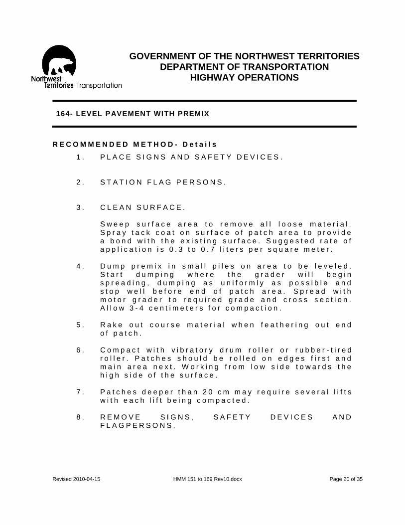
GOVERNMENT OF THE NORTHWEST TERRITORIES
DEPARTMENT OF TRANSPORTATION HIGHWAY OPERATIONS
Revised 2010-04-15 HMM 151 to 169 Rev10.docx Page 20 of 35
164- LEVEL PAVEMENT WITH PREMIX
R E C O M M E N D E D M E T H O D - D e t a i l s
1 . P L A C E S I G N S A N D S A F E T Y D E V I C E S .
2 . S T A T I O N F L A G P E R S O N S .
3 . C L E A N S U R F A C E . S w e e p s u r f a c e a r e a t o r e m o v e a l l l o o s e m a t e r i a l . S p r a y t a c k c o a t o n s u r f a c e o f p a t c h a r e a t o p r o v i d e a b o n d w i t h t h e e x i s t i n g s u r f a c e . S u g g e s t e d r a t e o f a p p l i c a t i o n i s 0 . 3 t o 0 . 7 l i t e r s p e r s q u a r e m e t e r .
4 . D u m p p r e m i x i n s m a l l p i l e s o n a r e a t o b e l e v e l e d . S t a r t d u m p i n g w h e r e t h e g r a d e r w i l l b e g i n s p r e a d i n g , d u m p i n g a s u n i f o r m l y a s p o s s i b l e a n d s t o p w e l l b e f o r e e n d o f p a t c h a r e a . S p r e a d w i t h m o t o r g r a d e r t o r e q u i r e d g r a d e a n d c r o s s s e c t i o n . A l l o w 3 - 4 c e n t i m e t e r s f o r c o m p a c t i o n .
5 . R a k e o u t c o u r s e m a t e r i a l w h e n f e a t h e r i n g o u t e n d o f p a t c h .
6 . C o m p a c t w i t h v i b r a t o r y d r u m r o l l e r o r r u b b e r - t i r e d r o l l e r . P a t c h e s s h o u l d b e r o l l e d o n e d g e s f i r s t a n d m a i n a r e a n e x t . W o r k i n g f r o m l o w s i d e t o w a r d s t h e h i g h s i d e o f t h e s u r f a c e .
7 . P a t c h e s d e e p e r t h a n 2 0 c m m a y r e q u i r e s e v e r a l l i f t s w i t h e a c h l i f t b e i n g c o m p a c t e d .
8 . R E M O V E S I G N S , S A F E T Y D E V I C E S A N D F L A G P E R S O N S .

GOVERNMENT OF THE NORTHWEST TERRITORIES
DEPARTMENT OF TRANSPORTATION HIGHWAY OPERATIONS
Revised 2010-04-15 HMM 151 to 169 Rev10.docx Page 21 of 35
166- ROUT AND SEAL
OBJECTIVE:
T o r e d u c e t h e a n n u a l r e a p p e a r a n c e o f c r a c k s w h i c h , i f l e f t u n s e a l e d , c a n c a u s e s e r i o u s d e t e r i o r a t i o n t o t h e s u b g r a d e a n d t h e p a v e m e n t .
D E S C R I P T I O N : R o u t a n d s e a l i s a s e m i p e r m a n e n t p r o c e s s t o s e a l c r a c k s t h a t h a v e b e e n r o u t e d a n d t h e n f i l l e d w i t h a s p e c i a l h o t r u b b e r i z e d p r o d u c t t o r e d u c e t h e p o s s i b i l i t y o f c r a c k s r e a p p e a r i n g d u r i n g t h e w i n t e r m o n t h s . T h i s p r o c e d u r e i s u s u a l l y l i m i t e d t o t h e f o l l o w i n g t y p e o f c r a c k s :
- L o n g i t u d i n a l - T r a n s v e r s e - M a p
L E V E L O F S E R V I C E
C r a c k f i l l i n g i s c o n s i d e r e d t o b e i m p o r t a n t i n t h e m a i n t e n a n c e o f p a v e d s u r f a c e s . B e c a u s e o f t h e g r e a t d i f f e r e n c e s i n t e m p e r a t u r e b e t w e e n t h e s e a s o n s , t h e p a v e d s u r f a c e s h a v e a t e n d e n c y t o e x p a n d a n d c o n t r a c t . A f t e r a w h i l e , t h e p a v e m e n t l o s e s i t e l a s t i c i t y a n d c r a c k s . W h e n w a t e r i s a l l o w e d t o s e e p i n t h r o u g h t h e c r a c k s i n t h e p a v e m e n t , i t u n d e r m i n e s t h e s u b g r a d e a n d t h e a s p h a l t m a t a l o n g t h e c r a c k b e g i n s t o d e t e r i o r a t e . U n d e r t h e s e c o n d i t i o n s a g o o d p a v e d r o a d c o u l d e n d u p f u l l o f p o t h o l e s a n d b u m p s i n a f e w y e a r s .
R E S P O N S I B I L I T Y :
H i g h w a y M a i n t e n a n c e S u p e r v i s o r w i t h g u i d a n c e f r o m R e g i o n a l M a n a g e r .
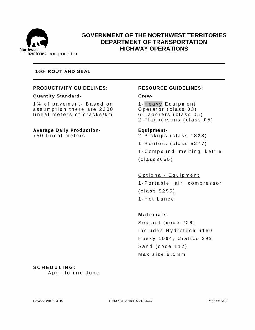
GOVERNMENT OF THE NORTHWEST TERRITORIES
DEPARTMENT OF TRANSPORTATION HIGHWAY OPERATIONS
Revised 2010-04-15 HMM 151 to 169 Rev10.docx Page 22 of 35
166- ROUT AND SEAL
PRODUCTIVITY GUIDELINES: RESOURCE GUIDELINES:
Quantity Standard- Crew-
1 % o f p a v e m e n t - B a s e d o n 1 - H e a v y E q u i p m e n t a s s u m p t i o n t h e r e a r e 2 2 0 0 O p e r a t o r ( c l a s s 0 3 ) l i n e a l m e t e r s o f c r a c k s / k m 6 - L a b o r e r s ( c l a s s 0 5 ) 2 - F l a g p e r s o n s ( c l a s s 0 5 ) Average Daily Production- Equipment- 7 5 0 l i n e a l m e t e r s 2 - P i c k u p s ( c l a s s 1 8 2 3 )
1 - R o u t e r s ( c l a s s 5 2 7 7 )
1 - C o m p o u n d m e l t i n g k e t t l e
( c l a s s 3 0 5 5 )
O p t i o n a l - E q u i p m e n t
1 - P o r t a b l e a i r c o m p r e s s o r
( c l a s s 5 2 5 5 )
1 - H o t L a n c e
M a t e r i a l s
S e a l a n t ( c o d e 2 2 6 )
I n c l u d e s H y d r o t e c h 6 1 6 0
H u s k y 1 0 6 4 , C r a f t c o 2 9 9
S a n d ( c o d e 1 1 2 )
M a x s i z e 9 . 0 m m
S C H E D U L I N G : A p r i l t o m i d J u n e

GOVERNMENT OF THE NORTHWEST TERRITORIES
DEPARTMENT OF TRANSPORTATION HIGHWAY OPERATIONS
Revised 2010-04-15 HMM 151 to 169 Rev10.docx Page 23 of 35
166- ROUT AND SEAL
R E C O M M E N D E D M E T H O D - G e n e r a l A p p r o a c h
1 . H i g h w a y M a i n t e n a n c e S u p e r v i s o r t o b e f a m i l i a r w i t h t h e a p p l i c a b l e c o n d i t i o n w h e r e a c t i v i t y 1 6 6 c o u l d b e u s e d t o c o r r e c t s p e c i f i c c o n d i t i o n s a s o u t l i n e d i n H i g h w a y s M a i n t e n a n c e O p e r a t i n g I n s t r u c t i o n s f o r A c t i v i t y 1 6 1 - 1 6 9 ( M a i n t e n a n c e T r e a t m e n t f o r A s p h a l t S u r f a c e ) . T h e H i g h w a y Maintenance Supervisor can obtain guidance from the Regional Manger and from the Highway Operat ions Off ice in Hay River.
2 . H i g h w a y M a i n t e n a n c e S u p e r v i s o r t o p r e d e t e r m i n e l o c a t i o n s t o b e s e a l e d .
R E C O M M E N D E D A P P R O A C H - D e t a i l s
1 . P L A C E S I G N S A N D S A F E T Y D E V I C E S .
2 . R o u t c r a c k s t o d e p t h a n d w i d t h a s s p e c i f i e d b y t h e R e g i o n a l M a n a g e r . G e n e r a l l y c r a c k s a r e r o u t e d t o d e p t h o f 2 0 m m w i t h t h e m o s t c o m m o n w i d t h s b e i n g 2 0 m m , 3 3 m m a n d 5 0 m m , w i d e r s e a l s a p p e a r t o l a s t l o n g e r .
3 . C l e a n o u t c r a c k s u s i n g c o m p r e s s e d a i r .
4 . P r e h e a t a n d d r y c r a c k s w i t h h o t l a n c e . C a u t i o n : E x c e s s i v e h o t l a n c i n g c a n s c o r c h t h e c r a c k e d e d g e s r e s u l t i n g i n m i c r o c r a c k s a n d p o o r e r b o n d i n g . S e a l c r a c k s u n i f o r m l y f l u s h w i t h s u r r o u n d i n g p a v e m e n t i n o n e p o u r . T h e o u t e r e n d s o f t r a n s v e r s e c r a c k s m u s t b e d a m m e d t o p r e v e n t s e a l a n t f r o m r u n n i n g o u t o n t o t h e s h o u l d e r .

GOVERNMENT OF THE NORTHWEST TERRITORIES
DEPARTMENT OF TRANSPORTATION HIGHWAY OPERATIONS
Revised 2010-04-15 HMM 151 to 169 Rev10.docx Page 24 of 35
166- ROUT AND SEAL
R E C O M M E N D E D A P P R O A C H - D e t a i l s ( c o n t i n u e d )
5 . S t r i k e o f f e x c e s s s e a l e r w i t h a m o d i f i e d s q u e e g e e .
T h e m o d i f i e d s q u e e g e e p r o d u c e s a u n i f o r m p r o f i l e b a n d o f s e a l a n t a l o n g t h e c r a c k w i t h a r a i s e d b e a d d i r e c t l y o v e r t h e c r a c k o p e n i n g . T h e b e a d s e t t l e s i n t o c r a c k u p o n c o o l i n g e n s u r i n g a m o r e s u c c e s s f u l s e a l .
6 . A p p l y a s u i t a b l e b l o t t e r s u c h a s a f i n e s a n d t o p r e v e n t t r a f f i c p i c k i n g u p s e a l a n t .
7 . R E M O V E S I G N S A N D S A F E T Y D E V I C E S . S p e c i a l N o t e : T h a t w i t h a p p r o v a l f r o m t h e R e g i o n a l M a n a g e r s t e p 4 a n d s t e p 6 f o r A c t i v i t y 1 6 6 c a n b e c o n s i d e r e d o p t i o n a l . T h i s i s b a s e d o n f i e l d c o n d i t i o n s a n d t h e d e p t h o f t h e c r a c k s .
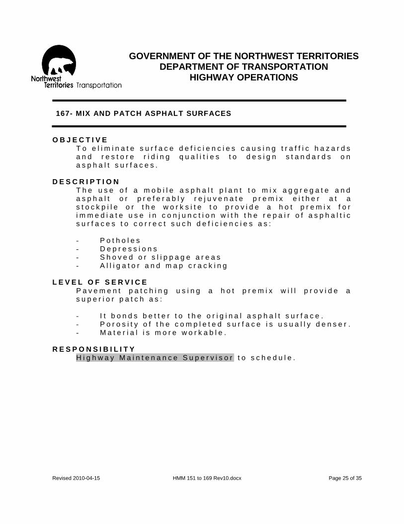
GOVERNMENT OF THE NORTHWEST TERRITORIES
DEPARTMENT OF TRANSPORTATION HIGHWAY OPERATIONS
Revised 2010-04-15 HMM 151 to 169 Rev10.docx Page 25 of 35
167- MIX AND PATCH ASPHALT SURFACES
O B J E C T I V E
T o e l i m i n a t e s u r f a c e d e f i c i e n c i e s c a u s i n g t r a f f i c h a z a r d s a n d r e s t o r e r i d i n g q u a l i t i e s t o d e s i g n s t a n d a r d s o n a s p h a l t s u r f a c e s .
D E S C R I P T I O N
T h e u s e o f a m o b i l e a s p h a l t p l a n t t o m i x a g g r e g a t e a n d a s p h a l t o r p r e f e r a b l y r e j u v e n a t e p r e m i x e i t h e r a t a s t o c k p i l e o r t h e w o r k s i t e t o p r o v i d e a h o t p r e m i x f o r i m m e d i a t e u s e i n c o n j u n c t i o n w i t h t h e r e p a i r o f a s p h a l t i c s u r f a c e s t o c o r r e c t s u c h d e f i c i e n c i e s a s : - P o t h o l e s - D e p r e s s i o n s - S h o v e d o r s l i p p a g e a r e a s - A l l i g a t o r a n d m a p c r a c k i n g
L E V E L O F S E R V I C E
P a v e m e n t p a t c h i n g u s i n g a h o t p r e m i x w i l l p r o v i d e a s u p e r i o r p a t c h a s : - I t b o n d s b e t t e r t o t h e o r i g i n a l a s p h a l t s u r f a c e . - P o r o s i t y o f t h e c o m p l e t e d s u r f a c e i s u s u a l l y d e n s e r . - M a t e r i a l i s m o r e w o r k a b l e .
R E S P O N S I B I L I T Y H i g h w a y M a i n t e n a n c e S u p e r v i s o r t o s c h e d u l e .

GOVERNMENT OF THE NORTHWEST TERRITORIES
DEPARTMENT OF TRANSPORTATION HIGHWAY OPERATIONS
Revised 2010-04-15 HMM 151 to 169 Rev10.docx Page 26 of 35
167- MIX AND PATCH ASPHALT SURFACES
PRODUCTIVITY GUIDELINES: RESOURCE GUIDELINES:
Quantity Standard- Crew-
0 . 1 0 m 3 / k m o f a s p h a l t s u r f a c e 4 - H e a v y E q u i p m e n t O p e r a t o r ( c l a s s 0 4 )
4 - L a b o r e r s ( c l a s s 0 5 ) 2 - T r a f f i c C o n t r o l S t a f f
Average Daily Production- Equipment- 1 0 c u b i c m e t e r s 1 - T a n d e m T r u c k
( c l a s s 1 5 0 4 ) 1 - H o p p e r S p r e a d e r ( c l a s s 5 4 2 2 )
1 - A s p a h l t M o b i l e P l a n t ( c l a s s 3 0 9 9 )
1 - L o a d e r / b a c k h o e ( c l a s s 2 8 0 9 )
1 - R o l l e r ( c l a s s 2 6 0 0 ) 2 - P i c k u p s ( c l a s s 2 6 2 2 ) O p t i o n a l - E q u i p m e n t 1 - P a v e m e n t s a w
M a t e r i a l
P r e m i x - C o l d ( c o d e 1 1 8 )
A s p h a l t - E m u l s i o n
( c o d e 2 2 4 )
S C H E D U L I N G J u n e t o m i d S e p t e m b e r

GOVERNMENT OF THE NORTHWEST TERRITORIES
DEPARTMENT OF TRANSPORTATION HIGHWAY OPERATIONS
Revised 2010-04-15 HMM 151 to 169 Rev10.docx Page 27 of 35
167- MIX AND PATCH ASPHALT SURFACES
R E C O M M E N D E D M E T H O D - G e n e r a l A p p r o a c h
1 . The Highway Maintenance Supervisor to determine where Activity 167 should be undertaken to correct a specif ic asphalt surface distress using the guidel ines in the Highway Maintenance Operating Instruct ions for Activity 161 -169 (Maintenance Treatment for Asphalt Surfaces ). The Highway Maintenance Supervisor can obtain guidance from the Regional Manger and from the Highway Operations Off ice in Hay River.
2. The Highway Maintenance Supervisor to clearly delineate the outer boundar ies of areas to be repaired.
R E C O M M E N D E D M E T H O D - D e t a i l s
1 . S E T O U T S I G N S A N D S A F E T Y D E V I C E S .
2 . S T A T I O N F L A G P E R S O N S A S R E Q U I R E D .
3 . P r e p a r e a r e a t o b e r e p a i r e d :
a ) D e p r e s s i o n s a n d s u r f a c e b r e a k s ( p o t h o l e s ) . R e m o v e a l l l o o s e m a t e r i a l , t r i m t h e s i d e s o f t h e p a t c h a r e a s t r a i g h t d o w n i f r e q u i r e d . S w e e p o u t a l l r e m a i n i n g d u s t a n d d e b r i s .
b ) D e e p p a t c h . i . R e m o v e t h e s u r f a c e a n d b a s e a s d e e p a s
n e c e s s a r y t o r e a c h f i r m s u p p o r t . E x t e n d a t l e a s t 3 0 c m i n t o g o o d p a v e m e n t o u t s i d e t h e c r a c k e d a r e a . T h i s m a y m e a n t h a t s o m e o f t h e s u b g r a d e w i l l a l s o h a v e t o b e r e m o v e d . M a k e t h e c u t s q u a r e o r r e c t a n g u l a r w i t h f a c e s s t r a i g h t a n d v e r t i c a l . O n e p a i r o f f a c e s s h o u l d b e a t r i g h t a n g l e s t o t h e d i r e c t i o n o f t r a f f i c . A p a v e m e n t s a w m a k e s a f a s t a n d n e a t c u t .
i i . B a c k f i l l s u b g r a d e a s n e c e s s a r y i n 1 0 0 m m l i f t s a n d c o m p a c t b e f o r e p r o c e e d i n g t o t h e n e x t . C o n t i n u e u n t i l f i l l m a t c h e s l e v e l o f s u b g r a d e .

GOVERNMENT OF THE NORTHWEST TERRITORIES
DEPARTMENT OF TRANSPORTATION HIGHWAY OPERATIONS
Revised 2010-04-15 HMM 151 to 169 Rev10.docx Page 28 of 35
167- MIX AND PATCH ASPHALT SURFACES
R E C O M M E N D E D M E T H O D - D e t a i l s c o n t i n u e d
4 . M o v e t h e i n t e g r a l u n i t ( T a n d e m t r u c k / h o p p e r s p r e a d e r / m o b i l e a s p h a l t p l a n t ) a n d p o s i t i o n s o t h a t t h e p l a n t c a n d i s c h a r g e t h e h o t p r e m i x a s d e s i r e d t o t h e a r e a t o b e r e p a i r e d .
5 . T a c k c o a t t h e a r e a t o b e p a t c h e d u s i n g h a n d s p r a y o n t h e m o b i l e a s p h a l t p l a n t . E n s u r e t h a t e d g e s a r e t a c k e d o n b r e a k s a n d c u t s . T a c k c o a t a p p l i c a t i o n r a t e a t 0 . 3 0 t o 0 . 7 0 l i t e r s / s q u a r e m e t e r .
6 . P l a c e a s p h a l t m i x i n t o p r e p a r e d a r e a d i r e c t l y f r o m t h e m o b i l e a s p h a l t p l a n t . L e v e l a s p h a l t m i x w i t h h a n d t o o l s t o b r i n g t h e s u r f a c e t o d e s i r e d g r a d e w h e n c o m p a c t e d . A n y l i f t s h o u l d n o t e x c e e d 5 0 m m w i t h o u t c o m p a c t i o n .
7 . C o m p l e t e c o m p a c t i o n o f p a t c h .
8 . R E M O V E S I G N S , S A F E T Y D E V I C E S A N D F L A G P E R S O N S .

GOVERNMENT OF THE NORTHWEST TERRITORIES
DEPARTMENT OF TRANSPORTATION HIGHWAY OPERATIONS
Revised 2010-04-15 HMM 151 to 169 Rev10.docx Page 29 of 35
168- ASPHALT SURFACE REPAIR- OTHER
O B J E C T I V E
T o p r o v i d e a s s a f e a d r i v i n g s u r f a c e a s p o s s i b l e u n d e r v a r i o u s c o n d i t i o n s .
D E S C R I P T I O N
A s p h a l t S u r f a c e R e p a i r - O t h e r ; i n c l u d e s s u r f a c e m a i n t e n a n c e p r o c e d u r e s n o t o t h e r w i s e c o v e r e d i n t h e m a i n M a i n t e n a n c e A c t i v i t i e s s u c h a s : - B l e e d i n g p a v e m e n t t r e a t m e n t . - S c a r i f y i n g a s p h a l t s u r f a c e s w h i c h a r e b e y o n d
r e p a i r . - S u r f a c e p l a n i n g . - T e m p o r a r y p a t c h i n g o f p o t h o l e s / s u r f a c e b r e a k s w i t h
g r a v e l a n d c a l c i u m c h l o r i d e e t c . L E V E L O F S E R V I C E
A l l t h e a s p h a l t m a i n t e n a n c e p r o c e d u r e s w e r e r e v i e w e d t o d e t e r m i n e w h i c h w e r e t h e a p p r o p r i a t e p r i n c i p a l a c t i v i t i e s . W o r k p r o c e d u r e s t h a t c o u l d n o t b e r e a s o n a b l y c h a r g e d t o t h e s e a c t i v i t i e s h a v e b e e n c a t e g o r i z e d a s “ A s p h a l t S u r f a c e R e p a i r - O t h e r ” . H o w e v e r , a l l w o r k c h a r g e d t o t h i s a c t i v i t y s h o u l d b e c l e a r l y d e f i n e d a s t o t h e n a t u r e o f t h e p r o c e d u r e . A n a n n u a l r e v i e w w i l l b e c o m p l e t e d t o c a t e g o r i z e t h e w o r k . U n t i l d e f i n i t i v e n e e d f o r a d d i t i o n a l a c t i v i t i e s h a s b e e n e s t a b l i s h e d , i t i s e x p e c t e d t h a t t h e m a i n r e q u i r e m e n t f o r t h i s a c t i v i t y w i l l b e b l e e d i n g p a v e m e n t .
R E S P O N S I B I L I T Y
H i g h w a y M a i n t e n a n c e S u p e r v i s o r , w i t h g u i d a n c e f r o m t h e R e g i o n a l M a n a g e r , t o d e t e r m i n e w h e n w o r k c a n b e a p p r o p r i a t e l y c h a r g e d t o t h i s a c t i v i t y .

GOVERNMENT OF THE NORTHWEST TERRITORIES
DEPARTMENT OF TRANSPORTATION HIGHWAY OPERATIONS
Revised 2010-04-15 HMM 151 to 169 Rev10.docx Page 30 of 35
168- ASPHALT SURFACE REPAIR- OTHER
PRODUCTIVITY GUIDELINES: RESOURCE GUIDELINES:
Quantity Standard- Crew-
0 . 5 h r / k m o f a s p h a l t s u r f a c e 1 - H e a v y E q u i p m e n t O p e r a t o r ( c l a s s 0 4 )
1 - L a b o u r e r
2 - T r a f f i c C o n t r o l S t a f f Average Daily Production- 8 h o u r s Equipment- 1 - T a n d e m T r u c k
( c l a s s 1 5 0 4 ) 1 - L o a d e r / b a c k h o e ( c l a s s 2 8 0 9 )
1 - H o p p e r S p r e a d e r ( c l a s s 5 4 2 2 )
M a t e r i a l S c r e e n e d S a n d ( c o d e 1 1 2 )
S C H E D U L I N G
I t is expected that any procedures charged to this act ivity wi l l occur between Apri l and mid September .
R E C O M M E N D E D M E T H O D - G e n e r a l A p p r o a c h
The Highway Maintenance Supervisor to determine where Activity 168 should be undertaken to correct a specif ic asphalt surface distress as outl ined in the Highway Maintenance Operating Instruct ions for Act ivity 161-169 (Maintenance Treatment for Asphalt Surfaces). The Highway Maintenance Supervisor can obtain guidance from the Regional Manger and from the Highway Operations Off ice in Hay River.

GOVERNMENT OF THE NORTHWEST TERRITORIES
DEPARTMENT OF TRANSPORTATION HIGHWAY OPERATIONS
Revised 2010-04-15 HMM 151 to 169 Rev10.docx Page 31 of 35
168- ASPHALT SURFACE REPAIR- OTHER
R E C O M M E N D E D M E T H O D - D e t a i l s
1 . S E T O U T S I G N S A N D W A R N I N G D E V I C E S A S R E Q U I R E D .
2 . E v a l u a t e t h e s i t u a t i o n a n d c h o s e t h e a p p r o p r i a t e m e t h o d f o r t h e w o r k :
a . I n m a n y c a s e s , b l e e d i n g c a n b e c o r r e c t e d w i t h r e p e a t e d a p p l i c a t i o n s o f h o t s a n d o r h o t r o c k s c r e e n i n g s t o b l o t u p t h e e x c e s s a s p h a l t .
b . W h e n b l e e d i n g i s l i g h t , u s e c h i p s e a l p a t c h i n g i n s u r i n g g o o d a g g r e g a t e r e t e n t i o n s o a s n o t t o a g g r a v a t e t h e b l e e d i n g .
c . F o r h e a v y b l e e d i n g , r e m o v e e x c e s s a s p h a l t w i t h s p e c i a l i z e d e q u i p m e n t s u c h a s a h e a t b u r n e r o r a h e a t p l a n e r .
3 . R E M O V E S I G N S A N D S A F E T Y D E V I C E S .

GOVERNMENT OF THE NORTHWEST TERRITORIES
DEPARTMENT OF TRANSPORTATION HIGHWAY OPERATIONS
Revised 2010-04-15 HMM 151 to 169 Rev10.docx Page 32 of 35
169- RECYCLE A.S.T. (Asphalt Surface Treatment)
O B J E C T I V E
T o r e s t o r e A . S . T . ( A s p h a l t S u r f a c e T r e a t m e n t ) t o a s a f e a n d a c c e p t a b l e d r i v i n g c o n d i t i o n i n a n e c o n o m i c a l m a n n e r .
D E S C R I P T I O N
T h e r e s t o r a t i o n o f a n A . S . T . o n a s o u n d g r a d e b y l i f t i n g a n d b r e a k i n g d o w n o f t h e e x i s t i n g m a t t o a w o r k a b l e s i z e , a d d i n g m a t e r i a l a s r e q u i r e d a n d t h e n r e l a y i n g t o c o r r e c t d e f i c i e n c i e s s u c h a s : - S e v e r e s u r f a c e d i s t o r t i o n s t h a t c o v e r m o r e t h a n
3 0 % o f t h e s u r f a c e a r e a . - S e v e r e p o t h o l e d c o n d i t i o n s w h i c h a r e g e n e r a l l y
d e e p e r t h a n 5 0 m m a n d c o v e r m o r e t h a n 3 0 % o f t h e s u r f a c e .
L E V E L O F S E R V I C E
N o r m a l l y t h i s a c t i v i t y w i l l o n l y b e u n d e r t a k e n o n a r o a d s u r f a c e t h a t h a s h a d t w o o r m o r e c h i p s e a l a p p l i c a t i o n s . F o r a n y t h i n g l e s s t h e r e i s i n s u f f i c i e n t m a t e r i a l t o r e c y c l e . T h e m a j o r f a c t o r s a f f e c t i n g t h e p e r f o r m a n c e o f A . S . T . , ( A s p h a l t S u r f a c e T r e a t m e n t ) a r e : - T r a f f i c , - W e a t h e r , - S u b g r a d e c o n d i t i o n a n d m a t e r i a l , a n d - T h e d e g r e e a n d t i m e l i n e s o f a p p r o p r i a t e s u r f a c e
m a i n t e n a n c e e f f o r t s a n d t h e s u r f a c e r e h a b i l i t a t i o n p r o g r a m .
T h i s p r o c e d u r e s h o u l d b e a n t i c i p a t e d t o p r o v i d e a n o r m a l m a i n t a i n a b l e s u r f a c e f o r a t l e a s t t w o y e a r s p r o v i d i n g n o n e o f t h e f o r e g o i n g f a c t o r s w a s a s e r i o u s c o n t r i b u t i n g i s s u e t o t h e c o n d i t i o n .

GOVERNMENT OF THE NORTHWEST TERRITORIES
DEPARTMENT OF TRANSPORTATION HIGHWAY OPERATIONS
Revised 2010-04-15 HMM 151 to 169 Rev10.docx Page 33 of 35
169- RECYCLE A.S.T. (Asphalt Surface Treatment)
R E S P O N S I B I L I T Y T h e H i g h w a y M a i n t e n a n c e S u p e r v i s o r w i t h g u i d a n c e f r o m t h e i r R e g i o n a l M a n a g e r a n d a p p r o v a l b y R e g i o n a l M a n a g e r .
PRODUCTIVITY GUIDELINES: RESOURCE GUIDELINES:
Quantity Standard- Crew-
1 % o f e x i s t i n g k i l o m e t e r s 3 - H e a v y E q u i p m e n t o f A . S . T . o n t h e O p e r a t o r ( c l a s s 0 3 ) N W T H i g h w a y S y s t e m
4 - L a b o u r e r s
2 - T r a f f i c C o n t r o l S t a f f Average Daily Production- Equipment- 4 , 0 0 0 s q u a r e m e t e r s 2 - G r a d e r s e q u i p p e d w i t h
R i p p e r ( c l a s s 2 3 0 4 ) 1 - A s p h a l t D i s t r i b u t o r ( c l a s s 3 0 6 6 )
2 - D u m p T r u c k s ( c l a s s 1 5 0 4 )
1 - F r o n t E n d L o a d e r ( c l a s s 2 1 0 9 )
2 - P a c k e r s ( c l a s s 2 6 0 0 )
2 - P i c k u p s ( c l a s s 1 8 2 3 ) O p t i o n a l 1 - S w e e p e r ( c l a s s 5 2 4 4 )
Material- Asphalt (code 224)
P r e m i x ( c o d e 1 1 8 )

GOVERNMENT OF THE NORTHWEST TERRITORIES
DEPARTMENT OF TRANSPORTATION HIGHWAY OPERATIONS
Revised 2010-04-15 HMM 151 to 169 Rev10.docx Page 34 of 35
169- RECYCLE A.S.T. (Asphalt Surface Treatment)
S C H E D U L I N G J u n e t o m i d A u g u s t d u r i n g h o t d r y w e a t h e r . R E C O M M E N D E D M E T H O D - G e n e r a l A p p r o a c h
1. Highway Maintenance Supervisor to be familiar with the appl icable condit ions where Activity 169 could be used to correct specif ic condit ions as out l ined in the Highway Maintenance O perating Instruct ions for Activity 161-169 (Maintenance Treatment for Asphalt Surfaces). The Highway Maintenance Supervisor can obtain guidance from the Regional Manger and from the Highway Operations Off ice in Hay River.
2. Highway Maintenance Supervisor to determine the area(s) requir ing
this procedure and clear ly Premark the locations.
3. Check with Regional Manager to determine type and grade of asphalt to add to broken down asphalt mater ial is required.
R E C O M M E N D E D M E T H O D - D e t a i l s
1 . P l a c e s i g n s , t r a f f i c c o n t r o l d e v i c e s a n d s t a t i o n f l a g p e r s o n s a s r e q u i r e d .
2 . C h e c k t h e t h i c k n e s s o f e x i s t i n g A . S . T . t o d e t e r m i n e d e p t h t o b e l i f t e d .
3 . S c a r i f y t h e e x i s t i n g A . S . T . t o t h e r e q u i r e d d e p t h w i t h a g r a d e r o r g r a d e r s e q u i p p e d w i t h R i p p e r . T a k e c a r e t o d i s t u r b a s l i t t l e o f t h e b a s e a s p o s s i b l e .
4 . T h e s c a r i f i e d m a t e r i a l s h o u l d b e b r o k e n d o w n t o a m a x i m u m s i z e o f 2 5 m m

GOVERNMENT OF THE NORTHWEST TERRITORIES
DEPARTMENT OF TRANSPORTATION HIGHWAY OPERATIONS
Revised 2010-04-15 HMM 151 to 169 Rev10.docx Page 35 of 35
169- RECYCLE A.S.T. (Asphalt Surface Treatment)
R E C O M M E N D E D M E T H O D - D e t a i l s c o n t i n u e d
5 . M i x m a t e r i a l w i t h m o t o r g r a d e r a d d i n g a s p h a l t
p r e m i x a s r e q u i r e d t o p r o v i d e a u n i f o r m m i x a n d u n i f o r m w i n d o w .
6 . S w e e p s u r f a c e a s r e q u i r e d .
7 . A p p l y l i g h t t a c k c o a t o v e r t h e a r e a t h a t i s t o b e l a i d i f r e q u i r e d . T a c k a p p l i c a t i o n s h o u l d b e w i t h i n t h e r a n g e o f 0 . 3 0 t o 0 . 7 0 l i t e r s / s q u a r e m e t e r .
8 . S p r e a d m a t e r i a l w i t h a m o t o r g r a d e r .
9 . C o m p a c t w i t h r u b b e r t i r e d r o l l e r / p a c k e r ( s ) .
1 0 . R e m o v e s i g n s a n d t r a f f i c c o n t r o l d e v i c e s a s c o n d i t i o n s p e r m i t .
N o t e : G e n e r a l l y a n a p p l i c a t i o n o f a s p h a l t w i l l b e r e q u i r e d w i t h i n a f e w d a y s t o s e a l a n y p o r o u s s u r f a c e , i . e . f o g c o a t .

GOVERNMENT OF THE NORTHWEST TERRITORIES
DEPARTMENT OF TRANSPORTATION HIGHWAY OPERATIONS
Revised 2010-04-16 161- 169 CMB Chipseal Maintenance Booklet Rev10.docx Page 1 of 42
161-169- MAINTENANCE TREATMENT FOR ASPHALT SURFACES
Every year the number of kilometres of asphaltic surfaced highways in the NWT is increasing. This systematic strategy guide for the maintenance of asphalt surfaced roads has been compiled to make the maintenance tasks easier and more effective. It is designed to meet the needs of field staff who have to make these decisions every day. Please contact the Highway Operations Office in Hay River for question or for more information. These guidelines are denoted as the Highway Maintenance Operating Instruction – Asphalt also known as the “Chipseal Maintenance Booklet or CMB.” The CMB contains the following elements:
1. A method of classifying each type of distress according to its severity and the extent of occurrence.
2. List of suitable treatments or maintenance alternatives for each condition based on type of surfacing. NOTE: Pavement denotes hot mix asphalt while AST denotes chipseal.
In the NWT there are essentially only two types of asphaltic surfaces. These are: Flexible Pavement
- Which will only be referred to as “pavement” and is generally more than 35 mm in depth with the asphalt material being produced either in an asphalt plant or by a road mix process.
Asphaltic Surface Treatment
- Which is generally less than 35 mm in depth. This type of surface comprises of one or two applications of liquid asphalt and a cover aggregate on a prepared base of consolidated gravel.
The different kinds of conditions/distresses that apply to pavement and asphalt surface treatments are:
1. Cracking 2. Surface Defects

GOVERNMENT OF THE NORTHWEST TERRITORIES
DEPARTMENT OF TRANSPORTATION HIGHWAY OPERATIONS
Revised 2010-04-16 161- 169 CMB Chipseal Maintenance Booklet Rev10.docx Page 2 of 42
161-169- MAINTENANCE TREATMENT FOR ASPHALT SURFACES
CRACKING, see Figure CMB-1
- Longitudinal - Transverse - Alligator - Map - Progressive Edge Cracking/Edge breaking
Note: Longitudinal and transverse cracks may be the result of reflection cracking.
These are cracks in asphalt overlays which reflect the crack pattern in the old pavements structure underneath.
Figure CMB-1, Cracking

GOVERNMENT OF THE NORTHWEST TERRITORIES
DEPARTMENT OF TRANSPORTATION HIGHWAY OPERATIONS
Revised 2010-04-16 161- 169 CMB Chipseal Maintenance Booklet Rev10.docx Page 3 of 42
161-169- MAINTENANCE TREATMENT FOR ASPHALT SURFACES
SURFACE DEFECTS, see Figures CMB-2, CMB-3 and CMB-4
- Potholes - Wheel track Rutting - Rippling/Shoving - Raveling/Segregation - Bleeding - Slippery Surface
Figure CMB-2
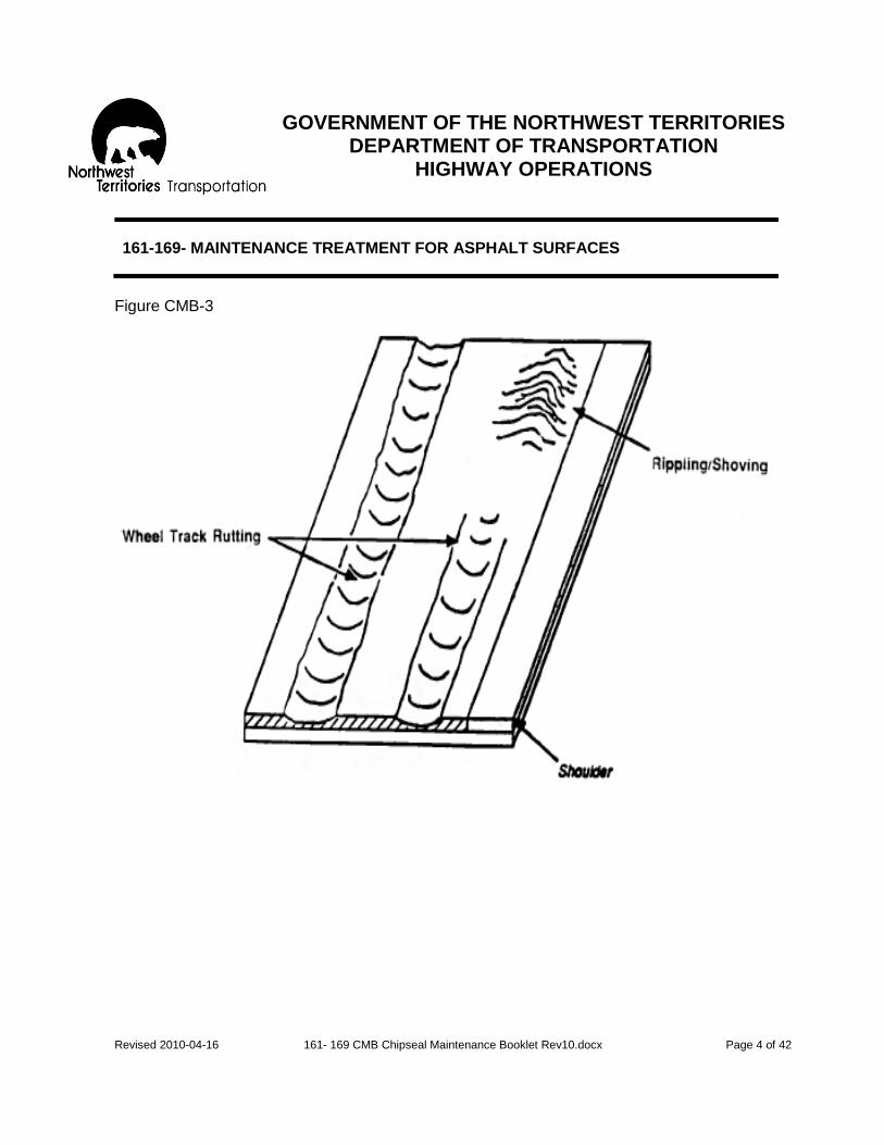
GOVERNMENT OF THE NORTHWEST TERRITORIES
DEPARTMENT OF TRANSPORTATION HIGHWAY OPERATIONS
Revised 2010-04-16 161- 169 CMB Chipseal Maintenance Booklet Rev10.docx Page 4 of 42
161-169- MAINTENANCE TREATMENT FOR ASPHALT SURFACES
Figure CMB-3

GOVERNMENT OF THE NORTHWEST TERRITORIES
DEPARTMENT OF TRANSPORTATION HIGHWAY OPERATIONS
Revised 2010-04-16 161- 169 CMB Chipseal Maintenance Booklet Rev10.docx Page 5 of 42
161-169- MAINTENANCE TREATMENT FOR ASPHALT SURFACES
Figure CMB-4

GOVERNMENT OF THE NORTHWEST TERRITORIES
DEPARTMENT OF TRANSPORTATION HIGHWAY OPERATIONS
Revised 2010-04-16 161- 169 CMB Chipseal Maintenance Booklet Rev10.docx Page 6 of 42
161-169- MAINTENANCE TREATMENT FOR ASPHALT SURFACES
The following steps summarize the procedure to be followed when using the Highway Maintenance Operating Instruction - Asphalt also known as the “Chipseal Maintenance Booklet or CMB,” contained in the following pages. Step 1 - Drive over the asphaltic surfaces; watch for signs of distress. This will give you an
overall impression of the surface condition and help locate areas of distress that need to be looked at more closely.
Step 2 - Stop and carefully examine each area of distress. Use the Guidelines to identify
each distress, then classify according to severity (slight, moderate, severe) and determine the density of occurrence (local or general)
Step 3 - Assess the urgency of the problem. For example, does it threaten the safety of the public? Step 4 - Decide on the priority of each distress. Which one should be repaired first, second, third…? Step 5 - Consult the treatment tables for each type of distress. If more than one method of
treatment is recommended, select the alternative which is the most effective. NOTE: Sometimes a distress may be so severe it must be fixed without delay. In such a case the recommended treatment may or may not be practical. It is up to the person in the field to make a decision and perhaps make do with the resources at hand rather than wait until a better treatment can be organized.
Step 6 - If the section contains a mixture of several different distresses, the Guidelines may
indicate several different treatments. Obviously, there are times when individual attention like this would not be practical. So, pick the treatment that is most universal, the one that will fix everything at once.
Step 7 - Decide if the selected treatment can be done by the maintenance crew. Confirm your decision (and your choice of treatments) with the Regional Manager. If the problem is too big for the maintenance crew to handle it should be referred to the Regional Manager for consideration under the Capital Program.
Step 8 - Consider other factors. The treatments recommended in these Guidelines are
usually correct but, occasionally, they may be altered in view of special circumstances such as urgency, class of road, availability of workers, money, materials, etc. It is up to the person in the field to consider such things and make a judgment call on the importance of these “other factors”.

GOVERNMENT OF THE NORTHWEST TERRITORIES
DEPARTMENT OF TRANSPORTATION HIGHWAY OPERATIONS
Revised 2010-04-16 161- 169 CMB Chipseal Maintenance Booklet Rev10.docx Page 7 of 42
161-169- MAINTENANCE TREATMENT FOR ASPHALT SURFACES
CRACKING- LONGITUDINAL
Description: Cracks follow a course approximately parallel to the direction of travel and are situated at or near the center of the wheel track, center line, mid-lane, pavement edges, etc. Possible Causes:
1. Traffic action (loading) combined with weak pavement. 2. Poor construction equipment and/or technique. 3. Environment and climatic conditions (frost action, moisture changes, etc.). 4. Poor drainage conditions at pavement and shoulder. 5. Natural shrinkage caused by very low temperatures. 6. High temperature susceptibility of asphalt cement binder in asphalt mixes. 7. Reflection cracks.
Severity: Class Guidelines (Based on crack width and condition) Slight Single crack with opening less than 10 mm. Moderate Single crack with opening 10 mm to 20 mm, or multiple cracks
although opening is less than 10 mm. Severe Single crack with opening more than 20 mm, or multiple cracks with
spalling beginning to develop. Density: Local: Less than 30% of asphalt surface affected; distress spotted over
localized areas only. General: More than 30% of asphalt surface affected; distress spotted evenly
over entire length of asphalt surface.

GOVERNMENT OF THE NORTHWEST TERRITORIES
DEPARTMENT OF TRANSPORTATION HIGHWAY OPERATIONS
Revised 2010-04-16 161- 169 CMB Chipseal Maintenance Booklet Rev10.docx Page 8 of 42
161-169- MAINTENANCE TREATMENT FOR ASPHALT SURFACES
ALTERNATIVE TREATMENTS FOR LONGITUDINAL CRACKING
Evaluation
Treatment for Condition
Pavement AST
Severity Density Use Activity Use Activity
Slight Local -Seal cracks less than 6 mm -Seal cracks greater than 6 mm
-- 163
162 162
General -Seal cracks less than 3 mm -Seal cracks greater than 3 mm
-- 163/169
162 162
Moderate Local -Seal single cracks -Seal multiple cracks
163/166 163/166
162 162
General -Seal single cracks -Chip seal multiple cracks
163/166 162
162 162
Severe Local -Seal single cracks -Chip seal multiple cracks
163/166 162
162 162
General - notify Regional Manager for guidance
---
---

GOVERNMENT OF THE NORTHWEST TERRITORIES
DEPARTMENT OF TRANSPORTATION HIGHWAY OPERATIONS
Revised 2010-04-16 161- 169 CMB Chipseal Maintenance Booklet Rev10.docx Page 9 of 42
161-169- MAINTENANCE TREATMENT FOR ASPHALT SURFACES
LONGITUDINAL CRACKING
Notes: These photos on LONGITUDINAL CRACKING extracted from the previous revision of the HMM. Updated photos with improved resolution will be available from the Highway Operations Office in Hay River.
SLIGHT
MODERATE SEVERE

GOVERNMENT OF THE NORTHWEST TERRITORIES
DEPARTMENT OF TRANSPORTATION HIGHWAY OPERATIONS
Revised 2010-04-16 161- 169 CMB Chipseal Maintenance Booklet Rev10.docx Page 10 of 42
161-169- MAINTENANCE TREATMENT FOR ASPHALT SURFACES
CRACKING- TRANSVERSE
Description: Cracks follow a course approximately at right angles to the asphaltic surface center line. Full transverse cracks tend to be regularly spread along the length of the road; half transverse and part transverse cracks occur at shorter intermediate distances. Possible Causes:
1. Environment and climatic conditions (frost action, moisture changes, etc.). 2. Natural shrinkage cause by very low temperatures. 3. High temperature susceptibility of asphalt cement binder in asphalt mixes. 4. Reflection cracks.
Severity: Class Guidelines (Based on crack width and condition) Slight Single crack with opening less than 10 mm. Moderate Single crack with opening 10 mm to 20 mm, or without cupping or
lipping or multiple transverse cracking with or without cupping or lipping although crack openings may be less than 10 mm.
Severe Single crack with opening more than 20 mm with or without cupping or
lipping; or multiple transverse cracks with cupping or lipping or spalling beginning to develop.
Density: Local: Less than 30% of asphalt surface affected; distress spotted over
localized areas only. General: More than 30% of asphalt surface affected; distress spotted evenly
over entire length of asphalt surface.

GOVERNMENT OF THE NORTHWEST TERRITORIES
DEPARTMENT OF TRANSPORTATION HIGHWAY OPERATIONS
Revised 2010-04-16 161- 169 CMB Chipseal Maintenance Booklet Rev10.docx Page 11 of 42
161-169- MAINTENANCE TREATMENT FOR ASPHALT SURFACES
ALTERNATIVE TREATMENTS FOR TRANSVERSE CRACKING
Evaluation
Treatment for Condition
Pavement AST
Severity Density Use Activity Use Activity
Slight Local -Seal cracks less than 6 mm -Seal cracks greater than 6 mm
-- 163
162 162
General -Seal cracks less than 3 mm -Seal cracks greater than 3 mm
-- 163/166
162 162
Moderate Local -Seal single cracks with or without cupping or lipping
163/166 163/166
162 162
General -Seal single cracks with or without cupping or lipping -Chip seal multiple cracks
163/166 162
162 162
Severe Local -Seal single cracks if no cupping or lipping
163/166 162
162 162
General - notify Regional Manager for guidance
---
---
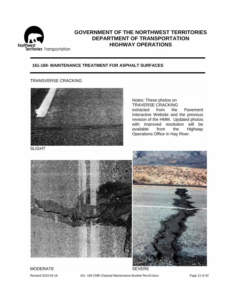
GOVERNMENT OF THE NORTHWEST TERRITORIES
DEPARTMENT OF TRANSPORTATION HIGHWAY OPERATIONS
Revised 2010-04-16 161- 169 CMB Chipseal Maintenance Booklet Rev10.docx Page 12 of 42
161-169- MAINTENANCE TREATMENT FOR ASPHALT SURFACES
TRANSVERSE CRACKING
Notes: These photos on TRAVERSE CRACKING extracted from the Pavement Interactive Website and the previous revision of the HMM. Updated photos with improved resolution will be available from the Highway Operations Office in Hay River.
SLIGHT
MODERATE SEVERE
GOVERNMENT OF THE NORTHWEST TERRITORIES
DEPARTMENT OF TRANSPORTATION HIGHWAY OPERATIONS
Revised 2010-04-16 161- 169 CMB Chipseal Maintenance Booklet Rev10.docx Page 13 of 42
161-169- MAINTENANCE TREATMENT FOR ASPHALT SURFACES
CRACKING- ALLIGATOR
Description: Cracks for a network of multi-sided (polygon) blocks resembling the skin of an alligator. The block size can range from 50 mm to 100 mm to about 500 mm. The alligatored area may or may not be accompanied by distortion in the form of depression, and may occur anywhere on the asphalt surface. (Some sources refer to this as „fatigue‟ cracking). Possible Causes:
1. Insufficient surface strength. 2. Poor base drainage and stiff or brittle asphalt mix at cold temperatures.
Severity: Class Guidelines (Based on crack width and condition) Slight Alligator pattern established with corners of polygon blocks fracturing. Moderate Alligator pattern established with spalling of polygon blocks. Severe Polygon blocks begin to lift; may or may not involve potholes. Density: Local: Less than 30% of asphalt surface affected; distress spotted over
localized areas only. General: More than 30% of asphalt surface affected; distress spotted evenly
over entire length of asphalt surface.

GOVERNMENT OF THE NORTHWEST TERRITORIES
DEPARTMENT OF TRANSPORTATION HIGHWAY OPERATIONS
Revised 2010-04-16 161- 169 CMB Chipseal Maintenance Booklet Rev10.docx Page 14 of 42
161-169- MAINTENANCE TREATMENT FOR ASPHALT SURFACES
ALTERNATIVE TREATMENTS FOR ALLIGATOR CRACKING
Evaluation
Treatment for Condition
Pavement AST
Severity Density Use Activity Use Activity
Slight Local -Chipseal -No action
162 ---
162 ---
General -Chipseal -No action, but monitor closely for future development
162 ---
162 ---
Moderate Local -Chipseal -Use Cold Mix Material -Hot mix patch
162 161 167
162 161 ---
General -Chipseal - Use Cold Mix Material -Hot mix patch Notify Regional Manager & continue monitoring
162 161 167
162 161 ---
Severe Local - Use Cold Mix Material -Hot mix patch -Excavate, granular and hot/cold mix patch -Improve drainage (additional)
161 167 122/161 164/167 210/211
161 --- 122/161 210/211
General - notify Regional Manager for guidance
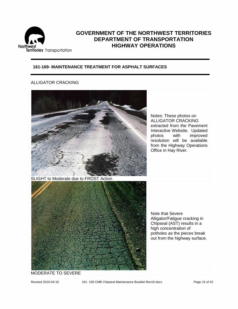
GOVERNMENT OF THE NORTHWEST TERRITORIES
DEPARTMENT OF TRANSPORTATION HIGHWAY OPERATIONS
Revised 2010-04-16 161- 169 CMB Chipseal Maintenance Booklet Rev10.docx Page 15 of 42
161-169- MAINTENANCE TREATMENT FOR ASPHALT SURFACES
ALLIGATOR CRACKING
Notes: These photos on ALLIGATOR CRACKING extracted from the Pavement Interactive Website. Updated photos with improved resolution will be available from the Highway Operations Office in Hay River.
SLIGHT to Moderate due to FROST Action
Note that Severe Alligator/Fatigue cracking in Chipseal (AST) results in a high concentration of potholes as the pieces break out from the highway surface.
MODERATE TO SEVERE

GOVERNMENT OF THE NORTHWEST TERRITORIES
DEPARTMENT OF TRANSPORTATION HIGHWAY OPERATIONS
Revised 2010-04-16 161- 169 CMB Chipseal Maintenance Booklet Rev10.docx Page 16 of 42
161-169- MAINTENANCE TREATMENT FOR ASPHALT SURFACES
CRACKING- Map
Description: Cracks run randomly along the asphalt surface, sometimes in a snakelike manner. The crack appears to have transverse and longitudinal cracks combined to form a map. Possible Causes:
1. Swelling or shrinkage. 2. Frost action. 3. Aging of standard pavement.
Severity: Class Guidelines (Based on crack width and condition) Slight Map pattern established with crack opening less than 10 mm. Moderate Map pattern established with crack opening 10 mm to 20 mm, multiple
cracking may begin to develop. Severe Map pattern established with crack opening greater than 20 mm,
multiple cracking developed. Density: Local: Less than 30% of asphalt surface affected; distress spotted over
localized areas only. General: More than 30% of asphalt surface affected; distress spotted evenly
over entire length of asphalt surface.

GOVERNMENT OF THE NORTHWEST TERRITORIES
DEPARTMENT OF TRANSPORTATION HIGHWAY OPERATIONS
Revised 2010-04-16 161- 169 CMB Chipseal Maintenance Booklet Rev10.docx Page 17 of 42
161-169- MAINTENANCE TREATMENT FOR ASPHALT SURFACES
ALTERNATIVE TREATMENTS FOR MAP CRACKING
Evaluation
Treatment for Condition
Pavement AST
Severity Density Use Activity Use Activity
Slight Local -Seal all cracks -No action
163 ---
162
General -Seal all cracks -No action
163 ---
162
Moderate Local -Seal all cracks
163/166
162
General -Chipseal patch -Chipsealing when included in annual program
162 840
162 840
Severe Local -Chipseal patch - notify Regional Manager
162 162
General - notify Regional Manager for guidance
---
---
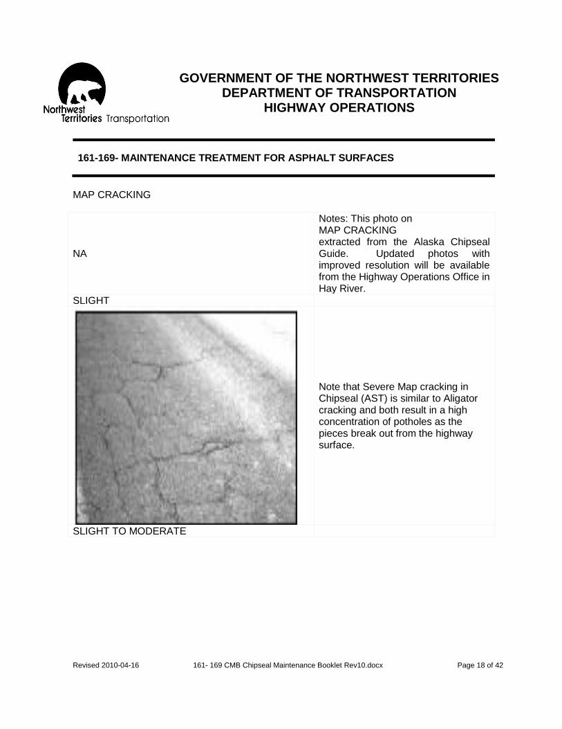
GOVERNMENT OF THE NORTHWEST TERRITORIES
DEPARTMENT OF TRANSPORTATION HIGHWAY OPERATIONS
Revised 2010-04-16 161- 169 CMB Chipseal Maintenance Booklet Rev10.docx Page 18 of 42
161-169- MAINTENANCE TREATMENT FOR ASPHALT SURFACES
MAP CRACKING
NA
Notes: This photo on MAP CRACKING extracted from the Alaska Chipseal Guide. Updated photos with improved resolution will be available from the Highway Operations Office in Hay River.
SLIGHT
Note that Severe Map cracking in Chipseal (AST) is similar to Aligator cracking and both result in a high concentration of potholes as the pieces break out from the highway surface.
SLIGHT TO MODERATE

GOVERNMENT OF THE NORTHWEST TERRITORIES
DEPARTMENT OF TRANSPORTATION HIGHWAY OPERATIONS
Revised 2010-04-16 161- 169 CMB Chipseal Maintenance Booklet Rev10.docx Page 19 of 42
161-169- MAINTENANCE TREATMENT FOR ASPHALT SURFACES
CRACKING- Edge Cracking/Edge Breaking
Description: Cracks begin parallel to and within 300 mm of the asphalt surface edge; cracking is either a fairly continuous straight crack or consists of crescent-shaped cracks in wave-formation. Progressive edge cracking will gradually encroach into the outer-wheel tracks, through the middle of the lane, and may even spread across to the centerline. Edge breaking occurs with or without cracks; it is generally occurs in asphalt surface-treatment type surfaces. Possible Causes:
1. Frost action. 2. Insufficient asphalt surface strength or excessive loading at the asphalt
surface edge. 3. Poor drainage at asphalt surface edge and shoulder. 4. Inadequate asphalt surface width forces traffic too close to asphalt surface
edge. Severity: Class Guidelines (Based on crack width and condition) Slight Less than 600 mm from asphalt surface edge; single or two parallel
cracks. Moderate Extending over 600 mm, but less than 900 mm from asphalt surface
edge; multiple cracks with connecting cracks. Severe Extending more than 900 mm from asphalt surface edge; alligatoring
of surface occurs at and near asphalt surface edge. Density: Local: Less than 30% of asphalt surface affected; distress spotted over
localized areas only. General: More than 30% of asphalt surface affected; distress spotted evenly
over entire length of asphalt surface.

GOVERNMENT OF THE NORTHWEST TERRITORIES
DEPARTMENT OF TRANSPORTATION HIGHWAY OPERATIONS
Revised 2010-04-16 161- 169 CMB Chipseal Maintenance Booklet Rev10.docx Page 20 of 42
161-169- MAINTENANCE TREATMENT FOR ASPHALT SURFACES
ALTERNATIVE TREATMENTS FOR EDGE CRACKING
Evaluation
Treatment for Condition
Pavement AST
Severity Density Use Activity Use Activity
Slight Local -Seal cracks
163
162
General -Seal cracks & monitor for any further development
163
162
Moderate Local -Chipseal patch - Use Cold Mix Material
162 161
162 161
General -Chipseal - Use Cold Mix Material -Cold/hot mix quarter patch -improve shoulder drainage - Notify Regional Manager & continue close monitoring
162 161 164/167 170
162 161 161 170
Severe Local -Chipseal - Use Cold Mix Material -Cold/hot mix quarter patch
162 161 164/167
162 161 161
General -Cold/hot mix quarter patch -Cold/hot mix full width patch -single course hot mix resurfacing -Improve drainage (additional) -recycle (AST) with approval of Regional Manager
164 164 * 170 ---
164 --- --- 170 169
*non routine maintenance activity-normally done by Transportation Engineer

GOVERNMENT OF THE NORTHWEST TERRITORIES
DEPARTMENT OF TRANSPORTATION HIGHWAY OPERATIONS
Revised 2010-04-16 161- 169 CMB Chipseal Maintenance Booklet Rev10.docx Page 21 of 42
161-169- MAINTENANCE TREATMENT FOR ASPHALT SURFACES
EDGE CRACKING
Notes: This photo on EDGE CRACKING extracted from the Pavement Preservation Library. Updated photos with improved resolution will be available from the Highway Operations Office in Hay River.
SLIGHT
Note that Severe Edge cracking in Chipseal (AST) results in the break out of the weakened piece of the chipseal surface. This will erode the edge of the highway and reduce the effective width of the highway surface unless attended to and repaired.
MODERATE

GOVERNMENT OF THE NORTHWEST TERRITORIES
DEPARTMENT OF TRANSPORTATION HIGHWAY OPERATIONS
Revised 2010-04-16 161- 169 CMB Chipseal Maintenance Booklet Rev10.docx Page 22 of 42
161-169- MAINTENANCE TREATMENT FOR ASPHALT SURFACES
SURFACE DISTORTION
Description: Any deviation of the Asphalt surface from original design shape (other than described for rippling, shoving and rutting). Generally, these distortions result from settlement, slope failure, volume changes due to moisture and frost heaving, and from residual effects of frost heaving accumulating after each winter. The resulting deformation may take the form of dishing, bumps, dips, tenting or stepping at cracks, all of which give rise to pitch and roll in a moving vehicle. For recommended treatments, surface distortions have been grouped as: -severe frost related bumps -excessive crown -sagging, dishing, depression and settlement Possible Causes:
1. Differential frost heave in poorly drained cuts and transitions. 2. Differential frost heave at asphalt surface edges or road centre. 3. Reverse differential frost heave at culverts. 4. Differential settlement of sub grade or base materials. 5. Lack of sub grade support. 6. Embankment slope failure.
Severity: Class Guidelines (Based personal experience of the interaction between
vehicle and pavement surface distortion) Slight Swaying or jarring motion, but good control of vehicle still present for
driver. Moderate Fair control of vehicle when driven over asphalt surface. Severe Poor control of vehicle when driven over asphalt surface; driver always
has to anticipate distortion ahead. Density: Local: less than 30% of asphalt surface affected; distress spotted over
localized areas only. General: More than 30% of asphalt surface affected; distress spotted evenly
over entire length of asphalt surface.
GOVERNMENT OF THE NORTHWEST TERRITORIES
DEPARTMENT OF TRANSPORTATION HIGHWAY OPERATIONS
Revised 2010-04-16 161- 169 CMB Chipseal Maintenance Booklet Rev10.docx Page 23 of 42
161-169- MAINTENANCE TREATMENT FOR ASPHALT SURFACES
ALTERNATIVE TREATMENTS FOR SEVERE FROST RELATED BUMP
Evaluation
Treatment for Condition
Pavement AST
Severity Density Use Activity
Use Activity
Slight Local -No action
---
---
General -Condition does not occur no action
---
---
Moderate Local -Cold mix patch -Hot mix patch (standard pavement)
161 167
161 ---
General -Condition does not occur no action
---
---
Severe Local -Cold mix patch and notify Regional Manager -Hot mix patch and notify Regional Manager -Cold mix patch and notify Regional Manager for future action (e.g. excavate and backfill with approved granular materials & cold/hot mix resurfacing in the spring.
162 162

GOVERNMENT OF THE NORTHWEST TERRITORIES
DEPARTMENT OF TRANSPORTATION HIGHWAY OPERATIONS
Revised 2010-04-16 161- 169 CMB Chipseal Maintenance Booklet Rev10.docx Page 24 of 42
161-169- MAINTENANCE TREATMENT FOR ASPHALT SURFACES
ALTERNATIVE TREATMENTS FOR EXCESSIVE CROWN
Evaluation
Treatment for Condition
Pavement AST
Severity Density Use Activity Use Activity
Slight Local -No action
---
---
General -no action, but monitor for future development
--- ---
Moderate Local -No action --- ---
General -No action but notify Regional Manager
---
---
Severe Local -Cold mix patch quarter width -cold mix patch full width -Recycle (A.S.T.)
164 164
164 164 169
General -Cold mix patch full width on selected areas with approval of Regional Manager -Cold mix patch quarter width on selected areas with approval of Regional Manager -Hot mix patch full width on selected areas with approval of Regional Manager -recycle (A.S.T.) with approval of Regional Manager
164 164 164 ---
164 164 164 ---
GOVERNMENT OF THE NORTHWEST TERRITORIES
DEPARTMENT OF TRANSPORTATION HIGHWAY OPERATIONS
Revised 2010-04-16 161- 169 CMB Chipseal Maintenance Booklet Rev10.docx Page 25 of 42
161-169- MAINTENANCE TREATMENT FOR ASPHALT SURFACES
ALTERNATIVE TREATMENTS FOR SAGGING, DISHING, DEPRESSION & SETTLEMENT
Evaluation
Treatment for Condition
Pavement AST
Severity Density Use Activity Use Activity
Slight Local -No action
---
---
General
-No action
---
---
Moderate Local -No action
---
---
General
-Cold mix patch with guidance of Regional Manager -Hot mix patch with approval of Regional Manager
161 164/167
161 164
Severe Local -Cold mix patch -Hot mix patch -Recycle A.S.T.
161 164/167 ---
161 --- 169
General
-Cold/hot mix patch with approval of Regional Manager -Recycle A.S.T. with approval of Regional Manager
161/164/167 ---
--- 169

GOVERNMENT OF THE NORTHWEST TERRITORIES
DEPARTMENT OF TRANSPORTATION HIGHWAY OPERATIONS
Revised 2010-04-16 161- 169 CMB Chipseal Maintenance Booklet Rev10.docx Page 26 of 42
161-169- MAINTENANCE TREATMENT FOR ASPHALT SURFACES
SURFACE DEFECTS- Potholes
Description: Bowl-shaped holes in asphalt surface; can be unrelated to other surface defects or a direct result of other defects such as raveling, alligator cracking, etc. Possible Causes:
1. Poor construction technique and poor quality control. 2. Poor aggregates in asphalt surface. 3. Result of other defects, (raveling, cracking, alligator cracking, etc.)
Severity: Class Guidelines (Based personal experience of the interaction between
vehicle and pavement surface distortion) Slight Less than 80 mm wide and shallow in depth. Moderate 80 mm to 300 mm wide and usually more then 50 mm deep. Severe more than 300 mm wide and usually more than 100 mm deep. Density: Local: less than 30% of asphalt surface affected; distress spotted over
localized areas only. General: More than 30% of asphalt surface affected; distress spotted evenly
over entire length of asphalt surface.

GOVERNMENT OF THE NORTHWEST TERRITORIES
DEPARTMENT OF TRANSPORTATION HIGHWAY OPERATIONS
Revised 2010-04-16 161- 169 CMB Chipseal Maintenance Booklet Rev10.docx Page 27 of 42
161-169- MAINTENANCE TREATMENT FOR ASPHALT SURFACES
ALTERNATIVE TREATMENTS FOR POTHOLES
Evaluation
Treatment for Condition
Pavement AST
Severity Density Use Activity Use Activity
Slight Local -spray patch (chipseal) (patch)
162
162
General -spray patch (chipseal) (patch)
162
162
Moderate Local -Cold mix patch -Hot mix patch (pavement)
161 161/167
161 ---
General -Cold mix patch -Hot mix patch (pavement)
161 164/167
161 ---
Severe Local -Cold mix patch -Hot mix patch (pavement)
161 164/167
161 ---
General -Cold/hot mix patch & chip sealing with approval of Director, Regional Manager. -Recycle A.S.T. with approval of Director, Regional Manager -Granular lift and chip sealing -Hot mix patch and surface treatment -Hot mix patch and single course hot mix resurfacing
161/840 --- * * *
--- 169/840 *
*non-routine maintenance- normally done by transportation Engineering.

GOVERNMENT OF THE NORTHWEST TERRITORIES
DEPARTMENT OF TRANSPORTATION HIGHWAY OPERATIONS
Revised 2010-04-16 161- 169 CMB Chipseal Maintenance Booklet Rev10.docx Page 28 of 42
161-169- MAINTENANCE TREATMENT FOR ASPHALT SURFACES
POTHOLES
Notes: These photos on POTHOLES extracted from the Pavement Interactive Website and the previous revision of the HMM. Updated photos with improved resolution will be available from the Highway Operations Office in Hay River.
SLIGHT TO MODERATE
Note that Severe Potholes are a safety concerns and must be dealt with as soon as possible. In Chipseal (AST) potholes are the result of various pavement concerns. Potholes also migrate for as vehicles hit one pothole they cause increased stress further down the highway creating another pothole and so on increasing the maintenance obligation.
MODERATE TO SEVERE

GOVERNMENT OF THE NORTHWEST TERRITORIES
DEPARTMENT OF TRANSPORTATION HIGHWAY OPERATIONS
Revised 2010-04-16 161- 169 CMB Chipseal Maintenance Booklet Rev10.docx Page 29 of 42
161-169- MAINTENANCE TREATMENT FOR ASPHALT SURFACES
SURFACE DEFECTS- Wheel Track Rutting
Description: Longitudinal depressions left in the wheel tracks after repeated load application. It results from compaction under load combined with a shoving sideways of asphalt material. Wheel track rutting can appear as single rut or double ruts. Possible Causes:
1. Poor construction technique and poor quality control. 2. Poor materials and/or material design. 3. Traffic action.
Severity: Class Guidelines (Based personal experience of the interaction between vehicle and pavement surface distortion)
Slight Less than 10 mm. Moderate up to 20 mm. Severe Greater than 20 mm. Density: Local: less than 30% of asphalt surface affected; distress spotted over
localized areas only. General: More than 30% of asphalt surface affected; distress spotted evenly
over entire length of asphalt surface.

GOVERNMENT OF THE NORTHWEST TERRITORIES
DEPARTMENT OF TRANSPORTATION HIGHWAY OPERATIONS
Revised 2010-04-16 161- 169 CMB Chipseal Maintenance Booklet Rev10.docx Page 30 of 42
161-169- MAINTENANCE TREATMENT FOR ASPHALT SURFACES
ALTERNATIVE TREATMENTS FOR WHEEL TRACK RUTTING
Evaluation
Treatment for Condition
Pavement AST
Severity Density Use Activity Use Activity
Slight Local -No action
---
---
General -No action
---
---
Moderate Local -No action
---
---
General -Single chipseal of wheel ruts, but notify Regional Manager And monitor especially if it is double rutting.
162 162
Severe Local -Double chipseal of wheel ruts -Cold mix patch -Hot mix patch -cold planning/milling
162 161/164/167 *
162 161/164
General -Double chipseal of wheel ruts -Recycle A.S.T. with approval of Director, Regional Manager -Granular lift and surface treatment -Hot mix patch and single course hot mix resurfacing
162 --- * *
162 169 *
* Non-routine maintenance activity- normally done by Transportation Engineering
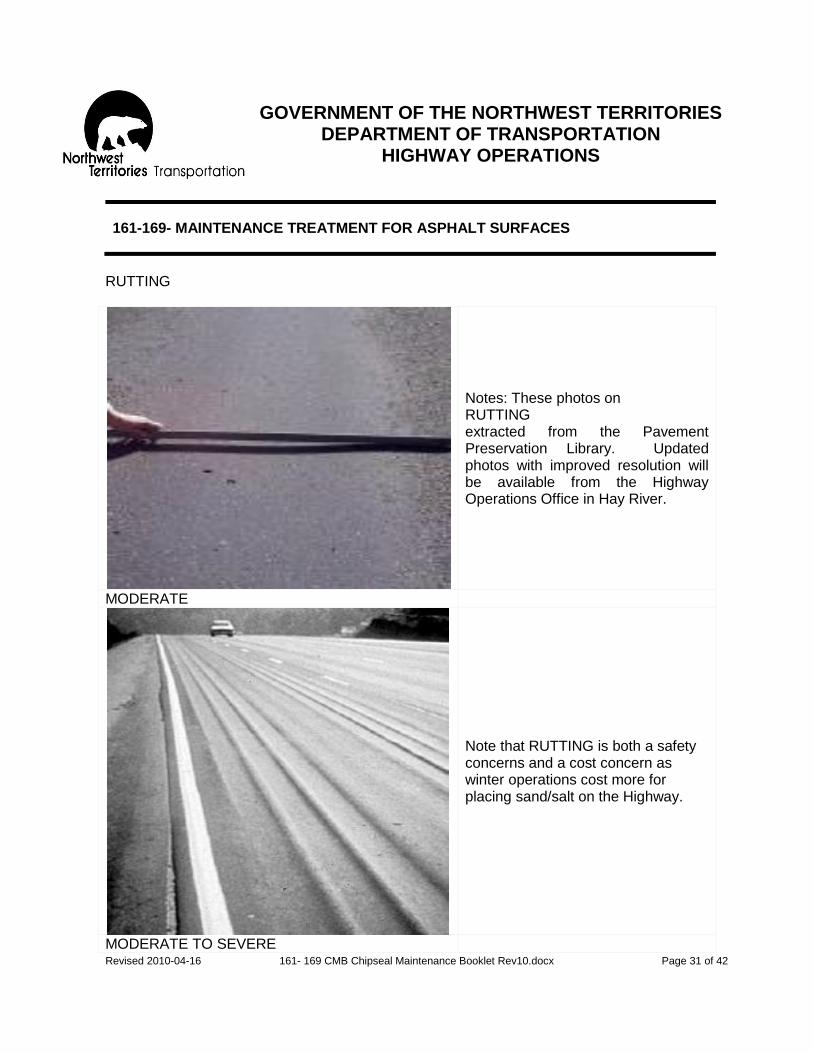
GOVERNMENT OF THE NORTHWEST TERRITORIES
DEPARTMENT OF TRANSPORTATION HIGHWAY OPERATIONS
Revised 2010-04-16 161- 169 CMB Chipseal Maintenance Booklet Rev10.docx Page 31 of 42
161-169- MAINTENANCE TREATMENT FOR ASPHALT SURFACES
RUTTING
Notes: These photos on RUTTING extracted from the Pavement Preservation Library. Updated photos with improved resolution will be available from the Highway Operations Office in Hay River.
MODERATE
Note that RUTTING is both a safety concerns and a cost concern as winter operations cost more for placing sand/salt on the Highway.
MODERATE TO SEVERE

GOVERNMENT OF THE NORTHWEST TERRITORIES
DEPARTMENT OF TRANSPORTATION HIGHWAY OPERATIONS
Revised 2010-04-16 161- 169 CMB Chipseal Maintenance Booklet Rev10.docx Page 32 of 42
161-169- MAINTENANCE TREATMENT FOR ASPHALT SURFACES
SURFACE DEFECTS- Rippling/Shoving
Description: Regular transverse undulations in the asphalt surface consisting of closely spread alternate valleys and crests; unevenness of pavement surface caused by traffic action moving surface mat forward, backward or sideways. Possible Causes:
1. Poor material design and construction technique; poor quality control. 2. Traffic action, such as stop and start at intersections.
Severity: Class Guidelines (Based personal experience of the interaction between
vehicle and pavement surface distortion) Slight Noticeable. Moderate Rough ride. Severe Very rough ride; loss of control of vehicle may result. Density: Local: less than 30% of asphalt surface affected; distress spotted over
localized areas only. General: More than 30% of asphalt surface affected; distress spotted evenly
over entire length of asphalt surface.

GOVERNMENT OF THE NORTHWEST TERRITORIES
DEPARTMENT OF TRANSPORTATION HIGHWAY OPERATIONS
Revised 2010-04-16 161- 169 CMB Chipseal Maintenance Booklet Rev10.docx Page 33 of 42
161-169- MAINTENANCE TREATMENT FOR ASPHALT SURFACES
ALTERNATIVE TREATMENTS FOR RIPPLING/SHOVING
Evaluation
Treatment for Condition
Pavement AST
Severity Density Use Activity Use Activity
Slight Local -No action
---
---
General -Monitor for future consideration
---
---
Moderate Local -Cold mix patch -Hot mix patch
161 164/167
161 ---
General -Cold mix patch with guidance of Regional Manager -Hot mix patch with guidance of Regional Manager -Cold planning/milling -Recycle A.S.T. with approval of Regional Manager
161 164/167 * ---
161 --- --- 169
Severe Local -Cold mix patch -Hot mix patch -Cold planning/milling -Recycle A.S.T.
161 164/167 * ---
161 --- --- 169
General -Recycle A.S.T. with approval of Regional Manager -Granular lift and surface treatment -Hot mix patch and single course hot mix resurfacing
--- * *
169 *
* non-routine maintenance activity- normally done by Transportation Engineering

GOVERNMENT OF THE NORTHWEST TERRITORIES
DEPARTMENT OF TRANSPORTATION HIGHWAY OPERATIONS
Revised 2010-04-16 161- 169 CMB Chipseal Maintenance Booklet Rev10.docx Page 34 of 42
161-169- MAINTENANCE TREATMENT FOR ASPHALT SURFACES
RIPPLING/SHOVING
MODERATE
Notes: This photo on RIPPLING/SHOVELLING extracted from the Pavement Interactive Website. Updated photos with improved resolution will be available from the Highway Operations Office in Hay River. Note that Shoving on Chipseal will result in a surface break and a pothole in short order. This is a characteristic of hot mixed asphalt where and when there are issues with the mix design

GOVERNMENT OF THE NORTHWEST TERRITORIES
DEPARTMENT OF TRANSPORTATION HIGHWAY OPERATIONS
Revised 2010-04-16 161- 169 CMB Chipseal Maintenance Booklet Rev10.docx Page 35 of 42
161-169- MAINTENANCE TREATMENT FOR ASPHALT SURFACES
SURFACE DEFECTS- Raveling/Segregation
Description: Progressive loss of asphalt surface material from surface downward. Asphalt surface looks as though it is breaking up in to small pieces like a peeling sunburn. Raveling can occur over the entire surface, but the wheel tracks are generally the worst areas because of the traffic action Possible Causes:
1. Poor construction technique and poor quality control. 2. Asphalt hardening due to aging. 3. Traffic action on a weak surface.
Severity: Class Guidelines (Based personal experience of the interaction between vehicle and pavement surface distortion)
Slight Noticeable loss of asphalt surface material. Moderate Shallow disintegration of asphalt surface; an open textured look. Severe Shallow disintegration of asphalt surface with small potholes, very
open texture with loose materials. Density: Local: less than 30% of asphalt surface affected; distress spotted over
localized areas only. General: More than 30% of asphalt surface affected; distress spotted evenly
over entire length of asphalt surface.

GOVERNMENT OF THE NORTHWEST TERRITORIES
DEPARTMENT OF TRANSPORTATION HIGHWAY OPERATIONS
Revised 2010-04-16 161- 169 CMB Chipseal Maintenance Booklet Rev10.docx Page 36 of 42
161-169- MAINTENANCE TREATMENT FOR ASPHALT SURFACES
ALTERNATIVE TREATMENTS FOR RAVELING/SEGREGATION
Evaluation
Treatment for Condition
Pavement AST
Severity Density Use Activity Use Activity
Slight Local -No action
---
---
General -No action
---
---
Moderate Local -Chipseal patch -No action
162
162
General -Chipseal patch -Chip sealing with approval of Director, Regional Manager -No action, but inform Regional Manager of the problem situation
162 840 ---
162 840 ---
Severe Local -Chipseal patch -Hot mix patch
162 167
162 ---
General -Chip sealing with approval of Director, Regional Manager -Single course hot mix resurfacing -No action but notify Regional Manager
840 * ---
840 --- ---
* non-routine maintenance activity- normally done by Transportation Engineering

GOVERNMENT OF THE NORTHWEST TERRITORIES
DEPARTMENT OF TRANSPORTATION HIGHWAY OPERATIONS
Revised 2010-04-16 161- 169 CMB Chipseal Maintenance Booklet Rev10.docx Page 37 of 42
161-169- MAINTENANCE TREATMENT FOR ASPHALT SURFACES
RAVELING/SEGREGATION
Notes: These photos on RAVELING AND SEGREGATION extracted from the Pavement Preservation Library and the Pavement Interactive Website. Updated photos with improved resolution will be available from the Highway Operations Office in Hay River.
MODERATE RAVELING DUE TO PLOWS
Note that RAVELING shows as a degradation of the asphaltic surface. In the upper photo the added pressure of plowing brought the condition out sooner and across a wider are compared to the wheel tracts of a non-plowed section from a Texas highway shown below.
MODERATE IN THE WHEEL TRACTS
GOVERNMENT OF THE NORTHWEST TERRITORIES
DEPARTMENT OF TRANSPORTATION HIGHWAY OPERATIONS
Revised 2010-04-16 161- 169 CMB Chipseal Maintenance Booklet Rev10.docx Page 38 of 42
161-169- MAINTENANCE TREATMENT FOR ASPHALT SURFACES
SURFACE DEFECTS- Bleeding
Description: Free asphalt migrating upwards to the asphalt surface. Most likely to occur in the wheel tracks, especially during hot weather. Possible Causes:
1. To much asphalt in mix; excess asphalt is forced to the surface by traffic action.
2. Paving over bleeding asphalt surfaces with new asphalt without treating bleeding surface.
3. Paving over excess primed surfaces. Severity: Class Guidelines (Based personal experience of the interaction between
vehicle and pavement surface distortion) Slight Coloring of asphalt surface visible (interconnected veining). Moderate Distinctive appearance (with excessive asphalt already free). Severe Free asphalt gives the surface a wet look; tire marks and tracking are
evident tire noise can be heard. Density: Local: Less than 30% of asphalt surface affected; distress spotted over
localized areas only. General: More than 30% of asphalt surface affected; distress spotted evenly
over entire length of asphalt surface.

GOVERNMENT OF THE NORTHWEST TERRITORIES
DEPARTMENT OF TRANSPORTATION HIGHWAY OPERATIONS
Revised 2010-04-16 161- 169 CMB Chipseal Maintenance Booklet Rev10.docx Page 39 of 42
161-169- MAINTENANCE TREATMENT FOR ASPHALT SURFACES
ALTERNATIVE TREATMENTS FOR BLEEDING
Evaluation
Treatment for Condition
Pavement AST
Severity Density Use Activity Use Activity
Slight Local -No action
---
---
General -No action
---
---
Moderate Local -No action
---
---
General -No action but notify Regional Manager Of the problem situation
--- ---
Severe Local -Blotting with sand -Burn and seal with fine aggregates
168 *
168 ---
General -Burn and sand seal or chip seal -Burn and single course hot mix resurfacing -Recycle A.S.T. with approval of Regional Manager
* * ---
--- --- 169
* Non-routine maintenance activity- normally done by Transportation Engineering
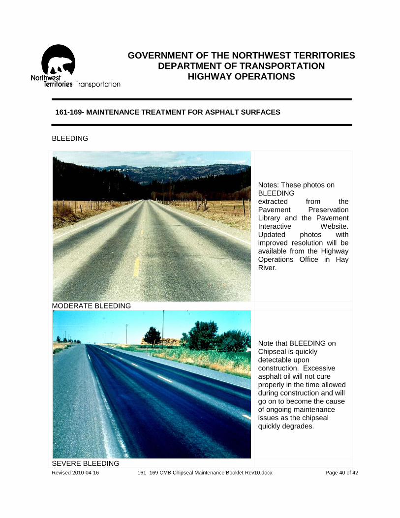
GOVERNMENT OF THE NORTHWEST TERRITORIES
DEPARTMENT OF TRANSPORTATION HIGHWAY OPERATIONS
Revised 2010-04-16 161- 169 CMB Chipseal Maintenance Booklet Rev10.docx Page 40 of 42
161-169- MAINTENANCE TREATMENT FOR ASPHALT SURFACES
BLEEDING
Notes: These photos on BLEEDING extracted from the Pavement Preservation Library and the Pavement Interactive Website. Updated photos with improved resolution will be available from the Highway Operations Office in Hay River.
MODERATE BLEEDING
Note that BLEEDING on Chipseal is quickly detectable upon construction. Excessive asphalt oil will not cure properly in the time allowed during construction and will go on to become the cause of ongoing maintenance issues as the chipseal quickly degrades.
SEVERE BLEEDING

GOVERNMENT OF THE NORTHWEST TERRITORIES
DEPARTMENT OF TRANSPORTATION HIGHWAY OPERATIONS
Revised 2010-04-16 161- 169 CMB Chipseal Maintenance Booklet Rev10.docx Page 41 of 42
161-169- MAINTENANCE TREATMENT FOR ASPHALT SURFACES
SURFACE DEFECTS- Slippery Surface
Description: Shining surface from excess asphalt; or polished coarse aggregates evident in the asphalt surface. Slippery surface is also known as polishing. Possible Causes:
1. Excess asphalt. 2. Coarse aggregates, which are easily polished under traffic and are smooth to
the touch. 3. Soft aggregates that are broken down by regular operations and become
smooth to the touch.
Severity: Class Severity levels are not applicable, however the degree of the slippery
surface condition may be reflected in a reduction of skid resistance, especially when the surface is wet. If a slipper asphalt surface condition is suspected, consult with Regional Manager.
ALTERNATIVE TREATMENTS FOR SLIPPERY SURFACE
Evaluation
Treatment for Condition
Pavement AST
Severity
Density
Use Activity Use Activity
If any areas of pavement surface are suspected of being slippery, notify Regional Manager For furtherance to HQ immediately of the problem situation, and meanwhile maintain monitoring of the suspected areas.

GOVERNMENT OF THE NORTHWEST TERRITORIES
DEPARTMENT OF TRANSPORTATION HIGHWAY OPERATIONS
Revised 2010-04-16 161- 169 CMB Chipseal Maintenance Booklet Rev10.docx Page 42 of 42
161-169- MAINTENANCE TREATMENT FOR ASPHALT SURFACES
SLIPPERY SURFACE also known as POLISHING
Notes: These photos on POLISHING/SLIPPERY SURFACE extracted from the Pavement Preservation Library and the Pavement Interactive Website. Updated photos with improved resolution will be available from the Highway Operations Office in Hay River.
POLISHING COMPARISON EXAMPLE
Note that POLISHING on Chipseal is a safety concern for traction in winter. See aggregate in the upper photo is the same on both sides. The right side shows 5 years in service on the highway. The lower photo is a concrete pavement with severe polishing.
SEVERE POLISHING

GOVERNMENT OF THE NORTHWEST TERRITORIES
DEPARTMENT OF TRANSPORTATION HIGHWAY OPERATIONS
Revised 2010-04-15 HMM 170-174 Rev 10.docx Page 1 of 9
170- SHOULDER BLADING
OBJECTIVE
To provide motorists with a safe transition from the driving surface to the shoulder. DESCRIPTION
Blading of gravel shoulders on paved sections to maintain proper cross-section and to remove pavement edge drop-off.
LEVEL OF SERVICE
All shoulders to be maintained to: - Provide a smooth unrutted and safe stopping area off the traveled surface. - Allow for free flowing drainage off the highway surface. - Provide structural support to pavement edges.
RESPONSIBILITY
Highway Maintenance Supervisor will schedule this activity. PRODUCTIVITY GUIDELINES: RESOURCE GUIDELINES:
Quantity Standard- Crew-
Once/year 1-Heavy Equipment Operator (class 03) Average Daily Production Range- Equipment-
12 shoulder kilometers 1-Grader (class 2304)
1-Packer (class 2600)
(Self Propelled Rubber Tire Packer is recommended for this activity.)
SCHEDULING:
Late April to late September
GOVERNMENT OF THE NORTHWEST TERRITORIES
DEPARTMENT OF TRANSPORTATION HIGHWAY OPERATIONS
Revised 2010-04-15 HMM 170-174 Rev 10.docx Page 2 of 9
170- SHOULDER BLADING
RECOMMENDED METHOD- General Approach
Maximum allowable drop-off is 3 cm otherwise the condition is considered hazardous. Shoulders on curves and intersections are subject to increased wear and may need attention with shoulder repair (Activity 172) prior to shoulder blading.
Poor drainage causes soft spots on shoulder and can cause an adjacent paved surface to fail. Ruts and depressions should be eliminated. The crossfall on shoulders should be maintained at 4% away from the pavement edges on the tangents. On curves, the shoulder slopes should conform to the superelevated slope of the pavement. Shoulder material should be reshaped to a level no higher than the pavement edge, otherwise water will be held and pavement drainage hindered.
Once per year it is desirable to re-establish the shoulder line by pulling back onto the shoulder any loose granular material from the grade slope. Care must be taken not to cut sod and also not to create a furrow along the slope which could trap water. Whenever possible, shoulder blading should be performed after rain when there is optimum moisture content in the shoulder material in order to obtain a stable compacted surface.
RECOMMENDED METHOD- Details
1. Set out warning signs. This is a surface activity (placing a windrow on the edge of the driving surface) and therefore temporary warning signs must be used. 2. Work should be done in relatively short sections, 1.5 to 3.0 kilometers – this working distance to be approved by the Regional Manager. Note the length of the working distance will be adjusted to suit traffic flows and weather conditions. If a long windrow is left for too long, it will dry out resulting in poor compaction after spreading. 3. Pass Procedures - see 3-pass and 2-pass procedures listed below. 4. Recommend use of self-propelled rubber tire packer for all compaction needs. 5. Any excess granular material remaining on the pavement should be removed by sweeping (Activity 174). 6. Remove warning signs.

GOVERNMENT OF THE NORTHWEST TERRITORIES
DEPARTMENT OF TRANSPORTATION HIGHWAY OPERATIONS
Revised 2010-04-15 HMM 170-174 Rev 10.docx Page 3 of 9
170- SHOULDER BLADING
Pass Procedures continued from Recommended Method- Detailed
a) 3-pass procedure with motor grader. (includes pass on upper grade slope) i) First pass
- once a year single pass should be made on the upper grade slope to recover loose material and redefine shoulder;
- windrow this material at outer edge of shoulder. ii) Second Pass
- The windrow is bladed from the shoulder line across the shoulder onto the edge of pavement;
- Rutted or uneven areas are cut; - Material is spread into low spots; - Loose material to be compacted against the pavement by operating the inner set
of grader wheels along the edge of the gravel shoulder adjoining the pavement, providing shoulder width permits;
- Remaining material is windrowed onto outer edge of pavement. iii) Third Pass
- The windrow is bladed from the pavement and spread outward on the shoulder to restore cross section;
- No material to be left higher than pavement edge; - Operator to keep grader tires along pavement edge as much as possible to
assist compaction. iv) Compact after second and third pass with packer.

GOVERNMENT OF THE NORTHWEST TERRITORIES
DEPARTMENT OF TRANSPORTATION HIGHWAY OPERATIONS
Revised 2010-04-15 HMM 170-174 Rev 10.docx Page 4 of 9
170- SHOULDER BLADING
Pass Procedures continued from Recommended Method- Detailed
b) 2-pass procedure with motor grader. (excludes pass on upper grade slope)
i) First Pass - The surface from the shoulder line to the edge of the pavement is bladed with
sufficient pressure to remove ridges and uneven areas; - Loose material is compacted against the pavement by operating the inner set of
grader wheels along the inside edge of the gravel shoulders adjoining the pavement, providing shoulder width permits same;
- remaining material is windrowed onto outer edges of the pavement. ii) Second Pass
- Windrow is bladed from the pavement and spread outward on the shoulder to restore cross section;
- No material is left higher than pavement edge; note operator is to keep grader tires along pavement edge as much as possible to assist compaction.
iii) Compact after each pass with packer.

GOVERNMENT OF THE NORTHWEST TERRITORIES
DEPARTMENT OF TRANSPORTATION HIGHWAY OPERATIONS
Revised 2010-04-15 HMM 170-174 Rev 10.docx Page 5 of 9
172- SHOULDER REPAIR
OBJECTIVE
To provide motorists with a safe transition from the driving surface to the shoulder and to preserve structural integrity of the road.
DESCRIPTION
The repair with gravel of non-paved shoulders on asphalted sections of highway to correct: - Minor settlements, low spots and small eroded areas. - Severe drop-offs from pavement when shoulder blading will not correct the
problem. Note: Repair of major settlements and erosion to be charged to Activity 122.
LEVEL OF SERVICE
The frequency and extent of this repair is to be based on the best judgment of the Highway Maintenance Supervisor taking into account the need to preserve the shoulders and provide safe, comfortable service to those using the shoulders.
RESPONSIBILITY
Highway Maintenance Supervisor will co-ordinate scheduling of the work. PRODUCTIVITY GUIDELINES: RESOURCE GUIDELINES:
Quantity Standard- Crew-
0.25 m3/km of gravel shoulder 4-Heavy Equipment Operator (class 03) Average Daily Production Range- Equipment-
60 m3 2-Tandem Trucks (class 1504) 1-Tilt Deck Trailer (class 1211) 1-Loader (class 2109) 1-Grader (class 2304) 1-Packer (class 2600) Average Annual Production- Material-
1/3 of NWT Highway System Crushed Gravel (code 110)
GOVERNMENT OF THE NORTHWEST TERRITORIES
DEPARTMENT OF TRANSPORTATION HIGHWAY OPERATIONS
Revised 2010-04-15 HMM 170-174 Rev 10.docx Page 6 of 9
172- SHOULDER REPAIR
SCHEDULING:
Mid May to September RECOMMENDED METHOD:
1. SET OUT WARNING SIGNS.
2. Place traffic gravel on area to be repaired to a minimum depth of 5 cm and
maximum depth of 15 cm. The traffic gravel should be well graded material,
preferably with a 15% fines content.
3. Shape the shoulder to establish proper cross section and compact the surface
using water if necessary to achieve proper density. Shoulder crossfall is
normally 4% from pavement edge on tangents or as originally designed.
4. Any subsequent lift required to maximum depth of 15 cm will be shaped and
compacted as in step 3.
5. Any granular material remaining on asphalt surfaces to be removed if
necessary by sweeping (Activity 174).
6. REMOVE WARNING SIGNS.

GOVERNMENT OF THE NORTHWEST TERRITORIES
DEPARTMENT OF TRANSPORTATION HIGHWAY OPERATIONS
Revised 2010-04-15 HMM 170-174 Rev 10.docx Page 7 of 9
174- SWEEPING
OBJECTIVE
To maintain a clean asphalt surface. DESCRIPTION
Sweeping of asphalt surfaces to: - Provide a safe clean dust free asphaltic surface - Prepare for pavement line marking activities - Prevent pavement line markings from becoming obscured
LEVEL OF SERVICE
During the spring, it is necessary to clean the winter accumulation of sand and gravel from road surfaces and shoulders, particularly at intersections and restricted speed zones. Depending on the length of the break-up period it may be necessary to repeat this activity several times.
RESPONSIBILITY
Highway Maintenance Supervisor to schedule this activity.
PRODUCTIVITY GUIDELINES: RESOURCE GUIDELINES:
Quantity Standard- Crew-
3 line-km/hour of asphaltic surface 1-Heavy Equipment Operator (class 04) 1-Laborer (class 05)
Average Daily Production Range- Equipment-
8 hours 1-Pickup Trucks (class 1823) 1-Broom (class 5244)
Optional 1-Tractor c/w broom (class 5200)
Material-
Water (code 990) when applicable Note: With approval from the Regional Manager and in cooperation with other DOT staff, the equipment allotment can be increased to improve production or to address local concerns.

GOVERNMENT OF THE NORTHWEST TERRITORIES
DEPARTMENT OF TRANSPORTATION HIGHWAY OPERATIONS
Revised 2010-04-15 HMM 170-174 Rev 10.docx Page 8 of 9
174- SWEEPING
SCHEDULING:
May to September with emphasis on - Initial spring sweeping. - Prior to pavement marking to ensure a clean surface for the application of the
paint.
Special Notes: When possible, sweeping should be scheduled
- During a rain or just after a rain. - When wind is blowing into ditch on travelled side. - When traffic flows are light.
RECOMMENDED METHOD- General Approach
Prior to beginning sweeping, accumulations of compacted sand, gravel and other materials to be loosened and removed where necessary with a grader or loader. This situation can occur at the transition of gravel to asphaltic surfaces - Accumulations of over 5 cm of sand and gravel on highways with roadside
barriers or bridge curbing and wide highway intersections to be removed by grader, loader or by hand.
- Pre-wetting of surfaces with a water truck may be required in urban areas during periods of dry weather.
- Install protective cover on rear of towing vehicle. - Fill sweeper water tank and check operation of spray system.

GOVERNMENT OF THE NORTHWEST TERRITORIES
DEPARTMENT OF TRANSPORTATION HIGHWAY OPERATIONS
Revised 2010-04-15 HMM 170-174 Rev 10.docx Page 9 of 9
174- SWEEPING
RECOMMENDED METHOD- Details
1. PLACE SIGNS AND SAFETY DEVICES
Special Note: As the sweeper can create a dangerous dust condition and can
throw debris, safety precautions are critical.
2. TURN ON FLASHING LIGHTS.
3. Sweep from centerline to edge of roadway in the direction of traffic.
4. If dust conditions are creating a hazard, control traffic following sweeper by
a. Stopping all traffic if necessary until it is safe to proceed.
b. Follow sweeper with the second pickup (pilot vehicle) at a sufficient
distance to be visible. Traffic can be held or allowed to proceed as
conditions permit from communication between sweeper unit and pilot
vehicle.
5. WHEN SWEEPING IS COMPLETE, REMOVE SIGNS AND SAFETY
DEVICES.

GOVERNMENT OF THE NORTHWEST TERRITORIES
DEPARTMENT OF TRANSPORTATION HIGHWAY OPERATIONS
Revised 2010-04-15 HMM 202-241 Rev by HO 10.docx Page 1 of 22
202 - CLEAN AND INSPECT CULVERTS
OBJECTIVE
To ensure the proper functioning of culverts and to identify possible culvert failures that could cause hazardous road condition.
DESCRIPTION
Clean and inspect culverts to determine structural integrity and to correct deficiencies such as:
a) Blockage or constriction with debris
b) Debris in outlet and inlet channels
c) Minor damage to culvert ends
d) Erosion at culvert ends
Note: The following should be reported to Activity 451 1. Installation and maintenance of steam pipes 2. Removal of ice and snow from inside or adjacent to the culvert ends
LEVEL OF SERVICE
Highway Maintenance Supervisor should be continuously alert for drainage problems caused by obstruction to the flow of water through culverts. This includes inspections after heavy rains or during periods of high run-off when drainage problems are most easily identified. In addition, a concentrated effort should be scheduled in the summer and early fall to clean out culverts, especially where perceived problems exist, to prepare them for the spring run-off.
RESPONSIBILITY
Highway Maintenance Supervisor to schedule inspections

GOVERNMENT OF THE NORTHWEST TERRITORIES
DEPARTMENT OF TRANSPORTATION HIGHWAY OPERATIONS
Revised 2010-04-15 HMM 202-241 Rev by HO 10.docx Page 2 of 22
202 - CLEAN AND INSPECT CULVERTS
PRODUCTIVITY GUIDELINES: RESOURCE GUIDELINES:
Quantity Standard- Crew-
25% of all culverts/year 2-Laborers (class 05) Average Daily Production Range- Equipment-
24 culverts 1-Pickup (class 1823) SCHEDULING: April to October
Culvert problems should be scheduled for remedial work as soon as possible after being identified.
RECOMMENDED METHOD - Details
1. INSPECT AND IDENTIFY ANY NEEDED MAINTENANCE
2. PERFORM ALL NECESSARY WORKS SUCH AS:
a) Clean debris from the culvert and the drainage channel immediately upstream and downstream from the culvert
b) Straighten and repair damaged ends (if material is required, repair using Activity 203)
c) Repair erosion adjacent to at culvert ends. Culverts subjected to flowing full under pressure should be checked for water channelization along the outer side of the culvert
d) Repair/replace rip-rap e) Straighten and tamp the culvert markers
3. RECORD CONDITION OF EACH CULVERT AND DETAILS OF THE WORK
COMPLETED ON A SEPARATE CULVERT INSPECTION REPORT, see current “Culvert Assessment Form.” - Original Culvert Inspection Reports to be retained at camp level for
future reference. - Copies of Culvert Inspection Reports for culverts with major
deficiencies are to be forwarded to the Regional Manager.

GOVERNMENT OF THE NORTHWEST TERRITORIES
DEPARTMENT OF TRANSPORTATION HIGHWAY OPERATIONS
Revised 2010-04-15 HMM 202-241 Rev by HO 10.docx Page 3 of 22
202 - CLEAN AND INSPECT CULVERTS
Quick Culvert Assessment Process This standard activity was revised to include all culverts on the Highway System where large culverts are viewed as Capital Projects and small culverts are viewed as O&M Projects. A small culvert is defined as being less than 1.5 metres in diameter and has an embankment depth to obvert at centreline of less than 2.0 metres. The DOT has an inventory of approximately 3,000 culverts system wide with an estimated lifecycle of 50 years each. Expected annual replacement costs would be 1% of total. The Assessment or Inspection Criteria for the culverts includes three main points:
1) The culvert barrel of pipe, 2) The end treatments at inlet and outlet and 3) The surrounding ditch lines or drainage course.
Assessment of a culvert in the field is a simple process. The following have been developed to meet our needs by evaluating only three culvert conditions:
a) Blocked with very little flow or no flow, b) Working poorly with unimpeded flows and c) Working well.
All conditions are important for a proper evaluation of the culvert and its function. Typically, our problems are blockages such as:
i) Blocked/collapsed culverts that do not allow water flow, ii) Blocked at the end treatment by debris or heaved by ice, and iii) Blocked in the ditch line upstream or downstream from the culvert.
If the culvert is blocked, immediately report this to the Regional Manager and make arrangements for repairs. Steaming or cleaning the culvert by clearing debris can remove the blockage and re-establish flow. If cleaning and steaming efforts do not restore culvert flow then the culvert may need replacement. The Regional Manager will assign resources to complete repairs and may request Engineering staff to inspect the culvert for design issues that can improve the performance for the new replacement culvert.

GOVERNMENT OF THE NORTHWEST TERRITORIES
DEPARTMENT OF TRANSPORTATION HIGHWAY OPERATIONS
Revised 2010-04-15 HMM 202-241 Rev by HO 10.docx Page 4 of 22
202 - CLEAN AND INSPECT CULVERTS
A culvert can be working poorly and not require replacement since it is still working and although water levels can be high – the water is flowing through the culvert. Examples include flow obstructing damage from equipment impacts or ice effects on the end treatments of the culvert. These issues could be considered as minor and can be addressed with a higher level of monitoring and inspection with repairs schedule for later in the summer during low water periods. The Regional Manager may assign staff to monitor conditions or cooperate with Engineering to complete a comprehensive assessment. Issues with surrounding drainages and in the ditch lines can be subjective based on the experience of the staff. However all can agree on the drainage and ditch lines working to bring water to the culvert inlet and then taking the water away from the outlet away from the road. Beaver dams and debris piles are obvious in the visual assessment as taken from the highway. Growth in the drainage course and in the ditch lines that is slowing down the flows can be viewed on a per case basis and the inspector can estimate future conditions in the 2-3 year range for the report. Do not hike up or down the drainage course alone. Any off highway examination of the ditch lines and drainage requires approval from the Regional Manager or his designate, safety first. Please call in your culvert assessment with the listed information by phone or fax to the Regional Manager or to the Highway Operations Office in Hay River. By phone at 867-874-5000 or by fax at 867-874-2272.

GOVERNMENT OF THE NORTHWEST TERRITORIES
DEPARTMENT OF TRANSPORTATION HIGHWAY OPERATIONS
Revised 2010-04-15 HMM 202-241 Rev by HO 10.docx Page 5 of 22
202 - CLEAN AND INSPECT CULVERTS
Culvert Assessment information includes the following: a) Date of the assessment; b) Staff: name of the inspector and his associates onsite; c) Highway; and d) Kilometre Location; e) Seasonal conditions: high or low water at the time of the assessment; f) Depth of pipe, C for Cover: closest 100 mm from obvert (top of the pipe) to the top of the
road at centreline; g) Diameter, D: closest to 50 mm since standing water can impede accuracy; h) Length of Pipe, L: closest 200 mm since it is a quick measurement, subject to traffic flows
– please remember safety first; i) Length of End Treatment, B: Upstream at culvert and upstream from culvert; j) Length of End Treatment, B: Downstream at culvert and downstream from culvert; and k) Sketch with estimated distances for the culvert, the highway and the problems. To assist with nomenclature for our quick culvert assessments see the figures below and the attached worksheet entitled: Culvert Assessment Form.

GOVERNMENT OF THE NORTHWEST TERRITORIES
DEPARTMENT OF TRANSPORTATION HIGHWAY OPERATIONS
Revised 2010-04-15 HMM 202-241 Rev by HO 10.docx Page 6 of 22

GOVERNMENT OF THE NORTHWEST TERRITORIES
DEPARTMENT OF TRANSPORTATION HIGHWAY OPERATIONS
Revised 2010-04-15 HMM 202-241 Rev by HO 10.docx Page 7 of 22
202 - CLEAN AND INSPECT CULVERTS
Figure 1
Figure 2

GOVERNMENT OF THE NORTHWEST TERRITORIES
DEPARTMENT OF TRANSPORTATION HIGHWAY OPERATIONS
Revised 2010-04-15 HMM 202-241 Rev by HO 10.docx Page 8 of 22
202 - CLEAN AND INSPECT CULVERTS
Example Location Photos
SCP 1
SCP 2 These Example Photos SCP - 1 & 2 show no current issues with the culvert or the downstream flows. Note the steam pipe in SCP 1 is in good form and free of concerns. Note that the brush (to the right) in SCP 2 is encroaching on the drainage course and should be listed for clearing during a low water period. For questionable issues – taking photos with larger viewscape would be most helpful.

GOVERNMENT OF THE NORTHWEST TERRITORIES
DEPARTMENT OF TRANSPORTATION HIGHWAY OPERATIONS
Revised 2010-04-15 HMM 202-241 Rev by HO 10.docx Page 9 of 22
202 - CLEAN AND INSPECT CULVERTS
Second Example Photos
SCP 3
SCP 4 The second Example Photos shows debris potential in blocking the culvert in SCP 3 and slight end damage for the culvert end in SCP 4. Both of the above examples are in spring thaw season with high water conditions. Both are working well. Dented or damaged ends require some attention and ice can heave bevelled ends causing significant issues with drainage potential. High water near a culvert or in the ditches leading to a culvert can saturate the road embankment causing rutting issues and reducing safety for highway travellers. Both of these situations should have increased monitoring for changes that can impact highway safety.
GOVERNMENT OF THE NORTHWEST TERRITORIES
DEPARTMENT OF TRANSPORTATION HIGHWAY OPERATIONS
Revised 2010-04-15 HMM 202-241 Rev by HO 10.docx Page 10 of 22
203 - CULVERT REPAIR/REPLACEMENT
OBJECTIVE
To maintain the integrity of the culverts to ensure adequate drainage capacity and the safe usage of the highways
DESCRIPTION
The repair and/or replacement of damage or undersized culverts up to maximum diameter of 1,200 millimetres and where the embankment depth to obvert at centreline is less that 2,000 millimetres. Obvert is the top of the culvert while invert describes the bottom of the culvert. Note: 1. Installation of new culverts across the roadway or an access at a new
location to correct drainage problems when approved with funding by the Regional Manager shall be reported to Activity 803
2. The subsequent patching of asphalt road surfaces following replacement of a culvert on an asphalt surfaced road should be reported to Activity 161/164.
LEVEL OF SERVICE
The Highway Maintenance Supervisor should note culverts requiring repair or replacement during the routine road patrol. Culvert problems recorded on Culvert Inspection Reports during formal culvert inspections should also form a part in determination of work priorities for culvert repairs. Culverts should also be checked after heavy storms or periods of high run off when the need for corrective measures is most easily identified. In case of severe washouts, the Highway Maintenance Supervisor, without official approval, if the Regional Manager cannot be contacted, may undertake emergency action, required to safeguard the traveling public and minimize erosion damage.
RESPONSIBILITY
Highway Maintenance Supervisor with guidance from Regional Manager. Refer to Highway Maintenance Operations Instructions for - Productivity Guidelines - Resource Guidelines - Scheduling - Recommended Method

GOVERNMENT OF THE NORTHWEST TERRITORIES
DEPARTMENT OF TRANSPORTATION HIGHWAY OPERATIONS
Revised 2010-04-15 HMM 202-241 Rev by HO 10.docx Page 11 of 22
203 - CULVERT REPAIR/REPLACEMENT
PRODUCTIVITY GUIDELINES: RESOURCE GUIDELINES:
Quantity Standard- Crew-
1% of all culverts/year 3-Heavy Equipment Operators (class 02) 2-Laborers (class 05) Average Daily Production Range- Equipment-
3 culverts 1-Loader (class 2109) 1-Tandem Truck (class 1504) 1-Loader/Backhoe (class 2809) 1-Tilt Deck Trailer (class 1211) * Note: Larger backhoe should be rented
when required
Materials-
Properly Sized Culvert (code 444) Pit Run Gravel (code 108) Crushed Gravel (code 110) SCHEDULING:
May to October during periods of dry weather when backfill material can be compacted.
RECOMMENDED METHOD
No culvert less than 800 mm diameter shall be installed through road grades on Category 1-4 highways. In some areas, such as Category 5 highways with low grades and accesses, the minimum size installed shall not be less than 600 mm diameter. Minimum cover should not be less than 1 metre to prevent frost heaving in the winter. Culverts shall be installed to match drainage flow line; too low causes sedimentation to build up in the culvert and too high creates ponding of water at the inlet end and erosions at the outlet end. Any culvert installed with less than 1 metre of cover (due to circumstances or grade issues) requires approval from the Regional Manager. For the replacement and installation of any culverts greater then 1200 mm diameter please contact the Highway and Marine Services Division to determine the correct culvert size and the design requirements for the installation. Refer to attached “Culvert Detail Sheet” for installation details.

GOVERNMENT OF THE NORTHWEST TERRITORIES
DEPARTMENT OF TRANSPORTATION HIGHWAY OPERATIONS
Revised 2010-04-15 HMM 202-241 Rev by HO 10.docx Page 12 of 22
203 - CLEAN AND INSPECT CULVERTS
IMPORTANT – Call before you dig. You must obtain locates from all utilities prior to excavating.
RECOMMENDED METHOD - Details
1. PLACE SIGNS AND SAFETY DEVICES
2. STATION FLAG PERSONS AS REQUIRED
3. CONSTRUCT NECESSARY DIVERSION ROAD OR EARTH DAMS
4. EXCAVATE & REMOVE THE OLD/DAMAGED SECTION OF THE CULVERT
Excavations for culverts should conform to the attached standard plan removing all soft clay or unstable sub grade material.
5. PREPARE FOUNDATION AND PLACE NEW CULVERT
a. The culvert bed shall be constructed to provide a uniform and firm foundation throughout its entire area and with the desired slope.
b. Section(s) of the culverts to be placed on the culvert bed with the horizontal lap(s) of the coupling band(s) at the side of the culvert.
c. Note: Only CORRAGATED COUPLERS allowed. No other type of coupler is allowed except by written authorization by the Regional Manager. The sections of the culverts shall be firmly joined and the joints shall be as tight as possible.
d. Ensure that the culvert sections are correctly aligned both horizontally and vertically before backfilling the culvert.
6. PLACE AND COMPACT BACKFILL MATERIAL
Select granular pit run material or crushed gravel is to be placed under the haunches of the culvert and hand tamped. Further select granular pit run material or crushed gravel is to be placed near the culvert in 150 mm lifts and after each lift the material is to be hand tamped. Continue to backfill with select granular material taking precautions not to disturb the alignment of the culvert. Backfill is to be placed in 150 mm lifts, compacting each layer with mechanical tampers before placement of the next lift to reduce future settlement. Fill should be kept horizontal along the length of the culvert at all times. A minimum of 300 mm of compacted cover over the culvert must be attained before mechanical equipment crosses it. Backfill may be placed in 150 mm lifts (loose measurement) using mechanical equipment when this minimum cover has been achieved.
GOVERNMENT OF THE NORTHWEST TERRITORIES
DEPARTMENT OF TRANSPORTATION HIGHWAY OPERATIONS
Revised 2010-04-15 HMM 202-241 Rev by HO 10.docx Page 13 of 22
203- CULVERT REPAIR/REPLACEMENT
RECOMMENDED METHOD - Details (cont’d)
7. REINSTATE ROAD SURFACE
a. Finally complete the backfill phase using either approved native backfill or granular material in lifts of 150 mm.
Always compact the last lift before proceeding with the next lift of backfill.
b. Place and compact a gravel base to a width and depth to match adjacent base. Where an asphalt surface exists, restore surface using Activity 161
8. Cleanup site, i.e. remove old culverts and any diversion earth dams and
excess material. 9. REMOVE SAFETY DEVICES AND SIGNS

GOVERNMENT OF THE NORTHWEST TERRITORIES
DEPARTMENT OF TRANSPORTATION HIGHWAY OPERATIONS
Revised 2010-04-15 HMM 202-241 Rev by HO 10.docx Page 14 of 22
203- CULVERT REPAIR/REPLACEMENT
This drawing is under review for specifications and content.

GOVERNMENT OF THE NORTHWEST TERRITORIES
DEPARTMENT OF TRANSPORTATION HIGHWAY OPERATIONS
Revised 2010-04-15 HMM 202-241 Rev by HO 10.docx Page 15 of 22
210 - DITCH CLEANING
OBJECTIVE
To maintain a good drainage system that will provide adequate water movement away from the highway to preserve the integrity of the highway grade.
DESCRIPTION
Clean and perform minor reshaping to existing roadside, interceptor and off take drainage ditches with a motor grader to correct deficiencies such as: - Ditch erosion - Non-conformity in grade line, or cross section - Blockages caused by rubbish and debris - When excess materials need not be hauled for disposal. Note: A crawler tractor may be substituted for the motor grader in areas that are either too soft or too rocky for the practical use of a motor grader
LEVEL OF SERVICE
Visual inspection, during the spring run-off or periods of wet weather, will help to locate blocked or restricted areas that require work to restore normal drainage patterns. The terrain and soil conditions will vary the amount of work required.
RESPONSIBILITY Highway Maintenance Supervisor to schedule the work
PRODUCTIVITY GUIDELINES: RESOURCE GUIDELINES:
Quantity Standard- Crew-
0.25 hours/ditch kilometre 1-Heavy Equipment Operator (class 03) Average Daily Production Range- Equipment-
8 hours 1-Grader (class 2304) Materials- N/A

GOVERNMENT OF THE NORTHWEST TERRITORIES
DEPARTMENT OF TRANSPORTATION HIGHWAY OPERATIONS
Revised 2010-04-15 HMM 202-241 Rev by HO 10.docx Page 16 of 22
210- DITCH CLEANING
SCHEDULING:
June - October
Schedule work during dry summer periods after problem areas have been identified.
RECOMMENDED METHOD
IMPORTANT – Call before you dig. You must obtain locates from all utilities prior to excavating.
IMPORTANT: Obtain a Land Use Permit before scheduling any work beyond the
highway right-of-way. 1. PLACE SIGNS AND SAFETY DEVICES, IF NECESSARY. 2. This annual ditching program should be carried out to clean all blocked and
restricted sections, and also to re-establish ditch cross sections and flow lines. The ditch cross section should be maintained preferably with a flat bottom.
The ditch bottom elevation should be low enough to ensure free drainage of the road base and the ditch gradient should be sufficient to maintain the desired flow (a minimum of 0.5% or one meter of fall in every 200 meters of ditch is recommended).
3. Suitable material bladed from the ditch should be used to strengthen grade
side slopes and to fill or repair washouts ad other eroded conditions. All material must be “feathered” out in such a manner that it does not interfere with work in other activities, i.e. Activity 301 or 311. Note: In areas requiring the loading, hauling and disposing of the excavated material, use activity 211 or for major ditching projects approved with funding by the Regional Manager, use Activity 851.
4. REMOVE SIGNS AND SAFETY DEVICES

GOVERNMENT OF THE NORTHWEST TERRITORIES
DEPARTMENT OF TRANSPORTATION HIGHWAY OPERATIONS
Revised 2010-04-15 HMM 202-241 Rev by HO 10.docx Page 17 of 22
211 - DITCH RECLAMATION
OBJECTIVE
To restore a drainage system that will provide adequate water movement away from the highway to preserve the integrity of the highway grade.
DESCRIPTION
Ditch reclamation is the reclamation of existing roadside, interceptor and off take drainage ditches by excavating, loading, hauling and disposing of material removed to correct deficiencies such as: - Non-conformity in grade line, or cross section - Blockages caused by rubbish and debris - Water flow restricted by trees and brush - Ditch erosion
LEVEL OF SERVICE
Visual inspection, during the spring run-off or periods of wet weather, will help to locate blocked or restricted areas that require work to restore normal drainage patterns.
RESPONSIBILITY Highway Maintenance Supervisor with guidance from the Regional Managers.
GOVERNMENT OF THE NORTHWEST TERRITORIES
DEPARTMENT OF TRANSPORTATION HIGHWAY OPERATIONS
Revised 2010-04-15 HMM 202-241 Rev by HO 10.docx Page 18 of 22
211 - DITCH RECLAMATION
PRODUCTIVITY GUIDELINES: RESOURCE GUIDELINES:
Quantity Standard - Crew-
0.25 hours/ditch kilometre 3-Heavy Equipment Operator (class 02) 1-Laborer/Flagperson (class 05) Average Daily Production Range - Equipment-
32 hours 1-Backhoe (class 2809) 2-Tandem Trucks (class 1504) 1-Tiltdeck Trailer (class 1211) Optional 1-Crawler Tractor-Wide pad (class 2404) *Note: A larger backhoe should be hired
when required SCHEDULING:
Schedule work during dry summer periods from June to October after problem areas have been identified.
RECOMMENDED METHOD - General Approach
IMPORTANT – Call before you dig. You must obtain locates from all utilities prior to excavating
The cleaning and reshaping of drainage off take ditches by use of a backhoe to excavate the undesired material, loading onto trucks and disposing thereof. This is generally performed on the short lengths of the ditch to correct a specific problem Suitable surplus material removed from ditches should be used to strengthen grade side slopes, fill or repair washouts or other eroded conditions. Only a backhoe will be used in areas where conditions will not permit the use of trucks. All spreading will normally be done with a crawler tractor and the material will be landscaped in such a manner that it will not interfere with other drainage and roadside activities. Activity 851 will be used when approved with funding by the Regional Managers for all major drainage problems. This will include all projects that require a large machine (such as Gradall etc.) that can remain on shoulder if necessary and has the capabilities to produce a smooth clean job. This will also apply to other ditching procedures such as rock blasting, ripping sedimentary rock, and stabilizing the slopes with retaining devices.

GOVERNMENT OF THE NORTHWEST TERRITORIES
DEPARTMENT OF TRANSPORTATION HIGHWAY OPERATIONS
Revised 2010-04-15 HMM 202-241 Rev by HO 10.docx Page 19 of 22
211 - DITCH RECLAMATION
RECOMMENDED METHOD - Details
1. PLACE SIGNS AND SAFETY DEVICES
2. STATION FLAGPERSONS (IF REQUIRED)
3. Excavate, load surplus material into trucks and haul to the disposal areas. In some cases it may be convenient to spread the surplus material near the excavation site without hauling (refer to Recommended Method - General Approach) for suggested disposal sites. While excavating, care should be exercised to maintain slopes not steeper than 2:1 and preferably not steeper than 3:1 when the slope is an integral part of the grade side slope. All other ditches to have slopes no steeper than 2:1. The ditch bottom cross section should be flat with a uniform gradient to prevent erosion or ponding of water.
4. Check for proper grade. The elevation of the ditch bottom should be low
enough to ensure proper drainage of the road base. The ditch gradient should not be less than 0.5% or one meter fall for each 200 meters of ditch in order to maintain the desired flow. In areas with light sandy soils, the ditch bottom should be kept wide and grades should not exceed 4% or one meter fall for each 25 meters of ditch, otherwise rip rap, weirs or other devices may be necessary to control erosion.
5. Spread the surplus material leaving the surface smooth with the edges
feathered.
6. REMOVE SIGNS AND SAFETY DEVICES.

GOVERNMENT OF THE NORTHWEST TERRITORIES
DEPARTMENT OF TRANSPORTATION HIGHWAY OPERATIONS
Revised 2010-04-15 HMM 202-241 Rev by HO 10.docx Page 20 of 22
241- BEAVER DAM REMOVAL
OBJECTIVE
To remove beaver dams that cause water ponding and the possibility of grade damage due to water seepage or the potential of a grade washout.
DESCRIPTION
The removal of obstruction caused by beaver or other animals in culverts, natural waterways, interceptors and off-take ditches to correct drainage deficiencies that affect the highway grade.
LEVEL OF SERVICE
The Highways Maintenance Supervisor should be continuously alert for beaver activity which can disrupt the normal water flow within the right-of-way in order to identify areas requiring corrective action within the given time frame.
RESPONSIBILITY Highway Maintenance Supervisor with guidance from the Regional Managers.
PRODUCTIVITY GUIDELINES: RESOURCE GUIDELINES:
Quantity Standard- Crew-
8 hours/culvert prone to beaver 1-Heavy Equipment Operator (class 04) problems 1-Laborer (class 05) Average Daily Production Range- Equipment-
16 hours 1-Medium Truck (class 1704)

GOVERNMENT OF THE NORTHWEST TERRITORIES
DEPARTMENT OF TRANSPORTATION HIGHWAY OPERATIONS
Revised 2010-04-15 HMM 202-241 Rev by HO 10.docx Page 21 of 22
241- BEAVER DAM REMOVAL
SCHEDULING:
Typically conducted from May to October where routine visual overviews to be made during road patrol to determine when and what resources are required.
RECOMMENDED METHOD - General Approach
There has not been developed a single totally effective method in reducing the problems associated with beaver activity on highway drainage systems. The following methods have been used with varying degrees of success. 1. Keeping the right-of-way clear of trees will make it more difficult for beavers to
dam water at or near the grade
2. By draining the right-of-way close to the road with interceptor ditches eliminates a suitable habitat for beavers to live near the road.
3. Trapping or killing all beavers by other means in the area and then removal of all dams, particularly in fall, will ensure that there are no dams in the spring to create problems.
4. The use of steel mesh cages built at culvert ends will prevent beavers from building dams inside culverts. Cone shaped screens made of concrete reinforcing mesh (10 cm square openings) mouthed at culvert ends can be effective in discouraging beavers from building dams at 1200mm and larger culverts.
5. Long pieces of perforated pipe that extend upstream from inside the screen on the culvert end can by effective for streams with a low volume of flow.
6. Various new mechanisms can be used to prevent beaver activity such as
Beaver Guard Screens and pipes as well as specialized culvert attachments. Please contact the Highway and Marine Service Division for advice and further information.

GOVERNMENT OF THE NORTHWEST TERRITORIES
DEPARTMENT OF TRANSPORTATION HIGHWAY OPERATIONS
Revised 2010-04-15 HMM 202-241 Rev by HO 10.docx Page 22 of 22
241- BEAVER DAM REMOVAL
RECOMMENDED METHOD - Detail
The use of different methods of eliminating beaver dams is determined by each particular situation and within limits set by available resources and environmental constraints. Some of the techniques commonly used are: 1. Driving used grader blades at 10 cm spacings into the ground or placing used
crusher screens at culvert ends will prevent beavers from building dams inside the culvert. Any dams built against these screens outside the culvert are easier to remove.
2. Existing dams built close to the road are usually removed with a backhoe
while dams in soft or remote areas may require blasting with explosives.
3. Beaver dams inside culverts can usually be dislodged with the use of a long pole chained to a backhoe bucket or by hand with the use of long wood or steel pike poles.
4. On site surveillance of the area after removal of the dam may force the beaver
to move elsewhere. 5. Various new mechanisms can be used to prevent beaver activity such as
Beaver Guard Screens and pipes as well as specialized culvert attachments. Please contact the Highway and Marine Service Division for advice and further information.

GOVERNMENT OF THE NORTHWEST TERRITORIES
DEPARTMENT OF TRANSPORTATION HIGHWAY OPERATIONS
Revised 2010-04-15 HMM 251-271 REV by HO 10.docx Page 1 of 27
251- BRIDGE & BRIDGE-CULVERT INSPECTION
OBJECTIVE
To determine, from visual observation, that the highway structure is safe for the intended use.
DESCRIPTION
Routine inspection and the reporting of structural conditions of highway structures - bridges and bridge-culverts (large culverts 1500 mm and over).
LEVEL OF SERVICE
A n a n n u a l i n s p e c t i o n w i l l b e m a d e i n t h e s p r i n g ( a f t e r t h e s p r i n g r u n - o f f ) w h e n w a t e r h a s d r o p p e d e n o u g h t o p e r m i t a t h o r o u g h i n s p e c t i o n . I d e a l l y , b r i d g e s s h o u l d b e i n s p e c t e d i m m e d i a t e l y a f t e r c l e a n i n g . Additional inspections of problem structures must be made as often as conditions dictate. All structures should be inspected after being subjected to any unusually high water. Note: Any critical conditions observed during the inspections are to be relayed immediately to the Regional Manager for furtherance to the Head of Structures Section, Highways and Marine Services Division.
RESPONSIBILITY Highway Maintenance Supervisor with guidance from the Regional Manager. The Regional Manager may collaborate with the Head of Structures for the assignment of DOT staff or additional personnel for these duties.
PRODUCTIVITY GUIDELINES: RESOURCE GUIDELINES:
Quantity Standard- Crew-
4 hours/bridge 1- Highway Maintenance Supervisor (class 01) 1- Labourer (class 05)
Average Daily Production Range- Equipment-
4 bridges/day 1-Pickup (class 1904) Materials
Nil

GOVERNMENT OF THE NORTHWEST TERRITORIES
DEPARTMENT OF TRANSPORTATION HIGHWAY OPERATIONS
Revised 2010-04-15 HMM 251-271 REV by HO 10.docx Page 2 of 27
251- BRIDGE INSPECTION
SCHEDULING:
1. Formal inspection should be carried out in spring, immediately after Activity
255 (Bridge Cleaning). 2. Routine visual overviews while traveling on road patrol.
3. Non-routine inspections after the following events:
a) Accident or vehicle collision with structure b) Spring run-off, heavy rains and flood c) Periods of prolonged extremely high temperatures and fire hazards d) Where perceived problems exist e) Other special circumstances Refer to Highway Maintenance Operating Instructions for Activity 251/258 for method.

GOVERNMENT OF THE NORTHWEST TERRITORIES
DEPARTMENT OF TRANSPORTATION HIGHWAY OPERATIONS
Revised 2010-04-15 HMM 251-271 REV by HO 10.docx Page 3 of 27
255- BRIDGE CLEANING
OBJECTIVE
To ensure that bridges are clean in order to reduce rust and corrosion to the structure, facilitate proper inspection, and improve the appearance.
DESCRIPTION
Bridge cleaning will be performed on all exposed bridge components to remove all dirt and debris, de-icing chemicals, winter sand or any other material with harmful effect on the bridge.
LEVEL OF SERVICE
The timing of the cleaning will be based on the best judgment of Highway Maintenance Supervisor taking into account the need to reduce all possible effects of harmful build-ups on the structure components.
RESPONSIBILITY Highway Maintenance Supervisor with guidance from the Regional Manager or the Structures Section of Highways and Marine Services Division. The Regional Manager may collaborate with the Head of Structures for the assignment of DOT staff or additional personnel for these duties.
PRODUCTIVITY GUIDELINES: RESOURCE GUIDELINES:
Quantity Standard- Crew-
32 hours/bridge 2-Laborers (class 05) Optional 2-Flagpersons (class 05)
Average Daily Production Range- Equipment-
1 bridge/day 1-Pickup (class 1923) 1-102 Water Pump (class 5801) Materials
Water (code 990)

GOVERNMENT OF THE NORTHWEST TERRITORIES
DEPARTMENT OF TRANSPORTATION HIGHWAY OPERATIONS
Revised 2010-04-15 HMM 251-271 REV by HO 10.docx Page 4 of 27
255- BRIDGE CLEANING
SCHEDULING:
1 ) A cleaning shall be carried out on all bridges in the spring of the year. 2 ) A second cleaning to be carried out on all bridges prior to freeze-up to remove any summer accumulations.
RECOMMENDED METHOD- General Approach
A thorough cleaning will be done each spring to remove de-icing chemicals, winter sand and any material that would be harmful to the bridge when it is reasonably certain that no further winter sand or de-icing chemicals will be spread on the bridge decks that spring. No bridge cleaning should take place when temperatures are at
0 Celsius and falling or when freezing temperatures are anticipated overnight. This Activity covers the regular routine cleaning of each structure’s exposed components to prevent build-up of gravel, dirt, winter sand, de-icing chemicals and debris, particularly on horizontal surfaces and in narrow openings, which may restrict normal movement of the structure, and/or may retain moisture or chemicals leading to component deterioration. The following areas will be cleaned of all deposits: a) Decks, sidewalks, curbs and the exterior surfaces of decks b) Railings and truss members to a minimum height of 3 meters above the deck
surface c) Drains, drain pipes and flumes d) Bearings e) Pier caps, abutment seats and ballast walls f) Expansion joints and deck joints g) Stringers, girders, exposed floor beams, chords, panel points, exposed
diaphragms/cross bracing, gusset areas and floor beam connections Note: Cleaning will be performed on all horizontal and vertical surfaces that can be subject to splash by de-icing chemicals. Cleaning will take place from the top to the bottom of the bridge.
GOVERNMENT OF THE NORTHWEST TERRITORIES
DEPARTMENT OF TRANSPORTATION HIGHWAY OPERATIONS
Revised 2010-04-15 HMM 251-271 REV by HO 10.docx Page 5 of 27
255- BRIDGE CLEANING
RECOMMENDED METHOD- Details
1. OBSERVE ALL ENVIRONMENTAL REGULATIONS
Before starting the cleaning operation, the Highway Maintenance Supervisor should take all the necessary measures to conform to all applicable environmental regulations. Read and apply the recommendations stated in the DFO document published at the URL below. h t t p : / / w w w . d f o - p o . g c . c a / r e g i o n s / c e n t r a l / h a b i t a t / o s -e o / p r o v i n c e s - t e r r i t o r i e s - t e r r i t o i r e s / n t / o s - e o 0 4 -e n g . h t m
2. PLACE SAFETY DEVICES AND SIGNS
3. STATION TWO (2) FLAG PERSONS
Note: Care should be taken to ensure that pedestrians and vehicles are protected from spray and debris resulting from the cleaning operation.
4. CLEAN STRUCTURE
All exposed horizontal surfaces and narrow openings in which dirt, debris and in particular winter sand has been lodged shall be loosened, swept and removed prior to washing to minimize the amount of material washed into the watercourse. Compacted material shall be scraped loose prior to sweeping and washing. All areas prone to salt contamination shall be liberally flushed with clean water. Particular attention is also required for the flushing of horizontal flanges, internal angles, abutment seats, pier caps and bearing blocks, sidewalks, gutters, drainage structures, expansion and deck joints; this includes railing and truss members to a height of three (3) metres above the deck surface and bridge paved approaches and all bridge elements for a distance of ten metres. Water for flushing should be pumped from an adjacent source if readily available.
5. REMOVE SAFETY DEVICES AND SIGNS.

GOVERNMENT OF THE NORTHWEST TERRITORIES
DEPARTMENT OF TRANSPORTATION HIGHWAY OPERATIONS
Revised 2010-04-15 HMM 251-271 REV by HO 10.docx Page 6 of 27
251-258 - BRIDGE MAINTENANCE
OBJECTIVE
To provide a safe and comfortable use of the structure and to maintain to the intended usage standard given available maintenance resources
DESCRIPTION
The following is a list of typical bridge maintenance items that are the responsibility of Highway Operations staff.
1. Monitor structures during the normal course of their road inspections and notify the
Head of Structures of any problems or anything unusual at a bridge site (e.g., accident damage, deck joint problems, abnormal alignment, etc.)
2. If there are any problems at a bridge site that are an immediate traffic safety concern,
take immediate action to accommodate traffic and/or to alleviate the safety concern until the Head of Structures or Structures Section staff can assess the situation (e.g., barricade lane, remove debris from roadway surface, etc.)
3. Supply, install, and maintain all signing for bridge structures in accordance with
current Department standards, including the maintenance of reflectors and hazard markers on bridge rails.
4. Wash all exposed and accessible bridge components such as the decks, drains,
curbs, railing, signs, abutments, piers, and the splash zones and bottom chords of trusses (de-icing salts should be removed as soon as practical). If there are question on which components to wash, refer to activity 255 or contact the Head of Structures for clarification.
5. Patch and crack fill Asphalt Concrete Pavement (ACP) deck wearing surfaces.
6. Repair of bank and headslope erosion and scour holes including replacement of
damaged or undersized rock rip rap. 7. Maintain bridge drainage (trough drains at ends of bridge, deck drains, etc.) including
drainage of bridge approaches. 8. Repair or replace timber stripdecks (running boards).

GOVERNMENT OF THE NORTHWEST TERRITORIES
DEPARTMENT OF TRANSPORTATION HIGHWAY OPERATIONS
Revised 2010-04-15 HMM 251-271 REV by HO 10.docx Page 7 of 27
251-258 - BRIDGE MAINTENANCE
9. Remove drift, beaver dams, or other debris and sediment that may impede the flow at
bridges and bridge-culverts. 10. Repair or replace bridge flexbeam railing (not posts). 11. Repair or replace approach road railing (flexbeams and timber posts).
12. Repair bumps at bridge and culvert approaches to reduce impact on structure. Non-routine, more specialized maintenance activities like approach slab settlement may be carried out under the direction of the Head of Structures and funded through the bridge maintenance budget.
13. Paint over graffiti on bridge structures. For approval of paint material and assistance
with preparation works, contact Head of Structures Section.
14. Monitor and provide minor repairs to struts in culverts.
15. Provide flag persons/traffic control devices for short-term repairs or inspections.
LEVEL OF SERVICE
Bridge and culvert structures form a vital part of the highway system. Appropriate actions must be taken when damage or deterioration is discovered. Deficiencies of a critical nature should be repaired immediately after notification of Regional Manager. Methodology guidance, if required, is to be obtained from the Head of Structures Section of the Highways and Marine Services Division.
RESPONSIBILITY Highway Maintenance Supervisor with guidance from the Regional Manager or the Head of Structures Section of the Highways and Marine Services Division. Highway Maintenance Supervisor with guidance from the Regional Manager. The Regional Manager may collaborate with the Head of Structures for the assignment of DOT staff or additional personnel for these duties.

GOVERNMENT OF THE NORTHWEST TERRITORIES
DEPARTMENT OF TRANSPORTATION HIGHWAY OPERATIONS
Revised 2010-04-15 HMM 251-271 REV by HO 10.docx Page 8 of 27
251-258 - BRIDGE MAINTENANCE
PRODUCTIVITY GUIDELINES: RESOURCE GUIDELINES:
Quantity Standard- Crew-
48 hours/bridge 1-Heavy Equipment Operator (class 04) 2-Laborers (class 05)
Average Daily Production Range- Equipment-
24 hours/day 1-Hiab Truck (class 1704) Materials
Miscellaneous (code 999)
SCHEDULING:
Schedule routine repairs during May to October when structures are free of ice and snow
Note: Emergency repairs will be done as required.
Refer to Highway Maintenance Operating Instructions for Activity 251/258
RECOMMENDED METHOD- General Approach
- Bridge inspections are necessary to ensure early detection and reporting problems, which if left unnoticed, could lead to more costly future repair needs.
- It is important that driving surfaces, curbs and sidewalks be maintained so that salt mixtures are prevented from entering the concrete surface material. Failure to recognize and act upon these conditions will result in further deterioration of the surface as well as the concrete reinforcing steel below.

GOVERNMENT OF THE NORTHWEST TERRITORIES
DEPARTMENT OF TRANSPORTATION HIGHWAY OPERATIONS
Revised 2010-04-15 HMM 251-271 REV by HO 10.docx Page 9 of 27
251-258 - BRIDGE MAINTENANCE
INSPECTION POINTS AND PROCEDURES
The following are checkpoints and remedial action required for different types of construction and certain specific structural parts. A variation of these will apply to any installation Concrete: (Note: This is under review by Structures Section)
CHECK ALL CONCRETE SURFACES FOR CRACKING Concrete should be free of cracks. If cracks exist, make a diagram showing length, width and location. Note if crack appears progressive. If in doubt, the problem shall be referred to Highway Structures Section, through the Regional Manager.
CHECK FOR SPALLING CONCRETE Spalling conditions are serious as rapid deterioration of re-reinforcing steel can result. All spalling conditions must be indicated on the annual report. Where large pieces of concrete are loose or missing or local spall exists, a cold mix or hot mix asphalt patch should be undertaken.
CHECK FOR POTHOLES Where potholes are larger or deeper than a pop-out of course aggregate, repairs can be made with hot or cold mix. Report all potholes larger and wider than 15cm to Regional Manager for furtherance to Highway Structures Section
CHECK FOR INTERNAL INTEGRITY OF CONCRETE The sound produced by dragging a short chain attached to a pipe handle across the deck will usually indicate concealed concrete defects. Report any indication of suspected defects to Regional Managers for furtherance to Highway Structures Section.

GOVERNMENT OF THE NORTHWEST TERRITORIES
DEPARTMENT OF TRANSPORTATION HIGHWAY OPERATIONS
Revised 2010-04-15 HMM 251-271 REV by HO 10.docx Page 10 of 27
251-258 - BRIDGE MAINTENANCE
I N S P E C T I O N P O I N T S A N D P R O C E D U R E S ( c o n t ’ d )
Steel:
CHECK FOR DEFORMATION Steel that is cracked or has been deformed from its original shape and/or position must be reported as it may require immediate attention. Report to Regional Managers for furtherance to Structures Section
CHECK FOR RUSTING CONDITIONS Severe rusting conditions are usually caused by moisture being held next to the metal in dirt build-up. Any accumulation of dirt must be cleared away to prevent such rusting. Severe rusting conditions should be reported to the Regional Manager for furtherance to Structures Section
Timber
CHECK FOR ANY ROTTING, BROKEN OR CRUSHED TIMBER IN THE TIMBER SUPPORT CRIBS Any deteriorated condition must be reported to Regional Manager for furtherance to Structures Section. If structure safety is involved, the inspector must do whatever is necessary to immediately warn and protect the traveling public.
CHECK FOR PROPER BEARING OF DECK ON STRINGERS OR LOOSE PLANKS Shim with cedar shingles any decking not properly seated
CHECK ALL BRIDGE IRON FOR TIGHTNESS Any loose iron should be tightened correctly by the maintenance crew
CHECK BRIDGE FOR FIRE HAZARD All brush, weeds and grass should be kept cleared from around timber support cribs to reduce fire hazard to a minimum

GOVERNMENT OF THE NORTHWEST TERRITORIES
DEPARTMENT OF TRANSPORTATION HIGHWAY OPERATIONS
Revised 2010-04-15 HMM 251-271 REV by HO 10.docx Page 11 of 27
251-258 - BRIDGE MAINTENANCE
INSPECTION POINTS AND PROCEDURES (cont’d)
Bridge Seats and Chord Members:
CHECK BRIDGE SEATS AND CHORD MEMBERS
Clean all dirt, sand and gravel from bottom of chords of trusses, beams and bearings to prevent rust. All bearing seats must drain properly. Take note of the positions of all bearings. These areas should be cleaned during Bridge Cleaning.
Decks:
CHECK TIMBER STRIPDECK
The average life of untreated timber stripdeck is dependent on the type and volume of traffic, grade and finish of the lumber, weather conditions, subdeck condition, and type of fastener, but is usually in the order of seven years. In cases where damage is limited to small areas, it is economical to repair these areas and extend the time before total replacement of the stripdeck is necessary. The wheel lines are often the areas of most wear and may become a safety concern if the deterioration is severe. Any damage should be reported to the Head of the Structures Section as soon as possible. Hazard markers may be required if repairs cannot be completed within the same day. It is preferable to carry out stripdeck patching or replacement when the surface is dry and free of gravel, snow and ice. Fall is generally the preferred season for stripdeck replacement, however, traffic safety may dictate when maintenance should be done. In some cases, it is less disruptive to the road users and safer to do one side of the bridge at a time.
CHECK BRIDGE DECK FOR GOOD DRAINAGE P e r i o d i c a l l y , t h e b u i l d - u p o f d i r t a n d d e b r i s o n a b r i d g e d e c k m u s t b e c l e a n e d a w a y t o e n s u r e g o o d d e c k d r a i n a g e . T h i s s h o u l d b e d o n e u n d e r A c t i v i t y 2 5 5 ( B r i d g e C l e a n i n g ) . A l l d e c k d r a i n s m u s t b e k e p t o p e n a n d i n g o o d r e p a i r .

GOVERNMENT OF THE NORTHWEST TERRITORIES
DEPARTMENT OF TRANSPORTATION HIGHWAY OPERATIONS
Revised 2010-04-15 HMM 251-271 REV by HO 10.docx Page 12 of 27
251-258 - BRIDGE MAINTENANCE
INSPECTION POINTS AND PROCEDURES (cont’d)
CHECK THE DECK SURFACE FOR WEAR OF CONCRETE, ASPHALT OR SEAL COAT Excess wear will require a planned repair of the wearing surface. P a t c h a n d c r a c k f i l l A C P w e a r i n g s u r f a c e s .
CHECK CONCRETE DECK SOFFIT FOR CRACKING Concrete should be free of cracks. If cracks exist, make a diagram showing length, width and location. Note if crack appears progressive. If in doubt, the problem should be referred to the Structures Section, through the Regional Manager.
CHECK FOR CONCRETE DECK TOP SPALLING Spalling conditions are serious as rapid deterioration of re-reinforcing steel can result. All spalling conditions must be indicated on the annual report. Where large pieces of concrete are loose or missing or local spall exists, a cold mix or hot mix asphalt patch should be undertaken
CHECK FOR DECK TOP POTHOLES Where potholes are larger or deeper than a pop-out of course aggregate, repairs can be made with hot or cold mix. Report all potholes larger and wider than 15cm to Regional Manager for furtherance to Structures Section

GOVERNMENT OF THE NORTHWEST TERRITORIES
DEPARTMENT OF TRANSPORTATION HIGHWAY OPERATIONS
Revised 2010-04-15 HMM 251-271 REV by HO 10.docx Page 13 of 27
251-258 - BRIDGE MAINTENANCE
INSPECTION POINTS AND PROCEDURES (cont’d)
CHECK FOR INTERNAL INTEGRITY OF CONCRETE The sound produced by dragging a short chain attached to a pipe handle across the deck will usually indicate concealed concrete defects. Report any indication of suspected defects to Regional Managers for furtherance to Structures Section.
CHECK FOR HOLES OR CRACKS A hole in a timber deck requires immediate attention. Erect warning devices and arrange necessary repairs. Cracks in concrete should be reported as described earlier.
CHECK DECK JOINTS Check the steel finger-type joints, which show cracks, breaks in welds, loose anchorage, or hard objects wedged in between the fingers Remove, if possible, any foreign material from in between the fingers. Report the existence of other defects to the Regional Manager for furtherance to the Structures Section.
Check all other joints for tightness of sealants and other joint materials. Check for breaking away of concrete or asphalt edges. Report to Regional Manager for furtherance to Structures Section. Remove all loose sealant from roadway and ensure that joints are kept free of sand and debris until repairs are made.
CHECK DECK LEVEL AND REPORT ANY UNEVEN CONDITIONS

GOVERNMENT OF THE NORTHWEST TERRITORIES
DEPARTMENT OF TRANSPORTATION HIGHWAY OPERATIONS
Revised 2010-04-15 HMM 251-271 REV by HO 10.docx Page 14 of 27
251-258 - BRIDGE MAINTENANCE
INSPECTION POINTS AND PROCEDURES (cont’d)
Guardrail/Bridge Railing/Timber Posts and Flexbeams:
CHECK FOR DAMAGE
Bridge rails are a safety feature required to protect the public from the hazards associated with falling from the bridge deck. There are a wide variety of bridge rails, dependent primarily on the type of structure and the standards at the time of construction. Typical bridge rails include timber plank, thrie-beam, w-beam, steel lattice, vertical bar rail, tube rail and concrete parapet. Damage or deterioration may present a hazard to traffic that warrants signing, repair or replacement of the bridge rails. All repairs associated with steel tube shall be referred to the Head Structures Section.
Repairs to bridge rails should be scheduled for high visibility hours and times where disruption to the travelling public is projected to be minimal. Work should be performed on one side of the bridge at a time.
Approaches:
CHECK FOR APPROACH TILTING OR SETTLEMENT AND/OR CAVITIES UNDER APPROACH SURFACES Bumps and/or uneven riding surface at bridge approaches should be smoothened. This may require corrective action to re-level concrete slabs or the addition of granular fill on gravel surfaced roads or winter roads. Cavities that form behind abutments are dangerous and must be properly repaired. Notify Regional Manager for furtherance to Head of Structures Section. Highway Maintenance Supervisor with guidance from the Regional Manager. The Regional Manager may collaborate with the Head of Structures for the assignment of DOT staff or additional personnel for these duties.

GOVERNMENT OF THE NORTHWEST TERRITORIES
DEPARTMENT OF TRANSPORTATION HIGHWAY OPERATIONS
Revised 2010-04-15 HMM 251-271 REV by HO 10.docx Page 15 of 27
251-258 - BRIDGE MAINTENANCE
INSPECTION POINTS AND PROCEDURES (cont’d)
CHECK CATCH BASINS Catch basins must be kept clean and in good repair to provide good drainage away from approaches and bridge deck.
CHECK APPROACH GUARDRAILS Guardrail on bridge approaches is a required safety feature which protects the travelling public from the hazard associated with a vehicle leaving the road adjacent to bridge structures. The approach flexbeam is generally attached to the bridgerail, which may require one of several types of transition sections. The end of the flexbeam that is away from the bridge is normally a turned down section. Flexbeam should be installed and/or repaired in accordance with current Departmental standards.
Installation or repair of bridge approach flexbeam should be done as soon as possible using Activity 503 in order to maximize the safety of the travelling public. When repairs cannot be done immediately, appropriate hazard warning must be installed.

GOVERNMENT OF THE NORTHWEST TERRITORIES
DEPARTMENT OF TRANSPORTATION HIGHWAY OPERATIONS
Revised 2010-04-15 HMM 251-271 REV by HO 10.docx Page 16 of 27
251-258 - BRIDGE MAINTENANCE
INSPECTION POINTS AND PROCEDURES (cont’d)
CHECK HAZARD MARKERS Hazard markers are alternating diagonal striped signs, installed to advise motorists of potentially dangerous roadside obstacles, such as the ends and edges of bridges and the protruding ends of culverts. Hazard markers are generally installed immediately in advance of the hazard, and the diagonal stripes point downward towards the roadway. In the case of portable bridges, the hazard markers are generally attached to the bridge ends. In some cases, special post brackets are used to allow easy removal and replacement, where necessary, to accommodate wide loads. Hazard markers must be in proper position to indicate bridge ends and any restriction in road width. These must be in good condition and clean at all times. Missing or damaged hazard markers should be repaired or replaced using Activity 514 as soon as possible, in order to maintain safety for the travelling public.
CHECK OTHER NECESSARY SIGNS Where overhead clearance is limited to 4.5 meters or less, a “minimum vertical clearance” sign must be attached to the leading overhead cross member of the structure. Load limit signs must be in proper position where a weight restriction has been placed on a bridge. Advance warning signs are also necessary. These signs must all be clean and in good condition. Install or maintain using Activity 510 or 514. Water course names (Bridge Identification Signs) should be kept clean, well anchored to posts and maintained in good state of repair on both sides of the bridge.

GOVERNMENT OF THE NORTHWEST TERRITORIES
DEPARTMENT OF TRANSPORTATION HIGHWAY OPERATIONS
Revised 2010-04-15 HMM 251-271 REV by HO 10.docx Page 17 of 27
251-258 - BRIDGE MAINTENANCE
INSPECTION POINTS AND PROCEDURES (cont’d)
Wing Walls and Retaining walls:
CHECK BINWALLS, WING WALLS AND RETAINING WALLS FOR DEFORMATION, MOVEMENT AND LOSS/SETTLEMENT OF FILL Excess pressure on binwalls, wing walls and retaining walls can cause movement or collapse. This may be due to poor approach material, too much material, or poorly placed material. Signs of movement must be reported to the Regional Manager for furtherance to the Head of Structures Section, as corrective measures may be necessary. Highway Maintenance Supervisor with guidance from the Regional Manager. The Regional Manager may collaborate with the Head of Structures for the assignment of DOT staff or additional personnel for these duties.
BRIDGE ABUTMENT WASHOUT
In cases of high flow conditions in a stream, heavy rains, or instances where there is poor alignment of the stream with respect to a bridge crossing, either the headslope or the approach road itself may be washed out or damaged due to overtopping or undermining. In the event of such an occurrence, the first consideration and action to be undertaken is to preserve the safety of the travelling public and immediately contact the H e a d o f t h e S t r u c t u r e s S e c t i o n . Highway Maintenance Supervisor with guidance from the Regional Manager. The Regional Manager may collaborate with the Head of Structures for the assignment of DOT staff or additional personnel for these duties. Temporary road closures, as well as other precautionary measures, may be required. The urgency and scope of repairs will be determined by the Structures Section depending on the extent of damage and the importance of the road, based on consideration of factors such as type and volume of traffic, and community emergency access requirements.

GOVERNMENT OF THE NORTHWEST TERRITORIES
DEPARTMENT OF TRANSPORTATION HIGHWAY OPERATIONS
Revised 2010-04-15 HMM 251-271 REV by HO 10.docx Page 18 of 27
251-258 - BRIDGE MAINTENANCE
INSPECTION POINTS AND PROCEDURES (cont’d)
ABUTMENT BACKWALL SCOUR
If left unattended, scour behind a backwall can result in holes appearing in the approach road and/or failure of the bridge. The failure will likely occur with little or no warning during high stream flow. Factors that can contribute to backwall scour are:
• Poor alignment of the bridge abutment and the stream bed • High localized stream velocities • Erodible stream bed and/or backwall material • Initial backwall cribs set too high
In the event of backwall scour occurring, the first consideration and action to be undertaken is to preserve the safety of the travelling public and immediately contact the Head of the Structures Section Temporary road closures, as well as other precautionary measures, may be required. Highway Maintenance Supervisor with guidance from the Regional Manager. The Regional Manager may collaborate with the Head of Structures for the assignment of DOT staff or additional personnel for these duties. The urgency and scope of repairs will be determined by the Structures Section depending on the extent of damage and the importance of the road, based on consideration of factors such as type and volume of traffic, and emergency access requirements.
Slopes and Channels:
Note: Any repair work to the slopes and channels must conform to all environmental regulations
C H E C K F O R E R O S I O N O R S L O P E S E T T L E M E N T A T A B U T M E N T S - The eroded area must be returned to original contour by back filling with clay. This should be protected by rip-rapping with fieldstone.

GOVERNMENT OF THE NORTHWEST TERRITORIES
DEPARTMENT OF TRANSPORTATION HIGHWAY OPERATIONS
Revised 2010-04-15 HMM 251-271 REV by HO 10.docx Page 19 of 27
251-258 - BRIDGE MAINTENANCE
INSPECTION POINTS AND PROCEDURES (cont’d)
C H E C K R I P - R A P P E D S L O P E S - Repair any settlement by backfilling with clay. Replace any missing rip-rap
CHECK GABIANS - Replace missing rock, mend mesh basket if torn, and re-level if required.
INSPECTION POINTS AND PROCEDURES (cont’d)
CHECK FOR SCOUR AROUND PIERS, AT TOE OF SLOPES, CULVERT ENDS AND APRONS AGGREGATION OR DEGRADATION- Backfill with clay where necessary and rip-rap with fieldstone. Report serious conditions to Regional Manager for furtherance to Head of Structures Section. The Regional Manager may collaborate with the Head of Structures for the assignment of DOT staff or additional personnel for these duties.
C H E C K F O R D E B R I S O R N A T U R A L G R O W T H P R E V E N T I N G F R E E D R A I N A G E O F W A T E R A W A Y F R O M T H E B R I D G E , O R F R E E M O V E M E N T O F W A T E R C O U R S E S - Remove any obstructions to water flow where possible and brush removal using Activity 312.
Slopes and Channels:
CHECK FOR BRUSH PREVENTING CLEAR VIEW OF BRIDGE AND CULVERT END MARKERS, OR GROWING IN CONTACT WITH THE BRIDGE AND CULVERT HEADSLOPES. Remove using Activity 312
Bridge-Culverts (1500 mm span and over) :
CHECK FOR CRACKED PLATES IN MULTI-PLATE CULVERTS Cracked plates with 100 mm or less of steel left between cracked bolt holes along the same longitudinal seam should be reported to the Head of Structures Section,
GOVERNMENT OF THE NORTHWEST TERRITORIES
DEPARTMENT OF TRANSPORTATION HIGHWAY OPERATIONS
Revised 2010-04-15 HMM 251-271 REV by HO 10.docx Page 20 of 27
251-258 - BRIDGE MAINTENANCE
INSPECTION POINTS AND PROCEDURES (cont’d)
Bridge-Culverts (1500 mm span and over) : (continued):
Cracked plates with 50 mm or less of steel left between cracked bolt holes along the same longitudinal seam or 2 or more seams with defects in the same barrel section should be reported to the Head of Structures Section for immediate action and continuous observation,
Two or more longitudinal seams with severe cracks in the same barrel section require immediate action should be taken to protect the public from the eminent danger of collapse. The Head of Structures Section should be immediately informed of the situation and all measures taken to close that section of the highway and safely accommodate the traffic.
CHECK FOR CIRCUMFERENTIAL SEAMS AND COUPLERS FAILURE
Circumferential seams are used to connect various lengths of culverts, resist separation of adjoining sections, and to prevent infiltration of backfill material. Defective seams may adversely affect the hydraulic and structural performance of the culvert. In CSP culverts, they are referred to as coupling systems and in SPCSP they are called bolted circumferential seams. Problems with circumferential seams are more common with CSP culverts. They are generally caused by longitudinal differential settlement, improper coupling system or installation methods, and/or gradual downstream movement of the culvert barrel. Circumferential seams in SPCSP are not as critical as the longitudinal seams. In the event of separation of adjoining sections, if the backfill is exposed but there is no infiltration, the finding should be reported to the Head of Structures Section.

GOVERNMENT OF THE NORTHWEST TERRITORIES
DEPARTMENT OF TRANSPORTATION HIGHWAY OPERATIONS
Revised 2010-04-15 HMM 251-271 REV by HO 10.docx Page 21 of 27
251-258 - BRIDGE MAINTENANCE
INSPECTION POINTS AND PROCEDURES (cont’d)
If minor infiltration of backfill through defects is observed, that means the structure has a reduced structural strength and should be reported immediately to the Head of Structures Section for assessment. If a void behind the bridge-culvert from loss of material due to infiltration is observed, immediately inform the Head of Structures Section followed by continuous observation of the structure until the required remedial action has been taken. If major loss of backfill material due to infiltration has occurred, immediate action should be taken to protect the public from the imminent danger of collapse. The Head of Structures Section should be immediately informed of the situation and all measures taken to close that section of the highway and safely accommodate the traffic.
CHECK FOR CORROSION AND LOSS OF GALVANIC PROTECTION
If isolated perforations in roof and sidewall with extensive perforations in floor are observed, that means the structural strength of the structure has been reduced and should be reported immediately to the Head of Structures Section for assessment.
If extensive perforations in roof and sidewall with severe perforations in floor are observed, immediately inform the Head of Structures Section followed by continuous observation of the structure until the required remedial action has been taken. If severe perforations in roof and sidewall are observed an immediate action should be taken to protect the public from the imminent danger of collapse. The Head of Structures Section should be immediately informed of the situation and all measures taken to close that section of the highway and safely accommodate the traffic.

GOVERNMENT OF THE NORTHWEST TERRITORIES
DEPARTMENT OF TRANSPORTATION HIGHWAY OPERATIONS
Revised 2010-04-15 HMM 251-271 REV by HO 10.docx Page 22 of 27
251-258 - BRIDGE MAINTENANCE
INSPECTION POINTS AND PROCEDURES (cont’d)
CHECK FOR EXCESSIVE SAG AND DISTORTION OF SHAPE If horizontal or vertical dimensional changes observed are within 10% to 15% of the original design dimensions, that means the structure has a reduced structural strength and should be reported immediately to the Head of Structures Section for assessment. If horizontal or vertical dimensional changes observed exceeds 15% of the original design dimensions and/or extreme flattening of roof and/or inward movement of sidewalls, reverse curvature, immediately inform the Head of Structures Section followed by continuous observation of the structure until the required remedial action has been taken. Upon any observed reverse curvature in flat horizontal ellipse or round bridge-culverts under low fill, or any evidence of impeding collapse immediate action should be taken to protect the public from the imminent danger of collapse. The Head of Structures Section should be immediately informed of the situation and all measures taken to close that section of the highway and safely accommodate the traffic.
REMOVE BEAVER DAMS
The presence of a beaver dam in close proximity to a bridge or culvert opening can significantly reduce the hydraulic capacity of the structure. The resulting damage can range from washout of the crossing to flooding at upstream. Removal of the beaver dam can also damage the structure, if improperly done. Beaver dams are more easily removed in low water conditions. Water depth upstream of the beaver dam should be determined for safety purposes before attempting removal. Remove beaver dams using Activity 241
GOVERNMENT OF THE NORTHWEST TERRITORIES
DEPARTMENT OF TRANSPORTATION HIGHWAY OPERATIONS
Revised 2010-04-15 HMM 251-271 REV by HO 10.docx Page 23 of 27
251-258 - BRIDGE MAINTENANCE
INSPECTION POINTS AND PROCEDURES (cont’d)
FLASH / REMOVE SEDIMENT
Excessive quantities of sediment are the result of erosion, principally during periods of high flow. During lower flows, as the velocity of runoff decreases, the transported materials are deposited, to be picked up by later peak flows. Sediment deposits at the inlet or within the culvert barrel reduce both the size of the opening and the capacity of the culvert to handle peak flows. Small pipes are sometimes completely blocked, particularly if they are never cleaned. Under extreme conditions they may be blocked, hidden by plant growth, and only found when the cause of land flooding is being investigated. Therefore, culverts should be kept reasonably clear and unobstructed. However, culverts should not be hydraulically cleaned with a large volume of high pressure water unless adequate measures are taken to protect the drainage way and prevent stream siltation or increased turbidity.
THAW FROZEN CULVERTS
Roadway flooding and icing is a major problem in several locations across the NWT, especially during the spring thawing period. At this time of the year, below-freezing soil temperatures surrounding roadway culverts can cause water to freeze inside the culvert. Obstruction and possible closure of a culvert may cause roadway flooding and icing, which can be a serious hazard to the traveling public. Several techniques exist for thawing frozen pipes however the potential of problems and injury relating to the process should be recognized and avoided.

GOVERNMENT OF THE NORTHWEST TERRITORIES
DEPARTMENT OF TRANSPORTATION HIGHWAY OPERATIONS
Revised 2010-04-15 HMM 251-271 REV by HO 10.docx Page 24 of 27
251-258 - BRIDGE MAINTENANCE
RECOMMENDED METHOD- Details
A. Activity 251- Bridge Inspection
1. PLACE SIGNS AND SAFETY DEVICES
2. Complete annual inspection as per steps outlined in Recommended Method- General Approach and fill out annual report sheet
3. REMOVE SIGNS AND SAFETY DEVICES
B. Activity 258- Bridge Repair
1. PLACE SIGNS AND SAFETY DEVICES
2. Complete applicable repairs as per steps outlined Recommended Method - General Approach
3. REMOVE SIGNS AND SAFETY DEVICES

GOVERNMENT OF THE NORTHWEST TERRITORIES
DEPARTMENT OF TRANSPORTATION HIGHWAY OPERATIONS
Revised 2010-04-15 HMM 251-271 REV by HO 10.docx Page 25 of 27
251-258 - BRIDGE MAINTENANCE
Annual Bridge Report - NEW
Part 1 Completed by Structures Section.
District Highway or Road Bridge Plan no.
Location Year Built:
EXISTING STRUCTURES:
Overall length Roadway Width No. of Spans
Overhead clearance Clearance underside to steam bottom
Skew: Stream Name:
General Type Substructure
Concrete Concrete Pile Steel Pile Timber Pile
General Type Superstructure
Steel Concrete Timber Truss

GOVERNMENT OF THE NORTHWEST TERRITORIES
DEPARTMENT OF TRANSPORTATION HIGHWAY OPERATIONS
Revised 2010-04-15 HMM 251-271 REV by HO 10.docx Page 26 of 27
Part 2 Completed by Highway Maintenance Supervisor
Control Sections Structures Location (kilometer)
EXISTING CONDITION
1. Condition of Substructure (a) Abutments (b) Pier(s)
2. Condition of Superstructure (a) Caps (b) Stringers or Trusses (c) Deck (d) Guardrail
3. Condition of Bearings 4. Conditions of stream bed and slopes beneath bridge
(a) Scour of slopes. Yes or no? [ ] (b) Scour around piers, yes or no? [ ] Describe below if yes
Minor repairs completed at time of inspection
Other repairs required or recommended
Signed Position Date
Part 3 Completed by the Regional Manager and sent to Structures Section for further action
if deemed necessary.
Describe assistance requested
Signature Date

GOVERNMENT OF THE NORTHWEST TERRITORIES
DEPARTMENT OF TRANSPORTATION HIGHWAY OPERATIONS
Revised 2010-04-15 HMM 251-271 REV by HO 10.docx Page 27 of 27
271 WINTER ROAD BRIDGES
N o t e : t h a t i t w a s r e c o m m e n d e d t h a t t h e “ S e c t i o n 2 7 1 f o r WINTER ROAD BRIDGES” would be removed. The intention being that the NWT winter road bridges would be inspected on the same basis and criteria as the all-season bridges. Highway Maintenance Supervisor would schedule and manage such activities with guidance from the Regional Manager. The Regional Manager may collaborate with the Head of Structures for the assignment of DOT staff or additional personnel for these duties. Due to the increasing number of winter road bridges on the NWT Highway System, a maintenance cost allotment will be required as the regular maintenance work such as cleaning of bridges described in this manual must occur in the summer months. To mobilize staff and equipment to these bridges in summer is akin to working in remote sites supported by aircraft or barges. A common estimate factor for such cleaning and other maintenance costs is 0.5% of the total asset value. Thus for $100 million dollars in bridges the O&M cost allotment should be $500,000 per year. The Department of Transportation must examine these maintenance requirements and adjust the O&M budgets to suit a best practises philosophy for the preservation and operation of this network of vital highway infrastructure.

GOVERNMENT OF THE NORTHWEST TERRITORIES
DEPARTMENT OF TRANSPORTATION HIGHWAY OPERATIONS
Revised 2010-04-15 HMM 301-341.docx Page 1 of 27
301- MACHINE MOWING
OBJECTIVE
To control brush and improve the sight distance for the safety of the user of the road. DESCRIPTION
Machine mowing of grass, small brush and other vegetation within the highway right of way to: 1. Control unwanted growth 2. Maintain visibility for safety 3. Improve roadside appearance 4. Minimize formation of snowdrifts
LEVEL OF SERVICE
The following areas that should not be mowed are: 1. Stony, rough and wet areas 2. Areas devoid of mowable vegetation 3. Slopes steeper than 3:1 or cuts or fills higher than 3 meters The annual mowing program for mowable areas includes:
Category 1-5 Highways: a. Through all urban areas b. Within 0.5 kilometers of highway intersections Category 1 & 2 c. Within 10 kilometers of territorial boundary d. One third (1/3) of the remaining mowable hectares every year for brush
control.
Category 3-5 e. One quarter (1/4) of the remaining mowable hectares every year for brush
control

GOVERNMENT OF THE NORTHWEST TERRITORIES
DEPARTMENT OF TRANSPORTATION HIGHWAY OPERATIONS
Revised 2010-04-15 HMM 301-341.docx Page 2 of 27
301- MACHINE MOWING
RESPONSIBILITY
Highway Maintenance Supervisor to schedule PRODUCTIVITY GUIDELINES: RESOURCE GUIDELINES:
Quantity Standard- Crew-
Planned hectares/once each year N/A (by contract) Average Daily Production Range- Equipment-
10 hectares N/A (by contract) Material- Misc (code 999) SCHEDULING:
Third week in June to mid September
RECOMMENDED METHOD- General Approach
Mowing should not be undertaken in areas where excessive damage to the highway shoulders and ditches occur. The conditions when this will generally occur are: 1. During or after heavy rain 2. Water filled ditches or soft muddy conditions exist.
RECOMMENDED METHOD- Details
1. Consideration must be given to mowing speed, blade sharpness and the
condition o vegetation to ensure that the packing down and stripping of the
vegetation is minimal and that a neat and even cut is obtained.
2. In smooth level areas, the height of the cut should not exceed 10 centimeters
immediately after mowing.

GOVERNMENT OF THE NORTHWEST TERRITORIES
DEPARTMENT OF TRANSPORTATION HIGHWAY OPERATIONS
Revised 2010-04-15 HMM 301-341.docx Page 3 of 27
301- MACHINE MOWING
3. In stony and debris littered areas cutting should be no more than 10cm above the
object
4. The foregoing steps 2 & 3 include all brush and trees up to 38mm in diameter
5. Areas around sign posts, culvert markers, delineators etc. should be neatly
trimmed without causing damage to the highway installations

GOVERNMENT OF THE NORTHWEST TERRITORIES
DEPARTMENT OF TRANSPORTATION HIGHWAY OPERATIONS
Revised 2010-04-15 HMM 301-341.docx Page 4 of 27
310- BRUSH AND DEBRIS REMOVAL
OBJECTIVE
To improve sight distance and remove debris to enhance the safety for the user of the road.
DESCRIPTION
Clearing right-of-way of trees, brush, stones and debris using heavy equipment including crawler tractors and motor graders to correct deficiencies such as: - Restrict sight distance - Obstructed visibility of signs - Interference to mowing - Could create snow drifts on road surface
LEVEL OF SERVICE
1. Clear the right of way of trees and brush that:
- Interfere with sight distance, especially on the inside of a curve - Conceals signs - Contribute to an icy condition in the winter or prevents drying in the
summer by shading the driving surface from the sun - Obstruct drainage - Are unsightly or will likely fall across the road because of the unsound
condition of the tree(s) - Create a safety hazard such as retarding the dissipation of dust on gravel
sections or limiting the ability to see large animals that are about to cross the driving surface.
The minimum setback distance from the shoulder to be kept free of growth exceeding 1.5 meters in height will be:
Category 1 & 2 9 m
Category 3, 4 & 5 6m
2. Clear the right of way of rocks and debris. The cleared areas will be finished in
such a manner that will permit the use of mowers or rotary brush cutters to clear the right of way in the future

GOVERNMENT OF THE NORTHWEST TERRITORIES
DEPARTMENT OF TRANSPORTATION HIGHWAY OPERATIONS
Revised 2010-04-15 HMM 301-341.docx Page 5 of 27
310- BRUSH AND DEBRIS REMOVAL
RESPONSIBILITY:
Highway Maintenance Supervisor to schedule with guidance from the Regional Manager.
PRODUCTIVITY GUIDELINES: RESOURCE GUIDELINES:
Quantity Standard- Crew-
1 hr/km of road 2-Heavy Equipment Operators (class 03) Average Daily Production Range- Equipment-
16 hours 1-Motor Grader (class 2304) 1-Crawler tractor (class 2404) 1-Pickup (class 1823) Optional For Winter Work 1-Brush rake for Crawler Tractor Material- N/A SCHEDULING:
Brush and tree removal may be scheduled between mid May and mid October, or during the winter months providing snow conditions do not seriously hamper work. Rock and debris removal should be scheduled between mid May and mid October, when the ground surface is free of frost.
RECOMMENDED METHOD
1. Place signs and safety devices if required
2. Make at least one pass along the outer edge of the areas to be cleared using an
angle dozer or motor grader to bring all materials inwards towards road. This will
delineate the outer edge and provide an area to further surplus material in step 6.
3. The next pass will be made along the inside edge line of the trees, brush or
stones which are nearest to the shoulder line of the road.

GOVERNMENT OF THE NORTHWEST TERRITORIES
DEPARTMENT OF TRANSPORTATION HIGHWAY OPERATIONS
Revised 2010-04-15 HMM 301-341.docx Page 6 of 27
310- BRUSH AND DEBRIS REMOVAL
4. Sufficient pressure will be maintained at all times on the dozer or grader blade to
remove the woody growth and cut off ridges.
5. Waste material will be moved towards the outer edge of the right of way.
6. Allow fines to be deposited in ruts and depressions.
7. When it is necessary to push the material beyond interceptor or off take ditches,
ensure that drainage ditch grade line is maintained to allow proper drainage and
that drainage ditch back slopes are not steeper than 2:1. Good drainage is
essential to the maintenance of a strong grade.
8. Feather out suitable surplus material towards the outer limits of the
predetermined width while sorting out the brush, stones and debris that will
interfere with future maintenance operations.
9. When environmental conditions and regulations will permit, push all sorted
material beyond the tree line into available pits; otherwise dispose as directed by
the Regional Manager.
GOVERNMENT OF THE NORTHWEST TERRITORIES
DEPARTMENT OF TRANSPORTATION HIGHWAY OPERATIONS
Revised 2010-04-15 HMM 301-341.docx Page 7 of 27
311- MACHINE CUTTING- BRUSH AND TREES
OBJECTIVE
To improve sight distances to enhance the safety for the user of the road DESCRIPTION
The cutting of undesirable brush and trees with a hydraulically operated rotary brushcutter mounted in either a grader or a skidder.
LEVEL OF SERVICE
An annual joint survey should be conducted by the Highway Maintenance Supervisor and the Regional Manager to identify and establish a corrective program for the removal of brush and tree growth within the right of way:
- That interfere with sight distance and obstruct signs - That contribute to icy conditions or prevent the surface from drying in the
summer by shading the road from the sun - That create a snow drift problem on the highway surface - That obstruct drainage - That are unsightly or unsound - That will create a safety hazard.
RESPONSIBILITY
Highway Maintenance Supervisor to supervise the work. The Regional Manager to schedule availability of equipment and provide guidelines.

GOVERNMENT OF THE NORTHWEST TERRITORIES
DEPARTMENT OF TRANSPORTATION HIGHWAY OPERATIONS
Revised 2010-04-15 HMM 301-341.docx Page 8 of 27
311- MACHINE CUTTING- BRUSH AND TREES
PRODUCTIVITY GUIDELINES: RESOURCE GUIDELINES:
Quantity Standard- Crew-
40% of 2 swath km/km of road 1-Heavy Equipment Operator (class 03) (Treed areas only) Average Daily Production Range- Equipment-
22 swath kilometers 1-Motor Grader (class 2304) 1-Brush Cutter (class 2759) 1-Pickup (class 1823) Optional For Winter Work 1-Skidder (class 5211) 1-Brush Cutter (class 2704) Material- N/A SCHEDULING:
Between late May to mid October subject to the availability of the rotary brush cutting equipment.
RECOMMENDED METHOD
1. Place signs and safety devices if required
2. Inspect equipment frequently as this type of equipment is prone to mechanical
problems
3. Avoid cutting in stony areas if practical to reduce the possibility of serious
damage to the unit.
4. Rotary brush cutters should not be used to cut:
- Wood greater than 10 cm in diameter
5. Do not operate rotary brushcutter near bystanders or vehicles as pieces of wood
and debris can be ejected from the brush cutter at a high velocity. This is
extremely important on rough ground.
GOVERNMENT OF THE NORTHWEST TERRITORIES
DEPARTMENT OF TRANSPORTATION HIGHWAY OPERATIONS
Revised 2010-04-15 HMM 301-341.docx Page 9 of 27
311- MACHINE CUTTING- BRUSH AND TREES
6. Normally the ground speed should be at a low enough speed that will allow the
rotary cutter to completely shred the brush and trees. However, at times it may
be necessary to oppose the initial pass to complete the shredding.
7. Avoid cutting closer than 10cm above ground level.
8. Remove any signs and safety devices.

GOVERNMENT OF THE NORTHWEST TERRITORIES
DEPARTMENT OF TRANSPORTATION HIGHWAY OPERATIONS
Revised 2010-04-15 HMM 301-341.docx Page 10 of 27
312- HAND BRUSHING
OBJECTIVE
To brush by hand when other methods are either impractical or impossible. DESCRIPTION
The use of labor with hand tools to: - Cut and dispose of brush from areas such as rock cuts, steep slopes, permafrost
and swampy areas or adjacent to sign posts, etc. - To provide a view or vista at specific locations - Clean up and disposal of windfall.
LEVEL OF SERVICE
The use of labor to perform the work when it is either impractical or impossible to use equipment.
RESPONSIBILITY
Highway Maintenance Supervisor to schedule.
PRODUCTIVITY GUIDELINES: RESOURCE GUIDELINES:
Quantity Standard- Crew-
0.12 hrs/swath km inventory of brush and trees 3-laborers (class 05) Average Daily Production Range- Equipment-
24 hours 1-Pickup (class 1823) Personal Protection Equipment to be issued
and will include: bush pants, caulk boots, hard hats with safety shields, gloves, ear muffs and other equipment as required.
Material- N/A

GOVERNMENT OF THE NORTHWEST TERRITORIES
DEPARTMENT OF TRANSPORTATION HIGHWAY OPERATIONS
Revised 2010-04-15 HMM 301-341.docx Page 11 of 27
312- HAND BRUSHING
SCHEDULING:
Throughout the year except when snow cover hampers effective work
RECOMMENDED METHOD
1. Cutting height above ground level should be 15 cm or less.
2. Any part of a tree with a minimum dimension of 10 cm in diameter should be
limbed and cut into maximum lengths of 3 meters
3. The salvaged wood and brush piles should not be placed in off take or
interceptor ditches.
4. The minimum height for brush piles should be 1 meter.
5. The disposal of the cut brush and trees is acceptable by:
a) Burning, provided it is done in compliance with the necessary permits,
b) Removal to an approved disposal site.
Note: Any burning should be done in such a manner that the smoke does not
create a serious traffic hazard and in compliance with instructions from the
Department of Environment and Natural Resources.

GOVERNMENT OF THE NORTHWEST TERRITORIES
DEPARTMENT OF TRANSPORTATION HIGHWAY OPERATIONS
Revised 2010-04-15 HMM 301-341.docx Page 12 of 27
314- CHEMICAL VEGETATION CONTROL
Recommendation to delete this work activity from the Highway Maintenance Manual Due to the various issues regarding health and safety for employees and the public and the potential impacts to the environment this activity will be deleted from the Highway Maintenance Manual. This standard will remain included in the manual as reference reading only. Any activity with vegetations control chemicals must be approved by the Regional Superintendent and the Regional Manager. Please note that any chemical methods or products that would be used for vegetation control will be only be allowed by trained staff from specially equipped companies that will only operate under contract on the NWT Highway System.

GOVERNMENT OF THE NORTHWEST TERRITORIES
DEPARTMENT OF TRANSPORTATION HIGHWAY OPERATIONS
Revised 2010-04-15 HMM 301-341.docx Page 13 of 27
314- CHEMICAL VEGETATION CONTROL
REFERENCE READING ONLY OBJECTIVE
Control brush effectively, economically and safely with chemicals DESCRIPTION
The spray application of a herbicide to control or eradicate brush within the environmental conditions. Note: The type of herbicide used and locations to be sprayed must be approved in advance by the Director, Highway Operations/Regional Superintendent.
LEVEL OF SERVICE
This type of work will be done by contract. Any kind of herbicide may be used to control or eradicate the brush providing it has the following characteristics: 1. The herbicide shall be non-toxic to humans and animals. 2. The herbicide shall not constitute a fire hazard. 3. The herbicide shall not be corrosive. 4. The herbicide shall not be volatile. 5. Sodium chloride compounds should be discouraged The height of brush to be sprayed should not exceed 1 meter. Spraying larger growths leaves an unsightly mess along the highway which is not aesthetically acceptable
RESPONSIBILITY
Maintenance Supervisor to schedule with guidance from the district/assistant regional Superintendent.

GOVERNMENT OF THE NORTHWEST TERRITORIES
DEPARTMENT OF TRANSPORTATION HIGHWAY OPERATIONS
Revised 2010-04-15 HMM 301-341.docx Page 14 of 27
314- CHEMICAL VEGETATION CONTROL
REFERENCE READING ONLY
PRODUCTIVITY GUIDELINES: RESOURCE GUIDELINES:
Quantity Standard- Crew-
As approved annually Not applicable, as contract work
Average Daily Production Range- Equipment-
N/A Not applicable, as contract work Material- Miscellaneous (code 999) SCHEDULING:
Mid June to end of July
RECOMMENDED METHOD- General Approach
1. Contractor to provide a statement of proven experience in the field of chemical brush control before the award of the contract.
2. All work involving the use of herbicides must be done by a contractor who is in possession of a valid chemical application license in the N.W.T.
3. Contractor shall maintain a comprehensive policy or policies of public liability and property damage in the minimum amount of $2,000,000.
4. Any brush control within 10 meters of any body of water, stream or drainage structure must conform to environmental conditions.
5. The work is to be done in such a manner that the equipment does not damage the highway shoulders or rut the ditches.
6. Adhere to all regulations imposed by governing regulatory bodies.

GOVERNMENT OF THE NORTHWEST TERRITORIES
DEPARTMENT OF TRANSPORTATION HIGHWAY OPERATIONS
Revised 2010-04-15 HMM 301-341.docx Page 15 of 27
314- CHEMICAL VEGETATION CONTROL
REFERENCE READING ONLY
RECOMMENDED METHOD- Details
1. Spray only when it is calm or the winds are light, and rain is not anticipated within the next 12 hours.
2. Apply specified chemical at an appropriate rate which will provide 100% kill on all the broad leafed woody brush.
3. The application to be controlled air projection method, with equipment having an accurate metering device and a monitoring showing delivery rate and speed of travel. The operator applying the chemical to have instant start/stop control of the application.

GOVERNMENT OF THE NORTHWEST TERRITORIES
DEPARTMENT OF TRANSPORTATION HIGHWAY OPERATIONS
Revised 2010-04-15 HMM 301-341.docx Page 16 of 27
320- LITTER PICKUP
OBJECTIVE
To ensure that the area within the right of way is maintained to an attractive appearance while enhancing the safety of the highway user.
REFERENCE
Additional reference for this standard (Recommended Method) from the Emergency Procedures Standard.
DESCRIPTION
The removal and disposal of litter, debris, objects and unwanted materials from the highway and its right of way and the general cleanup of ditches includes: 1. Removal of objects or litter which may present a hazard to the highway user
2. Removal of objects or litter which could harm maintenance forces personnel or
damage equipment during normal maintenance operations.
3. To give the highway a generally neat and tidy appearance. LEVEL OF SERVICE
Hazardous objects or litter on highway surfaces to be removed as quickly as possible. Before summer growth and the leaves appear on the trees, the entire highway right-of-way should be cleaned at locations such as:
- Through or near urban areas - Highway intersections - Approaches to ferry landings
Elsewhere, visible litter will be spot cleaned as found necessary.
RESPONSIBILITY
Highway Maintenance Supervisor to schedule.
GOVERNMENT OF THE NORTHWEST TERRITORIES
DEPARTMENT OF TRANSPORTATION HIGHWAY OPERATIONS
Revised 2010-04-15 HMM 301-341.docx Page 17 of 27
320- LITTER PICKUP
PRODUCTIVITY GUIDELINES: RESOURCE GUIDELINES:
Quantity Standard- Crew-
1 hr/km of road 1-Heavy Equipment Operator (class 04) 2-Laborers (class 05) Average Daily Production Range- Equipment-
24 hours 1-HIAB Truck (class 1704) Material- N/A SCHEDULING:
Throughout the year as required with a special emphasis on the spring clean-up.
RECOMMENDED METHOD
1. Remove any hazardous objects or litter from the road surface as quickly as possible. Abandoned vehicles and equipment within the right of way are to be reported to RCMP immediately.
2. See Emergency Procedures Section for more information on the actions
involving large animals on the Highway. The Departments of Environment and Natural Resources and Transportation will work together to fulfill their mandates within the regulations.
3. Clean ditches of old tires, metal objects, litter and debris. The crew shall be used in a variable manner as best suits the conditions. Generally one worker picks up on each side of the road and deposits litter in their individual garbage bags while the third drives the truck. The use of plastic garbage bags which may be deposited along the side of the road and picked up later allows the two workers to continue picking up litter while the truck goes to the dump.
Large items should be placed directly on the truck. Any large items too heavy to lift shall be removed by mechanical means as soon as possible.

GOVERNMENT OF THE NORTHWEST TERRITORIES
DEPARTMENT OF TRANSPORTATION HIGHWAY OPERATIONS
Revised 2010-04-15 HMM 301-341.docx Page 18 of 27
321- REST STOPS/LITTER BARRELS
OBJECTIVE
To provide highway users with a convenient method of disposing litter. DESCRIPTION
All work associated with rest stops and litter barrel sites such as:
- Installation and maintenance of litter barrels - Pickup of any litter adjacent to the litter barrels - Emptying of the litter barrels - Disposal of the litter.
Note: For surface maintenance of the ramps and parking areas adjacent to the litter barrel sites use the appropriate activity, such as 107, 116, 401, etc.
LEVEL OF SERVICE
Litter barrel sites are normally located at rest stops, scenic viewpoints and ferry landings where motorists usually stop. At these areas there exists greater concentration of litter that requires more attention, more often than the remainder of the right of way.
RESPONSIBILITY
Highway Maintenance Supervisor to schedule.
REFER TO HIGHWAY MAINTENANCE INSTRUCTIONS FOR:
- Productivity Guidelines - Resource Guidelines - Scheduling - Method

GOVERNMENT OF THE NORTHWEST TERRITORIES
DEPARTMENT OF TRANSPORTATION HIGHWAY OPERATIONS
Revised 2010-04-15 HMM 301-341.docx Page 19 of 27
321- REST STOPS/LITTER BARRELS
PRODUCTIVITY GUIDELINES: RESOURCE GUIDELINES:
Quantity Standard- Crew-
52 times/year/site (minimum) 2-Laborers (class 05) Average Daily Production Range- Equipment-
As requested 1-Pickup (class 1823) SCHEDULING:
As required throughout the year. The Highway Maintenance Supervisor may chose to schedule this activity with the road patrol to address key locations where additional visits may be required.
RECOMMENDED METHOD- General Approach:
The activity includes the installation and maintenance of the litter barrels. In areas where bears are a problem, barrels must be installed in such a manner that bears cannot tip the barrels. See page 2 and 3 for the installation sketch. Barrels should be placed in such a manner that users will require a minimum effort to dispose of their litter. Litter removal from the barrels and site cleanup must be performed on an as-and-when required basis. - To prevent an excess build-up of trash, - To eliminate or reduce offensive odors caused by decaying garbage during warm
weather The litter barrel areas should be kept tidy and free of grass and weeds to encourage the use of these facilities as to reduce littering potential on the highway.
RECOMMENDED METHOD- Details
1. Empty the litter barrels.
2. Pick up any litter in the area adjacent to the barrel. Includes hand raking if
necessary.
3. Cut any grass or remove any weeds around the installation as required
4. Dispose of the garbage, with permission, in an approved dump site.

GOVERNMENT OF THE NORTHWEST TERRITORIES
DEPARTMENT OF TRANSPORTATION HIGHWAY OPERATIONS
Revised 2010-04-15 HMM 301-341.docx Page 20 of 27
321- REST STOPS/LITTER BARRELS

GOVERNMENT OF THE NORTHWEST TERRITORIES
DEPARTMENT OF TRANSPORTATION HIGHWAY OPERATIONS
Revised 2010-04-15 HMM 301-341.docx Page 21 of 27
321- REST STOPS/LITTER BARRELS

GOVERNMENT OF THE NORTHWEST TERRITORIES
DEPARTMENT OF TRANSPORTATION HIGHWAY OPERATIONS
Revised 2010-04-15 HMM 301-341.docx Page 22 of 27
322- SURVIVAL CABINS
OBJECTIVE
To provide and maintain emergency shelters for highway users on low volume roads in remote areas.
DESCRIPTION
The clean-up and maintenance of Survival Cabins and adjacent facilities Note: Any works associated with litter barrels to be charged to Activity 321
LEVEL OF SERVICE
To maintain the facilities at the Survival Cabins to a level that would provide shelter in reasonable comfort for the average motorist during an emergency stop over while waiting for assistance or for weather or road conditions to improve.
RESPONSIBILITY
Highway Maintenance Supervisor to schedule normal clean-up and maintenance. Any
works required beyond the capabilities of the crew will be referred to the Regional
Manager for a solution.
PRODUCTIVITY GUIDELINES: RESOURCE GUIDELINES:
Quantity Standard- Crew-
12 times/year 1-Laborers (class 05) Average Daily Production Range- Equipment-
As required 1-Pick up (class 1823) Materials
Miscellaneous (class 999)

GOVERNMENT OF THE NORTHWEST TERRITORIES
DEPARTMENT OF TRANSPORTATION HIGHWAY OPERATIONS
Revised 2010-04-15 HMM 301-341.docx Page 23 of 27
322- SURVIVAL CABINS
SCHEDULING:
Periodic inspections are required by the Highway Maintenance Supervisor to ensure that the cabins are serviceable for the intended use. Required work to be scheduled by the Highway Maintenance Supervisor with emphasis that annual repair be done in the fall.
RECOMMENDED METHOD
1. Cut firewood from deadfalls, or other suitable sources and keep adequate supply in or near the cabin.
2. Inspect buildings for condition of:
a) Roof, b) Walls, c) Floor. d) Windows, e) Door, f) Stove and chimney.
3. Repair all defects within capability of crew and report major damage to the
Regional Manager who will, in turn make the required arrangements for repair. 4. General clean-up of cabin including sweeping of the floor.
5. Clean and maintain toilet facilities.

GOVERNMENT OF THE NORTHWEST TERRITORIES
DEPARTMENT OF TRANSPORTATION HIGHWAY OPERATIONS
Revised 2010-04-15 HMM 301-341.docx Page 24 of 27
330- WEIGH SCALE/COMPLIANCE
OBJECTIVE
To record weigh scale repair and maintenance and to report the usage of vehicles assigned to Motor Vehicles Division.
DESCRIPTION
Weigh scale/compliance includes: - Work directly related to weigh scale repair and maintenance. - Expenses directly chargeable to weigh scales/traffic operations, such as the use
of Highway Operations Division vehicles. Note: Any work performed in the maintenance of the driving surfaces at the weigh scales should be authorized by the Regional Superintendent.
LEVEL OF SERVICE
Any work associated with the maintenance or the repair of the weigh scales to be requested by weigh scale supervisory personnel. The use of weigh scale compliance vehicles to be authorized by the Regional Superintendent/Regional Manager. The use of DOT equipment will be reported to the MMS.
RESPONSIBILITY
- Highway Maintenance Supervisor to schedule requested work
- Operators of assigned vehicles to report usage.
GOVERNMENT OF THE NORTHWEST TERRITORIES
DEPARTMENT OF TRANSPORTATION HIGHWAY OPERATIONS
Revised 2010-04-15 HMM 301-341.docx Page 25 of 27
330- WEIGH SCALE/COMPLIANCE
PRODUCTIVITY GUIDELINES: RESOURCE GUIDELINES:
Quantity Standard- Crew-
N/A As appropriate for the work Average Daily Production Range- Equipment-
N/A As assigned or as appropriate for the work SCHEDULING:
As required
RECOMMENDED METHOD
- Requested work to be performed with the appropriate resources (crew, equipment and materials)
- Operators of assigned vehicles to report the biweekly usage of the vehicles on Highway Maintenance Management Forms in the prescribed manner and on a timely basis.

GOVERNMENT OF THE NORTHWEST TERRITORIES
DEPARTMENT OF TRANSPORTATION HIGHWAY OPERATIONS
Revised 2010-04-15 HMM 301-341.docx Page 26 of 27
341- PARK AND CAMPSITE MAINTENANCE
OBJECTIVE
To maintain the access roads and road system within the campsites or parks to enable the user to drive in safety and comfort.
DESCRIPTION
All work associated with road maintenance in the parks and campsite such as:
Blading,
Surface repair,
Drainage,
Installation/repair of onsite traffic control devices LEVEL OF SERVICE
The work to be done on an “as and when” required basis, with a special effort prior to the beginning of the summer recreational season to ensure that the drainage facilities are functioning and the roadways are properly shaped and the surface is smooth.
RESPONSIBILITY
Highway Maintenance Supervisor to schedule.

GOVERNMENT OF THE NORTHWEST TERRITORIES
DEPARTMENT OF TRANSPORTATION HIGHWAY OPERATIONS
Revised 2010-04-15 HMM 301-341.docx Page 27 of 27
341- PARK AND CAMPSITE MAINTENANCE
PRODUCTIVITY GUIDELINES: RESOURCE GUIDELINES:
Quantity Standard- Crew-
24 hours/park 1-Heavy Equipment Operator (class 02) 1-Heavy Equipment Operator (class 03) Average Daily Production Range- Equipment-
16 hrs. 1-Grader (class 2304) 1-Tandem Truck (1504) 1-Underblade (class 5377) 1-Tilt Deck (class 1211) 1-Loader (class 2109) Materials- Crushed Gravel (code 110) SCHEDULING:
Mid May to mid September, with a special effort to ensure the facilities are in good condition before June 1.
RECOMMENDED METHOD
1. Repair weak areas and spot gravel where necessary. 2. Blade surface to obtain a smooth surface with a 4% crown on tangents and
4-8% super elevation on curves.
3. Clean out or restore drainage in adjacent roadway ditches as required.
4. Installation and maintenance of standard highway signs as required.

GOVERNMENT OF THE NORTHWEST TERRITORIES
DEPARTMENT OF TRANSPORTATION HIGHWAY OPERATIONS
Revised 2010-04-15 HMM 401-455.docx Page 1 of 82
401- SNOW PLOWING- GRADER
OBJECTIVE
To maintain travel services that provide driving conditions that are as safe as possible, during and after a snow storm, based on a level of service specific to the road category and recognizing specific conditions.
DESCRIPTION
Plowing snow from the surface of the road using the mold board or other plow attachments mounted on a grader. This includes winging as required.
LEVEL OF SERVICE The service provided will be based on criteria dependent on two factors:
1. Type of driving surface
2. Category of road.
These criteria and the action to be taken are identified in the “Highway Maintenance
Operating Instructions” for Activity 401 and 402.
RESPONSIBILITY
The Highway Maintenance Supervisor will assess the conditions, follow level of service criteria and take action as appropriate given the conditions and local circumstances.
PRODUCTIVITY GUIDELINES: RESOURCE GUIDELINES:
Quantity Standard- Crew-
27 Pk/km/year 1-Heavy Equipment Operator (class 03) Average Daily Production Range- Equipment-
86 pass kilometres 1-Grader (class 2304) 1-Wing (class 5344) Material- Not Applicable

GOVERNMENT OF THE NORTHWEST TERRITORIES
DEPARTMENT OF TRANSPORTATION HIGHWAY OPERATIONS
Revised 2010-04-15 HMM 401-455.docx Page 2 of 82
402- SNOW PLOWING- TRUCK
OBJECTIVE
To maintain travel services that provide driving conditions that are as safe as possible, during and after a snow storm, based on a level of service specific to the road category and recognizing specific conditions.
DESCRIPTION
Plowing snow from the surface of the road using a one way, reversible, underbody plow, or wing mounted on a truck.
LEVEL OF SERVICE The service provided will be based on criteria dependent on two factors:
1. Type of driving surface
2. Category of road.
These criteria and the action to be taken are identified in the “Highway Maintenance Operating Instructions” for Activity 401 and 402.
RESPONSIBILITY
The Highway Maintenance Supervisor will assess the conditions, follow level of service criteria and take action as appropriate given the conditions and local circumstances.
PRODUCTIVITY GUIDELINES: RESOURCE GUIDELINES:
Quantity Standard- Crew-
60 Pk/km/year 1-Heavy Equipment Operator (class 03) Average Daily Production Range- Equipment-
192 pass kilometres 1-Tandem Truck (class 1504) 1-One Way Plow (class 5355) Optional 1-Underbody plow (class 5377) 1-Wing (class 5344) Material- Not Applicable

GOVERNMENT OF THE NORTHWEST TERRITORIES
DEPARTMENT OF TRANSPORTATION HIGHWAY OPERATIONS
Revised 2010-04-15 HMM 401-455.docx Page 3 of 82
401- 402 - SNOW PLOWING- GRADER & TRUCK
SCHEDULING
Generally, schedule after a storm unless a blockage exists or accumulation exceeds those limits identified in Levels of Service
LEVEL OF SERVICE – GENERAL APPROACH
Snowplowing must not be done in a manner that compromises the safety of the employee or the motoring public. This not only refers to the manner in which the activity is performed, but also to the quality of work that is left behind. From the operator’s position in the plow, he can best determine if he is a hazard to traffic. If in his opinion an unsafe condition has developed, the operator must immediately take steps to reduce or eliminate that danger and notify his supervisor immediately. Level of service is dependent upon two basic factors: 1) type of driving surface and 2) category of road (density or traffic). It is desirable to maintain a paved surface free of snow cover to prevent the snow from packing. If this occurs, it is often necessary to remove the resultant ice and snow pack through the use of chemicals, which is an expensive and undesirable method. A gravel surface is more abrasive and hence it is not critical to remove snow to the same degree or at the same speed as one would on pavement. To prevent excessive exposure and loss of gravel a snow cushion (1 to 2 cm) must be left on the surface. Although it is desirable to leave a small amount of snow to protect the gravel surface, particular attention must be given to all intersections, bridges, railroad and critical hills and corners. A snow build-up can become slippery and dangerous. The operator should remove as much snow as possible at these locations without unnecessarily scalping the surface. Generally, snowplowing is not performed until after a storm due to the limited visibility and resultant danger. If plowing is done during a storm, however, the higher category roads should be kept open to traffic and snowplowing should commence within the limits defined by the following Levels of Service.

GOVERNMENT OF THE NORTHWEST TERRITORIES
DEPARTMENT OF TRANSPORTATION HIGHWAY OPERATIONS
Revised 2010-04-15 HMM 401-455.docx Page 4 of 82
401- 402 - SNOW PLOWING- GRADER & TRUCK
LEVEL OF SERVICE – DETAILS ROAD CATEGORY 1: Objective – Bare Surface
- Begin plowing when snow reaches a depth on asphalt of 5 cm or 8 cm on gravel and continue until the surface is bared.
- Continue plowing during storms unless visibility is reduced to the point where the presence of equipment is a definite hazard to motorists.
- Restore the road to a bare surface as soon as possible and at least within 48 hours after a storm, through the use of all assigned men and equipment suited to the conditions.
- These roads must be kept open and free if ice and packed snow. - Shoulders will be winged as required. ROAD CATEGORY 2: Objective – Center Bare Surface - Begin to plow snow when snow on asphalt reaches a depth of 5 cm, or 8 cm
on gravel. - Bare the center 2 to 3 m as soon as possible and at least within 48 hours of a
storm. - When favorable weather prevails and as equipment becomes available bare
the surface for entire width. - Shoulders will be winged as required. ROAD CATEGORY 3 & 4: Objective – Snowplowed - Plow when snow is 5 cm deep, but plowing will not be done during a snow
storm unless a blockage occurs. - Maintain the road surface reasonably clear of packed snow. - Shoulders will be winged as required. ROAD CATEGORY 5: Objective – Snowplowed - Plow when snow is 10 cm deep, but plowing will not be done during a storm
unless blockage occurs. Maintain road surface reasonably clear of packed snow.
- Shoulders will be winged as required. Special Note:
i) Bare surface is defined as:
a) 0-1 cm of loose snow remaining on pavement b) 1-2 cm of loose snow remaining on A.S.T. and gravel

GOVERNMENT OF THE NORTHWEST TERRITORIES
DEPARTMENT OF TRANSPORTATION HIGHWAY OPERATIONS
Revised 2010-04-15 HMM 401-455.docx Page 5 of 82
401- 402 - SNOW PLOWING- GRADER & TRUCK
ii) Winging of shoulders will only be done routinely on all categories of the roads
that are less than 8.5 meters in width. Where the definition of shoulder line is either difficult, impossible or of no benefit, on category 5 roads the snow will be windrowed at the roadway edge maintaining the maximum roadway width possible. In all cases one winging will be scheduled in late March to remove as much snow as is practical before the spring break-up.
RECOMMENDED METHOD – General Approach
The objective of snow plowing is to remove as much snow as required without doing damage to either the plow or the road surface. Do so in such a manner as not to leave windrows or other hazards that may adversely affect driving conditions, or create conditions that can cause drifts on the road surface. Special considerations for the operation of tandem trucks used for snowplowing:
i) Carry at least 2m3 of sand in the box or the hopper spreader for ballast.
ii) When the sub grade is soft, trucks equipped with one way plows should not be used on A.S.T. or gravel surfaces.
On the first round after a snowfall, the operator’s main concern must be to clear the central road surface. Intersecting public roads should be left in a safe condition (no large windrows across them). No special attention should be given to private approaches on the initial round. During clean-up the operator should not leave any more snow on these driveways than he can help, considering the machine he is using. On all road classes, the following rule shall apply where plows from different areas meet an intersection: the first plow at the turning point will do an initial clean-up. That plow shall not leave the intersection until it has been cleared back a short distance in all directions. Road side turnouts and access to weigh scales should receive the same level of service as the adjacent highway. Care must be taken on bridges to ensure that the plow does not catch expansion plates or damage railings.

GOVERNMENT OF THE NORTHWEST TERRITORIES
DEPARTMENT OF TRANSPORTATION HIGHWAY OPERATIONS
Revised 2010-04-15 HMM 401-455.docx Page 6 of 82
401- 402 - SNOW PLOWING- GRADER & TRUCK
When winging, a stepped snow deposit should be retained at the outer edge of the shoulder to delineate the surface width except at drifting locations. Often an unnecessary expenditure is required to replace or repair signs damaged by snowplowing. The plow wing does not have to come in contact with a sign to break it. The snow load being thrown by the plow or the wing is often enough force against the sign to break or bend the post. Operators must be continually alert to keep this to an absolute minimum. Before leaving an intersection, he should check critical signs (stop, yield, etc.) to see that he has not caused a dangerous situation by knocking one down. All such sign damage is to be reported at once to the Highway Maintenance Supervisor.
RECOMMENDED METHOD
1. Amber flashing or rotating beacons are a necessity.
2. CONTINUOUS SNOW CONDITIONS
a) Paved or Smooth Gravel Surfaces The truck plow commences plowing along the centerline and will normally make two to four passes to clear the surface. However, a grader can be substituted for the truck plow or work in combination with the truck. In the latter, the truck will commence along the centerline and the grader follows on the outside of the traffic lane or shoulder, depending on the road width. All snowplowing done by the grader will be charged to Activity 401 and all done by the truck will be charged to Activity 402. Normally any required winging will be done by the grader.
b) Rough or Stony Gravel Surfaces.
A grader would normally be used in this type of surface under Activity 401. However, if a grader is not available, a tandem truck equipped with a one way or underbody plow may be used providing the operator reduces speed to compensate for the conditions. Snowplowing procedures would be the same as in “a” above. Normally any required winging will be done by the grader.
GOVERNMENT OF THE NORTHWEST TERRITORIES
DEPARTMENT OF TRANSPORTATION HIGHWAY OPERATIONS
Revised 2010-04-15 HMM 401-455.docx Page 7 of 82
401- 402 - SNOW PLOWING- GRADER & TRUCK
3. Intermittent snow conditions, isolated snowdrifts or accumulation of snow on
shoulders only-snowplow as required. Plowing should be done with the traffic flow.
4. Approximately 1-2 cm of snow cushion to be left on gravel roads expect at the specific excluded areas.
5. Periodically stop to allow any accumulated traffic behind to pass
(approximately every 15 km). Providing road ahead is not blocked.

GOVERNMENT OF THE NORTHWEST TERRITORIES
DEPARTMENT OF TRANSPORTATION HIGHWAY OPERATIONS
Revised 2010-04-15 HMM 401-455.docx Page 8 of 82
405- SNOW CLEARANCE- CUTS
OBJECTIVE
To provide a safe driving surface recognizing conditions at the time. DESCRIPTION
The removal of snow from cut areas in hilly or mountainous terrain primarily using a loader equipped with a snow blower. When there is a requirement, a loader complete with bucket, or crawler tractor complete with dozer can be substituted.
LEVEL OF SERVICE
In all phases of snow clearance in cuts, safety is of the utmost importance. This work must be done in a manner that compromises the safety of the operator or the motoring public. From the operators position on the equipment he can determine if he is a hazard to the traffic. If, in his opinion, an unsafe condition has developed, the operator should take steps immediately to reduce or eliminate that danger and notify his Supervisor. Sight distance can be extremely curtailed when using a snow blower. Therefore snow clearance is generally done after a storm when visibility is usually better. This criterion will normally be waived should an emergency situation develop during the storm.
RESPONSIBILITY
The Highway Maintenance Supervisor will assess the conditions, and take action as appropriate given the conditions and local circumstances.
PRODUCTIVITY GUIDELINES: RESOURCE GUIDELINES:
Quantity Standard- Crew-
200 hrs/cut 2-Heavy Equipment Operators (class 03) Average Daily Production Range- Equipment-
16 hours 1-Loader (class 2002) 1-Snow Blower (class 5300) 1-Crawler Tractor (class 2404)

GOVERNMENT OF THE NORTHWEST TERRITORIES
DEPARTMENT OF TRANSPORTATION HIGHWAY OPERATIONS
Revised 2010-04-15 HMM 401-455.docx Page 9 of 82
405- SNOW CLEARANCE- CUTS
RECOMMENDED METHOD – General Approach
This activity involves the snow clearance from mainly cut areas where snow cannot be removed from the road surface using normal snow plowing procedures. When the cut areas are blocked or impeded by snow, clean out the cuts either by blowing, hauling or disposing of the snow in such a manner that it does not cause snow traps which will increase the snow problem of a subsequent storm. A snow cushion of 1-2 cm must be left on gravel surfaces to minimize the loss of gravel; however, a snow build up can become either rutted or slippery. Sufficient snow should be removed from windward side of the cuts to create additional snow storage areas beyond the shoulder line. This will reduce the possibility of the cut becoming quickly blocked during the next storm. Where storage areas are impractical, snow cuts at the edge of the road that are over 3 meters high should be sloped away at a minimum slope of 2:1 to reduce wind turbulence that can cause serious visibility problems when combined with blowing snow.
RECOMMENDED METHOD – Details
1. Amber flashing lights or rotating beacons on equipment is necessary.
2. Place signs and safety devices behind area of operation
3. Commence snow removal down centerline where practical and open highway to a minimum of one lane until all cuts are open. Advise Highway Maintenance Supervisor or designate office that the road is open.
4. If another storm is imminent, and no emergency exits, open the cuts on an
individual basis to 2 lanes wide. Do not allow equipment to become trapped during a storm and unable to return to base of operation
5. Widen road to full width by blowing snow out of the cut or pushing snow to the
end of the cut and disposing of the snow in the ditch.
6. Create storage areas for snow or slope snow-cuts back depending on conditions.

GOVERNMENT OF THE NORTHWEST TERRITORIES
DEPARTMENT OF TRANSPORTATION HIGHWAY OPERATIONS
Revised 2010-04-15 HMM 401-455.docx Page 10 of 82
407- SNOW REMOVAL
OBJECTIVE
To provide a safe driving surface recognizing specific conditions at the time. DESCRIPTION
Snow removal from guardrails, bridge decks, railroad crossings, intersections, and other critical areas where snow cannot be simply bladed off the road surface during the snow plowing operation. Includes:
- Plowing snow to the nearest area where it can be deposited over the shoulder.
- Loading and hauling to a disposal site. - Hand Shovelling.
LEVEL OF SERVICE
During snow plow operations, a windrow is left at the side of the roadway in certain areas where the snow cannot be bladed over the shoulder. Snow removal must then take place to clear the necessary highway width at these locations such as bridge decks, railroad crossings, intersections and other critical areas, after snow plowing priorities are met, and equipment becomes available. The snow removal priorities are based on road category, where category 1 is cleared first.
RESPONSIBILITY
The Highway Maintenance Supervisor is responsible for co-coordinating this activity. PRODUCTIVITY GUIDELINES: RESOURCE GUIDELINES:
Quantity Standard- Crew-
0.3 hours/km of road 1-Heavy Equipment Operator (class 03) Average Daily Production Range- Equipment-
8 hours 1-Motor Grader (class 2304) 1-Wing (5344)
Equipment- 1-Loader (class 2002)
1-Snow Blower (class 5300)

GOVERNMENT OF THE NORTHWEST TERRITORIES
DEPARTMENT OF TRANSPORTATION HIGHWAY OPERATIONS
Revised 2010-04-15 HMM 401-455.docx Page 11 of 82
407- SNOW REMOVAL
SCHEDULING – Mid October to Mid April as Required
Category 1 highway to be completed first and category 5 last. RECOMMENDED METHOD
1. Place signs and safety devices, if necessary. 2. Snow build-up is cut with a motor grader, windrowed out and removed using a
straight blade if necessary to move the snow to the nearest area where it can be deposited over the shoulder with the aid of a wing. At some locations, it will be necessary to substitute the grader with a loader to obtain the desired results. If it is not practical to deposit the snow over the shoulder, use a loader and trucks to haul and dispose of the snow at a suitable location. Under the given circumstances, the most efficient manner will be employed to dispose of as much as possible of the snow build-up in the shortest possible time.
3. Remove signs and safety devices.
GOVERNMENT OF THE NORTHWEST TERRITORIES
DEPARTMENT OF TRANSPORTATION HIGHWAY OPERATIONS
Revised 2010-04-15 HMM 401-455.docx Page 12 of 82
410- ICE BLADING
OBJECTIVE
To provide a safe travel surface. DESCRIPTION
Spot or continuous removal of sheet ice from gravel and chip seal road surfaces using a grader equipped with ice or carbide tipped scarifier blades. Tandem truck complete with underblade equipped with ice blades may be substituted for the grader.
LEVEL OF SERVICE
Involves the removal of ice and compacted snow by mechanical means on continuous sections of road or at specific locations. Areas where vehicles either slow down or stop are more likely to be snow packed. Compacted snow may be removed from paved and chip sealed surfaces by using straight edge blades only, with approval of the Regional Manager. Chemicals may be used to loosen the snow or ice bonded to the road surface but such work would be charged to activity 411.
RESPONSIBILITY
The Highway Maintenance Supervisor with guidance from the Regional Manager. PRODUCTIVITY GUIDELINES: RESOURCE GUIDELINES:
Quantity Standard- Crew-
0.7 hours/km of road 1-Heavy Equipment Operator (class 03) Average Daily Production Range- Equipment-
60 Pass Kilometres 1-Motor Grader (class 2304)
Equipment-Optional 1-Underbody plow (class 5377)

GOVERNMENT OF THE NORTHWEST TERRITORIES
DEPARTMENT OF TRANSPORTATION HIGHWAY OPERATIONS
Revised 2010-04-15 HMM 401-455.docx Page 13 of 82
410- ICE BLADING
SCHEDULING
Mid October to mid April as required, but predominantly in late fall and spring. RECOMMENDED METHOD
1. Amber flashing lights or rotating beacons are a necessity.
2. a) GRAVEL SURFACES Motor grader equipped with ice or carbide tipped scarifier blades will be used to cut ice and compacted snow.
b) PAVED AND CHIP SEALED SURFACES
Build up of compacted snow may be removes with a grader equipped with straight edged blades. This would only be done with the approval of the Regional Manager.
3. The motor grader operator may have to work against the flow of traffic
periodically to facilitate complete removal in extreme conditions where ice has proven to be difficult to remove. Cutting against the first cut will often make removal possible. Working against the flow of traffic is an exception to the rule and is to be avoided, if at all possible.
NOTE: A tandem truck equipped with an underbody blade may be substituted for the
grader when necessary. Carbide tipped with scarifier blades will not be used on an underbody blade.
GOVERNMENT OF THE NORTHWEST TERRITORIES
DEPARTMENT OF TRANSPORTATION HIGHWAY OPERATIONS
Revised 2010-04-15 HMM 401-455.docx Page 14 of 82
411- ICE REMOVAL- CHEMICAL
OBJECTIVE
To remove ice from asphalt surfaces to provide a safe driving surface. DESCRIPTION
The removal of spot or continuous ice cover using chemicals. This applies normally to asphalt surfaces only.
LEVEL OF SERVICE
The formation of ice on the road surface can create an extremely dangerous situation and the only way that it may be possible to remove the hazard is by the application of chemicals such as sodium chloride or calcium chloride. Temperature, wind velocity, traffic volume, ice depths and the time of day, are all critical factors to be considered when making a decision to use a specific chemical, or a blend of chemicals, and the amount to be applied. Regardless of the chemicals used, it must be applied with discretion as a freezing condition could result that would be worse than the original problem. The concept of application is “the right amount of chemical in the right place at the right time”. Whenever there are hazardous driving conditions due to ice or snow pack build-up, chemical treated with sand will be applied immediately to all critical areas such as at stop sign locations, steep hills, etc. before any straight chemical is applied.
RESPONSIBILITY
The Highway Maintenance Supervisor to schedule with guidance from the Regional Manager.

GOVERNMENT OF THE NORTHWEST TERRITORIES
DEPARTMENT OF TRANSPORTATION HIGHWAY OPERATIONS
Revised 2010-04-15 HMM 401-455.docx Page 15 of 82
411- ICE REMOVAL- CHEMICAL
PRODUCTIVITY GUIDELINES: RESOURCE GUIDELINES:
Quantity Standard- Crew-
5 times/year 1-Heavy Equipment Operator (class 03) Average Daily Production Range- Equipment-
40 kms 1-Tandem Truck (class 1504) 1-Hopper Spreader (class 5422) 1-Loader (class 1209) Material Sodium Chloride- Bulk (code 330) SCHEDULING
From mid October to April. Primarily in the fall when temperature fluctuations are the greatest and freeze thaw cycles are predominant.
RECOMMENDED METHOD – General Approach
1. Sodium chloride should only be applied when the temperature is -4 C to -10 C and rising.
2. Calcium chloride is effective to -18 C.
3. Sodium chloride/calcium chloride blends can be used for temperatures
between -4 C and -18 C. Refer to the chart on page 4 for a blend that would be effective for a given temperature.
4. Every spreader should be calibrated before the winter season to ascertain the
amount of material that will be discharged with various settings. The calibrated discharge rates at speeds of 30-50 km/hr to be posted in the truck cab as a reminder to operators. All operators who may be called upon to use the spreader should know how to spread chemical with it at any desired rate.

GOVERNMENT OF THE NORTHWEST TERRITORIES
DEPARTMENT OF TRANSPORTATION HIGHWAY OPERATIONS
Revised 2010-04-15 HMM 401-455.docx Page 16 of 82
411- ICE REMOVAL- CHEMICAL
RECOMMENDED METHOD – Details
1. Vehicles to be properly equipped with flashing or rotating amber beacon(s) 2. Knowing the temperature and the amount of ice, determine the type of
chemical to be used and the rate of application. In general, application of the chemical should be 100-200 kg per kilometre, (see Salt Management Plan for added details). Any amounts in excess of this to be approved by the Regional Manager.
3. Apply chemical early in a rainstorm to prevent ice from sticking to the
pavement. 4. To remove existing ice. Chemical should be placed before 10:00 am to make
full use of any heat or sunshine. Unless temperature is rising and indications are that weather patterns will remain stable, no chemical should be placed after 2:00 pm as this could create a dangerous refreezing problem.
5. Do not use the spinner on the spreader, but lay the chemical in a narrow strip.
This will give the strongest brine concentration which will remove the most ice. The chemical will be applied along the centerline providing traffic conditions will safely allow. A wider strip (2-3 meters) will be required to prevent ice sticking during a storm or for removal of black ice.
6. If one application is not effective, re-apply but give first application a chance to
react.
7. If snow is drifting, don’t salt- if the snow is blowing off, there is no advantage to making it stick.
8. Amount of salt placed on a road depends on speed of truck and rate of flow
from the spreader box. The Highway Maintenance Supervisor is to advise the operator of the rate of application for each particular situation. Recommended application speed is 30-50 km/h.
9. Calcium chloride used straight or in high concentration applications can be
effective down to -18 C. However the quantities applied must be carefully controlled, as any residual chemicals remaining on the surface after the removal of the initial ice layer can cause “black ice” to form when
temperatures rise to the -18 C mark.

GOVERNMENT OF THE NORTHWEST TERRITORIES
DEPARTMENT OF TRANSPORTATION HIGHWAY OPERATIONS
Revised 2010-04-15 HMM 401-455.docx Page 17 of 82
411- ICE REMOVAL- CHEMICAL
Figure 411 – Ice Removal 090403 Graph

GOVERNMENT OF THE NORTHWEST TERRITORIES
DEPARTMENT OF TRANSPORTATION HIGHWAY OPERATIONS
Revised 2010-04-15 HMM 401-455.docx Page 18 of 82
412- SANDING
OBJECTIVE
To maintain the highways in a safe condition by eliminating hazardous slippery surface conditions given the available resources.
DESCRIPTION
Spreading of sand on slippery road surfaces using a truck equipped with a mechanical spreader to provide traction for vehicles when other methods to correct the condition are neither timely nor practical.
LEVEL OF SERVICE
Excess snow should be removed from the road surface prior to sanding whenever possible.
GUIDELINE FOR SANDING WHEN A HAZARDOUS SLIPPERY CONDITION EXISTS:
TYPE OF SURFACE DURING STORM AFTER STORM
Paved
Intersections
Curves with speed advisory
Bridges
Railroad crossings
Hills (over 5%)
Priority given to the same locations as the “during storm” column
If too cold to apply chemical then sand the remaining sections with a continuous application as required.
The Regional Manager will assign application rates to suit conditions
Gravel
Nil Intersections
Curves with speed advisory
Bridges
Railroad crossings
Hills (over 5%)
If only isolated or patchy slippery conditions exist, sand only where required. Note: The use of freeze dried aggregate may be more practical whenever it becomes necessary to complete a “during storm” application. Note: the freeze dried of Type 1 Winter Sand will increase the potential for damaged windshields for highway users. The Regional Manager will assign application rates to suit conditions.

GOVERNMENT OF THE NORTHWEST TERRITORIES
DEPARTMENT OF TRANSPORTATION HIGHWAY OPERATIONS
Revised 2010-04-15 HMM 401-455.docx Page 19 of 82
412- SANDING
RESPONSIBILITY
Highway Maintenance Supervisor to schedule with guidance from the Regional Manager for type of winter sand material and application schedule.
PRODUCTIVITY GUIDELINES: RESOURCE GUIDELINES:
Quantity Standard- Crew-
Asphalt Surfaces 8m3/km 1-Heavy Equipment Operator (class 04) Gravel (category 1 & 2) 2m3/km Gravel (category 3-5) 1m3/km Average Daily Production Range- Equipment-
16m3 1-Tandem Truck (class 1504) 1-Hopper Spreader (class 5422) 1-Loader (class 1209) Material Winter Sand, Type 2 (code 114) Or Freeze Dried Sand, Type 1 (code 115) SCHEDULING
Mid October through to April. Particular attention in the fall due to freeze and thaw cycle
RECOMMENDED METHOD – General Approach
1. a) Winter sand for use on asphaltic surfaces should be Type 2 – angular, well graded with the maximum size not exceeding 10 mm and with less than 35% passing the 0.42 mm screen (minimum amount of fines). See PSD, particle size distribution curves in HMM Standards 415.
b) On gravel surfaces, it is permissible to use the cleaner Type 2 (16mm minus) traffic gravel. See PSD, particle size distribution curves in HMM Standards 415.

GOVERNMENT OF THE NORTHWEST TERRITORIES
DEPARTMENT OF TRANSPORTATION HIGHWAY OPERATIONS
Revised 2010-04-15 HMM 401-455.docx Page 20 of 82
412- SANDING
2. Sanding without the use of chemical additives may be accomplished at
temperatures above -5 C but below that temperature, sodium or calcium chloride should be added to ensure workability of the granular material, for adhesion to the ice and to assist in removing ice. See HMM Standards 415 for added details on mixing and storage of winter sand.
3. At the time of loading of the winter sand, additional chemicals may be added dependent on the ambient temperature expected at time of spreading. When
the temperature is at or below -5 C it is recommended to use a sodium/calcium blend to reduce potential damage to equipment when the sand is frozen. See HMM Standards 415 for added details on mixing and storage of winter sand. The addition of chemical by volume for the purpose of cutting ice must be approved by the Regional Manager.
4. Routine sanding should not be undertaken when severe drifting is occurring
as it may trap more snow and aggravate the situation
5. On ice covered curves, when using tailgate spreaders, the upraised gravel box can be extremely hazardous and it may be necessary to back through the curve.
6. Besides the safety aspect for users of the road, weather and road conditions
should be carefully considered before the application of abrasive, as winter sand has become a costly material to produce and hence its application should be well justified.
7. Sand spreaders should be calibrated prior to the winter season and operators should be familiar with setting required for different conditions.
APPLICATION RATE GUIDELINE:
A Intersections, bridges, railway crossings, curves, through towns and hills with climbing grades over 5%
0.6 m3 / lane km
B Continuous sanding and for sanding gravel highway sections 0.8 m3 / 2 lane km
C Re-application rate to address key locations after initial placement. Note: This is half the application rate shown in category A.
0.6 m3 / 2 lane km
This application rate will normally be 50% higher on gravel surfaces in selected areas. The Regional Manager will assign application rates to suit condition.

GOVERNMENT OF THE NORTHWEST TERRITORIES
DEPARTMENT OF TRANSPORTATION HIGHWAY OPERATIONS
Revised 2010-04-15 HMM 401-455.docx Page 21 of 82
412- SANDING
RECOMMENDED METHOD – Details
1. The excess snow should be removed prior to sanding 2. The spreader should distribute the sand evenly in a band manner 3-4 meters
in width along the centerline of the road. However, it may be necessary to sand each lane separately for safety, to prevent damage to passing vehicles or reduce excessive spinner shut down. At all times, the operator must exercise care with both oncoming and following traffic to avoid the possibility of cracked windshields or other damage to vehicles by reducing speed or, where necessary, shutting off the spinner.
3. At the intersections and hills, depending on conditions, a wider coverage is
necessary.
4. Sanding should not stop in the middle of a curve, halfway up a hill or at a location of any other possible roadway hazard.
5. When necessary to sand to a beat boundary and it has not been done ahead, the operator should continue 1,000 m beyond while gradually tapering off the application. This is to avoid setting up a potential accident situation.

GOVERNMENT OF THE NORTHWEST TERRITORIES
DEPARTMENT OF TRANSPORTATION HIGHWAY OPERATIONS
Revised 2010-04-15 HMM 401-455.docx Page 22 of 82
415- STOCKPILE WINTER SAND
OBJECTIVE
To stockpile material which is readily workable in below freezing temperatures, and will provide good traction on ice or compacted snow?
DESCRIPTION
The stockpiling of winter sand includes:
- Screening of the aggregate when necessary, - Hauling, - Blending with chemicals or freeze drying the aggregate, - Stockpiling the processed material.
LEVEL OF SERVICE
Winter sand should be stockpiled at sites that are easily accessible in the winter, and where loading equipment is close by. The stockpiles should be placed on firm, well drained surfaces and be at least 200 meters away from water sources, to reduce the possibility of water contamination from chemicals in the stockpile. Only sufficient quantities should be stockpiled for the needs of one winter season. Any carry over will require reprocessing in the following autumn.
RESPONSIBILITY: Highway Maintenance Supervisor to schedule. SPECIAL NOTE – REGARDING NEW SALT MANAGEMENT PLAN:
New procedures will be forthcoming from the Highway Operations Office in Hay River to report on new sand salt buildings to be used for the storage of sand salt material for the Highway Maintenance Camps.

GOVERNMENT OF THE NORTHWEST TERRITORIES
DEPARTMENT OF TRANSPORTATION HIGHWAY OPERATIONS
Revised 2010-04-15 HMM 401-455.docx Page 23 of 82
415- STOCKPILE WINTER SAND
PRODUCTIVITY GUIDELINES: RESOURCE GUIDELINES:
Quantity Standard- Crew-
Chemical Added Material: 2-Heavy Equipment Operators (class 04) Asphalt surfaces- 8 m3/km Gravel surfaces- 1.5 m3/km Equipment-
2-Tandem Trucks (class 1504) Freeze Dried Material: Asphalt Surfaces- 2m3/km Average Daily Production Range-
150 m3 1-Loader (class 2109) Optional: 1-Crawler Tractor (class 2404) Materials-
Freeze Dried Sand or Type 1 (code 115) Winter Sand or Type 2 (code 114)
Sodium Chloride (code 332) SCHEDULING: Chemical Added Material: September and Early October, when weather is warm and dry. Freeze Dried Material: December to February, when the weather is clear and cold.
GOVERNMENT OF THE NORTHWEST TERRITORIES
DEPARTMENT OF TRANSPORTATION HIGHWAY OPERATIONS
Revised 2010-04-15 HMM 401-455.docx Page 24 of 82
415- STOCKPILE WINTER SAND
RECOMMENDED METHOD- General Approach:
1) Aggregate for Winter Sand is classified as two types, see attached gravel information. Type 1 is coarser and is referred to as “GRIT” and Type 2 is also coarse with a larger sand component referred to as “SAND.” Both types can be used on all NWT Highway segments to improve traction. If is preferred to use Type 1 on gravel and Type 2 on asphalt. There is also a lower potential for wind shield damage with Type 2 winter sand.
a) For use on asphalt surfaces, Type 2 winter sand (sand) is preferred for
both traction and a reduced potential for windshield damage
b) For gravel surface, Type 1 winter sand (grit) is preferred for traction. Windshield damage is an issue for traffic speeds greater than 50 km/hr.
2) The mixing of winter sand with road salt is recommended to prevent the sand pile from freezing solid in winter. This mixing process also referred to as “pickling” is acceptable to enhance the workability of winter sand in cold weather. This reduces the potential for frost chunks of winter sand from clogging the chute to the spinner and to reduce breakage in the chains. Winter sand can be mixed at various times in the season with the preference being in early October. This allows for a planned and prepared response to storm events during the winter and minimizes the time that road salt is exposed to the environment. a) Salt/sand mix:
A blended sand/salt mix that contains as little as 4% sodium chloride by
weight, will usually remain workable down to at least -30 C temperatures, providing the winter sand used was dry and the fall season was not excessively wet. Use only the driest winter sand available. i) Refer to the Regional Manager for rated mixture for the working
area – a table is attached for quantities of salt to sand and approximate percentages. Typically a 7% mixture is acceptable, 1 m3 of sodium chloride to 13 to 14 m3 of winter sand aggregate (approximately 100 kilograms of sodium chloride to each cubic meter of aggregate), see table 415-1 for mixing levels.

GOVERNMENT OF THE NORTHWEST TERRITORIES
DEPARTMENT OF TRANSPORTATION HIGHWAY OPERATIONS
Revised 2010-04-15 HMM 401-455.docx Page 25 of 82
415- STOCKPILE WINTER SAND
ii) Select a smooth firm surface for a mix site that is close to both
the chemical and aggregate supply. iii) Weather should be warm and dry.
iv) The normal mixing procedure has two variations:
- The loader either piles seven buckets of winter sand into a
separate pile, or dumps the same quantity into a windrow. - One bucket of salt is dumped on the pile or sprinkled along
the windrow using the loader. - The loader is used to add another seven buckets of winter
sand to either the pile or windrow as applicable. - Loader to turn the materials in order to distribute the salt as
evenly as possible within the sand.
v) When this batch is completely mixed move the material to the main stockpile site. Make all stockpiles either cone or wedge shaped. Regardless of the shape, avoid compacting the material with the loader.
b) Freeze Dry Process:
i) Select a cold, clear day.
ii) Ensure that the work area is smooth and free of snow.
iii) Break out 100 m3 or more from an untreated stockpile using either a crawler tractor or a loader.
iv) Work material until the aggregate is free of lumps and will remain
free flowing.
v) Stockpile freeze dried material.
vi) Repeat process until sufficient quantities are on hand.
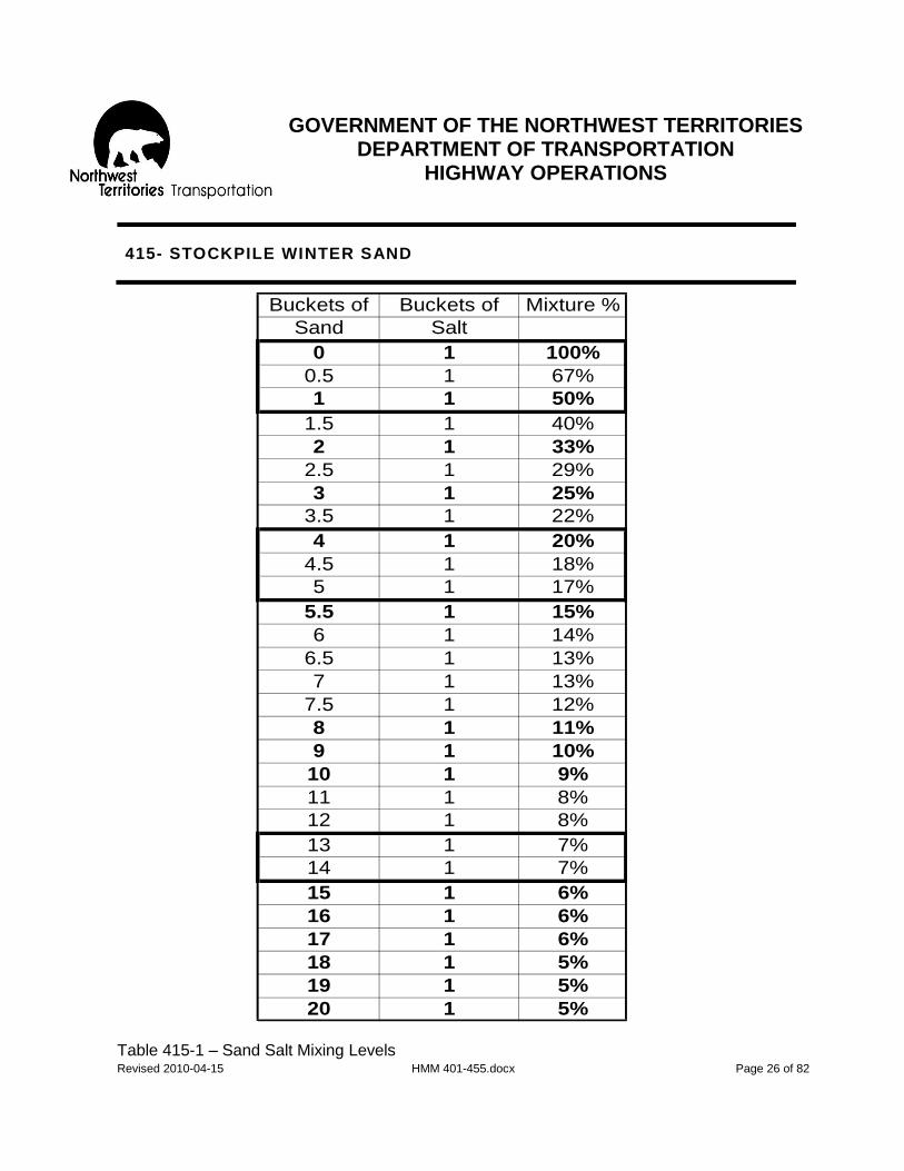
GOVERNMENT OF THE NORTHWEST TERRITORIES
DEPARTMENT OF TRANSPORTATION HIGHWAY OPERATIONS
Revised 2010-04-15 HMM 401-455.docx Page 26 of 82
415- STOCKPILE WINTER SAND
Table 415-1 – Sand Salt Mixing Levels
Buckets of Buckets of Mixture %
Sand Salt
0 1 100%
0.5 1 67%
1 1 50%
1.5 1 40%
2 1 33%
2.5 1 29%
3 1 25%
3.5 1 22%
4 1 20%
4.5 1 18%
5 1 17%
5.5 1 15%
6 1 14%
6.5 1 13%
7 1 13%
7.5 1 12%
8 1 11%
9 1 10%
10 1 9%
11 1 8%
12 1 8%
13 1 7%
14 1 7%
15 1 6%
16 1 6%
17 1 6%
18 1 5%
19 1 5%
20 1 5%

GOVERNMENT OF THE NORTHWEST TERRITORIES
DEPARTMENT OF TRANSPORTATION HIGHWAY OPERATIONS
Revised 2010-04-15 HMM 401-455.docx Page 27 of 82
415- STOCKPILE WINTER SAND
Figure 415-2: Particle Size Distribution Graph – Road Salt

GOVERNMENT OF THE NORTHWEST TERRITORIES
DEPARTMENT OF TRANSPORTATION HIGHWAY OPERATIONS
Revised 2010-04-15 HMM 401-455.docx Page 28 of 82
415- STOCKPILE WINTER SAND
Figure 415-3: Particle Size Distribution Graph – Type 1 (GRIT) Winter Sand

GOVERNMENT OF THE NORTHWEST TERRITORIES
DEPARTMENT OF TRANSPORTATION HIGHWAY OPERATIONS
Revised 2010-04-15 HMM 401-455.docx Page 29 of 82
415- STOCKPILE WINTER SAND
Figure 415-4: Particle Size Distribution Graph – Type 2 (SAND) Winter Sand

GOVERNMENT OF THE NORTHWEST TERRITORIES
DEPARTMENT OF TRANSPORTATION HIGHWAY OPERATIONS
Revised 2010-04-15 HMM 401-455.docx Page 30 of 82
421- ICE BRIDGE CONSTRUCTION
OBJECTIVE
To construct a safe travel surface across a river. DESCRIPTION
All work relating to the construction of ice bridges without the use of spray technology prior to the opening to the public. Includes rerouting due to overflow.
LEVEL OF SERVICE
Ice thickness, weather and the peculiarities of the river are the main contributing factors that determine when construction of an ice bridge should begin. Usually an ice bridge can be initially opened when there is sufficient ice to safely permit travel with vehicles having a gross vehicle weight not exceeding 3,500 kilograms.
RESPONSIBILITY
The Regional Superintendent/Regional Manager, in collaboration with headquarters will provide direct supervision and support to the Highway Maintenance Supervisor.
PRODUCTIVITY GUIDELINES: RESOURCE GUIDELINES:
Quantity Standard- Crew-
400 hrs/km of ice bridge 3-Heavy Equipment Operator (class 04) 2-Laborers (class 05) Average Daily Production Range- Equipment-
40 hours. 2-Pickups (class 1823) 1-Snow Machine (class 2904) 1-Crawler Tractor (class 2404) 2-Ice Augers (class 5266) Material N/A

GOVERNMENT OF THE NORTHWEST TERRITORIES
DEPARTMENT OF TRANSPORTATION HIGHWAY OPERATIONS
Revised 2010-04-15 HMM 401-455.docx Page 31 of 82
421- ICE BRIDGE CONSTRUCTION
SCHEDULING
Mid October- mid December, when there is sufficient ice. RECOMMENDED METHOD – General Approach
All work related to the construction of an ice bridge will be done as prescribed in the “A Field Guide to Ice Construction Safety.” A quick reference guide to the main points can be found in the Highway Maintenance Operating instruction for Activity 421-434 (Procedures for ice Bearing Assessment). This includes:
1. Ice measuring/testing, the recording of data to be done as required by the
booklet, “A Field Guide to Ice Construction Safety.” 2. Ice bearing capacities to be adhered to when choosing and deploying
equipment for the work. Note: the booklet, “A Field Guide to Ice Construction Safety” gives no consideration to equipment capable of floating.
3. If natural ice is not thick enough to safely support the construction, the ice
crossing shall be flooded or activities suspended until sufficient thickness has developed.
4. All personnel, while working on the ice crossings, will wear appropriate
flotation suits as described in the booklet, “A Field Guide to Ice Construction Safety.”
RECOMMENDED METHOD – Details
The exact method of construction will vary widely from year to year and from location to location. The accepted procedures include: 1. Post signs and safety devices indicating that the crossing is closed. 2. Test the ice to determine ice bearing capacity; see the booklet, “A Field Guide
to Ice Construction Safety.”

GOVERNMENT OF THE NORTHWEST TERRITORIES
DEPARTMENT OF TRANSPORTATION HIGHWAY OPERATIONS
Revised 2010-04-15 HMM 401-455.docx Page 32 of 82
421- ICE BRIDGE CONSTRUCTION
3. If there is sufficient bearing capacity:
a) Snow Covered Smooth Ice: -Snow can either be removed to accelerate ice thickness development.
b) Rough Ice: -Extremely rough ice may require to be broken down using hand tools before certain types of equipment, such as a bombardier, can be used to complete the levelling process. -Small pumps such as typhoon pumps may be used to flood areas that require strengthening. -Equipment such as small dozers/ski dozers can be used to level the ice when there is sufficient ice thickness.
4. Construct the ice bridge to a minimum width of 10 meters before initial
opening. The completed surface width can range between 40-60 meters wide, depending on location.
5. Necessary regulatory, advisory and information signs must be posted on the
ice bridge before opening to public travel. Where practical, markers such as flagging or small trees should be installed to delineate the edge of the roadway.
6. When the surface is smooth enough and the ice appears to have sufficient
strength to permit the safe passage of vehicles:
a) The Regional Superintendent/Regional Manager will interpret ice test results and recommend the opening of the ice bridge at the calculated load limit.
b) The Regional Superintendent/Regional Manager will be responsible for approving the opening date together with a load limit.
c) When a) and b) have taken place the Highway Maintenance Supervisor can post the load limit and open the ice bridge.
Note: At the entrance to all major ice bridges motorists are advised to: - Maintain a distance of 500 meters from other vehicles. - Travel at posted speed. - The Regional Superintendent/Regional Manager will provide the
interval distance and the posted speeds for the ice bridge crossing.

GOVERNMENT OF THE NORTHWEST TERRITORIES
DEPARTMENT OF TRANSPORTATION HIGHWAY OPERATIONS
Revised 2010-04-15 HMM 401-455.docx Page 33 of 82
423- ICE BRIDGE MAINTENANCE
OBJECTIVE
To maintain a safe travel surface across a river. DESCRIPTION
All work relating to the maintenance of ice bridges open to the public without the use of spray. Includes testing, snow plowing, snow removal and flooding with pumps.
LEVEL OF SERVICE
The ice bearing capacity of the ice bridge should be developed to the standard capable of allowing a vehicle with a gross weight up to a maximum of 64,000 kilograms, when possible, to travel safely at the posted speed.
RESPONSIBILITY The Highway Maintenance Supervisor is to monitor conditions and schedule work with guidance from the Regional Superintendent/Regional Manager and in collaboration with headquarters.
PRODUCTIVITY GUIDELINES: RESOURCE GUIDELINES:
Quantity Standard- Crew-
96 hrs/km of ice bridge 1-Heavy Equipment Operator (class 03) 2-Laborers (class 05) Average Daily Production Range- Equipment-
16 hours. 1-Pickup (class 1823) 1-Ice Auger (class 5266) 1-Motor Grader (class 2304) 1-Snow wing (class 5344)
SCHEDULING
Mid November to late April.

GOVERNMENT OF THE NORTHWEST TERRITORIES
DEPARTMENT OF TRANSPORTATION HIGHWAY OPERATIONS
Revised 2010-04-15 HMM 401-455.docx Page 34 of 82
423- ICE BRIDGE MAINTENANCE
RECOMMENDED METHOD – General Approach
1. All work related to maintenance of an ice bridge will be done as prescribed in the booklet, “A Field Guide to Ice Construction Safety.”
2. A quick reference guide to the main points can be found in the Highway Maintenance Operating Instructions for Activity 421-434 (Procedures for Ice Bearing Assessment).
a) Ice bearing capacities are to be adhered to when choosing and deploying equipment for the work.
RECOMMENDED METHOD – Details
1. Inspection of ice bridges should be done daily. 2. Ice measuring/testing and the recording of the data to be done as prescribed
by the booklet, “A Field Guide to Ice Construction Safety.” Recommended changes in the ice bearing capacity of the ice bridge are to be reported to the Regional Superintendent/Regional Manager and load limits increased or decreased on their approval. All applicable signs to be changed accordingly.
3. Ice bridges that were not widened to the full desired width (40-60 meters)
during the construction phase should be widened as soon as ice bearing capacities will permit. Obtain approval from the Regional Manager for widening activities for both safety concerns and billing purposes.
4. Flood using equipment such as an ice auger to increase thickness until an ice
bearing capacity of 64,000 kilograms is attained. The depth of each flood should not exceed 5 cm. Traffic will experience less inconvenience during flooding if the procedure is restricted to half of the road surface width. A small snow windrow down the center of the road may be used to contain the water.
5. Remove snow as necessary and keep the snow berms sloped away whenever
possible, to reduce the possibility of trapping snow unnecessarily.
GOVERNMENT OF THE NORTHWEST TERRITORIES
DEPARTMENT OF TRANSPORTATION HIGHWAY OPERATIONS
Revised 2010-04-15 HMM 401-455.docx Page 35 of 82
423- ICE BRIDGE MAINTENANCE
6. In the latter part of the season, it may be necessary to restrict vehicles of 4,000 kilograms or less from using the ice bridge whenever the surface water becomes to deep for their operation and the load bearing capacity is reduced for other vehicles.
7. Ice bridge closure dates to be approved in advance by the Regional Superintendent/Regional Manager.
8. At the end of the season, just prior to when the surface becomes unfit for safe usage by any vehicles, retrieve all signs and the reinstallation of barricades at shore exit points. Monitor closure.

GOVERNMENT OF THE NORTHWEST TERRITORIES
DEPARTMENT OF TRANSPORTATION HIGHWAY OPERATIONS
Revised 2010-04-15 HMM 401-455.docx Page 36 of 82
426- ICE SPRAY
OBJECTIVE
To thicken ice quickly and safely. DESCRIPTION
Ice spray is primarily the use of spray technology to develop a road on an ice surface which will permit the use of vehicles with a gross vehicle weight of up to 64,000 kgs. Includes all incidental work, such as route selection, ice testing, any levelling of rough ice or removal of snow that is required and mobilization and demobilization of camp and equipment.
LEVEL OF SERVICE
The use of spray technology is a method whereby ice thickness can be developed at a much faster rate than by conventional means, such as the natural process with below freezing temperatures, or the acceleration of ice growth by flooding with pumps. The spin-off from this faster ice growth is that the ferry at Fort Providence, for instance, can be shut down 3 to 4 weeks earlier while continuity of truck service is still being provided.
RESPONSIBILITY The Regional Manager in collaboration with Headquarters will provide direct supervision and support to the Highway Maintenance Supervisor.
Refer to the “Highway Maintenance Operating Instructions” for:
a) Productivity Guidelines b) Resources c) Scheduling d) Method

GOVERNMENT OF THE NORTHWEST TERRITORIES
DEPARTMENT OF TRANSPORTATION HIGHWAY OPERATIONS
Revised 2010-04-15 HMM 401-455.docx Page 37 of 82
426- ICE SPRAY
PRODUCTIVITY GUIDELINES: RESOURCE GUIDELINES:
Quantity Standard- Crew-
Once/year 5-Heavy Equipment Operators (class 03) 3-Laborers (class 05) Average Daily Production Range- Equipment-
96 hours 3-Large Water Pumps (Class 5833) 2-Pickups (class 1823) 2-Pickups (class 1844)
2-Bombardiers/Skidozers (class 2904) 2-Snow Drags (class 5388) 1-Wide Pad Crawler (class 2404) 2-Ice Augers (class 5266) 3-Genetor Sets (class 5600) 1-Profiler (class 4000)
Equipment- Optional
1-Badger, Light Vehicle (Class 2904) Material Miscellaneous (code 999) SCHEDULING
Early November to mid January. RECOMMENDED METHOD- General Approach
1. All work related to ice development using spray technology will be done as prescribed in the booklet, “A Field Guide to Ice Construction Safety.” A quick reference guide to the main points can be found in the Highway Maintenance Operating Instructions for Activity 421-434. (Procedures for ice Bearing Assessment. This includes:
a) Ice measuring/testing and the recording of data to be done as required by
the booklet, “A Field Guide to Ice Construction Safety.” b) Ice bearing capacities to be adhered to when choosing and deploying
equipment for the work. Note: the booklet, “A Field Guide to Ice Construction Safety” gives no consideration to equipment capable of floating.

GOVERNMENT OF THE NORTHWEST TERRITORIES
DEPARTMENT OF TRANSPORTATION HIGHWAY OPERATIONS
Revised 2010-04-15 HMM 401-455.docx Page 38 of 82
426- ICE SPRAY
c) If natural ice is not thick enough to safely support the ice development
process all activity should be suspended until sufficient ice thickness has developed.
d) All personnel, while working on the ice crossings, will wear appropriate flotation suits as described in the booklet, “A Field Guide to Ice Construction Safety.”
RECOMMENDED METHOD- Details
The exact method will vary widely from year to year and from location to location. The accepted procedures include: 2. Post signs and safety devices indicating that the crossing is closed.
3. Test the ice to determine the ice bearing capacity; see the booklet, “A Field Guide to Ice
Construction Safety.” 4. If there is sufficient bearing capacity
a) Snow covered Smooth Ice: i. Snow can either be removed or compacted to accelerate quicker ice thickness
development
b) Rough Ice: i. Extremely rough ice may need to be broken down using hand tools before
certain types if equipment, such as a bombardier, can be used to complete the levelling process.
ii. Small pumps such as Typhoon pumps may be used to flood areas that required strengthening
iii. Equipment such as small dozers/ski dozers can be used to level the ice when there is sufficient ice thickness. Widen proposed right of way to 40 meters.
5. Place station markers along the edge of the downwind side at 50 meter spacings, with
easily legible number.
6. Ice development:
a) Select site for ice spray. b) Use ice auger to drill a hole in the ice for the suction hose on the pump. c) Position the pump near the hole in the ice and lower suction hose in the water.

GOVERNMENT OF THE NORTHWEST TERRITORIES
DEPARTMENT OF TRANSPORTATION HIGHWAY OPERATIONS
Revised 2010-04-15 HMM 401-455.docx Page 39 of 82
426- ICE SPRAY
d) Start spraying operation:
i. Spray downwind
ii. Temperatures should be -8 C or colder iii. Nozzle size depends on temperature- when colder use a larger nozzle. iv. Height and distance of spray depends on elevation angle and size of nozzle.
During warmer weather use a higher spray patter with a smaller nozzle. v. Size of ice particles deposited on the ice lift should be around the size of a
lead pencil (7mm in diameter)
vi. The normal spray pattern is set to form a 30-40 , fan shaped area that usually covers a 25-75 meter area in length, starting approximately 25 meters from the pump.
vii. Depth of daily ice build-up should normally be in the 20cm range. The exact depth depends on temperature (i.e. all water contained on lift should freeze in 12 hours or less)
viii. The frozen surface should resemble a sponge. ix. Once the lift is completely frozen (usually the next day) another lift of ice can
be developed. Note: The first 20 minutes of spray pattern should contain some water to fill the voids in the existing sponge-like surface.
The foregoing cycle continues until the desired thickness of ice is developed.
6. Necessary regulatory, advisory and information signs must be posted in the ice
before opening to public travel. Where possible markers such as flagging or small trees will be installed on the upwind side to delineate the edge of the roadway.
7. When the ice surface is suitable for opening:
a) The Regional Manager will interpret the ice results and recommend the opening of the ice bridge at the calculated load limit.
b) The Regional Manager will be responsible for approving the opening date together with load limit.
c) When a) and b) have taken place, the Highway Maintenance Supervisor can post load limit and open the ice bridge.
Note: At the entrance to all major ice bridges motorists are advised to:
i. Maintain a distance of 500 meters from other vehicles. ii. Travel at posted speed. iii. The Regional Manager will provide the interval distance and the
posted speeds for the ice bridge crossing.

GOVERNMENT OF THE NORTHWEST TERRITORIES
DEPARTMENT OF TRANSPORTATION HIGHWAY OPERATIONS
Revised 2010-04-15 HMM 401-455.docx Page 40 of 82
431- SNOW ROAD CONSTRUCTION
OBJECTIVE
To construct a safe travel surface, mainly of snow, along a predetermined route. DESCRIPTION
The construction of a reliable road surface on an existing overland route with little or no traverse over ice.
LEVEL OF SERVICE
The quality of the road provided and its duration will be determined mainly by: a) Terrain
b) Weather
c) Conditions of the Department Environmental Guidelines Normally the winter roads will be constructed to a standard capable of allowing a vehicle with a maximum gross weight of 64,000 kgs (providing there is sufficient ice thickness) to travel safely at an average speed of 35 km/hr. However, under certain particular circumstances the road may only be of sufficient quality to permit restricted truck traffic and no attempt will be made to smooth the surfaces for light vehicles.
RESPONSIBILITY The Regional Superintendent/Regional Manager in collaboration with Headquarters will provide direct supervision and support to the Highway Maintenance Supervisor in this activity.
GOVERNMENT OF THE NORTHWEST TERRITORIES
DEPARTMENT OF TRANSPORTATION HIGHWAY OPERATIONS
Revised 2010-04-15 HMM 401-455.docx Page 41 of 82
431- SNOW ROAD CONSTRUCTION
PRODUCTIVITY GUIDELINES: RESOURCE GUIDELINES:
Quantity Standard- Crew-
Once/year 4-Heavy Equipment Operators (class 03) Average Daily Production Range- Equipment-
10 kms 1-Motor Grader (class 2304) 1-Snow Drag (class 5388) 2-Crawler Tractors (class 2404)
1-Bombardier (class 2904) 1-Fly Camp (class 5900) 1-Sleigh (class 1233) 1-Electric Set (class 5600) All mobile equipment to have survival gear and radio telephone.
Material Camp Supplies (code 999)

GOVERNMENT OF THE NORTHWEST TERRITORIES
DEPARTMENT OF TRANSPORTATION HIGHWAY OPERATIONS
Revised 2010-04-15 HMM 401-455.docx Page 42 of 82
431- SNOW ROAD CONSTRUCTION
RECOMMENDED METHOD- General Approach
1. The snow road should be constructed so that it can withstand constant hauling by normal type vehicles of up to 64,000 kg gross vehicle weight. The road is to be constructed to a standard that allows loaded trucks to travel safely at an average speed of no less than 35 km/hr. This standard may be lowered where severe ground conditions exist.
Rivers and streambeds that are so narrow as to create poor vertical alignment shall be filled in with snow or ice and compacted to provide a smooth and reasonably level crossing. Culverts will be installed in those fills where water flow must be maintained.
2. The winter road shall be constructed where possible to the following widths:
a. Overland Sections.
i. Straight roadway- 7 meters wide. ii. Corners and curves- 10 meters wide or to the limits of the established
right-of-way.
b. Existing Road Grades- full width of grade.
c. River, Stream and Lake Crossings. i. Less than 50 meters in length- 10 to 15 meters wide. ii. More than 50 meters in length- 30 to 50 meters wide.
3. All the foregoing will be done in accordance with applicable conditions of the Land
Use Permit.

GOVERNMENT OF THE NORTHWEST TERRITORIES
DEPARTMENT OF TRANSPORTATION HIGHWAY OPERATIONS
Revised 2010-04-15 HMM 401-455.docx Page 43 of 82
431- SNOW ROAD CONSTRUCTION
RECOMMENDED METHOD- Details
1. Ice Crossing- Construction Phase
The following steps will conform to the conditions as outlined in the booklet “A Field Guide to Ice Construction Safety.”
a. Ice measuring/testing and recording of data procedures to be done as
required by the booklet “A Field Guide to Ice Construction Safety.”
b. Ice Bearing Capacities to be adhered to when choosing and deploying equipment for the works. Note: The booklet “A Field Guide to Ice Construction Safety” gives no consideration to equipment capable of floating.
c. If natural ice is not thick enough to safely support the construction, the ice
crossing shall be flooded or activities suspended until sufficient ice thickness has developed.
d. All personnel, while working on ice crossings will wear appropriate flotation
suits as described in the booklet “A Field Guide to Ice Construction Safety.”
e. Snow clearance from the ice cover to the required width will only commence after it has been determined that there is sufficient ice to support the construction equipment.
Overland Construction
1. Initial compaction and snow removal for frost penetration shall commence as soon as the bearing capacity of the terrain permits the use of light weight low ground pressure equipment. The ultimate objective shall be to achieve compaction to the full width of the roadway.
2. Shaping the winter road shall commence as soon as the frost has penetrated
sufficiently to permit the use of heavier equipment. Any snow with debris shall be bladed to the tree line or beyond the outer limit of the planned roadway. Preliminary levelling shall be performed at this time.
3. Fresh fallen snow or some of the previously windrowed snow shall be bladed onto the
road surface and compacted to create a reasonably level and smooth road.
4. When snow plowing, blading and completing the winter roads, a minimum of 10 cm of compacted snow cover shall remain at some times.

GOVERNMENT OF THE NORTHWEST TERRITORIES
DEPARTMENT OF TRANSPORTATION HIGHWAY OPERATIONS
Revised 2010-04-15 HMM 401-455.docx Page 44 of 82
431- SNOW ROAD CONSTRUCTION
Overland Construction (cont’d)
5. It may be necessary to clear new short detours or bypasses. The clearing shall be 10 m wide and routing to be in accordance with the Land Use Permit Conditions. All cleared trees and debris shall be disposed of by burning.
6. Any portable bridges used to span rivers and streams will be installed as outlined in
Activity 271.
7. Necessary regulatory, advisory and information signs must be posted in the snow roads before the opening to public travel.
8. When the road surface is satisfactory and all ice crossings appear to have sufficient
strength to permit the safe passage of vehicles:
a. The Regional Superintendent/Regional Manager will interpret the ice results and recommend the opening of the snow road together with the load limit.
b. The Regional Superintendent/Regional Manager will be responsible for
approving the opening of the snow road together with the load limit.
c. When a) and b) have taken place, the Highway Maintenance Supervisor can post the load limit and open the road.

GOVERNMENT OF THE NORTHWEST TERRITORIES
DEPARTMENT OF TRANSPORTATION HIGHWAY OPERATIONS
Revised 2010-04-15 HMM 401-455.docx Page 45 of 82
432- SNOW ROAD MAINTENANCE
OBJECTIVE
To maintain a safe and serviceable driving surface on snow. DESCRIPTION
Maintenance of winter road built primarily over land and with portions traversing ice. LEVEL OF SERVICE
The winter road, including the ice crossings, shall be maintained to a standard, capable of allowing a vehicle with a gross weight of 64,000 kg (providing there is sufficient ice thickness to support this load) to travel safely at an average speed of 35 km/hour.
RESPONSIBILITY Highway Maintenance Supervisor to provide on-site routine patrolling and direction with guidance from Regional Manager.
PRODUCTIVITY GUIDELINES: RESOURCE GUIDELINES:
Quantity Standard- Crew-
Category 1- 42 Pass km/km of road 2-Heavy Equipment Operators (class 03) Category 2- 30 Pass km/km of road Equipment-
1-Pickup (class 1823) 1-Ice Auger (class 5266) 1-Motor Grader (class 2304) 1-Snow wing (class 5344)

GOVERNMENT OF THE NORTHWEST TERRITORIES
DEPARTMENT OF TRANSPORTATION HIGHWAY OPERATIONS
Revised 2010-04-15 HMM 401-455.docx Page 46 of 82
432- SNOW ROAD MAINTENANCE
PRODUCTIVITY GUIDELINES (cont’d): RESOURCE GUIDELINES (cont’d):
Average Daily Production Range- Equipment-
100 Pass kilometres 1-Motor Grader (class 2304) 1-Crawler Tractor (class 2404) 1-Winter Road Drag (class 5388)
As required- (cat 1 &2) 1-Fly Camp (class 5900) 1-Electric Set (class 5600) 1-Tandem Axle Tractor (class 1109) 1-Hi Boy Cat (class 1200)
As Required- (Cat 1) 1-Water Truck (class 1504) 1-Water Pump (class 5801) 1-Slip in Water Tank (class 5100) All mobile equipment to have survival gear and radio telephone
SCHEDULING
Maintain throughout the duration of the road as required during the period of January 1 to March 31.
RECOMMENDED METHOD- General Approach
1. Daily road condition reports to be forwarded to the Regional Superintendent/Regional Manager on a daily basis or more often if required regarding ice road conditions and maximum load limits allowable.
2. Signs to be erected indicating:
a. Road open/closed,
b. Maximum allowable gross vehicle weight (when applicable),
c. At all entrances to winter roads and at other strategic locations approved by the Regional Superintendent/Regional Manager. The information on these signs to be unerringly changed to suit current conditions

GOVERNMENT OF THE NORTHWEST TERRITORIES
DEPARTMENT OF TRANSPORTATION HIGHWAY OPERATIONS
Revised 2010-04-15 HMM 401-455.docx Page 47 of 82
432- SNOW ROAD MAINTENANCE
RECOMMENDED METHOD- Details
The snow road shall be maintained to same widths as existed at completion of construction and incompliance with any requirements of the Land Use Permit. The basic maintenance procedures are:
1. Ice testing to be done and load bearing capacity determined on all ice crossings in
accordance with procedures outlines in the booklet “A Field Guide to Ice Construction Safety.”
2. The grader shall be used mainly for: a. Plowing off excess snow after a snowfall with a minimum of 10 cm of
compacted snow should be left on the road surface. b. Blading and levelling roadway and pulling the drag, c. Filling in minor overflows, d. Winging back open areas where drifting occurs (providing grader is equipped
with wing), e. Scarifying glaciation (providing grader has a scarifier).
3. The crawler tractor should be used mainly for:
a. Making fills over the overflow on the river or creek crossings, b. Constructing detours, c. Controlling glaciation d. Plowing out drifted areas that are not possible with the grader, e. Other heavy work as required.
4. The tractor and low bed trailer will not normally be used to transport the crawler
tractor between work areas.
5. The water truck will be used primarily on category 1 snow roads for building smooth driving surfaces mainly where rough areas exist by stabilizing (freezing) the loose snow with water.
6. Required temporary signs to be erected and all permanent and temporary signs to be maintained throughout the duration of the maintenance phase.
GOVERNMENT OF THE NORTHWEST TERRITORIES
DEPARTMENT OF TRANSPORTATION HIGHWAY OPERATIONS
Revised 2010-04-15 HMM 401-455.docx Page 48 of 82
432- SNOW ROAD MAINTENANCE
7. Road closure in the spring will involve the following:
a. Closure date to be approved in advance by the Regional Manager. b. Remove all snow fills from stream crossings. At locations where culverts are
installed these are to be retrieved. All reusable culvert lengths to be safely stored nearby for reuse next year. Badly damaged culverts to be taken to an authorized disposal site.
c. Temporary winter road bridges are to be removed. Refer to Activity 271 for method.
d. Place closed tabs on all permanent signs and erect barricades at entrances to winter roads to coincide with actual closure. Note: All sign work in excess of one hour to be charged to activity 518.

GOVERNMENT OF THE NORTHWEST TERRITORIES
DEPARTMENT OF TRANSPORTATION HIGHWAY OPERATIONS
Revised 2010-04-15 HMM 401-455.docx Page 49 of 82
433- ICE ROAD CONSTRUCTION
OBJECTIVE
To construct a safe travel surface on ice DESCRIPTION
The construction of winter roads along a predetermined route that is primarily over ice surface with little or no traverse over land.
LEVEL OF SERVICE
The quality of the road provided and its duration will be determined mainly by:
a) Ice conditions
b) Weather
c) Terrain Safety will be the utmost priority while constructing an ice road to a standard that includes:
a) Minimum surface width of 30 meters.
b) An alignment that permits the user to travel safely to the upper limit of 70 km/hr
c) The potential to develop ice thickness which are capable of safely supporting vehicles with a maximum gross vehicle weight of 64,000 kilograms.
RESPONSIBILITY
The Regional Superintendent/Regional Manager in collaboration, with Headquarters, will provide direct supervision and support to the Highway Maintenance Supervisor.

GOVERNMENT OF THE NORTHWEST TERRITORIES
DEPARTMENT OF TRANSPORTATION HIGHWAY OPERATIONS
Revised 2010-04-15 HMM 401-455.docx Page 50 of 82
433- ICE ROAD CONSTRUCTION
PRODUCTIVITY GUIDELINES: RESOURCE GUIDELINES:
Quantity Standard- Crew-
Once per year 3-Heavy Equipment Operator (class 03) 2-Laborers (class 05) Average Daily Production Range- Equipment-
8 kms 1-Grader (class 2304) 1-V Plow (class 5333) 1-Snow Wing (class 5344) 1-Tandem Truck (class 1504) 1-One Way Plow (class 5355) 1-4x4 Pickup (class 1844)
1-Bombardier (class 2904) 1-Bunkhouse (class 5944) 1-Sleigh (class 1233) 1-Profiler (class 4000) Equipment- Optional 1-Small Crawler Tractor (class 2304) 1-Generator Set (class 5600) Note: All mobile equipment to have survival gear and radio telephone.
Material Misc (code 999) SCHEDULING: Early December to late January as ice conditions permit. RECOMMENDED METHOD- General Approach
1. All work related to the construction of an ice road will be done as prescribed in the booklet “A Field Guide to Ice Construction Safety.” A quick reference guide to main points can be found in the Highway Maintenance Operating Instructions for Activity 421-434 (Procedures for Ice Bearing Assessment) NOTE: Authorization from the Regional Superintendent/Regional Manager is required prior to the start of any activities associated with Ice including Ice Road Construction work.

GOVERNMENT OF THE NORTHWEST TERRITORIES
DEPARTMENT OF TRANSPORTATION HIGHWAY OPERATIONS
Revised 2010-04-15 HMM 401-455.docx Page 51 of 82
433- ICE ROAD CONSTRUCTION
The booklet “A Field Guide to Ice Construction Safety” includes:
a. Ice measuring/testing and recording of data.
b. Ice Bearing Capacities to be adhered to when choosing and deploying equipment for the works. Note: The booklet gives no consideration to equipment capable of floating.
c. If natural ice is not thick enough to safely support the construction, the ice crossing shall be flooded or activities suspended until sufficient ice thickness has developed.
d. All personnel, while working on ice crossings will wear appropriate flotation suits as described in the booklet “A Field Guide to Ice Construction Safety.”
e. Procedures for construction of winter roads over portages will be the same as overland routes in Activity 431. Note: Workers on foot are not to proceed onto ice which is less than 10 centimetres thick for any reason. Snowmobiles must have a minimum of 15 centimetres of ice and cars or light trucks less than 1600 kg in weight must have at least 20 centimetres of ice before proceeding, please refer to the Highway Maintenance Operating Instructions for Activity 421-434 (Procedures for Ice Bearing Assessment).
RECOMMENDED METHOD- Details
1. Barricades and signs will be posted and maintained at the entrances to the ice road stating that it is closed.
2. When the safety conditions permit, construction should begin. It is recommended that the work area be restricted to a 4-6 kilometre section and widened to the full width of 30 meters before proceeding. This will usually provide better quality surface with fewer cracks. Snow banks at the edge of the road to be flared out with wings to reduce potential for snow entrapment.
When necessary, hazards created by drifting snow can be reduced by using a V plow to create snow ridges approximately 30 meters from each side of the road.
3. Necessary regulatory, advisory and information signs must be posted on ice roads
before the opening to the public travel.

GOVERNMENT OF THE NORTHWEST TERRITORIES
DEPARTMENT OF TRANSPORTATION HIGHWAY OPERATIONS
Revised 2010-04-15 HMM 401-455.docx Page 52 of 82
433- ICE ROAD CONSTRUCTION
4. When construction is complete and the ice appears to have sufficient strength to
permit the safe opening to the public:
a. The Regional Superintendent/Regional Manager will interpret the ice test results and recommended the opening of the ice road at the calculated load limit.
b. The Regional Superintendent/Regional Manager will be responsible for
approving the opening date with a load limit.
c. When a) and b) has taken place, the Highway Maintenance Supervisor can post the load limit and open the road.
5. When the road is opened to traffic, the entry signs are to indicate:
a. Road is open,
b. Maximum allowable gross weight,
c. Phone number to call for road information,
d. Advice to motorists to carry chains and survival gear and that there are no
services available, and
e. Caution that motorists are driving on ice. Note: All sign work in excess of one hour to be charged to Activity 518.

GOVERNMENT OF THE NORTHWEST TERRITORIES
DEPARTMENT OF TRANSPORTATION HIGHWAY OPERATIONS
Revised 2010-04-15 HMM 401-455.docx Page 53 of 82
434- ICE ROAD MAINTENANCE
OBJECTIVE
To maintain a safe and serviceable driving surface on ice. DESCRIPTION
Maintenance of winter road built primarily over ice and with little or no traverse over land.
LEVEL OF SERVICE
The ice road shall be maintained to a standard, capable of allowing a vehicle with a gross weight of 64,000 kg (providing there is sufficient ice thickness to support this load) to travel safely at speeds up to the upper limit 35 km/hour.
RESPONSIBILITY Highway Maintenance Supervisor to provide on-site routine patrolling and direction with guidance from Regional Superintendent/Regional Manager.
PRODUCTIVITY GUIDELINES: RESOURCE GUIDELINES:
Quantity Standard- Crew-
North- 54 pass kms/km of road. 2-Heavy Equipment Operator (class 03) South- 42 pass kms/km of road. 2-Laborers (class 05) Note: The Arctic Circle is the dividing line between north and south
PRODUCTIVITY GUIDELINES (cont’d): RESOURCE GUIDELINES (cont’d):
Average Daily Production Range- Equipment-
200 Pass kilometres 1-Motor Grader (class 2304) 1-V Plow (class 5333) 1-Snow Wing (class 5344) 1-2 Man Camp (class 5900) 1-Generator Set (class 4000) 1-4x4 Pickup (class 1844) 1-Profiler (class 4000) 1-Tandem Truck (class 1504) 1-One Way Plow (class 5355)
Material Misc (code 999)

GOVERNMENT OF THE NORTHWEST TERRITORIES
DEPARTMENT OF TRANSPORTATION HIGHWAY OPERATIONS
Revised 2010-04-15 HMM 401-455.docx Page 54 of 82
434- ICE ROAD MAINTENANCE
SCHEDULING
January 1- April 30 (depending on geographical area) RECOMMENDED METHOD- General Approach
1. All work related to the maintenance of an ice road will be done as prescribed in the booklet “A Field Guide to Ice Construction Safety.” The main points contained in the guidelines can be found in Highway Maintenance Operation Instructions for Activity 421-434 (Procedures for Ice Bearing Assessment)
The booklet “A Field Guide to Ice Construction Safety” includes: a. Ice measuring/testing and recording data to be done as required by the the
booklet “A Field Guide to Ice Construction Safety.” . b. Ice bearing capacities are to be adhered to when choosing and deploying
equipment for work. Note: The booklet “A Field Guide to Ice Construction Safety.” give no consideration to equipment capable of floating.
2. Road condition reports to be forwarded to the Regional Superintendent/Regional
Manager on a daily basis or more often if required regarding ice road conditions and maximum load limits allowable.
3. Signs at the entrance to ice roads and at other applicable strategic locations indicating:
a. Road open/closed b. Maximum allowable gross vehicle weight (as applicable) c. Are to be maintained. The information on these signs to be unerringly
changed to suit current conditions. RECOMMENDED METHOD- Details
Ice roads should be maintained where practical to the same width as constructed. The basic maintenance procedures are:
1. Ice testing to be done and load bearing capacities determined as prescribed in
the Guidelines.

GOVERNMENT OF THE NORTHWEST TERRITORIES
DEPARTMENT OF TRANSPORTATION HIGHWAY OPERATIONS
Revised 2010-04-15 HMM 401-455.docx Page 55 of 82
434- ICE ROAD MAINTENANCE
2. Remove accumulations of snow, snow banks should be kept flared back and
to their lowest level in an effort to reduce quantities of snow reaching the road.
3. In areas of serious drift problems construct and maintain snow traps 30 meters from windward side of the road to reduce quantities of snow reaching the road.
4. In areas of failure or overflow, construct detours. Ice test, delineate and sign as required.
5. Maintain all regulatory, information and advisory signs as required.
6. In the latter part of the season, it may become necessary to restrict vehicles of 4,000 kilograms and less from using the road where the surface water becomes too deep for their operation and the load bearing capacity is reduced for other vehicles.
7. At the end of the season, just prior to when the entire surface becomes unfit for the safe usage by any vehicles retrieve all regulatory information and advisory signs posted on ice. Finalize closure with road closure signs and reinstallation of barricades at shore exit points. Monitor closure.

GOVERNMENT OF THE NORTHWEST TERRITORIES
DEPARTMENT OF TRANSPORTATION HIGHWAY OPERATIONS
Revised 2010-04-15 HMM 401-455.docx Page 56 of 82
421-434- PROCEDURES FOR ICE BEARING ASSESSMENT
OBJECTIVE
To ensure the safety of workers and road users when constructing, maintaining or using roads with ice surfaces.
RESPONSIBILITY Everyone that is required to work on ice on behalf of the Department of Transportation is expected to follow the conditions as outlined in the “Guidelines for Working on Winter Roads in the N.W.T.” and the new “Field Guide to Ice Construction Safety”, as well as to use common sense and good judgment.
RECOMMENDED METHOD: Complete details relating to procedures for ice bearing assessment are contained in the “Guidelines for Working on Winter Roads in the N.W.T”. However, as a quick concise reference, the following information was taken directly from the new Department of Transportation booklet entitled “A Field Guide to Ice Construction Safety.”
SAFETY CONCERNS
Working on Ice Crossings and Snow Roads is an occupation that has a special need for safe work guidelines and specifications. It is strongly recommended that all workers, supervisors and managers become familiar with these specifications with a strong focus on personal clothing, communications, windchill and warm-up breaks. Personal clothing suitable for working in cold weather and windy conditions is essential to reduce incidents of frostbite. Reliable and constant communications between workers, operators and supervisors is also important due to the isolated nature of this work and safety issues. Work in such conditions is possible when workers are properly dressed and have occasion to take warm-up breaks to find relief from the cold and wind. See Figure 1 for windchill calculations and Figure 2 for recommended warm-up breaks and communication intervals for all workers, operators, supervisors and managers.

GOVERNMENT OF THE NORTHWEST TERRITORIES
DEPARTMENT OF TRANSPORTATION HIGHWAY OPERATIONS
Revised 2010-04-15 HMM 401-455.docx Page 57 of 82
421-434- PROCEDURES FOR ICE BEARING ASSESSMENT
ICE CAPACITY AND TESTING:
1) Introduction:
Construction of ice bridges and ice roads has unique safety hazards because of the ever present danger of an ice failure. To reduce the risk for those working on the road as well as for the traveling public, strict attention must be paid to testing of the ice to ensure that it is capable of supporting the loads to which it is subjected, the following sections provide guidelines for testing of ice thickness and for determining the capacity of the ice to carry loads.
Figure 1 shows the calculations for windchill that can significantly increase the potential for frostbite. Wind velocity combines with air temperature to create cooling effect on human skin. The relationship between the calm-air temperature added to the cooling of wind results in a colder calm-air temperature. For example, a calm-air temperature of -20° Celsius poses little danger to exposed skin. However the same calm-air temperature of -20° Celsius with a wind speed of 50-kilometres per hour results in a colder calm-air temperature of -35° Celsius. Another factor in this situation is time. For a windy condition that results in a windchill of -35° Celsius there is a risk of frostbite for most people in 10 to 30 minutes. In colder temperatures, the time of risk for frostbite for most people drops to 5 minutes and then to 2 minutes. See the frostbite guide attached to Figure 1.

GOVERNMENT OF THE NORTHWEST TERRITORIES
DEPARTMENT OF TRANSPORTATION HIGHWAY OPERATIONS
Revised 2010-04-15 HMM 401-455.docx Page 58 of 82
421-434- PROCEDURES FOR ICE BEARING ASSESSMENT
Figure 1: Wind Chill Calculation Chart

GOVERNMENT OF THE NORTHWEST TERRITORIES
DEPARTMENT OF TRANSPORTATION HIGHWAY OPERATIONS
Revised 2010-04-15 HMM 401-455.docx Page 59 of 82
421-434- PROCEDURES FOR ICE BEARING ASSESSMENT
Figure 2: Warm-up breaks and Reporting Schedule for Outdoor Activities
Windchill (°C) Refer to Figure 1
Outside Worker Equipment Operator
-15 to -30
Warm-up break every hour. Where warm shelter is provided by heated cab, breaks are every 2 hours, otherwise, same as outside worker.
Persons working should be contacted every hour by visit or radio communications.
Same as outside worker.
-30 to -45
Warm-up breaks every ½ hour. Where warm shelter is provided by heated cab, breaks are every 2 hours, otherwise, same as outside worker.
Persons working should be contacted every ½ hour by visit or radio communications.
Same as outside worker.
NON-EMERGENCY WORK SHOULD CEASE. Where work must proceed, warm-up breaks should be taken every ½ hour.
NON-EMERGENCY WORK SHOULD CEASE. Where work must proceed, and where warm shelter is provided by heated cab, breaks are every hour, otherwise, same as outside worker.
Greater than -45
NON-EMERGENCY WORK SHOULD CEASE. Where work must proceed, person working alone should be contacted every ½ hour by visit or radio communications.
NON-EMERGENCY WORK SHOULD CEASE. Where work must proceed, same as outside worker.
Important: This is a guide only. Common sense should over-ride the strict application of this table.

GOVERNMENT OF THE NORTHWEST TERRITORIES
DEPARTMENT OF TRANSPORTATION HIGHWAY OPERATIONS
Revised 2010-04-15 HMM 401-455.docx Page 60 of 82
421-434- PROCEDURES FOR ICE BEARING ASSESSMENT
2) Ice Testing:
a) The Highway Maintenance Supervisor is responsible for supervising/measuring ice thickness at the test holes. A needle bar may be used to test ice up to 15 centimetres thick. An auger should be used for ice more than 15 centimetres thick.
b) Measurements should be taken using an ice measuring stick which
has a foot to hook the underside of the ice. This eliminates visibility problems caused by poor light or loose ice obstructing the view of the hole.
c) Workers on foot are not to proceed on to ice which is less than 10
centimetres thick for any reason. Be sure you know the weight of the equipment you are using and do not proceed if the ice is not thick enough to support both you and your equipment. Snowmobiles must have a minimum of 15 centimetres of ice and cars or light trucks less than 1600 kg in weight must have at least 20 centimetres of ice before proceeding.
d) If during the testing, the measured ice thickness is less than that
required to support the equipment you are using, back off slowly and suspend further testing. Immediately report these conditions to your Highway Maintenance Supervisor, Regional Manager or Superintendent.
e) If thin ice is found, drill additional holes to determine the extent of the
weak area. The thinnest ice measurement will govern the allowable loading. For example, if nine test holes read 25 centimetres and one reads 12 centimetres, the critical ice thickness will be 12 centimetres. Subsequent testing will start at the 12 centimetres test hole location
f) Ice thickness can be increased by flooding. Alternatively, construction
activities can be postponed until the ice thickens naturally.
g) In general, the most frequent and intensive testing will take place early in the construction season. As ice thickness increases and crews become more confident that all thin areas have been identified, the number of ice tests may be reduced. Typically the frequency and distribution of test holes is as described in Figure 3. Good judgment based on field experience must be used when varying from this table.

GOVERNMENT OF THE NORTHWEST TERRITORIES
DEPARTMENT OF TRANSPORTATION HIGHWAY OPERATIONS
Revised 2010-04-15 HMM 401-455.docx Page 61 of 82
421-434- PROCEDURES FOR ICE BEARING ASSESSMENT
Figure 3 – also referenced in the “A Field Guide to Ice Construction Safety”
Preconstruction Construction Operation and Maintenance
Initial test run From start of construction until road is opened to traffic
This may overlap with construction activities at lower road levels
Rivers (crossing with a flowing current)
30 meters between test holes along center line
30 meters between test holes along alternate edges
30 meters between test holes along alternate edges if SIR is used, test holes are only required for calibration and for mapping of thin areas
Look for thin areas caused by river current
Lakes
If within 250 meters of shore: 30 meters between test holes along center line
If within 250 meters of shore: 30 meters between test holes along alternate edges
250 meters between test holes along alternate edges
Beware of shallow or shoal areas that could affect the ice strength due to the underwater wave caused by vehicles passing over the ice
If more than 250 meters from the shores: 250 meters between test holes along center line
If more than 250 meters from the shores: 250 meters between test holes along alternate edges
If SIR is used, test holes are only required for calibration and for mapping of thin areas
Slow Moving Rivers (Mackenzie Delta)
250 meters between test holes along center line
250 meters between test holes along alternate edges
250 meters between test holes along alternate edges
If SIR is used, test holes are only required for calibration and for mapping of thin area.
Frequency - repeat as required until sufficient ice as formed to allow start of construction
Frequency - continuous testing in areas where construction is underway.
Frequency - test entire route prior to raising load limits or spot test known thin areas as directed by the Work Supervisor.
GOVERNMENT OF THE NORTHWEST TERRITORIES
DEPARTMENT OF TRANSPORTATION HIGHWAY OPERATIONS
Revised 2010-04-15 HMM 401-455.docx Page 62 of 82
421-434- PROCEDURES FOR ICE BEARING ASSESSMENT
h) If available, subsurface interface radar (SIR) may be used in
conjunction with test holes. This is particularly useful; in identifying air bubbles, cracks and other anomalies which might be missed by the test holes. The SIR unit must be calibrated to ensure its accuracy at the start of each day, after four hours of use and whenever erratic or questionable readings are obtained.
SIR tapes are to be annotated as they are produced indicating location and type of anomalies as well as significant thickness readings. The notes are to be initialled by the operator and submitted to the Regional Manager or Superintendent no later than the following day. These tapes will be retained until the end of the winter road season.
i) All distances, test hole locations and SIR results must be recorded in
the ICE THICKNESS log book (bound book). The records will be filed as part of the permanent record and may be made available to the Deputy Minister or his designate. It is very important that the log book is filled out accurately and in a professional manner. In addition to the distances and thickness, the following information will also be recorded:
Date of test
Time of start and finish
Names of testing crew
Temperature during testing
The presence of wide, wet cracks and other significant cracks
Details of load reductions and/or traffic detours
Location, i.e./ Peel, Mackenzie at Arctic Red, Arctic Red Branch at Mackenzie, Mackenzie river at Fort Providence, etc.,
Signature

GOVERNMENT OF THE NORTHWEST TERRITORIES
DEPARTMENT OF TRANSPORTATION HIGHWAY OPERATIONS
Revised 2010-04-15 HMM 401-455.docx Page 63 of 82
421-434- PROCEDURES FOR ICE BEARING ASSESSMENT
3) Ice Capacity:
The ability of ice to support a load is dependent on a number of factors including ice thickness, the pressure of the water below the ice as deflection develops, the way the ice formed initially, snow cover, vehicle speed and the kinds of load placed on the ice cover. The strength is different for sea ice and freshwater ice. The strength of the ice (bearing capacity) is affected by the presence of cracks and sudden or extreme temperature changes. It should also be remembered that ice thickness can vary considerably from place to place and until a margin of safety is achieved, extreme caution must be exercised. Although ice can be described as BLUE, WHITE, GREY, fresh water or salt water, this set of guidelines will treat all ice the same when applying the bearing capacity formula and the safety precautions required. Figure 4 is a graphical representation of the Gold Formula which is used as a guide for establishing the thickness of ice necessary to support a given load. The Gold Formula provides an estimate of the load limit for a particular thickness of ice, below which the failure of an ice sheet is unlikely. It is not an infallible measure of the bearing which the failure of an ice sheet is unlikely. It is not an infallible measure of the bearing capacity of an ice sheet and must be combined with field observations of other factors affecting ice strength when actual load limits are determined. Figure 5 is a tabular representation of the Gold Formula shown in Figure 4. Only the Gold Formula shall be used to determine the ice-bearing capacity. No other formula, graphs or charts shall be used. Every condition will be different – in the next few pages a number of observations will be made to assist the supervisor to make informed judgements when determining the ice bearing capacity. The presence of cracks, climatic conditions, load spacing, vehicle speeds, recent damage and presence of shoals could all affect the ultimate bearing capacity of the ice in question.

GOVERNMENT OF THE NORTHWEST TERRITORIES
DEPARTMENT OF TRANSPORTATION HIGHWAY OPERATIONS
Revised 2010-04-15 HMM 401-455.docx Page 64 of 82
421-434- PROCEDURES FOR ICE BEARING ASSESSMENT
Figure 4 – Ice Bearing Capacity Chart (Gold’s Formula)

GOVERNMENT OF THE NORTHWEST TERRITORIES
DEPARTMENT OF TRANSPORTATION HIGHWAY OPERATIONS
Revised 2010-04-15 HMM 401-455.docx Page 65 of 82
421-434- PROCEDURES FOR ICE BEARING ASSESSMENT
Figure 5 – Ice Bearing Capacity Chart (Gold’s Formula)
GOVERNMENT OF THE NORTHWEST TERRITORIES
DEPARTMENT OF TRANSPORTATION HIGHWAY OPERATIONS
Revised 2010-04-15 HMM 401-455.docx Page 66 of 82
421-434- PROCEDURES FOR ICE BEARING ASSESSMENT
SUDDEN AND EXTREME TEMPERATURE CHANGES:
A temperature drop of more than 15 Celsius over a 24 hour period will produce severe thermal stressing and cracking of the ice and can reduce the load bearing capacity of the ice. If this occurs the ice crossing or winter ice road should be checked for cracks which might compromise the load capacity.
PRESENCE OF CRACKS:
Any ice cover will have cracks caused by thermal contraction or movements in the ice cover. Except during spring thaw or in areas subject to fatigue, cracks do not necessarily indicate a loss in the load-bearing capacity of the ice. Where there is an indication that a wet crack penetrates right through the ice cover, a reduction in the allowable load limit is advisable. Once a wet crack refreezes, the new ice is as strong as the original. A healed wet crack should be tested with an ice drill or a chain saw to gauge the depth of healing. Where a dry crack over 10 centimetres wide is observed, a reduction in the maximum load limit should be considered. The decision to reduce the load limit will be based on frequency, width, depth and intersection of the cracks (see Figure 6). Dry cracks can be repaired by filling them with water or slush. As a result of normal thermal contraction, cracks sometimes form in the middle of a road perpendicular or parallel to the direction of travel. If they remain dry they do not seriously reduce the bearing capacity of the ice. Cracks at the sides of the road and running parallel to the direction of travel indicate over-stressing (perhaps by the weight of snow deposits from clearing operations) or possible fatigue from excessive traffic. If such cracks develop, particularly if they are wet, traffic should be diverted away from the crack and, in more extreme cases, road use should be suspended until the cracks have healed. Fluctuating water levels may produce cracks near and generally parallel to the shoreline, which can create hanging ice or pressure ridges. These cracks are often accompanied by a difference in levels of the floating and the grounded ice. If these cracks are wet, loads should be reduced accordingly. With extreme differences in the level, bridging repair or flooding may be necessary.

GOVERNMENT OF THE NORTHWEST TERRITORIES
DEPARTMENT OF TRANSPORTATION HIGHWAY OPERATIONS
Revised 2010-04-15 HMM 401-455.docx Page 67 of 82
421-434- PROCEDURES FOR ICE BEARING ASSESSMENT
Figure 6, Modification of the Ice Loading & Remedial Action for Various Types of Cracks
Type of Crack Modification of Ice Loads Remedial Action
Hair Cracks None None
Refrozen Cracks None None
Non-Intersecting and Intersecting Dry Cracks
Weight reduction to 90% of allowable should be considered based on frequency, width and intersection of cracks
Fill Cracks, and/or Detour around affected areas, and/or
Spray/flood affected area, and/or Abandon existing alignment
Non-Intersecting Wet Cracks
Weight reduction to 75% of allowable should be considered based on frequency, width and intersection of cracks
Intersecting Wet Cracks
Weight reduction to 50% of allowable should be considered based on frequency, width and intersection of cracks
MOVING LOADS:
Deflection of ice by a moving vehicle creates stresses which fatigue the ice when frequently repeated and in extreme cases may result in a sudden failure. The speed of the vehicle is a key factor. An empty truck traveling between 25 and 35 kilometres per hour will often cause more audible cracking in the ice cover than a fully loaded truck traveling at 10 kilometres per hour or less. The velocity effect is recognized as a significant factor in ice bearing capacity. It is required to restrict the speed of all traffic on the ice to protect the integrity of the ice and load capacity. Low speeds of 5 kilometres per hour can be used in certain circumstances. The Regional Manager or Superintendent will assign the speed limit for all traffic on the ice crossing or winter road. All workers and equipment operators will be observant of traffic that is operating at higher than the rated speed and report speeders to the Highway Maintenance Supervisor.
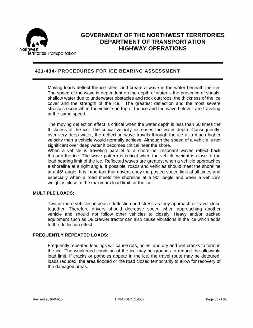
GOVERNMENT OF THE NORTHWEST TERRITORIES
DEPARTMENT OF TRANSPORTATION HIGHWAY OPERATIONS
Revised 2010-04-15 HMM 401-455.docx Page 68 of 82
421-434- PROCEDURES FOR ICE BEARING ASSESSMENT
Moving loads deflect the ice sheet and create a wave in the water beneath the ice. The speed of the wave is dependent on the depth of water – the presence of shoals, shallow water due to underwater obstacles and rock outcrops; the thickness of the ice cover and the strength of the ice. The greatest deflection and the most severe stresses occur when the vehicle on top of the ice and the wave below it are traveling at the same speed. The moving deflection effect is critical when the water depth is less than 50 times the thickness of the ice. The critical velocity increases the water depth. Consequently, over very deep water, the deflection wave travels through the ice at a much higher velocity than a vehicle would normally achieve. Although the speed of a vehicle is not significant over deep water it becomes critical near the shore. When a vehicle is traveling parallel to a shoreline, resonant waves reflect back through the ice. The wave pattern is critical when the vehicle weight is close to the load bearing limit of the ice. Reflected waves are greatest when a vehicle approaches a shoreline at a right angle. If possible, roads and vehicles should meet the shoreline
at a 45 angle. It is important that drivers obey the posted speed limit at all times and
especially when a road meets the shoreline at a 90 angle and when a vehicle’s weight is close to the maximum load limit for the ice.
MULTIPLE LOADS:
Two or more vehicles increase deflection and stress as they approach or travel close together. Therefore drivers should decrease speed when approaching another vehicle and should not follow other vehicles to closely. Heavy and/or tracked equipment such as D8 crawler tractor can also cause vibrations in the ice which adds to the deflection effect.
FREQUENTLY REPEATED LOADS:
Frequently repeated loadings will cause ruts, holes, and dry and wet cracks to form in the ice. The weakened condition of the ice may be grounds to reduce the allowable load limit. If cracks or potholes appear in the ice, the travel route may be detoured, loads reduced, the area flooded or the road closed temporarily to allow for recovery of the damaged areas.

GOVERNMENT OF THE NORTHWEST TERRITORIES
DEPARTMENT OF TRANSPORTATION HIGHWAY OPERATIONS
Revised 2010-04-15 HMM 401-455.docx Page 69 of 82
421-434- PROCEDURES FOR ICE BEARING ASSESSMENT
LONG TERM LOADS:
Long term loads are those imposed be vehicles parked for more than a few minutes. Over a period of time the ice begins to show signs of plastic or creep failure. This mechanism for failure is so sufficiently different that the standard load calculations do not apply. Parking of vehicles or equipment on ice that is at or near its load limits should be avoided. Also, avoid the parking of vehicles close together or near the edges of the ice road/bridge corridor where the snow banks are located as this area is much weaker due to the insulations provided by the snow and the constant weight applied by the snow banks.
WORKER SAFETY:
1) Introduction:
Working on ice is inherently dangerous. Failure can occur so quickly that rescue is impossible. It is therefore imperative that all employees are aware of the potential danger and take the necessary steps to protect themselves. Employees must observe all Occupational Health and safety Regulations as well as Departmental standards, procedures and practices relating to their work.
2) Ice Conditions:
Seek approval from the Foreman, Highway Maintenance Supervisor or Regional Manager before going on any winter road or ice road.
Every effort must be taken to know and to understand the local conditions.
Every operator must be aware of the required ice thickness for his/her vehicle.
It is recommended that a Badger or other similar type configuration of floating vehicle be used for any initial crossing or in conditions or areas where the thickness of the ice is unconfirmed.
The ice must be a minimum of 15 centimetres thick before a snowmobile or 20 centimetres thick before a car or light truck may travel on the ice.

GOVERNMENT OF THE NORTHWEST TERRITORIES
DEPARTMENT OF TRANSPORTATION HIGHWAY OPERATIONS
Revised 2010-04-15 HMM 401-455.docx Page 70 of 82
421-434- PROCEDURES FOR ICE BEARING ASSESSMENT
3) Weather Conditions:
Evaluate weather and ice conditions prior to venturing onto the winter road and follow Chapter 2 - “Guidelines for Working in a Cold Environment” as described in “A Field Guide to Ice Construction Safety.” Cancel or postpone travel on a winter road if weather is unsuitable or if deterioration in the ice is apparent.
4) Procedures:
On any winter road or ice bridge construction effort, a “buddy system” will be used. This means that any person working on winter roads will be able to contact another person by radio or telephone on an open channel at all times. Whenever possible, employees should not work alone. Employees are not allowed to work alone on ice bridge construction projects. If machine operators are working alone, they will radio the foreman at the beginning of each shift and give their location and direction of travel. During the shift they are required to call in as shown in the guidelines presented in Figure 2. All staff are required to be observant and to inspect the work site and ice areas for potential hazards. Any hazardous condition will be immediately reported to the Foreman, Highway Maintenance Supervisor or Regional Manager.

GOVERNMENT OF THE NORTHWEST TERRITORIES
DEPARTMENT OF TRANSPORTATION HIGHWAY OPERATIONS
Revised 2010-04-15 HMM 401-455.docx Page 71 of 82
421-434- PROCEDURES FOR ICE BEARING ASSESSMENT
5) Protective Clothing and Safety Equipment:
A life line (i.e. 15 millimetre thick nylon rope) must be used by employees who are doing initial testing of an area or suspect that they may be near the load limits given the equipment they are using (i.e. snowmobile or pickup with trailer mounted auger). The life line should be at least 30 meters in length and should be held by another employee rather than attached to a piece of equipment. The line must be inspected for damage before and after each use. The lead person during testing must wear a GNWT Department of Transportation approved harness to which the life line is secured. ALL WORKERS on the ice during construction must wear approved/certified floatation suits approved by the GNWT Department of Transportation. Such floatation suits to be Canadian Coast Guard (CCG) approved. The Department of Transportation has specified Mustang Survival, Anti-Exposure Coverall and Worksuit Model MS2176 and Mustang Survival Coverall Model MS-185 as an acceptable suit for their workers. All Contractors and/or other workers on the ice during initial ice road construction are strongly encouraged to adopt the same Canadian Coast Guard (CCG) approved Floatation suits as the GNWT Department of Transportation. ALL WORKERS on the ice during initial ice road construction shall also carry a set of ice rescue picks on them while on the ice. ALL WORKERS on the ice must inspect all personal safety equipment daily. If operating a vehicle, obtain a sealed emergency kit from the Foreman, Highway Maintenance Supervisor or Regional Manager. The approved type of emergency kit (and its contents) is described in Section 2.3 of the “A Field Guide to Ice Construction Safety.” Ensure that its “use before date” has not expired and that its seal is intact. Store it securely in the vehicle to protect it from damage, theft and direct sunlight. If items from the kit are used, they should be replaced or the kit exchanged for a fully serviced one at the end of the shift. Fire extinguishers, first aid kits, and warning devices such as flares, reflectors and flags are mandatory on all vehicles used on winter road construction and maintenance. Wear warm clothing and footwear appropriate for the conditions encountered or anticipated.

GOVERNMENT OF THE NORTHWEST TERRITORIES
DEPARTMENT OF TRANSPORTATION HIGHWAY OPERATIONS
Revised 2010-04-15 HMM 401-455.docx Page 72 of 82
421-434- PROCEDURES FOR ICE BEARING ASSESSMENT
6) Vehicles and Equipment:
Each piece of equipment will be weighed and the minimum ice thickness necessary to support it will be calculated according to the formula presented on the Ice Bearing Capacity chart (Figure 4). In communities without access to a weigh scale, equipment will be weighed with portable scales. If neither permanent nor portable scales are available, weight information given by the manufacturer can be obtained from the Central Repair Facility in Hay River. The gross vehicle weight (GVW) of all motor vehicles used for working on ice will be posted in clear view on the outside and inside of the vehicle for the operator’s reference. Workers must be aware of the operating weight of the equipment they are using and shall not proceed if the ice is not thick enough to support the weight of the equipment and operator plus any additional gear or attachments. Equipment operators will decide whether the doors and/or hatches on the equipment working on ice will be removed or lashed open during the construction phase. Wherever practical, canopies will be removed and panic bars or hatches will be installed on equipment doors so that operators can quickly exit in case of breakthrough. At the first sign of breakthrough the operator is to abandon the vehicle immediately. Use of seat belts is optional when traveling on ice during the construction
phase. Tools, equipment and materials must be stowed neatly in the vehicle. Visibility from the vehicle should be unobstructed (i.e., clean windshield). No equipment will be used on winter roads if it is not in proper running order. Vehicles operating close to the load bearing capacity of the ice during construction must not exceed 20 kilometres per hour. If required, materials and equipment will be repaired, replaced or modified. This may include the installation of snowplows and wings.

GOVERNMENT OF THE NORTHWEST TERRITORIES
DEPARTMENT OF TRANSPORTATION HIGHWAY OPERATIONS
Revised 2010-04-15 HMM 401-455.docx Page 73 of 82
421-434- PROCEDURES FOR ICE BEARING ASSESSMENT
Operators will be responsible for the care of their equipment and for reporting any equipment problems to their Foreman, Highway Maintenance Supervisor or Regional Manager. An operational check of all equipment will be done and proper training for all personnel carried out.
7) Summary of the Key Dos and Don’ts:
Do:
Ensure sufficient ice capacity for the heaviest unit to be used on the delineated ice road corridor.
Open up and clear a specific section to full width in one shift to avoid the refreezing of windrowed snow. (Compacted snow and disturbed snow freezes very hard and requires increased effort to move again.)
Keep the windrow height low (i.e. less than one metre) and spread out to reduce the overloading of the ice by the windrow and its ability to catch a lot of drifted snow.
Plow snow berms off the main ice road to catch drifting snow in areas where drifting is a problem. (Remember the snow catchment area behind a berm is approximately 30 times as long as the height of the berm – so get them back far enough from the main road.)
To promote rapid ice growth, remove all loose or fresh snow that insulates the ice sheet or compact the snow to remove air and insulating value from the snow cover.
If flooding, use multiple “lifts” of water that will freeze solidly in 12 to 24 hours. (This reduces “shell” ice from forming.) Keep traffic off flooded areas.

GOVERNMENT OF THE NORTHWEST TERRITORIES
DEPARTMENT OF TRANSPORTATION HIGHWAY OPERATIONS
Revised 2010-04-15 HMM 401-455.docx Page 74 of 82
421-434- PROCEDURES FOR ICE BEARING ASSESSMENT
Don’t:
Do not park heavy equipment on the ice or near the snowbanks overnight or for extended periods – the ice will “creep” and failure can occur.
Do not make multiple passes over the same area of ice within a short period of time (i.e. one hour). This can cause ice fatigue and ice failure.
Avoid opening new road when temperatures are very cold (-40 Celsius). This causes extreme internal stress in the ice sheet. (Ice needs some time to normalize these internal stresses.) This is not that critical if there is a lot of over capacity with the ice thickness.
Avoid loading the ice to its limits when temperatures are very cold or when there has been a sudden decline in air temperature.
8) The “VITAL, the Safety Message Program” for DOT Staff:
The Department of Transportation has introduced VITAL, the safety message program, see Figure 7, to act as a safety message for all personnel who work on or are responsible for working on and around ice road and ice bridge construction.
Figure 7: VITAL stands for:
V VEHICLE All operators and supervisors must be aware of the vehicle weight, ice required to support it, the characteristics and capabilities of the vehicle, ensuring it is in good repair and the most effective escape plan.
I ICE
Everyone working on or near the ice needs to know the ice thickness, the bearing capacity, the conditions and any special observations or notes. An ICE LOG is to be kept.
T TASK All workers are to know exactly what is expected of them while they are working or operating equipment on the ice.
A
ASSEMBLE the proper equipment
Everyone working on or near ice is to have the proper personal protective gear and tools to accomplish their task. Radios, ice chisels/augers, ice profilers, vehicles, ropes, floater suits, etc. are to be in good working order and tested prior to deploying on the task. If in doubt, ask.
L LEARN
Successfully working on ice takes experience, knowledge, training and skill. Learn the techniques and procedures and keep you and your team alive.

GOVERNMENT OF THE NORTHWEST TERRITORIES
DEPARTMENT OF TRANSPORTATION HIGHWAY OPERATIONS
Revised 2010-04-15 HMM 401-455.docx Page 75 of 82
441-SNOWFENCES
OBJECTIVE
To control or reduce snow drifts from forming on the highway. DESCRIPTION
Snowfencing includes the installation, annual inspections, repairs and removals when required.
LEVEL OF SERVICE
Snowfences should be located at sites where snow has drifted onto the highway and caused operational problems in the past. Serious consideration should be given to flattening slopes when practical to eliminate or reduce drifts in cuts where drifting is a problem. This in turn would provide a benefit to users and reduce annual snow removal and Snowfencing expenditures.
RESPONSIBILITY The Highway Maintenance Supervisor and the Regional Manager should make a yearly late winter inspection to inspect and record for future reference:
- The effectiveness of each fence,
- The method and scope of work required to improve the inferior
right-of-way condition to eliminate the need of the fence. PRODUCTIVITY GUIDELINES: RESOURCE GUIDELINES:
Quantity Standard- Crew-
0.25 hrs/lineal meter 2-Laborers (class 05) Average Daily Production Range- Equipment-
16 hours 1-Pickup (class 1823)

GOVERNMENT OF THE NORTHWEST TERRITORIES
DEPARTMENT OF TRANSPORTATION HIGHWAY OPERATIONS
Revised 2010-04-15 HMM 401-455.docx Page 76 of 82
441-SNOWFENCES
SCHEDULING
August and September RECOMMENDED METHOD- General Approach
The normal practice for the selection and placing of Snowfences includes:
1. The snowfence should be at a right angle to the prevailing winds and be of sufficient length to protect the problem areas plus 10%
2. The snowfence should have a porosity ranging between 47-53%
3. The snowfence should be placed on the upwind side of the posts/stands.
4. The installed fence should have a spacing between the ground level or the top
of the vegetation and the bottom of fencing ranging between 15-20% of the actual height of the fence.
5. The snowfence should be placed at a distance of 35 times the overall height
of the fence on the upwind side of the location to be protected.
6. Snowfence material and the support posts/stands should be of sufficient strength to withstand the area winds without significant damage.
7. An additional row of snowfence may be required upwind from the first row
when one row has not enough capacity to protect the site. RECOMMENDED METHOD- Details Permanent Fences:
1. Fence should be inspected thoroughly as soon as the snow had melted to determine the repairs required and the necessary material ordered.
2. All broken, split and missing material should be replaced or repaired.
3. Loose members of the fence should be either renailed or bolts
tightened to ensure that the original integrity is restored or enhanced.

GOVERNMENT OF THE NORTHWEST TERRITORIES
DEPARTMENT OF TRANSPORTATION HIGHWAY OPERATIONS
Revised 2010-04-15 HMM 401-455.docx Page 77 of 82
441-SNOWFENCES
Temporary Fencing: (using the standard 120 cm high manufactured fence)
1. Select location for the fence 45 meters upwind from the site to be protected and at right angles to the prevailing winds where possible.
2. Install posts at a 3 meter spacing in a straight line
3. Roll fence out on upwind side and fasten one end to an end post at
five points.
4. Leave 20 cm clearance between the ground cover and the bottom of the snow fence.
5. Anchor end post with 3 anchor posts. Anchor posts are placed 2m
from the end post and spaced 1m apart. Double strand wire is fastened from end post to anchor posts.
6. Stretch the fence gently to take up the slack. Do not over tighten so as
to risk breaking the wire.
7. Secure the fence to posts with tie wires at 3 points.
8. Anchor every post on each side perpendicular to the fence.
9. Install 3 anchors at the last post.
10. Overlap rolls of fence approximately 1 m and fasten together if more than 1 roll is used. Repeat above operation for each roll of fence.
11. Remove fence in spring as soon as possible after normal winter
maintenance activities.

GOVERNMENT OF THE NORTHWEST TERRITORIES
DEPARTMENT OF TRANSPORTATION HIGHWAY OPERATIONS
Revised 2010-04-15 HMM 401-455.docx Page 78 of 82
451- CULVERT STEAMING
OBJECTIVE
The thawing of frozen culverts to permit the local drainage pattern to function. DESCRIPTION
The opening of frozen culverts using a portable steam generator. Also includes: 1. The installation and maintenance of steam pipes installed in culverts. 2. Removal of ice and snow from inside or adjacent to culvert ends.
LEVEL OF SERVICE
Culverts requiring steaming should be noted by the Highway Maintenance Supervisor while on road patrol during winter and spring thaws. Visual inspection in winter will make note of snow depths and potential debris in the drainage area near the culvert. Visual inspections in spring thaw will monitor flows and possible blockages by debris or the build-up of ice near the culvert.
RESPONSIBILITY Highway Maintenance Supervisor to schedule. PRODUCTIVITY GUIDELINES: RESOURCE GUIDELINES:
Quantity Standard- Crew-
Once/each culvert prone to freezing 1-Heavy Equipment Operator (class 04) 1-Laborer (class 05) Average Daily Production Range- Equipment-
2 culverts/day 1-Medium Truck (class 1704) 1-Thawing Machine (class 5711)

GOVERNMENT OF THE NORTHWEST TERRITORIES
DEPARTMENT OF TRANSPORTATION HIGHWAY OPERATIONS
Revised 2010-04-15 HMM 401-455.docx Page 79 of 82
451- CULVERT STEAMING
SCHEDULING
Beginning of April to late May. RECOMMENDED METHOD:
1. Where steam pipes have been installed within the culvert prior to freeze up, attach steam hose from steamer after removing caps from both ends of pipe. Apply steam through pipe until water begins to flow freely through entire length of culvert.
2. Where no steam pipe has been installed then blow pipe is attached to steam
hose and pushed in to culvert for its entire length until the water from the opposite end of culvert begins to flow through freely.
3. Where a build-up of ice has occurred over the upstream end of the culvert,
steaming a vertical hole over the end of culvert is required to connect with horizontal hole previously made with blow pipe.
4. Reinspect culvert later to ensure free flow, particularly when temperature
drops. Caution: Snow and ice should not be removed from the culvert inverts
until the spring thaw is evident. Otherwise the first run-off may enter the opened culverts and then freeze inside the culverts if a cold spell occurs.
5. All steam pipes installed in culverts should be checked in the fall to repair any
cracks or leaks and to remove all moisture. Position steam pipes installation so that the standpipes will be readily visible. Fill the steam pipes with a non-freezing liquid that is not injurious to the environment and securely cap.
GOVERNMENT OF THE NORTHWEST TERRITORIES
DEPARTMENT OF TRANSPORTATION HIGHWAY OPERATIONS
Revised 2010-04-15 HMM 401-455.docx Page 80 of 82
455- GLACIATION/OVERFLOW CONTROL
OBJECTIVE:
To prevent ice build-up on road surfaces and in drainage structures by controlling unwanted winter water flows.
DESCRIPTION:
Glaciation/overflow control involves all work relating to the problems created by below freezing temperatures which cause ponding of water or a build-up of either adjacent to or on the highway and in drainage structures includes:
- Cutting off or diverting the water source. - Building berms of snow, ice, etc. to prevent or to reduce the build-up of ice in
culverts and ditches or on the road surface. LEVEL OF SERVICE:
The Highway Maintenance Supervisor should be continually alert during the winter months for signs of overflow/glaciation either within the right of way or threatening to encroach upon the right of way, in order to identify areas that may require corrective or defensive action. The build-up of ice on highway surfaces due to overflows usually creates a hazardous situation for the user. Prompt action is required to provide safe passage through these areas. Note: Do not disturb any areas where water is known to be flowing under the snow cover or within a body of ice and is causing no problems.
RESPONSIBILITY: Highway Maintenance Supervisor with guidance from the Regional Manager.

GOVERNMENT OF THE NORTHWEST TERRITORIES
DEPARTMENT OF TRANSPORTATION HIGHWAY OPERATIONS
Revised 2010-04-15 HMM 401-455.docx Page 81 of 82
455- GLACIATION/OVERFLOW CONTROL
PRODUCTIVITY GUIDELINES: RESOURCE GUIDELINES:
Quantity Standard- Crew-
96 hrs/glaciation site 2-Heavy Equipment Operators (class 03) Average Daily Production Range- Equipment-
16 hours 1-Crawler Tractor (class 2404) 1-Loader/Backhoe (class 2809) SCHEDULING
Late December- end of March. RECOMMENDED METHOD- Temporary and More Effective Methods Details:
There is not a single totally effective method of controlling glaciation/overflow. The use of different methods in minimizing the problem is determined by each particular situation, and by the limits set by available resources and environmental constraints. Some of the more commonly used techniques are: Temporary Methods:
1. The use of either a crawler tractor or loader to construct snow berms primarily
at the edge of the right of way to keep overflow back and promote freezing beyond the highway right of way.
2. The construction of debris free narrow channels where there is a major flow
will often have limited success when directing water down ditches and through culverts especially during periods of milder weather.
3. Finding the water source and attempting to cut it off by freezing.
4. Steaming frozen culverts to allow water flow.

GOVERNMENT OF THE NORTHWEST TERRITORIES
DEPARTMENT OF TRANSPORTATION HIGHWAY OPERATIONS
Revised 2010-04-15 HMM 401-455.docx Page 82 of 82
455- GLACIATION/OVERFLOW CONTROL
More Effective Methods:
1. Raising the elevation of grades to provide a large catchment area for the
water. 2. Redirecting the source of water away from the highway ditches.
3. If unable to redirect, channel water from the source in a defined V shaped
ditch to a highway drainage system.
4. Install heat tapes in culverts where their freezing holds back the overflow. Culverts can be easily thawed with the use of a generator set.
5. Some of the deeper culverts can be kept flowing all winter simply by insulating
the ends in the fall to retain the natural heat.

GOVERNMENT OF THE NORTHWEST TERRITORIES
DEPARTMENT OF TRANSPORTATION HIGHWAY OPERATIONS
Revised 2010-09-02 HMM 503 REV 100901.docx Page 1 of 7
503- GUIDERAIL MAINTENANCE
OBJECTIVE: To maintain existing guiderail in a condition that will satisfactorily serve its design purpose and have a reasonably neat appearance. DESCRIPTION: Guiderail maintenance includes the repair, replacement, cleaning, etc. of flexible beam, box beam and concrete barrier type guiderail to correct deficiencies such as:
- Broken, rotted posts - Posts out of alignment - Incorrect height of posts - Loose bolts, broken offset blocks - Bent or damaged guiderail - Removal of debris and vegetation under the guiderail - Dirty guiderail
LEVEL OF SERVICE: The existing guiderail was installed at location such as hazardous curves, high fills, deep water and approaches to bridges using design parameters in use at the time of installation. Guiderail elevation, alignment and structural integrity should be maintained in accordance with the purpose that it was installed. New installations or permanent removal shall not be undertaken without the approval of the Regional Manager. RESPONSIBILITY: The Highway Maintenance Supervisor will schedule with guidance from the Regional Manager. Refer to Highway Maintenance Operating Instructions for:
- Productivity and Resource Guidelines - Scheduling - Recommended Method
GOVERNMENT OF THE NORTHWEST TERRITORIES
DEPARTMENT OF TRANSPORTATION HIGHWAY OPERATIONS
Revised 2010-09-02 HMM 503 REV 100901.docx Page 2 of 7
503- GUIDERAIL MAINTENANCE
PRODUCTIVITY GUIDELINES: RESOURCE GUIDELINES: Quantity Standard- Crew- 25% of total lineal meters 1-Heavy Equipment Operator (class 03) Average Daily Production Range- Equipment- As Required 1-Hiab Truck (class 1704)
Materials- Miscellaneous (code 999) (All materials used to be reported to the proper code)
SCHEDULING Normally beginning June to mid October. Guiderails damaged in traffic accidents should be repaired as soon as conditions permit the work to be scheduled. RECOMMENDED METHOD- General Approach:
1. Each spring the Highway Maintenance Supervisor should inspect all the guiderails within his area for damage and deterioration in order to determine any need for material and when the required maintenance should be scheduled. Any locations requiring major works should be brought to the attention of the Regional Manager. Also recommendations are to be made to the Regional Manager where new installations of guiderails should be put or existing installations removed.
2. Guiderails must be raised or lowered as required to maintain an effective height
above the road surface when activities alter the elevation of the roadway.
3. The related grade repairs should be charged to the appropriate activity such as 120, 122, 810, etc.

GOVERNMENT OF THE NORTHWEST TERRITORIES
DEPARTMENT OF TRANSPORTATION HIGHWAY OPERATIONS
Revised 2010-09-02 HMM 503 REV 100901.docx Page 3 of 7
503- GUIDERAIL MAINTENANCE
RECOMMENDED METHOD- Details: Box and “W” Beam
1. Remove and replace any damaged or rotted posts and offset blocks. 2. Correct post alignment and elevation as required. 3. Replace damaged or severely deformed Box or “W” Beams. 4. Replace “W” Beams when bolt holes are enlarged or torn. Overlap of “W”
beams should be in the direction of traffic. Any “W” Beam presently incorrectly installed should be removed and installed properly.
5. Realign sections of Box or “W” beam as necessary to restore proper elevation and alignment.
6. Tighten all loose bolts. 7. Remove any build-up of gravel, sand or other debris beneath the guiderail
which may inhibit drainage and cause shoulder washouts. 8. Replace any damaged guiderail deflectors. 9. Clean any dirty guiderails.
Concrete Barriers:
1. Badly damaged sections should be replaced. 2. Sections with minor chips or missing corners can be repaired using instant
patch concrete. 3. Align as necessary by:
a) Removing section(s) of concrete barrier. b) Preparing a level compacted granular base at the desired elevation. c) Replacing section(s) and aligning to conform to the designs of the
installation. SPECIAL NOTE: the drawings for “W” Beam Guard Rail attached are under review. The specifications and drawings for “Box” and “Concrete” are being formulated and will be posted when approved. For more information please contact the Highway Operations Office in Hay River. For reference only:
Figure 503-1: “W” Beam taken from SD 700-04-02, not to scale Figure 503-1: “W” Beam taken from SD 700-04-02, not to scale Figure 503-1: “W” Beam taken from SD 700-04-02, not to scale Figure 503-1: “W” Beam taken from SD 700-04-02, not to scale

GOVERNMENT OF THE NORTHWEST TERRITORIES
DEPARTMENT OF TRANSPORTATION HIGHWAY OPERATIONS
Revised 2010-09-02 HMM 503 REV 100901.docx Page 4 of 7
503- GUIDERAIL MAINTENANCE
Figure 503-1: taken from SD 700-04-02, Not to Scale

GOVERNMENT OF THE NORTHWEST TERRITORIES
DEPARTMENT OF TRANSPORTATION HIGHWAY OPERATIONS
Revised 2010-09-02 HMM 503 REV 100901.docx Page 5 of 7
503- GUIDERAIL MAINTENANCE
Figure 503-2: taken from SD 700-04-01, Not to Scale

GOVERNMENT OF THE NORTHWEST TERRITORIES
DEPARTMENT OF TRANSPORTATION HIGHWAY OPERATIONS
Revised 2010-09-02 HMM 503 REV 100901.docx Page 6 of 7
503- GUIDERAIL MAINTENANCE
Figure 503-3: taken from SD 700-04-04, Not to Scale

GOVERNMENT OF THE NORTHWEST TERRITORIES
DEPARTMENT OF TRANSPORTATION HIGHWAY OPERATIONS
Revised 2010-09-02 HMM 503 REV 100901.docx Page 7 of 7
503- GUIDERAIL MAINTENANCE
Figure 503-4: taken from SD 700-04-05, Not to Scale

GOVERNMENT OF THE NORTHWEST TERRITORIES
DEPARTMENT OF TRANSPORTATION HIGHWAY OPERATIONS
Revised 2010-09-02 HMM 510-518 Signage Booklet REV 100901.docx Page 1 of 21
510- ERECT NEW SIGNS
OBJECTIVE: To erect new signs to guide motorists in a safe and orderly movement of traffic as facilities ahead change or new signage concepts are approved. DESCRIPTION: Erecting permanent signs at new locations on all weather roads as approved by the Regional Manager. LEVEL OF SERVICE: The need for new signage is an ongoing process as highway improvements are made, traffic regulations are changed, tourist facilities are enhanced or off-road development takes place, etc. Any request for new signs must be approved by the Regional Manager. All new signage will include the following characteristics, please coordinate with the Highway Operations Office in Hay River to verify purchase orders and to revise the NWT Highway Sign Listings:
1. Sign must conform to the “Uniform Traffic Control Devices of Canada” Manuel. 2. Reflective Properties of new signs to be “Diamond Grade” or equivalent. 3. Reverse of sign to be non-reflective with metal signs or white on wooden signs.
RESPONSIBILITY: Highway Maintenance Supervisor with guidance from Regional Manager. PRODUCTIVITY GUIDELINES: RESOURCE GUIDELINES: Quantity Standard- Crew- 5% of signs 1-Heavy Equipment Operator (class 03) 1-Laborer (class 05) Average Daily Production Range- Equipment- 4 signs 1-HIAB Truck (class 1704) Materials- Signs (code 662) Posts (code 668)

GOVERNMENT OF THE NORTHWEST TERRITORIES
DEPARTMENT OF TRANSPORTATION HIGHWAY OPERATIONS
Revised 2010-09-02 HMM 510-518 Signage Booklet REV 100901.docx Page 2 of 21
510- ERECT NEW SIGNS
SCHEDULING Signs required to protect the safety of the motorists shall be installed as soon as possible. General information signs will normally be installed between late May to late September. Note: the NWT Highway Sign Listings will be issued by the Highway Operations Office in Hay River on a regular basis to show all approved and active Highway Signs. Revisions and updates will be based on current conditions and also a reflection of changes in policy and standards. RECOMMENDED METHOD- General Approach:
1. Signs shall be installed in accordance with specific instructions including sketches in order to conform generally as detailed in the “Uniform Traffic Control Devices for Canada” manual. For more information contact the Highway Operations Office in Hay River.
2. Drawings for N.W.T. traffic control devices installations for a warning sign,
hazard marker and a delineator are included in the “Highways Maintenance Operating Instruction” for Activity 514.
RECOMMENDED METHOD- Details:
1. Warning, Information and Regulatory (generally with the exception of the stop and yield signs and hazard markers): - 150 meters from hazard, curve, etc. in rural areas. - 4 to 5 meter setback from shoulder line primarily to reduce damage to
signs by maintenance equipment and remain clear. - Lowest part of the sign to be a minimum of 1.5 meters above the outer
edge of driving surface. - Sign can be installed on either pressure-treated wood or metal posts
perpendicular, with signs securely fastened to the post.
- Signs should be placed at a slight angle (3 to 5 ) away from the approaching traffic to avoid spectacular glare from headlights.
- Signs should be spaced a minimum of 50 meters apart in rural areas. - Bracing of signs will be in the direction of traffic flow – please contact the
Highway Operations Office in Hay River for more information.

GOVERNMENT OF THE NORTHWEST TERRITORIES
DEPARTMENT OF TRANSPORTATION HIGHWAY OPERATIONS
Revised 2010-09-02 HMM 510-518 Signage Booklet REV 100901.docx Page 3 of 21
510- ERECT NEW SIGNS
RECOMMENDED METHOD- Details (continued):
2. Delineators:
- 0.25 to 0.50 meter setback from the shoulder line. - Center of delineator to be 1.2 meters above outer edge of driving
surface. - Post embedded minimum of 0.75 meter. - Color of delineator to be white on the right side and yellow on left side. -
Note: Spacings quoted in the foregoing is general practice for N.W.T. Transportation. Consult “Uniform Traffic Control Devices” manual for further information.

GOVERNMENT OF THE NORTHWEST TERRITORIES
DEPARTMENT OF TRANSPORTATION HIGHWAY OPERATIONS
Revised 2010-09-02 HMM 510-518 Signage Booklet REV 100901.docx Page 4 of 21
514- SIGN MAINTENANCE
OBJECTIVE: To maintain signs in a good condition at all times. DESCRIPTION: Sign maintenance includes straightening, repairing, cleaning and the replacement of permanent highway signs, markers, delineators and posts to correct deficiencies such as:
- Damage to signs, markers, delineators and posts - Sign illegibility - Paint deterioration - Obstructed visibility - Acts of vandalism - Replacement of obsolete signs - Poor reflectivity
This activity also includes reflectivity testing of signs and all work relating to culvert markers and kilometer posts. LEVEL OF SERVICE: Signs control, warn and expedite traffic and provide information as to highway routes, directions, destination and points of interest. A complete system of signing is necessary to convey to the motorist conditions that will be encountered and regulations that must be observed while driving on our highways. Poorly maintained signs lose their authority as traffic control devices. Damaged, defaced or dirt signs are ineffective and are a discredit to the Department of Transportation.

GOVERNMENT OF THE NORTHWEST TERRITORIES
DEPARTMENT OF TRANSPORTATION HIGHWAY OPERATIONS
Revised 2010-09-02 HMM 510-518 Signage Booklet REV 100901.docx Page 5 of 21
514- SIGN MAINTENANCE
RESPONSIBILITY: One of the main duties of a Highway Maintenance Supervisor is to see that traffic signs in his/her area are always in good condition. They must be constantly alert for signs that have been damaged, defaced or are missing. The repair and replacement of any signs is relative to the life threatening importance of the sign. This will often mean temporary repair (as in winter) until the job can be done properly. Where a “stop” sign is concerned, it may be necessary to position a flagperson until satisfactory repairs can be made. Refer to “Highway Maintenance Operating Instructions” for:
- Productivity Guidelines - Resource Guidelines - Scheduling - Recommended Method
PRODUCTIVITY GUIDELINES: RESOURCE GUIDELINES: Quantity Standard- Crew- 0.6 hrs per sign/delineator/km post 2-Laborers (class 05) Average Daily Production Range- Equipment- 16 hours 1-Medium Truck c/w HIAB (class 1704) Materials- Signs (code 662) Wood Posts (code 668) Or other required material SCHEDULING Signs maintenance requires attention throughout the year. Any sign deficiency that is likely to endanger life must be corrected immediately. Note: the NWT Highway Sign Listings will be issued by the Highway Operations Office in Hay River on a regular basis to show all approved and active Highway Signs. Revisions and updates will be based on current conditions and also a reflection of changes in policy and standards.

GOVERNMENT OF THE NORTHWEST TERRITORIES
DEPARTMENT OF TRANSPORTATION HIGHWAY OPERATIONS
Revised 2010-09-02 HMM 510-518 Signage Booklet REV 100901.docx Page 6 of 21
514- SIGN MAINTENANCE
RECOMMENDED METHOD- General Approach: The Highway Maintenance Supervisor has the following responsibilities regarding signage within their beat:
1. To recognize signs which are missing, defaced, bent or broken and record the deficiencies.
2. To keep an adequate inventory of emergency signs and other signs critical to
safety such as: stop, yield, road closed, one lane, bump, do not enter, curve signs and others as well as to replace or repair signs as soon as they are discovered to be missing, worn out, or damaged.
3. To arrange for the washing of dirty signs and the removal of snow accumulation
so that signs are readable.
4. To arrange for early removal of obstructions or relocation of signs where signs are obscured by other signs, structures, snow or brush.
5. To clean and paint wood signs and kilometer posts and culvert markers, once
every three years. Sign faces of reflective material should never be painted.
6. To align and straighten posts which are out of plumb. Cut off the tops of wooden posts which project above the top of the sign.
7. To make a night inspection of the reflective quality of all signs in November of
each year and submit deficiencies in writing to the Regional Manager. Make a thorough daytime inspection of all signs and sign structures to ensure that the required signs are present, properly worded, correctly located and in good condition. This latter inspection should be made in March or April of each year, with the list of “signs that are required submitted,” in writing to the Regional Manager.
8. Check permanent signs for correct height, distance from the road, and angle to
traffic. Refer to drawings on the following pages for typical N.W.T. traffic control devices installations for a warning sign, hazard marker, delineator, kilometer post and a culvert marker.

GOVERNMENT OF THE NORTHWEST TERRITORIES
DEPARTMENT OF TRANSPORTATION HIGHWAY OPERATIONS
Revised 2010-09-02 HMM 510-518 Signage Booklet REV 100901.docx Page 7 of 21
514- SIGN MAINTENANCE
RECOMMENDED METHOD- Details
1. Place Traffic Control Signs and safety devices as required.
2. Complete the required corrective work. All corrective sign work where N.W.T. typical drawings are not shown are to conform to the manual “Uniform Traffic Control Devices for Canada.”
3. Remove any Traffic Control Signs and safety devices.
SPECIAL NOTE: The drawings attached are under review.

GOVERNMENT OF THE NORTHWEST TERRITORIES
DEPARTMENT OF TRANSPORTATION HIGHWAY OPERATIONS
Revised 2010-09-02 HMM 510-518 Signage Booklet REV 100901.docx Page 8 of 21
514- SIGN MAINTENANCE
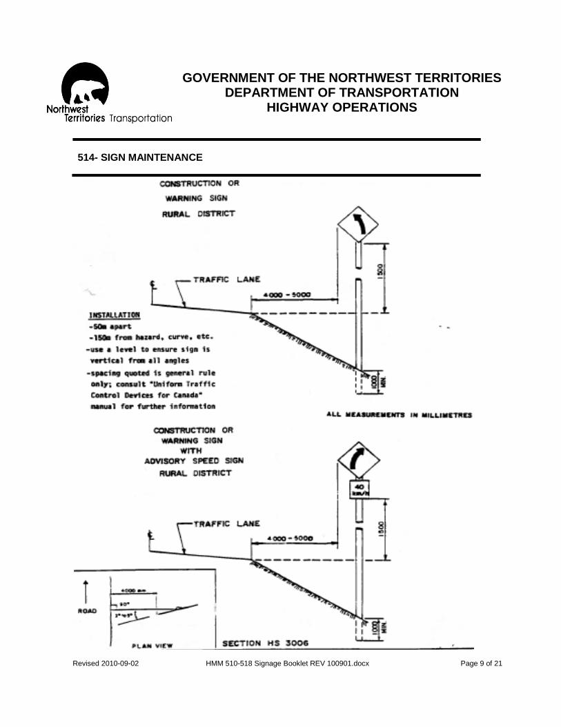
GOVERNMENT OF THE NORTHWEST TERRITORIES
DEPARTMENT OF TRANSPORTATION HIGHWAY OPERATIONS
Revised 2010-09-02 HMM 510-518 Signage Booklet REV 100901.docx Page 9 of 21
514- SIGN MAINTENANCE

GOVERNMENT OF THE NORTHWEST TERRITORIES
DEPARTMENT OF TRANSPORTATION HIGHWAY OPERATIONS
Revised 2010-09-02 HMM 510-518 Signage Booklet REV 100901.docx Page 10 of 21
514- SIGN MAINTENANCE

GOVERNMENT OF THE NORTHWEST TERRITORIES
DEPARTMENT OF TRANSPORTATION HIGHWAY OPERATIONS
Revised 2010-09-02 HMM 510-518 Signage Booklet REV 100901.docx Page 11 of 21
514- SIGN MAINTENANCE
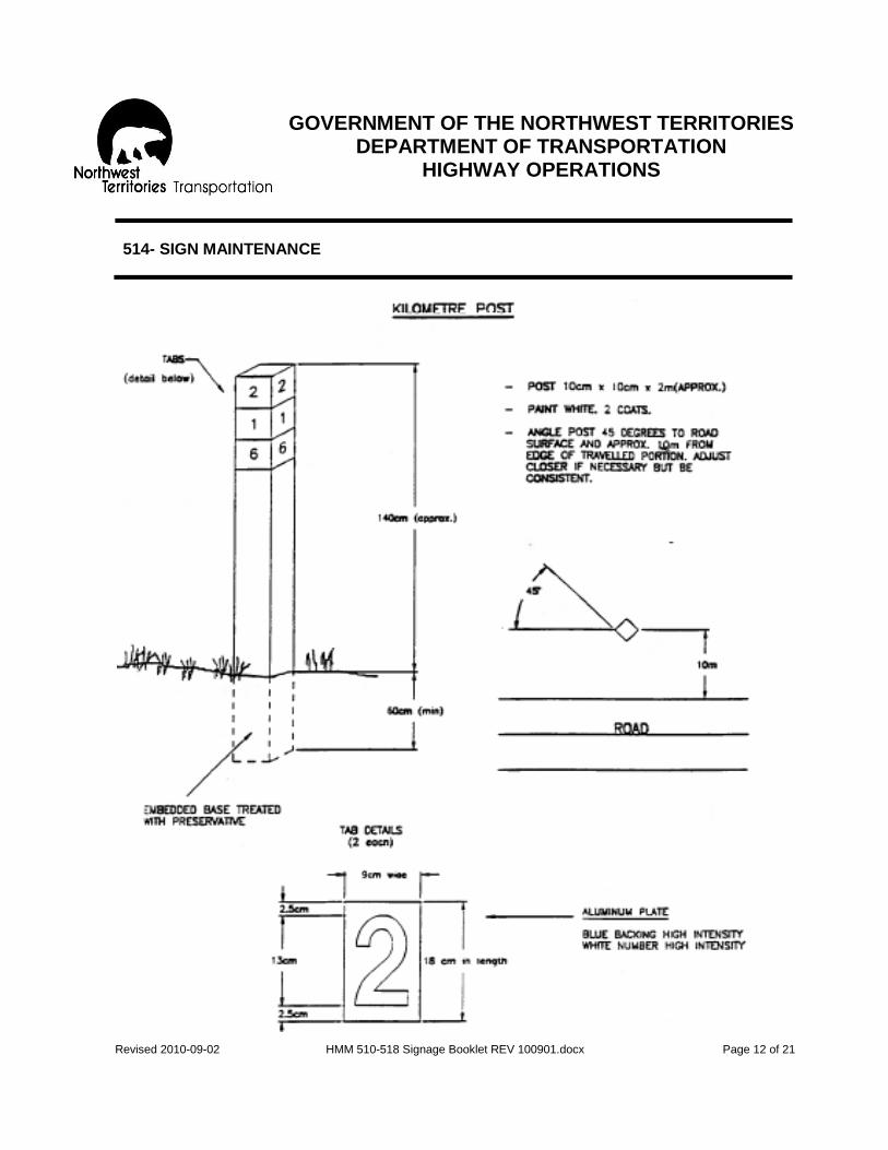
GOVERNMENT OF THE NORTHWEST TERRITORIES
DEPARTMENT OF TRANSPORTATION HIGHWAY OPERATIONS
Revised 2010-09-02 HMM 510-518 Signage Booklet REV 100901.docx Page 12 of 21
514- SIGN MAINTENANCE

GOVERNMENT OF THE NORTHWEST TERRITORIES
DEPARTMENT OF TRANSPORTATION HIGHWAY OPERATIONS
Revised 2010-09-02 HMM 510-518 Signage Booklet REV 100901.docx Page 13 of 21
518- TEMPORARY AND SEASONAL SIGNS
OBJECTIVE: To provide a safe and orderly method of traffic control on seasonal roads, through work areas and where emergency situations arise. DESCRIPTION: This temporary and seasonal signs activity includes the erection, maintenance and removal of:
- Temporary signs on all weather highways, - Signs on snow and ice roads, - Barricading, detour and emergency signing and flagpersons when not
directly chargeable to other activities, - Traffic control activities not otherwise covered, and - Includes the manufacture of the required barricades and sign stands.
LEVEL OF SERVICE:
1. Temporary or seasonal signs on all weather roads:
a) Temporary signs such as vehicle or weight restrictions to be erected promptly when required, changed as necessary and then removed when the condition for which the signs were erected no longer applies.
b) The changing of tabs on permanent signs such as ferry and ice bridge information, at distant locations to provide current information to motorists.
2. Signs for ice bridges and snow and ice roads. These can be classified into:
a) Permanent signs which are located at, or near the entrance which
convey the road status throughout the year. b) Destination and informational signing which must be removed at the
close of the winter season so as not to convey misinformation to the public.
c) Ice road and bridge signing which must be removed prior to breakup to prevent loss of material.

GOVERNMENT OF THE NORTHWEST TERRITORIES
DEPARTMENT OF TRANSPORTATION HIGHWAY OPERATIONS
Revised 2010-09-02 HMM 510-518 Signage Booklet REV 100901.docx Page 14 of 21
518- TEMPORARY AND SEASONAL SIGNS
3. Emergency signs (i.e., construction signs such as the WD series, barricades,
bump markers) which are erected at hazardous locations for the protection of the motorist. These should be installed immediately when a hazardous situation is identified.
RESPONSIBILITY: The Highway Maintenance Supervisor is responsible for proper traffic control within his beat. It is the duty of the Highway Maintenance Supervisor to be sure that he is completely equipped with signs that will meet all his temporary and seasonal signing requirements. He must see that all signs are posted in logical positions and in standard manner, and remain so for as long as the seasonal condition or traffic hazard exists. Signing must not be treated carelessly. Warning devices should never be left in place after the traffic hazard has been corrected and/or no longer exists. Refer to “Highway Operating Instructions” for:
- Productivity Guidelines - Resource Guidelines - Scheduling - Recommended Method
PRODUCTIVITY GUIDELINES: RESOURCE GUIDELINES: Quantity Standard- Crew- 0.3 hours/total kilometers of road 2-Laborers (class 05) Average Daily Production Range- Equipment- 16 hours 1-Pickup Truck (class 1823) Materials- Signs (code 662) Steel Posts (code 668)

GOVERNMENT OF THE NORTHWEST TERRITORIES
DEPARTMENT OF TRANSPORTATION HIGHWAY OPERATIONS
Revised 2010-09-02 HMM 510-518 Signage Booklet REV 100901.docx Page 15 of 21
518- TEMPORARY AND SEASONAL SIGNS
SCHEDULING Seasonal and temporary signs are to be erected, maintained and/or removed as required through the year, as conditions dictate. Note: the NWT Highway Sign Listings will be issued by the Highway Operations Office in Hay River on a regular basis to show all approved and active Highway Signs. Revisions and updates will be based on current conditions and also a reflection of changes in policy and standards. RECOMMENDED METHOD- General Approach:
1. The initial purchase of sign and post material is charged to Operations and Maintenance. When any sign and post material is first taken out of the camp stock for a work area or temporary signing, it should be charged against Activity 518 and the date issue clearly marked on the back of the sign. This will make identification easily recognizable when and if it is reissued from camp stock again, so that double charging to an activity can be avoided.
2. All traffic control device installations where N.W.T. typical drawings are not
available, are to conform to the manual “Uniform Traffic Control Devices for Canada” (please contact the Highway Operations Office in Hay River for advice and instructions). Typical drawings for a roadside diversion, successive work areas, one lane closed, stockpile and borrow site access signing and standard barricade are shown on the following pages.
3. Daytime inspection of temporary installation shall be done on an ongoing basis
to ensure all signs, posts and other traffic control devices are present, correctly located and in good condition. A night time inspection is desirable to evaluate the reflective quality of the signs. The resulting deficiencies from both inspections are to be corrected immediately.
SPECIAL NOTE: See attached several typical drawings to assist with signs and barricades. For more information please contact the Highway Operations Office in Hay River.

GOVERNMENT OF THE NORTHWEST TERRITORIES
DEPARTMENT OF TRANSPORTATION HIGHWAY OPERATIONS
Revised 2010-09-02 HMM 510-518 Signage Booklet REV 100901.docx Page 16 of 21
518- TEMPORARY AND SEASONAL SIGNS
Figure 518-1: Roadside Diversion (Shoefly), taken from SD 200-02-03, not to scale -------------------------------------------------------------------------------------------------

GOVERNMENT OF THE NORTHWEST TERRITORIES
DEPARTMENT OF TRANSPORTATION HIGHWAY OPERATIONS
Revised 2010-09-02 HMM 510-518 Signage Booklet REV 100901.docx Page 17 of 21
518- TEMPORARY AND SEASONAL SIGNS
Figure 518-2: Successive Work Areas, taken from SD 200-02-04, not to scale -------------------------------------------------------------------------------------------------

GOVERNMENT OF THE NORTHWEST TERRITORIES
DEPARTMENT OF TRANSPORTATION HIGHWAY OPERATIONS
Revised 2010-09-02 HMM 510-518 Signage Booklet REV 100901.docx Page 18 of 21
518- TEMPORARY AND SEASONAL SIGNS
Figure 518-3: One Lane Closed, taken from SD 200-02-05, not to scale -------------------------------------------------------------------------------------------------

GOVERNMENT OF THE NORTHWEST TERRITORIES
DEPARTMENT OF TRANSPORTATION HIGHWAY OPERATIONS
Revised 2010-09-02 HMM 510-518 Signage Booklet REV 100901.docx Page 19 of 21
518- TEMPORARY AND SEASONAL SIGNS
Figure 518-4: Access Road Signage, taken from SD 200-02-06, note to scale -------------------------------------------------------------------------------------------------

GOVERNMENT OF THE NORTHWEST TERRITORIES
DEPARTMENT OF TRANSPORTATION HIGHWAY OPERATIONS
Revised 2010-09-02 HMM 510-518 Signage Booklet REV 100901.docx Page 20 of 21
518- TEMPORARY AND SEASONAL SIGNS
Figure 518-5: Barricade, taken from SD 200-0207, not to scale
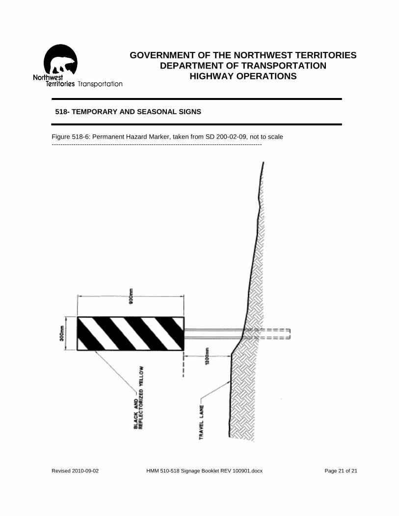
GOVERNMENT OF THE NORTHWEST TERRITORIES
DEPARTMENT OF TRANSPORTATION HIGHWAY OPERATIONS
Revised 2010-09-02 HMM 510-518 Signage Booklet REV 100901.docx Page 21 of 21
518- TEMPORARY AND SEASONAL SIGNS
Figure 518-6: Permanent Hazard Marker, taken from SD 200-02-09, not to scale -------------------------------------------------------------------------------------------------

GOVERNMENT OF THE NORTHWEST TERRITORIES
DEPARTMENT OF TRANSPORTATION HIGHWAY OPERATIONS
Revised 2010-09-02 HMM 521-526 Pre-Marking Booklet REV 100901.docx Page 1 of 15
521- ASPHALT SURFACE PRE-MARKING
OBJECTIVE: To place symbols in the proper position to facilitate the accurate placement of asphalt surface markings. Special Note: Asphalt Surface Markings are also referred to as Pavement Lines or Pavement Markings or Line Striping. DESCRIPTION: Pre-marking of an asphalt roadway is required:
- Before permanent asphalt surface marking can be applied on any new surface,
- When original markings have been obliterated, or - When traffic flows have changed due to new construction or a
modification of the highway as approved by the Regional Manager or the Director of Highways.
Includes the pre-marking of existing restrictions prior to resurfacing such as installation of pre-marking posts, use of Sta marks and offset radius staking on curves etc. Special Note: the drawings attached that describe the appearance and placement locations for Asphalt Surface Markings are under revision. Please contact the Highway Operations Office in Hay River for more information.
GOVERNMENT OF THE NORTHWEST TERRITORIES
DEPARTMENT OF TRANSPORTATION HIGHWAY OPERATIONS
Revised 2010-09-02 HMM 521-526 Pre-Marking Booklet REV 100901.docx Page 2 of 15
521- ASPHALT SURFACE PRE-MARKING
LEVEL OF SERVICE: All roadways generally require pre-marking for the following:
1) Center line or lane lines including:
a) Passing restrictions caused by limited sight distance on horizontal or vertical curves.
b) Regulatory passing restrictions on the approaches to major intersections, railway crossings and pedestrian crossings.
2) Edge lines may be required at the following locations:
a) Roadway transition lines b) Deceleration or acceleration lanes and tapers c) Bridges and other approaches
RESPONSIBILITY: Highway Maintenance Supervisor with guidance from Regional Manager and Project Manager. Refer to Highway Maintenance Operating Instructions for:
- Productivity guidelines - Resource Guidelines - Scheduling - Recommended Method
PRODUCTIVITY GUIDELINES: RESOURCE GUIDELINES: Quantity Standard- Crew- As required on the 1-Heavy Equipment Operator (class 03) total asphalt roads 1-Laborer (class 05) Average Daily Production Range- Equipment- 16 hours 1-Pickup Truck (class 1823)

GOVERNMENT OF THE NORTHWEST TERRITORIES
DEPARTMENT OF TRANSPORTATION HIGHWAY OPERATIONS
Revised 2010-09-02 HMM 521-526 Pre-Marking Booklet REV 100901.docx Page 3 of 15
521- ASPHALT SURFACE PRE-MARKING
RESOURCE GUIDELINES: (continued)
Materials- Traffic Paint (code 780) Miscellaneous (code 999) SCHEDULING June to September
a) Prior to resurfacing- placement of pre-marking posts b) Immediately following asphalt surfacing- pre-mark
RECOMMENDED METHOD- General Approach:
1. Pre-marking:
All pre-markings will generally conform to Part C, Division 2, “Pavement Marking in the Uniform Traffic Control Devices Manual for Canada,” unless otherwise specified. The warrants to be used for minimum sight distance for pavement markings must be approved by the Regional Manager or the Director of Highways. For more information please contact the Highway Operations Office in Hay River.
Pre-marking may be accomplished with relflectorized self adhesive pavement marking tape, traffic paint or spray bombs. Regardless of the method used all pre-markings must be approximately 100 mm x 100 mm in size and spaced not more than 15 meters apart on tangent and 5 meters apart on curves.
Special Note: Passing restrictions and edge lines: Passing restrictions required due to limited sight distance should be marked with small “L” shaped symbols (Figure A) at the beginning and end of the restriction. The stem should point the direction of the restriction (Figure B). Paint a short line beside the “L” shaped symbol when a broken line is to continue along the centre restriction (Figures A & B).

GOVERNMENT OF THE NORTHWEST TERRITORIES
DEPARTMENT OF TRANSPORTATION HIGHWAY OPERATIONS
Revised 2010-09-02 HMM 521-526 Pre-Marking Booklet REV 100901.docx Page 4 of 15
521- ASPHALT SURFACE PRE-MARKING
RECOMMENDED METHOD- General Approach (continued):
Regulatory passing restrictions and edge lines must be marked with a “T” (Figure A) at the beginning and end of the line with the stem of the “T” pointing in the direction of the line (Figure C). For further details, refer to the manual on “Uniform Traffic Control Devices for Canada.”
2. Pre-marker posts:
Pre-marking posts are installed to permanently mark the beginnings and ends of restriction lines (Figure D). Place these posts prior to seal coating or resurfacing that will obliterate old markings. This will save considerable time in pre-marking new surface. These posts should also be installed on highways which are not regularly repainted for reasons of geographic location, etc., and where traffic wear removes the lines so that the paint crews can not follow the old lines.
a) Cut posts from salvage sign posts, or other stock, 100 mm x 100 mm
approximately 1.8 meters long. b) Color- white with 0.3 meter long color code from the top. Red (end of restriction)
on one side, yellow (beginning of restriction) on the other side. c) Post location- near edge of right of way, or a minimum of 10 meters from edge
of asphalt surface, on the same side as, and directly opposite the end of the solid restriction line.
d) Set posts in ground approximately 0.5 meters leaving 1.3 meters above ground.
Arrange these markers so that the paint machine operator is able to fully understand all the restrictions required for both directions (Figure D).
RECOMMENDED METHOD- Details
1. Place signs and safety devices as required. 2. a) Premark selected area outlined in general approach.
b) Install Pre-marker posts when required as outlined in general approach.

GOVERNMENT OF THE NORTHWEST TERRITORIES
DEPARTMENT OF TRANSPORTATION HIGHWAY OPERATIONS
Revised 2010-09-02 HMM 521-526 Pre-Marking Booklet REV 100901.docx Page 5 of 15
521- ASPHALT SURFACE PRE-MARKING

GOVERNMENT OF THE NORTHWEST TERRITORIES
DEPARTMENT OF TRANSPORTATION HIGHWAY OPERATIONS
Revised 2010-09-02 HMM 521-526 Pre-Marking Booklet REV 100901.docx Page 6 of 15
521- ASPHALT SURFACE PRE-MARKING

GOVERNMENT OF THE NORTHWEST TERRITORIES
DEPARTMENT OF TRANSPORTATION HIGHWAY OPERATIONS
Revised 2010-09-02 HMM 521-526 Pre-Marking Booklet REV 100901.docx Page 7 of 15
521- ASPHALT SURFACE PRE-MARKING

GOVERNMENT OF THE NORTHWEST TERRITORIES
DEPARTMENT OF TRANSPORTATION HIGHWAY OPERATIONS
Revised 2010-09-02 HMM 521-526 Pre-Marking Booklet REV 100901.docx Page 8 of 15
521- ASPHALT SURFACE PRE-MARKING

GOVERNMENT OF THE NORTHWEST TERRITORIES
DEPARTMENT OF TRANSPORTATION HIGHWAY OPERATIONS
Revised 2010-09-02 HMM 521-526 Pre-Marking Booklet REV 100901.docx Page 9 of 15
524- ASPHALT SURFACE MARKING
SPECIAL NOTE for all of Section 524: This activity has been assigned to contractors over the last few years. This section will serve as a reference. Recommend that all staff assigned to monitor the contractor have a copy of the contract documents available for their review and to present any changes in specifications and operational requirements. Please contact the Highway Operations Office in Hay River for contractor schedules or for more information. OBJECTIVE: To provide delineation for traffic lanes including direction of travel and to define safe passing zones and lanes to be used for turning motions. DESCRIPTION: Asphalt Surface Marking involves the painting of the centerline, shoulder line, lane lines and intersection layouts on asphalt surfaces using paint and glass beads. LEVEL OF SERVICE: All asphalt surface markings should be well defined, distinct and reflective for night driving. Lane patterns will generally conform to the typical drawings and color codes as laid down in the manual of “Uniform Traffic Control Devices for Canada, Part C.” RESPONSIBILITY The Regional Manager, in collaboration with the project manager will provide direct supervision and support to the Highway Maintenance Supervisor. Refer to Highway Maintenance Operating Instructions for:
- Productivity Guidelines - Resource Guidelines - Scheduling - Recommended Method.

GOVERNMENT OF THE NORTHWEST TERRITORIES
DEPARTMENT OF TRANSPORTATION HIGHWAY OPERATIONS
Revised 2010-09-02 HMM 521-526 Pre-Marking Booklet REV 100901.docx Page 10 of 15
524- ASPHALT SURFACE MARKING
PRODUCTIVITY GUIDELINES: RESOURCE GUIDELINES: Quantity Standard- Crew- Category 1 & 2- asphalt surface: 1-Heavy Equipment Operator (class 03) once/yr 2-Laborers (class 05) 2-Traffic Control Staff Category 3 to 5- asphalt surface: once/2 yrs Average Daily Production Range- Equipment- 36 line kilometers/day 1-Line Striper (class 3000) 2-Pickups (class 1823) 1-Sweeper (class 5244) Materials- Traffic Paint- yellow (code 780) Traffic Paint- white (code 782) Glass beads (code 786) SCHEDULING
June to mid September when the surface is dry, air temperatures are above 10 C and the wind speed is less than 20 km/hr. RECOMMENDED METHOD- General Approach:
1. The painting unit and the pilot truck will each have the following safety equipment:
a) An overhead revolving or flashing beacon with an amber lens. The beacon
shall be mounted on the top of the vehicle fully visible to traffic approaching from both front and rear.
b) A sequential arrowboard of a minimum size 0.75 meters x 1.35 meters.
Arrowboard controls to be located in vehicle cabs.

GOVERNMENT OF THE NORTHWEST TERRITORIES
DEPARTMENT OF TRANSPORTATION HIGHWAY OPERATIONS
Revised 2010-09-02 HMM 521-526 Pre-Marking Booklet REV 100901.docx Page 11 of 15
524- ASPHALT SURFACE MARKING
RECOMMENDED METHOD- General Approach (continued):
c) A “slow moving vehicle” sign to be mounted at the rear of the vehicle and
be visible to the public only when the painting unit is applying paint.
d) A warning sign, mounted at the rear of the pilot truck, stating “wet paint please keep off” or a message of similar meaning.
e) The painting unit should not work against the flow of traffic.
2. The application of Asphalt Surface Markings:
a) All painted markings to be applied 10 cm wide at a film thickness of
approximately 375 microns. This is equivalent to 37.0 liters per kilometer of solid line, assuming no paint is lost.
b) Glass beads are to uniformly cover the line at a rate of 600 gm/l of paint.
For application reconciliation this equals 22.5 kg per kilometer of 10 cm wide solid line at a paint film thickness of 375 microns.
c) All lines shall be evenly covered with paint beads for the specified line
width. All lines shall have sharp edges with no significant overspray.
d) Color of lines:
Yellow lines will separate traffic flows in opposite directions; white line width. All lines shall have sharp edges with no significant overspray. Also:
i) On two lane highways the directional dividing line, including solid no passing lines, will be yellow and lane edge lines will be white.
ii) Lane edge lines on the left side of one-way ramps will be yellow.

GOVERNMENT OF THE NORTHWEST TERRITORIES
DEPARTMENT OF TRANSPORTATION HIGHWAY OPERATIONS
Revised 2010-09-02 HMM 521-526 Pre-Marking Booklet REV 100901.docx Page 12 of 15
524- ASPHALT SURFACE MARKING
RECOMMENDED METHOD- General Approach (continued):
iii) The single solid line between a left turn and its adjacent through
lane will remain white, but the outline of the left turn channelizing island and any cross hatching will be yellow.
e) Directional driving line (or lane line) spacing for dashed or broken lines
shall be 3 meter dash and 6 meter gap.
f) Directional dividing lines shall be painted in the following manner:
i) The only single painted lines permitted will be broken lines if passing is permitted for both lanes on a section of roadway. This single broken line shall be located with the longitudinal center of the line being located on the centerline of the roadway.
ii) Simultaneous solid and broken lines shall indicate passing restrictions (solid line) in one lane while the other lane shows no passing restrictions (broken line). Painting shall be such that the roadway centerline shall be located midway between the two longitudinal lines. Spacing between the longitudinal lines shall be 10 cm.
iii) Passing restrictions in both directional lanes at the same time shall be shown as two solid lines.
g) Lane edge lines or shoulder lines shall consist of single solid white lines
marking the right edge of a lane and normally separating the lane from a paved shoulder. Generally, lane edge lines shall be put down only where there is a paved shoulder more than 0.3 meters wide.
On main highways the lane edge may be marked if the resulting lane is no less than 3.45 meters in width, center to center markings, and where sufficient pavement is available, lane width must be 3.5 meters.

GOVERNMENT OF THE NORTHWEST TERRITORIES
DEPARTMENT OF TRANSPORTATION HIGHWAY OPERATIONS
Revised 2010-09-02 HMM 521-526 Pre-Marking Booklet REV 100901.docx Page 13 of 15
524- ASPHALT SURFACE MARKING
RECOMMENDED METHOD- General Approach (continued):
3. Directional dividing markings and lane lines shall not be continued through any
main side road, but may be continued through intersections with minor roads. A minor road would be defined, approximately, as one which has a summer traffic volume under 10 vehicles a day. Examples of minor side roads are tote trails, pit accesses and unmarked roadways intersecting a highway.
A directional dividing marking may be a single solid line, a dashed line alone, a dashed and a solid line, or two solid lines. In no case shall a marking consisting of two solid lines (a double line) be carried across a public road intersection. An adequate turning gap (25 to 75 meters) must be left where lines are omitted at intersections.
RECOMMENDED METHOD- Details
1. Place signs and safety devices as required. 2. Ensure that surface is clean and dry. If necessary, sweep. 3. Use the spray guns and bean dispensers on the left side of painting unit to
apply centerline markings, while in the right side an independently controlled broom with spray gun and bead dispenser will apply the right edge line when required.
4. Advance or retard paint application cycle or dashed lined to match lines being repainted.
5. Centerline marking should not exceed more than 4 cm variance from the edge of the marking to either side of the pre-marks.
6. Keep traffic off the paint until it has dried. Laying of 45 cm high traffic cones at 10 meter intervals may be required.
7. Paint spots caused by spilled paint on asphalt surfaces are to be painted over with black paint.
8. Remove signs and safety devices.

GOVERNMENT OF THE NORTHWEST TERRITORIES
DEPARTMENT OF TRANSPORTATION HIGHWAY OPERATIONS
Revised 2010-09-02 HMM 521-526 Pre-Marking Booklet REV 100901.docx Page 14 of 15
526- ASPHALT SURFACE MARKING- OTHER
SPECIAL NOTE for all of Section 526: This activity has been assigned to contractors over the last few years. This section will serve as a reference. Recommend that all staff assigned to monitor the contractor have a copy of the contract documents available for their review and to present any changes in specifications and operational requirements. Please contact the Highway Operations Office in Hay River for contractor schedules or for more information. OBJECTIVE: To provide clear and distinct asphalt surface marking where unique traffic control situations are required. DESCRIPTION: Asphalt surface markings including:
- Crosswalks - Stop lines, - Directional arrows, - Hatch/gore markers etc., - Temporary marking for detours, - Removal of superfluous or obsolete markings.
LEVEL OF SERVICE: All asphalt surface marking should be well defined, clear and distinct and conform to the typical drawings and color codes as laid down in the manual of “Uniform Traffic Control Devices for Canada, Part C”. Any superfluous or obsolete markings will be removed so as not to confuse the road user. RESPONSIBILITY: Highway Maintenance Supervisor with guidance from the Regional Manager can assist when required. PRODUCTIVITY GUIDELINES: RESOURCE GUIDELINES: Quantity Standard- Crew- 0.1 hr/km of asphalt surface 1-Heavy Equipment Operator (class 03) 1-Laborer (class 05)

GOVERNMENT OF THE NORTHWEST TERRITORIES
DEPARTMENT OF TRANSPORTATION HIGHWAY OPERATIONS
Revised 2010-09-02 HMM 521-526 Pre-Marking Booklet REV 100901.docx Page 15 of 15
526- ASPHALT SURFACE MARKING- OTHER
PRODUCTIVITY GUIDELINES: RESOURCE GUIDELINES: Average Daily Production Range- Equipment- 16 hours 1-Pickup (class 1823) 1-Line Painter (class 3000) Materials- Traffic Paint- yellow (code 7800) Traffic Paint- white (code 7820) Glass beads (code 7860) SCHEDULING
End of May to mid September when the surface is dry, air temperature is above 10 C and the wind speed is less than 20 kilometers. RECOMMENDED METHOD: 1. Place Traffic Control Signs and safety devices.
2. Paint marking
i) Ensure surface is clean and dry. ii) Place required template(s) at the proper location. iii) Use painter to apply paint to surface within the confines of the template. iv) Use a small hopper spreader to apply glass beads to painted surface
immediately after paint application. v) Carefully remove templates so as not to disfigure the paint. vi) Do not allow traffic on the painted surface until drying complete.
3. Options for the removal of superfluous or obsolete markings.
i) Application of heat to be such that the paint is heated only enough to aid removal without damage to asphalt surface.
ii) Removal of paint using mechanized planer/router adjusted only to the depth to remove paint.
4. Remove Traffic Control Signs and safety devices.

GOVERNMENT OF THE NORTHWEST TERRITORIES
DEPARTMENT OF TRANSPORTATION HIGHWAY OPERATIONS
Revised 2010-09-02 HMM 560-562 REV 100901.docx Page 1 of 14
560- TRAFFIC COUNTING
OBJECTIVE: To obtain meaningful traffic volume data. The quality and accuracy of the data collected is important as the overall counts are essential for planning needs and for budgetary allotments. DESCRIPTION (List of Locations is attached): Traffic counting includes:
- The installation, reading and servicing of traffic counters - Physical traffic counts - The compilation and analysis of the data collected
LEVEL OF SERVICE: Traffic volume should be measured to determine the maintenance category of roads and reconstruction needs. The methods of measurement are:
1. Physical counts over several days duration, at preselected locations.
2. Electronic counters using inductive loops embedded in the road surface.
3. Electronic counters using an open air-operated tube on the road surface. Road categorization is based on PSADT, Peak Summer Average Daily Traffic, over the heaviest traveled, one month period during the summer (i.e. highest average daily traffic over any 30 day period). Physical counts are used for short duration checks of volume and to determine traffic characteristics (i.e. type of vehicle, number of axles, etc.). Permanent inductive loops are utilized on sections of road for which continued counts over a period of years are required. Air hose installations are used for counts of short duration and are non-permanent installations. Special Note: New electronic traffic counting devices are being deployed to assist with this activity. These units use radar beams and proximity sensors to determine both the number of vehicles in a given time period but the type of vehicle as well. Please contact the Highway Operations Office in Hay River for more information.

GOVERNMENT OF THE NORTHWEST TERRITORIES
DEPARTMENT OF TRANSPORTATION HIGHWAY OPERATIONS
Revised 2010-09-02 HMM 560-562 REV 100901.docx Page 2 of 14
560- TRAFFIC COUNTING
RESPONSIBILITY: The Highway Maintenance Supervisor is responsible for ensuring that the traffic counting functions are maintained in their area. This would include the direct supervision of the staff involved in physical traffic counts. The Regional Manager is responsible for identifying/approving the location(s) of all traffic counters in the highway system. Refer to the Highway Maintenance Operating Instructions for:
- Productivity Guidelines - Resource Guidelines - Scheduling - Recommended Method
SPECIAL NOTE: For more information on productivity and resource guidelines, scheduling and method of operation please contact the Highway Operations Office in Hay River.

GOVERNMENT OF THE NORTHWEST TERRITORIES
DEPARTMENT OF TRANSPORTATION HIGHWAY OPERATIONS
Revised 2010-09-02 HMM 560-562 REV 100901.docx Page 3 of 14
560- TRAFFIC COUNTING
Counter by “Hwy-Km” Description Notes
1) Numbered Highways
1-58 15 km south of Alexandra Falls
1-85 1.2 km west Enterprise
1-322 0.4 km west Trout Lake Winter Road
1-477 5.2 km west Fort Simpson Access on Highway 1 1-468 defunct
2-10 10 km north of Enterprise, south of Paradise Gardens
2-32 40 metres north Highway 2 & 5 intersection
2-42 North of West Channel across bridge
3-2 2.3 km north of Highway 1 & 3 intersection, south of ferry Now collected by weigh-in-motion scale
3-175 53 km north Chan Lake, 62 km south Edzo Replaces 3-152
3-240 3 km south of Rae Access, south of Frank’s Channel
3-324 21 km east of Boundary Creek Replaces 3-305
3-338 At km 338 marker
4-1 1 km north Highway 3 & 4 intersection Replaces 4-0.25
4-10 2.5 km east of Yellowknife River Bridge, 200 metres west Detah Junction
4-43 Across from Powder Point Boat Launch
5-19 19 km east Highway 2 & 5 intersection 5-1 defunct
5-65 5 km south Highway 5 & 6 intersection 5-48 defunct
5-232 25 km west Fort Smith
5-257 6.1 km west Fort Smith
6-30 8.5 km east of Pine Point Access
6-74 16 km west Fort Resolution
7-35 2.6 km south of Fort Liard
7-253 0.3 km south of Checkpoint
8-34 10 km west of Midway Lake
8-106 4.6 km north of Fort McPherson Access Replaces 8-126
8-243 1 km south of Cabin Creek
8-260 0.7 km north of airport access
8-268 1.3 km south of Inuvik
2) Access Roads (subject to change)
Detah 0.5 km south of Highway 4
Fort Liard 1 km west of Highway 7
Fort Providence 2 km west of Highway 3
Fort Simpson 1 km north of Highway 1
Jean Marie River 1 km north of Highway 1
Rae 4.2 km north of Highway 3
3) Winter Roads (subject to change)
Aklavik 1 km west of Inuvik-Tuktoyaktuk Winter Road Counter installed in 09; first time since 96
Colville Lake 4.1 km east of Fort Good Hope
Deline 0.5 km east of Mackenzie Valley Winter Road
Detah Approaches at Yellowknife side and Detah side
Gameti 100 metres north of Wha Ti spur, 70 km north of Highway 3
Inuvik-Tuktoyaktuk 1.2 km north of Navy Road approach Counter installed in 09; first time since 97
MVWR 914 0.4 km south of Deline Spur
MVWR 1022 900 metres south of Quarry Road
MVWR 1031 400 metres north of Quarry Road
Tibbitt-Contwoyto 1st portage, 0.5 km north of Highway 4

GOVERNMENT OF THE NORTHWEST TERRITORIES
DEPARTMENT OF TRANSPORTATION HIGHWAY OPERATIONS
Revised 2010-09-02 HMM 560-562 REV 100901.docx Page 4 of 14
562- SURFACE DEFLECTION TESTING
OBJECTIVE: To test surfaces to establish the load bearing strength, which is primarily used for setting load restrictions on highways. DESCRIPTION: Surface deflection testing determines rebound levels at selected points on a flexible pavement. LEVEL OF SERVICE: Heavily loaded vehicles can shorten the life of roadway surface, especially when the base has lost some of its strength. Road bases are normally at their weakest when the frost is coming out in the spring, or the grade has been subjected to high water for a prolonged period of time. In order to protect the large capital investment in highway surfaces load restrictions are usually put in place to reduce potential damage. Load restrictions on a particular section of roadway are defined by rebound values determined by surface deflection testing. Surface Deflection testing can be carried out as part of pre-engineering studies on specific sections. RESPONSIBILITY: The Regional Manager in collaboration with the Director of Highways will assign load restrictions and road bans in order to preserve the highway infrastructure. Highway Maintenance Supervisors have an ongoing responsibility to relay information to their supervisor for furtherance whenever they suspect problems relating to base strength changes on asphalt surfaced roads. Refer to Highway Maintenance Operating Instructions for:
- Productivity Guidelines - Resource Guidelines - Scheduling - Recommended Method

GOVERNMENT OF THE NORTHWEST TERRITORIES
DEPARTMENT OF TRANSPORTATION HIGHWAY OPERATIONS
Revised 2010-09-02 HMM 560-562 REV 100901.docx Page 5 of 14
562- SURFACE DEFLECTION TESTING
SPECIAL NOTE for all of Section 562: This activity has been assigned to consultants over the last few years. This section will serve as a reference. Recommend that all staff assigned to monitor the consultants have a copy of the contract documents available for their review and to present any changes in specifications and operational requirements. Please contact the Highway Operations Office in Hay River for consultant schedules or for more information PRODUCTIVITY GUIDELINES: RESOURCE GUIDELINES: Quantity Standard- Crew- 3.25 hrs/km of asphalt surface 2-Heavy Equipment Operators (class 03)
Note: The second Operator is the Surface Deflection Beam Technician.
Average Daily Production Range- Equipment- 8 hours 1-Medium Truck (class 1704) Specifications:
1) 8530 kg single rear axle load 2) Dual tires per wheel 10x20, 12 ply.
1-Pickup (class 1904) 1-Deflection testing beam 1-Tire pressure measuring gauge 1-Cordless drill with 9mm tungsten carbide bit 1-Electronic thermometer
Materials- Ballast as required for truck SCHEDULING: April through August at the discretion of the Director of Highways.

GOVERNMENT OF THE NORTHWEST TERRITORIES
DEPARTMENT OF TRANSPORTATION HIGHWAY OPERATIONS
Revised 2010-09-02 HMM 560-562 REV 100901.docx Page 6 of 14
562- SURFACE DEFLECTION TESTING
RECOMMENDED METHOD- General Approach:
1. Prior to Start of testing, the Surface Deflection Beam Technician shall ensure the following:
a) The medium sized truck test vehicle with beam is equipped with all
necessary safety equipment in order to ensure the safety of the truck and crew during normal operation, as well as dusty or other dangerous conditions. Standard equipment shall include flashing and/or rotating beacons from all directions. Any additional safety devices deemed necessary by the contractor or technician shall be mounted. All standard safety equipment (including headlights, taillights, brakes, etc.) shall be in good operating condition.
b) The driver of the test vehicle is informed of the general test procedure, in
particular the positioning of the technician and test apparatus at the rear of the test vehicle.
c) The technician’s pickup truck is equipped with a safety sign (i.e. “Test
Vehicle - Frequent Stops”) securely mounted and clearly visible to traffic. The pickup truck shall be equipped with flashing and/or rotating beacons mounted on the vehicle in such a manner so they are clearly visible to traffic. All standard equipment on the truck must be in good operating condition.
2. During the test operation (including travel between test locations) the
Technician shall ensure that:
a) All safety equipment is turned on, this includes all rotating beacons and flashing lights, headlights, four-way flashers, etc. This shall apply to both the test vehicle and the Technician’s vehicle.
b) The technician is wearing a blaze-orange safety vest at all times.
c) The technician’s vehicle is parked no less than fifty (50) meters behind
the test vehicle and in the same lane, at such location that approaching traffic has adequate sight distance.

GOVERNMENT OF THE NORTHWEST TERRITORIES
DEPARTMENT OF TRANSPORTATION HIGHWAY OPERATIONS
Revised 2010-09-02 HMM 560-562 REV 100901.docx Page 7 of 14
562- SURFACE DEFLECTION TESTING
RECOMMENDED METHOD- General Approach (continued):
d) The surface deflection beam shall be securely fastened to the test vehicle during travel. The test vehicle should travel slow on rough roads.
3. The surface deflection beam to be used will be a Georgian Beam with
removable pylon. Note that newer electronic devices may be used for this work. Please contact the Highway Operations Office in Hay River for more information.
Assembly Instructions: When you open the storage case, there are four parts to the beam that must be assembled to put it in operation. These are as follows:
- Main frame, - Beam probe: resting in brackets along the back of the main frame, - Pylon: sitting in a holder in the lower back right hand corner of the case, - Readout gauge: stored in the left end of the case in an orange box inside of a
plastic bag.
Main Frame: The main frame supports the entire beam assembly on three points of contact with the surface of the road. The spread feet are at the front of the main frame and are 33 centimeters on center. The adjusting foot is located at the rear of the main frame and allows the main frame to be raised or lowered at this point to activate the digital indicator. Place the transport wheels in the down position (beam resting on the wheels) before going to the next step.
Beam probe: The beam probe is attached to the front of the mane frame with a quick disconnect joint. Loosen the two adjustable lock screws (DO NOT REMOVE) at the front of the main frame, insert the end of the probe with the two notches into the main frame and tighten to lock screws. Do not use a wrench on these nuts. Tighten securely by hand only and do not over tighten. The front of the beam has a small carbide wheel that can be chipped easily. Be careful not to drop this end down on the testing surface.

GOVERNMENT OF THE NORTHWEST TERRITORIES
DEPARTMENT OF TRANSPORTATION HIGHWAY OPERATIONS
Revised 2010-09-02 HMM 560-562 REV 100901.docx Page 8 of 14
562- SURFACE DEFLECTION TESTING
Pylon: The Pylon is 62 centimeters tall and contains an actuating rod assembly welded in to the front of it. This assembly fits between the digital readout and the actuating pin on the main frame. The pylon mounts to the main frame approximately 30 centimeters in front of the screw handle on the adjusting foot assembly. Remove the two bolts within the square aluminum bracket (do not remove the four bolts that secure the square positioning bracket) on the top of the main frame. Position the pylon in the bracket with the actuating rod facing the probe and the handle pointing towards the adjustable foot. Replace the two bolts and tighten them gently until they are secure.
Readout Gauge: The gauge used on this beam is a digital indicator and is made by Mitutoyo. You must insure that you have a model number 575-213 Digimatic Indicator, or you may experience problems mounting it, as the pylon is manufactured to accept this unit. To mount the gauge - place the pin down through the hole in the bracket on the front of the pylon. Remove the round brass retaining nut from its storage location on the side of the pylon and thread it in to the mounting spindle of the gauge below the mounting bracket and tighten until the gauge is secure.
The beam is now fully assembled in “transport mode: and can be moved on the wheels by lifting the handle on the pylon and walking it forward or backward. You may find it easier to remove the beam from the case if you install the pylon while the main frame is still in the case. Do not install the digital gauge unit until you have placed the beam on its wheels and installed the probe properly.

GOVERNMENT OF THE NORTHWEST TERRITORIES
DEPARTMENT OF TRANSPORTATION HIGHWAY OPERATIONS
Revised 2010-09-02 HMM 560-562 REV 100901.docx Page 9 of 14
562- SURFACE DEFLECTION TESTING
RECOMMENDED METHOD- Details: 1. The test truck shall be equipped as follows:
a) The vehicle shall have a single rear axle, equipped with 10.00 x 20 dual tires maintained at 80 PSI (551.6 kPA) after loading, for the duration of the testing.
b) The total load on the rear axle shall be 18,000 lbs (8,165 kg.). This load may
consist of any solid object(s) and must be securely fastened to the deck (or box) in such a way as to prevent load shifts. Liquid loads are not acceptable.
2. a) The point on the pavement to be tested is selected and marked. For highways,
the points are located at specified distances from the edge of the pavement according to the width of the lane, as follows:
Lane Width Distance From Pavement Edge
(meters) (meters) 2.75 or less 0.50 3.05 0.60 3.35 0.75 3.67 or more 0.90
On gravel roads the point to be tested is selected within the outside traveled wheel path.
b) The dual wheels of the truck are centered above the selected point.
3. To obtain a reading with the Georgian Beam follow these steps:
a) Position the beam assembly so that the probe tip rests between the rear duals of your vehicle.

GOVERNMENT OF THE NORTHWEST TERRITORIES
DEPARTMENT OF TRANSPORTATION HIGHWAY OPERATIONS
Revised 2010-09-02 HMM 560-562 REV 100901.docx Page 10 of 14
562- SURFACE DEFLECTION TESTING
RECOMMENDED METHOD- Details (continued):
b) Place the transport wheels in the up position by lifting the front handle and
pushing the wheels forward and up with your foot. (If you are putting the beam on the truck between each test shot, these wheels can remain in the up position, but remember that they should be down for assembly.) This will allow the beam to rest on the spread feet.
c) Release the lockdown clamp that is situated immediately behind the pylon on
the top of the main frame. This releases the probe and allows it to activate.
d) Turn on the digital gauge and allow it five seconds to stabilize. If it is reading “e-05” after the first pin deflection, press the on/zero switch to release the “error.”
e) Obtain an initial reading by turning the hand wheel on the adjusting foot
assembly counter clockwise. This reading should be a minimum of ten millimeters and if high deflections are expected, twenty millimeters.
f) Press the “zero” button on the gauge and allow two seconds for stabilizing, then
have your test vehicle pull forward a minimum of ten meters and come to a full stop.
g) Record the number on the readout as the total deflection. Even though this
number shows up as a negative value, record it as a positive one. Also make sure that you are recording either inches or millimeters. This can be selected using the button in the left side of the gauge.
h) Turn the hand wheel on the adjusting foot clockwise until the probe is off of the
actuating pin, and lock it down using the lockdown clamp. DO NOT LOCK THE BEAM DOWN WITH THE CLAMP ONLY, BECAUSE THE NEXT TIME IT IS UNLOCKED THE SHOCK OF THE PROBE HITTING THE DIGITAL GAUGE WILL DAMAGE IT.
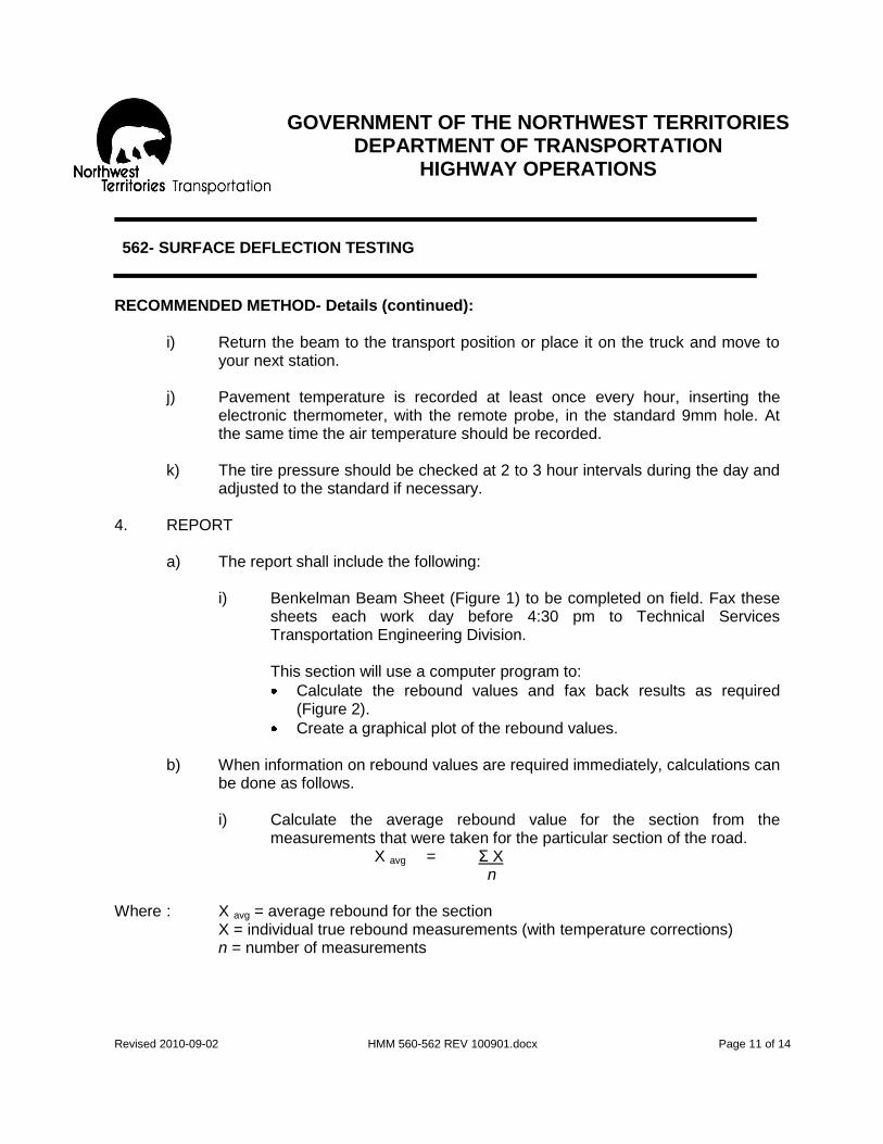
GOVERNMENT OF THE NORTHWEST TERRITORIES
DEPARTMENT OF TRANSPORTATION HIGHWAY OPERATIONS
Revised 2010-09-02 HMM 560-562 REV 100901.docx Page 11 of 14
562- SURFACE DEFLECTION TESTING
RECOMMENDED METHOD- Details (continued):
i) Return the beam to the transport position or place it on the truck and move to your next station.
j) Pavement temperature is recorded at least once every hour, inserting the
electronic thermometer, with the remote probe, in the standard 9mm hole. At the same time the air temperature should be recorded.
k) The tire pressure should be checked at 2 to 3 hour intervals during the day and
adjusted to the standard if necessary. 4. REPORT
a) The report shall include the following:
i) Benkelman Beam Sheet (Figure 1) to be completed on field. Fax these sheets each work day before 4:30 pm to Technical Services Transportation Engineering Division.
This section will use a computer program to:
Calculate the rebound values and fax back results as required (Figure 2).
Create a graphical plot of the rebound values.
b) When information on rebound values are required immediately, calculations can be done as follows.
i) Calculate the average rebound value for the section from the
measurements that were taken for the particular section of the road. X avg = Σ X n
Where : X avg = average rebound for the section X = individual true rebound measurements (with temperature corrections) n = number of measurements

GOVERNMENT OF THE NORTHWEST TERRITORIES
DEPARTMENT OF TRANSPORTATION HIGHWAY OPERATIONS
Revised 2010-09-02 HMM 560-562 REV 100901.docx Page 12 of 14
562- SURFACE DEFLECTION TESTING
ii) Calculate the standard deviation of the rebound values using the
equation:
S = Σ (X – X avg) -2
n - 1 Where: S = standard deviation of rebound values X = individual rebound measurements X avg = average rebound for the section n = number of measurements
This standard deviation of the rebound values is a measure of the spread of the sample data and can be used with the mean to estimate the distribution and range of strength (rebound) values, which may be encountered over the section.
iii) Calculate the estimated rebound value which is exceeded in only 2% of
the length of the flexible pavement section:
MAXIMUM PROBABLE = (X avg + 2S) 5. EXAMPLE AND WORKSHEET are attached.

GOVERNMENT OF THE NORTHWEST TERRITORIES
DEPARTMENT OF TRANSPORTATION HIGHWAY OPERATIONS
Revised 2010-09-02 HMM 560-562 REV 100901.docx Page 13 of 14
562- SURFACE DEFLECTION TESTING

GOVERNMENT OF THE NORTHWEST TERRITORIES
DEPARTMENT OF TRANSPORTATION HIGHWAY OPERATIONS
Revised 2010-09-02 HMM 560-562 REV 100901.docx Page 14 of 14
562- SURFACE DEFLECTION TESTING

GOVERNMENT OF THE NORTHWEST TERRITORIES
DEPARTMENT OF TRANSPORTATION HIGHWAY OPERATIONS
Revised 2010-04-15 HMM 803-899 rev 10.docx Page 1 of 48
803- CULVERT INSTALLATION
OBJECTIVE To instal l culverts to facil i tate drainage and preserve the grade. DESCRIPTION Culvert installat ion includes:
1. Instal lat ion of culverts at new locatio ns to correct drainage problems.
2. Instal lat ion of culverts to facil i tate access for the convenience of the Department .
3. Replacement of culverts that are considered to be beyond the scope of normal maintenance.
LEVEL OF SERVICE The use of the culvert instal lat ion act ivi ty wi l l be required when it becomes necessary to alleviate drainage problems or restore drainage patterns, mainly for the preservat ion of the grade, and when the work is either not a maintenance function or is beyond the scope of the nor mal maintenance act ivit ies. Before any work is undertaken using this act ivity, approval with necessary funding must be obtained from the Regional Manager . RESPONSIBILITY The Regional Manager or the Project Off icer is to schedule and manage in col laborat ion with the f ield and headquarters.

GOVERNMENT OF THE NORTHWEST TERRITORIES
DEPARTMENT OF TRANSPORTATION HIGHWAY OPERATIONS
Revised 2010-04-15 HMM 803-899 rev 10.docx Page 2 of 48
803- CULVERT INSTALLATION
PRODUCTIVITY GUIDELINES: RESOURCE GUIDELINES: Quantity Standard- Crew- Note: Annual program 2-Heavy Equipment Operator (class 03) determined by need 2-Laborers (class 05)
Average Daily Production Range- Equipment- 0.5 of a culvert 1-Tandem Dump (class 1504) 1-Tilt Deck (class 1211) 1-Loader (class 2109)
1-Pickup (class 1823) 1-Plate Tamper for Compaction *1-Backhoe (class 2809) , ( in most instances this larger type of backhoe is rented and may have a compact ion head attachment .)
Materials- 800 mm diameter Culvert or as required Pit Run Gravel (code 108)
SCHEDULING: As approved and in a t imely manner RECOMMENDED METHOD 1. Consult with Highway Operations Off ice in Hay River to coordinate
act ivit ies and budget . Request approval for necessary permits and advice for any possible environmental concerns.
2. Method wil l vary sl ight ly according to the scope of the project. The
standard method for instal lat ion of a culvert is outl ined in Activity 203 (culvert repair/replacement).
3. Al l work to be done in accordance with safe work methods and in conformance to sound engineering pract ice.
4. The completed work to be reported on the appropr iate Maintenance
Activity Report ing Forms with a descr ipt ive report on the scope of the work completed.

GOVERNMENT OF THE NORTHWEST TERRITORIES
DEPARTMENT OF TRANSPORTATION HIGHWAY OPERATIONS
Revised 2010-04-15 HMM 803-899 rev 10.docx Page 3 of 48
804- BINDER APPLICATION
OBJECTIVE To stabil ize loose surface gravel with binder to provide a smoother safer driving surface. DESCRIPTION Binder appl icat ion involves the applicat ion of a clay binder to gravel on the road surface to:
- Reduce ravel ing - Corrugation - Loss of gravel
LEVEL OF SERVICE Whenever the gravel surface exhibits ear ly failure between normal cycles of blading it should be analyzed to determine if there is a gradation def iciency. Once the def iciency is known, it should be determined what correct ive alternatives are avai lable. I f applicat ion of soil binder is the most economic choice, then the appropr iate amount should be appl ied. The desired gradation of the end product on the road should conform to specif icat ion s shown on the chart in Activity 830. I t should be possible to attain an optimum compact ion with the gradation, which wi l l provide a longer last ing surface due to better resistance to the destruct ive act ion of the traff ic. Before any work is undertaken using this act ivity approval with the necessary funding must be obtained from the Regional Manager . RESPONSIBILITY Highway Maintenance Supervisor to schedule with guidance from the Regional Manager.

GOVERNMENT OF THE NORTHWEST TERRITORIES
DEPARTMENT OF TRANSPORTATION HIGHWAY OPERATIONS
Revised 2010-04-15 HMM 803-899 rev 10.docx Page 4 of 48
804- BINDER APPLICATION
PRODUCTIVITY GUIDELINES: RESOURCE GUIDELINES: Quantity Standard- Crew- Annual program determined 5-Heavy Equipment Operator (class 03) by need 2-Laborer (class 05) 2-Traff ic Control Staff
Average Daily Production Range- Equipment- 2 kilometers 1-Motor Grader (c lass 2304) 4-Tandem Trucks (class 1504) 1-Loader (class 2109) 1-Sl ip- in Tank (class 5100)
1-Water Pump (class 5801) 1-Roller (class 2600) Materials- Clay Binder (code 104) Water (code 990)
SCHEDULING: June to mid September, during periods of dry weather. Resource equipment can be reduced when done in conjugation with wet blading. RECOMMENDED METHOD 1. In advance of the operat ion, take representat ive samples of the
surface gravel f rom the road surface and complete a sieve analysis to determine type and quant ity of binder required to produce an aggregate similar to C-1 traff ic gravel specif icat ions with 12 -15% f ines content. Contact the Highway Operations Off ice in Hay River f or more information or cold mix specif icat ions.
2. Dry binder or blend with traff ic gravel at pit . This wi l l make it easier for
the trucks to dump more uniformly on the road. 3. Place Traff ic Control Staff , s igns and safety devices as required.

GOVERNMENT OF THE NORTHWEST TERRITORIES
DEPARTMENT OF TRANSPORTATION HIGHWAY OPERATIONS
Revised 2010-04-15 HMM 803-899 rev 10.docx Page 5 of 48
804- BINDER APPLICATION
RECOMMENDED METHOD (continued): 4. Tight blade the surface ahead of the binder being laid down and
windrow gravel near shoulder or road. I f possible do not disturb the compacted gravel mat.
5. Scar ify any rough and sandy areas.
6. Dump binder on the road as uniformly as possible at the rate of : 35 m3 to 55 m3 per k ilometer depending on the results of the analysis in step 1. Please coordinate the quantities for these activities with the Highway Operations Office in Hay River.
7. Blade binder material unt i l the windrow is uniform.
8. Combine the binder and gravel windrows and blade unti l well mixed.
9. Dampen the surface with water and spread mater ial to produce the standard cross-section (4% crown with tangents and 4% to 8% crossfall on superelevated curves).
10. Add addit ional water as required.
11. Compact with rol lers.
12. Remove Traff ic Control Staf f , signs and safety devices.

GOVERNMENT OF THE NORTHWEST TERRITORIES
DEPARTMENT OF TRANSPORTATION HIGHWAY OPERATIONS
Revised 2010-04-15 HMM 803-899 rev 10.docx Page 6 of 48
806- GRAVEL SURFACE REHABILITATION
OBJECTIVE To re-establish the design cross sect ion or upgrade gravel surface to a specif ic level with a major applicat ion of gravel when the quantit ies in the annual surfacing program are inadequate. DESCRIPTION Gravel surface rehabi l itat ion involves the applicat ion of traff ic gravel on continuous long sections of gravel surface w ith signif icant quantit ies to:
- Re-establ ish design cross-sect ion - Upgrade a gravel surface ( i.e. major increases in traf f ic or road
category change that requires wet blading) LEVEL OF SERVICE This “re-gravel l ing” effort wi l l be required when there has been a signif icant loss of material and cannot regain through ANNUAL surfacing method (Activity 114) as evidenced by f requent surface breaks during dry weather, excessive rutt ing during wet weather and a serious loss of the intended cross-sect ion. Also addit ional quantit ies wi l l be required when upgrading of the road surface becomes necessary due to either an increase in traf f ic or a road category change. Before any work is undertaken using this act ivity, approval with the necessary funding must be obtained from the Regional Manager. RESPONSIBILITY: The Highway Maintenance Supervisor with guidance from the Regional Manager wil l assess the overall need for this act ivity in co ordinate with Headquarters. The Regional Manager or the Project Off icer is to sch edule and manage in col laboration with the f ield and headquarters. Refer to “Highway Maintenance Operat ing Instruct ions” for:
- Product ivity guidel ines - Resource guidel ines - Scheduling - Method.
GOVERNMENT OF THE NORTHWEST TERRITORIES
DEPARTMENT OF TRANSPORTATION HIGHWAY OPERATIONS
Revised 2010-04-15 HMM 803-899 rev 10.docx Page 7 of 48
806- GRAVEL SURFACE REHABILITATION
SPECIAL NOTE for all of Section 806: This activity has been assigned to contractors over the last few years. This section will serve as a reference. Recommend that all staff assigned to monitor the contractor have a copy of the contract documents available for their review and to present any changes in specifications and operational requirements. Please contact the Highway Operations Office in Hay River for contractor schedules or for more information. PRODUCTIVITY GUIDELINES: RESOURCE GUIDELINES: Quantity Standard- Crew- Varies 3-Heavy Equipment Operators (class 03) 2-Gravel Checkers (class 05) 2-Traff ic Control Staff
Average Daily Production Range- Equipment- 600m3 1-Motor Grader (c lass 2304) Note: Contractor should 1-Tandem Axle Tractor (class 1109) have suf f icient Trucks to 1-Tanker (Class 1304) haul 20,000 tonne-km or 1-102 mm Water Pump (class 5801) 12,000m3-km 1-Packer (class 2600) 2-Pickups (class 1823)
Hired/Contract Equipment: 6-Tandem Axle Tractors c/w Belly
Dumps 1-Loader (over 3.5m 3)
Materials- Crushed Gravel (code 110) Water (code 990)
SCHEDULING: Appl icat ion per iod - late May to late July. Gravel surface rehabi l itat ion should begin as soon as road condit ions have returned to normal, following spring break-up condit ions, and should be done in such a manner that the operat ion does not conf l ict with dust abatement programs.

GOVERNMENT OF THE NORTHWEST TERRITORIES
DEPARTMENT OF TRANSPORTATION HIGHWAY OPERATIONS
Revised 2010-04-15 HMM 803-899 rev 10.docx Page 8 of 48
806- GRAVEL SURFACE REHABILITATION
RECOMMENDED METHOD- General Approach
1. Before any gravel is placed, the road must be proper ly prepared to ensure that the base is stable and the gravel surface is smooth and uniform with the desired cross -section.
2. The Highway Maintenance Supervisor is responsible for the
management of gravel surface rehabi l ita t ion projects. Prior to start-up of the project, he must:
a) Check the contract for accuracy.
b) Have name of contractor, proposed start ing date and a l ist
of trucks, loaders and other equipment to be used. The following information wi l l be required for al l tr ucks used on the haul:
- License number, - Maximum al lowable gross, - Tar weight per unit .
c) Ensure that the checkers are trained.
d) I f required by the contract, determine volume capacity
al lowable for each truck.
e) Ensure that the maintenance forces and the gravel haul ing operat ions wi l l be proper ly coordinated.
For detailed procedures for guidance of Highway Maintenance Supervisors responsible for these contracts, refer to the sect ion entit led “Gravel Surfacing Contracts” that follows “Recommended Method - Detai ls” in Activity 114.

GOVERNMENT OF THE NORTHWEST TERRITORIES
DEPARTMENT OF TRANSPORTATION HIGHWAY OPERATIONS
Revised 2010-04-15 HMM 803-899 rev 10.docx Page 9 of 48
806- GRAVEL SURFACE REHABILITATION
RECOMMENDED METHOD- Details
1. Place Traff ic Control Staff , signs and safety devices.
2. Haul and dump gravel along roadway.
Dump Gravel along one side of the roadway, spacing each truck to obtain a uniform rate of appl icat ion and eliminate unnecessary drif t ing of the aggregate with the motor grader.
3. Windrow and mix with motor grader
Cut the mater ial f rom dump pi les with motor grader blade toward opposite shoulder of roadway. Move the mater ial back and forth to form a uniform sized windrow. Usually for easier spreading of the material, larger windrows should be placed at the center of the roadway.
4. Apply water to surface and dur ing the spreading operation as
necessary.
5. Cut material f rom windrow near the center of the roadway in proper amounts towards each shoulder, spreading to give an even depth of material across the ful l roadway surface. This should result in a f inished surface.
6. Apply water as necessary af ter spreading is complete.
7. Compact with pneumatic t ired rol ler.
8. Remove Traff ic Control Staf f , safety devices and signs.

GOVERNMENT OF THE NORTHWEST TERRITORIES
DEPARTMENT OF TRANSPORTATION HIGHWAY OPERATIONS
Revised 2010-04-15 HMM 803-899 rev 10.docx Page 10 of 48
810- MAJOR GRADE REPAIRS
SPECIAL NOTE for all of Section 810: This activity has been assigned to contractors over the last few years. This section will serve as a reference. Recommend that all staff assigned to monitor the contractor have a copy of the contract documents available for their review and to present any changes in specifications and operational requirements. Please contact the Highway Operations Office in Hay River for contractor schedules or for more information. OBJECTIVE To rect ify serious grade problems that require major correct ive act ion. DESCRIPTION Major grade repair involves the repair of long sections, or large areas of roadway with def ic iencies such as grade failures, washout or sl ides. Includes shoulders and side slopes. LEVEL OF SERVICE Major grade repair act ivity wi l l be required whe n it is necessary to carry out extensive repairs, beyond rout ine maintenance, to restore or improve the highway grade, in order to provide rel iabi l i ty of service to the user. Before any work is undertaken using this act ivity, approval with necessary funding must be obtained from the Regional Manager . RESPONSIBILITY: The Highway Maintenance Supervisor with guidance from the Regional Manager wi l l assess the overal l need for this act ivity in col laboration with Headquarters. The Regional Manager or the Project Off icer is to schedule and manage in col laboration with the f ield and headquarters.

GOVERNMENT OF THE NORTHWEST TERRITORIES
DEPARTMENT OF TRANSPORTATION HIGHWAY OPERATIONS
Revised 2010-04-15 HMM 803-899 rev 10.docx Page 11 of 48
810- MAJOR GRADE REPAIRS
PRODUCTIVITY GUIDELINES: RESOURCE GUIDELINES: Quantity Standard- Crew- Annual program as Varies determined by need
Average Daily Production Range- Equipment- Not Appl icable Varies
Materials- Miscellaneous (code 999)
SCHEDULING: As approved and in a t imely manner as this act ivity may be coordinated with other projects for economy of scale. RECOMMENDED METHOD
1. Determine the cause and order to devise solut ion. Please contact the Highway Operat ions Off ice in Hay River for assistance or for more information.
2. The Director of Highways in collaboration with the Regional
Manager to approve methodology of repair.
3. Method wil l vary according to scope of work.
4. Al l work to be done in accordance with safe work methods and in conformance to sound engineering pract ice.
5. The completed work to be reported on the appropr iate
Maintenance Management Report ing Forms, with a descr ipt ion of the work completed.

GOVERNMENT OF THE NORTHWEST TERRITORIES
DEPARTMENT OF TRANSPORTATION HIGHWAY OPERATIONS
Revised 2010-04-15 HMM 803-899 rev 10.docx Page 12 of 48
820- BRIDGE PAINTING
SPECIAL NOTE for all of Section 820: This activity has been assigned to contractors with specialized methods and equipment. This section will serve as a reference. Recommend that all staff assigned to monitor the contractor have a copy of the contract documents available for their review and to present any changes in specifications and operational requirements. Please contact the Highway Operations Office in Hay River for contractor schedules or for more information. OBJECTIVE To prevent corrosion of the steel components. DESCRIPTION Paint ing of steel br idges by hand or with spray equipment, including al l related operations such as sett ing up scaffolding and cleaning the steel by wire brushing, chipping, sand blast ing, etc. LEVEL OF SERVICE Reasons for bridge paint ing are:
- Economical preservation of the structu re - Improved visibi l i ty - Improved appearance
Paint ing wi l l be carr ied out when deteriorat ion of exist ing paint permits corrosion of base steel. This wi l l occur af ter an interval of many years. No paint ing of any bridge or part of the bridge wil l take place unt i l the work has been deemed necessary by the Director of Highways. RESPONSIBILITY: The Director of Highways wil l approve schedule and management of this work with input f rom inspection reports and the br idge plan f rom the Str uctures Section. As required, the Regional Manager wil l coordinate with the Director of Highways for the act ivit ies of Own Forces to support this work.

GOVERNMENT OF THE NORTHWEST TERRITORIES
DEPARTMENT OF TRANSPORTATION HIGHWAY OPERATIONS
Revised 2010-04-15 HMM 803-899 rev 10.docx Page 13 of 48
820- BRIDGE PAINTING
PRODUCTIVITY GUIDELINES: RESOURCE GUIDELINES: Quantity Standard- Crew- Annual program as Varies determined by need
Average Daily Production Range- Equipment- Not Appl icable Varies
Materials- Varies
Note: This work will normally be done by contract. SCHEDULING: Schedule paint ing, including surface preparat ion, in warm weather, af ter needed structural repairs and annual cleaning are completed (June to September). Caution: Ensure that al l required environmental concerns have been
addressed before any work begins. Note: Environmental author it ies are very sensit ive to any paint related operation on a bridge, especial ly when there is any water under the br idge.
RECOMMENDED METHOD
1. The Director of Highways to specify methods and materials with support f rom the Structures Section .
2. Al l work to be done in accordance with safe work methods and in
conformance to sound engineering pract ice and in compliance with the Safety Act and Regulat ions.
3. Report the completed work on the appropr iate Maintenance
Activity Report ing forms, with a br ief descript ion of the work.

GOVERNMENT OF THE NORTHWEST TERRITORIES
DEPARTMENT OF TRANSPORTATION HIGHWAY OPERATIONS
Revised 2010-04-15 HMM 803-899 rev 10.docx Page 14 of 48
821- MAJOR BRIDGE REPAIR
SPECIAL NOTE for all of Section 821: This activity has been assigned to contractors with specialized methods and equipment. This section will serve as a reference. Recommend that all staff assigned to monitor the contractor have a copy of the contract documents available for their review and to present any changes in specifications and operational requirements. Please contact the Highway Operations Office in Hay River for contractor schedules or for more information. OBJECTIVE To repair a br idge structure DESCRIPTION Major br idge repair includes major structural repairs, repair or replacement of joints, bearings, t imber and concrete decking, etc. LEVEL OF SERVICE The major bridge act ivity wi l l only be used when it become necessary to perform extensive work of a special nature to the structure for the safety of the motorist, or the preservat ion of the bridge. No work can be conducted on any br idge or part of the bridge unti l the work has been deemed necessary and has been approved by the Director of Highways. RESPONSIBILITY: The Director of Highways wil l approve schedule and management of this work with input f rom inspection reports and the br idge plan f rom the Structures Section. As required, the Regional Manager wil l coordinate with th e Director of Highways for the act ivit ies of Own Forces to support this work.

GOVERNMENT OF THE NORTHWEST TERRITORIES
DEPARTMENT OF TRANSPORTATION HIGHWAY OPERATIONS
Revised 2010-04-15 HMM 803-899 rev 10.docx Page 15 of 48
821- MAJOR BRIDGE REPAIR
PRODUCTIVITY GUIDELINES: RESOURCE GUIDELINES: Quantity Standard- Crew- Annual program as Varies determined by need
Average Daily Production Range- Equipment- Not Appl icable Varies
Materials- Varies
Note: This work will normally be done by contract. SCHEDULING: As required and approved. RECOMMENDED METHOD Caution: Ensure that al l required environmental concerns have b een
addressed before any work begins. Note: Environmental author it ies are very sensit ive to any operat ion on a bridge, especial ly when there is any water under the bridge.
1. The Director of Highways to specify methods and materials with
support f rom the Structures Section.
2. Al l work to be done in accordance with safe work methods and in conformance to sound engineering pract ice and in compliance with the Safety Act and Regulat ions.
3. Report the completed work on the appropr iate Maintenance Management Report ing forms, with a descr ipt ion of the completed work attached.

GOVERNMENT OF THE NORTHWEST TERRITORIES
DEPARTMENT OF TRANSPORTATION HIGHWAY OPERATIONS
Revised 2010-04-15 HMM 803-899 rev 10.docx Page 16 of 48
830- GRAVEL CRUSHING
SPECIAL NOTE for all of Section 830: This activity has been assigned to contractors with specialized methods and equipment. This section will serve as a reference. Recommend that all staff assigned to monitor the contractor have a copy of the contract documents available for their review and to present any changes in specifications and operational requirements. Please contact the Highway Operations Office in Hay River for contractor schedules or for more information. OBJECTIVE To produce crushed or screened gravel meeting required specif icat ions for use in highway resurfacing, chipseal coat ing (also known as AST or Asphalt ic Surface Treatment) and other maintenance needs such as winter sand. DESCRIPTION The production of crushed or screened gravel material with proper storage in stockpiles as per the development plan per pit of quarry. LEVEL OF SERVICE For budget purposes, the crushing program is l inked to other programs for the cycl ical resurfacing of gravel surfaces and the chipseal and surface repair of asphalt surfaces. The planned average annual requirement for 1 kilometer of highway is based on road surface types (and est imates f rom previous work ) as in Table 830-1:
- Chipseal or AST 10 cum/year - Gravel 50 cum/year
This volume does not include the ongoing act ivit ies of the Chipseal Over lay Program or the impacts of Capital Reconstruct ion Project s. RESPONSIBILITY: The Director of Highways wil l approve schedule and management of this work with input f rom inspection reports and the annual operations plan. As required, the Regional Manager wil l coordinate with the Director of Highways for the act ivit ies of Own Forces to support this work.

GOVERNMENT OF THE NORTHWEST TERRITORIES
DEPARTMENT OF TRANSPORTATION HIGHWAY OPERATIONS
Revised 2010-04-15 HMM 803-899 rev 10.docx Page 17 of 48
830- GRAVEL CRUSHING
PRODUCTIVITY GUIDELINES: RESOURCE GUIDELINES: Quantity Standard- Crew- See level of service for 1-Lab Person (class 05) planned quantit ies
Average Daily Production Range- Equipment- As per each specif ic contract Own Force 1-Pickup (class 1904) 1-Lab Trai ler (c lass 5911)
Contractor 1-Crusher Complex
Note: This work will normally be done by contract. SCHEDULING: Normally f rom Apri l through to October but can be completed year -round. RECOMMENDED METHOD Caution: Ensure that al l required environmental and land use permits are
in place pr ior to the start of work. Please contact the Highway Operations Off ice in Hay River for more information.
1. The Director of Highways to specify methods and materials with
support f rom the Highways Division.
2. Al l work to be done in accordance with safe work methods and in conformance to sound engineering pract ice and in compliance with the Safety Act and Regulat ions.
3. Contract for the required quant it ies of the specif ic aggregate required at the designated stockpile locat ions. Refer to Table 830-2 for standard “Aggregate Specif icat ions”.
4. Monitor the contractor to ensure conformity with the terms of the contract. For specialty aggregates, screening of exist ing stockpiles of crushed aggregates may be require d to obtain the desired product.

GOVERNMENT OF THE NORTHWEST TERRITORIES
DEPARTMENT OF TRANSPORTATION HIGHWAY OPERATIONS
Revised 2010-04-15 HMM 803-899 rev 10.docx Page 18 of 48
830- GRAVEL CRUSHING – Table 830-1

GOVERNMENT OF THE NORTHWEST TERRITORIES
DEPARTMENT OF TRANSPORTATION HIGHWAY OPERATIONS
Revised 2010-04-15 HMM 803-899 rev 10.docx Page 19 of 48
830- GRAVEL CRUSHING – Table 830-2

GOVERNMENT OF THE NORTHWEST TERRITORIES
DEPARTMENT OF TRANSPORTATION HIGHWAY OPERATIONS
Revised 2010-04-15 HMM 803-899 rev 10.docx Page 20 of 48
840- CHIP SEALING
OBJECTIVE To replace/ improve the wearing surface and to prevent surface entry of moisture into the subgrade. DESCRIPTION Chip seal or A.S.T. (Asphalt ic Surface Treatment ) is the applicat ion of l iquid asphalt oi l and covered with a specif ied aggregate to form a more resistant surface. This harder surface does not require dust suppressants nor grading af ter the oil has set and the excess aggregate is swept off . This new AST surface wi l l preserve and strengthen the highway, improve skid-resistance and prevent surface entry of moisture into the subgrade . This surface is not “asphalt ,” but it serves wel l on northern roads and highways. Whereas asphalt can last up to twenty years and can withstand high traf f ic volumes, chipseal is very economical and lasts for f ive to seven years with low traf f ic volumes. The chipseal on the NWT Highway System is evaluated every year to better plan rehabil itat ion act ivit ies and maintenance operat ions. Chipseal or A.S.T. wi l l be considered for replacement when the following occurs :
- Surface ravel ing or wear ing thin due to loss of aggregate - Al l igator cracking without grade failure, - Pol ishing of aggregate, - Damage due to maintenance, i.e. ice removal with serrated
blades. LEVEL OF SERVICE Chip seal ing is one of the more important maintenance act ivit ies for the preservat ion of asphalt ic surfaces and the simp lest method for the creation of a durable wear ing surface on the highway. Prior approval f rom the Regional Manager in collaboration with the Director of Highways is required as chipseal or A.S.T. act ivit ies require coordinat ion for the supply of aggregates and the del ivery of asphalt oi l. Other coordinat ion issues involve the efforts of contractors enlisted through the capital program and the support act ivit ies required to prepare for the applicat ion of chipseal. Please contact the Highway Operat ions Off ice in Hay River for more information.

GOVERNMENT OF THE NORTHWEST TERRITORIES
DEPARTMENT OF TRANSPORTATION HIGHWAY OPERATIONS
Revised 2010-04-15 HMM 803-899 rev 10.docx Page 21 of 48
840- CHIP SEALING
LEVEL OF SERVICE (continued): Prior to undertaking of chip seal operat ions the fol lowing condit ions must be corrected:
- Grade failures (use of act ivity 122) - Repair ing al l surface breaks (use Activity 161) - Seal ing or repair of al l cracks in excess of 33 mm in width (use
Activity 162 for A.S.T. and Activity 163 for pavement) - Restorat ion of surface cross-sect ion def iciencies to an
acceptable level (use Activity 164) The usual f requency for chip sealing is:
1. Single and double chip seals every 5-7 years.
2. Road and plant mixed surface every 5 -10 years. Note that new products and methods may extend this f requency to 10 -18 years.
The exact f requency to be based on the annual pavement evaluation – note that areas with ongoing issues with sub grade failure, excessive cracking or saturat ion f rom high water levels may require added efforts. RESPONSIBILITY: The Director of Highways wil l approve schedule and management of this work with input f rom inspection reports and the annual operations plan. As required, the Regional Manager wil l coordinate with the Director of Highways for the act ivit ies of Own Forces to support this work. Refer to “Highway Maintenance Operat ing Instruct ions” for:
- Product ivity guidel ines - Resource guidel ines - Scheduling - Method.
GOVERNMENT OF THE NORTHWEST TERRITORIES
DEPARTMENT OF TRANSPORTATION HIGHWAY OPERATIONS
Revised 2010-04-15 HMM 803-899 rev 10.docx Page 22 of 48
840- CHIP SEALING
PRODUCTIVITY GUIDELINES: RESOURCE GUIDELINES: Quantity Standard- Crew- Defined by approved program 1-Highway Maintenance Supervisor 8-Heavy Equipment Operator 5-Laborers 2-Traff ic Control Staff 1- Pi lot Truck Operator
Average Daily Production Range- Equipment- 7 lane kilometers, typical 1-Truck Tractor (class 1109) (To be adjusted based on 1-Distr ibutor- 9000 l i ter (class 3077) distance from aggregate source) 1-Chip Spreader (class 3044) 2-Asphalt Storage Tanks (class 3022)
4-Tandem Trucks (class 1504) 1-Loader (class 2109) 1-Broom (class 5244) 2-Rollers (class 2600)
4-Pickups (class 1904)
Materials- Emulsion Asphalt (code 225) Chips (code 110)
SCHEDULING: During periods of hot, dry weather. Normally the best t ime is between mid June to the end of August. Essential that the temperature of the road surface be above 10°C. See DOT standard RECOMMENDED METHOD- General Approach: As stated in the descript ion, chip seal ing is comprised of two components; a l iquid asphalt oil and aggregate. By obtaining the optimum combination of these two elements, a good long last ing asphalt ic surface treatment is possible.

GOVERNMENT OF THE NORTHWEST TERRITORIES
DEPARTMENT OF TRANSPORTATION HIGHWAY OPERATIONS
Revised 2010-04-15 HMM 803-899 rev 10.docx Page 23 of 48
840- CHIP SEALING
RECOMMENDED METHOD- General Approach (continued): The select ion of the proper grade of asphalt for chip seal ing should consider the environment, the aggregate and the equipment which wi l l be used. According to the Asphalt Inst itute, the correct grade of asphalt for a surface treatment should:
1. When applied, be f luid enough to spray properly and cover the surface uniformly.
2. Af ter applicat ion, retain the proper consistency to wet the applied aggregate.
3. Cure and develop adhesion quickly. 4. Af ter roll ing and cur ing, hold the aggregate t ight ly to the
road surface to prevent dis lodgment by traff ic. 5. When appl ied in the r ight amount it should not bleed or
str ip with changing weather condit ions. Af ter the chip seal ing has been subjected to traff ic the aggregate part icles wi l l seek their densest state. This can result only when the part ic les have oriented themselves on their f lattest s ide. Ideal ly, the asphalt oil should f i l l approximately 70% of the voids between part ic les as shown in Figure 1. With less than 50% of the void f i l led the asphalt surface treatment wi l l appear acceptable but wi l l perform poorly result ing in aggregate loss . With 100% of the voids f i l led the chipseal wi l l appear dark and wil l also perform poorly as excessive asphalt o i l causes f lushing. Because the aggregate part ic les tend to rest on their longest side, it becomes intuit ively obvious that the asphalt appl icat ion rate should be based on the average least dimension (ALD) as shown in Figure 1. The embedment depth is then based on the ALD. In general, the larger aggregate size results in a better surface treatment because the control of the asphalt spread becomes less cr i t ical. However, larger stones increase t ire noise which may not be desirable. Thus a compromise must be made.

GOVERNMENT OF THE NORTHWEST TERRITORIES
DEPARTMENT OF TRANSPORTATION HIGHWAY OPERATIONS
Revised 2010-04-15 HMM 803-899 rev 10.docx Page 24 of 48
840- CHIP SEALING
RECOMMENDED METHOD- General Approach (continued): The cover aggregate should be as uniform as possible. I t is suggested that 60% to 70% of the part ic les passing the specif ied normal size must be retained on the sieve, having an opening of 70% of that size, and that the smallest s ize part ic les should be no more than one half the largest size. Referr ing to Figure 2, it can be seen that if there is excessive dif ferences in aggregate part icle size, many of t he smaller part ic les wi l l be covered with asphalt oi l whi le larger part icles wil l be whipped of f by traff ic. The same condit ion may occur if many of the part icles are elongated. The ideal shape of the aggregate part icles is therefore cubical or pyramidal w ith al l part icles uniform in size. In summary, four things must be remembered in the design of a chip sealed surface:
1. A good foundation is a necessity. 2. Proper l iquid asphalt oi l must be selected for the use. 3. The aggregate should be of a uniform size and cubicle or
pyramidal shape. 4. The embedment depth and asphalt spread are based on
the average least dimension. Good Work Techniques Perhaps the single most important factor in producing a good chipseal is the recognit ion of a really good chipseal by everyone on the project. What should be seen is an aggregate without any evidence of f lushing, bleeding or ravel ing. Figure 3 shows the common problems, their causes and cures. Familiar ity with this chart wi l l aid considerably in gett ing a good, long last i ng job. The chip sealing procedure can be broken into four steps:
1. Foundation preparat ion. 2. Spreading of l iquid asphalt oi l . 3. Spreading of aggregate. 4. Compact ion.

GOVERNMENT OF THE NORTHWEST TERRITORIES
DEPARTMENT OF TRANSPORTATION HIGHWAY OPERATIONS
Revised 2010-04-15 HMM 803-899 rev 10.docx Page 25 of 48
840- CHIP SEALING – Figures 840-1 & 840-2

GOVERNMENT OF THE NORTHWEST TERRITORIES
DEPARTMENT OF TRANSPORTATION HIGHWAY OPERATIONS
Revised 2010-04-15 HMM 803-899 rev 10.docx Page 26 of 48
840- CHIP SEALING – Figure 840-3
Figure 3: Common Problems Encountered with Chip Seals
Problem Possible Causes Suggested Remedies
i . Ravel ing
1. Traf f ic W ear . 2. Too l i t t le
asphalt o i l b inder . 3. Faul ty d ist r ibutor
operat ion.
1. Contro l traf f ic at low speeds . 2. Increase residual asphalt o i l . 3. Check spreader nozzle - use
correct d is tr ibutor techniques .
i i . Sl ippage Cracks
1. Lack of bond between surface course and base.
2. Asphalt o i l too sof t . 3. Traf f ic a l lowed before
asphalt o i l is cured.
1. See Problem v. 2. Use harder grade of asphalt oi l . 3. Remove traf f ic unt i l asphalt oi l
has cured.
i i i . Corrugat ions (washboarding)
1. Lack of stabi l i t y in surface pavement.
2. Lack of cohesion in untreated road.
3. Inadequate compact ion.
4. Stone too rounded. 5. Surplus asphalt .
1. Check for surface damage. 2. Change base spec if icat ions or
use treated base. 3. Compact the mater ia l. 4. Use crushed s tone. 5. Decrease asphal t o i l content.
iv. Bleeding and Streak ing
1. Non-uniform asphal t o i l spread.
2. Asphalt o i l content to great .
3. Loss of cover aggregate .
1. Use good dis tr ibutor technique . 2. Reduce asphal t o i l content . 3. Do not begin construct ion i f
ra in is l ikely or i f the grade is wet. 4. Contro l traf f ic .
v. Lack of Bond between Asphalt and Ex ist ing Surface
1. Cold weather . 2. Excess mois ture. 3. Dust . 4. Rain immediate ly
before or af ter construct ion .
6. Begin construct ion only when several weeks of warm dry wea ther is l ike ly.
7. Do not begin construct ion on a wet surface.
8. Broom surface and wash chips. 9. Do not begin construct ion when
ra in is l ikely wi th in 24 hours .
v i . Al l igator Crack ing
1. Weak base.
1. Strengthen the pavement s tructure.
GOVERNMENT OF THE NORTHWEST TERRITORIES
DEPARTMENT OF TRANSPORTATION HIGHWAY OPERATIONS
Revised 2010-04-15 HMM 803-899 rev 10.docx Page 27 of 48
840- CHIP SEALING
RECOMMENDED METHOD- General Approach (continued): Preparat ion of the foundat ion is of ten neglected or improper ly completed. As was started ear l ier, a weak foundation wi l l always result in rapid failure of any surface. The asphalt ic surface treatment spread is the most cr it ical part of the operat ion. Considerable care should be taken to unsure uniform applicat ion of the asphalt oi l . This required that the asphalt distr ibutor be in good condit ion and that the spray bar be proper ly adju sted. Part icular attent ion should be paid dai ly to the spray bar height, nozzle size and angle. Frequent checks of the nozzles should be made to keep them clean and functioning proper ly. The nozzle angle should be set according to the manufacturer’s specif icat ion.
A common error in pract ice is to set the end nozzle at 90 with respect to the spray bar. “This pract ice should not be permitted as it wi l l produce a fat streak on the edge and rob the adjacent spray fan of the lap from this nozzle. A curtain on the end of the bar or a special end nozzle with all nozzles set at the same angle wil l provide more uniform coverage and make a better edge.” The spray bar height should be selected and maintained throughout the applicat ion to assure uniformity of spread. Streaking wi l l occur if the spray bar is too high or too low. When the spray bar is the correct height, the transverse spread wil l be uniform. Figures 4 and 5 show the proper height and al ignment of the spray bar. The Asphalt Inst itute recommends that the transverse spread should be al lowed to vary no more than 15% for th e asphalt emulsions and no more than 10% for other asphalt cements and cutback asphalt. The distr ibutor should be inspected at regular intervals to assure this uniformity. The longitudinal spread should vary no more than 10%. The distr ibutor ’s longitudinal spread rate should be checked and all gauges cal ibrated for each project. Do not rely on the calibrat ion f rom another project. I f the distr ibutor is used, taken to another project and brought back, check it out to conf irm that the sett ings are correct fo r your project . Some adjustments may be required.

GOVERNMENT OF THE NORTHWEST TERRITORIES
DEPARTMENT OF TRANSPORTATION HIGHWAY OPERATIONS
Revised 2010-04-15 HMM 803-899 rev 10.docx Page 28 of 48
840- CHIP SEALING– Figures 840-4 & 840-5

GOVERNMENT OF THE NORTHWEST TERRITORIES
DEPARTMENT OF TRANSPORTATION HIGHWAY OPERATIONS
Revised 2010-04-15 HMM 803-899 rev 10.docx Page 29 of 48
840- CHIP SEALING
RECOMMENDED METHOD- General Approach (continued): I t is also recommended that building paper should be used at the beginning and end of each shot to prevent overlap and dripping at the construct ion joint. I f two layers of surface treatment are used, the top shot of asphalt should be made in the reverse direct ion of the bottom shot. Because the asphalt oi l wi l l reach the road surface temperature in one minute or less af ter applicat ion, the aggregate should be spread immediately af ter the asphalt. This distance between the asphalt distr ibutor and aggregate spreader and rol ler should be such that the rol ler makes its f irst full coverage within 30 seconds. A suf f icient number of trucks should be on the job to assure a continuous supply of aggregate to the spreader. I f , for any reason, there should be a break in the supply the distr ibutor should be stopped at a point where the aggregate wi l l cover it and a construct ion joint made. This requires that the procedure function in a precise and coordinated manner. The aggregate spreader should also be inspected before any operation begins. The spreader should be able to distr ibute the aggregate part ic les uniformly over the surface and at a rate which wi l l minimize aggregate loss. Aggregate quantit ies should be measured f rom a pan placed under the spreading operation or f rom pavement samples to determine compliance with specif icat ions. Quantit ies hauled should continue to be recorded in order to al low f ield personnel control of the operation. The aggregate must be wel l drained and dust f ree for good adhesion; but in some instance damp or dusty gravel must be used. Clean, damp aggregate causes no problem when used in warm, dry weather. When used with asphalt emulsions, damp aggregate is desirable; however a satisfactory surface treatment wi l l seldom result when aggregate having f ree water is used. There is some evidence that when dusty aggregates must be used, dampening wi l l improve results. Rollers are used to seat the aggregate part icles into the asphalt. Because steel-wheeled rol lers bridge over the smaller part ic les and depressions whi le crushing sof ter partic les, these steel-drum rollers should not be used on asphalt ic surface treatments. The resi l ient t ires on the self -propelled smooth-tread pneumatic rollers force the part icles f irmly into place without crushing them. I t is suggested that two rol lers be used to provide proper coverage.

GOVERNMENT OF THE NORTHWEST TERRITORIES
DEPARTMENT OF TRANSPORTATION HIGHWAY OPERATIONS
Revised 2010-04-15 HMM 803-899 rev 10.docx Page 30 of 48
840- CHIP SEALING
RECOMMENDED METHOD- General Approach (continued): Traff ic control is an of ten neglected facet of the construct ion of surface treatments. I ts importance cannot be overstated because the lack of traff ic control can easily destroy the best of jobs. Traff ic speeds must be maintained at less than 45 km/hr (preferred to be at 30 km/hr to increase safety for chipseal workers) unti l the f inal cover is set. Sharp turns should be avoided. Traff ic control also extends to al l construct ion equipment. Traff ic control becomes even more important should it rain before the treatment has cured. An important factor in construct ing a good surface treatment is the weather. Whenever possible, surface treatments should only be started when the weather is expected to be hot and dry dur ing and for several days af ter placement. Never start with a wet surface or if i t looks l ike rain is imminent.
The minimum ground temperature should be 10 C however, 20 C is more desirable. In summary, the fol lowing chip seal ing guidel ines are recommended:
1. Assure al l equipment is in good working condit ion and proper ly adjusted.
2. Spread aggregate immediately af ter the applicat ion of the asphalt oil .
3. Start and stop on building paper to prevent overlapping and dripping.
4. Only use pneumatic rol lers. 5. Control traff ic including construct ion vehicles unt i l the f inal
coat has set up. 6. Never start on a wet surface or if rain is l ikely.
7. The minimum ground temperature should be 10 C. 8. Familiar ize each person on the job with exactly what a good
treatment looks l ike, as well as the causes and cures of problems which might occur.
GOVERNMENT OF THE NORTHWEST TERRITORIES
DEPARTMENT OF TRANSPORTATION HIGHWAY OPERATIONS
Revised 2010-04-15 HMM 803-899 rev 10.docx Page 31 of 48
840- CHIP SEALING
RECOMMENDED METHOD- Details: The following descr ibes detai ls of the recommended method for chipseal operat ions for both a) Exist ing Asphalt Surfaces and b) Untreated Gravel Surfaces:
b) Exist ing Asphalt Surfaces:
1. Def ine the beginning and end of section to be done. 2. Place necessary signs and safety devices. 3. Stat ion Traff ic Control Staf f . 4. Clean surface to remove al l loose material with a sweeper,
etc. 5. Apply an appl icat ion of asphalt (usual ly 1.35 to 1.85 l iters)
per square meter depending on amount lost by absorption 6. Immediately apply cover aggregate using a chip spreader to
ensure an even coverage that wil l neither “bleed” or waste excessive aggregate, Normal appl icat ion with range from 15 to 30 kg/m2 .
7. Roll the seal coat with a rubber t ire rol ler to knead the aggregate into the emulsion and f inish the surface with a steel drum rol ler only once.
8. Al low the emulsion to proper ly cure. Often low speed traff ic wi l l assist with the “sett l ing” of the aggregate into the emulsion. Proper traff ic control is essential at this stage to prevent excessive loss of aggregate. The Pi lot Truck Operator must heed to the speed requirements of the project.
9. Lightly sweep the surface to remove al l loose aggregate when the new surface is suff icient ly “set” . A minimum of f ive full days of “sett ing” t ime is recommended.

GOVERNMENT OF THE NORTHWEST TERRITORIES
DEPARTMENT OF TRANSPORTATION HIGHWAY OPERATIONS
Revised 2010-04-15 HMM 803-899 rev 10.docx Page 32 of 48
840- CHIP SEALING
RECOMMENDED METHOD- Details (continued):
c) Untreated Surface (Gravel):
1. Select suitable areas as predetermined from grade elevation.
2. Place necessary signs and safety devices. 3. Stat ion Traff ic Control Staf f as required. 4. Prepare a watered and bound surface; true to grade and
cross section and free of loose gravel. Crown should be 3%, except curves which wil l have a uniform superelevated slope.
5. Broom the surface if necessary to remove loose material. 6. Apply an appl icat ion of asphalt oi l (usually 1.35 to 1.85 l iters
per square meter) depending on the amount lost by surface absorpt ion and the aggregate. If an emulsion is used surface should be dampened with water pr ior to the asphalt applicat ion.
7. Immediately apply a cover aggregate using a chip spreader to ensure an even coverage that neither “bleeds” or wastes excessive loss of aggregate.
8. Roll the aggregate with a rubber t ire rol ler. 9. Al low emulsion to proper ly cure. Often low speed traf f ic wi l l
assist with the “sett l ing” of the aggregate into the emulsion. Proper traff ic control is essent ial at this stage to prevent excessive loss of aggregate. The Pi lot Truck Operator must heed to the speed requirements of the project.
10. Lightly sweep the surface to remove al l loose aggregate when the new surface is suff icient ly “set” . A minimum of f ive full days of “sett ing” t ime is required; some wett ing of surface may be required to ensure bonding of the two applicat ions of emulsion.
11. For a second applicat ion, repeat step 6, 7, 8 and 9.

GOVERNMENT OF THE NORTHWEST TERRITORIES
DEPARTMENT OF TRANSPORTATION HIGHWAY OPERATIONS
Revised 2010-04-15 HMM 803-899 rev 10.docx Page 33 of 48
841- RESURFACING WITH PREMIX
OBJECTIVE To restore surface prof i le to a level that wil l give an acceptable quality of r ide and safety. DESCRIPTION Resurfacing with premix involves the surfacing of highway sections with pavement or asphalt ic surface treatment that are in excess of 100 meters in length using a premixed asphalt ic mater ial to correct def iciencies by:
- Repair broken sections - Over laying distorted areas - Re-level ing of rutted sections - Level ing prior to chip sealing
LEVEL OF SERVICE Resurfacing should be done when pavement has lost its r iding quality to the following extent:
- Long sections of broken pavement - Long sect ions of pavement that have an irregular or distor ted
surface (depression, washboard, etc.) that provides an uncomfortable or a dangerous dr iving condit ion at the legal speed l imit. This is general ly surface variat ions of more than 25 mm in a distance of 3 meters.
- Long sections of “rutted’ pavement. General ly, rutted to a depth greater than 25 mm in a wheel path width of 1 meter.
- Unbroken depressions that should be restored to or iginal prof i le, especial ly before chip sealing.
Future road improvement plans fo r the area as wel l as the current safety level of the highway sect ion should be taken into considerat ion when consider ing the level of the repair effort. Before any work is undertaken using this act ivity, approval with the necessary funding must be obtained from the Regional Manager.

GOVERNMENT OF THE NORTHWEST TERRITORIES
DEPARTMENT OF TRANSPORTATION HIGHWAY OPERATIONS
Revised 2010-04-15 HMM 803-899 rev 10.docx Page 34 of 48
841- RESURFACING WITH PREMIX
RESPONSIBILITY Highway Maintenance Supervisor to schedule in accordance with instruct ions f rom the Regional Manager, and in col laboration with Headquarters. Refer to the “Highway Operat ing Instruct ions” for:
- Product ivity guidel ines, - Resource guidel ines, - Scheduling, - Method.
PRODUCTIVITY GUIDELINES: RESOURCE GUIDELINES: Quantity Standard- Crew- Defined by approved program 8-Heavy Equipment Operators (class 03) 3-Laborers (class 05) 2-Traff ic Control Staff
Average Daily Production Range- Equipment- 380m3 1-Grader (class 2304) 5-Tandem Trucks (class 1504)
1-Distr ibutor (class 3066) 1-Packer (class 2600) 1-Pickup (class 1823)
Materials- Emulsion (code 224) Premix (code 116)
SCHEDULING: During warm dry periods in June, July and August.

GOVERNMENT OF THE NORTHWEST TERRITORIES
DEPARTMENT OF TRANSPORTATION HIGHWAY OPERATIONS
Revised 2010-04-15 HMM 803-899 rev 10.docx Page 35 of 48
841- RESURFACING WITH PREMIX
RECOMMENDED METHOD- General Approach:
1. Any sub grade repairs (act ivity 122/810) necessary should be made well in advance.
2. Prior to the start -up of the resurfacing operation the Highway
Maintenance Supervisor and Regional Manager should inspect the appl icable sections to determine exactly where resurfacing with premix is necessary. Areas to be resurfaced should be pre-marked ( i.e. spot painted). This wi l l el iminate any guesswork on the part of the repair crew and prevent any waste of expensive premix by “over patching”.
RECOMMENDED METHOD- Details:
1. Place Traff ic Control Staff , signs and safety devices.
2. Prepare the area to be resurfaced. The motor grader is used to remove any undesirable old pavement to the side of the road for later disposal. Compact all areas of exposed sub -grade. I f an overlay is being made, it may be necessary to broom the surface so that it is reasonably clear and dust f ree.
3. A tack coat is applied (using the distr ibutor) to all of the area to
be resurfaced, at a suggested rate of 0.3 to 0.8 l i ters per square meter. This includes any exposed base or sub -grade.
4. Premix is to be dumped in small piles on the area to be
resurfaced. Start dumping where the grader wi l l start spreading, dumping as uniformly as possib le and stopping wel l in advance of the end of the patch. Spread to the desired grade and cross -section. Allow 3 to 4 centimeters for compaction.
Note: The material is to be placed in uncompacted l if ts not exceeding 75 mm in depth. The best f inished results wil l be obtained by using thin l i f ts of premix. This allows the person supervis ing the dumping to more accurately place the material where it is needed to bui ld up a smooth r iding prof i le

GOVERNMENT OF THE NORTHWEST TERRITORIES
DEPARTMENT OF TRANSPORTATION HIGHWAY OPERATIONS
Revised 2010-04-15 HMM 803-899 rev 10.docx Page 36 of 48
841- RESURFACING WITH PREMIX
RECOMMENDED METHOD- Details (continued):
5. Hand raking wi l l be required to “feather out” the ends of the resurfaced area. This is important.
6. The resurfaced area is to be rol led unt i l the mater ial has been
compacted to a t ight surface, and roller marks are no longer vis ible.
The edges of the resurfaced area should be rolled f irst and the main area next, working f rom the low sides towards the high side of the surface, over lapping each pass by 15 to 25 centimeters. Care should be taken to ensure that the roller is not turned or reversed on f resh material.
7. Remove signs and safety devices.

GOVERNMENT OF THE NORTHWEST TERRITORIES
DEPARTMENT OF TRANSPORTATION HIGHWAY OPERATIONS
Revised 2010-04-15 HMM 803-899 rev 10.docx Page 37 of 48
851- DRAINAGE CHANNEL IMPROVEMENT
OBJECTIVE To restore or upgrade drainage channels for the preservat ion of the grade. DESCRIPTION Drainage channel improvement includes:
- Major rehabi l itat ion or realignment of drainage ditches and stream channels
- Extensive r ip-rap instal lat ions
- Construct ion of new drainage ditches or channels
- Diversion or control of water which causes glaciat ion
- Ditch blocks LEVEL OF SERVICE The use of drainage channel improvement wi l l be required when it becomes necessary to improve drainage for a specif ic reason, such as to preserve highway grades, and the work is beyond the scope of the normal maintenance act ivit ies. Before any work is undertaken using this act ivity, approval with the necessary funding must be obtained from the Regional Manager. RESPONSIBILITY: The Regional Manager or the Project Off icer is to schedule and manage in col laborat ion with the f ield and headquarters.
GOVERNMENT OF THE NORTHWEST TERRITORIES
DEPARTMENT OF TRANSPORTATION HIGHWAY OPERATIONS
Revised 2010-04-15 HMM 803-899 rev 10.docx Page 38 of 48
851- DRAINAGE CHANNEL IMPROVEMENT
PRODUCTIVITY GUIDELINES: RESOURCE GUIDELINES: Quantity Standard- Crew- Defined by the approved program Varies
Average Daily Production Range- Equipment- Not Appl icable Varies
Materials- Miscellaneous (code 999)
SCHEDULING: As approved and in a t imely manner RECOMMENDED METHOD
1. Consult with Highway Operat ions Off ice in Hay River to coordinate act ivit ies and budget. Request approval for necessary permits and advice for any possible environmental concerns.
2. Method wil l vary according to the scope of the project.
3. Al l work to be done in accordance with safe work methods and in conformance to sound engineering pract ice.
4. The completed work to be reported on the appropr iate Maintenance Activity Report ing Forms, with a descript iv e report of the scope of the work completed.

GOVERNMENT OF THE NORTHWEST TERRITORIES
DEPARTMENT OF TRANSPORTATION HIGHWAY OPERATIONS
Revised 2010-04-15 HMM 803-899 rev 10.docx Page 39 of 48
855- RIGHT OF WAY IMPROVEMENT
OBJECTIVE To upgrade the r ight of way to enhance safety and improve reliabil i ty of service. DESCRIPTION Right of way improvement involves:
- The removal of brush, trees, rocks and debris and landscaping to enhance safety, improve aesthet ics or permit routine r ight of way maintenance act ivit ies.
- Reshaping or f lattening cuts or s lopes to reduce or el iminate snow problems.
LEVEL OF SERVICE Right of way improvement wi l l be required when it becomes necessary to improve the r ight of way for a specif ic reason such as to enhance safety or improve rel iabi l i ty of service to the motorists, and the work is beyond the scope of normal maintenance act ivit ies. Before any work is undertaken using this act ivity, approval with the necessary funding must be obtained from the Regional Manager. RESPONSIBILITY: The Regional Manager or the Project Off icer is to schedule and manage in col laborat ion with the f ield and headquarters.

GOVERNMENT OF THE NORTHWEST TERRITORIES
DEPARTMENT OF TRANSPORTATION HIGHWAY OPERATIONS
Revised 2010-04-15 HMM 803-899 rev 10.docx Page 40 of 48
855- RIGHT OF WAY IMPROVEMENT
PRODUCTIVITY GUIDELINES: RESOURCE GUIDELINES: Quantity Standard- Crew- Defined by the approved program Varies
Average Daily Production Range- Equipment- Not Appl icable Varies
Materials- Miscellaneous (code 999)
SCHEDULING: As approved and in a t imely manner RECOMMENDED METHOD
1. Consult with Highway Operat ions Off ice in Hay River to coordinate act ivit ies and budget. Request approval for necessary permits and advice for any possible environmental concerns.
2. Method wil l vary according to the scope of the project.
3. Al l work to be done in accordance with safe work methods and in conformance to sound engineering pract ice.
4. The completed work to be reported on the appropr iate Maintenance Activity Report ing Forms, with a descript ive report of the scope of the work completed.

GOVERNMENT OF THE NORTHWEST TERRITORIES
DEPARTMENT OF TRANSPORTATION HIGHWAY OPERATIONS
Revised 2010-04-15 HMM 803-899 rev 10.docx Page 41 of 48
870- TRANSPORTATION ENGINEERING PROJECTS
OBJECTIVE To undertake work on Transportat ion Engineering projects at their request . DESCRIPTION Transportat ion Engineering projects include:
- Al l direct ef forts on Capital Work Contracts or other Projects as requested by the Director of Highways in col laborat ion with the Regional Manager.
- Al l efforts to support Capital Work Contracts or other Projects as requested by the Director of Highways in col laborat ion with the Regional Manager.
Note: This act ivity includes a process to recover the costs through MMS coded bi l l ing as work is completed in behalf of the Highway and Marine Services Divis ion .
LEVEL OF SERVICE There are no budget do l lars assigned to this act ivity. The main function of this act ivity is to provide a means to record al l work done on behalf of the Highway and Marine Services Divis ion by maintenance forces. Normally casual employee earnings, overt ime for indeterminate employees, hired equipment and material costs are recoverable. Please contact the Highway Operations Off ice in Hay River for more information. RESPONSIBILITY: Highway Maintenance Supervisor to schedule with guidance from Regional Manager or designated Project Off icer.
GOVERNMENT OF THE NORTHWEST TERRITORIES
DEPARTMENT OF TRANSPORTATION HIGHWAY OPERATIONS
Revised 2010-04-15 HMM 803-899 rev 10.docx Page 42 of 48
870- TRANSPORTATION ENGINEERING PROJECTS
PRODUCTIVITY GUIDELINES: RESOURCE GUIDELINES: Quantity Standard- Crew- Not appl icable Varies
Average Daily Production Range- Equipment- Not Appl icable Varies
Materials- Miscellaneous (code 999)
SCHEDULING: As and when required but subject to operat ional requirements and with approval f rom the Regional Manager . RECOMMENDED METHOD
1. Perform the requested work in accordance with the Project
Off icer’s specif icat ions.
2. The labor and equipment hours and materials, with brief descr ipt ion of the work completed on the Transportat ion Engineering project, to be clearly identi f ied on the appropr iate forms such as:
i . Maintenance Management Report ing forms including Dai ly Activity cards, Period Overhead Cards, Contract Equipment Sheets and Contract Labor Sheets.
i i . Casual Personnel Authorizat ion for Staff Pay Act ion. i i i . Overt ime and Supplementary Pay Report and
Author izat ion. iv. Local Contract Authority.
3. The Regional Off ice wi l l recover al l costs where possible through
a MMS coded bil l ing voucher process based on information suppl ied by the f ield in 2.
GOVERNMENT OF THE NORTHWEST TERRITORIES
DEPARTMENT OF TRANSPORTATION HIGHWAY OPERATIONS
Revised 2010-04-15 HMM 803-899 rev 10.docx Page 43 of 48
872- OPERATIONS CAPITAL PROJECT WORK
OBJECTIVE To upgrade or replace maintenance infrastructure assigned to the Department of Transportat ion through the use of capital funding. DESCRIPTION Operations Capital Project Work wi l l include:
- Al l direct ef forts on Operations Capital Work Contracts or other Projects as requested by the Director of Highways in col laborat ion with the Regional Manager.
- Al l ef forts to support Operations Capital Work Contracts or other Projects as requested by the Director of Highways in col laborat ion with the Regional Manager.
Note: This act ivity includes a process to recover the costs through MMS coded bil l ing as work is completed in behalf of Highway and Marine Services Divis ion.
LEVEL OF SERVICE There are no budget dol lars assigned to this act ivity. The main function of this act ivity is to provide a means to record al l work done on behalf of the Highway and Marine Services Divis ion by maintenance forces. Normally casual employee earnings, overt ime for indeterminate employees, hired equipment and material costs are recoverable. Ple ase contact the Highway Operations Off ice in Hay River for more information. RESPONSIBILITY: Highway Maintenance Supervisor to schedule with guidance from Regional Manager or designated Project Off icer.

GOVERNMENT OF THE NORTHWEST TERRITORIES
DEPARTMENT OF TRANSPORTATION HIGHWAY OPERATIONS
Revised 2010-04-15 HMM 803-899 rev 10.docx Page 44 of 48
872- OPERATIONS CAPITAL PROJECT WORK
PRODUCTIVITY GUIDELINES: RESOURCE GUIDELINES: Quantity Standard- Crew- Not appl icable Varies
Average Daily Production Range- Equipment- Not Appl icable Varies
Materials- Miscellaneous (code 999)
SCHEDULING: As and when required but subject to operat ional requirements and with approval f rom the Regional Manager . RECOMMENDED METHOD
1. The use of the avai lable or required resources wi l l vary according to the needs of the situation.
2. The labor and equipment hours and material, including a brief
descr ipt ion of work completed on the capital project, to be clearly identif ied on the appropriate forms such as:
i . Maintenance act ivity report ing forms, including D.A.C,
P.O.C, C.E.S and C.L.S. i i . Casual personnel authorizat ion for staff pay act ion .
i i i . Overt ime and supplementary pay report and authorizat ion . iv. L.C.A.’s etc.
3. The Regional Off ice wi l l recover al l costs where possible through
a MMS coded bil l ing voucher process based on information suppl ied by the f ield in 2.

GOVERNMENT OF THE NORTHWEST TERRITORIES
DEPARTMENT OF TRANSPORTATION HIGHWAY OPERATIONS
Revised 2010-04-15 HMM 803-899 rev 10.docx Page 45 of 48
888- DISASTER
OBJECTIVE To capture costs of work relat ing to major unplanned events. DESCRIPTION Disaster involves al l work relat ing to major problems caused by high water, except ional ly heavy rains, major s l ides, forest f ires or other unusual events as well as special approval for costs to repair broken/damaged culverts and washouts. Work wi l l only be charged to this act ivity upon approval f rom the Regional Manager. This work would include:
- Pref lood preparat ion, such as dyking, r ip-rap, sandbagging or emergency off take ditches.
- Dislodging ice jams. - Usage of temporary drainage structures such as bai ley
bridges, etc. - Disposal of ice on road surfaces or other debr is within the
Highway Right-Of-Way that was deposited by f lood waters. - Al l work related to closure of roads due to f looding,
washouts or forest f ires. - Restorat ion of the Highway or other Transportat ion
Infrastructure. - Cutt ing of grades to reduce the overal l damage can only be
completed with approval f rom the Regional Manager. Note: This act ivity includes a process to recover the costs through MMS coded bil l ing as work is completed in behalf of Highway and Marine Services Divis ion. LEVEL OF SERVICE There are no budget dol lars assigned to this act ivity. The main function of this act ivity is to provide a means to record al l “disaster” : type work that is completed. I f and when a “disaster area” is declared by either the Territor ial or Federal Author it ies then al l funding wil l be allocated for recovery or part ial ly offset for restorat ion costs and such records wi l l be made avai lable to invoke the cost recovery process.

GOVERNMENT OF THE NORTHWEST TERRITORIES
DEPARTMENT OF TRANSPORTATION HIGHWAY OPERATIONS
Revised 2010-04-15 HMM 803-899 rev 10.docx Page 46 of 48
888- DISASTER
RESPONSIBILITY: The Regional Manager, in collaborat ion with the Director of Highways, wi l l provide a direct supervis ion and support to the Highway Maintenance Supervisor. PRODUCTIVITY GUIDELINES: RESOURCE GUIDELINES: Quantity Standard- Crew- Not appl icable Varies
Average Daily Production Range- Equipment- Not Appl icable Varies
Materials- Miscellaneous (code 999)
SCHEDULING: As directed by Regional Manager in col laboration with Headquarters. RECOMMENDED METHOD
1. The use of the avai lable or required resources wi l l vary according to the needs of the situation.
2. The labor and equipment hours and material, including a brief
descr ipt ion of work completed on the capital project, to be clearly identif ied on the appropriate forms such as:
v. Maintenance act ivity report ing forms, including D.A.C,
P.O.C, C.E.S and C.L.S. vi. Casual personnel authorizat ion for staff pay act ion .
vi i. Overt ime and supplementary pay report and authorizat ion . vi i i . L.C.A.’s etc.
3. The Regional Off ice wi l l recover al l costs where possible through
a MMS coded bil l ing voucher process based on information suppl ied by the f ield in 2.

GOVERNMENT OF THE NORTHWEST TERRITORIES
DEPARTMENT OF TRANSPORTATION HIGHWAY OPERATIONS
Revised 2010-04-15 HMM 803-899 rev 10.docx Page 47 of 48
899- MISCELLANEOUS
OBJECTIVE To capture unique procedures. DESCRIPTION Miscellaneous involves all maintenance procedures that are not covered by other exist ing act ivit ies. Note: Descr ipt ion of the type of work completed must be included in the Activity Report ing. LEVEL OF SERVICE There is no level of service as this act ivi ty has no def init ive descr ipt ion. The intent of this act ivity is to report those act ivit ies not covered by exist ing ones and to review work reported at the end of a f iscal year to determine w hether there is a need for addit ional standards. I f suff icient work units of a part icular sort have been accomplished then it may just ify the creat ion of an addit ional standard. As well, the act ivity is used to report unique act ivit ies that occur once or very seldom and cannot be predictably sch eduled. RESPONSIBILITY: The Regional Manager, in collaborat ion with the Director of Highways, wi l l provide a direct supervis ion and support to the Highway Maintenance Supervisor.

GOVERNMENT OF THE NORTHWEST TERRITORIES
DEPARTMENT OF TRANSPORTATION HIGHWAY OPERATIONS
Revised 2010-04-15 HMM 803-899 rev 10.docx Page 48 of 48
899- MISCELLANEOUS
PRODUCTIVITY GUIDELINES: RESOURCE GUIDELINES: Quantity Standard- Crew- Not appl icable Varies
Average Daily Production Range- Equipment- Not Appl icable Varies
Materials- Miscellaneous (code 999)
SCHEDULING: As and when required but subject to operat ional requirements and with approval f rom the Regional Manager . RECOMMENDED METHOD The method varies according to the task performed and al l work wil l be done in accordance with sound engineer ing pract ice. Method wil l general ly be agreed upon through consultat ion between the Highway Maintenance Supervisor and Regional Manager. Activity report ing wil l identify the task being performed plus other data routinely reported.

GOVERNMENT OF THE NORTHWEST TERRITORIES
DEPARTMENT OF TRANSPORTATION HIGHWAY OPERATIONS
Revised 2010-04-15 HMM 900-950 rev10.docx Page 1 of 41
900- ROAD PATROL
SPECIAL NOTE: All Highway Operations employees have the ongoing responsibility whether on duty or off duty, to correct or to report as may be appropriate any observed deficiencies which are potentially hazardous to the users of the Highway. Safety comes first in all situations and conditions. The employee will attend to the conditions as safely as possible and to the best of their present capacity and training allows. It is required without exception that employees make report or pass on a report made by others of any unsafe conditions as soon as possible. This report would be transmitted to either their supervisor, the nearest Regional Department of Transportation Office or to the Highway Operations Office in Hay River. OBJECTIVE To identify needed maintenance in order to establish priorities for required work and ensure that the completed work or services were effective. DESCRIPTION Road patrol is the inspection of highway conditions and highway facilities to detect conditions that may adversely affect:
- The comfort and safety of the users of the road - The environment - Structure of the highway - Or otherwise be in contravention of highway policy
LEVEL OF SERVICE The frequency and extent of road patrol is to be based on the best judgment of the Highway Maintenance Supervisor, or designate, taking into account the need to provide a safe and comfortable service to the users and to preserve the highway infrastructure. The minimum frequency of inspections should be:
Infrastructure Type Category Minimum Frequency
Highways 1, 2 & 3 Twice per week
Highways 4 & 5 Once per week.
Ice bridges 1, 2 & 3 Daily
Ice bridges 4 & 5 Twice per week
Ice roads All Twice per week
Snow roads All Once per week

GOVERNMENT OF THE NORTHWEST TERRITORIES
DEPARTMENT OF TRANSPORTATION HIGHWAY OPERATIONS
Revised 2010-04-15 HMM 900-950 rev10.docx Page 2 of 41
900- ROAD PATROL
RESPONSIBILITY: Highway Maintenance Supervisor or designate Refer to “Highway Maintenance Operating Instructions” for:
- Productivity Guidelines, - Resource Guidelines, - Scheduling, - Recommended Method.
Draft Emergency Response Matrix: In case of an Emergency, remain calm, ensure your safety first and complete the following: 1. Assess the situation from a traffic control perspective and ensure that you do so from a safe location. As you stop your vehicle be aware of other traffic and use your safety flashing light beacon and your emergency lights to make yourself visible to others. Use your traffic vest for safety and do not turn your back on traffic. 2. Park at roadside away from the travel lanes or at center of highway to block traffic from entering the accident scene. Have your partner or by-stander assist you with traffic control as you assess the situation. In special circumstances and with extreme caution you can instruct a vehicle to remain stopped in its lane, with emergency lights flashing to act as a blocker while you establish a perimeter for traffic control. 3. Quickly assess the situation from a first aid perspective and make reports by radio or satellite phone for assistance. Note how many are hurt and how serious the injuries are. If contact is not possible dispatch your partner or a by-stander to the nearest telephone location to call in for assistance. 4. Give what assistance you can to the injured. Remember your first aid kit and training for ABCD: Airway, Breathing, Circulation and Deadly Bleeding. Remember not move anyone unless it is absolutely warranted as most complications are the result of secondary injury that occurs when the patient is moved for treatment of the first injury. 5. Upon arrival of emergency personnel such as police, fire crews, ambulance teams and other staff to control traffic, give report on the situation and render what assistance you can until relieved. 6. Make notes for supervisor on the condition of the highway for signs, lights, guardrails, construction zones, locations of skid marks, wreckage, the weather and traffic conditions. A sketch with photographs and notes will assist with later investigations.

GOVERNMENT OF THE NORTHWEST TERRITORIES
DEPARTMENT OF TRANSPORTATION HIGHWAY OPERATIONS
Revised 2010-04-15 HMM 900-950 rev10.docx Page 3 of 41
900- ROAD PATROL
However not all events or issues on the Highway are accidents, please see table below for the added special response category which is one level of readiness lower that an emergency response.
Emergency Event or Issue Emergency Response
Vehicle Accident with fire on Highway
Evacuate the area as required, Report for assistance, Secure the area in both directions and Temporarily close to Traffic if necessary, Aid the injured and Control access
Vehicle Accident blocking both lanes of Highway
Secure the area in both directions, Close to Traffic until assistance arrives, Report for assistance, Aid the injured and Control access
Vehicle Accident blocking one lane of Highway
Set up Traffic Control Zone to secure the area in one direction, Report for assistance and Aid the injured
Vehicle Accident of off the Highway
Park safely near the accident, Report for assistance and Aid the injured
Fuel Spill from accident or from parked vehicle
Assess Dangers and priorities from accident, If possible Deploy spill kit booms or assign this duty to someone onsite, Report for assistance and Control access.
Animal on Highway, Alive or Dead blocking both lanes of Highway
Set up Traffic Control Zone in both directions, Control access and Report for assistance, See Dead Animal Checklist
Animal on Highway, Alive or Dead blocking one lane of Highway
Set up Traffic Control Zone in one direction, Control access and Report for assistance, See Dead Animal Checklist
Vehicle abandoned or broken down inside the travel lanes
Set up Traffic Control Zone, Remove vehicle from travel lanes, Record license and Report for assistance
Garbage/Debris blocking both lanes of highway
Park safely near the blockage, Set up Traffic Control Zone, Clear blockage from travel lanes and Report for assistance if necessary
Special Event or Issue Special Response
Vehicle abandoned or broken down outside of travel lanes
Place cones or other hazard marker, Record license and Report for further instructions.
Animal on Highway, Alive or Dead outside of travel lanes
Record location, Report for assistance, See Dead Animal Checklist
Garbage/Debris blocking one lane of highway
Park safely near the blockage, Set up Traffic Control Zone, Clear blockage from travel lanes and Report for assistance if necessary
Garbage/Debris outside of the travel lanes
Record location and Report for assistance if necessary

GOVERNMENT OF THE NORTHWEST TERRITORIES
DEPARTMENT OF TRANSPORTATION HIGHWAY OPERATIONS
Revised 2010-04-15 HMM 900-950 rev10.docx Page 4 of 41
900- ROAD PATROL
PRODUCTIVITY GUIDELINES: RESOURCE GUIDELINES: Quantity Standard- Crew- 840 hrs/year 1-Highway Maintenance Supervisor or designate Average Daily Production Range- Equipment- 8 hours 1-Pickup (class 1904) SCHEDULING: Where possible, road patrols are to be conducted while carrying out other duties or activities. Road patrols can usually be routinely scheduled except for the occurrence of unusual or special circumstances which will create the requirement for additional patrols. Unusual or special circumstances would include, but not be limited to, unfavorable weather conditions such as heavy rain, extremely hot weather, freezing rain, snowfalls, blizzards, sudden thaws, special events such as: Rely for Life, Folks on the Rocks, Halloween, large meetings, etc. It is suggested that roads requiring two formal inspections be inspected on Monday and Thursday; if only one formal inspection per week is required, it should be done on Thursday. RECOMMENDED METHOD- General Approach: Personnel performing road patrols should have knowledge of all applicable maintenance standards and operating instructions. It is strongly recommended that all staff assigned to conduct Road Patrols become familiar with the issues surrounding accidents, spills and signage and have participated in a training simulation for these issues. The inspections are to be conducted by the Highway Maintenance Supervisor or a delegated representative during formal road patrols or while carrying out other duties (i.e. traveling to and from work sites). All observations should be placed in a diary or Highway Condition Report. Deficiencies will be either corrected or reported as indicated. RECOMMENDED METHOD- General Approach:
1. Check for surface and shoulder deficiencies, and washout or drainage defects, which are a hazard to motorists. Temporary warning devices (i.e. flags, delineators, flares, hazard markers, etc.) must be placed immediately. If warranted, temporary repairs are to be made as soon as possible. Appropriate signs must be erected if permanent repairs are to be delayed. Notify the Regional Manager of the condition.

GOVERNMENT OF THE NORTHWEST TERRITORIES
DEPARTMENT OF TRANSPORTATION HIGHWAY OPERATIONS
Revised 2010-04-15 HMM 900-950 rev10.docx Page 5 of 41
900- ROAD PATROL
RECOMMENDED METHOD- General Approach (continued):
2. Check during the winter for conditions relating to snow, slippery conditions, overflow and ice thickness. Appropriate action shall be taken for ice and snow control and other conditions as necessary, to provide for the convenience and safety of the users of the road.
Check for washouts or drainage defects which present a hazard to traffic. Where a hazardous condition exists and immediate corrective action cannot be taken, hazard markers must be erected.
3. Check for missing, damaged, turned around, defaced or destroyed traffic
signs. IMPORTANT: Regulatory signs are to be repaired immediately, if there is any delay then Traffic Control Staff are to be assigned until repairs are completed.
Road patrol should be scheduled at least twice a year during darkness to check the reflectivity of signs and surface markings, once in the fall after equinox but before the snow and once during the winter after solstice. Check for damaged guard rail installations and arrange for repairs as soon as possible. Check signs and accesses which have or are being erected or constructed. Any installation that is suspected of not being covered by a permit should be reported immediately to the Regional Manager.
4. Bridges should be checked for changes to the condition of decks, expansion
joints, approaches, etc. Any changes in condition should be brought to the immediate attention of the Regional Manager for furtherance to the Head of Structures Section.
5. Any accident scene may require emergency response. All accident sites
should be investigated. Report all fatalities or serious accidents immediately to the Regional Manager; reports of all fatalities and serious accidents must be relayed to the Assistant Deputy Minister without delay. Complete an accident report for fatal accidents and where feasible for accidents involving serious personal injury, or extensive property damage. Include highway conditions at the time of accident if possible, see Draft Emergency Response Matrix. .

GOVERNMENT OF THE NORTHWEST TERRITORIES
DEPARTMENT OF TRANSPORTATION HIGHWAY OPERATIONS
Revised 2010-04-15 HMM 900-950 rev10.docx Page 6 of 41
900- ROAD PATROL
RECOMMENDED METHOD- General Approach (point # 5 continued):
IMPORTANT: In the event of an accident involving a vehicle carrying Dangerous Goods or if there is a leak/spill of unidentified material and you are either first on the scene, or those on the accident scene have done nothing, the following action should be taken:
a) Contact Spills Hotline at 920-8130 (24 hour service). b) Follow Spill Contingence Plan as per the ERG or “Emergence
Response Guidebook.” Special Attention to pages one through eight. Note: that the ERG is an excellent reference for spills as it is 378 pages of key information on the various chemicals and other materials that have been examined and have had procedures written to adapt to and identify the various hazards, health concerns, environmental impacts and contingency measures.
6. Check for brush and weed growth, particularly where it obscures signs or reduces sight distance.
7. Check the note for future correction any conditions which do not meet the
appropriate quality standard.
8. Check for stranded motorists and assist by arranging for appropriate help from commercial agencies or RCMP.
9. Report abandoned vehicles to the RCMP. Remove any vehicle creating a
hazardous situation, or stay with the vehicle until removed or appropriate signs and safety devices have been put in place.
10. Check for problems peculiar to a given area (beaver dams, glaciation slides,
etc.)

GOVERNMENT OF THE NORTHWEST TERRITORIES
DEPARTMENT OF TRANSPORTATION HIGHWAY OPERATIONS
Revised 2010-04-15 HMM 900-950 rev10.docx Page 7 of 41
901- EQUIPMENT SERVICING/REPAIR
OBJECTIVE To record time spent on equipment service and repair in the Highway Maintenance Camp. DESCRIPTION Equipment servicing/repair completed by equipment operators and field personnel such as:
a) Servicing and minor repairs to equipment b) Assisting mechanics involved in:
i. Major equipment repairs, ii. Preventative maintenance “B” and “C” inspections.
LEVEL OF SERVICE For the purpose of staff requirement calculation- assume 180 hours per year for each indeterminate staff assigned to this activity. There is no budget assigned to the activity except the allocation of person days. All labor charges for work done are to be reported on the EMS as a Work Order (where the standard M.M.S., Maintenance Management System, labor rate applies). Daily routine inspection and servicing that takes less than one hour will be charged to the activity, where the operator and equipment was originally intended to, or does work. RESPONSIBILITY: Highway Maintenance Supervisor to schedule with guidance from the Regional Manager in collaboration with the Fleet Manager. PRODUCTIVITY GUIDELINES: RESOURCE GUIDELINES: Quantity Standard- Crew- 180 hours/indeterminate staff 1-Heavy Equipment Operator Average Daily Production Range- Equipment- As required N/A Materials- N/A

GOVERNMENT OF THE NORTHWEST TERRITORIES
DEPARTMENT OF TRANSPORTATION HIGHWAY OPERATIONS
Revised 2010-04-15 HMM 900-950 rev10.docx Page 8 of 41
901- EQUIPMENT SERVICING/REPAIR
SCHEDULING: As required. RECOMMENDED METHOD- General Approach:
1. When equipment repair/servicing is less than ONE hour the operator and equipment will be charged directly to the activity where the work will be, or was performed as 90111.
2. When equipment repair/servicing is more than ONE hour, the labor hours will
be reported to the appropriate servicing activity as 90112.
ACTIVITY CODE DESCRIPTION ACCOMPLISHMENT
Own Force
90111 Equipment Servicing- Operator Hours
90112 Equipment Servicing- Assist Mechanic Hours
The reporting of these activities will be as follows:
a) ACTIVITY 90111- EQUIPMENT SERVICING- OPERATOR
i. ROUTINE EQUIPMENT SERVICING BY OPERATOR:
This work will consist of equipment servicing and minor repairs performed by equipment operators or field crews such as:
- Oiling and greasing of equipment - Minor repairs including lights and hitches etc. - P.M. “A” inspection - Installing or changing attachments such as blades and flags etc. - Picking up or delivering or spare parts - Hauling or towing inoperable equipment
Note: Any washing required as the result of a maintenance activity will be charged to that activity.

GOVERNMENT OF THE NORTHWEST TERRITORIES
DEPARTMENT OF TRANSPORTATION HIGHWAY OPERATIONS
Revised 2010-04-15 HMM 900-950 rev10.docx Page 9 of 41
901- EQUIPMENT SERVICING/REPAIR
RECOMMENDED METHOD- General Approach (continued):
i. ROUTINE EQUIPMENT SERVICING BY OPERATOR: (continued)
When the total time spent by a person is one hour or more per day, then all these hours can be recorded on the back of an EMS Work Order so please make out a separate line or record for each piece of equipment. The dollar value of these labor hours (number of hours x MMS standard labor rate) must be recorded on the front of the billing, in the cost distribution section, under the heading “other $”. (Note that due to the recent changes with SAM and EMS these steps may require additional revision in cooperation with the Highway Operations Office in Hay River.) The same hours must also be reported on either a DAC, daily activity card, and/or POC, period overhead card and be coded to labor class 99. Other information that must be shown in the reporting on either card will be as follows:
- Camp location and date for Activity 90111 - Employee name and hours worked - Billing number & Unit number
ii. MAJOR EQUIPMENT SERVICING BY OPERATOR
This work will consist of a major nature or a P.M. “B” inspection performed by operators or field crews without the assistance of a mechanic. Before any work is attempted on the foregoing, prior approval must be obtained from the Regional Manager. Reporting procedure will be identical as above with the added authorization.
In all cases, the DAC, daily activity card, and/or POC, period overhead card, must be attached to the billing and forwarded to the Regional Manager as part of MMS reconciliation process. Activity 90111 will be shown within the “work authorized” block. If a P.M. inspection is done, the applicable P.M. sheet must be attached to the billing and the meter and hour reading for the unit must be included in the billing.

GOVERNMENT OF THE NORTHWEST TERRITORIES
DEPARTMENT OF TRANSPORTATION HIGHWAY OPERATIONS
Revised 2010-04-15 HMM 900-950 rev10.docx Page 10 of 41
901- EQUIPMENT SERVICING/REPAIR
b) ACTIVITY 90112- EQUIPMENT SERVICING- ASSISTING MECHANIC
i. ASSISTING HIGHWAY OPERATIONS MECHANIC
This work will consist of equipment operators or field crews assisting a mechanic when requested to perform work such as:
- Major equipment repairs, - P.M. “B” or “C” inspections.
When the total time spent by an operator or the field person is one hour or more per day these hours must be recorded separately by the mechanic for each piece of equipment. The billing will be submitted with the mechanic’s reporting. The same hours as shown on the billing for the operator or field crews must also be reported on either a POC, period overhead card, or a DAC, daily activity card, and be coded to labor class 99. Other information must be shown in the reporting on either the period overhead card or the daily activity card will be as follows:
- Camp location and date for Activity 90112 - Employee name and hours worked - Billing Number & Unit number - Mechanic’s name
A copy of the billing will remain with the mechanic to include with the original of the Work Order with copies issued for the billing. The mechanic or a designated person shall record hours from the MMS reporting on the back of the billing in the “cost distribution” section under the heading “other $”. (Note that due to the recent changes with SAM and EMS these steps may require additional revision in cooperation with the Highway Operations Office in Hay River.)

GOVERNMENT OF THE NORTHWEST TERRITORIES
DEPARTMENT OF TRANSPORTATION HIGHWAY OPERATIONS
Revised 2010-04-15 HMM 900-950 rev10.docx Page 11 of 41
902- LEAVE
OBJECTIVE To account for leave hours that are approved in PeopleSoft. Note that the new PeopleSoft system is being considered for integration with the SAM, MMS and EMS to streamline the management of Staff Compensation and Benefits. This activity will be revised as needed to reflect these and other changes. DESCRIPTION Leave includes all forms of paid leave for personnel such as:
- Annual leave and travel time, - Statutory holidays, - Sick or special leave, - Winter leave, - Civic leave.
LEVEL OF SERVICE No budget dollars are assigned to this activity. The time is collected to verify the standard labor charge because paid leave is a component of it. Also the planned leave days are used in the calculation of the total staff requirements for each labor classification. The average number of leave days planned for each permanent employee is 47. The actual total is governed by the Collective Agreement. RESPONSIBILITY: Highway Maintenance Supervisor with guidance from Regional Manager to schedule discretionary leave. SCHEDULING: Annual leave is normally scheduled during the lower work demand periods. RECOMMENDED METHOD: Record all approved leave hours on the appropriate form, coded to the labor class 99. The standard labor rate for class 99 is $0.00.

GOVERNMENT OF THE NORTHWEST TERRITORIES
DEPARTMENT OF TRANSPORTATION HIGHWAY OPERATIONS
Revised 2010-04-15 HMM 900-950 rev10.docx Page 12 of 41
903- STOCKPILING MATERIALS
OBJECTIVE To stockpile materials for future requirements. DESCRIPTION Stockpiling and hauling at/or to storage areas of such materials as:
- Gravel and sand - Culvert materials - Dust inhibitors - Signs and signposts - Guiderail materials - Ice removal chemicals - Bridge materials, etc.
Note: Material being stockpiled or hauled for a specific activity should be charged directly to that activity. LEVEL OF SERVICE This is an overhead activity used for budget purposes only. Equipment and staff requirements would change according to actual need. Note that this Activity will be governed by the Highway Maintenance Camp Storage and Stockpile Plan or the Pit/Quarry Development Plan to reduce the costs for double handling of material. RESPONSIBILITY: Highway Maintenance Supervisor to schedule with Guidance from the Regional Manager or in cooperation with the Highway Operations Office in Hay River. PRODUCTIVITY GUIDELINES: RESOURCE GUIDELINES: Quantity Standard- Crew- 840 hrs/year, as required 1-Highway Maintenance Supervisor (class 01) Average Daily Production Range- Equipment- 8 hours 1-Tandem Truck (class 1504) 1-Loader (class 2109) 1-Tilt Deck (class 1211) Materials- N/A

GOVERNMENT OF THE NORTHWEST TERRITORIES
DEPARTMENT OF TRANSPORTATION HIGHWAY OPERATIONS
Revised 2010-04-15 HMM 900-950 rev10.docx Page 13 of 41
903- STOCKPILING MATERIALS
SCHEDULING: As required throughout the year as permitted by operational circumstances. Special Note: On occasion, this priority two activity will be seconded to a Capital Project or to the Chipseal Overlay Program where all rates are chargeable to the Project code. RECOMMENDED METHOD: This activity utilizes an average case for budget purposes:
1. The Regional Manager will approve this activity in compliance with the Highway Maintenance Camp Storage and Stockpile Plan or the Pit/Quarry Development Plan to reduce the costs for double handling of material.
2. In this case, it is intended that an operator will use a dump truck to pull a tilt deck trailer loaded with a loader to the job site and perform a self-loading operation.
3. The clearing and preparation of Stockpile sites will be charged to this Activity.

GOVERNMENT OF THE NORTHWEST TERRITORIES
DEPARTMENT OF TRANSPORTATION HIGHWAY OPERATIONS
Revised 2010-04-15 HMM 900-950 rev10.docx Page 14 of 41
904- FIELD SUPERVISION
OBJECTIVE To manage the given resources to carry out the assigned program within the guidelines of “Highway Maintenance Standards and Operating Instructions.” DESCRIPTION The required supervision of the maintenance operation when no manual work is performed by the supervisor or designate. LEVEL OF SERVICE To ensure that the assigned program is carried out in an effective and economical manner that is as safe and efficient as practicable, given the available maintenance resources available. RESPONSIBILITY: Highway Maintenance Supervisor with guidance as required from Regional Manager. PRODUCTIVITY GUIDELINES: RESOURCE GUIDELINES: Quantity Standard- Crew- 1260 hrs/year 1-Highway Maintenance Supervisor Average Daily Production Range- Equipment- 8 hours 1-Pickup (class 1904)

GOVERNMENT OF THE NORTHWEST TERRITORIES
DEPARTMENT OF TRANSPORTATION HIGHWAY OPERATIONS
Revised 2010-04-15 HMM 900-950 rev10.docx Page 15 of 41
904- FIELD SUPERVISION
SCHEDULING: Routine basis as required. RECOMMENDED METHOD: The supervisory duties will include:
- Planning and scheduling or work - Inspection of assigned areas for the specific purpose of determining
future work requirements - Arranging for the distribution of own force labor and equipment - Supervision of contracts - Providing technical guidance and quality control of the work - Investigating and follow-up of complaints - Ordering materials - Review and approval of reporting and progress claims - Collecting required data and reporting either verbally or in writing - Compiling beat road reports

GOVERNMENT OF THE NORTHWEST TERRITORIES
DEPARTMENT OF TRANSPORTATION HIGHWAY OPERATIONS
Revised 2010-04-15 HMM 900-950 rev10.docx Page 16 of 41
906- INCLEMENT WEATHER/STANDBY
OBJECTIVE To account for unproductive time. DESCRIPTION Inclement weather/standby is the unproductive crew time as the result of inclement weather and winter standby, or when other activities are impossible or impractical. LEVEL OF SERVICE This is an overhead activity in which historical data is used for budget purposes. The number of indeterminate operators is used as the basis for budgets. RESPONSIBILITY: Highway Maintenance Supervisor to approve the use of this activity. PRODUCTIVITY GUIDELINES: RESOURCE GUIDELINES: Quantity Standard- Crew- 64 hours/permanent Staff 2-Heavy Equipment Operator (class 03) Average Daily Production Range- Equipment- 8 hours NIL Materials- NIL SCHEDULING: Throughout the year, with greater emphasis on winter RECOMMENDED METHOD: Report all hours classified as being unproductive due to inclement weather, winter standby or when other activities are impractical or impossible on the appropriate Maintenance Activity Reporting form. Include a brief description of the type of unproductive work for each entry.

GOVERNMENT OF THE NORTHWEST TERRITORIES
DEPARTMENT OF TRANSPORTATION HIGHWAY OPERATIONS
Revised 2010-04-15 HMM 900-950 rev10.docx Page 17 of 41
907- TRAINING AND MEETINGS
OBJECTIVE To improve productivity, efficiency, economy and safety through training and meetings. DESCRIPTION Training and meetings are to account for the time spent by Highway Maintenance Supervisors and field crews attending training courses, safety meetings, conferences and conventions. LEVEL OF SERVICE Budget on the basis of historical data usage. Use the numbers of Highway Maintenance Supervisors and Staff as a basis for budgets for these examples:
- Highway Operations and Maintenance themed conference - Safety meetings at camp or headquarters’ level - In-service training sessions or courses - On the job training
RESPONSIBILITY: Regional Manager promotes training in collaboration with Departmental Leadership with input from the Highway Maintenance Supervisor. SCHEDULING: Courses, training sessions and conferences are normally scheduled in the off season. Current annual training allotments are:
96 hours Highway Maintenance Supervisors 32 hours Heavy Equipment Operators and Permanent Staff
16 hours Other Staff such as students and casuals are trained as required RECOMMENDED METHOD: Report time and equipment on the appropriate Maintenance Activity Reporting form. Include a brief description of the type of training or meeting.

GOVERNMENT OF THE NORTHWEST TERRITORIES
DEPARTMENT OF TRANSPORTATION HIGHWAY OPERATIONS
Revised 2010-04-15 HMM 900-950 rev10.docx Page 18 of 41
908- BUILDINGS AND GROUNDS
SPECIAL NOTE for all of Section 908: Some portions of this activity may be assigned to another GNWT Department. Until a decision is made and the details provided, all DOT staff are requested to assist with this activity as shown and to carry through their required assignments to completion. OBJECTIVE To maintain a neat, safe and well organized base of operations. DESCRIPTION Buildings and grounds (not including vehicles and equipment) includes all work performed in the maintenance of camp or grader shelter buildings and yards such as:
- Cleaning of buildings and facilities, including sweeping and tidying up, - Repairing or servicing buildings and facilities when damage is due to
neglect or abuse by Department of Transportation employees or its contractors.
LEVEL OF SERVICE Assets that are assigned to the Department of Transportation as maintenance facilities are typically:
Fixed: Highway Maintenance camps complete with garage shop, housing offices, water and sewage systems, fuel storage/dispensing/containment systems and fencing. Camp electric generators and Heating Systems are excluded unless approved by the Regional Manager.
Mobile: Where the portable unit had been sited at a maintenance camp and it may or may not be added to Highway Maintenance Camp Inventory but it is considered in the care of the Department of Transportation. It would be deemed as part of camp infrastructure for this activity in a shared capacity for responsibility between the parent Governmental Department and the Department of Transportation.
The Parent Governmental Department is responsible for:
- Maintenance of the facilities including accidental damage - Utilities such as heating fuel, water and sewage services, and electrical
for facilities located within communities - Funding of improvements, upgrades and replacements

GOVERNMENT OF THE NORTHWEST TERRITORIES
DEPARTMENT OF TRANSPORTATION HIGHWAY OPERATIONS
Revised 2010-04-15 HMM 900-950 rev10.docx Page 19 of 41
908- BUILDINGS AND GROUNDS
LEVEL OF SERVICE (continued): Department of Transportation is responsible for:
- Extraordinary maintenance as the result or negligence or abuse - Utilities such as heating fuel, water and sewer services and electrical
power for facilities located outside of communities. Includes power from generator sets
- Routine Janitorial services and periodic routine inspections. Note:
1) Funding for improvements are generally included in Government of the Northwest Territories capital plan.
2) Utilities should be reported to Activity 909 (camp operations) RESPONSIBILITY: Highway Maintenance Supervisor, with guidance from the Regional Manager, to ensure that:
- Buildings and grounds are kept clean, tidy and a safe place of work - Only normal wear and tear occurs to the facilities
PRODUCTIVITY GUIDELINES: RESOURCE GUIDELINES: Quantity Standard- Crew- As required 1-Heavy Equipment Operator 1-Laborer Average Daily Production Range- Equipment- 16 hours 1-Pickup (class 1904) 1-Loader (class 2109) Materials- N/A

GOVERNMENT OF THE NORTHWEST TERRITORIES
DEPARTMENT OF TRANSPORTATION HIGHWAY OPERATIONS
Revised 2010-04-15 HMM 900-950 rev10.docx Page 20 of 41
908- BUILDINGS AND GROUNDS
SCHEDULING: Throughout the year and in a timely fashion. RECOMMENDED METHOD: The use of different maintenance procedure is determined by the situation, such as:
1) Sweeping floors to remove dirt and debris. 2) Cleaning of buildings and facilities by washing floors, removing garbage, etc. 3) Straightening or tidying up boxes, piles of material, etc. 4) Removal of weeds or other unwanted growth and cutting grass in the summer
season. 5) Winter proofing services for the Asset. 6) Removal of snow during the winter season. 7) Repairing or servicing of buildings and facilities when damage is due to
neglect or abuse by either Department employees or its contractors. 8) Keeping records of activities and expenses.

GOVERNMENT OF THE NORTHWEST TERRITORIES
DEPARTMENT OF TRANSPORTATION HIGHWAY OPERATIONS
Revised 2010-04-15 HMM 900-950 rev10.docx Page 21 of 41
909- CAMP OPERATIONS
OBJECTIVE To capture camp operation costs. DESCRIPTION Camp operation includes all operating expenses of permanent maintenance camps including but not limited to such items as:
- Heating fuels (used by remote camps only) - Sewer water (remote camps) - Propane (not chargeable to other activities) - Self generated electrical energy - Groceries, small non-capital or expendable items not directly chargeable
to other activities LEVEL OF SERVICE This is an overhead activity in which historical data is used for budget purposes. RESPONSIBILITY: The Highway Maintenance Supervisor to approve all expenditures with guidance from the Regional Manager. SCHEDULING: As required throughout the year. RECOMMENDED METHOD: Report all camp operation costs on the appropriate Maintenance Activity Reporting Forms.

GOVERNMENT OF THE NORTHWEST TERRITORIES
DEPARTMENT OF TRANSPORTATION HIGHWAY OPERATIONS
Revised 2010-04-15 HMM 900-950 rev10.docx Page 22 of 41
910- RADIO NETWORK
SPECIAL NOTE for all of Section 910: There has been a significant reduction in the scale of the radio network in the NWT for DOT usage. This activity has been centralized and the information below is for reference only. This activity may be deleted as communication methods change to suit modern advances in Satellite Phone and Remote Web Access Technology. OBJECTIVE To capture camp radio network and long distance telephone charges. DESCRIPTION Radio network includes the expenses involved in operating and maintaining a radio communication system and telecommunication accounts. LEVEL OF SERVICE This is an overhead activity in which historical data and forced growth are used for budget purposes RESPONSIBILITY: Regional Manager to approve all expenditures in collaboration with the Regional Superintendent. PRODUCTIVITY GUIDELINES: RESOURCE GUIDELINES: Quantity Standard- Crew- *Camp average- $10,000/each Not applicable *To be adjusted to match actual expense Average Daily Production Range- Equipment- Not Applicable Not Applicable Materials- Miscellaneous (code 999) SCHEDULING: Throughout the year. RECOMMENDED METHOD: Report all camp radio network and long distance telephone charges on the appropriate Maintenance Activity Reporting Forms.

GOVERNMENT OF THE NORTHWEST TERRITORIES
DEPARTMENT OF TRANSPORTATION HIGHWAY OPERATIONS
Revised 2010-04-15 HMM 900-950 rev10.docx Page 23 of 41
911- HAY RIVER MANAGEMENT
SPECIAL NOTE for all of Section 911: There has been a significant change to centralize and computerize this activity. The information below is for reference only. This activity may be deleted as modifications in SAM, MMS and EMS take shape for budget planning and cost tracking. OBJECTIVE To capture administrative costs. DESCRIPTION This activity includes all salaries, vehicle charges and all other costs that relate to Administration issues and the Regional Manager’s office. LEVEL OF SERVICE This overhead activity is used for:
1) Budget purposes 2) Reconciliation purposes in which the expenditures reported in this activity are
combined with the expenditure of field activities in order to compare fiscal expenditure against the Maintenance Management System expenditures. This comparison should be normally done at least 6 times/year
RESPONSIBILITY: The Highway Operations Office in Hay River in collaboration with the Regional Manager. SCHEDULING: Throughout the year. RECOMMENDED METHOD: Report all Hay River Management Costs on the appropriate Maintenance Activity Reporting Forms.

GOVERNMENT OF THE NORTHWEST TERRITORIES
DEPARTMENT OF TRANSPORTATION HIGHWAY OPERATIONS
Revised 2010-04-15 HMM 900-950 rev10.docx Page 24 of 41
912- TRAVEL AND RELOCATION
SPECIAL NOTE for all of Section 912: There has been a significant change to centralize and computerize this activity. The information below is for reference only. This activity may be deleted as modifications in PeopleSoft, SAM, MMS and EMS take shape for budget planning and cost tracking. OBJECTIVE To capture travel and relocation costs. DESCRIPTION Travel and relocation includes travel expenses (meals, lodgings, etc.) of Highway Maintenance Supervisors, operators and laborers, and commuting and living allowance at temporary camps. LEVEL OF SERVICE This is an overhead activity in which historical data is used for budget purposes. RESPONSIBILITY: Highway Maintenance Supervisor to monitor. SCHEDULING: As required throughout the year RECOMMENDED METHOD: Report travel and relocation expenses on the appropriate Maintenance Activity Reporting forms.

GOVERNMENT OF THE NORTHWEST TERRITORIES
DEPARTMENT OF TRANSPORTATION HIGHWAY OPERATIONS
Revised 2010-04-15 HMM 900-950 rev10.docx Page 25 of 41
913- CAMP ADMINISTRATION
SPECIAL NOTE for all of Section 913: There has been a significant change to centralize and computerize this activity. The information below is for reference only. This activity may be deleted as modifications in SAM, MMS and EMS take shape for budget planning and cost tracking. OBJECTIVE To provide communication, continuity and administrative support. DESCRIPTION Camp administration is required primarily to identify the clerk/custodian’s time while involved with camp administrative and custodial support to road maintenance and camp operation. LEVEL OF SERVICE The camp staff will assist the Highway Maintenance Supervisor in ensuring that there is timely data reporting, inventory control and continuity of telephone/radio communications at the camp. When not required to assist with administrative duties, the camp staff will perform custodial duties with occasional trips to the field, such as delivery of personnel and materials to the jobsite and the pickup of mail and supplies. RESPONSIBILITY: Highway Maintenance Supervisor to supervise.

GOVERNMENT OF THE NORTHWEST TERRITORIES
DEPARTMENT OF TRANSPORTATION HIGHWAY OPERATIONS
Revised 2010-04-15 HMM 900-950 rev10.docx Page 26 of 41
913- CAMP ADMINISTRATION
PRODUCTIVITY GUIDELINES: RESOURCE GUIDELINES: Quantity Standard- Crew- 250 days/year 1-Camp Staff Average Daily Production Range- Equipment- 1 day 1-Pickup (class 1904) Materials- Miscellaneous (code 999) (dollars) SCHEDULING: Throughout the year. RECOMMENDED METHOD:
1) Camp Staff to be available at base camp for the majority of the time to ensure continuity of the communications.
2) Assist the Highway Maintenance Supervisor in the completion of maintenance
and equipment management reporting. Prepare labor summary and time-sheets. Forwards all necessary reports and data as directed to Regional Manager on a bi-weekly basis, or as often as requested.
3) Perform manual duties such as shop clean-up, washing and steaming of
vehicles.
4) Maintain inventories and report usage as directed (POL, equipment parts, signs, road maintenance material, tools, etc.)
5) Performs miscellaneous duties such as the delivery and pickup of mail and the
delivery of material or staff to job site.
GOVERNMENT OF THE NORTHWEST TERRITORIES
DEPARTMENT OF TRANSPORTATION HIGHWAY OPERATIONS
Revised 2010-04-15 HMM 900-950 rev10.docx Page 27 of 41
914- STOCKPILING PREMIX
SPECIAL NOTE for all of Section 914: This activity has been assigned to contract for supply and deliver. This section will serve as a reference. Recommend that all staff assigned to receive this material from the contractor have a copy of the contract documents available for their review and to present any changes in specifications and operational requirements. Please contact the Highway Operations Office in Hay River for contractor schedules or for more information. OBJECTIVE To stockpile premix for the repair of asphaltic surface treatment areas or for pavement areas. DESCRIPTION Stockpiling premix is the mixing of liquid asphalt oil with an aggregate. Includes:
- Preparation of premix using a pugmill - Hauling and stockpiling at a convenient site - Purchase of premix - Road mix process
LEVEL OF SERVICE Premix should be stockpiled to ensure that an adequate quantity of premix is readily available to repair deficiencies that occur in existing asphaltic surfaces. Note that this Activity will be governed by the Highway Maintenance Camp Storage and Stockpile Plan or the Pit/Quarry Development Plan to reduce the costs for double handling of material. RESPONSIBILITY: Highway Maintenance Supervisor monitors the production in collaboration with the Regional Manager.

GOVERNMENT OF THE NORTHWEST TERRITORIES
DEPARTMENT OF TRANSPORTATION HIGHWAY OPERATIONS
Revised 2010-04-15 HMM 900-950 rev10.docx Page 28 of 41
914- STOCKPILING PREMIX
PRODUCTIVITY GUIDELINES: RESOURCE GUIDELINES: (These productivity and resource guidelines are for reference only) Quantity Standard- Crew- 4 m3/km of asphalt surface 2-Heavy Equipment Operator (class 03) 1-Laborer (class 05) Average Daily Production Range- Equipment- 600 m3 1-Asphalt Plant (class 3088) 1-Heated Asphalt Tank (class 3033) 2-Loaders (class 1823) Materials- Emulsion Asphalt (code 225) Crushed Gravel (code 110) SCHEDULING: Mid June to mid September, preferred but delivery schedules may be adjusted to suit production runs by the contractor. RECOMMENDED METHOD FOR REFERENCE ONLY- General Approach:
1) Most common aggregate used will meet the A-2 aggregate specifications (100% passing 16 mm screen).
2) Either cutback asphalt, such as MC250, or emulsion asphalt, such as HF500,
may be used. MC250 will produce a premix that remains workable for a longer period of time providing there is close quality control. The emulsion asphalt can be handled at lower temperatures and is more tolerant to moisture. Therefore at the present time, the HF500 is the most common asphalt used.
When using a pugmill, asphalt storage temperatures for HF500 can be in the
40- 70 C range
3) Normal mixes will required between 120-150 liters of asphalt for each cubic meter of aggregate. However it is desirable that a mix design be obtained to determine an accurate percentage of asphalt required.

GOVERNMENT OF THE NORTHWEST TERRITORIES
DEPARTMENT OF TRANSPORTATION HIGHWAY OPERATIONS
Revised 2010-04-15 HMM 900-950 rev10.docx Page 29 of 41
914- STOCKPILING PREMIX
RECOMMENDED METHOD FOR REFERENCE ONLY- General Approach (continued):
4) Stockpile sites should have a solid base with good drainage. There should be
a minimum spacing of 15 meters between the stockpile base and any obstruction. Use existing stockpile base when possible to reduce stockpile loss.
RECOMMENDED METHOD FOR REFERENCE ONLY- Details:
1) Set up a pugmill at mixing site. The pugmill should be level. Connect the asphalt oil storage tank to pugmill.
2) Use one loader to charge plant while second loader will be used to take the
premix away from the discharge conveyor on the plant and pile it at the stockpile site. Please Note: a) Free fall distance of premix from conveyor belt to discharge surface
should not exceed 2 meters. b) Construct the stockpile to occupy the smallest feasible area.
3) Calibration of the pump on the pugmill will be done on the basis of liters of asphalt oil required for each cubic meter of premix. A uniform mixture should be produced. Mixing time should be increased if the premix aggregate is not completely coated with the asphalt binder.
Continue to monitor the quality of the premix.
4) Drier aggregates can usually by obtained by working on a wide southern face
of the stockpile, especially if the weather is hot and dry.

GOVERNMENT OF THE NORTHWEST TERRITORIES
DEPARTMENT OF TRANSPORTATION HIGHWAY OPERATIONS
Revised 2010-04-15 HMM 900-950 rev10.docx Page 30 of 41
915- STOCKPILE WINTER SAND
SPECIAL NOTE for all of Section 915: This activity has been replaced by Activity 415. This section will serve as a reference prior to being deleted. Please contact the Highway Operations Office in Hay River for more information. OBJECTIVE To stockpile material which is readily workable in below freezing temperatures, and will provide good traction on ice or compacted snow. DESCRIPTION The stockpiling of winter sand includes:
- Screening of the aggregate when necessary - Hauling - Blending with chemicals or freeze drying the aggregate - Stockpiling the processed material
LEVEL OF SERVICE Winter sand should be stockpiled at sites that are easily accessible in the winter, and where loading equipment is close by. The stockpiles should be placed on firm, well drained surfaces and be at least 200 meters away from water sources, to reduce the possibility of water contamination from chemicals in the stockpile. Only sufficient quantities should be stockpiled for the needs of one winter season. Any carry over will require reprocessing in the following autumn. RESPONSIBILITY: Highway Maintenance Supervisor to schedule.

GOVERNMENT OF THE NORTHWEST TERRITORIES
DEPARTMENT OF TRANSPORTATION HIGHWAY OPERATIONS
Revised 2010-04-15 HMM 900-950 rev10.docx Page 31 of 41
915- STOCKPILE WINTER SAND
PRODUCTIVITY GUIDELINES: RESOURCE GUIDELINES: Quantity Standard- Crew- Chemical Added Material: 2- Heavy Equipment Operators (class 03) Asphalt surfaces- 8 m3/km Optional: Gravel surfaces- 1.5 m3/km 1-Heavy Equipment Operators (class 03) as required Freeze Dried Material: Asphalt Surfaces- 2 m3/km Average Daily Production Range- Equipment- 150m3 2-Tandem Trucks (class 1504) 1-Loader (class 2109) Optional: 1-Crawler Tractor (class 2404) Materials- Gravel (code 110) Sodium Chloride (code 332) SCHEDULING: Chemical Added Material: September and Early October, when weather is warm and dry. Freeze Dried Material: December to February, when the weather is clear and cold.

GOVERNMENT OF THE NORTHWEST TERRITORIES
DEPARTMENT OF TRANSPORTATION HIGHWAY OPERATIONS
Revised 2010-04-15 HMM 900-950 rev10.docx Page 32 of 41
915- STOCKPILE WINTER SAND
RECOMMENDED METHOD- General Approach:
1) Aggregate for Winter Sand:
a) For use on asphalt surfaces:
Should be angular, well graded with the maximum size not exceeding 10 mm and less than 35% passing the 0.42 mm screen (minimum amount of fines).
b) For Gravel Surface:
It is permissible to use a cleaner (16 mm minus) traffic gravel when the material described in “a)” is not available.
Use only the driest aggregates available.
2) a) Salt/sand mix:
i) A blended sand/salt mix that contains as little as 4% sodium chloride by weight, will usually remain workable down to at least
-30 C temperatures, providing the aggregate used was dry and the fall season was not excessively wet. As a measure of safety, 6% mixture is normal. This is 1 m3 of sodium chloride to 12 m3 of aggregate (100 kilograms of sodium chloride to each cubic meter of aggregate).
ii) Select a smooth firm surface for a mix site that is close to both
the chemical and aggregate supply.
iii) Weather should be warm and dry.
iv) The normal mixing procedure has two variations:
- The loader either piles six buckets of aggregate into a separate pile, or dumps the same quantity into a windrow.
- One bucket of salt is dumped on the pile or sprinkled along the windrow using the loader.
- The loader is used to add another six buckets of aggregate to either the pile or windrow as applicable.
- Use loader to mix material.

GOVERNMENT OF THE NORTHWEST TERRITORIES
DEPARTMENT OF TRANSPORTATION HIGHWAY OPERATIONS
Revised 2010-04-15 HMM 900-950 rev10.docx Page 33 of 41
915- STOCKPILE WINTER SAND
v) When this batch is completely mixed move the material to the main stockpile site. Make all stockpiles either cone or wedge shaped. Regardless of the shape, avoid compacting the material with the loader.
vi) A thin cap of pure sodium chloride can be placed on the
stockpile to reduce the possibility if the surface crusting. b) Freeze Dry Process:
i) Select a cold, clear day.
ii) Ensure that the work area is smooth and free of snow.
iii) Break out 100 m3 or more from an untreated stockpile using either a crawler tractor or a loader.
iv) Work material until the aggregate is free of lumps and will remain
free flowing.
v) Stockpile freeze dried material.
vi) Repeat process until sufficient quantities are on hand.

GOVERNMENT OF THE NORTHWEST TERRITORIES
DEPARTMENT OF TRANSPORTATION HIGHWAY OPERATIONS
Revised 2010-04-15 HMM 900-950 rev10.docx Page 34 of 41
916- SUNDRY EQUIPMENT
OBJECTIVE To capture servicing and repair costs to sundry equipment when charges cannot be reasonably assigned elsewhere. DESCRIPTION Sundry equipment includes all charges for servicing and repairing of:
- Owned equipment that is not listed in the Equipment Classification Codes - Hired equipment where the expenditure is not the responsibility of the
contractor, and cannot be charged against the Equipment Management System or directly to specific activity
LEVEL OF SERVICE A procedure to assign hours of work and other costs against the sundry equipment when it cannot rightfully be charged elsewhere. RESPONSIBILITY: Regional Manager to approve all requests for Sundry Equipment. SCHEDULING: As required throughout the year. RECOMMENDED METHOD: Report on all charges on the appropriate Maintenance Activity Reporting forms, together with a brief description of the work performed. DO NOT COMPLETE A EMS WORK ORDER

GOVERNMENT OF THE NORTHWEST TERRITORIES
DEPARTMENT OF TRANSPORTATION HIGHWAY OPERATIONS
Revised 2010-04-15 HMM 900-950 rev10.docx Page 35 of 41
917- TRANSPORT
OBJECTIVE To transport supplies and equipment mainly for future requirements. DESCRIPTION Transport includes all expenses incurred in connection with the transportation of supplies and equipment not directly chargeable to another activity. Any transfer of equipment or supplies for a specific activity should be charged directly to that activity. LEVEL OF SERVICE This is an overhead activity in which historical data is used for budget purposes. An average situation is used in the resource guidelines. Equipment and staff requirements could change according to actual need or availability. RESPONSIBILITY: Highway Maintenance Supervisor to schedule. PRODUCTIVITY GUIDELINES: RESOURCE GUIDELINES:
Quantity Standard- Crew- 144 hrs/camp 1-Heavy Equipment Operator (class 03) Average Daily Production Range- Equipment- 8 hours or as required 1-Tandem Truck with 1-Tilt Deck Trailer or
1- Tractor with 1-Low Boy Trailer SCHEDULING: As required throughout the year. RECOMMENDED METHOD: This activity uses an average situation for budget purposes.
1) In this case, it is intended that an operator will use a dump truck to pull a tilt deck trailer loaded with culverts or
2) Equipment to be transported to Central Repair Facility in Hay River for repairs or as shared with another Camp by Own Force on a low boy or
3) A Contractor can be enlisted to transport equipment as required using As and When Rates.
The actual method to be determined or further modified from each given situation.

GOVERNMENT OF THE NORTHWEST TERRITORIES
DEPARTMENT OF TRANSPORTATION HIGHWAY OPERATIONS
Revised 2010-04-15 HMM 900-950 rev10.docx Page 36 of 41
918- MATERIAL SUSPENSE
SPECIAL NOTE for all of Section 918: There has been a significant change to centralize and computerize this activity. The information below is for reference only. This activity may be deleted as modifications in SAM, MMS and EMS take shape for budget planning and cost tracking. OBJECTIVE An accounting procedure to track materials in suspense. DESCRIPTION Material suspense is an accounting procedure only for materials purchased in a quantity which cannot be realistically charged directly to another specific activity or piece of equipment. When such material is consumed or transferred to a specific activity, the cost price is charged to the appropriate activity or piece of equipment and a corresponding credit made to the suspense account. LEVEL OF SERVICE To provide a holding account until actual usage takes place and the cost breakdown is known. Note: There is no allocation of funds provided in the budget for this activity. RESPONSIBILITY: Highway Maintenance Supervisor or Regional Manager to administer this process in collaboration with the Highway Operations Office in Hay River. SCHEDULING: Not applicable RECOMMENDED METHOD:
1) Complete the reporting for the purchased material on the appropriate Maintenance Activity Reporting Form and attach the required purchase slips.
2) When all or any part of the material is used, credit Activity 918 with the value
of the material being used and debit the appropriate activity.
Note: Two Maintenance Activity Reporting forms are required for a credit and debit transaction.

GOVERNMENT OF THE NORTHWEST TERRITORIES
DEPARTMENT OF TRANSPORTATION HIGHWAY OPERATIONS
Revised 2010-04-15 HMM 900-950 rev10.docx Page 37 of 41
919- CONTRACT EQUIPMENT SUSPENSE
SPECIAL NOTE for all of Section 919: This activity is scheduled to be deleted as modifications in SAM, MMS and EMS take shape for budget planning and cost tracking. Any future Contract Equipment Suspense will be attended to in the contract documents. OBJECTIVE A reporting procedure to record rental or contract equipment expenditures when the equipment is not required for productive work. DESCRIPTION: Contract equipment suspense is to provide a single activity charge for rental or contract equipment which is intended to be used on several different road maintenance activities and at this time, it is not realistic to charge against another activity. When the equipment is used, the cost can be allocated against the appropriate activity and a corresponding credit made to this activity. LEVEL OF SERVICE: To provide a holding account for rental or contract equipment charges. Note: There is no allocation of funds provided in the budget for this activity. RESPONSIBILITY: Highway Maintenance Supervisor or Regional Manager to administer process. PRODUCTIVITY GUIDELINES: RESOURCE GUIDELINES: Quantity Standard- Crew- Not applicable Not applicable Average Daily Production Range- Equipment- Not applicable Not applicable
Materials- Not applicable

GOVERNMENT OF THE NORTHWEST TERRITORIES
DEPARTMENT OF TRANSPORTATION HIGHWAY OPERATIONS
Revised 2010-04-15 HMM 900-950 rev10.docx Page 38 of 41
919- CONTRACT EQUIPMENT SUSPENSE
SCHEDULING: Not applicable RECOMMENDED METHOD:
1) Complete the reporting for this rental or contract equipment charge on the appropriate Maintenance Activity Reporting form.
2) When it is deemed desirable or necessary, a credit can be issued to Activity
919 for all or any accrued charges and an offsetting debit made to an applicable activity or activities.
Note: Two Maintenance Activity Reporting Forms are required for a credit and debit transaction.
GOVERNMENT OF THE NORTHWEST TERRITORIES
DEPARTMENT OF TRANSPORTATION HIGHWAY OPERATIONS
Revised 2010-04-15 HMM 900-950 rev10.docx Page 39 of 41
925- WORK DONE FOR OTHERS
SPECIAL NOTE for all of Section 925: There has been a significant change to centralize and computerize this activity. The information below is for reference only. This activity may be deleted or modified as changes in SAM, MMS and EMS take shape for budget planning and cost tracking. OBJECTIVE: To capture costs of work done for others for billing and cost recovery as per the cost sharing agreement. DESCRIPTION: Work done for others includes work done for other agencies or functions such as:
- Other departments or agencies of the Territorial Government - Other governments or departments or agencies (i.e. Parks Canada for the
Wood Buffalo National Park; Ministry of Transport, Alberta etc.) - Utilities such as NorthwesTel or Northern Utilities Limited - Companies - Private persons
Note: Only work approved by the Regional Managers, or designates may be charged to this activity.
LEVEL OF SERVICE: There are no budget dollars assigned to this activity. All requests for work should be formally requested and approved prior to the start of the work. Work will only be undertaken when the necessary labor, equipment and/or materials are available and Highway Operations Division operational requirements will allow. The reporting for the completed work will be forwarded in a timely manner to the Regional Manager so that a cost recovery procedure can be done where applicable. RESPONSIBILITY: Highway Maintenance Supervisor with approval from Regional Manager. SCHEDULING: As requested throughout the year and providing the resources are available.

GOVERNMENT OF THE NORTHWEST TERRITORIES
DEPARTMENT OF TRANSPORTATION HIGHWAY OPERATIONS
Revised 2010-04-15 HMM 900-950 rev10.docx Page 40 of 41
925- WORK DONE FOR OTHERS
PRODUCTIVITY GUIDELINES: RESOURCE GUIDELINES: Quantity Standard- Crew- Not applicable Varies Average Daily Production Range- Equipment- Varies Varies Materials- Varies RECOMMENDED METHOD: 1) “Work Done for Others” that is completed by field crews will be charged to Activity
92511. The steps are:
a) Obtain the work plan and approval of schedule from Regional Manager.
b) Perform the requested work and report the work completed on the appropriate Maintenance Activity Reporting form and include the following information:
- Detail of the work done - Location of work - Name of organization (if applicable) - Name of person requesting work - Name of person in Highway Operations authorizing the work - Whether or not the work is complete - Whether or not the work is collectable -
2) “Work Done for Others” – cost recovery will be completed by the Department of Transportation Staff as directed in the cost sharing agreement subject to:
a) Recoveries made from all other work such as private persons (snowplowing of driveways, etc.) or companies (NorthwesTel) goes into General Revenue, Department of Finance.
b) All monies recovered on behalf of the Department of Transportation to
be reported in the appropriate activity reporting forms as a credit to Activity 90512.

GOVERNMENT OF THE NORTHWEST TERRITORIES
DEPARTMENT OF TRANSPORTATION HIGHWAY OPERATIONS
Revised 2010-04-15 HMM 900-950 rev10.docx Page 41 of 41
950- ADMINISTRATION/CONTRACT ADJUSTMENT
SPECIAL NOTE for all of Section 950: This activity is scheduled to be deleted as modifications in SAM, MMS and EMS take shape for budget planning and cost tracking. OBJECTIVE: An adjustment process to reconcile Maintenance Management System budgets based on own force costs with the committed contract funds. DESCRIPTION: Administration/contract adjustment is a reconciliation procedure to provide a lump sum budget adjustment to cover:
- The difference between the own force unit costing system and the actual contract fiscal allotment for the year.
- The 6.5% administration fee charged on work done for Federal Government Agencies and Departments, etc.
LEVEL OF SERVICE: This activity provides for a means to reconcile Maintenance Management System budgets to be comparable to fiscal budgeted amounts. RESPONSIBILITY: Regional Manager in collaboration with the Director of Highways. SCHEDULING: Primarily in March when next year’s budgets are in. RECOMMENDED METHOD:
1. Highway Operations Office in Hay River to do the contract adjustment calculations after the temporary budget is run.
2. Adjust inventories to reflect contract adjustment.
3. Recommend annual budget allotment and changes to Leadership for
approval.

-'-----
. .,.·""'
\._�
----.
.,_.
�',_
... 111.8
ICAU:
o •o aa 10 40 to 100•"'
Hodgson Creek Bridge •• 701.0
Smllh Creek Bridge
UQfND
-- OAAMUI.AR IIOAO --.-- WNH:111 flOAD
HJGHW'AYI :,1 MACKENZIE (I) .... -. (I, YClLOWKNlfE
(!) INORAKAM lRAtl
(I) '""' ""'" 1) fOllt AUOlUtCN <l) llAIIO
River Belween Two Mounlalns Bridge ll1Rerl
Willowlake River Crossin
Shale Creek Bridge •• 111.7 18•11••
Marlin Rive, Bridge lM 4H,I IB111erl
:-i{�oer /
Jean Marie s,.eetr1ridge •• 411,7 Jean Marie Access Bridge •• 21.7 (T1111hrl
•• IH.1 ) _,
bil Creek Bridge H.D
,,,,,,'
___ ,,
'\ ,.... __ \
'-..,Musk�Qlliver Bridge ..... ,
A lo IIA( LAK(
\ WN1UI ACCl'.U ,JUii• \ \
\I \ ..
\ . \ I I I
:' _, ,
'7 ;;:,i)-.AC �� MAIITII(
��� \.
\ I . . . .'
·•, ..... .!!.
·-·---- -·-----·-·-·-·-·-·-· ____ ,.l!Olh_Paralle{ __ ·-·-· -·-·-·-·-·-·-·-.
NorlhWIISI Territories Canada
Tronspor tot ior, Er9r1Cering
Bridge and Ferry Locations
N.W.T. Highway System
..---, •""' "'"a1111v, u, ,,..111e : .....-:__ ...... - : '
I
I I
.' Boundary Creek Bridge
I
l Cameron River Bridge ;.✓ •• 14.1 , ..... ,. ,
llowknile River Bridg! lm 7,1
T-� ��f\,.>1'._,
i.,���
SLAVE otp .0
LAKE
le Buffalo River Bridge ....
Bridie No.3
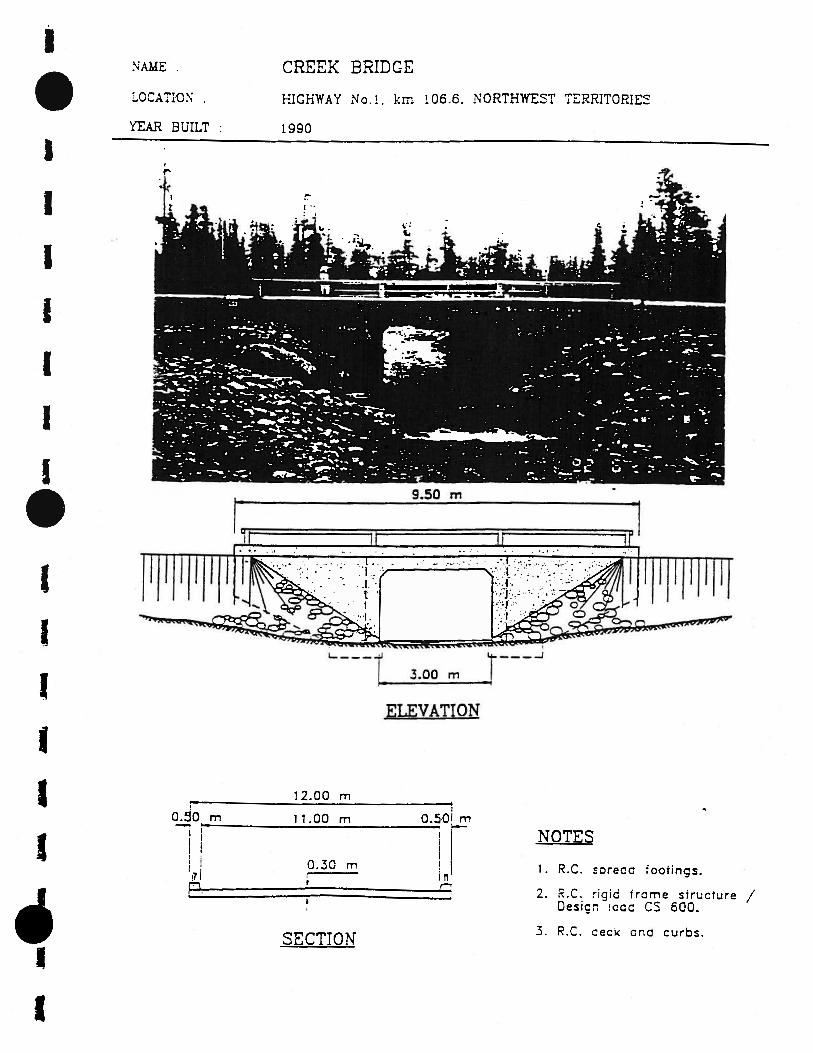


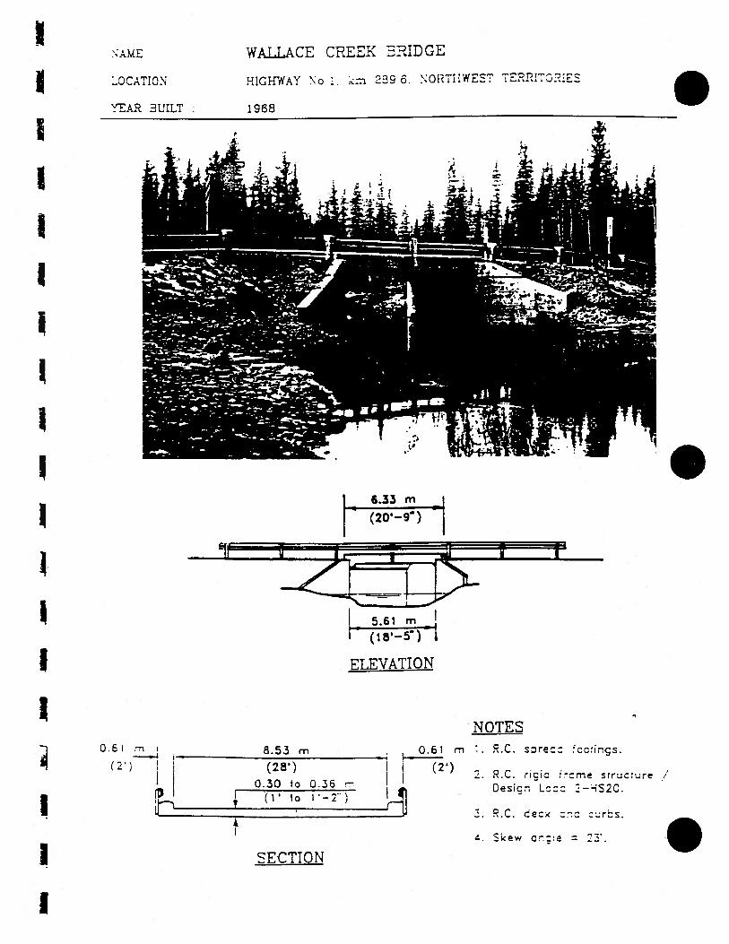
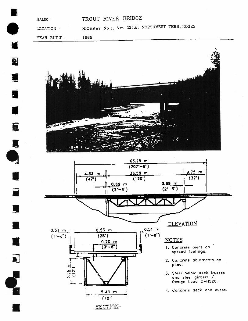


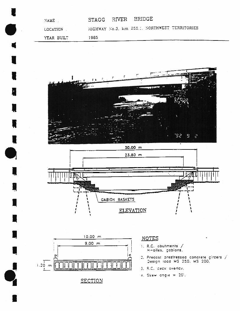


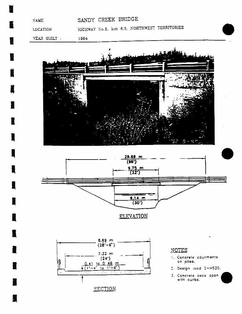


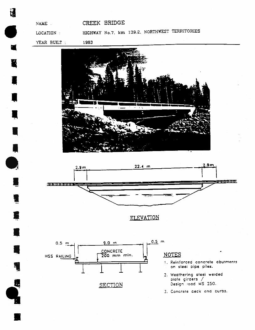


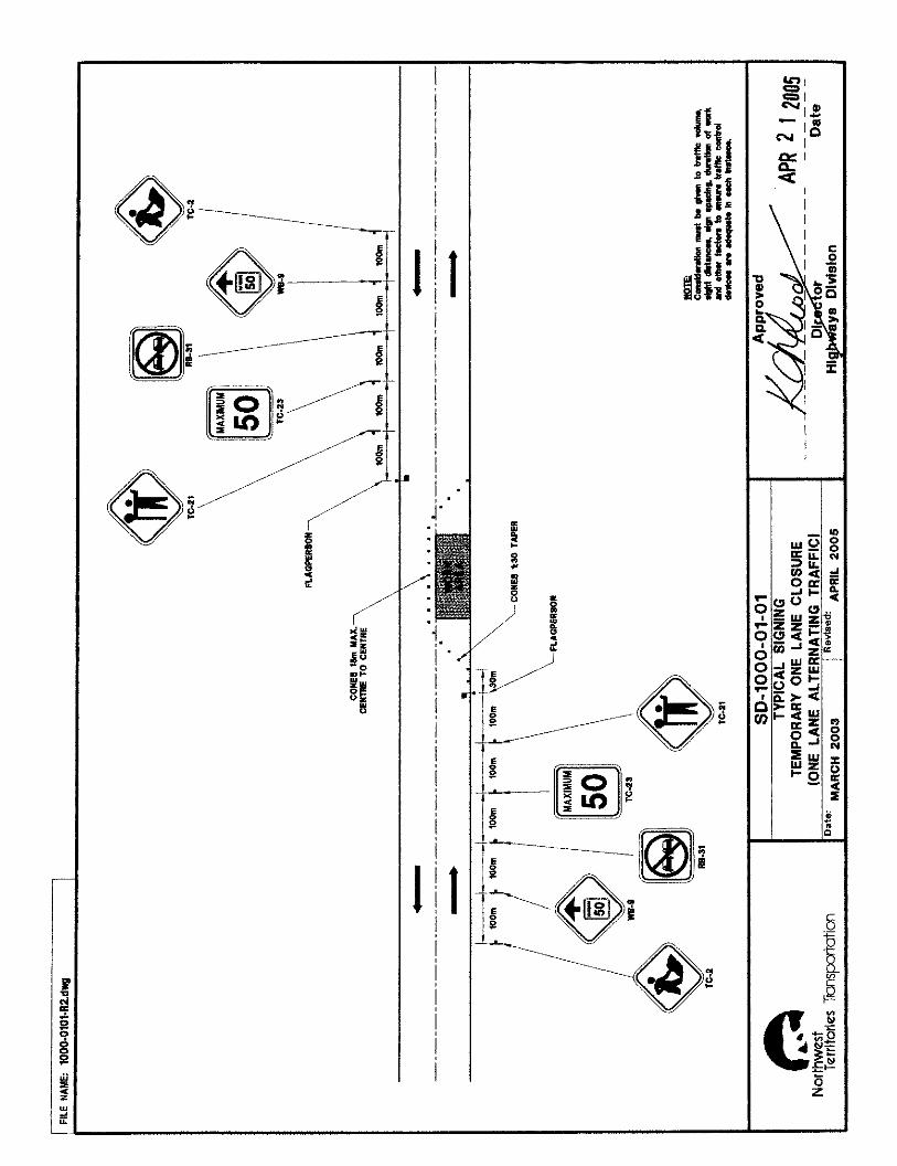


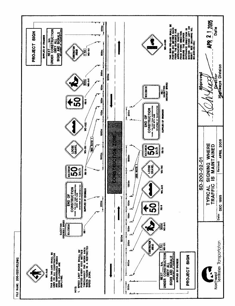


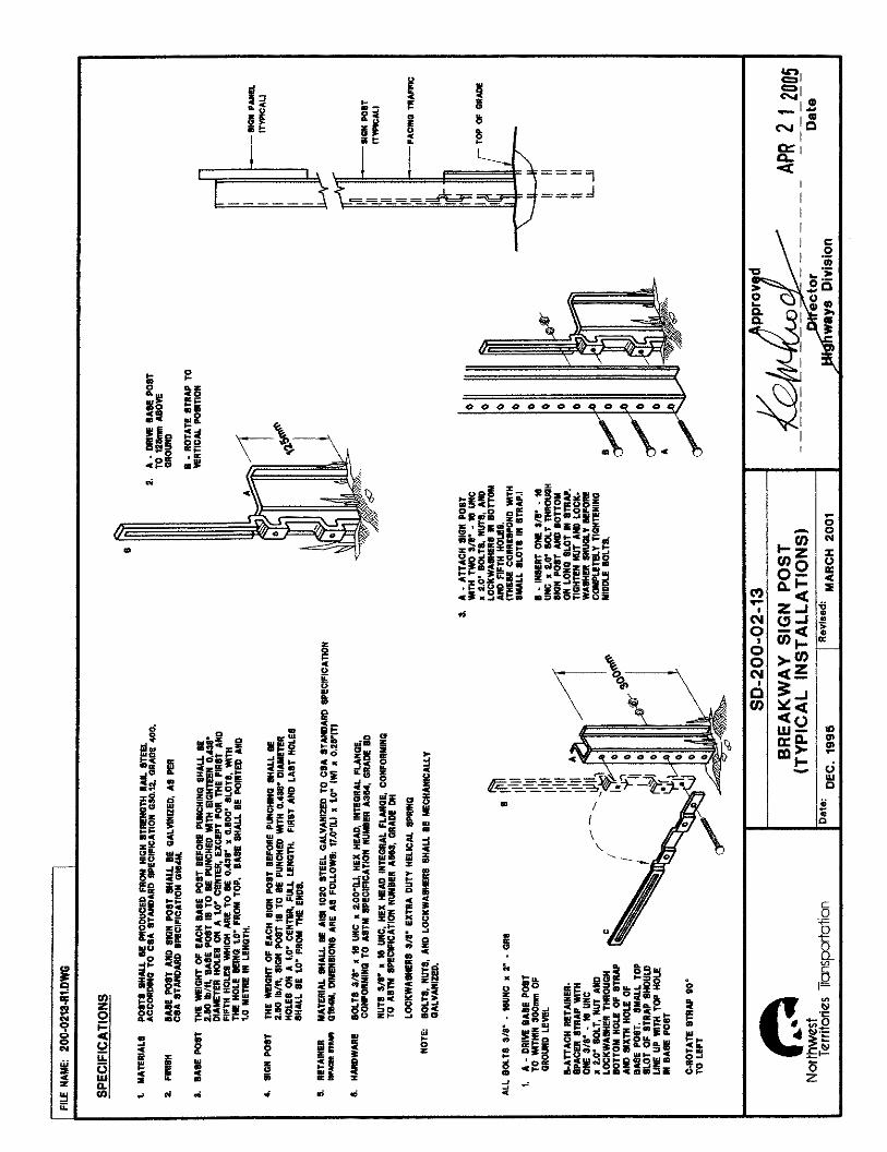


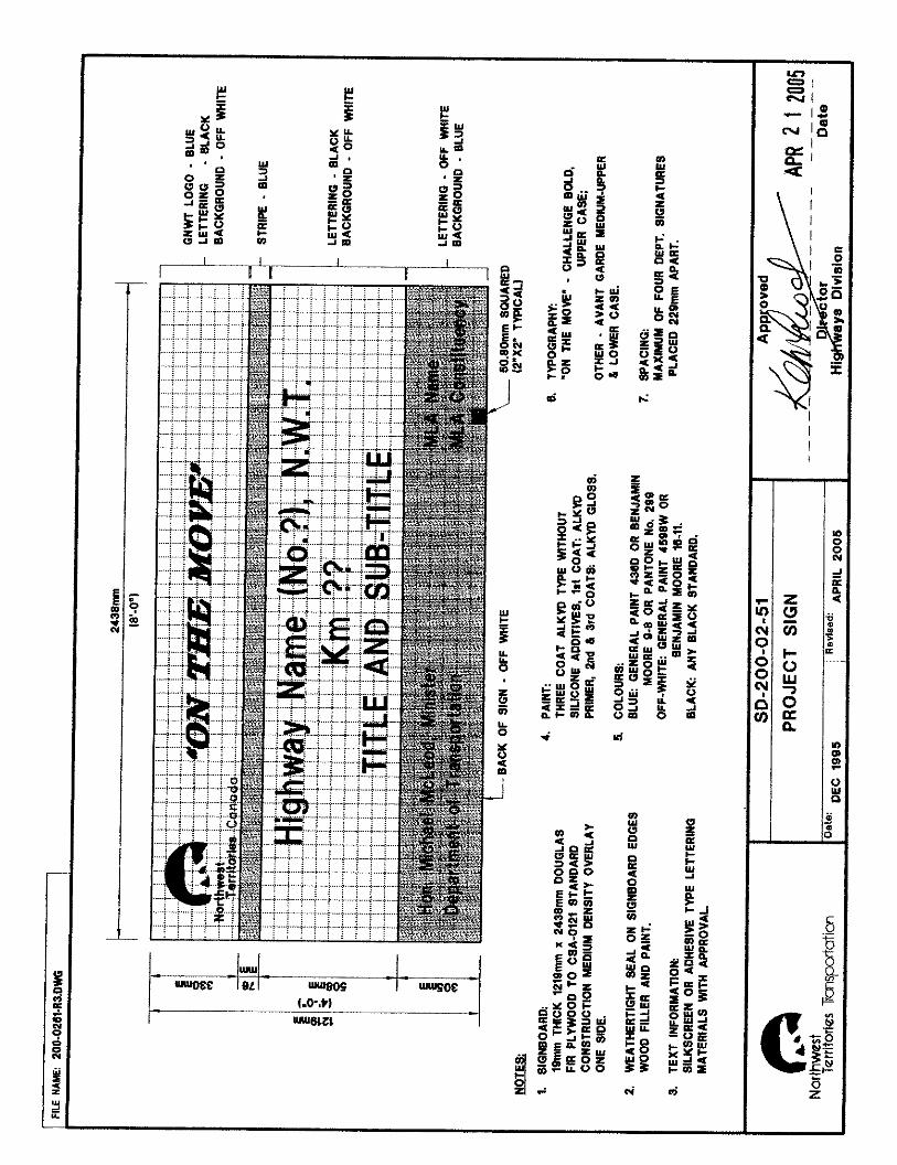


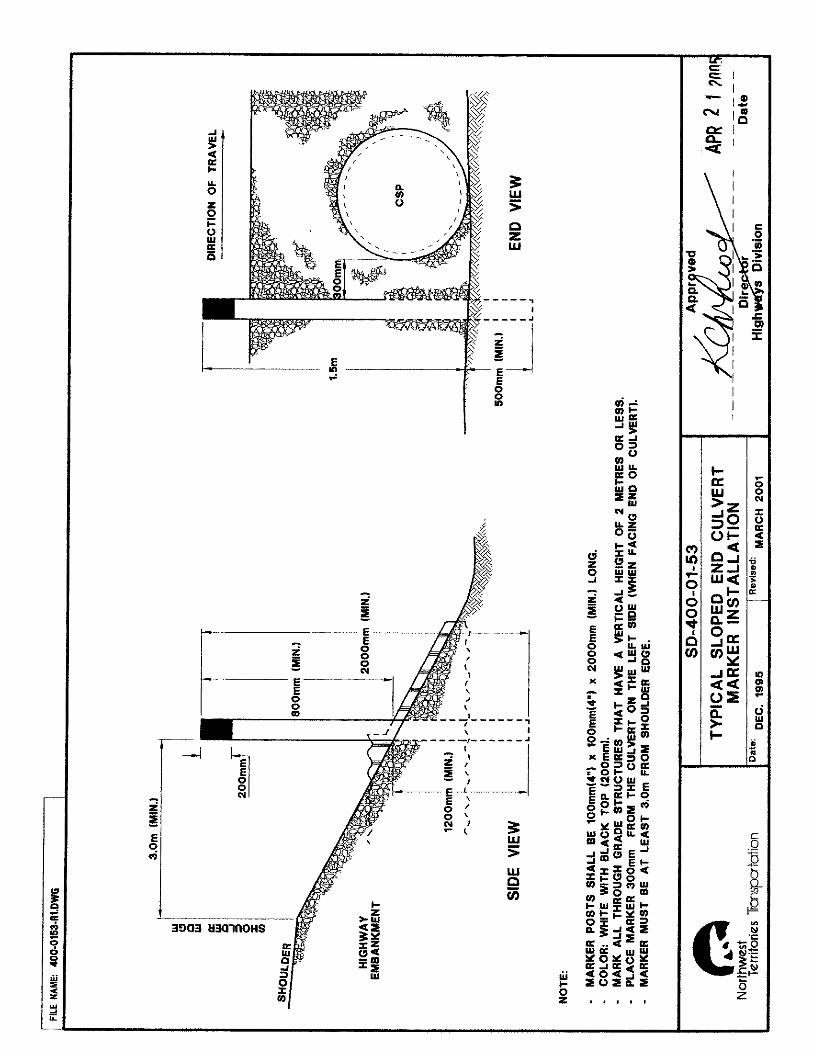


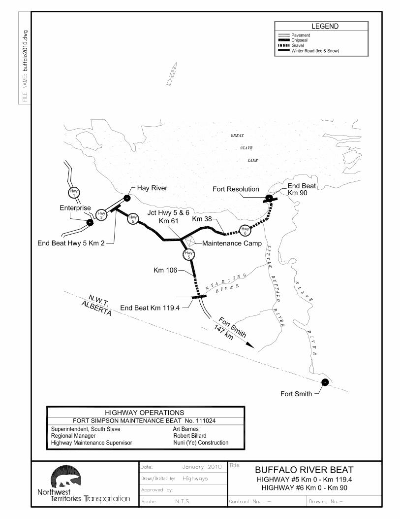


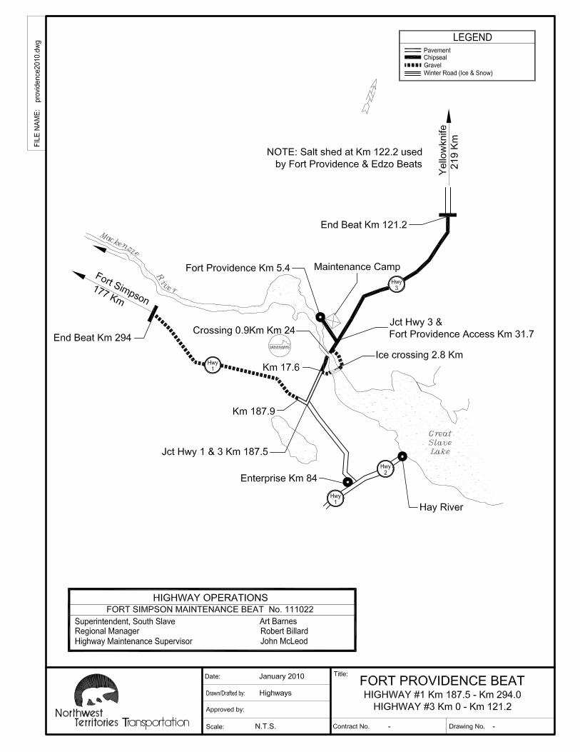


Copyright © 2022 FDOKUMEN