
VOLUME 2 HIGHWAY STRUCTURES
13
December 1993 DESIGN MANUAL FOR ROADS AND BRIDGES VOLUME 2 HIGHWAY STRUCTURES: DESIGN (SUBSTRUCTURES AND SPECIAL STRUCTURES), MATERIALS SECTION 2 SPECIAL STRUCTURES PART 3 TD 32/93 WIRE ROPE SAFETY FENCE SUMMARY This Standard is concerned with the requirements for wire rope safety fences for use on verges and central reserves of new and existing trunk roads, including motorways. INSTRUCTIONS FOR USE 1. Remove TD 32/89 which is superseded by this Standard and archive as appropriate. 2. Insert TD 32/93 into Volume 2, Section 2. 4. Archive this sheet as appropriate. Note: New contents pages for Volume 2 dated December 1993 are available with BA 48/93.
-
Upload
khangminh22 -
Category
Documents
-
view
0 -
download
0
Transcript of VOLUME 2 HIGHWAY STRUCTURES

December 1993
DESIGN MANUAL FOR ROADS AND BRIDGES
VOLUME 2 HIGHWAYSTRUCTURES: DESIGN(SUBSTRUCTURESAND SPECIALSTRUCTURES),MATERIALS
SECTION 2 SPECIAL STRUCTURES
PART 3
TD 32/93
WIRE ROPE SAFETY FENCE
SUMMARY
This Standard is concerned with the requirements forwire rope safety fences for use on verges and centralreserves of new and existing trunk roads, includingmotorways.
INSTRUCTIONS FOR USE
1. Remove TD 32/89 which is superseded by thisStandard and archive as appropriate.
2. Insert TD 32/93 into Volume 2, Section 2.
4. Archive this sheet as appropriate.
Note: New contents pages for Volume 2dated December 1993 are availablewith BA 48/93.

Wire Rope Safety Fence
Summary: This Standard is concerned with the requirements for wire rope safety fencesfor use on verges and central reserves of new and existing trunk roads,including motorways.
THE HIGHWAYS AGENCY TD 32/93
THE SCOTTISH OFFICE DEVELOPMENT DEPARTMENT
THE WELSH OFFICEY SWYDDFA GYMREIG
THE DEPARTMENT OF THE ENVIRONMENTFOR NORTHERN IRELAND

Volume 2 Section 2Part 3 TD 32/93 Registration of Amendments
ELECTRONIC COPY - NOT FOR USE OUTSIDE THE AGENCY
December 1993 PAPER COPIES OF THIS ELECTRONIC DOCUMENT ARE UNCONTROLLED
REGISTRATION OF AMENDMENTS
Amend Page No Signature & Date of Amend Page No Signature & Date ofNo incorporation of No incorporation of
amendments amendments

Volume 2 Section 2Registration of Amendments Part 3 TD 32/93
ELECTRONIC COPY - NOT FOR USE OUTSIDE THE AGENCY
PAPER COPIES OF THIS ELECTRONIC DOCUMENT ARE UNCONTROLLED December 1993
REGISTRATION OF AMENDMENTS
Amend Page No Signature & Date of Amend Page No Signature & Date ofNo incorporation of No incorporation of
amendments amendments

DESIGN MANUAL FOR ROADS AND BRIDGES
ELECTRONIC COPY - NOT FOR USE OUTSIDE THE AGENCY
December 1993 PAPER COPIES OF THIS ELECTRONIC DOCUMENT ARE UNCONTROLLED
VOLUME 2 HIGHWAYSTRUCTURES:DESIGN(SUBSTRUCTURESAND SPECIALSTRUCTURES),MATERIALS
SECTION 2 SPECIALSTRUCTURES
PART 3
TD 32/93
WIRE ROPE SAFETY FENCE
Contents
Chapter
1. Introduction
2. Definitions
3. Basic Criteria
4. Design Requirements
5. References
6. Enquiries

Volume 2 Section 2 Chapter 1Part 3 TD 32/93 Introduction
ard
the
e
vef
ia
al
1. INTRODUCTION
1.1 This Standard, TD 32/93, is concerned with threquirements for wire rope safety fences for use onverges and central reserves of new and existing trunkroads, including motorways. It replaces Department oTransport Departmental Standard TD 32/89 andScottish Technical Memorandum SH 3/90.
1.2 The specification requirements and the WRSeries of drawings for the Wire Rope Safety Fencepreviously contained in Appendices A.1 to A.6 ofDepartmental Standard TD 32/89 and TechnicalMemorandum SH 3/90 have been amended and are nincluded in the Manual of Contract Documents forHighway Works: Specification for Highway Works(MCHW 1) and Highway Construction Details (MCHW3).
1.3 Where wire rope safety fences are procuredthrough a contract incorporating the Specification forHighway Works (MCHW 1) products conforming toequivalent sampling and testing undertaken in othermember states will be acceptable in accordance with terms of the 104 and 105 Series of Clauses of theSpecification. Any contract not containing theseClauses must contain a suitable clause of mutualrecognition having the same effect, regarding whichadvice should be sought.
1.4 Consequent to further development of the wirrope safety fence system, based on reduced postspacing, together with feedback from users of thesystem since its introduction in 1989, amendments habeen included in this Standard, TD 32/93, in respect othe ‘limitations on use’ (Section 3.1) and ‘designrequirements’ (Section 4.2).
Scope
1.5 The wire rope safety fence described in thisStandard complies with the performance testing criterfor the normal level of vehicle containment given inSeries 400 of the Specification for Highway Works(MCHW 1). The Standard also sets down the essentilayout requirements and limitations on the use of wirerope safety fences.
ELECTRONIC COPY - NOT F
December 1993 PAPER COPIES OF THIS ELECTRO
e 1.6 Any request for a departure from this Standshall be referred to the Overseeing Department.
f
ow
Implementation
1.7 This Standard should be used forthwith for allschemes currently being prepared provided that, in theopinion of the Overseeing Department, this would notresult in significant additional expense or delayprogress. Design Organisations should confirm itsapplication to particular schemes with the OverseeingDepartment.
OR USE OUTSIDE THE AGENCY
NIC DOCUMENT ARE UNCONTROLLED 1/1

Volume 2 Section 2 Chapter 2Part 3 TD 32/93 Definitions
ELECTRONIC COPY - NOT FOR USE OUTSIDE THE AGENCY
December 1993 PAPER COPIES OF THIS ELECTRONIC DOCUMENT ARE UNCONTROLLED 2/1
2. DEFINITIONS
General Description of Fence
21. The fence consists of four tensioned galvanisedsteel wire ropes having an overall height of 604 mmsupported by galvanised steel posts at nominally 2.4 mcentres. The two upper ropes are located in a slot in thetop of the posts and the two lower ropes are interwovenalong the fence between each pair of posts. The ropesare joined and tensioned by means of rigging screwsprovided at intervals not exceeding 154 m. The ends ofthe ropes are attached to anchors embedded in theground or to surface mounted anchors. Where thelength of the fence is greater than 627 m intermediateanchors are used. To provide continuity two ropes (i.e.,one upper and one lower) of the four ropes are anchoredat each intermediate anchor. The connection betweeneach rope and its anchor is designed to uncouple when avehicle impact occurs in the vicinity of the anchor. Themovement of the released rope is restrained by a safetycheck rope.
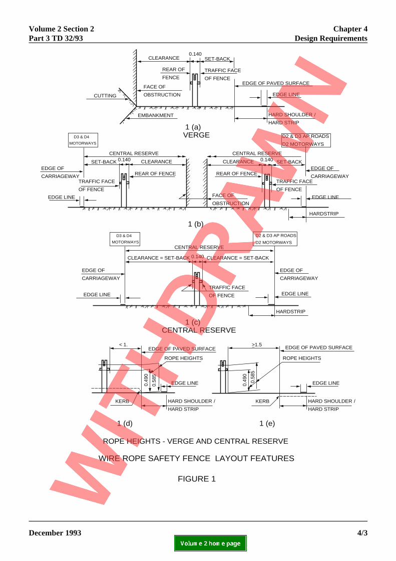
2.2 Set-back is the unobstructed horizontaldimension between the traffic face of the wire ropesafety fence and the edge of the:
(a) paved surface adjacent to the verge; (Note:paved surface comprises carriageway, hardshoulder orhardstrip);
(b) carriageway adjacent to the central reserve (seeFigure 1).
2.3 Clearance is the unobstructed horizontaldimension between the rear of the wire rope safetyfence and:
(a) the traffic face of an obstruction (e.g.,overbridge supports, sign posts rock, face, etc.);
(b) the opposite carriageway on a central reservewhere there are no obstructions and there is only onesafety fence between the carriageways.

Volume 2 Section 2 Chapter 3Part 3 TD 32/93 Basic Criteria
ELECTRONIC COPY - NOT FOR USE OUTSIDE THE AGENCY
December 1993 PAPER COPIES OF THIS ELECTRONIC DOCUMENT ARE UNCONTROLLED 3/1
3. BASIC CRITERIA
Limitations on Use.
3.1 Wire rope safety fences shall not be used:
(a) where the length of fence at full height wouldbe less than 24 m;
(b) on horizontal curves of radius less than 200 m;
(c) on vertical sag curves of radius less than 3,000 m;
(d) on central reserves having a width of less than:
(i) 3.14 m when the support posts are at2.4 m centres (see Figure 1);
(ii) 2.75 m when the support posts are at1.2 m centres;
(iii) 2.4 m when the support posts are at 1.0m centres.
(e) on central reserves for closing EmergencyCrossing Points (ECP) and Maintenance CrossingPoints (MCP) except where wire rope safety fencesalready exist on both sides of the crossing point orwhere specific approval has been given by theOverseeing Department (see Paragraph 3.2 also);
(f) where the height of any kerb at the edge of theadjacent paved surface exceeds 110 mm and the trafficface of the wire rope safety fence would be positionedless than 1.5 m from the kerb face;
(g) where high mast lighting columns are situatedwithin 10 m of the edge of the paved surface.
3.2 In addition, a wire rope safety fence shall notbe connected to any other safety fence or bridgeparapet. However, the wire rope safety fence can beinterfaced with certain other types of safety fence wheninstalled in accordance with the details shown onDrawings GA/50 to GA/54 of the HighwayConstruction Details (MCHW 3.2) or as specificallyagreed with the Overseeing Department.

Volume 2 Section 2 Chapter 4Part 3 TD 32/93 Design Requirements
NTS
4. DESIGN REQUIREMEGeneral
4.1 The design of wire rope safety fenceinstallations shall comply with the following layout anddetailing requirements.
Layout
4.2 Layout requirements are as follows:
(a) Set back at verge
The desirable minimum set-back shall normally be notless than 1.2 m. It may be reduced to:
(i) 1.0 m adjacent to an obstruction;
(ii) 0.6 m adjacent to any hard shoulder,hardstrip or road having a speed limitnot exceeding 50 mph.
(b) Set back at central reserve
(i) Where there are no obstructions andthere is only one safety fence betweenthe carriageways and the support postare at 2.4 centres, the minimum set-back shall be 1.5 m;
(ii) In all situations other than (i) above(e.g., two separate safety fences) theset-back shall normally be not lessthan 1.2 m. It may be further reducedto an absolute minimum of 1.0 madjacent to short obstructions and onlong structures provided the supportposts are spaced at 1.2 m centres.
(c) Clearance
The minimum clearance shall normally be not less tha
(i) 1.5 m when the support posts are at 2.m centres; D
(ii) 1.3 m when the support posts are at 1.m centres;
(iii) 1.1 m when the support posts are at 1.0m centres.
(
TtD
(
Tbbc
(
WtlmEfs
(
4
(
ELECTRONIC COPY - NO
December 1993 PAPER COPIES OF THIS ELECTR
s
n:
4etailing
2
d) Visibility
he layout of wire rope safety fences shall comply withhe requirements of sight distance given inepartmental Standard TD 9 (DMRB 6.1).
e) Transverse ground profile
he ground beneath, and to each side of the fence andetween any kerbing, shall be generally level and shalle free from obstructions within the set-back andlearance dimensions.
f) Height of fence
here the horizontal distance from the traffic face ofhe fence to the edge of the adjacent paved surface isess than 1.5 m, the heights of the ropes shall be
easured from the level of the adjacent paved surface. lsewhere the heights of the ropes shall be measured
rom the general ground level beneath the line of theafety fence (see Figure 1).
g) Length of fence
(i) Where a wire rope safety fence isprovided in front of an obstruction, itshall be extended at full height not lessthan 30 m in advance of theobstruction and shall continue at fullheight not less than 7.5 m beyond theobstruction;
(ii) On embankments 6 m or more inheight, the length of wire rope safetyfence should be extended beyond the 6m high section to ensure that vehiclesleaving the carriageway at places oflesser drop will not reach the 6 m highsection. On curves, further extensionmay be needed to reduce the risk ofvehicles passing behind the fence.
.3 Detailing requirements are as follows:
a) Post foundations
(i) Foundations shall be designed to resistthe test loadings specified in Clauses
T FOR USE OUTSIDE THE AGENCY
ONIC DOCUMENT ARE UNCONTROLLED 4/1
Chapter 4 Volume 2 Section 2Design Requirements Part 3 TD 32/93
403 and 404 of the Specification forHighway Works (MCHW 1);
(ii) For initial detailing, foundations maybe designed to resist the effects of ahorizontal shear of 10.25 kN combinedwith a bending moment of 6.0 kNm ina plane at right angles to the fencesubject to the test loading requirementsin (i) above taking precedence;
(iii) The construction details for drivenposts and concrete foundations shownon the WR Series of drawingscontained in the Highway ConstructionDetails (MCHW 3.2) shall be specifiedwherever appropriate. However,specially designed foundations will berequired to resist the loadingrequirements given in (i) above wherethe standard details are not suitabledue to poor ground conditions and/orwhere posts and foundations wouldinterfere with cables, ducts or drainagesystems;
(iv) Where a socket is cast into an in-situconcrete foundation to facilitate postreplacement, the foundation shall be ofsufficient size to ensure that it is notdisplaced when the post is knockeddown under vehicle impact.
(b) Anchors
Where intermediate anchors are required, they shall belocated not less than 30 m apart longitudinally.
(c) Ropes
The length of line rope between anchors shall be notmore than 627 m. In addition two ropes, one upper andone lower, shall be terminated on one end of anintermediate anchor.
ELECTRONIC COPY - NOT FOR USE OUTSIDE THE AGENCY
PAPER COPIES OF THIS ELECTRONIC DOCUMENT ARE UNCONTROLLED December 19934/2
Volume 2 Section 2 Chapter 4Part 3 TD 32/93 Design Requirements
CLEARANCE SET-BACK
REAR OF
FENCETRAFFIC FACE
OF FENCE
FACE OF
OBSTRUCTION
EDGE OF PAVED SURFACE
EDGE LINE
HARD SHOULDER /
HARD STRIP
EMBANKMENT
CUTTING
D3 & D4
MOTORWAYS
CENTRAL RESERVE
SET-BACK 0.140 CLEARANCE
REAR OF FENCE
TRAFFIC FACE
OF FENCE
EDGE OF
CARRIAGEWAY
EDGE LINE
CENTRAL RESERVE
CLEARANCE
REAR OF FENCE
SET-BACK
TRAFFIC FACE
OF FENCE
EDGE OF
CARRIAGEWAY
EDGE LINE
HARDSTRIP
D2 & D3 AP ROADS
D2 MOTORWAYS
D3 & D4
MOTORWAYS
D2 & D3 AP ROADS
D2 MOTORWAYSCENTRAL RESERVE
EDGE OF
CARRIAGEWAY
EDGE OF
CARRIAGEWAY
TRAFFIC FACE
OF FENCEEDGE LINE EDGE LINE
HARDSTRIP
CLEARANCE = SET-BACK CLEARANCE = SET-BACK
0.140
0.140
EDGE OF PAVED SURFACE _ EDGE OF PAVED SURFACE
HARD SHOULDER /
HARD STRIP
HARD SHOULDER /
HARD STRIP
EDGE LINE EDGE LINE
KERB KERB
ROPE HEIGHTS ROPE HEIGHTS
< 1. >1.5
0.49
0
0.49
0
0.58
5
0.58
5
1 (a)VERGE
1 (b)
1 (c)CENTRAL RESERVE
1 (d) 1 (e)
ROPE HEIGHTS - VERGE AND CENTRAL RESERVE
WIRE ROPE SAFETY FENCE LAYOUT FEATURES
FACE OF
OBSTRUCTION
FIGURE 1
0.140
ELECTRONIC COPY - NOT FOR USE OUTSIDE THE AGENCY
December 1993 PAPER COPIES OF THIS ELECTRONIC DOCUMENT ARE UNCONTROLLED 4/3

Volume 2 Section 2 Chapter 5Part 3 TD 32/93 References
ELECTRONIC COPY - NOT FOR USE OUTSIDE THE AGENCY
December 1993 PAPER COPIES OF THIS ELECTRONIC DOCUMENT ARE UNCONTROLLED 5/1
5. REFERENCES
1. Manual of Contract Documents for Highway Works
Volume 1: Specification for Highway Works HMSO (MCHW 1)
Volume 2: Highway Construction Details HMSO (MCHW 3)
2. Design Manual for Road and Bridges
Volume 6: Section 1: Links
TD9 Highway Link Design HMSO (DMRB 6.1.1)

Volume 2 Section 2 Chapter 6Part 3 TD 32/93 Enquiries
ELECTRONIC COPY - NOT FOR USE OUTSIDE THE AGENCY
December 1993 PAPER COPIES OF THIS ELECTRONIC DOCUMENT ARE UNCONTROLLED 6/1
6. ENQUIRIES
All technical enquiries or comments on this Standard should be sent in writing as appropriate to:-
Chief Highway EngineerThe Department of TransportSt. Christopher HouseSouthwark Street T A ROCHESTERLondon SE1 0TE Chief Highway Engineer
The Deputy Chief EngineerThe Scottish Office Industry DepartmentRoads DirectorateNew St. Andrew’s House J INNESEdinburgh EH1 3TG Deputy Chief Engineer
The Director of HighwaysWelsh OfficeY Swyddfa GymreigGovernment BuildingTy Glas RoadLlanishen K J THOMASCardiff CF4 5PL Director of Highways
Chief Engineer - Roads ServiceDepartment of the Environment for Northern IrelandRoads Service HeadquartersClarence Court10-18 Adelaide Street W J McCOUBREYBelfast BT2 8GB Chief Engineer - Roads Service