Dynamic response of full-scale sandwich composite structures ...
Upload
independentCategory
view
0download
0
Dynamic Characteristics and Effective Stiffness Propertiesof Honeycomb Composite Sandwich Structures
for Highway Bridge ApplicationsWahyu Lestari1 and Pizhong Qiao, M.ASCE2
Abstract: In this paper, a combined analytical and experimental study of dynamic characteristics of honeycomb composite sandwichstructures in bridge systems is presented, and a relatively simple and reliable dynamic experimental procedure to estimate the beambending and transverse shear stiffness is proposed. This procedure is especially practicable for estimating the beam transverse shearstiffness, which is primarily contributed by the core and is usually difficult to measure. The composite sandwich beams are made ofE-glass fiber and polyester resins, and the core consists of the corrugated cells in a sinusoidal configuration. Based on the modeling ofequivalent properties for the face laminates and core elements, analytical predictions of effective flexural and transverse shear stiffnessproperties of sandwich beams along the longitudinal and transverse to the sinusoidal core wave directions are first obtained. Usingpiezoelectric sensors, the dynamic response data are collected, and the dynamic characteristics of the sandwich structures are analyzed,from which the flexural and transverse shear stiffness properties are reduced. The experimental stiffness results are then compared to theanalytical stiffness properties, and relatively good correlations are obtained. The proposed dynamic tests using piezoelectric sensors canbe used effectively to evaluate the dynamic characteristics and stiffness properties of large sandwich structures suitable for highway bridgeapplications.
DOI: 10.1061/�ASCE�1090-0268�2006�10:2�148�
CE Database subject headings: Composite beams; Dynamic tests; Frequency; Honeycomb structures; Sandwich structures;Stiffness; Bridges, highway.
Introduction
Sandwich structures are commonly used in aerospace and auto-mobile structures, because they offer great energy absorption andincrease the moment of inertia without paying much in weight.The recent growing interest in fiber-reinforced polymer �FRP�composite materials for civil infrastructure provides a uniqueopportunity for development and implementation of sandwichstructures, as in rehabilitation and new construction. FRP com-posite honeycomb sandwich structures have shown efficient andeconomic applications in highway bridges, and they provide highmechanical performance �Plunkett 1997; Davalos et al. 2001�.Although the primary layout of the sandwich structure is thesame, which consists of face sheets and core, the sizes of civilinfrastructure are much thicker and larger as compared to thoseused in the aerospace and automobile industries. Most sandwichstructures have a lightweight core in the form of corrugated orclose cell geometry encased between two face sheets. The concept
1Research Scientist, Dept. of Civil Engineering, Univ. of Akron,Akron, OH 44325-3905.
2Associate Professor, Dept. of Civil Engineering, Univ. of Akron,Akron, OH 44325-3905. E-mail: [email protected]
Note. Discussion open until September 1, 2006. Separate discussionsmust be submitted for individual papers. To extend the closing date byone month, a written request must be filed with the ASCE ManagingEditor. The manuscript for this paper was submitted for review and pos-sible publication on October 1, 2004; approved on August 4, 2005. Thispaper is part of the Journal of Composites for Construction, Vol. 10, No.
2, April 1, 2006. ©ASCE, ISSN 1090-0268/2006/2-148–160/$25.00.148 / JOURNAL OF COMPOSITES FOR CONSTRUCTION © ASCE / MARC
of lightweight and heavy-duty FRP sandwich panels for highwaybridge decks with a unique sinusoidal core configuration wasintroduced by Plunkett �1997�. Some feasibility studies onFRP sandwich panels showed that the panels are very efficient inproviding high mechanical performance for minimum weight. Aseries of studies for testing and field installation of FRP bridgeswere successfully accomplished �Keller 2001�. Studies on designmodeling and performance evaluation of FRP sandwich panelswith a sinusoidal honeycomb core were conducted by Davalos etal. �2001�. Analytical estimation of core transverse shear stiffnesswith a general configuration was studied by Xu et al. �2001�.Significant research has been reported in the literature on model-ing and analysis of sandwich structures. A survey of recentdevelopments in the modeling of advanced sandwich structures,especially the study of stability behavior, was conducted byLibrescu and Hause �2000�. Analysis of a modern sandwich panel�i.e., thin high-strength face sheets and a soft core� using both theclassical and high-order models was performed by Frostig �2003�.In-plane and out-of-plane displacement patterns and stressdistributions in sandwich panels with various boundaries andloading conditions were demonstrated. This information providesimportant insight for the design process in considering criticallocations, failure mode, and failure loading. Providing insight tothe free vibration response of sandwich beams with a flexible/softcore has motivated many researchers to study the high-order freevibration of sandwich beams so that the effects of soft-coredisplacement on the dynamic response �i.e., the eigenfrequenciesand the eigenmodes� �Frostig and Thomsen 2004� as well asthe influences of the boundary conditions and core damage
�Sokolinsky et al. 2002, 2004� can be well understood. MostH/APRIL 2006

recently, a higher-order sandwich theory was developed by Yangand Qiao �2005� to study the free vibration and impact behaviorsof sandwich beams with a flexible core.
On the other hand, there are no easy and available methodsto accurately measure the stiffness properties of the sandwichconstruction. The conventional static experiment using measureddisplacement usually showed large discrepancies among theestimated bending and transverse shear stiffness properties ofcomposite beams �Bank and Melehan 1989; Zureick et al. 1994;Davalos et al. 1996; Salim 1996�. This has motivated manyresearchers to explore an alternative approach to estimate thematerial properties of sandwich structures. Some studies onmaterial properties estimation of sandwich structures usingdynamic or vibration tests were reported in the literature �Adamand Maheri 1997; Saito et al. 1997; Cunningham and White2001�. However, most of the studies dealt with thin honeycombsandwich beams, which are mainly used in the aircraft industry,where the ratio between the core thickness and face sheets isrelatively large, ranging between 20 and 30. This study focuses onthe sandwich structures for civil infrastructure, in which the thick-ness of the sandwich panels is quite large with relatively thickface sheets, and the ratio between the core thickness and facesheets is about 10. In such a case, the face sheet effect of thesandwich can play a significant role in defining the material prop-erties of the sandwich and also its dynamic behavior. Enclosure ofthe core design in sandwich structures also raises some otherconcerns, as it restricts access to the core for measurement orinspection purposes and thus increases the difficulty in measuringand monitoring structural conditions during a period in service�Lestari and Qiao 2005�.
In this paper, a simple comprehensive procedure to estimatethe material properties of thick sandwich structures based onexperimental and analytical dynamic responses is presented. First,the analytical stiffness properties of the face sheets and the coreof the sandwich structures are calculated based on the micro/macromechanics method �Davalos et al. 1996� and a combinedmechanics of materials �Davalos et al. 2001; Qiao and Wang2005� and homogenization approach �Xu et al. 2001�, respec-tively. The stiffness properties of sandwich beams are furtherderived by modeling the sandwich as a three-layer laminatedstructure, and they are later used for comparison and validation ofthe proposed experimental procedure. An analytical relationshipbetween the mechanical properties and the dynamic response isthen developed. Considering some assumptions and adjustment,Timoshenko beam theory is used to analyze the dynamic behaviorof the sandwich panels �Maheri and Adams 1998; Silverman1995�. Based on this relationship, the flexural and transverseshear stiffness properties of the sandwich beams are reduced andestimated from experimental results. A similar procedure toestimate the material properties of a thick composite laminatedbeam was performed by Ip and Tse �2001�. FRP sandwich beamswith two different honeycomb sinusoidal core directions �i.e.,longitudinal and transverse� are evaluated to obtain the respectiveflexural and transverse shear stiffness properties. Piezoelectricsensors are used to effectively measure the dynamic response ofsandwich beams, from which the beam flexural and transverseshear stiffness properties are extracted and compared with the
analytical predictions.JOURNAL OF COMP
Effective Flexural and Transverse Shear Stiffnessof Sandwich Beams
In this section, using a micro/macromechanics approach for theface laminates �Davalos et al. 1996�, a mechanics of materialsapproach �Davalos et al. 2001; Qiao and Wang 2005�, andhomogenization method �Xu et al. 2001� for the honeycomb core,and a mechanics of three-layer laminates for the sandwichbeams, the modeling of equivalent stiffness properties for facesheets, core elements, and sandwich beams, respectively,are briefly reviewed. The related material properties for theface laminate, sinusoidal core, and sandwich beam of the givensandwich structure �Fig. 1� are then summarized.
Modeling of Face Laminates
The apparent engineering properties of laminated panels canbe predicted by a combined micro- and macromechanicsapproach �Davalos et al. 1996�. The prediction of ply propertiesby micromechanics is well defined �Chamis 1984�, and thestiffness properties of each layer can be computed from existingmicromechanics models such as rule of mixtures �ROM� �Jones1999�, periodic microstructure �PM� �Luciano and Barbero 1994�,and composite cylinders �CC� �Hashin and Rosen 1964�, whereeach layer is modeled as a homogeneous, linearly elastic, andgenerally orthotropic material.
A typical face laminate may include the following four typesof fiber layers �Davalos et al. 2001�: �1� a chopped strand mat�ChopSM�, which is made of short fibers randomly oriented,resulting in nearly isotropic in-plane properties; �2� a continuousstrand mat �ContSM� consisting of continuous randomly orientedfibers, which is commonly used as a backing material fornonwoven fabrics and can be modeled as an isotropic layer;�3� bidirectional stitched fabrics �SF� with balanced off-angleunidirectional fibers �e.g., 0°/90° or ±45°�; and �4� a unidirec-tional layer of fiber bundles or rovings. The stiffness of eachply can be predicted from micromechanics models. In this study,a micromechanics model for composites with periodic micro-structure �Luciano and Barbero 1994� is used to obtain the elasticconstants for each individual layer �Table 1�.
After the elastic properties of each ply are obtained frommicromechanics, the equivalent stiffness properties of the facelaminate are computed from classical lamination theory �Jones1999�. A set of equivalent laminate stiffness properties can bedefined for approximately balanced symmetric face laminates�Davalos et al. 1996� and are given in Table 2. These elasticconstants �e.g., Ex
f , Eyf , Gxy
f , and vxyf � represent the stiffness of an
equivalent, orthotropic plate that behaves like the actual laminate
Fig. 1. Configuration of sandwich panel
under in-plane loads.
OSITES FOR CONSTRUCTION © ASCE / MARCH/APRIL 2006 / 149

Modeling of Honeycomb Core
Unlike traditional honeycomb sandwich structures, the shape ofthe corrugated cell wall in the sandwich is defined by a sinusoidalfunction in the plane �Fig. 1�. In the given coordinate system inFig. 2, the wave function of corrugated core wall can be describedas
y = h�1 − cos��x
b�� �1�
In this study, the honeycomb core depicted in Fig. 2 ismanufactured by Kansas Structural Composites, Inc. �KSCI,Russell, Kan.�, and the dimensions of the sinusoidal core areh=25.4 mm �1.0 in.� and b=50.8 mm �2.0 in.� �Fig. 2�. Themicrostructure of the core walls, either the flat or corrugatedportion, includes a continuous strand mat �ContSM� consistingof continuous randomly oriented fibers; this layer can be modeledas an isotropic layer, and its properties as predicted by themicromechanics model �Luciano and Barbero 1994� are given inTable 1.
In the following, the formulas for the core effective Young’smoduli and transverse shear moduli along the x and y directionsare summarized. An improved mechanics of materials approachrecently developed by Qiao and Wang �2005� is used to evaluatethe effective in-plane Young’s moduli of the sinusoidal cores.In particular, the internal forces of the curved wall in a unit cell�Fig. 2� are expressed in terms of resultant forces, and based onthe energy method and the principle of equivalence analysis, thein-plane stiffness properties of the sinusoidal cores are derived.For the transverse shear moduli, the formulas for general coreconfiguration obtained from homogenization theory �Xu et al.2001� are applied for the case of the sinusoidal core.
To obtain the core effective transverse Young’s modulus �Eye�,
a macroscopic stress �y is applied to the unit cell in the y direc-tion �Fig. 3�. Due to symmetry of the unit cell in Fig. 2, onlya quarter of the unit cell is studied �Fig. 3�a��. The free bodydiagram of a half-wave curved core wall is presented in Fig. 3�b�,
Table 1. Ply Stiffness Properties Obtained from Micromechanics Model
Ply name OrientationE1
�GPa�E2
�GP
Bond layer Random 9.72 9.7
CM3205 0° or 90° 27.72 8.0
Random 11.79 11.7
UM1810 0° 30.06 8.5
Random 15.93 15.9
Core mat Random 11.79 11.7
Table 2. Material Properties of Face Laminates
Exf
�GPa ��106 psi��Ey
f
�GPa ��106 psi�� vxyf
19.62 �2.85� 12.76 �1.85� 0.302
150 / JOURNAL OF COMPOSITES FOR CONSTRUCTION © ASCE / MARC
where P, F, and Mo are the resultant forces of the curved wallfrom the macroscopic stress �y �Fig. 3�a��. Based on the equilib-rium condition, the internal forces �M, N, and V in Fig. 3�b�� ofthe curved wall beam element are obtained as
M = − P�b − x� + Fh�1 + cos��x
b�� + M0 �2�
N =Fb + Ph� sin��x/b�
b�1 + �h�
b�2
sin2��x
b� �3�
V =Fh� sin��x/b� − Pb
b�1 + �h�
b�2
sin2��x
b� �4�
The elastic strain energy of the curved wall in Fig. 3 isexpressed as
U =�0
S ��MM2
2+
�NN2
2+
�VV2
2�ds �5�
where
�M =12
E1t23 , �N =
1
E1t2, �V =
1
�G13t2�6�
Invoking Castigliano’s theorem gives
�U
�M0= 0,
�U
�P= �y,
�U
�F= �x �7�
and note that
�x = −2Fb
E1t1�8�
Combining Eqs. �7� and �8� gives the expression of �x in termsof P. Therefore, the core effective transverse Young’s modulus�Ey
e� is obtained as
G12
�GPa�G23
�GPa� v12 v23
3.50 2.12 0.394 0.401
3.08 2.88 0.295 0.390
4.21 2.36 0.402 0.400
3.30 3.08 0.293 0.386
5.65 2.96 0.409 0.388
4.21 2.97 0.402 0.388
Gxyf
a ��106 psi��Gxz
f
�GPa ��106 psi��Gyz
f
�GPa ��106 psi��
.76 �0.55� 3.75 �0.54� 3.68 �0.53�
a�
2
0
9
5
3
9
�GP
3
H/APRIL 2006

Eye =
�y
�y=
P/b
�y/2h=
2Ph
b�y�9�
Similarly, a macroscopic stress �x is applied to the unit cellto compute the core effective longitudinal Young’s modulus in thex direction �Fig. 4�. Again, due to symmetry of the unit cell inFig. 2, only a quarter of the unit cell �Fig. 4�a�� is modeled andthe internal forces of this part of the unit cell can be obtained withthe aid of Fig. 4�b�. The strain energy of the quarter representativevolume element �RVE� is given as
U =�0
S ��MM2
2+
�NN2
2+
�VV2
2�ds +
F12b
E1t1+
F32b
E1t1�10�
where M, N, and V=internal forces of the half curve waved walland are calculated by using Eqs. �2�–�4� with P=0.
Again, invoking Castigliano’s theorem results in
�U
�M0= 0,
�U
�F1= �x,
�U
�F2= �x,
�U
�F3= �x �11�
where F1, F2, and F3 correspond to the forces on the top flat,curved, and bottom flat walls �see Fig. 4�b��, respectively, andcan be expressed in terms of �x. Hence, the core effectivelongitudinal Young’s modulus �Ex
e� is obtained as
Exe =
�F1 + F2 + F3��x
�12�
The solutions for the core effective transverse shear moduli�Gyz
e and Gxze � are obtained based on a homogenization method
�Xu et al. 2001� and are given as
Fig. 2. Unit cell of sinusoidal core
Fig. 3. Modeling of core effective transverse Young’s modulus �Eye�:
�a� Loading configuration and �b� internal force analysis
JOURNAL OF COMP
Gxze = � t1
2h+
bt2
2hS�G12
s ; Gyze =
2ht2
bSG12
s �13�
where G12s =shear modulus of solid walls �Table 1�; and
S=length for the curved segment, S=�ABds �Fig. 5�.
Based on the preceding formulas for both the Young’s moduliand the transverse shear moduli, the equivalent material proper-ties of the sinusoidal core in the longitudinal and transversedirections are provided in Table 3.
Effective Stiffness Propertiesof Honeycomb Sandwich Beams
In this section, the stiffness coefficients of a sandwich beam arederived by modeling the sandwich as a three-layer �i.e., top andbottom face sheets and core� laminated beam. Then the constitu-tive relations for the sandwich beam including the transverseshear deformation are obtained. The in-plane stress-strain relationof general orthotropic lamina is expressed as
�� = Q��� �14�
where ��= ��x ,�y ,�xy; ��= ��x ,�y ,�xy; and Q�=matrix of
reduced stiffness coefficient Qij. Integration of Eq. �14� throughthe thickness of the beam results in the following relationbetween the resultant forces and moments and the strains andcurvatures:
� �N�M = �A� B�
B� D� ������ �15�
where A�=extensional stiffness submatrix; B�=bending-extension coupling stiffness submatrix; and D�=bending stiff-ness submatrix �Jones 1999�. The sandwich beam is symmetricwith respect to the middle surface; hence, the bending-extensioncoupling coefficients are zero. The compliance equations areobtained by inverting the matrices in Eq. �15�:
Fig. 4. Modeling of core effective longitudinal Young’s modulus�Ex
e�: �a� Loading configuration and �b� internal force analysis
Fig. 5. Unit cell of sinusoidal core for out-of-plane shear moduli
OSITES FOR CONSTRUCTION © ASCE / MARCH/APRIL 2006 / 151

����� = ��� 0�
0� �� �� �N�M �16�
To obtain the beam stiffness coefficients from Eq. �16�, inaccordance with the assumption by Whitney et al. �1974�, only Nx
and Mx are retained. Hence, the compliance coefficients for thesandwich beam can be simplified as
��x0
�x = ��11 0
0 �11��Nx
Mx �17�
Inverting Eq. �17� leads to the expression for the forceresultant of the sandwich beam as
�Nx
Mx = �A 0
0 D���x
0
�x �18�
where A and D=extensional and bending stiffnesses of
the sandwich beam, and they are defined as A=1/�11
= �A11A22−A122 � /A22 and D=1/�11= �D11D22−D12
2 � /D22.Subsequently, the transverse shear stress resultant is derived
by considering the constitutive relations for transverse shearstresses in orthotropic lamina:
��xz
�yz = �Q55 0
0 Q44
��xz
yz �19�
Following similar procedure for the extensional and bendingstiffnesses and considering only the resultant component in thex direction �Qx�, and assuming a constant transverse shear strainthrough the beam thickness, the constitutive relation for thetransverse shear resultant is
Qx = kFxz �20�
where k=shear correction factor; and F=transverse shearstiffness.
Thus, from Eqs. �18� and �20�, the constitutive relations of thesandwich beam are expressed as follows:
�Nx
Mx
Qx� = �A 0 0
0 D 0
0 0 kF�� �x
0
�x
xz� �21�
In the following, the shear correction factor of a three-layersandwich beam is derived using the energy equivalent principle.Using two-dimensional equilibrium equations, the shear strainenergy is calculated and then equated to the shear strain energyobtained from the constitutive relations of Eq. �20�, whichassumes the constant average transverse shear strain through thethickness of the sandwich beam.
Using the equilibrium equation for the stresses in the xz planein the absence of body forces and integrating through the thick-ness, the shear stress expression becomes
�xz = −�z
�x,xdz �22�
Table 3. Equivalent Material Properties of Sinusoidal Honeycomb Core
Exc
�GPa ��104 psi��Ey
c
�GPa ��104 psi��
0.531 �7.702� 0.0449 �0.651�
−h/2
152 / JOURNAL OF COMPOSITES FOR CONSTRUCTION © ASCE / MARC
Substituting Eq. �14� into Eq. �22�, then using the expressionof strains and curvatures from Eq. �16� and considering the ex-pression for equilibrium equation of beam theory �i.e., Nx,x=0 andMx,x=−Qx�, yields
�xz = −�−h/2
z
Qxz�Q11�11 + Q12�12�dz �23�
Eq. �23� is the expression of the variation of the transverseshear stress through the thickness. Employing the constitutiverelation for the transverse shear given in Eq. �19� and neglecting�yz as an approximation, the shear strain energy per unit length isobtained as follows:
U =1
2�−h/2
h/2 ��xz�2
Q55
dz �24�
then:
U =1
2�−h/2
h/2 Qx2
Q55
���−h/2
z
z�Q11�11 + Q12�12�dz�2�dz �25�
Similarly, the constitutive relation of Eq. �20�, which assumesthat the average transverse shear strain is constant through thethickness, results in the shear strain energy per unit length as
U =1
2
Qx2
kF�26�
Equating the strain energy given by Eqs. �25� and �26�,the expression of the effective transverse shear stiffness of thesandwich beams including the shear correction factor is given by
kF = �kGA�xz
= ��−h/2
h/2 1
Q55
���−h/2
z
z�Q11�11 + Q12�12�dz�2�dz�−1
�27�
For the sandwich beam application, which consists of threelayers �i.e., two face sheet layers and one core layer�, the effectivetransverse shear stiffness of the sandwich beam is computedbased on Eq. �27� as follows:
�kGA�xz = b�2�−h/2
−hc/2 1
Q55f
���−h/2
z
z�Q11f�11 + Q12f�12�dz�2�dz
+�−hc/2
hc/2 1
Q55c
���−h/2
z
z�Q11f�11 + Q12f�12�dz
+�−h/2
z
z�Q11c�11 + Q12c�12�dz�2�dz −1
�28�
Gxzc
�GPa ��104 psi��Gyz
c
�GPa ��104 psi��
0.292 �4.235� 0.119 �1.726�
and the bending stiffness is computed using Eq. �18� as follows:
H/APRIL 2006

�EI�x = bD = b�D11D22 − D12
2 �D22
�29�
where h=thickness of the sandwich; hc=thickness of the core;b=width of the beam; the subscripts f and c stand for face sheetand core, respectively; and the other parameters are as explainedearlier. Based on Eqs. �14� and �15� and the equivalent propertiesof face laminates and cores given in Tables 2 and 3, the beamstiffness properties for the sandwiches with sinusoidal wavesalong the longitudinal and transverse directions are reported inTable 4. These properties are later compared with the experimen-tally reduced beam stiffness values.
Dynamics of Sandwich Beams
The governing equations for bending vibration with respect tothe total bending deflection, w, and the bending slope, , of aTimoshenko beam are given �Meirovitch 1967� as
EI�2�
�x2 + kGA� �w
�x− �� − �I
�2�
�t2 = 0 �30a�
�A�2w
�t2 − kGA� �2w
�x2 −��
�x� = 0 �30b�
where EI and GA=beam bending and transverse shear stiffnesses,respectively; w and � denote the transverse deflection and slopeof the centerline, respectively; A=cross section area of the beam;I=moment inertia about the neutral axis; �=mass density of theconstituent beam material; and k is a shear correction factor thatdefines the shear distribution over the cross section and dependson the shape of the cross section.
Eliminating the variables w and � from Eqs. �30a� and �30b�,respectively, yields two uncoupled differential equations:
�EI�4w
�x4 + �A�2w
�t2 − ��I +�EI
kG� �4w
�w2�t2 +�2I
kG
�4w
�t4 = 0
EI�4�
�x4 + �A�2�
�t2 − ��I +�EI
kG� �4�
�w2�t2 +�2I
kG
�4�
�t4 = 0� �31�
Assuming the solution of the equations for harmonic motionin the form of the separation function in time and space as
w = Wei t and � = �ei t �32�
and introducing some new parameters to Eq. �31� yields
��4W
��4 + b2�r2 + s2��2W
��2 − b2�1 − b2r2s2�W = 0
�4�
��4 + b2�r2 + s2��2�
��2 − b2�1 − b2r2s2�� = 0 � �33�
Table 4. Analytical Bending and Transverse Shear Stiffness Coefficients
BeamDimension �width b�depth d�
m�m�in.� in.��
Longitudinal 0.334�0.105�13.125�4.125�Transverse 0.203�0.105�8.0�4.125�
where �=normalized coordinate defined as �=x /L; and the
JOURNAL OF COMP
normalized coefficients b, r, and s are defined as follows:
b2 =�AL4 2
EI�34�
r2 = I/AL2 �35�
s2 =EI
kGAL2 �36�
Then, by imposing the cantilevered boundary conditions, thefollowing characteristic equation is yielded:
� �
2�−
�
2��sinh�b��sin�b��
−2s4 + �4 + �4 + 2s2��2 − �2�
2�s2 + �2��s2 − �2�cosh�b��cos�b�� = − 1 �37�
where � and �=roots of this biquadratic characteristic equationand are defined as follows:
�,� =1�2���r2 + s2� +��r2 − s2�2 +
4
b2�1/2
�38�
Based on the aforementioned assumptions, Eqs. �34�–�36� canbe rewritten as follows:
b2 =�AL4 2
�EI� f�39�
r2 = Ifc/AcL2 �40�
s2 =�EI� f
�kAG�cL2 �41�
where the subscripts f and c indicate face sheet and core,respectively; and Ifc is given by
Ifc = if + ��c/� f�Ic �42�
Hence, the beam dynamic elastic stiffness �EI and kGA� of thesandwich can be extracted from the measured dynamic responsedata by using the characteristic equation �i.e., Eq. �37��.
Test Specimens and Procedure
Sandwich Specimens
As mentioned previously, the sandwich panel investigated in thisstudy was manufactured by Kansas Structural Composites, Inc.�KSCI, Russell, Kan.�. The sandwich panel consisted of twoFRP face laminates, which were co-cured with the core. The
ndwich Beams
EI106 N-m2�106 lb-in.2��
kGA106 N�106 lb��
0.4965 �172.883� 12.323 �2.7706�
0.1900 �66.2012� 3.0945 �0.6957�
of Sa
configuration of the sandwich beam is shown in Fig. 1. The core
OSITES FOR CONSTRUCTION © ASCE / MARCH/APRIL 2006 / 153

geometry was composed of closed honeycomb type FRP cells.The waved flutes or core elements were produced by forming theFRP sheets to a corrugated mold. Unlike traditional honeycombsandwich structures, the shape of the FRP corrugated cell wallis defined by the sinusoidal function. Flat and waved FRP cellsare combined and bonded sequentially, which is similar to theprocess of paper resin sandwich panel. Then, the assembledcellular core is co-cured with the upper and bottom face laminatesto build a sandwich panel. The constituent materials used for thehoneycomb sandwich beam, for both the face laminates and thecore, consisted of E-glass fiber and polyester resins, and the plyproperties are listed in Table 1.
Two sandwich beam specimens were used in the experiment,one with a longitudinal core and the other with a transversecore. The longitudinal core beam had a cross section of0.105�0.334 m �4.125�13.125 in.�; whereas the transverse corebeam had a cross section of 0.105�0.203 m �4.125�8.0 in.�.The thickness of the face laminate was 0.011 m �0.428 in.�.The material properties of the sandwich beams used in thisanalytical study were calculated in the aforementioned sectionand are summarized in Table 4.
Dynamic Test Procedure
For extracting the beam dynamic elastic stiffness properties, bothsandwich beams were tested for different lengths. Hence, thematerial property estimation results obtained from the differentexperiments could be compared. Specimen configuration andspecification are presented in Table 5. To simulate a cantileveredcondition, one end of the beam was clamped in the Baldwinmachine with enough pressure such that the beam specimenposed well in place. This condition was considered as theclamped boundary condition for both the face sheet and the coreat this particular end. The sandwich beam was excited by usingimpulse hammer, and the polyvinylidene fluoride �PVDF� film�a piezoelectric-based material� bonded to the specimens wasused as a sensor. The experimental setup is presented in Fig. 6.The maximum frequency of interest was 1 kHz, where at leastthe first five natural frequencies of the beam could be measured.Once the natural frequencies of each beam were measured,data reductions for the beam dynamic elastic stiffness wereperformed using the expression in Eq. �24� and are explained in
Table 5. Specification of Sandwich Beams
Specimen DesignationLength
�m �in.���
kg/m3�10−2 lb/ in.3��
Longitudinal core L48 1.219 �48� 429.12 �1.5503�
L60 1.524 �60�
L80 2.032 �80�
L92 2.337 �92�
L108 2.743 �108�
Transverse core L48 1.219 �48� 252.95 �0.91385�
L60 1.524 �60�
L80 2.032 �80�
L92 2.337 �92�
the following section.
154 / JOURNAL OF COMPOSITES FOR CONSTRUCTION © ASCE / MARC
Experimental Results, Data Reductions,and Discussion
The results from the dynamic experiments for the two sandwichbeam specimens at various lengths were obtained and comparedto the analytical results. Then, the dynamic elastic stiffness prop-erties were estimated based on the measured natural frequenciesof the fourth and fifth modes, considering that the low frequencynotably contained noise interference.
Experimental Results
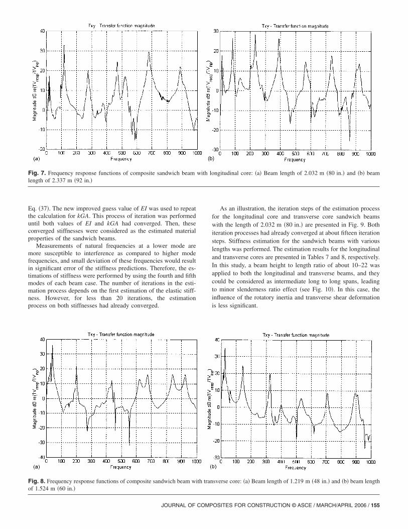
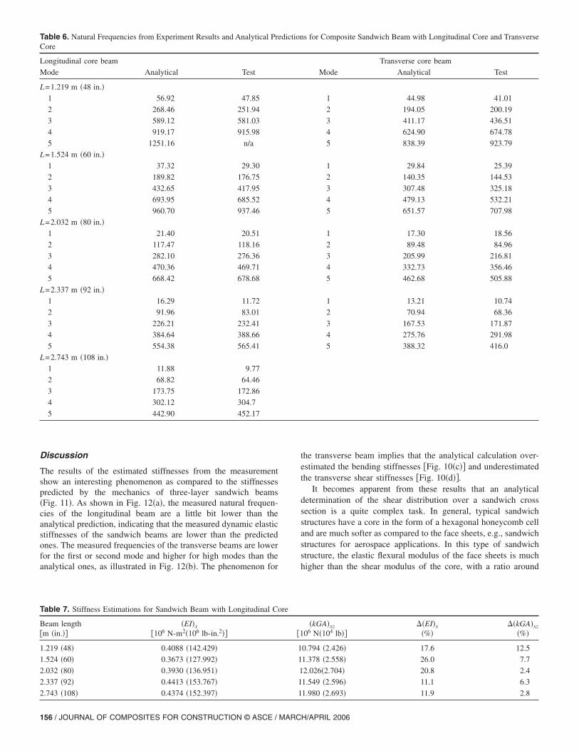
Results of typical frequency response functions from dynamictesting of the sandwich beams with longitudinal and transversecores at different lengths are presented in Figs. 7 and 8, respec-tively. The analytical natural frequencies of the beams werecalculated by using the Timoshenko beam theory with thecalculated beam stiffnesses given in Table 4. Results of the firstfive natural frequencies from both the analytical calculations andthe experimental measurements are presented in Table 6 for thelongitudinal and transverse core beams.
Data Reductions
The estimation procedure for the beam stiffness propertieswas based on the relationship between the frequencies and thematerial properties as expressed in Eq. �37�. In the data reduction,the shear correction factor was not specified and was includedin the estimation of the transverse shear stiffness as kGA.Once the frequencies were obtained from the experiment and sub-stituted into the equation, there were two unknowns in theequations we would like to extract, i.e., the elastic bending stiff-ness EI and the transverse shear stiffness kGA. Hence, by usingtwo different values of natural frequencies from the experimentalmeasurement, i and j, the bending and transverse shearstiffnesses can be evaluated.
First, from i, the value of EI was estimated by usingthe Euler-Bernoulli beam theory and used as an initial guess.Using the estimated EI together with another measured frequency j, the transverse shear stiffness kGA was estimated by solvingEq. �37�. Then, a new value for EI was calculated by incorpor-
Fig. 6. Experimental setup of cantilevered sandwich beam
ating the estimated kGA and the previous frequency i into
H/APRIL 2006
Eq. �37�. The new improved guess value of EI was used to repeatthe calculation for kGA. This process of iteration was performeduntil both values of EI and kGA had converged. Then, theseconverged stiffnesses were considered as the estimated materialproperties of the sandwich beams.
Measurements of natural frequencies at a lower mode aremore susceptible to interference as compared to higher modefrequencies, and small deviation of these frequencies would resultin significant error of the stiffness predictions. Therefore, the es-timations of stiffness were performed by using the fourth and fifthmodes of each beam case. The number of iterations in the esti-mation process depends on the first estimation of the elastic stiff-ness. However, for less than 20 iterations, the estimationprocess on both stiffnesses had already converged.
Fig. 7. Frequency response functions of composite sandwich beamlength of 2.337 m �92 in.�
Fig. 8. Frequency response functions of composite sandwich beam wiof 1.524 m �60 in.�
JOURNAL OF COMP
As an illustration, the iteration steps of the estimation processfor the longitudinal core and transverse core sandwich beamswith the length of 2.032 m �80 in.� are presented in Fig. 9. Bothiteration processes had already converged at about fifteen iterationsteps. Stiffness estimation for the sandwich beams with variouslengths was performed. The estimation results for the longitudinaland transverse cores are presented in Tables 7 and 8, respectively.In this study, a beam height to length ratio of about 10–22 wasapplied to both the longitudinal and transverse beams, and theycould be considered as intermediate long to long spans, leadingto minor slenderness ratio effect �see Fig. 10�. In this case, theinfluence of the rotatory inertia and transverse shear deformationis less significant.
ngitudinal core: �a� Beam length of 2.032 m �80 in.� and �b� beam
sverse core: �a� Beam length of 1.219 m �48 in.� and �b� beam length
with lo
th tran
OSITES FOR CONSTRUCTION © ASCE / MARCH/APRIL 2006 / 155
Discussion
The results of the estimated stiffnesses from the measurementshow an interesting phenomenon as compared to the stiffnessespredicted by the mechanics of three-layer sandwich beams�Fig. 11�. As shown in Fig. 12�a�, the measured natural frequen-cies of the longitudinal beam are a little bit lower than theanalytical prediction, indicating that the measured dynamic elasticstiffnesses of the sandwich beams are lower than the predictedones. The measured frequencies of the transverse beams are lowerfor the first or second mode and higher for high modes than theanalytical ones, as illustrated in Fig. 12�b�. The phenomenon for
Table 6. Natural Frequencies from Experiment Results and Analytical PreCore
Longitudinal core beam
Mode Analytical Test
L=1.219 m �48 in.�1 56.92 47.85
2 268.46 251.94
3 589.12 581.03
4 919.17 915.98
5 1251.16 n/a
L=1.524 m �60 in.�1 37.32 29.30
2 189.82 176.75
3 432.65 417.95
4 693.95 685.52
5 960.70 937.46
L=2.032 m �80 in.�1 21.40 20.51
2 117.47 118.16
3 282.10 276.36
4 470.36 469.71
5 668.42 678.68
L=2.337 m �92 in.�1 16.29 11.72
2 91.96 83.01
3 226.21 232.41
4 384.64 388.66
5 554.38 565.41
L=2.743 m �108 in.�1 11.88 9.77
2 68.82 64.46
3 173.75 172.86
4 302.12 304.7
5 442.90 452.17
Table 7. Stiffness Estimations for Sandwich Beam with Longitudinal Co
Beam length�m �in.��
�EI�x
106 N-m2�106 lb-in.2��
1.219 �48� 0.4088 �142.429�
1.524 �60� 0.3673 �127.992�
2.032 �80� 0.3930 �136.951�
2.337 �92� 0.4413 �153.767�
2.743 �108� 0.4374 �152.397�
156 / JOURNAL OF COMPOSITES FOR CONSTRUCTION © ASCE / MARC
the transverse beam implies that the analytical calculation over-estimated the bending stiffnesses �Fig. 10�c�� and underestimatedthe transverse shear stiffnesses �Fig. 10�d��.
It becomes apparent from these results that an analyticaldetermination of the shear distribution over a sandwich crosssection is a quite complex task. In general, typical sandwichstructures have a core in the form of a hexagonal honeycomb celland are much softer as compared to the face sheets, e.g., sandwichstructures for aerospace applications. In this type of sandwichstructure, the elastic flexural modulus of the face sheets is muchhigher than the shear modulus of the core, with a ratio around
s for Composite Sandwich Beam with Longitudinal Core and Transverse
Transverse core beam
Mode Analytical Test
1 44.98 41.01
2 194.05 200.19
3 411.17 436.51
4 624.90 674.78
5 838.39 923.79
1 29.84 25.39
2 140.35 144.53
3 307.48 325.18
4 479.13 532.21
5 651.57 707.98
1 17.30 18.56
2 89.48 84.96
3 205.99 216.81
4 332.73 356.46
5 462.68 505.88
1 13.21 10.74
2 70.94 68.36
3 167.53 171.87
4 275.76 291.98
5 388.32 416.0
�kGA�xz
06 N�104 lb����EI�x
�%���kGA�xz
�%�
0.794 �2.426� 17.6 12.5
1.378 �2.558� 26.0 7.7
2.026�2.704� 20.8 2.4
1.549 �2.596� 11.1 6.3
1.980 �2.693� 11.9 2.8
diction
re
1
1
1
1
1
1
H/APRIL 2006

200 or more. Hence, the separation of the task in the structuresuch as described in the assumption that the face sheets carry onlythe normal stresses and the core carries the transverse shearstress is justified. However, in the case of sandwich structures incivil infrastructure, where the ratio between the elastic flexuralmodulus of the face sheets and the transverse shear modulus ofthe core is not as high �in this case study, it is around 44�,the stress distribution over the beam cross section would besignificantly affected by the interaction between the face sheetsand the core. Moreover, the orientation of the sinusoidal core ofthe transverse beam �see Fig. 11�, which is perpendicular to thebeam length, results in more flexible core. Consequently, thetransverse sandwich beam has a lower shear stiffness as comparedto the longitudinal sandwich beam �see Tables 7 and 8�, which is
Table 8. Stiffness Estimations for Sandwich Beam with Transverse Core
Beam length�m �in.��
�EI�y
106 N-m2�106 lb-in.2��
1.219 �48� 0.1310 �45.649�
1.524 �60� 0.1333 �46.460�
2.032 �80� 0.1626 �56.673�
2.337 �92� 0.1822 �63.503�
Fig. 9. Iteration process for stiffness estimation of sandwich beam oflongitudinal beam; and �c� bending stiffness and �d� transverse shear
JOURNAL OF COMP
demonstrated by the difference in the trend of the measuredfrequencies between both beams, as shown in Fig. 12. This im-plies that the beam with a different core orientation has a differentshear stress distribution over its cross section.
The stiffness estimations from dynamic testing are moderatelyin agreement with the analytical calculation �2.2–31%� as listedin Tables 7 and 8. In general, these measured stiffnesses of boththe sandwich beams are lower than the calculated ones, and asexpected the longer the beam is, the closer the value betweenthe measured and the calculated stiffnesses. However, the trendsof the measured stiffnesses between the longitudinal and trans-verse core sandwich beams are different. For the beam with alongitudinal core, the variations of dynamic stiffness with lengthare quite modest. The bending stiffnesses from the dynamic test
�kGA�yz
06 N�104 lb����EI�y
�%���kGA�yz
�%�
.450 �45.649� 31.1 �11.5
.992 �46.460� 29.9 �29.0
.464 �56.673� 14.4 �11.9
.163 �63.503� 4.1 �2.2
m �80 in.�: �a� Bending stiffness and �b� transverse shear stiffness ofss of transverse beam
1
3
3
3
3
2.032stiffne
OSITES FOR CONSTRUCTION © ASCE / MARCH/APRIL 2006 / 157

are about 26% lower than the calculated ones. For the largerlength to height ratio, i.e., above 20, these stiffness differences arearound 11%. For the transverse core beams, the short beam hasmajor bending stiffness differences of around 31%. However, asthe length of the beam increases, the measured bending stiffnessconverges rapidly to the analytical results, with a difference ofabout 4%.
Estimation of the transverse shear stiffness shows that eachsandwich beam exhibits a different trend. For the beams with alongitudinal core, the measured shear stiffnesses from thedynamic test are about 2.4–12.5% lower than the analyticalones. The measured shear stiffnesses for the beams with atransverse core are much higher, by about 2.2–29%. These resultsindicate that the actual sandwich beam with a longitudinal coreis slightly softer in transverse shear stiffness than the analyticalcalculation; whereas the actual sandwich beam with transversecore is stiffer than the analytical estimation. The differencesbetween the measured and calculated predictions for both thebending and transverse shear stiffnesses are summarized in Tables7 and 8.
Comparison of the estimated stiffness properties from theproposed procedure with the static experimental results fromclassical three-point bending and four-point bending �Davalos
Fig. 10. Stiffness estimation results from various beam length for slongitudinal beam; and �c� bending stiffness and �d� transverse shear
et al. 2001� indicates a relatively good agreement, especially
158 / JOURNAL OF COMPOSITES FOR CONSTRUCTION © ASCE / MARC
for the transverse beam. The maximum midspan deflectionsfor using the estimated stiffness obtained by both the dynamicand static methods are presented in Fig. 13. For the longitudinalbeam, the maximum deflection from the static tests are generallylower than the ones predicted by the estimated dynamic stiffnessproperties, indicating that the stiffness properties from thedynamic experiment are lower than the ones from the staticexperiment. For the transverse beams, relatively close correlationsof the maximum deflections from the static experiment andthe ones computed using the estimated dynamic stiffness proper-ties are obtained, thus indirectly validating the accuracy ofthe dynamic approach for stiffness estimation and illustrating itsapplicability in the deflection prediction.
h beams: �a� Bending stiffness and �b� transverse shear stiffness ofss of transverse beam
Fig. 11. Configuration of sandwich beam with transverse core
andwicstiffne
H/APRIL 2006

Conclusions
This study demonstrates that the proposed stiffness estimationprocedure using the modified Timoshenko beam model can beused to evaluate the bending and transverse shear stiffnessesof sandwich beams. Most of the estimated stiffnesses fromthe experimentally measured data have a difference of about20% or smaller, as compared to the analytical calculation. Theprocedure has potential for practical application to estimatematerial properties of sandwich structures with a more complexgeometry or lay-up. Using the long span beam specimen producesgood estimation for bending stiffness. However, for the transverseshear stiffness estimation, the shorter span beam should beapplied to improve the accuracy of the procedure, due to thedominance of the shear deformation.
It can be summarized from the data reduction results that the
Fig. 12. Comparison between calculated natural frequencies and testbeam
Fig. 13. Comparison of estimated stiffness results with static�a� Longitudinal core beam and �b� transverse core beam
JOURNAL OF COMP
actual bending stiffness of both the longitudinal and transversesandwich beams and the transverse shear stiffness of the long-itudinal sandwich beam are lower than the analytical calculation.On the other hand, the actual transverse shear stiffness of thetransverse sandwich beam is stiffer than the analytical evaluation.Apparently, the assembly of the core with face sheets to formsandwich structures increases the shear stiffness of the coreconsiderably, especially for the beam with core in the transversedirection. Accordingly, the combined analytical and experimentalapproach presented in this study can be used as an effective toolto assess the bending and transverse shear stiffness properties ofcomposite honeycomb sandwich structures with relatively thickface sheets, and the evaluated mechanical properties can beadopted in highway design and structural health assessment�e.g., through the stiffness reduction�.
for 60 in. beam: �a� Longitudinal core beam and �b� transverse core
obtained by three-point bending and four-point bending tests:
results
results
OSITES FOR CONSTRUCTION © ASCE / MARCH/APRIL 2006 / 159

Acknowledgments
The test samples were provided by the KSCI, and we thankProfessor Julio F. Davalos of West Virginia University andDr. Jerry Plunkett of KSCI for their technical contributions andsupport. Partial financial support for this study is receivedfrom the National Science Foundation �EHR-0090472� and theFederal Highway Administration �FHWA�/Ohio Department ofTransportation �ODOT� �State Job No. 134142�. The opinions andfindings, however, are those of the writers and do not necessarilyreflect the views of the sponsoring agencies.
References
Adams, R. D., and Maheri, M. R. �1993�. “The dynamic shear propertiesof structural honeycomb materials.” Compos. Sci. Technol., 47,15–23.
Bank, L. C., and Melehan, T. P. �1989�. “Flexural and shear moduli of fullsection fiber reinforced plastic �FRP� pultruded beams.” J. Test. Eval.,17, 40–45.
Chamis, C. C. �1984�. “Simplified composites micromechanics equationsfor strength, fracture toughness, and environmental effects.”NASA TM-83696, National Aeronautics and Space Administration,Washington, D.C.
Cunningham, P. R., and White, R. G. �2001�. “A new measurementtechnique for the estimation of core shear strain in closed sandwichstructures.” Compos. Struct., 51, 319–334.
Davalos, J. F., Salim, H. A., Qiao, P. Z., Lopez-Anido, R., andBarbero, E. J. �1996�. “Analysis and design of pultruded FRP shapesunder bending.” Composites, Part B, 27�3–4�, 295–305.
Davalos, J. F., Qiao, P., Xu, X. F., Robinson, J., and Barth, K. E. �2001�.“Modeling and characterization of fiber-reinforcement plastichoneycomb sandwich panels for highway bridge applications.”Compos. Struct., 52, 441–452.
Frostig, Y. �2003�. “Classical and high-order computational models in theanalysis of modern sandwich panels.” Composites, Part B, 34�1�,83–100.
Frostig, Y., and Thomsen, O. T. �2004�. “High-order free vibration ofsandwich panels with a flexible core.” Int. J. Solids Struct., 41�7�,1697–1724.
Hashin, Z., and Rosen, B. W. �1964�. “The elastic modeling of fiber-reinforced materials.” J. Appl. Mech., 31, 223–232.
Ip, K. H., and Tse, P. C. �2001�. “Determination of dynamic flexuraland shear moduli of thick composite beam using natural frequencies.”J. Compos. Mater., 35�17�, 1553–1569.
Jones, R. M. �1999�. Mecahnics of composite materials, Taylor
& Francis, Bristol, Pa.
160 / JOURNAL OF COMPOSITES FOR CONSTRUCTION © ASCE / MARC
Keller, T. �2001�. “Recent all-composite and hybrid fibre-reinforced poly-mer bridges and building.” Prog. Struct. Eng. Mater., 3, 132–140.
Lestari, W., and Qiao, P. �2005�. “Damage detection of fiber-reinforcedpolymer honeycomb sandwich beams.” Compos. Struct., 67�3�,365–373.
Librescu, L., and Hause, T. �2000�. “Recent developments in the model-ing and behavior of advanced sandwich constructions: A survey.”Compos. Struct., 48�1�, 1–17.
Luciano, R., and Barbero, E. J. �1994�. “Formulas for the stiffness ofcomposites with periodic microstructure.” Int. J. Solids Struct.,31�21�, 2933–2944.
Maheri, M. R., and Adams, R. D. �1998�. “On the flexural vibration ofTimoshenko beams, and the applicability of the analysis to a sandwichconfiguration.” J. Sound Vib., 209�3�, 419–442.
Meirovitch, L. �1967�. Analytical methods in vibrations, Macmillan,
New York.Plunkett, J. D. �1997�. “Fiber-reinforcement polymer honeycomb short
span bridge for rapid installation.” IDEA Project Rep., National
Cooperative Highway Research Program, Washington, D.C.Qiao, P. Z., and Wang, J. L. �2005�. “On the mechanics of composite
sinusoidal honeycomb cores.” J. Aerosp. Eng., 18�1�, 42–50.Saito, T., Parberry, R. D., Okuno, S., and Kawano, S. �1997�. “Parameter
identification for aluminum honeycomb sandwich panels based onorthotropic Timoshenko beam theory.” J. Sound Vib., 208�2�,271–287.
Salim, H. A. �1996�. “Modeling and application of thin-walled compositebeams in bending and torsion.” Ph.D. thesis, West Virginia Univ.,Morgantown, W.V.
Silverman, I. K. �1995�. “Natural frequencies of sandwich beams includ-ing shear and rotary effects.” J. Sound Vib., 183�3�, 547–561.
Sokolinsky, V. S., Nutt, S. R., and Frostig, Y. �2002�. “Boundary condi-tion effects in free vibrations of higher-order soft sandwich beams.”AIAA J., 40�6�, 1220–1227.
Sokolinsky, V. S., von Bremen, H. F., Lesko, J. J., and Nutt, S. R. �2004�.“Higher-order free vibrations of sandwich beams with a locallydamaged core.” Int. J. Solids Struct., 41�22–23�, 6529–6547.
Whitney, J. M., Browning, C. E., and Mair, A. �1974�. “Analysis
of the flexure test for laminated composite materials.” Proc.,
Composite Materials: Testing and Design (Third Conf.), ASTM,West Conshohocken, Pa., 30.
Xu, X. F., Qiao, P., and Davalos, J. F. �2001�. “Transverse shear stiffnessof composite honeycomb core with general configuration.” J. Eng.Mech., 127�11�, 1144–1151.
Yang, M. J., and Qiao, P. �2005�. “Higher-order impact modeling of sand-wich beams with flexible core.” Int. J. Solids Struct., 42�20�,5460–5490.
Zureick, A., Khan, L. F., and Bandy, B. J. �1994�. “Tests on deep I-shape
pultruded beams.” Proc., 49th Annual Conf., Composites Institute,
Oxford, Miss.
H/APRIL 2006
Copyright © 2022 FDOKUMEN