“Part Il = Product's Service Guide в
604
Datex AS/3 Anaesthesia Monitor Service Manual Part I - General Service Guide P “Part Il = Product's Service Guide 1. “Anaesthesia Monitor Central Unit, F-CUS, B-CPU2, B-CPU3 and SsSTD96/ARIK96 “ Displays and'Command Board, D-VNCIS5, D-LCCIO, B-DISP, ' B-DVGA and K-VNCI5 Haemodynamic Modules M-ESTPR, M-ETPR and M-ESTR ‘Cardiac Output Modules, M-COP and M-COPSv . Pressure and Pressure-Temperature Modules, M-P and M-PT : Non-Invasive Blood Pressure Module, M-NIBP -Recorder Module, M-REC "Extension Frame, F-EXT4 “Memory Mödule, M-MEM and Memory Board, B-CMMEM “Nellcor Compatible Saturation Module, M-NSAT ‘Network Board, B-NET «Interface Board, B-INT .. “Airway Module, G- O/OV/AO/AiO/AOV/AiOV, and B-GAS ‘Anaesthesia Keyboard, K-ARK, B-ARK Neuro Muscular Transmission Module, M-NMT UPINET Board, B-UPINET | в == DONNA o пи мм ши мы = upwuNs o All specifications subject to change without notice Document no. 889535 March, 1996 Datex Division, Instrumentarium Corp. P.O.Box 446 FIN-00101 Helsinki Finland Tel. +358 0 39411 Fax +358 0 1463310
-
Upload
khangminh22 -
Category
Documents
-
view
3 -
download
0
Transcript of “Part Il = Product's Service Guide в
Datex AS/3
Anaesthesia Monitor
Service Manual
Part I - General Service Guide
P
“Part Il = Product's Service Guide
1. “Anaesthesia Monitor Central Unit, F-CUS, B-CPU2, B-CPU3 and
SsSTD96/ARIK96 “ Displays and'Command Board, D-VNCIS5, D-LCCIO, B-DISP,
' B-DVGA and K-VNCI5 Haemodynamic Modules M-ESTPR, M-ETPR and M-ESTR ‘Cardiac Output Modules, M-COP and M-COPSv
. Pressure and Pressure-Temperature Modules, M-P and M-PT : Non-Invasive Blood Pressure Module, M-NIBP -Recorder Module, M-REC "Extension Frame, F-EXT4
“Memory Mödule, M-MEM and Memory Board, B-CMMEM “Nellcor Compatible Saturation Module, M-NSAT
‘Network Board, B-NET «Interface Board, B-INT .. “Airway Module, G- O/OV/AO/AiO/AOV/AiOV, and B-GAS
‘Anaesthesia Keyboard, K-ARK, B-ARK
Neuro Muscular Transmission Module, M-NMT
UPINET Board, B-UPINET |
в == DONNA
o пи
мм
ши
мы =
upwuNs
o
All specifications subject to change without notice
Document no. 889535
March, 1996
Datex Division, Instrumentarium Corp. P.O.Box 446 FIN-00101 Helsinki Finland
Tel. +358 0 39411 Fax +358 0 1463310

Datex AS/3 Anaesthesia Monitor
Service Manual
に
Datex AS/3 Anaesthesia Monitor
Service Manual
Part I
AS/3 Anaesthesia Monitor
General Service Guide
I INTRODUCTION 1
1.1 Notes to the Reader nenene rieeieiieenionee 2 1.2 Symbols...
Symbols on Equipment... Symbols on Transport Packaging
1.3 Related Documents ........cccscscsscsssssssscssssccssescescsesssnsenesenceseasesessesssesersssecsssscanssesenseseseasseeass 4
2 SAFETY 5
21 Warnings... sense
2.2 Cautions ss
2.3 Equipment Classification.
3 ARCHITECTURE
3.1 Bus Structure... eee ieri ieri iii iii iii einen
3.2 Distributed processing... Ree ete een nné 3.3 Module Communication ..
3.4 Software loading
3.5 GenericModule........................ee eee eeemenenensnen
4 CLEANING AND MAINTENANCE 17
5 GENERAL TROUBLESHOOTING | 18
Datex AS/3 Anaesthesia Monitor
Service Manual

Datex AS/3 Anaesthesia Monitor
Service Manual
I INTRODUCTION
Datex AS/3 Anaesthesia Monitor is a cardiac and respiratory monitoring device used during anaesthesia in operating rooms.
The monitor consists of the Central Unit and different modules. Additionally the monitor can be equipped with a secondary display and Anaesthesia Record Keeper.
There are single and double width modules containing one or more parameters. The modules that are placed in the Central Unit can be removed and inserted during operation. The Airway Module, additional display and the Anaesthesia keyboard can only be connected when the monitor is turned off.
Part 1-1
Datex AS/3 Anaesthesia Monitor
Service Manual
1.1 Notes to the Reader
This service manual is intended for service personnel and
engineers who will perform service and maintenance procedures on Datex AS/3 Anaesthesia Monitor.
This service manual is divided into two parts: Part I gives to the reader overview of the AS/3 Anaesthesia Monitor and its configuration. Part II gives detailed descriptions of each module and component of AS/3 Anaesthesia Monitor.
The manufacturer reserves the right to make changes in product specifications without prior notice. The information in this manual is believed to be accurate and reliable; however, the
manufacturer assumes no responsibility for its use.
Datex assumes no responsibility for the use or reliability of its software on equipment that is not furnished by Datex.
This document is protected by copyright. All rights are reserved. No part of this document may be photocopied, reproduced, or translated to another language without the prior written consent of Datex.
AS/3, ComWheel, Datex, D-lite, D-fend, EarSat, FingerSat,
MemCard and Side Stream Spirometry, are trade marks of Instrumentarium Corp., Helsinki, Finland.
Copyright by Datex, 1994
Part I-2

1.2 Symbols
Я РЬ
GÖ Pb
— he
Datex AS/3 Anaesthesia Monitor
Service Manual
Symbols on Equipment
This battery contains lead acid and in case of disposal, must be separated from other waste according to local regulations.
This battery contains Pb and it can be recycled.
Dangerous voltage.
Symbols on Transport Packaging
The contents of the transport package are fragile and it has to be handled with care.
This symbol indicates the correct upright position of the transport package.
The transport package shall be kept in a dry environment.
This symbol is to indicate the temperature limitations within which the transport package shall be kept and handled.
Part 1-3

Datex AS/3 Anaesthesia Monitor
Service Manual
1.3 Related Documents
The following documents are available on and for Datex AS/3 Anaesthesia Monitor in addition to this service manual.
Datex AS/3 Anaesthesia Monitor Operator's Manual (p/n 889381)
This manual provides detailed instructions and references for the operating and configuration of the system. Everyday service and maintenance procedures as well as simple troubleshooting hints are also included.
Datex AS/3 Anaesthesia Monitor Installation Manual (p/n 889470)
The installation manual gives clear and comprehensive picture on planning, unpacking, and installing the system.
Datex AS/3 Schematic Diagrams (p/n 886091)
The Schematic Diagrams is the collection of schematic diagrams and part layouts of the Anaesthesia Monitor and other AS/3 Family products (excluded AS/3 Anaesthesia Delivery Unit).
Datex AS/3 Supplies and Accessories (p/n 882300)
Supplies and Accessories is an accessory catalogue in which (= all the necessary accessories and supplies to the system are listed.
Clinical Applications
The following Datex publications are useful in obtaining information on clinical application.
- Interpreting the Plethysmographic Pulse Wave, Appliguide
- Cardiac Output, Ouick Guide
- PCWP, Quick Guide
- ST Segment Analysis, Quick Guide
Part I-4

2 SAFETY
2.1 Warnings
Datex AS/3 Anaesthesia Monitor
Service Manual
A WARNING indicates a situation in which the user or the
patient may be in danger of injury or death
POWER CONNECTION:
e Before connecting the power cord to the mains outlet, check that the local voltage and frequency rating corresponds with the rating stated on the device plate on the rear panel of Anaesthesia Monitor Frame.
+ Connect the monitor to a three-wire, grounded, hospital
grade receptacle. Do not remove the grounding prong from the power plug.
» Use intact power cord. Replace the cord if it is cracked,
frayed, broken or otherwise damaged.
+ Do not apply tension to the power cord. The cord may get broken.
+ Do not use extension cords or adapters of any type.
EXTERNAL CONNECTION:
+ Donot connect any other external devices to the monitor than those specified by Datex.
FUSE REPLACEMENT:
+ Replace the fuse with a fuse of the same type and with the same rating.
EXPLOSION HAZARD:
。 Do not use the monitor in the presence of flammable anaesthetics.
Part I-5
Datex AS/3 Anaesthesia Monitor
Service Manual
PATIENT SAFETY:
+ Do not perform any testing or maintenance on the monitor while it is being used on a patient.
+ . Use only cables and accessories approved by Datex. Do not modify them. Other cables and accessories may damage the monitor or interfere with measurement.
CLEANING AND SERVICE:
+ Only trained personnel with proper tools and test equipment shall perform the tests and repairs described in this manual. Unauthorized service may void the monitor warranty.
e Switch the power off and unplug the power cord before cleaning or service. Get rid of moisture completely before reconnecting it to the mains outlet.
e Donot touch any exposed wire or conductive surface while covers are off and the monitor is energized. The voltages present can cause injury or death.
» Perform electrical safety check and current leakage test to the monitor always after service.
Part 1-6
2.2 Cautions
Datex AS/3 Anaesthesia Monitor
Service Manual
A CAUTION indicates a condition that may lead to equipment damage or malfunction.
INSTALLATION:
。 Leave space behind the monitor to allow proper ventilation.
BEFORE USE:
e Allow two minutes for warm-up and note any error messages or deviations from normal operation.
‧ Clean rear panel fan dust filter once a month or whenever necessary.
AUTOCLAVING, STERILIZING:
« © Donotautodlave any part of the monitor.
+ Donot gas sterilize the modules.
CLEANING AND SERVICE:
e Donot use ammonia-, phenol-, or acetone-based cleaners.
These cleaners may damage the monitor surface.
‧ Donot immerse the monitor in any liquid. Do not allow liquid to enter the monitor or into modules.
‧ Electrostatic discharge through the PC boards may damage the components. Before replacing PC boards, wear a static control wrist strap. Handle all PC boards by their non- conductive edges and use anti-static containers when transporting them.
‧ Do not break or bypass the patient isolation barrier when testing PC boards.
Part I-7
Datex AS/3 Anaesthesia Monitor
Service Manual
SPECIAL COMPONENTS:
e There are special components used in this monitor which are vital to assure reliability and safety. Datex assumes no responsibility for damage if replacement components not approved by Datex are used.
e There is a lithium battery on the CPU board. Discard М broken IC containing the battery according to local
regulations.
BATTERIES
The battery package of the power supply unit in this device contains lead acid (Pb) which is hazardous to environment and thus the battery needs to be disposed of carefully according to local regulations.
To replace the batteries safely, please refer to the instructions further on in this manual.
+ Donot short-circuit the battery terminals, short-circuiting the battery may produce a very high current, which damages the battery.
e Do not dispose of the battery into open flame, nor put the battery near fire, as it may explode.
+ Do not disassemble the battery. It contains electrolyte, which may damage clothing or cause injury to skin or eyes. If exposed to electrolyte, wash the injured area with plenty of water and contact a doctor.
See also the chapter “Symbols on Equipment”.
Part I-8
Datex AS/3 Anaesthesia Monitor
Service Manual
STORAGE AND TRANSPORT:
‧ Donot store or transport the monitor outside the specified temperature and pressure range:
Temperature -10 to +50°C /14 to 122°F. Ambient pressure 500 to 800 mmHg/660 to 1060 mbar Humidity 0 to 90 % non-condensing
except LCD Display: temperature +5...+35°C/41 to 95°F humidity 0 to 85 % non-condensing
DISCARD:
» Discard the device and paris thereof according to local regulations. Do not discard to the nature.
The manufacturer accepts no responsibility for any modifications made to the monitor outside the factory.
Part I-9
Datex AS/3 Anaesthesia Monitor
Service Manual
2.3 Equipment Classification
Classification according to TEC 601-1:
CLASS 1 equipment according to the type of protection against electrical shock.
TYPE BF or CF equipment according to the degree of protection against electrical shock is specified in the specifications of each parameter module.
Degree of protection against the harmful ingress of water as detailed in the IEC 529: IPX0.
Equipment not suitable for use in the presence of FLAMMABLE ANAESTHETIC MIXTURE with air or with OXYGEN /NITROUS OXIDE.
CONTINUOUS OPERATION according to the mode of operation.
Part I-10

Datex AS/3 Anaesthesia Monitor
Service Manual
3 ARCHITECTURE
Datex AS/3™ family builds up to freely configurable modular system. The architecture is designed to enable different module combinations so that the user is able to get the desirable parameter and feature set. Further, the modular approach makes it possible to add new features in the order and pace they are needed.
3.1 Bus structure
The operation of Datex AS/3™ products is based on two communication channels, the AS/3 Bus and Module Bus. All
boards connected to the AS/3 Bus as well as the parameter modules attached to the Module Bus receive their power from the same power supply, which is an integral part of the frame.
Display
UPI CPU Controller
Parameter, | Parameter
Module Module
Figure 1 General structure of AS/3 system
Part I-11
Datex AS/3 Anaesthesia Monitor
Service Manual
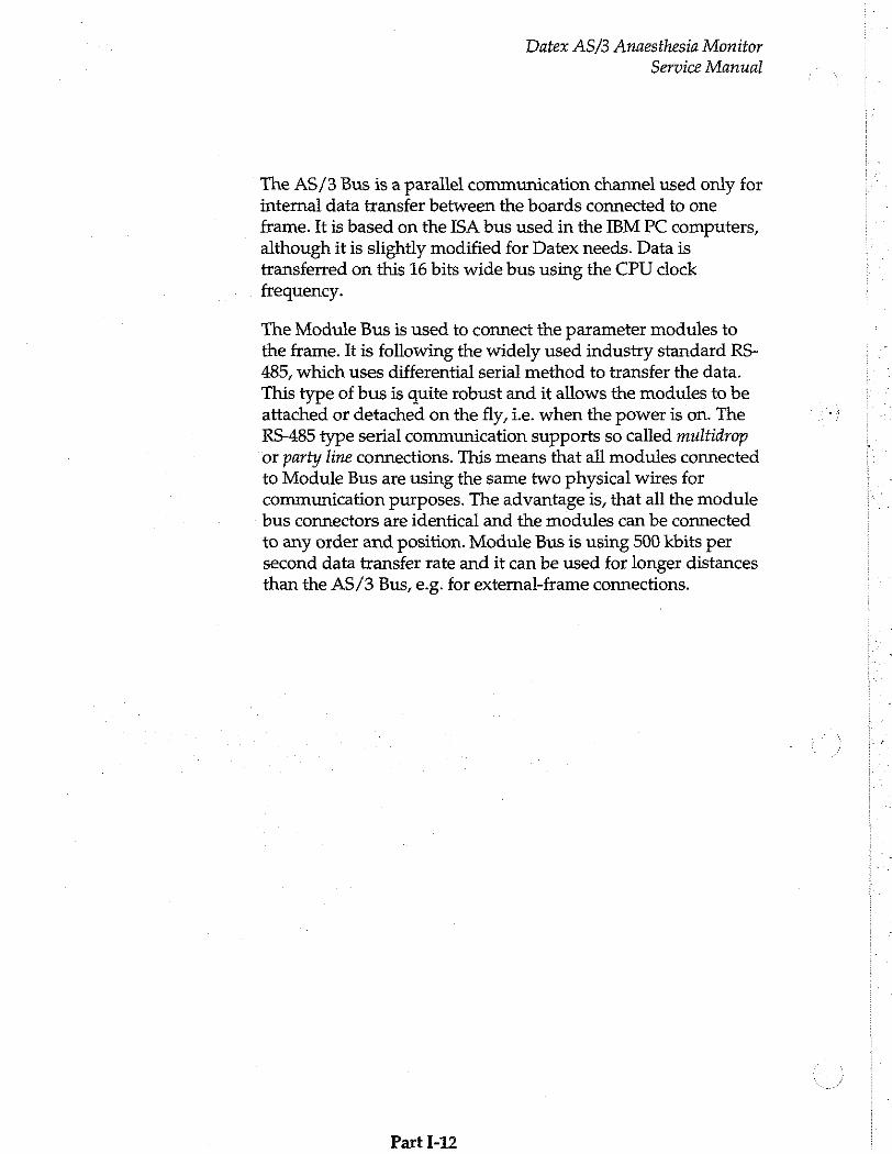
The AS/3 Bus is a parallel communication channel used only for internal data transfer between the boards connected to one frame. It is based on the ISA bus used in the IBM PC computers,
although it is slightly modified for Datex needs. Data is transferred on this 16 bits wide bus using the CPU clock frequency.
The Module Bus is used to connect the parameter modules to the frame. It is following the widely used industry standard RS- 485, which uses differential serial method to transfer the data. This type of bus is quite robust and it allows the modules to be attached or detached on the fly, ie. when the power is on. The RS-485 type serial communication supports so called multidrop or party line connections. This means that all modules connected to Module Bus are using the same two physical wires for communication purposes. The advantage is, that all the module bus connectors are identical and the modules can be connected to any order and position. Module Bus is using 500 kbits per second data transfer rate and it can be used for longer distances than the AS/3 Bus, e.g. for external-frame connections.
Part 1-12
Datex AS/3 Anaesthesia Monitor
Service Manual
3.2 Distributed processing
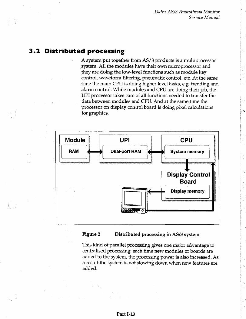
A system put together from AS/3 products is a multiprocessor system. All the modules have their own microprocessor and they are doing the low-level functions such as module key control, waveform filtering, pneumatic control, etc. At the same
time the main CPU is doing higher level tasks, e.g. trending and alarm control. While modules and CPU are doing their job, the UPI processor takes care of all functions needed to transfer the data between modules and CPU. And at the same time the processor on display control board is doing pixel calculations for graphics.
Dual-port RAM System memory
Display Control
Board
Display memory
Figure 2 Distributed processing in AS/3 system
This kind of parallel processing gives one major advantage to centralised processing: each time new modules or boards are added to the system, the processing power is also increased. As a result the system is not slowing down when new features are added.
Part I-13
Datex AS/3 Anaesthesia Monitor
Service Manual
3.3 Module Communication
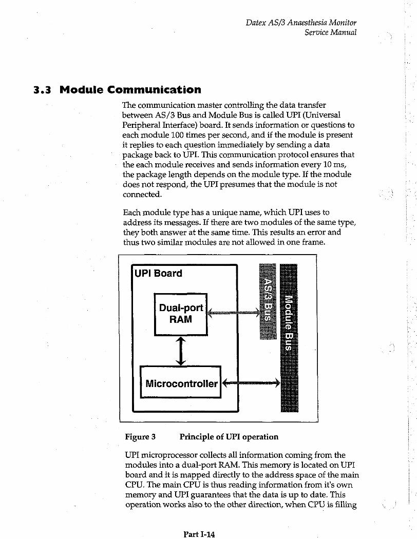
The communication master controlling the data transfer between AS/3 Bus and Module Bus is called UPI (Universal Peripheral Interface) board. It sends information or questions to each module 100 times per second, and if the module is present it replies to each question immediately by sending a data package back to UPI. This communication protocol ensures that the each module receives and sends information every 10 ms, the package length depends on the module type. If the module does not respond, the UPI presumes that the module is not connected.
Each module type has a unique name, which UPI uses to address its messages. If there are two modules of the same type, they both answer at the same time. This results an error and thus two similar modules are not allowed in one frame.
UPI Board
三 !
Бианром | 1 に 3 RAM =
© D.
S の !
Microcontroller ド ーーー つ
Figure 3 Principle of UPI operation
UPI microprocessor collects all information coming from the modules into a dual-port RAM. This memory is located on UPI board and it is mapped directly to the address space of the main CPU. The main CPU is thus reading information from it's own memory and UPI guarantees that the data is up to date. This operation works also to the other direction, when CPU is filling
Part I-14
Datex AS/3 Anaesthesia Monitor
Service Manual
the dual port RAM with data and UPI processor is distributing it to the modules.
3.4 Software loading
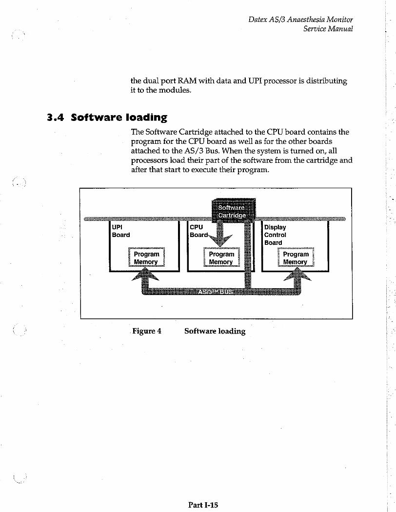
The Software Cartridge attached to the CPU board contains the program for the CPU board as well as for the other boards attached to the AS/3 Bus. When the system is turned on, all processors load their part of the software from the cartridge and after that start to execute their program.
Program Memory
Software
‘Cartridge
Program Memory
Display Control
Board
Program
Memory
Figure 4 Software loading
Part I-15
Datex AS/3 Anaesthesia Monitor
Service Manual
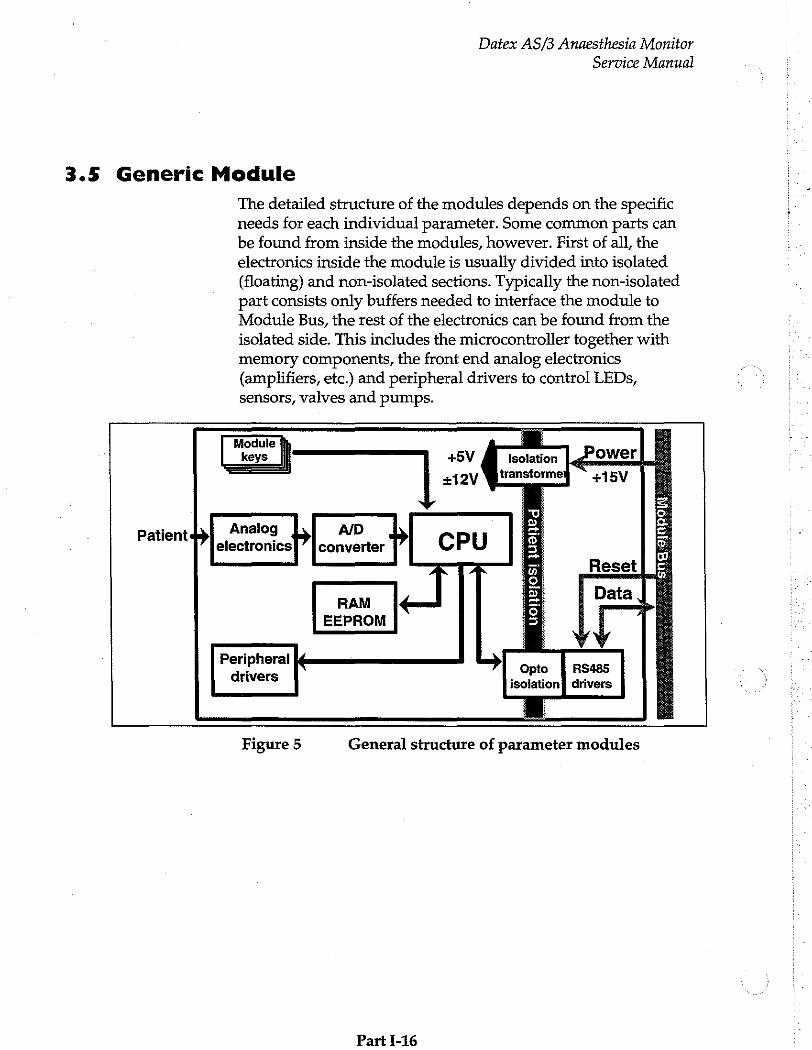
3.5 Generic Module
The detailed structure of the modules depends on the specific needs for each individual parameter. Some common parts can be found from inside the modules, however. First of all, the
electronics inside the module is usually divided into isolated (floating) and non-isolated sections. Typically the non-isolated part consists only buffers needed to interface the module to Module Bus, the rest of the electronics can be found from the isolated side. This includes the microcontroller together with memory components, the front end analog electronics (amplifiers, etc.) and peripheral drivers to control LEDs,
sensors, valves and pumps.
ee | es | +5V
+12V
Isolation
transforme:
Patient +>
Analog 2 GEE converter CPU 5
の El
RAM 回 EEPROM El
Peripheral
RS485 drivers
Opto drivers isolation
Figure 5 General structure of parameter modules
Part J-16

Datex AS/3 Anaesthesia Monitor
Service Manual
4 CLEANING AND MAINTENANCE
Field service is mostly limited to replacing the faulty circuit boards or mechanical parts. Only the parts listed as Spare Parts of each product are available for field service.
Datex is always available for service advice. Please provide the unit serial number, full type designation, and a detailed fault description.
Detailed description of the service procedures and troubleshooting is found in each of the module chapters in the part If, AS/3 Anaesthesia Monitor Product's Service Guide in this manual.
CAUTION: The tests and repairs outlined in this manual should only be attempted by a trained personnel. Unauthorized service may void the warranty of the unit.
The monitor can be cleaned by wiping with a soft cloth moistured with mild detergent solution, and disincfected by wiping with normal disinfectants. The monitor cannot be autoclaved.
Special attention must be paid to fan dust filter and D-fend water trap for their blockage may lead to monitor failure. See Operator's Manual for further instructions.
The LCD Display is a fragile component, please refer to PART II Displays for its cleaning and maintenance.
Part I-17
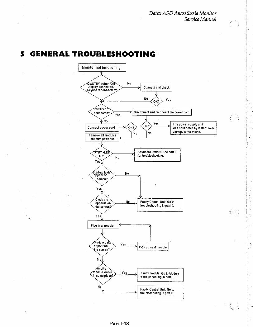
Monitor not functioning
On/STBY switch 'O No Display connected? Keyboard connected?
Connect power cord
Remove all modules and turn power on
Datex AS/3 Anaesthesia Monitor
Service Manual
GENERAL TROUBLESHOOTING
Connect and check
The power supply unit
was shut down by instant over
voltage in the mains.
No
Keyboard trouble. See part It for troubleshooting.
Yesy
tart-up texts appear on
screen?
Clock etc appears on the screen
No
Plug in a module [$
Module data appear on
Yes
Faulty Central Unit. Go to troubleshooting in part Il.
Pick up next module
Faulty module. Go to Module troubleshooting in part Il.
Faulty Central Unit. Go to troubleshooting in part Il.
Part 1-18
a,
Part li
AS/3 Anaesthesia Monitor
Product’s Service Guide
00 YOWRW
N σδυδων-9
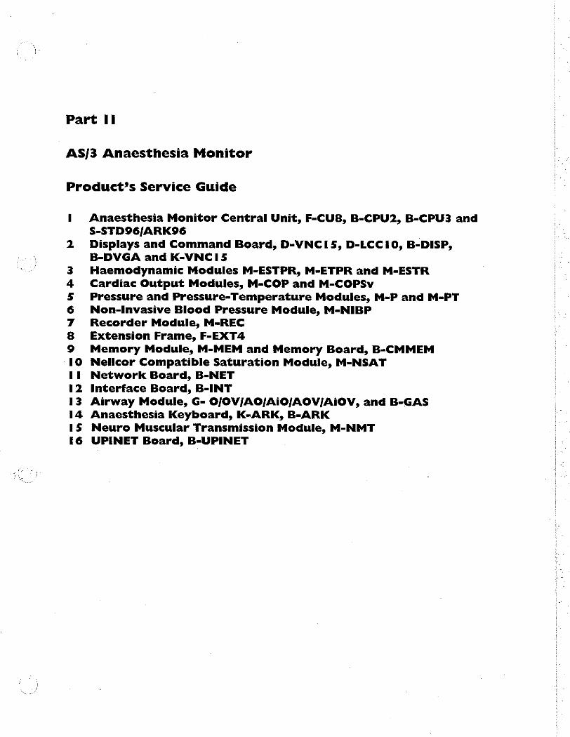
Anaesthesia Monitor Central Unit, F-CU8, B-CPU2, B-CPU3 and S-STD96/ARK96
Displays and Command Board, D-VNCI 5, D-LCC 10, B-DISP, B-DVGA and K-VNCI 5 Haemodynamic Modules M-ESTPR, M-ETPR and M-ESTR Cardiac Output Modules, M-COP and M-COPSv Pressure and Pressure-Temperature Modules, M-P and M-PT Non-Invasive Blood Pressure Module, M-NIBP
Recorder Module, M-REC
Extension Frame, F-EXT4
Memory Module, M-MEM and Memory Board, B-CMMEM Nellcor Compatible Saturation Module, M-NSAT Network Board, B-NET
Interface Board, B-INT
Airway Module, G- O/JOV/AO/AiO/AOV/JAiOV, and B-GAS Anaesthesia Keyboard, K-ARK, B-ARK
Neuro Muscular Transmission Module, M-NMT
UPINET Board, B-UPINET

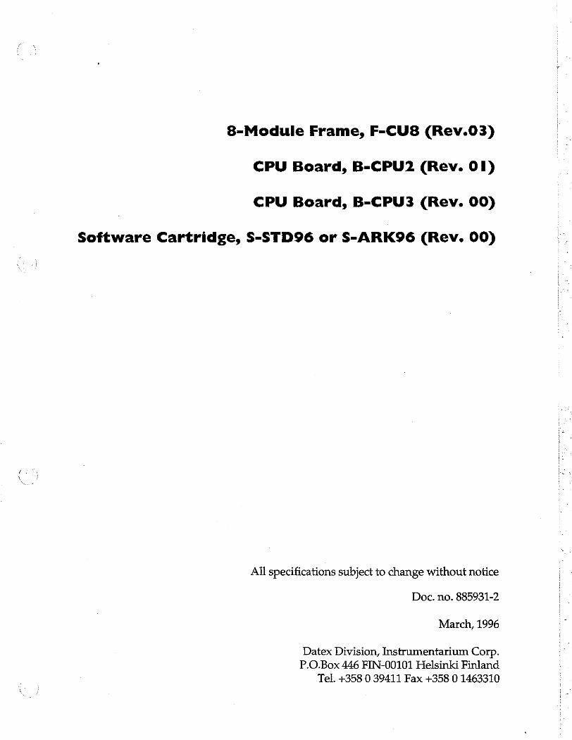
8-Module Frame, F-CU8 (Rev.03)
CPU Board, B-CPU2 (Rev. 01)
CPU Board, B-CPU3 (Rev. 00)
Software Cartridge, S-STD96 or S-ARK96 (Rev. 00)
All specifications subject to change without notice
Doc. no. 885931-2
March, 1996
Datex Division, Instrumentarium Corp.
P.O.Box 446 FIN-00101 Helsinki Finland Tel. +358 0 39411 Fax +358 0 1463310

Datex AS/3 Anaesthesia Monitor Central Unit
Service Manual X

Datex AS/3 Anaesthesia Monitor Central Unit
Service Manual
Table of Contents
INTRODUCTION I
1 SPECIFICATIONS 2
2 FUNCTIONAL DESCRIPTION
2.1 8-Module Frame... iene irene iii 3
2.1.1 UPI Board cecccessecsescsscsscccssssasecsescessssscsesscesscesssesessssencasensaescesenssessesenssassasesessecseesores 5
2.1.2 Power supply unit. 7 2.1.3 CPU Mother Board einen 18
2.1.4 Module Mother Board sterermermeeeeesereeser „18
2.2 CPU Board, B-CPU2 or B-CPU3...............
2.3 Software Cartridge, S-STD96 or S-ARK96.. 2.4 Connectors and Signals ....
2.4.1 Internal Connectors.. „23
2.4.2 External Connectors ..26
2.4.3 Serial Data Interface sine 29
2.4.2 Digital and analog I/O connector mn 29
3 SERVICE PROCEDURES 35
3.1 General Service informaton ss 35
3.2 Preventive Maintenance ee eee nene 36
3.3 Disassembly and Reassemblÿ eee een nete eee 38 3.4 Adjustments and Calibrations ss 42
4 TROUBLESHOOTING 43
5 SERVICE VIEW 46
5.1 To Enter Service Menu..................... ee 46
5.2 Service Menu Structure инета 47
5.3 Service View Menu.
5.3.1 Monitor Menu
54 Keyboard Menu 5.5 Module Menu
5.6 Service Log Menu
6 SPARE PARTS 54
6.1 Spare Parts sn 54 6.2 Exploded View of Anaesthesia Monitor Frame 아 아 와와 59
7 EARLIER REVISIONS 61

Datex AS/3 Anaesthesia Monitor Central Unit
Service Manual
INTRODUCTION
Datex AS/3 Anaesthesia Monitor Central Unit
Service Manual
This Service Manual Section provides information on the Datex AS/3 Anaesthesia Monitor’s Central Unit. It consists of following products:
8-Module Frame, F-CU8 (including UPI or UPINET board
and Power Supply Unit)
CPU Board, B-CPU2 or B-CPU3
Software cartridge, S-STD96 or S-ARK96
Part I-AM Central Unit-1

Datex AS/3 Anaesthesia Monitor Central Unit
Service Manual
I SPECIFICATIONS
CENTRAL UNIT Dimensions depth 382mm = (15.0 in)
width 315mm = (12.4 in) height 128 mm (5.0 in)
weight 9.5 kg (21 Ibs)
ELECTRICAL REQUIREMENTS
Power supply 100, 110-120, 220-240 VAC 50/60 Hz 1.2 A (for whole system)
Stability +10 % of nominal voltage Power consumption 280 VA Grounding Hospital grade Interruptibility Data memory and alarm settings are
saved during power failures up to 15 minutes
ENVIRONMENTAL REQUIREMENTS
Operating temperature 10 - 35°C / 50 - 95°F Storage temperature -10- 50°C / 14-122°F Atmospheric pressure 500 - 800 mmHg (660 - 1060 mbar) Humidity 0 - 90 % non-condensing
(in airway 0 - 100 % condensing)
Analog outputs (+5 V, -5 V) of UPI board
Resolution: 12 bits
Gain error: +2,5%...-4.5%
+5 У max.: +5.50 У
+5 У min.: +4.30 У
-BV max.: -465 V
-BV min.: -5.25 V
Part II-AM Central Unit-2
Datex AS/3 Anaesthesia Monitor Central Unit
Service Manual
2 FUNCTIONAL DESCRIPTION
2.1 8-Module Frame
The center of the Central Unit is the 8-Module Frame, F-CU8,
that includes UPI or UPINET Board and Power Supply Unit. To operate AS/3 Anaesthesia Monitor, the following products should be installed into the frame.
CPU board, B-CPU2 or B-CPU3
Display Controller, B-DISP or B-DVGA
Software Cartridge, S-STD96 or S-ARK96
The frame has two sections. The front part is vacant for housing the modules. The rear part is for installation of the AS/3 boards. On the wall between the front and rear parts, there are Module mother board and CPU mother board. The Module mother board connects modules to the system , and the CPU mother
board connects boards together.
Part II-AM Central Unit-3
Datex AS/3 Anaesthesia Monitor Central Unit
Service Manual
i > i a i © i 5 : の
i © : ==
| る 5 | Recorder Module
NIBP Module
o © Lo © © το
gs) RS > σσ ESTP Module 86 oa
u P ZE y
—s RG шо. Шо o IMI 5
m Fo 5
る W m | >= < 2 COP MOdule
る SEE 3 © 26 8 A 2
> Ep Бом =
è | 53 8 68 o
る = SED 26 & 228 osm P
ー | g 5 ο
8 m a 5 © = < o
. © E Airway Module = ©
R 3 5 ©
=
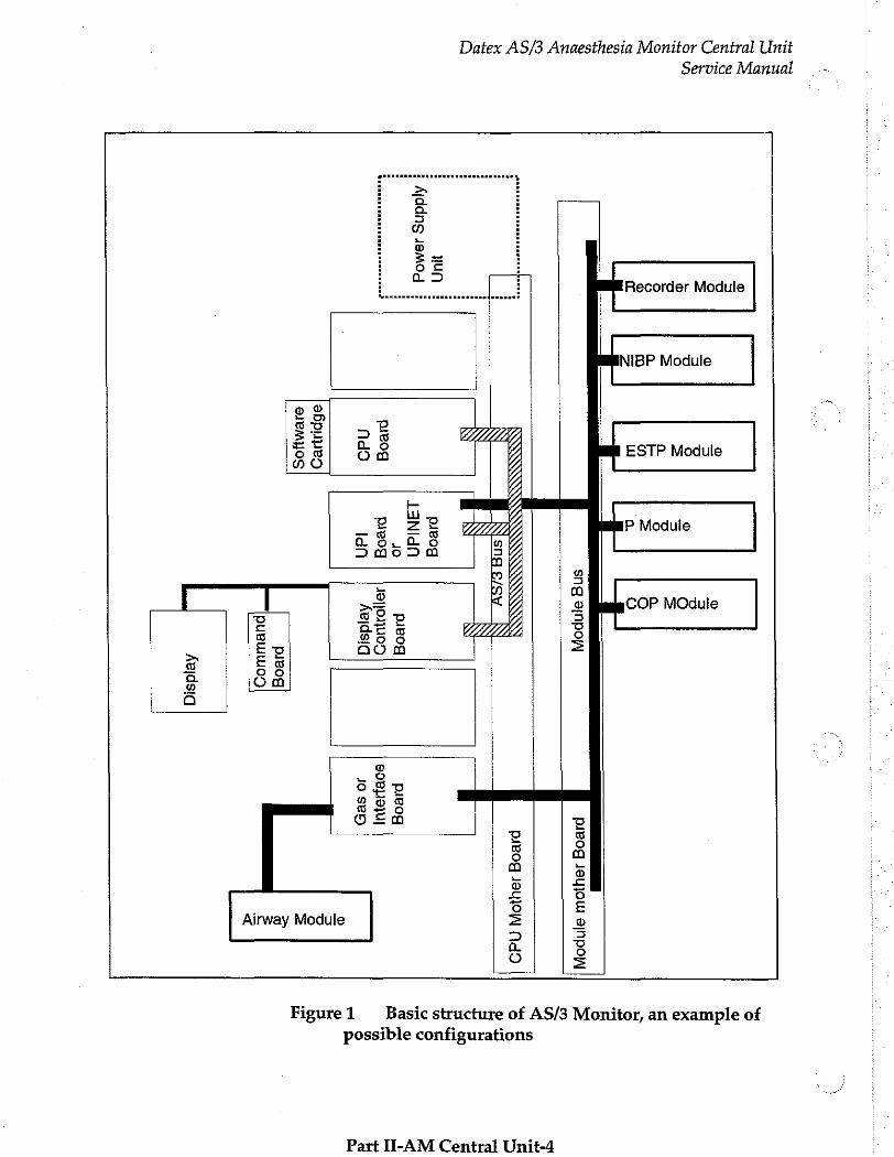
Figure1 Basic structure of AS/3 Monitor, an example of possible configurations
Part II-AM Central Unit-4
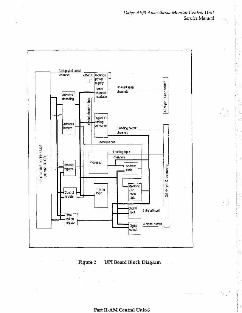
2.1.1 UPI Board
Datex AS/3 Anaesthesia Monitor Central Unit
] Service Manual
NOTE: the following information is related only to the UPI board. In case your monitor uses the UPINET board instead, please refer to the corresponding information in the UPINET section of this manual.
The UPI board functions as a general I/O-board. It performs I/O duties assigned to it by the CPU board. The main processor and the processor on the UPI board communicate through a dual- port memory which is located on the UPI board.
Functional blocks
The UPI board contains the external bus interface, a processor,
program- and dual-port memories, IO-block, and an isolated serial bus interface.
External bus interface
The UPI board is connected to the CPU mother board. The
following signals pass between the UPI and CPU mother board: Data bus, Address bus, Reset, Write and Read signals, and other
related signals.
Processor
The processor in the UPI board is an 80C196KC-16, which functions at 16 MHz frequency.
TO-block
IO-block consists of the following units.
- 4 channel 10 bits AD-converter
- 8 channel 12 bits DA-converter
- B digital inputs and 4 digital outputs
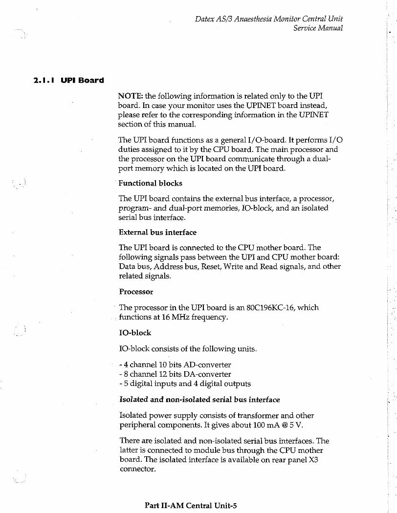
Isolated and non-isolated serial bus interface
Isolated power supply consists of transformer and other peripheral components. It gives about 100 mA @5 V.
There are isolated and non-isolated serial bus interfaces. The latter is connected to module bus through the CPU mother board. The isolated interface is available on rear panel X3 connector.
Part II-AM Central Unit-5
Datex AS/3 Anaesthesia Monitor Central Unit
Service Manual
Unisolated serial channel #1SVD. | isolation |
power supply 5 、 5 Serial Isolated serial ©
a channel channels 등 Address 1 9 decoding er interface a
2 = トニ ーー て で a
2 o =
2] , Ri 5 3 | [Digital lO
| Address の te 73 buffers 8 Analog output
channels
Address bus u о È 4 analog input u 5 channels
= 5 Processor ο Qu nterrupt + Address 은 ag register latch る zo u 5 no 8
° L 5 = Memory: a Timing -DP z
Contro! logic -code a
register -data κ
Digital ar; input 5 digital input
Data bufter/ TT register iai [register | Digital 4 digital output |
output
Figure 2 UPI Board Block Diagram
Part II-AM Central Unit-6
Datex AS/3 Anaesthesia Monitor Central Unit
Service Manual
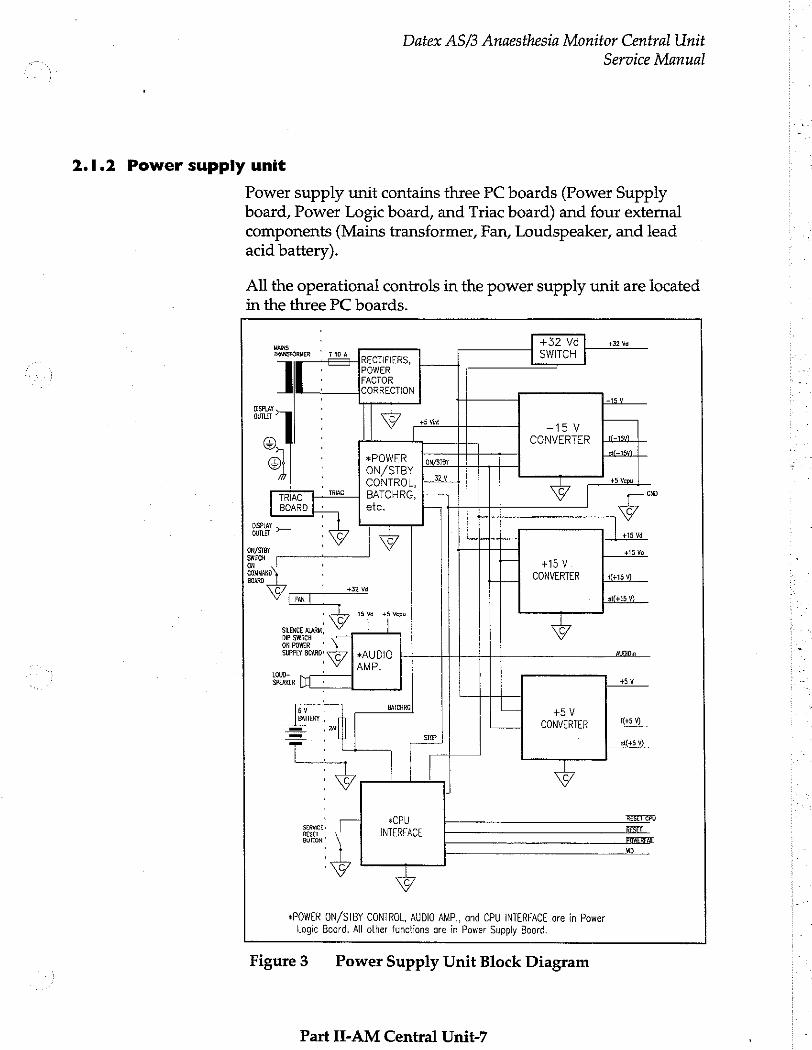
2.1.2 Power supply unit
Power supply unit contains three PC boards (Power Supply board, Power Logic board, and Triac board) and four external
components (Mains transformer, Fan, Loudspeaker, and lead
acid battery).
All the operational controls in the power supply unit are located in the three PC boards.
+32 Vd| sam HRANSFORMER ' TI0A RECTIFIERS, SWITCH -
, POWER I | ・ FACTOR
= CORRECTION
wy У ドー ・ | 45 Vint -15V
e CONVERTER [iim ・ *POWER [σης sei
© ON/STBY Fr : CONTROL, [Y +5 Ven | 一
TRAE me BATCHRG, 00 BOARD | * etc. y
ISPL aunt — ib τσ +15 Vá
+15 Va +15 V
CONVERTER 14159)
y
slí+15 V) 15 V4 +5 Vepu
DIP SMÍCH ON POWER SUPPLY BOARD: © *AUDIO
・ AMP.
АО,
45Υ
BATCHRG | Е +5 у
CONVERTER | 9 STOP
s+5
rl PU (— ro! fee INTERFACE BUTTON”
«POWER ON/STBY CONTROL, AUDIO AMP., and CPU INTERFACE are in Power Logic Board. All other functions are in Power Supply Board.
<A:
|
|
이
|
Figure3 Power Supply Unit Block Diagram
Part II-AM Central Unit-7
Datex AS/3 Anaesthesia Monitor Central Unit
Service Manual —.
APPLIANCE INLET MAINS F DISPLAY OUTLET TRANSFORMER yr T25A
: TRIAC - SA BOARD |P G La
L E BN Ux* |
5 ㆍ WH や
|
РЕ © VE “FIT IOA | La Supply D ee + Mains
N F2 av POWER SUPPLY [A Bu L BOARD 30 一 一 RD = POWER LOGIC
Y BOARD
GNYE
y : o La and Nx in Disploy outlet ore
Equipotentiolity separoted from the Supply Moins’ potentials L and N.
ий a τ я т ES Maira FT and E2
Ux« is the same nominal voltage 100 V Т 6.3 А as the nominal mains voltage 110-120 V| Slow 5 A
If no polarized mains plug and mains socket outlet system 220-240 V|T 3.15 A is used, position of line (L) and neutral (N) in the appliance inlet depends on the position of mains plug set into the mains socket outlet.
The contact positions of the appliance inlet by looking at the engagement face of the appliance inlet.
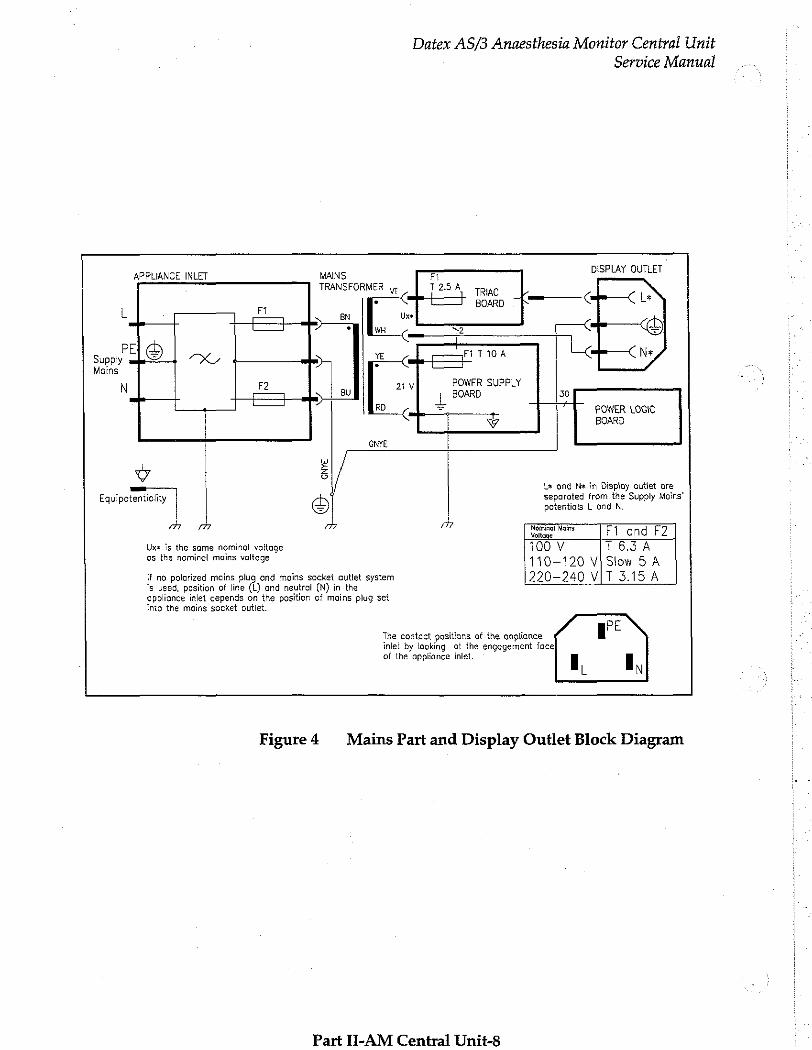
Figure 4 Mains Part and Display Outlet Block Diagram
Part II-AM Central Unit-8
Datex AS/3 Anaesthesia Monitor Central Unit
Service Manual
Power Supply Board
Power Supply board includes:
Rectifiers
Rectifiers processes 21 VAC from the mains transformer.
Power factor correction
Power factor correction is performed in a preregulator. The regulator modifies output current from sinusoidal power lines into sinusoidal form. Its purpose is to boost efficiency of the mains transformer.
Battery charging
Batchrg charges the 6 V battery which maintains the supply voltage of CPU for 15 minutes after the power is cut off. The battery is charged as long as the power cord is connected to the mains outlet.
Supply voltage for pulse width modulators
Supply voltage for pulse width modulators of chopper power supplies is generated by 12 V regulator at power-up and +15 V is short-circuited. Otherwise the supply voltage comes from +15 V.
-15 V converter
-15 V converter is a Flyback-type chopper power supply that generates -15 V analog voltage from +32 V. The load capacity is 1.2 A (18 W). +5 Vepu is also generated in this converter.
+15 V converter
+15 V converter is a Buck-type chopper power supply that generates +15 V from +32 V.
The output of the power supply is divided into two; +15 Va for analog voltage and +15 Vd for less sensitive components.
Part JI-AM Central Unit-9
Datex AS/3 Anaesthesia Monitor Central Unit
Service Manual
+5 V converter
+5 V converter is a Buck-type chopper power supply that generates +5.1 V from +32 V. The load capacity is 8 A (40 W).
+5 V, +15 V, +32 V, and +5 Vcpu checking
Those voltages are checked and if one of them increases more than is allowed, thyristor pulls the rectified +32 V down.
Service reset button
Service reset button is for service purpose. Press this button with an appropriate tool for at least five seconds before you remove the software cartridge, any PC board or the Power supply unit from the rear of the Central Unit.
Before connecting the power cord back and start monitoring, be sure that at least one minute has passed after the service reset button has pressed. Too short time may lead to memory flaw.
Audible Alarm for Power Fail
Under the cover plate of the Power supply unit there are two dip switches. By turning the switches to the right the audio alarm is activated. When mains power fails the audio alarm is generated by the lead-acid battery.
Part II-AM Central Unit-10
Datex AS/3 Anaesthesia Monitor Central Unit
Service Manual
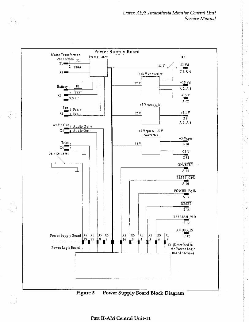
. Power Supply Board Mains Transformer
Preregulator X3 connectors py Xi
2 TIOA av 4 aa
X2 = „+15 V converter | Cuca
32V σσ +15 Vd
Battery , Εξ A ZA 4
X6 mi RA | RA È 415 V ma NIC CA
+5 V converter Fan
1 Fan + SIV x Fan- 32V #5
B8 」 A6,A8
Audio Out; Audio Out+
X4 4 Audio Out- +5 Vepu € -15V
converter +5 Vepu
i Km Triac 5 32V B10 X4 6
Service Reset | し L 5Y N ca
ON/STBY 一 一 一 >
À 14
RESET_CPU
Ald
POWER_FAIL ——_—_—_ a
A12
RESET
B14
REFRESH_WD
B12
AUDIO_IN
Power Supply Board |X5 İX5 |X5 |X5 X5 (XS |x 6 | [6 Ci 3 125 28 19 24 13 4 5 6 7
A EPA Aia Power Logic Board | the Power Logic Board Section)
Figure 5 Power Supply Board Block Diagram
Part II-AM Central Unit-11
Datex AS/3 Anaesthesia Monitor Central Unit
Service Manual
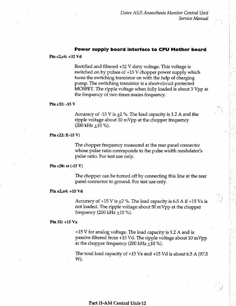
Power supply board interface to CPU Mother board
Pin c2,c4: +32 Vd
Rectified and filtered +32 V dirty voltage. This voltage is switched on by pulses of +15 V chopper power supply which turns the switching transistor on with the help of charging pump. The switching transistor is a short-circuit protected MOSFET. The ripple voltage when fully loaded is about 3 Vpp at the frequency of two times mains frequency.
Pin c32: -15 V
Accuracy of -15 V is +2 %. The load capacity is 1.2 A and the ripple voltage about 30 mVpp at the chopper frequency (200 kHz +10 %).
Pin c22: f(-15 V)
The chopper freguency measured at the rear panel connector whose pulse ratio corresponds to the pulse width modulator's pulse ratio. For test use only.
Pin c20: st (-15 V)
The chopper can be turned off by connecting this line at the rear panel connector to ground. For test use only.
Pin a2,a4: +15 Vd
Accuracy of +15 V is +2 %. The load capacity is 6.5 A if +15 Va is not loaded. The ripple voltage about 50 mVpp at the chopper frequency (200 kHz +10 %).
Pin 32: +15 Va
+15 V for analog voltage. The load capacity is 1.2 A and is passive filtered from +15 Vd. The ripple voltage about 10 mVpp at the chopper frequency (200 kHz +10 %).
The total load capacity of +15 Va and +15 Vd is about 6.5 A (97.5 W).
Part II-AM Central Unit-12
K i
Datex AS/3 Anaesthesia Monitor Central Unit
Service Manual
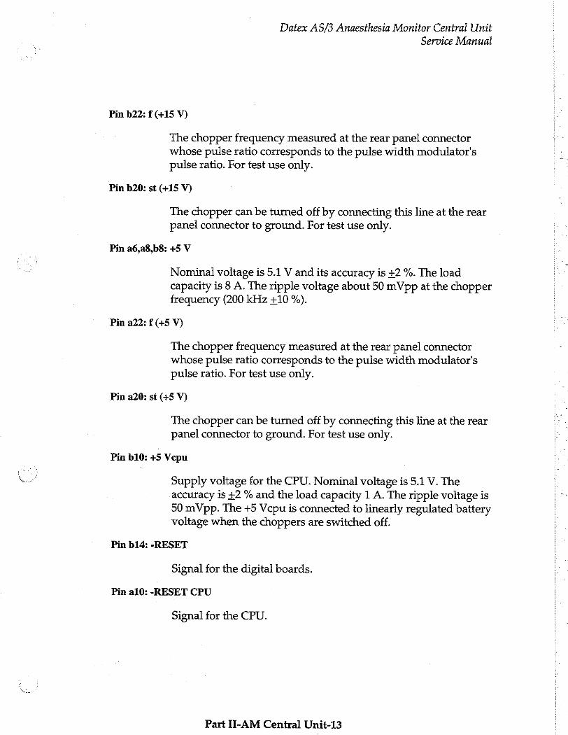
Pin b22: f (+15 V)
The chopper frequency measured at the rear panel connector whose pulse ratio corresponds to the pulse width modulator's pulse ratio. For test use only.
Pin b20: st (+15 V)
The chopper can be turned off by connecting this line at the rear panel connector to ground. For test use only.
Pin a6,a8,b8: +5 V
Nominal voltage is 5.1 V and its accuracy is +2 %. The load capacity is 8 A. The ripple voltage about 50 mVpp at the chopper frequency (200 kHz +10 %).
Pin a22: Е (+5 У)
The chopper frequency measured at the rear panel connector whose pulse ratio corresponds to the pulse width modulator's pulse ratio. For test use only.
Pin a20: st (+5 V)
The chopper can be turned off by connecting this line at the rear panel connector to ground. For test use only.
Pin b10: +5 Vepu
Supply voltage for the CPU. Nominal voltage is 5.1 V. The accuracy is +2 % and the load capacity 1 A. The ripple voltage is 50 mVpp. The +5 Vcpu is connected to linearly regulated battery voltage when the choppers are switched off.
Pin b14: -RESET
Signal for the digital boards.
Pin a10: -RESET CPU
Signal for the CPU.
Part II-AM Central Unit-13
Datex AS/3 Anaesthesia Monitor Central Unit
Service Manual
Pin a12: -POWERFAIL
Pin b12: WD
The signal informs about supply voltage failure to the CPU.
Watchdog input signal. The CPU must toggle WD every 1.6 seconds. Otherwise the power supply will generate -RESET and - RESET CPU signals.
Pin c12: AUDIOin
Ground
Audio signal which is amplified in Audio-amp. circuit.
All the signals and lines within the Power supply unit share the common ground which is connected to AS/3 Anaesthesia Monitor chassis.
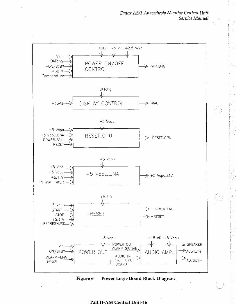
Power Logic Board
Power Logic board includes:
Power ON/STBY control
Power ON/STBY control includes a logic with which power supply is switched on or off by turning ON/STBY switch.
Reset
-RESET_CPU signal is transmitted to the CPU interface in case the mains voltage fails or the power is cut off.
-RESET signal is also generated for other digital boards.
Audio amp.
Audio signal from the CPU is amplified and filtered for the loudspeaker. Amplification gain is about 5 dB.
CPU interface
All the necessary communications between the Power supply unit and the CPU (Reset-, powerfail-, and watchdog-functions) are realized in this board. Additionally, the block contains a
Part II-AM Central Unit-14
Datex AS/3 Anaesthesia Monitor Central Unit
Service Manual
circuit that supervises the maintenance of CPU's supply voltage from the battery for 15 minutes after AS/3 Anaesthesia Monitor
is turned off.
Display control
Display control circuit controls Triac board control signal (TRIAC).
Part II-AM Central Unit-15
Datex AS/3 Anaesthesia Monitor Central Unit
Service Manual
VDD +5 Vint +2.5 Vref
Vin > + y
BATchg—>
—O0N/STBY—> POWER ON/OFF トー PWR_ENA
+32 У—>
Temperature—>
BATchg
| v
+15vi-> DISPLAY CONTROL トラ TRAC ο ο __— ———_
+5 Vepu
+5 Vep
+5 Vepu E RESET_CPU POWER_FAIL ~RESET_CPU
RESET-
+5 Vepu
+5 Vint +5 Vepu 451 V +5 Vepu ENA +5 Vepu ENA
15 min. TIMER
+5.1 V
+5 Vepu—> y
START —3A -> — POWER FAIL
-SToP—>| ~RESET > -RESET +5.1 V—>
一 REFRESH_WD 一 >> _
+5 Усри +15 VD +5 Vcpu
Vin 一 一 一 POWER OUT 4 | to SPEAKER _ | ALARM SIGNAL» | >
ON/STBY— POWER OUT AUDIO AMP. AU_OUT+ ALARM— ENA AUDIO IN s > switch A om, SPO AU- OUT—
Figure 6 Power Logic Board Block Diagram
Part IT-AM Central Unit-16
Datex AS/3 Anaesthesia Monitor Central Unit
Service Manual
Triac Board
Tasks of the Triac board are to supply voltage to the Video display when AS/3 Anaesthesia Monitor is turned on and cut off the voltage when it is turned off. This is done by a solid state relay and peripheral components.
External Components
1. Transformer
The power of the mains transformer is 250 VA. The secondary voltage is 21 VAC and for the display unit it is either 100 VAC, 115 VAC, or 230 VAC.
Depending on the voltage in use, there are three different transformers for the AS/3 Anaesthesia Monitor.
2. Fan
The fan is switched on automatically when +32 Vd is generated.
3. Loudspeaker
The loudspeaker is controlled by the audio-amplifier on the Power Logic board.
4. Battery
6 V, 1.2 Ah sealed lead-acid battery is used to supply power to the CPU board after the power is turned off and the power cord is disconnected.
Part II-AM Central Unit-17
Datex AS/3 Anaesthesia Monitor Central Unit
Service Manual
2.1.3 CPU Mother Board
The CPU mother board connects the CPU board and other AS/3
boards (e.g. UPI and Display controller) and functions as a bus between them.
There are connectors for six AS/3 boards. Four of those are
normally occupied (UPI or UPINET, CPU, Display controller and Gas interface or INT boards) and two are reserved for, e.g. B-
NET or B-ARK board. AS/3 bus structure is the same in all AS/3
monitors.
ON/STBY-line is connected only to a Display controller connector from where it goes directly to Keyboard and ON/STBY switch. The CPU mother board is connected to Module mother board by 25-pin D-connector.
2.1.4 Module Mother Board
This board connects AS/3 modules and the Anaesthesia Monitor
together electrically. Module Bus structure is the same in all the AS/3 monitors. There are connectors for four double-width or
eight single-width modules.
Part II-AM Central Unit-18
Datex AS/3 Anaesthesia Monitor Central Unit
Service Manual
2.2 CPU Board, B-CPU2 or B-CPU3
The CPU board takes care of the central processing.
The main features of the CPU board are: 80486 processor Clock freguency 32 MHz Software cartridge interface B-CPU2: 2 Mbytes DRAM B-CPU3: 8 Mbytes DRAM 8 Kbytes static RAM with real time clock 32 Kbytes EEPROM memory 4 channel UART: 3 channels with modem signals in AC-logic level 1 channels without modem signals in RS232-level programmabie alarm sound generator 5 external and 3 internal interrupts
* À
À 오
푸 0
*
Control logic
IO-decoding and wait state generation takes place in GAL IC
and as well as the processor itself. Code memory (EPROM) and working RAM (DRAM) are designed to be linear, and static
RAM and EPROM are mapped in I/O space.
Wait state generators
The processor and the GAL IC have internal wait state generators for their predecoded chip select pins. The wait state generator in the GAL IC is used also by the other boards connected to the AS/3 bus.
Halt detection
NMHinterrupt is generated by the power control logic. The interrupt signals in the CPU means that all supply voltages except +5V for the CPU board will be switched off shortly. NMI interrupt service program then saves all necessary parameters in the static RAM before supply voltages fail.
When hardware detects HALT command all signals generated in the CPU board as well as all the outputs to the CPU mother board are left floating in high impedance state; only DRAM refreshment cycle continues to occur. The halt state will
Part II-AM Central Unit-19
Datex AS/3 Anaesthesia Monitor Central Unit
Service Manual
continue until a RESET pulse from the power control logic circuit is received.
External Bus
External bus signals are AC logic level signals. Series resistors are used to limit signal ringing when the signals change their states. Additional signal filtering is performed in the CPU mother board.
Software cartridge interface
See chapter “Connectors and signals”.
Main peripherals
QUART
Four series channel Quart is used.
SAA1099
IC SAA1099 is used as alarm sound generator.
M48T18
Lithium battery back-up 8 Kbytes static RAM with a real-time clock.
CAUTION: The IC contains a lithium battery. Discard the battery according to local regulations.
Refresh watchdog
The processor has to refresh periodically the watchdog timer in the Power supply unit in order to prevent reset pulse.
Part II-AM Central Unit-20
Datex AS/3 Anaesthesia Monitor Central Unit
Service Manual
=
Processor
| il
(Address) lAddress| DRAM
latches muxes bank
JI
Data buffers
ddress decoding NT
Sw cartridge
Data connector
bus swap | |
Control logic ——
AS/3 BUS
Serial control Control bus
Data bus
Address bus
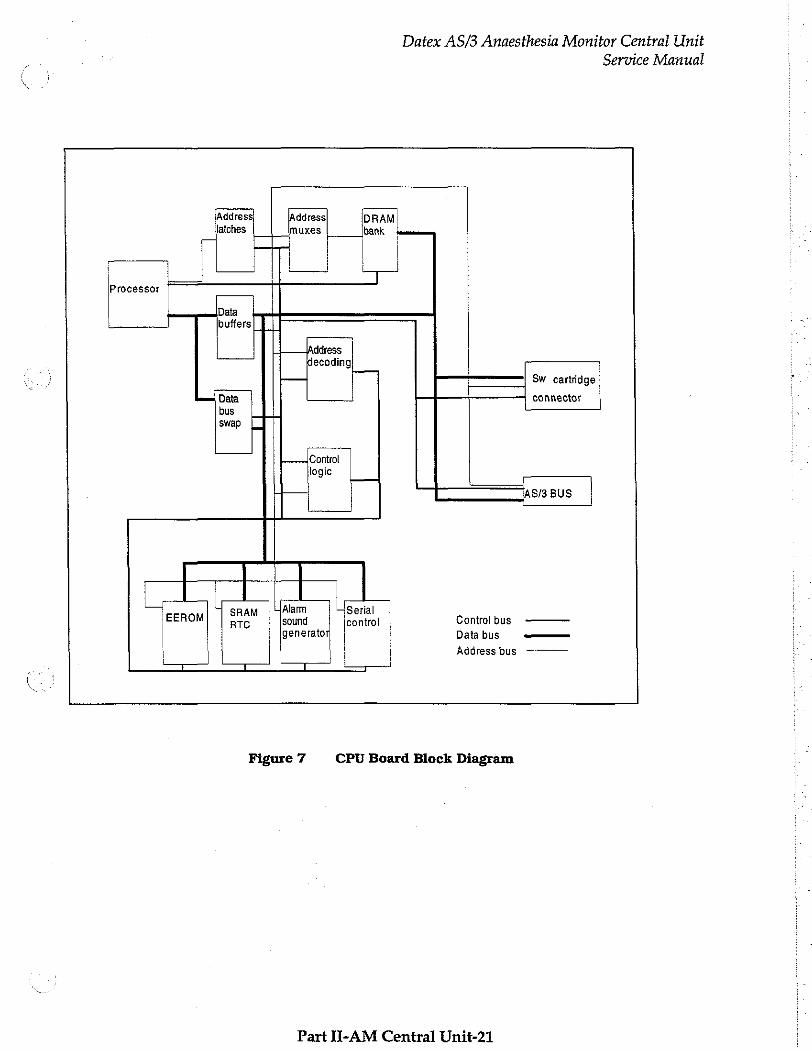
Figure 7 CPU Board Block Diagram
Part H-AM Central Unit-21
Datex AS/3 Anaesthesia Monitor Central Unit
Service Manual
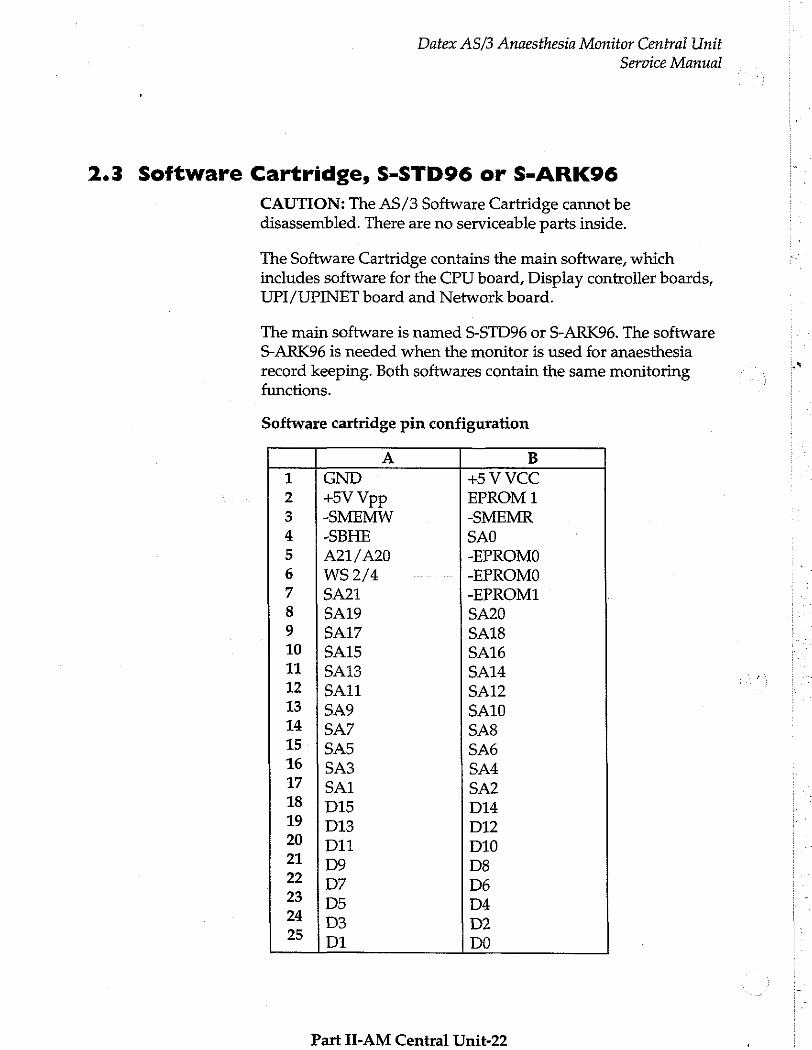
2.3 Software Cartridge, S-STD96 or S-ARK96
CAUTION: The AS/3 Software Cartridge cannot be disassembled. There are no serviceable parts inside.
The Software Cartridge contains the main software, which includes software for the CPU board, Display controller boards,
UPI/UPINET board and Network board.
The main software is named S-STD96 or S-ARK96. The software
S-ARK96 is needed when the monitor is used for anaesthesia
record keeping. Both softwares contain the same monitoring functions.
Software cartridge pin configuration
A B 1 [GND +5 V VCC 2 |+5VVpp EPROM 1 3 |-SMEMW -SMEMR 4 |-SBHE SAO 5 | A21/A20 -EPROMO 6 |ws2/4 -EPROMO 7 |SA21 -EPROM1 8 |SA19 SA20 9 |SA17 SA18 10 |SA15 SA16 11 |SA13 SA14 12 (SAI SA12 13 |549 SA10 14 | SA7 SA8 15 |545 SA6 16 | SA3 SA4 17 [sal SA2 18 | DIS D14 19 | p13 D12 20 | DI1 D10 21 | Do D8 > lp; D6 23 | D5 D4 24 [Ds D2 > İn DO
Part II-AM Central Unit-22
Datex AS/3 Anaesthesia Monitor Central Unit
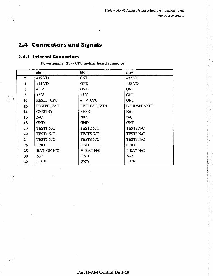
2.4 Connectors and Signals
2.4.1 Internal Connectors
Power supply (X3) - CPU mother board connector
Service Manual
a(a) b(c) c (e) 2 +15 VD GND +32 VD
4 +15 VD GND +32 VD
6 +5V GND GND
8 +5V 45V GND
10 RESET_CPU +5 V_CPU GND
12 POWER_FAIL REFRESH WD1 LOUDSPEAKER
14 ON/STBY RESET N/C
16 NIC NIC NIC
18 GND GND GND
20 TESTI N/C TEST2 N/C TEST3 N/C
22 TEST4 N/C TEST5 N/C TEST6 N/C
24 TEST7 N/C TESTS N/C TEST9 N/C
26 GND GND GND
28 BAT_ON NIC V_BATNIC LBAT NIC
30 N/C GND N/C
32 +15 V GND -15V
Part II-AM Central Unit-23
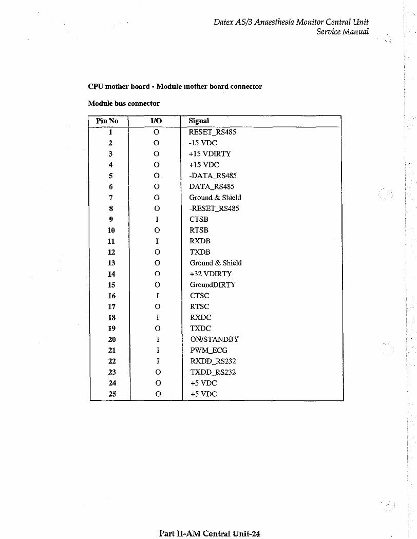
CPU mother board - Module mother board connector
Module bus connector
Datex AS/3 Anaesthesia Monitor Central Unit
Service Manual
Pin No MO Signal
1 o RESET RS485
2 o -15 VDC
3 o +15 VDIRTY
4 ο +15 VDC
5 0 -DATA_RS485
6 o DATA RS485
7 o Ground & Shield
8 ο -RESET_RS485
9 I CTSB
10 O RTSB
11 I RXDB
12 0 TXDB
13 o Ground & Shield
14 o +32 VDIRTY
15 o GroundDIRTY
16 I CTSC
17 o RTSC
18 I RXDC
19 o TXDC
20 I ON/STANDBY
21 I PWM_ECG
22 I RXDD_RS232
23 o TXDD RS232
24 o +5 VDC
25 o +5 VDC
Part II-AM Central Unit-24
Datex AS/3 Anaesthesia Monitor Central Unit
Service Manual
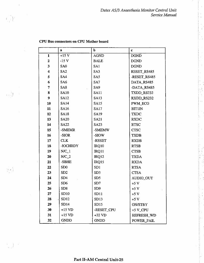
CPU Bus connectors on CPU Mother board
a b c
1 +15 V AGND DGND
2 -15V BALE DGND
3 SAO SA1 DGND
4 SA2 SA3 RESET_RS485
5 SA4 SAS -RESET RS485
6 SA6 SA7 DATA. RS485
7 SA8 SA9 -DATA_RS485
8 SA10 SA11 TXDD RS232
9 SA12 SA13 RXDD RS232
10 SA14 SA15 PWM_ECG
11 SA16 SA17 BITHN
12 SA18 SA19 TXDC
13 SA20 SA21 RXDC
14 SA22 SA23 RTSC
15 -SMEMR -SMEMW CTSC
16 -SIOR -SIOW TXDB
17 CLK -RESET RXDB
18 -IOCHRDY IRQ10 RTSB
19 N/C_1 IRO11 CTSB
20 N/C_2 IRQ12 TXDA
21 -SBHE 18015 RXDA
22 SDO SD1 RTSA
23 SD2 SD3 CTSA
24 SD4 $05 AUDIO_OUT
25 SD6 SD7 +5 V
26 SD8 SD9 +5V
27 SD10 SDi1 +5V
28 .|SD12 SD13 +5 V
29 SD14 SD13 ON/STBY
30 +15 VD -RESET_CPU +5 V_CPU
31 +15 VD +32 VD REFRESH_WD
32 GNDD GNDD POWER FAIL
Part II-AM Central Unit-25
Datex AS/3 Anaesthesia Monitor Central Unit
Service Manual
2.4.2 External Connectors
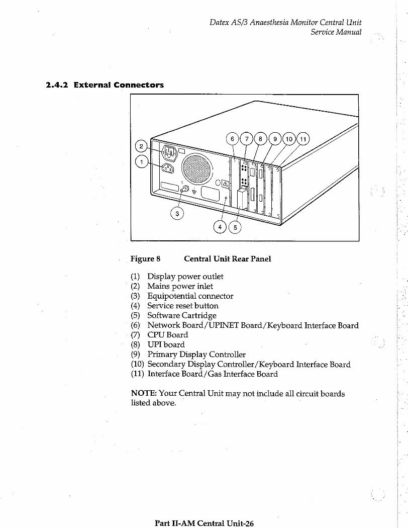
Figure 8 Central Unit Rear Panel
(1) Display power outlet (2) Mains power inlet (3) Equipotential connector (4) Service reset button (5) Software Cartridge
(6) Network Board /UPINET Board /Keyboard Interface Board
(7) CPU Board
(8) UPI board (9) Primary Display Controller (10) Secondary Display Controller /Keyboard Interface Board (11) Interface Board /Gas Interface Board
NOTE: Your Central Unit may not include all circuit boards listed above.
Part II-AM Central Unit-26
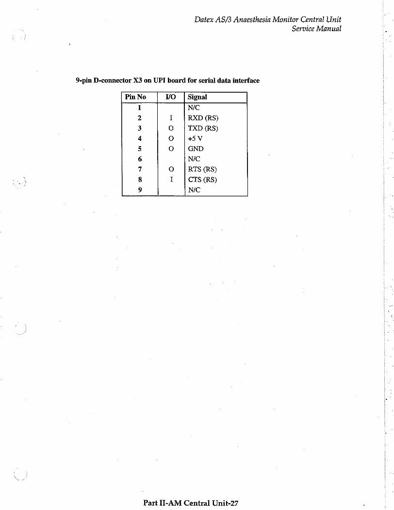
9-pin D-connector X3 on UPI board for serial data interface
Datex AS/3 Anaesthesia Monitor Central Unit
Pin No vo Signal
1
NO DUA
U aU N
000
©
N/C
RXD (RS)
TXD (RS)
+5 V
GND
NIC
RTS (RS)
CTS (RS)
NIC
Part II-AM Central Unit-27
Service Manual

Datex AS/3 Anaesthesia Monitor Central Unit
Service Manual
44-pin D-connector X2 for digital and analog I/O on the UPI Board
Pin No | VO | Signal
1 o GND 2 I (D) input 3
3 ο Def Sync (D) output 0
4 I (D) input 2
5 ο Nurse call (D) output 3
6 o Reserved (D) output 3 7 o GND
8 o Pacemaker Sync. (D) output 2
9 I Reserved (A) CH3
10 o (Ay CAS 11 ο +15 V 12 ο -15 У 13 I Reserved (A) CHO
14 ο (A)Y*CHI
15 o +5 V
16 ο (A)*CH4 17 ο (A)*CH3
18 I for monitor interfacing (A)CH1
19 ο (A)*CH2 20 ο (A)*CHO 21 I Reserved (D) INPUT 4
22 I for monitor interfacing (A) CH2
23 I Reserved (D) INPUTS
24 O (A)*CH6
25 ο (A)*CH7 26 М/С
27 NIC ; 28 NC に
29 N/C
30 N/C 31 N/C 32 N/C 33 N/C 34 N/C 35 N/C 36 N/C 37 N/C 38 0 Direct ECG (A) 39 NIC 40 NC 41 NC 42 NC 43 NC 44 NC
* Analog outputs are selectable.
Part Ii-AM Central Unit-28
Datex AS/3 Anaesthesia Monitor Central Unit
Service Manual
2.4.3 Serial Data Interface
Serial Data Interface connector
The Serial Data Interface connector is a 9-pin male D-connector (X3) on the rear panel of the UPI board.
Serial interface is RS-232 connection which uses +12V
input/output signals.
2.4.2 Digital and analog I/O connector
The digital and analog I/O connector is a 44-pin female D-connector (X2) on the rear panel of the UPI board.
Digital Inputs
There are 4 separate digital inputs. Each signal uses TTL -level. The inputs and pins are (numbering starts from input 2):
Input 2 pin4 Input 3 pin2 Input 4 pin 21 Input 5 pin 23 Ground pin7
Digital Outputs
There are 4 separate digital outputs. Each signal uses TTL-level. The outputs and pins are:
output 0 (Defibrillation Sync.) pin3 output 1 (Nurse Call) pin 5 output 2 (Pacemaker Sync.) pin 8 output 3 (reserved) Pin 6
ground pin7,1
Defibrillation Sync indication is generated by ECG. When active, the signal is state 1. After 10 ms the signal is reset to state 0. New Defibrillation Sync is not generated before the indication is deactivated.
Nurse Call indication is generated by red, yellow and white alarms. When activated, it is set to state 1 and remains at that
Part I-AM Central Unit-29
Datex AS/3 Anaesthesia Monitor Central Unit
Service Manual
state until the alarm situation is over or SILENCE ALARM key is pressed.
Pacemaker Sync indication is generated by ECG. When a pacemaker pulse is detected, this signal is set to state 1, then it is reset to state 0. The indication pulse width is between 0.5 ms and 2.5 ms.
The range of state 0 is from 0 to 0.8 V, and range of the state 1 is
2.8 to 5 V.
Analog Inputs
There are 4 separate analog input channels. Each channel accepts voltages between 0 and 5 volts. The resolution consists of 1024 different voltage levels. All signals are read once in 10 ms. The channels and pins are:
channelO pin 13 channeli pin 18 channel 2 pm22 channel3 Pin9 ground pin 7,1
NOTE: The inputs can be used only for interfacing and each of the channels require a simultaneous serial data interface at UPI board connector X3.
Part II-AM Central Unit-30
Datex AS/3 Anaesthesia Monitor Central Unit Service Manual
Analog Outputs
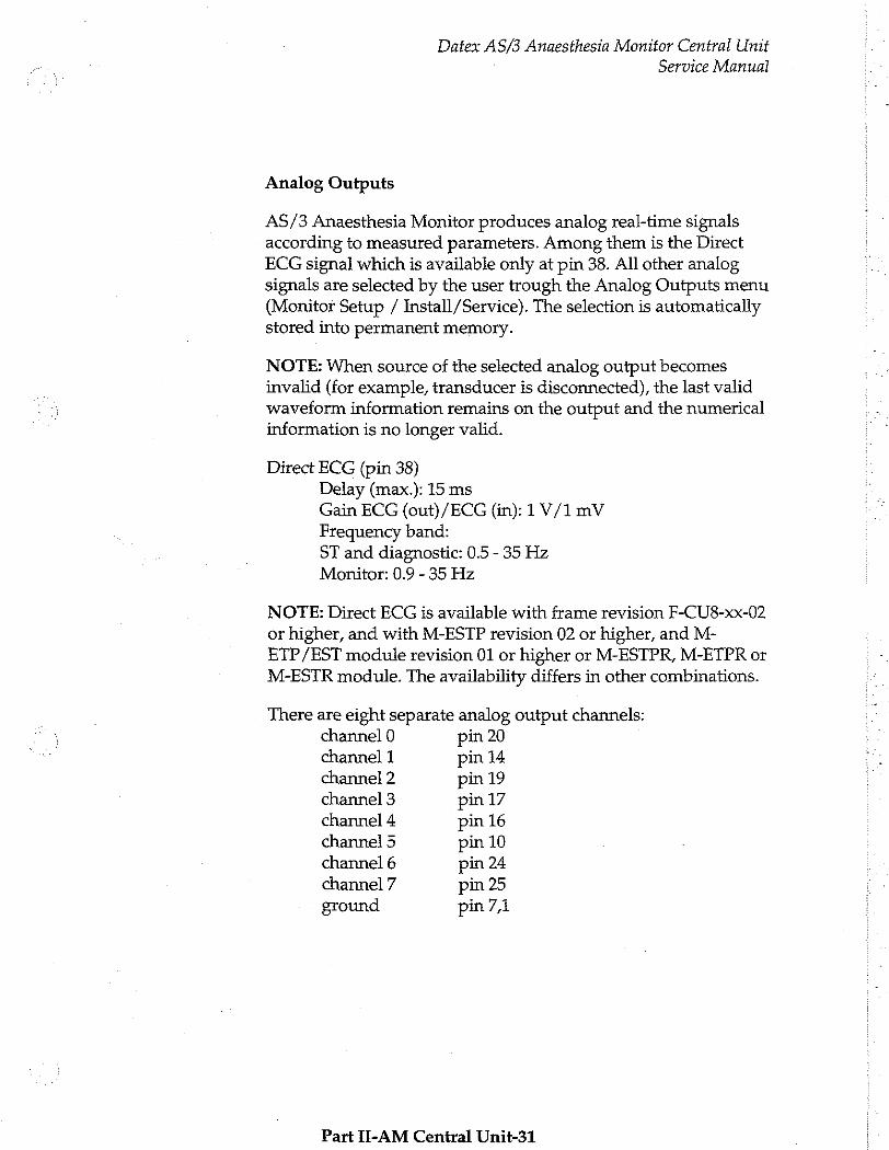
AS/3 Anaesthesia Monitor produces analog real-time signals according to measured parameters. Among them is the Direct ECG signal which is available only at pin 38. All other analog signals are selected by the user trough the Analog Outputs menu (Monitor Setup / Install/Service). The selection is automatically stored into permanent memory.
NOTE: When source of the selected analog output becomes invalid (for example, transducer is disconnected), the last valid waveform information remains on the output and the numerical
information is no longer valid.
Direct ECG (pin 38) Delay (max.): 15 ms Gain ECG (out)/ECG (in): 1 V/1 mV Frequency band:
ST and diagnostic: 0.5 - 35 Hz Monitor: 0.9 - 35 Hz
NOTE: Direct ECG is available with frame revision F-CU8-xx-02
or higher, and with M-ESTP revision 02 or higher, and M-
ETP/EST module revision 01 or higher or M-ESTPR, M-ETPR or
M-ESTR module. The availability differs in other combinations.
There are eight separate analog output channels: channel 0 pin 20 channel 1 pin 14 channel 2 pin 19 channel 3 pin 17 channel 4 pin 16 channel 5 pin 10 channel 6 pin 24 channel 7 pin 25 ground pin7,1
Part II-AM Central Unit-31

Datex AS/3 Anaesthesia Monitor Central Unit
Service Manual
Analog signals
Each signal is scaled in linear way between -5 ... +5 volts. The resolution consists of 4096 different voltage levels. All signal levels are updated once in 10 ms.
NOTE: Output scale -5...+5 volts is available from frame revision F-CU8-xx-02. The older versions use scale 0... 10 volts. See the UPI board information for specification.
OFF: Default state. No signal is present at analog output pin.
HR according to selected source (display value): The original scale 0...300 beats are scaled between 0 and 3 volts.
ECGI, ECG2, ECG3: The original scale -5000 microvolts...+5000
microvolts is scaled between -5 and +5 volts.
P1 lre, P2 Ire, P3 lre, P4 Ire (Invasive pressure real-time values,
low resolution): The original scale -20 mmHg...+320 mmHg is scaled between -0.2 and +3.2 volts.
P1 hre, P2 hre, P3 hre, P4 hre (Invasive pressure real-time values,
high resolution): The original scale -20 mmHg...+50 mmHg is scaled between -2 and +5 volts.
Pleth: The original scale -100%...100% is scaled between -5 and +5 volts.
SpO,>40, SpO,>60, SpO,>80 (beat-to-beat, display value, 10 s average): The original scale 40-100% (SpO,>40), 60-100% (SpO,>60) or 80-100% (SpO,>80) is scaled between -5 and +5 volts.
CO»: The original scale 0%...10% is scaled between 0 and +5 volts. Values greater than 10% are set to 10%. (Airway gas special indications are applied, see also chapter Special Indications).
AA (Anesthesia Agent): The original scale 0%...10% is scaled between 0 and +5 volts. Values greater than 10% are set to 10%. (Airway gas special indications are applied, see also chapter Special Indications).
Part II-AM Central Unit-32
Datex AS/3 Anaesthesia Monitor Central Unit
Service Manual
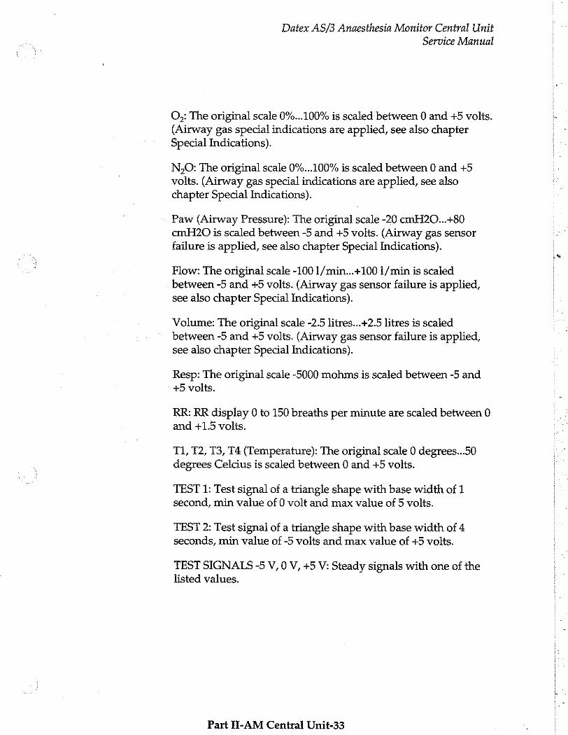
O,: The original scale 0%...100% is scaled between 0 and +5 volts. (Airway gas special indications are applied, see also chapter Special Indications).
N,O: The original scale 0%...100% is scaled between 0 and +5 volts. (Airway gas special indications are applied, see also chapter Special Indications).
Paw (Airway Pressure): The original scale -20 cmH20...+80 cmH20 is scaled between -5 and +5 volts. (Airway gas sensor failure is applied, see also chapter Special Indications).
Flow: The original scale -100 1/min...+100 1/min is scaled between -5 and +5 volts. (Airway gas sensor failure is applied, see also chapter Special Indications).
Volume: The original scale -2.5 litres...+2.5 litres is scaled between -5 and +5 volts. (Airway gas sensor failure is applied, see also chapter Special Indications).
Resp: The original scale -5000 mohms is scaled between -5 and +5 volts.
RR: RR display 0 to 150 breaths per minute are scaled between 0 and +1.5 volts.
T1, 12, T3, T4 (Temperature): The original scale 0 degrees...50 degrees Celcius is scaled between 0 and +5 volts.
TEST 1: Test signal of a triangle shape with base width of 1 second, min value of 0 volt and max value of 5 volts.
TEST 2: Test signal of a triangle shape with base width of 4 seconds, min value of -5 volts and max value of +5 volts.
TEST SIGNALS -5 V, 0 V, +5 V: Steady signals with one of the
listed values.
Part H-AM Central Unit-33
Datex AS/3 Anaesthesia Monitor Central Unit
Service Manual
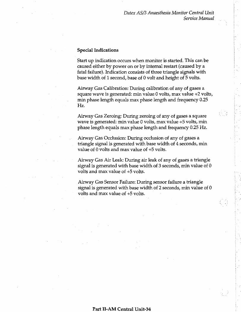
Special Indications
Start up indication occurs when monitor is started. This can be caused either by power on or by internal restart (caused by a fatal failure). Indication consists of three triangle signals with
base width of 1 second, base of 0 volt and height of 5 volts.
Airway Gas Calibration: During calibration of any of gases a square wave is generated: min value 0 volts, max value +2 volts,
min phase length equals max phase length and frequency 0.25 Hz.
Airway Gas Zeroing: During zeroing of any of gases a square wave is generated: min value 0 volts, max value +5 volts, min
phase length equals max phase length and frequency 0.25 Hz.
Airway Gas Occlusion: During occlusion of any of gases a triangle signal is generated with base width of 4 seconds, min value of 0 volts and max value of +5 volts.
Airway Gas Air Leak: During air leak of any of gases a triangle signal is generated with base width of 3 seconds, min value of 0 volts and max value of +5 volts.
Airway Gas Sensor Failure: During sensor failure a triangle signal is generated with base width of 2 seconds, min value of 0 volts and max value of +5 volts.
Part Ii-AM Central Dnit-34
Datex AS/3 Anaesthesia Monitor Central Unit
Service Manual
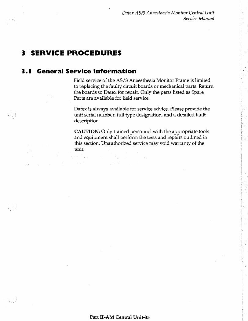
3 SERVICE PROCEDURES
3.1 General Service Information
Field service of the AS/3 Anaesthesia Monitor Frame is limited
to replacing the faulty circuit boards or mechanical parts. Return the boards to Datex for repair. Only the parts listed as Spare Parts are available for field service.
Datex is always available for service advice. Please provide the unit serial number, full type designation, and a detailed fault description.
CAUTION: Only trained personnel with the appropriate tools and equipment shall perform the tests and repairs outlined in this section. Unauthorized service may void warranty of the unit.
Part II-AM Central Unit-35
Datex AS/3 Anaesthesia Monitor Central Unit
Service Manual
3.2 Preventive Maintenance
We recommend that you perform these checks after any service and at least once a year to keep the AS/3 Anaesthesia Monitor Central Unit in good condition.
1. Visual inspection
_ Grounding wires and all connectors are properly connected. Check especially rear panel connectors for tight connection.
—: Fanis running and rear panel dust filter is clean (clean it at least once a month).
— Display screen is not distorted.
—: © Real time and date are correct in Monitor Setup menu. If the monitor is used part of the time, replace the lithium battery back-up static RAM MK48T02 (CPU1) every four years and MK48T08 (CPU2), MK48T18 (CPU3) every eight years.
Part II-AM Central Unit-36
Datex AS/3 Anaesthesia Monitor Central Unit
Service Manual
2. Functional checks
—: Check the operation of the loudspeaker with an alarm.
—: Press the key "DISPLAY TRENDS" and check that there are trends data in the memory. Turn the power off and disconnect the power cord. After two minutes, turn the power back on and make sure that the trend data is not erased from the memory. Check also that the real time and date is still correct.
_ Check that the modules operate normally in other slots as well.
CAUTION: The Airway module cannot be connected or disconnected while the power is on.
—: While the power is on, remove M-NIBP or M- ESTP/ETP/P module at a time from the Central Unit. Only the data of the parameters of the module in question should disappear from the display.
_: Reinsert the module to the Central Unit. Within 15
seconds, the data should return to the display.
Part II-AM Central Unit-37
Datex AS/3 Anaesthesia Monitor Central Unit
Service Manual
3.3 Disassembly and Reassembly
To open the monitor enclosure:
The Central unit is disassembled in the following way. See the exploded view of the unit:
a)
b)
©)
9)
e)
Disconnect the power cord.
Remove all the parameter modules from the front of the Central unit.
Press and hold the service reset button on the rear panel of the Power supply unit for at least five seconds (until a soft sound is heard). After this the Power supply unit, Software cartridge, and all the boards are free to be detached from the Central unit.
Remove the cross recess screw M6x30 with its support plate from the bottom of the unit.
Remove the two screws with star washers which are at the
top of the back panel of Power supply unit.
Now the Power supply unit is free. Get hold of the eguipotential connector pin and fuse housing, and pull the unit out. Move the unit from side to side if it does not come out smoothly. Be careful not to damage the speaker attached to the bottom of the unit.
f)
8)
h)
Blank connector plates, Software cartridge, and the boards are pulled off after removing two screws and washers. Notice that the boards can be removed only in certain order.
Remove the screws at the Module mother board and one screw from the bottom panel. The metal chassis to which Module mother board and CPU mother board are attached can be pulled out from rear.
Module mother board and CPU mother board are
attached to the metal chassis with screws. These boards
are connected to one another by 25-pin connector.
Part IJ-AM Central Unit-38
Power Supply Unit
Datex AS/3 Anaesthesia Monitor Central Unit
Service Manual
When reassembling, reverse the order of the disassembling steps as described before. When inserting the metal chassis into the external frame, fasten the screws from the front before fastening the one thick screw on the bottom panel. This way the metal chassis can be attached as close as possible to the inner divider wall. Check that the 25 pin module connectors are exactly in the middle of the openings for the connectors in the plastic frame.
When reinstalling PC boards, push them carefully until they stop before fastening them with screws.
NOTE: When reassembling the boards set them to the slots recommended in the sticker. The boards can only be assembled in certain order.
The Power Supply unit is disassembled by removing four screws from the top cover, disconnecting the cables between the top cover and the Power supply board and then lifting the cover off. Lead-acid battery and Power logic board are attached to the back of the top cover. See the exploded view of the unit, see chapter 6.2 of this section.
Power supply board is attached to the bottom of chassis with three screws. Transformer, loudspeaker, and Triac board are also
attached to the bottom. Fan, mains power receptacle, and display power outlet are attached to the rear of the chassis. Rear panel is also attached to the rear of the chassis with three screws.
When reassembling, reverse the order of the disassembling steps as described before. When inserting the Power Supply unit back to the Central unit, make sure that the Power Supply unit is
properly attached to the CPU mother board before fastening the screws.
Part II-AM Central Unit-39
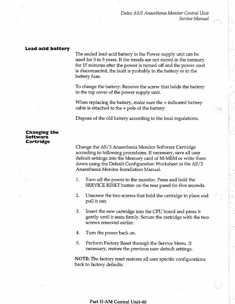
Lead acid battery
Changing the Software Cartridge
Datex AS/3 Anaesthesia Monitor Central Unit
Service Manual
The sealed lead-acid battery in the Power supply unit can be used for 3 to 5 years. If the trends are not stored in the memory for 15 minutes after the power is turned off and the power cord is disconnected, the fault is probably in the battery or in the battery fuse.
To change the battery: Remove the screw that holds the battery to the top cover of the power supply unit.
When replacing the battery, make sure the + indicated battery cable is attached to the + pole of the battery
Dispose of the old battery according to the local regulations.
Change the AS/3 Anaesthesia Monitor Software Cartridge according to following procedures. If necessary, save all user default settings into the Memory card of M-MEM or write them down using the Default Configuration Worksheet in the AS/3 Anaesthesia Monitor Installation Manual.
1. Turn off the power to the monitor. Press and hold the SERVICE RESET button on the rear panel for five seconds.
2. Unscrew the two screws that hold the cartridge in place and pull it out.
3. Insert the new cartridge into the CPU board and press it gently until it seats firmly. Secure the cartridge with the two screws removed earlier.
4. Turn the power back on.
5. Perform Factory Reset through the Service Menu. If necessary, restore the previous user default settings.
NOTE: The factory reset restores all user specific configurations back to factory defaults.
Part II-AM Central Unit-40

Changing and Installing AS/3 Board
Changing fuses
Datex AS/3 Anaesthesia Monitor Central Unit
Service Manual
Change any of the AS/3 boards according to following procedures.
1. Turn off the power to the monitor. Press and hold the SERVICE RESET button on the rear panel of the monitor for five seconds.
(Before removing the CPU board, remove the software cartridge as explained earlier.)
2. Unscrew the screws that hold the board in place and pull it out.
3. Remove the new board from the protective anti static packaging. Always hold the board by its edges and wear a wrist grounding strap.
CAUTION: The board comprises sensitive integrated circuits that can be damaged by an electrostatic discharge.
4. Insert the board into the slot and press the board gently until it seats firmly. Secure the board with the screws removed earlier.
5. Turn the power to the monitor back on.
Power supply main fuses are located next to power cord receptacle. The fuse holder can be removed by gently pushing the locking pin above the holder (or the locking pins at both sides) and the same time pulling the holder.
CAUTION: Use only fuses with specified type and ratings.
To change the secondary fuse on the power supply board: Remove the rear panel from the power supply unit by removing the two screws at the top and two screws at the bottom of the panel. Replace the fuse placed on the upper right corner.
Part II-AM Central Unit-41
Datex AS/3 Anaesthesia Monitor Central Unit
Service Manual
3.4 Adjustments and Calibrations
It is not necessary to do calibrations or adjustments to the Anaesthesia Monitor frame.
Part II-AM Central Unit-42
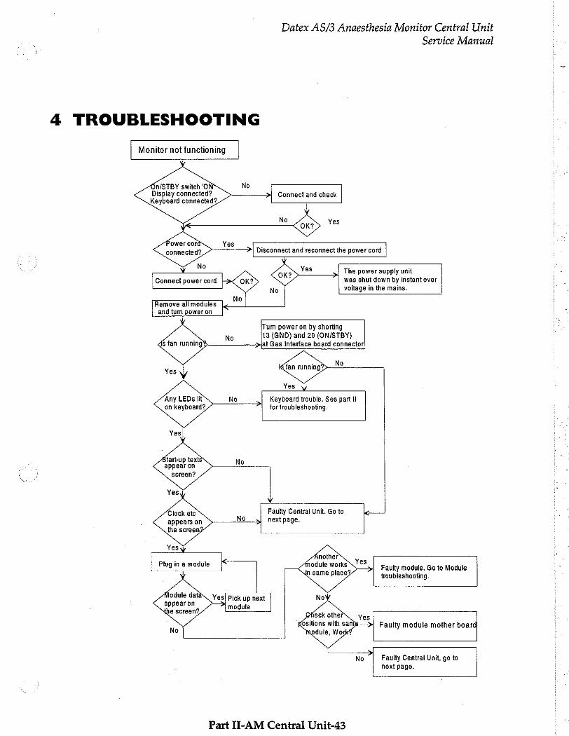
TROUBLESHOOTING
Monitor not functioning
On/STBY switch 'O No
Display connected? Keyboard connected?
No
Connect power cord <>
No Remove ali modules and tum power on
Datex AS/3 Anaesthesia Monitor Central Unit
Service Manual
>| Connect and check
Yes >| The power supply unit was shut down by instant over
voltage in the mains. No | |
Any LEDs lit on keyboard?
‘Tum power on by shorting 13 (GND) and 20 (ON/STBY) jat Gas Interface board connector:
No
Yes
Keyboard trouble. See part ll for troubleshooting.
tart-up texts appear on
screen?
Yes
Clock etc appears on No
Faulty Central Unit. Go to next page.
the screen Yesy
Plug in a module <
Faulty module. Go to Module troubleshooting.
odule data
appear on module
Yes! Pick up next
e screen? Faulty module mother board
Faulty Central Unit, go to
next page.
Part II-AM Central Unit-43
Datex AS/3 Anaesthesia Monitor Central Unit
Service Manual
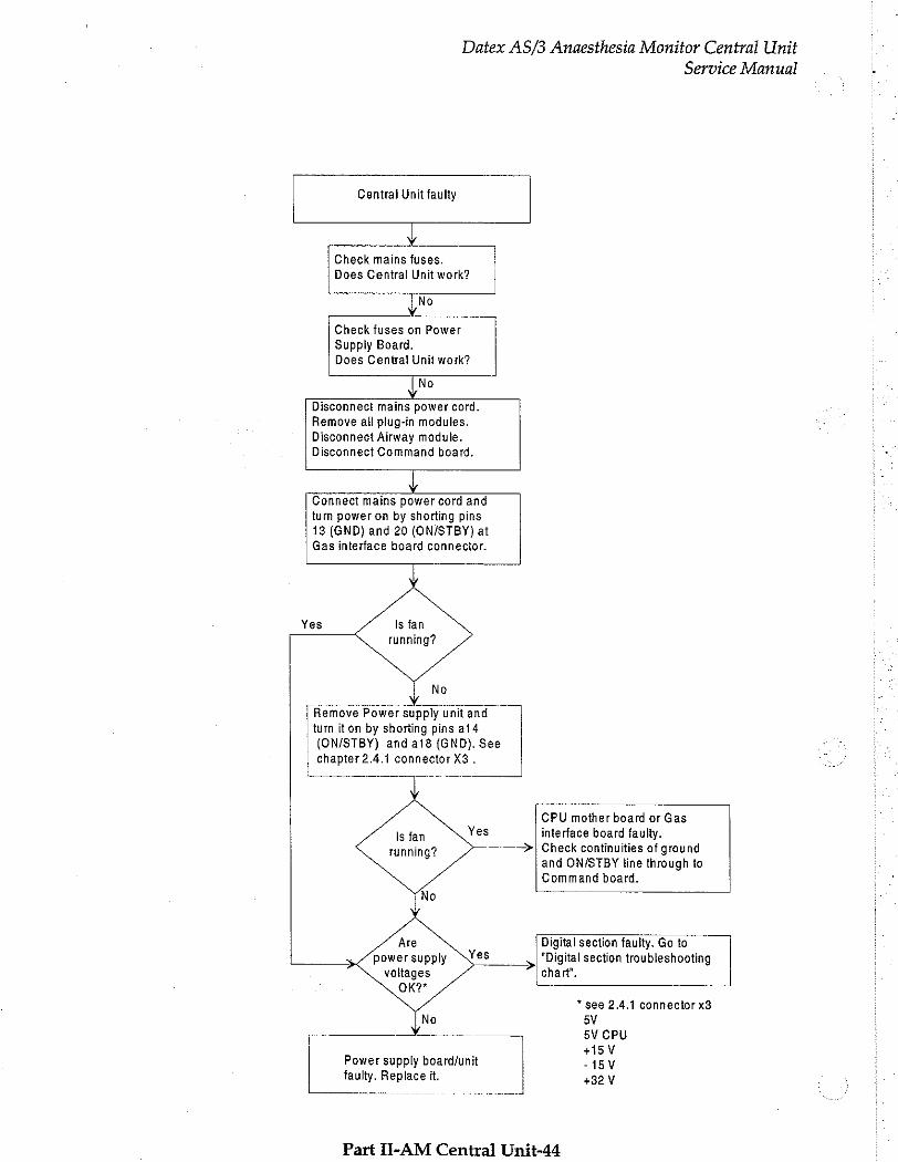
Central Unit faulty
| Y Check mains fuses. Does Central Unit work?
{No Y
Check fuses on Power
Supply Board,
Does Central Unit work?
[Νο Y
Disconnect mains power cord.
Remove ali plug-in modules. Disconnect Airway module. Disconnect Command board.
y
Connect mains power cord and
turn power on by shorting pins
13 (GND) and 20 (ON/STBY) at Gas interface board connector.
Yes
No
[ Remove Power supply unitand | turn iton by shorting pins ai4
(ON/STBY) and a18 (GND). See chapter 2.4.1 connector X3 .
一 一 一 -
CPU mother board or Gas Yes interface board faulty.
——~>| Check continuities of ground
and ON/STBY line through to Command board.
Digital section faulty. Go to power supply YES N "Digital section troubleshooting
voltages chart’.
OK?*
* see 2.4.1 connector x3
5V 一 -一 一 一 一 一 5V CPU
+15V Power supply board/unit -15V faulty. Replace it. +32 V
Part JI-AM Central Unit-44
Datex AS/3 Anaesthesia Monitor Central Unit
Service Manual
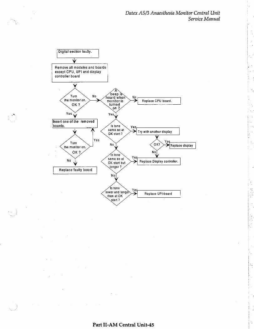
Digita! section faulty.
Y
Remove all modules and boards
except CPU, UPI and display controller board
Y
Turn the monitor on.
OK?
Insert one of the removed boards.
same as at OK start?
Try with another display
Tum the monitor on.
ОК?
Replace display |
s tone same as at OK start but longer?
Ye У >> Replace Display controller.
Replace faulty board
Is tone lower and longe than at OK
start ?
Ye
> Replace UPI-board
Part II-AM Central Unit-45
5 SERVICE VIEW
Datex AS/3 Anaesthesia Monitor Central Unit
Service Manual
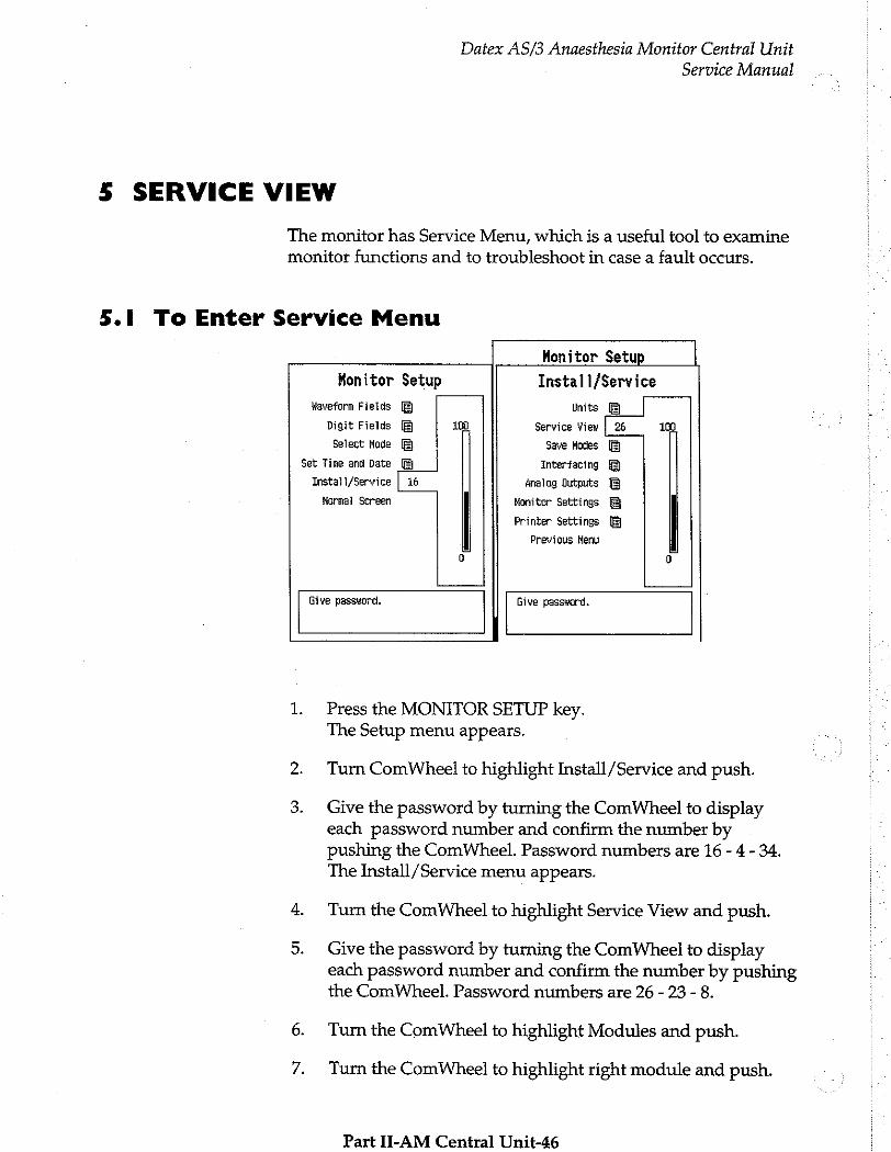
The monitor has Service Menu, which is a useful tool to examine
monitor functions and to troubleshoot in case a fault occurs.
5.1 To Enter Service Menu
Monitor Setup
Waveform Fields
Digit Fields
Select Mode
Set Time and Date
Instal1/Service
Normal Screen
De
Monitor Setup
100
Install/Service
Units
Service View
Save Modes
Interfacing
Analog Qutputs
Monitor Settings
Printer Settings
Previous Menu
26 100
m ABA
Give password.
Give password.
1. Press the MONITOR SETUP key. The Setup menu appears.
2. Turn ComWheel to highlight Install/Service and push.
3. Give the password by turning the ComWheel to display each password number and confirm the number by pushing the ComWheel. Password numbers are 16 - 4 - 34. The Install/Service menu appears.
4. Turn the ComWheel to highlight Service View and push.
5. Give the password by turning the ComWheel to display each password number and confirm the number by pushing the ComWheel. Password numbers are 26 - 23 - 8.
6. Turn the ComWheel to highlight Modules and push.
7. Turn the ComWheel to highlight right module and push.
Part II-AM Central Unit-46
Datex AS/3 Anaesthesia Monitor Central Unit
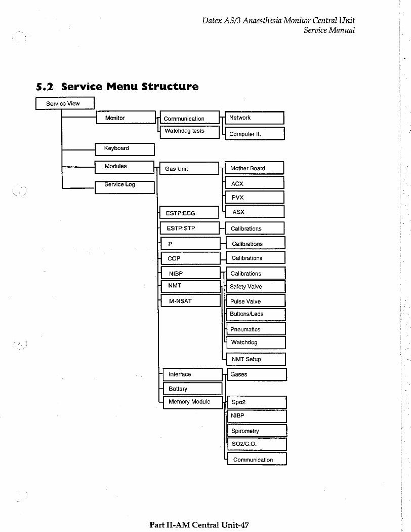
5.2 Service Menu Structure
Service View
Monitor Communication Network
| Watchdog tests | Computer If.
Keyboard
Modules -- Gas Unit Mother Board
Service Log ACX
PVX
A ESTP:ECG ASX
HA ESTP:STP ト - ゴ | Calibrations
НР | Calibrations
4 COP LJ Calibrations
mM NIBP Calibrations
Fi NMT | Safety Valve
(| M-NSAT Pulse Valve
Buttons/Leds
Pneumatics
| Watchdog
— NMT Setup
M Interface =| Gases
Hi Battery
i Memory Module Spo2
NIBP
Spirometry
| $02/C.0.
Communication
Part II-AM Central Unit-47
Service Manual
Datex AS/3 Anaesthesia Monitor Central Unit
Service Manual o...
5.3 Service View Menu
Service View] Sw version / Unit id
Monitor Monitor Frane -— Уег. 883898-5.0
Keyboard Keyboard 1 -ーーーーーーーーーーーーーーーーーーーーーーーー
Modules 3
Service Log Keyboard 2 一
11 Ver: ? sorol Vers Keyboard 3 一 - — Record Vers 3
Previous Menu Čascade Keyboard ————————
3 Gas Unit == mona nana 2 3 AN -----------------------— 一 一 一 3
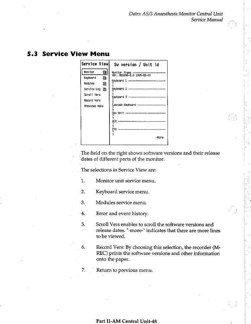
The field on the right shows software versions and their release dates of different parts of the monitor.
The selections in Service View are:
1. Monitor unit service menu.
2. Keyboard service menu.
3. Modules service menu.
4. Error and event history.
5. Scroll Vers enables to scroll the software versions and release dates. "-more-" indicates that there are more lines
to be viewed.
6. Record Vers: By choosing this selection, the recorder (M- REC) prints the software versions and other information onto the paper.
7. Return to previous menu.
Part II-AM Central Unit-48
Datex AS/3 Anaesthesia Monitor Central Unit
Service Manual
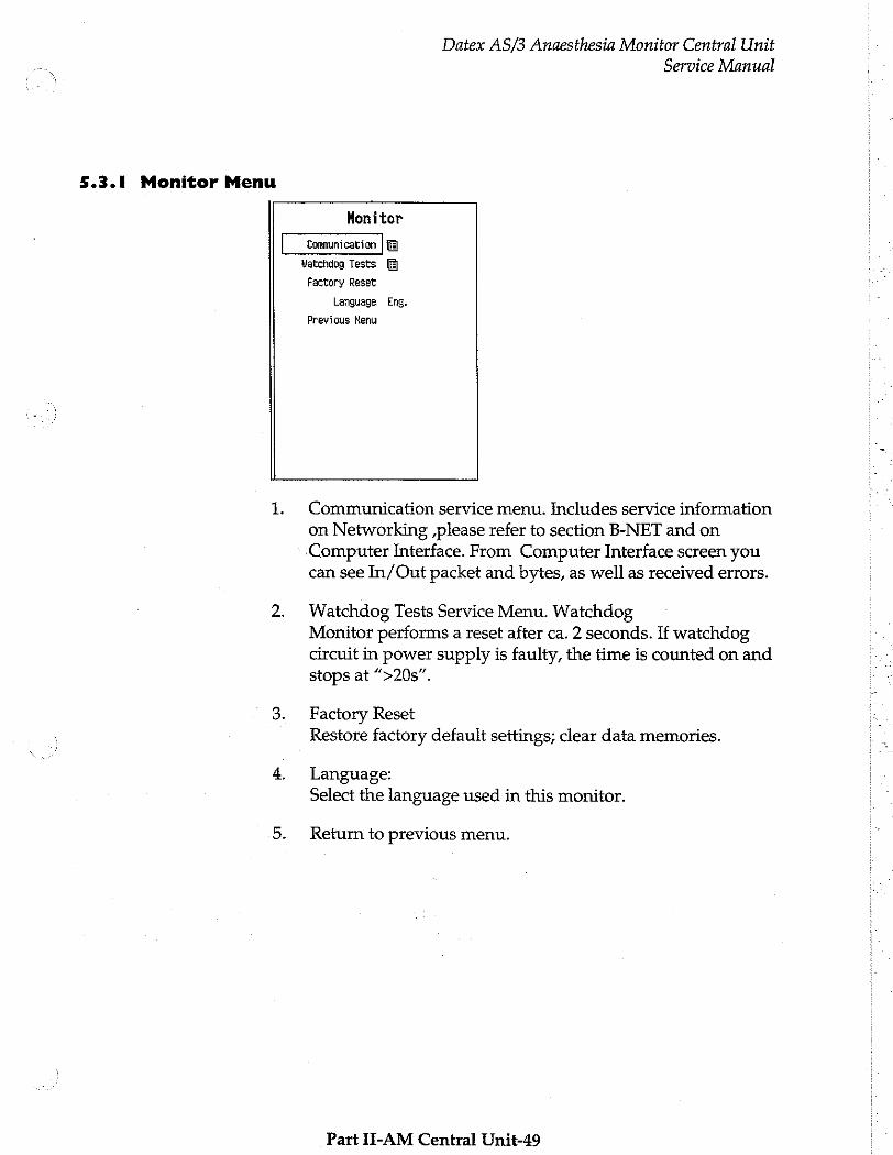
5.3.1 Monitor Menu
Monitor
Watchdog Tests
Factory Reset
Language Eng.
Previous Menu
1. Communication service menu. Includes service information on Networking „please refer to section B-NET and on Computer Interface. From Computer Interface screen you can see In/Out packet and bytes, as well as received errors.
2. Watchdog Tests Service Menu. Watchdog Monitor performs a reset after ca. 2 seconds. If watchdog circuit in power supply is faulty, the time is counted on and stops at “>20s”.
3. Factory Reset Restore factory default settings; clear data memories.
4. Language: Select the language used in this monitor.
5. Return to previous menu.
Part II-AM Central Unit-49
Datex AS/3 Anaesthesia Monitor Central Unit
Service Manual
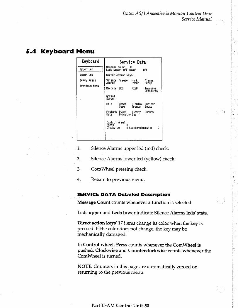
5.4 Keyboard Menu
Keyboard Service Data Message count. 0
Upper Led Leds upper OFF lower OFF
Lower Led Direct action keys
Dummy Press Silence Freeze Mark Alarms M Alarms Event Setup
Previous Men q Recorder ECG NIBP Invasive
Pressures
Normal Screen
Help Reset Display Monitor Case Trends Setup
Patient Pulse Airway Others Date Dximetry Gas
Control wheel Press Clockwise Ú Counterclockwise 0
1. Silence Alarms upper led (red) check.
2. Silence Alarms lower led (yellow) check.
3. ComWheel pressing check.
4. Return to previous menu.
SERVICE DATA Detailed Description
Message Count counts whenever a function is selected.
Leds upper and Leds lower indicate Silence Alarms leds' state.
Direct action keys' 17 items change its color when the key is pressed. If the color does not change, the key may be mechanically damaged.
In Control wheel, Press counts whenever the ComWheel is
pushed. Clockwise and Counterclockwise counts whenever the ComWheel is turned.
NOTE: Counters in this page are automatically zeroed on returning to the previous menu.
Part II-AM Central Unit-50
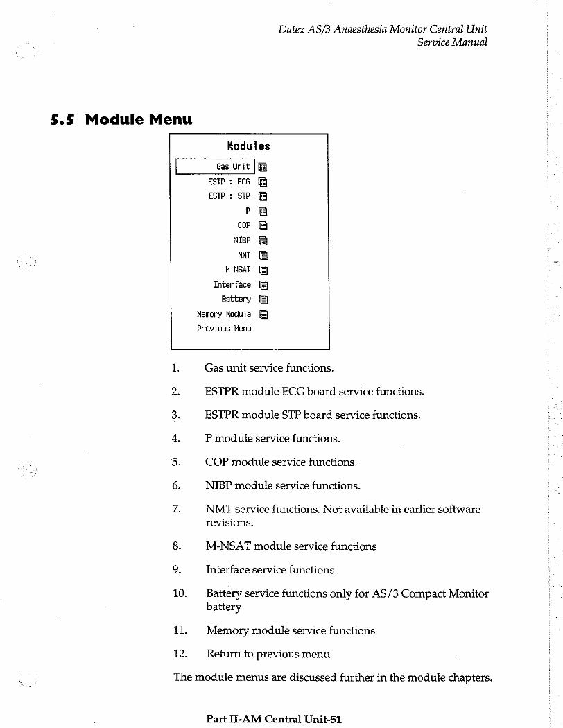
5.5 Module Menu
Datex AS/3 Anaesthesia Monitor Central Unit
Service Manual
Memory Module
Previous Menu
Hodules
ESTP : ECG
ESTP : STP
р
СОР
NIBP
NAT
M-NSAT
Interface
Battery
ü ©
© ©
© ©
a 0 mi
NS
4
Rp $ N
99
10.
11.
12.
Gas unit service functions.
ESTPR module ECG board service functions.
ESTPR module STP board service functions.
P module service functions.
COP module service functions.
NIBP module service functions.
NMT service functions. Not available in earlier software
revisions.
M-NSAT module service functions
Interface service functions
Battery service functions only for AS/3 Compact Monitor battery
Memory module service functions
Return to previous menu.
The module menus are discussed further in the module chapters.
Part II-AM Central Unit-51
Datex AS/3 Anaesthesia Monitor Central Unit
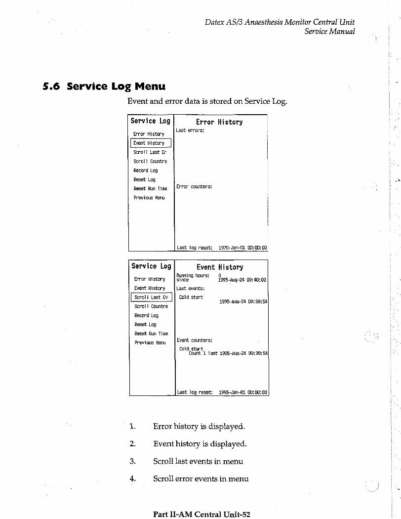
5.6 Service Log Menu
Event and error data is stored on Service Log.
Service Log
Error History
Scroll Last Er
Scroll Countrs
Record Log
Reset Log
Reset Run Time Error counters:
Previous Menu
Error History Last errors:
Last log reset: 1970-Jan-0i 00:00:00
Service Log
Error History since
Previous Menu
Event History Running hours:
Event History Last events:
Cold start Scroll Countrs
Record Log
Reset Log
Reset Run Time
Event counters:
Cold star! Û 1995-Aug-24 09:40:00
1995-Aug-24 09:39:54
t Count 1 last 1995-Aug-24 09:30:54
Last log reset: 1995-Jan-01 00:00:00
Error history is displayed.
Event history is displayed.
Scroll last events in menu
Scroll error events in menu
Part II-AM Central Unit-52
Service Manual
Datex AS/3 Anaesthesia Monitor Central Unit
Service Manual
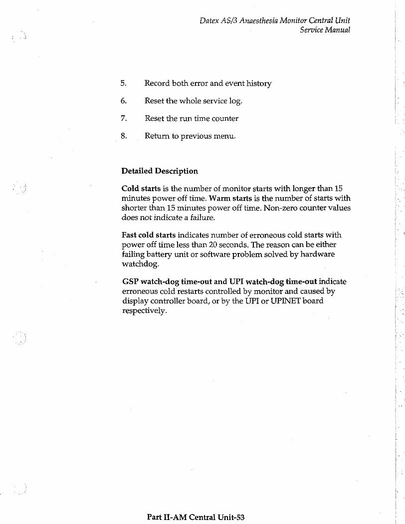
5. Record both error and event history
6. Reset the whole service log.
7. Reset the run time counter
8. Return to previous menu.
Detailed Description
Cold starts is the number of monitor starts with longer than 15 minutes power off time. Warm starts is the number of starts with shorter than 15 minutes power off time. Non-zero counter values does not indicate a failure.
Fast cold starts indicates number of erroneous cold starts with power off time less than 20 seconds. The reason can be either failing battery unit or software problem solved by hardware watchdog.
GSP watch-dog time-out and UPI watch-dog time-out indicate erroneous cold restarts controlled by monitor and caused by display controller board, or by the UPI or UPINET board respectively.
Part II-AM Central Unit-53
Datex AS/3 Anaesthesia Monitor Central Unit
Service Manual
6 SPARE PARTS
6.1 Spare Parts list
NOTE: Only changed part numbers are listed under later revisions. To find the desired part: check first the list of the revision that corresponds your device. If the part is not listed there, check the previous revision, etc. until you find the right number.
Item numbers refer to the exploded view in the chapter 6.2
Part II-AM Central Unit-54
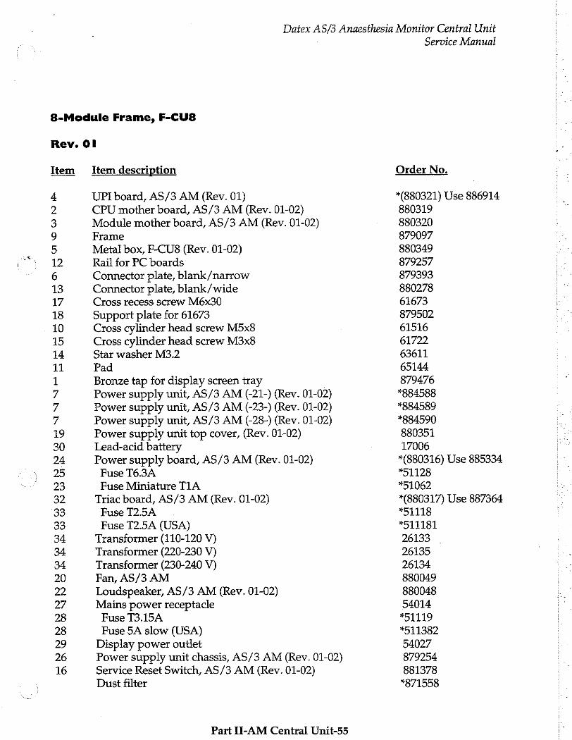
Datex AS/3 Anaesthesia Monitor Central Unit
8-Module Frame, F-CU8
Rev. Ol
Item Item description
4 UPI board, AS/3 AM (Rev. 01) 2 CPU mother board, AS/3 AM (Rev. 01-02) 3 Module mother board, AS/3 AM (Rev. 01-02) 9 Frame 5 Metal box, F-CU8 (Rev. 01-02) 12 Rail for PC boards 6 Connector plate, blank/narrow 13 Connector plate, blank/wide 17 Cross recess screw M6x30 18 Support plate for 61673 10 Cross cylinder head screw M5x8 15 Cross cylinder head screw M3x8 14 Star washer M3.2 11 Pad 1 Bronze tap for display screen tray 7 Power supply unit, AS/3 AM (-21-) (Rev. 01-02) 7 Power supply unit, AS/3 AM (-23-) (Rev. 01-02) 7 Power supply unit, AS/3 AM (-28-) (Rev. 01-02) 19 Power supply unit top cover, (Rev. 01-02) 30 Lead-acid battery 24 Power supply board, AS/3 AM (Rev. 01-02) 25 Fuse T6.3A 23 Fuse Miniature TIA 32 Triac board, AS/3 AM (Rev. 01-02) 33 Fuse T2.5A 33 Fuse T2.5A (USA) 34 Transformer (110-120 V) 34 Transformer (220-230 V) 34 Transformer (230-240 V) 20 Fan, AS/3 AM
2 Loudspeaker, AS/3 AM (Rev. 01-02) 27 Mains power receptacle 28 Fuse T3.15A 28 Fuse 5A slow (USA) 29 Display power outlet 26 Power supply unit chassis, AS/3 AM (Rev. 01-02) 16 Service Reset Switch, AS/3 AM (Rev. 01-02)
Dust filter
Part II-AM Central Unit-55
Service Manual
Order No.
*(880321) Use 886914 880319 880320 . 879097 880349 879257 879393 880278 61673 879502 61516 61722 63611 65144 879476 1884588 1884589 884590 880351 17006 *(880316) Use 885334 *51128 *51062 *(880317) Use 887364 *51118 *511181 26133 26135 26134 880049 880048 54014 *51119 *511382 54027 879254 881378 *871558
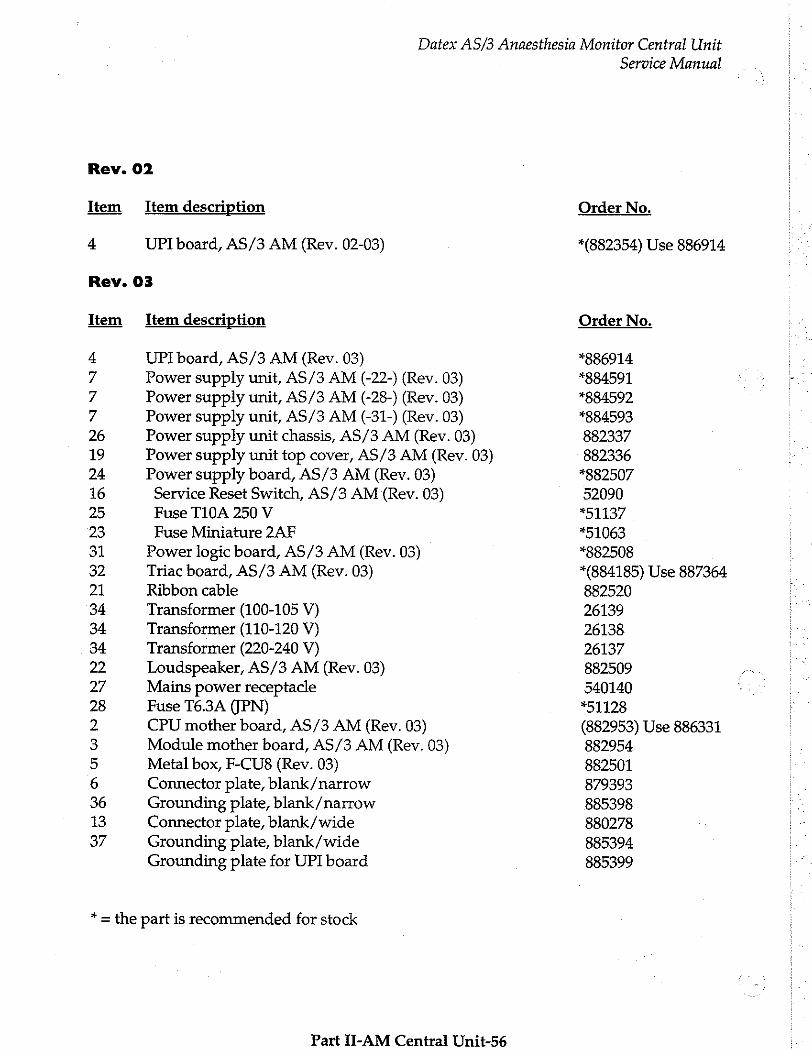
Datex AS/3 Anaesthesia Monitor Central Unit
Rev. 02
Item Item description
4 UPI board, AS/3 AM (Rev. 02-03)
Rev. 03
Item Item description
4 UPI board, AS/3 AM (Rev. 03)
7 Power supply unit, AS/3 AM (-22-) (Rev. 03) 7 Power supply unit, AS/3 AM (-28-) (Rev. 03) 7 Power supply unit, AS/3 AM (-31-) (Rev. 03) 26 Power supply unit chassis, AS/3 AM (Rev. 03) 19 Power supply unit top cover, AS/3 AM (Rev. 03) 24 Power supply board, AS/3 AM (Rev. 03) 16 Service Reset Switch, AS/3 AM (Rev. 03) 25 Fuse T10A 250 V 23 Fuse Miniature 2AF 31 Power logic board, AS/3 AM (Rev. 03)
32 Triac board, AS/3 AM (Rev. 03) 21 Ribbon cable 34 Transformer (100-105 V) 34 Transformer (110-120 V) 34 Transformer (220-240 V) 22 Loudspeaker, AS/3 AM (Rev. 03)
27 Mains power receptacle 28 Fuse T6.3A (JPN) 2 CPU mother board, AS/3 AM (Rev. 03)
3 Module mother board, AS/3 AM (Rev. 03)
5 Metal box, F-CU8 (Rev. 03)
6 Connector plate, blank/narrow 36 Grounding plate, blank/narrow 13 Connector plate, blank/wide 37 Grounding plate, blank/wide
Grounding plate for UPI board
* = the part is recommended for stock
Part II-AM Central Unit-56
Service Manual
Order No.
*(882354) Use 886914
Order No.
*886914 *884591 *884592 *884593 882337 882336 *882507 52090 *51137
*51063 *882508 *(884185) Use 887364 882520 26139 26138. 26137 882509 540140 *51128 (882953) Use 886331 882954 882501 879393 885398 880278 885394 885399
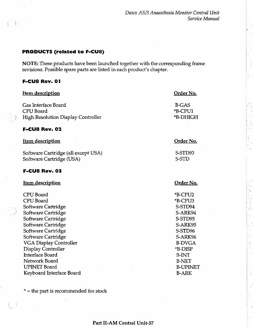
PRODUCTS (related to F-CU8)
Datex AS/3 Anaesthesia Monitor Central Unit
Service Manual
NOTE: These products have been launched together with the corresponding frame revisions. Possible spare parts are listed in each product's chapter.
F-CU8 Rev. Ol
Item description
Gas İnterface Board
CPU Board
High Resolution Display Controller
F-CU8 Rev. 02
İtem description
Software Cartridge (all except USA) Software Cartridge (USA)
F-CU8 Rev. 03
Item description
CPU Board CPU Board Software Cartridge Software Cartridge Software Cartridge Software Cartridge Software Cartridge Software Cartridge VGA Display Controller Display Controller Interface Board Network Board UPINET Board Keyboard Interface Board
* = the part is recommended for stock
Part U-AM Central Unit-57
Order No.
B-GAS *B-CPU1 *B-DHIGH
Order No.
S-STD93 S-STD
Order No.
*B-CPU2 *B-CPU3 S-STD94 S-ARK94 S-STD95 S-ARK95 S-STD96 S-ARK96 B-DVGA *B-DISP B-INT B-NET B-UPINET B-ARK
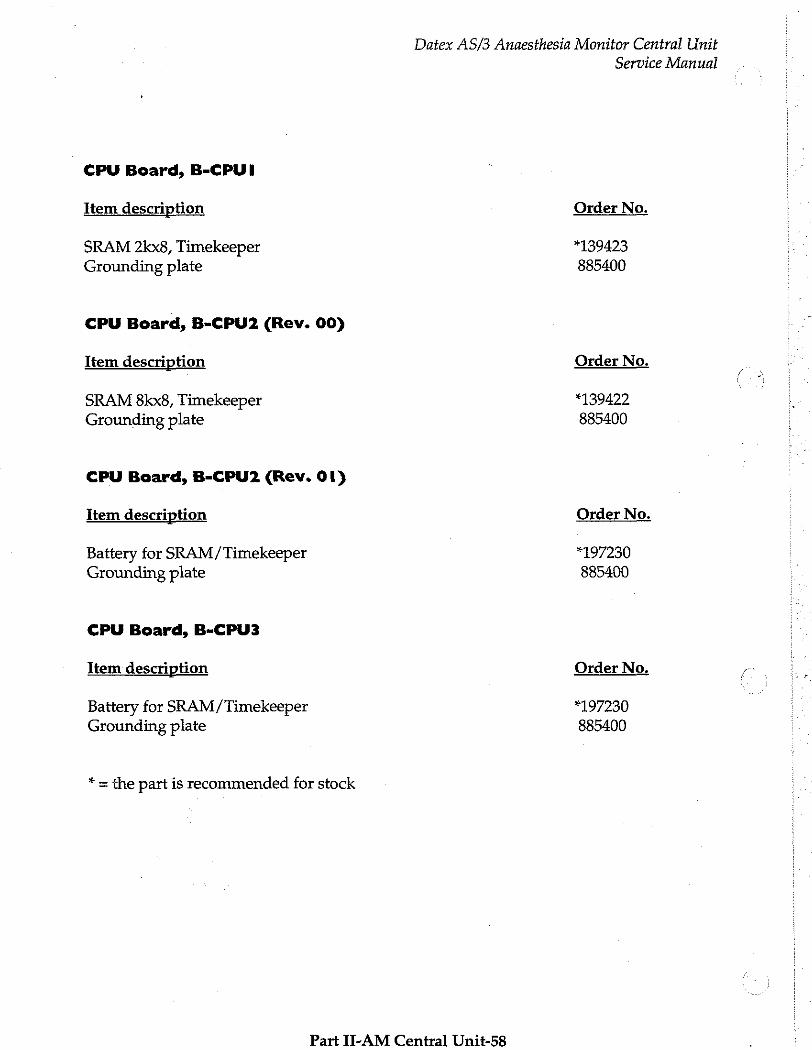
Datex AS/3 Anaesthesia Monitor Central Unit
CPU Board, B-CPUI
Item description
SRAM 2kx8, Timekeeper Grounding plate
CPU Board, B-CPU2 (Rev. 00)
Item description
SRAM 8kx8, Timekeeper
Grounding plate
CPU Board, B-CPU2 (Rev. 01)
Item description
Battery for SRAM/Timekeeper Grounding plate
CPU Board, B-CPU3
Item description
Battery for SRAM/Timekeeper Grounding plate
* = the part is recommended for stock
Part II-AM Central Unit-58
Service Manual
Order No.
*139423 885400
Order No.
*139422 885400
Order No.
*197230 885400
Order No.
*197230 885400
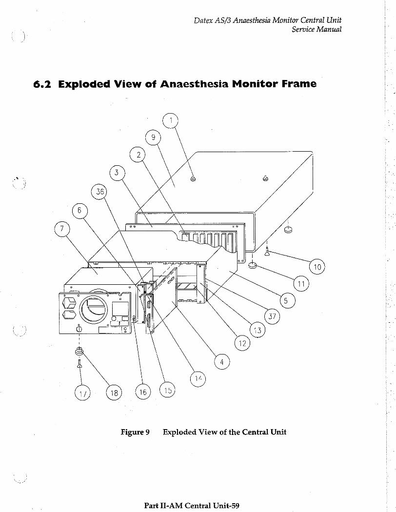
Datex AS/3 Anaesthesia Monitor Central Unit
Service Manual
6.2 Exploded View of Anaesthesia Monitor Frame
Figure9 Exploded View of the Central Unit
Part II-AM Central Unit-59

Datex AS/3 Anaesthesia Monitor Central Unit
Service Manual
Figure 10 Exploded View of the Power Unit
Part II-AM Central Unit-60
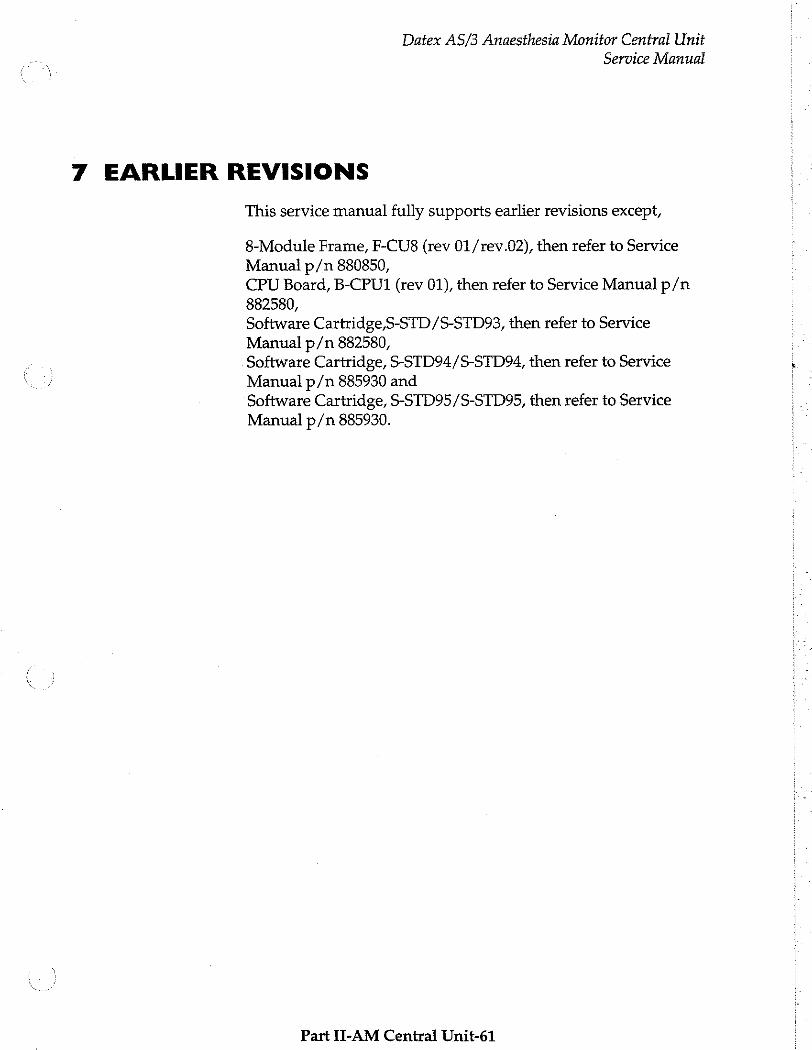
Datex AS/3 Anaesthesia Monitor Central Unit
Service Manual
7 EARLIER REVISIONS
This service manual fully supports earlier revisions except,
8-Module Frame, F-CU8 (rev 01/rev.02), then refer to Service Manual p/n 880850,
CPU Board, B-CPU1 (rev 01), then refer to Service Manual p/n 882580,
Software Cartridge,S-STD/S-STD93, then refer to Service
Manual p/n 882580,
Software Cartridge, S-STD94/S-STD94, then refer to Service
Manual p/n 885930 and Software Cartridge, S-STD95/S-STD95, then refer to Service Manual p/n 885930.
Part II-AM Central Unit-61

M
LTT
Video Display, D-VNCI 5 (Rev 00)
LCD Display, D-LCCIO (Rev. 03)
VGA Display Controller, B-DVGA (Rev. 03)
Display Controller, B-DISP (Rev. 00)
Command Board, K-VNCI5 (Rev. 00)
All specifications subject to change without notice
Document No. 889926
March 1996
Datex Division, Instrumentarium Corp.
P.O.Box 446 FIN-00101 Heisinki Finland
Tel. +358 0 39411 Fax +358 0 1463310
Datex AS/3 Displays and Command Board Service Manual
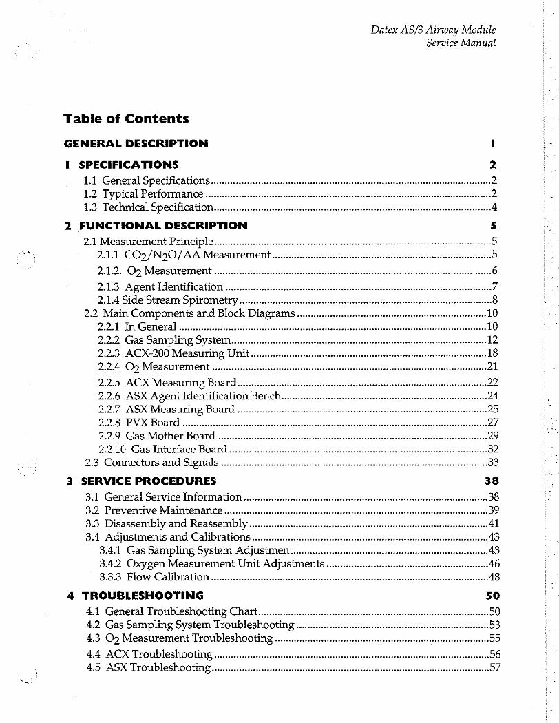
Datex AS/3 Airway Module
Service Manual
Table of Contents
GENERAL DESCRIPTION 1
I SPECIFICATIONS 2
1.1 General Specifications... iii 1.2 Typical Performance .... 1.3 Technical Specification
2 FUNCTIONAL DESCRIPTION 5
2.1 Measurement Principles 5 2.1.1 CO>/N20/AA Measurement .ee 5
2.1.2. Oz Measurement
2.13 Agent Identification se 2.1.4 Side Stream Spirometry ーー
2.2 Main Components and Block Diagram ,ee 10 2.2.1 In General unes 2.2.2 Gas Sampling System
2.2.3 ACX-200 Measuring Um ireesererensensereemeerrereereeesercereeereeneereeneenso 18 2.24 Où Measurement sn 21
2.2.5 ACX Measuring Board eee ee R ena R 22 2.2.6 ASX Agent Identification Bench... nnece 24 2.2.7 ASX Measuring Board
2.2.8 PVX Boad eee iii einen 2.2.9 Саз οι αμ μμ μμ μμ μμ μμ μμ μμ μϱϱϐϱἛϱ---ι
2.2.10 Gas Interface Board ...
2.3 Connectors and Signals
3 SERVICE PROCEDURES
3.1 General Service Information
3.2 Preventive Maintenance............ 3.3 Disassembly and Reassembly ...... 3.4 Adjustments and Calibrations ..
34.1 Gas Sampling System Adjustment….......................................... 43 3.4.2 Oxygen Measurement Unit Adjustments .0000 아 나 아 아 아 아 아 아 아 아 아 어 이 어 아 아 이 이 이 이 아 아 이 아 이 아 46 3.3.3 Flow Calibration iii 48
4 TROUBLESHOOTING
4.1 General Troubleshooting Chart... rene νε νκτο ντος 4.2 Gas Sampling System Troubleshooting 4.3 O 7 Measurement Troubleshooting
4.4 ACX Troubleshooting 4.5 ASX Troubleshooting

Datex AS/3 Airway Module Service Manual
4.6 PVX Board troubleshooting ................. 4.7 Gas Mother Board Troubleshooting .
48 ErrorMessages................................. eee
5 SERVICE VIEW
5.1 Gas Mother Board... issues
5.2 ACX Service menu....
5.3 PVX Service Menu .... .
54 ASX Service Menu e eee eno e nene en Pe KAR Re AA AR n nA Poe aan tao e né
6 SPARE PARTS 76
6.1 Spare parts list... sn 76
7 EARLIER REVISIONS 80

Datex AS/3 Displays and Command Board Service Manual
INTRODUCTION
This section provides information about the maintenance and service of the LCD display (D-LCC10), the Display controller boards (B-DISP, B-DVGA, B-DHIGH), and the Command
Boards (K-VNC15, K-VHC14) of the Anaesthesia and Compact Monitors.
Notice that the service information of D-VNC15 (D-VHC14) are delivered on request.
4 NOTE: The backlight circuit runs on a high voltage. Do not touch the adapter board when powered.
Part II-Displays and Command Board-1
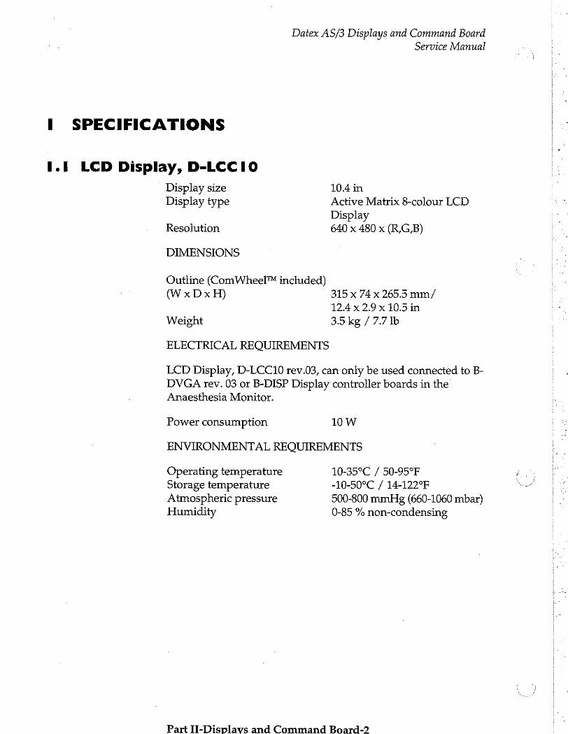
Datex AS/3 Displays and Command Board
SPECIFICATIONS
I.I LCD Display, D-LCCI0
Service Manual
Display size 10.4 in Display type Active Matrix 8-colour LCD
Display Resolution 640 x 480 x (R,G,B)
DIMENSIONS
Outline (ComWheel™ included) (WxDxH) 315 x 74 x 265.5 mm/
124x2.9x10.5in
Weight 3.5 kg / 7.7 lb
ELECTRICAL REQUIREMENTS
LCD Display, D-LCC10 rev.03, can only be used connected to B- DVGA rev. 03 or B-DISP Display controller boards in the Anaesthesia Monitor.
Power consumption 10W
ENVIRONMENTAL REQUIREMENTS
Operating temperature 10-35°C / 50-95°F Storage temperature -10-50°C / 14-122°F Atmospheric pressure 500-800 mmHg (660-1060 mbar) Humidity 0-85 % non-condensing
Part II-Displavs and Command Board-2
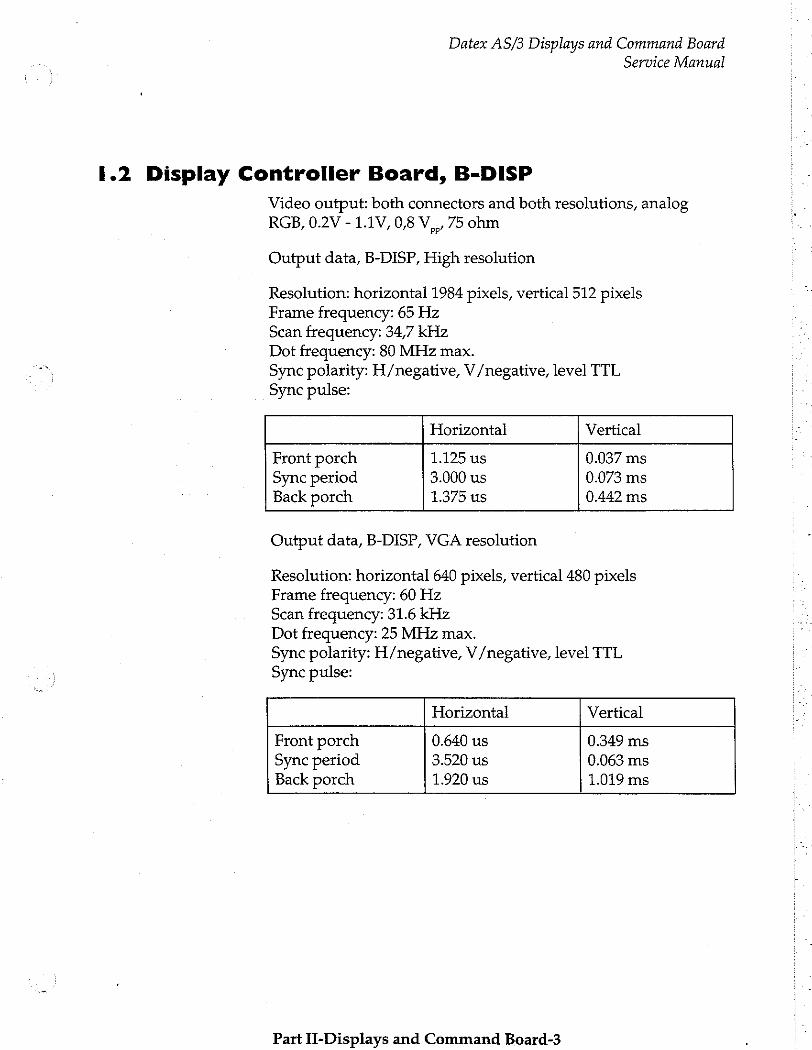
Datex AS/3 Displays and Command Board
1.2 Display Controller Board, B-DISP
Service Manual
Video output: both connectors and both resolutions, analog RGB, 0.2V - 1.1V, 0,8 V,,, 75 ohm
Output data, B-DISP, High resolution
Resolution: horizontal 1984 pixels, vertical 512 pixels Frame frequency: 65 Hz Scan frequency: 34,7 kHz Dot frequency: 80 MHz max. Sync polarity: H/negative, V/negative, level TTL
Sync pulse:
Horizontal Vertical
Front porch 1.125 us 0.037 ms Sync period 3.000 us 0.073 ms Back porch 1.375 us 0.442 ms
Output data, B-DISP, VGA resolution
Resolution: horizontal 640 pixels, vertical 480 pixels Frame freguency: 60 Hz Scan freguency: 31.6 kHz Dot freguency: 25 MHz max. Sync polarity: H/negative, V /negative, level TTL
Sync pulse:
Horizontal Vertical
Front porch 0.640 us 0.349 ms Sync period 3.520 us 0.063 ms Back porch 1.920 us 1.019 ms
Part II-Displays and Command Board-3
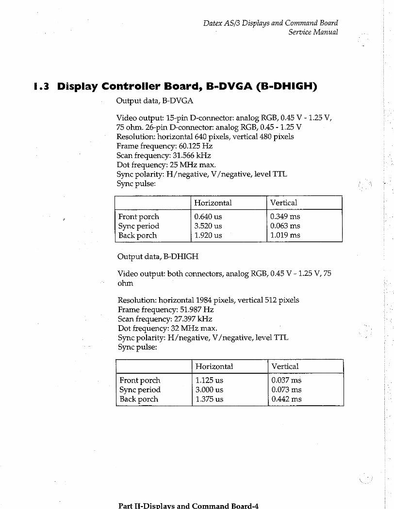
Datex AS/3 Displays and Command Board ] Service Manual
1.3 Display Controller Board, B-DVGA (B-DHIGH)
Output data, B-DVGA
Video output: 15-pin D-connector: analog RGB, 0.45 V - 1.25 V, 75 ohm. 26-pin D-connector: analog RGB, 0.45 - 1.25 V Resolution: horizontal 640 pixels, vertical 480 pixels Frame frequency: 60.125 Hz Scan frequency: 31.566 kHz Dot frequency: 25 MHz max.
Sync polarity: H/negative, V/negative, level TTL
Sync pulse:
Horizontal Vertical
Front porch 0.640 us 0.349 ms Sync period 3.520 us 0.063 ms Back porch 1.920 us 1.019 ms
Output data, B-DHIGH
Video output: both connectors, analog RGB, 0.45 V - 1.25 V, 75
ohm
Resolution: horizontal 1984 pixels, vertical 512 pixels
Frame frequency: 51.987 Hz Scan frequency: 27.397 kHz Dot frequency: 32 MHz max. Sync polarity: H/negative, V /negative, level TTL
Sync pulse:
Horizontal Vertical
Front porch 1.125 us 0.037 ms Sync period 3.000 us 0.073 ms Back porch 1.375 us 0.442 ms
Part ll-Displavs and Command Board-4
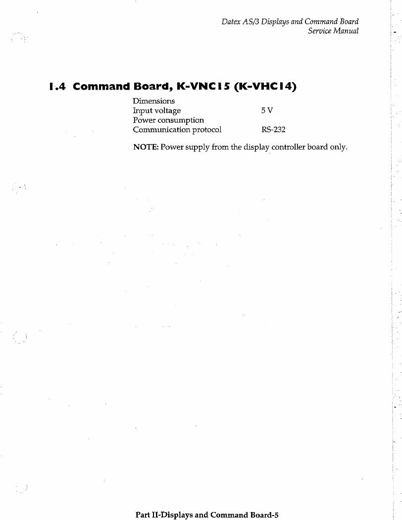
Datex AS/3 Displays and Command Board Service Manual
1.4 Command Board, K-VNCIS (K-VHCI4)
Dimensions Input voltage 5У Power consumption Communication protocol RS-232
NOTE: Power supply from the display controller board only.
Part II-Displays and Command Board-5
Datex AS/3 Displays and Command Board Service Manual
2 FUNCTIONAL DESCRIPTION
2.1 LCD Display
LCD Display, D-LCC10 includes LCD Display module, LCD Interface board, and Command Board with keyboard.
The keyboard works independent of the main keyboard of AS/3 monitor.
The LCD Display is connected to B-DVGA or B-DISP Display controller board in the monitor frame with the LCD Display interface cable. The interface cable is available as an accessory. See AS/3 Anaesthesia Monitor Supplies and Accessories Catalogue.
Communication between the Display controller board and the LCD Display takes place in analog form (in 00-02 revisions it was in digital form). Incoming signals are buffered in the interface board and fed forward to the LCD Display module.
Communication between the Display controller board and the Command Board takes place in RS232 serial communication channel D.
NOTE: B-DVGA rev. 01 and rev. 02 do not support D-LCC10- XX-03. D-LCC10-XX-03 requires B-DVGA rev. 03 or B-DISP.
Part TieDienlawve and Cammand Raard ik
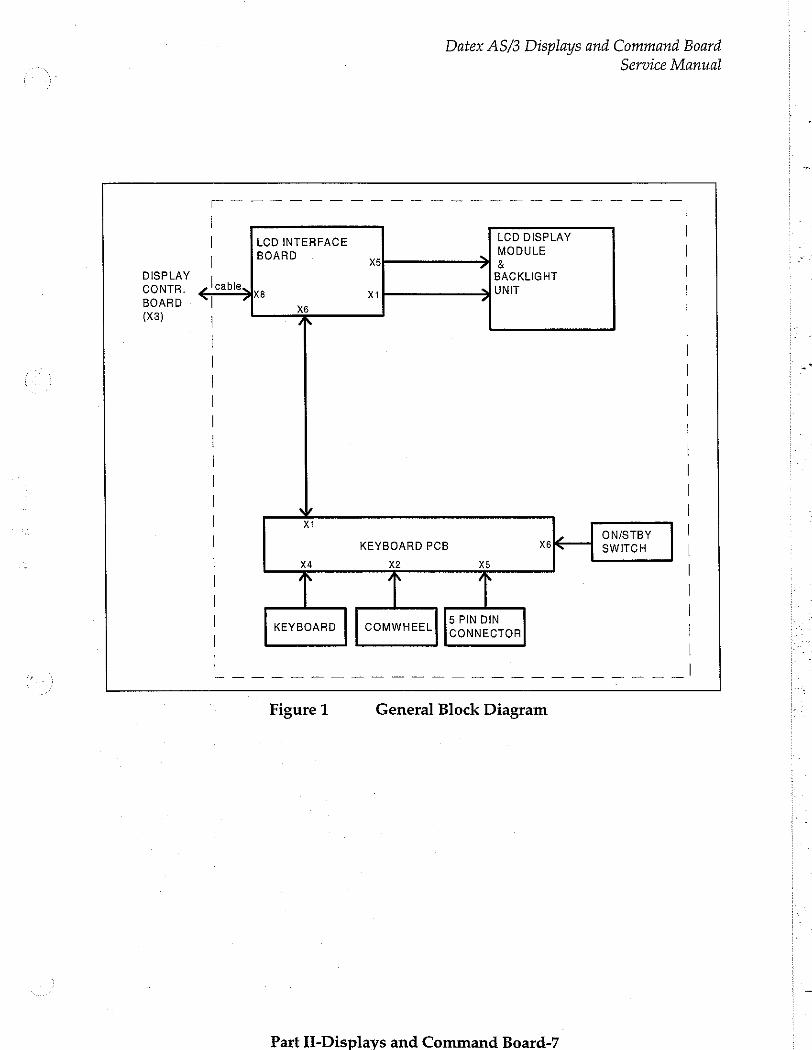
Datex AS/3 Displays and Command Board
Service Manual
一 一 一 一 一 一 一 一 一 一 一 一 一 一 一 一 一 一 一 一 一 一 一 一 i | |
| | LCD INTERFACE OLE |
BOARD xs る
DISPLAY | BACKLIGHT | CONTR. ¿cable UNIT | X8 x BOARD | xe ! À | (X3) |
| | |
| | | -
| |
| | | |
| | |
| | |
レル | | xi | | ON/STBY
KEYBOARD PCB x6 SWITCH | | X4 x2 X5 | |
| | |
| 5 PIN DIN | KEYBOARD | | COMWHEEL] CONNECTOR |
| | _ 이 의 의 그 |
Figure 1 General Block Diagram
Part H-Displavs and Command Board-7
Datex AS/3 Displays and Command Board Service Manual
2.1.1 LCD Interface Board
In general
The LCD Interface board is the interface between the Display controller board and the LCD Display component. The keyboard is also connected to the Interface board. (See Figure 1)
The incoming signal to LCD Interface board is pure analog VGA - RGB with separate horizontal and vertical synchronisation signals. (See Figure 2) The display element needs digital RGB- signals, HSYNC, VSYNC, DOTCEK and a display timing signal DTMG. The DTMG signal indicates that the digital RGB-signals are active.
The functions of this board are digitalization of the video signals, regeneration of the DOTCLK and generation of the DTMG. The backlight driver is also located on the board.
Power Supply
The DC/DC power supply is an isolated discontinuous mode flyback switcher. It has a current mode PWM circuit and a separate FET switch on the primary side. The transformer has two secondary windings, one for 5V and another for 12V. On
the secondary side (5V), there is a separate chip on the feedback path to drive the optoisolator.
Backlight Unit
The backlight unit is integrated to the LCD Display component. The backlight consists of one Cold Cathode Fluorescent Lamp (CCFL), which runs on a high AC voltage. The lamp needs approximately 1400 Volts to lit, but runs on a lower (500-600) voltage when on.
The backlight unit is an irreparable part, therefore only the whole LCD Display component can be replaced. If there is need to replace the LCD Display component please note: that the LCD Display is very sensitive for mistreatment. The service instructions (in Chapter 3) should be followed carefully when handling the component.
NOTE: The LCD Display component and Backlight unit are separate units in the D-LCC10, revision 01 and 02, therefore the
units are possible to be replaced separately.
Part TT-Dicplave and Cammana Poaard_8%
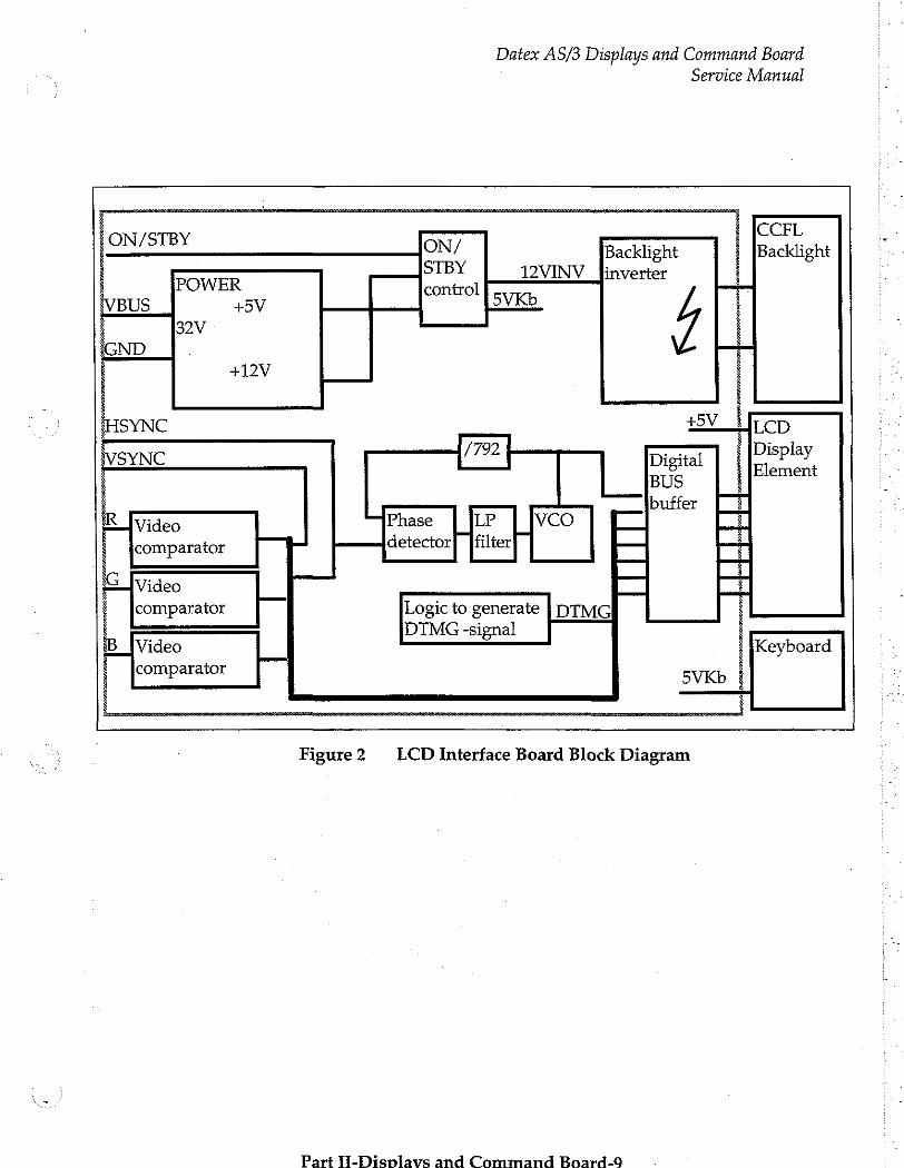
Datex AS/3 Displays and Command Board
Service Manual
CCFL ON/STBY ON/ Backlight Backlight STBY 12VINV li WER inverter control
US +5V 5VKb 32V
IND +12V
C +5V LCD
SYNC (792 Digital Display, BUS buffer
Video Phase LP VCO
comparator detector] filter
Video
comparator gic to generate | DTM
DTMG -signal Video Keyboard comparator
Figure 2. LCD Interface Board Block Diagram
Part TI-Displavs and Command Board-0

Datex AS/3 Displays and Command Board Service Manual
2.1.3 External Connector Configurations
LCD Display, D-LCC10 has two external connectors. Main connector is situated at the back. It is 13 pin Coax D-connector and has pins for operating voltage (+32 Vdc), display signals, and serial communication RS232.
5-pin DIN connector (see the following page) is situated on the right side of D-LCC10.
LCD Display 13 pin Coax D-connector (main connector)
Pin No JO | Signal Notes
Dirty Ground Intensity Hsync2 horiz. deflect Vsync2 vert. deflect Contrast +32 Vdd GND RXDD RS232 from keyboard TXDD RS232 to keyboard ON/STBY active GND BLUE GND & BLUE VIDEO 2 GREEN GND & GREEN VIDEO2
A3 I RED GND & RED VIDEO2
OE
AMA ENR
ha
o
AO
et
στι
> n > N
5-pin DIN connector (PC-connector)
Pin No | I/O | Signal Notes
1 0 CLK 2 I/O | DATA
3 not connected
4 GND 5 0 +5 Vde
Part I-Disnlaus and Command Baoard-10
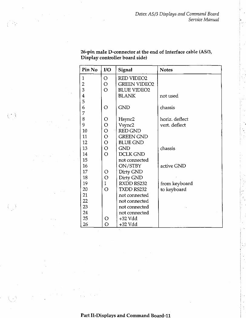
Datex AS/3 Displays and Command Board Service Manual
26-pin male D-connector at the end of Interface cable (AS/3,
Display controller board side)
Pin No | VO | Signal Notes
1 ο RED VIDEO2 2 0 GREEN VIDEO2 3 O BLUE VIDEO2 4 BLANK not used
5 6 O GND chassis
7
8 O Hsync2 horiz. deflect 9 o Vsync2 vert. deflect 10 0 RED GND 11 O GREEN GND 12 o BLUE GND 13 O GND chassis 14 o DCLK GND 15 not connected
16 ON/STBY active GND
17 O Dirty GND 18 O Dirty GND ] 19 I RXDD RS232 from keyboard 20 O TXDD RS232 to keyboard 21 not connected
22 not connected
23 not connected
24 not connected
25 0 +32 Vdd 26 O +32 Vdd
Part H-Displays and Command Board-11

Datex AS/3 Displays and Command Board Service Manual
2.2 Display Controller Board:
High Resolution Display, B-DISP
2.2.1 Functional Description
B-DISP board is connected to the CPU Mother board. The
processor on the CPU board transmits program through the AS/3 bus to B-DISP board.
B-DISP board includes the functions of both B-DHIGH and B- DVGA boards. Thus, B-DISP board supports both high resolution and VGA resolution. The resolution is automatically selected based on monitor ID codes. The resolution is set to 640x480 if a VGA resolution display is used, otherwise the resolution is set to 1984x512.
NOTE: S-STD96 and S-ARK96 softwares support B-DISP, B- DHIGH and B-DVGA boards. 1, however, B-DISP board is used
to drive D-VHC14 display, a small part of the resulting picture will be clipped.
System Memory
The system memory contains the GSP software code. The memory consists of two 256kx16 memory banks.
Frame Memory
The frame memory contains digital display data. The size of the memory is 1 Mbyte making 1984x512 display resolution with 256 colours possible. The memory consists of four 256kx8 VRAM memory circuits.
Video Interface Palette
The video interface palette reads the digital display data from the frame memory and converts the data into analog RGB- signals. The synchronization signals for the conversion are generated by the GSP.
The video interface palette is clocked by two pixel clocks. A 25 MHZ clock is selected for VGA resolution and a 40 MHz clock is
Part IT-Displave and CammandA Paard-19
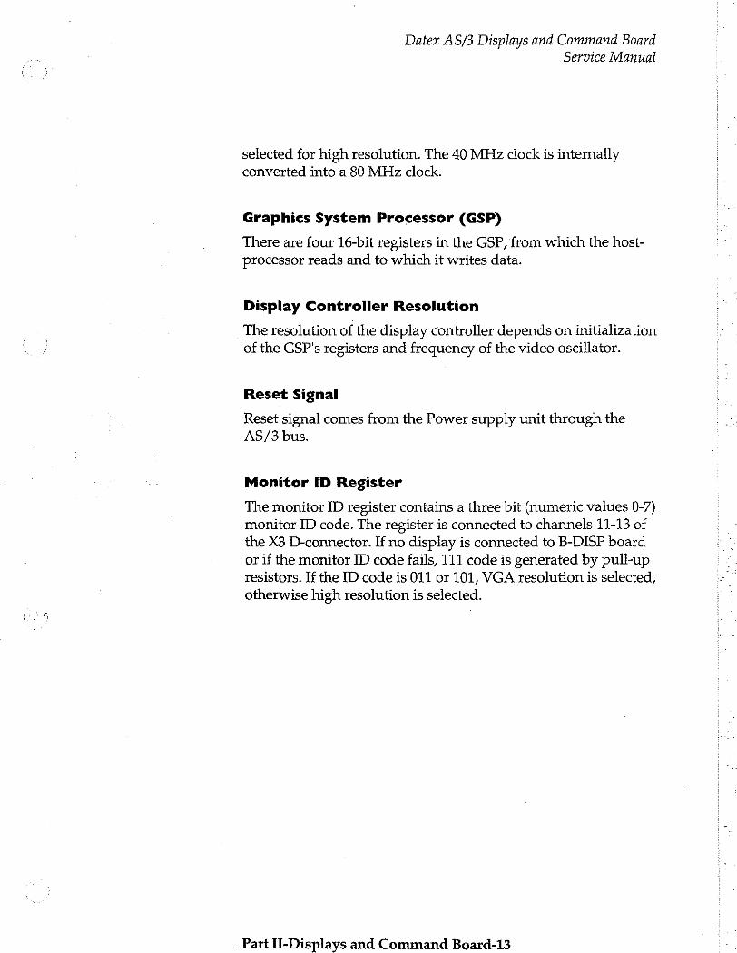
Datex AS/3 Displays and Command Board Service Manual
selected for high resolution. The 40 MHz clock is internally converted into a 80 MHz clock.
Graphics System Processor (GSP)
There are four 16-bit registers in the GSP, from which the host- processor reads and to which it writes data.
Display Controller Resolution
The resolution of the display controller depends on initialization of the GSP's registers and frequency of the video oscillator.
Reset Signal
Reset signal comes from the Power supply unit through the AS/3 bus.
Monitor ID Register
The monitor ID register contains a three bit (numeric values 0-7) monitor ID code. The register is connected to channels 11-13 of the X3 D-connector. If no display is connected to B-DISP board or if the monitor ID code fails, 111 code is generated by pull-up resistors. If the ID code is 011 or 101, VGA resolution is selected,
otherwise high resolution is selected.
Part II-Displays and Command Board-13

Datex AS/3 Displays and Command Board
Service Manual
2.2.2 Block Diagram
Control
logic
pixeldata
AS/3-bus
i AS な
i bus
|
interface | addr/data
GSP
TMS34010
DRAM
256K * 16
VRAM 256K * 16
addr/data
EEPROM 2K*8
FLASH 1M*16
or
2M*16
RGB 1
Video Interface
Palette RGB 2
Keyboard - um
Audio
Interface Audio
output
Figure 3
Part II-Displavs and Command Board-14
Display Controller Block Diagrams

2.2.3 Jumper Locations
Datex AS/3 Displays and Command Board Service Manual
The B-DISP board can be configured as either primary or secondary by shifting the location of J1 jumper (interrupt signal) as shown in figure 4.
Primary Display Controller Secondary Display Controller
Jiepej
Jifssje
Figure 4
2.2.4 Connectors and Signals
Jumper Locations, B-DISP Board
15-pin D-connector X2 on B-DISP Display controller boards
Pin No | V/O | Signal Notes
1 O RED VIDEO 1 analog 2 O GREEN VIDEO 1 | analog 3 O BLUE VIDEO 1 analog
4 MONIID2 monitor identification
5 0 GND
6 O RED GND
7 0 GREEN GND
8 0 BLUE GND
9 N/C
10 0 SYNC GND
11 MONIIDO monitor identification
12 MONIIDi monitor identification
13 0 HSYNC 1 TTL, CMOS
14 ο VSYNC 1 TTL, CMOS
15 N/C
Part II-Displays and Command Board-15
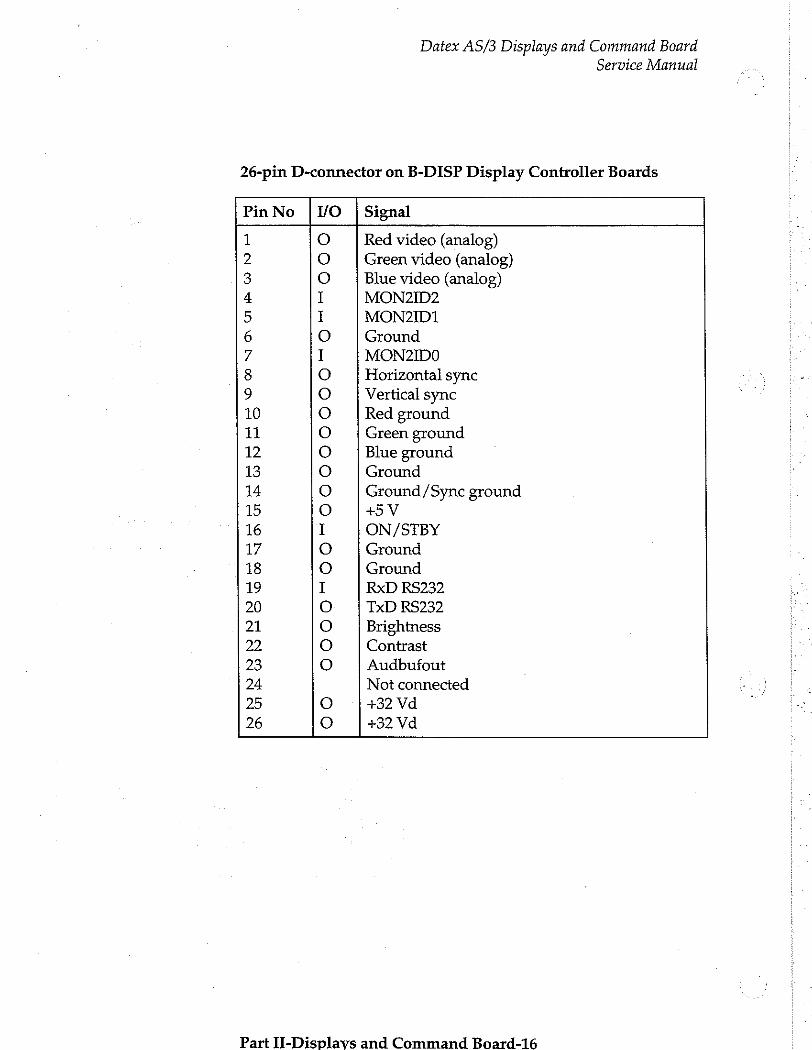
Datex AS/3 Displays and Command Board Service Manual
26-pin D-connector on B-DISP Display Controller Boards
PinNo | V/O | Signal
1 O Red video (analog) 2 ο Green video (analog) 3 O Blue video (analog) 4 I MON2ID2 5 I MON2ID1 6 O Ground 7 I MONZIDO 8 O Horizontal sync 9 O Vertical sync 10 O Red ground 11 O Green ground 12 O Blue ground 13 O Ground 14 O Ground /Sync ground 15 o +5V 16 I ON/STBY 17 0 Ground 18 O Ground 19 1 RxD RS232 20 O TxD RS232
21 O Brightness 22 O Contrast 23 O Audbufout 24 Not connected 25 o +32 Vd 26 0 +32 Vd
Part II-Displavs and Command Board-16
Datex AS/3 Displays and Command Board
Service Manual
2.3 Display Controller Board:
VGA Display, B-DVGA (B-DHIGH);
2.3.1 Functional Description
The Display controller board is connected to CPU Mother board. The CPU board's processor transmits program through the AS/3 bus to the Display controller board.
Graphics System Processor (GSP)
There are four 16-bit registers in the GSP, from which the host- processor reads and to which it writes data.
Display Memory
Four memory circuits (256k x 4 bit) are used.
Program Memory
Four memory circuits (256k x 4 bit) are used.
Video Signal
Serial outputs of the frame buffer memory are transferred to two Latch circuits so that two consecutive pixels (8 bits) are fed to one, and the next two consecutive pixels (8 bits) are fed to the other. Those four pixels (16 bits) are multiplexed into two consecutive pixel data bytes of 8 bits each. The data is then fed into the video palette circuit. The RGB signal is sent to the video buffer. The signal can be used with a CRT display.
Display Controller Resolution
The resolution of the display controller depends on initialization of the GSP's registers and frequency of video oscillator. The B- DHIGH board uses a 64 MHz oscillator and the B-DVGA board a 25 MHz oscillator.
Reset Signal
Reset signal comes from the Power supply unit through the AS/3 bus.
Part II-Displavs and Command Board-17
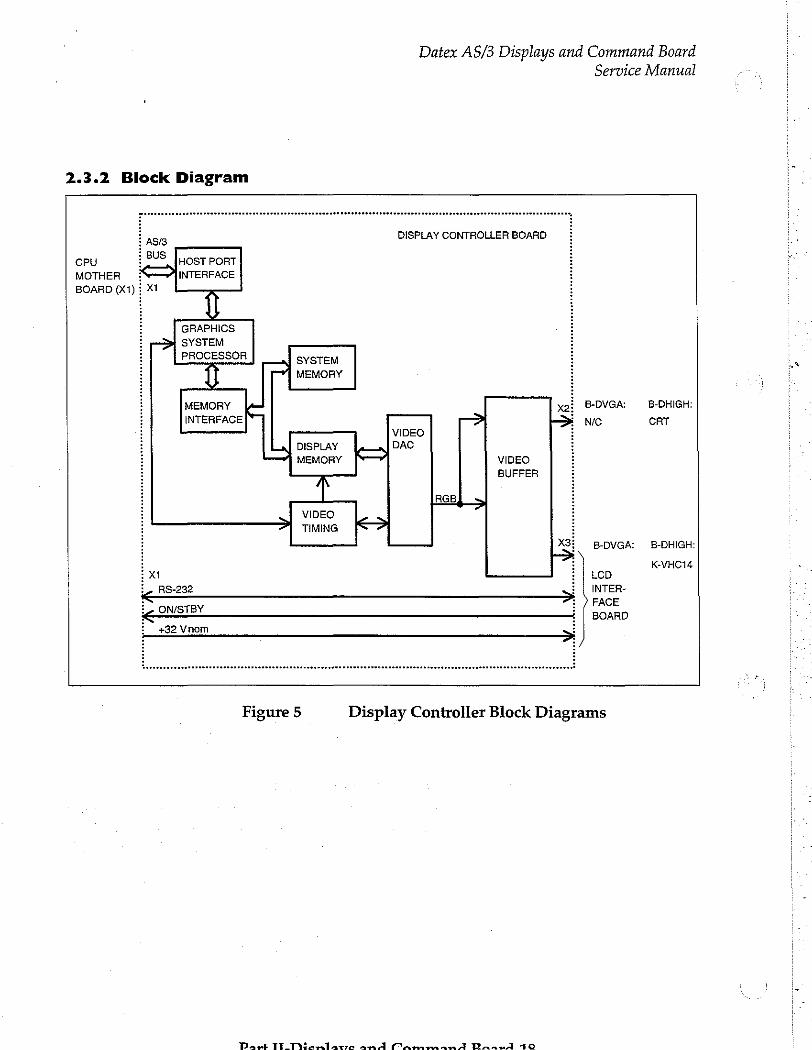
Datex AS/3 Displays and Command Board
Service Manual
2.3.2 Block Diagram
DISPLAY CONTROLLER BOARD
CPU HOST PORT MOTHER INTERFACE BOARD (X1
GRAPHICS SYSTEM PROCESSOR SYSTEM
1 MEMORY
i MEMORY ルー B-DVGA: B-DHIGH: i INTERFACE NC CRT i VIDEO i DISPLAY DAC i MEMORY [一 VIDEO i BUFFER
i Ines, i VIDEO i TIMING i B-DVGA: | B-DHIGH:
i K-VHC14 ix LCD İL RS-232 INTER-
に ONSTBY FACE < BOARD
+32 Vnom
Figure 5
Part TT_Dicrlatro and MammandA Braet 10
Display Controller Block Diagrams
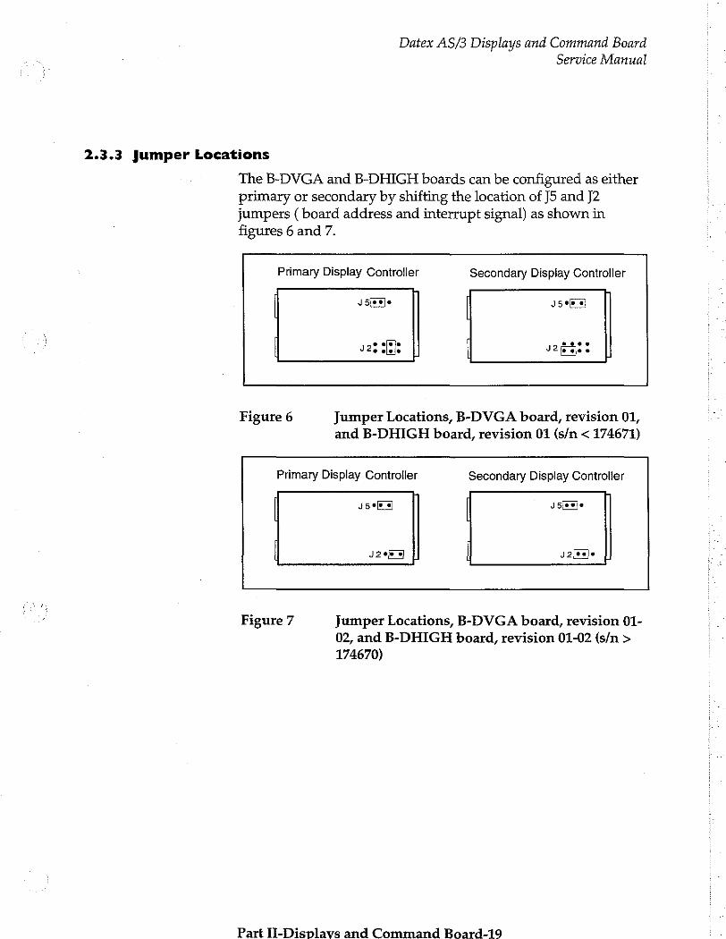
Datex AS/3 Displays and Command Board
Service Manual
2.3.3 Jumper Locations
The B-DVGA and B-DHIGH boards can be configured as either primary or secondary by shifting the location of J5 and J2 jumpers ( board address and interrupt signal) as shown in
figures 6 and 7.
Primary Display Controller Secondary Display Controller
Je 4598 회
vzs able | segs
Figure 6 Jumper Locations, B-DVGA board, revision 01,
and B-DHIGH board, revision 01 (s/n < 174671)
Primary Display Controller Secondary Display Controller
J5e 회 J5[ej*
42906 이 | Jales]e
Figure 7 Jumper Locations, B-DVGA board, revision 01-
02, and B-DHIGH board, revision 01-02 (s/n >
174670)
Part II-Displavs and Command Board-19

2.3.3 Connectors and Signals
Datex AS/3 Displays and Command Board Service Manual
15-pin D-connector X2 on Display controller boards
Pin No | I/O | Signal Notes
1 O RED VIDEO 1 analog 2 ο GREEN VIDEO 1 | analog 3 o BLUE VIDEO 1 | analog 4 N/C 5 o GND 6 o RED GND 7 o GREEN GND 8 o BLUE GND 9 N/C 10 O SYNC GND 11 N/C 12 N/C 13 ο HSYNC 1 14 O VSYNC 1 15 N/C
Part TI Term lace and CnammandA Raavd_an
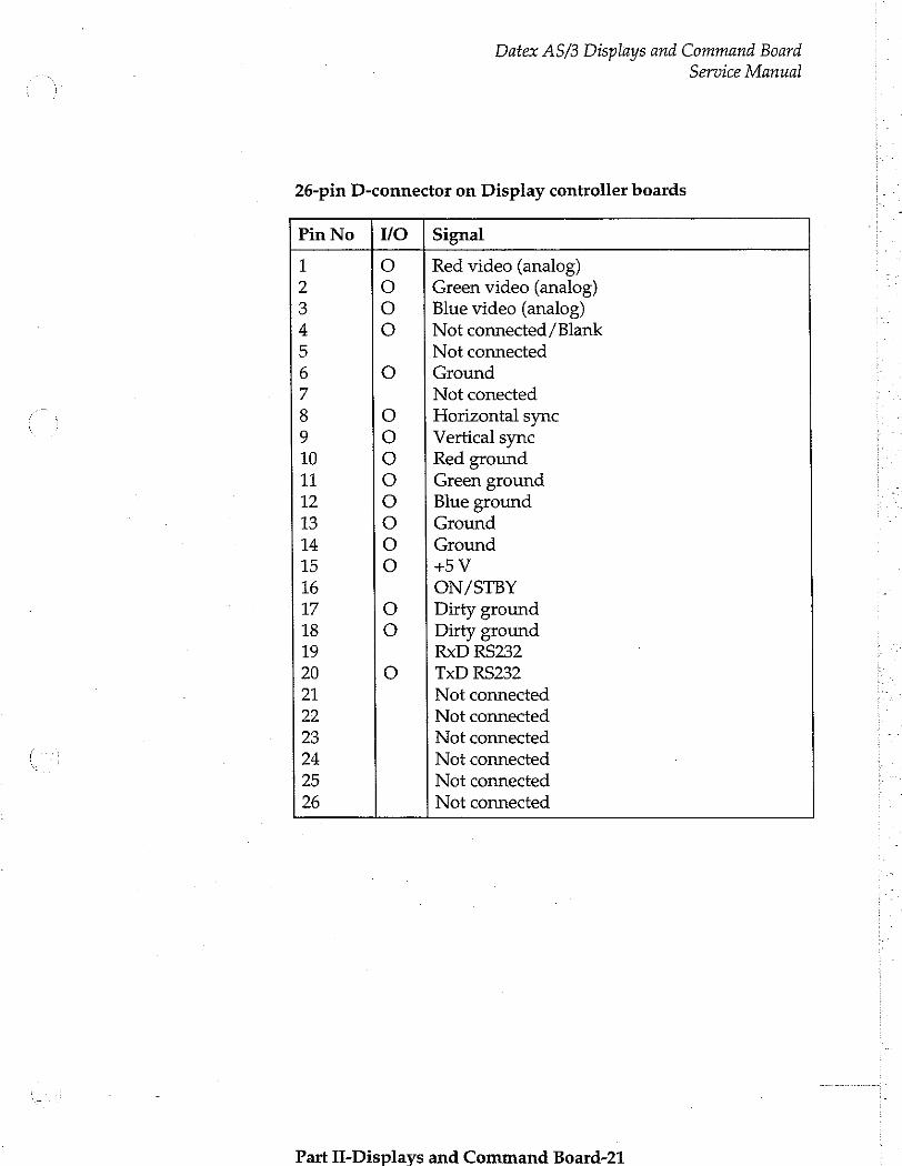
Datex AS/3 Displays and Command Board Service Manual
26-pin D-connector on Display controller boards
Pin No | VO | Signal
1 O Red video (analog)
2 O Green video (analog)
3 O Blue video (analog) 4 0 Not connected /Blank
5 Not connected
6 0 Ground
7 Not conected
8 O Horizontal sync 9 O Vertical sync 10 0 Red ground
11 O Green ground 12 0 Blue ground
13 o Ground
14 O Ground
15 0 +V 16 ON/STBY 17 O Dirty ground 18 O | Dirty ground 19 RxD RS232 20 O TxD RS232 21 Not connected
22 Not connected
23 Not connected
24 Not connected
25 Not connected
26 Not connected
Part If-Displays and Command Board-21
Datex AS/3 Displays and Command Board Service Manual
2.4 Command Boards, K-VNCI5 (K-VHCI4)
The Command board consists of 17 direct function keys, ComWheel, and ON/STBY switch.
2.4.1 Functional Description
Command Board PCB
The Command board PCB is located inside the Command
Board. The board reads the status of the front panel keys and the ComWheel and forwards the information to the CPU board.
External communication
Communication with the host processor takes place in R5232 serial communication channels which are available in both the
AS/3 bus and module bus. Two signals, TXD and RXD, are in
use. No handshaking is used.
The 26-pin subminiature D-connector of the Command Board is connected to a Display controller board.
Serial communication speed is 19.2 KBaud.
ComWheel
The ComWheel on the front panel is used for menu selection.
LEDs
The alarm LEDs are activated by the Command Board PCB under the commands received via serial communication from the CPU board. The red or yellow alarm LED is lit when red or yellow alarm is activated. "STBY" -led is lit when the device is switched to stand-by and connected to mains.
NOTE: If there are two Command Boards connected to the
system, the system is ON (STBY LED not lit), when at least one
of the switches is positioned ON.
Pat IL onliavoe and Cammanad ウス ュ マコ うう

2.4.2 Block Diagram
Datex AS/3 Displays and Command Board Service Manual
KEYBOARD PCB
DISPLAY xt CONTROLLER oar 기 BOARD È R8232
CPU
E, Come
E 5PINDIN (010010) CONNECTOR
PROGRAM
KEYBOARD SCANNING CIRCUIT
(DI MEMORY EPROM
X4 i
ドーーーーー KEYBOARD
DISPLAY i CONTROLLER € BOARD i
ALARM LEDS
STBY LED
i ON/STBY i SWITCH
Figure 8 K-VNC15 (K-VHC14) Block Diagram
Part II-Displavs and Command Board-23
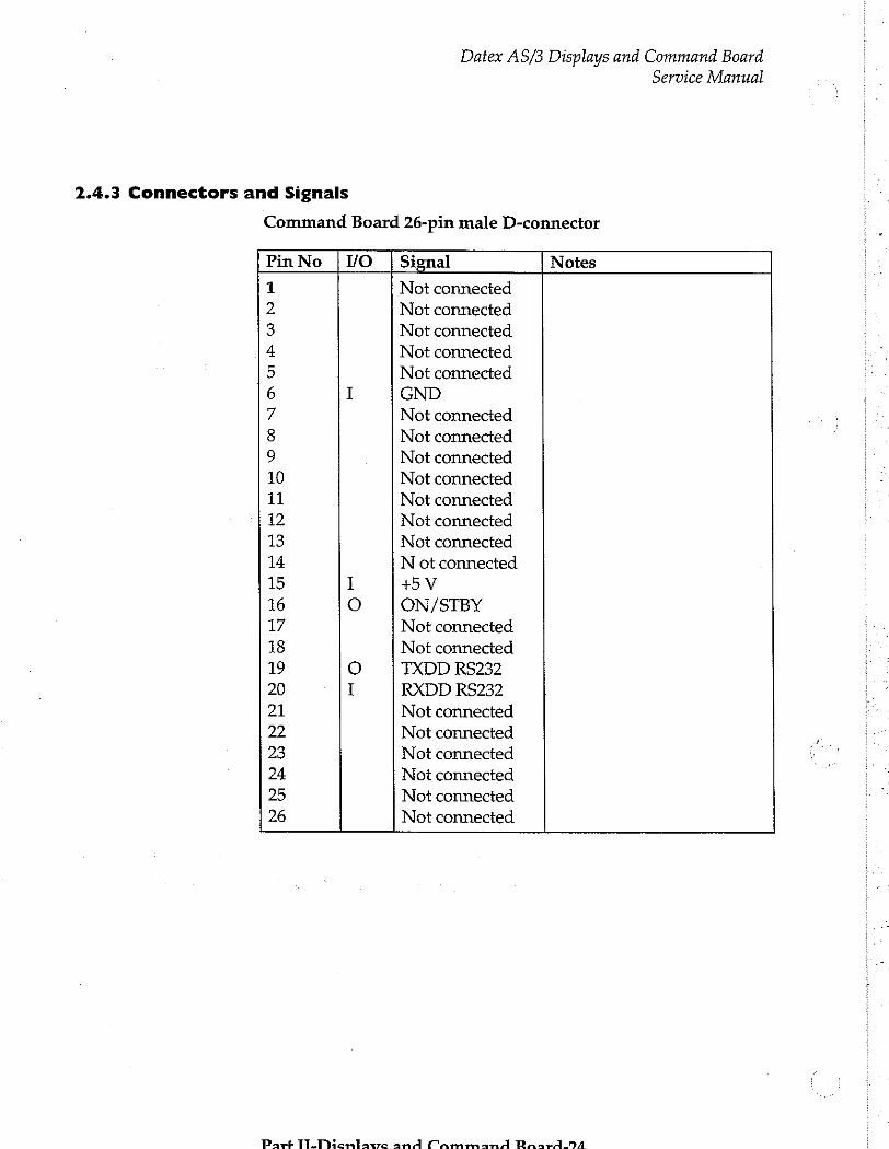
2.4.3 Connectors and Signals
Command Board 26-pin male D-connector
Datex AS/3 Displays and Command Board
Service Manual
Pin No | I/O | Signal Notes
1 Not connected
2 Not connected
3 Not connected
4 Not connected
5 Not connected
6 I GND
7 Not connected
8 Not connected
9 Not connected
10 Not connected
11 Not connected
12 Not connected
13 Not connected
14 N ot connected
15 I +5V
16 0 ON/STBY
17 Not connected
18 Not connected
19 O TXDD RS232
20 I RXDD RS232
21 Not connected
22 Not connected
23 Not connected
24 Not connected
25 Not connected
26 Not connected
Part TL TMHenlawe and CammmanA Paar4.59/4
Datex AS/3 Displays and Command Board Service Manual
3 SERVICE PROCEDURES
3.1 General Service Information
Usually field service is limited to replacing the faulty circuit boards or mechanical parts. The boards are then returned to Datex for repair.
Datex Technical Services is always available for service advice. Please provide the unit serial number, full type designation, and a detailed fault description.
CAUTION: The tests and repairs outlined in this section should only be attempted by trained personnel with the appropriate equipment. Unauthorized service may void warranty of the unit.
3.2 LCD Display
NOTE: The LCD Display component and the backlight lamp are irreparable parts and they should be replaced as a whole unit whenever necessary.
Part II-Displavs and Command Board-25
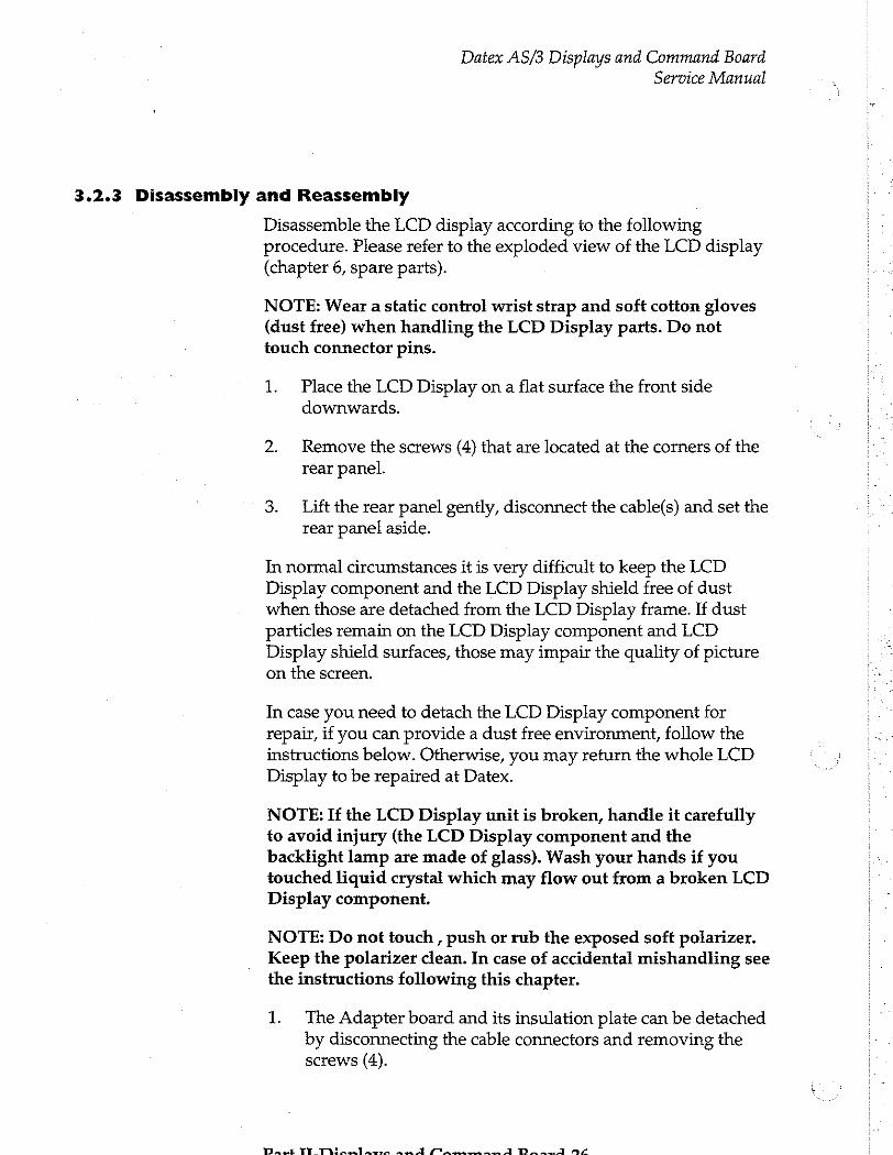
Datex AS/3 Displays and Command Board Service Manual
3.2.3 Disassembly and Reassembly
Disassemble the LCD display according to the following procedure. Please refer to the exploded view of the LCD display (chapter 6, spare parts).
NOTE: Wear a static control wrist strap and soft cotton gloves (dust free) when handling the LCD Display parts. Do not touch connector pins.
1. Place the LCD Display on a flat surface the front side
downwards.
2. Remove the screws (4) that are located at the corners of the rear panel.
3. Lift the rear panel gently, disconnect the cable(s) and set the rear panel aside.
In normal circumstances it is very difficult to keep the LCD Display component and the LCD Display shield free of dust when those are detached from the LCD Display frame. If dust particles remain on the LCD Display component and LCD Display shield surfaces, those may impair the quality of picture on the screen.
In case you need to detach the LCD Display component for repair, if you can provide a dust free environment, follow the instructions below. Otherwise, you may return the whole LCD Display to be repaired at Datex.
NOTE: If the LCD Display unit is broken, handle it carefully to avoid injury (the LCD Display component and the backlight lamp are made of glass). Wash your hands if you touched liquid crystal which may flow out from a broken LCD Display component.
NOTE: Do not touch , push or rub the exposed soft polarizer. Keep the polarizer clean. In case of accidental mishandling see the instructions following this chapter.
1. The Adapter board and its insulation plate can be detached by disconnecting the cable connectors and removing the screws (4).
Dayi TT M nel mn mes À nus ms A Do E Y

Datex AS/3 Displays and Command Board Service Manual
2. Remove the screws (8) that are located at the back of the LCD Display unit.
3. The following parts can now be lifted off one by one:
+ the Adapter unit
e the LCD Display component with the backlight
e the LCD Display shield
+ the EMC cover with the LCD Display gasket
4. The Command board PCB can be detached by disconnecting the cable connectors and removing the screws (3).
(D-LCC10 Rev. 00-02)
1. The backlight unit as well as the LCD Display component can be detached by removing the screws (4) at their corners.
2. The Command board PCB can be detached by disconnecting the cable connectors and removing the screws (2).
3. The Power supply board is attached to the rear panel by four (4) screws.
Reassembly of the LCD Display is made in reversed order. Make sure that all connectors are connected properly and cables are not pinched between covers.
NOTE: The backlight unit in D-LCC10, revision 03, cannot be
changed and the whole LCD display component must be sent back to the factory for repair.
Part II-Displavs and Command Board-27
Datex AS/3 Displays and Command Board Service Manual
3.3 Display Controller Boards
The Display controller boards can only be replaced. Please refer to the Installation manual of your monitor for instructions how to remove and replace the boards.
Part H-Displavs and Cammand Raard-298
Datex AS/3 Displays and Command Board” Service Manual
3.4 Command Boards
3.4.1 Preventive Maintenance Check List
We recommend that you perform these checks after any service and at least once every six months.
1. Visual inspection
All connectors are properly connected.
2. Functional checks
—: Check the operations of all the keys and ComWheel.
Check the alarm operation by changing alarm sound volume.
Check alarm LEDs
Part II-Displays and Command Board-29
Datex AS/3 Displays and Command Board ' Service Manual
3.4.2 Disassembly and Reassembly
The Command Board included in the display set is disassembled according to the following procedure. Please refer to the exploded view of the Command Board (chapter 6, spare parts).
Command Board, K-VNCI5
1. Disconnect the display power cable, the display data cable and the Command Board cable from the Central Unit.
Pull out the display power cable and the display data cable through the hole in the rear panel of the display screen tray. Leave the Command Board cable inside the tray.
Turn the display set upside down and unscrew the cross head screw holding the display screen tray to the display. Lift off the tray.
Turn the display screen tray upside down and unscrew the two screws holding the Command Board to the tray.
Turn the display screen tray right side up and pull off the Command Board.
Disconnect the Command Board cable, the wire set from
the ON /STBY switch, the wire set from the ComWheel and
the flat cable from the membrane keyboard.
Detach the Command Board PCB by pressing the two plastic fasteners holding the PCB in place and simultaneously lifting off the PCB.
The Command Board is reassembled by reversing the disassembly procedure.
Part TITiicn late and Cammand Raara.2n
Datex AS/3 Displays and Command Board Service Manual
Command Board, K-VHCI4
1. Disconnect the display power cable, the display data cable and the Command Board cable from the Central Unit.
2. Turn the display set upside down and unscrew the cross head screw holding the display screen tray to the display. Lift off the tray.
3. Pull out the display power cable and the display data cable through the slot in the rear panel of the display screen tray.
4. Unscrew the two screws holding the Command Board to the display screen tray. Remove the tray.
5. Unscrew the two screws holding the front cover of the Command Board to the rear cover. Carefully remove the rear cover.
6. Disconnect the Command Board cable, the wire set from
the ON/STBY switch, the wire set from the ComWheel and
the flat cable from the membrane keyboard.
7. Detach the Command Board PCB by pressing the two plastic fasteners holding the PCB in place and simultaneously lifting off the PCB.
The Command Board is reassembled by reversing the disassembly procedure.
Part II-Displavs and Command Board-31
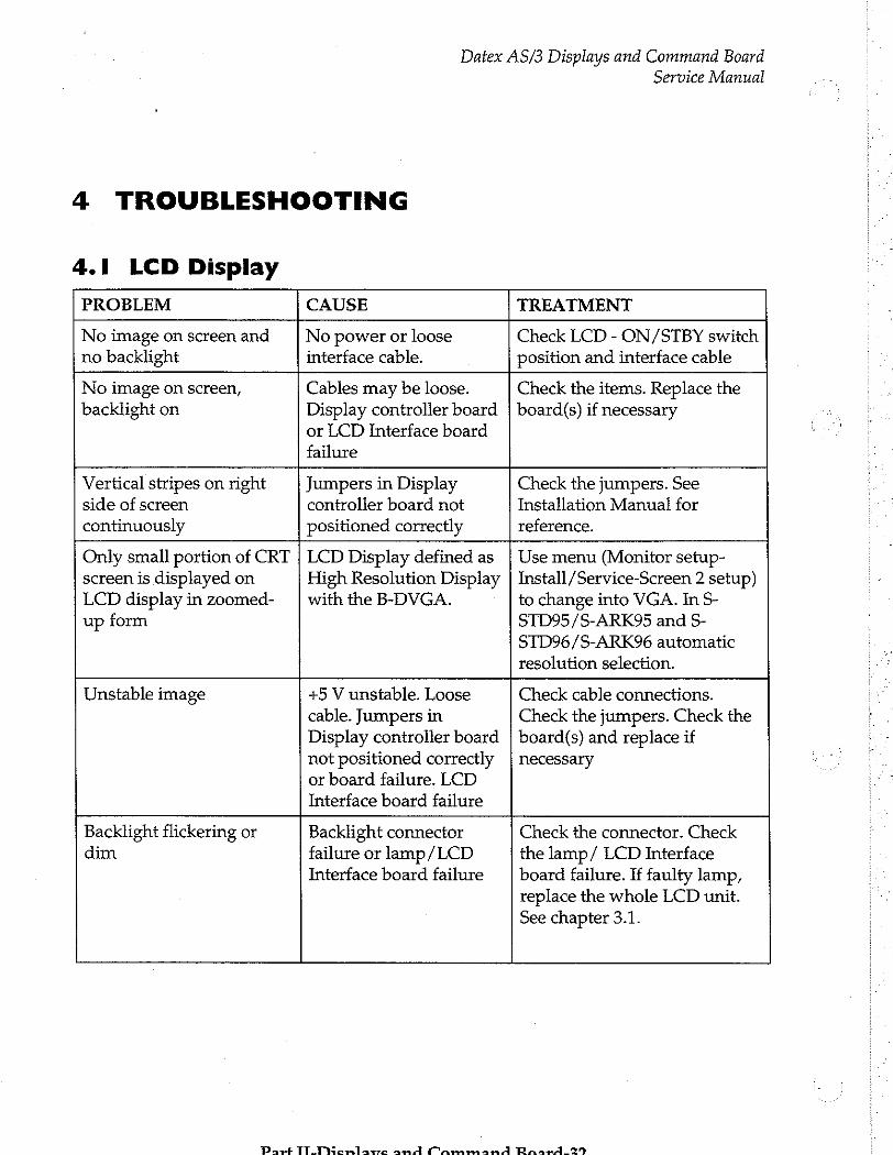
Datex AS/3 Displays and Command Board
4 TROUBLESHOOTING
4.1 LCD Display
Service Manual
PROBLEM CAUSE TREATMENT
No image on screen and no backlight
No power or loose interface cable.
Check LCD - ON/STBY switch position and interface cable
No image on screen, Cables may be loose. Check the items. Replace the
side of screen controller board not
backlight on Display controller board | board(s) if necessary or LCD Interface board failure
Vertical stripes on right Jumpers in Display Check the jumpers. See Installation Manual for
continuously positioned correctly reference.
Only small portion of CRT | LCD Display defined as | Use menu (Monitor setup- screen is displayed on High Resolution Display | Install/Service-Screen 2 setup) LCD display in zoomed- | with the B-DVGA. to change into VGA. In S- up form STD95/S-ARK95 and S-
STD96/S-ARK96 automatic
resolution selection.
Unstable image +5 V unstable. Loose
cable. Jumpers in Display controller board not positioned correctly or board failure. LCD
Interface board failure
Check cable connections.
Check the jumpers. Check the board(s) and replace if
necessary
Backlight flickering or dim Backlight connector
failure or lamp/LCD Interface board failure Check the connector. Check
the lamp/ LCD Interface board failure. If faulty lamp, replace the whole LCD unit. See chapter 3.1.
Part TITiicrlave and Cammand Ransawd.329

Datex AS/3 Displays and Command Board
Service Manual
4.2 Display Controller Boards
PROBLEM CAUSE TREATMENT
No image on the screen No power Check power on Cable or display board | Check cable and board loose connections Board or display faulty | Try with another board and/or
display
Regular stripes on the Faulty Display Replace the board. picture controller board
B-DHIGH and B-DISP with D-VNC15 only:
Part of the screen has wrong colours
Triac board failure Replace triac board, see part II
Central Unit, power supply.
Picture disfigured. Outer magnetic field Turn the monitor off, wait 10
minutes and turn the monitor on again in order to demagnetize the screen.
Part II-Dispiavs and Command Board-33
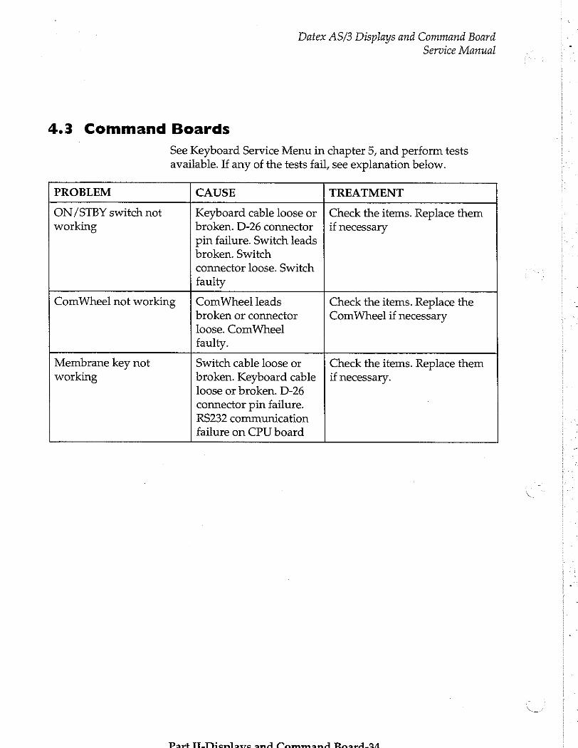
Datex AS/3 Displays and Command Board
4.3 Command Boards
See Keyboard Service Menu in chapter 5, and perform tests available. If any of the tests fail, see explanation below.
Service Manual
broken or connector
loose. ComWheel
faulty.
PROBLEM CAUSE TREATMENT
ON/STBY switch not Keyboard cable loose or | Check the items. Replace them working broken. D-26 connector | if necessary
pin failure. Switch leads broken. Switch connector loose. Switch faulty
ComWheel not working | ComWheel leads Check the items. Replace the ComWheel if necessary
Membrane key not working
Switch cable loose or
broken. Keyboard cable loose or broken. D-26
connector pin failure. RS232 communication
failure on CPU board Check the items. Replace them if necessary.
Part TE Tamaro and Cammand Pinar 421

Datex AS/3 Displays and Command Board Service Manual
5 SERVICE VIEW
Monitor Setup
Monitor Setup Install /Service
Waveform Fields Units
Digit Fields 100 Service View | 26 100
Select Mode Save Modes
Set Time and Date Interfacing
Install/Service | 16 Analog Outputs
Normal Screen Monitor Settings
Printer Settings
Previous Menu
5 ©
i a
A
a ©
Give password. Give password.
To enter Service Menu:
1. Press the MONITOR SETUP key. The Setup menu appears.
2. Turn ComWheel to highlight Install/Service and push.
3. Give the password by turning the ComWheel to display each password number and confirm the number by pushing the ComWheel. Password numbers are 16 - 4 - 34. The Install /Service menu appears.
4. Turn the ComWheel to highlight Service View and push.
5. Give the password by turning the ComWheel to display each password number and confirm the number by pushing the ComWheel. Password numbers are 26 - 23 - 8.
6. Turn the ComWheel to highlight Modules and push.
7. Turn the ComWheel to highlight the right module and push.
Part II-Displavs and Command Board-35

Datex AS/3 Displays and Command Board Service Manual
5.1 LCD Display
There is no separate service menu for the LCD Display.
5.2 Display Controller Boards
There is no separate service menu for Display controller boards.
Past TI U Honlaxrc 141 Mammand BRaardi2g
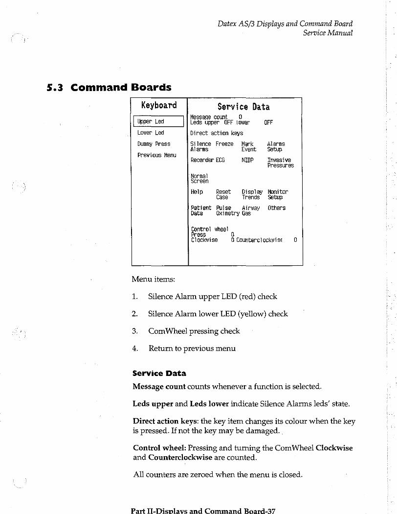
Datex AS/3 Displays and Command Board Service Manual
5.3 Command Boards
Keyboard Service Data Message count 0
Upper Led Leds upper OFF lower OFF
Lower Led Direct action keys
Dummy Press Silence Freeze Hark Alarms Alarms Event Setup
Previous Menu . Recorder ECG NIBP Invasive
Pressures
"Normal Screen
Help Reset Display Monitor Case Trends Setup
Patient Pulse Airway Others Data Oximetry Gas
Control wheel Press © Clockwise O Counterclockwise 0
Menu items:
1. Silence Alarm upper LED (red) check
2. Silence Alarm lower LED (yellow) check
3. ComWheel pressing check
4. Return to previous menu
Service Data
Message count counts whenever a function is selected.
Leds upper and Leds lower indicate Silence Alarms leds’ state.
Direct action keys: the key item changes its colour when the key is pressed. If not the key may be damaged. .
Control wheel: Pressing and turning the ComWheel Clockwise and Counterclockwise are counted.
Ali counters are zeroed when the menu is closed.
Part II-Displavs and Command Board-37
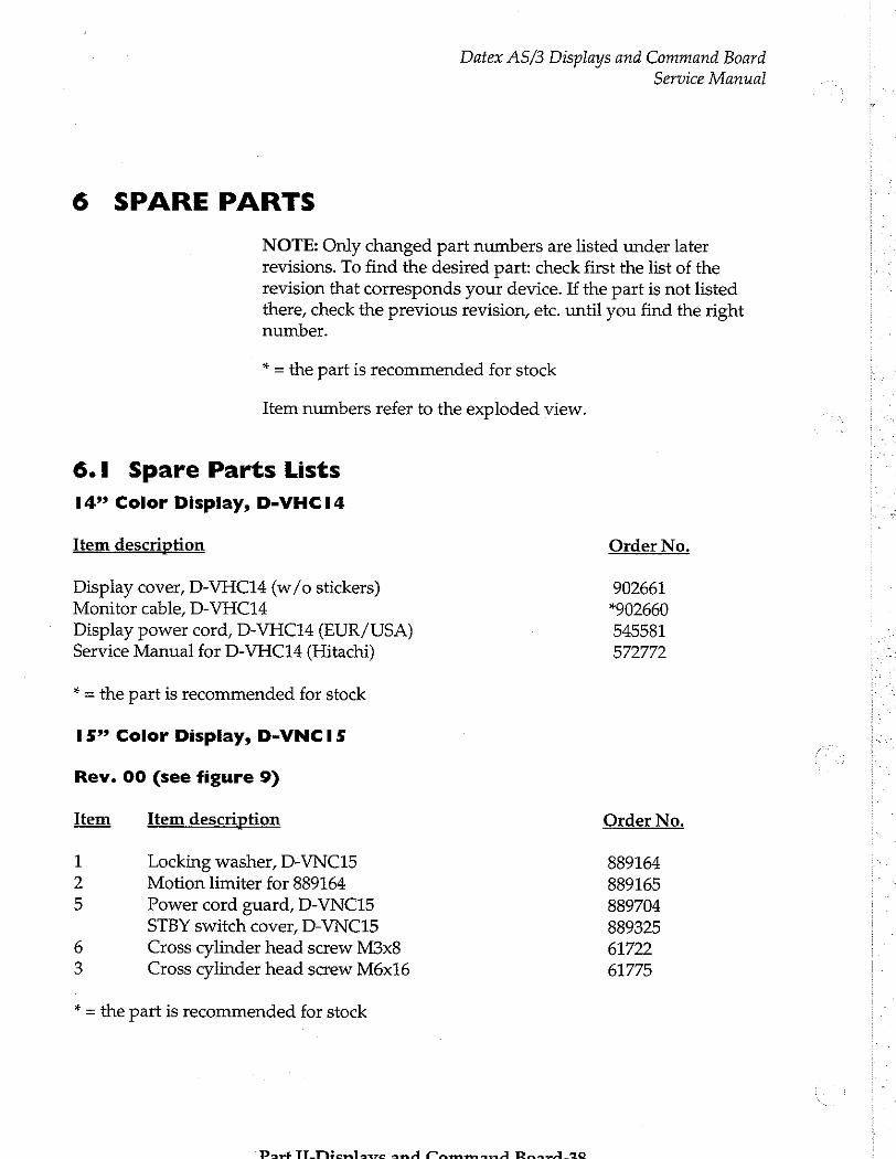
Datex AS/3 Displays and Command Board
Service Manual
6 SPARE PARTS
NOTE: Only changed part numbers are listed under later revisions. To find the desired part: check first the list of the revision that corresponds your device. If the part is not listed there, check the previous revision, etc. until you find the right number.
* = the part is recommended for stock
Item numbers refer to the exploded view.
6.1 Spare Parts Lists
14” Color Display, D-VHCI4
Item description Order No.
Display cover, D-VHC14 (w/o stickers) 902661 Monitor cable, D-VHC14 3902660
Display power cord, D-VHC14 (EUR/USA) 545581 Service Manual for D-VHC14 (Hitachi) 572772
* = the part is recommended for stock
15” Color Display, D-VNCI5
Rev. 00 (see figure 9)
Item Item description Order No.
1 Locking washer, D-VNC15 889164 2 Motion limiter for 889164 889165 5 Power cord guard, D-VNC15 889704
STBY switch cover, D-VNC15 889325
6 Cross cylinder head screw M3x8 61722 3 Cross cylinder head screw M6x16 61775
* = the part is recommended for stock
Part TlTEHentarre and Mammand Dn RO
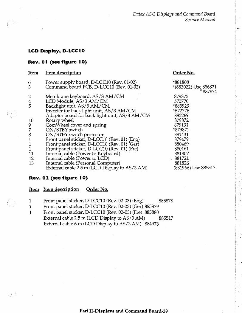
Datex AS/3 Displays and Command Board
LCD Display, D-LCCIO
Rev. OI (see figure 10)
rel tem Item description
Power supply board, D-LCC10 (Rev. 01-02) Command board PCB, D-LCC10 (Rev. 01-02)
Membrane keyboard, AS/3 AM/CM LCD Module, AS/3 AM/CM Backlight unit, AS/3 AM/CM Inverter for back light unit, AS/3 AM/CM Adapter board for back light unit, AS/3 AM/CM
10 Rotary wheel 9 ComWheel cover and spring 7 ON/STBY switch 8 ON/STBY switch protector 1 1 1
UAN
WO
Front panel sticker, D-LCC10 (Rev. 01) (Eng) Front panel sticker, D-LCC10 (Rev. 01) (Ger) Front panel sticker, D-LCC10 (Rev. 01) (Fre)
11 Internal cable (Power to Keyboard) 12 Internal cable (Power to LCD) 13 Internal cable (Personal Computer)
External cable 2.5 m (LCD Display to AS/3 AM)
Rev. 02 (see figure 10)
Item Item description Order No.
1 Front panel sticker, D-LCC10 (Rev. 02-03) (Eng) 885878
Front panel sticker, D-LCC10 (Rev. 02-03) (Ger) 885879
1 Front panel sticker, D-LCC10 (Rev. 02-03) (Fre) 885880 External cable 2.5 m (LCD Display to AS/3 AM) 885517 External cable 6 m (LCD Display to AS/3 AM) 884976
на
Part II-Displavs and Command Board-39
Service Manual
Order No.
*881808 *(883022) Use 886821
2887874 879373 572770 *883929 "572776 883269 879872 879191 *879871 881431 879479 880469 880161 881807 881721 881826 (881966) Use 885517

Datex AS/3 Displays and Command Board
Rev. 03 (see figure 11)
Item Item description
3 Command board PCB, AS/3 AM/CM Command board software
16 LCD display gasket, AS/3 AM/CM 17 LCD display shield, AS/3 AM/CM 18 LCD display unit, complete, AS/3 AM/CM 19 LCD display (contains the backlight), AS/3 AM/CM 20 Adapter unit, AS/3 AM/CM 21 Flat cable 22 Adapter board, AS/3 AM/CM 23 Insulation plate 24 Connector board (LCD), AS/3 AM/CM 25 Connector board (frame), D-LCC10 (Rev.03) 1 Front panel sticker, D-LCC10 (Rev. 03) (Spa) 1 Front panel sticker, D-LCC10 (Rev. 03) (Swe) 1 Front panel sticker, D-LCC10 (Rev. 03) (Dut) 1 Front panel sticker, D-LCC10 (Rev. 03) (Ita) 1 Front panel sticker, D-LCC10 (Rev. 03) (Fin) 26 Rear cover, D-LCC10 (Rev. 03)
External cable 2.5 m (LCD Display to AS/3 AM) External cable 10 m (LCD Display to AS/3 AM)
* = the part is recommended for stock
Service Manual
Order No.
*886821 *887874 887719 572787 887737 572784 887125 71409 887840 887739 888220 888222 886272 885946 886043 886751 888860 889367 888525 888643
” The Command board 886821 can be used as a replacement only with Command board software 887874.
NOTE: If you have to replace rear cover, please remove the type data sticker and send it tous. We will send you a new rear cover with reprinted sticker on it.
Display Controller Boards
Item description
Grounding plate
* = the part is recommended for stock
Part TT_Dienlawe and Cammand RaarA4-40
Order No.
885398
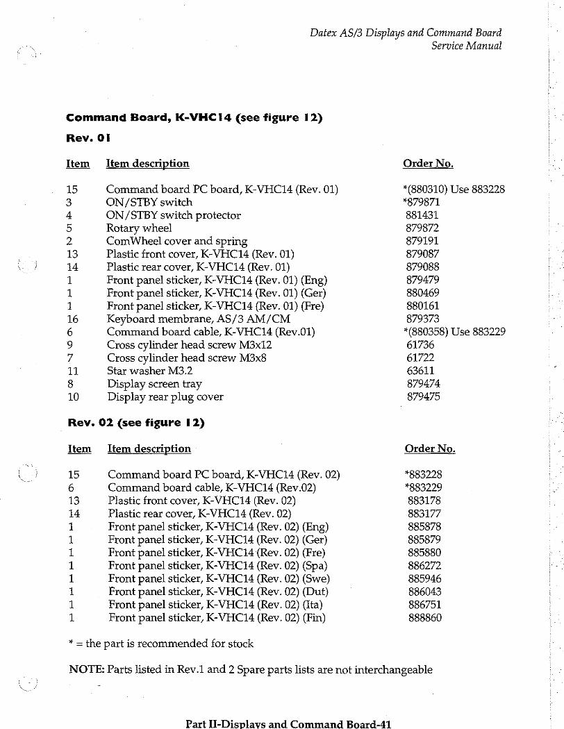
Datex AS/3 Displays and Command Board
Command Board, K-VHC14 (see figure 12)
Rev. Ol
Item Item description
al Command board PC board, K-VHC14 (Rev. 01)
ON/STBY switch
ON/STBY switch protector Rotary wheel ComWheel cover and spring Plastic front cover, K-VHC14 (Rev. 01) Plastic rear cover, K-VHC14 (Rev. 01) Front panel sticker, K-VHC14 (Rev. 01) (Eng) Front panel sticker, K-VHC14 (Rev. 01) (Ger) Front panel sticker, K-VHC14 (Rev. 01) (Fre)
Keyboard membrane, AS/3 AM/CM
Command board cable, K-VHC14 (Rev.01)
Cross cylinder head screw M3x12 Cross cylinder head screw M3x8 Star washer M3.2 Display screen tray Display rear plug cover
на на на на на
а М ОА
©
+ BO
G
PORNO
m o
Rev. 02 (see figure 12)
Item Item description
15 Command board PC board, K-VHC14 (Rev. 02) 6 Command board cable, K-VHC14 (Rev.02) 13 Plastic front cover, K-VHC14 (Rev. 02) 14 Plastic rear cover, K-VHC14 (Rev. 02)
Front panel sticker, K-VHC14 (Rev. 02) (Eng) Front panel sticker, K-VHC14 (Rev. 02) (Ger) Front panel sticker, K-VHC14 (Rev. 02) (Fre) Front panel sticker, K-VHC14 (Rev. 02) (Spa) Front panel sticker, K-VHC14 (Rev. 02) (Swe) Front panel sticker, K-VHC14 (Rev. 02) (Dut) Front panel sticker, K-VHC14 (Rev. 02) (Ita) Front panel sticker, K-VHC14 (Rev. 02) (Fin) ーー ロビ ビビ ロビ
は
* = the part is recommended for stock
Service Manual
Order No.
*(880310) Use 883228 *879871 881431 879872 879191 879087 879088 879479 880469 880161 879373 *(880358) Use 883229 61736 61722 63611 879474 879475
Order No.
*883228 *883229 883178 883177 885878 885879 885880 886272 885946 886043 886751 888860
NOTE: Parts listed in Rev.1 and 2 Spare parts lists are not interchangeable
Part II-Displavs and Command Board-41
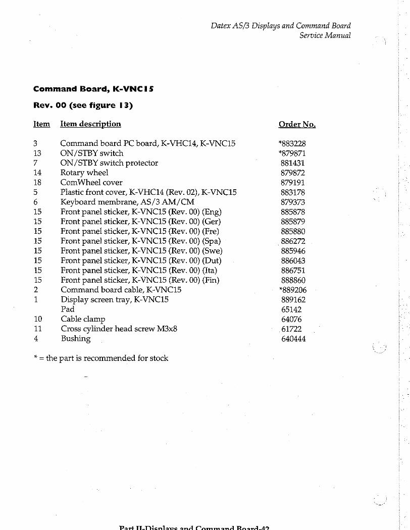
Datex AS/3 Displays and Command Board Service Manual
Command Board, K-VNCI5
Rev. 00 (see figure 13)
Item Item description Order No.
3 Command board PC board, K-VHC14, K-VNC15 #883228
13 ON/STBY switch *879871 7 ON/STBY switch protector 881431 14 Rotary wheel 879872 18 ComWheel cover 879191
5 Plastic front cover, K-VHC14 (Rev. 02), K-VNC15 883178 6 Keyboard membrane, AS/3 AM/CM 879373
15 Front panel sticker, K-VNC15 (Rev. 00) (Eng) 885878
15 Front panel sticker, K-VNC15 (Rev. 00) (Ger) 885879 15 Front panel sticker, K-VNC15 (Rev. 00) (Fre) 885880
15 Front panel sticker, K-VNC15 (Rev. 00) (Spa) 886272 15 Front panel sticker, K-VNC15 (Rev. 00) (Swe) 885946
15 Front panel sticker, K-VNC15 (Rev. 00) (Dut) 886043 15 Front panel sticker, K-VNC15 (Rev. 00) (Ita) 886751
15 Front panel sticker, K-VNC15 (Rev. 00) (Fin) 888860
2 Command board cable, K-VNC15 *889206
1 Display screen tray, K-VNC15 889162 Pad 65142
10 Cable clamp 64076 11 Cross cylinder head screw M3x8 61722 4 Bushing 640444
* = the part is recommended for stock
Pars TT_THonlamwre and CammanA Raax4_459
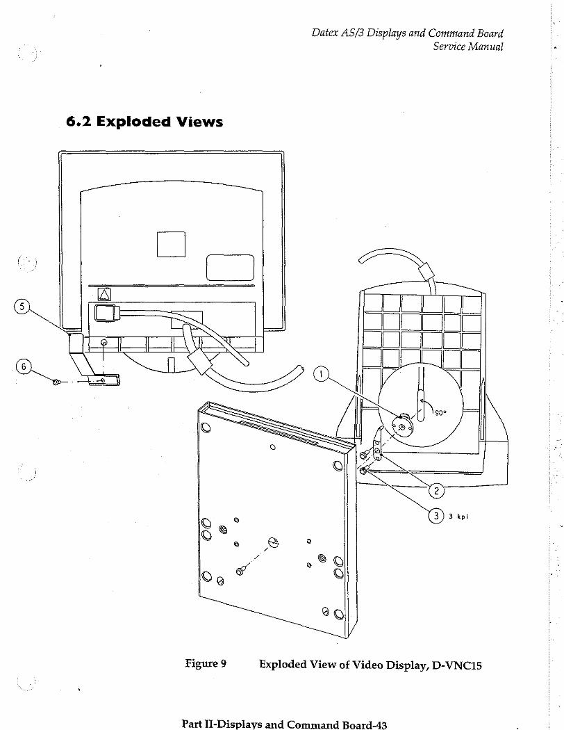
Datex AS/3 Displays and Command Board
Service Manual
6.2 Exploded Views
|
TT NENE
Figure 9 Exploded View of Video Display, D-VNC15
Part II-Displays and Command Board-43

Datex AS/3 Displays and Command Board
Service Manual
Figure 10 Exploded View of LCD Display (Revisions 01 and 02)
Port тс асе and Cammand RaarA_44
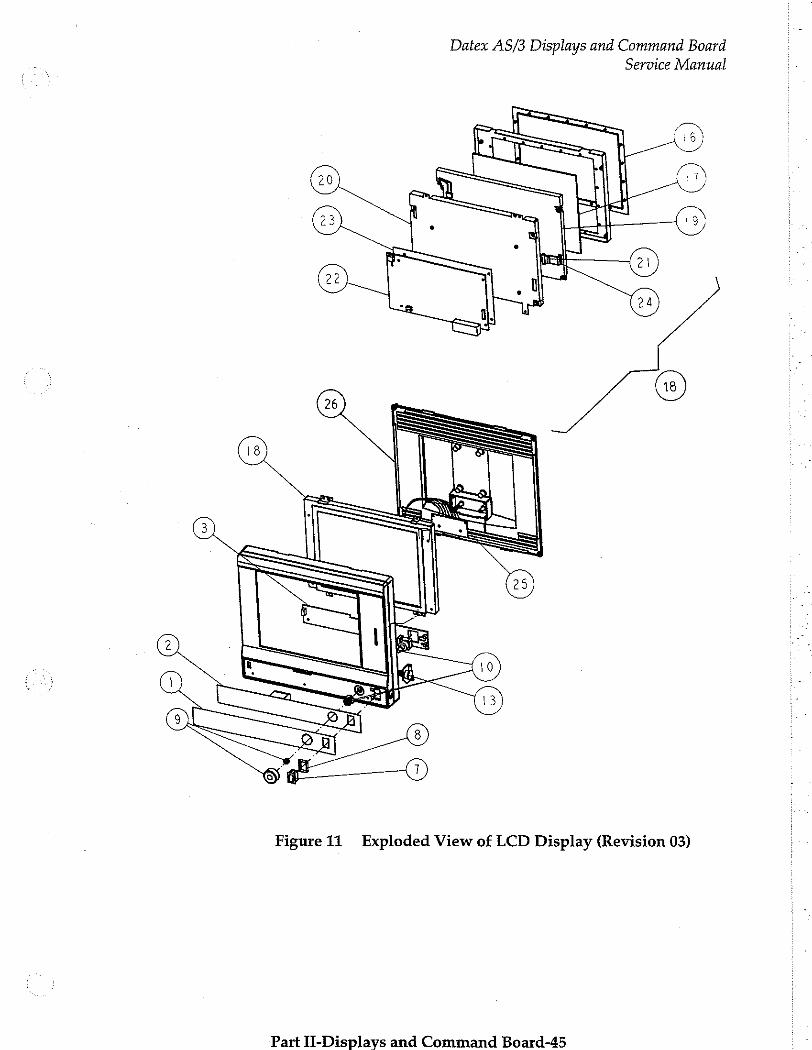
Datex AS/3 Displays and Command Board Service Manual
Figure 11 Exploded View of LCD Display (Revision 03)
Part II-Displavs and Command Board-45
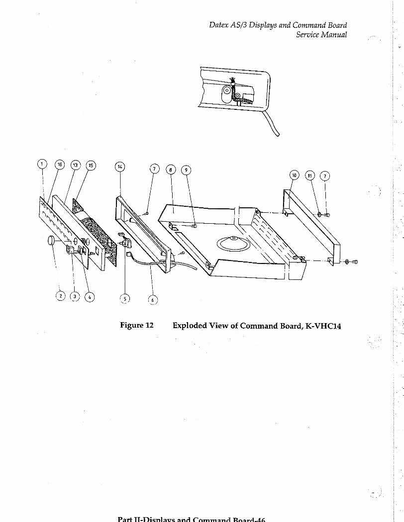
Datex AS/3 Displays and Command Board Service Manual
Figure 12 Exploded View of Command Board, K-VHC14
Part TT-Dicsnlawe and Cammana Raard Ag
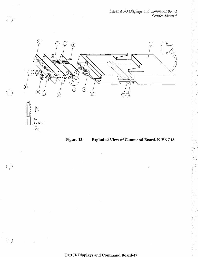
Datex AS/3 Displays and Command Board Service Manual
Figure 13 Exploded View of Command Board, K-VNC15
Part II-Displavs and Command Board-47
Datex AS/3 Displays and Command Board Service Manual
7 EARLIER REVISIONS
For more service information on the earlier revisions, please refer to:
Command Board revision 01 Service Manual p/n 880850 Command Board revision 02 Service Manual p/n 885930 LCD-Display revision 01 Service Manual p/n 882580 LCD-Display revision 02 Service Manual p/n 885930
This manual supports ail later revisions.
Part Tl-Dienlavs and Cammand Board-4&
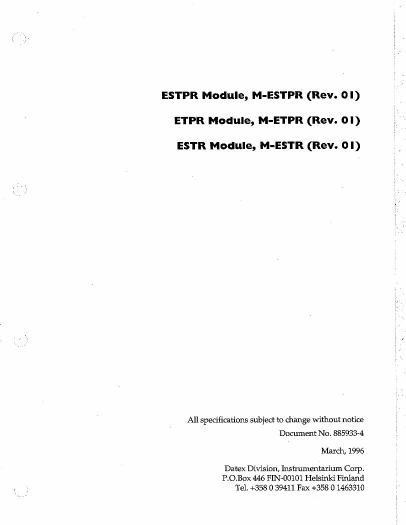
ESTPR Module, M-ESTPR (Rev. 01)
ETPR Module, M-ETPR (Rev. 01)
ESTR Module, M-ESTR (Rev. 01)
All specifications subject to change without notice
Document No. 885933-4
March, 1996
Datex Division, Instrumentarium Corp. P.O.Box 446 FIN-00101 Helsinki Finland
Tel. +358 0 39411 Fax +358 0 1463310

Datex AS/3 M-ESTPR/ESTR/ETPR
Service Manual
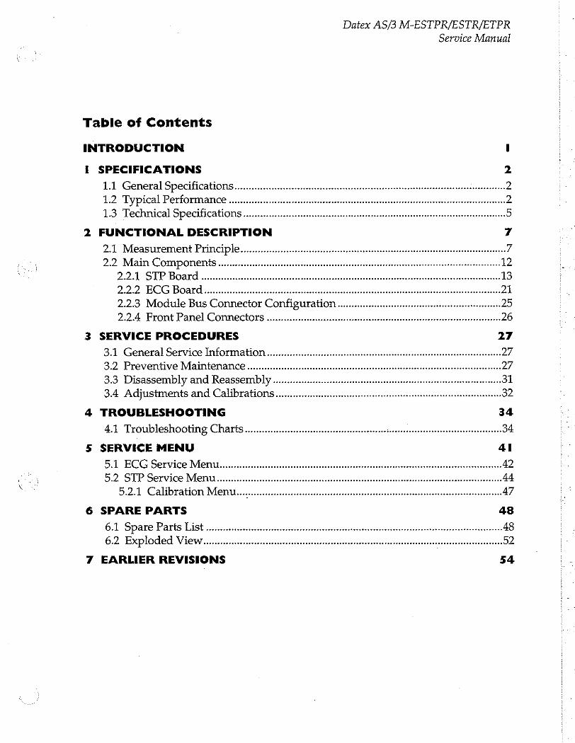
Datex AS/3 M-ESTPR/ESTR/ETPR
Service Manual
Table of Contents
INTRODUCTION I
I SPECIFICATIONS
1.1 General Specifications
12 Typical Performance in
1.3 Technical Specifications
FUNCTIONAL DESCRIPTION 7
2.1 Measurement Principles 7 2.2 Main Components sens 12
IAN AAA eeneeeeneraenn 13 2.2.2 ECG Board μμ μμ μμ μ.μ ὐμ-- 21 2.2.3 Module Bus Connector Configuration .................. ieri 25 2.2.4 Front Panel Connectors inner 26
SERVICE PROCEDURES
3.1 General Service Information
3.2 PreventiveMaintenance.............................. sise
3.3 Disassembly and Reassembly ....
34 Adjustments and Calibrations iii
TROUBLESHOOTING 34
4.1 Troubleshooting Charts... seen 34
SERVICE MENU 41
5А ЕСС бегусе Мепи........... лилии или erener reereneaneseneessenennsnz 42
5.2 STP Service Menti................ seine 44
5.2.1 Calibration Menu... tee tee né 47
SPARE PARTS
6.1 Spare Parts List
6.2 Exploded View
EARLIER REVISIONS 54

Datex AS/3 M-ESTPR/ESTR/ETPR
Service Manual
Datex AS/3 M-ESTPR/ESTR/ETPR
Service Manual
INTRODUCTION
Datex AS/3 Modules M-ESTPR, M-ESTR, and M-ETPR are
double width modules that provide general haemodynamic parameters followingly:
M-ESTPR: ECG with ST-segment analysis, pulse oximetry, two temperatures, two invasive blood pressures and respiration measurement.
M-ESTR: ECG with ST-segment analysis, pulse oximetry, two temperatures and respiration measurement.
M-ETPR: ECG with ST-segment analysis, two temperatures, two invasive blood pressure measurements and respiration measurement.
Use this manual with the module revisions M-ESTPR 01, M-
ETPR 01, and M-ESTR 01. Information on revisions M-ESTP
04 and 03, M-ETP 03 and 02, and M-EST 03 and 02 is also
available, but for older module revisions see other manuals
indicated in chapter 7.
Part II-ESTPR-1
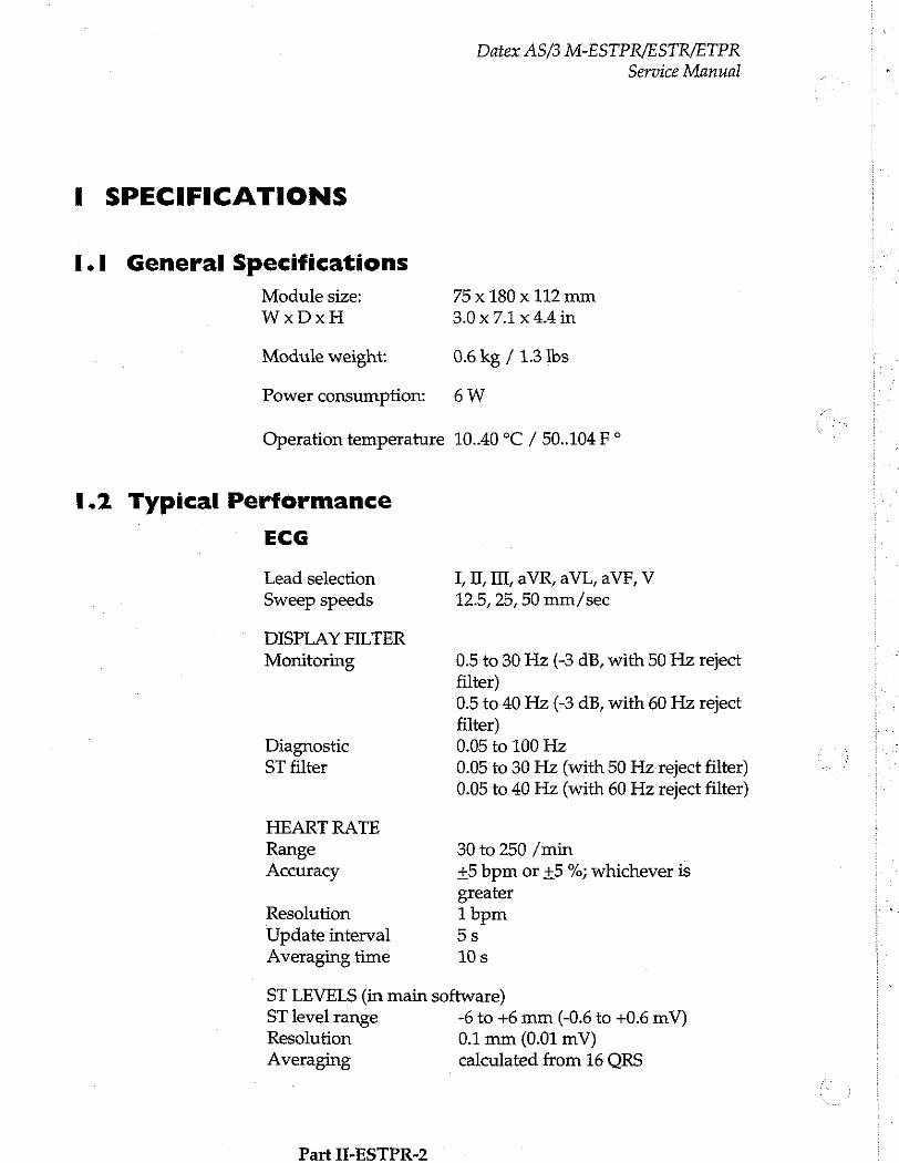
I SPECIFICATIONS
1.1 General Specifications
Module size:
WxDxH
Module weight:
Power consumption:
Operation temperature
1.2 Typical Performance
ECG
Lead selection Sweep speeds
Datex AS/3 M-ESTPR/ESTR/ETPR
Service Manual
75 x 180 x 112 mm
3.0x7.1x44in
0.6 kg / 1.3 Ibs
6W
10..40 °C / 50..104 F °
LIL I, aVR, aVL, aVF, V
12.5, 25, 50 mm/sec
DISPLAY FILTER Monitoring 0.5 to 30 Hz (-3 dB, with 50 Hz reject
filter) 0.5 to 40 Hz (-3 dB, with 60 Hz reject filter)
Diagnostic 0.05 to 100 Hz ST filter 0.05 to 30 Hz (with 50 Hz reject filter)
0.05 to 40 Hz (with 60 Hz reject filter)
HEART RATE Range 30 to 250 /min Accuracy +5 bpm or +5 %; whichever is
greater Resolution 1 bpm Update interval 5s Averaging time 10s
ST LEVELS (in main software) ST level range -6 to +6 mm (-0.6 to +0.6 mV) Resolution 0.1 mm (0.01 mV)
calculated from 16 ORS Averaging
Part II-ESTPR-2
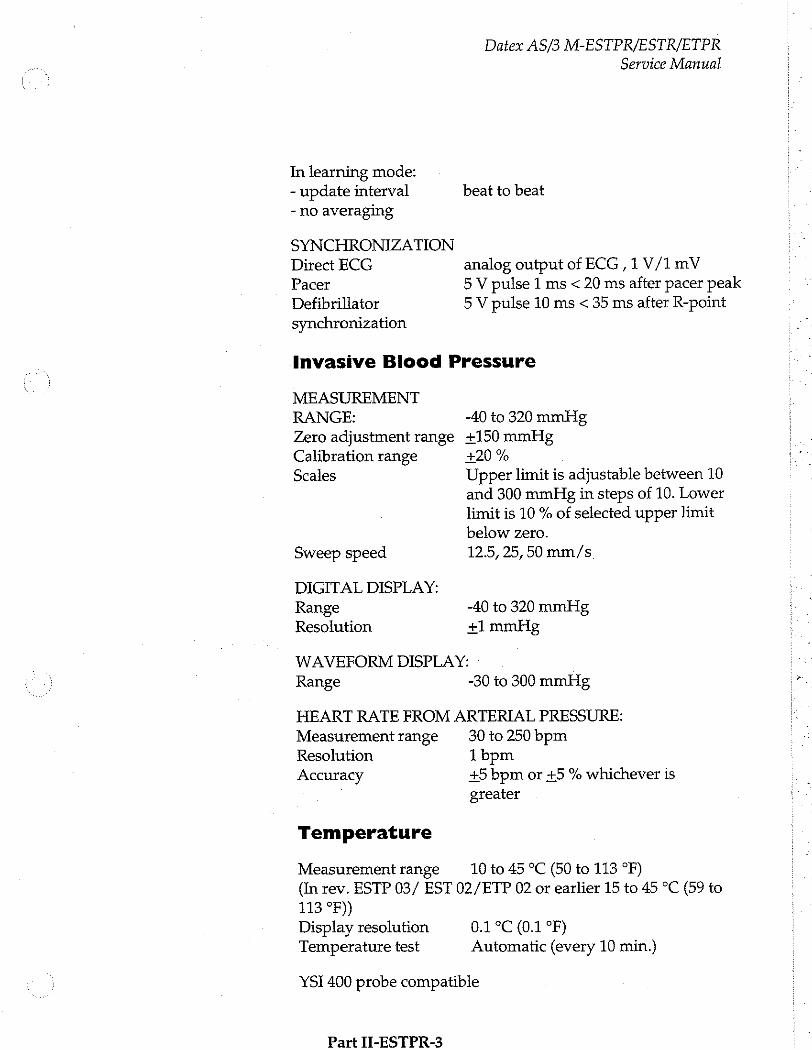
Datex AS/3 M-ESTPR/ESTR/ETPR Service Manual
In learning mode: - update interval beat to beat - no averaging
SYNCHRONIZATION Direct ECG analog output of ECG ,1 V/1 mV Pacer 5 V pulse 1 ms < 20 ms after pacer peak Defibrillator 5 V pulse 10 ms < 35 ms after R-point synchronization
Invasive Blood Pressure
MEASUREMENT RANGE: -40 to 320 mmHg Zero adjustment range +150 mmHg Calibration range +20 % Scales Upper limit is adjustable between 10
and 300 mmHg in steps of 10. Lower limit is 10 % of selected upper limit below zero.
Sweep speed 12.5, 25,50 mm/s
DIGITAL DISPLAY: Range -40 to 320 mmHg Resolution +1 mmHg
WAVEFORM DISPLAY: Range -30 to 300 mmHg
HEART RATE FROM ARTERIAL PRESSURE: Measurement range 30 to 250 bpm Resolution 1 bpm Accuracy +5 bpm or +5 % whichever is
greater
Temperature
Measurement range 10 to 45 °C (50 to 113 °F) (In rev. ESTP 03/ EST 02/ETP 02 or earlier 15 to 45 °C (59 to 113 °F)) Display resolution 0.1 °C (0.1 °F) Temperature test Automatic (every 10 min.)
YSI 400 probe compatible
Part II-ESTPR-3
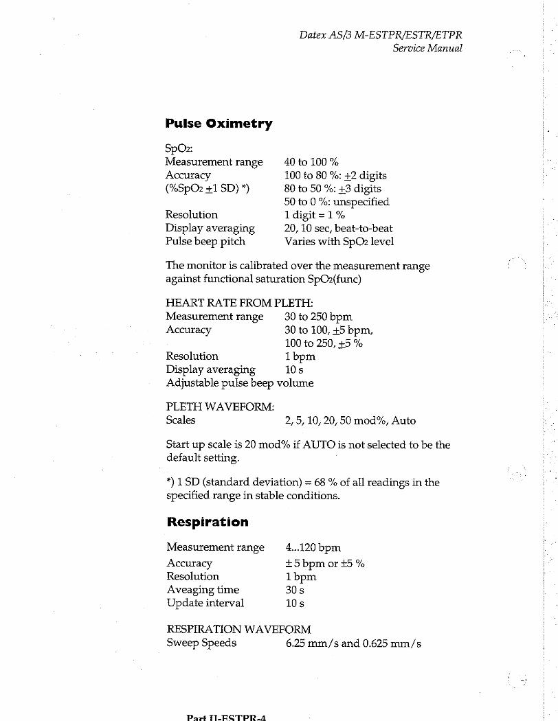
Datex AS/3 M-ESTPR/ESTR/ETPR Service Manual
Pulse Oximetry
SpOz: Measurement range 40 to 100 % Accuracy 100 to 80 %: +2 digits (%SpO2 +1 SD) *) 80 to 50 %: +3 digits
50 to 0 %: unspecified Resolution 1 digit = 1% Display averaging 20, 10 sec, beat-to-beat Pulse beep pitch Varies with SpO2 level
The monitor is calibrated over the measurement range against functional saturation SpOz(func)
HEART RATE FROM PLETH: Measurement range 30 to 250 bpm Accuracy 30 to 100, +5 bpm,
100 to 250, +5 % Resolution 1bpm Display averaging 10s Adjustable pulse beep volume
PLETH WAVEFORM:
Scales 2,5, 10, 20, 50 mod%, Auto
Start up scale is 20 mod% if AUTO is not selected to be the default setting.
*) 1 SD (standard deviation) = 68 % of all readings in the specified range in stable conditions.
Respiration
Measurement range 4...120 bpm
Accuracy +5 bpm ог +5 % Resolution 1 bpm Aveaging time 30s Update interval 10s
RESPIRATION WAVEFORM Sweep Speeds 6.25 mm/s and 0.625 mm/s
Part TILECTPR. A

Datex AS/3 M-ESTPR/ESTR/ETPR Service Manual
1.3 Technical Specifications
ECG
Defibrillation protection5000 V, 400 J Recovery time 28 Input impedance g.t. 2.5 Mohms/10Hz System noise <10 uV (p-p, RTD Allowable offset +300 mVDC Gain range 0.2 to 5.0 mV/cm Pacemaker pulse 2 to 500 mV, 0.5 to 2 ms pulses detection
Protection against Type CF defibrillator proof electrical shock
Invasive Biood Pressure
DIGITAL DISPLAY AVERAGING Digital displays Art and P1 are averaged over 5 seconds and updated at 5 seconds intervals. All other pressures have respiration artifact rejection.
Error +5 % or +2 mmHg Transducer and input sensitivity 5 uV/V/mmHg, 5 VDC
20 mA max current Input resistance 101º ohms Zero drift <0.1 mmHg/°C Nonlinearity <1 %, 0 to 200 mmHg
<2 %, -40 to 0 and 200 to 320 mmHg Gain drift <0.05 %f.s./°C
Filter O to 4 - 22 Hz adjustable Zero set accuracy +1 mmHg Calibration resolution +1 mmHg Zero time less than 5 sec
Protection against Type CF defibrillation proof electrical shock
NOTE: The accuracy of the measurement may be different from the specified, depending on transducer /probe used. Please check the transducer/probe specification.
Part II-ESTPR-5
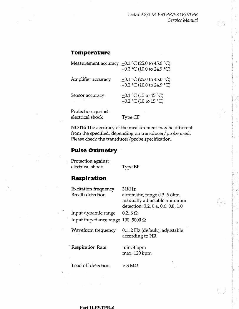
Temperature
Measurement accuracy
Amplifier accuracy
Sensor accuracy
Protection against
electrical shock
Datex AS/3 M-ESTPR/ESTR/ETPR
Service Manual
40.1 °C (25.0 to 45.0 °C) +0.2 ºC (10.0 to 24.9 °C)
+0.1 °C (25.0 to 45.0 °C) +0.2 °C (10.0 to 24.9 °C)
+0.1 ºC (15 to 45 °C) +0.2 °C (10 to 15 °C)
Type CF
NOTE: The accuracy of the measurement may be different from the specified, depending on transducer/probe used. Please check the transducer/probe specification.
Pulse Oximetry
Protection against electrical shock
Respiration
Excitation frequency Breath detection
Input dynamic range
Input impedance range
Waveform frequency
Respiration Rate
Lead off detection
Part ÎT-FSTPR.6
Type BF
31kHz
automatic, range 0.3..6 ohm
manually adjustable minimum detection: 0.2, 0.4, 0.6, 0.8, 1.0
0.2.60
100..5000 ©
0.1..2 Hz (default), adjustable according to HR
min. 4 bpm
max. 120 bpm
>3MQ
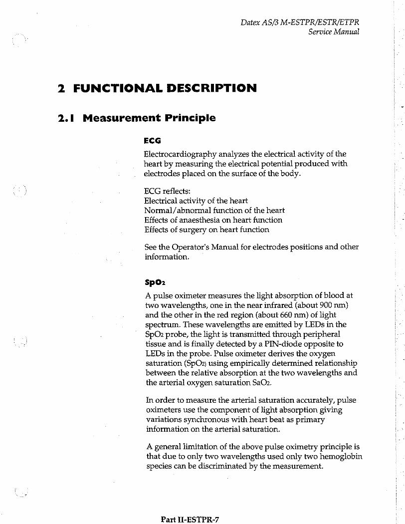
Datex AS/3 M-ESTPR/ESTR/ETPR
Service Manual
2 FUNCTIONAL DESCRIPTION
2.1 Measurement Principle
ECG
Electrocardiography analyzes the electrical activity of the heart by measuring the electrical potential produced with electrodes placed on the surface of the body.
ECG reflects:
Electrical activity of the heart Normal/abnormal function of the heart
Effects of anaesthesia on heart function Effects of surgery on heart function
See the Operator's Manual for electrodes positions and other information.
SpO>
A pulse oximeter measures the light absorption of blood at two wavelengths, one in the near infrared (about 900 nm) and the other in the red region (about 660 nm) of light spectrum. These wavelengths are emitted by LEDs in the SpOz probe, the light is transmitted through peripheral tissue and is finally detected by a PIN-diode opposite to LEDs in the probe. Pulse oximeter derives the oxygen saturation (SpOz) using empirically determined relationship between the relative absorption at the two wavelengths and the arterial oxygen saturation SaO2.
In order to measure the arterial saturation accurately, pulse oximeters use the component of light absorption giving variations synchronous with heart beat as primary information on the arterial saturation.
A general limitation of the above pulse oximetry principle is that due to only two wavelengths used only two hemoglobin species can be discriminated by the measurement.
Part H-ESTPR-7
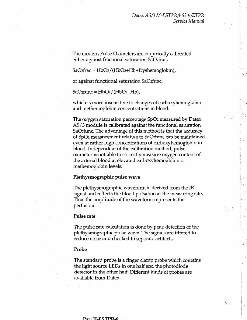
Datex AS/3 M-ESTPR/ESTR/ETPR
Service Manual
The modern Pulse Oximeters are empirically calibrated either against fractional saturation SaOzfrac,
SaOzfrac = HbO2/(HbO2+Hb+Dyshemoglobin),
or against functional saturation SaOzfunc,
SaOzfunc = HbO2/(HbO2+Hb),
which is more insensitive to changes of carboxyhemoglobin and methemoglobin concentrations in blood.
The oxygen saturation percentage SpO2 measured by Datex AS/3 module is calibrated against the functional saturation SaOzfunc. The advantage of this method is that the accuracy of SpO2 measurement relative to SaOzfunc can be maintained even at rather high concentrations of carboxyhemoglobin in blood. Independent of the calibration method, pulse
oximeter is not able to correctly measure oxygen content of the arterial blood at elevated carboxyhemoglobin or methemoglobin levels.
Plethysmographic pulse wave
The plethysmographic waveform is derived from the IR signal and reflects the blood pulsation at the measuring site. Thus the amplitude of the waveform represents the perfusion.
Pulse rate
The pulse rate calculation is done by peak detection of the plethysmographic pulse wave. The signals are filtered to reduce noise and checked to separate artifacts.
Probe
The standard probe is a finger clamp probe which contains the light source LEDs in one half and the photodiode detector in the other half. Different kinds of probes are available from Datex.
Part TILECTPR.R
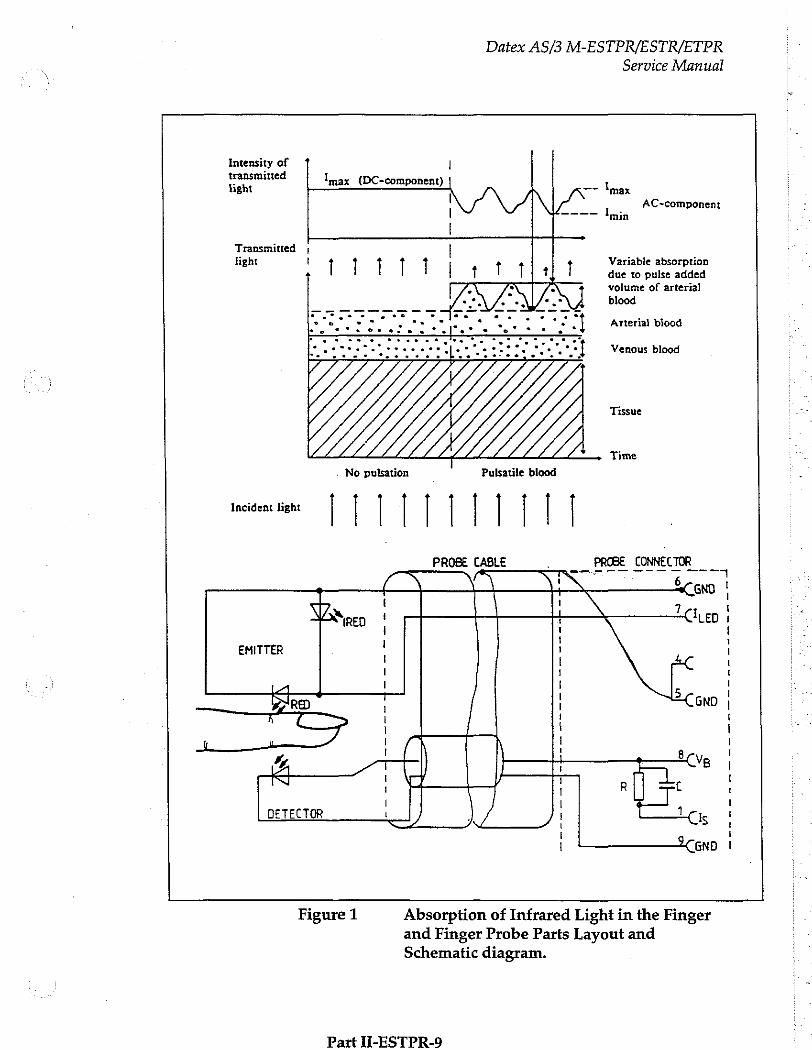
Datex AS/3 M-ESTPR/ESTR/ETPR
Service Manual
Intensity of | transmitted 1 e tight max (DC-component) — max
NL,
Transmitted | fight t
AC-component min
Variable absorption
due to pulse added volume of arterial
blood
Arterial blood
Venous blood
Tissue
Time
Incident light | | | | | | | | | | |
PROBE CABLE __PROBE CONNECTOR ___ i ` 6
4 + CNO |
Wa ! | \ 1 \ Try en | (RED | i СНЕС
+ EMITTER 1
| 1 1 < | | 5 | DIRE | 1 GND |
1 1
1 | 1 | | | 8
ん | NB |
| | R cl I I 1 1 DETECTOR | / / js |
k i
| — enn |
Figure 1 Absorption of Infrared Light in the Finger
Part II-ESTPR-9
and Finger Probe Parts Layout and Schematic diagram.
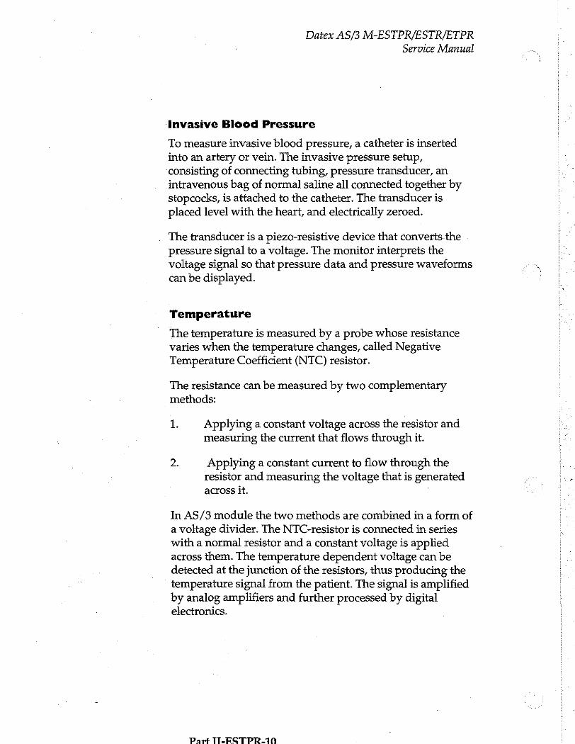
Datex AS/3 M-ESTPR/ESTR/ETPR
Service Manual
Invasive Blood Pressure
To measure invasive blood pressure, a catheter is inserted into an artery or vein. The invasive pressure setup, consisting of connecting tubing, pressure transducer, an intravenous bag of normal saline all connected together by stopcocks, is attached to the catheter. The transducer is placed level with the heart, and electrically zeroed.
The transducer is a piezo-resistive device that converts.the pressure signal to a voltage. The monitor interprets the voltage signal so that pressure data and pressure waveforms can be displayed.
Temperature
The temperature is measured by a probe whose resistance varies when the temperature changes, called Negative Temperature Coefficient (NTC) resistor.
The resistance can be measured by two complementary methods:
1 Applying a constant voltage across the resistor and measuring the current that flows through it.
2. Applying a constant current to flow through the resistor and measuring the voltage that is generated across it. ]
In AS/3 module the two methods are combined in a form of a voltage divider. The NTC-resistor is connected in series with a normal resistor and a constant voltage is applied across them. The temperature dependent voltage can be detected at the junction of the resistors, thus producing the temperature signal from the patient. The signal is amplified by analog amplifiers and further processed by digital electronics.
Part TT-ESTPR-10
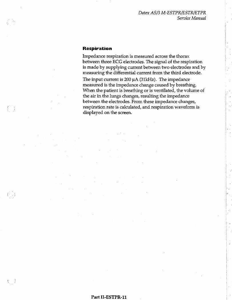
Datex AS/3 M-ESTPR/ESTR/ETPR
Service Manual
Respiration
Impedance respiration is measured across the thorax between three ECG electrodes. The signal of the respiration is made by supplying current between two electrodes and by measuring the differential current from the third electrode.
The input current is 200 LA (31kHz). The impedance measured is the impedance change caused by breathing. When the patient is breathing or is ventilated, the volume of
the air in the lungs changes, resulting the impedance between the electrodes. From these impedance changes, respiration rate is calculated, and respiration waveform is displayed on the screen.
Part II-ESTPR-11
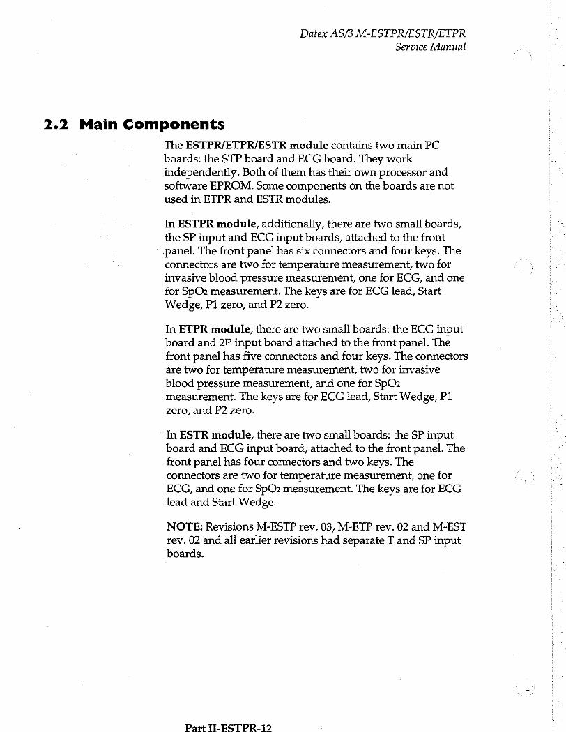
Datex AS/3 M-ESTPR/ESTR/ETPR
Service Manual
2.2 Main Components
The ESTPR/ETPR/ESTR module contains two main PC boards: the STP board and ECG board. They work independently. Both of them has their own processor and software EPROM. Some components on the boards are not used in ETPR and ESTR modules.
In ESTPR module, additionally, there are two small boards,
the SP input and ECG input boards, attached to the front panel. The front panel has six connectors and four keys. The connectors are two for temperature measurement, two for invasive blood pressure measurement, one for ECG, and one
for SpO2 measurement. The keys are for ECG lead, Start Wedge, P1 zero, and P2 zero.
In ETPR module, there are two small boards: the ECG input board and 2P input board attached to the front panel. The front panel has five connectors and four keys. The connectors are two for temperature measurement, two for invasive
blood pressure measurement, and one for SpOz measurement. The keys are for ECG lead, Start Wedge, P1
zero, and P2 zero.
In ESTR module, there are two small boards: the SP input board and ECG input board, attached to the front panel. The front panel has four connectors and two keys. The connectors are two for temperature measurement, one for ECG, and one for SpO2 measurement. The keys are for ECG lead and Start Wedge.
NOTE: Revisions M-ESTP rev. 03, M-ETP rev. 02 and M-EST
rev. 02 and all earlier revisions had separaté T and SP input boards.
Part TI-ESTPR-12
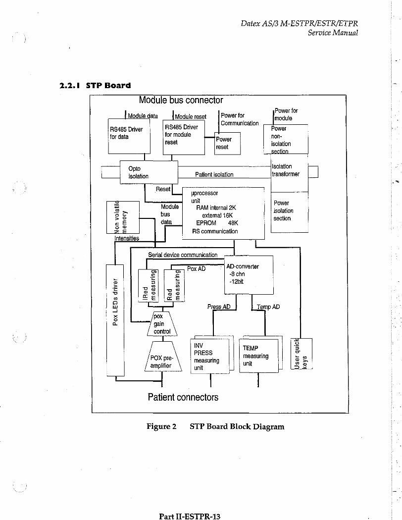
Datex AS/3 M-ESTPR/ESTR/ETPR
Service Manual
2.2.1 STP Board
Module bus connector Power for
[Modute data — {Module reset |Powertor ee À Communication
RS485 Driver R$485 Driver Power tor data for module — Power non-
rese isolati reset isolation
section | I
Opto Isolation
isolation Patient isolation transformer |] a
Reset| | processor W unit P
= Module | RAMintemal 2K isolation oF bus extemal 16K section сЕ data EPROM 48K oo
之 三 RS communication Intensities |
Serial device communication
ㄴㄴ 66006 | AD-converter
2 È -8 chn s 3 3 -12bit 、 = De o G -
=| | eel (Be u Press AD Temp AD
~ o a
[ 1 =
INV TEMP 3 PRESS measuring 2 o
P measuring unit os amplifier unit i 32
— | Patient connectors
Figure2 STP Board Block Diagram
Part II-ESTPR-13
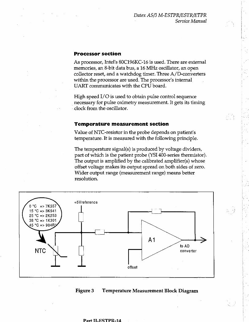
Datex AS/3 M-ESTPR/ESTR/ETPR
Service Manual
Processor section
As processor, Intel's 80C196KC-16 is used. There are external memories, an 8-bit data bus, a 16 MHz oscillator, an open
collector reset, and a watchdog timer. Three A/D-converters within the processor are used. The processor's internal UART communicates with the CPU board.
High speed 1/0 is used to obtain pulse control sequence necessary for pulse oximetry measurement. It gets its timing clock from the oscillator.
Temperature measurement section
Value of NTC-resistor in the probe depends on patient's temperature. It is measured with the following principle.
The temperature signal(s) is produced by voltage dividers, part of which is the patient probe (YSI 400-series thermistor). The output is amplified by the calibrated amplifier(s) whose offset voltage makes its output spread on both sides of zero. Wider output range (measurement range) means better resolution.
0°C => 7K357
15 °C => 3K541
25 °C => 2K253
38 °C => 1K301
45 °C => 984R
NTC
+5Vreference
|
LL
| | | U
| A1 +> to AD
| | converter
offset
Figure3 Temperature Measurement Block Diagram
Part TI-ESTPR-14
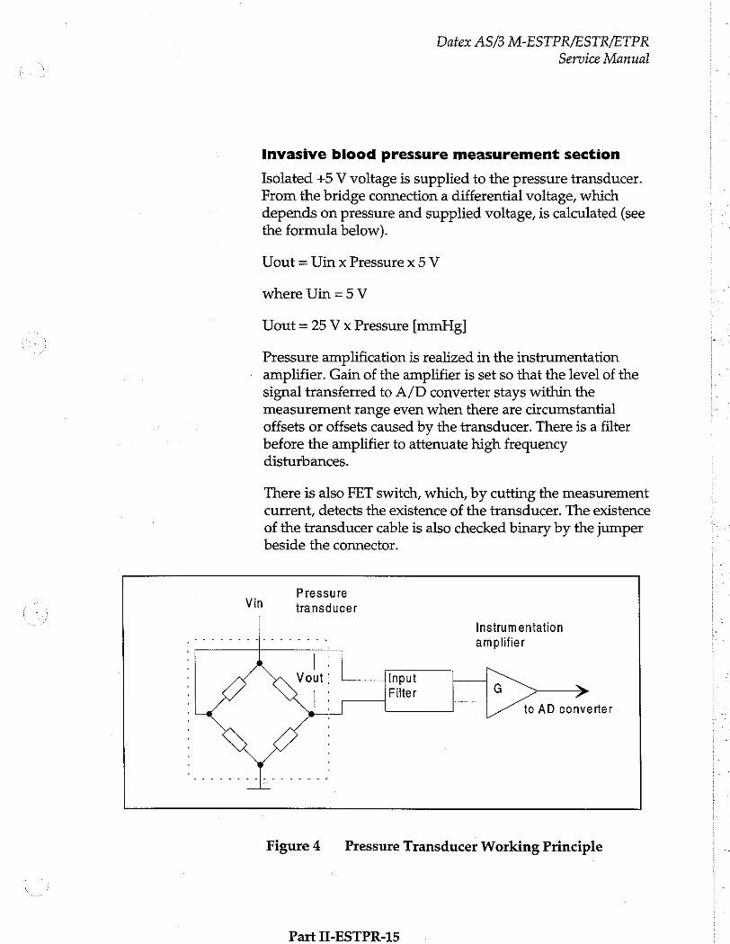
Datex AS/3 M-ESTPR/ESTR/ETPR
Service Manual
Invasive blood pressure measurement section
Isolated +5 V voltage is supplied to the pressure transducer. From the bridge connection a differential voltage, which depends on pressure and supplied voltage, is calculated (see the formula below).
Uout = Uin x Pressure x 5 V
where Uin=5V
Uout = 25 V x Pressure [mmHg]
Pressure amplification is realized in the instrumentation amplifier. Gain of the amplifier is set so that the level of the signal transferred to A/D converter stays within the measurement range even when there are circumstantial offsets or offsets caused by the transducer. There is a filter before the amplifier to attenuate high freguency disturbances.
There is also FET switch, which, by cutting the measurement current, detects the existence of the transducer. The existence
of the transducer cable is also checked binary by the jumper beside the connector.
Vin
Pressure
transducer
Instrumentation amplifier
Input Filter G >
to AD converter
Figure 4 = Pressure Transducer Working Principle
Part II-ESTPR-15
Datex AS/3 M-ESTPR/ESTR/ETPR
Service Manual
Pulse oximetry measurement section
LED control signals
The processor sends pulse width modulated signals, IRED intensity and RED intensity, which are converted to DC voltage and filtered. By switches either RED or IRED intensity is sent forward to amplifier in LED driving circuit.
LED driving circuit
Voltage difference which corresponds to LED current, is
measured by the differential amplifier circuit and its output is sent back to the processor in 0 to 5 V level. There are feedback circuits from LED current measurement and LED intensity control.
Background light is measured by picking up a sample from the signal. The sample is modified to 0 to 5 V level and sent to the processor.
Measured signal preamplification
Voltage of -4 V is gained by voltage divider from -12 V and is fed to non-inverted input of current-to-voltage converter amplifier. Thus inverse bias voltage is generated for probe detection. There is a switch, which if closed, a multiple (x30) amplification is resulted (necessary in thin tissue measurement such as earlobe).
Digitally controlled amplifier
D/A converter is a digitally controlled amplifier after which there is another constant amplifier.
Red and Infrared channels' separation
Red and infrared channels are separated from each other by switches. Operational amplifier functions as a buffer and after this infrared DC signal is sent to the processor. A capacitor separates AC signal from it and the AC signal is sent to the processor after amplification. There is a switch to choose the amplification constant.
Part TLESTPR.16
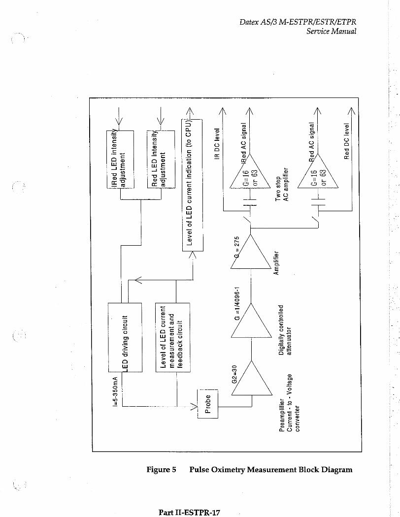
Service Manual
Datex AS/3 M-ESTPR/ESTR/ETPR
ΙΘΛ6Ι 9
pod
jeubis ov
pe
JeMIdue OV dais omy
18104
jeubls oy
pe 920
Jena 00
出
<= (nd9
이) 4 이 6904
146408 037
10 10767
juswysnipe
1ISU91UI 1377
POH
jueusn{pe
Joyenue}}e
pajoujuoo Ayeysiq
L-960ÿ/1= 9
Jinosjo yoRqpes}
put juaweinseeu
1uejun9 3710
19487
зэнелиоэ эбенмол
- 0}
- Juana
Je 由 dueaeid
eqoid
уполо Вылир
(3
HISU91Ul 937
рец!
ywoge-s=|
Pulse Oximetry Measurement Block Diagram Figure 5
Part II-ESTPR-17

Datex AS/3 M-ESTPR/ESTR/ETPR
Service Manual
Serial communication
Serial communication between the module and the frame is done by RS485 type bus whose buffers get their supply voltage (+5 VDC) from the Frame and in the isolation section get the supply voltage (+5 V) from the isolated power supply.
The buffers of the serial communication are controlled also
by Reset-signal so that when the Reset is active, the buffer does not transfer data.
Reset is also RS485 type and additionally, there is an auxiliary logic power reset, which keeps the reset active for about 500 ms despite the state of reset in the module bus. Time constant determines the power-up reset time. There are components to prevent the module from sending data during reset.
Data transmission rate is 500 kbit/s.
5 Receive data <? >
8 Send data, RS485 = © . ・ ' TR Driver ет の steve data : < > ss
o Send data 」 ' < NData で 2
a senderen, Opto isolation: Send/receive = 2 5 < Rese , < の で > Resetin © © 8 Rs485 TTT о Е
Е = 5 Reset | Driver LNResetmn = o Så © Es
Figure6 Serial Communication and Opto Isolation
Pat TTECTPR_12

Datex AS/3 M-ESTPR/ESTR/ETPR Service Manual
Isolated section
There are two opto isolators. Signal is processed on logical high-low level even though the outputs of the opto isolators are analog signals in the isolated section.
Reset line is an open collector type with a pull-up resistor. Thus the processor is able to use its internal watch-dog function.
Power supply section
Isolated supply voltage of the module is developed from +15 Vdirty voltage from the Central Unit. Power supply is a switched-mode circuit, where FET transistor switch is
controlled by an oscillator using bipolar timer. The frequency of the oscillator is about 30 kHz and pulse ratio 50 %. Controlling of the FET switch is slowed to suppress spurious interference.
A special pulse transformer is used in the circuit. In the secondary circuit normal linear regulators are used except for +5 V (low drop type linear regulator).
Input: +15 Vdirty = +15 V +0.5 V; 0.3 А
Isolated outputs: +5 Vref = +5 V +0.1 V; 100 mA max +5 V = +5 V 40.2 V; 100 mA max +12 V = +12 V +0.3 V; 70 mA max -12 V=-12 V +0.3 V; 70 mA max -5 V=-5V +0.2 V; 20 mA max (STP board only)
Total power: About 3.5 W All the voltages are regulated. Isolation
primary /secondary 5 kV.
Part II-ESTPR-19
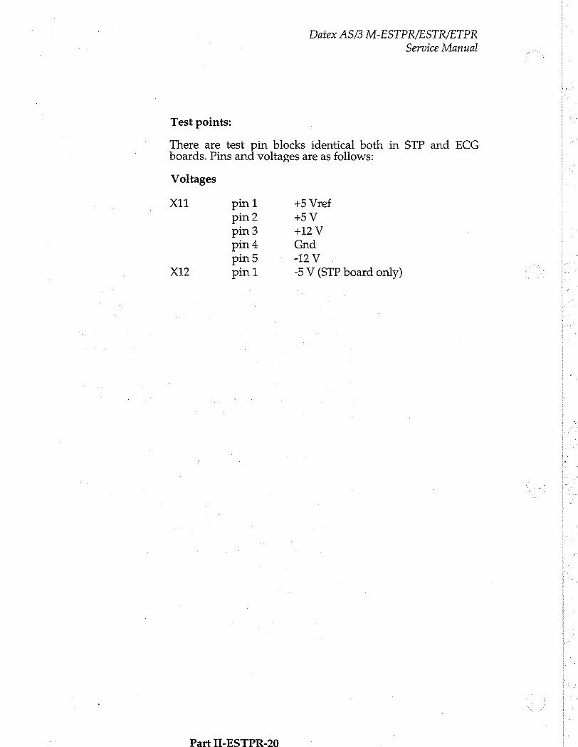
Datex AS/3 M-ESTPR/ESTR/ETPR
Service Manual
Test points:
There are test pin blocks identical both in STP and ECG boards. Pins and voltages are as follows:
Voltages
X11 pinl +5 Vref pin2 +5V pin 3 +12 V pin 4 Gnd
pin5 -12V X12 pini -5 V (STP board only)
Part IT-ESTPR-20
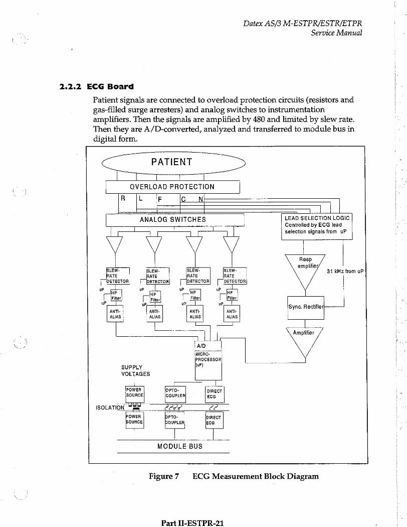
2.2.2 ECG Board
Datex AS/3 M-ESTPR/ESTR/ETPR Service Manual
Patient signals are connected to overload protection circuits (resistors and gas-filled surge arresters) and analog switches to instrumentation amplifiers. Then the signals are amplified by 480 and limited by slew rate. Then they are A/D-converted, analyzed and transferred to module bus in digital form.
OVERLOAD PROTECTION
R L F C N
ANALOG SWITCHES
(r rr |
YY い
LEAD SELECTION LOGIC Controlled by ECG lead
selection signals from uP
SLEW- RATE
[ DETECTOR Г
ISLEW- RATE DETECTOR | ㅣ
SLEW- RATE DETECTOR
SLEW- RATE
Г [DETECTOR]
P | | [Filter uP
up
uP,
HP Г Filter
uP
up
HP
| wwr 1
TE
uP,
ANTI-
ALIAS ANTI ALIAS
ANTE ALIAS ANTI-
ALIAS
ーー
Τ
31 kHz from uP
Sync. Rectifier]
Amplifier
AID MICRO-
PROCESSOR
SUPPLY (oP) MM
(7777 | POWER ¡OPTO- DIRECT SOURCE COUPLER| ECG
ISOLATION “pp PELO 22 POWER DPTO- DIRECT
SOURCE COUPLER ECG
MODULE BUS
Figure 7 ECG Measurement Block Diagram
Part II-ESTPR-21
Datex AS/3 M-ESTPR/ESTR/ETPR
Service Manual
Analog ECG section
ECG cable is connected to connector pins E1 to E6 on the input board which contains an overload protection circuit.
Leads are connected to amplifiers via analog switches. State of the switches depend on the cable type.
Lead-off, noise and pacemaker are detected by a slew rate detector.
Cut-off freguency is determined in high pass (HP) filter 0.5 Hz (monitor bandwidth) or 0.05 Hz (diagnostic or ST-
bandwidth).
ECG Filtering
The AS/3 monitors have three ECG filtering modes:
MONITORING | 0.5 - 30 Hz (-3 dB with 50 Hz reject filter) 0.5 - 40 Hz (-3 dB with 60 Hz reject filter)
DIAGNOSTIC 0.05 - 100 Hz
ST FILTER 0.05 - 30 Hz (with 50 Hz reject filter)
0.05 - 40 Hz (with 60 Hz reject filter)
The purpose of filtering is to reduce high frequency noise and low frequency (e.g. respiratory) movement artifacts.
Monitor filter is used in normal monitoring. Diagnostic filter is used if more accurate diagnostic information is needed. ST filter gives more accurate information of ST segment, but
reduces high frequency noise.
The high-pass filters 0.5 Hz and 0.05 Hz are done with hardware. The monitor sends a command to the ESTP(R)
module determining which of the corner frequencies 0.5 Hz or 0.05 Hz is to be used.
The 50 Hz and 60 Hz reject filters are both low-pass (notch type) filters with zero at 50 Hz or 60 Hz correspondingly and they are done with software. They are for the mains supply filtering. When notch filters are used, 3 dB value for low-pass filter is 30 Hz or 40 Hz.
Part TT_EC'TPR_95
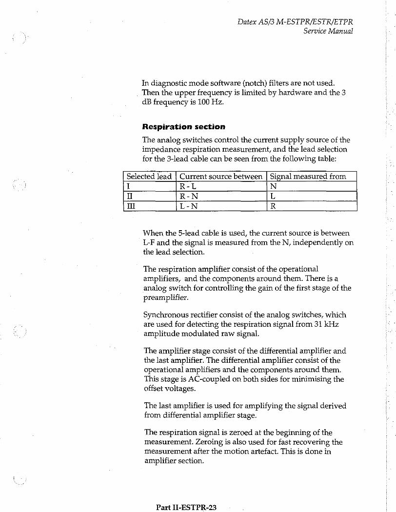
Datex AS/3 M-ESTPR/ESTR/ETPR Service Manual
In diagnostic mode software (notch) filters are not used. Then the upper frequency is limited by hardware and the 3 dB frequency is 100 Hz.
Respiration section
The analog switches control the current supply source of the impedance respiration measurement, and the lead selection
for the 3-lead cable can be seen from the following table:
Selected lead | Current source between | Signal measured from
I R-L N
II R-N L
I L-N R
When the 5-lead cable is used, the current source is between
L-F and the signal is measured from the N, independently on the lead selection.
The respiration amplifier consist of the operational amplifiers, and the components around them. There is a analog switch for controlling the gain of the first stage of the preamplifier.
Synchronous rectifier consist of the analog switches, which
are used for detecting the respiration signal from 31 kHz amplitude modulated raw signal.
The amplifier stage consist of the differential amplifier and the last amplifier. The differential amplifier consist of the operational amplifiers and the components around them. This stage is AC-coupled on both sides for minimising the offset voltages.
The last amplifier is used for amplifying the signal derived from differential amplifier stage.
The respiration signal is zeroed at the beginning of the measurement. Zeroing is also used for fast recovering the measurement after the motion artefact. This is done in amplifier section.
Part II-ESTPR-23

Datex AS/3 M-ESTPR/ESTR/ETPR
Service Manual
Microprocessor section
Microprocessor contains RAM and EPROM memories. The processor uses external EEPROM memory. The microprocessor's internal 8-channel A/D-converter converts the ECG-signals to digital form.
Serial communication
Communication with the module bus is made through RXD and TXD pins. See the serial communication section in STP board description.
Isolated section
The patient isolation of ECG is 5 kV in M-ESTPR rev. 01 and M-ESTR/ETPR rev. 01 modules. NOTE: The isolation has been changed from the earlier revisions.
WARNING: Do not touch battery operated monitor during defibrillation procedure.
See the isolated section in STP board description.
Power supply section
See the power supply section in STP board description.
There is a test connector (x20) on the board for voltages + 5 VREF, +5V, +12V, GND and -12V.
Part ILLEGTPR -24
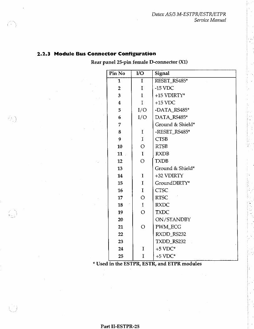
Datex AS/3 M-ESTPR/ESTR/ETPR
Service Manual
2.2.3 Module Bus Connector Configuration
Rear panel 25-pin female D-connector (X1)
Pin No Vo Signal
1 RESET RS485*
2 -15 VDC
3 +15 VDIRTY*
4 +15 VDC
5 I/O | -DATA_RS485*
6 I/O | DATA_RS485*
7 Ground & Shield*
8 I -RESET_RS485*
9 I CTSB
10 ο RTSB
11 I RXDB
12 ο TXDB
13 Ground & Shield*
14 I +32 VDIRTY
15 I GroundDIRTY*
16 I CTSC
17 O RISC
18 I RXDC
19 о TXDC
20 ON/STANDBY
21 o PWM, ECG
22 RXDD RS232
23 TXDD_RS232
24 I +5 VDC*
25 I +5 VDC*
* Used in the ESTPR, ESTR, and ETPR modules
Part H-ESTPR-25
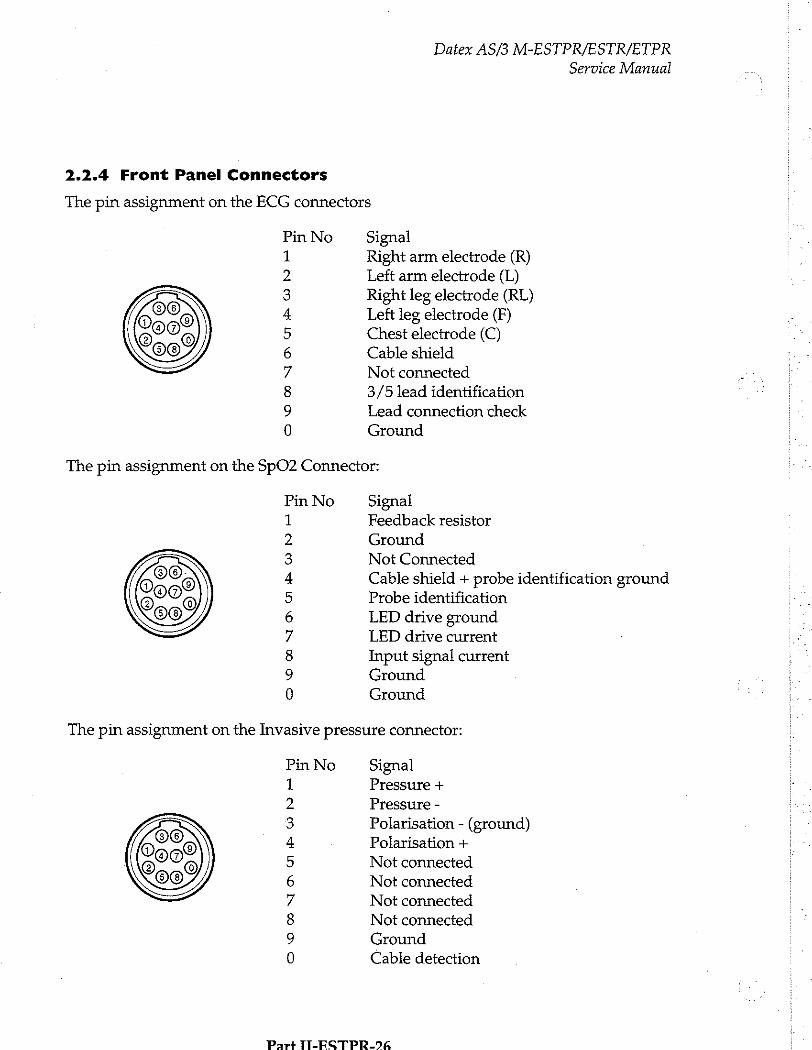
2.2.4 Front Panel Connectors
Datex AS/3 M-ESTPR/ESTR/ETPR
Service Manual
The pin assignment on the ECG connectors
H 5 Z o
つの どの
の
G
G A
©
D
HR
Signal Right arm electrode (R) Left arm electrode (L) Right leg electrode (RL)
Left leg electrode (F) Chest electrode (C)
Cable shield
Not connected
3/5 lead identification
Lead connection check
Ground
The pin assignment on the SpO2 Connector:
DO, Doo? 996
y 3 va o
つぐ
ひい G BON
F
Signal Feedback resistor
Ground
Not Connected
Cable shield + probe identification ground Probe identification
LED drive ground LED drive current
Input signal current Ground
Ground
The pin assignment on the Invasive pressure connector:
Pin No
の つぐ
ひい G & ϱ » -
Signal Pressure +
Pressure -
Polarisation - (ground)
Polarisation +
Not connected
Not connected
Not connected
Not connected
Ground
Cable detection
Part TT-ESTPR-%%
Datex AS/3 M-ESTPR/ESTR/ETPR
Service Manual
3 SERVICE PROCEDURES
3.1 General Service Information
Usually field service is limited to replacing the faulty circuit boards or mechanical parts. The boards are then returned to Datex for repair.
Datex is always available for service advice. Please provide the unit serial number, full type designation, and a detailed
fault description.
CAUTION: Only trained personnel with appropriate equipment shall perform the tests and repairs outlined in this section. Unauthorized service may void warranty of the unit.
3.2 Preventive Maintenance
Perform these checks after any service and at least once a year to keep the ESTPR/ESTR/ETPR Module in good condition.
1. Visual inspection
__: Ifthe module is disassembled, check that grounding wires and all connectors are properly connected and there is no loose object inside before attaching the module box.
2. Functional checks
Module:
Insert the module into frame.
__: Tum the monitor on. Select SpO, and Temp to be shown in digit fields. Within 15 seconds, SpO2 and
Temp windows should appear on the display. No error message appears.
__: Pull out the module. The SpO2 and Temp windows
go blank within 15 seconds.
Part II-ESTPR-27
Datex AS/3 M-ESTPR/ESTR/ETPR
Service Manual
—: Reinsert the module while the power is still on. The
SpOz and Temp measurement data appear on the windows again.
__ Connect a finger sensor to the module. The message Probe off should appear on the display. No waveform appears. Attach the sensor to your finger. The reading of 95 to 99 and an SpO2 waveform should appear.
__: Goto ESTPR:ECG and ESTPR:STP/P Service Menus
(Path: Monitor Setup, Install /Service (password 16-4- 34), Service View (password 26-23-8), Modules) and check the functions of cables and buttons (ON/OFF test).
ECG Cables:
Check the cables visually, and replace if any damages appear.
To test the cable:
Check that the following resistances are 4-6 kohm:
Clip to ECG connector pin N/RL L/LA R/RA F/LL C/V o
R RN
Ww
Check that the resistance from a lead to other leads
and to the shield (pin no 6) is > 1 Mohm.
If any of the tests fail, replace the cable.
ECG Cables together with Module:
__: Choose a field for ECG waveform (ECG1) in Monitor setup menu. The text ‘Leads off’ appears. Connect simulator to the module. The heart rate reading appears and the heart symbol starts to blink within 15 seconds. No error messages appear. Press the ECG LEAD key and try all Lead selections.
Part U-ESTPR-28
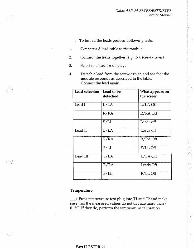
Datex AS/3 M-ESTPR/ESTR/ETPR Service Manual
To test all the leads perform following tests:
1 Connect a 3-lead cable to the module.
2. Connect the leads together (e.g. to a screw driver).
3. Select one lead for display.
4. Detach a lead from the screw driver, and see that the
module responds as described in the table. Connect the lead again.
Lead selection | Lead to be What appears on detached the screen
Lead I L/LA L/LA Off
R/RA R/RA Off
F/LL Leads off
Lead II L/LA Leads off
R/RA R/RA Off
F/LL F/LL Off
Lead II L/LA L/LA Off
R/RA Leads Off
F/LL F/LL Off
Temperature:
—: Put a temperature test plug into T1 and T2 and make
sure that the measured values do not deviate more than +
0.1°C. If they do, perform the temperature calibration.
Part II-ESTPR-29

Datex AS/3 M-ESTPR/ESTR/ETPR
Service Manual
Impedance Respiration
NOTE: The procedure described for the resp check apply to the MedSim 300 patient simulator only.
_: To test impedance respiration
1. Press the ECG Lead key on the module. Confirm that the ECG lead selection is displayed, and changes with each key press. Then set the lead selection to Lead Il.
2. Press the Monitor Setup key and select Waveform Fields to get into the corresponding menu. Make sure that the resp waveform is configured to be displayed.
3. Adjust the patient simulator as follows.
* Lead selection to II/RL-LL
* Resp rate to 20
* Ohms to 1.0
4. Press the Others key and select Resp Setup to get into the corresponding menu. Set the resp rate source to impedance.
5. Press the Normal Screen key. Confirm that the resp waveform and the resp rate are displayed after a delay of approximately 30 seconds.
—: To test apnea detection
1. Adjust the patient simulator as follows:
* Select resp by pushing the F2 key of the patient simulator
* Select the apnea from the patient simulator menu (to get more menu push the arrow key right)
2. Select cont from the patient simulator menu, APNEA alarm should be displayed on the monitor screen after a delay of approximately 30 seconds.
Part TT-FRTPR_2N

Datex AS/3 M-ESTPR/ESTR/ETPR
Service Manual
3.3 Disassembly and Reassembly
Disassemble the ESTPR/ESTR/ETPR module in the
following way. See Figure for the exploded view of the module.
a)
b)
d)
Remove the two screws from the back of the module.
Pull the module box slowly rearwards and detach it from the main body. Be careful with loose latch and spring pin for locking.
Two main PC boards will appear. The ECG board is on top of the STP board. The ECG board will be detached by removing four screws one in each corner,
disconnecting 9-pin ribbon cable that is connected to the STP board and 2-pin ribbon cable from the front panel. Slide the board rearward to disconnect the fixed 10-pin connector of ECG input board.
The STP board can be removed by detaching two screws on the solder side of the board near the front panel and disconnecting the two connectors from the SP input board. The T-input connector cables must be disconnected as well.
CAUTION: When reassembling the module, make sure that the cables are reconnected properly.
Part II-ESTPR-31
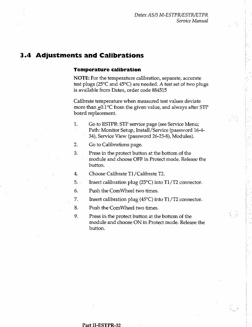
Datex AS/3 M-ESTPR/ESTR/ETPR
Service Manual
3.4 Adjustments and Calibrations
Temperature calibration
NOTE: For the temperature calibration, separate, accurate test plugs (25°C and 45°C) are needed. A test set of two plugs is available from Datex, order code 884515
Calibrate temperature when measured test values deviate more than +0.1°C from the given value, and always after STP
board replacement.
1.
の ©
oo
NR の
S R
Go to ESTPR: STP service page (see Service Menu; Path: Monitor Setup, Install/Service (password 16-4- 34), Service View (password 26-23-8), Modules).
Go to Calibrations page.
Press in the protect button at the bottom of the module and choose OFF in Protect mode. Release the button.
Choose Calibrate T1/Calibrate T2.
Insert calibration plug (25°C) into T1/T2 connector.
Push the ComWheel two times.
Insert calibration plug (45°C) into T1/T2 connector.
Push the ComWheel two times.
Press in the protect button at the bottom of the module and choose ON in Protect mode. Release the
button.
Part II-ESTPR-32
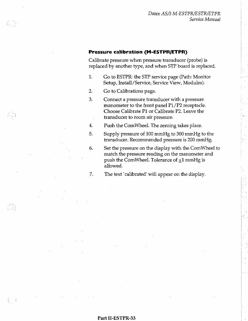
Datex AS/3 M-ESTPR/ESTR/ETPR
Service Manual
Pressure calibration (M-ESTPR/ETPR)
Calibrate pressure when pressure transducer (probe) is teplaced by another type, and when STP board is replaced.
1. Go to ESTPR: the STP service page (Path: Monitor Setup, Install/Service, Service View, Modules).
2. Go to Calibrations page.
Connect a pressure transducer with a pressure manometer to the front panel P1/P2 receptacle. Choose Calibrate P1 or Calibrate P2. Leave the transducer to room air pressure.
4. Push the ComWheel. The zeroing takes place.
Supply pressure of 100 mmHg to 300 mmHg to the transducer. Recommended pressure is 200 mmHg.
6. Set the pressure on the display with the ComWheel to match the pressure reading on the manometer and push the ComWheel. Tolerance of +1 mmHg is allowed.
7. The text “calibrated' will appear on the display.
Part II-ESTPR-33
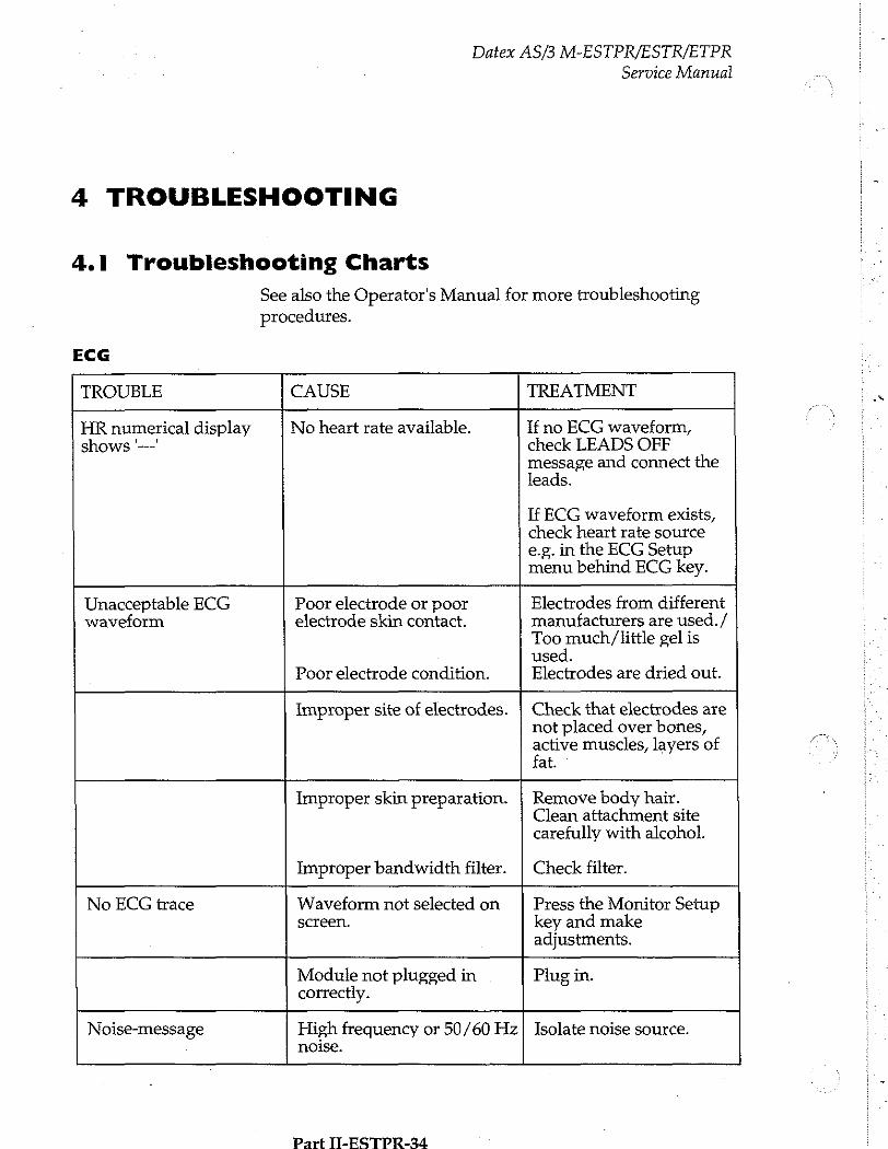
Datex AS/3 M-ESTPR/ESTR/ETPR
Service Manual
4 TROUBLESHOOTING
4.1 Troubleshooting Charts
See also the Operator's Manual for more troubleshooting
procedures.
ECG
TROUBLE CAUSE TREATMENT
HR numerical display No heart rate available. If no ECG waveform, shows '—' check LEADS OFF
message and connect the leads.
If ECG waveform exists, check heart rate source e.g. in the ECG Setup menu behind ECG key.
Unacceptable ECG Poor electrode or poor Electrodes from different waveform electrode skin contact. manufacturers are used. /
Too much/little gel is used.
Poor electrode condition. Electrodes are dried out.
Improper site of electrodes. ¡ Check that electrodes are not placed over bones, active muscles, layers of fat.
Improper skin preparation. | Remove body hair. Clean attachment site carefully with alcohol.
Improper bandwidth filter. | Check filter.
No ECG trace Waveform not selected on Press the Monitor Setup screen. key and make
adjustments.
Module not plugged in Plug in. correctly.
Noise-message High frequency or 50/60 Hz] Isolate noise source. noise.
Part IT-ESTPR-34
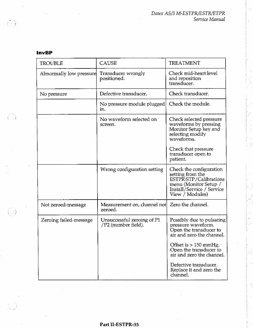
InvBP
Datex AS/3 M-ESTPR/ESTR/ETPR Service Manual
TROUBLE CAUSE TREATMENT
Abnormally low pressure} Transducer wrongly positioned.
Check mid-heart level and reposition transducer.
No pressure Defective transducer. Check transducer.
No pressure module plugged in.
Check the module.
No waveform selected on screen.
Check selected pressure waveforms by pressing Monitor Setup key and selecting modify waveforms.
Check that pressure transducer open to patient.
Wrong configuration setting Check the configuration setting from the ESTPR:STP /Calibrations menu (Monitor Setup / Install /Service / Service View / Modules)
Not zeroed-message Measurement on, channel not zeroed.
Zero the channel.
Zeroing failed-message
Unsuccessful zeroing of P1 /P2 (number field).
Possibly due to pulsating pressure waveform. Open the transducer to air and zero the channel.
Offset is > 150 mmHg. Open the transducer to air and zero the channel.
Defective transducer. Replace it and zero the channel.
Part II-ESTPR-35
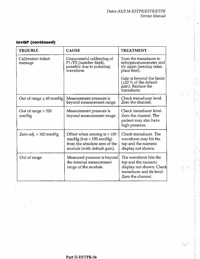
Datex AS/3 M-ESTPR/ESTR/ETPR
Service Manual
InvBP (continued)
TROUBLE CAUSE TREATMENT
Calibration failed- Unsuccessful calibrating of Turn the transducer to message P1/P2 (number field), © sphygmomanometer and
possibly due to pulsating try again (zeroing takes waveform place first).
Gain is beyond the limits (+20 % of the default gain). Replace the transducer.
Out of range < 40 mmHg| Measurement pressure is Check transducer level. beyond measurement range. | Zero the channel.
Out of range > 320 Measurement pressure is Check transducer level. mmHg beyond measurement range. | Zero the channel. The
patient may also have high pressure.
Zero adj. > 100 mmHg Offset when zeroing is > 100 mmHg (but < 150 mmHg) from the absolute zero of the module (with default gain).
Check transducer. The waveform may hit the top and the numeric display not shown.
Out of range Measured pressure is beyond the internal measurement range of the module. The waveform hits the
top and the numeric
display not shown. Check transducer and its level.
Zero the channel.
Part IL-ESTPR-36

Datex AS/3 M-ESTPR/ESTR/ETPR
Service Manual
Temp
TROUBLE CAUSE TREATMENT
Message Faulty calibration. Perform calibration. If it does not help, check that
"TEMPERATURE front panel connector is ERROR' properly connected to
STP board. Check front panel, SP-input board, or STP board.
No temperature Wrong type of probe. Use correct probe. displayed
Temperature out of measurable range.
The range is between 10 and 45°C.
With German monitor software, check that Protection is set to ON in the Service Menu.
Part II-ESTPR-37
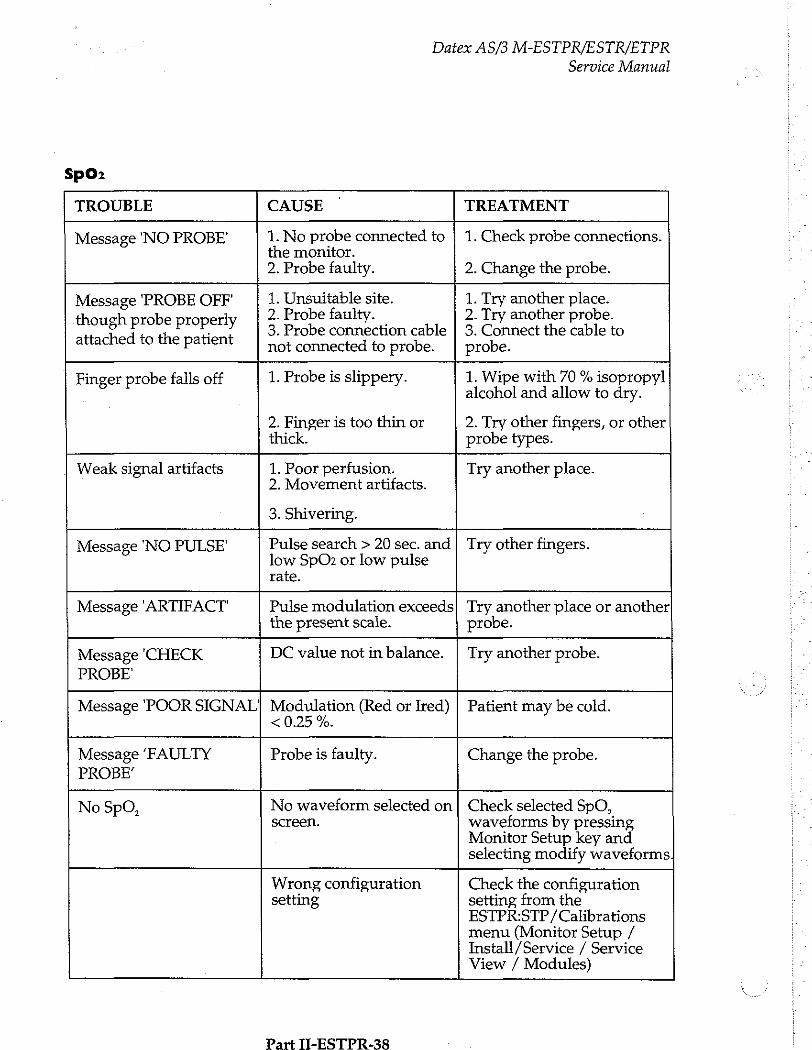
5602
Datex AS/3 M-ESTPR/ESTR/ETPR Service Manual
TROUBLE CAUSE TREATMENT
Message NO PROBE' 1. No probe connected to the monitor. 2. Probe faulty.
1. Check probe connections.
2. Change the probe.
Message PROBE OFF 1. Unsuitable site. 1. Try another place.
2. Probe faulty. 2. Try another probe. though probe properly 3. Probe connection cable | 3. Connect the cable to attached to the patien not connected to probe. | probe.
Finger probe falls off 1. Probe is slippery. 1. Wipe with 70 % isopropyl alcohol and allow to dry.
2. Finger is too thin or 2. Try other fingers, or other thick. probe types.
Weak signal artifacts 1. Poor perfusion. Try another place. 2. Movement artifacts.
3. Shivering.
Message 'NO PULSE' Pulse search > 20 sec. and | Try other fingers. low SpOz or low pulse rate.
Message 'ARTIFACT' Pulse modulation exceeds the present scale.
Try another place or another probe.
Message 'CHECK DC value not in balance. | Try another probe. PROBE'
Message POOR SIGNAL] Modulation (Red or Ired) | Patient may be cold. < 0.25 %.
Message ‘FAULTY Probe is faulty. Change the probe. PROBE’
No SpO, No waveform selected on | Check selected SpO, screen. waveforms by pressing
Monitor Setup key and selecting modify waveforms
Wrong configuration setting Check the configuration
setting from the ESTPR:STP/ Calibrations menu (Monitor Setup / Install /Service / Service View / Modules)
Part 11-ESTPR-38
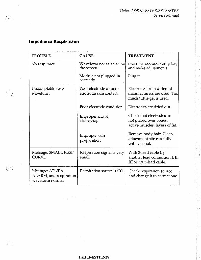
Impedance Respiration
Datex AS/3 M-ESTPR/ESTR/ETPR Service Manual
TROUBLE CAUSE TREATMENT
No resp trace Waveform not selected on the screen
Module not plugged in correctly
Press the Monitor Setup key and make adjustments
Plug in
Unacceptable resp waveform
Poor electrode or poor electrode skin contact
Poor electrode condition
Improper site of electrodes
Improper skin preparation
Electrodes from different
manufacturers are used. Too
much/little gel is used.
Electrodes are dried out.
Check that electrodes are not placed over bones, active muscles, layers of fat.
Remove body hair. Clean attachment site carefully with alcohol.
Message: SMALL RESP CURVE
Respiration signal is very small
With 3-lead cable try another lead connection I, II,
II or try 5-lead cable.
Message: APNEA ALARM, and respiration waveform normal Respiration source is CO, Check respiration source
and change it to correct one.
Part II-ESTPR-39

Datex AS/3 M-ESTPR/ESTR/ETPR
Service Manual
Possibly faulty ESTPR module
* | NO Select the correct
configuration
y YES
Remove all modules from the frame
insert ESTPR module and turn power on
Does fault still appear?
Fault notin ESTPR module
İ YES Y
Enter the Replace
Service menu STP board
A
Does another
module work in same
slot?
Remove ECG board
module ID on screen?
module 1D on screen?
YES
YES
Replace ECG board
NO 7
ECG module ID on screen?
YES Check front panel
key functions in Service menu
\
ΝΟ Has SpO2 A measurement
failed?
HasECG NNO / Has STP measurement >= board failed?
failed?
Do they work?
Has invBP measurement
failed?
measurement failed?
YES YES \ NO У Y し у
Check front panel unit, Replace Replace Replace Replace Replace ECG board, and STP beard | ECG board STP board STP board STPboard | STP board to find culprit. Replace if necessary.
ESTPR Module Troubleshooting Chart
Part II-ESTPR-40
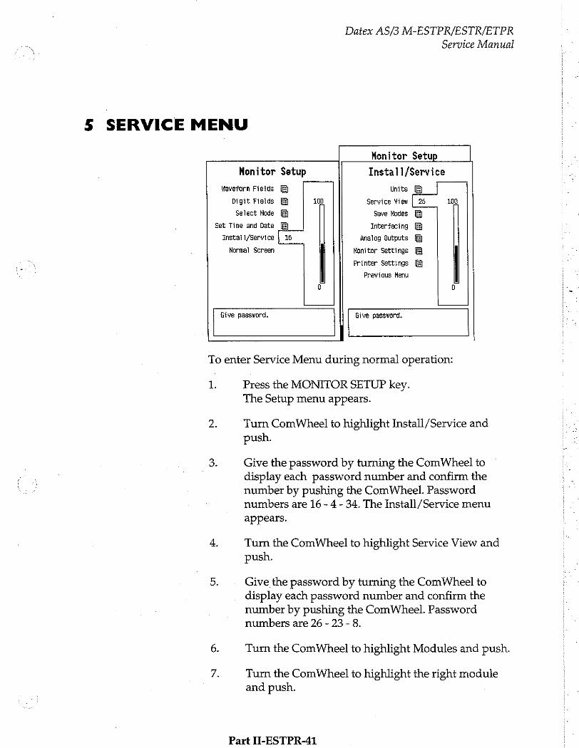
Datex AS/3 M-ESTPR/ESTR/ETPR
Service Manual
5 SERVICE MENU Monitor Setup
Monitor Setup Install/Service
Waveform Fields Units
Digit Fields 100 Service View | 26 108
Select Mode Save Modes
Set Time and Date Interfacing
Instali/Service [ie 4nalog Outputs
Normal Screen Monitor Settings
Printer Settings
Previous Menu
G 0
Give password. Give password.
To enter Service Menu during normal operation:
1. Press the MONITOR SETUP key. The Setup menu appears.
2. Turn ComWheel to highlight Install/Service and push.
3. Give the password by turning the ComWheel to display each password number and confirm the number by pushing the ComWheel. Password numbers are 16 - 4 - 34. The Install/Service menu appears.
4. Turn the ComWheel to highlight Service View and push.
5. Give the password by turning the ComWheel to display each password number and confirm the number by pushing the ComWheel. Password numbers are 26 - 23 - 8.
6. Turn the ComWheel to highlight Modules and push.
7. Turn the ComWheel to highlight the right module and push.
Part II-ESTPR-41
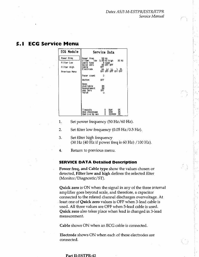
Datex AS/3 M-ESTPR/ESTR/ETPR
Service Manual
5.1 ECG Service Menu
ECG Module Service Data
- Filter low 0.50 Hz high 30 Hz Filter Low Cable type 3 lead
Quick zero ON OFF GFF Filter High Cable FF
Electrode RA Lê LL RL Previous Menu OFF OFF OFF OFF GFF
Pacer count 2
Button OFF
Resp Available GN Measurement BN Amp Zero OFF Value U
Tineouts G RAM OK Bad checksums G ROM OK Bad c-s by moc O EEPROM OK
1. Set power frequency (50 Hz/60 Hz).
2. Set filter low frequency (0.05 Hz/0.5 Hz).
3. Set filter high frequency (30 Hz (40 Hz if power freq is 60 Hz) /100 Hz).
4. Return to previous menu.
SERVICE DATA Detailed Description
Power freq, and Cable type show the values chosen or detected, Filter low and high defines the selected filter (Monitor/Diagnostic/ST).
Quick zero is ON when the signal in any of the three internal amplifier goes beyond scale, and therefore, a capacitor connected to the related channel discharges overvoltage. At least one of Quick zero values is OFF when 3-lead cable is used. All three values are OFF when 5-lead cable is used. Quick zero also takes place when lead is changed in 3-lead measurement.
Cable shows ON when an ECG cable is connected.
Electrode shows ON when each of these electrodes are
connected.
Part TI-ESTPR-42
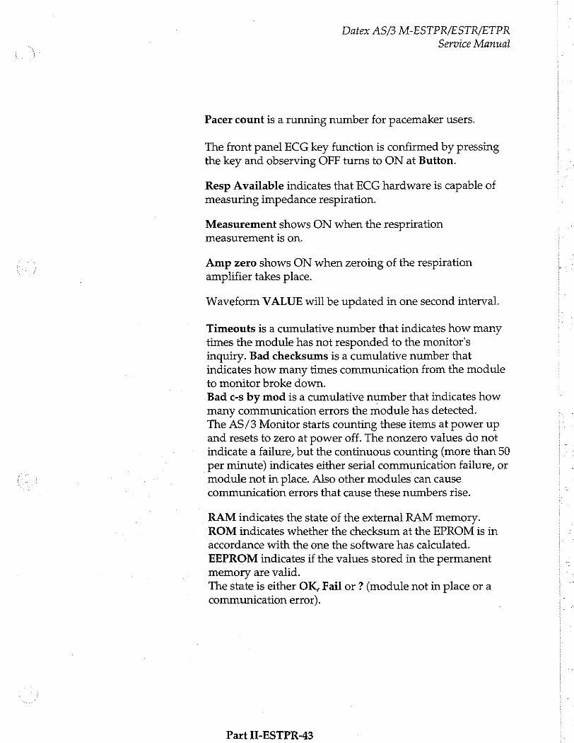
Datex AS/3 M-ESTPR/ESTR/ETPR
Service Manual
Pacer count is a running number for pacemaker users.
The front panel ECG key function is confirmed by pressing the key and observing OFF turns to ON at Button.
Resp Available indicates that ECG hardware is capable of
measuring impedance respiration.
Measurement shows ON when the respriration
measurement is on.
Amp zero shows ON when zeroing of the respiration
amplifier takes place.
Waveform VALUE will be updated in one second interval.
Timeouts is a cumulative number that indicates how many times the module has not responded to the monitor's inquiry. Bad checksums is a cumulative number that indicates how many times communication from the module to monitor broke down. Bad c-s by mod is a cumulative number that indicates how many communication errors the module has detected. The AS/3 Monitor starts counting these items at power up and resets to zero at power off. The nonzero values do not indicate a failure, but the continuous counting (more than 50 per minute) indicates either serial communication failure, or
module not in place. Also other modules can cause communication errors that cause these numbers rise.
RAM indicates the state of the external RAM memory. ROM indicates whether the checksum at the EPROM is in
accordance with the one the software has calculated.
EEPROM indicates if the values stored in the permanent
memory are valid. The state is either OK, Fail or ? (module not in place or a communication error).
Part II-ESTPR-43
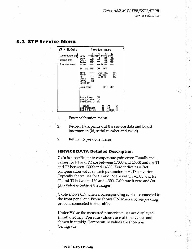
Datex AS/3 M-ESTPR/ESTR/ETPR
Service Manual
5.2 STP Service Menu
ESTP Hodule Service Data : ; pi 的 T2
Calibrations Gain 20900 20878 13725 12697 Zero -6 4 85 88
Record Data Cable OFF OFF ON BFF Probe OFF OFF ON OFF
Previous Menu Yalue — -— 2 —
Buttons OFF OFF OFF
5602 --- Ired int. 65 eder ーー Red int. &
Cable ON sain Probe ON Probe oft
Temp error OFF OFF as
Protect key DEF Protect mode ON Configuration STP
Timeouts 9 RAM UK Bad checksums 1 ROH Ok Bad c-s by mod O. EEPROM OK
1. Enter calibration menu
2. Record Data prints out the service data and board information (id, serial number and sw id)
2. Return to previous menu
SERVICE DATA Detailed Description
Gain is a coefficient to compensate gain error. Usually the . values for P1 and P2 are between 17000 and 25000 and for T1 Ee and T2 between 13000 and 14300. Zero indicates offset compensation value of each parameter in A/D converter. Typically the values for P1 and P2 are within +1000 and for T1 and T2 between -150 and +300. Calibrate if zero and/or gain value is outside the ranges.
Cable shows ON when a corresponding cable is connected to the front panel and Probe shows ON when a corresponding probe is connected to the cable.
Under Value the measured numeric values are displayed |ー simultaneously. Pressure values are real time values and shown in mmHg. Temperature values are shown in Centigrade.
Part II-ESTPR-44
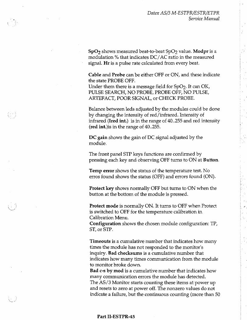
Datex AS/3 M-ESTPR/ESTR/ETPR
Service Manual
SpO» shows measured beat-to-beat SpO?2 value. Modpr is a modulation % that indicates DC/ AC ratio in the measured
signal. Hr is a pulse rate calculated from every beat.
Cable and Probe can be either OFF or ON, and these indicate
the state PROBE OFF.
Under them there is a message field for SpO». It can OK, PULSE SEARCH, NO PROBE, PROBE OFF, NO PULSE,
ARTEFACT, POOR SIGNAL, or CHECK PROBE.
Balance between leds adjusted by the modules could be done by changing the intensity of red /infrared. Intensity of infrared (Ired int.) is in the range of 40..255 and red intensity (red int.)is in the range of 40..255.
DC gain shows the gain of DC signal adjusted by the module.
The front panel STP keys functions are confirmed by pressing each key and observing OFF turns to ON at Button.
Temp error shows the status of the temperature test. No erros found shows the status (OFF) and errors found (ON).
Protect key shows normally OFF but turns to ON when the button at the bottom of the module is pressed.
Protect mode is normally ON. It turns to OFF when Protect is switched to OFF for the temperature calibration in Calibration Menu.
Configuration shows the chosen module configuration: TP,
ST, or STP.
Timeouts is a cumulative number that indicates how many times the module has not responded to the monitor's inquiry. Bad checksums is a cumulative number that indicates how many times communication from the module to monitor broke down. Bad c-s by mod is a cumulative number that indicates how many communication errors the module has detected. The AS/3 Monitor starts counting these items at power up and resets to zero at power off. The nonzero values do not indicate a failure, but the continuous counting (more than 50
Part II-ESTPR-45
Datex AS/3 M-ESTPR/ESTR/ETPR
Service Manual
per second) indicates either serial communication failure, or module not in place. Also other modules can cause communication errors that cause these numbers rise.
RAM indicates the state of the external RAM memory. ROM indicates whether the checksum at the EPROM is in accordance with the one the software has calculated. EEPROM indicates if the values stored in the permanent memory are valid. The state is either OK, Fail or ? (module not in place or a communication error).
Part II-ESTPR-46
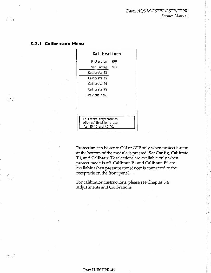
Datex AS/3 M-ESTPR/ESTR/ETPR
Service Manual
5.2.1 Calibration Menu
Calibrations
Protection OFF
Set Config STP
Ealibrate Ti
Calibrate T2
Calibrate PL
Calibrate P2
Previous Menu
Calibrate temperatures with calibration plugs
for 25 °C and 45 °C.
Protection can be set to ON or OFF only when protect button at the bottom of the module is pressed. Set Config, Calibrate T1, and Calibrate T2 selections are available only when protect mode is off. Calibrate P1 and Calibrate P2 are available when pressure transducer is connected to the receptacle on the front panel.
For calibration instructions, please see Chapter 3.4 Adjustments and Calibrations.
Part H-ESTPR-47
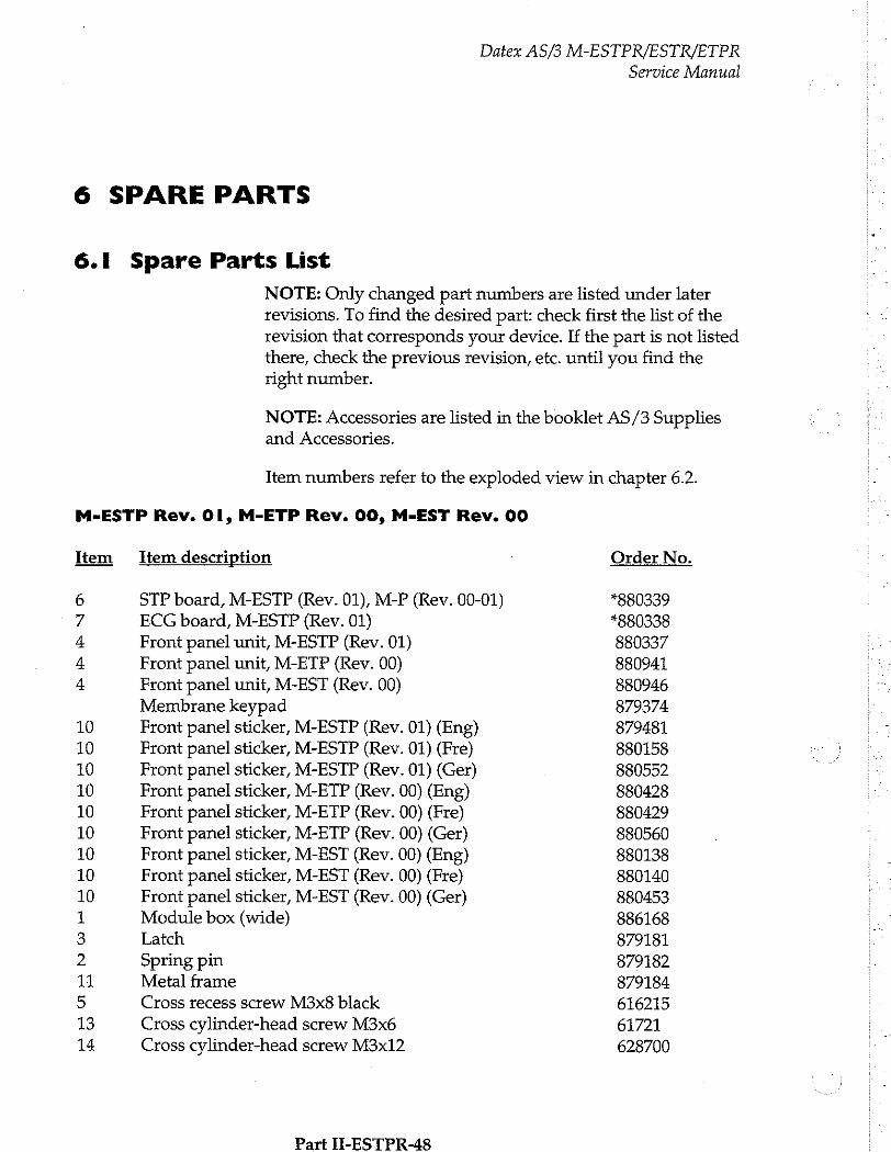
6 SPARE PARTS
6.1 Spare Parts List
NOTE: Only changed part numbers are listed under later revisions. To find the desired part: check first the list of the revision that corresponds your device. If the part is not listed there, check the previous revision, etc. until you find the right number.
Datex AS/3 M-ESTPR/ESTR/ETPR
Service Manual
NOTE: Accessories are listed in the booklet AS/3 Supplies and Accessories.
Item numbers refer to the exploded view in chapter 6.2.
M-ESTP Rev. OI, M-ETP Rev. 00, M-EST Rev. 00
Item Item description Order No.
STP board, M-ESTP (Rev. 01), M-P (Rev. 00-01) *880339 ECG board, M-ESTP (Rev. 01) *880338
Front panel unit, M-ESTP (Rev. 01) 880337
Front panel unit, M-ETP (Rev. 00) 880941 Front panel unit, M-EST (Rev. 00) 880946 Membrane keypad 879374 Front panel sticker, M-ESTP (Rev. 01) (Eng) 879481
Front panel sticker, M-ESTP (Rev. 01) (Fre) 880158
Front panel sticker, M-ESTP (Rev. 01) (Ger) 880552
Front panel sticker, M-ETP (Rev. 00) (Eng) 880428
Front panel sticker, M-ETP (Rev. 00) (Fre) 880429 Front panel sticker, M-ETP (Rev. 00) (Ger) 880560
Front panel sticker, M-EST (Rev. 00) (Eng) 880138
Front panel sticker, M-EST (Rev. 00) (Fre) 880140 Front panel sticker, M-EST (Rev. 00) (Ger) 880453
Module box (wide) 886168 Latch 879181 Spring pin 879182
Metal frame 879184
Cross recess screw M3x8 black 616215
Cross cylinder-head screw M3x6 61721 Cross cylinder-head screw M3x12 628700
Part I-ESTPR-48
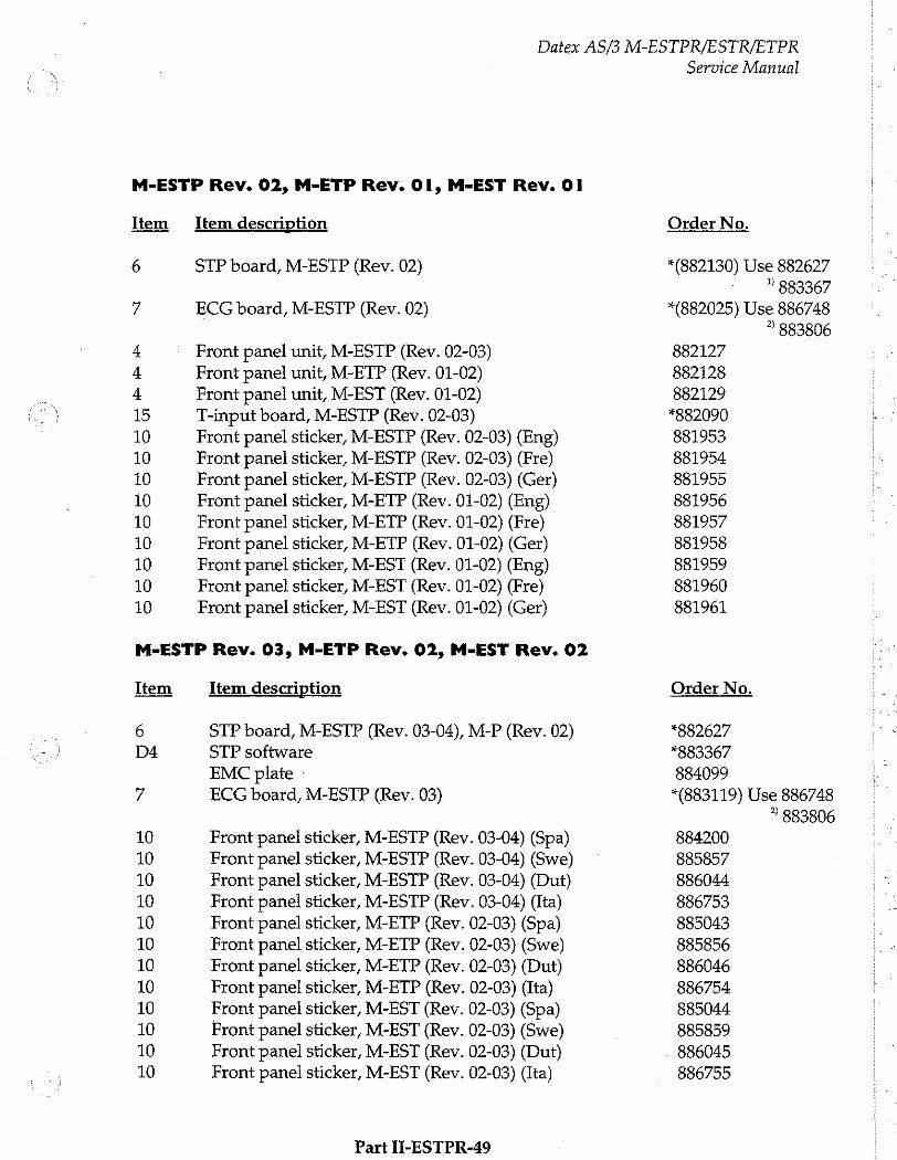
Datex AS/3 M-ESTPR/ESTR/ETPR
M-ESTP Rev. 02, M-ETP Rev. Ol, M-EST Rev. Ol
Item
6
Item description
STP board, M-ESTP (Rev. 02)
ECG board, M-ESTP (Rev. 02)
Front panel unit, M-ESTP (Rev. 02-03)
Front panel unit, M-ETP (Rev. 01-02)
Front panel unit, M-EST (Rev. 01-02) T-input board, M-ESTP (Rev. 02-03)
Front panel sticker, M-ESTP (Rev. 02-03) (Eng) Front panel sticker, M-ESTP (Rev. 02-03) (Fre)
Front panel sticker, M-ESTP (Rev. 02-03) (Ger)
Front panel sticker, M-ETP (Rev. 01-02) (Eng) Front panel sticker, M-ETP (Rev. 01-02) (Fre)
Front panel sticker, M-ETP (Rev. 01-02) (Ger)
Front panel sticker, M-EST (Rev. 01-02) (Eng)
Front panel sticker, M-EST (Rev. 01-02) (Fre)
Front panel sticker, M-EST (Rev. 01-02) (Ger)
M-ESTP Rev. 03, M-ETP Rev. 02, M-EST Rev. 02
Item
go
10 10 10 10 10 10 10 10 10 10 10 10
Item description
STP board, M-ESTP (Rev. 03-04), M-P (Rev. 02) STP software
EMC plate : ECG board, M-ESTP (Rev. 03)
Front panel sticker, M-ESTP (Rev. 03-04) (Spa) Front panel sticker, M-ESTP (Rev. 03-04) (Swe) Front panel sticker, M-ESTP (Rev. 03-04) (Dut)
Front panel sticker, M-ESTP (Rev. 03-04) (Ita) Front panel sticker, M-ETP (Rev. 02-03) (Spa) Front panel sticker, M-ETP (Rev. 02-03) (Swe)
Front panel sticker, M-ETP (Rev. 02-03) (Dut) Front panel sticker, M-ETP (Rev. 02-03) (Ita) Front panel sticker, M-EST (Rev. 02-03) (Spa) Front panel sticker, M-EST (Rev. 02-03) (Swe)
Front panel sticker, M-EST (Rev. 02-03) (Dut) Front panel sticker, M-EST (Rev. 02-03) (Ita)
Part II-ESTPR-49
Service Manual
Order No.
*(882130) Use 882627 ” 883367
*(882025) Use 886748 ? 883806
882127 882128 882129 *882090 881953 881954 881955 881956 881957 881958 881959 881960 881961
Order No.
*882627 *883367 884099 *(883119) Use 886748
2 883806 884200 885857 886044 886753 885043 885856 886046 886754 885044 885859 886045 886755
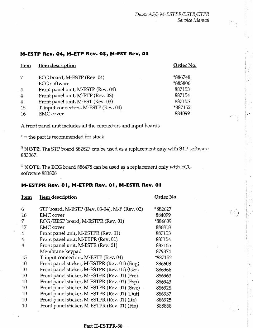
M-ESTP Rev. 04, M-ETP Rev. 03, M-EST Rev. 03
Item
M
на на
ны ны
>
5 6
Datex AS/3 M-ESTPR/ESTR/ETPR
Item description
ECG board, M-ESTP (Rev. 04) ECG software
Front panel unit, M-ESTP (Rev. 04) Front panel unit, M-ETP (Rev. 03) Front panel unit, M-EST (Rev. 03)
T-input connectors, M-ESTP (Rev. 04) EMC cover
Service Manual
Order No.
*886748 *883806 887153 887154 887155 *887152 884099
A front panel unit includes all the connectors and input boards.
* = the part is recommended for stock
2 NOTE: The STP board 882627 can be used as a replacement only with STP software 883367.
2 NOTE: The ECG board 886478 can be used as a replacement only with ECG software 883806 |
M-ESTPR Rev. 01, M-ETPR Rev. Ol, M-ESTR Rev. Ol
Item Item description
STP board, M-ESTP (Rev. 03-04), M-P (Rev. 02) EMC cover
ECG/RESP board, M-ESTPR (Rev. 01) EMC cover
Front panel unit, M-ESTPR (Rev. 01) Front panel unit, M-ETPR (Rev. 01) Front panel unit, M-ESTR (Rev. 01) Membrane keypad T-input connectors, M-ESTP (Rev. 04)
Front panel sticker, M-ESTPR (Rev. 01) (Eng) Front panel sticker, M-ESTPR (Rev. 01) (Ger) Front panel sticker, M-ESTPR (Rev. 01) (Fre) Front panel sticker, M-ESTPR (Rev. 01) (Esp) Front panel sticker, M-ESTPR (Rev. 01) (Swe) Front panel sticker, M-ESTPR (Rev. 01) (Dut) Front panel sticker, M-ESTPR (Rev. 01) (Ita) Front panel sticker, M-ESTPR (Rev. 01) (Fin)
Part II-ESTPR-50
Order No.
*882627 884099 *884609 886818 887153 887154 887155 879374 *887152 886603 886966 886963 886943 886928 886937 886925 888868
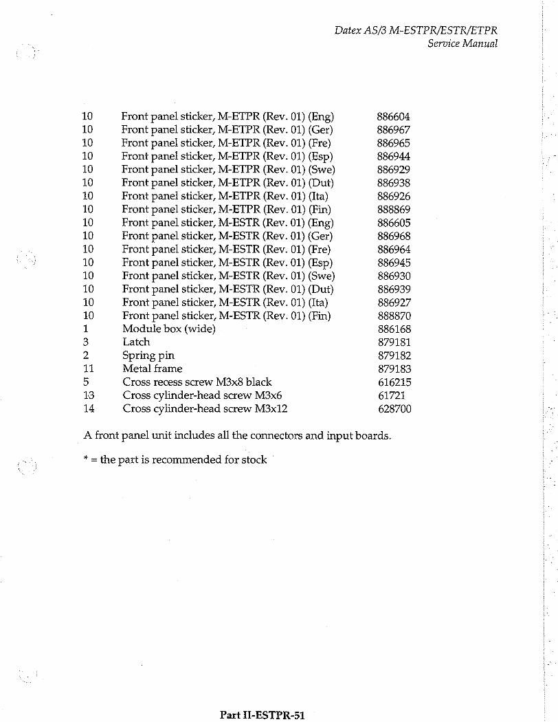
10 10 10 10 10 10 10 10 10 10 10 10 10 10 10 10 1 3 2 11
5 13 14
Front panel sticker, M-ETPR (Rev. 01) (Eng)
Front panel sticker, M-ETPR (Rev. 01) (Ger) Front panel sticker, M-ETPR (Rev. 01) (Fre)
Front panel sticker, M-ETPR (Rev. 01) (Esp)
Front panel sticker, M-ETPR (Rev. 01) (Swe) Front panel sticker, M-ETPR (Rev. 01) (Dut) Front pane! sticker, M-ETPR (Rev. 01) (Ita) Front panel sticker, M-ETPR (Rev. 01) (Fin) Front panel sticker, M-ESTR (Rev. 01) (Eng) Front panel sticker, M-ESTR (Rev. 01) (Ger) Front panel sticker, M-ESTR (Rev. 01) (Fre)
Front panel sticker, M-ESTR (Rev. 01) (Esp) Front panel sticker, M-ESTR (Rev. 01) (Swe) Front panel sticker, M-ESTR (Rev. 01) (Dut) Front panel sticker, M-ESTR (Rev. 01) (Ita)
Front panel sticker, M-ESTR (Rev. 01) (Fin)
Module box (wide) Latch
Spring pin Metal frame
Cross recess screw M3x8 black
Cross cylinder-head screw M3x6 Cross cylinder-head screw M3x12
Datex AS/3 M-ESTPR/ESTR/ETPR
Service Manual
886604 886967 886965 886944 886929 886938 886926 888869 886605 886968 886964 886945 886930 886939 886927 888870 886168 879181 879182 879183 616215 61721
628700
A front panel unit includes all the connectors and input boards.
* = the part is recommended for stock '
Part II-ESTPR-51
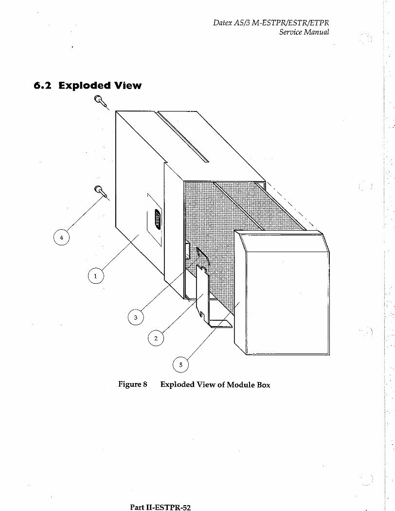
Datex AS/3 M-ESTPR/ESTR/ETPR
Service Manual
6.2 Exploded View
A
Figure8 Exploded View of Module Box
Part II-ESTPR-52
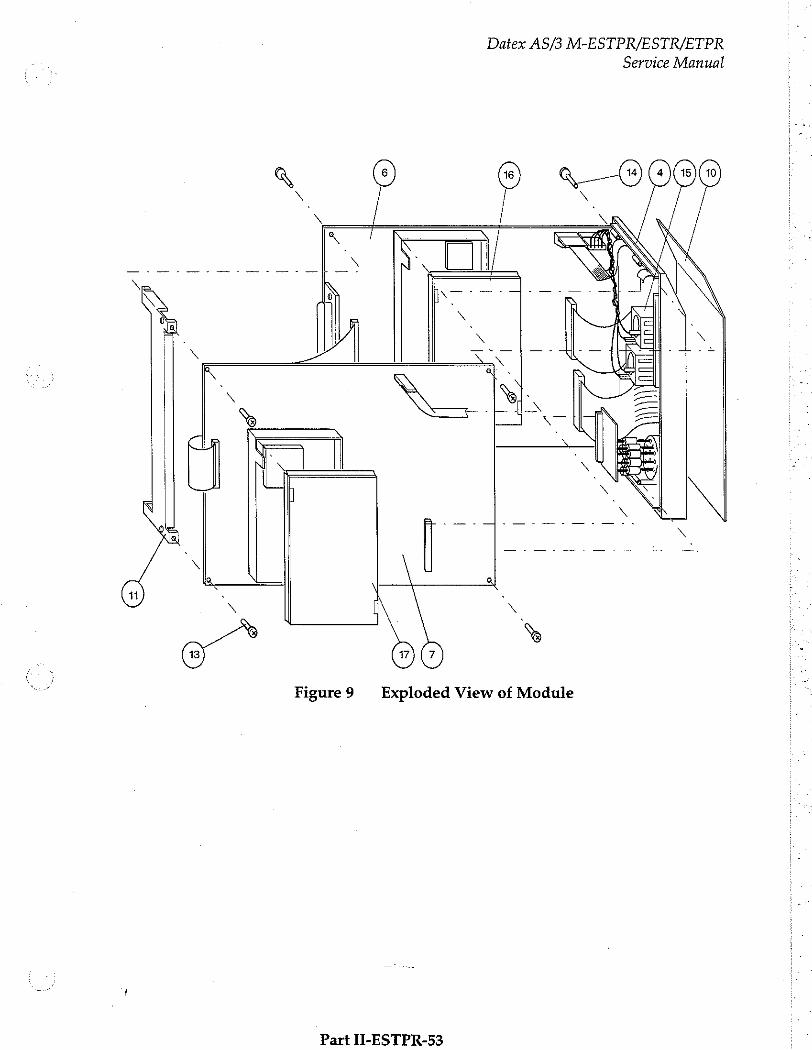
Datex AS/3 M-ESTPR/ESTR/ETPR
Service Manual
Figure9 Exploded View of Module
Part II-ESTPR-53
Datex AS/3 M-ESTPR/ESTR/ETPR
Service Manual
7 EARLIER REVISIONS
For service information on the earlier revisions, please refer
to:
ESTP Module revision 01 Service Manual p/n 880850 ETP Module revision 00 ーー
ESTP Module revision 02 Service Manual p/n 882580 ETP and EST Modules revision 01 ーー
ESTP Module revision 03-04, and ETP and EST Modules
revision 02-03 are supported by this manual too.
Part I-ESTPR-54
„u
Cardiac Output Module, M-COP (Rev. 02)
Cardiac Output and SvO, Module, M-COPSv (Rev. 00)
All specifications subject to change without notice
Document No. 889881
March, 1996
Datex Division, Instrumentarium Corp. P.O.Box 446 FIN-00101 Helsinki Finland
Tel. +358 0 39411 Fax +358 0 1463310

Datex AS/3 M-COP, M-COPSv
Service Manual

Datex AS/3 M-COP, M-COPSv Service Manual
Table of Contents
INTRODUCTION I
| SPECIFICATIONS 2
1.1 General Specifications ses rss eres erkende 2 1.2 Typical Performance... ss e eee Re Ren ete 2
1.3 Technical Specifications... sise 4
FUNCTIONAL DESCRIPTION 5
2.1 Measurement Principle A 5
2.2 Main Components and Block Diagram............................................. 9 2.2.1 COP Board
2.2.2 COPSv Board e eee ermenin
2.3 Connectors and signals…...….................................. sn 2.3.1 Module Bus Connector Configuration. ... 2.3.2 Front Panel Connectors.......... μμ μμ μϱ-ϱϐϱϐϱϐϱἛϱἛ-----.
SERVICE PROCEDURES 19
3.1 General Service Informatio 이 아 나 아 나 다 어 나 아 아 아 아 아 아 아 아 마 다 아 아 아 아 마 아 이 마 아 아 아 다 아 아 아 어 마 아 아 이 19 3.2 Preventive Maintenance Checks. … 20
3.3 Disassembly and Reassembiy..... „2 3.4 Adjustments and Calibrations .................... rire rien 22
TROUBLESHOOTING 24
SERVICE MENU 29
5.1 COP Service Men ee 30
SPARE PARTS - 33
6.1 Spare Parfs Es e een 33
¡ISS AAA nee ne 36
EARLIER REVISIONS 39

Datex AS/3 M-COP, M-COPSv
Service Manual
Datex AS/3 M-COP, M-COPSv
Service Manual
INTRODUCTION
Datex AS/3 Cardiac Output Modules, M-COP and M-
COPSv are single width plug-in modules for use with the Anaesthesia and Compact Monitors. Both modules provide cardiac output (C.O.), right ventricular ejection fraction (REF) and invasive pressure measurement. Additionally the COPSv module provides venous oxygen saturation (SvO,) measurement.
NOTE: Do not use identical modules in the same monitoring system. The COP and COPSv modules are considered as identical modules.
Part II-COP-1
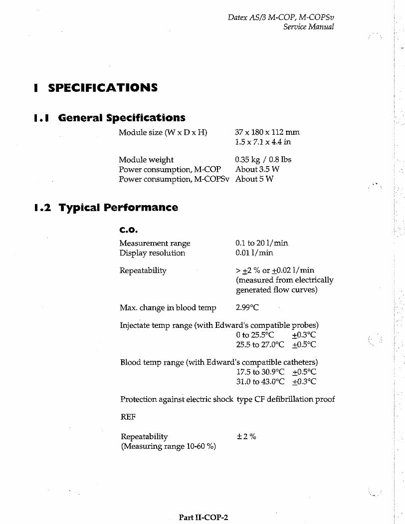
Datex AS/3 M-COP, M-COPSv
Service Manual
I SPECIFICATIONS
1.1 General Specifications
Module size (W x D x H) 37 x 180 x 112 mm 15x7.1x44in
Module weight 0.35 kg / 0.8 Ibs Power consumption, M-COP About 3.5 W
Power consumption, M-COPSv About 5W
1.2 Typical Performance
с.о.
Measurement range 0.1 to 20 1/min Display resolution 0.01 1/min
Repeatability > +2 % or +0.02 1/min (measured from electrically
generated flow curves)
Max. change in blood temp 2.99°C
Injectate temp range (with Edward's compatible probes) 0 to 25.5°C +0.3°С 25.5 40 27.0°С +0.5°C
Blood temp range (with Edward's compatible catheters) 17.5 to 30.9°C +0.5°C
31.0 to 43.0°C +0.3°C
Protection against electric shock type CF defibrillation proof
REF
Repeatability +2% (Measuring range 10-60 %)
Part П-СОР-2
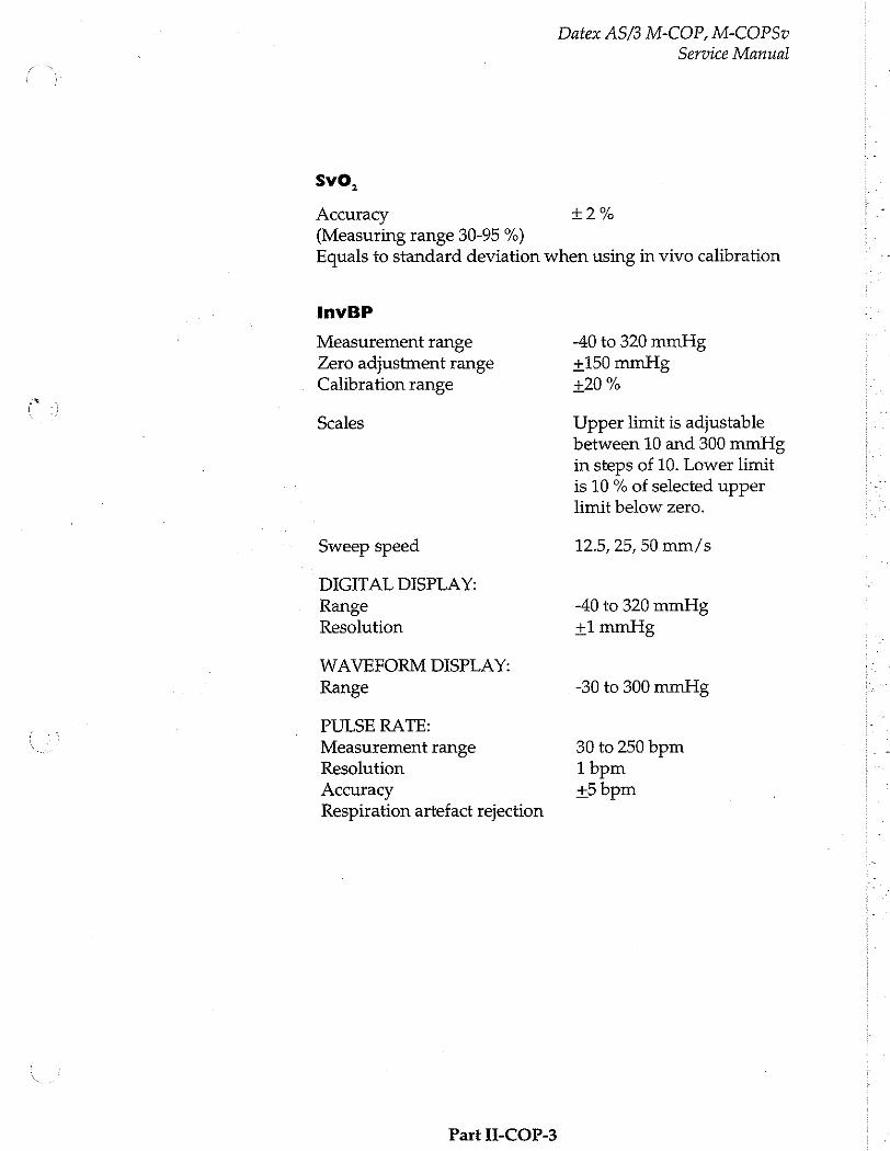
Datex AS/3 M-COP, M-COPSv
Service Manual
5νο 3
Accuracy +2% (Measuring range 30-95 %) Equals to standard deviation when using in vivo calibration
InvBP
Measurement range -40 to 320 mmHg Zero adjustment range +150 mmHg Calibration range +20 %
Scales Upper limit is adjustable between 10 and 300 mmHg in steps of 10. Lower limit is 10 % of selected upper limit below zero.
Sweep speed 12.5, 25, 50 mm/s
DIGITAL DISPLAY: Range -40 to 320 mmHg Resolution +1 mmHg
WAVEFORM DISPLAY: Range -30 to 300 mmHg
PULSE RATE: Measurement range 30 to 250 bpm Resolution 1 bpm Accuracy +5 bpm Respiration artefact rejection
Part Ii-COP-3
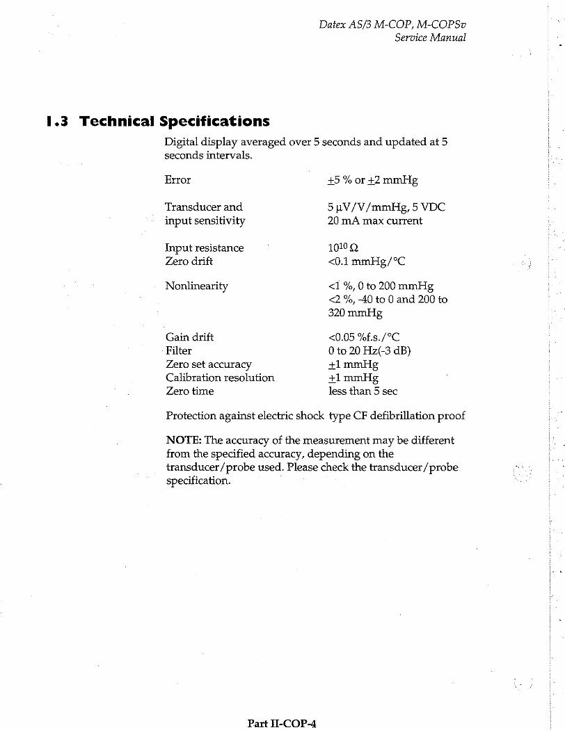
Datex AS/3 M-COP, M-COPSv
Service Manual
1.3 Technical Specifications
Digital display averaged over 5 seconds and updated at 5 seconds intervals.
Error +5 % or +2 mmHg
Transducer and 5uV/V/mmHg, 5 VDC
input sensitivity 20 mA max current
Input resistance 1019 Q Zero drift <0.1 mmHg/°C
Nonlinearity <1 %, 0 to 200 mmHg <2 %, -40 to 0 and 200 to
320 mmHg
Gain drift <0.05 %f.s./°C Filter 0 to 20 Hz(-3 dB) Zero set accuracy +1 mmHg Calibration resolution +1 mmHg
Zero time less than 5 sec
Protection against electric shock type CF defibrillation proof
NOTE: The accuracy of the measurement may be different from the specified accuracy, depending on the transducer /probe used. Please check the transducer/probe specification.
Part II-COP-4
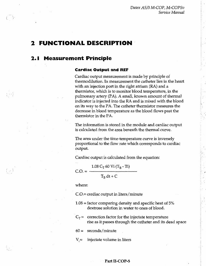
Datex AS/3 M-COP, M-COPSv Service Manual
2 FUNCTIONAL DESCRIPTION
2.1 Measurement Principle
Cardiac Output and REF
Cardiac output measurement is made by principle of thermodilution. In measurement the catheter lies in the heart with an injection port in the right atrium (RA) and a thermistor, which is to monitor blood temperature, in the
pulmonary artery (PA). A small, known amount of thermal indicator is injected into the RA and is mixed with the blood on its way to the PA. The catheter thermistor measures the decrease in blood temperature as the blood flows past the thermistor in the PA.
The information is stored in the module and cardiac output is calculated from the area beneath the thermal curve.
The area under the time-temperature curve is inversely proportional to the flow rate which corresponds to cardiac output.
Cardiac output is calculated from the equation:
1.08 Cr 60 Vi (Ty - Ti)
where:
C.O.= cardiac output in liters/minute
1.08 = factor comparing density and specific heat of 5% dextrose solution in water to ones of blood.
Cr= correction factor for the injectate temperature rise as it passes through the catheter and its dead space
60 = seconds/minute
V,= injectate volume in liters
Part II-COP-5

T=
T=
Datex AS/3 M-COP, M-COPSv
Service Manual
baseline blood temperature (°C)
injectate temperature
Tgdt =area under thermodilution curve between time o and x, where x is the time when the curve has dropped to 30% of its peak value.
area beneath thermodilution curve between x and end
of the curve.
©
で -T 9 Α area A
È 100% | start of meas.
o 80% |------ end of meas. bo a area C
점 30% v 된
8 0% | 5
8 9 > a tms. 180% tso% t E Time の F
Figure 1 Cardiac Output Measurement Curve
A =. area derived by integration of the time temperature thermodilution curve
C= area beneath the thermodilution curve between t39% and end of the curve. Computation based upon an exponential fit to the curve between tgg% of the peak and 39%.
Part II-COP-6
Datex AS/3 M-COP, M-COPSv
Service Manual
REF (right ventricular ejection fraction) measurement is a part of the thermodilution cardiac output measurement. Ejection fraction is determined using an exponential technique by synchronizing sensed R-waves with points of temperature changes on the thermodilution curve. Once ejection fraction, cardiac output, and heart rate are known,
right ventricular volumes may be calculated. The measurement requires BAXTER Edwards fast response thermistor catheter and also ECG-module to synchronise R- wave detection to the thermodilution curves.
SvO, Measurement (COPSv module only)
The COPSv module measures SvO, when coupled with Baxter-Edwards OM-2E optical module and Swan-Ganz oximetry catheter. To measure SvO,, the system utilizes a spectrophotometric technique involving the use of light- emitting diodes (LEDs) that produce red (660 nm) and
infrared (810 nm) light. The light is transmitted to the blood through a single plastic optical fiber in the oximetry catheter and reflected back through a separate optical fiber to a photodetector in the optical module. The light is electrically transmitted to the COPSv module and analyzed to determine SvO,.
The oximetry portion of the system measures SvO2 in the pulmonary artery by detecting colour changes in the red blood cells. When pulses of red and infrared light are transmitted through the oximetry catheter, the light is reflected from the red blood cells and transmitted back through the catheter to the optical module. The amount of light reflected at each wavelength depends primarily on the colour of the blood and the number of red blood celis. Since the number of red blood cells in the blood affects the amount of reflected light, the differences are compensated when the
patient's total haemoglobin value is entered. The optical module stores and transfers SvO, calibration data. SvO, values can be affected by the presence of methemeglobin or carboxyhaemoglobin which imitate the absorption characteristics of HbO,. Large concentrations of methemeglobin or carboxyhaemoglobin could then cause a falsely elevated SvO,. In cases where dysfunctional
Part II-COP-7
Datex A5/3 M-COP, M-COPSv
Service Manual
haemoglobins are suspected, SvO, should be interpreted with caution.
Invasive Biood Pressure Measurement
To measure invasive blood pressure, a catheter is inserted into an artery or vein. The invasive pressure setup, consisting of connecting tubing, pressure transducer, an intravenous bag of normal saline all connected together by stopcocks, is attached to the catheter. The transducer is
placed level with the heart, and electrically zeroed.
The transducer is a piezo-resistive device that converts the pressure signal to a voltage. The monitor interprets the voltage signal so that pressure data and pressure waveforms can be displayed.
Part Ii-COP-8
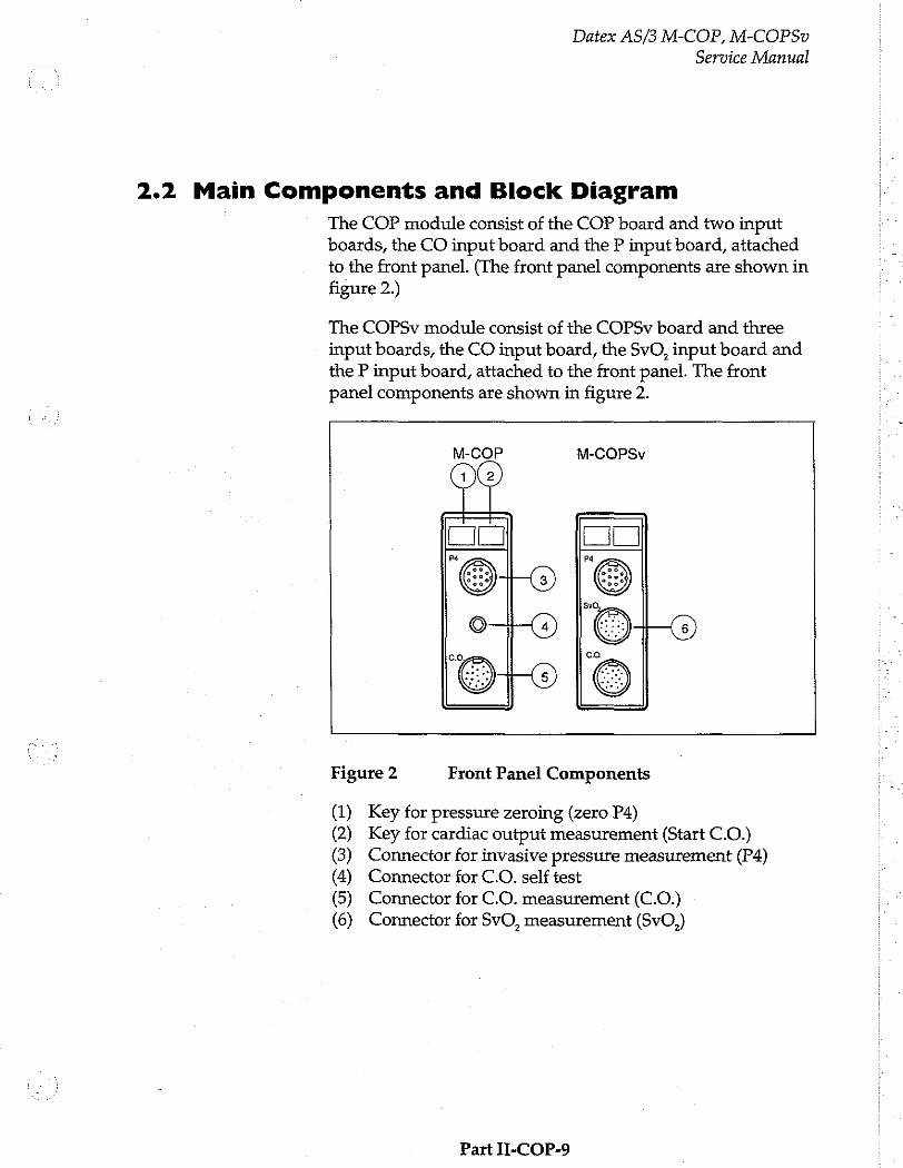
Datex AS/3 M-COP, M-COPSv
Service Manual
2.2 Main Components and Block Diagram
The COP module consist of the COP board and two input boards, the CO input board and the P input board, attached to the front panel. (The front panel components are shown in figure 2.)
The COPSv module consist of the COPSv board and three
input boards, the CO input board, the SvO, input board and
the P input board, attached to the front panel. The front panel components are shown in figure 2.
M-COP M-COPSv
oo ©
Figure 2 Front Panel Components
(1) Key for pressure zeroing (zero P4) (2) Key for cardiac output measurement (Start C.O.)
(3) Connector for invasive pressure measurement (P4) (4) Connector for C.O. self test (5) Connector for C.O. measurement (C.O.) (6) Connector for SvO, measurement (SvO,)
Part II-COP-9
2.2.1 COP Board
Datex AS/3 M-COP, M-COPSv
Service Manual
The COP board consists of the following functional sections.
e Processor section
» Cardiac output measurement section
e Cardiac output self test
« Invasive BP measurement section
+ Serial communication
e Isolated section
e Power supply section
Processor section
As the processor, Intel's 80C196KC-16 is used. There are external memories, an 8-bit data bus, a 16 MHz oscillator,
and a watchdog timer. Three A/D-converters within the processor are used. The processor's internal UART communicates with the host monitor.
Cardiac output measurement section
The catheter and the probe contain NTC-resistor that reacts to temperature change.
Temperature dependent voltage over the NTC-resistor is amplified and offset value is added to it, then regulated into +5 V range in voltage slicing and sent to A/D converter.
Because the temperature measurements are calibrated digitally and non-linearity of catheter/probe is compensated by software, ambient temperature change after calibration is the only factor that may have influence upon the measurement.
Cardiac output self test
There is a connector for C.O. test on the module front panel to find out whether the fault is in the catheter or in the
module.
When the cable is connected to the self-test connector,
processor starts the test program automatically. First, the processor measures 30°C. Then, it activates test circuits and
measures 37°C and then 41°C.
Part II-COP-10
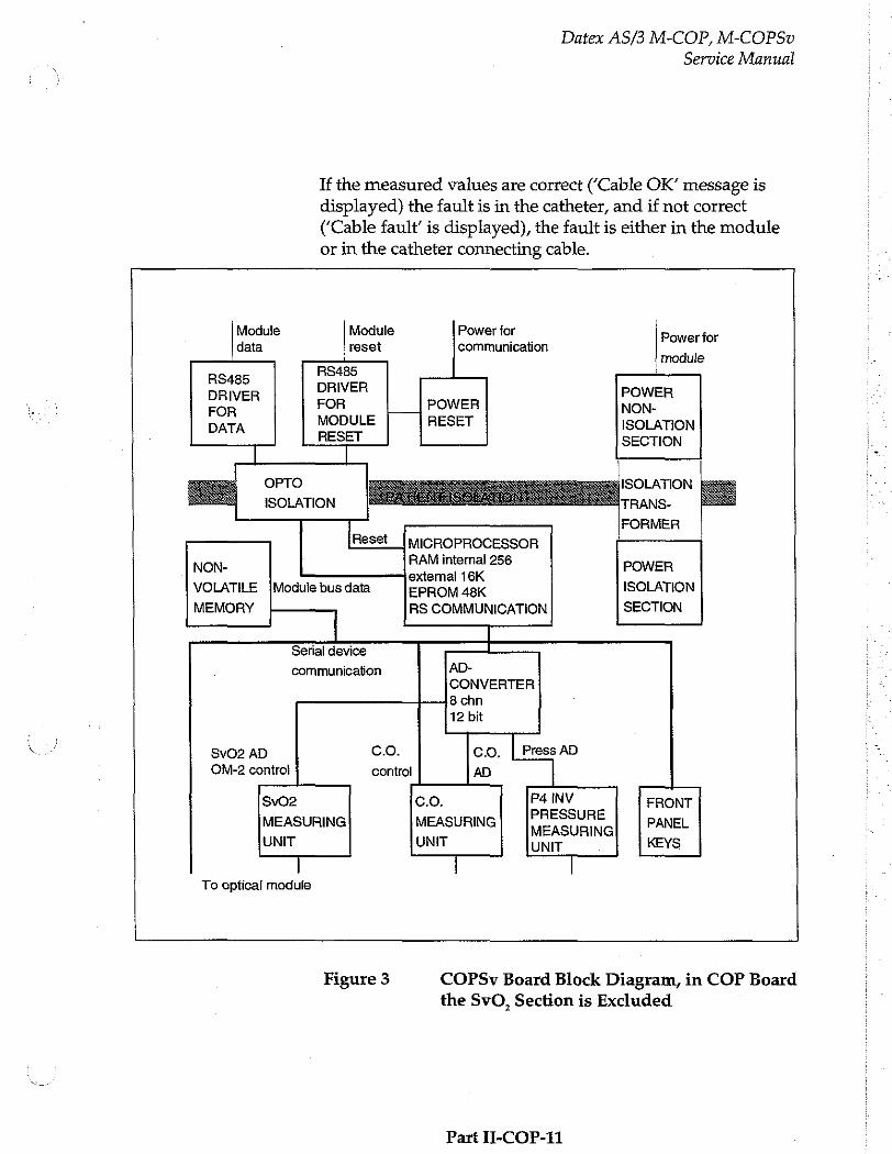
Datex AS/3 M-COP, M-COPSv
Service Manual
If the measured values are correct (‘Cable OK’ message is displayed) the fault is in the catheter, and if not correct (‘Cable fault’ is displayed), the fault is either in the module or in the catheter connecting cable.
Module Module Power for 」 Power for data reset communication
module
86486 DRIVER DRIVER POWER FOR FOR POWER NON- DATA MODULE RESET ISOLATION
RESET SECTION
OPTO
ISOLATION
Reset IMICROPROCESSOR NON- RAM internal 256 POWER
external 16K VOLATILE ¡Module bus data EPROM 48K ISOLATION
MEMORY RS COMMUNICATION SECTION
Serial device
communication AD- CONVERTER 8 chn 12 bit
SvO2 AD co. co. | Press AD OM-2 control control AD
SvO2 C.O. En И ЗОНЕ FRONT MEASURING MEASURING MEASURING PANEL
UNIT UNIT UNIT KEYS
| | | To optical module
Figure 3 COPSv Board Block Diagram, in COP Board the SvO, Section is Excluded
Part II-COP-11

Datex AS/3 M-COP, M-COPSv
Service Manual
Invasive BP measurement section
Isolated +5 V voltage is supplied to the pressure transducer. From the bridge connection a differential voltage, which depends on pressure and supplied voltage, is calculated (see the formula below).
Uout = Uin x Pressure x 5 V
where Uin=5 V
Uout = 25 V x Pressure [mmHg]
Pressure amplification is realized in the instrumentation amplifier. Gain of the amplifier is set so that the level of the signal transferred to A/D converter stays within the measurement range even when there are circumstantial offsets or offsets caused by the transducer. There is a filter before the amplifier to attenuate high frequency disturbances.
There is also FET switch, which, by cutting the measurement
current, detects the existence of the transducer. The existence
of the transducer is also checked binary by the jumper beside the connector.
Pressure transducer
instrumentation
amplifier
Input Filter ¢ >>
to AD converter
Figure 4 Pressure Transducer Working Principle
Part II-COP-12
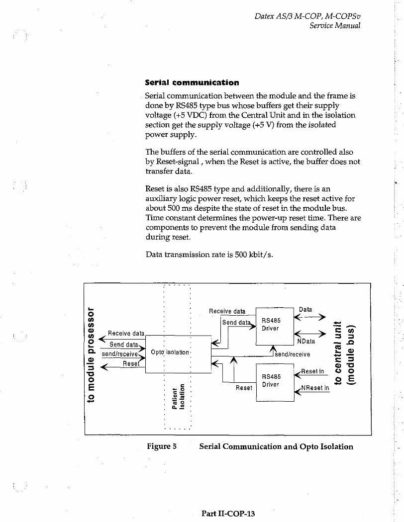
Datex AS/3 M-COP, M-COPSv
Service Manual
Serial communication
Serial communication between the module and the frame is done by RS485 type bus whose buffers get their supply voltage (+5 VDC) from the Central Unit and in the isolation section get the supply voltage (+5 V) from the isolated power supply.
The buffers of the serial communication are controlled also
by Reset-signal , when the Reset is active, the buffer does not
transfer data.
Reset is also RS485 type and additionally, there is an auxiliary logic power reset, which keeps the reset active for about 500 ms despite the state of reset in the module bus. Time constant determines the power-up reset time. There are components to prevent the module from sending data during reset.
Data transmission rate is 500 kbit/s.
Le i Data 5 Receive data
a Send data, RS485 < ? = の Driver =n a < > 5 5 o “—— NData — 2
es —— > AM © ©- send/receive L | Opto isolation. send/receive = 2 2 Reset ; 5 o
Resetin © O © Rs485 长。 一 = 2 Driver 22 E - 5 Reset NResetin
o sö © as
Figure 5 Serial Communication and Opto Isolation
Part II-COP-13
Datex AS/3 M-COP, M-COPSv
Service Manual
Isolated section
Signal is processed on logical high-low level even though the output of the opto isolators is analog signal in the isolated section.
Reset line is an open collector type with a pull-up resistor. Thus the processor is able to use its internal watch-dog function.
Power supply section
Isolated supply voltage of the module is developed from +15 Vdirty voltage from the host monitor.
Power supply is a switched-mode circuit, where a FET transistor switch is controlled by an oscillator using bipolar timer. Controlling of the FET switch is slowed to suppress spurious interference. A special pulse transformer is used in the circuit. In the secondary circuit normal linear regulators are used except for +5 V (low drop type linear regulator).
2.2.2 COPSv Board
The COPSv board consists of the same functional sections as the COP board, except for the cardiac output self test section. Additionally the COPSv board consists of the SvO, measurement section.
SVO, Measurement Section
The SvO, algorithm is a part of the COPSv module software. The algorithm consists of five different parts; initialization,
calibrations, signal processing and SvO, calculation, automatic gain control, and signal quality analysis.
Initialization
When the optical module is connected to the COPSv module, a number of start-up procedures are performed prior to normal operation. These procedures include transfer of calibration factors from the optical module to the COPSv module and initialization of LED currents.
Part Y-COP-14
Datex AS/3 M-COP, M-COPSv
Service Manual
Calibration
The system is calibrated according to either in-vitro or in- vivo calibration. In-vitro calibration is performed before the oximetry catheter is removed from the package with the catheter tip still inside the calibration cup. The resulting calibration factor is calculated on the basis of the measured ratio of red and infrared signals and the ideal ratio for the calibration cup. In-vivo calibration is performed when the catheter is inserted into the patient’s pulmonary artery. The resulting calibration factor is based on the measured ratio of
red and infrared signal and the Hgb and SvO, values measured in a laboratory. If the calibration is skipped, the result of an old calibration is used instead and “Not calibrated”-message is displayed in the SVO, number field.
Signal Processing and SvO, Calculation
The reflected red and infrared signals transferred from the optical module to the COPSv module are filtered, and SvO, is calculated on the basis of the ratio of the signals.
Automatic Gain Control
The intensity of the red and infrared signals can be amplified by four different gains. The gain is selected automatically to achieve optimal signal levels.
Signal Quality
The reflected red and infrared signals are checked for wall contact artefacts, pulsatility and intensity shifts. An index is calculated to indicate the signal quality. 0 indicates a normal signal, 1 indicates an intermediate signal, 2 indicates a poor signal, and 3 indicates an unacceptable signal. Please refer to the service menu section for more information.
Part II-COP-15
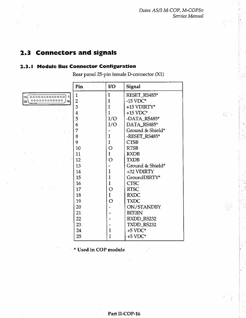
2.3 Connectors and signals
Datex AS/3 M-COP, M-COPSv
2.3.1 Module Bus Connector Configuration
3
1 0000000000000] 1
25 000000000000 [44
Rear panel 25-pin female D-connector (X1)
Service Manual
Pin 1/0 Signal
1 I RESET_RS485* 2 I -15 VDC* 3 I +15 VDIRTY* 4 I +15 VDC* 5 1/0 -DATA RS485* 6 1/0 DATA RS485* 7 - Ground & Shield*
8 I ~RESET_RS485* 9 I CTSB 10 ο RTSB 11 I RXDB 12 0 TXDB 13 - Ground & Shield*
14 I +32 VDIRTY 15 I GroundDIRTY* 16 I CTSC 17 ο RTSC 18 I RXDC 19 0 TXDC 20 ~ ON/STANDBY 21 - BITOIN 2 - RXDD RS232 23 - TXDD RS232
24 I +5 VDC* 25 I +5 VDC*
* Used in COP module
Part II-COP-16
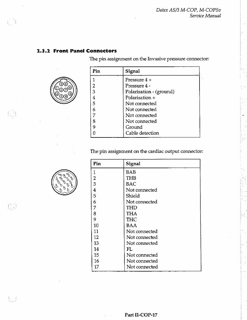
Datex AS/3 M-COP, M-COPSv
Service Manual
2.3.2 Front Panel Connectors
The pin assignment on the Invasive pressure connector:
Pin Signal
Pressure 4 +
Pressure 4 -
Polarisation - (ground) Polarisation +
Not connected
Not connected
Not connected
Not connected
Ground
Cable detection Ὁ
0 © “JO O1
©
ND H
The pin assignment on the cardiac output connector:
Pin Signal
1 BAB 2 THB 3 BAC 4 Not connected
5 Shield 6 Not connected
7 THD 8 THA 9 THC 10 BAA 11 Not connected
12 Not connected
13 Not connected
14 FL 15 Not connected
16 Not connected
17 Not connected
Part 11-COP-17

Datex AS/3 M-COP, M-COPSv
Service Manual
The pin assignment on the C.O. Self Test connector:
Pin Signal
1 CTC 2 CTA 3 CTB 4 CTD
The pin assignment on the SVO, connector
Pin Signal
1 IR CATHODE 2 CE 3 SK 4 DATA OUT 5 CHASSIS GND 6 SVO2 GND 7 HEATER RTN
8 REMOTE OUT 9 +V OPT 10 TEMP SENSOR 11 HEATER HI 12 LOCAL. OUT 13 REF RTN 14 LED_ANODE 15 RED CATHODE 16 DATA IN 17 -V OPT
Part II-COP-18
Datex AS/3 M-COP, M-COPSv
Service Manual
3 SERVICE PROCEDURES
3.1 General Service Information
Field service of the COP and COPSv modules is limited to
replacing faulty mechanical parts. In all other cases, return the faulty module to Datex for repair. The COP board or the COPSv board cannot be replaced, and all calibrations can be
done at the factory only.
Datex is always available for service advice. Please provide the unit serial number, full type designation, and a detailed fault description.
CAUTION: Only trained personnel with the appropriate tools and equipment shall perform the tests and repairs outlined in this section. Unauthorized service may void warranty of the unit.
Part II-COP-19
Datex AS/3 M-COP, M-COPSv
Service Manual
3.2 Preventive Maintenance Checks
We recommend you to perform these checks at least once a year and after any service.
1. Visual inspection
_ . Ifthe module is disassembled, check that all
connectors are properly connected and there is no loose object inside the module before attaching the module box.
2. Functional checks
a Insert the module into monitor frame.
—: Tumthe power on by STBY-switch. COP window should appear on the display if selected for display. No error message should appear.
_; Pull out the module. The COP window goes blank within 15 seconds.
== Reinsert the module while the power is still on. The
COP measurement data appear on the window again.
o: Go to Service Menu, Service View, Modules, COP and
check the functions of cable and probes. Check buttons (ON/OFF test).
Part II-COP-20
Datex AS/3 M-COP, M-COPSv
Service Manual
3.3 Disassembly and Reassembly
The COP and COPSv modules are disassembled in the following way. See the exploded view of the module.
a) Remove the two screws from the back of the module.
b) Pull the module box slowly rearward and detach it from main body. Be careful with loose latch and spring pin for locking.
CAUTION: When reassembling the module, make sure that the cables are reconnected properly.
Part H-COP-21
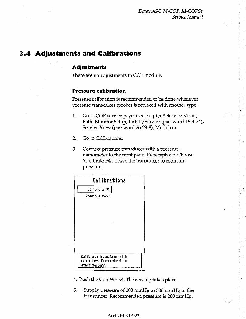
Datex AS/3 M-COP, M-COPSv
Service Manual
3.4 Adjustments and Calibrations
Adjustments
There are no adjustments in COP module.
Pressure calibration
Pressure calibration is recommended to be done whenever pressure transducer (probe) is replaced with another type.
1. - Goto COP service page. (see chapter 5 Service Menu; Path: Monitor Setup, Install /Service (password 16-4-34), Service View (password 26-23-8), Modules)
2. Go to Calibrations.
3. Connect pressure transducer with a pressure manometer to the front panel P4 receptacle. Choose ‘Calibrate P4’. Leave the transducer to room air pressure.
Calibrations
Calibrate Pd
Previous Menu
Calibrate transducer with nanometer. Press wheel to start zeroing.
4. Push the ComWheel. The zeroing takes place.
5. Supply pressure of 100 mmHg to 300 mmHg to the transducer. Recommended pressure is 200 mmHg.
Part II-COP-22
Datex AS/3 M-COP, M-COPSv
Service Manual
6. Set the pressure on the display with the ComWheel to match the pressure reading on manometer and push the ComWheel. Tolerance of +1 mmHg is allowed.
7. The text ‘calibrated’ will appear on the display.
Cardiac output calibration
The cardiac output calibration is done only at the factory.
Part H-COP-23
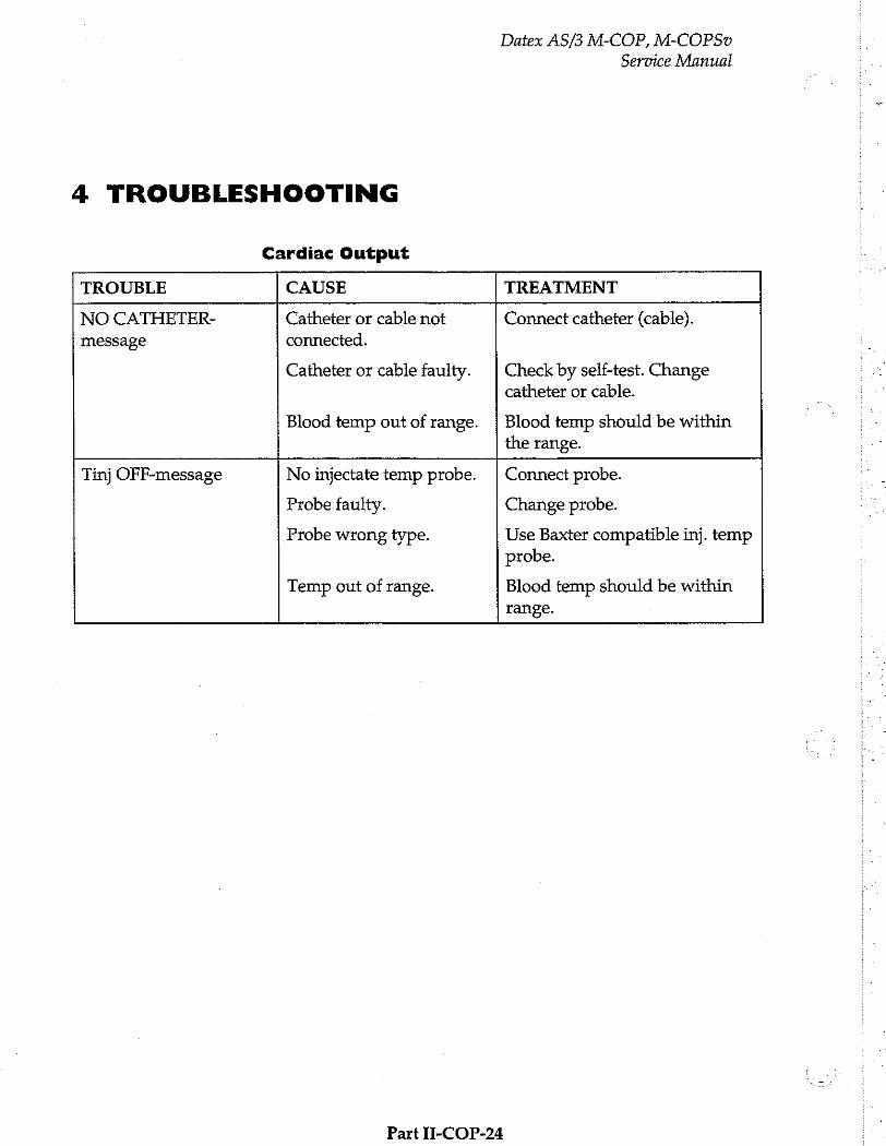
Datex AS/3 M-COP, M-COPSv
Service Manual
4 TROUBLESHOOTING
Cardiac Output
TROUBLE CAUSE TREATMENT
NO CATHETER- Catheter or cable not Connect catheter (cable). message connected.
Catheter or cable faulty.
Blood temp out of range.
Check by self-test. Change catheter or cable.
Blood temp should be within the range.
Tinj OFF-message
No injectate temp probe.
Probe faulty.
Probe wrong type.
Temp out of range. Connect probe.
Change probe.
Use Baxter compatible inj. temp probe.
Blood temp should be within range.
Part II-COP-24
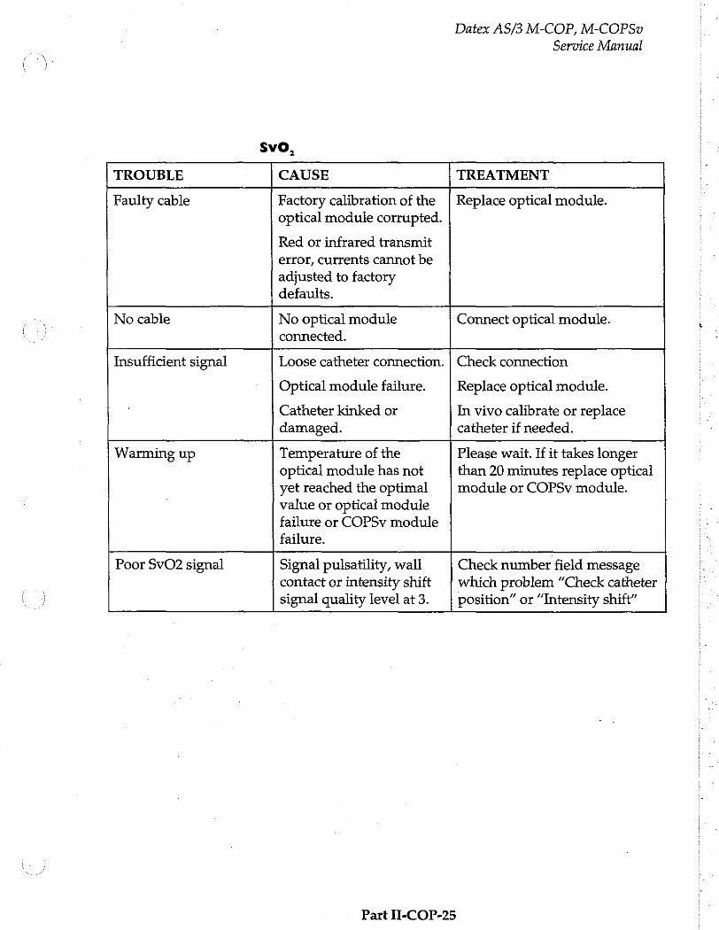
Datex AS/3 M-COP, M-COPSv
Service Manual
SVO,
TROUBLE CAUSE TREATMENT
Faulty cable Factory calibration of the | Replace optical module. optical module corrupted.
Red or infrared transmit error, currents cannot be adjusted to factory defaults.
No cabie No optical module Connect optical module.
connected.
Insufficient signal Loose catheter connection. | Check connection
Optical module failure. Replace optical module.
Catheter kinked or In vivo calibrate or replace damaged. catheter if needed.
Warming up Temperature of the Please wait. If it takes longer optical module has not than 20 minutes replace optical yet reached the optimal module or COPSv module. value or optical module failure or COPSv module failure.
Poor SvO2 signal Signal pulsatility, wall Check number field message
contact or intensity shift | which problem “Check catheter signal quality level at 3. position” or “Intensity shift”
Part II-COP-25

Datex AS/3 M-COP, M-COPSv
Service Manual
Invasive BP
TROUBLE CAUSE TREATMENT
Abnormally low Transducer wrongly Check mid-heart level and pressure positioned. reposition transducer.
No pressure Defective transducer. Check transducer.
No pressure module Check the module. plugged in.
No waveform selected on
screen.
To select the desired pressure waveforms press Monitor Setup key and select modify waveforms.
Check that pressure transducer is open to patient.
Not zeroed-message Measurement on, channel
not zeroed.
Zero the channel.
Zeroing failed-message Unsuccessful zeroing of Pi (number field).
Possibly due to pulsating pressure waveform. Open the transducer to air and zero the channel.
Offset is > 150 mmHg. Open the transducer to room air and
zero the channel.
Defective transducer. Replace it and zero the channel.
Calibration failed-
message
Unsuccessful calibrating of P4 (number field).
Pulsating waveform. Turn the transducer to sphygmomanometer and try again (zeroing takes place first).
Gain is beyond the limits (+20 % of the default gain) of the module. Replace the transducer.
Out of range < 40 mmHg Measurement pressure is
beyond measurement range. Check transducer level. Zero
the channel.
Part II-COP-26
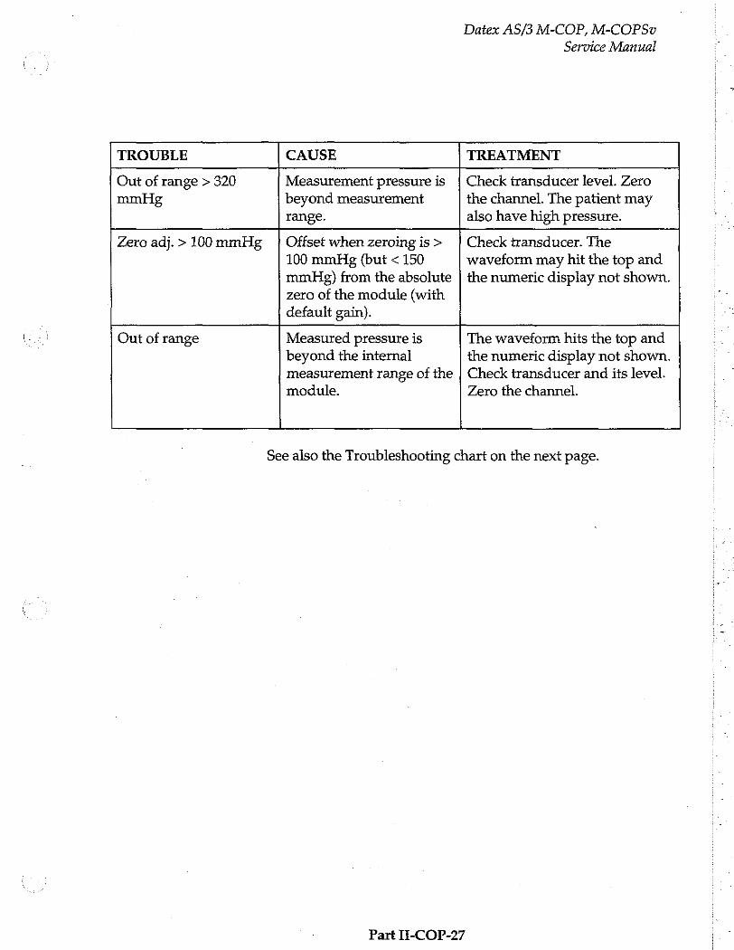
Datex AS/3 M-COP, M-COPSv
Service Manual
TROUBLE CAUSE TREATMENT
Out of range > 320 Measurement pressure is | Check transducer level. Zero mmHg beyond measurement the channel. The patient may
range. also have high pressure.
Zero adj. > 100 mmHg Offset when zeroing is > 100 mmHg (but < 150 mmHg) from the absolute zero of the module (with default gain).
Check transducer. The waveform may hit the top and the numeric display not shown.
Out of range Measured pressure is
beyond the internal measurement range of the module.
The waveform hits the top and the numeric display not shown. Check transducer and its level. Zero the channel.
See also the Troubleshooting chart on the next page.
Part II-COP-27
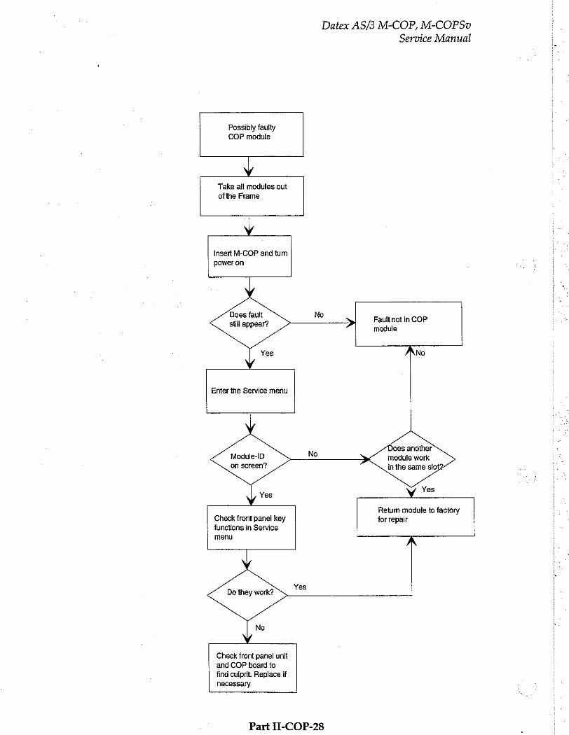
Datex AS/3 M-COP, M-COPSv
Service Manual
Possibly faulty
COP module
Y
Take all modules out
ofthe Frame
Y Insert M-COP and tum
power on
Does fault still appear?
No > Fault not in COP
module
No
Enter the Service menu
Does another module work in the same slo
Module-ID on screen?
Retum module to factory Check front panel key for repair functions in Service
menu
Do they work?
Check front panel unit
and COP board to find culprit. Replace if necessary
Part II-COP-28
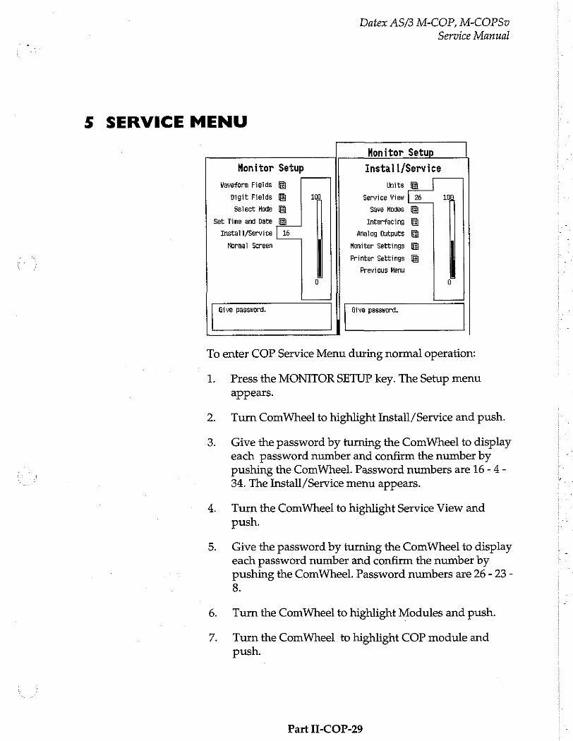
Datex AS/3 M-COP, M-COPSu
Service Manual
5 SERVICE MENU
Monitor Setup
Monitor Setup . Install/Service
Waveform Fields Units
Digit Fields 100 Service View | 26 100
Select Mode Save Modes
Set Time and Date Interfacing
Instat i/Service | 16 analog Outputs
Normal Screen Monitor Settings
Printer Settings
Previous Menu
a 8
Give password. Give password.
To enter COP Service Menu during normal operation:
1. Press the MONITOR SETUP key. The Setup menu appears.
Turn ComWheel to highlight Install /Service and push.
Give the password by turning the ComWheel to display each password number and confirm the number by pushing the ComWheel. Password numbers are 16 - 4 -
34. The Install /Service menu appears.
Turn the ComWheel to highlight Service View and push.
Give the password by turning the ComWheel to display each password number and confirm the number by pushing the ComWheel. Password numbers are 26 - 23 - 8.
Turn the ComWheel to highlight Modules and push.
Turn the ComWheel to highlight COP module and push.
Part II-COP-29
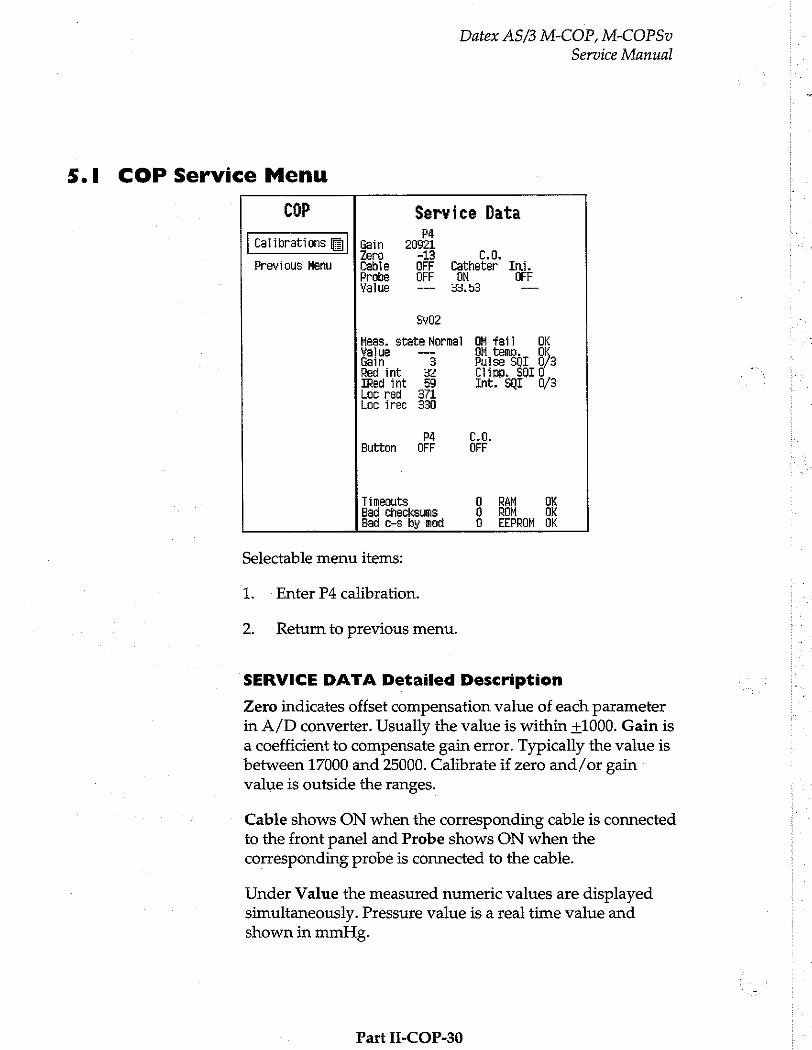
Datex AS/3 M-COP, M-COPSu
Service Manual
5.1 COP Service Menu
cor Service Data 4
Calibrations [Ej | Gain 209 어 - Zero -13 CO. 0
Previous Menu Cable OFF Catheter Ini. Probe OFF OM OFF Yalue ー- 33,53 —
5402
Heas. state Normal OM fail Ok Value — ето. 0 Gain. 3 Pulse SQL 0/3 Red int 32 Clipp. SOLU TRed int 59 Int. SQT 0/3 Loc red 371 Loc irec 330
På C.0. Button OFF OFF
Timeouts O RAM DK Bad checksums a ROM OK Bad c-s by mod O EEPROM OK
Selectable menu items:
1. Enter P4 calibration.
2. Return to previous menu.
SERVICE DATA Detailed Description
Zero indicates offset compensation value of each parameter in A/D converter. Usually the value is within +1000. Gain is a coefficient to compensate gain error. Typically the value is between 17000 and 25000. Calibrate if zero and/or gain value is outside the ranges.
Cable shows ON when the corresponding cable is connected to the front panel and Probe shows ON when the corresponding probe is connected to the cable.
Under Value the measured numeric values are displayed simultaneously. Pressure value is a real time value and shown in mmHg.
Part II-COP-30
Datex AS/3 M-COP, M-COPSv
Service Manual
At the Probe items Catheter (ON/OFF) and Inj. (FT, BATH, or OFF) indicate connections and Value indicates measured
temperature at 1/100th degrees of Centigrade.
Meas. state: Measurement status: No optical module (No OM) connected, initializing the optical module (Init OM), normal measurement state (Normal) and failed module (OM fail).
Value is a measured SvO, value.
Gain is a gain of the remote red and infrared signals (0,1,2
or 3)
Red int: Reflected red intensity
Ired int: Reflected infrared intensity
Loc red: Local red intensity
Loc ired: Local infrared intensity
OM fail: Reason why initialization OK (OK), can’t read EEPROM of the optical module correctly (EEPROM), can’t adjust led current to get local signal as wanted (Transmit).
OM temp: Temperature of the optical module OK (OK),
temp under 43 °C (Under), temp over 47 °C (Over).
Pulse SQI: Signal quality index for pulsing (low pulse/high pulse). 0 indicates a normal signal, 1 indicates an intermediate signal, 2 indicates a poor signal, and 3 indicates an unacceptable signal.
Clipp. SQI: Signal quality index for wall artefact. 0 indicates a normal signal, 1 indicates an intermediate signal, 2 | indicates a poor signal, and 3 indicates an unacceptable signal.
Int. SQI: Signal quality index for intensity shift from previous calibration or Hgb update (intensity decreased /increased) 0 indicates a normal signal, 1 indicates
an intermediate signal, 2 indicates a poor signal, and 3 indicates an unacceptable signal.
Part II-COP-31

Datex AS/3 M-COP, M-COPSv
Service Manual
The front panel key function is confirmed by pressing the key and observing OFF turns to ON at Button.
Timeouts is a cumulative number that indicates how many times the module has not responded to the monitor's inquiry.
Bad checksums is also a cumulative number that indicates how many times communication from the module to monitor broke down. Bad c-s by mod is a cumulative number that indicates how many communication errors the module has detected. The monitor starts counting these items at power up and resets to Zero at power off. The nonzero values do not indicate a failure, but the continuous counting (more than 50 per second) during the normal operation indicates either serial communication failure or module not in place.
RAM indicates the state of the external RAM memory. ROM indicates whether the checksum at the EPROM is in accordance with the one the software has calculated. EEPROM indicates if the values stored in the permanent memory are valid. The state is either OK, Fail or ? (module not in place ora communication error).
Part II-COP-32
Datex AS/3 M-COP, M-COPSv
Service Manual
6 SPARE PARTS
6.1 Spare Parts List
NOTE: Only changed part numbers are listed under later revisions. To find the desired part: check first the list of the revision that corresponds your device. If the part is not listed there, check the previous revision, etc. until you find the right number.
NOTE: Accessories are listed in the booklet AS/3 Supplies and Accessories.
item numbers refer to the exploded view in chapter 6.2.
Part II-COP-33
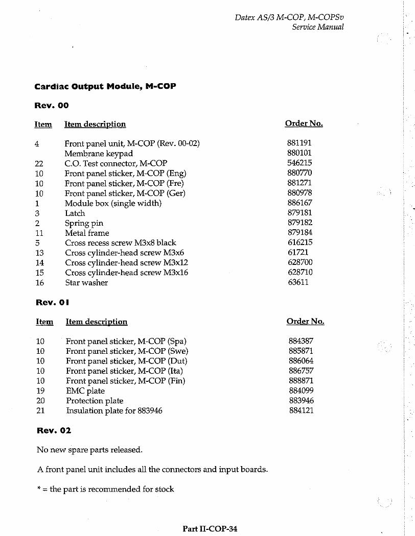
Cardiac Output Module, M-COP
Rev. 00
Item Item description
4 Front panel unit, M-COP (Rev. 00-02) Membrane keypad
22 C.O. Test connector, M-COP
10 Front panel sticker, M-COP (Eng) 10 Front panel sticker, M-COP (Pre) 10 Front panel sticker, M-COP (Ger) 1 Module box (single width) 3 Latch
2 Spring pin 11 Metal frame
5 Cross recess screw M3x8 black
13 Cross cylinder-head screw M3x6 14 Cross cylinder-head screw M3x12 15 Cross cylinder-head screw M3x16 16 Star washer
Item Item description
10 Front panel sticker, M-COP (Spa)
10 Front panel sticker, M-COP (Swe)
10 Front panel sticker, M-COP (Dut) 10 Front panel sticker, M-COP (Ita)
10 Front panel sticker, M-COP (Fin) 19 EMC plate
20 Protection plate 21 Insulation plate for 883946
Rev. 02
No new spare parts released.
Datex AS/3 M-COP, M-COPSv
Service Manual
Order No.
881191 880101 546215 880770 881271
880978 886167 879181 879182 879184 616215 61721 628700 628710 63611
Order No.
884387 885871 886064 886757 888871 884099 883946 884121
A front panel unit includes all the connectors and input boards.
* = the part is recommended for stock
Part II-COP-34
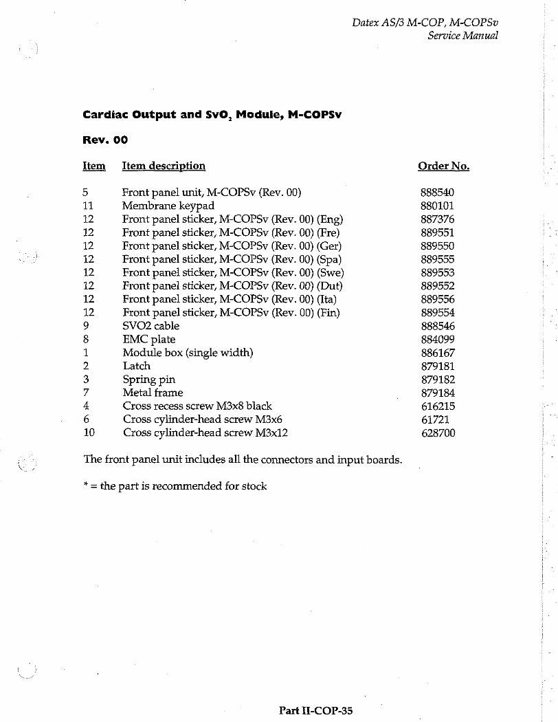
Datex AS/3 M-COP, M-COPSv
Cardiac Output and SvO, Module, M-COPSv
Rev. 00
Item Item description
5 Front panel unit, M-COPSv (Rev. 00) 11 Membrane keypad 12 Front panel sticker, M-COPSv (Rev. 00) (Eng) 12 Front panel sticker, M-COPSv (Rev. 00) (Fre) 12 Front panel sticker, M-COPSv (Rev. 00) (Ger)
12 Front panel sticker, M-COPSv (Rev. 00) (Spa) 12 Front panel sticker, M-COPSv (Rev. 00) (Swe) 12 Front panel sticker, M-COPSv (Rev. 00) (Dut) 12 Front panel sticker, M-COPSv (Rev. 00) (Ita) 12 Front panel sticker, M-COPSv (Rev. 00) (Fin) 9 SVO2 cable 8 EMC plate 1 Module box (single width)
2 Latch 3 Spring pin 7 Metal frame 4 Cross recess screw M3x8 black
6 Cross cylinder-head screw M3x6 10 Cross cylinder-head screw M3x12
The front panel unit includes all the connectors and input boards.
* = the part is recommended for stock
Part 1-COP-35
Service Manual
Order No.
888540 880101
887376 889551 389550 889555 889553 889552 889556 889554 888546 884099 886167 879181 879182 879184 616215 61721 628700
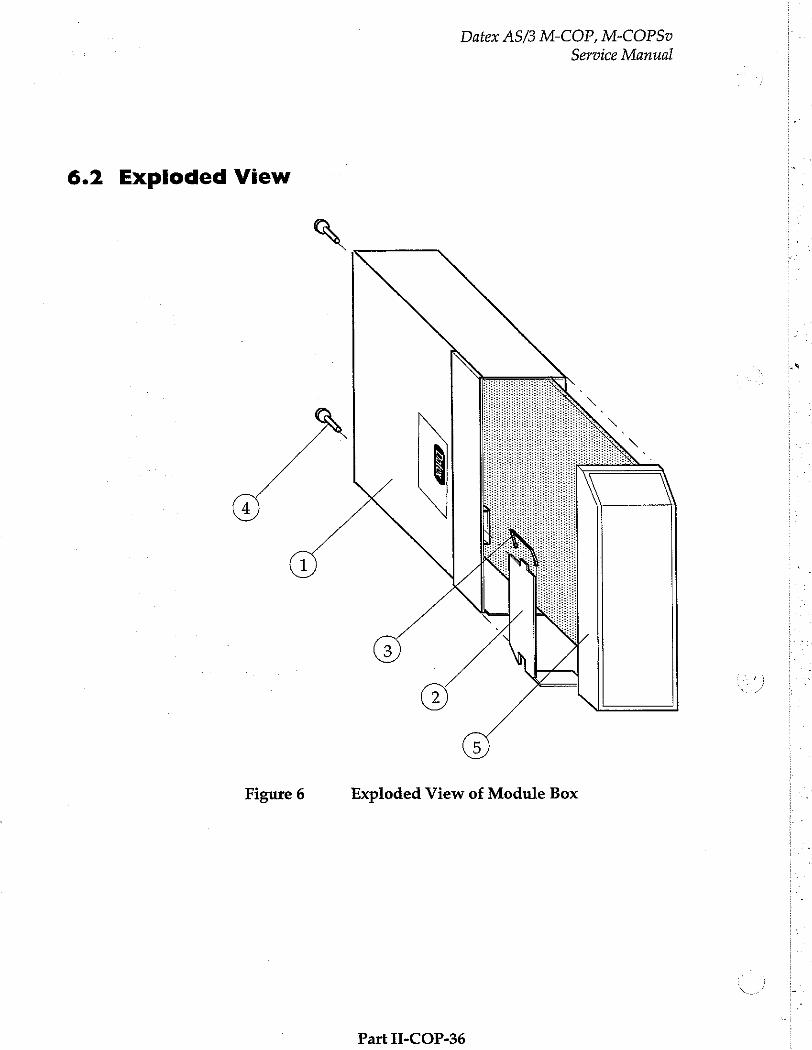
Datex AS/3 M-COP, M-COPSv
Service Manual
6.2 Exploded View
や
Figure 6 Exploded View of Module Box
Part II-COP-36
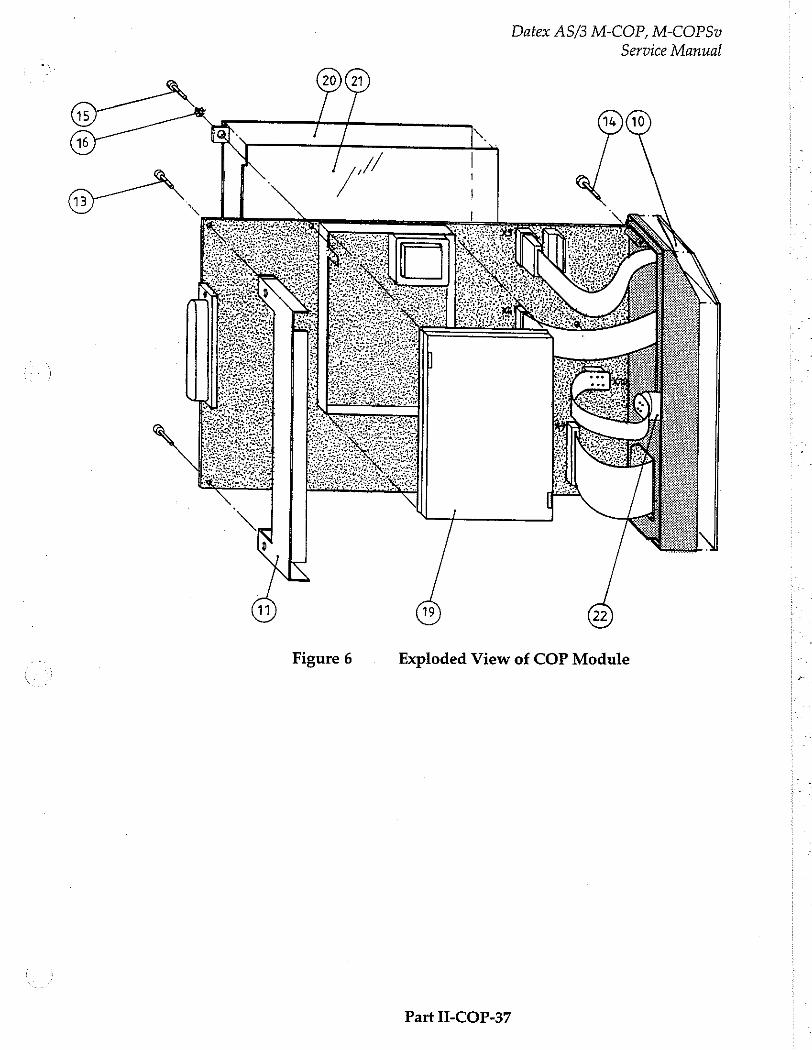
Datex AS/3 M-COP, M-COPSv
Service Manual
Gm が 16
ЛИ / |
Figure 6 Exploded View of COP Module
Part II-COP-37
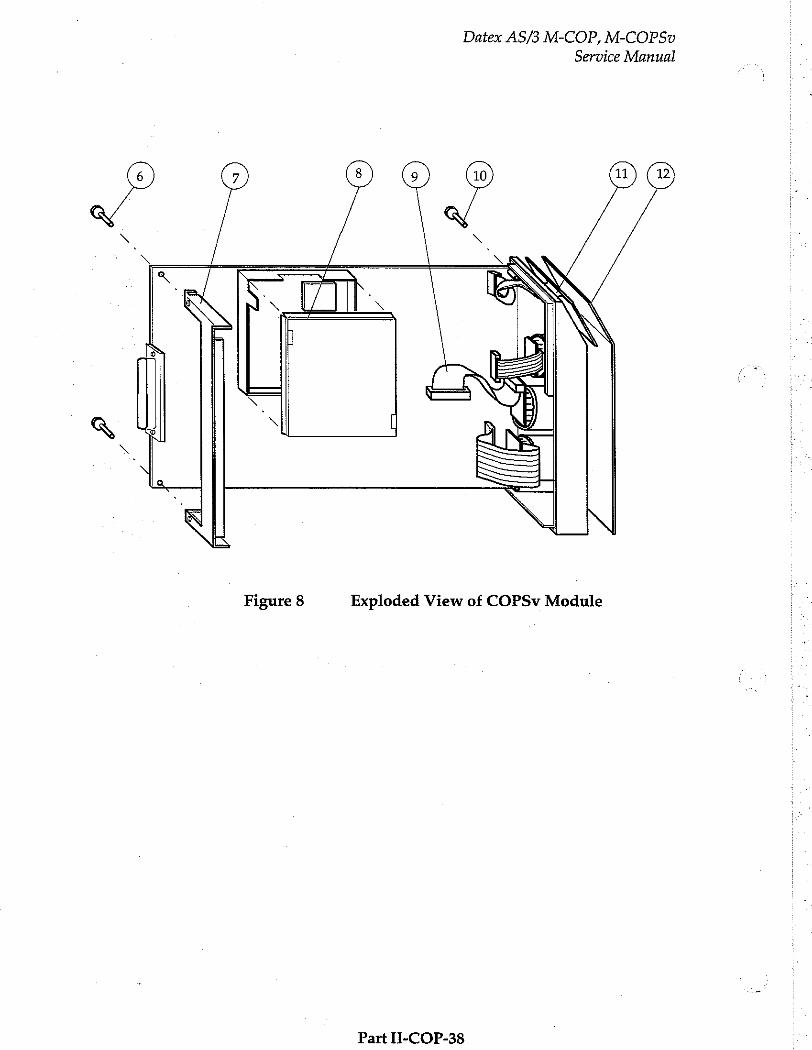
Datex AS/3 M-COP, M-COPSv
Service Manual
Figure 8 Exploded View of COPSv Module
Part II-COP-38
Datex AS/3 M-COP, M-COPSv
Service Manual
7 EARLIER REVISIONS
This manual supports all earlier module revisions.
Part II-COP-39


Pressure Module, M-P (Rev. 03)
Pressure Temp Module, M-PT (Rev. 00)
All specifications subject to change without notice
Document No. 885935-2
March, 1996
Datex Division, Instrumentarium Corp.
P.O.Box 446 FIN-00101 Helsinki Finland
Tel. +358 0 39411 Fax +358 0 1463310

Datex AS/3 M-P, M-PT
Service Manual
Datex AS/3 M-P, M-PT
Service Manual
Table of Contents
INTRODUCTION 1
I SPECIFICATIONS 2
1.1 General Specifications iii 2 1.2 Typical Performance ーー 13 Technical Specifications........................ eee eee eee rear a eee eee n 3
2 FUNCTIONAL DESCRIPTION 5
2.1 Measurement Principle issues 5 2.2 Main components and block diagrams.…...........................................
2.3 Connectors and Signals sun 2.3.1 Connectors on the board... ce
2.3.2 Front Panel ConnectoYS users anne 12
3 SERVICE PROCEDURES 13
3.1 General Service Information... eee onde aneta tea anne aaa onen nné 13
3.2 Preventive Maintenance.......... 14
3.3 Disassembly and Reassembly.... „1 3.4 Adjustments and Calibrations eee tn 16
4 TROUBLESHOOTING 18
5 SERVICE MENU 19
6 SPARE PARTS
6.1 Spare Parts Lists 6.2 Exploded View... seen
7 EARLIER REVISIONS | 28

Datex AS/3 M-P, M-PT
Service Manual
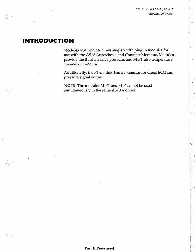
Datex AS/3 M-P, M-PT
Service Manual
INTRODUCTION
Modules M-P and M-PT are single width plug-in modules for use with the AS/3 Anaesthesia and Compact Monitors. Modules provide the third invasive pressure, and M-PT also temperature
channels T3 and TA.
Additionally, the PT-module has a connector for direct ECG and pressure signal output.
NOTE: The modules M-PT and M-P cannot be used simultaneously in the same AS/3 monitor.
Part Il Pressure-1
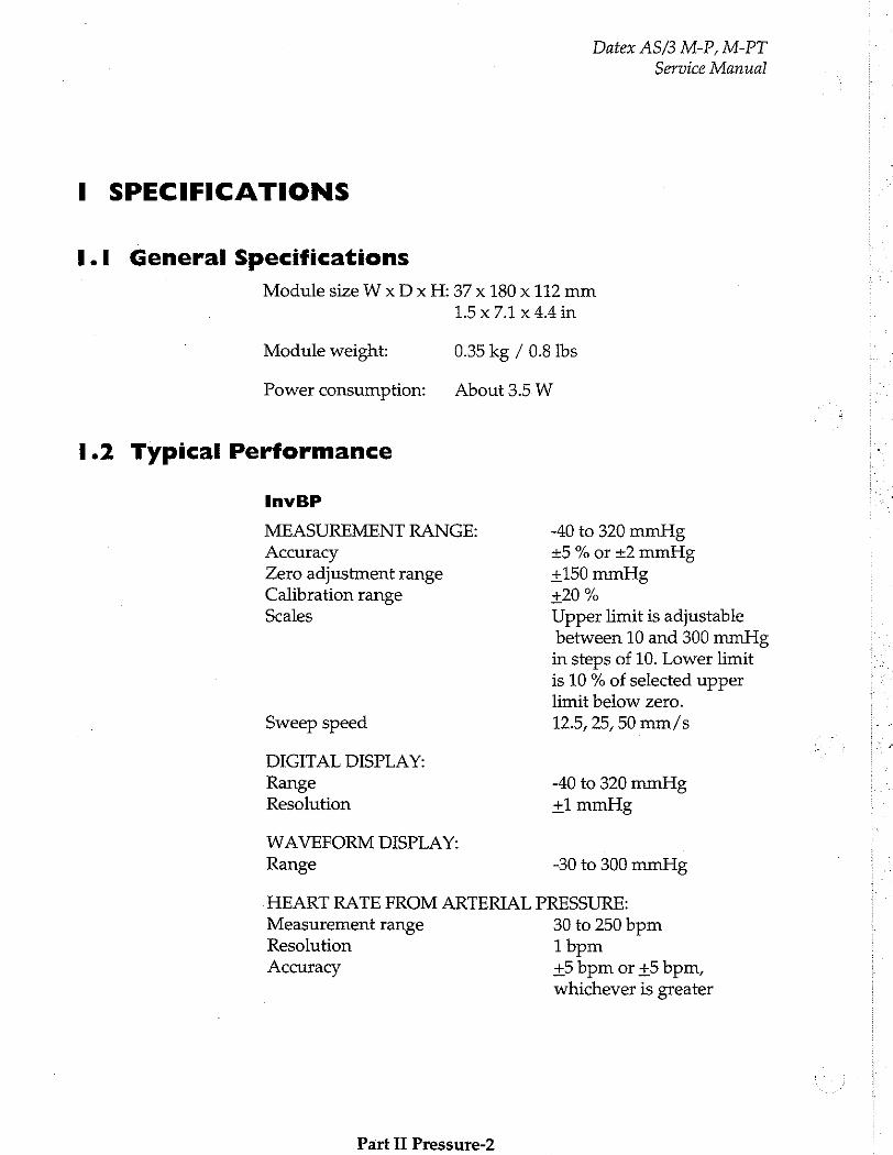
Datex AS/3 M-P, M-PT Service Manual
I SPECIFICATIONS
I.1 General Specifications
Module size W x D x H: 37 x 180 x 112 mm 15x7.1x44in
Module weight: 0.35 kg / 0.8 Ibs
Power consumption: About 3.5 W
1.2 Typical Performance
InvBP
MEASUREMENT RANGE: -40 to 320 mmHg Accuracy 15 % or +2 mmHg Zero adjustment range +150 mmHg Calibration range +20 % Scales Upper limit is adjustable
between 10 and 300 mmHg in steps of 10. Lower limit is 10 % of selected upper limit below zero.
Sweep speed 12.5, 25, 50 mm/s
DIGITAL DISPLAY: Range -40 to 320 mmHg Resolution +1 mmHg
WAVEFORM DISPLAY: Range -30 to 300 mmHg
HEART RATE FROM ARTERIAL PRESSURE: Measurement range 30 to 250 bpm Resolution 1bpm Accuracy +5 bpm or +5 bpm,
whichever is greater
Part II Pressure-2
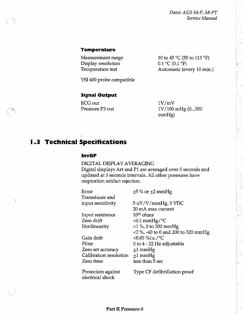
Datex AS/3 M-P, M-PT
Service Manual
Temperature
Measurement range 10 to 45 °C (50 to 113 °F)
Display resolution 0.1 °C (0.1 °F) Temperature test Automatic (every 10 min.)
YSI 400 probe compatible
Signal Output
ECG out
Pressure P3 out
1.3 Technical Specifications
InvBP
1V/mV
1V/100 mHg (0...300
mmHg)
DIGITAL DISPLAY AVERAGING Digital displays Art and P1 are averaged over 5 seconds and updated at 5 seconds intervals. All other pressures have respiration artifact rejection.
Error
Transducer and
input sensitivity
Input resistance Zero drift Nonlinearity
Gain drift
Filter
Zero set accuracy Calibration resolution
Zero time
Protection against electrical shock
+5 % or +2 mmHg
5 uV/V/mmHg, 5 VDC
20 mA max current
10% ohms
<0.1 mmHg/°C <1 %, 0 to 200 mmHg
<2 %, -40 to 0 and 200 to 320 mmHg <0.05 %f.s./°C
0 to 4- 22 Hz adjustable +1 mmHg
+1 mmHg
less than 5 sec
Type CF defibrillation proof
Part II Pressure-3
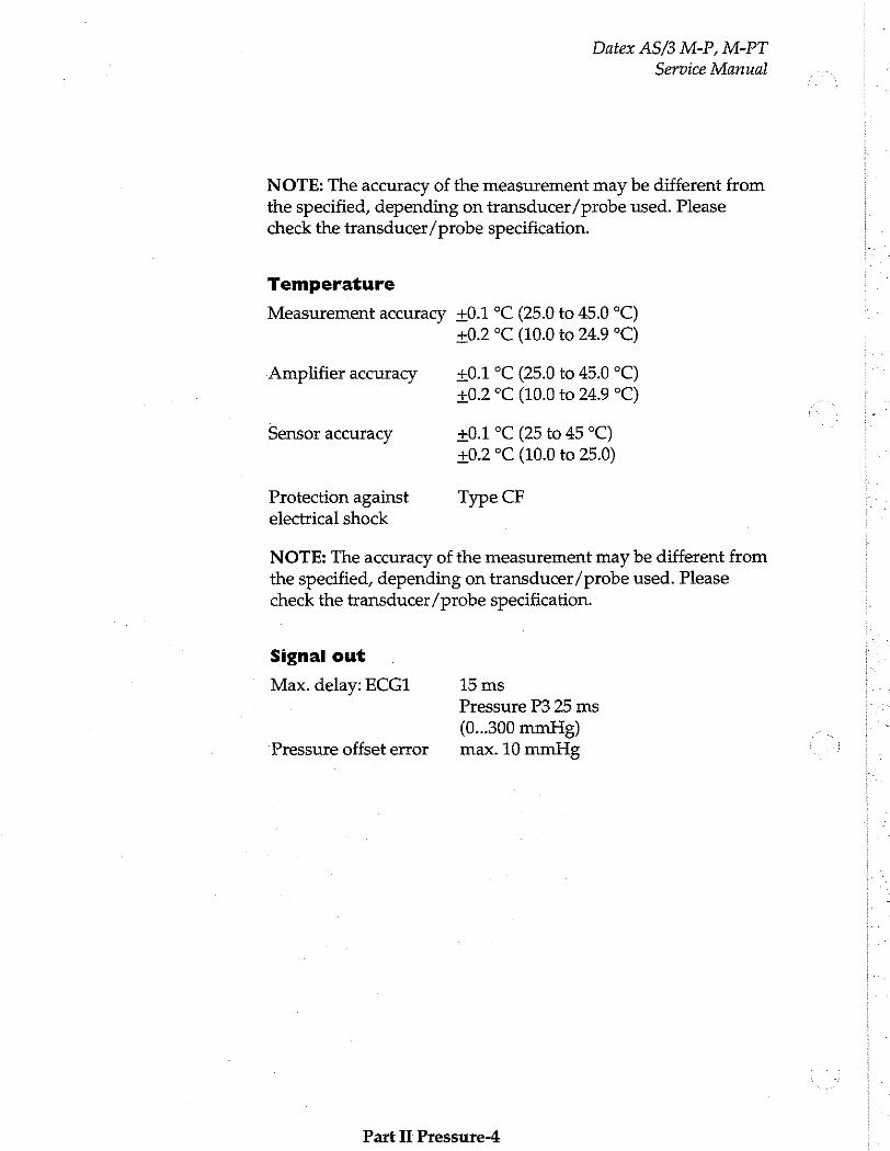
Datex AS/3 M-P, M-PT
Service Manual
NOTE: The accuracy of the measurement may be different from the specified, depending on transducer/probe used. Please check the transducer/probe specification.
Temperature
Measurement accuracy +0.1 °C (25.0 to 45.0 °C)
+0.2 °C (10.0 to 24.9 °C)
Amplifier accuracy 20.1 °C (25.0 to 45.0 °C) +0.2 °C (10.0 to 24.9 °C)
Sensor accuracy +0.1 °C (25 to 45 °C)
+0.2 °C (10.0 to 25.0)
Protection against Type CF electrical shock
NOTE: The accuracy of the measurement may be different from the specified, depending on transducer/probe used. Please check the transducer /probe specification.
Signal out
Max. delay: ECG1 15 ms Pressure P3 25 ms (0.300 mmHg)
Pressure offset error max. 10 mmHg
Part IT Pressure-4
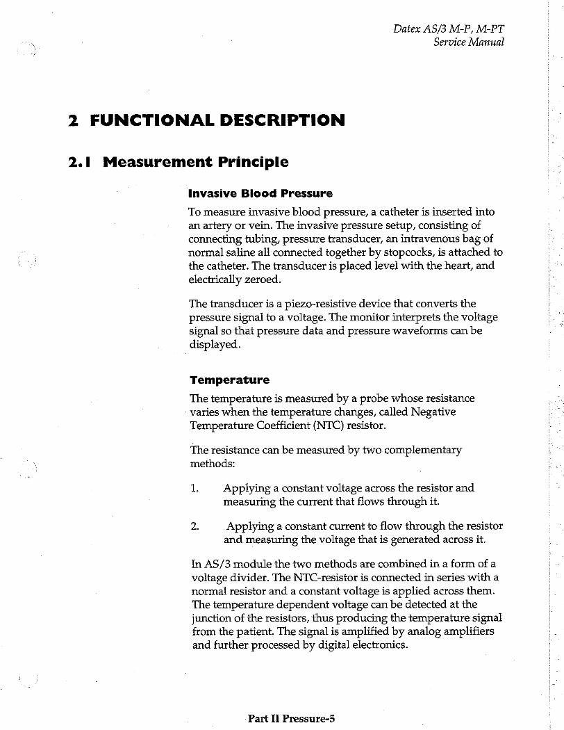
Datex AS/3 M-P, M-PT
Service Manual
2 FUNCTIONAL DESCRIPTION
2.1 Measurement Principle
Invasive Blood Pressure
To measure invasive blood pressure, a catheter is inserted into an artery or vein. The invasive pressure setup, consisting of connecting tubing, pressure transducer, an intravenous bag of normal saline all connected together by stopcocks, is attached to the catheter. The transducer is placed level with the heart, and electrically zeroed.
The transducer is a piezo-resistive device that converts the pressure signal to a voltage. The monitor interprets the voltage signal so that pressure data and pressure waveforms can be displayed.
Temperature
The temperature is measured by a probe whose resistance varies when the temperature changes, called Negative Temperature Coefficient (NTC) resistor.
The resistance can be measured by two complementary methods:
1. Applying a constant voltage across the resistor and measuring the current that flows through it.
2. Applying a constant current to flow through the resistor and measuring the voltage that is generated across it.
In AS/3 module the two methods are combined in a form of a voltage divider. The NTC-resistor is connected in series with a normal resistor and a constant voltage is applied across them. The temperature dependent voltage can be detected at the junction of the resistors, thus producing the temperature signal from the patient. The signal is amplified by analog amplifiers and further processed by digital electronics.
Part Ii Pressure-5
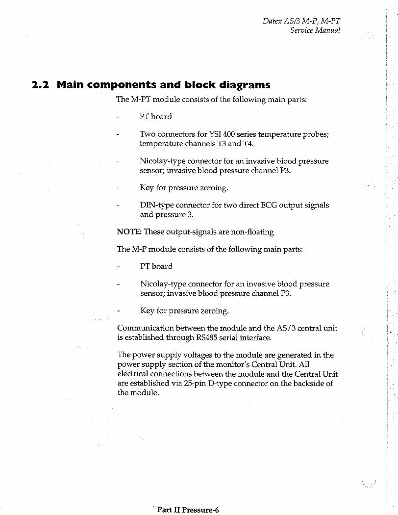
Datex AS/3 M-P, M-PT
Service Manual
2.2 Main components and block diagrams
The M-PT module consists of the following main parts:
PT board
Two connectors for YSI 400 series temperature probes; temperature channels T3 and T4.
Nicolay-type connector for an invasive blood pressure sensor; invasive blood pressure channel P3.
Key for pressure zeroing.
DIN-type connector for two direct ECG output signals and pressure 3.
NOTE: These output-signals are non-floating
The M-P module consists of the following main parts:
PT board
Nicolay-type connector for an invasive blood pressure sensor; invasive blood pressure channel P3.
Key for pressure zeroing.
Communication between the module and the AS/3 central unit
is established through RS485 serial interface.
The power supply voltages to the module are generated in the power supply section of the monitor’s Central Unit. All electrical connections between the module and the Central Unit are established via 25-pin D-type connector on the backside of the module.
Part II Pressure-6
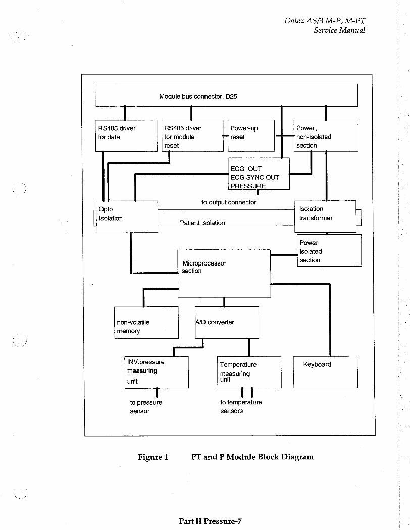
Datex AS/3 M-P, M-PT
Service Manual
Module bus connector, D25
RS485 driver RS485 driver Power-up Power,
for data for module r reset non-isolated
reset section
ECG OUT
ECG SYNC OUT
PRESSURE
to output connector Opto Isoiation -
Isolation transformer | | Patient Isolation 圖
Power,
isolated
Microprocessor section ees, SECİİON
non-volatile A/D converter
memory
INV. pressure Temperature Keyboard measuring measuring
unit unit
to pressure to temperature
sensor sensors
Figure 1 PT and P Module Block Diagram
Part II Pressure-7
Datex AS/3 M-P, M-PT
Service Manual
ECG and pressure signal prosessing
The PT-module has the Signal Out connector, for output of
analog ECG and pressure signals.
The analog ECG-output signals are made by detecting the pulse-width modulated (PWM) ECG signal of the AS/3 module bus. The module detects the presence of the pacemaker pulses by following the ECG module. Every time the pacer pulse has been detected, the microprocessor of the M-PT module generates a 2,5 ms pacer pulse which is added to the analog ECG signal.
The PRESSURE OUT signal is generated from the P3 invasive pressure signal of the M-PT module. The P3 signal is transmitted as a pulse width modulated (PWM) signal over the patient isolation. The analog signal is generated by low-pass filtering the PWM signal.
Part II Pressure-8

Datex AS/3 M-P, M-PT
Service Manual
2.3 Connectors and Signals
2.3.1 Connectors on the board
The following connectors on the board are used, when the
board is configured to M-PT or M-P:
The module bus 25-pin female D-connector (X1):
Pin No Vo Signal
1 I RESET RS485*
2 -15 VDC*
3 +15 VDIRTY*
4 +15 Vin*
5 I/O |NDATA RS485*
6 I/O |DATA RS485*
7 Ground*
8 I NRESET RS485*
9 I CTSB
10 O RTSB
11 I RXDB
12 O TXDB
13 Ground*
14 I +32 VDIRTY
15 I GroundDIRTY*
16 I CTSC
17 ο RISC
18 I RXDC
19 o TXDC
20 ON/STANDBY
21 ο PWM_ECG*
22 RXDD_RS232
23 TXDD_RS232
24 I +5 VDCin*
25 I +5 VDC*
* Used in the M-PT modules
Part II Pressure-9
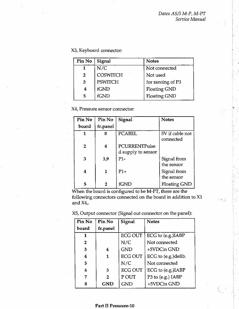
Datex AS/3 M-P, M-PT
Service Manual
X3, Keyboard connector:
Pin No | Signal Notes
1 N/C Not connected
2 COSWITCH Not used
3 PSWITCH for zeroing of P3
4 fGND Floating GND
5 fGND Floating GND
X4, Pressure sensor connector:
Pin No | Pin No | Signal Notes
board | fr.panel
1 0 PCABEL 5V if cable not connected
2 4 PCURRENTPulse d supply to sensor
3 3,9 P1- Signal from the sensor
4 1 P1+ Signal from the sensor
5 2 fGND Floating GND
When the board is configured to be M-PT, there are the following connectors connected on the board in addition to X1
and X4,.
X5, Output connector (Signal out connector on the panel):
Pin No | PinNo | Signal Notes
board | fr.panel
1 ECG OUT | ECG to (e.g.)IABP
2 N/C Not connected
3 4 GND +5VDCin GND
4 1 ECG OUT | ECG to (e.g.)defib.
5 N/C Not connected
6 3 ECG OUT | ECG to (e.g.)IABP
7 2 P OUT P3 to (e.g.) IABP
8 GND | GND +5VDCin GND
Part II Pressure-10

Datex AS/3 M-P, M-PT
Service Manual
X8, connector for temperature probes:
Pin No | Signal Notes
1 T3
2 T4
3 fGND Floating GND
4 CON Low if PT
5 fGND Floating GND
6 GND Floating GND
Part Il Pressure-11
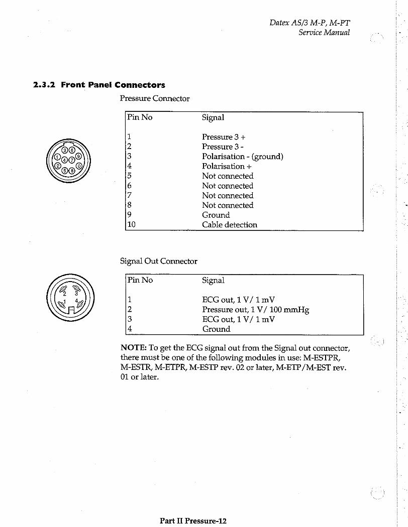
2.3.2 Front Panel Connectors
© ~ 009
Pressure Connector
Datex AS/3 M-P, M-PT
Service Manual
Pin No
Fa NO
oo
GV GTA Qi
Ha
Signal
Pressure 3 +
Pressure 3 -
Polarisation - (ground) Polarisation +
Not connected
Not connected
Not connected
Not connected
Ground
Cable detection
Signal Out Connector
Pin No
ona
Signal
ECG out, 1 V/ 1 mV
Pressure out, 1 V/ 100 mmHg ECG out, 1 V/ 1 mV
Ground
NOTE: To get the ECG signal out from the Signal out connector, there must be one of the following modules in use: M-ESTPR, M-ESTR, M-ETPR, M-ESTP rev. 02 or later, M-ETP/M-EST rev.
01 or later.
Part II Pressure-12
Datex AS/3 M-P, M-PT
Service Manual
3 SERVICE PROCEDURES
3.1 General Service Information
Usually field service is limited to replacing the faulty circuit
boards or mechanical parts. The boards are then returned to Datex for repair.
Datex is always available for service advice. Please provide the unit serial number, full type designation, and a detailed fault description.
CAUTION: Only trained personnel with appropriate equipment shall perform the tests and repairs outlined in this section. Unauthorized service may void warranty of the unit.
Part I Pressure-13
Datex AS/3 M-P, M-PT
Service Manual
3.2 Preventive Maintenance
We recommend you to perform these checks at least once a year and after any service.
1. Visual inspection
— Ifthe module is disassembled, check that grounding wires and all connectors are properly connected and there is no loose object inside before attaching the module box.
2. Functional checks
o: Insert the module into frame.
o Turn the power on by ON/STBY-switch. Within 15
seconds, Temp and P3 windows should appear on the display if selected for display. No error message appears.
—: Pull out the module. The windows go blank within 15 seconds.
_: Reinsert the module while the power is still on. The measurement data appear on the windows again.
od Go to Service Menu (Path: Monitor Setup, Install /Service,
Service View, Modules) and check the functions of cables and buttons (ON/OFF test).
—: Put temperature test plug into T3 and T4 and make sure that the measured values do not deviate more than +
0.1°C. If they do, perform the temperature calibration.
Part II Pressure-14
Datex AS/3 M-P, M-PT
Service Manual
3.3 Disassembly and Reassembly
Disassemble the module in the following way. See Figure for the exploded view of the module.
a) Remove the two screws from the back of the module.
b) Pull the module box slowly backwards and detach it from main body. Be careful with loose latch and spring pin for locking.
c) The PT board will appear. The board is now removed by detaching two screws on the folio side of the board near the front panel and disconnecting the two ribbon cables coming from the front panel.
CAUTION: When reassembling the module, make sure that the
cables are reconnected properly.
Part Il Pressure-15

Datex AS/3 M-P, M-PT
Service Manual
3.4 Adjustments and Calibrations
Pressure calibration
Perform pressure calibration whenever pressure transducer (probe) is replaced with another type. The pressure calibration is performed in Service Menu:
1. Go to P/PT service page (See chapter 5 Service Menu; path: Monitor Setup, Install /Service, Service View,
Modules).
Go to Calibrations page.
Connect pressure transducer with a pressure manometer to the front panel P3/P4 receptacle. Choose Calibrate P3. Leave the transducer to room air pressure.
Calibrations
Protection OFF
Set Config BP
Calibrate T3
Calibrate TA
Calibrate P3
Previous Menu
Calibrate temperatures with calibration plugs for 25 °C and 45 °C.
Push the ComWheel. The zeroing takes place.
Supply pressure of 100 mmHg to 300 mmHg to the transducer. Recommended pressure is 200 mmHg.
Set the pressure on the display with the ComWheel to match the pressure reading on manometer and push the ComWheel. Tolerance of +1 mmHg is allowed.
Part II Pressure-16
Datex AS/3 M-P, M-PT
Service Manual
The text ‘calibrated’ will appear on the display.
Temperature calibration (M-PT)
Temperature calibration is performed whenever the measured values deviate more than +0.1°C when temperature test plug is inserted into T3 and T4 receptacle. The temperature calibration is performed in Service Menu:
NOTE: For the temperature calibration, separate test plugs (25°C and 45°C) are necessary. A test set of two plugs is available from Datex, order code 884515.
1. Go to P service page ( See chapter 5 Service Menu; Path: Monitor Setup, Install /Service (password “10”), Service View (password ‘1’), Modules).
Go to Calibrations page.
Press in the protect button at the bottom of the module and choose OFF in Protect mode. Release the button.
Choose Calibrate T3/Calibrate T4.
Insert calibration plug (25°C) into T3/T4 connector.
Push the ComWheel two times.
Insert calibration plug (45°C) into T3/T4 connector.
Push the ComWheel two times.
Press in the protect button at the bottom of the module and choose ON in Protect mode. Release the button.
Part II Pressure-17
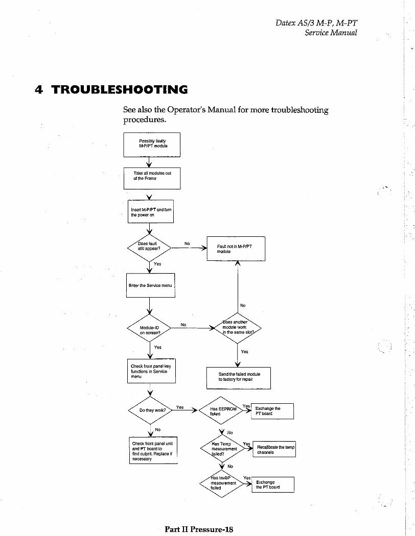
Datex AS/3 M-P, M-PT
Service Manual
4 TROUBLESHOOTING
See also the Operator's Manual for more troubleshooting procedures.
Possibly faulty M-P/PT module
Y Take all modules out of the Frame
у i
insert M-P/PT and tum the power on
Does fault still appear?
No —— —> Fault not in M-P/PT
module
\
Enter the Service menu
Does another module work in the same slot?
Module-ID on screen?,
Check front panel key
functions in Service menu
Send the failed module to factory for repair
Y
Ba they work? Has EEPROM Exchange the failed PT board
Check front panel unit Has Temp
and PT board to measurement Recatibrate the temp,
find culprit. Replace if channels
necessary
V No
Yes measurement Exchange
failed the PT board
Part II Pressure-18
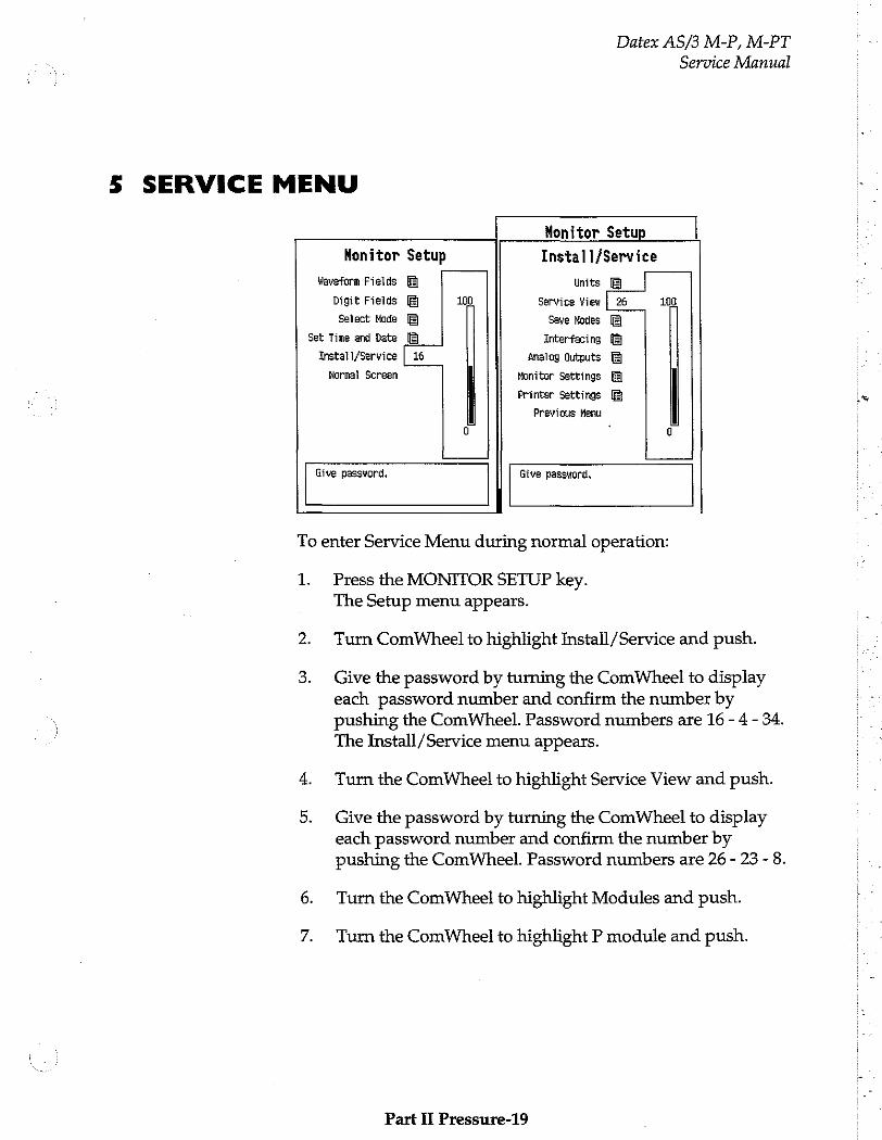
Datex AS/3 M-P, M-PT
Service Manual
5 SERVICE MENU
Monitor Setup
Monitor Setup Install /Service
Waveform Fields Units
Digit Fields 100 Service View | 26 100
Select Node Save Nodes
Set Time and Date Interfacing
Install/Service | 16 Analog Outputs
Normal Screen Monitor Settings
Printer Settings
Previous Menu
0 0
Give password. Give password.
To enter Service Menu during normal operation:
1 Press the MONITOR SETUP key. The Setup menu appears.
Turn ComWheel to highlight Install/Service and push.
Give the password by turning the ComWheel to display each password number and confirm the number by pushing the ComWheel. Password numbers are 16 - 4 - 34.
The Install/Service menu appears.
Turn the ComWheel to highlight Service View and push.
Give the password by turning the ComWheel to display each password number and confirm the number by pushing the ComWheel. Password numbers are 26 - 23 - 8.
Turn the ComWheel to highlight Modules and push.
Turn the ComWheel to highlight P module and push.
Part Il Pressure-19
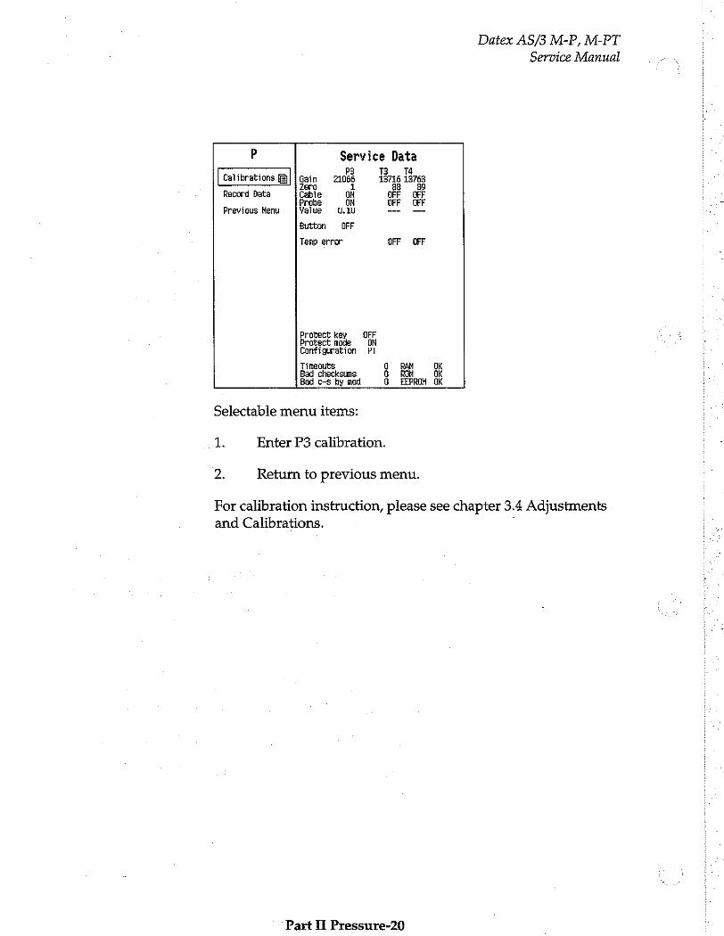
Datex AS/3 M-P, M-PT
Service Manual
P Service Data > 7 P3 T3 Ta
Calibrations Gain 21066 13716 13763 zero 1 88 89
Record Data Cable ON OFF OFF Probe ON OFF OFF
Previous Menu Yalue 8.10 — —
Button OFF
Tenp error OFF DFF
Protect key OFF Protect mode ON Configuration Fi
Timeouts O RAM OK Bad checksums O ROH OK Bad c-s by mod G EEPROM OK
Selectable menu items:
1. Enter P3 calibration.
2. Return to previous menu.
For calibration instruction, please see chapter 3.4 Adjustments and Calibrations. :
Part II Pressure-20
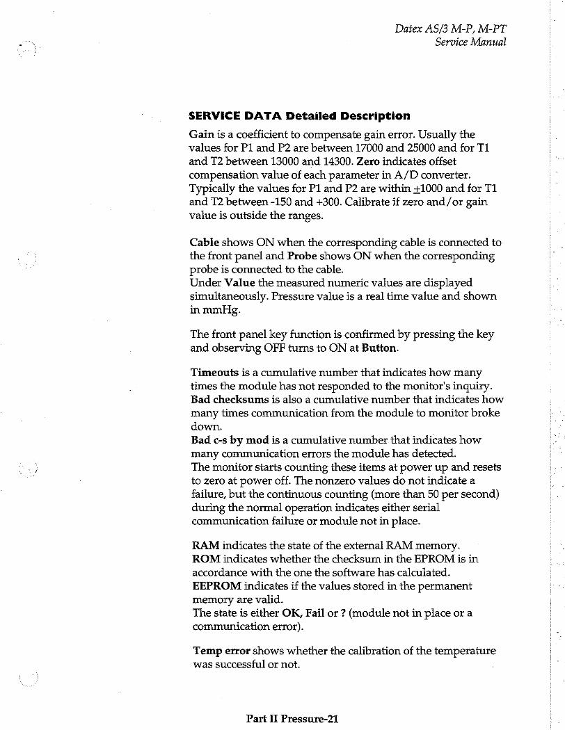
Datex AS/3 M-P, M-PT
Service Manual
SERVICE DATA Detailed Description
Gain is a coefficient to compensate gain error. Usually the values for P1 and P2 are between 17000 and 25000 and for T1 and T2 between 13000 and 14300. Zero indicates offset compensation value of each parameter in A/D converter. Typically the values for P1 and P2 are within +1000 and for T1 and T2 between -150 and +300. Calibrate if zero and/or gain value is outside the ranges.
Cable shows ON when the corresponding cable is connected to the front panel and Probe shows ON when the corresponding probe is connected to the cable. Under Value the measured numeric values are displayed simultaneously. Pressure value is a real time value and shown in mmHg.
The front panel key function is confirmed by pressing the key and observing OFF turns to ON at Button.
Timeouts is a cumulative number that indicates how many times the module has not responded to the monitor's inquiry. Bad checksums is also a cumulative number that indicates how many times communication from the module to monitor broke down. Bad c-s by mod is a cumulative number that indicates how many communication errors the module has detected. The monitor starts counting these items at power up and resets to zero at power off. The nonzero values do not indicate a failure, but the continuous counting (more than 50 per second) during the normal operation indicates either serial communication failure or module not in place.
RAM indicates the state of the external RAM memory. ROM indicates whether the checksum in the EPROM is in accordance with the one the software has calculated. EEPROM indicates if the values stored in the permanent
memory are valid. The state is either OK, Fail or ? (module not in place or a communication error).
Temp error shows whether the calibration of the temperature was successful or not.
Part II Pressure-21
Datex AS/3 M-P, M-PT
Service Manual
Protect key shows normally OFF but turns to ON when the button at the bottom of the module is pressed.
Protect mode is normally ON. It turns to OFF when Protect is switched to OFF for the temperature calibration in Calibration Menu.
Configuration shows the chosen module configuration: BP or PT.
Part II Pressure-22
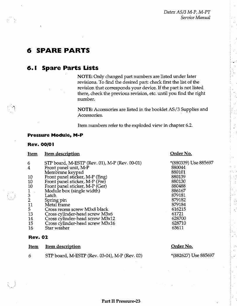
6 SPARE PARTS
6.1 Spare Parts Lists
NOTE: Only changed part numbers are listed under later revisions. To find the desired part: check first the list of the revision that corresponds your device. If the part is not listed there, check the previous revision, etc. until you find the right
number.
Datex AS/3 M-P, M-PT
Service Manual
NOTE: Accessories are listed in the booklet AS/3 Supplies and
Accessories.
Item numbers refer to the exploded view in chapter 6.2.
Pressure Module, M-P
Rev. 00/01
Item Item description
6 STP board, M-ESTP (Rev. 01), M-P (Rev. 00-01) 4 Front panel unit, M-P
Membrane keypad 10 Front panel sticker, M-P (Eng) 10 Front panel sticker, M-P (Fre 10 Front panel sticker, M-P (Ger) 1 Module box (single width) 3 Latch 2 Spring pin 11 Metal frame 5 Cross recess screw M3x8 black 13 Cross cylinder-head screw M3x6 14 Cross cylinder-head screw M3x12 15 Cross cylinder-head screw M3x16 16 Star washer
Rev. 02
Item Item description
6 STP board, M-ESTP (Rev. 03-04), M-P (Rev. 02)
Part II Pressure-23
Order No.
(880339) Use 885697 880044 880101 880139 880130 880488 886167 879181 879182 879184 616215 61721 628700 628710 63611
Order No.
*(882627) Use 885697
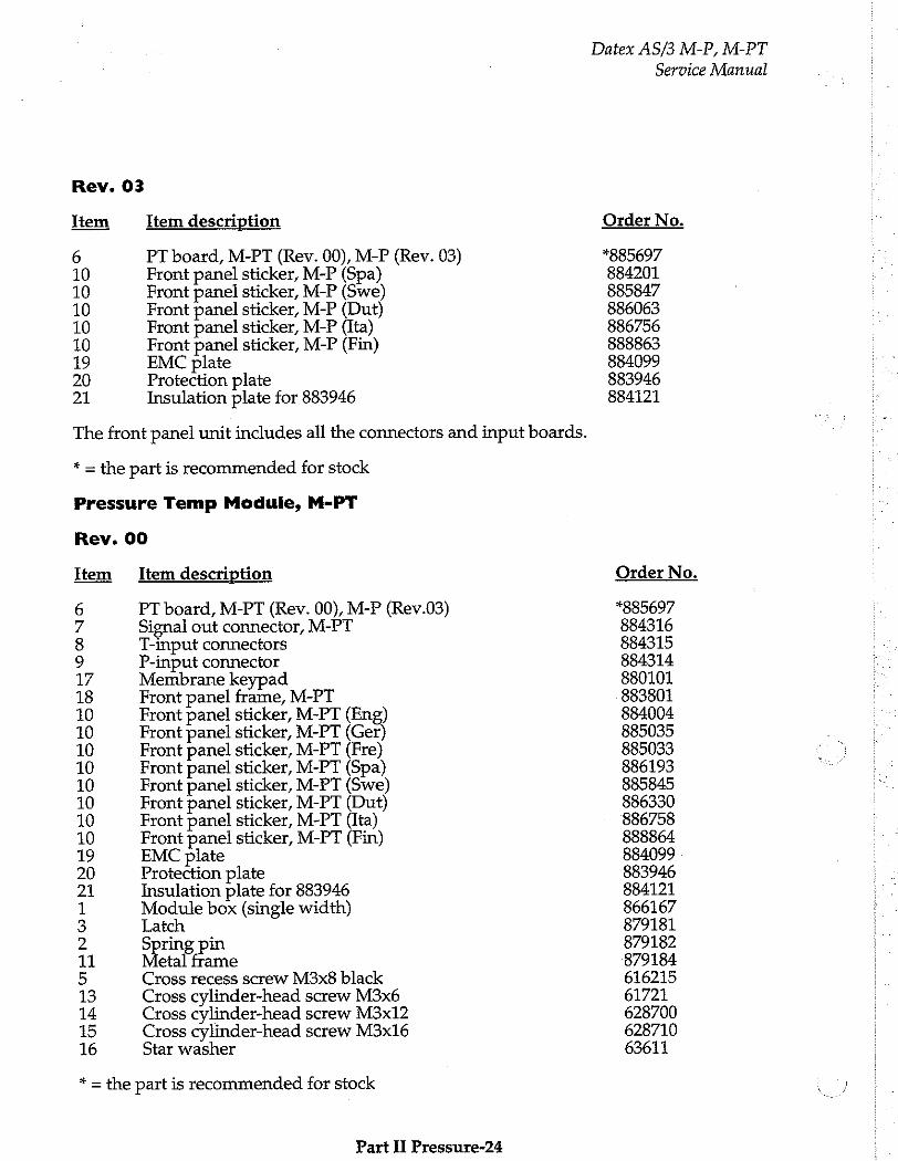
Rev. 03
Item Item description
6 PT board, M-PT (Rev. 00), M-P (Rev. 03) 10 Front panel sticker, M-P (Spa) 10 Front panel sticker, M-P (Swe) 10 Front panel sticker, M-P (Dut) 10 Front panel sticker, M-P (Ita) 10 Front panel sticker, M-P (Fin) 19 EMC plate 20 Protection plate 21 Insulation plate for 883946
The front panel unit includes all the connectors and input boards.
* = the part is recommended for stock
Pressure Temp Module, M-PT
Rev. 00
Item Item description
6 PT board, M-PT (Rev. 00), M-P (Rev.03) 7 Signal out connector, M-PT 8 T-input connectors 9 P-input connector 17 Membrane keypad 18 Front panel frame, M-PT 10 Front panel sticker, M-PT (Eng) 10 Front panel sticker, M-PT (Ger) 10 Front panel sticker, M-PT (Fre) 10 Front panel sticker, M-PT (Spa) 10 Front panel sticker, M-PT (Swe) 10 Front panel sticker, M-PT (Dut) 10 Front panel sticker, M-PT (Ita) 10 Front panel sticker, M-PT (Fin) 19 EMC plate 20 Protection plate 21 Insulation plate for 883946 1 Module box (single width) 3 Latch. 2 Spring pin 11 etal frame 5 Cross recess screw M3x8 black 13 Cross cylinder-head screw M3x6 14 Cross cylinder-head screw M3x12 15 Cross cylinder-head screw M3x16 16 Star washer
* = the part is recommended for stock
Part II Pressure-24
Datex AS/3 M-P, M-PT
Service Manual
Order No.
*885697 884201 885847 886063 886756 888863 884099 883946 884121
Order No.
*885697 884316 884315 884314 880101 883801 884004 885035 885033 886193 885845 886330 886758 888864 884099 883946 884121 866167 879181 879182 879184 616215 61721 628700 628710 63611
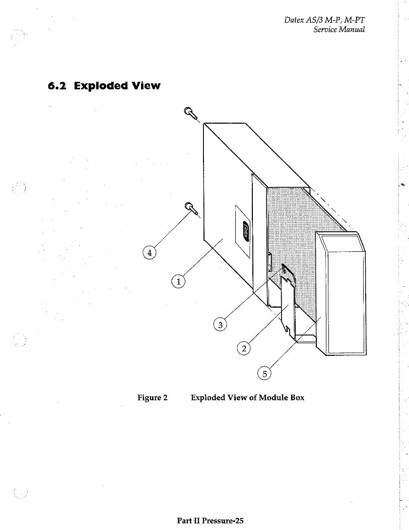
Datex AS/3 M-P, M-PT
Service Manual
6.2 Exploded View
a
GA
Figure 2 Exploded View of Module Box
Part II Pressure-25

Service Manual Datex AS/3 M-P, M-PT
11
Exploded View of M-P Module Figure 3
Part Il Pressure-26

Datex AS/3 M-P, M-PT
Service Manual
14À17À18 )(10
Figure 4
Exploded View of M-PT Module
Part Ii Pressure-27
Datex AS/3 M-P, M-PT
Service Manual
7 EARLIER REVISIONS
This manual also supports M-P revision 02.
For service information on the earlier revisions, please refer to:
P Module revision 00 Service Manual p/n 880850
P Module revision 01 © Service Manual p/n 882580
Part II Pressure-28
NIBP Module, M-NIBP (Rev. 03)
All specifications subject to change without notice
Document No. 885936-2
March, 1996
Datex Division, Instrumentarium Corp.
P.O.Box 446 FIN-00101 Helsinki Finland
Tel. +358 0 39411 Fax +358 0 1463310
Datex AS/3 M-NIBP
Service Manual
ος
Datex AS/3 M-NIBP
Service Manual
Table of Contents
INTRODUCTION 1
I SPECIFICATIONS 2
1.1 General Specifications..................... iii 2 1.2 Typical Performance .. 1.3 Technical Specifications ss... sein 3
2 FUNCTIONAL DESCRIPTION 4
21 Меазиите рипар............ ели алии ишииинииинитиитититлитиилитиичиння 4 2.2 Main Components.... „5
2.2.1 NIBP Board eee „5 2.3 Module Bus Connector Configuration.................. eee 9
3 SERVICE PROCEDURES 10
3.1 General Service Information... ss 10
3.2 PreventiveMaintenanceChecks................................. eee 11
3.3 Disassembly and Reassembly mu ЗА Adjustments and Calibrations te nné 14
4 TROUBLESHOOTING 18
41 Module Troubleshooting..…......….................. ns 18 4.2 Troubleshooting Chart.... . 19 4.3 Error Code Explanaton nn nné 21
5 SERVICE MENU
5.1 NIBP Service Menu cc ei sene
5.1.1 NIBP Calibration Menu... siennes
5.1.2 NIBP Safety Valve Menu... nn 5.1.3 NIBP Pulse Valve Menu...
5.1.4 NIBP Buttons/Leds Menu 6.1.5 NIBP Pneumatics Menu.
6.1.6 NIBP Watchdog Menu
6 SPARE PARTS
6.1 Spare Part List.......................... 6.2 Exploded View of Module
7. EARLIER REVISIONS

Datex AS/3 M-NIBP
Service Manual

Datex AS/3 M-NIBP
Service Manual
INTRODUCTION - The Non-Invasive Blood Pressure Module, M-NIBP, is a double
width module that provides non-invasive blood pressure measurement in the AS/3 monitors.
Part II- NIBP- 1
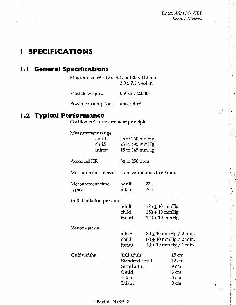
Datex AS/3 M-NIBP Service Manual
I SPECIFICATIONS
1.1 General Specifications
Module size W x D x H:75 x 180 x 112 mm
3.0x71x44in
Module weight: 0.9 kg / 2.0 Ibs
Power consumption: about4 W
1.2 Typical Performance Oscillometric measurement principle
Measurement range adult 25 to 260 mmHg
child 25 to 195 mmHg infant 15 to 145 mmHg
Accepted HR 30 to 250 bpm
Measurement interval from continuous to 60 min.
Measurement time, adult 23s
typical infant 20s
Initial inflation pressure adult 185 + 10 mmHg
child 150 + 10 mmHg infant 120 + 10 mmHg
Venous stasis
adult 80 + 10 mmHg / 2 min.
child 60 + 10 mmHg / 2 min.
infant 40 +10 mmHg / 1 min.
Cuff widths Tall adult 15 cm
Standard adult 12 cm
Small adult 9 cm
Child 6cm
Infant 5cm
Infant 3cm
Part If- NIBP- 2
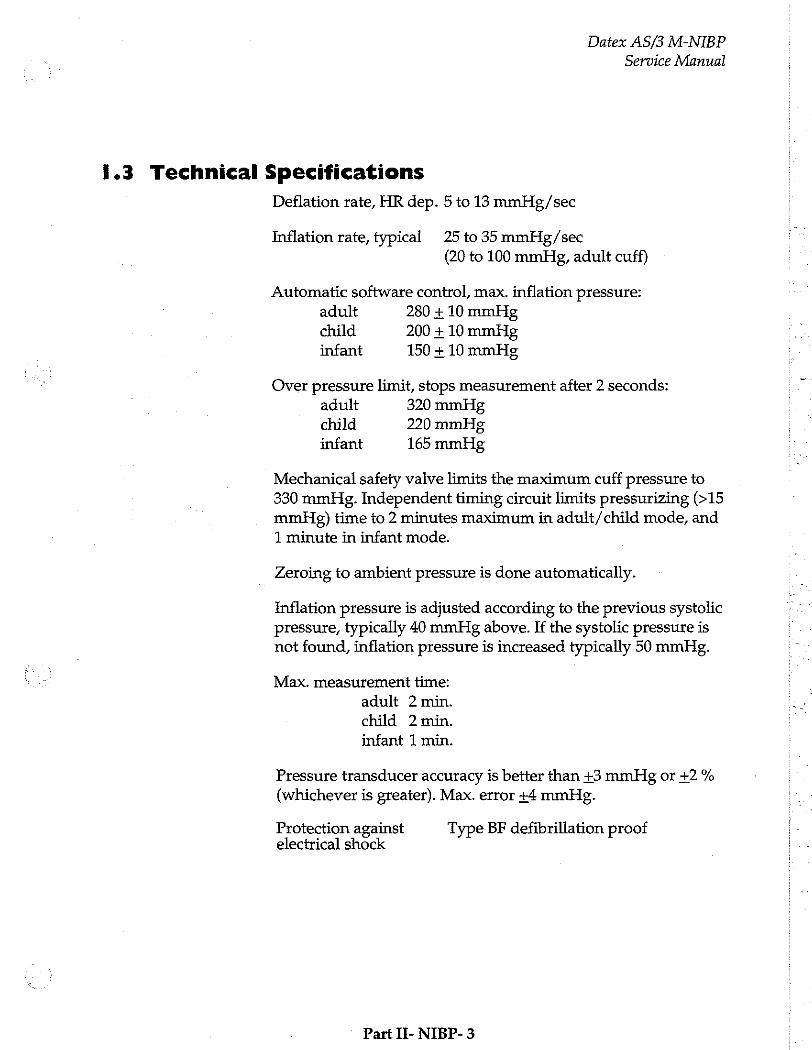
Datex AS/3 M-NIBP
Service Manual
1.3 Technical Specifications
Deflation rate, HR dep. 5 to 13 mmHg/sec
Inflation rate, typical 25 to 35 mmHig/sec (20 to 100 mmHg, adult cuff)
Automatic software control, max. inflation pressure: adult 280 + 10 mmHg
child 200 + 10 mmHg infant 150 + 10 mmHg
Over pressure limit, stops measurement after 2 seconds: adult 320 mmHg child 220 mmHg infant 165 mmHg
Mechanical safety valve limits the maximum cuff pressure to 330 mmHg. Independent timing circuit limits pressurizing (>15 mmHg) time to 2 minutes maximum in adult/child mode, and
1 minute in infant mode.
Zeroing to ambient pressure is done automatically.
Inflation pressure is adjusted according to the previous systolic pressure, typically 40 mmHg above. If the systolic pressure is not found, inflation pressure is increased typically 50 mmHg.
Max. measurement time:
adult 2 min.
child 2 min.
infant 1 min.
Pressure transducer accuracy is better than +3 mmHg or +2 %
(whichever is greater). Max. error +4 mmHg.
Protection against Type BF defibrillation proof electrical shock
Part II- NIBP- 3
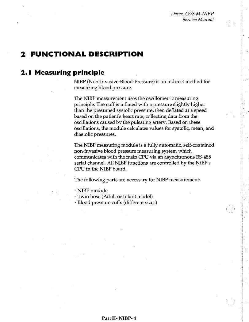
Datex AS/3 M-NIBP
Service Manual
2 FUNCTIONAL DESCRIPTION
2.1 Measuring principle
NIBP (Non-Invasive-Blood-Pressure) is an indirect method for measuring blood pressure.
The NIBP measurement uses the oscillometric measuring principle. The cuff is inflated with a pressure slightly higher than the presumed systolic pressure, then deflated at a speed based on the patient's heart rate, collecting data from the oscillations caused by the pulsating artery. Based on these oscillations, the module calculates values for systolic, mean, and
diastolic pressures.
The NIBP measuring module is a fully automatic, self-contained non-invasive blood pressure measuring system which communicates with the main CPU via an asynchronous RS-485 serial channel. All NIBP functions are controlled by the NIBP's CPU in the NIBP board.
The following parts are necessary for NIBP measurement:
- NIBP module
- Twin hose (Adult or Infant model) - Blood pressure cuffs (different sizes)
Part II- NIBP- 4
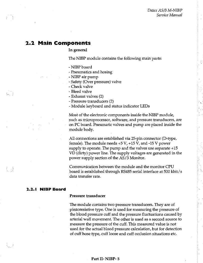
Datex AS/3 M-NIBP
Service Manual
2.2 Main Components
2.2.1 NIBP Board
In general
The NIBP module contains the following main parts:
- NIBP board - Pneumatics and hosing - NIBP air pump ~ Safety (Over pressure) valve - Check valve - Bleed valve - Exhaust valves (2) - Pressure transducers (2)
- Module keyboard and status indicator LEDs
Most of the electronic components inside the NIBP module,
such as microprocessor, software, and pressure transducers, are on PC board. Pneumatic valves and pump are placed inside the module body.
All connections are established via 25-pin connector (D-type,
female). The module needs +5 V, +15 V, and -15 V power
supply to operate. The pump and the valves use separate +15 VD (dirty) power line. The supply voltages are generated in the power supply section of the AS/3 Monitor.
Communication between the module and the monitor CPU
board is established through RS485 serial interface at 500 kbit/s data transfer rate.
Pressure transducer
The module contains two pressure transducers. They are of piezoresistive type. One is used for measuring the pressure of the blood pressure cuff and the pressure fluctuations caused by arterial wall movement. The other is used as a second source to measure the pressure of the cuff. This measured value is not used for the actual blood pressure calculation, but for detection of cuff hose type, cuff loose and cuff occlusion situations etc.
Part II- NIBP- 5
Datex AS/3 M-NIBP
Service Manual
The transducers are internally temperature compensated. They are supplied by a constant voltage and their output voltage changes up to 40 mV max. (50 kPa, 375 mmHg).
Signal processing
Two signals from the pressure transducers are amplified and sent to A/D converter. After the converter, digitized signals are sent to microprocessor for data processing. Before the converter, one of the signals is used to adjust the offset to the pressure safety level.
The NIBP module is controlled with 80C51FA microprocessor which uses 16 MHz oscillator frequency.
Memory
NIBP program memory (EPROM) size is 128k x 8. RAM size is 32k x 8 bit and it stores variable values in NIBP measurement. EEPROM is size 64 x 16 bit and is used to store the calibration values for the pressure transducers, the pulse valve constants gained during measurements, the PC board identification, and
module serial number.
Control
Software controls valves, pump and LEDs. In addition to the individual on/off signals for each component there is a common power switch for the valves and the pump that can be used at pump/valve failures.
In addition to external RS485 reset line the microprocessor system is equipped with its own power-up reset.
Safety circuit
The NIBP module is equipped with software independent safety circuit to disconnect supply voltages from the pump and the valves if the cuff has been pressurized longer than preset time. Pressure limit is specified to 15 mmHg. As soon as the cuff pressure rises over 15 mmHg, timer starts counting. The timer is adjusted to stop the pump and open the valves in 2 minutes 10 seconds in adult/child mode and in 1 minute 5 seconds in infant mode.
Part IT- NIBP- 6
Datex AS/3 M-NIBP
Service Manual
Pressure safety level check
Pressure safety level detection is checked in Service Menu. When pressure (generated by external pump with manometer) inside module exceeds safety level (adjusted to 14 mmHg) the sign of the signal at AD5 on the NIBP Menu/Pneumatics Service Menu changes from negative to positive value. If the change doesn't occur within 14 + 5 mmHg, adjust it (see the Chapter 4.3).
NIBP tubing lengths
There are two different tubes inside the module. They are silicon tubes 1.7 x 1 (part number 73373) and 3.18 x 6.35 (73375).
When ordering, specify the part number and length(s) required.
Part II- NIBP- 7
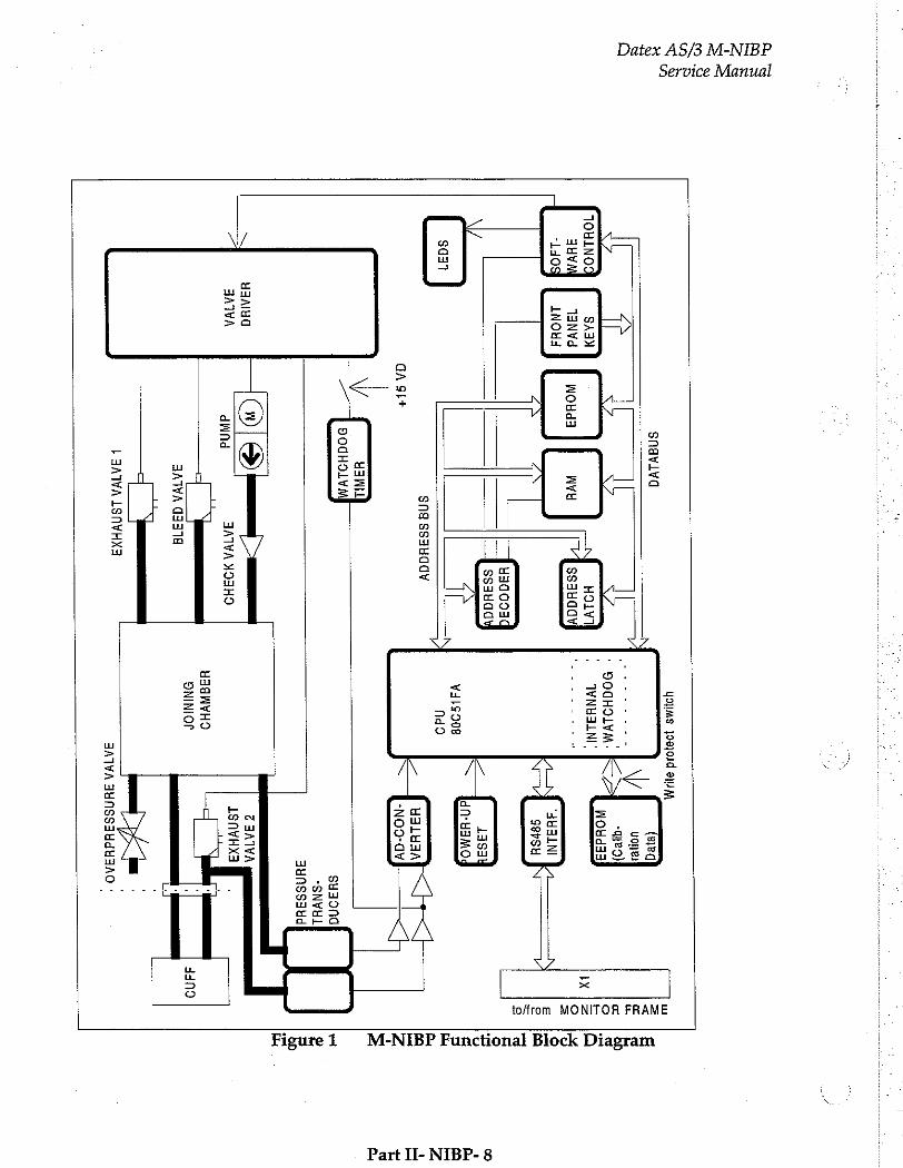
Service Manual
Datex AS/3 M-NIBP
snavlva
49148 19910Jd
34 从
ἴ it
JL IL
|| V
TOHLNO
auv “140
SAAM
TANYd 1NOHA
MOHd
ヨ MVH
(ereg uote
-queo) MOHd
ヨ ヨ
"3HALNÍ 9954
430093
9931064
8037
HIAIHO
AKIVA
Υ4 9908
13534
rd
ヨ AO
sna ssaucdy
ЦА 91+
nd9
H3LHIA
to/from MONITOR FRAME
-NO9-dY
у Pern
| 一
| BoaHolvym
1
ヨ ATVA 1STIVHX
ヨ
H ヨ WVHO
ΘΝΙΝΙΟΡ
ヨ HnSS
ヨ Hd
3309
ョ ATVA AUNSSAHdHAAO
"
M-NIBP Functional Block Diagram Figure 1
Part II- NIBP- 8
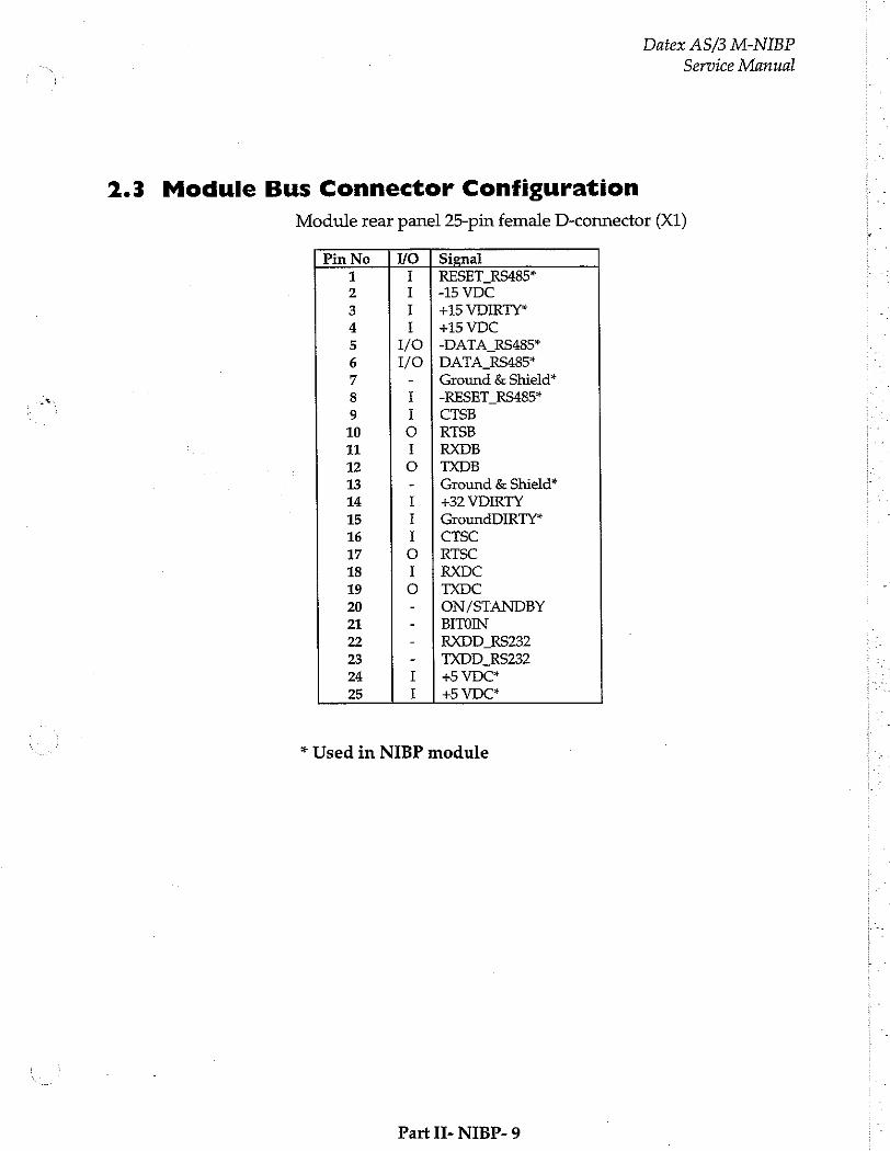
2.3 Module Bus Connector Configuration
Datex AS/3 M-NIBP
Service Manual
Module rear panel 25-pin female D-connector (X1)
Pin No VO | Signal
5 ©
@œ 1
@ UT
1 UN
mi
11
12
13
14
15
16
17
18
19
20
21
22
23
24
25
I | RESET RS485* I | -15 VDC I | +15 VDIRTY* 1 | +15 VDC
1/0 | -DATA_RS485* DATA_RS485* Ground & Shield*
-RESET RS485* CTSB RISB RXDB TXDB
+32 VDIRTY
CTSC RTSC RXDC TXDC
BITOIN
RXDD_RS232 TXDD_RS232 +5 VDC* +5 VDC* me
г ОНО нь ООН
SG
Ground & Shield*
GroundDIRTY*
ON/STANDBY
* Used in NIBP module
Part II- NIBP- 9
Datex AS/3 M-NIBP Service Manual
3 SERVICE PROCEDURES
3.1 General Service Information
Field service of the NIBP module is limited to replacing the faulty circuit boards or mechanical parts. Return the boards to Datex for repair.
Datex is always available for service advice. Please provide the unit serial number, full type designation, and a detailed fault description.
CAUTION: Only trained personnel with the appropriate tools and equipment shall perform the tests and repairs outlined in this section. Unauthorized service may void warranty of the unit.
Part II- NIBP- 10

Datex AS/3 M-NIBP
Service Manual
3.2 Preventive Maintenance Checks
Perform these checks after any service and at least once a year to keep the AS/3 Anaesthesia Monitor NIBP Module in good condition.
1. Visual inspection
_: Ifthe module is disassembled, check that grounding wires and all connectors are properly connected and there is no loose object inside the module. Check also that tubes are not pinched and there is no sharp bend before attaching the module box.
2. Functional checks
od Go to Service Menu, NIBP module, and Buttons/LEDs
test. Check that all the LEDs can be lit and the keys operate normally.
—: Connect a manometer to the NIBP connector. Go to Service Menu, NIBP module, Calibrations, and choose Active leak test. The module automatically pumps a pressure of about 265 mmHg and the pump stops. Wait for 15 seconds for the pressure to stabilize. Then check that the pressure does not go down more than 5 mmHg per minute. Release the pressure.
og Go to Service Menu, NIBP module, Calibrations, and
Calibration check. Check first zero offsets (z.o.) of both channels, B1 and B2, and write down the values when
NIBP connector is open to ambient air. The values should
be within + 10 mmHg.
Connect the manometer to the connector. Check the following pressures.
Manometer Allowed values on display
100 mmHg 100 + z.0. +2 mmHg 200 mmHg 200 + z.o. +3 mmHg 260 mmHg 260 + z.0. +4 mmHg
Calibrate if not within specification:
Part IT- NIBP- 11
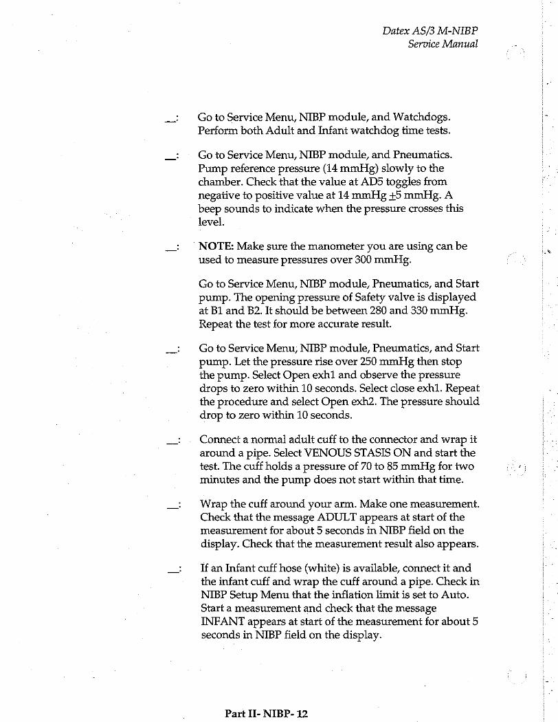
Datex AS/3 M-NIBP
Service Manual
Go to Service Menu, NIBP module, and Watchdogs.
Perform both Adult and Infant watchdog time tests.
Go to Service Menu, NIBP module, and Pneumatics.
Pump reference pressure (14 mmHg) slowly to the chamber. Check that the value at AD5 toggles from negative to positive value at 14 mmHg +5 mmHg. A beep sounds to indicate when the pressure crosses this level.
NOTE: Make sure the manometer you are using can be used to measure pressures over 300 mmHg.
Go to Service Menu, NIBP module, Pneumatics, and Start
pump. The opening pressure of Safety valve is displayed at B1 and B2. It should be between 280 and 330 mmFig. Repeat the test for more accurate result.
Go to Service Menu, NIBP module, Pneumatics, and Start
pump. Let the pressure rise over 250 mmHg then stop the pump. Select Open exh1 and observe the pressure drops to zero within 10 seconds. Select close exh1. Repeat the procedure and select Open exh2. The pressure should drop to zero within 10 seconds.
Connect a normal adult cuff to the connector and wrap it around a pipe. Select VENOUS STASIS ON and start the test. The cuff holds a pressure of 70 to 85 mmHg for two minutes and the pump does not start within that time.
Wrap the cuff around your arm. Make one measurement. Check that the message ADULT appears at start of the measurement for about 5 seconds in NIBP field on the display. Check that the measurement result also appears.
If an Infant cuff hose (white) is available, connect it and the infant cuff and wrap the cuff around a pipe. Check in NIBP Setup Menu that the inflation limit is set to Auto. Start a measurement and check that the message INFANT appears at start of the measurement for about 5 seconds in NIBP field on the display.
Part II- NIBP- 12
Datex AS/3 M-NIBP
Service Manual
3.3 Disassembly and Reassembly
Disassemble the NIBP module in the following way. See the exploded view of the module:
a)
b)
f)
8)
Remove the two screws from the back of the module.
Pull the module box slowly rearward and detach it from main body. Be careful with loose latch and spring pin for locking.
Remove the four corner screws from the back of NIBP
board. The NIBP board and the front panel can be detached.
To free the front panel and the NIBP board, disconnect
tubes and connectors.
Remove the five screws and lift off the plastic pump cover. NIBP pump, safety (over pressure) valve, and valve unit which includes two valves, wires and a connector will be exposed. Remove them.
Pull out pulse valve from the bottom of the NIBP frame.
Reassemble by reversing what was described above.
CAUTION: Before reattaching the module box, make sure that
the tubes are not pinched between the NIBP frame and the PC board.
NOTE: Take care that the connectors and especially the tubes are reconnected properly and to the right ports.
Part II- NIBP- 13
Datex AS/3 M-NIBP
Service Manual
3.4 Adjustments and Calibrations
Adjustment
Pressure safety level detection "OFFSET"
Remove two screws at the rear of the module. Take the module box away. Connect first the service cable (e.g. a long Gas Interface Cable) to the module connector inside the monitor frame and then to the rear connector of the module. Go to the NIBP Service Menu and select "Pneumatics". Pump reference pressure (14 mmHg) into the module. Adjust the trimmer R12 so that AD5 signal sign changes from negative to positive at 14 mmHg.
Calibrations
Pressure measurement calibration
The electronics of NIBP pressure measurement is calibrated at the factory. Pressure zero is automatically maintained by the processor. If the zero point of the pressure transducer drifts more than specified, an error message is given and the NIBP board needs to be recalibrated or replaced.
The calibration can be checked and, when necessary, .
recalibrated in the NIBP Service Menu.
The calibration of the primary pressure channel can also be checked in NIBP Set-up menu by selecting NIBP, NIBP Setup, and Calibration Check. In this case the auto zeroing is performed at start - remove hose before entering to ensure atmospheric pressure to the pressure transducers - the primary pressure is displayed. The zero-offset value should then be zero.
1. Calibration check
For how to reach the Calibration menu, see chapter 5, Service
Menu.
1. Enter Calibration menu.
Part Ii- NIBP- 14
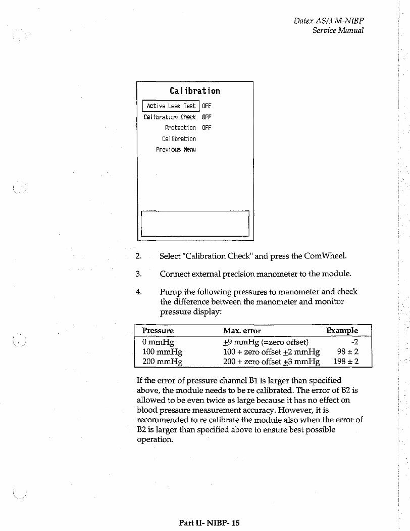
Datex AS/3 M-NIBP
Service Manual
Calibration
active Leak Test | OFF
Calibration Check OFF
Protection OFF
Calibration
Previous Menu
2. Select "Calibration Check" and press the ComWheel.
3. Connect external precision manometer to the module.
4, Pump the following pressures to manometer and check the difference between the manometer and monitor
pressure display:
Pressure Max. error Example
0 mmHg +9 mmHg (=zero offset) -2 100 mmHg 100 + zero offset +2 mmHg 98 +2 200 mmHg 200 + zero offset+3mmHg 19842
If the error of pressure channel B1 is larger than specified above, the module needs to be re calibrated. The error of B2 is
allowed to be even twice as large because it has no effect on blood pressure measurement accuracy. However, it is recommended to re calibrate the module also when the error of B2 is larger than specified above to ensure best possible operation.
Part H- NIBP- 15
Datex AS/3 M-NIBP
Service Manual
2. Calibration
For how to reach the Calibration menu, see chapter 5, Service
Menu.
1.
2.
Enter "Calibration" in NIBP Service Menu.
Remove hoses from front panel connector to enable proper zeroing.
Select "Calibration". If it is not available, perform the
steps A,B, and C.
NOTE: Do not pull off the NIBP module from the monitor frame. The module must be in the frame during the whole procedure.
A. Turn the toggle switch at the bottom of the NIBP module to enable the calibration. Turn the switch to the right by, for example, a sharp pencil. This enables menu selection "Protection". the message "Calibration switch ON!" appears.
B. Select Protection OFF in the Calibration menu and
push the ComWheel.
C. Return the toggle switch to the left. Menuselection "Calibration" is now enabled, and "Protection" is
disabled. When the calibration is enabled, a
message "Calibration not protected" appears.
Start Calibration by pushing the ComWheel. Messages "ZEROING" and "ZEROED" will appear in the NIBP message field. After this a pressure bar will appear.
Connect an external mercury manometer with pump to module through the both tubes of the hose - both transducers B1 and B2 must be calibrated simultaneously. Pump up to a pressure about 200 mmHg according to the manometer. Calibration is possible in the range 150 to 300 mmHg.
Verify that both pressure values in the prompt field match the manometer reading. If not, adjust by turning
Part II- NIBP- 16
Datex AS/3 M-NIBP
一 Service Manual
the ComWheel. When the values of the pressure bar and the manometer are equal, press the ComWheel to confirm the calibration. The message "Calibrating" will appear onto the NIBP digit field. After a few seconds it is followed by "Calibrated", which means that the calibration has succeeded, and the new calibration data
has been saved into EEPROM.
To set the protection on: Turn the toggle switch to the right. Select "Protection" ON and push the ComWheel. Then turn the toggle switch back to the left.
6. Remove the module from the frame and plug it back again. Then perform Calibration Check (see the preceding page) to verify the new calibration.
Part II- NIBP- 17
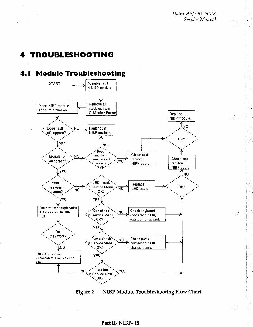
Datex AS/3 M-NIBP
Service Manual a
4.1 Module Troubleshooting
START > Possible fault in NIBP module.
Insert NIBP module Remove all
and turn power on. modules from ] C. Monitor Frame Replace
NIBP module.
Does fault Fault not in NO still appear? NIBP module.
NO
Does
Module ID due k renin ane Check and の module wor! replace
on screen? YES | NIBP board. replace NIBP board.
NO
Error LED check Replace
message on jn Service Menu LED board. OK? creen? OK?
See error code expianation
in Service Manual and Check keyboard fix it, connector. If OK,
change front panel.
Do
they work? y Check pump
in Service Menu connector. If OK, change pump.
Check tubes and connectors. Find leak and fix it.
Leak test NO
Figure2 NIBP Module Troubleshooting Flow Chart
Part II- NIBP- 18
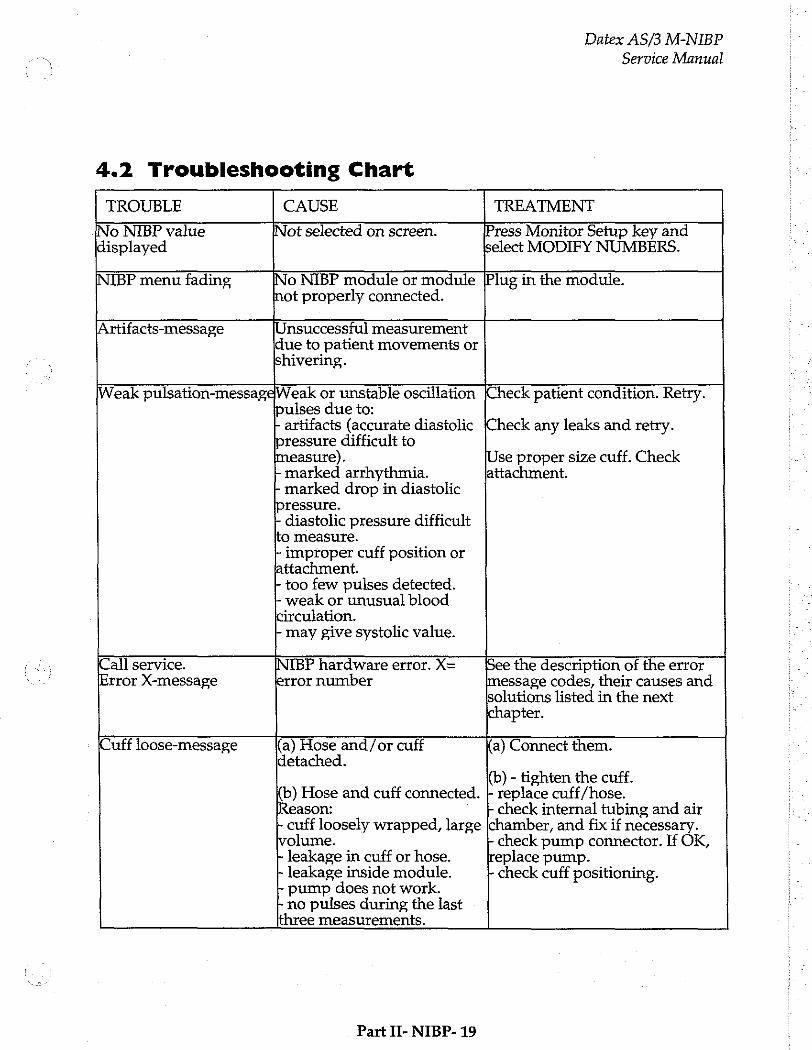
Datex AS/3 M-NIBP
Service Manual
4.2 Troubleshooting Chart
TROUBLE CAUSE TREATMENT
INo NIBP value INot selected on screen. Press Monitor Setup key and displayed select MODIFY NUMBERS.
INIBP menu fading INo NIBP module or module [Plug in the module. Inot properly connected.
|Artifacts-message [Unsuccessful measurement due to patient movements or shivering.
Weak pulsation-messageWeak or unstable oscillation pulses due to: | artifacts (accurate diastolic pressure difficult to measure). + marked arrhythmia. | marked drop in diastolic pressure. | diastolic pressure difficult to measure. | improper cuff position or attachment. + too few pulses detected. r- weak or unusual blood circulation. - may give systolic value.
(Check patient condition. Retry.
Check any leaks and retry.
[Use proper size cuff. Check attachment.
¡Call service. (Error X-message
INIBP hardware error. X= error number
See the description of the error message codes, their causes and solutions listed in the next chapter.
(Cuff 1oose-message (a) Hose and/or cuff detached.
(b) Hose and cuff connected. Reason: | cuff loosely wrapped, large volume. - leakage in cuff or hose. + leakage inside module. - pump does not work. + no pulses during the last three measurements. (a) Connect them.
(b) - tighten the cuff. - replace cuff/hose. + check internal tubing and air chamber, and fix if necessary. + check pump connector. If OK, replace pump. | check cuff positioning.
Part II- NIBP- 19
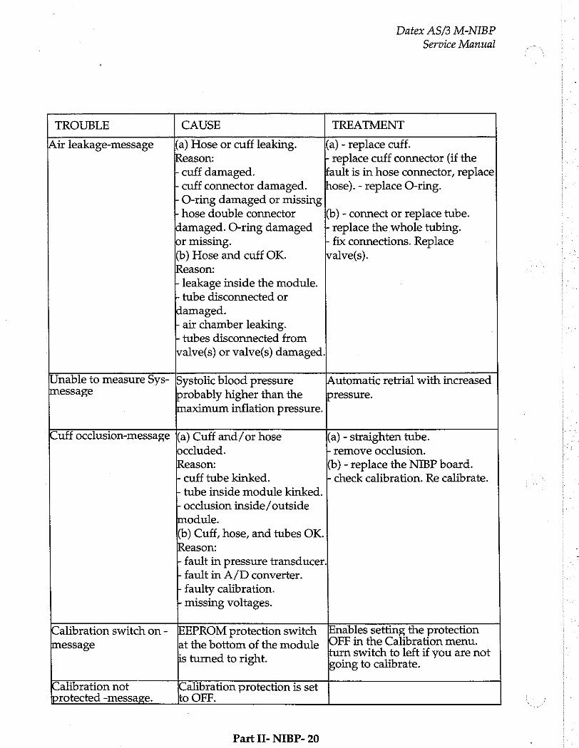
Datex AS/3 M-NIBP Service Manual
TROUBLE CAUSE TREATMENT
¡Air leakage-message |(a) Hose or cuff leaking. (a) - replace cuff. Reason: + replace cuff connector (if the | cuff damaged. fault is in hose connector, replace + cuff connector damaged. + O-ring damaged or missing + hose double connector damaged. O-ring damaged jor missing. (b) Hose and cuff OK. Reason: | leakage inside the module. - tube disconnected or damaged. - air chamber leaking. | tubes disconnected from valve(s) or valve(s) damaged
hose). - replace O-ring.
(b) - connect or replace tube. + replace the whole tubing. - fix connections. Replace valve(s).
(Unable to measure Sys- message
Systolic blood pressure probably higher than the maximum inflation pressure.
[Automatic retrial with increased
pressure.
Cuff occlusion-message (a) Cuff and/or hose occluded.
Reason:
- cuff tube kinked.
- tube inside module kinked.
+ occlusion inside/outside module.
(b) Cuff, hose, and tubes OK. Reason:
- fault in pressure transducer - fault in A/D converter.
- faulty calibration. - missing voltages.
(a) - straighten tube. + remove occlusion.
(b) - replace the NIBP board.
- check calibration. Re calibrate.
(Calibration switch on -
Imessage
IEEPROM protection switch at the bottom of the module
is turned to right.
Enables setting the protection OFF in the Calibration menu. turn switch to left if you are not going to calibrate.
Calibration not ¡protected -message. Calibration protection is set
[to OFF.
Part II- NIBP- 20
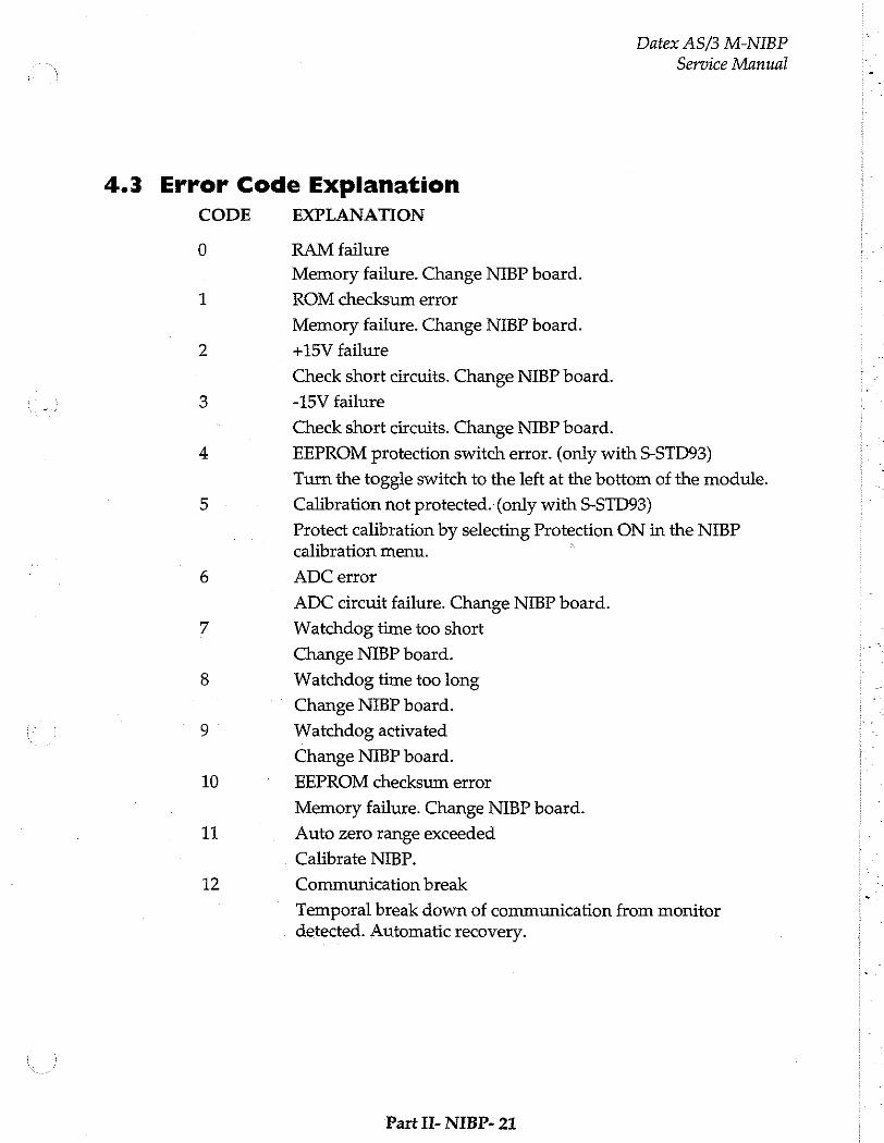
Datex AS/3 M-NIBP
Service Manual
4.3 Error Code Explanation
CODE
0
10
11
12
EXPLANATION
RAM failure
Memory failure. Change NIBP board.
ROM checksum error
Memory failure, Change NIBP board.
+15V failure
Check short circuits. Change NIBP board.
-15V failure
Check short circuits. Change NIBP board.
EEPROM protection switch error. (only with S-STD93)
Turn the toggle switch to the left at the bottom of the module.
Calibration not protected. (only with S-STD93)
Protect calibration by selecting Protection ON in the NIBP calibration menu. °
ADC error
ADC circuit failure. Change NIBP board.
Watchdog time too short
Change NIBP board.
Watchdog time too long
Change NIBP board.
Watchdog activated
Change NIBP board.
EEPROM checksum error
Memory failure. Change NIBP board.
Auto zero range exceeded
Calibrate NIBP.
Communication break
Temporal break down of communication from monitor detected. Automatic recovery.
Part II- NIBP- 21

Datex AS/3 M-NIBP
Service Manual
Monitor Setup
Monitor Setup Install/Service
Waveform Fields Units
Digit Fields 100 Service View | 26 100
Select Mode Save Modes
Set Time and Date Interfacing
Install/Service | 16 Analog Outputs
Normal. Screen Monitor Settings
Printer Settings
Previous Menu
0 8
Give password. Give password,
To enter Service Menu during normal operation:
1. 1. Press the MONITOR SETUP key. The Setup menu appears.
2. Turn ComWheel to highlight Install/Service and push.
3. Give the password by turning the ComWheel to display each password number and confirm the number by pushing the ComWheel. Password numbers are 16 - 4 - 34. The Install/Service menu appears.
4. Turn the ComWheel to highlight Service View and push.
5. Give the password by turning the ComWheel to display each password number and confirm the number by pushing the ComWheel. Password numbers are 26 - 23 - 8.
6. Turn the ComWheel to highlight Modules and push.
7. Turn the ComWheel to highlight NIBP module and push.
Part Ii- NIBP- 22

Datex AS/3 M-NIBP
Service Manual
5.1 NIBP Service Menu
NIBP Module Service Data B B2
Calibrations Pressure A 一 一
Zero 一 ~ — Safety Yalye AD0
Pulse Yalve apt ーーー
Buttons/Leds 203 ーー
i = Protect handle OFF ADS --- Preunatics Calibr. prot. Е A6 — Watchdog +15 ¥ power OFF AD? —
Previous Menu
Timeouts 65535 RAW ? Bad checksums 65535 ROM 3 Bad c-s by mod 0 FEPROM ?
Calibration functions.
Safety Valve functions.
Pulse Valve service functions.
Buttons/Leds service functions.
Pneumatics service functions.
Watchdog functions. o di PSN F
7. Return to previous menu.
SERVICE DATA Detailed Description
Pressure shows measured pressure multiplied by 10. Zero shows pressure at auto zeroing multiplied by 10 and changes between +20 and -20 mmHg. Absolute pressure is the sum of Pressure and Zero.
Protect handle indicates hardware protection for EEPROM memory. It should be ON all the time in normal operation. If it is OFF data can not be read from or written to EEPROM, only
Part II- NIBP- 23
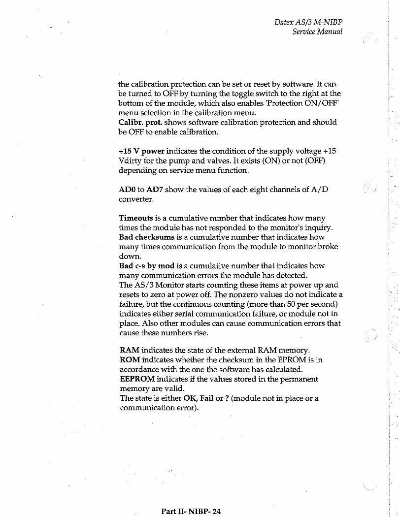
Datex AS/3 M-NIBP
Service Manual
the calibration protection can be set or reset by software. It can be turned to OFF by turning the toggle switch to the right at the bottom of the module, which also enables Protection ON/OFF'
menu selection in the calibration menu. Calibr. prot. shows software calibration protection and should
be OFF to enable calibration.
+15 V power indicates the condition of the supply voltage +15 Vdirty for the pump and valves. It exists (ON) or not (OFF) depending on service menu function.
ADO to AD7 show the values of each eight channels of A/D converter.
Timeouts is a cumulative number that indicates how many times the module has not responded to the monitor's inguiry. Bad checksums is a cumulative number that indicates how many times communication from the module to monitor broke down. Bad c-s by mod is a cumulative number that indicates how many communication errors the module has detected. The AS/3 Monitor starts counting these items at power up and resets to zero at power off. The nonzero values do not indicate a failure, but the continuous counting (more than 50 per second) indicates either serial communication failure, or module not in
place. Also other modules can cause communication errors that cause these numbers rise.
RAM indicates the state of the external RAM memory. ROM indicates whether the checksum in the EPROM is in accordance with the one the software has calculated. EEPROM indicates if the values stored in the permanent memory are valid. The state is either OK, Fail or ? (module not in place or a
communication error).
Part II- NIBP- 24

Datex AS/3 M-NIBP
Service Manual
5.1.1 NIBP Calibration Menu
Calibration
Active Leak Test | OFF
Calibration Check OFF
Protection OFF
Calibration
Previous Menu
1 Active leak test selection (ON/OFF)
2. Calibration check selection (ON/OFF)
3. Software calibration protection (ON/OFF). Select OFF when calibrating. Protection can be set to ON or OFF only when the toggle switch at the bottom of the module is set to the right.
4. Calibration. Calibration selection is available only when protection is OFF.
5. Return to previous menu.
Part II- NIBP- 25
Datex AS/3 M-NIBP
Service Manual
Active Leak Test
Wrap an adult cuff around a pipe and connect the cuff to the module. Select the active leak test (ON). The module automatically pumps a pressure of 260 mmHg into the cuff. Wait for several seconds until the pressure stabilizes. Then check that the pressure reading does not drop more than 5 mmHg per minute. If it does, leaking point(s) should be detected and fixed. Cancel the test by selecting Active leak test OFF.
Calibration Check
After the calibration check is selected (ON), manually pump pressure into the module and make sure that the same pressure values are shown both on the display and on manometer. Pressure of both pressure channels B1 and B2 are shown. Note that if the display shows +2 mmHg at zero pressure and if you pumped +200 mmHg into the module, the display should show +202 mmHg.
Calibration
NIBP calibration can be performed in the NIBP Service menu as follows:
NOTE : Both channels B1 and B2 must be calibrated
simultaneously.
1. If Protection is ON change it to OFF by first turning the toggle switch to the right at the bottom of the module, which enables the Protection selection. Then turn the toggle switch to the left to enable Calibration.
NOTE : Do not disconnect the module from the frame when turning the switch. The module must be in the frame during the whole procedure.
NOTE: When the switch is at the right, the NIBP field shows an error message "Calibration switch on!".
NOTE: When calibration is enabled, a message ‘Calibration not protected’ appears.
Part If- NIBP- 26
Datex AS/3 M-NIBP
Service Manual
For proper zeroing to take place, remove the hose from the front panel connector. Select Calibration and push the ComWheel. Messages "ZEROING" and "ZEROED" will appear in the NIBP message field. After this a pressure bar will appear beside the menu.
Connect an external mercury manometer with pump to module through the both tubes of the hose. Pump up to about 200 mmHg pressure (range of 150 to 300 mmHg allowed) according to the manometer. Verify that both pressure values in the prompt field match the manometer reading. If not, adjust by turning the ComWheel.
When the values are equal, push the ComWheel to confirm the calibration. First the message "Calibrating" will appear followed after a few seconds "Calibrated”, which means that the calibration data has now been saved.
Use the bottom switch to enable Protection setting and set it ON, and finally disable Protection setting.
Part 11- NIBP- 27
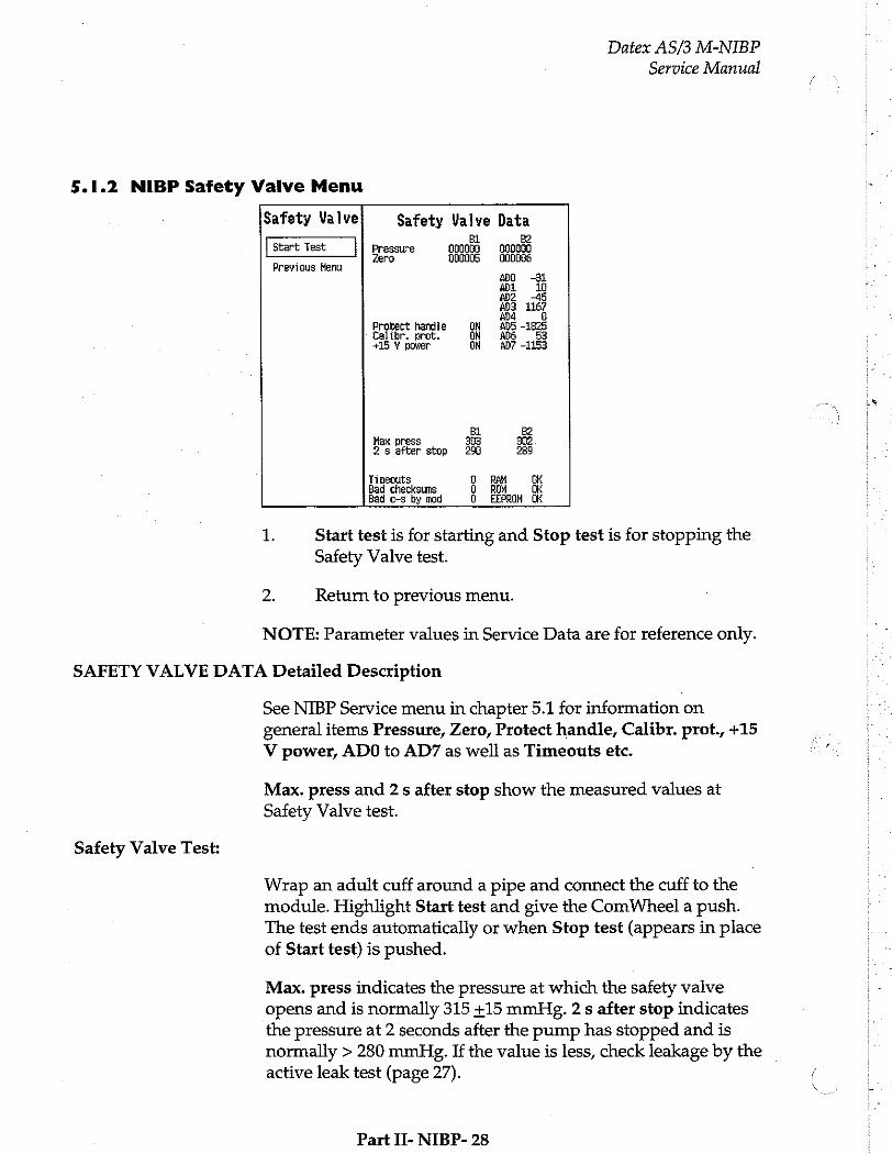
Datex AS/3 M-NIBP
Service Manual
5.1.2 NIBP Safety Valve Menu
Safety Valve Safety Valve Data BL B2
Start Test Pressure 000000 000000 - Zero 000095000088
Previous Henu ADO -31 А 10 ADZ 45 ADI 1167 ada 5
Protect handle ON AD5 -1825 Calibr. prot. EN AD6 53 +15 Y power ON AD? -1153
BL B2 Max press 303 302 2s after stop 290 289
Timeouts 0 RAH OK Bad checksums 0 ROM Ok Bad c-s by mod 0 EEPROM OK
1. Start test is for starting and Stop test is for stopping the Safety Valve test.
2. Return to previous menu.
NOTE: Parameter values in Service Data are for reference only.
SAFETY VALVE DATA Detailed Description
Safety Valve Test:
See NIBP Service menu in chapter 5.1 for information on general items Pressure, Zero, Protect handle, Calibr. prot., +15
V power, ADO to AD7 as well as Timeouts etc.
Max. press and 2 s after stop show the measured values at Safety Valve test.
Wrap an adult cuff around a pipe and connect the cuff to the module. Highlight Start test and give the ComWheel a push. The test ends automatically or when Stop test (appears in place of Start test) is pushed.
Max. press indicates the pressure at which the safety valve opens and is normally 315 +15 mmHg. 2 s after stop indicates the pressure at 2 seconds after the pump has stopped and is normally > 280 mmHg. If the value is less, check leakage by the . active leak test (page 27).
Part II- NIBP- 28
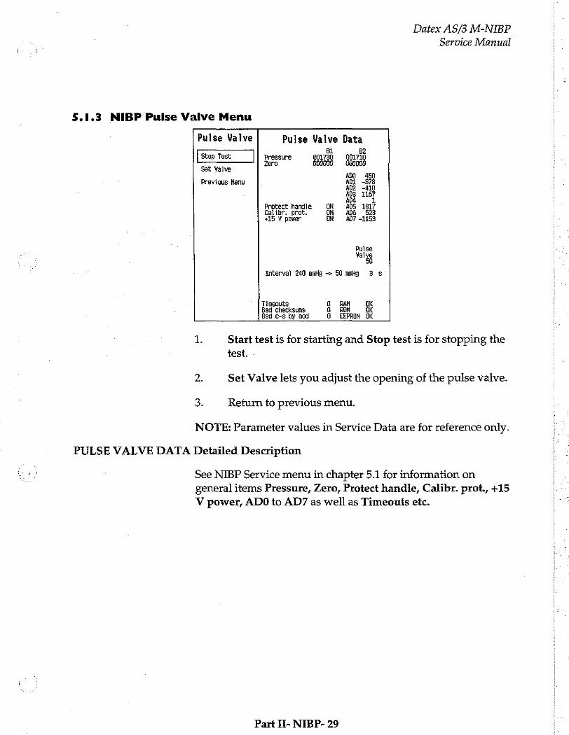
Datex AS/3 M-NIBP
Service Manual
5.1.3 NIBP Pulse Valve Menu
Pulse Valve Pulse Valve Data Bl B2
Stop Test Pressure 001730 01710 Zero 000000 080000
Set Valve . ADO 450
Previous Menu ADI -376 AD2 -410 203 2167 ADA 1
Protect handie ON ADS 1817 Calibr. prot. ON ADE 523 +15 ¥ power ON AD? -1153
Pulse Valve
50
Interval 240 mmHg -> 50 mmHg 3 s
Timeouts O RAM OK Bad checksums D ROM pis Bad c-s by mod G EEPROM OK
1. Start test is for starting and Stop test is for stopping the test.
2. Set Valve lets you adjust the opening of the pulse valve.
3. Return to previous menu.
NOTE: Parameter values in Service Data are for reference only.
PULSE VALVE DATA Detailed Description
See NIBP Service menu in chapter 5.1 for information on general items Pressure, Zero, Protect handle, Calibr. prot., +15
V power, ADO to AD7 as well as Timeouts etc.
Part Ii- NIBP- 29
Datex AS/3 M-NIBP
Service Manual
Pulse Valve Checking:
Wrap an adult cuff around a pipe and connect the cuff to the module. Select the Start test and push the ComWheel. The pressure rises beyond 240 mmHg and stops. The pulse valve opens. The module counts the time it takes for the pressure to go down from 240 mmHg to 50 mmHg and displays it. The test can be manually stopped by selecting Stop test.
The valve can be adjusted between 0 and 255 (0 for fully closed and 255 for fully open). First select Set Valve and push the ComWheel. See the pulse valve value and adjust it by turning the ComWheel. Then push the ComWheel to confirm the value.
The "Interval 240 mmHg -> 50 mmHg" time should be less than 60 seconds when the valve is '50' and less than 10 when fully opened (255). When fully closed (0), the system should be airtight and the pressure does not drop. Depending on an individual, the pulse valve may remain closed up to approx. value 45.
If the measured time deviates much from those above, then the
pulse valve or its tubes are faulty.
Part II- NIBP- 30

Datex AS/3 M-NIBP
Service Manual
5.1.4 NIBP Buttons/Leds Menu
Buttons/Leds Buttons/Leds Data Bi B2
auto = ON Pressure 000000 000000 Zero 0D00000 — 080000
Manual OFF ADO -31
STAT ON ADI 10 802 -45
Heasur. ON 20% 116
Previous Menu Protect handle ON ADS -1825 Calibr. prot, ON a6 53 +15 Y power ON AD7 -1153
tuto Set STAT Start би tele On/Off Cancel
OFF OFF ON OFF
Timeouts D RAM OK Bad checksums 2° ROM OK Bad c-s by mod 1 EEPROM OK
1to 4. Auto, Manual, Stat, and Measuring Led selectors. Select
ON and push the ComWheel to light the Led in question.
5. Return to previous menu
NOTE: Parameter values in Service Data are for reference only.
BUTTONS/LEDS DATA Detailed Description
See NIBP Service menu in chapter 5.1 for information on general items Pressure, Zero, Protect handle, Calibr. prot., +15
V power, ADO to AD7 as well as Timeouts etc.
Buttons Checking:
The front panel keys function is confirmed by pressing the key and observing OFF turns to ON at Auto On/Off, Set Cycle Time, Stat On/Off, and Start Cancel.
LEDS Checking:
The front panel LEDS can be lit by selecting Auto, Manual, Stat, or Measuring. ON and pushing the ComWheel.
Part II- NIBP- 31

6.1.5 NIBP Pneumatics Menu
Pneumatics
Stop Pump
Open Exhl
Close Exh2
Set Valve
Reset Clock
Previous Menu
Pneumatics Data BL B2
Pressure 000570 001320 Zero 000000 890900
#00 122 ADI -1005 #02 -156 #03 1162 ana 1
Protect handle GN ADS 1917 Calibr, prot. ON 206 381 +15 Y power ON AD7 -1153
Pump Exhl Exh2 Pulse Valve Valve Valve
ON CLOSED OPEN 41
Interval 20 mmHg -> 185 mmHg 4
Timeouts 0 RAM DK Bad checksums O ROM OK Bad c-s by mod G. EEPROM OK
Datex AS/3 M-NIBP
Service Manual
1. Start pump and Stop pump are for the pump.
2. Open Exh1 is for opening the exhaust valve 1.
3. Open Exh2 is for opening the exhaust valve 2.
4. With Set Valve, the opening of the pulse valve is adjusted between O and 255 (0 for fully closed and 255 for fully open). First push the ComWheel, then turn it to adjust the value on screen and finally push to set the value.
5. Reset Clock will zero the time on the display .
6. Return to previous menu
NOTE: Parameter values in Service Data are for reference only.
Part II- NIBP- 32

Datex AS/3 M-NIBP Service Manual
PNEUMATICS DATA Detailed Description
See NIBP Service menu in chapter 5.1 for information on general items Pressure, Zero, Protect handle, Calibr. prot., +15
V power, ADO to AD7 as well as Timeouts etc.
Pump, Exh1 Valve, and Exh2 Valve show their states.
Pulse Valve shows how much the valve is opened (0 to 255)
during Valve Setting.
Interval 20 mmHg -> 185 mmHg Checking:
Select the Start pump at different combinations of the valves open/closed and push the ComWheel. The module counts the time it takes for the pressure to go up from 20 mmHg to 185 mmHg and displays it. When all the valves are closed, the pump should be able to pump the pressure in about 1 to 4 seconds into an adult cuff wrapped around a pipe. The pump does not stop without selecting the STOP PUMP by pushing the ComWheel.
Watchdog BEEP:
Connect manometer to the front panel and pump pressure into the module. When the AD5 value changes from negative to positive value (at about 15 to 20 mmHg) a beep is heard. This is the watchdog threshold pressure. Beyond this pressure the watchdog is active and cut pressures at about 2 min. (adult).
Part Ii- NIBP- 33
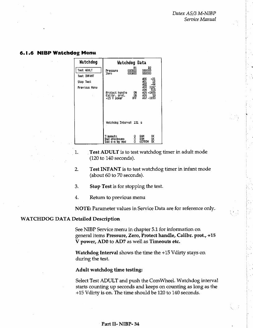
Datex AS/3 M-NIBP
Service Manual
6.1.6 NIBP Watchdog Menu i
Watchdog Watchdog Data i BI B2 Eos
Test ADULT Pressure 000900 000000 Zero 000000 000000 :
Test INFANT a ADO -31
Stop Test 部 1 10
Dá ue Previous Menu DA EIS
Protect handle ON ADS -1825 Calibr, prot. ON ADO 53 +15 Y power OFF #07 -1153
Watchdog Interval 131 s
Timeouts Q RAN BK Bad checksuns O ROM Ok Bad c-s by mod D EEPROH ÚK
1. Test ADULT is to test watchdog timer in adult mode (120 to 140 seconds).
2. Test INFANT is to test watchdog timer in infant mode (about 60 to 70 seconds).
3. Stop Test is for stopping the test.
4. Return to previous menu
NOTE: Parameter values in Service Data are for reference only.
WATCHDOG DATA Detailed Description
See NIBP Service menu in chapter 5.1 for information on general items Pressure, Zero, Protect handle, Calibr. prot., +15
V power, ADO to AD7 as well as Timeouts etc.
Watchdog Interval shows the time the +15 Vdirty stays on during the test.
Adult watchdog time testing:
Select Test ADULT and push the ComWheel. Watchdog interval starts counting up seconds and keeps on counting as long as the +15 Vdirty is on. The time should be 120 to 140 seconds.
Part II- NIBP- 34
Datex AS/3 M-NIBP
Service Manual
Infant watchdog time testing:
Select Test INFANT and push the ComWheel. Watchdog interval starts counting up seconds and keeps on counting as long as the +15 Vdirty is on. The time should be 60 to 70 seconds.
Part II- NIBP- 35

6 SPARE PARTS
6.1 Spare Part List
NOTE: Only changed part numbers are listed under later revisions. To find the desired part: check first the list of the revision that corresponds your device. If the part is not listed there, check the previous revision, etc. until you find the right
number.
Datex AS/3 M-NIBP Service Manual
NOTE: Accessories are listed in the booklet AS/3 Supplies and Accessories.
Item numbers refer to the exploded view in chapter 6.2.
NIBP Module, M-NIBP
Rev. 01
Item | Item description
8 NIBP board, M-NIBP (Rev. 01)
11 NIBP frame, M-NIBP 15 Plastic pump cover, M-NIBP 14 NIBP pump, M-NIBP (Rev. 01-02) 22 Pulse valve 21 Magnetic valve 20 Port plug for magnetic valve 13 Safety valve (overpressure valve) 4 Front panel unit, M-NIBP
Membrane keypad 16 Front panel sticker, M-NIBP (Eng) 16 Front panel sticker, M-NIBP (Fre) 16 Front panel sticker, M-NIBP (Ger) 17 LED board, M-NIBP 18 Hose connector 1 Module box (wide) 3 Latch 2 Spring pin 5 Cross recess screw M3x8 black 10 Cross cylinder-head screw M3x10 9 Cross cylinder-head screw M3x20 19 Cross cylinder-head screw M2.5x6
Part IT- NIBP- 36
Order No.
*(880359) Use 883011 ? 883902
880427 879176 *(880363) Use 883346 *880365 *58534 58535 877109 881335 879374 879482 880159 880476 880361 64654 886168 879181 879182 628706 628703 628709 628700
Rev. 02
Item Item description
8 NIBP board, M-NIBP (Rev. 02)
23 Check valve
Rev. 03
Item Item description
8 NIBP board, M-NIBP (Rev. 03)
NIBP software 14 NIBP pump, M-NIBP (Rev. 03) 16 Front panel sticker, M-NIBP (Spa) 16 Front panel sticker, M-NIBP (Swe) 16 Front panel sticker, M-NIBP (Dut) 16 Front panel sticker, M-NIBP (Ita) 16 Front panel sticker, M-NIBP (Fin)
The front panel unit includes all the connectors and input boards.
* = the part is recommended for stock
Datex AS/3 M-NIBP
Service Manual
Order No.
*(882418) Use 883011 3883902
58542
Order No.
*883011 *883902 *883346 884386 885870 886124 886752 888872
” The NIBP board 883011 can be used as a replacement only with NIBP software 883902.
Part 11- NIBP- 37
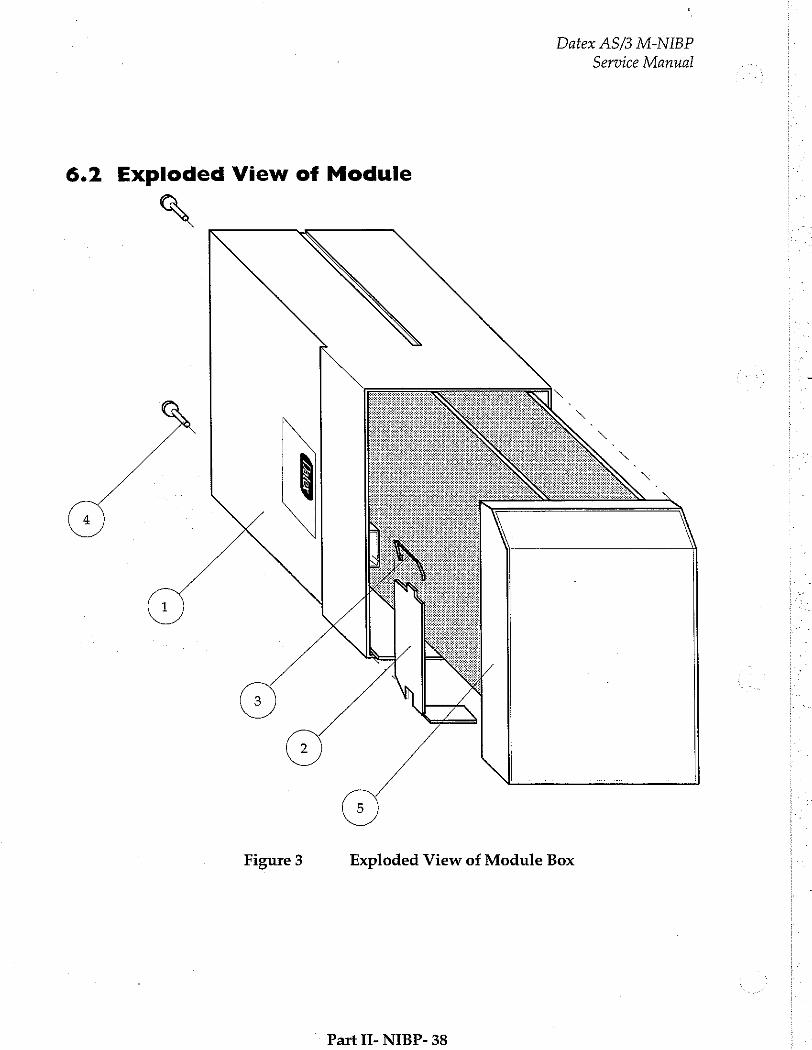
Datex AS/3 M-NIBP
Service Manual
6.2 Exploded View of Module
A
G
Figure 3 Exploded View of Module Box
Part II- NIBP- 38

Service Manual
Datex AS/3 M-NIBP
(10
73373 / 1.7 A
8
Figure 4 Exploded View of NIBP Module 73375 / 3,18x 6,35
Part II- NIBP- 39
Datex AS/3 M-NIBP
Service Manual
7. EARLIER REVISIONS
For service information on the earlier revisions, please refer to:
NIBP Module revision 01 Service Manual p/n 880850
NIBP Module revision 02 Service Manual p/n 882580
Part II- NIBP- 40
トレ ンジ
Recorder Module, M-REC (Rev. 02)
All specifications subject to change without notice
Document No. 885937-3
May, 1996
Datex-Engstrom Division, Instrumentarium Corp. P.O.Box 446 FIN-00101 Helsinki Finland
Until Oct. 11th, 1996 Tel. +358 0 39411, Fax +358 0 146 3310 After Oct. 12th, 1996 Tel. +358 9 39411, Fax +358 9 146 3310

Datex-Engstrom AS/3 M-REC Service Manual
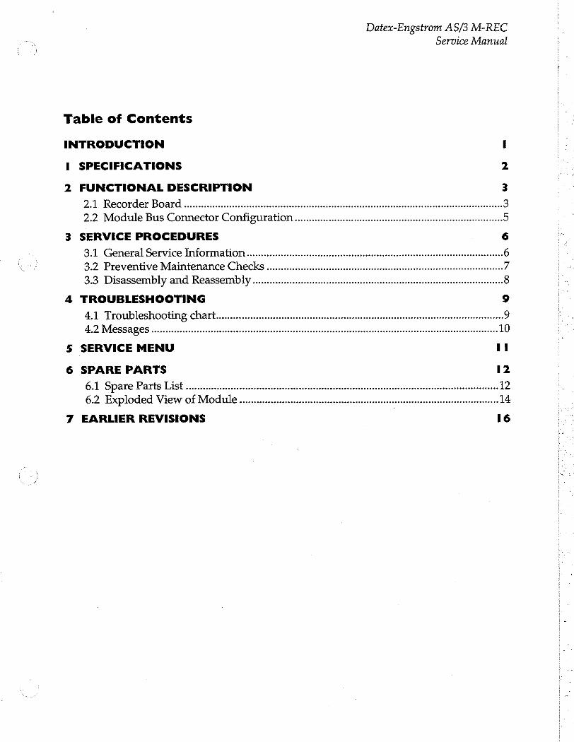
Datex-Engstrom AS/3 M-REC
Service Manual
Table of Contents
INTRODUCTION I
I SPECIFICATIONS 2
2 FUNCTIONAL DESCRIPTION 3
2.1 Recorder Board rei 3 2.2 Module Bus Connector Configuration... iii 5
3 SERVICE PROCEDURES 6
3.1 General Service Information...................... . ee 6 3.2 Preventive Maintenance Checks ... „7 3.3 Disassembly and Reassembiy ten een enter een een nenene 8
4 TROUBLESHOOTING 9
4.1 Troubleshooting chart... rei iii 9 4.2 Messages ーー EE EEE E RE RAP RER Ret 10
5 SERVICE MENU il
6 SPARE PARTS 12
6.1 Spare Parts List... sn 12 6.2 Exploded View of Module nn 14
7 EARLIER REVISIONS 16

Datex-Engstrom AS/3 M-REC Service Manual
Datex-Engstrom AS/3 M-REC
Service Manual
INTRODUCTION
The AS/3 Recorder Module, M-REC, and the built-in Recorder,
of the AS/3 Compact Monitor, F-CMREC, provide real time
printing of waveform and numerical data, and also trend data.
The Recorder module and the built-in Recorder are technically the same, the only difference is that the M-REC is placed in a module box, and the F-CMREC is placed in the AS/3 Compact Monitor frame. In the following they both are referred to as the recorder.
NOTES:
* Printings on thermal paper may be destroyed when exposed to light, heat, alcohol etc. Take a photocopy for archive.
The Recorder module cannot be used in the Extension
Frame, F-EXT4.
II-REC-1
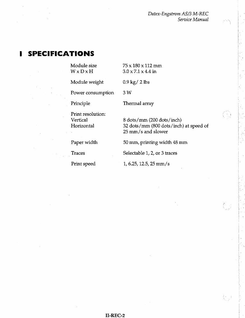
I SPECIFICATIONS
Module size
WxDxH
Module weight
Power consumption
Principle
Print resolution:
Vertical
Horizontal
Paper width
Traces
Print speed
Datex-Engstrom AS/3 M-REC
Service Manual
75x 180 x 112 mm
3.0x7.1x44in
0.9 kg/ 2 Ibs
3W
Thermal array
8 dots/mm (200 dots/inch)
32 dots/mm (800 dots/inch) at speed of 25 mm/s and slower
50 mm, printing width 48 mm
Selectable 1, 2, or 3 traces
1, 6.25, 12.5, 25 mm/s
II-REC-2
Datex-Engstrom AS/3 M-REC Service Manual
2 FUNCTIONAL DESCRIPTION
2.1 Recorder Board
In general
The task of the Recorder board inside the Recorder is to connect it to the module bus. Additionally, three front panel keys are connected through the board io the recorder.
In the module the recorder and the Recorder board are
connected together with a small connector board and 12-pin fex- strip cable.
External communication
Communication with the host processor takes place in +5 V CMOS-level serial communication B-channel and with RS485- reset.
Reset
Differential RS485-reset from the module bus is transferred to mod-bus-reset signal in the board. Besides, the board has its own power-up-reset, whose time constant is about 0.1 seconds. The RESET-signal is active when either the mod-bus-reset or the power-up-reset is active.
+5 V priority
The recorder supply voltage of +15 VREC is switched on after +5 V is present.
Front panel keys
The recorder can read up to three keys and pass their status on to the host processor in serial communication.
For protecting the key switch signals from static discharges, there are zener diodes and series resistance option. Pull-up resistor is not needed because there are pull-up resistors connecting the key switch signal inputs and +5 V together inside the recorder.
II-REC-3

Datex-Engstrom AS/3 M-REC
Service Manual -
Recorder Board i
Power-up Reset
reset logic Reseti
; RS-485-Reset ; Recorder Module ¡Serial interface i mother i : board i+15V TT + 15УВЕС i
+5V
Front : panel i Switches
membrane i switch
Figure 1 Recorder Board Block Diagram
II-REC-4
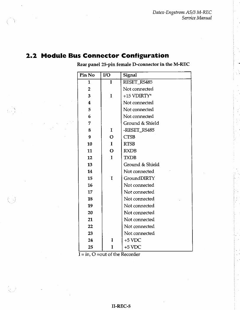
Datex-Engstrom AS/3 M-REC Service Manual
2.2 Module Bus Connector Configuration
Rear panel 25-pin female D-connector in the M-REC
PinNo {YO | Signal
1 I RESET_RS485
2 Not connected
3 I +15 VDIRTY*
4 Not connected
5 Not connected
6 Not connected
7 Ground & Shield
8 I -RESET_RS485
9 ο CTSB
10 I RTSB
11 O RXDB
12 I TXDB
13 Ground & Shield
14 Not connected
15 I GroundDIRTY
16 Not connected
17 Not connected
18 Not connected
19 Not connected
20 Not connected
21 Not connected
22 Not connected
23 Not connected
24 I +5 VDC
25 I +5 VDC
I = in, O =out of the Recorder
II-REC-5
Datex-Engstrom AS/3 M-REC
Service Manual
3 SERVICE PROCEDURES
3.1 General Service Information
Usually field service of the Recorder is limited to replacing the faulty circuit boards or mechanical parts. The boards are then returned to Datex-Engstrom for repair.
Datex-Engstrom is always available for service advice. Please provide the unit serial number, full type designation, and a
detailed fault description.
CAUTION: Only trained personnel with appropriate equipment shall perform the tests and repairs outlined in this section. Unauthorized service may void warranty of the unit.
T-REC-6
Datex-Engstrom AS/3 M-REC Service Manual
3.2 Preventive Maintenance Checks
Perform these checks after any service and at least once a year to keep the Recorder in good condition.
1. Visual inspection of the module
If the module is disassembled, check that grounding wires and all connectors are properly connected and there is no loose object inside the module before attaching the module box.
2. Functional checks (for F-CMREC only steps that are applicable)
Insert the module into Frame where there is at least
ESTP/EST/ETP module. Turn the power on. No error message appears.
Check the functions of the Record Wave and Stop keys.
Pull out the module. Reinsert the module while the power is still on. Check the functions of the Record Wave and Stop keys again.
Press Recorder and Recorder Setup keys. Choose 20 seconds as recording length and 6.25 mm/s as paper speed. Start printing by Record Wave key. The length of printout should be 12.5 + 1 cm.
Change paper speed to 12.5. The length should be 37.5 + 3 em.
Change paper speed to 25. The length should be 75 + 6
cm.
Press Recorder key and set up the following with the ComWheel:
Waveform 1 ECG1
Waveform 2 OFF
Waveform 3 OFF
Press Record Wave key. The printout should fill the paper and lines should be unbroken.
TI-REC-7
Datex-Engstrom AS/3 M-REC Service Manual
3.3 Disassembly and Reassembly
Disassemble the Recorder module in the following way. See the exploded view of the module:
a) Remove the two screws from the back of the module.
b) Pull the module box slowly rearward and detach it from main body. Be careful with loose latch and spring pin for locking.
c) Open paper loading hatch of the recorder. With a long blade screwdriver loosen the two screws at the bottom of the recorder housing.
d) Disconnect 50-pin connector from the back of the recorder and 5-pin ribbon connector of keypad from the Recorder board.
Now the recorder and front panel frame can be pulled out of the main body. The front panel frame is slipped out of the recorder by pulling rearward.
The Recorder board is attached to the metal chassis with four
screws.
CAUTION: In the M-REC the Recorder board is fixed to the metal chassis at the factory in a position that gives best contact of the D-connectors. The board and the chassis must not be separated.
Before disassembling the F-CMREC the AS/3 Compact Monitor Frame must be opened, see the corresponding service manual.
Н-ВЕС-8
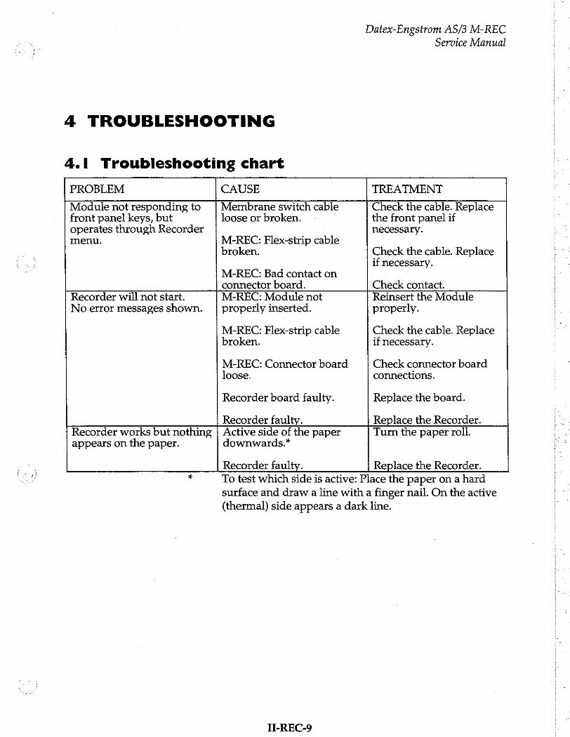
Datex-Engstrom AS/3 M-REC
Service Manual
4 TROUBLESHOOTING
4.1 Troubleshooting chart
PROBLEM CAUSE TREATMENT
Module not responding to | Membrane switch cable Check the cable. Replace front panel keys, but loose or broken. the front panel if operates through Recorder menu. M-REC: Flex-strip cable
broken.
M-REC: Bad contact on
necessary.
Check the cable. Replace if necessary.
M-REC: Flex-strip cable broken.
M-REC: Connector board
connector board. Check contact. Recorder will not start. M-REC: Module not Reinsert the Module No error messages shown. | properly inserted. properly.
Check the cable. Replace if necessary.
Check connector board
loose. connections.
Recorder board faulty. Replace the board.
Recorder faulty. Replace the Recorder. Recorder works but nothing | Active side of the paper Turn the paper roll. appears on the paper. downwards.*
Recorder faulty. Replace the Recorder.
To test which side is active: Place the paper on a hard surface and draw a line with a finger nail. On the active (thermal) side appears a dark line.
II-REC-9
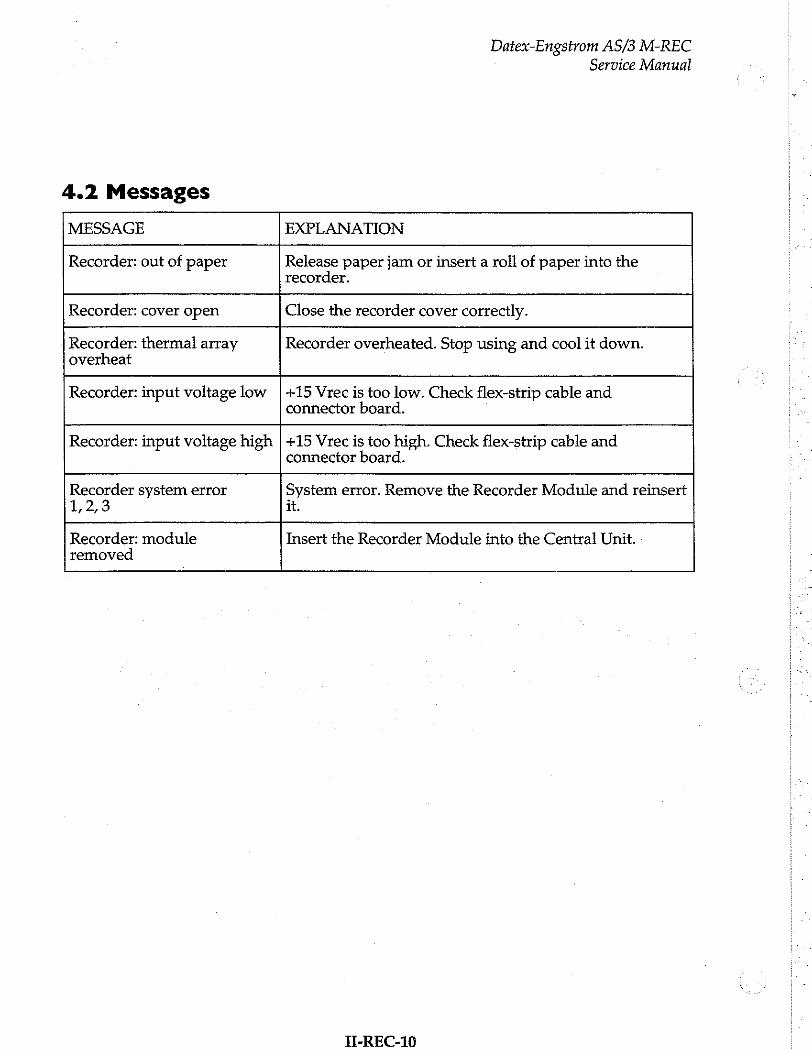
4.2 Messages
Datex-Engstrom AS/3 M-REC Service Manual
MESSAGE EXPLANATION
Recorder: out of paper Release paper jam or insert a roll of paper into the recorder.
Recorder: cover open Close the recorder cover correctly.
Recorder: thermal array overheat
Recorder overheated. Stop using and cool it down.
Recorder: input voltage low +15 Vrec is too low. Check flex-strip cable and connector board.
Recorder: input voltage high +15 Vrec is too high. Check flex-strip cable and connector board.
Recorder system error 1,2,3
System error. Remove the Recorder Module and reinsert it.
Recorder: module removed Insert the Recorder Module into the Central Unit.
TI-REC-10
Datex-Engstrom AS/3 M-REC
Service Manual
5 SERVICE MENU
There is no service menu for the Recorder module.
II-REC-11
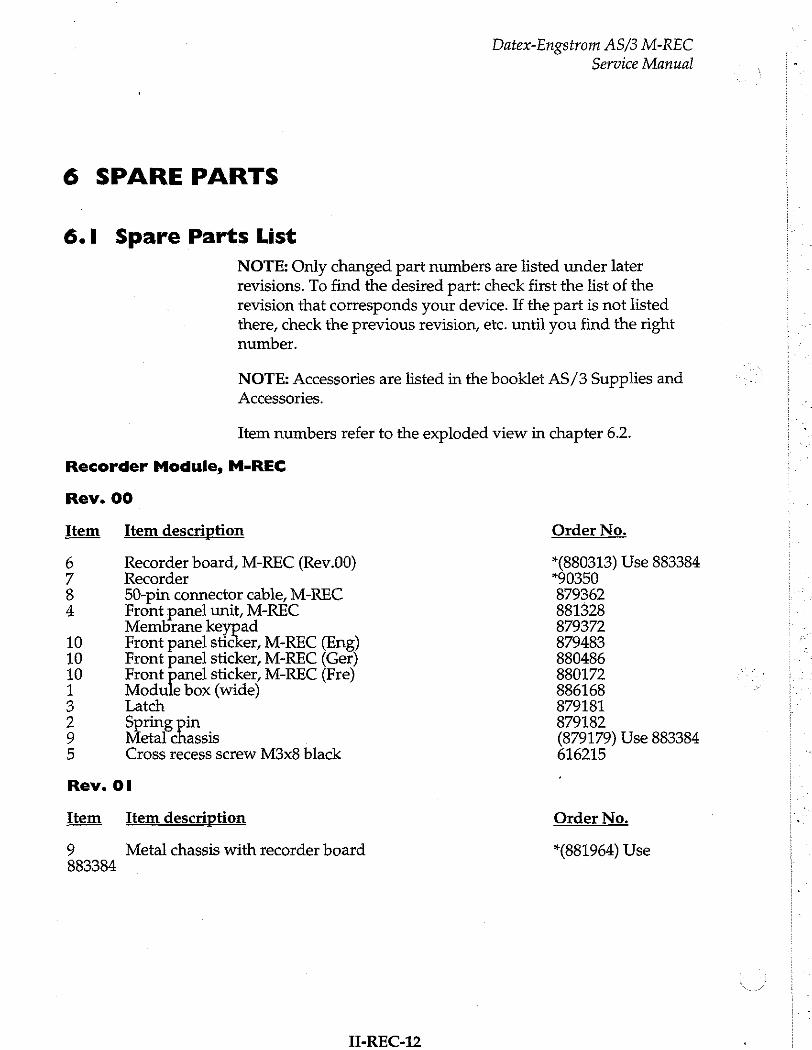
6 SPARE PARTS
6.1 Spare Parts List
Datex-Engstrom AS/3 M-REC
Service Manual
NOTE: Only changed part numbers are listed under later revisions. To find the desired part: check first the list of the revision that corresponds your device. If the part is not listed there, check the previous revision, etc. until you find the right number.
NOTE: Accessories are listed in the booklet AS/3 Supplies and
Accessories.
Item numbers refer to the exploded view in chapter 6.2.
Recorder Module, M-REC
Rev. 00
Item Item description
6 Recorder board, M-REC (Rev.00) 7 Recorder 8 50-pin connector cable, M-REC 4 Front panel unit, M-REC
Membrane keypad 10 Front panel sticker, M-REC (Eng) 10 Front panel sticker, M-REC (Ger) 10 Front panel sticker, M-REC (Fre) 1 Module box (wide) 3 Latch 2 Spring pin 9 5
etal chassis Cross recess screw M3x8 black
Rev. 01
Item Item description
9 Metal chassis with recorder board 883384
II-REC-12
Order No.
*(880313) Use 883384 *90350 879362 881328 879372 879483 880486 880172 886168 879181 879182 (879179) Use 883384 616215
Order No.
*(881964) Use
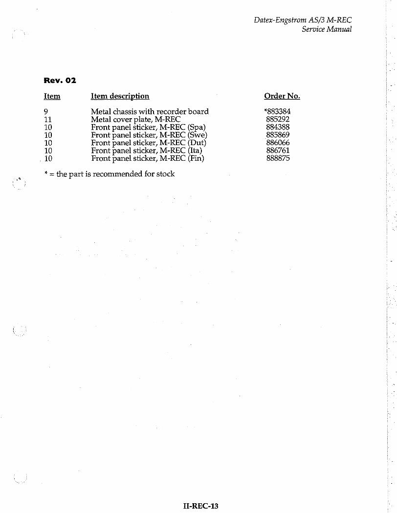
Rev. 02
Item Item description
9 Metal chassis with recorder board 11 Metal cover plate, M-REC 10 Front panel sticker, M-REC (Spa) 10 Front panel sticker, M-REC (Swe) 10 Front panel sticker, M-REC (Dut) 10 Front panel sticker, M-REC (Ita) 10 Front panel sticker, M-REC (Fin)
* = the part is recommended for stock
IT-REC-13
Datex-Engstrom AS/3 M-REC
Order No.
*883384 885292 884388 885869 886066 886761 888875
Service Manual
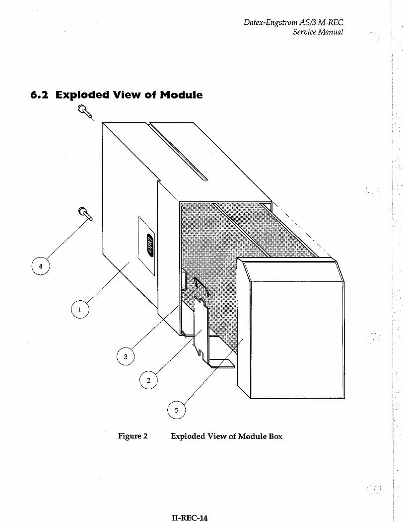
Datex-Engstrom AS/3 M-REC Service Manual
6.2 Exploded View of Module
A
©
Figure 2 Exploded View of Module Box
T-REC-14

on,
Datex-Engstrom AS/3 M-REC Service Manual
11
Figure 3 Exploded View of Recorder Module
II-REC-15
Datex-Engstrom AS/3 M-REC Service Manual
7 EARLIER REVISIONS
For service information on the earlier revisions, please refer to:
Recorder Module revision 00 Service Manual p/n 880850
Recorder Module revision 01 Service Manual p/n 882580
II-REC-16
Extension Frame, F-EXT4 (Rev. 01)
Extension Module, M-EXT (Rev. 00)
All specifications subject to change without notice
Document No. 885938-2
March, 1996
Datex Division, Instrumentarium Corp.
P.O.Box 446 FIN-00101 Helsinki Finland
Tel. +358 0 39411 Fax +358 0 1463310

Datex AS/3 Extension Frame and Module
Service Manual
A
Datex AS/3 Extension Frame and Module
Service Manual
Table of Contents
INTRODUCTION I
1 SPECIFICATIONS 2
2 FUNCTIONAL DESCRIPTION
2.1 External Connector Configuration .............rrerererensesereserernecrerererecrererererecererarerarenane 5
3 SERVICE PROCEDURES 7
3.1 Disassembly and Reassembly ss 8 3.2 Changingthefuse...................................... eee erme erener 8
4 TROUBLESHOOTING 9
5 SERVICE MENU 10
6 SPARE PARTS LE
IA A 11 6.2 Exploded View of Extension Frame... cr narnia nro 12
7 EARLIER REVISIONS 13

Datex AS/3 Extension Frame and Module
Service Manual
Datex AS/3 Extension Frame and Module
Service Manual
INTRODUCTION
The Extension Frame provides four additional module slots, and enables taking the measuring modules near to the patient. The Extension Frame is connected to the AS/3 Anaesthesia Monitor
with the Extension Module, which reserves one module slot.
NOTE:
* Only one F-EXT4 can be connected to the monitor at a time.
* The Recorder Module, M-REC, and Memory Module, M-
MEM cannot be used in the Extension Frame.
Do not use identical modules simultaneously in the Extension Frame and the monitor.
* When the Extension Frame is used with the AS/3
Anaesthesia Monitor the Central Unit must be of Rev. 03
(F-CU8-XX-03).
Part II-Extension-1

Datex AS/3 Extension Frame and Module
Service Manual
I SPECIFICATIONS
Frame size Wx DxH 160x205 x 137 mm
(w/module) 160 x 228 x 137 mm
Frame weight 13kg
Power consumption: 35 W (max at input voltage of +32 V) with ESTP and NIBP modules inserted and NIBP pump working.
Module size 37 x 180 x 112 mm
(WxDxH) 1.5х7.1х4.4 ш
Part II-Extension-2
Datex AS/3 Extension Frame and Module
Service Manual
2 FUNCTIONAL DESCRIPTION
The Extension Frame, F-EXT4, contains the Module mother
board, Power supply board, and space for four single-width or two double-width AS/3 modules. See figure 1.
The electronic unit receives +32 V from the AS/3 monitor frame
and generates from it necessary operational voltages for the inserted AS/3 modules.
The received +32 V is passed through fuse (F1) and filtered and
led to power supply components.
There is overvoltage and undervoltage protection for input voltage, the input voltage is set so that it can vary between +18.5 V and +36.0 V.
The purpose of the soft start is to raise input voltage +32 V slowly (about 1 second) to the maximum value so that capacitors in power supply components’ circuits have time to get charged. This enables E-EXT4 to be connected to AS/3 monitor frame during operation.
There is also overvoltage protection for outgoing supply voltages. The overvoltage limits are +5.95 V (+5 V) and +17.50 V (+15 Vd).
Signal routes
There are two connectors which are used for data
communications ( RS485), for supply voliages (+32 V, +15 Vd,
+15 Va, and +5 V), for grounds connections (GNDD,
GND&SHIELD) between the Power supply board and Module mother board.
Part II-Extension-3
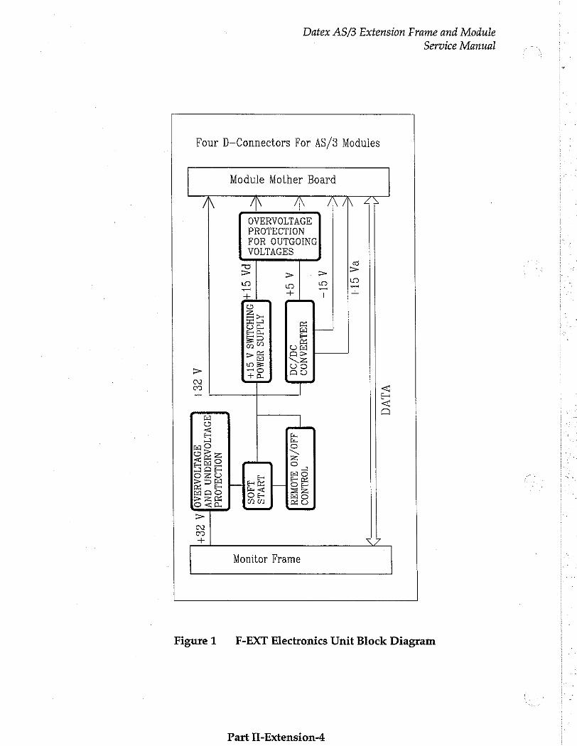
Datex AS/3 Extension Frame and Module
Service Manual
Four D-Connectors For AS/3 Modules
Module Mother Board
© VERVOLTAGE ROTECTION OR OUTGOING OLTAGES
+5
У
-15V
+15
Va
CONVERTER
+15
V SWITCHINGÝH
15
VA
< my
DC/DC
POWER
SUPPLY
+3
2 V
DATA
AN
D UNDERVOLTAGE
PROTECTION
REMOTE
ON/OFF
CONTROL
SOFT
START
+32
VIOV
ERVO
LTAG
E
Monitor Frame
Figure 1 F-EXT Electronics Unit Block Diagram
Part IT-Extension-4

2.1 External Connector Configuration
Datex AS/3 Extension Frame and Module
Service Manual
Extension Frame Rear panel 12-pin male DIN-connector (X1)
Pin No ΠΟ | Signal
A I RESET_RS485
B I/O |-DATA RS485
c 1/0 | DATA RS485
D I -RESET RS485
E BITOIN
F N/C
G I +32 VDC
H I Gnd and Shield
J N/C K N/C
L 1+32 VDC
M I GndD
Part M-Extension-5
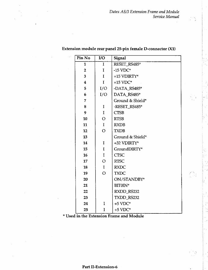
Datex AS/3 Extension Frame and Module
Service Manual
Extension module rear panel 25-pin female D-connector (X1)
Pin No vO Signal
1 I RESET_RS485*
2 I -15 VDC*
3 I +15 VDIRTY*
4 I +15 VDC*
5 I/O |-DATA_RS485*
6 I/O ¡DATA_RS485*
7 Ground & Shield*
8 I -RESET_RS485*
9 I CTSB
10 O RTSB
11 I RXDB
12 ο TXDB
13 Ground & Shieid*
14 I +32 VDIRTY*
15 I GroundDIRTY*
16 I CTSC
17 0 RISC
18 I RXDC
19 O TXDC
20 ON/STANDBY*
21 BITOIN*
22 RXDD_RS232
23 TXDD_RS232
24 I +5 VDC*
25 I +5 VDC*
* Used in the Extension Frame and Module
Part IT-Extension-6

Datex AS/3 Extension Frame and Module
Service Manual
3 SERVICE PROCEDURES
Field service of the Extension Frame, F-EXT4, is limited to
replacing the faulty circuit boards or mechanical parts. Return the faulty boards to Datex for repair.
Datex is always available for service advice. Please provide the unit serial number, full type designation, and a detailed fault
description.
CAUTION: Only trained personnel with the appropriate tools and equipment shall perform the tests and repairs outlined in this section. Unauthorized service may void warranty of the unit.
Part II-Extension-7
Datex AS/3 Extension Frame and Module
Service Manual
3.1 Disassembly and Reassembly
Disassemble the Extension Frame, F-EXT4 in the following way. See the exploded view in chapter 6.2
a) Remove the four screws from the front of the frame. PC
boards’ block is detached.
b) Remove the four screws from Module mother board with which it is attached to the rear frame.
c) Lift carefully Module mother board and Power supply board attached to it and detach the two connectors under
the Power supply board.
3.2 Changing the Fuse
Disassemble as described above. Fuse is located on the Power
supply board.
Replace the fuse by the one with the same type and rating.
Part II-Extension-8
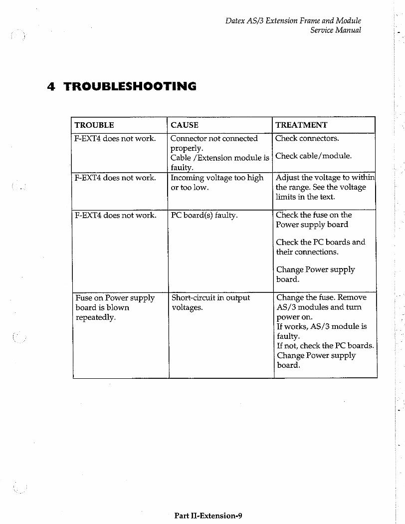
Datex AS/3 Extension Frame and Module
Service Manual
4 TROUBLESHOOTING
TROUBLE CAUSE TREATMENT
F-EXT4 does not work. | Connector not connected Check connectors. properly. Cable /Extension module is | Check cable/module. faulty.
F-EXT4 does not work. | Incoming voltage too high | Adjust the voltage to within or too low. the range. See the voltage
limits in the text.
F-EXT4 does not work. | PC board(s) faulty. Check the fuse on the Power supply board
Check the PC boards and their connections.
Change Power supply board.
Fuse on Power supply Short-circuit in output Change the fuse. Remove board is blown voltages. AS/3 modules and turn repeatedly. power on.
If works, AS/3 module is
faulty. If not, check the PC boards.
Change Power supply board.
Part II-Extension-9

Datex AS/3 Extension Frame and Module
Service Manual
5 SERVICE MENU
There is no service menu for Extension frame checking.
Part Il-Extension-10
6 SPARE PARTS
6.1 Spare Parts List
NOTE: Only changed part numbers are listed under later revisions. To find the desired part: check first the list of the revision that corresponds your device. If the part is not listed there, check the previous revision, etc. until you find the right number.
Datex AS/3 Extension Frame and Module
Service Manual
NOTE: Accessories are listed in the booklet AS/3 Supplies and
Accessories.
Item numbers refer to the exploded view in chapter 6.2.
4-Module Extension Frame, F-EXT4
Rev. 01
m = や B
OO NO
TON
FA
ES TO
Item description
Module mother board, F-EXT4 Power supply board, É-EXT4 Frame with rubber pads Pad Rear frame Fuse T2.5A fast Internal connector cable Cross cylinder-head screw M3x6 Cross cylinder-head screw M3x12 Nut bushing M3x9
Extension Module, M-EXT
Item
1 3 2 5
Item description
Module box (single width) Sone
Cross: TOSS cess screw M3x8 black
* = the part is recommended for stock
Order No.
884839 *884840 881233 65144 881234 *51118 884838 61721 61736 640455
Order No.
879095 879181 879182 616215
Part II-Extension-11
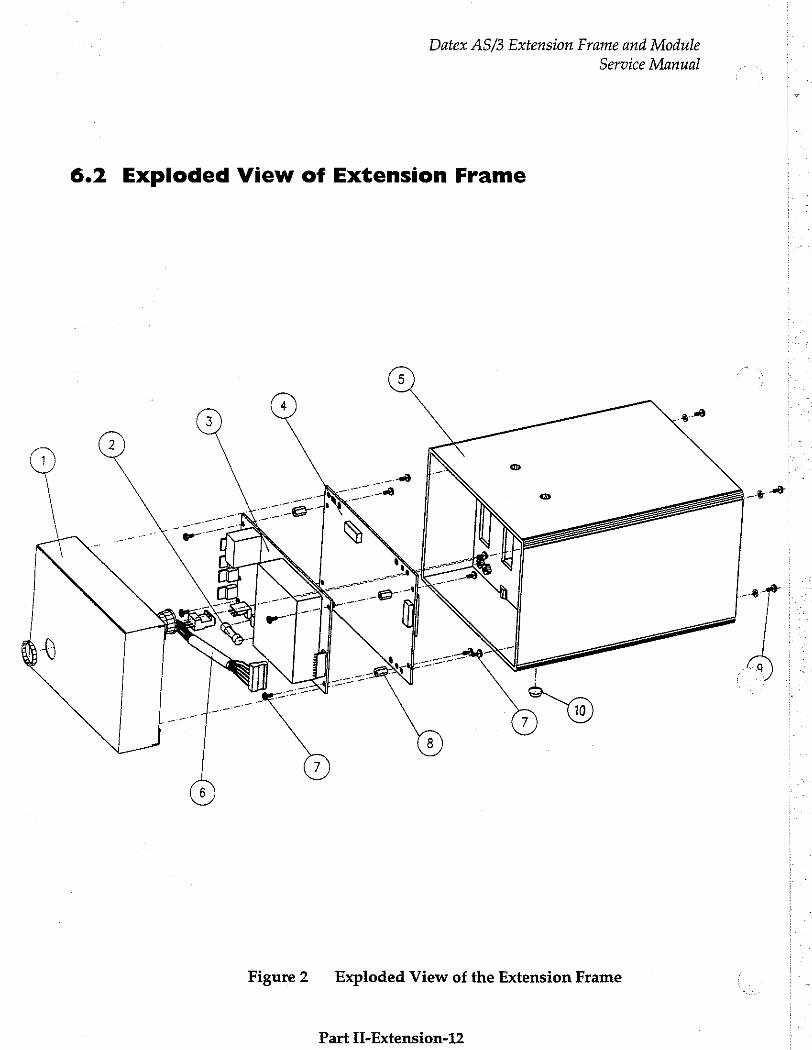
Datex AS/3 Extension Frame and Module
Service Manual
6.2 Exploded View of Extension Frame
Figure 2. Exploded View of the Extension Frame
Part II-Extension-12
Datex AS/3 Extension Frame and Module
Service Manual
7 EARLIER REVISIONS
This manual fully supports earlier revision of F-EXT4.
Part H-Extension-13


Memory Module, M-MEM ( Rev. 01)
Memory Board, B-CMMEM (Rev. 01)
All specifications subject to change without notice
Document No. 885939-2
March, 1996
Datex Division, Instrumentarium Corp.
P.O.Box 446 FIN-00101 Helsinki Finland
Tel. +358 0 39411 Fax +358 0 1463310

Datex AS/3 M-MEM, B-CMMEM
Service Manual

Datex AS/3 M-MEM, B-CMMEM
Service Manual
Table of Contents
INTRODUCTION I
I SPECIFICATIONS 3
1.1 General Specifications iii 3 1.2 Technical Specifications sn 3
2 FUNCTIONAL DESCRIPTION 4
2.1 Memory Module M-MEM........................... iii 5 2.1.1 Memory Module Board sn 5 212 LEDBoard......................... „7
2.2 Memory Board,B-CMMEM................. eee erer 7 2.2.1 B-CMMEM Board iii 7 2.2.2 Connector Board... 7
2.3 Connectors and Signals..…............................... nn 8
3 SERVICE PROCEDURES 10
3.1 General Service Information en eeoee eee e nete tea nene 10 3.2 Preventive Maintenance Checks….…...............ssssss 1 3.3 ПАваззетЬу ап4 ВеаззетЬ у .......... лилии 13
4 TROUBLESHOOTING 14
4.2 Troubleshooting Charts... sn 14
5 SERVICE MENU 15
51 ModuleStatus.................... een 16 5.2 COMMUNICATION... ri 18
6 SPARE PARTS
6.1 Spare Parts List... ss eeaereanenez 6.2 Exploded View of Module
7 EARLIER REVISIONS

Datex AS/3 M-MEM, B-CMMEM
Service Manual
Datex AS/3 M-MEM, B-CMMEM
Service Manual
INTRODUCTION
AS/3 Memory Module (M-MEM) is an optional data storage module for AS/3 family monitors. It is used for storing patient related physiological data, discrete record keeping events, menu configurations and user defined monitor configurations in removable PCMCIA! compatible memory cards.
Memory module can be utilized in the following applications:
1. As a backup media for patient related physiological and record keeping data.
2. As a local menu server for the monitor it is attached to.
3. A Memory card with its previously recorded patient data can be transported to a new monitor location with the patient enabling continuous data collection.
4. To save and load user defined monitor configurations.
The memory module is available in two versions:
1. Single-width external plug-in Memory Module M-MEM for AS/3 Monitors.
2. Internal memory board B-CMMEM for AS/3 Compact Monitor.
The two versions share the same electronics and software. However, because of the special space requirements of the Compact Monitor, the internal version of the module has different printed circuit board layout and mechanical design.
The internal version of the module will use one PC board slot in
the AS/3 Compact Monitor.
Memory module has two card slots, which use rewritable PCMCIA-ATA specification compatible memory cards: Data and Menu MemCards.
The Data card is used for storing patient related data and record keeping events, and the Menu card is used as a storage media for pre-recorded menu configurations and user defined monitor
Part H-Memory-1
Datex AS/3 M-MEM, B-CMMEM
Service Manual
configuration. If the module is used only for data backup and transportation, the Menu card is not necessarily required. Similarly, if only record keeping configurations are needed, Data card does not have to be present. In the latter case,
however, no physiological or event data can be stored ina memory card.
Module software runs under MS-DOS’ compatible operating system provided by Datalight’ . The files created in Data and Menu MemCards are MS-DOS compatible.
The communication between the monitor CPU and the Memory module is performed through high-speed internal TTL level RS-
232 serial interface. Data transfer rate is 76.8 kbits/second.
1 Personal Computer Memory Card International Association
2 MS-DOS is a trademark of Microsoft Corporation 3 Datalight is a trademark of Datalight, Inc.
NOTE: Memory Module, M-MEM, cannot be used in the
Extension Frame, F-EXTA.
NOTE: The M-MEM rev. 00 uses Microsoft Dos Flash File
System (FFS) compatible cards only.
NOTE: S-STD95/S-ARK95 and later main software revisions
support only PCMCIA-ATA cards (used in the M-MEM rev. 01) not Flash File cards.
S-STD94/S-ARK94 software supports Flash File cards ( used in M-MEM rev. 00) not PCMCIA-ATA cards.
Part U-Memory-2

| SPECIFICATIONS
1.1 General Specifications
M-MEM
Module size:
(WxDxH)
Module weight:
Total power:
B-CMMEM
Module size:
(WxDxH)
Module weight:
Total power:
1.2 Technical Specifications
MemCard capacity:
Data storage capacity:
Operating system:
File system:
MemCards:
Datex AS/3 M-MEM, B-CMMEM
Service Manual
37 x 180 x 112 mm
15x71x44in
0.4 kg / 1.0 lbs
2W maximum
30 x 170 x 108 mm
1.2 х 6.7 х 4.3 шт
0.3 kg / 0.6 Ibs
2W maximum
5 Mbytes
5 days of continuous physiological data trends
Datalight ROM-DOS
MS-DOS compatible
PCMCIA-ATA compatible memory cards
Part П-Метоту-3
Datex AS/3 M-MEM, B-CMMEM
Service Manual
2 FUNCTIONAL DESCRIPTION
The Memory Module M-MEM contains MEM PC board and a small LED (light emitting diode) PC board attached to the front panel.
The front panel has a dual PCMCIA card connector for two Datex AS/3 MemCards. Above the card slots there are two push buttons for removing the MemCards from the module, and two memory card specific LEDs. The LEDs are on during memory card read and write operations to notify the user not to remove them until the operation is complete.
The internal module contains B-CMMEM PC board and a
connector to a PC board that connects the B-CMMEM to the
module bus.
B-CMMEM contains the same components as the MEM PC board with the following differences:
1. B-CMMEM does not contain a module bus connector.
2. B-CMMEM contains a 14-pin connector to a separate connector PC board that is connected directly to the AS/3 bus.
NOTE: Memory Module M-MEM (rev. 00) and B-CMMEM (rev. 00) requires support of Main Software S-STD94 or S-ARK94 and cannot be used together with later main software versions.
Part II-Memory-4
Datex AS/3 M-MEM, B-CMMEM
Service Manual
2.1 Memory Module M-MEM
2.1.1 Memory Module Board
Processor Section
Basically, Memory module is a single board PC with unnecessary I/O functions removed. The processor is Intel 80C186 compatible and the software runs under DOS operating system. Operating frequency is 16 MHz. The board has 512 kbytes RAM, 448 kbytes ROM, 128 bytes EEPROM and associated buffer circuits for memory operations.
Intel 82365SL compatible PC Card Interface Controller (PCIC) provides all the functions needed in MemCard operations. Serial communication, EEPROM read and write operations and LED control is accomplished through a QUART circuit. In addition, processor board contains circuitry to control reset signals and MemCard programming voltages.
Memory module board block diagram is shown in Figure 1.
PCMCIA Card Interface
MEM has PCMCIA compatible card sockets for two MemCards. Both sockets consist of 60 signal and 8 power connections. MemCards are PCMCIA-ATA compatible, and their memory capacity is 5 Mbytes.
NOTE: Memory Module M-MEM (rev. 00) and B-CMMEM (rev. 00) are not supporting use of PCMCIA-ATA MemCards.
All MemCard read and write operations as well as card power management are controlled by PCIC interface controller.
Card removals and insertions are also detected by the interface controller.
MemCard files are MS-DOS compatible and they can be copied for archival with any MS-DOS compatible computer equipped with PCMCIA-ATA specification compatible card drive.
Part II-Memory-5
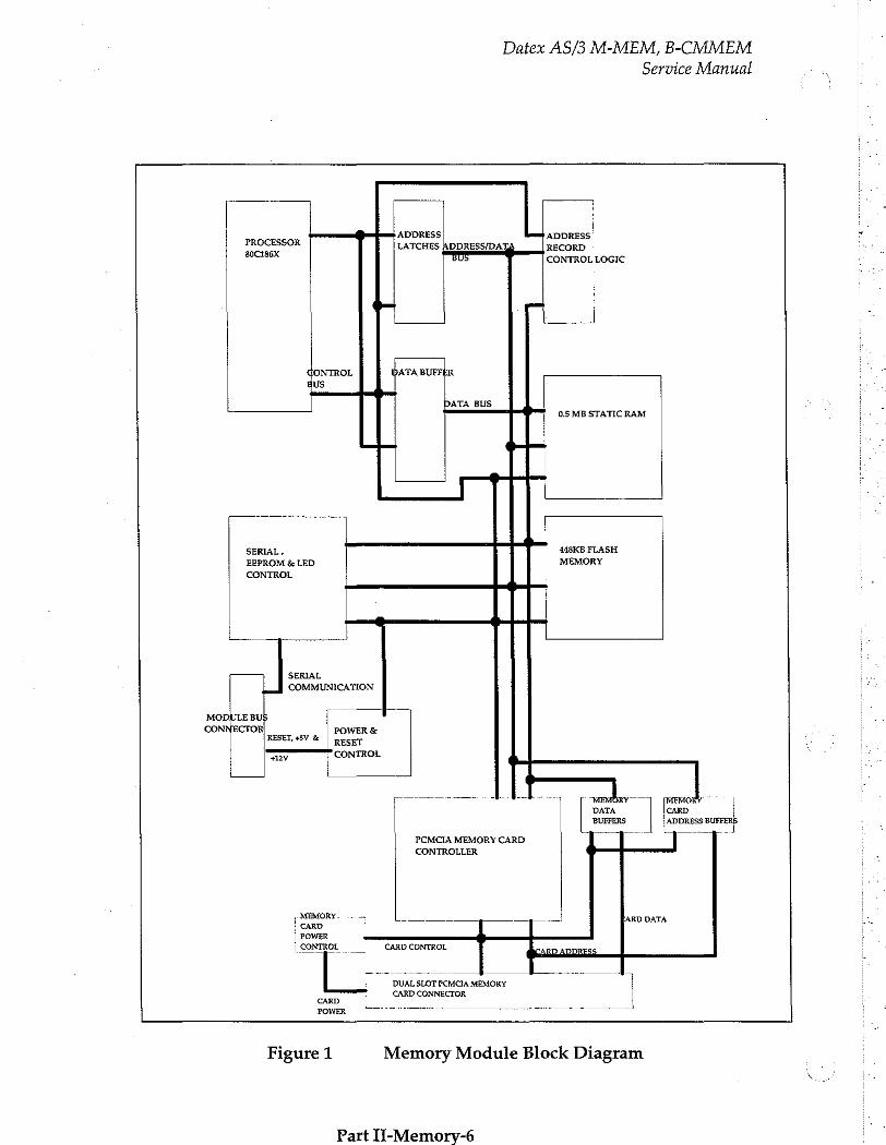
Datex AS/3 M-MEM, B-CMMEM
Service Manual
» ADDRESS fret ADDRESS 『 PROCESSOR LATCHES ADDRESS/DA’ | RECORD 30C186X TUS $ CONTROL|LOGIC
+ —
GONTROL dara BUFFER gus
DATA BUS $— 05 MBSTATICRAM
SERIAL, D casks FLASH EEPROM & LED MEMORY CONTROL
+
SERIAL COMMUNICATION
MODULE BU Г. 1 CONNECTOR! POWER &
RESET, +5V & RESET
= CONTROL
~ ~ J 1. DATA
BUFFERS | ADDRESS BUFFER!
PCMCIA MEMORY CARD | i | | CONTROLLER
MEMORY. 一 -ARD DATA CARD ]
POWER
[CONTROL | CARDCONTROL
Γ DUAL SLOT PCMCIA MEMORY
CARD CONNECTOR CARD | κ — 아아
Figure 1 Memory Module Block Diagram
Part Il-Memorv-6
2.1.2 LED Board
Datex AS/3 M-MEM, B-CMMEM
Service Manual
Serial Communication
Serial communication between the module and host monitor is
done through module bus TTL-level RS-232 interface. Data transfer rate is 76.8 kbits/second.
RS485 type monitor reset signal is converted to module reset by an interface transceiver, and power reset is generated by a reset circuit.
Power Supply
Module receives its power (+5V, +15V) from the host monitor. PCMCIA card programming voltage + 12V is generated from +15V by voltage regulators. Card programming voltage is controlled by an interface controller. Otherwise, only +5V power is used in the module. Maximum power consumption is 2 Watts.
LED board contains only two yellow light emitting diodes and a three-lead cable to the MEM PC board.
2.2 Memory Board, B-CMMEM
2.2.1 B-CMMEM Board
Differences between Memory Module Board and B- CMMEM
Module signals are taken to B-CMMEM through a separate connector board that is connected to the module bus. B- CMMEM is connected to the connector board by a 14-lead connector board cable.
Otherwise Memory module PC board and B-CMMEM PC board have the same components.
2.2.2 Connector Board
B-CMMEM connector board connects B-CMMEM to the AS/3 bus. It contains only CPU bus connector that is connected to the
Part II-Memory-7
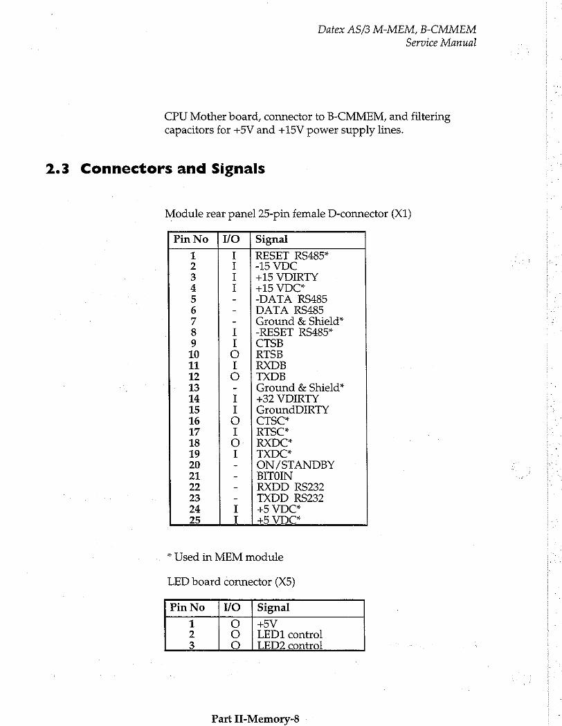
Datex AS/3 M-MEM, B-CMMEM Service Manual
CPU Mother board, connector to B-CMMEM, and filtering
capacitors for +5V and +15V power supply lines.
2.3 Connectors and Signals
Module rear panel 25-pin female D-connector (X1)
Pin No | WO | Signal
1 I | RESET RS485* 2 1 | -15 VDC 3 I | +15 VDIRTY 4 Т | +15 VDC* 5 - |-DATA RS485 6 - |DATA RS485 7 - | Ground & Shield” 8 I |-RESET RS485* 9 I |CTSB 10 O |RTSB 11 I | RXDB 12 O | TXDB 13 - | Ground & Shield” 14 I |+32 VDIRTY 15 I |GroundDIRTY 16 O |CTSC* 17 I |RTSC* 18 O |RXDC* 19 I TXDC* 20 - | ON/STANDBY 21 - | BITOIN 22 - RXDD RS232 23 - | TXDD RS232 24 I +5 VDC* 25 T_1+5 VDC*
* Used in MEM module
LED board connector (X5)
Pin No ¡VO | Signal
1 O | +5V 2 O | LEDI control 3 O | LED? control
Part II-Memory-8
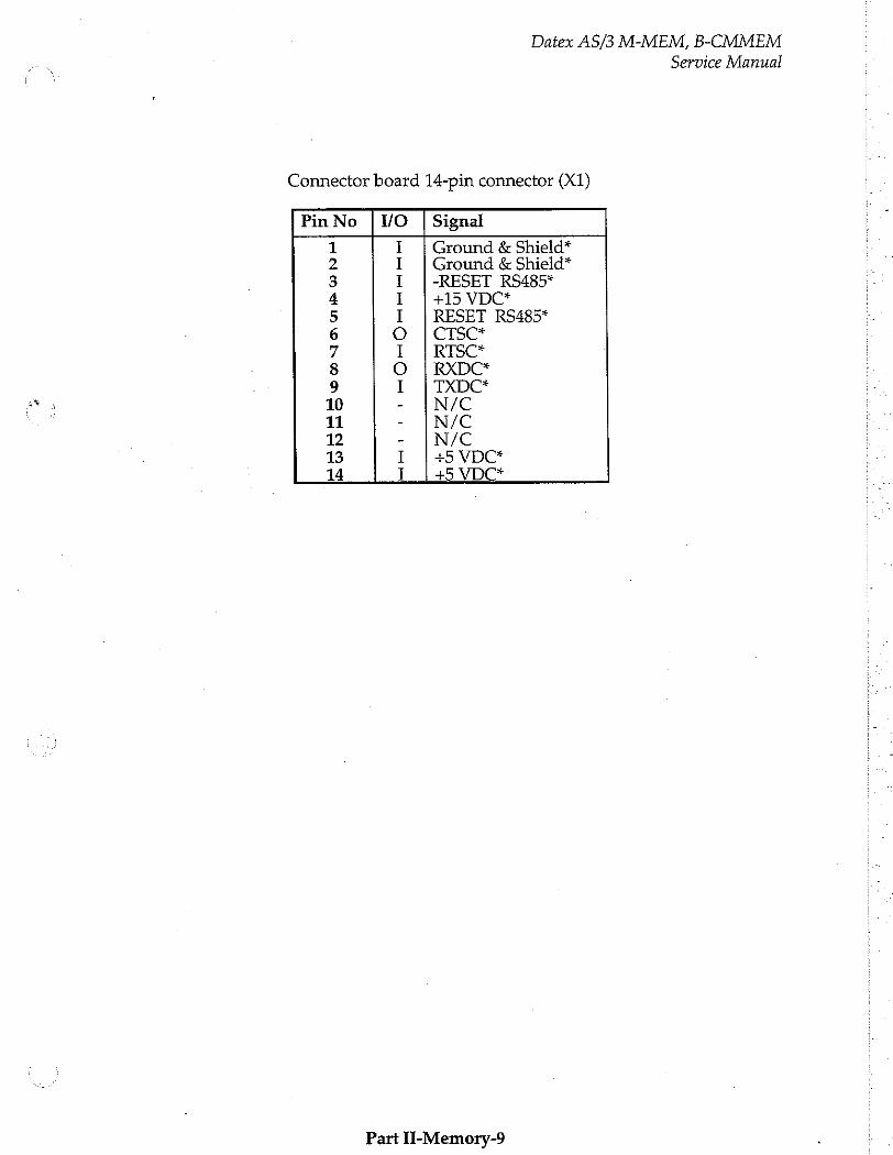
Datex AS/3 M-MEM, B-CMMEM
Service Manual
Connector board 14-pin connector (X1)
Pin No | WO | Signal
1 I | Ground & Shield” 2 I | Ground & Shield” 3 I |-RESET RS485* 4 1 | +15 VDC* 5 I | RESET RS485* 6 O | CTSC* 7 1 | RISC* 8 O | RXDC* 9 I | TXDC* 10 - | М/С 11 - | М/С 12 - | М/С
13 I | +5 VDC* 14 I |45VDG*
Part П-Метогу-9
Datex AS/3 M-MEM, B-CMMEM
Service Manual
3 SERVICE PROCEDURES
3.1 General Service Information
Field service for the Memory module is limited to replacing faulty PC boards, MemCards or mechanical parts. The faulty PC boards and MemCards are then returned to Datex for repair.
Datex is always available for service advice. Please provide the unit serial number, full type designation, and a detailed fault description.
CAUTION: Only trained personnel with the appropriate tools and eguipment shall perform the tests and repairs outlined in this section. Unauthorized service may void warranty of the unit.
Part II-Memory-10
Datex AS/3 M-MEM, B-CMMEM
Service Manual
3.2 Preventive Maintenance Checks
We recommend you to perform these checks at least once a year and after any service to keep the Memory Module in good condition.
Items marked (M-MEM) are valid for external Memory Module, M-MEM, only.
1. Visual inspection
o If the module is disassembled, check that all connectors
are properly connected and that there are no loose objects inside the module before attaching the module box (M- MEM).
2. Functional checks
Li Insert the module in the monitor frame (M-MEM).
o Turn the power on by ON/STBY-switch and wait until
the waveform fields appear on the screen.
o Insert MemCard labelled 'Menu' in the left hand side card
slot.
_: Confirm that the led above the menu card slot turns
briefly on (M-MEM).
_ Confirm that a text "Menu card inserted’ appears on the message field of the monitor display.
—: Confirm that a white menu card symbol appears on the upper right hand corner of the monitor display.(*
—: Insert MemCard labelled ‘Data’ in the right hand side slot of the module.
—: Confirm that the led above the data card slot turns briefly on (M-MEM).
-: Confirm that a text Data card inserted' appears on the message field of the monitor display.
Part Ii-Memory-11
Datex AS/3 M-MEM, B-CMMEM
Service Manual
_ Confirm that a green Data card symbol appears on the upper right hand corner of the monitor display.(*
—: Pull out the module. The card symbols disappear within 35 seconds, and a text Memory Module removed’
appears on the message field of the monitor display (M- MEM).
i Reinsert the module while the power is still on. Memory
Module removed’ text disappears and card symbols appear again on the display (M-MEM).
_: Go into Service Menu, Service View, Modules, Memory
Module, Communication and check the functions.
*NOTE: Battery symbol will override card symbols in Compact Monitor.
Part II-Memory-12
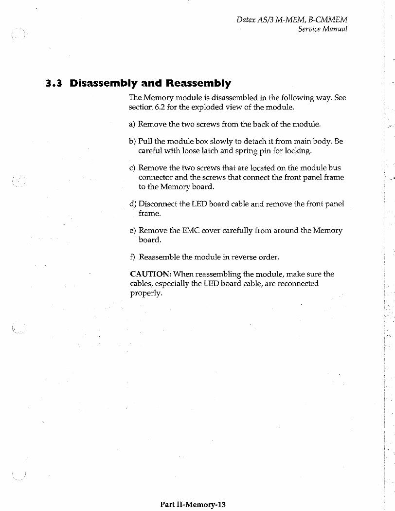
Datex AS/3 M-MEM, B-CMMEM
Service Manual
3.3 Disassembly and Reassembly
The Memory module is disassembled in the following way. See section 6.2 for the exploded view of the module.
a) Remove the two screws from the back of the module.
b) Pull the module box slowly to detach it from main body. Be careful with loose latch and spring pin for locking.
c) Remove the two screws that are located on the module bus connector and the screws that connect the front panel frame to the Memory board.
d) Disconnect the LED board cable and remove the front panel frame.
e) Remove the EMC cover carefully from around the Memory board.
f) Reassemble the module in reverse order.
CAUTION: When reassembling the module, make sure the cables, especially the LED board cable, are reconnected
properly.
Part II-Memory-13
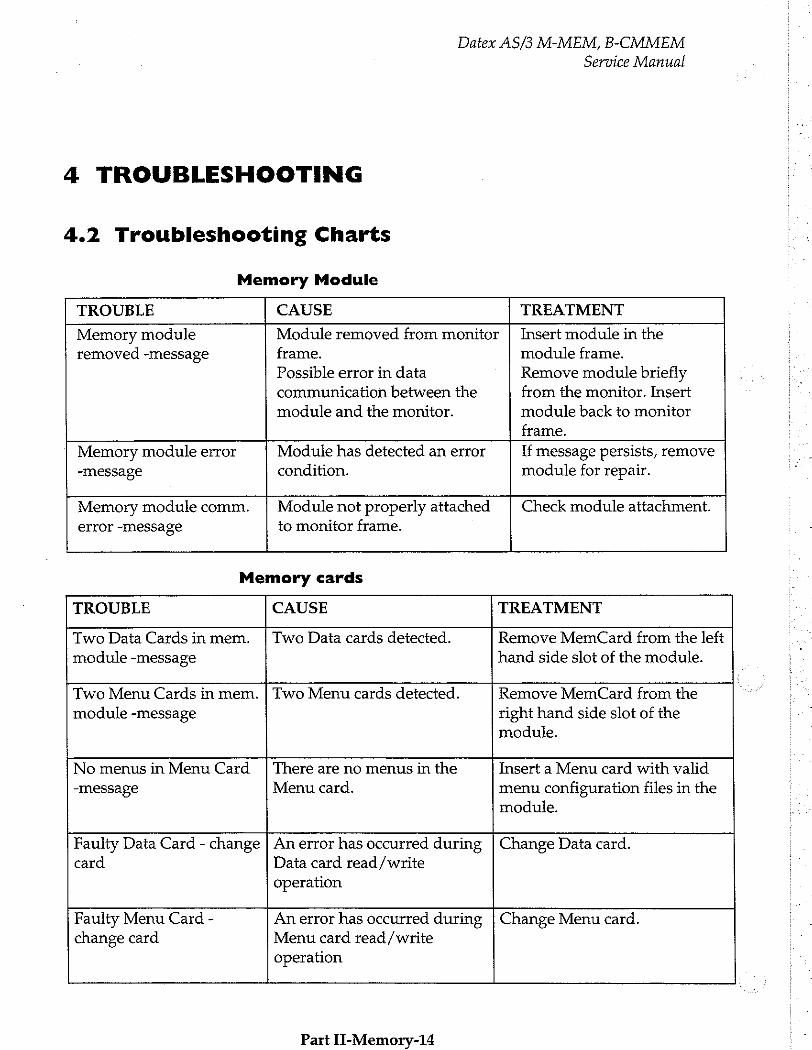
Datex AS/3 M-MEM, B-CMMEM
Service Manual
4 TROUBLESHOOTING
4.2 Troubleshooting Charts
Memory Module
TROUBLE CAUSE TREATMENT
Memory module Module removed from monitor | Insert module in the removed -message frame. module frame.
Possible error in data Remove module briefly communication between the from the monitor. Insert
module and the monitor. module back to monitor
frame.
Memory module error Module has detected an error If message persists, remove -message condition. module for repair.
Memory module comm. | Module not properly attached Check module attachment.
error -message to monitor frame.
Memory cards
TROUBLE CAUSE TREATMENT
Two Data Cards in mem. | Two Data cards detected. Remove MemCard from the left
module -message hand side slot of the module.
Two Menu Cards in mem. | Two Menu cards detected. Remove MemCard from the
module -message right hand side slot of the module.
No menus in Menu Card | There are no menus in the Insert a Menu card with valid
-message Menu card. menu configuration files in the module.
Faulty Data Card - change | An error has occurred during | Change Data card.
card Data card read/write operation
Faulty Menu Card - An error has occurred during | Change Menu card. change card Menu card read / write
operation
Part П-Метогу-14
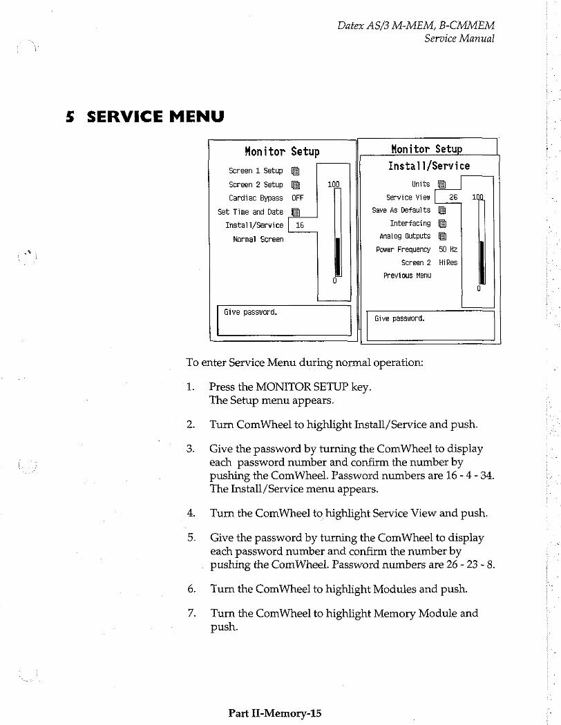
Datex AS/3 M-MEM, B-CMMEM
5 SERVICE MENU
Service Manual
Monitor Setup Honitor Setup Screen 1 Setup Install/Service
Screen 2 Setup 100 Units
Cardiac Bypass OFF Service View 25 1
Set Time and Date Save As Defaults
Instali/Service | 16 Interfacing
Normal Screen Analog Outputs Power Frequency 50 Hz
Screen 2 HiRes
Previous Menu
Give password. - | Give password.
To enter Service Menu during normal operation:
1. Press the MONITOR SETUP key. The Setup menu appears.
Turn ComWheel to highlight Install/ Service and push.
Give the password by turning the ComWheel to display each password number and confirm the number by pushing the ComWheel. Password numbers are 16 - 4 - 34. The Install/Service menu appears.
Turn the ComWheel to highlight Service View and push.
Give the password by turning the ComWheel to display each password number and confirm the number by pushing the ComWheel. Password numbers are 26 - 23 - 8.
Turn the ComWheel to highlight Modules and push.
Turn the ComWheel to highlight Memory Module and push.
Part Ц-Метогу-15
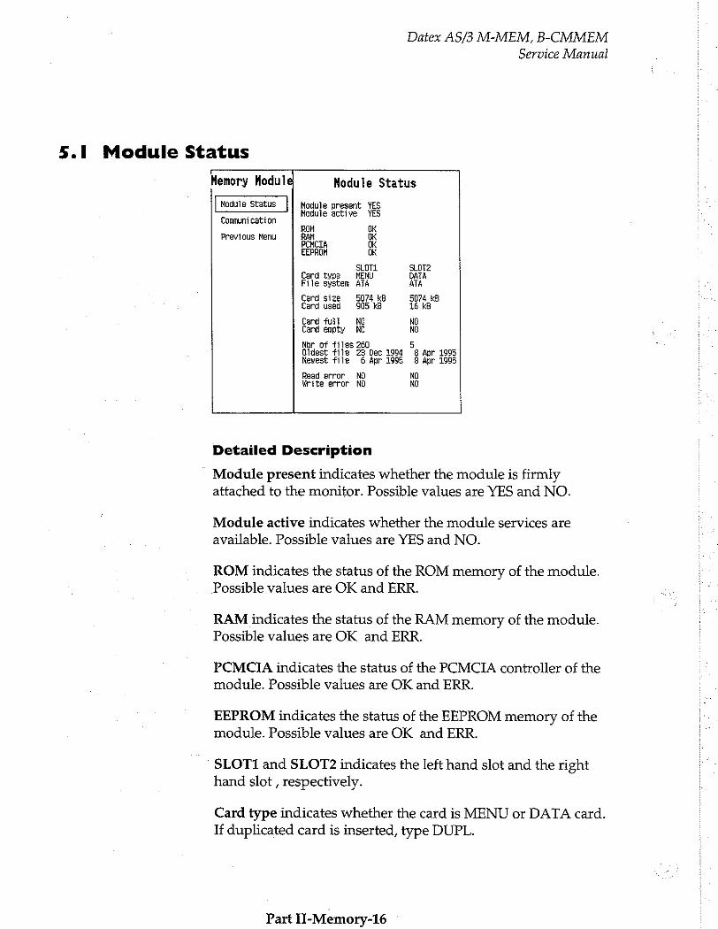
Datex AS/3 M-MEM, B-CMMEM
Service Manual
5.1 Module Status
Memory Module Hodule Status
Module Status Module present YES 一 一 Hodule active YES
Communication
ROM OK Previous Menu RAM OK
PEMCTA OK EEPROM OK
SLOT SLOT2 Card type MENU DATA File system ATA АТА
Card size 5074 kB 5074 kB Card used 905 kB 16 kB
Card full № NG Card empty NO NG
Nor of files 260 5 Oldest file 23 Dec 1994 8 Apr 1995 Newest file 6 Apr 1995 8 Apr 1995
Read error № NO Write error NO NO
Detailed Description
Module present indicates whether the module is firmly attached to the monitor. Possible values are YES and NO.
Module active indicates whether the module services are
available. Possible values are YES and NO.
ROM indicates the status of the ROM memory of the module. Possible values are OK and ERR.
RAM indicates the status of the RAM memory of the module. Possible values are OK and ERR.
PCMCIA indicates the status of the PCMCIA controller of the
module. Possible values are OK and ERR.
EEPROM indicates the status of the EEPROM memory of the module. Possible values are OK and ERR.
SLOT1 and SLOT2 indicates the left hand slot and the right hand slot , respectively.
Card type indicates whether the card is MENU or DATA card. If duplicated card is inserted, type DUPL.
Part II-Memory-16
Datex AS/3 M-MEM, B-CMMEM
Service Manual
File system indicates the type of the used memory card. The only supported file system is ATA. If a memory card using another file system is used, the message UNKNOWN is shown. If the card is poorly attached, the message LOOSE is shown.
Card size indicates the total amount of the disk space in the card in kilobytes.
Card used indicates the total amount of the used disk space in the card in kilobytes.
Card full indicates whether the all disc space in the card is used. Possible values are YES and NO.
Card empty indicates the lack of menu files in the MENU card or no files in the DATA card. Possible values are YES and NO.
Nbr of files tells the amount of the files stored in the card.
Oldest file tells the date of the oldest file in the card.
Newest file tells the date of the newest file in the card.
Read error indicates whether the reading from the card has
failed. Possible values are YES and NO.
Write error indicates whether the writing to the card has failed. Possible values are YES and NO.
All values can be ‘- - -’ to indicate ‘No data available’.
NOTE: This menu is related to S-STD95/S-ARK95 Main
Software. If S-STD94/S-ARK94 Main Software is used, only
Communication menu is available (SERVICE VIEW /MONITOR/COMMUNICATION /MEMORY MODULE).
Part II-Memory-17

Datex AS/3 M-MEM, B-CMMEM
Service Manual
5.2 Communication
r
Memory Module Communication
Hoduie Status Inteface status ACTIVE
hessare tes Ré - Record K 97 98
Previous Menu File Gp. 0 0 Service Ů 5 Modes 0 Ú Module status 5 5 Packets total 102 103 Bytes total 6203 35142
Timeouts 0 Chksum err O Length err 0 buplicated 0
Detailed Description
Interface status indicates the status of data link between the monitor and memory module. If memory module is properly attached, the status should always be on (‘ACTIVE’). If status
blinks between 'ACTIVE' and 'CLOSED’, a communications
error has occurred: remove module briefly, and insert it back to the monitor frame to check if error disappears.
Message types indicates the type of data packets that have been sent (Tx) and received (Rx) since last monitor start. Data types
are listed on the lines below 'Message types’ text.
Record K indicates the communication between the Monitor
and Record Keeper.
File Operation indicates the operations of Patient data.
Service indicates the Memory Module operations.
Modes indicates the User Mode operations.
Packets total indicates the total amount of data packets that have been sent/received since last monitor start.
Part Н-Метогу-18
Datex AS/3 M-MEM, B-CMMEM
Service Manual
Bytes total indicates the total amount of data bytes that have been sent/received since last monitor start.
The last four lines indicates transmission errors:
‧ Timeouts indicates the number of time-outs that have occurred in memory module data transmission since last monitor start.
‧ Chksum err indicates the number of checksum errors in data packets from memory module since last monitor start.
e Lenght err indicates the number of data packets with erroneous length from the memory module since last monitor start.
・ Duplicated indicates the number of duplicate data packets from the memory module since last monitor start.
Part II-Memory-19
6 SPARE PARTS
6.1 Spare Parts List
NOTE: Only changed part numbers are listed under later revisions. To find the desired part: check first the list of the revision that corresponds your device. If the part is not listed there, check the previous revision, etc. until you find the right number.
Datex AS/3 M-MEM, B-CMMEM
Service Manual
NOTE: Accessories are listed in the catalogue AS/3 Supplies and Accessories.
Item numbers refer to the exploded view in chapter 6.2.
Memory Module, M-MEM
Rev. 00
Item
N
WOUON WRN AAR
Item description
Memory board, M-MEM Front panel sticker, M-MEM Front panel frame, M-MEM LED board, M-MEM Module box (single width) Latch Spring pin
etal frame Cross recess screw M3x8 black Cross cylinder-head screw M3x6 Cross cylinder-head screw M3x12 EMC cover, M-MEM Insulation plate, M-MEM Slotted cylinder-head screw 4-40 UNCx1/4
Memory Card, Menu (Eng) Memory Card, Data (Eng Memory Card, Menu (Fre) Memory Card, Data (Fre)
Part II-Memory-20
Order No.
*883509 884597 883838 885252 886167 879181 879182 879184 616215 61721 628700 885860 886656 61371
*885195 *885196 *885552 *885553

Datex AS/3 M-MEM, B-CMMEM
Service Manual
Rev. 01
‘Item description Order No.
Memory Card, Menu (Eng) *887044 Memory Card, Data (Eng *887045 Memory Card, Menu (Fre) *887046 Memory Card, Data (Fre) *887047
NOTE: The memory cards listed above require revision 01 module, and S- STD95/ARK95 or later software.
Memory Board, B-CMMEM
Item description Order No.
Connection board, B-CMMEM 885680 Memory Card, Menu (Eng) *887044 Memory Card, Data (Eng) *887045 Memory Card, Menu (Fre) *887046 Memory Card, Data (Fre) *887047
* = the part is recommended for stock
Part II-Memory-21
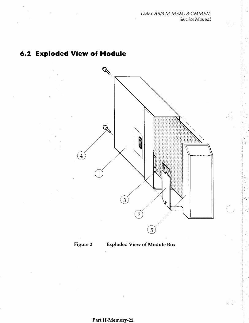
Datex AS/3 M-MEM, B-CMMEM
Service Manual
6.2 Exploded View of Module
Figure 2 Exploded View of Module Box
Part IH-Memory-22
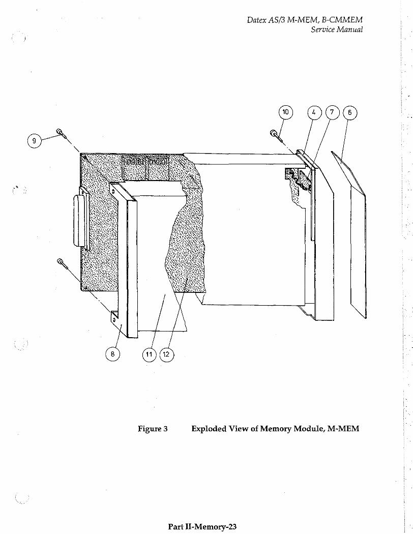
Datex AS/3 M-MEM, B-CMMEM
Service Manual
Figure 3
Exploded View of Memory Module, M-MEM
Part II-Memory-23
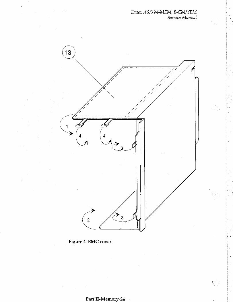
Datex AS/3 M-MEM, B-CMMEM
Service Manual
Figure 4 EMC cover
Part II-Memory-24
Datex AS/3 M-MEM, B-CMMEM
Service Manual
7 EARLIER REVISIONS
All main differences of Memory Module, M-MEM (rev.00) , B-
CMMEM (rev.00) and M-MEM (rev.01) , B-CMMEM (rev.01) are
noted in this manual.
Part II-Memory-25

Nelicor Compatible Saturation Module, M-NSAT (Rev. Ol)
All specifications subject to change without notice
Doc. no. 885940-3
March, 1996
Datex Division, Instrumentarium Corp.
P.O.Box 446 FIN-00101 Helsinki Finland
Tel. +358 0 39411 Fax +358 0 1463310

Datex AS/3 M-NSAT
Service Manual

Datex AS/3 M-NSAT
Service Manual
Table of Contents
INTRODUCTION I
I SPECIFICATIONS
1.1 General Specifications 1.2 Typical Performance
2 FUNCTIONAL DESCRIPTION 3
2.1 NSAT Interface board 2.1.1 ο πο seen 2.1.2 Power supply, non-isolated section... 2.1.3 Power supply, isolated section 214 Optoisolation....................... eee eeeeseememareseseeseaseeneaseenen 2.1.5 Microprocessor, UART, Non-volatile memory..
2.2 Connectors and Signals
3 SERVICE PROCEDURES 8
3.1 General Service Hmforrnato ses een 8
3.2 Visual inspection.....................
3.3 Functional checks
4. TROUBLESHOOTING 10
41Troubleshootingchart................................ een 11
5 SERVICE VIEW 12
5.1 M-NSAT Service ment eee тети ини нитииишииианетлнинияи 13
6 SPARE PARTS 15
6.1 Spare part ο σσ ου 15
6.2 Exploded μμ. sense 17
7 EARLIER REVISIONS 19

Datex AS/3 M-NSAT Service Manual

Datex AS/3 M-NSAT
Service Manual
INTRODUCTION
The Datex AS/3 Nellcor Compatible Saturation Module is a single width plug-in module for use with the AS/3 monitors. The module utilizes Nellcor's pulse oximetry algorithm and is designed to be used with Nellcor's pulse oximetry transducers only. Only one pulse oximetry source at a time is allowed by the AS/3 monitors. If M-ESTPR (or M-ESTR) and M-NSAT modules
are plugged in the monitor simultaneously, then M-NSAT overrides M-ESTPR (or M-ESTR) as a pulse oximetry source.
Part II- NSAT-1
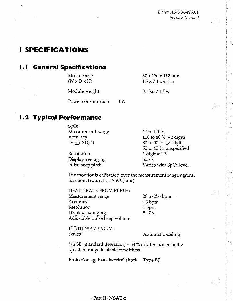
I SPECIFICATIONS
1.1 General Specifications
Module size:
(WxDxH)
Module weight:
Power consumption 3W
1.2 Typical Performance
SpOz: Measurement range
Accuracy
(% +1 SD) *)
Resolution Display averaging Pulse beep pitch
Datex AS/3 M-NSAT
Service Manual
37 x 180 x 112 mm
15x7.1x44in
0.4 kg / 1 lbs
40 to 100 %
100 to 80 %: +2 digits 80 to 50 %: +3 digits 50 to 40 %: unspecified
1 digit = 1 %
5...7 8
Varies with SpO» level
The monitor is calibrated over the measurement range against functional saturation SpOz(func)
HEART RATE FROM PLETH: Measurement range Accuracy Resolution Display averaging Adjustable pulse beep volume
PLETH WAVEFORM:
Scales
20 to 250 bpm -
+3 bpm 1 bpm
5..7 s
Automatic scaling
*) 1 SD (standard deviation) = 68 % of all readings in the specified range in stable conditions.
Protection against electrical shock Type BF
Part II- NSAT-2

Datex AS/3 M-NSAT
Service Manual
2 FUNCTIONAL DESCRIPTION -
The M-NSAT module contains the following main parts:
- SpO, sensor board - Sensor connector cable
- Nellcor Pulse Oximeter Module MP-203
- NSAT interface board
Sensors can be plugged into the M-NSAT module either directly or using sensor extension cables available from Nellcor. Sensors are plugged into a 9-pin female connector (D-type) on the front panel of the module. This connector is mounted on a small PC board, which is connected by a flat cable to the MP-203.
The MP-203 is a surface mounted PC board manufactured by Nellcor Incorporated. It contains the signal processing electronics and software that are based on Nellcor's stand-alone pulse oximeters. The MP-203 is used with an internal preamplifier.
The measured SpO, and pulse rate values, as well as status information, are transferred from the MP-203 to the NSAT
interface board. Communication between the MP-203 and NSAT interface board is established through RS232C serial interface. The NSAT interface board, in turn, transmits the measurement
information to the module bus of the AS/3.monitor through RS485 serial interface.
The operation of NSAT interface board is illustrated in the block diagram next page.
Part II- NSAT-3

Datex AS/3 M-NSAT
Service Manual
2.1 NSAT Interface board
Module bus connector
RS485 RS485 Power-up Power;
Driver for Driver for reset non-isolated
data module reset section
[| Opto isolation
Patient isolation
isolation transformer |
internal ROM; 16MHz
Microprocessor, 488 byte internal RAM, 16kbyte Power;
isolated
section
UART
serial communication to
Nellcor oximeter module Bidirectional asynchronous
Non-volatile
memory
+5V,+15V,-15V
supply voltages
to Nellcor
oximeter module
Figure 1
Part II- NSAT-4
NSAT Interface Board Block Diagram
Datex AS/3 M-NSAT
Service Manual
2.1.1 RS485 drivers
There are drivers for data and for module reset functions.
These drivers are used for driving the RS485 type serial communication bus between the module and the AS/3 Central Unit. Data transmission speed of the bus is 500kbit/s.
In addition to RS485 bus RESET, there is a Power- up reset,
which keeps the RESET pin of the CPU active during power up for about 500ms despite of the state at the RS485 bus RESET. This is used to prevent the sending of RS485 data during the RESET of the module.
2.1.2 Power supply, non-isolated section
Power supply is a half bridge type switched mode circuit, where the driver FETs are controlled by a quartz oscillator. The load of the half bridge is the primary of the isolation transformer. The voltage, +15 Vdirty from the AS/3 Central Unit is used as the
supply voltage of the switched mode circuit.
2.1.3 Power supply, isolated section
The secondary voltages of the isolation transformer are rectified, filtered and regulated. The voltages can be measured from the test connector X11. See Chapter 2.2.
2.1.4 Opto isolation
The signals of the serial communication bus between the NSAT module and the AS/3 Central Unit are transferred through the patient isolation by the high speed optocouplers. |
2.1.5 Microprocessor, UART, Non-volatile memory
The microprocessor with on-chip memory have been used to convert and transfer data from Nellcor pulse oximeter module MP-203 to AS/3 Anaesthesia Monitor.
The communication between MP-203 and the CPU of M-NSAT
is realized with the bidirectional asynchronous serial communication via the UART.
Part II- NSAT-5

Datex AS/3 M-NSAT
Service Manual
The non-volatile memory has been used to store identification information like serial number, control number, date etc.
Part II- NSAT-6
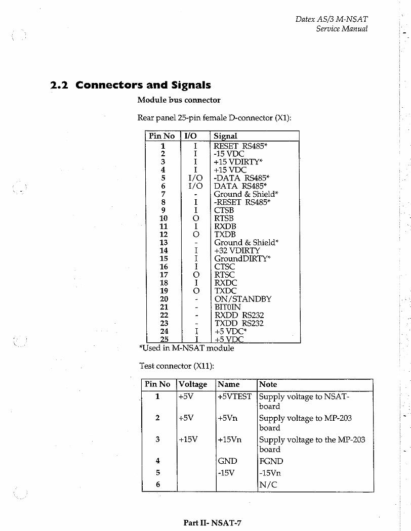
2.2 Connectors and Signals
Datex AS/3 M-NSAT
Service Manual
Module bus connector
Rear panel 25-pin female D-connector (X1):
Pin No | VO Signal
1 I RESET RS485* 2 I -15 VDC 3 I +15 VDIRTY* 4 I +15 VDC 5 I/O ¡-DATA RS485* 6 1/0 | DATA RS485* 7 - Ground & Shield* 8 I -RESET RS485* 9 I CTSB 10 О | RTSB 11 I RXDB 12 O | TXDB 13 - Ground & Shield* 14 I +32 VDIRTY 15 I GroundDIRTY* 16 I CTSC 17 O | RTSC 18 I RXDC 19 O TXDC 20 - ON/STANDBY 21 - BITOIN 22 - RXDD RS232 23 - TXDD RS232 24 I +5 VDC* 25 I +5 VDC
*Used in M-NSAT module
Test connector (X11):
Pin No |Voltage |Name Note
1 +5V +5VTEST |Supply voltage to NSAT-
board
2 +5V +5Vn Supply voltage to MP-203 board
3 +15V +15Vn Supply voltage to the MP-203 board
4 GND FGND
5 -15V -15Vn
6 N/C
Part II- NSAT-7
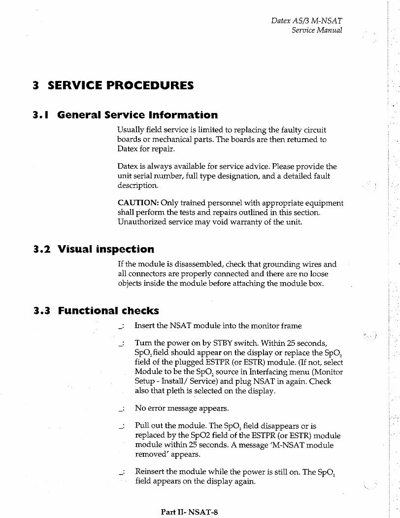
Datex AS/3 M-NSAT
Service Manual
3 SERVICE PROCEDURES |
3.1 General Service Information
Usually field service is limited to replacing the faulty circuit boards or mechanical parts. The boards are then returned to Datex for repair.
Datex is always available for service advice. Please provide the unit serial number, full type designation, and a detailed fault description.
CAUTION: Only trained personnel with appropriate equipment shall perform the tests and repairs outlined in this section. Unauthorized service may void warranty of the unit.
3.2 Visual inspection
If the module is disassembled, check that grounding wires and ail connectors are properly connected and there are no loose objects inside the module before attaching the module box.
3.3 Functional checks
_: Insert the NSAT module into the monitor frame
_ Turn the power on by STBY switch. Within 25 seconds, SpO, field should appear on the display or replace the SpO, field of the plugged ESTPR (or ESTR) module. (If not, select Module to be the SpO, source in Interfacing menu (Monitor Setup - Install/ Service) and plug NSAT in again. Check also that pleth is selected on the display.
_: No error message appears.
_ Pull out the module. The SpO, field disappears or is replaced by the SpO2 field of the ESTPR (or ESTR) module module within 25 seconds. A message ‘M-NSAT module removed’ appears.
ー Reinsert the module while the power is still on. The SpO, field appears on the display again.
Part II- NSAT-8

Datex AS/3 M-NSAT
Service Manual
Connect a finger probe to the module. The message Pulse search followed by Check probe in 20 seconds should appear on the display. No waveform coming from NSAT appears.
Attach the probe to your finger. A reading of 95 to 99 and SpO, wave form should appear.
Part II- NSAT-9
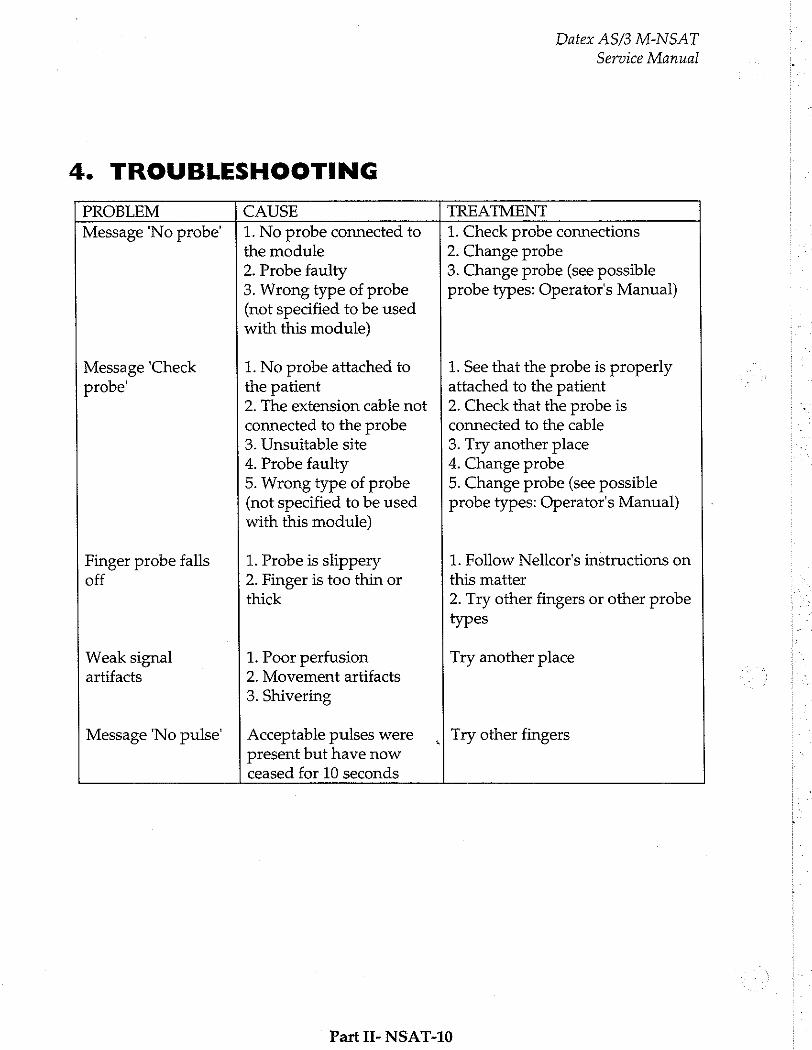
4. TROUBLESHOOTING
Datex AS/3 M-NSAT
Service Manual
PROBLEM CAUSE TREATMENT
Message ‘No probe’
Message ‘Check probe'
Finger probe falls off
Weak signal
artifacts
Message 'No pulse’
1. No probe connected to the module 2. Probe faulty 3. Wrong type of probe (not specified to be used with this module)
1. No probe attached to the patient 2. The extension cable not connected to the probe 3. Unsuitable site 4. Probe faulty 5. Wrong type of probe (not specified to be used with this module)
1. Probe is slippery 2. Finger is too thin or thick
1. Poor perfusion 2. Movement artifacts 3. Shivering
Acceptable pulses were present but have now ceased for 10 seconds
„| Try other fingers
1. Check probe connections 2. Change probe 3. Change probe (see possible probe types: Operator's Manual)
1. See that the probe is properly attached to the patient 2. Check that the probe is connected to the cable 3. Try another place 4. Change probe 5. Change probe (see possible probe types: Operator's Manual)
1. Follow Nellcor's instructions on
this matter
2. Try other fingers or other probe types
Try another place
Part II- NSAT-10
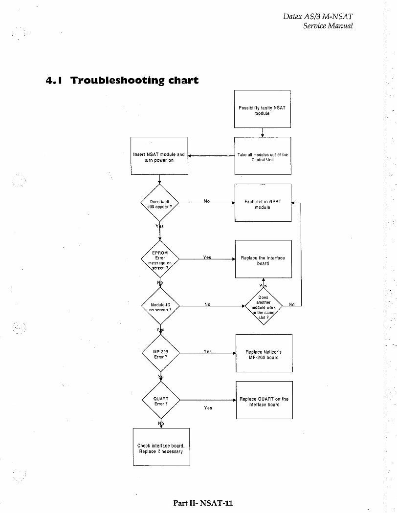
4.1 Troubleshooting chart
Insert NSAT module and
Datex AS/3 M-NSAT
Possibility faulty NSAT module
i
turn power on
Does fault still appear?
EPROM
Error message on screen 3,
Moduie-5D on screen ?
MP-203 Error ?
Check interface board. Replace if necessary
Part II- NSAT-11
Take all modules out of the Central Unit
Fault not in NSAT module
Replace the Interface board
Does another
Replace Nelicor's MP-203 board
Replace QUART on the interface board
Service Manual
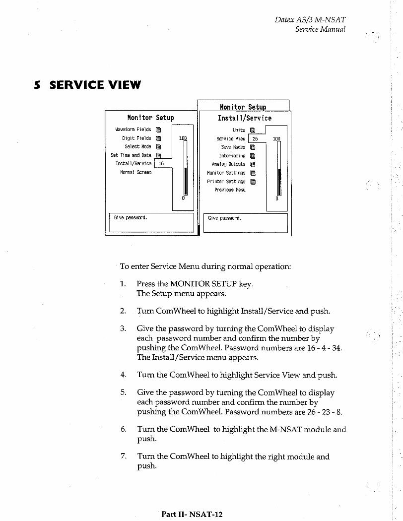
Datex AS/3 M-NSAT Service Manual
5 SERVICE VIEW
Monitor Setup
Monitor Setup Install/Service
Waveform Fields Units
Digit Fields 108 Service View | 26 100
Select Mode Save Modes
Set Time and Date Interfacing
Install/Service | 16 analog Outputs
Norma] Screen Monitor Settings
Printer Settings
Previous Menu
0 9
Give password. Give password.
To enter Service Menu during normal operation:
1. Press the MONITOR SETUP key. The Setup menu appears.
Turn ComWheel to highlight Install /Service and push.
Give the password by turning the ComWheel to display each password number and confirm the number by pushing the ComWheel. Password numbers are 16 - 4 - 34. The Install/Service menu appears.
Turn the ComWheel to highlight Service View and push.
Give the password by turning the ComWheel to display each password number and confirm the number by pushing the ComWheel. Password numbers are 26 - 23 - 8.
Turn the ComWheel to highlight the M-NSAT module and push.
Turn the ComWheel to highlight the right module and push.
Part II- NSAT-12

Datex AS/3 M-NSAT
Service Manual
5.1 M-NSAT Service menu
H-NSAT NSAT Data
PR — $р02% —
NoProbe 0 PulseSearch 0 NoPulse 0 CheckPrabe 1
MP-203 Error No QUART Errar Ro
O Error No
Timeouts 0 Bad checksums D ROM Dk Bad c-s by mod
PR shows the pulse rate value [bpm] calculated from pleth.
SpO,% shows the oxygen saturation value multiplied by 100.
Next are listed the messages that are sent from the module to the monitor. Digit '0' means that the message is not active, '1' is for the active one.
MP-203 Error is set as Yes if any error message is sent by the Nellcor MP-203 board.
OUART Error displays Yes if an error is detected in the data communications device OUART which is located in the
Interface board.
The status of I/O Error is Yes when an error occurs in the
communication between MP-203 and the Interface board.
Timeouts is a cumulative number that indicates how many times the module has not responded to the monitor's inguiry. Bad checksums is a cumulative number that indicates how many times communication from the module to monitor broke down.
Bad c-s by mod is a cumulative number that indicates how many communication errors the module has detected. The AS/3 Monitor starts counting these items at power up and resets to zero at power off. The nonzero values do not indicate a
Part II- NSAT-13
Datex AS/3 M-NSAT
Service Manual
failure, but the continuous counting (more than 50 per second) indicates either serial communication failure, or module not in
place. Also other modules can cause communication errors that cause these numbers rise.
ROM indicates whether the checksum in the EPROM is in
accordance with the one the software has calculated. The state is either OK, Fail or ? (module not in place or a communication error).
Part H- NSAT-14
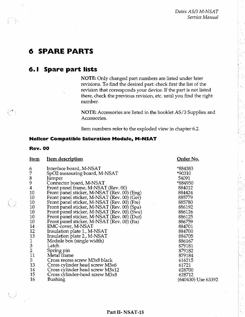
6 SPARE PARTS
6.1 Spare part lists
Nelicor Compatible Saturation Module, M-NSAT
Datex AS/3 M-NSAT
Service Manual
NOTE: Only changed part numbers are listed under later revisions. To find the desired part: check first the list of the revision that corresponds your device. If the part is not listed there, check the previous revision, etc. until you find the right number.
NOTE: Accessories are listed in the booklet AS/3 Supplies and Accessories.
Item numbers refer to the exploded view in chapter 6.2.
Rev. 00
Item Item description
6 Interface board, M-NSAT 7 SpO2 measuring board, M-NSAT 8 Jumper 9 Connector board, M-NSAT 4 Front panel frame, M-NSAT (Rev. 00) 10 Front panel sticker, M-NSAT (Rev. 00) (Eng) 10 Front panel sticker, M-NSAT (Rev. 00) (Ger) 10 Front panel sticker, M-NSAT (Rev. 00) (Fre) 10 Front panel sticker, M-NSAT (Rev. 00) (Spa) 10 Front panel sticker, M-NSAT (Rev. 00) (Swe) 10 Front panel sticker, M-NSAT (Rev. 00) (Dut) 10 Front panel sticker, M-NSAT (Rev. 00) (Ita) 14 EMC-cover, M-NSAT 12 Insulation plate 1., M-NSAT 13 Insulation plate 2., M-NSAT 1 Module box (single width) 3 gatch 2 ring pin 11 Metal frame 5 Cross recess screw M3x8 black 13 Cross cylinder head screw M3x6 14 Cross cylinder head screw M3x12 15 Cross cylinder-head screw M3x8 16 Bushing
Part II- NSAT-15
Order No.
“884383 *90310 54091 *884950 884012 884424 885779 885780 886192 886126 886125 886759 884701 884700 884705 886167 879181 879182 879184 616215 61721 628700 628712 (640430) Use 63392
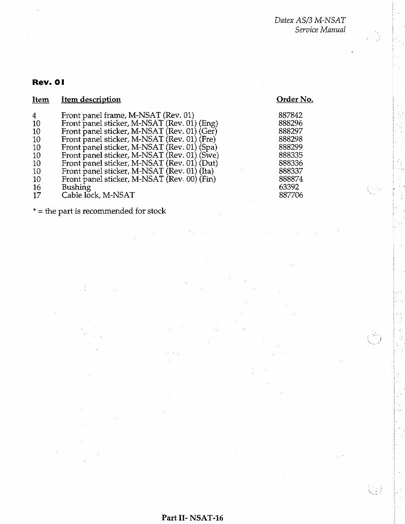
Rev. Ol
Item Item description
4 Front panel frame, M-NSAT (Rev. 01) 10 Front panel sticker, M-NSAT (Rev. 01) (Eng) 10 Front panel sticker, M-NSAT (Rev. 01) (Ger) 10 Front panel sticker, M-NSAT (Rev. 01) (Fre) 10 Front panel sticker, M-NSAT (Rev. 01) (Spa) 10 Front panel sticker, M-NSAT (Rev. 01) (Swe) 10 Front panel sticker, M-NSAT (Rev. 01) (Dut) 10 Front panel sticker, M-NSAT (Rev. 01) (Ita) 10 Front panel sticker, M-NSAT (Rev. 00) (Fin) 16 Bushing 17 Cable lock, M-NSAT
* = the part is recommended for stock
Part H- NSAT-16
Datex AS/3 M-NSAT
Service Manual
Order No.
887842 888296 888297 888298 888299 888335 888336 888337 888874 63392 887706
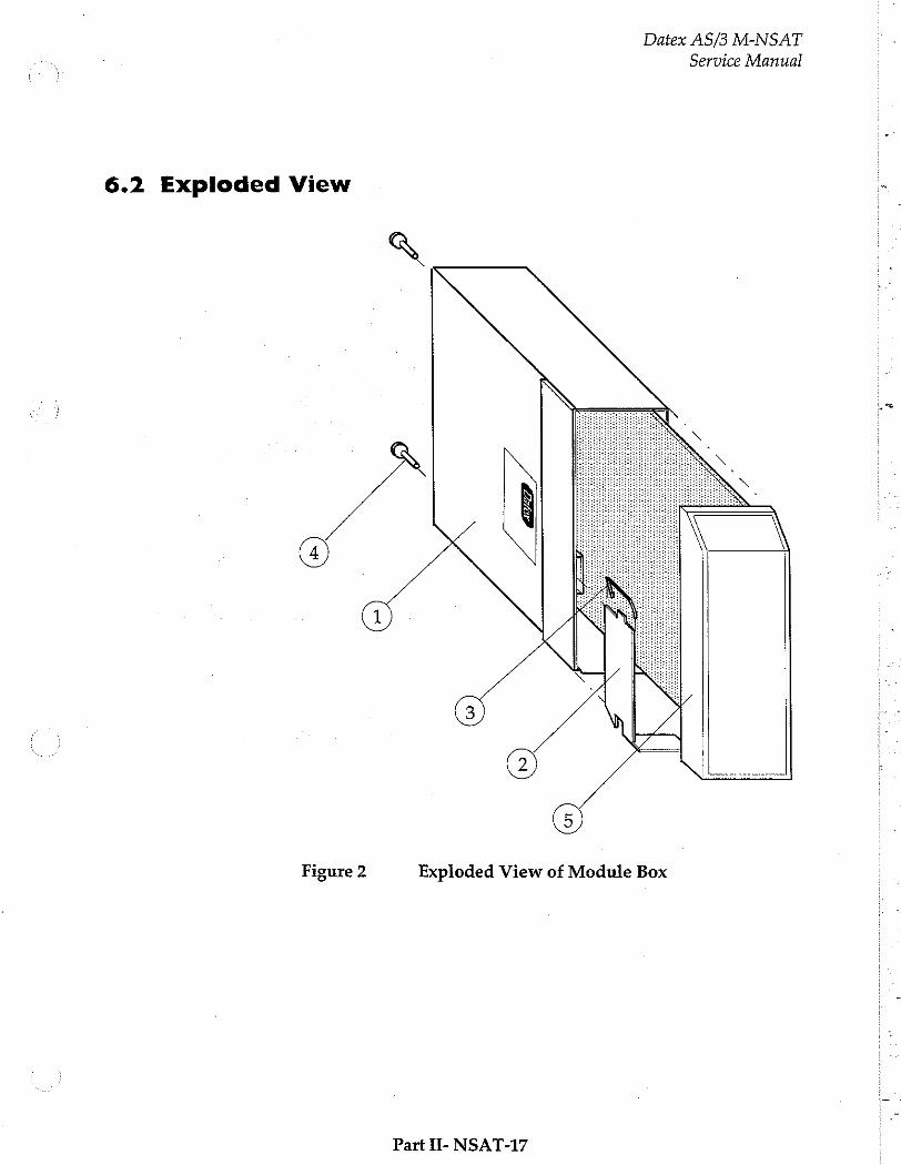
Datex AS/3 M-NSAT
Service Manual
6.2 Exploded View
や
Figure 2 Exploded View of Module Box
Part IT- NSAT-17

Datex AS/3 M-NSAT
Service Manual
Figure 3 Exploded View of the M-NSAT Module
Part II- NSAT-18
Datex AS/3 M-NSAT
Service Manual
7 EARLIER REVISIONS
This manual fully supports earlier revision of M-NSAT module.
Part II- NSAT-19


Network Board, B-NET (Rev. 00)
All specifications subject to change without notice
Document No. 885941-2
March, 1996
Datex Division, Instrumentarium Corp. P.O.Box 446 FIN-00101 Helsinki Finland
Tel. +358 0 39411 Fax +358 0 1463310

Datex AS/3 B-NET
Service Manual
Datex AS/3 B-NET
Service Manual
Table of Contents
INTRODUCTION 1
I TECHNICAL SPECIFICATIONS 2
2 FUNCTIONAL DESCRIPTION 3
2.1 Ge нитииитиининитилантвоиильн
2.2 Control LOGIC... i 2.3 Coding Element Interface...
24 Ethermetinterfaces....................... issus
2.5 Connectors and signals..................... iii
2.5.1 Extension Lead rire irene
3 SERVICE PROCEDURES に 1
4 TROUBLESHOOTING 9
5 SERVICE VIEW 12
6 SPARE PARTS 15
7 EARLIER REVISIONS 16

Datex AS/3 B-NET Service Manual
Datex AS/3 B-NET Service Manual
INTRODUCTION
The Datex AS/3 Network Board enables connecting the AS/3 monitor to the network. For installing the board please refer to the Installation Manual of your monitor.
Part II- B-NET-1
Datex AS/3 B-NET
Service Manual
I TECHNICAL SPECIFICATIONS
Meets IEEE802.3 specifications (10BASE-T)
Hospital grade approved data transformer
Coding element interface
64 Kbyte linear shared-memory /8x8Kbyte paged shared- memory
Support xxx86 real/protected mode programming
Electrical reguirements +5 Vdc/400 mA
Part H- B-NET-2
Datex AS/3 B-NET Service Manual
2 FUNCTIONAL DESCRIPTION
2.1 General
The B-NET board block diagram is shown in figure 2-1.
The network interface controller is basically the heart of the B- NET board. The interface controller communicates with the CPU board through the data and address buffering and decoding block, or through the RAM. During the startup sequence the CPU board loads the network communication software into the RAM. The processor then executes the communication software.
The network interface controller transmits data packets to the AS/3 Network and receives data packets from the network through the 10BASE-T transformer. The transformer filters and transforms the data and also provides the isolation.
The Ethernet status LEDs indicate the status of the network
communication. The status LEDs are controlled by the network interface controller. The LEDs are not visible when the board is
installed into the monitor.
The coding element interface block contains a unique network address. The interface block is connected to the coding element. The coding element contains information on the monitor location. The network address and the monitor location information are transmitted to the CPU board through the data and address buffering and decoding block.
Part II- B-NET-3
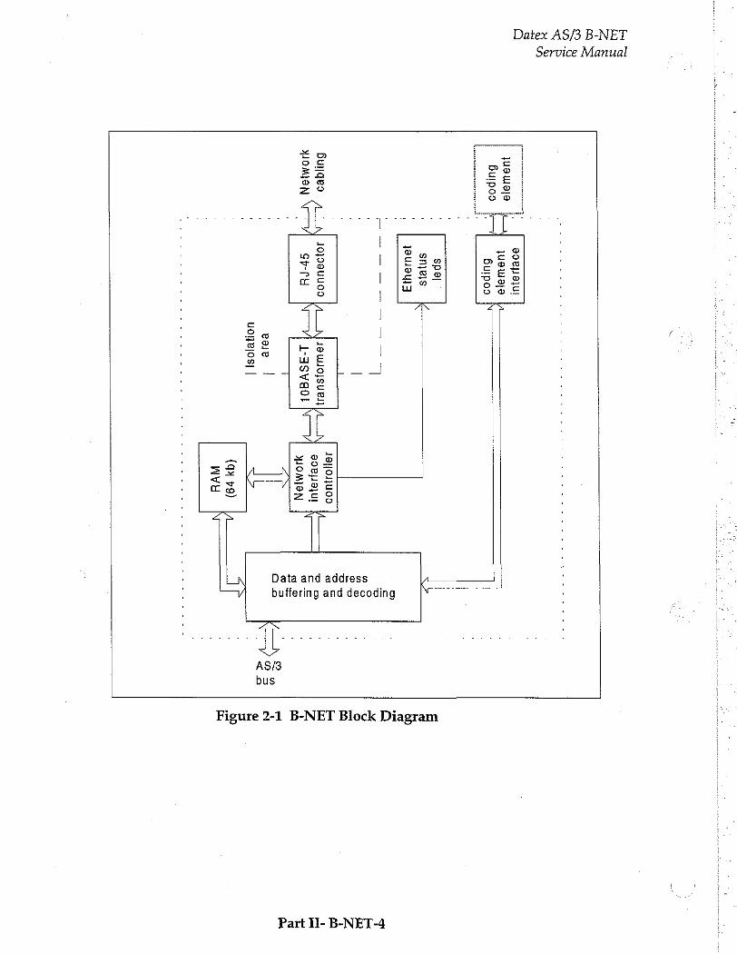
Service Manual
Datex AS/3 B-NET
」 θο8μθ]υ!
11899
Nİ jueuuele
Butpoo p=
6
비 000
spal snjeis
19419413
2 4
5
| 28 Do
L Bo
бинаеэ 101094400
JaWojsuel}A__N 40100
Es
' 999jJ9iul
| |
E >
OMEN У
stru КЕ
Lasvaoi |
기 OMION
sE ,
= 5
' T
os
na
eae |
| uonejos] |
(9% 79)
(A AVd
Part II- B-NET-4
ASB bus
Figure 2-1 B-NET Block Diagram
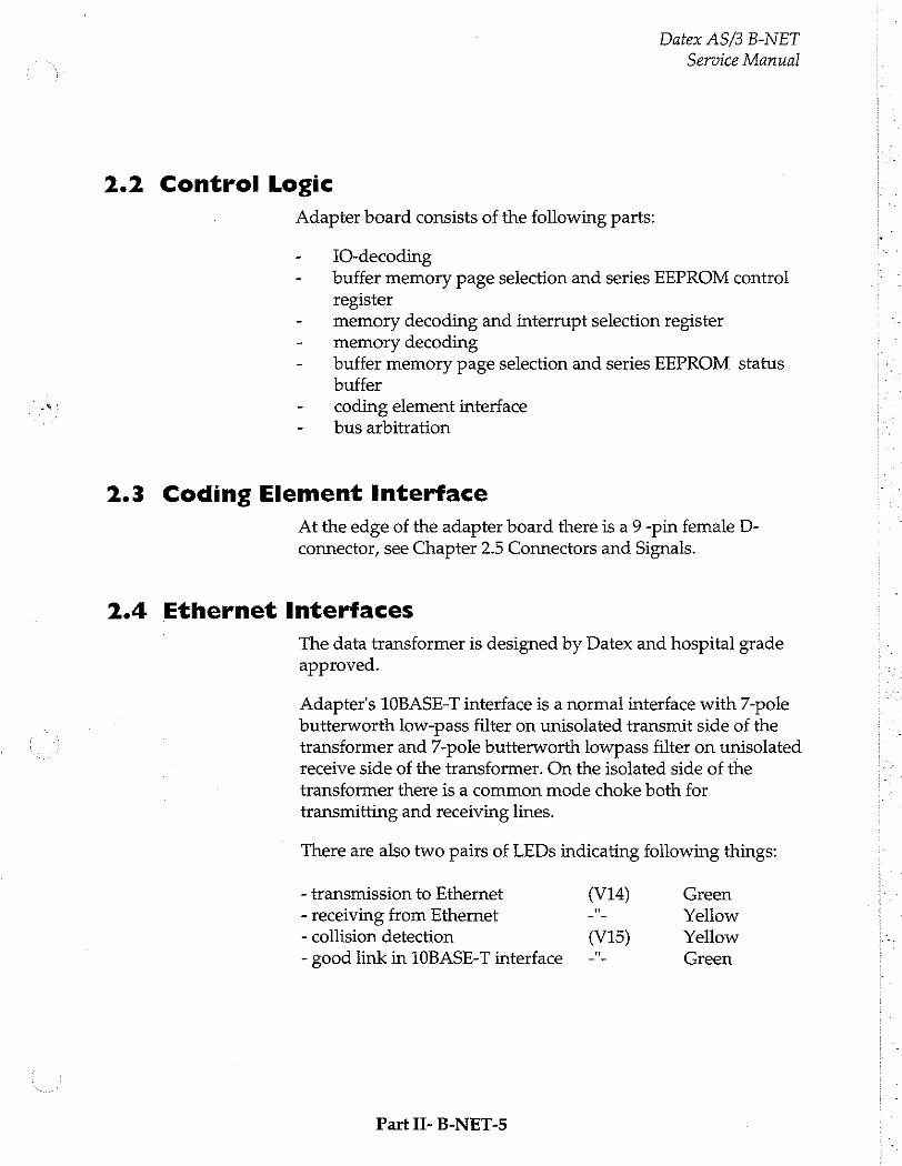
Datex AS/3 B-NET
Service Manual
2.2 Control Logic
Adapter board consists of the following parts:
1O-decoding buffer memory page selection and series EEPROM control register memory decoding and interrupt selection register memory decoding buffer memory page selection and series EEPROM status buffer coding element interface bus arbitration
2.3 Coding Element Interface
At the edge of the adapter board there is a 9 -pin female D- connector, see Chapter 2.5 Connectors and Signals.
2.4 Ethernet Interfaces
The data transformer is designed by Datex and hospital grade approved.
Adapter's 10BASE-T interface is a normal interface with 7-pole butterworth low-pass filter on unisolated transmit side of the transformer and 7-pole butterworth lowpass filter on unisolated receive side of the transformer. On the isolated side of the transformer there is a common mode choke both for transmitting and receiving lines.
There are also two pairs of LEDs indicating following things:
- transmission to Ethernet (V14) Green - receiving from Ethernet ーー Yellow - collision detection (V15) Yellow
- good link in 10BASE-T interface -"- Green
Part II- B-NET-5
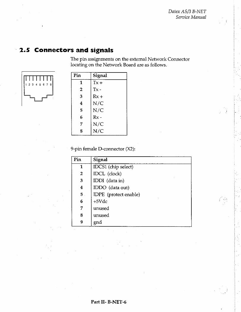
Datex AS/3 B-NET
Service Manual
‘ 2.5 Connectors and signals
The pin assignments on the external Network Connector locating on the Network Board are as follows.
Pin Signal
Tx +
Tx-
Rx+
N/C
N/C
Rx-
N/C
N/C
12345678
eon au
MR ON
F
9-pin female D-connector (X2):
Pin Signal
IDCS1 (chip select)
IDCL (clock)
IDDI (data in)
IDDO (data out)
IDPE (protect enable)
+5Vdc
unused
unused
gnd
NO ON
O GR
GN
ba
Part II- B-NET-6

Datex AS/3 B-NET
Service Manual
CPU Bus connector (X1):
a b с
1 [|+15V AGND DGND
2 |-15V BALE DGND
3 | SAO SAT DGND
4 |SA2 SA3 RESET_RS485
5 |SA4 SA5 -RESET_RS485
6 |SA6 SA7 DATA_RS485
7 |SA8 SA9 -DATA RS485
8 |SA10 SA11 TXDD_RS232
9 |SA12 SA13 RXDD RS232
10 |SA14 SA15 BITOIN
11 | SA16 SA17 BITIIN
12 ¡SA18 SA19 TXDC
13 | SA20 SA21 RXDC
14 | SA22 SA23 RTSC
15 |-SMEMR -SMEMW CTSC
16 |-IOR ΙΟΥΝ TXDB
17 |CLK -RESET RXDB
18 | IOCHRDY IRQ10 RISB
19 |N/C 1 IRQ11 CTSB
20 | N/C_2 IRQ12 TXDA
21 | -SBHE IRQ15 RXDA
22 |500 SDI RISA
23 | SD2 SD3 CTSA
24 1504 SD5 LOUDSPEAKER
25 | SD6 SD7 +5 V
26 |508 SD9 +5V
27 15010 $011 +5 V
28 |SD12 SD13 +5 V
29 |SD14 SD15 ON/STBY
30 ¡+15VD -RESET_CPU +5 V_CPU
31 |+15VD +32 VD REFRESH_WD
32 | GNDD GNDD POWER FAIL
2.5.1 Extension Lead
Every B-NET Board is equipped with an Extension Lead which facilitates the connecting and disconnecting the cable.
Part If- B-NET-7
Datex AS/3 B-NET
Service Manual
3 SERVICE PROCEDURES
Due to the nature of the Network Board, field service for the
board is limited to troubleshooting. The boards are returned to
Datex for repair.
Datex is always available for service advice. Please provide the unit serial number, full type designation, and a detailed fault
description.
CAUTION: Only trained personnel with appropriate tools and equipment are allowed to perform the tests and repairs outlined in this section. Unauthorized service may void warranty of the unit.
Please, refer to the Installation Manual of your monitor for
information on how to remove the Network Board.
Part II- B-NET-8
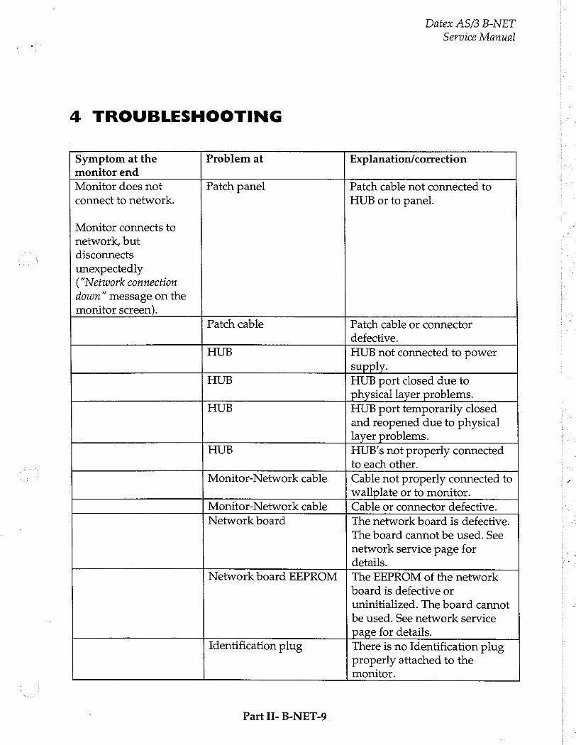
4 TROUBLESHOOTING
Datex AS/3 B-NET
Service Manual
Symptom at the Problem at Explanation/correction monitor end
Monitor does not Patch panel Patch cable not connected to connect to network. HUB or to panel.
Monitor connects to network, but
disconnects unexpectedly ("Network connection
down” message on the monitor screen).
Patch cable Patch cable or connector defective.
HUB HUB not connected to power supply.
HUB HUB port closed due to physical layer problems.
HUB HUB port temporarily closed and reopened due to physical layer problems.
HUB HUB's not properly connected to each other.
Monitor-Network cable Cable not properly connected to wallplate or to monitor.
Monitor-Network cable Cable or connector defective.
Network board The network board is defective.
The board cannot be used. See
network service page for details.
Network board EEPROM The EEPROM of the network
board is defective or
uninitialized. The board cannot
be used. See network service
page for details. Identification plug There is no Identification plug
properly attached to the monitor.
Part II- B-NET-9
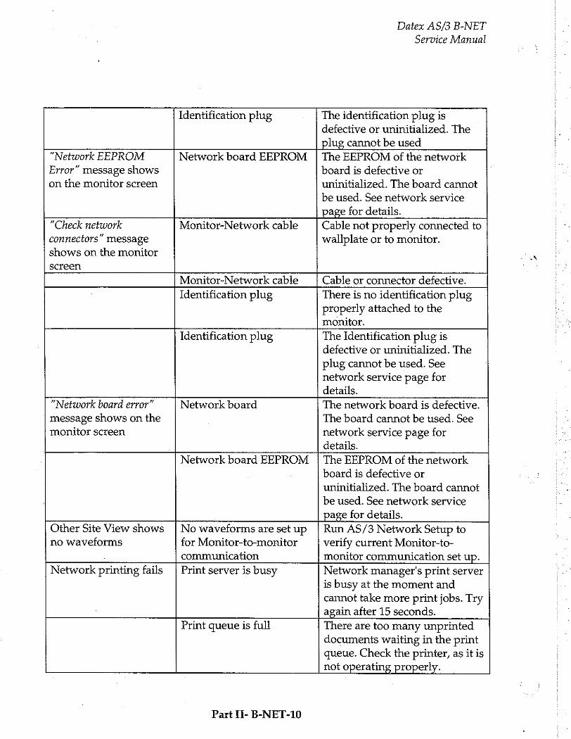
Datex AS/3 B-NET
Service Manual
Identification plug The identification plug is defective or uninitialized. The plug cannot be used
“Network EEPROM Network board EEPROM | The EEPROM of the network Error” message shows on the monitor screen
board is defective or
uninitialized. The board cannot
be used. See network service
page for details.
"Check network
connectors” message
shows on the monitor
screen
Monitor-Network cable Cable not properly connected to wallplate or to monitor.
Monitor-Network cable Cable or connector defective.
Identification plug There is no identification plug properly attached to the monitor.
Identification plug The Identification plug is
defective or uninitialized. The
plug cannot be used. See network service page for details.
“Network board error”
message shows on the monitor screen
Network board The network board is defective.
The board cannot be used. See
network service page for
details.
Network board EEPROM The EEPROM of the network
board is defective or
uninitialized. The board cannot
be used. See network service
page for details.
Other Site View shows
no waveforms
No waveforms are set up for Monitor-to-monitor
communication
Run AS/3 Network Setup to verify current Monitor-to- monitor communication set up.
Network printing fails Print server is busy Network manager's print server is busy at the moment and cannot take more print jobs. Try again after 15 seconds.
Print queue is full There are too many unprinted documents waiting in the print queue. Check the printer, as it is
not operating properly.
Part II- B-NET-10
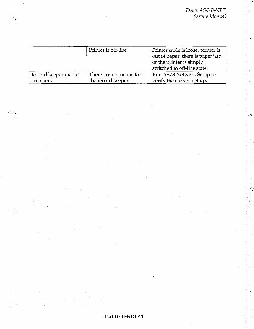
Datex AS/3 B-NET
Service Manual
Printer is off-line Printer cable is loose, printer is
out of paper, there is paper jam or the printer is simply switched to off-line state.
Record keeper menus There are no menus for Run AS/3 Network Setup to
are blank the record keeper verify the current set up.
Part If- B-NET-11

Datex AS/3 B-NET
Service Manual
5 SERVICE VIEW
Monitor Setup
Monitor Setup Install/Service
Waveform Fields Units
Digit Fields 100 Service View | 26 100
Select Mode Save Modes
Set Time and Date Interfacing
Install/Service | 16 Analog Outputs
Normal Screen Monitor Settings
Printer Settings
Previous Menu
Give password. Give password.
To enter Service Menu during normal operation:
1. Press the MONITOR SETUP key. The Setup menu appears.
Turn ComWheel to highlight Install/Service and push.
Give the password by turning the ComWheel to display each password number and confirm the number by pushing the ComWheel. Password numbers are 16 - 4 - 34. The Install /Service menu appears.
Turn the ComWheel to highlight Service View and push.
Give the password by turning the ComWheel to display each password number and confirm the number by pushing the ComWheel. Password numbers are 26 - 23 - 8.
Turn the ComWheel to highlight “Monitor” and push.
Turn the ComWheel to highlight “Communication” and push.
Under Communication there are two service views about
networking: Network , and Computer Interface. Highlight the desired one and push ComWheel.
Part II- B-NET-12
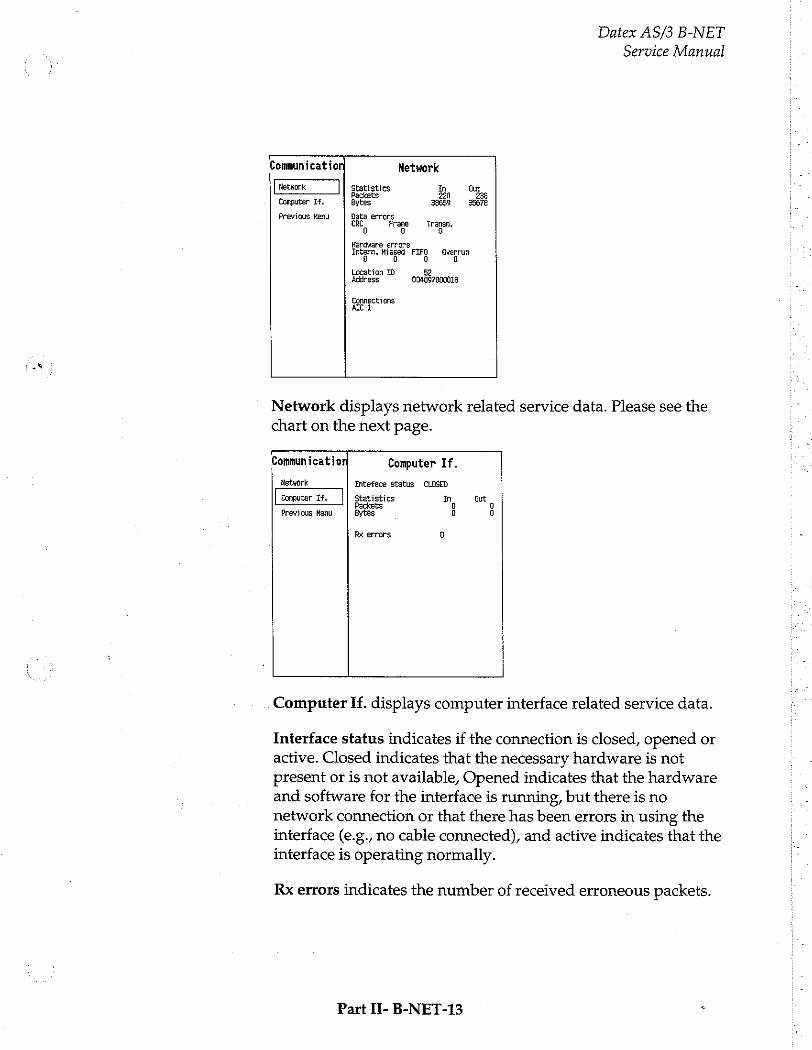
Datex AS/3 B-NET
Service Manual
r Communication Network
Network Statistics In Qut Packets 220 238
Computer If. Bytes 38655 35678
Previous Menu Data errors TRL Frage Fransen.
Hardware errors Intern. Missed FO Sverrun
Location TD 52 Address 004097000018
Connections ALI
Network displays network related service data. Please see the chart on the next page.
- Communication Computer If.
Network Inteface status CLOSED
Computer If. Statistics In Gut Packets 0
Previous Menu Bytes 0 so
Rx errors a
Computer If. displays computer interface related service data.
Interface status indicates if the connection is closed, opened or
active. Closed indicates that the necessary hardware is not present or is not available, Opened indicates that the hardware and software for the interface is running, but there is no network connection or that there has been errors in using the interface (e.g., no cable connected), and active indicates that the
interface is operating normally.
Rx errors indicates the number of received erroneous packets.
Part II- B-NET-13

Datex AS/3 B-NET
Service Manual
In the Network menu there are additionally following items that describe the communication in the network.
Value Usage Notes
Received packets Total number of (Statistics In/Packets) | received packets since
last cold start.
Transmitted packets Total number of (Statistics Out/Packets) | transmitted packets
since last cold start.
Received bytes Total number of (Statistics In/Bytes) received bytes since last
cold start
Transmitted bytes Total number of (Statistics In/Bytes) transmitted bytes since
last cold start
CRC errors (CRC) Number of received
packets with incorrect checksum.
Frame errors (Frame) Number of received Refers to physical layer packets with incorrect | problems. An frame structure. erroneous packet often
has both frame and CRC error.
Transmission errors Number or errors in : (Transm.) packet transmission. IN
Internal errors (Intern.) | Internal error of the Must always be 0. M network board.
Missed packets Number of received Must always be 0. (Missed) packets lost due to
overload.
FIFO errors (FIFO) Internal error of the Must always be 0. network board.
Overrun errors Practically same as Must always be 0. (Overrun) above.
Location ID Monitor’s location given at the setup
Address Monitor's ethernet address
Connections Names of AICs connected
Part II- B-NET-14
6 SPARE PARTS
Network Board, B-NET
Item description
Grounding plate Network cable extension
* = the part is recommended for stock
Part II- B-NET-15
Datex AS/3 B-NET
Service Manual
Order No.
885414 *713698
Datex AS/3 B-NET
Service Manual
7 EARLIER REVISIONS
There are no earlier revisions of B-NET.
Part II- B-NET-16

interface Board, B-INT (Rev. 00)
All specifications subject to change without notice
Document No. 885942-2
March, 1996
Datex Division, Instrumentarium Corp. P.O.Box 446 FIN-00101 Helsinki Finland
Tel. +358 0 39411 Fax +358 0 1463310

Datex AS/3 B-INT
Service Manual
Table of Contents
INTRODUCTION
SPECIFICATIONS
2 FUNCTIONAL DESCRIPTION
2.1 Main Components 2.2 Connectors and signals
3 SERVICE PROCEDURES
3.1 General Service Information
4 TROUBLESHOOTING
5 SERVICE VIEW
6 SPARE PARTS
7 EARLIER REVISIONS
Datex AS/3 B-INT
Service Manual

Datex AS/3 B-INT
Service Manual

Datex AS/3 B-INT
Service Manual
INTRODUCTION
The B-INT board provides an interface between AS/3 Anaesthesia Monitor and other monitors connected to it. It also provides a connection between the monitor frame and the Airway Module.
The list of the monitors that can be interfaced, and parameters
available from them, is in the installation manual of your monitor.
Part H-Interface-1
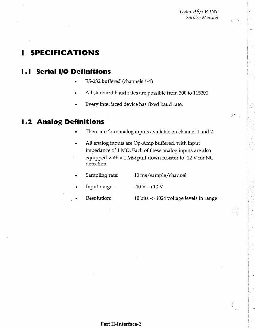
Datex AS/3 B-INT
Service Manual
I SPECIFICATIONS
1.1 Serial I/O Definitions
RS-232 buffered (channels 1-4)
All standard baud rates are possible from 300 to 115200
Every interfaced device has fixed baud rate.
1.2 Analog Definitions
9 There are four analog inputs available on channel 1 and 2.
All analog inputs are Op-Amp buffered, with input
impedance of 1 MQ. Each of these analog inputs are also
equipped with a 1 MQ pull-down resistor to -12 V for NC- detection.
Sampling rate: 10 ms/sample/channel
Input range: -10 V - +10 V
Resolution: 10 bits -> 1024 voltage levels in range
Part II-Interface-2
Datex AS/3 B-INT
Service Manual
2 FUNCTIONAL DESCRIPTION
B-INT detects and identifies the specified monitors connected to its four 9-pin connectors (one D-connector and three pin row connectors). The identification is made by a serial string.
There are three pin row connectors on the board surface. Two for serial and analog connectors (for all interfaces) and one for serial and digital connector.
In the back panel of the board there are two connectors; a 9-pin serial D-connector and a 25-pin D-connector. The 25-pin D- connector is used for connecting the Airway Module (as the Gas interface board is removed when B-INT is installed).
If both numerical and analog real time waveforms are desired,
the external monitor can be connected to the serial/analog connectors (X7 and X8) using additionally interface connector cable.
For detailed installation instructions please refer to AS/3 Anaesthesia Monitor Installation Manual.
Part H-Interface-3
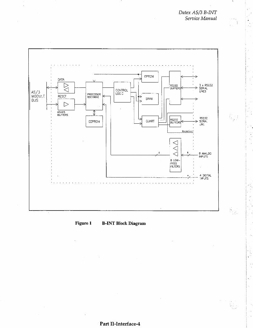
Datex AS/3 B-INT
Service Manual :
, EPROM DATA
RS232 ' 3 x RS232
7 > CONTROL | BUFFERSK—————> SERIAL : LINES
AS/3 elo PROCESSOR LOGIC MODULE RESET 80C196KC ie し , BUS İN m | SRAM =
' RS485 , ' BUFFERS $
・ a RS232 ' EEPROM QUART SO SERIAL , UNE
・ Isolation’
: 8 8, ' 8 ANALOG < 7 INPUTS
8 LOW- PASS FILTERS
4 ‘ 4 DIGITAL
INPUTS
Figure 1 B-INT Block Diagram
Part II-Interface-4
Datex AS/3 B-INT
Service Manual
2.1 Main Components
In general
The board contains 80C196KC16 (Intel) microcontroller.
External connections
The connectors of the board are:
- 96-pin E-connector to the CPU mother board (X1)
- 25-pin D-connector for an Airway module (X2).
9-pin D-connector. It is RS-232 level isolated serial connector (X3). No analog inputs available.
In addition, three connectors on the board make the following connections possible with AS/3 interface connector cable:
- RS-232 level serial and analog connectors for all interfaces (X7, X8).
- RS-232 level serial and digital connector (X9).
X7 and X8 connectors are for analog inputs (four inputs each) and X9 connector is for digital inputs (four inputs). Analog real- time waveforms are interfaced through X7 and X8 connectors. Also X3 and X9 connectors can be used to interface waveforms from Drager Cato and Cicero. |
The board is connected to the AS/3 module bus through the CPU mother board.
Serial communication signals for transmitting (TxD) and receiving (RxD) are sent to the microcontroller ports. The
direction of the communication is controlled by REC/SND/ signal at the buffers. RESET/ signal always reset the communication to RxD state.
Part I-Interface-5
Datex AS/3 B-INT
Service Manual
Reset
The Interface board is resetted when AS/3 Central Unit is reset
(MAIN/RESET/) or when the module bus is reset (RESET_RS485).
The RESET/ signal is sent to address decoding GAL circuit, from which it goes to the microcontroller as RESET/Z. When the RESET/ is active (low), the RESET/Z also goes low and
resets the microcontroller.
Serial communication channels
For four serial communication channels (TxD, RxD), there is a QUART. The microcontroller is able to reset the QUART any time by pulling QRESET signal high. The QUART is also reset when the microcontroller is reset; the microcontroller pulls all the port 1 signals high when it resets.
Memories
On the board there is static RAM, EPROM, EEPROM and
address decoding GAL unit.
The microcontroller communicates with the EEPROM in serial
mode.
Digital inputs
Four digital inputs are connected to connector X9 on the board. They are passed through to the microcontroller's high speed pins (DIGBUS). The digital inputs have an overvoltage protection and a pull-up circuit.
Analog inputs
Eight analog inputs are connected to connectors X7 and X8. They are passed through EMI filters and low-pass filters to the microprocessor's port 0.
Part II-Interface-6
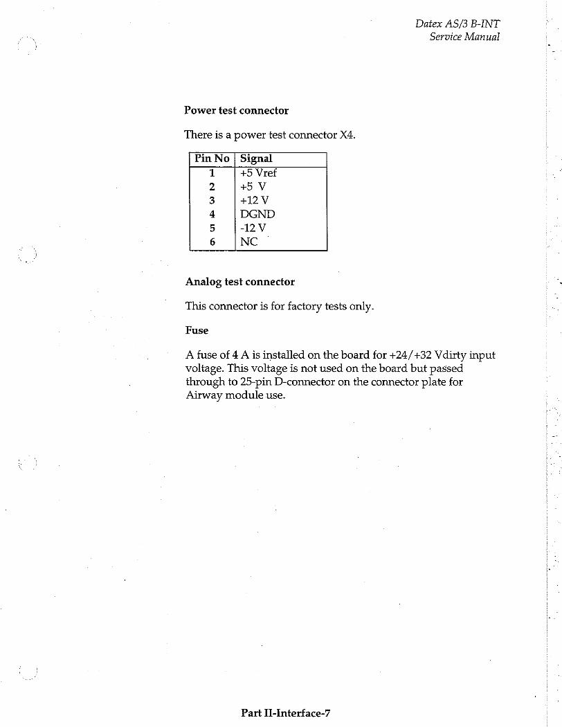
Datex AS/3 B-INT
Service Manual
Power test connector
There is a power test connector X4.
Pin No | Signal
+5 Vref +5 V
+12V
DGND
-12V
NC
au PWN
ha
Analog test connector
This connector is for factory tests only.
Fuse
A fuse of 4 A is installed on the board for +24/+32 Vdirty input voltage. This voltage is not used on the board but passed through to 25-pin D-connector on the connector plate for Airway module use.
Part II-interface-7
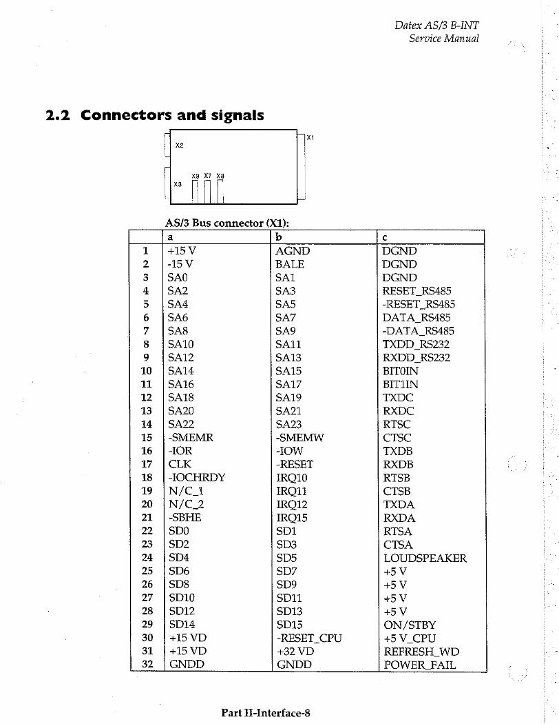
2.2. Connectors and signals
E
Bili
Xi
Datex AS/3 B-INT
Service Manual
AS/3 Bus connector (X1):
a b c
1 |+15V AGND DGND
2 |-15V BALE DGND
3 | SAO SAI DGND
4 ¡SA2 SA3 RESET_RS485
5 |544 $45 -RESET_RS485
6 |546 SA7 DATA_RS485
7 |SA8 SA9 -DATA_RS485
8 |SA10 SA11 TXDD_RS232
9 |SA12 SA13 RXDD_RS232
10 |SA14 SA15 BITOIN
11 | SA16 SA17 BITIIN
12 | SA18 SA19 TXDC
13 | SA20 SA21 RXDC
14 | SA22 SA23 RTSC
15 |-SMEMR -SMEMW CTSC
16 | -IOR -IOW TXDB
17 | CLK -RESET RXDB
18 | JOCHRDY IRQ10 RTSB
19 |N/C_1 КОП CTSB
20 | N/C_2 IRO12 TXDA
21 |-SBHE IRO15 RXDA
22 |500 SD1 RTSA
23 1502 $03 CTSA
24 |SD4 SD5 LOUDSPEAKER
25 |506 557 +5 V
26 |SD8 SD9 +5V
27 |SD10 SD11 +5 V
28 | SD12 SD13 +5 V
29 | SD14 SD15 ON/STBY
30 |+15VD -RESET_CPU +5 V_CPU
31 ¡+15VD +32 VD REFRESH_WD
32 | GNDD GNDD POWER FAIL
Part II-Interface-8
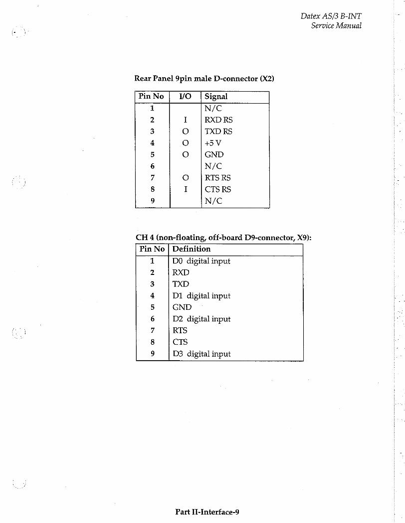
Rear Panel 9pin male D-connector (X2)
Pin No VO | Signal
ら
の
いさ
GA
G
À
GUN
ha
N/C
RXD RS
TXD RS
+5 V
GND
N/C
RTS RS
CTS RS
N/C
OOO M
m no
Datex AS/3 B-INT
Service Manual
CH 4 (non-floating, off-board D9-connector, X9):
Pin No Definition
MO
O
NI AG
BP GUN
r
DO digital input
RXD
TXD
D1 digital input
GND
D2 digital input
RTS
CTS
D3 digital input
Part H-Interface-9
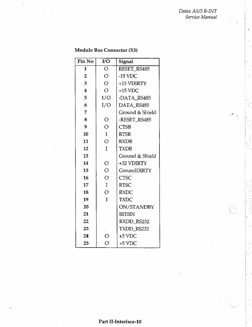
Module Bus Connector (X3)
Pin No | W/O | Signal 1 0 RESET_RS485
2 O -15 VDC
3 O +15 VDIRTY
4 O +15 VDC
5 I/O |-DATA_RS485
6 I/O |DATA_RS485
7 Ground & Shield
8 O -RESET_RS485
9 O CTSB
10 1 RTSB
11 O RXDB
12 I TXDB
13 Ground & Shield
14 O +32 VDIRTY
15 О GroundDIRTY
16 O CTSC
17 I RTSC
18 0 RXDC
19 I TXDC
20 ON/STANDBY
21 BITOIN
22 RXDD_RS232
23 - TXDD_RS232
24 0 +5 VDC
25 o +5 VDC
Part II-Interface-10
Datex AS/3 B-INT
Service Manual
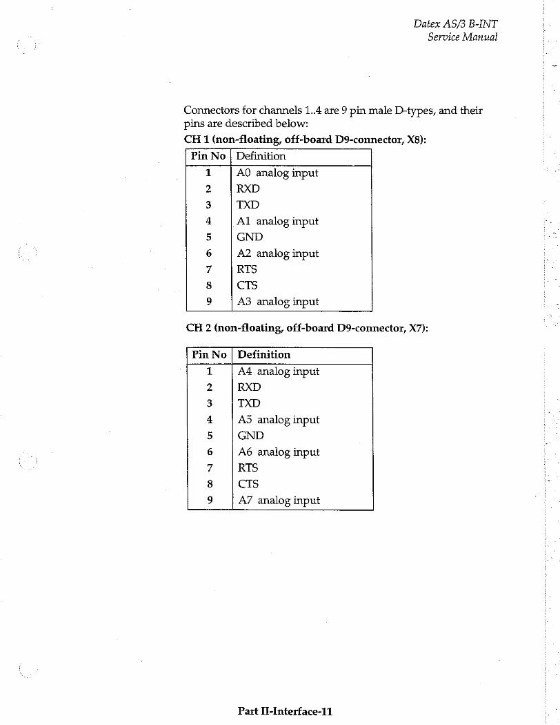
Datex AS/3 B-INT
Service Manual
Connectors for channels 1..4 are 9 pin male D-types, and their pins are described below:
CH 1 (non-floating, off-board D9-connector, X8):
Pin No | Definition
AO analog input
RXD
TXD
A1 analog input
GND
A2 analog input
RTS
CTS
A3 analog input
NO ON
O
G
B GN
F
CH 2 (non-floating, off-board D9-connector, X7):
Pin No | Definition
A4 analog input
RXD
TXD
A5 analog input
GND
A6 analog input
RTS
CTS
A7 analog input worn
aa
Fr GN F
Part II-Interface-11
Datex AS/3 B-INT
Service Manual
3 SERVICE PROCEDURES
3.1 General Service Information
Usually field service is limited to replacing the faulty circuit board. The board is then returned to Datex for repair.
Datex is always available for service advice. Please provide the unit serial number, full type designation, and a detailed fault description.
CAUTION: Only trained personnel with appropriate equipment shall perform the tests and repairs outlined in this section. Unauthorized service may void warranty of the unit.
Part IH-interface-12
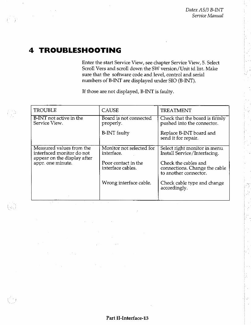
4 TROUBLESHOOTING
Datex AS/3 B-INT
Service Manual
Enter the start Service View, see chapter Service View, 5. Select
Scroll Vers and scroll down the SW version / Unit id list. Make
sure that the software code and level, control and serial
numbers of B-INT are displayed under SIO (B-INT).
If those are not displayed, B-INT is faulty.
TROUBLE CAUSE TREATMENT
B-INT not active in the Service View.
Board is not connected properly.
B-INT faulty
Check that the board is firmly pushed into the connector.
Replace B-INT board and send it for repair.
Measured values from the interfaced monitor do not appear on the display after appr. one minute.
Monitor not selected for interface.
Poor contact in the interface cables.
Wrong interface cable. Select right monitor in menu Install Service /Interfacing.
Check the cables and connections. Change the cable to another connector.
Check cable type and change accordingly.
Part IT-Interface-13

Datex AS/3 B-INT
Service Manual
5 SERVICE VIEW
To enter the Service View:
Monitor Setup
Monitor Setup Install/Service
Waveform Fields Units
Digit Fields 100 Service View | 26 100
Select Mode Save Nodes
Set Time and Date Interfacing
Install/Service | 16 Analog Üutputs
Normal Screen Monitor Settings
Printer Settings
Previous Menu
6 0
Give password. Give password.
Press the MONITOR SETUP key. The Setup menu appears.
Tum ComWheel to highlight Install /Service and push.
Give the password by turning the ComWheel to display each password number and confirm the number by pushing the ComWheel. Password numbers are 16 - 4 - 34. The Install/Service menu appears.
Turn the ComWheel to highlight Service View and push.
Give the password by turning the ComWheel to display each password number and confirm the number by pushing the ComWheel. Password numbers are 26 - 23 - 8.
Turn the ComWheel to highlight Modules and push.
Turn the ComWheel to highlight the Interface and push.
Part II-Interface-14
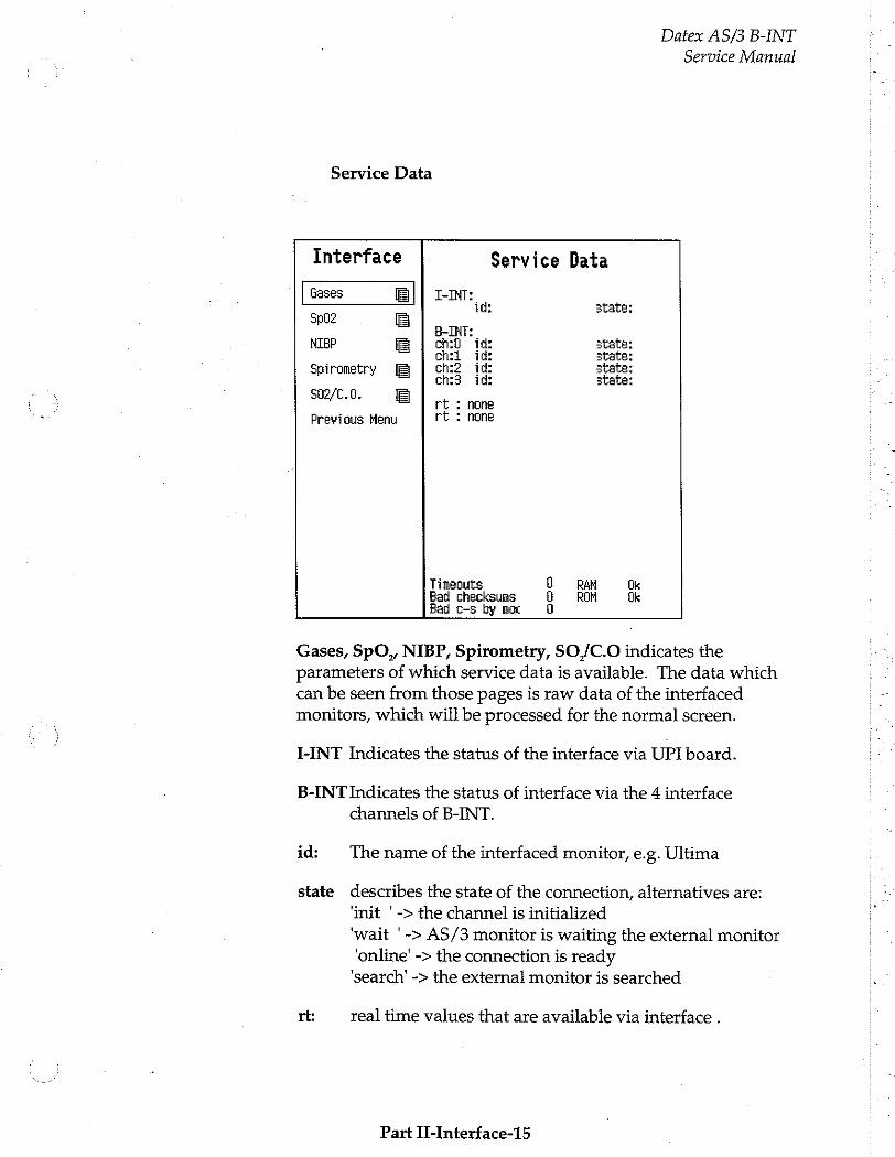
Service Data
Datex AS/3 B-INT
Service Manual
Interface Service Data Gases I-INT: Sp02 id: state:
E
NIBP в | ты tat ch:0 id: state: 9 e chi ig: State:
irometr [E ch? id: state: p y ch:3 id: state:
$02/C.0, rt none Previous Menu rt : none
Timeouts 0 RAM Ok Bad checksums b RON Ok Bad c-s by moc 0
Gases, SpO,, NIBP, Spirometry, S$O,/C.O indicates the
parameters of which service data is available. The data which can be seen from those pages is raw data of the interfaced monitors, which will be processed for the normal screen.
I-INT Indicates the status of the interface via UPI board.
B-INT Indicates the status of interface via the 4 interface
channels of B-INT.
id: The name of the interfaced monitor, e.g. Ultima
state describes the state of the connection, alternatives are:
‘init * -> the channel is initialized
‘wait '-> AS/3 monitor is waiting the external monitor 'online' -> the connection is ready ‘search’ -> the external monitor is searched
rt: real time values that are available via interface .
Part II-Interface-15
Datex AS/3 B-INT
Service Manual
Timeouts is a cumulative number that indicates how many times the module has not responded to the monitor's inquiry. Bad checksums is a cumulative number that indicates how many times communication from the module to monitor broke down.
Bad c-s by mod is a cumulative number that indicates how many communication errors the module has detected. The AS/3 Monitor starts counting these items at power up and resets to zero at power off. The nonzero values do not indicate a failure, but the continuous counting (more than 50 per second) indicates either serial communication failure, or module not in
place. Also other modules can cause communication errors that cause these numbers rise.
RAM indicates the state of the external RAM memory. ROM indicates whether the checksum in the EPROM is in accordance with the one the software has calculated. The state is either OK, Fail or ? (module not in place or a communication error).
Part II-Interface-16
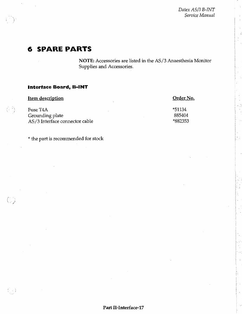
Datex AS/3 B-INT
Service Manual
6 SPARE PARTS
NOTE: Accessories are listed in the AS/3 Anaesthesia Monitor
Supplies and Accessories.
Interface Board, B-INT
Item description Order No.
Fuse T4A *51134
Grounding plate 885404 AS/3 Interface connector cable *882353
* the part is recommended for stock
Part ii-Interface-17

Datex AS/3 B-INT
Service Manual
7 EARLIER REVISIONS
There are no earlier revision of B-INT, only software changes have been made.
coe
Part II-Interface-18
Airway Module, G-O (Rev. 00)
Airway Module, G-OV (Rev. 00)
Airway Module, G-AO (Rev. 04)
Airway Module, G-AiO (Rev. 03)
Airway Module, G-AiOV (Rev. 02)
Airway Module, G-AOV (Rev. 02)
Gas Interface Board, B-GAS (Rev. 01)
All specifications subject to change without notice Document No. 885944-2
March, 1996
Datex Division, Instrumentarium Corp. P.O.Box 446 FIN-00101 Helsinki Finland
Tel. +358 0 39411 Fax +358 0 1463310

Datex AS/3 Airway Module
Service Manual
Datex AS/3 Airway Module
Service Manual
Table of Contents
GENERAL DESCRIPTION I
I SPECIFICATIONS 2
1.1 General Specifications... sens 2 1.2 Typical Performance .... „2 1.3 Technical Specifications 4
2 FUNCTIONAL DESCRIPTION 5
2.1 Measurement Principles 5 2.1.1 CO2/N20/AA Measurement inner nee ete 5
2.1.2. On Measurement линии виниле 6
2.13 Agent Identification riem ereneereareeeremeenrenereerrecearararaeraseaserereeseesasersera 7
2.1.4 Side Stream Spirometry seen 8 2.2 Main Components and Block DiagramS iii 10
2.2.1 in General 2.22 GasSampling5System........................... e een 2.2.3 ACX-200 Measuring Unit 2.24 O7 Measurement μυ
2.2.5 ACX MeasuringBoard.................... eee 2.2.6 ASX Agent Identification Bench. 2.2.7 ASX Measuring Board AI AAA nné 2.2.9 Gas Mother Board ... 2.2.10 Gas Interface Board
2.3 Connectors and Signals
3 SERVICE PROCEDURES
3.1 General Service Information... sus one one 3.2 Preventive Maintenance ........ 3.3 Disassembly and Reassembly.. 3.4 Adjustments and Calibrations ne teen
3.4.1 Gas Sampling System Adjustmeni.................................. eee eeeeereeneenee 3.4.2 Oxygen Measurement Unit Adjustments... 3.3.3 Flow Calibration in te een
4 TROUBLESHOOTING 50
4.1 General Troubleshooting Chart... inner 50 42 Gas Sampling System Troubleshooting 4.3 O2 Measurement Troubleshooting ....
44 ACX Troubleshooting ................... n 4.5 ASX Troubleshootmg… iii 57

Datex AS/3 Airway Module
Service Manual
4.6 PVX Board troubleshooting eee rie 58 4.7 Gas Mother Board Troubleshooting ...............eseeeseaereaseeeserereeneeereereerseraerersereeea 59
E AAA 60
5 SERVICE VIEW
5.1 Gas Mother Board... iii
5.2 ACX Service menu...
5.3 PVX Service Menu ....
5.4 ASX Service Menu
6 SPARE PARTS
6.1 Spare parts list iii
7 EARLIER REVISIONS 80
Datex AS/3 Airway Module Service Manual
GENERAL DESCRIPTION
The AS/3 Airway Modules, G-O, G-OV, G-AO, G-AiO, G-AOV and G-AiOV provide airway and respiratory parameters followingly:
All modules have a side-stream gas sampling system providing measurements of CO, and O,. The G-AO module can also measure N,O and anaesthetic agents. The modules G-AiO and G-AiOV can additionally identify the anaesthetic agent used. The modules G-OV G-AOV and G-AiOV provide the Side Stream Spirometry measurement which enables the measuring of respiratory parameters near the patient.
Gas Interface Board, B-GAS is used for connecting an Airway Module to the Central Unit. The connection can also be made
through the Interface Board, B-INT.
This service manual section provides information required to maintain and repair the Datex AS/3 Anaesthesia Monitor Airway Modules, G-O,G-OV, G-AO, G-AiO, G-AiOV, and G-
AOV. This manual is applicable for the current production revision of the modules.
Part H-Airway-1
Datex AS/3 Airway Module Service Manual
I SPECIFICATIONS
I.I General Specifications
Module size WxDxH 135 x 410 x 135 mm
5.3x 15.0 x 5.3 in
Module weight 6 kg/ 13 lbs
1.2 Typical Performance
Sampling rate 200 ml/min nominal (180 - 220 ml/min)
Display update rate breath-by-breath
Automatic compensation for pressure, CO,-N,O, and CO,-O,
collision broadening effect. Warm-up time 3 min for operation, 30 min for full specifications.
Auto-zeroing is performed at start-up, after 5 min, 5 min.,5 min., 15 min., 15min., 15 min., and after that at 60 min. regular
intervals.
co,
Measurement range 0 to 10 %, (0 to 10 kPa), (0 to 76 mmHg) Extended range 10 to 15 %, (10 to 15 kPa), (76 to 114 mmHg)
If CO, concentration is below 0.1 %, 0.0 % is displayed.
RESPIRATION RATE
Breath detection 1 % change in CO, level
Measurement range 4 to 60 breaths/min
O, Measurement range — Oto 100% O,
N,O
Measurement range 0 to 100% N,O
Part II-Airway-2
Datex AS/3 Airway Module
Service Manual
HAL, ISO, ENF Measurement range 0to5% Extended range 5 to 15 % (unspecified)
SEV Measurement range 0Oto8% Extended range 8 to 15 % (unspecified)
DES
Measurement range Oto 18% Extended range 18 to 25 % (unspecified)
Resolution two decimals when the AA concentration below 1.0 %
If AA concentration is below 0.10 %, 0.00 % is displayed.
AGENT IDENTIFICATION Identified agents HAL, ENF, ISO, SEV, DES
Identification time 30 seconds (typical value with pure agents)
Identification treshold 0.15 vol% (typical) Mixture warning when minor component concentration > 0.3 vol% and >15 %of total agent concentration
SIDE STREAM SPIROMETRY Values are valid when: Respiratory rate adult 4..30 pedi 4..50 LE ratio is 1:3 - 1:0.5
Inner diameter of ET tube is >5.5 mm (adult) or 3 to 6 mm
(paediatric).
Airway Pressure (Paw) Accuracy +15 cmH,O
Resolution 1 cmH,O
Measuring range -20 to +80 cmH,O
Tidal Volume (TV) Accuracy 46 % or 30 ml (adult); +6 % or 4 ml (paed)
Resolution 1ml Measurement range 150 to 2000 ml (adult)
15 to 300 ml (paed)
Part II-Airway-3
Minute Volume (MV)
Resolution
Measurement range
Flow Measurement range (adult)
(paed)
1.3 Technical Specification
co,
Measurement rise time
Gain stability
Gain temperature drift
Nonlinearity error
O,
Measurement rise time
Gain drift
Gain temperature drift
Nonlinearity error
N,0
Measurement rise time
Gain temperature drift
Gain drift
Nonlinearity error
AA Measurement rise time Gain drift Gain temperature drift Nonlinearity error
Datex AS/3 Airway Module Service Manual
0.11/min 2 to 15 1/min (adult)
0.5 to 5 1/min (paed)
1.5 to 100 1/min for both directions
0.25 to 25 1/min for both directions
<360 ms (from 10 to 90 %) <=0.2 %CO,/24h (0 to 8 %) <=0.4 %CO,/24 h (8 to 10 %)
<=0.2 %CO,/10°C (0 to 8 %)
<=0.4 %CO,/10°C (8 to 10 e)
<=0.2 %CO, (0 to 8 %)
<=0.4 %CO, (8 to 10 %)
<480 ms (from 10 to 90 %) <=2 % 07/24 h
<=3 % 03/10°C
<=2 % O,
<360 ms (from 10 to 90 96)
<=3 % N,0/10°C
<=2 % N,0/24h
<=2 % N,O
<520 ms (from 10 to 90 %) <=0.4 % AA/24h <=0.4 % АА/10°С
<=0.2 % АА
Protection against electrical shock Type BF
Part II-Airway-4
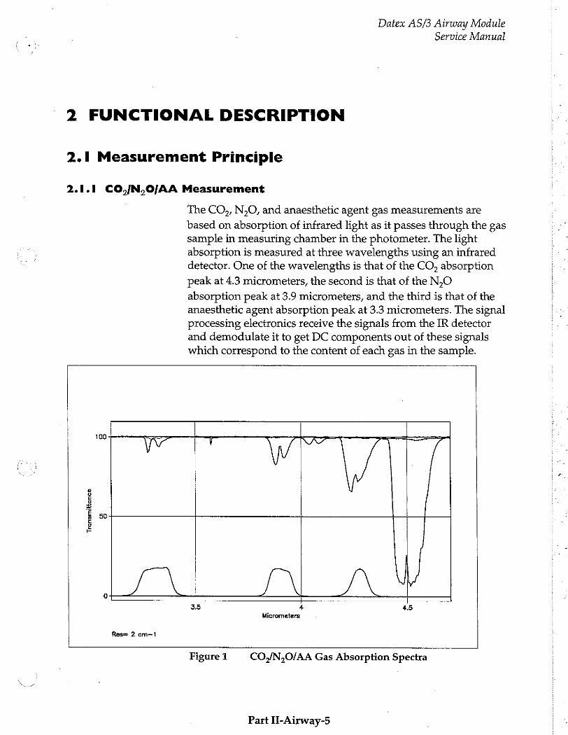
Datex AS/3 Airway Module
Service Manual
-2 FUNCTIONAL DESCRIPTION
2.1 Measurement Principle
2.1.1 CO /N,O/AA Measurement
The CO,, N,O, and anaesthetic agent gas measurements are
based on absorption of infrared light as it passes through the gas sample in measuring chamber in the photometer. The light absorption is measured at three wavelengths using an infrared detector. One of the wavelengths is that of the CO, absorption
peak at 4.3 micrometers, the second is that of the N,O
absorption peak at 3.9 micrometers, and the third is that of the anaesthetic agent absorption peak at 3.3 micrometers. The signal processing electronics receive the signals from the IR detector and demodulate it to get DC components out of these signals which correspond to the content of each gas in the sample.
Tran
smit
tanc
e
100
50
LN /\
Res= 2 cm--1
3.5 4 4.5 Micrometers
Figure 1 CO,/N,O/AA Gas Absorption Spectra
Part II-Airway-5
Datex AS/3 Airway Module Service Manual
2.1.2. O, Measurement
The differential oxygen measuring unit uses the paramagnetic principle in a pneumatic bridge configuration. The signal picked up with a differential pressure transducer is generated in a measuring cell with a strong magnetic field that is switched on and off at a freguency of 110Hz. The output signal is a DC voltage proportional to the O, concentration difference between
the two gases to be measured.
Part II-Airway-6

Datex AS/3 Airway Module Service Manual
2.1.3 Agent Identification
The anaesthetic agent identification bench identifies Halothane, Enflurane, isoflurane, Desflurane and Sevoflurane.
The bench measures the spectrum of the gas between 3.24 um and 3.39 ym. Because the spectrum of each of the anaesthetic agents is different it is possible to identify them.
The bench consists of an infrared source, a measuring chamber,
a rotating filter and a detector. The peak wavelength of the narrow bandpass filter changes when the angle between the light path and the filter is changed. When the filter rotates the required spectrum is scanned through. The agent or a mixture of agents is identified by comparing the measured spectrum with stored reference spectra.
500
Anesthetic Agent Gas Absorption Spectra
450
400
350
300 :
250
200 +
150 +
100 +
50 +
3246
—@— Halothane 0
—E Enflurane O
ir Isoflurane O
~-pt-~ Sevoflurane 0
—*— Desfiurane O
—e— Freon 0
Wavelength inmj
Figure 2 Anaesthetic Agents Gas Absorption Spectra
Part II-Airway-7
Datex AS/3 Airway Module Service Manual
2.1.4 Side Stream Spirometry
In anaesthesia, CMV (Controlled Mechanical Ventilation) is the
mostly used ventilation mode. In this mode, mechanical breaths are delivered to the patient by a ventilator with a proper tidal volume (TV), respiration rate (RR), and inspiration / expiration ratio in time (LE) determined by the settings of the ventilator.
Delivery of life support gases is based on pressure. However, without knowing volume measured of exhalation, one cannot be sure that a breath occurred. The ultimate goal of ventilation is to use the least amount of pressure to generate the most appropriate volume for each breath.
The Side Stream Spirometry monitors ventilation in anaesthesia. Both patient breathing circuit and the function of the ventilator are monitored. The following parameters are displayed:
Expiratory and inspiratory tidal volume (TV) in ml. Expiratory and inspiratory minute volume (MV) in 1/min. Expiratory volume in first second (V1.0) in per cent for adults and in 0.5 seconds for children. Inspiration/expiration ratio in time (LE) Airway pressures: Peak pressure (P-.,,), End inspiratory
pressure (Par), Positive end expiratory pressure (PEEP), Real
time airway pressure waveform (Pw)
Flow: Real time flow waveform (V") Compliance (C) Pressure volume loop Flow volume loop
Airway pressure
PEEP, Pea and Po are measured by pressure transducer on
the PVX board. Atmospheric pressure is used as a reference in measurement. The pressure measurement is made from the airway part that is closest to the patient between patient circuit and intubation tube.
Airway flow
The measurement is based on measuring the kinetic gas pressure and is performed using Pitot effect. Pressure
Part IT-Airway-8
Datex AS/3 Airway Module Service Manual
transducer is used to measure the Pitot pressure. The obtained pressure signal is linearized and corrected according to the density of the gas. Speed of the flow is calculated from these pressure values and TV value is then integrated. MV value is further calculated and averaged using TV and RR (respiratory rate) values.
Side Stream Spirometry Sensor
Side stream spirometry is measured with a specific sensor, D-lite or Pedi-lite. For more information about available sensors,
please refer to Datex AS/3 Supplies and Accessories Catalogue.
D-lite and Pedi-lite sensors are designed to measure kinetic pressure by two-sided Pitot tube. The pressure reduction caused by measuring cross is taken into account, too, especially in small flows.
Velocity is calculated from pressure difference according to Bernoulli's law. Flow is then determined using the calculated Velocity.
v= 2x dP/p (Bernoulli's law)
F=vxA
where, F = flow (Ymin) v = velocity (m/s) А = cross area (m2) dP = pressure difference (cmH,0) р = density (kg/m?)
Finally the volume information is obtained by integrating the flow signal.
Part II-Airway-9
Datex AS/3 Airway Module
Service Manual
2.2 Main Components and Block Diagrams
2.2.1 In General
The AS/3 Airway Module contains ACX-200 and OM-101 gas measuring units, ASX-200 agent identification unit (i models), PVX board for measuring airway volume and pressure (V models), tubings, sampling pump, ACX Measuring board and Gas mother board.
The gas sampling system samples the measured air to the module, and removes water and impurities from it. A sampling line is connected to the water trap on the front panel. The pump draws gas through the sampling line to gas measuring units.
After the measurements, the gas is exhausted from sample gas out connector on the rear panel of the module.
When Side Stream Spirometry is used, special sensors, D-lite or Pedi-lite, replaces the normal airway adapter in the patient circuit. The spirometry tubing is attached to the two connectors on the sensor and on the module front panel.
The Gas mother board processor controls the module functions,
such as power supply to each measuring unit, serial communication between module processor, and ACX
Measuring board. There are connectors for the pump, valves,
and gas measuring units on the board.
Part II-Airway-10
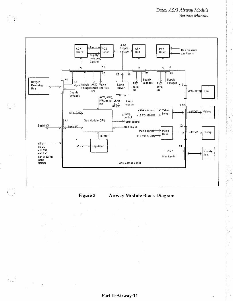
Datex AS/3 Airway Module Service Manual
| Lamp
ACX Signal abla cx Supply ASX PVX Gas pressure Board Bench Voltage Unit Board and flow in
Supply voltages, Control
X1 Xi 一 一 一 [ 1 E +
X2 rh X5 x3
o h X4 os Supply Supply xygen ygen ) Supply AČX Valve ASX voltages ΡΥΧ voltages mob
Measuing o . signal . serial serial Unit voltagesseria! controls o νο Supply 1/0 +24/+32 VE) Fan
voltages ACX, ASX, 山
PVX serial +5 Y Lamp
vo AH control жен
Valve controîs Valve 15 VD +} Valves +5 GND, i È amp ss yp, GNBB 01497 ・ | control Ш po χι Gas Module CPU -—— Pump control
Serial VO sj Serial 0 | İş... Mod key in x
Pump contrt— Pump Pump Driver
+5 Vref +15 VD, GNDD— 처
HV 一 一
+5 VL +15 V-—>) Regulator Х11 1
+15 VD GND—— Module HAV
| Key +24 /+32 VD Mod key.
GND 4 | GNDD Gas Mother Board
Figure 3 Airway Module Block Diagram
Part IT-Airway-11 ・

Datex AS/3 Airway Module Service Manual
2.2.2 Gas Sampling System
The function of the gas sampling system is to draw sample gas into the monitor gas sensors at a fixed rate and to separate impurities and condensed water from the gas flow.
Water trap
The gas sample enters the monitor through the water trap, where it is divided into two flows, main flow and side flow (see
Gas Sampling System Block Diagram). The main flow goes into the measuring system through a hydrophobic filter.
The side flow creates a slight sub-atmospheric pressure within the water trap container. This facilitates cathering the fluid removed by the hydrophobic filter.
Sampling line
The sampling line is an integral part of the total sampling system. The resistance established by the sampling line is significant when the software determines the occlusion and air- leak alarm limits during the turn-on sequence.
The small inner diameter causes fluids such as blood or mucus not to propagate within the tube, so that when the line is clogged, it is replaced.
The Nafion™ tube
A special tube (tubes A or B, and C: see Figure 7) is used to balance the sample gas humidity with that of ambient air. The tube will prevent errors caused by the effect of water vapor on gas partial pressure when humid gases are measured after calibration with dry gases. It is inserted between the water trap and the zero valve (models with i) or between the zero valve and ACX-200 measuring unit (models without i). The tube is also inserted between the CO, absorber and the zero valve.
Nafion is a trade mark of Du Pont.
Part II-Airway-12
Datex AS/3 Airway Module
Service Manual
Zero valve
The main flow passes through a solenoid valve before proceeding to the ACX-200 measuring unit. This valve is activated to establish the zero points for the ACX-200 and O,
measuring units at start-up, at 5 minutes, and after that at regular intervals. After 1-hour monitoring, the auto-zeroing is performed once an hour. When the valve is activated, room air is drawn through the CO, absorber into the internal system and the gas sensors.
Gas measuring units
After the zero valve, the gas passes through the ACX-200 and O,
measuring units. In the ACX-200 measuring unit, infrared light is passed through chambers containing the main flow gas (measurement) and a chamber containing reference gas. The measurement is made by determining the ratio between the two light intensities.
The oxygen sensor has two inputs. One input accepts the main flow and the other draws in room air for reference. The sensor uses a differential pressure transducer to compare the pressure gradient produced when both gases are exposed to an oscillating magnetic field. Both gas flows exit from a single port.
Ini model, the ASX agent identification unit is installed in parallel with the oxygen sensor. The task of the ASX unit is to identify anaesthesia agents by infrared light method used also in the ACX-200 unit.
Pressure valve
The pressure valve is used to measure the pressure gradient between the O, measurement flow and the O, reference flow.
This pressure gradient reflects the condition of the D-fend water trap filter.
Normally the pressure gradient between the O, measurement
flow and the reference flow is approximately +8 mmHg. If the software detects the gradient to be between 0 and -5 mmHg, the pressure valve will initiate pressure measurement of the reference flow. If the gradient is greater than -5 mmHg, the software triggers the message "REPLACE TRAP”.
Part II-Airway-13
Datex AS/3 Airway Module Service Manual
Flow cassettes
The internal flow rates are set using flow cassettes. These cassettes are used to set the side flow rate and the O, reference
flow rate, the flow rates through the measuring units and the
total flow rate of the sampling system.
Sampling pump and damping chamber
The sampling pump is a vibrating membrane pump driven by a 50 Hz/12 V/0.4 A square wave current.
The damping chamber is used to even out the pulsating flow and silence the exhaust flow.
Part H-Airway-14
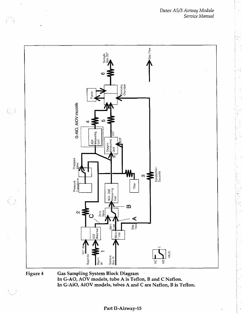
Datex AS/3 Airway Module
Service Manual
ayessog
40119548109
10 509
ados
499049
Buduogi
dung
+
=
293
o yun
in て
bulunspaW Buunsoa
i м
бд 00g-XOV
Hun
Suunsoay
XSY
sjepou AOIV
“Olv-D
SAID, 200NPSUDI]
3Jnssajid 21188844
SADA
OH apis
JAVA
ς
Ni S09
ajdwog
L IN
aly Wooy
ΝΙ 338
In G-AO, AOV models, tube A is Teflon, B and C Nafion.
In G-AiO, AiOV models, tubes A and C are Nafion, B is Teflon.
Gas Sampling System Block Diagram Figure 4
Part II-Airway-15

Datex AS/3 Airway Module Service Manual
ACX-200 Pump
Damping chamber /Filter
Sample out
-
Pressure valve
NC C Pressure transducer
Absorber
02 meosuring unit
ASX- 200
CNC
NO
Zero valve
Ges mother board side
on ο ©1 1. Constriction values of flow cassettes No € NC © Ol? are for reference onty.
O O] 4 Actua: volues moy differ. 9 ο NC=normally closed SA é
NO=normally open 5 一 引 5 C=common
Figure 5 Gas Sampling System Layout
Part II-Airway-16

Datex AS/3 Airway Module
Service Manual
Table 1 Flow Cassettes
FLOW CASSETTE CODE 50/26.0 878048 50/19.0 873800 50/16.3 878047 50/15.3 873801 50/14.1 878046 50/13.1 873802 50/12.4 878045 50/11.2 874770 50/10.4 873803 50/9.2 874509 50/8.7 873804 50/7.4 873805 50/6.5 878044 50/5.8 873806 50/5.1 878043 50/44 873807 50/3.8 878042 50/3.2 873808 50/3.0 878040 50/2.8 878039 50/25 878038 50/2.3 873809 50/2.0 878037 50/1.8 873810 50/1.6 878036 50/14 873811 50/11 873812
NOTE: The number on the cassette represents relative flow when a specific pressure is applied. Therefore 50/26.0 presents the least resistance and 50/1.1 the most.
Part l-Airway-17
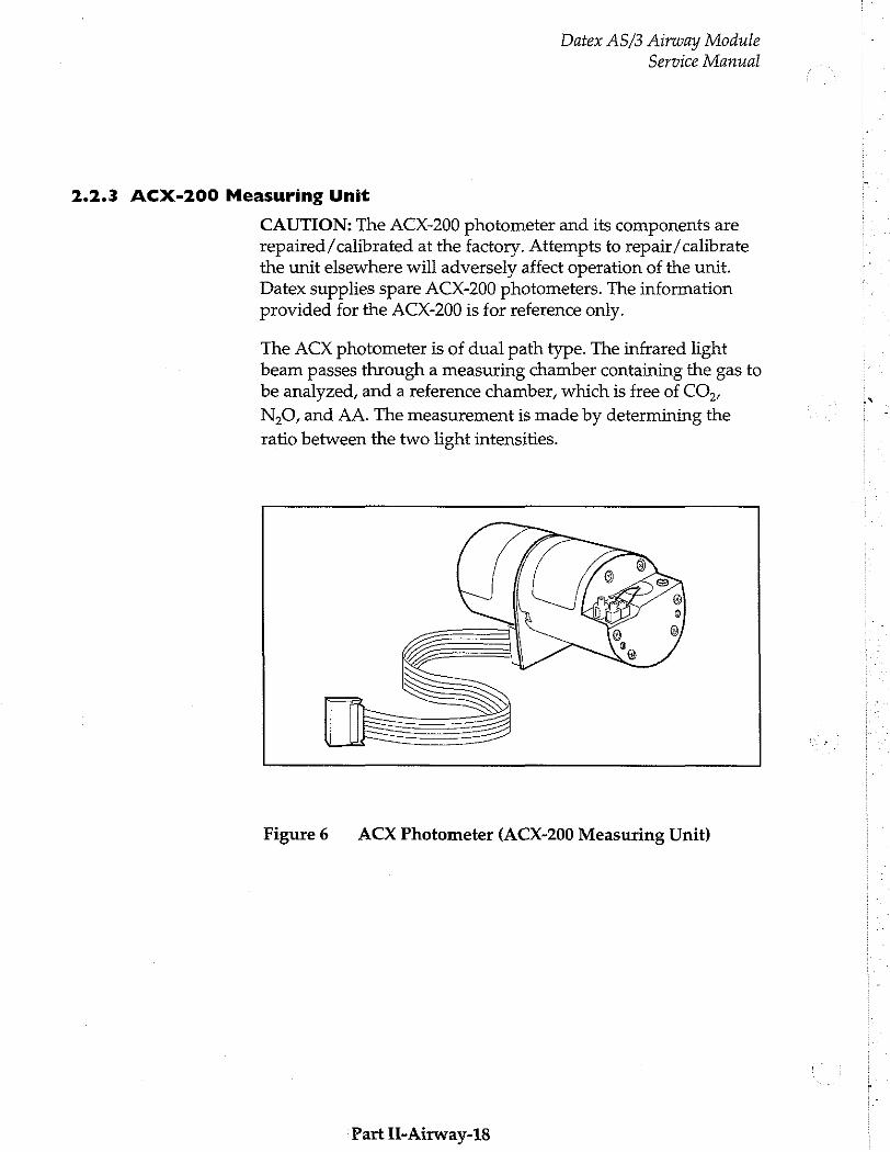
Datex AS/3 Airway Module
Service Manual
2.2.3 ACX-200 Measuring Unit
CAUTION: The ACX-200 photometer and its components are repaired/calibrated at the factory. Attempts to repair /calibrate the unit elsewhere will adversely affect operation of the unit. Datex supplies spare ACX-200 photometers. The information provided for the ACX-200 is for reference only.
The ACX photometer is of dual path type. The infrared light beam passes through a measuring chamber containing the gas to be analyzed, and a reference chamber, which is free of CO,,
N,O, and AA. The measurement is made by determining the
ratio between the two light intensities.
Figure6 ACX Photometer (ACX-200 Measuring Unit)
Part II-Airway-18
Datex AS/3 Airway Module Service Manual
A filter wheel is used to control the light from an incandescent lamp that passes through the photometer. The filters are arranged so that the light is passed sequentially:
- first at the CO, absorption wavelength through the reference chamber
- then through the measuring chamber
- finally it is blocked completely
The same sequence is repeated at the N,O and anaesthetic agent
gas absorption wavelengths.
After passing through the filters the light is reflected and focused by a mirror onto the infrared detector. This detector measures the three light levels for each gas described above.
There is an optical sensor incorporated in the photometer which detects light from a reflective surface on the filter wheel once every revolution. The pulses from this sensor are used to synchronize the electronics to the signal from the infrared detector. A stabilizing diode measures the temperature, which is needed to compensate for thermal drifts. The infrared detector, the optical sensor and the stabilizing diode are mounted on the preamplifier board.
Part II-Airway-19

Datex AS/3 Airway Module
Service Manual ,
TEMPERATURE 003, Ν20, ΛΑ
DETECTOR SIGNAL] MEASURING - CHANNEL
ACX—200 А, MEASURING の UNIT
(PHOTO PHOTOMETER ψ METER} PARAMETERS
TIMING va COZ, N20, AA PROCESSOR
SERIAL MOTOR SPEED , MOTOR Si COMMUNICATION
PRESSURE SAMPLING SYSTEM PRESSURE
AN, ACX—200 i MEASURING BOARD
GENERAL DIAGRAM
VERİ +10 VDC REFout m
10 VOC REF. +10 VDC REF. MOTOR CONTROL
MOTOR emp, (Teme. || TEMP. TEMPERATURE DRIVER SENSOR AMP.
MY | >
= OPTIC. TIMING MOTOR SWITCH PREAMP。
| GAIN CURR./ | ml PEAK SAMPLE, 5 LAMP prove, ads. var” PPocreor [MIX how 圖 MUX AD PAGA DA
a a $ a © = Now. È V = CHANNEL SELECT È MUX E PEAK SEARCH
2 < V き EE DARK TIMING co?
5 GAIN PAMPLE/ 1 SN20 = 2 BE HOLD M τα > Be +15 VDC CONST. PRES- PRES- | PRESS. SERIAL - 7 Зы BIAS sure >} sure 95 VOLT. 215 006 CURR. Sensor] 7 | AMP. ‘COMMUNICATION:
EEPROMI CALIBRATION
PARAMETERS
PH TER P/ EEPROM (OTOMETER PARAMETERS
АСХ-200 ΑΟΧ--200 때 MEASURING UNIT MEASURING BOARD
Figure 7 CO,/N,0/AA Measurement Block Diagram
Part IT-Aïrway-20
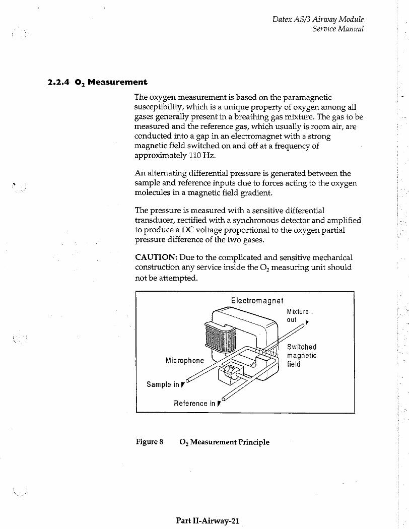
Datex AS/3 Airway Module Service Manual
2.2.4 O, Measurement
The oxygen measurement is based on the paramagnetic susceptibility, which is a unigue property of oxygen among all gases generally present in a breathing gas mixture. The gas to be measured and the reference gas, which usually is room air, are
conducted into a gap in an electromagnet with a strong magnetic field switched on and off at a freguency of approximately 110 Hz.
An alternating differential pressure is generated between the sample and reference inputs due to forces acting to the oxygen molecules in a magnetic field gradient.
The pressure is measured with a sensitive differential transducer, rectified with a synchronous detector and amplified to produce a DC voltage proportional to the oxygen partial pressure difference of the two gases.
CAUTION: Due to the complicated and sensitive mechanical construction any service inside the O, measuring unit should
not be attempted.
Electromagnet
Mixture
Switched magnetic
Microphone field
Sample in p“
Reference in r
Figure 8 O, Measurement Principle
Part IJ-Airway-21
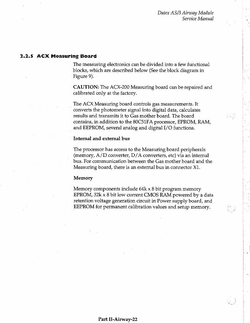
Datex AS/3 Airway Module Service Manual
2.2.5 ACX Measuring Board
The measuring electronics can be divided into a few functional blocks, which are described below (See the block diagram in Figure 9).
CAUTION: The ACX-200 Measuring board can be repaired and calibrated only at the factory.
The ACX Measuring board controls gas measurements. It converts the photometer signal into digital data, calculates results and transmits it to Gas mother board. The board contains, in addition to the 80C51FA processor, EPROM, RAM,
and EEPROM, several analog and digital I/O functions.
Internal and external bus
The processor has access to the Measuring board peripherals (memory, A/D converter, D/A converters, etc) via an internal
bus. For communication between the Gas mother board and the Measuring board, there is an external bus in connector X1.
Memory
Memory components include 64k x 8 bit program memory EPROM, 32k x 8 bit low current CMOS RAM powered by a data retention voltage generation circuit in Power supply board, and EEPROM for permanent calibration values and setup memory.
Part H-Airway-22
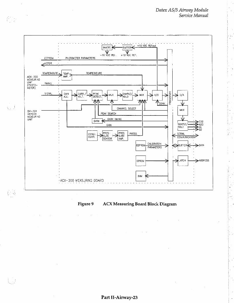
Datex AS/3 Airway Module
Service Manual
ACX-200 MEASURING UNIT
OM-101 OXYGEN
MEASURING UNIT
~10 VDC REF, +10 VDC REF. EEPROM “ PHOTOMETER PARAMETERS
MOTOR
TEMPERATURE | TEMP. TEMPERATURE PT AMP.
TIMING +
, [ x SIGNAL Syl GAIN CURR. PEAK SAMPLE ご ——> mı ai, > wx ği em wm > GITA
. | 4 A a o
‘ | cow Es V
| CHANNEL SELECT Mux
・ PEAK SEARCH
: DARK TIMING DARK 3 , SAMPLE/| , GAIN SAMP
・ Lt PRES- PRES- ・ CONST. L PRESS. SERIAL . SURE SURE Re ' CURR. SENSOR) © | AMP COMMUNICATION
: EEPRONL CALIBRATION BUFFER İL Se DATA ・ PARAMETERS 7
: EPROM e LATCH ————>ADDRESS
: RAM 'АСХ-200 MEASURING BOARD
Figure 9 ACX Measuring Board Block Diagram
Part Il-Airway-23
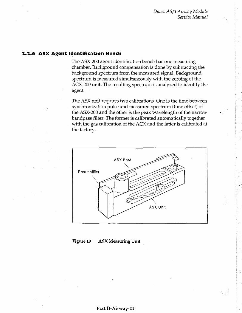
Datex AS/3 Airway Module
Service Manual
2.2.6 ASX Agent Identification Bench
The ASX-200 agent identification bench has one measuring chamber. Background compensation is done by subtracting the background spectrum from the measured signal. Background spectrum is measured simultaneously with the zeroing of the ACX-200 unit. The resulting spectrum is analyzed to identify the agent.
The ASX unit requires two calibrations. One is the time between synchronization pulse and measured spectrum (time offset) of the ASX-200 and the other is the peak wavelength of the narrow bandpass filter. The former is calibrated automatically together with the gas calibration of the ACX and the latter is calibrated at the factory.
ASX Bord
ASX Unit Figure 10 ASX Measuring Unit
Part Il-Airway-24

Datex AS/3 Airway Module
Service Manual
ASX Preamplifier Board
The absorption of infrared light is measured with a lead selenide detector. The signal is amplified and then led to the measuring board.
2.2.7 ASX Measuring Board
The measuring electronics can be divided into a few functional blocks, which are described below (See the block diagram in
Figure 11).
The ASX measuring board controls the measurement. It converts the ASX photometer signal to digital data, calculates results and communicates with the main CPU through a serial channel. The board contains, in addition to the 80C196
processor, EPROM, RAM, and EEPROM, several analog and
digital I/O functions.
Processor section
Processor is a 80C196 and works at 12 MHz. It has an internal A/D-converter with a multiplexer. One channel is used for converting temperature signal. Two others are for the measurement signal from preamplifier board.
The processor uses an internal bus to access EPROM (64k x 8 bit), SRAM (8k x 8 bit) and two D/A-converters. It
communicates with the Gas mother board through a serial channel (RXD, TXDB).
EEPROM is a 64 x 16 bit serial chip. It is partly protected so that if jumper X1 is installed the processor can erase or write the protected registers by serial communication commands. The protected section contains permanent factory calibrations.
Part II-Airway-25
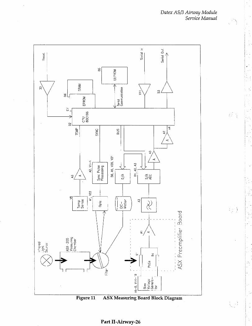
Datex AS/3 Airway Module
Service Manual
i 04008
Ja1N|OLUD3JJ
XSY
| P
у '
100 109$
| ὃν
80 |
, |
30} — 022095
| ev
| 290
RI
: |
7 У
A v/a
O
| А
ul joule:
, | 10005
HA ev
Y ja
| εν
zv id
‘ 61-71A
'8-9V ーー
-
JOJOW UONDAUNLUWIOI
Wa
-30
10195 sna
AOSd ヨ 3 ーーー
=>
LCA ‘OCA
"ον 80
J0HH 6ulss950oJd
odo sa
NAS
esind 2446
У
Tv TAN
1 961908
に
NOYdI ndo
| -
asuas Wvas
v 94291
dual |
Ev za
9A σα
{9 |
ça
ASX Measuring Board Block Diagram Figure 11
Part H-Airway-26

2.2.8 PVX Board
Datex AS/3 Airway Module
Service Manual
CAUTION: The PVX-100 measuring unit can be repaired only at the factory.
NOTE: Overpressure or negative pressure of more than 300 cmH,0 to the flow and volume tubing should never be applied.
The board is intended to perform the following tasks - Measure the pressures in airways and the speed of
breathing flow. - Calculate tidal volume, minute volume, compliance and
other useful information on patient lungs.
Pressure transducers
There are two pressure transducers on the PVX board for airway pressure measuring purposes.
The breathing flow of a patient passing through D-lite adapter creates pressure difference. This pressure difference is measured by pressure transducer, B1. Overpressure and negative pressure in airways are measured by another pressure transducer B2.
NOTE: Never apply DIFFERENTIAL pressure higher than 25 cmHLO to the spirometry tubing. Make sure that both spirometry tubes are always connected.
Temperature compensation
Temperature is measured by B1. This signal is used only for temperature compensation of the pressure transducer B1 on the PVX board.
Data processing
After the multiplexer, the signals, PRESS, FLOW0, FLOW1, and
TEMP are A/D converted for data processing.
External communication
Communication between the PVX board and the Gas mother
board is established in serial form, using the serial channel (pins
10 and 11) of CPU on the PVX board.
Part II-Airway-27
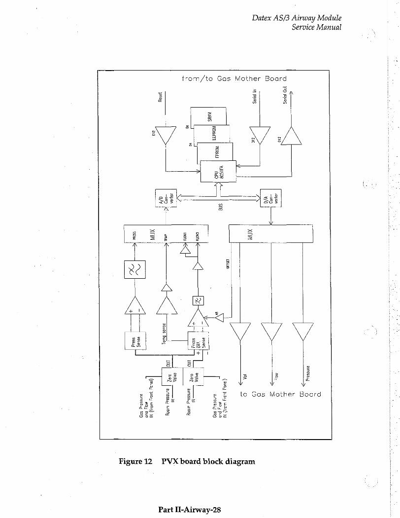
Datex AS/3 Airway Module Service Manual
from/to Gas Mother Board
100 10406 |
za 4919A -409
| va
ul 0006 |
σα ХПИ
195330 \31508
sng 000
ono «|
sa so
1401
SUSA
-409 dial
19898 a/v
ua XNA
SS3ad >
|
asuas
96614
© x
3119523 8
o s 0 £
+ Νο
o = n o o
IBA 0 Z
(leupd }U04
[ 92186914
509
AIOA o
097 NI
aunssasg 山 008
IMA M
AT | singsarg
wooy e
BUD 14024
цю)
№ Mol
Pug BjnsSajd
509
Figure 12 PVX board block diagram
Part II-Airway-28
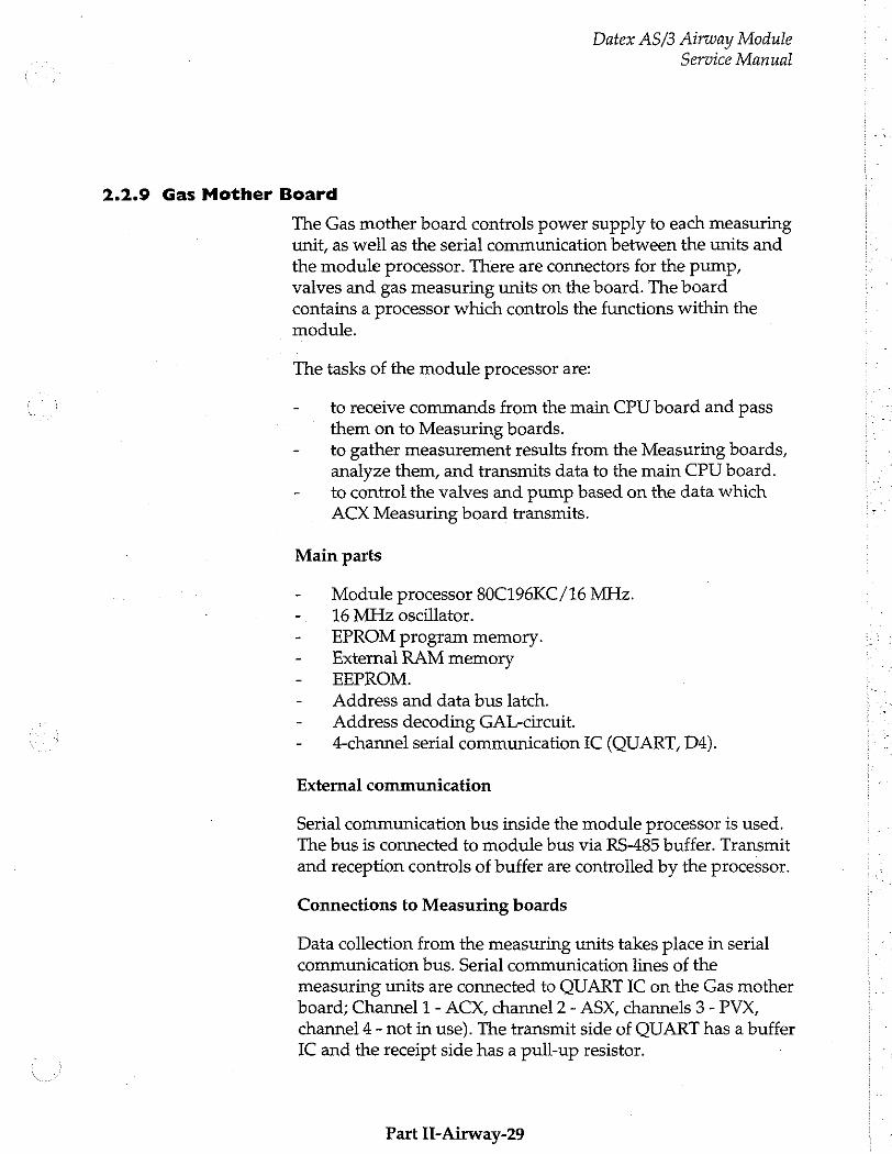
Datex AS/3 Airway Module
Service Manual
2.2.9 Gas Mother Board
The Gas mother board controls power supply to each measuring unit, as well as the serial communication between the units and
the module processor. There are connectors for the pump, valves and gas measuring units on the board. The board contains a processor which controls the functions within the module.
The tasks of the module processor are:
- to receive commands from the main CPU board and pass them on to Measuring boards.
- to gather measurement results from the Measuring boards, analyze them, and transmits data to the main CPU board.
- to control the valves and pump based on the data which ACX Measuring board transmits.
Main parts
- © Module processor 80C196KC/16 MHz. - 16 MHzoscillator. - EPROM program memory. - External RAM memory - EEPROM. - Address and data bus latch. - Address decoding GAL-circuit. - — 4-channel serial communication IC (QUART, D4).
External communication
Serial communication bus inside the module processor is used. The bus is connected to module bus via RS-485 buffer. Transmit and reception controls of buffer are controlled by the processor.
Connections to Measuring boards
Data collection from the measuring units takes place in serial communication bus. Serial communication lines of the measuring units are connected to QUART IC on the Gas mother board; Channel 1 - АСХ, channel 2 - ASX, channels 3 - PVX,
channel 4 - not in use). The transmit side of QUART has a buffer IC and the receipt side has a pull-up resistor.
Part II-Airway-29
Datex AS/3 Airway Module
Service Manual
Valves, pump, and infrared lamps control
Valves are controlled by ACX Measuring board from which the control signals are ran through buffer IC to the valve connector. OCCLUS signal controls the pressure (occlusion) vaive and ZERO signal controls the zero valve.
Control signal for the pump comes from the module processor. The signal is 50 Hz pulse-width modulated sguare wave. Control command is received from ACX Measuring board in serial communication.
Control command (LAMP) of the infrared lamps of the chambers comes from the module processor.
Key push reading
CPU reads the front panel key pushes.
Reset
Voltage supervising circuit performs power-on reset. Reset from the module bus is connected via RS-485 buffer.
Part Il-Airway-30
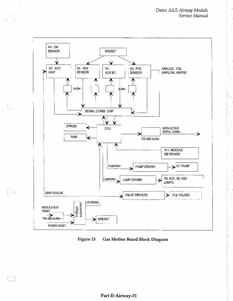
Datex AS/3 Airway Module
Service Manual
X4: OM SENSOR NRESET
X2: AOX X5: ASX xi: X3: PVX ANALOG: VOL. > UNIT SENSOR AUX VO SENSOR AWFLOW, AWPRE
TI buffer buffer
Y Y SERIAL COMM. CHIP <
Υ у EPROM CPU MODULE pus
SERIAL COMM. RAM > > <— RS-485 buffer
X11: MODULE KEYBOARD
PUMPDRV > PUMP DRIVER > X7: PUMP
LAMPDRV 、| LAMP DRIVER | | X9:ACX X8:ASX LAMPS
ZERO OCCLUS VALVE DRIVERS > X12: VALVES
5 JCPURESN x m MODULE BUS as RESET 85
Y OS
RS-465 butter >? NRESET > Lo
POWER RESET © 一 一 一
Figure 13 Gas Mother Board Block Diagram
Part II-Airway-31
Datex AS/3 Airway Module
Service Manual
2.2.10 Gas Interface Board
The Gas Interface Board, B-GAS is used for connecting an
Airway Module to the Central Unit.
The board connects Airway Module signals to the module bus and supplies voltages from the module bus to the Airway Module.
On the board there is a fuse (T4A) and some capacitors to regulate the power supply.
Part IT-Airway-32
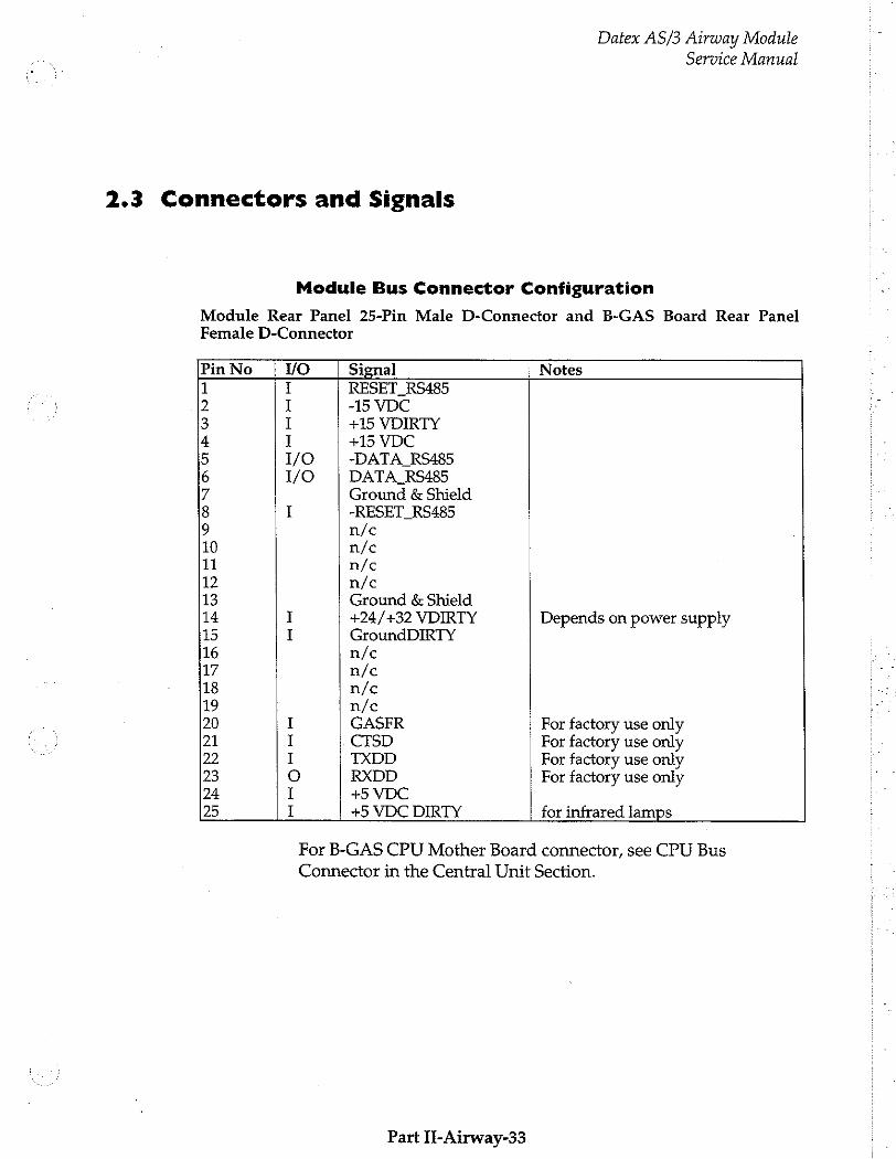
Datex AS/3 Airway Module Service Manual
2.3 Connectors and Signals
Module Bus Connector Configuration
Module Rear Panel 25-Pin Male D-Connector and B-GAS Board Rear Panel Female D-Connector
Pin No VO Signal Notes
1 I RESET_RS485 2 I -15 VDC 3 I +15 VDIRTY 4 I +15 VDC 5 1/0 -DATA_RS485 6 1/0 DATA_RS485 7 Ground & Shield 8 I -RESET_RS485 9 n/c 10 n/c 11 n/c 12 n/c 13 Ground & Shield 14 I +24/+32 VDIRTY Depends on power supply 15 I GroundDIRTY 16 n/c 17 n/c 18 n/c 19 n/c 20 I GASFR For factory use only
21 I CTSD For factory use only 22 I TXDD For factory use only 23 ο RXDD For factory use only 24 I +5 VDC 25 I +5 VDC DIRTY for infrared lamps
For B-GAS CPU Mother Board connector, see CPU Bus
Connector in the Central Unit Section.
Part II-Airway-33
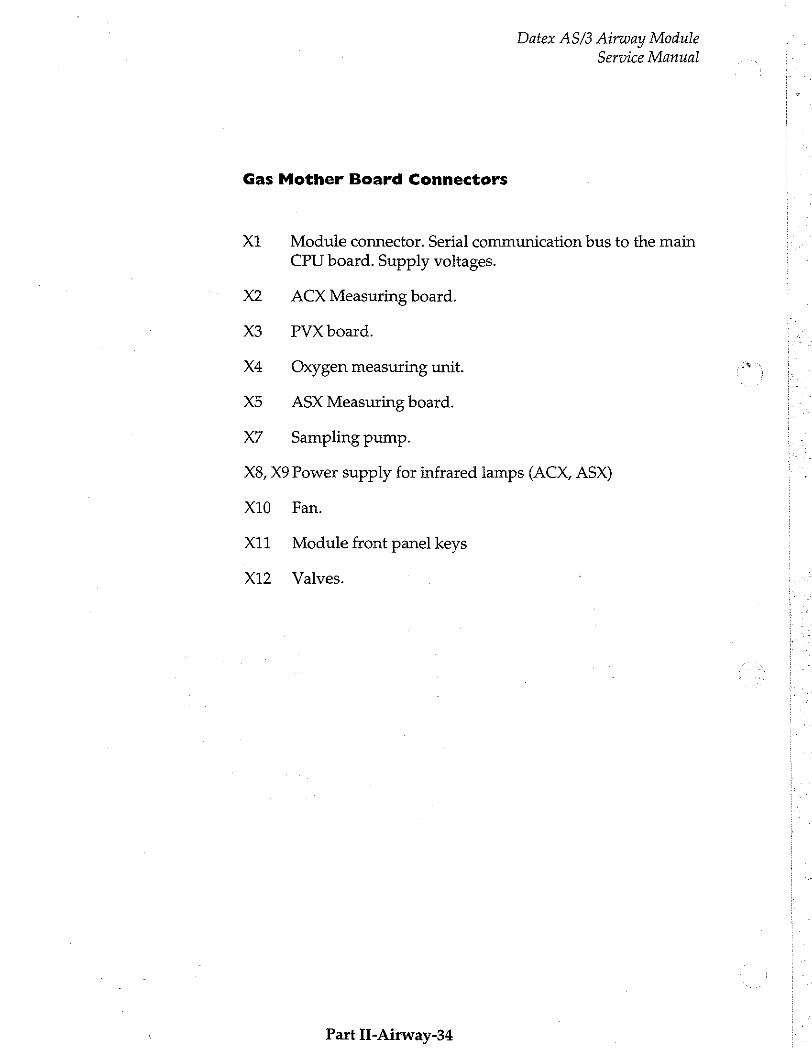
Datex AS/3 Airway Module Service Manual
Gas Mother Board Connectors
X1
X2
X3
X4
X5
X7
Module connector. Serial communication bus to the main
CPU board. Supply voltages.
ACX Measuring board.
PVX board.
Oxygen measuring unit.
ASX Measuring board.
Sampling pump.
X8, X9 Power supply for infrared lamps (ACX, ASX)
X10 Fan.
X11 Module front panel keys
X12 Valves.
Part II-Airway-34
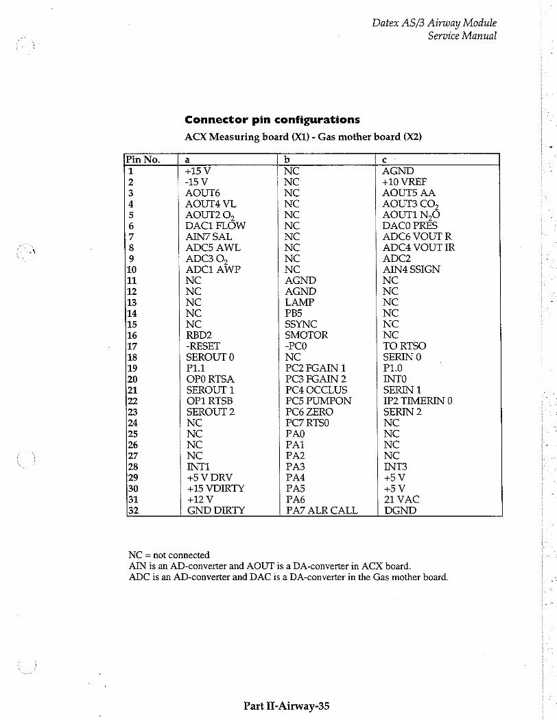
Datex AS/3 Airway Module
Service Manual
Connector pin configurations
ACX Measuring board (X1) - Gas mother board (X2)
Pin No. a b c
1 +15 V NC AGND 2 -15V NC +10 VREF 3 AOUT6 NC AOUT5 AA 4 AOUT4 VL NC AOUT3 CO, 5 AOUT2 0, NC AOUT1 N。O 6 DAC1 FLOW NC DACO PRES 7 AIN7 SAL NC ADC6 VOUT R 8 ADC5 AWL NC ADC4 VOUT IR 9 ADC3 O, NC ADC2 10 ADC1 AWP NC AIN4 SSIGN 11 NC AGND NC 12 NC AGND NC 13 NC LAMP NC 14 NC PB5 NC 15 NC SSYNC NC 16 RBD2 SMOTOR NC 17 -RESET -PCO TO RTSO 18 SEROUT 0 NC SERIN 0 19 P11 PC2 FGAIN 1 P10 (20 OPO RTSA PC3 FGAIN 2 INTO 21 SEROUT 1 PC4 OCCLUS SERIN 1 22 OP1 RTSB PC5 PUMPON IP2 TIMERIN 0 23 SEROUT 2 PC6 ZERO SERIN 2 24 NC PC7 RTSO NC 25 NC PAO NC 26 NC PAi NC 27 NC PA2 NC 28 INTI PA3 INT3 29 +5 V DRV PA4 +5У 30 +15 VDIRTY PAS +5V 31 +12V PA6 21 VAC 32 GND DIRTY PA7 ALR CALL DGND
NC = not connected ~ AIN is an AD-converter and AOUT is a DA-converter in ACX board. | ADC is an AD-converter and DAC is a DA-converter in the Gas mother board. i
Part İl-Airway-35
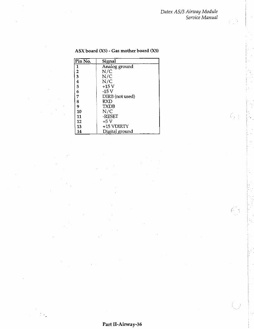
ASX board (X5) - Gas mother board (X5)
Pin No. Signal 1 Analog ground 2 N/C 3 N/C 4 N/C 5 +15 V 6 -15V 7 DIRB (not used) 8 RXD 9 TXDB 10 N/C 11 -RESET 12 +5 V B +15 VDIRTY 14 Digital ground
Part Il-Airway-36
Datex AS/3 Airway Module Service Manual
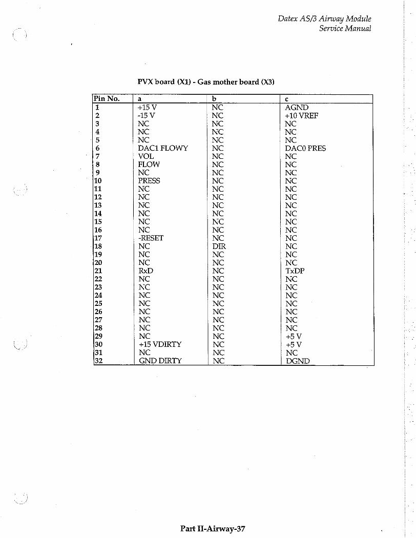
Datex AS/3 Airway Module Service Manual
PVX board (X1) - Gas mother board (X3)
Pin No. a b с
1 +15 V NC AGND 2 -15V NC +10 VREF 3 NC NC NC 4 NC NC NC 5 NC NC NC 6 DAC1 FLOWY NC DACO PRES 7 VOL NC NC 8 FLOW NC NC 9 NC NC NC 10 PRESS NC NC 1 NC NC NC 12 NC NC NC 13 NC NC NC 14 NC NC NC 15 NC NC NC 16 NC NC NC 17 -RESET NC NC 18 NC DIR NC 19 NC NC NC 20 NC NC NC 21 RxD NC TxDP 22 NC NC NC 23 NC NC NC 24 NC NC NC 25 NC NC NC 26 NC NC NC 27 NC NC NC 28 NC NC NC 29 NC NC +5V 30 +15 VDIRTY NC +5 V 31 NC NC NC 32 GND DIRTY NC DGND
Part İl-Airway-37

Datex AS/3 Airway Module Service Manual
3 SERVICE PROCEDURES
3.1 General Service Information
Usually field service is limited to replacing the faulty circuit’ boards or mechanical parts. The boards are then returned to Datex for repair.
Datex is always available for service advice. Please provide the unit serial number, full type designation, and a detailed fault description.
CAUTION: Only trained personnel with appropriate equipment shall perform the tests and repairs outlined in this section. Unauthorized service may void warranty of the unit.
NOTE: After any component replacement see Chapters Adjustments and Calibrations.
Part II-Airway-38
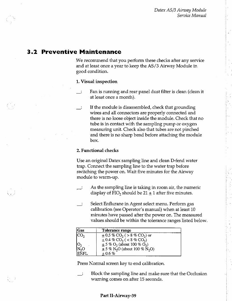
Datex AS/3 Airway Module
Service Manual
3.2 Preventive Maintenance
We recommend that you perform these checks after any service and at least once a year to keep the AS/3 Airway Module in good condition.
1. Visual inspection
Fan is running and rear panel dust filter is clean (clean it at least once a month).
If the module is disassembled, check that grounding wires and all connectors are properly connected and there is no loose object inside the module. Check that no tube is in contact with the sampling pump or oxygen measuring unit. Check also that tubes are not pinched and there is no sharp bend before attaching the module box.
2. Functional checks
Use an original Datex sampling line and clean D-fend water trap. Connect the sampling line to the water trap before switching the power on. Wait five minutes for the Airway module to warm-up.
As the sampling line is taking in room air, the numeric display of FIO, should be 21 + 1 after five minutes.
Select Enflurane in Agent select menu. Perform gas calibration (see Operator’s manual) when at least 10 minutes have passed after the power on. The measured values should be within the tolerance ranges listed below.
Gas Tolerance range
CO,
O, №0 ENFL
+0.5 % CO, (> 8 % CO,) or +0.4 % CO, (<8 % CO») +5 % O, (about 100 % O,) +5 % N30 (about 100 % N,0) + 0.6 %
Press Normal screen key to end calibration.
Block the sampling line and make sure that the Occlusion warning comes on after 15 seconds.
Part II-Airway-39
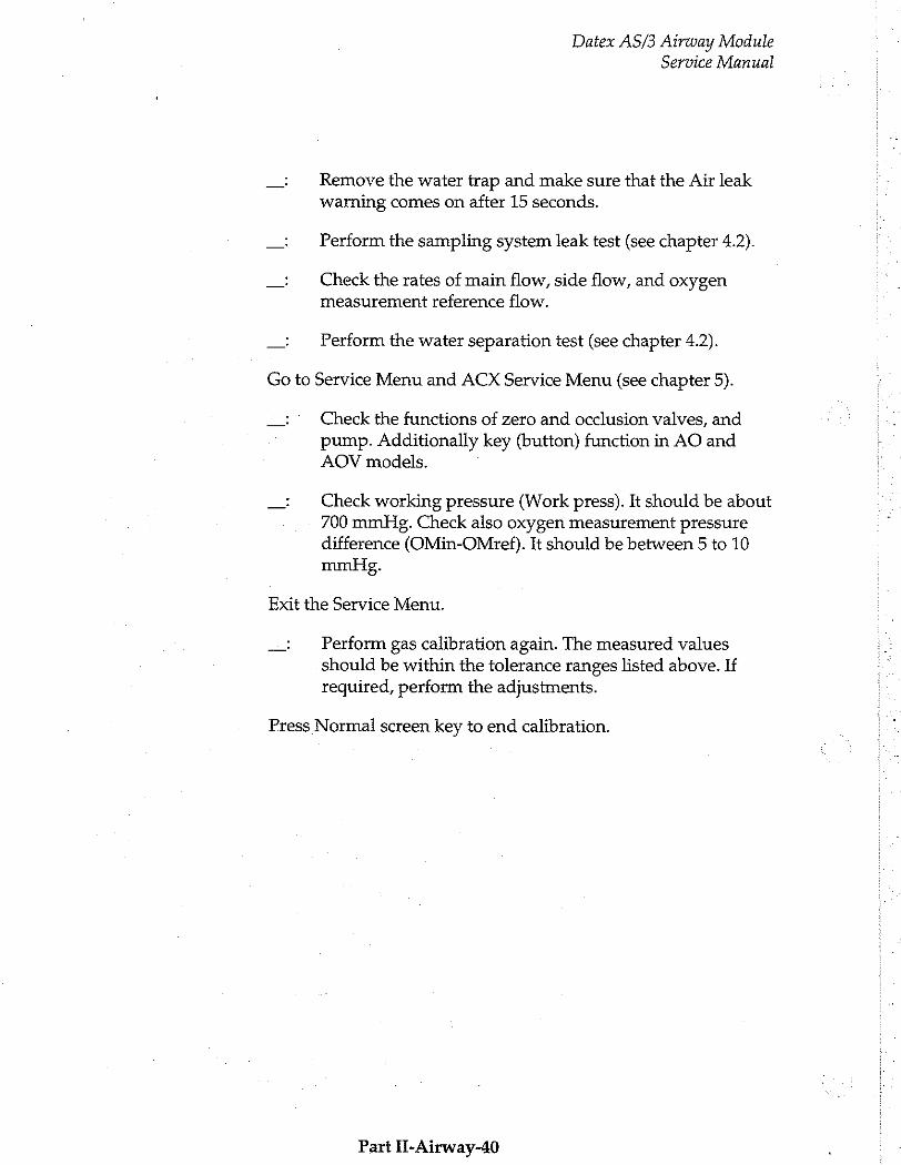
Datex AS/3 Airway Module Service Manual
Remove the water trap and make sure that the Air leak warning comes on after 15 seconds.
Perform the sampling system leak test (see chapter 4.2).
Check the rates of main flow, side flow, and oxygen
measurement reference flow.
Perform the water separation test (see chapter 4.2).
Go to Service Menu and ACX Service Menu (see chapter 5).
Check the functions of zero and occlusion valves, and
pump. Additionally key (button) function in AO and AOV models. ]
Check working pressure (Work press). It should be about 700 mmHg. Check also oxygen measurement pressure
difference (OMin-OMref). It should be between 5 to 10 mmHg.
Exit the Service Menu.
Perform gas calibration again. The measured values should be within the tolerance ranges listed above. If required, perform the adjustments.
Press Normal screen key to end calibration.
Part II-Airway-40
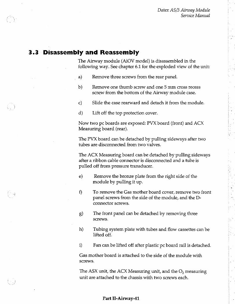
Datex AS/3 Airway Module Service Manual
3.3 Disassembly and Reassembly
The Airway module (AiOV model) is disassembled in the following way. See chapter 6.1 for the exploded view of the unit:
a) Remove three screws from the rear panel.
b) Remove one thumb screw and one 5 mm cross recess
screw from the bottom of the Airway module case.
с) Slide the case rearward and detach it from the module.
d) Lift off the top protection cover.
Now two pc boards are exposed: PVX board (front) and ACX Measuring board (rear).
The PVX board can be detached by pulling sideways after two tubes are disconnected from two valves.
The ACX Measuring board can be detached by pulling sideways after a ribbon cable connector is disconnected and a tube is pulled off from pressure transducer.
e) Remove the bronze plate from the right side of the module by pulling it up.
f) To remove the Gas mother board cover, remove two front panel screws from the side of the module, and the D-
connector screws.
5) The front panel can be detached by removing three screws.
h) Tubing system plate with tubes and flow cassettes can be lifted off.
i) Fan can be lifted off after plastic pc board rail is detached.
Gas mother board is attached to the side of the module with
screws.
The ASX unit, the ACX Measuring unit, and the O, measuring
unit are attached to the chassis with two screws each.
Part II-Airway-41
Datex AS/3 Airway Module
Service Manual
The pump and its magnetic shield can be removed from the chassis by unscrewing the two screws beneath two springs at the port side of the pump.
Damping chamber/ filter case can be slided out of hooks.
Reassembling is essentially reversing what was described above.
CAUTION: When reassembling the module, make sure that the tubes and cables are not pinched between the boards and the cover.
Part IT-Airway-42
Datex AS/3 Airway Module Service Manual
3.4 Adjustments and Calibrations
See Operator’s manual for normal gas calibration instructions.
3.4.1 Gas Sampling System Adjustment
Flow rates should be measured and possibly adjusted under the following conditions:
- After any part within the sampling system has been replaced
- Gas response is slow
NOTE: Adjust the flows with a new, clean D-fend water trap
and original Datex sampling line.
NOTE: Before adjusting the flows, make sure that there is no leakage in the sampling system.
NOTE: Let the monitor warm up for 30 minutes before measuring flow rates.
For the flow rate measurements a flowmeter with a low flow resistance and capability to measure low flow rates is required. A normal length of sampling line has to be connected to the monitor as it has a considerable effect on the flow.
The flow rates are adjusted by changing the flow resistance cassettes (constriction cassettes) in the sampling system. See Table 1 in chapter Gas Sampling System for the alternative cassettes.
The adjustments and the respective constrictions to be adjusted are shown in the next figure.
Flow Rate
If any flow rates are not correct, first replace the D-fend water trap. Then recheck the incorrect flows before adjusting the flow rates.
The sampling flow rate is measured by a flowmeter at the sampling line. The rate should be between 180 and 220 ml/min.
Part II-Airway-43
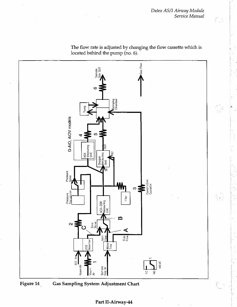
Service Manual
Datex AS/3 Airway Module
The flow rate is adjusted by changing the flow cassette which is located behind the pump (no. 6).
ЗАМА
ON ayyessag,
9
MMO|J 一 一 一
FE TE У
ap
Jaquupy? 6uldulpd
Hun
100 Buunsoay,
Ni $09
100 $09
00Z-XQYV aldwoS
9 NDA
+ Jy
vun 0:37
wooy
αἱ | Buunsosy
XSY
v diy Wooy
sjapow AOIV 'OIV- り
il 38900800]
21185914} 22138924
Part II-Airway-44
Gas Sampling System Adjustment Chart
Figure 14
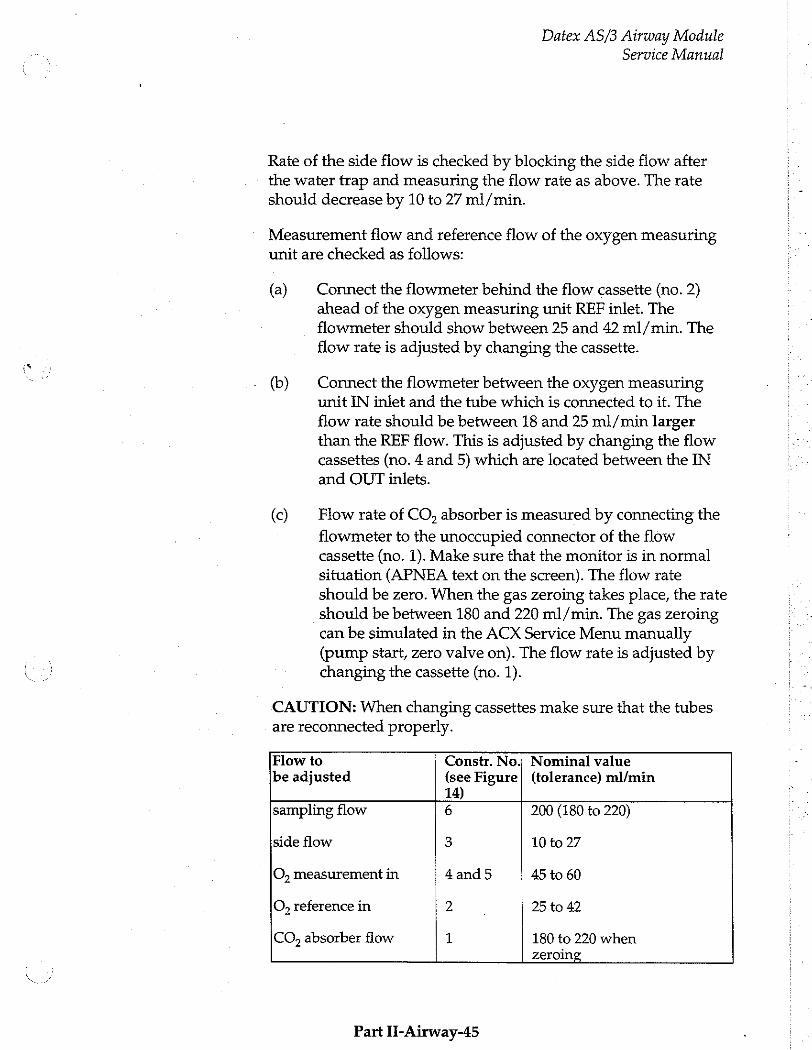
Datex AS/3 Airway Module
Service Manual
Rate of the side flow is checked by blocking the side flow after the water trap and measuring the flow rate as above. The rate should decrease by 10 to 27 ml/min.
Measurement flow and reference flow of the oxygen measuring unit are checked as follows:
{a)
(b)
(©)
Connect the flowmeter behind the flow cassette (no. 2) ahead of the oxygen measuring unit REF inlet. The flowmeter should show between 25 and 42 ml/min. The flow rate is adjusted by changing the cassette.
Connect the flowmeter between the oxygen measuring unit IN inlet and the tube which is connected to it. The flow rate should be between 18 and 25 ml/min larger than the REF flow. This is adjusted by changing the flow cassettes (no. 4 and 5) which are located between the IN and OUT inlets.
Flow rate of CO, absorber is measured by connecting the
flowmeter to the unoccupied connector of the flow cassette (no. 1). Make sure that the monitor is in normal situation (APNEA text on the screen). The flow rate
should be zero. When the gas zeroing takes place, the rate should be between 180 and 220 ml/min. The gas zeroing
can be simulated in the ACX Service Menu manually (pump start, zero valve on). The flow rate is adjusted by changing the cassette (no. 1).
CAUTION: When changing cassettes make sure that the tubes are reconnected properly.
Flow to Constr. No, Nominal value be adjusted (see Figure| (tolerance) ml/min
14) sampling flow 6 200 (180 to 220)
side flow 3 10 to 27
O, measurement in 4and5 45 to 60
O, reference in 2 , 25 to 42
CO, absorber flow 1 180 to 220 when zeroing
Part II-Airway-45
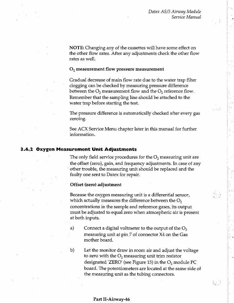
Datex AS/3 Airway Module Service Manual
NOTE: Changing any of the cassettes will have some effect on the other flow rates. After any adjustments check the other flow rates as well.
O, measurement flow pressure measurement
Gradual decrease of main flow rate due to the water trap filter clogging can be checked by measuring pressure difference between the O, measurement flow and the O, reference flow.
Remember that the sampling line should be attached to the water trap before starting the test.
The pressure difference is automatically checked after every gas zeroing.
See ACX Service Menu chapter later in this manual for further information.
3.4.2 Oxygen Measurement Unit Adjustments
The only field service procedures for the O, measuring unit are
the offset (zero), gain, and frequency adjustments. In case of any other trouble, the measuring unit should be replaced and the faulty one sent to Datex for repair.
Offset (zero) adjustment
Because the oxygen measuring unit is a differential sensor, which actually measures the difference between the O,
concentrations in the sample and reference gases, its output must be adjusted to equal zero when atmospheric air is present at both inputs.
a) Connect a digital voltmeter to the output of the O,
measuring unit at pin 7 of connector X4 on the Gas mother board.
b) Let the monitor draw in room air and adjust the voltage to zero with the O, measuring unit trim resistor
designated "ZERO" (see Figure 15) in the O, module PC
board. The potentiometers are located at the same side of the measuring unit as the tubing connectors.
Part II-Airway-46
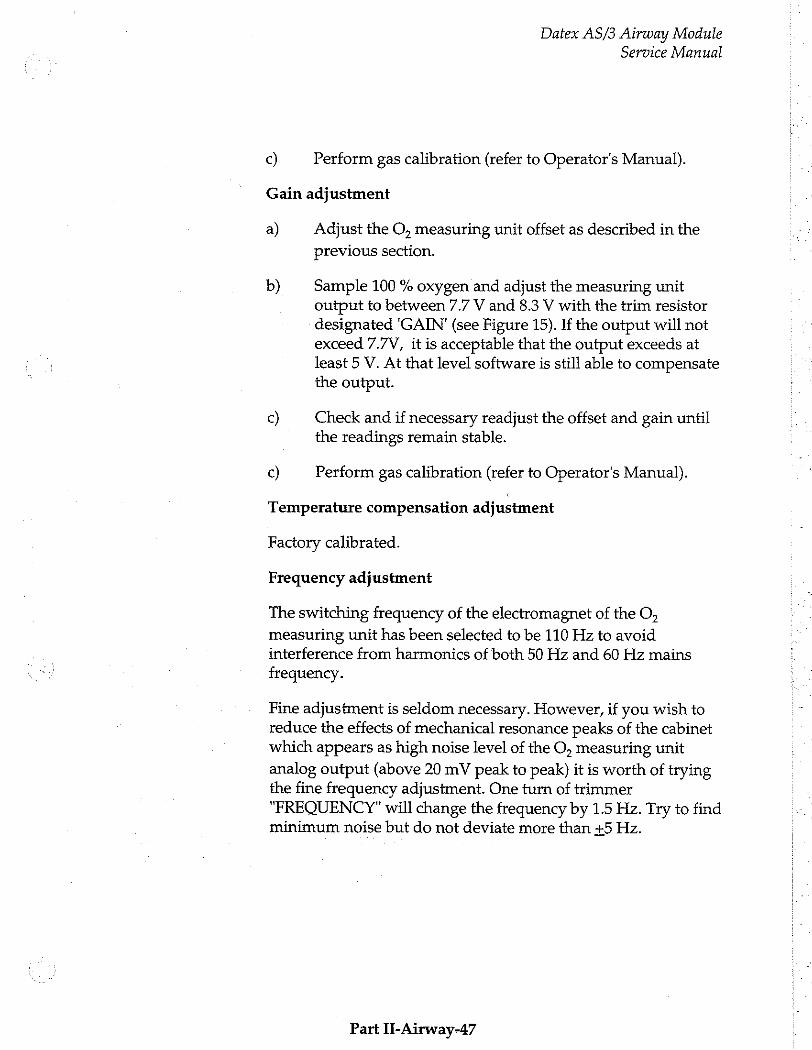
Datex AS/3 Airway Module Service Manual
c) Perform gas calibration (refer to Operator's Manual).
Gain adjustment
a) Adjust the O, measuring unit offset as described in the
previous section.
b) Sample 100 % oxygen and adjust the measuring unit output to between 7.7 V and 8.3 V with the trim resistor designated 'GAIN' (see Figure 15). If the output will not exceed 7.7V, it is acceptable that the output exceeds at least 5 V. At that level software is still able to compensate the output.
c) Check and if necessary readjust the offset and gain until the readings remain stable.
c) Perform gas calibration (refer to Operator's Manual).
Temperature compensation adjustment
Factory calibrated.
Freguency adjustment
The switching freguency of the electromagnet of the O,
measuring unit has been selected to be 110 Hz to avoid interference from harmonics of both 50 Hz and 60 Hz mains
freguency.
Fine adjustment is seldom necessary. However, if you wish to reduce the effects of mechanical resonance peaks of the cabinet which appears as high noise level of the O, measuring unit
analog output (above 20 mV peak to peak) it is worth of trying the fine freguency adjustment. One turn of trimmer "FREOUENCY" will change the freguency by 1.5 Hz. Try to find minimum noise but do not deviate more than +5 Hz.
Part II-Airway-47
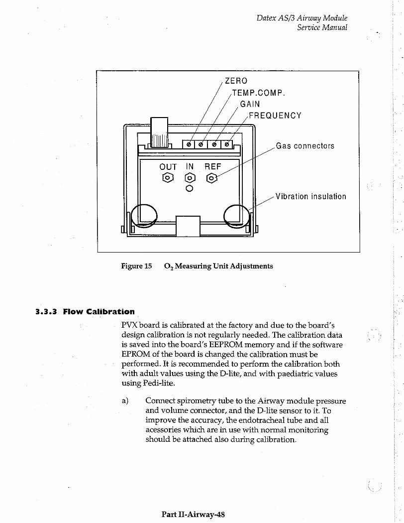
Datex AS/3 Airway Module
Service Manual
ZERO
TEMP.COMP.
GAIN
FREQUENCY Gas connectors
OUT IN REF
© © (6 0
Vibration insulation
Figure 15 O,Measuring Unit Adjustments
3.3.3 Flow Calibration
PVX board is calibrated at the factory and due to the board’s design calibration is not regularly needed. The calibration data is saved into the board’s EEPROM memory and if the software EPROM of the board is changed the calibration must be performed. It is recommended to perform the calibration both with adult values using the D-lite, and with paediatric values using Pedi-lite.
a) Connect spirometry tube to the Airway module pressure and volume connector, and the D-lite sensor to it. To
improve the accuracy, the endotracheal tube and all acessories which are in use with normal monitoring should be attached also during calibration.
Part II-Airway-48
b)
d)
Datex AS/3 Airway Module
Service Manual
Go to service menu: Monitor Setup -> Install Service (Password 16 - 4 - 34)-> Service View (26 - 23 - 8) >
Modules -> Gas Unit -> PVX -> Flow Calibration.
After the flow is zeroed ( "Zero OK" message displayed ) attach Calibration Pump or Spirometry Tester (code 884202) to the flow sensor ( D-lite or Pedi-lite ). To start
the calibration select Adult or Paediatric sensor calibration according to the flow sensor used.
Set calibration volume for adult 1000 ml and for the
pediatric patients 300ml.
Work on the calibration pump slowly, appr. 1 pump in 5 seconds, pump until 'adjust'-message appears. If you use the Spirometry Tester, perform the calibration according to the tester instructions.
Adjust the reading to match the calibration volume used ( 1000 ml for the D-lite and 300 ml for the Pedi-lite ).
Press Normal Screen to return to waveform display.
Part II-Airway-49
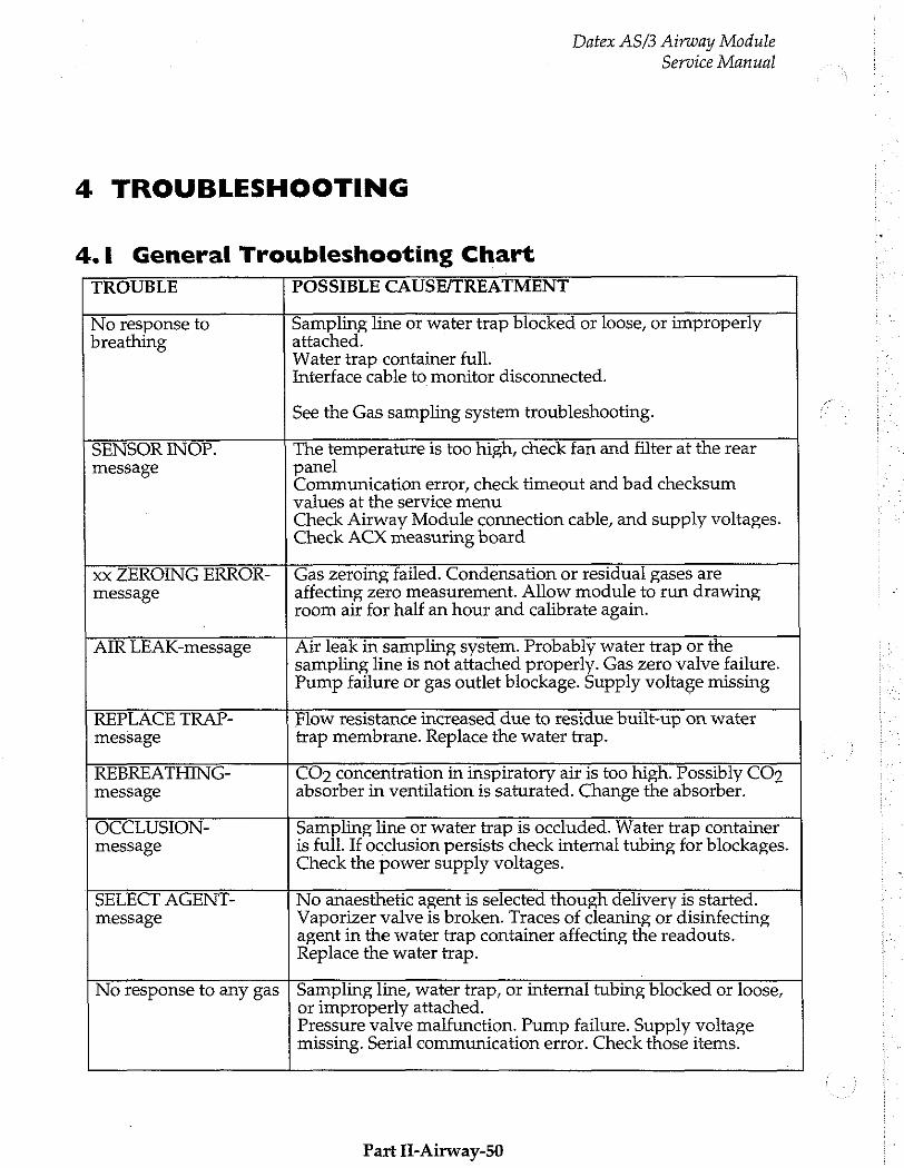
Datex AS/3 Airway Module Service Manual
4 TROUBLESHOOTING
4.1 General Troubleshooting Chart
TROUBLE POSSIBLE CAUSE/TREATMENT
No response to Sampling line or water trap blocked or loose, or improperly breathing attached.
Water trap container full. Interface cable to monitor disconnected.
See the Gas sampling system troubleshooting.
SENSOR INOP. The temperature is too high, check fan and filter at the rear message panel
Communication error, check timeout and bad checksum values at the service menu Check Airway Module connection cable, and supply voltages. Check ACX measuring board
xx ZEROING ERROR- | Gas zeroing failed. Condensation or residual gases are message affecting zero measurement. Allow module to run drawing
room air for half an hour and calibrate again.
AIR LEAK-message Air leak in sampling system. Probably waiter trap or the sampling line is not attached properly. Gas zero valve failure. Pump failure or gas outlet blockage. Supply voltage missing
REPLACE TRAP- Flow resistance increased due to residue built-up on water message trap membrane. Replace the water trap.
REBREATHING- CO» concentration in inspiratory air is too high. Possibly CO9 message absorber in ventilation is saturated. Change the absorber.
OCCLUSION- Sampling line or water trap is occluded. Water trap container message is full. If occlusion persists check internal tubing for blockages.
Check the power supply voltages.
SELECT AGENT- No anaesthetic agent is selected though delivery is started. message Vaporizer valve is broken. Traces of cleaning or disinfecting
agent in the water trap container affecting the readouts. Replace the water trap.
No response to any gas | Sampling line, water trap, or internal tubing, blocked or loose, or improperly attached. Pressure valve malfunction. Pump failure. Supply voltage missing. Serial communication error. Check those items.
Part H-Airway-50
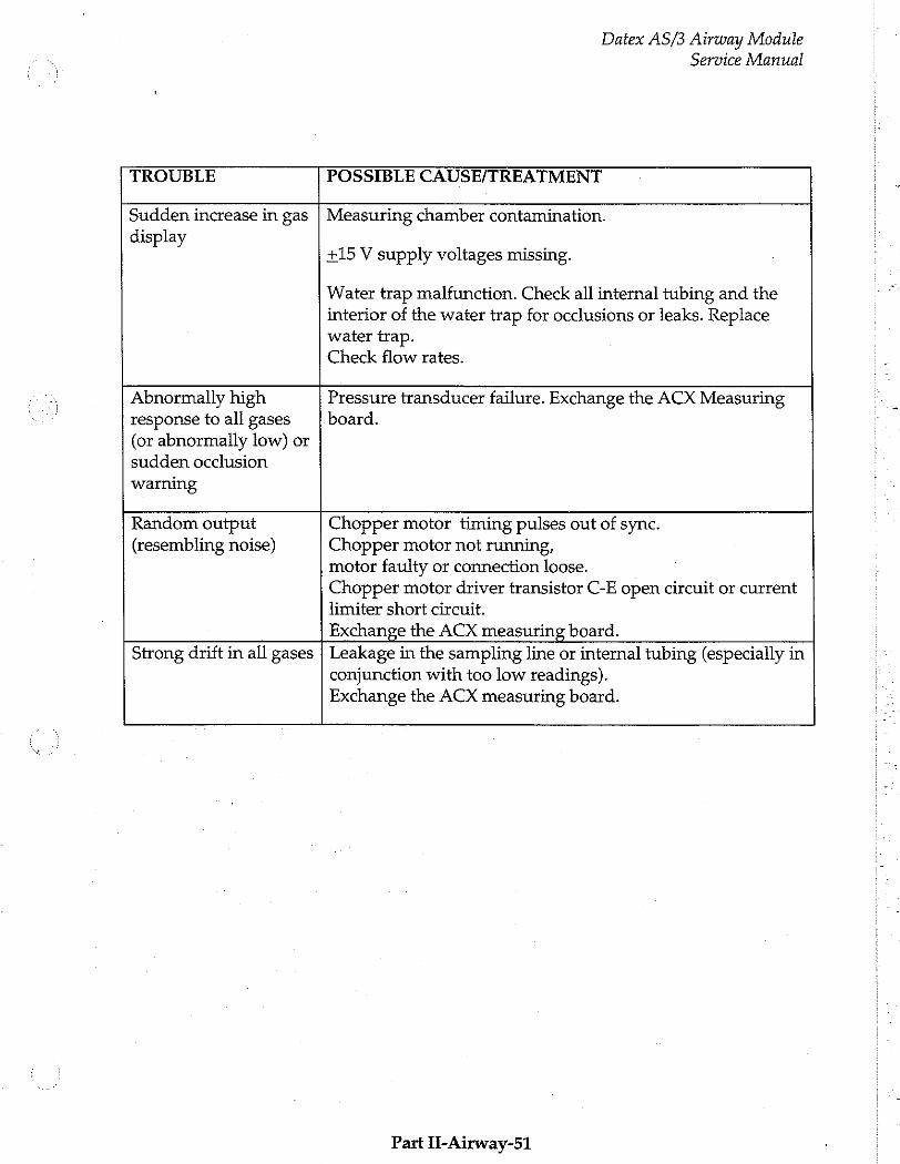
Datex AS/3 Airway Module
Service Manual
TROUBLE POSSIBLE CAUSE/TREATMENT
Sudden increase in gas display
Measuring chamber contamination.
+15 V supply voltages missing.
Water trap malfunction. Check all internal tubing and the interior of the water trap for occlusions or leaks. Replace water trap.
Check flow rates.
Abnormally high response to all gases (or abnormally low) or sudden occlusion warning
Pressure transducer failure. Exchange the ACX Measuring board.
Random output (resembling noise)
Chopper motor timing pulses out of sync. Chopper motor not running, motor faulty or connection loose. Chopper motor driver transistor C-E open circuit or current limiter short circuit. Exchange the ACX measuring board. Strong drift in all gases Leakage in the sampling line or internal tubing (especially in
conjunction with too low readings). Exchange the ACX measuring board.
Part ii-Airway-51

Supply voltage troubleshooting
Datex AS/3 Airway Module Service Manual
TROUBLE POSSIBLE CAUSE TREATMENT
“Gas module removed” +5V lost Gas module CPU not running. Check No Gas module exists after Gas Interface cable. turning the monitor on. Check +5V from module mother board
and timeout value from module service page.
Random CO, value. +5Vdirty lost Check the IR lamp resistance No CO, or AA response. (approximately 4 Ohm)and the lamp Abnormal AA mixture voltage (module mother board messages and AA selections. connectors X8 and X9) “Unknown Agent” X8 = ASX lamp(i-models) “Zero error” after zeroing X9 = ACX lamp “Calibrate Agent ID” “Sensor Inop”
“Continuous Occlusion” + 15V lost Check voltage from module mother “Sensor Inop” board X1 pin 4, X2 pin la, X3 pin la, X4
Random curve trace and gas pin 9 and X5 pin 5. digit values(resembling noise). Pressure and flow curves extremely low.
CO, value high. - 15V lost Check voltage from module mother “ Air leak” board X1 pin 2, X2 pin 2a, X3 pin 2a, X4
“Sensor Inop” pin 6 and X5 pin 6. Paw and Flow curves extremely high.
“Air Leak”-message remains on | +15V dirty lost Check voltage from module mother the screen. board X1 pin 3, X2 pin30a , X3 pin 30a,
X4 pin 1 and X5 pin 13.
Fan Stopped. +32V lost Check the fuse on Gas interface board. Check the fan and regulated fan supply voltage from module mother board connector X10.
“Calibrating gas sensor” remains on the screen. One or more of the
voltages lost: +5Vdirty, +15V,-15V, +15Vdirty
Check those voltages as above.
ACX measuring board Check whether the ACX software not communicating with version is available in the service menu.
the Gas mother board. If not, replace the ACX measuring board.
ACX measuring unit Replace the ACX measuring unit.
badly contaminated.
Part Il-Airway-52
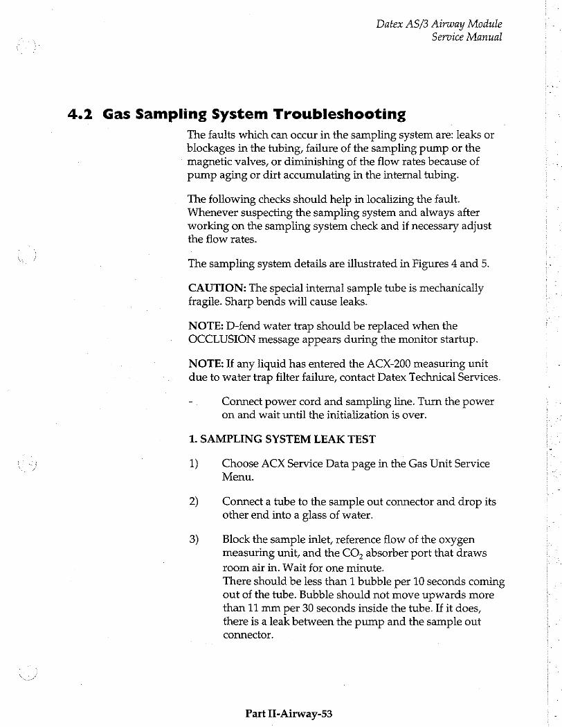
Datex AS/3 Airway Module
Service Manual
4.2 Gas Sampling System Troubleshooting
The faults which can occur in the sampling system are: leaks or blockages in the tubing, failure of the sampling pump or the magnetic valves, or diminishing of the flow rates because of pump aging or dirt accumulating in the internal tubing.
The following checks should help in localizing the fault. Whenever suspecting the sampling system and always after working on the sampling system check and if necessary adjust the flow rates.
The sampling system details are illustrated in Figures 4 and 5.
CAUTION: The special internal sample tube is mechanically fragile. Sharp bends will cause leaks.
NOTE: D-fend water trap should be replaced when the OCCLUSION message appears during the monitor startup.
NOTE: If any liquid has entered the ACX-200 measuring unit due to water trap filter failure, contact Datex Technical Services.
- Connect power cord and sampling line. Turn the power on and wait until the initialization is over.
1. SAMPLING SYSTEM LEAK TEST
1) Choose ACX Service Data page in the Gas Unit Service Menu.
2) Connect a tube to the sample out connector and drop its other end into a glass of water.
3) Block the sample inlet, reference flow of the oxygen measuring unit, and the CO, absorber port that draws
room air in. Wait for one minute. There should be less than 1 bubble per 10 seconds coming out of the tube. Bubble should not move upwards more than 11 mm per 30 seconds inside the tube. If it does, there is a leak between the pump and the sample out connector.
Part II-Airway-53

Datex AS/3 Airway Module
Service Manual
4) Perform leak test to the CO, absorber by opening zero
valve. The maximum permitted leakage is the same as above.
CAUTION: Do not turn the pump off while performing the leak test. Negative pressure in the sampling system will suck in waiter in the glass.
2. WATER SEPARATION
1) Dip the patient end of the sampling line into water quickly (about a half second) three times at 45 seconds’ interval. After that drop the end into water and lift it up when the sampling line is totally filled with water.
2) Check that all the water goes into the trap container and not into the monitor.
3. STEAM TEST FOR THE SPECIAL TUBES
Choose Halothane as anaesthetic agent and let the monitor sample room air. Then quickly feed air of 100 % relative humidity (for instance from a kettle in which you are boiling water) to the monitor. If the digital reading jumps as much as 0.1 % replace the special (Nafion) tubes.
Gas Sampling System Troubleshooting Chart
Part YI-Airway-54
Datex AS/3 Airway Module Service Manual
4.3 O, Measurement Troubleshooting
Because of the complex and very sensitive construction of the oxygen measuring unit no repairs should be attempted inside the unit. Instead, if the fault has been found in the measuring unit itself, it should be replaced and the faulty unit be sent to Datex for repair.
In cases of no response to O, or strong drift, check the tubing for
loose connections, blockages and leaks.
CAUTION: Never apply overpressure to the O, measuring unit
as the pressure transducer may be permanently damaged.
If the message ‘O, zero error’ is displayed check the O,
measuring unit output voltage on Gas mother board (see Section Offset adjustment).
If the adjustment range of the (software) calibration is insufficient check the O, measuring unit output voltage and
adjust the gain if necessary (see Section Gain adjustment).
If there are problems with O, response time check the O,
measurement flow rate and adjust it if necessary (see Section Gas Sampling System Adjustments).
If the O, signal is noisy, check the measurement unit suspension.
Freguency adjustment may help in some cases (see Section Freguency adjustment).
Part 1l-Airway-55
Datex AS/3 Airway Module
Service Manual
4.4 ACX Troubleshooting
CAUTION: The measuring unit ACX-200 can be repaired and calibrated only at the factory. Due to sensitivity of the measuring chamber surface, the measuring chamber of ACX-200 should not be attempted to clean with any detergent, not even with water.
The ACX troubleshooting is carried out in the General Troubleshooting scheme. The ACX testing is explained at the ACX Service Information section, please refer to it.
Part IT-Airway-56
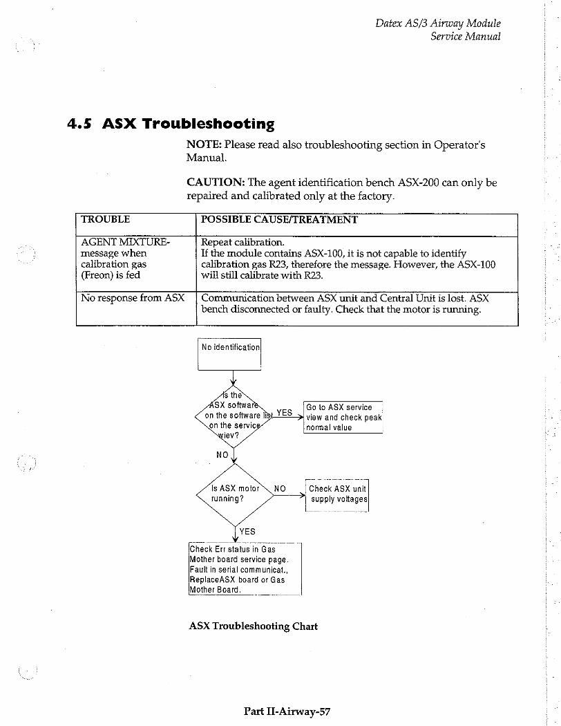
Datex AS/3 Airway Module Service Manual
4.5 ASX Troubleshooting
NOTE: Please read also troubleshooting section in Operator's Manual.
CAUTION: The agent identification bench ASX-200 can only be repaired and calibrated only at the factory.
TROUBLE POSSIBLE CAUSE/TREATMENT
AGENT MIXTURE- Repeat calibration. message when If the module contains ASX-100, it is not capable to identify calibration gas calibration gas R23, therefore the message. However, the ASX-100 (Freon) is fed will still calibrate with R23.
No response from ASX Communication between ASX unit and Central Unit is lost. ASX bench disconnected or faulty. Check that the motor is running.
No identification
Go to ASX service —— > view and check peak
normal value
Is ASX motor Check ASX unit
running? ~ “| supply voltages
Check Err status in Gas Mother board service page. Fault in serial communicat., ReplaceASX board or Gas Mother Board.
ASX Troubleshooting Chart
Part II-Airway-57
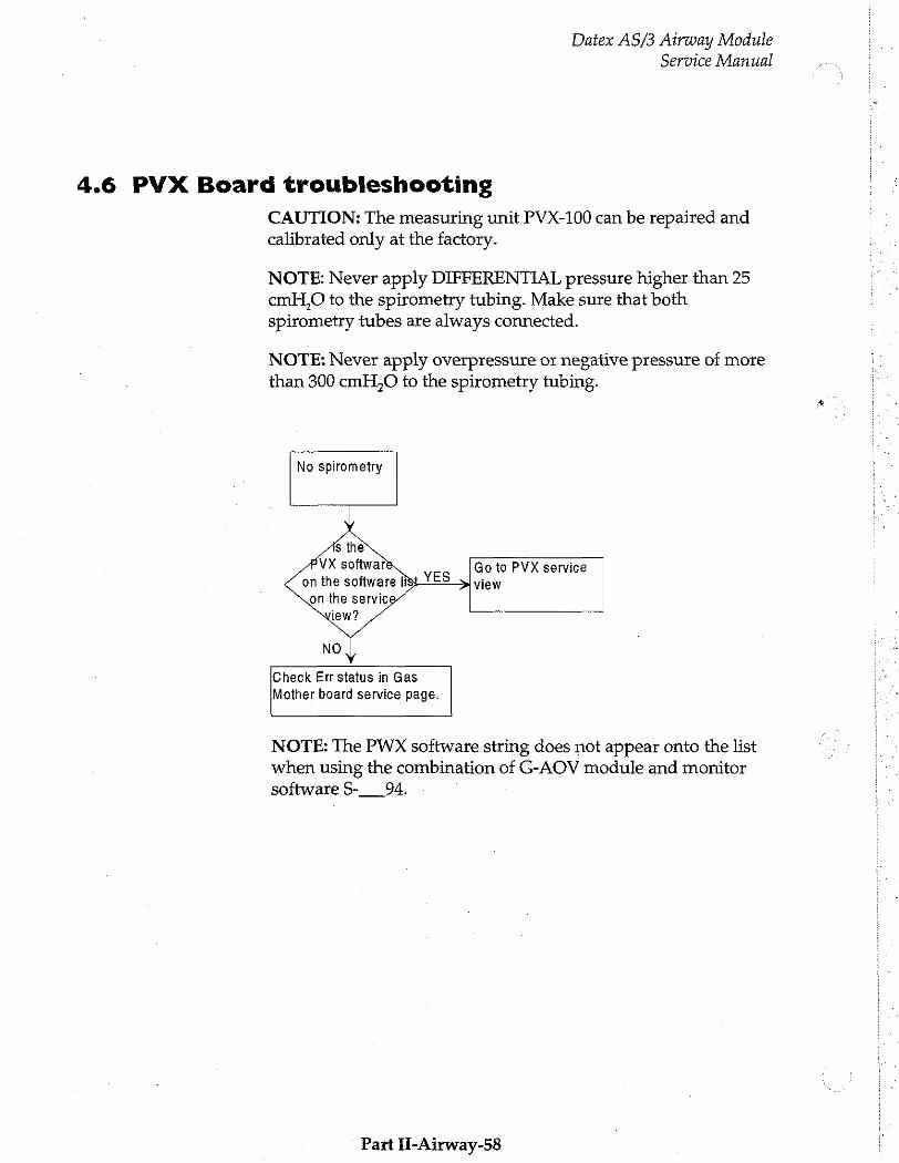
Datex AS/3 Airway Module Service Manual
4.6 PVX Board troubleshooting
CAUTION: The measuring unit PVX-100 can be repaired and calibrated only at the factory.
NOTE: Never apply DIFFERENTIAL pressure higher than 25 cmH,0 to the spirometry tubing. Make sure that both spirometry tubes are always connected.
NOTE: Never apply overpressure or negative pressure of more than 300 cmH,O to the spirometry tubing.
No spirometry
Go to PVX service view
Check Err status in Gas
Mother board service page.
NOTE: The PWX software string does not appear onto the list when using the combination of G-AOV module and monitor software S-___94,
Part H-Airway-58
Datex AS/3 Airway Module
Service Manual
4.7 Gas Mother Board Troubleshooting
Due to the complexity of the LSI circuitry there are only a few faults in the CPU digital electronics that can be located without special equipment.
Check that the RAM, EPROM, CPU and other I.C.'s that are on
the socket are properly.
See Gas mother board Service pages for more information.
Instructions After Replacing the Software or Gas Mother Board
After replacing the software or Gas mother board board:
- perform the gas calibration.
- re-establish previously used settings or inform the monitor user that settings are default values.
Part II-Airway-59
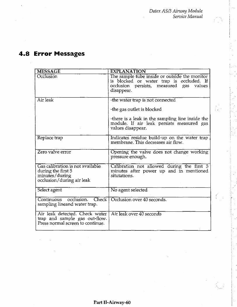
4.8 Error Messages
Datex AS/3 Airway Module
Service Manual
MESSAGE EXPLANATION Occlusion The sample tube inside or outside the monitor
is blocked or water trap is occluded. If occlusion persists, measured gas values disappear.
Air leak -the water trap is not connected
-the gas outlet is blocked
-there is a leak in the sampling line inside the module. If air leak persists measured gas values disappear.
Replace trap Indicates residue build-up on the water trap membrane. This decreases air flow.
Zero valve error Opening the valve does not change working pressure enough.
Gas calibration is not available during the first 5 minutes / during occlusion / during air leak
Calibration not allowed during the first 5 minutes after power up and in mentioned situtations.
Select agent No agent selected
Continuous occlusion. Check sampling lineand water trap.
Occlusion over 40 seconds.
Air leak detected. Check water trap and sample gas out-flow. Press normal screen to continue. Air leak over 40 seconds
Part II-Airway-60
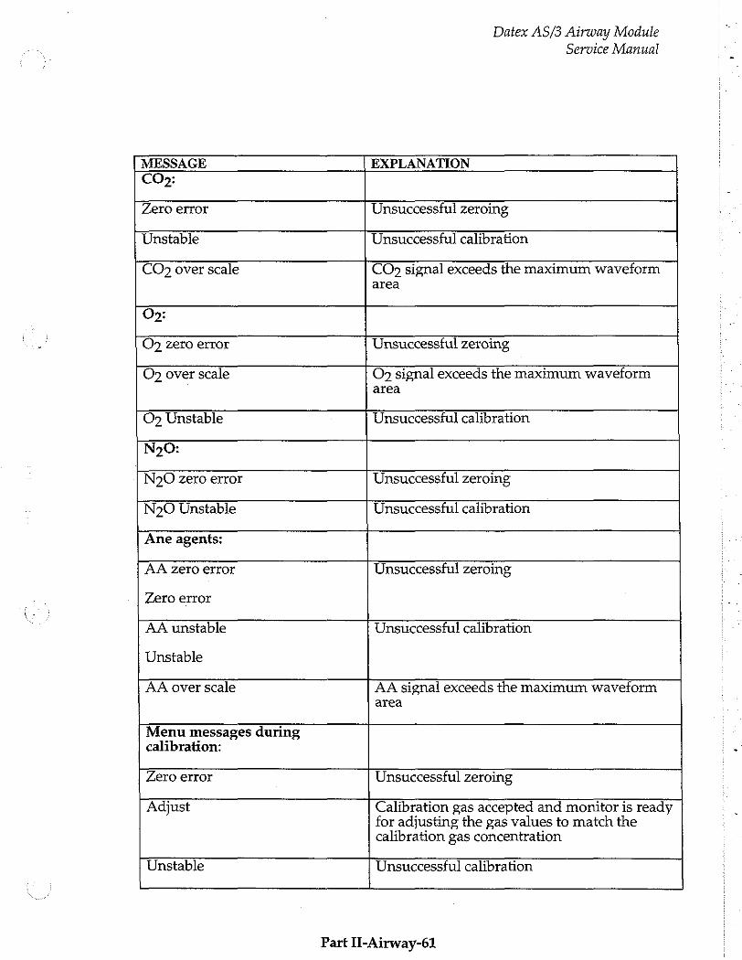
Datex AS/3 Airway Module Service Manual
MESSAGE EXPLANATION CO»:
Zero error Unsuccessful zeroing
Unstable Unsuccessful calibration
CO: over scale CO signal exceeds the maximum waveform area
Os:
Og zero error Unsuccessful zeroing
O over scale Os signal exceeds the maximum waveform area
Op Unstable Unsuccessful calibration
N20:
N20 zero error Unsuccessful zeroing
N20 Unstable Unsuccessful calibration
Ane agents:
AA zero error
Zero error
Unsuccessful zeroing
AA unstable
Unstable
Unsuccessful calibration
AA over scale AA signal exceeds the maximum waveform
area
Menu messages during calibration:
Zero error Unsuccessful zeroing
Adjust Calibration gas accepted and monitor is ready for adjusting the gas values to match the calibration gas concentration
Unstable Unsuccessful calibration
Part II-Airway-61
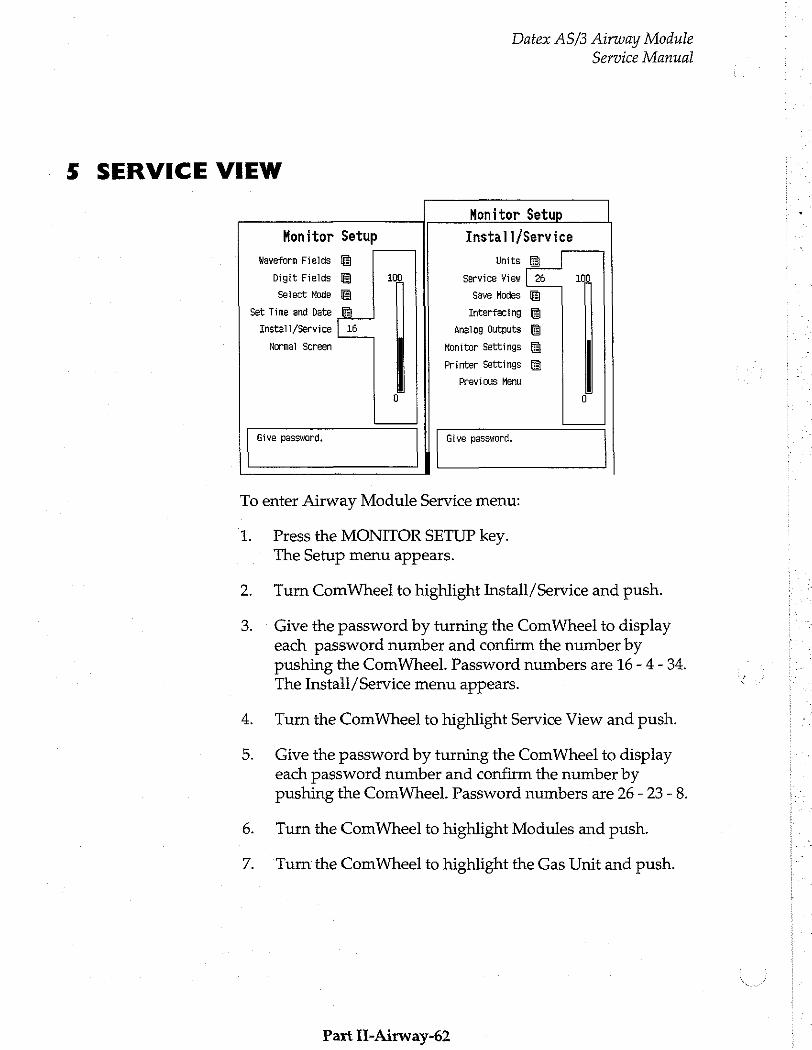
Datex AS/3 Airway Module Service Manual
5 SERVICE VIEW
Monitor Setup
Monitor Setup Install/Service
waveform Fields Units
Digit Fields 100 Service View | 26 100
Select Mode Save Modes
Set Time and Date Interfacing
Install/Service | 16 Analog Outputs
Normal Screen Monitor Settings
Printer Settings
Previous Menu
0 0
Give password. Give password.
To enter Airway Module Service menu:
1. Press the MONITOR SETUP key. The Setup menu appears.
Turn ComWheel to highlight Install/Service and push.
Give the password by turning the ComWheel to display each password number and confirm the number by pushing the ComWheel. Password numbers are 16 - 4 - 34. The Instail/Service menu appears.
Turn the ComWheel to highlight Service View and push.
Give the password by turning the ComWheel to display each password number and confirm the number by pushing the ComWheel. Password numbers are 26 - 23 - 8.
Turn the Com Wheel to highlight Modules and push.
Turn the ComWheel to highlight the Gas Unit and push.
Part II-Airway-62

Datex AS/3 Airway Module
Service Manual
5.1 Gas Mother Board
Mother Board Service Data
Previous Menu GAS ACK ASK РУХ C Û Oper state £ 5
ERR status LE Č € 0 Serial comm FFFF FFFE £ 0 Rep status EFFC С 타다 FEFF
Gen sta 0
Timeouts 65525 Bad checksum: 65535 Bad c-s by me 1
Service Data
Oper State
Internal operation state of the module: 0...9 function performed, if staying on, failure is
indicated 10...29 Initialization
30...39 Normal operation state 40...49 Zeroing 50...59 Calibrating
Part II-Airway-63
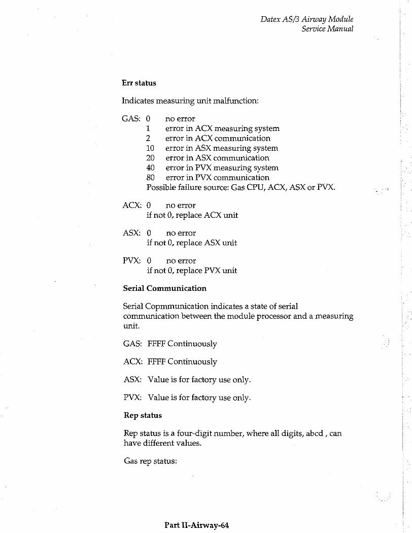
Datex AS/3 Airway Module
Service Manual
Err status
Indicates measuring unit malfunction:
GAS: 0 no error
1 error in ACX measuring system 2 error in ACX communication
10 error in ASX measuring system 20 error in ASX communication
40 error in PVX measuring system 80 error in PVX communication
Possible failure source: Gas CPU, ACX, ASX or PVX.
ACX: 0 no error
if not 0, replace ACX unit
ASX: 0 no error
if not 0, replace ASX unit
PVX: 0 no error
if not 0, replace PVX unit
Serial Communication
Serial Copmmunication indicates a state of serial communication between the module processor and a measuring unit.
GAS: FFFF Continuously
ACX: FFFF Continuously
ASX: Value is for factory use only.
PVX: Value is for factory use only.
Rep status
Rep status is a four-digit number, where all digits, abcd , can have different values.
Gas rep status:
Part l-Airway-64

Datex AS/3 Airway Module Service Manual
a 0 Nosevoflurane or desflurane measurement available
3 ACX can measure sevoflurane and desflurane
b: 0 No gas measurements available F CO2, 02 N20 and AA measuremnts available
3 CO2 and O2 available
c. 0 No ACX, ASX, nor PVX board running
1 ACXboard running 3 ACXand ASX board running 5 ACX and PVX board running 7 ACX, ASX and PVX board running
d 0 Normal operation state 1 Occlusion 2 Aïrleak 4 Other sampling system error 8 Replace trap
ACX rep status:
a empty Normal operation state 1 ACX initialization
b empty Normal operation state 2 Occlusion 4 Air leak
c C Normal operation state others values used in manuafcture’s testing
d 0 Normal operation state others values used in manuafcture’s testing
АСХ rep status FFFF continuously
PVX rep status FFFF continuously
General Status 0 Normal operation state
8000 Initialization
If not 0 or 8000, replace the Gas mother board.
Part 11-Airway-65
Datex AS/3 Airway Module Service Manual
Timeouts is a cumulative number that indicates how many times the module has not responded to the monitor's inquiry. Bad checksums is also a cumulative number that indicates how many times communication from the module to monitor broke down (first line) and from monitor to the module broke down (second line). Bad c-s by mod is a cumulative number that indicates how many communication errors the module has detected. The monitor starts counting these items at power up and resets
to zero at power off. The nonzero values do not indicate a failure, but the continuous counting indicates either serial communication failure or module not in place.
The timeouts etc numbers should not grow faster than 50/s.
Part II-Airway-66

Datex AS/3 Airway Module Service Manual
5.2 ACX Service menu
ACK Service Data
Pump ctrl 202 Uz Nau ΔΑ Fall time 280 440 320 400
Zero valve ctrl | Noise OFF 0 0 0 0 Calib zero 28380 16325 46869 25765
Pres valve ctr} gain 9060 8437 4686 21838 Ex 8 2090 0 -2 p
Noise Meas Insp 8 2090 9 -2
i Pressures: Ambient 765 Fall time Meas Work gress 7 2 sero 53
i re: in-re Previous Menu Tera chnl 725
Pump ON - Zero valve OFF Pres valve UFF ACX temp 32
C02-02 Delay 400 C02-N20 Delay 80 CO2-AA Delay 240 AUX ASK Delay 676
Timeouts 0 Bad checksums 0 Bad c-s by moc 0
Menu items:
1. Turn pump on/off
2. Turn zero valve on/off
3. Turn pressure valve on/off
4. Noise measurement
5 Fall time measurement
6 Return to previous menu
Fall time
Fall time indicates the response time of the measuring units. Select ‘Fall time meas’ from the menu. Notice that text ‘feed’ appears under each gas. Feed the calibration gas until every | ‘feed’ is replaced by ‘start’. Remove the sampling line quickly from the gas source.
Check that fall times are:
O2 < 480) ms
Part II-Airway-67
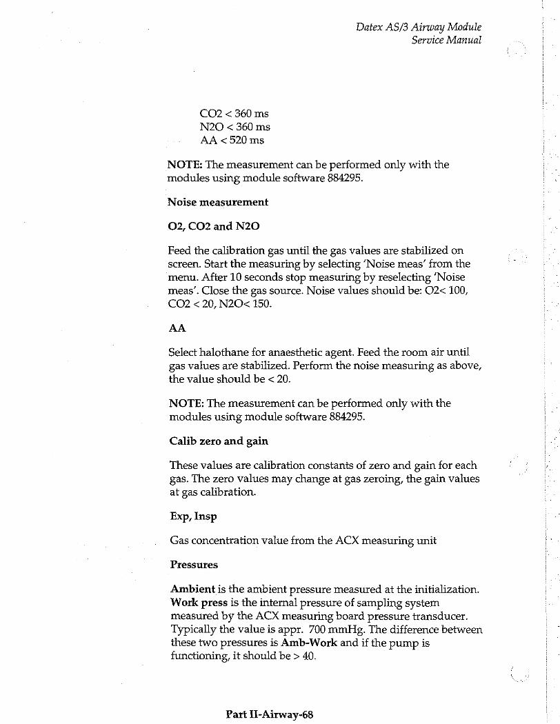
Datex AS/3 Airway Module Service Manual
CO2 < 360 ms
N20 < 360 ms
AA <520 ms
NOTE: The measurement can be performed only with the modules using module software 884295.
Noise measurement
O2, CO2 and N20
Feed the calibration gas until the gas values are stabilized on screen. Start the measuring by selecting ‘Noise meas’ from the menu. After 10 seconds stop measuring by reselecting ‘Noise meas’. Close the gas source. Noise values should be: O2< 100, CO2 < 20, N2O< 150.
AA
Select halothane for anaesthetic agent. Feed the room air until gas values are stabilized. Perform the noise measuring as above,
the value should be < 20.
NOTE: The measurement can be performed only with the modules using module software 884295.
Calib zero and gain
These values are calibration constants of zero and gain for each gas. The zero values may change at gas zeroing, the gain values at gas calibration.
Exp, Insp
Gas concentration value from the ACX measuring unit
Pressures
Ambient is the ambient pressure measured at the initialization. Work press is the internal pressure of sampling system measured by the ACX measuring board pressure transducer. Typically the value is appr. 700 mmHg. The difference between these two pressures is Amb-Work and if the pump is functioning, it should be > 40.
Part II-Airway-68
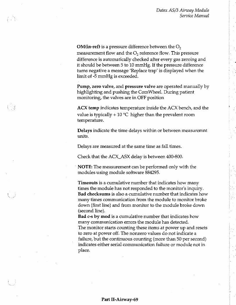
Datex AS/3 Airway Module
Service Manual
OM(in-ref) is a pressure difference between the O,
measurement flow and the O, reference flow. This pressure
difference is automatically checked after every gas zeroing and it should be between 5 to 10 mmHg. If the pressure difference turns negative a message ‘Replace trap’ is displayed when the limit of -5 mmHg is exceeded.
Pump, zero valve, and pressure valve are operated manually by highlighting and pushing the ComWheel. During patient monitoring, the valves are in OFF position
ACX temp indicates temperature inside the ACX bench, and the
value is typically + 10 °C higher than the prevalent room temperature.
Delays indicate the time delays within or between measuremnt units.
Delays are measured at the same time as fail times.
Check that the ACX_ASX delay is between 400-800.
NOTE: The measurement can be performed only with the modules using module software 884295.
Timeouts is a cumulative number that indicates how many times the module has not responded to the monitor's inquiry. Bad checksums is also a cumulative number that indicates how many times communication from the module to monitor broke down (first line) and from monitor to the module broke down (second line). Bad c-s by mod is a cumulative number that indicates how many communication errors the module has detected. The monitor starts counting these items at power up and resets to zero at power off. The nonzero values do not indicate a failure, but the continuous counting (more than 50 per second) indicates either serial communication failure or module not in place.
Part II-Airway-69
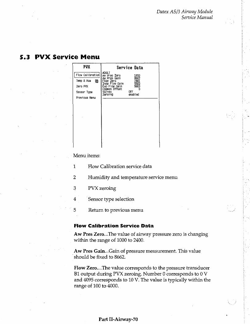
Datex AS/3 Airway Module
Service Manual
5.3 PVX Service Menu
РУХ Service Data - T ADULT
Fiow Calibration | aw Pres Zero 1933 dw Pres Gain 8662
Temp & Hum Flow Zero | 2301 Insp Flow Gain 5500
Zero PYX Exp Flow Gain 5800 Common Offset 0
Sensor Type Yalves Zeroing enabled
Previous Nenu
Menu items:
1 Flow Calibration service data
2 Humidity and temperature service menu.
3 PVX zeroing
4 Sensor type selection
Return to previous menu
Flow Calibration Service Data
Aw Pres Zero...The value of airway pressure zero is changing within the range of 1000 to 2400.
Aw Pres Gain...Gain of pressure measurement. This value should be fixed to 8662.
Flow Zero....The value corresponds to the pressure transducer BI output during PVX zeroing. Number 0 corresponds to 0 V and 4095 corresponds to 10 V. The value is typically within the range of 100 to 4000.
Part II-Airway-70
Datex AS/3 Airway Module Service Manual
Insp Flow Gain...Gain of inspired gas volume. Typically the value is between 5000 and 9000 depending on which sensor is used (adult/pediatric).
Exp Flow Gain...Gain of expired gas volume. Typically the value is between 5000 and 9000 depending on which sensor is used (adult/pediatric).
*Common Offset...Cancels common error which is caused by pressure from the pressure transducers. This is a transducer's own constant. The value should be between -230 and +230.
Valves...Position of zero valves.
Zeroing....Automatic zeroing is cancelled (disabled) or active (enabled).
NOTE: Items marked with asterisk (*) are not to be changed.
NOTE: The shown values are for the Adult module only. Changing the mode does not change the values.
Part H-Airway-71
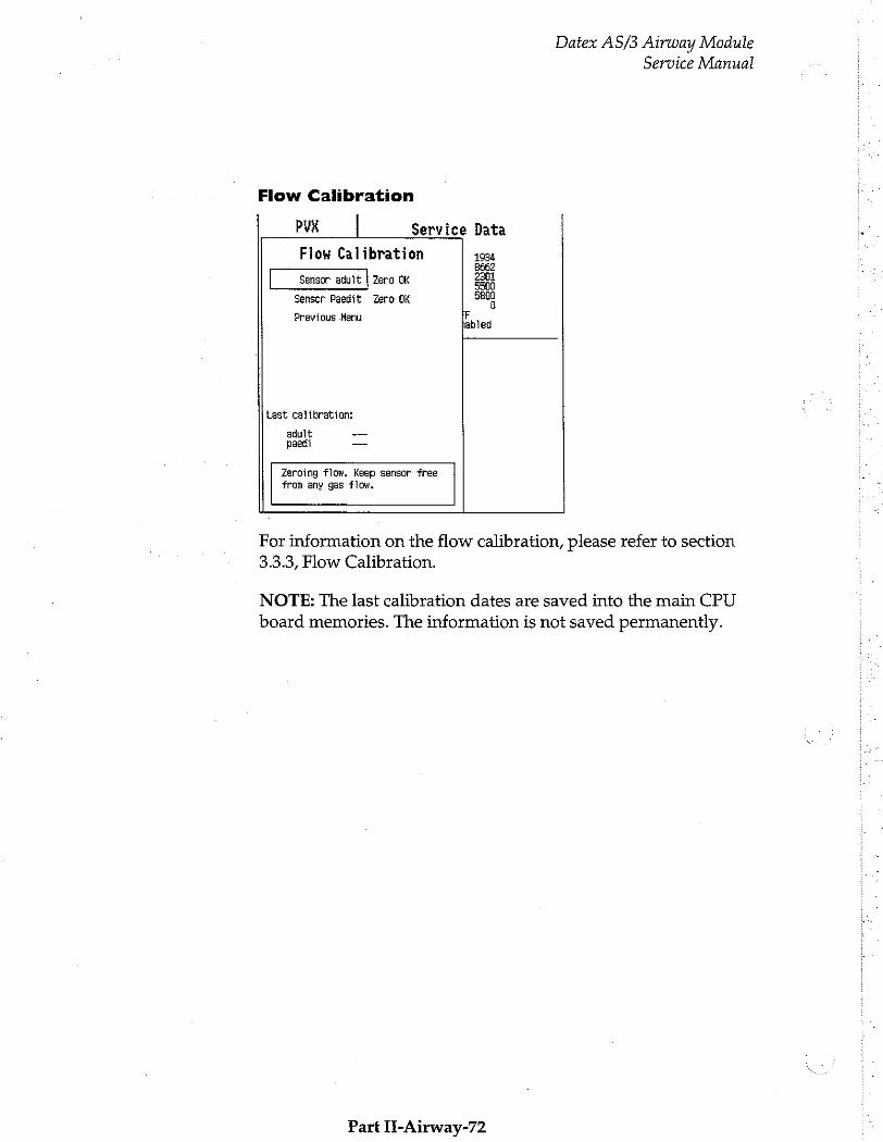
Datex AS/3 Airway Module Service Manual
Flow Calibration
РУХ | Service Data
Flow Calibration 1934 8662
Sensor adult | Zera OK ao
Sensor Paedit Zero OK 5800
Previous Henu
Last calibration:
adult ~ 一 08601 ーーー
Zeroing flow. Keep sensor free from any gas flow.
For information on the flow calibration, please refer to section 3.3.3, Flow Calibration.
NOTE: The last calibration dates are saved into the main CPU board memories. The information is not saved permanently.
Part If-Airway-72

Datex AS/3 Airway Module Service Manual
Temp & Hum Service Menu o
PVK Service Data Temp & Hum 4095 E
그 :
Room Humidity 50 0
Insp Temperature 32.0
Insp Humidity 50
Exp Temperature 25.0
Exp Humidity 82
Previous Henu
F
abled
Change room temperature to correct calibrated volume. It is used as a reference.
If circumstances noteceably differ from normal, or additional accuracy is required, the use of Temp & Humidity menu may be advisable.
Especially small errors in tidal values may indicate that temperature and humidity settings of the monitor differ too much from the used system.
Room Temperature and Humidity: these are needed only in calibration procedure.
Insp Temperature: The setting regarding the temperature of inspired gas. The value is used in calculations. Change if necessary.
Insp Humidity: The setting regarding the humidity of inspired gas. The value is used in calculations. Change if necessary.
Exp Temperature: The setting regarding the temperature of expired gas. The value is used in calculations. Change if necessary.
Exp Humidity: The setting regarding the humidity of expired gas. The value is used in calculations. Change if necessary.
Part II-Airway-73

Datex AS/3 Airway Module Service Manual
5.4 ASX Service Menu
NOTE: The ASX Service Menu in monitor software S-___94, S- ___95 and S-___96 supports only modules equipped with the
ASX-200.
ASK Service Data ID result: 0 None Total 0.00 Noise U. UO
- Temp C 0.00 Previous Menu Relg AGC 0
Fre O Motor DAC 0 На] O Motor Fiuct 0 Enf 0 Iso 0 Alc comp val 0 Des 0 sta Cl Sev 0 C Peak normal 0.00 Peak mirror 0.00
. Fact EEPRO RAM Time offset 0 D 0
Spectrum 0 1
-ὲὲ----
1 Zero gases
2 Return to previous menu
Service Data
ID result displays the identified gas or mixture
Total % is the anaesthetic agent concentration measured by ASX bench.
Rel % is the relative percentage of each measured agent in the mixture.
Noise value should be less than 80. Check the value only when no gas is fed and after a minimum of one minute stabilization time.
Temp C is the temperature inside the ASX unit.
Part Il-Airway-74
Datex AS/3 Airway Module
Service Manual
AGC (Automatic Gain Control) should be between 100 and 3500.
Motor DAC is a motor speed control voltage, 100...3900, and Motor Fluct is the speed fluctuation, should be < 200.
Alc comp val is the compensation factor for alcohol content measured during halothane, enflurane or isoflurane measuring. Sta shows the status of compensation, 0 means off, and 1 means
on.
The value without a leading text is for factory use only.
Peak normal, Peak mirror give the place of the spectrum’s peak in the channel numbers. The peak normal value should be 10.3- 10.7 with calibration gas R23, and 12.9-13.1 with R22. If the value is not within the range, the cas calibration must be performed. (see Operator’s manual for instructions).
Time offset is the time between motor synchronization pulse and filter 0° angle. Fact is the factory value for it, EEPRO is the user calibration result, stored in the ASX, and RAM is the user
calibration result, stored in the gas mother board.
Spectrum values tell about the scales of the spectrum display.
Part H-Airway-75
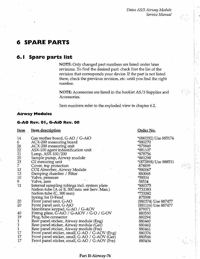
6 SPARE PARTS
6.1 Spare parts list
NOTE: Only changed part numbers are listed under later revisions. To find the desired part: check first the list of the revision that corresponds your device. If the part is not listed there, check the previous revision, etc. until you find the right number.
Datex AS/3 Airway Module
Service Manual
NOTE: Accessories are listed in the booklet AS/3 Supplies and Accessories.
Item numbers refer to the exploded view in chapter 6.2.
Airway Modules
G-AO Rev. OI, G-AiO Rev. 00
Item Item description
Gas mother board, G-AO / G-AiO ACX-200 measuring board ACX-200 measuring unit ASX-100 agent indentification unit Lamp, ASX-100/200 Sample pump, Airway module O2 mesuring unit Cover, top protection CO2 Absorber, Airway Module Damping chamber / Filter Valve, pressure Valve, zero Internal sampling tubings incl. system plate Nafion tube {A or B, 500 mm: see Serv. Man) Nafion tube (C, 300 mm) Spring for D-Fend Front panel unit, G-AO Front panel unit, G-AiO Membrane keypad, G-AO / G-AOV Fitting plate, G-AiO / G-AiOV / G-O / G-OV Plug, tube connector Rear panel sticker, Airway module (Eng) Rear panel sticker, Airway module (Ger) Rear panel sticker, Airway module (Fre) Front panel sticker, small, G-AO / G-AOV (Eng) Front panel sticker, small, G-AO / G-AOV (Ger) Front panel sticker, small, G-AO / G-AOV (Fre)
Part Il-Airway-76
Order No.
*(880352) Use 885174 *880270 #879849 *881107 *878756 #881298 *(872898) Use 888511 878859 *880067 880068 158534 58534 *880375 *733383 #733382. 875598 (880374) Use 887477 (881116) Use 887477 879371 880550 880294 880460 880462 880461 880376 880546 880454
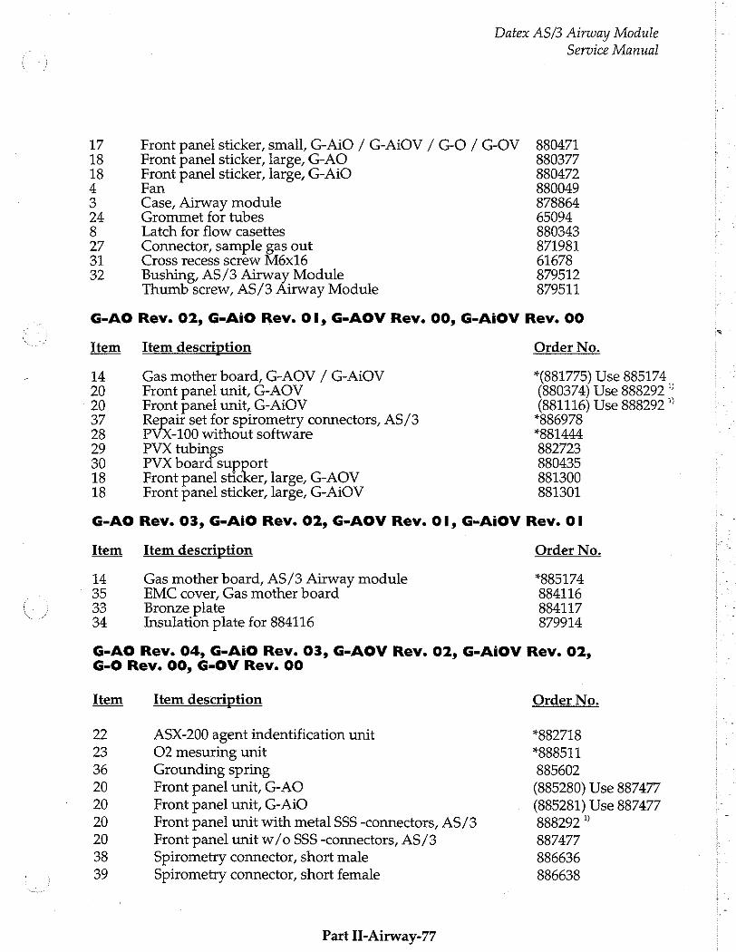
Datex AS/3 Airway Module
Service Manual
17 Front panel sticker, small, G-AiO / G-AiOV / G-O / G-OV 880471 18 Front panel sticker, large, G-AO 880377 18 Front panel sticker, large, G-AiO 880472 4 Fan 880049 3 Case, Airway module 878864 24 Grommet for tubes 65094 8 Latch for flow casettes 880343 27 Connector, sample gas out 871981 31 Cross recess screw M6x16 61678 32 Bushing, AS/3 Airway Module 879512
Thumb screw, AS/3 Airway Module 879511
G-AO Rev. 02, G-AiO Rev. 01, G-AOV Rev. 00, G-AiOV Rev. 00
Item Item description Order No.
14 Gas mother board, G-AOV / G-AiOV *(881775) Use 885174 20 Front panel unit, G-AOV (880374) Use 888292 ” 20 Front panel unit, G-AiOV (881116) Use 888292 ”
37 Repair set for spirometry connectors, AS/3 *886978 28 PVX-100 without software *881444 29 PVX tubings 882723 30 PVX board support 880435 18 Front panel sticker, large, G-AOV 881300 18 Front panel sticker, large, G-AiOV 881301
G-AO Rev. 03, G-AiO Rev. 02, G-AOV Rev. Ol, G-AiOV Rev. OI
Item Item description Order No.
14 Gas mother board, AS/3 Airway module *885174 35 EMC cover, Gas mother board 884116 33 Bronze plate 884117 34 Insulation plate for 884116 879914
G-AO Rev. 04, G-AiO Rev. 03, G-AOV Rev. 02, G-AiOV Rev. 02, G-0 Rev. 00, G-OV Rev. 00
Item Item description Order No.
22 ASX-200 agent indentification unit *882718 23 O2 mesuring unit *888511 36 Grounding spring 885602 20 Front panel unit, G-AO (885280) Use 887477
20 Front panel unit, G-AiO (885281) Use 887477 20 Front panel unit with metal SSS -connectors, AS/3 888292 " 20 Front panel unit w/o SSS -connectors, AS/3 887477 38 Spirometry connector, short male 886636 39 Spirometry connector, short female 886638
Part II-Airway-77

Datex AS/3 Airway Module
Service Manual
29 PVX tubings 885867 1 Rear panel sticker, Airway module (Spa) 886187 : 1 Rear panel sticker, Airway module (Swe) 885984 1 Rear panel sticker, Airway module (Dut) 886123 1 Rear panel sticker, Airway module (Ita) 886762 1 Rear panel sticker, Airway module (Fin) 888879 17 Front panel sticker, small, G-AO / G-AOV (Spa) 884405
17 Front panel sticker, small, G-AO / G-AOV (Swe) 885843 17 Front panel sticker, small, G-AO / G-AOV (Dut) 886065
17 Front panel sticker, small, G-AO / G-AOV (Ita) 886760
17 Front panel sticker, small, G-AO / G-AOV (Fin) 888876
17 Front panel sticker, small, G-AiO /-AiOV / -O / -OV 880471
18 Front panel sticker, large, G-O 885233
18 Front panel sticker, large, G-OV 886972
The Flow cassette’s and their order numbers can be found listed in the Gas Sampling System - section of this manual.
* = the part is recommended for stock
» NOTE: In case only the plastic spirometry connectors need repair, or compatibility with adultérpaediatric Side Stream Spirometry accessories is needed, the Repair set for spirometry connectors, order number 886978, is recommend to be used.
The Front panel unit, order number 888292, does not contain a membrane keypad, fitting plate and small front panel sticker. Those should be added separately according to the Airway module type and revision.
Gas Interface Board, B-GAS
Item description Order No.
Fuse T4A 250V *51134
Grounding plate 885404 6.2 Expioded view of the module
Part II-Airway-78

Service Manual
Datex AS/3 Airway Module
Exploded View of the Airway Module Figure 16
Part IL-Airway-79
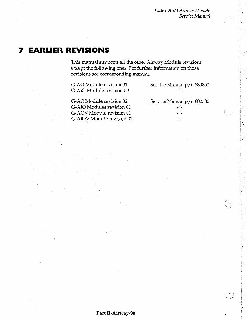
Datex AS/3 Airway Module
Service Manual
7 EARLIER REVISIONS
This manual supports all the other Airway Module revisions except the following ones. For further information on those revisions see corresponding manual.
G-AO Module revision 01 Service Manual p/n 880850 G-AiO Module revision 00 +.
G-AO Module revision 02 Service Manual p/n 882580 G-AiO Modules revision 01 ーー
G-AOV Module revision 01 一 -
G-AiOV Module revision 01 ーー
Part TE-Airway-80

Anaesthesia Keyboard, K-ARK (Rev. 00)
Keyboard Interface Board, B-ARK (Rev. 00)
All specifications subject to change without notice
Document No. 885943-2
March, 1996
Datex Division, Instrumentarium Corp. P.O.Box 446 FIN-00101 Helsinki Finland
Tel. +358 0 39411 Fax +358 0 1463310

Datex AS/3 Anaesthesia Keyboard Service Manual
AN,
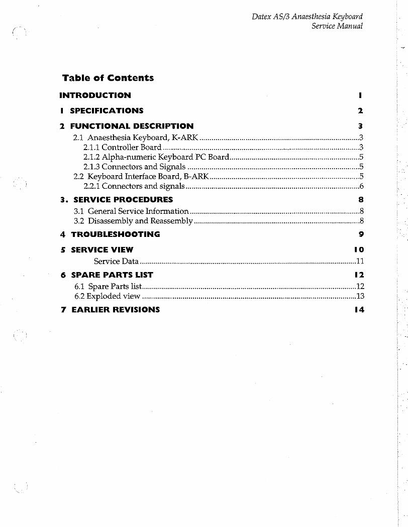
Datex AS/3 Anaesthesia Keyboard
Service Manual
Table of Contents
INTRODUCTION 1
i SPECIFICATIONS 2
2 FUNCTIONAL DESCRIPTION
21 AnaesthesiaKeyboard,K-ARK.................................. 3 2.1.1 Controller Board - 2.1.2 АЙрва-питемс КеуБоага РС Воагц.............. лилии 5 2.1.3 Connectors and Signals...............eeeeemeeeeeremeeeem eee
2.2 Keyboard Interface Board, B-ARK...
2.2.1 Connectors and signals...................
3. SERVICE PROCEDURES 8
3.1 General Service ImformatiOo ss 8 3.2 DisassembiyandReassembiy..................................... erme 8
4 TROUBLESHOOTING 9
5 SERVICE VIEW 10
Service Da ir иитииитиититититинитиннииня 11
6 SPARE PARTS LIST 12
6.1 Spare Parts list 6.2 Exploded view een 13
7 EARLIER REVISIONS 14

Datex AS/3 Anaesthesia Keyboard
Service Manual
Datex AS/3 Anaesthesia Keyboard Service Manual
INTRODUCTION
This service manual section provides information required to maintain and repair the Datex AS/3 Anaesthesia Monitor
Anaesthesia Keyboard, K-ARK and Keyboard Interface Board, B-ARK. The information is applicable for the current production revision of the modules.
Part H-ARK-1
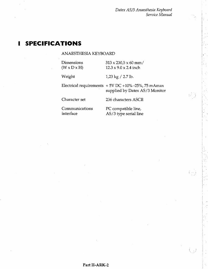
Datex AS/3 Anaesthesia Keyboard
Service Manual
.I SPECIFICATIONS
ANAESTHESIA KEYBOARD
Dimensions 313 x 230,5 x 60 mm/
(WxDxH) 12.3 x 9.0 x 2.4 inch
Weight 1,23 kg / 2.7 lb.
Electrical requirements + 5V DC +10% -25%, 75 mAmax
supplied by Datex AS/3 Monitor
Character set 256 characters ASCII
Communications PC compatible line, interface AS/3 type serial line
Part H-ARK-2
Datex AS/3 Anaesthesia Keyboard Service Manual
2 FUNCTIONAL DESCRIPTION
The Datex AS/3 Anaesthesia Record Keeper is an automated anaesthesia documentation system. For record keeping the Anaesthesia Keyboard, K-ARK ,and the software S-
ARK95/ARK96 (or S-ARK94) are needed.
The Anaesthesia Keyboard, K-ARK is connected to the
Anaesthesia Monitor via the Keyboard Interface Board, B-
ARK. Alternatively, the Keyboard can be connected to the Command Board connector on the LCD-Display, or on the Display controller board, B-DISP (or B-DHIGH).
K-ARK is connected to the Compact Monitor via the K-ARK connector on the side panel.
The Anaesthesia Record Keeper combines the physiological data measured by the monitor and the information entered via the Anaesthesia Keyboard into a printable anaesthesia record.
The Anaesthesia Record Keeper can be connected to a network, or run in a stand-alone AS/3 Monitor. If a stand-
alone monitor is used, the Memory Module, M-MEM (or B-
CMMEM) is needed for data storage. To get information of Memory module’s maintenance and service, please refer to the Memory module section of this manual.
2.1 Anaesthesia Keyboard, K-ARK The Anaesthesia Keyboard consists of following main parts: Controller Board, Alphanumeric keyboard and membrane keypads.
2.1.1 Controller Board
The Controller board is located inside the Anaesthesia Keyboard of AS/3 Anaesthesia Monitor. The board reads the status of the front panel keys (including selection and alpha- numeric keys) and the ComWheel on the front panel and forwards the information to the CPU Board, B-CPU2 or B-
CPU3, in RS232 serial communication mode.
Part II-ARK-3
Datex AS/3 Anaesthesia Keyboard ] Service Manual
Additionally, the board's own CPU controls the LEDs on the front panel.
External communication
Communication with the host processor takes place either in RS232 serial communication channel which is available in the
AS/3 bus, or, there are also two bidirectional signals (TxD
and RxD) for PCKB format communication.
For serial communication, the Anaesthesia Keyboard is connected to the AS/3 Anaesthesia Monitor Central Unit by 9-pin-26-pin interface cable. The cable is connected to Keyboard Interface Board, B-ARK or to Display Controller board, B-DISP (or B-DHIGH), in the Central Unit.
In case of PCKB type communication, the Keyboard can be connected to the AS/3 LCD Display, D-LCC10 or to the Compact Monitor.
CPU
The CPU on the Controller board is of a type 80C51FA and its oscillator's frequency is 11.059 MHz.
There is a power-up-reset whose time constant is about 1 second.
Serial communication
RS232 serial communication IC needs only +5 V supply voltage because it chops the necessary RS-level supply voltages to its external capacitors. There is a diode that allows the use of two keyboards, the pull-down resistor on
the CPU board of AS/3 Anaesthesia Monitor is used for pulling the corresponding line to the negative RS-level. The speed of the serial communication is 19.2 kBaud.
LEDs
The CPU on the board drives the alarm LEDs under the commands received from the host processor.
Part II-ARK-4
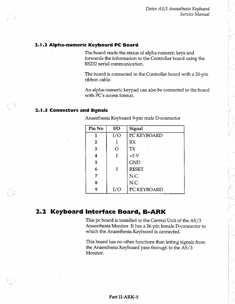
Datex AS/3 Anaesthesia Keyboard Service Manual
2.1.2 Alpha-numeric Keyboard PC Board
The board reads the status of alpha-numeric keys and forwards the information to the Controller board using the RS232 serial communication.
The board is connected to the Controller board with a 26-pin ribbon cable.
An alpha-numeric keypad can also be connected to the board with PC's access format.
2.1.3 Connectors and Signals
Anaesthesia Keyboard 9-pin male D-connector
Pin No I/O Signal
1 1/0 |PC KEYBOARD
2 I RX
3 O TX
4 I +5 V
5 GND
6 1 RESET
7 N.C.
8 N.C.
9 1/0 | PC KEYBOARD
2.2 Keyboard Interface Board, B-ARK
This pc board is installed to the Central Unit of the AS/3 Anaesthesia Monitor. It has a 26-pin female D-connector to which the Anaesthesia Keyboard is connected.
This board has no other functions than letting signals from the Anaesthesia Keyboard pass through to the AS/3 Monitor.
Part П-АВК-5

Datex AS/3 Anaesthesia Keyboard Service Manual
2.2.1 Connectors and signals
The connector located on the Keyboard Interface Board, B-
ARK.
5 Pin No | YO Signal
261 00000000 ) 19 2 N/C
3 N/C 4 N/C 5 N/C 6 O |Ground 7 N/C 8 N/C 9 N/C 10 N/C 11 N/C 12 N/C 13 N/C 14 N/C 15 O +5V 16 N/C 17 N/C 18 N/C 19 I RxD RS232 20 O | TxD RS232 21 N/C 22 N/C 23 N/C 24 N/C 25 N/C 26 N/C
Part II-ARK-6
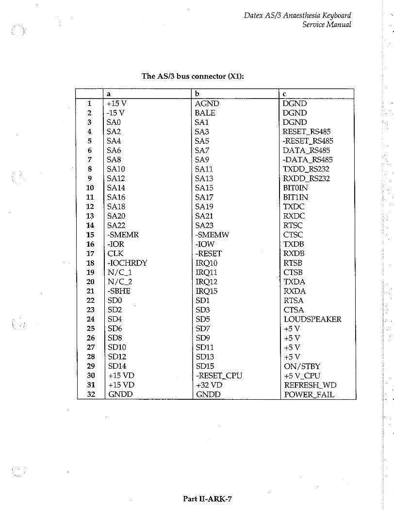
Datex AS/3 Anaesthesia Keyboard
Service Manual
The AS/3 bus connector (X1):
a b で
1 +15 V AGND DGND
2 -15V BALE DGND
3 SAO SAT DGND
4 SA2 SA3 RESET_RS485
5 SA4 SA5 -RESET_RS485
6 SA6 SA7 DATA_RS485
7 SA8 SA9 -DATA_RS485
8 SA10 SA11 TXDD_RS232
9 SA12 SA13 RXDD_RS232
10 | SA14 SA15 BITOIN
11 |SA16 SA17 BITUN
12 | SA18 SA19 TXDC
13 | SA20 SA21 RXDC
14 |SA22 SA23 RTSC
15 | SMEMR -SMEMW CTSC
16 |-IOR -IOW TXDB
17. | CLK -RESET RXDB
18 | -IOCHRDY IRO10 RTSB
19 ¡N/C_1 IRQ11 | CTSB
20 |N/C_2 IRO12 TXDA
21 |-SBHE IRO15 RXDA
22 |500 SD1 RTSA
23 |502 $03 СТЗА
24 |SD4 SD5 LOUDSPEAKER
25 |506 SD7 +5 V
26 |508 $09 +5 V
27 |SD10 SD11 +5 V
28 | SD12 SD13 +5 V
29 [SD14 SD15 ON/STBY
30 |+15 VD -RESET CPU +5 V CPU
31 |+15 VD +32 VD REFRESH WD
32 | GNDD GNDD POWER FAIL
Part II-ARK-7
Datex AS/3 Anaesthesia Keyboard Service Manual
3. SERVICE PROCEDURES
3.1 General Service Information
Usually field service is limited to replacing the faulty circuit boards or mechanical parts. The boards are then returned to Datex for repair.
Datex is always available for service advice. Please provide the unit serial number, full type designation, and a detailed fault description.
CAUTION: The tests and repairs outlined in this section should only be attempted by trained personnel with the appropriate equipment. Unauthorized service may void warranty of the unit.
3.2 Disassembly and Reassembly
The Anaesthesia Keyboard is disassembled in the following way. See Figure 1 for the exploded view of the module:
a) Disconnect the interface cable from the 9-pin D- connector of the Anaesthesia Keyboard.
b) Remove four screws from the back of the keyboard and detach the cover from the bottom.
Part II-ARK-8
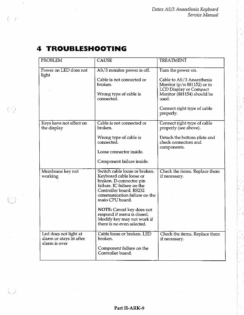
Datex AS/3 Anaesthesia Keyboard
4 TROUBLESHOOTING
Service Manual
PROBLEM CAUSE TREATMENT
Power on LED does not light
AS/3 monitor power is off.
Cable is not connected or broken.
Turn the power on.
Cable to AS/3 Anaesthesia Monitor (p/n 881152) or to LCD Display or Compact
the display broken.
Wrong type of cable is connected.
Loose connector inside.
Component failure inside.
Wrong type of cable is Monitor (881154) should be connected. used.
Connect right type of cable properly.
Keys have not effect on Cable is not connected or Connect right type of cable properly (see above).
Detach the bottom plate and check connectors and components.
Membrane key not working
Switch cable loose or broken. Keyboard cable loose or broken. D-connector pin failure. IC failure on the Controller board. RS232 communication failure on the main CPU board.
NOTE: Cancel key does not respond if menu is closed. Modify key may not work if there is no even selected.
Check the items. Replace them if necessary.
Led does not light at alarm or stays lit after alarm is over Cable loose or broken. LED
broken.
Component failure on the Controller board. Check the items. Replace them
if necessary.
Part II-ARK-9
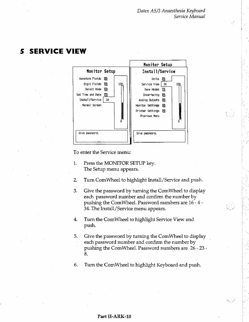
Datex AS/3 Anaesthesia Keyboard Service Manual
5 SERVICE VIEW
Honitor Setup
Monitor Setup Install/Service
Waveform Fields Units
Digit Fields 100 Service View | 26 106
Select Hode Save Modes
Set Time and Date Interfacing
Install/Service | 16 Analog Outputs
Normal Screen Honitor Settings
Printer Settings
Previous Menu
0 G
Give password. Give password.
To enter the Service menu:
1. Press the MONITOR SETUP key. The Setup menu appears.
Turn ComWheel to highlight Install/Service and push.
Give the password by turning the ComWheel to display
each password number and confirm the number by pushing the ComWheel. Password numbers are 16 - 4 - 34. The Install/Service menu appears.
Turn the ComWheel to highlight Service View and push.
Give the password by turning the ComWheel to display each password number and confirm the number by pushing the ComWheel. Password numbers are 26 - 23 - 8.
Turn the ComWheel to highlight Keyboard and push.
Part II-ARK-10
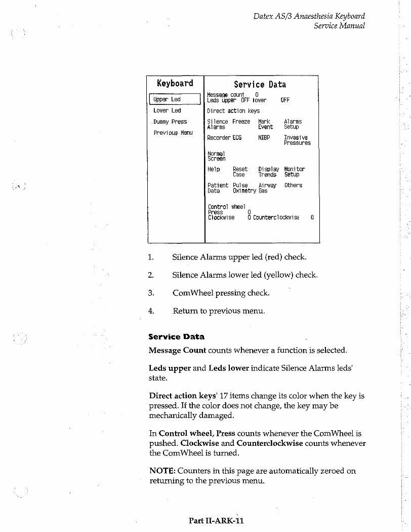
Datex AS/3 Anaesthesia Keyboard Service Manual
Keyboard Service Data Message count 0
Upper Led Leds upper OFF tower OFF
Lower Led Direct action keys
Dummy Press Silence Freeze Mark Alarms Alarms Event Setup
Previous Henu . Recorder ECG NIBP Invasive
Pressures
Normal Screen
Help Reset Display Monitor Case Trends Setup
Patient Pulse Airway Others Data Oximetry Gas
Control wheel Press Clockwise 0 Counterclockwise 0
1. Silence Alarms upper led (red) check.
2. Silence Alarms lower led (yellow) check.
3. ComWheel pressing check.
4. Return to previous menu.
Service Data
Message Count counts whenever a function is selected.
Leds upper and Leds lower indicate Silence Alarms leds’ state.
Direct action keys’ 17 items change its color when the key is pressed. If the color does not change, the key may be mechanically damaged.
In Control wheel, Press counts whenever the ComWheel is
pushed. Clockwise and Counterclockwise counts whenever the ComWheel is turned.
NOTE: Counters in this page are automatically zeroed on returning to the previous menu.
Part II-ARK-11

6 SPARE PARTS LIST
6.1 Spare Parts list
Item numbers refer to the exploded view in chapter 6.2.
Anaesthesia Keyboard, K-ARK
Datex AS/3 Anaesthesia Keyboard
Service Manual
Rev. 00
Item Item description Order No.
3 Controller board, K-ARK (Rev. 00) *884177 2 Alpha-numeric Keyboard PC board, K-ARK (Rev. 00) *884178 4 Rotary wheel 879872 5 ComWheel cover and spring 879191 10 Membrane keyboard 879373 8 Membrane keyboard 879964 9 Front panel sticker, K-ARK (Eng) 881648 9 Front panel sticker, K-ARK (Fre 884731 9 Front panel sticker, K-ARK (Ger) 885140 9 Front panel sticker, K-ARK (Spa) 886200 9 Front panel sticker, K-ARK (Swe) 885915 9 Front panel sticker, K-ARK (Dut) 886162 7 Front panel sticker, K-ARK (Eng) 884017 7 Front panel sticker, K-ARK (Fre 884406 7 Front panel sticker, K-ARK (Ger) 885133 7 Front panel sticker, K-ARK (Spa) 886198 7 Front panel sticker, K-ARK (Swe) 885916 7 Front panel sticker, K-ARK (Dut) 886282 7 Front panel sticker, K-ARK (Fle) 886161 7 Front panel sticker, K-ARK (Sca) 884632 1 Pad 65142 6 Cross cylinder-head screw M3x6 61721
Keyboard Interface Board, B-ARK
Item description Order No.
Grounding plate 885398
* = the part is recommended for stock
Part H-ARK-12

Datex AS/3 Anaesthesia Keyboard Service Manual
6.2 Exploded view
Figure 1 Exploded View of the Anaesthesia Keyboard
Part II-ARK-13

Datex AS/3 Anaesthesia Keyboard Service Manual
7 EARLIER REVISIONS
Rev. 00 is the first revision of the K-ARK, and B-ARK.
Part II-ARK-14
Neuro Muscular Transmission Module, M-NMT (Rev. 00)
All specifications subject to change without notice.
Document No. 887780-1
March, 1996
Datex Division, Instrumentarium Corp. P.O.Box 446 FIN-00101 Helsinki Finland
Tel. +358 0 39411 Fax +358 0 1463310

Datex AS/3 M-NMT
Service Manual

Datex AS/3 M-NMT
Service Manual
Table of Contents
INTRODUCTION I
i SPECIFICATIONS
1.1 General Specifications... ss iii 1.2 Technical Specifications
2 FUNCTIONAL DESCRIPTION 4
2.1 Measuring Prmeiple ieri 4
2.1.1 Nerve Stimulation .ee kernerne end 4
2.1.2 Response inner
2.1.3 Regional Block... 2.2 Main Components eee
2.1.1 μου μμ μμ μμ μμ μμ μμ μμ --ᾱ-ᾱ-,
2.1.2 띠 터 0070606079000000 나 나 나 아 아 아 아 아 아 아 아 아 이 아 이 아 아 아 아 아 아 아 아 아 아 라 아 머 아 아 아 마 아 어 아 아 아 아 아 아 아 아 아 이 아 니 7
3 SERVICE PROCEDURES
3.1 General Service Information... ss
3.2 Preventive Maintenance ............
3.3 Disassembly and Reassembly
4 TROUBLE SHOOTING 12
5 SERVICE MENU 14
5INMTServiceMenu............................... eee ereeeeeenenanazanı 15
6 SPARE PARTS 18
6.1 Spare Part List sense 18 6.2 Exploded View of Module uns 19
7 EARLIER REVISIONS 21

Datex AS/3 M-NMT
Service Manual

Datex AS/3 M-NMT Service Manual
INTRODUCTION
The M-NMT module contains peripheral nerve stimulation and response measurement which supports electromyography EMG. Module can be used also as a nerve locator for regional nerve block with Regional block -cable in which case there is no response measurement.
Part H-NMT-1

Datex AS/3 M-NMT
SPECIFICATIONS
1.1 General Specifications
1.2 Technical Specifications
Service Manual
Module size + 37x 180 x 112 mm
WxDxH 15x 7.1x44in
Module weight 0.37 kg /0.8 Ibs.
Power consumption 3,8W
NMT
Stimulation modes Train of four (TOF)
Double burst (3.3) (DBS)
Single twitch (ST) 50 Hz tetanus + post tetanic count (PTC)
Measurement intervals for TOF and DBS
Manual, 10 s,12s,15s,20 s
1s,1 min, 5 min, 15 min
Measurement intervals for ST
Manual, 1 s,10s,20 s
STIMULATOR
Stimulus pulse Sguare wave, constant current
Pulse width 100, 200 or 300 us
Stimulus current range 10-70 mA with 5 mA steps
Stimulus current accuracy
10 % or +3 mA which ever is greater measured as average
Max load 3kQ
Max. voltage 300 V
Part II-NMT-2
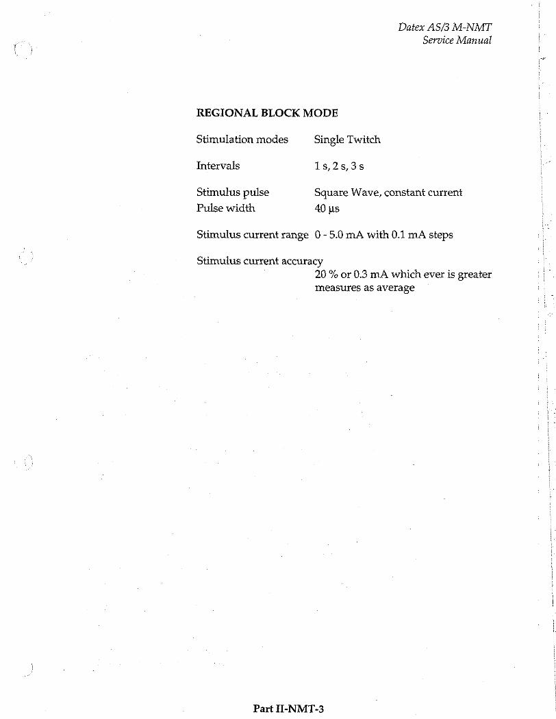
Datex AS/3 M-NMT
Service Manual
REGIONAL BLOCK MODE
Stimulation modes Single Twitch
Intervals 1s,2s,3s
Stimulus pulse Square Wave, constant current
Pulse width 40 us
Stimulus current range 0-5.0 mA with 0.1 mA steps
Stimulus current accuracy 20 % or 0.3 mA which ever is greater measures as average
Part Н-ММТ-3
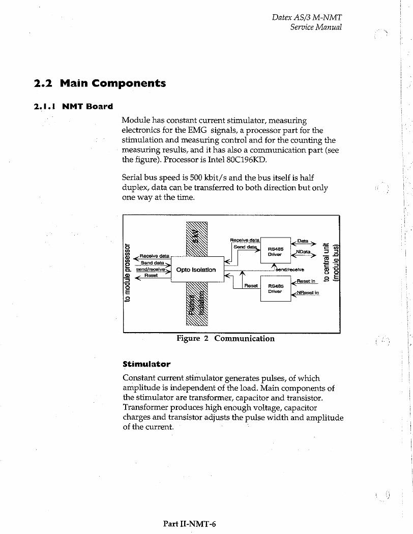
Datex AS/3 M-NMT
Service Manual
2.2 Main Components |
2.1.1 NMT Board
Module has constant current stimulator, measuring
electronics for the EMG signals, a processor part for the stimulation and measuring control and for the counting the measuring results, and it has also a communication part (see the figure). Processor is Intel 80C196KD.
Serial bus speed is 500 kbit/s and the bus itself is half duplex, data can be transferred to both direction but only one way at the time.
RS485 Driver
Receive data
Opto isolation Send/recelve
to central
unit
(module
bus)
RS4B5 Driver
to module pr
oses
sor
Figure 2 Communication
Stimulator
Constant current stimulator generates pulses, of which amplitude is independent of the load. Main components of the stimulator are transformer, capacitor and transistor. Transformer produces high enough voltage, capacitor charges and transistor adjusts the pulse width and amplitude of the current.
Part II-NMT-6

Datex AS/3 M-NMT
Service Manual
— | Power supply
Current m adjustment 80C196KD
トーーーー ゴ P W M Patient Constant current
generator Current HSO eo Li control 그
| Continuous
stimulation
congestion
Figure 3 Stimulator Block Diagram
2.1.2 NMT connectors
The pin assignments on the NMT Connector located on the M-NMT module are as follows.
Pin Signal
二 so
01 & ϱ
- EMG Signal +
EMG Signal - Not Used
Stimulus +
Stimulus -
Ground
Not Connected
Sensor Identification
+5 V
Mechanical Signal
Part II-NMT-7

Datex AS/3 M-NMT
Rear panel 25-pin female D-connector (X1)
Service Manual
Pin No I/O Signal
1 I RESET. RS485
2 I -15 VDC
3 I +15 VDIRTY
4 I +15 VDC
5 I/O |-DATA RS485
6 ГО |DATA RS485
7 Ground & Shield
8 I -RESET_RS485
9 I CTSB
10 О RTSB
11 I RXDB
12 O TXDB
13 Ground & Shield
14 I +32 VDIRTY
15 I GroundDIRTY
16 I CTSC
17 O RTSC
18 1 RXDC
19 O TXDC
20 ON/STANDBY
21 PWM_ECG
22 RXDD_RS232
23 TXDD_RS232
24 +5 VDC
25 +5 VDC
Part H-NMT-8
Datex AS/3 M-NMT
Service Manual
3 SERVICE PROCEDURES
3.1 General Service Information
Usually field service is limited to replacing the faulty circuit boards or mechanical parts. The boards are then returned to Datex for repair.
Datex is always available for service advice. Please provide the unit serial number, full type designation, and a detailed fault description.
Datex NMT Stimulator (order code 871251) is recommended
for functional checks.
CAUTION: Only trained personnel with appropriate equipment shall perform the tests and repairs outlined in this section. Unauthorized service may void warranty of the unit.
Part II-NMT-9
Datex AS/3 M-NMT
Service Manual
3.2 Preventive Maintenance
Perform these checks after any service and at least once a year to keep NMT Module in good condition.
Visual Inspection
If the module is disassembled, check that grounding
wires and all connectors are properly connected and there is no loose object inside before attaching the module box.
Functional checks
__: Insert the NMT module M-NMT into the AS/3 monitor. Check visually that the NMT accessories are not damaged.
___: Connect the NMT sensor cable and connect the NMT
sensor to the Datex NMT stimulator. Set stimulator
controls to “fade off” and max. Push start-up key on the module.
__: Check that no error messages are displayed while the
monitor searches for the supramaximal current and the reference level. To discontinue push the Stop/Continue key on the module.
Part II-NMT-10

Datex AS/3 M-NMT
Service Manual
3.3 Disassembly and Reassembly
Disassemble the NMT module in the following way. See Figure 4 for the exploded view of the module.
1. Remove the two screws from the back of the module.
2. Pull the module box slowly rearward and detach it from main body. Be careful with loose latch and spring pin for locking.
3. Detach the NMT board by removing the two screws that are located near the front panel frame, disconnect the cables and pull out the front panel frame.
CAUTION: When reassembling the module, make sure that the cables are reconnected properly.
Part II-NMT-11

Datex AS/3 M-NMT
Service Manual
4 TROUBLE SHOOTING
TROUBLE CAUSE TREATMENT
Check the stimulus Loose electrodes Change or attach the electrodes. or loose stimulus clip. electrodes or clip. EMG electrode off
Supramax. not found Loose electrodes
or loose stimulus clip.
Stimulus electrodes
attached to wrong place. Patient is relaxated.
Change or attach the electrodes or clip. Change the place of the stim. el.
Response too weak. Loose stimulus electrodes.
Measuring electrodes attached to wrong place. Patient is relaxated.
Change or attach the electrodes. Change the place of the meas. electrodes.
Ref. not stable Patient is relaxated.
Movement artefact.
Part II-NMT-12
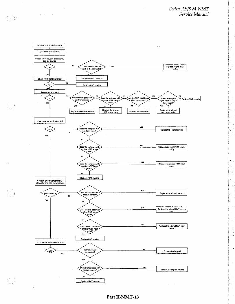
- Datex AS/3 M-NMT o
Service Manual
Open NMT Servica Menu
Check Timeouts, Bad checksums, Bad c-s by mod
Does another module work in tha same slo!
Replace original NMT
Fault not in NMT module
Does the test pass with ‘are the NMT input board
another sensor? wires connected? Replace NMT module
Check that sensor is identified
Does tha test pass with another sensor?
Replace the original sensor no
Does the test pass with enother NMT sensp
Replace the original NMT sensor
|
Does the test pass with Replace the original NMT input
|
πο
Repíace NMT module Connect ElectroSensor to NMT
stimulator and start measurement ー
Replace the original sensor
Does the test pass with another sensor?
Does the test pass with Replace the original NMT sensor
| Replace the original NMT input
са
Check front panel key functions
15 the keypad connected?
Connect the keypad
Does the test pass with another keypad?,
Replace the original keypad
Replace NMY module
Part I-NMT-13

Datex AS/3 M-NMT
Service Manual
5 SERVICE MENU
Monitor Setup
Monitor Setup Install /Service
Waveform Fields Units
Digit Fields 100 Service View | 26 100
Select Mode Save Modes
Set Time and Date Interfacing
Instali/Service | 16 Analog Outputs
Normal Screen Monitor Settings
Printer Settings
Previous Menu
0 9
Give password. Give password,
To enter Service Menu:
1. Press the MONITOR SETUP key. The Setup menu appears.
Turn ComWheel to highlight Install/Service and push.
Give the password by turning the ComWheel to display each password number and confirm the number by pushing the ComWheel. Password numbers are 16 - 4 - 34. The Install /Service menu appears.
Turn the ComWheel to highlight Service View and push.
Give the password by turning the ComWheel to display each password number and confirm the number by pushing the ComWheel. Password numbers are 26 - 23 - 8.
Turn the ComWheel to highlight Modules and push.
Turn the ComWheel to highlight the NMT module and push.
Part II-NMT-14

Datex AS/3 M-NMT
Service Manual
5.1 NMT Service Menu
Tix/ref
NMT Service Data
MT Setup Cable: ENG
Start Curr. test
Previous Menu
Cable check value: 1
Module keys: Start-up StopyCont. i
Stimulus mode: TOF Measurement: ON
Tis 1900 Absolute TL 2143 τος 678 Absolute T2 1495 Tax 508 Absolute T3 1089 Ta al? Absolute T4 680 RatioW 317 Ref 2143
Noise 19 Offset 512
Current test (mA): 30 ck 50 ok 70 ok Done
Curr set as Curr mess 268 Pulses
Piezo probe: T1% OFF Ref.search OFF
Timeouts 0 RAM DK Bad checksuns 1 RON BK Bad c-s by moc 1 EEPROH OK
By selecting NMT Setup you can enter the setup menu and change the values needed. Please refer to Operator's Manual for further information. '
Start Curr. Test is a test where the module itself checks the difference between current given and
measured. 3 kQ resistance should be set between the stimulus electrodes before starting the test. All the currents checked will be displayed on the service data screen. After the current value, there is also shown the
status of the test. If the test is not passed, send the module back to the factory for calibration.
3. T1%/ref not in use.
Service Data Detailed Description
Cable shows the type of cable used at the moment.
Cable check value show the bit amount. From the following chart you can check the values to each cable:
EMG -100...+100
Cable OFF >1950
Part II-NMT-15

Datex AS/3 M-NMT
Service Manual
Module Keys checks the function of the module keys. Blue background appears to the back of the text when the keys are pushed more than one second.
Stimulus mode shows the selected stimulus. Stimulus mode
can be changed from the NMT Setup menu.
Measurement indicates ON/OFF.
T1%, T2%... shows the measured response. Value 1000 corresponds to 100%.
Absolute Ti, T2... shows the voltage measured from the AD converter.
Noise indicates the interference just before the measurement. Typical value is <10.
Offset is an average length of the noise measurement.
Typical value is 510.
Curr set is the selected current, value 700 corresponds to 70 mA.
Curr meas is the measured current, value 700 corresponds to 70 mA.
Pulses indicates pulses the module has produced.
Piezo probe T1% and ref. search not in use.
Timeouts is a cumulative number that indicates how many times the module has not responded to the monitor's inquiry. Bad checksums is a cumulative number that indicates how many times communication from the module to monitor broke down. Bad c-s by mod is a cumulative number that indicates how many communication errors the module has detected. The AS/3 Monitor starts counting these items at power up and resets to zero at power off. The non-zero values do not indicate a failure, but the continuous counting (more than 50 per second) indicates either serial communication failure, or
module not in place. Also other modules can cause communication errors that cause these numbers rise.
Part II-NMT-16
Datex AS/3 M-NMT Service Manual
RAM indicates the state of the RAM memory. ROM indicates whether the checksum in the EPROM is in
accordance with the one the software has calculated.
EEPROM indicates if the values stored in the permanent memory are valid. The state is either OK, Fail or ? (module not in place or a
communication error).
Part H-NMT-17
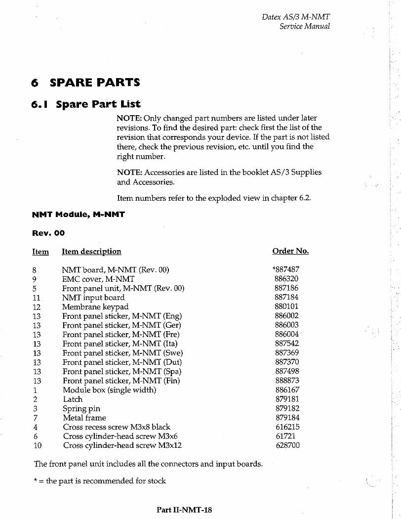
6 SPARE PARTS
6.1 Spare Part List
NOTE: Only changed part numbers are listed under later revisions. To find the desired part: check first the list of the revision that corresponds your device. If the part is not listed there, check the previous revision, etc. until you find the right number.
Datex AS/3 M-NMT
Service Manual
NOTE: Accessories are listed in the booklet AS/3 Supplies and Accessories.
Item numbers refer to the exploded view in chapter 6.2.
NMT Module, M-NMT
Rev. 00
Item Item description
8 NMT board, M-NMT (Rev. 00) 9 EMC cover, M-NMT
5 Front panel unit, M-NMT (Rev. 00)
11 NMT input board
12 Membrane keypad 13 Front panel sticker, M-NMT (Eng) 13 Front panel sticker, M-NMT (Ger)
13 Front panel sticker, M-NMT (Fre)
13 Front panel sticker, M-NMT (Ita) 13 Front panel sticker, M-NMT (Swe) 13 Front panel sticker, M-NMT (Dut) 13 Front panel sticker, M-NMT (Spa)
13 Front panel sticker, M-NMT (Fin) 1 Module box (single width) 2 Latch
3 Spring pin 7 Metal frame
4 Cross recess screw M3x8 black 6 Cross cylinder-head screw M3x6 10 Cross cylinder-head screw M3x12
The front panel unit includes all the connectors and input boards.
* = the part is recommended for stock
Part II-NMT-18
Order No.
*887487 886320 887186 887184 880101 886002 886003 886004 887542 887369 887370 887498 888873 886167 879181 879182 879184 616215 61721 628700
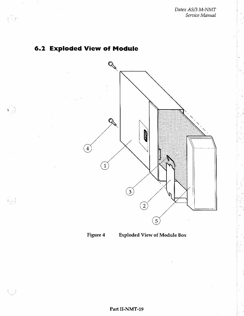
Datex AS/3 M-NMT
Service Manual
6.2 Exploded View of Module
Figure 4 Exploded View of Module Box
Part II-NMT-19
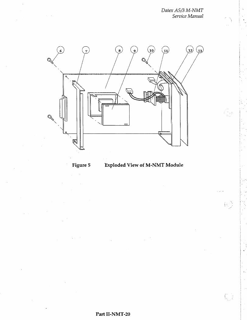
Datex AS/3 M-NMT Service Manual
Figure 5 Exploded View of M-NMT Module
Ῥατί Π-ΝΜΤ-20
Datex AS/3 M-NMT
Service Manual
7 EARLIER REVISIONS
There are no earlier revisions of M-NMT.
Part II-NMT-21

UPINET Board, B-UPINET (Rev. 00)
All specifications subject to change without notice
Document No. 888737
March, 1996
Datex Division, Instrumentarium Corp. P.O.Box 446 FIN-00101 Helsinki Finland
Tel. +358 0 39411 Fax +358 0 1463310

Datex AS/3 B-UPINET
Service Manual
Datex AS/3 B-UPINET Service Manual
Table of Contents
INTRODUCTION I
1 TECHNICAL SPECIFICATIONS 2
2 FUNCTIONAL DESCRIPTION 3
ANS
ANN
2.1.2 NET Section.
2.2 Ethernet InterfaCeS................... essences
2.3 Conmnectors and Signals eee eee nnné 2.3.1 Ethernet Network Interface
2.3.2 Network Coding Element Interfac@............................ rire 8 2.3.3 Serial Data Interface iii 9 2.3.4 Connection to the AS/3 Bus te aero eee 10
3 SERVICE PROCEDURES HI
4 TROUBLESHOOTING 12
4.1 Troubleshooting for the NET Section... 12 4.2 Troubleshooting for the UPI secton линии иена 14
5 SERVICE VIEW 15
6 SPARE PARTS 18
7 EARLIER REVISIONS 19

Datex AS/3 B-UPINET
Service Manual
Datex AS/3 B-UPINET
Service Manual
INTRODUCTION
Datex AS/3 UPINET Board, B-UPINET integrates the UPI board and the Network Board, B-NET.
Compared to a combination of the UPI board and the Network board, the UPINET board has a limited number of
input/output signals. There is only one digital output signal and one analog output signal available on the UPINET board.
For installing the board, please refer to the Installation
Manual of your monitor.
Part II-UPINET-1
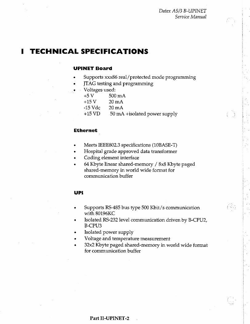
Datex AS/3 B-UPINET
Service Manual
I TECHNICAL SPECIFICATIONS
UPINET Board
e Supports xxx86 real/protected mode programming « © JTAG testing and programming
« © Voltages used: +5 V 500 mA +15 V 20 mA -15Vde 20mA +15 VD 50 mA +isolated power supply
Ethernet |
+ Meets IEEE802.3 specifications (10BASE-T)
+ Hospital grade approved data transformer
・ © Coding element interface
» © 64 Kbyte linear shared-memory / 8x8 Kbyte paged shared-memory in world wide format for communication buffer
UPI
» Supports RS-485 bus type 500 Kbit/s communication with 80196KC
e Isolated RS-232 level communication driven by B-CPU2,
B-CPU3
e Isolated power supply
» Voltage and temperature measurement
・ 32x2 Kbyte paged shared-memory in world wide format for communication buffer
Part II-UPINET-2
Datex AS/3 B-UPINET
Service Manual
2 FUNCTIONAL DESCRIPTION
2.1 General
2.1.1 UPI Section
The UPI section functions as a general I/O-board. It performs I/O duties assigned to it by the CPU board. The main processor in the CPU board and the processor in the UPI section communicate through a dual-port memory which is located on the UPINET board.
Functional blocks
The UPI section contains the external bus interface, a
processor, program- and dual-port memories, I/O-block, and an isolated serial bus interface.
External bus interface
The UPI section is connected to the CPU mother board. The
following signals pass on between the UPI section and CPU mother board: data bus, address bus, reset, read and write
signals, and other related signals.
Processor
The processor in the UPI section is an 80C196KC-16, which
functions at 16 MHz frequency.
Isolated and non-isolated serial bus interfaces
There are isolated and non-isolated serial bus interfaces. The
isolated serial bus is connected to the connector X4 and the
non-isolated serial bus is connected to the module bus
through the CPU mother board.
Isolated power supply consists of a transformer and other peripheral components. It gives about 10 -15V/5 W output.
Part II-UPINET-3
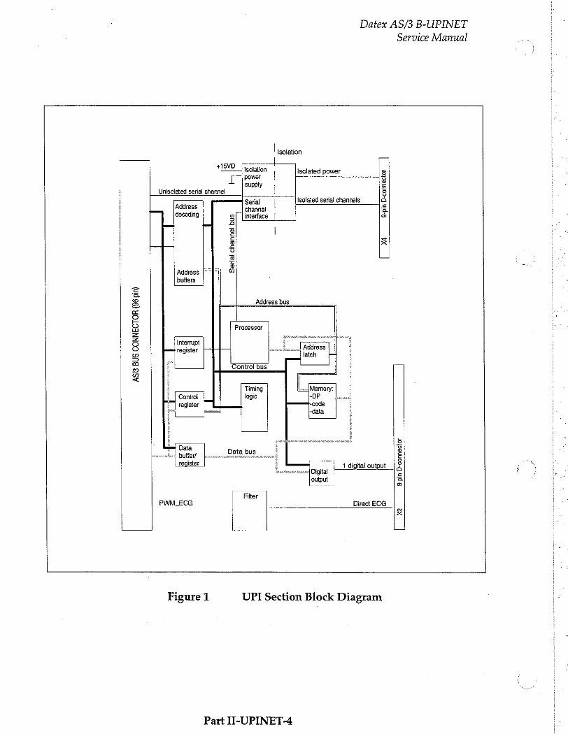
Datex AS/3 B-UPINET
Service Manual
| isolation |
15VD ' + Isolation | Isolated power 5
power 5
Lİ supply Е | Unisolated serial channel | 8
Isolated serial channels a == Se | 2 decoding gf [interface | >
= tue) 2
5 i = = n
i £ i o
i 5 © -
Address FF] 이 buffers
= a
8 Address bus
ec 2 9 Processor = 5 Interrupt
1 © poms register ro o 2 + | © Control bus a é “|| C É Timing Memory:
¿al Control | | logie -DP W: £ | register code
-data
i 5 i —= Data 3 i. buffer! Data bus È
register m 1 digital output | & e 이 Digital Ve i output a Lo a i
| PAM BCG . Lec Direct ECG |
| E
Figure 1 UPI Section Block Diagram
Part II-UPINET-4
2.1.2 NET Section
Datex AS/3 B-UPINET
Service Manual
The NET section is illustrated in a block diagram shown in figure 2.
The network interface controller is basically the heart of the NET section. The interface controller communicates with the CPU board through the data and address buffering and decoding block, or through the RAM. During the startup sequence the CPU board loads the network communication software into the RAM. The processor then executes the communication software.
The network interface controller transmits data packets to the AS/3 Network and receives data packets from the network through the 10BASE-T transformer. The transformer filters and transforms the data and also provides the isolation.
The Ethernet status LEDs indicate the status of the network
communication. The status LEDs are controlled by the network interface controller. The LEDs are not visible when
the board is installed into the monitor.
The coding element interface block contains a unique network address. The interface block is connected to the coding element. The coding element contains information on the monitor location. The network address and the monitor location information are transmitted to the CPU board through the data and address buffering and decoding block.
Part II-UPINET-5
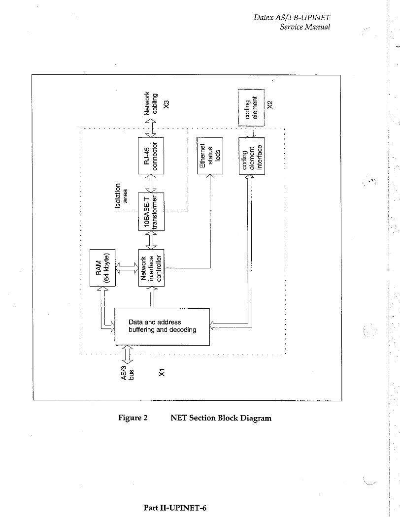
Service Manual
Datex AS/3 B-UPINET
ΖΧ
' eseuajyul
o
LA
uauele
upoo EA
Bupoo ド
| spe}
|
snjejs NE
D
一
一 一
一 一
一 一 一
£ TV 7
。 8
| 83
ex '
| Bo
Buijgeo AN
doloseuuoo |
à] seuoysuen
eno
|, [|
À 8
=
eoejeiu |]
BP
momen NY)
Sera. NOVÍ
1-39\8 아 ам
S
: T
E
2 y
E esse
uonejos| |
(2149; ve) pf
VH
IX
=>
sng
TV
SV
NET Section Block Diagram Figure 2
Part II-UPINET-6
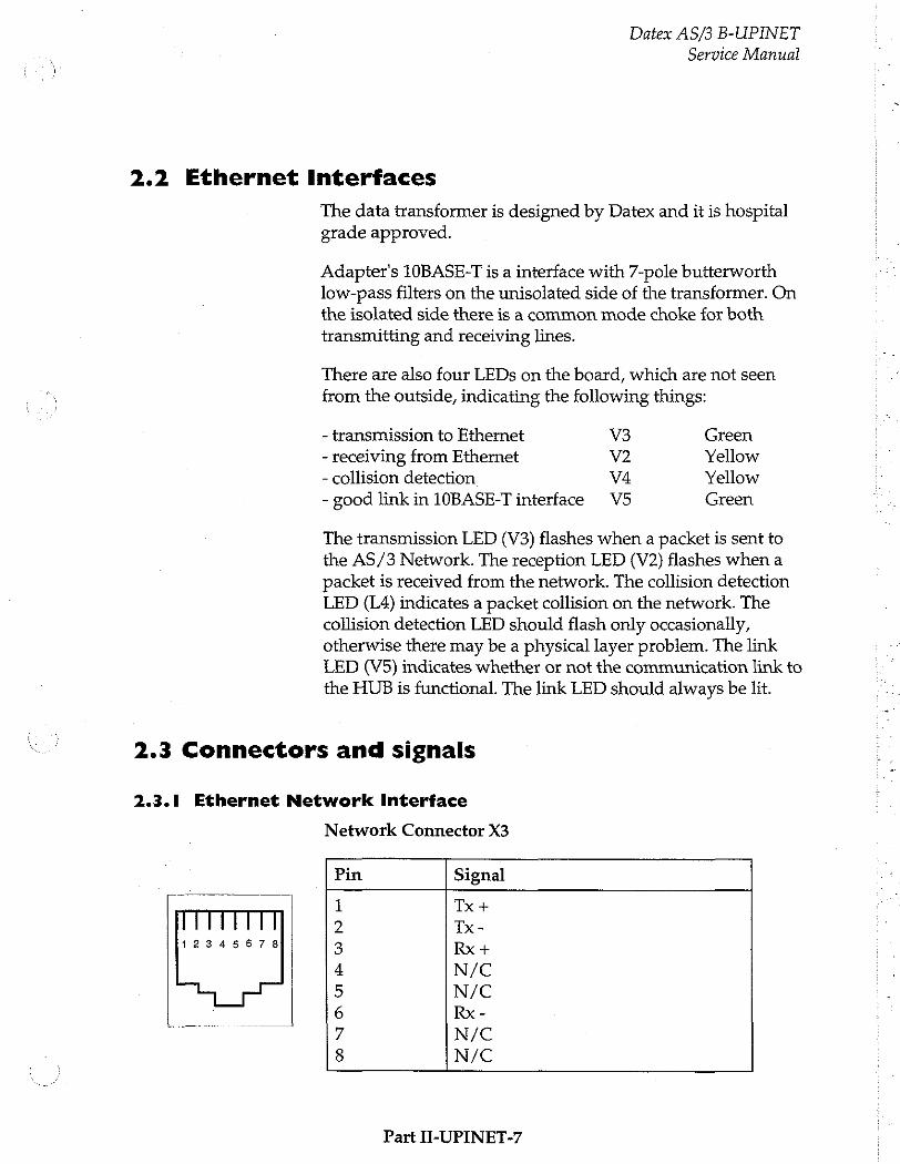
Datex AS/3 B-UPINET
Service Manual
2.2 Ethernet Interfaces
The data transformer is designed by Datex and it is hospital grade approved.
Adapter's 10BASE-T is a interface with 7-pole butterworth low-pass filters on the unisolated side of the transformer. On the isolated side there is a common mode choke for both transmitting and receiving lines.
There are also four LEDs on the board, which are not seen
from the outside, indicating the following things:
- transmission to Ethernet V3 Green - receiving from Ethernet V2 Yellow - collision detection V4 Yellow - good link in 10BASE-T interface V5 Green
The transmission LED (V3) flashes when a packet is sent to the AS/3 Network. The reception LED (V2) flashes when a packet is received from the network. The collision detection LED (L4) indicates a packet collision on the network. The
collision detection LED should flash only occasionally, otherwise there may be a physical layer problem. The link LED (V5) indicates whether or not the communication link to
the HUB is functional. The link LED should always be lit.
2.3 Connectors and signals
2.3.1 Ethernet Network Interface
12345678
Network Connector X3
Pin Signal
Tx+
Tx-
Rx +
N/C N/C Rx-
N/C
N/C SN ATE
GQ DN
ο
Part I-UPINET-7
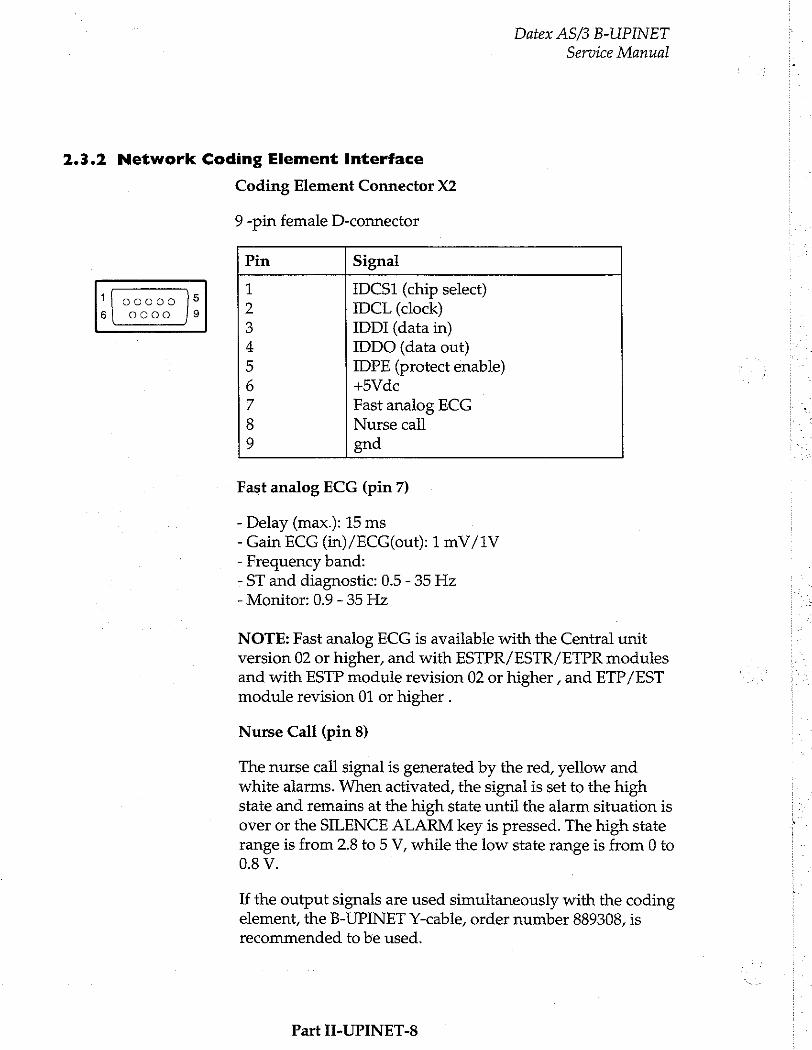
2.3.2 Network Coding Element Interface
Coding Element Connector X2
9.-pin female D-connector
Datex AS/3 B-UPINET
Service Manual
Pin Signal
IDCS1 (chip select) IDCL (clock)
IDDI (data in) IDDO (data out) IDPE (protect enable) +5Vdc Fast analog ECG Nurse call gnd
11 00000 |5 el 0000 |9
\ ら %
NI O O1
# ©
ND 그
Fast analog ECG (pin 7)
- Delay (max.): 15 ms - Gain ECG (in)/ECG(out): 1 mV/1V - Frequency band: - ST and diagnostic: 0.5 - 35 Hz - Monitor: 0.9 - 35 Hz
NOTE: Fast analog ECG is available with the Central unit version 02 or higher, and with ESTPR/ESTR/ETPR modules and with ESTP module revision 02 or higher , and ETP/EST module revision 01 or higher .
Nurse Call (pin 8)
The nurse call signal is generated by the red, yellow and white alarms. When activated, the signal is set to the high state and remains at the high state until the alarm situation is over or the SILENCE ALARM key is pressed. The high state range is from 2.8 to 5 V, while the low state range is from 0 to 0.8 V.
If the output signals are used simultaneously with the coding element, the B-UPINET Y-cable, order number 889308, is
recommended to be used.
Part II-UPINET-8

Datex AS/3 B-UPINET
Service Manual
2.3.3 Serial Data Interface
Serial Data Connector X4
Isolated serial data interface (RS232). The pin assignments are as follows.
Pin Signal
11 00000 |5 1 N/C esse Je) |? RxD 3 TxD
4 Vout (10-15V) i 5 GND ーー
6 N/C
Z RTS
8 CTS
9 N/C
Part I-UPINET-9
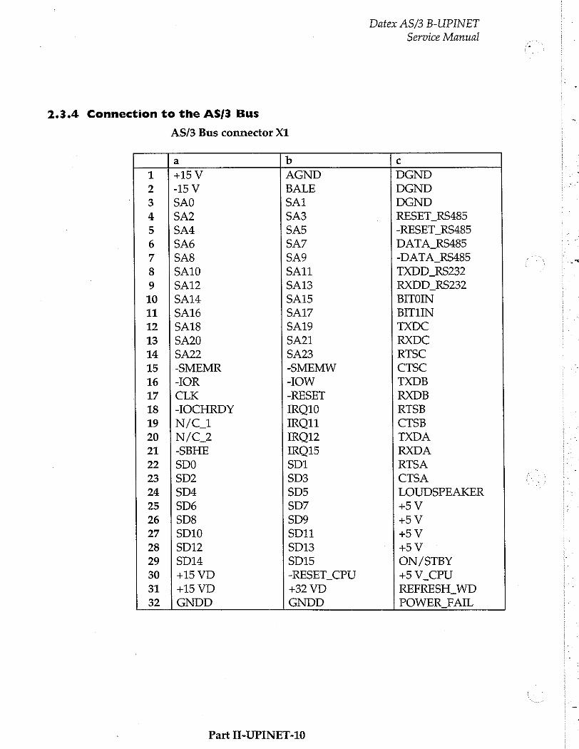
2.3.4 Connection to the AS/3 Bus
AS/3 Bus connector X1
Datex AS/3 B-UPINET Service Manual
a b c
1 +15 V AGND DGND
2 -15 V BALE DGND
3 |SAO SA1 DGND 4 SA2 SA3 RESET_RS485
5 SA4 SA5 -RESET RS485
6 SA6 SA7 DATA_RS485
7 SA8 SA9 -DATA_RS485
8 SA10 SA11 TXDD_RS232
9 SA12 SA13 RXDD_RS232
10 |SA14 SA15 BITOIN
11 | 9Α16 SA17 BIT1IN
12 |SA18 SA19 TXDC
13 | SA20 SA21 RXDC
14 |SA22 SA23 RTSC
15 |-SMEMR -SMEMW CTSC
16 |-IOR -IOW TXDB
17 | CLK -RESET RXDB
18 | -IOCHRDY IRQ10 RTSB
19 |N/C_1 IRQ11 CTSB
20 |N/C_2 IRQ12 TXDA
21 |-SBHE IRO15 RXDA
22 |500 SD1 RTSA
23 1902 SD3 CTSA
24 |SD4 SD5 LOUDSPEAKER
25 |506 507 +5 V
26 |508 $09 +5V 27 |SD10 SD11 +5
28 | SD12 SD13 +5V
29 |SD14 SD15 ON/STBY
30 |+15 VD -RESET CPU +5 V CPU
31 |+15VD +32 VD REFRESH_WD
32 |GNDD GNDD POWER_FAIL
Part II-UPINET-10
Datex AS/3 B-UPINET Service Manual
3 SERVICE PROCEDURES
Due to the nature of the UPINET Board, field service is
limited only for troubleshooting. Faulty UPINET boards are returned to Datex for repair.
Datex is always available for service advice. Please provide the unit serial number, full type designation, and a detailed fault description.
CAUTION: Only trained personnel with appropriate tools and equipment are allowed to perform the tests and repairs outlined in this section. Unauthorized service may void warranty of the unit.
Please, refer to the Installation Manual of your monitor for information on how to remove the UPINET Board.
Part H-UPINET-11
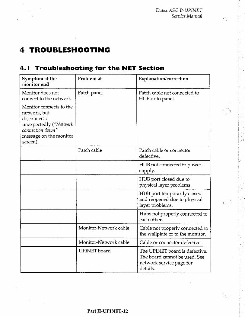
4 TROUBLESHOOTING
Datex AS/3 B-UPINET
Service Manual
4.1 Troubleshooting for the NET Section
Symptom at the monitor end
Problem at Explanation/correction
Monitor does not
connect to the network.
Monitor connects to the
network, but
disconnects
unexpectedly (“Network connection down”
message on the monitor screen).
Patch panel Patch cable not connected to
HUB or to panel.
Patch cable Patch cable or connector
defective.
HUB not connected to power supply.
HUB port closed due to physical layer problems.
HUB port temporarily closed and reopened due to physical layer problems.
Hubs not properly connected to each other.
Monitor-Network cable Cable not properly connected to the wallplate or to the monitor.
Monitor-Network cable Cable or connector defective. UPINET board The UPINET board is defective.
The board cannot be used. See
network service page for details.
Part II-UPINET-12
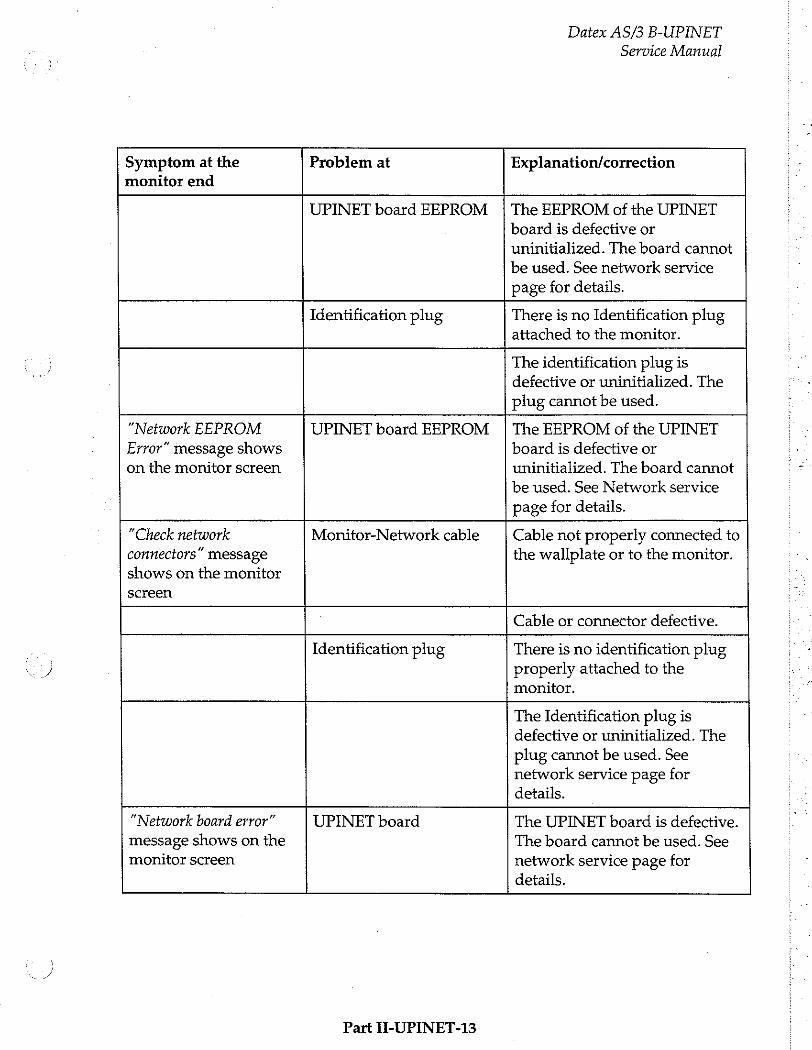
X
Datex AS/3 B-UPINET
Service Manual
Symptom at the monitor end
Problem at Explanation/correction
UPINET board EEPROM The EEPROM of the UPINET board is defective or
uninitialized. The board cannot
be used. See network service
page for details.
Identification plug There is no Identification plug attached to the monitor.
The identification plug is
defective or uninitialized. The
plug cannot be used.
“Network EEPROM Error” message shows on the monitor screen
UPINET board EEPROM The EEPROM of the UPINET board is defective or
uninitialized. The board cannot
be used. See Network service
page for details.
“Check network connectors” message shows on the monitor screen
Monitor-Network cable Cable not properly connected to the wallplate or to the monitor.
Cable or connector defective.
Identification plug There is no identification plug properly attached to the monitor.
The Identification plug is defective or uninitialized. The plug cannot be used. See network service page for details.
“Network board error”
message shows on the
monitor screen UPINET board The UPINET board is defective.
The board cannot be used. See
network service page for details.
Part II-UPINET-13

Datex AS/3 B-UPINET
Service Manual
Symptom at the monitor end
Problem at Explanation/correction
UPINET board EEPROM The EEPROM of the UPINET
board is defective or
uninitialized. The board cannot
be used. See network service
page for details.
Other Site View shows
no waveforms
No waveforms are set up
for Monitor-to-Monitor
communication
Run AS/3 Network Setup to verify current Monitor-to- Monitor communication setup.
Network printing fails Print server is busy Network manager's print server is busy at the moment and cannot take more print jobs. Try again after 15 seconds.
Print queue is full There are too many unprinted documents waiting in the print queue. Check the printer, as it is not operating properly.
Printer is off-line Printer cable is loose, printer is out of paper, there is paper jam or the printer is simply switched to off-line state.
Record keeper menus are blank There are no menus for
the record keeper Run AS/3 Network Setup to
verify the current set up.
4.2 Troubleshooting for the UPI section
Part II-UPINET-14
Please refer to troubleshooting in the central unit section.
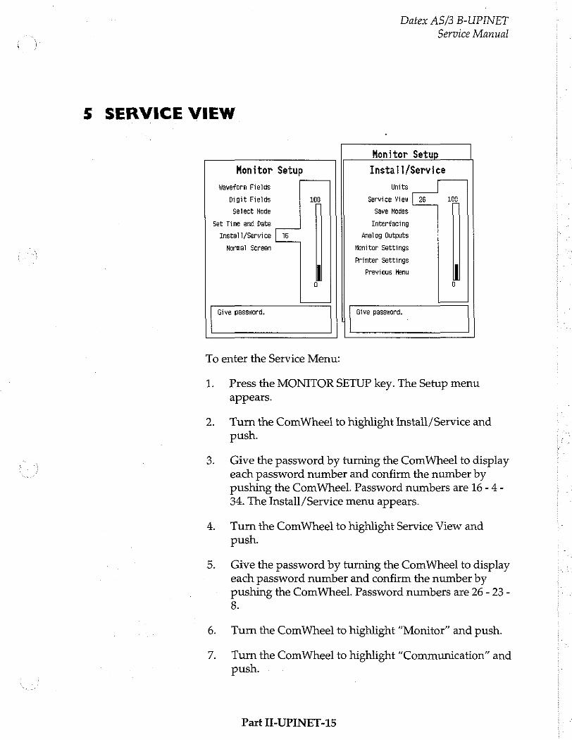
Datex AS/3 B-UPINET
Service Manual
5 SERVICE VIEW
Monitor Setup
Monitor Setup Install/Service
Waveform Fields Units
Digit Fields 100 Service View | 26 108
Select Hode Save Modes
Set Time and Date Interfacing
Insta] 1/Service Le Analog Gutputs
Normal Screen Konitor Settings
Printer Settings
Previous Menu
Give password, Give password.
To enter the Service Menu:
1. Press the MONITOR SETUP key. The Setup menu appears.
Turn the ComWheel to highlight Install/Service and push.
Give the password by turning the ComWheel to display each password number and confirm the number by pushing the ComWheel. Password numbers are 16 - 4 - 34. The Install /Service menu appears.
Turn the ComWheel to highlight Service View and push.
Give the password by turning the ComWheel to display each password number and confirm the number by pushing the ComWheel. Password numbers are 26 - 23 - 8.
Turn the ComWheel to highlight “Monitor” and push.
Turn the ComWheel to highlight “Communication” and push.
Part II-UPINET-15
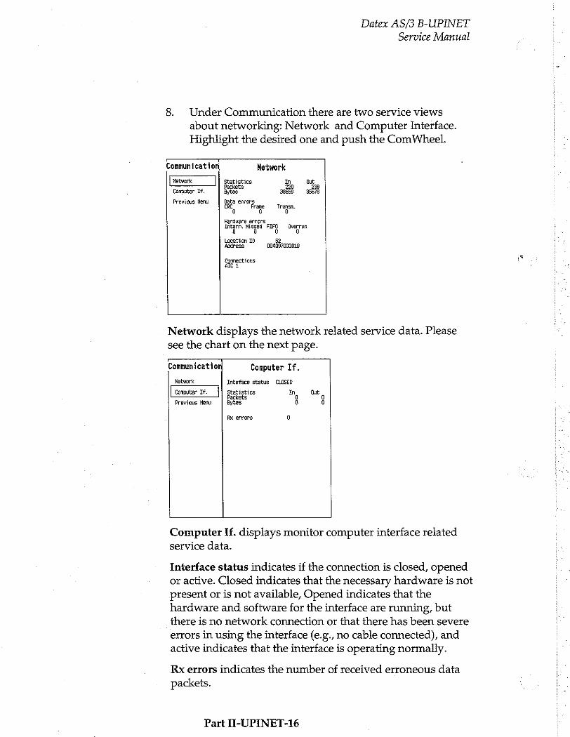
Datex AS/3 B-UPINET
Service Manual
8. Under Communication there are two service views
about networking: Network and Computer Interface. Highlight the desired one and push the ComWheel.
Communication Network
Network Statistics In Dut Packets 220 238
Computer If. Bytes 38659 35678
Previous Menu Data errors CRC Frane Transn.
Hardware errors Intern, Misged as Sverrun
Location 10 52 Address 004097000018
Connections ALİ
Network displays the network related service data. Please see the chart on the next page. — Communication Computer If.
Network Inteface status . CLOSED
Computer If. Statistics m Out Packets 0
previous Menu Bytes 6 oo
Rx errors 9
Computer If. displays monitor computer interface related service data.
Interface status indicates if the connection is closed, opened
or active. Closed indicates that the necessary hardware is not present or is not available, Opened indicates that the
hardware and software for the interface are running, but
there is no network connection or that there has been severe
errors in using the interface (e.g., no cable connected), and active indicates that the interface is operating normally.
Rx errors indicates the number of received erroneous data
packets.
Part II-UPINET-16
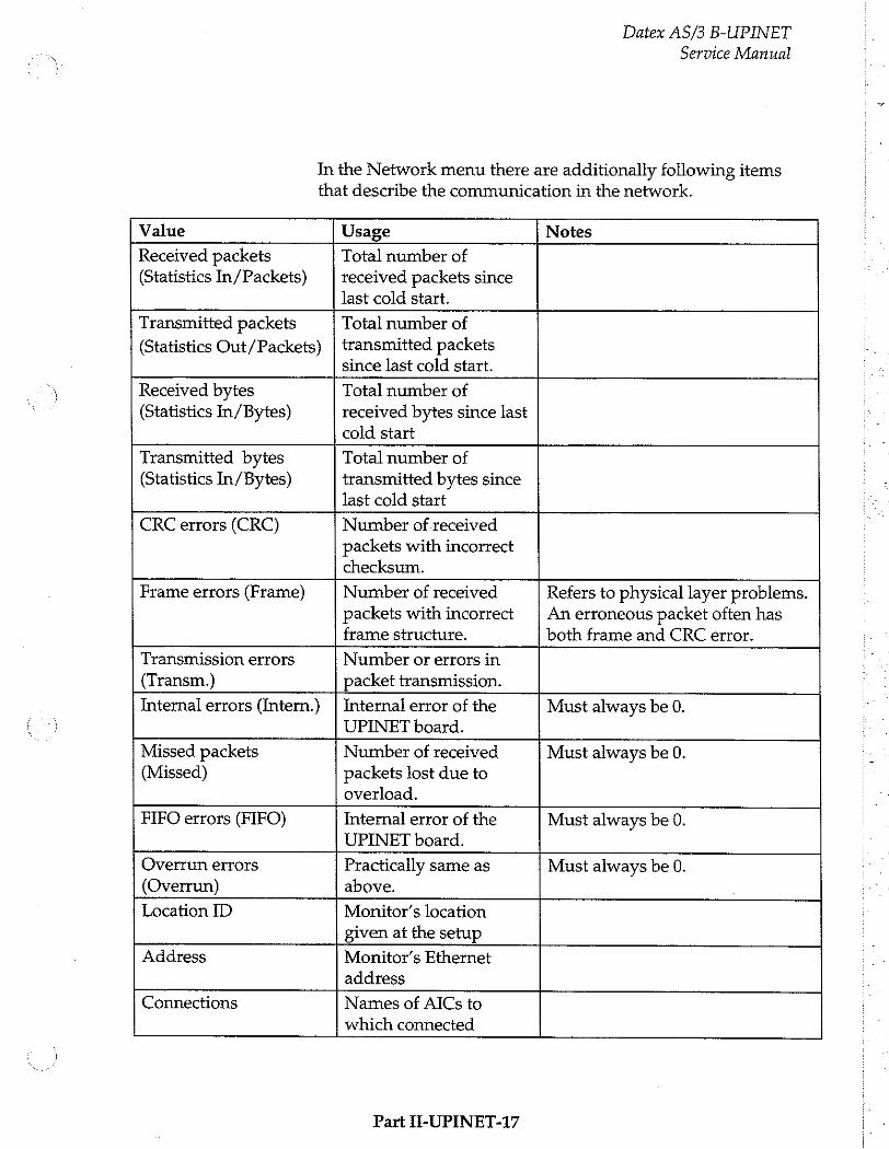
Datex AS/3 B-UPINET
Service Manual
In the Network menu there are additionally following items that describe the communication in the network.
Value Usage Notes
Received packets (Statistics In/Packets)
Total number of
received packets since last cold start.
Transmitted packets
(Statistics Out/Packets)
Total number of
transmitted packets since last cold start.
Received bytes (Statistics In/Bytes)
Total number of
received bytes since last cold start
Transmitted bytes Total number of
(Statistics In/Bytes) transmitted bytes since last cold start
CRC errors (CRC) Number of received packets with incorrect checksum.
Frame errors (Frame) Number of received
packets with incorrect frame structure.
Refers to physical layer problems. An erroneous packet often has both frame and CRC error.
Transmission errors Number or errors in
(Transm.) packet transmission.
Internal errors (Intern.) | Internal error of the Must always be 0. UPINET board.
Missed packets Number of received Must always be 0. (Missed) packets lost due to
overload.
FIFO errors (FIFO) Internal error of the Must always be 0.
UPINET board.
Overrun errors Practically same as Must always be 0. (Overrun) above.
Location ID Monitor's location given at the setup
Address Monitor's Ethernet address
Connections Names of AICs to which connected
Part I-UPINET-17
6 SPARE PARTS
UPINET Board, B-UPINET
Item description
Grounding plate EMC cover
* = the part is recommended for stock
Part IT-UPINET-18
Datex AS/3 B-UPINET
Service Manual
Order No.
887930 889296

Datex AS/3 B-UPINET
Service Manual
7 EARLIER REVISIONS
There are no earlier revisions of the UPINET board.
Part II-UPINET-19