Part 3. Supplemental Document for Contactless ICCs - PC/SC ...
37
Interoperability Specification for ICCs and Personal Computer Systems Part 3. Supplemental Document for Contactless ICCs Gemalto HID Omnikey NXP Semiconductors SCM Microsystems Inc. VASCO Data Security Revision 2.02.00 April 2010
-
Upload
khangminh22 -
Category
Documents
-
view
0 -
download
0
Transcript of Part 3. Supplemental Document for Contactless ICCs - PC/SC ...
Interoperability Specification for ICCs and Personal Computer Systems
Part 3. Supplemental Document for Contactless ICCs Gemalto
HID Omnikey
NXP Semiconductors
SCM Microsystems Inc.
VASCO Data Security
Revision 2.02.00
April 2010
Copyright © 1996–2010 Apple, Gemalto, Hewlett-Packard, IBM, Infineon, Ingenico, Microsoft, HID Omnikey, NXP Semiconductors, Siemens, Sun Microsystems, Toshiba.
All rights reserved.
INTELLECTUAL PROPERTY DISCLAIMER THIS SPECIFICATION IS PROVIDED “AS IS” WITH NO WARRANTIES WHATSOEVER INCLUDING ANY WARRANTY OF MERCHANTABILITY, FITNESS FOR ANY PARTICULAR PURPOSE, OR ANY WARRANTY OTHERWISE ARISING OUT OF ANY PROPOSAL, SPECIFICATION, OR SAMPLE. NO LICENSE, EXPRESS OR IMPLIED, BY ESTOPPEL OR OTHERWISE, TO ANY INTELLECTUAL PROPERTY RIGHTS IS GRANTED OR INTENDED HEREBY. GEMALTO, HEWLETT-PACKARD, HID OMNIKEY, IBM, INFINEON, INGENICO, MICROSOFT, NXP SEMICINDUCTORS, SIEMENS, SUN MICROSYSTEMS AND TOSHIBA DISCLAIM ALL LIABILITY, INCLUDING LIABILITY FOR INFRINGEMENT OF PROPRIETARY RIGHTS, RELATING TO IMPLEMENTATION OF INFORMATION IN THIS SPECIFICATION. GEMALTO, HEWLETT-PACKARD, HID OMNIKEY, IBM, INFINEON, INGENICO, MICROSOFT, NXP SEMICINDUCTORS, SIEMENS, SUN MICROSYSTEMS AND TOSHIBA DO NOT WARRANT OR REPRESENT THAT SUCH IMPLEMENTATION(S) WILL NOT INFRINGE SUCH RIGHTS. Windows are registered trademarks of Microsoft Corporation. All other product names are trademarks, registered trademarks, or servicemarks of their respective owners.

Revision History
Revision Issue Date Comments 2.00.00 March 29, 2010 First version

Interoperability Specification for ICCs and Personal Computer Systems Part 3. Supplemental Document for Contactless ICCs
Contents
1 SCOPE 1
1.1 Applicable Products 1
1.2 Abbreviations 2
2 APDU DEFINITION 3
2.1 Command APDU 3
2.2 Response APDU 3
2.3 Overview of the structure 5
3 COMMUNICATION METHOD 6
3.1 General Methods 6
3.2 Using Transmit() 6
3.3 Using Control() 6 3.3.1 Function Call for Control() 6 3.3.2 Implementation note for Windows and Linux 7
4 MANAGE SESSION COMMAND 8
4.1 Start Transparent Session Data Object 9
4.2 End Transparent Session Data Object 9
4.3 Version Data Object 10
4.4 Turn OFF the RF Data Object 10
4.5 Timer Data Object 11
4.6 Turn ON the RF Data Object 11
4.7 Get Parameters Data Object 12
4.8 Set Parameters Data Object 13
5 TRANSPARENT EXCHANGE COMMAND 15
5.1 Transmission and Reception Flag Data Object 16
© 1996–2010 PC/SC Workgroup. All rights reserved. Page i
Interoperability Specification for ICCs and Personal Computer Systems Part 3. Supplemental Document for Contactless ICCs
5.2 Transmission Bit Framing Data Object 17
5.3 Reception Bit Framing Data Object 17
5.4 Transmit Data Object 18
5.5 Receive Data Object 18
5.6 Transceive Data Object 18
5.7 Response Status Data Object 19
5.8 Response Data Object 19
6 SWITCH PROTOCOL COMMAND 20
6.1 Switch protocol Data Object 21
6.2 Switch Protocol Command example between ISO/IEC 14443-3 and ISO/IEC 14443-4. 22
7 REFERENCES 23
8 ANNEX 24
8.1 Switch Protocol command examples 24 8.1.1 Switch to ISO/IEC 14443-2 Type A 24 8.1.2 Switch to ISO14443-3 type A data object 24 8.1.3 Switch to ISO14443-4 Type A data object 25 8.1.4 Switch to ISO/IEC 14443-2 Type B data object 25 8.1.5 Switch to ISO/IEC 14443-3 Type B data object 26 8.1.6 Switch to ISO/IEC 14443-4 Type B data object 26 8.1.7 Switch to ISO/IEC 15693-2 Data Object 27 8.1.8 Switch to ISO/IEC 15693-3 Data Object 27 8.1.9 Switch to SONY FeliCa Framing 27 8.1.10 Switch to SONY FeliCa ICC activation 28 8.1.11 Switch to I-CODE EPC/UID 28 8.1.12 Switch to I-CODE 1 28 8.1.13 Switch to HF EPC G2/ISO18000-3 Mode 3 29
8.2 APDU sample for Transmit() 30
© 1996–2010 PC/SC Workgroup. All rights reserved. Page ii
Interoperability Specification for ICCs and Personal Computer Systems Part 3. Supplemental Document for Contactless ICCs
1 Scope
This amendment specifies the functions to transparently pass data from an application to a contactless ICC, return the received data transparently to the application and defines a means of switching the protocol simultaneously. The transparent transceiver and protocol switch function enable any application to handle widely established ISO/IEC 14443 and ISO/IEC 15693 based contactless ICC protocols, mode switches and commands.
This specification uses the IFD command coded with CLA (class) byte equal to FF, as used in PC/SC part 3. The instruction byte equals to C2 indicating a similar functional principle as the ENVELOPE command, described in ISO/IEC 7816-4.
All functions are coded within this single IFD command using P1, P2 combination and the BER-TLV structure. The data filed of C-APDU and R-APDU can contain multiple data objects encoded in TLV structure.
All numbers used in APDU or SW1-SW2 in this document are written in implicit hexadecimal notation (if not mentioned otherwise).
In this specification there can be use cases where the application needs to connect without presence of an ICC, in those cases direct mode shall be used.
As an alternative the communication can be done via Control() as described in §3 of this specification.
This specification doesn’t replace any existing PC/SC specification.
1.1 Applicable Products
All PC/SC compliant IFDs which are supporting PC/SC version 2.02 or higher.
© 1996–2010 PC/SC Workgroup. All rights reserved. Page 1
Interoperability Specification for ICCs and Personal Computer Systems Part 3. Supplemental Document for Contactless ICCs
1.2 Abbreviations The following table lists abbreviations used throughout this document.
Table 1: Abbreviations
Abbreviation Meaning
APDU Application Protocol Data Unit
ATR Answer To Reset
BER Basic Encoding Rules of ASN.1 (see ISO/IEC 8825 -1)
C-APDU Command APDU
CLA Class byte
ICC Integrated Circuit Card. In this specification this abbreviation is used for contactless ICC as PC/SC terminology. ISO/IEC 14443 uses “PICC” and ISO/IEC 15693 uses “VICC” for it.
IFD InterFace Device (reader/writer). In this specification this abbreviation is used for contactless IFD as PC/SC terminology. ISO/IEC 14443 uses “PCD” and ISO/IEC 15693 uses “VCD” for it.
INS INStruction byte
Lc field Length field for coding the number of Nc
Le field Length field for coding the number of Ne
Nc Number of bytes in the command data field
Ne Number of bytes expected in the response data field
Nr Number of bytes in the response data field
P1-P2 Parameter bytes (inserted for clarity, the dash is not significant)
PCD Proximity Coupling Device
PICC Proximity Integrated Circuit Card
R-APDU Response APDU
RFU Reserved for Future Use
SW1-SW2 Status bytes (inserted for clarity, the dash is not significant)
TLV Tag, Length, Value
VCD Vicinity Coupling Device
VICC Vicinity IC Card
© 1996–2010 PC/SC Workgroup. All rights reserved. Page 2
Interoperability Specification for ICCs and Personal Computer Systems Part 3. Supplemental Document for Contactless ICCs
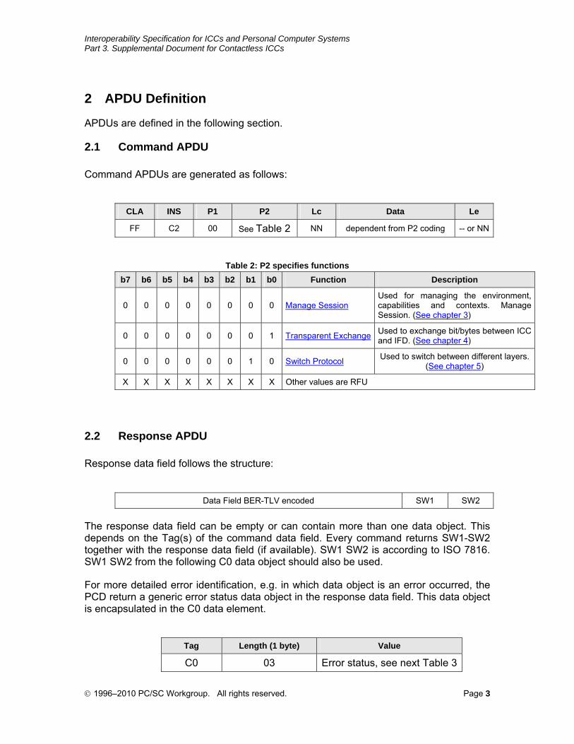
2 APDU Definition
APDUs are defined in the following section.
2.1 Command APDU
Command APDUs are generated as follows:
CLA INS P1 P2 Lc Data Le
FF C2 00 See Table 2 NN dependent from P2 coding -- or NN
Table 2: P2 specifies functions
b7 b6 b5 b4 b3 b2 b1 b0 Function Description
0 0 0 0 0 0 0 0 Manage SessionUsed for managing the environment, capabilities and contexts. Manage Session. (See chapter 3)
0 0 0 0 0 0 0 1 Transparent Exchange Used to exchange bit/bytes between ICC and IFD. (See chapter 4)
0 0 0 0 0 0 1 0 Switch Protocol Used to switch between different layers. (See chapter 5)
X X X X X X X X Other values are RFU
2.2 Response APDU
Response data field follows the structure:
Data Field BER-TLV encoded SW1 SW2
The response data field can be empty or can contain more than one data object. This depends on the Tag(s) of the command data field. Every command returns SW1-SW2 together with the response data field (if available). SW1 SW2 is according to ISO 7816. SW1 SW2 from the following C0 data object should also be used.
For more detailed error identification, e.g. in which data object is an error occurred, the PCD return a generic error status data object in the response data field. This data object is encapsulated in the C0 data element.
Tag Length (1 byte) Value
C0 03 Error status, see next Table 3
© 1996–2010 PC/SC Workgroup. All rights reserved. Page 3
Interoperability Specification for ICCs and Personal Computer Systems Part 3. Supplemental Document for Contactless ICCs
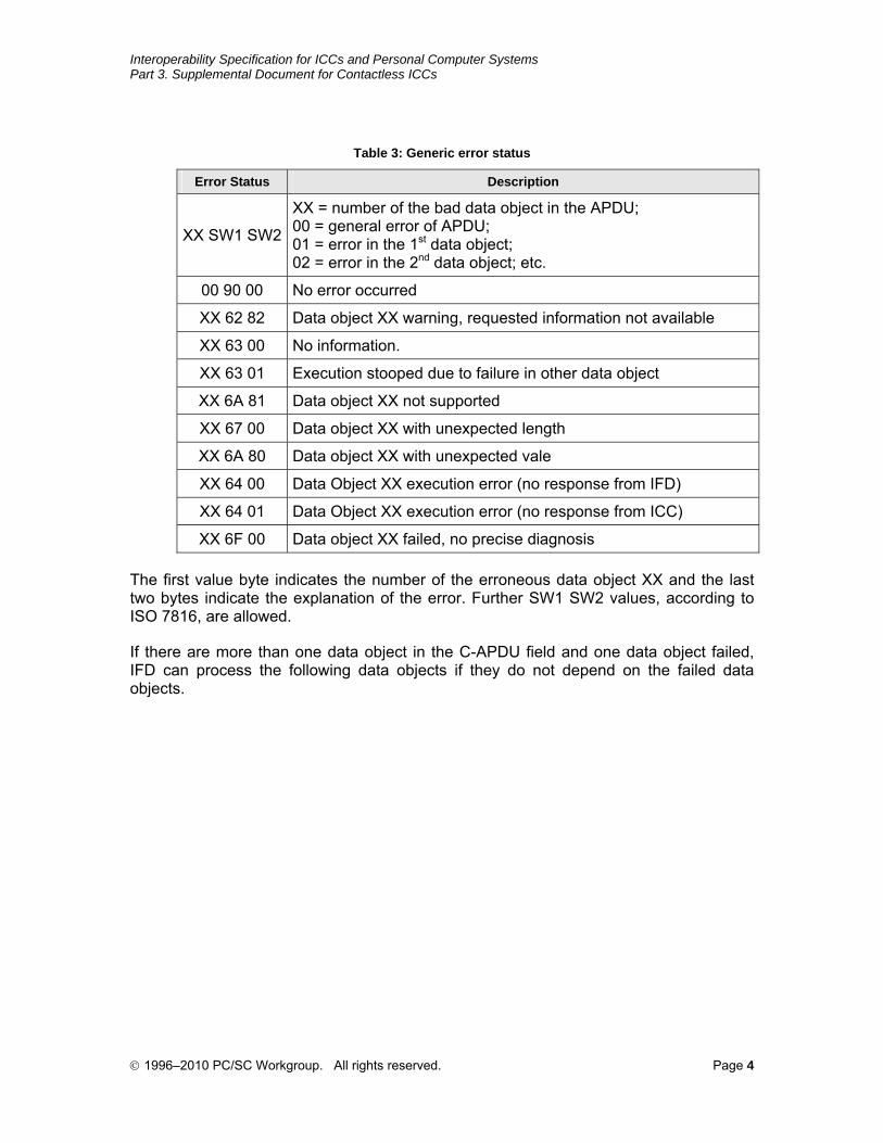
Table 3: Generic error status
Error Status Description
XX SW1 SW2
XX = number of the bad data object in the APDU; 00 = general error of APDU; 01 = error in the 1st data object; 02 = error in the 2nd data object; etc.
00 90 00 No error occurred
XX 62 82 Data object XX warning, requested information not available
XX 63 00 No information.
XX 63 01 Execution stooped due to failure in other data object
XX 6A 81 Data object XX not supported
XX 67 00 Data object XX with unexpected length
XX 6A 80 Data object XX with unexpected vale
XX 64 00 Data Object XX execution error (no response from IFD)
XX 64 01 Data Object XX execution error (no response from ICC)
XX 6F 00 Data object XX failed, no precise diagnosis
The first value byte indicates the number of the erroneous data object XX and the last two bytes indicate the explanation of the error. Further SW1 SW2 values, according to ISO 7816, are allowed.
If there are more than one data object in the C-APDU field and one data object failed, IFD can process the following data objects if they do not depend on the failed data objects.
© 1996–2010 PC/SC Workgroup. All rights reserved. Page 4
Interoperability Specification for ICCs and Personal Computer Systems Part 3. Supplemental Document for Contactless ICCs
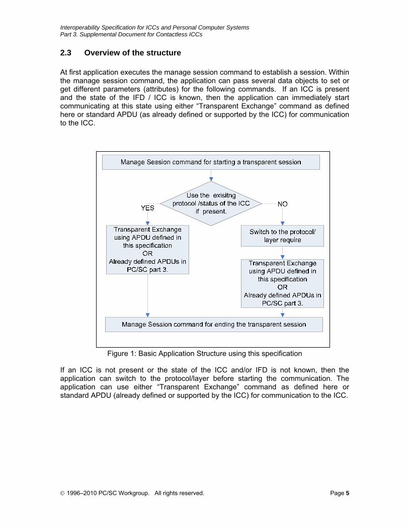
2.3 Overview of the structure
At first application executes the manage session command to establish a session. Within the manage session command, the application can pass several data objects to set or get different parameters (attributes) for the following commands. If an ICC is present and the state of the IFD / ICC is known, then the application can immediately start communicating at this state using either “Transparent Exchange” command as defined here or standard APDU (as already defined or supported by the ICC) for communication to the ICC.
Figure 1: Basic Application Structure using this specification
If an ICC is not present or the state of the ICC and/or IFD is not known, then the application can switch to the protocol/layer before starting the communication. The application can use either “Transparent Exchange” command as defined here or standard APDU (already defined or supported by the ICC) for communication to the ICC.
© 1996–2010 PC/SC Workgroup. All rights reserved. Page 5
Interoperability Specification for ICCs and Personal Computer Systems Part 3. Supplemental Document for Contactless ICCs
3 Communication Method
3.1 General Methods
PC/SC implementations behave differently regarding controlling the IFD and depending on the presence of an ICC.
For this reason this specification does not give a preference for one particular method of communication with an IFD.
Some PC/SC implementations might limit the usage of Transmit() while there might be limitations for others for using Control().
It will be up to the application developer to choose the right method for the actual purposes and environment.
3.2 Using Transmit()
This method can be used in any environment when an ICC is present and the application has established an ICC handle.
Some PC/SC implementations even may allow using this method without an ICC being present. The connection can be done using Connect() in the direct mode.
In any case the APDU to be transmitted is the byte string as described under 2.1 and the return message is the byte string as described under 2.2.
3.3 Using Control()
In environments not allowing Transmit() without an ICC or caused by any other reasons or developers preferences the application can communicate via Control().
The application should retrieve the control code corresponding to FEATURE_CCID_ESC_COMMAND (see part 10, rev.2.02.07). In case this feature is not returned, the application may try SCARD_CTL_CODE(3500) as control code to use.
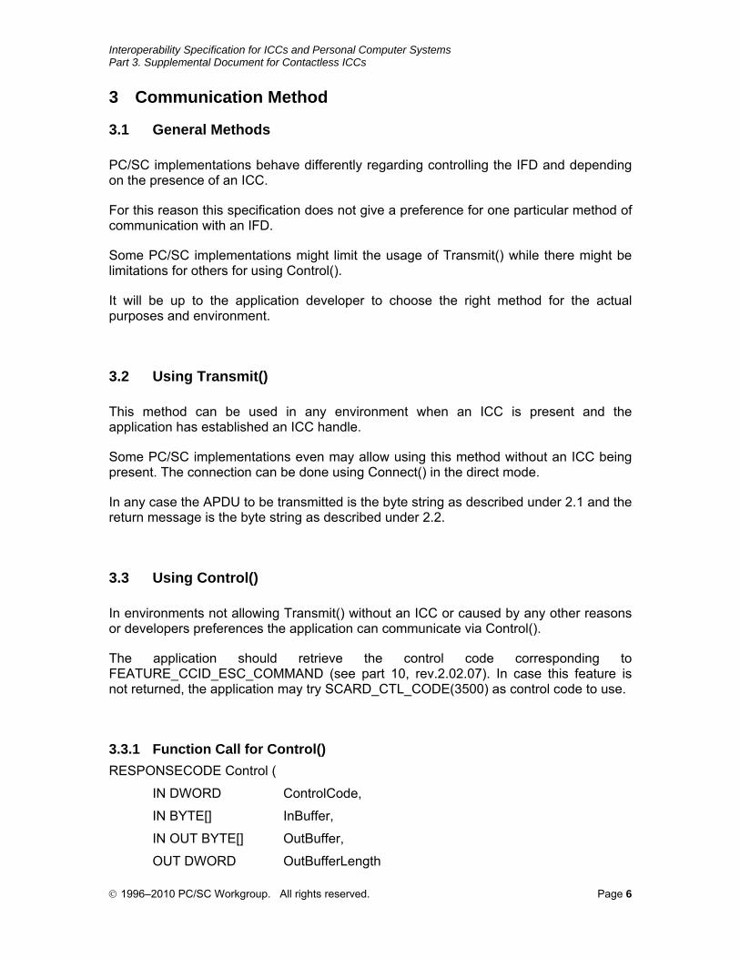
3.3.1 Function Call for Control() RESPONSECODE Control (
IN DWORD ControlCode,
IN BYTE[] InBuffer,
IN OUT BYTE[] OutBuffer,
OUT DWORD OutBufferLength
© 1996–2010 PC/SC Workgroup. All rights reserved. Page 6
Interoperability Specification for ICCs and Personal Computer Systems Part 3. Supplemental Document for Contactless ICCs
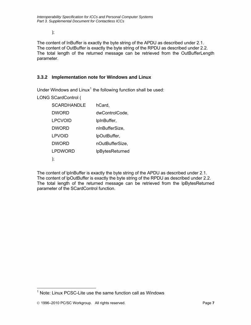
); The content of InBuffer is exactly the byte string of the APDU as described under 2.1. The content of OutBuffer is exactly the byte string of the RPDU as described under 2.2. The total length of the returned message can be retrieved from the OutBufferLength parameter.
3.3.2 Implementation note for Windows and Linux Under Windows and Linux1 the following function shall be used:
LONG SCardControl (
SCARDHANDLE hCard,
DWORD dwControlCode,
LPCVOID lpInBuffer,
DWORD nInBufferSize,
LPVOID lpOutBuffer,
DWORD nOutBufferSize,
LPDWORD lpBytesReturned
);
The content of lpInBuffer is exactly the byte string of the APDU as described under 2.1. The content of lpOutBuffer is exactly the byte string of the RPDU as described under 2.2. The total length of the returned message can be retrieved from the lpBytesReturned parameter of the SCardControl function.
1 Note: Linux PCSC-Lite use the same function call as Windows
© 1996–2010 PC/SC Workgroup. All rights reserved. Page 7
Interoperability Specification for ICCs and Personal Computer Systems Part 3. Supplemental Document for Contactless ICCs
4 Manage Session Command
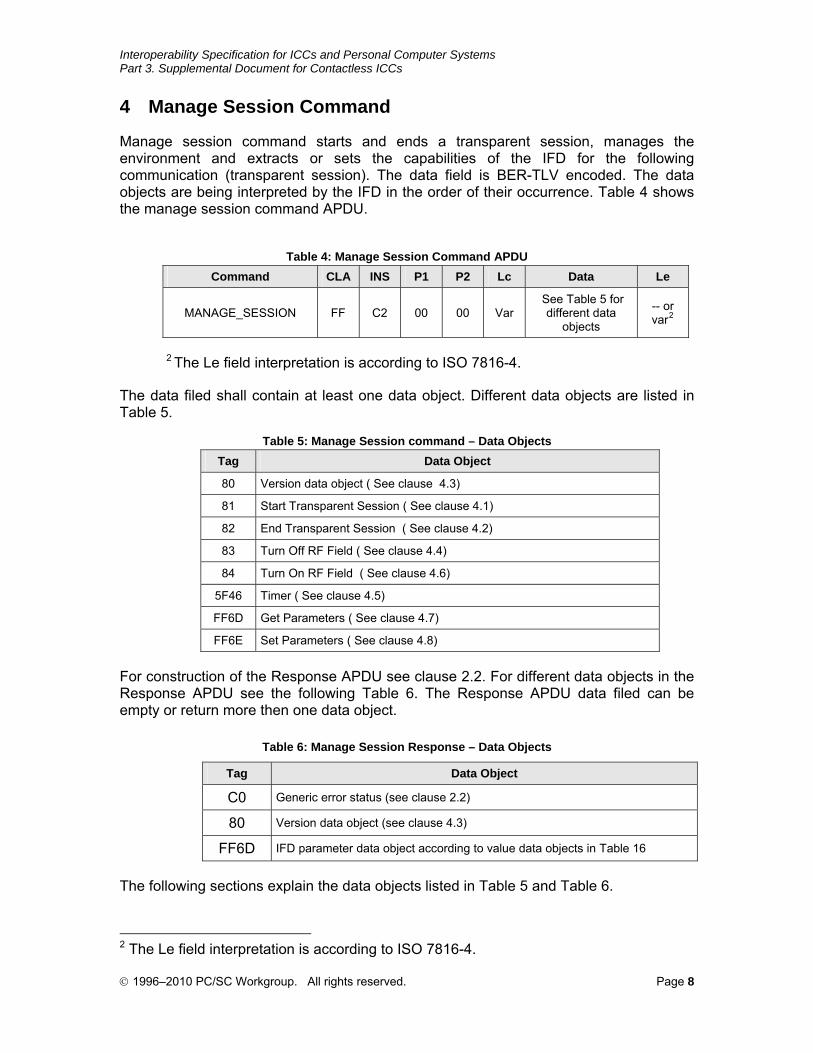
Manage session command starts and ends a transparent session, manages the environment and extracts or sets the capabilities of the IFD for the following communication (transparent session). The data field is BER-TLV encoded. The data objects are being interpreted by the IFD in the order of their occurrence. Table 4 shows the manage session command APDU.
Table 4: Manage Session Command APDU
Command CLA INS P1 P2 Lc Data Le
MANAGE_SESSION FF C2 00 00 Var See Table 5 for
different data objects
-- or var2
2 The Le field interpretation is according to ISO 7816-4.
The data filed shall contain at least one data object. Different data objects are listed in Table 5.
Table 5: Manage Session command – Data Objects
Tag Data Object
80 Version data object ( See clause 4.3)
81 Start Transparent Session ( See clause 4.1)
82 End Transparent Session ( See clause 4.2)
83 Turn Off RF Field ( See clause 4.4)
84 Turn On RF Field ( See clause 4.6)
5F46 Timer ( See clause 4.5)
FF6D Get Parameters ( See clause 4.7)
FF6E Set Parameters ( See clause 4.8)
For construction of the Response APDU see clause 2.2. For different data objects in the Response APDU see the following Table 6. The Response APDU data filed can be empty or return more then one data object.
Table 6: Manage Session Response – Data Objects
Tag Data Object
C0 Generic error status (see clause 2.2)
80 Version data object (see clause 4.3)
FF6D IFD parameter data object according to value data objects in Table 16
The following sections explain the data objects listed in Table 5 and Table 6.
2 The Le field interpretation is according to ISO 7816-4.
© 1996–2010 PC/SC Workgroup. All rights reserved. Page 8
Interoperability Specification for ICCs and Personal Computer Systems Part 3. Supplemental Document for Contactless ICCs
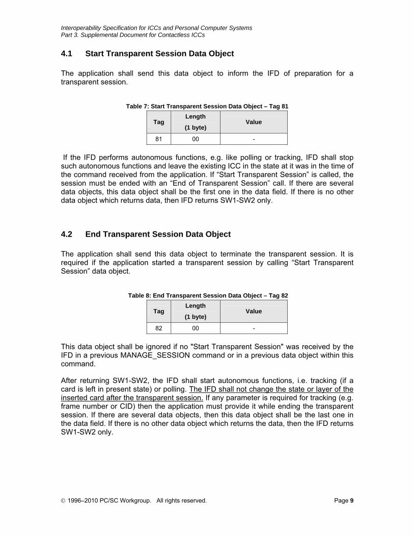
4.1 Start Transparent Session Data Object
The application shall send this data object to inform the IFD of preparation for a transparent session.
Table 7: Start Transparent Session Data Object – Tag 81
Tag Length
(1 byte) Value
81 00 -
If the IFD performs autonomous functions, e.g. like polling or tracking, IFD shall stop such autonomous functions and leave the existing ICC in the state at it was in the time of the command received from the application. If “Start Transparent Session” is called, the session must be ended with an “End of Transparent Session” call. If there are several data objects, this data object shall be the first one in the data field. If there is no other data object which returns data, then IFD returns SW1-SW2 only.
4.2 End Transparent Session Data Object
The application shall send this data object to terminate the transparent session. It is required if the application started a transparent session by calling “Start Transparent Session” data object.
Table 8: End Transparent Session Data Object – Tag 82
Tag Length
(1 byte) Value
82 00 -
This data object shall be ignored if no "Start Transparent Session" was received by the IFD in a previous MANAGE_SESSION command or in a previous data object within this command.
After returning SW1-SW2, the IFD shall start autonomous functions, i.e. tracking (if a card is left in present state) or polling. The IFD shall not change the state or layer of the inserted card after the transparent session. If any parameter is required for tracking (e.g. frame number or CID) then the application must provide it while ending the transparent session. If there are several data objects, then this data object shall be the last one in the data field. If there is no other data object which returns the data, then the IFD returns SW1-SW2 only.
© 1996–2010 PC/SC Workgroup. All rights reserved. Page 9
Interoperability Specification for ICCs and Personal Computer Systems Part 3. Supplemental Document for Contactless ICCs
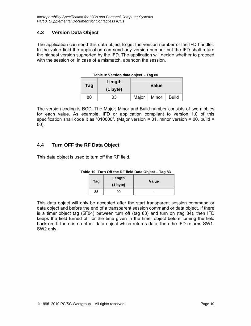
4.3 Version Data Object
The application can send this data object to get the version number of the IFD handler. In the value field the application can send any version number but the IFD shall return the highest version supported by the IFD. The application will decide whether to proceed with the session or, in case of a mismatch, abandon the session.
Table 9: Version data object - Tag 80
Tag Length (1 byte)
Value
80 03 Major Minor Build
The version coding is BCD. The Major, Minor and Build number consists of two nibbles for each value. As example, IFD or application compliant to version 1.0 of this specification shall code it as “010000”. (Major version = 01, minor version = 00, build = 00).
4.4 Turn OFF the RF Data Object
This data object is used to turn off the RF field.
Table 10: Turn Off the RF field Data Object – Tag 83
Tag Length
(1 byte) Value
83 00 -
This data object will only be accepted after the start transparent session command or data object and before the end of a transparent session command or data object. If there is a timer object tag (5F04) between turn off (tag 83) and turn on (tag 84), then IFD keeps the field turned off for the time given in the timer object before turning the field back on. If there is no other data object which returns data, then the IFD returns SW1-SW2 only.
© 1996–2010 PC/SC Workgroup. All rights reserved. Page 10
Interoperability Specification for ICCs and Personal Computer Systems Part 3. Supplemental Document for Contactless ICCs
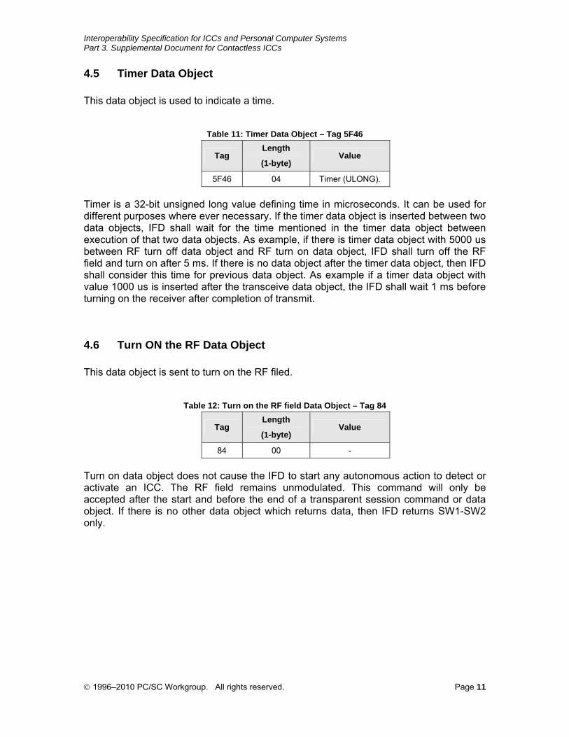
4.5 Timer Data Object
This data object is used to indicate a time.
Table 11: Timer Data Object – Tag 5F46
Tag Length
(1-byte) Value
5F46 04 Timer (ULONG).
Timer is a 32-bit unsigned long value defining time in microseconds. It can be used for different purposes where ever necessary. If the timer data object is inserted between two data objects, IFD shall wait for the time mentioned in the timer data object between execution of that two data objects. As example, if there is timer data object with 5000 us between RF turn off data object and RF turn on data object, IFD shall turn off the RF field and turn on after 5 ms. If there is no data object after the timer data object, then IFD shall consider this time for previous data object. As example if a timer data object with value 1000 us is inserted after the transceive data object, the IFD shall wait 1 ms before turning on the receiver after completion of transmit.
4.6 Turn ON the RF Data Object
This data object is sent to turn on the RF filed.
Table 12: Turn on the RF field Data Object – Tag 84
Tag Length
(1-byte) Value
84 00 -
Turn on data object does not cause the IFD to start any autonomous action to detect or activate an ICC. The RF field remains unmodulated. This command will only be accepted after the start and before the end of a transparent session command or data object. If there is no other data object which returns data, then IFD returns SW1-SW2 only.
© 1996–2010 PC/SC Workgroup. All rights reserved. Page 11
Interoperability Specification for ICCs and Personal Computer Systems Part 3. Supplemental Document for Contactless ICCs
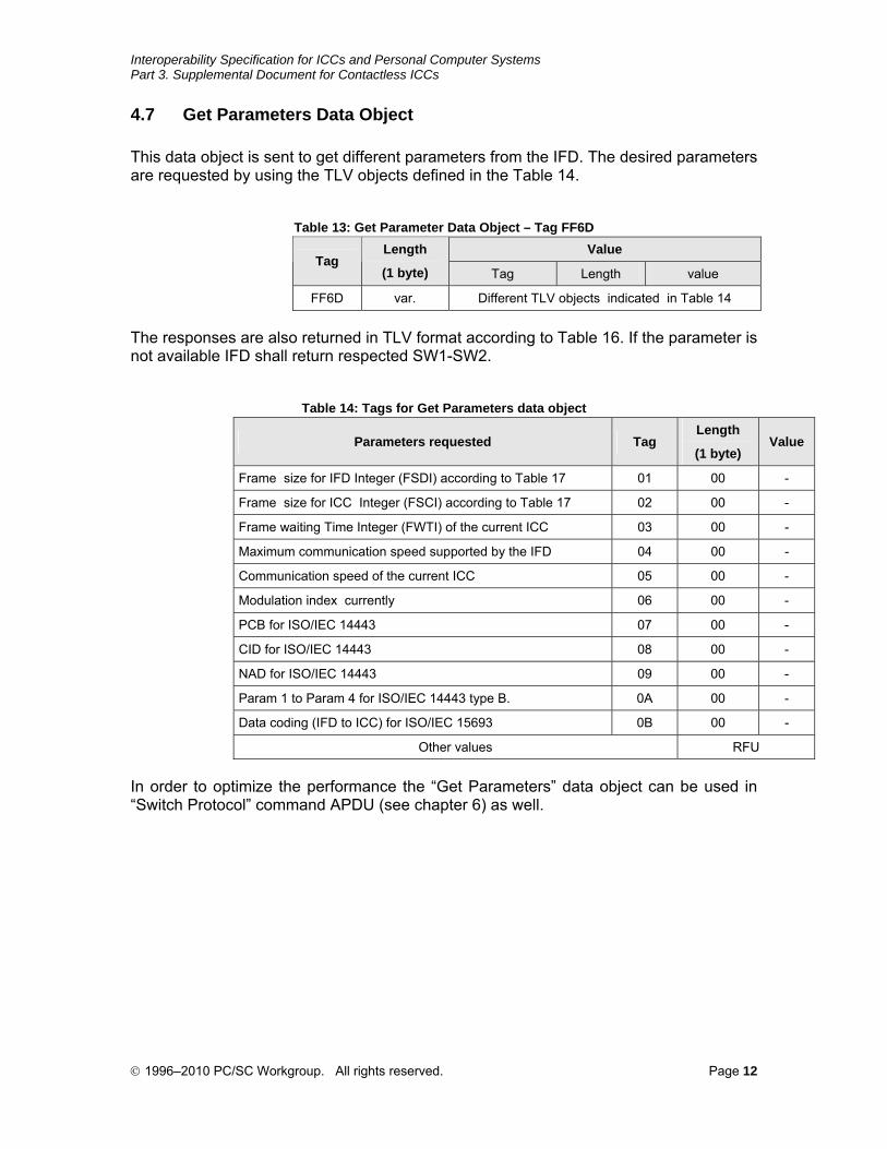
4.7 Get Parameters Data Object
This data object is sent to get different parameters from the IFD. The desired parameters are requested by using the TLV objects defined in the Table 14.
Table 13: Get Parameter Data Object – Tag FF6D
Value Tag
Length
(1 byte) Tag Length value
FF6D var. Different TLV objects indicated in Table 14
The responses are also returned in TLV format according to Table 16. If the parameter is not available IFD shall return respected SW1-SW2.
Table 14: Tags for Get Parameters data object
Parameters requested Tag Length
(1 byte) Value
Frame size for IFD Integer (FSDI) according to Table 17 01 00 -
Frame size for ICC Integer (FSCI) according to Table 17 02 00 -
Frame waiting Time Integer (FWTI) of the current ICC 03 00 -
Maximum communication speed supported by the IFD 04 00 -
Communication speed of the current ICC 05 00 -
Modulation index currently 06 00 -
PCB for ISO/IEC 14443 07 00 -
CID for ISO/IEC 14443 08 00 -
NAD for ISO/IEC 14443 09 00 -
Param 1 to Param 4 for ISO/IEC 14443 type B. 0A 00 -
Data coding (IFD to ICC) for ISO/IEC 15693 0B 00 -
Other values RFU
In order to optimize the performance the “Get Parameters” data object can be used in “Switch Protocol” command APDU (see chapter 6) as well.
© 1996–2010 PC/SC Workgroup. All rights reserved. Page 12

Interoperability Specification for ICCs and Personal Computer Systems Part 3. Supplemental Document for Contactless ICCs
4.8 Set Parameters Data Object
This data object is sent to set the parameters for the current session or while leaving the session. The parameters shall be set, are given by TLV objects described in Table 16.
Table 15: Set Parameter Data Object – Tag FF6E
Value Tag
Length
(1 byte) Tag Length Value
FF6E var. According to Table 16
Table 16: Tag for Parameters with Value data object
Tag Length
(1 byte) Value
01 01 Frame size for IFD Integer (FSDI) according to Table 17
02 01 Frame size for ICC Integer (FSCI) according to Table 17
03 01 Frame waiting Time Integer (FWTI) of the current ICC,
Time = 302.07 x 2FWTI microseconds.
04 01 Maximum communication speed supported by the IFD according to Table 18
05 01 Communication speed is set or will be set for the current ICC according to Table 18.
06 01 Modulation index (can be used for all ICCs, where modulation index is required)
07 01 PCB for ISO/IEC 14443
08 01 CID for ISO/IEC 14443
09 01 NAD for ISO/IEC 14443
0A 04 Param 1 to Param 4 for ISO/IEC 14443 type B.
0B 01 Data coding (IFD to ICC) for ISO/IEC 15693
Other values RFU
Table 17: coding of buffer size
FSCI/FSDI 0 1 2 3 4 5 6 7 8 >8
Frame size 16 24 32 40 48 64 96 128 256 RFU
Table 18: coding of communication speed
b7 b6 b5 b4 b3 b2 b1 b0
0 = Different speed for each direction supported.
1 = Only the same speed for both directions supported.
RFU set to 0
RFU set to 0
Communication speed ICC to IFD.
For ISO/IEC 14443.
01 = 212 kbps
10 = 424 kbps
11 = 848 kbps
RFU set to 0
Communication speed IFD to ICC.
For ISO/IEC 14443.
01 = 212 kbps
10 = 424 kbps
11 = 848 kbps
© 1996–2010 PC/SC Workgroup. All rights reserved. Page 13
Interoperability Specification for ICCs and Personal Computer Systems Part 3. Supplemental Document for Contactless ICCs
If there are several parameters in the command data filed, IFD shall consider the parameters which are supported and ignore the rest. In this case IFD shall return the respected SW1-SW2.
The application may then repeat the command with single data objects to figure out the non-supported value or object.
In order to optimize the performance the “Set Parameters” data object can be used in “Switch Protocol” command APDU (see chapter6) as well.
© 1996–2010 PC/SC Workgroup. All rights reserved. Page 14
Interoperability Specification for ICCs and Personal Computer Systems Part 3. Supplemental Document for Contactless ICCs
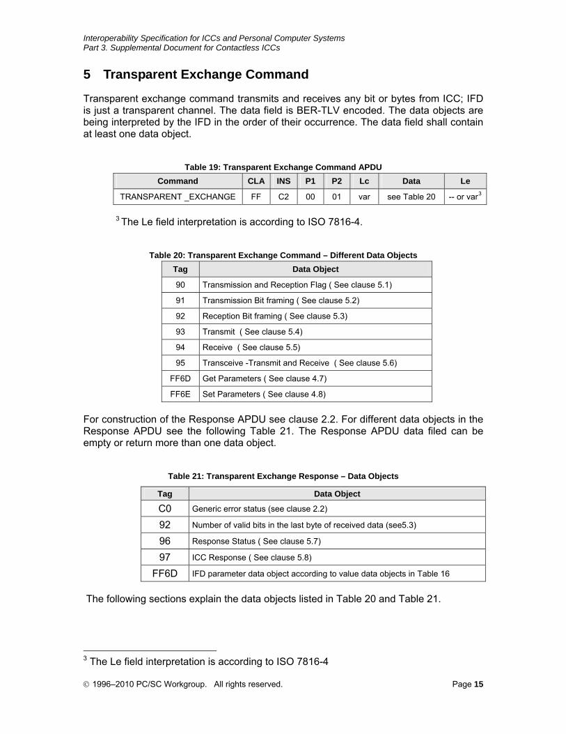
5 Transparent Exchange Command
Transparent exchange command transmits and receives any bit or bytes from ICC; IFD is just a transparent channel. The data field is BER-TLV encoded. The data objects are being interpreted by the IFD in the order of their occurrence. The data field shall contain at least one data object.
Table 19: Transparent Exchange Command APDU
Command CLA INS P1 P2 Lc Data Le
TRANSPARENT _EXCHANGE FF C2 00 01 var see Table 20 -- or var3
3 The Le field interpretation is according to ISO 7816-4.
Table 20: Transparent Exchange Command – Different Data Objects
Tag Data Object
90 Transmission and Reception Flag ( See clause 5.1)
91 Transmission Bit framing ( See clause 5.2)
92 Reception Bit framing ( See clause 5.3)
93 Transmit ( See clause 5.4)
94 Receive ( See clause 5.5)
95 Transceive -Transmit and Receive ( See clause 5.6)
FF6D Get Parameters ( See clause 4.7)
FF6E Set Parameters ( See clause 4.8)
For construction of the Response APDU see clause 2.2. For different data objects in the Response APDU see the following Table 21. The Response APDU data filed can be empty or return more than one data object.
Table 21: Transparent Exchange Response – Data Objects
Tag Data Object
C0 Generic error status (see clause 2.2)
92 Number of valid bits in the last byte of received data (see5.3)
96 Response Status ( See clause 5.7)
97 ICC Response ( See clause 5.8)
FF6D IFD parameter data object according to value data objects in Table 16
The following sections explain the data objects listed in Table 20 and Table 21.
3 The Le field interpretation is according to ISO 7816-4
© 1996–2010 PC/SC Workgroup. All rights reserved. Page 15
Interoperability Specification for ICCs and Personal Computer Systems Part 3. Supplemental Document for Contactless ICCs
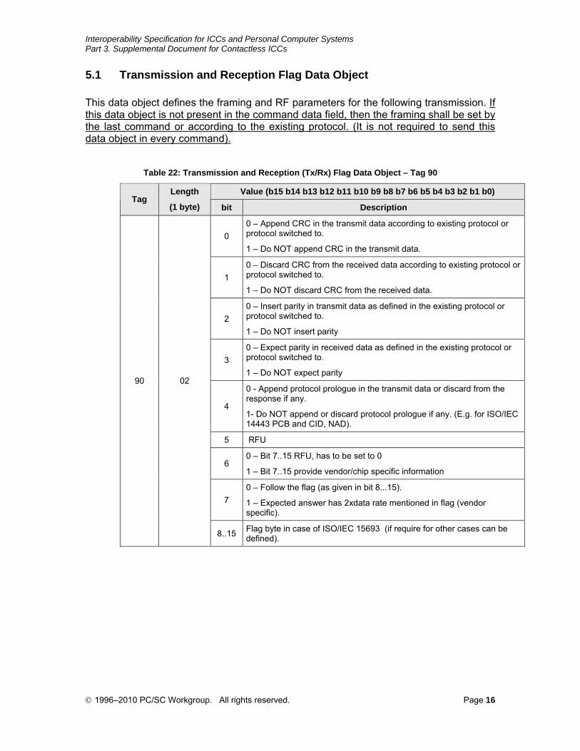
5.1 Transmission and Reception Flag Data Object
This data object defines the framing and RF parameters for the following transmission. If this data object is not present in the command data field, then the framing shall be set by the last command or according to the existing protocol. (It is not required to send this data object in every command).
Table 22: Transmission and Reception (Tx/Rx) Flag Data Object – Tag 90
Value (b15 b14 b13 b12 b11 b10 b9 b8 b7 b6 b5 b4 b3 b2 b1 b0) Tag
Length
(1 byte) bit Description
0 0 – Append CRC in the transmit data according to existing protocol or protocol switched to.
1 – Do NOT append CRC in the transmit data.
1 0 – Discard CRC from the received data according to existing protocol or protocol switched to.
1 – Do NOT discard CRC from the received data.
2 0 – Insert parity in transmit data as defined in the existing protocol or protocol switched to.
1 – Do NOT insert parity
3 0 – Expect parity in received data as defined in the existing protocol or protocol switched to.
1 – Do NOT expect parity
4
0 - Append protocol prologue in the transmit data or discard from the response if any.
1- Do NOT append or discard protocol prologue if any. (E.g. for ISO/IEC 14443 PCB and CID, NAD).
5 RFU
6 0 – Bit 7..15 RFU, has to be set to 0
1 – Bit 7..15 provide vendor/chip specific information
7 0 – Follow the flag (as given in bit 8...15).
1 – Expected answer has 2xdata rate mentioned in flag (vendor specific).
90 02
8..15 Flag byte in case of ISO/IEC 15693 (if require for other cases can be defined).
© 1996–2010 PC/SC Workgroup. All rights reserved. Page 16
Interoperability Specification for ICCs and Personal Computer Systems Part 3. Supplemental Document for Contactless ICCs
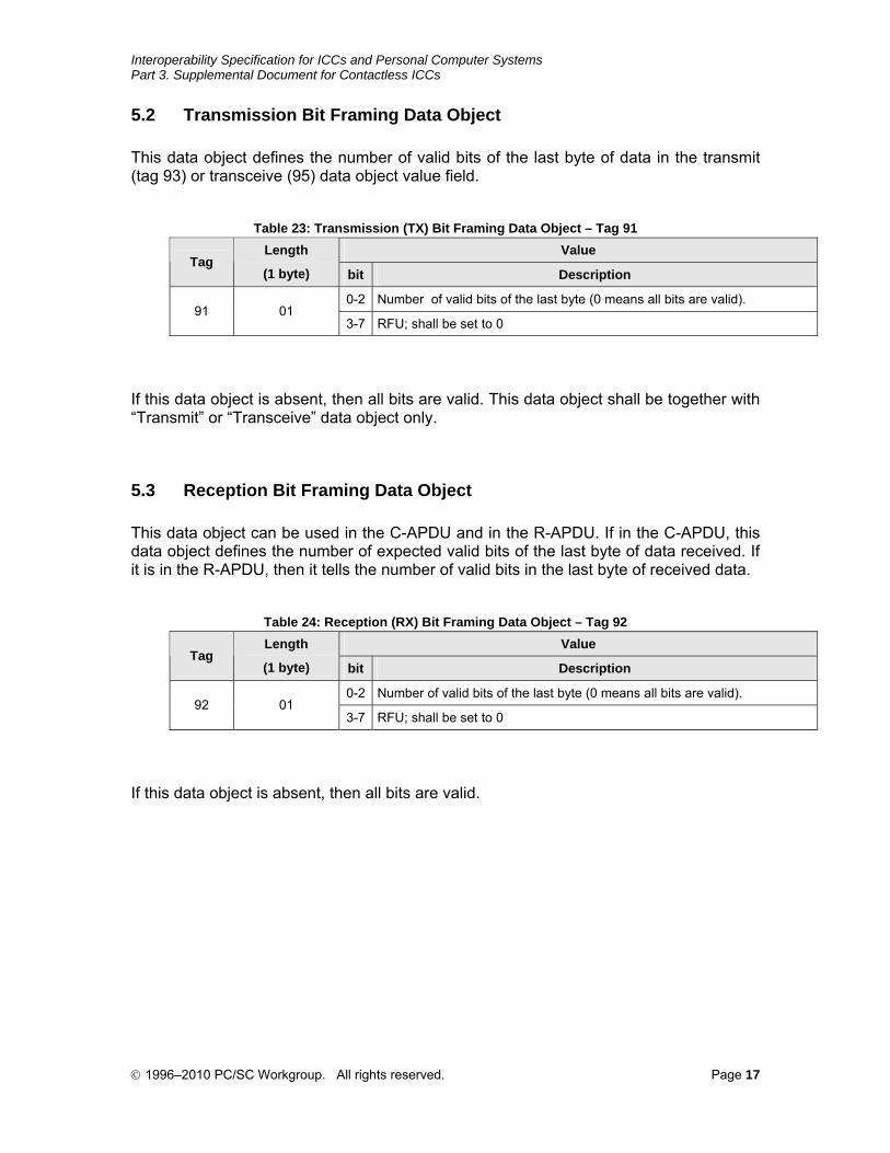
5.2 Transmission Bit Framing Data Object
This data object defines the number of valid bits of the last byte of data in the transmit (tag 93) or transceive (95) data object value field.
Table 23: Transmission (TX) Bit Framing Data Object – Tag 91
Value Tag
Length
(1 byte) bit Description
0-2 Number of valid bits of the last byte (0 means all bits are valid). 91 01
3-7 RFU; shall be set to 0
If this data object is absent, then all bits are valid. This data object shall be together with “Transmit” or “Transceive” data object only.
5.3 Reception Bit Framing Data Object
This data object can be used in the C-APDU and in the R-APDU. If in the C-APDU, this data object defines the number of expected valid bits of the last byte of data received. If it is in the R-APDU, then it tells the number of valid bits in the last byte of received data.
Table 24: Reception (RX) Bit Framing Data Object – Tag 92
Value Tag
Length
(1 byte) bit Description
0-2 Number of valid bits of the last byte (0 means all bits are valid). 92 01
3-7 RFU; shall be set to 0
If this data object is absent, then all bits are valid.
© 1996–2010 PC/SC Workgroup. All rights reserved. Page 17
Interoperability Specification for ICCs and Personal Computer Systems Part 3. Supplemental Document for Contactless ICCs
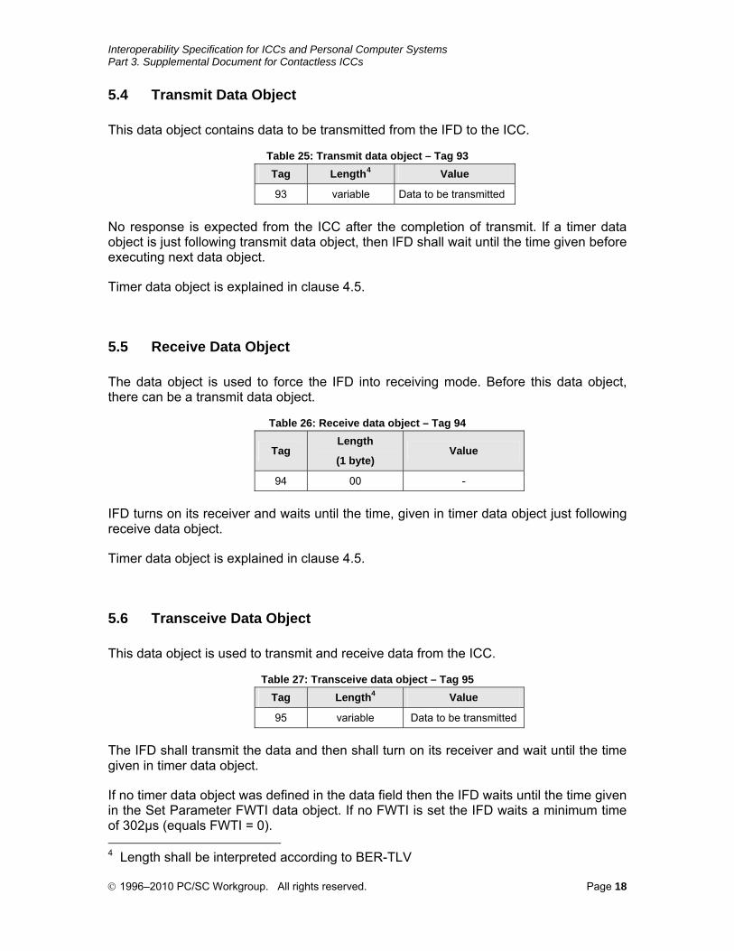
5.4 Transmit Data Object
This data object contains data to be transmitted from the IFD to the ICC.
Table 25: Transmit data object – Tag 93
Tag Length4 Value
93 variable Data to be transmitted
No response is expected from the ICC after the completion of transmit. If a timer data object is just following transmit data object, then IFD shall wait until the time given before executing next data object.
Timer data object is explained in clause 4.5.
5.5 Receive Data Object
The data object is used to force the IFD into receiving mode. Before this data object, there can be a transmit data object.
Table 26: Receive data object – Tag 94
Tag Length
(1 byte) Value
94 00 -
IFD turns on its receiver and waits until the time, given in timer data object just following receive data object.
Timer data object is explained in clause 4.5.
5.6 Transceive Data Object
This data object is used to transmit and receive data from the ICC.
Table 27: Transceive data object – Tag 95
Tag Length4 Value
95 variable Data to be transmitted
The IFD shall transmit the data and then shall turn on its receiver and wait until the time given in timer data object.
If no timer data object was defined in the data field then the IFD waits until the time given in the Set Parameter FWTI data object. If no FWTI is set the IFD waits a minimum time of 302µs (equals FWTI = 0). 4 Length shall be interpreted according to BER-TLV
© 1996–2010 PC/SC Workgroup. All rights reserved. Page 18
Interoperability Specification for ICCs and Personal Computer Systems Part 3. Supplemental Document for Contactless ICCs
The response data will be encapsulated in a simple data object with tag 0x97. If the received data are not modulo 8 data object 0x92 will be returned. If the receiver detects errors during receive a data object 0x96 will be returned.
Timer data object is explained in clause 4.5.
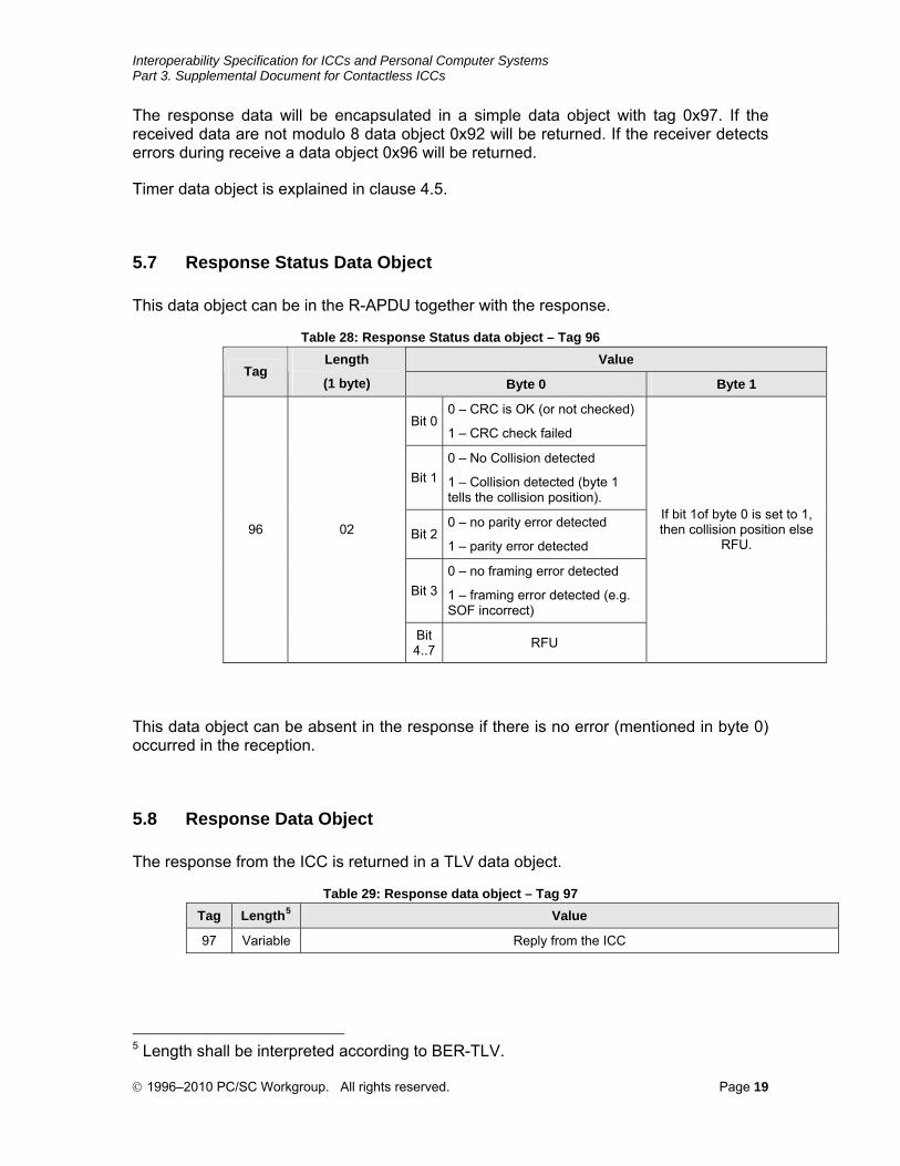
5.7 Response Status Data Object
This data object can be in the R-APDU together with the response.
Table 28: Response Status data object – Tag 96
Value Tag
Length
(1 byte) Byte 0 Byte 1
Bit 00 – CRC is OK (or not checked)
1 – CRC check failed
Bit 10 – No Collision detected
1 – Collision detected (byte 1 tells the collision position).
Bit 20 – no parity error detected
1 – parity error detected
Bit 30 – no framing error detected
1 – framing error detected (e.g. SOF incorrect)
96 02
Bit 4..7 RFU
If bit 1of byte 0 is set to 1, then collision position else
RFU.
This data object can be absent in the response if there is no error (mentioned in byte 0) occurred in the reception.
5.8 Response Data Object
The response from the ICC is returned in a TLV data object.
Table 29: Response data object – Tag 97
Tag Length5 Value
97 Variable Reply from the ICC
5 Length shall be interpreted according to BER-TLV.
© 1996–2010 PC/SC Workgroup. All rights reserved. Page 19
Interoperability Specification for ICCs and Personal Computer Systems Part 3. Supplemental Document for Contactless ICCs
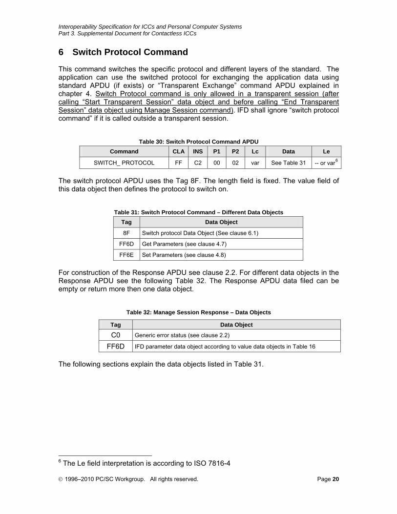
6 Switch Protocol Command
This command switches the specific protocol and different layers of the standard. The application can use the switched protocol for exchanging the application data using standard APDU (if exists) or “Transparent Exchange” command APDU explained in chapter 4. Switch Protocol command is only allowed in a transparent session (after calling “Start Transparent Session” data object and before calling “End Transparent Session” data object using Manage Session command). IFD shall ignore “switch protocol command” if it is called outside a transparent session.
Table 30: Switch Protocol Command APDU
Command CLA INS P1 P2 Lc Data Le
SWITCH_ PROTOCOL FF C2 00 02 var See Table 31 -- or var6
The switch protocol APDU uses the Tag 8F. The length field is fixed. The value field of this data object then defines the protocol to switch on.
Table 31: Switch Protocol Command – Different Data Objects
Tag Data Object
8F Switch protocol Data Object (See clause 6.1)
FF6D Get Parameters (see clause 4.7)
FF6E Set Parameters (see clause 4.8)
For construction of the Response APDU see clause 2.2. For different data objects in the Response APDU see the following Table 32. The Response APDU data filed can be empty or return more then one data object.
Table 32: Manage Session Response – Data Objects
Tag Data Object
C0 Generic error status (see clause 2.2)
FF6D IFD parameter data object according to value data objects in Table 16
The following sections explain the data objects listed in Table 31.
6 The Le field interpretation is according to ISO 7816-4
© 1996–2010 PC/SC Workgroup. All rights reserved. Page 20
Interoperability Specification for ICCs and Personal Computer Systems Part 3. Supplemental Document for Contactless ICCs
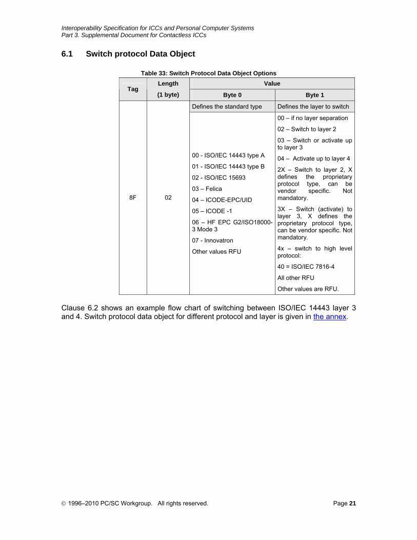
6.1 Switch protocol Data Object
Table 33: Switch Protocol Data Object Options
Value Tag
Length
(1 byte) Byte 0 Byte 1
Defines the standard type Defines the layer to switch
8F 02
00 - ISO/IEC 14443 type A
01 - ISO/IEC 14443 type B
02 - ISO/IEC 15693
03 – Felica
04 – ICODE-EPC/UID
05 – ICODE -1
06 – HF EPC G2/ISO18000-3 Mode 3
07 - Innovatron
Other values RFU
00 – if no layer separation
02 – Switch to layer 2
03 – Switch or activate up to layer 3
04 – Activate up to layer 4
2X – Switch to layer 2, X defines the proprietary protocol type, can be vendor specific. Not mandatory.
3X – Switch (activate) to layer 3, X defines the proprietary protocol type, can be vendor specific. Not mandatory.
4x – switch to high level protocol:
40 = ISO/IEC 7816-4
All other RFU
Other values are RFU.
Clause 6.2 shows an example flow chart of switching between ISO/IEC 14443 layer 3 and 4. Switch protocol data object for different protocol and layer is given in the annex.
© 1996–2010 PC/SC Workgroup. All rights reserved. Page 21
Interoperability Specification for ICCs and Personal Computer Systems Part 3. Supplemental Document for Contactless ICCs
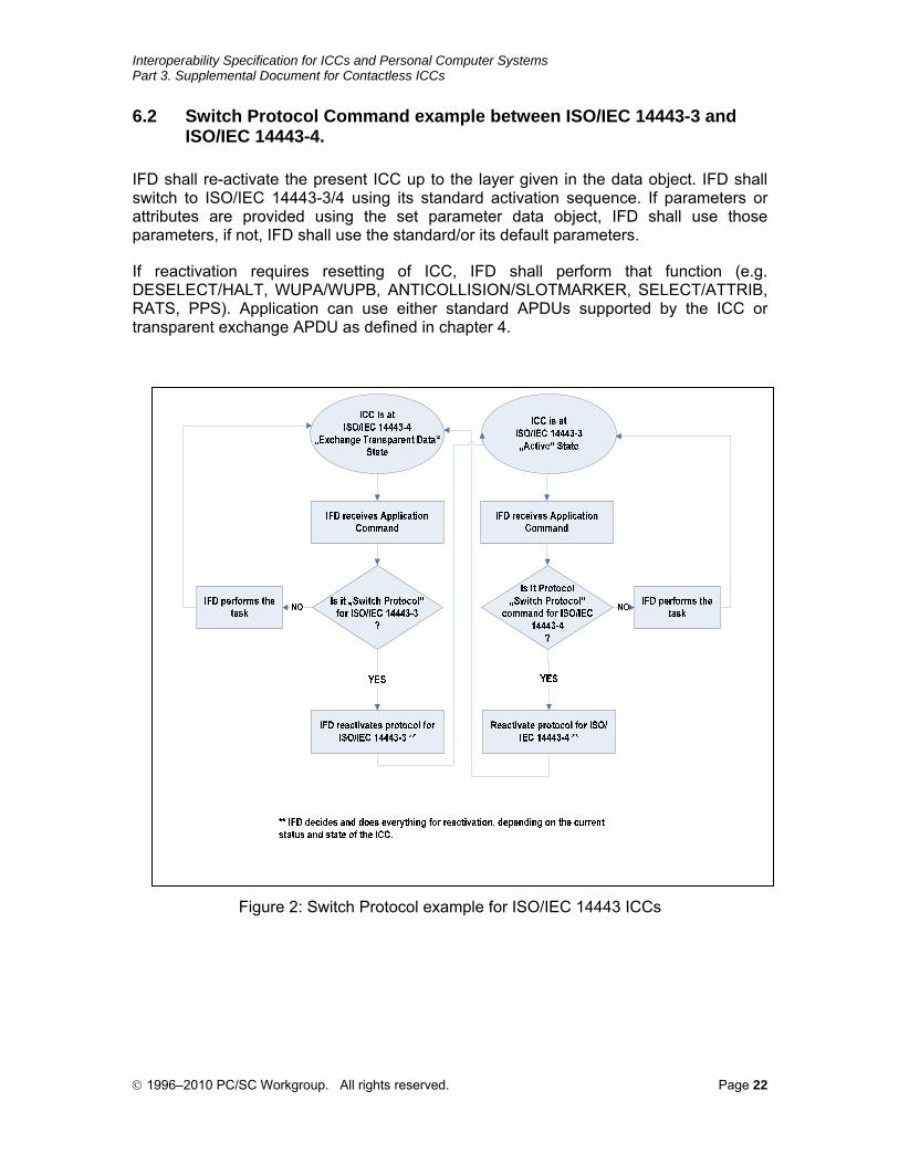
6.2 Switch Protocol Command example between ISO/IEC 14443-3 and ISO/IEC 14443-4.
IFD shall re-activate the present ICC up to the layer given in the data object. IFD shall switch to ISO/IEC 14443-3/4 using its standard activation sequence. If parameters or attributes are provided using the set parameter data object, IFD shall use those parameters, if not, IFD shall use the standard/or its default parameters.
If reactivation requires resetting of ICC, IFD shall perform that function (e.g. DESELECT/HALT, WUPA/WUPB, ANTICOLLISION/SLOTMARKER, SELECT/ATTRIB, RATS, PPS). Application can use either standard APDUs supported by the ICC or transparent exchange APDU as defined in chapter 4.
Figure 2: Switch Protocol example for ISO/IEC 14443 ICCs
© 1996–2010 PC/SC Workgroup. All rights reserved. Page 22
Interoperability Specification for ICCs and Personal Computer Systems Part 3. Supplemental Document for Contactless ICCs
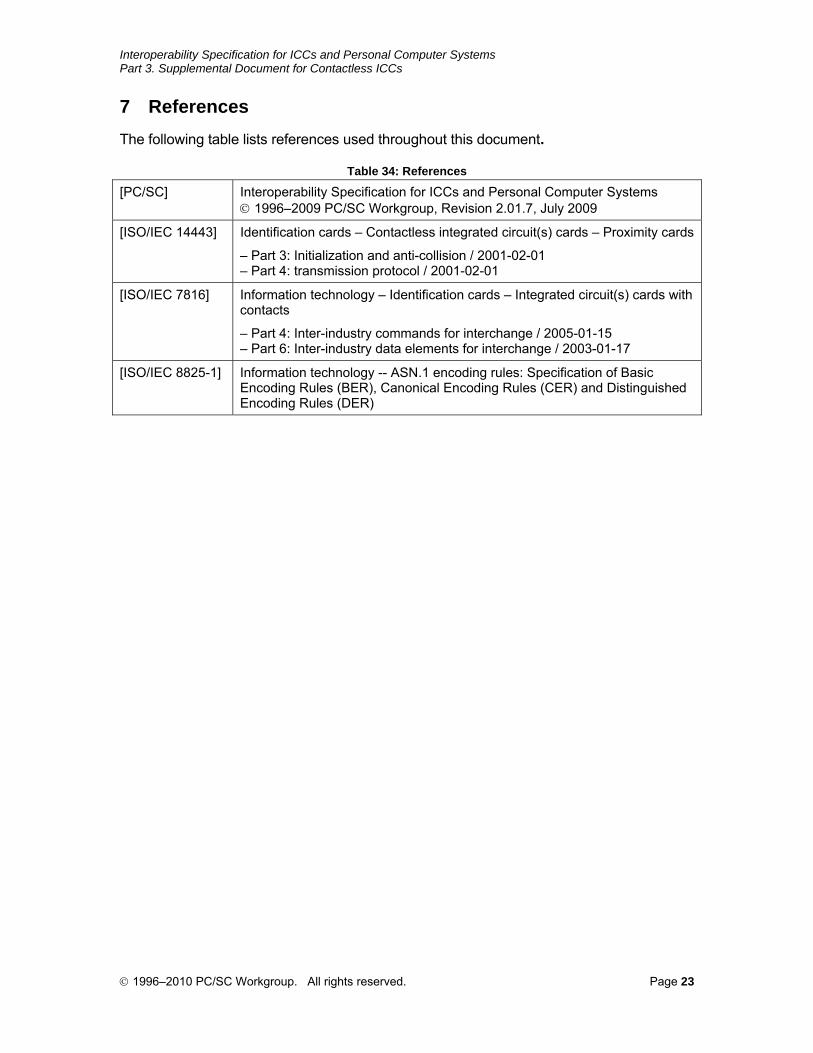
7 References The following table lists references used throughout this document.
Table 34: References
[PC/SC] Interoperability Specification for ICCs and Personal Computer Systems © 1996–2009 PC/SC Workgroup, Revision 2.01.7, July 2009
[ISO/IEC 14443] Identification cards – Contactless integrated circuit(s) cards – Proximity cards
– Part 3: Initialization and anti-collision / 2001-02-01 – Part 4: transmission protocol / 2001-02-01
[ISO/IEC 7816] Information technology – Identification cards – Integrated circuit(s) cards with contacts
– Part 4: Inter-industry commands for interchange / 2005-01-15 – Part 6: Inter-industry data elements for interchange / 2003-01-17
[ISO/IEC 8825-1] Information technology -- ASN.1 encoding rules: Specification of Basic Encoding Rules (BER), Canonical Encoding Rules (CER) and Distinguished Encoding Rules (DER)
© 1996–2010 PC/SC Workgroup. All rights reserved. Page 23
Interoperability Specification for ICCs and Personal Computer Systems Part 3. Supplemental Document for Contactless ICCs
8 Annex
8.1 Switch Protocol command examples
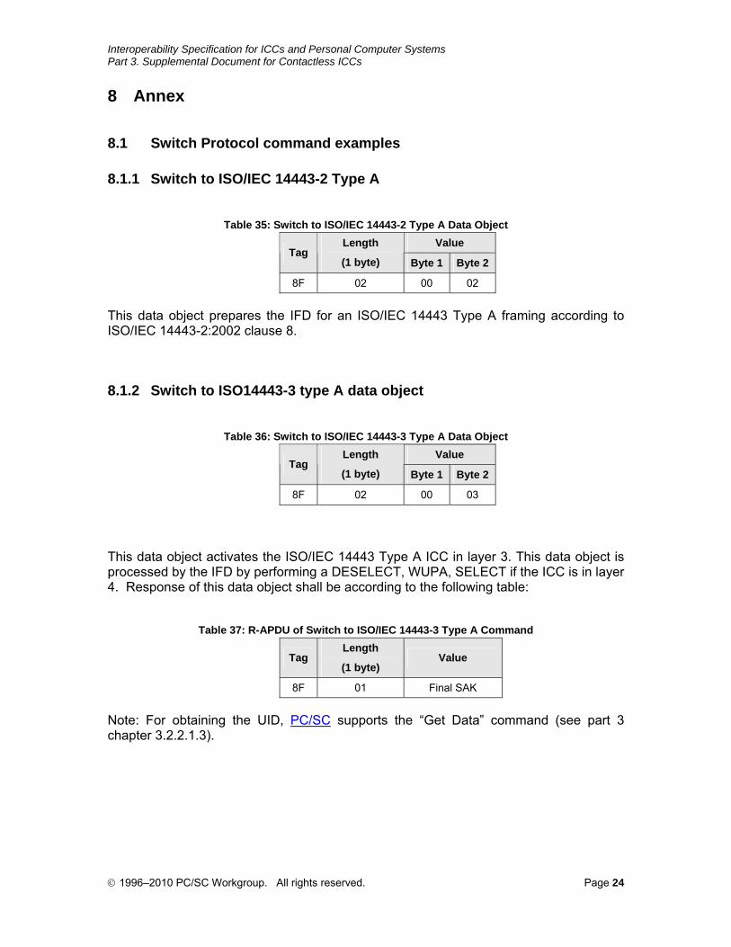
8.1.1 Switch to ISO/IEC 14443-2 Type A
Table 35: Switch to ISO/IEC 14443-2 Type A Data Object
Value Tag
Length
(1 byte) Byte 1 Byte 2
8F 02 00 02
This data object prepares the IFD for an ISO/IEC 14443 Type A framing according to ISO/IEC 14443-2:2002 clause 8.
8.1.2 Switch to ISO14443-3 type A data object
Table 36: Switch to ISO/IEC 14443-3 Type A Data Object
Value Tag
Length
(1 byte) Byte 1 Byte 2
8F 02 00 03
This data object activates the ISO/IEC 14443 Type A ICC in layer 3. This data object is processed by the IFD by performing a DESELECT, WUPA, SELECT if the ICC is in layer 4. Response of this data object shall be according to the following table:
Table 37: R-APDU of Switch to ISO/IEC 14443-3 Type A Command
Tag Length
(1 byte) Value
8F 01 Final SAK
Note: For obtaining the UID, PC/SC supports the “Get Data” command (see part 3 chapter 3.2.2.1.3).
© 1996–2010 PC/SC Workgroup. All rights reserved. Page 24
Interoperability Specification for ICCs and Personal Computer Systems Part 3. Supplemental Document for Contactless ICCs
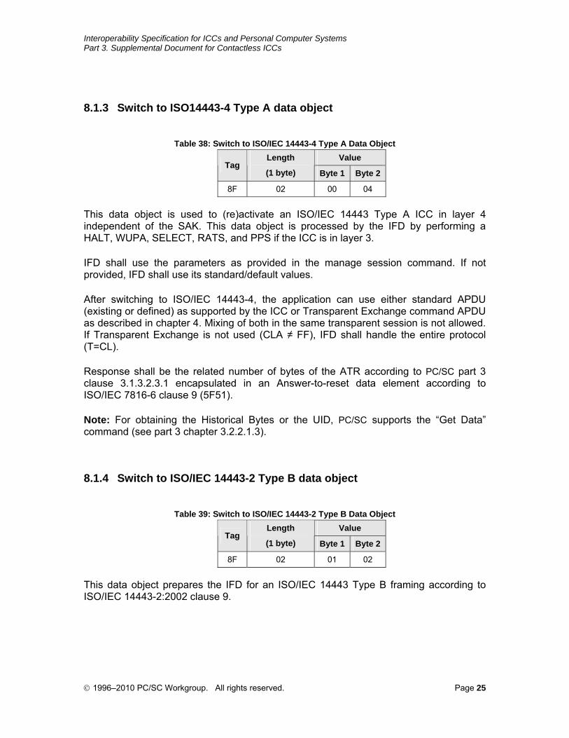
8.1.3 Switch to ISO14443-4 Type A data object
Table 38: Switch to ISO/IEC 14443-4 Type A Data Object
Value Tag
Length
(1 byte) Byte 1 Byte 2
8F 02 00 04
This data object is used to (re)activate an ISO/IEC 14443 Type A ICC in layer 4 independent of the SAK. This data object is processed by the IFD by performing a HALT, WUPA, SELECT, RATS, and PPS if the ICC is in layer 3.
IFD shall use the parameters as provided in the manage session command. If not provided, IFD shall use its standard/default values.
After switching to ISO/IEC 14443-4, the application can use either standard APDU (existing or defined) as supported by the ICC or Transparent Exchange command APDU as described in chapter 4. Mixing of both in the same transparent session is not allowed. If Transparent Exchange is not used (CLA ≠ FF), IFD shall handle the entire protocol (T=CL).
Response shall be the related number of bytes of the ATR according to PC/SC part 3 clause 3.1.3.2.3.1 encapsulated in an Answer-to-reset data element according to ISO/IEC 7816-6 clause 9 (5F51).
Note: For obtaining the Historical Bytes or the UID, PC/SC supports the “Get Data” command (see part 3 chapter 3.2.2.1.3).
8.1.4 Switch to ISO/IEC 14443-2 Type B data object
Table 39: Switch to ISO/IEC 14443-2 Type B Data Object
Value Tag
Length
(1 byte) Byte 1 Byte 2
8F 02 01 02
This data object prepares the IFD for an ISO/IEC 14443 Type B framing according to ISO/IEC 14443-2:2002 clause 9.
© 1996–2010 PC/SC Workgroup. All rights reserved. Page 25

Interoperability Specification for ICCs and Personal Computer Systems Part 3. Supplemental Document for Contactless ICCs
8.1.5 Switch to ISO/IEC 14443-3 Type B data object
Table 40: Switch to ISO/IEC 14443-3 Type B Data Object
Value Tag
Length
(1 byte) Byte 1 Byte 2
8F 02 01 03
This data object activates the ISO/IEC 14443 Type B ICC in layer 3. This data object is processed by the IFD by performing a DESELECT, WUPB if the ICC is in layer 4.
The response shall be according to the following table:
Table 41: R-APDU of Switch to ISO/IEC 14443-3 Type B Command
Tag Length (1 byte) Value
8F 03 Protocol info 1st byte Protocol info 2nd byte Protocol info 3rd byte
Note: For obtaining the UID, PC/SC supports the “Get Data” command (see part 3 chapter 3.2.2.1.3).
8.1.6 Switch to ISO/IEC 14443-4 Type B data object
Table 42: Switch to ISO/IEC 14443-4 Type B Data Object
Value Tag
Length
(1 byte) Byte 1 Byte 2
8F 02 01 04
This data object is used to (re)activate an ISO/IEC 14443 Type B ICC in layer 4 independent of the protocol info. This data object is processed by IFD performing a HALT, WUPB, and ATTRIB if the ICC is in layer 3.
IFD shall use the parameters as provided in the manage session command. If not provided, IFD shall use its standard/default values.
After switching to ISO/IEC 14443-4, the application can use either standard APDU (existing or defined) as supported by the ICC or Transparent Exchange command APDU as described in chapter 4. Mixing of both in the same transparent session is not allowed. If Transparent Exchange is not used (CLA ≠ FF), IFD shall handle the entire protocol (T=CL).
The response shall be the related number of bytes of the ATR according to PC/SC part 3 clause 3.1.3.2.3.1 encapsulated in an Answer-to-reset data element according to ISO/IEC 7816-6 clause 9 (5F51).
© 1996–2010 PC/SC Workgroup. All rights reserved. Page 26
Interoperability Specification for ICCs and Personal Computer Systems Part 3. Supplemental Document for Contactless ICCs
Note: For obtaining the Historical Bytes or the UID PC/SC supports the “Get Data” command (see part 3 chapter 3.2.2.1.3).
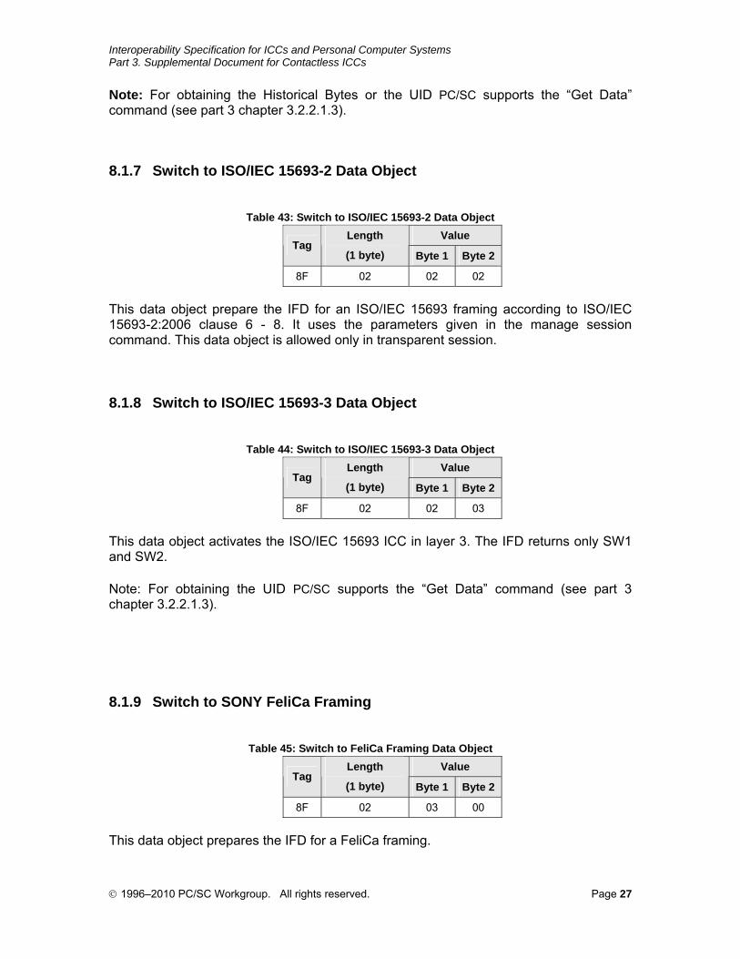
8.1.7 Switch to ISO/IEC 15693-2 Data Object
Table 43: Switch to ISO/IEC 15693-2 Data Object
Value Tag
Length
(1 byte) Byte 1 Byte 2
8F 02 02 02
This data object prepare the IFD for an ISO/IEC 15693 framing according to ISO/IEC 15693-2:2006 clause 6 - 8. It uses the parameters given in the manage session command. This data object is allowed only in transparent session.
8.1.8 Switch to ISO/IEC 15693-3 Data Object
Table 44: Switch to ISO/IEC 15693-3 Data Object
Value Tag
Length
(1 byte) Byte 1 Byte 2
8F 02 02 03
This data object activates the ISO/IEC 15693 ICC in layer 3. The IFD returns only SW1 and SW2.
Note: For obtaining the UID PC/SC supports the “Get Data” command (see part 3 chapter 3.2.2.1.3).
8.1.9 Switch to SONY FeliCa Framing
Table 45: Switch to FeliCa Framing Data Object
Value Tag
Length
(1 byte) Byte 1 Byte 2
8F 02 03 00
This data object prepares the IFD for a FeliCa framing.
© 1996–2010 PC/SC Workgroup. All rights reserved. Page 27
Interoperability Specification for ICCs and Personal Computer Systems Part 3. Supplemental Document for Contactless ICCs
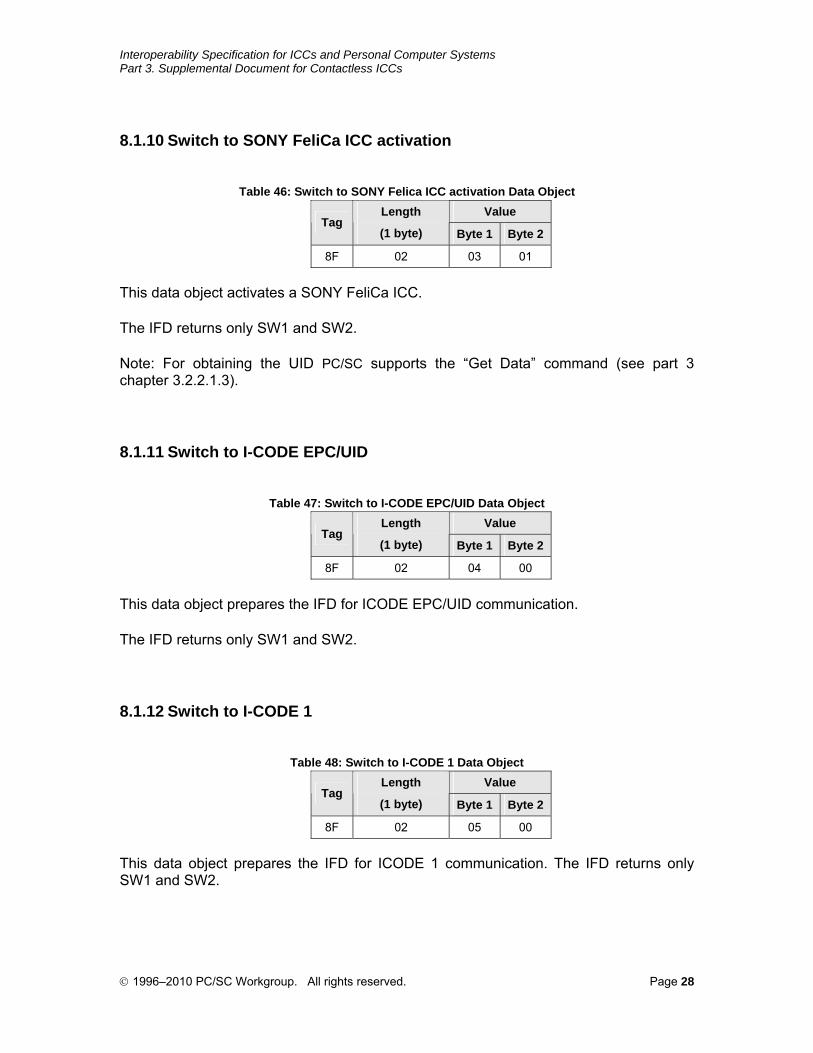
8.1.10 Switch to SONY FeliCa ICC activation
Table 46: Switch to SONY Felica ICC activation Data Object
Value Tag
Length
(1 byte) Byte 1 Byte 2
8F 02 03 01
This data object activates a SONY FeliCa ICC.
The IFD returns only SW1 and SW2.
Note: For obtaining the UID PC/SC supports the “Get Data” command (see part 3 chapter 3.2.2.1.3).
8.1.11 Switch to I-CODE EPC/UID
Table 47: Switch to I-CODE EPC/UID Data Object
Value Tag
Length
(1 byte) Byte 1 Byte 2
8F 02 04 00
This data object prepares the IFD for ICODE EPC/UID communication.
The IFD returns only SW1 and SW2.
8.1.12 Switch to I-CODE 1
Table 48: Switch to I-CODE 1 Data Object
Value Tag
Length
(1 byte) Byte 1 Byte 2
8F 02 05 00
This data object prepares the IFD for ICODE 1 communication. The IFD returns only SW1 and SW2.
© 1996–2010 PC/SC Workgroup. All rights reserved. Page 28
Interoperability Specification for ICCs and Personal Computer Systems Part 3. Supplemental Document for Contactless ICCs
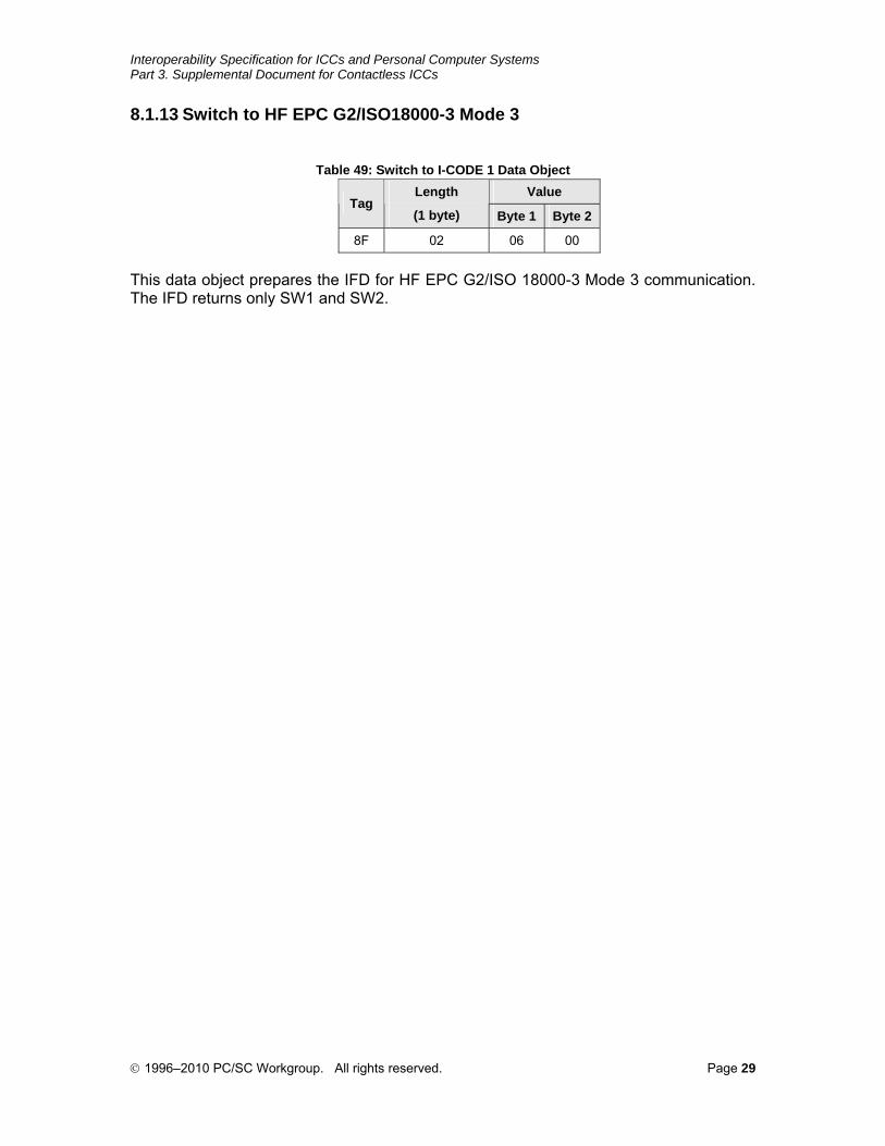
8.1.13 Switch to HF EPC G2/ISO18000-3 Mode 3
Table 49: Switch to I-CODE 1 Data Object
Value Tag
Length
(1 byte) Byte 1 Byte 2
8F 02 06 00
This data object prepares the IFD for HF EPC G2/ISO 18000-3 Mode 3 communication. The IFD returns only SW1 and SW2.
© 1996–2010 PC/SC Workgroup. All rights reserved. Page 29
Interoperability Specification for ICCs and Personal Computer Systems Part 3. Supplemental Document for Contactless ICCs
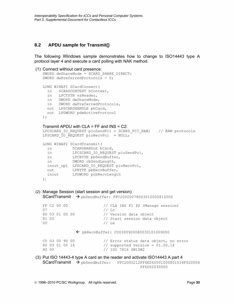
8.2 APDU sample for Transmit()
The following Windows sample demonstrates how to change to ISO14443 type A protocol layer 4 and execute a card polling with NAK method.
(1) Connect without card presence: DWORD dwShareMode = SCARD_SHARE_DIRECT; DWORD dwPreferredProtocols = 0; LONG WINAPI SCardConnect( in SCARDCONTEXT hContext, in LPCTSTR szReader, in DWORD dwShareMode, in DWORD dwPreferredProtocols, out LPSCARDHANDLE phCard, out LPDWORD pdwActiveProtocol ); Transmit APDU with CLA = FF and INS = C2: LPCSCARD_IO_REQUEST pioSendPci = SCARD_PCI_RAW; // RAM protocols LPSCARD_IO_REQUEST pioRecvPci = NULL; LONG WINAPI SCardTransmit( in SCARDHANDLE hCard, in LPCSCARD_IO_REQUEST pioSendPci, in LPCBYTE pbSendBuffer, in DWORD cbSendLength, inout_opt LPSCARD_IO_REQUEST pioRecvPci, out LPBYTE pbRecvBuffer, inout LPDWORD pcbRecvLength );
(2) Manage Session (start session and get version) SCardTransmit pbSendBuffer: FFC20000078003010000810000 FF C2 00 00 // CLA INS P1 P2 (Manage session) 07 // Lc 80 03 01 00 00 // Version data object 81 00 // Start session data object 00 // Le pbRecvBuffer: C00300900080030101009000 C0 03 00 90 00 // Error status data object, no error 80 03 01 00 14 // supported version = 01.00.14 90 00 // ISO 7816 SW1SW2
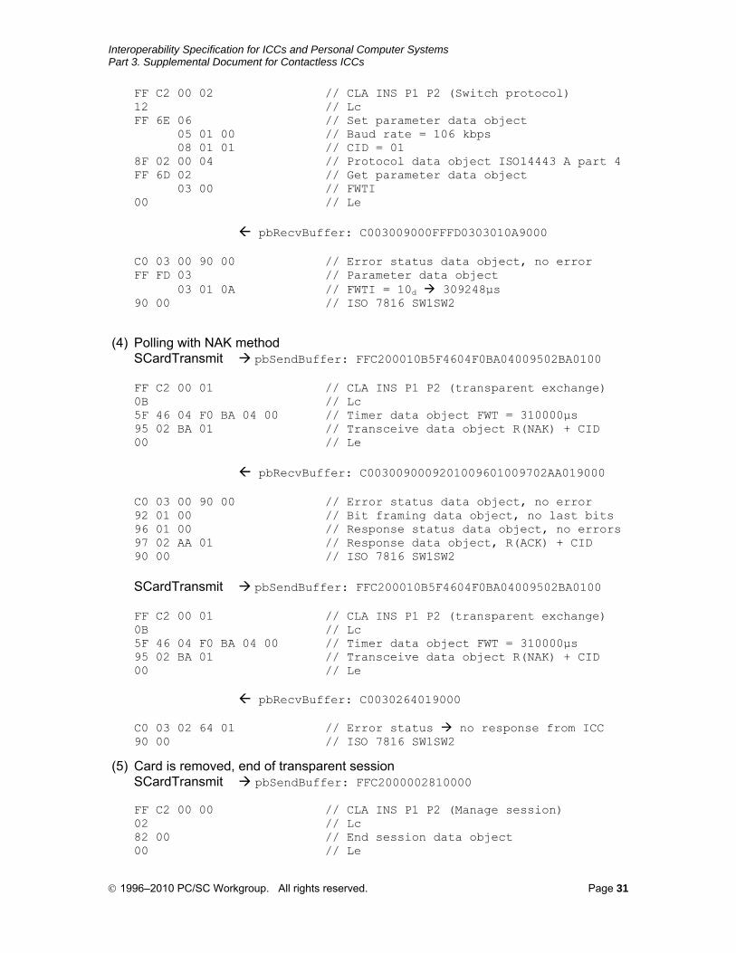
(3) Put ISO 14443-4 type A card an the reader and activate ISO14443 A part 4 SCardTransmit pbSendBuffer: FFC2000212FF6E060501000801018F020004 FF6D02030000
© 1996–2010 PC/SC Workgroup. All rights reserved. Page 30
Interoperability Specification for ICCs and Personal Computer Systems Part 3. Supplemental Document for Contactless ICCs
FF C2 00 02 // CLA INS P1 P2 (Switch protocol) 12 // Lc FF 6E 06 // Set parameter data object 05 01 00 // Baud rate = 106 kbps 08 01 01 // CID = 01 8F 02 00 04 // Protocol data object ISO14443 A part 4 FF 6D 02 // Get parameter data object 03 00 // FWTI 00 // Le pbRecvBuffer: C003009000FFFD0303010A9000 C0 03 00 90 00 // Error status data object, no error FF FD 03 // Parameter data object 03 01 0A // FWTI = 10d 309248μs 90 00 // ISO 7816 SW1SW2
(4) Polling with NAK method SCardTransmit pbSendBuffer: FFC200010B5F4604F0BA04009502BA0100 FF C2 00 01 // CLA INS P1 P2 (transparent exchange) 0B // Lc 5F 46 04 F0 BA 04 00 // Timer data object FWT = 310000μs 95 02 BA 01 // Transceive data object R(NAK) + CID 00 // Le pbRecvBuffer: C0030090009201009601009702AA019000 C0 03 00 90 00 // Error status data object, no error 92 01 00 // Bit framing data object, no last bits 96 01 00 // Response status data object, no errors 97 02 AA 01 // Response data object, R(ACK) + CID 90 00 // ISO 7816 SW1SW2 SCardTransmit pbSendBuffer: FFC200010B5F4604F0BA04009502BA0100 FF C2 00 01 // CLA INS P1 P2 (transparent exchange) 0B // Lc 5F 46 04 F0 BA 04 00 // Timer data object FWT = 310000μs 95 02 BA 01 // Transceive data object R(NAK) + CID 00 // Le pbRecvBuffer: C0030264019000 C0 03 02 64 01 // Error status no response from ICC 90 00 // ISO 7816 SW1SW2
(5) Card is removed, end of transparent session SCardTransmit pbSendBuffer: FFC2000002810000 FF C2 00 00 // CLA INS P1 P2 (Manage session) 02 // Lc 82 00 // End session data object 00 // Le
© 1996–2010 PC/SC Workgroup. All rights reserved. Page 31
Interoperability Specification for ICCs and Personal Computer Systems Part 3. Supplemental Document for Contactless ICCs
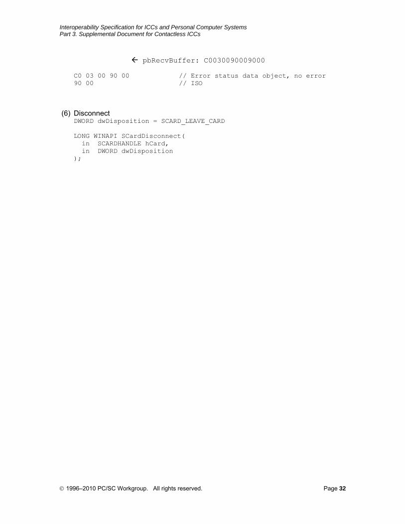
pbRecvBuffer: C0030090009000 C0 03 00 90 00 // Error status data object, no error 90 00 // ISO
(6) Disconnect DWORD dwDisposition = SCARD_LEAVE_CARD LONG WINAPI SCardDisconnect( in SCARDHANDLE hCard, in DWORD dwDisposition );
© 1996–2010 PC/SC Workgroup. All rights reserved. Page 32