Panorama Administrator's Guide
508
Panorama Administrator's Guide Version 9.1 paloaltonetworks.com/documentation
-
Upload
khangminh22 -
Category
Documents
-
view
2 -
download
0
Transcript of Panorama Administrator's Guide

Panorama Administrator's GuideVersion 9.1
paloaltonetworks.com/documentation

2 PANORAMA ADMINISTRATOR'S GUIDE |
Contact InformationCorporate Headquarters:Palo Alto Networks3000 Tannery WaySanta Clara, CA 95054www.paloaltonetworks.com/company/contact-support
About the Documentation• For the most recent version of this guide or for access to related documentation, visit the Technical
Documentation portal www.paloaltonetworks.com/documentation.• To search for a specific topic, go to our search page www.paloaltonetworks.com/documentation/
document-search.html.• Have feedback or questions for us? Leave a comment on any page in the portal, or write to us at
CopyrightPalo Alto Networks, Inc.www.paloaltonetworks.com
© 2019-2020 Palo Alto Networks, Inc. Palo Alto Networks is a registered trademark of PaloAlto Networks. A list of our trademarks can be found at www.paloaltonetworks.com/company/trademarks.html. All other marks mentioned herein may be trademarks of their respective companies.
Last RevisedOctober 19, 2020

TABLE OF CONTENTS iii
Table of ContentsPanorama Overview........................................................................................... 9
About Panorama........................................................................................................................................11Panorama Models..................................................................................................................................... 12Centralized Firewall Configuration and Update Management.......................................................14
Context Switch—Firewall or Panorama.................................................................................. 14Templates and Template Stacks...............................................................................................14Device Groups...............................................................................................................................16
Centralized Logging and Reporting...................................................................................................... 20Managed Collectors and Collector Groups............................................................................20Local and Distributed Log Collection......................................................................................21Caveats for a Collector Group with Multiple Log Collectors............................................ 22Log Forwarding Options.............................................................................................................24Centralized Reporting..................................................................................................................25
User-ID Redistribution Using Panorama............................................................................................. 26Role-Based Access Control.................................................................................................................... 27
Administrative Roles....................................................................................................................27Authentication Profiles and Sequences..................................................................................28Access Domains............................................................................................................................29Administrative Authentication.................................................................................................. 29
Panorama Commit, Validation, and Preview Operations................................................................ 31Plan Your Panorama Deployment........................................................................................................ 32Deploy Panorama: Task Overview....................................................................................................... 34
Set Up Panorama..............................................................................................35Determine Panorama Log Storage Requirements.............................................................................37Set Up the Panorama Virtual Appliance............................................................................................. 39
Setup Prerequisites for the Panorama Virtual Appliance................................................... 39Install the Panorama Virtual Appliance...................................................................................42Perform Initial Configuration of the Panorama Virtual Appliance....................................69Set Up The Panorama Virtual Appliance as a Log Collector..............................................72Set Up the Panorama Virtual Appliance with Local Log Collector................................... 77Set up a Panorama Virtual Appliance in Panorama Mode................................................. 81Set up a Panorama Virtual Appliance in Management Only Mode..................................81Expand Log Storage Capacity on the Panorama Virtual Appliance..................................82Increase CPUs and Memory on the Panorama Virtual Appliance..................................100Increase the System Disk on the Panorama Virtual Appliance.......................................105Complete the Panorama Virtual Appliance Setup............................................................. 110
Set Up the M-Series Appliance...........................................................................................................111M-Series Appliance Interfaces................................................................................................111Perform Initial Configuration of the M-Series Appliance.................................................113M-Series Setup Overview........................................................................................................116Set Up the M-Series Appliance as a Log Collector........................................................... 118Increase Storage on the M-Series Appliance......................................................................124Configure Panorama to Use Multiple Interfaces................................................................130
Register Panorama and Install Licenses............................................................................................137Register Panorama.....................................................................................................................137Activate a Panorama Support License..................................................................................138Activate/Retrieve a Firewall Management License when the Panorama VirtualAppliance is Internet-connected............................................................................................ 139

iv TABLE OF CONTENTS
Activate/Retrieve a Firewall Management License when the Panorama VirtualAppliance is not Internet-connected.................................................................................... 139Activate/Retrieve a Firewall Management License on the M-Series Appliance......... 142
Install the Panorama Device Certificate........................................................................................... 144Install Content and Software Updates for Panorama................................................................... 146
Panorama, Log Collector, Firewall, and WildFire Version Compatibility...................... 146Install Updates for Panorama in an HA Configuration..................................................... 147Install Updates for Panorama with an Internet Connection............................................148Install Updates for Panorama When Not Internet-Connected.......................................152Migrate Panorama Logs to the New Log Format.............................................................. 155
Transition to a Different Panorama Model......................................................................................157Migrate from a Panorama Virtual Appliance to an M-Series Appliance....................... 157Migrate a Panorama Virtual Appliance to a Different Hypervisor.................................160Migrate from an M-Series Appliance to a Panorama Virtual Appliance....................... 163Migrate from an M-100 Appliance to an M-500 Appliance............................................167
Access and Navigate Panorama Management Interfaces.............................................................171Log in to the Panorama Web Interface................................................................................171Navigate the Panorama Web Interface................................................................................171Log in to the Panorama CLI....................................................................................................172
Set Up Administrative Access to Panorama.................................................................................... 174Configure an Admin Role Profile........................................................................................... 174Configure an Access Domain..................................................................................................174Configure Administrative Accounts and Authentication..................................................175
Set Up Authentication Using Custom Certificates.........................................................................186How Are SSL/TLS Connections Mutually Authenticated?...............................................186Configure Authentication Using Custom Certificates on Panorama............................. 187Configure Authentication Using Custom Certificates on Managed Devices...............188Add New Client Devices..........................................................................................................190Change Certificates................................................................................................................... 190
Manage Firewalls............................................................................................193Add a Firewall as a Managed Device................................................................................................195Set Up Zero Touch Provisioning........................................................................................................ 199
ZTP Overview.............................................................................................................................199Install the ZTP Plugin................................................................................................................200Configure the ZTP Installer Administrator Account..........................................................205Add ZTP Firewalls to Panorama............................................................................................ 206Use the CLI for ZTP Tasks...................................................................................................... 210Uninstall the ZTP Plugin.......................................................................................................... 212
Manage Device Groups........................................................................................................................ 213Add a Device Group................................................................................................................. 213Create a Device Group Hierarchy......................................................................................... 214Create Objects for Use in Shared or Device Group Policy..............................................215Revert to Inherited Object Values.........................................................................................216Manage Unused Shared Objects........................................................................................... 217Manage Precedence of Inherited Objects...........................................................................217Move or Clone a Policy Rule or Object to a Different Device Group...........................218Select a URL Filtering Vendor on Panorama...................................................................... 219Push a Policy Rule to a Subset of Firewalls........................................................................223Manage the Rule Hierarchy.................................................................................................... 225
Manage Templates and Template Stacks.........................................................................................227Template Capabilities and Exceptions.................................................................................. 227Add a Template..........................................................................................................................227Configure a Template Stack....................................................................................................229

TABLE OF CONTENTS v
Configure a Template or Template Stack Variable............................................................231Import and Overwrite Existing Template Stack Variables............................................... 233Override a Template or Template Stack Value.................................................................. 234Disable/Remove Template Settings...................................................................................... 237
Manage the Master Key from Panorama......................................................................................... 238Redistribute User-ID Information to Managed Firewalls..............................................................241Transition a Firewall to Panorama Management............................................................................244
Plan the Transition to Panorama Management..................................................................244Migrate a Firewall to Panorama Management................................................................... 245Migrate a Firewall HA Pair to Panorama Management....................................................248Load a Partial Firewall Configuration into Panorama....................................................... 250
Device Monitoring on Panorama........................................................................................................253Monitor Device Health.............................................................................................................253Monitor Policy Rule Usage......................................................................................................254
Use Case: Configure Firewalls Using Panorama.............................................................................259Device Groups in this Use Case............................................................................................ 259Templates in this Use Case.....................................................................................................260Set Up Your Centralized Configuration and Policies........................................................ 261
Manage Large-Scale Firewall Deployments.............................................267Determine the Optimal Large-Scale Firewall Deployment Solution.......................................... 269Increased Device Management Capacity for M-600 and Panorama Virtual Appliance.........270
Increased Device Management Capacity Requirements..................................................270Deploy Panorama for Increased Device Management.....................................................271
Panorama Interconnect.........................................................................................................................274Panorama Interconnect Overview.........................................................................................274Panorama Interconnect Requirements................................................................................. 275Enable Authentication Between the Panorama Controller and Nodes.........................277Set Up the Panorama Interconnect Plugin..........................................................................281Synchronize Panorama Interconnect.................................................................................... 284Manage Firewalls with Panorama Interconnect.................................................................285Upgrade the Panorama Interconnect Plugin.......................................................................294
Manage Log Collection................................................................................. 297Configure a Managed Collector..........................................................................................................299Manage Collector Groups.................................................................................................................... 302
Configure a Collector Group...................................................................................................302Configure Authentication with Custom Certificates Between Log Collectors............304Move a Log Collector to a Different Collector Group......................................................306Remove a Firewall from a Collector Group.........................................................................307
Configure Log Forwarding to Panorama.......................................................................................... 308Forward Logs to Cortex Data Lake................................................................................................... 312Verify Log Forwarding to Panorama................................................................................................. 313Modify Log Forwarding and Buffering Defaults.............................................................................315Configure Log Forwarding from Panorama to External Destinations........................................317Log Collection Deployments................................................................................................................319
Deploy Panorama with Dedicated Log Collectors.............................................................319Deploy Panorama M-Series Appliances with Local Log Collectors............................... 324Deploy Panorama Virtual Appliances with Local Log Collectors....................................329Deploy Panorama Virtual Appliances in Legacy Mode with Local Log Collection......333
Manage WildFire Appliances.......................................................................335

vi TABLE OF CONTENTS
Add Standalone WildFire Appliances to Manage with Panorama.............................................. 337Configure Basic WildFire Appliance Settings on Panorama........................................................ 340Set Up Authentication Using Custom Certificates on WildFire Appliances and Clusters......341
Configure a Custom Certificate for a Panorama Managed WildFire Appliance..........341Configure Authentication with a Single Custom Certificate for a WildFireCluster...........................................................................................................................................343Apply Custom Certificates on a WildFire Appliance Configured throughPanorama..................................................................................................................................... 344
Remove a WildFire Appliance from Panorama Management......................................................347Manage WildFire Clusters....................................................................................................................348
Configure a Cluster Centrally on Panorama....................................................................... 348View WildFire Cluster Status Using Panorama.................................................................. 358Upgrade a Cluster Centrally on Panorama with an Internet Connection..................... 358Upgrade a Cluster Centrally on Panorama without an Internet Connection...............360
Manage Licenses and Updates................................................................... 365Manage Licenses on Firewalls Using Panorama............................................................................. 367Deploy Upgrades to Firewalls, Log Collectors, and WildFire Appliances UsingPanorama.................................................................................................................................................. 368
Supported Updates....................................................................................................................368Schedule a Content Update Using Panorama.................................................................... 369Upgrade Log Collectors When Panorama Is Internet-Connected..................................370Upgrade Log Collectors When Panorama Is Not Internet-Connected......................... 373Upgrade Firewalls When Panorama Is Internet-Connected............................................376Upgrade Firewalls When Panorama Is Not Internet-Connected....................................380Upgrade a ZTP Firewall............................................................................................................384Revert Content Updates from Panorama............................................................................ 385
Monitor Network Activity............................................................................387Use Panorama for Visibility................................................................................................................. 389
Monitor the Network with the ACC and AppScope.........................................................389Analyze Log Data.......................................................................................................................391Generate, Schedule, and Email Reports............................................................................... 391
Ingest Traps ESM Logs on Panorama................................................................................................394Use Case: Monitor Applications Using Panorama..........................................................................396Use Case: Respond to an Incident Using Panorama......................................................................399
Incident Notification................................................................................................................. 399Review the Widgets in the ACC............................................................................................399Review Threat Logs...................................................................................................................400Review WildFire Logs...............................................................................................................400Review Data Filtering Logs..................................................................................................... 401Update Security Rules.............................................................................................................. 401
Panorama High Availability..........................................................................403Panorama HA Prerequisites.................................................................................................................405Priority and Failover on Panorama in HA........................................................................................ 407Failover Triggers..................................................................................................................................... 408
HA Heartbeat Polling and Hello Messages......................................................................... 408HA Path Monitoring..................................................................................................................408
Logging Considerations in Panorama HA.........................................................................................409Logging Failover on a Panorama Virtual Appliance in Legacy Mode.............................409

TABLE OF CONTENTS vii
Logging Failover on an M-Series Appliance or Panorama Virtual Appliance inPanorama Mode......................................................................................................................... 410
Synchronization Between Panorama HA Peers..............................................................................411Manage a Panorama HA Pair.............................................................................................................. 412
Set Up HA on Panorama......................................................................................................... 412Set Up Authentication Using Custom Certificates Between HA Peers........................ 413Test Panorama HA Failover.................................................................................................... 414Switch Priority after Panorama Failover to Resume NFS Logging.................................415Restore the Primary Panorama to the Active State.......................................................... 416
Administer Panorama.................................................................................... 417Preview, Validate, or Commit Configuration Changes..................................................................419Enable Automated Commit Recovery............................................................................................... 422Manage Panorama and Firewall Configuration Backups.............................................................. 424
Schedule Export of Configuration Files............................................................................... 424Save and Export Panorama and Firewall Configurations................................................. 425Revert Panorama Configuration Changes............................................................................427Configure the Maximum Number of Configuration Backups on Panorama................ 429Load a Configuration Backup on a Managed Firewall......................................................429
Compare Changes in Panorama Configurations............................................................................. 431Manage Locks for Restricting Configuration Changes..................................................................432Add Custom Logos to Panorama........................................................................................................434Use the Panorama Task Manager...................................................................................................... 435Manage Storage Quotas and Expiration Periods for Logs and Reports.................................... 436
Log and Report Storage........................................................................................................... 436Log and Report Expiration Periods....................................................................................... 437Configure Storage Quotas and Expiration Periods for Logs and Reports.................... 437Configure the Run Time for Panorama Reports.................................................................438
Monitor Panorama..................................................................................................................................439Panorama System and Configuration Logs..........................................................................439Monitor Panorama and Log Collector Statistics Using SNMP........................................ 439
Reboot or Shut Down Panorama....................................................................................................... 442Configure Panorama Password Profiles and Complexity............................................................. 443
Panorama Plugins........................................................................................... 445About Panorama Plugins...................................................................................................................... 447
Install Panorama Plugins.......................................................................................................... 448VM-Series Plugin and Panorama Plugins..........................................................................................450
Install the VM-Series Plugin on Panorama..........................................................................450
Troubleshooting.............................................................................................. 453Troubleshoot Panorama System Issues............................................................................................ 455
Generate Diagnostic Files for Panorama............................................................................. 455Diagnose Panorama Suspended State..................................................................................455Monitor the File System Integrity Check.............................................................................455Manage Panorama Storage for Software and Content Updates....................................455Recover from Split Brain in Panorama HA Deployments................................................ 456
Troubleshoot Log Storage and Connection Issues.........................................................................458Verify Panorama Port Usage.................................................................................................. 458Resolve Zero Log Storage for a Collector Group.............................................................. 460Replace a Failed Disk on an M-Series Appliance...............................................................460Replace the Virtual Disk on an ESXi Server........................................................................461

viii TABLE OF CONTENTS
Replace the Virtual Disk on vCloud Air............................................................................... 461Migrate Logs to a New M-Series Appliance in Log Collector Mode............................. 462Migrate Logs to a New M-Series Appliance in Panorama Mode................................... 467Migrate Logs to a New M-Series Appliance Model in Panorama Mode in HighAvailability....................................................................................................................................473Migrate Logs to the Same M-Series Appliance Model in Panorama Mode in HighAvailability....................................................................................................................................479Migrate Log Collectors after Failure/RMA of Non-HA Panorama.................................485Regenerate Metadata for M-Series Appliance RAID Pairs.............................................. 488
Replace an RMA Firewall..................................................................................................................... 489Partial Device State Generation for Firewalls.................................................................... 489Before Starting RMA Firewall Replacement....................................................................... 489Restore the Firewall Configuration after Replacement....................................................490
Troubleshoot Commit Failures............................................................................................................493Troubleshoot Registration or Serial Number Errors...................................................................... 494Troubleshoot Reporting Errors........................................................................................................... 495Troubleshoot Device Management License Errors........................................................................ 496Troubleshoot Automatically Reverted Firewall Configurations.................................................. 497Complete Content Update When Panorama HA Peer is Down................................................. 499View Task Success or Failure Status................................................................................................. 501Test Policy Match and Connectivity for Managed Devices.........................................................502
Troubleshoot Policy Rule Traffic Match.............................................................................. 502Troubleshoot Connectivity to Network Resources...........................................................503
Downgrade from Panorama 9.1......................................................................................................... 505

9
Panorama OverviewThe Panorama™ management server provides centralized monitoring and managementof multiple Palo Alto Networks next-generation firewalls and of WildFire appliances andappliance clusters. It provides a single location from which you can oversee all applications,users, and content traversing your network, and then use this knowledge to create applicationenablement policies that protect and control the network. Using Panorama for centralizedpolicy and firewall management increases operational efficiency in managing and maintaininga distributed network of firewalls. Using Panorama for centralized WildFire appliance andWildFire appliance cluster management increases the number of firewalls a single networksupports, provides high availability for fault tolerance, and increases management efficiency.
> About Panorama> Panorama Models> Centralized Firewall Configuration and Update Management> Centralized Logging and Reporting> User-ID Redistribution Using Panorama> Role-Based Access Control> Panorama Commit, Validation, and Preview Operations> Plan Your Panorama Deployment> Deploy Panorama: Task Overview

10 PANORAMA ADMINISTRATOR'S GUIDE | Panorama Overview© 2020 Palo Alto Networks, Inc.

PANORAMA ADMINISTRATOR'S GUIDE | Panorama Overview 11© 2020 Palo Alto Networks, Inc.
About PanoramaPanorama enables you to effectively configure, manage, and monitor your Palo Alto Networks firewalls withcentral oversight. The three main areas in which Panorama adds value are:
• Centralized configuration and deployment—To simplify central management and rapid deploymentof the firewalls and WildFire appliances on your network, use Panorama to pre-stage the firewallsand WildFire appliances for deployment. You can then assemble the firewalls into groups, and createtemplates to apply a base network and device configuration and use device groups to administer globallyshared and local policy rules. See Centralized Firewall Configuration and Update Management.
• Aggregated logging with central oversight for analysis and reporting—Collect information on activityacross all the managed firewalls on the network and centrally analyze, investigate and report on thedata. This comprehensive view of network traffic, user activity, and the associated risks empowers youto respond to potential threats using the rich set of policies to securely enable applications on yournetwork. See Centralized Logging and Reporting.
• Distributed administration—Enables you to delegate or restrict access to global and local firewallconfigurations and policies. See Role-Based Access Control for delegating appropriate levels of accessfor distributed administration.
Five Panorama Models are available: the Panorama virtual appliance, M-600 appliance, M-500 appliance,M-200 appliance, and M-100 appliance (M-100 appliances are supported in PAN-OS 9.1 only if they havebeen upgraded to 32 GB memory from the default 16 GB). Panorama Centralized Management illustrateshow you can deploy Panorama in a high availability (HA) configuration to manage firewalls.
Figure 1: Panorama Centralized Management

12 PANORAMA ADMINISTRATOR'S GUIDE | Panorama Overview© 2020 Palo Alto Networks, Inc.
Panorama ModelsPanorama is available as one of the following virtual or physical appliances, each of which supports licensesfor managing up to 25, 100, or 1,000 firewalls. Additionally, M-600 appliances, and similarly resourcedPanorama virtual appliances, also supports licenses for managing up to 5,000 firewalls:
• Panorama virtual appliance—This model provides simple installation and facilitates server consolidationfor sites that need a virtual management appliance. You can install Panorama on Amazon Web Services(AWS), AWS GovCloud, Microsoft Azure, Google Cloud Platform (GCP), KVM, Hyper-V, a VMwareESXi server, or on VMware vCloud Air. The virtual appliance can collect firewall logs locally at ratesof up to 10,000 logs per second and can manage Dedicated Log Collectors for higher logging rates.The virtual appliance can function as a dedicated management server, a Panorama management serverwith local log collection capabilities, or as a Dedicated Log Collector. For the supported interfaces, logstorage capacity, and maximum log collection rates, see the Setup Prerequisites for the Panorama VirtualAppliance. You can deploy the virtual appliance in the following modes:
• Panorama mode—In this mode, the Panorama virtual appliance supports a local Log Collector with 1to 12 virtual logging disks (see Deploy Panorama Virtual Appliances with Local Log Collectors). Eachlogging disk has 2TB of storage capacity for a total maximum of 24TB on a single virtual applianceand 48TB on a high availability (HA) pair. Only Panorama mode enables you to add multiple virtuallogging disks without losing logs on existing disks. Panorama mode also provides the benefit of fasterreport generation. In Panorama mode, the virtual appliance does not support NFS storage.
As a best practice, deploy the virtual appliance in Panorama mode to optimize logstorage and report generation.
• Legacy mode (ESXi and vCloud Air only)—In this mode, the Panorama virtual appliance receives andstores firewall logs without using a local Log Collector (see Deploy Panorama Virtual Appliances inLegacy Mode with Local Log Collection). By default, the virtual appliance in Legacy mode has onedisk partition for all data. Approximately 11GB of the partition is allocated to log storage. If you needmore local log storage, you can add one virtual disk of up to 8TB on ESXi 5.5 and later versions oron vCloud Air. Earlier ESXi versions support one virtual disk of up to 2TB. If you need more than8TB, you can mount the virtual appliance in Legacy mode to an NFS datastore but only on the ESXiserver, not in vCloud Air. This mode is only available if your Panorama virtual appliance is in Legacymode on upgrade to PAN-OS 9.1. On upgrade to PAN-OS 9.0 and later releases, Legacy mode is nolonger available if you change to any other mode. If you change your Panorama virtual appliance fromLegacy mode to one of the available modes, you will no longer be able to change back into Legacymode.
While supported, Legacy mode is not recommended for production environments butmay still be used for lab or demo environments.
• Management Only mode—In this mode, the Panorama virtual appliance is a dedicated managementappliance for your managed devices and Dedicated Log Collectors and, in this mode, an appropriatelyresourced Panorama virtual appliance can manage up to 5,000 firewalls. The Panorama virtualappliance has no log collection capabilities except for config and system logs and requires aDedicated Log Collector to these store logs. By default, the virtual appliance in Management Onlymode has only one disk partition for all data so all logs forwarded to a Panorama virtual appliancein Management Only mode are dropped. Therefore, to store the log data from your managedappliances, you must configure log forwarding in order to store the log data from your manageddevices. For more information, see Increased Device Management Capacity Requirements.
• Log Collector mode—The Panorama virtual appliance functions as a Dedicated Log Collector. Ifmultiple firewalls forward large volumes of log data, a Panorama virtual appliance in Log Collectormode provides increased scale and performance. In this mode, the appliance does not have a webinterface for administrative access; it has only a command line interface (CLI). However, you can

PANORAMA ADMINISTRATOR'S GUIDE | Panorama Overview 13© 2020 Palo Alto Networks, Inc.
manage the appliance using the web interface of the Panorama management server. CLI access to aPanorama virtual appliance in Log Collector mode is necessary only for initial setup and debugging.For configuration details, see Deploy Panorama with Dedicated Log Collectors.
• M-Series appliance—The M-100, M-200, M-500, and M-600 appliances are dedicated hardwareappliances intended for large-scale deployments. In environments with high logging rates (over 10,000logs per second) and log retention requirements, these appliances enable scaling of your log collectioninfrastructure. For the supported interfaces, log storage capacity, and maximum log collection rates, seeM-Series Appliance Interfaces. All M-Series models share the following attributes:
• RAID drives to store firewall logs and RAID 1 mirroring to protect against disk failures• SSD to store the logs that Panorama and Log Collectors generate• MGT, Eth1, Eth2, and Eth3 interfaces that support 1Gbps throughput• Redundant, hot-swappable power supplies (except for the M-100 appliance)• front-to-back airflow
M-100 appliances are supported in PAN-OS 9.0 and later releases only if they have beenupgraded to 32GB memory from the default 16GB. See M-100 Memory Upgrade Guidefor more information.
The M-600 and M-500 appliances have the following additional attributes, which make them moresuitable for data centers:
• Eth4 and Eth5 interfaces that support 10Gbps throughput
Additionally, the following attribute makes the M-600 appliance more suitable for large-scale firewalldeployments:
• The M-600 appliance in Management Only mode can manage up to 5,000 firewalls.
You can deploy the M-Series appliances in the following modes:
• Panorama mode—The appliance functions as a Panorama management server to manage firewallsand Dedicated Log Collectors. The appliance also supports a local Log Collector to aggregate firewalllogs. Panorama mode is the default mode. For configuration details, see Deploy Panorama M-SeriesAppliances with Local Log Collectors.
• Management Only mode—The Panorama appliance is a dedicated management appliance for yourmanaged devices and Dedicated Log Collectors. The Panorama appliance has no log collectioncapabilities except for config and system logs and your deployment requires a Dedicated LogCollector to store these logs. By default, the Panorama appliance in Management Only mode has onlyone disk partition for all data so all logs forwarded to a Panorama virtual appliance in ManagementOnly mode are dropped. Therefore, to store the log data from your managed appliances, you mustconfigure log forwarding in order to store the log data from your managed devices.
• Log Collector mode—The appliance functions as a Dedicated Log Collector. If multiple firewallsforward large volumes of log data, an M-Series appliance in Log Collector mode provides increasedscale and performance. IIn this mode, the appliance does not have a web interface for administrativeaccess; it has only a command line interface (CLI). However, you can manage the appliance usingthe web interface of the Panorama management server. CLI access to an M-Series appliance in LogCollector mode is necessary only for initial setup and debugging. For configuration details, see DeployPanorama with Dedicated Log Collectors.
For more details and specifications for the M-Series appliances, see the M-Series Appliance HardwareReference Guides.

14 PANORAMA ADMINISTRATOR'S GUIDE | Panorama Overview© 2020 Palo Alto Networks, Inc.
Centralized Firewall Configuration and UpdateManagement
Panorama™ uses device groups and templates to group firewalls into logical sets that require similarconfiguration. You use device groups and templates to centrally manage all configuration elements, policies,and objects on the managed firewalls. Panorama also enables you to centrally manage licenses, software(PAN-OS® software, SSL-VPN client software, GlobalProtect™ agent/app software), and content updates(Applications, Threats, WildFire®, and Antivirus).
• Context Switch—Firewall or Panorama• Templates and Template Stacks• Device Groups
Context Switch—Firewall or PanoramaThe Panorama™ web interface enables you to toggle between a Panorama-centric view and a firewall-centric view using the Context drop-down at the top-left of every tab. Set the Context to Panorama tomanage firewalls centrally or switch context to the web interface of a specific firewall to configure it locally.The similarity of the Panorama and firewall web interfaces enables you to seamlessly move between themto monitor and manage firewalls.
The Context drop-down lists only the firewalls that are connected to Panorama. For a Device Groupand Template administrator, the drop-down lists only the connected firewalls that are within the AccessDomains assigned to that administrator. To search a long list, use the Filters within the drop-down.
For firewalls in a high availability (HA) configuration, the icons have colored backgrounds to indicate theHA state (as follows). Knowing the HA state is useful when selecting a firewall context. For example, yougenerally make firewall-specific configuration changes on an active firewall.
• Green—Active.• Yellow—Passive or the firewall is initiating (the initiating state lasts for up to 60 seconds after boot up).• Red—The firewall is non-functional (error state), suspended (an administrator disabled the firewall), or
tentative (for a link or path monitoring event in an active/active HA configuration).
Templates and Template StacksYou use templates and template stacks to configure the settings that enable firewalls to operate on thenetwork. Templates are the basic building blocks you use to configure the Network and Device tabs onPanorama™. You can use templates to define interface and zone configurations, to manage the serverprofiles for logging and syslog access, or to define VPN configurations. Template stacks give you the abilityto layer multiple templates and create a combined configuration. Template stacks simplify managementbecause they allow you to define a common base configuration for all devices attached to the templatestack and they give you the ability to layer templates to create a combined configuration. This enables youto define templates with location- or function-specific settings and then stack the templates in descendingorder of priority so that firewalls inherit the settings based on the order of the templates in the stack.
Both templates and template stacks support variables. Variables allow you to create placeholderobjects with their value specified in the template or template stack based on your configuration needs.Create a template or template stack variable to replace IP addresses, Group IDs, and interfaces in yourconfigurations. Template variables are inherited by the template stack and you can override them to createa template stack variable. However, templates do not inherit variables defined in the template stack. Whena variable is defined in the template or template stack and pushed to the firewall, the value defined for thevariable is displayed on the firewall.

PANORAMA ADMINISTRATOR'S GUIDE | Panorama Overview 15© 2020 Palo Alto Networks, Inc.
To accommodate firewalls that have unique settings, you can use templates to override the templatestack configuration. Alternatively, you can push a broader, common base configuration and then overridecertain pushed settings with firewall-specific values on individual firewalls. When you override a settingon the firewall, the firewall saves that setting to its local configuration and Panorama no longer managesthe setting. To restore template values after you override them, use Panorama to force the template ortemplate stack configuration onto the firewall. For example, after you define a common NTP server in atemplate and override the NTP server configuration on a firewall to accommodate a local time zone, youcan later revert to the NTP server defined in the template.
When defining a template stack, consider assigning firewalls that are the same hardware model andrequire access to similar network resources, such as gateways and syslog servers. This enables you toavoid the redundancy of adding every setting to every template stack. The following figure illustrates anexample configuration in which you assign data center firewalls in the Asia-Pacific (APAC) region to astack with global settings, one template with APAC-specific settings, and one template with data center-specific settings. To manage firewalls in an APAC branch office, you can then re-use the global and APAC-specific templates by adding them to another stack that includes a template with branch-specific settings.Templates in a stack have a configurable priority order that ensures Panorama pushes only one value forany duplicate setting. Panorama evaluates the templates listed in a stack configuration from top to bottomwith higher templates having priority. The following figure illustrates a data center stack in which the datacenter template has a higher priority than the global template: Panorama pushes the idle timeout value fromthe data center template and ignores the value from the global template.
Figure 2: Template Stacks
You cannot use templates or template stacks to set firewall modes: virtual private network (VPN) mode,multiple virtual systems (multi-vsys) mode, or operational modes (normal or FIPS-CC mode). For details, seeTemplate Capabilities and Exceptions. However, you can assign firewalls that have non-matching modes tothe same template or stack. In such cases, Panorama pushes mode-specific settings only to firewalls thatsupport those modes. As an exception, you can configure Panorama to push the settings of the defaultvsys in a template to firewalls that don’t support virtual systems or that don’t have any virtual systemsconfigured.
For the relevant procedures, see Manage Templates and Template Stacks.

16 PANORAMA ADMINISTRATOR'S GUIDE | Panorama Overview© 2020 Palo Alto Networks, Inc.
Device GroupsTo use Panorama effectively, you have to group the firewalls in your network into logical units calleddevice groups. A device group enables grouping based on network segmentation, geographic location,organizational function, or any other common aspect of firewalls that require similar policy configurations.Using device groups, you can configure policy rules and the objects they reference. You can organize devicegroup hierarchically, with shared rules and objects at the top, and device group-specific rules and objects atsubsequent levels. This enables you to create a hierarchy of rules that enforce how firewalls handle traffic.For example, you can define a set of shared rules as a corporate acceptable use policy. Then, to allow onlyregional offices to access peer-to-peer traffic such as BitTorrent, you can define a device group rule thatPanorama pushes only to the regional offices (or define a shared security rule and target it to the regionaloffices). For the relevant procedures, see Manage Device Groups. The following topics describe devicegroup concepts and components in more detail:
• Device Group Hierarchy• Device Group Policies• Device Group Objects
Device Group HierarchyYou can Create a Device Group Hierarchy to nest device groups in a tree hierarchy of up to four levels, withlower-level groups inheriting the settings (policy rules and objects) of higher-level groups. At the bottomlevel, a device group can have parent, grandparent, and great-grandparent device groups (ancestors). Atthe top level, a device group can have child, grandchild, and great-grandchild device groups (descendants).All device groups inheriting settings from the Shared location—a container at the top of the hierarchy forconfigurations that are common to all device groups.
Creating a device group hierarchy enables you to organize firewalls based on common policy requirementswithout redundant configuration. For example, you could configure shared settings that are global to allfirewalls, configure device groups with function-specific settings at the first level, and configure devicegroups with location-specific settings at lower levels. Without a hierarchy, you would have to configureboth function- and location-specific settings for every device group in a single level under Shared.
Figure 3: Device Group Hierarchy
For details on the order in which firewalls evaluate policy rules in a device group hierarchy, see DeviceGroup Policies. For details on overriding the values of objects that device groups inherit from ancestordevice groups, see Device Group Objects.
PANORAMA ADMINISTRATOR'S GUIDE | Panorama Overview 17© 2020 Palo Alto Networks, Inc.
Device Group PoliciesDevice groups provide a way to implement a layered approach for managing policies across a networkof managed firewalls. A firewall evaluates policy rules by layer (shared, device group, and local) and bytype (pre-rules, post-rules, and default rules) in the following order from top to bottom. When the firewallreceives traffic, it performs the action defined in the first evaluated rule that matches the traffic anddisregards all subsequent rules. To change the evaluation order for rules within a particular layer, type, andrulebase (for example, shared Security pre-rules), see Manage the Rule Hierarchy.
Whether you view rules on a firewall or in Panorama, the web interface displays them in evaluation order.All the shared, device group, and default rules that the firewall inherits from Panorama are shaded orange.Local firewall rules display between the pre-rules and post-rules.
Evaluation Order Rule Scope and Description Administration Device
Shared pre-rules
Device group pre-rules
Panorama pushes shared pre-rules toall the firewalls in all device groups.Panorama pushes device group-specific pre-rules to all the firewallsin a particular device group and itsdescendant device groups.
If a firewall inherits rules from devicegroups at multiple levels in thedevice group hierarchy, it evaluatespre-rules in the order of highest tolowest level. This means the firewallfirst evaluates shared rules and lastevaluates the rules of device groupswith no descendants.
You can use pre-rules to enforcethe acceptable use policy of anorganization. For example, a pre-rulemight block access to specific URLcategories or allow Domain NameSystem (DNS) traffic for all users.
These rules are visible on firewallsbut you can only manage them inPanorama.
Local firewall rules Local rules are specific to a singlefirewall or virtual system (vsys).
A local firewall administrator, or aPanorama administrator who switches

18 PANORAMA ADMINISTRATOR'S GUIDE | Panorama Overview© 2020 Palo Alto Networks, Inc.
Evaluation Order Rule Scope and Description Administration Device
to a local firewall context, can edit localfirewall rules.
Device group post-rules
Shared post-rules
Panorama pushes shared post-rulesto all the firewalls in all device groups.Panorama pushes device group-specific post-rules to all the firewallsin a particular device group and itsdescendant device groups.
If a firewall inherits rules from devicegroups at multiple levels in the devicegroup hierarchy, it evaluates post-rulesin the order of lowest to highest level.This means the firewall first evaluatesthe rules of device groups with nodescendants and last evaluates sharedrules.
Post-rules typically include rulesto deny access to traffic based onthe App-ID™ signatures, User-ID™
information (users or user groups), orservice.
These rules are visible on firewallsbut you can only manage them inPanorama.
intrazone-default
interzone-default
The default rules apply only to theSecurity rulebase, and are predefinedon Panorama (at the Shared level) andthe firewall (in each vsys). These rulesspecify how PAN-OS handles trafficthat doesn’t match any other rule.
The intrazone-default rule allows alltraffic within a zone. The interzone-default rule denies all traffic betweenzones.
If you override default rules, their orderof precedence runs from the lowestcontext to the highest: overriddensettings at the firewall level takeprecedence over settings at the devicegroup level, which take precedenceover settings at the Shared level.
Default rules are initially read-only,either because they are part of thepredefined configuration or becausePanorama pushed them to firewalls.However, you can override the rulesettings for tags, action, logging,and security profiles. The contextdetermines the level at which you canoverride the rules:
• Panorama—At the Shared or devicegroup level, you can overridedefault rules that are part of thepredefined configuration.
• Firewall—You can override defaultrules that are part of the predefinedconfiguration on the firewall orvsys, or that Panorama pushed fromthe Shared location or a devicegroup.
Device Group ObjectsObjects are configuration elements that policy rules reference, for example: IP addresses, URL categories,security profiles, users, services, and applications. Rules of any type (pre-rules, post-rules, default rules,and rules locally defined on a firewall) and any rulebase (Security, NAT, QoS, Policy Based Forwarding,Decryption, Application Override, Captive Portal, and DoS Protection) can reference objects. You can reusean object in any number of rules that have the same scope as that object in the Device Group Hierarchy.

PANORAMA ADMINISTRATOR'S GUIDE | Panorama Overview 19© 2020 Palo Alto Networks, Inc.
For example, if you add an object to the Shared location, all rules in the hierarchy can reference that sharedobject because all device groups inherit objects from Shared. If you add an object to a particular devicegroup, only the rules in that device group and its descendant device groups can reference that device groupobject. If object values in a device group must differ from those inherited from an ancestor device group,you can Override inherited object values (see Step Override inherited object values.). You can also Revertto Inherited Object Values at any time. When you Create Objects for Use in Shared or Device Group Policyonce and use them many times, you reduce administrative overhead and ensure consistency across firewallpolicies.
You can configure how Panorama handles objects system-wide:
• Pushing unused objects—By default, Panorama pushes all objects to firewalls regardless of whether anyshared or device group policy rules reference the objects. Optionally, you can configure Panorama topush only referenced objects. For details, see Manage Unused Shared Objects.
• Precedence of ancestor and descendant objects—By default, when device groups at multiple levelsin the hierarchy have an object with the same name but different values (because of overrides, as anexample), policy rules in a descendant device group use the object values in that descendant instead ofobject values inherited from ancestor device groups or Shared. Optionally, you can reverse this order ofprecedence to push values from Shared or the highest ancestor containing the object to all descendantdevice groups. For details, see Manage Precedence of Inherited Objects.

20 PANORAMA ADMINISTRATOR'S GUIDE | Panorama Overview© 2020 Palo Alto Networks, Inc.
Centralized Logging and ReportingPanorama aggregates logs from all managed firewalls and provides visibility across all the traffic on thenetwork. It also provides an audit trail for all policy modifications and configuration changes made to themanaged firewalls. In addition to aggregating logs, Panorama can forward them as SNMP traps, emailnotifications, syslog messages, and HTTP payloads to an external server.
For centralized logging and reporting, you also have the option to use the cloud-based Cortex Data Lakethat is architected to work seamlessly with Panorama. The Cortex Data Lake allows your managed firewallsto forward logs to the Cortex Data Lake infrastructure instead of to Panorama or to the managed LogCollectors, so you can augment your existing distributed log collection setup or to scale your current logginginfrastructure without having to invest time and effort yourself.
The Application Command Center (ACC) on Panorama provides a single pane for unified reporting acrossall the firewalls. It enables you to centrally Monitor Network Activity, to analyze, investigate, and report ontraffic and security incidents. On Panorama, you can view logs and generate reports from logs forwardedto the Cortex Data Lake, Panorama or to the managed Log Collectors, if configured, or you can query themanaged firewalls directly. For example, you can generate reports about traffic, threat, and/or user activityin the managed network based on logs stored on Panorama (and the managed collectors) or by accessingthe logs stored locally on the managed firewalls, or in the Cortex Data Lake.
If you don’t Configure Log Forwarding to Panorama or the Cortex Data Lake, you can schedule reports torun on each managed firewall and forward the results to Panorama for a combined view of user activity andnetwork traffic. Although reports don’t provide a granular drill-down on specific information and activities,they still provide a unified monitoring approach.
• Managed Collectors and Collector Groups• Local and Distributed Log Collection• Caveats for a Collector Group with Multiple Log Collectors• Log Forwarding Options• Centralized Reporting
Managed Collectors and Collector GroupsPanorama uses Log Collectors to aggregate logs from managed firewalls. When generating reports,Panorama queries the Log Collectors for log information, providing you visibility into all the network activitythat your firewalls monitor. Because you use Panorama to configure and manage Log Collectors, they arealso known as managed collectors. Panorama can manage two types of Log Collectors:
• Local Log Collector—This type of Log Collector runs locally on the Panorama management server. Onlyan M-600, M-500 appliance, M-200, M-100 appliance, or Panorama virtual appliance in Panorama modesupports a local Log Collector.
If you forward logs to a Panorama virtual appliance in Legacy mode, it stores the logslocally without a Log Collector.
• Dedicated Log Collector—This is an M-600, M-500, M-200, M-100 appliance or Panorama virtualappliance in Log Collector mode. You can use an M-Series appliance in Panorama mode or a Panoramavirtual appliance in Panorama or Legacy (ESXi and vCloud Air) mode to manage Dedicated LogCollectors. To use the Panorama web interface for managing Dedicated Log Collectors, you must addthem as managed collectors. Otherwise, administrative access to a Dedicated Log Collector is onlyavailable through its CLI using the predefined administrative user (admin) account. Dedicated LogCollectors don’t support additional administrative user accounts.
You can use either or both types of Log Collectors to achieve the best logging solution for yourenvironment (see Local and Distributed Log Collection).

PANORAMA ADMINISTRATOR'S GUIDE | Panorama Overview 21© 2020 Palo Alto Networks, Inc.
A Collector Group is 1 to 16 managed collectors that operate as a single logical log collection unit. If theCollector Group contains Dedicated Log Collectors, Panorama uniformly distributes the logs across allthe disks in each Log Collector and across all Log Collectors in the group. This distribution optimizes theavailable storage space. To enable a Log Collector to receive logs, you must add it to a Collector Group.You can enable log redundancy by assigning multiple Log Collectors to a Collector Group (see Caveats for aCollector Group with Multiple Log Collectors). The Collector Group configuration specifies which managedfirewalls can send logs to the Log Collectors in the group.
To configure Log Collectors and Collector Groups, see Manage Log Collection.
Local and Distributed Log CollectionBefore you Configure Log Forwarding to Panorama, you must decide whether to use local Log Collectors,Dedicated Log Collectors, or both.
A local Log Collector is easy to deploy because it requires no additional hardware or virtual machineinstance. In a high availability (HA) configuration, you can send logs to the local Log Collector on bothPanorama peers; the passive Panorama doesn’t wait for failover to start collecting logs.
For local log collection, you can also forward logs to a Panorama virtual appliance in Legacymode, which stores the logs without using a Log Collector as a logical container.
Dedicated Log Collectors are M-600, M-500, M-200, or M-100 appliances in Log Collector mode. Becausethey perform only log collection, not firewall management, Dedicated Log Collectors allow for a morerobust environment than local Log Collectors. Dedicated Log Collectors provide the following benefits:
• Enable the Panorama management server to use more resources for management functions instead oflogging.
• Provide high-volume log storage on a dedicated hardware appliance.• Enable higher logging rates.• Provide horizontal scalability and redundancy with RAID 1 storage.• Optimize bandwidth resources in networks where more bandwidth is available for firewalls to send logs
to nearby Log Collectors than to a remote Panorama management server.• Enable you to meet regional regulatory requirements (for example, regulations might not allow logs to
leave a particular region).
Distributed Log Collection illustrates a topology in which the Panorama peers in an HA configurationmanage the deployment and configuration of firewalls and Dedicated Log Collectors.
You can deploy the Panorama management server in an HA configuration but not theDedicated Log Collectors.

22 PANORAMA ADMINISTRATOR'S GUIDE | Panorama Overview© 2020 Palo Alto Networks, Inc.
Figure 4: Distributed Log Collection
Caveats for a Collector Group with Multiple Log CollectorsYou can Configure a Collector Group with multiple Log Collectors (up to 16) to ensure log redundancy,increase the log retention period, and accommodate logging rates that exceed the capacity of a singleLog Collector (see Panorama Models for capacity information). In any single Collector Group, all the LogCollectors must run on the same Panorama model: all M-600 appliances, all M-500 appliances, all, M-200appliances all M-100 appliances, or all Panorama virtual appliances. For example, if a single managed firewallgenerates 48TB of logs, the Collector Group that receives those logs will require at least six Log Collectorsthat are M-100 appliances or two Log Collectors that are M-500 appliances or Panorama virtual appliances.
A Collector Group with multiple Log Collectors uses the available storage space as one logical unit anduniformly distributes the logs across all its Log Collectors. The log distribution is based on the disk capacityof the Log Collectors (see Panorama Models) and a hash algorithm that dynamically decides which LogCollector owns the logs and writes to disk. Although Panorama uses a preference list to prioritize the list ofLog Collectors to which a managed firewall can forward logs, Panorama does not necessarily write the logsto the first Log Collector specified in the preference list. For example, consider the following preference list:
Managed Firewall Log Forwarding Preference List Defined in a Collector Group
FW1 L1,L2,L3
FW2 L4,L5,L6
Using this list, FW1 will forward logs to L1 so long as that primary Log Collector is available. However,based on the hash algorithm, Panorama might choose L2 as the owner that writes the logs to its disks. If L2becomes inaccessible or has a chassis failure, FW1 will not know because it can still connect to L1.

PANORAMA ADMINISTRATOR'S GUIDE | Panorama Overview 23© 2020 Palo Alto Networks, Inc.
Figure 5: Example - Typical Log Collector Group Setup
In the case where a Collector Group has only one Log Collector and the Log Collector fails, the firewallstores the logs to its HDD/SSD (the available storage space varies by firewall model). As soon asconnectivity is restored to the Log Collector, the firewall resumes forwarding logs where it left off beforethe failure occurred.
In the case of a Collector Group with multiple Log Collectors, the firewall does not buffer logs to its localstorage if only one Log Collector is down. In the example scenario where L2 is down, FW1 continuessending logs to L1, and L1 stores the log data that would be sent to L2. Once L2 is back up, L1 no longerstores log data intended for L2 and distribution resumes as expected. If one of the Log Collectors in aCollector Group goes down, the logs that would be written to the down Log Collector are redistributed tothe next Log Collector in the preference list.
Figure 6: Example - When a Log Collector Fails
Palo Alto Networks recommends the following mitigations if using multiple Log Collectors in a CollectorGroup:
• Enable log redundancy when you Configure a Collector Group. This ensures that no logs are lost if anyone Log Collector in the Collector Group becomes unavailable. Each log will have two copies and eachcopy will reside on a different Log Collector. Log redundancy is available only if each Log Collector hasthe same number of logging disks.
Because enabling redundancy creates more logs, this configuration requires morestorage capacity. When a Collector Group runs out of space, it deletes older logs.
Enabling redundancy doubles the log processing traffic in a Collector Group, whichreduces its maximum logging rate by half, as each Log Collector must distribute a copy ofeach log it receives.
• Obtain an On-Site-Spare (OSS) to enable prompt replacement if a Log Collector failure occurs.• In addition to forwarding logs to Panorama, configure forwarding to an external service as backup
storage. The external service can be a syslog server, email server, SNMP trap server, or HTTP server.

24 PANORAMA ADMINISTRATOR'S GUIDE | Panorama Overview© 2020 Palo Alto Networks, Inc.
Log Forwarding OptionsBy default, each firewall stores its log files locally. To use Panorama for centralized log monitoring andreport generation, you must Configure Log Forwarding to Panorama. Panorama supports forwarding logsto either a Log Collector, the Cortex Data Lake, or both in parallel. You can also use external services forarchiving, notification, or analysis by forwarding logs to the services directly from the firewalls or fromPanorama. External services include the syslog servers, email servers, SNMP trap servers, or HTTP-basedservices. In addition to forwarding firewall logs, you can forward the logs that the Panorama managementserver and Log Collectors generate. The Panorama management server, Log Collector, or firewall thatforwards the logs converts them to a format that is appropriate for the destination (syslog message, emailnotification, SNMP trap, or HTTP payload).
Palo Alto Networks firewalls and Panorama support the following log forwarding options. Before choosingan option, consider the logging capacities of your Panorama Models and Determine Panorama Log StorageRequirements.
• Forward logs from firewalls to Panorama and from Panorama to external services—This configuration isbest for deployments in which the connections between firewalls and external services have insufficientbandwidth to sustain the logging rate, which is often the case when the connections are remote. Thisconfiguration improves firewall performance by offloading some processing to Panorama.
You can configure each Collector Group to forward logs to different destinations.
Figure 7: Log Forwarding to Panorama and then to External Services
• Forward logs from firewalls to Panorama and to external services in parallel—In this configuration, bothPanorama and the external services are endpoints of separate log forwarding flows; the firewalls don’trely on Panorama to forward logs to external services. This configuration is best for deployments inwhich the connections between firewalls and external services have sufficient bandwidth to sustain thelogging rate, which is often the case when the connections are local.

PANORAMA ADMINISTRATOR'S GUIDE | Panorama Overview 25© 2020 Palo Alto Networks, Inc.
Figure 8: Log Forwarding to External Services and Panorama in Parallel
Centralized ReportingPanorama aggregates logs from all managed firewalls and enables reporting on the aggregated data fora global view of application use, user activity, and traffic patterns across the entire network. As soon asthe firewalls are added to Panorama, the ACC can display all traffic traversing your network. With loggingenabled, clicking into a log entry in the ACC provides direct access to granular details about the application.
For generating reports, Panorama uses two sources: the local Panorama database and the remote firewallsthat it manages. The Panorama database refers to the local storage on Panorama that is allocated for storingboth summarized logs and some detailed logs. If you have a distributed Log Collection deployment, thePanorama database includes the local storage on Panorama and all the managed Log Collectors. Panoramasummarizes the information—traffic, application, threat— collected from all managed firewalls at 15-minuteintervals. Using the local Panorama database allows for faster response times, however, if you prefer to notforward logs to Panorama, Panorama can directly access the remote firewall and run reports on data that isstored locally on the managed firewalls.
Panorama offers more than 40 predefined reports that can be used as is, or they can be customized bycombining elements of other reports to generate custom reports and report groups that can be saved.Reports can be generated on demand, on a recurring schedule, and can be scheduled for email delivery.These reports provide information on the user and the context so that you correlate events and identifypatterns, trends, and potential areas of interest. With the integrated approach to logging and reporting, theACC enables correlation of entries from multiple logs relating to the same event.
For more information, see Monitor Network Activity.

26 PANORAMA ADMINISTRATOR'S GUIDE | Panorama Overview© 2020 Palo Alto Networks, Inc.
User-ID Redistribution Using PanoramaOne of the key benefits of the Palo Alto Networks firewall is that it can enforce policies and generatereports based on usernames instead of IP addresses. The challenge for large-scale networks is ensuringevery firewall that enforces policies and generates reports has the IP address-to-username mappings foryour entire user base. Additionally, every firewall that enforces Authentication Policy requires a complete,identical set of authentication timestamps for your user base. Whenever users authenticate to accessservices and applications, individual firewalls record the associated timestamps but don’t automaticallyshare them with other firewalls to ensure consistency. User-ID™ solves these challenges for large-scalenetworks by enabling you to redistribute information (user mappings and timestamps). However, instead ofsetting up extra connections to redistribute the User-ID information between firewalls, you can leverageyour Panorama and distributed log collection infrastructure to Redistribute User-ID Information to ManagedFirewalls. The infrastructure has existing connections that enable you to redistribute User-ID information inlayers, from firewalls to Log Collectors to Panorama. Panorama can then redistribute the information to thefirewalls that enforce policies and generate reports for all your users.
Each firewall, Log Collector, or Panorama management server can receive User-ID information from upto 100 redistribution points. The redistribution points can be Windows-based User-ID agents or otherfirewalls, Log Collectors, and Panorama management servers. Panorama and Log Collectors as User-IDRedistribution Points illustrates a redistribution sequence where the firewalls perform user mapping bydirectly monitoring information sources such as directory servers and syslog senders. However, you canalso use Windows-based User-ID agents to perform the mapping and redistribute the information tofirewalls. Only the firewalls record authentication timestamps when user traffic matches Authenticationpolicy rules.
You can redistribute user mappings collected through any method except Terminal Services(TS) agents. You cannot redistribute username-to-group mapping or HIP match information.
Figure 9: Panorama and Log Collectors as User-ID Redistribution Points

PANORAMA ADMINISTRATOR'S GUIDE | Panorama Overview 27© 2020 Palo Alto Networks, Inc.
Role-Based Access ControlRole-based access control (RBAC) enables you to define the privileges and responsibilities of administrativeusers (administrators). Every administrator must have a user account that specifies a role and authenticationmethod. Administrative Roles define access to specific configuration settings, logs, and reports withinPanorama and firewall contexts. For Device Group and Template administrators, you can map roles toAccess Domains, which define access to specific device groups, templates, and firewalls (through contextswitching). By combining each access domain with a role, you can enforce the separation of informationamong the functional or regional areas of your organization. For example, you can limit an administratorto monitoring activities for data center firewalls but allow that administrator to set policies for test labfirewalls. By default, every Panorama appliance (virtual appliance or M-Series appliance) has a predefinedadministrative account (admin) that provides full read-write access (superuser access) to all functional areasand to all device groups, templates, and firewalls. For each administrator, you can define an authenticationprofile that determines how Panorama verifies user access credentials.
Instead of using the default account for all administrators, it is a best practice to create aseparate administrative account for each person who needs access to the administrativeor reporting functions on Panorama. This provides better protection against unauthorizedconfiguration changes and enables Panorama to log and identify the actions of eachadministrator.
• Administrative Roles• Authentication Profiles and Sequences• Access Domains• Administrative Authentication
Administrative RolesYou configure administrator accounts based on the security requirements of your organization, any existingauthentication services that your network uses, and the required administrative roles. A role defines thetype of system access that is available to an administrator. You can define and restrict access as broadlyor granularly as required, depending on the security requirements of your organization. For example, youmight decide that a data center administrator can have access to all device and networking configurations,but a security administrator can control only security policy definitions, while other key individuals can havelimited CLI or XML API access. The role types are:
• Dynamic Roles—These are built-in roles that provide access to Panorama and managed firewalls. Whennew features are added, Panorama automatically updates the definitions of dynamic roles; you neverneed to manually update them. The following table lists the access privileges associated with dynamicroles.
Dynamic Role Privileges
Superuser Full read-write access to Panorama
Superuser (read-only) Read-only access to Panorama
Panoramaadministrator
Full access to Panorama except for the following actions:
• Create, modify, or delete Panorama or firewall administrators and roles.• Export, validate, revert, save, load, or import a configuration in the Device >
Setup > Operations page.

28 PANORAMA ADMINISTRATOR'S GUIDE | Panorama Overview© 2020 Palo Alto Networks, Inc.
Dynamic Role Privileges
• Configure Scheduled Config Export functionality in the Panorama tab.
• Admin Role Profiles—To provide more granular access control over the functional areas of the webinterface, CLI, and XML API, you can create custom roles. When new features are added to the product,you must update the roles with corresponding access privileges: Panorama does not automaticallyadd new features to custom role definitions. You select one of the following profile types when youConfigure an Admin Role Profile.
Admin Role Profile Description
Panorama For these roles, you can assign read-write access, read-only access, or noaccess to all the Panorama features that are available to the superuser dynamicrole except the management of Panorama administrators and Panorama roles.For the latter two features, you can assign read-only access or no access, butyou cannot assign read-write access.
An example use of a Panorama role would be for security administrators whorequire access to security policy definitions, logs, and reports on Panorama.
Device Group andTemplate
For these roles, you can assign read-write access, read-only access, or noaccess to specific functional areas within device groups, templates, and firewallcontexts. By combining these roles with Access Domains, you can enforcethe separation of information among the functional or regional areas of yourorganization. Device Group and Template roles have the following limitations:
• No access to the CLI or XML API• No access to configuration or system logs• No access to VM information sources• In the Panorama tab, access is limited to:
• Device deployment features (read-write, read-only, or no access)• The device groups specified in the administrator account (read-write,
read-only, or no access)• The templates and managed firewalls specified in the administrator
account (read-only or no access)
An example use of this role would be for administrators in your operationsstaff who require access to the device and network configuration areas of theweb interface for specific device groups and/or templates.
Authentication Profiles and SequencesAn authentication profile defines the authentication service that validates the login credentials ofadministrators when they access Panorama. The service can be local authentication or an externalauthentication service. Some services (SAML, TACACS+, and RADIUS) provide the option to manage bothauthentication and authorization for administrative accounts on the external server instead of on Panorama.In addition to the authentication service, the authentication profile defines options such as Kerberos singlesign-on (SSO) and SAML single logout (SSO).
Some networks have multiple databases (such as TACACS+ and LDAP) for different users and user groups.To authenticate administrators in such cases, configure an authentication sequence—a ranked order ofauthentication profiles that Panorama matches an administrator against during login. Panorama checks
https://docs.paloaltonetworks.com/pan-os/9-1/pan-os-admin/authentication/authentication-types/tacacs

PANORAMA ADMINISTRATOR'S GUIDE | Panorama Overview 29© 2020 Palo Alto Networks, Inc.
against each profile in sequence until one successfully authenticates the administrator. An administrator isdenied access only if authentication fails for all the profiles in the sequence.
Access DomainsAccess domains control administrative access to specific Device Groups and templates, and also controlthe ability to switchcontext to the web interface of managed firewalls. Access domains apply only toadministrators with Device Group and Template roles. Mapping Administrative Roles to access domainsenables very granular control over the information that administrators access on Panorama. For example,consider a scenario where you configure an access domain that includes all the device groups for firewallsin your data centers and you assign that access domain to an administrator who is allowed to monitor datacenter traffic but who is not allowed to configure the firewalls. In this case, you would map the accessdomain to a role that enables all monitoring privileges but disables access to device group settings.
You configure access domains in the local Panorama configuration and then assign them to administrativeaccounts and roles. You can perform the assignment locally or use an external SAML, TACACS+, or RADIUSserver. Using an external server enables you to quickly reassign access domains through your directoryservice instead of reconfiguring settings on Panorama. To use an external server, you must define a serverprofile that enables Panorama to access the server. You must also define Vendor-Specific Attributes (VSAs)on the RADIUS or TACACS+ server, or SAML attributes on the SAML IdP server.
For example, if you use a RADIUS server, you would define a VSA number and value for each administrator.The value defined has to match the access domain configured on Panorama. When an administrator tries tolog in to Panorama, Panorama queries the RADIUS server for the administrator access domain and attributenumber. Based on the response from the RADIUS server, the administrator is authorized for access andis restricted to the firewalls, virtual systems, device groups, and templates that are assigned to the accessdomain.
For the relevant procedures, see:
• Configure an Access Domain.• Configure RADIUS Authentication for Panorama Administrators.• Configure TACACS+ Authentication for Panorama Administrators.• Configure SAML Authentication for Panorama Administrators.
Administrative AuthenticationYou can configure the following types of authentication and authorization (Administrative Roles and AccessDomains) for Panorama administrators:
AuthenticationMethod
AuthorizationMethod
Description
Local Local The administrative account credentials and authentication mechanismsare local to Panorama. You use Panorama to assign administrative rolesand access domains to the accounts. To further secure the accounts,you can create a password profile that defines a validity period forpasswords and set Panorama-wide password complexity settings. Fordetails, see Configure Local or External Authentication for PanoramaAdministrators.
SSH Keys Local The administrative accounts are local to Panorama, but authenticationto the CLI is based on SSH keys. You use Panorama to assignadministrative roles and access domains to the accounts. For details, see

30 PANORAMA ADMINISTRATOR'S GUIDE | Panorama Overview© 2020 Palo Alto Networks, Inc.
AuthenticationMethod
AuthorizationMethod
Description
Configure an Administrator with SSH Key-Based Authentication for theCLI.
Certificates Local The administrative accounts are local to Panorama, but authenticationto the web interface is based on client certificates. You use Panoramato assign administrative roles and access domains to the accounts. Fordetails, see Configure a Panorama Administrator with Certificate-BasedAuthentication for the Web Interface.
Externalservice
Local The administrative accounts you define locally on Panorama serveas references to the accounts defined on an external Multi-FactorAuthentication, SAML, Kerberos, TACACS+, RADIUS, or LDAP server.The external server performs authentication. You use Panorama toassign administrative roles and access domains to the accounts. Fordetails, see Configure Local or External Authentication for PanoramaAdministrators.
External Externalservice
The administrative accounts are defined only on an external SAML,TACACS+, or RADIUS server. The server performs both authenticationand authorization. For authorization, you define Vendor-SpecificAttributes (VSAs) on the TACACS+ or RADIUS server, or SAMLattributes on the SAML server. Panorama maps the attributes toadministrator roles and access domains that you define on Panorama.For details, see:
• Configure SAML Authentication for Panorama Administrators• Configure TACACS+ Authentication for Panorama Administrators• Configure RADIUS Authentication for Panorama Administrators
https://docs.paloaltonetworks.com/pan-os/9-1/pan-os-admin/authentication/authentication-types/tacacs
https://docs.paloaltonetworks.com/pan-os/9-1/pan-os-admin/authentication/authentication-types/radius

PANORAMA ADMINISTRATOR'S GUIDE | Panorama Overview 31© 2020 Palo Alto Networks, Inc.
Panorama Commit, Validation, and PreviewOperations
When you are ready to activate changes that you made to the candidate configuration on Panorama or topush changes to the devices that Panorama manages (firewalls, Log Collectors, and WildFire appliances andappliance clusters), you can Preview, Validate, or Commit Configuration Changes. For example, if you adda Log Collector to the Panorama configuration, firewalls cannot send logs to that Log Collector until youcommit the change to Panorama and then push the change to the Collector Group that contains the LogCollector.
You can filter changes by administrator or location and then commit, push, validate, or preview only thosechanges. The location can be specific device groups, templates, Collector Groups, Log Collectors, sharedsettings, or the Panorama management server.
When you commit changes, they become part of the running configuration. Changes that you haven’tcommitted are part of the candidate configuration. Panorama queues commit requests so that you caninitiate a new commit while a previous commit is in progress. Panorama performs the commits in the orderthey are initiated but prioritizes auto-commits that are initiated by Panorama (such as FQDN refreshes).However, if the queue already has the maximum number of administrator-initiated commits (10), you mustwait for Panorama to finish processing a pending commit before initiating a new one. You can Use thePanorama Task Manager ( ) to cancel pending commits or to see details about commits that arepending, in progress, completed, or failed. To check which changes a commit will activate, you can run acommit preview.
When you initiate a commit, Panorama checks the validity of the changes before activating them. Thevalidation output displays conditions that block the commit (errors) or that are important to know(warnings). For example, validation could indicate an invalid route destination that you need to fix for thecommit to succeed. The validation process enables you to find and fix errors before you commit (it makesno changes to the running configuration). This is useful if you have a fixed commit window and want to besure the commit will succeed without errors.
Automated commit recovery is enabled by default, allowing the managed firewalls to locally test theconfiguration pushed from Panorama to verify that the new changes do not break the connection betweenPanorama and the managed firewall. If the committed configuration breaks the connection betweenPanorama and a managed firewall then the firewall automatically fails the commit and the configurationis reverted to the previous running configuration and the Shared Policy or Template Status (Panorama >Managed Devices > Summary) gets out of sync depending on which configuration objects were pushed.Additionally, the managed firewalls test their connection to Panorama every 60 minutes and if a managedfirewall detects that it can no longer successfully connect to Panorama then it reverts its configuration tothe previous running configuration.
For details on candidate and running configurations, see Manage Panorama and FirewallConfiguration Backups.
To prevent multiple administrators from making configuration changes during concurrentsessions, see Manage Locks for Restricting Configuration Changes.
When pushing configurations to managed firewalls, Panorama pushes the runningconfiguration. Because of this, Panorama does not let you push changes to managedfirewalls until you first commit the changes to Panorama.
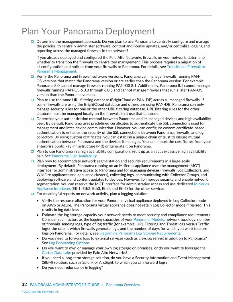
32 PANORAMA ADMINISTRATOR'S GUIDE | Panorama Overview© 2020 Palo Alto Networks, Inc.
Plan Your Panorama DeploymentDetermine the management approach. Do you plan to use Panorama to centrally configure and managethe policies, to centrally administer software, content and license updates, and/or centralize logging andreporting across the managed firewalls in the network?
If you already deployed and configured the Palo Alto Networks firewalls on your network, determinewhether to transition the firewalls to centralized management. This process requires a migration ofall configuration and policies from your firewalls to Panorama. For details, see Transition a Firewall toPanorama Management.Verify the Panorama and firewall software versions. Panorama can manage firewalls running PAN-OS versions that match the Panorama version or are earlier than the Panorama version. For example,Panorama 8.0 cannot manage firewalls running PAN-OS 8.1. Additionally, Panorama 8.1 cannot managefirewalls running PAN-OS 6.0.0 through 6.0.3 and cannot manage firewalls that run a later PAN-OSversion than the Panorama version.Plan to use the same URL filtering database (BrightCloud or PAN-DB) across all managed firewalls. Ifsome firewalls are using the BrightCloud database and others are using PAN-DB, Panorama can onlymanage security rules for one or the other URL filtering database. URL filtering rules for the otherdatabase must be managed locally on the firewalls that use that database.Determine your authentication method between Panorama and its managed devices and high availabilitypeer. By default, Panorama uses predefined certificates to authenticate the SSL connections used formanagement and inter-device communication. However, you can configure custom certificate-basedauthentication to enhance the security of the SSL connections between Panorama, firewalls, and logcollectors. By using custom certificates, you can establish a unique chain of trust to ensure mutualauthentication between Panorama and the devices it manages. You can import the certificates from yourenterprise public key infrastructure (PKI) or generate it on Panorama.Plan to use Panorama in a high availability configuration; set it up as an active/passive high availabilitypair. See Panorama High Availability.Plan how to accommodate network segmentation and security requirements in a large-scaledeployment. By default, Panorama running on an M-Series appliance uses the management (MGT)interface for administrative access to Panorama and for managing devices (firewalls, Log Collectors, andWildFire appliances and appliance clusters), collecting logs, communicating with Collector Groups, anddeploying software and content updates to devices. However, to improve security and enable networksegmentation, you can reserve the MGT interface for administrative access and use dedicated M-SeriesAppliance Interfaces (Eth1, Eth2, Eth3, Eth4, and Eth5) for the other services.For meaningful reports on network activity, plan a logging solution:
• Verify the resource allocation for your Panorama virtual appliance deployed in Log Collector modeon AWS or Azure. The Panorama virtual appliance does not retain Log Collector mode if resized. Thisresults in log data loss.
• Estimate the log storage capacity your network needs to meet security and compliance requirements.Consider such factors as the logging capacities of your Panorama Models, network topology, numberof firewalls sending logs, type of log traffic (for example, URL Filtering and Threat logs versus Trafficlogs), the rate at which firewalls generate logs, and the number of days for which you want to storelogs on Panorama. For details, see Determine Panorama Log Storage Requirements.
• Do you need to forward logs to external services (such as a syslog server) in addition to Panorama?See Log Forwarding Options.
• Do you want to own or manage your own log storage on premises, or do you want to leverage theCortex Data Lake provided by Palo Alto Networks?
• If you need a long-term storage solution, do you have a Security Information and Event Management(SIEM) solution, such as Splunk or ArcSight, to which you can forward logs?
• Do you need redundancy in logging?

PANORAMA ADMINISTRATOR'S GUIDE | Panorama Overview 33© 2020 Palo Alto Networks, Inc.
If you configure a Collector Group with multiple Log Collectors, you can enable redundancy to ensurethat no logs are lost if any one Log Collector becomes unavailable (see Caveats for a Collector Groupwith Multiple Log Collectors).
If you deploy Panorama virtual appliances in Legacy mode in an HA configuration, the managedfirewalls can send logs to both HA peers so that a copy of each log resides on each peer. Thisredundancy option is enabled by default (see Modify Log Forwarding and Buffering Defaults).
• Will you log to a Network File System (NFS)? If the Panorama virtual appliance is in Legacy mode anddoes not manage Dedicated Log Collectors, NFS storage is the only option for increasing log storagecapacity beyond 8TB. NFS storage is available only if Panorama runs on an ESXi server. If you useNFS storage, keep in mind that the firewalls can send logs only to the primary peer in the HA pair;only the primary peer is mounted to the NFS and can write to it.
Determine which role-based access privileges administrators require to access managed firewalls andPanorama. See Set Up Administrative Access to Panorama.Plan the required Device Groups. Consider whether to group firewalls based on function, security policy,geographic location, or network segmentation. An example of a function-based device group is onethat contains all the firewalls that a Research and Development team uses. Consider whether to createsmaller device groups based on commonality, larger device groups to scale more easily, or a DeviceGroup Hierarchy to simplify complex layers of administration.Plan a layering strategy for administering policies. Consider how firewalls inherit and evaluate policyrules within the Device Group Hierarchy, and how to best implement shared rules, device-group rules,and firewall-specific rules to meet your network needs. For visibility and centralized policy management,consider using Panorama for administering rules even if you need firewall-specific exceptions for sharedor device group rules. If necessary, you can Push a Policy Rule to a Subset of Firewalls within a devicegroup.Plan the organization of your firewalls based on how they inherit network configuration settings fromTemplates and Template Stacks. For example, consider assigning firewalls to templates based onhardware models, geographic proximity, and similar network needs for time zones, a DNS server, andinterface settings.

34 PANORAMA ADMINISTRATOR'S GUIDE | Panorama Overview
Deploy Panorama: Task OverviewThe following task list summarizes the steps to get started with Panorama. For an example of how to usePanorama for central management, see Use Case: Configure Firewalls Using Panorama.
STEP 1 | (M-Series appliance only) Rack mount the appliance.
STEP 2 | Perform initial configuration to enable network access to Panorama. See Set Up the PanoramaVirtual Appliance or Set Up the M-Series Appliance.
STEP 3 | Register Panorama and Install Licenses.
STEP 4 | Install Content and Software Updates for Panorama.
STEP 5 | (Recommended) Set up Panorama in a high availability configuration. See Panorama HighAvailability.
STEP 6 | Add a Firewall as a Managed Device.
STEP 7 | Add a Device Group or Create a Device Group Hierarchy, Add a Template, and (if applicable)Configure a Template Stack.
STEP 8 | (Optional) Configure log forwarding to Panorama and/or to external services. See Manage LogCollection.
STEP 9 | Monitor Network Activity using the visibility and reporting tools on Panorama.

35
Set Up PanoramaFor centralized reporting and cohesive policy management across all the firewalls on yournetwork, you can deploy the Panorama™ management server as a virtual appliance or as ahardware appliance (the M-100, M-200, M-500 or M-600 appliance).
M-100 appliances are supported in PAN-OS 9.1 only if they have beenupgraded to 32GB memory from the default 16GB. See M-100 MemoryUpgrade Guide for more information.
The following topics describe how to set up Panorama on your network:
> Determine Panorama Log Storage Requirements> Set Up the Panorama Virtual Appliance> Set Up the M-Series Appliance> Register Panorama and Install Licenses> Install the Panorama Device Certificate> Install Content and Software Updates for Panorama> Transition to a Different Panorama Model> Access and Navigate Panorama Management Interfaces> Set Up Administrative Access to Panorama> Set Up Authentication Using Custom Certificates

36 PANORAMA ADMINISTRATOR'S GUIDE | Set Up Panorama© 2020 Palo Alto Networks, Inc.

PANORAMA ADMINISTRATOR'S GUIDE | Set Up Panorama 37© 2020 Palo Alto Networks, Inc.
Determine Panorama Log StorageRequirements
When you Plan Your Panorama Deployment, estimate how much log storage capacity Panorama requiresto determine which Panorama Models to deploy, whether to expand the storage on those appliancesbeyond their default capacities, whether to deploy Dedicated Log Collectors, and whether to ConfigureLog Forwarding from Panorama to External Destinations. When log storage reaches the maximum capacity,Panorama automatically deletes older logs to create space for new ones.
Perform the following steps to determine the approximate log storage that Panorama requires. For detailsand use cases, refer to Panorama Sizing and Design Guide.
STEP 1 | Determine the log retention requirements of your organization.Factors that affect log retention requirements include:
• IT policy of your organization• Log redundancy—If you enable log redundancy when you Configure a Collector Group, each log will
have two copies, which doubles your required log storage capacity.• Regulatory requirements, such as those specified by the Payment Card Industry Data Security
Standard (PCI DSS), Sarbanes-Oxley Act, and Health Insurance Portability and Accountability Act(HIPAA).
If your organization requires the removal of logs after a certain period, you can set theexpiration period for each log type. You can also set a storage quota for each log type asa percentage of the total space if you need to prioritize log retention by type. For details,see Manage Storage Quotas and Expiration Periods for Logs and Reports.
STEP 2 | Determine the average daily logging rates.Do this multiple times each day at peak and non-peak times to estimate the average. The more often yousample the rates, the more accurate your estimate.
1. Display the current log generation rate in logs per second:
• If Panorama is not yet collecting logs, access the CLI of each firewall, run the following command,and calculate the total rates for all the firewalls. This command displays the number of logsreceived in the last second.
> debug log-receiver statistics
• If Panorama is already collecting logs, run the following command at the CLI of each appliancethat receives logs (Panorama management server or Dedicated Log Collector) and calculate thetotal rates. This command gives the average logging rate for the last five minutes.
> debug log-collector log-collection-stats show incoming-logs
You can also use an SNMP manager to determine the logging rates of Log Collectors(see the panLogCollector MIB, OID 1.3.6.1.4.1.25461.1.1.6) and firewalls (see thepanDeviceLogging, OID 1.3.6.1.4.1.25461.2.1.2.7).
2. Calculate the average of the sampled rates.3. Calculate the daily logging rate by multiplying the average logs-per-second by 86,400.

38 PANORAMA ADMINISTRATOR'S GUIDE | Set Up Panorama© 2020 Palo Alto Networks, Inc.
STEP 3 | Estimate the required storage capacity.
This formula provides only an estimate; the exact amount of required storage will differfrom the formula result.
Use the formula:
<required_storage_duration> x <average_log_size> x <average_logging_rate>
The average log size varies considerably by log type. However, you can use 500 bytes as an approximateaverage log size.
For example, if Panorama must store logs for 30 days and the average total logging rate for allfirewalls is 21,254,400 logs per day, then the required log storage capacity is: 30 x 500 x 21,254,400 =318,816,000,000 bytes (approximately 318GB).
STEP 4 | Next steps...If you determine that Panorama requires more log storage capacity:
• Expand Log Storage Capacity on the Panorama Virtual Appliance.• Increase Storage on the M-Series Appliance.

PANORAMA ADMINISTRATOR'S GUIDE | Set Up Panorama 39© 2020 Palo Alto Networks, Inc.
Set Up the Panorama Virtual ApplianceThe Panorama virtual appliance enables you to use your existing VMware virtual infrastructure to centrallymanage and monitor Palo Alto Networks firewalls and Dedicated Log Collectors. You can install the virtualappliance on an ESXi server, Amazon Web Services (AWS), AWS GovCloud, Microsoft Azure, Google CloudPlatform (GCP), KVM, Hyper-V, or in vCloud Air. In addition to or instead of deploying Dedicated LogCollectors, you can forward firewall logs directly to the Panorama virtual appliance. For greater log storagecapacity and faster reporting, you have the option to switch the virtual appliance from Legacy mode toPanorama mode and configure a local Log Collector. For more details about the Panorama virtual applianceand its modes, see Panorama Models.
These topics assume you are familiar with the public and private hypervisor productsrequired to create the virtual appliance, and don’t cover any related concepts or terminology.
• Setup Prerequisites for the Panorama Virtual Appliance• Install the Panorama Virtual Appliance• Perform Initial Configuration of the Panorama Virtual Appliance• Set Up The Panorama Virtual Appliance as a Log Collector• Set Up the Panorama Virtual Appliance with Local Log Collector• Set up a Panorama Virtual Appliance in Panorama Mode• Set up a Panorama Virtual Appliance in Management Only Mode• Expand Log Storage Capacity on the Panorama Virtual Appliance• Increase CPUs and Memory on the Panorama Virtual Appliance• Increase the System Disk on the Panorama Virtual Appliance• Complete the Panorama Virtual Appliance Setup
Setup Prerequisites for the Panorama Virtual ApplianceComplete the following tasks before you Install the Panorama Virtual Appliance:
Use your browser to access the Palo Alto Networks Customer Support web site and Register PanoramaYou will need the Panorama serial number that you received in the order fulfillment email. Afterregistering Panorama, you can access the Panorama software downloads page.Review the supported Panorama hypervisors to verify the hypervisor meets the minimum versionrequirements to deploy Panorama.If you will install Panorama on a VMware ESXi server, verify that the server meets the minimumrequirements as listed in the System Requirements for the Panorama Virtual Appliance. Theserequirements apply to Panorama 5.1 and later releases. The requirements vary based on whether youwill run the virtual appliance in Panorama mode or Management Only mode. For details on the modes,see Panorama Models.
If you install Panorama on VMware vCloud Air, you set the system settings duringinstallation.
Review the minimum resource requirements for deploying the Panorama virtual appliance on AmazonWeb Services (AWS), AWS GovCloud, Microsoft Azure, Google Cloud Platform (GCP), Hyper-V, KVM, andVMware ESXi to ensure that the virtual machine meets the minimum required resources for the desiredmode (Panorama, Management Only, or Log Collector). The minimum resource requirements for thePanorama virtual appliance are designed to help you achieve the maximum number of logs per second(LPS) for log collection in Panorama and Log Collector mode. If you add or remove virtual logging disks thatresults in a configuration that does not meet or exceed the number of virtual logging disks recommended(below), your LPS will be reduced.

40 PANORAMA ADMINISTRATOR'S GUIDE | Set Up Panorama© 2020 Palo Alto Networks, Inc.
If the minimum resource requirements are not met for Panorama mode when you Install the PanoramaVirtual Appliance, Panorama defaults to Management Only mode for all supported public (AWS, AWSGovCloud, Azure, and GCP) and private (Hyper-V, KVM, and VMware ESXi) hypervisors. If the minimumresource requirements are not met for Management Only mode, Panorama defaults to Maintenancemode for all supported public hypervisors, Hyper-V, and KVM. If the minimum resource requirements forManagement Only mode are not met when you Install Panorama on VMware, Panorama defaults to Legacymode.
It is recommended to deploy the Panorama management server in Panorama mode forboth device management and log collection capabilities. While still supported, Legacy modeis not recommended for production environments. Additionally, you can no longer switchPanorama to Legacy mode. For more information on supported modes, see PanoramaModels.
Table 1: System Requirements for the Panorama Virtual Appliance
Requirements Panorama Virtual Appliancein Management Only Mode
Panorama Virtual Appliance inPanorama Mode
Panorama Virtual Appliancein Log Collector Mode
Virtualhardwareversion
• VMware ESXi and vCloud Air—64-bit kernel-based VMware ESXi 5.5, 6.0, 6.5, or 6.7.The supported version of the virtual hardware family type (also known as the VMwarevirtual hardware version) on the ESXi server is vmx-10
The Panorama virtual appliance for ESXi does not support thecreation quiesced snapshots. Disable Quiesce guest file system in thevSphere client or set the quiesce flag to 0 or false in the vSphere CLIbefore creating a snapshot of your virtual Panorama appliance.
• Hyper-V—Windows Server 2016 with Hyper-V role or Hyper-V 2016• KVM—Ubuntu version 16.04 or CentOS7
In Panorama mode, the virtual appliance running on any ESXi version supports up to 12virtual logging disks with 2TB of log storage each, for a total maximum capacity of 24TB.
(VMware ESXi and vCloud Air only) In Legacy mode, the virtual appliance supports onevirtual logging disk. ESXi 5.5 and later versions supports one disk of up to 8TB. EarlierESXi versions support one disk of up to 2TB.
(ESXi andvCloud Aironly)
Clientcomputer
To install the Panorama virtual appliance and manage its resources, you must install aVMware vSphere Client or VMware Infrastructure Client that is compatible with yourESXi server.
System disk • Default—81GB• Upgraded—224GB
• Default—81GB• Upgraded—224GB
(Required for SD-WAN)
For log storage, Panoramauses virtual logging disksinstead of the system disk oran NFS datastore.
81GB
For log storage, Panoramauses virtual logging disksinstead of the system diskor an NFS datastore.
CPUs,memory,
• Manage up to 500managed devices
• Up to 10,000 logs/sec:
• 16 CPUs
• Up to 15,000 log/sec
• 16 CPUs

PANORAMA ADMINISTRATOR'S GUIDE | Set Up Panorama 41© 2020 Palo Alto Networks, Inc.
Requirements Panorama Virtual Appliancein Management Only Mode
Panorama Virtual Appliance inPanorama Mode
Panorama Virtual Appliancein Log Collector Mode
and loggingdisks
• 16 CPUs• 32GB memory• Local log storage not
supported• Manage up to 1,000
managed devices
• 32 CPUs• 128GB memory• Local log storage not
supported• To manage more than
1,000 firewalls, seeIncreased DeviceManagement CapacityRequirements.
• 32GB memory• 4x2TB logging disks• Manage up to 500
managed devices• Up to 20,000 log/sec
• 32 CPUs• 128GB memory• 8x2TB logging disks• Manage up to 1,000
managed devices
• 32GB memory• 4x2TB logging disks
• Up to 25,000 logs/sec
• 32 CPUs• 128GB memory• 8x2TB logging disks
Log storagecapacity
Panorama in ManagementOnly mode requires logforwarding to a DedicatedLog Collector.
2TB to 24TB 2TB to 24TB
Supported InterfacesInterfaces can be used for device management, log collection, Collector Group communication, licensingand software updates.
Function Amazon WebServices (AWS) andAWS GovCloud
MicrosoftAzure
GoogleCloudPlatform(GCP)
KVM Hyper-V VMware(ESXi, vCloudAir)
DeviceManagement
Any interface supported
Device LogCollection
Any interface supported
CollectorGroupCommunication
Any interface supported
Licensingand SoftwareUpdates
MGTinterfaceonly
MGTinterfaceonly
MGTinterfaceonly
MGTinterfaceonly
Anyinterfacesupported
Anyinterfacesupported
Anyinterfacesupported

42 PANORAMA ADMINISTRATOR'S GUIDE | Set Up Panorama© 2020 Palo Alto Networks, Inc.
Install the Panorama Virtual ApplianceBefore installation, decide whether to run the virtual appliance in Panorama mode, ManagementOnly mode, Log Collector mode, or Legacy mode (VMware only). Each mode has different resourcerequirements, as described in Setup Prerequisites for the Panorama Virtual Appliance. You must completethe prerequisites before starting the installation.
As a best practice, install the virtual appliance in Panorama mode to optimize log storageand report generation. For details on Panorama and Legacy mode, see Panorama Models.
• Install Panorama on VMware• Install Panorama on AWS• Install Panorama on AWS GovCloud• Install Panorama on Azure• Install Panorama on Google Cloud Platform• Install Panorama on KVM• Install Panorama on Hyper-V
Install Panorama on VMwareYou can install the Panorama virtual appliance on the ESXi and vCloud Air VMware platforms.
• Install Panorama on an ESXi Server• Install Panorama on vCloud Air• Support for VMware Tools on the Panorama Virtual Appliance
Install Panorama on an ESXi Server
Use these instructions to install a new Panorama virtual appliance on a VMware ESXi server. For upgradesto an existing Panorama virtual appliance, skip to Install Content and Software Updates for Panorama.
STEP 1 | Download the Panorama 9.1 base image Open Virtual Appliance (OVA) file.1. Go to the Palo Alto Networks software downloads site. (If you can’t log in, go to the Palo Alto
Networks Customer Support web site for assistance.)2. In the Download column in the Panorama Base Images section, download the latest version of the
Panorama release OVA file (Panorama-ESX-9.1.0.ova).
STEP 2 | Install Panorama.1. Launch the VMware vSphere Client and connect to the VMware server.2. Select File > Deploy OVF Template.3. Browse to select the Panorama OVA file and click Next.4. Confirm that the product name and description match the downloaded version, and click Next.5. Enter a descriptive name for the Panorama virtual appliance, and click Next.6. Select a datastore location (system disk) on which to install the Panorama image. See the Setup
Prerequisites for the Panorama Virtual Appliance for the supported system disk sizes. After selectingthe datastore, click Next.
7. Select Thick Provision Lazy Zeroed as the disk format, and click Next.8. Specify which networks in the inventory to use for the Panorama virtual appliance, and click Next.9. Confirm the selected options, click Finish to start the installation process, and click Close when it
finishes. Do not power on the Panorama virtual appliance yet.
STEP 3 | Configure resources on the Panorama virtual appliance.1. Right-click the Panorama virtual appliance and Edit Settings.

PANORAMA ADMINISTRATOR'S GUIDE | Set Up Panorama 43© 2020 Palo Alto Networks, Inc.
2. In the Hardware settings, allocate the CPUs and memory as necessary.
The virtual appliance boots up in Panorama mode if you allocate sufficient CPUsand Memory and add a virtual logging disk (later in this procedure). Otherwise,the appliance boots up in Management Only mode. For details on the modes, seePanorama Models.
3. Set the SCSI Controller to LSI Logic Parallel.4. Add a virtual logging disk.
This step is required in the following scenarios:
• In Panorama mode to store logs on a dedicated logging disk.• Manage your SD-WAN deployment in Management Only mode.
1. Add a disk, select Hard Disk as the hardware type, and click Next.2. Create a new virtual disk and click Next.3. Set the Disk Size to exactly 2TB.
In Panorama mode, you can later add additional logging disks (for a total of 12) with2TB of storage each. Expanding the size of a logging disk that is already added toPanorama is not supported.
4. Select your preferred Disk Provisioning disk format.
Consider your business needs when selecting the disk provisioning format. For more informationregarding the disk provisioning performance considerations, refer to the VMware Thick vs ThinDisks and All Flash Arrays document, or additional VMware documentation.
When adding multiple logging disks, it is a best practice to select the same DiskProvisioning format for all disks to avoid any unexpected performance issues thatmay arise.
5. Select Specify a datastore or datastore structure as the location, Browse to a datastore that hassufficient storage, click OK, and click Next.
6. Select a SCSI Virtual Device Node (you can use the default selection) and click Next.
Panorama will fail to boot if you select a format other than SCSI.
7. Verify that the settings are correct and click Finish.5. Click OK to save your changes.
STEP 4 | Power on the Panorama virtual appliance.1. In the vSphere Client, right-click the Panorama virtual appliance and select Power > Power On. Wait
for Panorama to boot up before continuing.2. Verify that the virtual appliance is running in the correct mode:
1. Right-click the Panorama virtual appliance and select Open Console.2. Enter your username and password to log in (default is admin for both).3. Display the mode by running the following command:
> show system info
In the output, the system-mode indicates either panorama or management-only mode.
STEP 5 | Increase the System Disk for Panorama on an ESXi Server if you intend to use the Panoramavirtual appliance for the following:

44 PANORAMA ADMINISTRATOR'S GUIDE | Set Up Panorama© 2020 Palo Alto Networks, Inc.
• Manage your SD-WAN deployment in Panorama mode.• Requires additional storage space for dynamic updates when managing large-scale firewall
deployments.
You are now ready to Perform Initial Configuration of the Panorama Virtual Appliance.
Install Panorama on vCloud Air
Use these instructions to install a new Panorama virtual appliance in VMware vCloud Air. If you areupgrading a Panorama virtual appliance deployed in vCloud Air, skip to Install Content and SoftwareUpdates for Panorama.
STEP 1 | Download the Panorama 9.1 base image Open Virtual Appliance (OVA) file.1. Go to the Palo Alto Networks software downloads site. (If you can’t log in, go to the Palo Alto
Networks Customer Support web site for assistance.)2. In the Download column in the Panorama Base Images section, download the Panorama 8.1 release
OVA file (Panorama-ESX-9.1.0.ova).
STEP 2 | Import the Panorama image to the vCloud Air catalog.For details on these steps, refer to the OVF Tool User’s Guide.
1. Install the OVF Tool on your client system.2. Access the client system CLI.3. Navigate to the OVF Tool directory (for example, C:\Program Files\VMware\VMware OVF Tool).4. Convert the OVA file to an OVF package:
ovftool.exe <OVA#file#pathname> <OVF#file#pathname>
5. Use a browser to access the vCloud Air web console, select your Virtual Private Cloud OnDemandlocation, and record the browser URL. You will use the URL information to complete the nextstep. The URL format is: https://<virtual#cloud#location>.vchs.vmware.com/compute/cloud/org/<vCloud#account#number>/#/catalogVAppTemplateList?catalog=<catalog#ID>.
6. Import the OVF package, using the information from the vCloud Air URL to complete the<virtual#cloud#location>, <vCloud#account#number>, and <catalog#ID> variables. The othervariables are your vCloud Air username and domain <user>@<domain>, a virtual data center<datacenter>, and a vCloud Air template <template>.
ovftool.exe -st="OVF" "<OVF#file#pathname>" "vcloud://<user>@<domain>:password@<virtual-cloud-location>.vchs.vmware.com?vdc=<datacenter>&org=<vCloud-account-number>&vappTemplate=<template>.ovf&catalog=default-catalog"
STEP 3 | Install Panorama.1. Access the vCloud Air web console and select your Virtual Private Cloud OnDemand region.2. Create a Panorama virtual machine. For the steps, refer to Add a Virtual Machine from a Template in
the vCloud Air Documentation Center. Configure the CPU, Memory and Storage as follows:
• Set the CPU and Memory based on whether the virtual appliance mode: see Setup Prerequisitesfor the Panorama Virtual Appliance.
• Set the Storage to configure the Panorama virtual appliance system disk. See Setup Prerequisitesfor the Panorama Virtual Appliance for the supported disk sizes based on the Panorama virtualappliance mode. For better logging and reporting performance, select the SSD-Acceleratedoption.

PANORAMA ADMINISTRATOR'S GUIDE | Set Up Panorama 45© 2020 Palo Alto Networks, Inc.
To increase the log storage capacity, you must Add a Virtual Disk to Panorama on vCloud Air. InPanorama mode, the virtual appliance does not use the system disk for log storage; you must adda virtual logging disk.
STEP 4 | Create vCloud Air NAT rules on the gateway to allow inbound and outbound traffic for thePanorama virtual appliance.Refer to Add a NAT Rule in the vCloud Air Documentation Center for the detailed instructions:
1. Add a NAT rule that allows Panorama to receive traffic from the firewalls and allows administratorsto access Panorama.
2. Add a NAT rule that allows Panorama to retrieve updates from the Palo Alto Networks update serverand to access the firewalls.
STEP 5 | Create a vCloud Air firewall rule to allow inbound traffic on the Panorama virtual appliance.Outbound traffic is allowed by default.
Refer to Add a Firewall Rule in the vCloud Air Documentation Center for the detailed instructions.
STEP 6 | Power on the Panorama virtual appliance if it isn’t already on.In the vCloud Air web console, select the Virtual Machines tab, select the Panorama virtual machine, andclick Power On.
You are now ready to Perform Initial Configuration of the Panorama Virtual Appliance.
Support for VMware Tools on the Panorama Virtual Appliance
VMware Tools is bundled with the software image (ovf) for the Panorama virtual appliance. The support forVMware Tools allows you to use the vSphere environment—vCloud Director and vCenter server—for thefollowing:
• View the IP address assigned to the Panorama management interface.• View resource utilization metrics on hard disk, memory, and CPU. You can use these metrics to enable
alarms or actions on the vCenter server or vCloud Director.• Graceful shutdown and restart of Panorama using the power off function on the vCenter server or
vCloud Director.• Enables a heartbeat mechanism between the vCenter server and Panorama for verifying that Panorama
is functioning, or if the firewall/Panorama is rebooting. If the firewall goes into maintenance mode,heartbeats are disabled so that the vCenter server does not shut down the firewall. Disabling heartbeatsallows the firewall to stay operational in maintenance mode when it cannot not send heartbeats to thevCenter server.
Install Panorama on AWSYou can now deploy Panorama™ and a Dedicated Log Collector on Amazon Web Services (AWS). Panoramadeployed on AWS is Bring Your Own License (BYOL), supports all deployment modes (Panorama, LogCollector, and Management Only), and shares the same processes and functionality as the M-Serieshardware appliances. For more information on Panorama modes, see Panorama Models.
STEP 1 | Log in to AWS Web Service console and select the EC2 Dashboard.• Amazon Web Service Console• AWS GovCloud Web Service Console
STEP 2 | Set up the VPC for your network needs.

46 PANORAMA ADMINISTRATOR'S GUIDE | Set Up Panorama© 2020 Palo Alto Networks, Inc.
Whether you launch the Panorama virtual appliance in an existing VPC or you create a new VPC, thePanorama virtual appliance must be able to receive traffic from the EC2 instances and perform inboundand outbound communication between the VPC and the internet.
Refer to the AWS VPC documentation for instructions on creating a VPC and setting it up for access.
1. Create a new VPC or use an existing VPC. Refer to the AWS Getting Started documentation.2. Verify that the network and security components are appropriately defined.
• Enable communication to the internet. The default VPC includes an internet gateway and, if youinstall the Panorama virtual appliance in the default subnet, the VPC can access to the internet.
• Create subnets. Subnets are segments of the IP address range assigned to the VPC in which youcan launch the EC2 instances. The Panorama virtual appliance must belong to the public subnet sothat you can configure it to access the internet.
• Create a Security Group as needed to manage inbound and outbound traffic from the EC2instances or subnets.
• Add routes to the route table for a private subnet to ensure that you can route traffic can berouted across subnets and security groups in the VPC as applicable.
STEP 3 | Deploy Panorama on Amazon Web Services.1. On the EC2 Dashboard, click Instances > Launch Instance.2. Select AWS Marketplace, search for Palo Alto Networks Panorama, and Select the Panorama
AMI and Continue.3. Choose the EC2 instance type for allocating the resources required for the Panorama virtual
appliance, and click Next: Configure Instance Details. Review the Setup Prerequisites for thePanorama Virtual Appliance for resource requirements.
If you plan to use the Panorama virtual appliance as a Dedicated Log Collector,ensure that you configure the appliance with the required resources during initialdeployment. The Panorama virtual appliance does not remain in Log Collector mode ifyou resize the virtual machine after you deploy it, and this results in a loss of log data.
4. Configure the instance details.
1. Select Next: Configure Instance Details.2. Select the Network you created in the previous step or use the default VPC provided by AWS. If3. Select the Subnet you created in the previous step or use the default subnets provided by AWS.4. To Auto-assign Public IP select Enable.
This IP must be accessible by the firewalls you plan to manage using Panorama. This allows youto obtain a publicly accessible IP address for the management interface of the Panorama virtualappliance. You can later attach an Elastic IP address to the management interface. Unlike thepublic IP address that is disassociated from the virtual appliance when the instance is terminated,the Elastic IP address provides persistence and you can the IP address to a new (or replacement)instance of the Panorama virtual appliance without the need to reconfigure the IP addresswhenever the Panorama virtual appliance instance is powered off.
5. Configure any additional instance details as needed.5. Configure the Panorama virtual appliance storage.
1. Select Next: Add Storage.2. Review the Root system disk size and determine whether you need to expand to a 224GB system
disk. Increase the system disk Size to 224GB if needed.
To support large datasets, a 224GB system disk is required to Manage Large-Scale FirewallDeployments in order to allow for sufficient disk space for things such as dynamic updates.

PANORAMA ADMINISTRATOR'S GUIDE | Set Up Panorama 47© 2020 Palo Alto Networks, Inc.
(SD-WAN only) A 224GB system disk expands storage for monitoring and reporting data formanaged firewall health if you intended to use the Panorama virtual appliance in Panorama modeto manage your SD-WAN deployment.
If you deploy a Panorama virtual appliance instance with a 224GB system disk, youcannot migrate to a smaller system disk in the future.
3. Add New Volume to add additional log storage.
(SD-WAN only) If you plan on managing your SD-WAN deployment in Management Only mode,you must add a 2TB logging disk.
If you intend to use the Panorama virtual appliance in Panorama mode or as a Dedicated LogCollector, add the virtual logging disks during the initial deployment. By default, the Panoramavirtual appliance is in Panorama mode for the initial deployment when you meet the Panoramamode resource requirements and have added at least one virtual logging disk. Otherwise, thePanorama virtual appliance defaults to Management Only mode. Change the Panorama virtualappliance to Management Only mode if you just want to manage devices and Dedicated LogCollectors, and to not collect logs locally.
The Panorama virtual appliance on AWS only supports 2TB logging disks, and in total supportsup to 24TB of log storage. You are unable to add a logging disk smaller than 2TB, or a loggingdisk with a size not divisible by the 2TB logging disk requirement. The Panorama virtual appliancepartitions logging disks larger than 2TB into 2TB partitions.
6. (Optional) Select Next: Add Tags and add one or more tags as metadata to help you identify andgroup the Panorama virtual appliance. For example, add a Name tag with a Value that helps youidentify which firewalls the Panorama virtual appliance manages.
7. Configure the instance security group.
1. Select Next: Configure Security Group.2. Create a new Security Group or select an existing one with HTTPS and SSH enabled at a
minimum. This security group is for restricting access to the management interface.8. Review and Launch the Panorama virtual appliance instance to verify that your selections are
accurate before you Launch.9. Select an existing key pair or create a new one and acknowledge the disclaimer.
If you created a new key from AWS, download and save the key to a safe location.The file extension is .pem. You must load the public key into PuTTYgen and save it in.ppk format. You cannot regenerate this key if lost.
It takes about 30 minutes to finish deploying the Panorama virtual appliance after you launch it onAWS. Deploying the Panorama virtual appliance may take longer depending on the number andsize of the disks attached to the instance. View the Launch Time by selecting the Panorama virtualappliance instance (Instances).

48 PANORAMA ADMINISTRATOR'S GUIDE | Set Up Panorama© 2020 Palo Alto Networks, Inc.
If you plan to use the Panorama virtual appliance as a Dedicated Log Collector,ensure that you the appliance with the required resources. The Panorama virtualappliance does not remain in Log Collector mode if you resize the virtual machine afteryou deploy it, and this results in a loss of log data.
STEP 4 | Shut down the Panorama virtual appliance.1. On the EC2 Dashboard, select Instances.2. Select the Panorama virtual appliance and click Actions > Instance State > Stop.
STEP 5 | Create or assign an Elastic IP (EIP) address to the management interface.1. In the AWS Console, select Elastic IPs and Allocate New Address.2. Click Allocate to generate a new EIP address, click Actions, and Associate address.3. Select Instance, select the Panorama virtual appliance instance to which to assign the EIP address,
and enter the Private IP address associated with the management interface and click Associate.
STEP 6 | Power on the Panorama virtual appliance.1. On the EC2 Dashboard, select Instance.2. From the list, select the Panorama virtual appliance and click Actions > Instance State > Start.
STEP 7 | Configure a new administrative password for the Panorama virtual appliance.You must configure a unique administrative password before you can access the web interface of thePanorama virtual appliance. To access the CLI, the private key used to launch the Panorama virtualappliance is required.
• If you have an SSH service installed on your computer:
1. Enter the following command to log into the Panorama virtual appliance:
ssh -i <private_key.ppk> admin@<public-ip_address>
2. Configure a new password using the following commands and follow the on screen prompts:

PANORAMA ADMINISTRATOR'S GUIDE | Set Up Panorama 49© 2020 Palo Alto Networks, Inc.
admin> configureadmin# set mgt-config users admin password
3. If you need to activate a BYOL, set the DNS server IP address so that the Panorama virtual appliancecan access the Palo Alto Networks licensing server. Enter the following command to set the DNSserver IP address:
admin# set deviceconfig system dns-setting servers primary <ip_address>
4. Commit your changes with the command:
admin# commit
5. Terminate the SSH session.
• If you are using PuTTY to SSH into the Panorama virtual appliance:
1. If you are using an existing key pair and have the .ppk file available, continue to the Step 7.3. If youcreated a new key pair or have only the .pem file of the existing key pair, open PuTTYgen and Loadthe .pem file.
2. Save the private key to a local accessible destination.3. Open PuTTY and select SSH > Auth and then Browse to the .ppk file you saved in the previous step.
4. Select Sessions and enter the public IP address of the Panorama virtual appliance. Click Open andclick Yes when the security prompt appears.
5. Log in as admin when prompted.6. Configure a new password using the following commands and follow the onscreen prompts:
admin> configureadmin# set mgt-config users admin password
7. Set the DNS server IP address so that the Panorama virtual appliance can access the Palo AltoNetworks licensing server. Enter the following command to set the DNS server IP address:
admin# set deviceconfig system dns-setting servers primary <ip_address>
8. Commit your changes with the command:

50 PANORAMA ADMINISTRATOR'S GUIDE | Set Up Panorama© 2020 Palo Alto Networks, Inc.
admin# commit
9. Terminate the SSH session.
STEP 8 | Activate the device management license and support license on the Panorama virtualappliance.• Activate/Retrieve a Firewall Management License when the Panorama Virtual Appliance is Internet-
connected• Activate/Retrieve a Firewall Management License when the Panorama Virtual Appliance is not
Internet-connected• Activate a Panorama Support License
STEP 9 | Complete configuring the Panorama virtual appliance for your deployment needs.• (Management Only mode) Set up a Panorama Virtual Appliance in Management Only Mode.• (Log Collector mode) Begin at Step 6 to Switch from Panorama mode to Log Collector mode.
Enter the Public IP address of the Dedicated Log Collector when you Add the LogCollector as a managed collector to the Panorama management server. You cannotspecify the IP Address, Netmask, or Gateway.
• (Panorama and Management Only mode) Configure a Managed Collector to add a Dedicated LogCollector to the Panorama virtual appliance. Management Only mode does not support local logcollection, and requires a Dedicated Log Collector to store managed device logs.
Install Panorama on AWS GovCloudYou can now deploy Panorama™ and a Dedicated Log Collector on Amazon Web Services (AWS) GovCloud.AWS GovCloud is an isolated AWS region that meets the regulatory and compliance requirements ofthe US government agencies and customers. Panorama deployed on AWS GovCloud is Bring Your OwnLicense (BYOL), supports all deployment modes (Panorama, Log Collector, and Management Only). Formore information on Panorama modes, see Panorama Models.
To secure your workloads that contain all categories of Controlled Unclassified Information (CUI) dataand government-oriented, publicly available data in the AWS GovCloud (US) region, the Panorama virtualappliance provides the same security features offered in the standard AWS public cloud on AWS GovCloud.The Panorama virtual appliance on AWS GovCloud and the standard AWS public cloud support the samefeatures and capabilities.
Review the Setup Prerequisites for the Panorama Virtual Appliance to review the supported EC2 instancetypes. Once you are ready, refer to Install Panorama on AWS to install the Panorama virtual appliance onAWS GovCloud.
See the following procedures to add additional logging storage to your Panorama virtual appliance, or toincrease the allocated CPU cores and memory:
• Add a Virtual Disk to Panorama on AWS• Increase CPUs and Memory for Panorama on AWS
Install Panorama on AzureYou can now deploy Panorama™ and a Dedicated Log Collector on Microsoft Azure. Panorama deployedon Azure is Bring Your Own License (BYOL), supports all deployment modes (Panorama, Log Collector, andManagement Only), and shares the same processes and functionality as the M-Series hardware appliances.For more information on Panorama modes, see Panorama Models.

PANORAMA ADMINISTRATOR'S GUIDE | Set Up Panorama 51© 2020 Palo Alto Networks, Inc.
STEP 1 | Log into to the Microsoft Azure portal.
STEP 2 | Deploy the Panorama virtual appliance.1. In the Azure Dashboard, select Virtual machines and Add a new virtual machine.2. Search for Palo Alto Networks and select the latest Panorama virtual appliance image.3. Create the Panorama virtual appliance.
STEP 3 | Configure the Panorama virtual appliance.1. Select your Azure Subscription.2. Select the Azure Resource Group to contain all your Azure instance resources.3. Enter a Virtual machine name for the Panorama virtual appliance.4. Select the Region for the Panorama virtual appliance to be deployed in.5. (Optional) Select the Availability options. See How to use availability sets for more information.6. Select the Image used to deploy the Panorama management server. Browse all public and private
images to deploy the Panorama management server from the Panorama image on the Azuremarketplace.
7. Configure the Panorama virtual appliance size. Review the Setup Prerequisites for the PanoramaVirtual Appliance for sizing requirements.
If you plan to use the Panorama virtual appliance as a Dedicated Log Collector,ensure that you configure the appliance with the required resources during initialdeployment. The Panorama virtual appliance does not remain in Log Collector mode ifyou resize the virtual machine after you deploy it, and this results in a loss of log data.
8. Enter a Username for the Panorama virtual appliance administrator. To ensure that your username issecure, admin is not a valid entry.
9. Enter a Password or copy and paste an SSH public key for securing administrative access to thePanorama virtual appliance.
10.Configure the Panorama virtual appliance instance Networking
1. Select an existing Virtual network or create a new virtual network.2. Configure the Subnet. The subnet is dependent on the virtual network you selected or created in
the previous step. If you selected an existing virtual network, you can choose one of the subnetsfor the selected virtual network.
3. Select an existing Public IP address or create a new one. This creates the management interfaceused to access your Panorama virtual appliance.
4. Select an existing NIC network security group or create a new security group. Network securitygroups control traffic to the virtual machine. Make sure that HTTPS and SSH are allowed for theInbound rules.
11.Configure the instance Management settings.
1. Select whether to enable Auto-shutdown. Auto-shutdown allows you to configure a daily timeto automatically shut down the virtual machine that you disable auto-shutdown to avoid thepossibility that a new public IP address gets assigned to the virtual machine, that logs are dropped,that logs are not or that you are unable to manage your firewalls while the Panorama virtualappliance is shut down.
2. Select whether to enable boot Monitoring. Select the Diagnostic storage account if enabled.Monitoring automatically sends boot-up diagnostic logs to your Diagnostics storage account. Formore information, see Overview of Monitoring in Microsoft Azure.
3. Configure any other settings as needed.12.Review the summary, accept the terms of use and privacy policy, and Create the Panorama virtual
appliance.
STEP 4 | Verify that you the Panorama virtual appliance has been successfully deployed.

52 PANORAMA ADMINISTRATOR'S GUIDE | Set Up Panorama© 2020 Palo Alto Networks, Inc.
1. Select Dashboard > Resource Groups and select the resource group containing the Panorama virtualappliance.
2. Under Settings, select Deployments for the virtual machine deployment status.
It takes about 30 minutes to deploy the Panorama virtual appliance. Launching thePanorama virtual appliance may take longer depending on the resources configuredfor the virtual machine. Microsoft Azure does not permit the ICMP protocol to testwhether it deployed successfully.
If you plan to use the Panorama virtual appliance as a Dedicated Log Collector,ensure that you correctly configured the appliance the required resources. ThePanorama virtual appliance does not remain in Log Collector mode if you resize thevirtual machine after you deploy it and this results in a loss of log data.
STEP 5 | Configure a static Public IP address.1. On the Azure portal, select Virtual machines and select the Panorama virtual machine.2. Select Overview and click the Public IP address.3. Under Assignment, select Static and Save the new IP address configuration.
STEP 6 | Log in to the web interface of the Panorama virtual appliance.1. On the Azure portal, in All Resources, select the Panorama virtual appliance and view the public IP
address located in the Overview section.
2. Use a secure (https) connection from your web browser to log in to the Panorama virtual applianceusing the public IP address.
3. Enter the username and password of the Panorama virtual appliance. You are prompted with acertificate warning. Accept the certificate warning and continue to the web page.
STEP 7 | Activate the device management license and support license on the Panorama virtualappliance.• Activate/Retrieve a Firewall Management License when the Panorama Virtual Appliance is Internet-
connected• Activate/Retrieve a Firewall Management License when the Panorama Virtual Appliance is not
Internet-connected• Activate a Panorama Support License
STEP 8 | Complete configuring the Panorama virtual appliance for your deployment needs.(SD-WAN only) If you plan on managing your SD-WAN deployment in Management Only mode, youmust add a 2TB logging disk.
1. Add a Virtual Disk to Panorama on Azure. By default, the 81GB system disk is automatically createdduring the initial deployment.

PANORAMA ADMINISTRATOR'S GUIDE | Set Up Panorama 53© 2020 Palo Alto Networks, Inc.
Adding a virtual logging disk is required before you can change the Panorama virtual appliance toPanorama mode or Log Collector mode.
By default, the Panorama virtual appliance on Azure is in Management Only mode on initialdeployment. If you intend to use the Panorama virtual appliance in Panorama mode or as a DedicatedLog Collector, add the virtual logging disks after successfully deploying Panorama on Azure.
The Panorama virtual appliance on Azure only supports 2TB logging disks, and in total supports upto 24TB of log storage. You are unable to add a logging disk smaller than 2TB, or a logging disk witha size not divisible by the 2TB logging disk requirement. The Panorama virtual appliance partitionslogging disks larger than 2TB into 2TB partitions.
2. Change the Panorama virtual appliance mode.
By default, the Panorama virtual appliance on Azure is deployed in Management Only mode. Tochange to Panorama mode or Log Collector mode, you must add at least one logging disk after theinitial deployment. Keep the Panorama virtual appliance set to Management Only mode if you justwant to manage devices and Dedicated Log Collectors and you do not want to collect logs locally.
• Set up a Panorama Virtual Appliance in Panorama Mode.• (Log Collector mode) Begin at Step 6 to Switch from Panorama mode to Log Collector mode.
Enter the Public IP address of the Dedicated Log Collector when you Add theLog Collector as a managed collector to the Panorama management server. Youcannot specify the IP Address, Netmask, or Gateway.
3. (Panorama and Management Only mode) Configure a Managed Collector to add a Dedicated LogCollector to the Panorama virtual appliance. Management Only mode does not support local logcollection and requires a Dedicated Log Collector to store managed device logs.
Install Panorama on Google Cloud PlatformYou can now deploy Panorama™ and a Dedicated Log Collector on Google Cloud Platform (GCP). Panoramadeployed on GCP is Bring Your Own License (BYOL), supports all deployment modes (Panorama, LogCollector, and Management Only), and shares the same processes and functionality as the M-Serieshardware appliances. For more information on Panorama modes, see Panorama Models.
To deploy the Panorama virtual appliance on GCP, you need to build a custom image. To begin this process,you must download the Panorama tar.gz from the Palo Alto Networks Customer Support portal andupload it to a GCP storage bucket. You can then create the custom image and use the image to deploy thePanorama virtual appliance on GCP.
STEP 1 | Download the Panorama virtual appliance image.1. Log in to the Palo Alto Networks Support Portal.2. Select Updates > Software Updates and filter by Panorama Base Images.3. Download the latest version of the Panorama on GCP tar.gz image.
STEP 2 | Upload the Panorama virtual appliance image to the Google Cloud Platform.1. Log in to the Google Cloud Console.2. From the Products and Services menu, select Storage.3. Click Create Bucket, configure the new storage bucket and click Create.
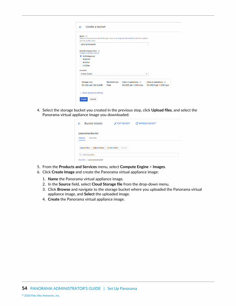
54 PANORAMA ADMINISTRATOR'S GUIDE | Set Up Panorama© 2020 Palo Alto Networks, Inc.
4. Select the storage bucket you created in the previous step, click Upload files, and select thePanorama virtual appliance image you downloaded.
5. From the Products and Services menu, select Compute Engine > Images.6. Click Create Image and create the Panorama virtual appliance image:
1. Name the Panorama virtual appliance image.2. In the Source field, select Cloud Storage file from the drop-down menu.3. Click Browse and navigate to the storage bucket where you uploaded the Panorama virtual
appliance image, and Select the uploaded image.4. Create the Panorama virtual appliance image.

PANORAMA ADMINISTRATOR'S GUIDE | Set Up Panorama 55© 2020 Palo Alto Networks, Inc.
STEP 3 | Configure the Panorama virtual appliance.1. From the Products and Services menu and select the Compute Engine.2. Click Create Instance to begin deploying the Panorama virtual appliance.3. Add a descriptive Name to easily identify the Panorama virtual appliance.4. Select the Region and Zone where you want to deploy the Panorama virtual appliance.5. Allocate the Machine Type and Customize the CPU cores, memory and CPU platform. Review the
Setup Prerequisites for the Panorama Virtual Appliance for minimum resource requirements.
If you plan to use the Panorama virtual appliance as a Dedicated Log Collector,ensure that you configure the appliance with the required resources during initialdeployment. The Panorama virtual appliance does not remain in Log Collector mode ifyou resize the virtual machine after you deploy it, and this results in a loss of log data.
The GCP zone selection determines the CPU platforms available to you. For moreinformation, refer to Regions and Zones for details.

56 PANORAMA ADMINISTRATOR'S GUIDE | Set Up Panorama© 2020 Palo Alto Networks, Inc.
6. Configure the Panorama boot disk.
1. For the Boot Disk, click Change > Custom image and select the Panorama image file you uploadedin Step 2
2. Configure the boot disk size. By default the system disk is 81GB but you can increase the systemdisk size to 224GB.
(SD-WAN only) If you plan on managing your SD-WAN deployment using this Panorama virtualappliance in Panorama mode, you must increase the system disk size to 224GB. If you plan onmanaging your SD-WAN deployment in Management Only mode, you must add a 2TB loggingdisk.
3. Click Select to save your configuration.7. Under Identity and API access, select Allow full access to all Cloud APIs.
8. Under Firewall, select Allow HTTPS traffic.
STEP 4 | Expand Management, security, disks, networking, sole tenancy .
STEP 5 | Enable access to the serial port so you can manage the Panorama virtual appliance.1. Select Management.2. Enter the following name-value pair as Metadata:
serial-port-enable true
STEP 6 | Reserve a static IP address for the management interface.

PANORAMA ADMINISTRATOR'S GUIDE | Set Up Panorama 57© 2020 Palo Alto Networks, Inc.
Reserve static internal and external IP addresses for the management interface in the event that if thePanorama virtual appliance is rebooted, your managed devices do not lose connection to the Panoramavirtual appliance when the IP addresses are reassigned.
For more information on how to reserve IP addresses, refer to Reserving a Static Internal IP Address andReserving a Static External IP Address.
1. Select Networking.2. Edit the network interface.
3. Select the Panorama virtual appliance Network.4. Select the Panorama virtual appliance Subnetwork. Instances in the same subnetwork will
communicate with each other using their internal IP addresses.5. Set the Primary internal IP address.
• Ephemeral (Automatic)— Automatically assign a primary internal IP address.• Ephemeral (Custom)—Configure a custom IP range that GCP uses to assign a primary internal IP
address.• Reserve a static internal IP address—Manually configure a static primary internal IP address.
6. Set the External IP address.
• Ephemeral—Automatically assign an external IP address from a shared IP pool.• Select an existing reserved external IP address.• Create IP address—Reserve an external IP address.
7. Set IP forwarding to On to allow the Panorama virtual appliance to receive packets from non-matching destinations or source IP addresses.
STEP 7 | Configure the SSH key. You need an SSH key to access the Panorama virtual appliance CLI toconfigure the administrative user password after the initial deployment.1. Select Security.2. Select the Block project-wide SSH keys box. Only instance keys are currently supported for logging
in to the Panorama virtual appliance after initial deployment.

58 PANORAMA ADMINISTRATOR'S GUIDE | Set Up Panorama© 2020 Palo Alto Networks, Inc.
3. Paste the SSH key in the comment box. For information on the correct SSH key format and how togenerate SSH keys for GCP, refer to Managing SSH keys in Metadata.
When generating the SSH key, save the private key in .ppk format. The private key isrequired to log in to the Panorama virtual appliance after the initial deployment beforeyou can configure the administrative password.
STEP 8 | (Panorama and Log Collector mode) Add additional storage for log collection. Repeat this step asneeded to add additional virtual logging disks.If you intend to use the Panorama virtual appliance in Panorama mode or as a Dedicated Log Collector,add the virtual logging disks during initial deployment. By default, the Panorama virtual appliance is inPanorama mode for the initial deployment when you meet the Panorama mode resource requirementsand have added at least one virtual logging disk. Otherwise, the Panorama virtual appliance defaults toManagement Only mode in which you can manage devices and Dedicated Log Collectors, and cannotcollect logs locally.
The Panorama virtual appliance on GCP only supports 2TB logging disks, and in total supports up to24TB of log storage. You are unable to add a logging disk smaller than 2TB, or a logging disk with a sizenot divisible by the 2TB logging disk requirement. The Panorama virtual appliance partitions loggingdisks larger than 2TB into 2TB partitions.
1. Select Disks > Add new disk.
2. Enter the Name.3. Expand the Type drop-down menu and select the desired type.4. For the Source type, select Blank disk.5. For the Mode, select Read/write.6. Select the Deletion rule to configure whether to delete the virtual logging disk if the Panorama virtual
appliance instance is deleted. To

PANORAMA ADMINISTRATOR'S GUIDE | Set Up Panorama 59© 2020 Palo Alto Networks, Inc.
7. Set the Size (GB) of the virtual logging disk.8. Set your preferred Encryption solution for the data on the virtual logging disk.9. Click Done.
STEP 9 | Create the Panorama virtual appliance. The Panorama virtual appliances takes roughly 10minutes to boot up after initial deployment.
STEP 10 | Configure a new administrative password for the Panorama virtual appliance.You must configure a unique administrative password before you can access the web interface ofthe Panorama virtual appliance. To access the CLI, use the private key to launch the Panorama virtualappliance.
• If you have an SSH service installed on your computer:
1. Enter the following command to log into the Panorama virtual appliance:
ssh -i <private_key.ppk> admin@<public-ip_address>
2. Configure a new password using the following commands and follow the onscreen prompts:
admin> configureadmin# set mgt-config users admin password
3. If you have a BYOL that you need to, set the DNS server IP address so that the Panorama virtualappliance can access the Palo Alto Networks licensing server. Enter the following command to set theDNS server IP address:
admin# set deviceconfig system dns-setting servers primary <ip_address>
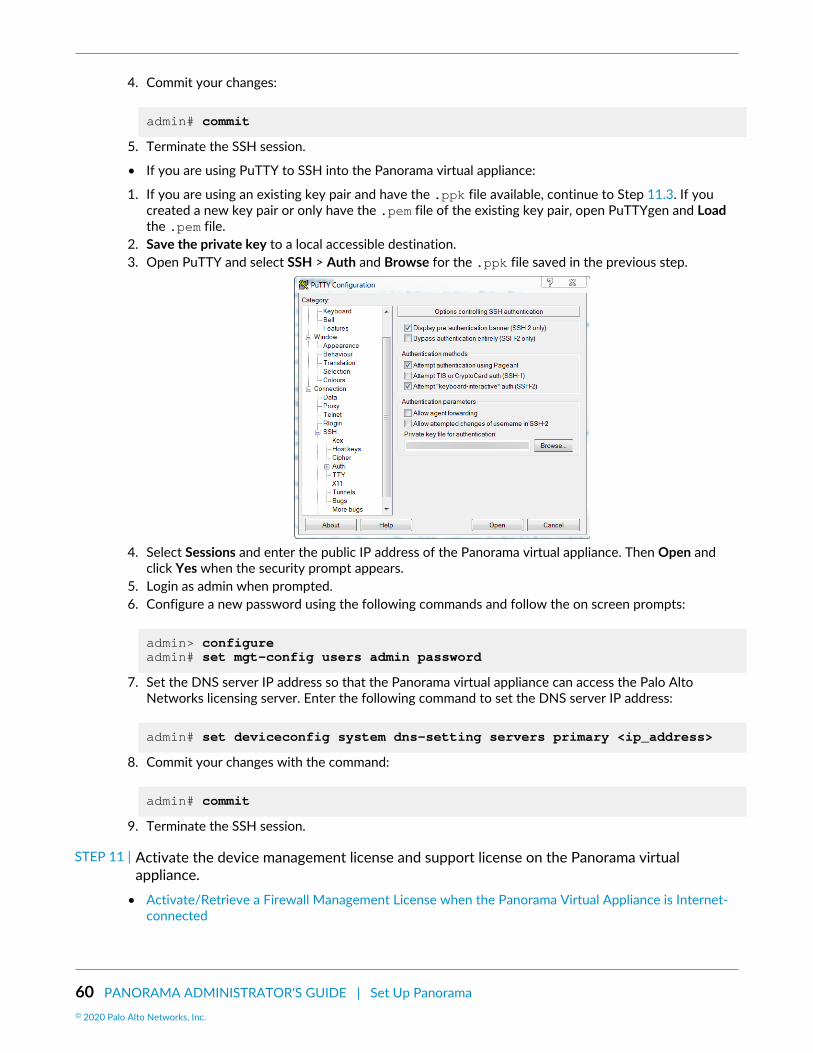
60 PANORAMA ADMINISTRATOR'S GUIDE | Set Up Panorama© 2020 Palo Alto Networks, Inc.
4. Commit your changes:
admin# commit
5. Terminate the SSH session.
• If you are using PuTTY to SSH into the Panorama virtual appliance:
1. If you are using an existing key pair and have the .ppk file available, continue to Step 11.3. If youcreated a new key pair or only have the .pem file of the existing key pair, open PuTTYgen and Loadthe .pem file.
2. Save the private key to a local accessible destination.3. Open PuTTY and select SSH > Auth and Browse for the .ppk file saved in the previous step.
4. Select Sessions and enter the public IP address of the Panorama virtual appliance. Then Open andclick Yes when the security prompt appears.
5. Login as admin when prompted.6. Configure a new password using the following commands and follow the on screen prompts:
admin> configureadmin# set mgt-config users admin password
7. Set the DNS server IP address so that the Panorama virtual appliance can access the Palo AltoNetworks licensing server. Enter the following command to set the DNS server IP address:
admin# set deviceconfig system dns-setting servers primary <ip_address>
8. Commit your changes with the command:
admin# commit
9. Terminate the SSH session.
STEP 11 | Activate the device management license and support license on the Panorama virtualappliance.
• Activate/Retrieve a Firewall Management License when the Panorama Virtual Appliance is Internet-connected

PANORAMA ADMINISTRATOR'S GUIDE | Set Up Panorama 61© 2020 Palo Alto Networks, Inc.
• Activate/Retrieve a Firewall Management License when the Panorama Virtual Appliance is notInternet-connected
• Activate a Panorama Support License
STEP 12 | Complete configuring the Panorama virtual appliance for your deployment needs.• (Management Only mode) Set up a Panorama Virtual Appliance in Management Only Mode.• (Log Collector mode) Begin at Step 6 to Switch from Panorama mode to Log Collector mode.
Enter the Public IP address of the Dedicated Log Collector when you Add the LogCollector as a managed collector to the Panorama management server. You cannotspecify the IP Address, Netmask, or Gateway.
• (Panorama and Management Only mode) Configure a Managed Collector to add a Dedicated LogCollector to the Panorama virtual appliance. Management Only mode does not support local logcollection, and requires a Dedicated Log Collector to store managed device logs.
Install Panorama on KVMYou can now deploy Panorama™ and a Dedicated Log Collector on KVM. Panorama deployed on KVMis Bring Your Own License (BYOL), supports all deployment modes (Panorama, Log Collector, andManagement Only), and shares the same processes and functionality as the M-Series hardware appliances.For more information on Panorama modes, see Panorama Models.
STEP 1 | Download the Panorama virtual appliance image for KVM.1. Log in to the Palo Alto Networks Support Portal.2. Select Software Updates and find the Panorama for KVM Base image.3. Download the latest available Panorama .qcow2 file.
STEP 2 | Create a new virtual machine image and add the Panorama virtual appliance image for KVM tothe Virtual Machine Manager.1. On the Virtual Machine Manager, select Create a new virtual machine.2. Select Import Existing disk image and click Forward.
3. Browse and select the Panorama virtual appliance image volume and Choose volume.4. Click Forward.

62 PANORAMA ADMINISTRATOR'S GUIDE | Set Up Panorama© 2020 Palo Alto Networks, Inc.
STEP 3 | Configure the memory and CPU settings.Review the Setup Prerequisites for the Panorama Virtual Appliance for minimum resource requirements.
If you plan to use the Panorama virtual appliance as a Dedicated Log Collector, ensurethat you configure the appliance with the required resources during initial deployment.The Panorama virtual appliance does not remain in Log Collector mode if you resize thevirtual machine after you deploy it, and this results in a loss of log data.
1. Configure the Memory based on the requirements for the desired operational mode.
The Virtual Machine Manager may use MiB (mebibyte) to allocate memory dependingon the version you are running. If MiB is used, be sure to correctly convert yourrequired memory allocation to avoid under provisioning the Panorama virtualappliance.
2. Configure the CPU based on the requirements for the desired operational mode.3. Click Forward.
STEP 4 | Name the Panorama virtual appliance, enable configuration customization, and select themanagement interface bridge.1. Enter a descriptive Name for the Panorama virtual appliance.2. Customize configuration before install.3. Make a Network selection—select the bridge for the management interface and accept the default
settings.4. Click Finish.

PANORAMA ADMINISTRATOR'S GUIDE | Set Up Panorama 63© 2020 Palo Alto Networks, Inc.
STEP 5 | Configure the virtual system disk settings.1. Select IDE Disk 1, go to Advanced options, and select the following:
• Disk Bus—VirtIO or IDE, depending on your configuration.• Storage format—qcow2
2. Go to Performance options and set Cache mode to writethrough. This setting improves installationtime and execution speed on the Panorama virtual appliance.
3. Click Apply.
STEP 6 | Configure the virtual machine console display to use the VNC server to interact with the virtualmachine.1. Select Display Spice.
Continue to the next step if Display VNC is listed in the Hardware list because thevirtual machine is already configured to use the VNC server for the display.
2. In the Type drop-down, select VNC server.3. Click Apply.

64 PANORAMA ADMINISTRATOR'S GUIDE | Set Up Panorama© 2020 Palo Alto Networks, Inc.
STEP 7 | (Panorama and Log Collector mode) Add additional storage for log collection. Repeat this step asneeded to add additional virtual logging disks.If you intend to use the Panorama virtual appliance in Panorama mode or as a Dedicated Log Collector,add the virtual logging disks during the initial deployment. By default, the Panorama virtual appliance isin Panorama mode for the initial deployment when you meet the Panorama mode resource requirementsand have added at least one virtual logging disk. Otherwise, the Panorama virtual appliance defaults toManagement Only mode. Change the Panorama virtual appliance to Management Only mode if you justwant to manage devices and Dedicated Log Collectors, and to not collect logs locally.
The Panorama virtual appliance on KVM only supports 2TB logging disks, and in total supports up to24TB of log storage. You are unable to add a logging disk smaller than 2TB, or a logging disk with a sizenot divisible by the 2TB logging disk requirement. The Panorama virtual appliance partitions loggingdisks larger than 2TB into 2TB partitions.
1. Add Hardware.2. Configure the new Storage disk:
1. Create a disk image for a virtual machine and configure the virtual disk storage capacity to14901.2 GiB (this is equivalent to 2TB).
The Virtual Machine Manager may use GiB (gibibyte) to allocate memorydepending on the version you are running. If GiB is used, be sure to correctlyconvert the required storage capacity to avoid under provisioning the virtual loggingdisk and sending the Panorama virtual appliance into maintenance mode.
2. Set the Device type to Disk device.3. Set the Bus type to VirtIO or IDE, depending on your configuration.4. Go to Advanced options and set Cache mode to writethrough.
3. Click Finish.

PANORAMA ADMINISTRATOR'S GUIDE | Set Up Panorama 65© 2020 Palo Alto Networks, Inc.
STEP 8 | Begin Installation ( ). The Panorama virtual appliances takes approximately 10minutes to boot.
STEP 9 | Configure the network access settings for the management interface.1. Open a connection to the console.2. Log in to the firewall using the default username and password: admin/admin.3. Enter configuration mode using the following command:
admin> configure
4. Use the following commands to configure and enable access to the management interface:
admin# set deviceconfig system type staticadmin# set deviceconfig system ip-address <Panorama-IP> netmask <netmask> default-gateway <gateway-IP> dns-setting servers primary <DNS-IP>
where <Panorama-IP> is the IP address you want to assign to the management interface, <netmask>is the subnet mask, <gateway-IP> is the IP address of the network gateway, and <DNS-IP> is the IPaddress of the DNS server.
admin# commit
STEP 10 | Activate the device management license and support license on the Panorama virtualappliance.
• Activate/Retrieve a Firewall Management License when the Panorama Virtual Appliance is Internet-connected
• Activate/Retrieve a Firewall Management License when the Panorama Virtual Appliance is notInternet-connected
• Activate a Panorama Support License
STEP 11 | Complete configuring the Panorama virtual appliance for your deployment needs.• (Management Only mode) Set up a Panorama Virtual Appliance in Management Only Mode.• (Log Collector mode) Begin at Step 6 to Switch from Panorama mode to Log Collector mode.

66 PANORAMA ADMINISTRATOR'S GUIDE | Set Up Panorama© 2020 Palo Alto Networks, Inc.
Enter the Public IP address of the Dedicated Log Collector when you Add the LogCollector as a managed collector to the Panorama management server. You cannotspecify the IP Address, Netmask, or Gateway.
• (Panorama and Management Only mode) Configure a Managed Collector to add a Dedicated LogCollector to the Panorama virtual appliance. Management Only mode does not support local logcollection, and requires a Dedicated Log Collector to store managed device logs.
Install Panorama on Hyper-VYou can now deploy Panorama™ and a Dedicated Log Collector on Hyper-V. Panorama deployed onHyper-V is Bring Your Own License (BYOL), supports all deployment modes (Panorama, Log Collector, andManagement Only), and shares the same processes and functionality as the M-Series hardware appliances.For more information on Panorama modes, see Panorama Models. Panorama virtual appliance and virtualDedicated Log Collector on Hyper-V is available only on PAN-OS 8.1.3 and later releases.
STEP 1 | Download the VHDX file.1. Log in to the Palo Alto Networks Support Portal.2. Select Updates > Software Updates, filter by Panorama Base Images, and download the VHDX file.
STEP 2 | Set up any vSwitch(es) that you will need. For more information, review the Virtual SwitchTypes for more information.1. From Hyper-V Manager, select the host and select Action > Virtual Switch Manager to open the
Virtual Switch Manager window.
2. Under Create virtual switch, select the type of vSwitch to create and click Create Virtual Switch.
STEP 3 | Install the Panorama virtual appliance.1. On the Hyper-V Manager, select the host and select Action > New > Virtual Machine. Configure the
following settings in the New Virtual Machine Wizard:
1. Choose a Name and Location for the Panorama virtual appliance. The Panorama virtual appliancestores the VHDX file at the specified location.
2. Choose Generation 1. This is the default option and the only version supported.

PANORAMA ADMINISTRATOR'S GUIDE | Set Up Panorama 67© 2020 Palo Alto Networks, Inc.
3. For Startup Memory, assign the memory based on the intended system mode. See the SetupPrerequisites for the Panorama Virtual Appliance for the memory requirements for each mode.
Do not enable dynamic memory; the Panorama virtual appliance requires staticmemory allocation.
4. Configure Networking. Select an external vSwitch to connect the management interface on thefirewall.
5. To connect the Virtual Hard Disk, select Use an existing virtual hard disk and browse to theVHDX file you downloaded earlier.
6. Review the summary and click Finish.
STEP 4 | Allocate the Panorama virtual appliance CPU cores.Review the Setup Prerequisites for the Panorama Virtual Appliance for minimum resource requirements.
If you plan to use the Panorama virtual appliance as a Dedicated Log Collector, ensurethat you configure the appliance with the required resources during initial deployment.The Panorama virtual appliance does not remain in Log Collector mode if you resize thevirtual machine after you deploy it, and this results in a loss of log data.
1. In the Hardware list, select Processor.2. Edit the currently allocated Number of virtual processors.
STEP 5 | Connect at least one network adapter for the dataplane interface on the firewall. Repeat this tocreate additional network interfaces on the Panorama virtual appliance.1. Select Settings > Hardware > Add Hardware and select the Hardware type for your network
adapter.
Legacy Network Adapter and SR-IOV are not supported. If selected, the VM-Seriesfirewall will boot into maintenance mode.
2. Click OK.
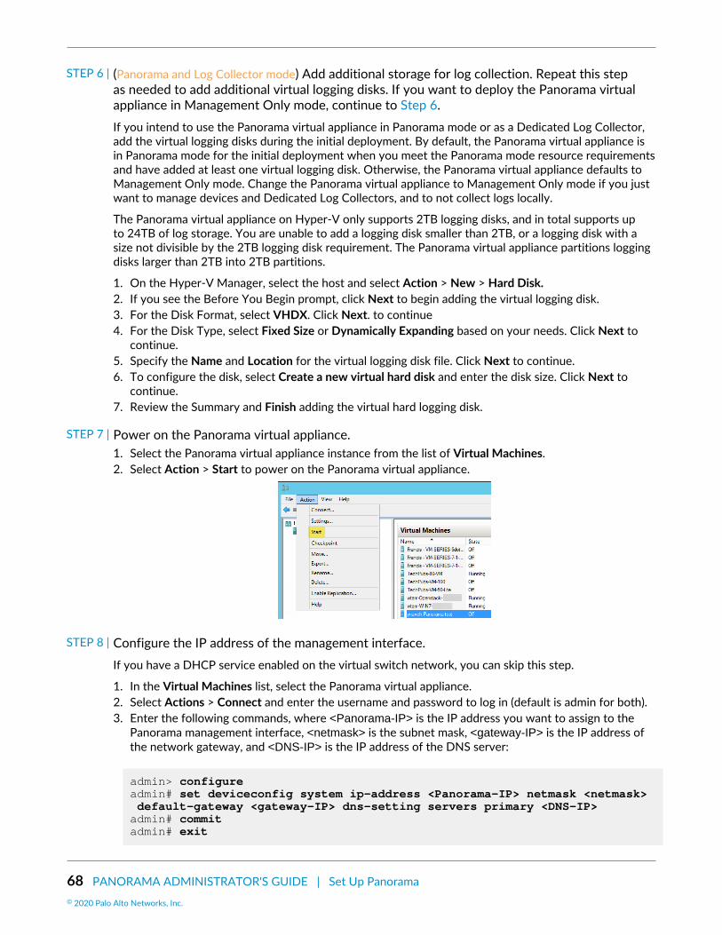
68 PANORAMA ADMINISTRATOR'S GUIDE | Set Up Panorama© 2020 Palo Alto Networks, Inc.
STEP 6 | (Panorama and Log Collector mode) Add additional storage for log collection. Repeat this stepas needed to add additional virtual logging disks. If you want to deploy the Panorama virtualappliance in Management Only mode, continue to Step 6.If you intend to use the Panorama virtual appliance in Panorama mode or as a Dedicated Log Collector,add the virtual logging disks during the initial deployment. By default, the Panorama virtual appliance isin Panorama mode for the initial deployment when you meet the Panorama mode resource requirementsand have added at least one virtual logging disk. Otherwise, the Panorama virtual appliance defaults toManagement Only mode. Change the Panorama virtual appliance to Management Only mode if you justwant to manage devices and Dedicated Log Collectors, and to not collect logs locally.
The Panorama virtual appliance on Hyper-V only supports 2TB logging disks, and in total supports upto 24TB of log storage. You are unable to add a logging disk smaller than 2TB, or a logging disk with asize not divisible by the 2TB logging disk requirement. The Panorama virtual appliance partitions loggingdisks larger than 2TB into 2TB partitions.
1. On the Hyper-V Manager, select the host and select Action > New > Hard Disk.2. If you see the Before You Begin prompt, click Next to begin adding the virtual logging disk.3. For the Disk Format, select VHDX. Click Next. to continue4. For the Disk Type, select Fixed Size or Dynamically Expanding based on your needs. Click Next to
continue.5. Specify the Name and Location for the virtual logging disk file. Click Next to continue.6. To configure the disk, select Create a new virtual hard disk and enter the disk size. Click Next to
continue.7. Review the Summary and Finish adding the virtual hard logging disk.
STEP 7 | Power on the Panorama virtual appliance.1. Select the Panorama virtual appliance instance from the list of Virtual Machines.2. Select Action > Start to power on the Panorama virtual appliance.
STEP 8 | Configure the IP address of the management interface.If you have a DHCP service enabled on the virtual switch network, you can skip this step.
1. In the Virtual Machines list, select the Panorama virtual appliance.2. Select Actions > Connect and enter the username and password to log in (default is admin for both).3. Enter the following commands, where <Panorama-IP> is the IP address you want to assign to the
Panorama management interface, <netmask> is the subnet mask, <gateway-IP> is the IP address ofthe network gateway, and <DNS-IP> is the IP address of the DNS server:
admin> configure admin# set deviceconfig system ip-address <Panorama-IP> netmask <netmask> default-gateway <gateway-IP> dns-setting servers primary <DNS-IP> admin# commit admin# exit

PANORAMA ADMINISTRATOR'S GUIDE | Set Up Panorama 69© 2020 Palo Alto Networks, Inc.
4. Troubleshoot Connectivity to Network Resources to verify network access to external servicesrequired for firewall management, such as the default gateway, DNS server, and the Palo AltoNetworks Update Server, as shown in the following example:
STEP 9 | Activate the device management license and support license on the Panorama virtualappliance.• Activate/Retrieve a Firewall Management License when the Panorama Virtual Appliance is Internet-
connected• Activate/Retrieve a Firewall Management License when the Panorama Virtual Appliance is not
Internet-connected• Activate a Panorama Support License
STEP 10 | Complete configuring the Panorama virtual appliance for your deployment needs.• (Management Only mode) Set up a Panorama Virtual Appliance in Management Only Mode.• (Log Collector mode) Begin at Step 6 to Switch from Panorama mode to Log Collector mode.
Enter the Public IP address of the Dedicated Log Collector when you Add the LogCollector as a managed collector to the Panorama management server. You cannotspecify the IP Address, Netmask, or Gateway.
• (Panorama and Management Only mode) Configure a Managed Collector to add a Dedicated LogCollector to the Panorama virtual appliance. Management Only mode does not support local logcollection, and requires a Dedicated Log Collector to store managed device logs.
Perform Initial Configuration of the Panorama Virtual ApplianceBased on your Panorama model, use the AWS, Azure, or GCP web interface, KVM Virtual MachineManager, Hyper-V Manager, VMware vSphere Client, or vCloud Air web console to set up network accessto the Panorama virtual appliance. By default, the Panorama virtual appliance is deployed in Panoramamode. For unified reporting, consider using Greenwich Mean Time (GMT) or Coordinated Universal Time(UTC) as the uniform time zone across Panorama and all the managed firewalls and Log Collectors.

70 PANORAMA ADMINISTRATOR'S GUIDE | Set Up Panorama© 2020 Palo Alto Networks, Inc.
STEP 1 | Gather the required information from your network administrator.Collect the following information for the management (MGT) interface:
IP address for the management (MGT) interfaceNetmaskDefault gatewayDNS server IP address
To complete the configuration of the MGT interface, you must specify the IP address,netmask (for IPv4) or prefix length (for IPv6), and default gateway. If you omit settings(such as the default gateway), you can access Panorama only through the consoleport for future configuration changes. As a best practice, always commit a completeMGT interface configuration.
STEP 2 | Access the console of the Panorama virtual appliance.1. Access the console.
On an ESXi server:
1. Launch the VMware vSphere Client.2. Select the Console tab for the Panorama virtual appliance and press enter to access the login
screen.
On vCloud Air:
1. Access the vCloud Air web console and select your Virtual Private Cloud OnDemand region.2. Select the Virtual Machines tab, right-click the Panorama virtual machine, and select Open In
Console.2. Enter your username and password to log in (default is admin for both).
On AWS, Azure, GCP, KVM, and Hyper-V:
• Log in to the Panorama CLI.
STEP 3 | Change the default administrator password.
Starting with PAN-OS 9.0.4, the predefined, default administrator password (admin/admin) must be changed on the first login on a device. The new password must bea minimum of eight characters and include a minimum of one lowercase and oneuppercase character, as well as one number or special character.
Be sure to use the best practices for password strength to ensure a strict password andreview the password complexity settings.
To ensure that the management interface remains secure, configure the MinimumPassword Complexity (Panorama > Setup > Management).
1. Click the admin link on the left side of the web interface footer.2. Enter the Old Password and the New Password and record the new password in a safe location.3. Click OK.
STEP 4 | Configure the network access settings for the MGT interface.Panorama uses the MGT interface for management traffic, high availability synchronization, logcollection, and communication within Collector Groups.

PANORAMA ADMINISTRATOR'S GUIDE | Set Up Panorama 71© 2020 Palo Alto Networks, Inc.
1. Enter the following commands, where <Panorama-IP> is the IP address you want to assign to thePanorama management interface, <netmask> is the subnet mask, <gateway-IP> is the IP address ofthe network gateway, and <DNS-IP> is the IP address of the DNS server:
> configure # set deviceconfig system ip-address <Panorama-IP> netmask <netmask> default-gateway <gateway-IP> dns-setting servers primary <DNS-IP> # commit # exit
2. Troubleshoot Connectivity to Network Resources to verify network access to external servicesrequired for firewall management, such as the default gateway, DNS server, and the Palo AltoNetworks Update Server, as shown in the following example:
STEP 5 | Configure the general settings.1. Using a secure connection (HTTPS) from a web browser, log in to the Panorama web interface using
the IP address and password you assigned to the management interface (https://<IP address>).2. Select Panorama > Setup > Management and edit the General Settings.3. Enter a Hostname for the server and enter the network Domain name. The domain name is just a
label; Panorama doesn’t use it to join the domain.4. Align the clock on Panorama and the managed firewalls to use the same Time Zone, for example
GMT or UTC. If you plan to use the Cortex Data Lake, you must configure NTP so that Panorama canstay in sync with the Cortex Data Lake.
Timestamps are recorded when Panorama receives the logs and the managed firewalls generatethe logs. Aligning the time zones on Panorama and the firewalls ensures that the timestamps aresynchronized and the process of querying logs and generating reports on Panorama is harmonious.
5. Enter the Latitude and Longitude to enable accurate placement of the Panorama management serveron the world map.
6. Enter the Serial Number you received in the order fulfillment email.7. Click OK to save your changes.

72 PANORAMA ADMINISTRATOR'S GUIDE | Set Up Panorama© 2020 Palo Alto Networks, Inc.
STEP 6 | (Optional) Modify the management interface settings.1. Select Panorama > Setup > Interfaces and click Management.2. If your firewalls connect to the Panorama management server using a public IP address that is
translated to a private IP address (NAT), enter the public IP in the Public IP Address field, and theprivate IP in the IP Address field to push both addresses to your firewalls.
3. Select which Network Connectivity Services to allow on the interface (such as SSH access).
Don’t select Telnet or HTTP. These services use plaintext and are less secure thanthe other services.
4. Click OK to save your changes to the interface.
STEP 7 | Commit your configuration changes.Select Commit > Commit to Panorama and Commit your changes.
STEP 8 | Next steps...1. If necessary, Expand Log Storage Capacity on the Panorama Virtual Appliance.2. (Best Practice) Replace the default certificate that Panorama uses to secure HTTPS traffic over the
management (MGT) interface.3. Activate a Panorama Support License.4. Activate/Retrieve a Firewall Management License when the Panorama Virtual Appliance is Internet-
connected.5. Install Content and Software Updates for Panorama.6. Set Up Administrative Access to Panorama.
Set Up The Panorama Virtual Appliance as a Log CollectorIf you want a dedicated virtual appliance for log collection, configure a Panorama virtual appliance on ESXi,AWS, AWS GovCloud, Azure, Google Cloud Platform, KVM, or Hyper-V in Log Collector mode. To dothis, you first perform the initial configuration of the virtual appliance in Panorama mode, which includeslicensing, installing software and content updates, and configuring the management (MGT) interface.You then switch the Panorama virtual appliance to Log Collector mode and complete the Log Collectorconfiguration. Additionally, if you want to use dedicated M-Series Appliance Interfaces (recommended)instead of the MGT interface for log collection and Collector Group communication, you must firstconfigure the interfaces for the Panorama management server, then configure them for the Log Collector,and then perform a Panorama commit followed by a Collector Group commit.
Perform the following steps to set up a new virtual appliance as a Log Collector or to convert an existingvirtual appliance that was previously deployed as a Panorama management server.
Switching the virtual appliance from Panorama mode to Log Collector mode reboots theappliance, deletes the local Log Collector, deletes any existing log data, and deletes allconfigurations except the management access settings. Switching the mode does not deletelicenses, software updates, or content updates.
STEP 1 | Set up the Panorama virtual appliance management server that will manage the Log Collector ifyou have not already done so.Perform one of the following tasks:
• Set Up the Panorama Virtual Appliance• Set Up the M-Series Appliance

PANORAMA ADMINISTRATOR'S GUIDE | Set Up Panorama 73© 2020 Palo Alto Networks, Inc.
STEP 2 | Record the management IP addresses of the Panorama management server.If you deployed Panorama in a high availability (HA) configuration, you need the IP address of each HApeer.
1. Log in to the web interface of the Panorama management server.2. Record the IP Address of the solitary (non-HA) or active (HA) Panorama by selecting Panorama >
Setup > Management and checking the Management Interface Settings.3. For an HA deployment, record the Peer HA IP Address of the passive Panorama by selecting
Panorama > High Availability and checking the Setup section.
STEP 3 | Set up the Panorama virtual appliance that will serve as a Dedicated Log Collector.If you previously deployed this appliance as a Panorama management server, you can skip this stepbecause the MGT interface is already configured and the licenses and updates are already installed.
The Panorama virtual appliance in Log Collector mode does not have a web interface for configurationtasks, only a CLI. Therefore, before changing the mode on the Panorama virtual appliance, use the webinterface in Panorama mode to:
1. Set up the Panorama virtual appliance in one of the following supported hypervisors:
• Install Panorama on an ESXi Server• Install Panorama on AWS.• Install Panorama on AWS GovCloud• Install Panorama on Azure.• Install Panorama on Google Cloud Platform.• Install Panorama on Hyper-V
2. Perform Initial Configuration of the Panorama Virtual Appliance.3. Register Panorama and Install Licenses.4. Install Content and Software Updates for Panorama.
STEP 4 | (Panorama on Azure only) Modify the admin password.The Dedicated Log Collector supports only the admin Administrator user in order to change in to LogCollector mode. Modify the admin password to allow you to log in using the admin Administrator user.
1. Log in to the Panorama Web Interface.2. Select Panorama > Administrators and select admin.3. Enter the Password, Confirm Password and click OK.4. Select Commit > Commit to Panorama and Commit your changes.
STEP 5 | (Panorama on AWS and Azure only) Delete all users, except for the admin user.1. Log in to the Panorama Web Interface as admin.2. Select Panorama > Administrators.3. Select the existing Administrators, except admin, and Delete.4. Select Commit > Commit to Panorama and Commit your changes.
STEP 6 | Log in to the Panorama CLI.
STEP 7 | Switch from Panorama mode to Log Collector mode.1. Switch to Log Collector mode by entering the following command:
> request system system-mode logger

74 PANORAMA ADMINISTRATOR'S GUIDE | Set Up Panorama© 2020 Palo Alto Networks, Inc.
2. Enter Y to confirm the mode change. The virtual appliance reboots. If the reboot process terminatesyour terminal emulation software session, reconnect to the virtual appliance to see the Panoramalogin prompt.
If you see a CMS Login prompt, this means the Log Collector has not finishedrebooting. Press Enter at the prompt without typing a username or password.
3. Log back in to the CLI.4. Verify that the switch to Log Collector mode succeeded:
> show system info | match system-mode
If the mode change succeeded, the output displays:
system-mode: logger
STEP 8 | Enable connectivity between the Log Collector and Panorama management server.Enter the following commands at the Log Collector CLI, where <IPaddress1> is for the MGT interface ofthe solitary (non-HA) or active (HA) Panorama and <IPaddress2> is for the MGT interface of the passive(HA) Panorama, if applicable.
> configure # set deviceconfig system panorama-server <IPaddress1> panorama-server-2 <IPaddress2> # commit # exit
STEP 9 | Record the serial number of the Log Collector.You need the serial number to add the Log Collector as a managed collector on the Panoramamanagement server.
1. At the Log Collector CLI, enter the following command to display its serial number.
> show system info | match serial
2. Record the serial number.
STEP 10 | Add the Log Collector as a managed collector to the Panorama management server.1. Select Panorama > Managed Collectors and Add a managed collector.2. In the General settings, enter the serial number (Collector S/N) you recorded for the Log Collector.3. In the Panorama Server IP field, enter the IP address or FQDN of the solitary (non-HA) or active (HA)
Panorama. For HA deployments, enter the IP address or FQDN of the passive Panorama peer in thePanorama Server IP 2 field.
These IP addresses must specify a Panorama interface that has Device Management and DeviceLog Collection services enabled. By default, these services are enabled only on the MGT interface.However, you might have enabled the services on other interfaces when you Set Up the M-SeriesAppliance that is a Panorama management server.
4. Select Interfaces, click Management, and enter the Public IP Addressof the Dedicated Log Collector.5. Click OK twice to save your changes to the Log Collector.6. Select Commit > Commit to Panorama and Commit your changes to the Panorama configuration.

PANORAMA ADMINISTRATOR'S GUIDE | Set Up Panorama 75© 2020 Palo Alto Networks, Inc.
7. Verify that Panorama > Managed Collectors lists the Log Collector you added. The Connectedcolumn displays a check mark to indicate that the Log Collector is connected to Panorama. You mighthave to wait a few minutes before the page displays the updated connection status.
At this point, the Configuration Status column displays Out of Sync and the RunTime Status column displays disconnected. The status will change to In Sync andconnected after you configure a Collector Group.
STEP 11 | Enable the logging disks.1. Select Panorama > Managed Collectors and edit the Log Collector.2. Select Disks and Add each disk.3. Click OK to save your changes.4. Select Commit > Commit to Panorama and Commit your changes to the Panorama configuration.
STEP 12 | (Recommended) Configure the Ethernet1, Ethernet2, Ethernet3, Ethernet4, and Ethernet5interfaces if the Panorama management server and Log Collector will use them for DeviceLog Collection (receiving logs from firewalls) and Collector Group Communication.
If you previously deployed the Log Collector as a Panorama management server and configured theseinterfaces, you must reconfigure them because switching to Log Collector mode would have deleted allconfigurations except the management access settings.
1. Configure each interface on the Panorama management server (other than the MGT interface) if youhaven’t already:
1. Select Panorama > Setup > Interfaces and click the Interface Name.2. Select <interface-name> to enable the interface.3. Complete one or both of the following field sets based on the IP protocols of your network:
• For ESXi
• IPv4—Public IP Address, IP Address, Netmask, and Default Gateway
IPv6—IPv6 Address/Prefix Length and Default IPv6 Gateway• For AWS, Azure, and Google™ Cloud Platform
• Public IP address4. Select the Device Management Services that the interface supports:
Device Management and Device Log Collection—You can assign one or more interfaces.
Collector Group Communication—You can assign only one interface.
Device Deployment (software and content updates)—You can assign only one interface.5. Click OK to save your changes.
2. Configure each interface on the Log Collector (other than the MGT interface):
1. Select Panorama > Managed Collectors and edit the Log Collector.2. Select Interfaces and click the name of the interface.3. Select <interface-name> to enable the interface.4. Complete one or both of the following field sets based on the IP protocols of your network:
• For ESXi
• IPv4—Public IP Address, IP Address, Netmask, and Default Gateway
IPv6—IPv6 Address/Prefix Length and Default IPv6 Gateway• For AWS and Azure
• Public IP address

76 PANORAMA ADMINISTRATOR'S GUIDE | Set Up Panorama© 2020 Palo Alto Networks, Inc.
5. Select the Device Management Services that the interface supports:
Device Log Collection—You can assign one or more interfaces.
Collector Group Communication—You can assign only one interface.6. Click OK to save your changes to the interface.
3. Click OK to save your changes to the Log Collector.4. Select Commit > Commit to Panorama and Commit your changes to the Panorama configuration.
STEP 13 | (Optional) If your deployment is using custom certificates for authentication betweenPanorama and managed devices, deploy the custom client device certificate. For moreinformation, see Set Up Authentication Using Custom Certificates.
1. Select Panorama > Certificate Management > Certificate Profile and choose the certificate profilefrom the drop-down or click New Certificate Profile to create one.
2. Select Panorama > Managed Collectors > Add > Communication for a Log Collector.3. Select the Secure Client Communication check box.4. Select the type of device certificate the Type drop-down.
• If you are using a local device certificate, select the Certificate and Certificate Profile from therespective drop-downs.
• If you are using SCEP as the device certificate, select the SCEP Profile and Certificate Profile fromthe respective drop-downs.
5. Click OK.
STEP 14 | (Optional) Configure Secure Server Communication Sn a Log Collector. For more information,see Set Up Authentication Using Custom Certificates.
1. Select Panorama > Managed Collectors > Add > Communication.2. Verify that the Custom Certificate Only check box is not selected. This allows you to continue
managing all devices while migrating to custom certificates.
When the Custom Certificate Only check box is selected, the Log Collector does notauthenticate and cannot receive logs from devices using predefined certificates.
3. Select the SSL/TLS service profile from the SSL/TLS Service Profile drop-down. This SSL/TLS serviceprofile applies to all SSL connections between the Log Collector and devices sending it logs.
4. Select the certificate profile from the Certificate Profile drop-down.5. Select Authorize Client Based on Serial Number to have the server check clients against the serial
numbers of managed devices. The client certificate must have the special keyword $UDID set as theCN to authorize based on serial numbers.
6. In Disconnect Wait Time (min), enter the number of minutes Panorama should wait before breakingand reestablishing the connection with its managed devices. This field is blank by default and therange is 0 to 44,640 minutes.
The disconnect wait time does not begin counting down until you commit the newconfiguration.
7. (Optional) Configure an authorization list.
1. Click Add under Authorization List.2. Select the Subject or Subject Alt Name as the Identifier type.3. Enter an identifier of the selected type.4. Click OK.5. Select Check Authorization List to enforce the authorization list.
8. Click OK.9. Select Commit > Commit to Panorama.

PANORAMA ADMINISTRATOR'S GUIDE | Set Up Panorama 77© 2020 Palo Alto Networks, Inc.
STEP 15 | Assign the Log Collector to a Collector Group.1. Configure a Collector Group. You must perform a Panorama commit and then a Collector Group
commit to synchronize the Log Collector configuration with Panorama and to put the Eth1, Eth2,Eth3, Eth4, and Eth5 interfaces (if you configured them) in an operational state on the Log Collector.
In any single Collector Group, all the Log Collectors must run on the same Panoramamodel: all M-600 appliances, all M-500 appliances, all M-200 appliances, all M-100appliances, or all Panorama virtual appliances.
As a best practice, Enable log redundancy across collectors if you add multiple LogCollectors to a single Collector group. This option requires each Log Collector to havethe same number of logging disks.
2. Select Panorama > Managed Collectors to verify that the Log Collector configuration is synchronizedwith Panorama.
The Configuration Status column should display In Sync and the Run Time Status column shoulddisplay connected.
3. Access the Log Collector CLI and enter the following command to verify that its interfaces areoperational:
> show interface all
The output displays the state as up for each interface that is operational.4. If the Collector Group has multiple Log Collectors, Troubleshoot Connectivity to Network Resources
to verify they can communicate with each other by performing a Ping connectivity test for eachinterface that the Log Collectors use. For the source IP address, specify the interface of one of theLog Collectors. For the host IP address, specify the matching interface of another Log Collector inthe same Collector Group.
STEP 16 | Next steps...To enable the Log Collector to receive firewall logs:
1. Configure Log Forwarding to Panorama.2. Verify Log Forwarding to Panorama.
Set Up the Panorama Virtual Appliance with Local Log CollectorIf the Panorama virtual appliance is in Legacy mode after you upgrade from a Panorama 8.0 or earlierrelease to a Panorama 8.1 (or later) release, switch to Panorama mode in order to create a local LogCollector, add multiple logging disks without losing existing logs. increase log storage up to 24TB, andenable faster report generation.
Once you change from Legacy mode to Panorama mode, Legacy mode will no longer beavailable.
After upgrading to Panorama 8.1, the first step is to increase the system resources on the virtual applianceto the minimum required for Panorama mode. Panorama reboots when you increase resources, so performthis procedure during a maintenance window. You must install a larger system disk (81GB), increase CPUsand memory based on the log storage capacity, and add a virtual logging disk. The new logging disk musthave at least as much capacity as the appliance currently uses in Legacy mode and cannot be less than 2TB.Adding a virtual disk enables you to migrate existing logs to the Log Collector and enables the Log Collectorto store new logs.

78 PANORAMA ADMINISTRATOR'S GUIDE | Set Up Panorama© 2020 Palo Alto Networks, Inc.
If Panorama is deployed in an HA configuration, perform the following steps on the secondary peer first andthen on the primary peer.
STEP 1 | Determine which system resources you need to increase before the virtual appliance canoperate in Panorama mode.
You must run the command specified in this step even if you have determined thatPanorama already has adequate resources.
1. Access the Panorama CLI:
1. Use terminal emulation software such as PuTTY to open an SSH session to the IP address that youspecified for the Panorama MGT interface.
2. Log in to the CLI when prompted.2. Check the resources you must increase by running the following command:
> request system system-mode panorama
Enter y when prompted to continue. The output specifies the resources you must increase. Forexample:
Panorama mode not supported on current system disk of size 52.0 GB. Please attach a disk of size 81.0 GB, then use 'request system clone-system-disk' to migrate the current system disk Please add a new virtual logging disk with more than 50.00 GB of storage capacity. Not enough CPU cores: Found 4 cores, need 8 cores
STEP 2 | Increase the CPUs and memory, and replace the system disk with a larger disk.1. Access the VMware ESXi vSphere Client, select Virtual Machines, right-click the Panorama virtual
appliance, and select Power > Power Off.2. Right-click the Panorama virtual appliance and Edit Settings.3. Select Memory and enter the new Memory Size.4. Select CPUs and specify the number of CPUs (the Number of virtual sockets multiplied by the
Number of cores per socket).5. Add a virtual disk.
You will use this disk to replace the existing system disk.
1. In the Hardware settings, Add a disk, select Hard Disk as the hardware type, and click Next.2. Create a new virtual disk and click Next.3. Set the Disk Size to exactly 81GB and select the Thick Provision Lazy Zeroed disk format.4. Select Specify a datastore or datastore structure as the location, Browse to a datastore of at least
81GB, click OK, and click Next.5. Select a SCSI Virtual Device Node (you can use the default selection) and click Next.
Panorama will fail to boot if you select a format other than SCSI.
6. Verify that the settings are correct and then click Finish and OK.6. Right-click the Panorama virtual appliance and select Power > Power On. Wait for Panorama to
reboot before continuing.7. Return to the Panorama CLI and copy the data from the original system disk to the new system disk:

PANORAMA ADMINISTRATOR'S GUIDE | Set Up Panorama 79© 2020 Palo Alto Networks, Inc.
> request system clone-system-disk target sdb
Enter y when prompted to continue.
The copying process takes around 20 to 25 minutes, during which Panorama reboots. When theprocess finishes, the output tells you to shut down Panorama.
8. Return to the vSphere Client console, right-click the Panorama virtual appliance, and select Power >Power Off.
9. Right-click the Panorama virtual appliance and Edit Settings.10.Select the original system disk, click Remove, select Remove from virtual machine, and click OK.11.Right-click the Panorama virtual appliance and Edit Settings.12.Select the new system disk, set the Virtual Device Node to SCSI (0:0), and click OK.13.Right-click the Panorama virtual appliance and select Power > Power On. Before proceeding, wait for
Panorama to reboot on the new system disk (around 15 minutes).
STEP 3 | Add a virtual logging disk.This is the disk to which you will migrate existing logs.
1. In the VMware ESXi vSphere Client, right-click the Panorama virtual appliance and select Power >Power Off.
2. Right-click the Panorama virtual appliance and Edit Settings.3. Repeat the steps to Add a virtual disk. Set the Disk Size to a multiple of 2TB based on the amount of
log storage you need. The capacity must be at least as large as the existing virtual disk or NFS storagethat Panorama currently uses for logs. The disk capacity must be a multiple of 2TB and can be up to24TB. For example, if the existing disk has 5TB of log storage, you must add a new disk of at least6TB.
After you switch to Panorama mode, Panorama will automatically divide the new disk into 2TBpartitions, each of which will function as a separate virtual disk.
4. Right-click the Panorama virtual appliance and select Power > Power On. Wait for Panorama toreboot before continuing.
STEP 4 | Switch from Legacy mode to Panorama mode.After switching the mode, the appliance reboots again and then automatically creates a local LogCollector and Collector Group. The existing logs won’t be available for querying or reporting until youmigrate them later in this procedure.
1. Return to the Panorama CLI and run the following command.
> request system system-mode panorama
Enter y when prompted to continue. After rebooting, Panorama automatically creates a local LogCollector (named Panorama) and creates a Collector Group (named default) to contain it. Panoramaalso configures the virtual logging disk you added and divides it into separate 2TB disks. Wait for theprocess to finish and for Panorama to reboot (around five minutes) before continuing.
2. Log in to the Panorama web interface.3. In the Dashboard, General Information settings, verify that the Mode is now panorama.
In an HA deployment, the secondary peer is in a suspended state at this point because its mode(Panorama) does not match the mode on the primary peer (Legacy). You will un-suspend thesecondary peer after switching the primary peer to Panorama mode later in this procedure.
4. Select Panorama > Collector Groupsto verify that the default collector group has been created, andthat the local Log Collector is part of the default collector group.

80 PANORAMA ADMINISTRATOR'S GUIDE | Set Up Panorama© 2020 Palo Alto Networks, Inc.
5. Push the configuration to the managed devices.
• If there are no pending changes:
1. Select Commit > Push to Devices and Edit Selections.2. Select Collector Group and make sure the default collector group is selected.3. Click OK and Push.
• If you have pending changes:
1. Select Commit > Commit and Push and Edit Selections.2. Verify that your Device Group devices and Templates are included.3. Select Collector Group and make sure the default collector group is selected.4. Click OK and Commit and Push.
6. Select Panorama > Managed Collectors and verify that the columns display the following informationfor the local Log Collector:
• Collector Name—This defaults to the Panorama hostname. It should be listed under the defaultCollector Group.
• Connected—Check mark• Configuration Status—In sync• Run Time Status—connected
STEP 5 | (HA only) Switch the primary Panorama from Legacy mode to Panorama mode.
This step triggers failover.
1. Repeat Step 1 through Step 4 on the primary Panorama.
Wait for the primary Panorama to reboot and return to an active HA state. If preemption is notenabled, you must manually fail back: select Panorama > High Availability and, in the OperationalCommands section, Make local Panorama functional.
2. On the primary Panorama, select Dashboard and, in the High Availability section, Sync to peer, clickYes, and wait for the Running Config to display Synchronized status.
3. On the secondary Panorama, select Panorama > High Availability and, in the Operational Commandssection, Make local Panorama functional.
This step is necessary to bring the secondary Panorama out of its suspended HA state.
STEP 6 | Migrate existing logs to the new virtual logging disks.If you deployed Panorama in an HA configuration, perform this only on the primary peer.
1. Return to the Panorama CLI.2. Start the log migration:
> request logdb migrate vm start
The process duration varies by the volume of log data you are migrating. To check the status of themigration, run the following command:
> request logdb migrate vm status
When the migration finishes, the output displays: migration has been done.3. Verify that the existing logs are available.

PANORAMA ADMINISTRATOR'S GUIDE | Set Up Panorama 81© 2020 Palo Alto Networks, Inc.
1. Log in to the Panorama web interface.2. Select Panorama > Monitor, select a log type that you know matches some existing logs (for
example, Panorama > Monitor > System), and verify that the logs display.
STEP 7 | Next steps...Configure log forwarding to Panorama so that the Log Collector receives new logs from firewalls.
Set up a Panorama Virtual Appliance in Panorama ModePanorama mode allows the Panorama™ virtual appliance to operate as a Panorama management serverwith local log collection capabilities. By default, the Panorama virtual appliance is deployed in Panoramamode when at least one virtual logging disk is attached to a Panorama virtual appliance on Amazon WebServices (AWS), AWS GovCloud Azure, Google Cloud Platform, KVM, Hyper-V, ESXi or vCloud Air on initialdeployment.
While still supported, switching from Legacy mode with a 50GB logging disk to Panoramamode is not recommended for production environments. If you switch to Panorama modewith a 50GB logging disk, you are unable to add additional logging disks.
STEP 1 | Log in to the Panorama CLI.
STEP 2 | Switch to Panorama mode.1. Change to Panorama mode:
> request system system-mode panorama
2. Enter Y to confirm the mode change. The Panorama virtual appliance reboots. If the reboot processterminates your terminal emulation software session, reconnect to the Panorama virtual appliance tosee the Panorama login prompt.
If you see a CMS Login prompt, this means the Panorama virtual appliance has not finishedrebooting. Press Enter at the prompt without typing a username or password.
STEP 3 | Verify that the switch to Panorama mode succeeded.1. Log back in to the CLI.2. Verify that the switch to Panorama mode succeeded:
> show system info | match system-mode
If the mode change succeeded, the output displays:
> system mode:panorama
Set up a Panorama Virtual Appliance in Management Only ModeManagement Only mode allows the Panorama virtual appliance to operate strictly as a Panoramamanagement server without local log collection capabilities. By default, the Panorama virtual appliance isin Panorama mode for the initial deployment. It is recommended to change the Panorama virtual applianceto Management Only immediately after the initial deployment because changing to Management Onlymode requires that there are no logs being forwarded to the Panorama management server because the

82 PANORAMA ADMINISTRATOR'S GUIDE | Set Up Panorama© 2020 Palo Alto Networks, Inc.
Panorama virtual appliance in Management Only mode does not support log collection. After you changeto Management Only mode, any existing log data stored on the Panorama virtual appliance becomesinaccessible, and the ACC and reporting features cannot query the logs stored on the Panorama virtualappliance.
STEP 1 | Log in to the Panorama CLI.
STEP 2 | Switch to Management Only mode.1. Change to Management Only mode:
> request system system-mode management-only
2. Enter Y to confirm the mode change. The Panorama virtual appliance reboots. If the reboot processterminates your terminal emulation software session, reconnect to the Panorama virtual appliance tosee the Panorama login prompt.
If you see a CMS Login prompt, this means the Panorama virtual appliance has not finishedrebooting. Press Enter at the prompt without typing a username or password.
STEP 3 | Verify that the switch to Management Only mode succeeded.1. Log back in to the CLI.2. Verify that the switch to Management Only mode succeeded:
> show system info | match system-mode
If the mode change succeeded, the output displays:
> system mode:management-only
Expand Log Storage Capacity on the Panorama Virtual ApplianceAfter you Perform Initial Configuration of the Panorama Virtual Appliance, the available log storage capacityand the options for expanding it depend on the virtual platform (VMware ESXi, vCloud Air, AWS, AWSGovCloud, Azure, Google Cloud Platform, KVM, or Hyper-V) and mode (Legacy, Panorama, or Log Collectormode): see Panorama Models for details.
To expand the log storage capacity on the Panorama virtual appliance, you must add additional loggingdisks. Expanding the log storage capacity of an existing logging disk is not supported, and Panorama doesnot recognize the additional storage capacity. For example; if you added a 2TB logging disk, and thenexpanded that existing logging disk to 4TB, Panorama continues to recognize the logging disk as having 2TBof storage capacity and ignores the additional 2TB of storage capacity.
For additional log storage, you can also forward firewall logs to Dedicated Log Collectors(see Configure a Managed Collector) or Configure Log Forwarding from Panorama toExternal Destinations.
Before expanding log storage capacity on Panorama, Determine Panorama Log Storage Requirements.
• Preserve Existing Logs When Adding Storage on Panorama Virtual Appliance in Legacy Mode• Add a Virtual Disk to Panorama on an ESXi Server• Add a Virtual Disk to Panorama on vCloud Air• Add a Virtual Disk to Panorama on AWS• Add a Virtual Disk to Panorama on Azure
PANORAMA ADMINISTRATOR'S GUIDE | Set Up Panorama 83© 2020 Palo Alto Networks, Inc.
• Add a Virtual Disk to Panorama on Google Cloud Platform• Add a Virtual Disk to Panorama on KVM• Add a Virtual Disk to Panorama on Hyper-V• Mount the Panorama ESXi Server to an NFS Datastore
Preserve Existing Logs When Adding Storage on Panorama VirtualAppliance in Legacy Mode
The Panorama virtual appliance in Legacy mode can use only one virtual disk for logging. Therefore, if youadd a virtual disk that is dedicated for logging, Panorama stops using the default 11GB log storage on thesystem disk and automatically copies any existing logs to the new logging disk. (Panorama continues usingthe system disk for data other than logs.)
If you replace an existing dedicated logging disk of up to 2TB storage capacity with a disk of up to 8TB, youwill lose the logs on the existing disk. To preserve the logs, your choices are:
• Configure log forwarding to external destinations before you replace the virtual disk.
• Set up a new Panorama virtual appliance for the new 8TB disk and maintain access to thePanorama containing the old disk for as long as you need the logs. To forward firewall logs tothe new Panorama virtual appliance, one option is to reconfigure the firewalls to connect withthe new Panorama IP address (select Device > Setup > Management and edit the PanoramaSettings), add the firewalls as managed devices to the new Panorama, and Configure LogForwarding to Panorama. To reuse the old Panorama IP address on the new Panorama, anotheroption is to export the configuration of the old Panorama and then import and load theconfiguration on the new Panorama.
• Copy logs from the old disk to the new disk. Copying can take several hours, depending onhow many logs the disk currently stores, and Panorama cannot collect logs during the process.Contact Palo Alto Networks Customer Support for instructions.
Add a Virtual Disk to Panorama on an ESXi ServerTo expand log storage capacity on the Panorama virtual appliance, you can add virtual logging disks. If theappliance is in Panorama mode, you can add 1 to 12 virtual logging disks of 2TB each or 1 24TB loggingdisk, for a maximum total of 24TB. If the appliance is in Legacy mode, you can add one virtual logging diskof up to 8TB on ESXi 5.5 and later versions or one disk of up to 2TB on earlier ESXi versions. Additionally,it is recommended to add logging disks with the same disk provisioning format to avoid any unexpectedperformance that may arise from having multiple disk with different provisioning formats.
If Panorama loses connectivity to the new virtual disk, Panorama might lose logs during thefailure interval.
To allow for redundancy, use the virtual disk in a RAID configuration. RAID10 provides thebest write performance for applications with high logging characteristics.
If necessary, you can Replace the Virtual Disk on an ESXi Server.
STEP 1 | Add additional disks to Panorama

84 PANORAMA ADMINISTRATOR'S GUIDE | Set Up Panorama© 2020 Palo Alto Networks, Inc.
In all modes, the first logging disk on the Panorama VM must be at least 2TB in order toadd additional disks. If the first logging disk is smaller than 2TB, you will be unable to addadditional disk space.
1. Access the VMware vSphere Client and select Virtual Machines.2. Right-click the Panorama virtual appliance and select Power > Power off.3. Right-click the Panorama virtual appliance and select Edit Settings.4. Click Add in the Hardware tab to launch the Add Hardware wizard.5. Select Hard Disk as the hardware type and click Next.6. Create a new virtual disk and click Next.7. Set the Disk Size. If the Panorama virtual appliance is in Panorama mode, set the size to at least 2TB.
If the appliance is in Legacy mode, you can set the size to as much as 8TB.
In Panorama mode, you can add disk sizes larger than 2TB and Panorama willautomatically create as many 2TB partitions as possible. For example, if disk sdc was24TB, it will create 12 2TB partitions. These disks will be named sdc1-12.
8. Select the Disk Provisioning format and click Next.9. Specify a datastore or datastore structure, Browse to a datastore with enough space for the
specified Disk Size, click OK, and click Next.10.Select a SCSI Virtual Device Node (you can use the default selection) and click Next.
The selected node must be in SCSI format; Panorama will fail to boot if you selectanother format.
11.Verify that the settings are correct and then click Finish and OK.
The new disk appears in the list of devices for the virtual appliance.12.Repeat Step 4 through Step 11 to add additional disks to the Panorama virtual appliance if necessary.13.Right click the Panorama virtual appliance and select Power > Power On. The virtual disk initializes
for first-time use. The size of the new disk determines how long initialization takes.
STEP 2 | Configure each disk.The following example uses the sdc virtual disk.
1. Log in to the Panorama CLI.2. Enter the following command to view the disks on the Panorama virtual appliance:
show system disk details
The user will see the following response:
Name: sdb State : Present Size : 2048 MB Status : Available Reason : Admin enabled Name : sdc State : Present Size : 2048 MB Status : Available Reason : Admin disabled
3. Enter the following command and confirm the request when prompted for all disks with theReason : Admindisabled response:request system disk add sdc

PANORAMA ADMINISTRATOR'S GUIDE | Set Up Panorama 85© 2020 Palo Alto Networks, Inc.
The requestsystem disk add command is not available on a Panoramamanagement server in Management Only mode because logging is not supported inthis mode. If you do not see the command, Set up a Panorama Virtual Appliance inPanorama Mode to enable the logging disks. Once in Panorama mode, Log in to thePanorama CLI and continue to Step 4 to verify the disk addition.
4. Enter the show system disk details command to verify the status of the disk addition.Continue to Step 3 when all newly added disk responses display Reason : Adminenabled.
STEP 3 | Make disks available for logging.1. Log in to the Panorama web interface.2. Select Panorama > Managed Collectors and edit the Log Collector.3. Select Disks and Add each newly added disk.4. Click OK.5. Select Commit > Commit and Push and Commit and Push your changes.
STEP 4 | Configure Panorama to receive logs.This step is intended for new Panorama deployments in Panorama mode. If you are adding logging disksto an existing Panorama virtual appliance, continue to Step 5.
1. Configure a Managed Collector.2. Configure a Collector Group.3. Configure Log Forwarding to Panorama.
STEP 5 | Verify that the Panorama Log Storage capacity has been increased.1. Log in to the Panorama web interface.2. Select Panorama > Collector Groups and select the Collector Group that the Panorama virtual
appliance belongs to.3. Verify that the Log Storage capacity accurately displays the disk capacity.
Add a Virtual Disk to Panorama on vCloud AirYou can add virtual logging disks to expand log storage capacity on the Panorama™ virtual appliance. If theappliance is in Panorama mode, you can add 1 to 12 virtual logging disks of 2TB each or 1 24TB loggingdisk, for a maximum total of 24TB. If the appliance is in Legacy mode, you can add one virtual logging diskof up to 8TB.
If Panorama loses connectivity to the new virtual disk, Panorama might lose logs for theduration of the failure.
If necessary, you can Replace the Virtual Disk on vCloud Air.
STEP 1 | Add additional disks to Panorama.
In all modes, the first logging disk on the Panorama VM must be at least 2TB to addadditional disks. If the first logging disk is less than 2TB, you will be unable to addadditional disk space.
1. Access the vCloud Air web console and select your Virtual Private Cloud On Demand region.2. Select the Panorama virtual appliance in the Virtual Machines tab.3. Add another disk (Actions > Edit Resources).

86 PANORAMA ADMINISTRATOR'S GUIDE | Set Up Panorama© 2020 Palo Alto Networks, Inc.
4. Set the Storage size. If the Panorama virtual appliance is in Panorama mode, set the size to at least2TB. If the appliance is in Legacy mode, you can set the size to as much as 8TB.
In Panorama mode, you can add disk sizes larger than 2TB and Panorama willautomatically create as many 2TB partitions as possible. For example, if disk sdcwas 24TB, Panorama will create 12 2TB partitions. These disks will be named sdc1through sdc12.
5. Set the storage tier to Standard or SSD-Accelerated.6. Repeat the previous steps to add additional disks to the Panorama virtual appliance as needed.7. Save your changes.
STEP 2 | Configure each disk.The following example uses the sdc virtual disk.
1. Log in to the Panorama CLI.2. Enter the following command to view the disks on the Panorama virtual appliance:
show system disk details
The user will see the following response:
Name: sdb State : Present Size : 2048 MB Status : Available Reason : Admin enabled Name : sdc State : Present Size : 2048 MB Status : Available Reason : Admin disabled
3. Enter the following command and confirm the request when prompted for all disks with theReason : Admindisabled response:request system disk add sdc
The requestsystem disk add command is not available on a Panoramamanagement server in Management Only mode because logging is not supported inthis mode. If you do not see the command, Set up a Panorama Virtual Appliance inPanorama Mode to enable the logging disks. Once in Panorama mode, Log in to thePanorama CLI and continue to Step 4 to verify the disk addition.
4. Enter the show system disk details command to verify the status of the disk addition.Continue to the next step when all newly added disk responses display Reason : Adminenabled.
STEP 3 | Make disks available for logging.1. Log in to the Panorama web interface.2. Select Panorama > Managed Collectors and edit the Log Collector.3. Select Disks and Add each new disk.4. Click OK.5. Select Commit > Commit and Push and Commit and Push your changes.
STEP 4 | Configure Panorama to receive logs.This step is intended for new Panorama deployments in Panorama mode. If you are adding logging disksto an existing virtual Panorama appliance, continue to the next step.

PANORAMA ADMINISTRATOR'S GUIDE | Set Up Panorama 87© 2020 Palo Alto Networks, Inc.
1. Configure a Managed Collector.2. Configure a Collector Group.3. Configure Log Forwarding to Panorama.
STEP 5 | Verify that the Panorama Log Storage capacity has been increased.1. Log in to the Panorama web interface.2. Select Panorama > Collector Groups and select the Collector Group to which the virtual Panorama
appliance belongs.3. Verify that the Log Storage capacity accurately displays your new disk capacity.
Add a Virtual Disk to Panorama on AWSAfter you Install Panorama on AWS or Install Panorama on AWS GovCloud, add virtual logging disks tothe Panorama™ virtual appliance instance to provide storage for logs generated by managed firewalls. Youcan add virtual disks to a local log Collector for a Panorama virtual appliance in Panorama mode or for aDedicated Log Collector. To add virtual disks, you must have access to the Amazon Web Service Console,the Panorama command-line interface (CLI), and the Panorama web interface.
The Panorama virtual appliance on AWS supports only 2TB logging disks and, in total, supports up to 24TBof log storage. You cannot add a logging disk smaller than 2TB or a logging disk of a size that is not evenlydivisible by 2TB because the Panorama virtual appliance partitions logging disks in to 2TB partitions. Forexample, if you attach a 4TB logging disk, Panorama will create two 2TB partitions. However, you cannotadd a 5TB logging disk because the leftover 1TB is not supported as a partition.
STEP 1 | Log in to AWS Web Service console and select the EC2 Dashboard.• Amazon Web Service Console• AWS GovCloud Web Service Console
STEP 2 | Add a virtual logging disk to Panorama.1. On the EC2 Dashboard, select Volumes and Create Volume:
• Select your preferred Volume Type. For general purpose use, select General Purpose SSD (GP2).• Configure the Size of the volume as 2048 GiB.• Select the same Availability Zone that your Panorama virtual appliance instance is located in.• (Optional) Encrypt the volume.• (Optional) Add tags to your volume.
2. Click Create Volume.

88 PANORAMA ADMINISTRATOR'S GUIDE | Set Up Panorama© 2020 Palo Alto Networks, Inc.
3. In the Volumes page, select the volume you, select Actions > Attach Volume.4. Attach the Panorama virtual appliance Instance.
STEP 3 | Configure each disk.The following example uses the sdc virtual disk.
1. Log in to the Panorama CLI.2. Enter the following command to view the disks on the Panorama virtual appliance:
show system disk details
The user will see the following response:
Name: sdb State : Present Size : 2048 MB Status : Available Reason : Admin enabled Name : sdc State : Present Size : 2048 MB Status : Available Reason : Admin disabled
3. Enter the following command and confirm the request when prompted for all disks with theReason : Admindisabled response:request system disk add sdc
The requestsystem disk add command is not available on a Panoramamanagement server in Management Only mode because logging is not supported inthis mode. If you do not see the command, Set up a Panorama Virtual Appliance inPanorama Mode to enable the logging disks. Once in Panorama mode, Log in to thePanorama CLI and continue to Step 4 to verify the disk addition.

PANORAMA ADMINISTRATOR'S GUIDE | Set Up Panorama 89© 2020 Palo Alto Networks, Inc.
4. Enter the show system disk details command to verify the status of the disk addition.Continue to the next step when all newly added disk responses display Reason : Adminenabled.
STEP 4 | Make disks available for logging.1. Log in to the Panorama web interface.2. Edit a Log Collector (Panorama > Managed Collectors).3. Select Disks and Add each newly added disk.4. Click OK.5. Select Commit > Commit and Push and Commit and Push your changes.
STEP 5 | (New Panorama deployments in Panorama mode only) Configure Panorama to receive logs.If you are adding logging disks to an existing Panorama virtual appliance, skip to step 6.
1. Configure a Collector Group.2. Configure Log Forwarding to Panorama.
STEP 6 | Verify that the Panorama Log Storage capacity is increased.1. Log in to the Panorama web interface.2. Select the Collector Group to which the Panorama virtual appliance belongs (Panorama > Collector
Groups).3. Verify that the Log Storage capacity accurately displays the disk capacity.
Add a Virtual Disk to Panorama on AzureAfter you Install Panorama on Azure, add virtual logging disks to the Panorama™ virtual appliance instanceto provide storage for logs generated by managed firewalls. You can add virtual disks to a local log Collectorfor a Panorama virtual appliance in Panorama mode or for a Dedicated Log Collector. To add virtual disks,you must have access to the Microsoft Azure portal, the Panorama command-line interface (CLI), and thePanorama web interface.
The Panorama virtual appliance on Azure supports only 2TB logging disks and, in total, supports up to 24TBof log storage. You cannot add a logging disk smaller than 2TB or a logging disk of a size that is not evenlydivisible by 2TB because the Panorama virtual appliance partition logging disks in to 2TB partitions. Forexample, if you attach a 4TB logging disk, Panorama will create two 2TB partitions. However, you cannotadd a 5TB logging disk because the leftover 1TB is not supported as a partition.
STEP 1 | Log in to the Microsoft Azure portal.
STEP 2 | Add a virtual logging disk to Panorama.1. In the Azure Dashboard, select the Panorama Virtual Machines to which you want to add a logging
disk.2. Select Disks.3. +Add data disk.4. In the drop-down for the new disk, Create disk.

90 PANORAMA ADMINISTRATOR'S GUIDE | Set Up Panorama© 2020 Palo Alto Networks, Inc.
5. Configure the logging disk.
1. Enter the disk Name.2. Select the Resource group. If you Create new resource groups, enter the group name.3. Verify the Account type (this field is automatically populated).4. In the Source type drop-down, select None.5. Select Change Size and select the 2048 GiB logging disk.6. Create the new logging disk.

PANORAMA ADMINISTRATOR'S GUIDE | Set Up Panorama 91© 2020 Palo Alto Networks, Inc.
7. For the Host caching, select Read/write.
STEP 3 | Enable each disk.The following example uses the sdc virtual disk.
1. Log in to the Panorama CLI.2. Enter the following command to view the disks on the Panorama virtual appliance:
show system disk details
The user will see the following response:
Name: sdb State : Present Size : 2048 MB Status : Available Reason : Admin enabled Name : sdc State : Present Size : 2048 MB Status : Available Reason : Admin disabled
3. Enter the following command and confirm the request when prompted for all disks with theReason : Admindisabled response:request system disk add sdc
The requestsystem disk add command is not available on a Panoramamanagement server in Management Only mode because logging is not supported inthis mode. If you do not see the command, Set up a Panorama Virtual Appliance inPanorama Mode to enable the logging disks. Once in Panorama mode, Log in to thePanorama CLI and continue to Step 4 to verify the disk addition.
4. Enter the show system disk details command to verify the status of the disk addition.Continue to the next step when all newly added disk responses display Reason : Adminenabled.
STEP 4 | Make disks available for logging.1. Log in to the Panorama web interface.2. Edit a Log Collector (Panorama > Managed Collectors)3. Select Disks and Add each newly added disk.4. Click OK.5. Select Commit > Commit and Push and Commit and Push your changes.
STEP 5 | (New Panorama deployments in Panorama mode only) Configure Panorama to receive logs.If you are adding logging disks to an existing Panorama virtual appliance, skip to step 6.
1. Configure a Collector Group.2. Configure Log Forwarding to Panorama.
STEP 6 | Verify that the Panorama Log Storage capacity is increased.

92 PANORAMA ADMINISTRATOR'S GUIDE | Set Up Panorama© 2020 Palo Alto Networks, Inc.
1. Log in to the Panorama web interface.2. Select the Collector Group to which the Panorama virtual appliance belongs (Panorama > Collector
Groups).3. Verify that the Log Storage capacity accurately displays the disk capacity.
Add a Virtual Disk to Panorama on Google Cloud PlatformAfter you Install Panorama on Google Cloud Platform, add virtual logging disks to the Panorama™ virtualappliance instance to provide storage for logs generated by managed firewalls. You can add virtual disks toa local log Collector for a Panorama virtual appliance in Panorama mode or for a Dedicated Log Collector.The Panorama virtual appliance on Google Cloud Platform supports only 2TB logging disks and, in total,supports up to 24TB of log storage. You cannot add a logging disk smaller than 2TB or a logging disk of asize that is not evenly divisible by 2TB because the Panorama virtual appliance partitions logging disks into 2TB partitions. For example, if you attach a 4TB logging disk, Panorama will create two 2TB partitions.However, you cannot add a 5TB logging disk because the leftover 1TB is not supported as a partition.
STEP 1 | Log in to the Google Cloud Console.
STEP 2 | Add the virtual logging disk.1. In the Products & Services menu, select and then Edit the Panorama virtual appliance instance
(Compute Engine > VM Instances).2. In the Additional Disks section, Add Item.3. Create disk (Name drop-down).
STEP 3 | Configure the virtual logging disks.1. Enter the Name.2. Expand the Disk Type drop-down menu and select the desired type.3. For the Source type, select None (blank disk).4. Set the Size (GB) of the virtual logging disk.5. Click Create.

PANORAMA ADMINISTRATOR'S GUIDE | Set Up Panorama 93© 2020 Palo Alto Networks, Inc.
6. Save the changes to update the Panorama virtual appliance instance.
STEP 4 | Configure each disk.The following example uses the sdc virtual disk.
1. Log in to the Panorama CLI.2. Enter the following command to view the disks on the Panorama virtual appliance:
show system disk details
The user will see the following response:
Name: sdb State : Present Size : 2048 MB Status : Available Reason : Admin enabled Name : sdc State : Present Size : 2048 MB Status : Available Reason : Admin disabled
3. Enter the following command and confirm the request when prompted for all disks with theReason : Admin disabled response:request system disk add sdc

94 PANORAMA ADMINISTRATOR'S GUIDE | Set Up Panorama© 2020 Palo Alto Networks, Inc.
The request system disk add command is not available on a Panoramamanagement server in Management Only mode because logging is not supported inthis mode. If you do not see the command, Set up a Panorama Virtual Appliance inPanorama Mode to enable the logging disks. Once in Panorama mode, Log in to thePanorama CLI and continue to Step 4 to verify the disk addition.
4. Enter the show system disk details command to verify the status of the disk addition.Continue to the next step when all newly added disk responses display Reason : Adminenabled.
STEP 5 | Make disks available for logging.1. Log in to the Panorama web interface.2. Edit a Log Collector (Panorama > Managed Collectors).3. Select Disks and Add each newly added disk.4. Click OK.5. Select Commit > Commit and Push and Commit and Push your changes.
STEP 6 | (New Panorama deployments in Panorama mode only) Configure Panorama to receive logs.If you are adding logging disks to an existing Panorama virtual appliance, skip to step 7.
1. Configure a Collector Group.2. Configure Log Forwarding to Panorama.
STEP 7 | Verify that the Panorama Log Storage capacity is increased.1. Log in to the Panorama web interface.2. Select the Collector Group to which the Panorama virtual appliance belongs (Panorama > Collector
Groups).3. Verify that the Log Storage capacity accurately displays the disk capacity.
Add a Virtual Disk to Panorama on KVMAfter you Install Panorama on KVM, add virtual logging disks to the Panorama™ virtual appliance instanceto provide storage for logs generated by managed firewalls. You can add virtual disks to a local log Collectorfor a Panorama virtual appliance in Panorama mode or for a Dedicated Log Collector. The Panorama virtualappliance on KVM supports only 2TB logging disks and, in total, supports up to 24TB of log storage. Youcannot add a logging disk smaller than 2TB or a logging disk of a size that is not evenly divisible by 2TBbecause the Panorama virtual appliance partitions logging disks in to 2TB partitions. For example, if youattach a 4TB logging disk, Panorama will create two 2TB partitions. However, you cannot add a 5TB loggingdisk because the leftover 1TB is not supported as a partition.
STEP 1 | Shutdown the Panorama virtual appliance instance on the Virtual Machine Manager.
STEP 2 | Double-click the Panorama virtual appliance instance in the Virtual Machine Manager andShow virtual hardware details .
STEP 3 | Add the virtual logging disk. Repeat this step as many times as needed.1. Create a disk image for a virtual image (Add Hardware > Storage) and configure the virtual disk
storage capacity to the appropriate 2TB value:2000GB or 14901.2GiB depending on your VirtualMachine Manager.
Depending on the version, some Virtual Machine Managers use GiB (gibibyte) toallocate memory. Be sure you correctly convert the required storage capacity to avoid

PANORAMA ADMINISTRATOR'S GUIDE | Set Up Panorama 95© 2020 Palo Alto Networks, Inc.
under provisioning the virtual logging disk and sending the Panorama virtual applianceinto maintenance mode.
2. In the Device type drop-down, select Disk device.3. In the Bus type drop-down, select VirtIO or IDE based on your configuration.4. Expand Advanced options and, in the Cache mode drop-down, select writethrough.5. Click Finish.
STEP 4 | Power on the Panorama virtual appliance instance.
STEP 5 | Configure each disk.The following example uses the sdc virtual disk.
1. Log in to the Panorama CLI.2. Enter the following command to view the disks on the Panorama virtual appliance:
show system disk details
The user will see the following response:
Name: sdb State : Present Size : 2048 MB Status : Available Reason : Admin enabled Name : sdc State : Present Size : 2048 MB Status : Available Reason : Admin disabled
3. Enter the following command and confirm the request when prompted for all disks with theReason : Admin disabled response:request system disk add sdc
The request system disk add command is not available on a Panoramamanagement server in Management Only mode because logging is not supported inthis mode. If you do not see the command, Set up a Panorama Virtual Appliance inPanorama Mode to enable the logging disks. Once in Panorama mode, Log in to thePanorama CLI and continue to Step 4 to verify the disk addition.

96 PANORAMA ADMINISTRATOR'S GUIDE | Set Up Panorama© 2020 Palo Alto Networks, Inc.
4. Enter the show system disk details command to verify the status of the disk addition.Continue to the next step when all newly added disk responses display Reason : Adminenabled.
STEP 6 | Make disks available for logging.1. Log in to the Panorama web interface.2. Edit a Log Collector (Panorama > Managed Collectors).3. Select Disks and Add each newly added disk.4. Click OK.5. Select Commit > Commit and Push and Commit and Push your changes.
STEP 7 | (New Panorama deployments in Panorama mode only) Configure Panorama to receive logs.If you are adding logging disks to an existing Panorama virtual appliance, skip to step 8.
1. Configure a Collector Group.2. Configure Log Forwarding to Panorama.
STEP 8 | Verify that the Panorama Log Storage capacity is increased.1. Log in to the Panorama web interface.2. Select the Collector Group to which the Panorama virtual appliance belongs (Panorama > Collector
Groups).3. Verify that the Log Storage capacity accurately displays the disk capacity.
Add a Virtual Disk to Panorama on Hyper-VAfter you Install Panorama on Hyper-V, add virtual logging disks to the Panorama™ virtual applianceinstance to provide storage for logs generated by managed firewalls. You can add virtual disks to a locallog Collector for a Panorama virtual appliance in Panorama mode or for a Dedicated Log Collector. ThePanorama virtual appliance on Hyper-V supports only 2TB logging disks and, in total, supports up to 24TBof log storage. You cannot add a logging disk smaller than 2TB or a logging disk of a size that is not evenlydivisible by 2TB because the Panorama virtual appliance partitions logging disks in to 2TB partitions. Forexample, if you attach a 4TB logging disk, Panorama will create two 2TB partitions. However, you cannotadd a 5TB logging disk because the leftover 1TB is not supported as a partition.
STEP 1 | Power off the Panorama virtual appliance.1. On the Hyper-V Manager, select the Panorama virtual appliance instance from the list of Virtual
Machines.2. Select Action > Turn Off to power off the Panorama virtual appliance.
STEP 2 | Add the virtual logging disk. Repeat this step as many times as needed.1. Select the Panorama virtual appliance from the list of Virtual Machines, and select Action > Settings.2. In the Hardware list, select IDE Controller 0.3. From the IDE Controller drives list, select Hard Drive and Add the new virtual logging disk.

PANORAMA ADMINISTRATOR'S GUIDE | Set Up Panorama 97© 2020 Palo Alto Networks, Inc.
4. Select the new Hard Drive created under IDE Controller 0.5. Under Media, add a New hard disk.
STEP 3 | Configure the new virtual logging disk.1. If you see the Before You Begin prompt, click Next to begin adding the virtual logging disk2. For the Disk Format, select VHDX. Click Next to continue3. For the Disk Type, select Fixed Size or Dynamically Expanding based on your needs. Click Next to
continue.4. Specify the Name and Location for the virtual logging disk file. Click Next to continue.5. To configure the disk, select Create a new virtual hard disk and enter the disk size. Click Next to
continue.

98 PANORAMA ADMINISTRATOR'S GUIDE | Set Up Panorama© 2020 Palo Alto Networks, Inc.
6. Review the Summary and Finish adding the virtual hard logging disk.7. Apply the new hard disk addition.
STEP 4 | Power on the Panorama virtual appliance.1. Select the Panorama virtual appliance instance from the list of Virtual Machines.2. Select Action > Start to power on the Panorama virtual appliance.
STEP 5 | Configure each disk.The following example uses the sdc virtual disk.
1. Log in to the Panorama CLI.2. Enter the following command to view the disks on the Panorama virtual appliance:
show system disk details
The user will see the following response:
Name: sdb State : Present Size : 2048 MB Status : Available Reason : Admin enabled Name : sdc State : Present Size : 2048 MB Status : Available Reason : Admin disabled
3. Enter the following command and confirm the request when prompted for all disks with theReason : Admin disabled response:request system disk add sdc
The request system disk add command is not available on a Panoramamanagement server in Management Only mode because logging is not supported in

PANORAMA ADMINISTRATOR'S GUIDE | Set Up Panorama 99© 2020 Palo Alto Networks, Inc.
this mode. If you do not see the command, Set up a Panorama Virtual Appliance inPanorama Mode to enable the logging disks. Once in Panorama mode, Log in to thePanorama CLI and continue to Step 4 to verify the disk addition.
4. Enter the show system disk details command to verify the status of the disk addition.Continue to the next step when all newly added disk responses display Reason : Adminenabled.
STEP 6 | Make disks available for logging.1. Log in to the Panorama web interface.2. Edit a Log Collector (Panorama > Managed Collectors).3. Select Disks and Add each newly added disk.4. Click OK.5. Select Commit > Commit and Push and Commit and Push your changes.
STEP 7 | (New Panorama deployments in Panorama mode only) Configure Panorama to receive logs.If you are adding logging disks to an existing Panorama virtual appliance, skip to Step 8.
1. Configure a Collector Group.2. Configure Log Forwarding to Panorama.
STEP 8 | Verify that the Panorama Log Storage capacity is increased.1. Log in to the Panorama web interface.2. Select the Collector Group to which the Panorama virtual appliance belongs (Panorama > Collector
Groups).3. Verify that the Log Storage capacity accurately displays the disk capacity.
Mount the Panorama ESXi Server to an NFS DatastoreWhen the Panorama virtual appliance in Legacy mode runs on an ESXi server, mounting to a Network FileSystem (NFS) datastore enables logging to a centralized location and expanding the log storage capacitybeyond what a virtual disk supports. (ESXi 5.5 and later versions can support a virtual disk of up to 8TB.Earlier ESXi versions support a virtual disk of up to 2TB.) Before setting up an NFS datastore in a Panoramahigh availability (HA) configuration, see Logging Considerations in Panorama HA.
The Panorama virtual appliance in Panorama mode does not support NFS.
STEP 1 | Select Panorama > Setup > Operations and, in the Miscellaneous section, click StoragePartition Setup.
STEP 2 | Set the Storage Partition type to NFS V3.
STEP 3 | Enter the IP address of the NFS Server.
STEP 4 | Enter the Log Directory path for storing the log files. For example, export/panorama.
STEP 5 | For the Protocol, select TCP or UDP, and enter the Port for accessing the NFS server.
To use NFS over TCP, the NFS server must support it. Common NFS ports are UDP/TCP111 for RPC and UDP/TCP 2049 for NFS.

100 PANORAMA ADMINISTRATOR'S GUIDE | Set Up Panorama© 2020 Palo Alto Networks, Inc.
STEP 6 | For optimal NFS performance, in the Read Size and Write Size fields, specify the maximum sizeof the chunks of data that the client and server pass back and forth to each other. Defining aread/write size optimizes the data volume and speed in transferring data between Panoramaand the NFS datastore.
STEP 7 | (Optional) Select Copy On Setup to copy the existing logs stored on Panorama to the NFSvolume. If Panorama has a lot of logs, this option might initiate the transfer of a large volume ofdata.
STEP 8 | Click Test Logging Partition to verify that Panorama can access the NFS Server and LogDirectory.
STEP 9 | Click OK to save your changes.
STEP 10 | Select Commit > Commit to Panorama and Commit your changes. Until you reboot, thePanorama virtual appliance writes logs to the local storage disk.
STEP 11 | Select Panorama > Setup > Operations and select Reboot Panorama in the DeviceOperations section. After rebooting, Panorama starts writing logs to the NFS datastore.
Increase CPUs and Memory on the Panorama Virtual ApplianceWhen you Perform Initial Configuration of the Panorama Virtual Appliance, you specify the memory andnumber of CPUs based on whether the appliance is in Panorama mode or Management Only mode andbased on the log storage capacity or number of managed firewalls. If you later add storage capacity ormanaged firewalls, you must also increase the memory and CPUs. A Panorama virtual appliance in LogCollector mode must meet the system requirements, and does not need to have the CPU and memoryincreased beyond the minimum requirement. Review the Setup Prerequisites for the Panorama VirtualAppliance for the CPU and memory requirements for each Panorama mode.
• Increase CPUs and Memory for Panorama on an ESXi Server• Increase CPUs and Memory for Panorama on vCloud Air• Increase CPUs and Memory for Panorama on AWS• Increase CPUs and Memory for Panorama on Azure• Increase CPUs and Memory for Panorama on Google Cloud Platform• Increase CPUs and Memory for Panorama on KVM• Increase CPUs and Memory for Panorama on Hyper-V
Increase CPUs and Memory for Panorama on an ESXi ServerFor the minimum CPUs and memory that Panorama requires, see Increase CPUs and Memory on thePanorama Virtual Appliance.
STEP 1 | Access the VMware vSphere Client and select Virtual Machines.
STEP 2 | Right-click the Panorama virtual appliance and select Power > Power Off.
STEP 3 | Right-click the Panorama virtual appliance and select Edit Settings.
STEP 4 | Select Memory and enter the new Memory Size.
STEP 5 | Select CPUs and specify the number of CPUs (the Number of virtual sockets multiplied by theNumber of cores per socket).

PANORAMA ADMINISTRATOR'S GUIDE | Set Up Panorama 101© 2020 Palo Alto Networks, Inc.
STEP 6 | Click OK to save your changes.
STEP 7 | Right-click the Panorama virtual appliance and select Power > Power On.
Increase CPUs and Memory for Panorama on vCloud AirFor the minimum CPUs and memory that Panorama requires, see Increase CPUs and Memory on thePanorama Virtual Appliance.
STEP 1 | Access the vCloud Air web console and select your Virtual Private Cloud OnDemand region.
STEP 2 | In the Virtual Machines tab, select the Panorama virtual machine and Power Off.
STEP 3 | Select Actions > Edit Resources.
STEP 4 | Set the CPU and Memory.
STEP 5 | Save your changes.
STEP 6 | Select the Panorama virtual machine and Power On.
Increase CPUs and Memory for Panorama on AWSFor the minimum CPUs and memory that Panorama™ requires, see Increase CPUs and Memory on thePanorama Virtual Appliance.
A Panorama virtual appliance in Log Collector mode does not remain in Log Collector modeif you resize the virtual machine after you deploy it and this can result in a loss of log data.
STEP 1 | Log in to AWS Web Service console and select the EC2 Dashboard.• Amazon Web Service Console• AWS GovCloud Web Service Console
STEP 2 | On the EC2 Dashboard, select Instances and select the Panorama virtual appliance instance.
STEP 3 | Select Actions > Instance State > Stop to power off the Panorama virtual appliance instance.
STEP 4 | Select Actions > Instance Settings > Change Instance Type to change the Panorama virtualappliance instance type.
STEP 5 | Select the Instance Type to which you want to upgrade and Apply it.
STEP 6 | Select Actions > Instance State > Start to power on the Panorama virtual appliance instance.

102 PANORAMA ADMINISTRATOR'S GUIDE | Set Up Panorama© 2020 Palo Alto Networks, Inc.
Increase CPUs and Memory for Panorama on AzureFor the minimum CPUs and memory that Panorama™ requires, see Increase CPUs and Memory on thePanorama Virtual Appliance.
A Panorama virtual appliance in Log Collector mode does not remain in Log Collector modeif you resize the virtual machine after you deploy it and this can result in a loss of log data.
STEP 1 | Log in to the Microsoft Azure portal.
STEP 2 | On the Azure Dashboard, under Virtual machines, select the Panorama virtual appliance.
STEP 3 | Select Overview and Stop the Panorama virtual appliance.
STEP 4 | Choose the new virtual machine Size and then Select it.
STEP 5 | Select Overview and Start the Panorama virtual appliance.
Increase CPUs and Memory for Panorama on Google Cloud PlatformFor the minimum CPUs and memory that Panorama™ requires, see Increase CPUs and Memory on thePanorama Virtual Appliance.
A Panorama virtual appliance in Log Collector mode does not remain in Log Collector modeif you resize the virtual machine after you deploy it and this can result in a loss of log data.
STEP 1 | Log in to the Google Cloud Console.
STEP 2 | Stop the Panorama virtual appliance instance.1. Select the Panorama virtual appliance instance in the Products & Services menu (Compute Engine >
VM Instances).2. Stop the Panorama virtual appliance instance. It can take 2 to 3 minutes for the Panorama virtual
appliance to completely shut down.

PANORAMA ADMINISTRATOR'S GUIDE | Set Up Panorama 103© 2020 Palo Alto Networks, Inc.
STEP 3 | Reconfigure the Panorama virtual appliance resources.1. Edit the Panorama virtual appliance instance details.2. Under Machine Type, Customize the Panorama virtual appliance CPU cores and memory.
STEP 4 | Save the changes to update the Panorama virtual appliance instance.
STEP 5 | Start the Panorama virtual appliance.
Increase CPUs and Memory for Panorama on KVMFor the minimum CPUs and memory that Panorama™ requires, see Increase CPUs and Memory on thePanorama Virtual Appliance.
A Panorama virtual appliance in Log Collector mode does not remain in Log Collector modeif you resize the virtual machine after you deploy it and this can result in a loss of log data.
STEP 1 | Shutdown the Panorama virtual appliance instance on the Virtual Machine Manager.
STEP 2 | Double-click the Panorama virtual appliance instance in the Virtual Machine Manager andShow virtual hardware details .
STEP 3 | Edit the allocated Panorama virtual appliance CPU cores.1. Edit the currently allocated CPUs.2. Apply the reconfigured CPU core allocation.
STEP 4 | Edit the allocated Panorama virtual appliance memory.1. Edit the currently allocated Memory.2. Apply the reconfigured memory allocation.
STEP 5 | Power on the Panorama virtual appliance instance.
Increase CPUs and Memory for Panorama on Hyper-VFor the minimum CPUs and memory that Panorama™ requires, see Increase CPUs and Memory on thePanorama Virtual Appliance.

104 PANORAMA ADMINISTRATOR'S GUIDE | Set Up Panorama© 2020 Palo Alto Networks, Inc.
A Panorama virtual appliance in Log Collector mode does not remain in Log Collector modeif you resize the virtual machine after you deploy it and this can result in a loss of log data.
STEP 1 | Power off the Panorama virtual appliance.1. On the Hyper-V Manager, select the Panorama virtual appliance instance from the list of Virtual
Machines.2. Select Action > Turn Off to power off the Panorama virtual appliance.
STEP 2 | On the Hyper-V Manager, select the Panorama virtual appliance instance form the listof Virtual Machines, and select Action > Settings to edit the Panorama virtual applianceresources.
STEP 3 | Edit the allocated Panorama virtual appliance memory.1. In the Hardware list, select Memory.2. Edit the currently allocated Startup RAM.
STEP 4 | Edit the allocated Panorama virtual appliance CPU cores.1. In the Hardware list, select Processor.2. Edit the currently allocated Number of virtual processors.

PANORAMA ADMINISTRATOR'S GUIDE | Set Up Panorama 105© 2020 Palo Alto Networks, Inc.
STEP 5 | Apply the reallocated memory and CPU cores.
STEP 6 | Power on the Panorama virtual appliance.1. Select the Panorama virtual appliance instance from the list of Virtual Machines.2. Select Action > Start to power on the Panorama virtual appliance.
Increase the System Disk on the Panorama Virtual ApplianceExpand the system disk capacity to 224GB for the Panorama virtual appliance to support large datasets toallow for sufficient disk space for things such as dynamic updates when you Manage Large-Scale FirewallDeployments. Additionally, a224GB system disk expands storage for monitoring and reporting data formanaged firewall health if you intended to use the Panorama virtual appliance in Panorama mode tomanage your SD-WAN deployment
• Increase the System Disk for Panorama on an ESXi Server• Increase the System Disk for Panorama on Google Cloud Platform
Increase the System Disk for Panorama on an ESXi ServerAdd a 224GB system disk to replace the default 81GB system disk. For the minimum resource requirementsfor the Panorama virtual appliance, see Setup Prerequisites for the Panorama Virtual Appliance.

106 PANORAMA ADMINISTRATOR'S GUIDE | Set Up Panorama© 2020 Palo Alto Networks, Inc.
Decreasing the Panorama virtual appliance system disk back to 81GB is not supported.
STEP 1 | (Best Practice) Save and Export Panorama and Firewall Configurations.Save and export your Panorama and firewall configuration to ensure you can recover Panorama if youencounter any issues.
STEP 2 | Access the VMware vSphere Client and navigate to your Panorama virtual appliance.
STEP 3 | Right-click the Panorama virtual appliance and select Power > Power Off.
STEP 4 | Add the new 224GB system disk.1. Right-click the Panorama virtual appliance and Edit Settings.2. Select New Hard Disk as the New Device and Add the new device.3. Configure the new hard disk with 224GB and click OK.
STEP 5 | Right-click the Panorama virtual appliance and select Power > Power On.
Panorama may take up to 30 minutes to initialize the new system disk. During this timethe Panorama web interface and CLI are unavailable.
STEP 6 | Migrate disk data from the old system disk to the new system disk.In this example, we are migrating to the newly added system disk labeled sdb.
1. Log in to the Panorama CLI.2. Enter the following command to view the available system disks for migration:
admin> request system clone-system-disk target ?
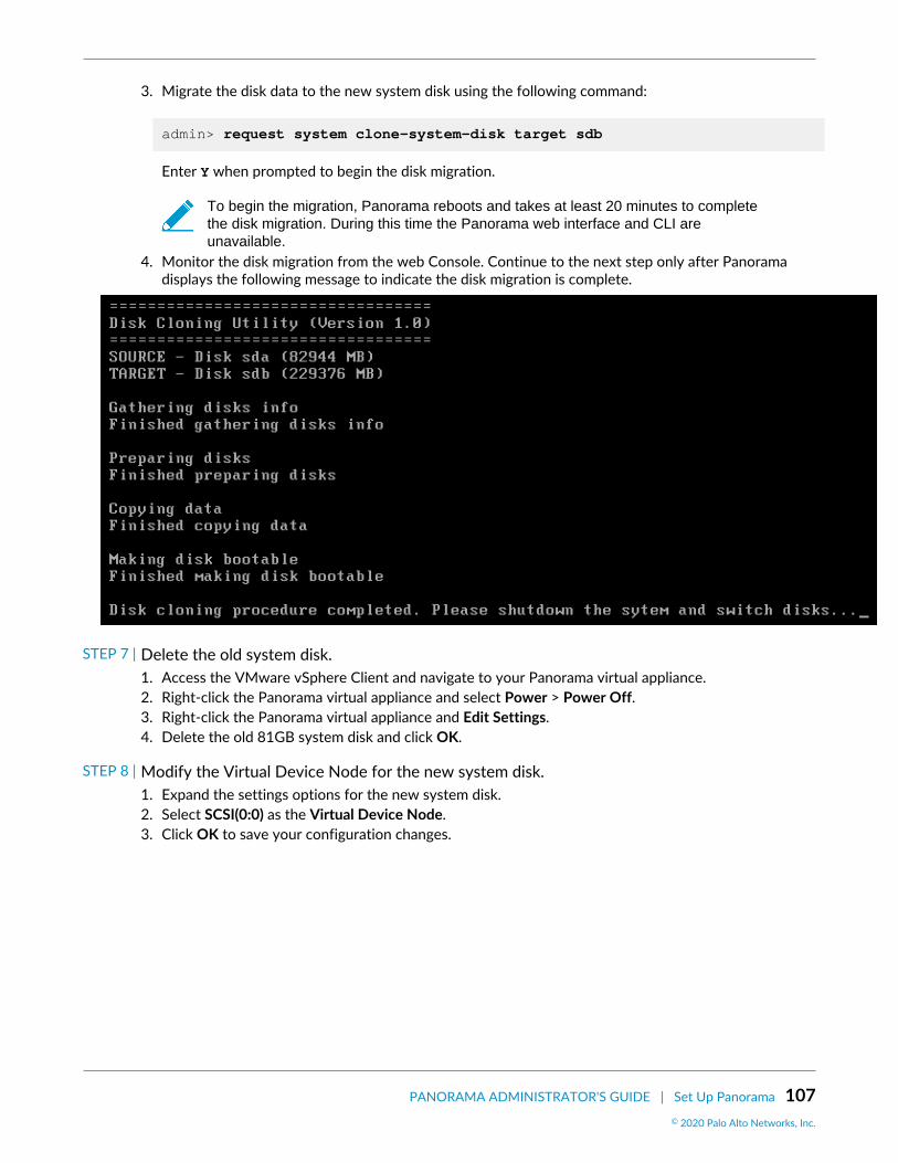
PANORAMA ADMINISTRATOR'S GUIDE | Set Up Panorama 107© 2020 Palo Alto Networks, Inc.
3. Migrate the disk data to the new system disk using the following command:
admin> request system clone-system-disk target sdb
Enter Y when prompted to begin the disk migration.
To begin the migration, Panorama reboots and takes at least 20 minutes to completethe disk migration. During this time the Panorama web interface and CLI areunavailable.
4. Monitor the disk migration from the web Console. Continue to the next step only after Panoramadisplays the following message to indicate the disk migration is complete.
STEP 7 | Delete the old system disk.1. Access the VMware vSphere Client and navigate to your Panorama virtual appliance.2. Right-click the Panorama virtual appliance and select Power > Power Off.3. Right-click the Panorama virtual appliance and Edit Settings.4. Delete the old 81GB system disk and click OK.
STEP 8 | Modify the Virtual Device Node for the new system disk.1. Expand the settings options for the new system disk.2. Select SCSI(0:0) as the Virtual Device Node.3. Click OK to save your configuration changes.

108 PANORAMA ADMINISTRATOR'S GUIDE | Set Up Panorama© 2020 Palo Alto Networks, Inc.
STEP 9 | Right-click the Panorama virtual appliance and select Power > Power On.
STEP 10 | Verify that you successfully migrated to the new system disk.1. Log in to the Panorama CLI.2. Enter the following command to view the system disk partitions.
You must add the /dev/root, /dev/sda5, /dev/sda6, and /dev/sda8 partitions to confirm thedisk size is increased.
admin> show system disk-space
Increase the System Disk for Panorama on Google Cloud PlatformAdd a 224GB system disk to replace the default 81GB system disk. For the minimum resource requirementsfor the Panorama virtual appliance, see Setup Prerequisites for the Panorama Virtual Appliance.
STEP 1 | (Best Practice) Save and Export Panorama and Firewall Configurations.Save and export your Panorama and firewall configuration to ensure you can recover Panorama if youencounter any issues.

PANORAMA ADMINISTRATOR'S GUIDE | Set Up Panorama 109© 2020 Palo Alto Networks, Inc.
STEP 2 | Log in to the Google Cloud Console.
STEP 3 | In VM Instances, Stop the Panorama VM instance.
STEP 4 | Add the new 224GB system disk.1. Select the Panorama VM instance and select Edit.2. In the Additional disks section Add new disk.3. Configure the new disk with 224GB and click OK.
STEP 5 | In VM Instances, Start the Panorama VM instance.
STEP 6 | Migrate disk data from the old system disk to the new system disk.In this example, we are migrating to the newly added system disk labeled sdb.
1. Log in to the Panorama CLI.2. Enter the following command to view the available system disks for migration:
admin> request system clone-system-disk target ?
3. Migrate the disk data to the new system disk using the following command:
admin> request system clone-system-disk target sdb
Enter Y when prompted to begin the disk migration.
To begin the migration, Panorama reboots and takes at least 20 minutes to completethe disk migration. During this time the Panorama web interface and CLI areunavailable.
4. Monitor the disk migration by attempting to log in to the Panorama CLI. The Panorama managementserver is in maintenance mode after the system disk migration is completed and will allow you to login to the Panorama CLI while in maintenance mode.

110 PANORAMA ADMINISTRATOR'S GUIDE | Set Up Panorama© 2020 Palo Alto Networks, Inc.
STEP 7 | Attach the new 224GB system disk.1. In VM Instances, Stop the Panorama VM instance.2. Select the Panorama VM instance and select Edit.3. In the Additional disks section, detach the new 224GB system disk.4. In the Boot Disk section, detach the old 81GB system disk.5. In the Boot Disk section, Add item and select the new 224GB system disk.6. Save your configuration changes.
STEP 8 | In VM Instances, Start the Panorama VM instance.
STEP 9 | Verify that you successfully migrated to the new system disk.1. Log in to the Panorama CLI.2. Enter the following command to view the system disk partitions.
You must add the /dev/root, /dev/sda5, /dev/sda6, and /dev/sda8 partitions to confirm thedisk size is increased.
admin> show system disk-space
Complete the Panorama Virtual Appliance SetupAfter you Perform Initial Configuration of the Panorama Virtual Appliance, continue with the following tasksfor additional configuration:
• Activate a Panorama Support License• Activate/Retrieve a Firewall Management License when the Panorama Virtual Appliance is Internet-
connected• Install Content and Software Updates for Panorama• Access and Navigate Panorama Management Interfaces• Set Up Administrative Access to Panorama• Manage Firewalls

PANORAMA ADMINISTRATOR'S GUIDE | Set Up Panorama 111© 2020 Palo Alto Networks, Inc.
Set Up the M-Series ApplianceThe M-600, M-500, M-200 and M-100 appliances are high performance hardware appliances that youcan deploy in Management Only mode (as Panorama management servers with no local log collection),Panorama mode (as Panorama management servers with local log collection) or in Log Collector mode(as Dedicated Log Collectors). The appliances provide multiple interfaces that you can assign to variousPanorama services such as firewall management and log collection. Before setting up the appliance,consider how you can configure the interfaces to optimize security, enable network segmentation (in large-scale deployments), and load balance the traffic for Panorama services.
M-100 appliances are supported in PAN-OS 9.1 only if they have been upgraded to 32GBmemory from the default 16GB. See M-100 Memory Upgrade Guide for more information.
• M-Series Appliance Interfaces• Perform Initial Configuration of the M-Series Appliance• M-Series Setup Overview• Set Up the M-Series Appliance as a Log Collector• Increase Storage on the M-Series Appliance• Configure Panorama to Use Multiple Interfaces
M-Series Appliance InterfacesThe Panorama M-600, M-500, M-200 and M-100 appliances have several interfaces for communicatingwith other systems such as managed firewalls and the client systems of Panorama administrators. Panoramacommunicates with these systems to perform various services, including managing devices (firewalls, LogCollectors, and WildFire appliances and appliance clusters), collecting logs, communicating with CollectorGroups, deploying software and content updates to devices, and providing administrative access toPanorama. By default, Panorama uses its management (MGT) interface for all these services. However, youcan improve security by reserving the MGT interface for administrative access and dedicating separateinterfaces for the other services. In a large-scale network with multiple subnetworks and heavy log traffic,using multiple interfaces for device management and log collection also enables network segmentation andload balancing (see Configure Panorama to Use Multiple Interfaces).
When assigning Panorama services to various interfaces, keep in mind that only the MGT interface allowsadministrative access to Panorama for configuration and monitoring tasks. You can assign any interfaceto the other services when you Perform Initial Configuration of the M-Series Appliance. The M-SeriesAppliance Hardware Reference Guides explain where to attach cables for the interfaces. The M-100appliance support 1Gbps throughput on all its interfaces: MGT, Eth1, Eth2, and Eth3. In addition to theseinterfaces, the M-500 appliance supports 10Gbps throughput on its Eth4 and Eth5 interfaces.
The M-Series appliances do not support Link Aggregation Control Protocol (LACP) foraggregating interfaces.
Supported InterfacesInterfaces can be used for device management, log collection, Collector Group communication, licensingand software updates. See Configure Panorama to Use Multiple Interfaces for more information on networksegmentation.

112 PANORAMA ADMINISTRATOR'S GUIDE | Set Up Panorama© 2020 Palo Alto Networks, Inc.
Interface MaximumSpeed
M-600Appliance
M-500Appliance
M-200Appliance
M-100Appliance
Management(MGT)
1Gbps
Ethernet 1(Eth1)
1Gbps
Ethernet 2(Eth2)
1Gbps
Ethernet 3(Eth3)
1Gbps
Ethernet 4(Eth4)
10Gbps — —
Ethernet 5(Eth5)
10Gbps — —
Logging RatesReview the logging rates for the all M-Series appliance models. To achieve the logging rates listed below,the M-Series appliance must be a single log collector in a collector group and you must install all the loggingdisks for your M-Series model. For example, to achieve 30,000 logs/second for the M-500 appliance, youmust install all 12 logging disks with either 1TB or 2TB disks.
Model Capacities andFeatures
M-600 Appliance M-500 Appliance M-200 Appliance M-100 Appliance
Maximum LoggingRate for Panoramain ManagementOnly mode
Local log storage is not supported
Maximum LoggingRate for Panoramain Panorama Mode
25,000 logs/second
20,000 logs/second
10,000 logs/second
10,000 logs/second
Maximum LoggingRate for Panoramain Log CollectorMode
50,000 logs/second
30,000 logs/second
28,000 logs/second
18,000 logs/second
Maximum LogStorage onAppliance
48TB (12x8TBRAID disk)
• 24TB (24x2TBRAID disks)
• 12TB (24x1TBRAID Disk)
16TB (4x8TBRAID disk)
• 8TB (8x2TBRAID Disk)
• 4TB (8x1TBRAID Disk)
Default Log Storageon Appliance
16TB (4x8TBRAID disks)
4TB (4x2TB RAIDdisks)
16TB (4x8TBRAID disks)
2TB (2x2TB RAIDdisks)

PANORAMA ADMINISTRATOR'S GUIDE | Set Up Panorama 113© 2020 Palo Alto Networks, Inc.
Model Capacities andFeatures
M-600 Appliance M-500 Appliance M-200 Appliance M-100 Appliance
SSD Storage onAppliance (forlogs that M-Series appliancesgenerate)
240GB 240GB 240GB 120GB
NFS Attached LogStorage
Not available
Perform Initial Configuration of the M-Series ApplianceBy default, Panorama has an IP address of 192.168.1.1 and a username/password of admin/admin. Forsecurity reasons, you must change these settings before continuing with other configuration tasks. Youmust perform these initial configuration tasks either from the Management (MGT) interface or using a directserial port connection to the console port on the M-600, M-500, M-200 or M-100 appliance.
If you are configuring an M-Series appliance in Log Collector mode with 10GB interfaces,you must complete this entire configuration procedure for the 10GB interfaces to display asUp.
STEP 1 | Gather the required interface and server information from your network administrator.• Gather the IP address, netmask (for IPv4) or prefix length (for IPv6), and default gateway for each
interface that you plan to configure (MGT, Eth1, Eth2, Eth3, Eth4, Eth5). Only the MGT interface ismandatory.
Palo Alto Networks recommends that you specify all these settings for the MGTinterface. If you omit values for some of these settings (such as the default gateway),you can access Panorama only through the console port for future configurationchanges. You cannot commit the configurations for other interfaces unless you specifyall these settings.
If you plan to use the appliance as a Panorama management server, Palo Alto Networks recommendsusing the MGT interface only for managing Panorama and using other interfaces for managingdevices, collecting logs, communicating with Collector Groups, and deploying updates to devices (seeM-Series Appliance Interfaces).
• Gather the IP addresses of the DNS servers.
STEP 2 | Access the M-Series appliance from your computer.1. Connect to the M-Series appliance in one of the following ways:
• Attach a serial cable from a computer to the Console port on the M-Series appliance and connectusing terminal emulation software (9600-8-N-1).
• Attach an RJ-45 Ethernet cable from a computer to the MGT port on the M-Series appliance.From a browser, go to https://192.168.1.1. Enabling access to this URL might require changingthe IP address on the computer to an address in the 192.168.1.0 network (for example,192.168.1.2).
2. When prompted, log in to the appliance using the default username and password (admin/admin).The appliance starts initializing.

114 PANORAMA ADMINISTRATOR'S GUIDE | Set Up Panorama© 2020 Palo Alto Networks, Inc.
STEP 3 | Change the default admin password.
Starting with PAN-OS 9.0.4, the predefined, default administrator password (admin/admin) must be changed on the first login on a device. The new password must bea minimum of eight characters and include a minimum of one lowercase and oneuppercase character, as well as one number or special character.
Be sure to use the best practices for password strength to ensure a strict password andreview the password complexity settings.
1. Click the admin link in the lower left of the web interface.2. Enter the Old Password, New Password, and Confirm New Password, and then click OK. Store the
new password in a safe location.
To ensure that the MGT interface remains secure, configure Minimum PasswordComplexity settings (select Panorama > Setup > Management) and specify theinterval at which administrators must change their passwords.
STEP 4 | Configure the network access settings for each interface that you will use to managePanorama, manage devices, collect logs, communicate with Collector Groups, and deployupdates to devices.1. Select Panorama > Setup > Interfaces and click the Interface Name.2. (Non-MGT interfaces only) Enable the interface.3. Edit the network access settings of each interface that Panorama will use. Only the MGT interface is
required. The Eth1, Eth2, Eth3, Eth4, and Eth5 interfaces are optional and apply only if you plan touse the M-Series appliance as a Panorama management server.
1. Complete one or both of the following field sets based on the IP protocols of your network:
IPv4—Public IP Address, IP Address, Netmask, and Default Gateway
If your firewalls connect to the Panorama management server using a public IPaddress that is translated to a private IP address (NAT), enter the public IP in thePublic IP Address field, and the private IP in the IP Address field to push bothaddresses to your firewalls.
IPv6—IPv6 Address/Prefix Length and Default IPv6 Gateway2. Select the Device Management Services that the interface supports:
Device Management and Device Log Collection—You can assign one or more interfaces.
Collector Group Communication—You can assign only one interface.
Device Deployment (software and content updates)—You can assign only one interface.3. (Optional) Select the Network Connectivity Services that the interface supports.
(MGT interface only) Disable Telnet and HTTP; these services use plaintext and soare less secure than other services.
4. Click OK to save your changes.
STEP 5 | Configure the hostname, time zone, and general settings.1. Select Panorama > Setup > Management and edit the General Settings.2. Align the clock on Panorama and the managed firewalls to use the same Time Zone, for example
GMT or UTC. If you plan to use the Cortex Data Lake, you must configure NTP so that Panorama canstay in sync with the Cortex Data Lake.

PANORAMA ADMINISTRATOR'S GUIDE | Set Up Panorama 115© 2020 Palo Alto Networks, Inc.
The firewall records timestamps when it generate logs and Panorama records timestamps uponreceiving the logs. Aligning the time zones ensures that the timestamps are synchronized and that theprocess of querying logs and generating reports on Panorama is harmonious.
3. Enter a Hostname for the server. Panorama uses this as the display name/label for the appliance. Forexample, this is the name that appears at the CLI prompt. It also appears in the Collector Name field ifyou add the appliance as a managed collector on the Panorama > Managed Collectors page.
4. (Optional) Enter the Latitude and Longitude to enable accurate placement of the M-Series applianceon the world map. The App Scope > Traffic Maps and App Scope > Threat Maps use these values.
5. Click OK to save your entries.
STEP 6 | Configure the DNS servers and Palo Alto Networks Update Server.1. Select Panorama > Setup > Services and edit the settings.2. Enter the IP address of the Primary DNS Server and (optionally) of the Secondary DNS Server.3. Enter the URL or static address of the Update Server (default updates.paloaltonetworks.com).
Select Verify Update Server Identity if you want Panorama to verify that the UpdateServer from which it downloads software or content packages has an SSL certificatethat a trusted authority signed. This option adds an additional level of security forcommunication between the Panorama management server and Update Server.
4. Click OK to save your entries.
STEP 7 | Commit your configuration changes.Select Commit > Commit to Panorama and Commit your changes.
If you plan to use the M-Series appliance as a Panorama management server and youconfigured interfaces other than MGT, you must assign those interfaces to the Device LogCollection or Collector Group Communication functions when you Configure a ManagedCollector. To make the interfaces operational, you must then Configure a Collector Groupfor the managed collector and perform a Collector Group commit.
STEP 8 | Verify network access to external services required for Panorama management, such as thePalo Alto Networks Update Server.1. Connect to the M-Series appliance in one of the following ways:
• Attach a serial cable from your computer to the Console port on the M-Series appliance. Then usea terminal emulation software (9600-8-N-1) to connect.
• Use terminal emulation software such as PuTTY to open an SSH session to the IP address that youspecified for the MGT interface of the M-Series appliance during initial configuration.
2. Log in to the CLI when prompted. Use the default admin account and the password that youspecified during initial configuration.
3. Use the Update Server Connectivity test to verify network connectivity to the Palo Alto NetworksUpdate Server as shown in the following example.
1. Select Panorama > Managed Devices > Troubleshooting, and select Updates Server Connectivityfrom the Select Test drop-down.
2. Execute the update server connectivity test.

116 PANORAMA ADMINISTRATOR'S GUIDE | Set Up Panorama© 2020 Palo Alto Networks, Inc.
4. Use the following CLI command to retrieve information on the support entitlement for Panoramafrom the Update Server:
admin> request support check
If you have connectivity, the Update Server responds with the support status for Panorama. BecausePanorama is not registered, the Update Server returns the following message:
Contact Us https://www.paloaltonetworks.com/company/contact-us.html Support Home https://www.paloaltonetworks.com/support/tabs/overview.html Device not found on this update server
STEP 9 | Next steps...1. Register Panorama and Install Licenses.2. Install Content and Software Updates for Panorama.
As a best practice, replace the default certificate that Panorama uses to secureHTTPS traffic over the MGT interface.
M-Series Setup OverviewUse the following procedures to set up an M-Series appliance:
• Set Up an M-Series Appliance in Management Only Mode• Set Up an M-Series Appliance in Panorama Mode• Set Up an M-Series Appliance in Log Collector Mode

PANORAMA ADMINISTRATOR'S GUIDE | Set Up Panorama 117© 2020 Palo Alto Networks, Inc.
Set Up an M-Series Appliance in Management Only Mode
STEP 1 | Rack mount the M-Series appliance. Refer to the M-Series Appliance Hardware ReferenceGuide for instructions.
STEP 2 | Perform Initial Configuration of the M-Series Appliance
STEP 3 | Register Panorama and Install Licenses
STEP 4 | Install Content and Software Updates for Panorama
STEP 5 | Change to Management Only mode.1. Log in to the Panorama CLI.2. Switch from Panorama mode to Management Only mode:
request system system-mode management-only
3. Enter Y to confirm the mode change. The Panorama management server reboots. If the rebootprocess terminates your terminal emulation software session, reconnect to the Panoramamanagement server to see the Panorama login prompt.
If you see a CMS Login prompt, this means the Panorama management server has not finishedrebooting. Press Enter at the prompt without typing a username or password.
4. Log back in to the CLI.5. Verify that the switch to Management Only mode succeeded:
show system info | match system-mode
If the mode change succeeded, the output displays:
system mode:management-only
STEP 6 | Set Up Administrative Access to Panorama
STEP 7 | Manage Firewalls
STEP 8 | Manage Log Collection
Set Up an M-Series Appliance in Panorama Mode
STEP 1 | Rack mount the M-Series appliance. Refer to the M-Series Appliance Hardware ReferenceGuide for instructions.
STEP 2 | Perform Initial Configuration of the M-Series Appliance.
STEP 3 | Register Panorama and Install Licenses.
STEP 4 | Install Content and Software Updates for Panorama.
STEP 5 | Configure each array. This task is required to make the RAID disks available for logging.Optionally, you can add disks to Increase Storage on the M-Series Appliance.
STEP 6 | Set Up Administrative Access to Panorama.
STEP 7 | Manage Firewalls.
STEP 8 | Manage Log Collection.

118 PANORAMA ADMINISTRATOR'S GUIDE | Set Up Panorama© 2020 Palo Alto Networks, Inc.
Set Up an M-Series Appliance in Log Collector Mode
STEP 1 | Rack mount the M-Series appliance. Refer to the M-Series Appliance Hardware ReferenceGuide for instructions.
STEP 2 | Perform Initial Configuration of the M-Series Appliance
STEP 3 | Register Panorama and Install Licenses
STEP 4 | Install Content and Software Updates for Panorama
STEP 5 | See step Configure each array.. This task is required to make the RAID disks available forlogging. Optionally, you can add disks to Increase Storage on the M-Series Appliance.
STEP 6 | Set Up the M-Series Appliance as a Log Collector
STEP 7 | Manage Log Collection
Set Up the M-Series Appliance as a Log CollectorIf you want a dedicated appliance for log collection, configure an M-100, M-200, M-500, M-600 appliancein Log Collector mode. To do this, you first perform the initial configuration of the appliance in Panoramamode, which includes licensing, installing software and content updates, and configuring the management(MGT) interface. You then switch the M-Series appliance to Log Collector mode and complete theLog Collector configuration. Additionally, if you want to use dedicated M-Series Appliance Interfaces(recommended) instead of the MGT interface for log collection and Collector Group communication, youmust first configure the interfaces for the Panorama management server, then configure them for the LogCollector, and then perform a Panorama commit followed by a Collector Group commit.
Perform the following steps to set up a new M-Series appliance as a Log Collector or to convert an existingM-Series appliance that was previously deployed as a Panorama management server.
If you are configuring an M-Series appliance in Log Collector mode with 10GB interfaces,you must complete this entire configuration procedure for the 10GB interfaces to display asUp.
Switching the M-Series appliance from Panorama mode to Log Collector mode reboots theappliance, deletes the local Log Collector, deletes any existing log data, and deletes allconfigurations except the management access settings. Switching the mode does not deletelicenses, software updates, or content updates.
STEP 1 | Set up the Panorama management server that will manage the Log Collector if you have notalready done so.Perform one of the following tasks:
• Set Up the Panorama Virtual Appliance• Set Up the M-Series Appliance
STEP 2 | Record the management IP addresses of the Panorama management server.If you deployed Panorama in a high availability (HA) configuration, you need the IP address of each HApeer.

PANORAMA ADMINISTRATOR'S GUIDE | Set Up Panorama 119© 2020 Palo Alto Networks, Inc.
1. Log in to the web interface of the Panorama management server.2. Record the IP Address of the solitary (non-HA) or active (HA) Panorama by selecting Panorama >
Setup > Management and checking the Management Interface Settings.3. For an HA deployment, record the Peer HA IP Address of the passive Panorama by selecting
Panorama > High Availability and checking the Setup section.
STEP 3 | Set up the M-Series appliance that will serve as a Dedicated Log Collector.If you previously deployed this appliance as a Panorama management server, you can skip this stepbecause the MGT interface is already configured and the licenses and updates are already installed.
The M-Series appliance in Log Collector mode does not have a web interface for configuration tasks,only a CLI. Therefore, before changing the mode on the M-Series appliance, use the web interface inPanorama mode to:
1. Perform Initial Configuration of the M-Series Appliance.2. Register Panorama and Install Licenses.3. Install Content and Software Updates for Panorama.
STEP 4 | Access the CLI of the M-Series appliance.1. Connect to the M-Series appliance in one of the following ways:
• Attach a serial cable from your computer to the Console port on the M-Series appliance. Then useterminal emulation software (9600-8-N-1) to connect.
• Use terminal emulation software such as PuTTY to open an SSH session to the IP address that youspecified for the MGT interface of the M-Series appliance during initial configuration.
2. Log in to the CLI when prompted. Use the default admin account and the password that youspecified during initial configuration.
STEP 5 | Switch from Panorama mode to Log Collector mode.1. Switch to Log Collector mode by entering the following command:
> request system system-mode logger
2. Enter Y to confirm the mode change. The M-Series appliance reboots. If the reboot processterminates your terminal emulation software session, reconnect to the M-Series appliance to see thePanorama login prompt.
If you see a CMS Login prompt, this means the Log Collector has not finishedrebooting. Press Enter at the prompt without typing a username or password.
3. Log back in to the CLI.4. Verify that the switch to Log Collector mode succeeded:
> show system info | match system-mode
If the mode change succeeded, the output displays:
system-mode: logger
STEP 6 | Configure the logging disks as RAID1 pairs.If you previously deployed the appliance as a Panorama management server, you can skip this stepbecause the disk pairs are already configured and available.

120 PANORAMA ADMINISTRATOR'S GUIDE | Set Up Panorama© 2020 Palo Alto Networks, Inc.
The time required to configure the drives varies from several minutes to a couple ofhours, based on the amount of data on the drives.
1. Determine which disk pairs are present for configuring as RAID pairs on the M-Series appliance:
> show system raid detail
Perform the remaining steps to configure each disk pair that has present disks. This example usesdisk pair A1/A2.
2. To add the first disk in the pair, enter the following command and enter y when prompted to confirmthe request:
> request system raid add A1
Wait for the process to finish before adding the next disk in the pair. To monitor the progress of theRAID configuration, re-enter:
> show system raid detail
After the process finishes for the first disk, the output displays the disk pair status as Available butdegraded.
3. Add the second disk in the pair:
> request system raid add A2
4. Verify that the disk setup is complete:
> show system raid detail
After the process finishes for the second disk, the output displays the disk pair status as Availableand clean:
Disk Pair A Available Status clean
STEP 7 | Enable connectivity between the Log Collector and Panorama management server.Enter the following commands at the Log Collector CLI, where <IPaddress1> is for the MGT interface ofthe solitary (non-HA) or active (HA) Panorama and <IPaddress2> is for the MGT interface of the passive(HA) Panorama, if applicable.
> configure # set deviceconfig system panorama-server <IPaddress1> panorama-server-2 <IPaddress2> # commit # exit
STEP 8 | Record the serial number of the Log Collector.You need the serial number to add the Log Collector as a managed collector on the Panoramamanagement server.

PANORAMA ADMINISTRATOR'S GUIDE | Set Up Panorama 121© 2020 Palo Alto Networks, Inc.
1. At the Log Collector CLI, enter the following command to display its serial number.
> show system info | match serial
2. Record the serial number.
STEP 9 | Add the Log Collector as a managed collector to the Panorama management server.1. Select Panorama > Managed Collectors and Add a managed collector.2. In the General settings, enter the serial number (Collector S/N) you recorded for the Log Collector.3. In the Panorama Server IP field, enter the IP address or FQDN of the solitary (non-HA) or active (HA)
Panorama. For HA deployments, enter the IP address or FQDN of the passive Panorama peer in thePanorama Server IP 2 field.
These IP addresses must specify a Panorama interface that has Device Management and DeviceLog Collection services enabled. By default, these services are enabled only on the MGT interface.However, you might have enabled the services on other interfaces when you Set Up the M-SeriesAppliance that is a Panorama management server.
4. Select Interfaces, click Management, and configure one or both of the following field sets for theMGT interface based on the IP protocols of your network.
• IPv4—IP Address, Netmask, and Default Gateway• IPv6—IPv6 Address/Prefix Length and Default IPv6 Gateway
5. Click OK twice to save your changes to the Log Collector.6. Select Commit > Commit to Panorama and Commit your changes to the Panorama configuration.
This step is required before you can enable logging disks.7. Verify that Panorama > Managed Collectors lists the Log Collector you added. The Connected
column displays a check mark to indicate that the Log Collector is connected to Panorama. You mighthave to wait a few minutes before the page displays the updated connection status.
At this point, the Configuration Status column displays Out of Sync and the RunTime Status column displays disconnected. The status will change to In Sync andconnected after you configure a Collector Group (Step Assign the Log Collector to aCollector Group.).
STEP 10 | Enable the logging disks.1. Select Panorama > Managed Collectors and edit the Log Collector.2. Select Disks and Add each RAID disk pair.3. Click OK to save your changes.4. Select Commit > Commit to Panorama and Commit your changes to the Panorama configuration.
STEP 11 | (Recommended) Configure the Ethernet1, Ethernet2, Ethernet3, Ethernet4, and Ethernet5interfaces if the Panorama management server and Log Collector will use them for DeviceLog Collection (receiving logs from firewalls) and Collector Group Communication.
If you previously deployed the Log Collector as a Panorama management server and configured theseinterfaces, you must reconfigure them because switching to Log Collector mode (Switch from Panoramamode to Log Collector mode.) would have deleted all configurations except the management accesssettings.
1. Configure each interface on the Panorama management server (other than the MGT interface) if youhaven’t already:
1. Select Panorama > Setup > Interfaces and click the Interface Name.2. Select <interface-name> to enable the interface.

122 PANORAMA ADMINISTRATOR'S GUIDE | Set Up Panorama© 2020 Palo Alto Networks, Inc.
3. Complete one or both of the following field sets based on the IP protocols of your network:
IPv4—IP Address, Netmask, and Default Gateway
IPv6—IPv6 Address/Prefix Length and Default IPv6 Gateway4. Select the Device Management Services that the interface supports:
Device Management and Device Log Collection—You can assign one or more interfaces.
Collector Group Communication—You can assign only one interface.
Device Deployment (software and content updates)—You can assign only one interface.5. Click OK to save your changes.
2. Configure each interface on the Log Collector (other than the MGT interface):
1. Select Panorama > Managed Collectors and edit the Log Collector.2. Select Interfaces and click the name of the interface.3. Select <interface-name> to enable the interface.4. Complete one or both of the following field sets based on the IP protocols of your network:
IPv4—IP Address, Netmask, and Default Gateway
IPv6—IPv6 Address/Prefix Length and Default IPv6 Gateway5. Select the Device Management Services that the interface supports:
Device Log Collection—You can assign one or more interfaces.
Collector Group Communication—You can assign only one interface.6. Click OK to save your changes to the interface.
3. Click OK to save your changes to the Log Collector.4. Select Commit > Commit to Panorama and Commit your changes to the Panorama configuration.
STEP 12 | (Optional) If your deployment is using custom certificates for authentication betweenPanorama and managed devices, deploy the custom client device certificate. For moreinformation, see Set Up Authentication Using Custom Certificates.
1. Select Panorama > Certificate Management > Certificate Profile and choose the certificate profilefrom the drop-down or click New Certificate Profile to create one.
2. Select Panorama > Managed Collectors > Add > Communication for a Log Collector.3. Select the Secure Client Communication check box.4. Select the type of device certificate the Type drop-down.
• If you are using a local device certificate, select the Certificate and Certificate Profile from therespective drop-downs.
• If you are using SCEP as the device certificate, select the SCEP Profile and Certificate Profile fromthe respective drop-downs.
5. Click OK.
STEP 13 | (Optional) Configure Secure Server Communication on a Log Collector. For more information,see Set Up Authentication Using Custom Certificates.
1. Select Panorama > Managed Collectors > Add > Communication.2. Verify that the Custom Certificate Only check box is not selected. This allows you to continue
managing all devices while migrating to custom certificates.
When the Custom Certificate Only check box is selected, the Log Collector does notauthenticate and cannot receive logs from devices using predefined certificates.
3. Select the SSL/TLS service profile from the SSL/TLS Service Profile drop-down. This SSL/TLS serviceprofile applies to all SSL connections between the Log Collector and devices sending it logs.

PANORAMA ADMINISTRATOR'S GUIDE | Set Up Panorama 123© 2020 Palo Alto Networks, Inc.
4. Select the certificate profile from the Certificate Profile drop-down.5. Select Authorize Client Based on Serial Number to have the server check clients against the serial
numbers of managed devices. The client certificate must have the special keyword $UDID set as theCN to authorize based on serial numbers.
6. In Disconnect Wait Time (min), enter the number of minutes Panorama should wait before breakingand reestablishing the connection with its managed devices. This field is blank by default and therange is 0 to 44,640 minutes.
The disconnect wait time does not begin counting down until you commit the newconfiguration.
7. (Optional) Configure an authorization list.
1. Click Add under Authorization List.2. Select the Subject or Subject Alt Name as the Identifier type.3. Enter an identifier of the selected type.4. Click OK.5. Select Check Authorization List to enforce the authorization list.
8. Click OK.9. Select Commit > Commit to Panorama.
STEP 14 | Assign the Log Collector to a Collector Group.1. Configure a Collector Group. You must perform a Panorama commit and then a Collector Group
commit to synchronize the Log Collector configuration with Panorama and to put the Eth1, Eth2,Eth3, Eth4, and Eth5 interfaces (if you configured them) in an operational state on the Log Collector.
In any single Collector Group, all the Log Collectors must run on the same Panoramamodel: all M-600 appliances, all M-500 appliances, all M-200 appliances or all M-100appliances, or all Panorama virtual appliances.
As a best practice, Enable log redundancy across collectors if you add multiple LogCollectors to a single Collector group. This option requires each Log Collector to havethe same number of logging disks.
2. Select Panorama > Managed Collectors to verify that the Log Collector configuration is synchronizedwith Panorama.
The Configuration Status column should display In Sync and the Run Time Status column shoulddisplay connected.
3. Access the Log Collector CLI and enter the following command to verify that its interfaces areoperational:
> show interface all
The output displays the state as up for each interface that is operational.4. If the Collector Group has multiple Log Collectors, Troubleshoot Connectivity to Network Resources
to verify they can communicate with each other by performing a Ping connectivity test for eachinterface that the Log Collectors use. For the source IP address, specify the interface of one of theLog Collectors. For the host IP address, specify the matching interface of another Log Collector inthe same Collector Group.
STEP 15 | Next steps...To enable the Log Collector to receive firewall logs:
1. Configure Log Forwarding to Panorama.

124 PANORAMA ADMINISTRATOR'S GUIDE | Set Up Panorama© 2020 Palo Alto Networks, Inc.
2. Verify Log Forwarding to Panorama.
Increase Storage on the M-Series ApplianceAfter you Perform Initial Configuration of the M-Series Appliance, you can increase log storage capacity ofthe appliance by upgrading the existing drive pairs to larger capacity drives or by installing additional drivepairs in empty drive bays. For example, you can choose to upgrade the existing 1TB drives to 2TB on anM-100 appliance, or you can add 2TB drives to the empty drive bays (B1 through D2).
The M-Series appliances leverage RAID 1 for data redundancy in the event of disk failure.Therefore, the pair of drives in a RAID 1 array need to be identical. However, you are freeto mix drive capacities across different RAID 1 arrays. For example, the drives in the A1/A2 RAID 1 array can be 1TB drives, and the drives in the B1/B2 RAID 1 array can be 2TBdrives.
The following table lists the maximum number of drive bays and the available drive capacities supported onM-Series appliances.
Because each drive pair (A1/A2 for example) is in a RAID 1 array, the total storage capacityis half of the total drives installed. For example, if an M-100 appliance has 2TB drivesinstalled in drive bays A1/A2 and B1/B2, the A1/A2 array provides 2TB total storage and theB1/B2 array provides another 2TB for a total of 4TB.
Appliance Number of Supported Drive Bays Supported Drive Capacity
M-100 Appliance 8 1TB or 2TB
M-200 Appliance 4 8TB
M-500 Appliance 24 1TB or 2TB
M-600 Appliance 12 8TB
Before expanding log storage capacity, Determine Panorama Log Storage Requirements. If you need morelog storage than a single M-Series appliance supports, you can add Dedicated Log Collectors (see Configurea Managed Collector) or you can Configure Log Forwarding from Panorama to External Destinations.
You don’t need to take the M-Series appliance offline to expand the storage when addingdrives to an M-Series appliance that is already deployed. When the additional drives areconfigurable and available, the M-Series appliance redistributes the logs among all availabledrives. This log redistribution process happens in the background and does not impactuptime or the availability of the M-Series appliance. However, the process does diminishthe maximum logging rate. The Redistribution State column (Panorama > Collector Groups)indicates the completion status of the process as a percentage.
• Add Additional Drives to an M-Series Appliance• Upgrade Drives on M-Series Appliances Running Panorama 7.0.8 or a Later Release• Upgrade Drives on M-Series Appliances Running Panorama 7.0.7 or an Earlier Release
Add Additional Drives to an M-Series Appliance
STEP 1 | Install the new drives in the appropriate drive bays.

PANORAMA ADMINISTRATOR'S GUIDE | Set Up Panorama 125© 2020 Palo Alto Networks, Inc.
Make sure to add the drives sequentially in the next open drive bays. For example, add drives to B1 andB2 before adding drives to C1 and C2.
STEP 2 | Access the command line interface (CLI) on the M-Series appliance.Connect to the M-Series appliance in one of two ways:
• Connect a serial cable from your computer to the Console port and connect to the M-Seriesappliance using terminal emulation software (9600-8-N-1).
• Use terminal emulation software (such as PuTTY) to open a Secure Shell (SSH) session to the IPaddress of the M-Series appliance.
STEP 3 | When prompted, log in to the appliance.Use the default administrator account and the assigned password.
STEP 4 | Configure each array.
The time required to mirror the data on the drive may vary from several minutes to a fewhours, depending on the amount of data on the drive.
The following example uses the drives in bays B1 and B2.
1. Enter the following commands and confirm the request when prompted:
> request system raid add B1 > request system raid add B2
2. To monitor the progress of the RAID configuration, enter the following command:
> show system raid detail
When the RAID set up is complete, the following response displays:
Disk Pair A Available Status clean Disk id A1 Present model : ST91000640NS size : 953869 MB status : active sync Disk id A2 Present model : ST91000640NS size : 953869 MB status : active sync Disk Pair B Available Status clean Disk id B1 Present model : ST91000640NS size : 953869 MB status : active sync Disk id B2 Present model : ST91000640NS size : 953869 MB status : active sync
STEP 5 | Make the array available for logging.

126 PANORAMA ADMINISTRATOR'S GUIDE | Set Up Panorama© 2020 Palo Alto Networks, Inc.
To enable the array for logging, you must first add the appliance as a managed collector on Panorama. Ifnot already added, see Configure a Managed Collector.
1. Log in to the web interface of the Panorama management server that manages this Log Collector.2. Select Panorama > Managed Collectors and edit the Log Collector.3. Select Disks and Add each array.4. Click OK to save your changes.5. Select Commit > Commit to Panorama and Commit your changes.6. Select Commit > Push to Devices, select the Collector Group, and Push your changes.
Upgrade Drives on M-Series Appliances Running Panorama 7.0.8 or aLater Release
STEP 1 | Access the command line interface (CLI) on the M-Series appliance.Connect to the M-Series appliance in one of two ways:
• Connect a serial cable from your computer to the Console port and connect to the M-Seriesappliance using terminal emulation software (9600-8-N-1).
• Use terminal emulation software (such as PuTTY) to open a Secure Shell (SSH) session to the IPaddress of the M-Series appliance.
STEP 2 | When prompted, log in to the appliance.Use the default administrator account and the assigned password.
STEP 3 | Verify that the RAID 1 status for the installed drives shows there are at least two functioningRAID 1 arrays. During the upgrade, you will upgrade one RAID 1 array at a time and there mustbe at least one other RAID 1 array that is available to the appliance. The appliance will show anabort error if you try to remove the only functioning array from the configuration.Enter the following command to view RAID status:
> show system raid detail
For example, the following shows an output from an M-500 appliance with two available arrays (DiskPair A and Disk Pair B). If there is only one available array, you must add a second array as described inAdd Additional Drives to an M-Series Appliance before you upgrade the drives.
Disk Pair A Available Status clean Disk id A1 Present model : ST91000640NS size : 953869 MB status : active sync Disk id A2 Present model : ST91000640NS size : 953869 MB status : active sync Disk Pair B Available Status clean Disk id B1 Present model : ST91000640NS size : 953869 MB status : active sync Disk id B2 Present

PANORAMA ADMINISTRATOR'S GUIDE | Set Up Panorama 127© 2020 Palo Alto Networks, Inc.
model : ST91000640NS size : 953869 MB status : active sync
STEP 4 | Remove the first 1TB drive and replace it with a 2TB drive.1. To remove the first drive from the RAID 1 array configuration (A1 in this example), enter the
following command and enter y when prompted to confirm the request:
> request system raid remove A1
2. Physically remove the first drive from the drive bay. Press the ejector button on the drive carrier indrive bay A1 to release the ejector handle. Then pull the handle toward you and slide the drive out ofthe appliance.
3. Remove a 2TB drive from its packaging and place the drive on a table next to the drive you justremoved. Take note of how the drive is installed in the carrier because you will install the 2TB drivein this same carrier.
4. Remove the four screws holding the 1TB drive in the carrier and remove the drive from the carrier.5. Attach the 2TB drive to the carrier using the same four screws you removed from the 1TB drive and
then reinsert the carrier with the 2TB drive into drive bay A1.6. Enter the following command to verify the 2TB drive is recognized:
show system raid detail
Verify that the A1 disk shows the correct model and size (about 2TB). If the model and size are notcorrect, run the above command again until the correct model and size are shown.
If the wrong model and size are consistently shown, enter the following command:
request system raid remove A1
Wait for 30 seconds once you run the above command, then remove the disk and reinsert it andrepeat the show system raid detail command to verify the size and model.
STEP 5 | Copy the data from the remaining installed 1TB drive in the RAID 1 array to the newly installed2TB drive in that array.
The time required to copy the data may vary from several minutes to a few hours,depending on the amount of data on the drive.
1. To copy the data from the 1TB drive in drive bay A2 to the newly installed 2TB drive in drive bay A1,enter the following command and enter y when prompted:
> request system raid copy from A2 to A1
2. To view the status of the copy process, run the following command:
> show system raid detail
Continue running this command to view the RAID detail output until you see that the array (A1/A2 inthis example) shows Available.
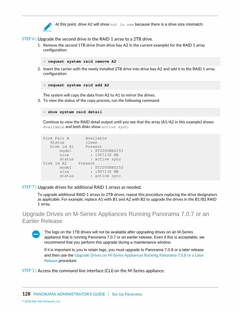
128 PANORAMA ADMINISTRATOR'S GUIDE | Set Up Panorama© 2020 Palo Alto Networks, Inc.
At this point, drive A2 will show not in use because there is a drive size mismatch.
STEP 6 | Upgrade the second drive in the RAID 1 array to a 2TB drive.1. Remove the second 1TB drive (from drive bay A2 in the current example) for the RAID 1 array
configuration:
> request system raid remove A2
2. Insert the carrier with the newly installed 2TB drive into drive bay A2 and add it to the RAID 1 arrayconfiguration:
> request system raid add A2
The system will copy the data from A2 to A1 to mirror the drives.3. To view the status of the copy process, run the following command:
> show system raid detail
Continue to view the RAID detail output until you see that the array (A1/A2 in this example) showsAvailable and both disks show active sync.
Disk Pair A Available Status clean Disk id A1 Present model : ST2000NX0253 size : 1907138 MB status : active sync Disk id A2 Present model : ST2000NX0253 size : 1907138 MB status : active sync
STEP 7 | Upgrade drives for additional RAID 1 arrays as needed.To upgrade additional RAID 1 arrays to 2TB drives, repeat this procedure replacing the drive designatorsas applicable. For example, replace A1 with B1 and A2 with B2 to upgrade the drives in the B1/B2 RAID1 array.
Upgrade Drives on M-Series Appliances Running Panorama 7.0.7 or anEarlier Release
The logs on the 1TB drives will not be available after upgrading drives on an M-Seriesappliance that is running Panorama 7.0.7 or an earlier release. Even if this is acceptable, werecommend that you perform this upgrade during a maintenance window.
If it is important to you to retain logs, you must upgrade to Panorama 7.0.8 or a later releaseand then use the Upgrade Drives on M-Series Appliances Running Panorama 7.0.8 or a LaterRelease procedure.
STEP 1 | Access the command line interface (CLI) on the M-Series appliance.

PANORAMA ADMINISTRATOR'S GUIDE | Set Up Panorama 129© 2020 Palo Alto Networks, Inc.
Connect to the M-Series appliance in one of two ways:
• Connect a serial cable from your computer to the Console port and connect to the M-Seriesappliance using terminal emulation software (9600-8-N-1).
• Use terminal emulation software (such as PuTTY) to open a Secure Shell (SSH) session to the IPaddress of the M-Series appliance.
STEP 2 | When prompted, log in to the appliance.Use the default administrator account and the assigned password.
STEP 3 | Verify that the RAID 1 status for the installed drives shows there are at least two functioningRAID 1 arrays. During the upgrade, you will upgrade one RAID 1 array at a time and there mustbe at least one other RAID 1 array that is available to the appliance. The appliance will show anabort error if you try to remove the only functioning array from the configuration.Enter the following command to view RAID status:
> show system raid detail
For example, the following shows an output from an M-500 appliance with two available arrays (DiskPair A and Disk Pair B). If there is only one available array, you must add a second array as described inAdd Additional Drives to an M-Series Appliance before you upgrade the drives.
Disk Pair A Available Status clean Disk id A1 Present model : ST91000640NS size : 953869 MB status : active sync Disk id A2 Present model : ST91000640NS size : 953869 MB status : active sync Disk Pair B Available Status clean Disk id B1 Present model : ST91000640NS size : 953869 MB status : active sync Disk id B2 Present model : ST91000640NS size : 953869 MB status : active sync
STEP 4 | Remove the first two 1TB drives from the first RAID 1 array configuration and then physicallyremove the drives.1. To remove the drives from the RAID 1 array configuration (A1 and A2 in this example), enter the
following commands and enter y when prompted to confirm each request:
> request system raid remove A1 > request system raid remove A2
2. Physically remove the drives from the drive bays. Press the ejector button on each drive carrier torelease the ejector handle. Then pull the handle toward you and slide the drives out of the appliance.

130 PANORAMA ADMINISTRATOR'S GUIDE | Set Up Panorama© 2020 Palo Alto Networks, Inc.
3. Remove two 2TB drives from their packaging and place them on a table next to the drives you justremoved. Take note of how the drives are installed in the carrier because you will install the 2TBdrives in these same carriers.
4. Remove the four screws holding each drive in its carrier and remove the drives from the carriers.5. Attach the 2TB drives to the carriers using the same screws you just removed and then insert the
carriers with the newly installed 2TB drives into the drive bays (A1 and A2 in this example).
STEP 5 | Create a new RAID 1 array for the newly installed 2TB drives and ensure that both drives are inthe new array.1. To create a new array that includes the drive in drive bay A1, enter the following command:
> request system raid add A1
2. To view and confirm the status of the new RAID 1 array configuration, enter the following command:
> show system raid detail
The following output shows that the Disk Pair A array is Available.
At this point, drive A2 will show not in use.
Disk Pair A Available Status clean, degraded Disk id A1 Present model : ST91000640NS size : 953869 MB status : active sync Disk id A2 Present model : ST91000640NS size : 953869 MB status : not in use
3. Add the second disk to the new array. In this example, add A2:
> request system raid add A2
4. Continue running the show system raid detail command to view the RAID output until thedisk pair status shows clean and both disks show active sync.
STEP 6 | Upgrade drives for additional RAID 1 arrays as needed.To upgrade additional RAID 1 arrays to 2TB drives, repeat this procedure replacing the drive designatorsas applicable. For example, replace A1 with B1 and A2 with B2 to upgrade the drives in the B1/B2 RAID1 array.
Configure Panorama to Use Multiple InterfacesIn a large-scale network, you can improve security and reduce congestion by implementing networksegmentation, which involves segregating the subnetworks based on resource usage, user roles, andsecurity requirements. Panorama supports network segmentation by enabling you to use multiple M-SeriesAppliance Interfaces for managing devices (firewalls, Log Collectors, and WildFire appliances and applianceclusters) and collecting logs; you can assign separate interfaces to the devices on separate subnetworks.Using multiple interfaces to collect logs also provides the benefit of load balancing, which is particularlyuseful in environments where the firewalls forward logs at high rates to the Log Collectors.

PANORAMA ADMINISTRATOR'S GUIDE | Set Up Panorama 131© 2020 Palo Alto Networks, Inc.
Because administrators access and manage Panorama over the MGT interface, securing that interface isespecially important. One method for improving the security of the MGT interface is to offload Panoramaservices to other interfaces. In addition to device management and log collection, you can also offloadCollector Group communication and deployment of software and content updates to firewalls, LogCollectors, and WildFire appliances and appliance clusters. By offloading these services, you can reserve theMGT interface for administrative traffic and assign it to a secure subnetwork that is segregated from thesubnetworks where your firewalls, Log Collectors, and WildFire appliances and appliance clusters reside.
• Multiple Interfaces for Network Segmentation Example• Configure Panorama for Network Segmentation
Multiple Interfaces for Network Segmentation ExampleFigure 10: Multiple Panorama Interfaces illustrates a deployment that uses multiple interfaces on M-500appliances in Panorama mode and Log Collector mode. In this example, the interfaces support networksegmentation as follows:
• Panorama management network—To protect the Panorama web interface, CLI, and XML API fromunauthorized access, the MGT interface on Panorama connects to a subnetwork that only administratorscan access.
• Internet—Panorama uses the MGT interface to communicate with external services such as the Palo AltoNetworks Update Server.
• Perimeter Gateway and Data Center—Panorama uses a separate pair of interfaces to manage thefirewalls and Log Collectors in each of these subnetworks. Managing firewalls typically generates lesstraffic than querying Log Collectors for report information. Therefore, Panorama uses 1Gbps interfaces(Eth1 and Eth2) for managing the firewalls and uses 10Gbps interfaces (Eth4 and Eth5) for querying andmanaging the Log Collectors. Each Log Collector uses its MGT interface to respond to the queries butuses its Eth4 and Eth5 interfaces for the heavier traffic associated with collecting logs from the firewalls.
• Software and content updates—The firewalls and Log Collectors in both subnetworks retrieve softwareand content updates over the Eth3 interface on Panorama.

132 PANORAMA ADMINISTRATOR'S GUIDE | Set Up Panorama© 2020 Palo Alto Networks, Inc.
Figure 10: Multiple Panorama Interfaces
Configure Panorama for Network SegmentationTo offload Panorama services from the MGT interface to other interfaces, start by configuring theinterfaces on the Panorama management server. If your network has heavy log traffic, remember thatthe Eth4 and Eth5 interfaces on the M-500 and M-600 appliances support higher throughput (10Gbps)than the other interfaces (1Gbps). Then, configure the Log Collectors in each subnetwork to connect withspecific interfaces on Panorama. For each Log Collector, you also select an interface for Collector Groupcommunication and one or more interfaces for collecting logs from firewalls. Finally, configure the firewallsin each subnetwork to connect with interfaces on Panorama.
If you are configuring an M-Series appliance in Log Collector mode with 10GB interfaces,you must complete this entire configuration procedure for the 10GB interfaces to display asUp.
Palo Alto Networks recommends that you specify the IP address, netmask (for IPv4) or prefixlength (for IPv6), and default gateway for the MGT interface. If you omit one of these settings

PANORAMA ADMINISTRATOR'S GUIDE | Set Up Panorama 133© 2020 Palo Alto Networks, Inc.
(such as the default gateway), you can access the M-Series appliance only through theconsole port for future configuration changes.
Perform the following steps to configure Panorama and Dedicated Log Collectors to use multiple interfaces:
STEP 1 | Verify that the Panorama appliances and firewalls support multiple interfaces, and have theprerequisite software versions and configurations.
The M-Series appliances must run Panorama 8.0 or later to use a separate interface for deployingupdates and to use multiple interfaces for device management and log collection. The M-200 andM-600 appliances must run Panorama 8.1 or later. Panorama appliances deployed on ESXi, vCloud,Air, Hyper-V and KVM must run Panorama 8.1 or later.If you deployed a Panorama or Log Collector as a virtual appliance, verify the Supported Interfacesfor the Panorama Virtual Appliance.The M-Series appliances must run Panorama 6.1 or later to use separate interfaces for log collectionor Collector Group communication.The initial configuration of each Panorama management server is complete. This includesconfiguration of the MGT interface.Log Collectors and Collector Groups are configured. This includes configuration of the MGT interfaceon the Log Collectors.The initial configuration of the firewalls is complete, you have added the firewalls to Panorama asmanaged devices, and the firewalls in each subnetwork are assigned to a separate template.The initial configuration of WildFire appliances is complete and you have added WildFire appliancesto Panorama as managed devices.
STEP 2 | Configure the interfaces on the solitary (non-HA) or active (HA) Panorama management server.
Because the MGT interface was configured during initial Panorama configuration, youdon’t have to configure it again.
Perform these steps for each interface:
1. Log in to the Panorama Web Interface of the solitary (non-HA) or active (HA) Panorama managementserver.
2. Select Panorama > Setup > Interfaces.3. Click an Interface Name to edit the interface.4. Select <interface-name> to enable the interface.5. Configure one or both of these field sets based on the IP protocols of your network:
• IPv4—IP Address, Netmask, and Default Gateway• IPv6—IPv6 Address/Prefix Length and Default IPv6 Gateway
6. Select the services that the interface supports:
• Device Management and Device Log Collection—Manage firewalls, Log Collectors, and WildFireappliances and appliance clusters, collect logs that the Log Collectors generate, and query the LogCollectors for report information. To support a segmented network, you can enable these serviceson multiple interfaces.
• Collector Group Communication—Communicate with the Collector Groups that Panoramamanages across all subnetworks.
• Device Deployment—Deploy software and content updates to managed firewalls, Log Collectors,and WildFire appliances and appliance clusters across all subnetworks.
7. Click OK to save your changes to the interface.8. Click Commit > Commit to Panorama and Commit your changes.

134 PANORAMA ADMINISTRATOR'S GUIDE | Set Up Panorama© 2020 Palo Alto Networks, Inc.
9. Click Commit > Push to Devices and push the changes to the Collector Group that contain the LogCollectors you modified.
STEP 3 | (HA only) Configure the interfaces on the passive Panorama management server.1. Log in to the Panorama Web Interface of the active Panorama management server.2. Select Panorama > Managed Collectors and select the passive HA peer.3. Select Interfaces and click an interface to edit.4. Check the Enable Interface box to enable the interface.5. Configure one or both of these field sets based on the IP protocols of your network:
• IPv4—IP Address, Netmask, and Default Gateway• IPv6—IPv6 Address/Prefix Length and Default IPv6 Gateway
6. Select the services that the interface supports:
• Device Management and Device Log Collection—Manage firewalls, Log Collectors, and WildFireappliances and appliance clusters, collect logs that the Log Collectors generate, and query the LogCollectors for report information. To support a segmented network, you can enable these serviceson multiple interfaces.
• Collector Group Communication—Communicate with the Collector Groups that Panoramamanages across all subnetworks.
• Device Deployment—Deploy software and content updates to managed firewalls, Log Collectors,and WildFire appliances and appliance clusters across all subnetworks.
7. Click OK to save your changes to the interface.8. Select Commit > Commit and Push to commit your changes to Panorama and to push the changes to
Collector Groups that contain the passive HA peer you modified.
STEP 4 | Configure each Log Collector to connect with a Panorama interface.To support a segmented network, you can connect the Log Collectors in each subnetwork to separatePanorama interfaces. The interfaces must have Device Management and Device Log Collection enabled,as described in the previous step.
1. Log in to the Panorama Web Interface of the solitary (non-HA) or active (HA) Panorama managementserver.
2. Select Panorama > Managed Collectors and edit the Log Collector.3. In the Panorama Server IP field, enter the IP address of an interface on the solitary (non-HA) or
active (HA) Panorama.4. (HA only) In the Panorama Server IP 2 field, enter the IP address of an interface on the passive
Panorama that will support Device Management and Device Log Collection if failover occurs on theactive Panorama.
5. Click OK to save your changes.6. Select Commit > Commit and Push to commit your changes to Panorama and to push the changes to
Collector Groups that contain the Log Collector you modified.7. Perform the following steps on each Dedicated Log Collector:
1. Access the Log Collector CLI by using emulation software such as PuTTY to open a SSH sessionto the Log Collector using its MGT interface IP address. When prompted, log in using Panoramaadministrator credentials.
2. Run the following commands, where <IPaddress1> is for the solitary (non-HA) or active (HA)Panorama and <IPaddress2> is for the passive Panorama (if applicable).
> configure # set deviceconfig system panorama-server <IPaddress1> panorama-server-2 <IPaddress2>

PANORAMA ADMINISTRATOR'S GUIDE | Set Up Panorama 135© 2020 Palo Alto Networks, Inc.
# commit
STEP 5 | (HA only) Configure an interface on the passive Panorama management server to deployupdates in case the active Panorama fails over.1. Log in to the Panorama Web Interface of the passive Panorama management server.2. Select Panorama > Setup > Interfaces.3. Click an Interface Name to edit the interface.4. Select <interface-name> to enable the interface.5. Configure one or both of these field sets based on the IP protocols of your network:
• IPv4—IP Address, Netmask, and Default Gateway• IPv6—IPv6 Address/Prefix Length and Default IPv6 Gateway
6. Select Device Deployment.7. Click OK to save your changes.8. Click Commit > Commit to Panorama and Commit your changes.
STEP 6 | Configure the interfaces that the Log Collectors will use to collect logs from firewalls andcommunicate with other Log Collectors.
Because the MGT interface was configured during initial configuration of the LogCollectors, you don’t have to configure it again.
1. Log in to the Panorama Web Interface of the solitary (non-HA) or active (HA) Panorama managementserver.
2. Select Panorama > Managed Collectors and edit the Log Collector.3. Select Interfaces and perform the following steps for each interface:
1. Click an interface name to edit that interface.2. Select <interface-name> to enable the interface.3. Configure one or both of the following field sets based on the IP protocols of your network.
IPv4—IP Address, Netmask, and Default Gateway
IPv6—IPv6 Address/Prefix Length and Default IPv6 Gateway4. Select the functions that the interface supports:
Device Log Collection—Collect logs from firewalls. You can load balance the logging traffic byenabling multiple interfaces to perform this function.
Collector Group Communication—Communicate with other Log Collectors in the Collector Group.5. Click OK to save your changes to the interface.
4. Click OK to save your changes to the Log Collector.5. Select Commit > Commit and Push to commit your changes to Panorama and to push the changes to
Collector Groups that contain the Log Collectors you modified.6. Select Panorama > Managed Collectors to verify that the Log Collectors are synchronized and
connected with Panorama.
The Configuration Status column should display InSync and the Run Time Status column shoulddisplay connected.
STEP 7 | Configure the firewalls to connect with a Panorama interface.To support a segmented network, you can connect the firewalls in each subnetwork to separatePanorama interfaces. The interfaces must have Device Management and Device Log Collection enabled.This step assumes that you use separate templates to configure the firewalls in separate subnetworks.

136 PANORAMA ADMINISTRATOR'S GUIDE | Set Up Panorama© 2020 Palo Alto Networks, Inc.
In this example deployment, Panorama uses these interfaces to manage the firewalls butnot to collect firewall logs. You specify which Dedicated Log Collectors will collect firewalllogs when you configure Collector Groups.
1. Log in to the Panorama Web Interface of the solitary (non-HA) or active (HA) Panorama managementserver.
2. On Panorama, select Device > Setup > Management, select a Template and edit the PanoramaSettings.
3. In the first Panorama Servers field, enter the IP address of an interface on the solitary (non-HA) oractive (HA) Panorama.
4. (HA only) In the second Panorama Servers field, enter the IP address of an interface on the passivePanorama that will support device management if failover occurs.
5. Click OK to save your changes.6. Select Commit > Commit and Push to commit your changes to Panorama and push the template
changes to firewalls.7. Select Panorama > Managed Devices to verify that the firewalls are synchronized and connected
with Panorama.
The Device State column should display Connected. The Shared Policy and Template columnsshould display InSync.

PANORAMA ADMINISTRATOR'S GUIDE | Set Up Panorama 137© 2020 Palo Alto Networks, Inc.
Register Panorama and Install LicensesBefore you can begin using Panorama for centralized management, logging, and reporting, you are requiredto register, activate, and retrieve the Panorama device management and support licenses. Every instance ofPanorama requires valid licenses that entitle you to manage firewalls and obtain support. The firewall devicemanagement license enforces the maximum number of firewalls that Panorama can manage. This license isbased on firewall serial numbers, not on the number of virtual systems on each firewall. The support licenseenables Panorama software updates and dynamic content updates (for the latest Applications and Threatssignatures, as an example). Additionally, Panorama virtual appliances on AWS and Azure must be purchasedfrom Palo Alto Networks, and cannot be purchased on the AWS or Azure marketplaces.
After upgrading your Panorama virtual appliance to PAN-OS 8.1, you are prompted if a capacity licensehas not been successfully installed or if the total number of firewalls being managed by Panorama exceedsthe device management license. You have 180 days from the date of upgrade to install a valid devicemanagement license if no license has been installed. If the number of managed firewalls exceeds thedevice management license, you have 180 days to delete firewalls to meet the device management licenserequirements or upgrade your device management license. All commits fail if a valid device managementlicense is not installed, or the existing device management license limit is not met, within 180 days ofupgrade. To purchase a device management license, contact your Palo Alto Networks sales representativeor authorized reseller.
If you want to use the cloud-based Cortex Data Lake, you require a Cortex Data Lake license, in addition tothe firewall management license and premium support license. To purchase licenses, contact your Palo AltoNetworks Systems Engineer or reseller.
If you are running an evaluation license for firewall management on your Panoramavirtual appliance and want to apply a Panorama license that you purchased, perform thetasks Register Panorama and Activate/Retrieve a Firewall Management License when thePanorama Virtual Appliance is Internet-connected.
• Register Panorama• Activate a Panorama Support License• Activate/Retrieve a Firewall Management License when the Panorama Virtual Appliance is Internet-
connected• Activate/Retrieve a Firewall Management License when the Panorama Virtual Appliance is not Internet-
connected• Activate/Retrieve a Firewall Management License on the M-Series Appliance
Register PanoramaSTEP 1 | Record the Panorama serial number or auth-code and record your Sales Order Number or
Customer ID.For the auth-code, Sales Order Number, or Customer ID, see the order fulfillment email that Palo AltoNetworks Customer Service sent when you placed your order for Panorama.
For the serial number, the location depends on the model:
• M-Series appliance—Log in to the Panorama web interface and record the Serial # value in theDashboard tab, General Information section.
• Panorama virtual appliance—See the order fulfillment email.
STEP 2 | Register Panorama. The steps depend on whether you already have a login for the Support site.

138 PANORAMA ADMINISTRATOR'S GUIDE | Set Up Panorama© 2020 Palo Alto Networks, Inc.
• If this is the first Palo Alto Networks appliance you are registering and you don’t yet have a login:
1. Go to the Palo Alto Networks Customer Support web site.2. Click Register at the bottom of the page (Overview > Get Help > Register), enter your Email
Address, enter the code displayed on the page, and click Submit.3. Complete the fields in the Create Contact Details section.4. Enter a Display Name, Confirm Email Address, and Password/Confirm Password.5. Enter the Panorama Device Serial Number or Auth Code.6. Enter your Sales Order Number or Customer ID.7. Click Submit.
• If you already have a support account:
1. Log in to the Palo Alto Networks Customer Support web site.2. Click Assets > Devices > Register New Device.3. Select Register device using Serial Number or Authorization Code, and click Submit.4. If the Panorama management server is not internet-connected, check Device will be used offline
and select the OS Release version.5. Enter the Panorama Serial Number.6. Enter the required Location Information (as indicated by the asterisks) if you have purchased the 4
hour RMA.7. Agree and Submit the EULA.
After you see the registration complete message, close the Device Registration dialog.
Activate a Panorama Support LicenseBefore activating a Panorama support license on a Panorama M-Series appliance or Panorama virtualappliance, you must Register Panorama.
If the support license expires, Panorama can still manage firewalls and collect logs, butsoftware and content updates will be unavailable. The software and content versions onPanorama must be the same as or later than the versions on the managed firewalls, or elseerrors will occur. For details, see Panorama, Log Collector, Firewall, and WildFire VersionCompatibility.
STEP 1 | Log in to the Palo Alto Networks customer support portal to activate the auth-code.1. Select Assets > Devices and enter your Panorama serial number to Filter by the Serial Number.
2. Select the pencil icon in the Action column, select Activate Auth-Code and enter your support licenseAuthorization Code, and click Agree and Submit.
STEP 2 | Log in to the Panorama web interface, and select Panorama > Support > Activate feature usingauthorization code.
STEP 3 | Enter the Authorization Code and click OK.

PANORAMA ADMINISTRATOR'S GUIDE | Set Up Panorama 139© 2020 Palo Alto Networks, Inc.
STEP 4 | Verify that the subscription is activated. Check the details (for example, the Expiry Date,support Level, and Description) in the Support section of the page.
Activate/Retrieve a Firewall Management License when thePanorama Virtual Appliance is Internet-connected
In order to manage devices on Panorama, you need to activate a firewall management license generatedby PAN-OS. The device management license you activate determines the number of devices Panoramacan manage. Log Collectors and WildFire appliances are not treated as managed devices and do not counttoward the number of devices allotted by the device management license.
Before activating and retrieving a firewall management license on the Panorama virtual appliance, you mustRegister Panorama. If you are running an evaluation license and want to apply a license that you purchased,you must still register and activate/retrieve the purchased license. Additionally, you must then change theserial number of the Panorama from the evaluation serial number to the production serial number.
STEP 1 | Log in to the Panorama Web Interface.
STEP 2 | Select Panorama > Setup > Management and edit the General Settings.
STEP 3 | Enter the Panorama Serial Number (included in the order fulfillment email) and click OK.
STEP 4 | Select Panorama > Licenses to activate or retrieve the firewall management license:• Retrieve license keys from license server—Panorama automatically retrieves and activates the
firewall management license from the Panorama Update Server.• Activate feature using authorization code—Enter the firewall management license authorization
code and click OK to activate the license. The authorization code can be obtained from the orderfulfillment email or by logging in to the Palo Alto Networks Customer Support web site by finding thePanorama management server.
• Manually upload license key—Log in to the Palo Alto Networks Customer Support web site, findyour Panorama management server, and download the firewall management license key to your localdevice. After you download the license key, click Choose File to select the license key and click OK.
STEP 5 | Verify the firewall management license is activated.The Device Management License section now appears displaying the date the license was issued, whenthe license expires, and a description of the firewall management license.
Activate/Retrieve a Firewall Management License when thePanorama Virtual Appliance is not Internet-connected
Before activating and retrieving a firewall management license on the Panorama virtual appliance, youmust Register Panorama. In order to manage devices on Panorama, you will need to activate a devicemanagement license. The device management license you activate will determine the number of devices

140 PANORAMA ADMINISTRATOR'S GUIDE | Set Up Panorama© 2020 Palo Alto Networks, Inc.
Panorama can manage. Log Collectors and WildFire appliances are not treated as managed devices andwill not count toward the number of devices allotted by the device management license. If you are runningan evaluation license and want to apply a license that you purchased, you must still register and activate/retrieve the purchased license.
After upgrading to PAN-OS 8.1, you will be prompted to retrieve a valid Panorama management licensewhen you first log in to the Panorama web interface when Panorama has finished rebooting. To activateor retrieve the valid management license if the Panorama virtual appliance is offline or unable to reach thePalo Alto Networks update server, you must get the relevant appliance information for the Panorama virtualappliance and upload it to the Customer Support web site.
STEP 1 | Log in to the Panorama Web Interface.
STEP 2 | (Initial Deployment only) Enter the Panorama Serial Number.1. Select Panorama > Setup > Management and edit the General Settings.2. Enter the Panorama Serial Number (included in the order fulfillment email) and click OK.3. Select Commit > Commit to Panorama and Commit your changes.
STEP 3 | Upload the Panorama virtual appliance information to the Customer Support website.1. On the Retrieve Management License dialogue, click the here link to gather the UUID, CPUID,
Panorama Version and Virtual Platform information. Click Download Link to download a XML file ofthe required Panorama information that can be uploaded to the Customer Support Portal.
On initial deployment, may need to log out and back in to the web interface to see the dialogue.2. Log in to the Palo Alto Networks Customer Support web site.3. Click Get Support in the upper right-hand corner.4. Select Assets > Devices, find your Panorama virtual appliance and in the Action column, click the edit
icon ( ).5. Select Is the Panorama Offline? and enter the Panorama information gathered in Step 2, or click
Select files... to upload the downloaded XML file.6. Agree and Submit the EULA.

PANORAMA ADMINISTRATOR'S GUIDE | Set Up Panorama 141© 2020 Palo Alto Networks, Inc.
STEP 4 | Install the device management license.1. In the Actions column, download the device management license.
2. In the Panorama web interface, click Panorama > Licenses and Manually upload license key.3. Click Choose file, locate the downloaded device management license key and click OK.
STEP 5 | Confirm that the device management license was successfully uploaded by verify that theDevice Management License displays with the license information.

142 PANORAMA ADMINISTRATOR'S GUIDE | Set Up Panorama© 2020 Palo Alto Networks, Inc.
Activate/Retrieve a Firewall Management License on the M-SeriesAppliance
In order to manage devices on Panorama, you need to activate a Capacity License. The Capacity Licensedetermines the number of devices Panorama can manage. Log Collectors and WildFire appliances arenot treated as managed devices and do not count toward the number of devices allotted by the CapacityLicense.
Before activating and retrieving a Panorama firewall management license on the M-Series appliance:
• Register Panorama.• Locate the auth-codes for the product/subscription you purchased. When you placed your order,
Palo Alto Networks Customer Service sent you an email that listed the auth-code associated with thepurchase. If you cannot locate this email, contact Palo Alto Networks Customer Support to obtain yourcodes before proceeding.
After you activate and retrieve the license, the Panorama > Licenses page displays the associated issuancedate, expiration date, and the number of firewalls that the license enables Panorama to manage.
To activate and retrieve the license, the options are:
• Use the web interface to activate and retrieve the license.Select this option if Panorama is ready to connect to the Palo Alto Networks update server (youcompleted the task Perform Initial Configuration of the M-Series Appliance) but you have not activatedthe license on the Palo Alto Networks Customer Support web site.
1. Select Panorama > Licenses and click Activate feature using authorization code.2. Enter the Authorization Code and click OK. Panorama retrieves and activates the license.
• Retrieve the license key from the license server.If Panorama is not ready to connect to the update server (for example, you have not completed theinitial M-Series appliance setup), you can activate the license on the Support website so that, whenPanorama is ready to connect, you can then use the web interface to retrieve the activated license. Theprocess of retrieving an activated license is faster than the process of both retrieving and activating.
1. Activate the license on the Palo Alto Networks Customer Support web site.
1. On a host with internet access, use a web browser to access the Palo Alto Networks CustomerSupport web site and log in.
2. Select Assets > Devices, find your M-Series appliance and, in the Action column, click the editicon ( ).
3. Select Activate Auth-Code, enter the Authorization Code and click Agree and Submit to activatethe license.
2. Configure Panorama to connect to the update server: see Perform Initial Configuration of the M-Series Appliance.
3. Select Panorama > Licenses and click Retrieve license keys from the license server. Panoramaretrieves the activated license.
• Manually upload the license from a host to Panorama. Panorama must have access to that host.If Panorama is set up (you completed the task Perform Initial Configuration of the M-Series Appliance)but does not have a connection to the update server, activate the license on the Support website,download it to a host that has a connection to the update server, then upload it to Panorama.
1. Activate and download the license from the Palo Alto Networks Customer Support web site.

PANORAMA ADMINISTRATOR'S GUIDE | Set Up Panorama 143© 2020 Palo Alto Networks, Inc.
1. On a host with internet access, use a web browser to access the Palo Alto Networks CustomerSupport web site and log in.
2. Select Assets > Devices, find your M-Series appliance and, in the Action column, click the editicon ( ).
3. Select Activate Auth-Code, enter the Authorization Code and click Agree and Submit to activatethe license.
4. In the Action column, click the download icon and save the license key file to the host.2. In the Panorama web interface, select Panorama > Licenses, click Manually upload license key and
click Browse.3. Select the key file you downloaded to the host and click Open.4. Click OK to upload the activated license key.

144 PANORAMA ADMINISTRATOR'S GUIDE | Set Up Panorama© 2020 Palo Alto Networks, Inc.
Install the Panorama Device CertificateIn PAN-OS 9.1.3 and later releases, you must install the device certificate on the Panorama™ managementserver to successfully authenticate Panorama with the Palo Alto Networks Customer Support Portal (CSP)and leverage Zero Touch Provisioning (ZTP). Panorama must have internet access to successfully install thedevice certificate.
If you are leveraging the Cloud Services plugin, you must have Cloud Services plugin 1.5 orlater release installed to successfully install the Panorama device certificate.
STEP 1 | Register Panorama with the Palo Alto Networks Customer Support Portal (CSP).
STEP 2 | Configure the Network Time Protocol (NTP) server.An NTP server is required validate the device certification expiration date, ensure the device certificatedoes not expire early or become invalid.
1. Log in to the Panorama Web Interface.2. Select Panorama > Setup > Services.3. Select NTP and enter the hostname pool.ntp.org as the Primary NTP Server or enter the IP
address of your primary NTP server.4. (Optional) Enter a Secondary NTP Server address.5. (Optional) To authenticate time updates from the NTP server(s), for Authenticastion Type, select one
of the following for each server.
• None (default)—Disables NTP authentication.• Symmetric Key—Firewall uses symmetric key exchange (shared secrets) to authenticate time
updates.
• Key ID—Enter the Key ID (1-65534)• Algorithm—Select the algorithm to use in NTP authentication (MDS or SHA1)
6. Click OK to save your configuration changes.7. Select Commit and Commit to Panorama.
STEP 3 | Generate the One Time Password (OTP).1. Log in to the Customer Support Portal.2. Select Assets > Device Certificates and Generate OTP.3. For the Device Type, select Generate OTP for Panorama and Generate OTP.4. Select the Panorama Device serial number.5. Generate OTP and copy the OTP.
STEP 4 | Log in to the Panorama Web Interface as an admin user.
STEP 5 | Select Panorama > Setup > Management > Device Certificate Settings and Get certificate.

PANORAMA ADMINISTRATOR'S GUIDE | Set Up Panorama 145© 2020 Palo Alto Networks, Inc.
STEP 6 | Enter the One-time Password you generated and click OK.
STEP 7 | Panorama successfully retrieves and install the certificate.

146 PANORAMA ADMINISTRATOR'S GUIDE | Set Up Panorama© 2020 Palo Alto Networks, Inc.
Install Content and Software Updates forPanorama
A valid support subscription enables access to the Panorama software image and release notes. To takeadvantage of the latest fixes and security enhancements, upgrade to the latest software and contentupdates that your reseller or a Palo Alto Networks Systems Engineer recommends for your deployment.The procedure to install software and content updates depends on whether Panorama has a directconnection to the internet and whether it has a high availability (HA) configuration.
M-100 appliances are supported in PAN-OS 9.1 only if they have been upgraded to 32GBmemory from the default 16GB. See M-100 Memory Upgrade Guide for more information.
• Panorama, Log Collector, Firewall, and WildFire Version Compatibility• Install Updates for Panorama in an HA Configuration• Install Updates for Panorama with an Internet Connection• Install Updates for Panorama without an Internet Connection• Migrate Panorama Logs to the New Log Format
Panorama, Log Collector, Firewall, and WildFire VersionCompatibility
For best results, adhere to the following Panorama™ compatibility guidelines:
Install the same Panorama release on both the Panorama management server and the Dedicated LogCollectors.Panorama must be running the same or a later PAN-OS version than the firewall it manages. Beforeupgrading firewalls to PAN-OS 9.1, you must first upgrade Panorama to 9.1.
Panorama 6.1 and later versions cannot push configurations to firewalls running PAN-OS6.0.0 through PAN-OS 6.0.3.
Panorama 9.1 can manage WildFire® appliances and WildFire appliance clusters that are running thesame or an earlier PAN-OS 9.1 release. It is recommended that the Panorama management server,Wildfire appliances, and Wildfire appliance clusters run the same PAN-OS release.The content release version on the Panorama management server must be the same (or earlier) versionas the content release version on any Dedicated Log Collectors or managed firewalls.
Palo Alto Networks® recommends installing the same Applications database version onPanorama as on the Dedicated Log Collectors and firewalls.
Regardless whether your subscriptions include the Applications database or Applications and Threatsdatabase, Panorama installs only the Applications database. Panorama and Dedicated Log Collectorsdo not enforce policy rules so they do not need the threat signatures from the Threats database.The Applications database contains threat metadata (such as threat IDs and names) that you use onPanorama and Dedicated Log Collectors when defining policy rules to push to managed firewalls andwhen interpreting threat information in logs and reports. However, firewalls require the full Applicationsand Threats database to match the identifiers recorded in logs with the corresponding threat, URL, orapplication names. Refer to the Release Notes for the minimum content release version required for aPanorama release.

PANORAMA ADMINISTRATOR'S GUIDE | Set Up Panorama 147© 2020 Palo Alto Networks, Inc.
Install Updates for Panorama in an HA ConfigurationTo ensure a seamless failover when you update the Panorama software in a high availability (HA)configuration, the active and passive Panorama peers must be running the same Panorama release with thesame Applications database version. The following example describes how to upgrade an HA pair (activepeer is Primary_A and passive peer is Secondary_B).
Before updating Panorama, refer to the Release Notes. for the minimum content release version requiredfor PAN-OS 9.1.
For M-100 appliances, Palo Alto Networks requires upgrading the memory to 32GB or morefor management and log collection tasks. See the M-100 Memory Upgrade Guide beforeupgrading your M-100 appliance to PAN-OS 9.1.0.
STEP 1 | Upgrade the Panorama software on the Secondary_B (passive) peer.Perform one of the following tasks on the Secondary_B peer:
• Install Updates for Panorama with an Internet Connection• Install Updates for Panorama When Not Internet-Connected
After the upgrade, this Panorama transitions to a non-functional state because the peers are no longerrunning the same software release.
STEP 2 | Suspend the Primary_A peer to force a failover.On the Primary_A peer:
1. In the Operational Commands section (Panorama > High Availability), Suspend local Panorama.2. Verify that state is suspended (displayed on bottom-right corner of the web interface).
The resulting failover should cause the Secondary_B peer to transition to active state.
STEP 3 | Upgrade the Panorama software on the Primary_A (currently passive) peer.Perform one of the following tasks on the Primary_A peer:
• Install Updates for Panorama with an Internet Connection• Install Updates for Panorama When Not Internet-Connected
After you reboot, the Primary_A peer is initially still in the passive state. Then, if preemption is enabled(default), the Primary_A peer automatically transitions to the active state and the Secondary_B peerreverts to the passive state.
If you disabled preemption, manually Restore the Primary Panorama to the Active State.
STEP 4 | Verify that both peers are now running any newly installed content release versions and thenewly installed Panorama release.On the Dashboard of each Panorama peer, check the Panorama Software Version and ApplicationVersion and confirm that they are the same on both peers and that the running configuration issynchronized.
STEP 5 | (Local Log Collectors in a Collector Group only) Upgrade the remaining Log Collectors in theCollector Group.• Upgrade Log Collectors When Panorama Is Internet-Connected• Upgrade Log Collectors When Panorama Is Not Internet-Connected

148 PANORAMA ADMINISTRATOR'S GUIDE | Set Up Panorama© 2020 Palo Alto Networks, Inc.
Install Updates for Panorama with an Internet ConnectionIf Panorama™ has a direct connection to the internet, perform the following steps to install Panoramasoftware and content updates as needed. If Panorama is running in a high availability (HA) configuration,upgrade the Panorama software on each peer (see Install Updates for Panorama in an HA Configuration).
Upgrading the software on the Panorama virtual appliance does not change the system mode; switching toPanorama mode or Management Only mode is a manual task that requires additional settings as describedwhen you Set Up the Panorama Virtual Appliance with Local Log Collector.
PAN-OS® 9.0 introduced a new log data format for local and Dedicated Log Collectors. On your upgradepath to PAN-OS 9.1, existing log data is automatically migrated to the new format when you upgrade toPAN-OS 9.0. During reformatting, log data is not visible in the ACC or Monitor tabs. Additionally, new logdata is not forwarded to Log Collectors until reformatting is complete. While the reformatting takes place,new logs are written to the firewall system disk and after the procedure is successfully completed, the newlogs are forwarded to the appropriate Log Collector.
You must upgrade all Log Collectors in a collector group at the same time to avoid losing log data loss. Nolog forwarding or log collection occurs if the Log Collectors in a collector group are not all running the samePAN-OS version. Additionally, the log data for the Log Collectors in the collector group is not visible in theACC or Monitor tabs until all Log Collectors are running the same PAN-OS version. For example, if youhave three Log Collectors in a collector group and you upgrade two of the Log Collectors, then no logs areforwarded to any Log Collectors in the collector group.
Before updating Panorama, refer to the Release Notes for the minimum content release version required forPAN-OS 9.1.
For Panorama on Azure, you must perform additional steps before you can successfully upgrade thesoftware version. To upgrade, you need to export the Panorama configuration, upgrade the content andsoftware versions, and import the configuration to the Panorama management server after you successfullyupgrade.
For M-100 appliances, Palo Alto Networks requires upgrading the memory to 32GB or morefor management and log collection tasks. See the M-100 Memory Upgrade Guide beforeupgrading your M-100 appliance to PAN-OS 9.1.0.
STEP 1 | Verify that the updates you plan to install are appropriate for your Panorama deployment.Refer to the Release Notes for the minimum content release version required for a Panoramasoftware release. If you intend to upgrade Log Collectors and firewalls to a particular release, youmust first upgrade Panorama to that (or a later) release.For a Panorama virtual appliance that runs on a hypervisor, ensure that the instance meets the SetupPrerequisites for the Panorama Virtual Appliance.
STEP 2 | Save a backup of the current Panorama configuration file that you can use to restore theconfiguration if you have problems with the upgrade.
Although Panorama automatically creates a backup of the configuration, best practice isto create and externally store a backup before you upgrade.
1. Save named Panorama configuration snapshot (Panorama > Setup > Operations), enter a Name forthe configuration, and click OK.
2. Export named Panorama configuration snapshot, select the Name of the configuration you justsaved, click OK, and save the exported file to a location that is external to Panorama.

PANORAMA ADMINISTRATOR'S GUIDE | Set Up Panorama 149© 2020 Palo Alto Networks, Inc.
STEP 3 | (As needed) Install content updates.
If Panorama is not running the minimum content versions required for the Panoramarelease to which you intend to upgrade, you must update content versions to theminimum (or later) versions before you install the software updates. Refer to ReleaseNotes for minimum content release version for a Panorama release.
Palo Alto Networks® highly recommends that Panorama, Log Collectors, and all managedfirewalls run the same content release version. Additionally, we recommend that youschedule automatic, recurring updates so that you are always running the latest contentversions (refer to 9).
1. Check Now (Panorama > Dynamic Updates) for the latest updates. If the value in the Action columnis Download, an update is available.
Ensure that Panorama is running the same but not a later content release version thanis running on managed firewalls and Log Collectors.
2. (As needed) Before you update the content release version on Panorama, be sure to upgrademanaged firewalls and then Log Collectors (see Upgrade Log Collectors When Panorama Is Internet-Connected) to the same (or a later) content release version.
If you do not need to install content updates at this time, then skip ahead to the next step.3. Install remaining content updates, as needed. When installed, the Currently Installed column displays
a check mark.
1. Download and Install the Applications or Applications and Threats update. Regardless of yoursubscription, Panorama installs and needs only the Applications content update, not the Threatscontent. For details, see Panorama, Log Collector, Firewall, and WildFire Version Compatibility.
2. Download and Install other updates (Antivirus, WildFire®, or URL Filtering) as needed, one at atime, and in any sequence.
STEP 4 | Determine the Upgrade Path to PAN-OS 9.1.You cannot skip the installation of any feature release versions in the path from the currently runningPAN-OS version to PAN-OS 9.1. Review the known issues and changes to default behavior in theRelease Notes and upgrade/downgrade considerations in the New Features Guide for each releasethrough which you pass as part of your upgrade path.
(Required if you are upgrading from a 7.1 or earlier release) PAN-OS 8.0 introduced a new log storageformat. After upgrading to PAN-OS 8.0, you must Migrate Panorama Logs to the New Log Formatbefore continuing in your upgrade path. Log migration is a one-time task; if you already migrated thelogs on the Log Collector for an upgrade to PAN-OS 8.0, you do not need to migrate them again.
If upgrading more than one Log Collector, streamline the process by determining theupgrade paths for all Log Collectors you intend to upgrade before you start downloadingimages.
STEP 5 | Install Panorama 9.1.1. Check Now (Panorama > Software) for the latest releases. If a software release is available, the
Action column displays Download.2. Locate and Download the model-specific file for the release version to which you are
upgrading. For example, to upgrade an M-Series appliance to Panorama 9.1.0, download thePanorama_m-9.1.0 image; to upgrade a Panorama virtual appliance to Panorama 9.1.0, downloadthe Panorama_pc-9.1.0 image. After a successful download, the Action column changes fromDownload to Install for the downloaded image.

150 PANORAMA ADMINISTRATOR'S GUIDE | Set Up Panorama© 2020 Palo Alto Networks, Inc.
3. (You cannot skip installation of any feature release versions in the path from the currently runningPAN-OS version to PAN-OS 9.1.0.) Install the downloaded image and then reboot.
1. Install the image.2. After the installation completes successfully, reboot using one of the following methods:
• If prompted to reboot, click Yes. If you see a CMS Login prompt, press Enter without typinga username or password. When the Panorama login prompt appears, enter the username andpassword you specified during initial configuration.
• If you are not prompted to reboot, Reboot Panorama from the Device Operations section(Panorama > Setup > Operations).
4. (Required only if upgrading to PAN-OS 9.1.1 or a later release) After you complete the above stepsfor the PAN-OS 9.1 base image, repeat steps 1 through 3 to upgrade to the target maintenancerelease.
STEP 6 | Check the status of the log format migration after a successful upgrade to PAN-OS 9.1.1. Log in to the Panorama CLI of the Log Collector.2. Run the following command to check the status of the log format migration:
admin> debug logdb show-es-upgrade-time
Example response when the log format migration is still in progress:
Responsefrom logger 23456212: 50.98% of indices upgraded complete. Approximatelyless than a minute remaining until migration is complete. Once thelog migration is complete, please run the ‘show log-collector-es-clusterhealth’ command to check the ElasticSearch cluster status to verifylogging and reporting functionality is restored.
Response when the log format migration is completed:
Responsefrom logger 23456212: 100% of indices complete. Please run the ‘showlog-collector-es-cluster health’ command to check the ElasticSearchcluster status to verify logging and reporting functionality isrestored.
3. After the log format migration is complete, run the following command to check the status of theElasticSearch cluster before you continue to the next step:
admin> show log-collector-es-cluster health
Continue to the next step when the “status” of the ElasticSearch cluster health displays “green”:

PANORAMA ADMINISTRATOR'S GUIDE | Set Up Panorama 151© 2020 Palo Alto Networks, Inc.
STEP 7 | (Panorama on Azure only) Load the exported Panorama configuration from Step 2.1. Import named Panorama configuration snapshot (Panorama > Setup > Operations), Browse and
select the Panorama configuration file, and click OK.2. Load named Panorama configuration snapshot, select the Name of the configuration you just
imported, enter the Decryption Key if required and click OK.3. Log in to the Panorama CLI.4. Commit the Panorama configuration by enter the following commands:
admin> configure
admin> commit force
STEP 8 | (If local Log Collector is in a Collector Group) Upgrade the remaining Log Collectors in the CollectorGroup.• Upgrade Log Collectors When Panorama Is Internet-Connected• Upgrade Log Collectors When Panorama Is Not Internet-Connected
STEP 9 | (Best Practice) Schedule recurring, automatic content updates.
Panorama does not synchronize content update schedules across HA peers. You mustperform this task on both the active and passive Panorama.
In the header row for each update type (Panorama > Dynamic Updates), the Schedule is initially set toNone. Perform the following steps for each update type.
1. Click None and select the update frequency (Recurrence). The frequency options depend on theupdate type.
2. Select the schedule action:
• Download And Install (Best Practice)—Panorama automatically installs updates after downloadingthem.
• Download Only—You must manually install updates after Panorama downloads them.3. Based on the best practices for the security posture of your organization, configure a delay
(Threshold) after an update becomes available before Panorama downloads the update.4. Click OK to save your changes.5. Select Commit > Commit to Panorama and Commit your changes.

152 PANORAMA ADMINISTRATOR'S GUIDE | Set Up Panorama© 2020 Palo Alto Networks, Inc.
Install Updates for Panorama When Not Internet-ConnectedIf Panorama™ does not have a direct connection to the internet, perform the following steps to installPanorama software and content updates as needed. If Panorama is deployed in a high availability (HA)configuration, you must upgrade each peer (see Install Updates for Panorama in an HA Configuration).
Upgrading the software on the Panorama virtual appliance does not change the system mode; switching toPanorama mode or Management Only mode is a manual task that requires additional settings as describedwhen you Set Up the Panorama Virtual Appliance with Local Log Collector.
PAN-OS® 9.0 introduced a new log data format for local and Dedicated Log Collectors. On your upgradepath to PAN-OS 9.1, existing log data is automatically migrated to the new format when you upgrade toPAN-OS 9.0. During reformatting, log data is not visible in the ACC or Monitor tabs. Additionally, new logdata is not forwarded to Log Collectors until reformatting is complete. While the reformatting takes place,new logs are written to the firewall system disk and after the procedure is successfully completed, the newlogs are forwarded to the appropriate Log Collector.
You must upgrade all Log Collectors in a collector group at the same time to avoid losing log data loss. Nolog forwarding or log collection occurs if the Log Collectors in a collector group are not all running the samePAN-OS version. Additionally, the log data for the Log Collectors in the collector group is not visible in theACC or Monitor tabs until all Log Collectors are running the same PAN-OS version. For example, if youhave three Log Collectors in a collector group and you upgrade two of the Log Collectors, then no logs areforwarded to any Log Collectors in the collector group.
Before you upgrade Panorama, refer to the Release Notes for the minimum content release versionrequired for PAN-OS® 9.1.
For Panorama on Azure, you must perform additional steps before you can successfully upgrade thesoftware version. To upgrade, you need to export the Panorama configuration, upgrade the content andsoftware versions, and import the configuration to the Panorama management server after you successfullyupgrade.
For M-100 appliances, Palo Alto Networks requires upgrading the memory to 32GB or morefor management and log collection tasks. See the M-100 Memory Upgrade Guide beforeupgrading your M-100 appliance to PAN-OS 9.1.0.
STEP 1 | Verify that the updates you plan to install are appropriate for your Panorama deployment.Refer to the Release Notes for the minimum content release version you must install for a Panoramasoftware release. If you intend to upgrade Log Collectors and firewalls to a particular release, youmust first upgrade Panorama to that (or a later) release.For a Panorama virtual appliance, ensure that the instance meets the Setup Prerequisites for thePanorama Virtual Appliance.
STEP 2 | Save a backup of the current Panorama configuration file that you can use to restore theconfiguration if you have problems with the upgrade.
Although Panorama automatically creates a backup of the configuration, best practice isto create and externally store a backup before you upgrade.
1. Save named Panorama configuration snapshot (Panorama > Setup > Operations), enter a Name forthe configuration, and click OK.
2. Export named Panorama configuration snapshot, select the Name of the configuration you justsaved, click OK, and save the exported file to a location that is external to Panorama.

PANORAMA ADMINISTRATOR'S GUIDE | Set Up Panorama 153© 2020 Palo Alto Networks, Inc.
STEP 3 | Determine which content updates you need to install.
Palo Alto Networks highly recommends that Panorama, Log Collectors, and all managedfirewalls run the same content release version.
1. For each content update, determine whether you need updates and which content updates you needto download in the following step.
Ensure that Panorama is running the same but not a later content release version thanis running on managed firewalls and Log Collectors.
2. (As needed) Before you update the content release version on Panorama, be sure to upgrademanaged firewalls and then Log Collectors (see Upgrade Log Collectors When Panorama Is Internet-Connected) to the same (or a later) content release version.
STEP 4 | Determine the Upgrade Path to PAN-OS 9.1.You cannot skip the installation of any feature release versions in the path from the currently runningPAN-OS version to PAN-OS 9.1. Review the known issues and changes to default behavior in theRelease Notes and upgrade/downgrade considerations in the New Features Guide for each releasethrough which you pass as part of your upgrade path.
(Required if you are upgrading from a 7.1 or earlier release) PAN-OS 8.0 introduced a new log storageformat. After upgrading to PAN-OS 8.0, you must Migrate Panorama Logs to the New Log Formatbefore continuing in your upgrade path. Log migration is a one-time task; if you already migrated thelogs on the Log Collector for an upgrade to PAN-OS 8.0, you do not need to migrate them again.
If upgrading more than one Log Collector, streamline the process by determining theupgrade paths for all Log Collectors you intend to upgrade before you start downloadingimages.
STEP 5 | (As needed) Download content updates to a host that can connect and upload content toPanorama either over SCP or HTTPS.If you do not need to install content updates at this time, then skip ahead to 6.
1. Use a host that has internet access to log in to the Palo Alto Networks Customer Support website.2. Download content updates as needed:
1. Click Updates > Dynamic Updates in the Resources section.2. Download the appropriate content updates and save the files to the host. Perform this step for
each content type you need to update.
STEP 6 | Install content updates as needed.
You must install content updates before software updates and you must UpgradeFirewalls first and then Upgrade Log Collectors before you install them on the Panoramamanagement server.
Install the Applications or Applications and Threats update first, and then install any other updates(Antivirus, WildFire®, and URL Filtering), one at a time, and in any sequence.
Regardless whether your subscription includes both Applications and Threats content,Panorama installs and needs only the Applications content. For details, see Panorama,Log Collector, Firewall, and WildFire Version Compatibility.
In Panorama (Panorama > Dynamic Updates), perform the following steps for each content type:

154 PANORAMA ADMINISTRATOR'S GUIDE | Set Up Panorama© 2020 Palo Alto Networks, Inc.
1. Click Upload, select the content Type, Browse to the location on the host to which you downloadedthe update, select the update, and click OK.
2. Install From File, select the Package Type, and click OK.
STEP 7 | Download the software updates to a host that can connect and upload content to Panoramaeither over SCP or HTTPS.1. Use a host with internet access to log in to the Palo Alto Networks Customer Support web site.2. Download software updates:
1. On the main page of Palo Alto Networks Customer Support website, click Updates > SoftwareUpdates.
2. For the first (or next) Panorama release in your upgrade path, identify the model-specificfile. For example, to upgrade an M-Series appliance to Panorama 9.1.0, download thePanorama_m-9.1.0 image; to upgrade a Panorama virtual appliance to Panorama 9.1.0,download the Panorama_pc-9.1.0 image.
You can quickly locate Panorama images by selecting Panorama M Images (M-Series appliances) or Panorama Updates (virtual appliances) from the Filter Bydrop-down.
3. Click the filename and save the file to the host.4. Repeat substep 2 above for any additional release versions in your upgrade path as determined in
Step 4.
STEP 8 | Install Panorama 9.1.For each release in your upgrade path (starting with the earliest), perform the following steps:
1. Click Upload (Panorama > Software).2. Browse to the location on the host to which you downloaded the update, select the update, Sync To
Peer if Panorama is in an HA configuration (to push the software image to the secondary peer), andclick OK.
3. Install the software image and reboot.
For an HA configuration, Install Updates for Panorama in an HA Configuration; otherwise:
1. Install the downloaded image.2. After you successfully complete the installation, reboot using one of the following methods:
• If prompted to reboot, click Yes. If you see a CMS Login prompt, press Enter without typinga username or password. When the Panorama login prompt appears, enter the username andpassword you specified during initial configuration.
• If you are not prompted to reboot, Reboot Panorama from the Device Operations section(Panorama > Setup > Operations).
4. Repeat substeps 1 through 3 above for each release in your path as needed.
STEP 9 | Check the status of the log format migration after a successfully upgrade to PAN-OS 9.1.1. Log in to the Panorama CLI of the Log Collector.2. Run the following command to check the status of the log format migration:
admin> debug logdb show-es-upgrade-time
Example response when the log format migration is still in progress:
Response from logger 23456212: 50.98% of indices upgraded complete. Approximately less than a minute remaining until migration is complete.

PANORAMA ADMINISTRATOR'S GUIDE | Set Up Panorama 155© 2020 Palo Alto Networks, Inc.
Once the log migration is complete, please run the ‘show log-collector-es-cluster health’ command to check the ElasticSearch cluster status to verify logging and reporting functionality is restored.
Response when the log format migration is completed:
Response from logger 23456212: 100% of indices complete. Please run the ‘show log-collector-es-cluster health’ command to check the ElasticSearch cluster status to verify logging and reporting functionality is restored.
3. After log format migration is completee, run the following command to check the status of theElasticSearch cluster before you continue to the next step:
admin> show log-collector-es-cluster health
Continue to the next step when the “status” of the ElasticSearch cluster health displays “green”:
STEP 10 | (Panorama on Azure only) Load the exported Panorama configuration from Step 2.1. Import named Panorama configuration snapshot (Panorama > Setup > Operations), Browse and
select the Panorama configuration file, and click OK.2. Load named Panorama configuration snapshot, select the Name of the configuration you just
imported, enter the Decryption Key if required and click OK.3. Log in to the Panorama CLI.4. Commit the Panorama configuration by enter the following commands:
admin> configure
admin> commit force
STEP 11 | (If local Log Collector is in a Collector Group) Upgrade the remaining Log Collectors in theCollector Group.
• Upgrade Log Collectors When Panorama Is Internet-Connected• Upgrade Log Collectors When Panorama Is Not Internet-Connected
Migrate Panorama Logs to the New Log FormatAfter you upgrade to a Panorama 8.0 or later release, Panorama Log Collectors use a new log storageformat. Because Panorama cannot generate reports or ACC data from logs in the pre-8.0-release logformat after you upgrade, you must migrate the existing logs as soon as you upgrade Panorama and its

156 PANORAMA ADMINISTRATOR'S GUIDE | Set Up Panorama© 2020 Palo Alto Networks, Inc.
Log Collectors from a PAN-OS® 7.1 or earlier release to a PAN-OS 8.0 or later release and you must dothis before you upgrade your managed firewalls. Panorama will continue to collect logs from manageddevices during the log migration but will store the incoming logs in the new log format after you upgrade toa PAN-OS 8.0 or later release. For this reason, you will see only partial data in the ACC and in Reports untilPanorama completes the log migration process.
Log migration to the new format is a one time task that you must perform when you upgradeto PAN-OS 8.0 or later release (or when you upgrade to PAN-OS 8.0 as part of your upgradepath); you do not need to perform this migration again when you upgrade to a later PAN-OSrelease.
The amount of time Panorama takes to complete the log migration process depends on the volume of newlogs being written to Panorama and the size of the log database you are migrating. Because log migration isa CPU-intensive process, begin the migration during a time when the logging rate is lower. You can alwaysstop migration during peak times if you notice that CPU utilization rates are high and resume the migrationwhen the incoming log rate is lower.
After you Install Content and Software Updates for Panorama and upgrade the Log Collectors, migrate thelogs as follows:
• View the incoming logging rate.For best results, start log migration when the incoming log rate is low. To check the rate, run thefollowing command from the Log Collector CLI:
admin@FC-M500-1> debug log-collector log-collection-stats show incoming-logs
High CPU utilization (close to 100%) during log migration is expected and operationswill continue to function normally. Log migration is throttled in favor of incoming logs andother processes in the event of resource contention.
• Start migrating the logs on each Log Collector to the new format.To begin the migration, enter the following command from the CLI of each Log Collector:
admin@FC-M500-1> request logdb migrate lc serial-number <ser_num> start
• View the log migration status to estimate the amount of time it will take to finish migrating allexisting logs to the new format.
admin@FC-M500-1> request logdb migrate lc serial-number <ser_num> status Slot: all Migration State: In Progress Percent Complete: 0.04 Estimated Time Remaining: 451 hour(s) 47 min(s)
• Stop the log migration process.To temporarily stop the log migration process, enter the following command from the Log Collector CLI:
admin@FC-M500-1 request logdb migrate lc serial-number <ser_num> stop

PANORAMA ADMINISTRATOR'S GUIDE | Set Up Panorama 157© 2020 Palo Alto Networks, Inc.
Transition to a Different Panorama ModelWhen your network requirements change (for example, the logging rate increases), you can migrate thePanorama management server and Dedicated Log Collectors to Panorama Models that better support thoserequirements.
• Migrate from a Panorama Virtual Appliance to an M-Series Appliance• Migrate a Panorama Virtual Appliance to a Different Hypervisor• Migrate from an M-Series Appliance to a Panorama Virtual Appliance• Migrate from an M-100 Appliance to an M-500 Appliance
Migrate from a Panorama Virtual Appliance to an M-SeriesAppliance
You can migrate the Panorama configuration from a Panorama virtual appliance to an M-Series appliancein Panorama mode. However, you cannot migrate the logs because the log format on the Panorama virtualappliance is incompatible with that on M-Series appliances. Therefore, if you want to maintain access tothe old logs stored on the Panorama virtual appliance, you must continue running the Panorama virtualappliance after the migration. The M-Series appliance will collect the new logs that firewalls forward afterthe migration. After the pre-migration logs expire or become irrelevant due to aging, you can shut down thePanorama virtual appliance.
Legacy mode is no longer supported in PAN-OS 8.1 or later releases. If the old Panorama virtual appliance isin Legacy mode, you must change Panorama to Panorama mode before migrating to the new hypervisor inorder to preserve the log settings and Log Collector forwarding configurations. Importing the configurationof the old Panorama in Legacy mode to a new Panorama in Panorama mode causes all log and logforwarding settings to be removed.
You cannot migrate logs between hypervisors. Therefore, if you want to maintain access to the logs storedon the old Panorama virtual appliance, you must continue running the old Panorama virtual appliance afterthe migration and add it as a managed Log Collector on the new Panorama virtual appliance. This allowsthe new Panorama virtual appliance to collect the new logs that firewalls forward after the migration, whilemaintaining access to the old log data. After the pre-migration logs expire or become irrelevant due toaging, you can shut down the Panorama virtual appliance.
If you store firewall logs on Dedicated Log Collectors (M-Series appliances in Log Collectormode) instead of on the Panorama virtual appliance, you can maintain access to the logs bymigrating the Dedicated Log Collectors to the M-Series appliance in Panorama mode.
STEP 1 | Plan the migration.Upgrade the software on the Panorama virtual appliance before the migration if the M-Seriesappliance requires a later release of the current software (the M-500 appliance requires Panorama7.0 or a later release. The M-600 and M-200 appliances require Panorama 8.1 or later release).For important details about software versions, see Panorama, Log Collector, Firewall, and WildFireVersion Compatibility.Schedule a maintenance window for the migration. Although firewalls can buffer logs after thePanorama virtual appliance goes offline and then forward the logs after the M-Series appliancecomes online, completing the migration during a maintenance window minimizes the risk that logswill exceed the buffer capacities and be lost during the transition between Panorama models.Consider whether to maintain access to the Panorama virtual appliance after the migration to accessexisting logs. The most efficient approach is to assign a new IP address to the Panorama virtual

158 PANORAMA ADMINISTRATOR'S GUIDE | Set Up Panorama© 2020 Palo Alto Networks, Inc.
appliance and reuse its old IP address for the M-Series appliance. This ensures that the Panoramavirtual appliance remains accessible and that firewalls can point to the M-Series appliance withoutyou reconfiguring the Panorama IP address on each firewall.
STEP 2 | Purchase the new M-Series appliance, and migrate your subscriptions to the new appliance.1. Purchase the new M-Series appliance.2. Purchase the new support license and migration license.3. At the time you purchase the new M-Series appliance, provide your sales representative the serial
number and device management auth-code of the Panorama virtual appliance you are phasing out, aswell as a license migration date of your choosing. On receipt of your M-Series appliance, register theappliance and activate the device management and support licenses using the migration and supportauth-codes provided by Palo Alto Networks. On the migration date, the device management licenseon the Panorama virtual appliance is decommissioned, and you can no longer manage devices orcollect logs using the Panorama virtual appliance. However, the support license is preserved and thePanorama appliance remains under support. You can complete the migration after the effective date,but you are unable to commit any configuration changes on the now decommissioned Panoramavirtual appliance.
STEP 3 | (Legacy mode only) On the old Panorama virtual appliance, change to Panorama mode.
This step is required to preserve the log data, settings and log forwarding configuration ofthe Panorama virtual appliance. If you export the Panorama configuration while in Legacymode, these settings are lost. You must complete Step 9 if you do not change Panoramato Panorama mode before continuing.
Continue to the next step if the Panorama virtual appliance is already in Panorama orManagement Only mode.
1. Set up a Panorama Virtual Appliance in Panorama Mode.2. Migrate Panorama Logs to the New Log Format if you want to preserve the existing log data on the
old Panorama virtual appliance.
STEP 4 | Export the Panorama configuration from the Panorama virtual appliance.1. Log in to the Panorama virtual appliance and select Panorama > Setup > Operations.2. Click Save named Panorama configuration snapshot, enter a Name to identify the configuration, and
click OK.3. Click Export named Panorama configuration snapshot, select the Name of the configuration you just
saved, and click OK. Panorama exports the configuration to your client system as an XML file.
STEP 5 | Power off the Panorama virtual appliance if you won’t need to access to it after the migrationor assign a new IP address to its management (MGT) interface if you will need access to it.To power off the Panorama virtual appliance, see the documentation for your VMware product.
To change the IP address on the Panorama virtual appliance:
1. Select Panorama > Setup > Management, and edit the Management Interface Settings.2. Enter the new IP Address and click OK.3. Select Commit > Commit to Panorama and Commit your changes.
STEP 6 | Perform the initial setup of the M-Series appliance.1. Rack mount the M-Series appliance. Refer to the M-Series Appliance Hardware Reference Guide for
instructions.2. Perform Initial Configuration of the M-Series Appliance to define the network connections required
to activate licenses and install updates.

PANORAMA ADMINISTRATOR'S GUIDE | Set Up Panorama 159© 2020 Palo Alto Networks, Inc.
3. Register Panorama.4. Activate a Panorama Support License.5. Activate/Retrieve a Firewall Management License on the M-Series Appliance. Use the auth-code
associated with the migration license.6. Install Content and Software Updates for Panorama. Install the same versions as those on the
Panorama virtual appliance.
STEP 7 | Load the Panorama configuration snapshot that you exported from the Panorama virtualappliance into the M-Series appliance.1. On the M-Series appliance, select Panorama > Setup > Operations.2. Click Import named Panorama configuration snapshot, Browse to the Panorama configuration file
you exported from the Panorama virtual appliance, and click OK.3. Click Load named Panorama configuration snapshot, select the Name of the configuration you just
imported, select a Decryption Key (the master key for Panorama), and click OK. Panorama overwritesits current candidate configuration with the loaded configuration. Panorama displays any errors thatoccur when loading the configuration file.
4. If errors occurred, save them to a local file. Resolve each error to ensure the migrated configuration isvalid.
STEP 8 | Modify the configuration on the M-Series appliance.Required if the M-Series appliance will use different values than the Panorama virtual appliance. If youwill maintain access to the Panorama virtual appliance to access its logs, use a different hostname and IPaddress for the M-Series appliance.
1. Select Panorama > Setup > Management.2. Edit the General Settings, modify the Hostname, and click OK.3. Edit the Management Interface Settings, modify the values as necessary, and click OK.
STEP 9 | Add the default managed collector and Collector Group back to the M-Series appliance.Loading the configuration from the Panorama virtual appliance (Step 7) removes the default managedcollector and Collector Group that are predefined on each M-Series appliance.
1. Configure a Managed Collector that is local to the M-Series appliance.2. Configure a Collector Group for the default managed collector.3. Select Commit > Commit to Panorama and Commit your changes to the Panorama configuration.
STEP 10 | Synchronize the M-Series appliance with the firewalls to resume firewall management.
Complete this step during a maintenance window to minimize network disruption.
1. On the M-Series appliance, select Panorama > Managed Devices and verify that the Device Statecolumn displays Connected for the firewalls.
At this point, the Shared Policy (device groups) and Template columns display Out of sync for thefirewalls.
2. Push your changes to device groups and templates:
1. Select Commit > Push to Devices and Edit Selections.2. Select Device Groups, select every device group, Include Device and Network Templates, and
click OK.3. Push your changes.
3. In the Panorama > Managed Devices page, verify that the Shared Policy and Template columnsdisplay In sync for the firewalls.

160 PANORAMA ADMINISTRATOR'S GUIDE | Set Up Panorama© 2020 Palo Alto Networks, Inc.
Migrate a Panorama Virtual Appliance to a Different HypervisorMigrate the Panorama configuration of a Panorama virtual appliance from one supported hypervisor toanother supported hypervisor in Management Only mode or Panorama mode. Before migrating to thePanorama virtual appliance to a new hypervisor, review the Panorama Models to ensure that the newhypervisor you are migrating to is supported. Additionally, if your Panorama configuration has multipleinterfaces configuration for device management includes multiple interfaces for device management, logcollection, Collector Group communication, licensing and software updates, review Setup Prerequisitesfor the Panorama Virtual Appliance to verify that the hypervisor you are migrating to supports multipleinterfaces.
Legacy mode is no longer supported in PAN-OS 8.1 or later releases. If the old Panorama virtual appliance isin Legacy mode, you must change Panorama to Panorama mode before migrating to the new hypervisor inorder to preserve the log settings and Log Collector forwarding configurations. Importing the configurationof the old Panorama in Legacy mode to a new Panorama in Panorama mode causes all log and logforwarding settings to be removed.
You cannot migrate logs from Panorama virtual appliance. Therefore, if you want to maintain access to thelogs stored on the old Panorama virtual appliance, you must continue running the old Panorama virtualappliance in Log Collector mode after the migration and add it as a managed Log Collector on the newPanorama virtual appliance. This allows the new Panorama virtual appliance to collect the new logs thatfirewalls forward after the migration, while maintaining access to the old log data. After the pre-migrationlogs expire or become irrelevant due to aging, you can shut down the Panorama virtual appliance.
If you store firewall logs on Dedicated Log Collectors (Panorama virtual appliance in LogCollector mode) instead of on the Panorama virtual appliance, you can maintain access tothe logs by migrating the Dedicated Log Collectors to the new Panorama virtual appliance inPanorama mode.
STEP 1 | Plan the migration.Upgrade the software on the Panorama virtual appliance before the migration if the new Panopramavirtual appliance requires a later release of the current software. Panorama on AWS and MicrosoftAzure require 8.1 or later release, Google Cloud Platform (GCP) requires 8.1.1 or later release, KVMand AWS GovCloud require 8.1.2 or later release, and Hyper-V requires 8.1.3 or later release. Forimportant details about software versions, see Panorama, Log Collector, Firewall, and WildFireVersion Compatibility.Schedule a maintenance window for the migration. Although firewalls can buffer logs after thePanorama virtual appliance goes offline and then forward the logs after the new Panorama virtualappliance comes online, completing the migration during a maintenance window minimizes the riskthat logs will exceed the buffer capacities and be lost during the transition between hypervisors.Consider whether to maintain access to the old Panorama virtual appliance after the migration toaccess existing logs. The most efficient approach is to assign a new IP address to the old Panoramavirtual appliance and reuse its old IP address for the Panorama virtual appliance. This ensures that theold Panorama virtual appliance remains accessible and that firewalls can point to the new Panoramavirtual appliance without you reconfiguring the Panorama IP address on each firewall.
STEP 2 | Purchase the new Panorama virtual appliance license, and migrate your subscriptions to thevirtual appliance.1. Purchase the new Panorama virtual appliance license.2. Purchase the new support license and migration license.3. At the time you purchase the new Panorama virtual appliance license, provide your sales
representative the serial number and device management auth-code of the Panorama virtual

PANORAMA ADMINISTRATOR'S GUIDE | Set Up Panorama 161© 2020 Palo Alto Networks, Inc.
appliance you are phasing out, as well as a license migration date of your choosing. After deployingthe new Panorama virtual appliance, register the appliance and activate the device managementand support licenses using the migration and support auth-codes provided by Palo Alto Networks.On the migration date, the device management license on the old Panorama virtual appliance isdecommissioned, and you can no longer manage devices or collect logs using the old Panoramavirtual appliance. However, the support license is preserved and the Panorama appliance remainsunder support. You can complete the migration after the effective date, but you are unable to commitany configuration changes on the now decommissioned Panorama virtual appliance.
STEP 3 | (Legacy mode only) On the old Panorama virtual appliance, change to Panorama mode.
This step is required to preserve the log data, settings and log forwarding configurationof the Panorama virtual appliance. If you export the Panorama configuration while inLegacy mode, these settings are lost. You must complete Step 10 if you do not changePanorama to Panorama mode before continuing.
Continue to the next step if the Panorama virtual appliance is already in Panorama orManagement Only mode.
1. Set up a Panorama Virtual Appliance in Panorama Mode.2. Migrate Panorama Logs to the New Log Format if you want to preserve the existing log data on the
old Panorama virtual appliance.
STEP 4 | Export the Panorama configuration from the old Panorama virtual appliance.1. Log in to the Panorama Web Interface.2. Select Panorama > Setup > Operations.3. Click Save named Panorama configuration snapshot, enter a Name to identify the configuration, and
click OK.4. Click Export named Panorama configuration snapshot, select the Name of the configuration you just
saved, and click OK. Panorama exports the configuration to your client system as an XML file.
STEP 5 | Power off the old Panorama virtual appliance if you won’t need to access to it after themigration or assign a new IP address to its management (MGT) interface if you will need accessto it.To power off the Panorama virtual appliance, see the supported documentation for the hypervisor onwhich the old Panorama virtual appliance has been deployed.
To change the IP address on the Panorama virtual appliance:
1. On the web interface of the old Panorama virtual appliance, select Panorama > Setup >Management, and edit the Management Interface Settings.
2. Enter the new IP Address and click OK.3. Select Commit > Commit to Panorama and Commit your changes.
STEP 6 | Perform the initial setup of the new Panorama virtual appliance.1. Set Up the Panorama Virtual Appliance.2. Perform Initial Configuration of the Panorama Virtual Appliance to define the network connections
required to activate licenses and install updates.3. Register Panorama.4. Activate a Panorama Support License.5. Activate/Retrieve a Firewall Management License when the Panorama Virtual Appliance is Internet-
connected. Use the auth-code associated with the migration license.6. Install Content and Software Updates for Panorama. Install the same versions as those on the old
Panorama virtual appliance.

162 PANORAMA ADMINISTRATOR'S GUIDE | Set Up Panorama© 2020 Palo Alto Networks, Inc.
STEP 7 | Load the Panorama configuration snapshot that you exported from the old Panorama virtualappliance into the new Panorama virtual appliance.1. Log in to the Panorama Web Interface of the new Panorama virtual appliance.2. Select Panorama > Setup > Operations.3. Click Import named Panorama configuration snapshot, Browse to the Panorama configuration file
you exported from the Panorama virtual appliance, and click OK.4. Click Load named Panorama configuration snapshot, select the Name of the configuration you just
imported, leave the Decryption Key blank (empty), and click OK. Panorama overwrites its currentcandidate configuration with the loaded configuration. Panorama displays any errors that occur whenloading the configuration file.
5. If errors occurred, save them to a local file. Resolve each error to ensure the migrated configuration isvalid.
STEP 8 | Modify the configuration on the new Panorama virtual appliance.Required if the new Panorama virtual appliance will use different values than the old Panorama virtualappliance. If you will maintain access to the old Panorama virtual appliance to access its logs, use adifferent hostname and IP address for the new Panorama virtual appliance.
Multiple interface configurations are not supported for Panorama deployed on AWS, AWSGovCloud, Microsoft Azure, and GCP. You must reconfigure device management, logcollection, Collector Group communication, licensing and software updates to operateover the MGT interface if migrating to one of these hypervisors.
1. Select Panorama > Setup > Management.2. Edit the General Settings, modify the Hostname, and click OK.3. Edit the Management Interface Settings, modify the values as necessary, and click OK.
STEP 9 | Add the default managed collector and Collector Group to the new Panorama virtual appliance.Loading the configuration from the old Panorama virtual appliance (Step 7) removes the default managedcollector and Collector Group that are predefined on each Panorama virtual appliance in Panoramamode.
1. Configure a Managed Collector that is local to the Panorama virtual appliance.2. Configure a Collector Group for the default managed collector.3. Select Commit > Commit to Panorama and Commit your changes to the Panorama configuration.
STEP 10 | (Legacy mode only) If you exported the Panorama configuration from a Panorama virtualappliance in Legacy mode, Configure Log Forwarding to Panorama.
STEP 11 | Synchronize the new Panorama virtual appliance with the firewalls to resume firewallmanagement.
Complete this step during a maintenance window to minimize network disruption.
1. On the new Panorama virtual appliance, select Panorama > Managed Devices and verify that theDevice State column displays Connected for the firewalls.
At this point, the Shared Policy (device groups) and Template columns display Out of sync for thefirewalls.
2. Push your changes to device groups and templates:
1. Select Commit > Push to Devices and Edit Selections.

PANORAMA ADMINISTRATOR'S GUIDE | Set Up Panorama 163© 2020 Palo Alto Networks, Inc.
2. Select Device Groups, select every device group, Include Device and Network Templates, andclick OK.
3. Push your changes.3. In the Panorama > Managed Devices page, verify that the Shared Policy and Template columns
display In sync for the firewalls.
Migrate from an M-Series Appliance to a Panorama VirtualAppliance
You can migrate the Panorama configuration from an M-100, M-200, M-500, M-600 appliance to aPanorama virtual appliance in Panorama mode. However, you cannot migrate the logs because the logformat on the M-Series appliances is incompatible with that on the Panorama virtual appliances. Therefore,if you want to maintain access to the old logs stored on the M-Series appliance, you must continue runningthe M-Series appliance as a Dedicated Log Collector after the migration and add it to the Panorama virtualappliance as a managed collector.
If your Panorama management server is part of a high availability configuration, you must deploy a secondPanorama virtual appliance of the same hypervisor or cloud environment, and purchase the required devicemanagement and support licenses. See Panorama HA Prerequisites for a full list of HA requirements.
STEP 1 | Plan the migration.Upgrade the M-Series appliance to PAN-OS 9.1 or later release before the migrating to the Panoramavirtual appliance. To upgrade Panorama, see Install Content and Software Updates for Panorama.For important details about software versions, see Panorama, Log Collector, Firewall, and WildFireVersion Compatibility.Schedule a maintenance window for the migration. Although firewalls can buffer logs after the M-Series appliance goes offline and then forward the logs after the Panorama virtual appliance comesonline, completing the migration during a maintenance window minimizes the risk that logs willexceed the buffer capacities during the transition to a different Panorama model.
STEP 2 | Purchase management and support licenses for the new Panorama virtual appliance.1. Contact your sales representative to purchase the new device management and support licenses.2. Provide your sales representative the serial number of the M-Series appliance you to plan phase
out, the serial number and support auth code you received when you purchased the new Panoramavirtual appliance, and the date when you expect your migration from the old device to the new virtualappliance to be completed. Before the migration date, register the serial number and activate supportauth code on the new virtual appliance so that you can begin your migration. The capacity auth codeon the old M-Series appliance is automatically removed on the expected migration completion dateyou provided.
STEP 3 | Perform the initial setup of the Panorama virtual appliance.1. Set Up the Panorama Virtual Appliance.2. Perform Initial Configuration of the Panorama Virtual Appliance to define the network connections
required to activate licenses and install updates.3. Register Panorama.4. Activate a Panorama Support License.5. Activate/Retrieve a Firewall Management License when the Panorama Virtual Appliance is Internet-
connected6. Install Content and Software Updates for Panorama. Install the same versions as those on the M-
Series appliance.

164 PANORAMA ADMINISTRATOR'S GUIDE | Set Up Panorama© 2020 Palo Alto Networks, Inc.
STEP 4 | Edit the M-Series appliance Panorama interface configuration to only use the managementinterface.The Panorama virtual appliance supports only the management interface for device management and logcollection.
1. Log in to the Panorama Web Interface of the M-Series appliance.2. Select Panorama > Setup > Management.3. Edit the General Settings, modify the Hostname, and click OK.4. Select Interfaces and edit the Management interface to enable the required services.5. Disable services for the remaining interfaces.6. Select Commit > Commit to Panorama.
STEP 5 | Add the IP address of the new Panorama virtual appliance.On the M-Series appliance, add the Public IP address of the Panorama virtual appliance as the secondPanorama Server to manage devices from the new Panorama management server. If the Panoramavirtual appliance is deployed on AWS, Azure or Google™ Cloud Platform, use the public IP address.
1. Select Device > Setup.2. In the Template context drop-down, select the template or template stack containing the Panorama
server configuration.3. Edit the Panorama Settings.4. Enter the Panorama virtual appliance public IP address and click OK.5. Select Commit > Commit and Push.
STEP 6 | Export the configuration from the M-Series appliance.1. Select Panorama > Setup > Operations.2. Click Save named Panorama configuration snapshot, enter a Name to identify the configuration, and
click OK.3. Click Export named Panorama configuration snapshot, select the Name of the configuration you just
saved, and click OK. Panorama exports the configuration to your client system as an XML file. Savethe configuration to a location external to the Panorama appliance.
STEP 7 | Power off the M-Series appliance or assign a new IP address to the management (MGT)interface.
If the M-Series appliance is in Panorama mode and has logs stored on the local LogCollector that you need access on the new Panorama virtual appliance, you must changethe IP address on the M-Series appliance in order to add it to the Panorama virtualappliance as a managed Log Collector.
• To Power off the M-Series appliance:
1. Log in to the Panorama web interface.2. Select Panorama > Setup > Operations, and under Device Operations, Shutdown Panorama. Click
Yes to confirm the shutdown.
• To change the IP address on the M-Series appliance:
1. Log in to the Panorama web interface.2. Select Panorama > Setup > Management, and edit the Management Interface Settings.3. Enter the new IP Address and click OK.4. Select Commit > Commit to Panorama and Commit your changes.

PANORAMA ADMINISTRATOR'S GUIDE | Set Up Panorama 165© 2020 Palo Alto Networks, Inc.
STEP 8 | Load the Panorama configuration snapshot that you exported from the M-Series appliance intothe Panorama virtual appliance.1. Log in to the Panorama web interface of the Panorama virtual appliance, and select Panorama >
Setup > Operations.2. Click Import named Panorama configuration snapshot, Browse to the Panorama configuration file
you exported from the M-Series appliance, and click OK.3. Click Load named Panorama configuration snapshot, select the Name of the configuration you just
imported, select a Decryption Key (the master key for Panorama), and click OK. Panorama overwritesits current candidate configuration with the loaded configuration. Panorama displays any errors thatoccur when loading the configuration file.
If errors occurred, save them to a local file. Resolve each error to ensure the migrated configuration isvalid. The configuration has been loaded once the commit is successful.
STEP 9 | Change the M-Series appliance to Log Collector mode to preserve existing log data.
Logging data is erased if you change to Log Collector mode while the logging disks arestill inserted in the M-Series appliance. Logging disks must be removed before changingmode to avoid log data loss.
Generating the metadata for each disk pair rebuilds the indexes. Therefore, dependingon the data size, this process can take a long time to complete. To expedite the process,you can launch multiple CLI sessions and run the metadata regeneration command ineach session to complete the process simultaneously for every pair. For details, seeRegenerate Metadata for M-Series Appliance RAID Pairs.
1. Remove the RAID disks from the old M-Series appliance.
1. Power off the M-Series appliance by pressing the Power button until the system shuts down.2. Remove the disk pairs. For details, refer to the disk replacement procedure in the M-Series
Appliance Hardware Reference Guides.2. Power on the M-Series appliance by pressing the Power button.3. Configure an admin superuser administrator account.
If an admin administrator account already is already created, continue to the next step.
An admin account with superuser privileges must be created before you switch to LogCollector mode or you lose access to the M-Series appliance after switching modes.
4. Log in to the Panorama CLI on the old M-Series appliance.5. Switch from Panorama mode to Log Collector mode.
• Switch to Log Collector mode by entering the following command:
> request system system-mode logger
• Enter Y to confirm the mode change. The M-Series appliance reboots. If the reboot processterminates your terminal emulation software session, reconnect to the M-Series appliance to seethe Panorama login prompt.
If you see a CMS Login prompt, this means the Log Collector has not finishedrebooting. Press Enter at the prompt without typing a username or password.
• Log back in to the CLI.• Verify that the switch to Log Collector mode succeeded:
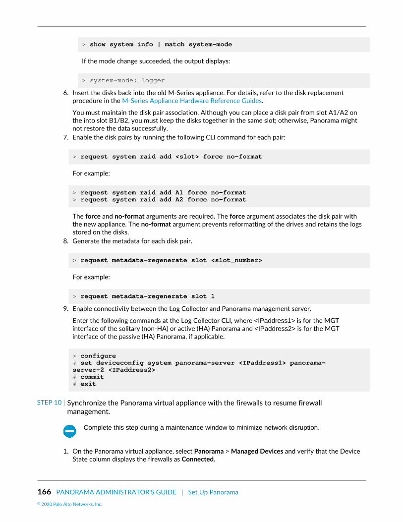
166 PANORAMA ADMINISTRATOR'S GUIDE | Set Up Panorama© 2020 Palo Alto Networks, Inc.
> show system info | match system-mode
If the mode change succeeded, the output displays:
> system-mode: logger
6. Insert the disks back into the old M-Series appliance. For details, refer to the disk replacementprocedure in the M-Series Appliance Hardware Reference Guides.
You must maintain the disk pair association. Although you can place a disk pair from slot A1/A2 onthe into slot B1/B2, you must keep the disks together in the same slot; otherwise, Panorama mightnot restore the data successfully.
7. Enable the disk pairs by running the following CLI command for each pair:
> request system raid add <slot> force no-format
For example:
> request system raid add A1 force no-format > request system raid add A2 force no-format
The force and no-format arguments are required. The force argument associates the disk pair withthe new appliance. The no-format argument prevents reformatting of the drives and retains the logsstored on the disks.
8. Generate the metadata for each disk pair.
> request metadata-regenerate slot <slot_number>
For example:
> request metadata-regenerate slot 1
9. Enable connectivity between the Log Collector and Panorama management server.
Enter the following commands at the Log Collector CLI, where <IPaddress1> is for the MGTinterface of the solitary (non-HA) or active (HA) Panorama and <IPaddress2> is for the MGTinterface of the passive (HA) Panorama, if applicable.
> configure # set deviceconfig system panorama-server <IPaddress1> panorama-server-2 <IPaddress2> # commit # exit
STEP 10 | Synchronize the Panorama virtual appliance with the firewalls to resume firewallmanagement.
Complete this step during a maintenance window to minimize network disruption.
1. On the Panorama virtual appliance, select Panorama > Managed Devices and verify that the DeviceState column displays the firewalls as Connected.

PANORAMA ADMINISTRATOR'S GUIDE | Set Up Panorama 167© 2020 Palo Alto Networks, Inc.
At this point, the Shared Policy (device groups) and Template columns display Out of sync for thefirewalls.
2. Push your changes to device groups and templates:
1. Select Commit > Push to Devices and Edit Selections.2. Select Device Groups, select every device group, and Include Device and Network Templates.3. Select Collector Groups, select every collector group, and click OK.4. Push your changes.
3. In the Panorama > Managed Devices page, verify that the Shared Policy and Template columnsdisplay In sync for the firewalls.
STEP 11 | (HA only) Set up the Panorama HA peer.If the Panorama management servers are in a high availability configuration, perform the steps below onthe HA peer.
1. Perform the initial setup of the Panorama virtual appliance.2. Edit the M-Series appliance Panorama interface configuration to only use the management interface.3. Add the IP address of the new Panorama virtual appliance.4. Power off the M-Series appliance or assign a new IP address to the management (MGT) interface.5. Change the M-Series appliance to Log Collector mode to preserve existing log data.
STEP 12 | (HA only) Modify the Panorama virtual appliance HA peer configuration.1. On an HA peer, Log in to the Panorama Web Interface, select Panorama > High Availability and edit
the Setup.2. In the Peer HA IP Address field, enter the new IP address of the HA peer and click OK.3. Select Commit > Commit to Panorama and Commit your change4. Repeat these steps on the other peer in the HA peer.
STEP 13 | (HA only) Synchronize the Panorama peers.1. Access the Dashboard on one of the HA peers and select Widgets > System > High Availability to
display the HA widget.2. Sync to peer, click Yes, and wait for the Running Config to display Synchronized.3. Access the Dashboard on the remaining HA peer and select Widgets > System > High Availability to
display the HA widget.4. Verify that the Running Config displays Synchronized.
Migrate from an M-100 Appliance to an M-500 ApplianceYou can migrate the Panorama configuration and firewall logs from an M-100 appliance to an M-500appliance in Panorama mode (Panorama management server). You can also migrate the firewall logs from anM-100 appliance to an M-500 appliance in Log Collector mode (Dedicated Log Collector). Because all theLog Collectors in a Collector Group must be the same Panorama model, you must migrate all or none of theM-100 appliances in any Collector Group.
In the following procedure, the Panorama management server is deployed in an active/passive highavailability (HA) configuration, you will migrate both the configuration and logs, and the M-500 applianceswill reuse the IP addresses from the M-100 appliances.
This procedure assumes you are no longer using the M-100 for device management orlog collection. If you plan on using the decommissioned M-100 appliance as a DedicatedLog Collector, a device management license is required on the M-100. Without a devicemanagement license, you are unable to use the M-100 as a Dedicated Log Collector.
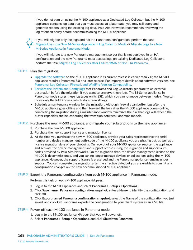
168 PANORAMA ADMINISTRATOR'S GUIDE | Set Up Panorama© 2020 Palo Alto Networks, Inc.
If you do not plan on using the M-100 appliance as a Dedicated Log Collector, but the M-100appliance contains log data that you must access at a later date, you may still query andgenerate reports using the existing log data. Palo Alto Networks recommends reviewing thelog retention policy before decommissioning the M-100 appliance.
If you will migrate only the logs and not the Panorama configuration, perform the taskMigrate Logs to a New M-Series Appliance in Log Collector Mode or Migrate Logs to a NewM-Series Appliance in Panorama Mode.
If you will migrate to a new Panorama management server that is not deployed in an HAconfiguration and the new Panorama must access logs on existing Dedicated Log Collectors,perform the task Migrate Log Collectors after Failure/RMA of Non-HA Panorama.
STEP 1 | Plan the migration.• Upgrade the software on the M-100 appliance if its current release is earlier than 7.0; the M-500
appliance requires Panorama 7.0 or a later release. For important details about software versions, seePanorama, Log Collector, Firewall, and WildFire Version Compatibility.
• Forward the System and Config logs that Panorama and Log Collectors generate to an externaldestination before the migration if you want to preserve those logs. The M-Series appliance inPanorama mode stores these log types on its SSD, which you cannot move between models. You canmove only the RAID drives, which store firewall logs.
• Schedule a maintenance window for the migration. Although firewalls can buffer logs after theM-100 appliance goes offline and then forward the logs after the M-500 appliance comes online,completing the migration during a maintenance window minimizes the risk that logs will exceed thebuffer capacities and be lost during the transition between Panorama models.
STEP 2 | Purchase the new M-500 appliance, and migrate your subscriptions to the new appliance.1. Purchase the new M-500 appliance.2. Purchase the new support license and migration license.3. At the time you purchase the new M-500 appliance, provide your sales representative the serial
number and device management auth-code of the M-100 appliance you are phasing out, as well as alicense migration date of your choosing. On receipt of your M-500 appliance, register the applianceand activate the device management and support licenses using the migration and support auth-codes provided by Palo Alto Networks. On the migration date, the device management license on theM-100 is decommissioned, and you can no longer manage devices or collect logs using the M-100appliance. However, the support license is preserved and the Panorama appliance remains undersupport. You can complete the migration after the effective date, but you are unable to commit anyconfiguration changes on the now decommissioned M-100 appliance.
STEP 3 | Export the Panorama configuration from each M-100 appliance in Panorama mode.Perform this task on each M-100 appliance HA peer:
1. Log in to the M-100 appliance and select Panorama > Setup > Operations.2. Click Save named Panorama configuration snapshot, enter a Name to identify the configuration, and
click OK.3. Click Export named Panorama configuration snapshot, select the Name of the configuration you just
saved, and click OK. Panorama exports the configuration to your client system as an XML file.
STEP 4 | Power off each M-100 appliance in Panorama mode.1. Log in to the M-100 appliance HA peer that you will power off.2. Select Panorama > Setup > Operations, and click Shutdown Panorama.

PANORAMA ADMINISTRATOR'S GUIDE | Set Up Panorama 169© 2020 Palo Alto Networks, Inc.
STEP 5 | Perform the initial setup of each M-500 appliance.1. Rack mount the M-500 appliances. Refer to the M-500 Appliance Hardware Reference Guide for
instructions.2. Perform Initial Configuration of the M-Series Appliance to define the network connections required
to activate licenses and install updates.3. Register Panorama.4. Activate a Panorama Support License.5. Activate a firewall management license. Use the auth-code associated with the migration license.6. Install Content and Software Updates for Panorama. Install the same versions as those on the M-100
appliance.7. (Dedicated Log Collector only) Set Up the M-Series Appliance as a Log Collector.
STEP 6 | Load the Panorama configuration snapshot that you exported from each M-100 appliance intoeach M-500 appliance in Panorama mode (both HA peers).Perform this task on each M-500 appliance HA peer:
1. Log in to the M-500 appliance and select Panorama > Setup > Operations.2. Click Import named Panorama configuration snapshot, Browse to the configuration file you exported
from the M-100 appliance that has the same HA priority (primary or secondary) as the M-500appliance will have, and click OK.
3. Click Load named Panorama configuration snapshot, select the Name of the configuration you justimported, select a Decryption Key (the master key for Panorama), and click OK. Panorama overwritesits current candidate configuration with the loaded configuration. Panorama displays any errors thatoccur when loading the configuration file. If errors occurred, save them to a local file. Resolve eacherror to ensure the migrated configuration is valid.
4. Select Commit > Commit to Panorama and Validate Commit. Resolve any errors before proceeding.5. Commit your changes to the Panorama configuration.
STEP 7 | Synchronize the configuration between the M-500 appliance HA peers in Panorama mode.1. On the active M-500 appliance, select the Dashboard tab and, in the High Availability widget, click
Sync to peer.2. In the High Availability widget, verify that the Local (primary M-500 appliance) is active, the Peer is
passive, and the Running Config is synchronized.
STEP 8 | Move the RAID drives from each M-100 appliance to its replacement M-500 appliance tomigrate the logs collected from firewalls.In the following tasks, skip any steps that you already completed on the M-500 appliance.
• Migrate Logs to a New M-Series Appliance in Panorama Mode. Migrate logs from the M-100appliance only if it uses a default managed collector for log collection.
• Migrate Logs to a New M-Series Appliance in Log Collector Mode.
STEP 9 | Synchronize the active M-500 appliance in Panorama mode with the firewalls to resumefirewall management.
Complete this step during a maintenance window to minimize network disruption.
1. In the active M-500 appliance, select Panorama > Managed Devices, and verify that the Device Statecolumn displays Connected for the firewalls.
At this point, the Shared Policy (device groups) and Template columns display Out of sync for thefirewalls.

170 PANORAMA ADMINISTRATOR'S GUIDE | Set Up Panorama© 2020 Palo Alto Networks, Inc.
2. Push your changes to device groups and templates:
1. Select Commit > Push to Devices and Edit Selections.2. Select Device Groups, select every device group, Include Device and Network Templates, and
click OK.3. Push your changes.
3. In the Panorama > Managed Devices page, verify that the Shared Policy and Template columnsdisplay In sync for the firewalls.

PANORAMA ADMINISTRATOR'S GUIDE | Set Up Panorama 171© 2020 Palo Alto Networks, Inc.
Access and Navigate Panorama ManagementInterfaces
Panorama provides three management interfaces:
• Web interface—The Panorama web interface has a look and feel similar to the firewall web interface.If you are familiar with the latter, you can easily navigate, complete administrative tasks, and generatereports from the Panorama web interface. This graphical interface enables you to access Panorama usingHTTPS and it is the best way to perform administrative tasks. See Log in to the Panorama Web Interfaceand Navigate the Panorama Web Interface. If you need to enable HTTP access to Panorama, edit theManagement Interface Settings on the Panorama > Setup > Management tab.
• Command line interface (CLI)—The CLI is a no-frills interface that allows you to type commands inrapid succession to complete a series of tasks. The CLI supports two command modes—operational andconfiguration—and each has its own hierarchy of commands and statements. When you become familiarwith the nesting structure and the syntax for the commands, the CLI enables quick response times andadministrative efficiency. See Log in to the Panorama CLI.
• XML API—The XML-based API is provided as a web service that is implemented using HTTP/HTTPSrequests and responses. It enables you to streamline your operations and integrate with existing,internally developed applications and repositories. For details on using the Panorama API, refer to thePAN-OS and Panorama XML API Usage Guide.
Log in to the Panorama Web InterfaceSTEP 1 | Launch an internet browser and enter the Panorama IP address using a secure connection
(https://<IP address>).
STEP 2 | Log in to Panorama according to the type of authentication used for your account. If logging into Panorama for the first time, use the default value admin for your username and password.• SAML—Click Use Single Sign-On (SSO). If Panorama performs authorization (role assignment) for
administrators, enter your Username and Continue. If the SAML identity provider (IdP) performsauthorization, Continue without entering a Username. In both cases, Panorama redirects you to theIdP, which prompts you to enter a username and password. After you authenticate to the IdP, thePanorama web interface displays.
• Any other type of authentication—Enter your user Name and Password. Read the login banner andselect I Accept and Acknowledge the Statement Below if the login page has the banner and checkbox. Then click Login.
STEP 3 | Read and Close any messages of the day.
Navigate the Panorama Web InterfaceUse the Panorama web interface to configure Panorama, manage and monitor firewalls, Log Collectors,and WildFire appliances and appliance clusters, and access the web interface of each firewall through theContext drop-down. Refer to the Panorama online help for details on the options and fields in each webinterface tab. The following is an overview of the tabs:

172 PANORAMA ADMINISTRATOR'S GUIDE | Set Up Panorama© 2020 Palo Alto Networks, Inc.
Tab Description
Dashboard View general information about the Panorama model and networkaccess settings. This tab includes widgets that display information aboutapplications, logs, system resources, and system settings.
ACC View the overall risk and threat level on the network, based oninformation that Panorama gathered from the managed firewalls.
Monitor View and manage logs and reports.
Device Groups > Policies Create centralized policy rules and apply them to multiple firewalls/device groups.
You must Add a Device Group for this tab to display.
Device Groups > Objects Define policy objects that policy rules can reference and that managedfirewalls/device groups can share.
You must Add a Device Group for this tab to display.
Templates > Network Configure network setting, such as network profiles, and apply them tomultiple firewalls.
You must Add a Template for this tab to display.
Templates > Device Configure device settings, such as server profiles and admin roles, andapply them to multiple firewalls.
You must Add a Template for this tab to display.
Panorama Configure Panorama, manage licenses, set up high availability, accesssoftware updates and security alerts, manage administrative access, andmanage the deployed firewalls, Log Collectors, and WildFire appliancesand appliance clusters.
Log in to the Panorama CLIYou can log in to the Panorama CLI using a serial port connection or remotely using a Secure Shell (SSH)client.
• Use SSH to log in to the Panorama CLI.The same instructions apply to an M-Series appliance in Log Collector mode.
Optionally, you can Configure an Administrator with SSH Key-Based Authentication forthe CLI.
1. Ensure the following prerequisites are met:
• You have a computer with network access to Panorama.• You know the Panorama IP address.• The Management interface supports SSH, which is the default setting. If an administrator disabled
SSH and you want to re-enable it: select Panorama > Setup > Interfaces, click Management,

PANORAMA ADMINISTRATOR'S GUIDE | Set Up Panorama 173© 2020 Palo Alto Networks, Inc.
select SSH, click OK, select Commit > Commit to Panorama, and Commit your changes to thePanorama configuration.
2. To access the CLI using SSH:
1. Enter the Panorama IP address in the SSH client and use port 22.2. Enter your administrative access credentials when prompted. After you log in, the message of the
day displays, followed by the CLI prompt in Operational mode. For example:
admin@ABC_Sydney>
• Use a serial port connection to log in to the Panorama CLI.1. Make sure that you have the following:
• A null-modem serial cable that connects Panorama to a computer with a DB-9 serial port• A terminal emulation program running on the computer
2. Use the following settings in the terminal emulation software to connect: 9600 baud; 8 data bits; 1stop bit; No parity; No hardware flow control.
3. Enter your administrative access credentials when prompted. After you log in, the message of the daydisplays, followed by the CLI prompt in Operational mode.
• Change to Configuration mode.To switch to Configuration mode, enter the following command at the prompt:
admin@ABC_Sydney> configure
The prompt changes to admin@ABC_Sydney#.

174 PANORAMA ADMINISTRATOR'S GUIDE | Set Up Panorama© 2020 Palo Alto Networks, Inc.
Set Up Administrative Access to PanoramaPanorama implements Role-Based Access Control (RBAC) to enable you to specify the privileges andresponsibilities of administrators. The following topics describe how to create administrator roles, accessdomains, and accounts for accessing the Panorama web interface and command line interface (CLI):
• Configure an Admin Role Profile• Configure an Access Domain• Configure Administrative Accounts and Authentication
Configure an Admin Role ProfileAdmin Role profiles are custom Administrative Roles that enable you to define granular administrativeaccess privileges to ensure protection for sensitive company information and privacy for end users.As a best practice, create Admin Role profiles that allow administrators to access only the areas of themanagement interfaces required to perform their jobs.
STEP 1 | Select Panorama > Admin Roles and click Add.
STEP 2 | Enter a Name for the profile and select the Role type: Panorama or Device Group andTemplate.
STEP 3 | Configure access privileges to each functional area of Panorama (Web UI) and firewalls(Context Switch UI) by toggling the icons to the desired setting: Enable (read-write), Read Only,or Disable.
If administrators with custom roles will commit device group or template changes tomanaged firewalls, you must give those roles read-write access to Panorama > DeviceGroups and Panorama > Templates. If you upgrade from an earlier Panorama version,the upgrade process provides read-only access to those nodes.
You cannot manage access to the firewall CLI or XML API through context-switching privileges inPanorama roles.
STEP 4 | If the Role type is Panorama, configure access to the XML API by toggling the Enabled/Disabled icon for each functional area.
STEP 5 | If the Role type is Panorama, select an access level for the Command Line interface: None(default), superuser, superreader, or panorama-admin.
STEP 6 | Click OK to save the profile.
Configure an Access DomainUse Access Domains to define access for Device Group and Template administrators for specific devicegroups and templates, and also to control the ability of those administrators to switch context to the webinterface of managed firewalls. Panorama supports up to 4,000 access domains.
STEP 1 | Select Panorama > Access Domain and click Add.
STEP 2 | Enter a Name to identify the access domain.

PANORAMA ADMINISTRATOR'S GUIDE | Set Up Panorama 175© 2020 Palo Alto Networks, Inc.
STEP 3 | Select an access privilege for Shared Objects:• write—Administrators can perform all operations on Shared objects. This is the default value.• read—Administrators can display and clone but cannot perform other operations on Shared objects.
When adding non-Shared objects or cloning Shared objects, the destination must be a device groupwithin the access domain, not the Shared location.
• shared-only—Administrators can add objects only to the Shared location. Administrators can display,edit, and delete Shared objects but cannot move or clone them.
A consequence of this option is that administrators can’t perform any operations on non-Shared objects other than to display them. An example of why you might select thisoption is for an organization that requires all objects to be in a single, global repository.
STEP 4 | Toggle the icons in the Device Groups tab to enable read-write or read-only access for devicegroups in the access domain.
If you set the Shared Objects access to shared-only, Panorama applies read-only accessto the objects in any device groups for which you specify read-write access.
STEP 5 | Select the Templates tab and Add each template you want to assign to the access domain.
STEP 6 | Select the Device Context tab, select firewalls to assign to the access domain, and click OK.Administrators can access the web interface of these firewalls by using the Context drop-downin Panorama.
Configure Administrative Accounts and AuthenticationIf you have already configured an authentication profile or you don’t require one to authenticateadministrators, you are ready to Configure a Panorama Administrator Account. Otherwise, perform one ofthe other procedures listed below to configure administrative accounts for specific types of authentication.
• Configure a Panorama Administrator Account• Configure Local or External Authentication for Panorama Administrators• Configure a Panorama Administrator with Certificate-Based Authentication for the Web Interface• Configure an Administrator with SSH Key-Based Authentication for the CLI• Configure RADIUS Authentication for Panorama Administrators• Configure TACACS+ Authentication for Panorama Administrators• Configure SAML Authentication for Panorama Administrators
Configure a Panorama Administrator AccountAdministrative accounts specify Administrative Roles and authentication for Panorama administrators.The service that you use to assign roles and perform authentication determines whether you add theaccounts on Panorama, on an external server, or both (see Administrative Authentication). For an externalauthentication service, you must configure an authentication profile before adding an administrativeaccount (see Configure Administrative Accounts and Authentication). If you already configured theauthentication profile or you will use the authentication mechanism that is local to Panorama, perform thefollowing steps to add an administrative account on Panorama.
You can’t add an administrator account to a Dedicated Log Collector (M-Series appliance inLog Collector mode). Only the predefined administrator account with the default username(admin) is available on Dedicated Log Collectors.

176 PANORAMA ADMINISTRATOR'S GUIDE | Set Up Panorama© 2020 Palo Alto Networks, Inc.
STEP 1 | Select Panorama > Administrators and Add an account.
STEP 2 | Enter a user Name for the administrator.
STEP 3 | Select an Authentication Profile or sequence if you configured either for the administrator.This is required if Panorama will use Kerberos SSO or an external service for authentication.
If Panorama will use local authentication, set the Authentication Profile to None and enter a Passwordand then Confirm Password.
STEP 4 | Select the Administrator Type:• Dynamic—Select a predefined administrator role.• Custom Panorama Admin—Select the Admin Role Profile you created for this administrator (see
Configure an Admin Role Profile).• Device Group and Template Admin—Map access domains to administrative roles as described in the
next step.
STEP 5 | (Device Group and Template Admin only) In the Access Domain to Administrator Role section,click Add, select an Access Domain from the drop-down (see Configure an Access Domain),click the adjacent Admin Role cell, and select an Admin Role profile.
STEP 6 | Click OK to save your changes.
STEP 7 | Select Commit > Commit to Panorama and Commit your changes.
Configure Local or External Authentication for Panorama AdministratorsYou can use an external authentication service or the service that is local to Panorama to authenticateadministrators who access Panorama. These authentication methods prompt administrators to respond toone or more authentication challenges, such as a login page for entering a username and password.
If you use an external service to manage both authentication and authorization (role andaccess domain assignments), see:
• Configure RADIUS Authentication for Panorama Administrators• Configure TACACS+ Authentication for Panorama Administrators• Configure SAML Authentication for Panorama Administrators
To authenticate administrators without a challenge-response mechanism, you can Configurea Panorama Administrator with Certificate-Based Authentication for the Web Interface andConfigure an Administrator with SSH Key-Based Authentication for the CLI.
STEP 1 | (External authentication only) Enable Panorama to connect to an external server forauthenticating administrators.1. Select Panorama > Server Profiles, select the service type (RADIUS, TACACS+, SAML, LDAP, or
Kerberos), and configure a server profile:
• Configure RADIUS Authentication for Panorama Administrators.
You can use a RADIUS server to support RADIUS authentication services or multi-factor authentication(MFA) services.

PANORAMA ADMINISTRATOR'S GUIDE | Set Up Panorama 177© 2020 Palo Alto Networks, Inc.
• Configure TACACS+ Authentication for Panorama Administrators.• Add a SAML IdP server profile. You cannot combine Kerberos single sign-on (SSO) with SAML
SSO; you can use only one type of SSO service.• Add a Kerberos server profile.• Add a LDAP Server Profile.
STEP 2 | (Optional) Define password complexity and expiration settings if Panorama uses localauthentication.These settings help protect Panorama against unauthorized access by making it harder for attackers toguess passwords.
1. Define global password complexity and expiration settings for all local administrators.
1. Select Panorama > Setup > Management and edit the Minimum Password Complexity settings.2. Select Enabled.3. Define the password settings and click OK.
2. Define a Password Profile.
You assign the profile to administrator accounts for which you want to override the global passwordexpiration settings.
1. Select Panorama > Password Profiles and Add a profile.2. Enter a Name to identify the profile.3. Define the password expiration settings and click OK.
STEP 3 | (Kerberos SSO only) Create a Kerberos keytab.A keytab is a file that contains Kerberos account information for Panorama. To support Kerberos SSO,your network must have a Kerberos infrastructure.
STEP 4 | Configure an authentication profile.
If your administrative accounts are stored across multiple types of servers, you cancreate an authentication profile for each type and add all the profiles to an authenticationsequence.
In the authentication profile, specify the Type of authentication service and related settings:
• External service—Select the Type of external service and select the Server Profile you created for it.• Local authentication—Set the Type to None.• Kerberos SSO—Specify the Kerberos Realm and Import the Kerberos Keytab you created.
STEP 5 | (Device group and template administrators only) Configure an Access Domain.Configure one or more access domains.
STEP 6 | (Custom roles only) Configure an Admin Role Profile.Configure one or more Admin Role profiles.
For custom Panorama administrators, the profile defines access privileges for the account. For devicegroup and template administrators, the profile defines access privileges for one or more access domainsassociated with the account.
STEP 7 | Configure an administrator.1. Configure a Panorama Administrator Account.

178 PANORAMA ADMINISTRATOR'S GUIDE | Set Up Panorama© 2020 Palo Alto Networks, Inc.
• Assign the Authentication Profile or sequence that you configured.• (Device Group and Template Admin only) Map the access domains to Admin Role profiles.• (Local authentication only) Select a Password Profile if you configured one.
2. Select Commit > Commit to Panorama and Commit your changes.3. (Optional) Test authentication server connectivity to verify that Panorama can use the authentication
profile to authenticate administrators.
Configure a Panorama Administrator with Certificate-Based Authenticationfor the Web Interface
As a more secure alternative to password-based authentication to the Panorama web interface, youcan configure certificate-based authentication for administrator accounts that are local to Panorama.Certificate-based authentication involves the exchange and verification of a digital signature instead of apassword.
Configuring certificate-based authentication for any administrator disables the username/password logins for all administrators on Panorama and all administrators thereafter requirethe certificate to log in.
STEP 1 | Generate a certificate authority (CA) certificate on Panorama.You will use this CA certificate to sign the client certificate of each administrator.
Create a self-signed root CA certificate.
Alternatively, you can import a certificate from your enterprise CA.
STEP 2 | Configure a certificate profile for securing access to the web interface.1. Select Panorama > Certificate Management > Certificate Profile and click Add.2. Enter a Name for the certificate profile and set the Username Field to Subject.3. Select Add in the CA Certificates section and select the CA Certificate you just created.4. Click OK to save the profile.
STEP 3 | Configure Panorama to use the certificate profile for authenticating administrators.1. Select the Panorama > Setup > Management and edit the Authentication Settings.2. Select the Certificate Profile you just created and click OK.
STEP 4 | Configure the administrator accounts to use client certificate authentication.Configure a Panorama Administrator Account for each administrator who will access the Panorama webinterface. Select the Use only client certificate authentication (Web) check box.
If you have already deployed client certificates that your enterprise CA generated, skip to Step 8.Otherwise, continue with Step 5.
STEP 5 | Generate a client certificate for each administrator.Generate a certificate on Panorama. In the Signed By drop-down, select the CA certificate you created.
STEP 6 | Export the client certificates.1. Export the certificates.2. Select Commit > Commit to Panorama and Commit your changes.

PANORAMA ADMINISTRATOR'S GUIDE | Set Up Panorama 179© 2020 Palo Alto Networks, Inc.
Panorama restarts and terminates your login session. Thereafter, administrators can access the webinterface only from client systems that have the client certificate you generated.
STEP 7 | Import the client certificate into the client system of each administrator who will access theweb interface.Refer to your web browser documentation as needed to complete this step.
STEP 8 | Verify that administrators can access the web interface.1. Open the Panorama IP address in a browser on the computer that has the client certificate.2. When prompted, select the certificate you imported and click OK. The browser displays a certificate
warning.3. Add the certificate to the browser exception list.4. Click Login. The web interface should appear without prompting you for a username or password.
Configure an Administrator with SSH Key-Based Authentication for the CLIFor administrators who use Secure Shell (SSH) to access the Panorama CLI, SSH keys provide a more secureauthentication method than passwords. SSH keys almost eliminate the risk of brute-force attacks, providethe option for two-factor authentication (private key and passphrase), and don’t send passwords over thenetwork. SSH keys also enable automated scripts to access the CLI.
STEP 1 | Use an SSH key generation tool to create an asymmetric key pair on the client system of theadministrator.The supported key formats are IETF SECSH and Open SSH. The supported algorithms are DSA (1024bits) and RSA (768-4096 bits).
For the commands to generate the key pair, refer to your SSH client documentation.
The public key and private key are separate files. Save both to a location that Panorama can access. Foradded security, enter a passphrase to encrypt the private key. Panorama prompts the administrator forthis passphrase during login.
STEP 2 | Configure the administrator account to use public key authentication.1. Configure a Panorama Administrator Account.
• Configure one of two authentication methods to use as a fallback if SSH key authentication fails:
External authentication service—Select an Authentication Profile.
Local authentication—Set the Authentication Profile to None and enter a Password and ConfirmPassword.
• Select the Use Public Key Authentication (SSH) check box, click Import Key, Browse to the publickey you just generated, and click OK.
2. Click OK to save the administrative account.3. Select Commit > Commit to Panorama and Commit your changes.
STEP 3 | Configure the SSH client to use the private key to authenticate to Panorama.Perform this task on the client system of the administrator. Refer to your SSH client documentation asneeded to complete this step.
STEP 4 | Verify that the administrator can access the Panorama CLI using SSH key authentication.1. Use a browser on the client system of the administrator to go to the Panorama IP address.

180 PANORAMA ADMINISTRATOR'S GUIDE | Set Up Panorama© 2020 Palo Alto Networks, Inc.
2. Log in to the Panorama CLI as the administrator. After entering a username, you will see the followingoutput (the key value is an example):
Authenticating with public key “dsa-key-20130415”
3. If prompted, enter the passphrase you defined when creating the keys.
Configure RADIUS Authentication for Panorama AdministratorsYou can use a RADIUS server to authenticate administrative access to the Panorama web interface. You canalso define Vendor-Specific Attributes (VSAs) on the RADIUS server to manage administrator authorization.Using VSAs enables you to quickly change the roles, access domains, and user groups of administratorsthrough your directory service, which is often easier than reconfiguring settings on Panorama.
You can use a RADIUS server to authenticate administrative access to the Panorama webinterface. You can also define Vendor-Specific Attributes (VSAs) on the RADIUS server tomanage administrator authorization. Using VSAs enables you to quickly change the roles,access domains, and user groups of administrators through your directory service, which isoften easier than reconfiguring settings on Panorama.
You can Import the Palo Alto Networks RADIUS dictionary into RADIUS server to define theauthentication attributes needed for communication between Panorama and the RADIUSserver.
You can also use a RADIUS server to implement multi-factor authentication (MFA) foradministrators.
STEP 1 | Add a RADIUS server profile.The profile defines how Panorama connects to the RADIUS server.
1. Select Panorama > Server Profiles > RADIUS and Add a profile.2. Enter a Profile Name to identify the server profile.3. Enter a Timeout interval in seconds after which an authentication request times out (default is 3;
range is 1–20).
If you use the server profile to integrate Panorama with an MFA service, enter aninterval that gives administrators enough time to respond to the authenticationchallenge. For example, if the MFA service prompts for a one-time password (OTP),administrators need time to see the OTP on their endpoint device and then enter theOTP in the MFA login page.
4. Select the Authentication Protocol (default is CHAP) that Panorama uses to authenticate to theRADIUS server.
Select CHAP if the RADIUS server supports that protocol; it is more secure than PAP.
5. Add each RADIUS server and enter the following:
• Name to identify the server• RADIUS Server IP address or FQDN• Secret/Confirm Secret (a key to encrypt usernames and passwords)• Server Port for authentication requests (default is 1812)
6. Click OK to save the server profile.
STEP 2 | Assign the RADIUS server profile to an authentication profile.

PANORAMA ADMINISTRATOR'S GUIDE | Set Up Panorama 181© 2020 Palo Alto Networks, Inc.
The authentication profile defines authentication settings that are common to a set of administrators.
1. Select Panorama > Authentication Profile and Add a profile.2. Enter a Name to identify the authentication profile.3. Set the Type to RADIUS.4. Select the Server Profile you configured.5. Select Retrieve user group from RADIUS to collect user group information from VSAs defined on the
RADIUS server.
Panorama matches the group information against the groups you specify in the Allow List of theauthentication profile.
6. Select Advanced and, in the Allow List, Add the administrators that are allowed to authenticate withthis authentication profile.
7. Click OK to save the authentication profile.
STEP 3 | Configure Panorama to use the authentication profile for all administrators.1. Select Panorama > Setup > Management and edit the Authentication Settings.2. Select the Authentication Profile you configured and click OK.
STEP 4 | Configure the roles and access domains that define authorization settings for administrators.1. Configure an Admin Role Profile if the administrator uses a custom role instead of a predefined
(dynamic) role.2. Configure an Access Domain if the administrator uses a Device Group and Template role.
STEP 5 | Commit your changes.Select Commit > Commit to Panorama and Commit your changes.
STEP 6 | Configure the RADIUS server.Refer to your RADIUS server documentation for the specific instructions to perform these steps:
1. Add the Panorama IP address or hostname as the RADIUS client.2. Add the administrator accounts.
If the RADIUS server profile specifies CHAP as the Authentication Protocol, you mustdefine accounts with reversibly encrypted passwords. Otherwise, CHAP authenticationwill fail.
3. Define the vendor code for Panorama (25461) and define the RADIUS VSAs for the role, accessdomain, and user group of each administrator.
When you predefine dynamic administrator roles for users, use lower-case to specify the role (forexample, enter superuser, not SuperUser).
STEP 7 | Verify that the RADIUS server performs authentication and authorization for administrators.1. Log in the Panorama web interface using an administrator account that you added to the RADIUS
server.2. Verify that you can access only the web interface pages that are allowed for the role you associated
with the administrator.3. In the Monitor, Policies, and Objects tabs, verify that you can access only the device groups that are
allowed for the access domain you associated with the administrator.
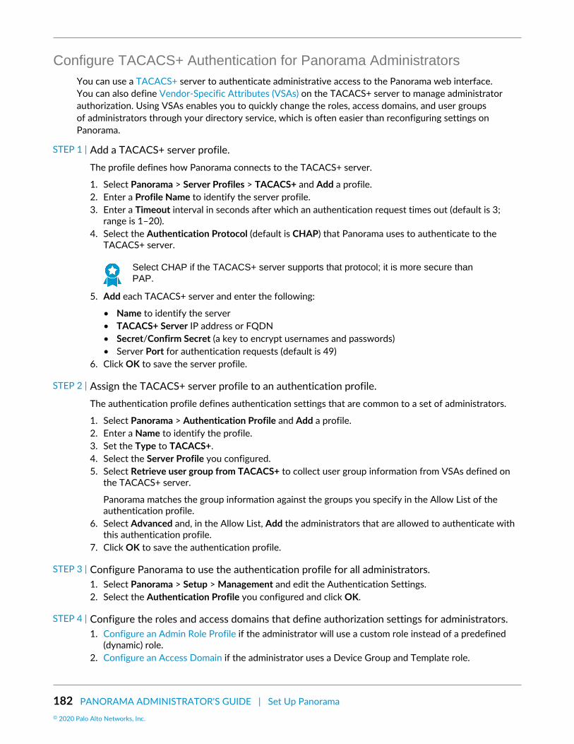
182 PANORAMA ADMINISTRATOR'S GUIDE | Set Up Panorama© 2020 Palo Alto Networks, Inc.
Configure TACACS+ Authentication for Panorama AdministratorsYou can use a TACACS+ server to authenticate administrative access to the Panorama web interface.You can also define Vendor-Specific Attributes (VSAs) on the TACACS+ server to manage administratorauthorization. Using VSAs enables you to quickly change the roles, access domains, and user groupsof administrators through your directory service, which is often easier than reconfiguring settings onPanorama.
STEP 1 | Add a TACACS+ server profile.The profile defines how Panorama connects to the TACACS+ server.
1. Select Panorama > Server Profiles > TACACS+ and Add a profile.2. Enter a Profile Name to identify the server profile.3. Enter a Timeout interval in seconds after which an authentication request times out (default is 3;
range is 1–20).4. Select the Authentication Protocol (default is CHAP) that Panorama uses to authenticate to the
TACACS+ server.
Select CHAP if the TACACS+ server supports that protocol; it is more secure thanPAP.
5. Add each TACACS+ server and enter the following:
• Name to identify the server• TACACS+ Server IP address or FQDN• Secret/Confirm Secret (a key to encrypt usernames and passwords)• Server Port for authentication requests (default is 49)
6. Click OK to save the server profile.
STEP 2 | Assign the TACACS+ server profile to an authentication profile.The authentication profile defines authentication settings that are common to a set of administrators.
1. Select Panorama > Authentication Profile and Add a profile.2. Enter a Name to identify the profile.3. Set the Type to TACACS+.4. Select the Server Profile you configured.5. Select Retrieve user group from TACACS+ to collect user group information from VSAs defined on
the TACACS+ server.
Panorama matches the group information against the groups you specify in the Allow List of theauthentication profile.
6. Select Advanced and, in the Allow List, Add the administrators that are allowed to authenticate withthis authentication profile.
7. Click OK to save the authentication profile.
STEP 3 | Configure Panorama to use the authentication profile for all administrators.1. Select Panorama > Setup > Management and edit the Authentication Settings.2. Select the Authentication Profile you configured and click OK.
STEP 4 | Configure the roles and access domains that define authorization settings for administrators.1. Configure an Admin Role Profile if the administrator will use a custom role instead of a predefined
(dynamic) role.2. Configure an Access Domain if the administrator uses a Device Group and Template role.

PANORAMA ADMINISTRATOR'S GUIDE | Set Up Panorama 183© 2020 Palo Alto Networks, Inc.
STEP 5 | Commit your changes.Select Commit > Commit to Panorama and Commit your changes.
STEP 6 | Configure the TACACS+ server to authenticate and authorize administrators.Refer to your TACACS+ server documentation for the specific instructions to perform these steps:
1. Add the Panorama IP address or hostname as the TACACS+ client.2. Add the administrator accounts.
If you selected CHAP as the Authentication Protocol, you must define accounts withreversibly encrypted passwords. Otherwise, CHAP authentication will fail.
3. Define TACACS+ VSAs for the role, access domain, and user group of each administrator.
When you predefine dynamic administrator roles for users, use lower-case to specifythe role (for example, enter superuser, not SuperUser).
STEP 7 | Verify that the TACACS+ server performs authentication and authorization for administrators.1. Log in the Panorama web interface using an administrator account that you added to the TACACS+
server.2. Verify that you can access only the web interface pages that are allowed for the role you associated
with the administrator.3. In the Monitor, Policies, and Objects tabs, verify that you can access only the virtual systems that are
allowed for the access domain you associated with the administrator.
Configure SAML Authentication for Panorama AdministratorsYou can use Security Assertion Markup Language (SAML) 2.0 for administrative access to the Panoramaweb interface (but not the CLI). You can also use SAML attributes to manage administrator authorization.SAML attributes enable you to quickly change the roles, access domains, and user groups of administratorsthrough your directory service instead of reconfiguring settings on Panorama.
To configure SAML single sign-on (SSO) and single logout (SLO), you must register Panorama and theidentity provider (IdP) with each other to enable communication between them. If the IdP provides ametadata file containing registration information, you can import it onto Panorama to register the IdPand to create an IdP server profile. The server profile defines how to connect to the IdP and specifiesthe certificate that the IdP uses to sign SAML messages. You can also use a certificate for Panorama tosign SAML messages. Using certificates is optional but recommended to secure communications betweenPanorama and the IdP.
STEP 1 | (Recommended) Obtain the certificates that the IdP and Panorama will use to sign SAMLmessages.If the certificates don’t specify key usage attributes, all usages are allowed by default, including signingmessages. In this case, you can obtain certificates by any method.
If the certificates do specify key usage attributes, one of the attributes must be Digital Signature,which is not available on certificates that you generate on Panorama. In this case, you must import thecertificates:
• Certificate Panorama uses to sign SAML messages—Import the certificate from your enterprisecertificate authority (CA) or a third-party CA.
• Certificate the IdP uses to sign SAML messages—Import a metadata file containing the certificatefrom the IdP (see the next step). The IdP certificate is limited to the following algorithms:
• Public key algorithms—RSA (1,024 bits or larger) and ECDSA (all sizes).

184 PANORAMA ADMINISTRATOR'S GUIDE | Set Up Panorama© 2020 Palo Alto Networks, Inc.
• Signature algorithms—SHA1, SHA256, SHA384, and SHA512.
STEP 2 | Add a SAML IdP server profile.The server profile registers the IdP with Panorama and defines how they connect.
In this example, you import a SAML metadata file from the IdP so that Panorama can automaticallycreate a server profile and populate the connection, registration, and IdP certificate information.
If the IdP doesn’t provide a metadata file, select Panorama > Server Profiles > SAMLIdentity Provider, Add the server profile, and manually enter the information (consult yourIdP administrator for the values).
1. Export the SAML metadata file from the IdP to a client system that Panorama can access.
The certificate specified in the file must meet the requirements listed in the preceding step. Refer toyour IdP documentation for instructions on exporting the file.
2. Select Panorama > Server Profiles > SAML Identity Provider and Import the metadata file ontoPanorama.
3. Enter a Profile Name to identify the server profile.4. Browse to the Identity Provider Metadata file.5. (Recommended) Select Validate Identity Provider Certificate (default) to have Panorama validate the
Identity Provider Certificate.
Validation occurs only after you assign the server profile to an authentication profile and Commit.Panorama uses the Certificate Profile in the authentication profile to validate the certificate.
Validating the certificate is a best practice for improved security.
6. Enter the Maximum Clock Skew, which is the allowed difference in seconds between the systemtimes of the IdP and Panorama at the moment when Panorama validates IdP messages (default is 60;range is 1 to 900). If the difference exceeds this value, authentication fails.
7. Click OK to save the server profile.8. Click the server profile Name to display the profile settings. Verify that the imported information is
correct and edit it if necessary.
STEP 3 | Configure an authentication profile.The authentication profile specifies a SAML IdP server profile and defines options for the authenticationprocess, such as SLO.
1. Select Panorama > Authentication Profile and Add a profile.2. Enter a Name to identify the profile.3. Set the Type to SAML.4. Select the IdP Server Profile you configured.5. Select the Certificate for Signing Requests.
Panorama uses this certificate to sign messages it sends to the IdP.6. (Optional) Enable Single Logout (disabled by default).7. Select the Certificate Profile that Panorama will use to validate the Identity Provider Certificate.8. Enter the Username Attribute that IdP messages use to identify users (default username).
When you predefine dynamic administrator roles for users, use lower-case tospecify the role (for example, enter superuser, not SuperUser). If you manageadministrator authorization through the IdP identity store, specify the Admin RoleAttribute and Access Domain Attribute also.

PANORAMA ADMINISTRATOR'S GUIDE | Set Up Panorama 185© 2020 Palo Alto Networks, Inc.
9. Select Advanced and Add the administrators who are allowed to authenticate with thisauthentication profile.
10.Click OK to save the authentication profile.
STEP 4 | Configure Panorama to use the authentication profile for all administrators.1. Select Panorama > Setup > Management, edit the Authentication Settings, and select the
Authentication Profile you configured.2. Select Commit > Commit to Panorama to activate your changes on Panorama and to validate the
Identity Provider Certificate that you assigned to the SAML IdP server profile.
STEP 5 | Create a SAML metadata file to register Panorama on the IdP.1. Select Panorama > Authentication Profile and, in the Authentication column for the authentication
profile you configured, click Metadata.2. Set the Management Choice to Interface (default is selected) and select the management (MGT)
interface.3. Click OK and save the metadata file to your client system.4. Import the metadata file into the IdP server to register Panorama. Refer to your IdP documentation
for instructions.
STEP 6 | Verify that administrators can authenticate using SAML SSO.1. Go to the URL of the Panorama web interface.2. Click Use Single Sign-On.3. Click Continue.
Panorama redirects you to authenticate to the IdP, which displays a login page. For example:
4. Log in using your SSO username and password.
After you successfully authenticate on the IdP, it redirects you back to Panorama, which displays theweb interface.
5. Use your Panorama administrator account to request access to another SSO application.
Successful access indicates SAML SSO authentication succeeded.

186 PANORAMA ADMINISTRATOR'S GUIDE | Set Up Panorama© 2020 Palo Alto Networks, Inc.
Set Up Authentication Using CustomCertificates
By default, Palo Alto Networks devices use predefined certificates for mutual authentication to establishthe SSL connections used for management access and inter-device communication. However, you canconfigure authentication using custom certificates instead. Additionally, you can use custom certificates tosecure the High Availability (HA) connections between Panorama HA peers. Custom certificates allow youto establish a unique chain of trust to ensure mutual authentication between Panorama and the managedfirewalls and log collectors. See Certificate Management for detailed information about the certificates andhow to deploy them on Panorama, Log Collectors, and firewalls.
The following topics describe how to configure and manage custom certificates using Panorama.
• How Are SSL/TLS Connections Mutually Authenticated?• Configure Authentication Using Custom Certificates on Panorama• Configure Authentication Using Custom Certificates on Managed Devices• Add New Client Devices• Change Certificates
How Are SSL/TLS Connections Mutually Authenticated?In a regular SSL connection, only the server needs to identify itself to the client by presenting its certificate.However, in mutual SSL authentication, the client presents its certificate to the server as well. Panorama,the primary Panorama HA peer, Log Collectors, WildFire appliances, and PAN-DB appliances can act asthe server. Firewalls, Log Collectors, WildFire appliances, and the secondary Panorama HA peer can actas the client. The role that a device takes on depends the deployment. For example, in the diagram below,Panorama manages a number of firewalls and a collector group and acts as the server for the firewalls andLog Collectors. The Log Collector acts as the server to the firewalls that send logs to it.
To deploy custom certificates for mutual authentication in your deployment, you need:
• SSL/TLS Service Profile—An SSL/TLS service profile defines the security of the connections byreferencing your custom certificate and establishing the SSL/TLS protocol versions used by the serverdevice to communicate with client devices.
• Server Certificate and Profile—Devices in the server role require a certificate and certificate profile toidentify themselves to the client devices. You can deploy this certificate from your enterprise public keyinfrastructure (PKI), purchase one from a trusted third-party CA, or generate a self-signed certificatelocally. The server certificate must include the IP address or FQDN of the device’s managementinterface in the certificate common name (CN) or Subject Alt Name. The client firewall or Log Collectormatches the CN or Subject Alt Name in the certificate the server presents against the server’s IP addressor FQDN to verify the server’s identity.
Additionally, use the certificate profile to define certificate revocation status (OCSP/CRL) and theactions taken based on the revocation status.
• Client Certificates and Profile—Each managed device requires a client certificate and certificate profile.The client device uses its certificate to identify itself to the server device. You can deploy certificatesfrom your enterprise PKI, using Simple Certificate Enrollment Protocol (SCEP), purchase one from atrusted third-party CA, or generate a self-signed certificate locally.
Custom certificates can be unique to each client device or common across all devices. The unique devicecertificates uses a hash of the serial number of the managed device and CN. The server matches the CNor the subject alt name against the configured serial numbers of the client devices. For client certificatevalidation based on the CN to occur, the username must be set to Subject common-name. The clientcertificate behavior also applies to Panorama HA peer connections.

PANORAMA ADMINISTRATOR'S GUIDE | Set Up Panorama 187© 2020 Palo Alto Networks, Inc.
You can configure the client certificate and certificate profile on each client device or push theconfiguration from Panorama to each device as part of a template.
Figure 11: SSL/TLS Authentication
Configure Authentication Using Custom Certificates on PanoramaComplete the following procedure to configure the server side (Panorama) to use custom certificatesinstead of predefined certificates for mutual authentication with managed devices in your deployment. SeeSet Up Authentication Using Custom Certificates Between HA Peers to configure custom certificates on aPanorama HA pair.
STEP 1 | Deploy the server certificate.You candeploy certificates on Panorama or a server Log Collector by generating a self-signed certificateon Panorama or obtaining a certificate from your enterprise CA or a trusted third-party CA.
STEP 2 | On Panorama, configure a certificate profile This certificate profile defines what certificate touse and what certificate field to look for the IP address or FQDN in.1. Select Panorama > Certificate Management > Certificate Profile.2. Configure a certificate profile.
If you configure an intermediate CA as part of the certificate profile, you must includethe root CA as well.
STEP 3 | Configure an SSL/TLS service profile.1. Select Panorama > Certificate Management > SSL/TLS Service Profile.2. Configure an SSL/TLS profile to define the certificate and protocol that Panorama and its managed
devices use for SSL/TLS services.
STEP 4 | Configure Secure Server Communication on Panorama or a Log Collector in the server role.

188 PANORAMA ADMINISTRATOR'S GUIDE | Set Up Panorama© 2020 Palo Alto Networks, Inc.
1. Select one of the following navigation paths:
• For Panorama: Panorama > Setup > Management and Edit the Secure Communications Settings• For a Log Collector: Panorama > Managed Collectors > Add > Communication
2. Verify that the Allow Custom Certificate Only check box is not selected. This allows you to continuemanaging all devices while migrating to custom certificates.
When the Custom Certificate Only check box is selected, Panorama does notauthenticate and cannot manage devices using predefined certificates.
3. Select the SSL/TLS Service Profile. This SSL/TLS service profile applies to all SSL connectionsbetween Panorama, firewalls, Log Collectors, and Panorama HA peers.
4. Select the Certificate Profile that identifies the certificate to use to establish secure communicationwith clients such as firewalls.
5. (Optional) Configure an authorization list. The authorization list adds an additional layer of securitybeyond certificate authentication. The authorization list checks the client certificate Subject orSubject Alt Name. If the Subject or Subject Alt Name presented with the client certificate does notmatch an identifier on the authorization list, authentication is denied.
You can also authorize client devices based on their serial number.
1. Add an Authorization List.2. Select the Subject or Subject Alt Name configured in the certificate profile as the Identifier type.3. Enter the Common Name if the identifier is Subject or and IP address, hostname or email if the
identifier is Subject Alt Name.4. Click OK.5. Select Check Authorization List to enforce the authorization list.
6. Select Authorize Client Based on Serial Number to have the server authenticate client based on theserial numbers of managed devices. The CN or subject in the client certificate must have the specialkeyword $UDID to enable this type of authentication.
7. In Disconnect Wait Time (min), specify how long Panorama should wait before terminating thecurrent session and reestablishing the connection with its managed devices. This field is blank bydefault and the range is 0 to 44,640 minutes. Leaving this field blank is the same as setting it to 0.
The disconnect wait time does not begin counting down until you commit the newconfiguration.
8. Click OK.9. Commit your changes.
Configure Authentication Using Custom Certificates on ManagedDevices
Complete the following procedure to configure the client side (firewall or Log Collector) to use customcertificates instead of predefined certificates for mutual authentication with managed devices in yourdeployment.
STEP 1 | Upgrade each managed firewall or Log Collector. All managed devices must be running PAN-OS 8.0 or later to enforce custom certificate authentication.Upgrade the firewall to PAN-OS 8.1 or later. After upgrade, each firewall connects to Panorama usingthe default predefined certificates.
STEP 2 | Obtain or generate the device certificate.

PANORAMA ADMINISTRATOR'S GUIDE | Set Up Panorama 189© 2020 Palo Alto Networks, Inc.
You candeploy certificates on Panorama or a server Log Collector by generating a self-signed certificateon Panorama or obtaining a certificate from your enterprise CA or a trusted third-party CA.
Set the common name to $UDID or subject to CN=$UDID (in the SCEP profile) if authorizing clientdevices based on serial number.
• You can generate a self-signed certificate on Panorama or obtain a certificate from your enterpriseCA or a trusted third-party CA.
• If you are using SCEP for the device certificate, configure a SCEP profile. SCEP allows you toautomatically deploy certificates to managed devices. When a new client devices with a SCEP profileattempts to authenticate with Panorama, the certificate is sent by the SCEP server to the device.
STEP 3 | Configure the certificate profile for the client device.You can configure this on each client device individually or you can push this configuration to themanaged device as part of a template.
1. Select one of the following navigation paths:
• For firewalls—Select Device > Certificate Management > Certificate Profile.• For Log Collectors—Select Panorama > Certificate Management > Certificate Profile.
2. Configure the certificate profile.
STEP 4 | Deploy custom certificates on each firewall or Log Collector.1. Select one of the following navigation paths:
• For firewalls: Select Device > Setup > Management and Edit the Panorama Settings• For Log Collectors: Select Panorama > Managed Collectors and Add a new Log Collector or select
an existing one. Select Communication.2. Select the Secure Client Communication check box (firewall only).3. Select the Certificate Type.
• If you are using a local device certificate, select the Certificate and Certificate Profile.• If you are using SCEP to deploy device certificate, select the SCEP Profile and Certificate Profile.
4. (Optional) Enable Check Server Identity. The firewall or Log Collector checks the CN in the servercertificate against Panorama’s IP address or FQDN to verify its identity.
5. Click OK.6. Commit your changes.
After committing your changes, the managed device does not terminate its current session withPanorama until the Disconnect Wait Time is complete.
STEP 5 | After deploying custom certificates on all managed devices, enforce authentication usingcustom certificates.
The WildFire appliance does not currently support custom certificates. If your Panoramais managing a WildFire appliance, do not select Allow Custom Certificates Only.
1. Select Panorama > Setup > Management and Edit the Panorama settings.2. Select Allow Custom Certificate Only.3. Click OK.4. Commit your changes.
After committing this change, all devices managed by Panorama must use custom certificates. If not,authentication between Panorama and the device fails.

190 PANORAMA ADMINISTRATOR'S GUIDE | Set Up Panorama© 2020 Palo Alto Networks, Inc.
Add New Client DevicesWhen adding a new firewall or Log Collector to Panorama, the workflow depends on whether or not thesedevices are configured to use custom certificates only for mutual authentication.
• If the Custom Certificates Only is not selected on Panorama, you can add the device to Panorama andthen deploy the custom certificate by following the process beginning in step Configure AuthenticationUsing Custom Certificates on Managed Devices.
• If the Custom Certificates Only is selected on Panorama, you must deploy the custom certificates onthe firewall before adding it to Panorama. If not, the managed device will not be able to authnticate withPanorama. This can be done manually through the firewall web interface or through bootstrapping aspart of the bootstrap.xml file.
Change CertificatesIf a custom certificate in your deployment has expired or been revoked and needs to be replaced, you cancomplete one of the tasks below.
• Change a Server Certificate• Change a Client Certificate• Change a Root or Intermediate CA Certificate
Change a Server CertificateComplete the following task to replace a server certificate.
STEP 1 | Deploy the new server certificate.You can deploy certificates on Panorama or a server Log Collector by generating a self-signed certificateon Panorama or obtaining a certificate from your enterprise CA or a trusted third-party CA.
STEP 2 | Change the certificate in the SSL/TLS Service Profile.1. Select Panorama > Certificate Management > SSL/TLS Service Profile and select the SSL/TLS
service profile.2. Select the Certificate.3. Click OK.
STEP 3 | Reestablish the connection between the server (Panorama or a Log Collector) and clientdevices.1. Select Panorama > Setup > Management and Edit the Panorama Settings for Panorama or select
Panorama > Managed Collectors > Add > Communication for a Log Collector.2. Set the Disconnect Wait Time.3. Click OK.4. Commit your changes.
Change a Client CertificateComplete the following task to replace a client certificate.
STEP 1 | Obtain or generate the device certificate.You can deploy certificates on Panorama or a server Log Collector by generating a self-signed certificateon Panorama or obtaining a certificate from your enterprise CA or a trusted third-party CA.
Set the common name to $UDID or subject to CN=$UDID (in the SCEP profile) if authorizing clientdevices based on serial number.

PANORAMA ADMINISTRATOR'S GUIDE | Set Up Panorama 191© 2020 Palo Alto Networks, Inc.
• You can generate a self-signed certificate on Panorama or obtain a certificate from your enterpriseCA or a trusted third-party CA.
• If you are using SCEP for the device certificate, configure a SCEP profile. SCEP allows you toautomatically deploy certificates to managed devices. When a new client devices with a SCEP profileattempts to authenticate with Panorama, the certificate is sent by the SCEP server to the device.
STEP 2 | Change the certificate in the certificate profile.1. Select Device > Certificate Management > Certificate Profile and select the certificate profile.2. Under CA Certificates, Add the new certificate to assign to the certificate profile.3. Click OK.4. Commit your changes.
Change a Root or Intermediate CA CertificateComplete the following task to replace a root or intermediate CA certificate.
STEP 1 | Configure the server to accept predefined certificates from clients.1. Select Panorama > Setup > Management and Edit the Panorama Settings.2. Uncheck Custom Certificate Only.3. Select None from the Certificate Profile drop-down.4. Click OK.5. Commit your changes.
STEP 2 | Deploy the new root or intermediate CA certificate.You can deploy certificates on Panorama or a server Log Collector by generating a self-signed certificateon Panorama or obtaining a certificate from your enterprise CA or a trusted third-party CA.
STEP 3 | Update the CA certificate in the server certificate profile.1. Select Panorama > Certificate Management > Certificate Profile and select the certificate profile to
update.2. Delete the old CA certificate.3. Add the new CA Certificate.4. Click OK.
STEP 4 | Generate or import the new client certificate.1. Select Device > Certificate Management > Certificates.2. Create a self-signed root CA certificate or import a certificate from your enterprise CA.
STEP 5 | Update the CA certificate in the client certificate profile.1. Select Device > Setup > Management and click the Edit icon in Panorama Settings for a firewall or
Select Panorama > Managed Collectors > Add > Communication for a Log Collector and select thecertificate profile to update.
2. Delete the old CA certificate.3. Add the new CA Certificate.4. Click OK.
STEP 6 | After updating the CA certificates on all managed devices, enforce custom-certificateauthentication.1. Select Panorama > Setup > Management and Edit the Panorama Settings.2. Select Custom Certificate Only.

192 PANORAMA ADMINISTRATOR'S GUIDE | Set Up Panorama
3. Click OK.4. Commit your changes.
After committing this change, all devices managed by Panorama must use custom certificates. If not,authentication between Panorama and the device fails.

193
Manage FirewallsTo use the Panorama™ management server for managing Palo Alto Networks firewalls, youmust add the firewalls as managed devices and then assign them to device groups and totemplates or template stacks. The following tasks best suit a first-time firewall deployment.Before proceeding, review Plan Your Panorama Deployment to understand the deploymentoptions.
> Add a Firewall as a Managed Device> Set Up Zero Touch Provisioning> Manage Device Groups> Manage Templates and Template Stacks> Manage the Master Key from Panorama> Redistribute User-ID Information to Managed Firewalls> Transition a Firewall to Panorama Management> Device Monitoring on Panorama> Use Case: Configure Firewalls Using Panorama
To view the Objects and Policies tabs on the Panorama web interface, you must first createat least one device group. To view the Network and Device tabs, you must create at least onetemplate. These tabs contain the options by which you configure and manage the firewalls onyour network.

194 PANORAMA ADMINISTRATOR'S GUIDE | Manage Firewalls© 2020 Palo Alto Networks, Inc.

PANORAMA ADMINISTRATOR'S GUIDE | Manage Firewalls 195© 2020 Palo Alto Networks, Inc.
Add a Firewall as a Managed DeviceTo use Panorama for managing your firewalls, you need to enable a connection between the firewall andPanorama. A successful connection requires that you enter the Panorama IP address on each firewallthat Panorama will manage and to also enter the serial number of each firewall on Panorama. When youadd a firewall as a managed device, you can associate the new firewall with a device group, templatestack, collector group, and Log Collector during the initial deployment. Additionally, you have the optionto automatically push the configuration to your newly added firewall when the firewall first connects toPanorama, which ensures that firewalls are immediately configured and ready to secure your network.
You can only bulk import single vsys firewalls to be managed by Panorama.
The firewall uses the Panorama management server IP address to set up an SSL connection to register withPanorama. Panorama and the firewall authenticate each other using 2,048-bit certificates and AES-256encrypted SSL connections for configuration management and log collection. Prepare Panorama and eachfirewall as follows:
STEP 1 | Configure the firewall to communicate with Panorama.Repeat this step for each firewall Panorama will manage.
1. Perform initial configuration on the firewall so that it is accessible and can communicate withPanorama over the network.
2. Configure each data interface you plan to use on the firewall and attach it to a security zone so thatyou can push configuration and policy from Panorama.
3. Add the Panorama IP address to the firewall.
1. Select Device > Setup > Management and edit the Panorama Settings.2. Enter the Panorama IP address in the first field.
Panorama issues a single IP address for device management, log collection,reporting, and dynamic updates. Enter the external, Internet-bound IP address toensure Panorama can successfully access existing and new managed devicesand Log Collectors. If an internal Panorama IP address is configured, you may beunable to manage some devices. For example, if you Install Panorama on AWSand enter the internal IP address, Panorama is unable to manage devices or LogCollectors outside of the AWS security group.
3. (Optional) If you have set up a high availability (HA) pair in Panorama, enter the IP address of thesecondary Panorama in the second field.
4. Click OK.5. Select Commit and Commit your changes.
STEP 2 | Add one or more firewalls to Panorama.• Add one or more firewalls.
1. Add a new managed device (Panorama > Managed Devices > Summary).2. Enter the firewall Serial number. If you are adding multiple firewalls, enter each serial number on
a separate line. If you want to associate the new firewalls with a device group, template stack,collector group, or Log Collector for the initial deployment, continue to the next step. To manuallyassign each firewall, click OK and continue to Step 3.
3. Select the Associate Devices check box and click OK.

196 PANORAMA ADMINISTRATOR'S GUIDE | Manage Firewalls© 2020 Palo Alto Networks, Inc.
4. Assign the Device Group, Template Stack, Collector Group, and Log Collector as needed from thedrop-down for each column.
5. Enable Auto Push on 1st connect check box to automatically push the device group and templatestack configuration to the new devices when they successfully connect to Panorama.
The Auto Push on 1st Connect option is supported only on firewalls runningPAN-OS 8.1 or later releases. The commit all job executes from Panorama tomanaged devices running PAN-OS 8.1 and later releases.
6. Click OK to add the devices.
• Bulk import multiple firewalls using a comma-separated values (CSV) file.
1. Add a new managed device (Panorama > Managed Devices > Summary).2. Click Import.

PANORAMA ADMINISTRATOR'S GUIDE | Manage Firewalls 197© 2020 Palo Alto Networks, Inc.
3. Download Sample CSV and edit the downloaded CSV file with the firewalls you are adding. Youcan choose to assign the firewalls to a device group, template stack, Collector Group, and LogCollector from the CSV or enter only the firewall serial numbers and assign them from the webinterface. Save the CSV after you finish editing it.
4. Browse and select the CSV file you edited in the previous step.5. If not already assigned in the CSV, assign the firewalls a Device Group, Template Stack, Collector
Group, and Log Collector as needed from the drop-down foreach column.6. If not already enabled in the CSV, enable Auto Push on 1st connect check box to automatically
push the device group and template stack configuration to the new devices when theysuccessfully connect to Panorama.
7. Click OK to add the devices.
STEP 3 | (Optional) Add a Tag. Tags make it easier for you to find a firewall from a large list; they helpyou to dynamically filter and refine the list of firewalls in your display. For example, if you add atag called branch office, you can filter for all branch office firewalls across your network.1. Select each firewall and click Tag.2. Click Add, enter a string of up to 31 characters (no empty spaces), and click OK.
STEP 4 | If your deployment is using custom certificates for authentication between Panorama andmanaged devices, deploy the custom client device certificate. For more information, see Set UpAuthentication Using Custom Certificates and Add New Client Devices.

198 PANORAMA ADMINISTRATOR'S GUIDE | Manage Firewalls© 2020 Palo Alto Networks, Inc.
STEP 5 | Select Commit > Commit to Panorama and Commit your changes.
STEP 6 | Verify that the firewall is connected to Panorama.1. Click Panorama > Managed Devices > Summary.2. Verify that the Device State for the new device shows as Connected.

PANORAMA ADMINISTRATOR'S GUIDE | Manage Firewalls 199© 2020 Palo Alto Networks, Inc.
Set Up Zero Touch ProvisioningSet up Zero Touch Provisioning (ZTP) to simplify and streamline initial firewall deployments by automatingthe new managed firewall on-boarding without the need for network administrators to manually provisionthe firewall.
• ZTP Overview• Install the ZTP Plugin• Configure the ZTP Installer Administrator Account• Add ZTP Firewalls to Panorama• Use the CLI for ZTP Tasks• Uninstall the ZTP Plugin
ZTP OverviewLearn more about Zero Touch Provisioning (ZTP) and its configuration elements.
• About ZTP• ZTP Configuration Elements
About ZTPZero Touch Provisioning (ZTP) is designed to simplify and automate the on-boarding of new firewalls tothe Panorama™ management server. ZTP streamlines the initial firewall deployment process by allowingnetwork administrators to ship managed firewalls directly to their branches and automatically add thefirewall to the Panorama™ management server after the ZTP firewall successfully connects to the Palo AltoNetworks ZTP service. This allows businesses to save on time and resources when deploying new firewallsat branch locations by removing the need for IT administrators to manually provision the new managedfirewall. After successful on-boarding, Panorama provides the means to configure and manage your ZTPconfiguration and firewalls.
Review and subscribe to ZTP Service Status events to be notified about scheduledmaintenance windows, outages, and workarounds.
ZTP is supported on the following ZTP firewalls running PAN-OS 9.1.3 and later releases:
• PA-220-ZTP and PA-220R-ZTP• PA-820-ZTP and PA-850-ZTP• PA-3220-ZTP, PA-3250-ZTP, and PA-3260-ZTP
ZTP Configuration ElementsThe elements of a ZTP configuration work together to allow you to quickly on-board newly deployed ZTPmanaged firewalls by adding automatically adding them to the Panorama management server using the ZTPservice.
• ZTP Service—Downloaded as a plugin on Panorama, the ZTP service allows Panorama to claim a ZTPfirewall for simplified on-boarding.
• Customer Support Portal (CSP)—The Palo Alto Networks Customer Support Portal is used to registeryour Panorama to connect to the CSP to automatically register newly added ZTP firewalls.
• One-time Password (OTP)—A one-time password provided by Palo Alto Networks used to retrieve andinstall the ZTP firewall device certificate from the CSP.

200 PANORAMA ADMINISTRATOR'S GUIDE | Manage Firewalls© 2020 Palo Alto Networks, Inc.
• Installer—An administrator user created using the installeradmin admin role for ZTP firewall on-boarding. This admin user has limited access to the Panorama web interface, only allowing access toenter the ZTP firewall serial number and claim key to register firewalls on the CSP and Panorama. Theinstaller admin can be created on Panorama or created using remote authentication such as RADIUS,SAML, or TACACS+.
• Claim Key—Eight digit numeric key physically attached to the ZTP firewall used to register the ZTPfirewall with the CSP.
• To-SW-Version—Designate the PAN-OS software version of the ZTP firewall (Panorama > ManagedDevices > Summary). Select the target PAN-OS release, and if the firewall is running an earlier releasethan the indicated version, the firewall begins an upgrade loop until the target release is successfullyinstalled.
Panorama can only manage firewalls running a PAN-OS release equal to or less than thatinstalled on the Panorama.
To leverage ZTP, the administrator must first install the ZTP plugin on Panorama and register Panoramawith the ZTP service. After registering Panorama, you can ship your ZTP firewalls directly to the branchlocation where they can be installed and connected to the internet using the ZTP installer administrativeuser. To complete the on-boarding, the ZTP firewall must be registered with the claim key and serialnumber provided by Palo Alto Networks to add the firewall as a managed device on Panorama andcomplete new ZTP firewall deployment.
Install the ZTP PluginInstall the ZTP plugin on your Panorama™ management server to register Panorama with the ZTP service inorder to claim ZTP firewalls for simplified on-boarding.
If your Panorama is in a high availability (HA) configuration, install the ZTP plugin and register bothPanorama HA peers with the ZTP service.
• Install the ZTP Plugin on Panorama• Register Panorama with the ZTP Service
Install the ZTP Plugin on PanoramaSimplify the on-boarding and management of ZTP firewalls by installing the ZTP plugin on your Panoramamanagement server.
STEP 1 | Install the Panorama Device Certificate.
STEP 2 | Log in to the Panorama Web Interface or as a superuser or Panorama administrator with accessto Panorama plugins (Panorama > Plugins).
STEP 3 | Select Panorama > Plugins and search for the ztp plugin.
STEP 4 | Download and Install the most recent version of the ZTP plugin.
Register Panorama with the ZTP ServiceRegister the Panorama™ management server with the ZTP service for new and existing deployments.
• Register Panorama with the ZTP Service for New Deployments• Register Panorama with the ZTP Service for Existing Deployments

PANORAMA ADMINISTRATOR'S GUIDE | Manage Firewalls 201© 2020 Palo Alto Networks, Inc.
Register Panorama with the ZTP Service for New Deployments
After you install the ZTP plugin on the Panorama™ management server, you must register the Panoramawith the ZTP service to enable the ZTP service to associate firewalls with the Panorama. As part of theregistration process for ZTP new deployment, automatically generate the device group and templateconfigurations required to connect your ZTP firewalls to the ZTP service. After the device group andtemplate are automatically generated, you must add your ZTP firewalls to the device group and template sothey can connect to the ZTP service after they first connect to Panorama.
STEP 1 | Install the Panorama Device Certificate.
STEP 2 | Log in to the Palo Alto Networks Customer Support Portal (CSP).
STEP 3 | Associate your Panorama with the ZTP Service on the Palo Alto Networks Customer SupportPortal (CSP).The ZTP Service supports associating up to two Panoramas only if they are in a high availability (HA)configuration. If Panorama is not in an HA configuration, only a single Panorama can be associated.
1. Select Assets > ZTP Service and Modify Association.2. Select the serial number of the Panorama managing your ZTP firewalls.3. (HA only) Select the serial number of the Panorama HA peer.4. Click OK.
STEP 4 | Log in to the Panorama Web Interface.
STEP 5 | Select Panorama > Zero Touch Provisioning > Setup and edit the General ZTP settings.
STEP 6 | Register Panorama with the ZTP service.1. Enable ZTP Service.2. Enter the Panorama FQDN or IP Address.
This is the FQDN or public IP address of the Panorama the ZTP plugin is installed on and that ZTPfirewalls will connect to.
3. (HA only) Enter the Peer FQDN or IP Address.
This is the FQDN or public IP address of the Panorama peer on which the ZTP plugin is installed andthat ZTP firewalls will connect to in case of failover.
4. Click OK to save your configuration changes.
STEP 7 | Create the default device group and template to automatically generate the requiredconfiguration to connect your ZTP firewalls to Panorama.Adding the device group and template automatically generates a new device group and template thatcontain the default configuration to connect the Panorama and the ZTP firewalls.

202 PANORAMA ADMINISTRATOR'S GUIDE | Manage Firewalls© 2020 Palo Alto Networks, Inc.
1. Add Device Group and Template.2. Enter the Device Group name.3. Enter the Template name.4. Click OK to save your configuration changes.
STEP 8 | Add your ZTP firewalls to the device group and template specified in the previous step.1. Select Panorama > Device Groups and select the device group that was automatically created.2. Select the ZTP Devices.3. Click OK to save your configuration changes.4. Select Panorama > Templates and Add Stack.5. In the Templates section, Add the template that was automatically generated.6. Select the ZTP Devices.7. Click OK to save your configuration changes.
STEP 9 | Verify that the required device group and template configurations generated successfully.1. Select Network > Interfaces > Ethernet and select the Template you created in the previous step.2. Verify that ethernet1/1 is configured with an IP Address, Virtual Router, and Security Zone.3. Select Network > Interfaces > Loopback and select the Template you created in the previous step.4. Verify that the loopback.900 interface is successfully created.5. Select Policies > Security > Pre Rules and select the Device Group you created in the previous step.6. Verify that rule1 is successfully created.7. Select Policies > NAT > Pre Rules and select the Device Group you created in the previous step.8. Verify that ztp-nat is successfully created.
STEP 10 | Modify your device groups and templates as needed.Create and configure new or existing device groups and templates to complete your deployment.
When considering your device group hierarchy and template priority in your template stack, ensure thatthe device group and template containing the required ZTP configuration that allows the ZTP firewalland Panorama to communicate have priority such that the configuration is not overridden in the event ofconflicting configurations.
Do not modify the IP address, virtual router, and Security zone of the ethernet1/1interface, the loopback.900 loopback interface, the rule1 Security policy rule, or ztp-nat NAT policy rule. These configurations are required to connect your ZTP firewall toPanorama.
STEP 11 | Select Commit and Commit to Panorama
STEP 12 | Sync to ZTP Service and verify that the Panorama Sync Status displays as In Sync.

PANORAMA ADMINISTRATOR'S GUIDE | Manage Firewalls 203© 2020 Palo Alto Networks, Inc.
Register Panorama with the ZTP Service for Existing Deployments
After you install the ZTP plugin on the Panorama™ management server, you must register Panoramawith the ZTP service to enable the ZTP service to associate firewalls with the Panorama. As part of theregistration process, add your ZTP firewalls to a device group and template that contain the required ZTPconfiguration to connect your ZTP firewalls with the ZTP service after they first connect to Panorama.
STEP 1 | Install the Panorama Device Certificate.
STEP 2 | Log in to the Palo Alto Networks Customer Support Portal (CSP).
STEP 3 | Associate your Panorama with the ZTP Service on the Palo Alto Networks CSP.The ZTP Service supports associating up to two Panoramas only if they are in a high availability (HA)configuration. If Panorama is not in an HA configuration, only a single Panorama can be associated.
1. Select Assets > ZTP Service and Modify Association.2. Select the serial number of the Panorama managing your ZTP firewalls.3. (HA only) Select the serial number of the Panorama HA peer.4. Click OK.
STEP 4 | Log in to the Panorama Web Interface.
STEP 5 | Select Panorama > Zero Touch Provisioning > Setup and edit the General ZTP settings.
STEP 6 | Register Panorama with the ZTP service.1. Enable ZTP Service.2. Enter the Panorama FQDN or IP Address.
This is the FQDN or public IP address of the Panorama the ZTP plugin is installed on and that ZTPfirewalls will connect to.
3. (HA only) Enter the Peer FQDN or IP Address.
This is the FQDN or public IP address of the Panorama peer on which the ZTP plugin is installed andthat ZTP firewalls will connect to in case of failover.
4. Click OK to save your configuration changes.

204 PANORAMA ADMINISTRATOR'S GUIDE | Manage Firewalls© 2020 Palo Alto Networks, Inc.
STEP 7 | Add your ZTP firewalls to the device group and template that will contain the required ZTPconfiguration.1. Select Panorama > Device Groups and select the device group that will contain the required ZTP
configuration.2. Select the ZTP Devices.3. Click OK to save your configuration changes.4. Select Panorama > Templates and select the template stack that contains the template that will have
the required ZTP configuration.5. Select the ZTP Devices.6. Click OK to save your configuration changes.
STEP 8 | Modify your device groups and templates as needed.When considering your device group hierarchy and template priority in your template stack, ensure thatthe device group and template containing the required ZTP configuration that allows the ZTP firewalland Panorama to communicate have priority such that the configuration is not overridden in the event ofconflicting configurations.
1. Configure the Ethernet1/1 interface.
1. Select Network > Interfaces > Ethernet, select a Template to contain your ZTP configuration andselect ethernet1/1.
2. For Interface Type, select Layer3.3. Select Config and configure a Virtual Router and set the Security Zone to Untrust.4. Select IPv4 and for the Type, select DHCP Client.
A DHCP client is required for the ZTP firewalls to communicate with the ZTPservice.
5. Press OK to save your configuration changes.2. Create the loopback interface
1. Select Network > Interfaces > Loopback, select a Template to contain your ZTP configuration andAdd a loopback interface.
2. For the Interface Name, enter loopback and enter the 900 suffix.3. Select Config, select a Virtual Router, and set the Security Zone to Trust.4. Press OK to save your configuration changes.
3. Create the Security policy rule to allow the ZTP firewall and Panorama to communicate.
1. Select Policies > Security > Pre Rules, select the Device Group to contain your ZTP policy rules,and Add a new rule.
2. Enter a descriptive Name for the policy rule.3. Select Source > Source Zone and Add the Trust zone.4. Select Destination > Destination Zone and Add the Untrust zone.

PANORAMA ADMINISTRATOR'S GUIDE | Manage Firewalls 205© 2020 Palo Alto Networks, Inc.
5. Select Action > Action Settings > Action and select Allow.4. Create the NAT policy rule to allow the ZTP firewall and Panorama to communicate.
1. Select Policies > NAT > Pre Rules, select the Device Group to contain your ZTP policy rules, andAdd a new rule.
2. Enter a descriptive Name for the policy rule.3. Select Original Packet and configure the following:
1. For the Source Zone, Add the Trust zone.2. For the Destination Zone, select the Untrust zone.3. For the Destination Interface, select the ethernet1/1 interface.
4. Click OK to save your configuration changes.
STEP 9 | Select Commit and Commit to Panorama
STEP 10 | Sync to ZTP Service and verify that the Panorama Sync Status displays as In Sync.
Configure the ZTP Installer Administrator AccountThe ZTP installer admin user is an administrator account created for non-IT staff or installation contractorto on-board new ZTP firewalls. The installer admin uses an automatically created installeradmin adminrole to limit visibility into the Panorama web interface and only allow the installer the ability to enter theZTP firewall claim key and serial number on Panorama.
If you want to configure remote authentication instead of a locally defined administrator,you can configure authorization for the ZTP installer administrator account using RADIUSand TACACS+ authentication so long as you pass the installeradmin admin role to theVendor-Specific Attributes (VSA) for the administrator.
To configure authorization for the ZTP installer admin using SAML authentication, map theinstalleradmin admin role to the SAML Response Attribute and specify the attribute asAdmin Role Attribute in the SAML authentication profile.
STEP 1 | Log in to the Panorama Web Interface.
STEP 2 | Select Panorama > Admin Roles and verify that the installeradmin admin role is created.
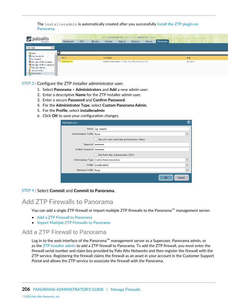
206 PANORAMA ADMINISTRATOR'S GUIDE | Manage Firewalls© 2020 Palo Alto Networks, Inc.
The installeradmin is automatically created after you successfully install the ZTP plugin onPanorama.
STEP 3 | Configure the ZTP installer administrator user.1. Select Panorama > Administrators and Add a new admin user.2. Enter a descriptive Name for the ZTP installer admin user.3. Enter a secure Password and Confirm Password.4. For the Administrator Type, select Custom Panorama Admin.5. For the Profile, select installeradmin6. Click OK to save your configuration changes.
STEP 4 | Select Commit and Commit to Panorama.
Add ZTP Firewalls to PanoramaYou can add a single ZTP firewall or import multiple ZTP firewalls to the Panorama™ management server.
• Add a ZTP Firewall to Panorama• Import Multiple ZTP Firewalls to Panorama
Add a ZTP Firewall to PanoramaLog in to the web interface of the Panorama™ management server as a Superuser, Panorama admin, oras the ZTP installer admin to add a ZTP firewall to Panorama. To add the ZTP firewall, you must enter thefirewall serial number and claim key provided by Palo Alto Networks and then register the firewall with theZTP service. Registering the firewall claims the firewall as an asset in your account in the Customer SupportPortal and allows the ZTP service to associate the firewall with the Panorama.

PANORAMA ADMINISTRATOR'S GUIDE | Manage Firewalls 207© 2020 Palo Alto Networks, Inc.
While adding ZTP firewalls to Panorama, do not perform any commits on the ZTP firewallbefore you verify that the firewall is successfully added to Panorama in Step 4. Performinga local commit on the ZTP firewall disables ZTP functionality and results in the failure tosuccessfully add the firewall to Panorama.
STEP 1 | Log in to the Panorama Web Interface using the ZTP installer admin credentials.
STEP 2 | Add a ZTP firewall to Panorama.1. Select Firewall Registration and Add a new ZTP firewall.2. Enter the Serial Number of the ZTP firewall.3. Enter the Claim Key for the ZTP firewall provided by Palo Alto Networks.
The eight digit numeric claim key is printed on a physical label attached to the back of the ZTPfirewall you received from Palo Alto Networks.
4. Click OK to save your configuration changes.
STEP 3 | Register the ZTP firewall.1. Select the newly added ZTP firewall and Register the firewall.2. When prompted, click Yes to confirm registering the ZTP firewall.
STEP 4 | Verify the firewall successfully registered with the ZTP service.1. Select Registration Status and verify that the ZTP firewall successfully registered with the ZTP
service.

208 PANORAMA ADMINISTRATOR'S GUIDE | Manage Firewalls© 2020 Palo Alto Networks, Inc.
2. Log in to the Panorama Web Interface using admin credentials.3. Select Panorama > Managed Devices > Summary and verify that the ZTP firewall is successfully
added as a managed firewall.
Ensure that the To SW Version column is configured to the correct PAN-OS versionso that the firewall does not upgrade or downgrade unintentionally. ZTP functionality issupported only for PAN-OS 9.1.3 and later releases. Additionally, the PAN-OS versionmust be the same or an earlier version of the PAN-OS version running on Panorama.
For more information, see Upgrade a ZTP Firewall.
STEP 5 | Add the ZTP firewall to device group and template stack.You must add the ZTP firewall to a device group and template stack for your firewalls to display asConnected and to push policy and network configurations.
1. Log in to the Panorama Web Interface using admin credentials.2. Select Panorama > Device Groups and assign the firewall to the appropriate device group.
Add a device group to create and configure a new device group to contain the policy objects andrules for your ZTP firewalls.
3. Select Panorama > Templates and assign the firewall to the appropriate template stack.
Configure a template stack to create and configure a new template stack to contain the networkconfiguration for your ZTP firewalls.
Import Multiple ZTP Firewalls to PanoramaLog in to the web interface of the Panorama™ management server as a Superuser, Panorama admin, or asthe ZTP installer admin to import multiple ZTP firewalls to Panorama. To import multiple ZTP firewalls, youmust import a CSV file of the ZTP firewall serial number and corresponding claim key provided by Palo AltoNetworks and then register the firewalls with the ZTP service. Registering the firewall claims the firewalls asassets in your account in the Customer Support Portal and allows the ZTP service to associate the firewallswith the Panorama.
While adding ZTP firewalls to Panorama, do not perform any commits on the ZTP firewallbefore you verify that the firewall is successfully added to Panorama in Step 5. Performing

PANORAMA ADMINISTRATOR'S GUIDE | Manage Firewalls 209© 2020 Palo Alto Networks, Inc.
a local commit on the ZTP firewall disables ZTP functionality and results in the failure tosuccessfully add the firewall to Panorama.
STEP 1 | Gather the serial numbers and claim keys for your ZTP firewalls.The eight digit numeric claim key is printed on a physical label attached to the back of the ZTP firewallyou received from Palo Alto Networks.
STEP 2 | Create a CSV file containing the ZTP firewall serial numbers and claim keys. The first columnmust contain the serial numbers and the second column must contain the corresponding claimkey for that firewall. Refer to the following example for reference.
STEP 3 | Import the ZTP firewalls to Panorama.1. Log in to the Panorama Web Interface using the ZTP installer admin credentials.2. Select Panorama > Zero Touch Provisioning > Firewall Registration and Import the ZTP firewalls.3. Browse and select the CSV file containing the ZTP firewall information and click OK.
STEP 4 | Register the ZTP firewalls.1. Select the newly added ZTP firewalls and Register the firewalls.2. When prompted, click Yes to confirm registering the ZTP firewalls.
STEP 5 | Verify the firewall successfully registered with the ZTP service.1. Select Registration Status and verify that the ZTP firewalls successfully registered with the ZTP
service.2. Log in to the Panorama Web Interface using admin credentials.3. Select Panorama > Managed Devices > Summary and verify that the ZTP firewalls are successfully
added as a managed firewall.
Ensure that the To SW Version column is configured to the correct PAN-OS versionso that the firewall does not upgrade or downgrade unintentionally. ZTP functionality issupported only for PAN-OS 9.1.3 and later releases. Additionally, the PAN-OS versionmust be the same or an earlier version of the PAN-OS version running on Panorama.
For more information, see Upgrade a ZTP Firewall.
STEP 6 | Add the ZTP firewalls to a device group and template stack.You must add the ZTP firewall to a device group and template stack for your firewalls to display asConnected and to push policy and network configurations.
1. Log in to the Panorama Web Interface using admin credentials.2. Select Panorama > Device Groups and assign the firewalls to the appropriate device group.

210 PANORAMA ADMINISTRATOR'S GUIDE | Manage Firewalls© 2020 Palo Alto Networks, Inc.
Add a device group to create and configure a new device group to contain the policy objects andrules for your ZTP firewalls.
3. Select Panorama > Templates and assign the firewalls to the appropriate template stack.
Configure a template stack to create and configure a new template stack to contain the networkconfiguration for your ZTP firewalls.
Use the CLI for ZTP TasksUse the following CLI commands to perform Zero Touch Provisioning (ZTP) tasks and view the ZTP servicestatus.
If you want to ... Use ...
Administer the firewall from the firewall CLI
Display the connection status to the ZTP service.> show system ZTP status
Display the connection status to the Panoramamanagement server. > show panorama status
Display the ZTP model number and firewall systeminformation. > show system info
Disable the ZTP state machine on the firewall.
Running this command does not delete anyexisting ZTP configuration.
You cannot re-enable the ZTPstate machine on the firewall afterit is disabled from the CLI.
To re-enable, you must reset thefirewall to factory default settings.
> request disable ztp
Register, configure, and manage your ZTP firewalls from Panorama
Create a device group or template containing thenecessary configurations to connect managedfirewalls with Panorama using the ZTP service onthe Eth1/1 interface.
> request plugins ztp create dgroup-template device-group <device group name>
> request plugins ztp create dgroup-template template <template name>

PANORAMA ADMINISTRATOR'S GUIDE | Manage Firewalls 211© 2020 Palo Alto Networks, Inc.
If you want to ... Use ...
Add a ZTP firewall to the list of firewalls for futureregistration with the ZTP service. > request plugins ztp firewall-add
<serial number> claim-key <claim key>
Modify the serial number of a ZTP firewall thathas already been added to the list of firewalls forfuture registration with the ZTP service.
> request plugins ztp firewall-add-modify firewall <old serial number> claim-key <claim key> new-serial <new serial number>
Delete a ZTP firewall from the list of firewalls forfuture registration with the ZTP service. > request plugins ztp firewall-delete
firewall <serial number>
Add a ZTP firewall to the list of firewalls for futurere-registration with the ZTP service.
Use this command when a ZTP firewall initiallyfails registration with the ZTP service and needs.
> request plugins ztp firewall-re-enter-info firewall <serial number> claim-key <claim key>
Register your Panorama™ management serverwith the ZTP service. > request plugins ztp panorama-
registration
Register a ZTP firewall with the ZTP service.> request plugins ztp firewall-registration firewall <serial number> claim-key <claim key>
Re-register ZTP firewalls with the ZTP service.
Use this command to start the re-registrationprocess for a ZTP firewall that failed initialregistration with the ZTP service.
> request plugins ztp firewall-register-retry firewall <serial number> claim-key <claim key>
Import ZTP firewall serial number and claim keyinformation.
The specified file must be in CSV format.
> request plugins ztp ztp-add-import import-path <file path>
View ZTP firewall information and ZTP service status from Panorama
Retrieve the list of ZTP firewalls registered to thePanorama from the ZTP service. > request plugins ztp ztp-service-
info
The following details are displayed:
• first-firewall-connect-time—Timestamp of when the ZTP firewall firstconnected to the ZTP service.

212 PANORAMA ADMINISTRATOR'S GUIDE | Manage Firewalls© 2020 Palo Alto Networks, Inc.
If you want to ... Use ...
• last-firewall-connect-time—Timestamp of when the ZTP firewall lastconnected to the ZTP service.
• registration-time—Timestamp of whenthe ZTP firewall registered with the ZTPservice.
• isZTPFirewall—Whether the firewall is aZTP firewall.
• created_by—Administrative user that addedthe ZTP firewall.
• IP address—IP address of the ZTP firewall.
View the list of ZTP firewalls in the list of firewallsto be registered with the ZTP service. > show plugins ztp device-add-list
View the registration status of your ZTP firewalls.> show plugins ztp device-reg-status
View the ZTP service synchronization status forZTP firewalls. > request plugins ztp ztp-sync-status
Uninstall the ZTP PluginFollow the procedure to remove the ZTP configuration from your Panorama™ management server anduninstall the ZTP plugin. If your Panorama is in a high availability (HA) configuration, repeat these steps onboth Panorama HA peers.
STEP 1 | Log in to the Panorama Web Interface.
STEP 2 | Delete the ZTP installer administrator account.1. Select Panorama > Administrators and select the ZTP installer administrator account you previously
configured.2. Delete the ZTP installer administrator account.3. Select Panorama > Administrators and select the installeradmin admin role.4. Delete the installeradmin admin role.5. Select Commit and Commit to Panorama.
STEP 3 | Uninstall the ZTP plugin1. Select Panorama > Plugins and navigate to the ZTP plugin installed on Panorama.2. In the Actions column, Remove Config to delete ZTP related configurations from Panorama3. Click OK when prompted to confirm removing the ZTP configuration from Panorama.4. Select Commit and Commit to Panorama.5. Uninstall the ZTP plugin.6. Click OK when prompted to uninstall the ZTP plugin from Panorama.

PANORAMA ADMINISTRATOR'S GUIDE | Manage Firewalls 213© 2020 Palo Alto Networks, Inc.
Manage Device Groups• Add a Device Group• Create a Device Group Hierarchy• Create Objects for Use in Shared or Device Group Policy• Revert to Inherited Object Values• Manage Unused Shared Objects• Manage Precedence of Inherited Objects• Move or Clone a Policy Rule or Object to a Different Device Group• Select a URL Filtering Vendor on Panorama• Push a Policy Rule to a Subset of Firewalls• Manage the Rule Hierarchy
Add a Device GroupAfter adding firewalls (see Add a Firewall as a Managed Device), you can group them into Device Groups(up to 1,024), as follows. Be sure to assign both firewalls in an active-passive high availability (HA)configuration to the same device group so that Panorama will push the same policy rules and objects tothose firewalls. PAN-OS doesn’t synchronize pushed rules across HA peers. To manage rules and objects atdifferent administrative levels in your organization, Create a Device Group Hierarchy.
STEP 1 | Select Panorama > Device Groups, and click Add.
STEP 2 | Enter a unique Name and a Description to identify the device group.
STEP 3 | In the Devices section, select check boxes to assign firewalls to the group. To search a long listof firewalls, use the Filters.
You can assign any firewall to only one device group. You can assign each virtual systemon a firewall to a different device group.
STEP 4 | In the Reference Template section, Add any templates or template stacks with objectsreferenced by the device group configuration.You must assign the appropriate template or template stack references to the device group in order tosuccessfully associate the template or template stack to the device group. This allows you to referenceobjects configured in a template or template stack without adding an unrelated device to a templatestack.
Skip this step if the device group configuration does not reference any objects configured in a templateor template stack.
STEP 5 | (Optional) Select Group HA Peers for firewalls that are HA peers.You can only group managed firewall HA peers if they are in the same device group.
The firewall name of the passive or active-secondary peer is in parentheses. GroupingHA peers is a visual change and no configuration change occurs.
STEP 6 | Select the Parent Device Group (default is Shared) that will be just above the device group youare creating in the device group hierarchy.

214 PANORAMA ADMINISTRATOR'S GUIDE | Manage Firewalls© 2020 Palo Alto Networks, Inc.
STEP 7 | If your policy rules will reference users and groups, assign a Master firewall.This will be the only firewall in the device group from which Panorama gathers username and user groupinformation.
STEP 8 | Click OK to save your changes.
STEP 9 | Select Commit > Commit and Push and then Commit and Push your changes to the Panoramaconfiguration and to the device group you added.
Create a Device Group HierarchySTEP 1 | Plan the Device Group Hierarchy.
1. Decide the device group levels, and which firewalls and virtual systems you will assign to each devicegroup and the Shared location. You can assign any one firewall or virtual system (vsys) to only onedevice group. If a device group will be just an organizational container for lower level device groups,you don’t need to assign firewalls to it.
2. Remove firewall or vsys assignments from existing device groups if those assignments don’t fit yourplanned hierarchy.
1. Select Panorama > Device Groups and select the device group.2. In the Devices section, clear the check boxes of firewalls and virtual systems you want to remove,
and click OK.3. If necessary, add more firewalls that you will assign to device groups: see Add a Firewall as a
Managed Device.
STEP 2 | For each top-level device group, Add a Device Group.1. In the Panorama > Device Groups page, click Add and enter a Name to identify the device group.2. In the Devices section, select check boxes to assign firewalls and virtual systems to the device group.3. Leave the Parent Device Group option at Shared (the default) and click OK.
STEP 3 | For each lower-level device group, Add a Device Group.• For new device groups at each lower level, repeat the previous step, but set the Parent Device Group
to a device group at the next level above.• For each existing device group, in the Device Groups page, select the device group to edit it, select a
Parent Device Group, and click OK.
If you move a device group to a different parent, all its descendant device groups movewith it, along with all firewalls, policy rules, and objects associated with the device groupand its descendants. If the new parent is in another access domain, the moved devicegroup will no longer have membership in the original access domain. If the new accessdomain has read-write access for the parent device group, it will also have read-writeaccess for the moved device group. If the new access domain has read-only access forthe parent, it will have no access for the moved device group. To reconfigure access fordevice groups, see Configure an Access Domain.
STEP 4 | Configure, move, and clone objects and policy rules as needed to account for inheritance in thedevice group hierarchy.• Create Objects for Use in Shared or Device Group Policy, or edit existing objects.
You can edit objects only at their location: the device group to which they are assigned. Descendantdevice groups inherit read-only instances of the objects from that location. However, you can optionallysee Step Override inherited object values.

PANORAMA ADMINISTRATOR'S GUIDE | Manage Firewalls 215© 2020 Palo Alto Networks, Inc.
• Create or edit policies.• Move or Clone a Policy Rule or Object to a Different Device Group.
STEP 5 | Override inherited object values.Applicable only if object values in a particular device group must differ from the values inherited from anancestor device group.
After overriding an object, you can override it again in descendant device groups. However, you cannever override shared or predefined (default) objects.
In the Objects tab, inherited objects have a green icon in the Name column, and the Location columndisplays the ancestor device group.
1. In the Objects tab, select the object type (for example, Objects > Addresses).2. Select the Device Group that will have the override instance.3. Select the object and click Override.4. Edit the values. You can’t edit the Name or Shared settings.5. Click OK. The Name column displays a yellow-overlapping-green icon for the object to indicate it is
overridden.
If necessary, you can later Revert to Inherited Object Values.
STEP 6 | Save and commit your changes.
Commit to Panorama and push to device groups after any change to the hierarchy.
You must also push changes to templates if a template references objects in a device group (such asinterfaces referencing addresses), and a firewall assigned to the template is no longer assigned to thatdevice group because of a hierarchy change.
Select Commit > Commit and Push and then Commit and Push your changes to the Panoramaconfiguration and to the device groups you added or changed.
Create Objects for Use in Shared or Device Group PolicyYou can use an object in any policy rule that is in the Shared location, or in the same device group as theobject, or in descendants of that device group (for details, see Device Group Objects).
See Use Dynamic Address Groups in Policy to verify the number of supported registered IPaddresses on Panorama if you intended to leverage dynamic address groups in order tocreate policies that automatically adapt to changes in your network.
• Create a shared object.In this example, we add a shared object for URL Filtering categories for which we want to trigger alerts.
1. Select the Objects > Security Profiles > URL Filtering tab and click Add.
The Objects tab appears only after you Add a Device Group (at least one).2. Enter a Name and a Description.3. Select Shared.4. The Disable Override option is cleared by default, which means you can override inherited instances
of the object in all device groups. To disable overrides for the object, select the check box.

216 PANORAMA ADMINISTRATOR'S GUIDE | Manage Firewalls© 2020 Palo Alto Networks, Inc.
5. In the Categories tab, select every Category for which you want notification.6. In the Action column, select Alert.7. Click OK to save your changes to the object.8. Select Commit > Commit to Panorama and Commit your changes.
• Create a device group object.In this example, we add an address object for specific web servers on your network.
1. Select Objects > Addresses and select the Device Group in which you will use the object.2. Click Add and enter a Name to identify the object.3. Be sure to leave the Shared option cleared.4. The Disable Override option is cleared by default, which means you can override inherited instances
of the object in device groups that are descendants of the selected Device Group. To disableoverrides for the object, select the Disable Override option.
5. Select the Type of address object and the associated value. For example, select IP Range and enterthe IP address range for the web servers.
6. Click OK to save your changes to the object.7. Select Commit > Commit and Push and then Commit and Push your changes to the Panorama
configuration and to the device group where you added the object.
• View shared objects and device group objects in Panorama.In the pages of the Objects tab, the Location column indicates whether an object is shared or is specificto a device group.
1. In the Objects tab, select the object type (Objects > Addresses, in this example).2. Select the Device Group to which you added the object.
The Objects tab only displays objects that are in the selected Device Group or areinherited from an ancestor device group or the Shared location.
3. Verify that the device group object appears. Note that the device group name in the Location columnmatches the selection in the Device Group drop-down.
Revert to Inherited Object ValuesAfter overriding the values that a device group object inherits from an ancestor device group, you canrevert the object to its ancestor values at any time. In the Objects tab, overridden objects have a yellow-overlapping-green icon ( ) in the Name column.
If you want to push ancestor values to all overridden objects instead of reverting a specificobject, see Manage Precedence of Inherited Objects.
For the steps to override values, see Step 5
For details on object inheritance and overrides, see Device Group Objects.
STEP 1 | In the Objects tab, select the object type (for example, Objects > Addresses) and select theDevice Group that has an override instance of the object.
STEP 2 | Select the object, click Revert, and click Yes. The Name column displays a green icon for theobject, indicating that it now inherits all values from an ancestor device group.

PANORAMA ADMINISTRATOR'S GUIDE | Manage Firewalls 217© 2020 Palo Alto Networks, Inc.
STEP 3 | Select Commit > Commit and Push and then Commit and Push your changes to the Panoramaconfiguration and to the device group where you reverted the object.
Manage Unused Shared ObjectsWhen you push configuration changes Device Groups, by default Panorama pushes all shared objects tofirewalls whether or not any shared or device group policy rules reference the objects. However, you canconfigure Panorama to push only the shared objects that rules reference in the device groups. The ShareUnused Address and Service Objects with Devices option enables you to limit the objects that Panoramapushes to the managed firewalls.
When Share Unused Address and Service Objects with Devices is disabled, Panoramaignores the Target firewalls when you Push a Policy Rule to a Subset of Firewalls. This meansthat all objects referenced by any rules are pushed to all firewalls in the device group.
To limit the number of objects pushed to a set of managed firewalls, add the policy rules toa child device group and reference shared objects as needed. See Create a Device GroupHierarchy for more information on creating a child device group.
On lower-end models, such as the PA-220, consider pushing only the relevant shared objects to themanaged firewalls. This is because the number of objects that can be stored on the lower-end models isconsiderably lower than that of the mid- to high-end models. Also, if you have many address and serviceobjects that are unused, clearing Share Unused Address and Service Objects with Devices reduces thecommit times significantly on the firewalls because the configuration pushed to each firewall is smaller.However, disabling this option might increase the commit time on Panorama because Panorama has todynamically check whether policy rules reference a particular object.
STEP 1 | Select Panorama > Setup > Management, and edit the Panorama Settings.
STEP 2 | Clear the Share Unused Address and Service Objects with Devices option to push only theshared objects that rules reference, or select the option to re-enable pushing all shared objects.
STEP 3 | Click OK to save your changes.
STEP 4 | Select Commit > Commit to Panorama and Commit your changes.
Manage Precedence of Inherited ObjectsBy default, when device groups at different levels in the Device Group Hierarchy have an object with thesame name but different values (because of overrides, as an example), policy rules in a descendant devicegroup use the object values in that descendant instead of using object values inherited from ancestor devicegroups. Optionally, you can reverse this order of precedence to push values from the highest ancestorcontaining the object to all descendant device groups. After you enable this option, the next time you pushconfiguration changes to device groups, the values of inherited objects replace the values of any overriddenobjects in the descendant device groups. The figure below demonstrates the precedence of inheritedobjects in a device group:

218 PANORAMA ADMINISTRATOR'S GUIDE | Manage Firewalls© 2020 Palo Alto Networks, Inc.
If a firewall has locally defined objects with the same name as shared or device groupobjects that Panorama pushes, a commit failure occurs.
If you want to revert a specific overridden object to its ancestor values instead of pushingancestor values to all overridden objects, see Revert to Inherited Object Values.
STEP 1 | Select Panorama > Setup > Management and edit the Panorama Settings.
STEP 2 | If you want to reverse the default order of precedence, select Objects defined in ancestorswill take higher precedence. The dialog then displays the Find Overridden Objects link, whichprovides the option to see how many overridden (shadowed) objects will have ancestor valuesafter you commit this change. You can hover over the quantity message to display the objectnames.If you want to revert to the default order of precedence, clear Objects defined in ancestors will takehigher precedence.
Find Overridden Objects only detects a Shared device group object that shares a namewith another object in the device group.
STEP 3 | Click OK to save your changes.
STEP 4 | Select Commit > Commit to Panorama and Commit your changes.
STEP 5 | (Optional) If you selected Objects defined in ancestors will take higher precedence, Panoramadoes not push the ancestor objects until you push configuration changes to device groups:select Commit > Push to Devices and Push your changes.
Move or Clone a Policy Rule or Object to a Different DeviceGroup
On Panorama, if a policy rule or object that you will move or clone from a device group has referencesto objects that are not available in the target device group (Destination), you must move or clone thereferenced objects and the referencing rule or object in the same operation. In a Device Group Hierarchy,remember that referenced objects might be available through inheritance. For example, shared objects areavailable in all device groups. You can perform a global find to check for references. If you move or clonean overridden object, be sure that overrides are enabled for that object in the parent device group of theDestination (see Create Objects for Use in Shared or Device Group Policy).
When cloning multiple policy rules, the order by which you select the rules will determinethe order they are copied to the device group. For example, if you have rules 1-4 and your

PANORAMA ADMINISTRATOR'S GUIDE | Manage Firewalls 219© 2020 Palo Alto Networks, Inc.
selection order is 2-1-4-3, the device group where these rules will be cloned will display therules in the same order you selected. However, you can reorganize the rules as you see fitonce they have been successfully copied.
STEP 1 | Log in to Panorama and select the rulebase (for example, Policy > Security > Pre Rules) orobject type (for example, Objects > Addresses).
STEP 2 | Select the Device Group and select one or more rules or objects.
STEP 3 | Perform one of the following steps:• (Rules only) Move > Move to other device group• (Objects only) Move• (Rules or objects) Clone
STEP 4 | In the Destination drop-down, select the new device group or Shared. The default is previouslyselected Device Group.
STEP 5 | (Rules only) Select the Rule order:• Move top (default)—The rule will come before all other rules.• Move bottom—The rule will come after all other rules.• Before rule—In the adjacent drop-down, select the rule that comes after the Selected Rules.• After rule—In the adjacent drop-down, select the rule that comes before the Selected Rules.
STEP 6 | The Error out on first detected error in validation check box is selected by default, whichmeans Panorama will display the first error it finds and stop checking for more errors. Forexample, an error occurs if the Destination device group doesn't have an object that isreferenced in the rule you are moving. When you move or clone many items at once, selectingthis check box can simplify troubleshooting. If you clear the check box, Panorama will find allthe errors before displaying them. Regardless of this setting, Panorama won’t move or cloneanything until you fix all the errors for all the selected items.
STEP 7 | Click OK to start the error validation. If Panorama finds errors, fix them and retry the move orclone operation. If Panorama doesn't find errors, it performs the operation.
STEP 8 | Select Commit > Commit and Push, Edit Selections in the Push Scope, select Device Groups,select the original and destination device groups, click OK, and then Commit and Push yourchanges to the Panorama configuration and to the device groups.
Select a URL Filtering Vendor on PanoramaURL filtering enables firewalls to monitor and control web access for your users. The policy rules thatyou configure to control web access (Security, QoS, Captive Portal, and Decryption rules) reference URLcategories. The URL filtering vendor you select on Panorama determines which URL categories are availablefor referencing in the rules that you add to device groups and push to firewalls.
By default, Panorama uses PAN-DB, a URL filtering database that is tightly integrated into PAN-OS and thePalo Alto Networks threat intelligence cloud. PAN-DB provides high-performance local caching to maximizein-line performance for URL lookups. The other vendor option is BrightCloud, a third-party URL database.
Unlike firewalls, Panorama does not download the URL database and does not require aURL filtering license.

220 PANORAMA ADMINISTRATOR'S GUIDE | Manage Firewalls© 2020 Palo Alto Networks, Inc.
The following topics describe how to change the URL filtering vendor on Panorama or on both Panoramaand managed firewalls. You can also change the URL filtering vendor on just the firewalls.
• Must Panorama and Firewalls Have Matching URL Filtering Vendors?• Change the URL Filtering Vendor on HA Panorama• Change the URL Filtering Vendor on non-HA Panorama• Migrate Panorama and HA Firewalls from BrightCloud to PAN-DB• Migrate Panorama and non-HA Firewalls from BrightCloud to PAN-DB
Must Panorama and Firewalls Have Matching URL Filtering Vendors?On any single Panorama management server or firewall, only one URL filtering vendor can be active: PAN-DB or BrightCloud. When selecting a vendor for Panorama, you must consider the vendor and PAN-OSversion of the managed firewalls:
• PAN-OS 5.0.x and earlier versions—Panorama and the firewalls require matching URL filtering vendors.• PAN-OS 6.0 or later versions—Panorama and the firewalls do not require matching URL filtering
vendors. If a vendor mismatch is detected, the firewall maps the URL categories in the URL Filteringprofiles and rules that it received from Panorama to URL categories that align with those of the vendorenabled on the firewall.
Therefore, for a deployment in which some firewalls run PAN-OS 6.0 or later and some firewalls run earlierPAN-OS versions, Panorama must use the same URL filtering vendor as the firewalls that run earlier PAN-OS versions. For example, if firewalls that run PAN-OS 5.0 use PAN-DB, and firewalls that run PAN-OS 7.0use BrightCloud, Panorama must use PAN-DB.
Change the URL Filtering Vendor on HA PanoramaIn a high availability (HA) deployment, each Panorama peer must be in a non-functional state when youchange the URL filtering vendor. Therefore, to avoid disrupting Panorama operations, change the URLfiltering vendor on the passive Panorama (Panorama2 in this example) and then trigger failover beforechanging the vendor on the active Panorama (Panorama1 in this example).
STEP 1 | Change the URL filtering vendor on each Panorama HA peer.
Complete this task on Panorama2 (passive peer) before Panorama1 (active peer).
1. Log in to the Panorama web interface.2. Select Panorama > High Availability and Suspend local Panorama.
When you perform this step on Panorama1, failover occurs and Panorama2 becomes active.3. Select Panorama > Setup > Management and edit the General Settings.4. Select the URL Filtering Database vendor: paloaltonetworks (PAN-DB) or brightcloud.5. Select Panorama > High Availability and Make local Panorama functional.
When you perform this step on Panorama1 with preemption enabled on both HA peers, Panorama1automatically reverts to active status and Panorama2 reverts to passive status.
STEP 2 | Verify that the URL categories are available for referencing in policies.1. Select Objects > Security Profiles > URL Filtering.2. Click Add and verify that the Categories tab of the URL Filtering profile dialog displays the URL
categories associated with the selected vendor.

PANORAMA ADMINISTRATOR'S GUIDE | Manage Firewalls 221© 2020 Palo Alto Networks, Inc.
Change the URL Filtering Vendor on non-HA PanoramaPerform this procedure to change the URL filtering vendor on a Panorama management server that is notdeployed in a high availability (HA) configuration.
STEP 1 | Change the URL filtering vendor.1. Select Panorama > Setup > Management and edit the General Settings.2. Select the URL Filtering Database vendor: paloaltonetworks (PAN-DB) or brightcloud.
STEP 2 | Verify that the URL categories are available for referencing in policies.1. Select Objects > Security Profiles > URL Filtering.2. Click Add and verify that the Categories tab of the URL Filtering profile dialog displays the URL
categories associated with the selected vendor.
Migrate Panorama and HA Firewalls from BrightCloud to PAN-DBPerform this procedure to migrate the URL filtering vendor from BrightCloud to PAN-DB on Panorama andfirewalls when the firewalls are deployed in a high availability (HA) configuration. In this example, the active(or active-primary) firewall is named fw1 and the passive (or active-secondary) firewall is named fw2. Themigration automatically maps BrightCloud URL categories to PAN-DB URL categories.
STEP 1 | Determine which firewalls require new PAN-DB URL filtering licenses.1. Log in to Panorama and select Panorama > Device Deployment > Licenses.2. Check the URL column to determine which firewalls have PAN-DB licenses and whether the licenses
are valid or expired.
A firewall can have valid licenses for both BrightCloud and PAN-DB, but only one license can beactive.
If you’re not sure whether a PAN-DB URL filtering license is active, access the firewallweb interface, select Device > Licenses, and verify that the Active field displays Yes inthe PAN-DB URL Filtering section.
3. Purchase a new license for each firewall that does not have a valid PAN-DB license.
In HA deployments, each firewall peer needs a distinct PAN-DB license and authorization code. PaloAlto Networks sends an email containing activation codes for the licenses you purchase. If you can’tfind this email, contact Customer Support before proceeding.
STEP 2 | Change the URL filtering vendor to PAN-DB on Panorama.Access the Panorama web interface and perform one of the following tasks:
• Change the URL Filtering Vendor on HA Panorama• Change the URL Filtering Vendor on non-HA Panorama
STEP 3 | Configure the TCP session settings on both firewall HA peers to ensure sessions that are notyet synchronized will fail over when you suspend a peer.Log in to the CLI of each firewall and run the following command:
> set session tcp-reject-non-syn no
STEP 4 | Migrate the URL filtering vendor to PAN-DB on each firewall HA peer.

222 PANORAMA ADMINISTRATOR'S GUIDE | Manage Firewalls© 2020 Palo Alto Networks, Inc.
Complete this task on fw2 (passive or active-secondary peer) before fw1 (active or active-primary peer).
1. Access the firewall web interface, select Device > High Availability > Operational Commands, andSuspend local device.
Performing this step on fw1 triggers failover to fw2.2. Select Device > Licenses.3. In the License Management section, select Activate feature using authorization code, enter the
Authorization Code and click OK.
Activating the PAN-DB license automatically deactivates the BrightCloud license.4. In the PAN-DB URL Filtering section, Download the seed file, select your region, and click OK.5. Commit and push your configuration changes:
1. Access the Panorama web interface.2. Select Commit > Commit and Push and Edit Selections in the Push Scope3. Select Device Groups, select the firewall, and click OK.4. Commit and Push your changes to the Panorama configuration and to device groups.
6. Access the firewall web interface, select Device > High Availability > Operational Commands, andMake local device functional.
When you perform this step on fw1 with preemption enabled on both firewalls, fw1 automaticallyreverts to active (or active-primary) status and fw2 reverts to passive (or active-secondary) status.
STEP 5 | Revert both firewall HA peers to the original TCP session settings.Run the following command at the CLI of each firewall:
> set session tcp-reject-non-syn yes
Migrate Panorama and non-HA Firewalls from BrightCloud to PAN-DBPerform this procedure to migrate the URL filtering vendor from BrightCloud to PAN-DB on Panoramaand firewalls when the firewalls are not deployed in a high availability (HA) configuration. The migrationautomatically maps BrightCloud URL categories to PAN-DB URL categories.
STEP 1 | Determine which firewalls require new PAN-DB URL filtering licenses.1. Log in to Panorama and select Panorama > Device Deployment > Licenses.2. Check the URL column to determine which firewalls have PAN-DB licenses and whether the licenses
are valid or expired.
A firewall can have valid licenses for both BrightCloud and PAN-DB, but only one license can beactive.
If you’re not sure whether a PAN-DB URL filtering license is active, access the firewallweb interface, select Device > Licenses, and verify that the Active field displays Yes inthe PAN-DB URL Filtering section.
3. Purchase new licenses for the firewalls that don’t have valid PAN-DB licenses.
Palo Alto Networks sends an email containing activation codes for the licenses you purchase. If youcan’t find this email, contact Customer Support before proceeding.
STEP 2 | Change the URL filtering vendor to PAN-DB on Panorama.Access the Panorama web interface and perform one of the following tasks:

PANORAMA ADMINISTRATOR'S GUIDE | Manage Firewalls 223© 2020 Palo Alto Networks, Inc.
• Change the URL Filtering Vendor on HA Panorama• Change the URL Filtering Vendor on non-HA Panorama
STEP 3 | Migrate the URL filtering vendor to PAN-DB on each firewall.1. Access the firewall web interface and select Device > Licenses.2. In the License Management section, select Activate feature using authorization code, enter the
Authorization Code, and click OK.
Activating the PAN-DB license automatically deactivates the BrightCloud license.3. In the PAN-DB URL Filtering section, Download the seed file, select your region, and click OK.4. Commit and push your configuration changes:
1. Access the Panorama web interface.2. Select Commit > Commit and Push and Edit Selections in the Push Scope3. Select Device Groups, select the firewall, and click OK.4. Commit and Push your changes to the Panorama configuration and to device groups.
Push a Policy Rule to a Subset of FirewallsA policy target allows you to specify the firewalls in a device group to which to push policy rules. It allowsyou to exclude one or more firewalls or virtual systems, or to apply a rule only to specific firewalls or virtualsystems in a device group.
As your rulebase evolves and you push new or modified rules to firewalls, changes and audit informationget lost over time unless they are archived at the time the rule is created or modified. Use the auditcomment archive to view the audit comment and configuration log history of a selected rule, as well tocompare two policy rule versions to see how the rule changed. The audit comment history for a rule pushedfrom Panorama is viewable only from the Panorama management server. However, you can view the auditcomments in the configurations logs forwarded to Panorama from managed firewalls. However, the auditcomment archive is not viewable for rules created or modified locally on the firewall. To ensure that auditcomments are captured at the time a rule is created or modified, Enforce Policy Rule, Description, Tag andAudit Comment.
The ability to target a rule enables you to keep policies centralized on Panorama. Targeted rules allow youto define the rules (as either shared or device group pre- or post-rules) on Panorama and improve visibilityand efficiency when managing the rules (see Device Group Policies). The audit comment archive addsfurther visibility by allowing you to track how and why your policy rules change over time so you can auditthe rule evolution over the course of the rule lifecycle.
STEP 1 | (Best Practice) Enforce audit comments for policy rules.Although this step is optional, it is a best practice to enforce audit comments for policy rules to ensurethat you capture the reason for creating or modifying the rule. This also helps maintain an accurate rulehistory for auditing purposes.
1. Select Panorama > Setup > Management and edit the Policy Rulebase Settings.2. Enable the option to Require audit comment on policies.3. Configure the Audit Comment Regular Expression to specify the audit comment format.
When creating or modifying a rule, require audit comments to adhere to a specific format based onyour business and auditing needs by specifying letter and number expressions. For example, you canuse this setting to specify regular expressions to match your ticketing number formats:
• [0-9]{<Number of digits>}—Requires the audit comment to contain a minimum numberof digits ranging from 0 to 9. For example, [0-9]{6} requires a minimum of 6 digit numericalexpression with numbers 0 to 9. Configure the minimum number of digits as needed.

224 PANORAMA ADMINISTRATOR'S GUIDE | Manage Firewalls© 2020 Palo Alto Networks, Inc.
• <Letter Expression>—Requires the audit comment to contain a letter expression. Forexample, Reason for Change- requires that the administrator to begin the audit commentwith this letter expression.
• <Letter Expression>-[0-9]{<Number of digits>}—Requires the audit comment tocontain a set character prefix with a minimum number of digits ranging from 0 to 9. For example,SB-[0-9]{6} requires the audit comment format to begin with SB-, followed by a minimum 6digit numerical expression with numbers 0 to 9 such as SB-012345.
• (<Letter Expression>)|(<Letter Expression>)|(<Letter Expression>)|-[0-9]{<Number of digits>}—Requires the audit comment to contain a prefix using one of theconfigured set of letter expressions with a minimum number of digits ranging from 0 to 9.For example, (SB|XY|PN)-[0-9]{6} requires the audit comment format begin with SB-,XY-, or PN- followed by a minimum 6 digit numerical expression with numbers 0 to 9 such asSB-012345, XY-654321, or PN-012543.
4. Click OK to apply the new policy rulebase settings.
5. Select Commit and Commit to Panorama.
STEP 2 | Create a rule.In this example, we define a pre-rule in the Security rulebase that permits users on the internal networkto access the servers in the DMZ.
1. On the Policies tab and select the Device Group for which you want to define a rule.2. Select the rulebase. For this example, select Policies > Security > Pre-Rules and Add a rule.3. In the General tab, enter a descriptive rule Name and enter an Audit Comment.4. In the Source tab, set the Source Zone to Trust.5. In the Destination tab, set the Destination Zone to DMZ.6. In the Service/ URL Category tab, set the Service to application-default.7. In the Actions tab, set the Action to Allow.8. Leave all the other options set to their default values.
STEP 3 | Target the rule to include or exclude a subset of firewalls.To apply the rule to a selected set of firewalls:
1. Select the Target tab in the Policy Rule dialog.2. Select the firewalls to which you want to apply the rule.
If you do not select firewalls to target, the rule is added to all of the (unchecked) firewalls in thedevice group.
By default, although the check box for the virtual systems in the device group isdisabled, all virtual systems will inherit the rule on commit unless you select one ormore virtual systems to which you want the rule to apply.
3. (Optional) To exclude a subset of firewalls from inheriting the rule, Install on all but specified devicesand select the firewalls you want to exclude.

PANORAMA ADMINISTRATOR'S GUIDE | Manage Firewalls 225© 2020 Palo Alto Networks, Inc.
If you Install on all but specified devices and do not select any firewalls, the rule is notadded to any of the firewalls in the device group.
4. Click OK to add the rule.
STEP 4 | Commit and push the configuration changes.1. Select Commit > Commit and Push and Edit Selections in the Push Scope.2. Select Device Groups, select the device group where you added the rule, and click OK.3. Commit and Push your changes to the Panorama configuration and to device groups.
STEP 5 | Troubleshoot Policy Rule Traffic Match to verify that the rules allow and deny traffic as theintended.
Manage the Rule HierarchyThe order of policy rules is critical for the security of your network. Within any policy layer (shared, devicegroup, or locally defined rules) and rulebase (for example, shared Security pre-rules), the firewall evaluatesrules from top to bottom in the order they appear in the pages of the Policies tab. The firewall matchesa packet against the first rule that meets the defined criteria and ignores subsequent rules. Therefore, toenforce the most specific match, move the more specific rules above more generic rules.
To understand the order in which the firewall evaluates rules by layer and by type (pre-rules,post-rules, and default rules) across the Device Group Hierarchy, see Device Group Policies.
STEP 1 | View the rule hierarchy for each rulebase.1. Select the Policies tab and click Preview Rules.2. Filter the preview by Rulebase (for example, Security or QoS).3. Filter the preview to display the rules of a specific Device Group and the rules it inherits from the
Shared location and ancestor device groups. You must select a device group that has firewallsassigned to it.
4. Filter the preview by Device to display its locally defined rules.5. Click the green arrow icon to apply your filter selections to the preview (see Device Group Policies).6. Close the Combined Rules Preview dialog when you finish previewing rules.
STEP 2 | Delete or disable rules, if necessary.
To determine which rules a firewall doesn’t currently use, select that firewall in theContext drop-down on Panorama, select the rulebase (for example, Policies > Security),and select the Highlight Unused Rules check box. A dotted orange background indicatesthe rules that the firewall doesn’t use.
1. Select the rulebase (for example, Policies > Security > Pre Rules) that contains the rule you will deleteor disable.
2. Select the Device Group that contains the rule.3. Select the rule, and click Delete or Disable as desired. Disabled rules appear in italicized font.
STEP 3 | Reposition rules within a rulebase, if necessary.
To reposition local rules on a firewall, access its web interface by selecting that firewall inthe Context drop-down before performing this step.
226 PANORAMA ADMINISTRATOR'S GUIDE | Manage Firewalls© 2020 Palo Alto Networks, Inc.
1. Select the rulebase (for example, Policies > Security > Pre Rules) that contains the rule you will move.2. Select the Device Group that contains the rule.3. Select the rule, select Move, and select:
• Move Top—Moves the rule above all other rules in the device group (but not above rules inheritedfrom Shared or ancestor device groups).
• Move Up—Moves the rule above the one that precedes it (but not above rules inherited fromShared or ancestor device groups).
• Move Down—Moves the rule below the one that follows it.• Move Bottom—Moves the rule below all other rules.• Move to other device group—See Move or Clone a Policy Rule or Object to a Different Device
Group.
STEP 4 | If you modified the rules, commit and push the changes.1. Select Commit > Commit and Push and Edit Selections in the Push Scope2. Select Device Groups, select the device group that contains the rules you changed or deleted, and
click OK.3. Commit and Push your changes to the Panorama configuration and to device groups.

PANORAMA ADMINISTRATOR'S GUIDE | Manage Firewalls 227© 2020 Palo Alto Networks, Inc.
Manage Templates and Template StacksUse templates and template stacks to define the common base configurations that enable firewalls tooperate in your network. See Templates and Template Stacks for an overview of the issues you shouldconsider when deciding which firewalls to add to which templates, ordering templates in a stack to managelayers of common and firewall group-specific settings, and overriding template settings with firewall-specific values.
To delete a template, you must first locally Disable/Remove Template Settings on the firewall.Only administrators with the superuser role can disable a template.
• Template Capabilities and Exceptions• Add a Template• Configure a Template Stack• Configure a Template or Template Stack Variable• Import and Overwrite Existing Template Stack Variables• Override a Template Setting• Disable/Remove Template Settings
Template Capabilities and ExceptionsYou can use Templates and Template Stacks to define a wide array of settings but you can perform thefollowing tasks only locally on each managed firewall:
• Configure a device block list.• Clear logs.• Enable operational modes such as normal mode, multi-vsys mode, or FIPS-CC mode.• Configure the IP addresses of firewalls in an HA pair.• Configure a master key and diagnostics.• Compare configuration files (Config Audit).
To Manage Licenses and Updates (software or content) for firewalls, use the Panorama >Device Management tab options; do not use templates.
• Renaming a vsys on a multi-vsys firewall.
Add a TemplateYou must add at least one template before Panorama™ displays the Device and Network tabs required todefine the network setup and device configuration elements for firewalls. Panorama supports up to 1,024templates. Every managed firewall must belong to a template stack. While templates contain manageddevice configurations, template stacks allow you to manage and push the template configurations to allmanaged firewalls assigned to the template stack.
Combine templates in to a template stack to avoid duplicating many configurations amongtemplates (see Templates and Template Stacks and Configure a Template Stack).
STEP 1 | Add a template.1. Select Panorama > Templates.2. Click Add and enter a unique Name to identify the template.

228 PANORAMA ADMINISTRATOR'S GUIDE | Manage Firewalls© 2020 Palo Alto Networks, Inc.
3. (Optional) Enter a Description for the template.4. Click OK to save the template.5. If the template has a virtual system (vsys) with configurations (for example, interfaces) that you want
Panorama to push to firewalls that don’t have virtual systems, select the template you created, selectthe vsys from the Default VSYS drop-down and click OK.
6. Select Commit > Commit and Push and then Commit and Push your changes to the Panoramaconfiguration and to the template.
STEP 2 | Verify that the template is available.After you add the first template, Panorama displays the Device and Network tabs. These tabs display aTemplate drop-down. Check that the drop-down displays the template you just added.
STEP 3 | Configure a Template Stack and add the template to the template stack.
STEP 4 | Use the template to push a configuration change to firewalls.
Renaming a vsys is allowed only on the local firewall, not on Panorama the result is anentirely new vsys or the new vsys name gets mapped to the wrong vsys on the firewall.
For example, define a primary Domain Name System (DNS) server for the firewalls in the template.
You can also Configure a Template or Template Stack Variable to push device-specificvalues to managed devices.
1. In the Device tab, select the Template from the drop-down.2. Select Device > Setup > Services > Global, and edit the Services section.3. Enter an IP address for the Primary DNS Server.
4. Select Commit > Commit and Push and then Commit and Push your changes to the Panoramaconfiguration and to the template.
STEP 5 | Verify that the firewall is configured with the template settings that you pushed fromPanorama.1. In the Context drop-down, select one of the firewalls to which you pushed the template setting.2. Select Device > Setup > Services > Global. The IP address that you pushed from the template
appears. The Services section header displays a template icon ( ) to indicate that settings in thesection have values pushed from a template.

PANORAMA ADMINISTRATOR'S GUIDE | Manage Firewalls 229© 2020 Palo Alto Networks, Inc.
STEP 6 | Troubleshoot Connectivity to Network Resources to verify your firewalls can access yournetwork resources.
Configure a Template StackA template stack is configurable and allows you to combine multiple templates to push full configurationsto your managed firewalls. While templates are modular portions of your firewall configuration thatyou can reuse across different stacks, you can also configure the template stack to fill in the remainingconfigurations that you need to apply across all firewalls assigned to the stack. Panorama supports up to1,024 template stacks and each stack can have up to 8 templates assigned to it. You can reference objectsconfigured in a template stack from a template belonging to the temple stack. In the event that the templatestack and a template in the stack have conflicting values, the value configured in the template stack will bepushed. For details and planning, see Templates and Template Stacks.
Add a Template to configure interfaces, VLANs, Virtual Wires, IPSec Tunnels, DNS Proxyand Virtual Systems. These objects must be configured and pushed from a template, and nota template stack. Once pushed from a template, you can override these objects, except forVirtual Systems, in the template stack.
STEP 1 | Plan the templates and their order in the stack.Add a Template you plan to assign to the template stack.
When planning the priority order of templates within the stack (for overlapping settings),you must check the order to prevent misconfiguration. For example, consider a stackin which the ethernet1/1 interface is of type Layer 3 in Template_A but of type Layer 2with a VLAN in Template_B. If Template_A has a higher priority, Panorama will pushethernet1/1 as type Layer 3 but assigned to a VLAN.
Also note that a template configuration can’t reference a configuration in another template even if bothtemplates are in the same stack. For example, a zone configuration in Template_A can’t reference a zoneprotection profile in Template_B.
STEP 2 | Create a template stack.1. Select Panorama > Templates and Add Stack.2. Enter a unique Name to identify the stack.3. For each of the templates the stack will combine (up to 8), Add and select the template. The dialog
lists the added templates in order of priority with respect to duplicate settings, where values in the

230 PANORAMA ADMINISTRATOR'S GUIDE | Manage Firewalls© 2020 Palo Alto Networks, Inc.
higher templates override those that are lower in the list. To change the order, select a template andMove Up or Move Down.
4. In the Devices section, select firewalls to assign them to the stack. For firewalls with multiple virtualsystems, you can’t assign individual virtual systems, only an entire firewall. You can assign any firewallto only one template stack.
Whenever you add a new managed firewall to Panorama, you must assign it to theappropriate template stack; Panorama does not automatically assign new firewalls toa template or template stack. When you push configuration changes to a template,Panorama pushes the configuration to every firewall assigned to the template stack.
5. (Optional) Select Group HA Peers to display a single check box for firewalls that are in a highavailability (HA) configuration. Icons indicate the HA state: green for active and yellow for passive.The firewall name of the secondary peer is in parentheses.
For active/passive HA, add both peers to the same template so that both will receive theconfigurations. For active/active HA, whether you add both peers to the same template depends onwhether each peer requires the same configurations. For a list of the configurations that PAN-OSsynchronizes between HA peers, see High Availability Synchronization.
6. Click OK to save the template stack.
STEP 3 | (Optional) Configure a Template or Template Stack Variable.
STEP 4 | Edit the Network and Device settings, as necessary.
Renaming a vsys is allowed only on the local firewall. If you rename a vsys on Panorama,the result is an entirely new vsys or the new vsys name gets mapped to the wrong vsyson the firewall.
In an individual firewall context, you can override settings that Panorama pushes from a stack in thesame way you override settings pushed from a template, see Override a Template or Template StackValue.
1. Filter the tabs to display only the mode-specific settings you want to edit:
While Panorama pushes mode-specific settings only to firewalls that support thosemodes, this selective push doesn’t adjust mode-specific values. For example, if atemplate has firewalls in Federal Information Processing Standards (FIPS) mode andan IKE Crypto profile that uses non-FIPS algorithms, the template push will fail. Toavoid such errors, use the Mode drop-down in the Network and Device tabs to filtermode-specific features and value options.
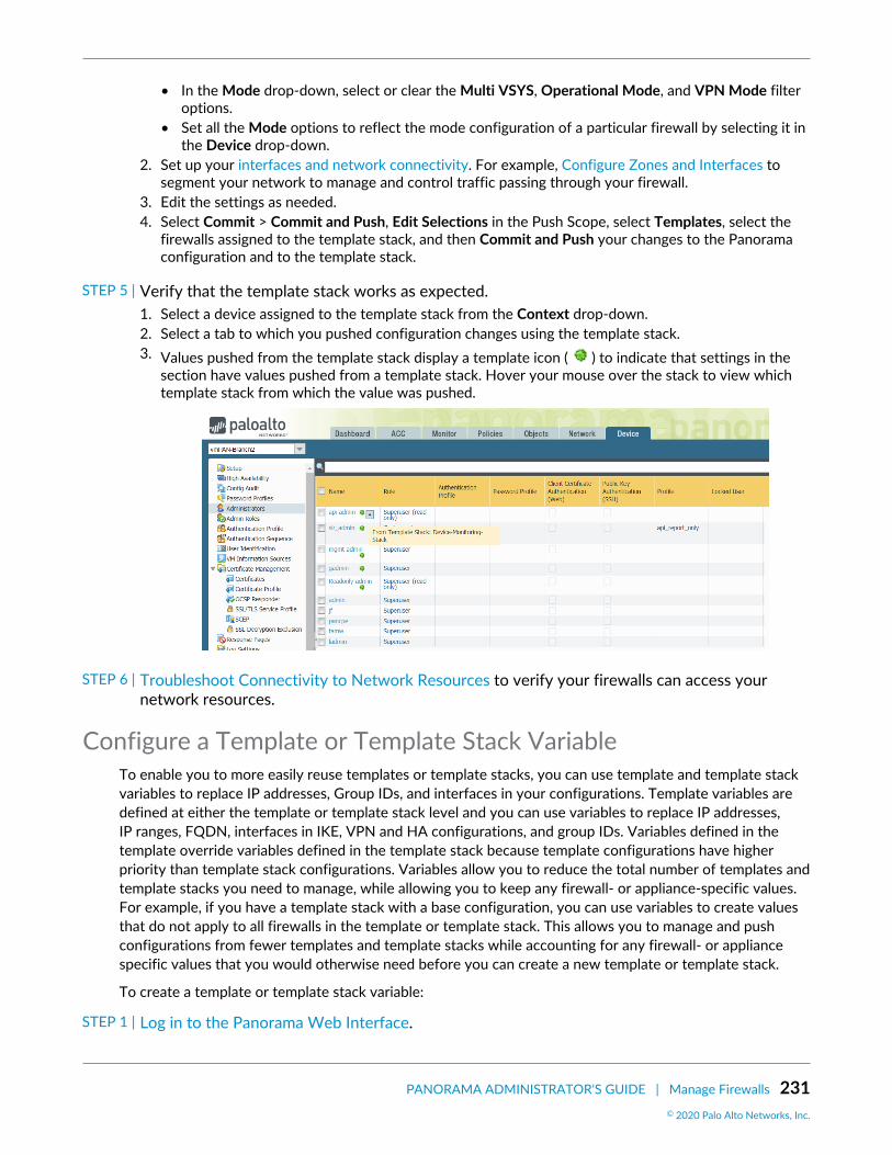
PANORAMA ADMINISTRATOR'S GUIDE | Manage Firewalls 231© 2020 Palo Alto Networks, Inc.
• In the Mode drop-down, select or clear the Multi VSYS, Operational Mode, and VPN Mode filteroptions.
• Set all the Mode options to reflect the mode configuration of a particular firewall by selecting it inthe Device drop-down.
2. Set up your interfaces and network connectivity. For example, Configure Zones and Interfaces tosegment your network to manage and control traffic passing through your firewall.
3. Edit the settings as needed.4. Select Commit > Commit and Push, Edit Selections in the Push Scope, select Templates, select the
firewalls assigned to the template stack, and then Commit and Push your changes to the Panoramaconfiguration and to the template stack.
STEP 5 | Verify that the template stack works as expected.1. Select a device assigned to the template stack from the Context drop-down.2. Select a tab to which you pushed configuration changes using the template stack.3. Values pushed from the template stack display a template icon ( ) to indicate that settings in the
section have values pushed from a template stack. Hover your mouse over the stack to view whichtemplate stack from which the value was pushed.
STEP 6 | Troubleshoot Connectivity to Network Resources to verify your firewalls can access yournetwork resources.
Configure a Template or Template Stack VariableTo enable you to more easily reuse templates or template stacks, you can use template and template stackvariables to replace IP addresses, Group IDs, and interfaces in your configurations. Template variables aredefined at either the template or template stack level and you can use variables to replace IP addresses,IP ranges, FQDN, interfaces in IKE, VPN and HA configurations, and group IDs. Variables defined in thetemplate override variables defined in the template stack because template configurations have higherpriority than template stack configurations. Variables allow you to reduce the total number of templates andtemplate stacks you need to manage, while allowing you to keep any firewall- or appliance-specific values.For example, if you have a template stack with a base configuration, you can use variables to create valuesthat do not apply to all firewalls in the template or template stack. This allows you to manage and pushconfigurations from fewer templates and template stacks while accounting for any firewall- or appliancespecific values that you would otherwise need before you can create a new template or template stack.
To create a template or template stack variable:
STEP 1 | Log in to the Panorama Web Interface.

232 PANORAMA ADMINISTRATOR'S GUIDE | Manage Firewalls© 2020 Palo Alto Networks, Inc.
STEP 2 | Create a template and template stack.1. Add a Template2. Configure a Template Stack.
STEP 3 | Select Panorama > Templates and Manage (Variables column) the template or template stackfor which you want to create a variable.
STEP 4 | Add the new variable.A variable name must start with the dollar ( $ ) symbol.
1. Name the new variable. In this example, the variables are named $DNS-primary and $DNS-secondary.
2. Select the variable Type and enter the corresponding value for the selected variable type.
For this example, select IP Netmask.3. Enter the corresponding value for Type.4. Click OK and Close
Variables can also be created inline where variables are supported.
STEP 5 | From the Template drop-down, select the template or template stack to which the variablebelongs.
STEP 6 | Enter the variable in the appropriate location.For this example, reference the previously defined DNS value.
1. Select Device > Setup > Services and edit Services.2. Type $DNS-primary or select it from the drop-down for Primary DNS Server.3. Type $DNS-secondary or select it from the drop-down for Secondary DNS Server.4. Click OK.
STEP 7 | Click Commit and Commit and Push your changes to managed firewalls.
When you push a device group configuration with references to template or templatestack variables, you must Edit Selections and Include Device and Network Templates.

PANORAMA ADMINISTRATOR'S GUIDE | Manage Firewalls 233© 2020 Palo Alto Networks, Inc.
STEP 8 | Verify that the values for all variables were pushed to the managed devices.1. From the Context drop-down, select a firewall that belongs to the template stack for which the
variable was created.2. Select Device > Setup > Services.3. Settings with values defined by a template or template stack are indicated by a template symbol ( ).
Hover over the indicator to view to which template or template stack the variable definition belongs.When viewing from the firewall context, the variables display as the IP address you configured forthe variable.
STEP 9 | Troubleshoot Connectivity to Network Resources to verify your firewalls can access yournetwork resources.
Import and Overwrite Existing Template Stack VariablesUse template stack variables to replace IP addresses, IP ranges, FQDN, interfaces, or group ID in yourfirewall configurations. Variables allow you to reduce the total number of templates and template stacksyou need to manage, while allowing you to preserve any firewall-specific values.
Importing template stack variables allows you to overwrite the values of multiple existing variables, and youcannot create new template stack variables when importing. For more information how on how to createnew template or template stack variable, see Configure a Template or Template Stack Variable.
STEP 1 | Log in to the Panorama Web Interface.
STEP 2 | Export the existing template stack variables.1. Select Panorama > Templates and select a template or template stack.2. Select Variable CSV > Export. The configured template stack variables are downloaded locally as a
CSV file.3. Open the exported CSV.
STEP 3 | Edit the CSV file containing the template stack variables to import to Panorama in thefollowing format:Values that display as #inherited# are values that are defined in the template stack.
1. Correct the number of the cells containing the firewall serial number. Repeat this step for all firewallsin the CSV file.
1. Right-click the cell containing the firewall serial number and select Format Cells.2. Select Number > Text and click OK.

234 PANORAMA ADMINISTRATOR'S GUIDE | Manage Firewalls© 2020 Palo Alto Networks, Inc.
3. Add a 0 at the beginning of the serial number.
2. Enter a new value for the desired template variable.3. Select File > Save As and save the file in CSV UTF-8 format.
STEP 4 | Import the CSV file to the template stack.1. Log in to the Panorama Web Interface.2. Select Panorama > Templates and select the template stack for which you exported the variables in
Step 2.3. Select Variable CSV > Import and Browse for the CSV file edited in Step 3.4. Click OK to import the template stack variables.
STEP 5 | Select Commit > Commit to Panorama and Commit your changes.
STEP 6 | Enter the variables in the appropriate locations.
STEP 7 | Click Commit and Commit and Push your changes to managed firewalls.
When you push a device group configuration with references to template or templatestack variables, you must Edit Selections and Include Device and Network Templates.
Override a Template or Template Stack ValueWhile Templates and Template Stacks enable you to apply a base configuration to multiple firewalls,you might want to configure firewall-specific settings that don’t apply to all the firewalls in a template ortemplate stack. Conversely, you may want to override the template settings to create a template stackconfiguration that you can apply as a base configuration to all your managed firewalls. Overrides allow forexceptions or modifications to meet your configuration needs. For example, if you use a template to createa base configuration but a few firewalls in a test lab environment need different settings for the Domain

PANORAMA ADMINISTRATOR'S GUIDE | Manage Firewalls 235© 2020 Palo Alto Networks, Inc.
Name System (DNS) server IP address or the Network Time Protocol (NTP) server, you can override thetemplate and template stack settings.
If you want to disable or remove all the template or stack settings on a firewall instead ofoverriding a single value, see Disable/Remove Template Settings.
You can override a template or template stack value in one of the following ways:
• Override a Template Value on the Firewall or Override a Template or Template Stack Value UsingVariables—There are two ways to override values pushed from a template or template stack. The firstis to define a value locally on the firewall to override a value pushed from a template or template stack.The second is to define firewall-specific variables to override values pushed from a template or templatestack.
• Override a Template Value Using a Template Stack—Define values or variables on the template stack tooverride values pushed from a template.
Override a Template Value on the FirewallOverride a setting on the local firewall that was pushed from a template or template stack to createfirewall-specific configurations. This allows you to manage the base template or template stackconfiguration from Panorama™, while maintaining any firewall-specific configurations that do not apply toother firewalls.
STEP 1 | Access the firewall web interface.Directly access the firewall by entering its IP address in the URL field of your browser or use the Contextdrop-down in Panorama to switch to the firewall context.
STEP 2 | Override a value pushed from a template or template Stack.In this example, you override the DNS server IP address that you assigned using a template in Add aTemplate
1. Select Device > Setup > Services and edit the Services section.2. Click the template icon ( ) for the Primary DNS Server to enable overrides for that field.3. Enter the new IP address for the Primary DNS Server. A template override symbol ( ) indicates
that the template value wasoverridden.4. Click OK and Commit your changes.
Override a Template Value Using a Template StackYou can use template stack values to override configurations pushed to the managed firewall from atemplate to create a template stack configuration that you can use to manage the base configuration ofyour managed firewalls from Panorama™. This enables you to leverage the management capabilities ofPanorama to push configuration changes to multiple devices from a single location. In this example, you willuse a template stack to override the Primary DNS server IP address variable called $DNS that was pushedfrom a template.
Panorama supports using a template stack to override interfaces configured in a templateexcept for Layer2 sub-interfaces of an aggregated interface.
STEP 1 | Log in to the Panorama Web Interface.
STEP 2 | From the Template drop-down, select the template stack that will override the templateconfiguration.

236 PANORAMA ADMINISTRATOR'S GUIDE | Manage Firewalls© 2020 Palo Alto Networks, Inc.
STEP 3 | Override the pushed template configuration.1. Select Device > Setup > Services and edit the Services section.2. Configure the Primary DNS with the IP address to override the pushed template configuration and
click OK.
STEP 4 | Commit and Push the configuration change.
Override a Template Value Using a Template Stack Variable
You can use template stack values and variables to override configurations pushed to the managed firewallfrom a template to create a template stack configuration that you can use to manage the base configurationof your managed firewalls from Panorama™. This enables you to leverage the management capabilities ofPanorama to push configuration changes to multiple firewalls from a single location. In this example, youwill create a template stack variable by overriding the Primary DNS server IP address variable called $DNSthat was pushed from a template.
Panorama supports using a template stack to override interfaces configured in a templateexcept for Layer2 sub-interfaces of an aggregated interface.
STEP 1 | Log in to the Panorama Web Interface.
STEP 2 | Override the template variable.1. Select Panorama > Templates.2. Manage (Variables column) the template stack containing the template variable you need to override.3. Locate and select the $DNS variable.4. Select Override.5. Enter the new variable value and click OK.
STEP 3 | Commit and Push your changes.
Override a Template or Template Stack Value Using VariablesYou can use firewall-specific variables to override variables pushed to the managed firewall from a templateor template stack to create firewall-specific configurations. This allows you to manage the base templateor template stack configuration while maintaining any firewall-specific configurations that do not applyto other firewalls—all from Panorama™. This allows you to leverage the management capabilities ofPanorama while accounting for any specific configurations required for individual firewalls. In this example,the Primary DNS server IP address variable called $DNS that has been pushed from a template will beoverridden to create a firewall-specific variable.
You can override template or template stack variables that have not been overridden. If atemplate or template stack variable is already overridden, Revert the override to create afirewall-specific variable.
STEP 1 | Log in to the Panorama Web Interface.
STEP 2 | Override the template or template stack variable.1. Select Panorama > Managed Devices > Summary.2. Edit (Variables column) the firewall containing the variable you need to override.3. Locate and select the $DNS variable.4. Select Override.5. Enter the new firewall-specific IP address and click OK.

PANORAMA ADMINISTRATOR'S GUIDE | Manage Firewalls 237© 2020 Palo Alto Networks, Inc.
STEP 3 | Commit and Push your changes.
Disable/Remove Template SettingsIf you want to stop using a template or template stack for managing the configuration on a managedfirewall, you can disable the template or stack. When disabling, you can copy the template/stack values tothe local configuration of the firewall or delete the values.
If you want to override a single setting instead of disabling or removing every template orstack setting, see Override a Template Setting.
See Templates and Template Stacks for details on how to use these for managing firewalls.
STEP 1 | Access the web interface of the managed firewall as an administrator with the Superuser role.You can directly access the firewall by entering its IP address in the browser URL field or, inPanorama, select the firewall in the Context drop-down.
STEP 2 | Select Device > Setup > Management and edit the Panorama Settings.
STEP 3 | Click Disable Device and Network Template.
STEP 4 | (Optional) Select Import Device and Network Template before disabling, to save theconfiguration settings locally on the firewall. If you do not select this option, PAN-OS willdelete all Panorama-pushed settings from the firewall.
STEP 5 | Click OK twice and then Commit the changes.

238 PANORAMA ADMINISTRATOR'S GUIDE | Manage Firewalls© 2020 Palo Alto Networks, Inc.
Manage the Master Key from PanoramaPanorama, firewalls, Log Collectors, and WF-500 appliances use a master key to encrypt sensitive elementsin the configuration and they have a default master key they use to encrypt passwords and configurationelements.
As part of a standard security practice, you should replace the default master key and change the key oneach individual firewall, Log Collector, WildFire appliance, and Panorama before it expires. You must deploythe same master key to all of your managed devices and you must configure the master key on Panoramato successfully push the configuration from Panorama to your managed devices. To ensure a uniform keydeployment, deploy a new master key or renew an expiring master key on multiple firewalls, Log Collectors,and WF-500 appliances directly from Panorama. See Configure the Master Key for more information onconfiguring a master key.
STEP 1 | Log in to the Panorama Web Interface.
STEP 2 | (Best Practice) Select Commit and Commit and Push any pending configuration changes.Panorama must re-encrypt data using the new master key. To ensure all configuration elements areencrypted with the new master key, you should commit all pending changes before deploying the newmaster key.
STEP 3 | Configure the firewall, Log Collector, and WildFire appliance master key to automaticallyrenew with the same master key after the lifetime of the key expires.Automatically renewing the master key allows you to keep your configuration encrypted in the eventthe key expires before a maintenance window but this is not a replacement for deploying a new masterkey after the key lifetime expires. Consider the number of days until your next available maintenancewindow when configuring the master key to automatically renew when the lifetime of the key expires.
1. Select Device > Master Key and Diagnostics and edit the Master Key setting.2. Configure Panorama to Auto Renew with Same Master Key for a specified number of days or hours.
STEP 4 | Deploy the master key to managed firewalls.1. Select Panorama > Managed Devices > Summary and Deploy Master Key.2. Select all devices and Change the master key.
3. Configure the master key:

PANORAMA ADMINISTRATOR'S GUIDE | Manage Firewalls 239© 2020 Palo Alto Networks, Inc.
1. If renewing a master key, enter the Current Master Key. If you are replacing the default masterkey with a new master key, do not specify a Current Master Key.
2. Specify the New Master Key and Confirm Master Key.3. Configure the master key Lifetime and Time for Reminder.4. Click OK.
4. Verify that the master key was deployed successfully to all selected devices.
A System log generates when you deploy a new master key from Panorama.
STEP 5 | Deploy the master key to Log Collectors. The master key must be identical to the key deployedin Step 3.1. Select Panorama > Managed Collectors and Deploy Master Key.2. Select all devices and Change the master key.3. Configure the master key:
1. If renewing a master key, enter the Current Master Key. If you are replacing the default masterkey with a new master key, do not specify a Current Master Key.
2. Specify the New Master Key and Confirm Master Key.3. Configure the master key Lifetime and Time for Reminder.4. Click OK.
4. Verify that the master key was deployed successfully to all selected devices.

240 PANORAMA ADMINISTRATOR'S GUIDE | Manage Firewalls© 2020 Palo Alto Networks, Inc.
A System log generates when you deploy a new master key from Panorama.
STEP 6 | Deploy the master key to managed WildFire appliances. The master key must be identical tothe key deployed in Step 3.1. Select Panorama > Managed WildFire Appliances and Deploy Master Key.2. Select all devices and Change the master key.3. Configure the master key:
1. If renewing a master key, enter the Current Master Key. If you are replacing the default masterkey with a new master key, do not specify a Current Master Key.
2. Specify the New Master Key and Confirm Master Key.3. Configure the master key Lifetime and Time for Reminder.4. Click OK.
4. Verify that the master key was deployed successfully to all selected devices.
A System log generates when you deploy a new master key from Panorama.
STEP 7 | Configure the master key on Panorama. The master key must be identical to the key deployedto firewalls, Log Collectors, and WildFire appliances in Steps 3 through 5.1. Select Panorama > Master Key and Diagnostics and configure the master key.
1. If renewing a master key, enter the Current Master Key. If you are replacing the default masterkey with a new master key, o not specify a Current Master Key.
2. Configure the New Master Key and Confirm Master Key.3. Configure the master key Lifetime and Time for Reminder.4. Click OK.
2. Select Commit > Commit to Panorama and Commit your changes.

PANORAMA ADMINISTRATOR'S GUIDE | Manage Firewalls 241© 2020 Palo Alto Networks, Inc.
Redistribute User-ID Information to ManagedFirewalls
To ensure all the firewalls that enforce policies and generate reports have the required IP address-to-username mappings and authentication timestamps for your entire user base, you can leverage yourPanorama and distributed log collection infrastructure to redistribute the mappings and timestamps.
Before you configure User-ID Redistribution Using Panorama and Log Collectors:
• Configure user mapping using PAN-OS Integrated User-ID agents or Windows-based User-ID Agents.• Configure the firewalls to redistribute User-ID information.
• Configure a Dedicated Log Collector to redistribute User-ID information.
A Log Collector that is local to the Panorama management server does not redistributeUser-ID information.
1. Add Panorama, firewalls, or virtual systems as User-ID redistribution points to a Log Collector:
1. Select Panorama > Managed Collectors and select the Log Collector to edit it.2. Select User-ID Agents and Add a redistribution point.
1. Enter a Name to identify the redistribution point.2. Enter the Host name or IP address of the interface on the firewall or Panorama that will
respond to User-ID information queries from the Log Collector.3. Enter the Port number on which Panorama or the firewall will listen for User-ID information
queries (default is 5007).4. If the redistribution point is a firewall or virtual system, enter the Collector Name and
Collector Pre-Shared Key.
In this context, the collector is a User-ID collector, not a Log Collector.
5. Click OK to save your changes.2. Enable the management (MGT) interface of the Log Collector to respond to User-ID information
queries from Panorama or firewalls:
1. Select Panorama > Managed Collectors and select the Log Collector to edit it.2. Select Interfaces and Management.3. Select User-ID in the Network Connectivity Services section and click OK.
3. Click OK to save your changes to the Log Collector.4. Select Commit > Commit and Push to activate your changes on Panorama and push the changes to
the Log Collector.
• Configure the Panorama management server to redistribute User-ID information.1. Add Log Collectors, firewalls, or virtual systems as redistribution points to Panorama:
1. Select Panorama > User Identification and Add each redistribution point.2. Enter a Name to identify the redistribution point.3. Enter the Host name or IP address of the MGT interface on the Log Collector or firewall.4. Enter the Port number on which the Log Collector or firewall will listen for User-ID information
queries (default is 5007).

242 PANORAMA ADMINISTRATOR'S GUIDE | Manage Firewalls© 2020 Palo Alto Networks, Inc.
5. If the redistribution point is a firewall or virtual system, enter the Collector Name and CollectorPre-Shared Key.
6. Click OK to save the configuration.2. Enable the Panorama MGT interface to respond to User-ID information queries from Log Collectors
or firewalls:
If the Panorama management server has a high availability (HA) configuration,perform this step on each HA peer as a best practice so that redistribution continues ifPanorama fails over.
1. Select Panorama > Setup > Interfaces and Management.2. Select User-ID in the Network Connectivity Services section and click OK.
3. Select Commit > Commit to Panorama to activate your changes on Panorama.
• Configure firewalls to receive User-ID information from Panorama or Log Collectors.
If you are using Panorama to manage both your firewall and the Dedicated Log Collector(DLC), and you want to configure the firewall to receive User-ID information fromPanorama or the log collectors, add the User-ID agent using the serial number to thePanorama template, then push the template to the firewall. If you add the User-ID agenton the firewall using the serial number, you will only see Panorama and not the DLC, andyou will need to add the DLC to the firewall using the host and port number.
1. Select Device > User Identification > User-ID Agents, select the Template to which the firewalls areassigned, and Add one of the following as a redistribution point:
• Panorama—Add an Agent Using the Serial Number, and set the Serial Number to panorama forthe active or solitary Panorama or to panorama2 (HA only) for the passive Panorama.
• Log Collector—Add an Agent Using the Host and Port. Enter the Host name or IP address of theMGT interface on the Log Collector. Then enter the Port number on which the Log Collectorlistens for User-ID information queries (default is 5007).
2. Click OK to save the configuration.3. Select Commit > Commit and Push to activate your changes on Panorama and push the changes to
the firewalls.
• Verify that Panorama, Log Collectors, and firewalls receive redistributed user mappings.1. Access the CLI of a firewall, Log Collector, or Panorama management server that redistributes User-
ID information.2. Display all the user mappings by running the following command:
> show user ip-user-mapping all
3. Record the IP address associated with any one username.4. Access the CLI of a firewall, Log Collector, or Panorama management server that receives
redistributed User-ID information.5. Display the mapping information and authentication timestamp for the <IP-address> you recorded:
> show user ip-user-mapping ip <IP-address> IP address: 192.0.2.0 (vsys1) User: corpdomain\username1 From: UIA Idle Timeout: 10229s Max. TTL: 10229s

PANORAMA ADMINISTRATOR'S GUIDE | Manage Firewalls 243© 2020 Palo Alto Networks, Inc.
MFA Timestamp: first(1) - 2016/12/09 08:35:04 Group(s): corpdomain\groupname(621)
This example output shows the timestamp for a response to one authenticationchallenge (factor). For Authentication rules that use multi-factor authentication (MFA),the output shows multiple timestamps.
244 PANORAMA ADMINISTRATOR'S GUIDE | Manage Firewalls© 2020 Palo Alto Networks, Inc.
Transition a Firewall to Panorama ManagementIf you have already deployed Palo Alto Networks firewalls and configured them locally, but now want to usePanorama for centrally managing them, you must perform pre-migration planning. The migration involvesimporting firewall configurations into Panorama and verifying that the firewalls function as expected afterthe transition. If some settings are unique to individual firewalls, you can continue accessing the firewalls tomanage the unique settings. You can manage any given firewall setting by pushing its value from Panoramaor by configuring it locally on the firewall, but you cannot manage the setting through both Panorama andthe firewall. If you want to exclude certain firewall settings from Panorama management, you can either:
• Migrate the entire firewall configuration and then, on Panorama, delete the settings that you will managelocally on firewalls. You can also Override a Template Setting that Panorama pushes to a firewall insteadof deleting the setting on Panorama.
• Load a partial firewall configuration, including only the settings that you will use Panorama to manage.
Firewalls do not lose logs during the transition to Panorama management.
• Plan the Transition to Panorama Management• Migrate a Firewall to Panorama Management• Migrate a Firewall HA Pair to Panorama Management• Load a Partial Firewall Configuration into Panorama
Plan the Transition to Panorama ManagementThe following tasks are a high-level overview of the planning required to migrate firewalls to Panoramamanagement:
Decide which firewalls to migrate.Determine the Panorama and firewall software and content versions, and how you will Manage Licensesand Updates. For important details, see Panorama, Log Collector, Firewall, and WildFire VersionCompatibility.Plan Your Panorama Deployment with respect to the URL filtering database (BrightCloud or PAN-DB),log collection, and administrator roles.Plan how to manage shared settings.
Plan the Device Group Hierarchy, Templates and Template Stacks in a way that will reduce redundancyand streamline the management of settings that are shared among all firewalls or within firewall sets.During the migration, you can select whether to import objects from the Shared location on the firewallinto Shared on Panorama, with the following exceptions:
• If a shared firewall object has the same name and value as an existing shared Panorama object, theimport excludes that firewall object.
• If the name or value of the shared firewall object differs from an existing shared Panorama object,Panorama imports the firewall object into each new device group that is created for the import.
• If a configuration imported into a template references a shared firewall object, or if a shared firewallobject references a configuration imported into a template, Panorama imports the object as a sharedobject regardless of whether you select the Import devices' shared objects into Panorama's sharedcontext check box.
Determine if the firewall has configuration elements (policies, objects, and other settings) that you don’twant to import, either because Panorama already contains similar elements or because those elementsare firewall-specific (for example, timezone settings) and you won’t use Panorama to manage them. Youcan perform a global find to determine if similar elements exist on Panorama.

PANORAMA ADMINISTRATOR'S GUIDE | Manage Firewalls 245© 2020 Palo Alto Networks, Inc.
Decide the common zones for each device group. This includes a zone-naming strategy for the firewallsand virtual systems in each device group. For example, if you have zones called Branch LAN and WAN,Panorama can push policy rules that reference those zones without being aware of the variations in portor media type, model, or logical addressing schema.Create a post-migration test plan.
You will use the test plan to verify that the firewalls work as efficiently after the migration as they didbefore. The plan might include tasks such as:
• Monitor the firewalls for at least 24 hours after the migration.• Monitor Panorama and firewall logs for anomalies.• Check administrator logins on Panorama.• Test various types of traffic from multiple sources. For example, check bandwidth graphs, session
counts, and deny-rule traffic log entries (see Use Panorama for Visibility). The testing should cover arepresentative sample of policy configurations.
• Check with your network operations center (NOC) and security operations center (SOC) for any user-reported issues.
• Include any other test criteria that will help verify firewall functionality.
Migrate a Firewall to Panorama ManagementWhen you import a firewall configuration, Panorama automatically creates a template to containthe imported network and device settings. To contain the imported policies and objects, Panoramaautomatically creates one device group for each firewall or one device group for each virtual system (vsys)in a multi-vsys firewall.
When you perform the following steps, Panorama imports the entire firewall configuration. Alternatively,you can Load a Partial Firewall Configuration into Panorama.
Panorama can import configurations from firewalls that run PAN-OS 5.0 or later releasesand can push configurations to those firewalls. The exception is that Panorama 6.1 and laterreleases cannot push configurations to firewalls running PAN-OS 6.0.0 through 6.0.3.
Panorama can import configurations from firewalls that are already managed devices butonly if they are not already assigned to device groups or templates.
STEP 1 | Plan the migration.See the checklist in Plan the Transition to Panorama Management.
STEP 2 | Add the firewall as a managed device.Add a Firewall as a Managed Device:
1. Log in to Panorama, select Panorama > Managed Devices > Summary and click Add.2. Enter the serial number of the firewall and click OK.
If you will import multiple firewall configurations, enter the serial number of each oneon a separate line. Optionally, you can copy and paste the serial numbers from aMicrosoft Excel worksheet.
3. Select Commit > Commit to Panorama and Commit your changes.
STEP 3 | Set up a connection from the firewall to Panorama.1. Log in to the firewall, select Device > Setup, and edit the Panorama Settings.2. In the Panorama Servers fields, enter the IP addresses of the Panorama management server.3. Click OK and Commit.

246 PANORAMA ADMINISTRATOR'S GUIDE | Manage Firewalls© 2020 Palo Alto Networks, Inc.
STEP 4 | Import the firewall configuration into Panorama.
If you later decide to re-import a firewall configuration, first remove the firewall devicegroups and template to which it is a member. If the device group and template names arethe same as the firewall hostname, then you can delete the device group and templatebefore re-importing the firewall configuration or use the Device Group Name Prefixfields to define new names for the device group and template created by the re-import.Additionally, firewalls don’t lose logs when you remove them from device groups ortemplates.
1. From Panorama, select Panorama > Setup > Operations, click Import device configuration toPanorama, and select the Device.
Panorama can’t import a configuration from a firewall that is assigned to an existingdevice group or template.
2. (Optional) Edit the Template Name. The default value is the firewall name. You can’t use the name ofan existing template or template stack.
3. (Optional) Edit the Device Group names. For a multi-vsys firewall, each device group has a vsys nameby default, so add a character string as a Device Group Name Prefix for each. Otherwise, the defaultvalue is the firewall name. You can’t use the names of existing device groups.
The Import devices' shared objects into Panorama's shared context check box isselected by default, which means Panorama compares imports objects that belong tothe Shared location in the firewall to Shared in Panorama. If an imported object is notin the Shared context of the firewall, it is applied to each device group being imported.If you clear the check box, Panorama copies will not compare imported objects, andapply all shared firewall objects into device groups being imported instead of Shared.This could create duplicate objects, so selecting the check box is a best practice inmost cases. To understand the consequences of importing shared or duplicate objectsinto Panorama, see Plan how to manage shared settings.
4. Select a Rule Import Location for the imported policy rules: Pre Rulebase or Post Rulebase.Regardless of your selection, Panorama imports default security rules (intrazone-default andinterzone-default) into the post-rulebase.
If Panorama has a rule with the same name as a firewall rule that you import,Panorama displays both rules. Delete one of the rules before performing a Panoramacommit to prevent a commit error.
5. Click OK. Panorama displays the import status, result, details about your selections, details aboutwhat was imported, and any warnings. Click Close.
6. Select Commit > Commit to Panorama and Commit your changes.
STEP 5 | Push the configuration from Panorama to the newly added device.To prevent duplicate rule or object names, push the device group configuration from Panorama to thefirewall to avoid commit errors.
This step is required to successfully migrate firewall management to the Panoramamanagement server. Failure to perform this step successfully causes configuration errorsand commit failures.
1. Log in to the Panorama Web Interface and select Panorama > Setup > Operations and click Export orpush device config bundle.
2. Click Export or push device config bundle, select the Device from the drop-down menu, and clickOK.

PANORAMA ADMINISTRATOR'S GUIDE | Manage Firewalls 247© 2020 Palo Alto Networks, Inc.
3. Select the Device from which you imported the configuration, click OK, and click Push & Commit.Panorama pushes the bundle and initiates a commit on the firewall.
4. Click Close after the push has committed successfully.5. Launch the Web Interface of the firewall and ensure that the configuration has been successfully
committed. If not, Commit the changes locally on the firewall.6. On the Panorama web interface, Select Panorama > Managed Devices > summary, and verify that
the device group and template stack are in sync for the passive firewall. Verify policy rules, objectsand network settings on the passive firewall match the active firewall. On the firewall web interface,verify that configuration objects display a green cog ( ), signifying that the configuration object ispushed from Panorama.
7. Select Commit > Commit to Panorama and Commit your changes.
STEP 6 | Fine-tune the imported configuration.1. In Panorama, select Panorama > Config Audit, select the Running config and Candidate config for
the comparison, click Go, and review the output.2. Update the device group and template configurations as needed based on the configuration audit and
any warnings that Panorama displayed after the import. For example:
• Delete redundant objects and policy rules.• Move or Clone a Policy Rule or Object to a Different Device Group.• Move firewalls to different device groups or templates.• Move a device group that Panorama created during the import to a different parent device group:
Select Panorama > Device Groups, select the device group you want to move, select a newParent Device Group, and click OK.
STEP 7 | Push the firewall configuration bundle to the firewall to remove all policy rules and objectsfrom its local configuration.This step is necessary to prevent duplicate rule or object names, which would cause commit errors whenyou push the device group configuration from Panorama to the firewall in the next step.
1. In Panorama, select Commit > Commit to Panorama and Commit your changes.2. Select Panorama > Setup > Operations and click Export or push device config bundle.3. Select the Device from which you imported the configuration, click OK, and click Push & Commit.
Panorama pushes the bundle and initiates a commit on the firewall.
STEP 8 | Push the device group and template configurations to complete the transition to centralizedmanagement.If you are migrating multiple firewalls, perform all the preceding steps—including this one—for eachfirewall before continuing.
1. Select Commit > Commit and Push and Edit Selections in the Push Scope.2. Select Device Groups and select the device groups that contain the imported firewall configurations.3. Select Merge with Device Candidate Config, Include Device and Network Templates, and Force
Template Values.4. Click OK to save your changes to the Push Scope.5. Commit and Push your changes.
STEP 9 | Consolidate all the imported firewall configurations.This step is required if you are migrating multiple firewalls.
1. After importing all the firewall configurations, update the device groups and templates as neededto eliminate redundancy and streamline configuration management: see Fine-tune the importedconfiguration. (You don’t need to push firewall configuration bundles again.)

248 PANORAMA ADMINISTRATOR'S GUIDE | Manage Firewalls© 2020 Palo Alto Networks, Inc.
2. Configure any firewall-specific settings.
If the firewalls will have local zones, you must create them before performing a device group ortemplate commit; Panorama can’t poll the firewalls for zone name or zone configuration. If you willuse local firewall rules, ensure their names are unique (not duplicated in Panorama). If necessary, youcan Override a Template or Template Stack Value with a firewall-specific value.
3. Commit and push your changes:
1. Select Commit > Commit and Push and Edit Selections in the Push Scope.2. Select Device Groups, select the device groups you changed, and Include Device and Network
Templates.3. Click OK to save your changes to the Push Scope.4. Commit and Push your changes.
STEP 10 | Perform your post-migration test plan.Perform the verification tasks that you devised during the migration planning to confirm that thefirewalls work as efficiently with the Panorama-pushed configuration as they did with their original localconfiguration: see Create a post-migration test plan.
Migrate a Firewall HA Pair to Panorama ManagementIf you have a pair of firewalls in an HA configuration that you want to manage using Panorama, you havethe option to import the configuration local to your firewall HA pair to Panorama without needing torecreate any configurations or policies. You first import the firewall configurations to Panorama, whichare used to create a new device group and template. You will perform a special configuration push of thedevice group and template to the firewalls to overwrite the local firewall configurations and synchronize thefirewalls with Panorama.
STEP 1 | Plan the migration.See the checklist in Plan the Transition to Panorama Management.
STEP 2 | Disable configuration synchronization between the HA peers.Repeat these steps for both firewalls in the HA pair.
1. Log in to the web interface on each firewall, select Device > High Availability > General and edit theSetup section.
2. Clear Enable Config Sync and click OK.3. Commit the configuration changes on each firewall.
STEP 3 | Connect each firewall to Panorama.
If Panorama is already receiving logs from these firewalls, you do not need to perform thisstep. Continue to Step 5.
Repeat these steps for both firewalls in the HA pair.
1. Log in to the web interface on each firewall, select Device > Setup > Management and edit thePanorama Settings.
2. In the Panorama Servers fields, enter the IP addresses of the Panorama management servers, confirmPanorama Policy and Objects and Device and Network Template are enabled and select OK.
3. Commit the configuration changes on each firewall.
STEP 4 | Add each firewall as a managed device.

PANORAMA ADMINISTRATOR'S GUIDE | Manage Firewalls 249© 2020 Palo Alto Networks, Inc.
If Panorama is already receiving logs from these firewalls, you do not need to perform thisstep. Continue to Step 5.
Add a Firewall as a Managed Device.
1. Log in to the Panorama Web Interface, select Panorama > Managed Devices and click Add.2. Enter the serial number of each firewall and click OK.3. Select Commit > Commit to Panorama and Commit your changes.4. Verify that the Device State for each firewall is Connected.
STEP 5 | Import each firewall configuration into Panorama.
If you later decide to re-import a firewall configuration, first remove the firewall devicegroups and template to which it is a member. If the device group and template names arethe same as the firewall hostname, then you can delete the device group and templatebefore re-importing the firewall configuration or use the Device Group Name Prefixfields to enter a new name for the device group and template created by the re-import.Additionally, firewalls don’t lose logs when you remove them from device groups ortemplates.
1. From Panorama, select Panorama > Setup > Operations, click Import device configuration toPanorama, and select the Device.
Panorama can’t import a configuration from a firewall that is assigned to an existingdevice group or template stack.
2. (Optional) Edit the Template Name. The default value is the firewall name. You can’t use the name ofan existing template or template stack.
3. (Optional) Edit the Device Group names. For a multi-vsys firewall, each device group has a vsys nameby default, so add a character string as a Device Group Name Prefix for each. Otherwise, the defaultvalue is the firewall name. You can’t use the names of existing device groups.
The Imported devices’ shared objects into Panorama’s shared context check box isselected by default, which means Panorama compares imports objects that belong tothe Shared location in the firewall to Shared in Panorama. If an imported object is notin the Shared context of the firewall, it is applied to each device group being imported.If you clear the check box, Panorama copies will not compare imported objects, andapply all shared firewall objects into device groups being imported instead of Shared.This could create duplicate objects, so selecting the check box is a best practice inmost cases. To understand the consequences of importing shared or duplicate objectsinto Panorama, see Plan how to manage shared settings.
4. Commit to Panorama.5. Select Panorama > Setup > Operations and Export or push device config bundle. Select the Device,
select OK and Push & Commit the configuration.
The Enable Config Sync setting in Step 2 must be cleared on both firewalls before youpush the device group and template stack.

250 PANORAMA ADMINISTRATOR'S GUIDE | Manage Firewalls© 2020 Palo Alto Networks, Inc.
6. Launch the Web Interface of firewall HA peer and ensure that the configuration has beensuccessfully committed. If not, Commit the changes locally on the firewall.
7. On the Panorama web interface, select Panorama > Managed Devices > Summary, and verify thatthe device group and template stack are in sync for the passive firewall. Verify policy rules, objectsand network settings on the passive firewall match the active firewall. On the firewall web interface,verify that configuration objects display a green cog ( ), signifying that the configuration object ispushed from Panorama.
8. Commit to Panorama.9. Repeat Step 1-8 above on the second firewall. The process will create a device group and template
stack for the firewall.10.Select Commit > Commit to Panorama and Commit your changes.
STEP 6 | Add the HA firewall pair into the same device group and template stack.Skip this step if the HA firewall pair are in an active/active configuration.
Do not combine the HA firewall pair in to a single template if a unique Hostname, managementIP address, or HA configuration is configured for each HA peer. You may also configure a uniqueHostname, management IP address, or HA configuration locally on the firewalls.
1. Select Panorama > Device Group, select the device group of the second firewall and Delete it.2. Select the device group for the first firewall, select the second firewall, click OK and Commit to
Panorama to add it to the same device group as the HA peer.3. Select Panorama > Templates, select the template stack for the second firewall and Delete it.4. Select the template stack for the first firewall, add the second firewall, select OK and Commit to
Panorama to add it to the same template stack as the HA peer.5. If you add the HA peers to the same template stack, Configure a Template or Template Stack
Variable to preserve the firewall-specific HA configurations.
If you do not want to manage the firewall HA configuration from Panorama, deletethe firewall HA configuration from the template or template stack, Launch the WebInterface of each firewall HA peer and configure the HA IP address locally.
6. Select Commit and Commit and Push the configuration changes.
You must push the Panorama configuration in the previous step to both firewall HApeers to successfully synchronize the configuration between the HA peers.
7. Select Panorama > Managed Devices > Summary, and verify that the device group and templateare in sync for the passive firewall. Verify policy rules, objects and network settings on the passivefirewall match the active firewall.
STEP 7 | Enable configuration synchronization between the HA peers.Repeat these steps for both firewalls in the HA pair if you plan on maintaining a local configuration thatneeds to be synchronized.
1. Log in to the web interface on each firewall, select Device > High Availability > General and edit theSetup section.
2. Select Enable Config Sync and click OK.3. Commit the configuration changes on each firewall.
Load a Partial Firewall Configuration into PanoramaIf some configuration settings on a firewall are common to other firewalls, you can load those specificsettings into Panorama and then push them to all the other firewalls or to the firewalls in particular devicegroups and templates.

PANORAMA ADMINISTRATOR'S GUIDE | Manage Firewalls 251© 2020 Palo Alto Networks, Inc.
Loading a configuration into a Panorama management server requires a full commit and must be performedby a superuser. Full commits are required when performing certain Panorama operations, such as revertingand loading a configuration snapshot, and are not supported for custom Admin Role profiles.
STEP 1 | Plan the transition to Panorama.See the checklist in Plan the Transition to Panorama Management.
STEP 2 | Resolve how to manage duplicate settings, which are those that have the same names inPanorama as in a firewall.Before you load a partial firewall configuration, Panorama and that firewall might already have duplicatesettings. Loading a firewall configuration might also add settings to Panorama that are duplicates ofsettings in other managed firewalls.
If Panorama has policy rules or objects with the same names as those on a firewall,a commit failure will occur when you try to push device group settings to that firewall.If Panorama has template settings with the same names as those on a firewall, thetemplate values will override the firewall values when you push the template.
1. On Panorama, perform a global find to determine if duplicate settings exist.2. Delete or rename the duplicate settings on the firewall if you will use Panorama to manage them, or
delete or rename the duplicate settings on Panorama if you will use the firewall to manage them. Ifyou will use the firewall to manage device or network settings, instead of deleting or renaming theduplicates on Panorama, you can also push the settings from Panorama (Step 6) and then Override aTemplate or Template Stack Value on the firewall with firewall-specific values.
STEP 3 | Export the entire firewall configuration to your local computer.1. On the firewall, select Device > Setup > Operations.2. Click Save named configuration snapshot, enter a Name to identify the configuration, and click OK.3. Click Export named configuration snapshot, select the Name of the configuration you just saved, and
click OK. The firewall exports the configuration as an XML file.
STEP 4 | Import the firewall configuration snapshot into Panorama.1. On Panorama, select Panorama > Setup > Operations.2. Click Import named Panorama configuration snapshot, Browse to the firewall configuration file you
exported to your computer, and click OK.
After using this option to import a firewall configuration file, you can’t use thePanorama web interface to load it. You must use the XML API or CLI, as described inthe next step.
STEP 5 | Load the desired part of the firewall configuration into Panorama.To specify a part of the configuration (for example, all application objects), you must identify the:
• Source xpath—The XML node in the firewall configuration file from which you are loading.• Destination xpath—The node in the Panorama configuration to which you are loading.
Use the XML API or CLI to identify and load the partial configuration:
1. Use the firewall XML API or CLI to identify the source xpath.
For example, the xpath for application objects in vsys1 of the firewall is:

252 PANORAMA ADMINISTRATOR'S GUIDE | Manage Firewalls© 2020 Palo Alto Networks, Inc.
/config/devices/entry[@name='localhost.localdomain']/vsys/entry[@name='vsys1']/application
2. Use the Panorama XML API or CLI to identify the destination xpath.
For example, to load application objects into a device group named US-West, the xpath is:
/config/devices/entry[@name='localhost.localdomain']/device-group/entry[@name='US-West']/application
3. Use the Panorama CLI to load the configuration and commit the change:
# load config partial mode [append|merge|replace] from-xpath <source-xpath> to-xpath <destination-xpath> from <filename> # commit
For example, enter the following to load the application objects from vsys1 on an imported firewallconfiguration named fw1-config.xml into a device group named US-West on Panorama:
# load config partial mode merge from-xpath devices/entry[@name='localhost.localdomain']/vsys/entry[@name='vsys1']/application to-xpath /config/devices/entry[@name='localhost.localdomain']/device-group/entry[@name='US-West']/application from fw1-config.xml # commit
STEP 6 | Push the partial configuration from Panorama to the firewall to complete the transition tocentralized management.1. On the firewall, delete any rules or objects that have the same names as those in Panorama. If
the device group for that firewall has other firewalls with rules or objects that are duplicated inPanorama, perform this step on those firewalls also. For details, see Step 2.
2. On Panorama, push the partial configuration to the firewall.
1. Select Commit > Commit and Push and Edit Selections in the Push Scope.2. Select Device Groups and select the device groups that contain the imported firewall
configurations.3. Select Merge with Device Candidate Config, Include Device and Network Templates, and Force
Template Values.4. Click OK to save your changes to the Push Scope.5. Commit and Push your changes.
3. If the firewall has a device or network setting that you won’t use Panorama to manage, Override aTemplate or Template Stack Value on the firewall.
STEP 7 | Perform your post-migration test plan.Perform the verification tasks that you devised during the migration planning to confirm that thefirewall works as efficiently with the Panorama-pushed configuration as it did with its original localconfiguration: see Create a post-migration test plan.

PANORAMA ADMINISTRATOR'S GUIDE | Manage Firewalls 253© 2020 Palo Alto Networks, Inc.
Device Monitoring on PanoramaAfter adding your firewalls and configuring policy rules, you can monitor the health status to ensure thatyour firewalls are operating within healthy parameters. For policy rules, monitor rule traffic matches toidentify which rules match your traffic enforcement needs.
• Monitor Device Health• Monitor Policy Rule Usage
Monitor Device HealthMonitor the health information of your managed firewalls to identify and resolve hardware issues beforethey impact your network security. Both Panorama™ and the managed firewalls must be running PAN-OS®
8.1 or later releases but firewalls do not need to be part of a device group or template stack to monitor theirsummary session, logging, resource, and environmental performance. Panorama stores the last 90 days ofhealth monitoring statistics of your managed firewalls so when you select a firewall, you can view the time-trended graphs and tables for sessions, environmentals, interfaces, logging, resources, and high availabilityperformance. Panorama calculates the baseline performance of each metric using seven-day averages andstandard deviation to determine a normal operating range for the specific firewall. In addition to trackingthe baseline and comparing time-trended performance, you can view which firewalls have deviating metricsand isolate performance-related issues before they impact your network. When Panorama identifies that ametric is outside the normal operating range, it marks the metric and populates the Deviating Devices tabwith the deviating firewall.
The health monitoring data is stored on Panorama, and is preserved in the event a firewall is removed.When a firewall is removed from Panorama management, the health monitoring data no longer display butare preserved for 90 days. After 90 days, all health monitoring data of the removed firewall are removedfrom Panorama. If a firewall is added back to Panorama management, the latest health monitoring data fromwhen the firewall was removed is displayed.
STEP 1 | Log in to the Panorama Web Interface.
STEP 2 | Select Panorama > Managed Devices > Health to monitor the health of managed firewalls.View All Devices to see a list of all managed firewalls and the monitored health metrics. Select anindividual firewall to view Detailed Device View with time-trended graphs and tables of monitoredmetrics.
Figure 12: Managed Firewall Health Monitoring

254 PANORAMA ADMINISTRATOR'S GUIDE | Manage Firewalls© 2020 Palo Alto Networks, Inc.
Figure 13: Detailed Device View
STEP 3 | Select Deviating Devices to view firewalls with health metrics that deviated outside of thecalculated baseline.Panorama lists all firewalls that are reporting metrics that deviate from the calculated baseline anddisplays deviating metrics in red.
Monitor Policy Rule UsageAs your policies change, tracking rule usage on Panorama helps you evaluate whether your policyimplementation continues to match your enforcement needs. This visibility helps you identify and removeunused rules to reduce security risks and keep your policy rule base organized. Additionally, rule usagetracking allows you to quickly validate new rule additions and rule changes and to monitor rule usage foroperations and troubleshooting tasks. On Panorama, you can view the rule usage of firewalls in a devicegroup—to which you pushed policies—to determine if all, some, or none of the firewalls have traffic matchesinstead of being able to monitor only the total number of hits across all firewalls in a device group. You canquickly filter rules using the rule usage data, such as Created and Modified dates, within a customizable timeframe. The displayed rule usage information persists across reboot, dataplane restarts, and upgrades.
On Panorama, you can view the rule usage details for managed firewalls that are running a PAN-OS 8.1 orlater release, that have policy rule hit count enabled (default), and for which you have defined and pushedpolicy rules using device groups. Panorama cannot retrieve rule usage details for policy rules configured

PANORAMA ADMINISTRATOR'S GUIDE | Manage Firewalls 255© 2020 Palo Alto Networks, Inc.
locally on the firewall so you must log in to the firewall to view rule usage information for locally configuredrules.
Policy rule usage data may also be useful when using Policy Optimizer to prioritize whichrules to migrate or clean up first.
To view the rule usage across any Shared rule or for a specific device group:
STEP 1 | Log in to the Panorama Web Interface.
STEP 2 | Verify that the Policy Rule Hit Count is enabled.1. Navigate to Policy Rulebase Settings (Panorama > Setup > Management.2. Verify that Policy Rule Hit Count is enabled.
STEP 3 | Select Policies > <policy rule> to view a rule.
STEP 4 | Change the Device Group context to Shared or to the specific device group you want to view.
STEP 5 | Determine whether the rule is being used (Rule Usage). The policy rule usage status is one ofthe following:Firewalls must run PAN-OS 8.1 or later release with Policy Rule Hit Count enabled for Panorama todetermine rule usage.
• Used—When all firewalls in the device group—to which you pushed the policy rule—have trafficmatches for the policy rule.
• Partially Used—When some of the firewalls in the device group—to which you pushed the policy rule—have traffic matches for the policy rule.
• Unused—When no firewalls in the device group—to which you pushed the policy rule—have trafficmatches for the policy rule.
• Em-dash (—)—When no firewalls in the device group—to which you pushed the policy rule—havePolicy Rule Hit Count enabled or available for Panorama to determine the rule usage.
• Modified—The date and time the policy rule was last modified.• Created—The date and time the policy rule was created.
If the rule was created when Panorama was running PAN-OS 8.1 and the Policy RuleHit Count setting is enabled, the First Hit date and time is used as the Created dateand time on upgrade to PAN-OS 9.1. If the rule was created in PAN-OS 8.1 when thePolicy Rule Hit Count setting was disabled or if the rule was created when Panoramawas running PAN-OS 8.0 or an earlier release, the Created date for the rule will be thedate and time you successfully upgraded Panorama to PAN-OS 9.1

256 PANORAMA ADMINISTRATOR'S GUIDE | Manage Firewalls© 2020 Palo Alto Networks, Inc.
STEP 6 | Click the Rule Usage status to view the list of firewalls using the rule and the hit-count data fortraffic that matches that rule on each firewall.
STEP 7 | (Optional) View the policy rule hit-count data for individual appliances in the device group.1. Click Preview Rules.2. From the Device context, select the appliance for which you want to view the policy rule usage data.
STEP 8 | Select Policies and, in the Policy Optimizer dialog, view the Rule Usage filter.
STEP 9 | Filter rules in the selected rulebase.You can filter the rule usage for rules pushed to firewalls from Panorama. Panorama cannot filter ruleusage for rules configured locally on the firewall.

PANORAMA ADMINISTRATOR'S GUIDE | Manage Firewalls 257© 2020 Palo Alto Networks, Inc.
Use the rule usage filter to evaluate the rule usage within a specified period of time. Forexample, filter the selected rulebase for Unused rules within the last 30 days. You canalso evaluate rule usage with other rule attributes, such as the Created and Modifieddates, which enables you to filter for the correct set of rules to review. You can use thisdata to help manage your rule lifecycle and to determine if a rule needs to be removed toreduce your network attack surface.
1. Select the Timeframe you want to filter on, or specify a Custom time frame.2. Select the rule Usage on which you want to filter.3. (Optional) If you have reset the rule usage data for any rules, check for Exclude rules reset during
the last <number of days> days and decide when to exclude a rule based on the number of days youspecify since the rule was reset. Only rules that were reset before your specified number of days areincluded in the filtered results.
4. (Optional) Specify search filters based on additional rule data, other than the rule usage.
1. Hover your mouse over the column header, and from the drop-down select Columns.2. Add any additional columns you want to filter with or to display.

258 PANORAMA ADMINISTRATOR'S GUIDE | Manage Firewalls© 2020 Palo Alto Networks, Inc.
3. Hover your mouse over the column data that you would like to filter, and select Filter from thedrop-down. For data that contain dates, select whether to filter using This date, This date orearlier, or This date or later.
4. Click Apply Filter ( ).

PANORAMA ADMINISTRATOR'S GUIDE | Manage Firewalls 259© 2020 Palo Alto Networks, Inc.
Use Case: Configure Firewalls Using PanoramaLet’s say that you want to use Panorama in a high availability configuration to manage a dozen firewallson your network: you have six firewalls deployed across six branch offices, a pair of firewalls in a highavailability configuration at each of two data centers, and a firewall in each of the two regional head offices.
Figure 14: Firewall Distribution Example
The first step in creating your central management strategy is to determine how to group the firewalls intodevice groups and templates to efficiently push configurations from Panorama. You can base the groupingon the business functions, geographic locations, or administrative domains of the firewalls. In this example,you create two device groups and three templates to administer the firewalls using Panorama:
• Device Groups in this Use Case• Templates in this Use Case• Set Up Your Centralized Configuration and Policies
Device Groups in this Use CaseIn Use Case: Configure Firewalls Using Panorama, we need to define two device groups based on thefunctions the firewalls will perform:
• DG_BranchAndRegional for grouping firewalls that serve as the security gateways at the branch officesand at the regional head offices. We placed the branch office firewalls and the regional office firewalls inthe same device group because firewalls with similar functions will require similar policy rulebases.
• DG_DataCenter for grouping the firewalls that secure the servers at the data centers.

260 PANORAMA ADMINISTRATOR'S GUIDE | Manage Firewalls© 2020 Palo Alto Networks, Inc.
We can then administer shared policy rules across both device groups as well as administer distinctdevice group rules for the regional office and branch office groups. Then for added flexibility, the localadministrator at a regional or branch office can create local rules that match specific source, destination,and service flows for accessing applications and services that are required for that office. In this example,we create the following hierarchy for security rules. you can use a similar approach for any of the otherrulebases.
Figure 15: Security Rules Hierarchy
Templates in this Use CaseWhen grouping firewalls for templates, we must take into account the differences in the networkingconfiguration. For example, if the interface configuration is not the same—the interfaces are unlike in type,or the interfaces used are not alike in the numbering scheme and link capacity, or the zone to interfacemappings are different—the firewalls must be in separate templates. Further, the way the firewalls areconfigured to access network resources might be different because the firewalls are spread geographically;for example, the DNS server, syslog servers and gateways that they access might be different. So, to allowfor an optimal base configuration, in Use Case: Configure Firewalls Using Panorama we must place thefirewalls in separate templates as follows:
• T_Branch for the branch office firewalls• T_Regional for the regional office firewalls• T_DataCenter for the data center firewalls

PANORAMA ADMINISTRATOR'S GUIDE | Manage Firewalls 261© 2020 Palo Alto Networks, Inc.
Figure 16: Device Group Example
If you plan to deploy your firewalls in an active/active HA configuration, assign eachfirewall in the HA pair to a separate template. Doing so gives you the flexibility to set upseparate networking configurations for each peer. For example, you can manage thenetworking configurations in a separate template for each peer so that each can connectto different northbound and southbound routers, and can have different OSPF or BGPpeering configurations.
Set Up Your Centralized Configuration and PoliciesIn Use Case: Configure Firewalls Using Panorama, we would need to perform the following tasks tocentrally deploy and administer firewalls:
• Add the Managed Firewalls and Deploy Updates• Use Templates to Administer a Base Configuration• Use Device Groups to Push Policy Rules• Preview the Rules and Commit Changes
Add the Managed Firewalls and Deploy UpdatesThe first task in Use Case: Configure Firewalls Using Panorama is to add the firewalls as managed devicesand deploy content updates and PAN-OS software updates to those firewalls.
STEP 1 | For each firewall that Panorama will manage, Add a Firewall as a Managed Device.In this example, add 12 firewalls.
STEP 2 | Deploy the content updates to the firewalls. If you purchased a Threat Prevention subscription,the content and antivirus databases are available to you. First install the Applications orApplications and Threats database, then the Antivirus.
To review the status or progress for all tasks performed on Panorama, see Use thePanorama Task Manager.
1. Select Panorama > Device Deployment > Dynamic Updates.2. Click Check Now to check for the latest updates. If the value in the Action column is Download, this
indicates an update is available.3. Click Download. When the download completes, the value in the Action column changes to Install.

262 PANORAMA ADMINISTRATOR'S GUIDE | Manage Firewalls© 2020 Palo Alto Networks, Inc.
4. In the Action column, click Install. Use the filters or user-defined tags to select the managed firewallson which you would like to install this update.
5. Click OK, then monitor the status, progress, and result of the content update for each firewall. TheResult column displays the success or failure of the installation.
STEP 3 | Deploy the software updates to the firewalls.1. Select Panorama > Device Deployment > Software.2. Click Check Now to check for the latest updates. If the value in the Action column is Download, this
indicates an update is available.3. Locate the version that you need for each hardware model and click Download. When the download
completes, the value in the Action column changes to Install.4. In the Action column, click the Install link. Use the filters or user-defined tags to select the managed
firewalls on which to install this version.5. Enable the check box for Reboot device after install or Upload only to device (do not install) and
click OK. The Results column displays the success or failure of the installation.
Use Templates to Administer a Base ConfigurationThe second task in Use Case: Configure Firewalls Using Panorama is to create the templates you will needto push the base configuration to the firewalls.
STEP 1 | For each template you will use, Add a Template and assign the appropriate firewalls to each.In this example, create templates named T_Branch, T_Regional, and T_DataCenter.
STEP 2 | Define a DNS server, NTP server, syslog server, and login banner. Repeat this step for eachtemplate.1. In the Device tab, select the Template from the drop-down.2. Define the DNS and NTP servers:
1. Select Device > Setup > Services > Global and edit the Services.2. In the Services tab, enter an IP address for the Primary DNS Server.
For any firewall that has more than one virtual system (vsys), for each vsys, add aDNS server profile to the template (Device > Server Profiles > DNS).
3. In the NTP tab, enter an IP address for the Primary NTP Server.4. Click OK to save your changes.
3. Add a login banner: select Device > Setup > Management, edit the General Settings, enter text forthe Login Banner and click OK.
4. Configure a Syslog server profile (Device > Server Profiles > Syslog).
STEP 3 | Enable HTTPS, SSH, and SNMP access to the management interface of the managed firewalls.Repeat this step for each template.1. In the Device tab, select the Template from the drop-down.2. Select Setup > Management, and edit the Management Interface Settings.3. Under Services, select the HTTPS, SSH, and SNMP check boxes, and click OK.
STEP 4 | Create a Zone Protection profile for the firewalls in the data center template (T_DataCenter).1. Select the Network tab and, in the Template drop-down, select T_DataCenter.2. Select Network Profiles > Zone Protection and click Add.3. For this example, enable protection against a SYN flood—In the Flood Protection tab, select the SYN
check box, set the Action to SYN Cookies as, set the Alert packets/second to 100, set the Activatepackets/second to 1000, and set the Maximum packets/second to 10000.

PANORAMA ADMINISTRATOR'S GUIDE | Manage Firewalls 263© 2020 Palo Alto Networks, Inc.
4. For this example, enable alerts—In the Reconnaissance Protection tab, select the Enable check boxesfor TCP Port Scan, Host Sweep, and UDP Port Scan. Ensure the Action values are set to alert (thedefault value).
5. Click OK to save the Zone Protection profile.
STEP 5 | Configure the interface and zone settings in the data center template (T_DataCenter), and thenattach the Zone Protection profile you just created.
Before performing this step, you must have configured the interfaces locally on thefirewalls. As a minimum, for each interface, you must have defined the interface type,assigned it to a virtual router (if needed), and attached a security zone.
1. Select the Network tab and, in the Template drop-down, select T_DataCenter.2. Select Network > Interface and, in the Interface column, click the interface name.3. Select the Interface Type from the drop-down.4. In the Virtual Router drop-down, click New Virtual Router. When defining the router, ensure the
Name matches what is defined on the firewall.5. In the Security Zone drop-down, click New Zone. When defining the zone, ensure that the Name
matches what is defined on the firewall.6. Click OK to save your changes to the interface.7. Select Network > Zones, and select the zone you just created. Verify that the correct interface is
attached to the zone.8. In the Zone Protection Profile drop-down, select the profile you created, and click OK.
STEP 6 | Push your template changes.1. Select Commit > Commit and Push and Edit Selections in the Push Scope.2. Select Templates and select the firewalls assigned to the templates where you made changes.3. Commit and Push your changes to the Panorama configuration and to the template.
Use Device Groups to Push Policy RulesThe third task in Use Case: Configure Firewalls Using Panorama is to create the device groups to managepolicy rules on the firewalls.
STEP 1 | Create device groups and assign the appropriate firewalls to each device group: see Add aDevice Group.In this example, create device groups named DG_BranchAndRegional and DG_DataCenter.
When configuring the DG_BranchAndRegional device group, you must assign a Master firewall. Thisis the only firewall in the device group that gathers user and group mapping information for policyevaluation.
STEP 2 | Create a shared pre-rule to allow DNS and SNMP services.1. Create a shared application group for the DNS and SNMP services.
1. Select Objects > Application Group and click Add.2. Enter a Name and select the Shared check box to create a shared application group object.3. Click Add, type DNS, and select dns from the list. Repeat for SNMP and select snmp, snmp-trap.4. Click OK to create the application group.
2. Create the shared rule.
1. Select the Policies tab and, in the Device Group drop-down, select Shared.2. Select the Security > Pre-Rules rulebase.

264 PANORAMA ADMINISTRATOR'S GUIDE | Manage Firewalls© 2020 Palo Alto Networks, Inc.
3. Click Add and enter a Name for the security rule.4. In the Source and Destination tabs for the rule, click Add and enter a Source Zone and a
Destination Zone for the traffic.5. In the Applications tab, click Add, type the name of the applications group object you just created,
and select it from the drop-down.6. In the Actions tab, set the Action to Allow, and click OK.
STEP 3 | Define the corporate acceptable use policy for all offices. In this example, create a shared rulethat restricts access to some URL categories and denies access to peer-to-peer traffic that is ofrisk level 3, 4, or 5.1. Select the Policies tab and, in the Device Group drop-down, select Shared.2. Select Security > Pre-Rules and click Add.3. In the General tab, enter a Name for the security rule.4. In the Source and Destination tabs, click Add and select any for the traffic Source Zone and
Destination Zone.5. In the Application tab, define the application filter:
1. Click Add and click New Application Filter in the footer of the drop-down.2. Enter a Name, and select the Shared check box.3. In the Risk column, select levels 3, 4, and 5.4. In the Technology column, select peer-to-peer.5. Click OK to save the new filter.
6. In the Service/URL Category tab, URL Category section, click Add and select the categories you wantto block (for example, streaming-media, dating, and online-personal-storage).
7. You can also attach the default URL Filtering profile—In the Actions tab, Profile Setting section, selectthe Profile Type option Profiles, and select the URL Filtering option default.
8. Click OK to save the security pre-rule.
STEP 4 | Allow Facebook for all users in the Marketing group in the regional offices only.Enabling a security rule based on user and group has the following prerequisite tasks:
• Set up User-ID on the firewalls.• Enable User-ID for each zone that contains the users you want to identify.• Define a master firewall for the DG_BranchAndRegional device group (see step 1).
1. Select the Policies tab and, in the Device Group drop-down, select DG_BranchAndRegional.2. Select the Security > Pre-Rules rulebase.3. Click Add and enter a Name for the security rule.4. In the Source tab, Add the Source Zone that contains the Marketing group users.5. In the Destination tab, Add the Destination Zone.6. In the User tab, Add the Marketing user group to the Source User list.7. In the Application tab, click Add, type Facebook, and then select it from the drop-down.8. In the Action tab, set the Action to Allow.9. In the Target tab, select the regional office firewalls and click OK.
STEP 5 | Allow access to the Amazon cloud application for the specified hosts/servers in the datacenter.1. Create an address object for the servers/hosts in the data center that need access to the Amazon
cloud application.
1. Select Objects > Addresses and, in the Device Group drop-down, select DG_DataCenter.2. Click Add and enter a Name for the address object.

PANORAMA ADMINISTRATOR'S GUIDE | Manage Firewalls 265© 2020 Palo Alto Networks, Inc.
3. Select the Type, and specify an IP address and netmask (IP Netmask), range of IP addresses (IPRange), or FQDN.
4. Click OK to save the object.2. Create a security rule that allows access to the Amazon cloud application.
1. Select Policies > Security > Pre-Rules and, in the Device Group drop-down, selectDG_DataCenter.
2. Click Add and enter a Name for the security rule.3. Select the Source tab, Add the Source Zone for the data center, and Add the address object
(Source Address) you just defined.4. Select the Destination tab and Add the Destination Zone.5. Select the Application tab, click Add, type amazon, and select the Amazon applications from the
list.6. Select the Action tab and set the Action to Allow.7. Click OK to save the rule.
STEP 6 | To enable logging for all internet-bound traffic on your network, create a rule that matchestrust zone to untrust zone.1. Select the Policies tab and, in the Device Group drop-down, select Shared.2. Select the Security > Pre-Rules rulebase.3. Click Add and enter a Name for the security rule.4. In the Source and Destination tabs for the rule, Add trust_zone as the Source Zone and
untrust_zone as the Destination Zone.5. In the Action tab, set the Action to Deny, set the Log Setting to Log at Session end, and click OK.
Preview the Rules and Commit ChangesThe final task in Use Case: Configure Firewalls Using Panorama is to review the rules and commit thechanges you have made to Panorama, device groups, and templates.
STEP 1 | Preview the rules.This preview enables you to visually evaluate how rules are layered for a particular rulebase.
1. Select Policies and Preview Rules.2. Select a Rulebase, Device Group, and Device.3. Close the preview dialog when you finish.
STEP 2 | Commit and push your configuration changes.1. Select Commit > Commit and Push and Edit Selections in the Push Scope.2. Select Device Groups, select the device groups you added, and Include Device and Network
Templates.3. Click OK to save your changes to the Push Scope.4. Commit and Push your changes.
STEP 3 | Verify that Panorama applied the template and policy configurations.1. In the Panorama header, set the Context to the firewall to access its web interface.2. Review the template and policy configurations to ensure your changes are there.

266 PANORAMA ADMINISTRATOR'S GUIDE | Manage Firewalls

267
Manage Large-Scale Firewall DeploymentsPanorama™ provides multiple options to manage a large-scale firewall deployment. Forconsolidation of all management functions, Panorama supports management of up to 5,000firewalls using an M-600 appliance in Management Only mode or up to 2,500 firewalls witha Panorama virtual appliance in Management Only mode. To simplify the deployment andoperational management of a large-scale firewall deployment greater than 5,000 firewalls, thePanorama Interconnect plugin allows you to manage multiple Panorama management serverNodes from a single Panorama Controller.
> Determine the Optimal Large-Scale Firewall Deployment Solution> Increased Device Management Capacity for M-600 and Panorama Virtual Appliance> Panorama Interconnect

268 PANORAMA ADMINISTRATOR'S GUIDE | Manage Large-Scale Firewall Deployments© 2020 Palo Alto Networks, Inc.

PANORAMA ADMINISTRATOR'S GUIDE | Manage Large-Scale Firewall Deployments 269© 2020 Palo Alto Networks, Inc.
Determine the Optimal Large-Scale FirewallDeployment Solution
To ease the operational burden of managing the configuration of your large-scale firewall deployment, PaloAlto Networks provides different firewall management options to best suit your deployment scenario.
If your large-scale firewall deployment is composed of one or very few Panorama management servers, youcan deploy an M-600 appliance to manage up to 5,000 firewalls, or Panorama virtual appliance to manageup to 2,500 firewalls, to leverage all Panorama capabilities from a single Panorama management server. TheIncreased Device Management Capacity for M-600 and Panorama Virtual Appliance is ideal for verticallyscaled deployments where you manage a large number of firewalls from a single Panorama managementserver rather than deploying multiple Panorama management servers to manage fewer firewalls.
If your large-scale firewall deployment is composed of multiple Panorama management servers withsimilar configurations, the Panorama Interconnect plugin allows you to manage multiple Panorama Nodesfrom a single Panorama Controller. This plugin simplifies the deployment and operational managementof large scale firewall deployments because you can centrally manage policy and configuration from aPanorama Controller. From the Panorama Controller, the device group and template stack configuration issynchronized to the Panorama Nodes and pushed to managed devices. The Panorama Interconnect plugin isideal for horizontally-scaled firewall deployments with multiple distributed Panorama management servers.
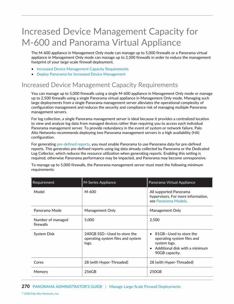
270 PANORAMA ADMINISTRATOR'S GUIDE | Manage Large-Scale Firewall Deployments© 2020 Palo Alto Networks, Inc.
Increased Device Management Capacity forM-600 and Panorama Virtual Appliance
The M-600 appliance in Management Only mode can manage up to 5,000 firewalls or a Panorama virtualappliance in Management Only mode can manage up to 2,500 firewalls in order to reduce the managementfootprint of your large-scale firewall deployment.
• Increased Device Management Capacity Requirements• Deploy Panorama for Increased Device Management
Increased Device Management Capacity RequirementsYou can manage up to 5,000 firewalls using a single M-600 appliance in Management Only mode or manageup to 2,500 firewalls using a single Panorama virtual appliance in Management Only mode. Managing suchlarge deployments from a single Panorama management server alleviates the operational complexity ofconfiguration management and reduces the security and compliance risk of managing multiple Panoramamanagement servers.
For log collection, a single Panorama management server is ideal because it provides a centralized locationto view and analyze log data from managed devices rather than requiring you to access each individualPanorama management server. To provide redundancy in the event of system or network failure, PaloAlto Networks recommends deploying two Panorama management servers in a high availability (HA)configuration.
For generating pre-defined reports, you must enable Panorama to use Panorama data for pre-definedreports. This generates pre-defined reports using log data already collected by Panorama or the DedicatedLog Collector, which reduces the resource utilization when generating reports. Enabling this setting isrequired, otherwise Panorama performance may be impacted, and Panorama may become unresponsive.
To manage up to 5,000 firewalls, the Panorama management server must meet the following minimumrequirements:
Requirement M-Series Appliance Panorama Virtual Appliance
Model M-600 All supported Panoramahypervisors. For more information,see Panorama Models.
Panorama Mode Management Only Management Only
Number of managedfirewalls
5,000 2,500
System Disk 240GB SSD—Used to store theoperating system files and systemlogs.
• 81GB—Used to store theoperating system files andsystem logs.
• Additional disk with a minimum90GB capacity.
Cores 28 (with Hyper-Threaded) 28 (with Hyper-Threaded)
Memory 256GB 250GB

PANORAMA ADMINISTRATOR'S GUIDE | Manage Large-Scale Firewall Deployments 271© 2020 Palo Alto Networks, Inc.
Requirement M-Series Appliance Panorama Virtual Appliance
Log Collection Local log collection is notsupported.
See Deploy Panorama withDedicated Log Collectors to set uplog collection.
Local log collection is notsupported.
See Deploy Panorama withDedicated Log Collectors to set uplog collection.
Logging and Reporting Enable the Use PanoramaData for Pre-Defined Reportssetting (Panorama > Setup >Management > Logging andReporting Settings > Log Exportand Reporting)
Enable the Use PanoramaData for Pre-Defined Reportssetting (Panorama > Setup >Management > Logging andReporting Settings > Log Exportand Reporting)
Deploy Panorama for Increased Device ManagementTo deploy Panorama for increased device management, determine your deployment scenario and follow theprocedure:
• Install Panorama for Increased Device Management Capacity• Upgrade Panorama for Increased Device Management Capacity
Install Panorama for Increased Device Management CapacityActivate the device management license to manage more than 1,000 firewalls from a single M-600Panorama™ management server or a single Panorama virtual appliance.
STEP 1 | Contact your Palo Alto Networks sales representative to obtain the Panorama devicemanagement license that enables you to manage up to 5,000 firewalls with an M-600appliance or up to 2,500 firewalls with a Panorama virtual appliance.• If you are deploying an M-600 appliance, obtain the PAN-M-600-P-1K device management license.• If you are deploying a Panorama virtual appliance, obtain the PAN-PRA-1000 device management
license.
STEP 2 | Set up the Panorama management server.• (M-600 appliances only) Set Up the M-Series Appliance.
or
• Set Up the Panorama Virtual Appliance.
STEP 3 | Change the Panorama management server to Management Only mode if Panorama is notalready in this mode.• Begin at Step 5 to Set Up an M-Series Appliance in Management Only Mode.• Set up a Panorama Virtual Appliance in Management Only Mode.
STEP 4 | Register your Panorama management server and install licenses.1. Register Panorama.2. Activate a Panorama Support License.3. Activate the device management license on the Panorama management server.

272 PANORAMA ADMINISTRATOR'S GUIDE | Manage Large-Scale Firewall Deployments© 2020 Palo Alto Networks, Inc.
• Activate/Retrieve a Firewall Management License on the M-Series Appliance.• Activate/Retrieve a Firewall Management License when the Panorama Virtual Appliance is not
Internet-connected.• Activate/Retrieve a Firewall Management License when the Panorama Virtual Appliance is
Internet-connected.
STEP 5 | Select Panorama > Licenses and verify that the device management license is successfullyactivated.
If you are activating a new device management license on a Panorama, you can manageup to 5,000 firewalls with an M-600 appliance, or up to 2,500 firewalls with a Panoramavirtual appliance, but the Description still displays Device management license tomanage up to 1000 devices or more.
Upgrade Panorama for Increased Device Management CapacityUpgrade to PAN-OS 9.1 to use your existing device management license on your M-600 appliance tomanage up to 5,000 firewalls or Panorama™ virtual appliance to manage up to 2,500 firewalls.
STEP 1 | Increase CPUs and Memory on the Panorama Virtual Appliance if the Panorama virtualappliance does not already meet the minimum resource requirements for increased devicemanagement.Review the Increased Device Management Capacity Requirements to verify whether your existingPanorama virtual appliance meets the minimum requirements before upgrading.
STEP 2 | Log in to the Panorama CLI.
STEP 3 | Change the Panorama management server to Management Only if Panorama is not already inthis mode.• (M-600 appliances only) Begin at Step 5 to Set Up an M-Series Appliance in Management Only
Mode.
or
• Set up a Panorama Virtual Appliance in Management Only Mode.
STEP 4 | Log in to the Panorama Web Interface.
STEP 5 | Upgrade the Panorama management server.• Install Updates for Panorama with an Internet Connection.• Install Updates for Panorama When Not Internet-Connected.• Install Updates for Panorama in an HA Configuration.
STEP 6 | Select Panorama > Licenses and verify that the device management license is successfullyactivated.
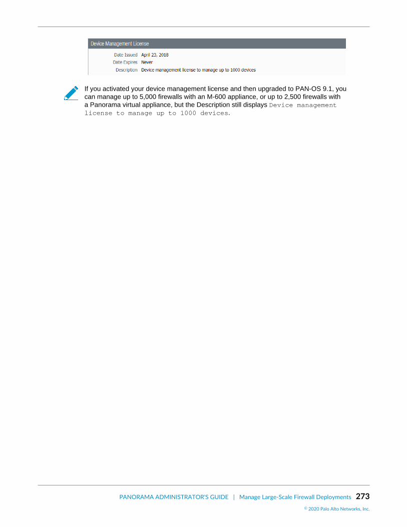
PANORAMA ADMINISTRATOR'S GUIDE | Manage Large-Scale Firewall Deployments 273© 2020 Palo Alto Networks, Inc.
If you activated your device management license and then upgraded to PAN-OS 9.1, youcan manage up to 5,000 firewalls with an M-600 appliance, or up to 2,500 firewalls witha Panorama virtual appliance, but the Description still displays Device managementlicense to manage up to 1000 devices.

274 PANORAMA ADMINISTRATOR'S GUIDE | Manage Large-Scale Firewall Deployments© 2020 Palo Alto Networks, Inc.
Panorama InterconnectUse Panorama™ Interconnect to manage the configuration of your large-scale firewall deployment.Panorama Interconnect is ideal when managing the configuration of multiple Panorama managementservers with similar configurations.
• Panorama Interconnect Overview• Panorama Interconnect Requirements• Enable Authentication Between the Panorama Controller and Nodes• Set Up the Panorama Interconnect Plugin• Synchronize Panorama Interconnect• Manage Firewalls with Panorama Interconnect• Upgrade the Panorama Interconnect Plugin
Panorama Interconnect OverviewWhen you have homogeneous configurations across a large number of firewalls that exceed themanagement capacity of a single Panorama instance, or if you have deployed multiple Panorama™
management servers, you can use the Interconnect plugin on Panorama to reduce the operational burden.The Interconnect plugin allows you to set up a Panorama Controller that manages up to 64 PanoramaNodes, so that you can streamline common configuration and policies across Panorama appliances and themanaged firewalls on your network. For example, you can set up the Panorama Controller as the centralpoint for managing both the Panorama specific configuration such as admin roles on the Panorama Nodes,and all the common template stack and device group configurations that you push to the Panorama Nodesfor managing all the firewalls. The following figure illustrates the Panorama Interconnect hierarchy, wherethe Panorama Controller manages multiple Panorama Nodes, which in turn manage multiple devices.
The following figure displays an example of a Panorama Interconnect Setup page for a Panorama Controllerand a Panorama Node once they have been successfully configured.

PANORAMA ADMINISTRATOR'S GUIDE | Manage Large-Scale Firewall Deployments 275© 2020 Palo Alto Networks, Inc.
The following tasks must be completed to set up the Panorama Interconnect plugin:
Task Details
Review the Panorama Interconnect Requirements The Panorama management servers andfirewalls must meet the system and operationalrequirements in order to successfully deployPanorama Interconnect.
This includes installing and activating licenses,and registering the Panorama managementserver.
Enable Authentication Between the PanoramaController and Nodes
Generate or import a Certificate Authority andissue certificates for the Nodes, and configurea certificate profile, to secure communicationbetween the Panorama Controller and PanoramaNodes.
Set Up the Panorama Interconnect Plugin Download, install, and set up the PanoramaInterconnect plugin on the Panorama Controllerand Panorama Nodes.
Prepare the Panorama Controller to PushConfiguration to the Managed Firewalls
On the Panorama Controller, Add a Device Groupand Configure a Template Stack to configurepolicy rules, objects, and settings to enable thefirewalls to operate on the network.
Synchronize Panorama Interconnect Push the Panorama-specific configuration, aswell as the template stack and device groupconfigurations, from the Panorama Controller tothe Panorama Nodes.
Manage Firewalls with Panorama Interconnect Add one or more firewalls and push thesynchronized configuration from the PanoramaNode to the managed devices.
Panorama Interconnect RequirementsPlan and review the requirements for successfully deploying the Panorama™ Interconnect plugin on yourPanorama management servers:
• Plan Your Panorama Interconnect Deployment• System Requirements for Panorama Interconnect• Certificate Requirements for Panorama Interconnect

276 PANORAMA ADMINISTRATOR'S GUIDE | Manage Large-Scale Firewall Deployments© 2020 Palo Alto Networks, Inc.
Plan Your Panorama Interconnect DeploymentTo successfully deploy the Panorama™ Interconnect plugin on your Panorama management servers:
Set the Panorama Controller and the Panorama Nodes to Management Only mode. See Set Up an M-Series Appliance in Management Only Mode or Set up a Panorama Virtual Appliance in ManagementOnly Mode for more information on changing your Panorama management server mode.
Deploying Panorama Interconnect on a Panorama Controller or Panorama Node inPanorama mode with local log collection may result in decreased performance due tohigh resource demand for management processes and log collection processes.
Register Panorama and Install Licenses for the Panorama Controller and Panorama Nodes.Deploy one or more Dedicated Log Collectors for log collection. See Set Up Panorama for moreinformation on log storage requirements and procedures deploying a Panorama management server inLog Collection mode.Ensure that the Panorama Controller and all Panorama Nodes are in Operational mode before installingthe plugin. The Panorama Interconnect plugin does not support Panorama management servers in FIPSmode, and may cause the Panorama management server to be come unresponsive.Obtain a Certificate Authority (CA), and generate Panorama Node certificates signed by the PanoramaController CA to secure communication between the Panorama Controller and Panorama Nodes. SeeEnable Authentication Between the Panorama Controller and Nodes for more information.Enable HTTPS access on the Panorama Controller, Panorama Nodes and managed firewalls so you canLog in to the Panorama Web Interface and firewall web interfaces. Panorama Interconnect does notsupport CLI and API access.
System Requirements for Panorama InterconnectEnsure that the Panorama™ management servers and firewalls meet the following system requirements tosuccessfully install the Panorama Interconnect plugin and managing your large-scale firewall deployment:
• Panorama Interconnect can only manage single VSYS firewalls
Requirements Panorama Controller and Nodes Firewall
Mode Management Only (Recommended) N/A
CPUs and memory 8 CPUs and 16GB memory N/A
System Disk 81GB N/A
Supported OS PAN-OS 8.1.3 or later releases PAN-OS 7.1 or later releases
Supported Models • M-Series Appliances—M-600• Panorama Virtual Appliance—See
Panorama Models for all supportedPanorama virtual appliance models.
• Physical Firewalls—See FirewallModels for all supported physicalfirewall models.
• VM-Series Firewalls—See VM-Series Models for all supportedVM-Series firewalls.
Certificate Requirements for Panorama InterconnectTo secure communication between the Panorama™ Controller and Panorama Nodes, make sure thecertificates you use meet the following requirements:

PANORAMA ADMINISTRATOR'S GUIDE | Manage Large-Scale Firewall Deployments 277© 2020 Palo Alto Networks, Inc.
A Certificate Authority (CA) responsible for issuing certificates to Panorama Nodes is required on thePanorama Controller. You can either Create a Self-Signed Root CA Certificate or Import a Certificate andPrivate Key to sign it. Please note you must configure the CA certificate in the Panorama tab in order toset up the Interconnect plugin.Import a certificate or generate a unique certificate for each Panorama Node, The CA certificate on thePanorama Controller must issue the certificates that you use on the Nodes.
• If you are importing a certificate to the Panorama Node, ensure that the certificate Common Name isthe serial number of the Panorama Node.
• The certificate must be in PKCS12 or PEM format and must include a private key so that thePanorama Nodes can authenticate successfully.
Enable Authentication Between the Panorama Controller andNodes
Create a Certificate Profile to secure communication between the Panorama™ Controller and PanoramaNodes.
• Obtain the CA Certificate for the Panorama Controller• Generate the Panorama Node Certificate• Create a Certificate Profile for Authenticating Panorama Nodes
Obtain the CA Certificate for the Panorama ControllerCreate a trusted Certificate Authority (CA) responsible for issuing certificates to Panorama™ Nodes tosecure connections to the internet. A trusted CA is required when setting up Panorama for large scalefirewall deployments.
STEP 1 | Log in to the Panorama Web Interface of the Panorama Controller.
STEP 2 | Create the Certificate Authority certificate.• Generate a new CA certificate
1. Select Panorama > Certificate Management > Certificates and Generate a new certificate.2. For the Certificate Type, select Local.3. Enter a Certificate Name, such as panorama-ca. The name is case-sensitive and can have up to 31
characters. It must be unique and use only letters, numbers, hyphens, and underscores.4. In the Common Name field, enter the IP address or FQDN of the Panorama Controller.5. Leave the Signed By field blank to designate the certificate as self-signed.6. Select the Certificate Authority check box.7. Generate the CA certificate.

278 PANORAMA ADMINISTRATOR'S GUIDE | Manage Large-Scale Firewall Deployments© 2020 Palo Alto Networks, Inc.
• Import an existing CA certificate
1. Select Panorama > Certificate Management > Certificates and Import the CA certificate.2. Enter a Certificate Name, such as panorama-CA. The name is case-sensitive and can have up to 31
characters. It must be unique and use only letters, numbers, hyphens, and underscores.3. Browse to find the Certificate File.4. Select a File Format:
• Base64 Encoded Certificate (PEM)—You must import the key separately from the certificate.Select the Import Private Key check box, and Browse for the Key File.
• Encrypted Private Key and Certificate (PKCS12)— Common format in which the key andcertificate are in a single container (Certificate File).
5. Enter and re-enter (confirm) the Passphrase used to encrypt the key.6. Click OK. The Certificates page now displays the imported CA certificate.
STEP 3 | Click Commit and Commit to Panorama.
Generate the Panorama Node CertificateFor the Panorama™ Controller to authenticate each Panorama Node, create a unique certificate for eachPanorama Node. The Panorama Controller and Node use certificate-based authentication to securely

PANORAMA ADMINISTRATOR'S GUIDE | Manage Large-Scale Firewall Deployments 279© 2020 Palo Alto Networks, Inc.
communicate with each other. Before you generate the unique Panorama Node certificates, Obtain the CACertificate for the Panorama Controller.
If your Panorama Node is in a high availability (HA) configuration, you must create and import the PanoramaNode certificates of both Panorama Nodes to each peer in the HA configuration.
STEP 1 | Log in to the Panorama Web Interface of the Panorama Controller.
STEP 2 | Select Panorama > Certificate Management > Certificates and Generate a new certificate:1. For the Certificate Type, select Local.
SCEP is currently not supported.
2. Enter a Certificate Name, such as panorama-node1_cert. The name is case-sensitive and can haveup to 31 characters. It must be unique and use only letters, numbers, hyphens, and underscores.
3. In the Common Name field, enter the serial number of the Panorama Node.
The serial number must be entered in the Common Name field in order to authenticatethe connection between the Panorama Controller and Panorama Node. ThePanorama Node cannot connect to the Panorama Controller if the serial number is notentered in this field.
4. In the Signed By field, select the CA certificate.5. Generate the certificate.
STEP 3 | Click Commit and Commit to Panorama.
STEP 4 | Export the certificates for each Panorama Node generated in Step 2.1. Select Panorama > Certificate Management > Certificates, select the certificate, and Export
Certificate.2. Select the File Format:
• Base64 Encoded Certificate (PEM)—Allows you to export the certificate and private keyseparately. If you want the exported file to include the private key, select the Export Private Keycheck box.

280 PANORAMA ADMINISTRATOR'S GUIDE | Manage Large-Scale Firewall Deployments© 2020 Palo Alto Networks, Inc.
• Encrypted Private Key and Certificate (PKCS12)— Export the certificate and private in a singlefile.
3. Check the Export private key box.4. Enter a Passphrase and Confirm Passphrase to encrypt the private key. This passphrase is when
importing the certificate key to the Panorama Nodes.5. Click OK and save the certificate/key file to your computer.
6. Enter a descriptive file name for the certificate so that you can easily identify the Panorama Node itneeds to be imported to, and Save the certificate.
STEP 5 | Import the certificate in to each Panorama Node.1. Log in to the Panorama Web Interface of the Panorama Node.2. Select Panorama > Certificate Management > Certificates, and Import a certificate:
1. For the Certificate Type, select Local.
SCEP is currently not supported.
2. Enter the same Certificate Name.The name is case-sensitive and can have up to 31 characters. Itmust be unique and use only letters, numbers, hyphens, and underscores.
3. Browse for the certificate you exported in Step 4.4. Check the Import private key box.5. Enter the Passphrase and Confirm Passphrase used to encrypt the private key.6. Click OK to import the certificate.
3. Click Commit and Commit to Panorama.
Create a Certificate Profile for Authenticating Panorama NodesCertificate profiles define which certificate authority (CA) certificates to use for verifying the PanoramaNode certificates used to secure communication between the Panorama™ Controller and Panorama Nodesand to verify Panorama Node revocation status. A certificate profile is required to set up Panorama for largescale firewall deployments.
STEP 1 | Log in to the Panorama Web Interface of the Panorama Controller.

PANORAMA ADMINISTRATOR'S GUIDE | Manage Large-Scale Firewall Deployments 281© 2020 Palo Alto Networks, Inc.
STEP 2 | Obtain the CA Certificate for the Panorama Controller.
STEP 3 | Generate the Panorama Node Certificate used to secure communication between thePanorama Controller and Panorama Nodes. Repeat this step for all Panorama Nodes.
STEP 4 | Create a Certificate Profile.
CRL and OCSP is currently not supported.
1. Select Panorama > Certificate Management > Certificate Profile and Add a new Certificate Profile.2. Enter a Name for the Certificate Profile.3. Add the CA certificate created in Step 2.4. Click OK to finishing adding the Certificate Profile.
STEP 5 | Click Commit and Commit to Panorama.
Set Up the Panorama Interconnect PluginCentralize the template stack and device group management of large scale firewall deployments usingPanorama™ Interconnect to push replicated configurations from a Panorama Controller to Panorama Nodesto ensure consistency of firewall configurations and security policies. Panorama Interconnect allows youto establish a Panorama Controller with which to manage the Panorama Nodes, who manage the firewallsand push configurations. This allows you to manage the configuration of large scale firewall deploymentsfrom a single location, reducing the time you need to spend configuring multiple Panorama managementservers, and reducing your security vulnerability in the event of a misconfiguration. Before setting up thePanorama Interconnect plugin on your Panorama management servers, review the Panorama InterconnectRequirements.
If your Panorama Node is in a high availability (HA) configuration, you must set up the PanoramaInterconnect plugin on both Panorama HA peers.
STEP 1 | Install the Panorama Interconnect plugin. You must install the plugin on the PanoramaController, and all Panorama Nodes.1. Log in to the Panorama Web Interface.

282 PANORAMA ADMINISTRATOR'S GUIDE | Manage Large-Scale Firewall Deployments© 2020 Palo Alto Networks, Inc.
2. Select Panorama > Plugins and search for Interconnect.3. Download and Install the Panorama Interconnect plugin.4. Click Commit > Commit to Panorama to finish installing the Panorama Interconnect plugin.
STEP 2 | Enable Authentication Between the Panorama Controller and Nodes to secure authenticationbetween the Panorama Controller and Panorama Nodes.
STEP 3 | Set up the plugin on the Panorama Controller. Repeat this step on the high availability peer ifthe Panorama Controller is in an HA configuration.
Once the Panorama has been configured as the Panorama Controller, you cannotreconfigure the Panorama Controller as a Panorama Node. Verify that you are configuringthe correct Panorama management server as the Panorama Controller before continuing.
1. Select Panorama > Interconnect > Setup and edit the Interconnect Plugin Setup:2. In the Server Mode field, select Yes.3. Select the Certificate Profile you created in Step 2.4. Click OK to save the settings.
5. Click Commit and Commit to Panorama.
STEP 4 | Set up the plugin on the Panorama Node. Repeat this step for all Panorama Nodes.
If your Panorama Node is in a high availability (HA) configuration, you must select thePanorama Node certificate you imported to each Panorama Node HA peer when settingup the Panorama Interconnect plugin on each peer.
1. Select Panorama > Interconnect > Setup and edit the Interconnect Plugin Setup:
1. In the Server Mode field, select No.2. Manager Panorama IP—Enter the management IP address of the Panorama Controller.3. HA Manager IP—If the Panorama Controller is in a High Availability configuration, enter the
management IP address of the HA Panorama Controller peer.4. Select the Panorama Node certificate you imported in Step 2.5. (HA only) Select the peer Panorama Node certificate you imported in Step 2.
2. Click OK to save the settings.

PANORAMA ADMINISTRATOR'S GUIDE | Manage Large-Scale Firewall Deployments 283© 2020 Palo Alto Networks, Inc.
3. Click Commit and Commit to Panorama to finish setting up the plugin on the Panorama Node.
STEP 5 | Add the Panorama Nodes to the Panorama Controller.1. Select Panorama > Interconnect > Panorama Nodes and Add the Panorama Node.
1. Enter a Name for the Panorama Node. This does not need to match Device Name set on thePanorama management server.
A period (.) in the Panorama Node Name is not supported.
2. Enter the Serial No of the Panorama Node.3. Enter the IP address of the Panorama Node. The IP address must be accessible to the Panorama
Controller.4. Enter a Description of the Panorama Node.
2. Click OK to add the Panorama Node.
3. Click Commit and Commit to Panorama to finish adding the Panorama Node.
STEP 6 | Verify that the newly added Panorama Node is Connected.1. Select Panorama > Interconnect > Panorama Nodes.2. Find the Panorama Node you added, and verify that the Connection Status column displays
Connected.
STEP 7 | Once the plugin has been successfully installed on the Panorama Controller and PanoramaNodes, perform the next steps to complete setting up Panorama Interconnect:1. On the Panorama Controller, Add a Device Group. Repeat this step to create as many device groups
as required.2. On the Panorama Controller, Configure a Template Stack. Repeat this step to create as many
template stacks as required.3. Synchronize Panorama Interconnect to push the Panorama-specific configuration, as well as the
template stack and device group configurations, from the Panorama Controller to the PanoramaNodes.
4. On the Panorama Controller, add one or more firewalls to be managed by a Panorama Node.
• Add a Firewall to a Panorama Node• Import Multiple Firewalls to a Panorama Node
5. Push the Panorama Node Configuration to Managed Devices.

284 PANORAMA ADMINISTRATOR'S GUIDE | Manage Large-Scale Firewall Deployments© 2020 Palo Alto Networks, Inc.
Synchronize Panorama InterconnectTo push the Panorama™ template stack and device group configurations from the Panorama Controller,synchronize the Panorama Node configuration with the Panorama Controller to sync any Panorama-specificconfiguration and enable the Panorama Node to push the configuration to the managed devices.
• Push the Common Panorama Configuration to Panorama Nodes• Synchronize the Panorama Node with the Panorama Controller
Push the Common Panorama Configuration to Panorama NodesPush the common configuration of the Panorama™ Controller to the Panorama Node to apply anyPanorama-specific configurations to the Panorama Nodes. To synchronize the template stack and devicegroup configuration to push them to managed devices, see Synchronize the Panorama Node with thePanorama Controller.
STEP 1 | Log in to the Panorama Web Interface of the Panorama Controller.
STEP 2 | Select Panorama > Interconnect > Panorama Nodes and select the Panorama Nodes managingthe firewalls to push the configuration to.
STEP 3 | Push Common Config to push the Panorama-specific configurations to the Panorama Nodes.
Synchronize the Panorama Node with the Panorama ControllerSynchronize the Panorama™ Controller configuration with the Panorama Nodes so that the Panorama Nodecan push any template stack or device group configurations to the managed devices.
STEP 1 | Log in to the Panorama Web Interface of the Panorama Controller.
STEP 2 | Select Panorama > Interconnect > Panorama Nodes and select the Panorama Nodes tosynchronize with the Panorama Controller.
STEP 3 | Synchronize Config to push the device group and template stack configurations to thePanorama Nodes. This is required to push the configuration to managed devices.

PANORAMA ADMINISTRATOR'S GUIDE | Manage Large-Scale Firewall Deployments 285© 2020 Palo Alto Networks, Inc.
STEP 4 | In the Sync Status column, verify that the Panorama Node is in-sync.
Manage Firewalls with Panorama InterconnectAdd a single firewall, or bulk import multiple devices, to be managed by a Panorama™ Node.
• Add a Firewall to a Panorama Node• Import Multiple Firewalls to a Panorama Node• Import Template Stack Variables• Manage the Master Key with Panorama Interconnect• Push the Panorama Node Configuration to Managed Devices
Add a Firewall to a Panorama NodeAdd a single firewall to be managed by a Panorama™ Node in order to manage the template stack anddevice group configuration from a centralized Panorama Controller. To bulk import multiple firewalls, seeImport Multiple Firewalls to a Panorama Node.
STEP 1 | Configure the firewall to communicate with the Panorama Node.1. Perform initial configuration on the firewall so that it is accessible and can communicate with
Panorama over the network.2. Add the Panorama Node IP address to the firewall.
1. Select Device > Setup > Management and edit the Panorama Settings.2. Enter the Panorama IP address in the first field.3. (Optional) If you have set up a High Availability pair in Panorama, enter the IP address of the
secondary Panorama in the second field.4. Click OK.
3. Select Commit and Commit your changes.
STEP 2 | Log in to the Panorama Web Interface of the Panorama Controller.
STEP 3 | Select Panorama > Interconnect > Devices and Add the firewall.
STEP 4 | Enter the firewall information:

286 PANORAMA ADMINISTRATOR'S GUIDE | Manage Large-Scale Firewall Deployments© 2020 Palo Alto Networks, Inc.
• Enter the Serial No of the firewall.• Select the Panorama Node to manage the firewall.• Select the Template Stack with which to manage the firewall configuration.• Select the Device Group with which to associate the firewall.
STEP 5 | Click OK to add the firewall as a managed device.
STEP 6 | Click Commit and Commit to Panorama to finish adding the firewall.
STEP 7 | Select Panorama > Interconnect > Panorama Nodes and Synchronize Config.
STEP 8 | Verify that the newly added firewall is Connected.1. Select Panorama > Interconnect > Devices.2. Find the firewall you added, and verify that the Connection Status column displays Connected.
Import Multiple Firewalls to a Panorama NodeYou can import multiple firewall to be managed by a Panorama™ Node using a CSV template provided toyou during the import procedure. Importing multiple firewalls at once allows you to quickly add multiplefirewalls to Panorama Nodes, and assign them to a template stack and device group to centralize itsconfiguration management.
When importing multiple firewalls, you can add firewalls to different Panorama Nodes, and differenttemplate stacks and device groups. For example, you have deployed Panorama Node A and Panorama NodeB, each with two template stacks and two device groups. If you are importing 100 firewalls, they can beimported in the following way:
• Add 50 firewalls to Panorama Node A:
• Assign 25 firewalls to template stack A1 and device group A1.• Assign 25 firewalls to template stack A2 and device group A2.
• Add 50 firewalls to Panorama Node B:
• Assign 30 firewalls to template stack B1 and device group B1.• Assign 20 firewalls to template stack B2 and device group B2.
To add a single firewall, see Add a Firewall to a Panorama Node.
STEP 1 | Configure the firewall to communicate with the Panorama Node.Repeat this step for all firewalls to be managed by a Panorama using the Interconnect plugin.

PANORAMA ADMINISTRATOR'S GUIDE | Manage Large-Scale Firewall Deployments 287© 2020 Palo Alto Networks, Inc.
1. Perform initial configuration on the firewall so that it is accessible and can communicate withPanorama over the network.
2. Add the Panorama Node IP address to the firewall.
1. Select Device > Setup > Management and edit the Panorama Settings.2. Enter the Panorama IP address in the first field.3. (Optional) If you have set up a High Availability pair in Panorama, enter the IP address of the
secondary Panorama in the second field.4. Click OK.
3. Select Commit and Commit your changes.
STEP 2 | Log in to the Panorama Web Interface of the Panorama Controller.
STEP 3 | Click Commit and Commit to Panorama any pending configurations changes to the PanoramaController. Importing multiple firewalls requires that there be no pending changes to thePanorama Controller, or the import fails.
STEP 4 | Select Panorama > Interconnect > Devices and Import the firewalls.
STEP 5 | Click Download Sample CSV to download a template of the CSV file with the correct format toupload multiple firewalls.
STEP 6 | Fill out the downloaded CSV. Enter the appropriate values in the serial, panorama, device-group, and template-stack fields. The Panorama Node, device group, and template stack mustalready be added and created on the Panorama Controller before importing the firewalls andare required to successfully add the firewall. Once you have finished entering the firewallinformation, Save the file.You also have the ability to assign the firewalls to content schedules. These are not required for thefirewall import.
Changing the CSV column order is not supported. The firewall import fails if the columnorder re-ordered.
STEP 7 | Back in the Panorama web interface, Select File to browse and select the CSV file containingthe firewall information.
A firewall with required information missing in the bulk import causes the entire importto fail. You are prompted with an error message indicating the location of issues in theimport file if an error is encountered.
STEP 8 | Append the new devices to add them to the end of the list of Devices. All imported devicesmust be new devices. The import fails if any of the devices being imported are part of therunning configuration on the Panorama Controller.
De-select the Append box if you want to delete existing devices in the list and just add thenew devices that you are adding now.
STEP 9 | Click OK to add the firewalls as managed devices.
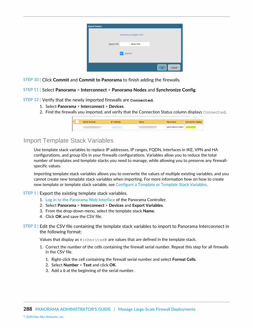
288 PANORAMA ADMINISTRATOR'S GUIDE | Manage Large-Scale Firewall Deployments© 2020 Palo Alto Networks, Inc.
STEP 10 | Click Commit and Commit to Panorama to finish adding the firewalls.
STEP 11 | Select Panorama > Interconnect > Panorama Nodes and Synchronize Config.
STEP 12 | Verify that the newly imported firewalls are Connected.1. Select Panorama > Interconnect > Devices.2. Find the firewalls you imported, and verify that the Connection Status column displays Connected.
Import Template Stack VariablesUse template stack variables to replace IP addresses, IP ranges, FQDN, interfaces in IKE, VPN and HAconfigurations, and group IDs in your firewalls configurations. Variables allow you to reduce the totalnumber of templates and template stacks you need to manage, while allowing you to preserve any firewall-specific values.
Importing template stack variables allows you to overwrite the values of multiple existing variables, and youcannot create new template stack variables when importing. For more information how on how to createnew template or template stack variable, see Configure a Template or Template Stack Variables.
STEP 1 | Export the existing template stack variables.1. Log in to the Panorama Web Interface of the Panorama Controller.2. Select Panorama > Interconnect > Devices and Export Variables.3. From the drop-down menu, select the template stack Name.4. Click OK and save the CSV file.
STEP 2 | Edit the CSV file containing the template stack variables to import to Panorama Interconnect inthe following format:Values that display as #inherited# are values that are defined in the template stack.
1. Correct the number of the cells containing the firewall serial number. Repeat this step for all firewallsin the CSV file.
1. Right-click the cell containing the firewall serial number and select Format Cells.2. Select Number > Text and click OK.3. Add a 0 at the beginning of the serial number.

PANORAMA ADMINISTRATOR'S GUIDE | Manage Large-Scale Firewall Deployments 289© 2020 Palo Alto Networks, Inc.
2. Enter a new value for the desired template variable.3. Select File > Save As and save the file in CSV UTF-8 format.
STEP 3 | Import the CSV file to the template stack.1. Log in to the Panorama Web Interface of the Panorama Controller.2. Select Panorama > Interconnect > Devices and Import Variables.3. In the Select template stack drop-down, select the template stack to import the variables to.4. In the Import CSV File, click Select File and select the CSV file containing the template stack
variables.5. Click OK to import the template stack variables.
6. Select Commit > Commit to Panorama and Commit your changes.
STEP 4 | Synchronize the Panorama Node with the Panorama Controller.
STEP 5 | Push the Panorama Node Configuration to Managed Devices.

290 PANORAMA ADMINISTRATOR'S GUIDE | Manage Large-Scale Firewall Deployments© 2020 Palo Alto Networks, Inc.
Manage the Master Key with Panorama InterconnectPanorama, firewalls, Log Collectors, and WF-500 appliances use a master key to encrypt sensitive elementsin the configuration and they have a default master key they use to encrypt passwords and configurationelements.
As part of a standard security practice, you must renew the key on each individual firewall, Log Collector,WildFire appliance, and Panorama when your master key expires. The master key deployed to yourmanaged devices must be the same for the Panorama Controller, Panorama Nodes, and managed devicesto successfully push the configuration. To ensure a uniform key deployment, deploy a new master key orrenew an expiring master key on multiple firewalls, Log Collectors, and WF-500 appliances directly fromPanorama. When using Panorama Interconnect, you must configure and deploy the same master key for thePanorama Controller and all Panorama Nodes and managed devices during a single procedure. To deploya master key to managed devices, you must configure the master key on each Panorama Node and deploythem to all devices managed by that node. See Configure the Master Key for more information.
STEP 1 | Configure the master key on the Panorama Controller.1. Log in to the Panorama Web Interface on the Panorama Controller.2. Select Panorama > Master Key and Diagnostics and configure the master key.
1. If renewing a master key, enter the Current Master Key. If you are replacing the default masterkey with a new master key, do not specify a Current Master Key.
2. Configure the New Master Key and Confirm Master Key.3. Configure the master key Lifetime and Time for Reminder.4. Configure the Panorama Controller to Auto Renew with Same Master Key for a specified number
of days after the lifetime of the key expires.5. Click OK.
3. Select Commit > Commit to Panorama and Commit your changes.
STEP 2 | Deploy the master key to devices managed by the Panorama Node.Repeat this step for all Panorama Nodes.
1. Log in to the Panorama Web Interface on the Panorama Node.2. Select Panorama > Master Key and Diagnostics and configure the master key.The new master key
must be the same key you configured on the Panorama Controller in Step 1
1. If renewing a master key, enter the Current Master Key. If you are replacing the default masterkey with a new master key, do not specify a Current Master Key.
2. Configure the New Master Key and Confirm Master Key.3. Configure the master key Lifetime and Time for Reminder.4. Configure the Panorama Controller to Auto Renew with Same Master Key for a specified number
of days after the lifetime of the key expires.5. Click OK.
3. Select Panorama > Managed Devices > Summary and Deploy Master Key.4. Select all devices and Change the master key.

PANORAMA ADMINISTRATOR'S GUIDE | Manage Large-Scale Firewall Deployments 291© 2020 Palo Alto Networks, Inc.
5. Configure the master key. The key must be the same key you configured in Step 1:
1. If renewing a master key, enter the Current Master Key. IIf you are replacing the default masterkey with a new master key, do not specify a Current Master Key.
2. Configure the New Master Key and Confirm Master Key.3. Configure the master key Lifetime and Time for Reminder.4. Click OK.
6. Verify that the master key was deployed successfully to all selected devices.
A System log generates when a you deploy a new master key from Panorama.

292 PANORAMA ADMINISTRATOR'S GUIDE | Manage Large-Scale Firewall Deployments© 2020 Palo Alto Networks, Inc.
STEP 3 | Deploy the master key to Log Collectors.Repeat this step for all Panorama Nodes. The new master key must be the same as the one configured inStep 1.
1. Select Panorama > Managed Collectors and Deploy Master Key.2. Select all devices and Change the master key.3. Configure the master key:
1. If renewing a master key, enter the Current Master Key. If you are replacing the default masterkey with a new master key, do not specify a Current Master Key.
2. Specify the New Master Key and Confirm Master Key.3. Configure the master key Lifetime and Time for Reminder.4. Click OK.
4. Verify that the master key was deployed successfully to all selected devices.
A System log generates when you deploy a new master key from Panorama.
STEP 4 | Deploy the master key to managed WildFire appliances.Repeat this step for all Panorama Nodes. The new master key must be the same as the one configured inStep 1.
1. Select Panorama > Managed WildFire Appliances and Deploy Master Key.2. Select all devices and Change the master key.3. Configure the master key:
1. If renewing a master key, enter the Current Master Key. If you are replacing the default masterkey with a new master key, do not specify a Current Master Key.
2. Specify the New Master Key and Confirm Master Key.3. Configure the master key Lifetime and Time for Reminder.4. Click OK.
4. Verify that the master key was deployed successfully to all selected devices.
A System log generates when you deploy a new master key from Panorama.

PANORAMA ADMINISTRATOR'S GUIDE | Manage Large-Scale Firewall Deployments 293© 2020 Palo Alto Networks, Inc.
Push the Panorama Node Configuration to Managed DevicesOnce you Synchronize the Panorama Node with the Panorama Controller, template stack and device groupconfigurations, push the template stack and device group configuration to the managed devices.
STEP 1 | Log in to the Panorama Web Interface of the Panorama Controller.
STEP 2 | Select Panorama > Interconnect > Devices.
STEP 3 | Push to Devices to push the synchronized configuration from the Panorama Nodes to themanaged devices.
STEP 4 | Add the Panorama Node managing the devices to push the configuration to. Repeat this stepto push to multiple Panorama Nodes, devices groups, or templates as needed:1. Select the Panorama Node.2. Select the Device Group to push both the device group and template stack configurations, or select a
Template Stack to only push the template stack configuration.3. Click OK to finish defining the push scope.
STEP 5 | Click OK to push the configuration to managed devices.

294 PANORAMA ADMINISTRATOR'S GUIDE | Manage Large-Scale Firewall Deployments© 2020 Palo Alto Networks, Inc.
STEP 6 | In the Device Group Push Status column, and the Template Stack Push Status column, verifythat the pushes are in-sync.
Upgrade the Panorama Interconnect PluginUse the following procedure to upgrade the Panorama™ Interconnect plugin on the Panorama Controllerand Panorama Nodes. When you upgrade the Panorama Interconnect plugin, you must upgrade thePanorama Controller before you upgrade the Panorama Nodes to the same plugin version as the Controller.The new plugin version you download and install on the Panorama Node must be the same plugin versionyou installed on the Panorama Controller to ensure that the plugin version on the Panorama Controller andselected Panorama Nodes remain synchronized.
If this is the first time you are installing the plugin, see Set Up the Panorama Interconnect Plugin.
STEP 1 | Log in to the Panorama Web Interface of the Panorama Controller.
STEP 2 | Upgrade the Panorama Interconnect plugin on the Panorama Controller.1. Select Panorama > Plugins and search for Interconnect.2. Download and Install the new Interconnect plugin version. A prompt is displayed to notify you after
the installation is completed.3. Verify that the Dashboard displays the newly installed Interconnect plugin version.
STEP 3 | Upgrade the Panorama Interconnect plugin on the Panorama Node.1. Select Panorama > Interconnect > Panorama Nodes, select one or more Panorama Nodes, and
Upgrade Plugin.2. Verify the selected Panorama Nodes and click OK to begin the plugin upgrade.
3. Wait until the plugin upgrade job is Completed. Click Panorama > Interconnect > Tasks to view thejob progress.
4. After the upgrade completes successfully, select Panorama > Interconnect > Panorama Nodes toverify that the Plugin version is correct for the selected Panorama Nodes.

PANORAMA ADMINISTRATOR'S GUIDE | Manage Large-Scale Firewall Deployments 295© 2020 Palo Alto Networks, Inc.

296 PANORAMA ADMINISTRATOR'S GUIDE | Manage Large-Scale Firewall Deployments

297
Manage Log CollectionAll Palo Alto Networks firewalls can generate logs that provide an audit trail of firewallactivities. For Centralized Logging and Reporting, you must forward the logs generated on thefirewalls to your on-premise infrastructure that includes the Panorama™ management serveror Log Collectors or send the logs to the cloud-based Cortex Data Lake. Optionally, you canthen configure Panorama to forward the logs to external logging destinations (such as syslogservers).
If you forward logs to a Panorama virtual appliance in Legacy mode, you don’t need toperform any additional tasks to enable logging. If you forward logs to Log Collectors, youmust configure them as managed collectors and assign them to Collector Groups. A managedcollector can be local to an M-Series appliance, or Panorama virtual appliance in Panoramamode. Additionally, an M-Series appliance, or Panorama virtual appliance in Log Collectormode can be Dedicated Log Collectors. To determine whether to deploy either or both typesof managed collectors, see Local and Distributed Log Collection.
To manage the System and Config logs that Panorama generates locally, see MonitorPanorama.
> Configure a Managed Collector> Manage Collector Groups> Configure Log Forwarding to Panorama> Forward Logs to the Cortex Data Lake> Verify Log Forwarding to Panorama> Modify Log Forwarding and Buffering Defaults> Configure Log Forwarding from Panorama to External Destinations> Log Collection Deployments

298 PANORAMA ADMINISTRATOR'S GUIDE | Manage Log Collection© 2020 Palo Alto Networks, Inc.

PANORAMA ADMINISTRATOR'S GUIDE | Manage Log Collection 299© 2020 Palo Alto Networks, Inc.
Configure a Managed CollectorTo enable the Panorama management server to manage a Log Collector, you must add it as a managedcollector. You can add two types of managed collectors:
• Dedicated Log Collector—To set up a new M-600, M-500, M-200, M-100 appliance, or Panorama virtualappliance as a Log Collector or switch an existing M-Series appliance or Panorama virtual appliance fromPanorama mode to Log Collector mode, see Set Up the M-Series Appliance as a Log Collector. Keep inmind that switching from Panorama Mode to Log Collector Mode removes the local Log Collector that ispredefined on the M-Series appliance in Panorama mode.
• Local Log Collector—A Log Collector can run locally on the M-600, M-500, M-200, M-100 appliance,or Panorama virtual appliance in Panorama mode. On the M-Series appliances, the Log Collector ispredefined; on the virtual appliance, you must add the Log Collector. When the Panorama managementserver has a high availability (HA) configuration, each HA peer can have a local Log Collector. However,relative to the primary Panorama, the Log Collector on the secondary Panorama is remote, not local.Therefore, to use the Log Collector on the secondary Panorama, you must manually add it to the primaryPanorama (for details, see Deploy Panorama M-Series Appliances with Local Log Collectors or DeployPanorama Virtual Appliances with Local Log Collectors). If you delete a local Log Collector, you can lateradd it back. The following steps describe how to add a local Log Collector.
As a best practice, retain a local Log Collector and Collector Group on the Panoramamanagement server, regardless of whether it manages Dedicated Log Collectors.
If the Panorama virtual appliance is in Legacy mode, you must switch to Panorama modeto create a Log Collector. For details, see Set Up the Panorama Virtual Appliance with LocalLog Collector.
STEP 1 | Record the serial number of the Log Collector.You will need this when you add the Log Collector as a managed collector.
1. Access the Panorama web interface.2. Select Dashboard and record the Serial # in the General Information section.
STEP 2 | Add the Log Collector as a managed collector.1. Select Panorama > Managed Collectors and Add a new Log Collector.2. In the General settings, enter the serial number (Collector S/N) you recorded for the Log Collector.3. Click OK to save your changes.4. Select Commit > Commit to Panorama.
STEP 3 | (Optional) Configure the Log Collector admin authentication.1. Select Panorama > Managed Collectors and edit the Log Collector by clicking its name.2. Configure the Log Collector admin password:
1. Select the password Mode.2. If you selected Password mode, enter a plaintext Password and Confirm Password. If you
selected Password Hash mode, enter a hashed password string of up to 63 characters.3. Configure the admin login security requirements:
If you set the Failed Attempts to a value other than 0 but leave the Lockout Time at0, then the admin user is indefinitely locked out until another administrator manually

300 PANORAMA ADMINISTRATOR'S GUIDE | Manage Log Collection© 2020 Palo Alto Networks, Inc.
unlocks the locked out admin. If no other administrator has been created, you mustreconfigure the Failed Attempts and Lockout Time settings on Panorama and push theconfiguration change to the Log Collector. To ensure that an admin is never lockedout, use the default 0 value for both Failed Attempts and Lockout Time.
1. Enter the number of login Failed Attempts value. The range is between the default value 0 to themaximum of 10 where the value 0 specifies unlimited login attempts.
2. Enter the Lockout Time value between the default value 0 to the maximum of 60 minutes.4. Click OK to save your changes.
STEP 4 | Enable the logging disks.1. Select Panorama > Managed Collectors and edit the Log Collector by clicking its name.
The Log Collector name has the same value as the hostname of the Panorama management server.2. Select Disks and Add each disk pair.3. Click OK to save your changes.4. Select Commit > Commit to Panorama.
STEP 5 | (Optional) If your deployment is using custom certificates for authentication between Panoramaand managed devices, deploy the custom client device certificate. For more information, seeSet Up Authentication Using Custom Certificates.1. Select Panorama > Certificate Management > Certificate Profile and choose the certificate profile
from the drop-down or click New Certificate Profile to create one.2. Select Panorama > Managed Collectors and Add a new Log Collector or select an existing one. Select
Communication.3. Select the type of device certificate the Type drop-down.
• If you are using a local device certificate, select the Certificate and Certificate Profile from therespective drop-downs.
• If you are using SCEP as the device certificate, select the SCEP Profile and Certificate Profile fromthe respective drop-downs.
4. Click OK.
STEP 6 | (Optional) Configure Secure Server Communication on a Log Collector. For more information,see Set Up Authentication Using Custom Certificates.1. Select Panorama > Managed Collectors and click Add. Select Communication.2. Verify that the Custom Certificate Only check box is not selected. This allows you to continue
managing all devices while migrating to custom certificates.
When the Custom Certificate Only check box is selected, the Log Collector does notauthenticate and cannot receive logs from devices using predefined certificates.
3. Select the SSL/TLS service profile from the SSL/TLS Service Profile drop-down. This SSL/TLS serviceprofile applies to all SSL connections between the Log Collector and devices sending it logs.
4. Select the certificate profile from the Certificate Profile drop-down.5. Select Authorize Client Based on Serial Number to have the server check clients against the serial
numbers of managed devices. The client certificate must have the special keyword $UDID set as theCN to authorize based on serial numbers.
6. In Disconnect Wait Time (min), enter the number of minutes Panorama should before breaking andreestablishing the connection with its managed devices. This field is blank by default and the range is0 to 44,640 minutes.
The disconnect wait time does not begin counting down until you commit the newconfiguration.

PANORAMA ADMINISTRATOR'S GUIDE | Manage Log Collection 301© 2020 Palo Alto Networks, Inc.
7. (Optional) Configure an authorization list.
1. Click Add under Authorization List.2. Select the Subject or Subject Alt Name as the Identifier type.3. Enter an identifier of the selected type.4. Click OK.5. Select Check Authorization List to enforce the authorization list.
8. Click OK.9. Select Commit > Commit to Panorama.
STEP 7 | Verify your changes.1. Verify that the Panorama > Managed Collectors page lists the Log Collector you added. The
Connected column displays a check mark to indicate that the Log Collector is connected toPanorama. You might have to wait a few minutes before the page displays the updated connectionstatus.
Until you Configure a Collector Group and push configuration changes to the CollectorGroup, the Configuration Status column displays Out of Sync, the Run Time Statuscolumn displays disconnected, and the CLI command show interface alldisplays the interfaces as down.
2. Click Statistics in the last column to verify that the logging disks are enabled.
STEP 8 | Next steps...Before a Log Collector can receive firewall logs, you must:
1. Configure Log Forwarding to Panorama.2. Configure a Collector Group—On the M-Series appliances, a default Collector Group is predefined
and already contains the local Log Collector as a member. On the Panorama virtual appliance, youmust add the Collector Group and add the local Log Collector as a member. On both models, assignfirewalls to the local Log Collector for log forwarding.

302 PANORAMA ADMINISTRATOR'S GUIDE | Manage Log Collection© 2020 Palo Alto Networks, Inc.
Manage Collector GroupsA Collector Group is 1 to 16 Log Collectors that operate as a single logical unit for collecting firewall logs.You must assign at least one Log Collector to a Collector Group for firewalls to successfully send logsto a Log Collector. Firewall logs are dropped if there is no Collector Group configured or none of theLog Collectors are assigned to a Collector Group. You can configure a Collector Group with multiple LogCollectors to ensure log redundancy or to accommodate logging rates that exceed the capacity of a singleLog Collector (see Panorama Models). To understand the risks and recommended mitigations, see Caveatsfor a Collector Group with Multiple Log Collectors.
The M-600, M-500, M-200 and M-100 appliances in Panorama mode have a predefined Collector Groupthat contains a predefined local Log Collector. You can edit all the settings of the predefined CollectorGroup except its name (default).
If you delete a Collector Group, you will lose logs.
Palo Alto Networks recommends preserving the predefined Log Collector and CollectorGroup on the Panorama management server, regardless of whether Panorama alsomanages Dedicated Log Collectors.
If you switch an M-Series appliance from Panorama mode to Log Collector mode, theappliance will lose its predefined Collector Group and Log Collector. You would then haveto Set Up the M-Series Appliance as a Log Collector, add it as a managed collector toPanorama, and configure a Collector Group to contain the managed collector.
• Configure a Collector Group• Configure Authentication with Custom Certificates Between Log Collectors• Move a Log Collector to a Different Collector Group• Remove a Firewall from a Collector Group
Configure a Collector GroupBefore configuring Collector Groups, decide whether each one will have a single Log Collector or multipleLog Collectors (up to 16). A Collector Group with multiple Log Collectors supports higher logging rates andlog redundancy but has the following requirements:
• In any single Collector Group, all the Log Collectors must run on the same Panorama model: all M-600appliances, all M-500 appliances, all M-200, all M-100 appliances, or all Panorama virtual appliances.
• Log redundancy is available only if each Log Collector has the same number of logging disks. To adddisks to a Log Collector, see Increase Storage on the M-Series Appliance.
• (Best Practice) All Log Collectors in the same Collector Group should be in the same local area network(LAN). Avoid adding Log Collectors in the same or different wide area networks (WAN) to the sameCollector Group as network disruption are much more common and may result in log data loss.Additionally, it is recommended that Log Collectors in the same Collector Group be in close physicalproximity to each other to allow Panorama to quickly query the Log Collectors when needed.
STEP 1 | Perform the following tasks before configuring the Collector Group.1. Add a Firewall as a Managed Device for each firewall that you will assign to the Collector Group.2. Configure a Managed Collector for each Log Collector that you will assign to the Collector Group.
STEP 2 | Add the Collector Group.1. Access the Panorama web interface, select Panorama > Collector Groups, and Add a Collector Group
or edit an existing one.

PANORAMA ADMINISTRATOR'S GUIDE | Manage Log Collection 303© 2020 Palo Alto Networks, Inc.
2. Enter a Name for the Collector Group if you are adding one.
You cannot rename an existing Collector Group.3. Enter the Minimum Retention Period in days (1 to 2,000) for which the Collector Group will retain
firewall logs.
By default, the field is blank, which means the Collector Group retains logs indefinitely.4. Add Log Collectors (1 to 16) to the Collector Group Members list.5. (Recommended) Enable log redundancy across collectors if you are adding multiple Log Collectors to
a single Collector group.
Redundancy ensures that no logs are lost if any one Log Collector becomes unavailable. Each log willhave two copies and each copy will reside on a different Log Collector. For example, if you have twoLog Collectors in the collector group the log is written to both Log Collectors.
Enabling redundancy creates more logs and therefore requires more storage capacity, reducingstorage capability in half. When a Collector Group runs out of space, it deletes older logs.Redundancy also doubles the log processing traffic in a Collector Group, which reduces its maximumlogging rate by half, as each Log Collector must distribute a copy of each log it receives.
STEP 3 | Assign Log Collectors and firewalls to the Collector Group.1. Select Device Log Forwarding and Add log forwarding preference lists for the firewalls.
Log data is forwarded over a separate TCP channel. By adding a log forwarding preference, list youenable the creation of separate TCP connections for forwarding log data.
A preference list determines the order in which Log Collectors receive logs from afirewall. If a log forwarding preference list is not assigned, you may encounter one ofthe following scenarios:
• If Panorama is in Management Only mode, Panorama drops all incoming logs.• If the local Log Collector is not configured as a managed collector when Panorama
is in Panorama mode, Panorama drops all incoming logs.• If the local Log Collector is configured as a managed collector when Panorama
is in Panorama mode, incoming logs are received but the Panorama may act asa bottleneck because all managed firewalls are forwarding logs to the local LogCollector first before being redistributed to other available Log Collectors.
1. In the Devices section, Modify the list of firewalls and click OK.2. In the Collectors section, Add Log Collectors to the preference list.
If you enabled redundancy in Step 2, it is recommended to add at least two Log Collectors. Ifyou assign multiple Log Collectors, the first one will be the primary; if the primary becomesunavailable, the firewalls send logs to the next Log Collector in the list. To change the priority of aLog Collector, select it and Move Up (higher priority) or Move Down (lower priority).
3. Click OK.
STEP 4 | Define the storage capacity (log quotas) and expiration period for each log type.1. Return to the General tab and click the Log Storage value.
If the field displays 0MB, verify that you enabled the disk pairs for logging andcommitted the changes (see Configure a Managed Collector, Disks tab).
2. Enter the log storage Quota(%) for each log type.3. Enter the Max Days (expiration period) for each log type (1 to 2,000).
By default, the fields are blank, which means the logs never expire.

304 PANORAMA ADMINISTRATOR'S GUIDE | Manage Log Collection© 2020 Palo Alto Networks, Inc.
STEP 5 | Commit and verify your changes.1. Select Commit > Commit and Push and then Commit and Push your changes to Panorama and the
Collector Group you configured.2. Select Panorama > Managed Collectors to verify the Log Collectors in the Collector Group are:
• Connected to Panorama—The Connected column displays a check mark icon to indicate that aLog Collector is connected to Panorama.
• Synchronized with Panorama—The Configuration Status column indicates whether a LogCollector is In Sync (green icon) or Out of Sync (red icon) with Panorama.
STEP 6 | Troubleshoot Connectivity to Network Resources to verify your firewalls successfullyconnected to the Log Collector.
STEP 7 | Next steps...1. Configure Log Forwarding to Panorama.
The Collector Group won’t receive firewall logs until you configure the firewalls to forward toPanorama.
2. (Optional) Configure Log Forwarding from Panorama to External Destinations.
You can configure each Collector Group to forward logs to separate destinations (such as a syslogserver).
Configure Authentication with Custom Certificates Between LogCollectors
Complete the following procedure to configure custom certificates for communication between LogCollectors. You must configure secure server communication and secure client communication on eachLog Collector in a Collector Group because the server and client roles are chosen dynamically. Use customcertificates to create a unique chain of trust that ensures mutual authentication between the members ofyour Log Collector Group.
For more information about using custom certificates, see How Are SSL/TLS Connections MutuallyAuthenticated?
STEP 1 | Obtain key pairs and certificate authority (CA) certificates for each Log Collector.
STEP 2 | Import the CA certificate to validate the identity of the client Log Collector, the server key pair,and the client key pair for each Log Collector in the Collector Group.1. Select Panorama > Certificate Management > Certificates > Import.2. Import the CA certificate, server key pair, and client key pair.3. Repeat th step for the each Log Collector.
STEP 3 | Configure a certificate profile that includes the root CA and intermediate CA for secure servercommunication. This certificate profile defines the authentication between Log Collectors.1. Select Panorama > Certificate Management > Certificate Profile.2. Configure a certificate profile.
If you configure an intermediate CA as part of the certificate profile, you must also include the rootCA.
STEP 4 | Configure the certificate profile for secure client communication. You can configure this profileon each client Log Collector individually or you can push the configuration from Panorama™ tomanaged Log Collectors.

PANORAMA ADMINISTRATOR'S GUIDE | Manage Log Collection 305© 2020 Palo Alto Networks, Inc.
If you are using SCEP for the client certificate, configure a SCEP profile instead of acertificate profile.
1. Select Panorama > Certificate Management > Certificate Profile.2. Configure a Certificate Profile.
STEP 5 | Configure an SSL/TLS service profile.1. Select Panorama > Certificate Management > SSL/TLS Service Profile.2. Configure an SSL/TLS service profile to define the certificate and protocol that the Log Collectors use
for SSL/TLS services.
STEP 6 | After deploying custom certificates on all Log Collectors, enforce custom-certificateauthentication.1. Select Panorama > Collector Groups and select the Collector Group.2. On the General tab, Enable secure inter LC Communication.
If you enable secure inter LC communication and your Collector Group includes a local Log Collector,a link should appear that stating that the Log Collector on local Panorama is using the secure clientconfiguration from Panorama > Secure Communication Settings. You can click this link to open theSecure Communication Settings dialog and configure the secure server and secure client settings forthe Local Log Collector from there.
3. Click OK.4. Commit your changes.
STEP 7 | Configure secure server communication on each Log Collector.1. Select Panorama > Managed Collectors for Dedicated Log Collectors or Panorama > Setup >
Management and Edit the Secure Communication Settings for a Local Log Collector.2. For Dedicated Log Collectors, click the Log Collector and select Communications.3. Enable the Customize Secure Server Communication feature.4. Select the SSL/TLS service profile from the SSL/TLS Service Profile drop-down. This SSL/TLS service
profile applies to all SSL connections between Log Collectors.5. Select the Certificate Profile from the drop-down.6. Verify that the Custom Certificates Only is disabled (cleared). This allows the inter Log Collector
communication to continue with the predefined certificate while configuring to custom certificates.7. Set the disconnect wait time—the number of minutes Log Collectors wait before breaking and
reestablishing the connection with other Log Collectors. This field is empty by default (range is 0 to44,640).
8. (Optional) Configure an authorization list. The authorization list adds an additional layer of securitybeyond certificate authentication. The authorization list checks the client certificate Subject orSubject Alt Name. If the Subject or Subject Alt Name presented with the client certificate does notmatch an identifier in the authorization list, authentication is denied.
1. Add an Authorization List.2. Select the Subject or Subject Alt Name configured in the certificate profile as the Identifier type.3. Enter the Common Name if the identifier is Subject or an IP address, hostname, or email if the
identifier is Subject Alt Name.4. Click OK.5. Enable the Check Authorization List option to configure Panorama to enforce the authorization
list.9. Click OK.10.Commit your changes.

306 PANORAMA ADMINISTRATOR'S GUIDE | Manage Log Collection© 2020 Palo Alto Networks, Inc.
After committing these changes, the disconnect wait time countdown begins. When the wait time ends,Log Collectors in the Collector Group cannot connect without the configured certificates.
STEP 8 | Configure secure client communication on each Log Collector.1. Select Panorama > Managed Collectors for Dedicated Log Collectors or Panorama > Setup >
Management and Edit the Secure Communication Settings for a Local Log Collector.2. For Dedicated Log Collectors, click the Log Collector and select Communications.3. Under Secure Client Communications, select the Certificate Type, Certificate, and Certificate Profile
from the respective drop-downs.4. Click OK.5. Commit your changes.
Move a Log Collector to a Different Collector GroupM-600, M-500, M-200, M-100 and Panorama virtual appliances can have one or more Log Collectors ineach Collector Group. You assign Log Collectors to a Collector Group based on the logging rate and logstorage requirements of that Collector Group. If the rates and required storage increase in a CollectorGroup, the best practice is to Increase Storage on the M-Series Appliance or Configure a Collector Groupwith additional Log Collectors. However, in some deployments, it might be more economical to move LogCollectors between Collector Groups.
When a Log Collector is local to an M-500 or M-100 appliance in Panorama mode, moveit only if the appliance is the passive peer in a high availability (HA) configuration. HAsynchronization applies the configurations associated with the new Collector Group. Nevermove a Log Collector that is local to the active HA peer.
In any single Collector Group, all the Log Collectors must run on the same Panorama model:all M-600 appliances, all M-500 appliances, all M-200 appliances, all M-100 appliances, or allPanorama virtual appliances.
Log redundancy is available only if each Log Collector has the same number of loggingdisks. To add disks to a Log Collector, see Increase Storage on the M-Series Appliance.
STEP 1 | Remove the Log Collector from Panorama management.1. Select Panorama > Collector Groups and edit the Collector Group that contains the Log Collector
you will move.2. In the Collector Group Members list, select and Delete the Log Collector.3. Select Device Log Forwarding and, in the Log Forwarding Preferences list, perform the following
steps for each set of firewalls assigned to the Log Collector you will move:
1. In the Devices column, click the link for the firewalls assigned to the Log Collector.2. In the Collectors column, select and Delete the Log Collector.
To reassign the firewalls, Add the new Log Collector to which they will forward logs.
3. Click OK twice to save your changes.4. Select Panorama > Managed Collectors and then select and Delete the Log Collector you will move.
STEP 2 | Configure a Collector Group.Add the Log Collector to its new Collector Group and assign firewalls to the Log Collector.

PANORAMA ADMINISTRATOR'S GUIDE | Manage Log Collection 307© 2020 Palo Alto Networks, Inc.
When you push changes to the Collector Group configuration, Panorama startsredistributing logs across the Log Collectors. This process can take hours for eachterabyte of logs. During the redistribution process, the maximum logging rate is reduced.In the Panorama > Collector Groups page, the Log Redistribution State column indicatesthe completion status of the process as a percentage.
STEP 3 | Configure Log Forwarding to Panorama for the new Collector Group you configured.
STEP 4 | Select Commit > Commit and Push to commit your changes to Panorama and push thechanges to device groups, templates, and Collector Groups if you have not already done so.
Remove a Firewall from a Collector GroupIf you use a Panorama virtual appliance in Legacy mode to manage Dedicated Log Collectors, you have theoption to forward firewall logs to Panorama instead of forwarding to the Log Collectors. For such cases, youmust remove the firewall from the Collector Group; the firewall will then automatically forward its logs toPanorama.
To temporarily remove the log forwarding preference list on the firewall, you can deleteit using the CLI on the firewall. You must however, remove the assigned firewalls in theCollector Group configuration on Panorama. Otherwise, the next time you push changesto the Collector Group, the firewall will be reconfigured to send logs to the assigned LogCollector.
STEP 1 | Select Panorama > Collector Groups and edit the Collector Group.
STEP 2 | Select Device Log Forwarding, click the firewall in the Devices list, Modify the Devices list,clear the check box of the firewall, and click OK three times.
STEP 3 | Select Commit > Commit and Push and then Commit and Push your changes to Panorama andthe Collector Group from which you removed the firewall.

308 PANORAMA ADMINISTRATOR'S GUIDE | Manage Log Collection© 2020 Palo Alto Networks, Inc.
Configure Log Forwarding to PanoramaEach firewall stores its log files locally by default and cannot display the logs that reside on other firewalls.Therefore, to achieve global visibility into the network activity that all your firewalls monitor, you mustforward all firewall logs to Panorama and Use Panorama for Visibility. In cases where some teams in yourorganization can achieve greater efficiency by monitoring only the logs that are relevant to their operations,you can create forwarding filters based on any log attributes (such as threat type or source user). Forexample, a security operations analyst who investigates malware attacks might be interested only in Threatlogs with the type attribute set to wildfire-virus.
The following steps describe how to use Panorama templates and device groups for configuring multiplefirewalls to forward logs.
If Panorama manages firewalls running software versions earlier than PAN-OS 7.0, specifya WildFire® server from which Panorama can gather analysis information for WildFiresamples that those firewalls submit. Panorama uses the information to complete WildFireSubmissions logs that are missing field values introduced in PAN-OS 7.0. Firewalls runningearlier releases won’t populate those fields. To specify the server, select Panorama >Setup > WildFire, edit the General Settings, and enter the WildFire Private Cloud name. Thedefault is wildfire-public-cloud, which is the WildFire cloud hosted in the United States.
You can also forward firewall logs to external services (such as a syslog server). For details,see Log Forwarding Options.
STEP 1 | Add a Device Group for the firewalls that will forward logs.Panorama requires a device group to push a Log Forwarding profile to firewalls. Create a new devicegroup or assign the firewalls to an existing device group.
STEP 2 | Add a Template for the firewalls that will forward logs.Panorama requires a template to push log settings to firewalls. Create a new template or assign thefirewalls to an existing template.
STEP 3 | Create a Log Forwarding profile.The profile defines the destinations for Traffic, Threat, WildFire Submission, URL Filtering, Data Filtering,Tunnel and Authentication logs.
1. Select Objects > Log Forwarding, select the Device Group of the firewalls that will forward logs, andAdd a profile.
2. Enter a Name to identify the Log Forwarding profile.3. Add one or more match list profiles.
The profiles specify log query filters, forwarding destinations, and automatic actions such as tagging.For each match list profile:
1. Enter a Name to identify the profile.2. Select the Log Type.3. In the Filter drop-down, select Filter Builder. Specify the following and then Add each query:
Connector logic (and/or)
Log Attribute
Operator to define inclusion or exclusion logic

PANORAMA ADMINISTRATOR'S GUIDE | Manage Log Collection 309© 2020 Palo Alto Networks, Inc.
Attribute Value for the query to match4. Select Panorama.
4. Click OK to save the Log Forwarding profile.
STEP 4 | Assign the Log Forwarding profile to policy rules and network zones.Security, Authentication, and DoS Protection rules support log forwarding. In this example, you assignthe profile to a Security rule.
Perform the following steps for each rule that will trigger log forwarding:
1. Select the rulebase (for example, Policies > Security > Pre Rules), select the Device Group of thefirewalls that will forward logs, and edit the rule.
2. Select Actions and select the Log Forwarding profile you created.3. Set the Profile Type to Profiles or Group, and then select the security profiles or Group Profile
required to trigger log generation and forwarding for:
• Threat logs—Traffic must match any security profile assigned to the rule.• WildFire logs—Traffic must match a WildFire Analysis profile assigned to the rule.
4. For Traffic logs, select Log At Session Start and/or Log At Session End.5. Click OK to save the rule.
STEP 5 | Configure the destinations for System logs, Configuration logs, User-ID™ logs, and HIP Matchlogs.
Panorama generates Correlation logs based on the firewall logs it receives, rather thanaggregating Correlation logs from firewalls.
1. Select Device > Log Settings and select the Template of the firewalls that will forward logs.2. For each log type that the firewall will forward, see step Add one or more match list profiles.
STEP 6 | (PA-7000 Series firewalls only) Configure a log card interface to perform log forwarding.When you configure a data port on one of the PA-7000 Series Network Processing Cards (NPCs) as aLog Card interface, the firewall will automatically begin using this interface to forward logs to the loggingdestinations you configure and forward files for WildFire analysis. Make sure that the interface youconfigure can reach the log forwarding destinations and the WildFire cloud, WildFire appliance, or both.
Because PA-7000 Series firewall can now forward logs to Panorama, Panorama nolonger treats the PA-7000 Series firewalls it manages as Log Collectors. If you havenot configured the PA-7000 Series firewalls to forward logs to Panorama, all logs amanaged PA-7000 Series firewall generates are only viewable from the local firewall andnot from Panorama. If you do not yet have a log forwarding infrastructure that is capableof handling the logging rate and volume from the PA-7000 Series firewalls, starting withPAN-OS 8.0.8 you can enable Panorama to directly query PA-7000 Series firewallswhen monitoring logs. To use this functionality, both Panorama and the PA-7000 Seriesfirewalls must be running PAN-OS 8.0.8 or later. Enable Panorama to directly queryPA-7000 Series firewalls by entering the following command from the Panorama CLI:
> debug reportd send-request-to-7k yes
After running this command, you will be able to view logs for managed PA-7000 Seriesfirewalls on the Panorama Monitor tab. Additionally, as with all managed devices, you canalso generate reports that include PA-7000 Series log data by selecting Remote DeviceData as the Data Source. If you later decide to enable the PA-7000 Series firewalls to

310 PANORAMA ADMINISTRATOR'S GUIDE | Manage Log Collection© 2020 Palo Alto Networks, Inc.
forward logs to Panorama, you must first disable this option using the debug reportdsend-request-to-7k no command.
1. Select Network > Interfaces > Ethernet, select the Template of the firewalls that will forward logs,and Add Interface.
2. Select the Slot and Interface Name.3. Set the Interface Type to Log Card.4. Enter the IP Address, Default Gateway, and (for IPv4 only) Netmask.5. Select Advanced and specify the Link Speed, Link Duplex, and Link State.
These fields default to auto, which specifies that the firewall automatically determinesthe values based on the connection. However, the minimum recommended LinkSpeed for any connection is 1000 (Mbps).
6. Click OK to save your changes.
STEP 7 | Configure Panorama to receive the logs.
If you will forward logs to a Panorama virtual appliance in Legacy mode, you can skip thisstep.
1. For each Log Collector that will receive logs, Configure a Managed Collector.2. Configure a Collector Group to assign firewalls to specific Log Collectors for log forwarding.
STEP 8 | Commit your configuration changes.1. Select Commit > Commit and Push and Edit Selections.2. Select Merge with Device Candidate Config and Include Device and Network Templates, and click
OK.
3. Commit and Push your changes to Panorama and push the changes to the device groups, templates,and Collector Groups.
4. Verify Log Forwarding to Panorama to confirm that your configuration is successful.

PANORAMA ADMINISTRATOR'S GUIDE | Manage Log Collection 311© 2020 Palo Alto Networks, Inc.
To change the log forwarding mode that the firewalls use to send logs to Panorama,you can Modify Log Forwarding and Buffering Defaults. You can also Manage StorageQuotas and Expiration Periods for Logs and Reports.

312 PANORAMA ADMINISTRATOR'S GUIDE | Manage Log Collection© 2020 Palo Alto Networks, Inc.
Forward Logs to Cortex Data LakeCortex Data Lake is Palo Alto Networks’ cloud-based logging infrastructure. Before you can configure yourmanaged firewalls to send logs to Cortex Data Lake (previously called the Logging Service), you need topurchase a license for the volume of logs in your deployment, and install the cloud services plugin. If youalready have on premise Log Collectors, you can use Cortex Data Lake to complement and augment yourexisting setup.
STEP 1 | Install Panorama Plugins.
STEP 2 | Configure the firewalls to send logs to Cortex Data Lake.For firewalls running PAN-OS 8.1 or later releases, you can opt to send logs to both the Cortex DataLake and to your Panorama and on premise log collection setup when you select Enable DuplicateLogging (Cloud and On-Premise). When enabled, the firewalls that belong to the selected Template willsave a copy of the logs to both locations. You may select either Enable Duplicate Logging (Cloud andOn-Premise) or Enable Logging Service, but not both.

PANORAMA ADMINISTRATOR'S GUIDE | Manage Log Collection 313© 2020 Palo Alto Networks, Inc.
Verify Log Forwarding to PanoramaVerify log forwarding to Panorama once you Configure Log Forwarding to Panorama or to the Cortex DataLake to test that your configuration succeeded.
After you configure log forwarding to Log Collectors, managed firewalls open a TCP connection to allconfigured Log Collectors. These connections timeout every sixty (60) seconds and do not indicate thatthe firewall has lost connection to the Log Collectors. When you configure log forwarding to a local orDedicated Log Collector over a supported ethernet interface, the firewall traffic logs show incompletesessions despite the firewall being able to successfully connect to the Log Collectors. If you configure logforwarding over the management port, no traffic logs showing incomplete sessions are generated. Trafficlogs showing incomplete sessions are generated by all firewalls except for the PA-5200 and PA-7000series firewalls.
STEP 1 | Access the firewall CLI.
STEP 2 | If you configured Log Collectors, verify that each firewall has a log forwarding preference list.
> show log-collector preference-list
If the Collector Group has only one Log Collector, the output will look something like this:
Forward to all: No Log collector Preference List Serial Number: 003001000024 IP Address: 10.2.133.48 IPV6 Address: unknown
STEP 3 | Verify that each firewall is forwarding logs.
> show logging-status
For successful forwarding, the output indicates that the log forwarding agent is active.
• For a Panorama virtual appliance, the agent is Panorama.• For an M-Series appliance, the agent is a LogCollector.• For the Cortex Data Lake, the agent is Log CollectionService.. And the
‘Log Collection log forwarding agent’ is active and connected to <IP_address>.
STEP 4 | View the average logging rate. The displayed rate will be the average logs/second for the lastfive minutes.• If Log Collectors receive the logs, access the Panorama web interface, select Panorama > Managed
Collectors and click the Statistics link in the far-right column.• If a Panorama virtual appliance in Legacy mode receives the logs, access the Panorama CLI and run
the following command: debug log-collector log-collection-stats show incoming-logs

314 PANORAMA ADMINISTRATOR'S GUIDE | Manage Log Collection© 2020 Palo Alto Networks, Inc.
This command also works on an M-Series appliance.

PANORAMA ADMINISTRATOR'S GUIDE | Manage Log Collection 315© 2020 Palo Alto Networks, Inc.
Modify Log Forwarding and Buffering DefaultsYou can define the log forwarding mode that the firewalls use to send logs to Panorama and, whenconfigured in a high availability (HA) configuration, specify which Panorama peer can receive logs. To accessthese options, select Panorama > Setup > Management, edit the Logging and Reporting Settings, and selectLog Export and Reporting.
• Define the log forwarding mode on the firewall: The firewalls can forward logs to Panorama (pertainsto both the M-Series appliance and the Panorama virtual appliance) in either Buffered Log Forwardingmode or in the Live Mode Log Forwarding mode.
Logging Options Description
(Best Practice) Buffered LogForwarding from Device
Default: Enabled
Allows each managed firewall to buffer logs and send the logs at 30-second intervals to Panorama (not user configurable).
Buffered log forwarding is very valuable when the firewall losesconnectivity to Panorama. The firewall buffers log entries to itslocal hard disk and keeps a pointer to record the last log entry thatwas sent to Panorama. When connectivity is restored the firewallresumes forwarding logs from where it left off.
The disk space available for buffering depends on the log storagequota for the firewall model and the volume of logs that are pendingroll over. If the firewall was disconnected for a long time and the lastlog forwarded was rolled over, all the logs from its local hard disk willbe forwarded to Panorama on reconnection. If the available space onthe local hard disk of the firewall is consumed, the oldest entries aredeleted to allow logging of new events.
Live Mode Log Forwarding fromDevice
This option is enabled whenthe check box for BufferedLog Forwarding from Device iscleared.
In live mode, the managed firewall sends every log transaction toPanorama at the same time as it records it on the firewall.
• Define log forwarding preference on a Panorama virtual appliance in Legacy mode that is deployed in ahigh availability (HA) configuration:
• When logging to a virtual disk, enable logging to the local disk on the primary Panorama peer only. Bydefault, both Panorama peers in the HA configuration receive logs.
For the 5200 and 7000 series firewalls, only the active peer receive logs.
• When logging to an NFS (ESXi server only), enable the firewalls to send only newly generated logs toa secondary Panorama peer, which is promoted to primary, after a failover.

316 PANORAMA ADMINISTRATOR'S GUIDE | Manage Log Collection© 2020 Palo Alto Networks, Inc.
Logging Options Pertains to Description
Only Active Primary Logs toLocal Disk
Default: Disabled
Panorama virtual appliancein Legacy mode that islogging to a virtual diskand is deployed in an HAconfiguration.
Allows you to configure only theprimary Panorama peer to save logsto the local disk.
Get Only New Logs on Convertto Primary
Default: Disabled
Panorama virtual appliancein Legacy mode that ismounted to a Network FileSystem (NFS) datastore, runson a VMware ESXi server,and is deployed in an HAconfiguration
With NFS logging, when youhave a pair of Panorama serversconfigured in a high availabilityconfiguration, only the primaryPanorama peer mounts the NFSdatastore. Therefore, the firewallscan only send logs to the primaryPanorama peer, which can write tothe NFS datastore.
When an HA failover occurs, theGet Only New Logs on Convertto Primary option allows anadministrator to configure themanaged firewalls to send only newlygenerated logs to Panorama. Thisevent is triggered when the priorityof the active-secondary Panorama ispromoted to primary and it can beginlogging to the NFS. This behavioris typically enabled to prevent thefirewalls from sending a large volumeof buffered logs when connectivityto Panorama is restored after asignificant period of time.

PANORAMA ADMINISTRATOR'S GUIDE | Manage Log Collection 317© 2020 Palo Alto Networks, Inc.
Configure Log Forwarding from Panorama toExternal Destinations
Panorama enables you to forward logs to external services, including syslog, email, SNMP trap, and HTTP-based services. Using an external service enables you to receive alerts for important events, archivemonitored information on systems with dedicated long-term storage, and integrate with third-party securitymonitoring tools. In addition to forwarding firewall logs, you can forward the logs that the Panoramamanagement server and Log Collectors generate. The Panorama management server or Log Collector thatforwards the logs converts them to a format that is appropriate for the destination (syslog message, emailnotification, SNMP trap, or HTTP payload).
If your Panorama management server is a Panorama virtual appliance in Legacy mode, itconverts and forwards logs to external services without using Log Collectors.
You can also forward logs directly from firewalls to external services: see Log ForwardingOptions.
On a Panorama virtual appliance running Panorama 5.1 or earlier releases, you can useSecure Copy (SCP) commands from the CLI to export the entire log database to an SCPserver and import it to another Panorama virtual appliance. A Panorama virtual appliancerunning Panorama 6.0 or later releases, and M-Series appliances running any release, donot support these options because the log database on those models is too large for anexport or import to be practical.
To forward logs to external services, start by configuring the firewalls to forward logs to Panorama. Thenyou must configure the server profiles that define how Panorama and Log Collectors connect to theservices. Lastly, you assign the server profiles to the log settings of Panorama and to Collector Groups.
STEP 1 | Configure the firewalls to forward logs to Panorama.Configure Log Forwarding to Panorama.
STEP 2 | Configure a server profile for each external service that will receive log information.1. Select Panorama > Server Profiles and select the type of server that will receive the log data: SNMP
Trap, Syslog, Email, or HTTP.2. Configure the server profile:
• Configure an SNMP Trap server profile. For details on how SNMP works for Panorama and LogCollectors, refer to SNMP Support.
• Configure a Syslog server profile. If the syslog server requires client authentication, use thePanorama > Certificate Management > Certificates page to create a certificate for securing syslogcommunication over SSL.
• Configure an Email server profile.• Configure an HTTP server profile.
STEP 3 | Configure destinations for:• Logs that the Panorama management server and Log Collectors generate.• Firewall logs that a Panorama virtual appliance in Legacy mode collects.
1. Select Panorama > Log Settings.2. Add one or more match list profiles for each log type.

318 PANORAMA ADMINISTRATOR'S GUIDE | Manage Log Collection© 2020 Palo Alto Networks, Inc.
The profiles specify log query filters, forwarding destinations, and automatic actions such as tagging.For each match list profile:
1. Enter a Name to identify the profile.2. Select the Log Type.3. In the Filter drop-down, select Filter Builder. Specify the following and then Add each query:
Connector logic (and/or)
Log Attribute
Operator to define inclusion or exclusion logic
Attribute Value for the query to match4. Add the server profiles you configured for each external service.5. Click OK to save the profile.
STEP 4 | Configure destinations for firewall logs that Log Collectors receive.
Each Collector Group can forward logs to different destinations. If the Log Collectors arelocal to a high availability (HA) pair of Panorama management servers, you must log intoeach HA peer to configure log forwarding for its Collector Group.
1. Select Panorama > Collector Groups and edit the Collector Group that receives the firewall logs.2. (Optional, SNMP trap forwarding only) Select Monitoring and configure the SNMP settings.3. Select Collector Log Forwarding and Add configured match list profiles as necessary.4. Click OK to save your changes to the Collector Group.
STEP 5 | (Syslog forwarding only) If the syslog server requires client authentication and the firewallsforward logs to Dedicated Log Collectors, assign a certificate that secures syslogcommunication over SSL.Perform the following steps for each Dedicated Log Collector:
1. Select Panorama > Managed Collectors and edit the Log Collector.2. Select the Certificate for Secure Syslog and click OK.
STEP 6 | (SNMP trap forwarding only) Enable your SNMP manager to interpret traps.Load the Supported MIBs and, if necessary, compile them. For the specific steps, refer to thedocumentation of your SNMP manager.
STEP 7 | Commit and verify your configuration changes.1. Select Commit > Commit and Push to commit your changes to Panorama and push the changes to
device groups, templates, and Collector Groups.2. Verify that the external services are receiving the log information:
• Email server—Verify that the specified recipients are receiving logs as email notifications.• Syslog server—Refer to the documentation for your syslog server to verify it’s receiving logs as
syslog messages.• SNMP manager—Refer to the documentation for your SNMP trap server to verify it’s receiving
logs as SNMP traps.• HTTP server—Verify that the HTTP-based server is receiving logs in the correct payload format.

PANORAMA ADMINISTRATOR'S GUIDE | Manage Log Collection 319© 2020 Palo Alto Networks, Inc.
Log Collection DeploymentsThe following topics describe how to configure log collection in the most typical deployments. Beforestarting, Plan Your Panorama Deployment according to your current and future logging needs.
The deployments in these topics all describe Panorama in a high availability (HA)configuration. Palo Alto Networks recommends HA because it enables automatic recovery(in case of server failure) of components that are not saved as part of configuration backups.In HA deployments, the Panorama management server only supports an active/passiveconfiguration.
• Deploy Panorama with Dedicated Log Collectors• Deploy Panorama M-Series Appliances with Local Log Collectors• Deploy Panorama Virtual Appliances with Local Log Collectors• Deploy Panorama Virtual Appliances in Legacy Mode with Local Log Collection
Deploy Panorama with Dedicated Log CollectorsThe following figures illustrate Panorama in a distributed log collection deployment. In these examples,the Panorama management server comprises two M-Series or Panorama virtual appliances in Panoramamode that are deployed in an active/passive high availability (HA) configuration. The firewalls send logsto Dedicated Log Collectors (M-Series or Panorama virtual appliances in Log Collector mode). This is therecommended configuration if the firewalls generate over 10,000 logs/second.
If you will assign more than one Log Collector to a Collector Group, see Caveats for aCollector Group with Multiple Log Collectors to understand the requirements, risks, andrecommended mitigations.
Figure 17: Single Dedicated Log Collector Per Collector Group

320 PANORAMA ADMINISTRATOR'S GUIDE | Manage Log Collection© 2020 Palo Alto Networks, Inc.
Figure 18: Multiple Dedicated Log Collectors Per Collector Group
Perform the following steps to deploy Panorama with Dedicated Log Collectors. Skip any steps you havealready performed (for example, the initial setup).
STEP 1 | Perform the initial setup of the Panorama management server (virtual appliances or M-Seriesappliances) and the Dedicated Log Collectors.For each M-Series appliance:
1. Rack mount the M-Series appliance. Refer to the M-Series Hardware Reference Guide forinstructions.
2. Perform Initial Configuration of the M-Series Appliance.
Palo Alto Networks recommends reserving the management (MGT) interface foradministrative access to Panorama and dedicating separate M-Series ApplianceInterfaces to other Panorama services.
3. Configure each array. This task is required to make the RAID disks available for logging. Optionally,you can add disks to Increase Storage on the M-Series Appliance.
4. Register Panorama and Install Licenses.5. Install Content and Software Updates for Panorama.
For each virtual appliance (if any):
1. Install the Panorama Virtual Appliance.2. Perform Initial Configuration of the Panorama Virtual Appliance.3. Register Panorama and Install Licenses.4. Install Content and Software Updates for Panorama.

PANORAMA ADMINISTRATOR'S GUIDE | Manage Log Collection 321© 2020 Palo Alto Networks, Inc.
For the Panorama management server (virtual appliance or M-Series appliance), you must also Set UpHA on Panorama.
STEP 2 | Switch from Panorama mode to Log Collector mode on each Panorama management serverthat will be a Dedicated Log Collector.
Switching the mode of an M-Series or Panorama virtual appliance deletes any existinglog data and deletes all configurations except the management access settings. Afterthe switch, the M-Series or Panorama virtual appliance retains CLI access but loses webinterface access.
1. Connect to Panorama in one of the following ways:
• (M-Series appliances only) Attach a serial cable from your computer to the Console port on the M-Series appliance. Then use terminal emulation software (9600-8-N-1) to connect.
• Use terminal emulation software such as PuTTY to open an SSH session to the IP address that youspecified for the MGT interface of the Panorama management server during initial configuration.
2. Log in to the CLI when prompted. Use the default admin account and the password that youspecified during initial configuration.
3. Switch to Log Collector mode by entering the following command:
> request system system-mode logger
4. Enter Y to confirm the mode change. The Panorama management server reboots. If the rebootprocess terminates your terminal emulation software session, reconnect to Panorama to see thePanorama login prompt.
If you see a CMS Login prompt, this means the Log Collector has not finishedrebooting. Press Enter at the prompt without typing a username or password.
5. Log back in to the CLI.6. Verify that the switch to Log Collector mode succeeded:
> show system info | match system-mode
If the mode change succeeded, the output displays:
system-mode: logger
STEP 3 | Enable connectivity between each Log Collector and the Panorama management server.This step is required before you can enable logging disks on the Log Collectors.
Enter the following commands at the CLI of each Log Collector. <IPaddress1> is for the MGT interfaceof the active Panorama and <IPaddress2> is for the MGT interface of the passive Panorama.
> configure # set deviceconfig system panorama-server <IPaddress1> panorama-server-2 <IPaddress2> # commit # exit
STEP 4 | Record the serial number of each Log Collector.

322 PANORAMA ADMINISTRATOR'S GUIDE | Manage Log Collection© 2020 Palo Alto Networks, Inc.
You need the serial numbers to add the Log Collectors as managed collectors on the Panoramamanagement server.
1. At the CLI of each Log Collector, enter the following command to display its serial number.
> show system info | match serial
2. Record the serial number.
STEP 5 | Add each Log Collector as a managed collector.Use the web interface of the primary Panorama management server peer to Configure a ManagedCollector:
1. Select Panorama > Managed Collectors and Add the managed collector.2. In the General tab, enter the serial number (Collector S/N) you recorded for the Log Collector.3. Enter the IP address or FQDN of the active and passive Panorama HA peers in the Panorama Server
IP field and Panorama Server IP 2 field respectively. These fields are required.4. Select Interfaces, click Management, and configure one or both of the following field sets for the
MGT interface based on the IP protocols of your network.
• IPv4—IP Address, Netmask, and Default Gateway• IPv6—IPv6 Address/Prefix Length and Default IPv6 Gateway
5. (Optional) Select SNMP if you will use an SNMP manager to monitor Log Collector statistics.
Using SNMP requires additional steps besides configuring the Log Collector (see Monitor Panoramaand Log Collector Statistics Using SNMP).
6. Click OK to save your changes.7. Select Commit > Commit to Panorama and Commit your changes.
This step is required before you can enable logging disks on the Log Collectors.8. Verify that the Panorama > Managed Collectors page lists the Log Collector you added. The
Connected column displays a check mark to indicate that the Log Collector is connected toPanorama. You might have to wait a few minutes before the page displays the updated connectionstatus.
At this point, the Configuration Status column displays Out of Sync and the RunTime Status column displays disconnected. The status will change to In Sync andconnected after you configure a Collector Group (Step 9).
STEP 6 | Enable the logging disks on each Log Collector.Use the web interface of the primary Panorama management server peer to perform these steps:
1. Select Panorama > Managed Collectors and edit the Log Collector.2. Select Disks, Add each disk pair, and click OK.3. Select Commit > Commit to Panorama and Commit your changes.
STEP 7 | (Recommended) Configure the Ethernet1, Ethernet2, Ethernet3, Ethernet4, and Ethernet5interfaces if the Log Collector will use them for Device Log Collection (receiving logs fromfirewalls) and Collector Group Communication.By default, the Log Collector uses the MGT interface for log collection and Collector Groupcommunication. Assigning other interfaces to these functions enables you to reserve the MGTinterface for management traffic. In an environment with heavy log traffic, consider using the 10Gbpsinterfaces (Ethernet4 and Ethernet5) on the M-500 appliance for log collection and Collector Group
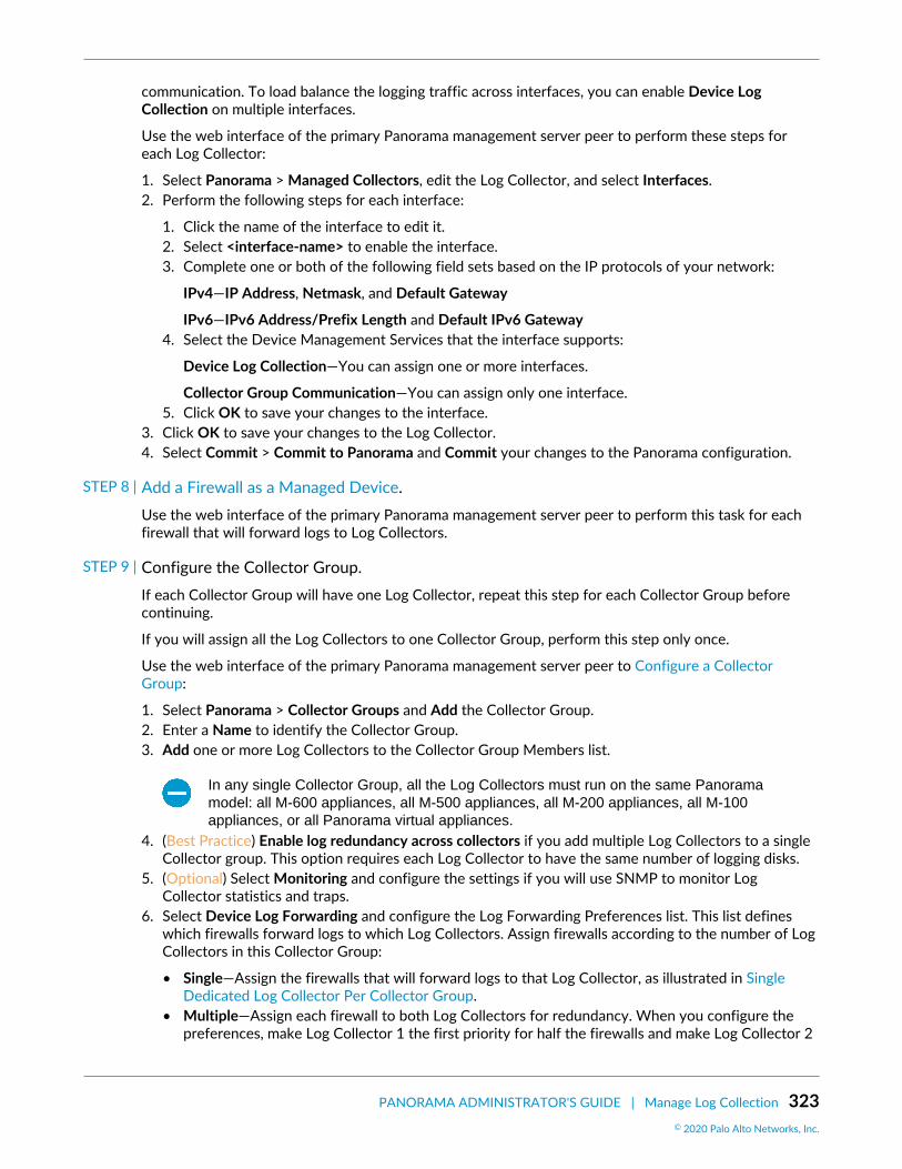
PANORAMA ADMINISTRATOR'S GUIDE | Manage Log Collection 323© 2020 Palo Alto Networks, Inc.
communication. To load balance the logging traffic across interfaces, you can enable Device LogCollection on multiple interfaces.
Use the web interface of the primary Panorama management server peer to perform these steps foreach Log Collector:
1. Select Panorama > Managed Collectors, edit the Log Collector, and select Interfaces.2. Perform the following steps for each interface:
1. Click the name of the interface to edit it.2. Select <interface-name> to enable the interface.3. Complete one or both of the following field sets based on the IP protocols of your network:
IPv4—IP Address, Netmask, and Default Gateway
IPv6—IPv6 Address/Prefix Length and Default IPv6 Gateway4. Select the Device Management Services that the interface supports:
Device Log Collection—You can assign one or more interfaces.
Collector Group Communication—You can assign only one interface.5. Click OK to save your changes to the interface.
3. Click OK to save your changes to the Log Collector.4. Select Commit > Commit to Panorama and Commit your changes to the Panorama configuration.
STEP 8 | Add a Firewall as a Managed Device.Use the web interface of the primary Panorama management server peer to perform this task for eachfirewall that will forward logs to Log Collectors.
STEP 9 | Configure the Collector Group.If each Collector Group will have one Log Collector, repeat this step for each Collector Group beforecontinuing.
If you will assign all the Log Collectors to one Collector Group, perform this step only once.
Use the web interface of the primary Panorama management server peer to Configure a CollectorGroup:
1. Select Panorama > Collector Groups and Add the Collector Group.2. Enter a Name to identify the Collector Group.3. Add one or more Log Collectors to the Collector Group Members list.
In any single Collector Group, all the Log Collectors must run on the same Panoramamodel: all M-600 appliances, all M-500 appliances, all M-200 appliances, all M-100appliances, or all Panorama virtual appliances.
4. (Best Practice) Enable log redundancy across collectors if you add multiple Log Collectors to a singleCollector group. This option requires each Log Collector to have the same number of logging disks.
5. (Optional) Select Monitoring and configure the settings if you will use SNMP to monitor LogCollector statistics and traps.
6. Select Device Log Forwarding and configure the Log Forwarding Preferences list. This list defineswhich firewalls forward logs to which Log Collectors. Assign firewalls according to the number of LogCollectors in this Collector Group:
• Single—Assign the firewalls that will forward logs to that Log Collector, as illustrated in SingleDedicated Log Collector Per Collector Group.
• Multiple—Assign each firewall to both Log Collectors for redundancy. When you configure thepreferences, make Log Collector 1 the first priority for half the firewalls and make Log Collector 2

324 PANORAMA ADMINISTRATOR'S GUIDE | Manage Log Collection© 2020 Palo Alto Networks, Inc.
the first priority for the other half, as illustrated in Multiple Dedicated Log Collectors Per CollectorGroup.
7. Click OK to save your changes to the Collector Group.8. Select Commit > Commit and Push and then Commit and Push your changes to Panorama and to the
Collector Groups you added.9. Select Panorama > Managed Collectors to verify that the Log Collector configuration is synchronized
with Panorama.
The Configuration Status column should display In Sync and the Run Time Status column shoulddisplay connected.
STEP 10 | Configure log forwarding from firewalls to Panorama.Use the web interface of the primary Panorama management server peer to:
1. Configure Log Forwarding to Panorama.2. Verify Log Forwarding to Panorama.3. (Optional) Configure Log Forwarding from Panorama to External Destinations.
Deploy Panorama M-Series Appliances with Local Log CollectorsThe following figures illustrate Panorama in a centralized log collection deployment. In these examples, thePanorama management server comprises two M-Series appliances in Panorama mode that are deployedin an active/passive high availability (HA) configuration. The firewalls send logs to the predefined (default)local Log Collector on each Panorama M-Series appliance. This is the recommended deployment if thefirewalls generate up to 10,000 logs/second.
If you will assign more than one Log Collector to a Collector Group, see Caveats for aCollector Group with Multiple Log Collectors to understand the requirements, risks, andrecommended mitigations.
After implementing this deployment, if the logging rate increases beyond 10,000 logsper second, Palo Alto Networks recommends that you add Dedicated Log Collectors (M-Series appliances in Log Collector mode) as described in Deploy Panorama with DedicatedLog Collectors. Such an expansion might require reassigning firewalls from the local LogCollectors to Dedicated Log Collectors.

PANORAMA ADMINISTRATOR'S GUIDE | Manage Log Collection 325© 2020 Palo Alto Networks, Inc.
Figure 19: Single Local Log Collector Per Collector Group
Figure 20: Multiple Local Log Collectors Per Collector Group
Perform the following steps to deploy Panorama with local Log Collectors. Skip any steps you have alreadyperformed (for example, the initial setup).
STEP 1 | Perform the initial setup of each M-Series appliance.1. Rack mount the M-Series appliance. Refer to the M-Series Hardware Reference Guides for
instructions.2. Perform Initial Configuration of the M-Series Appliance.

326 PANORAMA ADMINISTRATOR'S GUIDE | Manage Log Collection© 2020 Palo Alto Networks, Inc.
Palo Alto Networks recommends reserving the management (MGT) interface foradministrative access to Panorama and dedicating separate M-Series ApplianceInterfaces to other Panorama services.
3. Configure each array. This task is required to make the RAID disks available for logging. Optionally,you can add disks to Increase Storage on the M-Series Appliance.
4. Register Panorama and Install Licenses.5. Install Content and Software Updates for Panorama.6. Set Up HA on Panorama.
STEP 2 | Perform the following steps to prepare Panorama for log collection.1. Connect to the primary Panorama in one of the following ways:
• Attach a serial cable from your computer to the Console port on the primary Panorama. Then useterminal emulation software (9600-8-N-1) to connect.
• Use terminal emulation software such as PuTTY to open an SSH session to the IP address that youspecified for the MGT interface of the primary Panorama during initial configuration.
2. Log in to the CLI when prompted. Use the default admin account and the password that youspecified during initial configuration.
3. Enable the primary Panorama to connect to the secondary Panorama by entering the followingcommand, where <IPaddress2> represents the MGT interface of the secondary Panorama:
> configure # set deviceconfig system panorama-server <IPaddress2> # commit
4. Log in to the CLI of the secondary Panorama.5. Enable the secondary Panorama to connect to the primary Panorama by entering the following
command, where <IPaddress1> represents the MGT interface of the primary Panorama:
> configure # set deviceconfig system panorama-server <IPaddress1> # commit # exit
6. In the CLI of the secondary Panorama, enter the following command to display the serial number, andthen record it:
> show system info | match serial
You need the serial number to add the Log Collector of the secondary Panorama as a managedcollector to the primary Panorama.
STEP 3 | Edit the Log Collector that is local to the primary Panorama.Use the web interface of the primary Panorama to perform these steps:
1. Select Panorama > Managed Collectors and select the default (local) Log Collector.2. Select Disks and Add each logging disk pair.3. Click OK to save your changes.
STEP 4 | Configure the Log Collector that is local to the secondary Panorama.
Panorama treats this Log Collector as remote because it’s not local to the primaryPanorama. Therefore you must manually add it on the primary Panorama.

PANORAMA ADMINISTRATOR'S GUIDE | Manage Log Collection 327© 2020 Palo Alto Networks, Inc.
Use the web interface of the primary Panorama to Configure a Managed Collector:
1. Select Panorama > Managed Collectors and Add the Log Collector.2. Enter the serial number (Collector S/N) you recorded for the Log Collector of the secondary
Panorama.3. Enter the IP address or FQDN of the primary and secondary Panorama HA peers in the Panorama
Server IP field and Panorama Server IP 2 field respectively.
Both of these fields are required.4. Select Interfaces and configure each interface that the Log Collector will use. The Management
interface is required. Perform the following steps for each interface:
1. Click the interface name.2. Configure one or both of the following field sets based on the IP protocols of your network.
IPv4—IP Address, Netmask, and Default Gateway
IPv6—IPv6 Address/Prefix Length and Default IPv6 Gateway3. (Management interface only) Select SNMP if you will use an SNMP manager to monitor Log
Collector statistics.
Using SNMP requires additional steps besides configuring the Log Collector (see MonitorPanorama and Log Collector Statistics Using SNMP).
4. Click OK to save your changes to the interface.5. Click OK to save your changes to the Log Collector.6. Select Commit > Commit to Panorama and Commit your changes.
This step is required before you can enable logging disks.7. Edit the Log Collector by clicking its name.8. Select Disks, Add each RAID disk pair, and click OK.9. Select Commit > Commit to Panorama and Commit your changes.
STEP 5 | Add a Firewall as a Managed Device.Use the web interface of the primary Panorama to perform this task for each firewall that will forwardlogs to the Log Collectors.
STEP 6 | Edit the default Collector Group that is predefined on the primary Panorama.Use the web interface of the primary Panorama to Configure a Collector Group:
1. Select Panorama > Collector Groups and edit the default Collector Group.2. Add the local Log Collector of the secondary Panorama to the Collector Group Members list if you
are adding multiple Log Collectors to a single Collector group. By default, the list displays the localLog Collector of the primary Panorama because it is pre-assigned to the default Collector Group.
In any single Collector Group, all the Log Collectors must run on the same Panoramamodel: all M-600 appliances, all M-500 appliances, all M-200 appliances, all M-100appliances, or all Panorama virtual appliances.
3. (Best Practice) Enable log redundancy across collectors if you add multiple Log Collectors to a singleCollector group. This option requires each Log Collector to have the same number of logging disks.
4. (Optional) Select Monitoring and configure the settings if you will use SNMP to monitor LogCollector statistics and traps.
5. Select Device Log Forwarding and configure the Log Forwarding Preferences list. This list defineswhich firewalls forward logs to which Log Collectors. Assign firewalls according to the number of LogCollectors in this Collector Group:

328 PANORAMA ADMINISTRATOR'S GUIDE | Manage Log Collection© 2020 Palo Alto Networks, Inc.
• Single—Assign the firewalls that will forward logs to the local Log Collector of the primaryPanorama, as illustrated in Single Local Log Collector Per Collector Group.
• Multiple—Assign each firewall to both Log Collectors for redundancy. When you configure thepreferences, make Log Collector 1 the first priority for half the firewalls and make Log Collector2 the first priority for the other half, as illustrated in Multiple Local Log Collectors Per CollectorGroup.
6. Click OK to save your changes.
STEP 7 | Configure a Collector Group that contains the Log Collector of the secondary Panorama.Required if each Collector Group has only one Log Collector.
Use the web interface of the primary Panorama to Configure a Collector Group:
1. Select Panorama > Collector Groups and Add the Collector Group.2. Enter a Name to identify the Collector Group.3. Add the local Log Collector of the secondary Panorama to the Collector Group Members list.4. (Optional) Select Monitoring and configure the settings if you will use an SNMP manager to monitor
Log Collector statistics and traps.5. Select Device Log Forwarding and Add an entry to the Log Forwarding Preferences list:
1. Modify the Devices list, select the firewalls that will forward logs to the local Log Collector of thesecondary Panorama (see Single Local Log Collector Per Collector Group), and click OK.
2. Add the local Log Collector of the secondary Panorama to the Collectors list and click OK.6. Click OK to save your changes.
STEP 8 | Commit and push your changes to the Panorama configuration and the Collector Groups.In the web interface of the primary Panorama, select Commit > Commit and Push and then Commit andPush your changes to Panorama and the Collector Groups you added.
STEP 9 | Manually fail over so that the secondary Panorama becomes active.Use the web interface of the primary Panorama to perform the following steps:
1. Select Panorama > High Availability.2. Click Suspend local Panorama in the Operational Commands section.
STEP 10 | On the secondary Panorama, configure the network settings of the Log Collector that is localto the primary Panorama.
Use the web interface of the secondary Panorama to perform the following steps:
1. In the Panorama web interface, select Panorama > Managed Collectors and select the Log Collectorthat is local to the primary Panorama.
2. Enter the IP address or FQDN of the primary and secondary Panorama HA peers in the PanoramaServer IP field and Panorama Server IP 2 field respectively.
Both of these fields are required.3. Select Interfaces, click Management, and complete one or both of the following field sets (based on
the IP protocols of your network) with the MGT interface values of the primary Panorama:
• IPv4—IP Address, Netmask, and Default Gateway• IPv6—IPv6 Address/Prefix Length and Default IPv6 Gateway
4. Click OK to save your changes.5. Select Commit > Commit and Push and then Commit and Push your changes to Panorama and the
Collector Groups you added.

PANORAMA ADMINISTRATOR'S GUIDE | Manage Log Collection 329© 2020 Palo Alto Networks, Inc.
STEP 11 | Manually fail back so that the primary Panorama becomes active.Use the web interface of the secondary Panorama to perform the following steps:
1. Select Panorama > High Availability.2. Click Suspend local Panorama in the Operational Commands section.
STEP 12 | Configure log forwarding from firewalls to Panorama.Use the web interface of the primary Panorama to:
1. Configure Log Forwarding to Panorama.2. Verify Log Forwarding to Panorama.3. (Optional) Configure Log Forwarding from Panorama to External Destinations.
You can assign separate external server profiles to each Panorama HA peer. Forexample, you might want each peer to forward logs to a different syslog server. Tomake each Panorama peer forward logs to different external services, log in to theweb interface of each peer, select Panorama > Collector Groups, select the CollectorGroup, select Collector Log Forwarding, assign the server profiles, and click OK.
Deploy Panorama Virtual Appliances with Local Log CollectorsYou can configure firewalls to send logs to a Log Collector that runs locally on a Panorama virtual appliancein Panorama mode. In a high availability (HA) configuration, each Panorama HA peer can have a local LogCollector. You can assign the local Log Collectors on the HA peers to the same Collector Group or toseparate Collector Groups, as illustrated in the following figures. Refer to the Setup Prerequisites for thePanorama Virtual Appliance to review the supported logs per second when deploying the Panorama virtualappliance with local Log Collectors in a VMware virtual infrastructure.
If you will assign more than one Log Collector to a Collector Group, see Caveats for aCollector Group with Multiple Log Collectors to understand the requirements, risks, andrecommended mitigations.

330 PANORAMA ADMINISTRATOR'S GUIDE | Manage Log Collection© 2020 Palo Alto Networks, Inc.
Figure 21: Single Log Collector Per Collector Group
Figure 22: Multiple Log Collectors Per Collector Group

PANORAMA ADMINISTRATOR'S GUIDE | Manage Log Collection 331© 2020 Palo Alto Networks, Inc.
Perform the following steps to deploy Panorama with local Log Collectors. Skip any steps you have alreadyperformed (such as the initial setup).
STEP 1 | Perform the initial setup of each Panorama virtual appliance.1. Install the Panorama Virtual Appliance. You must configure the following resources to ensure the
virtual appliance starts in Panorama mode:
• System disk with exactly 81GB of storage.• CPUs and memory that are sufficient for the quantity of logs that Panorama will receive and store.• Virtual logging disk with 2–24TB of storage.
Panorama automatically divides the new disk into 2TB partitions, each of which willfunction as a separate virtual disk.
2. Perform Initial Configuration of the Panorama Virtual Appliance.3. Register Panorama and Install Licenses.4. Install Content and Software Updates for Panorama.
STEP 2 | Set up the Panorama virtual appliances in an HA configuration.1. Set Up HA on Panorama.2. Test Panorama HA Failover.
STEP 3 | Add a Log Collector that is local to the primary Panorama.On the primary Panorama:
1. Record the Panorama serial number.
1. Access the Panorama web interface.2. Select Dashboard and record the Serial # in the General Information section.
2. Add the Log Collector as a managed collector.
1. Select Panorama > Managed Collectors and Add a new Log Collector.2. In the General settings, enter the serial number (Collector S/N) you recorded for Panorama.3. Click OK to save your changes.4. Select Commit > Commit to Panorama.
This step is required before you can add the virtual logging disks.3. Add the virtual logging disks.
1. Select Panorama > Managed Collectors and edit the Log Collector by clicking its name.
The Log Collector name has the same value as the hostname of the primary Panorama.2. Select Disks and Add the virtual logging disks.3. Click OK to save your changes.4. Select Commit > Commit to Panorama.
STEP 4 | Add a Log Collector that is local to the secondary Panorama.
Panorama treats this Log Collector as remote because it does not run locally on theprimary Panorama.
1. Record the serial number of the secondary Panorama.
1. Access the web interface of the secondary Panorama.2. Select Dashboard and record the Serial # in the General Information section.
2. Access the web interface of the primary Panorama.

332 PANORAMA ADMINISTRATOR'S GUIDE | Manage Log Collection© 2020 Palo Alto Networks, Inc.
3. Select Panorama > Managed Collectors and Add the Log Collector.4. In the General settings, enter the serial number (Collector S/N) you recorded for the secondary
Panorama.5. Enter the IP address or FQDN of the primary and secondary Panorama HA peers in the Panorama
Server IP field and Panorama Server IP 2 field respectively.
Both of these fields are required.6. Click OK to save your changes to the Log Collector.7. Select Commit > Commit to Panorama and Commit your changes.
This step is required before you can add the virtual logging disks.8. Edit the Log Collector by clicking its name.
The Log Collector name has the same value as the hostname of the secondary Panorama.9. Select Disks, Add the virtual logging disks, and click OK.10.Select Commit > Commit to Panorama and Commit your changes.
STEP 5 | Add a Firewall as a Managed Device.Use the primary Panorama to perform this task for each firewall that will forward logs to the LogCollectors.
STEP 6 | Configure the Collector Group.Perform this step once if you will assign both Log Collectors to the same Collector Group. Otherwise,configure a Collector Group for each Log Collector.
On the primary Panorama:
1. Select Panorama > Collector Groups and Add a Collector Group.2. Add one or both Log Collectors as Collector Group Members.
In any single Collector Group, all the Log Collectors must run on the same Panoramamodel: all M-500 appliances, all M-100 appliances, or all Panorama virtual appliances.
3. (Best Practice) Enable log redundancy across collectors if you add multiple Log Collectors to a singleCollector group. This option requires each Log Collector to have the same number of virtual loggingdisks.
Enabling redundancy doubles the amount of logs and log processing traffic in aCollector Group. If necessary, Expand Log Storage Capacity on the Panorama VirtualAppliance.
4. Select Device Log Forwarding and configure the Log Forwarding Preferences list. This list defineswhich firewalls forward logs to which Log Collectors. Assign firewalls according to the number of LogCollectors in this Collector Group:
• Single—Assign the firewalls that will forward logs to the Log Collector that is local to the primaryPanorama, as illustrated in Single Log Collector Per Collector Group.
• Multiple—Assign each firewall to both Log Collectors for redundancy. When you configure thepreference list, make Log Collector 1 the first priority for half the firewalls and make Log Collector2 the first priority for the other half, as illustrated in Multiple Log Collectors Per Collector Group.
5. Click OK to save your changes.6. Select Commit > Commit and Push and then Commit and Push your changes to Panorama and the
Collector Groups you added.
STEP 7 | Trigger failover on the primary Panorama so that the secondary Panorama becomes active.On the primary Panorama:

PANORAMA ADMINISTRATOR'S GUIDE | Manage Log Collection 333© 2020 Palo Alto Networks, Inc.
1. Select Panorama > High Availability.2. Click Suspend local Panorama in the Operational Commands section.
STEP 8 | Configure the connection from the secondary Panorama to the Log Collector that is local tothe primary Panorama.On the secondary Panorama:
1. In the Panorama web interface, select Panorama > Managed Collectors and select the Log Collectorthat is local to the primary Panorama.
2. Enter the IP address or FQDN of the primary and secondary Panorama HA peers in the PanoramaServer IP field and Panorama Server IP 2 field respectively.
Both of these fields are required.3. Click OK to save your changes.4. Select Commit > Commit and Push and then Commit and Push your changes to Panorama and the
Collector Groups.
STEP 9 | Trigger fail-back on the secondary Panorama so that the primary Panorama becomes active.On the secondary Panorama:
1. Select Panorama > High Availability.2. Click Suspend local Panorama in the Operational Commands section.
STEP 10 | Configure log forwarding from the firewalls to Panorama.On the primary Panorama to:
1. Configure Log Forwarding to Panorama from firewalls.2. Verify Log Forwarding to Panorama.
Deploy Panorama Virtual Appliances in Legacy Mode with LocalLog Collection
The following figure illustrates Panorama in a centralized log collection deployment. In this example,the Panorama management server comprises two Panorama virtual appliances in Legacy mode thatare deployed in an active/passive high availability (HA) configuration. This configuration suits firewallmanagement within a VMware virtual infrastructure in which Panorama processes up to 10,000 logs/second. The firewalls send logs to the NFS datastore (ESXi server only) or virtual disk on the Panoramamanagement server. By default, the active and passive peers both receive logs, though you can ModifyLog Forwarding and Buffering Defaults so that only the active peer does. For the 5200 and 7000 seriesfirewalls, only the active peer receive logs. By default, the Panorama virtual appliance in Legacy modeuses approximately 11GB on its internal disk partition for log storage, though you can Expand Log StorageCapacity on the Panorama Virtual Appliance if necessary.
If the logging rate increases beyond 10,000 logs per second, it is recommended that youDeploy Panorama with Dedicated Log Collectors.

334 PANORAMA ADMINISTRATOR'S GUIDE | Manage Log Collection
Figure 23: Panorama Virtual Appliances in Legacy Mode with Local Log Collection
Perform the following steps to deploy Panorama virtual appliances with local log collection. Skip any stepsyou have already performed (for example, the initial setup).
STEP 1 | Perform the initial setup of each Panorama virtual appliance.1. Install the Panorama Virtual Appliance. To ensure the virtual appliance starts in Panorama mode, do
not add a virtual logging disk during installation.
By default, Panorama uses an 11GB partition on its system disk for log storage. If youwant more storage, you can add a dedicated virtual logging disk of up to 8TB after theinstallation.
2. Perform Initial Configuration of the Panorama Virtual Appliance.3. Register Panorama and Install Licenses.4. Install Content and Software Updates for Panorama.
STEP 2 | Set up the Panorama virtual appliances in an HA configuration.1. Set Up HA on Panorama.2. Test Panorama HA Failover.
STEP 3 | Perform the following steps to prepare Panorama for log collection.1. Add a Firewall as a Managed Device for each one that will forward logs to Panorama.2. Configure Log Forwarding to Panorama.
STEP 4 | Commit your changes.Select Commit > Commit to Panorama and Commit your changes.
335
Manage WildFire AppliancesYou can manage up to 200 standalone WildFire appliances and WildFire appliance clusternodes centrally using a Panorama M-Series or virtual appliance. Compared to managingWildFire appliances and appliance clusters individually using the local CLI, using Panoramaprovides centralized management and monitoring of multiple appliances and appliance clusters.Centralized management enables you to push common configurations, configuration updates,and software upgrades to all or a subset of the managed WildFire appliances, which makes iteasy to ensure that WildFire appliances and appliance clusters have consistent configurations.
When you use Panorama to manage WildFire appliance clusters, Panorama must run an equalor later version than the WildFire appliances being managed.
> Add Standalone WildFire Appliances to Manage with Panorama> Configure Basic WildFire Appliance Settings on Panorama> Set Up Authentication Using Custom Certificates on WildFire Appliances and Clusters> Remove a WildFire Appliance from Panorama Management> Manage WildFire Clusters

336 PANORAMA ADMINISTRATOR'S GUIDE | Manage WildFire Appliances© 2020 Palo Alto Networks, Inc.

PANORAMA ADMINISTRATOR'S GUIDE | Manage WildFire Appliances 337© 2020 Palo Alto Networks, Inc.
Add Standalone WildFire Appliances toManage with Panorama
You can manage up to 200 WildFire appliances with a Panorama M-Series or virtual appliance. The 200WildFire appliance limit is the combined total of standalone appliances and WildFire appliance cluster nodes(if you also Configure a Cluster and Add Nodes on Panorama).
Ensure that Panorama runs at least version 8.0.1, and that any WildFire appliance you add to Panorama alsoruns at least version 8.0.1.
STEP 1 | Using the local CLI, verify that each WildFire appliance that you want to manage withPanorama runs PAN-OS 8.0.1 or later.
admin@qa16> show system info | match version sw-version: 8.0.1-c45 wf-content-version: 702-283 logdb-version: 8.0.15
STEP 2 | On each Panorama appliance you want to use to manage WildFire appliances, verify thatPanorama runs version 8.0.1 or later:Dashboard > General Information > Software Version displays the running software version.
STEP 3 | If you aren’t sure if a WildFire appliance belongs to a WildFire appliance cluster or is astandalone appliance on the local WildFire appliance CLI, check the Node mode to ensure thatthe status is stand_alone and check the Application status to ensure that the global-db-service and global-queue-service indicate ReadyStandalone.
admin@WF-500> show cluster membership Service Summary: wfpc signature Cluster name: Address: 10.10.10.100 Host name: WF-500 Node name: wfpc-012345678901-internal Serial number: 012345678901 Node mode: stand_alone Server role: True HA priority: Last changed: Mon, 06 Mar 2017 16:34:25 -0800 Services: wfcore signature wfpc infra Monitor status: Serf Health Status: passing Agent alive and reachable Application status: global-db-service: ReadyStandalone wildfire-apps-service: Ready global-queue-service: ReadyStandalone wildfire-management-service: Done siggen-db: ReadyMaster Diag report: 10.10.10.100: reported leader '10.10.10.100', age 0. 10.10.10.100: local node passed sanity check.

338 PANORAMA ADMINISTRATOR'S GUIDE | Manage WildFire Appliances© 2020 Palo Alto Networks, Inc.
STEP 4 | If the WildFire appliances you want to manage with Panorama are new, check Get Started withWildFire to ensure that you complete basic steps such as confirming your WildFire licenseis active, enabling logging, connecting firewalls to WildFire appliances, and configuring basicWildFire features.
STEP 5 | On the local CLI of each WildFire appliance the Panorama server will manage, configure the IPaddress of the Panorama server.Before you register standalone WildFire appliances to a Panorama appliance, you must first configurethe Panorama IP address or FQDN on each WildFire appliance. This is how each WildFire applianceknows which Panorama appliance manages it.
1. Configure the IP address or FQDN of the primary Panorama appliance’s management interface:
admin@WF-500# set deviceconfig system panorama-server <ip-address | FQDN>
2. If you use a backup Panorama appliance for high availability (recommended), configure the IP addressor FQDN of the backup Panorama appliance’s management interface:
admin@WF-500# set deviceconfig system panorama-server-2 <ip-address | FQDN>
STEP 6 | Register WildFire appliances on the primary Panorama appliance.1. From the Panorama web interface, Panorama > Managed WildFire Appliances and Add Appliance.2. Enter the serial number of each WildFire appliance on a separate line. If you do not have a list of
serial numbers, on each WildFire appliance, run:
admin@WF-500> show system info | match serial serial: 012345678901
Several local CLI commands display the WildFire appliance serial number, including show clustermembership.
3. Click OK.
If it is available, information about configuration that is already committed on the WildFire appliancesdisplays, such as IP address and software version.
STEP 7 | (Optional) Import WildFire appliance configurations into the Panorama appliance.1. Select the appliances that have configurations you want to import from the list of managed WildFire
appliances.2. Import Config.3. Select Yes.
Importing configurations updates the displayed information and makes the imported configurationspart of the Panorama appliance candidate configuration.
4. Commit to Panorama to make the imported WildFire appliance configurations part of the Panoramarunning configuration.
STEP 8 | Configure or confirm the configuration of the WildFire appliance interfaces.Each WildFire appliance has four interfaces: Management (Ethernet0), Analysis Network Environment(Ethernet1), Ethernet2, and Ethernet3.
1. Select Panorama > Managed WildFire Appliances and select a WildFire appliance.2. Select Interfaces.

PANORAMA ADMINISTRATOR'S GUIDE | Manage WildFire Appliances 339© 2020 Palo Alto Networks, Inc.
3. Select an interface to configure or edit it. You can enable the interface, set the speed and duplex,the IP address and netmask, the default gateway, the MTU, the DNS server, the link state, andthe Management Services for each interface. You can also Add permitted IP addresses so that aninterface accepts traffic only from specified addresses.
The Analysis Network Environment, Ethernet2, and Ethernet3 interfaces support only Ping as aManagement Services option.
The Management interface supports Ping, SSH, and SNMP as Management Services options. Inaddition, the Management interface supports proxy server configuration in case a direct connectionto the internet is not possible.
4. Click OK after you configure or confirm the settings.
STEP 9 | Commit the configuration on the Panorama appliance and push it to the appliance or tomultiple appliances.1. Commit and Push.2. If there are configurations on the Panorama appliance that you do not want to push, Edit Selections
to choose the appliances to which you push configurations. The pushed configuration overwrites therunning configuration on the WildFire appliance.
STEP 10 | Verify the configuration.1. Select Panorama > Managed WildFire Appliances.2. Check the following fields:
• Connected—State is Connected.• Role—Each WildFire appliance’s role is Standalone.• Config Status—Status is In Sync.• Last Commit State—Commit succeeded.

340 PANORAMA ADMINISTRATOR'S GUIDE | Manage WildFire Appliances© 2020 Palo Alto Networks, Inc.
Configure Basic WildFire Appliance Settings onPanorama
Configuring basic settings such as content update and WildFire cloud servers, WildFire cloud services,logging, authentication, and so on, is similar to how you Configure General Cluster Settings on Panorama.Instead of selecting a cluster and configuring settings on the cluster, select a WildFire appliance andconfigure the individual settings for that appliance. Select and configure each WildFire appliance that youadd to Panorama.
Configure the WildFire Appliance describes how to integrate a WildFire appliance into a network andperform basic setup with the CLI, but the concepts are the same as performing basic setup using Panorama.
Many settings are pre-populated with either defaults, information from previously existingsettings on the WildFire appliance, or the settings you configured when adding the WildFireappliance to Panorama.

PANORAMA ADMINISTRATOR'S GUIDE | Manage WildFire Appliances 341© 2020 Palo Alto Networks, Inc.
Set Up Authentication Using CustomCertificates on WildFire Appliances andClusters
By default, a WildFire® appliance uses predefined certificates for mutual authentication with other PaloAlto Networks® firewalls and appliances to establish the SSL connections used for management accessand inter-device communication. However, you can configure authentication using custom certificatesinstead. Custom certificates allow you to establish a unique chain of trust to ensure mutual authenticationbetweenyour WildFire appliance or WildFire cluster managed by Panorama™ and firewalls. You cangenerate these certificates locally on Panorama or the firewall, obtain them from a trusted third-partycertificate authority (CA), or obtain certificates from enterprise private key infrastructure (PKI).
For more information about using custom certificates, see How Are SSL/TLS Connections MutuallyAuthenticated?
• Configure a Custom Certificate for a Panorama Managed WildFire Appliance• Configure Authentication with a Single Custom Certificate for a WildFire Cluster• Apply Custom Certificates on a WildFire Appliance Configured through Panorama
Configure a Custom Certificate for a Panorama Managed WildFireAppliance
If you use Panorama™ to manage your WildFire® appliance or WildFire cluster, you can configure customcertificate authentication through the Panorama web interface instead of using WildFire appliance CLI. Thefirewall or Panorama uses this connection to forward samples to WildFire for analysis.
This procedure describes how to install a unique certificate on a single WildFire appliance. If the WildFireappliance is part of a cluster, that device and each cluster member has a unique client certificate. To deploya single certificate to all WildFire appliances in the cluster, see Configure Authentication with a SingleCustom Certificate for a WildFire Cluster.
STEP 1 | Obtain key pairs and certificate authority (CA) certificates for the WildFire appliance and thefirewall.
STEP 2 | Import the CA certificate to validate the identity of the firewall and the key pair for theWildFire appliance.1. Select Panorama > Certificate Management > Certificates > Import.2. Import the CA certificate and the key pair on Panorama.
STEP 3 | Configure a certificate profile that includes the root CA and intermediate CA. This certificateprofile defines how the WildFire appliance and the firewalls authenticate mutually.1. Select Panorama > Certificate Management > Certificate Profile.2. Configure a certificate profile.
If you configure an intermediate CA as part of the certificate profile, you must also include the rootCA.
STEP 4 | Configure an SSL/TLS profile for the WildFire appliance.

342 PANORAMA ADMINISTRATOR'S GUIDE | Manage WildFire Appliances© 2020 Palo Alto Networks, Inc.
PAN-OS 8.0 and later releases support only TLS 1.2 and higher so ou must set the maxversion to TLS 1.2 or max.
1. Select Panorama > Certificate Management > SSL/TLS Service Profile.2. Configure an SSL/TLS service profile to define the certificate and protocol that the WildFire
appliance and its the firewalls use for SSL/TLS services.
STEP 5 | Configure Secure Server Communication on WildFire.1. Select Panorama > Managed WildFire Clusters or Panorama > Managed WildFire Appliances and
select a cluster or appliance.2. Select Communication.3. Enable the Customize Secure Server Communication feature.4. Select the SSL/TLS Service Profile. This SSL/TLS service profile applies to all SSL connection
between the WildFire appliance and the firewall or Panorama.5. Select the Certificate Profile you configured for communication between the WildFire appliance and
the firewall or Panorama.6. Verify that Custom Certificates Only is disabled (cleared). This allows the WildFire appliance to
continue communicating with the firewalls with the predefined certificate while migrating to customcertificates.
7. (Optional) Configure an authorization list.
1. Add an Authorization List.2. Select the Subject or Subject Alt Name configured in the certificate profile as the Identifier type.3. Enter the Common Name if the identifier is Subject or enter an IP address, hostname, or email if
the identifier is Subject Alt Name.4. Click OK.5. Enable Check Authorization List to enforce the list.
8. Click OK.9. Commit your changes.
STEP 6 | Import the CA certificate to validate the certificate for the WildFire appliance.1. Log in to the firewall web interface.2. Import the CA certificate.
STEP 7 | Configure a local or SCEP certificate for the firewall.• If you are using a local certificate, import the key pair for the firewall.• If you are using SCEP for the firewall certificate, configure a SCEP profile.
STEP 8 | Configure the certificate profile for the firewall or Panorama. You can configure this profile oneach client firewall or Panorama appliance individually or you can use a template to push theconfiguration from Panorama to managed firewalls.1. Select Device > Certificate Management > Certificate Profile for firewalls or Panorama > Certificate
Management > Certificate Profile for Panorama.2. Configure a Certificate Profile.
STEP 9 | Deploy custom certificates on each firewall or Panorama appliance.1. Log in to the firewall web interface.2. Select Device > Setup > Management for a firewall or Panorama > Setup > Management for
Panorama and Edit the Secure Communication Settings.3. Select the Certificate Type, Certificate, and Certificate Profile.

PANORAMA ADMINISTRATOR'S GUIDE | Manage WildFire Appliances 343© 2020 Palo Alto Networks, Inc.
4. In the Customize Communication settings, select WildFire Communication.5. Click OK.6. Commit your changes.
STEP 10 | After deploying custom certificates on all managed devices, enforce custom-certificateauthentication.
1. Log in to Panorama.2. Select Panorama > Managed WildFire Clusters or Panorama > Managed WildFire Appliances and
select a cluster or appliance.3. Select Communication.4. Select Custom Certificate Only.5. Click OK.6. Commit your changes.
After committing this change, WildFire immediately begins the enforcement of custom certificates.
Configure Authentication with a Single Custom Certificate for aWildFire Cluster
Instead of assigning unique certificates to each WildFire® appliance in a cluster, you can assign a single,shared client certificate to the entire WildFire cluster, which, in turn, allows you to push a single certificateto all WildFire appliances in the cluster instead of configuring separate certificates for each cluster member.Because the individual WildFire appliances share a client certificate, you must configure a unique hostname(DNS name) for each WildFire appliance. Then you can add all the hostnames as certificate attributes to theshared certificate or use a one-wildcard string that matches all the custom hostnames on all the WildFireappliances in the cluster.
To configure a single custom certificate for your WildFire cluster to use when communicating with thePanorama™, complete the following procedure.
STEP 1 | Obtain a server key pair and CA certificate for Panorama.
STEP 2 | Configure a certificate profile that includes the root certificate authority (CA) and theintermediate CA. This certificate profile defines the authentication between the WildFirecluster (client) and the Panorama appliance (server).1. Select Panorama > Certificate Management > Certificate Profile.2. Configure a certificate profile.
If you configure an intermediate CA as part of the certificate profile, you must also include the rootCA.
STEP 3 | Configure an SSL/TLS service profile.1. Select Panorama > Certificate Management > SSL/TLS Service Profile.2. Configure an SSL/TLS service profile to define the certificate and protocol that the WildFire cluster
and Panorama appliance use for SSL/TLS services.
STEP 4 | Connect each node in the cluster to Panorama.
STEP 5 | Configure a unique hostname (DNS name) on each node in the cluster or use a string witha single wildcard that matches all custom DNS names set on the WildFire appliances in thecluster.

344 PANORAMA ADMINISTRATOR'S GUIDE | Manage WildFire Appliances© 2020 Palo Alto Networks, Inc.
If using a single-wildcard string, see RFC-6125,Section 6.4.3 for requirements and limitations of wildcardstring values. Make sure you understand these requirements and limitations when configuring yourcustom DNS names.
1. Log in to the WildFire CLI on a node.2. Use the following command to assign a unique custom DNS name to the node.
admin@WF-500> configure
admin@WF-500# set deviceconfig setting wildfire custom-dns-name <dns-name>
3. Commit your change.4. Repeat this process for each node in the cluster.
STEP 6 | On Panorama, generate a client certificate for all nodes in the cluster. Under CertificateAttributes, add a hostname entry for each custom DNS name you assigned to the cluster nodesor add one hostname entry with a one-wildcard string that matches all of the node hostnames,such as *.example.com; you can do this only if each custom DNS name shares a common string.
STEP 7 | On Panorama, configure the certificate profile for the cluster client certificate.1. Select Panorama > Certificate Management > Certificate Profile for Panorama.2. Configure a Certificate Profile.
STEP 8 | Deploy custom certificates on each node. This certificate profile must contain the CAcertificate that signed the Panorama server certificate.1. Select Panorama > Managed WildFire Clusters and click on the cluster name.2. Select Communications.3. Under Secure Client Communications, select the Certificate Type, Certificate, and Certificate Profile.4. Click OK.5. Commit your changes.
STEP 9 | Configure secure server communication on Panorama.1. Select Panorama > Setup > Management and Edit to select Customize Secure Server
Communication.2. Enable Customize Secure Server Communication.3. Select the SSL/TLS Service Profile. This SSL/TLS service profile applies to all SSL connection
between WildFire and Panorama.4. Select the Certificate Profile for Panorama.5. Enable Custom Certificates Only.6. Click OK.7. Commit your changes.
Apply Custom Certificates on a WildFire Appliance Configuredthrough Panorama
By default, Panorama™ uses a predefined certificate when communicating with a WildFire® appliance topush configurations. You can alternatively configure custom certificates to establish mutual authenticationfor the connection Panorama uses to push configurations to a managed WildFire appliance or cluster.Complete the following procedure to configure the server certificate on Panorama and the client certificateon the WildFire appliance.

PANORAMA ADMINISTRATOR'S GUIDE | Manage WildFire Appliances 345© 2020 Palo Alto Networks, Inc.
STEP 1 | Obtain key pairs and certificate authority (CA) certificates for Panorama and the WildFireappliance.
STEP 2 | Import the CA certificate to validate the identify of the WildFire appliance and the key pair forPanorama.1. Select Panorama > Certificate Management > Certificates > Import.2. Import the CA certificate and the key pair on Panorama.
STEP 3 | Configure a certificate profile that includes the root CA and intermediate CA. This certificateprofile defines the authentication between the WildFire appliance (client) and the Panoramavirtual or M-Series appliance (server).1. Select Panorama > Certificate Management > Certificate Profile.2. Configure a certificate profile.
If you configure an intermediate CA as part of the certificate profile, you must also include the rootCA.
STEP 4 | Configure an SSL/TLS service profile.1. Select Panorama > Certificate Management > SSL/TLS Service Profile.2. Configure an SSL/TLS service profile to define the certificate and protocol that the WildFire and
Panorama appliances use for SSL/TLS services.
STEP 5 | Configure secure server communication on the Panorama appliance.1. Select Panorama > Setup > Management and Edit to select Customize Secure Server
Communication.2. Enable the Customize Secure Server Communication feature.3. Select the SSL/TLS Service Profile.4. Select the certificate profile from the Certificate Profile drop-down.5. Verify that Custom Certificates Only is disabled (cleared). This allows Panorama to continue
communicating with WildFire with the predefined certificate while migrating to custom certificates.6. (Optional) Configure an authorization list.
1. Add an Authorization List.2. Select the Subject or Subject Alt Name configured in the certificate profile as the Identifier type.3. Enter the Common Name if the identifier is Subject or an IP address, hostname, or email if the
identifier is Subject Alt Name.4. Click OK.5. Enable the Check Authorization List option to configure Panorama to enforce the authorization
list.7. Click OK.8. Commit your changes.
STEP 6 | Import the CA certificate to validate the certificate on Panorama.1. Log in to the Panorama user interface.2. Import the CA certificate.
STEP 7 | Configure a local or a SCEP certificate for the WildFire appliance.1. If you are using a local certificate, import the key pair for the WF-500 appliance.2. If you are using SCEP for the WildFire appliance certificate, configure a SCEP profile.
STEP 8 | Configure the certificate profile for the WildFire appliance.1. Select Panorama > Certificate Management > Certificate Profile.
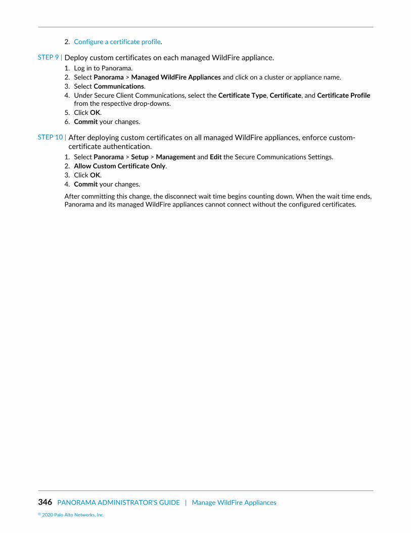
346 PANORAMA ADMINISTRATOR'S GUIDE | Manage WildFire Appliances© 2020 Palo Alto Networks, Inc.
2. Configure a certificate profile.
STEP 9 | Deploy custom certificates on each managed WildFire appliance.1. Log in to Panorama.2. Select Panorama > Managed WildFire Appliances and click on a cluster or appliance name.3. Select Communications.4. Under Secure Client Communications, select the Certificate Type, Certificate, and Certificate Profile
from the respective drop-downs.5. Click OK.6. Commit your changes.
STEP 10 | After deploying custom certificates on all managed WildFire appliances, enforce custom-certificate authentication.
1. Select Panorama > Setup > Management and Edit the Secure Communications Settings.2. Allow Custom Certificate Only.3. Click OK.4. Commit your changes.
After committing this change, the disconnect wait time begins counting down. When the wait time ends,Panorama and its managed WildFire appliances cannot connect without the configured certificates.

PANORAMA ADMINISTRATOR'S GUIDE | Manage WildFire Appliances 347© 2020 Palo Alto Networks, Inc.
Remove a WildFire Appliance from PanoramaManagement
You can remove WildFire standalone appliances from Panorama management. When you remove astandalone WildFire appliance from Panorama management, you no longer enjoy the benefits of centralizedmanagement and must manage the appliance using its local CLI and scripts.
STEP 1 | Select Panorama > Managed WildFire Appliances.
STEP 2 | Select the WildFire appliance or appliances you want to remove from Panorama managementby selecting the checkbox next to each appliance or by clicking in an appliance’s row.
STEP 3 | Remove the selected WildFire appliances from Panorama management.

348 PANORAMA ADMINISTRATOR'S GUIDE | Manage WildFire Appliances© 2020 Palo Alto Networks, Inc.
Manage WildFire ClustersA WildFire appliance cluster is an interconnected group of WildFire appliances that pool resources toincrease sample analysis and storage capacity, support larger groups of firewalls and simplify configurationand management of multiple WildFire appliances. For enhanced security and to maintain confidentiality oftransmitted content, you can also encrypt communications between WildFire appliances in a cluster. Formore information about WildFire clusters and deployment processes, refer to WildFire Appliance Clusters.
The following tasks can be performed using Panorama to manage your WildFire cluster.
• Configure a Cluster Centrally on Panorama• View WildFire Cluster Status Using Panorama• Upgrade a Cluster Centrally on Panorama with an Internet Connection• Upgrade a Cluster Centrally on Panorama without an Internet Connection• Configure Appliance-to-Appliance Encryption Using Predefined Certificates Centrally on Panorama• Configure Appliance-to-Appliance Encryption Using Custom Certificates Centrally on Panorama
Configure a Cluster Centrally on PanoramaBefore you configure a WildFire appliance cluster on a Panorama M-Series or virtual appliance, have twoWildFire appliances available to configure as a high availability controller node pair and any additionalWildFire appliances needed to serve as worker nodes to increase the analysis, storage capacity, andresiliency of the cluster.
If the WildFire appliances are new, check Get Started with WildFire to ensure that you complete basicsteps such as confirming your WildFire license is active, enabling logging, connecting firewalls to WildFireappliances, and configuring basic WildFire features.
To create WildFire appliance clusters, you must upgrade all of the WildFire appliances thatyou want to place in a cluster to PAN-OS 8.0.1 or later. If you use Panorama to manageWildFire appliance clusters, Panorama also must run PAN-OS 8.0.1 or later. On eachWildFire appliance that you want to add to a cluster, run show system info | matchversion on the WildFire appliance CLI to ensure that the appliance is running PAN-OS8.0.1 or later. On each Panorama appliance you use to manage clusters (or standaloneappliances), Dashboard > General Information > Software Version displays the runningsoftware version.
When your WildFire appliances are available, perform the appropriate tasks:
• Configure a Cluster and Add Nodes on Panorama• Configure General Cluster Settings on Panorama• Remove a Cluster from Panorama Management
Removing a node from a cluster using Panorama is not supported. Instead, Remove a Nodefrom a Cluster Locally using the local WildFire CLI.
Configure a Cluster and Add Nodes on PanoramaBefore configuring a WildFire appliance cluster from Panorama, you must upgrade Panorama to 8.0.1or later and upgrade all WildFire appliances you plan to add to the cluster to 8.0.1 or later. All WildFireappliances must run the same version of PAN-OS.
You can manage up to 200 WildFire appliances with a Panorama M-Series or virtual appliance. The 200WildFire appliance limit is the combined total of standalone appliances and WildFire appliance cluster

PANORAMA ADMINISTRATOR'S GUIDE | Manage WildFire Appliances 349© 2020 Palo Alto Networks, Inc.
nodes (if you also Add Standalone WildFire Appliances to Manage with Panorama). Except where noted,configuration takes place on Panorama.
Each WildFire appliance cluster node must have a static IP address in the same subnet andhave low-latency connections.
STEP 1 | Using the local CLI, configure the IP address of the Panorama server that will manage theWildFire appliance cluster.Before you register cluster or standalone WildFire appliances to a Panorama appliance, you must firstconfigure the Panorama IP address or FQDN on each WildFire appliance using the local WildFire CLI.This is how each WildFire appliance knows which Panorama appliance manages it.
1. On each WildFire appliance, configure the IP address or FQDN of the primary Panorama appliance’smanagement interface:
admin@WF-500# set deviceconfig system panorama-server <ip-address | FQDN>
2. On each WildFire appliance, if you use a backup Panorama appliance for high availability(recommended), configure the IP address or FQDN of the backup Panorama appliance’s managementinterface:
admin@WF-500# set deviceconfig system panorama-server-2 <ip-address | FQDN>
3. Commit the configuration on each WildFire appliance:
admin@WF-500# commit
STEP 2 | On the primary Panorama appliance, Register the WildFire appliances.The newly registered appliances are in standalone mode unless they already belong to a cluster due tolocal cluster configuration.
1. Select Panorama > Managed WildFire Appliances and Add Appliance.2. Enter the serial number of each WildFire appliance on a separate line. If you do not have a list of
WildFire appliance serial numbers, using the local CLI, run show system info on each WildFireappliance to obtain the serial number.
3. Click OK.
If it is available, information about configuration that is already committed on the WildFire appliancesdisplays, such as IP address and software version. WildFire appliances that already belong to a cluster(for example, because of local cluster configuration) display their cluster information and connectionstatus.
STEP 3 | (Optional) Import WildFire appliance configurations into the Panorama appliance.Importing configurations saves time because you can reuse or edit the configurations on Panorama andthen push them to one or more WildFire appliance clusters or standalone WildFire appliances. If thereare no configurations you want to import, skip this step. When you push a configuration from Panorama,the pushed configuration overwrites the local configuration.
1. Select Panorama > Managed WildFire Appliances, and select the appliances that have configurationsyou want to import from the list of managed WildFire appliances.
2. Import Config.3. Select Yes.

350 PANORAMA ADMINISTRATOR'S GUIDE | Manage WildFire Appliances© 2020 Palo Alto Networks, Inc.
Importing configurations updates the displayed information and makes the imported configurationspart of the Panorama appliance candidate configuration.
4. Commit to Panorama to make the imported WildFire appliance configurations part of the Panoramarunning configuration.
STEP 4 | Create a new WildFire appliance cluster.1. Select Managed WildFire Clusters.
Appliance > No Cluster Assigned displays standalone WildFire appliances (nodes) and indicates howmany available nodes are not assigned to a cluster.
2. Create Cluster.3. Enter an alphanumeric cluster Name of up to 63 characters in length. The Name can contain lower-
case characters and numbers, and hyphens and periods if they are not the first or last character. Nospaces or other characters are allowed.
4. Click OK.
The new cluster name displays but has no assigned WildFire nodes.
STEP 5 | Add WildFire appliances to the new cluster.The first WildFire appliance added to the cluster automatically becomes the controller node, and thesecond WildFire appliance added to the cluster automatically becomes the controller backup node. Allsubsequent WildFire appliances added to the cluster become worker nodes. Worker nodes use thecontroller node settings so that the cluster has a consistent configuration.
1. Select the new cluster.2. Select Clustering.3. Browse the list of WildFire appliances that do not belong to clusters.4. Add ( ) each WildFire appliance you want to include in the cluster. You can add up to twenty
nodes to a cluster. Each WildFire appliance that you add to the cluster is displayed along with itsautomatically assigned role.
5. Click OK.
STEP 6 | Configure the Management, Analysis Environment Network, HA, and cluster managementinterfaces.Configure the Management, Analysis Environment Network, and cluster management interfaces oneach cluster member (controller and worker nodes) if they are not already configured. The clustermanagement interface is a dedicated interface for management and communication within the clusterand is not the same as the Management interface.
Configure the HA interfaces individually on both the controller node and the controller backup node.The HA interfaces connect the primary and backup controller nodes and enable them to remain in syncand ready to respond to a failover.
Cluster nodes need IP addresses for each of the four WildFire appliance interfaces. Youcannot configure HA services on worker nodes.
1. Select the new cluster.2. Select Clustering.3. If the management interface is not configured on a cluster node, select Interface Name >
Management and enter the IP address, netmask, services, and other information for the interface.4. If the interface for the Analysis Environment Network is not configured on a cluster node, select
Interface Name > Analysis Environment Network and enter the IP address, netmask, services, andother information for the interface.

PANORAMA ADMINISTRATOR'S GUIDE | Manage WildFire Appliances 351© 2020 Palo Alto Networks, Inc.
5. On both the controller node and controller backup node, select the interface to use for the HAcontrol link. You must configure the same interface on both controller nodes for the HA service. Forexample, on the controller node and then on the controller backup node, select Ethernet3.
6. For each controller node, select Clustering Services > HA. (The HA option is not available for workernodes.) If you also want the ability to ping the interface, select Management Services > Ping.
7. Click OK.8. (Recommended) Select the interface to use as the backup HA control link between the controller
node and the controller backup node. You must use the same interface on both nodes for the HAbackup service. For example, on both nodes, select Management.
Select Clustering Services > HA Backup for both nodes. You can also select Ping, SSH, and SNMP ifyou want those Management Services on the interface.
The Analysis Environment Network interface cannot be an HA or HA Backup interfaceor a cluster management interface.
9. Select the dedicated interface to use for management and communication within the cluster. Youmust use the same interface on both nodes, for example, Ethernet2.
10.Select Clustering Services > Cluster Management for both nodes. If you also want the ability to pingon the interface, select Management Services > Ping.
Worker nodes in the cluster automatically inherit the controller node’s settings for thededicated management and communication interface.
STEP 7 | Commit the configuration on the Panorama appliance and push it to the cluster.1. Commit and Push.2. If there are configurations on the Panorama appliance that you do not want to push, Edit Selections
to choose the appliances to which you push configurations. The pushed configuration overwrites therunning configuration on the cluster nodes so that all cluster nodes run the same configuration.
STEP 8 | Verify the configuration.1. Select Panorama > Managed WildFire Clusters.2. Check the following fields:
• Appliance—Instead of displaying as standalone appliances, the WildFire nodes added to thecluster display under the cluster name.
• Cluster Name—The cluster name displays for each node.• Role—The appropriate role (Controller, Controller Backup, or Worker) displays for each node.• Config Status—Status is In Sync.• Last Commit State—Commit succeeded.
STEP 9 | Using the local CLI on the primary controller node (not the Panorama web interface), check toensure that the configurations are synchronized.If they are not synchronized, manually synchronize the high availability configurations on the controllernodes and commit the configuration.
Even though you can perform most other configuration on Panorama, synchronizing the controller nodehigh availability configurations must be done on the primary controller node’s CLI.
1. On the primary controller node, check to ensure that the configurations are synchronized:
admin@WF-500(active-controller)> show high-availability all
At the end of the output, look for the Configuration Synchronization output:

352 PANORAMA ADMINISTRATOR'S GUIDE | Manage WildFire Appliances© 2020 Palo Alto Networks, Inc.
Configuration Synchronization: Enabled: yes Running Configuration: synchronized
If the running configuration is synchronized, you do not need to manually synchronize theconfiguration. However, if the configuration is not synchronized, you need to synchronize theconfiguration manually.
2. If the configuration is not synchronized, on the primary controller node, synchronize the highavailability configuration to the remote peer controller node:
admin@WF-500(active-controller)> request high-availability sync-to-remote running-config
If there is a mismatch between the primary controller node’s configuration and the configurationon the controller backup node, the configuration on the primary controller node overrides theconfiguration on the controller backup node.
3. Commit the configuration:
admin@WF-500# commit
Configure General Cluster Settings on PanoramaSome general settings are optional and some general settings are pre-populated with default values. It’sbest to at least check these settings to ensure that the cluster configuration matches your needs. Generalsettings include:
• Connecting to the WildFire public cloud and submitting samples to the public cloud.• Configuring data retention policies.• Configuring logging.• Setting the analysis environment (the VM image that best matches your environment) and customizing
the analysis environment to best service the types of samples the firewalls submit to WildFire.• Set IP addresses for the DNS server, NTP server, and more.
STEP 1 | Configure settings for the WildFire appliance cluster nodes.Many settings are pre-populated with either defaults, information from previously existing settings onthe controller node, or the settings you just configured.
1. Select the cluster.2. Select Appliance.3. Enter new information, keep the pre-populated information from the cluster controller node, or edit
the pre-populated information, including:
• Domain name.• IP address of the Primary DNS Server and the Secondary DNS Server.• NTP Server Address and Authentication Type of the Primary NTP Server and the Secondary NTP
Server. The Authentication Type options are None, Symmetric Key, and AutoKey.
STEP 2 | Configure general cluster settings.Many settings are pre-populated with either defaults, information from previously existing settings onthe controller node, or the settings you just configured.
1. Select the new cluster > General.

PANORAMA ADMINISTRATOR'S GUIDE | Manage WildFire Appliances 353© 2020 Palo Alto Networks, Inc.
2. (Optional) Enable DNS for the controller node to advertise the service status using DNS protocol.The cluster controller provides DNS services on the management (MGT) interface port.
3. Register Firewall To the use the service advertised by the cluster controller(s). Palo Alto Networksrecommends adding both controllers as authority servers as this provides the benefit of high-availability. Use the form:
wfpc.service.<cluster-name>.<domain>
For example, a cluster named mycluster in the paloaltonetworks.com domain would have the domainname:
wfpc.service.mycluster.paloaltonetworks.com
4. Enter the Content Update Server for the cluster. Use the defaultupdates.paloaltonetworks.com FQDN to connect to the closest server. Check Server Identityto confirm the update server identity by matching the common name (CN) in the certificate with theIP address or FQDN of the server (this is checked by default).
5. (Optional) Enter the public WildFire Cloud Server location or use the defaultwildfire.paloaltonetworks.com so that the cluster (or standalone appliance managed byPanorama) can send information to the closest WildFire cloud server. If you leave this field blank anddo not connect to a WildFire cloud server, the cluster can’t receive signature updates directly fromthe WildFire public cloud, and can’t send samples for analysis or contribute data to the public cloud.
6. If you connect the cluster to the public WildFire cloud, select the cloud services you want to enable:
• Send Analysis Data—Send an XML report about local malware analysis. If you send the actualsamples, the cluster doesn’t send reports.
• Send Malicious Samples—Send malware samples.• Send Diagnostics—Send diagnostic data.• Verdict Lookup—Automatically query the WildFire public cloud for verdicts before performing
local analysis to reduce the load on the local WildFire appliance cluster.7. Select the Sample Analysis Image to use, based on the types of samples the cluster will analyze.8. Configure the amount of time for the cluster to retain Benign/Grayware sample data (1-90 day
range, 14 day default) and Malicious sample data (minimum 1 day, no maximum (indefinite), default isindefinite). Malicious sample data includes phishing verdicts.
9. (Optional) Select Preferred Analysis Environment to allocate more resources to Executablesor Documents, depending on your environment. The Default allocation is balanced betweenExecutables and Documents. The available resource amount depends on the number of WildFirenodes in the cluster.
STEP 3 | Check to ensure that the primary and backup Panorama servers are configured.If you did not configure a backup Panorama server and want to do so, you can add the backup Panoramaserver.
1. Select the cluster.2. Select Appliance.3. Check (or enter) the IP address or FQDN of the primary Panorama Server and of the backup
Panorama Server 2 if you are using a high availability configuration for centralized clustermanagement.
STEP 4 | (Optional) Configure system and configuration log settings for the cluster, including logforwarding.1. Select the cluster.2. Select Logging.

354 PANORAMA ADMINISTRATOR'S GUIDE | Manage WildFire Appliances© 2020 Palo Alto Networks, Inc.
3. Select System or Configuration to configure a system or configuration log, respectively. The processfor configuring them is similar.
4. Add ( ) and Name the log forwarding instance, select the Filter, and configure the Forward Method(SNMP, Email, Syslog, or HTTP).
STEP 5 | Configure administrator authentication.1. Select the cluster.2. Select Authentication.3. Select the Authentication Profile, either None or radius. RADIUS is the only supported external
authentication method.4. Set the Local Authentication mode for admin users as either Password or Password Hash, and enter
the Password.
STEP 6 | Commit the configuration on the Panorama appliance and push it to the cluster.1. Commit and Push.2. If there are configurations on the Panorama appliance that you do not want to push, Edit Selections
to choose the appliances to which you push configurations. The pushed configuration overwrites therunning configuration on the cluster nodes so that all cluster nodes run the same configuration.
Remove a Cluster from Panorama ManagementTo remove a cluster from Panorama management, Panorama > Managed WildFire Clusters and select therow of the cluster you want to remove (do not click the cluster name) and Remove From Panorama.
If you remove a WildFire appliance cluster from Panorama management, the Panorama web interfaceplaces the WildFire appliances in that cluster into read-only mode. Although the WildFire appliancesin the removed cluster display in the Panorama web interface, when in read-only mode, you can’t pushconfigurations to the WildFire appliances or manage them with Panorama. After being removed fromPanorama management, the WildFire appliance cluster members use the local cluster configuration and youcan manage the cluster using the local CLI.
To manage the WildFire appliances in the cluster with Panorama after you remove the cluster fromPanorama management, import the cluster back into Panorama (Panorama > Managed WildFire Clusters >Import Cluster Config).
STEP 1 | Select the cluster’s controller node. The cluster name populates Cluster automatically.
STEP 2 | Click OK. The cluster backup controller node and worker nodes populate automatically.
STEP 3 | Click OK to import the cluster.
STEP 4 | Commit the changes.
Configure Appliance-to-Appliance Encryption Using Predefined CertificatesCentrally on Panorama
STEP 1 | Upgrade each managed WildFire appliance to PAN-OS 8.1.x. All managed appliances must berunning PAN-OS 8.1 or later to enable appliance-to-appliance encryption.
STEP 2 | Verify that your WildFire appliance cluster has been properly configured and is operating in ahealthy state.

PANORAMA ADMINISTRATOR'S GUIDE | Manage WildFire Appliances 355© 2020 Palo Alto Networks, Inc.
STEP 3 | On Panorama, select Panorama > Managed WildFire Clusters > WF_cluster_name>Communication.
STEP 4 | Enable Secure Cluster Communication.
STEP 5 | (Recommended) Enable HA Traffic Encryption. This optional setting encrypts the HA trafficbetween the HA pair and is a Palo Alto Networks recommended best practice.
HA Traffic Encryption cannot be disabled when operating in FIPS/CC mode.
STEP 6 | Click OK to save the WildFire Cluster settings.
STEP 7 | Commit your changes.
Configure Appliance-to-Appliance Encryption Using Custom CertificatesCentrally on Panorama
STEP 1 | Upgrade each managed WildFire appliance to PAN-OS 8.1.x. All managed appliances must berunning PAN-OS 8.1 or later to enable appliance-to-appliance encryption.

356 PANORAMA ADMINISTRATOR'S GUIDE | Manage WildFire Appliances© 2020 Palo Alto Networks, Inc.
STEP 2 | Verify that your WildFire appliance cluster has been properly configured and is operating in ahealthy state.
STEP 3 | Review your existing WildFire secure communications configuration. Keep in mind, if youpreviously configured the WildFire appliance and the firewall for secure communicationsusing a custom certificate, you can also use that custom certificate for secure communicationsbetween WildFire appliances.1. Select Panorama >Managed WildFire Clusters> WF_cluster_name> Communication.2. If Customize Secure Server Communication has been enabled and you would like to use that
certificate, identify the details of the custom certificate being used. Otherwise proceed to Step 5 tobegin the process of installing a new custom certificate.
3. Determine the custom certificate FQDN (DNS name) that will be used to define the firewallregistration address in step 4.
Make sure to note the custom certificate name and the associated FQDN. These arereferenced several times during the configuration process.
STEP 4 | Configure the firewall registration address on Panorama.1. On Panorama, select Panorama >Managed WildFire Clusters> WF_cluster_name> General.2. In the Register Firewall To field, specify the DNS name used for authentication found in the custom
certificate (typically the SubjectName or the SubjectAltName). For example, the default domain nameis wfpc.service.mycluster.paloaltonetworks.com
STEP 5 | Configure WildFire Secure Server Communication settings on Panorama. If you alreadyconfigured secure communications between the firewall and the WildFire cluster and are usingthe existing custom certificate, proceed to step d.1. On Panorama, select Panorama> Managed WildFire Clusters> WF_cluster_name> Communication.2. Click Customize Secure Server Communication.3. Configure and deploy custom certificates used by the WildFire appliances and the associated
firewall. The SSL/TLS service profile defines the custom certificate used by WildFire appliances tocommunicate with WildFire appliance peers and to the firewall. You must also configure the customcertificate settings on the firewall associated with the WildFire appliance cluster. This is configuredlater in step 9.

PANORAMA ADMINISTRATOR'S GUIDE | Manage WildFire Appliances 357© 2020 Palo Alto Networks, Inc.
1. Open the SSL/TLS Service Profile drop-down and click SSL/TLS Service Profile. Configure an SSL/TLS service profile with the custom certificate that you want to use. After you configure the SSL/TLS service profile, click OK and select the newly created SSL/TLS Service profile.
2. Open the Certificate Profile drop-down and click Certificate Profile. Configure a Certificate Profilethat identifies the custom certificate used to establish secure connections between the firewalland WildFire appliances, as well as between peer WildFire appliances. After you configure theCertificate Profile, click OK and select the newly created profile.
4. Select the Custom Certificate Only check box. This allows you to use the custom certificates that youconfigured instead of the default preconfigured certificates.
5. (Optional) Configure an authorization list. The authorization list checks the custom certificate Subjector Subject Alt Name; if the Subject or Subject Alt Name presented with the custom certificate doesnot match an identifier on the authorization list, authentication is denied.
1. Add an Authorization List.2. Select the Subject or Subject Alt Name configured in the custom certificate profile as the
Identifier type.3. Enter the Common Name if the identifier is Subject or and IP address, hostname or email if the
identifier is Subject Alt Name.4. Click OK.5. Select Check Authorization List to enforce the authorization list.
6. Click OK.
STEP 6 | Enable Secure Cluster Communication.
STEP 7 | (Recommended) Enable HA Traffic Encryption. This optional setting encrypts the HA trafficbetween the HA pair and is a Palo Alto Networks recommended best practice.
HA Traffic Encryption cannot be disabled when operating in FIPS/CC mode.
STEP 8 | Click OK to save the WildFire Cluster settings.
STEP 9 | Configure the firewall Secure Communication Settings on Panorama to associate the WildFireappliance cluster with the firewall custom certificate. This provides a secure communicationschannel between the firewall and WildFire appliance cluster. If you already configured secure

358 PANORAMA ADMINISTRATOR'S GUIDE | Manage WildFire Appliances© 2020 Palo Alto Networks, Inc.
communications between the firewall and the WildFire appliance cluster and are using theexisting custom certificate, proceed to step 10.1. Select Device > Setup > Management > Secure Communication Settings and click the Edit icon in
Secure Communication Settings to configure the firewall custom certificate settings.2. Select the Certificate Type, Certificate, and Certificate Profile from the respective drop-downs and
configure them to use the custom certificate.3. Under Customize Communication, select WildFire Communication.4. Click OK.
STEP 10 | Commit your changes.
View WildFire Cluster Status Using PanoramaTo confirm that a configured WildFire appliance cluster is operating correctly, you can view the currentstatus using the Panorama appliance.
Palo Alto Networks recommends using the WildFire appliance CLI to verify the status of yourWildFire cluster. Additional status details that are not visible from Panorama are displayed inthe command output.
STEP 1 | On the primary Panorama appliance, select Panorama > Managed WildFire Clusters.
STEP 2 | In the Cluster Status column, verify that:1. The wfpc and signature services are running.2. No other operations are present. Abnormal operations and their status conditions include:
• Decommission [requested / ongoing / denied / success / fail]• Suspend [requested / ongoing / denied / success / fail]• Reboot [requested / ongoing / denied / success / fail]• Cluster [offline / splitbrain / unready]• Service [suspended / none]• HA [peer-offline / cfg-not-sync / cfg-sync-off]
STEP 3 | In the Config Status column, verify that:1. The appliance configuration is In Sync with the configuration stored on the Panorama appliance.2. No other status is present. Abnormal status conditions include:
• Out of Sync [The appliance configuration is not in sync with its saved configuration on Panorama.You can mouse over the magnifying glass to display the cause of the sync failure].
STEP 4 | In the Connected column, verify that the configured WildFire appliances show a status ofConnected.
Upgrade a Cluster Centrally on Panorama with an InternetConnection
WildFire appliances in a cluster can be upgraded in parallel when they are managed by Panorama. IfPanorama has a direct connection to the internet, you can check and download new releases directly fromPanorama.

PANORAMA ADMINISTRATOR'S GUIDE | Manage WildFire Appliances 359© 2020 Palo Alto Networks, Inc.
Panorama can only manage WildFire appliances and appliance clusters operating the samesoftware version or a later software version.
STEP 1 | Upgrade Panorama to an equal or later release than the target software release you want toinstall on the WildFire cluster.For information on upgrading Panorama, refer to Install Content and Software Updates for Panorama.
STEP 2 | Temporarily suspend sample analysis.1. Stop firewalls from forwarding any new samples to the WildFire appliance.
1. Log in to the firewall web interface.2. Select Device > Setup > WildFire and edit General Settings.3. Clear the WildFire Private Cloud field.4. Click OK and Commit.
2. Confirm that analysis for samples the firewalls already submitted to the appliance is complete:
1. Log in to the Panorama web interface.2. Select Panorama > Managed WildFire Clusters and View the cluster analysis environment
Utilization.3. Verify that the Virtual Machine Usage does not show any sample analysis in progress.
If you do not want to wait for the WildFire appliance to finish analyzing recently-submitted samples, you can continue to the next step. However, consider that theWildFire appliance then drops pending samples from the analysis queue.
STEP 3 | Install the latest WildFire appliance content update.These updates equip the appliance with the latest threat information to accurately detect malware.
You must install content updates before installing software upgrades. Refer to the ReleaseNotes for the minimum content release version you must install for a Panorama release.
1. Download the WildFire content update:
1. Select Panorama > Device Deployment > Dynamic Updates.2. Select a WildFire content update release package and click Download.
2. Click Install.3. Select the WildFire cluster(s) or individual appliances that you want to upgrade.4. Click OK to start the installation.
STEP 4 | Download the PAN-OS software version to the WildFire appliance.You cannot skip any major release version when upgrading the WildFire appliance. For example, if youwant to upgrade from PAN-OS 6.1 to PAN-OS 7.1, you must first download and install PAN-OS 7.0.
1. Download the WildFire software upgrade:
1. Select Panorama > Device Deployment > Software.2. Click Check Now to retrieve an updated list of releases.3. Select the WildFire release that you wish to install and click Download.4. Click Close to exit the Download Software window
2. Click Install.3. Select the WildFire cluster(s) that you want to upgrade.4. Select an install mode:
• (8.0.2 and later) Select Reboot device after install.

360 PANORAMA ADMINISTRATOR'S GUIDE | Manage WildFire Appliances© 2020 Palo Alto Networks, Inc.
• (8.0.1 and later) Select Upload only.5. Click OK to start the installation.6. (Optional) Monitor installation progress on Panorama.7. (8.0.1 only) After the upgrade package finishes uploading, install the upgrade on each node:
1. admin@WF-500 (passive-controller)> request system software install version 8.0.2
2. Confirm that the upgrade is complete. Run the following command and look for the job typeInstall and status FIN:
admin@WF-500(passive-controller)> show jobs all
Enqueued Dequeued ID Type Status Result Completed----------------------------------------------------14:53:15 14:53:15 5 Install FIN OK 14:53:19
3. Gracefully restart the appliance:
admin@WF-500(passive-controller)> request cluster reboot-local-node
The upgrade process could take 10 minutes or over an hour, depending on thenumber of samples stored on the WildFire appliance.
4. Repeat for each WildFire worker node in the cluster.
STEP 5 | (Optional) View the status of the reboot tasks on the WildFire controller node.On the WildFire cluster controller, run the following command and look for the job type Install andStatus FIN:
admin@WF-500(active-controller)> show cluster task pending
STEP 6 | Check that the WildFire appliance is ready to resume sample analysis.1. Verify that the sw-version field shows 8.0.1:
admin@WF-500(passive-controller)> show system info | match sw-version
2. Confirm that all processes are running:
admin@WF-500(passive-controller)> show system software status
3. Confirm that the auto-commit (AutoCom) job is complete:
admin@WF-500(passive-controller)> show jobs all
Upgrade a Cluster Centrally on Panorama without an InternetConnection
WildFire appliances in a cluster can be upgraded in parallel when they are managed by Panorama. IfPanorama does not have a direct connection to the internet, you must download the software content andupdates from the Palo Alto Networks Support site and host them on an internal server before they can bedistributed by Panorama.

PANORAMA ADMINISTRATOR'S GUIDE | Manage WildFire Appliances 361© 2020 Palo Alto Networks, Inc.
Panorama can only manage WildFire appliances and appliance clusters operating the samesoftware version or a later software version.
STEP 1 | Upgrade Panorama to an equal or later release than the target software release you want toinstall on the WildFire cluster.For information on upgrading Panorama, refer to Install Content and Software Updates for Panorama.
STEP 2 | Temporarily suspend sample analysis.1. Stop firewalls from forwarding any new samples to the WildFire appliance.
1. Log in to the firewall web interface.2. Select Device > Setup > WildFire and edit General Settings.3. Clear the WildFire Private Cloud field.4. Click OK and Commit.
2. Confirm that analysis for samples the firewalls already submitted to the appliance is complete:
1. Log in to the Panorama web interface.2. Select Panorama > Managed WildFire Clusters and View the cluster analysis environment
Utilization.3. Verify that the Virtual Machine Usage does not show any sample analysis in progress.
If you do not want to wait for the WildFire appliance to finish analyzing recently-submitted samples, you can continue to the next step. However, consider that theWildFire appliance then drops pending samples from the analysis queue.
STEP 3 | Download the WildFire content and software updates to a host that has internet access.Panorama must have access to the host.1. Use a host with internet access to log in to the Palo Alto Networks Customer Support web site2. Download content updates:
1. Click Dynamic Updates in the Tools section.2. Download the desired content update and save the file to the host. Perform this step for each
content type you will update.3. Download software updates:
1. Return to the main page of the Palo Alto Networks Customer Support web site and click SoftwareUpdates in the Tools section.
2. Review the Download column to determine the version to install. The filename of the updatepackage indicates the model and release of the upgrade: WildFire_<release>.
3. Click the filename and save the file to the host.
STEP 4 | Install the latest WildFire appliance content update.These updates equip the appliance with the latest threat information to accurately detect malware.
You must install content updates before installing software upgrades. Refer to the ReleaseNotes for the minimum content release version you must install for a Panorama release.
1. Download the WildFire content update:
1. Select Panorama > Device Deployment > Dynamic Updates.2. Click Upload, select the content Type, Browse to the WildFire content update file, and click OK.3. Click Install From File, select the package Type, the File Name, and the WildFire appliances in the
cluster that you want to upgrade, then click OK.

362 PANORAMA ADMINISTRATOR'S GUIDE | Manage WildFire Appliances© 2020 Palo Alto Networks, Inc.
2. Click OK to start the installation.
STEP 5 | Download the PAN-OS software version to the WildFire appliance.You cannot skip any major release version when upgrading the WildFire appliance. For example, if youwant to upgrade from PAN-OS 6.1 to PAN-OS 7.1, you must first download and install PAN-OS 7.0.
1. Download the WildFire software upgrade:
1. Select Panorama > Device Deployment > Software.2. Click Check Now to retrieve an updated list of releases.3. Select the WildFire release that you wish to install and click Download.4. Click Close to exit the Download Software window
2. Click Install.3. Select the WildFire cluster(s) that you want to upgrade.4. Select an install mode:
• (8.0.2 and later) Select Reboot device after install.• (8.0.1 and later) Select Upload only.
5. Click OK to start the installation.6. (Optional) Monitor installation progress on Panorama.7. (8.0.1 only) After the upgrade package finishes uploading, install the upgrade on each node:
1. admin@WF-500 (passive-controller)> request system software install version 8.0.2
2. Confirm that the upgrade is complete. Run the following command and look for the job typeInstall and status FIN:
admin@WF-500(passive-controller)> show jobs all
Enqueued Dequeued ID Type Status Result Completed----------------------------------------------------14:53:15 14:53:15 5 Install FIN OK 14:53:19
3. Gracefully restart the appliance:
admin@WF-500(passive-controller)> request cluster reboot-local-node
The upgrade process could take 10 minutes or over an hour, depending on thenumber of samples stored on the WildFire appliance.
4. Repeat step 7 for each WildFire worker node in the cluster.
STEP 6 | (Optional) View the status of the reboot tasks on the WildFire controller node.On the WildFire cluster controller, run the following command and look for the job type Install andStatus FIN:
admin@WF-500(active-controller)> show cluster task pending
STEP 7 | Check that the WildFire appliance is ready to resume sample analysis.1. Verify that the sw-version field shows 8.0.1:
admin@WF-500(passive-controller)> show system info | match sw-version

PANORAMA ADMINISTRATOR'S GUIDE | Manage WildFire Appliances 363© 2020 Palo Alto Networks, Inc.
2. Confirm that all processes are running:admin@WF-500(passive-controller)> show system software status
3. Confirm that the auto-commit (AutoCom) job is complete:
admin@WF-500(passive-controller)> show jobs all

364 PANORAMA ADMINISTRATOR'S GUIDE | Manage WildFire Appliances

365
Manage Licenses and UpdatesYou can use the Panorama™ management server to centrally manage licenses, softwareupdates, and content updates on firewalls and Dedicated Log Collectors. When you deploylicenses or updates, Panorama checks in with the Palo Alto Networks® licensing server orupdate server, verifies the request validity, and then allows retrieval and installation of thelicense or update. This capability facilitates deployment by eliminating the need to repeat thesame tasks on each firewall or Dedicated Log Collector. It is particularly useful for managingfirewalls that don’t have direct internet access or for managing Dedicated Log Collectors,which don’t have a web interface.
Before deploying updates, see Panorama, Log Collector, Firewall, and WildFire VersionCompatibility for important details about update version compatibility.
You must activate a support subscription directly on each firewall; you cannot use Panorama todeploy support subscriptions.
To activate licenses or install updates on the Panorama management server, see RegisterPanorama and Install Licenses and Install Content and Software Updates for Panorama.
> Manage Licenses on Firewalls Using Panorama> Deploy Upgrades to Firewalls, Log Collectors, and WildFire Appliances Using Panorama

366 PANORAMA ADMINISTRATOR'S GUIDE | Manage Licenses and Updates© 2020 Palo Alto Networks, Inc.

PANORAMA ADMINISTRATOR'S GUIDE | Manage Licenses and Updates 367© 2020 Palo Alto Networks, Inc.
Manage Licenses on Firewalls Using PanoramaThe following steps describe how to retrieve new licenses using an authentication (auth) code and push thelicense keys to managed firewalls. It also describes how to manually update (refresh) the license status offirewalls that do not have direct internet access. For firewalls that have direct internet access, Panorama™
automatically performs a daily check-in with the licensing server, retrieves license updates and renewals,and pushes them to the firewalls. The check-in is hard-coded to occur between 1 a.m. and 2 a.m.; youcannot change this schedule.
You cannot use Panorama to activate the support license for firewalls. You must access thefirewalls individually to activate their support licenses.
To activate licenses for Panorama, see Register Panorama and Install Licenses.
• Activate newly purchased licenses.1. Select Panorama > Device Deployment > Licenses and Activate.2. Enter the Auth Code that Palo Alto Networks® provided for each firewall that has a new license.3. Activate the license.4. (WildFire® subscriptions only) Perform a commit on each firewall that has a new WildFire
subscription to complete the activation:
• Commit any pending changes. You must access each firewall web interface to do this.• If no configuration changes are pending, make a minor change and Commit. For example, update
a rule description and commit the change. If the firewalls belong to the same device group, youcan push the rule change from Panorama to initiate a commit on all those firewalls instead ofaccessing each firewall separately.
Check that the WildFire Analysis profile rules include the advanced file types that theWildFire subscription supports.
• Update the license status of firewalls.1. Select Panorama > Device Deployment > Licenses.
Each entry on the page indicates whether the license is active or inactive and displays the expirationdate for active licenses.
2. If you previously activated auth codes for the support subscription directly on the firewalls, clickRefresh and select the firewalls from the list. Panorama retrieves the license, deploys it to thefirewalls, and updates the licensing status on the Panorama web interface.

368 PANORAMA ADMINISTRATOR'S GUIDE | Manage Licenses and Updates© 2020 Palo Alto Networks, Inc.
Deploy Upgrades to Firewalls, Log Collectors,and WildFire Appliances Using Panorama
You can use Panorama™ to qualify software and content updates by deploying them to a subset offirewalls, Dedicated Log Collectors, or WildFire® appliances and appliance clusters before installingthe updates on the rest of your managed appliances. If you want to schedule periodic content updates,Panorama requires a direct internet connection. To deploy software or content updates on demand(unscheduled), the procedure differs based on whether Panorama is connected to the internet. Panoramadisplays a warning if you manually deploy a content update when a scheduled update process has started orwill start within five minutes.
When deploying updates, Panorama notifies the managed appliances (firewalls, Log Collectors, and WildFireappliances) that updates are available and the appliances then retrieve the update packages from Panorama.By default, managed appliances retrieve updates over the management (MGT) interface on Panorama.However, if you want to reduce the traffic load on the MGT interface by using another interface forappliances to retrieve updates, you can Configure Panorama to Use Multiple Interfaces.
You can quickly revert a content version for one or more firewalls to the previously installed contentversion using Panorama. After a new content version is installed on the firewall, you can revert back to thepreviously installed version if the newly installed content version destabilizes or otherwise disrupts yournetwork operations.
By default, you can download up to two software or content updates of each type toPanorama. When you start any download beyond that maximum, Panorama deletes theoldest update of the selected type. To change the maximum, see Manage Panorama Storagefor Software and Content Updates.
• Supported Updates• Schedule a Content Update Using Panorama• Upgrade Log Collectors When Panorama Is Internet-Connected• Upgrade Log Collectors When Panorama Is Not Internet-Connected• Upgrade Firewalls When Panorama Is Internet-Connected• Upgrade a ZTP Firewall• Upgrade Firewalls When Panorama Is Not Internet-Connected• Revert Content Updates from Panorama
Supported UpdatesThe software and content updates you can install vary based on which subscriptions are active on eachfirewall, Log Collector, and WildFire® appliance and appliance cluster:
Appliance Type Software Updates Content Updates
Log Collector Panorama™ Applications (Log Collectors don’tneed Threats signatures)
Antivirus
BrightCloud URL filtering
WildFire®

PANORAMA ADMINISTRATOR'S GUIDE | Manage Licenses and Updates 369© 2020 Palo Alto Networks, Inc.
Appliance Type Software Updates Content Updates
Firewall PAN-OS®
GlobalProtect™ agent/app
Applications
Applications and Threats
Antivirus
BrightCloud URL filtering
WildFire
WildFire PAN-OS
VM images
WildFire
Schedule a Content Update Using PanoramaPanorama™ requires a direct internet connection for scheduling Supported Updates on firewalls, LogCollectors, and WildFire® appliances and appliance clusters. Otherwise, you can perform only on-demandupdates. (To schedule Antivirus, WildFire, or BrightCloud URL updates for Log Collectors, the LogCollectors must be running Panorama 7.0.3 or a later release.) Each firewall, Log Collector, or WildFireappliance or appliance cluster receiving an update generates a log to indicate that the installation succeeded(a Config log) or failed (a System log). To schedule updates on the Panorama management server, see InstallUpdates for Panorama with an Internet Connection.
Before deploying updates, see Panorama, Log Collector, Firewall, and WildFire VersionCompatibility for important details about content release version compatibility. Refer to theRelease Notes for the minimum content release version you must install for a Panoramarelease.
Panorama can download only one update at a time for updates of the same type so if youschedule multiple updates of the same type to download during the same time interval, onlythe first download will succeed. To ensure that multiple updates of the same type succeed,stagger the updates.
If your firewalls connect directly to the Palo Alto Networks® Update Server, you can also usePanorama templates (Device > Dynamic Updates) to push content update schedules to thefirewalls. If you want to delay the installation of updates for a period after they are released,you must deploy schedules using templates. In rare instances, a content update includeserrors; specifying a delay increases the likelihood that Palo Alto Networks will identify andremove such an update from the Update Server before your firewalls install it.
Perform the following steps for each update type you want to schedule.
STEP 1 | Select Panorama > Device Deployment > Dynamic Updates, click Schedules, and Add aschedule.
STEP 2 | Specify a Name (to identify the schedule), the update Type, and the update frequency(Recurrence). The frequency options depend on the update Type.
PAN-OS® uses the Panorama timezone for update scheduling.

370 PANORAMA ADMINISTRATOR'S GUIDE | Manage Licenses and Updates© 2020 Palo Alto Networks, Inc.
If you set the Type to App and Threat, Log Collectors install and need only the Applications content, notthe Threats content. Firewalls use both Applications and Threats content. For details, see Panorama, LogCollector, Firewall, and WildFire Version Compatibility.
STEP 3 | Select one of the following schedule actions and then select the firewalls or Log Collectors:• Download And Install (Best Practice)—Select Devices (firewalls), Log Collectors, or WildFire
Appliances and Clusters.• Download Only—Panorama downloads the update but does not install it.
STEP 4 | Click OK.
STEP 5 | Select Commit > Commit to Panorama and then Commit your changes.
Upgrade Log Collectors When Panorama Is Internet-ConnectedFor a list of software or content updates you can install on Log Collectors, see Supported Updates.
You must upgrade all Log Collectors in a collector group at the same time to avoid losing log data loss. Nolog forwarding or log collection occurs if the Log Collectors in a collector group are not all running the samePAN-OS version. Additionally, the log data for the Log Collectors in the collector group is not visible in theACC or Monitor tabs until all Log Collectors are running the same PAN-OS version. For example, if youhave three Log Collectors in a collector group and you upgrade two of the Log Collectors, then no logs areforwarded to any Log Collectors in the collector group.
PAN-OS® 9.0 introduced a new log data format for local and Dedicated Log Collectors. On your upgradepath to PAN-OS 9.1, existing log data is automatically migrated to the new format when you upgrade toPAN-OS 9.0. During reformatting, log data is not visible in the ACC or Monitor tabs. Additionally, new logdata is not forwarded to Log Collectors until reformatting is complete. While the reformatting takes place,new logs are written to the firewall system disk and after the procedure is successfully completed, the newlogs are forwarded to the appropriate Log Collector.
Palo Alto Networks recommends that you upgrade Log Collectors during a maintenance window. Due tolog format migration, the entire upgrade procedure takes an additional number of hours depending on theamount of log data on the local and Dedicated Log Collectors.
For M-100 appliances, Palo Alto Networks requires upgrading the memory to 32GB or morefor management and log collection tasks. See the M-100 Memory Upgrade Guide beforeupgrading your M-100 appliance to PAN-OS 9.1.0.
STEP 1 | Before you upgrade Log Collectors, ensure that you are running the appropriate Panorama™
software release on the Panorama management server.
Palo Alto Networks® highly recommends that Panorama and Log Collectors run thesame Panorama software release and that Panorama, Log Collectors, and all managedfirewalls run the same content release version. For important software and contentcompatibility details, see Panorama, Log Collector, Firewall, and WildFire VersionCompatibility.
Panorama must be running the same (or later) software release as Log Collectors but must have thesame or an earlier content release version:
• Software release version—If your Panorama management server is not already running the same or alater software release than the release to which you intend to update Log Collectors, then you must

PANORAMA ADMINISTRATOR'S GUIDE | Manage Licenses and Updates 371© 2020 Palo Alto Networks, Inc.
install the same or a later Panorama release on Panorama (see Install Content and Software Updatesfor Panorama) before you update any Log Collectors.
• Content release version—For content release versions, you should ensure that all Log Collectors arerunning the latest content release version or, at minimum, running a later version than is runningon Panorama; if not, then first update managed firewalls (using Panorama) and then update LogCollectors before you update the content release version on the Panorama management server.
To check software and content versions:
• Panorama management server—To determine which software and content versions are runningon the Panorama management server, log in to the Panorama web interface and go to GeneralInformation settings (Dashboard).
• Log Collectors—To determine which software and content versions are running on Log Collectors, login to the CLI of each Log Collector and run the show system info command.
STEP 2 | Install the latest content updates.
Refer to the Release Notes for the minimum content release versions required for aPanorama software release.
1. Check Now (Panorama > Device Deployment > Dynamic Updates) for the latest updates. If anupdate is available, the Action column displays a Download link.
2. If not already installed, Download the appropriate content updates. After a successful download, thelink in the Action column changes from Download to Install.
3. Install the content update (Applications or Applications and Threats update) before any others:
Click Install, select the Log Collectors, and click OK.
Regardless whether your subscription includes both Applications and Threats content,Panorama installs and needs only the Applications content. For details, see Panorama,Log Collector, Firewall, and WildFire Version Compatibility.
4. Repeat substeps 2 and 3 above for any other updates (Antivirus, WildFire, or URL Filtering) asneeded, one at a time, and in any sequence.
STEP 3 | Determine the Upgrade Path to PAN-OS 9.1.You cannot skip the installation of any feature release versions in the path from the currently runningPAN-OS version to PAN-OS 9.1. Review the known issues and changes to default behavior in theRelease Notes and upgrade/downgrade considerations in the New Features Guide for each releasethrough which you pass as part of your upgrade path.
(Required if you are upgrading from a 7.1 or earlier release) PAN-OS 8.0 introduced a new log storageformat. After upgrading to PAN-OS 8.0, you must Migrate Panorama Logs to the New Log Formatbefore continuing in your upgrade path. Log migration is a one-time task; if you already migrated thelogs on the Log Collector for an upgrade to PAN-OS 8.0, you do not need to migrate them again.
If upgrading more than one Log Collector, streamline the process by determining theupgrade paths for all Log Collectors you intend to upgrade before you start downloadingimages.
STEP 4 | For all Log Collectors you intend to update to PAN-OS 9.1, continue using the upgrade pathidentified in Step 3 to upgrade Log Collectors to your target Panorama release.1. On Panorama, Check Now (Panorama > Device Deployment > Software) for the latest updates. If an
update is available, the Action column displays a Download link.

372 PANORAMA ADMINISTRATOR'S GUIDE | Manage Licenses and Updates© 2020 Palo Alto Networks, Inc.
2. For each release in your upgrade path, Download the model-specific file for the release versionto which you are upgrading. For example, to upgrade an M-Series appliance to Panorama 9.1.0,download the Panorama_m-9.1.0 image.
After a successful download, the Action column changes from Download to Install for that image.3. Click Install for the first (or next) version in your upgrade path and select the appropriate Log
Collectors.4. Select one of the following depending on the version you are installing within your upgrade path
(Step 3):
• Upload only to device (do not install).• Reboot device after install.
5. Click OK to start the upload or installation.6. Repeat substeps 3 through 5 above until Log Collectors are running the desired release.
STEP 5 | Check the status of the log format migration after a successful upgrade to PAN-OS 9.1.1. Log in to the Panorama CLI of the Log Collector.2. Run the following command to check the status of the log format migration:
admin> debug logdb show-es-upgrade-time
Example response when the log format migration is still in progress:
Response from logger 23456212: 50.98% of indices upgraded complete. Approximately less than a minute remaining until migration is complete. Once the log migration is complete, please run the ‘show log-collector-es-cluster health’ command to check the ElasticSearch cluster status to verify logging and reporting functionality is restored.
Response when the log format migration is completed:
Response from logger 23456212: 100% of indices complete, please run the ‘show log-collector-es-culster health’ command to check the ElasticSearch cluster status to verify logging and reporting functionality is restored.
3. After the log format migration is complete, run the following command to check the status of theElasticSearch cluster before you continue to the next step:
admin> show log-collector-es-cluster health
Continue to the next step when the “status” of the ElasticSearch cluster health displays “green”:

PANORAMA ADMINISTRATOR'S GUIDE | Manage Licenses and Updates 373© 2020 Palo Alto Networks, Inc.
STEP 6 | Verify the software and content update versions that are installed on the Log Collector.Enter the show system info operational command. The output will resemble the following:
sw-version: 9.1.0 app-version: 8085-5112 app-release-date: 2018/10/29 18:21:51
Upgrade Log Collectors When Panorama Is Not Internet-Connected
For a list of software or content updates you can install on Log Collectors, see Supported Updates.
PAN-OS® 9.0 introduces a new log data format for local and Dedicated Log Collectors. On your upgradepath to PAN-OS 9.1, existing log data is automatically migrated to the new format when you upgrade toPAN-OS 9.0. During reformatting, log data is not visible in the ACC or Monitor tabs. Additionally, new logdata is not forwarded to Log Collectors until reformatting is complete. While the reformatting takes place,new logs are written to the firewall system disk and after the procedure is successfully completed, the newlogs are forwarded to the appropriate Log Collector.
You must upgrade all Log Collectors in a collector group at the same time to avoid losing log data loss. Nolog forwarding or log collection occurs if the Log Collectors in a collector group are not all running the samePAN-OS version. Additionally, the log data for the Log Collectors in the collector group is not visible in theACC or Monitor tabs until all Log Collectors are running the same PAN-OS version. For example, if youhave three Log Collectors in a collector group and you upgrade two of the Log Collectors, then no logs areforwarded to any Log Collectors in the collector group.
Palo Alto Networks recommends that you upgrade Log Collectors during a maintenance window. Due tolog format migration, the entire upgrade procedure takes an additional number of hours depending on theamount of log data on the local and Dedicated Log Collectors.
For M-100 appliances, Palo Alto Networks requires upgrading the memory to 32GB or morefor management and log collection tasks. See the M-100 Memory Upgrade Guide beforeupgrading your M-100 appliance to PAN-OS 9.1.0.
STEP 1 | Before you upgrade Log Collectors, ensure that you are running the appropriate Panorama™
software release on the Panorama management server.
Palo Alto Networks® highly recommends that Panorama and Log Collectors run thesame Panorama software release and that Panorama, Log Collectors, and all managedfirewalls run the same content release version. For important software and contentcompatibility details, see Panorama, Log Collector, Firewall, and WildFire VersionCompatibility.
Panorama must be running the same (or later) software release as Log Collectors but must have thesame or an earlier content release version:
• Software release version—If your Panorama management server is not already running the same or alater software release than the release to which you intend to update Log Collectors, then you mustinstall the same or a later Panorama release on Panorama (see Install Content and Software Updatesfor Panorama) before you update any Log Collectors.
• Content release version—For content release versions, you should ensure that all Log Collectors arerunning the latest content release version or, at minimum, running a later version than you will installor that is running on Panorama; if not, then first update managed firewalls (using Panorama) and then

374 PANORAMA ADMINISTRATOR'S GUIDE | Manage Licenses and Updates© 2020 Palo Alto Networks, Inc.
update Log Collectors before you update the content release version on the Panorama managementserver (see Install Content and Software Updates for Panorama).
To check the software and content versions:
• Panorama management server—To determine which software and content versions are runningon the Panorama management server, log in to the Panorama web interface and go to GeneralInformation settings (Dashboard).
• Log Collectors—To determine which software and content versions are running on Log Collectors, login to the CLI of each Log Collector and run the show system info command.
STEP 2 | Determine which content updates you need to install on Log Collectors. Refer to the ReleaseNotes for the minimum content release version you must install for a Panorama release.
You must install content updates before software updates.
1. Run the show system info CLI command to view the current update versions.2. For each content update, determine whether you need updates and take note of which content
updates you need to download in Step 4.
Ensure that Panorama is running the same but not a later content release version thanis running on managed firewalls and Log Collectors.
3. (As needed) Before you update content versions on Log Collectors, first upgrade managed firewalls tothe same or later content release versions.
STEP 3 | Determine the Upgrade Path to PAN-OS 9.1.You cannot skip the installation of any feature release versions in the path from the currently runningPAN-OS version to PAN-OS 9.1. Review the known issues and changes to default behavior in theRelease Notes and upgrade/downgrade considerations in the New Features Guide for each releasethrough which you pass as part of your upgrade path.
(Required if you are upgrading from a 7.1 or earlier release) PAN-OS 8.0 introduced a new log storageformat. After upgrading to PAN-OS 8.0, you must Migrate Panorama Logs to the New Log Formatbefore continuing in your upgrade path. Log migration is a one-time task; if you already migrated thelogs on the Log Collector for an upgrade to PAN-OS 8.0, you do not need to migrate them again.
If upgrading more than one Log Collector, streamline the process by determining theupgrade paths for all Log Collectors you intend to upgrade before you start downloadingimages.
STEP 4 | Download the content and software updates to a host that can connect and upload the files toPanorama either over SCP or HTTPS.1. Use a host with internet access to log in to the Palo Alto Networks Customer Support web site.2. Download content updates:
1. Click Dynamic Updates in the Resources section.2. Download the desired content updates and save the files to the host. Perform this step for each
content type you will update.3. Download software updates:
1. Return to the main page of the Palo Alto Networks® Customer Support website and clickSoftware Updates in the Resources section.
2. Review the Download column to determine which version to install. The update packagefilenames for M-Series appliances begin with “Panorama_m” followed by the release

PANORAMA ADMINISTRATOR'S GUIDE | Manage Licenses and Updates 375© 2020 Palo Alto Networks, Inc.
number. For example, to upgrade an M-Series appliance to Panorama 9.1.0, download thePanorama_m-9.1.0 image.
You can quickly locate Panorama images by selecting Panorama M Images (for M-Series appliances) from the Filter By drop-down.
4. Click the appropriate filename and save the file to the host.
STEP 5 | Install content updates on Log Collectors.
If you need to install content updates, you must do so before you install software updates.Additionally, install content updates on firewalls first and then on Log Collectors beforeyou update the content release version on Panorama.
Install the Applications or Applications and Threats update first and then install any other updates(Antivirus, WildFire®, or URL Filtering) as needed, one at a time, and in any sequence.
Regardless whether your subscription includes both Applications and Threats content,Panorama installs and needs only the Applications content. For details, see Panorama,Log Collector, Firewall, and WildFire Version Compatibility.
1. In Panorama, select Panorama > Device Deployment > Dynamic Updates.2. Click Upload, select the update Type, Browse to the appropriate content update file on the host, and
click OK.3. Click Install From File, select the update Type, and select the File Name of the update you just
uploaded.4. Select the Log Collectors.5. Click OK to start the installation.6. Repeat these steps for each content update.
STEP 6 | Install software updates.1. Select Panorama > Device Deployment > Software.2. Click Upload, Browse to the appropriate software update file on the host, and click OK.3. Click Install in the Action column for the release you just uploaded.4. Select the Log Collectors on which to install the update.5. Select one of the following based on the software version you are installing within the upgrade path
(Step 3):
• Upload only to device (do not install).• Reboot device after install.
6. Click OK to start the installation.
STEP 7 | Check the status of the log format migration after a success upgrade to PAN-OS 9.1.1. Log in to the Panorama CLI of the Log Collector.2. Run the following command to check the status of the log format migration:
admin> debug logdb show-es-upgrade-time
Example response when the log format migration is still in progress:
Response from logger 23456212: 50.98% of indices upgraded complete. Approximately less than a minute remaining until migration is complete. Once the log migration is complete, please run the ‘show log-collector-

376 PANORAMA ADMINISTRATOR'S GUIDE | Manage Licenses and Updates© 2020 Palo Alto Networks, Inc.
es-cluster health’ command to check the ElasticSearch cluster status to verify logging and reporting functionality is restored.
Response when the log format migration is completed:
Response from logger 23456212: 100% of indices complete, please run the ‘show log-collector-es-culster health’ command to check the ElasticSearch cluster status to verify logging and reporting functionality is restored.
3. After the log format migration is complete, run the following command to check the status of theElasticSearch cluster before you continue to the next step:
admin> show log-collector-es-cluster health
Continue to the next step when the “status” of the ElasticSearch cluster health displays “green”:
STEP 8 | Verify the software and content versions that are installed on each Log Collector.Log in to the Log Collector CLI and enter the show system info operational command. The outputwill resemble the following:
sw-version: 9.1.0 app-version: 8085-5112 app-release-date: 2018/10/29 18:21:51
Upgrade Firewalls When Panorama Is Internet-ConnectedReview the PAN-OS 9.1 Release Notes and then use the following procedure to upgrade firewalls that youmanage with Panorama. This procedure applies to standalone firewalls and firewalls deployed in a highavailability (HA) configuration.
If Panorama is unable to connect directly to the updates server, follow the Upgrade FirewallsWhen Panorama Is Not Internet-Connected procedure so that you can manually downloadimages to Panorama and then distribute the images to firewalls.
Before you can upgrade firewalls from Panorama, you must:
Make sure Panorama is running the same or a later PAN-OS version than you are upgrading to. Beforeupgrading managed firewalls to PAN-OS 9.1, you must Install Content and Software Updates forPanorama and Deploy Upgrades to Firewalls, Log Collectors, and WildFire Appliances Using Panoramato upgrade Panorama and Log Collectors to PAN-OS 9.1.

PANORAMA ADMINISTRATOR'S GUIDE | Manage Licenses and Updates 377© 2020 Palo Alto Networks, Inc.
Ensure that firewalls are connected to a reliable power source. A loss of power during an upgrade canmake a firewall unusable.
STEP 1 | Save a backup of the current configuration file on each managed firewall you plan to upgrade.
Although the firewall automatically creates a configuration backup, it is a best practice tocreate and externally store a backup before you upgrade.
1. From the Panorama web interface, select Panorama > Setup > Operations and click ExportPanorama and devices config bundle to generate and export the latest configuration backup ofPanorama and of each managed appliance.
2. Save the exported file to a location external to the firewall. You can use this backup to restore theconfiguration if you have problems with the upgrade.
STEP 2 | Update the content release version on the firewalls you plan to upgrade.Refer to the Release Notes for the minimum content release version required for PAN-OS 9.1. Makesure to follow the Best Practices for Application and Threat Updates when deploying content updates toPanorama and managed firewalls.
1. Select Panorama > Device Deployment > Dynamic Updates and Check Now for the latest updates. Ifan update is available, the Action column displays a Download link.
2. If not already installed, Download the latest content release version.3. Click Install, select the firewalls on which you want to install the update, and click OK. If you are
upgrading HA firewalls, you must update content on both peers.

378 PANORAMA ADMINISTRATOR'S GUIDE | Manage Licenses and Updates© 2020 Palo Alto Networks, Inc.
By default, you can upload a maximum of two software or content updates of eachtype to a Panorama appliance and if you download a third update of the same type,Panorama will delete the update for the earliest version of that type. If you need toupload more than two software updates or content updates of a single type, use thesetmax-num-images count <number> CLI command to increase the maximum.
STEP 3 | (HA firewall upgrades only) If you will be upgrading firewalls that are part of an HA pair, disablepreemption. You need only disable this setting on one firewall in each HA pair.1. Select Device > High Availability and edit the Election Settings.2. If enabled, disable (clear) the Preemptive setting and click OK.
3. Commit your change. Make sure the commit is successful before you proceed with the upgrade.
STEP 4 | Determine the Upgrade Path to PAN-OS 9.1.You cannot skip installation of any feature release versions in the path from the currently running PAN-OS version to PAN-OS 9.1.0. Review the known issues and changes to default behavior in the ReleaseNotes and upgrade/downgrade considerations in the New Features Guide for each release throughwhich you pass as part of your upgrade path.
If upgrading more than one firewall, streamline the process by determining upgrade pathsfor all firewalls before you start downloading images.
STEP 5 | Download the target PAN-OS 9.1. release image.1. Select Panorama > Device Deployment > Software and Check Now for the latest release versions.2. Download the firewall-specific file (or files) for the release version to which you are upgrading. You
must download a separate installation file for each firewall model (or firewall series) that you intendto upgrade.

PANORAMA ADMINISTRATOR'S GUIDE | Manage Licenses and Updates 379© 2020 Palo Alto Networks, Inc.
For example, to upgrade your PA-220 and PA-5250 firewalls to PAN-OS 9.1.0, download thePanOS_220-9.1.0, PanOS_3000-9.1.0, and PanOS_5200-9.1.0 images. After you successfullydownload an image, the Action column changes to Install for that image.
STEP 6 | Install the PAN-OS 9.1 software update on the firewalls.1. Click Install in the Action column that corresponds to the firewall models you want to upgrade. For
example, if you want to upgrade your PA-220 firewalls, click Install in the row that corresponds toPanOS_220-9.1.0.
2. In the Deploy Software file dialog, select all firewalls that you want to upgrade. To reduce downtime,select only one peer in each HA pair. For active/passive pairs, select the passive peer; for active/active pairs, select the active-secondary peer.
3. (HA firewall upgrades only) Make sure Group HA Peers is not selected.4. Select Reboot device after install.5. To begin the upgrade, click OK.6. After the installation completes successfully, reboot using one of the following methods:
• If you are prompted to reboot, click Yes.• If you are not prompted to reboot, select Device > Setup > Operations and Reboot Device.
7. After the firewalls finish rebooting, select Panorama > Managed Devices and verify the SoftwareVersion is 9.1.0 for the firewalls you upgraded. Also verify that the HA status of any passive firewallsyou upgraded is still passive.
STEP 7 | (HA firewall upgrades only) Upgrade the second HA peer in each HA pair.1. (Active/passive upgrades only) Suspend the active device in each active/passive pair you are
upgrading.
1. Switch context to the active firewall.2. In the High Availability widget on the Dashboard, verify that Local firewall state is Active and the
Peer is Passive).
3. Select Device > High Availability > Operational Commands > Suspend local device.
4. Go back to the High Availability widget on the Dashboard and verify that Local changed toPassive and Peer changed to Active.
2. Go back to the Panorama context and select Panorama > Device Deployment > Software.3. Click Install in the Action column that corresponds to the firewall models of the HA pairs you are
upgrading.4. In the Deploy Software file dialog, select all firewalls that you want to upgrade. This time, select only
the peers of the HA firewalls you just upgraded.5. Make sure Group HA Peers is not selected.6. Select Reboot device after install.

380 PANORAMA ADMINISTRATOR'S GUIDE | Manage Licenses and Updates© 2020 Palo Alto Networks, Inc.
7. To begin the upgrade, click OK.8. After the installation completes successfully, reboot using one of the following methods:
• If you are prompted to reboot, click Yes.• If you are not prompted to reboot, select Device > Setup > Operations and Reboot Device.
9. (Active/passive upgrades only)From the CLI of the peer you just upgraded, run the followingcommand to make the firewall functional again:request high-availability state functional
STEP 8 | Verify the software and content release version running on each managed firewall.1. On Panorama, select Panorama > Managed Devices.2. Locate the firewalls and review the content and software versions in the table.
For HA firewalls, you can also verify that the HA Status of each peer is as expected.
STEP 9 | (HA firewall upgrades only)If you disabled preemption on one of your HA firewalls before youupgraded, then edit the Election Settings (Device > High Availability) and re-enable thePreemptive setting for that firewall and then Commit the change.
Upgrade Firewalls When Panorama Is Not Internet-ConnectedFor a list of software and content updates you can install on firewalls, see Supported Updates.
STEP 1 | Before you upgrade managed firewalls, ensure that you are running the appropriatePanorama™ software release on the Panorama management server and Log Collectors.
Palo Alto Networks® highly recommends that Panorama and Log Collectors run thesame Panorama software release and that Panorama, Log Collectors, and all managedfirewalls run the same content release version.
For important software and content compatibility details, see Panorama, Log Collector,Firewall, and WildFire Version Compatibility.
Panorama must be running the same (or later) software release as the firewalls but must have the sameor an earlier content release version:
• Software release version—If your Panorama management server or Log Collectors are not alreadyrunning the same or a later software release than the release to which you intend to update firewalls,then you must install the same or a later Panorama release on Panorama and then on Log Collectors(see Install Content and Software Updates for Panorama) before you update any firewalls.
• Content release version—For content release versions, you should ensure that all firewalls arerunning the latest content release version or, at minimum, are running a later version than is runningon Panorama and Log Collectors; if not, then update managed firewalls and then Upgrade LogCollectors When Panorama Is Not Internet-Connected before you update the content release versionon the Panorama management server (see Install Content and Software Updates for Panorama).

PANORAMA ADMINISTRATOR'S GUIDE | Manage Licenses and Updates 381© 2020 Palo Alto Networks, Inc.
To check the software and content versions:
• Panorama management server—Log in to the Panorama web interface and go to General Informationsettings (Dashboard).
• Log Collectors—Log in to the CLI of each Log Collector and run the show system info command.
STEP 2 | Save a backup of the current configuration file on each managed firewall you plan to upgrade.
Although the firewall automatically creates a configuration backup, it is a best practice tocreate and externally store a backup before you upgrade.
1. Export Panorama and devices config bundle (Panorama > Setup > Operations) to generate andexport the latest configuration backup of Panorama and of each managed appliance.
2. Save the exported file to a location external to the firewall. You can use this backup to restore theconfiguration if you have problems with the upgrade.
STEP 3 | Determine which content updates you need to install. Refer to Release Notes for the minimumcontent release version you must install for a PAN-OS® release.
Palo Alto Networks highly recommends that Panorama, Log Collectors, and all managedfirewalls run the same content release version.
For each content update, determine whether you need updates and take note of which content updatesyou need to download in Step 5.
Ensure that Panorama is running the same but not a later content release version than isrunning on managed firewalls and Log Collectors.
STEP 4 | Determine the software upgrade path for the firewalls that you intend to update to Panorama9.1. Refer to the New Features Guide for the upgrade path to PAN-OS 9.1.Log in to Panorama, select Panorama > Managed Devices, and note the current Software Version for thefirewalls you intend to upgrade.
We highly recommend that you review the known issues and changes to default behaviorin the Release Notes and upgrade/downgrade considerations in the New Features Guidefor each release through which you pass as part of your upgrade path.
STEP 5 | Download the content and software updates to a host that can connect and upload the files toPanorama either over SCP or HTTPS.By default, you can upload a maximum of two software or content updates of each type to a Panoramaappliance and if you download a third update of the same type, Panorama will delete the update for theearliest version of that type. If you need to upload more than two software updates or content updatesof a single type, use the set max-num-images count <number> CLI command to increase themaximum number of images that Panorama can store.
1. Use a host with internet access to log in to the Palo Alto Networks Customer Support web site.2. Download content updates:
1. Click Dynamic Updates in the Resources section.2. Download the latest content release version (or, at a minimum, the same or a later version than
you will install or is running on the Panorama management server) and save the file to the host;repeat for each content type you need to update.
3. Download software updates:

382 PANORAMA ADMINISTRATOR'S GUIDE | Manage Licenses and Updates© 2020 Palo Alto Networks, Inc.
1. Return to the main page of the Palo Alto Networks Customer Support web site and click SoftwareUpdates in the Resources section.
2. Review the Download column to determine which versions you need to install. The filenameof the update packages indicates the model. For example, to upgrade a PA-220 and PA-5260firewall to PAN-OS 8.0.8, download the PanOS_220-8.0.8, PanOS_3000-8.0.8, andPanOS_5200-8.0.8 images.
You can quickly locate specific PAN-OS images by selecting PAN-OS for thePA-<series/model> from the Filter By drop-down.
4. Click the appropriate filename and save the file to the host.
STEP 6 | Install content updates on managed firewalls.
You must install content updates before software updates.
Install the Applications or Applications and Threats update first and then install any other updates(Antivirus, WildFire®, or URL Filtering) as needed, one at a time, and in any sequence.
1. Select Panorama > Device Deployment > Dynamic Updates.2. Click Upload, select the update Type, Browse to the appropriate content update file, and click OK.3. Click Install From File, select the update Type, and select the File Name of the content update you
just uploaded.4. Select the firewalls on which to install the update.5. Click OK to start the installation.6. Repeat these steps for each content update.
STEP 7 | (Firewalls serving as GlobalProtect™ portals only) Upload and activate a GlobalProtect agent/appsoftware update on firewalls.
You activate the update on firewalls so that users can download it to their endpoints(client systems).
1. Use a host with internet access to log in to the Palo Alto Networks Customer Support website.2. Download the appropriate GlobalProtect agent/app software update.3. On Panorama, select Panorama > Device Deployment > GlobalProtect Client.4. Click Upload, Browse to the appropriate GlobalProtect agent/app software update on the host to
which you downloaded the file, and click OK.5. Click Activate From File and select the File Name of the GlobalProtect agent/app update you just
uploaded.
You can activate only one version of agent/app software at a time. If you activate anew version but some agents require a previous version, you will have to reactivatethe earlier version again for those agents to download the previous update.
6. Select the firewalls on which to activate the update.7. Click OK to activate.
STEP 8 | Upload PAN-OS software updates.1. Select Panorama > Device Deployment > Software.2. Click Upload, Browse to the appropriate software update file on the host, and click OK.
STEP 9 | Install PAN-OS software updates.

PANORAMA ADMINISTRATOR'S GUIDE | Manage Licenses and Updates 383© 2020 Palo Alto Networks, Inc.
To avoid downtime when updating the software on high availability (HA) firewalls, updateone HA peer at a time.
For active/active firewalls, it doesn’t matter which peer you update first.
For active/passive firewalls, you must update the passive peer first, suspend the activepeer (fail over), update the active peer, and then return the active peer to a functionalstate (fail back).
1. Perform the steps that apply to your firewall configuration to install the PAN-OS software updateyou just uploaded.
• Non-HA firewalls—Click Install in the Action column, select all the firewalls you are upgrading,select Reboot device after install, and click OK.
• Active/active HA firewalls:
1. Confirm that the preemption setting is disabled on the first peer that you intend to upgrade(Device > High Availability > Election Settings). If enabled, then edit Election Settings anddisable (clear) the Preemptive setting and Commit your change. You need only disable thissetting on one firewall in each HA pair but ensure that the commit is successful before youproceed.
2. Click Install, disable (clear) Group HA Peers, select either HA peer, select Reboot device afterinstall, and click OK. Wait for the firewall to finish rebooting before you proceed.
3. Click Install, disable (clear) Group HA Peers, select the HA peer that you didn’t update in theprevious step, Reboot device after install, and click OK.
• Active/passive HA firewalls—In this example, the active firewall is named fw1 and the passivefirewall is named fw2:
1. Confirm that the preemption setting is disabled on the first peer that you intend to upgrade(Device > High Availability > Election Settings). If enabled, then edit Election Settings anddisable (clear) the Preemptive setting and Commit your change. You need only disable thissetting on one firewall in each HA pair but ensure that the commit is successful before youproceed.
2. Click Install in the Action column for the appropriate update, disable (clear) Group HA Peers,select fw2, Reboot device after install, and click OK. Wait for fw2 to finish rebooting beforeyou proceed.
3. After fw2 finishes rebooting, verify on fw1 (Dashboard > High Availability) that fw2 is still thepassive peer (the Local firewall state is active and the Peer—fw2—is passive).
4. Access fw1 and Suspend local device (Device > High Availability > Operational Commands).5. Access fw2 (Dashboard > High Availability) and verify that the Local firewall state is active
and the Peer is suspended.6. Access Panorama, select Panorama > Device Deployment > Software, click Install in the
Action column for the appropriate release, disable (clear) Group HA Peers, select fw1, Rebootdevice after install, and click OK. Wait for fw1 to finish rebooting before you proceed.
7. Access fw1 (Device > High Availability > Operational Commands), click Make local devicefunctional, and then wait two minutes before you proceed.
8. On fw1 (Dashboard> High Availability), verify that the Local firewall state is passive and thePeer (fw2) is active.
2. After you complete the above steps for a PAN-OS release update, repeat Step 8 and Step 9 to uploadthe next PAN-OS release in your upgrade path as needed until all firewalls are running the targetPAN-OS 9.1 release.
STEP 10 | Verify the software and content versions that are installed on each managed firewall.1. Select Panorama > Managed Devices.

384 PANORAMA ADMINISTRATOR'S GUIDE | Manage Licenses and Updates© 2020 Palo Alto Networks, Inc.
2. Locate the firewall and review the values in the Software Version, Apps and Threat, Antivirus, URLFiltering, and GlobalProtect Client columns.
STEP 11 | If you disabled preemption on one of your HA firewalls before you upgraded, then edit theElection Settings (Device > High Availability) and re-enable the Preemptive setting for thatfirewall.
Upgrade a ZTP FirewallAfter you successfully add a ZTP firewall to the Panorama™ management server, configure the target PAN-OS version of the ZTP firewall. Panorama checks whether PAN-OS version installed on the ZTP firewall isgreater than or equal to the configured target PAN-OS version after it successfully connects to Panoramafor the first time. If the PAN-OS version installed on the ZTP firewall is less than the target PAN-OS version,then the ZTP firewall enters an upgrade cycle until target PAN-OS version is installed.
STEP 1 | Add a ZTP Firewall to Panorama.
STEP 2 | Log in to the Panorama Web Interface as an admin user.
STEP 3 | Select Panorama > Device Deployment > Updates and Check Now for the latest PAN-OSreleases.
STEP 4 | Select Panorama > Managed Devices > Summary and select one or more ZTP firewalls.
STEP 5 | Reassociate the selected ZTP firewall(s).
STEP 6 | In the To SW Version column, select the target PAN-OS version for the ZTP firewall.
STEP 7 | Click OK to save your configuration changes.
STEP 8 | Select Commit and Commit and Push your configuration changes.
STEP 9 | Verify the ZTP firewall software upgrade.1. Select Panorama > Managed Devices > Summary and navigate to the ZTP firewall(s).

PANORAMA ADMINISTRATOR'S GUIDE | Manage Licenses and Updates 385© 2020 Palo Alto Networks, Inc.
2. Verify the Software Version column displays the correct target PAN-OS release.
Revert Content Updates from PanoramaPanorama™ allows you to quickly revert the Applications, Applications and Threats, Antivirus, WildFire®,and WildFire content versions on one or more firewalls, Log Collectors, or WildFire appliances directly fromPanorama. Use Panorama to revert content versions installed on managed devices to leverage a centralizedworkflow that helps mitigate any risk associated with the introduction or modification of applications ornew threat signatures in a content update. Panorama generates a system log for each device when yourevert content. Make sure that you use Best Practices for Application and Threat Updates when you deploycontent updates to your managed devices.
STEP 1 | Log in to the Panorama Web Interface.
STEP 2 | Select Panorama > Device Deployment > Dynamic Updates and Revert Content.
STEP 3 | Select the content type you need to revert.
STEP 4 | Select one or more firewalls on which to revert content and click OK. The content version yourevert to must be an older version than the version currently installed on the device.

386 PANORAMA ADMINISTRATOR'S GUIDE | Manage Licenses and Updates

387
Monitor Network ActivityThe Panorama™ management server provides a comprehensive, graphical view of networktraffic. Using the visibility tools on Panorama—the Application Command Center (ACC), logs,and report generation capabilities—you can centrally analyze, investigate and report on allnetwork activity, identify areas with potential security impact, and translate them into secureapplication enablement policies.
This section covers the following topics:
> Use Panorama for Visibility> Ingest Traps ESM Logs on Panorama> Use Case: Monitor Applications Using Panorama> Use Case: Respond to an Incident Using Panorama

388 PANORAMA ADMINISTRATOR'S GUIDE | Monitor Network Activity© 2020 Palo Alto Networks, Inc.

PANORAMA ADMINISTRATOR'S GUIDE | Monitor Network Activity 389© 2020 Palo Alto Networks, Inc.
Use Panorama for VisibilityIn addition to its central deployment and firewall configuration features, Panorama also allows you tomonitor and report on all traffic that traverses your network. While the reporting capabilities on Panoramaand the firewall are very similar, the advantage that Panorama provides is that it is a single pane viewof aggregated information across all your managed firewalls. This aggregated view provides actionableinformation on trends in user activity, traffic patterns, and potential threats across your entire network.
Using the Application Command Center (ACC), the App-Scope, the log viewer, and the standard,customizable reporting options on Panorama, you can quickly learn more about the traffic traversingthe network. The ability to view this information allows you to evaluate where your current policies areadequate and where they are insufficient. You can then use this data to augment your network securitystrategy. For example, you can enhance the security rules to increase compliance and accountability for allusers across the network, or manage network capacity and minimize risks to assets while meeting the richapplication needs for the users in your network.
The following topics provide a high-level view of the reporting capabilities on Panorama, including a coupleof use cases to illustrate how you can use these capabilities within your own network infrastructure. For acomplete list of the available reports and charts and the description of each, refer to the online help.
• Monitor the Network with the ACC and AppScope• Analyze Log Data• Generate, Schedule, and Email Reports
Monitor the Network with the ACC and AppScopeBoth the ACC and the AppScope allow you to monitor and report on the data recorded from traffic thattraverses your network.
The ACC on Panorama displays a summary of network traffic. Panorama can dynamically query data fromall the managed firewalls on the network and display it in the ACC. This display allows you to monitor thetraffic by applications, users, and content activity—URL categories, threats, security policies that effectivelyblock data or files—across the entire network of Palo Alto Networks next-generation firewalls.
The AppScope helps identify unexpected or unusual behavior on the network at a glance. It includes anarray of charts and reports—Summary Report, Change Monitor, Threat Monitor, Threat Map, NetworkMonitor, Traffic Map—that allow you to analyze traffic flows by threat or application, or by the source ordestination for the flows. You can also sort by session or byte count.
Use the ACC and the AppScope to answer questions such as:
ACC Monitor > AppScope
• What are the top applications used onthe network and how many are high-riskapplications? Who are the top users of high-risk applications on the network?
• What are the top URL categories being viewedin the last hour?
• What are the application usage trends—what arethe top five applications that have gained useand the top five that have decreased in use?
• How has user activity changed over the currentweek as compared to last week or last month?
• What are the top bandwidth-usingapplications? Who are the users/hosts thatconsume the highest bandwidth?
• Which users and applications take up mostof the network bandwidth? And how has thisconsumption changed over the last 30 days?

390 PANORAMA ADMINISTRATOR'S GUIDE | Monitor Network Activity© 2020 Palo Alto Networks, Inc.
ACC Monitor > AppScope
• What content or files are being blocked andare there specific users who trigger this FileBlocking/Data Filtering rule?
• What is the amount of traffic exchangedbetween two specific IP addresses orgenerated by a specific user? Where isthe destination server or client locatedgeographically?
• What are the threats on the network, and howare these incoming and outgoing traffic threatsdistributed geographically?
You can then use the information to maintain or enforce changes to the traffic patterns on your network.See Use Case: Monitor Applications Using Panorama for a glimpse into how the visibility tools on Panoramacan influence how you shape the acceptable use policies for your network.
Here are a few tips to help you navigate the ACC:
Figure 24: ACC Navigation Tips
• Switch from a Panorama view to a Device view—Use the Context drop-down to access the webinterface of any managed firewall. For details, see Context Switch—Firewall or Panorama.
• Change Device Group and Data Source—The default Data Source used to display the statistics onthe charts in the ACC is Panorama local data, and the default Device Group setting is All. Using thelocal data on Panorama provides a quick load time for the charts. You can, however, change the datasource to Remote Device Data if all the managed firewalls are on PAN-OS 7.0 or a later release. If themanaged firewalls have a mix of PAN-OS 7.0 and earlier releases, you can only view Panorama data.When configured to use Remote Device Data, Panorama will poll all the managed firewalls and presentan aggregated view of the data. The onscreen display indicates the total number of firewalls being polledand the number of firewalls that have responded to the query for information.
• Select the Tabs and Widgets to View—The ACC includes three tabs and an array of widgets that allowyou to find the information that you care about. With the exception of the application usage widget andhost information widget, all the other widgets display data only if the corresponding feature has beenlicensed on the firewall, and you have enabled logging.
PANORAMA ADMINISTRATOR'S GUIDE | Monitor Network Activity 391© 2020 Palo Alto Networks, Inc.
• Tweak Time Frame and Refine Data—The reporting time period in the ACC ranges from the last 15minutes to the last hour, day, week, month, or any custom-defined time. By default, each widget displaysthe top 10 items and aggregates all the remaining items as others. You can sort the data in each widgetusing various attributes—for example, sessions, bytes, threats, content, and URLs. You can also set localfilters to filter the display within the table and graph in a widget, and then promote the widget filter as aglobal filter to pivot the view across all the widgets in the ACC.
Analyze Log DataThe Monitor tab on Panorama provides access to log data; these logs are an archived list of sessions thathave been processed by the managed firewalls and forwarded to Panorama.
Log data can be broadly grouped into two types: those that detail information on traffic flows on yournetwork such as applications, threats, host information profiles, URL categories, content/file types andthose that record system events, configuration changes, and User-ID™ mapping information.
Based on the log forwarding configuration on the managed firewalls, the Monitor > Logs tab can includelogs for traffic flows, threats, URL filtering, data filtering, host information profile (HIP) matches, andWildFire™ submissions. You can review the logs to verify a wealth of information on a given session ortransaction. Some examples of this information are the user who initiated the session, the action (allowor deny) that the firewall performed on the session, and the source and destination ports, zones, andaddresses. The System and Config logs can indicate a configuration change or an alarm that the firewalltriggered when a configured threshold was exceeded.
If Panorama will manage firewalls running software versions earlier than PAN-OS 7.0,specify a WildFire server from which Panorama can gather analysis information for WildFiresamples that those firewalls submit. Panorama uses the information to complete WildFireSubmissions logs that are missing field values introduced in PAN-OS 7.0. Firewalls runningearlier releases won’t populate those fields. To specify the server, select Panorama >Setup > WildFire, edit the General Settings, and enter the WildFire Private Cloud name. Thedefault is wildfire-public-cloud, which is the WildFire cloud hosted in the United States.
Generate, Schedule, and Email ReportsYou can configure reports to run immediately or schedule them to run at specific intervals. You can saveand export the reports or email them to specific recipients. Emailing is particularly useful if you want toshare reports with administrators who do not have access to Panorama. Panorama supports the same reporttypes as the Palo Alto Networks firewall.
It is recommended that you install matching software releases on Panorama and the firewallsfor which you will generate reports. For example, if the Panorama management serverruns Panorama 9.1, install PAN-OS 9.1 on its managed firewalls before generating thereports. This practice avoids issues that might occur if you create reports that include fieldssupported in the Panorama release but not supported in an earlier PAN-OS release on thefirewalls.
STEP 1 | Configure Panorama to receive and store user and user group information that it receives fromfirewalls.Required to generate reports based on usernames and groups instead of just IP addresses.
1. If you want Panorama to include user group information in reports, upgrade the managed firewallsto PAN-OS 9.1.0 or a later release. Panorama cannot synchronize group information from firewallsrunning earlier releases.

392 PANORAMA ADMINISTRATOR'S GUIDE | Monitor Network Activity© 2020 Palo Alto Networks, Inc.
2. Select Panorama > Setup > Management, edit the Panorama Settings, and Enable reporting andfiltering on groups.
3. Add a Device Group if you haven’t already. For each device group:
• Select a Master Device, which is the firewall that provides user and user group information toPanorama.
• Enable Panorama to Store users and groups from Master Device.
STEP 2 | Generate reports.The steps to generate a report depend on the type.
• Custom report:
1. Select Monitor > Manage Custom Reports and Add the report.2. Enter a Name to identify the report.3. Select a Database for the report.
You can base the report on Summary Databases or Detailed Logs databases.
To base the report on logs stored on the Panorama management server and Log Collectors, selectPanorama Data (recommended for faster performance).
To base the reports on logs stored on the managed firewalls, select Remote Device Data. Thisoption is for cases where the firewalls might have logs that were not yet forwarded to Panorama.However, because Panorama must query the firewalls directly, this option is slower.
4. Select Scheduled.5. Define your log filtering criteria by selecting the Time Frame, Sort By order, Group By preference,
and the columns (log attributes) that the report will display.
Selecting the Sort By order is required in order to generate an accurate report. Ifyou do not select a Sort By order, the generated custom report is populated withthe most recent log matches for the selected database.
6. (Optional) Use the Query Builder to further refine the log filtering criteria based on log attributes.7. To test the report settings, select Run Now. If necessary, modify the settings to change the
information that the report displays.8. Click OK to save the custom report.
• PDF Summary Report:
1. Select Monitor > PDF Reports > Manage PDF Summary and add the report.2. Enter a Name to identify the report.3. Use the drop-down for each report group and select one or more of the elements to design the
PDF Summary Report. You can include up to 18 elements.4. Click OK to save the settings.
STEP 3 | Configure a Report Group.It can include predefined reports, PDF Summary reports, and custom reports. Panorama compiles all theincluded reports into a single PDF.
1. Select Monitor > PDF Reports > Report Groups and Add a report group.2. Enter a Name to identify the report group.3. (Optional) Select Title Page and add a Title for the PDF output.4. Select reports in the Predefined Report, Custom Report, and PDF Summary Report lists.5. Add the selected reports to the report group.6. Click OK to save the settings.

PANORAMA ADMINISTRATOR'S GUIDE | Monitor Network Activity 393© 2020 Palo Alto Networks, Inc.
STEP 4 | Configure an Email server profile.The profile defines how the firewall connects to the server and sends email.
1. Select Panorama > Server Profiles > Email and Add a server profile.2. Enter a Name to identify the profile.3. Add up to four SMTP servers and Add the following information for each one:
• Name—A name to identify the SMTP server (1 to 31 characters). This field is just a label anddoesn’t have to be the hostname of an existing server.
• Email Display Name—The name to display in the From field of the email.• From—The email address where notification emails will be sent from.• To—The email address to which notification emails will be sent.• Additional Recipient—To send notifications to a second account, enter the additional address
here.• Email Gateway—The IP address or hostname of the SMTP gateway to use to send the emails.
4. Click OK to save the profile.
STEP 5 | Schedule the report for email delivery.1. Select Monitor > PDF Reports > Email Scheduler and Add an email scheduler profile.2. Enter a Name to identify the profile.3. Select the Report Group, the Email server profile you just created (Email Profile), and the Recurrence
for the report (default is Disable).4. Send test email to verify that the email settings are accurate.5. Click OK to save your changes.6. Select Commit > Commit to Panorama and Commit your changes.

394 PANORAMA ADMINISTRATOR'S GUIDE | Monitor Network Activity© 2020 Palo Alto Networks, Inc.
Ingest Traps ESM Logs on PanoramaVisibility is a critical first step in preventing and reducing the impact of an attack. To help you meet thischallenge, Panorama provides an integrated view of firewall logs (events on the network) and Traps™ ESMServer logs (security events on the endpoints) so that you can trace any suspicious or malicious activity.
For awareness and context on the events observed on the network and on your endpoints, forward securityevents that the Traps agents report to the ESM Server on to Panorama. Panorama can serve as a Syslogreceiver that ingests these logs from the Traps ESM components using Syslog over TCP, UDP, or SSL. Then,Panorama can correlate discrete security events that occur on the endpoints with what’s happening on thenetwork and generate match evidence. This evidence gives you more context on the chronology and flowof events to investigate issues and fix security gaps in your network.
STEP 1 | Define the log ingestion profile on Panorama and attach it to a Collector Group.
Panorama virtual appliance in legacy mode cannot ingest Traps logs.
1. Select Panorama > Log Ingestion Profile, and click Add.2. Enter a Name for the profile.3. Click Add and enter the details for the ESM Server. You can add up to four ESM Servers to a profile.
1. Enter a Source Name.2. Specify the Port on which Panorama will be listening for syslog messages. The range is 23000 to
23999.3. Select the Transport layer protocol—TCP, UDP, or SSL.4. Select Traps_ESM for External Log type and your Traps ESM Version. For example, for Traps ESM
4.0 or 4.1, select 3.4.1+.
As Traps log formats are updated, the updated log definitions will be available through contentupdates on Panorama.
4. Select Panorama > Collector Groups > Log Ingestion and Add the log ingestion profile so that theCollector Group can receive logs from the ESM Server(s) listed in the profile.
If you are enabling SSL for secure syslog communication between Panorama and the ESM Server(s),you must attach a certificate to the Managed Collectors that belong to the Collector Group(Panorama > Managed Collectors > General, and select the certificate to use for Inbound Certificatefor Secure Syslog).
5. Commit changes to Panorama and the Collector Group.
STEP 2 | Configure Panorama as a Syslog receiver on the ESM Server.Traps ESM 4.0 and later supports log forwarding to both an external syslog receiver and Panorama.Because earlier Traps ESM releases do not support log forwarding to multiple syslog receivers, youmust configure Panorama as a syslog receiver in the Syslog settings (for Traps ESM 3.4, see Enable LogForwarding to an External Logging Platform).
For Traps ESM 4.0 and later releases:
1. From the ESM Console, select Settings > ESM > Panorama, and Enable log forwarding to Panorama.2. Enter the Panorama hostname or IP address as the Panorama Server and the Panorama Server Port
on which Panorama is listening. Repeat this step for an optional Panorama Failover Server.3. Select the Transport layer Communication Protocol: TCP, TCP with SSL, or UDP. If you select TCP
with SSL, the ESM Server requires a server certificate to enable client authentication.

PANORAMA ADMINISTRATOR'S GUIDE | Monitor Network Activity 395© 2020 Palo Alto Networks, Inc.
From Panorama, you must export the root CA certificate for the Inbound Certificate for SecureSyslog, and import the certificate in to the trusted root certificate store of the host on which youhave installed the ESM Server.
STEP 3 | View ESM logs and correlated events.1. Select Monitor > External Logs > Traps ESM to view the logs ingested in to Panorama.
Figure 25: ESM Logs and Correlated Events2. Select Monitor > Automated Correlation Engine > Correlated Events, and filter on the Wildfire and
Traps ESM Correlated C2 correlation object name to find correlated events. Panorama generatescorrelated events when a host on your network exhibits command and control activity that matchesthe behavior observed for a malicious file in the WildFire virtual environment. This correlated eventalerts you to suspicious activity that a Traps agent and the firewall have observed from one or moreinfected hosts on your network.

396 PANORAMA ADMINISTRATOR'S GUIDE | Monitor Network Activity© 2020 Palo Alto Networks, Inc.
Use Case: Monitor Applications UsingPanorama
This example takes you through the process of assessing the efficiency of your current policies anddetermining where you need to adjust them to fortify the acceptable use policies for your network.
When you log in to Panorama, the Top Applications widget on the Dashboard gives a preview of the mostused applications over the last hour. To display the widget, select Widgets > Application > Top Applicationsin the toolbar. You can either glance over the list of top applications and mouse over each application blockfor which you want to review the details, or you can select the ACC tab to view the same information as anordered list. The following image is a view of the Top Applications widget on the Dashboard.
Figure 26: Top Applications Widget
The data source for this display is the application statistics database; it does not use the Traffic logs andis generated whether or not you have enabled logging for security rules. This view into the traffic on yournetwork depicts everything that is allowed on your network and is flowing through unblocked by any policyrules that you have defined.
In the ACC tab, you can select and toggle the Data Source to be local on Panorama or you can query themanaged firewalls (Remote Device Data) for the data; Panorama automatically aggregates and displaysthe information. For a speedier flow, consider using Panorama as the data source (with log forwarding toPanorama enabled) because the time to load data from the managed firewalls varies by the time periodfor which you choose to view data and the volume of traffic that is generated on your network. If yourmanaged firewalls have a combination of PAN-OS 7.0 and earlier versions, Remote Device Data is notavailable.
The Dashboard example in Figure 26: Top Applications Widget shows BitTorrent as a popular application. Ifyou click the BitTorrent application block, Panorama opens the ACC > Network Activity tab with BitTorrentapplied as a global filter and shows information on the application, users who accessed the application, andthe details on the risk level and characteristics of the application.

PANORAMA ADMINISTRATOR'S GUIDE | Monitor Network Activity 397© 2020 Palo Alto Networks, Inc.
Figure 27: Network Activity Tab
In the User Activity widget, you can see how many users are using BitTorrent and the volume of trafficbeing generated. If you have enabled User-ID, you can view the names of the users who are generating thistraffic, and drill in to review all the sessions, content or threats associated with each user.
In the Threat Activity tab, view the Compromised Hosts widget to see what correlation objects werematched on, and view the match evidence associated with the user and application. You can also view thethreat name, category and ID in the Threat Activity widget.
With BitTorrent set as a global filter, use the Destination IP Activity and the Destination Regions widgetsto verify where the traffic was destined. You can also view the ingress and egress zones and the securityrule that is letting this connection through.
For more detailed information, jump into the Traffic logs for a filtered view and review each log entryfor ports used, packets sent, bytes sent and received. Adjust the columns to view more information or lessinformation based on your needs.
The Monitor > App-Scope > Traffic Map tab displays a geographical map of the traffic flow and providesa view of incoming versus outgoing traffic. You can also use the Monitor > App-Scope > Change Monitortab to view changes in traffic patterns. For example, compare the top applications used over this hour to thelast week or month to determine if there is a pattern or trend.
With all the information you have now uncovered, you can evaluate what changes to make to your policyconfigurations. Here are some suggestions to consider:
• Be restrictive and create a pre-rule on Panorama to block all BitTorrent traffic. Then use Panoramadevice groups to create and push this policy rule to one or more firewalls.

398 PANORAMA ADMINISTRATOR'S GUIDE | Monitor Network Activity© 2020 Palo Alto Networks, Inc.
• Enforce bandwidth use limits and create a QoS profile and policy rule that de-prioritizes non-businesstraffic. Use Panorama device groups and templates to configure QoS and then push rules to one or morefirewalls.
• Reduce risk to your network assets and create an application filter that blocks all file sharing applicationsthat are peer-to-peer technology with a risk factor of 4 or 5. Make sure to verify that the BitTorrentapplication is included in that application filter, and will therefore be blocked.
• Schedule a custom report group that pulls together the activity for the specific user and that of topapplications used on your network to observe that pattern for another week or two before taking action.
Besides checking for a specific application, you can also check for any unknown applications in the list oftop applications. These are applications that did not match a defined App-ID™ signature and display asunknown-udp and unknown-tcp. To delve into these unknown applications, click on the name to drill downto the details for the unclassified traffic.
Use the same process to investigate the top source IP addresses of the hosts that initiated the unknowntraffic along with the IP address of the destination host to which the session was established. For unknowntraffic, the traffic logs, by default, perform a packet capture (pcap) when an unknown application isdetected. The green arrow in the left column represents the packet capture snippet of the application data.Clicking on the green arrow displays the pcap in the browser.
Having the IP addresses of the servers (destination IP), the destination port, and the packet captures, youwill be better positioned to identify the application and make a decision on how you would like to takeaction on your network. For example, you can create a custom application that identifies this traffic insteadof labeling it as unknown TCP or UDP traffic. Refer to the article Identifying Unknown Applications formore information on identifying unknown application and Custom Application Signatures for information ondeveloping custom signatures to discern the application.

PANORAMA ADMINISTRATOR'S GUIDE | Monitor Network Activity 399© 2020 Palo Alto Networks, Inc.
Use Case: Respond to an Incident UsingPanorama
Network threats can originate from different vectors, including malware and spyware infections due todrive-by downloads, phishing attacks, unpatched servers, and random or targeted denial of service (DoS)attacks, to name a few methods of attack. The ability to react to a network attack or infection requiresprocesses and systems that alert the administrator to an attack and provide the necessary forensicsevidence to track the source and methods used to launch the attack.
The advantage that Panorama provides is a centralized and consolidated view of the patterns and logscollected from the managed firewalls across your network. You can use the information from the automatedcorrelation engine alone or in conjunction with the reports and logs generated from a Security InformationEvent Manager (SIEM), to investigate how an attack was triggered and how to prevent future attacks andloss of damage to your network.
The questions that this use case probes are:
• How are you notified of an incident?• How do you corroborate that the incident is not a false positive?• What is your immediate course of action?• How do you use the available information to reconstruct the sequence of events that preceded or
followed the triggering event?• What are the changes you need to consider for securing your network?
This use case traces a specific incident and shows how the visibility tools on Panorama can help yourespond to the report.
• Incident Notification• Review the Widgets in the ACC• Review Threat Logs• Review WildFire Logs• Review Data Filtering Logs• Update Security Rules
Incident NotificationThere are several ways that you could be alerted to an incident depending on how you’ve configured thePalo Alto Networks firewalls and which third-party tools are available for further analysis. You might receivean email notification that was triggered by a log entry recorded to Panorama or to your syslog server, oryou might be informed through a specialized report generated on your SIEM solution, or a third-party paidservice or agency might notify you. For this example, let’s say that you receive an email notification fromPanorama. The email informs you of an event that was triggered by an alert for a Zero Access gent.GenCommand And Control Traffic that matched against a spyware signature. Also listed in the email are the IPaddress of the source and destination for the session, a threat ID and the timestamp of when the event waslogged.
Review the Widgets in the ACCIn the ACC > Threat Activity tab, check the Compromised Hosts widget and Threat Activity widget for anycritical or high severity threats. In the Compromised Hosts widget, look into the Matching Objects and clicka Match Count value to view the match evidence for the associated incident.

400 PANORAMA ADMINISTRATOR'S GUIDE | Monitor Network Activity© 2020 Palo Alto Networks, Inc.
Review Threat LogsTo begin investigating the alert, use the threat ID to search the Threat logs on Panorama (Monitor > Logs >Threat). From the Threat logs, you can find the IP address of the victim, export the packet capture (PCAP)by clicking the download icon in the log entry, and use a network analyzer tool such as WireShark toreview the packet details. In the HTTP case, look for a malformed or bogus HTTP REFERER in the protocol,suspicious host, URL strings, the user agent, the IP address and port in order to validate the incident. Datafrom these pcaps is also useful in searching for similar data patterns and creating custom signatures ormodifying security policy to better address the threat in the future.
As a result of this manual review, if you feel confident about the signature, consider transitioning thesignature from an alert action to a block action for a more aggressive approach. In some cases, you maychoose to add the attacker IP to an IP block list to prevent further traffic from that IP address from reachingthe internal network.
If you see a DNS-based spyware signature, the IP address of your local DNS server mightdisplay as the Victim IP address. Often this is because the firewall is located north of thelocal DNS server, and so DNS queries show the local DNS server as the source IP ratherthan showing the IP address of the client that originated the request.
If you see this issue, enable the DNS sinkholing action in the Anti-Spyware profile in securityrules to identify the infected hosts on your network. DNS sinkholing allows you to controloutbound connections to malicious domains and redirect DNS queries to an internal IPaddress that is unused; the sinkhole that does not put out a response. When a compromisedhost initiates a connection to a malicious domain, instead of going out to the internet,the firewall redirects the request to the IP address you defined and it is sinkholed. Now,reviewing the traffic logs for all hosts that connected to the sinkhole allows you locate allcompromised hosts and take remedial action to prevent the spread.
To continue with the investigation on the incident, use the information on the attacker and the victim IPaddress to find out more information, such as:
• Where is the attacker located geographically? Is the IP address an individual IP address or a NATed IPaddress?
• Was the event caused by a user being tricked into going to a website, a download, or was it sent throughan email attachment?
• Is the malware being propagated? Are there other compromised hosts/endpoints on the network?• Is it a zero-day vulnerability?
The log details for each log entry display the related logs for the event. This information points you tothe Traffic, Threat, URL Filtering or other logs that you can review and correlate the events that led tothe incident. For example, filter the Traffic log (Monitor > Logs > Traffic) using the IP address as both thesource and the destination IP to get a complete picture of all the external and internal hosts/clients withwhich this victim IP address has established a connection.
Review WildFire LogsIn addition to the Threat logs, use the victim IP address to filter though the WildFire Submissionslogs. The WildFire Submissions logs contain information on files uploaded to the WildFire service foranalysis. Because spyware typically embeds itself covertly, reviewing the WildFire Submissions logs tellsyou whether the victim recently downloaded a suspicious file. The WildFire forensics report displaysinformation on the URL from which the file or .exe was obtained, and the behavior of the content. It informsyou if the file is malicious, if it modified registry keys, read/wrote into files, created new files, openednetwork communication channels, caused application crashes, spawned processes, downloaded files, orexhibited other malicious behavior. Use this information to determine whether to block the application that

PANORAMA ADMINISTRATOR'S GUIDE | Monitor Network Activity 401© 2020 Palo Alto Networks, Inc.
caused the infection (web-browsing, SMTP, FTP), make more stringent URL Filtering rules, or restrict someapplications/actions (for example, file downloads to specific user groups).
Access to the WildFire logs from Panorama requires the following: a WildFire subscription,a File Blocking profile that is attached to a Security rule, and Threat log forwarding toPanorama.
If Panorama will manage firewalls running software versions earlier than PAN-OS 7.0,specify a WildFire server from which Panorama can gather analysis information for WildFiresamples that those firewalls submit. Panorama uses the information to complete WildFireSubmissions logs that are missing field values introduced in PAN-OS 7.0. Firewalls runningearlier releases won’t populate those fields. To specify the server, select Panorama >Setup > WildFire, edit the General Settings, and enter the WildFire Private Cloud name. Thedefault is wildfire-public-cloud, which is the WildFire cloud hosted in the United States.
If WildFire determines that a file is malicious, a new antivirus signature is created within 24-48 hours andmade available to you. If you have a WildFire subscription, the signature is made available within 30-60minutes as part of the next WildFire signature update. As soon as the Palo Alto Networks next-generationfirewall has received a signature for it, if your configuration is configured to block malware, the file will beblocked and the information on the blocked file will be visible in your threat logs. This process is tightlyintegrated to protect you from this threat and stems the spread of malware on your network.
Review Data Filtering LogsThe Data Filtering log (Monitor > Logs > Data Filtering) is another valuable source for investigatingmalicious network activity. While you can periodically review the logs for all the files that you are beingalerted on, you can also use the logs to trace file and data transfers to or from the victim IP address or user,and verify the direction and flow of traffic: server to client or client to server. To recreate the events thatpreceded and followed an event, filter the logs for the victim IP address as a destination, and review thelogs for network activity.
Because Panorama aggregates information from all managed firewalls, it presents a good overview of allactivity in your network. Some of the other visual tools that you can use to survey traffic on your networkare the Threat Map, Traffic Map, and the Threat Monitor. The threat map and traffic map (Monitor >AppScope > Threat Map or Traffic Map) allow you to visualize the geographic regions for incoming andoutgoing traffic. It is particularly useful for viewing unusual activity that could indicate a possible attackfrom outside, such as a DDoS attack. If, for example, you do not have many business transactions withEastern Europe, and the map reveals an abnormal level of traffic to that region, click into the correspondingarea of the map to launch and view the ACC information on the top applications, traffic details on thesession count, bytes sent and received, top sources and destinations, users or IP addresses, and the severityof the threats detected, if any. The threat monitor (Monitor > AppScope > Threat Monitor) displays the topten threats on your network, or the list of top attackers or top victims on the network.
Update Security RulesWith all the information you have now uncovered, you can sketch together how the threat impacts yournetwork—the scale of the attack, the source, the compromised hosts, the risk factor—and evaluate whatchanges, if any, to follow through. Here are some suggestions to consider:
• Forestall DDoS attacks by enhancing your DoS Protection profile to configure random early drop or todrop SYN cookies for TCP floods. Consider placing limits on ICMP and UDP traffic. Evaluate the optionsavailable to you based on the trends and patterns you noticed in your logs, and implement the changesusing Panorama templates.

402 PANORAMA ADMINISTRATOR'S GUIDE | Monitor Network Activity
Create a dynamic block list (Objects > Dynamic Block Lists), to block specific IP addresses that youhave uncovered from several intelligence sources: analysis of your own threat logs, DDoS attacks fromspecific IP addresses, or a third-party IP block list.
The list must be a text file that is located on a web server. Using device groups on Panorama, push theobject to the managed firewalls so that the firewalls can access the web server and import the list at adefined frequency. After creating a dynamic block list object, define a Security rule that uses the addressobject in the source and destination fields to block traffic from or to the IP address, range, or subnetdefined. This approach allows you to block intruders until you resolve the issue and make larger policychanges to secure your network.
• Determine whether to create shared policy rules or device group rules to block specific applications thatcaused the infection (web-browsing, SMTP, FTP), make more stringent URL Filtering rules, or restrictsome applications/actions (for example, file downloads to specific user groups).
• On Panorama, you can also switch to the firewall context and configure the firewall for Botnet reportsthat identify potential botnet-infected hosts on the network.

403
Panorama High AvailabilityTo provide redundancy in case of a system or network failure, you can deploy two Panorama™
management servers in a high availability (HA) configuration. Panorama supports an HAconfiguration in which one peer is the active-primary and the other is the passive-secondary.If a failure occurs on the primary peer, it automatically fails over and the secondary peerbecomes active.
> Panorama HA Prerequisites> Priority and Failover on Panorama in HA> Failover Triggers> Logging Considerations in Panorama HA> Synchronization Between Panorama HA Peers> Manage a Panorama HA Pair

404 PANORAMA ADMINISTRATOR'S GUIDE | Panorama High Availability© 2020 Palo Alto Networks, Inc.

PANORAMA ADMINISTRATOR'S GUIDE | Panorama High Availability 405© 2020 Palo Alto Networks, Inc.
Panorama HA PrerequisitesTo configure Panorama in HA, you require a pair of identical Panorama servers with the followingrequirements on each:
• The same form factor—The peers must be the same model and mode: both M-600 appliances, M-500appliances, M-200 appliances, M-100 appliances, Panorama virtual appliances on AWS, Azure, GCP, andESXi in Panorama mode, Management Only mode or Legacy mode (ESXi and vCloud Air only). Panoramaappliances in Log Collector mode do not support HA.
The shipping configuration of the M-100 appliance has increased memory and systemdisk capacity. Because of this change, if you purchase a new M-100 appliance orissue an RMA, you will receive an appliance with 32 GB memory and a 120 GB or 150GB SSD. In this case, you can configure HA between an M-100 appliance with thehigher capacity and an M-100 that has 16 GB memory and 120 GB or 150 GB SSD.It is recommended that you upgrade the memory to match, but to set up HA on theM-100 appliance the memory does not need to match. No changes to the system disk isnecessary, if the capacities differ.
M-100 appliances are supported in PAN-OS 9.0 and later releases only if they have beenupgraded to 32GB memory from the default 16GB. See M-100 Memory Upgrade Guidefor more information.
• The same Panorama OS version—Must run the same Panorama version to synchronize configurationinformation and maintain parity for a seamless failover.
• The same set of licenses—Must have the same firewall management capacity license.• (Panorama virtual appliance only) Unique serial number—Must have unique serial numbers; if the serial
number is the same for both Panorama instances, they will be in suspended mode until you resolve theissue.

406 PANORAMA ADMINISTRATOR'S GUIDE | Panorama High Availability© 2020 Palo Alto Networks, Inc.
Figure 28: Panorama HA Organization
The Panorama servers in the HA configuration are peers and you can use either (active or passive) tocentrally manage the firewalls, Log Collectors, and WildFire appliances and appliance clusters, with a fewexceptions (see Synchronization Between Panorama HA Peers). The HA peers use the management (MGT)interface to synchronize the configuration elements pushed to the managed firewalls, Log Collectors,and WildFire appliances and appliance clusters to maintain state information. Typically, Panorama HApeers are geographically located in different sites, so you need to make sure that the MGT interface IPaddress assigned to each peer is routable through your network. HA connectivity uses TCP port 28 withencryption enabled. If encryption is not enabled, ports 28769 and 28260 are used for HA connectivity andto synchronize configuration between the HA peers. We recommend less than 500ms latency between thepeers. To determine the latency, use Ping during a period of normal traffic.

PANORAMA ADMINISTRATOR'S GUIDE | Panorama High Availability 407© 2020 Palo Alto Networks, Inc.
Priority and Failover on Panorama in HAEach Panorama peer in the HA pair is assigned a priority value. The priority value of the primary orsecondary peer determines which will be eligible for being the main point of administration and logmanagement. The peer set as primary assumes the active state, and the secondary becomes passive. Theactive peer handles all the configuration changes and pushes them to the managed firewalls; the passivepeer cannot make any configuration changes or push configuration to the managed firewalls. However,either peer can be used to run reports or to perform log queries.
The passive peer is synchronized and ready to transition to the active state if a path, link, system, ornetwork failure occur on the active Panorama.
When a failover occurs, only the state (active or passive) of the Panorama peer changes; the priority(primary and secondary) does not. For example, when the primary peer fails, its status changes from active-primary to passive-primary.
A peer in the active-secondary state can perform all functions with two exceptions:
• It cannot manage firewall or Log Collector deployment functions such as license updates or softwareupgrades.
• It cannot log to an NFS until you manually change its priority to primary. Only the Panorama virtualappliance in Legacy mode supports NFS.
The following table lists the capabilities of Panorama based on its state and priority settings:
Figure 29: Panorama HA Capabilities
For more information, see Panorama HA Prerequisites or Set Up HA on Panorama.

408 PANORAMA ADMINISTRATOR'S GUIDE | Panorama High Availability© 2020 Palo Alto Networks, Inc.
Failover TriggersWhen a failure occurs on the active Panorama and the passive Panorama takes over the task of managingthe firewalls, the event is called a failover. A failover is triggered when a monitored metric on the activePanorama fails. This failure transitions the state on the primary Panorama from active-primary to passive-primary, and the secondary Panorama becomes active-secondary.
The conditions that trigger a failover are:
• The Panorama peers cannot communicate with each other and the active peer does not respond tohealth and status polls; the metric used is HA Heartbeat Polling and Hello Messages.
When the Panorama peers cannot communicate with each other, the active one monitors whether thepeers are still connected before a failover is triggered. This check helps in avoiding a failover and causinga split-brain scenario, where both Panorama peers are in an active state.
• One or more of the destinations (IP addresses) specified on the active peer cannot be reached; themetric used is HA Path Monitoring.
In addition to the failover triggers listed above, a failover also occurs when the administrator places thePanorama peer in a suspended state or when preemption occurs. Preemption is a preference for theprimary Panorama to resume the active role after recovering from a failure (or user-initiated suspension).By default, preemption is enabled and when the primary Panorama recovers from a failure and becomesavailable, the secondary Panorama relinquishes control and returns to the passive state. When preemptionoccurs, the event is logged in the System log.
If you are logging to an NFS datastore, do not disable preemption because it allows the primary peer (that ismounted to the NFS) to resume the active role and write to the NFS datastore. For all other deployments,preemption is only required if you want to make sure that a specific Panorama is the preferred active peer.
HA Heartbeat Polling and Hello MessagesThe HA peers use hello messages and heartbeats to verify that the peer is responsive and operational. Hellomessages are sent from one peer to the other at the configured Hello Interval to verify the state of theother. The heartbeat is an ICMP ping to the HA peer, and the peer responds to the ping to establish thatthe peers are connected and responsive. By default, the interval is 1,000 milliseconds for the heartbeat and8,000ms for hello messages.
HA Path MonitoringPath monitoring checks the network connectivity and link state for an IP address or group of IP addresses(path group). The active peer uses ICMP pings to verify that one or more destination IP addresses can bereached. For example, you can monitor the availability of interconnected networking devices like a routeror a switch, connectivity to a server, or some other vital device that is in the flow of traffic. Make sure thatthe node/device configured for monitoring is not likely to be unresponsive, especially when it comes underload, as this could cause a path monitoring failure and trigger a failover.
The default ping interval is 5,000ms. An IP address is considered unreachable when three consecutive pings(the default value) fail, and a peer failure is triggered when any or all of the IP addresses monitored becomeunreachable. By default, if any one of the IP addresses becomes unreachable, the HA state transitions tonon-functional.

PANORAMA ADMINISTRATOR'S GUIDE | Panorama High Availability 409© 2020 Palo Alto Networks, Inc.
Logging Considerations in Panorama HASetting up Panorama in an HA configuration provides redundancy for log collection. Because the managedfirewalls are connected to both Panorama peers over SSL, when a state change occurs, each Panoramasends a message to the managed firewalls. The firewalls are notified of the Panorama HA state and canforward logs accordingly.
By default, when the managed firewalls cannot connect to Panorama, they buffer the logs;when the connection is restored, they resume sending logs from where it was last left off.
The logging options on the hardware-based Panorama and on the Panorama virtual appliance differ:
• Logging Failover on a Panorama Virtual Appliance in Legacy Mode• Logging Failover on an M-Series Appliance or Panorama Virtual Appliance in Panorama Mode
Logging Failover on a Panorama Virtual Appliance in Legacy ModeThe Panorama virtual appliance in Legacy mode provides the following log failover options:
Log Storage Type Description
Virtual disk By default, the managed firewalls send logs as independent streams to eachPanorama HA peer. By default, if a peer becomes unavailable, the managedfirewalls buffer the logs and when the peer reconnects it resumes sending logsfrom where it had left off (subject to disk storage capacity and duration of thedisconnection).
The maximum log storage capacity depends on the virtual platform (VMwareESXi or vCloud Air); see Panorama Models for details.
You can choose whether to forward logs only to the active peer(see Modify Log Forwarding and Buffering Defaults). However,Panorama does not support log aggregation across the HApair. Therefore, if you log to a virtual disk, for monitoring andreporting you must query the Panorama peer that collects thelogs from the managed firewalls.
Network File System(NFS)
You can mount NFS storage only to a Panorama virtual appliance that runson a VMware ESXi server. Only the active-primary Panorama mounts to theNFS-based log partition and can receive logs. On failover, the primary devicegoes into a passive-primary state. In this scenario, until preemption occurs, theactive-secondary Panorama manages the firewalls, but it does not receive thelogs and it cannot write to the NFS. To allow the active-secondary peer to logto the NFS, you must manually switch it to primary so that it can mount to theNFS partition. For instructions, see Switch Priority after Panorama Failover toResume NFS Logging.

410 PANORAMA ADMINISTRATOR'S GUIDE | Panorama High Availability© 2020 Palo Alto Networks, Inc.
Logging Failover on an M-Series Appliance or Panorama VirtualAppliance in Panorama Mode
If you forward firewall logs to the local Log Collectors on an HA pair of M-600 appliances, M-500appliances, M-200 appliances, M-100 appliances, or Panorama virtual appliances in Panorama mode, youspecify which firewalls send logs to which Log Collectors when you Configure a Collector Group. Youcan configure a separate Collector Group for the Log Collector of each Panorama peer or configure asingle Collector Group to contain the Log Collectors of both peers. In a Collector Group that contains bothlocal Log Collectors, the log forwarding preference list determines which Log Collector receives logs fromfirewalls. For the PA-7000 Series and PA-5200 Series firewalls, you have the option to send logs to all theLog Collectors in the Collector Group, in which case Panorama uses round-robin load balancing to selectwhich Log Collector receives the logs at any given moment.
In a Collector Group that contains both Log Collectors, you can also enable redundancy so that each log willhave two copies and each copy will reside on a different Log Collector. This redundancy ensures that, if anyone Log Collector becomes unavailable, no logs are lost: you can see all the logs forwarded to the CollectorGroup and run reports for all the log information. Log redundancy is available only if each Log Collector inthe Collector Group has the same number of disks.
All the Log Collectors for any particular Collector Group must be the same model: all M-100appliances, all M-200 appliances all M-500 appliances, all M-600 appliances or all Panoramavirtual appliances in Panorama mode.
Because enabling redundancy creates more logs, this configuration requires more storagecapacity. Enabling redundancy doubles the log processing traffic in a Collector Group, whichreduces its maximum logging rate by half, as each Log Collector must distribute a copy ofeach log it receives. (When a Collector Group runs out of space, it deletes older logs.)

PANORAMA ADMINISTRATOR'S GUIDE | Panorama High Availability 411© 2020 Palo Alto Networks, Inc.
Synchronization Between Panorama HA PeersThe Panorama HA peers synchronize the running configuration each time you commit changes on theactive Panorama peer. The candidate configuration is synchronized between the peers each time you savethe configuration on the active peer or just before a failover occurs.
Settings that are common across the pair, such as shared objects and policy rules, device group objectsand rules, template configuration, certificates and SSL/TLS service profiles, and administrative accessconfiguration, are synchronized between the Panorama HA peers.
When you Enable Automated Commit Recovery, HA synchronization occurs only after the firewallsuccessfully tests the connection between itself and Panorama after a push from Panorama.
The settings that are not synchronized are those that are unique to each peer, such as the following:
• Panorama HA configuration—Priority setting, peer IP address, path monitoring groups and IP addresses• Panorama configuration—Management interface IP address, FQDN settings, login banner, NTP server,
time zone, geographic location, DNS server, permitted IP addresses for accessing Panorama, SNMPsystem settings, and dynamic content update schedules
• Scheduled configuration exports• NFS partition configuration and all disk quota allocation for logging. This applies only to a Panorama
virtual appliance in Legacy mode that runs on a VMware ESXi server.• Disk quota allocation for the different types of logs and databases on the Panorama local storage (SSD)
If you use a master key to encrypt the private keys and certificates on Panorama, youmust use the same master key on both HA peers. If the master keys differ, Panoramacannot synchronize the HA peers.
For more information, see Panorama HA Prerequisites or Set Up HA on Panorama.

412 PANORAMA ADMINISTRATOR'S GUIDE | Panorama High Availability© 2020 Palo Alto Networks, Inc.
Manage a Panorama HA Pair• Set Up HA on Panorama• Set Up Authentication Using Custom Certificates Between HA Peers• Test Panorama HA Failover• Switch Priority after Panorama Failover to Resume NFS Logging• Restore the Primary Panorama to the Active State
To install software or content updates, see Install Updates for Panorama in an HAConfiguration.
Set Up HA on PanoramaReview the Panorama HA Prerequisites before performing the following steps:
STEP 1 | Set up connectivity between the MGT ports on the HA peers.The Panorama peers communicate with each other using the MGT port. Make sure that the IP addressesyou assign to the MGT port on the Panorama servers in the HA pair are routable and that the peerscan communicate with each other across your network. To set up the MGT port, see Perform InitialConfiguration of the Panorama Virtual Appliance or Perform Initial Configuration of the M-SeriesAppliance.
Pick a Panorama peer in the pair and complete the remaining tasks.
STEP 2 | Enable HA and (optionally) enable encryption for the HA connection.1. Select Panorama > High Availability and edit the Setup section.2. Select Enable HA.3. In the Peer HA IP Address field, enter the IP address assigned to the peer Panorama.4. In the Monitor Hold Time field, enter the length of time (milliseconds) that the system will wait
before acting on a control link failure (range is 1000-60000, default is 3000).5. If you do not want encryption, clear the Encryption Enabled check box and click OK: no more steps
are required. If you do want encryption, select the Encryption Enabled check box, click OK, andperform the following tasks:
1. Select Panorama > Certificate Management > Certificates.2. Select Export HA key. Save the HA key to a network location that the peer Panorama can access.3. On the peer Panorama, navigate to Panorama > Certificate Management > Certificates, select
Import HA key, browse to the location where you saved the key, and import it.
STEP 3 | Set the HA priority.1. In Panorama > High Availability, edit the Election Settings section.2. Define the Device Priority as Primary or Secondary. Make sure to set one peer as primary and the
other as secondary.
If both peers have the same priority setting, the peer with the higher serial number willbe placed in a suspended state.
3. Define the Preemptive behavior. By default preemption is enabled. The preemption selection—enabled or disabled—must be the same on both peers.

PANORAMA ADMINISTRATOR'S GUIDE | Panorama High Availability 413© 2020 Palo Alto Networks, Inc.
If you are using an NFS for logging and you have disabled preemption, to resumelogging to the NFS see Switch Priority after Panorama Failover to Resume NFSLogging.
STEP 4 | To configure path monitoring, define one or more path groups.The path group lists the destination IP addresses (nodes) that Panorama must ping to verify networkconnectivity.
Perform the following steps for each path group that includes the nodes that you want to monitor.
1. Select Panorama > High Availability and, in the Path Group section, click Add.2. Enter a Name for the path group.3. Select a Failure Condition for this group:
• any triggers a path monitoring failure if any one of the IP addresses becomes unreachable.• all triggers a path monitoring failure only when none of the IP addresses are reachable.
4. Add each destination IP address you want to monitor.5. Click OK. The Path Group section displays the new group.
STEP 5 | (Optional) Select the failure condition for path monitoring on Panorama.1. Select Panorama > High Availability and edit the Path Monitoring section.2. Select a Failure Condition:
• all triggers a failover only when all monitored path groups fail.• any triggers a failover when any monitored path group fails.
3. Click OK.
STEP 6 | Commit your configuration changes.Select Commit > Commit to Panorama and Commit your changes.
STEP 7 | Configure the other Panorama peer.Repeat Step 2 through Step 6 on the other peer in the HA pair.
STEP 8 | Synchronize the Panorama peers.1. Access the Dashboard on the active Panorama and select Widgets > System > High Availability to
display the HA widget.2. Sync to peer, click Yes, and wait for the Running Config to display Synchronized.3. Access the Dashboard on the passive Panorama and select Widgets > System > High Availability to
display the HA widget.4. Verify that the Running Config displays Synchronized.
Set Up Authentication Using Custom Certificates Between HAPeers
You can Set Up Authentication Using Custom Certificates for securing the HA connection betweenPanorama HA peers.
STEP 1 | Generate a certificate authority (CA) certificate on Panorama.1. Select Panorama > Certificate Management > Certificates.2. Create a self-signed root CA certificate or import a certificate from your enterprise CA.

414 PANORAMA ADMINISTRATOR'S GUIDE | Panorama High Availability© 2020 Palo Alto Networks, Inc.
STEP 2 | Configure a certificate profile that includes the root CA and intermediate CA.1. Select Panorama > Certificate Management > Certificate Profile.2. Configure a certificate profile.
STEP 3 | Configure an SSL/TLS service profile.1. Select Panorama > Certificate Management > SSL/TLS Service Profile.2. Configure an SSL/TLS profile to define the certificate and protocol that Panorama and its manage
devices use for SSL/TLS services.
STEP 4 | Configure Secure Server Communication on Panorama.1. Select Panorama > Setup > Management and Edit the Panorama Settings.2. Verify that the Custom Certificate Only check box is not selected. This allows you to continue
managing all devices while migrating to custom certificates.
When the Custom Certificate Only check box is selected, Panorama does notauthenticate and cannot manage devices using predefined certificates.
3. Select the SSL/TLS service profile from the SSL/TLS Service Profile drop-down. This SSL/TLS serviceprofile applies to all SSL connections between Panorama, firewalls, Log Collectors, and Panorama’sHA peers.
4. Select the certificate profile from the Certificate Profile drop-down.5. (Optional) Configure an authorization list.
1. Click Add under Authorization List.2. Select the Subject or Subject Alt Name as the Identifier type.3. Enter the Common Name
6. In Disconnect Wait Time (min), enter the number of minutes Panorama should before breaking andreestablishing the connection with its managed devices. This field is blank by default and the range is0 to 44,640 minutes.
The disconnect wait time does not begin counting down until you commit the newconfiguration.
1. Click OK.2. Commit your changes.
STEP 5 | Upgrade the client-side Panorama to 8.1.Upgrade Panorama.
STEP 6 | Configure Secure Client Communication.1. Select Panorama > High Availability and Edit the HA settings.2. Select Certificate and Certificate Profile.3. Click OK.4. Commit your changes.
Test Panorama HA FailoverTo test that your HA configuration works properly, trigger a manual failover and verify that the peertransitions states successfully.
STEP 1 | Log in to the active Panorama peer.You can verify the state of the Panorama server in the bottom right corner of the web interface.

PANORAMA ADMINISTRATOR'S GUIDE | Panorama High Availability 415© 2020 Palo Alto Networks, Inc.
STEP 2 | Suspend the active Panorama peer.Select Panorama > High Availability, and then click the Suspend local Panorama link in the OperationalCommands section.
STEP 3 | Verify that the passive Panorama peer has taken over as active.On the Panorama Dashboard, High Availability widget, verify that the state of the Local passive server isactive and the state of the Peer is suspended.
STEP 4 | Restore the suspended peer to a functional state. Wait for a couple minutes, and then verifythat preemption has occurred, if preemptive is enabled.On the Panorama you previously suspended:
1. Select Panorama > High Availability and, in the Operational Commands section, click Make localPanorama functional.
2. In the High Availability widget on the Dashboard, confirm that this (Local) Panorama has taken overas the active peer and that the other peer is now in a passive state.
Switch Priority after Panorama Failover to Resume NFS LoggingThe Panorama virtual appliance in Legacy mode running on an ESXi server can use an NFS datastore forlogging. In an HA configuration, only the primary Panorama peer is mounted to the NFS-based log partitionand can write to the NFS. When a failover occurs and the passive Panorama becomes active, its statebecomes active-secondary. Although a secondary Panorama peer can actively manage the firewalls, itcannot receive logs or write to the NFS because it does not own the NFS partition. When the firewallscannot forward logs to the primary Panorama peer, each firewall writes the logs to its local disk. Thefirewalls maintain a pointer for the last set of log entries that they forwarded to Panorama so that when thepassive-primary Panorama becomes available again, they can resume forwarding logs to it.
Use the instructions in this section to manually switch priority on the active-secondary Panorama peer sothat it can begin logging to the NFS partition. The typical scenarios in which you might need to trigger thischange are as follows:
• Preemption is disabled. By default, preemption is enabled on Panorama and the primary peer resumesas active when it becomes available again. When preemption is disabled, you need to switch the priorityon the secondary peer to primary so that it can mount the NFS partition, receive logs from the managedfirewalls, and write to the NFS partition.
• The active Panorama fails and cannot recover from the failure in the short term. If you do not switchthe priority, when the maximum log storage capacity on the firewall is reached, the oldest logs will beoverwritten to enable it to continue logging to its local disk. This situation can lead to loss of logs.
STEP 1 | Log in to the currently passive-primary Panorama, select Panorama > Setup > Operations and,in the Device Operations section, click Shutdown Panorama.
STEP 2 | Log in to the active-secondary Panorama, select Panorama > High Availability, edit theElection Settings, and set the Priority to Primary.
STEP 3 | Click OK to save your changes.
STEP 4 | Select Commit > Commit to Panorama and Commit your changes.Do not reboot when prompted.

416 PANORAMA ADMINISTRATOR'S GUIDE | Panorama High Availability
STEP 5 | Log in to the Panorama CLI and enter the following command to change the ownership of theNFS partition to this peer: request high-availability convert-to-primary
STEP 6 | Select Panorama > Setup > Operations and, in the Device Operations section, click RebootPanorama.
STEP 7 | Power on the Panorama peer that you powered off in step 1. This peer will now be in apassive-secondary state.
Restore the Primary Panorama to the Active StateBy default, the preemptive capability on Panorama allows the primary Panorama to resume functioning asthe active peer as soon as it becomes available. However, if preemption is disabled, the only way to forcethe primary Panorama to become active after recovering from a failure, a non-functional, or a suspendedstate, is by suspending the secondary Panorama peer.
Before the active-secondary Panorama goes into a suspended state, it transfers the candidate configurationto the passive Panorama so that all your uncommitted configuration changes are saved and can be accessedon the other peer.
STEP 1 | Suspend Panorama.1. Log in to the Panorama peer that you want to place in a suspended state.2. Select Panorama > High Availability, and click the Suspend local Panorama link in the Operational
Commands section.
STEP 2 | Verify that the status indicates that the Panorama was suspended at user request.On the Dashboard, High Availability widget, verify that the Local state is suspended.
A failover is triggered when you suspend a peer, and the other Panorama takes over as the active peer.
STEP 3 | Restore the suspended Panorama to a functional state.1. In the Panorama > High Availability tab, Operational Commands section, click the Make local
Panorama functional link.2. On the Dashboard, High Availability widget, confirm that the Panorama has transitioned to either the
active or passive state.

417
Administer PanoramaThis section describes how to administer and maintain the Panorama™ management server. Itincludes the following topics:
> Preview, Validate, or Commit Configuration Changes> Enable Automated Commit Recovery> Manage Panorama and Firewall Configuration Backups> Compare Changes in Panorama Configurations> Manage Locks for Restricting Configuration Changes> Add Custom Logos to Panorama> Use the Panorama Task Manager> Manage Storage Quotas and Expiration Periods for Logs and Reports> Monitor Panorama> Reboot or Shut Down Panorama> Configure Panorama Password Profiles and Complexity
For instructions on completing initial setup, including defining network access settings,licensing, upgrading the Panorama software version, and setting up administrative access toPanorama, see Set Up Panorama.

418 PANORAMA ADMINISTRATOR'S GUIDE | Administer Panorama© 2020 Palo Alto Networks, Inc.

PANORAMA ADMINISTRATOR'S GUIDE | Administer Panorama 419© 2020 Palo Alto Networks, Inc.
Preview, Validate, or Commit ConfigurationChanges
You can perform Panorama Commit, Validation, and Preview Operations on pending changes to thePanorama configuration and then push those changes to the devices that Panorama manages, includingfirewalls, Log Collectors, and WildFire appliances and appliance clusters. You can filter the pending changesby administrator or location and then commit, push, validate, or preview only those changes. The locationscan be specific device groups, templates, Collector Groups, Log Collectors, shared settings, or the Panoramamanagement server.
Because Panorama pushes its running configuration, you cannot push changes to devices until you firstcommit them to Panorama. If the changes are not ready to activate on devices, you can select Commit >Commit to Panorama to commit the changes to the Panorama configuration without pushing them todevices. Later, when the changes are ready to activate on devices, you can select Commit > Push toDevices. If the changes are ready to activate on both Panorama and the devices, select Commit > Commitand Push as described in the following procedure.
STEP 1 | Configure the scope of configuration changes that you will commit, validate, or preview.1. Click Commit at the top of the web interface.2. Select one of the following options:
• Commit All Changes (default)—Applies the commit to all changes for which you haveadministrative privileges. You cannot manually filter the commit scope when you select thisoption. Instead, the administrator role assigned to the account you used to log in determines thecommit scope.
• Commit Changes Made By—Enables you to filter the commit scope by administrator or location.The administrative role assigned to the account you used to log in determines which changes youcan filter.
To commit the changes of other administrators, the account you used to log in mustbe assigned the Superuser role or an Admin Role profile with the Commit For OtherAdmins privilege enabled.
3. (Optional) To filter the commit scope by administrator, select Commit Changes Made By, click theadjacent link, select the administrators, and click OK.
4. (Optional) To filter by location, select Commit Changes Made By and clear any changes that youwant to exclude from the Commit Scope.
If dependencies between the configuration changes you included and excluded causea validation error, perform the commit with all the changes included. For example,when you commit changes to a device group, you must include the changes of alladministrators who added, deleted, or repositioned rules for the same rulebase in thatdevice group.
STEP 2 | Preview the changes that the commit will activate.
When you preview changes after you delete and then re-add the same device to a policyrule, Panorama displays that same device as both deleted in the running configurationand as added in the candidate configuration. Additionally, the order of devices in thedevice target list in the running configuration may then be different from the candidateconfiguration and display as a change when you preview changes even when there aren'tany configuration changes.

420 PANORAMA ADMINISTRATOR'S GUIDE | Administer Panorama© 2020 Palo Alto Networks, Inc.
This can be useful if, for example, you don’t remember all your changes and you’re not sure you want toactivate all of them.
Panorama compares the configurations you selected in the Commit Scope to the running configuration.The preview window displays the configurations side-by-side and uses color coding to indicate whichchanges are additions (green), modifications (yellow), or deletions (red).
Preview Changes and select the Lines of Context, which is the number of lines from the comparedconfiguration files to display before and after the highlighted differences. These lines help you correlatethe preview output to settings in the web interface. Close the preview window when you finishreviewing the changes.
Because the preview results display in a new window, your browser must allow pop-upwindows. If the preview window does not open, refer to your browser documentation forthe steps to unblock pop-up windows.
STEP 3 | Preview the individual settings for which you are committing changes.This can be useful if you want to know details about the changes, such as the types of settings and whochanged them.
1. Click Change Summary.2. (Optional) Group By a column name (such as the Type of setting).3. Close the Change Summary dialog when you finish reviewing the changes.
STEP 4 | Validate the changes before committing to ensure the commit will succeed.1. Validate Changes.
The results display all the errors and warnings that an actual commit would display.2. Resolve any errors that the validation results identify.
STEP 5 | (Optional) Modify the Push Scope.By default, the Push Scope includes all locations with changes that require a Panorama commit.
If you select Commit > Push to Devices, the push scope includes all locations associatedwith devices that are out of sync with the Panorama running configuration.
1. Remove Selections to remove firewalls listed in the Push Scope.2. Edit Selections and select:
• Device Groups—Select device groups or individual firewalls or virtual systems.• Templates—Select templates, template stacks, or individual firewalls.• Collector Groups—Select Collector Groups.
3. Click OK to save your changes to the Push Scope.
STEP 6 | Validate the changes you will push to device groups or templates.1. Validate Device Group Push or Validate Template Push.
The results display all the errors and warnings that an actual push operation would display.2. Resolve any errors that the validation results identify.
STEP 7 | Commit your changes to Panorama and push the changes to devices.Commit and Push the configuration changes.

PANORAMA ADMINISTRATOR'S GUIDE | Administer Panorama 421© 2020 Palo Alto Networks, Inc.
Use the Panorama Task Manager to see details about commits that are pending(optionally, you can cancel these), in progress, completed, or failed.

422 PANORAMA ADMINISTRATOR'S GUIDE | Administer Panorama© 2020 Palo Alto Networks, Inc.
Enable Automated Commit RecoveryTo ensure that broken configurations caused by configuration changes pushed from the Panorama™
management server to managed firewalls, or committed locally on the firewall, enable Automated CommitRecovery to enable managed firewalls to test configuration changes for each commit and to verify that thechanges did not break the connection between Panorama and the managed firewall. You can configure thenumber of tests that each managed firewall performs and the interval at which each test occurs before themanaged firewall automatically reverts its configuration back to the previous running configuration. Whenyou enable automated commit recovery, the managed firewall configuration reverts and not the Panoramaconfiguration. Additionally, the managed firewall tests its connection to Panorama every 60 minutesto ensure continued communication in the event unrelated network configuration changed disruptedconnectivity between the firewall and Panorama or if impacts from a past committed configuration affectedconnectivity. For high availability (HA) configurations, HA synchronization between the HA peers after apush from Panorama occurs only after a connectivity test.
Automated commit recovery is enabled by default. However, if you disabled automated commit recoveryand then want to re-enable this feature in an existing production environment, first verify that there are nopolicy rules that will break the connection between Panorama and the managed firewall. For example, in theevent where management traffic traverses the dataplane, it is possible there is a policy rule that restrictstraffic from the firewall to Panorama.
The firewall generates a config log after the firewall configuration successfully reverts to the last runningconfiguration. Additionally, the firewall generates a system log when tan administrator disables this feature,when a configuration revert event begins due to a connectivity test that fails after a configuration push,and when the Panorama connectivity test that is performed every 60 minutes fails and causes the firewallconfiguration to revert.
Enable Automated Commit Recovery independent of any other configuration change. Ifenabled alongside any other configuration changes that result in a connection break betweenPanorama and managed firewalls, the firewall configuration cannot automatically revert.
STEP 1 | Log in to the Panorama Web Interface.
STEP 2 | Select Device > Setup > Management and select the desired Template or Template Stack fromthe Template context drop-down.
STEP 3 | Enable automated commit recovery.1. Edit ( ) the Panorama Settings.2. Enable automated commit recovery.3. Configure the Number of attempts to check for Panorama connectivity (default is 1 attempt).4. Configure the Interval between retries (default is 10 seconds).5. Click OK to save your changes.

PANORAMA ADMINISTRATOR'S GUIDE | Administer Panorama 423© 2020 Palo Alto Networks, Inc.
STEP 4 | Commit > Commit and Push and Commit and Push your changes.
STEP 5 | Verify that the automated commit recovery feature is enabled on your managed firewalls.1. Launch the Firewall Web Interface.2. Select Device > Setup > Management and, in the Panorama Settings, verify that Enable automated
commit recovery is enabled (checked).

424 PANORAMA ADMINISTRATOR'S GUIDE | Administer Panorama© 2020 Palo Alto Networks, Inc.
Manage Panorama and Firewall ConfigurationBackups
The running configuration on Panorama comprises all the settings that you have committed and that aretherefore active. The candidate configuration is a copy of the running configuration plus any inactivechanges that you made since the last commit. Saving backup versions of the running or candidateconfiguration enables you to later restore those versions. For example, if a commit validation shows that thecurrent candidate configuration has more errors than you want to fix, you can restore a previous candidateconfiguration. You can also revert to the current running configuration without saving a backup first.
See Panorama Commit, Validation, and Preview Operations for more information oncommitting configuration changes to Panorama and pushing the changes to manageddevices.
After a commit on a local firewall that runs PAN-OS 5.0 or later, a backup is sent of its runningconfiguration to Panorama. Any commits performed on the local firewall will trigger the backup, includingcommits that an administrator performs locally on the firewall or automatic commits that PAN-OS initiates(such as an FQDN refresh). By default, Panorama stores up to 100 backups for each firewall, though this isconfigurable. To store Panorama and firewall configuration backups on an external host, you can scheduleexports from Panorama or export on demand. You can also import configurations from firewalls intoPanorama device groups and templates to Transition a Firewall to Panorama Management.
(VMware ESXi and vCloud Air only) VMware snapshot functionality is not supported for a Panorama virtualappliance deployed on VMware ESXi and vCloud Air. Taking snapshots of a Panorama virtual appliancecan impact performance, result in intermittent and inconsistent packet loss, and Panorama may becomeunresponsive. Additionally, you may lose access to the Panorama CLI and web interface and switchingto Panorama mode is not supported. Instead, save and export your named configuration snapshot to anynetwork location.
• Schedule Export of Configuration Files• Save and Export Panorama and Firewall Configurations• Revert Panorama Configuration Changes• Configure the Maximum Number of Configuration Backups on Panorama• Load a Configuration Backup on a Managed Firewall
Schedule Export of Configuration FilesPanorama saves a backup of its running configuration as well as the running configurations of all managedfirewalls. The backups are in XML format with file names that are based on serial numbers (of Panorama orthe firewalls). Use these instructions to schedule daily exports of the backups to a remote host. Panoramaexports the backups as a single gzip file. You require superuser privileges to schedule the export.
If Panorama has a high availability (HA) configuration, you must perform these instructionson each peer to ensure the scheduled exports continue after a failover. Panorama does notsynchronize scheduled configuration exports between HA peers.
To export backups on demand, see Save and Export Panorama and Firewall Configurations.
STEP 1 | Select Panorama > Scheduled Config Export and click Add.
STEP 2 | Enter a Name and Description for the scheduled file export and Enable it.

PANORAMA ADMINISTRATOR'S GUIDE | Administer Panorama 425© 2020 Palo Alto Networks, Inc.
STEP 3 | Using the 24-hour clock format, enter a daily Scheduled Export Start Time or select one fromthe drop-down.
If you are configuring a scheduled export to two or more servers, stagger the start timeof the scheduled exports. Scheduling multiple exports at the same start time results indiscrepancies between the exported configurations.
STEP 4 | Set the export Protocol to Secure Copy (SCP) or File Transfer Protocol (FTP).
STEP 5 | Enter the details for accessing the server, including: Hostname or IP address, Port, Path foruploading the file, Username, and Password.The Path supports the following characters: .(period), +, { and }, /, -, _, 0-9, a-z, and A-Z. Spaces arenot supported in the file Path.
If you are exporting to an FTP server using an IPv6 address as the Hostname,you must enter the address enclosed in square brackets ([ ]). For example,[2001:0db8:0000:0000:0000:8a2e:0370:7334].
If you are exporting to a BSD server, you will need to modify the SSHD password promptto <username>@<hostname> <password>: .
STEP 6 | (SCP only) Click Test SCP server connection. To enable the secure transfer of data, you mustverify and accept the host key of the SCP server. Panorama doesn’t establish the connectionuntil you accept the host key. If Panorama has an HA configuration, perform this step on eachHA peer so that each one accepts the host key of the SCP server. If Panorama can successfullyconnect to the SCP server, it creates and uploads the test file named ssh-export-test.txt.
STEP 7 | Click OK to save your changes.
STEP 8 | Select Commit > Commit to Panorama and Commit your changes.
Save and Export Panorama and Firewall ConfigurationsSaving a backup of the candidate configuration to persistent storage on Panorama enables you to laterrestore that backup (see Revert Panorama Configuration Changes). Additionally, Panorama allows youto save and export the device group, template, and template stack configurations that you specify. Thisis useful for preserving changes that would otherwise be lost if a system event or administrator actioncauses Panorama to reboot. After rebooting, Panorama automatically reverts to the current version of therunning configuration, which Panorama stores in a file named running-config.xml. Saving backupsis also useful if you want to revert to a Panorama configuration that is earlier than the current runningconfiguration. Panorama does not automatically save the candidate configuration to persistent storage.You must manually save the candidate configuration as a default snapshot file (.snapshot.xml) or as acustom-named snapshot file. Panorama stores the snapshot file locally but you can export it to an externalhost.
You don’t have to save a configuration backup to revert the changes made since the lastcommit or reboot; just select Config > Revert Changes (see Revert Panorama ConfigurationChanges).
Palo Alto Networks recommends that you back up any important configurations to anexternal host.
STEP 1 | Save changes to the candidate configuration.

426 PANORAMA ADMINISTRATOR'S GUIDE | Administer Panorama© 2020 Palo Alto Networks, Inc.
• To overwrite the default snapshot file (.snapshot.xml) with all the changes that all administratorsmade, perform one of the following steps:
• Select Panorama > Setup > Operations and Save candidate Panorama configuration.• Log in to Panorama with an administrative account that is assigned the Superuser role or an
Admin Role profile with the Save For Other Admins privilege enabled. Then select Config > SaveChanges at the top of the web interface, select Save All Changes and Save.
• To overwrite the default snapshot (.snapshot.xml) with changes made by administrators tospecific device group, template, or template stack configurations:
1. Select Panorama > Setup > Operations, Save candidate Panorama configuration, and SelectDevice Group & Templates.
2. Select the specific device groups, templates, or template stacks to revert.3. Click OK to confirm the operation.4. (Optional) Select Commit > Commit to Panorama and Commit your changes to overwrite the
running configuration with the snapshot.• To create a snapshot that includes all the changes that all administrators made but without
overwriting the default snapshot file:
1. Select Panorama > Setup > Operations and Save named Panorama configuration snapshot.2. Specify the Name of a new or existing configuration file.3. Click OK and Close.
• To save only specific changes to the candidate configuration without overwriting any part of thedefault snapshot file:
1. Log in to Panorama with an administrative account that has the role privileges required to savethe desired changes.
2. Select Config > Save Changes at the top of the web interface.3. Select Save Changes Made By.4. To filter the Save Scope by administrator, click <administrator-name>, select the administrators,
and click OK.5. To filter the Save Scope by location, clear any locations that you want to exclude. The locations
can be specific device groups, templates, Collector Groups, Log Collectors, shared settings, or thePanorama management server.
6. Click Save, specify the Name of a new or existing configuration file, and click OK.
• To save a specific device group, template, or template stack configuration:
1. Select Panorama > Setup > Operations, Save named Panorama configuration snapshot, andSelect Device Group & Templates.
2. Select the specific device groups, templates, or template stacks to save.3. Click OK to confirm the operation.
STEP 2 | Export a candidate or running configuration to a host external to Panorama or to a firewall.You can schedule daily exports to an SCP or FTP server (see Schedule Export of Configuration Files) orexport configurations on demand. To export on demand, select Panorama > Setup > Operations andselect one of the following options:
• Export named Panorama configuration snapshot—Export the current running configuration, a namedcandidate configuration snapshot, or a previously imported configuration (candidate or running).Panorama exports the configuration as an XML file with the Name you specify. Select Device Group& Templates to specify the device group, template, or template stack configurations to export.
• Export Panorama configuration version—Select a Version of the running configuration to export asan XML file. Select Device Group & Templates to specify the device group, template, or templatestack configurations to export as an XML file.

PANORAMA ADMINISTRATOR'S GUIDE | Administer Panorama 427© 2020 Palo Alto Networks, Inc.
• Export Panorama and devices config bundle—Generate and export the latest version of the runningconfiguration backup of Panorama and of each managed firewall. To automate the process ofcreating and exporting the configuration bundle daily to a Secure Copy (SCP) or FTP server, seeSchedule Export of Configuration Files.
• Export or push device config bundle—After you import a firewall configuration into Panorama,Panorama creates a firewall configuration bundle named <firewall_name>_import.tgz, in which alllocal policies and objects are removed. You can then Export or push device config bundle to performone of the following actions:
• Push & Commit the configuration bundle to the firewall to remove any local configuration from it,enabling you to manage the firewall from Panorama.
• Export the configuration to the firewall without loading it. When you are ready to load theconfiguration, log in to the firewall CLI and run the configuration mode command load device-state. This command cleans the firewall in the same way as the Push & Commit option.
The full procedure to Transition a Firewall to Panorama Management requires additionalsteps.
Revert Panorama Configuration ChangesWhen you revert changes, you are replacing settings in the current candidate configuration with settingsfrom another configuration. Reverting changes is useful when you want to undo changes to multiplesettings as a single operation instead of manually reconfiguring each setting.
You can revert pending changes that were made to the Panorama configuration since the last commit. Youcan revert all pending changes on Panorama or select specific device groups, templates, or template stacks.Panorama provides the option to filter the pending changes by administrator or location. The locations canbe specific device groups, templates, Collector Groups, Log Collectors, shared settings, or the Panoramamanagement server. If you saved a snapshot file for a candidate configuration that is earlier than the currentrunning configuration (see Save and Export Panorama and Firewall Configurations), you can also revertto that candidate configuration snapshot. Reverting to a snapshot enables you to restore a candidateconfiguration that existed before the last commit. Panorama automatically saves a new version of therunning configuration whenever you commit changes and you can restore any of those versions.
Reverting a Panorama management server configuration requires a full commit and must be performed by asuperuser. Full commits are required when performing certain Panorama operations, such as reverting andloading a Panorama configuration, and are not supported for custom Admin Role profiles.
• Revert to the current Panorama running configuration (file named running-config.xml).This operation undoes changes you made to the candidate configuration since the last commit.
• To revert all the changes that all administrators made, perform one of the following steps:
• Select Panorama > Setup > Operations, Revert to running Panorama configuration, and click Yesto confirm the operation.
• Log in to Panorama with an administrative account that is assigned the Superuser role or anAdmin Role profile with the Commit For Other Admins privilege enabled. Then select Config >Revert Changes, select Revert All Changes, and Revert.
• To revert only specific changes to the candidate configuration:
1. Log in to Panorama with an administrative account that has the role privileges required to revertthe desired changes.
The privileges that control commit operations also control revert operations.

428 PANORAMA ADMINISTRATOR'S GUIDE | Administer Panorama© 2020 Palo Alto Networks, Inc.
2. Select Config > Revert Changes.3. Select Revert Changes Made By.4. To filter the Revert Scope by administrator, click <administrator-name>, select the administrators,
and click OK.5. To filter the Revert Scope by location, clear any locations that you want to exclude.6. Revert the changes.
• To revert specific device group, template, or template stack changes to the running configuration:
1. Select Panorama > Setup > Operations, Revert to running Panorama configuration, and SelectDevice Group & Templates.
2. Select the specific device groups, templates, or template stacks to revert.3. Click OK to confirm the operation.4. (Optional) Select Commit > Commit to Panorama and Commit your changes to overwrite the
running configuration.
• Revert to the default snapshot (.snapshots.xml) of the Panorama candidate configuration.• To revert all the changes that all administrators made:
1. Select Panorama > Setup > Operations and Revert to last saved Panorama configuration.2. Click Yes to confirm the operation.3. (Optional) Select Commit > Commit to Panorama and Commit your changes to overwrite the
running configuration with the snapshot.• To revert specific device group, template, or template stack changes to the running configuration:
1. Select Panorama > Setup > Operations, Revert to last saved Panorama configuration, and SelectDevice Group & Templates.
2. Select the specific device groups, templates, or template stacks to revert.3. Click OK to confirm the operation.4. (Optional) To overwrite the running configuration, select Commit > Commit to Panorama and
Commit your changes with the snapshot.
• Revert to a previous version of the running configuration that is stored on Panorama.• To revert all changes that administrators made:
1. Select Panorama > Setup > Operations, Load Panorama configuration version, and Select DeviceGroup & Templates.
2. Select a configuration Version and click OK.3. (Optional) To overwrite the running configuration with the version you just restored, select
Commit > Commit to Panorama and Commit your changes.• To revert specific device group, template, or template changes to the running configuration:
1. Select Panorama > Setup > Operations, Load Panorama configuration version, and select aconfiguration version Name.
2. Select Device Group & Templates and select the specific device groups, templates, or templatestacks to revert.
3. Click OK to confirm the operation.4. (Optional) To overwrite the running configuration with the snapshot, select Commit > Commit to
Panorama and Commit your changes.
• Revert to one of the following:• Custom-named version of the Panorama running configuration that you previously imported.• Custom-named Panorama candidate configuration snapshot (instead of the default snapshot).

PANORAMA ADMINISTRATOR'S GUIDE | Administer Panorama 429© 2020 Palo Alto Networks, Inc.
1. Select Panorama > Setup > Operations, Load named Panorama configuration snapshot, and selectthe Name of the configuration file you just imported.
2. (Optional) Load Shared Objects or Load Shared Policies to load all shared objects or policies. You canload all shared objects and policies, as well as load all objects and policies configured in the devicegroups and templates you specify in the next step.
3. (Optional) Select Device Group & Templates, and select the specific device group, template, ortemplate stack configurations to load. Skip this step if you want to revert the entire Panoramaconfiguration.
4. Click OK to confirm the operation.5. (Optional) To overwrite the running configuration with the snapshot, select Commit > Commit to
Panorama and Commit your changes.
• Restore a Panorama running or candidate configuration that you previously exported to anexternal host.1. Select Panorama > Setup > Operations, Import named Panorama configuration snapshot, Browse to
the configuration file on the external host, and click OK.2. Load named Panorama configuration snapshot and select the Name of the configuration file you just
imported.3. (Optional) Load Shared Objects or Load Shared Policies to load all shared objects or policies. You can
load all shared objects and policies, as well as load all objects and or policies configured in the devicegroups and templates you specify in the next step.
4. (Optional) Select Device Group & Templates and select the specific device group, template, ortemplate stack configurations to load. Skip this step if you want to revert the entire Panoramaconfiguration.
5. Click OK to confirm the operation.6. (Optional) To overwrite the running configuration with the snapshot you just imported, select
Commit > Commit to Panorama and Commit your changes.
Configure the Maximum Number of Configuration Backups onPanoramaSTEP 1 | Select Panorama > Setup > Management and edit the Logging and Reporting Settings.
STEP 2 | Select Log Export and Reporting and enter the Number of Versions for Config Backups(default is 100; range is 1 to 1,048,576).
STEP 3 | Click OK to save your changes.
STEP 4 | Select Commit > Commit to Panorama and Commit your changes.
Load a Configuration Backup on a Managed FirewallUse Panorama to load a configuration backup on a managed firewall. You can choose to revert to apreviously saved or committed configuration on the firewall. Panorama pushes the selected version to themanaged firewall, thereby overwriting the current candidate configuration on the firewall.
STEP 1 | Select Panorama > Managed Devices > Summary.
STEP 2 | Select Manage in the Backups column.

430 PANORAMA ADMINISTRATOR'S GUIDE | Administer Panorama© 2020 Palo Alto Networks, Inc.
STEP 3 | Select from the Saved Configurations or Committed Configurations.• Click a version number to view the contents of that version.• Load a configuration version.
STEP 4 | Select Commit > Commit to Panorama and Commit your changes.

PANORAMA ADMINISTRATOR'S GUIDE | Administer Panorama 431© 2020 Palo Alto Networks, Inc.
Compare Changes in Panorama ConfigurationsTo compare configuration changes on Panorama, you can select any two sets of configuration files: thecandidate configuration, the running configuration, or any other configuration version that has beenpreviously saved or committed on Panorama. The side-by-side comparison enables you to:
• Preview the configuration changes before committing them to Panorama. You can, for example, previewthe changes between the candidate configuration and the running configuration. As a best practice,select the older version on the left pane and the newer version on the right pane, to easily compare andidentify modifications.
• Perform a configuration audit to review and compare the changes between two sets of configurationfiles.
• Compare changes in Panorama configurations.1. Select Panorama > Config Audit.2. In each drop-down, select a configuration for the comparison.3. Select the number of lines that you want to include for Context and click Go.
Panorama uses color shading to highlight items you added (green), modified (yellow), or deleted (red).
• Configure the number of versions Panorama stores for configuration audits.1. Select Panorama > Setup > Management and edit the Logging and Reporting Settings.2. Enter the Number of Versions for Config Audit (range is 1–1,048,576; default is 100).3. Click OK to save your changes.4. Select Commit > Commit to Panorama and Commit your changes.
• View and compare Panorama configuration files before committing.1. Select Commit > Commit to Panorama and Preview Changes.2. Select the number of Lines of Context you want to see, and click OK.

432 PANORAMA ADMINISTRATOR'S GUIDE | Administer Panorama© 2020 Palo Alto Networks, Inc.
Manage Locks for Restricting ConfigurationChanges
Locking the candidate or running configuration prevents other administrators from changing theconfiguration until you manually remove the lock or Panorama removes it automatically (after a commit).Locks ensure that administrators don’t make conflicting changes to the same settings or interdependentsettings during concurrent login sessions.
If you are changing settings that are unrelated to the settings other administrators arechanging in concurrent sessions, you don’t need configuration locks to prevent commitconflicts. Panorama queues commit operations and performs them in the order thatadministrators initiate the commits. For details, see Panorama Commit, Validation, andPreview Operations.
A template or device group configuration push will fail if a firewall assigned to the template ordevice group has a commit or config lock that an administrator set locally on that firewall.
• View details about current locks.For example, you can check whether other administrators have set locks and read comments theyentered to explain the locks.
Click the locked padlock ( ) at the top of the web interface. The adjacent number indicates the numberof current locks.
• Lock a configuration.Read-only administrators who cannot modify firewall or Panorama configurations cannot set locks.
1. Click the padlock icon at the top of the web interface.
The icon varies based on whether existing locks are ( ) or are not ( ) set.2. Take a Lock and select the lock Type:
• Config—Blocks other administrators from changing the candidate configuration.
A custom role administrator who cannot commit changes can set a Config lock andsave the changes to the candidate configuration. However, because that administratorcannot commit the changes, Panorama does not automatically release the lock aftera commit; the administrator must manually remove the Config lock after making therequired changes.
• Commit—Blocks other administrators from changing the running configuration.3. Select the Location to determine the scope of the lock:
• Shared—Restricts changes to the entire Panorama configuration, including all device groups andtemplates.
• Template—Restricts changes to the firewalls included in the selected template. (You can’t take alock for a template stack, only for individual templates within the stack.)
• Device group—Restricts changes to the selected device group but not its descendant devicegroups.
4. (Optional) As a best practice, enter a Comment to describe your reason for setting the lock.5. Click OK and Close.

PANORAMA ADMINISTRATOR'S GUIDE | Administer Panorama 433© 2020 Palo Alto Networks, Inc.
• Unlock a configuration.Only a superuser or the administrator who locked the configuration can manually unlock it. However,Panorama automatically removes a lock after completing the commit operation that the administratorwho set the lock initiated.
1. Click the locked padlock ( ) at the top of the web interface.2. Select the lock entry in the list.3. Click Remove Lock, OK, and Close.
• Configure Panorama to automatically lock the running configuration when you change thecandidate configuration. This setting applies to all Panorama administrators.1. Select Panorama > Setup > Management and edit the General Settings.2. Select Automatically Acquire Commit Lock and click OK.3. Select Commit > Commit to Panorama and Commit your changes.

434 PANORAMA ADMINISTRATOR'S GUIDE | Administer Panorama© 2020 Palo Alto Networks, Inc.
Add Custom Logos to PanoramaYou can upload image files to customize the following areas on Panorama:
• Background image on the login screen• Header on the top left corner of the web interface; you can also hide the Panorama default background• Title page and footer image in PDF reports
Supported image types include .jpg, .gif, and .png. Image files for use in PDF reports cannot contain analpha channel. The size of the image must be less than 128 Kilobytes (131,072 bytes); the recommendeddimensions are displayed on screen. If the dimension is larger than the recommended size, the image will beautomatically cropped.
STEP 1 | Select Panorama > Setup > Operations.
STEP 2 | In the Miscellaneous section, click Custom Logos.
STEP 3 | Click the Upload logo icon and select an image for any of the following options: the loginscreen, the left corner of the main user interface, the PDF report title page and the PDF reportfooter.
STEP 4 | Click Open to add the image. To preview the image, click the preview logo icon.
STEP 5 | (Optional) To clear the green background header on the Panorama web interface, select thecheck box for Remove Panorama background header.
STEP 6 | Click Close to save your changes.
STEP 7 | Select Commit > Commit to Panorama and Commit your changes.

PANORAMA ADMINISTRATOR'S GUIDE | Administer Panorama 435© 2020 Palo Alto Networks, Inc.
Use the Panorama Task ManagerClick Tasks ( ) at the bottom of the web interface to open the Task Manager, which displays detailsabout all the operations that administrators initiated (for example, manual commits) or that Panorama or amanaged firewall initiated (for example, scheduled report generation) since the last Panorama or firewallreboot. You can use the Task Manager to troubleshoot failed operations, investigate warnings associatedwith completed commits, or cancel pending commits.
STEP 1 | Click Tasks.
STEP 2 | Show the Running (in progress) tasks or All tasks (the default), optionally filter by type(Reports; Log Requests; or commit, download, and installation Jobs), and select Panorama(default) or the firewall for which you want to see the tasks.
STEP 3 | Perform any of the following actions:• Display or hide task details—By default, the Task Manager displays the Type, Status, Start Time, and
Messages for each task. To see the End Time and Job ID for a task, you must manually display thosecolumns. To display or hide a column, open the drop-down in any column header, select Columns,and select or clear the columns as desired.
• Investigate warnings or failures—Read the entries in the Messages column for task details. If thecolumn says Too many messages, click the entry in the Type column to see more information.
• Display a commit description—If an administrator entered a description for a commit, click CommitDescription in the Messages column to display it.
• Check the position of a commit in the queue—The Messages column indicates the queue position ofcommits that are in progress.
• Cancel pending commits—Clear Commit Queue to cancel all pending commits (available only topredefined administrative roles). To cancel an individual commit, click x in the Action column (thecommit remains in the queue until Panorama dequeues it). You cannot cancel commits that are inprogress.
436 PANORAMA ADMINISTRATOR'S GUIDE | Administer Panorama© 2020 Palo Alto Networks, Inc.
Manage Storage Quotas and Expiration Periodsfor Logs and Reports
• Log and Report Storage• Log and Report Expiration Periods• Configure Storage Quotas and Expiration Periods for Logs and Reports• Configure the Run Time for Panorama Reports
Log and Report StorageYou can edit the default storage quotas for each log type. When a log quota reaches the maximum size,Panorama starts overwriting the oldest log entries with the new log entries.The storage capacity for reportsis not configurable. The Log storage locations and report storage capacities vary by Panorama model:
• Panorama virtual appliance in Panorama mode—The storage space for reports is 200MB. The applianceuses its virtual system disk to store the System and Config logs that Panorama and Log Collectorsgenerate. The virtual system disk also stores the Application Statistics (App Stats) logs that Panoramaautomatically receives at 15-minute intervals from all managed firewalls. Panorama stores all other logtypes to its virtual logging disks (1 to 12).
• Panorama virtual appliance in Management Only mode—The storage space for reports is 500MB.The appliance uses its virtual system disk to store the System and Config logs that Panorama and LogCollectors generate. The virtual system disk also stores the Application Statistics (App Stats) logs thatPanorama automatically receives at 15-minute intervals from all managed firewalls. You must Configurea Managed Collector to forward logs from managed firewalls as Panorama in Management Only modecannot store any other log type.
• Panorama virtual appliance in Legacy mode—The storage space for reports is 200MB for Panorama8.0 or earlier releases and 500MB for Panorama 8.0.1 and later releases. Panorama writes all logs to itsassigned storage space, which can be any of one the following:
• Virtual system disk—By default, approximately 11GB is allocated for log storage on the virtual systemdisk that you created when installing Panorama. If you add a virtual logging disk or NFS partition,Panorama still uses the system disk to store the System and Config logs that Panorama and LogCollectors generate and to store the App Stats logs collected from firewalls.
• Dedicated virtual logging disk—Stores all log types except those that reside on the system disk.• NFS partition—This option is available only to Panorama running on a VMware ESXi server. The NFS
partition stores all log types except those that reside on the system disk.• M-600, M-500, M-200 or M-100 appliance—The storage space for reports is 500MB for Panorama 6.1
or later releases and 200MB for earlier releases. The M-Series appliances use their internal SSD to storethe Config logs and System logs that Panorama and Log Collectors generate and to store the App Statslogs collected from firewalls. Panorama saves all other log types to its RAID-enabled disks. The RAIDdisks are either local to the M-Series appliance in Panorama mode or are in a Dedicated Log Collector(M-Series appliance in Log Collector mode). You edit the log storage quotas on the RAID disks when youConfigure a Collector Group.
For details on the log storage options and capacities, see Panorama Models. You canExpand Log Storage Capacity on the Panorama Virtual Appliance by adding virtual loggingdisks or NFS storage. You can Increase Storage on the M-Series Appliance by addingRAID drives or by upgrading from 1TB drives to 2TB drives.

PANORAMA ADMINISTRATOR'S GUIDE | Administer Panorama 437© 2020 Palo Alto Networks, Inc.
Log and Report Expiration PeriodsYou can configure automatic deletion based on time for the logs that the Panorama management server andLog Collectors collect from firewalls, as well as the logs and reports that Panorama and the Log Collectorsgenerate locally. This is useful in deployments where periodically deleting monitored information is desiredor necessary. For example, deleting user information after a certain period might be mandatory in yourorganization for legal reasons. You configure separate expiration periods for:
• Reports—Panorama deletes expired reports at the same it generates new reports (see Configure the RunTime for Panorama Reports).
• Each log type—Panorama evaluates logs as it receives them, and deletes logs that exceed the configuredexpiration period.
• Panorama synchronizes expiration periods across high availability (HA) pairs. Becauseonly the active HA peer generates logs, the passive peer has no logs or reports to deleteunless failover occurs and it starts generating logs.
Even if you don’t set expiration periods, when a log quota reaches the maximum size,Panorama starts overwriting the oldest log entries with the new log entries.
Configure Storage Quotas and Expiration Periods for Logs andReportsSTEP 1 | Configure the storage quotas and expiration periods for:
• Logs of all types that a Panorama virtual appliance in Legacy mode receives from firewalls.• App Stats logs that Panorama receives from firewalls.• System and Config logs that Panorama and Log Collectors generate locally.
The Panorama management server stores these logs locally.
If you reduce a storage quota such that the current logs exceed it, after you commit thechange, Panorama removes the oldest logs to fit the quota.
1. Select Panorama > Setup > Management and edit the Logging and Reporting Settings.2. In the Log Storage settings, enter the storage Quota (%) for each log type.
When you change a percentage value, the page refreshes to display the corresponding absolute value(Quota GB/MB column) based on the total allotted storage on Panorama.
3. Enter the Max Days (expiration period) for each log type (range is 1 to 2,000).
By default, the fields are blank, which means the logs never expire.
Restore Defaults if you want to reset the quotas and expiration periods to the factorydefaults.
STEP 2 | Configure the expiration period for reports that Panorama generates.1. Select Log Export and Reporting and enter the Report Expiration Period in days (range is 1 to 2,000).
By default, the field is blank, which means reports never expire.2. Click OK to save your changes.
STEP 3 | Configure the storage quotas and expiration periods for logs of all types (except App Stats logs)that M-600, M-500, M-200, M-100 appliances, or Panorama virtual appliance in Panoramamode receives from firewalls.

438 PANORAMA ADMINISTRATOR'S GUIDE | Administer Panorama© 2020 Palo Alto Networks, Inc.
The local or Dedicated Log Collectors store these logs.
You configure these storage quotas at the Collector Group level, not for individual LogCollectors.
1. Select Panorama > Collector Groups and edit the Collector Group.2. In the General settings, click the Log Storage value.
A value doesn’t display unless you assigned Log Collectors to the Collector Group. Ifthe field displays 0MB after you assign Log Collectors, verify that you enable the diskpairs when you Configure a Managed Collector and that you committed the changes(Panorama > Managed Collectors > Disks).
3. Enter the storage Quota(%) for each log type.
When you change a percentage value, the page refreshes to display the corresponding absolute value(Quota GB/MB column) based on the total storage allotted to the Collector Group.
4. Enter the Max Days (expiration period) for each log type (range is 1 to 2,000).
By default, the fields are blank, which means the logs never expire.
Restore Defaults if you want to reset the quotas and expiration periods to the factorydefaults.
5. Click OK to save your changes.
STEP 4 | Commit the changes to Panorama and push the changes to the Collector Group.1. Select Commit > Commit and Push and Edit Selections in the Push Scope.2. Select Collector Groups, select the Collector Group you modified, and click OK.3. Commit and Push your changes.
STEP 5 | Verify that Panorama applied the storage quota changes.1. Select Panorama > Setup > Management and, in the Logging and Reporting Settings, verify that the
Log Storage values are correct for the logs that the Panorama management server stores.2. Select Panorama > Collector Groups, select the Collector Group you modified, and verify that the
Log Storage values in the General tab are correct for the logs that the Log Collectors store.
You can also verify the Collector Group storage quotas by logging in to a Log CollectorCLI and entering the operational command show log-diskquota-pct.
Configure the Run Time for Panorama ReportsPanorama generates reports daily at the time you specify. Panorama deletes any expired reports aftergenerating the new reports.
STEP 1 | Select Panorama > Setup > Management and edit the Logging and Reporting Settings.
STEP 2 | Select Log Export and Reporting and set the Report Runtime to an hour in the 24-hour clockschedule (default is 02:00; range is 00:00 [midnight] to 23:00).
STEP 3 | Select Commit > Commit to Panorama and Commit your changes.

PANORAMA ADMINISTRATOR'S GUIDE | Administer Panorama 439© 2020 Palo Alto Networks, Inc.
Monitor PanoramaTo monitor Panorama and its managed collectors, you can periodically view their System and Config logs(filter logs by type), configure an SNMP manager to collect (GET) Panorama statistics on a regular basis, orconfigure SNMP traps or email alerts that notify you when a monitored metric changes state or reaches athreshold on Panorama. Email alerts and SNMP traps are useful for immediate notification about criticalsystem events that need your attention. To configure email alerts or SNMP traps, see Configure LogForwarding from Panorama to External Destinations.
• Panorama System and Configuration Logs• Monitor Panorama and Log Collector Statistics Using SNMP
Panorama System and Configuration LogsYou can configure Panorama to send notifications when a system event or configuration change occurs. Bydefault, Panorama records every configuration change in the Config logs. In the System logs, each event hasa severity level to indicate its urgency and impact. When you Configure Log Forwarding from Panorama toExternal Destinations, you can forward all System and Config logs or filter the logs based on attributes suchas the receive time or severity level (System logs only). The following table summarizes the severity levelsfor System logs:
Severity Description
Critical Indicates a failure and the need for immediate attention, such as a hardware failure,including high availability (HA) failover and link failures.
High Serious issues that will impair the operation of the system, including disconnectionof a Log Collector or a commit failure.
Medium Mid-level notifications, such as Antivirus package upgrades, or a Collector Groupconfiguration push.
Low Minor severity notifications, such as user password changes.
Informational Notification events such as log in or log out, any configuration change,authentication success and failure notifications, commit success, and all otherevents that the other severity levels don’t cover.
Panorama stores the System and Config logs locally; the exact location and storage capacity varies byPanorama model (see Log and Report Storage). Upon reaching the capacity limit, Panorama deletes theoldest logs to create space for new logs. If you need to store the logs for longer periods than what the localstorage allows, you can Configure Log Forwarding from Panorama to External Destinations.
For information on using Panorama to monitor firewall logs, see Monitor Network Activity.
Monitor Panorama and Log Collector Statistics Using SNMPYou can configure an SNMP manager to request information from a Panorama management serverand configure Panorama to respond. For example, the SNMP manager can request the high availability(HA) mode, Panorama state, and Panorama version. If the Panorama management server has a local Log

440 PANORAMA ADMINISTRATOR'S GUIDE | Administer Panorama© 2020 Palo Alto Networks, Inc.
Collector, then Panorama can also provide logging statistics: average logs per second, storage duration,retention periods, log disk usage, log forwarding status from individual firewalls to Panorama and externalservers, and the status of firewall-to-Log Collector connections. Panorama doesn’t synchronize SNMPconfigurations between HA peers; you must enable SNMP requests and responses on each peer.
You can also configure a Dedicated Log Collector to respond to requests for the same logging statistics asthe Panorama management server. This information is useful when evaluating whether you need to expandlog storage capacity.
You can’t configure an SNMP manager to control Panorama or Log Collectors (using SETmessages); an SNMP manager can only collect statistics (using GET messages).
For details on how Panorama implements SNMP, see SNMP Support.
STEP 1 | Configure the SNMP Manager to get statistics from Panorama and the Log Collectors.The following steps are an overview of the tasks you perform on the SNMP manager. For the specificsteps, refer to the documentation of your SNMP manager.
1. To enable the SNMP manager to interpret statistics, load the Supported MIBs and, if necessary,compile them.
2. For each Panorama appliance that the SNMP manager will monitor, define its connection settings (IPaddress and port) and authentication settings (SNMPv2c community string or SNMPv3 username andpassword). All Panorama appliances use port 161.
The SNMP manager can use the same or different connection and authentication settings for multiplePanorama management servers and Log Collectors. The settings must match those you define whenyou configure SNMP on Panorama (see Configure the Panorama management server to respond tostatistics requests from an SNMP manager. and Configure the Dedicated Log Collectors (if any) torespond to SNMP requests.). For example, if you use SNMPv2c, the community string you definewhen configuring Panorama must match the community string you define in the SNMP manager forPanorama.
3. Determine the object identifiers (OIDs) of the statistics you will monitor. For example, to monitor thelogging rate, a MIB browser shows that this statistic corresponds to OID 1.3.6.1.4.1.25461.2.3.30.1.1in PAN-PRODUCT-MIB.my. For details, see Use an SNMP Manager to Explore MIBs and Objects.
4. Configure the SNMP manager to monitor the desired OIDs.
STEP 2 | Enable SNMP traffic on the management (MGT) interface of the Panorama managementserver.1. Select Panorama > Setup > Management and edit the Management Interface Settings.2. In the Services section, select the SNMP check box and click OK.
STEP 3 | Enable SNMP traffic on the management (MGT) interface of any M-Series appliances in LogCollector mode:1. Select Panorama > Managed Collectors and select the Log Collector.2. Select the Management tab, select the SNMP check box, and click OK.
STEP 4 | Configure the Panorama management server to respond to statistics requests from an SNMPmanager.1. Select Panorama > Setup > Operations and, in the Miscellaneous section, click SNMP Setup.2. Select the SNMP Version and configure the authentication values as follows. For version details, see
SNMP Support.

PANORAMA ADMINISTRATOR'S GUIDE | Administer Panorama 441© 2020 Palo Alto Networks, Inc.
• V2c—Enter the SNMP Community String, which identifies a community of SNMP managersand monitored devices (Panorama, in this case), and serves as a password to authenticate thecommunity members to each other.
Don’t use the default community string public; it is well known and therefore notsecure.
• V3—Create at least one SNMP view group and one user. User accounts and views provideauthentication, privacy, and access control when SNMP managers get statistics.
Views—Each view is a paired OID and bitwise mask: the OID specifies a MIB, and the mask (inhexadecimal format) specifies which objects are accessible inside (include matching) or outside(exclude matching) that MIB. Click Add in the first list and enter a Name for the group of views.For each view in the group, click Add and configure the view Name, OID, matching Option(include or exclude), and Mask.
Users—Click Add in the second list, enter a username in the Users column, select the View groupfrom the drop-down, enter the authentication password (Auth Password) used to authenticateto the SNMP manager, and enter the privacy password (Priv Password) used to encrypt SNMPmessages to the SNMP manager.
3. Click OK to save the settings.
STEP 5 | Configure the Dedicated Log Collectors (if any) to respond to SNMP requests.For each Collector Group:
1. Select Panorama > Collector Groups and select the Collector Group.2. Select the Monitoring tab, configure the same settings as in Step Configure the Panorama
management server to respond to statistics requests from an SNMP manager., and click OK.
STEP 6 | Commit the changes to Panorama and push the changes to Collector Groups.1. Select Commit > Commit and Push and Edit Selections in the Push Scope.2. Select Collector Groups you, select the Collector Groups you edited, and click OK.3. Commit and Push your changes.
STEP 7 | Monitor the Panorama and Log Collector statistics in an SNMP manager.Refer to the documentation of your SNMP manager.

442 PANORAMA ADMINISTRATOR'S GUIDE | Administer Panorama© 2020 Palo Alto Networks, Inc.
Reboot or Shut Down PanoramaThe reboot option initiates a graceful restart of Panorama. A shutdown halts the system and powers it off.To restart Panorama, after a shutdown, manually disconnect and re-cable the power cord on the system.
STEP 1 | Select Panorama > Setup > Operations.
STEP 2 | In the Device Operations section, select Reboot Panorama or Shutdown Panorama.

PANORAMA ADMINISTRATOR'S GUIDE | Administer Panorama 443© 2020 Palo Alto Networks, Inc.
Configure Panorama Password Profiles andComplexity
To secure the local administrator account, you can define password complexity requirements that areenforced when administrators change or create new passwords. Unlike password profiles, which can beapplied to individual accounts, the password complexity rules are firewall-wide and apply to all passwords.
To enforce periodic password updates, create a password profile that defines a validity period forpasswords.
STEP 1 | Configure minimum password complexity settings.1. Select Panorama > Setup > Management and edit the Minimum Password Complexity section.2. Select Enabled.3. Define the Password Format Requirements. You can enforce the requirements for uppercase,
lowercase, numeric, and special characters that a password must contain.4. To prevent the account username (or reversed version of the name) from being used in the password,
select Block Username Inclusion (including reversed).5. Define the password Functionality Requirements.
If you have configured a password profile for an administrator, the values defined in the passwordprofile will override the values that you have defined in this section.
STEP 2 | Create password profiles.You can create multiple password profiles and apply them to administrator accounts as required toenforce security.
1. Select Panorama > Password Profiles and click Add.2. Enter a Name for the password profile and define the following:
1. Required Password Change Period—Frequency, in days, at which the passwords must bechanged.
2. Expiration Warning Period—Number of days before expiration that the administrator will receivea password reminder.
3. Post Expiration Grace Period—Number of days that the administrator can still log in to the systemafter the password expires.
4. Post Expiration Admin Login Count—Number of times that the administrator can log in to thesystem after the password has expired.

444 PANORAMA ADMINISTRATOR'S GUIDE | Administer Panorama

445
Panorama PluginsThe Panorama extensible plugin architecture enables support for third-party integrationplugins, such as VMware NSX, and other Palo Alto Networks products, such as theGlobalProtect cloud service. With this modular architecture, you can take advantage of newcapabilities without waiting for a new PAN-OS version.
You can also configure the VM-Series plugin from Panorama. The VM-Series plugin is a singleplugin that enables integration with public cloud environments such as Google Cloud Platform(GCP), Azure, AWS and private cloud hypervisors such as KVM, ESXi and others. The VM-Series plugin enables you to publish metrics from VM-Series firewalls deployed in publicclouds. You can use Panorama to configure the VM-Series plugin settings for public clouds andpush your configuration to your managed firewalls.
> About Panorama Plugins> VM-Series Plugin and Panorama Plugins

446 PANORAMA ADMINISTRATOR'S GUIDE | Panorama Plugins© 2020 Palo Alto Networks, Inc.

PANORAMA ADMINISTRATOR'S GUIDE | Panorama Plugins 447© 2020 Palo Alto Networks, Inc.
About Panorama PluginsPanorama supports an extensible plugin architecture that enables the integration and configuration of thefollowing capabilities:
• AWS—The AWS plugin enables you to monitor your EC2 workloads on AWS. With the plugin, youcan enable communication between Panorama (running PAN-OS 8.1.3 or a later release) and yourAWS VPCs so that Panorama can collect a predefined set of attributes (or metadata elements) as tagsfor your EC2 instances and register the information to your Palo Alto Networks firewalls. When youreference these tags in Dynamic Address Groups and match against them in Security policy rules, youcan consistently enforce policy across all assets deployed within your VPCs.
• Azure—The Azure plugin enables you to monitor your virtual machines on the Azure public cloud.With the plugin, you can enable communication between Panorama (running PAN-OS 8.1.6 or a laterrelease) and your Azure subscriptions so that Panorama can collect a predefined set of attributes (ormetadata elements) as tags for your Azure virtual machines and register the information to your PaloAlto Networks firewalls. When you reference these tags in Dynamic Address Groups and match againstthem in Security policy rules, you can consistently enforce policy across all assets deployed within VNetsin your subscriptions.
• Cisco ACI—The Cisco ACI plugin enables you to monitor endpoints in your Cisco ACI fabric. Withthe plugin, you enable communication between Panorama (8.1.6 and later) and your Cisco APIC sothat Panorama can collect endpoint information as tags for your Endpoint Groups and register theinformation to you Palo Alto Networks firewalls. When you reference these tags in Dynamic AddressGroups and match against them in Security policy rules, you can consistently enforce policy across allassets deployed within your Cisco ACI fabric.
• Cisco TrustSec—The Cisco TrustSec Plugin enables monitoring of endpoints in your Cisco TrustSecenvironment. With the plugin, you enable communication between Panorama and your Cisco pxGridserver so that Panorama can collect endpoint information as tags for your endpoints and register theinformation to you Palo Alto Networks firewalls. When you reference these tags in Dynamic AddressGroups and match against them in security policy rules, you can consistently enforce policy across allassets deployed within your Cisco TrustSec environment.
• Cloud Services—The Cloud Services plugin enables the use of the Cortex Data Lake and Prisma Access.The Cortex Data Lake solves operational logging challenges and the Prisma Access cloud service extendsyour security infrastructure to your remote network locations and mobile workforce.
• GCP—Enables you to secure Kubernetes services in a Google Kubernetes Engine (GKE) cluster.Configure the Panorama plugin for Google Cloud Platform (GCP) to connect to your GKE cluster andlearn about the services that are exposed to the internet.
• Interconnect—The Interconnect plugin enables you to Manage Large-Scale Firewall Deployments. Usethe Interconnect plugin to set up a two-tier Panorama deployment (on Panorama running PAN-OS 8.1.3or a later release) for a horizontal scale-out architecture. With the Interconnect plugin, you can deploya Panorama Controller with up to 64 Panorama Nodes or 32 Panorama HA pairs to centrally manage alarge number of firewalls.
• Nutanix—The Panorama plugin for Nutanix enables VM monitoring in your Nutanix environment.It allows you to track the virtual machine inventory within your Nutanix Prism Central so that youcan consistently enforce security policy that automatically adapts to changes within your Nutanixenvironment. As virtual machines are provisioned, de-provisioned or moved, this solution allows you tocollect the IP addresses and associated sets of attributes (or metadata elements) as tags. You can thenuse the tags to define Dynamic Address Groups and use them in Security policy. The Panorama pluginfor Nutanix requires Panorama 9.0.4 or later.
• SD-WAN—The Software-Defined Wide Area Network (SD-WAN) plugin allows you to use multipleinternet and private services to create an intelligent and dynamic WAN, which helps lower costs andmaximize application quality and usability. Instead of using costly and time-consuming MPLS withcomponents such as routers, firewalls, WAN path controllers, and WAN optimizers to connect your

448 PANORAMA ADMINISTRATOR'S GUIDE | Panorama Plugins© 2020 Palo Alto Networks, Inc.
WAN to the internet, SD-WAN on a Palo Alto Networks firewall allows you to use less expensiveinternet services and fewer pieces of equipment.
• VMware NSX—The VMware NSX plugin enables integration between the VM-Series firewall on VMwareNSX with VMware NSX Manager. This integration allows you to deploy the VM-Series firewall as aservice on a cluster of ESXi servers.
• VMware vCenter—The Panorama plugin for VMware vCenter allows you to monitor the virtualmachines in your vCenter environment. The plugin retrieves IP addresses of virtual machines in yourvCenter environment and converts them to tags that you can use to build policy using dynamic addressgroups.
• Zero Touch Provisioning—Zero Touch Provisioning (ZTP) is designed to simplify and automate theon-boarding of new firewalls to Panorama. ZTP streamlines the initial firewall deployment process byallowing network administrators to ship managed firewalls directly to their branches and automaticallyadd the firewall to Panorama, allowing business to save on time and resources when deploying newfirewalls. ZTP is supported on PAN-OS 9.1.3 and later releases.
Refer to the Palo Alto Networks Compatibility Matrix for details on the different plugin versions andcompatibility information.
Install Panorama PluginsYou can install one or more of the available plugins on Panorama to enable the integration theGlobalProtect cloud service and Cortex Data Lake,VMware NSX, or for monitoring your virtual machines onAWS or Azure public cloud.
For the cloud services plugin, you must activate a valid auth code on the Customer Support Portal andselect the region—Americas or Europe—to which you want to send logs.
If you have a version of a plugin currently installed and you Install a new version of theplugin, Panorama replaces the currently installed version.
STEP 1 | Download the plugin.1. Select Panorama > Plugins.
2. Select Check Now to retrieve a list of available updates.3. Select Download in the Action column to download the plugin.
You must be running Panorama 8.1.3 or later to install the Azure or AWS plugins.
STEP 2 | Install the plugin.Select the version of the plugin and click Install in the Action column to install the plugin. Panorama willalert you when the installation is complete. For more details, refer to install the VMware NSX plugin orthe Cloud Services plugin.

PANORAMA ADMINISTRATOR'S GUIDE | Panorama Plugins 449© 2020 Palo Alto Networks, Inc.
When installing the plugin for the first time on a Panorama HA pair, install the plugin onthe passive peer before the active peer. On installing the plugin on the passive peer, ittransitions to a non-functional state. Then, after you successfully install the plugin on theactive peer, the passive peer returns to a functional state.
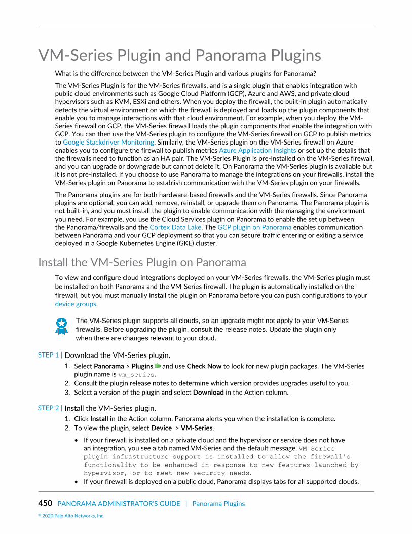
450 PANORAMA ADMINISTRATOR'S GUIDE | Panorama Plugins© 2020 Palo Alto Networks, Inc.
VM-Series Plugin and Panorama PluginsWhat is the difference between the VM-Series Plugin and various plugins for Panorama?
The VM-Series Plugin is for the VM-Series firewalls, and is a single plugin that enables integration withpublic cloud environments such as Google Cloud Platform (GCP), Azure and AWS, and private cloudhypervisors such as KVM, ESXi and others. When you deploy the firewall, the built-in plugin automaticallydetects the virtual environment on which the firewall is deployed and loads up the plugin components thatenable you to manage interactions with that cloud environment. For example, when you deploy the VM-Series firewall on GCP, the VM-Series firewall loads the plugin components that enable the integration withGCP. You can then use the VM-Series plugin to configure the VM-Series firewall on GCP to publish metricsto Google Stackdriver Monitoring. Similarly, the VM-Series plugin on the VM-Series firewall on Azureenables you to configure the firewall to publish metrics Azure Application Insights or set up the details thatthe firewalls need to function as an HA pair. The VM-Series Plugin is pre-installed on the VM-Series firewall,and you can upgrade or downgrade but cannot delete it. On Panorama the VM-Series plugin is available butit is not pre-installed. If you choose to use Panorama to manage the integrations on your firewalls, install theVM-Series plugin on Panorama to establish communication with the VM-Series plugin on your firewalls.
The Panorama plugins are for both hardware-based firewalls and the VM-Series firewalls. Since Panoramaplugins are optional, you can add, remove, reinstall, or upgrade them on Panorama. The Panorama plugin isnot built-in, and you must install the plugin to enable communication with the managing the environmentyou need. For example, you use the Cloud Services plugin on Panorama to enable the set up betweenthe Panorama/firewalls and the Cortex Data Lake. The GCP plugin on Panorama enables communicationbetween Panorama and your GCP deployment so that you can secure traffic entering or exiting a servicedeployed in a Google Kubernetes Engine (GKE) cluster.
Install the VM-Series Plugin on PanoramaTo view and configure cloud integrations deployed on your VM-Series firewalls, the VM-Series plugin mustbe installed on both Panorama and the VM-Series firewall. The plugin is automatically installed on thefirewall, but you must manually install the plugin on Panorama before you can push configurations to yourdevice groups.
The VM-Series plugin supports all clouds, so an upgrade might not apply to your VM-Seriesfirewalls. Before upgrading the plugin, consult the release notes. Update the plugin onlywhen there are changes relevant to your cloud.
STEP 1 | Download the VM-Series plugin.1. Select Panorama > Plugins and use Check Now to look for new plugin packages. The VM-Series
plugin name is vm_series.2. Consult the plugin release notes to determine which version provides upgrades useful to you.3. Select a version of the plugin and select Download in the Action column.
STEP 2 | Install the VM-Series plugin.1. Click Install in the Action column. Panorama alerts you when the installation is complete.2. To view the plugin, select Device > VM-Series.
• If your firewall is installed on a private cloud and the hypervisor or service does not havean integration, you see a tab named VM-Series and the default message, VM Seriesplugin infrastructure support is installed to allow the firewall'sfunctionality to be enhanced in response to new features launched byhypervisor, or to meet new security needs.
• If your firewall is deployed on a public cloud, Panorama displays tabs for all supported clouds.

PANORAMA ADMINISTRATOR'S GUIDE | Panorama Plugins 451© 2020 Palo Alto Networks, Inc.
STEP 3 | (Optional) Save your configuration and push it to your managed firewalls.
STEP 4 | (Optional) On the VM-Series firewall, select Device > VM-Series. If you have configuredthe integration for your platform, you see a single tab for the cloud in which the firewall isdeployed. If you have not configured an integration, you see the default message about theVM-Series plugin infrastructure.

452 PANORAMA ADMINISTRATOR'S GUIDE | Panorama Plugins

453
TroubleshootingThe following topics address issues for the Panorama™ management server and Dedicated LogCollectors:
> Troubleshoot Panorama System Issues> Troubleshoot Log Storage and Connection Issues> Replace an RMA Firewall> Troubleshoot Commit Failures> Troubleshoot Registration or Serial Number Errors> Troubleshoot Reporting Errors> Troubleshoot Device Management License Errors> Troubleshoot Automatically Reverted Firewall Configurations> Complete Content Update When Panorama HA Peer is Down> View Task Success or Failure Status> Test Policy Match and Connectivity for Managed Devices> Downgrade from Panorama 9.1

454 PANORAMA ADMINISTRATOR'S GUIDE | Troubleshooting© 2020 Palo Alto Networks, Inc.

PANORAMA ADMINISTRATOR'S GUIDE | Troubleshooting 455© 2020 Palo Alto Networks, Inc.
Troubleshoot Panorama System Issues• Generate Diagnostic Files for Panorama• Diagnose Panorama Suspended State• Monitor the File System Integrity Check• Manage Panorama Storage for Software and Content Updates• Recover from Split Brain in Panorama HA Deployments
Generate Diagnostic Files for PanoramaDiagnostic files aid in monitoring system activity and in discerning potential causes for issues on Panorama.To assist Palo Alto Networks Technical Support in troubleshooting an issue, the support representativemight request a tech support file. The following procedure describes how to download a tech support fileand upload it to your support case.
STEP 1 | Select Panorama > Support and click Generate Tech Support File.
STEP 2 | Download and save the file to your computer.
STEP 3 | Upload the file to your case on the Palo Alto Networks Customer Support web site.
Diagnose Panorama Suspended StateIf Panorama is in a suspended state, check for the following conditions:
• Serial numbers—Verify that the serial number on each Panorama virtual appliance is unique. If the sameserial number is used to create two or more instances of Panorama, all instances using the same serialnumber will be suspended.
• Mode—If you deploy the Panorama virtual appliance in a high availability (HA) configuration, verify thatboth HA peers are in the same mode: Panorama mode or Legacy mode.
• HA priority—Verify that you have set the HA priority setting on one peer as Primary and the other asSecondary. If the priority setting is identical on both peers, the Panorama peer with a higher numericalvalue in serial number is placed in a suspended state.
• Panorama software version—Verify that both Panorama HA peers are running the same Panoramasoftware version (major and minor version number).
Monitor the File System Integrity CheckPanorama periodically performs a file system integrity check (FSCK) to prevent corruption of the Panoramasystem files. This check occurs after eight reboots or at a reboot that occurs 90 days after the last FSCKwas executed. If Panorama is running a FSCK, the web interface and Secure Shell (SSH) login screens willdisplay a warning to indicate that an FSCK is in progress. You cannot log in until this process completes. Thetime to complete this process varies by the size of the storage system; depending on the size, it can takeseveral hours before you can log back in to Panorama.
To view the progress on the FSCK, set up console access to Panorama and view the status.
Manage Panorama Storage for Software and Content UpdatesYou can Install Content and Software Updates for Panorama and Deploy Updates to Firewalls, LogCollectors and WildFire Appliances Using Panorama. You cannot configure the amount of space availableon Panorama to store updates. When the alloted storage capacity reaches 90%, Panorama alerts you to

456 PANORAMA ADMINISTRATOR'S GUIDE | Troubleshooting© 2020 Palo Alto Networks, Inc.
free up space (delete stored updates) for new downloads or uploads. The maximum number of updates is aglobal setting that applies to all the updates that Panorama stores. You must access the CLI to configure thissetting. The default value is two updates of each type.
• Modify the maximum number of updates of each type.Access the Panorama CLI and enter the following, where <number> can be between 2 and 64:
> set max-num-images count <number>
• View the number of updates that Panorama currently stores.Enter:
> show max-num-images
• Use the web interface to delete updates to free up space on Panorama.1. Select the type of update to delete:
• Firewall or Log Collector updates:
PAN-OS/Panorama software images—Select Panorama > Device Deployment > Software.
GlobalProtect™ agent/app software updates—Select Panorama > Device Deployment >GlobalProtect Client.
Content updates—Select Panorama > Device Deployment > Dynamic Updates.• Panorama software images—Select Panorama > Software.• Panorama content updates—Select Panorama > Dynamic Updates.
2. Click the X icon in the far right column for the image or update.
• Use the CLI to delete updates to free up space on Panorama.Delete software images by version:
> delete software version <version_number>
Delete content updates:
> delete content update <filename>
Recover from Split Brain in Panorama HA DeploymentsWhen Panorama is configured in a high availability (HA) setup, the managed firewalls are connected toboth the active and passive Panorama HA peers. When the connection between the active and the passivePanorama peers fails, before the passive Panorama takes over as the active peer it checks whether anyfirewall is connected to both the active and the passive peer. If even one firewall is connected to bothpeers, the failover is not triggered.
In the rare event that a failover is triggered when a set of firewalls are connected to the active peer and aset of firewalls are connected to the passive peer, but none of the firewalls are connected to both peers, itis called a split brain. When a split brain occurs, the following conditions occur:
• Neither Panorama peer is aware of the state nor the HA role of the other peer.

PANORAMA ADMINISTRATOR'S GUIDE | Troubleshooting 457© 2020 Palo Alto Networks, Inc.
• Both Panorama peers become active and manage a unique set of firewalls.
To resolve a split brain, debug your network issues and restore connectivity between the Panorama HApeers.
However, if you need to make configuration changes to your firewalls without restoring the connectionbetween the peers, here are a couple of options:
• Manually add the same configuration changes on both Panorama peers. This ensures that when the linkis reestablished the configuration is synchronized.
• If you need to add/change the configuration at only one Panorama location, make the changes andsynchronize the configuration (make sure that you initiate the synchronization from the peer on whichyou made the changes) when the link between the Panorama peers is re-established. To synchronize thepeers, select the Dashboard tab and click the Sync to peer link in the High Availability widget.
• If you need to add/change the configuration for only the connected firewalls at each location, you canmake configuration changes independently on each Panorama peer. Because the peers are disconnected,there is no replication and each peer now has a completely different configuration file (they are outof sync). Therefore, to ensure that the configuration changes on each peer are not lost when theconnection is restored, you cannot allow the configuration to be automatically re-synchronized. Tosolve this problem, export the configuration from each Panorama peer and manually merge the changesusing an external diff and merge tool. After the changes are integrated, you can import the unifiedconfiguration file on the primary Panorama and then synchronize the imported configuration file withthe peer.

458 PANORAMA ADMINISTRATOR'S GUIDE | Troubleshooting© 2020 Palo Alto Networks, Inc.
Troubleshoot Log Storage and ConnectionIssues
Migrating logs is supported only for M-Series appliance. Refer to Migrate a Panorama VirtualAppliance to a Different Hypervisor to migrate a Panorama virtual appliance.
• Verify Panorama Port Usage• Resolve Zero Log Storage for a Collector Group• Replace a Failed Disk on an M-Series Appliance• Replace the Virtual Disk on an ESXi Server• Replace the Virtual Disk on vCloud Air• Migrate Logs to a New M-Series Appliance in Log Collector Mode• Migrate Logs to a New M-Series Appliance in Panorama Mode• Migrate Logs to a New M-Series Appliance Model in Panorama Mode in High Availability• Migrate Logs to the Same M-Series Appliance Model in Panorama Mode in High Availability• Migrate Log Collectors after Failure/RMA of Non-HA Panorama• Regenerate Metadata for M-Series Appliance RAID Pairs
Verify Panorama Port UsageTo ensure that Panorama can communicate with managed firewalls, Log Collectors, and WildFire appliancesand appliance clusters, and its high availability (HA) peer, use the following table to verify the ports that youmust open on your network. Panorama uses TCP protocol for port communications.
By default, Panorama uses the management (MGT) interface to manage devices (firewalls, Log Collectors,and WildFire appliances and appliance clusters), collect logs, communicate with Collector Groups, anddeploy software and content updates to devices. However, you can optionally assign the log collection andCollector Group communication functions to the Eth1 or Eth2 interfaces on an M-500 or M-100 appliancerunning Panorama 6.1 through 7.1. If the appliance runs Panorama 8.0 or a later release, you can assign anyfunction to the Eth1, Eth2, or Eth3 interfaces on the M-100 appliance and to the Eth1, Eth2, Eth3, Eth4, orEth5 interfaces on the M-500 appliance. The ports listed in the following table apply regardless of whichfunction you assign to which interface. For example, if you assign log collection to MGT and assign CollectorGroup communication to Eth2, then MGT will use port 3978 and Eth2 will use port 28270. (The Panoramavirtual appliance can only use the MGT interface for all these functions.)
Communicating Systems& Direction of ConnectionEstablishment
Ports Usedin Panorama5.x
Ports Usedin Panorama6.x to 7.x
Ports Usedin Panorama8.x and later
Description
Panorama and Panorama(HA)
Direction: Each peer initiatesits own connection to theother
28 28 28 For HA connectivity andsynchronization if encryptionis enabled.
Used for communicationbetween Log Collectors ina Collector Group for logdistribution.

PANORAMA ADMINISTRATOR'S GUIDE | Troubleshooting 459© 2020 Palo Alto Networks, Inc.
Communicating Systems& Direction of ConnectionEstablishment
Ports Usedin Panorama5.x
Ports Usedin Panorama6.x to 7.x
Ports Usedin Panorama8.x and later
Description
Panorama and Panorama(HA)
Direction: Each peer initiatesits own connection to theother
28769 and28260(5.1)
28769 and49160(5.0)
28260 and28769
28260 and28769
For HA connectivity andsynchronization if encryptionis not enabled.
Panorama and managedfirewalls
Direction: Initiated by thefirewall
3978 3978 3978 A bi-directional connectionwhere the logs areforwarded from thefirewall to Panorama; andconfiguration changes arepushed from Panoramato the managed firewalls.Context switchingcommands are sent over thesame connection.
Panorama and Log Collector
Direction: Initiated by theLog Collector
3978 3978 3978 For management and logcollection/reporting.
Used for communicationbetween the local LogCollector on a Panoramain Panorama mode, and forcommunicating with LogCollectors in a distributed logcollection deployment.
Panorama and manageddevices (firewalls, LogCollectors, and WildFireappliances and applianceclusters)
Direction:
• Initiated by manageddevices running PAN-OS8.x or later releases.
• Initiated by Panorama fordevices running PAN-OS7.x or earlier releases.
3978 3978 28443 Devices running PAN-OS8.x or later releases use port28443 to retrieve softwareand content update filesfrom Panorama.
Devices running 7.x or earlierreleases do not retrieveupdate files from Panorama;Panorama pushes the updatefiles to the devices over port3978.
Support for Panoramamanagement of WildFireappliances and applianceclusters requires PAN-OS 8.0.1 or later installedon the managed WildFireappliances. We recommendthat Panorama runs 8.0.1or later to manage WildFire

460 PANORAMA ADMINISTRATOR'S GUIDE | Troubleshooting© 2020 Palo Alto Networks, Inc.
Communicating Systems& Direction of ConnectionEstablishment
Ports Usedin Panorama5.x
Ports Usedin Panorama6.x to 7.x
Ports Usedin Panorama8.x and later
Description
appliances and applianceclusters.
Log Collector to LogCollector
Direction: Each Log Collectorinitiates a connection to theother Log Collectors in theCollector Group
49190 28270 28270 For distributing blocks andall binary data between LogCollectors.
Panorama to Cortex DataLake
NA NA 444
Version8.0.5andlater.
For setting up a securecommunication channel withthe Cortex Data Lake.
The managed firewalls useport 3978 to
communicate with theCortex Data Lake.
Resolve Zero Log Storage for a Collector GroupThe log storage capacity for the Collector Group might display as 0MB if the disk pairs are not enabled forlogging in the Log Collectors. To enable the disk pairs, perform the following steps for each Log Collector inthe Collector Group.
STEP 1 | Add the RAID disk pairs.1. Select Panorama > Managed Collectors and click the Collector Name.2. Select Disks, Add each RAID disk pair, and click OK.
STEP 2 | Commit the changes to Panorama and push the changes to the Collector Group.1. Select Commit > Commit and Push and Edit Selections in the Push Scope.2. Select Collector Groups, select the Collector Group you modified, and click OK.3. Commit and Push your changes.
STEP 3 | Verify the state of the Log Collectors and disk pairs.1. Select Panorama > Managed Collectors and verify that the configuration of each Log Collector is
synchronized with Panorama.
The Configuration Status column should display In Sync and the Run Time Status column shoulddisplay connected.
2. Click Statistics in the last column for each Log Collector and verify that the disk pairs are Enabled andAvailable.
Replace a Failed Disk on an M-Series ApplianceIf a disk fails on the M-Series appliance, you must replace the disk and reconfigure it in a RAID 1 array. Fordetails, refer to the M-Series appliance Hardware Reference Guides.

PANORAMA ADMINISTRATOR'S GUIDE | Troubleshooting 461© 2020 Palo Alto Networks, Inc.
Replace the Virtual Disk on an ESXi ServerYou cannot resize a virtual disk after adding it to the Panorama virtual appliance running on a VMwareESXi server. Because the Panorama virtual appliance in Legacy mode allows only one log storage location,you must replace the virtual disk as follows to modify the log storage capacity. In Panorama mode, youcan simply add another disk (up to the maximum of 12) to Expand Log Storage Capacity on the PanoramaVirtual Appliance.
On the Panorama virtual appliance in Legacy mode, you will lose the logs on the existingdisk when you replace it. For the options to preserve existing logs, see Preserve ExistingLogs When Adding Storage on Panorama Virtual Appliance in Legacy Mode.
STEP 1 | Remove the old virtual disk.1. Access the VMware vSphere Client and select the Virtual Machines tab.2. Right-click the Panorama virtual appliance and select Power > Power Off.3. Right-click the Panorama virtual appliance and select Edit Settings.4. Select the virtual disk in the Hardware tab and click Remove.5. Select one of the Removal Options and click OK.
STEP 2 | Add the new virtual disk.1. Add a Virtual Disk to Panorama on an ESXi Server.
Panorama running on ESXi 5.5 and later versions supports a virtual disk of up to 8TB. Panoramarunning on an earlier ESXi version supports a virtual disk of up to 2TB.
2. In the vSphere Client, right-click the Panorama virtual appliance and select Power > Power On.
The reboot process might take several minutes and the message cache data unavailable willdisplay.
STEP 3 | Verify that the modified log storage capacity is correct.1. Log in to the Panorama virtual appliance.2. Select Panorama > Setup > Management and verify that the Logging and Reporting Settings section,
Log Storage field, displays the modified log storage capacity accurately.
Replace the Virtual Disk on vCloud AirYou cannot resize a virtual disk after adding it to the Panorama virtual appliance running on VMware vCloudAir. Because the Panorama virtual appliance in Legacy mode allows only one log storage location, you mustreplace the virtual disk as follows to modify the log storage capacity. In Panorama mode, you can simplyAdd a Virtual Disk to Panorama on vCloud Air (up to the maximum of 12).
On the Panorama virtual appliance in Legacy mode, you will lose the logs on the existingdisk when you replace it. For the options to preserve existing logs, see Preserve ExistingLogs When Adding Storage on Panorama Virtual Appliance in Legacy Mode.
STEP 1 | Remove the old virtual disk.1. Access the vCloud Air web console and select your Virtual Private Cloud OnDemand region.2. Select the Panorama virtual appliance in the Virtual Machines tab.3. Select Actions > Edit Resources.4. Click x for the virtual disk you are removing.
STEP 2 | Add the new virtual disk.

462 PANORAMA ADMINISTRATOR'S GUIDE | Troubleshooting© 2020 Palo Alto Networks, Inc.
1. Add another disk.2. Set the Storage to up to 8TB and set the storage tier to Standard or SSD-Accelerated.3. Save your changes.
STEP 3 | Reboot Panorama.1. Log in to the Panorama virtual appliance.2. Select Panorama > Setup > Operations and Reboot Panorama.
STEP 4 | Verify that the modified log storage capacity is correct.1. Log in to the Panorama virtual appliance after it reboots.2. Select Panorama > Setup > Management and verify that the Logging and Reporting Settings section,
Log Storage field, displays the modified log storage capacity accurately.
Migrate Logs to a New M-Series Appliance in Log Collector ModeIf you need to replace an M-600, M-500, M-200 or M-100 appliance in Log Collector mode (Dedicated LogCollector), you can migrate the logs it collected from firewalls by moving its RAID disks to a new M-Seriesappliance. This procedure enables you to recover logs after a system failure on the M-Series appliance or tomigrate logs as part of a hardware upgrade (from an M-100 appliance to an M-500 appliance).
Migrating logs by removing the logging disks from any M-Series appliance and loading theminto an M-600 Panorama management server is not supported. To migrate to an M-600appliance, set up the M-600 appliance, configure log forwarding to the new M-600 applianceand configure the M-Series appliance as a managed Log Collector until you no longer neededaccess to the logs stored on the M-Series appliance.
STEP 1 | Perform initial setup of the new M-Series appliance that will be a Dedicated Log Collector.1. Rack mount the M-Series appliance. Refer to the M-Series Appliance Hardware Reference Guides for
instructions.2. Perform Initial Configuration of the M-Series Appliance.
When configuring interfaces, configure only the Management (MGT) interface.Switching to Log Collector mode (later in this procedure) removes the configurationsfor any other interfaces. If the Log Collector will use interfaces other than MGT, addthem when configuring the Log Collector (see Step 2).
3. Register Panorama.4. Purchase and activate the Panorama support license or transfer licenses as follows only if the new
M-Series appliance is the same hardware model as the old M-Series appliance. If the new M-Seriesappliance is a different model than the old M-Series appliance, you must purchase new licenses.
1. Log in to the Palo Alto Networks Customer Support web site.2. Select the Assets tab and click the Spares link.3. Click the Serial Number of the new M-Series appliance.4. Click Transfer Licenses.5. Select the old M-Series appliance and click Submit.
5. Activate a firewall management license. If you are migrating from an M-100 appliance to an M-500appliance, enter the auth-code associated with the migration license.
6. Install Content and Software Updates for Panorama. For important details about software versions,see Panorama, Log Collector, Firewall, and WildFire Version Compatibility.
7. Switch from Panorama mode to Log Collector mode:
1. Access the Log Collector CLI and switch to Log Collector mode:

PANORAMA ADMINISTRATOR'S GUIDE | Troubleshooting 463© 2020 Palo Alto Networks, Inc.
> request system system-mode logger
2. Enter Y to confirm the mode change. The M-Series appliance reboots. If the reboot processterminates your terminal emulation software session, reconnect to the M-Series appliance todisplay the Panorama login prompt.
If you see a CMS Login prompt, press Enter without typing a username orpassword.
8. Use the Log Collector CLI to enable connectivity between the Log Collector and Panoramamanagement server. <IPaddress1 is for the MGT interface of the primary Panorama and<IPaddress2> is for the MGT interface of the secondary Panorama.
> configure # set deviceconfig system panorama-server <IPaddress1> panorama-server-2 <IPaddress2> # commit # exit
STEP 2 | On the Panorama management server, add the new Log Collector as a managed collector.
For all steps with commands that require a serial number, you must type the entire serialnumber; pressing the Tab key won’t complete a partial serial number.
1. Configure the Log Collector as a managed collector using the Panorama web interface or using thefollowing CLI commands:
> configure # set log-collector <LC_serial_number> deviceconfig system hostname <LC_hostname> # exit
If the old Log Collector used interfaces other than the MGT interface for log collectionand Collector Group communication, you must define those interfaces on the newLog Collector when you configure it as a managed collector (Panorama > ManagedCollectors > Interfaces).
2. Verify that the Log Collector is connected to Panorama and that the status of its disk pairs is present/available.
> show log-collector serial-number <log-collector_SN>
The disk pairs will display as disabled at this stage of the restoration process.3. Commit your changes to Panorama. Don’t commit the changes to the Collector Group just yet.
> configure # commit # exit
STEP 3 | Remove the RAID disks from the old Log Collector.1. Power off the old Log Collector by pressing the Power button until the system shuts down.2. Remove the disk pairs. For details, refer to the disk replacement procedure in the M-Series Appliance
Hardware Reference Guides.

464 PANORAMA ADMINISTRATOR'S GUIDE | Troubleshooting© 2020 Palo Alto Networks, Inc.
STEP 4 | Prepare the disks for migration.
Generating the metadata for each disk pair rebuilds the indexes. Therefore, dependingon the data size, this process can take a long time to complete. To expedite the process,you can launch multiple CLI sessions and run the metadata regeneration command ineach session to complete the process simultaneously for every pair. For details, seeRegenerate Metadata for M-Series Appliance RAID Pairs.
1. Insert the disks into the new Log Collector. For details, refer to the disk replacement procedure in theM-Series Appliance Hardware Reference Guides.
The disk carriers of the M-100 appliance are incompatible with those of the M-500appliance. Therefore, when migrating between these hardware models, you mustunscrew each disk from its old carrier and insert the disk in the new carrier beforeinserting the disk in the new appliance.
You must maintain the disk pair association. Although you can place a disk pair from slot A1/A2 onthe old appliance into slot B1/B2 on the new appliance, you must keep the disks together in the sameslot; otherwise, Panorama might not restore the data successfully.
2. Enable the disk pairs by running the following CLI command for each pair:
> request system raid add <slot> force no-format
For example:
> request system raid add A1 force no-format > request system raid add A2 force no-format
The force and no-format arguments are required. The force argument associates the disk pairwith the new Log Collector. The no-format argument prevents reformatting of the drives andretains the logs stored on the disks.
3. Generate the metadata for each disk pair.
> request metadata-regenerate slot <slot_number>
For example:
> request metadata-regenerate slot 1
STEP 5 | Add a Log Collector with no disks to a Collector Group.
From this point, only commits that are required to complete the migration process onPanorama and the Log Collectors. Hold off making any other changes.
1. Access the Panorama CLI.2. Overwrite Panorama restriction to allow Log Collector with no disk to be added to a Collector Group:
request log-migration-set-start
STEP 6 | Migrate the logs.
You must use the Panorama CLI for this step, not the web interface.

PANORAMA ADMINISTRATOR'S GUIDE | Troubleshooting 465© 2020 Palo Alto Networks, Inc.
You must assign the new Log Collector to the Collector Group that contains the old Log Collector.
1. Assign the new Log Collector to the Collector Group and commit your changes to Panorama.
> configure # set log-collector-group <collector_group_name> logfwd-setting collectors <new_LC_serial_number> # commit # exit
2. For each disk pair, migrate the logs from the old Log Collector to the new Log Collector and attachthe disk pair to the new Log Collector.
> request log-migration from <old_LC_serial_number> old-disk-pair <log_disk_pair> to <new_LC_serial_number> new-disk-pair <log_disk_pair>
For example:
> request log-migration from 003001000010 old-disk-pair A to 00300100038 new-disk-pair A
STEP 7 | Reconfigure the Collector Group.1. Use the web interface to assign the new Log Collector to the firewalls that forward logs (Panorama >
Collector Groups > Device Log Forwarding). Give the new Log Collector the same priority in thefirewall preference lists as the old Log Collector.
You cannot use the CLI change the priority assignments of firewall preference lists.
2. Delete the old Log Collector from the Collector Group.
> configure # delete log-collector-group <group_name> logfwd-setting collectors <old_LC_serial_number>
For example:
# delete log-collector-group DC-Collector-Group logfwd-setting collectors 003001000010
3. Delete the old Log Collector from the Panorama configuration and commit your changes toPanorama.
# delete log-collector <old_LC_serial_number> # commit # exit
4. Commit the Collector Group changes so that the managed firewalls can send logs to the new LogCollector.
> commit-all log-collector-config log-collector-group <collector_group_name>

466 PANORAMA ADMINISTRATOR'S GUIDE | Troubleshooting© 2020 Palo Alto Networks, Inc.
For example:
> commit-all log-collector-config log-collector-group DC-Collector-Group
STEP 8 | Generate new keys on the new Dedicated Log Collector.
This command is required in order to add the new Log Collector to the Collector Groupand should only be run for the Collector Group of the Log Collector being replaced. Thisstep deletes the existing RSA keys and allows Panorama to create new RSA keys.
1. Access the Panorama CLI.2. Delete all RSA keys on new Log Collector:
request logdb update-collector-group-after-replace collector-group<collector-group-name>
The process can take up to 10 minutes to completed.
STEP 9 | Confirm that SearchEngine Status is Active for all Log Collectors in the Collector Group.
Do not continue until SearchEngine Status is Active for all Log Collectors in the CollectorGroup. This will result in purging of logs from the Log Collector being replaced.
1. Access the Panorama CLI.2. Show the Log Collector details by running the following commands either:
• On Panorama for all Log Collectors:
show log-collector all
Alternatively, you can run the following command on each Dedicated Log Collector:
show log-collector detail
3. Confirm that SearchEngine Status is Active.
Redistribution status: none
Last commit-all: commit succeeded, current ring version 1
SearchEngine status: Active
md5sum 4e5055a359f7662fab8f8c4f57e24525 updated at 2017/06/14 09:58:19
STEP 10 | On the new Log Collector, replace previous Log Collector serial number with the new LogCollector serial number.
You must replace the old Log Collector serial number with the new Log Collector serial number so thatthe new Log Collector will not run in to purging issues, resulting in the Log Collector being unable topurge old data from the migrated logs when necessary.
1. Access the Log Collector CLI.2. Replace old Log Collector serial number with new Log Collector serial number:

PANORAMA ADMINISTRATOR'S GUIDE | Troubleshooting 467© 2020 Palo Alto Networks, Inc.
request log-migration-update-logger from <old-log-collector-serial-number>to <new-log-collector-serial-number>
Migrate Logs to a New M-Series Appliance in Panorama ModeIf you need to replace an M-600, M-500, M-200 or M-100 appliance in Panorama mode (Panoramamanagement server), you can migrate the logs it collected from firewalls by moving its RAID disks to thenew M-Series appliance. Moving the disks enables you to recover logs after a system failure on the M-Series appliance or to migrate logs as part of a hardware upgrade (from an M-100 appliance to an M-500appliance).
Migrating logs by removing the logging disks from any M-Series appliance and loading theminto an M-600 Panorama management server is not supported. To migrate to an M-600appliance, set up the M-600 appliance, configure log forwarding to the new M-600 applianceand configure the M-Series appliance as a managed Log Collector until you no longer neededaccess to the logs stored on the M-Series appliance.
This migration procedure covers the following scenarios where you are replacing a single M-Seriesappliance, not in a HA configuration, with a managed collector (Log Collector) in a Collector Group.
STEP 1 | Forward any logs on the SSD of the old M-Series appliance to an external destination if youwant to preserve them.The SSD stores the System and Config logs that Panorama and Log Collectors generate. You cannotmove the SSD between M-Series appliances.
Configure Log Forwarding from Panorama to External Destinations.
STEP 2 | Export the Panorama configuration from the decommissioned M-Series appliance in Panoramamode.1. Log in to the Panorama appliance and select Panorama > Setup > Operations.2. Click Save named Panorama configuration snapshot, enter a Name to identify the configuration, and
click OK.3. Click Export named Panorama configuration snapshot, select the Name of the configuration you just
saved, and click OK. Panorama exports the configuration to your client system as an XML file.
STEP 3 | Remove the RAID disks from the old M-Series appliance.1. Power off the old M-Series appliance by pressing the Power button until the system shuts down.2. Remove the disk pairs. For details, refer to the disk replacement procedure in the M-Series Appliance
Hardware Reference Guides.
STEP 4 | Perform initial setup of the new M-Series appliance.1. Rack mount the M-Series appliance. Refer to the M-Series Appliance Hardware Reference Guides for
instructions.2. Perform Initial Configuration of the M-Series Appliance.3. Register Panorama.4. Purchase and activate a Panorama support license or transfer licenses as follows only if the new
M-Series appliance is the same hardware model as the old M-Series appliance. If the new M-Seriesappliance is a different model than the old M-Series appliance, you must purchase new licenses.
1. Log in to the Palo Alto Networks Customer Support web site.2. Select the Assets tab and click the Spares link.3. Click the Serial Number of the new M-Series appliance.

468 PANORAMA ADMINISTRATOR'S GUIDE | Troubleshooting© 2020 Palo Alto Networks, Inc.
4. Click Transfer Licenses.5. Select the old M-Series appliance and click Submit.
5. Activate a firewall management license. If you are migrating from an M-100 appliance to an M-500appliance, enter the auth-code associated with the migration license.
6. Install Content and Software Updates for Panorama. For important details about software versions,see Panorama, Log Collector, Firewall, and WildFire Version Compatibility.
STEP 5 | Load the Panorama configuration snapshot that you exported from the decommissioned M-Series appliance into the new M-Series appliance in Panorama mode.1. Log in to the Panorama Web Interface of the new M-Series appliance and select Panorama > Setup >
Operations.2. Click Import named Panorama configuration snapshot, Browse to the configuration file you exported
from the decommissioned M-Series appliance, and click OK.3. Click Load named Panorama configuration snapshot, select the Name of the configuration you just
imported, select a Decryption Key (the master key for Panorama), and click OK. Panorama overwritesits current candidate configuration with the loaded configuration. Panorama displays any errors thatoccur when loading the configuration file. If errors occurred, save them to a local file. Resolve eacherror to ensure the migrated configuration is valid.
To replace an RMA Panorama, make sure you Retain Rule UUIDs when you load thenamed Panorama configuration snapshot. If you do not select this option, Panoramaremoves all previous rule UUIDs from the configuration snapshot and assignsnew UUIDs to the rules on Panorama, which means it does not retain informationassociated with the previous UUIDs, such as the policy rule hit count.
4. Perform any additional configuration changes as needed.
If the old M-Series appliance used interfaces other than the MGT interface forPanorama services (such as log collection), you must define those interfaces on thenew M-Series appliance (Panorama > Setup > Interfaces).
5. Select Commit > Commit to Panorama and Validate Commit. Resolve any errors before proceeding.6. Commit your changes to the Panorama configuration.
STEP 6 | Insert the disks into the new M-Series appliance. For details, refer to the disk replacementprocedure in the M-Series Appliance Hardware Reference Guides.
The disk carriers of the M-100 appliance are incompatible with those of the M-500appliance. Therefore, when migrating between these hardware models, you mustunscrew each disk from its old carrier and insert the disk in the new carrier beforeinserting the disk in the new appliance.
You must maintain the disk pair association. Although you can place a disk pair from slot A1/A2 on theold appliance into slot B1/B2 on the new appliance, you must keep the disks together in the same slot;otherwise, Panorama might not restore the data successfully.
STEP 7 | Contact Palo Alto Networks Customer Support to copy log collector group metadata from thedecommissioned M-Series appliance to the new M-Series appliance and restart the mgmtsrvrprocess.
STEP 8 | If the M-Series appliance was part of a Collector Group, verify that the decommissioned M-Series appliance serial number is still part of the correct Collector Group:debug log-collector-group show name <Log Collector Group name>

PANORAMA ADMINISTRATOR'S GUIDE | Troubleshooting 469© 2020 Palo Alto Networks, Inc.
If the decommissioned M-Series appliance serial number is no longer a part of the correct CollectorGroup, then the Tech Support folders were incorrectly copied in the previous step. Contact Palo AltoNetworks Customer Support again to copy the Tech Support folders to the correct location.
STEP 9 | Prepare the disks for migration.
Generating the metadata for each disk pair rebuilds the indexes. Therefore, dependingon the data size, this process can take a long time to complete. To expedite the process,you can launch multiple CLI sessions and run the metadata regeneration command ineach session to complete the process simultaneously for every pair. For details, seeRegenerate Metadata for M-Series Appliance RAID Pairs.
1. Insert the disks into the new M-Series appliance. For details, refer to the disk replacement procedurein the M-Series Appliance Hardware Reference Guides.
The disk carriers of the M-100 appliance are incompatible with those of the M-500appliance. Therefore, when migrating between these hardware models, you mustunscrew each disk from its old carrier and insert the disk in the new carrier beforeinserting the disk in the new appliance.
You must maintain the disk pair association. Although you can place a disk pair from slot A1/A2 onthe old appliance into slot B1/B2 on the new appliance, you must keep the disks together in the sameslot; otherwise, Panorama might not restore the data successfully.
2. Enable the disk pairs by running the following CLI command for each pair:
admin> request system raid add <slot> force no-format
For example:
admin> request system raid add A1 force no-format admin> request system raid add A2 force no-format
The force and no-format arguments are required. The force argument associates the disk pair withthe new appliance. The no-format argument prevents reformatting of the drives and retains the logsstored on the disks.
3. Generate the metadata for each disk pair.
This step may take up to 6 hours depending on the volume of log data on the disks.
admin> request metadata-regenerate slot <slot_number>
For example:
admin> request metadata-regenerate slot 1
STEP 10 | Configure the local Log Collector on the new M-Series appliance.
For all steps with commands that require a serial number, you must type the entire serialnumber; pressing the Tab key won’t complete a partial serial number.

470 PANORAMA ADMINISTRATOR'S GUIDE | Troubleshooting© 2020 Palo Alto Networks, Inc.
Don’t enable the disks on the new M-Series appliance at this point. When you successfully migrate thelogs, Panorama automatically enables the disks.
1. Configure the local Log Collector as a managed collector using the Panorama web interface or usingthe following CLI commands:
admin> configure admin# set log-collector <log-collector_SN> deviceconfig system hostname <log-collector-hostname> admin# exit
2. Verify that the local Log Collector is connected to Panorama and that the status of its disk pairs ispresent/available.
admin> show log-collector serial-number <log-collector_SN>
The disk pairs will display as disabled at this stage of the restoration process.3. Commit your changes to Panorama. Don’t commit the changes to the Collector Group just yet.
admin> configure admin# commit
STEP 11 | Add a Log Collector with no disks to a Collector Group.
From this point, only commits that are required to complete the migration process onPanorama and the Log Collectors. Hold off making any other changes.
1. Access the Panorama CLI of the new M-Series appliance.2. Overwrite Panorama restriction to allow Log Collector with no disk to be added to a Collector Group:
request log-migration-set-start
3. Commit the overwritten restriction:
admin> configure admin# commit force
STEP 12 | Migrate the logs.1. Access the Panorama CLI of the new M-Series appliance.2. Add the new local Log Collector as a member of the Collector Group and commit your changes to
Panorama.
admin# set log-collector-group <collector_group_name> logfwd-setting collectors <SN_managed_collector> admin# commit admin# exit
The old local Log Collector still appears in the list of members, because you haven’t deleted it fromthe configuration.
3. For each disk pair, migrate the logs to the new appliance.

PANORAMA ADMINISTRATOR'S GUIDE | Troubleshooting 471© 2020 Palo Alto Networks, Inc.
admin> request log-migration from <old_LC_serial_number> old-disk-pair <log_disk_pair> to <new_LC_serial_number> new-disk-pair <log_disk_pair>
For example:
admin> request log-migration from 003001000010 old-disk-pair A to 00300100038 new-disk-pair A
4. Commit the changes to Panorama.
admin> configure admin# commit
STEP 13 | Reconfigure the Collector Group.1. Log in to the Panorama Web Interface of the new M-Series appliance to assign the new Log Collector
to the firewalls that forward logs (Panorama > Collector Groups > Device Log Forwarding). Give thenew Log Collector the same priority in the firewall preference lists as the old Log Collector.
You cannot use the CLI change the priority assignments of firewall preference lists.
2. Access the Panorama CLI of the new M-Series appliance.3. Delete the old Log Collector from the Collector Group.
admin# delete log-collector-group <group_name> logfwd-setting collectors <old_LC_serial_number>
For example:
admin# delete log-collector-group DC-Collector-Group logfwd-setting collectors 003001000010
4. Delete the old Log Collector from the Panorama configuration and commit your changes toPanorama.
admin# delete log-collector <old_LC_serial_number> admin# commit admin# exit
5. Commit the Collector Group changes so that the managed firewalls can send logs to the new LogCollector.
admin> commit-all log-collector-config log-collector-group <collector_group_name>
For example:
admin> commit-all log-collector-config log-collector-group DC-Collector-Group
STEP 14 | Generate new keys on the new Log Collector.

472 PANORAMA ADMINISTRATOR'S GUIDE | Troubleshooting© 2020 Palo Alto Networks, Inc.
This command is required in order to add the new Log Collector to the Collector Groupand should only be run for the Collector Group of the Log Collector being replaced. Thisstep deletes the existing RSA keys and allows Panorama to create new RSA keys.
1. Access the Panorama CLI of the new M-Series appliance.2. Delete all RSA keys on the new Log Collector:
request logdb update-collector-group-after-replace collector-group<collector-group-name>
The process can take up to 10 minutes to completed.
STEP 15 | Confirm that SearchEngine Status is Active for all Log Collectors in the Collector Group.
Do not continue until SearchEngine Status is Active for all Log Collectors in the CollectorGroup. This will result in purging of logs from the Log Collector being replaced.
1. Access the Panorama CLI of the new M-Series appliance.2. Show the Log Collector details by running the following commands either:
• On Panorama for all Log Collectors:
show log-collector all
Alternatively, you can run the following command on each Dedicated Log Collector:
show log-collector detail
3. Confirm that SearchEngine Status is Active.
Redistribution status: none
Last commit-all: commit succeeded, current ring version 1
SearchEngine status: Active
md5sum 4e5055a359f7662fab8f8c4f57e24525 updated at 2017/06/14 09:58:19
STEP 16 | On the new Log Collector, replace previous Log Collector serial number with the new LogCollector serial number.
You must replace the old Log Collector serial number with the new Log Collector serial number so thatthe new Log Collector will not run in to purging issues, resulting in the Log Collector being unable topurge old data from the migrated logs when necessary.
1. Access the Log Collector CLI.2. Replace old Log Collector serial number with new Log Collector serial number:
request log-migration-update-logger from <old-log-collector-serial-number>to <new-log-collector-serial-number>

PANORAMA ADMINISTRATOR'S GUIDE | Troubleshooting 473© 2020 Palo Alto Networks, Inc.
Migrate Logs to a New M-Series Appliance Model in PanoramaMode in High Availability
If you need to replace an M-600, M-500, M-200 or M-100 appliance in Panorama mode (Panoramamanagement server) with a different M-Series appliance than the M-Series appliance being replaced, youcan migrate the logs it collected from firewalls by moving its RAID disks to the new M-Series appliance.Moving the disks enables you to migrate logs as part of a hardware upgrade (from an M-100 appliance toan M-500 appliance). You can migrate an M-100 appliance to and from an M-500 appliance. M-100 andM-500 appliances cannot be migrated to or from M-200 or M-600 appliances.
Migrating logs by removing the logging disks from any M-Series appliance and loading theminto an M-600 Panorama management server is not supported. To migrate to an M-600appliance, set up the M-600 appliance, configure log forwarding to the new M-600 applianceand configure the M-Series appliance as a managed Log Collector until you no longer neededaccess to the logs stored on the M-Series appliance.
This migration procedure covers the following scenarios:
• One Panorama HA peer has a managed collector (Log Collector) in a Collector Group.
Figure 30: Panorama HA Peer with Collector Group
• Both Panorama HA peers have managed collectors that belong to a single Collector Group. For details,see Multiple Local Log Collectors Per Collector Group.
• Both Panorama HA peers have a managed collector and each is assigned to a separate Collector Group.For details, see Single Local Log Collector Per Collector Group.
STEP 1 | Forward any logs on the SSD of the old M-Series appliance to an external destination if youwant to preserve them.

474 PANORAMA ADMINISTRATOR'S GUIDE | Troubleshooting© 2020 Palo Alto Networks, Inc.
The SSD stores the System and Config logs that Panorama and Log Collectors generate. You cannotmove the SSD between M-Series appliances.
Configure Log Forwarding from Panorama to External Destinations.
STEP 2 | Export the Panorama configuration from the Primary decommissioned M-Series appliance inPanorama mode.1. Log in to the Panorama Web Interface of the M-Series appliance you are replacing and select
Panorama > Setup > Operations.2. Click Save named Panorama configuration snapshot, enter a Name to identify the configuration, and
click OK.3. Click Export named Panorama configuration snapshot, select the Name of the configuration you just
saved, and click OK. Panorama exports the configuration to your client system as an XML file.
STEP 3 | Remove the RAID disks from the old M-Series appliance.1. Power off the old M-Series appliance by pressing the Power button until the system shuts down.2. Remove the disk pairs. For details, refer to the disk replacement procedure in the M-Series Appliance
Hardware Reference Guides.
STEP 4 | Perform initial setup of the new M-Series appliance.Repeat this step for each of the new M-Series appliances in the HA configuration.
1. Rack mount the M-Series appliance. Refer to the M-Series Appliance Hardware Reference Guides forinstructions.
2. Perform Initial Configuration of the M-Series Appliance.3. Register Panorama.4. Purchase and activate a Panorama support license or transfer licenses as follows only if the new
M-Series appliance is the same hardware model as the old M-Series appliance. If the new M-Seriesappliance is a different model than the old M-Series appliance, you must purchase new licenses.
1. Log in to the Palo Alto Networks Customer Support web site.2. Select the Assets tab and click the Spares link.3. Click the Serial Number of the new M-Series appliance.4. Click Transfer Licenses.5. Select the old M-Series appliance and click Submit.
5. Activate a firewall management license. If you are migrating from an M-100 appliance to an M-500appliance, enter the auth-code associated with the migration license.
6. Install Content and Software Updates for Panorama. For important details about software versions,see Panorama, Log Collector, Firewall, and WildFire Version Compatibility.
7. Set Up HA on Panorama. The new M-Series appliance must have the same priority as the HA peeryou are replacing.
STEP 5 | Load the Panorama configuration snapshot that you exported from the Primarydecommissioned M-Series appliance into the new Primary M-Series appliance in Panoramamode.1. Log in to the Panorama Web Interface of the new M-Series appliance and select Panorama > Setup >
Operations.2. Click Import named Panorama configuration snapshot, Browse to the configuration file you exported
from the decommissioned M-Series appliance, and click OK.3. Click Load named Panorama configuration snapshot, select the Name of the configuration you just
imported, select a Decryption Key (the master key for Panorama), and click OK. Panorama overwritesits current candidate configuration with the loaded configuration. Panorama displays any errors that

PANORAMA ADMINISTRATOR'S GUIDE | Troubleshooting 475© 2020 Palo Alto Networks, Inc.
occur when loading the configuration file. If errors occurred, save them to a local file. Resolve eacherror to ensure the migrated configuration is valid.
To replace an RMA Panorama, make sure you Retain Rule UUIDs when you load thenamed Panorama configuration snapshot. If you do not select this option, Panoramaremoves all previous rule UUIDs from the configuration snapshot and assignsnew UUIDs to the rules on Panorama, which means it does not retain informationassociated with the previous UUIDs, such as the policy rule hit count.
4. Perform any additional configuration changes as needed.
If the old M-Series appliance used interfaces other than the MGT interface forPanorama services (such as log collection), you must define those interfaces on thenew M-Series appliance (Panorama > Setup > Interfaces).
5. Select Commit > Commit to Panorama and Validate Commit. Resolve any errors before proceeding.6. Commit your changes to the Panorama configuration. Once committed, the Panorama configuration
is synced across the HA peers.
STEP 6 | Insert the disks into the new M-Series appliance. For details, refer to the disk replacementprocedure in the M-Series Appliance Hardware Reference Guides.Repeat this step for each of the new M-Series appliances in the HA configuration.
The disk carriers of the M-100 appliance are incompatible with those of the M-500appliance. Therefore, when migrating between these hardware models, you mustunscrew each disk from its old carrier and insert the disk in the new carrier beforeinserting the disk in the new appliance.
You must maintain the disk pair association. Although you can place a disk pair from slot A1/A2 on theold appliance into slot B1/B2 on the new appliance, you must keep the disks together in the same slot;otherwise, Panorama might not restore the data successfully.
STEP 7 | Contact Palo Alto Networks Customer Support to copy log collector group metadata from thedecommissioned M-Series appliance to the new M-Series appliance and restart the mgmtsrvrprocess.
STEP 8 | If the M-Series appliance was part of a Collector Group, verify that the decommissioned M-Series appliance serial number is still part of the correct Collector Group:debug log-collector-group show name <Log CollectorGroup name>
If the decommissioned M-Series appliance serial number is no longer a part of the correct CollectorGroup, then the Tech Support folders were incorrectly copied in the previous step. Contact Palo AltoNetworks Customer Support again to copy the Tech Support folders to the correct location.
STEP 9 | Prepare the disks for migration.
Generating the metadata for each disk pair rebuilds the indexes. Therefore, dependingon the data size, this process can take a long time to complete. To expedite the process,you can launch multiple CLI sessions and run the metadata regeneration command ineach session to complete the process simultaneously for every pair. For details, seeRegenerate Metadata for M-Series Appliance RAID Pairs.
1. Enable the disk pairs by running the following CLI command for each pair:
admin> request system raid add <slot> force no-format

476 PANORAMA ADMINISTRATOR'S GUIDE | Troubleshooting© 2020 Palo Alto Networks, Inc.
For example:
admin> request system raid add A1 force no-format admin> request system raid add A2 force no-format
The force and no-format arguments are required. The force argument associates the disk pair withthe new appliance. The no-format argument prevents reformatting of the drives and retains the logsstored on the disks.
2. Generate the metadata for each disk pair.
This step may take up to 6 hours depending on the volume of log data on the disks.
admin> request metadata-regenerate slot <slot_number>
For example:
admin> request metadata-regenerate slot 1
STEP 10 | Configure the local Log Collector on the new M-Series appliance.
For all steps with commands that require a serial number, you must type the entire serialnumber; pressing the Tab key won’t complete a partial serial number.
Don’t enable the disks on the new M-Series appliance at this point. When you successfully migrate thelogs, Panorama automatically enables the disks.
1. Configure the local Log Collector as a managed collector using the Panorama web interface or usingthe following CLI commands:
admin> configure admin# set log-collector <log-collector_SN> deviceconfig system hostname <log-collector-hostname> admin# exit
2. Commit your changes to Panorama. Don’t commit the changes to the Collector Group just yet.
admin> configure admin# commit
3. Verify that the local Log Collector is connected to Panorama and that the status of its disk pairs ispresent/available.
admin> show log-collector serial-number <log-collector_SN>
The disk pairs will display as disabled at this stage of the restoration process.
STEP 11 | Add a Log Collector with no disks to a Collector Group.
From this point, only commits that are required to complete the migration process onPanorama and the Log Collectors. Hold off making any other changes.
1. Access the Panorama CLI of the new M-Series appliance.

PANORAMA ADMINISTRATOR'S GUIDE | Troubleshooting 477© 2020 Palo Alto Networks, Inc.
2. Overwrite Panorama restriction to allow Log Collector with no disk to be added to a Collector Group:requestlog-migration-set-start
3. Commit the changes to Panorama.
admin> configure admin# commit force
STEP 12 | Migrate the logs.1. Access the Panorama CLI of the new M-Series appliance.2. Add the new local Log Collector as a member of the Collector Group and commit your changes to
Panorama.
admin# set log-collector-group <collector_group_name> logfwd-setting collectors <SN_managed_collector> admin# commit admin# exit
The old local Log Collector still appears in the list of members, because you haven’t deleted it fromthe configuration.
3. For each disk pair, migrate the logs to the new appliance.
admin> request log-migration from <old_LC_serial_number> old-disk-pair <log_disk_pair> to <new_LC_serial_number> new-disk-pair <log_disk_pair>
For example:
admin> request log-migration from 003001000010 old-disk-pair A to 00300100038 new-disk-pair A
4. Commit the changes to Panorama.
admin> configure admin# commit
STEP 13 | Reconfigure the Collector Group.1. Log in to the Panorama Web Interface of the new M-Series appliance to assign the new Log Collector
to the firewalls that forward logs (Panorama > Collector Groups > Device Log Forwarding). Give thenew Log Collector the same priority in the firewall preference lists as the old Log Collector.
You cannot use the CLI change the priority assignments of firewall preference lists.
2. Access the Panorama CLI of the new M-Series appliance.3. Delete the old Log Collector from the Collector Group.
admin# delete log-collector-group <group_name> logfwd-setting collectors <old_LC_serial_number>
For example:

478 PANORAMA ADMINISTRATOR'S GUIDE | Troubleshooting© 2020 Palo Alto Networks, Inc.
admin# delete log-collector-group DC-Collector-Group logfwd-setting collectors 003001000010
4. Delete the old Log Collector from the Panorama configuration and commit your changes toPanorama.
admin# delete log-collector <old_LC_serial_number> admin# commit admin# exit
5. Commit the Collector Group changes so that the managed firewalls can send logs to the new LogCollector.
admin> commit-all log-collector-config log-collector-group <collector_group_name>
For example:
admin> commit-all log-collector-config log-collector-group DC-Collector-Group
STEP 14 | Generate new keys on the new Log Collector.
This command is required in order to add the new Log Collector to the Collector Groupand should only be run for the Collector Group of the Log Collector being replaced. Thisstep deletes the existing RSA keys and allows Panorama to create new RSA keys.
1. Access the Panorama CLI of the new M-Series appliance.2. Delete all RSA keys on the new Log Collector:
request logdb update-collector-group-after-replacecollector-group<collector-group-name>
The process can take up to 10 minutes to completed.
STEP 15 | Confirm that SearchEngine Status is Active for all Log Collectors in the Collector Group.
Do not continue until SearchEngine Status is Active for all Log Collectors in the CollectorGroup. This will result in purging of logs from the Log Collector being replaced.
1. Access the Panorama CLI of the new M-Series appliance.2. Show the Log Collector details by running the following commands either:
• On Panorama for all Log Collectors:
show log-collector all
Alternatively, you can run the following command on each Dedicated Log Collector:
show log-collector detail
3. Confirm that SearchEngine Status is Active.
Redistribution status: none

PANORAMA ADMINISTRATOR'S GUIDE | Troubleshooting 479© 2020 Palo Alto Networks, Inc.
Last commit-all: commit succeeded, current ring version 1
SearchEngine status: Active
md5sum 4e5055a359f7662fab8f8c4f57e24525 updated at 2017/06/14 09:58:19
STEP 16 | On the new Log Collector, replace previous Log Collector serial number with the new LogCollector serial number.
You must replace the old Log Collector serial number with the new Log Collector serial number so thatthe new Log Collector will not run in to purging issues, resulting in the Log Collector being unable topurge old data from the migrated logs when necessary.
1. Access the Log Collector CLI.2. Replace old Log Collector serial number with new Log Collector serial number:
request log-migration-update-logger from <old-log-collector-serial-number>to <new-log-collector-serial-number>
STEP 17 | Set up the new secondary Panorama high availability peer.1. Forward any logs on the SSD of the old M-Series appliance to an external destination if you want to
preserve them.2. Remove the RAID disks from the old M-Series appliance.3. Perform initial setup of the new M-Series appliance.4. Insert the disks into the new M-Series appliance.5. Repeat Steps 7 through 16 to migrate the logs from the old M-Series appliance to the new M-Series
appliance.6. Set Up HA on Panorama. The new M-Series appliance must have the same priority as the HA peer
you are replacing.7. Log in to the Panorama Web Interface of the primary HA peer and click Dashboard > High
Availability > Sync to peer to synchronize the configuration of the M-Series appliance HA peers.
Migrate Logs to the Same M-Series Appliance Model in PanoramaMode in High Availability
If you need to replace an M-600, M-500, M-200, or M-100 appliance deployed in high availability (HA)configuration in Panorama mode (Panorama management server) with the same M-Series appliance as theM-Series appliance being replaced, you can migrate the logs it collected from firewalls by moving its RAIDdisks to the new M-Series appliance. Moving the disks enables you to recover logs after a system failure onthe M-Series appliance.
This migration procedure covers the following scenarios:
• One Panorama HA peer has a managed collector (Log Collector) in a Collector Group.

480 PANORAMA ADMINISTRATOR'S GUIDE | Troubleshooting© 2020 Palo Alto Networks, Inc.
Figure 31: Panorama HA Peer with Collector Group
• Both Panorama HA peers have managed collectors that belong to a single Collector Group. For details,see Multiple Local Log Collectors Per Collector Group.
• Both Panorama HA peers have a managed collector and each is assigned to a separate Collector Group.For details, see Single Local Log Collector Per Collector Group.
STEP 1 | Forward any logs on the SSD of the old M-Series appliance to an external destination if youwant to preserve them.The SSD stores the System and Config logs that Panorama and Log Collectors generate. You cannotmove the SSD between M-Series appliances.
Configure Log Forwarding from Panorama to External Destinations.
STEP 2 | Remove the RAID disks from the old M-Series appliance.1. Power off the old M-Series appliance by pressing the Power button until the system shuts down.2. Remove the disk pairs. For details, refer to the disk replacement procedure in the M-Series Appliance
Hardware Reference Guides.
STEP 3 | Perform initial setup of the new M-Series appliance.1. Rack mount the M-Series appliance. Refer to the M-Series Appliance Hardware Reference Guides for
instructions.2. Perform Initial Configuration of the M-Series Appliance.
If the old M-Series appliance used interfaces other than the MGT interface forPanorama services (such as log collection), you must define those interfaces duringinitial configuration of the new M-Series appliance (Panorama > Setup > Interfaces).
3. Register Panorama.

PANORAMA ADMINISTRATOR'S GUIDE | Troubleshooting 481© 2020 Palo Alto Networks, Inc.
4. Purchase and activate a Panorama support license or transfer licenses as follows only if the newM-Series appliance is the same hardware model as the old M-Series appliance. If the new M-Seriesappliance is a different model than the old M-Series appliance, you must purchase new licenses.
1. Log in to the Palo Alto Networks Customer Support web site.2. Select the Assets tab and click the Spares link.3. Click the Serial Number of the new M-Series appliance.4. Click Transfer Licenses.5. Select the old M-Series appliance and click Submit.
5. Activate a firewall management license. If you are migrating from an M-100 appliance to an M-500appliance, enter the auth-code associated with the migration license.
6. Install Content and Software Updates for Panorama. For important details about software versions,see Panorama, Log Collector, Firewall, and WildFire Version Compatibility.
7. Perform any additional configuration changes as needed.
If the old M-Series appliance used interfaces other than the MGT interface forPanorama services (such as log collection), you must define those interfaces on thenew M-Series appliance (Panorama > Setup > Interfaces).
8. Set Up HA on Panorama. The new M-Series appliance must have the same priority as the HA peeryou are replacing.
STEP 4 | Insert the disks into the new M-Series appliance. For details, refer to the disk replacementprocedure in the M-Series Appliance Hardware Reference Guides.
The disk carriers of the M-100 appliance are incompatible with those of the M-500appliance. Therefore, when migrating between these hardware models, you mustunscrew each disk from its old carrier and insert the disk in the new carrier beforeinserting the disk in the new appliance.
You must maintain the disk pair association. Although you can place a disk pair from slot A1/A2 on theold appliance into slot B1/B2 on the new appliance, you must keep the disks together in the same slot;otherwise, Panorama might not restore the data successfully.
STEP 5 | If the M-Series appliance was part of a Collector Group, verify that the decommissioned M-Series appliance serial number is still part of the correct Collector Group:debug log-collector-group show name <Log CollectorGroup name>
STEP 6 | Prepare the disks for migration.
Generating the metadata for each disk pair rebuilds the indexes. Therefore, dependingon the data size, this process can take a long time to complete. To expedite the process,you can launch multiple CLI sessions and run the metadata regeneration command ineach session to complete the process simultaneously for every pair. For details, seeRegenerate Metadata for M-Series Appliance RAID Pairs.
1. Enable the disk pairs by running the following CLI command for each pair:
admin> request system raid add <slot> force no-format
For example:
admin> request system raid add A1 force no-format

482 PANORAMA ADMINISTRATOR'S GUIDE | Troubleshooting© 2020 Palo Alto Networks, Inc.
admin> request system raid add A2 force no-format
The force and no-format arguments are required. The force argument associates the disk pair withthe new appliance. The no-format argument prevents reformatting of the drives and retains the logsstored on the disks.
2. Generate the metadata for each disk pair.
admin> request metadata-regenerate slot <slot_number>
For example:
admin> request metadata-regenerate slot 1
STEP 7 | Configure the local Log Collector on the new M-Series appliance.
For all steps with commands that require a serial number, you must type the entire serialnumber; pressing the Tab key won’t complete a partial serial number.
Don’t enable the disks on the new M-Series appliance at this point. When you successfully migrate thelogs, Panorama automatically enables the disks.
1. Configure the local Log Collector as a managed collector using the Panorama web interface or usingthe following CLI commands:
admin> configure admin# set log-collector <log-collector_SN> deviceconfig system hostname <log-collector-hostname> admin# exit
2. Commit your changes to Panorama. Don’t commit the changes to the Collector Group just yet.
admin> configure admin# commit
3. Verify that the local Log Collector is connected to Panorama and that the status of its disk pairs ispresent/available.
admin> show log-collector serial-number <log-collector_SN>
The disk pairs will display as disabled at this stage of the restoration process.
STEP 8 | Add a Log Collector with no disks to a Collector Group.
From this point, only commits that are required to complete the migration process onPanorama and the Log Collectors. Hold off making any other changes.
1. Access the Panorama CLI.2. Overwrite Panorama restriction to allow Log Collector with no disk to be added to a Collector Group:
request log-migration-set-start
3. Commit the overwritten restriction:
admin> configure admin# commit force

PANORAMA ADMINISTRATOR'S GUIDE | Troubleshooting 483© 2020 Palo Alto Networks, Inc.
STEP 9 | Migrate the logs.1. Access the Panorama CLI.2. Add the new local Log Collector as a member of the Collector Group and commit your changes to
Panorama.
admin# set log-collector-group <collector_group_name> logfwd-setting collectors <SN_managed_collector> admin# commit admin# exit
The old local Log Collector still appears in the list of members, because you haven’t deleted it fromthe configuration.
3. For each disk pair, migrate the logs to the new appliance.
admin> request log-migration from <old_LC_serial_number> old-disk-pair <log_disk_pair> to <new_LC_serial_number> new-disk-pair <log_disk_pair>
For example:
admin> request log-migration from 003001000010 old-disk-pair A to 00300100038 new-disk-pair A
4. Commit the changes to Panorama.
admin> configure admin# commit
STEP 10 | Reconfigure the Collector Group.1. Use the web interface to assign the new Log Collector to the firewalls that forward logs (Panorama >
Collector Groups > Device Log Forwarding). Give the new Log Collector the same priority in thefirewall preference lists as the old Log Collector.
You cannot use the CLI change the priority assignments of firewall preference lists.
2. Delete the old Log Collector from the Collector Group.
admin# delete log-collector-group <group_name> logfwd-setting collectors <old_LC_serial_number>
For example:
admin# delete log-collector-group DC-Collector-Group logfwd-setting collectors 003001000010
3. Delete the old Log Collector from the Panorama configuration and commit your changes toPanorama.
admin# delete log-collector <old_LC_serial_number> admin# commit admin# exit

484 PANORAMA ADMINISTRATOR'S GUIDE | Troubleshooting© 2020 Palo Alto Networks, Inc.
4. Synchronize the configuration of the M-Series appliance HA peers.
admin> request high-availability sync-to-remote running-config
5. Commit the Collector Group changes so that the managed firewalls can send logs to the new LogCollector.
admin> commit-all log-collector-config log-collector-group <collector_group_name>
For example:
admin> commit-all log-collector-config log-collector-group DC-Collector-Group
STEP 11 | Generate new keys on the new Log Collector.
This command is required in order to add the new Log Collector to the Collector Groupand should only be run for the Collector Group of the Log Collector being replaced. Thisstep deletes the existing RSA keys and allows Panorama to create new RSA keys.
1. Access the Panorama CLI.2. Delete all RSA keys on the new Log Collector:
request logdb update-collector-group-after-replacecollector-group<collector-group-name>
The process can take up to 10 minutes to completed.
STEP 12 | Confirm that SearchEngine Status is Active for all Log Collectors in the Collector Group.
Do not continue until SearchEngine Status is Active for all Log Collectors in the CollectorGroup. This will result in purging of logs from the Log Collector being replaced.
1. Access the Panorama CLI.2. Show the Log Collector details by running the following commands either:
• On Panorama for all Log Collectors:
show log-collector all
Alternatively, you can run the following command on each Dedicated Log Collector:
show log-collector detail
3. Confirm that SearchEngine Status is Active.
Redistribution status: none
Last commit-all: commit succeeded, current ring version 1
SearchEngine status: Active

PANORAMA ADMINISTRATOR'S GUIDE | Troubleshooting 485© 2020 Palo Alto Networks, Inc.
md5sum 4e5055a359f7662fab8f8c4f57e24525 updated at 2017/06/14 09:58:19
STEP 13 | On the new Log Collector, replace previous Log Collector serial number with the new LogCollector serial number.
You must replace the old Log Collector serial number with the new Log Collector serial number so thatthe new Log Collector will not run in to purging issues, resulting in the Log Collector being unable topurge old data from the migrated logs when necessary.
1. Access the Log Collector CLI.2. Replace old Log Collector serial number with new Log Collector serial number:
request log-migration-update-logger from <old-log-collector-serial-number>to <new-log-collector-serial-number>
Migrate Log Collectors after Failure/RMA of Non-HA PanoramaIf a system failure occurs on a Panorama management server that is not deployed in a high availability (HA)configuration, use this procedure to restore the configuration on the replacement Panorama and restoreaccess to the logs on the Dedicated Log Collectors that it manages. The allowed migration scenarios vary byPanorama management server model:
Old/Failed Panorama New/Replacement Panorama
Panorama virtual appliance • Panorama virtual appliance• M-100 appliance• M-200 appliance• M-500 appliance• M-600 appliance
M-100 appliance • Panorama virtual appliance• M-100 appliance• M-200 appliance• M-500 appliance• M-600 appliance
M-500 appliance • Panorama virtual appliance• M-100 appliance• M-200 appliance• M-500 appliance• M-600 appliance
Panorama maintains a ring file that maps the segments and partitions that Dedicated Log Collectors useto store logs. An M-Series appliance in Panorama mode stores the ring file on its internal SSD; a Panoramavirtual appliance stores the ring file on its internal disk. When a system failure occurs, a non-HA Panoramacannot automatically recover the ring file. Therefore, when you replace Panorama, you must restore the ringfile to access the logs on the Dedicated Log Collectors.

486 PANORAMA ADMINISTRATOR'S GUIDE | Troubleshooting© 2020 Palo Alto Networks, Inc.
This procedure requires that you backed up and exported your Panorama configurationbefore the system failure occurred.
Palo Alto Networks recommends deploying Panorama in an HA configuration. The activePanorama peer automatically synchronizes the ring file to the passive peer in an HAconfiguration, thereby maintaining access to logs on the Dedicated Log Collectors even ifyou must replace one of the peers.
STEP 1 | Perform initial setup of the new Panorama appliance.1. Set Up the M-Series Appliance or Set Up the Panorama Virtual Appliance based on your needs. If you
are setting up a new M-Series appliance, refer to the M-Series Appliance Hardware Reference Guidesfor instructions on how to rack mount the new M-Series appliance.
2. Perform Initial Configuration of the M-Series Appliance or Perform Initial Configuration of thePanorama Virtual Appliance.
If the old M-Series appliance used interfaces other than the MGT interface forPanorama services (such as log collection), you must define those interfaces duringinitial configuration of the new M-Series appliance (Panorama > Setup > Interfaces).The Panorama virtual appliance does not support interfaces other than MGT.
3. Register Panorama.4. Transfer licenses as follows only if the new Panorama appliance is the same model as the old
appliance. Otherwise, you must purchase new licenses.
1. Log in to the Palo Alto Networks Customer Support web site.2. Select the Assets tab and click the Spares link.3. Click the Serial Number of the new M-Series appliance.4. Click Transfer Licenses.5. Select the old appliance and click Submit.
5. Activate a Panorama Support License.6. Activate a firewall management license.7. Install Content and Software Updates for Panorama.
The M-500 appliance requires Panorama 7.0 or a later release. M-200 and M-600appliances require Panorama 8.1. For important details about software versions, seePanorama, Log Collector, Firewall, and WildFire Version Compatibility.
STEP 2 | Restore the configuration from the old Panorama to the replacement Panorama.1. Log in to the new Panorama and select Panorama > Setup > Operations.2. Click Import named Panorama configuration snapshot, Browse to the backup configuration file, and
click OK.3. Click Load named Panorama configuration snapshot, select the Name of the file you just imported,
and click OK.
To replace an RMA Panorama, make sure you Retain Rule UUIDs when you load thenamed Panorama configuration snapshot. If you do not select this option, Panoramaremoves all previous rule UUIDs from the configuration snapshot and assignsnew UUIDs to the rules on Panorama, which means it does not retain informationassociated with the previous UUIDs, such as the policy rule hit count.
4. Select Commit > Commit to Panorama and Commit your changes.5. Select Panorama > Managed Collectors and verify that the Connected column displays a check mark
for the Dedicated Log Collector.

PANORAMA ADMINISTRATOR'S GUIDE | Troubleshooting 487© 2020 Palo Alto Networks, Inc.
If the Dedicated Log Collector doesn’t appear, you must reconfigure it and its Collector Group asdescribed in the next step. Otherwise, skip the following step to Fetch the ring file to restore accessto the logs stored on the Dedicated Log Collector.
STEP 3 | Reconfigure the Dedicated Log Collector and Collector Group if they are missing on Panorama.1. Access the CLI of the Dedicated Log Collector and enter the following commands to display the name
of its Collector Group.
1. Enter the command:
> request fetch ring from log-collector <serial_number>
The following error will display:
Server error: Failed to fetch ring info from <serial_number>
2. Enter the command:
> less mp-log ms.log
The following error will display:
Dec04 11:07:08 Error: pan_cms_convert_resp_ring_to_file(pan_ops_cms.c:3719): Current configuration does not contain group CA-Collector-Group
In this example, the error message indicates that the missing Collector Group has the name CA-Collector-Group.
2. Configure the Collector Group and assign the Dedicated Log Collector to it.
> configure # set log-collector-group <collector-group-name> # set log-collector-group <collector-group-name> logfwd-settingcollector <serial-number>
3. Commit the changes to Panorama but not to the Collector Group.
# commit # exit
STEP 4 | Fetch the ring file to restore access to the logs stored on the Dedicated Log Collector.1. Access the CLI of the new Panorama.2. Fetch the ring file:
> request fetch ring from log-collector <serial-number>
For example:
> request fetch ring from log-collector 009201000343

488 PANORAMA ADMINISTRATOR'S GUIDE | Troubleshooting© 2020 Palo Alto Networks, Inc.
If you don’t know the serial number of the Dedicated Log Collector, log in to its CLIand enter the show system info operational command.
3. Commit your changes to the Collector Group.
> commit-all log-collector-config log-collector-group <collector-group-name>
Regenerate Metadata for M-Series Appliance RAID PairsWhen a system failure occurs on the M-600, M-500, M-200 or M-100 appliance and you need to physicallymove the disks from one appliance to another, regenerating the metadata is necessary. The metadata isrequired to locate logs on the disk; when a user issues a log query, the query consults this metadata toaccess the requested log data.
For each configured RAID disk pair in the M-Series appliance, you must access the appliance CLI and runthe following command to regenerate the metadata:
> request metadata-regenerate slot <slot_number>
For example:
> request metadata-regenerate slot 1
The size of the RAID disks determines how long metadata regeneration takes. On average, it takes anhour for every 100GB. When you run the command, the CLI session is locked until the command is fullyexecuted. You can use multiple CLI sessions to save time. For example, to replace four RAID pairs of 1TBdrives with a total of 4TB of log data, launch four CLI sessions and run the command in each session toregenerate metadata simultaneously for all the pairs/slots in about 10 hours.
During metadata regeneration, the Collector Group to which these disks belong is not available and thedisk pair is not available for any logging or reporting operations (writes/queries). However, you can performother tasks such as handling new firewall connections or managing configuration changes on the managedfirewalls. All other Collector Groups that Panorama manages and that aren’t part of this RMA process canperform the assigned logging and reporting functionality as normal.

PANORAMA ADMINISTRATOR'S GUIDE | Troubleshooting 489© 2020 Palo Alto Networks, Inc.
Replace an RMA FirewallTo minimize the effort required to restore the configuration on a managed firewall involving a ReturnMerchandise Authorization (RMA), replace the serial number of the old firewall with that of the new firewallon Panorama. To then restore the configuration on the replacement firewall, either import a firewall statethat you previously generated and exported from the firewall or use Panorama to generate a partial devicestate for managed firewalls running PAN-OS 5.0 and later versions. By replacing the serial number andimporting the firewall state, you can resume using Panorama to manage the firewall.
• Partial Device State Generation for Firewalls• Before Starting RMA Firewall Replacement• Restore the Firewall Configuration after Replacement
Partial Device State Generation for FirewallsWhen you use Panorama to generate a partial device state, it replicates the configuration of the managedfirewalls with a few exceptions for Large Scale VPN (LSVPN) setups. You create the partial device state bycombining two facets of the firewall configuration:
• Centralized configuration that Panorama manages—Panorama maintains a snapshot of the shared policyrules and templates that it pushes to firewalls.
• Local configuration on the firewall—When you commit a configuration change on a firewall, it sendsa copy of its local configuration file to Panorama. Panorama stores this file and uses it to compile thepartial device state bundle.
In an LSVPN setup, the partial device state bundle that you generate on Panorama is notthe same as the version that you export from a firewall (by selecting Device > Setup >Operations and clicking Export device state). If you manually ran the device state exportor scheduled an XML API script to export the file to a remote server, you can use theexported device state in your firewall replacement workflow.
If you did not export the device state, the device state that you generate in thereplacement workflow will not include the dynamic configuration information, such asthe certificate details and registered firewalls, that is required to restore the completeconfiguration of a firewall functioning as an LSVPN portal. See Before Starting RMAFirewall Replacement for more information.
Panorama does not store the device state; you generate it on request using the CLI commands listed inRestore the Firewall Configuration after Replacement.
Before Starting RMA Firewall ReplacementThe firewall you will replace must have PAN-OS 5.0.4 or a later version. Panorama cannot generate thedevice state for firewalls running older PAN-OS versions.Record the following details about the firewall you will replace:
• Serial number—You must enter the serial number on the Palo Alto Networks Customer Supportweb site to transfer the licenses from the old firewall to the replacement firewall. You will also enterthis information on Panorama, to replace all references to the old serial number with the new serialnumber of the replacement firewall.
• (Recommended) PAN-OS version and the content database version—Installing the same softwareand content database versions, including the URL database vendor, enables you to create the samestate on the replacement firewall. If you decide to install the latest version of the content database,

490 PANORAMA ADMINISTRATOR'S GUIDE | Troubleshooting© 2020 Palo Alto Networks, Inc.
you might notice differences because of updates and additions to the database. To determine theversions installed on the firewall, access the firewall System logs stored on Panorama.
Prepare the replacement firewall for deployment. Before you import the device state bundle and restorethe configuration, you must:
• Verify that the replacement firewall is the same model as the old firewall and is enabled for similaroperational capability. Consider the following operational features: must the replacement firewallhave multiple virtual systems, support jumbo frames support, or operate in CC or FIPS mode?
• Configure network access, transfer the licenses, and install the appropriate PAN-OS and contentdatabase versions.
You must use the Panorama CLI to complete this firewall replacement process, and therefore youradministrator account must have the superuser or panorama-admin user role.If you have an LSVPN configuration, and are replacing a Palo Alto Networks firewall deployed as asatellite or as an LSVPN portal, the dynamic configuration information that is required to restore LSVPNconnectivity will not be available when you restore the partial device state generated on Panorama. Ifyou followed the recommendation to frequently generate and export the device state for firewalls in anLSVPN configuration, use the device state that you previously exported from the firewall itself instead ofgenerating one on Panorama.
If you have not manually exported the device state from the firewall, and need to generate a partialdevice state on Panorama, the missing dynamic configuration impacts the firewall replacement processas follows:
• If the firewall you are replacing is a GlobalProtect portal that is explicitly configured with theserial number of the satellites (Network > GlobalProtect > Portals > Satellite Configuration), whenrestoring the firewall configuration, although the dynamic configuration is lost, the portal firewall willbe able to authenticate the satellites successfully. The successful authentication will populate thedynamic configuration information and LSVPN connectivity will be reinstated.
• If you are replacing a satellite firewall, it will not be able to connect and authenticate to the portal.This failure occurs either because the serial number was not explicitly configured on the firewall(Network > GlobalProtect > Portals > Satellite Configuration) or, if the serial number was explicitlyconfigured, because the serial number of the replaced firewall does not match that of the old firewall.To restore connectivity after importing the device state bundle, the satellite administrator must login to the firewall and enter the credentials (username and password) for authenticating to the portal.After authentication, the dynamic configuration required for LSVPN connectivity is generated on theportal.
However, if the firewall was configured in a high availability configuration, after restoring theconfiguration, the firewall will automatically synchronize the running configuration with its peer andattain the latest dynamic configuration required to function seamlessly.
Restore the Firewall Configuration after ReplacementTo restore the firewall configuration on the new firewall, you will first perform initial configuration on thenew firewall, including setting the operational mode, upgrading the PAN-OS software and content releaseversion to match what was installed on the old firewall. You will then export the device state of the oldfirewall from Panorama and import it onto the new firewall. Finally, you will go back to Panorama to validatethat the new firewall has connected and then sync it with Panorama.
STEP 1 | Perform initial configuration on the new firewall and verify network connectivity.Use a serial port connection or a Secure Shell (SSH) connection to add an IP address, a DNS server IPaddress, and to verify that the new firewall can access the Palo Alto Networks updates server.
STEP 2 | (Optional) Set the Operational mode on the new firewall to match that on the old firewall.A serial port connection is required for this task.

PANORAMA ADMINISTRATOR'S GUIDE | Troubleshooting 491© 2020 Palo Alto Networks, Inc.
1. Enter the following CLI command to access maintenance mode on the firewall:
> debug system maintenance-mode
2. For Operational mode, select Set FIPS Mode or Set CCEAL 4 Mode from the main menu.
STEP 3 | Retrieve the license(s) on the new firewall.Enter the following command to retrieve the licenses:
> request license fetch
STEP 4 | (Optional) Match the operational state of the new firewall with that of the old firewall. Forexample, enable multi-virtual system (multi-vsys) capability for a firewall that was enabled formulti-vsys capability.Enter the commands that pertain to your firewall settings:
> set system setting multi-vsys on > set system setting jumbo-frame on
STEP 5 | Upgrade the PAN-OS version on the new firewall.You must upgrade to the same PAN-OS installed on the old firewall. You must upgrade the contentrelease versions to the same or later version that is installed on the old firewall.
Enter the following commands:
1. To upgrade the content release version:
> request content upgrade download latest > request content upgrade install version latest
2. To upgrade the anti-virus release version:
> request anti-virus upgrade download latest > request anti-virus upgrade install version latest
3. To upgrade the PAN-OS software version:
> request system software download version <version> > request system software install version <version>
STEP 6 | Go to the Panorama CLI and export the device state bundle from the old firewall to a computerusing Secure Copy (SCP) or TFTP (you cannot do this from the web interface).
If you manually exported the device state from the firewall, you can skip this step.
The export command generates the device state bundle as a tar zipped file and exports it to thespecified location. This device state will not include the LSVPN dynamic configuration (satelliteinformation and certificate details).
Enter one of the following commands:

492 PANORAMA ADMINISTRATOR'S GUIDE | Troubleshooting© 2020 Palo Alto Networks, Inc.
> scp export device-state device <old serial#> to <login> @ <serverIP>: <path>
or
> tftp export device-state device <old serial#> to <login> @ <serverIP>: <path>
STEP 7 | Replace the serial number of the old firewall with that of the new replacement firewall onPanorama.By replacing the serial number on Panorama you allow the new firewall to connect to Panorama afteryou restore the configuration on the firewall.
1. Enter the following command in Operational mode:
> replace device old <old SN#> new <new SN#>
2. Enter Configuration mode and commit your changes.
> configure # commit
3. Exit Configuration mode.
# exit
STEP 8 | On the new firewall, import the device state and commit the changes.1. Access the web interface of the new firewall.2. Select Device > Setup > Operations and click the Import Device State link in the Configuration
Management section.3. Browse to locate the file and click OK.4. Commit your changes to the running configuration on the firewall.
STEP 9 | From Panorama, verify that you successfully restored the firewall configuration.1. Access the Panorama web interface and select Panorama > Managed Devices.2. Verify that the Connected column for the new firewall has a check mark.
STEP 10 | Synchronize the firewall with Panorama.1. Access the Panorama web interface, select Commit > Commit and Push and Edit Selections in the
Push Scope.2. Select Device Groups, select the device group that contains the firewall, and Include Device and
Network Templates.3. Select Collector Groups and select the Collector Group that contains the firewall.4. Click OK to save your changes to the Push Scope.5. Commit and Push your changes.
If you need to generate reports for a period when the old firewall was still functionalafter you installed the new firewall, you must generate a separate query for eachfirewall serial number because replacing the serial number on Panorama does notoverwrite the information in logs.

PANORAMA ADMINISTRATOR'S GUIDE | Troubleshooting 493© 2020 Palo Alto Networks, Inc.
Troubleshoot Commit FailuresIf commit or push operation failures occur on Panorama, check for the following conditions:
Symptom Condition Resolution
Template or devicegroup push failure
The ability to receive template anddevice groups configuration changesfrom Panorama is disabled on thefirewall.
Access the firewall web interface,select Device > Setup, edit thePanorama Settings, and then clickEnable Device and Network Templateand Enable Panorama Policy andObjects.
Panorama commitfailure or template,device group, orCollector Group pushfailure
The Panorama management serverhas an earlier software version thanthe Dedicated Log Collectors orfirewalls that it manages.
Upgrade the Panorama managementserver to the same or a highersoftware version than the managedfirewalls, Log Collectors, and WildFireappliances and appliance clusters. Fordetails, see Panorama, Log Collector,Firewall, and WildFire VersionCompatibility.

494 PANORAMA ADMINISTRATOR'S GUIDE | Troubleshooting© 2020 Palo Alto Networks, Inc.
Troubleshoot Registration or Serial NumberErrors
On the M-600, M-500, M-200 or M-100 appliance, if the Panorama > Support page doesn’t display supportlicense details or the Panorama > Setup > Management page displays Unknown for the Serial Number evenafter you Register Panorama, perform the following steps:
STEP 1 | Record the Panorama serial number from the order fulfillment email that Palo Alto Networkssent when you placed your order for Panorama.
STEP 2 | Select Panorama > Setup > Management and edit the General Settings.
STEP 3 | Enter the Serial Number and click OK.
STEP 4 | Select Commit > Commit to Panorama and Commit your changes.

PANORAMA ADMINISTRATOR'S GUIDE | Troubleshooting 495© 2020 Palo Alto Networks, Inc.
Troubleshoot Reporting ErrorsIf Panorama fails to generate a report, or the report is missing expected data, its content versions (such asthe Applications database) might differ from those on the managed collectors and firewalls. The contentversions on Panorama must be the same as or lower than the content versions on the managed collectorsand firewalls. For details, see Panorama, Log Collector, Firewall, and WildFire Version Compatibility.

496 PANORAMA ADMINISTRATOR'S GUIDE | Troubleshooting© 2020 Palo Alto Networks, Inc.
Troubleshoot Device Management LicenseErrors
After upgrading to PAN-OS 8.1, the Panorama virtual appliance will check if a device management licenseshas been successfully installed. If a device management license has not been successfully installed, or thenumber of firewalls managed by the Panorama virtual appliance exceeds the device management licenselimit, you have 180 days to install a valid device management license. If no valid device management licensehas been installed, the following alert appears each time you log in to the Panorama web interface:
If the number of firewalls managed by the Panorama virtual appliance exceeds the device managementlicense limit, the following alerts appears each time you log in to the Panorama web interface:
To resolve, install a valid device management license:
STEP 1 | Contact your Palo Alto Networks sales representative or your authorized reseller to purchasethe appropriate device management license.
STEP 2 | Log in to the Panorama Web Interface.
STEP 3 | Activate/Retrieve a device management license based on whether the Panorama virtualappliance is online or offline.• Activate/Retrieve a Firewall Management License when the Panorama Virtual Appliance is Internet-
connected.• Activate/Retrieve a Firewall Management License when the Panorama Virtual Appliance is not
Internet-connected.

PANORAMA ADMINISTRATOR'S GUIDE | Troubleshooting 497© 2020 Palo Alto Networks, Inc.
Troubleshoot Automatically Reverted FirewallConfigurations
If your managed firewall automatically reverts its configuration due to a configuration change that causeda connection to break between the Panorama™ management server and the firewall, you can troubleshootthe out-of-sync firewalls to determine what changes were made and to determine what aspects of that lastconfiguration push caused the firewall revert its configuration.
STEP 1 | Verify that the managed firewall automatically reverted to the last running configuration.• On the firewall
1. Launch the Firewall Web Interface.2. Click Tasks (bottom-right hand corner of the web interface).3. Verify that the last commit operation (either pushed from Panorama or committed locally) shows a
Reverted status.
• On Panorama
1. Log in to the Panorama Web Interface.2. Select Panorama > Managed Devices > Summary.3. View the Shared Policy and Template sync status. If you have recently pushed a configuration
from Panorama to your managed firewalls and it reverted, the Shared Policy or Template displayas Out of Sync (depending on what configuration changes were made).
STEP 2 |In the Last Merged Diff column for a managed firewall, Show Last Merged Config Diff ( )to compare the current running configuration and the reverted configuration. In this example,a policy rule pushed from Panorama denied all traffic between the managed firewall andPanorama, which caused the firewall configuration to automatically revert.

498 PANORAMA ADMINISTRATOR'S GUIDE | Troubleshooting© 2020 Palo Alto Networks, Inc.
STEP 3 | Modify configuration objects as needed as to not break the connection between the managedfirewalls and Panorama before you re-push the configuration.

PANORAMA ADMINISTRATOR'S GUIDE | Troubleshooting 499© 2020 Palo Alto Networks, Inc.
Complete Content Update When PanoramaHA Peer is Down
When deploying content updates to managed devices when Panorama™ is in a high availability (HA)configuration, Panorama balances the content update jobs between the HA peers to decrease the load oneach Panorama. In the event that an HA peer becomes unreachable during the content update, the contentupdate jobs fail for the managed devices to which the down HA peer would normally push the contentupdates. This occurs for both scheduled and manual content updates. To complete the content update, youmust manually push the content update to those managed devices.
STEP 1 | Log in to the Panorama CLI and disable load balancing for content updates:
admin> set dlsrvr distribute no
STEP 2 | Log in to the Panorama Web Interface.
STEP 3 | Select Panorama > Device Deployment > Dynamic Updates and Install the dynamic update.
STEP 4 | Select the managed devices that failed content update and click OK.
STEP 5 | Verify that the content update was successfully pushed to the selected managed devices.

500 PANORAMA ADMINISTRATOR'S GUIDE | Troubleshooting© 2020 Palo Alto Networks, Inc.
STEP 6 | Log in to the Panorama CLI and enable load balancing for content updates:
admin> set dlsrvr distribute yes

PANORAMA ADMINISTRATOR'S GUIDE | Troubleshooting 501© 2020 Palo Alto Networks, Inc.
View Task Success or Failure StatusClick the Task Manager icon at the bottom right of the Panorama web interface to view the successor failure of a task. The Task Manager also displays a detailed message to help debug an issue. For details,see Use the Panorama Task Manager.

502 PANORAMA ADMINISTRATOR'S GUIDE | Troubleshooting© 2020 Palo Alto Networks, Inc.
Test Policy Match and Connectivity forManaged Devices
After you successfully push the device group and template stack configurations to your firewalls, LogCollectors, and WF-500 appliances, test that the correct traffic matches the policy rules pushed to yourmanaged devices and that your firewalls can successfully connect to all appropriate network resources.
• Troubleshoot Policy Rule Traffic Match• Troubleshoot Connectivity to Network Resources
Troubleshoot Policy Rule Traffic MatchTo perform policy match tests for managed firewalls, test the policy rule configuration for your manageddevices to ensure that the running configuration appropriately secures your network by allowing anddenying the correct traffic. After the results are generated for traffic that was matched to configured rules,you can Export to PDF for auditing purposes.
STEP 1 | Log in to the Panorama Web Interface.
STEP 2 | Select Panorama > Managed Devices > Troubleshooting to perform a policy match.
You may also run a policy match test from the Policies tab.
STEP 3 | Enter the required information to perform the policy match test. In this example, a Securitypolicy match test is run.1. Select Security Policy Match from the Select Test drop-down.2. Select device/VSYS and select the managed firewalls to test.3. Enter the Source IP address from which traffic originated.4. Enter the Destination IP address of the target device for the traffic.5. Enter the Protocol IP used for the traffic.6. If necessary, enter any additional information relevant for your Security policy rule testing.
STEP 4 | Execute the Security policy match test.
STEP 5 | Select the Security policy match Results to review the policy rules that match the test criteria.

PANORAMA ADMINISTRATOR'S GUIDE | Troubleshooting 503© 2020 Palo Alto Networks, Inc.
Troubleshoot Connectivity to Network ResourcesPerform connectivity tests for managed firewalls to ensure that your managed devices can connect toall appropriate network resources. Test the device configuration for your managed devices to ensure therunning configuration appropriately secures your network by allowing you to verify that the configurationspushed to your managed devices still allow those devices to connect to resources such as your LogCollectors, configured External Dynamic Lists, and the Palo Alto Networks Update Server. Additionally,you can execute routing, WildFire®, Threat Vault, ping, and traceroute connectivity tests to verify thatPanorama™ and managed devices can access any external network resources critical to the operation andsecurity of your network. After the results are generated, you can Export to PDF for auditing purposes.
The Ping connectivity test is only supported for firewalls running PAN-OS 9.0 or laterrelease.
STEP 1 | Log in to the Panorama Web Interface.
STEP 2 | Select Panorama > Managed Devices > Troubleshooting to perform a connectivity test.
You may also run a policy match test from the Policies tab.
STEP 3 | Enter the required information to perform the connectivity test. In this example, a LogCollector Connectivity test is run.1. Select Log Collector Connectivity from the Select Test drop-down.2. Select device/VSYS and select the managed firewalls to test.3. If necessary, enter any additional information relevant for your connectivity testing.
STEP 4 | Execute the Log Collector connectivity test.
STEP 5 | Select the log collector connectivity Results to review the Log Collector connectivity status forthe selected devices.

504 PANORAMA ADMINISTRATOR'S GUIDE | Troubleshooting© 2020 Palo Alto Networks, Inc.

PANORAMA ADMINISTRATOR'S GUIDE | Troubleshooting 505© 2020 Palo Alto Networks, Inc.
Downgrade from Panorama 9.1PAN-OS® 9.1 introduces the ability for the firewall to automatically revert its configuration to the lastrunning configuration if the connection between the Panorama management server and the firewall isbroken and support for SD-WAN. However, these features are not compatible with Panorama™ runningPAN-OS 9.0 or earlier release. Use the following workflow to downgrade firewalls before you downgradeLog Collectors and Panorama running a Panorama 9.1 release to an earlier feature release. This procedureworks both for Panorama when managing a local Log Collector and for Panorama when managing one ormore Dedicated Log Collectors.
Review the Palo Alto Networks Compatibility Matrix to confirm that the firewalls andappliances you intend to downgrade are compatible with the PAN-OS release to which youintend to downgrade. For example, PA-220, PA-800 Series, PA-5200 Series and someVM-Series firewalls are not supported on any release earlier than PAN-OS 8.0 and youcannot manage these firewalls from Panorama after you downgrade Panorama to Panorama7.1. For the firewalls and appliances that you can downgrade, you should also reviewthe Upgrade/Downgrade Considerations to ensure that you account for all features andconfiguration settings that will be different or unavailable after you downgrade.
STEP 1 | Save a backup of the configuration files for Panorama and managed devices.1. Export Panorama and device configuration snapshot (Panorama > Setup > Operations).2. Save the exported .tgz file to a location external to Panorama, Log Collectors, and firewalls. You can
use this backup to restore the configuration if you experience problems that cause you to start over.
STEP 2 | Downgrade each firewall running a PAN-OS 9.1 release.
If downgrading more than one firewall, streamline the process by having each firewall-specific PAN-OS 9.0 image downloaded to Panorama before you start downgrading.For example, to downgrade your PA-220 firewall to PAN-OS 9.0.0, download thePanOS_220-9.0.0 or PanOS_3000-9.0.0 images.
Panorama requires that all firewalls are running the same or an earlier PAN-OS release. So before youdowngrade Panorama, use and repeat the appropriate tasks below according to your environment todowngrade all managed firewalls as needed:
1. Check Now for available images (Panorama > Device Deployment > Software).2. Locate the PAN-OS 9.0 image for each model or series of firewalls you intend to downgrade. If the
image is not already downloaded, then Download it.
Non-HA Firewalls
Install (Action column) the appropriate PAN-OS 9.0 version, select all the firewalls you intend todowngrade, select Reboot device after install, and click OK.
Active/Active HA Firewalls
1. Click Install, disable (clear) Group HA Peers, select either of the HA peers, select Reboot device afterinstall, and click OK. Wait for the firewall to finish rebooting before you proceed.
2. Click Install, disable (clear) Group HA Peers, select the HA peer that you didn’t update in the previousstep, select Reboot device after install, and click OK.
Active/Passive HA Firewalls
In this example, the active firewall is named fw1 and the passive firewall is named fw2:

506 PANORAMA ADMINISTRATOR'S GUIDE | Troubleshooting© 2020 Palo Alto Networks, Inc.
1. Install (Action column) the appropriate update, disable (clear) Group HA Peers, select fw2, selectReboot device after install, and click OK.
2. After fw2 finishes rebooting, verify fw1 (Dashboard > High Availability widget) is still the activepeer and that fw2 is still the passive peer (the Local firewall state is active and the Peer—fw2—ispassive).
3. Access fw1 and Suspend local device (Device > High Availability > Operational Commands).4. Access fw2 (Dashboard > High Availability) and verify that the Local firewall state is active and the
Peer firewall—fw1—is suspended.5. Access Panorama, select Panorama > Device Deployment > Software, Install (Action column) the
appropriate update, disable (clear) Group HA Peers, select fw1, select Reboot device after install, andclick OK. Wait for fw1 to finish rebooting before you proceed.
6. Access fw1 (Dashboard > High Availability widget) and verify that the Local firewall state is passiveand the Peer—fw2—is active.
If you enabled preemption in the Election settings (Device > High Availability >General), then fw1 will be reinstated as the active peer after reboot.
STEP 3 | Downgrade each Log Collector running Panorama 9.1.1. Check Now for available images (Panorama > Device Deployment > Software).2. Locate the Panorama 9.0 image. If the image is not already downloaded, then Download it (Action
column).3. After the download is complete, Install the image on each Log Collector running Panorama 9.1. Select
Reboot device after install to automatically reboot the device when the upgrade is complete.
STEP 4 | Downgrade Panorama.1. Check Now for available images (Panorama > Device Deployment > Software).2. Locate the Panorama 9.0 image. If the image is not already downloaded, then Download it.3. After the download is complete, Install the image on Panorama.4. Reboot Panorama as follows:
• If you are prompted to reboot, click Yes. If you see a CMS Login prompt, press Enter withouttyping the username or password. When the Panorama login prompt appears, enter the usernameand password you set during initial configuration.
• If you are not prompted to reboot, select Panorama > Setup > Operations and click RebootPanorama (Device Operations).
STEP 5 | Migrate Panorama logs to the PAN-OS 9.0 log format.
During the migration, log data is not visible in the ACC or Monitor tabs. Additionally, newlog data is not forwarded to Log Collectors until the migration is complete.
1. View the incoming logging rate.
For best results, start log migration when the incoming log rate is low. To check the rate, run thefollowing command from the Log Collector CLI:
admin@FC-M500-1> debug log-collector log-collection-stats show incoming-logs
High CPU utilization (close to 100%) during log migration is expected and operationswill continue to function normally. Log migration is throttled in favor of incoming logsand other processes in the event of resource contention.
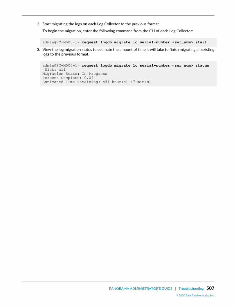
PANORAMA ADMINISTRATOR'S GUIDE | Troubleshooting 507© 2020 Palo Alto Networks, Inc.
2. Start migrating the logs on each Log Collector to the previous format.
To begin the migration, enter the following command from the CLI of each Log Collector:
admin@FC-M500-1> request logdb migrate lc serial-number <ser_num> start
3. View the log migration status to estimate the amount of time it will take to finish migrating all existinglogs to the previous format.
admin@FC-M500-1> request logdb migrate lc serial-number <ser_num> status Slot: all Migration State: In Progress Percent Complete: 0.04 Estimated Time Remaining: 451 hour(s) 47 min(s)

508 PANORAMA ADMINISTRATOR'S GUIDE | Troubleshooting