
pag. 91-106_POWER SUPPLY AND DISTRIBUTION RELAY ...
16
Power Supply and Distribution Relay Protection Optimization and Monitoring System Realization Based on PLC International Journal of Mechatronics and Applied Mechanics, 2019, Issue 6, Vol. I 91 POWER SUPPLY AND DISTRIBUTION RELAY PROTECTION OPTIMIZATION AND MONITORING SYSTEM REALIZATION BASED ON PLC Xi-yan Wang Zhengzhou Railway Vocational & Technical College, Henan, 451460, China. Email: [email protected] Abstract - In order to solve the problems of long setting time, limited means of fault detection, difficulty in fault judgment and location of traditional relay protection device backup protection, the problem that traditional protection cannot identify instantaneous system operation status and fault status on-line is fundamentally solved. Firstly, the traditional over-current protection is compared with the multi-agent based over-current protection. It proves that it is feasible to remedy the shortcomings of backup protection through multi-agent communication. Then, the CAN (Controller Area Network) bus communication network architecture is completed and the specific engineering application of multi-agent over-current protection is realized. Secondly, the necessity analysis and logical verification of the automatic protection device for unattended substation, especially the automatic switching device of standby power supply, are carried out, and the computer-based standby automatic switching device is realized. Finally, the design of man-machine interface on the host computer is completed, and the integrated automation system of power supply and distribution for specific projects is improved. The research results show that the optimization and monitoring system of power supply and distribution relay protection based on PLC (Programmable Logic Controller) can be better realized by multi-agent over-current protection based on CAN bus communication network framework. Keywords: Multi-Agent Mechanism; Standby Self-Switching Device; Microprocessor-Based Standby Self-Switching Device. 1. Introduction After the power system has been put into operation, how to find out the existing problems in the daily operation and management and correct them in time are the main measures to prevent the occurrence of power accidents. The existing research on relay protection mainly focuses on the design of relay protection equipment, the setting of parameters, and the prediction of on-line faults. However, there is no in-depth study on the operation and management of the system. Especially in the aspect of maintenance, there is an urgent need for a set of theories and norms to evaluate the whole process risk of relay protection and to guide the maintenance of power protection status, so that problems can be found and solved early, and risk hidden dangers can be eliminated in the budding state [1]. The reliability of power system relay protection has never been interrupted, but most previous studies have not paid attention to the mis-operation of power system relay protection. Through practical experience, it is known that the occasional malfunction of relay protection in normal operation of power system will not make the whole system work normally, but if the relay protection fails to remove the fault in time when a fault occurs, this situation will lead to serious damage to the protected equipment [2]. In electric power enterprises, power supply and distribution system is the basis of all automation system equipment. The intelligent power supply and distribution system based on PLC (Programmable Logic Controller) bus is in line with the development direction of power supply and distribution system in the future. With the development of society, people need a large number of PLC products, some of which are the core productivity of production. If the PLC equipment cannot run continuously, it will bring serious consequences. In order to strengthen the stability of the operation of PLC equipment, people need to design the protection optimization and monitoring system of power supply and distribution relay equipment for PLC. The protection optimization of power supply and distribution relay equipment and the functional requirements of monitoring system of PLC are analyzed, and its functional requirements design is completed through hardware and software design. Under some special circumstances, the power system of PLC
-
Upload
khangminh22 -
Category
Documents
-
view
0 -
download
0
Transcript of pag. 91-106_POWER SUPPLY AND DISTRIBUTION RELAY ...
Power Supply and Distribution Relay Protection Optimization and Monitoring System Realization Based on PLC
International Journal of Mechatronics and Applied Mechanics, 2019, Issue 6, Vol. I 91
POWER SUPPLY AND DISTRIBUTION RELAY PROTECTION OPTIMIZATION AND MONITORING SYSTEM
REALIZATION BASED ON PLC
Xi-yan Wang Zhengzhou Railway Vocational & Technical College, Henan, 451460, China.
Email: [email protected]
Abstract - In order to solve the problems of long setting time, limited means of fault detection, difficulty in fault judgment and location of traditional relay protection device backup protection, the problem that traditional protection cannot identify instantaneous system operation status and fault status on-line is fundamentally solved. Firstly, the traditional over-current protection is compared with the multi-agent based over-current protection. It proves that it is feasible to remedy the shortcomings of backup protection through multi-agent communication. Then, the CAN (Controller Area Network) bus communication network architecture is completed and the specific engineering application of multi-agent over-current protection is realized. Secondly, the necessity analysis and logical verification of the automatic protection device for unattended substation, especially the automatic switching device of standby power supply, are carried out, and the computer-based standby automatic switching device is realized. Finally, the design of man-machine interface on the host computer is completed, and the integrated automation system of power supply and distribution for specific projects is improved. The research results show that the optimization and monitoring system of power supply and distribution relay protection based on PLC (Programmable Logic Controller) can be better realized by multi-agent over-current protection based on CAN bus communication network framework. Keywords: Multi-Agent Mechanism; Standby Self-Switching Device; Microprocessor-Based Standby Self-Switching Device.
1. Introduction After the power system has been put into operation, how to find out the existing problems in the daily operation and management and correct them in time are the main measures to prevent the occurrence of power accidents. The existing research on relay protection mainly focuses on the design of relay protection equipment, the setting of parameters, and the prediction of on-line faults. However, there is no in-depth study on the operation and management of the system. Especially in the aspect of maintenance, there is an urgent need for a set of theories and norms to evaluate the whole process risk of relay protection and to guide the maintenance of power protection status, so that problems can be found and solved early, and risk hidden dangers can be eliminated in the budding state [1].
The reliability of power system relay protection has never been interrupted, but most previous studies have not paid attention to the mis-operation of power system relay protection. Through practical experience, it is known that the occasional malfunction of relay protection in normal operation of power system will not make the whole system
work normally, but if the relay protection fails to remove the fault in time when a fault occurs, this situation will lead to serious damage to the protected equipment [2].
In electric power enterprises, power supply and distribution system is the basis of all automation system equipment. The intelligent power supply and distribution system based on PLC (Programmable Logic Controller) bus is in line with the development direction of power supply and distribution system in the future. With the development of society, people need a large number of PLC products, some of which are the core productivity of production. If the PLC equipment cannot run continuously, it will bring serious consequences. In order to strengthen the stability of the operation of PLC equipment, people need to design the protection optimization and monitoring system of power supply and distribution relay equipment for PLC. The protection optimization of power supply and distribution relay equipment and the functional requirements of monitoring system of PLC are analyzed, and its functional requirements design is completed through hardware and software design. Under some special circumstances, the power system of PLC

Power Supply and Distribution Relay Protection Optimization and Monitoring System Realization Based on PLC
International Journal of Mechatronics and Applied Mechanics, 2019, Issue 6, Vol. I 92
cannot fail; otherwise, it will cause very serious consequences. The power supply and distribution relay protection system of PLC is used to supply power for PLC equipment uninterruptedly.
To provide a set of power supply and distribution relay system design and monitoring system for PLC is to optimize the operation of the PLC system [3].
With the continuous improvement of PLC technology, the continuous development of monitoring technology and other related technologies, the intelligent power supply and distribution system will develop towards a more intelligent, faster, and more human-oriented direction.
Therefore, the power supply and distribution monitoring system is bound to move towards the integrated automation of power supply and distribution: the integration of functions, the intellectualization of operation management, the computerization of structure, and the screen of operation monitoring.
The integration of integrated automation of power supply and distribution system with intelligent building system (BAS) and enterprise resource planning (ERP) to achieve good management has become an inevitable trend and development direction [4].
In the final analysis, the application of adaptive technology in relay protection is that the protection device can adapt itself to the instantaneous changes of the operation status of power supply and distribution system, and actively adjust the protection logic parameters according to the system changes, so as to achieve tracking and updating.
The emergence of multi-agent technology is an inevitable choice for the development of distributed artificial intelligence and artificial life science. In recent years, due to its complexity and variability, as well as the increasing demand for flexibility of power grid dispatching, modern power system has almost all the characteristics mentioned above, which makes multi-agent mechanism play an important role in relay protection, power flow dispatching, power market, voltage and reactive power regulation, fault diagnosis and other fields.
Automatic devices play an important role in
power system. For example, automatic devices can
significantly improve the reliability of system
operation and user power consumption; it can
cooperate with system relay protection devices
when there is a specific demand; it can immediately
remove the fault when the equipment fails, and
effectively and timely prevent the expansion of the
accident; it can realize the needs of power grid
telemetry, remote control, remote regulation, remote
communication, etc., realize unattended, reduce the
intensity of manual labor and enhance the system
self-operation and maintenance capability [5].
2. Over-Current Protection Optimization Based on Multi-Agent Technology
The emergence of agent concept is accompanied by the development of distributed artificial intelligence technology. Agent technology is a kind of encapsulated computer analysis system, which encapsulates attributes, methods, thinking ability, decision-making ability etc. That is to say, agents have certain knowledge, goals and problem-solving abilities, can use knowledge to analyze problems and integrate real-time information with other agents in the environment to communicate and solve problems cooperatively.
Compared with the traditional system, which needs the technical operation support of human, the establishment of knowledge system needs the introduction of artificial database, and the information exchange is limited to the degree of pre-design, the emergence of agent has brought about great changes to the traditional system. Agents are self-made individuals who can plan their own behaviour without the influence of other people or other agents. Actions of agents in events are not passive stressful behaviours, but can adapt to the tasks set or updated at any time, and complete the relevant answers. It is necessary to activate communication cooperation strategies when cooperating with people or other agents in the environment. Agents are self-learning entities and they can perceive changes in the environment and change their knowledge system to adapt to changes after adjustment, reasoning, and induction. Based on the autonomy, spontaneity, interaction and cooperation, variability and adaptability of the above agents, the ability of agents to deal with the problems in the environment can be obtained. However, due to the large and complex nature of the task, even if a single agent can continue to learn, its limited knowledge inventory also constrains the ability of a single agent to complete solution formulation.
Multi-agent system is generally used to deal with problems that cannot be solved by a single or a few agents. The key to realize multi-agent system is to solve organizational strategies, message transfer, conflict resolution, coordination and cooperation. The essence of multi-agent based on distributed artificial intelligence is that through communication cooperation technology and communication protocol, the free agent factors in the environment are effectively aggregated according to certain integration rules and principles, that is to say, many agents in the environment become "agent clusters" in a "loose affinity" state, which make up for the ability analysis and shortcomings of problem solving of a single agent. It can realize the integration of resources and complete specific tasks through information exchange and operation interaction.

Power Supply and Distribution Relay Protection Optimization and Monitoring System Realization Based on PLC
International Journal of Mechatronics and Applied Mechanics, 2019, Issue 6, Vol. I 93
In a specific multi-agent system, as the smallest
unit of multi-agent system, agent has the ability of
communication, cooperation, coordination,
scheduling, and management. It not only can actively
send request instructions to other agents of the
system, but also accept requests from other agents.
Therefore, in solving complex problems, multi-
agent has advantages that other mechanisms cannot
match [6].
2.1 Structure and characteristics of relay protection system based on multi-agent mechanism
The research shows that the multi-agent based
protection system can improve the reliability of protection action and make the protection work more flexible by coordinating the distributed intelligent protection in space.
The structure diagram and task solving flow chart of multi-agent system are shown in Figure 1.
Start agent
Blackboard system
Control agent
user interface
Option 1 Option 2 Option n
Question input and
allocation
Programming for
problems
Detailed problem
customer's opinions
Solution Integration
Output
input layer
Execution layer
output layer
Y
N
Figure 1: Structural diagram of multi-agent system and flow chart of task solution
The task-solving system based on multi-agent
technology consists of three layers: input layer, execution layer, and output layer. The start-up agent is located in the input layer of the system. Its main function is to use the start-up agent to realize the multi-agent system to acquire, receive and utilize relevant information from the outside user layer. Solution agent is located in the executive layer of the system. Solution agent itself has multiple problem solutions, among which each problem solution has its own knowledge, information, resource base and is responsible for the formulation of the scheme. In relay protection based on multi-agent mechanism, each scheme agent is a variety of components that need to install protective devices in power system. The control agent is located in the system output layer. The blackboard system is used to complete the information exchange among the agents of multiple schemes in the executive layer. The role of the control agent is to control the interaction process according to the relevant criteria when the agent of multiple schemes interacts with each other. On the
other hand, it integrates and normalizes the schemes and submits the integration scheme to the users.
The system based on multi-agent mechanism can disperse complex problems into simpler sub-problem modules and realize the information interaction of multi-agent, and user's intention inquiry and feedback, and complete the integrated output of design schemes in the process of problem scheme design, thus reducing the difficulty of solving complex problems and ensuring the reliability of the system [7].
2.2 Relay protection model and work flow of distribution network based on multi-agent mechanism
A typical distribution network relay protection
model based on multi-agent mechanism is shown in Figure 2. The whole system consists of three layers of agent structure, namely the top organization layer, the middle coordination layer and the bottom execution layer.

Power Supply and Distribution Relay Protection Optimization and Monitoring System Realization Based on PLC
International Journal of Mechatronics and Applied Mechanics, 2019, Issue 6, Vol. I 94
Communication interaction and coordination among layers can be achieved to ensure the reliability and rapidity of circuit breaker action.
In the process of system operation based on multi-agent mechanism, the coordination layer plays a connecting role between the preceding and the following. It is a unit that builds contact based on system communication network. The search agent of coordination layer in power supply and distribution system uploads the switching quantity and load status to the network reorganization agent of organization layer for recording in real time. The organization layer makes comprehensive analysis according to the network status and the state
information obtained from the bottom layer, and carries out the work of defining the instant state of network, confirming the fault point, and changing the trip strategy. After the decision-making of the organizational level is completed, the information is transmitted through the downlink network to the tripping agent of the executive level, and then acts on the circuit breaker, so that the system can achieve real-time state monitoring and relay protection strategy transformation optimization through the up and down transmission of information. Figure 2 is a schematic diagram of the relay protection model structure and working flow of distribution network based on multi-agent mechanism.
Selection of
Scheme
Mechanisms Inter stage
communication
Conventional
mechanism
Inter stage
communication
Conventional
mechanism
Measurement
signal input
Conditional
comparison
Trip instruction
Measurement
signal input
Conditional
comparison
Trip instructionExcision
failure
Excision
failure
Selection of
Scheme
Mechanisms
Agent
A
Agent
B
Meeting
conditions
Meeting
conditions
Not satisfying
the conditions
Not satisfying
the conditions
implement implement
Non
execution
Non
execution
Execution
layer
Coordination
layer
Tissue layer
Measurement
agent
Trip agent
Search agent
Network
Reorganization
Agent
Reorganiz
ation
record
Skip trip
Information
interaction
Figure 2: Relay protection model structure and working flow diagram of distribution network based on multi-agent
mechanism
Over-current protection based on multi-agent mechanism realizes inter-level communication, so its protection strategy can quickly make information contact between levels and achieve accelerated action.
2.3 Principle explanation of over-current protection based on multi-agent mechanism
The traditional mode of over-current protection
has no communication links between all levels, which results in that, when the action of the circuit breaker does not operate in time, the upper circuit breaker needs to passively wait for the pre-set time difference before acting on the remote backup circuit breaker tripping.
As a result, it leads to a long time limit, and short-circuit current exists in the power supply and distribution system for a long time, causing serious consequences for the system.
Over-current protection based on multi-agent
mechanism is to coordinate and communicate
among the over-current protection agents within the
scope of protection delimitation, to achieve fast
cooperative response of multi-agent protection on
the basis of ensuring the selectivity of relay
protection, to start the upper action immediately
when the circuit breaker fails to act correctly, and to
complete fast fault removal. Figure 3 is a package
module for over-current protection based on multi-
agent mechanism.

Power Supply and Distribution Relay Protection Optimization and Monitoring System Realization Based on PLC
International Journal of Mechatronics and Applied Mechanics, 2019, Issue 6, Vol. I 95
labc1
labc2
labc3
labc4
labc2
labc1
labc3
labc4
KC1KC1
KC2
KC3
KC2
KC3
l1
l2
l3
l4
KC1
KC2
KC3
Overcurrent protection module based on multi-agent
mechanism:
Input:
Setting Value of Overcurrent Protection at Bus B1, B2, B3
and B4
Output:
External Control Input Signal of Circuit Breaker K1, K2,
K3 Trip
Figure 3: Over-current protection logic unit packaging module based on multi-agent mechanism
Similar to the traditional mode over-current
protection module, the sampling input signal and output required by the module are the same. Over-current protection based on multi-agent mechanism realizes inter-level communication, so its protection strategy can quickly make information contact between levels and achieve accelerated action.
Over-current protection based on multi-agent mechanism can effectively shorten the coordination operation time of over-current protection of circuit breakers through interconnection between stages, which is a significant improvement in the performance of backup protection in traditional mode. In addition, it is also necessary to consider the sensitivity of one of the relay protection requirements, so as to meet the relevant requirements. In order to meet the requirements of sensitivity, criteria are added to the over-current protection based on multi-agent mechanism.
The starting current of over-current protection is set according to the maximum load current. At the end of power supply and distribution system, the short-circuit current is relatively small because of the large short-circuit impedance of the system. In this case, if the operating current of over-current protection is large, the backup protection sensitivity of power supply and distribution system may not meet the corresponding national standards or engineering requirements. In order to improve the sensitivity of over-current protection, a low-voltage blocking device is used to reduce the setting current of backup protection to the maximum load current of the system by utilizing the characteristics that the bus voltage decreases significantly in short circuit and little in overload. On the other hand, the sensitivity of backup protection is improved by installing a low-voltage blocking device and using a combined judgment mechanism of low-voltage and over-current to reduce the setting current value of backup protection to the maximum load current value of the system. Voltage device cooperated with
current detection can solve the problem of dead zone of relay protection well [8].
3. Logic Analysis of Self-Adaptive Standby Power Supply Automatically Input
3.1 Necessity and workflow analysis of automatic switching-in device for standby power supply
With the increasing load scale of enterprise
power supply and distribution system and the higher requirement of power supply reliability, standby self-switching becomes an important automatic device to ensure continuous power supply. Most enterprises belong to continuous production units according to process and production requirements, which put forward strict requirements for the continuity and reliability of power supply system. After the use of a microcomputer-based bus-connected automatic switching device, under the same circumstances, the system automatically closes the bus-connected circuit breaker according to the corresponding logic immediately to ensure the continuous operation of the system on the basis of ensuring the sequence.
The automatic switching device of standby power supply is an important automatic device in intelligent unattended substation. The standby automatic switching device is applied in the system by self-adapting and self-starting mode to improve the reliability of power supply. Self-adaptation is the system's self-inspection of the system's condition, and self-start-up is the system's self-operation after satisfying the conditions. In order to improve the scope of application and ensure flexibility, the device combines bus connection and line standby self-switching, but at most one form of standby self-switching is adopted by the device at a specific time [9].

Power Supply and Distribution Relay Protection Optimization and Monitoring System Realization Based on PLC
International Journal of Mechatronics and Applied Mechanics, 2019, Issue 6, Vol. I 96
The standby self-switching device can be used in three connection modes: wire entry, bus connection, self-adapting with manual switching, accident switching, non-working conditions (voltage loss and switch mistake jump); the device is installed in the switch cabinet of the sectional circuit breaker, and the panel openings are installed. At the same time, in order to cooperate with the standby self-switching device, PT parallel device is installed in the system at the same time, which is installed in the isolation car
switch cabinet with fewer adjacent secondary cables. The unattended substation will be put into the comprehensive insurance system, which will input the switching and analog values in the set logic into the comprehensive insurance system and become a part of the comprehensive insurance of the whole plant. The self-adaptive standby power automatic switching device runs smoothly as shown in Figure 4.
Standby Auto-
switch Function
Start-up
Running
status query
Preparations for
Mother Union's
Self-turning-in
Preparations for
Line Standby Auto-
switching
Mother Union's
own investment
Manual release of
locking self-
contained switching
device
Running
status query
Optical Character
Card "Alphabet
ready for self-
throwing"
Running
status query
Line self-
supporting input
Manual release of
locking self-
contained switching
device
Optical Character
Board "Line Ready
for Auto-switching
Over"
Reversion
device ReturnReversion
deviceReturn
Lighten up Lighten up
Standby conditions
for self-provided bus
Federation
Standby
Conditions for
Line Standby
Start-up Conditions of
Self-provided Bus
Union
Start-up Conditions
for Line Self-
supporting Operation
Figure 4: Flow chart of automatic switching device for adaptive standby power supply
Both of them are widely used in industrial and
mining enterprises with high continuity and reliability of power supply.
However, in practical application, attention should be paid to the margin of power supply capacity, no matter what form of standby power supply is used.
For example, in line standby power supply, the capacity of standby power supply should ensure that the load after the conversion of standby power supply occurs, or consider adding automatic load shedding function to ensure that important loads are not lost power and secondary loads are automatically removed when the power supply capacity is limited before the application of standby auto-switching design.
The purpose of this is to prevent overload from causing low voltage or logic errors in the system. After completion of the operation, the system changes the operation mode.
At this time, the backup device can be manually restored by engineers or remotely reset by the host computer.
If the device is no longer needed, the backup device can be withdrawn from operation.
3.2 Logic analysis of automatic operation of standby power supply
The schematic diagram of the detection of the action of the bus-connected automatic switching device is shown in Figure 5.

Power Supply and Distribution Relay Protection Optimization and Monitoring System Realization Based on PLC
International Journal of Mechatronics and Applied Mechanics, 2019, Issue 6, Vol. I 97
1#Inlet current of power
supply
Section I Bus Voltage
2#Inlet current of power
supply
SectionⅡ Bus Voltage
and
Switch off the circuit breaker
for power lossShut-in Bus Circuit Breaker
and
or
Figure 5: Principle diagram for detection of motion of auto-switching device
Action logic: When the incoming current is far
less than the rated load current value, the incoming current of the power supply here is approximately
Rated current Rated current1% 5% I I I , which is
considered as "no current" of the incoming line, and the bus voltage
Rated bus voltage30( —60) %UU of the bus
section is considered as "out-of-voltage" state of the bus. When an incoming line is in the "no-flow" state and the corresponding bus is in the "out-of-voltage"
state, the above judgment conditions are taken as the operation conditions of bus-link backup automatic switching-on. This method can effectively avoid the possibility of mis-operation caused by bus voltage only. For instance, PT secondary side disconnection may also cause low voltage.
The detection principle diagram of the action of the line standby automatic switching device is shown in Figure 6.
Inlet Current of Municipal
Power Supply
Inlet Voltage of Standby
Power Supply
andSwitch off the circuit breaker
for power loss
Circuit Breaker Closed on
Standby Power Supply Inlet
Figure 6: Principle diagram for detection of actions of line standby auto-switching device
Action logic: When the current of the municipal
power line is far less than the rated load current, the current
Rated current Rated current1% 5% I I I of the
municipal power line is considered as "no current" in this section, and the voltage
Bus rated voltage80%U U of the
standby power line is considered as "voltage but no current" in the standby power supply. When the municipal power line is in the "no-current" state and the power side of the standby power line is "voltage and no-current", the above judgment condition is taken as the operation condition of the standby self-switching of the line [10].
Starting with the necessity and feasibility, the necessity of automatic devices such as standby power supply automatic switching-in to realize unattended power supply and distribution system is analysed. Then, the work flow of adaptive standby
automatic switching-in device is explained, and finally, a logical analysis of bus/line conforming to standby automatic switching-in system is made, and its logical feasibility and rationality is obtained.
4. Optimization of Microcomputer-Based Relay Protection and Realization of Standby Auto-Switching
4.1 Optimization of microcomputer-based relay protection and realization of standby auto-switching
The core of multi-agent mechanism to optimize multi-level protection strategy is to realize the sharing of local resources and information by means of inter-level communication. Taking PLC as the
Power Supply and Distribution Relay Protection Optimization and Monitoring System Realization Based on PLC
International Journal of Mechatronics and Applied Mechanics, 2019, Issue 6, Vol. I 98
carrier, the whole plant communication network of an inorganic fluoride enterprise based on CAN bus is established, the whole plant communication network architecture is designed, and the protection based on multi-agent mechanism is realized.
The over-current protection is realized by PLC programmable control, that is, the distributed control system of over-current protection is constructed by using the Begaley series PLC, through the software programming and hardware debugging of the PLC. It realizes the over-current protection based on multi-agent mechanism and effectively reduces the possible impact of the long time limit on the power supply and distribution system.
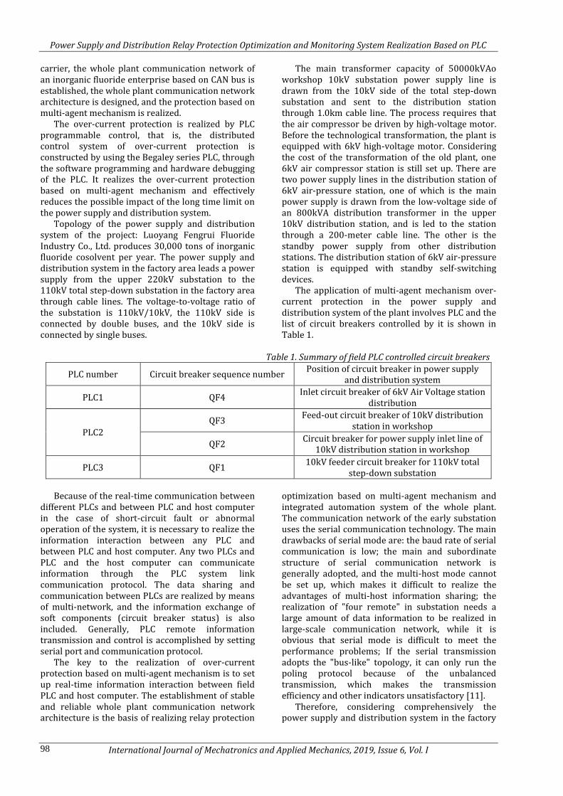
Topology of the power supply and distribution system of the project: Luoyang Fengrui Fluoride Industry Co., Ltd. produces 30,000 tons of inorganic fluoride cosolvent per year. The power supply and distribution system in the factory area leads a power supply from the upper 220kV substation to the 110kV total step-down substation in the factory area through cable lines. The voltage-to-voltage ratio of the substation is 110kV/10kV, the 110kV side is connected by double buses, and the 10kV side is connected by single buses.
The main transformer capacity of 50000kVAo workshop 10kV substation power supply line is drawn from the 10kV side of the total step-down substation and sent to the distribution station through 1.0km cable line. The process requires that the air compressor be driven by high-voltage motor. Before the technological transformation, the plant is equipped with 6kV high-voltage motor. Considering the cost of the transformation of the old plant, one 6kV air compressor station is still set up. There are two power supply lines in the distribution station of 6kV air-pressure station, one of which is the main power supply is drawn from the low-voltage side of an 800kVA distribution transformer in the upper 10kV distribution station, and is led to the station through a 200-meter cable line. The other is the standby power supply from other distribution stations. The distribution station of 6kV air-pressure station is equipped with standby self-switching devices.
The application of multi-agent mechanism over-current protection in the power supply and distribution system of the plant involves PLC and the list of circuit breakers controlled by it is shown in Table 1.
Table 1. Summary of field PLC controlled circuit breakers
PLC number Circuit breaker sequence number Position of circuit breaker in power supply
and distribution system
PLC1 QF4 Inlet circuit breaker of 6kV Air Voltage station
distribution
PLC2
QF3 Feed-out circuit breaker of 10kV distribution
station in workshop
QF2 Circuit breaker for power supply inlet line of
10kV distribution station in workshop
PLC3 QF1 10kV feeder circuit breaker for 110kV total
step-down substation
Because of the real-time communication between
different PLCs and between PLC and host computer in the case of short-circuit fault or abnormal operation of the system, it is necessary to realize the information interaction between any PLC and between PLC and host computer. Any two PLCs and PLC and the host computer can communicate information through the PLC system link communication protocol. The data sharing and communication between PLCs are realized by means of multi-network, and the information exchange of soft components (circuit breaker status) is also included. Generally, PLC remote information transmission and control is accomplished by setting serial port and communication protocol.
The key to the realization of over-current protection based on multi-agent mechanism is to set up real-time information interaction between field PLC and host computer. The establishment of stable and reliable whole plant communication network architecture is the basis of realizing relay protection
optimization based on multi-agent mechanism and integrated automation system of the whole plant. The communication network of the early substation uses the serial communication technology. The main drawbacks of serial mode are: the baud rate of serial communication is low; the main and subordinate structure of serial communication network is generally adopted, and the multi-host mode cannot be set up, which makes it difficult to realize the advantages of multi-host information sharing; the realization of "four remote" in substation needs a large amount of data information to be realized in large-scale communication network, while it is obvious that serial mode is difficult to meet the performance problems; If the serial transmission adopts the "bus-like" topology, it can only run the poling protocol because of the unbalanced transmission, which makes the transmission efficiency and other indicators unsatisfactory [11].
Therefore, considering comprehensively the power supply and distribution system in the factory

Power Supply and Distribution Relay Protection Optimization and Monitoring System Realization Based on PLC
International Journal of Mechatronics and Applied Mechanics, 2019, Issue 6, Vol. I 99
area, CAN bus is adopted as the communication network framework. The core of multi-agent communication in the system is that the communication between agents, agent institutions, and host computers through the controller LAN (Local Area Network) bus CAN realizes the information connection and interaction between multi-layer and multi-agent agencies, shares local information, completes the protection strategy based on multi-agent mechanism, and realizes data
interaction between the internal system of the plant power supply and distribution system and the detection and execution agencies .
As a result, after comprehensive consideration, the power supply and distribution system of Luoyang Fengrui Fluoride Co., Ltd., which produces 30,000 tons of inorganic fluoride cosolvent per year, CAN bus is used as the communication network framework. The network framework is shown in Figure 7.
Monitor
Host
PLC2PC2
QF3 QF2
PLC1 PLC3 PC3PC1
Upper
position
QF4 QF1
RS232 RS232 RS232
CAN
networ
k
To circuit
breaker coil
Figure 7: Schematic diagram of communication system network architecture for power supply and distribution
system
Three field PLC units, PLC1, PLC2 and PLC3, are connected with each other by field bus CAN to simulate the field control level of industrial control network. Each field PLC is connected with the central control host computer through field bus CAN to simulate the enterprise management level in industrial control network. The host computer can configure remote interface and printer according to the demand, and the host computer is equipped with independent UPS (Uninterrupted Power Supply) power supply. Each protective device is distributed on the corresponding switch cabinet and protective screen. Each protective device communicates with other devices and host computer through shielded twisted pair to form CAN network real-time communication system.
The field PLC is equipped with a PC as the programming and monitoring equipment of the PLC. Each PLC is also equipped with CPU module, digital/analog mixed input and output module, etc. Each PC is equipped with Windows operating system, PLC programming software Automation Studio, and industrial monitoring configuration software Windows Control Center, which are used for configuration programming of PLC system and configuration design monitoring of human-machine
interface. Each PC is connected with its corresponding PLC through RS232 interface.
Considering the above characteristics, the core of multi-agent communication in the system is to realize the information contact and interaction among agents, agent institutions and host computers through CAN communication of controller LAN bus, to share local information, to complete the protection strategy based on multi-agent mechanism, and to realize the data interaction between the internal system of power supply and distribution system and the detection and execution agencies. For example, when the circuit breaker in this system cannot turn on correctly, search for the adjacent circuit breaker to jump off and accelerate the protection action.
As far as the realization of over-current protection based on multi-agent mechanism by using PLC is concerned, three field-level PLCs (control QF1-QF4) and central-control PC are used as discrete control systems of multi-master station nodes. Firstly, the same-level transmission of the switch-on and switch-off instructions and the state of the circuit breaker can be realized, which is the core of the optimization of the over-current mechanism. Secondly, it can upload the PLC information to the host computer, realize the remote transmission of

Power Supply and Distribution Relay Protection Optimization and Monitoring System Realization Based on PLC
International Journal of Mechatronics and Applied Mechanics, 2019, Issue 6, Vol. I 100
the bottom field information and the summary of the central control system. Finally, it can realize the adjustment of the host computer through the CAN bus for the control mode of the field PLC, realize the conversion of the communication mode, the remote circuit breaker closing and opening operation, and the setting of the communication mode system of the microcomputer-based over-current protection.
For circuit breakers QF1, QF2, QF3 and QF4 located around the system, each section of the protection is equipped with fast break and over-current protection. The fast break and setting values are obtained by calculating the standard short circuit (The protection coordination is focused on, so the primary current and voltage values are selected directly, and the appropriate CT/PT conversion ratio should be selected in practice). The quick-break protection is used to cut off the fault immediately when the short circuit occurs, and the over-current protection is the near-backup protection of this section of line and the far-backup protection of the next section of line. In addition, relevant switching operation rules are also considered in the process of switching-on and switching-off of circuit breakers to meet the requirements of "five preventions" for switchgear cabinets of transformer and distribution substations.
The PLC program of any circuit breaker is divided into three parts: one is the initialization program of CAN communication based on CAN bus communication.
The second is the communication settings, including the sending and receiving communication program between the PLC of the circuit breaker and the PLC of other locations, and the sending and receiving communication program between the PLC of the circuit breaker and the host computer.
The third is the short-circuit fault trip module
program, which includes the short-circuit trip
condition of relay protection and trip instructions.
Among them, the short-circuit tripping condition of
over-current protection based on multi-agent
mechanism is the comparison condition of the
setting value of the over-current protection of the
circuit breaker, and the actual operation condition of
the circuit breaker when the over-current short-
circuit occurs in the lower circuit breaker.
In Figure 8, the starting of "accelerated tripping"
depends on two "information". One is whether the
lower circuit breaker has the control signal of
tripping and closing; the other is whether the lower
circuit breaker is correct and timely tripping, that is,
reading the status of the lower circuit breaker.
QF4
Current signal
sampling
Comparison of
Filtration
Conditions
Trip
instruction
Cut out
fault
Accelerated
trip
Trip
instruction
Meeting
conditions
Not
satisfying
the
conditions
implement
Non
execution
QF3
Current signal
sampling
Comparison of
Filtration
Conditions
Trip
instruction
Cut out
fault
Meeting
conditions
Not
satisfying
the
conditions
implement
QF2
Current signal
sampling
Comparison of
Filtration
Conditions
Trip
instruction
Cut out
fault
Meeting
conditions
Not
satisfying
the
conditions
implement
QF1
Current signal
sampling
Comparison of
Filtration
Conditions
Trip
instruction
Cut out
fault
Meeting
conditions
Not
satisfying
the
conditions
implement
Accelerated
trip
Trip
instruction
Accelerated
trip
Trip
instruction
implement
implement
implement
Non
execution
Non
execution
Non
execution
Non
execution
Figure 8: Operating principle of accelerated trip of over-current protection circuit breaker based on microcomputer
multi-agent mechanism
The circuit breaker QF4 communication settings
include QF4 and QF3 CAN communication
transmission settings, QF4 and host computer CAN
communication transmission settings, QF4 and host
computer CAN communication reception settings.
The circuit breaker QF4 short circuit fault trip module program includes the following components:
Circuit breaker tripping conditions, namely QF4 current quick-break protection tripping and fixed-time over-current protection tripping; communication mode (over-current protection based on multi-agent mechanism):
Power Supply and Distribution Relay Protection Optimization and Monitoring System Realization Based on PLC
International Journal of Mechatronics and Applied Mechanics, 2019, Issue 6, Vol. I 101
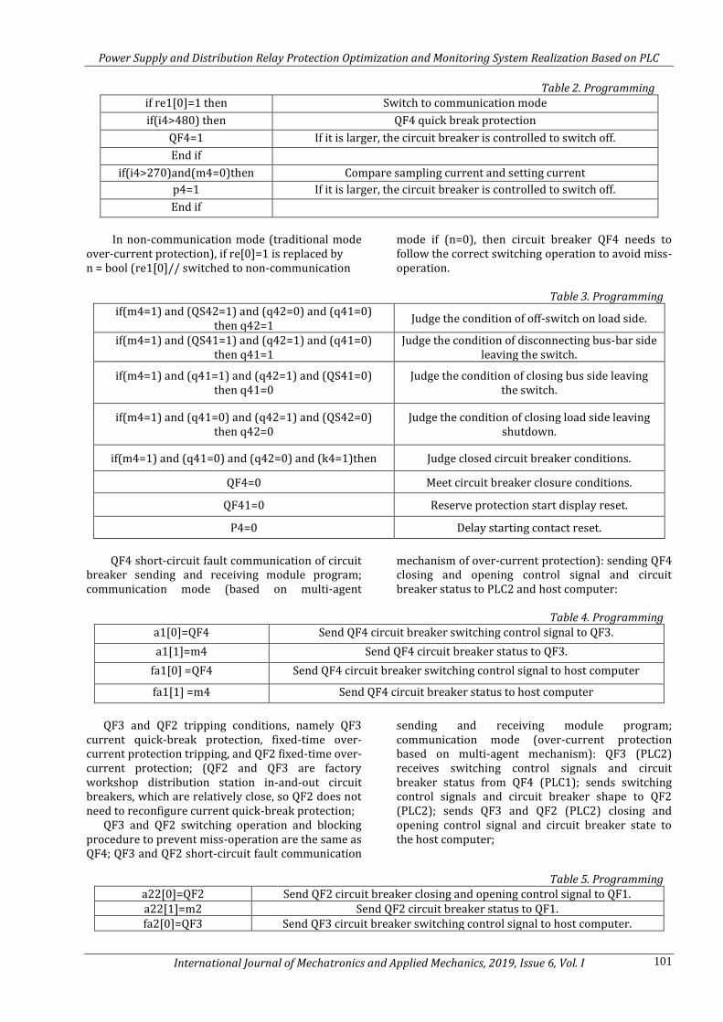
Table 2. Programming if re1[0]=1 then Switch to communication mode
if(i4>480) then QF4 quick break protection
QF4=1 If it is larger, the circuit breaker is controlled to switch off.
End if
if(i4>270)and(m4=0)then Compare sampling current and setting current
p4=1 If it is larger, the circuit breaker is controlled to switch off.
End if
In non-communication mode (traditional mode
over-current protection), if re[0]=1 is replaced by n = bool (re1[0]// switched to non-communication
mode if (n=0), then circuit breaker QF4 needs to follow the correct switching operation to avoid miss-operation.
Table 3. Programming
if(m4=1) and (QS42=1) and (q42=0) and (q41=0) then q42=1
Judge the condition of off-switch on load side.
if(m4=1) and (QS41=1) and (q42=1) and (q41=0) then q41=1
Judge the condition of disconnecting bus-bar side leaving the switch.
if(m4=1) and (q41=1) and (q42=1) and (QS41=0) then q41=0
Judge the condition of closing bus side leaving the switch.
if(m4=1) and (q41=0) and (q42=1) and (QS42=0) then q42=0
Judge the condition of closing load side leaving shutdown.
if(m4=1) and (q41=0) and (q42=0) and (k4=1)then Judge closed circuit breaker conditions.
QF4=0 Meet circuit breaker closure conditions.
QF41=0 Reserve protection start display reset.
P4=0 Delay starting contact reset.
QF4 short-circuit fault communication of circuit
breaker sending and receiving module program; communication mode (based on multi-agent
mechanism of over-current protection): sending QF4 closing and opening control signal and circuit breaker status to PLC2 and host computer:
Table 4. Programming
a1[0]=QF4 Send QF4 circuit breaker switching control signal to QF3.
a1[1]=m4 Send QF4 circuit breaker status to QF3.
fa1[0] =QF4 Send QF4 circuit breaker switching control signal to host computer
fa1[1] =m4 Send QF4 circuit breaker status to host computer
QF3 and QF2 tripping conditions, namely QF3
current quick-break protection, fixed-time over-current protection tripping, and QF2 fixed-time over-current protection; (QF2 and QF3 are factory workshop distribution station in-and-out circuit breakers, which are relatively close, so QF2 does not need to reconfigure current quick-break protection;
QF3 and QF2 switching operation and blocking procedure to prevent miss-operation are the same as QF4; QF3 and QF2 short-circuit fault communication
sending and receiving module program; communication mode (over-current protection based on multi-agent mechanism): QF3 (PLC2) receives switching control signals and circuit breaker status from QF4 (PLC1); sends switching control signals and circuit breaker shape to QF2 (PLC2); sends QF3 and QF2 (PLC2) closing and opening control signal and circuit breaker state to the host computer;
Table 5. Programming a22[0]=QF2 Send QF2 circuit breaker closing and opening control signal to QF1. a22[1]=m2 Send QF2 circuit breaker status to QF1. fa2[0]=QF3 Send QF3 circuit breaker switching control signal to host computer.
Power Supply and Distribution Relay Protection Optimization and Monitoring System Realization Based on PLC
International Journal of Mechatronics and Applied Mechanics, 2019, Issue 6, Vol. I 102
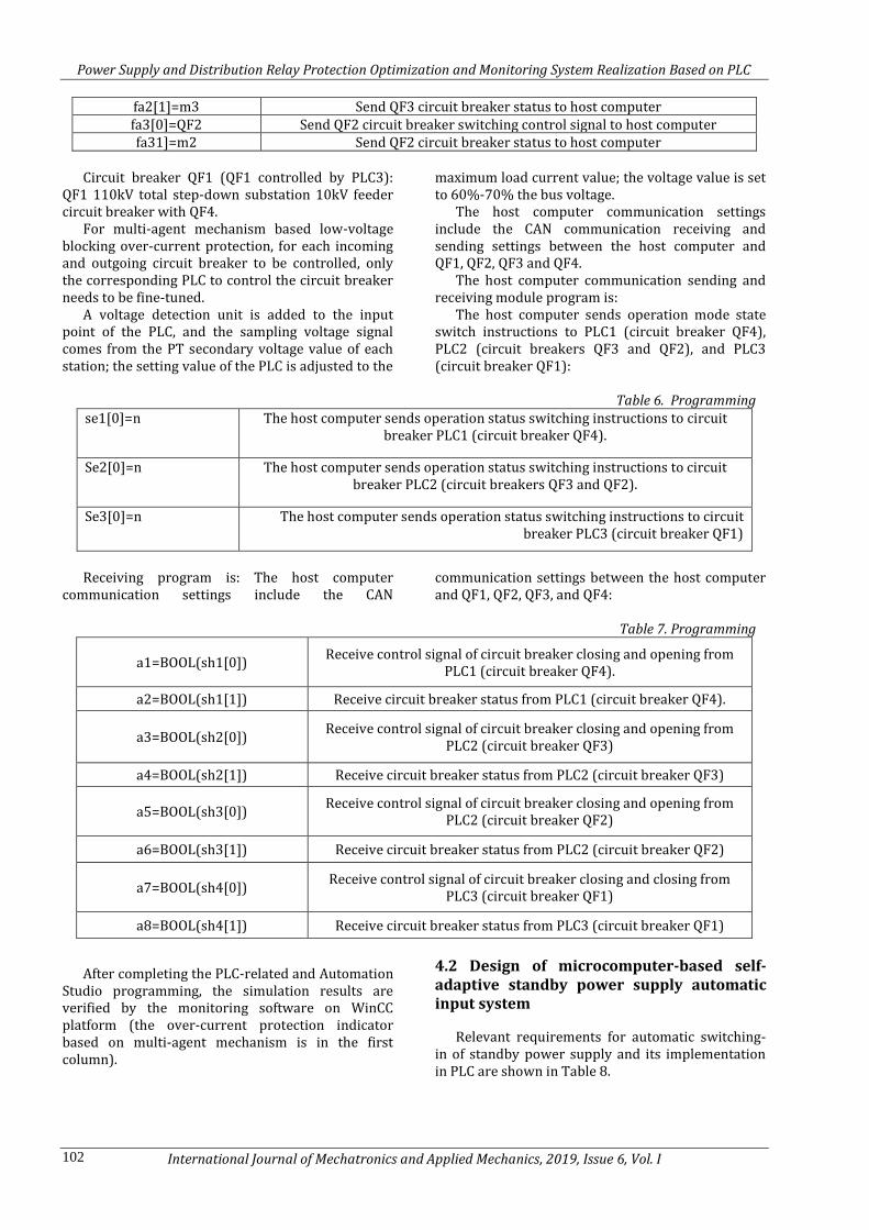
fa2[1]=m3 Send QF3 circuit breaker status to host computer fa3[0]=QF2 Send QF2 circuit breaker switching control signal to host computer fa31]=m2 Send QF2 circuit breaker status to host computer
Circuit breaker QF1 (QF1 controlled by PLC3):
QF1 110kV total step-down substation 10kV feeder circuit breaker with QF4.
For multi-agent mechanism based low-voltage blocking over-current protection, for each incoming and outgoing circuit breaker to be controlled, only the corresponding PLC to control the circuit breaker needs to be fine-tuned.
A voltage detection unit is added to the input point of the PLC, and the sampling voltage signal comes from the PT secondary voltage value of each station; the setting value of the PLC is adjusted to the
maximum load current value; the voltage value is set to 60%-70% the bus voltage.
The host computer communication settings include the CAN communication receiving and sending settings between the host computer and QF1, QF2, QF3 and QF4.
The host computer communication sending and receiving module program is:
The host computer sends operation mode state switch instructions to PLC1 (circuit breaker QF4), PLC2 (circuit breakers QF3 and QF2), and PLC3 (circuit breaker QF1):
Table 6. Programming
se1[0]=n The host computer sends operation status switching instructions to circuit breaker PLC1 (circuit breaker QF4).
Se2[0]=n The host computer sends operation status switching instructions to circuit breaker PLC2 (circuit breakers QF3 and QF2).
Se3[0]=n The host computer sends operation status switching instructions to circuit breaker PLC3 (circuit breaker QF1)
Receiving program is: The host computer
communication settings include the CAN communication settings between the host computer and QF1, QF2, QF3, and QF4:
Table 7. Programming
a1=BOOL(sh1[0]) Receive control signal of circuit breaker closing and opening from
PLC1 (circuit breaker QF4).
a2=BOOL(sh1[1]) Receive circuit breaker status from PLC1 (circuit breaker QF4).
a3=BOOL(sh2[0]) Receive control signal of circuit breaker closing and opening from
PLC2 (circuit breaker QF3)
a4=BOOL(sh2[1]) Receive circuit breaker status from PLC2 (circuit breaker QF3)
a5=BOOL(sh3[0]) Receive control signal of circuit breaker closing and opening from
PLC2 (circuit breaker QF2)
a6=BOOL(sh3[1]) Receive circuit breaker status from PLC2 (circuit breaker QF2)
a7=BOOL(sh4[0]) Receive control signal of circuit breaker closing and closing from
PLC3 (circuit breaker QF1)
a8=BOOL(sh4[1]) Receive circuit breaker status from PLC3 (circuit breaker QF1)
After completing the PLC-related and Automation Studio programming, the simulation results are verified by the monitoring software on WinCC platform (the over-current protection indicator based on multi-agent mechanism is in the first column).
4.2 Design of microcomputer-based self-adaptive standby power supply automatic input system
Relevant requirements for automatic switching-in of standby power supply and its implementation in PLC are shown in Table 8.

Power Supply and Distribution Relay Protection Optimization and Monitoring System Realization Based on PLC
International Journal of Mechatronics and Applied Mechanics, 2019, Issue 6, Vol. I 103
Table 8. Requirements of backup auto-switching and its realization in PLC Requirements for standby self-switching
equipment Realization of PLC
The voltage of the working power supply, except that it disappears due to manual disconnection or protective action of the power supply inlet switch, should be operated when the voltage disappears due to other reasons.
The secondary circuit of circuit breaker includes control circuit and protection circuit. The control circuit is used to realize the artificial active control circuit breaker on the switch cabinet body or remote control panel; The protection circuit is used to trigger the protective outlet relay when the relay protection device in the switchgear meets certain conditions and complete the automatic trip of the circuit breaker. Locking contacts of control circuit and protection circuit are set in backup automatic switching operation circuit: once the feeder circuit breaker has manual or protection action, ensure that backup automatic switching does not act.
It is necessary to ensure that the working power supply is disconnected before it is put into standby power supply, and that the time for automatic switching of standby power supply is as short as possible.
When programming with PLC software, set up the condition of electric blockage to ensure the sequence of action of circuit breakers with standby self-switching in: all can ensure that bus circuit breaker/standby power supply circuit breaker can be automatically closed only after the breaker of power-loss power supply is jumped off, and "choosing two in three" electric blockade can be added when necessary.
It should be guaranteed that the standby self-switching device only operates once.
Physical realization: the standby self-switching device can only store the energy of the standby self-switching action once at a time. Program realization: when virtual counter of standby automatic switching program equipment meets the technical conditions of the counter, the standby self-switching operation is blocked until the instruction is restored to the counter and the state of the circuit breaker after the action.
The device monitors the standby self-switching
device in real time by the host computer: the standby self-switching PLC sends the control circuit breakers to the host computer; the host computer sends the state switching instruction to decide whether to put the standby self-switching device into operation or not according to the requirements of the project; if the system confirms the use of the standby self-switching device, the host computer sends the instruction to activate the device. The condition that the self-adaptive standby self-switching device is in the "ready" state is to detect that the system is in a pre-set initial state as shown in the table.
If the host computer sends instructions to activate the device, and the device patrols to one of the three initial states mentioned above, it enters the ready-to-put state of the bus/line standby switching device, and lights the "ready-to-switching of the bus/line standby switching device", which indicates that the ready-to-switching system can be automatically put in when the starting condition of the bus/line standby switching device is satisfied. The PLC settings of bus connection and line standby auto-switching are shown in Table 9 and Table 10, respectively.
Table 9. PLC Setting of microcomputer-based bus-connected auto-switching
Standby self-switching mode
Bus-bar standby self-switching
PLC configuration
Input
1. 1# power input current 2. I-section bus voltage 3. 2# power input current 4. II-section bus voltage 5. 1# power input circuit breaker state 6.2# power input
circuit breaker state 7. Bus circuit breaker status
Output 1. Circuit breaker trip of lost power supply 2. Bus
circuit breaker close (confirm that lost power circuit breaker trip completed)

Power Supply and Distribution Relay Protection Optimization and Monitoring System Realization Based on PLC
International Journal of Mechatronics and Applied Mechanics, 2019, Issue 6, Vol. I 104
Table 10. PLC setting of microcomputer-based line standby auto-switching Standby self-switching
mode Line standby auto-switching
PLC configuration
Input 1. Main power supply line current 2. Standby power
line voltage 3. Main power supply line breaker status 4. Standby power supply line breaker status
Output 1. Circuit breaker tripping of power loss 2. Closing of
standby power supply circuit breaker (confirming that power loss circuit breaker tripping is completed)
According to the analysis, the stable and reliable
communication network is the key to realize the optimization of multi-agent over current. The comparison of traditional serial communication network and CAN bus communication network is focused on based on specific engineering examples, and the feasibility analysis of CAN communication is carried out. Secondly, combined with the project, the hardware input and output ports of relevant PLC and host computer are set up. Based on the principle of multi-agent mechanism, the software programming and debugging work of over-current protection are carried out, and the optimization of over-current protection and the multi-agent principles are realized.
5. Design and Implementation of Human-Computer Interactive Monitoring System
The construction of object-oriented monitoring network is an important part of the realization of unattended power supply and distribution system. According to the requirement of enterprise monitoring, the man-machine interface is designed by industrial configuration software on host computer, and the "four remote" monitoring network is realized by remote communication.
This interface design uses Siemens configuration software Win CC, which can make the flow chart of PLC graphic, modularize program commands, realize data management, and complete data report processing and design of graphic monitoring system. This set of visual meter needs to complete two tasks: graphic monitoring and graphic analysis.
This graphics monitoring system uses the graphics editor provided by configuration network to complete the graphics editing, which can dynamically run the process of PLC. The process of graphic monitoring is actually to analyze whether the process of PLC is the same as the predetermined process. For example, the graphic display color of circuit breaker's opening and closing is different. The configuration network software can analyze whether to give an alarm intelligently according to the change of color [12].
It is clarified that the variable transfer from the programming software Automation Studio to the host computer monitoring software Win CC is realized by the OPC (Open Platform Communications) client. Secondly, according to the specific situation of the power supply and distribution system of Fengrui Fluoride Company, a remote terminal and monitoring system which can realize the function of "four remote" is designed on Win CC.
OPC client serves as the interface of data transmission in this system, connecting Automation Studio and Windows Control Center. The essence of OPC client is to provide an effective channel for variable transmission. Define the variables needed by the system in Automation Studio. In the process of variable upload, the OPC client acts as a "variable register". By using the "Import Online" instruction of the OPC client, all variables defined by Automation Studio are displayed, and the required variables are selected to complete the setting of the OPC server and the uploading of the selected variables by using "Import". The PLC variable transmission channel is shown in Figure 9.
Automation
Studio
OPC
Configuration
Windows
Control Center
Variable uploadExternal variable
input
Figure 9: PLC variable transfer channel
In Win CC, changes in graphics, numerical values,
and input of control parameters are all passed through "variables" (or tags) to transfer data or state. Win CC must use OPC client as the interface for data transmission: add OPC driver to Win CC's "Variable Manager" to complete the setting of OPC
client, then open the OPC entry manager, finally set the data variables needed to be transmitted in the OPC server, complete the adding of data entry, and complete the setting and input of external variables [13, 14].

Power Supply and Distribution Relay Protection Optimization and Monitoring System Realization Based on PLC
International Journal of Mechatronics and Applied Mechanics, 2019, Issue 6, Vol. I 105
The human-computer interaction monitoring system of this project includes three sub-function options to realize real-time and complete monitoring of the system.
Click the interface option button to jump to three sub-functional modules according to the target. The main interface is shown in Figure 10.
Power Supply and Distribution Monitoring System of 30 000 Tons Inorganic Fluoride Flux Project of Luoyang
Fengrui Fluoride Industry Co., Ltd.
Interface options
On-line power flow
monitoringControl panel
Relay protection and
automatic device
monitoring
Figure 10: Main interface of man-machine interactive monitoring system for power supply and distribution project
6. Conclusion The hidden risk is focused on and the whole process of relay protection is considered, aiming at improving the operation and management criteria of relay protection, especially the condition-based maintenance criteria of relay protection.
In the control system, as a kind of field equipment of monitoring system, PLC has excellent data acquisition and programmable control ability, stable performance, strong anti-interference ability, flexible design and configuration, etc. PLC control instead of traditional relay is an economical, reliable and useful control system. It not only has simple operation and less investment, but also can modify the program at any time in off-line or on-line state, which greatly improves the reliability of power supply.
Relay protection is an important guarantee for reliability of power supply and distribution system. As an important backup protection in three-stage over current protection, multi-agent technology is combined with over-current protection, the performance optimization of backup protection based on communication mechanism is realized by using CAN bus after feasibility demonstration, and the intelligence is improved by using automatic devices.
Firstly, multi-agent technology is a new branch formed by the intersection of computer technology, network technology, and artificial intelligence. Multi-agent can be widely used in power system by virtue of its practical advantages in the field of power control. The combination of multi-agent technology
and relay protection is focused on to remedy the disadvantages of over-current protection in traditional mode, such as long setting time and passive protection strategy.
The simulation comparison experiment is designed and the optimization and upgrading of the operation strategy of over-current protection based on multi-agent mechanism is explained. The core of the optimization and upgrading of the operation strategy of over-current protection based on multi-agent mechanism is to transfer the original passive time limit through inter-stage connection into active protection strategy communication.
After verifying the feasibility of the optimization of protection strategy through experiments, the CAN bus is selected in the realization of over-current protection computer based on multi-agent mechanism to construct the communication network for actual plant power supply and distribution projects and the corresponding network, PLC and CAN communication related settings of host computer. The application of multi-agent technology in power system relay protection is demonstrated.
The automatic switching-in of standby power supply is one of the important automatic devices to ensure the continuity of power supply. A bus/line composite automatic switching device with self-adaptive function is simulated, the logic analysis of action improvement is carried out, and the above functions are implemented in the computer-based automatic switching system.
Finally, a human-computer interaction monitoring system suitable for specific objects is established on Win CC for specific projects.

Power Supply and Distribution Relay Protection Optimization and Monitoring System Realization Based on PLC
International Journal of Mechatronics and Applied Mechanics, 2019, Issue 6, Vol. I 106
Based on the actual situation of the power supply and distribution system in Fengrui Fluorine Plant, an interactive monitoring interface with the function of "four remote" is realized on the host computer of the system.
References
[1] Lian, Y., Chunju, F., Nengling, T., & Wentao, H.
(2015). Energy storage station locating and
sizing based on relay protection and improved
algorithm. Transactions of China
Electrotechnical Society, 30(3), 53-60.
[2] Liu, K., Wang, K., & Qi, X. (2017). Reliability
evaluation and distribution terminal optimal
configuration of power distribution system
based on bathtub curve of component failure
rate. Dianli Xitong Baohu yu Kongzhi/Power
System Protection and Control, 45(13), 49-56.
[3] Zheng, T., Pan, Y. M., Guo, K. Y., Wang, Z. P., &
Sun, J. (2014). Fault location of distribution
network based on immune algorithm. Dianli
Xitong Baohu yu Kongzhi/Power System
Protection and Control, 42(1), 77-83.
[4] Lu, Y., & Wu, F. J. (2016). Deriving operating
characteristic equations for overcurrent
protection devices based on eigensystem
realization algorithm. Journal of the Chinese
Institute of Engineers, 39(3), 12.
[5] Li, Q., Zhang, Q., & Qin, J. (2014). Beamforming
in non-regenerative two-way multi-antenna
relay networks for simultaneous wireless
information and power transfer. IEEE
Transactions on Wireless Communications,
13(10), 5509-5520.
[6] Khandaker, M. R. A., & Rong, Y. (2014).
Transceiver optimization for multi-hop mimo
relay multicasting from multiple sources. IEEE
Transactions on Wireless Communications,
13(9), 5162-5172.
[7] Tsai, P. S., Mateo, C., Field, J. J, Schaffer, C. B., Anderson, M. E., & Kleinfeld, D. (2015). Ultra-large field-of-view two-photon microscopy. Optics Express, 23(11), 13833-47.
[8] Yang, J., Champagne, Benoît, Zou, Y., & Hanzo, L. (2016). Joint optimization of transceiver matrices for mimo-aided multiuser af relay networks: improving the qos in the presence of csi errors. IEEE Transactions on Vehicular Technology, 65(3), 1434-1451.
[9] Shen, Y., Yang, P., & Luo, Y. (2015). Development of a customized wireless sensor system for large-scale spatial structures and its applications in two cases. International Journal of Structural Stability and Dynamics, 16(4), 1640017.
[10] Li, Z., He, J., Wang, X., & Yip, T. (2015). Research on fault analysis and protection configuration of dc microgrid. Journal of Beijing Jiaotong University, 39(2), 62-68.
[11] Yang, Y., Ma, H., & Aissa, S. (2014). Partial qos-aware opportunistic relay selection over two-hop channels: end-to-end performance under spectrum-sharing requirements. IEEE Transactions on Vehicular Technology, 63(8), 3829-3840.
[12] Wang, D., Liu, Y., Qiu, X., Gong, R., Zhou, Y., & Yu, L. (2014). Anticipated mode generating for on-line verification of relay protection setting based on maintenance tickets information. Automation of Electric Power Systems, 38(19), 81-84.
[13] Richter, J., Scheunert, C., Engelmann, S., & Jorswieck, E. A. (2015). Weak secrecy in the multiway untrusted relay channel with compute-and-forward. IEEE Transactions on Information Forensics and Security, 10(6), 1262-1273.
[14] Jidong, H., Zhanfeng, F., Baowei, L. I., Xiaogang, L., Maojun, D., & Yuanwen, H., et al. (2017). Design of matching function of application-oriented and online customized local protection. Power System Protection & Control, 45(9), 113-118.