Overview of Technologies for Direct Optical Imaging of Exoplanets
11
Overview of Technologies for Direct Optical Imaging of Exoplanets March 26, 2009 1 Overview of Technologies for Direct Optical Imaging of Exoplanets Marie Levine (818) 354-9196, Jet Propulsion Laboratory, California Institute of Technology [email protected] & Rémi Soummer Space Telescope Science Institute With contributions from Jon Arenberg, Northrop Grumman Corporation Amy Lo, Northrop Grumman Corporation Ruslan Belikov, NASA Ames Research Center Patrick J. Lowrance, Spitzer Science Center Paul Bierden, Boston Micromachines Bruce Macintosh, Lawrence Livermore National Lab. Anthony Boccaletti, Observatoire de Paris Sean McCully, Lockheed Martin Robert Brown, Space Telescope Science Institute Mark Marley, NASA Ames Research Center Adam Burrows, Princeton Christian Marois, Hertzberg Institute for Astrophysics Chris Burrows, Metajiva Gary Matthews, ITT Space Systems Division, LLC Eric Cady, Princeton University Dimitri Mawet, Jet Propulsion Laboratory Webster Cash, University of Colorado Ben Mazin, Jet Propulsion Laboratory Mark Clampin, NASA Goddard Space Flight Center Gary Mosier, Goddard Space Flight Center Costas Cossapakis , L’Garde Charley Noecker, Ball Aerospace Ian Crossfield, University of California Los Angeles Laurent Pueyo, Jet Propulsion Laboratory Larry Dewell, Lockheed Martin Ben R. Oppenheimer, American Museum of Natural History Robert Egerman,ITT Space Systems Division, LLC Nelson Pedreiro, Lockheed Martin Henry Fergusson, Space Telescope Science Institute Marc Postman, Space Telescope Science Institute Jian Ge, University of Florida Aki Roberge, NASA Goddard Space Flight Center Amir Give’On, Jet Propulsion Laboratory Stephen Ridgway, National Optical Astronomy Observatories Olivier Guyon, University of Arizona Glenn Schneider, University of Arizona Sara Heap, NASA Goddard Space Flight Center Jean Schneider, Observatoire de Paris Tupper Hyde NASA Goddard Space Flight Center Gene Serabyn, Jet Propulsion Laboratory B. Jaroux, NASA Ames Research Center Stuart Shaklan, Jet Propulsion Laboratory Jeremy Kasdin, Princeton University Michael Shao, Jet Propulsion Laboratory Jim Kasting, Penn State University Anand Sivaramakrishnan, Am. Museum of Natural History Matthew Kenworthy, University of Arizona David Spergel, Princeton University Steve Kilston, Ball Aerospace - retired Karl Stapelfeldt, Jet Propulsion Laboratory Andy Klavins, Lockheed Martin Motohide Tamura, NAOJ John Krist, Jet Propulsion Laboratory Domenick Tenerelli, Lockheed Martin Marc Kuchner, Goddard Space Flight Center Volker Tolls, Havard-Smithonian Center For Astrophysics Benjamin Lane, Draper Laboratory Wesley Traub, Jet Propulsion Laboratory Chuck Lillie, Northrop Grumman Corporation John Trauger, Jet Propulsion Laboratory Rick Lyon, NASA Goddard Space Flight Center Robert J. Vanderbei, Princeton University James Lloyd, Cornell Jeff Wynn, ITT Space Systems Division - retired
-
Upload
independent -
Category
Documents
-
view
2 -
download
0
Transcript of Overview of Technologies for Direct Optical Imaging of Exoplanets
Overview of Technologies for Direct Optical Imaging of Exoplanets March 26, 2009
1
Overview of Technologies for Direct Optical Imaging of Exoplanets
Marie Levine (818) 354-9196, Jet Propulsion Laboratory, California Institute of Technology
Rémi Soummer Space Telescope Science Institute
With contributions from Jon Arenberg, Northrop Grumman Corporation Amy Lo, Northrop Grumman Corporation Ruslan Belikov, NASA Ames Research Center Patrick J. Lowrance, Spitzer Science Center Paul Bierden, Boston Micromachines Bruce Macintosh, Lawrence Livermore National Lab. Anthony Boccaletti, Observatoire de Paris Sean McCully, Lockheed Martin Robert Brown, Space Telescope Science Institute Mark Marley, NASA Ames Research Center Adam Burrows, Princeton Christian Marois, Hertzberg Institute for Astrophysics Chris Burrows, Metajiva Gary Matthews, ITT Space Systems Division, LLC Eric Cady, Princeton University Dimitri Mawet, Jet Propulsion Laboratory Webster Cash, University of Colorado Ben Mazin, Jet Propulsion Laboratory Mark Clampin, NASA Goddard Space Flight Center Gary Mosier, Goddard Space Flight Center Costas Cossapakis , L’Garde Charley Noecker, Ball Aerospace Ian Crossfield, University of California Los Angeles Laurent Pueyo, Jet Propulsion Laboratory Larry Dewell, Lockheed Martin Ben R. Oppenheimer, American Museum of Natural History Robert Egerman,ITT Space Systems Division, LLC Nelson Pedreiro, Lockheed Martin Henry Fergusson, Space Telescope Science Institute Marc Postman, Space Telescope Science Institute Jian Ge, University of Florida Aki Roberge, NASA Goddard Space Flight Center Amir Give’On, Jet Propulsion Laboratory Stephen Ridgway, National Optical Astronomy Observatories Olivier Guyon, University of Arizona Glenn Schneider, University of Arizona Sara Heap, NASA Goddard Space Flight Center Jean Schneider, Observatoire de Paris Tupper Hyde NASA Goddard Space Flight Center Gene Serabyn, Jet Propulsion Laboratory B. Jaroux, NASA Ames Research Center Stuart Shaklan, Jet Propulsion Laboratory Jeremy Kasdin, Princeton University Michael Shao, Jet Propulsion Laboratory Jim Kasting, Penn State University Anand Sivaramakrishnan, Am. Museum of Natural History Matthew Kenworthy, University of Arizona David Spergel, Princeton University Steve Kilston, Ball Aerospace - retired Karl Stapelfeldt, Jet Propulsion Laboratory Andy Klavins, Lockheed Martin Motohide Tamura, NAOJ John Krist, Jet Propulsion Laboratory Domenick Tenerelli, Lockheed Martin Marc Kuchner, Goddard Space Flight Center Volker Tolls, Havard-Smithonian Center For Astrophysics Benjamin Lane, Draper Laboratory Wesley Traub, Jet Propulsion Laboratory Chuck Lillie, Northrop Grumman Corporation John Trauger, Jet Propulsion Laboratory Rick Lyon, NASA Goddard Space Flight Center Robert J. Vanderbei, Princeton University James Lloyd, Cornell Jeff Wynn, ITT Space Systems Division - retired
Overview of Technologies for Direct Optical Imaging of Exoplanets March 26, 2009
2
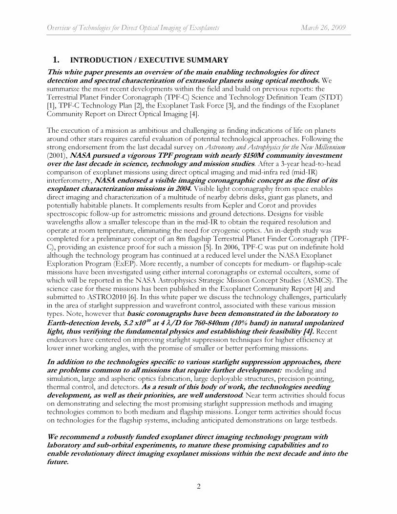
1. INTRODUCTION / EXECUTIVE SUMMARY
This white paper presents an overview of the main enabling technologies for direct detection and spectral characterization of extrasolar planets using optical methods. We summarize the most recent developments within the field and build on previous reports: the Terrestrial Planet Finder Coronagraph (TPF-C) Science and Technology Definition Team (STDT) [1], TPF-C Technology Plan [2], the Exoplanet Task Force [3], and the findings of the Exoplanet Community Report on Direct Optical Imaging [4]. The execution of a mission as ambitious and challenging as finding indications of life on planets around other stars requires careful evaluation of potential technological approaches. Following the strong endorsement from the last decadal survey on Astronomy and Astrophysics for the New Millennium (2001), NASA pursued a vigorous TPF program with nearly $150M community investment over the last decade in science, technology and mission studies. After a 3-year head-to-head comparison of exoplanet missions using direct optical imaging and mid-infra red (mid-IR) interferometry, NASA endorsed a visible imaging coronagraphic concept as the first of its exoplanet characterization missions in 2004. Visible light coronagraphy from space enables direct imaging and characterization of a multitude of nearby debris disks, giant gas planets, and potentially habitable planets. It complements results from Kepler and Corot and provides spectroscopic follow-up for astrometric missions and ground detections. Designs for visible wavelengths allow a smaller telescope than in the mid-IR to obtain the required resolution and operate at room temperature, eliminating the need for cryogenic optics. An in-depth study was completed for a preliminary concept of an 8m flagship Terrestrial Planet Finder Coronagraph (TPF-C), providing an existence proof for such a mission [5]. In 2006, TPF-C was put on indefinite hold although the technology program has continued at a reduced level under the NASA Exoplanet Exploration Program (ExEP). More recently, a number of concepts for medium- or flagship-scale missions have been investigated using either internal coronagraphs or external occulters, some of which will be reported in the NASA Astrophysics Strategic Mission Concept Studies (ASMCS). The science case for these missions has been published in the Exoplanet Community Report [4] and submitted to ASTRO2010 [6]. In this white paper we discuss the technology challenges, particularly in the area of starlight suppression and wavefront control, associated with these various mission types. Note, however that basic coronagraphs have been demonstrated in the laboratory to Earth-detection levels, 5.2 x10⁻¹⁰ at 4 λ/D for 760-840nm (10% band) in natural unpolarized light, thus verifying the fundamental physics and establishing their feasibility [4]. Recent endeavors have centered on improving starlight suppression techniques for higher efficiency at lower inner working angles, with the promise of smaller or better performing missions.
In addition to the technologies specific to various starlight suppression approaches, there are problems common to all missions that require further development: modeling and simulation, large and aspheric optics fabrication, large deployable structures, precision pointing, thermal control, and detectors. As a result of this body of work, the technologies needing development, as well as their priorities, are well understood. Near term activities should focus on demonstrating and selecting the most promising starlight suppression methods and imaging technologies common to both medium and flagship missions. Longer term activities should focus on technologies for the flagship systems, including anticipated demonstrations on large testbeds. We recommend a robustly funded exoplanet direct imaging technology program with laboratory and sub-orbital experiments, to mature these promising capabilities and to enable revolutionary direct imaging exoplanet missions within the next decade and into the future.

Overview of Technologies for Direct Optical Imaging of Exoplanets March 26, 2009
3
2. ARCHITECTURE SCALES FOR DIRECT IMAGING MISSIONS
2.1 SUBORBITAL ENVIRONMENTS Suborbital experiments with sounding rockets or balloons offer interesting possibilities for starlight suppression technology demonstration and risk reduction, in order to help advance laboratory concepts to flight status. They would also be able to make observations of a few exoplanets, planet forming regions and zodiacal disk. 2.2 MEDIUM-SIZE MISSIONS 2.2.1 Internal Coronagraphs The first relevant scale for space imaging missions is the “medium mission” scale (<$800M), where it becomes reasonable to consider 1.5m class telescopes and very high contrast coronagraphic instruments (10-9-10-10) (mission concepts: PECO, ACCESS, EPIC). In 1997, NASA rated an optimized coronagraphic instrument proposed for Hubble as "selectable." (CODEX). This mission class allows measurements of exozodiacal disk levels, characterization of mature giant planets and planetary systems known from radial velocity, and possibly imaging a few Super Earths (twice the radius of Earths) around nearby stars. Given the small telescope diameter, the inner working angle (IWA) is a critical parameter for this mission scale. The most promising approach enables IWA in the 2-3 λ/D range, however at the cost of tighter pointing and stability requirements. It is important to note that internal coronagraph technology demonstration is predominantly driven by contrast and bandwidth for Earth-detection, and is independent of mission size, so that considering missions in this scale is solely driven by constraints in the NASA budget. 2.2.2 External Occulters For external occulters this cost range requires identifying an existing host telescope. Possible telescope options include JDEM and JWST in conjunction with occulters between 30m and 70m in diameter. Using an existing telescope adds complexity to the star-occulter alignment scheme because the navigation burden relies on the starshade spacecraft only. 2.3 FLAGSHIP-SIZE MISSIONS 2.3.1 Internal Coronagraphs The next size scale is the "flagship" class mission (>$1B) with monolithic telescope diameter ≥ 4m. While this introduces new engineering challenges associated with large mirrors in space, it opens up the possibility of characterizing a large number of terrestrial planets in the habitable zone of the parent star. The telescope is a conventional diffraction limited design, and does not require mirror surface quality beyond the state of the art, contrary to some reports. The major challenges reside in fabricating a large off-axis mirror and maintaining the required opto-mechanical stability. An 8 m x 3.5 m elliptical monolithic primary mirror is the largest size that can be launched with an existing Delta IV heavy rocket (e.g., TPF-C FB1); and an 8m circular or 16m segmented mirror would be feasible with a future planned Ares V (e.g., ATLAST). Because of diffraction issues, internal coronagraph concepts utilizing segmented primaries have yet to be designed to the required contrast. The original Terrestrial Planet Finder Coronagraph (TPF-C) study from 2005 proved the feasibility of an 8 m flagship coronagraph using existing launch vehicles [5]. Emerging concepts with IWAs close to 2λ/D would possibly enable a 4m system with almost the same exoplanet finding capability as TPF-C (IWA= 4λ/D), but at a significant cost savings, reducing complexity of deployments, verification and flight operations.
Yet another alternative to a large telescope is a dilute aperture telescope which uses multiple smaller telescopes to achieve an inner working angle equal to that of a large contiguous aperture telescope. Such an approach shares many of the properties of a segmented telescope, and could possibly be achieved through a nulling coronagraphic architecture (e.g., DaVINCI).

Overview of Technologies for Direct Optical Imaging of Exoplanets March 26, 2009
4
2.3.2 External Occulters External occulters (a.k.a. TPF-O) are aligned between a target star and the telescope, forming a deep broadband shadow around the telescope that eliminates starlight. Mission concepts include NWO, THEIA, ATLAST, JWST add on. Since no starlight enters, the need for mid-spatial frequency, high-contrast wavefront control is eliminated. Therefore the telescope can be on-axis or segmented with conventional diffraction-limited quality and the coronagraph instrument complexity is removed. Occulters enable very small IWAs over very large bandpasses, and the field of view is not limited by an Outer Working Angle (OWA). These advantages come at the cost of a second, formation flying spacecraft with a large deployable screen and several other engineering challenges discussed in the next section.
A 4m telescope using an external occulter to achieve high contrast at an IWA of 72 mas requires a shade of >40 m tip-to-tip flown at roughly 55,000 km from the telescope. Such a system can achieve the needed contrast over a broad band (0.4-0.7µm) even with a segmented telescope. However, the size of the occulter scales with the size of the telescope, and in the visible a 16 m segmented telescope would require an 85m starshade flying at 115000km distance (e.g., ATLAST).
Fuel use for slew and, to a much lesser extent, for station keeping, limits the number of independent observations by the occulter to ~ 100 over a 5-yr mission. The occulter requires several days to weeks to move between stars, dependent on their separation. This time can be used for general Astrophysics programs.
To keep scattered sunlight to an acceptable level, the edges of the occulter have a radius of curvature < 100 µm. The occulter can appear as close as 45 degrees to the sun assuming appropriate telescope baffling. When these conditions are met, scattered sunlight will not limit the effectiveness of external occulter observations.
3. TECHNOLOGY
We discuss the readiness of enabling direct exoplanet imaging technologies, and propose maturation programs. Past TPF activities and ongoing mission concept studies provide significant inputs for this assessment. 3.1 STARLIGHT SUPPRESSION For internal coronagraphs starlight suppression is provided through a system comprised of coronagraphic masks, and/or beam shaping optics, deformable mirrors (DM) and wavefront sensing and control algorithms. It is important to note that these coronagraph instrument technologies and their required performance goals remain essentially the same for any of the mission scales. In external occulters starlight suppression is achieved by tailoring the shape and size of the occulter to the distance and size of the telescope. 3.1.1 Internal Coronagraphs Concepts: A large number of coronagraphic concepts have been developed in the past few years (e.g. STDT [1]). They can be organized as Pupil Apodization, either using shaped pupils, amplitude or phase apodization, or pupil remapping; Lyot Coronagraphs, using a series of focal and pupil masks (amplitude or phase); and Interferometric Coronagraphs, using amplitude division interferometry to create a null. To date Band-limited Lyot coronagraphs (BLC) are the most mature and have demonstrated the contrasts and bandwidth required for earth detections (Figure 1). Other
Figure 1 Contrast in 760-840 nm (10%) bandwidth in HCIT (Moody, et al., 2008) [4] [4].
Overview of Technologies for Direct Optical Imaging of Exoplanets March 26, 2009
5
approaches are currently being tested as summarized in Figure 3. Funds are needed to bring the most promising concepts to the same level of maturity. Wavefront control: Internal coronagraphs need precision wavefront control (WFC) to remove spurious starlight speckles, and create a dark hole of sufficient contrast depth to extract the image of the target planet. This is achieved in broadband light by controlling pairs of DMs to correct phase and amplitude imperfections and propagations effects. Algorithms exist to efficiently estimate the electric field and control the DM surface shape. Overall the problem of control with a perfect estimate has solid theoretical foundations, but additional development is needed to generalize the approach to 2 DMs, improve convergence speed, reduce sensitivity to sensing errors and variations in the system and improve robustness against partial DM failures.
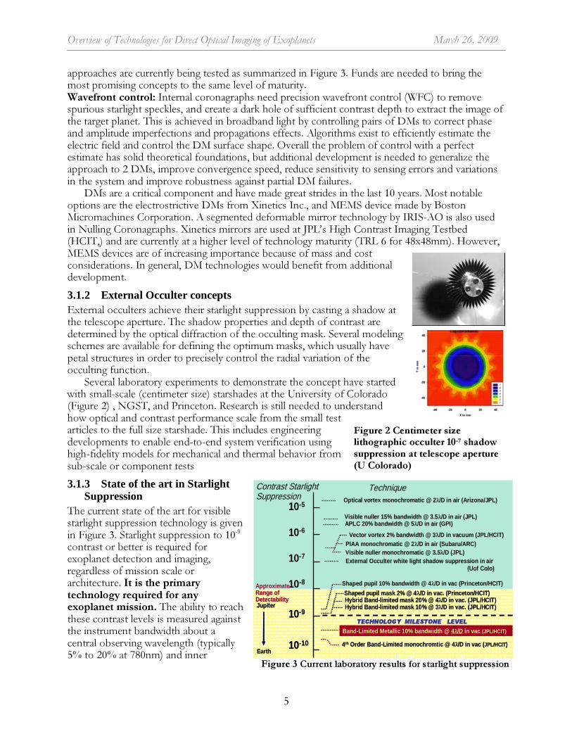
DMs are a critical component and have made great strides in the last 10 years. Most notable options are the electrostrictive DMs from Xinetics Inc., and MEMS device made by Boston Micromachines Corporation. A segmented deformable mirror technology by IRIS-AO is also used in Nulling Coronagraphs. Xinetics mirrors are used at JPL’s High Contrast Imaging Testbed (HCIT,) and are currently at a higher level of technology maturity (TRL 6 for 48x48mm). However, MEMS devices are of increasing importance because of mass and cost considerations. In general, DM technologies would benefit from additional development. 3.1.2 External Occulter concepts External occulters achieve their starlight suppression by casting a shadow at the telescope aperture. The shadow properties and depth of contrast are determined by the optical diffraction of the occulting mask. Several modeling schemes are available for defining the optimum masks, which usually have petal structures in order to precisely control the radial variation of the occulting function.
Several laboratory experiments to demonstrate the concept have started with small-scale (centimeter size) starshades at the University of Colorado (Figure 2) , NGST, and Princeton. Research is still needed to understand how optical and contrast performance scale from the small test articles to the full size starshade. This includes engineering developments to enable end-to-end system verification using high-fidelity models for mechanical and thermal behavior from sub-scale or component tests 3.1.3 State of the art in Starlight
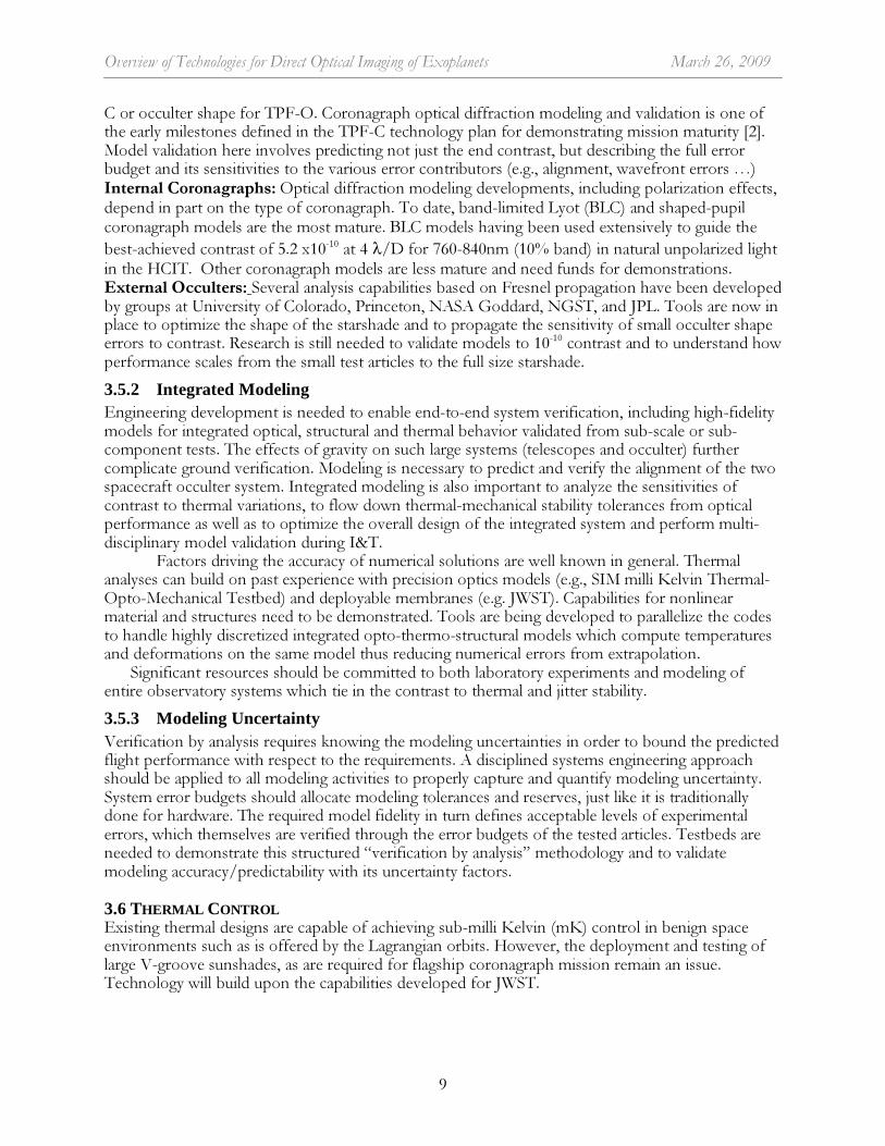
Suppression The current state of the art for visible starlight suppression technology is given in Figure 3. Starlight suppression to 10-9 contrast or better is required for exoplanet detection and imaging, regardless of mission scale or architecture. It is the primary technology required for any exoplanet mission. The ability to reach these contrast levels is measured against the instrument bandwidth about a central observing wavelength (typically 5% to 20% at 780nm) and inner
Figure 2 Centimeter size lithographic occulter 10-7 shadow suppression at telescope aperture (U Colorado)
Figure 3 Current laboratory results for starlight suppression
10-5
10-6
10-7
10-8
10-9
10-10
External Occulter white light shadow suppression in air(Uof Colo)
Visible nuller monochromatic @ 3.5λ/D (JPL)PIAA monochromatic @ 2λ/D in air (Subaru/ARC)
Visible nuller 15% bandwidth @ 3.5λ/D in air (JPL)
Contrast Starlight Suppression Optical vortex monochromatic @ 2λ/D in air (Arizona/JPL)
Shaped pupil mask 2% @ 4λ/D in vac. (Princeton/HCIT)
Shaped pupil 10% bandwidth @ 4λ/D in vac (Princeton/HCIT)
Technique
Jupiter
Earth
Band-Limited Metallic 10% bandwidth @ 4λ/D in vac (JPL/HCIT)
Approximate Range of Detectability
4th Order Band-Limited monochromtic @ 4λ/D in vac (JPL/HCIT)
TECHNOLOGY MILESTONE LEVEL
Vector vortex 2% bandwidth @ 3λ/D in vacuum (JPL/HCIT)
Hybrid Band-limited mask 20% @ 4λ/D in vac. (JPL/HCIT)Hybrid Band-limited mask 10% @ 3λ/D in vac. (JPL/HCIT)
APLC 20% bandwidth @ 5λ/D in air (GPI)

Overview of Technologies for Direct Optical Imaging of Exoplanets March 26, 2009
6
working angle (IWA) (typically 2λ/D to 4λ/D). Designs working at wider bandwidths and smaller IWAs are highly desired as they can significantly improve the mission efficiency and reduce the telescope size, hence mission cost, albeit at the expense of tighter stability requirements. To date a Band-Limited metallic Lyot coronagraph has been demonstrated to milestone levels (Figure 1 & 3), and independently certified, thus establishing an existence proof of an approach for direct optical imaging of Earths. Future technology funds should be applied to testing and maturing new techniques with lower IWAs in a precision infrastructure such as HCIT. 3.2 OPTICS AND MIRROR TECHNOLOGIES
3.2.1 Coronagraph optics There are a number of technology options for internal coronagraph masks. They include: Amplitude Masks: (Band-limited Lyot or pupil apodization). In most cases a gray amplitude transmittance is needed, and the main difficulty is to control the amplitude and induced phase shift in broadband. Materials and dielectric combinations can be tailored to minimize the dispersion. Binary Masks (shaped pupils and Lyot stops). The common technique used for these masks is deep reactive ion etching (DRIE). Currently, the features can be manufactured reliably to the required tolerance of about 5 µm through a 50 µm substrate, sufficient for a 10-10 contrast. Phase-Amplitude Apodization: aspheric surfaces are needed for the Phase Induced Amplitude Apodization (PIAA) coronagraph. Prototype optics have been manufactured using aspheric diamond turning of both lenses and mirrors, and are currently being tested in the JPL HCIT. Phase Masks: (vector or optical vortex). Examples of manufacturing processes include half-wave plates, liquid crystal polymer spin deposition, and electron beam lithographic technique. Visible Nullers: consists of two cascading shearing, nulling interferometers creating a 4th order null. Some require an array of lenslets matched to an array of single mode spatial fiber at the Lyot plane.
Pro and cons of these methods are summarized in Table 1. Most are at TRL 4 or lower and their current state of starlight suppression demonstration is shown in Figure 3. Table 1 Relative merits of the internal coronagraph options Property Band-Limited Lyot Shaped Pupil PIAA Vortex Visible Nuller
Throughput at 2 λ/D 27% 0 50% 50% 17%
Throughput at 4 λ/D 45% 20% 90% 90% 45%Instantaneous Discovery Space
>90% 40-60% > 90% >90% <50%
Implementation Complexity
Moderate Moderate High Moderate High
Manufacturing Tolerances
Moderate Low High Moderate Moderate
Pros • Good aberration rejection
• Simple• Well Understood• Good aberration rejection
• Very high throughput• Smallest IWA• Broadband
• High throughput• Path to broadband• Good aberration rejection
• Reduced sensitivity to high spatial frequency errors• Can theoretically be used w/ segmented telescope
Cons• Moderate IWA & throughput• Image plane glass
• Low throughput• Larger spot size
• Challenging manufacturing• Tighter system stability at low IWA
• Image plane glass
• High complexity• Bandwidth• Modest IWA & throughput• Limited search space
3.2.2 Mirrors and telescope Off-axis and aspheric mirrors: Off-axis mirrors are required for most internal coronagraphs because of sensitivity to obscurations, while on-axis architectures which are easier to fabricate suffice for external occulters. The most significant challenge for any telescope is in the fabrication and testing of the primary mirror, especially when it is > 4m. Several fabrication options exist, as by fusing smaller hexagonal segments together, although most require further demonstration. Some concepts, such as the PIAA, call for small (~10 cm) but highly aspheric optics. Tinsley (under contract to NASA ARC) has already delivered a set that will be tested shortly in the HCIT.
Overview of Technologies for Direct Optical Imaging of Exoplanets March 26, 2009
7
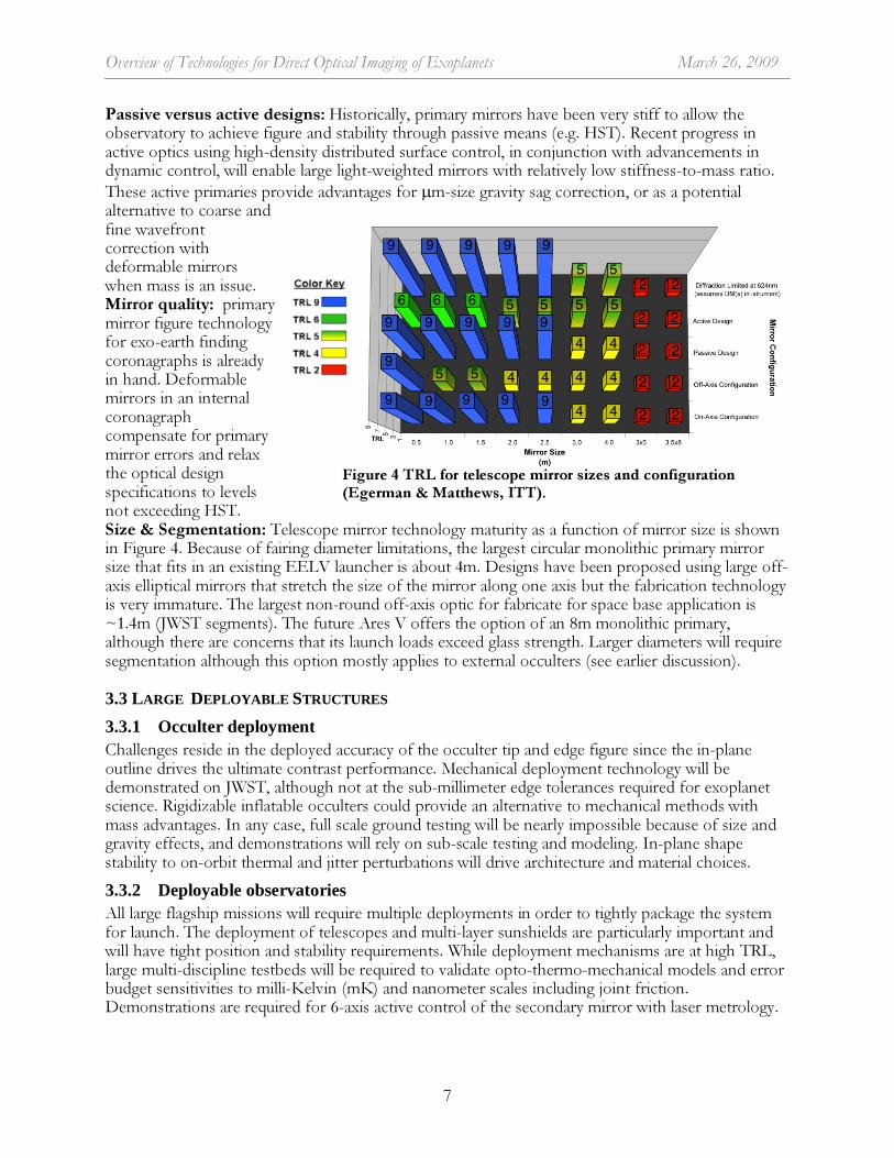
Passive versus active designs: Historically, primary mirrors have been very stiff to allow the observatory to achieve figure and stability through passive means (e.g. HST). Recent progress in active optics using high-density distributed surface control, in conjunction with advancements in dynamic control, will enable large light-weighted mirrors with relatively low stiffness-to-mass ratio. These active primaries provide advantages for µm-size gravity sag correction, or as a potential alternative to coarse and fine wavefront correction with deformable mirrors when mass is an issue. Mirror quality: primary mirror figure technology for exo-earth finding coronagraphs is already in hand. Deformable mirrors in an internal coronagraph compensate for primary mirror errors and relax the optical design specifications to levels not exceeding HST. Size & Segmentation: Telescope mirror technology maturity as a function of mirror size is shown in Figure 4. Because of fairing diameter limitations, the largest circular monolithic primary mirror size that fits in an existing EELV launcher is about 4m. Designs have been proposed using large off-axis elliptical mirrors that stretch the size of the mirror along one axis but the fabrication technology is very immature. The largest non-round off-axis optic for fabricate for space base application is ~1.4m (JWST segments). The future Ares V offers the option of an 8m monolithic primary, although there are concerns that its launch loads exceed glass strength. Larger diameters will require segmentation although this option mostly applies to external occulters (see earlier discussion). 3.3 LARGE DEPLOYABLE STRUCTURES
3.3.1 Occulter deployment Challenges reside in the deployed accuracy of the occulter tip and edge figure since the in-plane outline drives the ultimate contrast performance. Mechanical deployment technology will be demonstrated on JWST, although not at the sub-millimeter edge tolerances required for exoplanet science. Rigidizable inflatable occulters could provide an alternative to mechanical methods with mass advantages. In any case, full scale ground testing will be nearly impossible because of size and gravity effects, and demonstrations will rely on sub-scale testing and modeling. In-plane shape stability to on-orbit thermal and jitter perturbations will drive architecture and material choices. 3.3.2 Deployable observatories All large flagship missions will require multiple deployments in order to tightly package the system for launch. The deployment of telescopes and multi-layer sunshields are particularly important and will have tight position and stability requirements. While deployment mechanisms are at high TRL, large multi-discipline testbeds will be required to validate opto-thermo-mechanical models and error budget sensitivities to milli-Kelvin (mK) and nanometer scales including joint friction. Demonstrations are required for 6-axis active control of the secondary mirror with laser metrology.
Figure 4 TRL for telescope mirror sizes and configuration (Egerman & Matthews, ITT).
Overview of Technologies for Direct Optical Imaging of Exoplanets March 26, 2009
8
3.4 POINTING
3.4.1 Formation control for occulter The starshade must be aligned on the star for the full observation, to within a few milli arcseconds (mas) or < 1 m from the telescope-star line of site. Examples of occulter acquisition and alignment maintenance options include a three-beacon concept on the starshade (R. Lyon, 2007), or an astrometric sensor and in-shadow sensors (Noecker, 2007). Some approaches do not require sensors and beacons on both the telescope and occulter, but make the alignment even more challenging for occulter concepts that propose the use of existing telescopes. Included in the design of the control system are thruster firings, reaction wheel forces, micro-meteroid impacts, thermal deformations, solar wind, solar pressure and gravity gradient. System verification can only be performed by analysis through models validated on sub-scale articles under gravity loads. 3.4.2 Vibration isolation and Damping Technology is needed to hold jitter to the required tight mas pointing tolerances for internal coronagraphs or to minimize in-plane dynamic response of the large starshade. Excitation sources are reaction wheels or impulsive thruster firings. Two-stage passive isolation systems: an existing and proven technology that has been shown by analysis to be sufficient for internal coronagraphs operating under somewhat relaxed jitter requirements (~10 mas) assuming an active secondary mirror participating in the pointing control.. Two-stage isolation systems typically have a roll-off at about 2 Hz, making them unsuitable for occulters which have system modes well below 1 Hz depending on size. Active vibration isolation: required when pointing tolerances are tight and margin is needed. Options include hard-mounted active hexapods which are already at TRL 6 or magnetic devices such as the Disturbance-Free Payload (DFP) in which payload and spacecraft are separate bodies that fly in close-proximity formation, allowing precision payload control and simultaneous isolation from spacecraft disturbances. The DFP offers the most effective capability but it is less mature. To date, a testbed has demonstrated broadband isolation in excess of 68 dB (a factor of 2,512). Damping: either passive or active damping is an alternate way of ensuring low dynamic response to on-board excitations. Damping will primarily benefit external occulters and is a high TRL technology. While some level of system damping is expected from deployable joint friction, it will be impossible to measure it on the ground because of gravity and induced air damping of large membranes. Engineering the desired amount of damping into the design with elastomeric materials or active struts may be required. 3.5 MODELING AND VALIDATION Modeling is a critical lifecycle technology for any of the exoplanet missions, the degree of which is dependent on the scale of the mission. For a large mission, especially, end-to-end testing will be limited if not impossible in the case of the occulters, and verification will be performed mainly through analysis. Modeling is also one of the 3 anchors of technology development: error budgets that establish performance levels from flight design, testbed demonstrations that measure performance and finally model/error budget validation that scales testbed results to flight. As recommended by the Exoplanet Task Force (ExoPTF), a blue-ribbon panel should evaluate the status of these models and demonstrations before any mission is allowed to proceed into development. 3.5.1 Optical diffraction and polarization modeling with laboratory verification From the very beginning stages of the project, models need to adequately represent the physics in order to define the error budgets and then flow down requirements to lower levels of design. This involves first and foremost the ability to efficiently model optical diffraction and polarization physics, and to model the various components: deformable mirrors and wavefront control for TPF-
Overview of Technologies for Direct Optical Imaging of Exoplanets March 26, 2009
9
C or occulter shape for TPF-O. Coronagraph optical diffraction modeling and validation is one of the early milestones defined in the TPF-C technology plan for demonstrating mission maturity [2]. Model validation here involves predicting not just the end contrast, but describing the full error budget and its sensitivities to the various error contributors (e.g., alignment, wavefront errors …) Internal Coronagraphs: Optical diffraction modeling developments, including polarization effects, depend in part on the type of coronagraph. To date, band-limited Lyot (BLC) and shaped-pupil coronagraph models are the most mature. BLC models having been used extensively to guide the best-achieved contrast of 5.2 x10⁻¹⁰ at 4 λ/D for 760-840nm (10% band) in natural unpolarized light in the HCIT. Other coronagraph models are less mature and need funds for demonstrations. External Occulters: Several analysis capabilities based on Fresnel propagation have been developed by groups at University of Colorado, Princeton, NASA Goddard, NGST, and JPL. Tools are now in place to optimize the shape of the starshade and to propagate the sensitivity of small occulter shape errors to contrast. Research is still needed to validate models to 10-10 contrast and to understand how performance scales from the small test articles to the full size starshade. 3.5.2 Integrated Modeling Engineering development is needed to enable end-to-end system verification, including high-fidelity models for integrated optical, structural and thermal behavior validated from sub-scale or sub-component tests. The effects of gravity on such large systems (telescopes and occulter) further complicate ground verification. Modeling is necessary to predict and verify the alignment of the two spacecraft occulter system. Integrated modeling is also important to analyze the sensitivities of contrast to thermal variations, to flow down thermal-mechanical stability tolerances from optical performance as well as to optimize the overall design of the integrated system and perform multi-disciplinary model validation during I&T.
Factors driving the accuracy of numerical solutions are well known in general. Thermal analyses can build on past experience with precision optics models (e.g., SIM milli Kelvin Thermal-Opto-Mechanical Testbed) and deployable membranes (e.g. JWST). Capabilities for nonlinear material and structures need to be demonstrated. Tools are being developed to parallelize the codes to handle highly discretized integrated opto-thermo-structural models which compute temperatures and deformations on the same model thus reducing numerical errors from extrapolation.
Significant resources should be committed to both laboratory experiments and modeling of entire observatory systems which tie in the contrast to thermal and jitter stability. 3.5.3 Modeling Uncertainty Verification by analysis requires knowing the modeling uncertainties in order to bound the predicted flight performance with respect to the requirements. A disciplined systems engineering approach should be applied to all modeling activities to properly capture and quantify modeling uncertainty. System error budgets should allocate modeling tolerances and reserves, just like it is traditionally done for hardware. The required model fidelity in turn defines acceptable levels of experimental errors, which themselves are verified through the error budgets of the tested articles. Testbeds are needed to demonstrate this structured “verification by analysis” methodology and to validate modeling accuracy/predictability with its uncertainty factors. 3.6 THERMAL CONTROL Existing thermal designs are capable of achieving sub-milli Kelvin (mK) control in benign space environments such as is offered by the Lagrangian orbits. However, the deployment and testing of large V-groove sunshades, as are required for flagship coronagraph mission remain an issue. Technology will build upon the capabilities developed for JWST.

Overview of Technologies for Direct Optical Imaging of Exoplanets March 26, 2009
10
3.7 DETECTORS Electron multiplying CCDs (EMCDD) having high quantum efficiency (QE) in the optical and near-IR (0.4-1.1 µm) with low dark current and read noise will be a critical component of any exoplanet direct imaging mission The technology for n-channel EMCCDs in the 0.4-0.8 µm region is already well in hand, with high-QE photon counting detectors commercially available (e.g. E2V’s L3Vision series CCDs) sufficient for medium scale missions. We recommend the continued development to enhance the QE in the near-IR by bringing photon-counting capabilities to p-channel CCDs.
4. TECHNOLOGY ASSESSMENT SUMMARY
Figure 5 illustrates how mission architecture impacts technical risk and readiness as an indicator of technology development need, irrespective of the merit of the science. The first column lists the main technologies of interest, with demonstration of the starlight suppression physics to flight levels being the most important. The subsequent columns correspond to representative concepts of various sizes, and are not intended to be an exhaustive list of proposed missions. Numerical values, where appropriate, represent performance goals for flight which can vary with mission scale.
5. PROPOSED MATURATION PROGRAM
5.1 TECHNOLOGY DEVELOPMENT While specific technology development plans are tailored for each individual direct exoplanet imaging mission concept (e.g., TPF-C [2]) we present a broader view covering the overall direct optical imaging missions.
In the very near-term there should be a competed effort to downselect the most promising starlight suppression approach(es) with a path to a TRL 6 demonstration in time for a medium and/or large mission. Note that for internal coronagraph starlight suppression architectures are essentially independent of mission size and can be demonstrated as a full scale system.
In parallel we advocate a long term community investment in the common technologies for large scale exoplanet missions, starting with modeling and large deployable structures as the priorities. This investment is expected to grow substantially once the starlight suppression options have been demonstrated and down-selected as to accommodate funding for the large testbeds
Internal Coronagraph
1.5m Telescope
@ 4λ/D
1.5m Telescope
@ 2λ/D
4m Telescope
@ 4λ/D
8m Telescope
@ 4λ/D
16m Active Segmented
@ 4λ/D
Raw Contrast at IWA
1e-10 @ 10-20%
bandwidth
1e-10 @ 10-20%
bandwidth
1e-10 @ 10-20%
bandwidth
1e-10 @ 10-20%
bandwidth
1e-10 @ 10-20%
bandwidth
DMsWFSC
Algorithms
Masks/Optics
Telescope & Primary Mirror Technology
Optical
Integrated: Opto-Thermal Mechanical
Telescope Pointing 5-10 mas < 5 mas 5-10 mas 10 masThermal Stability <mK ~0.1mK <mK 0.5 mK
DetectorsSystem Verification &
Validation
Mo
del
ing
T
oo
ls &
V
alid
atio
n
Co
ron
agra
ph
In
stru
men
t T
ech
no
log
ies
External Coronagraph
1.1 m Telescope
w/15 m Starshade
Existing Telescope
w/ 50m Starshade
4m Telescope
w/ 50m Starshade
Occulter Raw Contrast 1e
-8 @ 100%
bandwidth
1e-10
@ 100%
bandwidth
1e-10
@ 100%
bandwidthPetal Position
Errors 0.5 m 0.1 m 0.1 m
Shape Error 5 mm ~10µm ~10µmEdge Effects ~1 cm <1 mm <1 mm
Optical & Scaling
Integrated Opto-Thermal Mechanical
±1 m <1 m <1 m~5 K ~5 K ~ 5 K
Occ
ult
er
Dep
loym
ent
& T
ole
ran
ce
Occulter Thermal Control
DetectorsSystem Verification &
Validation
Telescope & Mirror Technology
Formation Flying
Mo
del
ing
T
oo
ls &
V
alid
atio
n
Figure 5 Summary of technologies for internal and external coronagraphs as a function of size. Columns correspond to representative mission concepts and scales. Green represents mature/low risk technologies, red are immature/high risk technologies, yellow is in between.
Overview of Technologies for Direct Optical Imaging of Exoplanets March 26, 2009
11
specifically designed for targeted flagship missions. We also highly recommend the use of near-term sub-orbital or space station flight opportunities for system demonstrations of promising starlight suppression methods. Such demonstrations would also validate multi-disciplinary integrated models. The sub-orbital platform could be re-used to evaluate several exoplanet imaging approaches.
While we have not performed an in-depth cost estimate for the community’s technology development activities, from the review of on-going work we anticipate that funding for a starlight suppression downselect and demonstration to TRL 6 will be approximately in the $50M range total over the next 3 years or so, supporting a near-term medium mission start. A proper demonstration of the larger scale technologies may well exceed $200M especially if multiple mission options are pursued. Sub-orbital demonstrations have been roughly costed at $20M, which assumes a mature coronagraph design and includes the cost of a meter-class telescope and post-flight data analysis. 5.2 FACILITIES AND INFRASTRUCTURE The proposed technology development will require specialized facilities and infrastructure, some of which already exists but require upgrades as the technologies progress towards system configurations and TRL 6 demonstrations. We plan to make extensive use of existing community testbeds, such as Princeton, Subaru, NASA (JPL, Ames, Goddard) and University of Colorado for exploratory investigations of starlight suppression in air. These “skunk works” will enable rapid prototyping and coordinated community efforts to investigate architectures and software.
Once sufficiently matured, the technology can then be tested within the precision HCIT facility. Funded under past NASA TPF activities and JPL internal funds, the HCIT demonstrates starlight suppression methods and hardware in a flight-like environment within which various concepts for coronagraphs, wavefront sensing, and nulling algorithms can be tested as a system. The HCIT has been shown to achieve close to the 10-10 level contrast necessary for Earth-like planet imaging. Overall, the Exoplanet Exploration Technology Program (ExEP) has provided infrastructure support to 6 of the 7 selected ASMCS exoplanet imaging studies, by request from the Principal Investigators (PIs). Besides the HCIT, other TPF-derived assets at JPL helped mature the ASMCS concepts in the areas of WFS&C, mask fabrication, modeling and error budgeting tools.
We recommend sufficient funding to continue this successful and demonstrated synergy amongst the various community collaborators and infrastructure.
We also anticipate that substantial infrastructure investments will be required for the large scale multi-disciplinary testbeds imposed by the flagship missions (Coronagraphs and Occulters), although re-use of existing facilities within the NASA and industry partners community is expected.
6. REFERENCES
[1] Levine, Shaklan, Kasting, “Science and Technology Definition Team Report “, JPL Report D-34923 (2006) http://planetquest.jpl.nasa.gov/TPF/STDT_Report_Final_Ex2FF86A.pdf [2] Dooley, Lawson, “TPF-C Technology Plan”, Jet Propulsion Lab, April 2005 http://planetquest.jpl.nasa.gov/TPF/TPF-CTechPlan.pdf [3] Lunine et al., “Exoplanet Task Force Report”, 2008 http://www.nsf.gov/mps/ast/aaac/exoplanet_task_force/reports/exoptf_final_report.pdf [4] Lawson, Traub, Unwin, et al. “Exoplanet Community report”, Direct Imaging Chapter3, http://exep.jpl.nasa.gov/exep_exfCommunityReport.cfm [5] Ford et al., “TPF-C Flight Baseline Report”, 2005, http://planetquest.jpl.nasa.gov/documents/TPFC-FB1_Report.pdf [6] Kasting, Traub et al. “Exoplanet Characterization and the Search for Life”, submission to ASTRO 2010 Science White Paper, 2009.
ACKNOWLEDGEMENTS The work described in this report was performed at the Jet Propulsion Laboratory, California Institute of Technology, under a contract with the National Aeronautics and Space Administration.
© 2009. All rights reserved.