Oscillating Currents
55
Oscillating Currents • Ch.30: Induced E Fields: Faraday’s Law • Ch.30: RL Circuits • Ch.31: Oscillations and AC Circuits
-
Upload
khangminh22 -
Category
Documents
-
view
0 -
download
0
Transcript of Oscillating Currents

Oscillating Currents
• Ch.30: Induced E Fields: Faraday’s Law
• Ch.30: RL Circuits
• Ch.31: Oscillations and AC Circuits

Review: Inductance
• If the current through a coil of wire changes,
there is an induced emf proportional to the rate of
change of the current.
•Define the proportionality constant to be the
inductance L:
dt
diL−−−−====εεεε
• SI unit of inductance is the henry (H).

LC Circuit Oscillations
Suppose we try to discharge a capacitor, using an
inductor instead of a resistor:
At time t=0 the capacitor
has maximum charge and
the current is zero.
Later, current is increasing
and capacitor’s charge is
decreasing

Oscillations (cont’d)
In fact, q = 0 means i = maximum!
What happens when q=0?
Does I=0 also?
No, because inductor does
not allow sudden changes.
So now, charge starts to build up on C
again, but in the opposite direction!

Textbook Figure 31-1
Energy is moving back and forth between C,L
CqUULiUU ECBL /22
2
1
2
1 ================

Textbook Figure 31-1

Mechanical Analogy
• Looks like SHM (Ch. 15) Mass on spring.
• Variable q is like x, distortion of spring.
• Then i=dq/dt, like v=dx/dt, velocity of mass.
By analogy with SHM, we can guess that
)cos( tQq ωωωω====
)sin( tQdt
dqi ωωωωωωωω−−−−========

Look at Guessed Solution
)cos( tQq ωωωω==== )sin( tQdt
dqi ωωωωωωωω−−−−========
q
i

Mathematical description of
oscillations
Note essential terminology:
amplitude, phase, frequency, period,
angular frequency. You MUST
know what these words mean! If
necessary review Chapters 10, 15.

Get Equation by Loop Rule
If we go with the
current as shown,
the loop rule gives:
0====−−−−−−−−dt
diL
C
q
Now replace i by
dq/dt to get: qLCdt
qd
−−−−====1
2
2

Guess Satisfies Equation!
)cos( tQq ωωωω====q
LCdt
qd
−−−−====1
2
2Start with
qtQdt
qd 22
2
2
)cos( ωωωωωωωωωωωω −−−−====−−−−====
so that )sin( tQdt
dqωωωωωωωω−−−−====
And taking one more derivative gives us
So the solution is correct, provided our angular
frequency satisfies
====LC
12ωωωω

LC Circuit Example
Given an inductor with L = 8.0 mH and a
capacitor with C = 2.0 nF, having initial charge
q(0) = 50 nC and initial current i(0) = 0.
(a) What is the frequency of oscillations (in Hz)?
(b) What is the maximum current in the inductor?
(c) What is the capacitor’s charge at t = 30 µµµµs?

Example: Part (a)
L = 8 mH, C = 2 nF, q(0) = 50 nC, i(0) = 0
(a) What is the frequency of the oscillations?
s
rad
LC
5
93105.2
102108
11××××====
××××××××××××========
−−−−−−−−ωωωω
kHzcyclerad
sradf 40104
/28.6
/105.2
2
45
====××××====××××
========ππππωωωω

Example: Part (b)
( L = 8 mH, C = 2 nF, q(0) = 50 nC, i(0) = 0 )
(b) What is the maximum current?
JC
QE
7
9
292
1025.6100.22
)1050(
2
−−−−−−−−
−−−−
××××====××××××××
××××========
L
EIsoLIEBut
222
2
1 ========
mAL
EISo 5.12
108
1025.6223
7
====××××
××××××××======== −−−−
−−−−

Example: Part (c)
( L = 8 mH, C = 2 nF, q(0) = 50 nC, i(0) = 0 )
(c) What is the charge at t = 30 µµµµs?
nC
nC
radnC
nC
tQtq
17347.050
)430cos()50(
)5.7cos()50(
)1030105.2cos()50(
)cos()(
65
====××××====
°°°°====
====
××××××××××××====
====−−−−
ωωωω

AC Voltage Sources
• For an AC circuit, we need an
alternating emf, or AC power
supply.
• This is characterized by its
amplitude and its frequency.
tm ωεε sin=
amplitude angular frequency

Notation for oscillating functions
tVv ωωωωsin==== tIi ωωωωsin====
Note that the textbook uses lower-case
letters for oscillating time-dependent
voltages and currents, with upper-case
letters for the corresponding amplitudes.

AC Currents and Voltages
tVvt RRm ωωεε sinsin ===
tRRvi mRR ωε sin)/(/ ==Ohm’s Law gives:
So the AC current is: tIi RR ωsin=
So the amplitudes are related by: RIV RR =

AC Voltage-Current Relations
• First apply an alternating emf to a resistor, a
capacitor, and an inductor separately, before
dealing with them all at once.
• For C, L, define reactance X analogous to
resistance R for resistor. Measured in ohms.
LLL XIV ====CCC XIV ====RIV RR ====

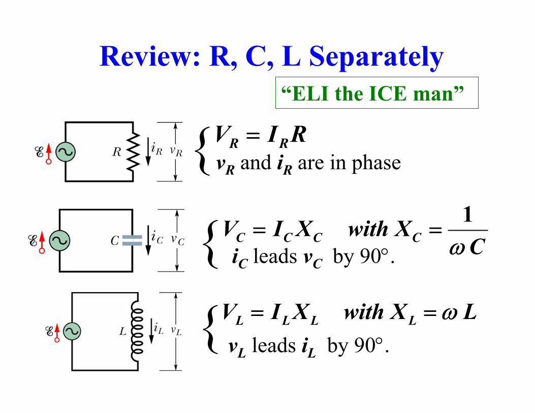
Summary for R, C, L Separately
RIV RR ====vR and iR are in phase
CXwithXIV CCCC ωωωω
1========
iC leads vC by 90°.
LXwithXIV LLLL ωωωω========
vL leads iL by 90°.
“ELI the ICE man”

Q.31-1Which of the following is true about
the phase relation between the current
and the voltage for an inductor?
(1) The current is in phase with the voltage.
(2) The current is ahead of the voltage by 90º.
(3) The current is behind the voltage by 90º.
(4) They are out of phase by 180º.

Q.31-1Which of the following is true about
the phase relation between the current
and the voltage for an inductor?
(1) The current is in phase with the voltage.
(2) The current is ahead of the voltage by 90º.
(3) The current is behind the voltage by 90º.
(4) They are out of phase by 180º.
Remember ELI the ICE man!
Inductor: voltage leads current.

Q.31-1What is the phase relation between the
current and the voltage for an inductor?
)cos(
)sin(
tLIdt
diLvisDrop
tIiLet
ωωωωωωωω
ωωωω
========
====Proof:
)sin( ti ωωωω∝∝∝∝
)cos( tv ωωωω∝∝∝∝v hits peak before i

Q.31-2
HL
srad
AI
03.
/200
0.3
====
====
====
ωωωωAn inductor L carries a current with
amplitude I at angular frequency ωωωω.
What is the amplitude V of the voltage
across this inductor?
VVVVVV
VVVVVV
LLL
LLL
600)6(18)5(12)4(
0.6)3(0.2)2(5.0)1(
============
============

Q.31-2
HL
srad
AI
03.
/200
0.3
====
====
====
ωωωω
The reactance is:
VVVVVV
VVVVVV
LLL
LLL
600)6(18)5(12)4(
0.6)3(0.2)2(5.0)1(
============
============
ΩΩΩΩ====××××======== 0.603.200LXL ωωωω
Thus the voltage amplitude is:
VAXIV LLL 180.60.3 ====ΩΩΩΩ××××========

Impedance
Obviously, for a resistor, RZ =for a capacitor and for an inductor
CXZ = LXZ =
But if you have a combination of circuit
elements, Z is more complicated.
The “AC Ohm’s Law” is: IZm =εwhere Z is called the impedance.

Impedance and Phase Angle
Given εεεεm and ωωωω, find Z and φφφφ.
( )φω −= tIti sin)(
tt m ωεε sin)( =
General problem:
if we are given
By definition of impedance ZI m /ε=
can we find i(t)?
We can always write
??

Series RLC Circuit
LCR vvv ++++++++====εεεε
1. The currents
are all equal.
2. The voltage drops add
up to the applied emf as
a function of time:
BUT: Because of the phase differences, the
amplitudes do not add:LCRm VVV ++++++++≠≠≠≠εεεε
So the impedance is not
just a sum: LC XXRZ ++++++++≠≠≠≠

Results for series circuits
It turns out that for this particular circuit
tt m ωωωωεεεεεεεε sin)( ====
(((( ))))φφφφωωωω −−−−==== tIti sin)(
22)( CL XXRZ −−−−++++====
R
XX CL −−−−====φφφφtan CL XX −−−−
R
Z
φφφφ

Series Circuit Example
Given L = 50 mH, C = 60 µF, εm=120V,
f=60Hz, and I=4.0A.
(a) What is the impedance?
(b) What is the resistance R?
ΩΩΩΩ============ 304
120
IZ mεεεε
Solution to (a) is easy:

Example (part b)
ΩΩΩΩ====−−−−====−−−−−−−−==== 164.2530)(2222
CL XXZR
L=50 mH, C = 60 µF, εm=120V, f=60Hz, I=4.0A
(a)
(b) What is the resistance R?
Ω= 30Z
ΩΩΩΩ====××××××××======== −−−− 8.1810503773
LXL ωωωωsradf /3776014.322 ====××××××××======== ππππωωωω
ΩΩΩΩ====××××××××
======== −−−−2.44
1060377
116
CXC ωωωω
ΩΩΩΩ====−−−−====−−−− 4.258.182.44LC XX

AC Circuits
• Ch.30: Faraday’s Law
• Ch.30: Inductors and RL Circuits:
• Ch.31: AC Circuits

Review: Inductance
• If the current through a coil of wire changes,
there is an induced emf proportional to the rate of
change of the current.
•Define the proportionality constant to be the
inductance L:
dt
diL−−−−====εεεε
• SI unit of inductance is the henry (H).

Review: LC Circuits
)cos( tQq ωωωω====
)sin( tQdt
dqi ωωωωωωωω−−−−========
qLCdt
qd
−−−−====1
2
2
Loop rule gives differential equation:
Solution if frequency is correct:
====LC
12ωωωω
Natural frequency of oscillations!

Review: AC Voltage Sources
• For an AC circuit, we need an
alternating emf, or AC power
supply.
• This is characterized by its
amplitude and its frequency.
tm ωεε sin=
amplitude angular frequency
Review: R, C, L Separately
RIV RR ====vR and iR are in phase
CXwithXIV CCCC ωωωω
1========
iC leads vC by 90°.
LXwithXIV LLLL ωωωω========
vL leads iL by 90°.
“ELI the ICE man”

Review: Simple series circuit
It turns out that for this particular circuit
tt m ωωωωεεεεεεεε sin)( ====
(((( ))))φφφφωωωω −−−−==== tIti sin)(
22)( CL XXRZ −−−−++++====
R
XX CL −−−−====φφφφtan CL XX −−−−
R
Z
φφφφ

Series Circuit Example
Given L = 50 mH, C = 60 µF, εm=120V,
f=60Hz, and I=4.0A.
(a) What is the impedance?
(b) What is the resistance R?
ΩΩΩΩ============ 304
120
IZ mεεεε
Solution to (a) is easy:

Example (part b)
ΩΩΩΩ====−−−−====−−−−−−−−==== 164.2530)(2222
CL XXZR
L=50 mH, C = 60 µF, εm=120V, f=60Hz, I=4.0A
(a)
(b) What is the resistance R?
Ω= 30Z
ΩΩΩΩ====××××××××======== −−−− 8.1810503773
LXL ωωωωsradf /3776014.322 ====××××××××======== ππππωωωω
ΩΩΩΩ====××××××××
======== −−−−2.44
1060377
116
CXC ωωωω
ΩΩΩΩ====−−−−====−−−− 4.258.182.44LC XX
Q.31-3
A certain series RLC circuit is driven by an
applied emf with angular frequency 20 radians
per second. If the maximum charge on the
capacitor is 0.03 coulomb, what is the
maximum current in the circuit?
(1) 6 A (2) 1.5 A (3) 0.6 A (4) 0.15 A
(5) Not enough information

Q.31-3A certain series RLC circuit is driven by an
applied emf with angular frequency 20 radians
per second. If the maximum charge on the
capacitor is 0.03 coulomb, what is the
maximum current in the circuit?
(1) 6 A (2) 1.5 A (3) 0.6 A (4) 0.15 A
(5) Not enough information
(((( )))) (((( ))))
AQI
tQdt
dqitQq
6.003.020
cossin
====××××========
============
ωωωω
ωωωωωωωωωωωω

Q.31-4
In a series RLC circuit, find the resistance, given the impedance
and phase constant:
Z = 500 Ω φφφφ = 60° R = ?
(1) 400 Ω (2) 350 Ω (3) 300 Ω (4) 250 Ω

Q.31-4In an RLC circuit:
Z = 500 Ω φφφφ = 60° R = ?
(1) 400 Ω (2) 350 Ω (3) 300 Ω (4) 250 Ω
CL XX −−−−
R
Z
φφφφ
(((( )))) (((( ))))ΩΩΩΩ========
====°°°°====°°°°
====
2502/2
130sin60cos
cos
ZR
ZR φφφφ
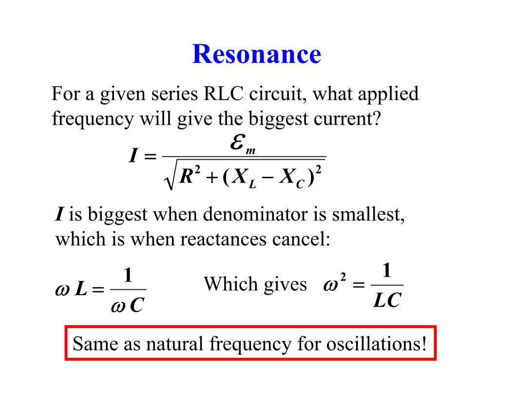
Resonance
For a given series RLC circuit, what applied
frequency will give the biggest current?
22)( CL
m
XXRI
−−−−++++====
εεεε
I is biggest when denominator is smallest,
which is when reactances cancel:
CL
ωωωωωωωω
1==== Which gives
LC
12 ====ωωωω
Same as natural frequency for oscillations!
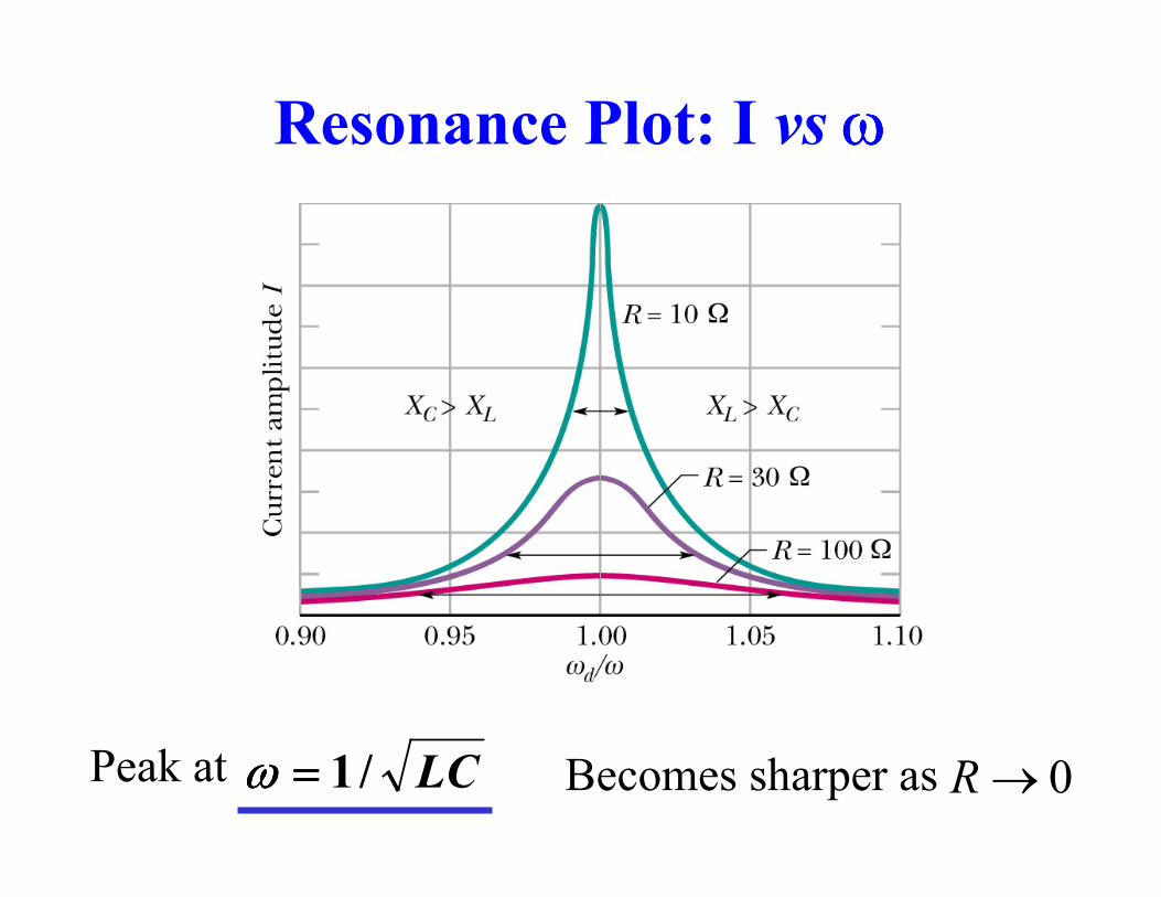
Resonance Plot: I vs ωωωω
Peak at LC/1====ωωωω Becomes sharper as 0→R
Power in AC Circuits
To know how much power will be consumed
in an AC circuit we need more than the
impedance Z; we also need the phase angle φφφφ.

AC Power
What is the power provided by an AC source?
• Only interested in the time average!
• Time average power to L and C is zero.
• So Pave(from source) = Pave(to resistor).
RRRR
RRRRave
IVtIV
tItVivP
2
1sin
)sin)(sin(
2 ========
========
ωωωω
ωωωωωωωω

RMS Values
2/2
1sin
222VVtVvVRMS ================ ωωωω
2/2
IiILikewise RMS ========
VIIV
IVP RMSRMSave2
1
22============
So for a resistor:

Power and Phase Angle
(((( ))))
RIRIP
tRIRiP
Ravg
Ravg
RR
222
22
2
1sin
sin2
========
−−−−======== φφφφωωωω
φφφφ
φφφφ
cos
cos
2
2
1ZIPSo
ZR
avg ====
====
Power factor
Power to resistor
But we want result in terms of impedance and phase angle:
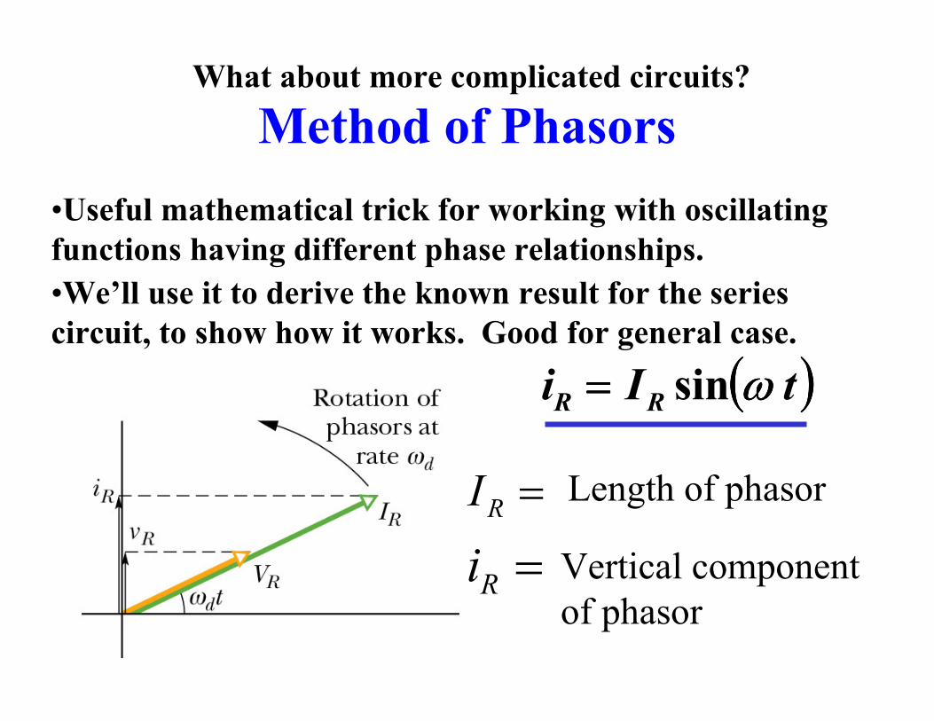
Method of Phasors
•Useful mathematical trick for working with oscillating
functions having different phase relationships.
•We’ll use it to derive the known result for the series
circuit, to show how it works. Good for general case.
(((( ))))tIi RR ωωωωsin====
=Ri
=RI Length of phasor
Vertical component
of phasor
What about more complicated circuits?

Series RLC Circuit
LCR vvv ++=ε
1. The currents
are all equal.
2. The voltage
drops add up to the
applied emf:
Because of the phase differences, the amplitudes
do not add, but in the phasor diagram, this means
that the vertical components do add, so we get the
right answer if we add the phasors as vectors.

Phasors for Series RLC Circuit
tvvv mLCR ωωωωεεεεεεεε sin====++++++++====(((( ))))φφφφωωωω −−−−============ tIiii LCR sin
i I
(((( ))))φφφφωωωω −−−−t

Adding the Voltage Phasors
tvvv mLCR ωωωωεεεεεεεε sin====++++++++====
I
ε

Adding the Voltage Phasors
tvvv mLCR ωωωωεεεεεεεε sin====++++++++====
22)( CLRm VVV −−−−++++====εεεε
R
CL
V
VV −−−−====φφφφtan

Impedance and Phase Angle
22)( CLRm VVV −−−−++++====εεεε
R
CL
V
VV −−−−====φφφφtan
Divide by the common current amplitude I:
22)( CL XXRZ −−−−++++====
R
XX CL −−−−====φφφφtan
CCLLRm IXVIXVIRVIZ ================ ,,,εεεε