Oscillating-water-column wave energy converters and air turbines: A review
34
Review Oscillating-water-column wave energy converters and air turbines: A review Ant onio F.O. Falc ~ ao * , Jo ~ ao C.C. Henriques IDMEC, LAETA, Instituto Superior T ecnico, Universidade de Lisboa, 1049-001, Lisbon, Portugal article info Article history: Received 9 March 2015 Received in revised form 18 July 2015 Accepted 29 July 2015 Available online xxx Keywords: Wave energy Oscillating water column Air turbines Modelling Control Review abstract The ocean waves are an important renewable energy resource that, if extensively exploited, may contribute significantly to the electrical energy supply of countries with coasts facing the sea. A wide variety of technologies has been proposed, studied, and in some cases tested at full size in real ocean conditions. Oscillating-water-column (OWC) devices, of fixed structure or floating, are an important class of wave energy devices. A large part of wave energy converter prototypes deployed so far into the sea are of OWC type. In an OWC, there is a fixed or floating hollow structure, open to the sea below the water surface, that traps air above the inner free-surface. Wave action alternately compresses and de- compresses the trapped air which is forced to flow through a turbine coupled to a generator. The paper presents a comprehensive review of OWC technologies and air turbines. This is followed by a survey of theoretical, numerical and experimental modelling techniques of OWC converters. Reactive phase con- trol and phase control by latching are important issues that are addressed, together with turbine rota- tional speed control. © 2015 Elsevier Ltd. All rights reserved. Contents 1. Introduction ....................................................................................................................... 00 2. OWC technology .............................................................. ..................................................... 00 2.1. Early developments until 1990 ................................................................................................ 00 2.2. Developments since the early 1990s ................................................. .......................................... 00 2.2.1. Fixed-structure OWCs ................................................................................................ 00 2.2.2. Breakwater-integrated OWCs ................................................ ......................................... 00 2.2.3. Floating-structure OWCs ................................................... ........................................... 00 2.2.4. Floating structure WECs with interior OWC .............................................................................. 00 2.2.5. Multi-OWC devices ..................................................... ............................................. 00 2.3. Concluding remarks .......................................................................................................... 00 3. Air turbines ....................................................................................................................... 00 3.1. Introduction ................................................................................................................. 00 3.2. Wells turbines ............................................................................................................... 00 3.3. Axial-flow self-rectifying impulse turbine ....................................................................................... 00 3.4. Wells turbine versus axial-flow impulse turbine ........................................... ..................................... 00 3.5. Other axial-flow air turbines for bidirectional flows .............................................................................. 00 3.6. Radial-flow self-rectifying air turbines ................................................ ......................................... 00 3.7. Some air turbine prototypes ................................................................................................... 00 3.8. Turbine noise ............................................................................................................... 00 3.9. Dimensional analysis ........................................................ ................................................ 00 3.10. Turbine performance in random waves ............................................... ........................................ 00 * Corresponding author. E-mail address: [email protected] (A.F.O. Falc~ ao). Contents lists available at ScienceDirect Renewable Energy journal homepage: www.elsevier.com/locate/renene http://dx.doi.org/10.1016/j.renene.2015.07.086 0960-1481/© 2015 Elsevier Ltd. All rights reserved. Renewable Energy xxx (2015) 1e34 Please cite this article in press as: A.F.O. Falc~ ao, J.C.C. Henriques, Oscillating-water-columnwave energy converters and air turbines: A review, Renewable Energy (2015), http://dx.doi.org/10.1016/j.renene.2015.07.086
-
Upload
independent -
Category
Documents
-
view
0 -
download
0
Transcript of Oscillating-water-column wave energy converters and air turbines: A review
lable at ScienceDirect
Renewable Energy xxx (2015) 1e34
Contents lists avai
Renewable Energy
journal homepage: www.elsevier .com/locate/renene
Review
Oscillating-water-column wave energy converters and airturbines: A review
Ant�onio F.O. Falc~ao*, Jo~ao C.C. HenriquesIDMEC, LAETA, Instituto Superior T�ecnico, Universidade de Lisboa, 1049-001, Lisbon, Portugal
a r t i c l e i n f o
Article history:Received 9 March 2015Received in revised form18 July 2015Accepted 29 July 2015Available online xxx
Keywords:Wave energyOscillating water columnAir turbinesModellingControlReview
* Corresponding author.E-mail address: [email protected] (A.F.O. Fa
http://dx.doi.org/10.1016/j.renene.2015.07.0860960-1481/© 2015 Elsevier Ltd. All rights reserved.
Please cite this article in press as: A.F.O. FalcRenewable Energy (2015), http://dx.doi.org/
a b s t r a c t
The ocean waves are an important renewable energy resource that, if extensively exploited, maycontribute significantly to the electrical energy supply of countries with coasts facing the sea. A widevariety of technologies has been proposed, studied, and in some cases tested at full size in real oceanconditions. Oscillating-water-column (OWC) devices, of fixed structure or floating, are an important classof wave energy devices. A large part of wave energy converter prototypes deployed so far into the sea areof OWC type. In an OWC, there is a fixed or floating hollow structure, open to the sea below the watersurface, that traps air above the inner free-surface. Wave action alternately compresses and de-compresses the trapped air which is forced to flow through a turbine coupled to a generator. The paperpresents a comprehensive review of OWC technologies and air turbines. This is followed by a survey oftheoretical, numerical and experimental modelling techniques of OWC converters. Reactive phase con-trol and phase control by latching are important issues that are addressed, together with turbine rota-tional speed control.
© 2015 Elsevier Ltd. All rights reserved.
Contents
1. Introduction . . . . . . . . . . . . . . . . . . . . . . . . . . . . . . . . . . . . . . . . . . . . . . . . . . . . . . . . . . . . . . . . . . . . . . . . . . . . . . . . . . . . . . . . . . . . . . . . . . . . . . . . . . . . . . . . . . . . . . . 002. OWC technology . . . . . . . . . . . . . . . . . . . . . . . . . . . . . . . . . . . . . . . . . . . . . . . . . . . . . . . . . . . . . . . . . . . . . . . . . . . . . . . . . . . . . . . . . . . . . . . . . . . . . . . . . . . . . . . . . . . 00
2.1. Early developments until 1990 . . . . . . . . . . . . . . . . . . . . . . . . . . . . . . . . . . . . . . . . . . . . . . . . . . . . . . . . . . . . . . . . . . . . . . . . . . . . . . . . . . . . . . . . . . . . . . . . 002.2. Developments since the early 1990s . . . . . . . . . . . . . . . . . . . . . . . . . . . . . . . . . . . . . . . . . . . . . . . . . . . . . . . . . . . . . . . . . . . . . . . . . . . . . . . . . . . . . . . . . . . 00
2.2.1. Fixed-structure OWCs . . . . . . . . . . . . . . . . . . . . . . . . . . . . . . . . . . . . . . . . . . . . . . . . . . . . . . . . . . . . . . . . . . . . . . . . . . . . . . . . . . . . . . . . . . . . . . . . 002.2.2. Breakwater-integrated OWCs . . . . . . . . . . . . . . . . . . . . . . . . . . . . . . . . . . . . . . . . . . . . . . . . . . . . . . . . . . . . . . . . . . . . . . . . . . . . . . . . . . . . . . . . . 002.2.3. Floating-structure OWCs . . . . . . . . . . . . . . . . . . . . . . . . . . . . . . . . . . . . . . . . . . . . . . . . . . . . . . . . . . . . . . . . . . . . . . . . . . . . . . . . . . . . . . . . . . . . . . 002.2.4. Floating structure WECs with interior OWC . . . . . . . . . . . . . . . . . . . . . . . . . . . . . . . . . . . . . . . . . . . . . . . . . . . . . . . . . . . . . . . . . . . . . . . . . . . . . . 002.2.5. Multi-OWC devices . . . . . . . . . . . . . . . . . . . . . . . . . . . . . . . . . . . . . . . . . . . . . . . . . . . . . . . . . . . . . . . . . . . . . . . . . . . . . . . . . . . . . . . . . . . . . . . . . . 00
2.3. Concluding remarks . . . . . . . . . . . . . . . . . . . . . . . . . . . . . . . . . . . . . . . . . . . . . . . . . . . . . . . . . . . . . . . . . . . . . . . . . . . . . . . . . . . . . . . . . . . . . . . . . . . . . . . . . . 003. Air turbines . . . . . . . . . . . . . . . . . . . . . . . . . . . . . . . . . . . . . . . . . . . . . . . . . . . . . . . . . . . . . . . . . . . . . . . . . . . . . . . . . . . . . . . . . . . . . . . . . . . . . . . . . . . . . . . . . . . . . . . 00
3.1. Introduction . . . . . . . . . . . . . . . . . . . . . . . . . . . . . . . . . . . . . . . . . . . . . . . . . . . . . . . . . . . . . . . . . . . . . . . . . . . . . . . . . . . . . . . . . . . . . . . . . . . . . . . . . . . . . . . . . 003.2. Wells turbines . . . . . . . . . . . . . . . . . . . . . . . . . . . . . . . . . . . . . . . . . . . . . . . . . . . . . . . . . . . . . . . . . . . . . . . . . . . . . . . . . . . . . . . . . . . . . . . . . . . . . . . . . . . . . . . 003.3. Axial-flow self-rectifying impulse turbine . . . . . . . . . . . . . . . . . . . . . . . . . . . . . . . . . . . . . . . . . . . . . . . . . . . . . . . . . . . . . . . . . . . . . . . . . . . . . . . . . . . . . . . 003.4. Wells turbine versus axial-flow impulse turbine . . . . . . . . . . . . . . . . . . . . . . . . . . . . . . . . . . . . . . . . . . . . . . . . . . . . . . . . . . . . . . . . . . . . . . . . . . . . . . . . 003.5. Other axial-flow air turbines for bidirectional flows . . . . . . . . . . . . . . . . . . . . . . . . . . . . . . . . . . . . . . . . . . . . . . . . . . . . . . . . . . . . . . . . . . . . . . . . . . . . . . 003.6. Radial-flow self-rectifying air turbines . . . . . . . . . . . . . . . . . . . . . . . . . . . . . . . . . . . . . . . . . . . . . . . . . . . . . . . . . . . . . . . . . . . . . . . . . . . . . . . . . . . . . . . . . 003.7. Some air turbine prototypes . . . . . . . . . . . . . . . . . . . . . . . . . . . . . . . . . . . . . . . . . . . . . . . . . . . . . . . . . . . . . . . . . . . . . . . . . . . . . . . . . . . . . . . . . . . . . . . . . . . 003.8. Turbine noise . . . . . . . . . . . . . . . . . . . . . . . . . . . . . . . . . . . . . . . . . . . . . . . . . . . . . . . . . . . . . . . . . . . . . . . . . . . . . . . . . . . . . . . . . . . . . . . . . . . . . . . . . . . . . . . 003.9. Dimensional analysis . . . . . . . . . . . . . . . . . . . . . . . . . . . . . . . . . . . . . . . . . . . . . . . . . . . . . . . . . . . . . . . . . . . . . . . . . . . . . . . . . . . . . . . . . . . . . . . . . . . . . . . . 003.10. Turbine performance in random waves . . . . . . . . . . . . . . . . . . . . . . . . . . . . . . . . . . . . . . . . . . . . . . . . . . . . . . . . . . . . . . . . . . . . . . . . . . . . . . . . . . . . . . . 00
lc~ao).
~ao, J.C.C. Henriques, Oscillatin10.1016/j.renene.2015.07.086
g-water-column wave energy converters and air turbines: A review,

A.F.O. Falc~ao, J.C.C. Henriques / Renewable Energy xxx (2015) 1e342
3.11. Turbine induced damping . . . . . . . . . . . . . . . . . . . . . . . . . . . . . . . . . . . . . . . . . . . . . . . . . . . . . . . . . . . . . . . . . . . . . . . . . . . . . . . . . . . . . . . . . . . . . . . . . . . . 003.12. Concluding remarks . . . . . . . . . . . . . . . . . . . . . . . . . . . . . . . . . . . . . . . . . . . . . . . . . . . . . . . . . . . . . . . . . . . . . . . . . . . . . . . . . . . . . . . . . . . . . . . . . . . . . . . . 00
4. OWC modelling . . . . . . . . . . . . . . . . . . . . . . . . . . . . . . . . . . . . . . . . . . . . . . . . . . . . . . . . . . . . . . . . . . . . . . . . . . . . . . . . . . . . . . . . . . . . . . . . . . . . . . . . . . . . . . . . . . . . . 004.1. Theoretical hydrodynamic modelling . . . . . . . . . . . . . . . . . . . . . . . . . . . . . . . . . . . . . . . . . . . . . . . . . . . . . . . . . . . . . . . . . . . . . . . . . . . . . . . . . . . . . . . . . . . 004.2. Thermodynamics of air chamber . . . . . . . . . . . . . . . . . . . . . . . . . . . . . . . . . . . . . . . . . . . . . . . . . . . . . . . . . . . . . . . . . . . . . . . . . . . . . . . . . . . . . . . . . . . . . . 004.3. Model testing of OWCs . . . . . . . . . . . . . . . . . . . . . . . . . . . . . . . . . . . . . . . . . . . . . . . . . . . . . . . . . . . . . . . . . . . . . . . . . . . . . . . . . . . . . . . . . . . . . . . . . . . . . . 00
5. Control . . . . . . . . . . . . . . . . . . . . . . . . . . . . . . . . . . . . . . . . . . . . . . . . . . . . . . . . . . . . . . . . . . . . . . . . . . . . . . . . . . . . . . . . . . . . . . . . . . . . . . . . . . . . . . . . . . . . . . . . . . . . 005.1. Reactive phase control . . . . . . . . . . . . . . . . . . . . . . . . . . . . . . . . . . . . . . . . . . . . . . . . . . . . . . . . . . . . . . . . . . . . . . . . . . . . . . . . . . . . . . . . . . . . . . . . . . . . . . . . 005.2. Phase control by latching . . . . . . . . . . . . . . . . . . . . . . . . . . . . . . . . . . . . . . . . . . . . . . . . . . . . . . . . . . . . . . . . . . . . . . . . . . . . . . . . . . . . . . . . . . . . . . . . . . . . 005.3. Turbine rotational speed and air flow control . . . . . . . . . . . . . . . . . . . . . . . . . . . . . . . . . . . . . . . . . . . . . . . . . . . . . . . . . . . . . . . . . . . . . . . . . . . . . . . . . . . 00
6. Conclusions . . . . . . . . . . . . . . . . . . . . . . . . . . . . . . . . . . . . . . . . . . . . . . . . . . . . . . . . . . . . . . . . . . . . . . . . . . . . . . . . . . . . . . . . . . . . . . . . . . . . . . . . . . . . . . . . . . . . . . . 00Uncited references . . . . . . . . . . . . . . . . . . . . . . . . . . . . . . . . . . . . . . . . . . . . . . . . . . . . . . . . . . . . . . . . . . . . . . . . . . . . . . . . . . . . . . . . . . . . . . . . . . . . . . . . . . . . . . . . . 00Acknowledgements . . . . . . . . . . . . . . . . . . . . . . . . . . . . . . . . . . . . . . . . . . . . . . . . . . . . . . . . . . . . . . . . . . . . . . . . . . . . . . . . . . . . . . . . . . . . . . . . . . . . . . . . . . . . . . . . 00References . . . . . . . . . . . . . . . . . . . . . . . . . . . . . . . . . . . . . . . . . . . . . . . . . . . . . . . . . . . . . . . . . . . . . . . . . . . . . . . . . . . . . . . . . . . . . . . . . . . . . . . . . . . . . . . . . . . . . . . . 00
Nomenclature
Roman lettersA added massB radiation force coefficientc blade chord (Section 3)D turbine rotor diameterE energy per unit mass (Section 3)fe, fr excitation force, radiation forceFe, Fr complex amplitudes of fe, frg acceleration of gravityG radiation conductanceH radiation susceptancek polytropic exponentm massp pressureP complex amplitude of pPt turbine powerq volume flow rateQ complex amplitude of qS inner free-surface areat cascade pitch (Section 3)
t timeT torqueU blade velocityV absolute flow velocity (Section 3)V air chamber volume (Section 4)w mass flow ratex vertical coordinateX complex amplitude of x
Greek lettersa absolute flow velocity angleb relative flow velocity angleh turbine efficiencyP dimensionless turbine powerr densitys standard deviation (or rms)f flow rate coefficient (Section 3)F dimensionless flow ratej pressure coefficient (Section 3)J dimensionless pressure headu radian frequencyU rotational speed
1. Introduction
The ocean waves are an important renewable energy resourcethat, if extensively exploited, may contribute significantly to theelectrical energy supply of countries with coasts facing the ocean[1]. A wide variety of technologies has been proposed, studied, andin some cases tested at full size in real ocean conditions [2e5]. Themechanical process of energy absorption from the waves requires amoving interface, involving (i) a partly or totally submerged mov-ing body and/or (ii) a moving airewater interface subject to a time-varying pressure. In the latter case, there is a fixed or oscillatinghollow structure, open to the sea below the water surface, thattraps air above the inner free-surface; wave action alternatelycompresses and decompresses the trapped air which forces air toflow through a turbine coupled to a generator. Such a device isnamed oscillating-water-column (OWC). Although the concept wasalready known in the 1940s, this designation seems to haveappeared for the first time in published paper form in 1978 [6] andhas been widely used ever since, even if the moving water insidethe structure is far from shaped like a column. Before that, this type
Please cite this article in press as: A.F.O. Falc~ao, J.C.C. Henriques, OscillatinRenewable Energy (2015), http://dx.doi.org/10.1016/j.renene.2015.07.086
of wave energy converter (WEC) was sometimes known as theMasuda device. The main advantage of the OWC versus most otherWECs is its simplicity: the only moving part of the energy conver-sion mechanism is the rotor of a turbine, located above water level,rotating at a relatively high velocity and directly driving a con-ventional electrical generator. OWCs are a major class of wave en-ergy converters, possibly the class that has been most extensivelystudied and with the largest number of prototypes so far deployedinto the sea.
In almost all OWCs, the air alternately flows from the chamberto the atmosphere and back, although in some concepts the flow isin closed circuit. Unless rectifying valves are used, which is widelyregarded as unpractical except possibly in small devices like navi-gation buoys, the turbines are self-rectifying, i.e. their rotationaldirection remains unchanged regardless of the direction of the airflow. Several types of such special turbines have been developed.The axial-flow Wells turbine, invented in the mid-1970s, is themost popular self-rectifying turbine, but other types, namely self-rectifying impulse turbines, have also been proposed, studied andused.
g-water-column wave energy converters and air turbines: A review,
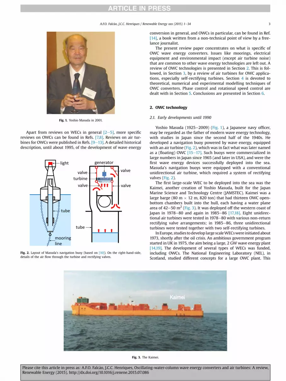
Fig. 1. Yoshio Masuda in 2001.
A.F.O. Falc~ao, J.C.C. Henriques / Renewable Energy xxx (2015) 1e34 3
Apart from reviews on WECs in general [2e5], more specificreviews on OWCs can be found in Refs. [7,8]. Reviews on air tur-bines for OWCs were published in Refs. [9e13]. A detailed historicaldescription, until about 1995, of the development of wave energy
generator
turbine valve
valve
valve
valve light
tube
mooring line
tube
Fig. 2. Layout of Masuda's navigation buoy (based on [10]). On the right-hand-side,details of the air flow through the turbine and rectifying valves.
Fig. 3. The K
Please cite this article in press as: A.F.O. Falc~ao, J.C.C. Henriques, OscillatinRenewable Energy (2015), http://dx.doi.org/10.1016/j.renene.2015.07.086
conversion in general, and OWCs in particular, can be found in Ref.[14], a book written from a non-technical point of view by a free-lance journalist.
The present review paper concentrates on what is specific ofOWC wave energy converters. Issues like moorings, electricalequipment and environmental impact (except air turbine noise)that are common to other wave energy technologies are left out. Areview of OWC technologies is presented in Section 2. This is fol-lowed, in Section 3, by a review of air turbines for OWC applica-tions, especially self-rectifying turbines. Section 4 is devoted totheoretical, numerical and experimental modelling techniques ofOWC converters. Phase control and rotational speed control aredealt with in Section 5. Conclusions are presented in Section 6.
2. OWC technology
2.1. Early developments until 1990
Yoshio Masuda (1925e2009) (Fig. 1), a Japanese navy officer,may be regarded as the father of modern wave energy technology,with studies in Japan since the second half of the 1940s. Hedeveloped a navigation buoy powered by wave energy, equippedwith an air turbine (Fig. 2), which was in fact what was later namedas a (floating) OWC [15e17]. Such buoys were commercialized inlarge numbers in Japan since 1965 (and later in USA), and were thefirst wave energy devices successfully deployed into the sea.Masuda's navigation buoys were equipped with a conventionalunidirectional air turbine, which required a system of rectifyingvalves (Fig. 2).
The first large-scale WEC to be deployed into the sea was theKaimei, another creation of Yoshio Masuda, built for the JapanMarine Science and Technology Centre (JAMSTEC). Kaimei was alarge barge (80 m � 12 m, 820 ton) that had thirteen OWC open-bottom chambers built into the hull, each having a water planearea of 42e50 m2 (Fig. 3). It was deployed off the western coast ofJapan in 1978e80 and again in 1985e86 [17,18]. Eight unidirec-tional air turbines were tested in 1978e80 with various non-returnrectifying valve arrangements; in 1985e86, three unidirectionalturbines were tested together with two self-rectifying turbines.
InEurope, studies todevelop large scaleWECswere initiatedabout1973, shortly after the oil crisis. An ambitious government programstarted in UK in 1975, the aim being a large, 2 GWwave energy plant[14,19]. The development of several types of WECs was funded,including OWCs. The National Engineering Laboratory (NEL), inScotland, studied different concepts for a large OWC plant. This
aimei.
g-water-column wave energy converters and air turbines: A review,
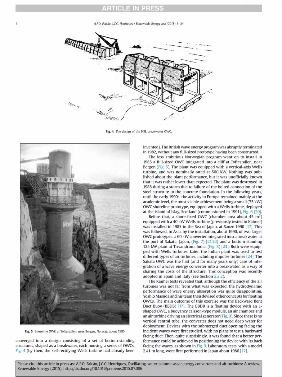
Fig. 4. The design of the NEL breakwater OWC.
Fig. 5. Shoreline OWC at Toftestallen, near Bergen, Norway, about 1985.
A.F.O. Falc~ao, J.C.C. Henriques / Renewable Energy xxx (2015) 1e344
converged into a design consisting of a set of bottom-standingstructures, shaped as a breakwater, each housing a series of OWCs,Fig. 4 (by then, the self-rectifying Wells turbine had already been
Please cite this article in press as: A.F.O. Falc~ao, J.C.C. Henriques, OscillatinRenewable Energy (2015), http://dx.doi.org/10.1016/j.renene.2015.07.086
invented). The Britishwave energy programwas abruptly terminatedin 1982, without any full-sized prototype having been constructed.
The less ambitious Norwegian program went on to install in1985 a full-sized OWC integrated into a cliff at Toftestallen, nearBergen (Fig. 5). The plant was equipped with a vertical-axis Wellsturbine, and was nominally rated at 500 kW. Nothing was pub-lished about the plant performance, but it was unofficially knownthat it was rather lower than expected. The plant was destroyed in1988 during a storm due to failure of the bolted connection of thesteel structure to the concrete foundation. In the following years,until the early 1990s, the activity in Europe remained mainly at theacademic level, the most visible achievement being a small (75 kW)OWC shoreline prototype, equipped with a Wells turbine, deployedat the island of Islay, Scotland (commissioned in 1991), Fig. 6 [20].
Before that, a shore-fixed OWC (chamber area about 45 m2)equipped with a 40 kWWells turbine (previously tested in Kaimei)was installed in 1983 in the Sea of Japan, at Sanze 1990 [17]. Thiswas followed, in Asia, by the installation, about 1990, of two largerOWC prototypes: a 60 kW converter integrated into a breakwater atthe port of Sakata, Japan, (Fig. 7) [21,22] and a bottom-standing125 kW plant at Trivandrum, India, (Fig. 8) [23]. Both were equip-ped with Wells turbines. Later, the Indian plant was used to testdifferent types of air turbines, including impulse turbines [24]. TheSakata OWC was the first (and for many years only) case of inte-gration of a wave energy converter into a breakwater, as a way ofsharing the costs of the structure. This conception was recentlyadopted in Spain and Italy (see Section 2.2.2).
The Kaimei tests revealed that, although the efficiency of the airturbines was not far from what was expected, the hydrodynamicperformance of wave energy absorption was quite disappointing.YoshioMasudaandhis teamthendevisedother concepts forfloatingOWCs. The main outcome of this exercise was the Backward BentDuct Buoy (BBDB) [17]. The BBDB is a floating device with an L-shaped OWC, a buoyancy caisson-type module, an air chamber andanair turbinedriving anelectrical generator (Fig. 9). Since there is novertical central tube, the converter does not need deep water fordeployment. Devices with the submerged duct opening facing theincident waves were first studied, with no plans to test a backwardfacing duct. Then, quite surprisingly, it was found that a better per-formance could be achieved by positioning the device with its backfacing the waves, as shown in Fig. 9. Laboratory tests, with a model2.41 m long, were first performed in Japan about 1986 [17].
g-water-column wave energy converters and air turbines: A review,

Fig. 6. Shoreline OWC on the island of Islay, Scotland, rated 75 kW, commissioned in 1991 (courtesy of M. Folley).
Fig. 7. OWC plant integrated into a breakwater at Sakata harbour, Japan, 1990. Rated power 60 kW.
A.F.O. Falc~ao, J.C.C. Henriques / Renewable Energy xxx (2015) 1e34 5
2.2. Developments since the early 1990s
2.2.1. Fixed-structure OWCsThe situation in Europewas dramatically changed by the decision
made in 1991 by the European Commission of includingwave energyin their R&D program on renewable energies. This lead to the basicstudies, followed by the design and construction, of two full-sizedfixed-structure OWC plants (the so-called European pilot plants),one on the island of Pico, Azores, Portugal, and the other on the islandof Islay, Scotland, UK. Both were equipped with Wells turbines. ThePico plant, rated 400 kW, was completed in 1999 and is still opera-tional. It was built, standing on the sea bottom, adjacent to a vertical
Please cite this article in press as: A.F.O. Falc~ao, J.C.C. Henriques, OscillatinRenewable Energy (2015), http://dx.doi.org/10.1016/j.renene.2015.07.086
cliff (Fig. 10) [25]. The Islay plant, completed in 2000 and rated500 kW, was built in a recess carved into a rocky cliff (Fig. 11) [26].Another shoreline OWC plant, rated 100 kW, was built in 2001 inGuangdong Province, China (Fig. 12) [27]. A few years earlier, a largenearshore bottom-standing OWC (named OSPREY), rated 1MW,wasdestroyed by the sea shortly after having been towed and sunk intoplace near the Scottish coast in 1995. A large bottom-standing OWC,the greenWAVE, rated 1 MW, was recently constructed by theAustralian company Oceanlinx (Fig. 13). An accident to the airbagssupporting the 3000-tonne structure occurred in March 2014 whenthe plant was being towed from Port Adelaide to PortMacDonnell, inwestern Australia, forcing the plant to be left aground.
g-water-column wave energy converters and air turbines: A review,

Fig. 8. Bottom-standing OWC installed in 1990 at Trivandrum, southern India. Rated power 125 kW.
buoyancy
air turbine
wave buoyancy
direction
Fig. 9. Schematic representation of the Backward Bent Duct Buoy (BBDB).
A.F.O. Falc~ao, J.C.C. Henriques / Renewable Energy xxx (2015) 1e346
A recently completed bottom-standing OWC, rated 500 kW, wasinstalled at Yongsoo, about 1 km off the coast of Jeju Island, SouthKorea (Fig. 14). The plant is 37 m long and 31.2 m wide.
It has been found since the early 1980s that the wave energyabsorption process can be enhanced by extending the chamberstructure by protruding (natural or man-made) walls in the direc-tion of the waves, forming a harbour or a collector [28,29]. Thisconcept was put into practice in some of the early OWC prototypes,namely in Toftestallen, Norway (Fig. 5) and Trivandrum, India(Fig. 8). The Australian company Energetech developed a technol-ogy using a parabolic-shaped collector for this purpose. A bottom-standing nearshore prototype, whose structure was made of steel,was tested at Port Kembla, Australia, in 2005 [30] (Fig. 15).
2.2.2. Breakwater-integrated OWCsThe design and construction of the structure are the most
critical issues in fixed-structure OWC technology, and the mostinfluential on the economics of energy produced from the waves.The integration of the plant structure into a breakwater for coastalor harbour protection has several advantages: the constructioncosts are shared, and the access for construction, operation andmaintenance of the wave energy plant becomes much easier. Thishas been done successfully for the first time in the harbour of
Please cite this article in press as: A.F.O. Falc~ao, J.C.C. Henriques, OscillatinRenewable Energy (2015), http://dx.doi.org/10.1016/j.renene.2015.07.086
Sakata, Japan, in 1990 (Fig. 7) [21], where one of the caissonsmaking up the breakwater had a special shape to accommodatethe OWC and the mechanical and electrical equipment. The optionof the “breakwater OWC” was adopted in the breakwater con-structed at the port of Mutriku, in northern Spain (2008e10) [31],with 16 chambers and 16 Wells turbines rated 18.5 kW each(Fig. 16).
A different geometry for an OWC embedded into a breakwaterwas proposed by Boccotti [32], with an OWC that is long in the wavecrest direction but narrow (small aperture) in the fore-aft direction.The OWC cross-section is U-shaped, with its outer opening facingupwards (Fig. 17). An advantage of this conception is that it allowsthe total length of the water column to be increased without placingthe opening too far below the sea surface. This type of OWC-breakwater is being constructed at the harbour of Civitavecchia(near Rome), Italy (Fig. 17), with 17 caissons and 136 OWCs, and isplanned to be adopted for new breakwaters in Italy [33e35].
2.2.3. Floating-structure OWCsSince the early model tests in Japan in the mid-1980s, the BBDB
concept has been object of considerable interest in several coun-tries (Europe, Japan, South Korea, USA, China, India), with theo-retical/numerical and experimental studies [36e40]. A 1:4th-scaleBBDB OWC (the OE Buoy) was tested in Galway Bay, Ireland, be-tween 2008 and 2011 (Fig. 18) [41]. It was equipped first with aWells turbine and later with an axial-flow self-rectifying impulseturbine [41,42].
The Mighty Whale, another floating OWC converter, wasdeveloped by the Japan Marine Science and Technology Center. Thedevice consisted of a floating structure (length 50 m, breadth 30 m,draught 12 m, displacement 4400 ton) which had three air cham-bers located at the front, side by side, and buoyancy tanks (Fig. 19).Each air chamber was connected to a Wells air turbine. The totalrated power was 110 kW. The device was deployed near the mouthof Gokasho Bay, in Mie Prefecture, Japan, in 1998 and tested forseveral years [43,44].
The Australian company Oceanlinx deployed, from February toMay 2010, off Port Kembla, Australia, a one-third-scale grid-
g-water-column wave energy converters and air turbines: A review,

Fig. 11. LIMPET OWC plant, rated 500 kW, installed in 2000 on the island of Islay, Scotland, UK.
Fig. 10. Back view of the 400 kW OWC plant on the island of Pico, Azores, Portugal, 1999.
A.F.O. Falc~ao, J.C.C. Henriques / Renewable Energy xxx (2015) 1e34 7
connected model of the 2.5 MW full-scale OWC device, the Mk3,which (like the Kaimei three decades earlier) is a floating platformwith several OWC chambers (in this case eight chambers) eachwithan air turbine. During the tests, only two turbines (of differenttypes) were installed (Fig. 20).
The concept of an axisymmetric floating OWC, consisting of arelatively long vertical tube, open at both ends, attached to a floater,has been considered since the early pioneers of wave energy con-version. The length of the tube determines the resonance frequencyof the inner water column. This device, sometimes named OWCspar-buoy, was object of two of the earliest journal papers devotedto the theoretical modelling of wave energy converters [45,46] andis analysed by McCormick in his pioneer book [47]. Several types ofwave-powered navigation buoys have been based on this concept[16,48], which has also been considered for larger scale energyproduction [49]. A report prepared for the British Department ofTrade and Industry in 2005 [50] compared several types of floatingOWCs for electricity generation in an Atlantic environment and
Please cite this article in press as: A.F.O. Falc~ao, J.C.C. Henriques, OscillatinRenewable Energy (2015), http://dx.doi.org/10.1016/j.renene.2015.07.086
considered the OWC spar-buoy to be the lowest risk and mosteconomic option for further development. The OWC spar-buoy wasobject of optimization studies that showed the advantage of thetube being tapered at its lower part rather than cylindrical (Fig. 21)(see Refs. [51,52]).
2.2.4. Floating structure WECs with interior OWCSome WEC configurations have been proposed and studied in
which the OWC is enclosed in the floating structure and is notconnected to the outer sea water.
The U-Gen device consists of an asymmetric floater with aninterior U-tank partially filled with water and two lateral airchambers connected by a duct. The motion of the U-shaped OWC,mainly induced by the pitching of the floater, forces the air throughthe duct where a self-rectifying air turbine is installed to absorb theenergy (Fig. 22). A 1:16th-scale model, 1.25 m long, was tested in2010 at the IFREMER wave tank, in Brest, France [53]. Results fromtheoretical modelling are reported in Ref. [54]. A somewhat similar
g-water-column wave energy converters and air turbines: A review,

Fig. 12. 100 kW shoreline OWC built in 2001 in Guangdong Province, China [27].
Fig. 13. Oceanlinx greenWAVE, Australia, rated power 1 MW. In Port Adelaide, before being towed to Port MacDonnell, 2014.
A.F.O. Falc~ao, J.C.C. Henriques / Renewable Energy xxx (2015) 1e348
device, using a water turbine of cross-flow type instead of an airturbine, was studied in Ref. [55]. Another pitching devicewith whatcan be considered as an interior OWC is described and theoreticallymodelled in Ref. [56]. It consists of a buoyant tethered submergedcircular cylinder which is allowed to pitch freely about an axisbelow its centre. Within the body of the cylinder a fluid half fills anannular tank. The pitching motion of the cylinder in waves induces
Please cite this article in press as: A.F.O. Falc~ao, J.C.C. Henriques, OscillatinRenewable Energy (2015), http://dx.doi.org/10.1016/j.renene.2015.07.086
a sloshing motion inside the tank which in turns drives an airturbine connecting air chambers above the two isolated internalfree surfaces.
An axisymmetric WEC recently proposed and analysed in Ref.[57] consists in an air-filled box that is fixed to the sea bottom or isfloating (Fig. 23). The moving interface between the enclosed airand the surrounding sea water may be a rigid surface mounted on
g-water-column wave energy converters and air turbines: A review,
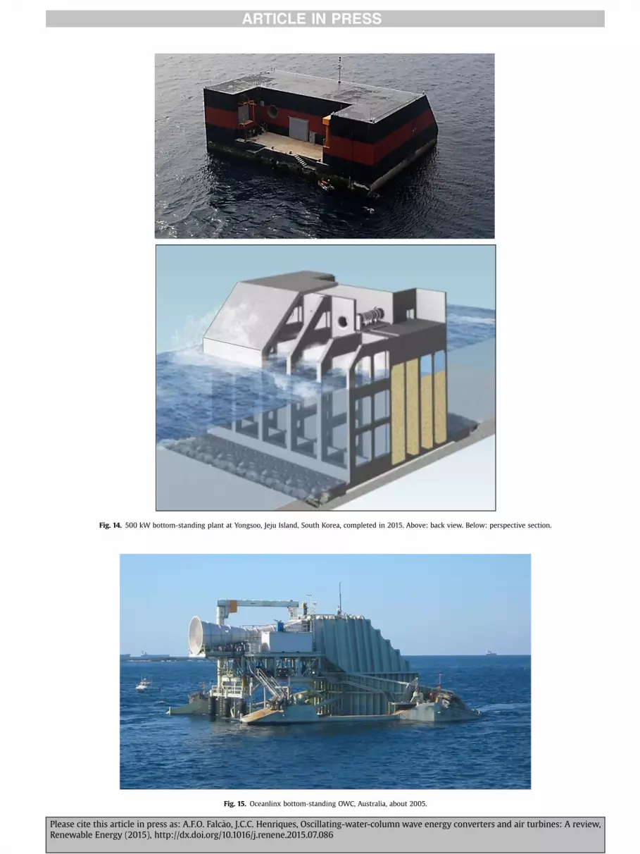
Fig. 14. 500 kW bottom-standing plant at Yongsoo, Jeju Island, South Korea, completed in 2015. Above: back view. Below: perspective section.
Fig. 15. Oceanlinx bottom-standing OWC, Australia, about 2005.
Please cite this article in press as: A.F.O. Falc~ao, J.C.C. Henriques, Oscillating-water-column wave energy converters and air turbines: A review,Renewable Energy (2015), http://dx.doi.org/10.1016/j.renene.2015.07.086

Fig. 16. Multi-chamber OWC plant integrated into a breakwater, Mutriku harbour, Basque Country, Spain, 2008e10.
A.F.O. Falc~ao, J.C.C. Henriques / Renewable Energy xxx (2015) 1e3410
flexible bellows, or a rigid surface connected to the box walls inthe manner of a loudspeaker diaphragm, or it may be madecompletely out of a flexible membrane. The box enclosed air spaceV1 is connected to the atmosphere by an OWC whose walls are co-axial tubes, an air volume V2 and an air turbine (Fig. 23). The OWCand the air compressibility play essential roles in the device dy-namics. The required air volume is larger for the bottom-fixeddevice whose frequency response width was found to be sub-stantially wider than that the floating version.
2.2.5. Multi-OWC devicesApart from OWCs integrated into breakwaters, other WECs have
been studied consisting of multiple OWCs. In some cases, several airchambers share a single unidirectional conventional air turbine,which requires low pressure and high pressure air ducts andrectifying air valves.
The Seabreath, under development at Padova University, Italy[58], is a floating attenuator, i.e. its elongated structure is alignedwith the propagation direction of the incident waves (Fig. 24). It
Please cite this article in press as: A.F.O. Falc~ao, J.C.C. Henriques, OscillatinRenewable Energy (2015), http://dx.doi.org/10.1016/j.renene.2015.07.086
comprises a set of rectangular chambers with open bottom. EachOWC air chamber is connected by non-return valves to two longi-tudinal ducts (high pressure and low pressure) that feed a con-ventional unidirectional air turbine.
The LEANCON is another multi-OWC device. The OWCs are ar-ranged in two rows under two beams connected to each other in aV-shaped fashion (Fig. 25). As in Seabreath, each OWC chamber isconnected by non-return valves to two ducts that feed a conven-tional unidirectional air turbine. Model tests were performed in thedeep wave tank of Aalborg University, in Denmark, using a 1:40th-scale model with a total of 120 OWC chambers or pipes [59].
A largely similar, although substantially smaller, device wasnumerically simulated and model tested at scale 1:50 at the largeoceanic basin of the Hydraulics and Maritime Research Centre,located at University College Cork, Ireland [60]. The 32 OWCchambers are arranged along the two legs of a 90-degree V-shapedfloating structure. Cross trusses between the two legs of the plat-form provide the necessary structural strength to enable the plat-form to survive sea conditions.
g-water-column wave energy converters and air turbines: A review,
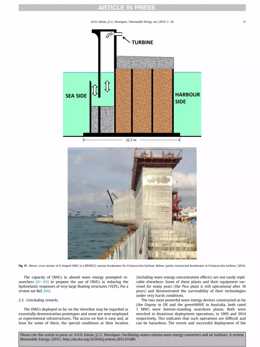
Fig. 17. Above: cross section of U-shaped OWC in a REWEC3 caisson breakwater for Civitavecchia harbour. Below: partly constructed breakwater at Civitavecchia harbour (2014).
A.F.O. Falc~ao, J.C.C. Henriques / Renewable Energy xxx (2015) 1e34 11
The capacity of OWCs to absorb wave energy prompted re-searchers [61e63] to propose the use of OWCs in reducing thehydroelastic responses of very large floating structures (VLFS). For areview see Ref. [64].
2.3. Concluding remarks
The OWCs deployed so far on the shoreline may be regarded asessentially demonstration prototypes and some are now employedas experimental infrastructures. The access on foot is easy and, atleast for some of them, the special conditions at their location
Please cite this article in press as: A.F.O. Falc~ao, J.C.C. Henriques, OscillatinRenewable Energy (2015), http://dx.doi.org/10.1016/j.renene.2015.07.086
(including wave energy concentration effects) are not easily repli-cable elsewhere. Some of these plants and their equipment sur-vived for many years (the Pico plant is still operational after 16years) and demonstrated the survivability of their technologiesunder very harsh conditions.
The two most powerful wave energy devices constructed so far(the Osprey in UK and the greenWAVE in Australia, both rated1 MW) were bottom-standing nearshore plants. Both werewrecked in disastrous deployment operations, in 1995 and 2014respectively, This indicates that such operations are difficult andcan be hazardous. The recent and successful deployment of the
g-water-column wave energy converters and air turbines: A review,
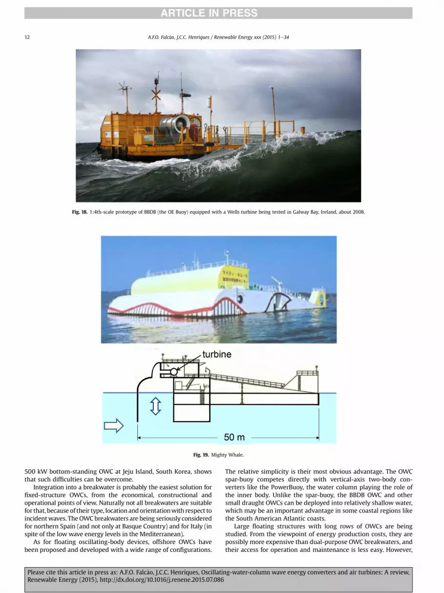
Fig. 18. 1:4th-scale prototype of BBDB (the OE Buoy) equipped with a Wells turbine being tested in Galway Bay, Ireland, about 2008.
Fig. 19. Mighty Whale.
A.F.O. Falc~ao, J.C.C. Henriques / Renewable Energy xxx (2015) 1e3412
500 kW bottom-standing OWC at Jeju Island, South Korea, showsthat such difficulties can be overcome.
Integration into a breakwater is probably the easiest solution forfixed-structure OWCs, from the economical, constructional andoperational points of view. Naturally not all breakwaters are suitablefor that, because of their type, locationandorientationwith respect toincidentwaves. TheOWCbreakwaters are being seriously consideredfor northern Spain (and not only at Basque Country) and for Italy (inspite of the low wave energy levels in the Mediterranean).
As for floating oscillating-body devices, offshore OWCs havebeen proposed and developed with a wide range of configurations.
Please cite this article in press as: A.F.O. Falc~ao, J.C.C. Henriques, OscillatinRenewable Energy (2015), http://dx.doi.org/10.1016/j.renene.2015.07.086
The relative simplicity is their most obvious advantage. The OWCspar-buoy competes directly with vertical-axis two-body con-verters like the PowerBuoy, the water column playing the role ofthe inner body. Unlike the spar-buoy, the BBDB OWC and othersmall draught OWCs can be deployed into relatively shallow water,which may be an important advantage in some coastal regions likethe South American Atlantic coasts.
Large floating structures with long rows of OWCs are beingstudied. From the viewpoint of energy production costs, they arepossibly more expensive than dual-purpose OWC breakwaters, andtheir access for operation and maintenance is less easy. However,
g-water-column wave energy converters and air turbines: A review,

Fig. 20. 1:3rd-scale Oceanlinx Mk3 multi-chamber floating OWC device, 2010.
Fig. 21. Spar-buoy OWC. Cross section and 1:16th-scale model tested at NAREC, UK, in 2012.
OWC
air turbine
waves
Fig. 22. Schematic representation of the U-Gen.
A.F.O. Falc~ao, J.C.C. Henriques / Renewable Energy xxx (2015) 1e34 13
Please cite this article in press as: A.F.O. Falc~ao, J.C.C. Henriques, OscillatinRenewable Energy (2015), http://dx.doi.org/10.1016/j.renene.2015.07.086
they exploit a more energetic resource offshore, and their locationis not dependent on harbour protection convenience.
Converters with internal water column are at early stages ofdevelopment. It is too soon for comparisons with more “conven-tional” OWC technologies. Having the air turbine protected fromthe corrosive and mechanical effects of sea water may be one oftheir advantages.
The hydrodynamic process of energy absorption from the wavesby an OWC device is related to the interference between the inci-dent wave field and the radiated waves produced by the motion ofthe body and/or the motion of the OWC. It can be said that a goodwave energy absorber must be a good wave radiator. Obviously, in
g-water-column wave energy converters and air turbines: A review,
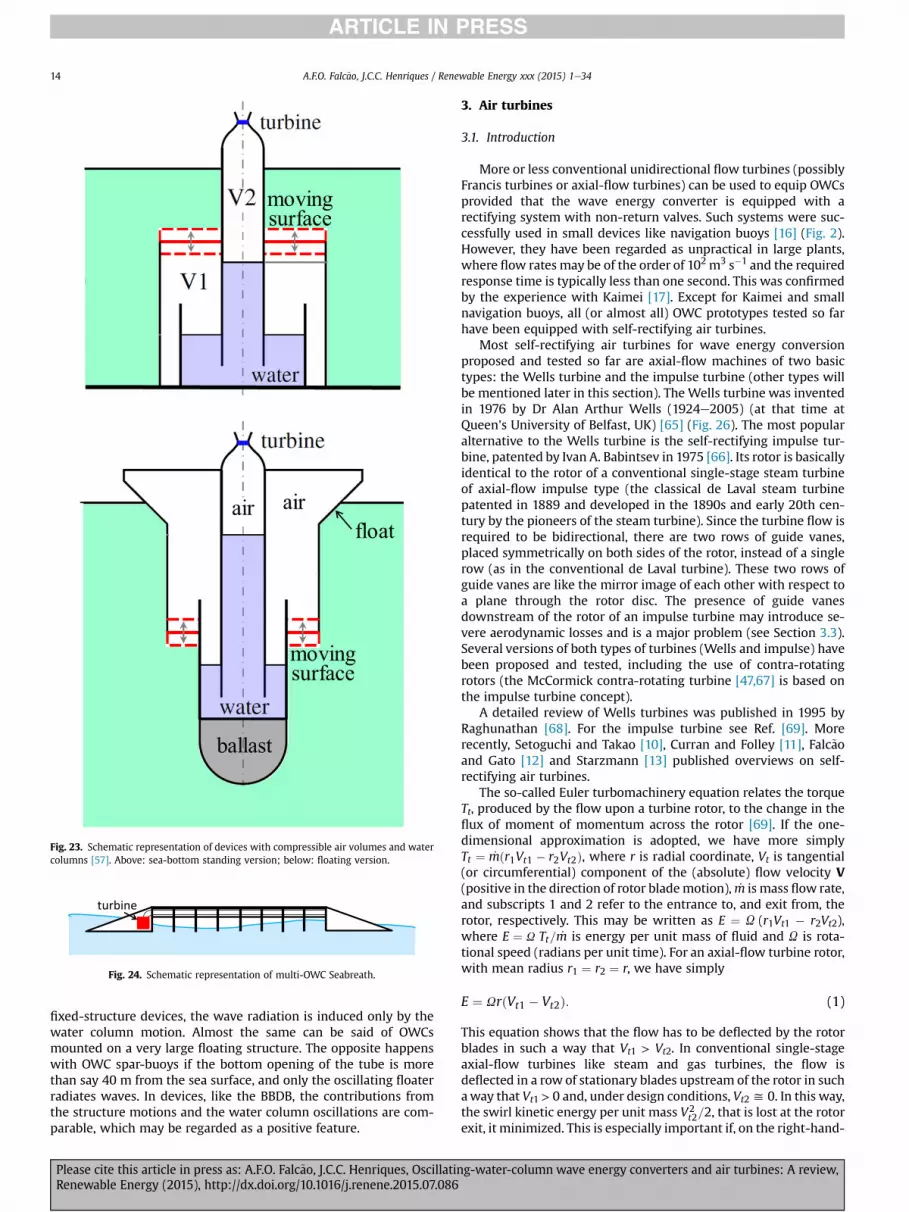
Fig. 23. Schematic representation of devices with compressible air volumes and watercolumns [57]. Above: sea-bottom standing version; below: floating version.
turbine
Fig. 24. Schematic representation of multi-OWC Seabreath.
A.F.O. Falc~ao, J.C.C. Henriques / Renewable Energy xxx (2015) 1e3414
fixed-structure devices, the wave radiation is induced only by thewater column motion. Almost the same can be said of OWCsmounted on a very large floating structure. The opposite happenswith OWC spar-buoys if the bottom opening of the tube is morethan say 40 m from the sea surface, and only the oscillating floaterradiates waves. In devices, like the BBDB, the contributions fromthe structure motions and the water column oscillations are com-parable, which may be regarded as a positive feature.
Please cite this article in press as: A.F.O. Falc~ao, J.C.C. Henriques, OscillatinRenewable Energy (2015), http://dx.doi.org/10.1016/j.renene.2015.07.086
3. Air turbines
3.1. Introduction
More or less conventional unidirectional flow turbines (possiblyFrancis turbines or axial-flow turbines) can be used to equip OWCsprovided that the wave energy converter is equipped with arectifying system with non-return valves. Such systems were suc-cessfully used in small devices like navigation buoys [16] (Fig. 2).However, they have been regarded as unpractical in large plants,where flow rates may be of the order of 102 m3 s�1 and the requiredresponse time is typically less than one second. This was confirmedby the experience with Kaimei [17]. Except for Kaimei and smallnavigation buoys, all (or almost all) OWC prototypes tested so farhave been equipped with self-rectifying air turbines.
Most self-rectifying air turbines for wave energy conversionproposed and tested so far are axial-flow machines of two basictypes: the Wells turbine and the impulse turbine (other types willbe mentioned later in this section). The Wells turbine was inventedin 1976 by Dr Alan Arthur Wells (1924e2005) (at that time atQueen's University of Belfast, UK) [65] (Fig. 26). The most popularalternative to the Wells turbine is the self-rectifying impulse tur-bine, patented by Ivan A. Babintsev in 1975 [66]. Its rotor is basicallyidentical to the rotor of a conventional single-stage steam turbineof axial-flow impulse type (the classical de Laval steam turbinepatented in 1889 and developed in the 1890s and early 20th cen-tury by the pioneers of the steam turbine). Since the turbine flow isrequired to be bidirectional, there are two rows of guide vanes,placed symmetrically on both sides of the rotor, instead of a singlerow (as in the conventional de Laval turbine). These two rows ofguide vanes are like the mirror image of each other with respect toa plane through the rotor disc. The presence of guide vanesdownstream of the rotor of an impulse turbine may introduce se-vere aerodynamic losses and is a major problem (see Section 3.3).Several versions of both types of turbines (Wells and impulse) havebeen proposed and tested, including the use of contra-rotatingrotors (the McCormick contra-rotating turbine [47,67] is based onthe impulse turbine concept).
A detailed review of Wells turbines was published in 1995 byRaghunathan [68]. For the impulse turbine see Ref. [69]. Morerecently, Setoguchi and Takao [10], Curran and Folley [11], Falc~aoand Gato [12] and Starzmann [13] published overviews on self-rectifying air turbines.
The so-called Euler turbomachinery equation relates the torqueTt, produced by the flow upon a turbine rotor, to the change in theflux of moment of momentum across the rotor [69]. If the one-dimensional approximation is adopted, we have more simplyTt ¼ _mðr1Vt1 � r2Vt2Þ, where r is radial coordinate, Vt is tangential(or circumferential) component of the (absolute) flow velocity V(positive in the direction of rotor blademotion), _m is mass flow rate,and subscripts 1 and 2 refer to the entrance to, and exit from, therotor, respectively. This may be written as E ¼ U (r1Vt1 � r2Vt2),where E ¼ U Tt= _m is energy per unit mass of fluid and U is rota-tional speed (radians per unit time). For an axial-flow turbine rotor,with mean radius r1 ¼ r2 ¼ r, we have simply
E ¼ UrðVt1 � Vt2Þ: (1)
This equation shows that the flow has to be deflected by the rotorblades in such a way that Vt1 > Vt2. In conventional single-stageaxial-flow turbines like steam and gas turbines, the flow isdeflected in a row of stationary blades upstream of the rotor in suchaway that Vt1 > 0 and, under design conditions, Vt2y 0. In this way,the swirl kinetic energy per unit mass V2
t2=2, that is lost at the rotorexit, it minimized. This is especially important if, on the right-hand-
g-water-column wave energy converters and air turbines: A review,

Fig. 25. Schematic representation of multi-OWC LEANCON.
Fig. 26. Dr Alan Arthur Wells, inventor of the Wells turbine (1924e2005).
A.F.O. Falc~ao, J.C.C. Henriques / Renewable Energy xxx (2015) 1e34 15
side of Eq. (1), the blade velocity U r is not much larger thanDVt ¼ Vt1 � Vt2, as is the case of impulse turbines.
Because of construction reasons, open turbomachines, likehorizontal-axis wind turbines and marine-current turbines, are notprovided with guide vanes. On the other hand, the blade tip speedis much larger than DVt (or than the axial velocity component), andthe exit kinetic energy V2
t2=2 is a small fraction of the work E. In theWells turbine under normal working conditions, the rotor bladespeed is also much larger than the flow velocity. For this reason,V2t2=2 is a relatively small fraction of the work E, and the absence of
stator blades does not dramatically impair the turbine efficiency.The cascade model is a convenient two-dimensional approxi-
mation to an axial-flow turbomachine: the blades are intersectedby a circular cylindrical surface that is developed onto a plane. Thethree-dimension flow is replaced by a two-dimensional plane flowabout a rectilinear periodic row, or cascade, of aerofoil profiles (seee.g. Ref. [69]). Equation (1) is replaced by
E ¼ UrVxðcot a2 � cot a1Þ; (2)
where Vx is the axial component of the flow velocity (assumed totake equal values upstream and downstream of the cascade) andcotai ¼ Vx/Vti (i ¼ 1, 2). The cascade approximation will be used inSections 3.2 and 3.3 in the introductory study of the flow throughWells and axial-flow impulse turbines.
Please cite this article in press as: A.F.O. Falc~ao, J.C.C. Henriques, OscillatinRenewable Energy (2015), http://dx.doi.org/10.1016/j.renene.2015.07.086
3.2. Wells turbines
We consider now the special case of the Wells turbine (withoutand with guide vanes), and the corresponding cascades and ve-locity diagrams (Fig. 27). The absolute flow velocity, relative flowvelocity and rotor blade velocity are denoted by vectors V,W and U,respectively (with U ¼ Ur). The rotor blade profile is symmetricaland the blades are set at a stagger angle of 90� (i.e. they are sym-metrical with respect to a plane perpendicular to the rotor axis).Early theoretical investigations on the Wells turbine aerodynamics,based on the two-dimensional cascade flow model, are reported inRefs. [70e72] (Fig. 27).
We consider the two-dimensional cascade flow approximation,and denote by c the rotor blade chord and by t¼ 2p r/Z (Z¼ numberof blades) the rotor blade pitch. Before dealing with real fluid flow,we derive some remarkable aerodynamic properties of the Wellsturbine from well-known analytical results for a cascade of flatplates in incompressible irrotational flow [73e75] (see also [12]).For that, as an approximation, we assume incompressible irrota-tional flow and neglect the blade thickness. We find (see Ref. [76])
cot a2 ¼ cot a1 þ 2 tanpc2t
: (3)
From Eq. (2), we directly obtain, for the rotor work per unit massof air,
E ¼ 2UrVx tanpc2t
: (4)
Equation (3) shows that the exit flow angle a2 depends only ona1 and on the rotor chord-to-pitch ratio c/t, not on the flow rate oron the rotational speed. This is the basis of the design of guidevanes for a Wells turbine. If the two rows of guide vanes are to bethe mirror image of each other, it should be a2 ¼ p � a1. Then
a1 ¼ p
2
�1þ c
t
�(5)
is the angle at which the flow should leave the first row of guidevanes [80]. It is important to relate the pressure drop Dp to the flowrate. We define a dimensionless pressure coefficientj ¼ Dp(r U2r2)�1 (r ¼ air density) and a dimensionless flow ratecoefficient f ¼ VxU
�1r�1. Assuming as before perfect-fluid flow, itcan be found for a Wells turbine cascade with guide vanes [12,76]
g-water-column wave energy converters and air turbines: A review,

Fig. 28. Two-dimensional cascade representation of the Wells turbine with two contra-rotating rotors.
Fig. 27. Wells turbine, two-dimensional cascade representation and velocity diagrams: (a) without guide vanes; (b) with guide vanes.
A.F.O. Falc~ao, J.C.C. Henriques / Renewable Energy xxx (2015) 1e3416
j ¼ 2f tanpc2t
: (6)
In the case of a Wells turbine without guide vanes, Eq. (6) isreplaced by (see Ref. [12])
j ¼ 2f�1þ f tan
pc2t
�tan
pc2t
: (7)
Please cite this article in press as: A.F.O. Falc~ao, J.C.C. Henriques, OscillatinRenewable Energy (2015), http://dx.doi.org/10.1016/j.renene.2015.07.086
Equation (6), applicable to a Wells turbine with guide vanes, is alinear relationship between pressure and flow rate. The slope of thestraight line increases with the rotor blade-chord-to-pitch ratio c/t.In the case of a Wells turbine without guide vanes (see Eq. (7)), thelinear relationship is an approximation, since in generalf tanðp c=2tÞ is much smaller than unity. This linear relationship isapproximately confirmed by results from model testing. Indeed,
g-water-column wave energy converters and air turbines: A review,

Fig. 29. 400 kW variable-pitch Wells turbine built for installation at the Pico plant. Thecontrol mechanism is driven by eddy currents.
A.F.O. Falc~ao, J.C.C. Henriques / Renewable Energy xxx (2015) 1e34 17
unlike other self-rectifying turbines, theWells turbine is commonlyregarded as a linear turbine.
Apart from two rows of guide vanes one on each side of therotor, there are other ways of avoiding exit losses due to swirlingflow, while keeping the turbine insensitive to reversing flow di-rection. One of them is the contra-rotating turbine without guidevanes: there are two rows of rotor blades (with identical profile andblade pitch) that rotate in opposite directions with equal speed, asshown in Fig. 28. For the whole turbine it is
j1 þ j2 ¼ 4f tanpc2t
: (8)
and E ¼ E1þE2, with E1 ¼ E2 given by the right-hand-side of Eq. (4).The work per unit mass E done by a rotor with a single row of
blades increases with the chord-to-pitch ratio c/t, as shown by Eq.(4). Obviously this ratio cannot be too close to unity. The contra-rotating rotor configuration provides a way of doubling the workE. A major disadvantage is the increased complexity due to twoturbine-generator rotating sets and the duplication of the powerelectronics. An alternative way is to have two axially-offset rows ofrotor blades mounted on a single rotor (biplane rotor). As theoriginal monoplane Wells turbine, the biplane Wells turbine orig-inated also at the Queen's University of Belfast [77] where it wasobject of investigations whose results are reported in detail inRaghunathan's review paper [68]. The biplane rotor can be com-plemented or not by guide vanes on both sides of the rotating bladeset (see Ref. [12]). BiplaneWells turbines without guide vanes wereused in the cliff-integrated Islay OWC plant commissioned in 1995[20] and, more recently, in the Mutriku OWC breakwater [31]. Adifferent configuration, proposed in Ref. [78], consists in placing theguide vanes between the two rotor blade rows. If properly designed(see Ref. [12]), this arrangement can provide a way of avoiding orminimizing swirl kinetic energy losses at turbine exit. It can also beextended to more than two rotor blade planes, in what could beconsidered as amulti-stage turbine. MultistageWells turbines wereinvestigated as an alternative to impulse turbines in OWCs char-acterized by relatively large air pressure oscillations [79].
In linear (small amplitude) water wave theory, the wave crestsand troughs are of similar amplitude and so the predicted air flowvelocities through the turbine are of identical magnitudes in bothdirections. However, this is not true for real sea waves, especially inmore energetic sea states. The wave crests tend to be higher andshorter as compared with the wave troughs. Consequently the flowconditions through the air turbine may be significantly different,with peak velocities for outward flow in general larger than forinward flow. In order to equalize the peak values of the angle ofincidence at the inlet to rotor blades in inward and outward flows(and avoid stalling losses due to excessive incidence), a staggerangle (slightly) different from 90� may be adopted, as proposed inRefs. [80,81].
Turbines whose rotor blade setting angle (stagger angle) isadjustable and controllable have been proposed and built. A400 kW variable-pitch Wells turbine, whose sophisticated controlmechanism was driven by eddy currents was designed and con-structed [82], Fig. 29. This will be mentioned again in Section 5.1 inconnection with reactive control.
3.3. Axial-flow self-rectifying impulse turbine
The most frequently proposed alternative to theWells turbine isthe axial-flow self-rectifying impulse turbine (Fig. 30). In the im-pulse turbine (unlike in the Wells turbine), neighbouring rotorblades form channels or ducts. The exit flow angle (in a referenceframe fixed to the blade row) is approximately equal to the exit
Please cite this article in press as: A.F.O. Falc~ao, J.C.C. Henriques, OscillatinRenewable Energy (2015), http://dx.doi.org/10.1016/j.renene.2015.07.086
angle of the (moving or fixed) blades (the angular difference cor-responding to the effect of slip).
The geometry of the rotor blades is a modified version of theclassical steam turbine of impulse type (see e.g. Ref. [69]): thesymmetry now imposes two sharp edges and equal inlet and outletblade angles. As for the Wells turbine, we replace the three-dimensional annular row of rotor blades by the correspondingtwo-dimensional cascade of blades (Fig. 30) and assume the flow tobe incompressible and irrotational.We denote by a and b the anglesof the absolute and relative flow velocities. Those angles (at inletand outlet) are related to each other by cota1 ¼ �f�1 þ cotb1,cota2 ¼ �f�1 þ cotb2, where, as before, f ¼ Vx/U is a dimensionlessflow coefficient and Vx is the axial velocity component. We notethat a1> b1 and a2> b2. Fig. 30 shows that, under design conditions,the flow leaves the rotor at an angle a2 significantly larger thanp � a1, where a1 is the exit flow angle from the inlet guide-vanerow. We note that symmetry considerations require a secondguide-vane row to exist, which is the mirror image of the first one.The “ideal” inlet flow angle into this guide-vane system (i.e. forstall-free conditions) is equal to p � a1. However, for “design” flowconditions, this cannot occur. An incompatibility situation arisesfrom this: one cannot have simultaneously the right flow incidence(i.e. stall-free conditions) at the rotor blades and at the secondguide-vane row, a problem that has been known since the begin-ning to designers of impulse turbines for wave energy applications.
McCormick [47,83] proposed a contra-rotating self-rectifyingimpulse turbine, a prototype of which was built and tested inKaimei in the mid-1980s. Results from testing can be found in Ref.[83]. The excessive incidence problem persists in the contra-rotating turbine, in the relative flow at the inlet to the second
g-water-column wave energy converters and air turbines: A review,

Fig. 30. Self-rectifying impulse turbine: rotor with twin guide vane system. Below: two-dimensional cascade representation.
A.F.O. Falc~ao, J.C.C. Henriques / Renewable Energy xxx (2015) 1e3418
rotor, and (as in the single-rotor turbine) also in the flow at the inletto the second row of guide vanes.
To solve the excessive incidence problem, guide vanes of vari-able geometry have been proposed by Kim et al. [84] (see also areview in Ref. [9]). In order to avoid the difficulties of activegeometry-control, the vanes (or a segment of them) may pivotunder the action of the aerodynamic moments acting on them, andoccupy one of two pre-set angular positions, depending onwhetherthe air is flowing inwards or outwards (Fig. 31). This allows thedownstream guide-vane geometry to better match the angle a2 ofthe flow leaving the rotor. Although this conception increases themechanical complexity and introduces additional reliability andmaintenance problems, it has been found to improve the aero-dynamic performance of the turbine.
In any case, since the flow coefficient f is strongly time-varying,oscillating irregularly between negative and positive values, it isimpossible to avoid aerodynamic stalling at the rotor blades and/or atthe downstreamguidevanesduring a relatively largepart of the time.
3.4. Wells turbine versus axial-flow impulse turbine
The operating flow range of a Wells turbine is known to berelatively narrow: for increasing flow rate, the efficiency drops
Please cite this article in press as: A.F.O. Falc~ao, J.C.C. Henriques, OscillatinRenewable Energy (2015), http://dx.doi.org/10.1016/j.renene.2015.07.086
sharply when stalling at rotor blades occurs [10e12,68]. For thebest designs, peak efficiency under laboratory conditions was foundto reach about 75% [13].
The main problem with the impulse turbine lies in the largeaerodynamic losses due to excessive incidence flow angle at theentry to the second row of guide vanes (this is a result of therequired symmetry of the guide vane rows with respect to eachother). Although the operational flow range of the impulse turbineis wider comparedwith theWells turbine, its peak efficiency hardlyexceeds about 50%. To reduce these losses, guide vanes of variablegeometry have been proposed (see Section 3.3). This was found toincrease the peak aerodynamic performance of the turbine up toabout 60%. A comparison of the efficiency-versus-flow-rate curvesof the two types of turbines is shown in Fig. 32.
The two-dimensional representation may be used to make com-parisons between rotational speed, basic aerodynamic performanceand rotor diameter of the Wells turbine and of the impulse turbine.Westartbyconsidering thedimensionless turbine loadingcoefficient,defined as E*¼E(Ur)�2. For the Wells turbine (subscript W) with asingle-plane rotor, with or without guide vanes, it is (see Eq. (4))
E*W ¼ 2Vx
Urtanðpc=2tÞ: (9)
g-water-column wave energy converters and air turbines: A review,

Fig. 31. Two-dimensional representation of impulse turbine with self-pitching guidevanes (of mono-vane type) in the two angular positions.
Fig. 32. Efficiency versus flow coefficient ratio F=Fh for a monoplane Wells turbinewith guide vanes and an impulse turbine with fixed guide vanes. Fh denotes peakefficiency conditions. From Ref. [12].
Table 1Comparison between typical Wells (W) and impulse (imp) turbines.Ratios are shown for axial flow velocity Vx; outer rotor diameter D androtational speed U: The work per unit mass E, the flow rate and theinner-to-outer diameter ratio Di=D are the same for both turbines.
V2xW
V2x imp
DWDimp
UWUimp
0.27 1.4 1.7
A.F.O. Falc~ao, J.C.C. Henriques / Renewable Energy xxx (2015) 1e34 19
We note that, in the absence of guide vanes, it isf ¼ Vx(Ur)�1 ¼ tanb1. In real-fluid flow, it is known that aero-dynamic stalling (boundary layer separation) will occur (with se-vere aerodynamic losses) if the angle of incidence b1 at rotor inletexceeds a critical value b1cr that depends on blade profile, chord-to-pitch ratio c/t, upstream flow conditions and Reynolds number.Taking b1¼ b1cr, and assuming as typical b1cr¼ 11� and c/t¼ 0.5, wefind, for the loading coefficient, E*Wy0:39. For the impulse turbine(subscript “imp”), from similar considerations [12], it can be found
Please cite this article in press as: A.F.O. Falc~ao, J.C.C. Henriques, OscillatinRenewable Energy (2015), http://dx.doi.org/10.1016/j.renene.2015.07.086
that E*impy2:0. We conclude that, for fixed work E per unit mass,the blade speed U r of the Wells turbine is typically aboutffiffiffiffiffiffiffiffiffiffiffiffiffiffiffiffiffiffiffi2:0=0:39
p ¼ 2:3 times larger as compared with the impulseturbine.
The two-dimensional flow approximation was used in Ref. [12]to compare the Wells turbine (subscript W) and the axial-flowimpulse turbine (subscript imp), it being assumed that the work Eper unit mass, the turbine flow rate and the inner/outer diameterratio Di/D are equal for both turbines. The results are given inTable 1, in terms of ratios, for V2
x (twice the exit kinetic energy perunit mass), the rotor outer diameter D and the rotational speed U.Table 1 shows that the rotor blade speed is much larger in a Wellsturbine, which also has a larger diameter and larger rotationalspeed. This indicates that aerodynamic noise problems are ex-pected to be much more serious in the Wells turbine (see Section3.8), which, on the other hand, has a much larger capacity for en-ergy storage by flywheel effect (this is important to smooth out thepower oscillations in the electrical equipment).
The loss related to swirl kinetic energy at the exit from the lastrow of blades can be avoided (or reduced) by the use of guide vanesor (in the case of the Wells turbine) of contra-rotating rotors. Theloss of the kinetic energy (per unit mass) associated to the axialflow velocity, V2
x =2, cannot be avoided except if some kind of,possibly axisymmetric, divergent duct is used as a diffuser. This lossis much greater in the impulse turbine than the Wells turbine, asshown in the first column of Table 1. This explains why the use of anaxisymmetric diffuser is much more important in an impulse tur-bine than in a Wells turbine.
The two-dimensional flow analysis indicates that the efficiencyof the Wells turbine can be much more sensitive to changes inReynolds number than the efficiency of the impulse turbine [12].The Wells turbine is known to perform poorly in small modeltesting (and small flow velocities), more so than the impulse tur-bine, mostly due to Reynolds number effects. A fair comparisonbetween the two turbines should be based on results from testingat sufficiently large Reynolds number. Some of the comparisons inthe published literature that show the Wells turbine with sub-stantially lower peak efficiency than the impulse turbine are basedon testing of models of 0.3 m outer rotor diameter or less at rela-tively small Reynolds number.
3.5. Other axial-flow air turbines for bidirectional flows
An alternative method of reducing the aerodynamic losses byexcessive incidence angle at the entrance to the second row ofguide vanes of an impulse turbine consists in increasing the dis-tance between the guide vane rows and the rotor blades, with theobject of reducing the velocity (and hence the kinetic energy) of theflow at the entrance to the second row of guide vanes and in thisway reduce the energy losses due to boundary layer separation(stalling) at those vanes. This methodology was proposed in Refs.[85,86]: the two rows of guide vanes, one on each side of the rotor,are offset from the rotor blades, radially as well as axially, withannular ducts connecting the guide vane sets with the rotor bladerow. The radial offset allows, by conservation of angular
g-water-column wave energy converters and air turbines: A review,

A.F.O. Falc~ao, J.C.C. Henriques / Renewable Energy xxx (2015) 1e3420
momentum, the circumferential component of the flow velocity tobe reduced at the entrance to the second row of guide vanes. Thisradial offset, eventually combined with an increase in the gap be-tween the inner and outer walls of the annular ducts (i.e. an in-crease in blade span of the stator system), produces also a decreasein the meridian component (projected onto an axial plane) of theflow velocity. One such turbine, commercially named HydroAir(Fig. 33), equipped the 1:3rd-scale floating OWC prototypeOceanlinxMk3 briefly tested off Port Kembla, Australia, in 2010 (seeFig. 20).
The so-called Denniss-Auld turbine, developed in Australia toequip OWC plants [87,88], is a self-rectifying axial-flow turbine,that shares some characteristics with the variable-pitch Wellsturbine, the main difference being that the setting angle g of theDenniss-Auld rotor blades (Fig. 34) may be controlled to varywithin a range a < g < p � a (where ay20� 35�), whereas in thevariable-pitch Wells turbine it is �q < g < q (with qy25�). While inthe Wells turbine the rotor blade rounded leading edge faces theincoming flow all the time, in the Denniss-Auld turbine both edgesof a blade must be identical since (like in the impulse turbine rotor)each edge behaves alternately as a leading edge or as a trailing edgedepending on the direction of the reciprocating flow through theturbine. It is to be noted that, whenever the flow changes direction(exhaust or intake), the blades of the Denniss-Auld turbine arerequired to pivot almost instantaneously between their extremepositions, whereas in the Wells turbine the blades are required topivot smoothlywithin a relatively small angular range. Results frommodel testing gave a peak efficiency of 0.65 [88]. A Dennis-Auldturbine prototype was tested in Oceanlinx Mk3 side-by-side withthe HydroAir turbine (Fig. 20).
Fig. 33. HydroAir turbine.
Fig. 34. Denniss-Auld turbine. Below: velocity diagram and blade setting angle g.
Please cite this article in press as: A.F.O. Falc~ao, J.C.C. Henriques, OscillatinRenewable Energy (2015), http://dx.doi.org/10.1016/j.renene.2015.07.086
3.6. Radial-flow self-rectifying air turbines
Apart from the more common axial-flow configuration, studieshave also beenmade on radial-flow self-rectifying impulse turbines(Fig. 35). It should be noted that the turbine is no longer insensitiveto the flow direction: the flow through the rotor blades and guidevanes is radially centrifugal or centripetal depending on the wavecycle. The turbine is connected to the OWC chamber by an axialduct, whereas the exit to, or admission from, the atmosphere isradial. The radial turbine was investigated by model testing[89e91] and by numerical simulation [92e95]. Takao et al. [96]investigated the effect of pitch-controlled (inner and outer) guidevanes, and found an increase up to about 15% in the efficiency incomparison with fixed guide vanes. With the available (experi-mental and numerical) information, the radial configuration of theimpulse turbine appears as an alternative to the axial one, althoughnot necessarily a better choice.
A radial-flow version of the classical axial-flow Wells turbinewas proposed by John Kentfield in 1983 [97], and was recentlystudied by numerical simulation and experimentally [98,99](Fig. 36). The results from model testing revealed that, as for themore conventional axial-flow Wells turbine, the pressure head isapproximately a linear function of the flow rate, and a sharp dropin efficiency occurs if the flow rate exceeds a critical value; thisvalue is about 30% higher for outward flow. A peak efficiency of0.65 was measured for outward flow, compared with 0.60 forinward flow.
g-water-column wave energy converters and air turbines: A review,
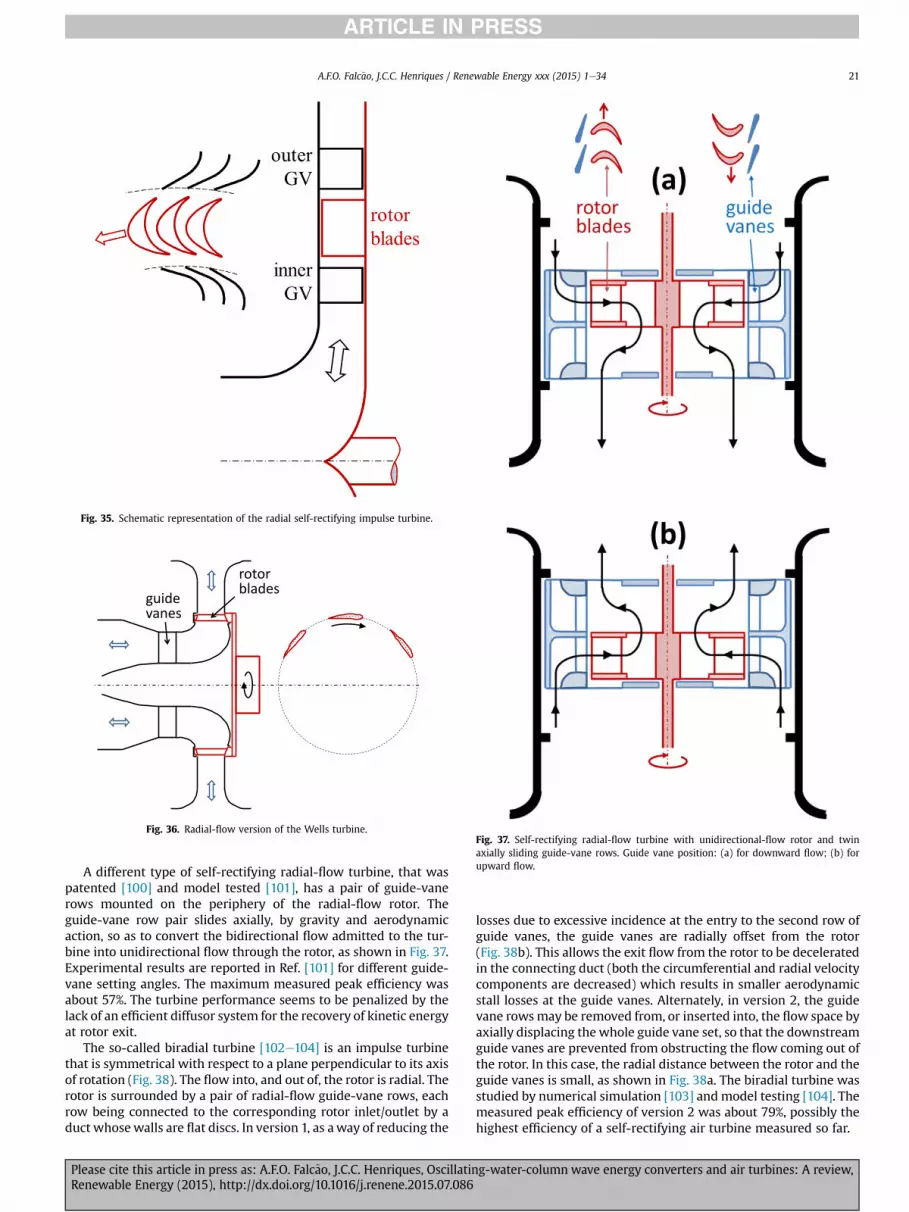
Fig. 37. Self-rectifying radial-flow turbine with unidirectional-flow rotor and twinaxially sliding guide-vane rows. Guide vane position: (a) for downward flow; (b) forupward flow.
Fig. 35. Schematic representation of the radial self-rectifying impulse turbine.
guide vanes
rotor blades
Fig. 36. Radial-flow version of the Wells turbine.
A.F.O. Falc~ao, J.C.C. Henriques / Renewable Energy xxx (2015) 1e34 21
A different type of self-rectifying radial-flow turbine, that waspatented [100] and model tested [101], has a pair of guide-vanerows mounted on the periphery of the radial-flow rotor. Theguide-vane row pair slides axially, by gravity and aerodynamicaction, so as to convert the bidirectional flow admitted to the tur-bine into unidirectional flow through the rotor, as shown in Fig. 37.Experimental results are reported in Ref. [101] for different guide-vane setting angles. The maximum measured peak efficiency wasabout 57%. The turbine performance seems to be penalized by thelack of an efficient diffusor system for the recovery of kinetic energyat rotor exit.
The so-called biradial turbine [102e104] is an impulse turbinethat is symmetrical with respect to a plane perpendicular to its axisof rotation (Fig. 38). The flow into, and out of, the rotor is radial. Therotor is surrounded by a pair of radial-flow guide-vane rows, eachrow being connected to the corresponding rotor inlet/outlet by aduct whosewalls are flat discs. In version 1, as away of reducing the
Please cite this article in press as: A.F.O. Falc~ao, J.C.C. Henriques, OscillatinRenewable Energy (2015), http://dx.doi.org/10.1016/j.renene.2015.07.086
losses due to excessive incidence at the entry to the second row ofguide vanes, the guide vanes are radially offset from the rotor(Fig. 38b). This allows the exit flow from the rotor to be deceleratedin the connecting duct (both the circumferential and radial velocitycomponents are decreased) which results in smaller aerodynamicstall losses at the guide vanes. Alternately, in version 2, the guidevane rowsmay be removed from, or inserted into, the flow space byaxially displacing thewhole guide vane set, so that the downstreamguide vanes are prevented from obstructing the flow coming out ofthe rotor. In this case, the radial distance between the rotor and theguide vanes is small, as shown in Fig. 38a. The biradial turbine wasstudied by numerical simulation [103] andmodel testing [104]. Themeasured peak efficiency of version 2 was about 79%, possibly thehighest efficiency of a self-rectifying air turbine measured so far.
g-water-column wave energy converters and air turbines: A review,

Fig. 38. Biradial turbine: (a) version 2, with axially-sliding guide vanes; (b) version 1, with radially-offset fixed guide vanes; (c) perspective view of version 2. GV ¼ guide vanes,RB ¼ rotor blades.
Fig. 39. Twin unidirectional impulse turbine topology.
A.F.O. Falc~ao, J.C.C. Henriques / Renewable Energy xxx (2015) 1e3422
Single stage conventional turbines, like steam and gas turbines,with a row of guide vanes followed by a bladed rotor, are known toattain high efficiencies in unidirectional flow. In such turbines, ifthe sign of the pressure head is changed (and the rotational speed iskept unaltered), the flow rate (apart from changing sign) becomesmuch smaller (and the turbine performance becomes very poor).This has led to the idea of associating two identical “conventional”air turbines (turbines T1 and T2) in parallel to convert the pneu-matic energy from an OWC, such that, for a given pressure headsituation, the flow sequence guide-vanes-rotor-blades in turbine T1is reversed with respect to turbine T2 (see Refs. [105e107]). Thistopology is shown in Fig. 39. With this arrangement, for a givenpressure head (independently of its sign), most of the flow isadmitted to one of the turbines (that is drivenwith good efficiency)
Please cite this article in press as: A.F.O. Falc~ao, J.C.C. Henriques, Oscillating-water-column wave energy converters and air turbines: A review,Renewable Energy (2015), http://dx.doi.org/10.1016/j.renene.2015.07.086

A.F.O. Falc~ao, J.C.C. Henriques / Renewable Energy xxx (2015) 1e34 23
while a smaller fraction of the flow is admitted to the other turbine(that is in choking mode and operates at very low efficiency). Thetwo turbines can be coupled to a common electrical generator (as inFig. 39) or, alternately, each turbine is coupled to its own generator.Since the turbines are not symmetrical, their rotor blades, as inFig. 39, need no longer to be symmetrical with respect to the mid-chord point. Some positive degree of reaction may be convenient.Model testing of a unidirectionaleturbine pair in a rig capable of bi-directional oscillating air flow is reported in Ref. [106]. The turbinerotor diameter was 165 mm and each turbine was coupled to itsown generator. A peak efficiency of 0.6 was measured. The aero-dynamic performance of the twin unidirectional turbine configu-ration was numerically simulated in detail in Ref. [108]. It wasfound that the flow rate through the turbine in reverse mode isabout one-third of the total flow and produces a negative torquewhich reduces the system efficiency if the two turbines are directlyconnected to the same rotation axis.
3.7. Some air turbine prototypes
Several full-sized OWC prototypes have been deployed into thesea; in some cases large models at scales about 1:3rd to 1:4th havebeen tested in sheltered waters. The first large prototype was Kai-mei, already mentioned in Section 2.1, in whose thirteen open-bottom chambers different types of turbines were tested(including unidirectional, Wells and self-rectifying impulse tur-bines). Since then, most prototypes were equipped with Wellsturbines, some of which are listed in Table 2, together with theirmain characteristics. Remarkable for their size are the pair of2�500 kW contra-rotating Wells turbines that equipped thebottom-standing OSPREY prototype (Fig. 40). They never operated:the plant structure was damaged during deployment in Scotland in1995 and later destroyed by wave action.
The Indian bottom-standing OWC plant, commissioned in 1991,was operated with several axial-flow self-rectifying air turbines ofWells and impulse type [24]. The Mutriku plant recently completedin northern Spain (Fig. 15) comprises 16 OWC chambers, eachequipped with a 0.75 m-diameter vertical axis Wells turbine ofbiplane type without guide vanes, rated 18.5 kW [31,113]. TheDenniss-Auld turbine equipped the several OWC prototypes Mk1(bottom standing) to Mk3 (floating), developed in Australia. Theprototype Mk 3 (1:3rd scale), briefly tested in 2010, also incorpo-rated a HydroAir impulse turbine (Figs. 20 and 33). The 1:4th-scaleBBDB OWC (the OE Buoy) tested in Galway Bay, Ireland, between2008 and 2011 (Fig. 18) was equipped first with aWells turbine andlater with an axial-flow self-rectifying impulse turbine with actu-ated variable-pitch guide vanes [41,42], Fig. 41. The recentlycompleted bottom-standing OWC, located at Juju Island, SouthKorea (Fig. 14), is equipped with two 250 kW axial-flow impulseturbines of 1.8 m diameter, with 26 rotor blades and fixed guidevanes (Fig. 42).
Table 2Characteristics of Wells turbines of some OWC prototypes. Type: MP ¼monoplane; BP ¼to-tip ratio; Z ¼ rotor blade number; c ¼ rotor blade chord; s ¼ solidity (total bladed ar
Plant Year Type D (m)
Sakata, Japan [109] 1989 MP, GV 1.337Vizhijam, �India [110] 1991 MP 2.0Islay, UK [111] 1991 BP 1.2OSPREY, UK 1995 CR 3.5Mighty Whale, Japan [43] 1998 MP, GV 1.7Pico, Portugal [25] 1999 MP, GV 2.3LIMPET, UK [26] 2000 CR 2.6Pico, Portugal [82,112] 2001 VP 1.7Mutriku, Spain [113] 2011 BP 0.75
Please cite this article in press as: A.F.O. Falc~ao, J.C.C. Henriques, OscillatinRenewable Energy (2015), http://dx.doi.org/10.1016/j.renene.2015.07.086
3.8. Turbine noise
All turbines operating with air or other gas produce noise. Thiscan be a nuisance if the machine is located near an inhabited areaand is not properly shielded, as is the case of many wind turbines.Noise can also be a problem with air turbines for wave energyconversion, especially in shoreline or nearshore applications.Produced noise level increases with machine size and especiallywith flow velocity and rotor blade speed. This means that it mayaffect particularly Wells turbines, especially under stalled flowconditions. A noise attenuation chamber had to be retrofitted ontothe end of the Wells turbine ducting of the LIMPET shoreline plant(Islay island, Scotland) to reduce the transmitted noise. This turnedout to cause mal-distribution of flow during the intake stroke of theturbine; the increased air flow at the bottom of the turbine ductingcaused a further increase in stall with an associated reduction inturbine performance [114,115].
Takao et al. [116] performed a model testing investigation onseveral self-rectifying air turbines and concluded that impulseturbines are superior to Wells turbines on what concerns noisecharacteristics. An extensive experimental investigation on acous-tic characteristics of Wells turbines was carried out at Siegen Uni-versity, in Germany [13,117]. It was found that, for fixed rotationalspeed, the sound power radiated by a Wells turbine increases moreor less steadily with rising pressure head up to an operating pointwhere themaximumpower point is reached. Beyond this point, theturbine stalls and a dramatic increase in sound power is observed. Astalled Wells turbine emits noise that far exceeds all noise levelsfound in a healthy flow regime.
3.9. Dimensional analysis
Dimensional analysis is widely used in turbomachinery studies(see e.g. Ref. [69]). Its application to air turbines for OWCs isespecially useful in two situations: (i) when transposing resultsfrom turbine model testing to full-sized prototype; (ii) to study theeffects of changes in rotational speed upon the aerodynamic per-formance curves of a given turbine.
In OWC converters operating under energetic sea conditions,the pressure oscillations in the air chambermay be large enough forchanges in air density to be non-negligible. This means that Machnumber effects in the turbine flowmay be significant. We consider:(i) the same turbine under different working conditions, or (ii) afull-sized turbine and its geometrically similar model. Dimensionalanalysis requires that three dimensionless quantities take equalvalues for the similarity relationships to apply: Reynolds number,Mach number and inlet-to-outlet pressure ratio [69]. Not muchaccurate information is available from the monitoring of full-sizedprototype air turbines under real sea conditions. Indeed, most in-formation comes from model testing under laboratory conditions,in most cases with turbine rotor diameters between 0.3 and 0.6 m.
biplane; CR ¼ contra-rotating; GV ¼with guide vanes; VP ¼ variable-pitch; h ¼ hub-ea divided by annular area).
h Z c (m) s Pt ðkWÞ0.75 16 0.1625 0.71 300.6 8 0.380 0.611 1500.62 4 þ 4 0.4 0.54 75
2 � 5000.706 8 300.598 8 0.375 0.53 4000.62 7 þ 7 0.329 2 � 0.34 2 � 2500.71 15 0.2 0.66 400
3 þ 3 18
g-water-column wave energy converters and air turbines: A review,
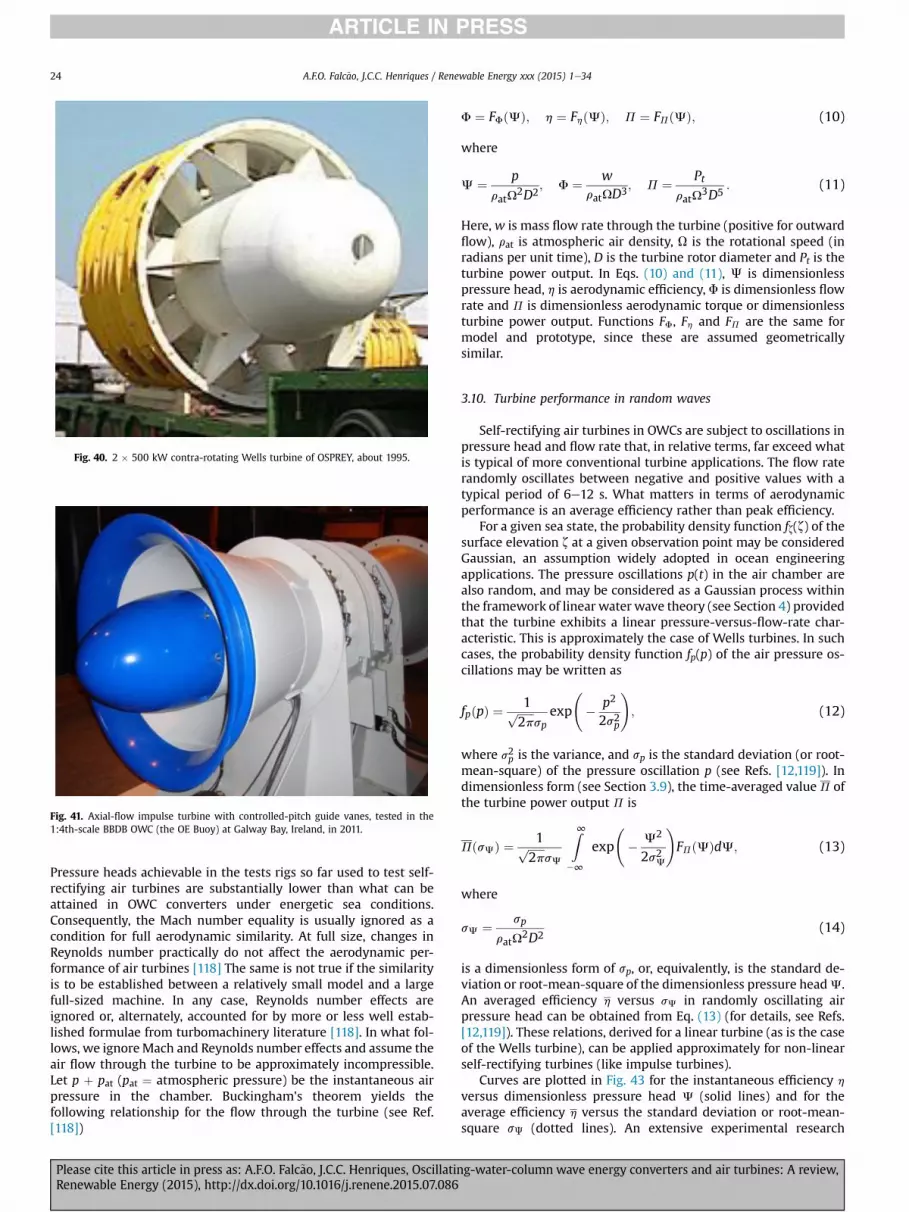
Fig. 40. 2 � 500 kW contra-rotating Wells turbine of OSPREY, about 1995.
Fig. 41. Axial-flow impulse turbine with controlled-pitch guide vanes, tested in the1:4th-scale BBDB OWC (the OE Buoy) at Galway Bay, Ireland, in 2011.
A.F.O. Falc~ao, J.C.C. Henriques / Renewable Energy xxx (2015) 1e3424
Pressure heads achievable in the tests rigs so far used to test self-rectifying air turbines are substantially lower than what can beattained in OWC converters under energetic sea conditions.Consequently, the Mach number equality is usually ignored as acondition for full aerodynamic similarity. At full size, changes inReynolds number practically do not affect the aerodynamic per-formance of air turbines [118] The same is not true if the similarityis to be established between a relatively small model and a largefull-sized machine. In any case, Reynolds number effects areignored or, alternately, accounted for by more or less well estab-lished formulae from turbomachinery literature [118]. In what fol-lows, we ignoreMach and Reynolds number effects and assume theair flow through the turbine to be approximately incompressible.Let p þ pat (pat ¼ atmospheric pressure) be the instantaneous airpressure in the chamber. Buckingham's theorem yields thefollowing relationship for the flow through the turbine (see Ref.[118])
Please cite this article in press as: A.F.O. Falc~ao, J.C.C. Henriques, OscillatinRenewable Energy (2015), http://dx.doi.org/10.1016/j.renene.2015.07.086
F ¼ FFðJÞ; h ¼ FhðJÞ; P ¼ FPðJÞ; (10)
where
J ¼ p
ratU2D2
; F ¼ wratUD3; P ¼ Pt
ratU3D5
: (11)
Here, w is mass flow rate through the turbine (positive for outwardflow), rat is atmospheric air density, U is the rotational speed (inradians per unit time), D is the turbine rotor diameter and Pt is theturbine power output. In Eqs. (10) and (11), J is dimensionlesspressure head, h is aerodynamic efficiency, F is dimensionless flowrate and P is dimensionless aerodynamic torque or dimensionlessturbine power output. Functions FF, Fh and FP are the same formodel and prototype, since these are assumed geometricallysimilar.
3.10. Turbine performance in random waves
Self-rectifying air turbines in OWCs are subject to oscillations inpressure head and flow rate that, in relative terms, far exceed whatis typical of more conventional turbine applications. The flow raterandomly oscillates between negative and positive values with atypical period of 6e12 s. What matters in terms of aerodynamicperformance is an average efficiency rather than peak efficiency.
For a given sea state, the probability density function fz(z) of thesurface elevation z at a given observation point may be consideredGaussian, an assumption widely adopted in ocean engineeringapplications. The pressure oscillations p(t) in the air chamber arealso random, and may be considered as a Gaussian process withinthe framework of linear water wave theory (see Section 4) providedthat the turbine exhibits a linear pressure-versus-flow-rate char-acteristic. This is approximately the case of Wells turbines. In suchcases, the probability density function fp(p) of the air pressure os-cillations may be written as
fpðpÞ ¼ 1ffiffiffiffiffiffi2p
psp
exp
� p2
2s2p
!; (12)
where s2p is the variance, and sp is the standard deviation (or root-mean-square) of the pressure oscillation p (see Refs. [12,119]). Indimensionless form (see Section 3.9), the time-averaged value P ofthe turbine power output P is
PðsJÞ ¼ 1ffiffiffiffiffiffi2p
psJ
Z∞�∞
exp
� J2
2s2J
!FPðJÞdJ; (13)
where
sJ ¼ sp
ratU2D2
(14)
is a dimensionless form of sp, or, equivalently, is the standard de-viation or root-mean-square of the dimensionless pressure headJ.An averaged efficiency h versus sJ in randomly oscillating airpressure head can be obtained from Eq. (13) (for details, see Refs.[12,119]). These relations, derived for a linear turbine (as is the caseof the Wells turbine), can be applied approximately for non-linearself-rectifying turbines (like impulse turbines).
Curves are plotted in Fig. 43 for the instantaneous efficiency h
versus dimensionless pressure head J (solid lines) and for theaverage efficiency h versus the standard deviation or root-mean-square sJ (dotted lines). An extensive experimental research
g-water-column wave energy converters and air turbines: A review,
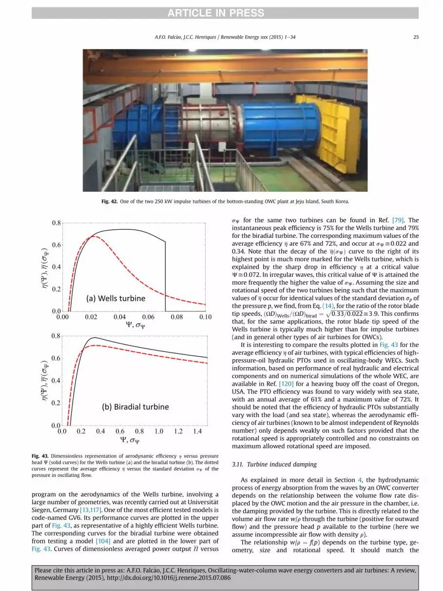
Fig. 43. Dimensionless representation of aerodynamic efficiency h versus pressurehead J (solid curves) for the Wells turbine (a) and the biradial turbine (b). The dottedcurves represent the average efficiency h versus the standard deviation sJ of thepressure in oscillating flow.
Fig. 42. One of the two 250 kW impulse turbines of the bottom-standing OWC plant at Jeju Island, South Korea.
A.F.O. Falc~ao, J.C.C. Henriques / Renewable Energy xxx (2015) 1e34 25
program on the aerodynamics of the Wells turbine, involving alarge number of geometries, was recently carried out at Universit€atSiegen, Germany [13,117]. One of the most efficient tested models iscode-named GV6. Its performance curves are plotted in the upperpart of Fig. 43, as representative of a highly efficient Wells turbine.The corresponding curves for the biradial turbine were obtainedfrom testing a model [104] and are plotted in the lower part ofFig. 43. Curves of dimensionless averaged power output P versus
Please cite this article in press as: A.F.O. Falc~ao, J.C.C. Henriques, OscillatinRenewable Energy (2015), http://dx.doi.org/10.1016/j.renene.2015.07.086
sJ for the same two turbines can be found in Ref. [79]. Theinstantaneous peak efficiency is 75% for the Wells turbine and 79%for the biradial turbine. The corresponding maximum values of theaverage efficiency h are 67% and 72%, and occur at sJy0:022 and0.34. Note that the decay of the hðsJÞ curve to the right of itshighest point is much more marked for the Wells turbine, which isexplained by the sharp drop in efficiency h at a critical valueJy0:072. In irregular waves, this critical value of J is attained themore frequently the higher the value of sJ. Assuming the size androtational speed of the two turbines being such that the maximumvalues of h occur for identical values of the standard deviation sp ofthe pressure p, we find, from Eq. (14), for the ratio of the rotor bladetip speeds, ðUDÞWells=ðUDÞbirad ¼ ffiffiffiffiffiffiffiffiffiffiffiffiffiffiffiffiffiffiffiffiffiffiffiffiffi
0:33=0:022p
y3:9. This confirmsthat, for the same applications, the rotor blade tip speed of theWells turbine is typically much higher than for impulse turbines(and in general other types of air turbines for OWCs).
It is interesting to compare the results plotted in Fig. 43 for theaverage efficiency h of air turbines, with typical efficiencies of high-pressure-oil hydraulic PTOs used in oscillating-body WECs. Suchinformation, based on performance of real hydraulic and electricalcomponents and on numerical simulations of the whole WEC, areavailable in Ref. [120] for a heaving buoy off the coast of Oregon,USA. The PTO efficiency was found to vary widely with sea state,with an annual average of 61% and a maximum value of 72%. Itshould be noted that the efficiency of hydraulic PTOs substantiallyvary with the load (and sea state), whereas the aerodynamic effi-ciency of air turbines (known to be almost independent of Reynoldsnumber) only depends weakly on such factors provided that therotational speed is appropriately controlled and no constraints onmaximum allowed rotational speed are imposed.
3.11. Turbine induced damping
As explained in more detail in Section 4, the hydrodynamicprocess of energy absorption from the waves by an OWC converterdepends on the relationship between the volume flow rate dis-placed by the OWC motion and the air pressure in the chamber, i.e.the damping provided by the turbine. This is directly related to thevolume air flow rate w/r through the turbine (positive for outwardflow) and the pressure head p available to the turbine (here weassume incompressible air flow with density r).
The relationship w/r ¼ f(p) depends on the turbine type, ge-ometry, size and rotational speed. It should match the
g-water-column wave energy converters and air turbines: A review,

A.F.O. Falc~ao, J.C.C. Henriques / Renewable Energy xxx (2015) 1e3426
hydrodynamics requirements, which, for a given OWC device,depend on the sea state, especially on the representative wavefrequency. For a given turbine geometry (independently of turbinesize, rotational speed and air density), the dimensional analysisallows us to write F ¼ FJ(J), where FJ is a functional relationshipthat characterizes the turbine geometry, F is the dimensionlessflow rate and J the dimensionless pressure head as defined by Eq.(11).
The Wells turbines are known to be approximately linear tur-bines, i.e. it is J ¼ KF, where K is a factor that depends, amongother parameters, on the hub-to-tip diameter ratio and on bladesolidity (total bladed area divided by annular area). It follows that
wp¼ D
KU: (15)
The hydrodynamics of an OWC converter in a given represen-tative sea state yields a design value (w/p)des for the ratio w/p. If,besides that, the turbine geometry is specified (i.e. for fixed K), wefind a design value (D/U)des for the ratio D/U. A further condition isintroduced by the dependence of the turbine efficiency on thedimensionless pressure head h¼ Fh(J) (assumed known). LetJhmax
be the value of J that maximizes the efficiency h. Assuming an“average” or “design” value pdes for the pressure head p, we obtainðUDÞdes ¼ p1=2desr
�1=2J�1=2hmax . This together with the value (D/U)des,
finally gives the design values Ddes and Udes. Note that these designvalues were optimized for a representative or “design” sea state.The turbine rotational speed should be increased in more energeticstates, and decreased in less energetic sea states, it the turbine ef-ficiency is not to be negatively affected. From Eq. (15) we concludethat this changes would imply decreasing, or increasing, thedamping ratio w/p, which in turn would affect the efficiency of thehydrodynamic process of wave energy absorption.
The linearity of the Wells turbine makes it different from otherturbines. In most other self-rectifying turbines (including those ofimpulse types), and in conventional axial- and radial-flow waterand gas turbines, the pressure head versus flow rate is roughlyquadratic, or
w2
py
rD4
K1: (16)
This shows that the damping provided by the turbine is approxi-mately independent of the rotational speed. This speed may beadjusted to maximize the turbine efficiency without that affectingthe hydrodynamic process.
In real irregular waves and in a wave climate consisting of a widerange of sea states, the turbine optimization procedures are a lotmore complex than outlined above. Such procedures are described inRef. [121] for a fixed-structure OWC and in Ref. [79] for a floating one.
3.12. Concluding remarks
Several types of self-rectifying air turbines were developedsince the mid-1970s to equip OWC plants. The axial-flow Wellsturbine is the best known. It is also mechanically the simplestturbine, especially the variant without guide vanes, and possiblythe cheapest one to construct. The performance characteristics canbe adjusted by changing the hub-to-tip diameter ratio and theblade solidity (total bladed area divided by annular area). This canbe extended by setting the rotor blades onto two planes (bi-planeturbine). The introduction of guide vanes, as away of recovering theexit swirl kinetic energy, can improve the peak efficiency by a fewpercent. A similar effect can be achieved by contra-rotating rotors,but this is a substantially more expensive solution. Multi-stage
Please cite this article in press as: A.F.O. Falc~ao, J.C.C. Henriques, OscillatinRenewable Energy (2015), http://dx.doi.org/10.1016/j.renene.2015.07.086
Wells turbines have been considered for relatively large pressureheads, but this seems never to have been tested. Results frommodel testing of Wells turbines indicate that peak efficiencies up toabout 75% are attainable with the best designs. The basic concep-tion of the turbine itself, together with limits in the lift-to-dragratio of aerofoils, makes this value unlikely to be exceeded bymore than a few percent. The major limitation of the Wells turbineis the sharp drop in efficiency that occurs whenever the flow rateexceeds the stall-free conditions at the rotor blades. This isparticularly damaging in irregular waves, as shown in Fig. 43a. Foridentical applications and conditions, the rotor blade speed of a(single stage) Wells turbine is much larger than that of any othertype of self-rectifying turbine (both the rotor diameter and therotational speed are larger). While this increases the kinetic energystorage capability by flywheel effect (which may be desirable), itmay also have negative effects, namely constraints due to Machnumber effects (occurrence of shock waves) and excessive cen-trifugal stresses.
The main snag about the self-rectifying axial- and radial-flowturbines of impulse type is the presence, under both flow direc-tion conditions, of a row of guide vanes downstream of the rotor.This was found to limit the peak efficiency to about 50%. The use ofpassively or actively controlled pivoting guide vanes can improvethe peak efficiency of such turbines by about 10e15%, but this isachieved at the cost of increased mechanical complexity. An alter-native for reducing the aerodynamic losses at the downstreamguide vanes is to offset them radially from the rotor. A problem ofthis configuration is associated with the increased distance thefluid in strongly swirling flow has to travel between the first row ofguide vanes and the rotor blades: this is likely to produce signifi-cant losses and flow profile distortion due to interaction with theduct wall boundary layers. The only way of totally avoiding thisproblem is to remove the downstream guide vanes from the flowcoming out of the rotor; this is done in the sliding-guide-vaneversion of the biradial turbine, which allowed a measured peakefficiency of 79% to be attained. Again, this is achieved at the cost ofincreased mechanical complexity.
Controlling the rotor blade pitch of axial-flow turbines as a wayof widening the flow range response has also been attempted, butthis introduces even higher mechanical complexity.
Conventional hydraulic and gas turbines of radial- and axial-flow types are very efficient machines, with peak efficiencies inthe range of 90e93%. Their use in OWC applications would requirea valve mechanism of flow rectification. This has been consideredfor some multi-OWC floating devices with all (or some) chambersconnected to a single turbine through low- and high-pressureducts.
The power level available to the turbine varies widely with thesea state. Since full-sized air turbines operate at large Reynoldsnumbers, such variations should not significantly affect the averageefficiency of the turbine, provided that its rotational speed isadequately controlled. The same cannot be said of electrical gen-erators, whose efficiency is known to drop substantially at partialloads.
4. OWC modelling
4.1. Theoretical hydrodynamic modelling
Not surprisingly, OWCs were among the first wave energyconverters to be theoretically modelled. This was particularly thecase of the OWC spar-buoy which was analysed by MichaelMcCormick, one of the wave energy pioneers, in what were two ofthe first theoretical papers onwave energy converters to have beenpublished in journal form [45,46]. These were followed, in 1978, by
g-water-column wave energy converters and air turbines: A review,
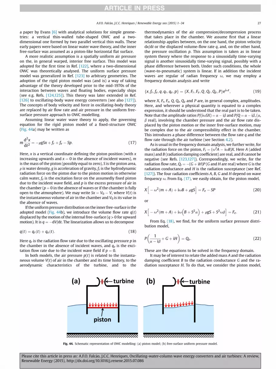
A.F.O. Falc~ao, J.C.C. Henriques / Renewable Energy xxx (2015) 1e34 27
a paper by Evans [6] with analytical solutions for simple geome-tries: a vertical thin-walled tube-shaped OWC and a two-dimensional one formed by two parallel vertical thin walls. Theseearly papers were based on linear water wave theory, and the innerfree-surface was assumed as a piston-like horizontal flat surface.
A more realistic assumption is a spatially uniform air pressureon the, in general warped, interior free surface. This model wasadopted for the first time in Ref. [122], where a two-dimensionalOWC was theoretically analysed. The uniform surface pressuremodel was generalized in Ref. [123] to arbitrary geometries. Theadoption of the rigid piston model was (and is) a way of takingadvantage of the theory developed prior to the mid-1970s of theinteraction between waves and floating bodies, especially ships(see e.g. Refs. [124,125]). This theory was later extended in Ref.[126] to oscillating-body wave energy converters (see also [127]).The concepts of body velocity and force in oscillating-body theoryare replaced by air flow rate and air pressure in the uniform free-surface pressure approach to OWC modelling.
Assuming linear water wave theory to apply, the governingequation for the rigid piston model of a fixed-structure OWC(Fig. 44a) may be written as
md2xdt2
¼ �rgSxþ fr þ fe � Sp: (17)
Here, x is a vertical coordinate defining the piston position (with xincreasing upwards and x ¼ 0 in the absence of incident waves), mis themass of the piston (possibly equal to zero), S is the piston area,r is water density, g is acceleration of gravity, fr is the hydrodynamicradiation force on the piston due to the piston motion in otherwisecalm water, fe is the excitation force on the assumedly fixed pistondue to the incident wave field, and p is the excess pressure of air inthe chamber (p¼ 0 in the absence of waves or if the chamber is fullyopen to the atmosphere). We may write Sx ¼ V0 � V, where V(t) isthe instantaneous volume of air in the chamber and V0 is its value inthe absence of waves.
If the uniformpressuredistributionon the inner free-surface is theadopted model (Fig. 44b), we introduce the volume flow rate q(t)displaced by themotion of the internal free-surface (q> 0 for upwardmotion). It is q ¼ �dV/dt. The linearization allows us to decompose
qðtÞ ¼ qrðtÞ þ qeðtÞ: (18)
Here qr is the radiation flow rate due to the oscillating pressure p inthe chamber in the absence of incident waves, and qe is the exci-tation flow rate due to the incident wave field if p ¼ 0.
In both models, the air pressure p(t) is related to the instanta-neous volume V(t) of air in the chamber and its time history, to theaerodynamic characteristics of the turbine, and to the
turbine
piston
(a)
Fig. 44. Schematic representation of OWC modelling: (a) p
Please cite this article in press as: A.F.O. Falc~ao, J.C.C. Henriques, OscillatinRenewable Energy (2015), http://dx.doi.org/10.1016/j.renene.2015.07.086
thermodynamics of the air compression/decompression processthat takes place in the chamber. We assume first that a linearrelationship applies between, on the one hand, the piston velocitydx/dt or the displaced volume-flow rate q, and, on the other hand,the pressure oscillation p. This assumption is taken as in linearsystem theory where the response to a sinusoidally time-varyingsignal is another sinusoidally time-varying signal, possibly with aphase difference between both. Under such conditions, the whole(wave-to-pneumatic) system is linear. If in addition the incidentwaves are regular of radian frequency u, we may employ afrequency domain analysis and write
fx; fr; fe; q; qr; qe;pg ¼ fX; Fr ; Fe;Q ;Qr;Qe; Pgeiut ; (19)
where X, Fr, Fe, Q, Qr, Qe and P are, in general complex, amplitudes.Here, and wherever a physical quantity is equated to a complexexpression, it should be understood that the real part is to be taken.Note that the amplitude ratios P/(iuSX)¼ a� ib and P/Q¼ a� ib, (a,b real), involving the chamber pressure and the air flow rate dis-placed by the piston motion or the inner free-surface motion, maybe complex due to the air compressibility effect in the chamber.This introduces a phase difference between the flow rate q and theflow rate through the air turbine (see Section 4.2).
As is usual in the frequency domain analysis, we furtherwrite, forthe radiation force on the piston, Fr ¼ (u2A � iuB)X. Here A (addedmass) and B (radiation damping coefficient) are real, and B cannot benegative (see Refs. [123,127]). Correspondingly, we write, for theradiation flow rate, Qr¼�(Gþ iH)P (G andH are real) where G is theradiation conductance and H is the radiation susceptance (see Ref.[127]). The four radiation coefficients A, B, G and H depend on wavefrequency u. From Eq. (17), we easily obtain, for the piston model,
Xh� u2ðmþ AÞ þ iuBþ rgS
i¼ Fe � SP (20)
or
Xh� u2ðmþ AÞ þ iu
�Bþ S2a
�þ rgSþ S2ub
i¼ Fe: (21)
From Eq. (18), we find, for the uniform surface pressure distri-bution model,
P�
1a� ib
þ Gþ iH�
¼ Qe: (22)
These are the equations to be solved in the frequency domain.It may be of interest to relate the addedmass A and the radiation
damping coefficient B to the radiation conductance G and the ra-diation susceptance H. To do that, we consider the piston model,
turbine (b)
iston model; (b) free-surface uniform pressure model.
g-water-column wave energy converters and air turbines: A review,

A.F.O. Falc~ao, J.C.C. Henriques / Renewable Energy xxx (2015) 1e3428
and assume no incident waves. Consequently, in Eq. (17), we setFe ¼ 0 and replace X by Xr (complex amplitude of the pistondisplacement due to the time varying air pressure only). Thecomplex amplitude of the flow rate displaced by the piston motionis iuSXr which, as for Qr, we decompose as iuSXr ¼ �(G1þiH1)P,where subscript 1 is used to denote that the radiation conductanceG1 and the radiation susceptance H1 are defined for the pistonmodel, and so are not expected to be exactly equal to G and H. Thenwe are left with
�ðG1 þ iH1ÞPiuS
h� u2ðmþ AÞ þ iuBþ rgS
i¼ �SP (23)
or
S2G1
G21 þ H2
1
¼ B; (24)
uS2H1
G21 þ H2
1
¼ �u2ðmþ AÞ þ rgS: (25)
Equations (24) and (25) relate the pair of hydrodynamic co-efficients (G1,H1) to the pair (A, B). We recall that the pairs of hy-drodynamic coefficients (G1,H1) and (G, H) are physically similar,but their numerical values do not coincide because the two modelsare not expected to yield exactly equal results.
By setting P ¼ 0 in Eq. (20), we easily find the following rela-tionship between the complex excitation force amplitude Fe and thecomplex excitation flow rate amplitude Qe,1, where, as above, thesubscript 1 indicates that Qe,1 is not exactly equal to Qe,
Qe;1 ¼ iuSh� u2ðmþ AÞ þ iuBþ rgS
i�1Fe: (26)
In general, the piston velocity dx/dt and the displaced volume-flow rate q are not proportional to the pressure oscillation p. Thenonlinearities may be introduced by the air chamber thermody-namics or by the aerodynamic performance curves of the turbine.In such cases, the frequency domain analysis is no longer applicableand has to be replaced by a time domain analysis. In particular, theexpression of the radiation force on the piston involves a convo-lution integral, as in the so-called Cummins equation in ship hy-drodynamics [128], extended to oscillating-body wave energyconverters in Ref. [129]. Similarly, the radiation flow rate qr can beexpressed by a convolution integral as done in Ref. [130]
qrðtÞ ¼ �Zt�∞
hrðt � tÞpcðtÞdt: (27)
The memory function hr is related to the radiation susceptanceG through the Fourier transform
hrðsÞ ¼ 2p
Z∞0
GðuÞcos us du: (28)
The surface pressure distribution model was extended fromfixed structure to floating structure OWCs in Ref. [131]. The theo-retical modelling of OWCs based on the free-surface uniformpressure model is the subject of a full chapter in Falnes' book [127].
Analytical solutions based on the surface pressure distributionmodel were obtained for several simple geometries by integratingLaplace's equation for the velocity potential function by themethodof separation of variables together with the matched eigenfuctionexpansionmethod. This is the case of a two-dimensional OWCwith
Please cite this article in press as: A.F.O. Falc~ao, J.C.C. Henriques, OscillatinRenewable Energy (2015), http://dx.doi.org/10.1016/j.renene.2015.07.086
vertical thin walls [132], a vertical thin-walled circular cylindricalOWC [133] and a circular cylindrical OWC at the tip of a breakwater[134] or the tip of a coastal corner [135]. More complex geometriesinclude a floating vertical axisymmetric OWC [136] and a two-dimensional dual-chamber OWC on stepped bottom [137]. Fornon-diffracting OWC structures, analytical solutions can be derivedfrom the expressions for the wave field induced by time-harmonicsurface pressure distributions [124]. This was the method adoptedin Ref. [138] for in infinite linear array of OWCs, which wasextended to other array configurations in Ref. [139].
Even if linear water wave theory is assumed to apply (whichimplies irrotational flow and small amplitudes for the outer andinner free-surface motions), complex geometries require theapplication of numerical methods. These are usually based on thecomputation of hydrodynamic coefficients as defined above.Commercial codes based on the boundary element method (BEM)are available to compute such coefficients for ships and marinestructures. Such codes, like WAMIT, ANSYS/Aqwa and Aquaplus,have also been frequently employed by thewave energy conversioncommunity. Their use assumes an oscillating body or a set ofoscillating bodies in awave field to be an acceptable approximation.In the case of OWCs, this implies the inner free-surface to besimulated by a rigid piston. The possibility of employing commer-cial codes based on the BEM is possibly the main reason why therigid piston model, rather than the more realistic surface pressuredistribution approach, is so popular in OWC theoretical/numericalmodelling. It is possible to modify a BEM code developed for thestudy of floating bodies and extend it to the modelling of OWCs.This was done with the radiation-diffraction code Aquadyn devel-oped at Ecole Centrale de Nantes, France, bymodifying the dynamicboundary condition on the internal water free surface to accountfor the imposed oscillatory uniform pressure distribution withinthe chamber [140]. The modified code was used to model theshoreline OWC plant constructed at the island of Pico, Azores,including the effect of surrounding coastline and non-flat bottom[141]. A method was developed in Ref. [142] to apply a three-dimensional BEM like WAMIT to model an OWC device account-ing for the appropriate interior free-surface boundary condition.
The methods mentioned above are based on Laplace's equationand linear water wave theory, and are unable to model non-smallwave and body-motion amplitudes and real fluid dissipative ef-fects like viscous friction, turbulence and eddy shedding. Such ef-fects may be important especially in the more energetic sea statesand under conditions close to resonance. Computational fluid dy-namics (CFD) methods may be employed to account for such ef-fects. They are usually based on the numerical integration of theReynolds-averaged NaviereStokes (RANS) equations togetherwith an appropriate turbulence model. Commercial and open-source codes are available and have been used for wave energyconversion applications, including especially OWCs. In some cases,the computational domain has included the air flow field in theOWC chamber. The use of such codes implies heavy computing. Insome (possibly most) cases (see e.g. Refs. [143e148]), the geometryis two-dimensional (the so-called numerical wave tank) and thewaves are regular (the computational effort required for calcula-tions in irregular waves to be of statistical value can be prohibitive).
4.2. Thermodynamics of air chamber
The volume of the air chamber of the OWC converter should belarge enough to avoid ingestion of water by the air turbine underrough sea conditions. Typical design values of the air chambervolume divided by the area of the OWC free surface range between3 and 8 m, and are affected by tidal oscillations in fixed-structureOWC devices. An increase in this ratio is not necessarily
g-water-column wave energy converters and air turbines: A review,

A.F.O. Falc~ao, J.C.C. Henriques / Renewable Energy xxx (2015) 1e34 29
detrimental to the efficiency of the energy conversion. Obviously, ifthe volume increases to very large values, the amplitude of the airpressure oscillations becomes very small, and the capability of thedevice to absorb wave energy vanishes. The spring-like effect of aircompressibility in the chamber increases with chamber volume,and is important in a full-sized OWC converter. This effect wasmodelled for the first time in Ref. [149], and shortly afterwards inRef. [150]. In both papers, and in many subsequent ones (see e.g.Ref. [151]), a simple isentropic relationship between air pressureand density was assumed. In fact, the aerodynamic and thermo-dynamic processes that take place in the air chamber and turbine ofan OWC converter are quite complex; they were analysed in detailin Ref. [152]. It seems reasonable to assume that they are approx-imately adiabatic. Indeed, the temperature oscillations in the airchamber are relatively small and their time scales (a few seconds)are too short for significant heat exchanges to occur across thechamber walls and across the airewater interface, in comparisonwith the energy flux in the turbine.
However, even if the process is assumed as adiabatic, significantchanges in specific entropy occur in the flow through the turbine,due to viscous losses. Such changes can be related to turbine effi-ciency. We recall that the pressure in the chamber is pat þ p, wherepat is the atmospheric pressure. During inhalation, it is p < 0, and airwith specific entropy s > sat is admitted to the chamber, where ahighly turbulent mixing process takes place (the increase in specificentropy in the flow through the turbine is due to real fluid effects).During exhalation, p > 0, air leaves the chamber through the tur-bine in a process at approximately constant specific entropy for theair remaining in the chamber. The inhalation and exhalation pro-cesses in an OWC were studied in some detail in Ref. [152]. A pol-ytropic relationship between the pressure p þ pat and the densityrch in the air chamber was proposed in Ref. [118]
pat þ p
rkch
¼ patrkat
; (29)
where k is the polytropic exponent that is related to the averageefficiency h of the turbine (see Section 3.10 and [118] for a definitionof average efficiency). A good approximation to the relationshipproposed in Ref. [118] is
k ¼ 0:13h2 þ 0:27hþ 1: (30)
If h ¼ 1 (perfectly efficient turbine), then k ¼ 1.4, and Eq. (29) be-comes simply the isentropic pressureedensity relationship. Ifh ¼ 0, it is k ¼ 1 and Eq. (29) becomes the isothermal relationship.
4.3. Model testing of OWCs
The theoretical modelling based on linear water wave theory isan essential step in the development of wave energy converters. Itprovides insights and important information at relatively low costs,in general in a relatively fast way. However, there are importantnon-linear effects that are not accounted for by this kind ofmodelling, namely those associated with large amplitude waves,large amplitude motions of the wave energy converter oroscillating-water-column, and real fluid effects due to viscosity,turbulence, and vortex shedding. Commercially availablecomputational-fluid-dynamics (CFD) codes, usually based on thenumerical integration of the Reynolds-averaged NaviereStokes(RANS) equations, may be used to account for such effects. How-ever, even such codes, apart from being computationallydemanding, require some experimental validation. Thereforephysical model testing in awave flume or wave tank is normally thenext step. The scales range between about 1:100th in small wave
Please cite this article in press as: A.F.O. Falc~ao, J.C.C. Henriques, OscillatinRenewable Energy (2015), http://dx.doi.org/10.1016/j.renene.2015.07.086
flumes to about 1:10th in the largest wave tanks. Tests at largerscales (typically 1:4th to 1:3rd scale) sometimes take place insheltered sea locations. We may apply dimensional analysis tech-niques to relate the conditions in model testing to those of the full-sized prototype in real sea conditions. Dimensional analysis inmodel testing of wave energy converters in general is addressed inthe pioneer book by McCormick [47] and more recently in Refs.[153e155]. The testing of OWCs raises specific issues, related to theturbine and the air compressibility effect in the chamber, that areaddressed in Refs. [118,156].
When performing model testing inwaves, it is assumed that thewetted part of the model is an exact geometric representation ofthe full-scale prototype. This geometric similarity is supposed toapply also to the bottom and surrounding walls. The incident wavesmay be represented by a given variance density spectrum (Pier-soneMoskowitz or other (see e.g. Ref. [157]), Sf ðHs; Te; f Þ, where Hs
is the significant wave height, Te is energy period (or some otherrepresentative period) and f is frequency. In the case of regularwaves, Hs and Te are simply the wave height and period.
Let L be a characteristic length (this could be a diameter in thecase of an axisymmetric device). As before, we denote by pþ pat thepressure in the air chamber of the OWC converter. Buckingham'stheorem of dimensional analysis allows us to write
P1 ¼ Q�Hs=L; Fr; Re; Pp
�: (31)
Here, Q is a function, Fr ¼ L1=2g�1=2T�1e is a Froude number,
Re ¼ L2n�1T�1e is a Reynolds number, Pp ¼ pL�1r�1g�1 is dimen-
sionless pressure, P1 ¼ PL�7=2r�1g�3=2 is dimensionless power,and r and n are water density and kinematic viscosity respectively.Identical relationships could be established by replacing P1 byother dimensionless quantities. If the four dimensionless variablesFr, Re, Hs=L andPp take equal values in themodel and the full-sizedprototype, the same will be true for P1; P2; :::.
Let the subscripts m and F denote the model and the full-sizedprototype. The length scale is defined as ε ¼ Lm/LF. The constancyof the Froude number Fr and the Reynolds number Re cannot besatisfied simultaneously, since this would require nm=nF ¼ ε
3=2, acondition that is obviously unachievable in practice if ε is not closeto unity. In model testing, the effects due to variations in Froudenumber are almost always much more important than thoseassociated with changes in Reynolds number, and so the Reynoldsnumber is ignored as a modelling rule.
The expression of dimensionless power P1 ¼ PL�7=2r�1g�3=2
shows that the scale ratio for power is ε7/2 (if variations in water
density r are neglected). In model testing of wave energy con-verters in the largest wave tanks, the length scale ε in general doesnot exceed about 1:10th. This implies a maximum power ratio ofabout 1:3200. In the case of an OWC wave energy converter, thisscale is too small for the turbine to be simulated adequately by amini-turbine. The usual procedure is to simulate the turbine by anorifice, if the turbine is of impulse type or by a layer of porousmaterial, where the flow is approximately laminar and simulates alinear turbine like the Wells turbine. Only in tests performed underreal sea conditions at scales not less than about 1:4th, is a realturbine fitted to themodel. This was done in the shelteredwaters ofGalway Bay, Ireland, at scale 1:4th, with a Backward Bent Duct Buoy(BBDB) (the OE Buoy) fitted first with aWells turbine and later withan impulse turbine [41,42], Fig. 18.
We consider now that the Froude geometric similarity isextended to the part of the device located above water level,namely the air chamber and its air volume V, i.e. Vm/VF ¼ ε
3. Thiswould allow realistic representation of water motion inside thechamber and provide information on how to avoid green waterfrom reaching the air turbine. However, that would require pat,m/
g-water-column wave energy converters and air turbines: A review,

A.F.O. Falc~ao, J.C.C. Henriques / Renewable Energy xxx (2015) 1e3430
pat,F ¼ ε d. (d ¼ rm/rF) (see Ref. [118]) The latter condition, con-cerning atmospheric pressure, is obviously impossible to satisfy inpractice if the length scale ε is not close to unity. This impossibilitywas recognized in Ref. [156] and examined in more detail in Ref.[118].
Now we assume more realistically that the atmospheric pres-sure is the same at both scales pat,m ¼ pat,F. We further assume thatthe pressure oscillation p is much smaller than the atmosphericpressure, which would exclude the more energetic sea states at fullscale. The following similarity condition can be obtained for the airchamber volume ratio [118]
Vm
VF¼ km
kFε2d�1; (32)
where k is the polytropic exponent as defined in Section 4.2. Inmodel testing at large scale (say about 1:4th to 1:3rd) performed inthe sea, it is d ¼ 1 (equal water density). If in addition an appro-priately scaled-sized turbine is used to realistically simulate thefull-sized machine, it is km y kF (if the turbine model is not toosmall). Then, from Eq. (32), we have
Vm
VF¼ ε
2: (33)
A result identical to Eq. (32) was first obtained in Ref. [149],based on a frequency-domain analysis of the hydrodynamics and alinearized isentropic assumption. It later appeared in other papers(e.g. Refs. [150,151,155e158]). It shows that the scale ratio for airchamber volume should be ε
2, rather than ε3. Failure to meet this
condition may result in substantial errors in the conversion to fullscale of the experimental data at a smaller scale (for a numericalcase study, see Ref. [118]).
If the OWC device is of fixed structure (possibly bottom-standing), it is not difficult to satisfy condition (32) at smallmodel scale. One simple way of achieving that is to connect the airchamber of the model to a rigid-walled reservoir of air of appro-priate volume. This procedure was adopted in the model testing ofthe bottom-standing OWC installed in 1999 on the island of Pico,Azores, Portugal, as reported in Ref. [158]. If however a floatingOWC device is to be modelled at small scale, this could introducedifficulties because the reservoir is likely not to be small comparedwith the device's size, and possibly is a lot larger.
If themodel scale is large enough (say not less than about 1:4th),the model may be equipped with a real turbine (rather than asimple orifice or a porous plug). In such cases (in which the waterdensity is that of sea water), if the model turbine is geometricallysimilar to the full-sized one and both are equally efficient, thefollowing similarity conditions can be obtained for the rotordiameter D and rotational speed U (see Ref. [118])
Dm
DF¼ ε;
Um
UF¼ ε
�1=2: (34)
This shows that the linear scale for the turbine should be thesame as for the wetted part of the structure.
5. Control
5.1. Reactive phase control
In WECs of oscillating-body and OWC types, the highest effi-ciency of wave energy absorption from regular waves is attainedunder conditions close to resonance. Especially in the case ofrelatively small devices (the so-called point absorbers), it is wellknown that the resonance bandwidth is relatively narrow, which
Please cite this article in press as: A.F.O. Falc~ao, J.C.C. Henriques, OscillatinRenewable Energy (2015), http://dx.doi.org/10.1016/j.renene.2015.07.086
implies that their performance in irregular waves is relatively poor.Besides, for many point absorbers, the natural frequency of reso-nance is higher than the typical frequency of the waves. Phasecontrol has been proposed to improve these situations [159e161].Reactive phase control is a way of doing that: reactive power con-tributes nothing to the average delivered power and is back-and-forth exchange of energy between the PTO and the oscillatingsystem. This energy may be stored in a flywheel, a gas accumulator,a battery of condensers, or may be supplied by the electrical grid. Amajor drawback of reactive phase control is the energy loss bydissipative processes inherent to the back-and-forth energy ex-change, especially if the magnitude of such exchanged energy iscomparable to, or even significantly larger than, the net absorbedenergy. This may be the case of point absorbers. Reactive phasecontrol is particularly appropriate if the PTO is a high-pressurehydraulic circuit with gas accumulator, where the fluid flow maybe reversed by controlling the valve system. This may also beachieved in the case of direct electrical energy conversion (linear orrotating generator) by two-way exchange of energy with the grid.
Reactive control has also been considered for OWCs equippedwith self-rectifying air turbines. If the setting angle of the rotorblades of a Wells turbine is controllable within a sufficiently widerange (say ±20�), then the machine can operate either as a turbineor as a compressor, and may be used to achieve reactive control[162e164]. A 400 kW variable-pitch Wells turbine, whose sophis-ticated control mechanism was driven by eddy currents (Fig. 29),was built to be tested in the Pico plant, Azores, Portugal [82,112],but was never installed. The relatively modest efficiency of theWells turbine, especially when operating in the compressor mode,severely limits the gains from reactive control [165]. This, in addi-tion to the much higher mechanical complexity of the turbine andinherent reliability problems, has deterred the use of reactivecontrol in OWCs.
5.2. Phase control by latching
An alternative to reactive phase control is control by latching.This was first proposed for single oscillating bodies reacting againsta fixed reference frame (in general the sea bottom) [160], andconsists in latching the body in a fixed position during certain in-tervals of the oscillation cycle.
In principle, reactive control may be optimal, i.e. may allow thetheoretical maximum wave energy capture, as predicted by linearwater wave theory, to be achieved in unconstrained amplitudeconditions (such optimal control is non-causal). This is not the caseof control by latching, that is necessarily suboptimal [127]. On theother hand, latching control avoids the two-way energy transferand the associated energy dissipation that characterize a reactivelyphase-controlled PTO. In the case of an OWC converter, latching isachieved by closing a valve in series with the turbine.
Latching control of an OWC was analysed for the first time inRef. [166], where air compressibility was ignored, and [150] wherethe air compressibility in the chamber was accounted for, but onlyregular waves were considered and the analysis was in the fre-quency domain. Both papers considered a fixed-structure OWC.Pontryagin maximum principle was used in Ref. [166] to show thatthe optimal control is bangebang, i.e. the position of the valve iseither fully open or fully closed.
There are specific problems related to latching control of anOWC. One is the compressibility of the air in the chamber that actsas a spring and prevents the water column to remain fixed withrespect to the structure, even if the air flow is stopped at theentrance to the turbine. Besides, it should be noted that suchcompressibility may remove the constraint of the latchingthreshold having to coincide with an instant of zero (relative)
g-water-column wave energy converters and air turbines: A review,

A.F.O. Falc~ao, J.C.C. Henriques / Renewable Energy xxx (2015) 1e34 31
velocity. Another problem, especially if the turbine is of axial-flowtype (as the Wells turbine and most self-rectifying impulse tur-bines), is the practical difficulty of designing and constructing avalve with a response time not exceeding a few tens of a second. Avery fast and mechanically very complex valve with an elastomericmembrane was designed and constructed to be mounted in serieswith the 400 kW variable-pitch Wells turbine at the Pico, AzoresOWC plant [167], but was never installed. Latching may be lessdifficult if the turbine is of radial-flow type, in which case anaxially-sliding cylindrical valve with a relatively small stroke maybe positioned close to the rotor [168].
The forces involved in latching of oscillating-bodyWECs may bevery large, and have to be supported by the PTO or by a specialbraking system. This has been regarded has a major problem forthis type of phase control. Latching forces on air valves are muchsmaller in the case of OWCs, since the area of the valve surfacesubject to the chamber pressure is a small fraction of the area of thewater column free surface.
Model testing of a fixed-structure OWC showed that substantialgains can be achieved by latching based on a causal algorithm [169](air compressibility effects were not simulated). As in the case of anoscillating two-body WEC versus a single-body one, latching con-trol of a floating OWC converter raises more difficult problems thanfor a fixed-structure OWC, since the closure of the latching valvedoes not stop the motion either of the OWC or of the floater. Nu-merical simulations of latching control of an OWC spar-buoy inregular waves revealed that large gains in produced energy can beachieved over a wide range of wave frequencies [170]. However thegains were found to be more modest when similar methods,namely causal control, were extended to irregular waves [171],which seems to indicate that more sophisticated control methods,possibly model predictive control, will be required for more satis-factory results. Latching control of OWCs appears as a way of sub-stantially increasing the power produced by OWCs that is worthfurther investigation.
5.3. Turbine rotational speed and air flow control
The rotational speed should be adjusted to the pneumatic en-ergy level available to the turbine, more precisely to the standarddeviation (or root-mean-square) sp of the pressure oscillation p. InSection 3.10, it was shown from dimensional analysis that theaverage efficiency h of a given turbine (or a set of geometricallysimilar turbines) is a function of the dimensionless standard devi-ation (or root-mean-square) sJ of the pressure oscillation p. Inparticular, its maximum value hmax occurs for sJ,max. the corre-sponding value for the averaged turbine power output being Pmax.In the case of the Wells turbine and the biradial turbine consideredin Section 3.10, it is sJ,max ¼ 0.022 and 0.34, respectively. From thedefinition of sJ (Eq. (14)), it follows that the rotational speed Ushould be proportional ffiffiffiffiffi
spp . Apart from affecting the turbine
aerodynamic efficiency, changes in rotational speed also affect thedamping provided by the PTO (i.e. the relationship between pres-sure and flow rate) and in this way affect the hydrodynamic per-formance of the wave energy absorption process. For this reason,the control algorithm for the rotational speed should take intoaccount both the hydrodynamic and the aerodynamic efficiencies.An algorithm that has been proposed based, on numerical simu-lation of fixed structure and floating OWCs, is of the form
Tem ¼ constant� Uz; (35)
where Tem is the instantaneous electromagnetic torque on thegenerator rotor, U is the instantaneous rotational velocity and z isan exponent taking a value typically not very different from 2,
Please cite this article in press as: A.F.O. Falc~ao, J.C.C. Henriques, OscillatinRenewable Energy (2015), http://dx.doi.org/10.1016/j.renene.2015.07.086
depending on the OWC and turbine (see Refs. [79,119,172]). Thisalgorithm should be implemented in the programmable logiccontroller (PLC) of the plant through the power electronics. Notethat if should be exactly z ¼ 2 if the average aerodynamic efficiencyof the turbine rather than the overall average efficiency is to bemaximized. The implications of rotational speed control on theelectrical equipment are addressed in Ref. [173].
Control algorithm (35) may yield values for the rotational speedthat, in the more energetic sea states, exceed what should beallowed from the viewpoint of centrifugal stresses. This is espe-cially critical in the case of Wells turbines, because of their typicallyhigh rotor blade tip speed; a maximum limit about 150e170 m/shas sometimes been established for the blade tip speed. Suchconstraint results, in the case of themore energetic sea states, in thevalue of sJ substantially exceeding sJ,max as defined above.Fig. 43a shows that the Wells turbine average efficiency h decaysrapidly with sJ for sJ > sJ,max. To prevent such unwanted effi-ciency decay to low values in the more energetic sea states, it hasbeen proposed to install an air valve in plants equipped with aWells air turbine. The valve is either in parallel with the turbine(relief valve) to limit the magnitude the pressure head p [172,174],or in series with the turbine to limit the flow rate [130]. This kind ofstrategy was recently implemented at the Pico OWC plant, takingadvantage of the plant being equipped with a relief valve. Thechamber hydrodynamics are forecasted using a neural network thatconsiders wave measurements made 60 m up wave and otheroperational, environmental and preceding wave parameters [175].
6. Conclusions
The OWCwas the first concept for wave energy conversion to bedeveloped, and is still the favourite technology among a large partof the wave energy conversion community. It can be employed inisolated shoreline or nearshore situations, integrated into a break-water, or in single- and multi-OWC floating plants. From the me-chanical viewpoint, the PTO is particularly simple and reliable: theonly moving part is the rotor of an air turbine, located above seawater, directly driving a conventional electrical generator.
Theoverall efficiencyof thewave-to-wire energyconversionchainis critically dependent on the performance of the air turbine. Sub-stantial improvements were achieved in this respect since the earlyself-rectifying air turbineswereproposed in themid-1970s: theaxial-flow Wells and impulse turbines. Model testing shows that peak ef-ficiencies close to 80% and average efficiency in randomwaves above70% can be attained by new-generation turbines. This places the air-turbine PTO in close competition with the high-pressure hydrauliccircuit or the direct electrical energyconversion by linear generator. Itseems not unreasonable to expect that efficiencies closer to what istypical of more conventional turbines e hydraulic, steam and gasturbines ewill be attained in the near future.
Theoretical hydrodynamic modelling of OWCs based on linearwater wave theory and hydrodynamic coefficients is still the mostfrequently adopted approach, especially if that involves controlstudies. CFD computational tools, based on the Reynolds-averagedNaviereStokes (RANS) equations are being increasingly employed,although in many cases restricted to two-dimensional geometriesand regular waves.
Like for wave energy converters in general, an essential step inthe development of OWCs is model testing, usually in wave tank orwave flume. The air compressibility effect in the air chamber andthe simulation of the air turbine raise special problems in modeltesting that in many cases failed to be adequately addressed.
Phase control is an area from which substantial improvementsin power efficiency, and hence economic viability, can be expectedat relatively little extra costs. In the case of OWCs, phase control by
g-water-column wave energy converters and air turbines: A review,

A.F.O. Falc~ao, J.C.C. Henriques / Renewable Energy xxx (2015) 1e3432
latching appears as the most promising approach, although theo-retical control problems are still to be appropriately solved beforepractical implementation.
Changes in rotational speed affect the aerodynamic efficiency ofthe turbine and, in general to a lesser extent, the hydrodynamicefficiency of the wave absorption process. Algorithms have beenproposed to control the rotational speed, expressing the electro-magnetic torque on the generator rotor as a function of theinstantaneous rotational speed.
Acknowledgements
This work was funded by the Portuguese Foundation for theScience and Technology (FCT) through IDMEC, under LAETA, projectUID/EMS/50022/2013. The second author was supported by FCTresearcher grant No. IF/01457/2014.
References
[1] S. Barstow, G. Mork, D. Mollison, J. Cruz, The wave energy resource, in: J. Cruz(Ed.), Ocean Wave Energy, Springer, Berlin, 2008, pp. 93e132.
[2] J. Falnes, A review of wave-energy extraction, Mar. Struct. 20 (2007)185e201.
[3] B. Drew, A.R. Plummer, M. Sahinkaya, A review of wave energy convertertechnology, Proc. Inst. Mech. Eng. Part A: J. Power Energy 223 (2009)887e902.
[4] A.F. de O. Falc~ao, Wave energy utilization: a review of the technologies,Renew. Sustain. Energy Rev. 14 (2010) 899e918.
[5] I. L�opez, J. Andreu, S. Ceballos, I. Martinez de Alegria, I. Kortabarria, Review ofwave energy technologies and the necessary power-equipment, Renew. Sust.Energy Rev. 27 (2013) 413e434.
[6] D.V. Evans, The oscillating water column wave-energy device, J. Inst. Math.Appl. 22 (1978) 423e433.
[7] Carbon Trust, Oscillating Water Column Wave Energy Converter EvaluationReport, 2005. Available at: http://www.carbontrust.com/media/173555/owc-report.pdf (accessed 7.03.15.).
[8] T.V. Heath, A review of oscillating water column, Philos. Trans. R. Soc. A 370(2012) 235e245.
[9] T. Setoguchi, S. Santhakumar, H. Maeda, M. Takao, K. Kaneko, A review ofimpulse turbines for wave energy conversion, Renew. Energy 23 (2001)261e292.
[10] T. Setoguchi, M. Takao, Current status of self rectifying air turbines for waveenergy conversion, Energy Conv. Manag. 47 (2006) 2382e2396.
[11] R. Curran, M. Folley, Air turbine design for OWCs, in: J. Cruz (Ed.), OceanWave Energy, Springer, Berlin, 2008, pp. 189e219.
[12] A.F.O. Falc~ao, L.M.C. Gato, Air turbines, in: A.A. Sayigh (Ed.), ComprehensiveRenewable Energy vol. 8, Ocean Energy, Elsevier, Oxford, 2012, pp. 111e149.
[13] R. Starzmann, Aero-acoustic Analysis of Wells Turbines for Ocean WaveEnergy Conversion (Doctoral thesis), Universit€at Siegen, Germany, 2012.Fortschr-Ber VDI Reihe 7, Nr 500, Düsseldorf: VDI Verlag.
[14] D. Ross, Power from the Waves, Oxford University Press, Oxford, 1995.[15] Y. Masuda, Wave-activated generator, in: Int. Colloq Exposition Oceans,
Bordeaux, France, 1971.[16] Y. Masuda, An experience of wave power generator through tests and
improvement, in: A.F. de O. Falc~ao, D.V. Evans (Eds.), Hydrodynamics ofOcean Wave-energy Utilization, Springer, Berlin, 1986, pp. 445e452.
[17] Y. Masuda, M.E. McCormick, Experiences in pneumatic wave energy con-version in Japan, in: M.E. McCormick, Y.C. Kim (Eds.), Utilization of OceanWaves e Wave to Energy Conversion, Amer Soc Civil Eng, New York, 1986,pp. 1e33.
[18] H. Hotta, T. Miyazaki, S.I. Ishii, On the performance of the wave power deviceKaimei, in: Proc 7th Int Conf Offshore Mech Arct Eng, New York, 1988, pp.91e96.
[19] C. Grove-Palmer, Wave energy in the United Kingdom e A review of theprogramme June 1975eMarch 1982, in: H. Berge (Ed.), Proc 2nd Int SympWave Energy Utilization, Trondheim, Norway, 1982, pp. 23e54.
[20] T.J.T. Whittaker, S.J. McIlwaine, S. Raghunathan, A review of the Islayshoreline wave power station, in: Proc First European Wave Energy Symp,Edinburgh, 1993, pp. 283e286.
[21] H. Ohneda, S. Igarashi, O. Shinbo, S. Sekihara, K. Suzuki, H. Kubota, et al.,Construction procedure of a wave power extracting caisson breakwater, in:Proc 3rd Symp Ocean Energy Utilization, Tokyo, 1991, pp. 171e179.
[22] M. Suzuki, C. Arakawa, S. Takahashi, Performance of a wave power gener-ating system installed in breakwater at Sakata port in Japan, in: Proc 14th IntOffshore Polar Eng Conf, Toulon, France, 2004.
[23] M. Ravindran, P.M. Koola, Energy from sea waves e the Indian wave energyprogram, Curr. Sci. 60 (1991) 676e680.
[24] K. Mala, S.N. Badrinath, S. Chidanand, G. Kailash, V. Jayashankar, Analysis ofpower modules in the Indian wave energy plant, in: Proc Annual IEEE India
Please cite this article in press as: A.F.O. Falc~ao, J.C.C. Henriques, OscillatinRenewable Energy (2015), http://dx.doi.org/10.1016/j.renene.2015.07.086
Conf INDICON, 2009, pp. 95e98.[25] A.F. de O. Falc~ao, The shoreline OWC wave power plant at the Azores, in:
Proc 4th European Wave Energy Conf, Aalborg, Denmark, 2000, pp. 42e47.[26] T. Heath, T.J.T. Whittaker, C.B. Boake, The design, construction and operation
of the LIMPET wave energy converter (Islay, Scotland), in: Proc 4th EuropeanWave Energy Conf, Aalborg, Denmark, 2000, pp. 49e55.
[27] D. Zhang, W. Li, Y. Lin, Wave energy in China: current status and perspec-tives, Renew. Energy 34 (2009) 2089e2092.
[28] N. Ambli, K. Bonke, O. Malmo, H. Reitan, The Kvaerner multiresonant OWC,in: Proc 2nd Int Symposium Wave Energy Utilization, Trondheim, Norway,1982, pp. 275e295.
[29] B. Count, D.V. Evans, The influence of projecting side walls on the hydro-dynamic performance of wave energy devices, J. Fluid Mech. 145 (1984)361e376.
[30] R. Alcorn, S. Hunter, C. Signorelli, R. Obeyesekera, T. Finnigan, T. Denniss,Results of the testing of the Energetech wave energy plant at Port Kembla,Energetech Rep. (2005).
[31] Y. Torre-Enciso, I. Ortubia, L.I. L�opez de Aguileta, J. Marqu�es, Mutriku wavepower plant: from the thinking out to the reality, in: Proc 8th EuropeanWave Tidal Energy Conf, Uppsala, Sweden, 2009, pp. 319e329.
[32] P. Boccotti, Caisson breakwaters embodying an OWC with a small opening.Part I: theory, Ocean. Eng. 34 (2007) 806e819.
[33] F. Arena, A. Romolo, G. Malara, A. Ascanelli, On design and building of a U-OWC wave energy converter in the Mediterranean sea, in: Proc 32nd IntConf Ocean Offshore Arct Eng, Nantes, France; 2013, 2013.
[34] F. Arena, V. Fiamma, V. Laface, G. Malara, et al., Installing U-OWC devicesalong the Italian coasts, in: Proc 32nd Int Conf Ocean Offshore Arct Eng,Nantes, France, 2013.
[35] F. Arena, Un impianto REWEC3 per la produzione di energia elettrica damoto ondoso: dall'invenzione del Prof. Paolo Boccottu alla costruzione delprimo prot�otipo, in: Workshop Energia dal Mare le Nuove Tecnologie per iMari Italiani, Rome, 2014. Available at: http://www.enea.it/it/enea_informa/events/energia-dal-mare/Arena1.pdf (accessed 7.03.15.).
[36] M.E. McCormick, A theoretical analysis of a self-propelled backward-bentduct wave-energy conversion system, J. Energy Convers. Technol.-Trans.ASME 113 (1991) 94e100.
[37] Y. Masuda, T. Kuboki, M. Ravindran, A.G. Pathak, V. Jayashankar, X.G. Liang,Development of backward bent duct buoy (BBDB), in: Proc 9th Int OffshorePolar Eng Conf, Brest, France, vol. 1, 1999, pp. 142e149.
[38] Y. Masuda, T. Kuboki, A. Thakker, X.G. Liang, Prospect of economical wavepower electric generator by the terminator backward bent duct buoy (BBDB),in: Proc. 12th Int Offshore Polar Eng Conf, Kyushu, Japan, vol. 1, 2002, pp.607e613.
[39] D.C. Hong, S.Y. Hong, S.W. Hong, Numerical study of the reverse drift force offloating BBDB wave energy absorbers, Ocean. Eng. 31 (2004) 1259e1294.
[40] K.-R. Lee, W. Koo, M.-H. Kim, Fully nonlinear time-domain simulation of abackward bent duct buoy floating wave energy converter using an acceler-ation potential method, Int. J. Nav. Arch. Ocean. Eng. 5 (2013) 513e528.
[41] J. Rea, J. Kelly, R. Alcorn, D. O'Sullivan, Development and operation of a po-wer take-off rig for ocean energy research and testing, in: Proc 9th EuropeanWave Tidal Energy Conf, Southampton, 2011.
[42] R. Alcorn, A. Blavette, M. Healy, A. Lewis, FP7 EU funded CORES wave energyproject: a coordinators' perspective on the Galway Bay sea trials, Underw.Technol. 32 (2014) 51e59.
[43] Y. Washio, H. Osawa, Y. Nagata, F. Fujii, H. Furuyama, T. Fujita, The offshorefloating type wave power device “Mighty Whale”: open sea tests, in: Proc10th Int Offshore Polar Eng Conf, Seattle, vol. 1, 2000, pp. 373e380.
[44] T. Ogata, Y. Washio, H. Osawa, Y. Tsuritani, S. Yamashita, Y. Nagata, The opensea tests on the offshore floating type wave power device Mighty Whale:performance of the prototype, in: Proc 21st Int Conf Offshore Mech Arct Eng,Oslo, Norway, 2002. Paper No OMAE2002e28335.
[45] M.E. McCormick, Analysis of a wave energy conversion buoy, J. Hydronaut. 8(1974) 77e82.
[46] M.E. McCormick, A modified linear analysis of a wave-energy conversionbuoy, Ocean. Eng. 3 (1976) 133e144.
[47] M.E. McCormick, Ocean Wave Energy Conversion, Wiley, New York, 1981.[48] T.J.T. Whittaker, F.A. McPeake, Design optimization of axisymmetric tail tube
buoys, in: D.V. Evans, A.F. de O. Falc~ao (Eds.), Hydrodynamics of Ocean WaveEnergy Utilization, Springer, Berlin, 1986, pp. 103e111.
[49] A. Tucker, J.M. Pemberton, D.T. Swift-Hook, J.M. Swift-Hook, et al., Laminatedreinforced concrete technology for the SPERBOY wave energy converter, in:Proc XI World Renewable Energy Congress, Abu Dhabi, UAE, 2010, pp.941e946.
[50] Nearshore Floating Oscillating Water Column: Prototype Development andEvaluation. Rep. URN 05/581, Department of Trade and Industry, UK, 2005.Available at: http://webarchive.nationalarchives.gov.uk/20090609003228/http://www.berr.gov.uk/files/file17347.pdf (accessed 7.03.15.).
[51] A.F.O. Falc~ao, J.C.C. Henriques, J.J. Candido, Dynamics and optimization of theOWC spar buoy wave energy converter, Renew. Energy 48 (2012) 369e381.
[52] R.P.F. Gomes, J.C.C. Henriques, L.M.C. Gato, A.F.O. Falc~ao, Hydrodynamicoptimization of an axisymmetric floating oscillating water column for waveenergy conversion, Renew. Energy 44 (2012) 328e339.
[53] N. Fonseca, J. Pessoa, S. Ribeiro e Silva, M. Le Boulluec, J. Ohana, Model testsof a wave energy converter based on water oscillating in a U tank, in: 12�emesJourn�ees Hydrodynamique, Nantes France, 2010.
g-water-column wave energy converters and air turbines: A review,

A.F.O. Falc~ao, J.C.C. Henriques / Renewable Energy xxx (2015) 1e34 33
[54] N. Fonseca, J. Pessoa, Numerical modeling of a wave energy converter basedon U-shaped interior oscillating water column, Appl. Ocean. Res. 40 (2013)60e73.
[55] B.H. Kim, J. Wata, M.A. Zullah, M.R. Ahmed, Y.H. Lee, Numerical and exper-imental studies on the PTO system of a novel floating wave energy converter,Renew. Energy 79 (2015) 111e121.
[56] D.V. Evans, A submerged cylinder wave energy converter with internalsloshing power take off, Eur. J. Mech. B-Fluids 47 (2014) 108e123.
[57] A. Kurniawan, D. Greaves, J. Chaplin, Wave energy devices with compressiblevolumes, Proc. R. Soc. A 470 (2014) 20140559.
[58] M. Martinelli, P. Pezzutto, P. Ruol, Experimentally based model to size thegeometry of a new OWC device, with reference to the Mediterranean Seawave environment, Energies 6 (2013) 4696e4720.
[59] J.P. Kofoed, P. Frigaard, Hydraulic Evaluation of the LEANCON Wave EnergyConverter. Dept Civil Engineering, Aalborg University, Denmark, Techn RepNo. 45, 2008. Available at:: http://vbn.aau.dk/files/16184099/Hydraulic_Evaluation_of_the_LEACON_Wave_Energy_Converter(accessed 7.03.15.).
[60] T. Kelly, T. Dooley, J. Campbell, J.V. Ringwood, Comparison of the experi-mental and numerical results of modelling a 32-oscillating water column(OWC), V-shaped floating wave energy converter, Energies 6 (2013)4045e4077.
[61] H. Maeda, C.K. Rheem, Y. Washio, H. Osawa, Y. Nagata, T. Ikoma, N. Fujita,M. Arita, Reduction effects of hydroelastic responses on a very large floatingstructure with wave energy absorption devices using OWC system, in: Proc20th Int Conf Offshore Mech Arct Eng, Rio de Janeiro, 2001. PaperOMAE2001e5013.
[62] D.C. Hong, S.Y. Hong, S.W. Hong, Reduction of hydroelastic responses of avery-long floating structure by a floating oscillating-water-column break-water system, Ocean. Eng. 33 (2006) 610e634.
[63] D.C. Hong, S.Y. Hong, Hydroelastic responses and drift forces of a very-longfloating structure equipped with a pin-connected oscillating-water-columnbreakwater system, Ocean. Eng. 34 (2007) 696e708.
[64] C.M. Wang, Z.Y. Tay, K. Takagi, T. Utsunomiya, Literature review of methodsfor mitigating hydroelastic response of VLFS under wave action, Appl. Mech.Rev. 63 (2010) 030802.
[65] A.A. Wells, Fluid Driven Rotary Transducer. British patent spec No. 1595700;1976.
[66] I.A. Babintsev, Apparatus for Converting Sea Wave Energy into ElectricalEnergy. U.S. patent No. 3922739; 1975.
[67] M.E. McCormick, Ocean wave energy concepts, in: Proc Oceans 79 Conf, SanDiego (MTS-IEEE), 1979, pp. 553e557.
[68] S. Raghunathan, The Wells turbine for wave energy conversion, Prog. Aerosp.Sci. 31 (1995) 335e386.
[69] S.L. Dixon, C.A. Hall, Fluid Mechanics and Thermodynamics of Turboma-chinery, seventh ed., Elsevier, Amsterdam, 2014.
[70] D.P. Sturge, Turbine for an Oscillating Water Column Wave Power System,CEGB Rep No MM/MECH TA 41, 1977.
[71] R.J. Grant, C.G. Johnson, D.P. Sturge, Performance of a Wells turbine for use ina wave energy system, in: Future Energy Concepts, IEE, 1981. Publ No 192.
[72] S. Raghunathan, C.P. Tan, N.A.J. Wells, Theory and performance of a Wellsturbine, J. Energy 6 (1982) 157e160.
[73] T. von K�arm�an, J.M. Burgers, General aerodynamic theory e perfect fluids, in:W.F. Durand (Ed.), Aerodynamic Theory, vol. 2, Springer, Berlin, 1934.
[74] F.S. Weinig, Theory of two-dimensional flow through cascades, in:W.R. Hawthorne (Ed.), Aerodynamics of Turbines and Compressors, OxfordUniversity Press, London, 1964, pp. 13e82.
[75] N. Scholz, Aerodynamics of Cascades. AGARD-AG-220, 1977.[76] L.M.C. Gato, AF. de O. Falc~ao, Performance of the Wells turbine with double
row of guide vanes, JSME Int. J.-Ser. II 33 (1990) 265e271.[77] S. Raghunathan, C.P. Tan, The performance of the biplane Wells turbine,
J. Energy 7 (1983) 741e742.[78] R. Arlitt, H.-U. Banzhaf, R. Starzmann, F. Biskup, Air Turbine for Wave Power
Station. Patent No. WO 2009/089902; 2009.[79] A.F.O. Falc~ao, J.C.C. Henriques, L.M.C. Gato, R.P.F. Gomes, Air turbine choice
and optimization for floating oscillating-water-column wave energy con-verter, Ocean. Eng. 75 (2014) 148e156.
[80] T. Setoguchi, T.H. Kim, K. Kaneko, M. Takao, Y.W. Lee, M. Inoue, Air turbinewith staggered blades for wave power conversion, in: Proc 12th Int OffshorePolar Eng Conf, 2002, pp. 662e667.
[81] T. Setoguchi, S. Sathakumar, M. Takao, T.H. Kim, K. Kaneko, A modified Wellsturbine for wave energy conversion, Renew. Energy 28 (2003) 79e91.
[82] J.R.M. Taylor, N.J. Caldwell, Design and construction of the variable-pitch airturbine for the Azores wave energy plant, in: Proc 3rd European WaveEnergy Conf, Patras, Greece, 1998, pp. 328e337.
[83] D. Richards, F.B. Weiskopf, Studies with and testing of the McCormickpneumatic wave energy turbine with some comments on PWECS systems,in: M.E. McCormick, Y.C. Kim (Eds.), Utilization of Ocean Waves e Wave toEnergy Conversion, ASCE, New York, 1986, pp. 80e102.
[84] T.W. Kim, K. Kaneko, T. Setoguchi, M. Inoue, Aerodynamic performance of animpulse turbine with self-pitch-controlled guide vanes for wave powergenerator, in: Proc 1st KSME-JSME Thermal Fluid Eng Conf, vol. 2, 1988, pp.133e137.
[85] C. Freeman, S.J. Herring, K. Banks, Impulse Turbine for Use in Bi-directionalFlows. Patent No. WO 2008/012530 A2; 2008.
[86] S. Natanzi, J.A. Teixeira, G. Laird, A novel high-efficiency impulse turbine for
Please cite this article in press as: A.F.O. Falc~ao, J.C.C. Henriques, OscillatinRenewable Energy (2015), http://dx.doi.org/10.1016/j.renene.2015.07.086
use in oscillating water column devices, in: Proc 9th European Wave TidalEnergy Conf, Southampton, UK, 2011.
[87] R. Curran, T. Denniss, C. Boake, Multidisciplinary design for performance:ocean wave energy conversion, in: Proc 10th Int Offshore Polar Eng Conf,Seattle, vol. 1, 2000, pp. 434e441.
[88] T. Finnigan, D. Auld, Model testing of a variable-pitch aerodynamic turbine,in: Proc 13th Int Offshore Polar Eng Conf, Hononulu, 2003, pp. 357e360.
[89] M.E. McCormick, J.G. Rehak, B.D. Williams, An experimental study of a bi-directional radial turbine for pneumatic conversion, in: Proc MasteringOcean through Technol, vol. 2, 1992, pp. 866e870.
[90] M.E. McCormick, B. Cochran, A performance study of a bi-directional radialturbine, in: Proc European Wave Energy Symp, Edinburgh, 1993, pp.443e448.
[91] M. Takao, K. Itakura, T. Setoguchi, T.H. Kim, K. Kaneko, A. Thakker, Perfor-mance of a radial turbine for wave power conversion, in: Proc 12th IntOffshore Polar Eng Conf, Kitakyushu, Japan, 2002, pp. 562e567.
[92] F. Castro, A. el Marjani, M.A. Rodriguez, T. Parra, Viscous flow analysis in aradial impulse turbine for OWC wave energy systems, in: Proc 7th EuropeanWave Tidal Energy Conf, Porto, Portugal, 2007.
[93] B. Pereiras, F. Castro, A. el Marjani, M.A. Rodriguez, Radial impulse turbine forwave energy conversion. A new geometry, in: Proc 27th Int Conf OffshoreMech Arct Eng, Estoril, Portugal, 2008. Paper OMAE2008e57951.
[94] B. Pereiras, F. Castro, A.A. Rodriguez, Tip clearance effect on the flow patternof a radial impulse turbine for wave energy conversion, in: Proc 9th IntOffshore Polar Eng Conf, Osaka, 2009, pp. 290e298.
[95] B. Pereiras, F. Castro, A. el Marjani, M.A. Rodriguez, An improved radial im-pulse turbine for OWC, Renew. Energy 36 (2011) 1477e1484.
[96] M. Takao, Y. Fujioka, T. Setoguchi, Effect of pitch-controlled guide vanes onthe performance of a radial turbine for wave energy conversion, Ocean. Eng.32 (2005) 2079e2087.
[97] J.A.C. Kentfield, A bidirectional flow air-turbine for wave energy extraction,in: Proc 6th. Int Conf Alternative Energy Sources, Miami Beach, 1983, pp.59e60.
[98] C. Moisel, R. Starzmann, Aerodynamic design and numerical investigation ofa new radial bi-directional turbine for wave energy conversion, in: Proc 10thEuropean Wave Tidal Energy Conf, Aalborg, Denmark, 2013.
[99] C. Moisel, T.H. Carolus, Experimental loss analysis on a model-scale radialbidirectional air-turbine for wave energy conversion, in: Proc 1st Interna-tional Conf Renew Energies Offshore, Lisbon, 2014.
[100] Y. Osada, T. Konno, Air Turbine for Wave Power Generation. Japanese patentJP2008095569(A); 2008.
[101] T. Konno, Y. Nagata, M. Takao, T. Setoguchi, Experimental study of a radialturbine using floating nozzle for wave energy conversion. In: Proc 29th IntConf Ocean Offshore Arct Eng, Honolulu, Hawaii; 2009, PaperOMAE2009e80076.
[102] L.M.C. Gato, A.F.O. Falc~ao, Turbine with Radial Inlet and Outlet Flow Rotor forUse in Bi-directional Flows. Patent WO2011102746 A4; 2012.
[103] A.F.O. Falc~ao, L.M.C. Gato, E.P.A.S. Nunes, A novel radial self-rectifying airturbine for use in wave energy converters, Renew. Energy 50 (2013)289e298.
[104] A.F.O. Falc~ao, L.M.C. Gato, E.P.A.S. Nunes, A novel radial self-rectifying airturbine for use in wave energy converters. Part 2. Results from modeltesting, Renew. Energy 53 (2013) 159e164.
[105] V. Jayashankar, S. Anand, T. Geetha, S. Santhakumar, V.J. Kumar,M. Ravindran, T. Setoguchi, M. Takao, K. Toyota, S. Nagata, A twin unidi-rectional impulse turbine topology for OWC based wave energy plants,Renew. Energy 34 (2009) 692e698.
[106] K. Mala, J. Jayara, V. Jayashankar, T.M. Muruganandam, S. Santhakumar,M. Ravindran, M. Takao, T. Setoguchi, K. Toyota, S. Nagata, A twin unidi-rectional impulse turbine topology for OWC based wave energy plants eexperimental validation and scaling, Renew. Energy 36 (2011) 307e314.
[107] V. Jayashankar, K. Mala, J. Jayaraj, T. Setoguchi, M. Takao, A twin unidirec-tional turbine topology for wave energy, in: Proc 3rd Int Conf Ocean Energy,Bilbao, Spain, 2010.
[108] B. Pereiras, P. Valdez, F. Castro, Numerical analysis of a unidirectional axialturbine for twin turbine configuration, Appl. Ocean. Res. 47 (2014) 1e8.
[109] M. Suzuki, C. Arakawa, S. Takahashi, Performance of wave power generatingsystem installed in breakwater at Sakata port in Japan, in: Proc 14th IntOffshore Polar Eng Conf, Toulon, France, 2004, pp. 202e209.
[110] V.S. Raju, M. Ravindran, P.M. Koola, Experiences on a 150 kW wave energypilot plant, in: Proc European Wave Energy Symp, Edinburgh, 1993, pp.277e282.
[111] S. Raghunathan, R. Curran, T.J.T. Whittaker, Performance of the Islay Wells airturbine, Proc. Inst. Mech. Eng. Part A: J. Power Energy 209 (1995) 55e62.
[112] N.J. Caldwell, J.R.M. Taylor, Eddy-current actuator for a variable pitch airturbine, in: Proc 3rd European Wave Energy Conf, Patras, Greece, 1998, pp.104e110.
[113] T.V. Heath, The development of a turbo-generation system for application inOWC breakwaters, in: Proc 7th European Wave Tidal Energy Conf, Porto,Portugal, 2007.
[114] Islay LIMPET Wave Power Plant, Publishable Report. Contract JOR-CT98e0312, The European Commission, 2002.
[115] T.J.T. Whittaker, W. Beattie, M. Folley, C. Boake, A. Wright, M. Osterried,T. Heath, Performance of the LIMPET wave power plant e Prediction, mea-surement and potential, in: Proc 5th European Wave Energy Conf, Cork,
g-water-column wave energy converters and air turbines: A review,

A.F.O. Falc~ao, J.C.C. Henriques / Renewable Energy xxx (2015) 1e3434
Ireland, 2003, pp. 97e104.[116] M. Takao, T. Setoguchi, K. Kaneko, S. Raghunathan, M. Inoue, Noise charac-
teristics of turbines for wave power conversion, Proc. Inst. Mech. Eng. Part A:J. Power Energy 216 (2002) 223e228.
[117] R. Starzmann, T. Carolus, Model-based selection of full-scale Wells turbines foroceanwaveenergy conversionandpredictionof their aerodynamic andacousticperformances, Proc. Inst. Mech. Eng. Part A J. Power Energy 228 (2014) 2e16.
[118] A.F.O. Falc~ao, J.C.C. Henriques, Model-prototype similarity of oscillating-water-column wave energy converters, Int. J. Mar. Energy 6 (2014) 18e34.
[119] A.F. de O. Falc~ao, R.J.A. Rodrigues, Stochastic modelling of OWC wave powerplant performance, Appl. Ocean. Res. 24 (2002) 59e71.
[120] Y. Kamizuru, C. Fissmann, H. Murrenhoff, Hydrostatic drive trains for waveenergy converters: simulation and experiments for efficient design, in: Proc10th European Wave Tidal Energy Conf, Aalborg, 2013.
[121] A.F. de O. Falc~ao, Stochastic modelling in wave power-equipment optimi-zation: maximum energy production versus maximum profit, Ocean. Eng. 31(2004) 1407e1421.
[122] A.F. de O. Falc~ao, A.J.N.A. Sarmento, Wave generation by a periodic surface-pressure and its application in wave-energy extraction, in: 15th Int CongrTheor Appl Mech, Toronto, 1980.
[123] D.V. Evans, Wave-power absorption by systems of oscillating surface pres-sure distributions, J. Fluid Mech. 114 (1982) 481e499.
[124] J.V. Wehausen, E.V. Laitone, Surface waves, in: Encyclopedia of Physics, Vol.IX Fluid Dynamics III, Springer Verlag, Berlin, 1960, pp. 446e778.
[125] J.V. Wehausen, The motion of floating bodies, Annu. Rev. Fluid Mech. 3(1971) 237e268.
[126] D.V. Evans, Theory for wave-power absorption by oscillating bodies, J. FluidMech. 77 (1976) 1e25.
[127] J. Falnes, Ocean Waves and Oscillating Systems, Cambridge University Press,Cambridge, 2002.
[128] W.E. Cummins, The impulse response function and ship motions, Schiff-stechnik 9 (1962) 101e109.
[129] E.R. Jefferys, Device characterisation, in: B. Count (Ed.), Power from SeaWaves, Academic Press, London, 1980, pp. 413e438.
[130] AF. de O. Falc~ao, P.A.P. Justino, OWC wave energy conversion with valve-constrained flow, in: Proc 2nd European Wave Power Conf, Lisbon, 1995,pp. 187e194.
[131] J. Falnes, P. McIver, Surface wave interactions with systems of oscillatingbodies and pressure distributions, Appl. Ocean. Res. 7 (1985) 225e234.
[132] D.V. Evans, R. Porter, Hydrodynamic characteristics of an oscillating watercolumn device, Appl. Ocean. Res. 17 (1995) 155e164.
[133] D.V. Evans, R. Porter, Efficient calculation of hydrodynamic properties ofOWC-type devices, J. Offshore Mech. Arct. Eng.-Trans. ASME 119 (1997)210e218.
[134] H. Martin-Rivas, C.C. Mei, Wave power extraction from an oscillating watercolumn at the tip of a breakwater, J. Fluid Mech. 626 (2008) 395e414.
[135] S. Lovas, C.C. Mei, Y. Liu, Oscillating water column at a coastal corner forwave power extraction, Appl. Ocean. Res. 32 (2010) 267e283.
[136] S.A. Mavrakos, D.N. Konispoliatis, Hydrodynamics of a free floating verticalaxisymmetric oscillating water column device, J. Appl. Math. 2012 (2012).Article No. 142850.
[137] K. Rezanejad, J. Bhattacharjee, C.G. Soares, Analytical and numerical study ofdual-chamber oscillating water columns on stepped bottom, Renew. Energy75 (2015) 272e282.
[138] A.F. de O. Falc~ao, Wave-power absorption by a periodic linear array ofoscillating water columns, Ocean. Eng. 29 (2002) 1163e1186.
[139] G.C. Nihous, Wave power extraction by arbitrary arrays of non-diffractingoscillating water columns, Ocean. Eng. 51 (2012) 94e105.
[140] A. Brito-Melo, A.J.N.A. Sarmento, A.H. Cl�ement, G.A. Delhommeau, 3Dboundary element code for the analysis of OWC wave-power plants, in: Proc9th Int Offshore Polar Eng Conf, Brest France, vol. 1, 1999, pp. 188e195.
[141] A. Brito-Melo, T. Hofmann, A.J.N.A. Sarmento, A.H. Cl�ement, G. Delhommeau,Numerical modelling of OWC-shoreline devices including the effect of sur-rounding coastline and non-flat bottom, Int. J. Offshore Polar Eng. 11 (2001)147e154.
[142] C.H. Lee, J.N. Newman, F.G. Nielsen, Wave interactions with an oscillatingwater column, in: Proc 6th Int Offshore Polar Eng Conf, Los Angeles, 1996.
[143] Y. Zhang, Q.P. Zhou, D. Greaves, Air-water two-phase flow modelling ofhydrodynamic performance of an oscillating water column device, Renew.Energy 41 (2012) 159e170.
[144] Y.Y. Luo, J.R. Nader, P. Cooper, S.P. Zhu, Nonlinear 2D analysis of the effi-ciency of fixed oscillating water column wave energy converters, Renew.Energy 64 (2013) 255e265.
[145] P.R.F. Teixeira, D.P. Davyt, E. Didier, R. Ramalhais, Numerical simulation of anoscillating water column device using a code based on Navier-Stokesequations, Energy 61 (2013) 513e530.
[146] I. Lopez, B. Pereiras, F. Castro, G. Iglesias, Optimization of turbine-induceddamping for an OWC wave energy converter using a RANSeVOF numericalmodel, Appl. Energy 127 (2014) 105e114.
[147] Y. Luo, Z. Wang, G. Peng, Y. Xiao, L. Zhai, X. Liu, Q. Zhang, Numerical
Please cite this article in press as: A.F.O. Falc~ao, J.C.C. Henriques, OscillatinRenewable Energy (2015), http://dx.doi.org/10.1016/j.renene.2015.07.086
simulation of a heave-only floating OWC (oscillating water column) device,Energy 76 (2014) 799e806.
[148] A. Karmath, H. Bihs, O.A. Arntsen, Numerical modeling of power take-offdamping in an oscillating water column device, Int. J. Mar. Energy 10(2015) 1e16.
[149] A.J.N.A. Sarmento, A.F. de O. Falc~ao, Wave generation by an oscillatingsurface-pressure and its application in wave-energy extraction, J. FluidMech. 150 (1985) 467e485.
[150] R. Jefferys, T. Whittaker, Latching control of an oscillating water columndevice with air compressibility, in: D.V. Evans, A.F. de O. Falc~ao (Eds.), Hy-drodynamics of Ocean Wave Energy Utilization, Springer, Berlin, 1986, pp.281e291.
[151] W. Sheng, R. Alcorn, A. Lewis, On thermodynamics in the primary powerconversion of oscillating water column wave energy converters, J. Renew.Sust. Energy 5 (2013) 023105.
[152] A.F. de O. Falc~ao, P.A.P. Justino, OWC wave energy devices with air-flowcontrol, Ocean. Eng. 26 (1999) 1275e1295.
[153] G. Payne, Guidance for the Experimental Tank Testing of Wave EnergyConverters. SuperGen Marine Rep., Univ. Edinburgh, 2008. Available at:http://www.supergen-marine.org.uk/drupal/files/reports/WEC_tank_testing.pdf (accessed 7.03.15.).
[154] V. Heller, Development of wave devices from initial conception to com-mercial demonstration, in: A. Sayigh (Ed.), Comprehensive Renewable En-ergy vol. 8, Ocean Energy, Elsevier, Oxford, 2012, pp. 79e110.
[155] W. Sheng, R. Alcorn, T. Lewis, Physical modelling of wave energy converters,Ocean. Eng. 84 (2014) 29e36.
[156] J. Weber, Representation of non-linear aero-thermodynamic effects duringsmall scale physical modelling of OWC WECs, in: Proc 7th European WaveTidal Energy Conf, Porto, Portugal, 2007.
[157] L.H. Holthuijsen, Waves in Oceanic and Coastal Waters, Cambridge Univer-sity Press, Cambridge, 2007.
[158] A.J.N.A. Sarmento, Model tests optimisation of an OWC wave power plant,Int. J. Offshore Polar Eng. 3 (1993) 66e72.
[159] S.H. Salter, D.C. Jeffery, J.R.M. Taylor, The architecture of nodding duck wavepower generators, Nav. Arch. 1 (1976) 21e24.
[160] J. Falnes, K. Budal, Wave power conversion by point absorbers, Nor. Marit.Res. 6 (1978) 2e11.
[161] J. Falnes, Optimum control of oscillation of wave-energy converters, Int. J.Offshore Polar Eng. 12 (2002) 147e155.
[162] L.M.C. Gato, A.F.O. de Falc~ao, Aerodynamics of the Wells turbine: control byswinging rotor blades, Int. J. Mech. Sci. 31 (1989) 425e434.
[163] A.J.N.A. Sarmento, L.M.C. Gato, A.F. de O. Falc~ao, Turbine-controlled waveenergy absorption by oscillating water column device, Ocean. Eng. 17 (1990)481e497.
[164] L.M.C. Gato, L.R.C. Eça, A.F. de O. Falc~ao, Performance of the Wells turbinewith variable pitch rotor blades, J. Energ Resour. Technol.-Trans. ASME 113(1991) 141e146.
[165] J. Perdig~ao, A. Sarmento, Overall-efficiency optimisation in OWC devices,Appl. Ocean. Res. 25 (2003) 157e166.
[166] R.E. Hoskin, B.M. Count, N.K. Nichols, D.A.C. Nicol, Phase control for theoscillating water column, in: D.V. Evans, A.F. de O. Falc~ao (Eds.), Hydrody-namics of Wave-energy Utilization, Springer, Berlin, 1986, pp. 257e268.
[167] N.J. Caldwell, J.R.M. Taylor, Design and construction of elastomeric parts forthe Azores OWC high speed valve, in: Proc 3rd European Wave Energy Conf,Patras, Greece, 1998, pp. 318e327.
[168] J.C.C. Henriques, J.C. Chong, A.F.O. Falc~ao, R.P.F. Gomes, Latching control of afloating oscillating water column wave energy converter in irregular waves,in: Proc 33rd Int Conf Ocean Offshore Arct Eng, San Francisco, 2014. PaperOMAE 2014e23260.
[169] M.F.P. Lopes, J. Hals, R.P.F. Gomes, T. Moan, L.M.C. Gato, A.F. de O. Falc~ao,Experimental and numerical investigation of non-predictive phase-controlstrategies for a point-absorbing wave energy converter, Ocean. Eng. 36 (2009)386e402.
[170] J.C.C. Henriques, A.F.O. Falc~ao, R.P.F. Gomes, L.M.C. Gato, Latching control ofan oscillating water column spar-buoy wave energy converter in regularwaves, J. Offshore Mech. Arct. Eng. Trans. ASME 135 (2013) 021902.
[171] J.C.C. Henriques, J.C. Chong, A.F.O. Falc~ao, R.P.F. Gomes, Latching control of afloating oscillating water column wave energy converter in irregular waves,in: Proc 33rd Int Conf Ocean Offshore Arct Eng, San Francisco, 2014. PaperNo. OMAE 2014e23260.
[172] A.F. de O. Falc~ao, Control of an oscillating water column wave power plantfor maximum energy production, Appl. Ocean. Res. 24 (2002) 73e82.
[173] M. Amundarain, M. Alberdi, A.J. Garrido, I. Garrido, Neural rotational speedcontrol for wave energy converters, Int. J. Control 84 (2011) 293e309.
[174] A.F. de O. Falc~ao, L.C. Vieira, P.A.P. Justino, J.M.C.S. Andr�e, By-pass air-valvecontrol of an OWC wave power plant, J. Offshore Mech. Arct. Eng. Trans.ASME 125 (2003) 205e210.
[175] K. Monk, D. Conley, M. Lopes, Q. Zou, Pneumatic power regulation by waveforecasting and real-time relief valve control for an OWC, in: Proc 10thEuropean Wave Tidal Energy Conf, Aalborg, Denmark, 2013.
g-water-column wave energy converters and air turbines: A review,