Computation of Nonlinear Load Harmonic Currents in ... - MDPI
15
Citation: Skamyin, A.; Belsky, A.; Dobush, V.; Gurevich, I. Computation of Nonlinear Load Harmonic Currents in the Presence of External Distortions. Computation 2022, 10, 41. https://doi.org/10.3390/ computation10030041 Academic Editor: Demos T. Tsahalis Received: 21 February 2022 Accepted: 14 March 2022 Published: 15 March 2022 Publisher’s Note: MDPI stays neutral with regard to jurisdictional claims in published maps and institutional affil- iations. Copyright: © 2022 by the authors. Licensee MDPI, Basel, Switzerland. This article is an open access article distributed under the terms and conditions of the Creative Commons Attribution (CC BY) license (https:// creativecommons.org/licenses/by/ 4.0/). computation Article Computation of Nonlinear Load Harmonic Currents in the Presence of External Distortions Aleksandr Skamyin 1, * , Aleksey Belsky 1 , Vasiliy Dobush 2 and Ilya Gurevich 1 1 Department of Electric Power and Electromechanics, Saint-Petersburg Mining University, 199106 Saint-Petersburg, Russia; [email protected] (A.B.); [email protected] (I.G.) 2 Department of General Electrical Engineering, Saint-Petersburg Mining University, 199106 Saint-Petersburg, Russia; [email protected] * Correspondence: [email protected] Abstract: This paper deals with the issues of computation of the nonlinear load harmonic currents in the presence of external distortions based on the real measurements with help of passive harmonic. Such values are necessary when modeling an equivalent nonlinear load as current sources in the presence of external distortions. The passive filter allows to separate external and internal distortions, which is necessary when determining the harmonic currents of a single consumer. The influence of various parameters on the computation of harmonic currents of a nonlinear load, such as the parameters of a passive harmonic filter, the impedance of the power supply transformer, the load parameters of the consumer, taking into account the harmonic generation from the grid side, and from the consumer side, is considered. It is shown that an external source of distortion has practically no effect on the error in estimating the harmonic current magnitudes of a nonlinear load. The obtained simulation results were confirmed experimentally on a laboratory test bench. Recommendations for the selection of passive harmonic filter parameters have been developed to minimize the error in determining the harmonic current magnitudes of a nonlinear load. Keywords: nonlinear load; computation; passive harmonic filter; distortions; power quality; capacitor banks; simulation 1. Introduction A large number of nonlinear consumers are connected to modern electrical grids [1]. Such installations include semiconductor rectifiers [2], arc furnaces [3], controlled and uncontrolled power converters [4], LED lighting systems [5], etc. The operation of such devices leads to the occurrence of harmonics in current and voltage [6]. Harmonic currents flow through power lines and transformers, causing a non-sinusoidal voltage drop, thereby degrading the power quality [7]. It is necessary to calculate the operating modes of the consumers and grids with degraded power quality indicators in order to determine the parameters of harmonic reduction devices [8], to predict power quality indicators depending on load parameters [9], determine negative impact of distortions on electrical equipment [10], determine power losses [11], etc. The correctness of such operating modes modeling in many respects is determined by the accepted model of nonlinear load [12,13]. There are various models of nonlinear electrical loads, which can generally be classi- fied into simulation models based on models of semiconductor elements being a part of them [14–16]; in the form of current sources at harmonic frequencies [17–19]; in the form of volt-ampere characteristics obtained by approximation according to various equations [20–22]; in the form of nonlinear impedances [23–25]; based on time-domain, frequency-domain, or time-frequency modeling approaches [26–29]. Various approaches are proposed to determine the parameters of a nonlinear load for simulation from real measured data [30–32]. In [31], an approach and modeling algorithm were proposed, based on the measured harmonic parameters in the electrical nodes with Computation 2022, 10, 41. https://doi.org/10.3390/computation10030041 https://www.mdpi.com/journal/computation
-
Upload
khangminh22 -
Category
Documents
-
view
2 -
download
0
Transcript of Computation of Nonlinear Load Harmonic Currents in ... - MDPI

Citation: Skamyin, A.; Belsky, A.;
Dobush, V.; Gurevich, I. Computation
of Nonlinear Load Harmonic
Currents in the Presence of External
Distortions. Computation 2022, 10, 41.
https://doi.org/10.3390/
computation10030041
Academic Editor: Demos T. Tsahalis
Received: 21 February 2022
Accepted: 14 March 2022
Published: 15 March 2022
Publisher’s Note: MDPI stays neutral
with regard to jurisdictional claims in
published maps and institutional affil-
iations.
Copyright: © 2022 by the authors.
Licensee MDPI, Basel, Switzerland.
This article is an open access article
distributed under the terms and
conditions of the Creative Commons
Attribution (CC BY) license (https://
creativecommons.org/licenses/by/
4.0/).
computation
Article
Computation of Nonlinear Load Harmonic Currents in thePresence of External DistortionsAleksandr Skamyin 1,* , Aleksey Belsky 1, Vasiliy Dobush 2 and Ilya Gurevich 1
1 Department of Electric Power and Electromechanics, Saint-Petersburg Mining University,199106 Saint-Petersburg, Russia; [email protected] (A.B.); [email protected] (I.G.)
2 Department of General Electrical Engineering, Saint-Petersburg Mining University,199106 Saint-Petersburg, Russia; [email protected]
* Correspondence: [email protected]
Abstract: This paper deals with the issues of computation of the nonlinear load harmonic currents inthe presence of external distortions based on the real measurements with help of passive harmonic.Such values are necessary when modeling an equivalent nonlinear load as current sources in thepresence of external distortions. The passive filter allows to separate external and internal distortions,which is necessary when determining the harmonic currents of a single consumer. The influenceof various parameters on the computation of harmonic currents of a nonlinear load, such as theparameters of a passive harmonic filter, the impedance of the power supply transformer, the loadparameters of the consumer, taking into account the harmonic generation from the grid side, and fromthe consumer side, is considered. It is shown that an external source of distortion has practically noeffect on the error in estimating the harmonic current magnitudes of a nonlinear load. The obtainedsimulation results were confirmed experimentally on a laboratory test bench. Recommendations forthe selection of passive harmonic filter parameters have been developed to minimize the error indetermining the harmonic current magnitudes of a nonlinear load.
Keywords: nonlinear load; computation; passive harmonic filter; distortions; power quality; capacitorbanks; simulation
1. Introduction
A large number of nonlinear consumers are connected to modern electrical grids [1].Such installations include semiconductor rectifiers [2], arc furnaces [3], controlled anduncontrolled power converters [4], LED lighting systems [5], etc. The operation of suchdevices leads to the occurrence of harmonics in current and voltage [6]. Harmonic currentsflow through power lines and transformers, causing a non-sinusoidal voltage drop, therebydegrading the power quality [7]. It is necessary to calculate the operating modes ofthe consumers and grids with degraded power quality indicators in order to determinethe parameters of harmonic reduction devices [8], to predict power quality indicatorsdepending on load parameters [9], determine negative impact of distortions on electricalequipment [10], determine power losses [11], etc. The correctness of such operating modesmodeling in many respects is determined by the accepted model of nonlinear load [12,13].
There are various models of nonlinear electrical loads, which can generally be classi-fied into simulation models based on models of semiconductor elements being a part ofthem [14–16]; in the form of current sources at harmonic frequencies [17–19]; in the form ofvolt-ampere characteristics obtained by approximation according to various equations [20–22];in the form of nonlinear impedances [23–25]; based on time-domain, frequency-domain, ortime-frequency modeling approaches [26–29].
Various approaches are proposed to determine the parameters of a nonlinear load forsimulation from real measured data [30–32]. In [31], an approach and modeling algorithmwere proposed, based on the measured harmonic parameters in the electrical nodes with
Computation 2022, 10, 41. https://doi.org/10.3390/computation10030041 https://www.mdpi.com/journal/computation
Computation 2022, 10, 41 2 of 15
nonlinear loads, which make it possible to represent nonlinear loads as a set of distributionfunctions of harmonic currents.
In some works [18,24], when modeling a nonlinear load as current sources, expressionsare presented for determining the harmonic current magnitudes depending on the type ofload. Among them are three-phase uncontrolled rectifiers, controlled rectifiers, variablefrequency drives, thyristor power controllers, etc.
In a number of papers, it is proposed to determine the parameters of inverters andrectifiers based on various methods, such as time-frequency analysis technique [33,34],periodogram technique [35,36], and machine learning algorithm [37,38]. Basically, such ananalysis is carried out for the classification and localization of nonlinear loads [39,40].
Traditional nonlinear load models in the form of current sources are suitable forsimplified computations in the presence of harmonics. In this case, the magnitude valuesof current sources for different frequencies are set by simplified expressions, where theharmonic current magnitude at the fundamental frequency is divided by the harmonic order.The obtained magnitude values differ significantly from the real measured data [41–43].In this case, the parameters of the energy system and equipment loading are not takeninto account.
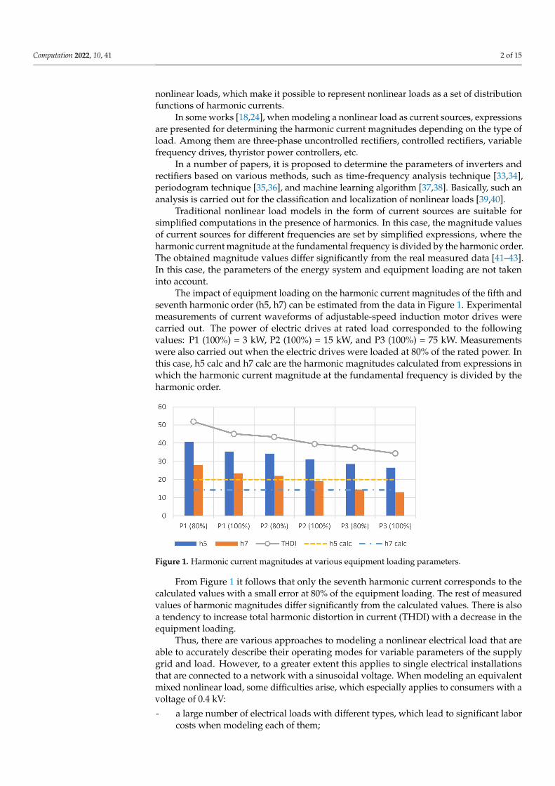
The impact of equipment loading on the harmonic current magnitudes of the fifth andseventh harmonic order (h5, h7) can be estimated from the data in Figure 1. Experimentalmeasurements of current waveforms of adjustable-speed induction motor drives werecarried out. The power of electric drives at rated load corresponded to the followingvalues: P1 (100%) = 3 kW, P2 (100%) = 15 kW, and P3 (100%) = 75 kW. Measurementswere also carried out when the electric drives were loaded at 80% of the rated power. Inthis case, h5 calc and h7 calc are the harmonic magnitudes calculated from expressions inwhich the harmonic current magnitude at the fundamental frequency is divided by theharmonic order.
Figure 1. Harmonic current magnitudes at various equipment loading parameters.
From Figure 1 it follows that only the seventh harmonic current corresponds to thecalculated values with a small error at 80% of the equipment loading. The rest of measuredvalues of harmonic magnitudes differ significantly from the calculated values. There is alsoa tendency to increase total harmonic distortion in current (THDI) with a decrease in theequipment loading.
Thus, there are various approaches to modeling a nonlinear electrical load that areable to accurately describe their operating modes for variable parameters of the supplygrid and load. However, to a greater extent this applies to single electrical installationsthat are connected to a network with a sinusoidal voltage. When modeling an equivalentmixed nonlinear load, some difficulties arise, which especially applies to consumers with avoltage of 0.4 kV:
- a large number of electrical loads with different types, which lead to significant laborcosts when modeling each of them;

Computation 2022, 10, 41 3 of 15
- discrepancy between the existing power supply scheme and the design scheme ofconsumers, which leads to significant complexity in the preparation of the electricalequivalent circuit;
- in the design documentation, only generalized load parameters are indicated, whichdoes not allow to accurately identify the parameters of nonlinear electrical loadfor simulation.
Under such conditions, it is quite difficult to simulate the nonlinear electrical loadof the consumer without real measurements at the facility. Direct measurement of theconsumer currents makes it possible to determine the currents at harmonic frequencies anduse them when modeling a nonlinear load as current sources. However, in the presence ofexternal distortions in the voltage, this approach will be incorrect, since it will not allowseparating the external grid distortions from the internal consumer distortions. Therefore,a new approach is needed to evaluate the parameters of a nonlinear electrical load in orderto carry out simplified computations of power quality indicators in the presence of externaldistortions in the supply voltage.
In [41], based on experimental studies of a different types of nonlinear load, it isshown that the parameters of nonlinear load can be determined by connecting a passiveharmonic filter to the grid. In this case, the nonlinear load current at harmonic frequency isdistributed between the branches of the supply feeder and the passive filter. By measuringthese harmonic currents and performing their complex addition, it is possible to determinethe parameters of the equivalent nonlinear load of the consumer correctly in the presence ofexternal distortions. This approach can be applied to virtually any enterprise with nonlinearload, provided there is a single-tuned filter. The obtained harmonic current magnitudes ofequivalent nonlinear load can be used to increase the accuracy of modeling the nonlinearload and power consumption modes in the presence of harmonics.
This paper further extends the earlier works and aims to assess the impact of thepassive filter parameters, the energy system, and load parameters on the determinationof nonlinear load harmonic currents. Based on assessment of such factors, it is necessaryto develop recommendations for the selection of filter parameters in order to minimizethe error in determining harmonic current magnitudes. The remainder of this paper isorganized as follows: Section 2 illustrates the proposed method of distortion sourcesassessment based on application of passive filter and description of the case under study.Section 3 presents the results and discussion. Section 4 concludes this paper.
2. Research Methods2.1. Method of Distortion Sources Assessment Based on Application of Passive Filter
The method for assessing the parameters of nonlinear electrical load is based onconnecting a single-tuned harmonic filter and measuring the currents of the system and thepassive filter at harmonic frequencies (Figure 2). In this case, it is assumed that nonlinearload harmonic currents flow through the branches with the energy system impedance andthe impedance of the passive harmonic filter. Thus, the summation or subtraction in thecomplex form of the mentioned currents, depending on their direction, gives the harmoniccurrent of an equivalent nonlinear load of the consumer, which can be further used inmodeling and setting the magnitude of nonlinear load in the form of current sources.
From the scheme in Figure 2 it follows that the nonlinear load currents I01h and I02hare divided and flow almost completely through the branches with filter impedance ZFhand system impedance Z0h. Then, we can write the following equation:
I01h + I02h = I0h + IFh (1)
where I0h is the energy system harmonic current, IFh is the filter harmonic current. In thiscase, the system harmonic current and the filter harmonic current can be measured withinthe consumer. Such measured data make it possible to determine the harmonic magnitudeof the equivalent nonlinear load, which in this case consists of two nonlinear consumers.

Computation 2022, 10, 41 4 of 15
Figure 2. The scheme for identification nonlinear load current at harmonic frequencies of h order.
However, Equation (1) is valid only with a certain error, which can be estimated usingthe following coefficients:
n1h = Z1h/Z0h, n2h = Z2h/Z0h, nFh = ZFh/Z0h (2)
where Z1h, Z2h is the consumer’s impedance of h order.According to the superposition method, it is possible to determine the currents I0h
and IFh. The energy system harmonic current can be defined as follows:
I0h =n1h·n2h·nFh
n1h·n2h·nFh + n1h·nFh + n2h·nFh + n1h·n2h·( I01h + I02h) (3)
Filter harmonic current can be defined as follows:
IFh =n1h·n2h
n1h·n2h·nFh + n1h·nFh + n2h·nFh + n1h·n2h·(I01h + I02h) (4)
The summation of the currents I0h and IFh gives the following result:
I0h + IFh =
(1
1 + 1n2h
+ 1n1h
+ 1nFh
+1
1 + nFhn2h
+ nFhn1h
+ nFh
)·(I01h + I02h) (5)
Considering that the coefficients n1h and n2h are much greater than unity at harmonicfrequencies, the following expression can be obtained:
I0h + IFh =
(1
1 + 1/nFh+
11 + nFh
)·(I01h + I02h) = I01h + I02h (6)
Thus, the assumption about the possibility of using a passive filter to determinethe parameters of an equivalent nonlinear load is confirmed. An important feature ofthis method is the determination of the harmonic current magnitudes of nonlinear load,regardless of the external harmonic distortions. This also follows from the superpositionmethod in the presence of external distortions.
When using a passive harmonic filter, the parameters of the filter, system, and loadwill play an essential role in determining harmonic current of nonlinear load, since witha certain combination of these parameters, resonant phenomena may occur at harmonicfrequencies, which may cause an error in determining harmonic current of nonlinear loadby the mentioned method.
2.2. Case Study
A simplified equivalent circuit, the parameters of which correspond to an industrialenterprise with small installed capacity, was developed to study the impact of the pas-sive filter, system, and load parameters on the harmonic current estimation of nonlinearload (Figure 3).

Computation 2022, 10, 41 5 of 15
Figure 3. The scheme under study.
The equivalent circuit parameters are presented in Table 1.
Table 1. The parameters of the equivalent circuit.
Elements of the Scheme Parameters and Values
Energy system (ES) U0 = 0.4 kV, X0 = 0.002 ΩTransformer (T1, T2) S = 630 kVA, UHV/LV = 10/0.4 kV, ∆PSC = 7.6 kW, USC = 5.5%
Induction motor (M1) PM = 250 kW, QM = 200 kvarThyristor rectifier (TR1, TR2) STR = 200 kVA, I5 = 61 A
Capacitor banks (CB1) Unom = 0.4 kV, QCB = 120 kvarPassive filter (PF1) QF = 25 kvar, LF = 0.77 mH, CF = 530 µF, RF = 0.02 Ω
The simulation was carried out in the MATLAB Simulink platform. During thesimulation, it was necessary to assess the impact of the passive filter, energy system, andload parameters on the harmonic current computation of nonlinear load. In this case, thevalues of passive filter resistance varied from 0 to 0.1 Ohm and the values of passive filtercapacitance varied within ±30%. The place of nonlinear load connection was also changed,and the capacitor banks were switched on or off. Additionally, the value of the powersystem impedance was varied from 0 to 0.04 Ohm, which consists of the power system andtransformer impedance. The considered simulation options are presented in Table 2.
For example, for the first simulation option, the subject for consideration is a circuitwith the initial parameters from Table 1, with the following changes made: TR2 discon-nected, the parameters of the filter resistance vary from 0 to 0.01 Ohm for the case of aconnected and disconnected capacitor banks.
To determine the harmonic current magnitude of the nonlinear load, a shunt filter,being virtually a short circuit at a tuned harmonic frequency, is connected to the consumer’sbuses. In [41], based on experimental studies, it is shown that for a thyristor controlledrectifier, a thyristor power regulator, and a diode uncontrolled rectifier, the relative valueof the generated harmonic current to the current at the fundamental frequency remainsalmost constant before and after connecting the passive filter. It means that the ratio of thecurrent harmonic to the current at the fundamental frequency changes with a small error.Therefore, in this paper, the equivalent nonlinear load is set in the form of a current sourceat harmonic frequencies during simulation.

Computation 2022, 10, 41 6 of 15
Table 2. Simulation parameters.
SimulationNumber Options of Simulation Range of
Variation
TR2 disconnected1 Variation of PF1 resistance with switched on/off CB1 [0; 0.1] Ω2 Variation of PF1 capacitance with switched on/off CB1 [−30; +30]%3 Variation of T1 impedance with switched on/off CB1 [0; 0.04] Ω
TR2 connected4 Variation of PF1 resistance with switched on/off CB1 [0; 0.1] Ω5 Variation of PF1 capacitance with switched on/off CB1 [−30; +30]%6 Variation of T1 impedance with switched on/off CB1 [0; 0.04] Ω
In this paper, the task assigned by the authors is to determine the impact of the passivefilter, energy system, and load parameters on the accuracy of computation of the harmoniccurrent magnitude of an equivalent nonlinear load for a single consumer. Such parametersare necessary for a more precise setting of nonlinear load parameters when modeling andcalculating consumer operating modes in the presence of harmonics. Therefore, the schemein Figure 3 is considered in view of the first consumer, i.e., only those measured parametersthat can be obtained within the first consumer are taken into account. As a result, thedependencies of the nonlinear load harmonic current, the supply system harmonic currentof the consumer, the passive filter harmonic current on the parameters of the passive filter,the energy system, and load of the consumer are constructed.
2.3. Experimental Study in Laboratory Test Bench
In the work, experimental measurements were also carried out in the laboratory testbench to confirm the results obtained in the simulation. The single line scheme and testbench view are presented in Figure 4. The laboratory test bench is powered from a three-phase power supply system with a phase voltage of 220 V. In the electrical grid outsidethe considered consumer, an uncontrolled rectifier UR is connected with a load in theform of heating resistance HR. The consumer load includes a passive harmonic filter PF,a controlled thyristor rectifier TR, an induction motor M with a load in the form of a DCgenerator, capacitor banks CB. The consumer is connected to the grid through a power linewith inductance L.
Figure 4. The single line scheme and test bench view.
The measurements were carried out using an Industrial Scopemeter Fluke 125B. Theparameters of the electrical equipment included in the test bench are presented in Table 3.

Computation 2022, 10, 41 7 of 15
Table 3. The equipment parameters of the laboratory bench.
Equipment Parameters
Grid parameters U = 380 V, L = 1 mHUncontrolled rectifier UR UUR = 380 V, RUR = 121 Ω
Thyristor rectifier TR UTR = 380 V, PTR = 0.5 ÷ 4.0 kWPassive filter PF RF = 0.2 Ω, LF = 8.29 mH, CF = 50 µF
Induction motor M PM = 1.5 kW, UM = 220/380 V, PF = 0.84Capacitor banks QCB = 0.5 kvar, C = 9 µF, UCB = 450 V, star connection
When conducting laboratory studies, the error estimation in determining the fifthharmonic current of the controlled thyristor rectifier was carried out by the current equalto the sum of the passive filter current and the supply system current of the consumerat the harmonic frequency. The measured harmonic current of the nonlinear load beforethe filter is connected and the nonlinear load current after the filter is connected, whichis calculated based on the measured currents of the filter and the supply system, werecompared to determine the error. Three modes were considered, in which some parameterswere changed: mode 1—equipment parameters correspond to the data from Table 3; mode2—equipment parameters correspond to the data from Table 3 and there is no power lineinductance; mode 3—the equipment parameters correspond to the data from Table 3, thereis no line inductance, the capacitance of the passive filter is equal to 60 µF.
3. Results and Discussion3.1. Simulation without External Distortions
In this block, the scheme in Figure 3 is considered, wherein the non-linear load TR2 isdisconnected and the rest of the equipment is connected. The simulation is carried out inaccordance with numbers 1–3 from Table 2.
During Simulation 1, the filter resistance was changed. Figure 5 shows the depen-dencies of the nonlinear load harmonic current ITR1, the supply system harmonic currentof the consumer IT1, the harmonic current of the passive filter IPF1, the harmonic currentcalculated from the summation of the harmonic filter current, and the harmonic systemcurrent of the consumer before and after connecting the capacitor banks ISUM1, ISUM2 onthe resistance of the filter RF.
Figure 5. The dependences of the 5th harmonic currents ITR1, IT1, IPF1, ISUM1, ISUM2 on the passivefilter resistance RF.
It is obvious that with an increase in the filter resistance, the harmonic system current ofthe consumer increases, and the harmonic current of the passive filter decreases. When thefilter resistance changes, the harmonic current ISUM1 is substantially equal to the nonlinear

Computation 2022, 10, 41 8 of 15
load harmonic current ITR1. The error in estimating the harmonic current magnitude ofnonlinear load by means of harmonic current ISUM1 increases with an increase in the filterresistance and is about 10% at the maximum value of 0.1 Ohm. This is due to the factthat part of the harmonic current flows through the branch with capacitor banks CB1.Disconnecting CB1 for the time of measurements reduces the estimation error, which atthe maximum value of the filter resistance was 7%. It is worth noting that with the ratedparameters of the passive filter (Table 2), corresponding to the parameters of the filter atan existing industrial facility, the error in estimating the harmonic current magnitude ofnonlinear load current is about 1.6%.
During Simulation 2, the filter capacitance was changed. Figure 6 shows the depen-dencies of the harmonic currents ITR1, IT1, IPF1, ISUM1, ISUM2 on the capacitance of thefilter XCF.
Figure 6. The dependences of the 5th harmonic currents ITR1, IT1, IPF1, ISUM1, ISUM2 on the passivefilter capacitance XCF.
From Figure 6, it follows that with an increase in the filter capacitance, the systemharmonic current of the consumer ITR1 and the harmonic current of the passive filter IPF1increase, which is due to the occurrence of the parallel resonance near the fifth harmonicfrequency. In this case, the filter is considered detuned, and its tuning frequency is shiftedto higher frequencies. At the fifth harmonic frequency, the passive filter has a capacitivecharacter, which leads to the occurrence of resonant phenomena. It also follows from thegraph that the harmonic current ISUM2 with the capacitor banks disconnected is equal to theharmonic current of the nonlinear load ITR1 with any changes in the filter capacitance in therange from −30 to 0%. It appears that in order to accurately estimate the harmonic currentof the nonlinear load using a passive filter, its LC circuit should have either active or active-inductive character at the tuned harmonic frequency. It is also necessary to disconnectcapacitor banks designed to compensate for reactive power.
During Simulation 3, the transformer impedance was changed. Figure 7 shows thedependencies of the harmonic currents ITR1, IT1, IPF1, ISUM1, ISUM2 on the transformerimpedance XT1.
The calculated harmonic currents ISUM1 and ISUM2 with the CB1 connected and discon-nected at the fifth harmonic is substantially equal to the harmonic current of the nonlinearload ITR1. In this case, the change in the transformer impedance virtually does not affectthe accuracy of estimating the harmonic current of the nonlinear load according to theproposed method.

Computation 2022, 10, 41 9 of 15
Figure 7. The dependences of the 5th harmonic currents ITR1, IT1, IPF1, ISUM1, ISUM2 on the energysystem impedance XT1.
3.2. Simulation with External Distortions
In this block, the scheme in Figure 3 is considered, wherein the nonlinear load TR2and the rest of the equipment are connected. In this case, two consumers are connected tothe point of common coupling. One consumer contains mixed load and a passive harmonicfilter, and the other consumer contains completely nonlinear load. For visual clarity, thenonlinear load parameters of the first consumer are reduced by ten times (ITR1 = 6.1 A). Thesimulation is carried out in accordance with numbers 4–6 from Table 2.
During Simulation 4, the filter resistance was changed. Figure 8 shows the depen-dencies of the nonlinear load harmonic current ITR1, the supply system harmonic currentof the consumer IT1, the harmonic current of the passive filter IPF1, the harmonic currentcalculated from the summation of the harmonic filter current and the harmonic systemcurrent of the consumer before and after connecting the capacitor banks ISUM1, ISUM2 onthe resistance of the filter RF.
Figure 8. The dependences of the 5th harmonic currents ITR1, IT1, IPF1, ISUM1, ISUM2 on the passivefilter resistance RF (simulation 4).
From the graph it follows that the error in estimating the harmonic current magnitudeof nonlinear load by means of harmonic current ISUM1 increases with an increase in thefilter resistance and is 28% at its maximum value. When capacitor banks are disconnected,the maximum error is reduced to 16%. At the rated filter parameters (quality factor is 60),the error is about 4%.

Computation 2022, 10, 41 10 of 15
During Simulation 5, the filter capacitance was changed. Figure 9 shows the depen-dencies of the harmonic currents ITR1, IT1, IPF1, ISUM1, ISUM2 on the filter capacitance XCF.
Figure 9. The dependences of the 5th harmonic currents ITR1, IT1, IPF1, ISUM1, ISUM2 on the passivefilter capacitance XCF (simulation 5).
An increase in the filter harmonic current and system harmonic current is due to theoccurrence of the parallel resonance near the fifth harmonic. To avoid the occurrence of sucha phenomenon, it is necessary to ensure the active-inductive character of the passive filtercircuit at the fifth harmonic frequency, i.e., tune it to the frequency of the fifth harmonic andbelow. With such a tuning, it can be seen from the graph that the harmonic current ISUM2with the capacitor banks disconnected is equal to the harmonic current of the nonlinearload ITR1, which indicates the efficiency of the method under consideration.
During Simulation 6, the transformer impedance was changed. Figure 10 shows thedependencies of the harmonic currents ITR1, IT1, IPF1, ISUM1, ISUM2 on the transformerimpedance XT1.
Figure 10. The dependences of the 5th harmonic currents ITR1, IT1, IPF1, ISUM1, ISUM2 on the trans-former impedance XT1 (simulation 6).
From Figure 10, it follows that the harmonic current ISUM2 with the capacitor banksdisconnected is substantially equal to the harmonic current of the nonlinear load ITR1. Atthe rated value of the transformer impedance, the error in estimating harmonic currentof nonlinear load is about 5%. The maximum estimation error is equal to 26% withzero transformer impedance and CB1 connected. In this case, the impedance of the firstenterprise for the external harmonic current is minimal. As a result, high-ampere harmonic

Computation 2022, 10, 41 11 of 15
current from the external source flows through the branch with transformer impedance andthen gets divided into branches with a passive filter, load, and capacitor banks. The part ofthe harmonic current that flows through the branch with load and the capacitor banks isnot considered when calculating the harmonic current of nonlinear load and increases thecomputation error. However, in real conditions, in the presence of transformer impedance,the external harmonic currents virtually do not affect the determination of the harmoniccurrent magnitude of nonlinear load at the enterprise under consideration.
3.3. Current Waveforms during Simulation
For a more detailed understanding of the proposed method, current waveforms wereobtained (Figure 11), which are necessary to calculate the harmonic current of nonlinearload (h = 5).
Figure 11. Current waveforms during simulation: passive filter current iPF (red line), supply systemcurrent iT (blue line), calculated current iSUM (yellow line).
The model parameters were close to the test bench parameters in terms of the load ratioand composition: external nonlinear load TR2 and capacitor banks CB1 were connected,the transformer impedance was doubled, the power ratio of the linear load M1 and thenonlinear load TR1 was equal to the ratio of these parameters in laboratory studies, thenonlinear load parameters (TR1, TR2) were set according to Table 1. Calculated currentiSUM was defined as the sum of the currents iPF and iT. The fifth harmonic current ofthe nonlinear load was calculated based on the Fourier transform. As a result, the fifthharmonic current was equal to 62.4 A, and the error relative to the true value was 2.3%.
3.4. Experimental Study in Laboratory Test Bench
This block presents the results of experimental studies on a laboratory bench, describedin Section 2.3. The instantaneous current of the nonlinear load was calculated by measuringthe instantaneous current of the consumer supply feeder (blue line), the instantaneouscurrent of the passive filter (red line), and their subsequent subtraction (yellow line). Thesubtraction had to be applied due to the selected current clamp connection during themeasurement (source to load). Figure 12 shows current waveforms for one of the studiedmodes (additional inductance, external nonlinear load, capacitor banks were connected).
The error in determining the fifth harmonic current of a nonlinear load was calculatedrelative to the fifth harmonic current of thyristor rectifier, which was measured when itwas only connected to the power supply system. Cases were considered in which theparameters of the power supply line and passive harmonic filter were changed, as well asthe capacitor banks and the uncontrolled rectifier were connected or disconnected. Theerror estimation data are presented in Table 4.

Computation 2022, 10, 41 12 of 15
Figure 12. Current waveforms during experimental study: passive filter current iPF (red line), supplysystem current iT (blue line), calculated current iSUM (yellow line).
Table 4. The relative error estimation for various modes of test bench load.
Mode Number
Relative Error, %
CB Connected CB Disconnected
UR Connected UR Disconnected UR Connected UR Disconnected
1 2.8 4.3 3.7 4.22 −0.9 2.6 3.3 0.53 −1.0 −3.4 4.1 −1.2
It follows from the data in Table 4 that the error in estimating the fifth harmoniccurrent of nonlinear load based on measurements of the supply feeder current and passivefilter current does not exceed 5% for the considered modes. In this case, the maximumerror is observed when an additional inductance is connected (mode 1), the minimumerror corresponds to the case without inductance in the power line (mode 2), and the errorincreases within small limits when the filter capacitance changes (mode 3). It should alsobe noted that an external source of distortion does not significantly affect the error for thecases under consideration.
Laboratory studies were carried out when a passive harmonic filter was connected,the parameters of which were selected taking into account the results obtained during thesimulation. The quality factor of the passive filter was approximately equal to 60, the filtercircuit had an active-inductive character at the fifth harmonic frequency. It should alsobe noted that when a passive filter was connected in laboratory conditions, the supplyfeeder current decreased at the fundamental frequency. This leads to an increase in thecalculated nonlinear load current at the fundamental frequency and may affect the currentcomputation at the fifth harmonic frequency. However, the influence of such a factor for theselected type of nonlinear load in laboratory conditions was insignificant. To reduce thisinfluence, it is necessary to select the filter parameters based on the minimum compensatingability at the fundamental frequency.
4. Conclusions
Thus, in this work, a method was proposed and tested for determining the harmoniccurrents of equivalent nonlinear load in the presence of external distortions. The impact ofthe passive filter parameters, the energy system, and load parameters on the computationof nonlinear load harmonic currents with application of single tuned harmonic filter have

Computation 2022, 10, 41 13 of 15
been revealed. The factors that most affect the error in calculating the harmonic current ofnonlinear load based on the measurements of filter harmonic current and supply systemharmonic current have been identified. The main advantage of the proposed method isthe separation of external and internal distortions, which makes it possible to correctlyestimate the parameters of the nonlinear load of a single consumer. It should also benoted that the proposed method has disadvantages: a filter is required for each tunedharmonic; an additional device is required if the consumer does not have a passive filter;the passive filter is connected temporarily as a measuring device, after its disconnection,the parameters of the nonlinear load may change. The obtained simulation results wereconfirmed experimentally on a laboratory test bench. Based on the conducted research,the following recommendations for the selection of passive harmonic filter parametershave been developed in order to minimize the error in determining harmonic current ofnonlinear load in the presence of external distortions:
1. The lower the passive filter resistance, the higher the accuracy of estimating theharmonic current of nonlinear load. In this case, the error does not exceed 5% for filterquality factor values from 20 to 120. In addition, it is necessary to take into accountthe current overload ratio of the filter, since a decrease in its resistance results in anincrease in the current through the filter at harmonic frequencies.
2. It is necessary to disconnect the capacitor banks for the reactive power compensationduring the measurements of supply system harmonic current and filter harmoniccurrent, since part of the harmonic current that flows through the capacitor banksat harmonic frequencies is not accounted for when performing computations ofnonlinear load harmonic current.
3. A passive filter should have active or active-inductive character at a tuned frequencyin order to avoid the resonance phenomena with the grid impedance. Therefore, filtertuning should be made to the frequency of the generated harmonic by nonlinear load,or to a lower frequency.
4. The generated reactive power of the passive filter at the fundamental frequency shouldnot affect the voltage at the consumer’s buses. In this case, voltage deviations canaffect the accuracy of calculating the harmonic current magnitudes of a nonlinear load.
Further research opportunities include the development of a mobile measuring devicebased on the passive filter application and its testing and implementation at industrialplants with a voltage of 0.4 kV.
Author Contributions: Conceptualization, A.S.; Methodology, A.S. and A.B.; Investigation, I.G. andV.D.; Writing—original draft preparation, A.S.; Supervision and project administration, A.S. andA.B.; Writing—review and editing, A.S. and V.D. All authors have read and agreed to the publishedversion of the manuscript.
Funding: This research was financially supported by the Russian Science Foundation grant No.21-79-10027, https://rscf.ru/en/project/21-79-10027/ (accessed date 20 February 2022).
Institutional Review Board Statement: Not applicable.
Informed Consent Statement: Not applicable.
Conflicts of Interest: The authors declare no conflict of interest.
Nomenclature
THDI Total harmonic distortion in currentTHDU Total harmonic distortion in voltageh Harmonic orderh5 (h7) calc Calculated 5th (7th) harmonic magnitudeh5 (h7) Measured 5th (7th) harmonic magnitude

Computation 2022, 10, 41 14 of 15
I01h, I02h Nonlinear load currents of the consumers (vector value)I0h Energy system harmonic current of h order (vector value)IFh Filter harmonic current of h order (vector value)Z0h Energy system impedance of h order (vector value)ZFh Filter impedance of h order (vector value)Z1h, Z2h Consumer impedance of h order (vector value)T1, T2 Supply transformerES Energy systemM1 Induction motor of the first consumerTR1, TR2 Thyristor rectifierCB1 Capacitor banks of the first consumerPF1 Passive filter of the first consumerUR Uncontrolled rectifierHR Heating resistanceRF Filter resistanceXCF Filter capacitanceITR1 Nonlinear load harmonic current magnitude of consumerIT1 Supply system harmonic current magnitude of the consumerIPF1 Passive filter harmonic current magnitude of the consumer
ISUM1
Harmonic current magnitude calculated from the summation of the harmonic filtercurrent and the harmonic system current of the consumer before connecting thecapacitor banks
ISUM2
Harmonic current magnitude calculated from the summation of the harmonic filtercurrent and the harmonic system current of the consumer after connecting thecapacitor banks
References1. Bogdanov, I.; Abramovich, B. Improving the Efficiency of Autonomous Electrical Complexes of Oil and Gas Enterprises. J. Min.
Inst. 2021, 249, 408–416. [CrossRef]2. Almeida, C.F.M.; Kagan, N. Harmonic Coupled Norton Equivalent Model for Modeling Harmonic-Producing Loads. In
Proceedings of the 14th International Conference on Harmonics and Quality of Power-ICHQP, Bergamo, Italy, 26–29 September2010; IEEE: Manhattan, NY, USA, 2010; pp. 1–9. [CrossRef]
3. Shabalov, M.Y.; Zhukovskiy, Y.L.; Buldysko, A.D.; Gil, B.; Starshaia, V.V. The Influence of Technological Changes in EnergyEfficiency on the Infrastructure Deterioration in the Energy Sector. Energy Rep. 2021, 7, 2664–2680. [CrossRef]
4. Shklyarskiy, Y.; Guerra, D.D.; Iakovleva, E.; Rassõlkin, A. The Influence of Solar Energy on the Development of the MiningIndustry in the Republic of Cuba. J. Min. Inst. 2021, 249, 427–440. [CrossRef]
5. Korolev, N.; Kozyaruk, A.; Morenov, V. Efficiency Increase of Energy Systems in Oil and Gas Industry by Evaluation of ElectricDrive Lifecycle. Energies 2021, 14, 6074. [CrossRef]
6. Beltran-Carbajal, F.; Tapia-Olvera, R.; Valderrabano-Gonzalez, A.; Yanez-Badillo, H. An Asymptotic and Algebraic EstimationMethod of Harmonics. Electr. Power Syst. Res. 2022, 206, 107771. [CrossRef]
7. Jiménez Carrizosa, M.; Stankovic, N.; Vannier, J.-C.; Shklyarskiy, Y.; Bardanov, A. Multi-Terminal DC Grid Overall Control withModular Multilevel Converters. J. Min. Inst. 2020, 243, 357. [CrossRef]
8. Senchilo, N.D.; Ustinov, D.A. Method for Determining the Optimal Capacity of Energy Storage Systems with a Long-TermForecast of Power Consumption. Energies 2021, 14, 7098. [CrossRef]
9. Zhukovskiy, Y.; Tsvetkov, P.; Buldysko, A.; Malkova, Y.; Stoianova, A.; Koshenkova, A. Scenario Modeling of SustainableDevelopment of Energy Supply in the Arctic. Resources 2021, 10, 124. [CrossRef]
10. Mayordomo, J.G.; Beites, L.F.; Yang, X.; Xu, W. A Detailed Procedure for Harmonic Analysis of Three-Phase Diode RectifiersUnder Discontinuous Conduction Mode and Nonideal Conditions. IEEE Trans. Power Deliv. 2018, 33, 741–751. [CrossRef]
11. Kryltcov, S.B.; Solovev, S.V.; Munoz-Guijosa, J.M. Application of an active rectifier used to mitigate currents distortion in 6–10 kVdistribution grids. J. Min. Inst. 2019, 236, 229–238. [CrossRef]
12. Mayordomo, J.G.; Carbonero, Á.; Beites, L.F.; Asensi, R.; Xu, W. A Contribution Towards a General and Systematic Procedurefor Modeling Line Commutated AC/DC Converters in the Harmonic Domain. IEEE Trans. Power Deliv. 2009, 24, 2415–2427.[CrossRef]
13. Alexandrov, V.I.; Kopteva, A.V.; Serzan, S.L. Effective Parameters of Tail Processing of Gold-Bearing Ore Hydrotransport forVerninskaya Processing Factory. Key Eng. Mater. 2020, 836, 25–35. [CrossRef]
14. Lian, K.L.; Perkins, B.K.; Lehn, P.W. Harmonic Analysis of a Three-Phase Diode Bridge Rectifier Based on Sampled-Data Model.IEEE Trans. Power Deliv. 2008, 23, 1088–1096. [CrossRef]
15. Sun, Y.; Zhang, G.; Xu, W.; Mayordomo, J.G. A Harmonically Coupled Admittance Matrix Model for AC/DC Converters. IEEETrans. Power Syst. 2007, 22, 1574–1582. [CrossRef]

Computation 2022, 10, 41 15 of 15
16. Voronin, V.; Nepsha, F. Simulation of the Electric Drive of the Shearer to Assess the Energy Efficiency Indicators of the PowerSupply System. J. Min. Inst. 2021, 246, 633–639. [CrossRef]
17. Shklyarskiy, Y.E.; Shklyarskiy, A.Y.; Zamyatin, E.O. Analysis of Distortion-Related Electric Power Losses in Aluminum Industry.Tsvetnye Met. 2019, 4, 84–91. [CrossRef]
18. Grotzbach, M.; Redmann, R. Line Current Harmonics of VSI-Fed Adjustable-Speed Drives. IEEE Trans. Ind. Appl. 2000, 36,683–690. [CrossRef]
19. Borisov, S.; Koltunova, E.; Kladiev, S. Traction Asynchronous Electric Drive of Mine Electric Locomotive Simulation ModelStructure Improvement. J. Min. Inst. 2021, 247, 1–8. [CrossRef]
20. Carpinelli, G.; Iacovone, F.; Russo, A.; Varilone, P.; Verde, P. Analytical Modeling for Harmonic Analysis of Line Current ofVSI-Fed Drives. IEEE Trans. Power Deliv. 2004, 19, 1212–1224. [CrossRef]
21. Thakur, S.; Odavic, M.; Allu, A.; Zhu, Z.Q.; Atallah, K. Analytical Modelling and Optimization of Output Voltage HarmonicSpectra of Full-Bridge Modular Multilevel Converters in Boost Mode. IEEE Trans. Power Electron. 2022, 37, 3403–3420. [CrossRef]
22. Wcislik, M. Analytical Model of Single-Phase AC Circuit with Inductance and Bridge Rectifier. Przeglad Elektrotechniczny 2018, 1,128–131. [CrossRef]
23. Zeng, Z.; Xiao, H.; Niu, C.; Chen, J.; Wang, Z.; Wu, X.; Cheng, M. An Improved Impedance Modeling Method of Grid-TiedInverters with White-Box Property. IEEE Trans. Power Electron. 2022, 37, 3980–3989. [CrossRef]
24. Hansen, S.; Asiminoaei, L.; Blaabjerg, F. Simple and Advanced Methods for Calculating Six-Pulse Diode Rectifier Line-SideHarmonics. In Proceedings of the 38th IAS Annual Meeting on Conference Record of the Industry Applications Conference, SaltLake City, UT, USA, 12–16 October 2003; IEEE: Manhattan, NY, USA, 2003; Volume 3, pp. 2056–2062. [CrossRef]
25. Iakovleva, E.; Belova, M.; Soares, A. Allocation of Potentially Environmentally Hazardous Sections on Pipelines. Geosciences 2020,11, 3. [CrossRef]
26. Faifer, M.; Laurano, C.; Ottoboni, R.; Toscani, S.; Zanoni, M. Frequency-Domain Nonlinear Modeling Approaches for PowerSystems Components—A Comparison. Energies 2020, 13, 2609. [CrossRef]
27. Gao, B.; Wang, Y.; Xu, W. Modeling Voltage Source Converters for Harmonic Power Flow Studies. IEEE Trans. Power Deliv. 2021,36, 3426–3437. [CrossRef]
28. Guarderas, G.; Frances, A.; Ramirez, D.; Asensi, R.; Uceda, J. Blackbox Large-Signal Modeling of Grid-Connected DC-ACElectronic Power Converters. Energies 2019, 12, 989. [CrossRef]
29. John, M.; Mertens, A. Frequency-Domain Modeling of Harmonic Interactions in Voltage-Source Inverters with Closed-LoopControl. Energies 2020, 13, 5823. [CrossRef]
30. Li, F.; Wang, Y.; Wu, F.; Huang, Y.; Liu, Y.; Zhang, X.; Ma, M. Review of Real-Time Simulation of Power Electronics. J. Mod. PowerSyst. Clean Energy 2020, 8, 796–808. [CrossRef]
31. Kovernikova, L.I.; Luong, V.C. New Approach to Modeling the Nonlinear Loads. E3S Web Conf. 2019, 139, 01055. [CrossRef]32. Nassif, A.B.; Yong, J.; Xu, W. Measurement-Based Approach for Constructing Harmonic Models of Electronic Home Appliances.
IET Gener. Transm. Distrib. 2010, 4, 363. [CrossRef]33. Abdullah, A.R.; Abidullah, N.A.; Shamsudin, N.H.; Ahmad, N.H.H.; Jopri, M.H. Power Quality Signals Classification System
Using Time-Frequency Distribution. Appl. Mech. Mater. 2014, 494–495, 1889–1894. [CrossRef]34. Jopri, M.H.; Abdullah, A.R.; Manap, M.; Sutikno, T.; Ab Ghani, M.R. An Identification of Multiple Harmonic Sources in a
Distribution System by Using Spectrogram. Bull. Electr. Eng. Inform. 2018, 7, 244–256. [CrossRef]35. Jopri, M.H.; Abdullah, A.R.; Manap, M.; Yusoff, M.R.; Sutikno, T. A Fast Localization of Multiple Harmonic Sources for Rectifier
Loads by Utilizing Periodogram. TELKOMNIKA Telecommun. Comput. Electron. Control. 2017, 15, 71. [CrossRef]36. Manap, M.; Jopri, M.H.; Abdullah, A.R.; Karim, R.; Yusoff, M.R.; Azahar, A. A Verification of Periodogram Technique for
Harmonic Source Diagnostic Analytic by Using Logistic Regression. TELKOMNIKA Telecommun. Comput. Electron. Control. 2019,17, 497. [CrossRef]
37. Jopri, M.H.; Abdullah, A.R.; Sutikno, T.; Manap, M.; Ghani, M.R.A.; Yusoff, M.R. A Critical Review of Time-Frequency DistributionAnalysis for Detection and Classification of Harmonic Signal in Power Distribution System. Int. J. Electr. Comput. Eng. 2018,8, 4603. [CrossRef]
38. Jopri, M.H.; Ab Ghani, M.R.; Abdullah, A.R.; Manap, M.; Sutikno, T.; Too, J. K-Nearest Neighbor and Naïve Bayes BasedDiagnostic Analytic of Harmonic Source Identification. Bull. Electr. Eng. Inform. 2021, 9, 2650–2657. [CrossRef]
39. Jopri, M.H.; Abdullah, A.R.; Manap, M.; Yusoff, M.R.; Sutikno, T.; Habban, M.F. An Improved of Multiple Harmonic SourcesIdentification in Distribution System with Inverter Loads by Using Spectrogram. Int. J. Power Electron. Drive Syst. 2016, 7, 1355.[CrossRef]
40. Shawon, M.H.; Barczentewicz, S.; Bien, A.; Hanzelka, Z. Localization of Harmonic Sources in Power System-Simulation andLaboratory Study. Renew. Energy Power Qual. J. 2016, 14, 546–551. [CrossRef]
41. Skamyin, A.; Shklyarskiy, Y.; Dobush, V.; Dobush, I. Experimental Determination of Parameters of Nonlinear Electrical Load.Energies 2021, 14, 7762. [CrossRef]
42. Busatto, T.; Ravindran, V.; Larsson, A.; Rönnberg, S.K.; Bollen, M.H.J.; Meyer, J. Deviations between the Commonly-Used Modeland Measurements of Harmonic Distortion in Low-Voltage Installations. Electr. Power Syst. Res. 2020, 180, 106166. [CrossRef]
43. Kryltcov, S.; Makhovikov, A.; Korobitcyna, M. Novel Approach to Collect and Process Power Quality Data in Medium-VoltageDistribution Grids. Symmetry 2021, 13, 460. [CrossRef]