OSCI HVAC CONTROLS UPGRADE SCOPE OF WORK - BidNet
87
OSCI HVAC CONTROLS UPGRADE SCOPE OF WORK BACKGROUND THE OREGON STATE CORRECTIONAL INSTITUTION (OSCI). HVAC CONTROLS ARE LOCATED IN THE MAIN BUILDING COMPLEX AT 3405 DEER PARK DRIVE SE, IN SALEM, OREGON AND WAS BUILT CIRCA 1959, WITH ADDITIONS IN 1962 & 1970. EXISTING HVAC CONTROLS WERE INSTALLED 1992. PROJECT SCOPE OF WORK ACCEPTABLE MANUFACTURES/CONTRACTORS: THIS PROJECT IS AN OPEN BID CONTROLS UPGRADE ANY BACNET CONTROL SYSTEM THAT MEETS THE WRITTEN SPECIFICATIONS AND DRAWINGS IS ACCEPTABLE. THE FOLLOWING MANUFACTURES ARE EXPLICITLY LISTED AS EQUAL SIEMENS - HONEYWELL - DELTA - CARRIER -RELIABLE - JOHNSON CONTROLS CONTROLS UPGRADES & MODIFICAITONS: • REPLACE EXISTING BUILDING DDC/BAS SYSTEM WITH NEW BACNECT DDC/BAS SYSTEM. • REPLACE VALVE OR DAMPER ACTUATOR WITH NEW ELECTRIC ACTUATOR – SEE REFERENCE PLANS FOR ORIGINAL EQUIPMENT INFO. • PROVIDE ALL NEW THERMOSTATS AND COORDINATE ALL LOCATIONS WITH OWNER. ADD ALTERNATE LINE ITEM COSTS: • PROVIDE LINE ITEM COST TO REPLACE STEAM CONTROL VALVE BODDIES THAT ARE DAMAGED BEYOND REPAIR BY ODOC. SEE REFERENCE DRAWINGS FOR ORIGINAL EQUIPMENT INFO. DEMOLITION WORK: • REMOVE ALL EXISTING CONTROLS WIRING AND ASSOCIATED PANELS. • CAP & SEAL ALL PNEUMATIC TUBING TO REMOVED ACTUATORS. • PNEUMATIC SYSTEM TO REMAIN OPERATIONAL FOR EXISTING STEAM RADIATORS. WIRING: CONTRACTOR IS RESPONSIBLE FOR PROVIDING AND ROUTING OF ALL CONTROL WIRING, INCLUDING, BUT NOT LIMITED TO: • PROVIDING WIRE RATED FOR WET LOCATIONS FOR ALL WIRING OUTSIDE THE BUILDING ENVELOPE. • PROVIDING CONDUIT FOR ALL WIRING REQUIRED BY THE NEC. • PROVIDING WEATHER TIGHT ROOF PENETRATIONS. • PROVIDING WIRE SUPPORTS AND CONDUIT ANCHORS PER THE NEC. REMOVAL OF ALL UNUSED CONTROL WIRING. WIRING SCOPE TO INCLUDE ALL REQUIRED LOW AND LINE VOLTAGE WIRING & POWER. ALL LINE VOLTAGE WORK TO BE PERFORMED BY A LICENSED ELECTRICAL CONTRACTOR. • PROVIDE ALL REQUIRED LINE VOLTAGE POWER FOR NEW DDC PANELS. BALANCING: CONTRACTOR IS RESPONSIBLE FOR HIRING A BALANCING FIRM TO RE-BLANCE ALL EQUIPMENT MODIFIED DURING CONTROLS UPGRADE TO THE ORIGINAL VALUES LISTED ON THE REFERENCE DRAWINGS. ITEMS TO INCLUDE, BUT NOT LIMITED TO, AIR HANDLER FLOW RATES, OUTSIDE AIR FLOW RATES, WATER/STEAM FLOW RATES, DAMPER MINIMUM AND MAXIMUM POSITIONS, AND VFD MINIMUM AND MAXIMUM VALUES. REPORT ALL DISCREPANCIES TO THE OWNER FOR CLARIFICATIONS.
-
Upload
khangminh22 -
Category
Documents
-
view
0 -
download
0
Transcript of OSCI HVAC CONTROLS UPGRADE SCOPE OF WORK - BidNet
OSCI HVAC CONTROLS UPGRADE SCOPE OF WORK
BACKGROUND
THE OREGON STATE CORRECTIONAL INSTITUTION (OSCI). HVAC CONTROLS ARE LOCATED IN THE MAIN
BUILDING COMPLEX AT 3405 DEER PARK DRIVE SE, IN SALEM, OREGON AND WAS BUILT CIRCA 1959, WITH ADDITIONS IN 1962 & 1970. EXISTING HVAC CONTROLS WERE INSTALLED 1992.
PROJECT SCOPE OF WORK
ACCEPTABLE MANUFACTURES/CONTRACTORS:
THIS PROJECT IS AN OPEN BID CONTROLS UPGRADE ANY BACNET CONTROL SYSTEM THAT MEETS THE WRITTEN SPECIFICATIONS AND DRAWINGS IS ACCEPTABLE. THE FOLLOWING MANUFACTURES ARE EXPLICITLY LISTED AS EQUAL
SIEMENS - HONEYWELL - DELTA - CARRIER -RELIABLE - JOHNSON CONTROLS
CONTROLS UPGRADES & MODIFICAITONS:
· REPLACE EXISTING BUILDING DDC/BAS SYSTEM WITH NEW BACNECT DDC/BAS SYSTEM. · REPLACE VALVE OR DAMPER ACTUATOR WITH NEW ELECTRIC ACTUATOR –
SEE REFERENCE PLANS FOR ORIGINAL EQUIPMENT INFO. · PROVIDE ALL NEW THERMOSTATS AND COORDINATE ALL LOCATIONS WITH OWNER.
ADD ALTERNATE LINE ITEM COSTS:
· PROVIDE LINE ITEM COST TO REPLACE STEAM CONTROL VALVE BODDIES THAT ARE DAMAGED BEYOND REPAIR BY ODOC. SEE REFERENCE DRAWINGS FOR ORIGINAL EQUIPMENT INFO.
DEMOLITION WORK:
· REMOVE ALL EXISTING CONTROLS WIRING AND ASSOCIATED PANELS. · CAP & SEAL ALL PNEUMATIC TUBING TO REMOVED ACTUATORS. · PNEUMATIC SYSTEM TO REMAIN OPERATIONAL FOR EXISTING STEAM RADIATORS.
WIRING:
CONTRACTOR IS RESPONSIBLE FOR PROVIDING AND ROUTING OF ALL CONTROL WIRING, INCLUDING, BUT NOT LIMITED TO:
· PROVIDING WIRE RATED FOR WET LOCATIONS FOR ALL WIRING OUTSIDE THE BUILDING ENVELOPE. · PROVIDING CONDUIT FOR ALL WIRING REQUIRED BY THE NEC. · PROVIDING WEATHER TIGHT ROOF PENETRATIONS. · PROVIDING WIRE SUPPORTS AND CONDUIT ANCHORS PER THE NEC. REMOVAL OF ALL UNUSED
CONTROL WIRING. WIRING SCOPE TO INCLUDE ALL REQUIRED LOW AND LINE VOLTAGE WIRING & POWER. ALL LINE VOLTAGE WORK TO BE PERFORMED BY A LICENSED ELECTRICAL CONTRACTOR.
· PROVIDE ALL REQUIRED LINE VOLTAGE POWER FOR NEW DDC PANELS.
BALANCING: CONTRACTOR IS RESPONSIBLE FOR HIRING A BALANCING FIRM TO RE-BLANCE ALL EQUIPMENT MODIFIED DURING CONTROLS UPGRADE TO THE ORIGINAL VALUES LISTED ON THE REFERENCE DRAWINGS. ITEMS TO INCLUDE, BUT NOT LIMITED TO, AIR HANDLER FLOW RATES, OUTSIDE AIR FLOW RATES, WATER/STEAM FLOW RATES, DAMPER MINIMUM AND MAXIMUM POSITIONS, AND VFD MINIMUM AND MAXIMUM VALUES. REPORT ALL DISCREPANCIES TO THE OWNER FOR CLARIFICATIONS.
OSCI Controls Replacement Common HVAC Materials and Methods 9-17-20 23 05 00 - 1
SECTION 23 05 00 – COMMON HVAC MATERIALS AND METHODS
PART 1 - GENERAL
1.1 DESCRIPTION
A. The provisions of the General Conditions for Public Improvement Contracts, i.e. “The General Conditions”, Supplementary General Conditions, i.e. “SGC”, apply to the HVAC work specified in this Division.
B. The requirements of this Section apply to the HVAC systems specified in these
Specifications and in other Division 23 sections. C. Provide all items, articles, materials, equipment, operations and/or methods listed,
mentioned, shown and/or scheduled on the Drawings and/or in these Specifications, including all labor, supervision, services, permits, fees, and incidentals necessary and required to provide a complete and operable facility with complete systems as shown, specified, and required by applicable codes.
D. The work shall include, but not be limited to, the following systems:
1. Complete Controls upgrade to the main Facility.
E. Advise sub-contractor, suppliers, and vendors involved in the work specified in
this Section of the applicable requirements.
1.2 QUALITY ASSURANCE
A. All work and materials shall conform to all applicable local and state codes and all federal, state and other applicable laws and regulations. All clarifications and modifications which have been cleared with appropriate authorities are listed under the applicable sections. All electrical products shall bear the label of a recognized testing laboratory such as UL or CSA.
B. Whenever the requirements of the Specifications or Drawings exceed those of the
applicable code or standard, the requirements of the Specifications and Drawings shall govern.
C. Codes and Standards: Comply with the provisions of the following referenced
codes, standards and specifications: 1. Federal Specifications (FS) 2. American National Standards Institute (ANSI) 3. National Electrical Manufacturer's Association (NEMA) 4. National Fire Protection Association (NFPA) 5. Underwriters Laboratories, Inc. (UL) 6. Factory Mutual (FM) 7. International Building Code (IBC) with State and Local Amendments 8. International Mechanical Code (IMC) with State and Local Amendments 9. Uniform Plumbing Code (UPC) with State and Local Amendments 10. American Society for Testing and Materials (ASTM) 11. Americans with Disabilities Act (ADA)
OSCI Controls Replacement Common HVAC Materials and Methods 9-17-20 23 05 00 - 2
12. International Fire Code (IFC) with State and Local Amendments 13. Energy Policy Act (EPAct) 14. Manufacturers Standardization Society (MSS) 15. American Gas Association (AGA)
D. Each piece of equipment furnished shall meet all detailed requirements of the Drawings and Specifications and shall be suitable for the installation shown. Equipment not meeting all requirements shall not be acceptable, even though specified by name. Where two or more units of the same class of equipment are furnished, use product of the same manufacturer; component parts of the entire system need not be products of same manufacturer. Furnish all materials and equipment, new and free from defect and of size, make, type and quality herein specified or approved by the Owner. All materials shall be installed in a neat and professional manner.
E. All apparatus shall be built and installed to deliver its full rated capacity at the
efficiency for which it was designed. F. The Drawings and Specifications are complementary, per The General
Conditions, Section A – General Provisions, A.3 – Interpretation of Contract Documents.
G. Drawings: Do not scale drawings for roughing-in measurements, nor use as shop
drawings. Make field measurements and prepare shop drawings as required. Coordinate work with shop drawings of other specification divisions.
H. Field Wiring: It is the intent of these specifications that all systems shall be
complete and operable. Refer to all drawings and specifications, especially the electrical drawings, to determine voltage, phase, circuit ampacity and number of connections provided. Provide all necessary field wiring and devices from the point of connection indicated on the electrical drawings. All equipment shall be installed in compliance with the Electrical Code and the equipment’s UL listing. Bring to the attention of the Owner in writing, all conflicts, incompatibilities, and/or discrepancies prior to bid per The General Conditions, Section A – General Provisions, A.4 – Examination of Plans, Specifications, & Site.
1.3 WORK OF OTHER DIVISIONS
A. Work under this Division shall be conducted in a manner to cooperate with the installation of such equipment or items as specified in other Divisions.
B. Consult all Drawings and Specifications in this project and become familiar with
all equipment to be installed. Coordinate all aspects of the construction with the other trades on the job to ensure that all work and materials required to provide a complete and operational facility are included in the bid.
C. All sections of Division 23 are interrelated and shall be considered in their entirety
when interpreting any material, method, or direction listed in any section of Division 23. Individual sections are not written for specific sub-contractors or suppliers but for the General Contractor.
OSCI Controls Replacement Common HVAC Materials and Methods 9-17-20 23 05 00 - 3
1.4 SHOP DRAWINGS, PRODUCT DATA, AND SAMPLES (SUBMITTALS)
A. See the General Conditions, Section B – Administration of the Contract, B.18 – Submittals, Shop Drawings, Product Data and Samples for detailed requirements of shop drawings.
1.5 PRODUCT SUBSTITUTION
A. Materials other than those specified may be approved for this project in compliance with the General Conditions, Section B – Administration of the Contract, B.19 – Substitutions.
1.6 CHANGE ORDERS
A. All Change Orders shall be in compliance with the General Conditions, Section D – Changes in the Work.
1.7 RECORD DOCUMENTS
A. Project Record (As-Installed) Drawings: Shall be in compliance with the General Conditions, Section K- Contract Close-Out, K.1 – Record Documents
B. Operating and Maintenance Manuals: Shall be in compliance with the General
Conditions, Section K- Contract Close-Out, K.2 – Operation and Maintenance Manuals.
C. Systems Manual: Submit separate Systems Manual [30] days prior to scheduling
the required Instruction Period. The Systems Manual shall be a hard copy binder with fold out full size drawings, and a CD with all data in electronic format. The Document shall contain at minimum the following: 1. Permit/Construction/Design Drawings. 2. Contractor As-Built Drawings. 3. Single line diagrams for all systems or components that require regular
owner adjustment. 4. As-Built Sequence of Operations, Control Drawings, and Original Set
Points for all equipment requiring contractor programming or set up, including but not limited to;
a. HVAC DDC systems. b. HVAC Equipment. c. Plumbing/Pump systems. 6. Operating instructions for integrated building systems. 5. Programing instructions. 6. Recommended schedule of maintenance requirements and frequency. 7. Recommended schedule for retesting of commissioned systems with blank
test forms from the original commissioning plan. 8. Recommended schedule for calibrating sensors and actuators. 9. Emergency measures and procedures for systems failures.
1.8 WARRANTY
A. Warranty Documents shall be in compliance with the General Conditions, Section I – Corrections of Work, Entire Section Applies.
OSCI Controls Replacement Common HVAC Materials and Methods 9-17-20 23 05 00 - 4
B. Where the manufacturer's guarantee exceeds one year, the longer guarantee shall govern and include the Contractor's labor.
PART 2 - PRODUCTS
2.1 GENERAL
A. General: Provide all new materials and equipment, identical to apparatus or equipment in successful operation for a minimum of two years. Provide materials of comparable quality omitted here but necessary to complete the work. Maximum allowable variation from stated capacities, minus 5% to plus 10% as approved in each case.
B. Compatibility: Provide products which are compatible with other portions of the
work and provide products with the proper or correct power and fuel-burning characteristics, and similar adaptations for the project.
C. Efficiency: Heating and cooling equipment shall comply with ASHRAE
Standard 90.1-2019 and the State Energy Code. Where equipment efficiencies are indicated, the use of alternate or substitute manufacturer’s equipment with lower efficiencies is not permitted.
D. Storage and Handling:
1. Delivery: Deliver to project site with manufacturer's labels intact and legible.
2. Handling: Avoid damage. 3. Storage: Inside protected from weather, dirt and construction dust. Where
necessary to store outside, elevate well above grade and enclose with durable, waterproof wrapping.
2.2 STARTERS AND SWITCHES
A. Manufacturers: General Electric, ITE, Allen Bradley, Square D, Cutler-Hammer, Cerus Industrial or Approved Equal. Provide starters by same manufacturer throughout project.
B. General: Provide each motor with starter or switch as approved and
recommended by manufacturer of motor or equipment of which motor is a part. C. Starter Characteristics: Type I general purpose enclosure with padlock ears and
supports for mounting as indicated. Starter type and size as recommended by motor manufacturer. Use no starter smaller than NEMA Size 1.
D. Manual Switches: Provide on motors 1/3 horsepower and smaller except where
automatic control or interlock is indicated. Include pilot light. Provide overload protection where not protected by internal motor overload protection.
OSCI Controls Replacement Common HVAC Materials and Methods 9-17-20 23 05 00 - 5
E. Magnetic Starters: Provide for 1/2 horsepower and larger motors, and for smaller motors on automatic control or with interlock switch. Full voltage, across the line, single speed, non-reversing except where otherwise required. Include power on and running pilot lights, on-off-auto selector switch, external reset button, overload relay on each phase, and devices for coordination with control system (including fused transformer for control circuit). Provide automatic ambient temperature compensation for starter heaters.
2.3 GUARDS
A. Provide guards in accordance with State Safety Code and OSHA requirements over all rotating equipment including belts, shafts and couplings. Drive guards over belts and sheaves shall include 2-1/2" diameter access opening at shaft ends for speed counter.
2.4 HANGERS AND SUPPORTS
A. General: Provide factory-fabricated horizontal piping hangers, clamps, hanger rod, inserts, supports, etc., of the indicated MSS type and size. The Manufacturers Standardization Society (MSS) of the Valve and Fittings Industry Practice SP-58 and SP-69 are referenced in this section.
B. Manufacturers: B-Line, Carpenter & Paterson, Grinnell, Michigan, Superstrut,
Tolco, Erico, or Approved Equal. Grinnell figure numbers in parentheses where applicable (or other manufacturers as noted).
C. Corrosion Protection: Provide materials which are zinc plated or factory painted
to prevent corrosion. Prevent electrolysis in the support of copper tubing by the use of hangers and supports which are copper plated, plastic coated, or by other recognized industry methods.
D. Seismic Requirements: Provide seismic restraints in accordance with OSSC
Section 1613. Design restraint systems in accordance with "Seismic Restraint Manual: Guidelines for Mechanical Systems," Second Edition, 1998, SMACNA, or “A Practical Guide to Seismic Restraint” ASHRAE RP-812, 1999.
E. Horizontal Piping Hangers and Supports:
1. Adjustable Clevis Hanger: MSS Type 1 (Fig. 260). 2. Adjustable Band Hanger: MSS Type 7 (Fig. 97), fabricated from steel. 3. Adjustable Swivel-Band Hanger: MSS Type 10 (Fig. 70). 4. Clamp: MSS Type 4 (Fig. 212, 216).
F. Vertical Pipe Clamps:
1. Two-Bolt Riser Clamp: MSS Type 8 (Fig. 261). 2. Four-Bolt Riser Clamp: MSS Type 42 include pipe spacers at inner bolt-
holes. G. Hanger Attachment:
1. Hanger Rod: Rolled threads, zinc plated. Right hand threaded. 2. Turnbuckles: MSS Type 13 (Fig. 230).
OSCI Controls Replacement Common HVAC Materials and Methods 9-17-20 23 05 00 - 6
3. Weldless Eye-Nut: MSS Type 17 (Fig. 290). 4. Malleable Eye-Socket: MSS Type 16 (Fig. 110R). 5. Clevises: MSS Type 14 (Fig. 299).
H. Building Attachments:
1. Concrete Inserts: MSS Type 18 (Fig. 282), steel or Grinnell Power-Strut PS349 continuous channel. Acceptable Manufacturers: Michigan Hanger, Globestrut, Unistrut, Super Strut.
2. Clamps: MSS Type 19 (Fig. 285, 281), Type 20, 21 (Fig. 225, 226, 131), Type 23 (Fig. 86, 87, 88), Type 25 (Fig. 227), Type 27 through 30 where applicable.
2.5 IDENTIFICATION MARKERS
A. Duct Markers: 1. Adhesive duct markers 2¼”x14” with black text indicating contents on
white background with directional flow arrow. 2. Acceptable Manufacturers: Brady B946 or similar Seaton, Zeston, MSI.
B. Nameplates:
1. Engraved nameplates, 1/16" thick, laminated 2-ply plastic, bottom ply white, outer ply black, letters formed by exposing bottom ply.
2. Size: 2" by 4" nameplates with 1/4" high letters. 2.6 CONCRETE FOR MECHANICAL WORK
A. Classes and Applications: Provide strength classes with the following cement content and water/cement ratios for the indicated applications and similar required applications:
1. 3000 psi Class: 500 pounds cement/yard (5.25 sacks); 0.68 water/cement
ratio. Provide 3000 Class for miscellaneous underground structural concrete, reinforced encasement, block type foundations (with smallest dimension at least 0.2 times largest dimension), curbs, pads, inertia blocks (unframed type), and similar structural support work.
2.7 PENETRATION FIRE STOPPING
A. Through-penetration fire stopping system tested and listed by Underwriters Laboratories. Hilti, 3M, Metacaulk, SpecSeal, or Approved Equal.
B. Select system for proper application based on wall construction, type of
penetrating item, wall rating, etc.
OSCI Controls Replacement Common HVAC Materials and Methods 9-17-20 23 05 00 - 7
PART 3 - EXECUTION
3.1 LAYOUT AND COORDINATION
A. Site Examination: Before starting work, carefully examine site and all contract Drawings in accordance with the General Conditions, Section A – General Provisions, Sub-Section A.4 – Examination of Plans, Specifications, and Site, Entire Section.
B. Utility Locations: The location of existing utilities, wires, conduits, pipes, ducts,
or other service facilities are shown in a general way only on the Drawings and are taken from existing records. Ascertain whether any additional facilities other than those shown on the plans may be present and determine the exact location and elevations of all utilities prior to commencing installation.
C. Sleeves, Inserts, Cast-in-Place Work: Provide sleeves, inserts, anchoring devices,
cast-in-place work, etc. which must be set in concrete sequenced at the proper time for the project schedule.
D. Coordination:
1. The drawings are based on equipment of a certain manufacturer and may
be identified as such. Where alternate manufacturers or Approved Equals are incorporated into the work, any required design changes are the responsibility of the Contractor in accordance with the General Conditions, Section B – Administration of the Contract, Sub-Section B.1.9 – Substitutions. Such changes may include changes in utility or system connection sizes, location, or orientation, service clearances, structural support or acoustic considerations.
2. Where the work must be sequenced and positioned with precision in order to fit into the available space, prepare accurate scale shop drawings showing the actual physical dimensions required for the installation and submit prior to purchase/fabrication/installation of any of the elements involved in the coordination in accordance with the General Conditions, Section A – General Provisions, Sub-Section A.4 – Examination of Plans, Specifications, and Site, Entire Section.
3. Cooperate with other trades in furnishing material and information for sleeves, bucks, chases, mountings, backing, foundations and wiring required for installation of mechanical items.
4. Coordinate all work with other trades and determine in advance where interfacing of the mechanical work and other work are required to be connected together. Provide all materials and equipment to make those connections. Submit shop drawings showing required connections where special conditions exist.
E. Discrepancies: Report immediately any error, conflict or discrepancy in Plans,
Specifications and/or existing conditions per The General Conditions, Section A – General Provisions, A.4 – Examination of Plans, Specifications, & Site. Do not proceed with any questionable items of work until clarification of same has been made. Should rearrangement or re-routing of piping be necessary, provide for approval the simplest layout possible for that particular portion of the work.
OSCI Controls Replacement Common HVAC Materials and Methods 9-17-20 23 05 00 - 8
3.2 CONTINUITY OF EXISTING SERVICES
A. Existing water, power, heat, ventilation, air conditioning and other services shall remain in service during new construction work. Coordinate any interruption of these services with the Owner's representative a minimum of three (3) business days in advance. Arrange work to minimize number and extent of all interruptions.
B. Protect from damage active utilities existing and evident by reasonable inspection
of the site whether shown or not on the Drawings. Protect, relocate or abandon utilities encountered in the work which are not shown on the Drawings or evident by inspection of the work as directed by the Owner. Maintain continuity of all utility services to existing buildings.
C. All necessary service interruptions of utilities shall be scheduled with the Physical
Plant Manager. Minor interruptions shall require a minimum of three (3) business days prior notification. Major shut down of any utility is to be scheduled between the hours of 5:30 p.m. and 6:00 a.m. and shall require a minimum of five (5) business days prior notice.
3.3 EQUIPMENT REMOVAL
A. All removed mechanical equipment is the property of the Owner unless indicated otherwise. Disconnect Salvage and return to the owner all such equipment.
B. Disable electrical circuits by disconnection of both ends and make safe with wire
nuts or other approved methods. Remove wire and conduit to concealed locations.
C. Reused Equipment: Reconnect piping, wiring and/or controls to restore original
equipment functions unless indicated otherwise.
3.4 MECHANICAL EQUIPMENT WIRING
A. Provide all mechanical equipment motors, automatic temperature, limit, float and similar control devices required, with wiring complete from power source indicated on Electrical Drawings.
B. Provide properly rated motor overload and undervoltage protection and all manual
or automatic motor operating devices for all mechanical equipment. C. Equipment and systems shown on the Drawings and/or specified, are based upon
requirements of specific manufacturers which are intended as somewhat typical of several makes which may be approved. Provide all field wiring and/or devices necessary for a complete and operable system including controls for the actual selected equipment/system.
D. Provide all starters for mechanical motors. Review Electrical Specifications and
Drawings to determine which mechanical motor starters shall be provided under the Electrical Specification Sections and provide all others.
OSCI Controls Replacement Common HVAC Materials and Methods 9-17-20 23 05 00 - 9
3.5 GENERAL INSTALLATION
A. Locating and Positioning Equipment: Observe all Codes, Regulations and good common practice in locating and installing mechanical equipment and material so that completed installation presents the least possible hazard. Maintain adequate clearances for repair and service to all equipment and comply with Code requirements.
B. Arrangement: Arrange piping parallel with primary lines of the building
construction, and with a minimum of 7' overhead clearance in all areas where possible. Unless indicated otherwise, conceal all piping. Locate operating and control equipment properly to provide easy access, and arrange entire mechanical work with adequate access for operation and maintenance. Give right-of-way to piping which must slope for drainage. Set all equipment level or as recommended by manufacturer. Under no conditions shall beams, girders, footings or columns be cut for mechanical items. Casting of pipes into concrete is prohibited unless so shown on Drawings.
C. Drip Pans: Provide drip pans under all above ceiling evaporator units and cooling
coils. Locate pan immediately below piping and equipment, and extend a minimum of 6" on each side and lengthwise 18" beyond equipment being protected. Fabricate pans 2" deep, of reinforced 20 gauge galvanized sheet metal with watertight seams and rolled or hemmed edges. Provide 3/4" drainage piping, properly discharged to over floor drain or as shown on the Drawings. Comply with Mechanical Code for overflow protection and pipe sizing.
E. Adjusting: Adjust and calibrate all automatic mechanical equipment, temperature
controls, float devices, etc. Adjust flow rates at each piece of equipment or fixture.
F. Building Vapor Barrier: Wherever the building insulation vapor barrier is
penetrated by piping, hangers, conduits, etc., provide clear self-adhesive tape recommended by the insulation manufacturer around the penetrations.
G. Concrete Work: Coordinate with other work, particularly other concrete work and
accessories. Comply with applicable provisions of this Section for mechanical work concrete, including formwork, reinforcement, mix design, materials, admixtures, accessories, (including waterstops), placing of wet concrete, finishing, curing, protecting, testing, submittals and other requirements of the concrete work.
3.6 INSTALLATION OF HANGERS AND SUPPORTS
A. General: Proceed with the installation of hangers, supports and anchors only after the required building structural work has been completed in areas where the work is to be installed. Correct inadequacies including (but not limited to) the proper placement of inserts, anchors and other building structural attachments. 1. Install hangers, supports, clamps, and attachments to support piping and
equipment properly from the building structure. Use no wire or perforated metal to support piping, and no supports from other piping or equipment. For exposed continuous pipe runs, install hangers and supports of the same type and style as installed for adjacent similar piping.
OSCI Controls Replacement Common HVAC Materials and Methods 9-17-20 23 05 00 - 10
2. Prevent electrolysis in the support of copper tubing by the use of hangers and supports which are copper plated or by other recognized industry methods.
3. Support fire sprinkler piping independently of other piping and in accordance with NFPA Pamphlet 13.
4. Arrange supports to prevent eccentric loading of joists and joist girders. Locate supports at panel points only.
B. Provisions for Movement:
1. Install hangers and supports to allow controlled movement of piping
systems and to permit freedom of movement between pipe anchors, and to facilitate the action of expansion joints, expansion loops, expansion bends and similar units. Install specified seismic restraints to restrict excessive movement.
2. Install hangers and supports so that equipment and piping live and dead loading and stresses from movement shall not be transmitted to connected equipment.
3. Install hangers and supports to provide the indicated pipe slopes, and so that maximum pipe deflections allowed by ANSI B31 are not exceeded. Comply with the following installation requirements: a. Clamps: Attach clamps, including spacers (if any), to piping
outside the insulated piping support. Do not exceed pipe stresses allowed by ANSI B31.
b. Insulated Pipe Supports: Insulated pipe supports shall be supplied and installed on all insulated pipe and tubing.
c. Load Rating: All insulated pipe supports shall be load rated by the manufacturer based upon testing and analysis in conformance with ASME B31.1, MSS SP-58, MSS SP-69 and MSS SP-89.
d. Support Type: Manufacturer's recommendations, hanger style and load shall determine support type.
e. Insulated Piping Supports: Where insulated piping with continuous vapor barrier or where exposed to view in finished areas is specified, install hard maple wood insulation shields (Elcen Fig. 216) or steel pipe covering protection shields (MSS type 39) at each hanger.
C. Pipe Support:
1. Vertical Spacing: Support at base, at equivalent of every floor height
(maximum 10' as required by Code) and just below roof line. 2. Screwed or Welded Steel or Copper Piping: Maximum hanger spacing
shall be as follows: Steel Copper 1-1/4" and smaller 7' span 6' span 1-1/2" pipe 9' span 6' span 2" pipe 10' span 10' span 2-1/2" & larger 12' span 10' span
3. Install additional hangers or supports at concentrated loads such as pumps,
valves, etc. to maintain alignment and prevent sagging. 4. Support Rod: Hanger support rods sized as follows:
OSCI Controls Replacement Common HVAC Materials and Methods 9-17-20 23 05 00 - 11
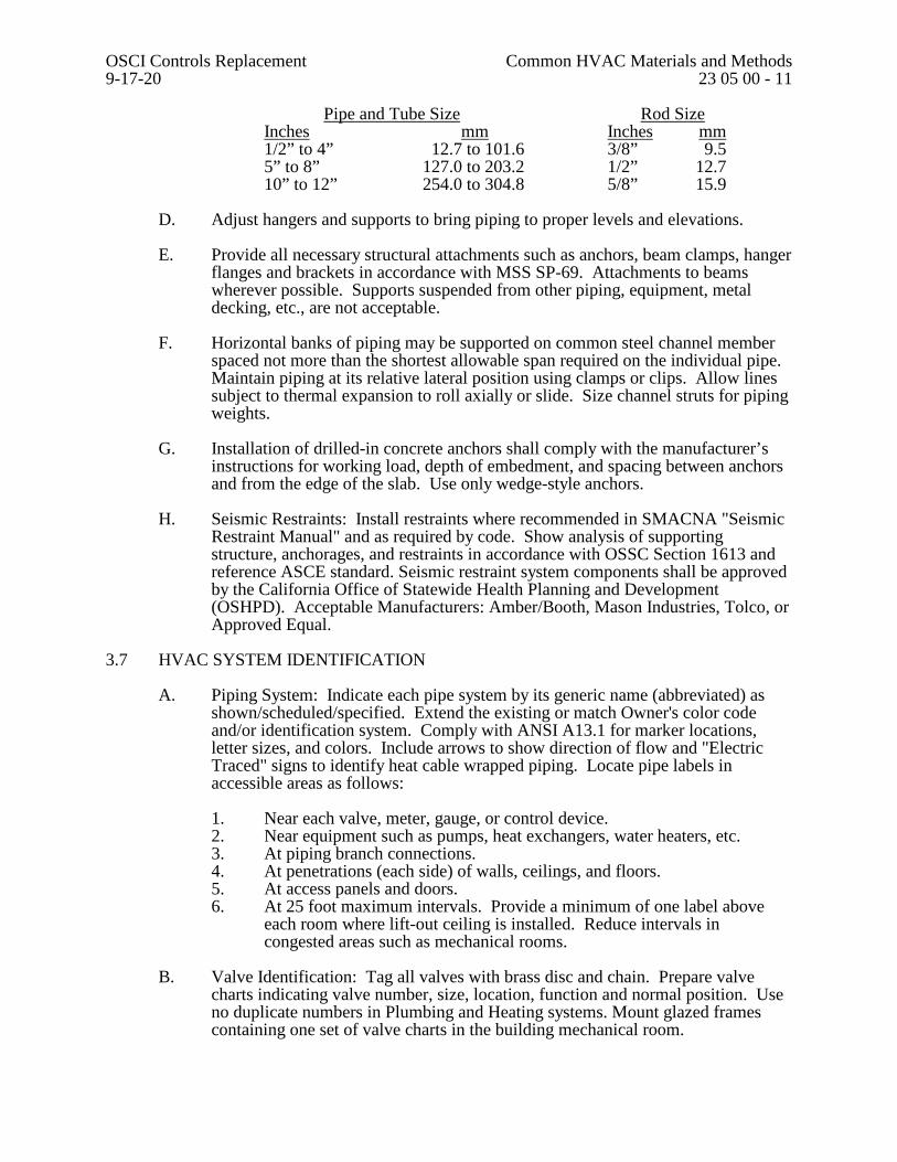
Pipe and Tube Size Rod Size Inches mm Inches mm 1/2” to 4” 12.7 to 101.6 3/8” 9.5 5” to 8” 127.0 to 203.2 1/2” 12.7 10” to 12” 254.0 to 304.8 5/8” 15.9
D. Adjust hangers and supports to bring piping to proper levels and elevations. E. Provide all necessary structural attachments such as anchors, beam clamps, hanger
flanges and brackets in accordance with MSS SP-69. Attachments to beams wherever possible. Supports suspended from other piping, equipment, metal decking, etc., are not acceptable.
F. Horizontal banks of piping may be supported on common steel channel member
spaced not more than the shortest allowable span required on the individual pipe. Maintain piping at its relative lateral position using clamps or clips. Allow lines subject to thermal expansion to roll axially or slide. Size channel struts for piping weights.
G. Installation of drilled-in concrete anchors shall comply with the manufacturer’s
instructions for working load, depth of embedment, and spacing between anchors and from the edge of the slab. Use only wedge-style anchors.
H. Seismic Restraints: Install restraints where recommended in SMACNA "Seismic
Restraint Manual" and as required by code. Show analysis of supporting structure, anchorages, and restraints in accordance with OSSC Section 1613 and reference ASCE standard. Seismic restraint system components shall be approved by the California Office of Statewide Health Planning and Development (OSHPD). Acceptable Manufacturers: Amber/Booth, Mason Industries, Tolco, or Approved Equal.
3.7 HVAC SYSTEM IDENTIFICATION
A. Piping System: Indicate each pipe system by its generic name (abbreviated) as shown/scheduled/specified. Extend the existing or match Owner's color code and/or identification system. Comply with ANSI A13.1 for marker locations, letter sizes, and colors. Include arrows to show direction of flow and "Electric Traced" signs to identify heat cable wrapped piping. Locate pipe labels in accessible areas as follows:
1. Near each valve, meter, gauge, or control device. 2. Near equipment such as pumps, heat exchangers, water heaters, etc. 3. At piping branch connections. 4. At penetrations (each side) of walls, ceilings, and floors. 5. At access panels and doors. 6. At 25 foot maximum intervals. Provide a minimum of one label above
each room where lift-out ceiling is installed. Reduce intervals in congested areas such as mechanical rooms.
B. Valve Identification: Tag all valves with brass disc and chain. Prepare valve
charts indicating valve number, size, location, function and normal position. Use no duplicate numbers in Plumbing and Heating systems. Mount glazed frames containing one set of valve charts in the building mechanical room.
OSCI Controls Replacement Common HVAC Materials and Methods 9-17-20 23 05 00 - 12
C. Equipment: Provide engraved plastic-laminate signs at locations of major equipment such as heat exchangers, pumps, etc. Identify equipment in field same as on drawings. Permanently mount in an appropriate and effective location.
D. Operation Tags: Where needed for proper and adequate information on operation
and maintenance of mechanical systems, provide tags of plasticized card stock, either pre-printed or hand printed to convey the message; example: "DO NOT CLOSE THIS VALVE EXCEPT WHEN THE PUMP IS OFF."
3.8 EQUIPMENT CONNECTIONS
A. Provide complete connections for all items of equipment requiring such connections, including incidental piping, fittings, trim and labor necessary for a finished working installation.
B. Verify the rough-in and finish requirements for all equipment provided under
other Divisions of the work and requiring HVAC piping or duct connections with equipment supplier and installer prior to rough-in.
3.9 PROTECTION
A. Protect all work and materials against loss or damage in compliance with the General Conditions, Section F – Job Site Conditions, F.2 – Protection of Workers, Property, and the Public.
3.10 CUTTING AND PATCHING
A. General: Comply with the General Conditions, Section F – Job Site Conditions, F.3 – Cutting and Patching.
3.11 PIPE PENETRATION FIRE STOPPING
A. Install as recommended by manufacturer and in accordance with the product’s UL listing. Below are the minimum installation requirements.
1. Install specified penetrating item(s) with required annular spacing in
proper size wall or floor opening. Support penetrating item(s) adequately on both sides of construction.
2. Clean all opening and penetrating item surfaces in penetration area to remove loose debris, dirt, oil, wax, grease, old caulking, etc.
3. If needed or required for gypsum or concrete block walls, install specified galvanized steel wire mesh or sleeve recessed and centered inside wall around penetrating item(s) so that it is snug against perimeter of opening.
4. When required, install specified type and depth of backing material in annular space, recessed to required fill depth of fire stopping caulking.
5. Gun, trowel, and/or pump fire stopping sealant to specified depth in annular space around penetrating item(s). Trowel sealant surfaces flush with wall or floor surfaces to a smooth, defect-free finish. Where required, apply specified size caulking bead around penetrating item(s) at zero annular contact areas and tool smooth.
OSCI Controls Replacement Common HVAC Materials and Methods 9-17-20 23 05 00 - 13
3.12 HVAC WORK CLOSEOUT
A. General: Refer to the General Conditions, Section K – Contract Close Out for general closeout requirements. Calibrate all equipment requiring same. Complete each system as shown or specified herein and place in operation except where only roughing-in or partial systems are called for. Each system shall be tested and left in proper operation free of leaks, obstructions, or contamination.
B. Record Drawings: Submit record set of drawings as previously specified in this
Section. C. Closeout Equipment/Systems Operations: Sequence operations properly so that
work of project shall not be damaged or endangered. Coordinate with seasonal requirements. Operate each item of equipment and each system in a test run of appropriate duration with the Owner present, and with the Owner's operating personnel present, to demonstrate sustained, satisfactory performance. Adjust and correct operations as required for proper performance. Clean and lubricate each system and replace dirty filters, excessively worn parts and similar expendable items of the work.
D. Operating Instructions: Conduct a walk-through instruction seminar for the
Owner's personnel who are to be involved in the continued operation and maintenance of the HVAC equipment and systems per The General Conditions, Section K – Contract Close Out, Sub-Section K.5 - Training. Provide written instructions outlining and explaining the identification system, operational diagrams, emergency and alarm provisions, sequencing requirements, seasonal provisions, security, safety, efficiency and similar features of the systems per The General Conditions, Section K – Contract Close Out, Sub-Section K.2 – Operation & Maintenance Manuals.
END OF SECTION
OSCI Controls Replacement Testing, Adjusting and Balancing 9-17-20 23 05 90 - 1
SECTION 23 05 90 - TESTING, ADJUSTING AND BALANCING
PART 1 - GENERAL
1.1 DESCRIPTION
A. Work Included: After completion of the work of installation, test and regulate all components of the new heating, air conditioning and ventilating systems to verify air volumes and heating-cooling flow rates indicated on the Drawings and as coordinated with General Terms & Conditions (GTC), and Supplemental General Conditions (SGC).
B. Related Work: General Scope of work shown on sheet M0.1
1. The intend of the TAB scope is only to require balancing in items/equipment that have been modified or need re-calibration as a result of the controls upgrade – items that should be balanced are listed as noted above on sheet M0.1
2. Diffusers or similar distribution devices are not required to be balanced, as these devices will not be modified. Likewise water flows are not required to be balanced, unless balancing valves or fluid control valves are modified during the controls upgrade.
3. Items where the controls upgrade is simply open/close or on/off (such as make up air units or exhaust fans) do not require air balancing, as airflow should not be effected by the addition of controls.
4. C. Balancing Organization:
1. Balancing of the Heating and Air Conditioning Systems: Performed by a firm providing this service licensed in the State of Oregon.
2. Balancing Organization: Approval by Owner. Air Balancing Specialties, Air Introduction & Regulation, Northwest Engineering Services, Neudorfer Engineers, Pacific Coast Air Balancing, or approved.
3. Provide all necessary personnel, equipment, and services. 1.2 QUALITY ASSURANCE
A. Balancing of the Heating and Air Conditioning Systems: Agency shall be a current member of NEBB or AABC specializing in the adjusting and balancing of systems specified with a minimum of 10 years documented experience.
B. Testing, adjusting, and balancing shall be performed under direct field supervision
of a Certified NEBB Supervisor or a Certified AABC Supervisor.
1.3 SUBMITTALS
A. Balancing Data: Include the following minimum information in the Operation and Maintenance Data, as specified in Section 23 05 00.
1. Names or initials of personnel performing the balancing. 2. Dates balancing was performed. 3. List of balancing instruments utilized.
OSCI Controls Replacement Testing, Adjusting and Balancing 9-17-20 23 05 90 - 2
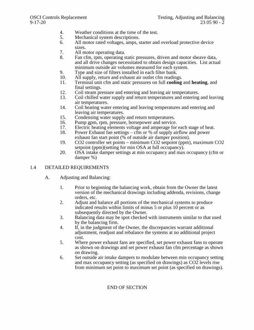
4. Weather conditions at the time of the test. 5. Mechanical system descriptions. 6. All motor rated voltages, amps, starter and overload protective device
sizes. 7. All motor operating data. 8. Fan cfm, rpm, operating static pressures, driven and motor sheave data,
and all drive changes necessitated to obtain design capacities. List actual minimum outside air volumes measured for each system.
9. Type and size of filters installed in each filter bank. 10. All supply, return and exhaust air outlet cfm readings. 11. Terminal unit cfm and static pressures on full cooling and heating, and
final settings. 12. Coil steam pressure and entering and leaving air temperatures. 13. Coil chilled water supply and return temperatures and entering and leaving
air temperatures. 14. Coil heating water entering and leaving temperatures and entering and
leaving air temperatures. 15. Condensing water supply and return temperatures. 16. Pump gpm, rpm, pressure, horsepower and service. 17. Electric heating elements voltage and amperage for each stage of heat. 18. Power Exhaust fan settings – cfm or % of supply airflow and power
exhaust fan start point (% of outside air damper position). 19. CO2 controller set points – minimum CO2 setpoint (ppm), maximum CO2
setpoint (ppm)(setting for min OSA at full occupancy). 20. OSA intake damper settings at min occupancy and max occupancy (cfm or
damper %)
1.4 DETAILED REQUIREMENTS
A. Adjusting and Balancing: 1. Prior to beginning the balancing work, obtain from the Owner the latest
version of the mechanical drawings including addenda, revisions, change orders, etc.
2. Adjust and balance all portions of the mechanical systems to produce indicated results within limits of minus 5 or plus 10 percent or as subsequently directed by the Owner.
3. Balancing data may be spot checked with instruments similar to that used by the balancing firm.
4. If, in the judgment of the Owner, the discrepancies warrant additional adjustment, readjust and rebalance the systems at no additional project cost.
5. Where power exhaust fans are specified, set power exhaust fans to operate as shown on drawings and set power exhaust fan cfm percentage as shown on drawing.
6. Set outside air intake dampers to modulate between min occupancy setting and max occupancy setting (as specified on drawings) as CO2 levels rise from minimum set point to maximum set point (as specified on drawings).
END OF SECTION
OSCI Controls Upgrade 230900 - 1 BUILDING AUTOMATION SYSTEM 9-17-20
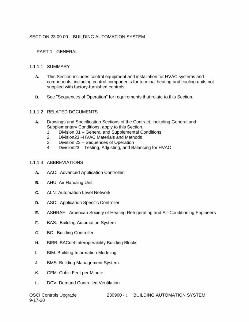
SECTION 23 09 00 – BUILDING AUTOMATION SYSTEM
PART 1 - GENERAL
1.1.1.1 SUMMARY
A. This Section includes control equipment and installation for HVAC systems and components, including control components for terminal heating and cooling units not supplied with factory-furnished controls.
B. See "Sequences of Operation" for requirements that relate to this Section.
1.1.1.2 RELATED DOCUMENTS
A. Drawings and Specification Sections of the Contract, including General and Supplementary Conditions, apply to this Section. 1. Division 01 – General and Supplemental Conditions 2. Division23 –HVAC Materials and Methods 3. Division 23 – Sequences of Operation 4. Division23 – Testing, Adjusting, and Balancing for HVAC
1.1.1.3 ABBREVIATIONS
A. AAC: Advanced Application Controller
B. AHU: Air Handling Unit.
C. ALN: Automation Level Network
D. ASC: Application Specific Controller
E. ASHRAE: American Society of Heating Refrigerating and Air-Conditioning Engineers
F. BAS: Building Automation System
G. BC: Building Controller
H. BIBB: BACnet Interoperability Building Blocks
I. BIM: Building Information Modeling
J. BMS: Building Management System.
K. CFM: Cubic Feet per Minute.
L. DCV: Demand Controlled Ventilation
OSCI Controls Upgrade 230900 - 2 BUILDING AUTOMATION SYSTEM 9-17-20
M. DDC: Direct digital controls
N. EIA: Electronics Industries Alliance
O. EMI: Electro-Magnetic Interference
P. EP: Electric-to-Pneumatic
Q. FAS: Fire Alarm System.
R. FLN: Floor Level Network
S. FCU: Fan Coil Unit
T. HMI: Human Machine Interface
U. HVAC: Heating, Ventilating and Air Conditioning.
V. IEEE: Institute of Electrical and Electronic Engineers
W. I/O: Input/Output
X. IP: Internet Protocol
Y. IT: Information Technology
Z. LAN: Local area network.
AA. LCD: Liquid Crystal Display
BB. LED: Light Emitting Diode
CC. MER: Mechanical Equipment Room.
DD. MLN: Management Level Network
EE. MS/TP: Master-slave/token-passing.
FF. NEMA: National Electric Manufacturers’ Association
GG. NFPA: National Fire Protection Association
HH. OEM: Operator Equipment Manufacturer
II. PC: Personal Computer
JJ. PICS: Protocol Implementation Conformance Statement
KK. PID: Proportional Integral Derivative.
LL. POT: Portable Operators Terminal.
OSCI Controls Upgrade 230900 - 3 BUILDING AUTOMATION SYSTEM 9-17-20
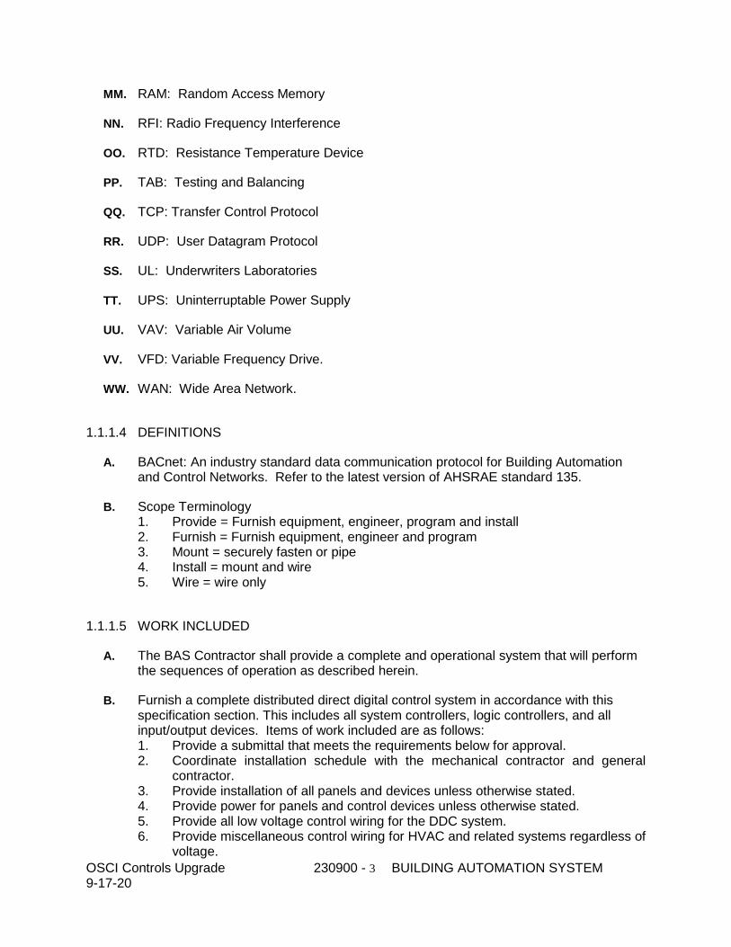
MM. RAM: Random Access Memory
NN. RFI: Radio Frequency Interference
OO. RTD: Resistance Temperature Device
PP. TAB: Testing and Balancing
QQ. TCP: Transfer Control Protocol
RR. UDP: User Datagram Protocol
SS. UL: Underwriters Laboratories
TT. UPS: Uninterruptable Power Supply
UU. VAV: Variable Air Volume
VV. VFD: Variable Frequency Drive.
WW. WAN: Wide Area Network.
1.1.1.4 DEFINITIONS
A. BACnet: An industry standard data communication protocol for Building Automation and Control Networks. Refer to the latest version of AHSRAE standard 135.
B. Scope Terminology 1. Provide = Furnish equipment, engineer, program and install 2. Furnish = Furnish equipment, engineer and program 3. Mount = securely fasten or pipe 4. Install = mount and wire 5. Wire = wire only
1.1.1.5 WORK INCLUDED
A. The BAS Contractor shall provide a complete and operational system that will perform the sequences of operation as described herein.
B. Furnish a complete distributed direct digital control system in accordance with this specification section. This includes all system controllers, logic controllers, and all input/output devices. Items of work included are as follows: 1. Provide a submittal that meets the requirements below for approval. 2. Coordinate installation schedule with the mechanical contractor and general
contractor. 3. Provide installation of all panels and devices unless otherwise stated. 4. Provide power for panels and control devices unless otherwise stated. 5. Provide all low voltage control wiring for the DDC system. 6. Provide miscellaneous control wiring for HVAC and related systems regardless of
voltage.
OSCI Controls Upgrade 230900 - 4 BUILDING AUTOMATION SYSTEM 9-17-20
7. Provide engineering and technician labor to program and commission software for each system and operator interface. Submit commissioning reports for approval.
8. Participate in commissioning for all equipment that is integrated into the BAS (Refer to Commissioning sections of the equipment or systems in other parts of this specification.)
9. Provide testing, demonstration and training as specified below.
C. The installation of the control system shall be performed under the direct supervision of the controls manufacturer with the shop drawings, flow diagrams, bill of materials, component designation, or identification number and sequence of operation all bearing the name of the manufacturer.
1.1.1.6 TECHNICAL DOCUMENTS/SUBMITALS
A. Technical documents shall be prepared in accordance with these specifications. Six (6) copies of the submital shall be submitted with the bid. submitals that are unbound, loose in a file folder, stapled, stapled in a manila file folder, etc., will not be acceptable. The technical documents shall include the following data/information as a minimum. The order of listing here is not intended to indicate, nor should it be construed to indicate, the relative importance of the data/information: 1. Information on organizational capability to handle this project (management,
personnel, manufacturing, single source responsibility, etc.). 2. Information on training program to demonstrate specification compliance. 3. System Configuration as Proposed:
a. Describe system architecture including a schematic layout with location and type (model number) of all control panels.
b. Describe system operation, functions and control techniques. c. Modularity. d. Migration strategies to protect owner’s investment in BMS system.
4. Technical data to support the information on the hardware and software proposed for this solution including any integrated systems and/or solutions.
5. Detailed description of all operating, command, application and energy management software provided for this project.
6. A signed certificate stating the Contractor "has read the performance and functional requirements, understands them and his technical documents will comply with all parts of the specification."
7. Line-by-line specification concordance statement. 8. Other requirements for inclusion in the technical documents are located
throughout this specification.
B. Submit technical documentss with pricing in accordance with Instructions to Bidders.
1.1.1.7 SUBMITTALS
A. Provide submittals for fast track items that need to be approved and released to meet the schedule of the project. Provide submittals for the following items separately upon request: 1. Valve schedule and product data
OSCI Controls Upgrade 230900 - 5 BUILDING AUTOMATION SYSTEM 9-17-20
2. Damper schedule and product data 3. Mounting and wiring diagrams for factory-installed control components 4. Thermostat locations
B. Provide a complete submittal with all controls system information for approval before construction starts. Include the following: 1. Schematic flow diagrams showing fans, pumps, coils, dampers, valves, and
control devices. 2. Wiring Diagrams: Power, signal, and control wiring.Detail the wiring of the
control devices and the panels. Show point-to-point wiring from field devices to the control panel. Show point-to-point wiring of hardwired interlocks. Show a ladder diagram or schematic of wiring internal to the panels, including numbered terminals. Clearly designate wiring that is done at a factory, at a panel shop or in the field.
3. Details of control panel faces, including sizes, controls, instruments, and labeling. 4. Schedule of dampers and actuators including size, leakage, and flow
characteristics.If dampers are furnished by other, submit a damper actuator schedule coordinating actuator sizes with the damper schedule.
5. Schedule of valves including leakage and flow characteristics. 6. Written description of the Sequence of Operations. 7. Network riser diagram showing wiring types, network protocols, locations of floor
penetrations and number of control panels. Label control panels with network addresses and BACnet device instance numbers. Show all routers, switches, hubs and repeaters.
8. Point list for each system controller including both inputs and outputs (I/O), point numbers, controlled device associated with each I/O point, and location of I/O device.
9. Starter and variable frequency drive wiring details of all automatically controlled motors.
10. Reduced size floor plan drawings showing locations of control panels, thermostats and any devices mounted in occupied space.
11. Product Data: Include manufacturer's technical literature for each control device indicated, labeled with setting or adjustable range of control. Indicate dimensions, capacities, performance characteristics, electrical characteristics, finishes for materials, and installation and startup instructions for each type of product indicated. Submit a write-up of the application software that will be used on the operator workstation including revision level, functionality and software applications required to meet the specifications.
12. Submit BACnet Protocol Implementation Conformance Statements (PICS) for all direct digital controllers, software and other system components that will communicate on the BAS utilizing BACnet.
C. Submit a description of the application software that will be used on the operator workstation including revision level, functionality and software applications required to meet the specifications.
D. Submit blank field check-out and commissioning test reports, customized for each panel or system, which will be filled out by the technician during start-up.
E. Variance letter: Submit a letter detailing each item in the submission that varies from the contract specification or sequence of operation in any way.
OSCI Controls Upgrade 230900 - 6 BUILDING AUTOMATION SYSTEM 9-17-20
F. After the BAS system is approved for construction, submit sample operator workstation graphics for typical systems for approval. Print and submit the graphics that the operator will use to view the systems, change setpoints, modify parameters and issue manual commands. Programming shall not commence until typical graphics are approved.
G. Operation and Maintenance Data: In addition to items specified in Division 1 Section "Operation and Maintenance Data," include the following: 1. Product data with installation details, maintenance instructions and lists of spare
parts for each type of control device. 2. Keyboard illustrations and step-by-step procedures indexed for each operator
function. 3. Inspection period, cleaning methods, cleaning materials recommended and
calibration tolerances. 4. Calibration records and list of set points.
1.1.1.8 PROJECT RECORD DOCUMENTS
A. Project Record Documents: Submit three (3) copies of record (as-built) documents upon completion of installation. Submittal shall consist of: 1. Project Record Drawings. As-built versions of the submittal shop drawings
provided as AutoCAD compatible files in electronic format and as 11 x 17 inch prints.
2. Testing and Commissioning Reports and Checklists. Completed versions of reports, checklists, and trend logs used to meet requirements in the Control System Demonstration and Acceptance section of this specification.
3. Operation and Maintenance (O & M) Manual. a. As-built versions of the submittal product data. b. Names, addresses, and 24-hour telephone numbers of installing
contractors and service representatives for equipment and control systems. c. Operator’s Manual with procedures for operating control systems, logging
on and off, handling alarms, producing point reports, trending data, overriding computer control, and changing setpoints and variables.
d. Programming manual or set of manuals with description of programming language and of statements for algorithms and calculations used, of point database creation and modification, of program creation and modification, and of editor use.
e. Engineering, installation, and maintenance manual or set of manuals that explains how to design and install new points, panels, and other hardware; how to perform preventive maintenance and calibration; how to debug hardware problems; and how to repair or replace hardware.
f. Documentation of all programs created using custom programming language, including setpoints, tuning parameters, and object database.
g. Graphic files, programs, and database on electronic media. h. List of recommended spare parts with part numbers and suppliers. i. Complete original-issue documentation, installation, and maintenance
information for furnished third-party hardware, including computer equipment and sensors.
OSCI Controls Upgrade 230900 - 7 BUILDING AUTOMATION SYSTEM 9-17-20
j. Complete original original-issue copies of furnished software, including operating systems, custom programming language, operator workstation software, and graphics software.
k. Licenses, guarantees, and warranty documents for equipment and systems.
B. Operating manual to serve as training and reference manual for all aspects of day-to-day operation of the system. As a minimum include the following: 1. Sequence of operation for automatic and manual operating modes for all building
systems. The sequences shall cross-reference the system point names. 2. Description of manual override operation of all control points in system. 3. BMS system manufacturers complete operating manuals.
C. Provide maintenance manual to serve as training and reference manual for all aspects of day-to-day maintenance and major system repairs. As a minimum include the following: 1. Complete as-built installation drawings for each building system. 2. Overall system electrical power supply schematic indicating source of electrical
power for each system component. Indicate all battery backup provisions. 3. Photographs and/or drawings showing installation details and locations of
equipment. 4. Routine preventive maintenance procedures, corrective diagnostics
troubleshooting procedures, and calibration procedures. 5. Parts list with manufacturer's catalog numbers and ordering information. 6. Lists of ordinary and special tools, operating materials supplies and test
equipment recommended for operation and servicing. 7. Manufacturer's operation, set-up, maintenance and catalog literature for each
piece of equipment. 8. Maintenance and repair instructions. 9. Recommended spare parts.
D. Provide Programming Manual to serve as training and reference manual for all aspects of system programming. As a minimum include the following: 1. Complete programming manuals, and reference guides. 2. Details of any custom software packages and compilers supplied with system. 3. Information and access required for independent programming of system.
1.1.1.9 QUALITY ASSURANCE
A. Codes 1. Perform all wiring in accordance with Division 26, NEC, local codes and Owner’s
requirements. 2. Electrical Components, Devices, and Accessories: Listed and labeled as defined
in NFPA 70, Article 100, by a testing agency acceptable to authorities having jurisdiction, and marked for intended use.
3. Comply with NFPA 90A, "Installation of Air Conditioning and Ventilation Systems."
4. Comply with ASHRAE 135-2010 BACnet: A Data Communication Protocol for Building Automation and Control Networks.
OSCI Controls Upgrade 230900 - 8 BUILDING AUTOMATION SYSTEM 9-17-20
5. Comply with ASHRAE 90.1-2019 Energy Standard for Buildings Except Low-Rise Residential Buildings.
6. All equipment shall be UL listed and approved and shall meet with all applicable NFPA standards, including UL 916 - PAZX Energy Management Systems, a. Provide written approvals and certifications after installation has been
completed. 7. All electronic equipment shall conform to the requirements of FCC Regulation,
Part 15, Governing Radio Frequency Electromagnetic Interference and be so labeled.
8. The manufacturer of the building automation system shall provide documentation supporting compliance with ISO-9002 (Model for Quality Assurance in Production, Installation, and Servicing) and ISO-140001 (The application of well-accepted business management principles to the environment). The intent of this specification requirement is to ensure that the products from the manufacturer are delivered through a Quality System and Framework that will assure consistency in the products delivered for this project.
B. Qualifications 1. Installing contractor shall be in the business of installing and servicing DDC
controls for mechanical systems, temperature and ventilation control, environmental control, lighting control, access and security, life safety and energy management as their primary business.
2. 1Installer Qualifications: An experienced installer who is the authorized representative of the automatic control system manufacturer for both installation and maintenance of controls required for this Project.
3. 2Engineering, drafting, programming, and graphics generation shall be performed by the local branch engineers and technicians directly employed by the Building Automation System Contractor.
4. Supervision, checkout and commissioning of the system shall be by the local branch engineers and technicians directly employed by the Building Automation System Contractor. They shall perform commissioning and complete testing of the BAS system.
C. The BAS contractor shall maintain a service organization consisting of factory trained service personnel and provide a list of ten (10) projects, similar in size and scope to this project, completed within the last five years.
D. Final determination of compliance with these specifications shall rest solely with the Engineers and Owner who will require proof of prior satisfactory performance.
E. For any BAS system and equipment submitted for approval, the BAS contractor shall state what, if any, specific points of system operation differ from these specifications.
F. All portions of the system must be designed, furnished, installed, commissioned and serviced by manufacturer approved, factory trained employees.
G. The system shall have a documented history of compatibility by design for a minimum of 15 years. Future compatibility shall be supported for no less than 10 years. Compatibility shall be defined as the ability for any existing control system component including but not limited to building controllers, advanced application controllers, application specific, personal operator workstations and portable operator's terminals,

OSCI Controls Upgrade 230900 - 9 BUILDING AUTOMATION SYSTEM 9-17-20
to be connected and directly communicate with any new BAS system equipment without bridges, routers or protocol converters.
1.1.1.10 DELIVERY, STORAGE, AND HANDLING
A. Factory-Mounted Components: Where control devices specified in this Section are indicated to be factory mounted on equipment, arrange for shipping of control devices to unit manufacturer.
B. Deliver, store, protect, and handle products to site under provisions of the contract Documents. Coordinate all site delivers with Construction project Manager.
C. Protect products from construction operations, dust, and debris, by storing materials inside, protected from weather in a conditioned space.
1.1.1.11 COORDINATION
A. Coordinate IP drops, network connections, user interfaces, firewall, etc with Owner’s IT representative.
B. Coordinate location of thermostats, humidistats, panels, and other exposed control components with plans and room details before installation.
C. Coordinate equipment with Division 28 "Fire Alarm" to achieve compatibility with equipment that interfaces with that system.
D. Coordinate power for control units and operator workstation with electrical contractor.
E. Coordinate equipment with provider of starters and drives to achieve compatibility with motor starter control coils and VFD control wiring.
F. Coordinate scheduling with the mechanical contractor and general contractor. Submit a schedule for approval based upon the installation schedule of the mechanical equipment.
G. Coordinate installation of taps, valves, airflow stations, etc. with the mechanical contractor.
H. Products Furnished and Installed Under This Section 1. Hydronic and Refrigerant Piping accessories:
a. Control Valves b. Temperature Sensor Wells and Sockets c. Pressure Sensor Wells and Sockets d. Flow Switches e. Flow Meters f. Differential Pressure Transmitters
2. Sheetmetal accessories a. Dampers b. Airflow Stations
OSCI Controls Upgrade 230900 - 10 BUILDING AUTOMATION SYSTEM 9-17-20
c. Terminal Unit Controls
1.1.1.12 WARRANTY
A. Provide warranty per Division 20 Section “General Mechanical Requirements” and as supplemented in this section.
B. Warranty shall cover all costs for parts, labor, associated travel, and expenses for a period of 1224 months from completion of system demonstration.
C. Hardware and software personnel supporting this warranty agreement shall provide on-site or off-site service in a timely manner after failure notification to the vendor. The maximum acceptable response time to provide this service at the site shall be 24 hours.
D. During normal building occupied hours, failure of items that are critical for system operation shall be provided within 4 hours of notification from the Owner’s Representative.
E. This warranty shall apply equally to both hardware and software.
PART 2 - PRODUCTS
2.1.1.1 SYSTEM DESCRIPTION
A. The Building Automation System (BAS) contractor shall furnish and install a networked system of HVAC controls. The contractor shall incorporate direct digital control (DDC) for central plant equipment, building ventilation equipment, supplemental heating and cooling equipment, and terminal units.
B. The BAS shall be based on the Niagara Framework (or “Niagara”), a Java-based framework developed by Tridium. Niagara provides an automation infrastructure that integrates diverse systems and devices (regardless of manufacturer, communication standard or software) into a unified platform that can be managed in real time over the Internet using a standard Web browser.
C. The BAS shall be comprised of Network Area Controller or Controllers (NAC) within each facility. The NAC shall connect to the owner’s local or wide area network, depending on configuration. Access to the system, either locally in each building, or remotely from a central site or sites, shall be accomplished through standard Web browsers, via the Internet and/or local area network. Each NAC shall communicate to BACnet Building Controllers and other open and legacy protocol systems/devices.
D. Provide networking to new DDC equipment using industry accepted communication standards. System shall utilize BACnet communication according to ANSI/ASHRAE standard 135-2010 for interoperability with smart equipment, for the main IP communication trunk to the BAS Server and for peer-to-peer communication between DDC panels and devices. The system shall not be limited to only standard protocols,
OSCI Controls Upgrade 230900 - 11 BUILDING AUTOMATION SYSTEM 9-17-20
but shall also be able to integrate to a wide variety of third-party devices and applications via drivers and gateways.
E. Provide standalone controls where called for on the drawings or sequences.
2.1.1.2 BUILDING AUTOMATION SYSTEM NETWORK
A. All networked control products provided for this project shall be comprised of an industry standard open protocol internetwork. Communication involving control components (i.e. all types of controllers and operator interfaces) shall conform to ASHRAE 135-2010 BACnet standard. Networks and protocols proprietary to one company or distributed by one company are prohibited.
B. Access to system data shall not be restricted by the hardware configuration of the building management system. The hardware configuration of the BMS network shall be totally transparent to the user when accessing data or developing control programs. 1. Software applications, features, and functionality, including administrative
configurations, shall not be separated into several network control engines working together.
C. Provide at a minimum 1 operator interface to be designated as the BAS Server with server application software. Additional operator interfaces shall use operator workstation licenses or connect via a thick or thin-client application.
D. BAS Server shall be capable of simultaneous direct connection and communication with BACnet/IP, OPC and TCP/IP corporate level networks without the use of interposing devices.
E. Any break in Ethernet communication from the server to the controllers on the Primary Network shall result in a notification at the server.
F. Any break in Ethernet communication between the server and standard client workstations on the Primary Network shall result in a notification at each workstation.
G. The network architecture shall consist of three levels of networks: 1. The Management Level Network (MLN) shall utilize BACnet/IP over Ethernet
along with other standardized protocol, such as web services, html, JAVA, SOAP, XML, etc., to transmit data to non-BAS software applications and databases. The BAS Server and Operator Workstations shall reside on this level of the network architecture.
2. The Automation Level Network (ALN) shall utilizeBACnet/IP over Ethernet. It shall connect BACnet Building Controllers to the BAS Server and Operator Workstations. Controllers for central plant equipment and large infrastructure air handlers shall reside on the ALN backbone BACnet/IP network. The building’s Ethernet LAN shall be utilized for the ALN backbone and all ALN devices shall be connected to the building’s LAN. Coordinate IP drops with Owner.
3. The Floor Level Network shall utilizeBACnet/IP over Ethernet or BACnet MS/TP over RS-485 toconnect all of the DDC-controlled terminal heating and cooling equipment on a floor or in a system that are controlled with BACnet Advanced Application Controllers or BACnet Application Specific Controllers. FLN devices
OSCI Controls Upgrade 230900 - 12 BUILDING AUTOMATION SYSTEM 9-17-20
are networked to a router that connects to the Automaton Level Network backbone.
H. Provide a router for each RS-485 subnetwork to connect them to the base building backbone level network. The router shall connect BACnet MS/TP subnetworks to BACnet over Ethernet. Routers shall be capable of handling all of the BACnet BIBBs that are listed for the controller that reside on the subnetwork.
I. The Building Level Controllers shall be able to support subnetwork protocols that may be needed depending on the type of equipment or application. Subnetworks shall be limited to : 1. BACnet MS/TP
J. BACnet MSTP Setup rules 1. Addressing for the MSTP devices shall start at 00 and continue sequentially for
the number of devices on the subnetwork. 2. No gaps shall be allowed in the addresses. 3. Set the MaxMaster property to the highest address of the connected device. 4. MaxMaster property shall be adjusted when devices are added to the
subnetwork.
K. Provide all communication media, connectors, repeaters, bridges, switches, and routers necessary for the internetwork.
L. Controllers and software shall be BTL listed at the time of installation.
M. The system shall meet peer-to-peer communication services such that the values in any one BACnet Building Controller or BACnetAdvanced Application Controllercan be read or changed from all other controllers without the need for intermediary devices. The software shall provide transparent transfer of all data, control programs, schedules, trends, and alarms from any one controller through the internetwork to any other controller, regardless of subnetwork routers.
N. Systems that use variations of BACnet using Point-to-Point (PTP) between controllers, gateways, bridges or networks that are not peer-to-peer are not allowed.
O. Remote Communications: Provide a TCP/IP compatible communication port for connection to the Owner’s network for remote communications. Provide coordination with the Owner for addressing and router configuration on both ends of the remote network.
P. The system shall be installed with a 10% spare capacity on each subnetwork for the addition of future controllers. (provide 40% spare capacity on any units/areas where there are steam or hot water radiators that will not be connected to DDS system at this time).
Q. On each floor, wing or major mechanical room provide an Ethernet RJ45 connection that allows connection to the BACnet network. An open port shall always be available and shall not require any part of the network to be disconnected. The location shall be accessible to the base building personnel and not in a location where the tenant can restrict the access.
OSCI Controls Upgrade 230900 - 13 BUILDING AUTOMATION SYSTEM 9-17-20
R. Distributed Control Requirements: 1. The loss of any one DDC controller shall not affect the operation of other HVAC
systems, only for the points connected to the DDC controller. 2. The system shall be scalable in nature and shall permit expansion of both
capacity and functionality through the addition of sensors, actuators, DDC Controllers, and operator devices.
3. System architectural design shall eliminate dependence upon any single device for alarm reporting and control execution. Each DDC Controller shall operate independently by performing its own specified control, alarm management, operator I/O, and data collection. The failure of any single component or network connection shall not interrupt the execution of any control strategy, reporting, alarming and trending function, or any function at any operator interface device.
4. DDC Controllers shall be able to access any data from, or send control commands and alarm reports directly to, any other DDC Controller on the network without dependence upon a central processing device. DDC Controllers shall also be able to send alarms to multiple operator workstations without dependence upon a central or intermediate processing device.
5. Operators shall have the ability to make database changes at the central system server while operator workstations are on-line without disrupting other system operations.
6. The DDC control panel shall be mounted in the same mechanical room as the equipment being controlled, or an adjacent utility room.
7. Multiple systems can be programmed on the same controller as long as they are in the same room. Systems on separate floors shall have separate controllers.
8. VAV boxes subnetworks shall be connected to the AHU controller that feeds those boxes. If multiple subnetworks are needed, then the VAV shall be grouped into subnetworks in an orderly method, such as per floor, per wing, etc.
9. Remote sensors shall be wired to the control panel of the equipment it is controlling, not across the network.
10. Signals to remote motor control centers shall be hard wired to the control panel, not across the network.
11. Terminal units shall each have their own controller. Only exceptions are: a. Groups of reheat coils b. Groups of exhaust fans c. Groups of chilled beams serving same zone or several adjacent zones
2.1.1.3 BACNET ADVANCED WORKSTATION SOFTWARE
A. The Graphical User Interface (GUI) shall include navigation with logical grouping of the equipment into equipment summary screens such that all the VAV boxes being fed air from a particular AHU can be displayed together for comparison.
B. The GUI shall include Air Handler unit roll up screens showing the min/max and average airflow devices in the family of equipment and provide for a means to quickly reset static discharge set point for more efficient controls.
C. The GUI shall logically group graphics navigation by tenant so that in a multi-tenant building, only the equipment graphics associated with the tenants’ space can be easily viewed.
OSCI Controls Upgrade 230900 - 14 BUILDING AUTOMATION SYSTEM 9-17-20
D. The Custom Equipment graphics for VAV boxes shall allow the user to initiate the creation of trend storage and collection of a system point through a simple drag and drop.
E. Each custom VAV equipment graphic shall have the ability to display the detailed sequence of operations controlling the space from within each unique device and/or application.
F. The GUI shall provide a completely interactive user interface and must offer the following features as a minimum: 1. Operating System:
a. The GUI shall run on Microsoft Windows Operating Systems and/or standard Internet browsers including Internet Explorer, Firefox, and Chrome.
2. The GUI shall employ browser-like functionality for ease of navigation. It shall include a tree view (similar to Windows Explorer) for quick viewing of, and access to, the hierarchical structure of the database. In addition, menu-pull downs, and toolbars shall employ buttons, commands and navigation to permit the operator to perform tasks with a minimum knowledge of the HVAC Control System and basic computing skills. These shall include, but are not limited to, forward/backward buttons, home button, and a context sensitive locator line (similar to a URL line), that displays the location and the selected object identification.
3. Real-Time Displays. The GUI, shall at a minimum, support the following graphical features and functions: a. Graphic screens shall have the capability to contain objects for text, real-
time values, animation, color spectrum objects, logs, graphs, HTML or XML document links, schedule objects, hyperlinks to other URL’s, and links to other graphic screens.
b. Graphics shall support layering and each graphic object shall be configurable for assignment to a layer. A minimum of six layers shall be supported.
c. Modifying common application objects, such as schedules, calendars, and set points shall be accomplished in a graphical manner.
d. Schedule times will be adjusted using a graphical slider, without requiring any keyboard entry from the operator.
e. Holidays shall be set by using a graphical calendar without requiring any keyboard entry from the operator.
f. Commands to start and stop binary objects shall be done by selecting the appropriate object and selecting the appropriate command from the pop-up menu. No entry of text shall be required.
g. Adjustments to analog objects, such as set points, shall be done by right-clicking the selected object and using a graphical slider to adjust the value. No entry of text shall be required.
4. System Configuration. At a minimum, the GUI shall permit the operator to perform the following tasks, with proper password access: a. Create, delete or modify control strategies. b. Add/delete objects to the system. c. Tune control loops through the adjustment of control loop parameters. d. Enable or disable control strategies. e. Generate hard copy records or control strategies on a printer.
OSCI Controls Upgrade 230900 - 15 BUILDING AUTOMATION SYSTEM 9-17-20
f. Select points to be alarmable and define the alarm state. g. Select points to be trended over a period of time and initiate the recording
of values automatically. 5. On-Line Help. Provide a context sensitive, on-line help system to assist the
operator in operation and editing of the system. On-line help shall be available for all applications and shall provide the relevant data for that particular screen. Additional help information shall be available through the use of hypertext. All system documentation and help files shall be in HTML format.
6. Security. Each operator shall be required to log on to that system with a user name and password in order to view, edit, add, or delete data. System security shall be selectable for each operator. The system administrator shall have the ability to set passwords and security levels for all other operators. Each operator password shall be able to restrict the operators’ access for viewing and/or changing each system application, full screen editor, and object. Each operator shall automatically be logged off of the system if no keyboard or mouse activity is detected. This auto log-off time shall be set per operator password. All system security data shall be stored in an encrypted format.
7. System Diagnostics. The system shall automatically monitor the operation of all workstations, printers, modems, network connections, building management panels, and controllers. The failure of any device shall be annunciated to the operator.
8. Alarm Console: a. The system will be provided with a dedicated alarm window or console.
This window will notify the operator of an alarm condition, and allow the operator to view details of the alarm and acknowledge the alarm. The use of the Alarm Console can be enabled or disabled by the system administrator.
b. When the Alarm Console is enabled, a separate alarm notification window will supersede all other windows on the desktop and shall not be capable of being minimized or closed by the operator. This window will notify the operator of new alarms and un-acknowledged alarms. Alarm notification windows or banners that can be minimized or closed by the operator shall not be acceptable.
G. Web Browser Clients 1. The system shall be capable of supporting an unlimited number of clients using a
standard Web browser such as Internet Explorer™ or Chrome. 2. The Web browser software shall run on any operating system and system
configuration that is supported by the Web browser. Systems that require specific machine requirements in terms of processor speed, memory, etc., in order to allow the Web browser to function with the System, shall not be acceptable.
3. The Web browser shall provide the same view of the system, in terms of graphics, schedules, calendars, logs, etc., and provide the same interface methodology as is provided by the Graphical User Interface. Systems that require different views or that require different means of interacting with objects such as schedules, or logs, shall not be permitted.
4. The Web browser client shall support at a minimum, the following functions: a. User log-on identification and password shall be required. If an
unauthorized user attempts access, a blank web page shall be displayed.
OSCI Controls Upgrade 230900 - 16 BUILDING AUTOMATION SYSTEM 9-17-20
Security using Java authentication and encryption techniques to prevent unauthorized access shall be implemented.
b. Graphical screens developed for the GUI shall be the same screens used for the Web browser client. Any animated graphical objects supported by the GUI shall be supported by the Web browser interface.
c. HTML programming shall not be required to display system graphics or data on a Web page. HTML editing of the Web page shall be allowed if the user desires a specific look or format.
d. Storage of the graphical screens shall be in the Network Area Controller (NAC), without requiring any graphics to be stored on the client machine. Systems that require graphics storage on each client are not acceptable.
e. Real-time values displayed on a Web page shall update automatically without requiring a manual “refresh” of the Web page.
f. Users shall have administrator-defined access privileges. Depending on the access privileges assigned, the user shall be able to perform the following: 1) Modify common application objects, such as schedules, calendars,
and set points in a graphical manner. a) Schedule times will be adjusted using a graphical slider,
without requiring any keyboard entry from the operator. b) Holidays shall be set by using a graphical calendar, without
requiring any keyboard entry from the operator. 2) Commands to start and stop binary objects shall be done by right-
clicking the selected object and selecting the appropriate command from the pop-up menu. No entry of text shall be required.
3) View logs and charts 4) View and acknowledge alarms 5) Setup and execute SQL queries on log and archive information
g. The system shall provide the capability to specify a user’s (as determined by the log-on user identification) home page. Provide the ability to limit a specific user to just their defined home page. From the home page, links to other views, or pages in the system shall be possible, if allowed by the system administrator.
h. Graphic screens on the Web Browser client shall support hypertext links to other locations on the Internet or on Intranet sites, by specifying the Uniform Resource Locator (URL) for the desired link.
H. System Programming 1. The Graphical User Interface software (GUI) shall provide the ability to perform
system programming and graphic display engineering as part of a complete software package. Access to the programming functions and features of the GUI shall be through password access as assigned by the system administrator.
2. A library of control, application, and graphic objects shall be provided to enable the creation of all applications and user interface screens. Applications are to be created by selecting the desired control objects from the library, dragging or pasting them on the screen, and linking them together using a built in graphical connection tool. Completed applications may be stored in the library for future use. Graphical User Interface screens shall be created in the same fashion. Data for the user displays is obtained by graphically linking the user display objects to the application objects to provide “real-time” data updates. Any real-
OSCI Controls Upgrade 230900 - 17 BUILDING AUTOMATION SYSTEM 9-17-20
time data value or object property may be connected to display its current value on a user display. Systems requiring separate software tools or processes to create applications and user interface displays shall not be acceptable.
3. Programming Methods: a. The software shall provide the ability to view the logic in a monitor mode.
When on-line, the monitor mode shall provide the ability to view the logic in real time for easy diagnosis of the logic execution. When off-line (debug), the monitor mode shall allow the user to set values to inputs and monitor the logic for diagnosing execution before it is applied to the system.
b. All programming shall be done in real-time. Systems requiring the uploading, editing, and downloading of database objects shall not be allowed.
c. The system shall support object duplication within a customer’s database. An application, once configured, can be copied and pasted for easy re-use and duplication. All links, other than to the hardware, shall be maintained during duplication.
4. The B-ASC, and Building Controller’s sequence of operations must be visible and editable from Niagara AX and via the Siemens LaunchPad Web Services application. All Building Controllers shall be available on the network for command, control and editing through the Niagara AX without the requirement of the BACnet Driver on Niagara AX.
I. BACnet: 1. The BAS server and Operator Workstations shall meet the BACnet device profile
of an Advanced Workstation Server (B-AWS) and Operator Workstation (B-OWS) and shall support the following BACnet BIBBs: a. Data Sharing
1) Data Sharing-Read Property-Initiate, Execute (DS-RP-A,B) 2) Data Sharing-Read Property Multiple-Initiate, Execute (DS-RPM-A,B) 3) Data Sharing-Write Property-Initiate, Execute (DS-WP-A,B) 4) Data Sharing-Write Property Multiple-Initiate (DS-WPM-A) 5) Data Sharing-COV-Initiate (DS-COV-A)
b. Scheduling 1) Scheduling-Initiate (SCHED-A)
c. Trending 1) Trending-Viewing and Modifying Trends-Initiate (T-VMT-A) 2) Trending-Automated Trend Retrieval-Initiate (T-ATR-A)
d. Network Management 1) Network Management-Connection Establishment-Initiate (NM-CE-A)
e. Alarming 1) Alarm and Event-Notification-Initiate (AE-N-A) 2) Alarm and Event-ACK-Initiate (AE-ACK-A) 3) Alarm and Event –Alarm Summary-Initiate (AE-ASUM-A) 4) Alarm and Event –Enrollment Summary-Initiate (AE-ESUM-A) 5) Alarm and Event –Information-Initiate (AE-INFO-A)
f. Device Management 1) Device Management-Dynamic Device Binding- Initiate, Execute (DM-
DDB-A, B) 2) Device Management-Dynamic Object Binding- Initiate, Execute (DM-
DOB-A,B)
OSCI Controls Upgrade 230900 - 18 BUILDING AUTOMATION SYSTEM 9-17-20
3) Device Management-Device Communication Control- Initiate (DM-DCC-A)
4) Device Management-Private Transfer- Initiate, Execute (DM-PT-A,B) 5) Device Management-Text Message-Execute (DM-TM-B) 6) Device Management-Time Synchronization- Initiate (DM-TS-A) 7) Device Management-UTC Time Synchronization- Initiate (DM-UTC-
A) 8) Device Management-Reinitialize Device- Initiate (DM-RD-A) 9) Device Management-Backup and Restore- Initiate (DM-BR-A) 10) Device Management-List Manipulation- Initiate, Execute (DM-LM-
A,B) 11) Device Management-Object Creation and Deletion- Initiate (DM-
OCD-A) 2. The BAS Server and Workstations shall support the following Data Link Layers:
a. BACnet IP Annex J b. BACnet IP Annex J Foreign Device c. ISO 8802-3, Ethernet (Clause 7)
3. The BAS Server and Workstations shall be able to interact with all of the BACnet objects in the controllers. In addition, the software shall be able to support the following objects as they relate to features in the workstation software: a. Calendar – Creatable, Deletable b. Command – Creatable, Deletable c. Event Enrollment – Creatable, Deletable d. Notification Class – Creatable, Deletable e. Schedule - Creatable, Deletable
4. The BAS Server and Workstations shall support transmitting and receiving segmented messages.
5. The BAS Server and Workstation shall have the capability to be the BACnet/IP Broadcast Management Device (BBMD) and support foreign devices.
2.1.1.4 WEB BASED CONTROLLER SOFTWARE FOR CONFIGURATION, PROGRAMMING AND OPERATORS
A. The purpose of this specification is to allow the Owner/Operator to have the same controller programming capabilities as the Controls Contractor Technician without additional software, tools, or licenses. 1. The controller programming shall be accessible to any user via a Web Services
application over an IP or Internet connection through port 80.
B. The following types of controllers shall have this feature: 1. All BACnet BC level controllers 2. Network Engine Controllers 3. Controllers on equipment or sequences customized for this job
C. Manufacturer: 1. Siemens Launch Pad™ (compatible with TC controllers) 2. Controllers from other manufacturers shall meet the capabilities of this
specification
OSCI Controls Upgrade 230900 - 19 BUILDING AUTOMATION SYSTEM 9-17-20
D. The controller shall come with the software built-in and delivered with the controller as part of the controller purchase. It shall not require a separate software license to enable the software capability. 1. The software shall be provided as an integral part of DDC Controllers and shall
not be dependent upon any higher level computer or another controller for execution.
E. The software application shall be accessible from a PC using Web Services, but shall use all of its own services and data files so as to not be susceptible to Microsoft Windows operating systems based viruses.
F. Access to the controller software shall be username and password protected. User shall be authenticated by the controller.
G. The embedded Web Services shall provide the following functionality to users, based on their access and privilege rights:
1. Point Navigation – Provide a screen that allows users to see all of the points that
are active in the system. The points shall include hardwired, software, schedules, trends, alarms and network setup. a. The point navigation shall display the point name, descriptor, command
priority, alarm status, and current value. b. The user shall be able to run and print a pre-configured point log report
through a web interface client that shows the point name, descriptor, command priority, alarm status, and current value.
c. The interface and report shall allow selection filter such that the operator can select or deselect the types of point that are visible.
2. Alarm Display –displays current BAS alarms to which the user has access will be
displayed. Users will be able to acknowledge active alarms, erase resolved alarms, and directly link to the Point Commanding feature. a. The alarm display must provide a filter that displays all alarms whether
acknowledged or not. b. The alarm display must provide a filter that displays only alarms that have
not yet been acknowledged. c. The alarm display must provide a persistent indication whenever there is
one or more unacknowledged alarm in any connected field panel.
3. Point details – users will have access to point detail information including operational status, operational priority, physical address, and alarm limits, for point objects to which they have access rights.
4. Point Commanding – users will be able to override and command points they
have access to via the Web browser interface.
5. Scheduling – allows operators, depending on their current user privileges, to override schedules selected by date, and to modify the properties of a selected schedule. a. The scheduler display must be able to represent facility mode schedules in
a graphical format.
OSCI Controls Upgrade 230900 - 20 BUILDING AUTOMATION SYSTEM 9-17-20
6. Trend Data Report – allows users to run and print a pre-configured trend data report for historical data reporting, including a representation of the alarm status of the each point for each Trend sample. The report shall allow selection of individual points or wildcard selection of points. a. Trend data shall be exportable to a data file, such as .csv or other
comparable.
7. Network navigation - Provide a screen that allows users to navigate to the panels and terminal units via the network architecture.
H. The web server shall be able to send SMTP text messages to notify users of alarm status. The owners shall provide a mail server and a connection port. SSL shall not be required.
I. The operator shall be able to add modify and delete controller database program, including points, schedules, alarms, and trends. 1. The operator shall be able to edit the custom program in the field panel that
executes the sequences of operations, control loops and logic for the systems controlled.
2. The operator shall be able to add terminal unit controllers that reside on field panel subnetworks.
J. Internet connections, ISP services, as well as necessary firewalls or proxy servers shall be provided by the Owner as required to support the Web access feature.
K. Coordinate with the Owner/Operator’s IT representatives to setup and allow access to controllers via IP connections and Web Services through port 80. 1. It shall be the responsibility of the Owner/IT to setup and maintain security for
user access to the private networks. 2. Coordinate IP addressing scheme.
2.1.1.5 NETWORK AREA CONTROLLERS (NAC)
A. The Network Area Controller (NAC) shall provide the interface between the LAN or WAN and the field control devices, and provide global supervisory control functions over the control devices connected to the NAC. It shall be capable of executing application control programs to provide: 1. Calendar functions 2. Scheduling 3. Trending 4. Alarm monitoring and routing 5. Time synchronization 6. Integration of controller data through NiagaraAX drivers installed in the NAC. 7. Network Management functions for all controllers
B. The Network Area Controller must provide the following hardware features as a minimum: 1. One Ethernet Port – 10/100 Mbps 2. One RS-232 port 3. One RS-485 ports
OSCI Controls Upgrade 230900 - 21 BUILDING AUTOMATION SYSTEM 9-17-20
4. Battery Backup 5. Flash memory for long term data backup (If battery backup or flash memory is
not supplied, the controller must contain a hard disk with at least 1 gigabyte storage capacity)
6. The NAC must be capable of operation over a temperature range of 32 to 122°F 7. The NAC must be capable of withstanding storage temperatures of between 0
and 158°F 8. The NAC must be capable of operation over a humidity range of 5 to 95% RH,
non-condensing.
C. The NAC shall provide multiple user access to the system and support for ODBC or SQL. A database resident on the NAC shall be an ODBC-compliant database or must provide an ODBC data access mechanism to read and write data stored within it.
D. The NAC shall support standard Web browser access via the Intranet/Internet. It shall support a minimum of 32 simultaneous users.
E. Provide a “query” feature to allow review of specific alarms by user defined parameters.
F. A separate log for system alerts (controller failures, network failures, etc.) shall be provided and available for review by the user.
G. An Error Log to record invalid property changes or commands shall be provided and available for review by the user.
H. Network Access 1. Remote Access:
a. For Local Area Network installations, provide access to the LAN from a remote location, via the Internet. The Owner shall provide a connection to the Internet to enable this access via high speed cable modem, asynchronous digital subscriber line (ADSL) modem, ISDN line, T1 Line or via the customer’s Intranet to a corporate server providing access to an Internet Service Provider (ISP). Customer agrees to pay monthly access charges for connection and ISP.
2. Event Alarm Notification and actions a. The NAC shall provide alarm recognition, storage; routing, management,
and analysis to supplement distributed capabilities of equipment or application specific controllers.
b. The NAC shall be able to route any alarm condition to any defined user location whether connected to a local network or remote via dial-up telephone connection, or wide-area network.
c. Alarm generation shall be selectable for annunciation type and acknowledgement requirements including but limited to: 1) To alarm 2) Return to normal 3) To fault
d. Provide for the creation of a minimum of eight of alarm classes for the purpose of routing types and or classes of alarms, i.e.: security, HVAC, Fire, etc.
e. Provide timed (schedule) routing of alarms by class, object, group, or node.
OSCI Controls Upgrade 230900 - 22 BUILDING AUTOMATION SYSTEM 9-17-20
f. Provide alarm generation from binary object “runtime” and /or event counts for equipment maintenance. The user shall be able to reset runtime or event count values with appropriate password control.
3. Control equipment and network failures shall be treated as alarms and annunciated.
4. Alarms shall be annunciated in any of the following manners as defined by the user: a. Screen message text b. Email of the complete alarm message to multiple recipients. Provide the
ability to route and email alarms based on: 1) Day of week 2) Time of day 3) Recipient
c. Pagers via paging services that initiate a page on receipt of email message d. Graphic with flashing alarm object(s) e. Printed message, routed directly to a dedicated alarm printer
5. The following shall be recorded by the NAC for each alarm (at a minimum): a. Time and date b. Location (building, floor, zone, office number, etc.) c. Equipment (air handler #, accessway, etc.) d. Acknowledge time, date, and user who issued acknowledgement. e. Number of occurrences since last acknowledgement.
6. Alarm actions may be initiated by user defined programmable objects created for that purpose.
7. Defined users shall be given proper access to acknowledge any alarm, or specific types or classes of alarms defined by the user.
8. A log of all alarms shall be maintained by the NAC and/or a server (if configured in the system) and shall be available for review by the user.
9. Provide a “query” feature to allow review of specific alarms by user defined parameters.
10. A separate log for system alerts (controller failures, network failures, etc.) shall be provided and available for review by the user.
11. An Error Log to record invalid property changes or commands shall be provided and available for review by the user.
I. Data Collection and Storage 1. The NAC shall have the ability to collect data for any property of any object and
store this data for future use. 2. The data collection shall be performed by log objects, resident in the NAC that
shall have, at a minimum, the following configurable properties: a. Designating the log as interval or deviation. b. For interval logs, the object shall be configured for time of day, day of week
and the sample collection interval. c. For deviation logs, the object shall be configured for the deviation of a
variable to a fixed value. This value, when reached, will initiate logging of the object.
d. For all logs, provide the ability to set the maximum number of data stores for the log and to set whether the log will stop collecting when full, or rollover the data on a first-in, first-out basis.
e. Each log shall have the ability to have its data cleared on a time-based event or by a user-defined event or action.
OSCI Controls Upgrade 230900 - 23 BUILDING AUTOMATION SYSTEM 9-17-20
3. All log data shall be stored in a relational database in the NAC and the data shall be accessed from a server (if the system is so configured) or a standard Web browser.
4. All log data, when accessed from a server, shall be capable of being manipulated using standard SQL statements.
5. All log data shall be available to the user in the following data formats: a. HTML b. XML c. Plain Text d. Comma or tab separated values
6. Systems that do not provide log data in HTML and XML formats at a minimum shall not be acceptable.
7. The NAC shall have the ability to archive its log data either locally (to itself), or remotely to a server or other NAC on the network. Provide the ability to configure the following archiving properties, at a minimum: a. Archive on time of day b. Archive on user-defined number of data stores in the log (buffer size) c. Archive when log has reached its user-defined capacity of data stores d. Provide ability to clear logs once archived
J. Audit Log 1. Provide and maintain an Audit Log that tracks all activities performed on the
NAC. Provide the ability to specify a buffer size for the log and the ability to archive log based on time or when the log has reached its user-defined buffer size. Provide the ability to archive the log locally (to the NAC), to another NAC on the network, or to a server. For each log entry, provide the following data: a. Time and date b. User ID c. Change or activity: i.e., Change setpoint, add or delete objects, commands,
etc.
K. DATABASE BACKUP AND STORAGE 1. The NAC shall have the ability to automatically backup its database. The
database shall be backed up based on a user-defined time interval. 2. Copies of the current database and, at the most recently saved database shall be
stored in the NAC. The age of the most recently saved database is dependent on the user-defined database save interval.
3. The NAC database shall be stored, at a minimum, in XML format to allow for user viewing and editing, if desired. Other formats are acceptable as well, as long as XML format is supported.
2.1.1.6 DIRECT DIGITAL CONTROLLER SOFTWARE
A. Provide a full capability user license to the owner for the operator to be able to see, modify, create, upload, download and save control programs to the DDC controllers.
B. The software program shall be provided as an integral part of DDC Controllers and shall not be dependent upon any higher level computer or another controller for execution.
OSCI Controls Upgrade 230900 - 24 BUILDING AUTOMATION SYSTEM 9-17-20
C. The software application shall be accessible from a PC using the Windows environment, but shall use all of its own services and data files so as to not be susceptible to Microsoft Windows operating systems based viruses.
D. The software shall be provided with an interactive HELP function to assist operators with syntax, abbreviations, commands and saving programs.
E. Point naming and communication format: 1. All points, panels, and programs shall be identified by a 30-character name. All
points shall also be identified by a 16-character point descriptor. The same names shall be displayed at both Building Controller and the Operator Interface.
2. All digital points shall have a consistent, user-defined, two-state status indication with 8 characters minimum (e.g., Summer, Enabled, Disabled, Abnormal).
3. The Building Controller Software shall be capable of BACnet communications. The BACnet Building Controller (B-BC) shall have demonstrated interoperability during at least one BTL Interoperability Workshop, have demonstrated compliance to BTL through BTL listing and shall substantially conform to BACnet Building Controller (B-BC) device profile as specified in ANSI/ASHRAE 135-2004, Annex L.
F. System Security 1. User access shall be secured using individual security passwords and user
names. 2. Passwords shall restrict the user to the objects, applications, and system
functions as assigned by the system manager. 3. Building Controllers shall be able to assign a minimum of 50 passwords access
and control priorities to each point individually. The logon password (at any Operator Interface or portable operator terminal) shall enable the operator to monitor, adjust and control only the points that the operator is authorized for. All other points shall not be displayed at the Operator Interface or portable terminal. Passwords and priorities for every point shall be fully programmable and adjustable.
4. User Log On/Log Off attempts shall be recorded. 5. The system shall protect itself from unauthorized use by automatically logging off
following the last keystroke. The delay time shall be user-definable. 6. Use of workstation resident security as the only means of access control is not
an acceptable alternative to resident system security in the DDC controller software.
G. User Defined Control Applications: The applications software shall program DDC routines to meet the sequences of operations. 1. Building Controllers shall have the ability to perform energy management
routines including but not limited to time of day scheduling, calendar-based scheduling, holiday scheduling, temporary schedule overrides, start stop time optimization, automatic daylight savings time switch over, night setback control, enthalpy switch over, peak demand limiting, temperature-compensated duty cycling, heating/cooling interlock, supply temperature reset, priority load shedding, and power failure restart.
2. The Building Controllers shall have the ability to perform the following pre tested control algorithms: a. Two position with differential control and time delays
OSCI Controls Upgrade 230900 - 25 BUILDING AUTOMATION SYSTEM 9-17-20
b. Floating control c. Proportional control d. Proportional plus integral control e. Proportional, integral, plus derivative control f. Automatic tuning of control loops g. Start Stop Time Optimization
3. Controllers shall be able to execute custom, job-specific processes defined by the user, to automatically perform calculations and special control routines.
4. Each controller shall support plain language text comment lines in the operating program to allow for quick troubleshooting, documentation, and historical summaries of program development.
H. Peer-to-peer access to other DDC controllers 1. It shall be possible to use any actual or virtual point data or status, any system
calculated data, a result from any process, or any user-defined constant in any controller in the system.
2. Any process shall be able to issue commands to points in any and all other controllers in the system.
3. Processes shall be able to generate operator messages and advisories to other operator I/O devices. A process shall be able to directly send a message to a specified device or cause the execution of an advanced annunciation feature, such as: a. Generate a report b. Annunciate an alarm c. Issue a text message or email
I. Alarm Management 1. Alarm management shall be provided within the controller software to monitor
and direct alarm information to operator devices. 2. Each Building Controller shall perform distributed, independent alarm analysis,
minimize network traffic and prevent alarms from being lost. At no time shall the Building Controllers ability to report alarms be affected by either operator or activity at a PC workstation, local I/O device or communications with other panels on the network.
3. Conditional alarming shall allow generation of alarms based upon user defined multiple criteria.
4. An Alarm “shelving” feature shall be provided to disable alarms during testing. (Pull the Plug, etc.).
5. Binary Alarms. Each binary alarm object shall be set to alarm based on the operator-specified state. Provide the capability to automatically and manually disable alarming.
6. Analog Alarms. Each analog alarm object shall have both high and low alarm limits. Alarming must be able to be automatically and manually disabled.
7. All alarm shall include the point's user-defined language description and the time and date of occurrence.
8. Alarm reports and messages shall be routed to user-defined list of operator workstations, or other devices based on time and other conditions. An alarm shall be able to start programs, print reports, be logged in the event log, generate custom messages, and display graphics.
9. The user shall be able to add a 200-character alarm message to each alarm point to more fully describe the alarm condition or direct operator response.
OSCI Controls Upgrade 230900 - 26 BUILDING AUTOMATION SYSTEM 9-17-20
Each Building Controller shall be capable of storing a library of at least 50 alarm messages. Each message may be assigned to any number of points in the Controller.
10. Operator-selected alarms shall be capable of initiating a trigger to an advanced annunciation, such as text, email, etc.
11. An alarm history log shall report the start of the alarm condition, acknowledgement by a user and return of the alarm to normal condition.
J. Scheduling: 1. Provide a comprehensive menu driven program to automatically start and stop
designated multiple objects or events in the system according to a stored time. 2. Schedules shall reside in the building controller and shall not rely on external
processing or network. 3. It shall be possible to define a group of objects as a custom event (i.e., meeting,
athletic activity, etc.). Events can then be scheduled to operate all necessary equipment automatically.
4. For points assigned to one common load group, it shall be possible to assign variable time delays between each successive start and/or stop within that group.
5. The operator shall be able to define the following information: a. Time, day b. Commands such as on, off, auto, etc. c. Time delays between successive commands. d. There shall be provisions for manual overriding of each schedule by an
authorized operator. 6. It shall be possible to schedule calendar-based events up to one year in advance
based on the following: a. Weekly Schedule. Provide separate schedules for each day of the week.
Each of these schedules should include the capability for start, stop, optimal start, optimal stop, and night economizer. When a group of objects are scheduled together as an Event, provide the capability to adjust the start and stop times for each member.
b. Exception Schedules. Provide the ability for the operator to designate any day of the year as an exception schedule. Exception schedules may be defined up to a year in advance. Once an exception schedule is executed, it will be discarded and replaced by the standard schedule for that day of the week.
K. Peak Demand Limiting (PDL): 1. The Peak Demand Limiting (PDL) program shall limit the consumption of
electricity to prevent electrical peak demand charges. 2. PDL shall continuously track the amount of electricity being consumed, by
monitoring one or more electrical kilowatt-hour/demand meters. These meters may measure the electrical consumption (kWh), electrical demand (kW), or both.
3. PDL shall sample the meter data to continuously forecast the demand likely to be used during successive time intervals.
4. If the PDL forecasted demand indicates that electricity usage is likely to exceed a user preset maximum allowable level, then PDL shall automatically shed electrical loads.
5. Once the demand peak has passed, loads that have been shed shall be restored and returned to normal control.
OSCI Controls Upgrade 230900 - 27 BUILDING AUTOMATION SYSTEM 9-17-20
L. Temperature-compensated duty cycling 1. User defined conditions shall be able to initiate a Duty Cycle Control Program. 2. The Duty Cycle Control Program (DCCP) shall be configured to periodically stop
and start loads according to various patterns. 3. The loads shall be cycled such that there is a net reduction in both the electrical
demands and the energy consumed.
M. Automatic Daylight Savings Time Switchover. The system shall provide automatic time adjustment for switching to/from Daylight Savings Time.
N. Night setback control. The system shall provide the ability to automatically adjust setpoints for night control.
O. Enthalpy switchover (economizer). The Building Controller Software (BCS) shall control the position of the air handler relief, return, and outside air dampers. If the outside air dry bulb temperature falls below changeover setpoint the BCS will modulate the dampers to provide 100 percent outside air. The user will be able to quickly change over to an economizer system based on dry bulb temperature and will be able to override the economizer cycle and return to minimum outside air operation at any time.
P. Control Loop Algorithm 1. Provide a PID (proportional-integral-derivative) closed-loop control algorithm with
direct or reverse action and anti-windup. The algorithm shall calculate a time-varying analog value that is used to position an output or stage a series of outputs. The controlled variable, setpoint, and weighting parameters shall be accessible from the operator workstation.
Q. Adaptive Loop Tuning 1. Building Controllers shall also provide high resolution sampling capability for
verification of DDC control loop performance. Documented evidence of tuned control loop performance shall be provided on a monthly, seasonal, quarterly, annual period.
2. For PID control loops, operator-initiated automatic and manual loop tuning algorithms shall be provided for all operator-selected PID control loops. Evidence of tuned control loop performance shall be provided via graphical plots or trended data logs for all loops. a. In automatic mode, the controller shall perform a step response test with a
minimum one-second resolution, evaluate the trend data, calculate the new PID gains and input these values into the selected LOOP statement.
b. Loop tuning shall be capable of being initiated either locally at the Building Controller, from a network workstation or remotely using dial-in modems. For all loop tuning functions, access shall be limited to authorized personnel through password protection.
R. Logic programming: Provide a software routine that can build ladder logic to control using many conditional statements. 1. The logic programming syntax shall be able to combine ladder logic with other
software features, such as combining status, scheduling, PDL and alarm conditions into one conditional decision.
2. Logic programming shall be able to reference conditions in any other controller in the system.
OSCI Controls Upgrade 230900 - 28 BUILDING AUTOMATION SYSTEM 9-17-20
S. Staggered Start: 1. This application shall prevent all controlled equipment from simultaneously
restarting after a power outage. The order in which equipment (or groups of equipment) is started, along with the time delay between starts, shall be user definable in an application and shall not require written scripts or ladder logic.
2. Upon the resumption of power, each Building Controller shall analyze the status of all controlled equipment, compare it with normal occupancy scheduling and turn equipment on or off as necessary to resume normal operations.
T. Totalization Features: 1. Run-Time Totalization. Building Controllers shall automatically accumulate and
store run-time hours for all digital input and output points. A high runtime alarm shall be assigned, if required, by the operator.
2. Consumption totalization. Building Controllers shall automatically sample, calculate and store consumption totals on a daily, weekly or monthly basis for all analog and digital pulse input type points.
3. Event totalization. Building Controllers shall have the ability to count events such as the number of times a pump or fan system is cycled on and off. Event totalization shall be performed on a daily, weekly or monthly basis for all points. The event totalization feature shall be able to store the records associated with events before reset.
U. Data Collection: 1. A variety of historical data collection utilities shall be provided to manually or
automatically sample, store, and display system data for all points. 2. Building Controllers shall store point history data for selected analog and digital
inputs and outputs: 3. Any point, physical or calculated may be designated for trending. Any point,
regardless of physical location in the network, may be collected and stored in each Building Controllers point group.
4. Two methods of collection shall be allowed: either by up to four pre-defined time intervals or upon a pre-defined change of value. Sample intervals of l minute to 7 days shall be provided.
5. Each Building Controller shall have a dedicated RAM-based buffer for trend data and shall be capable of storing a minimum of 10,000 data samples.
6. Trend data shall be stored at the Building Controllers and uploaded to the workstation when retrieval is desired. Uploads shall occur based upon either user-defined interval, manual command or when the trend buffers are full. All trend data shall be available for use in third-party personal computer applications.
2.1.1.7 BACNET BUILDING CONTROLLERS
A. Provide all necessary hardware for a complete operating system as required. The Building Controller shall be able to operate as a standalone panel and shall not be dependent upon any higher level computer or another controller for operation.
B. Basis of design is Siemens TC Modular and TC Compact Controllers.
OSCI Controls Upgrade 230900 - 29 BUILDING AUTOMATION SYSTEM 9-17-20
C. This controller shall have the BTL listing and meet the BACnet device profile of a Building Controller (B-BC) and shall support the following BACnet BIBBs: 1. Data Sharing
a. Data Sharing-Read Property-Initiate, Execute (DS-RP-A,B) b. Data Sharing-Read Property Multiple- Initiate, Execute (DS-RPM-A,B) c. Data Sharing-Write Property- Initiate, Execute (DS-WP-A,B) d. Data Sharing-Write Property Multiple- Execute (DS-WPM-B) e. Data Sharing-COV- Initiate, Execute (DS-COV-A,B) f. Data Sharing-COV-Unsolicited- Initiate, Execute (DS-COVU-A,B)
2. Scheduling a. Scheduling-Internal- Execute (SCHED-I-B) b. Scheduling-External- Execute (SCHED-E-B)
3. Trending a. Trending-Viewing and Modifying Trends - Initiate (T-VMT-A) b. Trending-Viewing and Modifying Trends Internal- Execute (T-VMT-I-B) c. Trending-Viewing and Modifying Trends-External- Execute (T-VMT-E-B) d. Trending-Automated Trend Retrieval- Execute (T-ATR-B)
4. Network Management a. Network Management-Connection Establishment- Initiate (NM-CE-A)
5. Alarming a. Alarm and Event-Notification- Initiate (AE-N-A) b. Alarm and Event-Notification Internal- Execute (AE-N-E-B) c. Alarm and Event-Notification External- Execute (AE-N-E-B) d. Alarm and Event-ACK- Initiate, Execute (AE-ACK-A,B) e. Alarm and Event –Alarm Summary- Execute (AE-ASUM-B) f. Alarm and Event –Enrollment Summary- Execute (AE-ESUM-A,B) g. Alarm and Event –Information- Initiate, Execute (AE-ESUM-A,B)
6. Device Management a. Device Management-Dynamic Device Binding- Initiate, Execute (DM-DDB-
A,B) b. Device Management-Dynamic Object Binding- Initiate, Execute (DM-DOB-
A,B) c. Device Management-Device Communication Control- Execute (DM-DCC-
B) d. Device Management-Private Transfer- Initiate, Execute (DM-PT-A,B) e. Device Management-Text Message- Initiate, Execute (DM-TM-A,B) f. Device Management-Time Synchronization- Execute (DM-TS-B) g. Device Management-Reinitialize Device- Execute (DM-RD-B) h. Device Management-Backup and Restore- Execute (DM-RD-B) i. Device Management-List Manipulation- Execute (DM-RD-B) j. Device Management-Object Creation and Deletion- Execute (DM-OCD-B)
7. The Building Level Controller shall support the following Data Link Layers: a. BACnet IP Annex J b. BACnet IP Annex J Foreign Device c. MS/TP Master (Claus 9)
8. The Building Level Controller shall be able to interact with all of the BACnet objects in the controllers. In addition, the software shall be able to support the following objects as they relate to features in the workstation software: a. Calendar – Creatable, Deletable b. Command – Creatable, Deletable c. Event Enrollment – Creatable, Deletable
OSCI Controls Upgrade 230900 - 30 BUILDING AUTOMATION SYSTEM 9-17-20
d. Notification Class – Creatable, Deletable e. Schedule - Creatable, Deletable
9. The Building Level Controller shall support transmitting and receiving segmented messages.
10. The Building Level Controller shall have the capability to be the BACnet/IP Broadcast Management Device (BBMD) and support foreign devices.
11. The Building Level Controller shall have the capability to act as a BACnet router between MS/TP subnetworks and BACnet/IP.
D. This level of controller shall be used for the following types of systems: 1. Chiller plant systems 2. Heating plant systems 3. Cooling Towers 4. Pumping systems 5. VAV air handlers 6. Air handlers over 15,000 cfm 7. Systems with over 24 input/output points 8. Rooftop systems
E. Computing power and memory minimum: 1. A 32-bit, stand-alone, multi-tasking, multi-user, real-time 100MHz digital control
microprocessor module. 2. Inputs shall be 16-bit minimum analog-to-digital resolution 3. Outputs shall be 10-bit minimum digital-to-analog resolution 4. Memory module (24 Megabyte, minimum) to accommodate all Primary Control
Panel software requirements, including but not limited to, its own operating system and databases (see Controllers Software section), including control processes, energy management applications, alarm management applications, historical/trend data for points specified, maintenance support applications, custom processes, operator I/O, dial-up communications.
5. Real time clock and battery 6. Data collection/ Data Trend module sized for 10,000 data samples. 7. Flash Memory Firmware: Each Building Level Control Panel shall support
firmware upgrades without the need to replace hardware.
F. Onboard or Modular hardware and connections: 1. Primary Network communication module, if needed for primary network
communications. 2. Secondary Network communication module, if needed for secondary network
communications. 3. RJ45 port 10/100Mbaud 4. RS485 ports for subnetworks and point expansion 5. Man to Machine Interface port (MMI) 6. USB Port
G. Input and Output Points Hardware 1. Input/output point modules as required including spare capacity. 2. Input/output point modules shall have removable terminal blocks. 3. Monitoring of the status of all hand-off-auto switches. 4. Monitoring of all industry standard types of analog and digital inputs and outputs,
without the addition of equipment to the primary control panel.
OSCI Controls Upgrade 230900 - 31 BUILDING AUTOMATION SYSTEM 9-17-20
5. Local status indication for each digital input and output for constant, up-to-date verification of all point conditions without the need for an operator I/O device. Each primary control panel shall perform diagnostics on all inputs and outputs and a failure of any input or output shall be indicated both locally and at the operator workstation.
6. Graduated intensity LEDs or analog indication of value for each analog output.
H. Code compliance 1. Approvals and standards: UL916; CE; FCC 2. Provide UL864-UUKL where called for in the sequences of operations.
I. Accessories: 1. Appropriate NEMA rated metal enclosure. 2. Power supplies as required for all associated modules, sensors, actuators, etc.
J. The operator shall have the ability to manually override automatic or centrally executed commands at the primary control panels via local, point discrete, on-board hand/off/auto operator override switches. If on board switches are not available, provide separate control panels with HOA switches. Mount panel adjacent to primary control panel. Provide hand/off/auto switch for each digital output, including spares.
K. Each Building Level Control Panel shall continuously perform self-diagnostics on all hardware modules and network communications. The System Level Control Panel shall provide both local and remote annunciation of any detected component failures, low battery conditions or repeated failure to establish communication with any system.
L. Panel setup, point definitions and sequencing diagrams shall be backed up on EEPROM memory.
M. Power loss. In the event of the loss of power, there shall be an orderly shutdown of all Building Controllers to prevent the loss of database or operating system software. Non-volatile memory shall be incorporated for all critical controller configuration data and battery backup shall be provided to support the real-time clock and all volatile memory for a minimum of 30 days.
N. Building Level control panels shall provide at least two serial data communication ports for operation of operator I/O devices such as industry standard printers, operator terminals, modems and portable laptop operator's terminals. Primary control panels shall allow temporary use of portable devices without interrupting the normal communications, operation of permanently connected modems, printers or terminals.
O. Building Level Controllers shall have the capability to serve as a gateway between Modus subnetworks and BACnet objects. Provide software, drives and programming.
P. Isolation shall be provided at all primary control panel terminations, as well as all field point terminations to suppress induced voltage transients consistent with IEEE Standards 587-1980.
Q. Spare Capacity: Provide enough inputs and outputs to handle the equipment shown to be “future” on drawings and 10% more of each point type. Provide all hardware modules, software modules, processors, power supplies, communication controllers,
OSCI Controls Upgrade 230900 - 32 BUILDING AUTOMATION SYSTEM 9-17-20
etc. required to ensure adding a point to the spare point location only requires the addition of the appropriate sensor/actuator and field wiring/tubing.
R. Environment. 1. Controller hardware shall be suitable for the anticipated ambient conditions. 2. Controllers used outdoors and/or in wet ambient conditions shall be mounted
within waterproof enclosures and shall be rated for operation at 0°C to 49°C (32°F to 120°F).
3. Controllers used in conditioned space shall be mounted in dust-proof enclosures and shall be rated for operation at 0°C to 49°C (32°F to 120°F).
4. Controller hardware shall be optionally suitable for rooftop environments.
S. Immunity to power and noise. 1. Controller shall be able to operate at 90% to 110% of nominal voltage rating and
shall perform an orderly shutdown below 80% nominal voltage. 2. Operation shall be protected against electrical noise of 5 to 120 Hz and from
keyed radios up to 5 W at 1 m (3 ft). 3. Isolation shall be provided at all primary network terminations, as well as all field
point terminations to suppress induced voltage transients consistent with: a. RF-Conducted Immunity (RFCI) per ENV 50141 (IEC 1000-4-6) at 3V. b. Electro Static Discharge (ESD) Immunity per EN 61000-4-2 (IEC 1000-4-2)
at 8 kV air discharge, 4 kV contact. c. Electrical Fast Transient (EFT) per EN 61000-4-4 (IEC 1000-4-4) at 500V
signal, 1 kV power. d. Output Circuit Transients per UL 864 (2,400V, 10A, 1.2 Joule max).
4. Isolation shall be provided at all Building Controller’s AC input terminals to suppress induced voltage transients consistent with: a. IEEE Standard 587 1980 b. UL 864 Supply Line Transients c. Voltage Sags, Surge, and Dropout per EN 61000-4-11 (EN 1000-4-11)
2.1.1.8 BACNET ADVANCED APPLICATION CONTROLLERS
A. Provide all necessary hardware for a complete operating system as required. The Advanced Application level control panel shall be able to operate as a standalone panel and shall not be dependent upon any higher level computer or another controller for operation.
B. Basis of design is Unitary Equipment Controller (TCxx-UCM).
C. The Advanced Application Controller Software shall be capable of BACnet communications. The BACnet Advanced Application Controller (B-AAC) shall have demonstrated compliance to BTL through BTL listing and shall substantially conform to BACnet Advanced Application Controller (B-AAC) device profile as specified in ANSI/ASHRAE 135-2004 or ANSI/ASHRAE 135-2008. Supported BIBBS shall include: 1. Data Sharing
a. Data Sharing-Read Property-Initiate, Execute (DS-RP-A,B)
OSCI Controls Upgrade 230900 - 33 BUILDING AUTOMATION SYSTEM 9-17-20
b. Data Sharing-Read Property Multiple- Initiate, Execute (DS-RPM-A,B) c. Data Sharing-Write Property- Initiate, Execute (DS-WP-A,B) d. Data Sharing-Write Property Multiple- Execute (DS-WPM-B) e. Data Sharing-COV- Initiate, Execute (DS-COV-A,B)
2. Scheduling a. Scheduling-Internal- Execute (SCHED-I-B)
3. Trending a. Trending-Viewing and Modifying Trends Internal- Execute (T-VMT-I-B) b. Trending-Automated Trend Retrieval- Execute (T-ATR-B)
4. Network Management a. Network Management-Connection Establishment- Initiate (NM-CE-A)
5. Alarming a. Alarm and Event-Notification Internal- Execute (AE-N-I-B) b. Alarm and Event-ACK- Initiate, Execute (AE-ACK-A,B) c. Alarm and Event –Enrollment Summary- Execute (AE-ESUM-B) d. Alarm and Event –Information- Execute (AE-INFO-B)
6. Device Management a. Device Management-Dynamic Device Binding- Initiate, Execute (DM-DDB-
A,B) b. Device Management-Dynamic Object Binding- Initiate, Execute (DM-DOB-
A,B) c. Device Management-Device Communication Control- Execute (DM-DCC-
B) d. Device Management-Time Synchronization- Execute (DM-TS-B) e. Device Management-Reinitialize Device- Execute (DM-RD-B) f. Device Management-Backup and Restore- Execute (DM-BR-B) g. Device Management-List Manipulation- Execute (DM-LM-B) h. Device Management-Object Creation and Deletion- Execute (DM-OCD-B)
7. The Advanced Application Controller shall be able to interact with all of the BACnet objects in the controllers. In addition, the software shall be able to support the following objects as they relate to features in the workstation software: a. Calendar – Creatable, Deletable b. Command – Creatable, Deletable c. Event Enrollment – Creatable, Deletable d. Notification Class – Creatable, Deletable e. Schedule - Creatable, Deletable
8. The Advanced Application Controller shall support transmitting and receiving segmented messages.
D. Communication: 1. BAS Network: The Advanced Application Controller shall support the following
Data Link Layers: a. MS/TP Master
2. Serial Communication: Temporary use of portable devices shall not interrupt the BAS communication, nor the normal operation of permanently connected printers or terminals. a. Provide at least one EIA-232C serial data communication port for operation
of operator I/O devices such as industry standard printers, operator terminals, and portable laptop operator's terminals.
OSCI Controls Upgrade 230900 - 34 BUILDING AUTOMATION SYSTEM 9-17-20
b. A USB port shall alternatively be available to support local HMI tools connection.
E. Software 1. The software programs specified in this section shall be provided as an integral
part of Advanced Application Controllers and shall not be dependent upon any higher level computer or another controller for execution.
2. Advanced Application Controllers shall have the ability to perform energy management routines including but not limited to a. scheduling, calendar-based scheduling, holiday scheduling, temporary
schedule overrides b. automatic daylight savings time switch over c. night setback control d. economizer switch over using enthalpy, dry bulb or a combination e. peak demand limiting, f. temperature-compensated duty cycling g. heating/cooling interlock h. supply temperature reset i. priority load shedding j. power failure restart
3. The software shall have a routine for automatic tuning of control loops 4. System Security in the Field Panel
a. User access shall be secured using individual security passwords and user names.
b. Passwords shall restrict the user to the objects, applications, and system functions as assigned by the system manager.
c. The system shall protect itself from unauthorized use by automatically logging off following the last keystroke. The delay time shall be user-definable.
d. Use of workstation resident security as the only means of access control is not an acceptable alternative to resident system security in the field panel.
5. User Defined Control Applications: a. Controllers shall be fully-programmable. Controllers shall execute custom,
job-specific sequences to automatically perform calculations and special control routines. Factory installed or pre-configured sequences shall only be allowed if they exactly match the sequence specified herein.
b. Programs shall combine control logic, control loop algorithms, and energy management routines
c. Each controller shall support plain language text comment lines in the operating program to allow for quick troubleshooting, documentation, and historical summaries of program development.
d. Controller shall provide a HELP function key, providing enhanced context sensitive on-line help with task oriented information from the user manual.
F. Adaptive Loop Control. 1. Each AAC controller shall come standard with an Adaptive Control Loop
Algorithm a. Tuning parameter shall automatically adjust for non-linear applications
2. Model-Free Adaptive (MFA) algorithm a. The algorithm shall not require modeling of the non-linear system in order
to maintain control at all points of the non-linear load.
OSCI Controls Upgrade 230900 - 35 BUILDING AUTOMATION SYSTEM 9-17-20
b. The controlled variable, setpoint, and weighting parameters shall be user-selectable.
3. Output shall be analog or shall stage a series of outputs. 4. Adaptive Control shall take the place of Proportional, Proportional + Integral, and
PID type algorithms for non-linear applications. Adaptive Control routines shall : a. Improve response time b. Improve System efficiency c. Improve Stability d. Result in Consistent outputs e. Reduce cycling and repositioning f. Reduce wear and tear on actuators
5. Adaptive control shall auto-adjust to compensate for a. mode changes b. load changes c. seasonal changes d. Heating and cooling changeover e. Heating or cooling capacity changes on the primary side f. Flow changes on the primary or secondary side g. Airflow changes across coil h. Flow across a heat exchanger
6. Adaptive control shall auto-adjust to compensate for a. Non-linear coils and heat exchangers b. Hot water and chilled water reset routines c. Water flow reset routines d. Duct Static reset routines
7. Auto-Tune PID loops are not acceptable substitutions. 8. If Adaptive Loop Control is not available, then the BAS contractor shall provide
re-tuning of the control loops for coils and heat exchangers for each of the following conditions: a. Low heating supply water, high heating supply water b. Low load on steam coil, high load on steam coil c. Chilled water coil, non dehumidification and condensing d. Chilled water coil, low airflow, high airflow, economizer e. Dual temperature systems tune for heating and cooling modes f. Each of 4 seasons
G. This level of controller shall be used for the following types of systems: 1. Systems with custom sequences that meet all of the criteria below: 2. No primary pumping systems 3. Secondary Pumping systems that are remote from Central Plants 4. Air handlers up to 15,000 cfm 5. Systems up to 20 input/output points 6. Room control sequences that cannot be achieved with an application specific
controller 7. BAS Network or Architecture or Sequences do not require the system to be on
an IP network 8. No systems that require integration to meters, VFDs or other smart equipment 9. Integration to smart thermostats is allowed
H. Input/Outputs 1. Inputs shall be 16-bit minimum digital resolution
OSCI Controls Upgrade 230900 - 36 BUILDING AUTOMATION SYSTEM 9-17-20
2. Outputs shall be 10-bit minimum digital resolution 3. The following I/O port types shall be available on the controller
a. Universal Input (software configurable): 1) Digital Input choices:
a) Pulse Accumulator b) Contact Closure Sensing c) Dry Contact/Potential Free inputs only d) Digital Input (10 ms settling time) e) Counter inputs up to 20 Hz, minimum pulse duration 20 ms
(open or closed) 2) Analog Input Choices:
a) 0-10 Vdc b) 4-20 mA c) 1K Ni RTD @ 32°F (Siemens, JCI, DIN Ni 1K) d) 1K Pt RTD (375 or 385 alpha) @ 32°F e) 10K NTC Type 2 or Type 3 Thermistor f) 100K NTC Type 2 Thermistor
b. Universal Input or Output (software configurable): 1) All of the above input types 2) Analog Output Types:
a) 0 to 10 Vdc @ 1 mA max c. Super Universal Input or Output (software configurable):
1) All of the above input types 2) All of the above output types 3) Super digital output type:
a) 0 to 24 Vdc, 22 mA max. (for controlling pilot relay) 4) Super Analog Output Choices:
a)
OSCI Controls Upgrade 230900 - 37 BUILDING AUTOMATION SYSTEM 9-17-20
J. Power loss. In the event of the loss of power, there shall be an orderly shutdown of all controllers to prevent the loss of database or operating system software. Non-volatile memory shall be incorporated for the operating system software and firmware. 1. Controller shall be able to operate at 90% to 110% of nominal voltage rating and
shall perform an orderly shutdown below 80% nominal voltage. 2. Brownout protection and power recovery circuitry protect the controller board
from power fluctuations. 3. Battery backup shall be provided to support the real-time clock for 10 years 4. The program and database information stored SDRAM memory shall be battery
backed for a minimum of 30 days and up to 60 days. This eliminates the need for time consuming program and database re-entry in the event of an extended power failure.
K. Database Restore: Each AAC controller shall automatically save the latest programmed database. The controller shall be able to automatically restore a lost or corrupt database without involvement from the operator.
L. Each System Level Control Panel shall continuously perform self-diagnostics on all hardware modules and network communications. The System Level Control Panel shall provide both local and remote annunciation of any detected component failures, low battery conditions or repeated failure to establish communication with any system.
M. Each Control Panel shall support firmware upgrades without the need to replace hardware.
N. System Level control panels shall provide at least two RS-232C serial data communication ports for operation of operator I/O devices such as operator terminals, and additional memory. Control panels shall allow temporary use of portable operator interface devices without interrupting the normal communications.
O. Immunity to noise. 1. Operation shall be protected against electrical noise of 5 to 120 Hz and from
keyed radios up to 5 W at 1 m (3 ft). 2. Isolation shall be provided at all primary network terminations, as well as all field
point terminations to suppress induced voltage transients consistent with: a. RF-Conducted Immunity (RFCI) per ENV 50141 (IEC 1000-4-6) at 3V. b. Electro Static Discharge (ESD) Immunity per EN 61000-4-2 (IEC 1000-4-2)
at 8 kV air discharge, 4 kV contact. c. Electrical Fast Transient (EFT) per EN 61000-4-4 (IEC 1000-4-4) at 500V
signal, 1 kV power. d. Output Circuit Transients per UL 864 (2,400V, 10A, 1.2 Joule max).
3. Isolation shall be provided at all Advanced Application Controller’s AC input terminals to suppress induced voltage transients consistent with: a. IEEE Standard 587 1980 b. Voltage Sags, Surge, and Dropout per EN 61000-4-11 (EN 1000-4-11)
P. Agency Compliance 1. UL UL916 PAZX (all models) 2. UL916 PAZX7 (all models) 3. FCC Compliance CFR47 Part 15, Subpart B, Class B
OSCI Controls Upgrade 230900 - 38 BUILDING AUTOMATION SYSTEM 9-17-20
Q. Spare Capacity: Provide enough inputs and outputs to handle the equipment shown to be “future” on drawings and 10% more of each point type. Provide all hardware modules, software modules, processors, power supplies, communication controllers, etc. required to ensure adding a point to the spare point location only requires the addition of the appropriate sensor/actuator and field wiring/tubing.
2.1.1.9 INTEGRATION GATEWAYS
A. The Building Automation System shall establish a seamless interconnection with other building, electrical and/or mechanical subsystems as well as other manufacturers control systems. List of systems may be specified in the sequences, on the drawings or in the specifications. These systems shall be controlled, monitored and graphically operated with the same software used for all other control modules.
B. System Information. All system information specified in the I/O Point Summary and related documents shall be available to the BAS server.
C. This contactor shall include labor and material for communicating and displaying at the BAS Interfaces points from packaged equipment and building subsystems that are specified to be BACnet and are required in the sequence of operations.
D. Hardware: 1. The integration software driver shall reside on a Building Controller or on a
dedicated DDC gateway device designed to provide seamless, two-way translation between two or more standard or non-standard protocols.
2. Provide Data Link\Physical Layer communication ports as necessary to match the communication available from the 3rd part equipment manufacturer. Configurations including EIA-232, EIA-485, and Ethernet.
3. In addition to BACnet, the protocol gateway shall also support other protocols including Modbus, J-Bus and other protocols as specified herein for electrical/mechanical subsystems.
4. The gateway shall have at least two communication ports. One shall be for communication between native BACnet controllers residing on the controller network. The other port(s) shall have the ability to be configured for different protocols.
E. The protocol gateway shall provide full custom programmability of the data flowing between the networks using the same software used for the Building Controllers as specified herein. The system shall have the ability to create custom building control strategies using global data between networks.
2.1.1.10 CONTROL PANELS
A. Controllers in mechanical rooms shall be mounted in NEMA 1 enclosures.
B. Controllers in areas where moisture is a concern shall be mounted in NEMA 12 enclosures.

OSCI Controls Upgrade 230900 - 39 BUILDING AUTOMATION SYSTEM 9-17-20
C. Controllers installed outdoors shall be mounted in NEMA 4X enclosures. Provide heaters where freezing temperatures are normally experienced.
D. Mount on walls at an approved location or provide a free standing rack.
E. Panels shall be constructed of 16 gauge, furniture-quality steel, or extruded-aluminum alloy, totally enclosed, with hinged doors and keyed lock and with ANSI 61 gray polyester-powder painted finish, UL listed. Provide common keying for all panels.
F. Provide power supplies for control voltage power.
G. Dedicate 1 power supply to the DDC controller. Other devices shall be on a separate power supply, unless the power for the control device is derived from the controller terminations.
H. Power supplies for controllers shall be a transformer with a fuse or circuit breaker. Power supplies for other devices can be plain transformers.
I. All power supplies for 24V low voltage wiring shall be class 2 rated and less than 100VA. If low voltage devices require more amps, then provide multiple power supplies. If a single device requires more amps, then provide a dedicated power supply in a separate enclosure and run a separate, non-class 2 conduit to the device.
J. Surge transient protection shall be incorporated in design of system to protect electrical components in all DDC Controllers and operator’s workstations.
K. All devices in a panel shall be permanently mounted, including network switches, modems, media converters, etc.
L. Provide a pocket to hold documentation.
2.1.1.11 UNINTERRUPTIBLE POWER SUPPLY
A. Provide an UPS for each of the following: 1. BAS Server
B. Each UPS shall power the device for a minimum of 30 minutes, in the case of power interruption.
C. The UPS shall be DIN rail mounted within the associated control panel and consist of a battery power source, charger, AC output inverter system and automatic load transfer circuits for a full automatic operation. The UPS shall be an on-line type. When normal AC power returns, the UPS shall transfer the load to the rectifier output. At this time, the charger shall turn on to its 'high' charge rate until the batteries are charged approximately 80% of their rated capacity and then automatically shall switch to its maintenance 'sensing' position to keep the batteries in their best full-charge condition. Battery recharge time shall not be more than 3 hours.
D. Each UPS shall be provided, as a minimum, with pilot lights for the following conditions: "Incoming AC Power is Available", "UPS Ready Mode" and "UPS in
OSCI Controls Upgrade 230900 - 40 BUILDING AUTOMATION SYSTEM 9-17-20
Standby Mode". The UPS shall have the capability to hot-swap batteries without interrupting the supply of power to its users.
E. The batteries shall be of the totally enclosed nickel-cadmium type or equal. Batteries that can leak gas shall not be acceptable. There shall not be any damages should the emergency outage of line power exceed the maximum operation time of the UPS. Automatic shutdown shall occur when the UPS' maximum duty cycle is exceeded.
F. Provide APC, Liebert, or pre-approved equal.
2.1.1.12 SENSORS
A. General 1. Provide mounting hardware for all devices, including actuator linkages, wells,
installation kits for insertion devices, wall boxes and fudge plates, brackets, etc. 2. If a special tool is required to mount a device, provide that tool.
B. Terminal Unit Space Thermostats 1. Each controller performing space temperature control shall be provided with a
matching room temperature sensor. a. Plain Space Temperature Sensors – Wired: Where called for in the
sequences or on the drawings, provide sensors with plain covers. b. The sensing element for the space temperature sensor shall be thermistor
type providing the following. 1) Element Accuracy: + /- 1.0°F 2) Operating Range: 55 to 95°F 3) Set Point Adjustment Range: 55 to 95°F 4) Calibration Adjustments: None required 5) Installation: Up to 100 ft. from controller 6) Auxiliary Communications Port: as required 7) Local LCD Temperature Display: as required 8) Setpoint Adjustment Dial as required 9) Occupancy Override Switch as required
c. Auxiliary Communication Port. Each room temperature sensor shall include a terminal jack integral to the sensor assembly. The terminal jack shall be used to connect a portable operator's terminal to control and monitor all hardware and software points associated with the controller. RS-232 communications port shall allow the operator to query and modify operating parameters of the local room terminal unit from the portable operator’s terminal.
2. Digital Display temperature sensor specifications – Wired:
a. As called for in the sequences of operations or on the drawings, provide temperature sensors with digital displays.
b. The sensing element for the space temperature sensor must be IC-based and provide the following. 1) Digitally communicating with the Application Specific Controller. 2) Mountable to and fully covering a 2 x 4 electrical junction box without
the need for an adapter wall plate. 3) IC Element Accuracy: +/- 0.9°F
OSCI Controls Upgrade 230900 - 41 BUILDING AUTOMATION SYSTEM 9-17-20
4) Operating Range: 55 to 95°F 5) Setpoint Adjustment Range: User limiting, selectable range between
55 and 95°F 6) Display of temperature setpoint with numerical temperature values 7) Display of temperature setpoint graphically, with a visual
Hotter/Colder setpoint indication 8) Calibration: Single point, field adjustable at the space sensor to +/-
5°F 9) Installation: Up to 100 ft. from controller 10) Auxiliary Communications Port: included 11) Local OLED Temperature Display: included 12) Display of Temperature to one decimal place 13) Temperature Setpoint Adjustment included 14) Occupancy Override Function included
c. Auxiliary Communication Port. Each room temperature sensor shall include a terminal jack integral to the sensor assembly. The terminal jack shall be used to connect a portable operator's terminal to control and monitor all hardware and software points associated with the controller. RS-232 communications port shall allow the operator to query and modify operating parameters of the local room terminal unit from the portable operator’s terminal.
3. Provide the following options as they are called for in the sequences or on the
drawings: a. Setpoint Adjustment. The setpoint adjustment function shall allow for
modification of the temperature by the building operators. Setpoint adjustment may be locked out, overridden, or limited as to time or temperature through software by an authorized operator at any central workstation, Building Controller, room sensor two-line display, or via the portable operator's terminal.
b. Override Switch. An override button shall initiate override of the night setback mode to normal (day) operation when activated by the occupant and enabled by building operators. The override shall be limited to two (2) hours (adjustable.) The override function may be locked out, overridden, or limited through software by an authorized operator at the operator interface, Building Controller, room sensor two-line display or via the portable operator's terminal.
c. Space Combination Temperature and Humidity Sensors. Each controller performing space temperature control shall be provided with a matching room temperature sensor, which also includes the ability to measure humidity for either monitoring or control purposes. The combination temperature and humidity sensors shall have the same appearance as the space temperature sensors. Humidity elements shall measure relative humidity with a +/- 2% accuracy over the range of 10 to 90% relative humidity. Humidity element shall be an IC (integrated circuit) sensing element. Humidity sensing elements shall be removable and field replaceable if needed.
C. Temperature Sensors 1. All temperature sensors shall meet the following specifications:
a. Accuracy: Plus or minus 0.2 percent at calibration point.
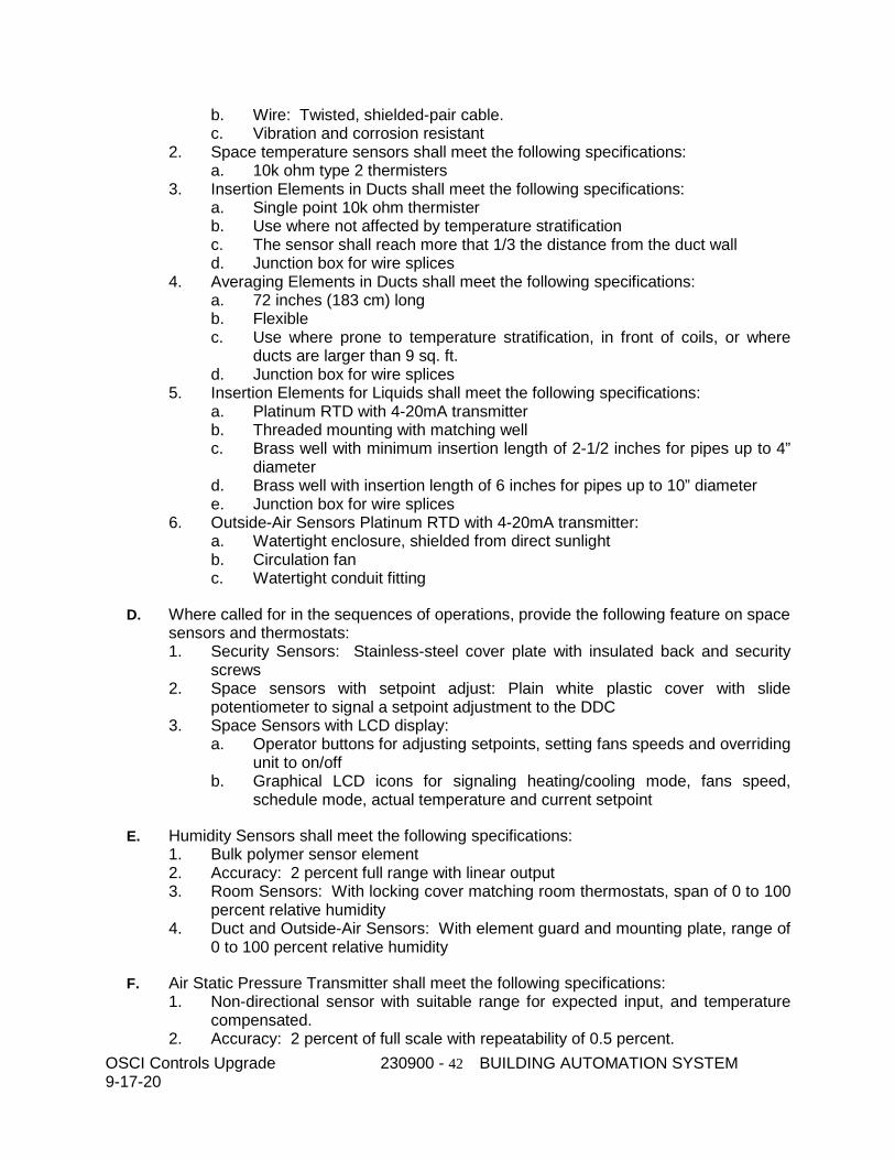
OSCI Controls Upgrade 230900 - 42 BUILDING AUTOMATION SYSTEM 9-17-20
b. Wire: Twisted, shielded-pair cable. c. Vibration and corrosion resistant
2. Space temperature sensors shall meet the following specifications: a. 10k ohm type 2 thermisters
3. Insertion Elements in Ducts shall meet the following specifications: a. Single point 10k ohm thermister b. Use where not affected by temperature stratification c. The sensor shall reach more that 1/3 the distance from the duct wall d. Junction box for wire splices
4. Averaging Elements in Ducts shall meet the following specifications: a. 72 inches (183 cm) long b. Flexible c. Use where prone to temperature stratification, in front of coils, or where
ducts are larger than 9 sq. ft. d. Junction box for wire splices
5. Insertion Elements for Liquids shall meet the following specifications: a. Platinum RTD with 4-20mA transmitter b. Threaded mounting with matching well c. Brass well with minimum insertion length of 2-1/2 inches for pipes up to 4”
diameter d. Brass well with insertion length of 6 inches for pipes up to 10” diameter e. Junction box for wire splices
6. Outside-Air Sensors Platinum RTD with 4-20mA transmitter: a. Watertight enclosure, shielded from direct sunlight b. Circulation fan c. Watertight conduit fitting
D. Where called for in the sequences of operations, provide the following feature on space sensors and thermostats: 1. Security Sensors: Stainless-steel cover plate with insulated back and security
screws 2. Space sensors with setpoint adjust: Plain white plastic cover with slide
potentiometer to signal a setpoint adjustment to the DDC 3. Space Sensors with LCD display:
a. Operator buttons for adjusting setpoints, setting fans speeds and overriding unit to on/off
b. Graphical LCD icons for signaling heating/cooling mode, fans speed, schedule mode, actual temperature and current setpoint
E. Humidity Sensors shall meet the following specifications: 1. Bulk polymer sensor element 2. Accuracy: 2 percent full range with linear output 3. Room Sensors: With locking cover matching room thermostats, span of 0 to 100
percent relative humidity 4. Duct and Outside-Air Sensors: With element guard and mounting plate, range of
0 to 100 percent relative humidity
F. Air Static Pressure Transmitter shall meet the following specifications: 1. Non-directional sensor with suitable range for expected input, and temperature
compensated. 2. Accuracy: 2 percent of full scale with repeatability of 0.5 percent.
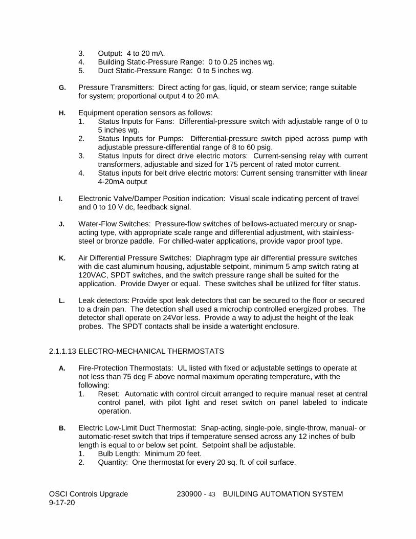
OSCI Controls Upgrade 230900 - 43 BUILDING AUTOMATION SYSTEM 9-17-20
3. Output: 4 to 20 mA. 4. Building Static-Pressure Range: 0 to 0.25 inches wg. 5. Duct Static-Pressure Range: 0 to 5 inches wg.
G. Pressure Transmitters: Direct acting for gas, liquid, or steam service; range suitable for system; proportional output 4 to 20 mA.
H. Equipment operation sensors as follows: 1. Status Inputs for Fans: Differential-pressure switch with adjustable range of 0 to
5 inches wg. 2. Status Inputs for Pumps: Differential-pressure switch piped across pump with
adjustable pressure-differential range of 8 to 60 psig. 3. Status Inputs for direct drive electric motors: Current-sensing relay with current
transformers, adjustable and sized for 175 percent of rated motor current. 4. Status inputs for belt drive electric motors: Current sensing transmitter with linear
4-20mA output
I. Electronic Valve/Damper Position indication: Visual scale indicating percent of travel and 0 to 10 V dc, feedback signal.
J. Water-Flow Switches: Pressure-flow switches of bellows-actuated mercury or snap-acting type, with appropriate scale range and differential adjustment, with stainless-steel or bronze paddle. For chilled-water applications, provide vapor proof type.
K. Air Differential Pressure Switches: Diaphragm type air differential pressure switches with die cast aluminum housing, adjustable setpoint, minimum 5 amp switch rating at 120VAC, SPDT switches, and the switch pressure range shall be suited for the application. Provide Dwyer or equal. These switches shall be utilized for filter status.
L. Leak detectors: Provide spot leak detectors that can be secured to the floor or secured to a drain pan. The detection shall used a microchip controlled energized probes. The detector shall operate on 24Vor less. Provide a way to adjust the height of the leak probes. The SPDT contacts shall be inside a watertight enclosure.
2.1.1.13 ELECTRO-MECHANICAL THERMOSTATS
A. Fire-Protection Thermostats: UL listed with fixed or adjustable settings to operate at not less than 75 deg F above normal maximum operating temperature, with the following: 1. Reset: Automatic with control circuit arranged to require manual reset at central
control panel, with pilot light and reset switch on panel labeled to indicate operation.
B. Electric Low-Limit Duct Thermostat: Snap-acting, single-pole, single-throw, manual- or automatic-reset switch that trips if temperature sensed across any 12 inches of bulb length is equal to or below set point. Setpoint shall be adjustable. 1. Bulb Length: Minimum 20 feet. 2. Quantity: One thermostat for every 20 sq. ft. of coil surface.
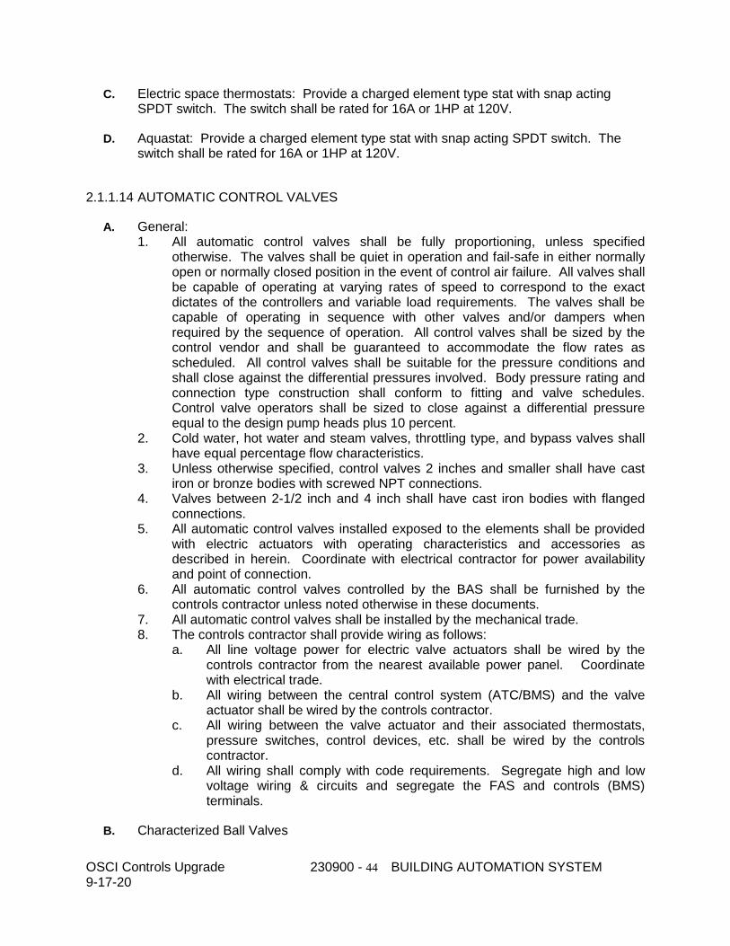
OSCI Controls Upgrade 230900 - 44 BUILDING AUTOMATION SYSTEM 9-17-20
C. Electric space thermostats: Provide a charged element type stat with snap acting SPDT switch. The switch shall be rated for 16A or 1HP at 120V.
D. Aquastat: Provide a charged element type stat with snap acting SPDT switch. The switch shall be rated for 16A or 1HP at 120V.
2.1.1.14 AUTOMATIC CONTROL VALVES
A. General: 1. All automatic control valves shall be fully proportioning, unless specified
otherwise. The valves shall be quiet in operation and fail-safe in either normally open or normally closed position in the event of control air failure. All valves shall be capable of operating at varying rates of speed to correspond to the exact dictates of the controllers and variable load requirements. The valves shall be capable of operating in sequence with other valves and/or dampers when required by the sequence of operation. All control valves shall be sized by the control vendor and shall be guaranteed to accommodate the flow rates as scheduled. All control valves shall be suitable for the pressure conditions and shall close against the differential pressures involved. Body pressure rating and connection type construction shall conform to fitting and valve schedules. Control valve operators shall be sized to close against a differential pressure equal to the design pump heads plus 10 percent.
2. Cold water, hot water and steam valves, throttling type, and bypass valves shall have equal percentage flow characteristics.
3. Unless otherwise specified, control valves 2 inches and smaller shall have cast iron or bronze bodies with screwed NPT connections.
4. Valves between 2-1/2 inch and 4 inch shall have cast iron bodies with flanged connections.
5. All automatic control valves installed exposed to the elements shall be provided with electric actuators with operating characteristics and accessories as described in herein. Coordinate with electrical contractor for power availability and point of connection.
6. All automatic control valves controlled by the BAS shall be furnished by the controls contractor unless noted otherwise in these documents.
7. All automatic control valves shall be installed by the mechanical trade. 8. The controls contractor shall provide wiring as follows:
a. All line voltage power for electric valve actuators shall be wired by the controls contractor from the nearest available power panel. Coordinate with electrical trade.
b. All wiring between the central control system (ATC/BMS) and the valve actuator shall be wired by the controls contractor.
c. All wiring between the valve actuator and their associated thermostats, pressure switches, control devices, etc. shall be wired by the controls contractor.
d. All wiring shall comply with code requirements. Segregate high and low voltage wiring & circuits and segregate the FAS and controls (BMS) terminals.
B. Characterized Ball Valves
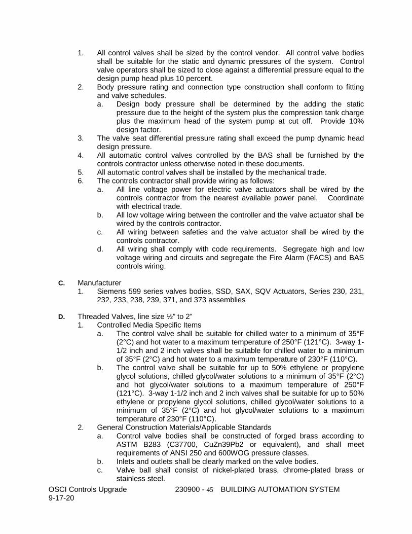
OSCI Controls Upgrade 230900 - 45 BUILDING AUTOMATION SYSTEM 9-17-20
1. All control valves shall be sized by the control vendor. All control valve bodies shall be suitable for the static and dynamic pressures of the system. Control valve operators shall be sized to close against a differential pressure equal to the design pump head plus 10 percent.
2. Body pressure rating and connection type construction shall conform to fitting and valve schedules. a. Design body pressure shall be determined by the adding the static
pressure due to the height of the system plus the compression tank charge plus the maximum head of the system pump at cut off. Provide 10% design factor.
3. The valve seat differential pressure rating shall exceed the pump dynamic head design pressure.
4. All automatic control valves controlled by the BAS shall be furnished by the controls contractor unless otherwise noted in these documents.
5. All automatic control valves shall be installed by the mechanical trade. 6. The controls contractor shall provide wiring as follows:
a. All line voltage power for electric valve actuators shall be wired by the controls contractor from the nearest available power panel. Coordinate with electrical trade.
b. All low voltage wiring between the controller and the valve actuator shall be wired by the controls contractor.
c. All wiring between safeties and the valve actuator shall be wired by the controls contractor.
d. All wiring shall comply with code requirements. Segregate high and low voltage wiring and circuits and segregate the Fire Alarm (FACS) and BAS controls wiring.
C. Manufacturer 1. Siemens 599 series valves bodies, SSD, SAX, SQV Actuators, Series 230, 231,
232, 233, 238, 239, 371, and 373 assemblies
D. Threaded Valves, line size ½” to 2” 1. Controlled Media Specific Items
a. The control valve shall be suitable for chilled water to a minimum of 35°F (2°C) and hot water to a maximum temperature of 250°F (121°C). 3-way 1-1/2 inch and 2 inch valves shall be suitable for chilled water to a minimum of 35°F (2°C) and hot water to a maximum temperature of 230°F (110°C).
b. The control valve shall be suitable for up to 50% ethylene or propylene glycol solutions, chilled glycol/water solutions to a minimum of 35°F (2°C) and hot glycol/water solutions to a maximum temperature of 250°F (121°C). 3-way 1-1/2 inch and 2 inch valves shall be suitable for up to 50% ethylene or propylene glycol solutions, chilled glycol/water solutions to a minimum of 35°F (2°C) and hot glycol/water solutions to a maximum temperature of 230°F (110°C).
2. General Construction Materials/Applicable Standards a. Control valve bodies shall be constructed of forged brass according to
ASTM B283 (C37700, CuZn39Pb2 or equivalent), and shall meet requirements of ANSI 250 and 600WOG pressure classes.
b. Inlets and outlets shall be clearly marked on the valve bodies. c. Valve ball shall consist of nickel-plated brass, chrome-plated brass or
stainless steel.
OSCI Controls Upgrade 230900 - 46 BUILDING AUTOMATION SYSTEM 9-17-20
d. End connections shall be NPT internally threaded according to ANSI B1.20.1.
e. The control valve flow rate (Cv) shall meet the requirements of ANSI/ISA S75.02.
f. The control valve shall have an equal percentage flow characteristic, according to ANSI/ISA S75.11. A single glass filled PTFE V port insert shall provide both the ball seal and shall establish the flow coefficient of the valve. The V port insert shall be retained by the valve body itself, not requiring additional retaining components. Flow coefficient adapters requiring a retainer clip, or installed after final assembly of the valve or as inserts in the ball shall not be allowed.
g. 2-way valves and the A-AB path on 3-way valves shall meet the requirements of ANSI Class IV (0.01% of rated Cv) seat leakage, or better, according to ANSI/FCI 70.2, at the specified close-off pressure. Bypass path (B-AB) on 3-way valves shall meet the requirements of ANSI Class III (0.1% of rated Cv) seat leakage, or better, according to ANSI/FCI 70.2.
h. Chilled and Hot water valve shall have a blow-out proof stem with two EPDM (peroxide cured) O-rings. External stem retainers will not be allowed.
i. Valve stem shall be made of brass or stainless steel. j. Valve shall have the ability to be manually operated in the event of a power
failure.
E. Actuators - Electric 1. The valves shall be provided with an actuator by the same manufacturer, factory
installed. 2. All actuators shall have visual position indication. 3. No external programming device shall be required. 4. Actuator shall be electric motor driving, microprocessor signal controlled. 5. Modulating valves shall be positive positioning, responding to a 0-10VDC, 2-
10VDC or 4-20mA signal. Floating modulating signals are acceptable for modulation on terminal units and radiation units. There shall be a visual valve position indicator.
6. Power: All actuators shall be 24VAC power and less than 100VA draw. Power shall be via Class 2 wiring. Actuators requiring more than 100VA shall have a dedicated conduit for power wiring, not mixed with the signal wiring.
7. Fail Safe: Valves actuators shall position the valve in a fail-safe position when the power supply is disrupted or the signal goes to 0. Fail-safe according to the following guidelines unless otherwise stated in the sequence of operations a. Power fail safe shall be via spring loaded mechanical means b. Any AHU hot water exposed to ventilation air shall fail open c. AHU Chilled water coils exposed to ventilation air in possible freezing
conditions shall be fail open d. AHU Chilled water coils that are drained in winter months or are in climate
zones without freezing conditions shall be fail-in-place e. Terminal unit valves shall fail-in-place
8. Fail in Safe valves on primary equipment such as chilled water systems, hot water systems and condenser water systems shall have a means to manually open the valve when power is not available, such as a hand wheel or a geared crank with a clutch.
OSCI Controls Upgrade 230900 - 47 BUILDING AUTOMATION SYSTEM 9-17-20
9. The actuator shall be designed with a current limiting motor protection. A release button (clutch) or handle on the actuator shall be provided to allow for manual override (except when actuator is spring return type).
10. Actuator shall provide minimum torque required for proper valve close-off. The close-off differential pressure rating of the valve shall exceed the highest possible head pressure available at the pump plus 10%, and still be rated for a Class IV leakage.
11. The actuator shall have the capability of adding auxiliary switches or feedback potentiometer if specified.
12. All automatic control valves installed in locations exposed to the elements shall be provided with weather resistant housings and heaters for climates that reach below freezing.
13. Actuators shall be UL and CSA listed.
F. Hot Water / Condenser Water / Control Valves 1. Single-seated. 2. Fully proportioning with modulating plug or V-port inner valves. 3. Body pressure rating and connection type construction shall conform to fitting
and valve schedules. The ANSI rating of the valve shall match the ANSI rating of the piping in which the valve is installed. Minimum ANSI rating shall be ANSI 125.
4. Stainless steel stems and trim. 5. Spring loaded Teflon packing 6. Quiet in operation. 7. Fail-safe in either normally open or normally closed position in the event of power
failure. 8. Capable of operating in sequence with other valves and/or dampers when
required by the sequence of operation. 9. Capable of operating at varying rates of speed to correspond to the exact
dictates of the controller and variable load requirements.
G. Differential Pressure Control Valves : 1. Provide for all water systems where modulating water flow conditions are
required to prevent excessive pump pressure build-up. Provide a valve for each closed loop water system. Valve to be globe type. Provide valves 2" and smaller with screwed end bodies and provide valves 2-1/2" and larger with flanged ends.
H. Steam Valves:
1. Steam control valves shall be of linear flow characteristics for modulating service.
2. Sizing Criteria: a. 15 psig or less; pressure drop 80% of inlet psig. b. 16 to 50 psig; pressure drop 50% of inlet psig. c. Over 50 psig; pressure drop as scheduled on plans. d. Steam valves shall fail normally open or closed, as scheduled on plans, or
as follows: 1) Heating coils in air handlers: normally open. 2) Steam to hot water heat exchanger: normally closed. 3) Other applications: as required by sequences of operation.
OSCI Controls Upgrade 230900 - 48 BUILDING AUTOMATION SYSTEM 9-17-20
2.1.1.15 PRESSURE INDEPENDENT CONTROL VALVES (PICV)
A. General 1. All control valves shall be sized by the control vendor. All control valve bodies
shall be suitable for the static and dynamic pressures of the system. Control valve operators shall be sized to close against a differential pressure equal to the design pump head plus 10 percent. a. Body pressure rating and connection type construction shall conform to
fitting and valve schedules. Design body pressure shall be determined by the adding the static pressure due to the height of the system plus the compression tank charge plus the maximum head of the system pump at cut off. Provide 10% design factor.
2. The valve seat differential pressure rating shall exceed the pump dynamic head design pressure.
2. All automatic control valves controlled by the BAS shall be furnished by the controls contractor unless otherwise noted in these documents.
3. All automatic control valves shall be installed by the mechanical trade. 4. The controls contractor shall provide wiring as follows:
a. All line voltage power for electric valve actuators shall be wired by the controls contractor from the nearest available power panel. Coordinate with electrical trade.
b. All low voltage wiring between the controller and the valve actuator shall be wired by the controls contractor.
c. All wiring between safeties and the valve actuator shall be wired by the controls contractor.
d. All wiring shall comply with code requirements. Segregate high and low voltage wiring and circuits and segregate the Fire Alarm (FACS) and BAS controls wiring.
B. Manufacturer 1. Siemens 599 series valves bodies, SSD, SAY, SAX, SAV and SQV Actuators,
Series 230, 231, 232, 233, 238, 239, 334, 335, 371, 373, 378 and 379 assemblies
C. Where to use PICVs 1. Provide PICVs where called for in the specifications, sequences of operations, or
on the drawings. 2. If it is not stated elsewhere, PICV valves should be provided to meet the
following guidelines: a. Provide in direct return, constant speed pumping systems. b. Provide in direct return, variable flow water systems where with the system
at full flow the pressure differential between the supply connection and the return connection is more than double the pressure drop of the circuit or loop at design flow (including piping, fittings, devices, control valve and coil).
c. Provide in reverse return, constant speed pumping systems where the circuits and loop pressure drops differ by more than 50%.
d. Provide in reverse return, variable speed pumping systems where the differential pressure between the systems will vary more than the pressure drop of the circuit or loop.
OSCI Controls Upgrade 230900 - 49 BUILDING AUTOMATION SYSTEM 9-17-20
e. Provide in systems that have direct return headers and reverse return branch lines where with the system at full flow the pressure differential between the supply connection and the return connection is more than double the pressure drop of the branch at design flow (including piping, fittings, devices, control valve and coil).
D. Piping for circuits with PICVs 1. Systems installed with PICVs shall not require balancing valves. 2. Calibrated balancing valves shall not be required in branches or loops where
PICV are installed. 3. Automatic flow control valves are strictly prohibited in branches or loops where
PICVs are installed. 4. Circuit setters may be required for coils with multiple sections. Follow the piping
details. 5. Install pressure ports on either side of the coil for the balancer to test the flow
across the coil at different system flows.
E. Sizing Criteria (Pressure Independent): 1. Two-way modulating service:
a. Determine the design GPM of the actual coil that is selected be used (may be different than the coil and GPM on the design coil schedule).
b. Select the PICV valve with a GPM rating higher than the GPM required. c. If more than one valve fits the GPM rating, then pick the valve that matches
or is closest to the line size of the circuit piping. d. If the maximum GPM of the valve exceeds the design GPM required, then
adjust the Flow Limiter setting on the valve to the GPM required. e. Traditional flow coefficient and pressure drop sizing is not applicable to
PICV valves.
F. Flanged Valves, line size 2 ½” and larger 1. Controlled Media Specific Items
a. The control valve shall be suitable for chilled water to a minimum of 34°F (1°C) and hot water to a maximum temperature of 248°F (120°C).
b. The control valve shall be suitable for up to 50% ethylene or propylene glycol solutions, chilled glycol/water solutions to a minimum of 34°F (1°C) and hot glycol/water solutions to a maximum temperature of 248°F (120°C).
2. General Construction Materials/Applicable a. Control valve bodies shall be constructed of cast iron and shall meet
requirements of ANSI 125 or ANSI 250 pressure classes. b. Inlets and outlets shall be clearly marked on the valve bodies. c. Valves shall be constructed with a single chamber and multiple seats to
provide flow limiting, pressure compensation and flow control. d. Valves shall contain a mechanical, spring-loaded pressure independent
regulator to maintain a consistent differential pressure across the control port of the valve.
e. Valves shall contain an actuated flow control portion that responds to the modulating signal from the controller. This control valve portion shall have a linear flow characteristic.
f. Valves shall contain a field adjustable flow limiter. The flow limiter shall be easily adjustable in the field without the use of special tools. The
OSCI Controls Upgrade 230900 - 50 BUILDING AUTOMATION SYSTEM 9-17-20
adjustment dial shall be set for and indicate maximum flow. It shall be possible to manually limit the flow to the required value with the flow limiter and then modulate the flow with the control valve and actuator. 1) A table shall be attached to each valve indicating GPM
corresponding to each setting on the dial. 2) No mechanical devices besides the valve and actuator shall be
permitted to adjust the maximum flow setting. Flow limiting port shall be integrated into the valve body.
3) The valve shall always maintain full nominal stroke regardless of the maximum flow setting of the flow limiter.
4) The flow limiter shall be lockable and tamper resistant when the actuator is installed correctly.
g. At any given actuator setting the flow accuracy across the entire pressure independent operating range of the automatic differential pressure regulator shall be ±10% or less.
h. Pressure ports shall be standard in the body of the valve for all flanged valves. Pressure ports shall provide a means for a balancer to test the differential pressure across the valve control port to ensure the PICV is operating within the pressure independent range.
i. Valves 2-1/2 inch and larger shall be provided with ANSI 125 or ANSI 250 flanged connections.
j. Valves 2-1/2 inch and larger line size shall meet or exceed ANSI Class IV (0 to 0.01% of nominal maximum) leakage rating at 100 psi close off.
k. The differential pressure range for effective pressure independent operation shall be 3.6 – 90 psi or 8 – 90 psi for 2-½ and 3 inch flanged valves and 5 – – 90 psi for 4 to 6 inch flanged valves, depending on the maximum gpm flow range of the valve.
l. Valve materials shall meet or exceed the following: 1) Valve body: Cast iron 2) Stem, spring: Stainless steel 3) Seat: Stainless steel 4) Plug: Brass and EPDM 5) Seals: EPDM (peroxide cured)
G. Threaded Valves, line size ½” to 2” 1. Controlled Media Specific Items
a. The control valve shall be suitable for chilled water to a minimum of 35°F (2°C) and hot water to a maximum temperature of 250°F (121°C).
b. The control valve shall be suitable for up to 50% ethylene or propylene glycol solutions, chilled glycol/water solutions to a minimum of 35°F (2°C) and hot glycol/water solutions to a maximum temperature of 250°F (121°C).
2. General Construction Materials/Applicable Standards a. Control valve bodies shall be constructed of forged DZR brass or ductile
iron and shall meet requirements of ANSI 250 pressure class. b. Inlets and outlets shall be clearly marked on the valve bodies. c. Valves shall be constructed with a single chamber and multiple seats to
provide flow limiting, pressure compensation and flow control. d. Valves shall contain a mechanical, spring-loaded pressure independent
regulator to maintain a consistent differential pressure across the control port of the valve.
OSCI Controls Upgrade 230900 - 51 BUILDING AUTOMATION SYSTEM 9-17-20
e. Valves shall contain an actuated flow control portion that responds to the modulating signal from the controller. This control valve portion shall have a linear flow characteristic.
f. Valves shall contain a field adjustable flow limiter. The flow limiter shall be easily adjustable in the field without the use of special tools. The adjustment dial shall be set for and indicate maximum flow. It shall be possible to manually limit the flow to the required value with the flow limiter and then modulate the flow with the control valve and actuator. 1) The dial shall show settings in GPM. 2) No mechanical devices besides the valve and actuator shall be
permitted to adjust the maximum flow setting. Flow limiting port shall be integrated into the valve body.
3) The valve shall always maintain full nominal stroke regardless of the maximum flow setting of the flow limiter.
4) The flow limiter shall be lockable and tamper resistant when the actuator is installed correctly.
g. At any given actuator setting the flow accuracy across the entire pressure independent operating range of the automatic differential pressure regulator shall be +/- -
h. Pressure ports shall be an optional accessory that can be added to threaded valves. Pressure ports shall provide a means for a balancer to test the differential pressure across the valve control port to ensure the PICV is operating within the pressure independent range.
i. Valves 2 inch and smaller shall be provided female NPT piping connections.
j. Close-off and leakage 1) Normally open valves 1-1/4 inch and smaller line size shall meet or
exceed ANSI Class IV (0 to 0.01% of nominal maximum) leakage rating at 200 psi close off.
2) Normally closed valves 1-1/4 inch and smaller line size shall meet or exceed ANSI Class IV (0 to 0.01% of nominal maximum) leakage rating at 45 psi close off.
3) Valves 1-1/2 and 2 inch line sizes shall meet or exceed ANSI Class IV (0 to 0.01% of nominal maximum) leakage rating at 100 psi close off.Differential pressure ranges:
4) The start-up differential pressure of the automatic differential pressure regulator shall be between 2.3 and 5 psi, depending on valve size and flow rate for ½ to 2 inch valves.
5) The maximum operating differential pressure of the automatic differential pressure regulator shall be 58 psi for ½ to 2 inch valves.
6) In no instance shall the minimum effective pressure differential for effective pressure independent operation exceed 5 psi for valves less than or equal to 2 inch line size.
k. Valve materials shall meet or exceed the following: 1) Valve body: DZR brass or ductile iron 2) Stem, spring: Stainless steel 3) Seat: brass 4) Plug: Brass and EPDM 5) Seals: EPDM (peroxide cured)
OSCI Controls Upgrade 230900 - 52 BUILDING AUTOMATION SYSTEM 9-17-20
2.1.1.16 ELECTRONIC ACTUATOR SPECIFICATION
A. ELECTRONIC VALVE ACTUATORS 1. Actuator shall be fully modulating, floating (tri-state), two position, and/or spring
return as indicated in the control sequences. Specified fail safe actuators shall require mechanical spring return.
2. Modulating valves shall be positive positioning, responding to a 2-10VDC or 4-20mA signal. There shall be a visual valve position indicator.
3. The actuator shall have the capability of adding auxiliary switches or feedback potentiometer if specified.
4. Actuator shall provide minimum torque required for proper valve close-off. The actuator shall be designed with a current limiting motor protection. A release button (clutch) or handle on the actuator shall be provided to allow for manual override (except when actuator is spring return type).
5. Actuators shall be UL listed.
B. ELECTRONIC DAMPER ACTUATORS 1. Actuator shall be direct coupled (over the shaft), enabling it to be mounted
directly to the damper shaft without the need for connecting linkage. The actuator-to-shaft clamp shall use a "V" bolt and "V" shaped, toothed cradle to attach to the damper shaft for maximum holding strength. Single bolt or set screw type fasteners are not acceptable.
2. Actuator shall have electronic overload or digital rotation sensing circuitry to prevent damage to the actuator throughout the rotation of the actuator. End switches to deactivate the actuator at the end of rotation or magnetic clutch are not acceptable.
3. For power-failure/safety applications, a mechanical, spring return mechanism shall be used.
4. Actuators with spring return mechanisms shall be capable of either clockwise or counterclockwise spring return operation by simply changing the mounting orientation.
5. Proportional actuators shall accept a 2-10VDC, 4-20mA signal, or be of the 2 point floating type and provide a 2-10VDC actuator position feedback signal.
6. All actuators shall have an external manual gear release (clutch) or manual crank to aid in installation and for allowing manual positioning when the actuator is not powered.
7. All actuators shall have an external direction of rotation switch to aid in installation and to allow proper control response.
8. Actuators shall be provided with a factory-mounted 3-foot electrical cable and conduit fitting to provide easy hook-up to an electrical junction box.
9. Actuators shall be listed under Underwriters Laboratories Standard 873 and Canadian Standards Association. They must be manufactured under ISO 9001.
PART 3 - EXECUTION
3.1.1.1 EXAMINATION
OSCI Controls Upgrade 230900 - 53 BUILDING AUTOMATION SYSTEM 9-17-20
A. The project plans shall be thoroughly examined for control device and equipment locations. Any discrepancies, conflicts, or omissions shall be reported to the architect/engineer for resolution before rough-in work is started.
B. The contractor shall inspect the site to verify that equipment may be installed as shown. Any discrepancies, conflicts, or omissions shall be reported to the engineer for resolution before rough-in work is started.
C. The contractor shall examine the drawings and specifications for other parts of the work. If head room or space conditions appear inadequate—or if any discrepancies occur between the plans and the contractor’s work and the plans and the work of others—the contractor shall report these discrepancies to the engineer and shall obtain written instructions for any changes necessary to accommodate the contractor’s work with the work of others.
3.1.1.2 INSTALLATION
A. Provide all relays, switches, sources of emergency and UPS battery back-up electricity and all other auxiliaries, accessories and connections necessary to make a complete operable system in accordance with the sequences specified. All field wiring shall be by this contractor.
B. Install controls so that adjustments and calibrations can be readily made. Controls are to be installed by the control equipment manufacturer.
C. Mount surface-mounted control devices on brackets to clear the final finished surface on insulation.
D. Install equipment level and plumb.
E. Install control valves horizontally with the power unit up.
F. Unless otherwise noted, install wall mounted thermostats and humidistat 60” above the floor measured to the center line of the instrument, or as otherwise directed by the Architect.
G. Install averaging elements in ducts and plenums in horizontal crossing or zigzag pattern.
H. Install outdoor sensors in perforated tube and sunshield.
I. Install damper motors on outside of duct in protected areas, not in locations exposed to outdoor temperatures.
J. Install labels and nameplates on each control panel listing the name of the panel referenced in the graphics and a list of equipment numbers served by that panel.
K. Furnish hydronic instrument wells, valves, and other accessories to the mechanical contractor for installation.
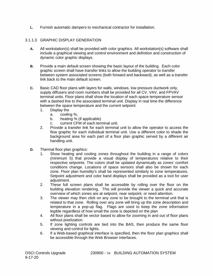
OSCI Controls Upgrade 230900 - 54 BUILDING AUTOMATION SYSTEM 9-17-20
L. Furnish automatic dampers to mechanical contractor for installation.
3.1.1.3 GRAPHIC DISPLAY GENERATION
A. All workstation(s) shall be provided with color graphics. All workstation(s) software shall include a graphical viewing and control environment and definition and construction of dynamic color graphic displays.
B. Provide a main default screen showing the basic layout of the building. Each color graphic screen shall have transfer links to allow the building operator to transfer between system associated screens (both forward and backward), as well as a transfer link back to the main default screen.
C. Basic CAD floor plans with layers for walls, windows, low pressure ductwork only, supply diffusers and room numbers shall be provided for all CV, VAV, and FPVAV terminal units. Floor plans shall show the location of each space temperature sensor with a dashed line to the associated terminal unit. Display in real time the difference between the space temperature and the current setpoint. 1. Display the
a. cooling %, b. heating % (if applicable) c. current CFM of each terminal unit.
2. Provide a transfer link for each terminal unit to allow the operator to access the flow graphic for each individual terminal unit. Use a different color to shade the background area for each part of a floor plan graphic served by a different air handling unit.
D. Thermal floor plan graphics: 1. Show heating and cooling zones throughout the building in a range of colors
(minimum 5) that provide a visual display of temperatures relative to their respective setpoints. The colors shall be updated dynamically as zones’ comfort conditions change. Locations of space sensors shall also be shown for each zone. Floor plan humidity’s shall be represented similarly to zone temperatures. Setpoint adjustment and color band displays shall be provided as a tool for user adjustment.
2. These full screen plans shall be accessible by rolling over the floor on the building elevation rendering. This will provide the viewer a quick and accurate overview of which zones are at setpoint, near setpoint, or need attention.
3. The viewer may then click on any zone to be brought to the terminal unit that is related to that zone. Rolling over any zone will bring up the zone description and temperature in a pop-up flag. Flags are used to keep the zone information legible regardless of how small the zone is depicted on the plan
4. All floor plans shall be vector based to allow for zooming in and out of floor plans without pixelization.
5. If zone lighting controls are tied into the BAS, then produce the same floor viewing and control for lights.
6. If a Web-based graphical interface is specified, then the floor plan graphics shall be accessible through the Web Browser Interfaces.

OSCI Controls Upgrade 230900 - 55 BUILDING AUTOMATION SYSTEM 9-17-20
E. All control set points shall be easily adjustable from the system’s color graphic screen by operators with the proper access level. Each controlled point on the BAS operator workstation color graphic screens shall have the set point indicated along with the actual controlled variable reading (preferred set point on top and actual reading on bottom). All points shall indicate the associated engineering unit. All analog outputs points shall indicate engineering units such as “%-open” or “%-closed” as required by the application. All normally-closed or normally-open points shall indicate the normal position (such as “N.C.” or “N.O.” next to the controlled device).
F. Provide system color graphics for each HVAC system and for each electrical, plumbing and/or piping system that is monitored and/or controlled by the BMS. Provide scaled floor plans indicating equipment location, service, and system data as required.
G. Provide color graphic floor plan displays and system schematics for each piece of mechanical equipment, including but not limited to air handling units, chilled water systems and hot water systems to optimize system performance analysis and speed alarm recognition.
H. The operator interface shall allow users to access the various system schematics and floor plans via a graphical penetration scheme, menu selection or text-based commands.
I. Dynamic temperature values, humidity values, flow values and status indication shall be shown in their actual respective locations and shall automatically update to represent current conditions without operator intervention.
J. The windowing environment of the PC operator workstation(s) shall allow the user to simultaneously view several graphics at a time to analyze total building operation or to allow the display of a graphic associated with an alarm to be viewed without interrupting work in progress. 1. Provide libraries of pre-engineered screens and symbols depicting standard air
handling unit components (e.g., fans, cooling coils, filters, dampers, etc.), complete mechanical systems (e.g., constant volume-terminal reheat, VAV, etc.) and electrical symbols.
2. Graphical displays can be created to represent any logical grouping of system points or calculated data based upon building function, mechanical system, building layout or any other logical grouping of points which aids the operator in the analysis of the facility.
K. Provide an automatically updated, dynamic display of the site-specific BMS architecture indicating the status of primary and secondary controllers, PC workstation(s)and networks.
L. Provide a separate dynamic display page of each HVAC (AHU, AC, chiller, cooling tower, fuel oil, etc.), electrical, and/or plumbing system connected to the BMS.
M. Provide a separate dynamic display page of each piece of terminal equipment (VAV box, fan coil unit, etc.) connected to the BMS.
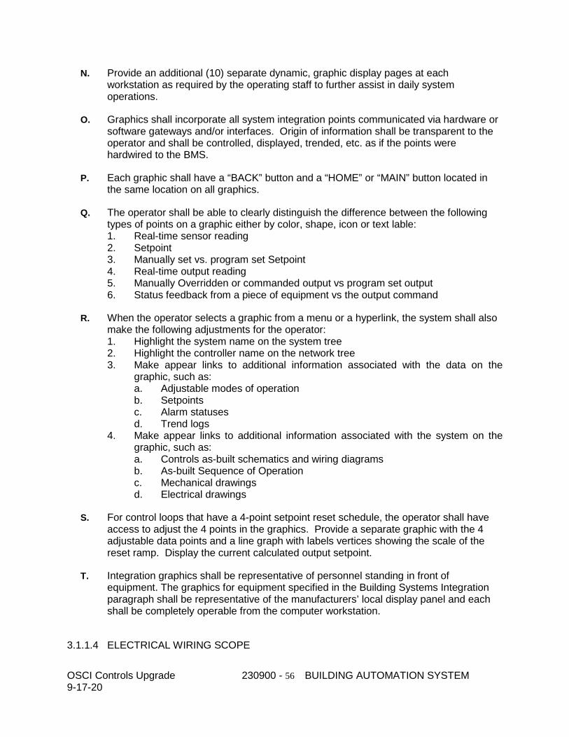
OSCI Controls Upgrade 230900 - 56 BUILDING AUTOMATION SYSTEM 9-17-20
N. Provide an additional (10) separate dynamic, graphic display pages at each workstation as required by the operating staff to further assist in daily system operations.
O. Graphics shall incorporate all system integration points communicated via hardware or software gateways and/or interfaces. Origin of information shall be transparent to the operator and shall be controlled, displayed, trended, etc. as if the points were hardwired to the BMS.
P. Each graphic shall have a “BACK” button and a “HOME” or “MAIN” button located in the same location on all graphics.
Q. The operator shall be able to clearly distinguish the difference between the following types of points on a graphic either by color, shape, icon or text lable: 1. Real-time sensor reading 2. Setpoint 3. Manually set vs. program set Setpoint 4. Real-time output reading 5. Manually Overridden or commanded output vs program set output 6. Status feedback from a piece of equipment vs the output command
R. When the operator selects a graphic from a menu or a hyperlink, the system shall also make the following adjustments for the operator: 1. Highlight the system name on the system tree 2. Highlight the controller name on the network tree 3. Make appear links to additional information associated with the data on the
graphic, such as: a. Adjustable modes of operation b. Setpoints c. Alarm statuses d. Trend logs
4. Make appear links to additional information associated with the system on the graphic, such as: a. Controls as-built schematics and wiring diagrams b. As-built Sequence of Operation c. Mechanical drawings d. Electrical drawings
S. For control loops that have a 4-point setpoint reset schedule, the operator shall have access to adjust the 4 points in the graphics. Provide a separate graphic with the 4 adjustable data points and a line graph with labels vertices showing the scale of the reset ramp. Display the current calculated output setpoint.
T. Integration graphics shall be representative of personnel standing in front of equipment. The graphics for equipment specified in the Building Systems Integration paragraph shall be representative of the manufacturers’ local display panel and each shall be completely operable from the computer workstation.
3.1.1.4 ELECTRICAL WIRING SCOPE

OSCI Controls Upgrade 230900 - 57 BUILDING AUTOMATION SYSTEM 9-17-20
A. This contractor shall be responsible for power that is not shown on the electrical drawings, to controls furnished by this contractor. If power circuits are shown on the electrical drawings, this contractor shall continue the power run to the control device. If power circuits are not shown, this contractor shall coordinate with the electrical contractor to provide breakers at distribution panels for power to controls. This contractor is then responsible for power from the distribution panel. 1. Coordinate panel locations. If enclosures for panels are shown on the electrical
drawings, furnish the enclosures according to the electrician’s installation schedule.
B. This contractor shall not be responsible for power to control panels and control devices that are furnished by others, unless it is part of the control interlock wiring.
C. Refer to Coordination section for what devices this contractor is responsible to mount and which are turned over to others to mount.
D. This contractor shall be responsible for wiring of any control device that is furnished as part of this section of specification.
E. Interlock wiring shall be run in separate conduits from BAS associated wiring.
F. Provide network wiring for equipment that is called to be integrated to the BAS.
3.1.1.5 ELECTRICAL WIRING AND CONNECTION INSTALLATION
A. All low voltage control wiring shall be class 2. Control wiring that is not class 2 shall be run in separate conduits from class 2 wiring.
B. Floor level network wiring between terminal units can be combined with thermostat and other low voltage wiring in the same conduit. All other network wiring shall be in dedicated conduits.
C. Install raceways, boxes, and cabinets according to Division 26 Section "Raceways and Boxes."
D. Install building wire and cable according to Division 26 Section "Conductors and Cables."
E. Installation shall meet the following requirements: 1. Conceal cable and conduit, except in mechanical rooms and areas where other
conduit and piping are exposed. 2. Install exposed cable in raceway or conduit. 3. Install concealed cable using plenum rated cable. 4. Bundle and harness multiconductor instrument cable in place of single cables
where several cables follow a common path. 5. Fasten flexible conductors, bridging cabinets and doors, along hinge side; protect
against abrasion. Tie and support conductors. 6. Number-code or color-code conductors for future identification and service of
control system, except local individual room control cables. 7. All wiring in lab areas shall be in conduit.
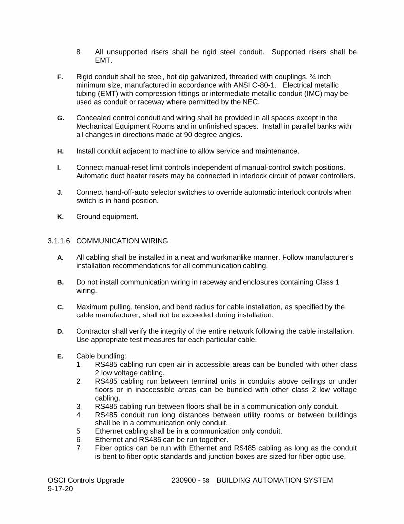
OSCI Controls Upgrade 230900 - 58 BUILDING AUTOMATION SYSTEM 9-17-20
8. All unsupported risers shall be rigid steel conduit. Supported risers shall be EMT.
F. Rigid conduit shall be steel, hot dip galvanized, threaded with couplings, ¾ inch minimum size, manufactured in accordance with ANSI C-80-1. Electrical metallic tubing (EMT) with compression fittings or intermediate metallic conduit (IMC) may be used as conduit or raceway where permitted by the NEC.
G. Concealed control conduit and wiring shall be provided in all spaces except in the Mechanical Equipment Rooms and in unfinished spaces. Install in parallel banks with all changes in directions made at 90 degree angles.
H. Install conduit adjacent to machine to allow service and maintenance.
I. Connect manual-reset limit controls independent of manual-control switch positions. Automatic duct heater resets may be connected in interlock circuit of power controllers.
J. Connect hand-off-auto selector switches to override automatic interlock controls when switch is in hand position.
K. Ground equipment.
3.1.1.6 COMMUNICATION WIRING
A. All cabling shall be installed in a neat and workmanlike manner. Follow manufacturer’s installation recommendations for all communication cabling.
B. Do not install communication wiring in raceway and enclosures containing Class 1 wiring.
C. Maximum pulling, tension, and bend radius for cable installation, as specified by the cable manufacturer, shall not be exceeded during installation.
D. Contractor shall verify the integrity of the entire network following the cable installation. Use appropriate test measures for each particular cable.
E. Cable bundling: 1. RS485 cabling run open air in accessible areas can be bundled with other class
2 low voltage cabling. 2. RS485 cabling run between terminal units in conduits above ceilings or under
floors or in inaccessible areas can be bundled with other class 2 low voltage cabling.
3. RS485 cabling run between floors shall be in a communication only conduit. 4. RS485 conduit run long distances between utility rooms or between buildings
shall be in a communication only conduit. 5. Ethernet cabling shall be in a communication only conduit. 6. Ethernet and RS485 can be run together. 7. Fiber optics can be run with Ethernet and RS485 cabling as long as the conduit
is bent to fiber optic standards and junction boxes are sized for fiber optic use.

OSCI Controls Upgrade 230900 - 59 BUILDING AUTOMATION SYSTEM 9-17-20
F. RS485 Cabling 1. RS485 cabling shall be used for BACnet MS/TP networks. 2. RS485 shall use low capacitance, 20-24 gauge, twisted shielded pair. 3. The shields shall be tied together at each device. 4. The shield shall be grounded at one end only and capped at the other end. 5. Provide end of line (EOL) termination devices at each end of the RS485 network
or subnetwork run, to match the impedance of the cable, 100 to 120ohm.
G. Ethernet Cabling 1. Ethernet shall not be run with any Class 1 or low voltage Class 2 wiring. 2. CAT6, unshielded twisted pair (UTP) cable shall be used for BAS Ethernet. 3. Solid wire shall be used for long runs, between mechanical rooms and between
floors. Stranded cable can be used for patch cables and between panels in the same mechanical room up to 50 feet away.
4. When the BAS Ethernet connects to an Owner’s network switch, document the port number on the BAS As-builts.
H. Fiber-Optic Cabling 1. Maximum pulling tensions as specified by the cable manufacturer shall not be
exceeded during installation. Post-installation residual cable tension shall be within cable manufacturer’s specifications.
2. All cabling and associated components shall be installed in accordance with manufacturers’ instructions. Minimum cable and unjacketed fiber bend radii, as specified by cable manufacturer, shall be maintained.
3. All terminations shall to be made into a patch panel, designed for such use. Free air terminations with patch panels are prohibited.
I. When a cable enters or exits a building, a lightning arrestor must be installed between the lines and ground. The lighting arrestor shall be installed according to the manufacturer’s instructions.
J. All runs of communication wiring shall be unspliced length when that length is commercially available.
K. All communication wiring shall be labeled to indicate origination and destination data.
L. Grounding of coaxial cable shall be in accordance with NEC regulations article on “Communications Circuits, Cable, and Protector Grounding.”
3.1.1.7 IDENTIFICATION
A. Permanent warning labels shall be affixed to all equipment that can be automatically started by the DDC system. 1. Labels shall use white lettering (12-point type or larger) on a red background. 2. Warning labels shall read as follows: C A U T I O N This equipment is operating
under automatic control and may start or stop at any time without warning. Switch disconnect to “Off” position before servicing.
B. Permanent warning labels shall be affixed to all motor starters and all control panels that are connected to multiple power sources utilizing separate disconnects.
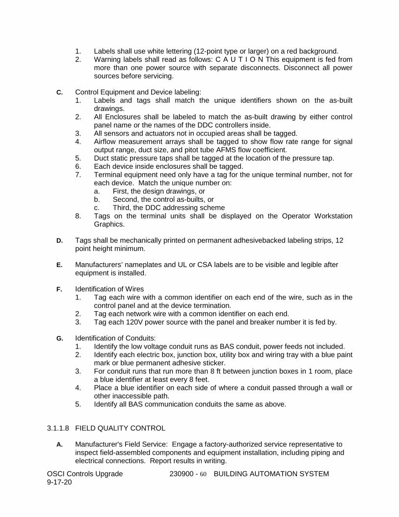
OSCI Controls Upgrade 230900 - 60 BUILDING AUTOMATION SYSTEM 9-17-20
1. Labels shall use white lettering (12-point type or larger) on a red background. 2. Warning labels shall read as follows: C A U T I O N This equipment is fed from
more than one power source with separate disconnects. Disconnect all power sources before servicing.
C. Control Equipment and Device labeling: 1. Labels and tags shall match the unique identifiers shown on the as-built
drawings. 2. All Enclosures shall be labeled to match the as-built drawing by either control
panel name or the names of the DDC controllers inside. 3. All sensors and actuators not in occupied areas shall be tagged. 4. Airflow measurement arrays shall be tagged to show flow rate range for signal
output range, duct size, and pitot tube AFMS flow coefficient. 5. Duct static pressure taps shall be tagged at the location of the pressure tap. 6. Each device inside enclosures shall be tagged. 7. Terminal equipment need only have a tag for the unique terminal number, not for
each device. Match the unique number on: a. First, the design drawings, or b. Second, the control as-builts, or c. Third, the DDC addressing scheme
8. Tags on the terminal units shall be displayed on the Operator Workstation Graphics.
D. Tags shall be mechanically printed on permanent adhesivebacked labeling strips, 12 point height minimum.
E. Manufacturers’ nameplates and UL or CSA labels are to be visible and legible after equipment is installed.
F. Identification of Wires 1. Tag each wire with a common identifier on each end of the wire, such as in the
control panel and at the device termination. 2. Tag each network wire with a common identifier on each end. 3. Tag each 120V power source with the panel and breaker number it is fed by.
G. Identification of Conduits: 1. Identify the low voltage conduit runs as BAS conduit, power feeds not included. 2. Identify each electric box, junction box, utility box and wiring tray with a blue paint
mark or blue permanent adhesive sticker. 3. For conduit runs that run more than 8 ft between junction boxes in 1 room, place
a blue identifier at least every 8 feet. 4. Place a blue identifier on each side of where a conduit passed through a wall or
other inaccessible path. 5. Identify all BAS communication conduits the same as above.
3.1.1.8 FIELD QUALITY CONTROL
A. Manufacturer's Field Service: Engage a factory-authorized service representative to inspect field-assembled components and equipment installation, including piping and electrical connections. Report results in writing.
OSCI Controls Upgrade 230900 - 61 BUILDING AUTOMATION SYSTEM 9-17-20
1. Operational Test: After electrical circuitry has been energized, start units to confirm proper unit operation. Remove malfunctioning units, replace with new units, and retest.
2. Test and adjust controls and safeties. Replace damaged and malfunctioning controls and equipment, and retest.
3. Calibration test controllers by disconnecting input sensors and stimulating operation with compatible signal generator.
B. Engage a factory-authorized service representative to perform startup service.
C. Replace damaged or malfunctioning controls and equipment. 1. Start, test, and adjust control systems. 2. Demonstrate compliance with requirements, including calibration and testing, and
control sequences. 3. Adjust, calibrate, and fine tune circuits and equipment to achieve sequence of
operation specified.
3.1.1.9 SYSTEM CHECKOUT AND STARTUP
A. Inspect each termination in the MER control panels and devices to make sure all wires are connected according to the wiring diagrams and all termination are tight.
B. After the controls devices and panels are installed and power is available to the controls, perform a static checkout of all the points, including the following: 1. Inspect the setup and reading on each temperature sensor against a
thermometer to verify its accuracy. 2. Inspect the setup and reading on each humidity sensor against a hygrometer to
verify its accuracy. 3. Inspect the reading on each CO2 sensor using a calibration kit to verify the
sensor range accuracy matches the DDC setup. 4. Inspect the reading of each status switch to verify the DDC reads the open and
close correctly. 5. Command each relay to open and close to verify its operation. 6. Command each 2-position damper actuator to open and close to verify operation. 7. Command each 2-position valve to open and close to verify operation. 8. Ramp each modulating actuator to 0%, 25%, 50%, 75% and 100% to verify its
operation. 9. Ramp each modulating output signal, such as a VFD speed, to verify its
operation. 10. Test each safety device with a real life simulation, for instance check freezestats
with ice water, water detectors with water, etc.
C. Document that each point was verified and operating correctly. Correct each failed point before proceeding to the dynamic startup.
D. Verify that each DDC controller communicates on its respective network correctly.
E. After all of the points are verified, and power is available to the mechanical system, coordinate a startup of each system with the mechanical contractor. Include the following tests:

OSCI Controls Upgrade 230900 - 62 BUILDING AUTOMATION SYSTEM 9-17-20
1. Start systems from DDC. 2. Verify that each setpoint can be met by the system. 3. Change setpoints and verify system response. 4. Change sensor readings to verify system response. 5. Test safety shutdowns. 6. Verify time delays. 7. Verify mode changes. 8. Adjust filter switches and current switches for proper reactions. 9. Adjust proportional bands and integration times to stabilize control loops.
F. Perform all program changes and debugging of the system for a fully operational system.
G. Verify that all graphics at the operator workstations correspond to the systems as installed. Verify that the points on the screens appear and react properly. Verify that all adjustable setpoints and manual commands operate from the operator workstations.
H. After the sequence of operation is verified, setup the trends that are listed in the sequence of operations for logging and archiving for the commissioning procedure.
3.1.1.10 SYSTEM COMMISSIONING, DEMONSTRATION AND TURNOVER
A. The BAS Contractor shall prepare and submit for approval a complete acceptance test procedure including submittal data relevant to point index, functions, sequence, inter-locks, and associated parameters, and other pertinent information for the operating system. Prior to acceptance of the BAS by the Owner and Engineer, the BAS contractor shall completely test the BAS using the approved test procedure.
B. After the BAS contractor has completed the tests and certified the BAS is 100% complete, the Engineer shall be requested, in writing, to approve the satisfactory operation of the system, sub-systems and accessories. The BAS contractor shall submit Maintenance and Operating manuals at this time for approval. An acceptance test in the presence of the Engineer and Owner's representative shall be performed. The Owner will then shake down the system for a fixed period of time (30 days).
C. The BAS contractor shall fix punch list items within 30 days of acceptance.
D. When the system performance is deemed satisfactory in whole or in part by these observers, the system parts will be accepted for beneficial use and placed under warranty.
3.1.1.11 TRAINING
A. During System commissioning and at such time as acceptable performance of the Building Automation System hardware and software has been established, the BAS contractor shall provide on-site operator instruction to the owner's operating personnel. Operator instruction during normal working hours shall be performed by a competent building automation contractor representative familiar with the Building Automation System's software, hardware and accessories.
OSCI Controls Upgrade 230900 - 63 BUILDING AUTOMATION SYSTEM 9-17-20
B. At a time mutually agreed upon, during System commissioning as stated above, the BAS contractor shall give 16-hours of onsite training on the operation of all BAS equipment. Describe its intended use with respect to the programmed functions specified. Operator orientation of the automation system shall include, but not be limited to: 1. Explanation of drawings and operator’s maintenance manuals. 2. Walk-through of the job to locate all control components. 3. Operator workstation and peripherals. 4. DDC Controller and ASC operation/sequence. 5. Operator control functions including scheduling, alarming, and trending. 6. Explanation of adjustment, calibration and replacement procedures.
C. Additional 8-hours of training shall be given after the 30 day shakedown period.
D. Since the Owner may require personnel to have more comprehensive understanding of the hardware and software, additional training must be available from the Contractor. If the Owner requires such training, it will be contracted at a later date. Provide description of available local and factory customer training. Provide costs associated with performing training at an off-site classroom facility and detail what is included in the manufacturer’s standard pricing such as transportation, meals, etc.

OSCI Controls Upgrade 230900 - 64 BUILDING AUTOMATION SYSTEM 9-17-20
END OF 23 09 00
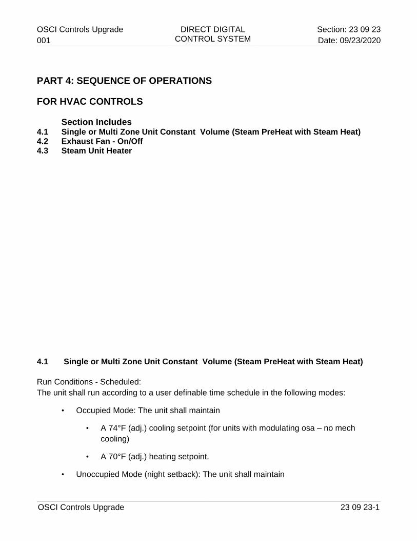
OSCI Controls Upgrade DIRECT DIGITAL CONTROL SYSTEM
Section: 23 09 23 001
Date: 09/23/2020
OSCI Controls Upgrade 23 09 23-1
PART 4: SEQUENCE OF OPERATIONS
FOR HVAC CONTROLS
Section Includes 4.1 Single or Multi Zone Unit Constant Volume (Steam PreHeat with Steam Heat) 4.2 Exhaust Fan - On/Off 4.3 Steam Unit Heater 4.1 Single or Multi Zone Unit Constant Volume (Steam PreHeat with Steam Heat) Run Conditions - Scheduled: The unit shall run according to a user definable time schedule in the following modes:
• Occupied Mode: The unit shall maintain
• A 74°F (adj.) cooling setpoint (for units with modulating osa – no mech cooling)
• A 70°F (adj.) heating setpoint.
• Unoccupied Mode (night setback): The unit shall maintain
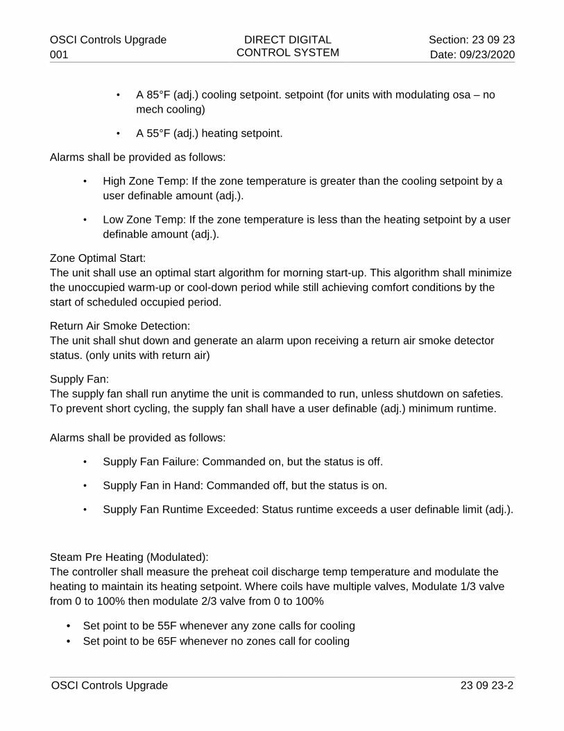
OSCI Controls Upgrade DIRECT DIGITAL CONTROL SYSTEM
Section: 23 09 23 001
Date: 09/23/2020
OSCI Controls Upgrade 23 09 23-2
• A 85°F (adj.) cooling setpoint. setpoint (for units with modulating osa – no mech cooling)
• A 55°F (adj.) heating setpoint.
Alarms shall be provided as follows:
• High Zone Temp: If the zone temperature is greater than the cooling setpoint by a user definable amount (adj.).
• Low Zone Temp: If the zone temperature is less than the heating setpoint by a user definable amount (adj.).
Zone Optimal Start: The unit shall use an optimal start algorithm for morning start-up. This algorithm shall minimize the unoccupied warm-up or cool-down period while still achieving comfort conditions by the start of scheduled occupied period.
Return Air Smoke Detection: The unit shall shut down and generate an alarm upon receiving a return air smoke detector status. (only units with return air)
Supply Fan: The supply fan shall run anytime the unit is commanded to run, unless shutdown on safeties. To prevent short cycling, the supply fan shall have a user definable (adj.) minimum runtime. Alarms shall be provided as follows:
• Supply Fan Failure: Commanded on, but the status is off.
• Supply Fan in Hand: Commanded off, but the status is on.
• Supply Fan Runtime Exceeded: Status runtime exceeds a user definable limit (adj.).
Steam Pre Heating (Modulated): The controller shall measure the preheat coil discharge temp temperature and modulate the heating to maintain its heating setpoint. Where coils have multiple valves, Modulate 1/3 valve from 0 to 100% then modulate 2/3 valve from 0 to 100%
· Set point to be 55F whenever any zone calls for cooling · Set point to be 65F whenever no zones call for cooling
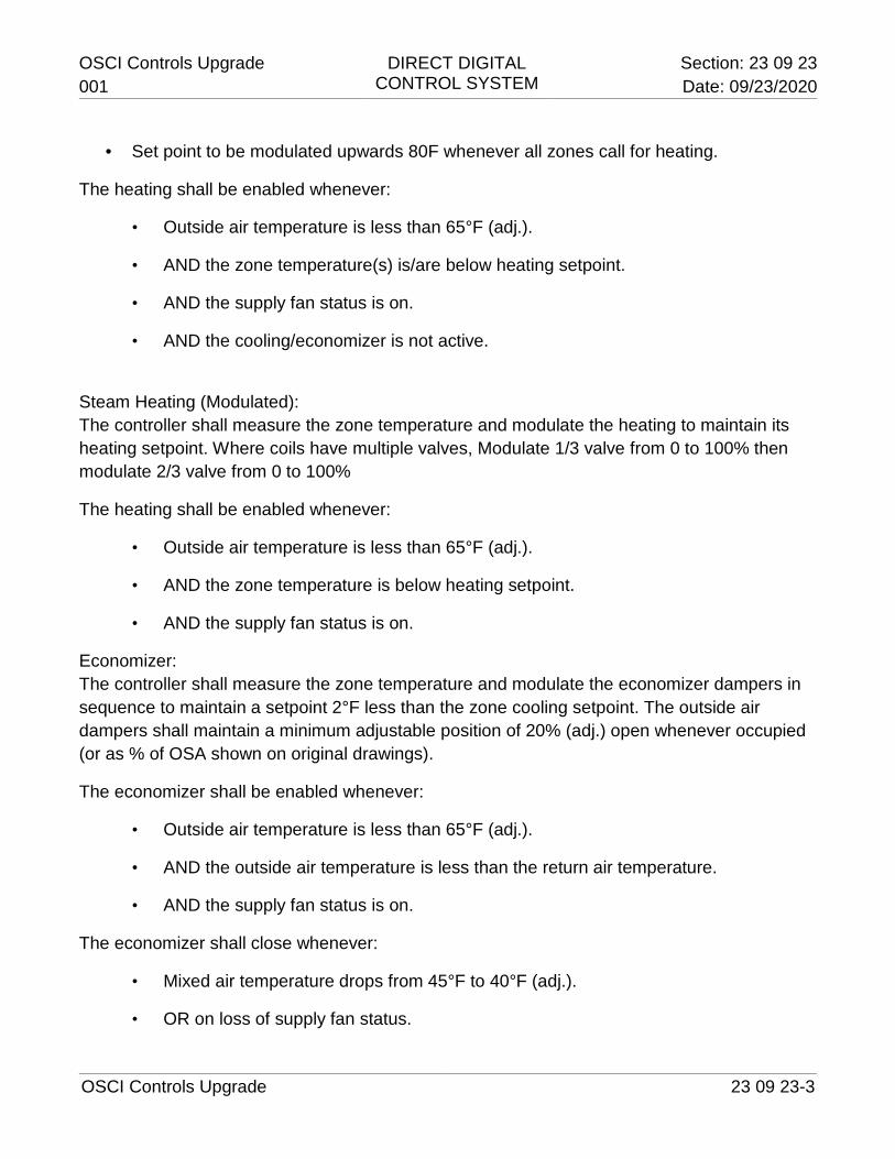
OSCI Controls Upgrade DIRECT DIGITAL CONTROL SYSTEM
Section: 23 09 23 001
Date: 09/23/2020
OSCI Controls Upgrade 23 09 23-3
· Set point to be modulated upwards 80F whenever all zones call for heating.
The heating shall be enabled whenever:
• Outside air temperature is less than 65°F (adj.).
• AND the zone temperature(s) is/are below heating setpoint.
• AND the supply fan status is on.
• AND the cooling/economizer is not active.
Steam Heating (Modulated): The controller shall measure the zone temperature and modulate the heating to maintain its heating setpoint. Where coils have multiple valves, Modulate 1/3 valve from 0 to 100% then modulate 2/3 valve from 0 to 100%
The heating shall be enabled whenever:
• Outside air temperature is less than 65°F (adj.).
• AND the zone temperature is below heating setpoint.
• AND the supply fan status is on.
Economizer: The controller shall measure the zone temperature and modulate the economizer dampers in sequence to maintain a setpoint 2°F less than the zone cooling setpoint. The outside air dampers shall maintain a minimum adjustable position of 20% (adj.) open whenever occupied (or as % of OSA shown on original drawings).
The economizer shall be enabled whenever:
• Outside air temperature is less than 65°F (adj.).
• AND the outside air temperature is less than the return air temperature.
• AND the supply fan status is on.
The economizer shall close whenever:
• Mixed air temperature drops from 45°F to 40°F (adj.).
• OR on loss of supply fan status.
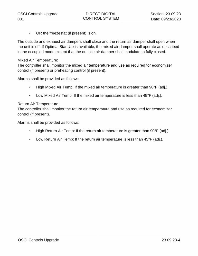
OSCI Controls Upgrade DIRECT DIGITAL CONTROL SYSTEM
Section: 23 09 23 001
Date: 09/23/2020
OSCI Controls Upgrade 23 09 23-4
• OR the freezestat (if present) is on.
The outside and exhaust air dampers shall close and the return air damper shall open when the unit is off. If Optimal Start Up is available, the mixed air damper shall operate as described in the occupied mode except that the outside air damper shall modulate to fully closed.
Mixed Air Temperature: The controller shall monitor the mixed air temperature and use as required for economizer control (if present) or preheating control (if present).
Alarms shall be provided as follows:
• High Mixed Air Temp: If the mixed air temperature is greater than 90°F (adj.).
• Low Mixed Air Temp: If the mixed air temperature is less than 45°F (adj.).
Return Air Temperature: The controller shall monitor the return air temperature and use as required for economizer control (if present).
Alarms shall be provided as follows:
• High Return Air Temp: If the return air temperature is greater than 90°F (adj.).
• Low Return Air Temp: If the return air temperature is less than 45°F (adj.).
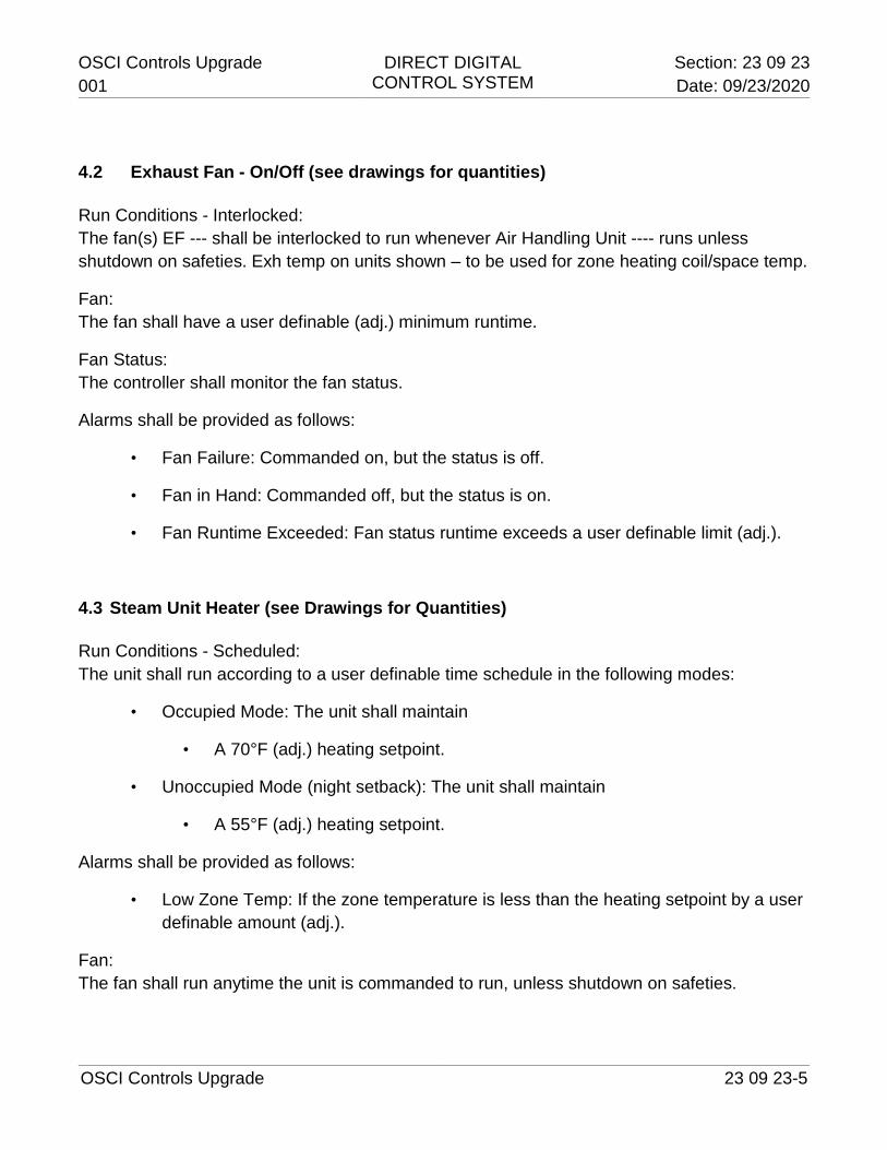
OSCI Controls Upgrade DIRECT DIGITAL CONTROL SYSTEM
Section: 23 09 23 001
Date: 09/23/2020
OSCI Controls Upgrade 23 09 23-5
4.2 Exhaust Fan - On/Off (see drawings for quantities) Run Conditions - Interlocked: The fan(s) EF --- shall be interlocked to run whenever Air Handling Unit ---- runs unless shutdown on safeties. Exh temp on units shown – to be used for zone heating coil/space temp.
Fan: The fan shall have a user definable (adj.) minimum runtime.
Fan Status: The controller shall monitor the fan status.
Alarms shall be provided as follows:
• Fan Failure: Commanded on, but the status is off.
• Fan in Hand: Commanded off, but the status is on.
• Fan Runtime Exceeded: Fan status runtime exceeds a user definable limit (adj.).
4.3 Steam Unit Heater (see Drawings for Quantities) Run Conditions - Scheduled: The unit shall run according to a user definable time schedule in the following modes:
• Occupied Mode: The unit shall maintain
• A 70°F (adj.) heating setpoint.
• Unoccupied Mode (night setback): The unit shall maintain
• A 55°F (adj.) heating setpoint.
Alarms shall be provided as follows:
• Low Zone Temp: If the zone temperature is less than the heating setpoint by a user definable amount (adj.).
Fan: The fan shall run anytime the unit is commanded to run, unless shutdown on safeties.
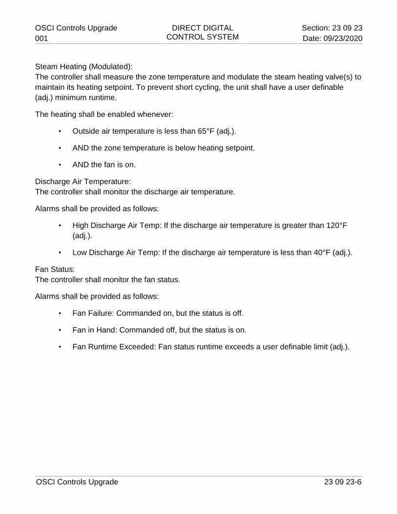
OSCI Controls Upgrade DIRECT DIGITAL CONTROL SYSTEM
Section: 23 09 23 001
Date: 09/23/2020
OSCI Controls Upgrade 23 09 23-6
Steam Heating (Modulated): The controller shall measure the zone temperature and modulate the steam heating valve(s) to maintain its heating setpoint. To prevent short cycling, the unit shall have a user definable (adj.) minimum runtime.
The heating shall be enabled whenever:
• Outside air temperature is less than 65°F (adj.).
• AND the zone temperature is below heating setpoint.
• AND the fan is on.
Discharge Air Temperature: The controller shall monitor the discharge air temperature.
Alarms shall be provided as follows:
• High Discharge Air Temp: If the discharge air temperature is greater than 120°F (adj.).
• Low Discharge Air Temp: If the discharge air temperature is less than 40°F (adj.).
Fan Status: The controller shall monitor the fan status.
Alarms shall be provided as follows:
• Fan Failure: Commanded on, but the status is off.
• Fan in Hand: Commanded off, but the status is on.
• Fan Runtime Exceeded: Fan status runtime exceeds a user definable limit (adj.).
OSCI Controls Upgrade DIRECT DIGITAL CONTROL SYSTEM
Section: 23 09 23 001
Date: 09/23/2020
OSCI Controls Upgrade 23 09 23-7