Organic Chemistry in Single- and Multiphase Continuous ... - unipub
290
DISSERTATION ZUR ERLANGUNG DES DOKTORGRADES DER NATURWISSENSCHAFTLICHEN FAKULTÄT DER KARL-FRANZENS-UNIVERSITÄT GRAZ ZUM THEMA Organic Chemistry in Single- and Multiphase Continuous Flow Regimes VORGELEGT VON BARTHOLOMÄUS PIEBER, MSc am Institut für Chemie Erstbegutachter: Prof. Dr. C. Oliver Kappe Zweitbegutachter: Prof. Dr. Frank Uhlig 2015
-
Upload
khangminh22 -
Category
Documents
-
view
0 -
download
0
Transcript of Organic Chemistry in Single- and Multiphase Continuous ... - unipub

DISSERTATION
ZUR ERLANGUNG DES DOKTORGRADES DER
NATURWISSENSCHAFTLICHEN FAKULTÄT DER
KARL-FRANZENS-UNIVERSITÄT GRAZ
ZUM THEMA
Organic Chemistry in Single- and
Multiphase Continuous Flow Regimes
VORGELEGT VON
BARTHOLOMÄUS PIEBER, MSc
am Institut für Chemie
Erstbegutachter: Prof. Dr. C. Oliver Kappe
Zweitbegutachter: Prof. Dr. Frank Uhlig
2015


Obstacles are those frightful things you see
when you take your eyes off your goal.
-Henry Ford


Acknowledgements
The present thesis was accomplished at the Christian Doppler Laboratory for Flow Chemistry
(CDLMC), Institute of Chemistry, Karl-Franzens-University Graz, Austria between
November 2011 and July 2015 under the supervision of Prof. Dr. C. Oliver Kappe. The work
was supported by a grant from the Christian Doppler Research Association (CDG) and
ThalesNano (Budapest, Hungary).
First, I would like to thank my supervisor Prof. C. Oliver Kappe for his guidance,
encouragement and support during this thesis and for giving me the opportunity to work in an
exciting and growing scientific field. I am extremely thankful for his continuous motivation
and especially his trust in me and my ideas.
Special thanks to all former and present colleagues in the group: I am very happy that I had
the ability to work in such an enthusiastic lab. I would especially like to thank Bernhard and
David for their ongoing scientific support. Without you this thesis would lack a lot of quality
and the last years would have never been as funny as they were!
Many thanks to my colleagues Dr. Sigurd Schober, and Dr. Harald Hofbauer for their
scientific support, their motivating words and the possibility to talk about other topics besides
chemistry while drinking a (few) beer(s) during the last couple of years.
I want to express my gratitude to my better half, Cathrin: You are the most important part of
my life and I am very thankful and thoroughly lucky that I found you. You make me happy
like no one else can on every single day.
Thanks to all of my friends who supported me during the last years! Everything is easier when
you are surrounded by so many amazing people.
Last but not least, I am greatly indebted to my family for their financial and moral support
during my whole life.


List of Publications
1 G. S. Kumar, B. Pieber, K. R. Reddy, C. O. Kappe, “Copper-Catalyzed Formation of C-
O Bonds by Direct α-C-H Bond Activation of Ethers Using Stoichiometric Amounts of
Peroxide in Batch and Continuous-Flow Formats”, Chemistry a European Journal,
2012, 18, 6124.
2 B. Pieber, C. O. Kappe, “Direct Aerobic Oxidation of 2-Benzylpyridines in a Gas-
Liquid Continuous-Flow Regime using Propylene Carbonate as Solvent”, Green
Chemistry, 2013, 15, 320.
3 B. Pieber, S. Teixeira Martinez, D. Cantillo and C. O. Kappe, “In situ Generation of
Diimide from Hydrazine and Oxygen - Transfer Hydrogenation of Olefins in
Continuous Flow”, Angewandte Chemie International Edition, 2013, 52, 10241.
4 B. Pieber, T. Glasnov, C. O. Kappe, ”Flash Carboxylation: Fast Lithiation
Carboxylation Sequence at Room Temperature in Continuous Flow” RSC Advances,
2014, 4, 13430.
5 M. M. Moghaddam, B. Pieber, T. Glasnov, C. O. Kappe, “Immobilized Iron Oxide
Nanoparticles as Stable and Reusable Catalysts for Hydrazine-mediated Nitro
Reductions in Continuous Flow”, ChemSusChem, 2014, 7, 3122.
6 B. Pieber, T. Glasnov, C. O. Kappe, “Continuous Flow Reduction of Artemisinic Acid
Utilizing Multi-Injection Strategies – Closing the Gap Toward a Fully Continuous
Synthesis of Antimalaria Drugs”, Chemistry a European Journal, 2015, 21, 4368.
7 C. E. M. Salvador, B. Pieber, P. M. Neu, A. Torvisco, C. K. Z. Andrade, C. O. Kappe,
“A Sequential Ugi Multicomponent/Cu-Catalyzed Azide-Alkyne Cycloaddition
Approach for the Continuous Flow Generation of Cyclic Peptoids”, Journal of Organic
Chemistry, 2015, 80, 4590.
8 B. Pieber, C. O. Kappe, “Aerobic Oxidations in Continuous Flow”, Topics in
Organometallic Chemistry, 2015, in press.
9 J. L. Monteiro, B. Pieber, A. G. Corrêa, C. O. Kappe, “Continuous Synthesis of
Hydantoins: Intensifying the Bucherer-Bergs Reaction”, 2015, submitted.


Table of Contents
i
Table of Contents
Introduction 1
Part 1: Gas/Liquid Reactions in Continuous Flow 11
A. Aerobic Oxidations in Continuous Flow 13
1. Introduction 15
2. Technological Aspects 16
3. Oxidation of Hydrocarbons 18
4. Oxidation of Alcohols 24
4.1 Heterogeneous Catalysis in Common Solvents 24
4.2 Heterogeneous Catalysis in Supercritical CO2 30
4.3 Homogeneous Catalysis 34
5. Oxidation of Aldehydes 37
6. Oxidative Carbon-Carbon Coupling Reactions 39
7. Miscellaneous 43
8. Photochemical Reactions Involving Molecular Oxygen 45
9. Concluding Remarks 50
10. References 51
B. Direct Aerobic Oxidation of 2-Benzylpyridines in a Gas-Liquid
Continuous-Flow Regime using Propylene Carbonate as Solvent 59
1. Introduction 61
2. Results and Discussion 63
3. Conclusion 67
4. References 67
5. Supporting Information 70

Table of Contents
ii
C. In situ Generation of Diimide from Hydrazine and Oxygen - Transfer
Hydrogenation of Olefins in Continuous Flow 77
1. Introduction 79
2. Results and Discussion 80
3. Conclusion 85
4. References 86
5. Supporting Information 88
D. Continuous Flow Reduction of Artemisinic Acid Utilizing Multi-
Injection Strategies – Closing the Gap Toward a Fully Continuous
Synthesis of Antimalaria Drugs 111
1. Introduction 113
2. Results and Discussion 115
2.1 Continuous Flow Concept 115
2.2 Process Intensification, Scope and Limitations 116
2.3 Efficiency of Hydrazine Oxidation 120
2.4 Reduction of Artemisinic Acid 122
3. Conclusion 127
4. References 128
5. Supporting Information 131
E. Flash Carboxylation: Fast Lithiation Carboxylation Sequence at
Room Temperature in Continuous Flow 139
1. Introduction 141
2. Results and Discussion 142
3. Conclusion 145
4. References 146
5. Supporting Information 148

Table of Contents
iii
F. Continuous Synthesis of Hydantoins: Intensifying the Bucherer-Bergs
Reaction 157
1. Introduction 159
2. Results and Discussion 160
3. Conclusion 165
4. References 165
5. Supporting Information 169
Part 2: Homogeneous and Solid/Liquid Reactions in Continuous Flow 179
G. Copper-Catalyzed Formation of C-O Bonds by Direct α-C-H Bond
Activation of Ethers Using Stoichiometric Amounts of Peroxide in Batch
and Continuous-Flow Formats 181
1. Introduction 183
2. Results and Discussion 184
3. Conclusion 190
4. References 190
5. Supporting Information 193
H. Immobilized Iron Oxide Nanoparticles as Stable and Reusable Catalysts
for Hydrazine-mediated Nitro Reductions in Continuous Flow 209
1. Introduction 211
2. Results and Discussion 214
2.1 Synthesis, Evaluation, and Characterization of Supported Fe3O4 Nanoparticles 214
2.2 Bench Stability of nano-Fe3O4@Al2O3 217
2.3 Scope and Limitations in Batch 218
2.4 Continuous Flow Reactor 219
2.5 Process Intensification in Continuous Flow 220
2.6 Scope and Limitations in Continuous Flow 222
2.7 Catalyst Stability in Continuous Flow 223
3. Conclusion 225
4. Experimental Section 226
5. References 230

Table of Contents
iv
I. A Sequential Ugi Multicomponent/Cu-Catalyzed Azide-Alkyne
Cycloaddition Approach for the Continuous Flow Generation of Cyclic
Peptoids 235
1. Introduction 237
2. Results and Discussion 240
2.1 Peptoid Synthesis 241
2.2 Isocyanide Preparation 244
2.3 Azide Formation 246
2.4 Multistep Synthesis of Linear Peptoids in Continuous Flow 247
2.5 CuAAC in Continuous Flow 249
3. Conclusion 252
4. Experimental Section 253
5. References 261
6. Supporting Information 267
Summary & Concluding Remarks 273

Introduction
1
Introduction
Within the last decades continuous flow chemistry emerged from an exotic curiosity in
research laboratories to a well-recognized technique for performing organic synthesis.[1,2]
In
stark contrast to traditional batch procedures, a flow reaction is carried out by introducing a
continuous stream of reactants, reagents and, if necessary, catalysts into a reactor unit
(Scheme 1). After a well-defined amount of time (residence time) the reaction mixture is
continuously leaving the reactor and either collected or subsequently used in another
continuous transformation or purification step. The residence time is determined by the
volume of the reaction zone and the flow rate of the solution which is typically controlled by
standard HPLC, syringe or peristaltic pumps. If more than one stream is used, an active or
passive mixing element combines the different feeds before entering the reaction zone.
Various reactor types can be utilized for carrying out a continuous flow reaction depending on
the processing conditions and the respective chemical transformation. Homogeneous reactions
and biphasic gas/liquid or liquid/liquid reactions are typically performed in chip or coil
reactors made of glass, simple polymeric materials, ceramics or metals/alloys.[1,2]
Reactions
involving heterogeneous catalysts or reagents are generally carried out in packed bed reactors
where the insoluble material is physically trapped inside a cartridge or immobilized on the
channel wall.[1-3]
A further important feature is the use of a pressure regulating unit which
allows straightforward access to elevated pressure regimes. Thus, reactions can be
conveniently performed far above the boiling point of the respective solvent often resulting in
highly intensified processes.
Scheme 1. Schematic description of a simple continuous flow reactor

Introduction
2
Most continuous flow reactors which are utilized in the synthesis of fine chemicals or
pharmaceuticals are characterized by channel sizes below 1000 µm and are often referred as
microreactors.[1-2]
These small dimensions offer unique advantages compared to conventional
“flask chemistry” and opens new horizons for synthetic chemists.
By utilizing microreactor technology a highly efficient mixing of two or more reagent
streams can be easily achieved as diffusion paths are reduced by the order of magnitudes
compared to conventional batch reactors.[1,2]
Thus, continuous flow processing enables a very
accurate control of the reaction time (= residence time, tRes) for extremely fast reactions where
the overall rate is controlled by mass transfer/mixing phenomena. When the substrate and
reagent feeds are merged, the chemical transformation starts and by addition of a quenching
reagent it is immediately stopped (Scheme 2). Residence time control is therefore achieved by
either varying the length/volume of the reaction zone or the flow rate of one or both feeds.
Scheme 2. Residence time control in continuous flow
Another important characteristic is the exceptional heat transfer in a microstructured flow
reactor resulting from the high surface-to-volume ratio.[1,2]
This is extremely important for
controlling highly exothermic reactions where heat has to dissipate from the reaction mixture.
Moreover, precise heating (or cooling) of a reaction mixture happens almost instantaneously.
In general, flow chemistry often provides a safe alternative to hazardous batch
processes due to the small channel dimensions and reactor volumes.[1,2]
Toxic, unstable and
explosive intermediates can be generated in-situ and subsequently used in continuous multi-
step sequences thus avoiding exposure, handling, storage and transport of such substances.
The high pressure resistance of small coil, chip and packed-bed reactors enables processing of
usually slow transformations at high temperature/pressure conditions (“novel process
windows”) in a safe and controllable manner allowing to increase reaction rates - even for
reaction under explosive regimes - on a routine basis.[4]

Introduction
3
An important point for every chemical process is undoubtedly its scalability. In general,
scaling of processes established in continuous flow mode are considerably easier than for
protocols developed in a batch reactor.[1-2]
In many cases, the flow conditions developed in a
research laboratory can be directly translated to larger flow reactors or require just a minimal
re-optimization (scale-up). Alternatively, microreactors can be simply operated for extended
time periods in order to produce sufficient quantities of the desired product (scale-out).
Another promising strategy, especially for the fine chemical industry, is the parallel operation
of several identical continuous flow reactors for production scale (numbering-up).
Especially biphasic reactions (gas/liquid, liquid/liquid, solid/liquid) often dramatically
benefit from microreactor technology due to a significantly enlarged interfacial and an
improved mass transfer. Since the solubility of most gases in organic chemistry is usually
rather low under standard conditions, high pressure operation is often essential for sufficient
reaction rates. Moreover, the utilization of many gaseous reagents suitable for synthetic
applications such as O2, O3, H2 or even CH2N2 is accompanied by severe safety hazards
which are naturally addressed by continuous flow chemistry.[1,2]
Importantly, the flow pattern of a biphasic gas/liquid or liquid/liquid reaction is a
controllable parameter and has a significant impact on the interfacial area and the overall flow
rate (Scheme 3).[1,2]
Depending on the temperature, back pressure, the the flow rate of the
immiscible phases, their partial solubility and physical properties such as surface tension as
well as viscosity different regimes can be observed. In most applications segmented flow
patterns (sometimes also referred to as slug-, plug-, or Taylor flow) are utilized for biphasic
reactions in continuous flow mode. It is worth noting that once these segments are formed, an
internal fluid vortex is generated which causes internal mixing in each segment. Thus, the
interfacial area is continuously refreshed which also contributes to rate acceleration in
biphasic reactions utilizing this enabling technology.
Scheme 3. Flow patterns in biphasic continuous flow applications

Introduction
4
The first part of this thesis focuses on gas/liquid reactions in continuous flow mode for the
production of fine chemicals. The first chapter embodies a comprehensive overview on recent
developments for aerobic oxidations in continuous flow. This critical review includes a
general part on gas/liquid processing as well as current state of the art examples for the
continuous oxidation of hydrocarbons, alcohols, aldehydes and other small organic molecules
utilizing molecular oxygen. Furthermore, oxidative carbon-carbon couplings and
photochemical reactions involving O2 are discussed. Many of these transformations are
usually carried out at elevated temperatures and pressures in organic solvents posing severe
explosion risks. Importantly, the possibility for flame propagation is minimized in the small
channel dimensions of a continuous flow microreactor making it an ideal tool for intensifying
such oxidation reactions even under traditionally “forbidden” conditions.
In that respect, the continuous aerobic oxidation of 2-benzylpyridines to the respective
ketones in an iron-catalyzed protocol is presented in chapter B (Scheme 4). In this example,
the reaction rate is highly increased by working at elevated temperatures (200°C) in an
annular flow regime resulting in a reduction of the reaction time from hours in batch to
several minutes in flow mode.
Scheme 4. Aerobic oxidation of 2-benzylpyridines in continuous flow formats (Chapter B)
Moreover, a segmented flow pattern for the in situ generation of diimide (N2H2) from
molecular oxygen and hydrazine hydrate and its subsequent utilizations for the highly
selective reduction of olefins is discussed in chapter C (Scheme 5). This approach exemplifies
how a combination of the increased mass transfer for biphasic gas/liquid reactions in
continuous flow and high temperature/pressure processing enables chemical transformations
which cannot be (safely) reproduced in batch environments. The initial oxidation of hydrazine
hydrate is rather slow under conventional conditions and usually requires the utilization of a
catalytic species. On the contrary, continuous flow processing allows a catalyst-free olefin
reduction within just several minutes under intensified conditions. As water and nitrogen gas

Introduction
5
are produced as only byproducts this straightforward and selective transformation is
essentially work-up free.
In addition, a detailed study of the hydrazine oxidation with special emphasis on side-
reactions of the reactive intermediate (N2H2) under continuous flow conditions leading to an
advanced methodology for less reactive olefins is described in chapter D. The effective
residence time could be increased by expanding the continuous system by multiple addition of
hydrazine hydrate to circumvent over-oxidation of diimide and reduce its disproportionation.
This strategy enables a highly selective reduction of artemisinic acid resulting in the direct
precursor of the important antimalarial drug artemisinin.
Scheme 5. Olefin reduction via in situ generation of diimide (Chapter C and D)
In chapter E, the accurate residence time control gained by the exceptional mixing capability
in flow devices is utilized for the development of a continuous lithiation-carboxylation
sequence at room temperature (Scheme 6). Initially, a terminal alkyne or a heterocyclic
starting material is directly lithiated upon mixing with a suitable organolithium compound.
After less than 5 seconds the reaction mixture is quenched with gaseous carbon dioxide as
electrophile. Moreover, the extremely fast carboxylation step (~0.5 s) is precisely controlled
by an additional feed for quenching the reaction mixture with water.
Scheme 6. Lithiation-carboxylation sequence in continuous flow (Chapter E)

Introduction
6
Mixing and mass transfer characteristics are also important attributes for the intensified
Bucherer-Bergs reaction in continuous flow (Chapter F). This multicomponent reaction for
the synthesis of hydantoins from simple ketones or aldehydes using potassium cyanide and
ammonium carbonate represents a combination of biphasic liquid/liquid and gas/liquid
continuous flow processing (Scheme 7). Initially, an organic stream containing the precursor
molecule is mixed with an aqueous reagent stream resulting in segmented flow pattern for an
accurate stoichiometry control. Upon heating in the reaction zone (NH4)2CO3 decomposes to
generate ammonia and carbon dioxide as the final reagents. The main benefit of the
continuous route is the lack of gaseous headspace due to the high pressure protocol. Thus, the
gaseous reagents cannot disappear by volatilization or sublimation as in standard reflux or
autoclave protocols allowing reaction times which are unattainable in by conventional flask
chemistry.
Scheme 7. Continuous Bucherer-Bergs hydantoin synthesis (Chapter F)
The main focus of the second part of this thesis lies on homogeneous and solid/liquid
reactions in continuous flow mode. In the latter case, immobilized or heterogeneous catalysts
are utilized for carrying out synthetic transformations.[1-3]
A main advantage is the fact that
catalyst separation occurs simultaneously to the desired reaction. Consequently, the catalytic
material remains in the flow systems allowing its subsequent reutilization (recycling). It has to
be stressed that this strategy may result in catalyst leaching in certain cases.[1-3,5]
Thus, careful
analysis of the liquid phase by e.g. ICPMS is of crucial importance during the development of
such continuous protocols. Nevertheless, the large interfacial areas and the short path required
for molecular diffusion in the narrow microchannel space provides very efficient liquid/solid
interaction which is not attainable in normal batch systems.
Chapter G describes the totally homogeneous copper-catalyzed formation of carbon-
oxygen bonds by the cross dehydrogenative coupling of ethers and carbonyl compounds in
both, batch and continuous flow formats (Scheme 8). This reaction requires a high excess of

Introduction
7
the respective ether (solvent), stoichiometric amounts of tert-butyl hydroperoxide (TBHP) as
oxidant and relatively high temperatures in order to provide the desired, unsymmetrical acetal
scaffolds. As mixtures of ethers and organic peroxides pose severe explosion hazards,
translation to a microreactor protocol offers the opportunity to safely scale this process to
synthetically useful quantities of acetal products. In addition, low boiling ethers, such as Et2O
are unreactive under reflux conditions as the desired reaction temperature cannot be reached.
This limitation can be elegantly circumvented by using high pressure flow protocols for
heating the reaction mixture far above the boiling point of such solvents in a safe and
controllable manner.
Scheme 8. Copper-catalyzed oxidative cross-dehydrogenative-coupling in flow (Chapter G)
In chapter H, the hydrazine mediated nitro reduction utilizing a supported iron oxide
nanocatalyst is described (Scheme 9). The catalytic active material (nano-Fe3O4@Al2O3) can
be easily prepared by a simple impregnation method on basic Al2O3 using Fe(acac)3 as iron
precursor and hydrazine hydrate in batch. By packing the totally heterogeneous material in a
dedicated cartridge system, reductions of nitroarenes can be perfomed in a virtually work-up
free method in continuous flow mode in the range of minutes (Scheme 9). Importantly, no
iron leaching is observed and stable reactions can be carried out for several hours with high
productivity.
Scheme 9. Reduction of nitroarenes catalyzed by nano-Fe3O4@Al2O3 in flow (Chapter H)

Introduction
8
Finally, the multistep synthesis of linear peptoids is demonstrated in chapter I. These
peptidomimetic compounds can be easily synthesized by an Ugi four component reaction. In
order to avoid exposure to the often toxic and malodorous isocyanides the dehydration of the
corresponding amides can be installed providing a telescoped process. Moreover, an azide
functionality can be installed by a nucleophilic substitution in a telescoped process which
allows the possibility for subsequent modifications of the linear reaction products (Scheme
10). This example demonstrates how continuous flow synthesis enables the multistep
synthesis of rather complex molecules without the need of tedious and often unnecessary
isolation procedures which is of particular interest when hazardous reagents or unstable
intermediates are part of the synthetic route.[6]
The functionalized linear peptoid can be further cyclized in a copper-catalyzed azide
alkyne cycloadditions (CuAAC) by utilizing a copper coil reactor without the need of any
additive.[7]
Such reactors represent a special example of heterogeneous flow devices as the
nature of the coil itself avoids the necessity of any catalytically active species. However,
depending on the nature of the linear precursor and the resulting ring strain, either a dimeric
or a monomeric form of the cyclic product can be obtained within less than half an hour under
intensified continuous flow conditions.
Scheme 10. Continuous multi-step synthesis of functionalized, linear peptoids and their
subsequent cyclization in a copper coil reactor (Chapter I)

Introduction
9
References
[1] For reviews on flow chemistry, see: (a) B. Gutmann, D. Cantillo, C. O. Kappe, Angew.
Chem. Int. Ed. 2015, 54, 6688; (b) K. F. Jensen, B. J. Reizmana, S. G. Newman, Lab
Chip 2014, 14, 3206; (c) C. Wiles, P. Watts, Green Chem. 2014, 16, 55; (d) S. G.
Newman, K. F. Jensen, Green Chem. 2013, 15, 1456; (e) I. R. Baxendale, L. Brocken,
C. J. Mallia, Green Proc. Synth. 2013, 2, 211.
[2] For extensive treatises on microreactor and continuous flow technology, see: (a) Flow
Chemistry, (Eds.: F. Darvas, V. Hessel, G. Dorman), De Gruyter, Berlin, 2014; (b)
Microreactors in Preparative Chemistry, (Ed.: W. Reschetilowski), Wiley-VCH,
Weinheim, 2013; (c) Microreactors in Organic Synthesis and Catalysis, 2n Ed. (Ed.:
T. Wirth), Wiley-VCH, Weinheim, 2013; (d) Handbook of Micro Reactors (Eds.: V.
Hessel, J. C. Schouten, A. Renken, Y. Wang, J.-i. Yoshida), Wiley-VCH, Weinheim,
2009; (e) Chemical Reactions and Processes under Flow Conditions (Ed.: S. V. Luis,
E. Garcia-Verdugo), RSC Green Chemistry, 2010.
[3] R. Munirathinam, J. Huskens, W. Verboom, Adv. Synth. Catal. 2015, 357, 1093.
[4] V. Hessel, D. Kralisch, N. Kockmann, T. Noel, Q. Wang, ChemSusChem 2013, 6, 746.
[5] D. Cantillo, C. O. Kappe, ChemCatChem 2014, 6, 3286.
[6] For reviews on continuous flow multi-step synthesis, see: (a) J. Wegner, S. Ceylan, A.
Kirschning, Adv. Synth. Catal. 2012, 354, 17; (b) D. Webb, T. F. Jamison, Chem. Sci.
2010, 1, 675; (c) D. T. McQuade, P. H. Seeberger, J. Org. Chem. 2013, 78, 6384; (d)
J. C. Pastre, D. L. Browne, S. V. Ley, Chem. Soc. Rev. 2013, 42, 8849.
[7] For a recent review about the utilization of copper flow reactors, see: (a) J. Bao, G. K.
Tranmer, Chem. Commun. 2015, 51, 3037.


Part 1
11
Part 1
Gas/Liquid Reactions in
Continuous Flow


Chapter A
13
A. Aerobic Oxidations in Continuous Flow
Graphical Abstract
Abstract
In recent years, the high demand for sustainable processes resulted in the development of
highly attractive oxidation protocols utilizing molecular oxygen or even air instead of more
uneconomic and often toxic reagents. The application of these sustainable, gaseous oxidants
in conventional batch reactors is often associated with severe safety risks and process
challenges especially on larger scales. Continuous flow technology offers the possibility to
minimize these safety hazards and concurrently allows working in high temperature/pressure
regimes to access highly efficient oxidation protocols. This review article critically discusses
recent literature examples of flow methodologies for selective aerobic oxidations of organic
compounds. Several technologies and reactor designs for biphasic gas/liquid- as well as
supercritical reaction media are presented in detail.


Chapter A
15
1. Introduction
The high demand for more sustainable oxidation processes in the synthesis of commodity and
fine chemicals necessitates the development of safe and efficient methodologies employing
virtually ideal oxidants such as O2 or even air. The economic and environmental advantages
using these cheap and readily available oxidation reagents are apparent. However,
applications are often restricted to substrates capable of undergoing selective autoxidation
reactions. For a more widespread use of this sustainable oxidant a plethora of versatile
catalytic methods for aerobic oxidations of complex organic molecules −such as the oxidation
of alcohols, oxidative cross-coupling reactions and selective C−H bond oxidations− have been
developed in recent years.[1-5]
Oxidations using molecular oxygen or air are often associated with severe safety risks
and process challenges. Such transformations are generally exothermic and the heat of the
reaction can be difficult to dissipate. The consequential non-isothermal conditions potentially
reduce reaction selectivity and product quality. Furthermore, aerobic oxidations suitable for
fine chemical manufacturing are usually carried out at elevated temperatures and pressures in
organic solvents posing severe explosion hazards. To avoid spontaneous ignition of such
reactions mixtures, large scale applications in conventional batch reactors have to be carried
out below the limiting oxygen concentration (LOC).[6]
This is typically achieved by mixing
the gaseous oxidant with an inert gas as, e.g. N2 to dilute the oxygen/solvent vapor. Moreover,
non-optimal temperature and pressure ranges are applied resulting in relatively slow and
inefficient processes.
Continuous flow (micro)reactor technology offers the unique possibility to address the
above mentioned safety hazards, concurrently working at high temperature/pressure regimes
(“novel process windows”) feasible for efficient oxidation protocols.[7-13]
Exothermic
reactions are easily controlled by the excellent mass and heat transfer making this technology
an ideal tool to harness hazardous chemical processes.[14]
Importantly, the small volumes and
channel dimensions minimize the possibility of propagation of an explosion inside the reactor
thereby tremendously broadening the possible operation range.[15, 16]
Especially biphasic
gas/liquid reactions such as aerobic oxidations can benefit from this enabling technology due
to fast mixing characteristics and a dramatically enlarged interfacial area between the liquid
and the gaseous phase.[17]
Moreover, continuous flow devices allow for rapid screening of
process conditions in biphasic gas/liquid reactions compared to pressurized autoclave
systems.

Chapter A
16
A crucial issue for many chemical reactions developed in research laboratories, but especially
hazardous reactions involving O2, is related to a possible large-scale application. Scaling is
generally considerably easier for a continuous process than for a batch process and flow
routes developed and optimized in the laboratory can often be scaled to production quantities
with minimal re-optimization and/or without major changes in the synthetic path [14]
.
Numbering-up of flow devices or scaling-up of the reactor volume increases the throughput,
while the performance of the reactor can be largely conserved by keeping certain
characteristics of the system constant (“smart dimensioning”). Alternatively, simply running a
reactor for extended periods of time to generate the desired quantities of pharmaceutical
intermediates or final products is often an acceptable strategy.
In this review we aim to provide a comprehensive overview on recent developments in
aerobic oxidation reactions in gas/liquid continuous flow mode. In the first chapter, reactor
designs and technologies suitable for such biphasic transformations are introduced.
Thereafter, continuous oxidation protocols of small organic molecules and other reactions
involving O2 as sole oxidant are critically discussed. Finally, the photochemical utilization of
molecular oxygen for e.g. the generation of singlet oxygen (1O2) in organic synthesis will be
outlined briefly for selected examples. For reactions involving ozonolysis and gas-phase
oxidations, the authors refer to the following references.[15, 18-21]
2. Technological Aspects
In general, the majority of gas/liquid reactions in continuous flow such as aerobic oxidations
are carried using a gaseous feed and one or more liquid feeds containing the substrate and, if
necessary a homogeneous catalyst or other additives (Scheme 1, A). The liquid solution is
usually pumped using standard HPLC, syringe or peristaltic pumps, whereas the gaseous
phase can be accurately fed using e.g. a mass flow controller (MFC). This dedicated tool
enables an easy control of the stoichiometry of the gaseous reagent which can be hardly done
in conventional batch processes. Mixing of the streams is carried out in either static or active
mixing units before entering the reaction zone where the chemical transformations occurs. A
further important feature –in particular for biphasic gas/liquid flow chemistry– is the use of
backpressure regulators (BPR) which allow a precise control of the residence time and
straightforward access to elevated pressure regimes. Therefore, a higher solubility of the
gaseous oxidant can be conveniently achieved in a safe manner often resulting in intensified
protocols.

Chapter A
17
An alternative approach to feed gaseous reagents in the liquid reaction mixture is the use of
membrane reactors (Scheme 1, B).[17]
Among those, the so called tube-in-tube reactor
developed by Ley and coworkers has gained significant attention since its first application in
2010.[22]
In principal, this device consists of a gas permeable Teflon AF-2400 membrane
tubing (inner tube) that is fixed within larger impermeable tubing (outer tube). These tubes
are separated by T-pieces allowing for an independent feed of both channels. Only gaseous
reagents can pass the membrane and react with substrates in the liquid phase or simply
saturate the solvent for subsequent use. In that respect, Jensen and coworkers recently
communicated a quantitative model for predicting gas and substrate concentration profiles in
the tube-in-tube reactor unit.[23]
The authors concluded that the low gas loading, insufficient
radial mixing and heating characteristics limits the general applicability of this device. It
should be further noted that on the one hand an accurate control of the stoichiometry is hardly
possible and on the other hand membrane materials are often restricted to relatively low
temperature and pressure ranges to avoid damage. Nevertheless, the reactor unit remains a
convenient gas-loading tool on laboratory-scale for certain applications.
Scheme 1. Typical set ups for aerobic oxidations in continuous flow (A,B), reactor types (C)
and common gas/liquid flow regimes (D).

Chapter A
18
Depending on the application, three different common reactor types (reaction zone) are
predominantly used in aerobic oxidations of small molecules (Scheme 1, C). Homogeneously
catalyzed and catalyst-free oxidations are typically carried out in chip or coil reactors made of
glass, simple polymeric materials, ceramics or metals/alloys. Additionally, the gas loading
unit itself can be simultaneously used as reaction zone by using membrane reactor
applications.[22]
If a heterogeneous species is used to enhance an oxidation process packed-
bed reactors loaded with a heterogeneous (supported) catalyst are typically employed [24]
.
The flow pattern of the biphasic mixture represents a very important and controllable
parameter in gas/liquid flow reactions which has a significant influence on the interfacial area
and the overall flow rate (Scheme 1, D). Various flow regimes can be achieved depending on
the solubility of the gaseous oxidant in the reaction medium, the reaction temperature, the
back pressure and the flow rates of the liquid as well as the gaseous stream. If the gas is fully
dissolved, a homogeneous liquid flow appears which is often the case using membrane reactor
applications. Among the biphasic flow patterns, segmented flow (sometimes also referred to
as slug-, plug-, or Taylor flow) and annular flow are most commonly applied in continuous
organic synthesis. Single phase oxidations can be observed in certain cases when supercritical
solvents (sc) like e.g. scH2O are used, since both, the substrate and the oxidant are totally
dissolved in the reaction medium.[25]
In the latter case, extremely high pressures are usually
required which also necessitates special dosing techniques to deliver the gaseous oxidant.
However, an accurate control of gas/liquid reactions such as aerobic oxidations is by
no means trivial as a large number of parameters have to be taken into account during the
reactor development and design of experiments.
3. Oxidation of Hydrocarbons
Highly efficient methods for the preparation of bulk chemicals by liquid phase oxidation with
O2 have been developed, and several commodity chemicals, such as
cyclohexanol/cyclohexanone (KA oil), cumene hydroperoxide, tert-butyl hydroperoxide/tert-
butyl alcohol, or terephthalic acid are produced on an enormous scale by aerobic oxidation of
petroleum-based compounds. The latter material is an important intermediate in the
production of polyester materials. The industrial synthesis (AMOCO Process) is realized by
an oxidation of p-xylene (1) using O2 in acetic acid catalyzed by cobalt and/or manganese
salts in presence of a bromide source.[26]
In 2002, Poliakoff and coworkers presented an
alternative, sustainable methodology for the synthesis of terephthalic acid (2) replacing the
organic solvent by supercritical water in a continuous process (Scheme 2).[27]
A standard

Chapter A
19
reactor design using compressed air was not feasible since the required amount of oxygen for
these experiments was extremely small. Therefore, an aqueous solution of H2O2 was heated at
400 °C to in situ generate O2 in the first coil reactor. The oxygen/water mixture was
subsequently mixed with a solution of MnBr2 and 1 to initiate the supercritical oxidation
process in a Hastelloy C276 coil at 400 °C and 280 bar. Afterwards, a NaOH solution was fed
to prevent the product mixture from precipitation and the solution was subsequently cooled in
an additional coil reactor before passing a backpressure regulator.
Scheme 2. Continuous synthesis of terephthalic acid (2) via aerobic oxidation of p-xylene (1)
in scH2O.
Importantly, due to the extreme reaction conditions, a residence time of only 9 s was
sufficient to generate 2 in good yields (>79 %) and high selectivity (>92 %). Problematic
impurities such as 4-carboxybenzaldehyde were not observed under optimized conditions,
thus offering a potential alternative to common industrial processes. The system could further
be applied to other methylaromatic compounds like o- and m-xylene, mesitylene, toluene,
ethylbenzene and even heteroaromatic picolines.[28, 29]
Despite significant differences in their
reactivity, mixed xylenes can be simultaneously oxidized in reasonable yields and good
selectivity by carefully tuning the experimental conditions.[30]
A main drawback in both, the
scH2O and the conventional acetic acid process is the hydrolysis of the homogeneous
manganese catalyst resulting in insoluble metal oxides.[31]
This not only results in a reduced
activity and recyclability of the active species, but can also lead to reactor clogging in the
continuous route. Hence, Poliakoff and coworkers found out that manganese recovery can be
significantly improved by the addition of Brønsted acids and by increasing the Br:Mn ratio for
the oxidation of o-xylene in scH2O.[31]
Hydrobromic acid was shown to be the most efficient
additive since it provides the required acidity and simultaneously acts as a bromide source.
Detailed mechanistic studies on the continuous oxidation of o- and p-xylene led to the
discovery of another catalytic system using CuBr2 in a selective oxidation process utilizing a

Chapter A
20
similar flow setup.[32, 33]
A synergistic effect between copper and other metals, such as cobalt
was found to enhance this reaction as exemplified by utilizing a four component catalyst
system (Cu/Co/NH4/Br). In this case sub-critical water gave significantly better results than
scH2O which was rationalized by a temperature dependent equilibrium shift in the ammonium
bromide decomposition.[33]
In contrast to the synthesis of carboxylic acids discussed above, Kappe and coworkers
realized a partial aerobic oxidation of ethylbenzene (3) yielding acetophenone (4) in a
gas/liquid coil reactor (Scheme 3, A).[34]
Complete conversion of 3 was obtained within 6 min
at 120 °C in a PFA coil using catalytic amounts of CoBr2 and Mn(OAc)2 and compressed air
as oxygen source. The desired ketone (4) was formed in high selectivity (80 %) and isolated
in 66 % yield. Due to the tight control of reaction parameters, over-oxidation to benzoic acid
was minimized to a relatively small amount (~10 %). This was further demonstrated by
processing the same reaction mixture at higher temperatures (150 °C) in combination with a
longer residence time (16 min) yielding benzoic acid (71 %) as a main product.
A similar set up was used for the oxidation of 2-benzylpyridines to the respective
ketones in an iron-catalyzed protocol.[35]
In this case, standard polar, aprotic solvents like
NMP or DMSO as reaction media were prone to decomposition under the harsh reaction
conditions (200 °C). To overcome these issues, the authors used propylene carbonate, a
sustainable, high boiling solvent with excellent oxidation stability. Good to excellent isolated
yields for potential drug precursor molecules were obtained at 200 °C within 13 min in a
stainless steel coil significantly enhancing the original batch protocol.[36]
Scheme 3. Aerobic oxidation of ethylbenzene (A) and picolines (B) in continuous flow.

Chapter A
21
A silicon nitride coated halo-etched chip reactor was used by Jensen and coworkers for the
metal-free oxidation of picolines (Scheme 3, B).[37]
The reaction is suggested to proceed via
deprotonation of the methyl group in presence of a strong base such as potassium tert-amylate
(t-AmOK) followed by an anionic oxidation step. Notably, different solvent mixtures were
necessary for each picoline derivative in order to obtain high conversions. Moreover, the
same group recently described the application of a surface-passivated silicon microchip in the
solvent-free autoxidation of β-pinene and (+)-valencene gaining insights into reaction kinetics
by visual determination of O2 consumption during the reaction.[38]
KA oil, an unrefined mixture of cyclohexanone and cyclohexanol, is an important
precursor for the production of -caprolactam and adipic acid which are further converted to
nylon polymers. Industrial production of KA oil is mainly carried out via the aerobic
oxidation of cyclohexane in bubble column reactors within 15-60 min. Typical conversions in
these processes are below 6 % for obtaining a sufficient selectivity.[39]
The group of de
Bellefon reported on a segmented flow pattern in a chip-based microreactor by mixing
cyclohexanone and O2 to study this transformation on laboratory scale.[40]
At 200 °C and 25
bar, 4.3 % conversion were obtained maintaining a high selectivity (88 %). Under almost
identical conditions a significantly lower conversion (1.6 %) was observed when oxygen was
replaced by compressed air. However, the higher throughput compared to industrial routes
applying bubble column reactors or continuous stirred tank reactors (CSTR) was explained by
the intensified conditions and the excellent residence time control.
An intensification study for this industrially relevant oxidation in capillary reactors
with inner diameters between 0.5 and 2.15 mm further showed that elevated temperatures
(260 °C) enable a significant reduction of the reactor volume and thus resulting in a reduction
of the power of a potential explosion.[41]
The study was conducted by applying a neat
cyclohexane stream and air in a segmented flow pattern (Fig. 1). However, it has to be
stressed that the improvement of the gas/liquid mass transfer in the microreactor was shown
to be very low compared to standard bubble column reactors.
Figure 1. Gas/liquid segmented flow pattern for the oxidation of cyclohexane with air.
Reproduced with permissions from [41]

Chapter A
22
A more versatile protocol employing homogeneous palladium catalysis was utilized to realize
a continuous anti-Markovnikov Wacker oxidation of functionalized styrenes (Scheme 4,
A).[42]
Initially, an aqueous solution of bis(acetonitrile)dichloropalladium(II) and CuCl2 was
mixed with an organic stream containing a styrene derivative. To avoid solvent freezing of t-
BuOH −which is necessary to obtain the desired selectivity− toluene was added as a co-
solvent. The liquid mixture was subsequently loaded with oxygen as gaseous oxidant in a
tube-in-tube membrane reactor. Afterwards, the final reaction mixture was fed in a stainless
steel coil heated at 60 °C to carry out the desired transformation. It could be shown that an
accurate control of the oxygen pressure is of crucial importance to obtain on the one hand
complete conversion and on the other hand to avoid over-oxidation which would generate
undesired carboxylic acids. Importantly, a modified system using a second gas addition
allowed for higher concentrations and thus an improved throughput, thus accessing a multi-
gram scale protocol.
Scheme 4. (A) Anti-Markovnikov Wacker oxidation of styrenes using a membrane reactor.
(B) Biocatalytic catechol synthesis in a tube-in-tube reactor.
The tube-in tube reactor was also used in the biocatalytic production of 3-phenylcatechol (6)
from 2-hydroxybiphenyl (5) catalyzed by 2-hydroxybiphenyl 3-monooxygenase (HbpA)

Chapter A
23
(Scheme 4, B).[43, 44]
Formate dehydrogenase (FDH) was added for cofactor recycling which
converts sodium formate to carbon dioxide. However, high substrate loadings were achieved
by using an organic liquid feed containing the substrate and an aqueous stream consisting of
both enzymes, the co-factor and sodium formate. Under optimized conditions a productivity
of ~18 g L-1
h-1
of the desired catechol was achieved which is 38 times higher than in
conventional batch reactions.[43]
Chemists from Bristol-Myers Squibb applied continuous flow technology to develop a
scalable, high yielding route for the hydroxylation of buspirone (7) by an enolization/
oxidation sequence (Scheme 5).[45]
In the first step, the substrate feed was mixed with the base
by slowly reducing the temperature in two sequential static mixing units (SMU) to avoid
precipitation of the inorganic base. After complete enolization in a coil-based heat exchanger,
the reaction mixture entered a trickle bed reactor (TBR) packed with Pro-Pak® distillation
packing material. The optimized oxidation process was carried out at a reactor temperature of
-36 °C at atmospheric pressure using a counter-current O2 stream and a residence time of 3-4
min. Afterwards, the reaction was quenched with 2.5 M HCl in a continuous stirred tank
reactor. Upscaling by a larger reactor volume was not feasible due to a lower cooling
efficiency (heat transfer) causing the researchers to use a numbering-up approach. Therefore,
the reaction mixture was spilt into four different streams after enolization and fed into a 4-
channel oxidation reactor (Quad reactor), to finally result in the potential anxiolytic agent 6-
hydroxybuspirone (8, Scheme 5). The whole sequence was operated for 72 h using process
analytical techniques for in situ control of its performance. Notably, a constant purity profile
was monitored (90 %) over time at a high production rate (15 kg d-1
).
Scheme 5. Continuous enolization, oxidation sequence of Buspirone (7). A numbering-up
technique is used for the oxidation step (Quad reactor). Adapted with permission from [45]

Chapter A
24
The last examples clearly demonstrate that aerobic oxidation reactions of hydrocarbons in a
continuous manner are not only limited to bulk chemical synthesis. However, applications in
fine chemical manufacturing are extremely rare since selective C-H oxidations of more
complex organic molecules are by no means trivial due to the lack of selective autoxidation
processes. In contrast, oxidations of functional groups, such as alcohols or catalytic reactions
involving an aerobic oxidation of the catalyst potentially allow for a significantly broader
scope.
4. Oxidation of Alcohols
The oxidation of primary and secondary alcohols to the corresponding carbonyl compounds is
among the most fundamental transformations in organic synthesis. Common strategies
involve stoichiometric amounts of special oxidants such as NMO in the presence of TPAP,
bleach in combination with TEMPO, permanganates, activated DMSO, toxic chromium(VI)
complexes (Collins reagent, PDC, PCC) or hypervalent iodine reagents such as Dess-Martin
periodinane and IBX. These relatively expensive reagents generate considerable amounts of
often toxic waste and suffer from poor atom economies. In stark contrast, oxidations using air
or molecular oxygen theoretically produce water as the only by-product. Therefore,
considerable effort has been invested in the development of catalytic protocols to explore the
applicability of these environmentally benign alternatives.[46-49]
4.1 Heterogeneous Catalysis in Common Solvents
It is not surprising that aerobic alcohol oxidations, especially examples involving
heterogeneous catalysis, are often studied in continuous flow reactors since the many
advantages of triphasic gas/liquid/solid reactions are quite evident. Early examples applying
continuous packed bed reactors were published already in the late 1980s and early 1990s,
marking the beginning of continuous aerobic oxidation studies in research laboratories.[50-52]
.
Various heterogeneous catalysts, especially supported noble metals, are well known to
facilitate the aerobic oxidation of primary and secondary alcohols.[46, 48]
Among those,
ruthenium is probably the most promising and extensively studied material. The pioneering
work by Plucinski and coworkers showed the applicability of supported ruthenium catalysts in
a multichannel compact reactor for the selective oxidation of benzyl alcohol (9) with
molecular oxygen (Scheme 6).[53-56]
The reactor elements were fabricated by etching of thin
stainless steel plates followed by their assembly applying a diffusion bonding technique. The

Chapter A
25
liquid and gaseous feeds are combined in a static mixing unit and the resulting stream is
guided into a packed-bed channel. Since the reactor contains five of those units, the length of
the catalyst bed can be conveniently varied by connecting two or more channels. This
approach also allows for multiple addition of e.g. O2 by installing another gas feed between
two consecutive packed bed units.
Scheme 6. Aerobic oxidation of benzyl alcohol (9) using a multichannel compact reactor.
Adapted with permission from [53]
In addition, temperature control can be ensured using glycerol as heat transfer fluid which is
circulated towards heat exchange channels. For testing the multichannel reactor, the aerobic
oxidation of benzyl alcohol (9) to benzaldehyde (10) in toluene catalyzed by Ru/Al2O3 was
chosen as model reaction. Careful optimization of all reaction parameters resulted in 25 %
and 39 % conversion at 115 °C by using one or two channels, respectively. In addition,
splitting of the oxygen stream by installing a second gas feed after the first packed bed
channel slightly increased the consumption of 9 resulting in 46 % of the corresponding
aldehyde 10. Noteworthy, the catalyst activity decreased very slowly during a stability study
which is most likely a result of poisoning by over-oxidized benzoic acid. Subsequently, the
same reactor design was used to test a ruthenium(III) hydrated oxide catalyst supported on
TiO2 nanotubes for its catalytic activity in the aerobic oxidation of aromatic primary alcohols
[54]. The application of this more active ruthenium species improved the single pass
conversions dramatically (75 %) maintaining an excellent selectivity for the corresponding
aldehyde at similar conditions to the Ru/Al2O3 system discussed above.
The versatility of the easily accessible Ru/Al2O3 catalyst was further explored on a
broader scope by the group of Hii in collaboration with Pfizer using a commercially available
reactor system (Scheme 7, A).[57]
The oxygen flow was controlled by a pressure valve and the
gas/liquid ratio was monitored by a bubble detector unit prior to the packed bed reactor.

Chapter A
26
Relatively low single-pass conversions for various alcohols at 115 °C and 5 bar caused the
authors to recirculate the reaction mixture for 45 min to 7 h depending on the reactivity of the
respective primary or secondary alcohol. High conversions and selectivities were achieved for
a range of allylic and benzylic primary alcohols including pyridyl and thienyl systems. Even
the more challenging aliphatic secondary and primary alcohols could be selectively oxidized
in moderate to good conversions under those conditions. It could be shown that catalyst
deactivation over time can be circumvented by installing an additional cartridge filled with
MgSO4 as desiccant to remove accumulated water. This scavenging technique resulted in
improved conversions of 2-hexanol (91 % instead of 75 %) within a 7 h recirculation
experiment. ICP analysis revealed no leaching of the catalytically active material allowing for
an almost work-up free procedure. Given the fact that the reaction mixture exclusively
consists of the desired product, the researchers designed a telescoped process by combining
the continuous aerobic oxidation with a subsequent Wittig olefination in batch.
Scheme 7. (A) Ru-catalyzed aerobic oxidation of alcohols using a recirculation technique.
(B) Continuous tow-step amide synthesis towards alcohol oxidation and subsequent
amidation.
More recently, an almost identical experimental set up was utilized to demonstrate the
potential of immobilized iron oxide nanoparticles as catalyst for the aerobic oxidation of
benzyl alcohol (9).[58]
The catalytic material was generated and immobilized by heating FeCl2
together with dispersed aluminum doped mesoporous silica (Al-SBA15) in ethanol at 150 °C

Chapter A
27
for several minutes. The supported catalyst showed promising activities in the presence of
TEMPO as a co-catalyst resulting in single pass conversions of 42 % using a n-heptane-
dioxane mixture as liquid phase. Again recirculation over 1 h was necessary to obtain a
selective, almost quantitative oxidation without detectable amounts of iron leaching.
These semi-continuous recirculation protocols are utilized to simulate an extension of
the small packed bed reactors usually applied on laboratory scale. It has to be stressed that
after each single-pass a separation of the oxidation agent occurs and fresh oxygen is added for
the next cycle. Overall, an enormous excess of the gaseous reagent is necessary and a
continuous monitoring of the conversion over a long time period is required. These
circumstances may limit the practical application in the context of an industrial protocol but
undoubtedly show the potential of such gas/liquid/solid oxidation procedures in continuous
flow.
In contrast to these relatively inconvenient recirculation procedures, Jensen and
coworkers could show that high conversions (95 %) for aerobic benzyl alcohol oxidations can
be achieved in a residence time as low as 19 s at 80 °C using the Ru/Al2O3 catalyst.[59]
A high
excess of oxygen (200 µL min-1
) was mixed with the aldehyde precursor in acetonitrile (0.1
M, 5 µL min-1
) and the combined mixture entered a silicon-Pyrex microreactor filled with the
supported catalyst. Notably, a stable conversion was observed over a period of 24 h. The
oxidation procedure was further utilized for a continuous two-step synthesis of amides from
various benzylic alcohols and secondary amines (Scheme 7, B). Therefore, a membrane
separator was installed after the heterogeneously catalyzed oxidation, in order remove
unreacted O2 enabling a better residence time control for the subsequent oxidative amidation
using urea hydrogen peroxide (UHP), based on a previous protocol from the same group.[60]
More recently, Ru(OH)x/Al2O3 was introduced as an efficient alternative to the
classical Ru/Al2O3 catalyst for continuous aerobic oxidations circumventing the necessity for
tedious recirculation procedures or high excess of O2.[61]
Careful analysis of the standard
benzyl alcohol model oxidation provided insights into the deactivation caused by over-
oxidized benzoic acid. Initially, a significant drop in the catalytic activity was observed
followed by an almost stable conversion. The resulting catalyst activity profile was the basis
for the development of high steady state single-pass conversions (up to 99 %) using the
partially deactivated catalyst. The final protocol is characterized by an O2/substrate molar
ratio of 2:1, a single pass residence time of 1 h at 80 °C and a back pressure of 11 bar.
Noteworthy, the authors used diluted O2 (8 % in N2) to work below the LOC of toluene in all

Chapter A
28
experiments, thus showcasing the superior activity of supported Ru(OH)x compared to
metallic ruthenium.
Despite these common heterogeneous catalysts for aerobic oxidation, also TPAP was
reported to show activity in the transformation of benzyl alcohol to the corresponding
aldehyde.[62]
Other common noble metal catalysts such as metallic silver, palladium or
platinum were also mentioned in combination with various supports for the oxidation of
alcohols in continuous flow mode.[63-68]
Gold catalyzed oxidation procedures are currently gaining a considerable amount of
interest in the continuous flow community.[69-78]
Among those, an extremely efficient protocol
was communicated by Kobayashi and coworkers (Scheme 8, A).[69]
Their reactor unit was
fabricated by immobilization of microencapsulated gold on a polysiloxane-coated capillary
via cross-linking. Initially, an organic substrate feed was mixed with an aqueous solution
containing potassium carbonate and the combined liquid stream was merged with O2
accurately added by a mass flow controller. The multiphasic mixture passed the
functionalized heated capillary (50 – 70 °C). Notably, no back pressure is required to convert
various secondary alcohols to the corresponding ketones in almost perfect isolated yields at
temperatures below the boiling point of the solvent mixture. It could be shown that the
catalytic activity is completely stable over 4 d and no catalyst leaching could be detected.
Unfortunately, low yields were obtained for benzylic and allylic primary alcohols using the
Au functionalized capillary. However, this problem could be solved by using a bimetallic
Au/Pd immobilized reactor column instead, resulting in almost quantitative amounts for these
less reactive starting materials.
Another strategy was communicated by Kirschning and coworkers in 2014 using an
unconventional heating methodology (Scheme 8, B).[78]
Catalytically active gold(0)
nanocrystals were immobilized on nanostructured particles with a superparamagnetic iron
oxide core and a silica shell (MAGSILICA®). The resulting material was filled into a PEEK
reactor in order to perform the oxidation of primary and secondary alcohols under continuous
flow conditions. By applying an external oscillating electromagnetic field the particles can be
heated inductively. Therefore, the material was not only serving as catalyst but also as heating
tool. The starting materials were dissolved in benzene and the organic solution was mixed
with oxygen using a tube-in-tube membrane reactor. Inductive heating at 150 °C was reported
to be necessary to obtain single pass conversions with residence times of approximately 30
min for simple primary and secondary alcohols. Replacement of benzene by less toxic
solvents was not feasible since solvent oxidation or comparably low conversions were

Chapter A
29
observed. Nevertheless, the authors could replace O2 by compressed air due to the high
activity of the nano-catalyst.
Scheme 8. Gold catalyzed aerobic oxidation of alcohols using (A) microencapsulated Au
immobilized on a capillary or (B) gold-doped superparamagnetic nanoparticles.
Inspired by HNO3 based oxidations, Hermans and coworkers recently developed a metal-free
batch oxidation protocol using catalytic amounts of HNO3 as oxygen shuttle in combination
with Amberlyst-15. This combination led to an NOx propagated chain oxidation using O2 as
terminal oxidant.[79]
Subsequently, the group developed an intensified process using
continuous flow technology (Scheme 9).[80]
The ion exchange resin was placed into a packed
bed reactor as heterogeneous catalyst. Oxygen was mixed with a liquid feed containing the
alcohol and 10 mol% HNO3. At a reaction temperature of 100 °C 4-25 s were sufficient to
synthesize several aldehydes and ketones in excellent yields and selectivity. On-line
monitoring of gas phase N2O and of the oxidation efficiency was realized by using a
gas/liquid separator in combination with different infrared spectroscopic techniques. In
addition, a milder protocol (55 °C) using TEMPO on silica instead of Amberlyst 15 was
developed.[81]
Scheme 9. Metal free aerobic oxidation of alcohols using a packed bed reactor.

Chapter A
30
4.2 Heterogeneous Catalysis in Supercritical CO2
Supercritical CO2 (scCO2) is an extremely attractive medium for reactions involving
molecular oxygen due to its inert environment which minimizes safety concerns compared to
common organic solvents.[82-84]
Although the advantages connected with this green solvent
are quite obvious, the necessity of high pressure equipment such as autoclaves has limited its
application in organic synthesis. Continuous flow processing offers a comparably convenient
access to such process windows especially in academic research laboratories. As already
discussed in the oxidation of xylenes in scH2O, the reactor design usually differs from
common gas/liquid phase flow setups. The relatively harsh temperature and pressure
conditions often necessitate special materials compared to liquid phase oxidations for safety
reasons. In case of scCO2, the substrate is usually fed into the flow system in a separate
stream and mixed with the supercritical solvent in the reactor system.
At the turn of the millennium, Baiker and colleagues started an intensive research
period on heterogeneous noble metal-catalyzed aerobic oxidations using this nonexplosive
and nonflammable “solvent” under continuous flow conditions (Scheme 10).[85-97]
In general,
their setup consisted of a liquid CO2 feed controlled by a compressor unit which was in a first
step mixed with O2. Control of the gaseous oxidant supply was carried out using a 6-way-
valve, dosing 50 µL pulses at high pressure and constant frequency. Afterwards, the CO2/O2
stream was combined with a liquid stream of the substrate (neat or with butanone as co-
solvent) and the mixture was heated in a fixed bed reactor filled with a precious metal catalyst
(e.g., 4 % Pd – 1 % Pt – 5 % Bi/C) at a back pressure of 95 – 120 bar. Several secondary
alcohols could be oxidized to the corresponding ketones in good yields and selectivities
within less than 30 s. The oxidation of primary alcohols required an internal stabilization by
an aromatic system or unsaturated carbon−carbon bonds in order to give satisfactory results.
Furthermore, accurate control of the oxygen concentration was crucial to avoid over-oxidation
of the catalyst which could cause a dramatic reduction in activity. Under optimized
conditions, neither catalyst deactivation, nor metal leaching was observed.
A detailed investigation of all reaction parameters using 1- and 2-octanol as model
substrates in the presence of Pd/Al2O3 using the same reactor showed that the oxidation of
unstabilized primary alcohols is generally troublesome whilst ketone synthesis from the
corresponding secondary alcohols is straightforward and conversions up to 46 % can be
obtained at 140°C.[86]
Good selectivity values for 1-octanol could be achieved at low
conversion rates avoiding a subsequent hydration of the aldehyde which would result in a

Chapter A
31
geminal diol which itself is prone to oxidative dehydration resulting in the corresponding
carboxylic acid.
Scheme 10. Aerobic oxidation of alcohols in scCO2.
More recently, the group of Poliakoff reported an improved protocol using a supported
platinum and bismuth catalyst.[98]
Initial problems of catalyst over-oxidation due to
inhomogeneous O2 concentrations and formation of “hot-spots” in the exothermic reaction
were solved by dosing smaller volumes of O2 via the 6-port-valve and improving the CO2/O2
mixing prior to addition of the substrate. This strategy resulted in 75 % conversion of 2-
octanol without evidence for catalyst deactivation over 5 h at 150 °C. A higher mass balance
could be obtained using a catalyst-filled T-piece instead of a standard packed bed reactor unit.
Utilizing the final experimental design, several simple secondary alcohols were converted to
the corresponding ketones in reasonable yields. Furthermore, the challenging oxidation of 1-
octanol leading to the corresponding aldehyde in >70 % yield could be realized by carefully
optimizing temperature and equivalents of O2.[98]
Notably, supported Palladium was shown to be far more active than Pt or Ru in the
selective oxidation of benzyl alcohol (9).[87]
In order to obtain operando structural analysis by
X-ray absorption spectroscopy (XAS) the standard reactor design of the Baiker group
(Scheme 10) was adapted for analytical applications (Fig. 2, A).[88, 89, 96]
Miniaturization of the
fixed bed reactor and installation of two X-ray transparent beryllium windows on both sites of
the catalyst compartment facilitated in situ measurements of the solid catalyst during aerobic
oxidation of 9 in scCO2. The continuous experiments indicated that palladium was mainly
present in the metallic state during the overall process. As anticipated, the catalytic activity
increased with the O2 concentration since removal of adsorbed hydrogen (Had) originating
from alcohol dehydration is accelerated (Fig. 2, B). The reaction rate reaches a maximum and

Chapter A
32
subsequently drops at higher oxygen concentrations. This was rationalized by the inhibiting
effect of surface PdOx species resulting from catalyst over-oxidation as analyzed by XAS.
Figure 2. (A) Packed bed reactor for in situ XAS measurements of aerobic oxidation in
scCO2. (B) Simplified model for structure-activity relationship in Pd catalyzed oxidation of
benzyl alcohol (9).
A similar analytical reactor was further used for in situ EXAFS studies of aerobic benzyl
alcohol and cinnamyl alcohol oxidations in O2-saturated organic solvents, demonstrating that
metallic palladium exhibits a higher activity for alcohol oxidation than the palladium oxide
species.[99-101]
In 2005, Leitner and colleagues realized that the palladium cluster
[Pd561phen60(OAc)180] displays an active catalyst in the aerobic oxidation of alcohols in scCO2
when embedded in a PEG-1000 matrix.[102]
The active material was identified as highly
dispersed Pd nanoparticles stabilized by the organic matrix. A similar catalyst could be also
obtained by simply heating Pd(acac)2 in PEG-1000 in the presence of a commercial
surfactant. Benzyl alcohol (9) was chosen as model substrate for the development of a
continuous process in a CSTR. It was shown that the aldehyde precursor and O2 can be
transported through the catalytic PEG phase without extrusion of the nanoparticles or the
matrix material using scCO2. With both Pd nanoparticle precursors ~15 % single pass
conversion with excellent selectivity was obtained at 80 °C and 155 bar backpressure after
isolating the product mixture in a cold trap. Notably, a steady increase in activity was
observed during continuous operation over 40 h. Transmission electron microscopy (TEM)
studies of the catalytic material formed from the Pd cluster indicated that the dispersion of the
nanoparticles is significantly improved after a batch oxidation process explaining the
increasing activity in the continuous long run experiment (Fig. 3). However, reduction of the
system pressure to 132 bar resulted in a 2-fold higher activity due to a shift of the partition

Chapter A
33
coefficient of the substrate in the biphasic medium. This rationalization could be supported by
the fact that the solubility of 9 became insufficient in scCO2 when the back pressure is further
decreased to 110 bar.[102]
Figure 3. TEM images of the catalytically active material formed from [Pd531phen60(OAc)180]
and PEG-1000 before (a) and after (b) the aerobic oxidation. Reproduced with permission
from [102]
Based on these results the authors developed a well-defined Pd nanoparticle catalyst on a
solid, inorganic matrix using PEG-modified silica surfaces for the application in a continuous
packed bed reactor.[103]
Initially, a covalently anchored PEG-phase (12) was synthesized by
reacting 3-chloropropyltriethoxysilane (11) with polyethylene glycol 750 monomethyl ether
in the presence of NaH (Scheme 11, A). Copolymerization with tetraethoxysilane (TEOS)
afforded the PEG-modified silica support 13 which was subsequently impregnated with a
solution of [Pd561phen60(OAc)180] yielding the final catalytic material 14. The supported
nanoparticles were shown to efficiently catalyze the aerobic oxidation of several secondary
alcohols as well as benzylic and allylic primary alcohols to the corresponding ketones and
aldehydes using scCO2 in batch mode. A stainless steel packed bed reactor was used for the
translation to a continuous process and good single pass conversions (50-60 % with a
selectivity of >98 %) were obtained for the benzyl alcohol oxidation within an estimated
residence time of 1.2 h at 80 °C and 150 bar. Importantly, a stable catalytic activity was
observed during a 30 h experiment with a total turnover number of 1750. TEM analysis
confirmed that the particles were effectively prevented from agglomeration by the covalently
bound PEG chains.
In an alternative approach, 2,2’-dipyridylamine (16) was installed as a linker unit
instead of PEG to immobilize and simultaneously stabilize the Pd nanoparticles on
mesoporous silica for a catalytic aerobic oxidation in scCO2.[104]
Similar to the immobilization
technique discussed above, coupling of a trialkoxysilyl derivative (15) with 16 followed by

Chapter A
34
addition of TEOS led to a functionalized mesoporous material (18) (Scheme 11, B).
Treatment with palladium acetate and subsequent reduction with benzyl alcohol under reflux
yields the catalytically active supported nanoparticles 19. It has to be noted that significant
amounts of unreduced Pd(II) were still present on the surface. An alternative reduction using
molecular hydrogen on the one hand provided a higher degree of Pd(II) reduction but on the
other hand resulted in a significantly decreased catalytic activity for the aerobic oxidation of
benzyl alcohol in scCO2. This could be explained by generation of small primary crystallites
in case of the benzyl alcohol reduction leading to a large number of high indexed planes in
small volume units. However, catalyst 19 showed good single pass conversions (41 % at a
selectivity >98 %) at temperatures as low as 60 °C and remained constant over >28 h.
Although at higher temperatures an increased activity was achieved, a significantly lower
selectivity (90 %) and leaching of catalytic material did not allow for further intensification.
Scheme 11. Catalyst preparation using a PEG (A) and a 2,2’dipyridylamine (B) unit for
immobilization of Pd nanoparticles.
4.3 Homogeneous Catalysis
Homogeneous catalysts are often superior compared to heterogeneous materials regarding
their activity and selectivity. Furthermore, the possibility for fine-tuning of the active material
by e.g., ligands often accesses a broader scope compared to metallic species or salts used in
heterogeneous catalysis. Over the past years a plethora of effective aerobic oxidation

Chapter A
35
protocols utilizing homogeneous palladium or copper catalysis have been developed.[49, 105, 106]
These contributions are almost exclusively small scale laboratory reactions predominantly
carried out in a flask equipped with an O2-filled balloon. Apparently, the oxygen
concentration in the liquid solution is relatively low and mixing of the different phases is
rather poor. This is especially problematic for homogeneous palladium catalysis as the
catalyst stability is highly sensitive to the dissolved oxygen concentration. Even temporary
periods of poor gas/liquid mixing can lead to catalyst decomposition via agglomeration of
homogeneous Pd(0) complexes forming metallic palladium.[107]
In order to tackle these mechanistic challenges and simultaneously providing a
scalable aerobic oxidation protocol, a continuous approach was developed by the Stahl group
together with chemists from Eli Lilly (Scheme 12).[108]
Translation of the batch protocol using
catalytic amounts of Pd(OAc)2 and pyridine was realized towards a three feed methodology.
To avoid the above mentioned reduction or decomposition of the catalyst, a solution of
Pd(OAc)2 was initially mixed with oxygen. Subsequently, the substrate as well as pyridine
enter the flow system via a second mixing unit before the central coil reactor. A residence
time of 2.5 h was necessary to oxidize several secondary and benzylic primary alcohols to the
corresponding carbonyl compounds on a multi-gram scale using diluted oxygen (8 % in N2).
Furthermore, the synthesis of benzaldehyde (6) was carried out on a kilogram scale using a 7
L stainless steel coil as residence time unit highlighting the reliability of the flow reactor for
large scale applications.
Scheme 12. Aerobic oxidation of alcohols using homogeneous Pd catalysis in flow:
However, all alcohol oxidations discussed so far were limited to secondary alcohols or
stabilized primary alcohols due to over-oxidation of unstabilized derivatives to the
corresponding carboxylic acid. This limitation can be elegantly circumvented by the well-
established homogeneous copper-catalyzed aerobic oxidation protocol developed by Stahl
using a catalytic mixture of Cu(OTf)2, 2,2’-bipyridine, TEMPO and NMI.[49]
Similar reactor

Chapter A
36
concepts as for the Pd catalyzed protocol were used in order to test the feasibility of the
copper-based system for continuous purposes.[109, 110]
Importantly, a stainless steel syringe
pump and storage unit for the catalyst mixture caused severe problems since a significant drop
in catalytic activity was observed.[109]
This was attributed to a reaction of the catalyst material
with stainless steel. Thus, the authors modified the experimental setup by replacing steel units
by e.g., PTFE based equipment. A range of aliphatic alcohols could be almost quantitatively
converted into the corresponding aldehydes at 60 °C within 30-45 min (Table 1). Moreover,
stabilized alcohols were selectively oxidized within only 5 min at 100 °C showing the
tremendous activity of the Cu(I)/TEMPO strategy compared to palladium catalysis.
Table 1. Scope of the Cu(I)/TEMPO Catalyzed Aerobic Oxidation in Flow
Root and colleagues used this copper catalyzed protocol to test an inexpensive variant of the
tube-in-tube reactor by utilizing simple PTFE instead of the costly Teflon-AF 2400 as gas
permeable membrane material.[111]
Their reactor design consisted of a PTFE tubing coiled
into a stainless steel shell (tube-in-shell, Scheme 13). An oxygen bottle was connected to the
“shell” and the whole reactor unit was heated. Under elevated conditions (100 °C) the oxygen
permeability of the PTFE tubing was high enough to convert a 0.2 M solution of primary or
secondary alcohols within only 1 min residence time. The scalability was also demonstrated
in a multi-tube membrane reactor by mounting 13 PTFE tubes in a pressure vessel. This
numbering-up approach could be used to oxidize 10 g of benzyl alcohol within a total
processing time of 45 min instead of 21 h in the single tube reactor. Furthermore, the authors

Chapter A
37
used the prototype tube-in-shell reactor as gas loading unit prior to a packed bed reactor filled
with RuOHx/Al2O3 in a heterogeneously catalyzed oxidation of benzyl alcohol to highlight its
versatility for multiple applications.
Albeit this method exemplifies a potential alternative to expensive gas-permeable
membrane materials such as Teflon-AF2400, the utilization of PTFE, PFA or other common
tubing materials is presumably limited to applications at relatively harsh conditions since the
gas permeability of these material strongly depends on the temperature. Thus, reactions at
room temperature or below might not be feasible or would require extremely diluted
conditions to maintain a proper stoichiometry.
Scheme 13. Cu(I)/TEMPO catalyzed aerobic oxidation of alcohols using in a tube-in-shell
reactor.
5. Oxidation of Aldehydes
Aldehydes are produced on an enormous scale typically from olefins and syngas (CO/H2) via
hydroformylation (oxo-process).[112]
These valuable compounds are further used in the
synthesis of several bulk chemicals such as alcohols, amines, or carboxylic acids (and their
corresponding esters). The latter are usually obtained via liquid-phase aerobic oxidation
processes either in presence of a metal catalyst or following catalyst-free strategies.[113]
Catalytic oxidations of aldehydes are interesting model reactions for gas/liquid microreactors
since the transformations generally are quite fast and selective.[114, 115]
As an example, Hessel
and coworkers used the oxidation of butyraldehyde to test the reliability of a mathematical
reactor model for predicting conversions in a micro-bubble column based on hydrodynamic
information and transport modeling.[114]
A heterogeneously catalyzed oxidation of 4-isopropoxybenzaldehyde using Pt/Al2O3
in a single-channel silicon-Pyrex reactor was carried out by Jensen and colleagues (Fig.
4).[115]
An initial temperature screening showed an optimum temperature of 90 °C. The molar
ratio of O2 to the substrate was optimized by varying the liquid flow at constant flow rate of

Chapter A
38
the gaseous oxidant. An O2/substrate ratio of 1.5 was sufficient to obtain 95 % conversion to
the corresponding carboxylic acid within less than 6 s. Replacement of O2 by compressed air
at the same O2/substrate ratio gave a conversion of only 76 % since the gas flow had to be
increased resulting in a shorter contact time (~1 s). In order to obtain a higher residence time
and a better conversion, the liquid flow had to be decreased. This increased the amount of O2
by a factor of ~5 compared to the substrate.
Figure 4. (A) Single-channel packed bed reactor for heterogeneously catalyzed aldehyde
oxidations (B) Front view showing the catalyst bed. Reproduced with permission from [115]
The group of Favre-Réguillon could show that the aerobic oxidation of reactive aliphatic
aldehydes can be carried out in a segmented flow pattern without the need of adding any
catalytically active material at room temperature (Scheme 14).[116]
To maintain mild
conditions catalytic amounts of a Mn(II) salt (100 ppm) were added in the oxidation of less
reactive substrates. More recently, these authors established a synergistic effect of Mn(II)
catalyst and a large range of salts as additives improving both the reaction rate and selectivity
for the oxidation of aldehydes.[117]
Scheme 14. Catalyst-free aerobic oxidation of aldehydes at room temperature.

Chapter A
39
6. Oxidative Carbon−Carbon Coupling Reactions
Metal catalyzed coupling reactions are undoubtedly among the most widely used reactions to
construct carbon−carbon or carbon−heteroatom bond. Among those, palladium-catalyzed
cross-coupling reactions have a significant impact on the synthesis of pharmaceuticals,
agrochemicals and natural products due to their high selectivity and functional group
tolerance.[118]
Over the past years, a plethora of examples were translated from conventional
batch regimes into flow approaches allowing for continuous manufacturing.[119, 120]
The oxidative Heck reaction (Fujiwara-Moritana reaction) is of special interest since it
does not require an electrophilic (pseudo)halide. This avoids the formation of stoichiometric
amounts of the corresponding salts which typically cause extensive environmental
pollution.[121, 122]
From a mechanistic point of view, these transformations involve catalytic
amounts of a Pd(II) species which initially undergoes an oxidative addition of the nucleophile
followed by coordination of an alkene, β-hydride elimination and reductive elimination of the
desired product. To close the catalytic cycle, the resulting Pd(0) species has to be re-oxidized
by e.g., molecular oxygen.[121, 122]
It is therefore not surprising that several researchers have
recognized the potential of continuous gas/liquid processing for this versatile coupling
strategy.
In their seminal contribution, Park and Kim established a membrane based dual-
channel microreactor for the oxidative Heck reaction of arylboronic acids and alkenes under
continuous flow conditions (Scheme 15, A).[123]
In a typical dual-channel setup, one of the
channels carries the liquid feed containing the substrates and the catalyst, while the other
channel is fed with O2. The oxidant diffuses through a permeable poly(dimethylsiloxane)
(PDMS) membrane separating the two channels thus providing a continuous supply of the
gaseous reagent. PDMS is reasonably stable in polar organic solvents such as DMF, DMSO
or acetonitrile, but many common nonpolar solvents diffuse into the PDMS polymer and
cause the material to swell. However, the authors demonstrated that good conversions can be
obtained within 30 min at room temperature using their experimental setup. A comparison of
the results of oxidative couplings in the dual channel reactor with a simple single-channel
reactor using a segmented flow showed slightly better conversions as well as higher
selectivity for the desired product using the membrane concept.
In a related approach Park and coworkers applied the tube-in-tube reactor for an
oxidative Heck coupling of arylboronic acids with cyclohex-2-enone and its subsequent
oxidative dehydrogenation to the corresponding phenol.[124]
Excellent yields were observed at
70 °C for various arylboronic acids at residence times of just 20 min. A comparison of the

Chapter A
40
oxidative coupling of 4-methxyphenylboronic acid and cyclohex-2-enone under identical
conditions (20 min, 70 °C) gave excellent isolated yields for the continuous approach (92 %)
in contrast to a classical batch reaction (20 %) clearly showing the benefits of continuous
gas/liquid processing. The authors put great efforts into the development of an oxidative
dehydrogenation protocol for the transformation of the coupling product to the corresponding
phenol. Long reaction times (120 min) were required in order to obtain sufficient conversions
at 120° and a back pressure of 5 bar in presence of TFA. Gratifyingly, after further
optimization studies a combination of both steps using a sequence of tube-in-tube reactors
was applicable resulting in a single continuous process at 120 °C with two consecutive
reactions involving O2 (Scheme 15, B).
Scheme 15. (A) Dual-channel reactor for oxidative Heck reactions in continuous flow. (B)
Oxidative Heck reaction followed by oxidative dehydrogenation in a sequence of tube-in-tube
reactors.
It is worth noting that the oxidative Heck coupling is not only limited to arylboronic acids as
nucleophilic reagent. As an alternative strategy, Leadbeater et al. optimized the reaction
conditions for the decarboxylative Heck reaction of 2,6-dimethoxycinnamic acid (20) and
methyl acrylate (21) utilizing microwave irradiation in batch.[125]
A direct translation of the
optimized protocol (140 °C, 30 min) was not feasible using the tube-in-tube technique. After a
re-evaluation in flow a residence time of 2 h at 140 °C was found to be necessary to obtain

Chapter A
41
satisfying yields of the coupling product 22 (Scheme 16, A). However, the process suffers
from some limitations as other alkenes such as styrene or acrylonitrile were prone to
decomposition. This resulted in the formation of large amounts of undesired byproducts under
the relatively harsh reaction conditions.
The continuous cross-dehydrogenative Heck reaction of olefins and indoles has
recently been described by Noel and coworkers using a coil reactor setup (Scheme 16, B).[126]
A solution of the indole and TFA was first mixed with the alkene in a mixing unit.
Afterwards, oxygen was added using a mass flow controller and another static T-mixer. The
utilization of high boiling DMSO allowed for a continuous process without the need of a back
pressure controlling unit. A short residence time of 10-20 min was demonstrated to be
sufficient to generate a broad range of coupling products at 110 °C using a segmented flow
pattern whilst higher temperatures caused decomposition of the catalytically active material.
Importantly, control experiments in batch showed that very long reaction times (4 h) were
necessary to obtain full conversion of the starting materials. Moreover, significantly lower
yields were obtained in batch mode presumably due to indole decomposition as a result of the
long reaction times.
Scheme 16. (A) Decarboxylative oxidative Heck-type coupling in a tube-in-tube-reactor. (B)
Cross-dehydrogenative coupling of indoles and olefins using molecular oxygen.

Chapter A
42
In addition to the Pd catalyzed cross-coupling protocols discussed above, the Ley group
demonstrated the applicability of their tube-in-tube membrane reactor for copper catalyzed
Glaser-Hay acetylene homocouplings (Scheme 17, A).[127]
An oxygenated solvent stream was
merged with a pre-combined solution of the terminal alkyne and catalytic amounts of
CuOTf(MeCN)4 and TMEDA. The combined mixture then entered a coil reactor heated at
100 °C. Several aromatic alkynes resulted in good to excellent yields after 17 min reaction
time. In case of aliphatic derivatives 25 mol% of DBU had to be added in order to obtain
satisfying results. Scavenger cartridges were used for in-line purification of the generated 1,3-
butadienes. Immobilized thiourea was packed into a cartridge to remove the copper catalyst
and polymer-supported sulfonic acid neutralized remaining TMEDA to avoid purification by
column chromatography.
In 2015, a combination of a tube-in-tube membrane reactor followed by a residence
time coil was utilized in an iron-catalyzed aerobic nitro-Mannich reaction via a radical
pathway by the group of Polyzos (Scheme 17, B).[128]
A process intensification study resulted
in a 2 h protocol using 10 mol% of FeCl2 as catalyst whilst the original batch protocol
required 5-7 d for similar results.[129]
Scheme 17. Tube-in-tube based continuous flow setups for (A) a Glaser-Hay coupling for the
synthesis of symmetric 1,3-butadiynes and (B) the iron-catalyzed aerobic nitro-Mannich
reaction.

Chapter A
43
7. Miscellaneous
The fact that alkyl Grignard reagents can be oxidized by O2 to produce the corresponding
alcohols has been known for more than hundred years.[130]
Aerobic oxidation of the analogous
aryl Grignard compounds often results in complex reaction mixtures resulting from poor
selectivity for the desired phenols due to the low reactivity of the aryl radicals intermediates
towards O2.[131, 132]
Scheme 18. Aerobic oxidation of aryl Grignard reagents in single step flow procedure (A)
and in a telescoped three step process (B).
In 2014, Jamison and coworkers hypothesized that the high surface-to-volume ratio of a
continuous flow reaction in combination with the faster heat and mass transfer may enhance
the reactivity and thus providing a general strategy for the synthesis of valuable phenols.[133]
A simple two-feed flow reactor was assembled to evaluate this theory (Scheme 18, A). Under
optimized conditions (-25 °C, 17 bar, 3.4 min) several electron-rich or electron-deficient aryl
magnesium bromides and even heteroaryl magnesium reagents could be successfully
converted into the corresponding phenols in good yields using pressurized air as oxygen
source. Noteworthy, oxidation-sensitive functional groups such as alkenes, anilines, tertiary

Chapter A
44
amines and thiol ethers were tolerated illustrating the broad applicability of this methodology.
Furthermore, the authors were able to expand their continuous system by generating ortho-
substituted aryl magnesium compounds prior to the oxidation (Scheme 18, B).
The aromatic hydroxyl group synthesized via this oxidation strategy is undoubtedly an
important structural motif in several relevant compounds. Among them, the simplest
molecule, phenol, is produced on an enormous scale via several industrial routes starting from
cumene, chlorobenzene, benzene or toluene.[134]
In case of the latter raw material, aerobic
oxidation generates benzoic acid which is further oxidized to phenol (Dow phenol process).
The second step was studied by Poliakoff using heterogeneous catalysis in water under high
temperature/high pressure continuous flow conditions.[135]
The general setup involving
hydrogen peroxide decomposition to in situ generate oxygen was already thoroughly
discussed in Chapter 3 (Scheme 2). The main difference to their earlier contributions is that
the heated coil was replaced by a packed bed reactor to evaluate various heterogeneous
materials for their applicability in this industrially relevant process. Among the tested
catalysts, Carulite®
showed promising activity and high robustness at 350 °C and 200 bar for
the selective formation of phenol in this proof-of-concept study.
The researchers additionally used this setup in studies on the oxidative
dehydrogenation of 4-vinylcyclohexene to yield ethylbenzene catalyzed by Pd/Al2O3.[136]
Unfortunately, total oxidation to CO2 was to a large extend observed at 420 °C and 90 bar.
This could be rationalized by periodic temperature spikes at the catalyst bed indicating flame
propagation due to the extremely harsh conditions.
Oxygen is not exclusively applied for the oxidation of hydrocarbons, specific
functionalities or to re-oxidize a catalyst but also in the generation of the highly reactive
species diimide (N2H2) from hydrazine, which subsequently acts as selective reducing agent
for unpolarized carbon-carbon double bonds.[137, 138]
Since the initial oxidation step is rather
slow under laboratory batch conditions, catalysts are usually added in order to provide a
feasible experimental protocol. Kappe and coworkers could show that a continuous flow
protocol in a high-temperature/high-pressure regime significantly enhances this process and
thus eliminates the need for a catalyst.[139, 140]
In the original procedure, an organic stream
consisting of an olefin and hydrazine hydrate in n-propanol was mixed with oxygen resulting
in a segmented flow pattern which is heated in a residence time unit to 100-120 °C at a back
pressure of 20 bar.[139]
Reaction times of 10-30 min were sufficient to selectively reduce
various terminal and internal carbon−carbon double bonds. Since nitrogen gas and water were

Chapter A
45
the only byproducts most saturated compounds could be isolated simply by evaporation of the
solvent.
By studying the hydrazine oxidation in more detail the authors developed a strategy
for more challenging substrates such as artemisinic acid (23) to obtain the direct precursor
molecule (24) of the antimalaria drug artemisinin (Scheme 19).[140]
Scheme 19. Selective reduction of artemisinic acid (23) by in situ generated diimide.
Key to the success was the multiple addition of small portions of hydrazine hydrate to reduce
the disproportionation of the reactive intermediated diimide and circumvent its complete
over-oxidation in a single coil. In addition, the temperature could be reduced to 60 °C in order
to obtain high selectivity and diastereomeric ratio. Notably, a comparison with the catalyst-
free batch reduction of the same compound at 40 °C demonstrated significantly longer
reaction times (11 h) in order to obtain similar values for isolated yield and product purity.[141]
8. Photochemical Reactions Involving Molecular Oxygen
A serious issue coming along with photochemical transformations –especially on larger
scales– is arising from the logarithmic decrease with path length of the transmission of light
through a liquid medium (Lambert−Beer law) resulting in inefficient irradiation of the entire
reaction mixture. This severe limitation in conventional batch processes can be addressed
using continuous flow processing.[142, 143]
The large surface-to-volume ratio which is typically
present using this enabling technology ensures a highly increased irradiation efficiency of the
entire solution often resulting in significantly intensified protocols. Apparently, such a
process using oxygen as reagent is well suited for continuous flow processing since it offers
advantages in both gas/liquid processing and photochemistry.

Chapter A
46
Noël and coworkers used oxygen in a photocatalytic oxidation of thiols to generate the
corresponding symmetric disulfides.[144, 145]
Initial batch experiments revealed that a
combination of Eosin Y as catalyst and stoichiometric amounts of TMEDA can facilitate this
oxidation in the presence of oxygen.[144]
Mechanistically, the photosensitizer is excited by
visible light and subsequently activates the thiol by generating a thiyl radical. This key step is
proposed to be facilitated by the base as demonstrated in kinetic experiments. Oxygen is used
to re-oxidize [Eosin Y]- via single electron transfer (SET) in order to close the catalytic cycle.
The continuous strategy is based on a simple two feed setup using a mass flow controller to
control the O2 stream. The resulting segmented flow pattern entered a PFA capillary which
was irradiated by white LED light for 20 min to convert various simple thiols to the
corresponding disulfide in excellent yield (87-99 %). Furthermore, the authors put great effort
in demonstrating the versatility of their strategy in an intramolecular peptide coupling
affording the hormone oxytocin in a short residence time of 200 s (Scheme 20).
Scheme 20. Continuous photochemical disulfide formation to produce Oxytocin.
The single electron transfer from a reduced photocatalyst and oxygen is not only interesting
for the re-oxidation of the catalytic species but also for generating a superoxide radical (O2∙-).
This reactive oxygen species is able to react with aryl boronic acids selectively generating the
corresponding phenols.[146]
Safety concerns and long reaction times in batch forced George
and coworkers to intensify this process under flow conditions using air as oxygen source.[147]
The gaseous oxidant was mixed with the liquid feed and irradiated with white LEDs in a
tubular sapphire photoreactor filled with glass beads to promote gas/liquid mixing. With the
aid of continuous processing under high pressure regimes, the original catalyst
[Ru(bpy)3Cl2]∙6H2O could be replaced by the inexpensive organic dye Rose Bengal and the

Chapter A
47
solvent (DMF) was substituted by a more sustainable ethanol-water mixture. Notably, a
continuous reaction at 20 bar gave a quantitative reaction with a 90-fold higher productivity
than the batch control experiment.
Another versatile reactive dioxygen species is singlet oxygen (1O2) which can be
generated either through chemical processes or, more commonly, by photoexcitation of
molecular oxygen in the presence of a photosensitizer.[148]
Even though singlet oxygen is
rather widely used in contemporary organic synthesis, its application in the pharmaceutical
industry on a large scale has not yet proven to be feasible. In 2002, de Mellow and coworkers
demonstrated that microreactor technology is a promising tool to tackle this limitation.[149]
In
their pioneering work, a solution of Rose Bengal and terpinene (25) in methanol was mixed
with oxygen in a glass chip reactor irradiated by a tungsten lamp (Scheme 21). Both, the
gaseous and the liquid stream were controlled by using gas tight syringe pumps resulting in
residence times of approximately 5 s. Within this short residence time 85 % conversion to
ascaridole (26) was observed.
Scheme 21. Generation of singlet oxygen for the synthesis of ascaridole (26) from α-terpinene
(25).
Prompted by these encouraging results, a multitude of reactor designs –including microfluidic
chip reactors,[150]
falling-film reactors,[151]
dual- and triple-channel microreactors,[152, 153]
coil
based devices,[154, 155]
gas permeable microcapillary films,[156]
tube-in-tube membrane devices
[157]– were subsequently applied for the generation and subsequent utilization of
1O2 in
gas/liquid continuous flow regimes using well-known photosensitizers such as Rose Bengal,
methylene blue and porphyrins. Furthermore, it was shown that porphyrins can be
immobilized on the channel wall of a glass microreactor to heterogeneously catalyze the
formation of the reactive oxygen species.[158]
In this context Seeberger and coworkers developed a procedure for the oxidation of
primary and secondary amines to the corresponding imines in continuous flow using singlet
oxygen which was generated using low amounts of meso-tetraphenylporphyrin (TPP).[159-162]

Chapter A
48
The imines generated from secondary amines immediately resulted in the corresponding α-
aminonitriles in good to excellent isolated yields at room temperature using CH2Cl2 as solvent
in the presence of trimethylsilyl cyanide as trapping agent (Scheme 22).[159]
Scheme 22. Oxidation of amines to imines with singlet oxygen in continuous flow and
subsequent trapping to yield α-aminonitriles.
When primary amines were subjected to these conditions an oxidative homo-coupling
resulting in the corresponding N-substituted imines was observed. The authors found that
primary amines could be converted to α-aminonitriles in a selective manner by switching
from CH2Cl2 to THF as solvent at significantly lower temperatures (-50 °C) adding sub-
stoichiometric amounts of TBAF to activate the TMSCN. The concept was further expanded
for the synthesis of α-cyanoepoxides and fluorinated α-amino acids.[160, 162]
Oxygen, and especially singlet oxygen plays an important role in the (semi-)synthesis
of the antimalaria drug artemisinin. In the previous chapter, the reduction of artemisinic acid
(23) to dihydroartemisinic acid (24) utilizing O2 and hydrazine was already discussed.[140]
The
reduced compound 24 forms an allylic hydroperoxide in the presence of 1O2 which
subsequently undergoes an acid-promoted Hock cleavage, and oxidation by O2. This triggers
a spontaneous cascade of condensation reactions generating artemisinin (27). Seeberger and
coworkers performed the whole reaction sequence as a single, fully continuous process using
a sequence of coil reactors (Scheme 23).[163, 164]
Under optimized conditions, a mixture of 24,
TFA and catalytic amounts of 9,10-dicyanoanthracene in toluene were mixed with pure O2
and passed through the photoreactor at -20 °C.[164]
The reactor unit consisted of FEP tubing
wrapped around a glass plate which was immersed in a cooling bath. A LED module was
mounted at a fixed distance in front of the reactor to efficiently irradiate the solution.
Afterwards, the mixture was slowly heated in to consecutive coils to accomplish the acid-
catalyzed Hock-cleavage, the oxidation and the condensation cascade resulting in 27 in good
selectivity. Extraction and recrystallization gave 46 % of the final antimalarial drug. The
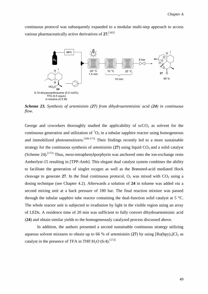
Chapter A
49
continuous protocol was subsequently expanded to a modular multi-step approach to access
various pharmaceutically active derivatives of 27.[165]
Scheme 23. Synthesis of artemisinin (27) from dihydroartemisinic acid (24) in continuous
flow.
George and coworkers thoroughly studied the applicability of scCO2 as solvent for the
continuous generation and utilization of 1O2 in a tubular sapphire reactor using homogeneous
and immobilized photosensitizers.[166-171]
Their findings recently led to a more sustainable
strategy for the continuous synthesis of artemisinin (27) using liquid CO2 and a solid catalyst
(Scheme 24).[172]
Thus, meso-tetraphenylporphyrin was anchored onto the ion-exchange resin
Amberlyst-15 resulting in [TPP-Amb]. This elegant dual catalyst system combines the ability
to facilitate the generation of singlet oxygen as well as the Brønsted-acid mediated Hock
cleavage to generate 27. In the final continuous protocol, O2 was mixed with CO2 using a
dosing technique (see Chapter 4.2). Afterwards a solution of 24 in toluene was added via a
second mixing unit at a back pressure of 180 bar. The final reaction mixture was passed
through the tubular sapphire tube reactor containing the dual-function solid catalyst at 5 °C.
The whole reactor unit is subjected to irradiation by light in the visible region using an array
of LEDs. A residence time of 20 min was sufficient to fully convert dihydroartemisinic acid
(24) and obtain similar yields to the homogeneously catalyzed process discussed above.
In addition, the authors presented a second sustainable continuous strategy utilizing
aqueous solvent mixtures to obtain up to 66 % of artemisinin (27) by using [Ru(bpy)3]Cl2 as
catalyst in the presence of TFA in THF:H2O (6:4).[172]

Chapter A
50
Scheme 24. Synthesis of artemisinin (27) in liquid CO2 using a dual-function solid catalyst.
Adapted with permission from [172].
9. Concluding Remarks
The utilization of oxygen in continuous flow environments offers several advantages
compared to conventional batch techniques and a broad range of oxidation reactions have
been studied using this enabling technology. The main drivers are on the one hand that safety
concerns can be significantly reduced when working with a continuous flow (micro-) reactor.
Exothermic reactions are easily controlled by the excellent mass and heat transfer and the
small volumes and channel dimensions minimize the possibility for propagation of an
explosion inside the reactor even under extreme conditions. On the other hand, working at
elevated temperatures and, more importantly, at high pressures can be easily achieved often
resulting in improved and highly intensified oxidation protocols. Thus, especially aerobic
oxidation protocols using supercritical solvents are predominantly studied in continuous
environments.
Several technologies and reactor designs have been developed in the past to perform
reactions involving oxygen in order to meet these demands. Liquid phase oxidations are
typically carried out by using a mass flow controlling unit or membrane reactors to deliver the
gaseous reagent. In case of supercritical solvents dosing techniques are often applied due to
the high system pressures. However, a universal reactor design does not exist and all reaction
parameters have to be taken into account for developing a suitable continuous flow reactor.
Thus, strong collaborations between chemists and process engineers are of utmost importance
for this rapidly growing area.

Chapter A
51
The application of continuous flow has already reached widespread use for the aerobic
oxidation of specific functional groups such as alcohols in order to replace expensive and
often toxic reagents thus providing more sustainable alternatives. Furthermore, in recent years
a clear trend to other applications such as oxidative coupling reactions or photochemical
applications can be observed. Since continuous processing is gaining increasing attention by
synthetic chemists it is apparent that entirely new synthetic routes will be developed on a
more routine basis by using this enabling technology. Therefore, flow chemistry can
potentially help to access more selective strategies and better (catalytic) systems which are
hardly feasible in traditional batch equipment. Flow chemistry on laboratory scale is not only
used to enhance aerobic oxidations developed in batch, but also to get deeper insights into
industrial processes and reaction mechanisms of well-known transformations.
10. References
[1] S. E. Allen, R. R. Walvoord, R. Padilla-Salinas, M. C. Kozlowski, Chem. Rev. 2013,
113, 6234.
[2] A. N. Campbell, S. S. Stahl, Acc. Chem. Res. 2012, 45, 851.
[3] Q. Cao, L. M. Dornan, L. Rogan, N. L. Hughes, M. J. Muldoon, Chem. Commun.
2014, 50, 4524.
[4] S. E. Davis, M. S. Ide, R. J. Davis, Green. Chem. 2013, 15, 17.
[5] A. E. Wendlandt, A. M. Suess, S. S. Stahl, Angew. Chem. Int. Ed. 2011, 50, 11062.
[6] P. M. Osterberg, J. K. Niemeier, C. J. Welch, J. M. Hawkins, J. R. Martinelli, T. E.
Johnson, T. W. Root, S. S. Stahl, Org. Process Res. Dev. doi:10.1021/op500328f
[7] V. Hessel, D. Kralisch, N. Kockmann, T. Noel, Q. Wang, ChemSusChem 2013, 6,
746.
[8] C. Wiles, P. Watts, Green Chem. 2014, 16, 55.
[9] L. Vaccaro, D. Lanari, A. Marrocchi, G. Strappaveccia, Green Chem. 2014, 16, 3680.
[10] K. F. Jensen, B. J. Reizman, S. G. Newman, Lab Chip 2014, 14, 3206.
[11] J. C. Pastre, D. L. Browne, S. V. Ley, Chem. Soc. Rev. 2013, 42, 8849.
[12] D. T. McQuade, P. H. Seeberger, J. Org. Chem. 2013, 78, 6384.
[13] I. R. Baxendale, L. Brocken, C. J. Mallia, Green Process Synth. 2013, 2, 211.
[14] B. Gutmann, D. Cantillo, C. O. Kappe, Angew. Chem. Int. Ed. 2015, 54, 6688.
[15] K. Jahnisch, V. Hessel, H. Lowe, M. Baerns, Angew. Chem. Int. Ed. 2004, 43, 406.
[16] T. Inoue, M. A. Schmidt, K. F. Jensen, Ind. Eng. Chem. Res. 2007, 46, 1153.

Chapter A
52
[17] T. Noel, V. Hessel, ChemSusChem 2013, 6, 405.
[18] G. Kolb, V. Hessel, V. Cominos, C. Hofmann, H. Lowe, G. Nikolaidis, R. Zapf, A.
Ziogas, E. R. Delsman, M. H. J. M. de Croon, J. C. Schouten, O. de la Iglesia, R.
Mallada, J. Santamaria, Catal. Today 2007, 120, 2.
[19] M. D. Roydhouse, A. Ghaini, A. Constantinou, A. Cantu-Perez, W. B. Motherwell, A.
Gavriilidis, Org. Process Res. Dev. 2011, 15, 989.
[20] M. Nobis, D. M. Roberge, Chim. Oggi 2011, 29, 56.
[21] M. Irfan, T. N. Glasnov, C. O. Kappe, Org. Lett. 2011, 13, 984.
[22] M. Brzozowski, M. O'Brien, S. V. Ley, A. Polyzos, Acc. Chem. Res. 2015, 48, 349.
[23] L. Yang, K. F. Jensen, Org. Process Res. Dev. 2013, 17, 927.
[24] R. Munirathinam, J. Huskens, W. Verboom, Adv. Synth. Catal. 2015, 357, 1093.
[25] H. Schmieder, J. Abeln, Chem. Eng. Technol. 1999, 22, 903.
[26] R. A. F. Tomas, J. C. M. Bordado, J. F. P. Gomes, Chem. Rev. 2013, 113, 7421.
[27] P. A. Hamley, T. Ilkenhans, J. M. Webster, E. Garcia-Verdugo, E. Venardou, M. J.
Clarke, R. Auerbach, W. B. Thomas, K. Whiston, M. Poliakoff, Green Chem. 2002, 4,
235.
[28] E. Garcia-Verdugo, E. Venardou, W. B. Thomas, K. Whiston, W. Partenheimer, P. A.
Hamley, M. Poliakoff, Adv. Synth. Catal. 2004, 346, 307.
[29] J. Fraga-Dubreuil, E. Garcia-Verdugo, P. A. Hamley, E. M. Vaquero, L. M. Dudd, I.
Pearson, D. Housley, W. Partenheimer, W. B. Thomas, K. Whiston, M. Poliakoff,
Green Chem. 2007, 9, 1238.
[30] E. Garcia-Verdugo, J. Fraga-Dubreuil, P. A. Hamley, W. B. Thomas, K. Whiston, M.
Poliakoff, Green Chem. 2005, 7, 294.
[31] J. Fraga-Dubreuil, E. Garcia-Verdugo, P. A. Hamley, E. Perez, I. Pearson, W. B.
Thomas, D. Housley, W. Partenheimer, M. Poliakoff, Adv. Synth. Catal. 2009, 351,
1866.
[32] E. Perez, J. Fraga-Dubreuil, E. Garcia-Verdugo, P. A. Hamley, W. B. Thomas, D.
Housley, W. Partenheimer, M. Poliakoff, Green Chem. 2011, 13, 2389.
[33] E. Perez, J. Fraga-Dubreuil, E. Garcia-Verdugo, P. A. Hamley, M. L. Thomas, C. Yan,
W. B. Thomas, D. Housley, W. Partenheimer, M. Poliakoff, Green Chem. 2011, 13,
2397.
[34] B. Gutmann, P. Elsner, D. Roberge, C. O. Kappe, ACS Catal. 2013, 3, 2669.
[35] B. Pieber, C. O. Kappe, Green Chem. 2013, 15, 320.
[36] J. De Houwer, K. A. Tehrani, B. U. W. Maes, Angew. Chem. Int. Ed. 2012, 51, 2745.

Chapter A
53
[37] M. Hamano, K. D. Nagy, K. F. Jensen, Chem Commun. 2012, 48, 2086.
[38] U. Neuenschwander, K. F. Jensen, Ind. Eng. Chem. Res. 2014, 53, 601.
[39] M. T. Musser, Cyclohexanol and Cyclohexanone, Wiley-VCH, Weinheim, 2000.
[40] A. Leclerc, M. Alame, D. Schweich, P. Pouteau, C. Delattre, C. de Bellefon, Lab Chip
2008, 8, 814.
[41] J. Fischer, T. Lange, R. Boehling, A. Rehfinger, E. Klemm, Chem. Eng. Sci. 2010, 65,
4866.
[42] S. L. Bourne, S. V. Ley, Adv. Synth. Catal. 2013, 355, 1905.
[43] B. Tomaszewski, R. C. Lloyd, A. J. Warr, K. Buehler, A. Schmid, ChemCatChem
2014, 6, 2567.
[44] B. Tomaszewski, A. Schmid, K. Buehler, Org. Process Res. Dev. 2014, 18, 1516.
[45] T. L. LaPorte, M. Hamedi, J. S. DePue, L. F. Shen, D. Watson, D. Hsieh, Org.
Process Res. Dev. 2008, 12, 956.
[46] B. Z. Zhan, A. Thompson, Tetrahedron 2004, 60, 2917.
[47] M. J. Schultz, M. S. Sigman, Tetrahedron 2006, 62, 8227.
[48] C. Parmeggiani, F. Cardona, Green Chem. 2012, 14, 547.
[49] B. L. Ryland, S. S. Stahl, Angew. Chem.Int. Ed. 2014, 53, 8824.
[50] T. R. Felthouse, J. Am. Chem. Soc. 1987, 109, 7566.
[51] T. R. Felthouse, P. B. Fraundorf, R. M. Friedman, C. L. Schosser, J. Catal. 1991, 127,
393.
[52] H. Kimura, Appl. Catal. A-Gen. 1993, 105, 147.
[53] D. V. Bavykin, A. A. Lapkin, S. T. Kolaczkowski, P. K. Plucinski, Appl Catal A-Gen.
2005, 288, 175.
[54] D. V. Bavykin, A. A. Lapkin, P. K. Plucinski, J. M. Friedrich, F. C. Walsh, J. Catal.
2005, 235, 10.
[55] P. K. Plucinski, D. V. Bavykin, S. T. Kolaczkowski, A. A. Lapkin, Ind. Eng. Chem.
Res. 2005, 44, 9683.
[56] P. K. Plucinski, D. V. Bavykin, S. T. Kolaczkowski, A. A. Lapkin, Catal. Today 2005,
105, 479.
[57] N. Zotova, K. Hellgardt, G. H. Kelsall, A. S. Jessiman, K. K. Hii, Green Chem. 2010,
12, 2157.
[58] D. Obermayer, A. M. Balu, A. A. Romero, W. Goessler, R. Luque, C. O. Kappe,
Green Chem. 2013, 15, 1530.
[59] X. Y. Liu, K. F. Jensen, Green Chem. 2013, 15, 1538.

Chapter A
54
[60] X. Y. Liu, K. F. Jensen, Green Chem. 2012, 14, 1471.
[61] D. S. Mannel, S. S. Stahl, T. W. Root, Org. Process Res. Dev. 2014, 18, 1503.
[62] E. H. Cao, W. B. Motherwell, A. Gavriilidis, Chem. Eng. Technol. 2006, 29, 1372.
[63] E. Cao, A. Gavriilidis, W. B. Motherwell, Chem. Eng. Sci. 2004, 59, 4803.
[64] A. Muzen, M. S. Fraguio, M. C. Cassanello, M. A. Ayude, P. M. Haure, O. M.
Martinez, Ind. Eng. Chem. Res. 2005, 44, 5275.
[65] A. L. Tarasov, L. M. Kustov, A. A. Bogolyubov, A. S. Kiselyov, V. V. Semenov,
Appl. Catal. A-Gen. 2009, 366, 227.
[66] A. Brandner, K. Lehnert, A. Bienholz, M. Lucas, P. Claus, Top. Catal. 2009, 52, 278.
[67] F. Al Badran, S. Awdry, S. T. Kolaczkowski, Catal. Today 2013, 216, 229.
[68] T. Osako, K. Torii, Y. Uozumi, RSC Adv. 2015, 5, 2647.
[69] N. W. Wang, T. Matsumoto, M. Ueno, H. Miyamura, S. Kobayashi, Angew. Chem.
Int. Ed. 2009, 48, 4744.
[70] K. Kaizuka, K. Y. Lee, H. Miyamura, S. Kobayashi, J. Flow Chem. 2012, 2, 1.
[71] B. N. Zope, R. J. Davis, Top. Catal. 2009, 52, 269.
[72] B. N. Zope, S. E. Davis, R. J. Davis, Top. Catal. 2012, 55, 24.
[73] S. D. Pollington, D. I. Enache, P. Landon, S. Meenakshisundaram, N. Dimitratos, A.
Wagland, G. J. Hutchings, E. H. Stitt, Catal. Today 2009, 145, 169.
[74] E. H. Cao, M. Sankar, S. Firth, K. F. Lam, D. Bethell, D. K. Knight, G. J. Hutchings,
P. F. McMillan, A. Gavriilidis, Chem. Eng. J. 2011, 167, 734.
[75] N. Asao, N. Hatakeyama, Menggenbateer, T. Minato, E. Ito, M. Hara, Y. Kim, Y.
Yamamoto, M. W. Chen, W. Zhang, A. Inouei, Chem. Commun. 2012, 48, 4540.
[76] K. Heidkamp, M. Aytemir, K. D. Vorlop, U. Prusse, Catal. Sci. Technol. 2013, 3,
2984.
[77] G. W. Wu, A. Constantinou, E. H. Cao, S. Kuhn, M. Morad, M. Sankar, D. Bethell, G.
J. Hutchings, A. Gavriilidis, Ind. Eng. Chem. Res. 2015, 54, 4183.
[78] S. R. Chaudhuri, J. Hartwig, L. Kupracz, T. Kodanek, J. Wegner, A. Kirschning, Adv.
Synth. Catal. 2014, 356, 3530.
[79] C. Aellig, C. Girard, I. Hermans, Angew. Chem. Int. Ed. 2011, 50, 12355.
[80] C. Aellig, D. Scholz, I. Hermans, ChemSusChem 2012, 5, 1732.
[81] C. Aellig, D. Scholz, S. Conrad, I. Hermans, Green Chem. 2013, 15, 1975.
[82] W. Leitner, Acc. Chem. Res. 2002, 35, 746.
[83] C. M. Rayner, Org. Process Res. Dev. 2007, 11, 121.
[84] X. Han, M. Poliakoff, Chem. Soc. Rev. 2012, 41, 1428.

Chapter A
55
[85] G. Jenzer, D. Sueur, T. Mallat, A. Baiker, Chem. Commun. 2000, 2247.
[86] G. Jenzer, M. S. Schneider, R. Wandeler, T. Mallat, A. Baiker, J. Catal. 2001, 199,
141.
[87] G. Jenzer, T. Mallat, A. Baiker, Catal. Lett. 2001, 73, 5.
[88] J. D. Grunwaldt, M. Caravati, M. Ramin, A. Baiker, Catal. Lett. 2003, 90, 221.
[89] M. Caravati, J. D. Grunwaldt, A. Baiker, Catal. Today 2004, 91-2, 1.
[90] M. Caravati, J. D. Grunwaldt, A. Baiker, Phys. Chem. Chem. Phys. 2005, 7, 278.
[91] M. Burgener, T. Tyszewski, D. Ferri, T. Mallat, A. Baiker, Appl. Catal. A-Gen. 2006,
299, 66.
[92] M. Caravati, J. D. Grunwaldt, A. Baiker, Appl. Catal. A-Gen. 2006, 298, 50.
[93] J. D. Grunwaldt, A. Baiker, Phys. Chem. Chem. Phys. 2005, 7, 3526.
[94] M. Caravati, D. M. Meier, J. D. Grunwaldt, A. Baiker, J. Catal. 2006, 240, 126.
[95] M. Caravati, J. D. Grunwaldt, A. Baliker, Catal. Today 2007, 126, 27.
[96] J. D. Grunwaldt, M. Caravati, A. Baiker, J. Phys. Chem. B 2006, 110, 9916.
[97] M. J. Beier, J. D. Grunwaldt, I. Tsivintzelis, A. D. Jensen, G. M. Kontogeorgis, A.
Baiker, J. Supercrit. Fluid. 2012, 63, 199.
[98] A. O. Chapman, G. R. Akien, N. J. Arrowsmith, P. Licence, M. Poliakoff, Green
Chem. 2010, 12, 310.
[99] C. Keresszegi, J. D. Grunwaldt, T. Mallat, A. Baiker, Chem. Commun. 2003, 2304.
[100] J. D. Grunwaldt, C. Keresszegi, T. Mallat, A. Baiker, J. Catal. 2003, 213, 291.
[101] J. D. Grunwaldt, M. Caravati, A. Baiker, J. Phys. Chem. B 2006, 110, 25586.
[102] Z. Hou, N. Theyssen, A. Brinkmann, W. Leitner, Angew. Chem. Int. Ed. 2005, 44,
1346.
[103] Z. S. Hou, N. Theyssen, W. Leitner, Green Chem. 2007, 9, 127.
[104] Z. Hou, N. Theyssen, A. Brinkmann, K. V. Klementiev, W. Grunert, M. Buhl, W.
Schmidt, B. Spliethoff, B. Tesche, C. Weidenthaler, W. Leitner, J. Catal. 2008, 258,
315.
[105] S. S. Stahl, Science 2005, 309, 1824.
[106] S. S. Stahl, Angew. Chem. Int. Ed. 2004, 43, 3400.
[107] B. A. Steinhoff, S. S. Stahl, J. Am. Chem. Soc. 2006, 128, 4348.
[108] X. A. Ye, M. D. Johnson, T. N. Diao, M. H. Yates, S. S. Stahl, Green Chem. 2010, 12,
1180.
[109] J. F. Greene, J. M. Hoover, D. S. Mannel, T. W. Root, S. S. Stahl, Org. Process Res.
Dev. 2013, 17, 1247.

Chapter A
56
[110] L. Vanoye, M. Pablos, C. de Bellefon, A. Favre-Reguillon, Adv. Synth. Catal. 2015,
357, 739.
[111] J. F. Greene, Y. Preger, S. S. Stahl, T. W. Root, Org. Process Res. Dev. doi:10.1021/
acs.oprd.5b00125
[112] R. Franke, D. Selent, A. Borner, Chem. Rev. 2012, 112, 56752.
[113] F. Röhrscheid, Carboxylic Acids, Aromatic, Wiley-VCH, Weinheim, 2000.
[114] V. Haverkamp, V. Hessel, M. A. Liauw, H. Lowe, M. G. Menges, Ind. Eng. Chem.
Res. 2007, 46, 8558.
[115] X. Y. Liu, B. Unal, K. F. Jensen, Catal. Sci. Technol. 2012, 2, 2134.
[116] L. Vanoye, A. Aloui, M. Pablos, R. Philippe, A. Percheron, A. Favre-Reguillon, C. de
Bellefont, Org. Lett. 2013, 15, 5978.
[117] L. Vanoye, M. Pablos, N. Smith, C. de Bellefon, A. Favre-Reguillon, RSC Adv. 2014,
4, 57159.
[118] C. C. C. J. Seechurn, M. O. Kitching, T. J. Colacot, V. Snieckus, Angew. Chem. Int.
Ed. 2012, 51, 5062.
[119] D. Cantillo, C. O. Kappe, ChemCatChem 2014, 6, 3286.
[120] T. Noel, S. L. Buchwald, Chem. Soc. Rev. 2011, 40, 5010.
[121] B. Karimi, H. Behzadnia, D. Elhamifar, P. F. Akhavan, F. K. Esfahani, A. Zamani,
Synthesis 2010, 1399.
[122] K. M. Gligorich, M. S. Sigman, Chem. Commun. 2009, 3854.
[123] C. P. Park, D. P. Kim, J. Am. Chem. Soc. 2010, 132, 10102.
[124] J. H. Park, C. Y. Park, M. J. Kim, M. U. Kim, Y. J. Kim, G. H. Kim, C. P. Park, Org.
Process Res. Dev. doi:10.1021/acs.oprd.5b00077
[125] D. M. Rudzinski, N. E. Leadbeater, Green Process Synth. 2013, 2, 323.
[126] H. P. L. Gemoets, V. Hessel, T. Noel, Org. Lett. 2014, 16, 5800.
[127] T. P. Petersen, A. Polyzos, M. O'Brien, T. Ulven, I. R. Baxendale, S. V. Ley,
ChemSusChem 2012, 5, 274.
[128] M. Brzozowski, J. A. Forni, G. P. Savage, A. Polyzos, Chem. Commun. 2015, 51, 334.
[129] M. O. Ratnikov, X. F. Xu, M. P. Doyle, J. Am. Chem. Soc. 2013, 135, 9475.
[130] M. T. Goebel, C. S. Marvel, J. Am. Chem. Soc. 1933, 55, 1693.
[131] C. W. Porter, C. Steel, J. Am. Chem. Soc. 1920, 42, 2650.
[132] G. A. Russell, R. F. Bridger, J. Am. Chem. Soc. 1963, 85, 3765.
[133] Z. He, T. F. Jamison, Angew. Chem. Int. Ed. 2014, 53, 3353.
[134] R. J. Schmidt, Appl. Catal. A-Gen. 2005, 280, 89.

Chapter A
57
[135] J. Fraga-Dubreuil, J. Garcia-Serna, E. Garcia-Verdugo, L. M. Dudd, G. R. Aird, W. B.
Thomas, M. Poliakoff, J. Supercrit. Fluid 2006, 39, 220.
[136] M. L. Thomas, J. Fraga-Dubreuil, A. S. Coote, M. Poliakoff, Green Chem. 2008, 10,
197.
[137] S. Hunig, H. R. Muller, W. Thier, Angew. Chem. Int. Ed. 1965, 4, 271.
[138] D. J. Pasto, R. T. Taylor, Org. React. 1991, 40, 91.
[139] B. Pieber, S. T. Martinez, D. Cantillo, C. O. Kappe, Angew. Chem. Int. Ed. 2013, 52,
10241.
[140] B. Pieber, T. Glasnov, C. O. Kappe, Chem. Eur. J. 2015, 21, 4368.
[141] M. P. Feth, K. Rossen, A. Burgard, Org. Process Res. Dev. 2013, 17, 282.
[142] K. Gilmore, P. H. Seeberger, Chem. Rec. 2014, 14, 410.
[143] Y. H. Su, N. J. W. Straathof, V. Hessel, T. Noel, Chem. Eur. J. 2014, 20, 10562.
[144] A. Talla, B. Driessen, N. J. W. Straathof, L.-G. Milroy, L. Brunsveld, V. Hessel, T.
Noël, Adv. Synth. Catal. doi:10.1002/adsc.201401010
[145] Y. Su, V. Hessel, T. Noël, AIChE 2015, 61, 2215.
[146] Y. Q. Zou, J. R. Chen, X. P. Liu, L. Q. Lu, R. L. Davis, K. A. Jorgensen, W. J. Xiao,
Angew. Chem. Int. Ed. 2012, 51, 784.
[147] I. G. T. M. Penders, Z. Amara, R. Horvath, K. Rossen, M. Poliakoff, M. W. George,
RSC Adv. 2015, 5, 6501.
[148] P. R. Ogilby, Chem. Soc. Rev. 2010, 39, 3181.
[149] R. C. R. Wootton, R. Fortt, A. J. de Mello, Org. Process Res. Dev. 2002, 6, 1879.
[150] K. N. Loponov, J. Lopes, M. Barlog, E. V. Astrova, A. V. Malkov, A. A. Lapkin, Org.
Process Res. Dev. 2014, 18, 1443.
[151] K. Jahnisch, U. Dingerdissen, Chem. Eng. Technol. 2005, 28, 426.
[152] C. P. Park, R. A. Maurya, J. H. Lee, D. P. Kim, Lab Chip 2011, 11, 1941.
[153] R. A. Maurya, C. P. Park, D. P. Kim, Beilstein J. Org. Chem. 2011, 7, 1158.
[154] F. Levesque, P. H. Seeberger, Org. Lett. 2011, 13, 5008.
[155] T. S. A. Heugebaert, C. V. Stevens, C. O. Kappe, ChemSusChem 2015, 8, 1648.
[156] K. S. Elvira, R. C. R. Wootton, N. M. Reis, M. R. Mackley, A. J. DeMello, ACS
Sustain. Chem. Eng. 2013, 1, 209.
[157] C. Y. Park, Y. J. Kim, H. J. Lim, J. H. Park, M. J. Kim, S. W. Seo, C. P. Park, RSC
Adv. 2015, 5, 4233.
[158] E. K. Lumley, C. E. Dyer, N. Pamme, R. W. Boyle, Org. Lett. 2012, 14, 5724.

Chapter A
58
[159] D. B. Ushakov, K. Gilmore, D. Kopetzki, D. T. McQuade, P. H. Seeberger, Angew.
Chem. Int. Ed. 2014, 53, 557.
[160] D. B. Ushakov, K. Gilmore, P. H. Seeberger, Chem. Commun. 2014, 50, 12649.
[161] D. B. Ushakov , M. B. Plutschack , K. Gilmore, P. H. Seeberger Chem. Eur. J. 2015,
21, 6528.
[162] S. Vukelic, D. B. Ushakov, K. Gilmore, B. Koksch, P. H. Seeberger, Eur. J. Org.
Chem. 2015, 3036.
[163] F. Levesque, P. H. Seeberger, Angew. Chem. Int. Ed. 2012, 51, 1706.
[164] D. Kopetzki, F. Levesque, P. H. Seeberger, Chem. Eur. J. 2013, 19, 5450.
[165] K. Gilmore, D. Kopetzki, J. W. Lee, Z. Horvath, D. T. McQuade, A. Seidel-
Morgenstern, P. H. Seeberger, Chem. Commun. 2014, 50, 12652.
[166] R. A. Bourne, X. Han, A. O. Chapman, N. J. Arrowsmith, H. Kawanami, M.
Poliakoff, M. W. George, Chem. Commun. 2008, 4457.
[167] R. A. Bourne, X. Han, M. Poliakoff, M. W. George, Angew. Chem. Int. Ed. 2009, 48,
5322.
[168] X. Han, R. A. Bourne, M. Poliakoff, M. W. George, Green Chem. 2009, 11, 1787.
[169] X. Han, R. A. Bourne, M. Poliakoff, M. W. George, Chem. Sci. 2011, 2, 1059.
[170] J. F. B. Hall, X. Han, M. Poliakoff, R. A. Bourne, M. W. George, Chem. Commun.
2012, 48, 3073.
[171] J. F. B. Hall, R. A. Bourne, X. Han, J. H. Earley, M. Poliakoff, M. W. George, Green
Chem. 2013, 15, 177.
[172] Z. Amara, J. F. B. Bellamy, R. Horvath, S. J. Miller, A. Beeby, A. Burgard, K.
Rossen, M. Poliakoff, M. W. George, Nature Chem. 2015, 7, 489.

Chapter B
59
B. Direct Aerobic Oxidation of 2-Benzylpyridines in a Gas-Liquid
Continuous-Flow Regime using Propylene Carbonate as Solvent
Graphical Abstract
Abstract
The use of high-temperature/pressure gas-liquid continuous flow conditions dramatically
enhances the iron-catalyzed aerobic oxidation of 2-benzylpyridines to their corresponding
ketones. Pressurized air serves as readily available oxygen source and propylene carbonate
as green solvent in this radically intensified preparation of synthetically valuable 2-
aroylpyridines.


Chapter B
61
1. Introduction
The direct oxidation of CH bonds for atom- and step-economical synthesis of functionalized
molecules is a rapidly growing field in the organic chemistry community.[1]
The oxidation of
2-benzylpyridines to the corresponding benzoyl derivatives, for example, was developed in
1930 using potassium permanganate as oxidant in large excess.[2]
In the last few years
catalytic methods for such transformations were developed using stoichiometric amounts of
strong oxidants such as potassium bromate or tert-butylhydroperoxide.[3-5]
Very recently
substantial progress in this reaction was reported by Maes and coworkers, who discovered
that this oxidation can be carried out using molecular oxygen in the presence of catalytic
amounts of iron or copper salts in combination with acetic acid as additive (Scheme 1).[6]
The
ketones resulting from this transformation are key intermediates for the synthesis of several
active pharmaceutical ingredients (APIs) including antihistamines (e.g. Pheniramine,
Triprolidine, Doxylamine, Carbinoxamine, Arpromidine),[7]
antiarrhytmic agents
(Disopyramide),[8]
and of promising candidates for cancer treatment such as 2-
benzoylpyridine 2´-pyridylhydrazones and 2-benzoylpyridine thiosemicarbazone derivatives
(Scheme 1).[9,10]
In recent years, the use of microreactors and continuous flow technology in general
has become increasingly popular in synthetic organic chemistry.[11,12]
One of the main
advantages of continuous flow processing is the ease with which reactions can be
scaledwithout the need for reoptimizationthrough the operation of multiple systems in
parallel (numbering-up, scaling-out) or related strategies, thereby readily achieving
production scale quantities.[11,12]
Enhanced heat- and mass transfer characteristics and the
ability to efficiently optimize reaction conditions by control of residence time add value to the
technology. Notably, biphasic reactions can often be dramatically improved using
microreactor technology owing to an enhanced mass transfer of e.g., gaseous reactants into a
liquid phase.[13]
Examples of such continuous gasliquid reactions including
hydrogenations,[14]
hydroformylations,[15]
carbonylations,[16]
halogenations,[17]
ethylene
cycloadditions,[18]
ozonoloysis reactions,[19]
and oxidations[20]
have been carried out in a
variety of biphasic flow patterns and formats.
A very important factor in the reaction design is undoubtedly the correct choice of
solvents. A proper solvent can affect a chemical transformation not just by dissolving reaction
partners, it is also able to stabilize transition states, shift the reaction equilibrium by
precipitating a (by)product, or allows an accurate setting of the reaction temperature (e.g.

Chapter B
62
reflux conditions). Nowadays sustainability is a major concern in the development of any
chemical process.
N
10 mol% Fe or Cu1 equiv. AcOH1 atm O2
DMSO, 24 h, 100°C
N
O
R
R
N
N
R
HN
N
N
NHN
SRHN
N
NH2
O
NiPr
iPr
N
O
Cl
N
N
O
N
N
N
N
R
N
N
F
HN
NH2N
N
HN
Arpromidine
R=H PheniramineR=Cl Chloropheni ramine
Triprolidine Doxylamine Carbinoxamine Disopyramide
2-benzoylpyridine 2´-pyridylhydrazones
2-benzoylpyridine th iosemicarbazones
Maes and coworkers(ref. 6)
Scheme 1 Cu or Fe catalyzed direct oxidation of 2-benzylpyridines using molecular oxygen
as sole oxidant provides important intermediates for API synthesis.
The replacement of traditional organic solvents by “greener alternatives” represents a
fundamental challenge in academic as well as industrial research.[21]
In this context, propylene
carbonate (PC), a nontoxic and biodegradable cyclic carbonate which can be prepared from
CO2 and propylene oxide in an highly atom-efficient process,[22]
has been introduced as
greener alternative to more traditional solvents for intermolecular alkyne
hydroacetylations,[23]
proline-catalyzed aldol reactions,[24]
asymmetric hydrogenations,[25,26]
proline-catalyzed aminations,[27]
and in asymmetric cyanohydrin syntheses.[28]
In particular,
there is need to substitute common aprotic, dipolar solvents owing to their poor performances
in waste (MeCN), health (DMF, NMF, NMP, DMA) or reactivity (DMSO) rankings in e.g.
the GSK solvent selection guide.[29]
Therefore, PC presents an promising alternative as it is
nontoxic and stable while its polarity is even higher than compared to MeCN.[21,29]

Chapter B
63
Herein, we describe a gasliquid continuous flow protocol for the direct oxidation of 2-
benzylpyridines using propylene carbonate as solvent, which exhibits several advantages
compared to the previously described process in DMSO.[25,29]
In addition inexpensive iron(III)
chloride was used as catalyst underlining the sustainability of this transformation.[30]
The
utilization of a high- temperature/high-pressure (high-T/p) process window,[31]
results in an
intensified process which requires lower amounts of the catalytically active species and
allows a high productivity of the desired ketones in an efficient, continuous manner.
2. Results and Discussion
The microreactor concept used in this study followed a standard two feed approach. The
gaseous oxygen source, synthetic air, was mixed with the liquid phase in a T-shaped mixing
device (Figure 1). The liquid phase containing iron(III) chloride and 2-benzylpyridine
dissolved in the respective solvent was pumped by an HPLC pump. The biphasic reaction
stream passed through a 120 m stainless steel coil (inner diameter of 0.8 mm) heated to the
respective reaction temperature with a standard GC oven. To obtain detailed information
about the temperature homogeneity along the coil temperature sensors were installed at
different positions: at the beginning of the heated reaction zone, one after approximately 1 m,
and at the outlet of the oven. It has to be emphasized that no back pressure regulator was used
at the end of the residence time unit as this was not necessary when a liquid flow rate of 0.6
mL min-1
and gaseous inputs of 1.2 – 1.7 NL min-1
were applied.
Figure 1. Schematic diagram of the gasliquid continuous flow reactor used in this study:
The flow rate of the liquid phase is controlled by an HPLC pump. The gas flow was measured
using a mass flow controller (MFC). The two phases are mixed in a T-shaped mixing unit
before entering the residence time unit (stainless steel coil, inner diameter 0.8 mm, length 120
m) heated in a GC oven. The reaction temperature was additionally monitored using thermo
couples (TC 1-3; for illustrations of the reactor and detailed descriptions of all parts, see the
ESI).

Chapter B
64
The oxidation of 2-benzylpyridine (1a) served as model reaction for an initial optimization
study (Table 1). First attempts to reproduce the conditions reported in the original work in
DMSO at higher temperatures (100-170 °C) resulted in a repulsive odor presumably from side
reactions of the solvent.[6]
Thus, for a continuous application we decided to use a more stable
solvent under the high-temperature conditions such as N-methyl-pyrrolidone (NMP). Reaction
at 150 °C with a catalyst loading of 10 mol% (FeCl3) resulted in 75 % conversion when a
liquid flow rate of 0.6 ml min-1
and an air stream of 1.7 NL min-1
was applied (Table 1, entry
1). Notably, under these intensified conditions the use of an additive such as acetic acid as
described by Maes and coworkers was not necessary for a successful oxidation.[6]
A further
increase of the reaction temperature to 170 °C enabled an almost full conversion of the
starting material 1a (Table, entry 2 and 3). Unfortunately, it was not possible to further raise
the temperature as decomposition of NMP was observed resulting in a characteristic odor and
a dark brown to black discoloration of the solvent.
Since acetic acid showed the ability to significantly enhance the reaction rate in the
batch protocol[6]
this solvent was also evaluated under continuous flow conditions. When the
oxidation was performed at 100 °C no product was identified by GC-FID analysis (Table 1,
entry 4). At 120 °C the reaction solvent was essentially “distilled” off in the microreactor
leaving the catalyst/substrate/product mixture inside the heated reaction zone (Table 1, entry
5). To avoid this effect we reduced the gaseous flow rate to 1.2 NL min-1
, resulting however in
only 15 % conversion (Table 1, entry 6).
The problems described above with DMSO, NMP and AcOH indicate that a
successful reaction under high-temperature conditions requires a solvent which is extremely
stable against oxidation and also has a high boiling point. The excellent properties of PC,
including its high boiling point (242 °C), good chemical stability and low viscosity, make this
solvent a very attractive alternative to traditional aprotic polar solvents such as NMP, DMSO,
etc.0,[25,29]
in particular for continuous flow applications in a high-T/p process window. An
initial experiment at 180 °C provided a somewhat lower conversion compared to NMP at 170
°C but, satisfyingly, no decomposition or other undesired effects occurred (Table 1, entry 7).
Thus, the temperature was increased to 200 °C resulting in total consumption of substrate 1a
(Table 1, entry 8). A subsequent reduction of the catalyst loading to 5 mol% with concomitant
increase of the starting material concentration still led to full conversion (Table 1, entry 9).
Product isolation by simple filtration over a plug of silica with hexanes provided 81 % of the
desired ketone 2a which is in good agreement with the results described for the batch protocol
(80%).[6,32]
Lower amounts of catalyst resulted in high conversions as well but small amounts

Chapter B
65
of the substrate 1a were still present (Table 1, entry 10). Notably, a control experiment in the
absence of the catalyst revealed that a homogeneous iron source is clearly required for this
oxidation reaction to proceed and that the stainless steel coil itself cannot enhance this
reaction in any significant way (Table 1, entry 11). Additional temperature monitoring
demonstrated that the target temperature (200 °C) was reached after 1 m of the stainless steel
coil. As expected, the temperature at the reactor entrance is significantly lower (165 °C, for
detailed information about the temperature monitoring see the ESI).
Table 1. Optimization of the direct aerobic oxidation of 2-benzylpyridinea
N NFeCl3
O2 (synthetic air)
solvent, conditions(continuous flow)
O
1a 2a
Entry FeCl3 (mol%) 2-Benzylpyridine (M) Solvent T (°C) Conv. b
(%)
1 10 0.6 NMP
150 75
2 10 0.6 NMP 160 93
3 10 0.6 NMP 170 98
4 10 0.6 AcOH 100 0
5
10 0.6 AcOH 120 n.d.c
6d
10 0.6 AcOH 120 15
7 10 0.6 PCe
180 97
8 10 0.6 PC 200 >99
9 5.0 1.2 PC 200 >99(81%)f
10 2.5 1.2 PC 200 97
11 -- 1.2 PC 200 3
a Reaction conditions for optimized conditions (entry 9): 2.3 mmol 2-benzylpyridine (1a), 0.12 mmol FeCl3, 2
mL propylene carbonate; flow rate liquid phase 0.6 mL min-1
; flow rate synthetic air: 1.7 NL min-1
.b
GC-FID
peak area percent of 2-benzoylpyridine (2a). c
not determined, solvent distillation. d Flow rate of synthetic air
was 1.2 NL min-1
.e Propylene carbonate.
f Isolated yield in parentheses.
The overall processing time for the optimized reaction conditions from the HPLC pump to the
point where the reaction mixture leaves the residence time unit was exactly 13 min. This
constitutes a major advantage in comparison to the originally published batch protocol where
24 h were required for full conversion of the starting material.[6]
Furthermore, our intensified

Chapter B
66
process did not require any additive (AcOH) while working at higher concentrations (1.2 M
vs. 0.5 M) and significantly lower catalyst loadings (5 mol% vs. 10 mol%).[6]
Importantly,
pure oxygen could be replaced by pressurized air, apparently due to the high mass transfer
between the gaseous and the liquid phase.[33]
With the optimized conditions in hand we moved on to synthesize some of the other
desired 2-aroylpyridine target intermediates shown in Scheme 1 (Table 2). The oxidation of 2-
(4-methylbenzyl)pyridine (1b) furnished the precursor for Triprolidine in 69 % isolated yield
(Table 2, entry 1). For the chloro-substituted derivative (1c) 81 % of the pure ketone
compound could be obtained (Table 2, entry 2). A Wittig reaction of this ketone with
subsequent reduction of the double bond can result in Chloropheniramine, while a reduction
of the keto-group with subsequent etherification will lead to the H1-antagonist
Carbinoxamine.[7]
The intermediate for Arpromidine, containing a fluorine atom at the benzyl
moiety was obtained in 83 % (Table 2, entry 3).
Table 2. Direct aerobic oxidation of 2-benzylpyridine derivativesa
Entry Substrate Product Yield (%)
1
69
2
81
3
83
a Reaction conditions see Table 1, footnote a

Chapter B
67
3. Conclusion
In summary, we have demonstrated that the direct aerobic oxidation of 2-benzylpyridine
derivatives can be dramatically enhanced using continuous flow methodology in a high-T/p
process window in combination with propylene carbonate as green solvent. The reaction time
could be significantly reduced from hours to minutes and molecular oxygen could be replaced
by synthetic air as sole oxygen source. Thus, several key intermediates for API synthesis can
be synthesized in a continuous and environmentally benign manner.
4. References
[1] For a review on CH functionalization in total synthesis including several examples of
direct oxidation, see: W. R. Gutekunst, P. S. Baran, Chem. Soc. Rev. 2011, 40, 1976.
[2] K. E. Crook, S. M. McElvain, J. Am. Chem. Soc. 1930, 52, 4006.
[3] B. Akhlaghinia, H. Ebrahimabadi, E. K. Goharshadi, S. Samiee, S. Rezazadeh, J. Mol.
Catal. A-Chem., 2012, 357, 67-72.
[4] J. Zhang, Z. Whang, Y, Wang, C. Wan, X. Zheng, Z. Wang, Green Chem. 2009, 11,
1973.
[5] M. Nakanishi, C. Bolm, Adv. Synth. Catal. 2007, 349, 861.
[6] J. de Houwer, K. A. Tehrani, B. U. W. Maes, Angew. Chem. Int. Ed. 2012, 51, 2745.
[7] A. Kleemann, J. Engel, B. Kutscher, D. Reichert, Pharmaceutical Substances, Georg
Thieme, 4th ed., Stuttgart,
[8] A. C. Guyton, J. E. Hall, Textbook of Medical Physiology, Elsevier Saunders, 11th
ed.,
Philadelphia.
[9] J. Easmon, G. Heinisch, G. Pürstinger, T. Langer, J. K. Österreicher, J. Med. Chem.
1997, 40, 4420.
[10] D. C. Reis, M. C. X. Pinto, E. M. Souza-Fagundes, S. M. S. V. Wardell, J. L. Wardell,
H. Beraldo, Eur. J. Med. Chem. 2010, 45, 3904.
[11] For recent reviews on continuous flow/microreactor chemistry, see: (a) J. Wegner, S.
Ceylan, A. Kirschning, Adv. Synth. Catal. 2012, 354, 17; (b) C. Wiles, P. Watts, Green
Chem. 2012, 14, 38; (c) R. L. Hartman, J. P. McMullen, K. F. Jensen, Angew. Chem.
Int. Ed. 2011, 50, 7502.
[12] (a) Microreactors in Organic Synthesis and Catalysis, ed. T. Wirth, Wiley-VCH,
Weinheim, 2008; (b) Handbook of Micro Reactors, ed. V. Hessel, J. C. Schouten, A.

Chapter B
68
Renken, Y. Wang, J.-i. Yoshida, Wiley-VCH, Weinheim, 2009; (c) J.-i. Yoshida,
Flash Chemistry—Fast Organic Synthesis in Microsystems, Wiley-VCH, Weinheim,
2008.
[13] P. Sobieszuk, J. Aubin, R. Pohorecki, Chem. Eng. Technol. 2012, 35, 1346.
[14] J. Kobayashi, Y. Mori, K. Okamoto, R. Akiyama, M. Ueno, T. Kitamori, S.
Kobayashi, Science 2004, 304, 1305.
[15] P. B. Webb, M. F. Sellin, T. E. Kunene, S. Williamson, A. M. Z. Slawin, D. J. Cole-
Hamilton, J. Am. Chem. Soc. 2003, 125, 15577.
[16] (a) P. W. Miller, N. J. Long, A. J. de Mello, R. Vilar, J. Passchier, A. Gee, Chem.
Commun. 2006, 546; (b) P. W. Miller, N. J. Long, A. J. de Mello, R. Vilar, H.
Audrain, D. Bender, J. Passchier, A. Gee, Angew. Chem. Int. Ed. 2007, 46, 2875; (c)
X. Gong, P. W. Miller, A. D. Gee, N. J. Long, A. J. de Mello, R. Vilar, Chem. Eur. J.
2012, 18, 2768. (d) C. G. Kelly, C. Lee, M. A. Mercadante, N. E. Leadbeater, Org.
Process. Res. Dev. 2011, 15, 717.
[17] (a) N. de Mas, A. Günther, M. A. Schmidt, K. F. Jensen, Ind. Eng. Chem. Res. 2002,
42, 698; (b) P. Tundo, M. Selva, Green Chem. 2005, 7, 464.
[18] K. Terao, Y. Nishiyama, H. Tanimoto, T. Morimoto, M. Oelgemöller, K. Kakiuchi, J.
Flow. Chem. 2012, 2, 73.
[19] M. O’Brien, I. R. Baxendale, S. V. Ley, Org. Lett. 2010, 12, 1596.
[20] Z. Hou, N. Theyssen, A. Brinkmann, W. Leitner, Angew. Chem. Int. Ed. 2005, 44,
1346.
[21] For an excellent perspective article about green solvents, see: P. G. Jessop, Green
Chem. 2011, 13, 1391.
[22] (a) M. North, R. Pasquale, C. Young, Green Chem. 2010, 12, 1514; (b) J. E. Dengler,
M. W. Lehenmeier, S. Klaus, C. E. Anderson, E. Herdtweck, B. Rieger, Eur. J. Inorg.
Chem. 2011, 336.
[23] P. Lenden, P. M. Ylioja, C. González-Rodríguez, D. A. Entwistle, M. C. Willis, Green
Chem. 2011, 13, 1980.
[24] W. Clegg, R. W. Harrington, M. North, F. Pizzato, P. Villuendas, Tetrahedron:
Asymmetry 2010, 21, 1262.
[25] J. Bayardon, J. Holz, B. Schäffner, V. Andrushko, S. Verevkin, A. Preetz, A. Börner,
Angew. Chem. Int. Ed. 2007, 46, 5971.
[26] B. Schäffner, V. Andrushko, J. Holz, S. P. Verevkinand, A. Börner, ChemSusChem
2008, 1, 934.

Chapter B
69
[27] C. Beattie, M. North, P. Villuendas, Molecules 2011, 16, 3420.
[28] M. North, M. Omedes-Pujol, Beilstein J. Org. Chem. 2010, 6, 1043.
[29] A comparison of solvents can be found in the extended GSK solvent selection guide:
R. K. Henderson, C. Jiménez-González, D. J. C. Constable, S. R. Alston, G. G. A.
Inglis, G. Fisher, J. Sherwood, S. P. Binks, A. D. Curzons, Green Chem. 2011, 13,
854.
[30] S. Enthaler, K. Junge, M. Beller, Angew. Chem. Int. Ed. 2008, 47, 3317.
[31] For a general discussion on novel process windows and process intensification
technologies based on high-T/p conditions, see: (a) V. Hessel, Chem. Eng. Technol.
2009, 32, 1655; (b) V. Hessel, B. Cortese, M. H. J. M. de Croon, Chem. Eng. Sci.
2011, 66, 1426; (c) T. Van Gerven, A. Stankiewicz, Ind. Eng. Chem. Res. 2009, 48,
2465; (d) T. Razzaq, C. O. Kappe, Chem. Asian J. 2010, 5, 1274.
[32] The yield of 2-benzylpyridine 2a was also calculated by GC-FID analysis using
methyl phenylacetate as internal standard and is consistent with the isolated yield.
[33] It is worth mentioning that the high-T/p gas-liquid continuous flow approach
described herein cannot be carried out using the “tube-in-tube” concept developed by
the Ley group (e.g., ref. 19). Commercially available instruments using this
technology are either used to saturate the liquid phase with the gaseous reactant before
entering a heated residence time unit, or are limited to temperatures below 150 °C. For
representative examples, see: (a) P.B. Cranwell, M. O’Brien, D. Browne, P. Koos, A.
Polyzos, M. Pêna López, S.V. Ley, Org. Biomol. Chem. 2012, 10, 5774; (b) S.
Newton, S.V. Ley, E.C. Arce, D. Grainger, Adv. Synth. Catal. 2012, 354, 1805; (c)
T.P. Peterson, A. Polyzos, M. O’Brien, T. Ulven, I.R. Baxendale, S.V. Ley,
ChemSusChem 2012, 5, 274; (d) M. A. Mercandate, N. E. Leadbeater, Org. Biomol.
Chem. 2011, 9, 6575.

Chapter B
70
5. Supporting Information
General Remarks. All chemicals were purchased from Sigma-Aldrich, or Alfa Aesar and
were used without further purification. Reagents were weighed and handled in air at room
temperature. 1H-NMR and
13C spectra were recorded on a Bruker 300 MHz instrument using
CDCl3 as solvent. Chemical shifts (δ) are expressed in ppm downfield from TMS as internal
standard. The letters s, d, t, q, and m are used to indicate a singlet, doublet, triplet, quadruplet,
and multiplet. Melting points were determined on a Stuart™ SMP3 melting point apparatus.
GC-FID analysis was performed on a Trace-GC (ThermoFisher) with a flame ionization
detector using a HP5 column (30 m×0.250 mm×0.025 μm). After 1 min at 50°C the
temperature was increased in 25°C min−1
steps up to 300°C and kept at 300°C for 4 min. The
detector gas for the flame ionization is H2 and compressed air (5.0 quality).GC-MS analysis
was performed on a Trace-GC Ultra – DSQ II-MS system (ThermoElectron, Waltham, MA,
USA). The GC conditions were as follows: HP-5 MS column (30 m × 0.25 mm ID, 0.25 μm
film, Agilent, Waldbronn, Germany); carrier gas helium 5.0, flow 1 mL min-1
, temperature
gradient identical to GC-FID. The MS conditions were as follows: positive EI ionization,
ionization energy 70 eV, ionization source temperature 280 °C, emission current 100 μA; full-
scan-mode. Silica gel flash chromatography separations were performed on a Biotage SP1
instrument using petroleum ether/ethyl acetate mixtures as eluent.

Chapter B
71
Gas-Liquid continuous flow reactor
Figure S1: Gas-liquid continuous flow reactor. The main parts of this custom-built device
are a gas bottle (synthetic air, 5.0 quality) with a 50 bar pressure regulating valve (A), a
mass flow controller (B),[S1]
a binary pumping module (C),[S2]
a GC oven (D) to heat the
residence time unit (E) and a digital 4-channel-thermometer equipped with three
thermocouples (F) to monitor the reaction temperature at different positions of the reaction
coil.[S3]
Figure S2: Mass Flow controller (MFC, EL-FLOW Select F-201CV-5K0)[S1]
and the
Uniqsis Binary Pumping Module.[S2]
The gaseous reagent (synthetic air) is controlled by the
MFC and mixed with the liquid phase in a T-mixer (M) containing a pressure transducer
after passing a 7 bar backpressure regulator (BPR). The liquid stream enters the binary
pumping module through an inlet selection valve (ISV) which is used to control the liquid
feed (e.g. either solvent or reagent). The flow rate is controlled by a HPLC pump (P) allowing
flow rates from 0.01 to 10 mL min-1
. The priming valve (PV) equipped with another pressure
transducer enables priming with solvent before performing a reaction. The system constantly
monitors the pressure and will stop if the pressure either rises above or falls below the global
limits. The maximum allowed pressure of this device is 100 bar.

Chapter B
72
Figure S3: Residence time unit (120 m stainless steel coil with an inner diameter of 0.8 mm)
inside a GC-oven. To monitor the temperature at different positions thermocouples were
installed at the entrance of the heated reaction zone (TC 1), after approximately 1 m of the
coil (TC 2) and at the outlet of the oven (TC 3).
Figure S4: Temperature profile of the temperature at the entrance of the heated reaction zone
(TC 1), after approximately 1 m of the coil (TC 2) and at the outlet of the oven (TC 3) over 30
minutes using the optimized reaction conditions (liquid flow rate: 0.6 mL min-1
; air flow rate:
1.7 NL min-1
. At the beginning of the heated zone (TC 1) the temperature is significantly lower
than the desired temperature (~ 165 °C), after 1 m of the stainless steel coil (TC 2, 198 °C)
the temperature raised almost to the target temperature. The thermocouple at the end of the
residence time unit (TC 3, 200 °C) shows exactly the reaction temperature.

Chapter B
73
Synthesis of 2,4-Dimethyl-3-(2-pyridinylmethyl)pentan-3-ol.[S4]
To a stirred solution of 2-methylpyridine (2 mL, 20.3 mmol) in dry THF (30 mL), under Ar-
atmosphere was added BuLi (8.5 mL, 2.5 M in hexanes, 21.3 mmol) dropwise at -84 °C. After
30 min stirring at -84 °C the mixture was stirred for 30 min at 50 °C. Then diisopropylketone
(3.3 mL, 22.9 mmol) was added and the mixture was stirred further at -50 °C for 2 h. The
reaction was then quenched with water (25 mL) and extracted three times with ethyl acetate
(25 mL). The combined organic fractions were washed with brine (25 mL), dried over
MgSO4, filtered over a pad of Celite and concentrated. Column chromatography with an
automated chromatography system using silica flash cartridges applying a heptane-ethyl
acetate gradient resulted in 2,4-dimethyl-3-(2-pyridinylmethyl)pentan-3-ol (3.6 g, 86 %) as a
yellow oil. 1H NMR (300 MHz, CDCl3) δ 8.44 (d, J = 4.1 Hz, 1H), 7.60 (td, J = 7.7, 1.8 Hz,
1H), 7.23 – 7.07 (m, 2H), 6.33 (s, 1H), 2.91 (s, 2H), 2.01 – 1.82 (m, 2H), 0.89 (dd, J = 6.9, 4.8
Hz, 13H).13
C NMR (75 MHz, CDCl3) δ 161.78, 147.83, 136.80, 124.55, 121.02, 78.11, 38.07,
35.18, 18.17, 17.92.
General procedure for the synthesis of 2-Benzylpyridines.[S4]
Palladium(II) trifluoroacetate (83 mg, 0.25 mmol), the aryl halide (5.0 mmol), 2,4-dimethyl-
3-(2-pyridylmethyl)pentan-3-ol (1.25 g, 6.0 mmol), Cs2CO3 (2.45 g, 7.5 mmol), xylene (10
mL) and tricyclohexylphosphine (0.50 mmol) were subsequently transferred in an round
bottomed flask. The resulting mixture was flushed with argon for 5 min and stirred at reflux
under an argon-atmosphere for 6 h. After cooling to room temperature, the mixture was
filtered over a pad of Celite (dichloromethane, 50 mL). The solvent was removed under
reduced pressure and the crude residue was finally purified via column chromatography with
an automated chromatography system using silica flash cartridges applying a heptane-ethyl
acetate gradients.

Chapter B
74
2-(4-Methylbenzyl)pyridine (1b).
From 1-chloro-4-methylbenzene.Yield: 1.07 g (97 %). Isolated as yellow oil.1H NMR (300
MHz, CDCl3) δ 8.56 (d, J = 3.7 Hz, 1H), 7.58 (td, J = 7.7, 1.8 Hz, 1H), 7.15 (dt, J = 7.7, 5.7
Hz, 6H), 4.14 (s, 2H), 2.34 (s, 3H).13
C NMR (75 MHz, CDCl3) δ 161.29, 149.31, 136.49,
136.44, 135.88, 129.28, 128.99, 123.02, 121.15, 44.35, 21.03.
2-(4-Fluorobenzyl)pyridine (1d).
From 1-bromo-4-fluorobenzene. Yield: 843 mg (75 %). Isolated as yellow oil.1H NMR (300
MHz, CDCl3) δ 8.57 (d, J = 4.2 Hz, 1H), 7.60 (td, J = 7.7, 1.8 Hz, 1H), 7.24 (dd, J = 8.6, 5.5
Hz, 2H), 7.13 (dd, J = 10.1, 6.9 Hz, 2H), 7.00 (t, J = 8.7 Hz, 2H), 4.14 (s, 2H).13
C NMR (75
MHz, CDCl3) δ 163.21, 160.72, 159.97, 149.45, 136.60, 135.18 (d, J = 3.2 Hz) , 130.48 (d, J
= 7.9 Hz), 123.00, 121.34, 115.34 (d, J = 21.2 Hz), 43.83.
General procedure for the direct aerobic oxidation of 2-benzylpyridines (1a-d) in
continuous flow.
Feed A consisted of the respective 2-benzylpyridine 1 (2.3 mmol), FeCl3 (19 mg; 0.12 mmol)
dissolved in propylene carbonate (2 mL), whereas feed B was synthetic air (purity 5.0). The
liquid stream (0.6 mL min-1
) and the gaseous stream (1.7 NL min-1
) were mixed together in a
T-shaped mixing device. The resulting biphasic stream was passed through a stainless steel
reactor coil (0.8 mm inner diameter, 120 m length) at 200°C. The reaction mixture was
collected at the outlet of the coil and isolated by filtration over a plug of silica (20 g) using
copious amounts of petroleum ether/ ethyl acetate/ triethylamine (9:1:0.02).

Chapter B
75
Phenyl(pyridine-2-yl)methanone (2a).
Compound 2a was isolated in 81 % (338.3 mg) as yellow oil. 1H NMR (300 MHz, CDCl3) δ
8.74 (ddd, J = 4.7, 1.6, 0.9 Hz, 1H), 8.12 – 8.02 (m, 3H), 7.91 (td, J = 7.7, 1.7 Hz, 1H), 7.65 –
7.56 (m, 1H), 7.54 – 7.46 (m, 3H).13
C NMR (75 MHz, CDCl3) δ 193.91, 155.10, 148.57,
137.07, 136.27, 132.94, 130.99, 128.17, 126.17, 124.63.
(4-Methylphenyl)(pyridine-2-yl)methanone (2b).
Compound 2b was isolated in 69 % (321.6 mg) as yellow oil. 1H NMR (300 MHz, CDCl3) δ
8.74 (ddd, J = 4.7, 1.5, 0.8 Hz, 1H), 8.07 – 7.96 (m, 3H), 7.91 (td, J = 7.7, 1.7 Hz, 1H), 7.49
(ddd, J = 7.5, 4.8, 1.2 Hz, 1H), 7.31 (d, J = 8.0 Hz, 2H), 2.45 (s, 3H). 13
C NMR (75 MHz,
CDCl3) δ 193.60, 155.41, 148.50, 143.80, 136.98, 133.63, 131.13, 128.90, 125.98, 124.53,
21.73.
(4-Chlorophenyl)(pyridine-2-yl)methanone (2c).
Compound 2c was isolated in 81 % (411.4 mg) as white solid. m.p. 62-64 °C. 1H NMR (300
MHz, CDCl3) δ 8.73 (d, J = 4.8 Hz, 1H), 8.08 (d, J = 8.6 Hz, 3H), 7.93 (td, J = 7.7, 1.7 Hz,
1H), 7.56 – 7.42 (m, 3H).13
C NMR (75 MHz, CDCl3) δ 192.43, 154.68, 148.52, 139.41,
137.21, 134.58, 132.50, 128.47, 126.43, 124.69.

Chapter B
76
(4-Fluorophenyl)(pyridine-2-yl)methanone (2d).
Compound 2d was isolated in 83 % (391,3 mg) as white solid. m. p. 83-85 °C; 1H NMR (300
MHz, CDCl3) δ 8.74 (d, J = 4.7 Hz, 1H), 8.24 – 8.14 (m, 2H), 8.08 (d, J = 7.8 Hz, 1H), 7.93
(td, J = 7.7, 1.7 Hz, 1H), 7.52 (ddd, J = 7.6, 4.8, 1.2 Hz, 1H), 7.23 – 7.14 (m, 2H). 13
C NMR
(75 MHz, CDCl3) δ 192.06, 165.70 (dCF, J = 254.9 Hz), 154.90, 148.44, 137.18, 133.80 (dCF,
J = 9.3 Hz), 132.50 (dCF, J = 3.0 Hz), 132.48, 126.29, 124.68, 115.45, 115.31 (dCF, J = 21.8
Hz).
References
[S1] www.bronkhorst.com
[S2] www.uniqsis.com
[S3] www.voltcraft.ch
[S4] T. Niwa, H. Yorimutsu, K. Oshima, Angew. Chem. Int. Ed. 2007, 46, 2643.

Chapter C
77
C. In situ Generation of Diimide from Hydrazine and Oxygen - Transfer
Hydrogenation of Olefins in Continuous Flow
Graphical Abstract
Abstract
A highly efficient, catalyst-free process to generate diimide in situ from hydrazine
monohydrate and molecular oxygen for the selective reduction of alkenes is presented. The
use of a gas-liquid segmented flow regime allowed safe operating conditions and
dramatically enhanced this atom economic reaction resulting in short processing times.
Mixing
Heating


Chapter C
79
1. Introduction
In situ generated diimide (N2H2)[1]
has been used as transfer hydrogenation agent in synthetic
organic chemistry for more than a century,[2]
and its ability to selectively reduce unsaturated
carboncarbon bonds has been established already in the early 1960s.[2]
Investigations on the
thermal stability demonstrated that diimide readily undergoes disproportionation to N2 and
hydrazine at temperatures around -180°C.[2]
In solution phase the first direct evidence for the
existence of diimide was obtained by Sellmann and Hennige who were able to trap the trans
isomer as a diazene complex.[3]
The most straightforward and atom economic pathway for the
generation of diimide is the oxidation of hydrazine using, e.g., H2O2, NaIO4, K3[(FeCN)6], or
molecular oxygen as oxidants.[2]
The generated diimide is then typically utilized as transfer
hydrogenation agent for the highly selective reduction of unsaturated carboncarbon bonds.[2]
Compared to classical, transition-metal catalyzed reduction processes involving hydrogen gas,
this method often provides a useful alternative owing to its extremely high selectivity.[4]
Synthetically useful protocols for the oxidation of hydrazine with molecular oxygen in
general require catalysts to enhance this transformation. Traditionally, copper salts were used
in order to obtain high reaction rates,[2]
whereas today iron salts[5,6]
and organocatalysts such
as guanidine salts,[7]
or flavin derivatives are well studied alternatives.[8]
The generation of
diimide by oxidation of hydrazine with oxygen gas in the absence of a catalyst is also
possible, even though significantly longer reaction times in combination with a high excess of
hydrazine are often required, as the oxidation proceeds relatively slow and the reactive
intermediate is prone to disproportionation (re-formation of hydrazine) and over-oxidation
(Scheme 1).[2]
In fact, Burgard and co-workers recently described the selective reduction of a
terminal olefin (artemisinic acid) employing 3 equivalents of hydrazine hydrate in
combination with synthetic air (5% v/v oxygen for safety reasons) on pilot plant scale.[9]
A
continuous process employing microreactors could potentially overcome these limitations by
allowing intensified process conditions (i.e., high temperature/pressure) in a safe and
controllable manner.[10]
Importantly, biphasic gas-liquid continuous flow processing in
microreactors leads to extremely large and well-defined interfacial areas (e.g., in segmented
flow regimes) compared to the situation in conventional batch environments, and thus to a
significantly enhanced mass transfer.[11]
In this communication we present a highly intensified and catalyst-free protocol for
the in situ generation of diimide from hydrazine monohydrate (N2H4·H2O) and molecular
oxygen in continuous flow mode. The diimide generated via this novel gas-liquid flow
protocol is applied to the selective reduction of a variety of alkenes to provide the

Chapter C
80
corresponding alkanes in excellent yields and high selectivity.[12]
Notably, the high surface-to-
volume area in combination with high-temperature/high-pressure conditions (Novel Process
Windows)[13]
results in remarkably short reaction times (10-30 min) employing only 4-5
equivalents of the hydrazine precursor.
Scheme 2. Aerobic oxidation of hydrazine to diimide and subsequent transfer hydrogenation,
disproportionation and over-oxidation.
In this communication we present a highly intensified and catalyst-free protocol for the in situ
generation of diimide from hydrazine monohydrate (N2H4·H2O) and molecular oxygen in
continuous flow mode. The diimide generated via this novel gas-liquid flow protocol is
applied to the selective reduction of a variety of alkenes to provide the corresponding alkanes
in excellent yields and high selectivity.[12]
Notably, the high surface-to-volume area in
combination with high-temperature/high-pressure conditions (Novel Process Windows)[13]
results in remarkably short reaction times (10-30 min) employing only 4-5 equivalents of the
hydrazine precursor.
2. Results and Discussion
The continuous flow setup (Figure 1) consists of a pump (P), a mass flow controller (MFC), a
glass static mixer (GSM) to generate segments of the liquid phase and O2, a residence time
unit (RT) made of perfluoroalkoxy (PFA), a heat exchanger (HE) and a static (BPR1) as well
as an adjustable back pressure regulator (BPR2).[14]
Preliminary experiments using ethanol as
solvent revealed that at a backpressure of 20 bar, a liquid flow rate of 0.4 mL min-1
and a
gaseous stream of 2 mL min-1
are necessary to maintain both a suitable segment pattern and a
proper residence time (10 min).

Chapter C
81
Figure 1. Continuous flow set up for the in situ generation of diimide and subsequent olefin
reductions. (for further details, see the Supporting Information).
The reduction of allylbenzene to propylbenzene was chosen as model transformation for a
detailed optimization study of the continuous process. Initially, a solvent screening was
performed using a variety of alkyl alcohols and 5 equivalents of hydrazine monohydrate at
different temperatures (see Table S1 and Figure S4 in the Supporting Information). At 80 °C a
clear trend with respect to reaction rate (MeOH<EtOH<i-PrOH<n-PrOH<n-butanol<n-
pentanol) was observed. The most reasonable explanation for this phenomenon is related to
the increasing solubility of oxygen gas in this series of alcohols.[15]
We therefore decided to
utilize n-PrOH for all further optimization experiments as the conversions in this solvent were
significantly higher than in MeOH, EtOH or i-PrOH, and the boiling point of n-PrOH,
compared to the higher homologues, is still low enough to allow for a convenient work up.
The allylbenzene model reaction was further tested at higher temperatures resulting in
a conversion of 94 % at 100 °C by using 5 equivalents of N2H4·H2O (see Table S2 in the
Supporting Information). To drive the reaction to completion and simultaneously increase the
throughput, the substrate concentration was increased from 0.1 to 0.5 M. This intensified
process allowed us to reduce the amount of hydrazine hydrate to 4 equivalents while still
maintaining quantitative conversion with perfect selectivity in only 10 min reaction time,[16,17]
whereas lower amounts resulted in incomplete reactions, even at elevated temperatures. It has
to be stressed that mixtures of oxygen and organic solvents have a rather high potential for
explosions and therefore the small volumes and channel dimensions of a continuous flow
(micro-)reactor minimizes a possible flame propagation.[18]
The installed heat exchanger cools
the reaction mixture to ambient temperatures before depressurization. As anticipated, the use
of synthetic air instead of O2 resulted in dramatically reduced substrate consumption (53 %).

Chapter C
82
Control experiments without hydrazine (<1 % conversion) or nitrogen instead of oxygen (8 %
conversion) were additionally carried out.
Table 1. Reduction of olefins via in situ generated diimide form N2H4·H2O and O2 (Scheme
1).[a]
Entry Substrate Coil
[mL]
N2H4· H2O
[equiv] T [°C]
Conversion
[%][b]
Selectivity
[%][b]
Yield
[%][c]
1
10 4 100 >99 >99 99
2 10 4 100 >99 >99 98
3
10 4 100 >99 >99 92
4
10 4 100 >99 >99 95
5
10 4 100 >99 >99 92
6 10 5 100 >99 >99 88
7[d]
10 4 100 >99
[e] >99
[e] 87
8[f]
10 5 100 >99
[e] >99
[e] 97
9
10 4 100 >99 >99 93
10
10 5 100 >99 66[g]
58
11 16 5 120 >99 >99 94
12
26 5 120 >99 >99 91
[a] Conditions: 0.5 M (0.5 or 1 mmol) alkene in n-PrOH, 0.4 mL min-1
liquid flow rate, 2 mL min-1
gas flow
rate, 20 bar backpressure, residence time 10 min (10 mL coil), 20 min (16 mL coil), 30 min (26 mL coil);[b]
Determined as GC-FID peak area percent. [c] Isolated yield. [d] Concentration was 0.33 M. [e] Determined
by 1H NMR analysis. [f] n-PrOH:H2O (1:1) as solvent. [g] Determined as HPLC peak area percent at 215
nm.

Chapter C
83
With the optimized conditions for allylbenzene in hand, we next evaluated the continuous
flow transfer hydrogenation system for a variety of functionalized alkenes. The suitability of
the substrates for the reaction was pre-evaluated through calculations at the M06-2X level[19]
for the hydrogen transfer from cis-diimide to the corresponding olefin. Notably, the
computational results provided valuable guidance prior to the experimental assessment of the
reactivity (Table 1 and Table S4 in the Supporting Information). Most of the chosen
substrates (1-5,7,9) underwent total consumption without any need for re-optimization
compared to conditions used for allylbenzene, whilst some other olefins required a higher
excess of the hydrazine (6, 8, 10), or a combination of higher amounts of hydrazine, longer
reaction times and slightly increased temperatures (11, 12). In terms of selectivity it is worth
noting that olefins containing nitro groups (1, 3) resulted in the desired products in near
quantitative yields.[20]
Silyl ether protecting groups (5) and halogen atoms (9) easily resisted
the applied conditions. In addition, Cbz-protected amines (7), which are prone to deprotection
in transition metal catalyzed hydrogenations were reduced in almost quantitative yields.[21]
Notably, carbonyl functionalities are somewhat critical when hydrazine is used as a reagent.
Somewhat surprisingly, the reduction of ethyl cinnamate (11) however afforded the desired
product in almost quantitative yield without any detectable amount of the corresponding
hydrazide.
A comparison study for the reduction of cinnamate 11 using standard batch balloon
methodology was carried out in n-pentanol to mimic the experimental conditions (120°C) of
the continuous experiment (Scheme 2). Analysis of the reaction mixture revealed that in the
batch experiment the majority of the cinnamate (11) reacted with N2H4, resulting in hydrazide
11c, whilst only very small amounts of the saturated ester (11a) resulting from diimide
reduction were obtained. With prolonged reaction time hydrazide 11c is reduced by diimide
resulting in 3-phenylpropanehydrazide (11b). This example impressively highlights that the
generation of diimide in the gas-liquid segmented flow reactor is dramatically enhanced and
significantly faster than, e.g., hydrazide formation. The same reaction was also carried out in a
small scale quartz autoclave using n-propanol at 120°C and 10 bar O2 pressure.[17]
Under
these conditions, a quantitative reaction was obtained within 20 min resulting in the desired
ester (11a) in good selectivity (97%, see also Scheme 2 and Figure S8 in the Supporting
Information). However, an autoclave experiment of this nature involving pure oxygen and a
mixture of flammable organic solvent and hydrazine is of very limited practical usability
owing to the high potential for explosions which is minimized in the continuous approach.

Chapter C
84
Scheme 2. Comparison of continuous flow, pressurized and atmospheric batch reductions of
ethyl cinnamate 11 (conversions for batch experiments were determined by GC-MS peak area
integration).
In order to estimate the rate of oxidation of hydrazine and the stability of diimide under the
gas-liquid reaction conditions a set of additional experiments was designed. Using a modified
continuous flow set-up with two separate residence time units incorporating an additional
liquid feed in between the two units (Figure 2, see also Figure S9 in the Supporting
Information), the consumption of hydrazine in the oxidation process was investigated. For this
purpose a 5.5 mL residence time unit was installed in which hydrazine monohydrate in n-
PrOH was allowed to react with oxygen at 100 °C in the absence of the olefin substrate. After
the first residence time unit a stream of benzaldehyde dissolved in n-PrOH was introduced via
a T-mixer and the mixture was passed through and collected after an additional residence time
unit (6.5 mL, 100 °C). Notably, only very small amounts of the benzaldehyde trapping
reagent were consumed, demonstrating that under these intensified conditions hydrazine has
been almost completely oxidized within the residence time of ~5 min in coil 1. Changing the
first residence time unit to smaller volumes (2.5 mL, residence time ~2 min) resulted in a
significantly higher conversion of benzaldehyde, indicating residual amounts of hydrazine in
the reaction mixture.

Chapter C
85
Figure 2. Continuous flow set up for hydrazine trapping experiments with benzaldehyde or 3-
nitrostyrene.
When the same trapping experiments were repeated with 3-nitrostyrene (3) instead of
benzaldehyde (in order to estimate the lifetime of diimide), 12% of the reduced olefin were
obtained utilizing the 2.5 mL coil. Only trace amounts of the transfer hydrogenation product
were observed when the longer 5.5 mL coil was used, indicating that hydrazine was almost
completely over-oxidized to nitrogen and water in the absence of an olefin substrate. This
clearly demonstrates the extremely short lifetime of the diimide intermediate in solution phase
as well as the efficiency of the gas-liquid flow procedure.
3. Conclusion
In summary, we have developed a highly efficient and catalyst-free process for the in situ
generation of diimide from hydrazine hydrate and molecular oxygen and its application for
the selective reduction of unsaturated carboncarbon bonds. Key to the success was the use of
a gas-liquid continuous flow methodology which enabled a catalyst-free protocol at high
oxygen pressure in a safe and scalable way. The protocol described herein was shown to
enable olefin reductions which cannot be reproduced using batch techniques at atmospheric
pressure.

Chapter C
86
4. References
[1] Alternative names for diimide reported in the literature are diazene and diimine.
[2] a) S. Hünig, H. R. Müller, W. Thier, Angew. Chem. 1965, 77, 386; Angew. Chem., Int.
Ed. 1965, 4, 271; b) D. J. Pasto, R. T. Taylor, Org. React. 1991, 40, 91.
[3] D. Sellmann, A. Hennige, Angew. Chem. 1997, 109, 270; Angew. Chem., Int. Ed.
1997, 36, 276.
[4] a) P. A. Chaloner, M. A. Esteruleas, F. Joó, L. A. Oro, Homogeneous Hydrogenation,
Kluwer, Dodrecht, 1994; b) Handbook of Homogeneous Hydrogenation, Vols. 1-3,
(Eds. J. G. de Vries, C. J. Elsevier), Wiley-VCH, Weinheim, 2007.
[5] M. Lamani, G. S. Ravikumara, K. R. Prabhu, Adv. Synth. Catal. 2012, 354, 1437.
[6] For reports on olefin reductions under argon atmosphere employing N2H4 in the
presence of Fe3O4 nanoparticles or Rh-Fe3O4 heterodimer nanocrystals without
further oxidizing agents, see: a) E. Kim, S. Kim, B. M. Kim, Bull. Korean Chem.
Soc. 2011, 32, 3183; b) Y. Jang, S. Kim, S. W. Jun, B. H. Kim, S. Hwang, I. K.
Song, B. M. Kim, T. Hyeon, Chem. Commun. 2011, 47, 3601.
[7] M. Lamani, R. S. Guralamata, K. R. Prabhu, Chem. Commun. 2012, 48, 6583.
[8] a)Y. Imada, H. Iida, T. Naota, J. Am. Chem. Soc. 2005, 127, 14544; b) C. Smit, M. W,
Fraaije, A. J. Minnaard, J. Org. Chem. 2008, 73, 9482; c) B. J. Marsh, E. L. Heath, D.
R. Carbery, Chem. Commun. 2011, 47, 280; d) J. F. Teichert, T. den Hartog, M.
Hanstein, C. Smit, B. ter Horst, V. Hernandez-Olmos, B. L. Feringa, A. J. Minnaard,
ACS Catal. 2011, 1, 309, e) Y. Imada, H. Iida, T. Kitagawa, T. Naota, Chem. Eur. J.
2011, 17, 5908.
[9] M. P. Feth, K. Rossen, A. Burgard, Org. Process. Res. Dev. 2013, 17, 282
[10] Micro Process Engineering (Eds.: V. Hessel, A. Renken, J. C. Schouten, J. Yoshida),
Wiley-Blackwell, Oxford, 2009.
[11] For a recent summary and further information about gas-liquid flow chemistry, see: T.
Noël, V. Hessel, ChemSusChem 2013, 6, 405; and references therein.
[12] For a recent publication describing olefin reductions in continuous flow mode using
diimide generated via a different pathway from hydroxylamine and N,O-
bistrifluoroacetyl hydroxylamine, see: A. S. Kleinke, T. F. Jamison, Org. Lett. 2013,
15, 710.
[13] For a recent review on Novel Process Windows and process intensification
technologies based on high-T/p conditions, see: V. Hessel, D. Kralisch, N. Kockmann,
T. Noël, Q. Wang, ChemSusChem 2013, 6, 746.

Chapter C
87
[14] A detailed description of the continuous flow set up is given in the Supporting
Information. See also, B. Gutmann, D. Obermayer, J.-P. Roduit, D. M. Roberge, C. O.
Kappe, J. Flow. Chem. 2012, 1, 8.
[15] R. Battino, T. R. Rettich, T. Tominaga, J. Phys. Chem. Ref. Data. 1983, 12, 163.
[16] The only byproduct observed in these experiments according to GC-MS analysis was
a small amount of 1,2-dipropylidenehydrazine resulting from solvent oxidation and
subsequent reaction with hydrazine (see Figure S5 in the Supporting Information).
[17] Caution: Reactions/reagents described herein have the potential to release large
amounts of energy in an uncontrolled way. These oxidations should not be undertaken
without stringent hazard assessment and proper safety precautions put in place.
[18] M. Hamano, K. D. Nagy, K. F. Jensen, Chem. Commun. 2012, 48, 2086.
[19] For further details on the calculations and references see Supporting Information.
[20] This remarkable selectivity is the result of performing the reaction in the absence of a
metal catalyst. For an Fe-catalyzed, hydrazine mediated protocol for nitro group
reductions, see: D. Cantillo, M. Baghbanzadeh, C. O. Kappe, Angew. Chem. 2012,
124, 10337; Angew. Chem., Int. Ed. 2012, 51, 10190.
[21] H. Sajiki, Tetrahedron Lett. 1995, 36, 3465.

Chapter C
88
5. Supporting Information
General Remarks. All chemicals were purchased from Sigma-Aldrich or Alfa Aesar and
were used without further purification. Reagents were weighed and handled in air at room
temperature. 1H-NMR and
13C spectra were recorded on a Bruker 300 MHz instrument using
CDCl3 as solvent. Chemical shifts (δ) are expressed in ppm downfield from TMS as internal
standard. The letters s, d, t, q, and m are used to indicate a singlet, doublet, triplet, quadruplet,
and multiplet. Melting points were determined on a Stuart™ SMP3 melting point apparatus.
GC-FID analysis was performed on a Trace-GC (ThermoFisher) with a flame ionization
detector using a HP5 column (30 m×0.250 mm×0.025 μm). After 1 min at 50°C the
temperature was increased in 25°C min−1
steps up to 300°C and kept at 300°C for 4 min. The
detector gas for the flame ionization is H2 and compressed air (5.0 quality).GC-MS analysis
was performed on a Trace-GC Ultra – DSQ II-MS system (ThermoElectron, Waltham, MA,
USA). The GC conditions were as follows: HP-5 MS column (30 m × 0.25 mm ID, 0.25 μm
film, Agilent, Waldbronn, Germany); carrier gas helium 5.0, flow 1 mL min-1
, temperature
gradient identical to GC-FID. The MS conditions were as follows: positive EI ionization,
ionization energy 70 eV, ionization source temperature 280 °C, emission current 100 μA; full-
scan-mode. Analytical HPLC (Shimadzu LC20) analysis was carried out on a C18 reversed-
phase (RP) analytical column (150 × 4.6 mm, particle size 5 μm) at 25 °C using a mobile
phase A (water/acetonitrile 90:10 (v/v) + 0.1 % TFA) and B (MeCN + 0.1 % TFA) at a flow
rate of 1.0 mL/min. The following gradient was applied: linear increase from solution 30% B
to 100 % B in 8 min, hold at 100% solution B for 2 min. Pressurized batch experiments were
carried out in a Multiwave Pro multimode microwave reactor (Anton Paar GmbH, Austria)
using 80 mL quartz reaction vessels in combination with a dedicated gas loading tool.[S1]
Silica gel flash chromatography separations were performed on a Biotage SP1 instrument
using petroleum ether/ethyl acetate mixtures as eluent. ICPMS analyses were performed in
an Agilent 7500ce inductively coupled plasma mass spectrometer. Substrates were
synthesized according to literature procedures. All synthesized substrates and reduced olefins
have been characterized by 1H and
13C NMR analysis and identified by data reported in
literature.

Chapter C
89
Continuous Flow Setup
Figure S1. Oxygen is controlled by the mass flow controller (MFC)[S2]
and mixed with the
liquid phase in a glass static mixer (GSM) after passing a static back pressure regulator (11
bar, BPR1) which was installed for safety reasons. The liquid stream enters the system via a
HPLC pump (P) allowing flow rates from 0.01 to 10 mL min-1
. The biphasic reaction mixture
was heated in a polyfluoroalkoxy coil (PFA, inner diameter: 0.8 mm, volume 10 – 26 mL)
before cooling in a water-cooled heat exchanger (HE, located behind the GSM). Finally, an
adjustable back pressure regulator (BPR2, Swagelok, 0-26 bar) was installed to maintain a
pressure of 20 bar. The main part of this continuous flow reactor (GSM, RT, P, HE) is part of
the Uniqsis FlowSyn.[S3]

Chapter C
90
Segmented Flow Pattern
Figure S2. Segmented flow generation in the glass static mixer. Fluorescein was added to a
3:1 mixture of n-propanol and 1% NaOH to visualize the segment generation under black
light.
Figure S3. Gas-liquid segments in the 10 mL residence time unit. The liquid phase (n-
propanol) was colored with a purple dye for better visualization.

Chapter C
91
Solvent Screening in Continuous Flow
Table S1. Solvent screening for the reduction of allylbenzene using in situ generated
diimide[a]
Entry Solvent Conversion at 60 °C [%][b]
Conversion at 80 °C
[%][b]
1 Methanol 10 18
2 Ethanol 10 27
3 i-Propanol 41 50
4 n-Propanol 32 60
5 n-Butanol 41 66
6 n-Pentanol 39 72
[a] Conditions: 0.2 mmol allylbenzene, 1 mmol N2H
4*H
2O, 2 mL ROH, 0.4 mL min
-1
liquid flow
rate, 2 mL min-1
O2 flow rate, 20 bar back pressure; [b] Conversion was determined as HPLC peak
area percent at 254nm.
Figure S4. Conversions for the reduction of allylbenzene in different alcohols using 5
equivalents hydrazine hydrate and oxygen in continuous flow at 60 and 80 °C (Table S1).

Chapter C
92
Optimization in Continuous Flow
Table S2.Optimization of the reduction of allylbenzene using in situ generated diimide[a]
Entry Substrate [M] N2H
4 * H
2O [equiv.] Oxidant T [°C]
Conversion
[%][b]
1 0.1 5 O2 100 94
2 0.2 5 O2 100 98
3 0.4 5 O2 100 >99
4 0.5 5 O2 100 >99
5 0.5 5 Air 100 53
6 0.5 4 O2 100 >99
7 0.5 3.5 O2 100 98
8 0.5 3 O2 100 97
9 0.5 3 O2 120 98
11 0.5 0 O2 100 <1
12 0.5 4 N2 100 8
[a] Conditions: allylbenzene and hydrazine hydrate in 2 mL n-PrOH, 0.4 mL min-1 liquid flow rate, 2 mL min-1
gas flow rate, 20 bar back pressure; [b] Conversion was determined as GC peak area percent.
Figure S5. GC-MS chromatogram of the reaction mixture after a continuous flow reaction at
optimized conditions (Table S2, entry 6).
RT: 0.00 - 14.03
0 2 4 6 8 10 12 14
Time (min)
0
50000000
100000000
150000000
200000000
250000000
300000000
350000000
400000000
450000000
Rel
ativ
e A
bund
ance
3.79
3.203.98 4.41 6.71 7.23 10.38 11.36 12.269.48
NL:4.97E8
TIC MS olred_45

Chapter C
93
Table S3: ICPMS data from the reduction of allybenzene under optimized conditions (Table
S2, Entry 6)
Element Concentration [mg/L] Element Concentration [mg/L]
Li < 0.01 Sn < 0.01
Be < 0.01 Sb < 0.01
B < 0.1 Te < 0.01
Na < 1 Cs < 0.01
Mg < 0.1 Ba < 0.01
Al < 0.1 La < 0.01
K < 0.01 Ce < 0.01
Ca < 1 Pr < 0.01
Sc < 0.01 Nd < 0.01
Ti < 0.01 Sm < 0.01
V < 0.01 Eu < 0.01
Cr < 0.01 Gd < 0.01
Mn < 0.01 Tb < 0.01
Fe < 0.01 Dy < 0.01
Co < 0.01 Ho < 0.01
Ni < 0.01 Er < 0.01
Cu < 0.01 Tm < 0.01
Zn < 0.01 Yb < 0.01
Ga < 0.01 Lu < 0.01
Ge < 0.01 Hf < 0.01
As < 0.01 Ta < 0.01
Se < 0.01 W ~0.02
Rb < 0.01 Re < 0.01
Sr < 0.01 Os < 0.01
Y < 0.01 Ir < 0.01
Zr < 0.01 Pt < 0.01
Nb < 0.01 Au < 0.01
Mo ~0.02 Hg < 0.01
Ru < 0.01 Tl < 0.01
Rh < 0.01 Pb < 0.01
Pd < 0.01 Bi < 0.01
Ag < 0.01 Th < 0.01
Cd < 0.01 U < 0.01
In < 0.01

Chapter C
94
Substrate Screening and in silico Data
Computational Details. All of the calculations were carried out using the Gaussian 09
package.[S4]
The M06-2X[S5]
density-functional method in conjunction with the 6-31G(d,p)
basis set was selected for all the geometry optimizations and frequency analysis. The
geometries were optimized including solvation effects. For this purpose, the SMD[S6]
solvation method was employed and n-propanol was selected as solvent. Frequency
calculations at 298.15 K on all the stationary points were carried out at the same level of
theory as the geometry optimizations to ascertain the nature of the stationary points. Ground
and transition states were characterized by none and one imaginary frequency, respectively.
Reported values for exp(-ΔG/RT) (Table S4) correspond to the calculated barriers for the
hydrogen transfer from cis-diimide to the olefin double bond.
Table S4. In silico and experimental data of the olefin reduction via the in situ synthesis of
diimide form hydrazine hydrate and O2.[a]
Conversion
10 mL [%][b] Conversion
16 mL [%][b] Conversion
26 mL [%][b]
Entry Substrate e-ΔG/RT
(calc.)
100°C
4 eq.
100°C
5 eq.
100°C
5 eq.
120°C
4 eq.
120°C
5 eq.
120°C
5 eq.
140°C
5 eq.
1 14.1 >99 -- -- -- -- -- --
2
17.6 >99 -- -- -- -- -- --
3
50.8 >99 -- -- -- -- -- --
4
26.5 >99 -- -- -- -- -- --
5
225 >99 -- -- -- -- -- --
6
18.1 92 >99 -- -- -- -- --
7[c]
28.3 >99[d] -- -- -- -- -- --
8[e]
18.1 93[d] >99[d] -- -- -- -- --

Chapter C
95
Conversion
10 mL [%][b] Conversion
16 mL [%][b] Conversion
26 mL [%][b]
Entry Substrate e-ΔG/RT
(calc.)
100°C
4 eq.
100°C
5 eq.
100°C
5 eq.
120°C
4 eq.
120°C
5 eq.
120°C
5 eq.
140°C
5 eq.
9
86.4 >99 -- -- -- -- -- --
10
3.37 97 >99 -- -- -- -- --
11 0.435 80 91 97 98 >99 -- --
12
0.614 70 -- 85 88 91 >99 --
14
0.383 51 -- -- -- -- 70 84
13[f]
0.328 53 -- -- -- -- -- --
15
0.043
0.564 40 -- -- -- -- -- --
16[g]
0.364 30 -- -- -- -- -- --
17[h]
0.326 <1 -- -- -- -- -- --
18[i]
0.0037
0.0002 <1[d] -- -- -- -- -- --
[a] Conditions: 0.5 M alkene in n-propanol, 0.4 mL min-1 liquid flow rate, 2 mL min-1 gas flow rate, 20 bar back
pressure; [b] Determined as GC-FID peak area percent. [c] Concentration was 0.33 M. [d] Determined by 1H NMR
analysis. [e] Dissolved in n-PrOH: H2O (1:1).[f] Toluene:n-PrOH (3:7) was used as solvent. [g] 0.1 Min toluene:n-
PrOH (3:2). [h] 0.25 M in toluene:n-PrOH (1:1). [i] Concentration was 0.25M

Chapter C
96
Olefin Reduction
General Experimental Procedure for the Reduction of Olefins.Feed A consisted of the
respective olefin and hydrazine monohydrate dissolved in n-propanol, whereas feed B was
oxygen (purity 5.0). The liquid stream (0.4 mL min-1
) and the gaseous stream (the flow was
set at 40 mL min-1
(standard conditions) at the instrument, resulting in a calculated flow of 2
mL min-1
at a back pressure of 20 bar) were mixed together in a glass static mixer. The
resulting segmented flow stream was passed through a PFA reactor coil (0.8 mm inner
diameter, 10, 16 or 26 mL reactor volume) at the desired temperature. Subsequently, the
mixture was cooled in a heat exchanger with water as cooling agent. After passing a back
pressure regulator (20 bar) the solution was collected.
Work up procedure A. The solvent was evaporated under reduced pressure. Afterwards the
product was dried overnight using a desiccator with CaCl2.
Work up procedure B. The reaction mixture was concentrated under reduced pressure; the
residue was filtered through a plug of silica and eluted with copious amounts of CHCl3. The
solvent was evaporated under reduced pressure and the product was dried overnight using a
desiccator with CaCl2.
Work up procedure C. The reaction mixture was concentrated under reduced pressure and
the residue was purified by preparative flash chromatography using petroleum ether – ethyl
acetate gradient as eluent.
1-Nitro-4-propoxybenzene (Table 1 & S4, Entry 1). From 1-nitro-4-allyloxybenzene (179.2
mg, 1 mmol) with 4 equivalents of hydrazine monohydrate (200.2 mg, 4 mmol) dissolved in
n-propanol (2 mL).
Residence time unit: 10 mL Temperature: 100 °C Work up procedure: A
Yield: 99% of the title compound as orange liquid (180.1 mg, 0.99 mmol).
1H NMR (300 MHz, CDCl3) δ 8.21 (d, J = 9.3 Hz, 1H), 6.96 (d, J = 9.3 Hz, 1H), 4.03 (t, J =
6.5 Hz, 1H), 1.94 – 1.80 (m, 1H), 1.07 (t, J = 7.4 Hz, 2H). 13
C NMR (75 MHz, CDCl3) δ
164.24, 141.28, 125.90, 114.38, 70.32, 22.34, 10.40.

Chapter C
97
2-Propylphenol (Table 1 & S4, Entry 2). From 2-allylphenol (136.9 mg, 1 mmol) with 4
equivalents of hydrazine monohydrate (200.2 mg, 4 mmol) dissolved in n-propanol (2 mL).
Residence time unit: 10 mL Temperature: 100 °C Work up procedure: A
Yield: 98% of the title compound as yellowish liquid (133.0 mg, 0.98 mmol).
1H NMR (300 MHz, CDCl3) δ 7.11 (dd, J = 14.8, 7.5 Hz, 1H), 6.89 (t, J = 7.4 Hz, 1H), 6.79
(d, J = 7.9 Hz, 1H), 2.67 – 2.55 (m, 1H), 1.75 – 1.59 (m, 1H), 1.00 (t, J = 7.3 Hz, 1H).13
C
NMR (75 MHz, CDCl3) δ 153.50, 130.24, 128.39, 127.01, 120.65, 115.16, 32.00, 22.90,
14.03.
1-Ethyl-3-nitrobenzene (Table 1 & S4, Entry 3). From 3-nitrostyrene (149.1 mg, 1 mmol)
with 4 equivalents of hydrazine monohydrate (200.2 mg, 4 mmol) dissolved in n-propanol (2
mL).
Residence time unit: 10 mL Temperature: 100 °C Work up procedure: A
Yield: 92% of the title compound as yellow liquid (180.1 mg, 0.92 mmol).
1H NMR (300 MHz, CDCl3) δ 8.06 (d, J = 9.3 Hz, 1H), 7.54 (d, J = 7.6 Hz, 1H), 7.46 (t, J =
7.7 Hz, 1H), 2.78 (q, J = 7.6 Hz, 1H), 1.31 (t, J = 7.6 Hz, 1H).13
C NMR (75 MHz, CDCl3) δ
148.35, 146.05, 134.24, 129.14, 122.69, 120.86, 28.56, 15.18.
4-Ethylaniline (Table 1& S4, Entry 4). From 4-aminostyrene (122.9 mg, 1 mmol) with 4
equivalents of hydrazine monohydrate (200.2 mg, 4 mmol) dissolved in n-propanol (2 mL).
Residence time unit: 10 mL Temperature: 100 °C Work up procedure: A
Yield: 95% of the title compound as orange liquid (115.6 mg, 0.95 mmol).
1H NMR (300 MHz, CDCl3) δ 7.02 (d, J = 8.3 Hz, 1H), 6.66 (d, J = 8.3 Hz, 1H), 3.44 (s, 1H),
2.57 (q, J = 7.6 Hz, 1H), 1.22 (t, J = 7.6 Hz, 2H).13
C NMR (75 MHz, CDCl3) δ 144.01,
134.49, 128.59, 115.29, 27.99, 15.97.
Tert-butyldimethyl-(2-propylphenoxy)silane (Table 1 & S4, Entry 5). From (2-
allylphenoxy)(tert-butyl)dimethylsilane (124.2 mg, 0.5 mmol) with 4 equivalents of hydrazine
monohydrate (100.1 mg, 2 mmol) dissolved in n-propanol (1 mL).
Residence time unit: 10 mL Temperature: 100 °C Work up procedure: B
Yield: 92% of the title compound as colorless liquid (114.7 mg, 0.92 mmol).
1H NMR (300 MHz, CDCl3) δ 7.16 (dd, J = 7.4, 1.6 Hz, 1H), 7.09 (td, J = 7.7, 1.8 Hz, 1H),
6.90 (td, J = 7.4, 1.1 Hz, 1H), 6.81 (dd, J = 8.0, 0.9 Hz, 1H), 2.68 – 2.50 (m, 1H), 1.73 – 1.53

Chapter C
98
(m, 1H), 1.05 (s, 2H), 0.98 (t, J = 7.3 Hz, 1H), 0.26 (s, 1H).13
C NMR (75 MHz, CDCl3) δ
153.55, 133.32, 130.21, 126.57, 120.87, 118.34, 32.74, 25.78, 23.32, 18.25, 14.12, -4.15.
N-Ethyl-N-o-tolylbutyramide (Table 1 & S4, Entry 6). From (E)-N-ethyl-N-o-tolylbut-2-
enamide (180.6 mg, 1 mmol) with 5 equivalents of hydrazine monohydrate (250.3 mg,
5mmol) dissolved in n-propanol (2 mL).
Residence time unit: 10 mL Temperature: 100 °C Work up procedure: B
Yield: 88% of the title compound as yellow liquid (180.6 mg, 0.88 mmol).
1H NMR (300 MHz, CDCl3) δ 7.35 – 7.21 (m, 1H), 7.11 – 7.04 (m, 1H), 4.13 (dq, J = 14.2,
7.2 Hz, 1H), 3.22 (dt, J = 14.0, 7.1 Hz, 1H), 2.23 (s, J = 6.5 Hz, 1H), 1.89 (dtd, J = 22.5, 15.1,
7.2 Hz, 1H), 1.67 – 1.50 (m, 1H), 1.13 (t, J = 7.2 Hz, 1H), 0.82 (t, J = 7.4 Hz, 1H).13
C NMR
(75 MHz, CDCl3) δ 172.64, 141.08, 135.87, 131.40, 129.34, 128.11, 126.95, 42.88, 36.01,
18.61, 17.57, 13.89, 12.93.
Benzyl 4-Ethylphenylcarbamate (Table 1 & S4, Entry 7). From benzyl 4-
vinylphenylcarbamate (126.7 mg, 0.5 mmol) with 4 equivalents of hydrazine monohydrate
(100.1 mg, 2 mmol) dissolved in n-propanol (1.5 mL).
Residence time unit: 10 mL Temperature: 100 °C Work up procedure: B
Yield: 87% of the title compound as white solid (110.9mg, 0.434 mmol).
m.p. 67-69 °C1H NMR (300 MHz, CDCl3) δ 7.51 – 7.25 (m, 1H), 7.16 (d, J = 8.5 Hz, 1H),
6.63 (s, 1H), 5.22 (s, 1H), 2.63 (q, J = 7.6 Hz, 1H), 1.23 (t, J = 7.6 Hz, 1H). 13
C NMR (75
MHz, CDCl3) δ 153.46, 139.62, 136.14, 135.33, 128.62, 128.41, 128.32, 118.92, 66.96, 28.21,
15.70.
N-Propylurea (Table 1 & S4, Entry 8). From N-allylurea (100.1 mg, 1 mmol) with 5
equivalents of hydrazine monohydrate (250.3 mg, 5 mmol) dissolved in n-propanol:H2O (1:1,
2 mL).
Residence time unit: 10 mL Temperature: 100 °C Work up procedure: A
Yield: 97% of the title compound as pale yellow solid (98.6 mg, 0.97 mmol).
m.p. 106-110 °C1H NMR (300 MHz, DMSO) δ 5.90 (s, 1H), 5.35 (s, 2H), 2.90 (dd, J = 12.8,
6.9 Hz, 2H), 1.45 – 1.24 (m, 2H), 0.82 (t, J = 7.4 Hz, 3H). 13
C NMR (75 MHz, DMSO) δ
159.17, 41.44, 23.65, 11.80.

Chapter C
99
1-Bromo-4-propoxybenzene (Table 1 & S4, Entry 9). From 1-(allyloxy)-4-bromobenzene
(213.07 mg, 1 mmol) with 4 equivalents of hydrazine monohydrate (200.2 mg, 4 mmol)
dissolved in n-propanol (2.0 mL).
Residence time unit: 10 mL Temperature: 100 °C Work up procedure: A
Yield: 93% of the title compound as yellow liquid (199.0 mg, 0.925 mmol).
1H NMR (300 MHz, CDCl3) δ 7.38 (d, J = 9.0 Hz, 1H), 6.79 (d, J = 9.0 Hz, 1H), 3.90 (t, J =
6.6 Hz, 1H), 1.90 – 1.72 (m, 1H), 1.05 (t, J = 7.4 Hz, 1H).13
C NMR (75 MHz, CDCl3) δ
158.24, 132.19, 116.29, 112.56, 77.45, 77.03, 76.61, 69.74, 22.50, 10.49.
Phenyl(propyl)sulfane (Table 1 & S4, Entry 10). From allyl(phenyl)sulfane (150.24 mg,
1mmol) with 5 equivalents of hydrazine monohydrate (250.3 mg, 5mmol) dissolved in n-
propanol (2.0 mL).
Residence time unit: 10 mL Temperature: 100 °C Work up procedure: C
Yield: 58 % of the title compound as colorless liquid (88.3 mg, 0.579 mmol).
1H NMR (300 MHz, CDCl3) δ 7.39 – 7.26 (m, 1H), 7.23 – 7.14 (m, 1H), 2.97 – 2.86 (m, 1H),
1.78 – 1.61 (m, 1H), 1.05 (t, J = 7.3 Hz, 1H).13
C NMR (75 MHz, CDCl3) δ 136.93, 128.95,
128.82, 125.67, 35.60, 22.52, 13.46.
Ethyl 3-Phenylpropanoate (Table 1 & S4, Entry 11). From ethyl cinnamate (176.21 mg, 1
mmol) with 5 equivalents of hydrazine monohydrate (250.3 mg, 5 mmol) dissolved in n-
propanol (2.0 mL).
Residence time unit: 16 mL Temperature: 120 °C Work up procedure: B
Yield: 94 % of the title compound as pale yellow liquid (168.1 mg, 0.943 mmol).
1H NMR (300 MHz, CDCl3) δ 7.35 – 7.28 (m, 2H), 7.26 – 7.17 (m, 3H), 4.15 (q, J = 7.1 Hz,
2H), 3.02 – 2.92 (m, 2H), 2.64 (t, J = 7.8 Hz, 2H), 1.25 (t, J = 7.1 Hz, 3H).13
C NMR (75
MHz, CDCl3) δ 172.98, 140.47, 128.47, 128.29, 126.22, 60.44, 35.96, 30.97, 14.20.
1-Methoxy-4-propylbenzene (Table 1 & S4, Entry 2). From trans-anethole (148.2 mg, 1
mmol) with 5 equivalents of hydrazine monohydrate (250.3 mg, 5 mmol) dissolved in n-
propanol (2.0 mL).
Residence time unit: 26 mL Temperature: 120 °C Work up procedure: B
Yield: 91 % of the title compound as colorless liquid (136.0 mg, 0.905 mmol).
1H NMR (300 MHz, CDCl3) δ 7.11 (d, J = 8.6 Hz, 2H), 6.84 (d, J = 8.6 Hz, 2H), 3.81 (s, 3H),
2.65 – 2.44 (m, 2H), 0.95 (t, J = 7.3 Hz, 3H).13
C NMR (126 MHz, CDCl3) δ 157.65, 134.83,
129.31, 113.65, 55.25, 37.15, 24.79, 13.78.

Chapter C
100
Case Study: Ethyl Cinnamate (Scheme 2)
Reduction of Ethyl cinnamate in batch mode at atmospheric pressure. Ethyl cinnamate
(176.21 mg, 1 mmol) and hydrazine monohydrate (250.3 mg, 5 mmol) were dissolved in n-
pentanol (2 mL) in a microwave vial. The vial was crimped and flushed with oxygen for 5
minutes. Afterwards, a balloon filled with oxygen was added via a syringe needle through the
septum. After 1 and 2h samples (100µL) were taken, diluted with n-PrOH and analyzed by
GC-MS.
Reduction of Ethyl cinnamate in batch mode at 10 bar in a microwave autoclave. Ethyl
cinnamate (1.32 g, 7.5 mmol) and hydrazine monohydrate (1.88 g, 37.5 mmol) were dissolved
in n-propanol (15 mL) in a 80 mL XQ80 quartz vessel. The vessel was placed in a 8SXQ80
rotor and pre-pressurized with 10 bar O2 using the dedicated gas loading tool before heating at
120 °C for 20 minutes using microwave irradiation (Multiwave Pro, Anton Paar GmbH).
After cooling, 100 µL of the reaction mixture were diluted with n-PrOH and analyzed by GC-
MS.

Chapter C
101
Figure S6. GC-MS chromatogram from the reduction of ethyl cinnamate in batch at
atmospheric pressure after 1h.

Chapter C
102
Figure S7. GC-MS chromatogram from the reduction of ethyl cinnamate in batch at
atmospheric pressure after 2h.

Chapter C
103
Figure S8. GC-MS chromatogram from the reduction of ethyl cinnamate in batch at 10 bar
after 20min.

Chapter C
104
Stability Studies in Continuous Flow
General Experimental Conditions for Hydrazine Trapping Experiments. Feed A
consisted hydrazine monohydrate dissolved in n-propanol (0.5 M) , whereas feed B was
oxygen (purity 5.0). The liquid stream (0.4 mL min-1
) and the gaseous stream (2.3 mL min-1
)
were mixed together in a glass static mixer. The resulting segmented flow stream was passed
through a PFA reactor coil (0.8 mm inner diameter, 2.5 or 5.5 mL reactor volume) at 100°C.
Afterwards a third feed (C) was introduced towards a T-shaped mixing unit, consisting of
benzaldehyde or 3-nitrostyrene (1 M, respectively) at 0.2 mL min-1
. The biphasic reaction
mixture enters a second residence time unit (6.5 mL), set at 100°C. Subsequently, the mixture
was cooled in a heat exchanger with water as cooling agent. After passing a back pressure
regulator (set at 20 bar) the solution was collected
Figure S9. Three-feed set up for continuous flow trapping studies to study the formation and
stability of diimide. The continuous flow setup basically consists of two HPLC pumps (P), a
mass flow controller (MFC), a glass static mixer (GSM) to generate segments of the liquid
phase and O2, two different residence time units (RT1 & 2) made of perfluoroalkoxy, a T-
piece (T), a heat exchanger (HE) and a static (BPR1) as well as an adjustable back pressure
regulator (BPR2)

Chapter C
105
Figure S10. GC-FID chromatogram from the trapping experiment of hydrazine with
benzaldehyde after oxidation in a 2.5 mL coil.

Chapter C
106
Figure S11. GC-FID chromatogram from the trapping experiment of hydrazine with
benzaldehyde after oxidation in a 5.5 mL coil.

Chapter C
107
Figure S12. GC-FID chromatogram from the trapping experiment of hydrazine with 3-
nitrostyrene after oxidation in a 2.5 mL coil.

Chapter C
108
Figure S13. GC-MS chromatogram from the trapping experiment of hydrazine with 3-
nitrostyrene after oxidation in a 5.5 mL coil.

Chapter C
109
References
[S1] http://www.anton-paar.com/
[S2] The ThalesNano Gas module was used as mass flow controller;
http://www.thalesnano.com
[S3] http://www.uniqsis.com
[S4] Gaussian 09, Revision A.02, M. J. Frisch, G. W. Trucks, H. B. Schlegel, G. E.
Scuseria, M. A. Robb, J. R. Cheeseman, G. Scalmani, V. Barone, B. Mennucci, G. A.
Petersson, H. Nakatsuji, M. Caricato, X. Li, H. P. Hratchian, A. F. Izmaylov, J.
Bloino, G. Zheng, J. L. Sonnenberg, M. Hada, M. Ehara, K. Toyota, R. Fukuda, J.
Hasegawa, M. Ishida, T. Nakajima, Y. Honda, O. Kitao, H. Nakai, T. Vreven, J. A.
Montgomery, Jr., J. E. Peralta, F. Ogliaro, M. Bearpark, J. J. Heyd, E. Brothers, K. N.
Kudin, V. N. Staroverov, R. Kobayashi, J. Normand, K. Raghavachari, A. Rendell, J.
C. Burant, S. S. Iyengar, J. Tomasi, M. Cossi, N. Rega, J. M. Millam, M. Klene, J. E.
Knox, J. B. Cross, V. Bakken, C. Adamo, J. Jaramillo, R. Gomperts, R. E. Stratmann,
O. Yazyev, A. J. Austin, R. Cammi, C. Pomelli, J. W. Ochterski, R. L. Martin, K.
Morokuma, V. G. Zakrzewski, G. A. Voth, P. Salvador, J. J. Dannenberg, S. Dapprich,
A. D. Daniels, Ö. Farkas, J. B. Foresman, J. V. Ortiz, J. Cioslowski, and D. J. Fox,
Gaussian, Inc., Wallingford CT, 2009.
[S5] Y. Zhao, D. G. Truhlar, Theor. Chem. Acc. 2008, 120, 215.
[S6] A. V. Marenich, C. J. Cramer, D. G. Truhlar, J. Phys. Chem. B 2009, 113, 6378.


Chapter D
111
D. Continuous Flow Reduction of Artemisinic Acid Utilizing Multi-
Injection Strategies – Closing the Gap Toward a Fully Continuous
Synthesis of Antimalaria Drugs
Graphical Abstract
Abstract
One of the rare alternative reagents for the reduction of carboncarbon double bonds is
diimide (HN=NH) which can be generated in situ from hydrazine hydrate (N2H4 ∙ H2O) and
O2. Albeit this selective method is extremely clean and powerful it is rarely used as the rate-
determining oxidation of hydrazine in the absence of a catalyst is relatively slow using
conventional batch protocols. A continuous high-temperature/high-pressure methodology
dramatically enhances the initial oxidation step, at the same time allowing for a safe and
scalable processing of the hazardous reaction mixture. Simple alkenes can be selectively
reduced within 10-20 minutes at 100-120 °C and 20 bar O2 pressure. The development of a
multi-injection reactor platform for the periodic addition of N2H4 ∙ H2O enables the reduction
of less reactive olefins even at lower reaction temperatures. This concept was utilized for the
highly selective reduction of artemisinic acid to dihydroartemisinic acid, the precursor
molecule for the semi-synthesis of the antimalarial drug artemisinin. The industrially relevant
reduction was achieved by using four consecutive liquid feeds (of N2H4 ∙ H2O) and residence
time units resulting in an highly selective reduction within ~40 min at 60 °C and 20 bar O2
pressure providing dihydroartemisinic acid in ≥93% yield and ≥95% selectivity.


Chapter D
113
1. Introduction
The advantages of continuous flow processing are increasingly appreciated by a growing
number of scientists, from research chemists in academia to process chemists and chemical
engineers in pharmaceutical companies. Thus, continuous flow technologies are nowadays
more and more used on a routine basis on laboratory as well as industrial scales for fine
chemical production.[1-3]
An intriguing recent example of industrial importance is the
development of a continuous photochemical reactor for the synthesis of artemisinin from
dihydroartemisinic acid.[4]
Artemisinin, a sesquiterpene endoperoxide, is the key component of so called
artemisinin-based combination therapies (ACTs) which are currently the standard treatment
for malaria.[5]
The pharmaceutically active ingredient can be extracted in low amounts
(typically ≤1 wt%) from Artemisia annua (sweet wormwood) but unfortunately,
environmental and economic factors render the amount of artemisinin obtained to be
unpredictable causing a steadily fluctuating price situation.[6]
These issues can be tackled by
semi-synthetic approaches starting from potential precursor molecules like artemisinic acid
(AA) or dihydroartemisinic acid (DHAA), which can be also found in the plant extract
(Scheme 1).[7]
Furthermore, recent breakthroughs in synthetic biology have shown that
glucose can be used to generate amorphadiene or even AA in genetically modified yeast
offering a plant–independent production strategy.[8,9]
Scheme 1. Production routes to Artemisinin and its derivatives
The semi-synthetic route to artemisinin is based on a biomimetic, photochemical reaction of
DHAA which was discovered in the late 1980s.[10]
Central in this chemical transformation is
an ene reaction of dihydroartemisinic acid with singlet oxygen (1O2). The photooxidation is

Chapter D
114
subsequently followed by a Hock cleavage, addition of triplet oxygen and a series of
spontaneous condensation reactions. Unfortunately, the photochemical generation of singlet
oxygen proved to be extremely challenging to scale. In fact, it took industrial scientists more
than two decades to overcome these limitation and recently researchers from Sanofi-Aventis
were able to adapt this chemical route for industrial artemisinin production.[11]
Simultaneously, Seeberger and coworkers showed that the complete reaction sequence can be
ultimately performed as a single, fully continuous chemical process.[4]
In addition, the same
group recently communicated a module based continuous flow strategy for the synthesis of
dihydroartemisinin, β-arthemeter, β-artemotil and artesunate from AA, all ingredients of ACT
antimalarials.[12]
Since both, plant extraction as well as synthetic biology provides AA, a simple and
efficient strategy for the diastereoselective reduction to DHAA is essential for a productive
process. Batch hydrogenation in the presence of Wilkinson’s catalyst results in quantitative
conversion and good diastereoselectivity (94:6) after 19 h at 80°C at 47 bar hydrogen
pressure.[9b]
The improved protocol by Sanofi-Aventis provides similar results within 6 h at
room temperature and 22 bar using a ruthenium catalyst in presence of triethylamine.[11]
Importantly, the same group recently presented a catalyst free protocol using diimide (N2H2),
generated in situ from hydrazine hydrate and O2.[13]
Due to safety reasons, the highest
admissible oxygen concentration allowed in the presence of a flammable solvent (i-PrOH)
was 5% O2 in N2 (v/v). At 40°C full conversion was achieved after 11 h using only 3
equivalents of N2H4 ∙ H2O. The surprisingly high diastereomeric ratio (≥97:3) achieved in this
reduction process can be explained mechanistically.[14]
In situ generated diimide has been used as transfer hydrogenation agent for more than
one century.[15]
Several methods for its generation such as decarboxylation of dipotassium
azodicarboxylate or the thermal decomposition of sulfonylhydrazides are known.[15]
However,
from an (atom-)economic point of view the aerobic oxidation of N2H4 is the most attractive
source. Since this oxidation is generally very slow, several catalysts such as Cu-,[15]
or Fe
salts,[16,17]
guanidine derivatives,[18]
flavin-based catalysts,[19]
or even visible light[20]
were
studied. The generation of diimide in batch by oxidation of hydrazine with O2 in the absence
of a catalyst is also possible, even though significantly longer reaction times in combination
with a high excess of hydrazine are required to reduce simple olefins.[21]
Recently, our group has communicated a catalyst-free continuous flow protocol for the
selective reduction of olefins to alkanes based on the highly efficient in situ generation of
N2H2 from N2H4 ∙ H2O and O2.[22]
Herein, we present the application of this methodology

Chapter D
115
towards the stereoselective reduction of artemisinic acid to dihydroartemisinic acid under
relatively mild conditions applying a multi-injection continuous flow platform.
2. Results and Discussion
2.1 Continuous Flow Concept
The reduction of olefins is traditionally carried out by metal-catalyzed processes involving
hydrogen gas, typically at elevated pressures in dedicated hydrogenation devices. However, in
certain cases this strategy is accompanied by severe selectivity problems as several undesired
side-reactions such as hydrogenolysis of protecting groups, reduction of other functionalities,
alkene migration or racemization can occur.[19b]
In contrast, in situ generated diimide is an
extremely selective reagent for the reduction of unsaturated carboncarbon bonds.[15]
The
generation of this highly unstable and reactive azo compound from simple hydrazine hydrate
and oxygen/air is of particular interest as both reagents are readily available and of low cost.
In addition, a catalyst free protocol ultimately results in a virtually work-up free methodology
as only water and nitrogen gas are generated as benign chemical byproducts. However, since
this reaction is predominantly carried out in presence of a catalyst,[15-19]
the oxidation of
hydrazine is a rather slow and inefficient process under standard batch conditions.[21]
Noteworthy, diimide generation using this oxidation protocol not only results in the reduction
of olefins. An over-oxidation process of the unstable N2H2 intermediate results in the
formation of nitrogen and water. Furthermore, a disproportionation can cause the formation of
hydrazine and nitrogen. Thus, the diimide precursor has to be usually added in (high) excess
to guarantee a quantitative consumption of the unsaturated starting material.
Based on this knowledge we started to design a continuous flow reactor for the
reduction of olefins using this methodology. Our initial hypothesis was that the typical high
surface-to-volume areas in a biphasic reaction mixture in continuous flow should dramatically
enhance the oxidation rate of hydrazine hydrate.[2]
Furthermore, we assumed that the
additional use of a high-temperature/high-pressure protocol (Novel Process Windows)[23]
would push the diimide generation to its limits. We thus assembled a two feed continuous
flow reactor as shown in Figure 1.

Chapter D
116
Figure 1. Two feed continuous flow set-up for the reduction of olefins with diimide.
A HPLC pump (P) was used to continuously pump the olefin and hydrazine hydrate dissolved
in a proper solvent. Oxygen was delivered from by a standard compressed gas cylinder and
the flow controlled by a mass flow controller (MFC). The two reagent streams were combined
in a glass static mixer (GSM) resulting in a segmented flow pattern which was then allowed to
pass a heated residence time unit (RTU). For that purpose, a perfluoroalkoxy tubing (PFA, i.
d. 0.8 mm, o. d. 1.6 mm) was used which has lower gas permeability than e.g. PTFE.
Concerning gas permeability, stainless steel would be a more suitable option but from a
chemical point of view we were concerned that over time iron oxide could be generated in
such a corrosive regime. This material was recently shown to catalyze the reduction of nitro
and azide groups in the presence of hydrazine and could therefore cause selectivity problems
in certain cases.[17b,24]
The reaction mixture was finally cooled in a heat exchanger and
depressurized by passing a backpressure regulating unit (BPR).
2.2 Process Intensification, Scope and Limitations
Initially, the reduction of allylbenzene was studied using the above described continuous flow
setup. Since most protocols involving the generation of diimide from hydrazine and oxygen
are using polar, protic solvents, such as e.g., ethanol we decided to start the process
intensification by a screening of various alcohols as reaction media. For that purpose, the
model substrate (0.1 M) and 5 equivalents of hydrazine hydrate where dissolved in different
alcohols (methanol, ethanol, i-propanol, n-propanol, n-butanol or n-pentanol) and pumped at a
flow rate of 0.4 mL min-1
. The oxygen stream was set at 40 mLN min-1
resulting in a suitable
segmented flow pattern at a back pressure of 20 bar. By using a 10 mL PFA coil a residence
time of 10 minutes was observed which appeared to be adequate for comparing different
solvents for the chosen model reaction. The assessment of the different alcohols at 80°C
showed a nearly linear trend with respect to the reaction rate (Figure 2).

Chapter D
117
Figure 2. Solvent screening for the continuous reduction of allylbenzene using 5 equivalents
of hydrazine hydrate in presence of oxygen.
This observation seems to directly relate to the oxygen solubility in this series of alcohols.[25]
However, when the same experiments were carried out at a somewhat lower temperature
(60°C) a significant reduction of this phenomenon was observed. Whilst methanol and
ethanol resulted in ~10% conversion of allylbenzene to propylbenzene, reactions using the
higher boiling homologs showed starting material consumptions between 30% and 40%.
Therefore, we assume that in particular at elevated temperatures the solvent choice is of
crucial importance for enhancing the rate determining oxidation step.
Since this catalyst-free methodology generates only water and nitrogen as byproducts
finding a convenient work up protocol was one of the ultimate goals of this study. Given the
low boiling nature of some potential target molecules n-PrOH (b.p. 97 °C) was the solvent of
choice being a compromise between reaction rate at higher temperatures and the ability for
smooth solvent evaporation. The model reaction was further optimized aiming for quantitative
consumption of the starting material (Table 1). When the reaction temperature was increased
to 100°C a significantly higher conversion was obtained (entry 2). We further noticed that
better conversions could be achieved by using a higher olefin concentration (entry 3-5). The
use of a 0.5 M solution resulted in an oxygen stoichiometry of ~8 equivalents. Changing the
oxidizing agent to synthetic air (~1.6 equivalents O2), caused a dramatic reduction in
conversion (entry 6). Nevertheless, it was possible to reduce the amount of hydrazine hydrate
to 4 equivalents resulting in a selective and quantitative reduction of allylbenzene within just
10 minutes (entry 7). Further attempts to reduce the amount of the diimide precursor gave
incomplete reactions even at higher temperatures corroborating the need of a relatively high
excess of hydrazine owing to over-oxidation and disproportionation of hydrazine (entry 8-10).

Chapter D
118
In the absence of hydrazine hydrate no conversion was observed at all (entry 11). Since a
catalytic hydrazine mediated reduction of double bonds was also reported to proceed under
inert conditions,[17]
a control experiment using N2 instead of O2 was carried out resulting in a
conversion of only 8 %. This can be rationalized by small amounts of oxygen dissolved in n-
PrOH.
Table 1. Optimization of the reduction of allylbenzene using in situ generated diimide[a]
Entry Concentration
[M]
N2H
4 · H
2O
[eq.] Oxidant
T
[°C] Conversion
[%][b]
1 0.1 5 O2 80 60
2 0.1 5 O2 100 94
3 0.2 5 O2 100 98
4 0.4 5 O2 100 >99
5 0.5 5 O2 100 >99
6 0.5 5 Air 100 53
7 0.5 4 O2 100 >99
8 0.5 3.5 O2 100 98
9 0.5 3 O2 100 97
10 0.5 3 O2 120 98
11 0.5 0 O2 100 <1
12 0.5 4 N2 100 8
[a] Conditions: allylbenzene and hydrazine hydrate in 2 mL n-PrOH, 0.4 mL min-1 liquid flow rate, 40 mLN
min-1 gas flow rate, 20 bar back pressure; [b] Conversion was determined as GC peak area percent.
The optimized conditions were further tested for a range of simple olefins to evaluate the
scope and robustness of the continuous methodology (Table 2). The majority of the chosen
simple olefins resulted in quantitative conversion under the optimized reaction conditions (2a-
e, 2g, 2i-j). However, in some cases it was necessary to increase the amount of hydrazine
hydrate to drive the reaction to completion (2f, 2h). For some less reactive examples an
increased reaction temperature in combination with a somewhat longer reaction time
successfully led to the saturated derivatives (2k-l). Noteworthy, neither a nitro-reduction (2c)
nor a deprotection (2e, 2g) as side reaction was observed. The only example where a non-
selective transfer hydrogenation occurred was by using sulfide 2j. In this case, oxidation
products (sulfoxides and sulfones) of both, the olefin and its saturated derivative were

Chapter D
119
observed. We argue that this is not a result of an aerobic oxidation, but more likely due to the
formation of hydrogen peroxide during the hydrazine oxidation process. A similar finding
was made by Imada and coworkers reporting that the hydrazine/O2 system can oxidize
sulfides and amines under ambient conditions in the presence of a flavin catalyst.[26]
Table 2. Reduction of olefins in continuous flow using hydrazine hydrate and oxygen.[a]
[a] Conditions: olefin (0.5M) and hydrazine hydrate (4 equiv) in n-PrOH, 0.4 mL min-1 liquid flow
rate, 40 mLN min-1 O2 flow rate, 20 bar back pressure, 10 mL PFA coil. [b] 5 equiv of hydrazine
hydrate were used. [c] conc.=0.33 M. [d] n-PrOH/H2O (1:1) as solvent. [e] Reaction was carried out at
120°C in a 16 mL coil. [f] Reaction was carried out at 120°C in a 26 mL coil.
The main limitation of this protocol is the use of aldehydes or ketones as starting materials as
these functionalities immediately undergo hydrazine and azine formation in the presence of
hydrazine. It is somewhat surprising that ethyl cinnamate (2k) could be selectively reduced
albeit the ester moiety is prone to hydrazide formation. In fact, the same reaction in batch
under atmospheric conditions (O2 balloon) resulted mainly in the unreduced hydrazide after 1-
2 h at 120°C. An autoclave experiment resulted in selectivity similar to the continuous
experiment under more or less identical conditions (120°C, 20min, 10 bar). We can therefore
conclude that the oxidation efficiency in the continuous protocol is clearly more a result of the
high-temperature/high-pressure concept than of the high surface-to-volume area obtained by
the segmented flow pattern.

Chapter D
120
2.3 Efficiency of Hydrazine Oxidation
The above described method is limited to olefins of relatively high reactivity. When less
reactive substrates such as e.g., menthol (2m) were passed through the continuous flow
reactor under optimized conditions only moderate conversions were obtained (Table 3). Even
at higher temperatures (120°C) and a longer residence time (~30 min, 26 mL coil volume)
only 70% of the starting material was consumed. Similar reactivates could be observed for the
carbazole derivative 2n, camphene (2o) and a stilbene analog (2o).
It appears that the competitive over-oxidation and disproportionation of diimide
consumes comparably high amounts of the reactive intermediate resulting in insufficient
reduction rates. This would imply that a total reduction of such compounds would
theoretically need an enormous excess of hydrazine and therefore also the amount of oxygen
gas would have to be increased dramatically. To overcome this severe limitation, a deeper
understanding of the initial oxidation step is clearly of great importance.
Table 3. Conversion of olefins of lower reactivity in continuous flow using hydrazine hydrate
and oxygen.[a]
[a] Conditions: olefin (0.5 M) and hydrazine hydrate (4 equiv) in n-PrOH,
0.4 mL min-1 liquid flow rate, 40 mLN min-1 O2flow rate, 20 bar back
pressure, 10 mL PFA coil. Conversions determined as GC-FID peak area
percent. [b] Reaction was carried out at 120°C in a 26 mL coil. [c]
Toluene:n-PrOH (3:7) was used as solvent. [d] 0.1 M in toluene:n-PrOH
(3:2).
To get a general idea of the efficiency of the initial hydrazine oxidation and the unwanted
(side-) reactions of the highly reactive diimide species we decided to carry out a range of
trapping experiments. The underlying idea was that in a first coil O2 and N2H4 ∙ H2O are
allowed to react and remaining hydrazine can be subsequently trapped by the addition of
benzaldehyde. If unreacted N2H4 ∙ H2O is still in solution after a defined residence time this
will ultimately lead to the formation of the corresponding hydrazone which subsequently
undergoes a condensation forming benzaldehyde azine. Therefore, we modified the original

Chapter D
121
flow set up by installing a second liquid feed and an additional residence time unit (RTU 2)
connected by a T-mixer (T, Figure 3).
Figure 1. Continuous flow setup for the hydrazine trapping experiments using benzaldehyde
Initially, we mounted a 2.5 mL coil for the oxidation step at 100°C using a hydrazine hydrate
concentration of 0.5 M. The liquid flow rate was set at 0.4 mL min-1
and the oxygen stream at
40 mL min-1
. After passing the heated reaction zone a 1 M solution of benzaldehyde was
added via the mixing unit at a flow rate of 0.2 mL min-1
and the mixture passed the second
heated zone (100 °C, 6.5 mL PFA coil) before cooling and depressurization. GC-MS analysis
of the resulting reaction mixture showed 38% benzaldehyde and the desired benzaldehyde
azine in 52 %. In addition, we could identify an azine formed of benzaldehyde and propanal
(10 %) which likely resulted from solvent oxidation (Figure 4A). When the same experiment
was carried out with a 5.5 mL coil (RTU 1), the majority of hydrazine was consumed as GC
analysis showed benzaldehyde as main analyte (>80 %) (Figure 4B). In addition, the same
experimental approach was carried out with 3-nitrostyrene instead of benzaldehyde to
estimate how much of the remaining hydrazine initializes the reduction of the alkene moiety.
The experiment using a 2.5 mL coil resulted in a consumption of just ~10 % of the olefin.
Since the corresponding benzaldehyde experiment indicated significant amounts of residual
hydrazine it can be concluded that the majority of hydrazine entering the second coil is not
contributing to the olefin reduction. This observation could be confirmed in the second
example (RTU 1: 5.5 mL) where just trace amounts (~1%) of the reduction product could be
detected albeit the aldehyde trapping experiments indicated remaining hydrazine. However,
the values have to be taken with caution as all experiments contained small amounts of
propanal azine which was most likely formed in the first coil. In addition, the aldehyde

Chapter D
122
experiments also showed significant amounts of benzaldehyde propanal azine which is
probably a result of propanal hydrazone formed in RTU 1.
Figure 4. GC-MS chromatograms from the benzaldehyde trapping experiments using a 2.5
(A) or a 5.5 mL coil (B) for the oxidation of hydrazine and diimide
oxidation/disproportionation.
2.4 Reduction of Artemisinic Acid
The ultimate target of our studies on the in situ generation of diimide in continuous flow was
to establish an efficient protocol for the reduction of artemisinic acid to the artemisinin
precursor DHAA. Since the conversion of DHAA to artemisinin as well as the subsequent
transformation to its pharmaceutically active derivatives was already reported in a continuous
protocol,[4,12]
the selective AA to DHAA reduction can be regarded as the “missing link”
towards a fully continuous strategy for the synthesis of such antimalarial drugs. Inspired by
the previous work by Sanofi-Aventis,[13]
we hypothesized that diimide reduction of AA to
DHAA could be dramatically enhanced by our continuous strategy. Safety concerns in batch

Chapter D
123
prompted the Sanofi-Aventis team to use 5% O2 in N2 at atmospheric pressure which is most
likely the reason for the comparably long reaction time (11 h at 40 °C). The small volumes
and channel dimensions in a continuous flow (micro)reactor minimize possible flame
propagation leading to an inherently safer processing of such explosive mixtures even under
relatively harsh reaction conditions.[27]
We started our optimization study using a slightly modified protocol (Table 4). The
glass static mixer described above was replaced by a simple T-mixer since we realized that a)
the flow pattern is similar without the active mixing unit, and b) that the efficiency of the
hydrazine oxidation is essentially a result of the elevated temperature/pressure combination
and not of the mixing or flow pattern achieved.
By applying similar conditions as in the previous study 82 % conversion of AA were
obtained as analyzed by HPLC-UV/VIS (entry 1).[28]
However, decreasing the oxygen flow to
20 mL min-1
resulted in a longer residence time maintaining an excess of the oxidizing agent.
Unfortunately, neither an increased residence time nor the use of a higher reaction
temperature gave a quantitative formation of DHAA (entry 2-4).
Table 4. Reduction of artemisinic acid in continuous flow.[a]
Entry N2H4
[equiv] O2 [mL/min] T [°C] RTU [mL] t [min] Conversion [%]
[b]
1 4 40 (4 equiv) 100 10 7 82
2 4 20 (2 equiv) 100 10 11 91
3 4 20 (2 equiv) 120 10 11 90
4 4 20 (2 equiv) 100 20 25 92
[a] Conditions: artemisinic acid (1 mmol) and hydrazine hydrate dissolved in n-PrOH (1 mL), liquid flow rate
0.4 mL min-1
. [b] Determined as HPLC peak area percent at 215 nm; relative response factor of AA:DHAA
(4.6:1)
Taking the previous experiments on oxidation efficiency into consideration we concluded that
a multiple injection, mimicking a traditional dropping funnel in batch experiments, could
drive the reaction to completion by continuously adding fresh hydrazine hydrate. This
strategy was originally used in continuous processes involving highly exothermic reactions to

Chapter D
124
improve thermal control.[29,30]
We argued that a multiple injection of hydrazine hydrate would
possibly reduce the amount of disproportionation due to a reduced hydrazine/diimide
concentration along the reactor. In addition, this methodology enables the possibility to
increase the effective reaction time since we have already shown that under the continuous
high-temperature/high-pressure conditions most of the N2H4 ∙ H2O is consumed within less
than 10 min. However, from a technical point of view this setup is similar to the trapping
experiment described above (Figure 3). Since low flow rates for the additional hydrazine
feeds were required syringe pumps were used instead of standard HPLC pumps. The pressure
limit of these devices necessitates a maximum backpressure of 20 bar. In addition all further
optimization experiments were carried out with a liquid flow rate of 0.4 mL min-1
at an AA
concentration of ~0.8 M and a gas flow rate of 20 mL min-1
corresponding to 2 equivalents of
O2 (Table 5).
Table 5. Reduction of artemisinic acid in flow using multi injection of hydrazine hydrate.[a]
Entry N2H4 [eq.] T [°C] RTU [mL] t [min] Conversion [%][b]
1 2+2 100 2 x 10 18 >99(78)[c]
2 2+2 80 2 x 10 18 >99(79)[c]
3 2+2 60 2 x 10 18 89
4 3+3 60 2 x 10 18 95(89)[c]
5 2+2+2 60 3 x 10 27 96(91)[c]
6 2+1+1 60 3 x 10 27 97(91)[c]
7 2+1+1 40 3 x 10 27 80
8 2+1+1 25 3 x 10 27 67
9 4+0+0 60 3 x 10 27 83
10 2+1+1+1 60 4 x 10 37 >99(80)[d]
[a] Conditions: artemisinic acid (1 mmol) and hydrazine hydrate dissolved in n-PrOH (1
mL), liquid flow rate 0.4 mL min-1
. [b] Determined as HPLC peak area percent at 215 nm;
relative response factor of AA:DHAA (4.6:1). [c] Determined by 1H-NMR analysis using
pyridine as internal standard. [d] Isolated yield.

Chapter D
125
The first multi-injection experiment was carried out using two times two equivalents of
hydrazine hydrate and two identical residence time units (2 x 10 mL) at 100°C resulting in an
overall reaction time of ~18 min (entry 1). Interestingly, we ultimately observed full
consumption of the starting material whilst a similar experiment with 4 equivalents of N2H4 ∙
H2O and a 20 mL residence time showed an incomplete reaction (Table 4, entry 4). This result
already strongly supports our initial hypotheses on the benefits of the multi-injection
approach. However, NMR analysis revealed that the DHAA yield was only 78%. GC-MS
analysis after silylation revealed that the reaction was not as selective as the batch protocol,[13]
showing a purity of 85% with 7 % of the undesired diastereomer (DHAA 2) and 8 % of the
over-reduced tetrahydroartemisinic acid (THAA). We assumed that this selectivity problem is
a result of the comparably high reaction temperature. Therefore, a similar experiment at 80°C
was carried out which unfortunately led to similar values (entry 2). A further reduction of the
temperature to 60°C decreased the reaction rate and an even higher excess of hydrazine was
not enough to fully consume the substrate (entry 3-4). However, at this temperature a higher
selectivity was obtained according to 1H-NMR analysis. Encouraged by this promising result
a third hydrazine feed was added and almost quantitative conversion was observed (entry 5).
In addition, the amount of hydrazine could be decreased to an overall value of 4 equivalents
(entry 6). A further reduction of the reaction temperature caused a significant reduction of the
reaction rate (entry 7-8) indicating that the optimal temperature for high conversions and
sufficient selectivity is 60°C. Importantly, a control experiment also demonstrated that a
single hydrazine addition at the beginning results in comparably low conversion (entry 9).
Finally, by adding a fourth liquid feed AA could be quantitatively reduced within 37 minutes
at 60 °C using an overall hydrazine stoichiometry of 5 equivalents (2+1+1+1) and just two
equivalents of O2 (entry 10, Figure 5).
Figure 5. Optimized multi-injection setup for the reduction of artemisinic acid towards in situ
generation of diimide from hydrazine hydrate and oxygen

Chapter D
126
Isolation by crystallization afforded DHAA in 80 %. GC-MS analysis confirms a highly
selective reduction with low amounts of THAA (~2 %) and DHAA 2 (~1 %) as only
byproducts.
Scale-out experiments using 8.5 mmol of artemisinic acid resulted in an identical
selectivity with slightly lower conversion (~97% according to HPLC). However, on this scale
crystallization afforded the desired artemisinin precursor in significantly higher yield (≥ 93
%) with only 2 % of THAA present and a diastereomeric ratio of ≥97:3.
A comparison of the continuous methodology with other published batch strategies for
the reduction of artemisinic acid demonstrates that the major advantage of this novel protocol
is the relatively short reaction time of less than 40 minutes (Table 6). A more detailed
inspection reveals that the diastereomeric ratio in the diimide protocols is slightly higher
compared to transition metal-catalyzed hydrogenation procedures. From an economic point of
view, it is noteworthy that no precious metal catalyst has to be used when N2H2 is used as
reducing agent. Due to the lack of values for isolated yields from the literature protocols we
calculated the space-time-yield based on quantitative reactions for the ruthenium-catalyzed
hydrogenation protocol. A comparison of this value shows that the continuous methodology
described herein is clearly superior over the batch protocols for the reduction of artemisinic
acid.
Table 6. Comparison of different strategies for the reduction of artemisinic acid.
Amyris[a]
Sanofi-
Aventis[b]
Sanofi-
Aventis[c]
This work
Technology Batch Batch Batch Continuous
Flow
Reducing agent H2 H2 N2H2 N2H2
Catalyst RhCl(PPh3)3
[0.05mol%]
RuCl2[(R)-dtbm-
Segphos](DMF)2
[~0.01mol%]
-- --
T [°C] 80 25 40 60
p [bar] 47 22 atm. 20
t [h] 19 6 11 ~0.6
Yield [%] quant.
(not isolated)
quant.
(not isolated) >90 ≥93
d.r. 94:6 95:5 ≥97:3 ≥97:3
Space-time-yield
[mmol L-1
h-1
] 0.023 --
[d] 0.023 0.56
[a] Data taken from ref [9b]. [b] Data taken from ref [10]. [c] Data taken from ref [13]. [d] Space-time-yield
cannot be calculated as no reactor volume was reported.

Chapter D
127
Due to the relatively clean reaction and the inert nature of the main byproducts (H2O, N2), we
assume that the crude reaction mixture can be directly converted to the antimalarial
artemisinin since also a crude plant extract from Artemisia annua could be processed in the
continuous drug synthesis.[4a]
In an ideal case the reduction process could be directly coupled
with the photochemical methodology as both transformations require the same gaseous
reagent.[4]
3. Conclusion
The in situ generation of diimide for the transfer hydrogenation of olefins from hydrazine and
oxygen can be efficiently carried out in a catalyst-free procedure using a gas-liquid
continuous flow approach. Simple alkenes can be selectively reduced within 10 minutes in a
virtually work-up free procedure.
It could be shown that the oxidation of hydrazine hydrate, a time consuming step
under conventional batch conditions, can be dramatically enhanced using this enabling
technology. The obtained kinetic information led to the development of a multi-injection
principle applying periodic additions of fresh hydrazine hydrate. This methodology enables
the possibility for increased effective residence times and can be applied in cases where less
reactive olefins need to be reduced.
As illustrative example, the selective reduction of artemisinic acid yielding the direct
precursor molecule for the antimalarial drug artemisinin could be successfully accomplished.
This industrially relevant reduction was achieved by using four consecutive liquid feeds and
residence time units with 2 equivalents of O2, a total amount of 5 equivalents N2H4 ∙ H2O and
an overall reaction time of ~40 min. A comparison with other published procedures for this
reduction shows a >20 fold higher space-time-yield for the continuous process described
herein.

Chapter D
128
4. References
[1] For a discussion on continuous manufacturing in pharma, see: (a) A. M. Thayer, Chem.
Eng. News 2014, 92(21), 13; (b) P. Poechlauer, J. Colberg, E. Fisher, M. Jansen, M. D.
Johnson, S. G. Koenig, M. Lawler, T. Laporte, J. Manley, B. Martin, A. O’Kearney-
McMullan, Org. Process Res. Dev. 2013, 17, 1472; (c) L. Malet-Sanz, F. Susanne, J.
Med. Chem. 2012, 55, 4062.
[2] For extensive treatises on microreactor and continuous flow technology, see: (a) Flow
Chemistry, (Eds.: F. Darvas, V. Hessel, G. Dorman), De Gruyter, Berlin, 2014; (b)
Microreactors in Preparative Chemistry, (Ed.: W. Reschetilowski), Wiley-VCH,
Weinheim, 2013; (c) Microreactors in Organic Synthesis and Catalysis, 2n Ed. (Ed.: T.
Wirth), Wiley-VCH, Weinheim, 2013; (d) Handbook of Micro Reactors (Eds.: V.
Hessel, J. C. Schouten, A. Renken, Y. Wang, J.-i. Yoshida), Wiley-VCH, Weinheim,
2009; (e) Chemical Reactions and Processes under Flow Conditions (Ed.: S. V. Luis, E.
Garcia-Verdugo), RSC Green Chemistry, 2010.
[3] For recent reviews on flow chemistry, see: B. Gutmann, D. Cantillo, C. O. Kappe,
Angew. Chem. Int. Ed. 2015, DOI: 10.1002/anie.201409318; Angew. Chem. 2015,
10.1002/ange.201409318. (a) K. F. Jensen, B. J. Reizmana, S. G. Newman, Lab Chip
2014, 14, 3206; (b) ) C. Wiles, P. Watts, Green Chem. 2014, 16, 55; (c) S. G. Newman,
K. F. Jensen, Green Chem. 2013, 15, 1456; (d) I. R. Baxendale, L. Brocken, C. J.
Mallia, Green Proc. Synth. 2013, 2, 211;(e) I. R. Baxendale, J. Chem. Technol.
Biotechnol. 2013, 88, 519; (f) N. G. Anderson, Org. Process Res. Dev. 2012, 16, 852;
(g) C. Wiles, P. Watts, Green Chem. 2012, 14, 38
[4] (a) D. Kopetzki, F. Levesque, P. H. Seeberger, Chem. Eur. J. 2013, 19, 5450 ; (b) F.
Levesque, P. H. Seeberger, Angew. Chem. 2012, 124, 1738; Angew. Chem. Int. Ed.
2012, 51, 1706.
[5] World Health Organization. World Malaria Report 2013, (WHO, Geneva, 2013)
[6] R. van Noorden, Nature, 2010, 466, 672.
[7] For recent reviews and highlight articles about the semi-synthesis of artemisinin, see:
(a) M. A. Corsello, N. K. Garg, Nat. Prod. Rep. 2015, DOI: 10.1039/C4NP90042A; (b)
D. S. Barnett, R. K. Guy, Chem. Rev. 2014, 114, 11221; (c) A. Kumar, D. Paliwal, D.
Saini, A. Thakur, S. Aggarwal, D. Kaushik, Eur. J. Med. Chem. 2014, 85, 147; (d) M.
Peplow, Science, 2013, 494, 160 (e) K. B. Millburn, Nat. Chem. 2012, 4, 433; (f) K.
Kupferschmidt, Science, 2012, 336, 798

Chapter D
129
[8] P. J. Westfall, D. J. Pitera, J. R. Lenihan, D. Eng, F. X. Woolard, R. Regentin, T.
Horning, H. Tsuruta, D. J. Melis, A. Owens, S. Fickes, D. Diola, K. R. Benjamin, J. D.
Keasling, M. D. Leavell, D. J. McPhee, N. S. Renninger, J. D. Newman and C. J.
Paddon, Proc. Natl. Acad. Sci. U. S. A. 2012, 109, E111
[9] (a) D.-E. Ro, E. M. Paradise, M. Ouellet, K. J. Fisher, K. L. Newman, J. M. Ndungu, K.
A. Ho, R. A. Eachus, T. S. Ham, J. Kirby, M. C. Y. Chang, S. T. Withers, Y. Shiba, R.
Sarpong, J. D. Keasling, Nature, 2006, 440, 940. (b) C. J. Paddon, P. J. Westfall, D. J.
Pitera, K. Benjamin, K. Fisher, D. McPhee, M. D. Leavell, A. Tai, A. Main, D. Eng, D.
R. Polichuk, K. H. Teoh, D. W. Reed, T. Treynor, J. Lenihan, H. Jiang, M. Fleck, S.
Bajad, G. Dang, D. Dengrove, D. Diola, G. Dorin, K. W. Ellens, S. Fickes, J. Galazzo,
S. P. Gaucher, T. Geistlinger, R. Henry, M. Hepp, T. Horning, T. Iqbal, L. Kizer, B.
Lieu, D. Melis, N. Moss, R. Regentin, S. Secrest, H. Tsuruta, R. Vazquez, L. F.
Westblade, L. Xu, M. Yu, Y. Zhang, L. Zhao, J. Lievense, P. S. Covello, J. D. Keasling,
K. K. Reiling, N. S. Renninger and J. D. Newman, Nature 2013, 496, 528.
[10] (a) R. J. Roth, N. Acton, J. Nat. Prod. 1989, 52, 1183; (b) R. K. Haynes, S. C.
Vonwiller, J. Chem. Soc., Chem. Commun. 1990, 451.
[11] J. Turconi, F. Griolet, R. Guevel, G. Oddon, R. Villa, A. Geatti, M. Hvala, K. Rossen,
R. Göller, A. Burgard, Org. Process, Res. Dev. 2014, 18, 417.
[12] K. Gilmore, D. Kopetzki, J. W. Lee, Z. Horváth, D. T. McQuade, A. Seidel-
Morgenstern, P. H. Seeberger, Chem. Commun. 2014, 50, 12652.
[13] M. P. Feth, K. Rossen, A. Burgard, Org. Process Res. Dev. 2013, 17, 282.
[14] B. Castro, R. Chaudret, G. Ricci, M. Kurz, P. Ochsenbein, G. Kretzschmar, V. Kraft, K.
Rossen, O. Eisenstin, J. Org. Chem. 2014, 79, 5939.
[15] (a) S. Hünig, H. R. Müller, W. Thier, Angew. Chem. 1965, 77, 386; Angew. Chem., Int.
Ed. 1965, 4, 271; (b) D. J. Pasto, R. T. Taylor, Org. React. 1991, 40, 91.
[16] M. Lamani, G. S. Ravikumara, K. R. Prabhu, Adv. Synth. Catal. 2012, 354, 1437.
[17] For reports on olefin reductions under argon atmosphere employing N2H4 in the
presence of Fe3O4 nanoparticles or Rh-Fe3O4 heterodimer nanocrystals without further
oxidizing agents, see: (a) E. Kim, S. Kim, B. M. Kim, Bull. Korean Chem. Soc. 2011,
32, 3183; (b) Y. Jang, S. Kim, S. W. Jun, B. H. Kim, S. Hwang, I. K. Song, B. M. Kim,
T. Hyeon, Chem. Commun. 2011, 47, 3601.
[18] M. Lamani, R. S. Guralamata, K. R. Prabhu, Chem. Commun. 2012, 48, 6583.
[19] (a) Y. Imada, H. Iida, T. Naota, J. Am. Chem. Soc. 2005, 127, 14544; (b) C. Smit, M.
W, Fraaije, A. J. Minnaard, J. Org. Chem. 2008, 73, 9482; (c) B. J. Marsh, E. L. Heath,

Chapter D
130
D. R. Carbery, Chem. Commun. 2011, 47, 280; (d) J. F. Teichert, T. den Hartog, M.
Hanstein, C. Smit, B. ter Horst, V. Hernandez-Olmos, B. L. Feringa, A. J. Minnaard,
ACS Catal. 2011, 1, 309; (e) Y. Imada, H. Iida, T. Kitagawa, T. Naota, Chem. Eur. J.
2011, 17, 5908.
[20] D. Leow; Y.-H. Chen, Y. Su, Y.-Z. Lin, Eur. J. Org. Chem. 2014, 7347.
[21] (a) N. Menges, M. Balci, Synlett 2014, 25, 671; (b) H. Chen. J. Wang, X. Hong, H.-B.
Zhou, C. Dong, Can. J. Chem. 2012, 90, 758
[22] B. Pieber, S. T. Martinez, D. Cantillo, C. O. Kappe, Angew. Chem. Int. Ed. 2013, 52,
10241; Angew. Chem. 2013, 125, 10431.
[23] V. Hessel, D. Kralisch, N. Kockmann, T. Noel, Q. Wang, ChemSusChem 2013, 6, 746.
[24] For the continuous reduction of nitro groups by iron oxide and hydrazine, see (a) D.
Cantillo, M. Baghbanzadeh, C. O. Kappe, Angew. Chem. 2012, 124, 10337; Angew.
Chem. Int. Ed. 2012, 51, 10190; (b) D. Cantillo, M. M. Moghaddam, C. O. Kappe, J.
Org. Chem. 2013, 78, 4530; (c) M. M. Moghaddam, B. Pieber, T. Glasnov, C. O.
Kappe, ChemSusChem 2014, 7, 3122.
[25] R. Battino, T. R. Retich, T. Tominaga, J. Phys. Chem. Ref. Data, 1983, 12, 163.
[26] Y. Imada, H. Iida, S. Ono, S.-I. Murahashi, J. Am. Chem. Soc. 2003, 125, 2868.
[27] M. Hamano, K. D. Nagy, K. F. Jensen, Chem. Commun, 2012, 48, 2086.
[28] It has to be noted that HPLC analysis just shows DHAA and AA, we could neither
seperate DHAA from its diastereomer (DHAA 2), nor detect the over-reduced
tetrahydroartemisinic acid (THAA).
[29] J. Haber, M. N. Kashid, A. Renken, L. Kiwi-Minsker, Ind. Eng. Chem. Res. 2012, 51,
1474.
[30] a) P. Barthe, C. Guermeur, O. Lobet, M. Moreno, P. Woehl, D. M. Roberge, N. Bieler,
B. Zimmermann, Chem. Eng. Technol. 2008, 31, 1146; b) D. M. Roberge, N. Bieler, M.
Mathier, M. Eyholzer, B. Zimmermann, P. Barthe, C. Guermeur, O. Lobet, M. Moreno,
P. Woehl, Chem. Eng. Technol. 2008, 31, 1155.

Chapter D
131
5. Supporting Information
General Remarks. All standard chemicals were purchased from Sigma-Aldrich and used
without further purification. Reagents were weighed and handled in air at room temperature.
1H-NMR and
13C spectra were recorded on a Bruker 300 MHz instrument using CDCl3 or
DMSO-d6 as solvent. Chemical shifts (δ) are expressed in ppm downfield from TMS as
internal standard. The letters s, d, t, q, and m are used to indicate a singlet, doublet, triplet,
quadruplet, and multiplet. Melting points were determined on a Stuart™ SMP3 melting point
apparatus. Analytical HPLC (Shimadzu LC20) analysis was carried out on a C18 reversed-
phase (RP) analytical column (150 × 4.6 mm, particle size 5 μm) at 25 °C using a mobile
phase A (water/acetonitrile 90:10 (v/v) + 0.1 % TFA) and B (MeCN + 0.1 % TFA) at a flow
rate of 1.0 mL/min. The following gradient was applied: linear increase from solution 30% B
to 100 % B in 8 min, hold at 100% solution B for 2 min. GC-FID analysis was performed on a
Trace-GC (ThermoFisher) with a flame ionization detector using a HP5 column (30 m×0.250
mm×0.025 μm). After 1 min at 50°C the temperature was increased in 25°C min−1
steps up to
300°C and kept at 300°C for 4 min. The detector gas for the flame ionization is H2 and
compressed air (5.0 quality).GC-MS analysis was performed on a Trace-GC Ultra – DSQ II-
MS system (ThermoElectron, Waltham, MA, USA). The GC conditions were as follows: HP-
5 MS column (30 m × 0.25 mm ID, 0.25 μm film, Agilent, Waldbronn, Germany); carrier gas
helium 5.0, flow 1 mL min-1
, temperature gradient identical to GC-FID for the simple olefins.
For the reduction of Artemisinic acid the following temperature gradient was used: After 1
min at 100°C the temperature was increased in 5°C min−1
steps up to 300°C and kept at
300°C for 4 min. The MS conditions were as follows: positive EI ionization, ionization
energy 70 eV, ionization source temperature 280 °C, emission current 100 μA; full-scan-
mode. Silica gel flash chromatography separations were performed on a Biotage SP1
instrument using petroleum ether/ethyl acetate mixtures as eluent. All synthesized compounds
have been characterized by 1H and
13C NMR analysis and identified by data reported in
literature.

Chapter D
132
General Experimental Procedure for the Reduction of Simple Olefins in a Single Liquid
Injection Reactor (Table 2). Feed A consisted of the respective olefin and hydrazine
monohydrate dissolved in n-propanol, whereas feed B was oxygen (purity 5.0). The liquid
stream (0.4 mL min-1
) and the gaseous stream (the flow was set at 40 mL min-1
(standard
conditions) at the instrument, resulting in a calculated flow of 2 mL min-1
at a back pressure
of 20 bar) were mixed together in a glass static mixer. The resulting segmented flow stream
was passed through a PFA reactor coil (0.8 mm inner diameter, 10 mL reactor volume if not
stated otherwise) at 100°C (if not stated otherwise). Subsequently, the mixture was cooled in a
heat exchanger with water as cooling agent. After passing a back pressure regulator (20 bar)
the solution was collected. For isolating the title compounds the solvent was evaporated under
reduced pressure and the product was dried overnight (work up A). In certain cases the
reaction mixture was concentrated, filtered through a plug of silica and eluted with copious
amounts of CHCl3. The solvent was evaporated under reduced pressure and the product was
dried overnight using a desiccator with CaCl2 (work up B).
1-Nitro-4-propoxybenzene (Table 2, 2a). From 1-nitro-4-allyloxybenzene (179.2 mg, 1
mmol) with 4 equivalents of hydrazine monohydrate (200.2 mg, 4 mmol). Yield (work up A):
99% as orange liquid (180.1 mg, 0.99 mmol). 1H NMR (300 MHz, CDCl3) δ 8.21 (d, J = 9.3
Hz, 1H), 6.96 (d, J = 9.3 Hz, 1H), 4.03 (t, J = 6.5 Hz, 1H), 1.94 – 1.80 (m, 1H), 1.07 (t, J =
7.4 Hz, 2H). 13
C NMR (75 MHz, CDCl3) δ 164.24, 141.28, 125.90, 114.38, 70.32, 22.34,
10.40.
2-Propylphenol (Table 2, 2b). From 2-allylphenol (136.9 mg, 1 mmol) with 4 equivalents of
hydrazine monohydrate (200.2 mg, 4 mmol). Yield (work up A): 98% as yellowish liquid
(133.0 mg, 0.98 mmol). 1H NMR (300 MHz, CDCl3) δ 7.11 (dd, J = 14.8, 7.5 Hz, 1H), 6.89
(t, J = 7.4 Hz, 1H), 6.79 (d, J = 7.9 Hz, 1H), 2.67 – 2.55 (m, 1H), 1.75 – 1.59 (m, 1H), 1.00 (t,
J = 7.3 Hz, 1H).13
C NMR (75 MHz, CDCl3) δ 153.50, 130.24, 128.39, 127.01, 120.65,
115.16, 32.00, 22.90, 14.03.
1-Ethyl-3-nitrobenzene (Table 2, 2c). From 3-nitrostyrene (149.1 mg, 1 mmol) with 4
equivalents of hydrazine monohydrate (200.2 mg, 4 mmol). Yield (work up A): 92% of the
title compound as yellow liquid (180.1 mg, 0.92 mmol).1H NMR (300 MHz, CDCl3) δ 8.06
(d, J = 9.3 Hz, 1H), 7.54 (d, J = 7.6 Hz, 1H), 7.46 (t, J = 7.7 Hz, 1H), 2.78 (q, J = 7.6 Hz, 1H),
1.31 (t, J = 7.6 Hz, 1H).13
C NMR (75 MHz, CDCl3) δ 148.35, 146.05, 134.24, 129.14,
122.69, 120.86, 28.56, 15.18.

Chapter D
133
4-Ethylaniline (Table 2, 2d). From 4-aminostyrene (122.9 mg, 1 mmol) with 4 equivalents
of hydrazine monohydrate (200.2 mg, 4 mmol). Yield (work up A): 95% of the title
compound as orange liquid (115.6 mg, 0.95 mmol). 1
H NMR (300 MHz, CDCl3) δ 7.02 (d, J
= 8.3 Hz, 1H), 6.66 (d, J = 8.3 Hz, 1H), 3.44 (s, 1H), 2.57 (q, J = 7.6 Hz, 1H), 1.22 (t, J = 7.6
Hz, 2H).13
C NMR (75 MHz, CDCl3) δ 144.01, 134.49, 128.59, 115.29, 27.99, 15.97.
Tert-butyldimethyl-(2-propylphenoxy)silane (Table 2, 2e). From (2-allylphenoxy)(tert-
butyl)dimethylsilane (124.2 mg, 0.5 mmol) with 4 equivalents of hydrazine monohydrate
(100.1 mg, 2 mmol). Yield (work up B): 92% of the title compound as colorless liquid (114.7
mg, 0.92 mmol). 1H NMR (300 MHz, CDCl3) δ 7.16 (dd, J = 7.4, 1.6 Hz, 1H), 7.09 (td, J =
7.7, 1.8 Hz, 1H), 6.90 (td, J = 7.4, 1.1 Hz, 1H), 6.81 (dd, J = 8.0, 0.9 Hz, 1H), 2.68 – 2.50 (m,
1H), 1.73 – 1.53 (m, 1H), 1.05 (s, 2H), 0.98 (t, J = 7.3 Hz, 1H), 0.26 (s, 1H).13
C NMR (75
MHz, CDCl3) δ 153.55, 133.32, 130.21, 126.57, 120.87, 118.34, 32.74, 25.78, 23.32, 18.25,
14.12, -4.15.
N-Ethyl-N-o-tolylbutyramide (Table 2, 2f). From (E)-N-ethyl-N-o-tolylbut-2-enamide
(180.6 mg, 1 mmol) with 5 equivalents of hydrazine monohydrate (250.3 mg, 5mmol). Yield
(work up B): 88% of the title compound as yellow liquid (180.6 mg, 0.88 mmol). 1H NMR
(300 MHz, CDCl3) δ 7.35 – 7.21 (m, 1H), 7.11 – 7.04 (m, 1H), 4.13 (dq, J = 14.2, 7.2 Hz,
1H), 3.22 (dt, J = 14.0, 7.1 Hz, 1H), 2.23 (s, J = 6.5 Hz, 1H), 1.89 (dtd, J = 22.5, 15.1, 7.2 Hz,
1H), 1.67 – 1.50 (m, 1H), 1.13 (t, J = 7.2 Hz, 1H), 0.82 (t, J = 7.4 Hz, 1H).13
C NMR (75
MHz, CDCl3) δ 172.64, 141.08, 135.87, 131.40, 129.34, 128.11, 126.95, 42.88, 36.01, 18.61,
17.57, 13.89, 12.93.
Benzyl 4-Ethylphenylcarbamate (Table 2, 2g). From benzyl 4-vinylphenylcarbamate (126.7
mg, 0.5 mmol) with 4 equivalents of hydrazine monohydrate (100.1 mg, 2 mmol) in 1.5 mL
n-PrOH (0.33 M). Yield (work up B): 87% of the title compound as white solid (110.9mg,
0.434 mmol). m.p. 67-69 °C1H NMR (300 MHz, CDCl3) δ 7.51 – 7.25 (m, 1H), 7.16 (d, J =
8.5 Hz, 1H), 6.63 (s, 1H), 5.22 (s, 1H), 2.63 (q, J = 7.6 Hz, 1H), 1.23 (t, J = 7.6 Hz, 1H). 13
C
NMR (75 MHz, CDCl3) δ 153.46, 139.62, 136.14, 135.33, 128.62, 128.41, 128.32, 118.92,
66.96, 28.21, 15.70.

Chapter D
134
N-Propylurea (Table 2, 2h). From N-allylurea (100.1 mg, 1 mmol) with 5 equivalents of
hydrazine monohydrate (250.3 mg, 5 mmol) dissolved in n-propanol:H2O (1:1, 2 mL). Yield
(work up A): 97% of the title compound as pale yellow solid (98.6 mg, 0.97 mmol).m.p. 106-
110 °C1H NMR (300 MHz, DMSO) δ 5.90 (s, 1H), 5.35 (s, 2H), 2.90 (dd, J = 12.8, 6.9 Hz,
2H), 1.45 – 1.24 (m, 2H), 0.82 (t, J = 7.4 Hz, 3H). 13
C NMR (75 MHz, DMSO) δ 159.17,
41.44, 23.65, 11.80.
1-Bromo-4-propoxybenzene (Table 2, 2i). From 1-(allyloxy)-4-bromobenzene (213.07 mg,
1 mmol) with 4 equivalents of hydrazine monohydrate (200.2 mg, 4 mmol). Yield (work up
A): 93% of the title compound as yellow liquid (199.0 mg, 0.925 mmol). 1H NMR (300 MHz,
CDCl3) δ 7.38 (d, J = 9.0 Hz, 1H), 6.79 (d, J = 9.0 Hz, 1H), 3.90 (t, J = 6.6 Hz, 1H), 1.90 –
1.72 (m, 1H), 1.05 (t, J = 7.4 Hz, 1H).13
C NMR (75 MHz, CDCl3) δ 158.24, 132.19, 116.29,
112.56, 77.45, 77.03, 76.61, 69.74, 22.50, 10.49.
Phenyl(propyl)sulfane (Table 2, 2j). From allyl(phenyl)sulfane (150.24 mg, 1mmol) with 5
equivalents of hydrazine monohydrate (250.3 mg, 5mmol). Yield after column
chromatography using petroleum ether/ethyl acetate: 58 % of the title compound as colorless
liquid (88.3 mg, 0.579 mmol). 1H NMR (300 MHz, CDCl3) δ 7.39 – 7.26 (m, 1H), 7.23 – 7.14
(m, 1H), 2.97 – 2.86 (m, 1H), 1.78 – 1.61 (m, 1H), 1.05 (t, J = 7.3 Hz, 1H).13
C NMR (75
MHz, CDCl3) δ 136.93, 128.95, 128.82, 125.67, 35.60, 22.52, 13.46.
Ethyl 3-Phenylpropanoate (Table 2, 2k). From ethyl cinnamate (176.21 mg, 1 mmol) with 5
equivalents of hydrazine monohydrate (250.3 mg, 5 mmol) using a 16 mL residence time unit
and a reaction temperature of 120°C. Yield (work up B): 94 % of the title compound as pale
yellow liquid (168.1 mg, 0.943 mmol). 1H NMR (300 MHz, CDCl3) δ 7.35 – 7.28 (m, 2H),
7.26 – 7.17 (m, 3H), 4.15 (q, J = 7.1 Hz, 2H), 3.02 – 2.92 (m, 2H), 2.64 (t, J = 7.8 Hz, 2H),
1.25 (t, J = 7.1 Hz, 3H).13
C NMR (75 MHz, CDCl3) δ 172.98, 140.47, 128.47, 128.29,
126.22, 60.44, 35.96, 30.97, 14.20.
1-Methoxy-4-propylbenzene (Table 2, 2l). From trans-anethole (148.2 mg, 1 mmol) with 5
equivalents of hydrazine monohydrate (250.3 mg, 5 mmol) using a 26 mL residence time unit
and a reaction temperature of 120°C. Yield (work up B): 91 % of the title compound as
colorless liquid (136.0 mg, 0.905 mmol). 1H NMR (300 MHz, CDCl3) δ 7.11 (d, J = 8.6 Hz,
2H), 6.84 (d, J = 8.6 Hz, 2H), 3.81 (s, 3H), 2.65 – 2.44 (m, 2H), 0.95 (t, J = 7.3 Hz, 3H).13
C
NMR (126 MHz, CDCl3) δ 157.65, 134.83, 129.31, 113.65, 55.25, 37.15, 24.79, 13.78.

Chapter D
135
General Procedure for the Reduction of Artemisinic Acid in a Multi-Injection Flow
Reactor. Feed A consisted of n-propanol, whereas feed B was oxygen (purity 5.0).
Artemisinic acid (1 or 8.5 mmol) and hydrazine hydrate (2 equivalents) were dissolved in n-
PrOH (1 or 8.5 mL) and injected in a sample loop which was connected to Feed A via a 6-
way valve. The liquid stream (400 µL min-1
) and the gaseous stream (40 mLN min-1
) were
mixed together in a T-mixer. The resulting segmented flow stream was passed through a PFA
reactor coil (0.8 mm inner diameter, 10 mL reactor volume) at 60°C. After coil 1, a T-mixer
connected another Feed C adding hydrazine hydrate Feed in n-PrOH (3.33 M in n-PrOH) at a
flow rate of 100µL min-1
. The combined stream passes another 10 mL PFA tubing at 60°C
(coil 2). This addition principle is repeated two times (Feed D, coil 3, Feed E, coil 4) resulting
in three additional hydrazine hydrate feeds and an overall reactor volume of 40 mL.
Subsequently, the mixture was cooled in a heat exchanger with water as cooling agent. After
passing a back pressure regulator (20 bar) the solution was collected. For isolating the title
compound, the solvent was evaporated under reduced pressure and the product was
precipitated by adding water (3-5 mL) and concentrated H3PO4 until pH <2. The solids were
filtered and dried overnight. Yields and purities are summarized in Table S1.
Derivatization Procedure for the Determination of Purity and Diastereomeric Ratio by
GC-MS. A representative, small amount of the solid material was dissolved in MeCN (200
µL) in an GC vial and 100 µL N-Methyl-N-(trimethylsilyl) trifluoroacetamide (MSTFA) were
added. The vial was capped and put in a drying oven set at 50°C for 30 min. After cooling to
room temperature the mixture was diluted with MeCN and subjected to analysis.
Table S1. Results of the reduction of artemisinic acid using the optimized multi-injection
protocol.
GC-MS
Entry AA
[g]
AA
[mmol]
Yield
[g]
Yield
[%] Appearance
DHAA
[%]
DHAA 2
[%]
THAA
[%]
AA
[%]
1 0.243 1 0.189 80 pale-yellow solid 97 1 2 <1
2 1.989 8.5 1.883 94 yellow solid 95 2 2 1
3 1.996 8.5 1.8714 93 yellow solid 95 2 2 1

Chapter D
136
Figure S1. GC-MS-TIC chromatogram of the reduction of 1 mmol artemisinic acid (Table S1,
Entry 1).
Figure S2. GC-MS-TIC chromatogram (detail) of the reduction of 1 mmol artemisinic acid
(Table S1, Entry 1).

Chapter D
137
Figure S3. GC-MS-TIC chromatogram (detail) of the reduction of 8.5 mmol artemisinic acid
(Table S1, Entry 2&3).
Figure S4. 1H-NMR spectrum of the isolated product from the reduction of 8.5 mmol
artemisinic acid. Small amounts of the substrate and the undesired stereoisomer are indicated
in the enlarged area. All other peaks are identical to literature data.

Chapter D
138
Figure S5. 13
C-NMR spectrum of the isolated product from the reduction of artemisinic acid.

Chapter E
139
E. Flash Carboxylation: Fast Lithiation Carboxylation Sequence at
Room Temperature in Continuous Flow
Graphical Abstract
Abstract
A method for the direct lithiation of terminal alkynes and heterocycles with subsequent
carboxylation in a continuous flow format was developed. This method provides
carboxylic acids at ambient conditions within less than five seconds with only little excess
of the organometallic base and CO2.

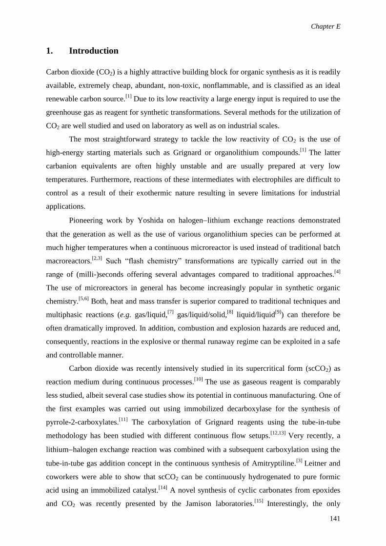
Chapter E
141
1. Introduction
Carbon dioxide (CO2) is a highly attractive building block for organic synthesis as it is readily
available, extremely cheap, abundant, non-toxic, nonflammable, and is classified as an ideal
renewable carbon source.[1]
Due to its low reactivity a large energy input is required to use the
greenhouse gas as reagent for synthetic transformations. Several methods for the utilization of
CO2 are well studied and used on laboratory as well as on industrial scales.
The most straightforward strategy to tackle the low reactivity of CO2 is the use of
high-energy starting materials such as Grignard or organolithium compounds.[1]
The latter
carbanion equivalents are often highly unstable and are usually prepared at very low
temperatures. Furthermore, reactions of these intermediates with electrophiles are difficult to
control as a result of their exothermic nature resulting in severe limitations for industrial
applications.
Pioneering work by Yoshida on halogenlithium exchange reactions demonstrated
that the generation as well as the use of various organolithium species can be performed at
much higher temperatures when a continuous microreactor is used instead of traditional batch
macroreactors.[2,3]
Such “flash chemistry” transformations are typically carried out in the
range of (milli-)seconds offering several advantages compared to traditional approaches.[4]
The use of microreactors in general has become increasingly popular in synthetic organic
chemistry.[5,6]
Both, heat and mass transfer is superior compared to traditional techniques and
multiphasic reactions (e.g. gas/liquid,[7]
gas/liquid/solid,[8]
liquid/liquid[9]
) can therefore be
often dramatically improved. In addition, combustion and explosion hazards are reduced and,
consequently, reactions in the explosive or thermal runaway regime can be exploited in a safe
and controllable manner.
Carbon dioxide was recently intensively studied in its supercritical form (scCO2) as
reaction medium during continuous processes.[10]
The use as gaseous reagent is comparably
less studied, albeit several case studies show its potential in continuous manufacturing. One of
the first examples was carried out using immobilized decarboxylase for the synthesis of
pyrrole-2-carboxylates.[11]
The carboxylation of Grignard reagents using the tube-in-tube
methodology has been studied with different continuous flow setups.[12,13]
Very recently, a
lithiumhalogen exchange reaction was combined with a subsequent carboxylation using the
tube-in-tube gas addition concept in the continuous synthesis of Amitryptiline.[3]
Leitner and
coworkers were able to show that scCO2 can be continuously hydrogenated to pure formic
acid using an immobilized catalyst.[14]
A novel synthesis of cyclic carbonates from epoxides
and CO2 was recently presented by the Jamison laboratories.[15]
Interestingly, the only

Chapter E
142
lithiationcarboxylation sequence of heterocycles reported so far was carried out for the
conversion of furan and 2-chlorothiophene with n-BuLi and carbon dioxide at -30°C (in case
of the latter at 0°C) resulting in the corresponding acids after 2 - 3.5 minutes.[16]
The present study was designed in order to develop a facile and efficient flash
synthesis of carboxylic acids from terminal alkynes and heterocycles (Fig 1) in a multistep
continuous process. Therefore, the substrates were initially lithiated using suitable metalation
agents. The organometallic intermediate was then treated with a well-defined amount of CO2
and subsequently quenched yielding the desired target molecules within a few seconds.
Figure 1. Carboxylation of alkynes and heterocycles using organolithium bases and CO2.
2. Results and Discussion
Phenylacetylene (1a) was chosen as model substrate to establish a setup for the
metalationcarboxylation sequence with lithium bis(trimethylsilyl)amide (LiHMDS) and CO2
in a gas/liquid continuous flow regime. We initially optimized the parameters required for the
carboxylation step by mixing a solution of LiHMDS and 1a in THF with the gaseous reagent
in a T-mixing unit.[17]
After an intensive evaluation of various reaction parameters, including
gas and liquid flow rates, residence time, temperature as well as back pressure regulation it
was established that the carboxylate is formed in sufficient amounts within ~0.5 seconds at
room temperature. The next logical step was to combine the gas/liquid carbon dioxide fixation
with an on-demand continuous flow generation of the reactive intermediate.[17]
Importantly,
this could be easily implemented using an additional mixer in combination with a 0.1 mL
residence time, resulting in the 4-feed approach shown in Fig. 2.[18]
In the final setup, a liquid stream of a commercially available 1M solution of LiHMDS
in THF was mixed with the alkyne dissolved in THF via a T-mixer. The flow rates and
substrate concentration were set in order to obtain a slight excess of the lithium amide (1.1
equiv). After a residence time of ~3 seconds the lithium alkynate was mixed with the gaseous
reagent in a second T-mixer resulting in a completely homogenous gas/liquid mixture at a

Chapter E
143
back pressure of 10 bar. It has to be pointed out that the CO2 flow rate of 19 mLN min-1
corresponds to a comparably low excess (1.2 equiv) and therefore constitutes an almost
quantitative consumption of the greenhouse gas. However, we additionally realized that the
performance of the CO2 mass flow controller had to be stabilized by preheating the gas to
65°C in a stainless steel coil.[19]
High conversions of the organolithium intermediate to the
corresponding carboxylate could be achieved within a short residence time of only ~0.5
seconds. It is worth noting, that the residence time can be accurately controlled using a water
quench before depressurization and collection of the reaction mixture. As small amounts of
precipitates were formed either during the carboxylation, or after adding H2O a 1 mL coil was
installed directly after the quench. During the time in which the reaction mixture passes this
residence unit all solids dissolved, allowing the reaction mixture to smoothly pass the
pressure-regulating unit.
Figure 2. Continuous flow set up for the synthesis of carboxylic acids with CO2.
With the optimized conditions in hand, we next evaluated our setup using several terminal
alkynes (Table 1). It has to be noted that in all examples, small amounts of the substrate were
still present in the reaction mixture as analyzed by HPLC-UV.[20]
Furthermore, we realized
that 1-10% of a byproduct was formed during the reaction which could be identified as a
trimethylsilane derivative apparently from a reaction of the base and the alkyne moiety.

Chapter E
144
Electron-rich (1a, 1b) and electron poor (1c, 1d, 1f) aromatic alkynes were transformed into
their corresponding carboxylic acids resulting in good yields after extraction of the
byproducts followed by acidification and crystallization. Unfortunately, it was not possible to
convert the phenol derivative 1e and 3-ethynylpyridine (1h) due to precipitation of either the
organometallic intermediate or, in case of 1h, the carboxylate, resulting in a clogged reactor.
However, we could expand the synthetic scope of our methodology by heterocyclic (1g) and
aliphatic (1i, 1j) substrates without further modifications.
The propiolic acids obtained are valuable synthetic intermediates for a range of
pharmaceutically or industrially relevant molecules, including polymers, coumarins, flavones,
spirobenzofuranes, spiroindoles or vinyl sulfides.[21]
Table 2 Preparation of propionic acids in continuous flowa
Substrate
Conversionb
(Selectivity)
(%)
Yieldc
(%) Substrate
Conversionb
(Selectivity)
(%)
Yieldc
(%)
93(99) 85
93(98) 89
94(92) 81
91(89) 81
91(98) 78
clogging --
97(95) 84
n.d.(n.d.)d 90
clogging --
n.d.(n.d.) 66
a Reactions were carried out using 1.42 mmol alkyne, for general conditions see Figure 2.
b Determined as
HPLC-UV peak area percent at 215 nm. c Isolated yield.
d Not determined.
In order to broaden the synthetic horizon of the lithiationcarboxylation flow reactor concept,
we decided to test the same methodology for its suitabilityto convert heterocycles into their
corresponding carboxylic acids. Initially we decided to use the lithiation of thiophene (3a) by

Chapter E
145
lithium diisopropylamide (LDA) with subsequent carboxylation for a feasibility study. In an
initial experiment the reactor clogged immediately after the water quench which prompted us
to change to a mixture of water and acetic acid (10:1) to overcome this hurdle. Gratifyingly,
thiophene-2-carboxylic acid (4a) could be isolated by extraction after this minor modification
in satisfying yields without any further re-optimization of the continuous method (Fig. 3). An
additional experiment using significantly higher amounts of CO2 (1.9 equiv) resulted in only
slightly higher amounts of the desired target molecule. Methyl substituted thiophenes (3b, 3c)
as well as benzofuran (3f) provided moderate yields. Further optimization studies using 3b
and either a higher excess of LDA (2M, 2.2 equiv) or larger amounts of carbon dioxide (30
mLN min-1
, 1.9 equiv) did not result in a significant improvement. In case of 1-phenylpyrazole
the reactor immediately clogged after mixing with the organometallic base as the intermediate
is apparently completely insoluble in THF. However, the use of electron poor thiophenes (4d,
4e) expanded the synthetic potential of the presented continuous flow methodology.
Fig. 3 LDA mediated carboxylation of heterocycles in flowa
a
Reactions were carried out using 1.42 mmol alkyne, for
all general conditions see Figure 2. b
Reaction was carried
out using 1.9 equiv CO2 (30 mLN min-1
).
3. Conclusion
In summary, we have developed a fast and efficient process for the continuous lithiation and
subsequent carboxylation with carbon dioxide of terminal alkynes and heterocycles. The
presented method provides valuable carboxylic acids within ~3.5 seconds reaction time using
low excess of the organometallic base and the gaseous reagent in moderate to good isolated
yields.

Chapter E
146
4. References
[1] (a) T. Sakaura, J.-C. Choi, H. Yasuda, Chem. Rev. 2007, 107, 2365; (b) M. Aresta,
A. Dibeneedetto, Dalton Trans. 2007, 2975; (c) I. Omae, Coord. Chem. Rev. 2012,
256, 1384; (d) X. Cai, B. Xie, Synthesis, 2013, 45, 3305.
[2] (a) A. Nagaki, D. Ichinari, J.Yoshida, Chem. Commun. 2013, 49, 3242; (b) A.
Nagaki, Y. Uesugi, H. Kim, J. Yoshida, Chem. Asian J. 2013, 8, 705; (c) A.
Nagaki, Y. Takahashi, S. Yamada, C. Matsuo, S. Haraki, Y. Moriwaki, S. Kim, J.
Yoshida, J. Flow. Chem. 2012, 2, 70; (d) A. Nagaki, Y. Moriwaki, S. Haraki, A.
Kenmoku, A. Hayashi, J. Yoshida, Chem. Asian J. 2012, 7, 1061.
[3] L. Kupracz , A. Kirschning, Adv. Synth. Catal. 2013, 355, 3375.
[4] (a) J. Yoshida, Y. Takahashi, A. Nagaki, Chem. Commun. 2013, 49, 9896; (b) J.
Yoshida, Chem. Rec. 2010, 10, 323; (c) J. Yoshida, Flash Chemistry: Fast
Organic Synthesis in Microsystems, Wiley-Blackwell, Oxford, U.K. 2008.
[5] For selected books see: (a) W. Ehrfeld, V. Hessel, H. Lowe, Microreactors,
Wiley-VCH, Weinheim, Germany, 2000; (b) V. Hessel, S. Hardt, H. Lowe,
Chemical Micro Process Engineering, Wiley-VCH, Weinheim, Germany, 2004;
(c) V. Hessel, A. Renken, J. C. Schouten, J. Yoshida, Micro Process Engineering,
Wiley-Blackwell, Oxford, U.K., 2009; (d) T. Wirth, Microreactors in Organic
Synthesis and Catalysis, Wiley-VCH, Weinheim, Germany, 2nd edn., 2013.
[6] For recent reviews see: (a) R. L. Hartman, J. P. McMullen, K. F. Jensen, Angew.
Chem. Int. Ed. 2011, 50, 7502; (b) J. Wegner, S. Ceylan , A. Kirschning, Adv.
Synth. Catal. 2012, 354, 17; (c) C. Wiles, P. Watts, Green Chem. 2012, 14, 38; (d)
S. G. Newman, K. F. Jensen, Green Chem. 2013, 15, 1456; (e) S. C. Stouten, T.
Noel, Q. Wang, V. Hessel, Aust. J. Chem., 2013, 66, 121.
[7] For recent publications on continuous gas/liquid chemistry from our laboratories,
see: (a) B. Gutmann, P. Elsner, D. Roberge, C. O. Kappe, ACS Catal. 2013, 3,
2669; (b) F. Mastronardi, B. Gutmann, C. O. Kappe, Org. Lett. 2013, 16, 5590; (c)
B. Pieber, S. T. Martinez, D. Cantillo, C. O. Kappe, Angew. Chem. Int. Ed. 2013,
52, 10241; (d) B. Pieber, C. O. Kappe, Green Chem. 2013, 15, 320.
[8] For a recent publications on continuous gas/liquid/solid chemistry from our
laboratories, see: D. Obermayer, A. M. Balu, A. A. Romero, W. Goessler, R.
Luque, C. O. Kappe, Green Chem. 2013, 15, 1530.

Chapter E
147
[9] For recent publications on continuous liquid/liquid chemistry from our
laboratories, see: (a) B. Reichart, T. N. Glasnov, C. O. Kappe, Synlett 2013, 24,
239; (b) M. Damm, B. Gutmann, C. O. Kappe, ChemSusChem 2013, 6, 978.
[10] (a) U. Hintermair, G. Francio, W. Leitner, Chem. Eur. J. 2013, 19, 4538; (b) J.
Theuerkauf, G. Francio, W. Leitner, Adv. Synth. Catal. 2013, 355, 209; (c) M. J.
Casciato, G. Vevitin, D. W. Hess, M. A. Grover, ChemSusChem, 2012, 5, 1186;
(d) M. Selva, S. Guidi, A. Perosa, M. Signoretto, P. License, T. Maschmeyer,
Green Chem. 2012, 14, 2727.
[11] T. Matsuda, R. Marukado, S. Koguchi, T. Nagasawa, M. Mukouyama, T. Harada,
K. Nakamura, Terahedron Lett. 2008, 49, 6019.
[12] A. Polyzos, M. O’Brien, T. P. Petersen, I. R. Baxendale, S. V. Ley, Angew. Chem.
Int. Ed. 2011, 50, 1190.
[13] J. J. F. van Gool, S. A. M. W. van den Broek, R. M. Ripken, P. J. Nieuwland, K.
Koch, F. P. J. T. Rutjes, Chem. Eng. Technol. 2013, 36, 1042.
[14] S. Wesselbaum, U. Hintermair, W. Leitner, Angew. Chem. Int. Ed. 2012, 51, 8585.
[15] J. A. Kozak, J. Wu, F. Simeon, T. A. Hatton, T. F. Jamison, J. Am. Chem. Soc.,
2013, 153, 18497.
[16] S. Buchholz, C. Severins, K. Tellmann, K. Weidemann, J. Wieschemeyer, Ger.
Pat., DE102009060033, 2011.
[17] A detailed summary of the optimization see Table S1& S2 in the ESI.
[18] For a detailed description including images of the continuous flow set up, see ESI.
[19] The mass flow controller was not able to control the gaseous reagent in a stable
fashion, presumably due to condensation.
[20] A representative HPLC chromatogram is given in the ESI (Figure S3).
[21] F. Manjolinho, M. Arndt, K. Gooßen , L. J. Gooßen, ACS Catal. 2012, 2, 2014.

Chapter E
148
5. Supporting Information
General Remarks. All substrates and reagents were purchased from Sigma-Aldrich and were
used without further purification. THF (HPLC grade) was dried using molecular sieves (3Å)
prior to use. 1H-NMR and
13C spectra were recorded on a Bruker 300 MHz instrument using
DMSOd6 or CDCl3 as solvent. Chemical shifts (δ) are expressed in ppm downfield from TMS
as internal standard. The letters s, d, t, q, and m are used to indicate a singlet, doublet, triplet,
quadruplet, and multiplet respectively. Melting points were determined on a Stuart™ SMP3
melting point apparatus. Analytical HPLC (Shimadzu LC20) analysis was carried out on a
C18 reversed-phase (RP) analytical column (150 × 4.6 mm, particle size 5 μm) at 25 °C using
a mobile phase A (water/acetonitrile 90:10 (v/v) + 0.1 % TFA) and B (MeCN + 0.1 % TFA)
at a flow rate of 1.0 mL/min. The following gradient was applied: linear increase from
solution 30% B to 100 % B in 8 min, hold at 100% solution B for 2 min. All synthesized
compounds have been characterized by 1H and
13C NMR analysis as well as their melting
points and identified by data reported in literature.
Continuous Flow Set up
Figure S1. 4-Feed gas/liquid continuous flow reactor for carboxylation using CO2. Carbon
dioxide is preheated using a stainless steel coil (~10 mL) in an oil bath (OB) set at 65°C
before entering the mass flow controller (MFC).[S1]
The liquid flow rate of the organometallic
base and the substrate in dry THF is controlled using HPLC pumps (P1,P2). The reagents are
loaded in either a 4 mL (substrate, SL1) or a 3 mL (base, SL2) sample loop and can be
introduced in the flow system by 6 way valves (6W1, 6W2).[S2]
The reaction zone (RZ) is
explained in more detailed below (Figure S2). For adding the water quench a third HPLC
pump (P3) is used. The reaction mixture and the quench solution pass a 1 mL coil (Coil) for
dissolving any precipitates. Pressure regulation occurs in a static 10 bar back pressure
regulator (BPR).

Chapter E
149
Figure S2. Reaction Zone. The substrate solution is mixed with the organometallic base in a
T-mixing unit (T1, i.d. 0.5 mm). Metalation is carried out in a residence time unit made of
PTFE (R1, i.d. 0.8 mm, 0.1 mL). The organometallic intermediate is mixed with CO2 in a
second T-mixer (T2, i.d. 0.5 mm) entering a second residence coil (R2, PTFE, i.d. 0.8 mm,
0.02 mL). The reaction is then quenched in a third mixing unit (T3, i.d. 0.5 mm) before
reaching the back pressure regulator.
General Conditions for Using the Mass Flow Controller[S1]
with CO2. The pressure
regulator of the gas cylinder was set at 30-40 bar and the system was first flushed with the
maximum CO2 flow rate (74 ml min-1
). As soon as the system pressure was reached (~10 bar)
the liquid streams were activated. After 2-5 minutes additional flushing at the maximum gas
the desired gas flow rate was chosen and experiments were started after the gas flow rate got
stable.
Cleaning Procedure. In order to avoid clogging or other serious problems during the course
of this research study the reactor was flushed with a cleaning solvent after use. The solvent
mixture of choice for such efforts is AcOH:THF:H2O (1:1:1) which removes all impurities
caused by the organometallic reagent/intermediate and traces of water within the reaction
solvents. After washing, the reactor was additionally flushed/stored in iPrOH.

Chapter E
150
Optimization
Table S1. Optimization of the carboxylation parameters.a
Entry T (RTU)
[°C]
RTU
[V]
Liquid Flow
(P1)
[mL min-1
]
Gas Flow
[mL min-1
]
BPR
[bar]
A
[%]c
B
[%]c
C
[%]c
1 100 10 0.8 45(9.0)b
17 93 7 <1
2 80 10 0.8 45(9.0) 17 96 4 <1
3 60 10 0.8 45(9.0) 17 95 5 <1
4 r.t. 10 0.8 45(9.0) 17 97 3 <1
5 r.t. 10 0.8 45(9.0) 10 97 3 <1
6 r.t. 10 1.5 45(4.8) 10 96 4 <1
7 r.t. 4.0 2 15(1.2) 10 90 5 4
8 r.t. 4.0 2.5 19(1.2) 10 94 5 1
9 r.t. 2.0 3 23(1.2) 10 88 6 6
10 r.t. 1.0 2.5 19(1.2) 10 91 7 1
11 r.t. 1.0 3 23(1.2) 10 93 4 3
12 r.t. 0.1 2.5 19(1.2) 10 92 3 5
13 r.t. 0.02 2.5 19(1.2) 10 92 5 3 a Conditions: 1 mmol phenylacetylene and 1.1 mmol LiHMDS (1M in THF) were dissolved in 2 mL dry
THF and injected via a sample loop. b
CO2 equivalents in parentheses. c
Determined as HPLC-UV/VIS
peak area percent at 215 nm.

Chapter E
151
Table S2. Implementation of the metalation step.a
Entry Coil 1
[V]
Liquid Flow
(P1)
[mL min-1
]
Liquid Flow
(P2)
[mL min-1
]
A
[%]b
B
[%]b
C
[%]b
1 1 0.7 1.8 87 5 8
2 0.1 0.7 1.8 88 5 7
3 0.02 0.7 1.8 74 14 12 a
The reaction was carried out using 1.42 mmol phenylacetylene. c
Determined as HPLC-
UV/VIS peak area percent at 215 nm.
Figure S3. Representative HPLC-UV/VIS chromatogram (215 nm) for the carboxylation of
phenylacetylene under the optimized conditions (Table S2, Entry 2)

Chapter E
152
General experimental procedure for the synthesis of carboxylic acids from alkynes and
heterocycles (Table 1, Figure 3). The respective alkyne or heterocycle (1.42 mmol) in dry
THF (4 mL) and 3 mL of either an1 M solution of LiHMDS in THF (commercially available)
or an 1M solution of LDA in THF/hexanes (commercially available) were loaded into
individual sample loops. Pump 1 was set at 1.8 mL min-1
and pump 2 at 0.7 mL min-1
. Sample
loop 2 containing the base was switched 45 seconds prior to sample loop 1 to injecting mode
in order to avoid diffusion phenomena and guarantee a proper stoichiometry. The 2 streams
were combined in a T-mixing unit before passing a 0.1 mL residence time unit. Afterwards,
the mixture entered a second T-mixer where CO2 was introduced at 19 mLN min-1
.
Carboxylation occurs in a second residence time unit (0.02 mL) prior to a third mixer where,
in case of LiHMDs a water quench (1 mL min-1
), or in case of LDA a water:AcOH quench
(10:1, 1 mL min-1
) was added. The mixture was finally collected after passing a 10 bar static
back pressure regulator.
Work up A. THF was removed under reduced pressure and the aqueous residue was
extracted twice using Et2O (15 mL). The organic layer was discarded and the aqueous phase
was acidified using concentrated HCl until precipitation (pH ~1). The mixture was cooled in
an ice bath, the solid collected by filtration and carefully washed with cold, aqueous HCl
(1M) to furnish analytically pure carboxylic acids after drying in a desiccator under reduced
pressure.
Work up B. THF was removed under reduced pressure and the aqueous residue was
extracted twice using Et2O (15 mL). The organic layer was discarded and the aqueous phase
was acidified using HCl (pH ~1). Afterwards, Et2O (20 mL) was added to extract the
carboxylic acid. The organic phase was washed with brine and dried over Na2SO4.
Evaporation of the organic solvent afforded the respective carboxylic acids which were finally
dried in a desiccator under reduced pressure.
3-Phenylpropiolic acid (Table 1, 2a). From phenylacetylene (145.1 mg, 1.42mmol) and
LiHMDS. Work up A resulted in the title compound as white solid in 85% (177.2 mg, 1.21
mmol). m.p. 132-134°C 1H NMR (300 MHz, DMSO) δ 13.81 (br, s, 1H), 7.63 (d, J = 7.4 Hz,
1H), 7.55 (t, J = 6.8 Hz, 1H), 7.47 (t, J = 7.5 Hz, 1H). 13
C NMR (75 MHz, DMSO) δ 154.72,
133.04, 131.36, 129.48, 119.40, 84.84, 82.18.

Chapter E
153
3-(p-Tolyl)propiolic acid (Table 1, 2b). From 4-ethynyltoluene (164.9 mg, 1.42 mmol) and
LiHMDS. Work up A resulted in the title compound as white solid in 81% (184.0 mg, 1.15
mmol). m.p. 143-144°C1H NMR (300 MHz, DMSO) δ 13.75 (br, s, 1H), 7.52 (d, J = 8.1 Hz,
2H), 7.28 (d, J = 8.0 Hz, 2H), 2.35 (s, 2H).13
C NMR (75 MHz, DMSO) δ 154.81, 141.62,
133.04, 130.11, 116.33, 85.31, 81.86, 21.66.
3-(4-Chlorophenyl)propiolic acid (Table 1, 1c). From 1-chloro-4-ethynylbenzene (194.0
mg, 1.42 mmol) and LiHMDS. Work up A resulted in the title compound as white solid in
78% (199.2 mg, 1.10 mmol). m.p. 184-186°C1H NMR (300 MHz, DMSO) δ 13.93 (br, s,
1H), 7.66 (d, J = 8.5 Hz, 2H), 7.55 (d, J = 8.4 Hz, 2H).13
C NMR (75 MHz, DMSO) δ 154.58,
136.28, 134.82, 129.71, 118.32, 83.55, 83.01.
3-(4-Methoxyphenyl)propiolic acid (Table 1, 1d). From 4-ethynylanisole (187.5 mg, 1.42
mmol) and LiHMDS. Work up A resulted in the title compound as off-white solid in 84%
(211.1 mg, 1.20mmol). m.p. 139-140°C1H NMR (300 MHz, DMSO) δ 13.63 (br, s, 1H), 7.59
(d, J = 8.8 Hz, 2H), 7.02 (d, J = 8.9 Hz, 2H), 3.81 (s, 1H).13
C NMR (75 MHz, DMSO) δ
161.66, 154.96, 135.12, 115.19, 111.00, 85.75, 81.51, 55.94, 55.89.
3-(4-(Trifluoromethyl)phenyl)propiolic acid (Table 1, 1f). From 4-ethynyl-α,α,α-
trifluorotoluene (240.9 mg, 1.42 mmol) and LiHMDS. Work up A resulted in the title
compound as white solid in 89% (270.3 mg, 1.26mmol). m.p. 142-145°C1H NMR (300 MHz,
DMSO) δ 14.11 (br, s, 1H), 7.92 – 7.79 (m, 4H).13
C NMR (75 MHz, DMSO) δ 154.36,
133.78, 131.11, 130.68, 126.36, 126.32, 126.27, 126.22, 125.94, 123.81, 123.79, 122.33,
83.91, 82.72.
3-(Thiophen-3-yl)propiolic acid (Table 1, 1g). From 3-ethynylthiophene (153.2 mg, 1.42
mmol) and LiHMDS. Work up B resulted in the title compound as off-white solid in 81%
(174.6 mg, 1.15mmol).m.p. 133-135°C1H NMR (300 MHz, DMSO) δ 13.76 (br, s, 1H), 8.20
(dd, J = 2.8, 1.0 Hz, 1H), 7.71 (dd, J = 5.0, 2.9 Hz, 1H), 7.33 (dd, J = 5.0, 1.0 Hz, 1H).13
C
NMR (75 MHz, DMSO) δ 154.84, 135.34, 130.38, 128.23, 118.35, 82.00, 80.77.

Chapter E
154
3-Cyclohexylpropiolic acid (Table 1, 1i). From ethynylcyclohexane (153.6 mg, 1.42 mmol)
and LiHMDS. Work up A resulted in the title compound as yellow oil in 90% (193.6 mg, 1.27
mmol).1H NMR (300 MHz, DMSO) δ13.38 (br, s, 1H), 2.68 – 2.55 (m, 1H), 1.77 (m, 2H),
1.63 (m, 2H), 1.53 – 1.21 (m, 6H). 13
C NMR (75 MHz, DMSO) δ 154.82, 91.72, 74.61, 31.51,
28.21, 25.52, 24.53.
3-Cyclopentylpropiolic acid (Table 1, 1j). From ethynylcyclopentene (133.6 mg, 1.42
mmol) and LiHMDS. Work up A resulted in the title compound as off-white solid in 66%
(128.9 mg, 0.93mmol). m.p. 55-57°C 1H NMR (300 MHz, DMSO) δ 13.33 (br, s, 1H), 2.93 –
2.68 (m, 1H), 2.07 – 1.78 (m, 2H), 1.77 – 1.42 (m, 6H).13
C NMR (75 MHz, DMSO) δ 154.80,
92.31, 74.15, 33.09, 29.27, 25.16.
Thiophene-2-carboxylic acid (Figure 3, 4a). From thiophene (119.3 mg, 1.42 mmol) and
LDA. Work up B resulted in the title compound as white solid in 79% (143.8 mg, 1.12mmol).
m.p. 125-127°C. 1H NMR (300 MHz, DMSO) δ 13.02 (s, 1H), 7.88 (d, J = 4.9 Hz, 1H), 7.73
(d, J = 2.5 Hz, 1H), 7.18 (m, 1H). 13
C NMR (75 MHz, DMSO) δ 163.37, 135.08, 133.73,
133.66, 128.68.
5-Methylthiophene-2-carboxylic acid (Figure 3, 4b). From 2-methylthiophene (138.9 mg,
1.42 mmol) and LDA. Work up A resulted in the title compound as off-white solid in 48%
(95.6 mg, 0.67mmol). m.p. 132-134°C. 1H NMR (300 MHz, CDCl3) δ 10.41 (s, 1H), 7.73 (d,
J = 3.7 Hz, 1H), 6.83 (d, J = 3.7 Hz, 1H), 2.57 (s, 3H). 13
C NMR (75 MHz, CDCl3) δ 167.60,
149.98, 135.60, 130.02, 126.79, 15.95.
4-Methylthiophene-2-carboxylic acid (Figure 3, 4c). From3-methylthiophene (139.1 mg,
1.42 mmol) and LDA. Work up A resulted in the title compound as off-white solid in 43%
(85.7 mg, 0.60mmol). m.p. 118-120°C. 1H NMR (300 MHz, DMSO) δ 12.96 (s, 1H), 7.56 –
7.53 (m, 1H), 7.47 (s, 1H), 2.23 (s, 3H). 13
C NMR (75 MHz, DMSO) δ 163.38, 138.68,
135.42, 134.60, 129.07, 15.66.

Chapter E
155
5-Chlorothiophene-2-carboxylic acid (Figure 3, 4d). From2-chlorothiophene (167.8 mg,
1.42 mmol)and LDA. Work up A resulted in the title compound as light brown solid in 72%
(166.7 mg, 1.03mmol). m.p. 149-151°C. 1H NMR (300 MHz, DMSO) δ 13.45 (s, 1H), 7.61
(d, J = 4.0 Hz, 1H), 7.23 (d, J = 4.0 Hz, 1H). 13
C NMR (75 MHz, DMSO) δ 162.25, 135.25,
133.88, 133.66, 128.96.
Benzo[b]thiophene-2-carboxylic acid (Figure 3, 4e). Frombenzo[b]thiophene(190.3 mg,
1.42 mmol) and LDA. Work up A resulted in the title compound as white solid in 70% (176.2
mg, 0.99mmol). m.p. 238-240°C. 1H NMR (300 MHz, DMSO) δ 13.47 (s, 1H), 8.12 (s, 1H),
8.08 – 7.98 (m, 2H), 7.56 – 7.42 (m, 2H). 13
C NMR (75 MHz, DMSO) δ 163.99, 141.77,
139.18, 135.18, 130.72, 127.49, 126.20, 125.53, 123.44.
Benzofuran-2-carboxylic acid (Figure 3, 4f) From benzofuran(190.3 mg, 1.42 mmol) and
LDA. Work up A resulted in the title compound as yellow solid in 46% (105.3 mg,
0.65mmol). m.p. 190-192°C. 1H NMR (300 MHz, DMSO) δ 13.58 (s, 1H), 7.79 (d, J = 7.6
Hz, 1H), 7.74 – 7.64 (m, 2H), 7.51 (t, J = 7.6 Hz, 1H), 7.35 (t, J = 7.5 Hz, 1H). 13
C NMR (75
MHz, DMSO) δ 160.54, 155.42, 146.60, 128.02, 127.29, 124.28, 123.55, 113.97, 112.53.
References
[S1] http://www.thalesnano.com
[S2] http://www.uniqsis.com


Chapter F
157
F. Continuous Synthesis of Hydantoins: Intensifying the Bucherer-Bergs
Reaction
Graphical Abstract
Abstract
A continuous Bucherer-Bergs hydantoin synthesis utilizing intensified conditions is reported.
The methodology is characterized by a 2-feed flow approach to independently feed the
organic substrate and the aqueous reagent solution. The increased interfacial area of the
biphasic reaction mixture and the lack of headspace enabled almost quantitative conversions
within ~30 min at 120°C and 20 bar even for unpolar starting materials. In addition, a
selective N(3)-monoalkylation of the resulting heterocycles under batch microwave conditions
is reported yielding potential acetylcholinesterase inhibitors.


Chapter F
159
1. Introduction
The hydantoin scaffold is an important structural motif with a broad range of biological
activities.[1]
Potential applications for medicinal purposes include the utilization as androgen
receptor modulators,[2]
anticonvulsant-,[3]
antidiabetic-,[4]
or anticancer agents.[5]
From an
industrial point of view, one of the simplest representatives of this compound class, 5,5-
dimethylhydantoin (DMH), is a key intermediate in the synthesis of several commodity
chemicals such as 1,3-dichloro-5,5-dimethylhydantoin, 1-bromo-3-chloro-5,5-
dimethylhydantoin and 1,3-dibromo-5,5-dimethylhydantoin. These N,N’-dihalogenated
analogues of DMH are widely used as biocides for e.g. water treatment [6]
and have also
shown high potential as halogenation agents or oxidants in organic synthesis.[7]
A plethora of synthetic strategies are known to construct the heterocyclic core
structure from a broad range of precursor molecules.[1,8]
Among those, the Bucherer-Bergs
reaction is presumably the most commonly used methodology to generate hydantoins from
aldehydes or ketones (Scheme 1).[1]
Mechanistically, the carbonyl compound initially reacts
with ammonia and the cyanide anion forming an α-aminonitrile.[1,9]
Nucleophilic addition of
this intermediate to CO2 generates a cyano-carbamic acid which undergoes a cyclization-
rearrangement sequence to finally result in the hydantoin scaffold. From a practical point of
view, the reaction is generally carried out by heating a mixture of the starting material,
potassium cyanide and ammonium carbonate −which thermally decomposes into ammonia
and carbon dioxide− in a mixture of water and ethanol at reflux for several hours or even
days.[1]
It has to be stressed that significant amounts of ammonia and carbon dioxide are lost
due to their volatility using traditional batch techniques. The highly polar reaction mixture can
cause severe solubility problems for certain substrates resulting in a rather inefficient
processes.[8c]
Moreover, heating an aqueous solutions of potassium cyanide poses severe
safety hazards especially on larger scales.
Scheme 1. Synthesis of hydantoins via the Bucherer-Bergs reaction.

Chapter F
160
We hypothesized that a continuous process using microreactor technology can potentially
overcome limitations associated with this multicomponent reaction.[10-12]
In continuous flow
mode reactions can be easily conducted without any headspace at high temperatures, while
working at high pressure conditions to keep the gaseous reagents in solution.[10]
Such “novel
process windows” enable intensified processes even far above the boiling point of the reaction
medium in a safe and scalable manner.[10,13]
Biphasic liquid/liquid reactions can be efficiently
carried out by generating a segmented flow pattern with significantly larger interfacial areas
compared to traditional batch techniques.[14]
Consequently, a modified Bucherer-Bergs
reaction in continuous flow utilizing an aqueous solution of KCN and (NH4)2CO3 in
combination with an organic solution of the carbonyl compound would result in a efficient
protocol even for highly unpolar starting materials which often suffer from low conversions in
the traditional batch protocol.
2. Results and Discussion
To confirm these assumptions, a two-feed setup was assembled utilizing high pressure syringe
pumps for both the organic (feed A) and the aqueous stream (feed B) in order to precisely
control reagent stoichiometry.[15]
The solutions were merged in a T-shaped mixing unit and
the combined stream then entered a heated Hastelloy coil (16 mL) to perform the
multicomponent hydantoin synthesis. The reaction mixture left the continuous flow system
through an adjustable stainless steel back pressure regulator. Acetophenone (1a) was chosen
as starting material for an initial process intensification study under continuous flow
conditions (Table 1). Since the liquid starting material can be easily pumped without the need
of any organic solvent, the neat ketone was first utilized for feed A (Entry 1). Unfortunately,
the resulting heterocycle (2a) precipitated inside the flow system resulting in reactor clogging.
Thus, various alcohols were tested for their applicability as suitable (co-)solvents (Entry 2-4).
By additionally heating the back pressure regulating unit to 100-120°C on a standard hot plate
blocking of the system could be avoided for all tested alcohols and promising conversions
were obtained. However, we realized that mixing of the two phases led to a poorly defined
flow pattern since the alcohol dissolved in the aqueous phase whereas the relatively unpolar
starting material travels slowly on the channel wall.[16]
Hence, different residence times for
the aqueous and the organic phase were observed making a precise control of reagent
stoichiometry impossible. Gratifyingly, by using ethyl acetate as organic solvent a well-
defined segmented flow pattern was obtained allowing for accurate processing of the reaction
mixture (Entry 5).[16]

Chapter F
161
Table 1. Optimization of the Bucherer-Bergs reaction in continuous flow.
Entry Solvent
(M)
Feed A/B
(µL min-1
)
tRes
[min]
KCN/(NH4)2CO3
(equiv.)
Conversion
(%)a
1 - 166 / 834 16 1.2 / 3.0 clogging
2b
EtOH (4) 166 / 834 16 1.2 / 3.0 90
3b
MeOH (4) 166 / 834 16 1.2 / 3.0 93
4b i-PrOH (4) 166 / 834 16 1.2 / 3.0 92
5 EtOAc (4) 166 / 834 16 1.2 / 3.0 72
6 EtOAc (4) 83 / 417 32 1.2 / 3.0 80
7c EtOAc (4) 83 / 417 32 1.2 / 3.0 55
8d EtOAc (4) 83 / 417 32 1.2 / 3.0 60
9 EtOAc (5) 83 / 417 32 1.2 / 3.0 88
10 EtOAc (5) 70 / 430 32 1.2 / 3.0 87
11 EtOAc (5) 70 / 430 32 1.5 / 3.5 96 (91)e
12 EtOAc (5) 70 / 490 29 1.5 / 4.0 95 aDetermined as HPLC peak area percent at 215 nm.
bAccurate control of the stoichiometry was
impossible due to an undefined flow pattern. cReaction was performed at 100°C.
dReaction was
performed at 140°C.eIsolated yield in parentheses.
Systematic optimization of the reaction parameters resulted in an almost quantitative
consumption of 1a within 32 min and excellent isolated yields were obtained for the
corresponding hydantoin 2a (Entry 5-11). Notably, under the final conditions a saturated
aqueous solution of KCN and (NH4)2CO3 was utilized resulting in a productivity of ~19 mmol
h-1
. A batch control experiment employing a dedicated 10 mL microwave autoclave resulted
in significantly lower conversions (~40%) using a 3.5 mL reaction volume under identical
conditions.[17-19]
This is presumably resulting from the lower interfacial area of the biphasic
mixture and the fact that a significant amount of (NH4)2CO3 sublimed at the top of the 10 mL
reaction vessel.[18]
Reduction of the headspace by using a larger reaction volume (7 mL) gave
even lower conversion (15%), likely due to inefficient stirring of the biphasic reaction
mixture.[18]
Utilization of an improved stir bar design which was recently developed in our
laboratories improved the hydantoin formation to 77% which is still significantly below the
performance of the continuous flow reactor (96%).[18,20]

Chapter F
162
Table 2. Scope of the continuous Bucherer-Bergs reaction.a
Entry Substrate Solvent c [M]b
Yield (%)c
1
EtOAc
5 91
2
EtOAc
5 72
3
EtOAc
5 90
4
EtOAc
5 78
5
EtOAc
5 95
6
EtOAc
( 5 88
7
EtOAc
3 92
8
EtOAc
2 99
9
DMF:EtOAc (2:1) 0.5 96
10
neat neat 82
aFlow reactions were performed using two independent pumps for the aqueous and organic feed.
All reactions were performed in a 16 mL Hastelloy coil. To avoid clogging the back pressure
regulator was heated to ~120 °C. cSubstrate concentration in feed A.
cIsolated yields.

Chapter F
163
Encouraged by these promising results, the applicability of the optimized protocol was further
tested to demonstrate the versatility of the continuous strategy (Table 2).[21]
Gratifyingly,
various aromatic and aliphatic carbonyl compounds could be processed without the need for
any re-optimization and the desired hydantoins were obtained in good to excellent isolated
yields (Entry 1-6). In case of 3-methoxybenzaldehyde (1h), the low solubility of the resulting
heterocycle required a less concentrated organic feed to avoid clogging of the reactor (Entry
7). The same issue necessitated even lower concentrations or a different solvent system for
the synthesis of spirohydantoins 2i and 2j in almost quantitative yields (Entry 8-9). In
contrast, for the industrially relevant hydantoin DMH (2k) no organic solvent was required
resulting in an efficient, gram-scale continuous flow process (Entry 10). It has to be pointed
out that no segmented flow pattern was observed in this case since the starting material,
acetone (1k), was completely soluble in the aqueous reagent mixture.[16]
However, a
quantitative multicomponent reaction was observed and DMH (2k) could be isolated in 60 %
by crystallization from the reaction mixture which is in good agreement with data reported in
the literature.[22]
By carefully extracting the mother liquor multiple times with EtOAc the
yield could be further increased to 82 % resulting in a productivity of 20 mmol h-1
.
Noteworthy, it was recently reported that hydantoins can possibly be applied to treat
neurodegenerative disorders such as Alzheimer’s or Parkinsons’s disease, by inhibition of
acetylcholinesterase enzyme (AChE), which is mainly responsible for regulation of the
neurotransmitter acetylcholine (ACh).[23]
In this context, preliminary unpublished results from
our laboratories, employing an immobilized acetylcholinesterase capillary reactor,[24]
indicated that the heterocyclic compounds 2a and 2k show moderate activity for the inhibition
of AChE. We hypothesized that installing an aliphatic tertiary amine group mimicking the
ACh scaffold increases the affinity to AChE, simultaneously improving their biological
activity (Scheme 2). Similar structural motifs were already demonstrated to exhibit significant
antimicrobiological activity.[25]
Scheme 2. Structural modification of hydantoins to mimic acetylcholine (ACh).

Chapter F
164
Initial experiments using (2-bromoethyl)trimethylammonium bromide (n=2) suffered from
extremely low conversions presumably due to steric hindrance of the brominated carbon
atom.[25]
However, by using (5-bromopentyl)trimethylammonium bromide (3, n=5) satisfying
conversions were determined by HPLC analysis.[26]
A subsequent optimization study with the
aid of microwave dielectric heating technology utilizing a dedicated batch reactor, resulted in
an efficient, selective N(3)-monoalkylation of hydantoins 2a-k (Scheme 3).[17,27]
Scheme 3. Synthesis of N(3)-substituted hydantoins in batch. aAn insoluble material was
obtained. bReaction resulted in a complex mixture.

Chapter F
165
Depending on the starting material 10-45 min at 120°C in acetonitrile were sufficient to
synthesize several hitherto undisclosed hydantoins (4a, 4c-f, 4i-k) using 1.2 equiv. of 3 and
1.1 equiv. of K2CO3 as base. In case of 2g, a complex reaction mixture was observed and the
corresponding ammonium salt (4g) could not be isolated. For the structurally similar
hydantoins 4b and 4h an insoluble white solid was obtained which could not be characterized
by NMR analysis.
3. Conclusion
In conclusion, a highly intensified continuous variant of the Bucherer-Bergs hydantoin
synthesis was developed. Key to the success was the utilization of a well-defined segmented
flow pattern to overcome solubility issues for unpolar starting materials and to significantly
increase the interfacial areas compared to traditional batch techniques. The lack of gaseous
headspace under high pressure conditions avoids sublimation/volatilization of the in situ
generated gaseous reagents (NH3, CO2). In addition, a microwave batch protocol for the
selective N(3)-monoalkylation of the resulting hydantoin scaffolds is presented resulting in a
series of potential acetylcholinesterase inhibitors. The biological activity of the final N-
substituted hydantoins is currently under investigation in our laboratories.
4. References
[1] (a) M. Meusel, M. Gütschow, Org. Prep. Proc. Int. 2004, 36, 391; (b) E. Ware, Chem.
Rev. 1950, 46, 403.
[2] (a) F. Nique, S. Hebbe, C. Peixoto, D. Annoot, J.-M. Lefrancois, E. Duval, L.
Michoux, N. Triballeau, J.-M. Lemoullec, P. Mollat, M. Thauvin, T. Prange, D.
Minet, P. Clement-Lacroix, C. Robin-Jagerschmidt, D. Fleury, D. Guedin, P.
Deprez, J. Med. Chem. 2012, 55, 8225; (b) F. Nique, S. Hebbe, N. Triballeau, C.
Peixoto, J.-M. Lefrancois, H. Jary, L. Alvey, M. Manioc, C. Housseman, H.
Klaassen, B. K. Van, D. Guedin, F. Namour, D. Minet, d. A. E. Van, J. Feyen, S.
Fletcher, R. Blanque, C. Robin-Jagerschmidt, P. Deprez, J. Med.
Chem. 2012, 55, 8236.
[3] (a) M. Dhanawat, A. G. Banerjee, Med. Chem. Res. 2012, 21, 2807. (b) J. C.
Thenmozhiyal, P. T.-H. Wong, W.-K. Chui, J. Med. Chem. 2004, 47, 1527.

Chapter F
166
[4] Z. Iqbal, S. Ali, J. Iqbal, Q. Abbas, I. Z. Qureshi, S. Hameed, Bioorg. Med. Chem.
Lett. 2013, 23, 488.
[5] (a) A. A. Sallam, M. M. Mohyeldin, A. I. Foudah, M. R. Akl, S. Nazzal, S. A. Meyer,
Y.-Y. Liu, K. A. El Sayed, Org. Biomol. Chem. 2014, 12, 5295; (b) M.
Azizmohammadi, M. Khoobi, A. Ramazani, S. Emami, A. Zarrin, O. Firuzi, R. Miri,
A. Shafiee, Eur. J. Med. Chem. 2013, 59, 15.
[6] Y. Ura, G. Sakata, “Chloroamines”, Ullmann’s Enzyclopedia of Industrial Chemistry,
Wiley-VCH, Weinheim, 2000.
[7] For selected examples, see: (a) Z. Xu, D. Zhang, X. Zou, Synth. Commun. 2006, 36,
255; (b) D. M. Barnes, A. C. Christesen, K. M. Engstrom, A. R. Haight, M. C. Hsu, E.
C. Lee, M. J. Peterson, D. J. Plata, P. S. Raje, E. J. Stoner, J. S. Tedrow, S. Wagaw,
Org. Process Res. Dev. 2006, 10, 803; (c) G. Hernández-Torres, B. Tan, C. F. Barbas
III, Org. Lett. 2012, 14, 1858; (d) T. Maegawa, Y. Koutani, K. Otake, H. Fujioka, J.
Org. Chem. 2013, 78, 3384.
[8] For recent, illustrative examples, see: (a) L. Konnert, B. Reneaud, R. M. de
Figueiredo, J.-M. Campagne, F. Lamaty, J. Martinez, E. Colacino, J. Org. Chem.
2014, 79, 10132; (b) M. C. Hillier, H.-H. Gong, D. S. Clyne, M. J. Babcock,
Tetrahedron 2014, 70, 9413. (c) J. Safari, L. Javadian, RSC Adv. 2014, 4, 48973; (d) S.
Gore, K. Chinthapally, S. Baskaran, B. König, Chem. Commun. 2013, 49, 5052; (e) M.
Gao. Y. Yang. Y.-D. Wu, C. Deng, W.-M. Shu, D.-X. Zhang, L.-P. Cao, N.-F. She,
A.-X. Wu, Org. Lett. 2010, 12, 4026; (f) S. M. Dumbris, D. J. Díaz, L. McElwee-
White, J. Org. Chem. 2009, 74, 8862; (g) B. Zhao, H. Du, Y. Shi, J. Am. Chem. Soc.
2008, 130, 7220; (h) R. G. Murray, D. M. Whitehead, F. Le Strat, S. J. Conway, Org.
Biomol. Chem. 2008, 6, 988; (i) D. Zhang, X. Xing, G. D. Cuny, J. Org. Chem. 2006,
71, 1750. (j) C. Montagne, M. Shipman, Synlett 2006, 14, 2203.
[9] F. L. Chubb, J. T. Edward, S. C. Wong, J. Org. Chem. 1980, 45, 2315.
[10] For recent reviews on flow chemistry, see: (a) B. Gutmann, D. Cantillo, C. O. Kappe,
Angew. Chem. Int. Ed. 2015, 54, 6688; (b) K. F. Jensen, B. J. Reizmana, S. G.
Newman, Lab Chip 2014, 14, 3206; (c) C. Wiles, P. Watts, Green Chem. 2014, 16, 55;
(d) S. G. Newman, K. F. Jensen, Green Chem. 2013, 15, 1456; (e) I. R. Baxendale, L.
Brocken, C. J. Mallia, Green Proc. Synth. 2013, 2, 211; (f) D. T. McQuade, P. H.
Seeberger, J. Org. Chem. 2013, 78, 6384; (g) J. C. Pastre, D. L. Browne, S. V. Ley,
Chem. Soc. Rev. 2013, 42, 8849.

Chapter F
167
[11] For selected examples of multicomponent reactions in flow, see: (a) C. E. M.
Salvador, B. Pieber, P. M. Neu, A. Torvisco, C. K. Z. Andrade, C. O. Kappe, J. Org.
Chem. 2015, 80, 4590; (b) G. C. O. Silva, J. R. Correa, M. O. Rodrigues, H. G. O.
Alvim, B. C. Guido, C. C. Gatto, K. A. Wanderley, M. Fioramonte, F. C. Gozzo, R. O.
M. A. de Souza, B. A. D. Neto, RSC Adv. 2015, 5, 48506; (c) S. Sharma, R. A.
Maurya, K.-I. Min, G.-Y. Jeong, D.-P. Kim, Angew. Chem. Int. Ed. 2013, 52, 7564;
(d) N. Pagano, A. Herath, N. D. P. Cosford, J. Flow Chem. 2011, 1, 28; (e) M.
Baumann, I. R. Baxendale, A. Kirschning, S. V. Ley, Wegner, J. Heterocycles, 2011,
82, 1297; (f) A. Herath, N. D. P. Cosford, Org. Lett. 2010, 12, 5182.
[12] For continuous flow reactions involving cyanides, see: (a) T. S. A. Heugebaert, B. I.
Roman, A. De Blieck, C. V. Stevens, Tetrahedron Lett. 2010, 51, 4189; (b) C. Wiles,
P. Watts, Eur. J. Org. Chem. 2008, 5597; (c) C. Wiles, P. Watts, Org. Process Res.
Dev. 2008, 12, 1001; (d) D. R. J. Acke, C. V. Stevens, Green Chem. 2007, 9, 386.
[13] V. Hessel, D. Kralisch, N. Kockmann, T. Noel, Q. Wang, ChemSusChem, 2013, 6,
746.
[14] For selected examples of biphasic liquid/liquid reactions in flow, see: (a) F. E. A. Van
Waes, S. Seghers, W. Dermaut, B. Cappuyns, C. V. Stevens, J. Flow Chem. 2014, 4,
118; (b) M. Damm, B. Gutmann, C. O. Kappe, ChemSusChem, 2013, 6, 978; (c) H.
Mehenni, L. Sinatra, R. Mahfouz, K. Katsiev, O. M. Bakr, RSC Adv. 2013, 3, 22397;
(d) B. Reichart, C. O. Kappe, T. Glasnov, Synlett, 2013, 24, 2393.
[15] For details about the continuous flow setup, see the Supporting Information.
[16] The flow regimes were monitored in a transparent perfluoroalkoxy tubing between the
mixing unit and the Hastelloy coil.
[17] For a recent discussion on microwave assisted organic synthesis, see: C. O. Kappe, B.
Pieber, D. Dallinger, Angew. Chem. Int. Ed. 2013, 52, 1088; and references therein.
[18] For details, see Table S1 and Figure S2 in the Supporting Information.
[19] In many cases microwave chemistry examples can be directly translated to continuous
flow applications: T. N. Glasnov, C. O. Kappe, Chem. Eur. J. 2011, 17, 11956.
[20] D. Obermayer, M. Damm, C. O. Kappe, Org. Biomol. Chem. 2013, 11, 4949.
[21] General Experimental Procedure for the Continuous Bucherer Bergs reaction:
Feed A consisting of the carbonyl compound (1a-k) dissolved in ethyl acetate was
pumped with a flow rate of 70 μL min–1
and merged in a T-shaped mixing unit with a
second feed (430 µL min-1
) containing an aqueous solution of ammonium carbonate
(3.5 equiv.) and potassium cyanide (1.5 equiv.). The combined mixture was passed

Chapter F
168
through a coil reactor made out of Hastelloy (16 mL internal volume, 32 min residence
time) at 120°C and 20 bar back pressure. To avoid precipitation of the corresponding
hydantoin, the back pressure regulating unit was heated to 120 °C. The reaction
mixture was collected in a sealed flask and subsequently acidified with concentrated
hydrochloric acid. Work-up by extraction with EtOAc or crystallization afforded the
respective hydantoins (2a-k) in analytical purity.
[22] The solubility of DMDH in water causes relatively low isolated yields and recovery
rates: E. C. Wagner, M. Baizer, Org. Synth. 1940, 20, 42.
[23] (a) M. A. Khanfar, B. A. Asal, M. Mudit, A. Kaddoumi, K. A. El Sayed, Biorg. Med.
Chem. 2009, 17, 6032; (b) G. S. Hamilton, US 20020058685, 2002.
[24] K. Vanzolini, L. C. C. Vieira, C. L. Cardoso, A. G. Correa, Q. B. Cass, J. Med. Chem.
2013, 56, 2038.
[25] R. K. Jain, E. Low, C. Francavilla, T. P. Shiau, B. Kim, S. K. Nair, WO 2010054009,
2010.
[26] Very recently, a similar observation was reported for the N-alkylation of Riboflavin
derivatives: A. V. Silva, A. López-Sánchez, H. C. Junqueira, L. Rivas, M. S. Baptista,
G. Orellana, Tetrahedron, 2015, 71, 457.
[27] General Experimental Procedure for the selective N(3)-monoalkylation of
hydantoins: A sealed 10 mL microwave process vial containing a mixture of the
respective hydantoin (0.5 mmol-1.0 mmol), potassium carbonate (1.1 equiv.), and (5-
bromopenthyl)trimethylammonium bromide (1.2 equiv.) in 2 mL MeCN was heated
for 10-45 min at 120 °C using a single mode microwave reactor. After cooling to room
temperature, the reaction mixture was concentrated. The organic material was
dissolved in acetonitrile and the inorganic salts were separated by filtration.
Evaporation of the solvent resulted in a solid material which was carefully washed
with cold ethanol before drying affording the respective N-substituted hydantoins (4a-
k) in analytical purity.

Chapter F
169
5. Supporting Information
General Remarks. All compounds and solvents were obtained from standard commercial
vendors and used without further purification. 1H-NMR and
13C spectra were recorded on a
300 MHz instrument using D2O or DMSO-d6 as solvent. Chemical shifts (δ) are expressed in
ppm downfield from TMS as internal standard. The letters s, d, t, q, qt and m are used to
indicate a singlet, doublet, triplet, quadruplet, quintuplet and multiplet, respectively. Melting
points were determined on a standard melting point apparatus. Analytical HPLC analysis was
carried out on a C-18 reversed-phase (RP) analytical column (150 × 4.6 mm, particle size 5
μm) at 37 °C using a mobile phase A (water/acetonitrile 90:10 (v/v) + 0.1 % TFA) and B
(MeCN + 0.1 % TFA) at a flow rate of 1.0 mL min-1
. The following gradient was applied:
linear increase from solution 30% B to 100% B in 8 min, hold at 100% solution B for 2 min.
For new compounds, HRMS experiments were performed on a TOF LC/MS instrument
equipped with an APCI ion source (positive ionization mode).
Continuous Flow Experiments. For continuous flow experiments, two high pressure syringe
pumps (SyrDosTM
, HiTec Zang), a sample loop (0.5 or 3 mL) and a Hastelloy tube reactor (16
mL) mounted on a dedicated heating module were used (Asia Flow Chemistry modules,
Syrris). The back pressure was controlled using an adjustable regulation unit (Swagelok)
placed on a standard hotplate set at 120°C. A detailed experimental setup is shown in Figure
S1.
Figure S1. Detailed Description of the 2-feed continuous flow reactor for continuous
hydantoin synthesis.

Chapter F
170
Microwave Autoclave Experiments. All experiments were carried out in a Monowave 300
single-mode microwave reactor using 10 mL Pyrex vessels (Anton Paar GmbH). The
reaction temperature was monitored by an external infrared sensor (IR) housed in the side-
walls of the microwave cavity measuring the surface temperature of the reaction vessel.
Table S1. Comparison of the Bucherer-Bergs hydantoin synthesis under batch and continuous
flow conditions.
Entry Condition Conversion (%)a
A Microwave Batch, 3.5 mL 39
B Microwave Batch, 7 mL 15
C Microwave Batch, 7mL, improved stir barS1
77
D Continuous Flow 96 aDetermined as HPLC-UV/VIS peak area percent at 215nmm
Figure S2. Picture of the reaction mixtures after heating at 120°C for 32 minutes in batch.

Chapter F
171
General Experimental Procedure for the Continuous Synthesis of Hydantoins (Table 2,
2a-2i). Feed A consisting of the carbonyl compound dissolved in ethyl acetate was pumped
with a flow rate of 70 μL min–1
and merged in a T-shaped mixing unit with a second feed
(430 µL min-1
) containing an aqueous solution of ammonium carbonate (3.5 equiv.) and
potassium cyanide (1.5 equiv.). The combined mixture was passed through a coil reactor
made out of Hastelloy (16 mL internal volume, 32 min residence time) at 120°C and 20 bar
back pressure. To avoid precipitation of the corresponding hydantoin, the back pressure
regulating unit was heated to 120 °C. The reaction mixture was collected in a sealed flask and
subsequently acidified with concentrated hydrochloric acid. Work-up by extraction with
EtOAc or crystallization afforded the respective hydantoins in analytical purity.
5-Methyl-5-phenylimidazolidine-2,4-dione (Table 2, 2a). Feed A: acetophenone (2.53 mmol,
5.0 M in EtOAc). Feed B: KCN (1.24 M), (NH4)2CO3 (2.88 M) in H2O. Isolation by
extraction afforded the title compound in 91 % yield (440 mg, 2.31 mmol) as a colorless
solid. Mp: 197-199 oC (lit.
S2 196-198 °C).
1H NMR (300 MHz, DMSO) δ 10.77 (s, 1H), 8.62
(s, 1H), 7.48 (m, 2H), 7.36 (m, 3H), 1.66 (s, 3H); 13
C NMR (75 MHz, DMSO) δ 177.42,
156.69, 140.37, 128.93, 128.26, 125.77, 64.35, 25.39.
5-Phenyl-imidazolidine-2,4-dione (Table 2, 2b). Feed A: benzaldehyde (2.51 mmol, 5.0 M in
EtOAc). Feed B: KCN (1.24 M), (NH4)2CO3 (2.88 M) in H2O. Isolation by extraction
afforded the title compound in 91 % yield (401 mg, 2.28 mmol) as colorless solid. Mp: 180-
183 oC (lit.
S2 176-178 °C).
1H NMR (300 MHz, DMSO) δ 10.79 (s, 1H), 8.41 (s, 1H), 7.38
(m, 5H), 5.16 (s, 1H); 13
C NMR (75 MHz, DMSO) δ 174.65, 157.95, 136.50, 129.11, 128.70,
127.15, 61.64.
5-Benzyl-imidazolidine-2,4-dione (Table 2, 2c). Feed A: phenylacetaldehyde (2.52 mmol,
5.0 M in EtOAc). Feed B: KCN (1.24 M), (NH4)2CO3 (2.88 M) in H2O. Isolation by
extraction afforded the title compound in 72 % yield (346 mg, 1.82 mmol) as yellow solid.
Mp: 186-188 o
C (lit.S3
181-183 °C). 1
H NMR (300 MHz, DMSO) δ 10.43 (s, 1H), 7.92 (s,
1H), 7.25 (m, 5H), 4.33 (t, J = 4.6 Hz, 1H), 3.93 (m, 2H); 13
C NMR (75 MHz, DMSO) δ
175.63, 157.56, 136.07, 130.18, 128.52, 127.10, 58.84, 36.86.

Chapter F
172
5-Ethyl-5-phenylimidazolidine-2,4-dione (Table 2, 2d). Feed A: propiophenone (2.48 mmol,
5.0 M in EtOAc). Feed B: KCN (1.24 M), (NH4)2CO3 (2.88 M) in H2O. Isolation by
extraction afforded the title compound in 90 % yield (455 mg, 2.23 mmol) as a colorless
solid. Mp: 193-195 o
C (lit.S2
194-196 °C). 1H NMR (300 MHz, DMSO) δ 10.80 (s, 1H), 8.62
(s, 1H), 7,50 (m, 2H), 7.35 (m, 3H), 2.07 (dq, J = 7.2, 14.4 Hz, 1H), 1.89 (dq, J = 7.4, 14.7,
Hz, 1H), 0.81 (t, J = 7.3 Hz, 3H); 13
C NMR (75 MHz, DMSO) δ 176.96, 176.96, 157.43,
139.62, 128.85, 128.15, 125.85, 68.46, 31.61, 8.50.
5-(4-Fluoro-phenyl)-5-methyl-imidazolidine-2,4-dione (Table 2, 2e). Feed A: 4-
fluoroacetophenone (2.47 mmol, 5.0 M in EtOAc). Feed B: KCN (1.24 M), (NH4)2CO3 (2.88
M) in H2O. Isolation by crystallization afforded the title compound in 78 % yield (400 mg,
1.92 mmol) as yellow solid. Mp: 209-210 o
C (lit.S4
212-215 °C). 1H NMR (300 MHz,
DMSO) δ 10.80 (s, 1H), 8.64 (s, 1H), 7.51 (m, 2H), 7.23 (t, J = 8.9 Hz, 2H), 1.64 (s, 3H); 13
C
NMR (75 MHz, DMSO) δ 177.29, 163.76, 160.53, 156.59, 136.62, 136.58, 128.02, 127.91,
115.83, 115.55, 63.96, 25.64.
5-(2-Hydroxy-phenyl)-5-methyl-imidazolidine-2,4-dione (Table 2, 2f). Feed A: 2´-
hydroxyacetophenone (2.54 mmol, 5.0 M in EtOAc). Feed B: KCN (1.24 M), (NH4)2CO3
(2.88 M) in H2O. Isolation by extraction afforded the title compound in 95 % yield (500 mg,
2.42 mmol) as a yellow solid. Mp: 232-234 o
C (lit.S5
229-230 °C). 1H NMR (300 MHz,
DMSO) δ 10.52 (s, 1H), 9.84 (s, 1H), 7.88 (s, 1H), 7.31 (dd, J = 1.4, 7.7 Hz, 1H), 7.17 (td, J =
1.6, 7.7 Hz, 1H), 6.80 (m, 2H), 1.63 (s, 3H); 13
C NMR (75 MHz, DMSO) δ 178.99, 157.32,
156.13, 129.83, 128.00, 125.49, 118.94, 116.11, 62.13, 24.15. HRMS (APCI): m/z: calcd for
C10H10N2O3 [(M+H)]+: 207,076419, found: 207,076455.
5-Methyl-5-[4]pyridyl-imidazolidine-2,4-dione (Table 2, 2g). Feed A: 4-acetylpyridine (2.53
mmol, 5.0 M in EtOAc). Feed B: KCN (1.24 M), (NH4)2CO3 (2.88 M) in H2O. Isolation by
extraction afforded the title compound in 88 % yield (428 mg, 2.24 mmol) as colorless solid.
Mp: 232-234 oC (lit.
S6 234-235 °C).
1H NMR (300 MHz, DMSO) δ 10.93 (s, 1H), 8.73 (s,
1H), 8.60 (dd, J = 1.6, 4.5 Hz, 2H), 7.48 (dd, J = 1.7, 4.5 Hz, 2H), 1.66 (s, 3H). 13
C NMR (75
MHz, DMSO) δ 176.31, 156.58, 150.37, 148.92, 120.89, 63.90, 25.13. HRMS (APCI): m/z:
calcd for C9H9N3O2 [(M+H)]+: 192.076753, found: 192.076861.

Chapter F
173
5-(3-Methoxyphenyl)-imidazolidine-2,4-dione (Table 2, 2h). Feed A: m-anisaldehyde (1.52
mmol, 3.0 M in EtOAc). Feed B: KCN (0.74 M), (NH4)2CO3 (1.73 M) in H2O. Isolation by
extraction afforded the title compound in 92 % yield (287 mg, 1.40 mmol) as yellow solid.
Mp: 129-131 o
C. 1H NMR (300 MHz, DMSO) δ 10.77 (s, 1H), 8.41 (s, 1H), 7.32 (t, J = 7.9
Hz, 1H), 6.91 (m, 3H), 3.76 (s, 3H); 13
C NMR (75 MHz, DMSO) δ 174.44, 159.85, 157.93,
137.97, 130.23, 119.11, 114.05, 112.87, 61.52, 55.61, 55.57. HRMS (APCI): m/z: calcd for
C10H10N2O3 [(M+H)]+: 207.076419, found: 207.076566.
1,3-Diazaspiro [4,5] decane-2,4-dione (Table 2, 2i). Feed A: cyclohexanone (1.01 mmol, 2.0
M in EtOAc). Feed B: KCN (0.49 M), (NH4)2CO3 (1.15 M) in H2O. Isolation by
crystallization afforded the title compound in 99 % yield (168 mg, 0.99 mmol) as a colorles
solid. Mp: 218-219 o
C (lit.S8
220 °C). 1H NMR (300 MHz, DMSO) δ 10.51 (s, 1H), 8.39 (s,
1H), 1.54 (m, 8H), 1.25 (m, 1H); 13
C NMR (75 MHz, DMSO) δ 178.95, 156.78, 62.46, 33.68,
24.91, 21.28.
Continuous Flow Synthesis of Spiro(hydantoin-5,2’-tetraline (Table 2, 2j). Feed A
consisting of β-tetralone (1.47 mmol, 0.5 M, 3.0 mL sample loop) dissolved in EtOAc/DMF
(1:2) was pumped with a flow rate of 200 μL min–1
and merged in a T-shaped mixing unit
with a second feed with an flow rate of 300 µL min-1
containing an aqueous solution of
ammonium carbonate (1.14 M, 3.5 equiv.) and potassium cyanide (0.49 M, 1.5 equiv.). The
combined mixture was passed through a coil reactor made out of Hastelloy (16 mL internal
volume, 32 min residence time) at 120oC and 20 bar back pressure. To avoid precipitation of
the corresponding hydantoin, the back pressure regulating unit was heated to 120 °C as well.
The product was collected in a sealed flask. Work-up by crystallization afforded the title
compound in 96 % yield (304 mg, 1.40 mmol) as colorless solid. Mp: 258-260 oC (lit.
S9 267
°C). 1H NMR (300 MHz, DMSO) δ 10.71 (s, 1H), 8.32 (s, 1H), 7.10 (m, 4H), 3.11 (d, J =
16.9 Hz, 1H), 2.91 (dd, J = 5.9, 10.5 Hz, 2H), 2.77 (d, J = 17.0 Hz, 1H), 2.91 (m, 1H), 1.95
(m, 1H), 1.81 (m, 1H); 13
C NMR (75 MHz, DMSO) δ 178.65, 156.77, 135.30, 133.06,
129.42, 129.03, 126.41, 126.32, 61.18, 37.28, 30.49, 25.16.

Chapter F
174
Continuous Flow Synthesis of 5,5-Dimethyl-2,4-imidazolidinedione (Table 2, 2k). Feed A
consisting of acetone (40.8 mmol, 3.0 mL) was pumped with a flow rate of 30 μL min–1
and
merged in a T-shaped mixing unit with a second feed with a flow rate of 470 µL min-1
containing an aqueous solution of ammonium carbonate (3.0 M, 3.5 equiv.) and potassium
cyanide (1.30 M, 1.5 equiv.). The combined mixture was passed through a coil reactor made
out of Hastelloy (16 mL internal volume, 32 min residence time) at 120oC and 20 bar back
pressure. To avoid precipitation of the corresponding hydantoin, the back pressure regulating
unit was heated to 120 °C as well. The product was collected in a sealed flask. After remained
collection was finished, the solvent was removed and the product was crystalized. The
aqueous face was concentrated and extracted with EtOAc (2x 3 times) afforded the respective
hydantoin in 82 % yield (4.31 g, 33.6 mmol) as a colorless solid. Mp: 170-172 oC (lit.
S10 171-
172 °C). 1H NMR (300 MHz, DMSO) δ 7.87 (s, 1H), 1.24 (s, 6H);
13C NMR (75 MHz,
DMSO) δ 180.20, 157.15, 59.27, 25.11.
General Experimental Procedure for the Selective N(3)-Monoalkylation of Hydantoins
(Scheme 2). A sealed 10 mL microwave process vial containing a mixture of the respective
hydantoin (2a-j, 0.5 mmol; 2k, 1.0 mmol), potassium carbonate (1.1 equiv.), and (5-
bromopenthyl)trimethylammonium bromide (1.2 equiv.) in 2 mL MeCN was heated for 10-45
min at 120 °C using a single mode microwave reactor. After cooling to room temperature, the
reaction mixture was concentrated. The organic material was dissolved in acetonitrile and the
inorganic salts were separated by filtration. Evaporation of the solvent resulted in a solid
material which was carefully washed with cold ethanol before drying affording the respective
N-substituted hydantoins in analytical purity.
5-(4-methyl-2,5-dioxo-4-phenylimidazolidin-1-yl)-N,N,N-trimethylpentan-1-aminium
bromide (Scheme 3, 4a): Reaction time: 10 min. Yield: 66 % (130 mg, 0.33 mmol) as white
solid. Mp: 222-224 o
C. 1H NMR (300 MHz, DMSO) δ 8.90 (s, 1H), 7.40 (m, 5H), 3.37 (m,
4H), 3.22 (m, 2H), 3.02 (s, 9H), 1.68 (s, 3H), 1.55 (m, 2H), 1.20 (m, 2H). 13
C NMR (75 MHz,
DMSO) δ 175.85, 156.11, 140.06, 133.97, 129.05, 128.43, 125.81, 65.46, 63.14, 52.60, 52.56,
52.52, 37.94, 27.54, 25.40, 23.42, 22.03. HRMS (APCI): m/z: calcd for C18H28N3O2+ [(M-Br
-
)]+: 318.217604, found: 318.217459.

Chapter F
175
5-(4-benzyl-2,5-dioxoimidazolidin-1-yl)-N,N,N-trimethylpentan-1-aminium bromide
(Scheme 3, 4c): Reaction time: 45 min. Yield: 48 % (95.2 mg, 0.24 mmol) as white solid.
Mp: 197-199 o
C. 1H NMR (300 MHz, D2O) δ 7.23 (m, 3H), 7.12 (dd, J = 1.9, 7.5 Hz, 2H),
4.43 (t, J = 4.3 Hz, 1H), 3.23 (dt, J = 6.2, 14.0 Hz, 1H), 3.11 (dd, J = 6.5, 7.6 Hz, 1H), 3.05
(d, J = 4.2 Hz, 2H), 3.01 (d, J = 3.5 Hz, 2H), 2.98 (s, 9H), 1.49 (m, 2H), 1.09 (m, 2H), 0.62
(m, 2H). 13
C NMR (75 MHz, D2O) δ 176.45, 158.83, 134.03, 130.01, 128.42, 127.30, 66.26,
57.71, 52.77, 52.72, 52.67, 37.60, 35.63, 26.38, 22.09, 21.60. HRMS (APCI): m/z: calcd for
C18H28N3O2+ [(M-Br
-)]
+: 318.217604, found: 318.217337.
5-(4-ethyl-2,5-dioxo-4-phenylimidazolidin-1-yl)-N,N,N-trimethylpentan-1-aminium
bromide (Scheme 3, 4d): Reaction time: 30 min. Yield: 82 % (170 mg, 0.41 mmol). Mp. 230-
232 oC.
1H NMR (300 MHz, D2O) δ 7.39 (m, 5H), 3.43 (td, J = 2.6, 6.7 Hz, 2H), 3.05 (dd, J =
8.5, 17.3 Hz, 2H), 2.93 (s, 9H), 2.20 (dq, J = 7.3, 14.5 Hz, 1H), 2.05 (dq, J = 7.4, 14.7 Hz,
1H), 1.58 (m, 4H), 1.13 (m, 2H), 0.78 (t, J = 7.4 Hz, 3H). 13
C NMR (75 MHz, D2O) δ 177.83,
158.47, 137.24, 129.11, 128.77, 125.40, 68.15, 66.25, 52.74, 52.69, 52.64, 37.96, 29.88,
26.49, 22.48, 21.54, 7.16. HRMS (APCI): m/z: calcd for C19H30N3O2+ [(M-Br
-)]
+:
332.233254, found: 332.233085.
5-(4-(4-fluorophenyl)-4-methyl-2,5-dioxoimidazolidin-1-yl)-N,N,N-trimethylpentan-1-
aminium bromide (Scheme 3, 4e): Reaction time: 45 min. Yield: 52 % (109 mg, 0.26 mmol)
as white solid. Mp: 223-225 o
C. 1H NMR (300 MHz, D2O) δ 7.41(m, 2H), 7.08 (m, 2H), 3.42
(td, J = 2.3, 6.8 Hz, 2H), 3.09 (m, 2H), 2.95 (s, 9H), 1.71 (s, 3H), 1.65 (m, 2H), 1.54 (m, 2H),
1.14 (m, 2H). 13
C NMR (75 MHz, D2O) δ 178.42, 164.14, 160.89, 157.95, 133.84, 133.80,
127.45, 127.34, 115.89, 115.60, 66.23, 63.43, 52.75, 52.70, 52.65, 38.00, 26.51, 22.97, 22.46,
21.58. HRMS (APCI): m/z: calcd for C18H27FN3O2+ [(M-Br
-)]
+: 336.208182, found:
336.208143.
5-(4-(2-hydroxyphenyl)-4-methyl-2,5-dioxoimidazolidin-1-yl)-N,N,N-trimethylpentan-1-
aminium bromide (Scheme 3, 4f): Reaction time: 30 min. Yield: 65 % (134 mg, 0.32 mmol)
as white solid. Mp: 265 oC (decomp.).
1H NMR (300 MHz, D2O) δ 7.40 (d, J = 7.6 Hz, 1H),
7.24 (t, J = 7.6 Hz, 1H), 6.91 (t, J = 7.5 Hz, 1H), 6.81 (d, J = 7.9 Hz, 1H), 3.49 (m, 2H), 3.20
(m, 2H), 3.00 (s, 9H), 1.78 (m, 2H), 1.71 (s, 3H), 1.61 (m, 2H), 1.32 (m, 2H). 13
C NMR (75
MHz, D2O) δ 180.93, 158.71, 154.48, 130.85, 128.07, 123.35, 120.24, 116.23, 66.39, 61.52,
52.77, 52.74, 52.71, 38.14, 26.44, 22.71, 22.07, 21.71. HRMS (APCI): m/z: calcd for
C18H28N3O3+ [(M-Br
-)]
+: 334.212518, found: 334.212404.

Chapter F
176
5-(2,4-dioxo-1,3-diazaspiro[4.5]decan-3-yl)-N,N,N-trimethylpentan-1-aminium bromide
(Scheme 3, 4i): Reaction time: 30 min. Yield: 58 % (110 mg, 0.29 mmol) as white solid. Mp:
150-152 oC.
1H NMR (300 MHz, D2O) δ 3.40 (t, J = 6.9 Hz, 2H), 3.19 (m, 2H), 3.00 (s, 9H),
1.68 (m, 11H), 1.27 (m, 5H). 13
C NMR (75 MHz, D2O) δ 180.38, 158.03, 66.28, 62.50, 52.79,
52.74, 52.69, 37.73, 32.55, 26.63, 23.89, 22.49, 21.69, 20.94. HRMS (APCI): m/z: calcd for
C16H30N3O2+ [(M-Br
-)]
+: 296.233254, found: 296.233369.
5-(2,5-dioxo-3',4'-dihydro-2'H-spiro[imidazolidine-4,1'-naphthalen]-1-yl)-N,N,N-
trimethylpentan-1-aminium bromide (Scheme 3, 4j): Reaction time: 45 min. Yield: 40 %
(83.6 mg, 0.20 mmol) as white solid. Mp: 181-183 o
C. 1
H NMR (300 MHz, D2O) δ 7.12 (m,
3H), 7.07 (t, J = 5.9 Hz, 1H), 3.44 (t, J = 6.9 Hz, 2H), 3.21 (m, 2H), 3.14 (d, J = 16.4 Hz, 1H),
3.00 (s, 9H), 2.90 (m, 2H), 2.77 (d, J = 16.3 Hz, 1H), 2.03 (m, 1H), 1.87 (m, 1H), 1.73 (m,
2H), 1.59 (m, 2H), 1.26 (m, 2H). 13
C NMR (75 MHz, D2O) δ 179.48, 158.11, 134.59, 131.90,
129.25, 128.77, 126.73, 126.31, 66.37, 60.96, 52.80, 52.74, 52.69, 37.89, 36.21, 29.49, 26.68,
24.49, 22.55, 21.70. HRMS (APCI): m/z: calcd for C20H30N3O2+ [(M-Br
-)]
+: 344.233254,
found: 344.233240.
5-(4,4-dimethyl-2,5-dioxoimidazolidin-1-yl)-N,N,N-trimethylpentan-1-aminium bromide
(Scheme 3, 4k): Reaction time: 45 min. Yield: 58 % (195 mg, 0.58 mmol) as white solid. Mp:
198-200 oC.
1H NMR (300 MHz, D2O) δ 3.40 (t, J = 6.9 Hz, 2H), 3.20 (m, 2H), 3.00 (s, 9H),
1.73 (m, 2H), 1.57 (m, 2H), 1.30 (s, 6H), 1.23 (m, 2H). 13
C NMR (75 MHz, D2O) δ 181.01,
157.68, 66.35, 59.03, 52.83, 52.78, 52.72, 37.88, 26.66, 23.37, 22.53, 21.73. HRMS (APCI):
m/z: calcd for C13H26N3O2+ [(M-Br
-)]
+: 256.201954, found: 256.201924.

Chapter F
177
References
[S1] D. Obermayer, M. Damm, C. O. Kappe, Org. Biomol. Chem. 2013, 11, 4949.
[S2] R. G. Murray, D. M. Whitehead, F. Le Strat, S. J. Conway, Org. Biomol. Chem. 2008,
6, 988.
[S3]
(a) L. Konnert, B. Reneaud, R. M. Figueiredo, J. Campagne, F. Lamaty, J. Martinez,
E. Colacino, J. Org. Chem. 2014, 79, 10132; (b) T. Suzuki, K. Igarashki, K. Hase, K.
Tuzimura, Agric. Biol. Chem. 1973, 37, 411.
[S4] M. K. Kashif, A. Hussain, M. K. Rauf, M. Ebihara, S. Hameed Acta Cryst. 2008, 64,
444.
[S5] W. Persch, A. Schmidt, US2687416 A, 1954.
[S6] C. Chu, C. P. Teag, J. Org. Chem. 1958, 23, 1578.
[S7] M. J. Gracia, R. Azerad, Tetrahedron: Asymmetry 1997, 8, 85.
[S8] J. Safari, S. Gandomi‐Ravandi, L. Javadian, Synth. Commun., 2013, 43, 3115.
[S9] A. Pesquet, A. Daïch, L. van Hijfte, J. Org. Chem. 2006, 71, 530.
[S10] E. C. Wagner, M. Baizer, Org. Synth. 1955, 3, 323.


Part 2
179
Part 2
Homogeneous and
Solid/Liquid Reactions in
Continuous Flow


Chapter G
181
G. Copper-Catalyzed Formation of C-O Bonds by Direct α-C-H Bond
Activation of Ethers Using Stoichiometric Amounts of Peroxide in
Batch and Continuous-Flow Formats
Graphical Abstract
Abstract
2-Carbonyl-substituted phenols and β-ketoesters can be reacted safely with ethers in a
microreactor environment using a copper catalyst and an organic peroxide (TBHP). This
protocol results in unsymmetrical acetal scaffolds not easily available otherwise.


Chapter G
183
1. Introduction
Numerous synthetic strategies for transition-metal-catalyzed CC as well as Cheteroatom
bond formation have been advanced during the last decades.[1]
Apart from the well-established
classical cross-coupling protocols involving pre-functionalized starting materials,[1]
the direct
functionalization of the CH bond (“CH activation”) for the atom- and step-economical
synthesis of functionalized molecules has attracted significant interest in the synthetic
community.[2]
Among the many CH bond activation protocols which have been developed
over the past few years, catalytic cross-dehydrogenative-coupling (CDC) reactions have been
shown to be particularly useful,[3]
and have been extensively utilized in various CC bond
forming protocols.[4]
The α-functionalization of amines, for example, is a widely investigated
CC bond-forming method using the CDC approach under oxidative conditions (Scheme 1,
Method A).[5]
In addition, several methods involving the concept of CH bond activation for
the construction of CO bonds have appeared in the literature.[6-10]
For example, the synthesis
of 2,3-dihydrobenzofurans via intramolecular oxidative CO coupling involving activation of
an aromatic CH bond was recently described.[6]
Similarly, intermolecular CO couplings
have been reported for the acetoxylation of aromatic and aliphatic CH bonds using
transition-metal catalysts.[7]
These and related methods for the α-functionalization of ethers
via CH bond activation have recently been reviewed.[8]
In this context, CDC methods have
demonstrated to be very efficient for the formation of CC bonds (Scheme 1, Method B).[9]
However, the α-functionalization of ethers toward the formation of a CO bond has rarely
been disclosed in the literature (Scheme 1, Method C).[10]
The only known example involves
the Bu4NI-catalyzed formation of esters from carboxylic acids and ethers requiring 20 mol%
of the catalyst, 2.2 equiv of tert-butyl hydroperoxide (TBHP) as oxidant and a typical reaction
time of 12 h at 80 °C temperature.[10]
R1 XR2
H
X = O
Method A
Method B
X = N
C C
C O
X = OMethod CR1 N
R2
C
R1 OR2
CR1 O
R2
O
Scheme 1. Cross-dehydrogenative-coupling (CDC) approaches for CC and CO bond
formation via α-CH bond activation.

Chapter G
184
Herein, we present a novel copper-catalyzed oxidative CO bond formation protocol in which
2-carbonyl-substituted phenols and -ketoesters are directly coupled with simple ethers to
generate hitherto undisclosed unsymmetrical acetal scaffolds (Scheme 2). Under optimized
conditions, catalyst amounts as low as 1 mol% of Cu(OAc)2 can be employed, resulting in
high product yields within 20-30 min in an elevated temperature regime. Since a key
requirement to the success of this oxidative CO bond forming protocol is the use of 2-3
equiv of TBHP as oxidant, an obvious safety issue results from the combination of a peroxide
with ethers at high temperatures. Therefore, the synthesis was successfully translated to a
continuous flow/microreactor protocol providing a means to safely scale this process to
synthetically useful quantities of acetal products, and to best of our knowledge represents the
first application of continuous flow processing to CH activation chemistry.[11]
R1 R3
OOH
R2
Cu(OAc)2, TBHP
R1 R3
OO
R2
O
R5
R4
R4O R5
batch orcontinuous flow
1, 4
(2)
3, 5
Scheme 2. Copper-catalyzed oxidative cross-dehydrogenative-coupling of -ketoesters or 2-
carbonyl-substituted phenols with ethers.
2. Results and Discussion
Previous investigations from our laboratory on the copper-catalyzed CDC reaction of -
dicarbonyl derivatives or 2-carbonyl-substituted phenols with N,N’-disubstituted formamides
mediated by stoichiometric amounts of TBHP have indicated that the carbonyl group adjacent
to the hydroxy moiety acts as directing group, and therefore constitutes an essential
functionality for efficient coupling reactions.[12]
In order to explore the ability of these
substrates in a putative CDC reaction with ethers, the coupling behavior of 2-
hydroxyacetophenone (1a) and 1,4-dioxane (2a) under different conditions was evaluated
(Table 1). Gratifyingly, the use of 10 mol% of Cu(OAc)2 as catalyst in combination with
aqueous (70%) TBHP at 80 °C for 3 h did indeed afford the desired acetal (3a) in moderate
yield (Table 1, entry 1). Surprisingly, all other tested CuII species, with the exception of
Cu(OAc)2 hydrate, were completely inactive (Table 1, entries 2 and 3, see also Table S1 in the
Supporting Information), whereas several CuI
catalysts showed moderate catalytic activity

Chapter G
185
(Table 1, entry 4 and Table S1). The nature of the oxidant was also found to be a crucial
factor in this transformation; no desired product was observed by replacing TBHP with a
variety of other common oxidants (Table 1, entries 5-7, see also Table S1). Moving from
aqueous TBHP to a commercially available solution of TBHP in decane (5-6 M), the product
yield could be slightly increased (Table 1, entry 8) and further experiments at elevated
temperature clearly demonstrated a reaction enhancement using the water-free variant (Table
1, entries 9 and 10). A systematic reaction optimization using both increased temperatures and
higher amounts of oxidant in combination with a significantly reduced catalyst loading
ultimately resulted in virtually full substrate conversion and a 81% isolated yield of the
desired acetal 3a (Table 1, entry 10, see also Table S1). The lack of product formation in
control experiments without oxidant clearly underlines the importance of both, metal catalyst
and oxidant (Table 1, entries 11 and 12).
Table 1. Optimization of reaction conditions.[a]
OH O
+O
OCu catalyst
oxidant
80-100 °C, 3 h
OO
O
O
1a 2a 3a
Entry Catalyst [mol%] Oxidant [equiv] T [°C] 3a [%][b]
1 Cu(OAc)2 (10) TBHP in water (1.5) 80 29
2 Cu(OAc)2 H2O (10) TBHP in water (1.5) 80 24
3 CuCl2 (10) TBHP in water (1.5) 80 -
4 CuCl (10) TBHP in water (1.5) 80 24
5 Cu(OAc)2 (10) H2O2 (1.5) 80 -
6 Cu(OAc)2 (10) NaOCl (1.5) 80 -
7 Cu(OAc)2 (10) DTBP[c]
(1.5) 80 -
8 Cu(OAc)2 (10) TBHP in decane (1.5) 80 31
9 Cu(OAc)2 (5) TBHP in water (2.2) 100 69
10 Cu(OAc)2 (5) TBHP in decane (2.2) 100 81
11 - TBHP in decane (2.2) 100 -
12 Cu(OAc)2 (5) - 100 -
[a] Reaction conditions: 1a (1 mmol), 2a (2 mL), 3 h, unless noted otherwise. [b] Isolated
yields after chromatograhpy. [c] Di-tert-butyl hydroperoxide.
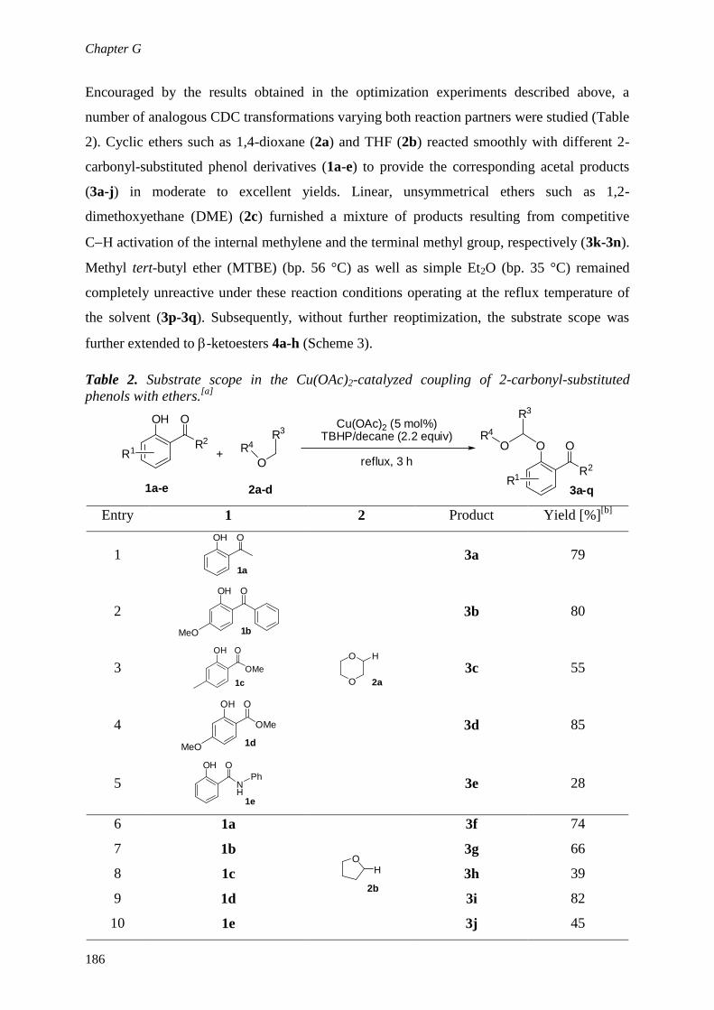
Chapter G
186
Encouraged by the results obtained in the optimization experiments described above, a
number of analogous CDC transformations varying both reaction partners were studied (Table
2). Cyclic ethers such as 1,4-dioxane (2a) and THF (2b) reacted smoothly with different 2-
carbonyl-substituted phenol derivatives (1a-e) to provide the corresponding acetal products
(3a-j) in moderate to excellent yields. Linear, unsymmetrical ethers such as 1,2-
dimethoxyethane (DME) (2c) furnished a mixture of products resulting from competitive
CH activation of the internal methylene and the terminal methyl group, respectively (3k-3n).
Methyl tert-butyl ether (MTBE) (bp. 56 °C) as well as simple Et2O (bp. 35 °C) remained
completely unreactive under these reaction conditions operating at the reflux temperature of
the solvent (3p-3q). Subsequently, without further reoptimization, the substrate scope was
further extended to -ketoesters 4a-h (Scheme 3).
Table 2. Substrate scope in the Cu(OAc)2-catalyzed coupling of 2-carbonyl-substituted
phenols with ethers.[a]
R2
O
+
OH
R4
O
R3
1a-e 2a-d
R1
R2
OO
3a-qR1
R3
OR4
Cu(OAc)2 (5 mol%)TBHP/decane (2.2 equiv)
reflux, 3 h
Entry 1 2 Product Yield [%][b]
1
OOH
1a
O
O
2a
H
3a 79
2
OOH
MeO 1b
3b 80
3 OMe
OOH
1c
3c 55
4 OMe
OOH
MeO 1d
3d 85
5 NH
OOH
1e
Ph
3e 28
6 1a
O
2b
H
3f 74
7 1b 3g 66
8 1c 3h 39
9 1d 3i 82
10 1e 3j 45

Chapter G
187
Entry 1 2 Product Yield [%][b]
11 1a
O
O HH
2c
65
12
12 1b
41
18
13 1c
35
14 1d
64
20
15 1a O
2dH
3o 76
16
1a OH
2e
3p -
17
1a O
2fH
3q -
[a] Reaction conditions: 1a-e (1 mmol), 2a-d (2 mL), reflux temperature of the respective ether. [b] Isolated
yields after chromatography. [c] Amount of terminal coupling product too low for isolation.

Chapter G
188
R2
OCu(OAc)2 (5 mol%)
TBHP/decane (2.2 equiv)
100 °C, 3 h+
O O O
R2
O O
O
O O
O
R1
O
O
O
O
O
O
O
O
R1
O O
O
O
O
O O
O
O
O O O
O
O
O O O
O
O
O
O O
O
O
O
O O
O
O
O
53% (5a) 60% (5b)37% (5c)
55% (5d) 61% (5e)
60% (5f)
54% (5g) 25% (5h)
4a-h 2a 5a-h
Scheme 3. Substrate scope in the Cu(OAc)2-catalyzed coupling of ß-ketoesters with dioxane.
In order to move this potentially hazardous coupling protocol involving a peroxide/ether
mixture to a safe and scalable continuous flow regime,[13]
we first attempted to reduce the
initially optimized reaction time of 3 h under reflux conditions (Table 1) to something more
suitable for a continuous processing approach (< 30 min). Therefore the CDC of 2-
hydroxyacetophenone (1a) and 1,4-dioxane (2a) was reevaluated more closely under sealed-
vessel microwave conditions paying particular attention to the reaction time.[14]
An initial
temperature screen using accurate internal temperature monitoring[15]
indicated that the
optimum temperature window for the oxidative coupling is between 120 and 135 °C. At
lower, as well as higher temperatures, a drop in conversion was observed (see Table S2 and
Figure S1 in the Supporting Information). We presume that the decomposition of TBHP is
faster than the desired CDC reaction at higher temperatures.[16]
However, further optimization
at 135 °C showed almost full conversion within only 15 min when the amount of TBHP
oxidant was increased to 3 equiv, and was added portionwise (3 1 equiv).[16]
In addition,
under these intensified conditions it was possible to decrease the amount of Cu(OAc)2 catalyst
to 1 mol% at the expense of a 30 min reaction time. Ultimately, keeping the desire of
throughput in the flow process in mind, a catalyst loading of 2.5 mol% and a reaction time of

Chapter G
189
20 min were chosen.[16]
Under these high-temperature conditions in the sealed microwave
vial, substrate 1a was also successfully coupled not only with THF (2b) providing a 96%
isolated yield of acetal 3b, but also with MTBE (2e) and diethyl ether (2f), furnishing the
desired target molecules 3p and 3q in moderate yields (Table S5 in the Supporting
Information).
The optimized microwave batch protocols were then translated to a continuous flow
regime (“microwave-to-flow” paradigm)[17]
in a Uniqsis FlowSyn reactor equipped with a 20
mL internal volume stainless steel coil (i.d.1.0 mm) operating at 130 °C coil temperature.[18]
In order to avoid large volumes of ether/peroxide mixtures, a two-feed strategy as shown in
Figure 1 was devised. Therefore, a solution of the Cu catalyst and 2-hydroxyacetophenone
substrate (1a) in 1,4-dioxane (Feed A, flow rate: 0.8 mL min-1
), and commercially available
TBHP in decane (Feed B, flow rate 0.2 mL min-1
) were passed through a glass static mixer
(M) and subsequently heated in the above-mentioned coil reactor (RC). Within the 20 min
residence time of this flow experiment, conversion/yields similar to those obtained under
microwave batch conditions were obtained, considering that multiple additions of oxidant
were possible in the batch experiment.[16]
MBPR
RC
Feed Aether (2), Cu(OAc)2
substrate 1a
Feed BTBHP/decane
OO
O
O OO
O
OO
O
3a 3f 3q
flow 82% flow 84% flow 36%
MW[a] 82% MW[a] 96% MW[a] 54%
130 °C
17 bar
0.8 mL min-1
0.2 mL min-1
OO
3a,f,q
R3
OR4
Figure 1. Schematic diagram for the two-feed continuous flow oxidative CO coupling of 2-
hydroxyacetophenone 1a. For more details, see the Supporting Information. [a]
TBHP was
added portionwise in the batch experiments, explaining the higher yields, see also Tables S7
and S8.

Chapter G
190
3. Conclusion
In summary, we have demonstrated the efficient construction of CO bonds via -CH bond
activation of simple ethers using an inexpensive copper catalyst in combination with a
commercially available decane solution of TBHP as stoichiometric oxidant. This protocol
allows the generation of unsymmetrical acetal scaffolds not easily available by other methods.
In order to make this potentially hazardous synthetic protocol scalable, a two-feed high-
temperature/pressure microreactor approach was developed that provided the desired acetals
in yields similar to those obtained in the batch protocols.
4. References
[1] (a) Metal-Catalyzed Cross-Coupling Reactions, (Eds: A. de Meijere, F. Diederich),
Wiley-VCH, Weinheim, 2004; (b) R. Jana, T. P. Pathak, M. S. Sigman, Chem. Rev.
2011, 111, 1417; c) I. P. Beletskaya, A. V. Cheprakov, Coord. Chem. Rev. 2004,
248, 2337.
[2] (a) CH Activation (Eds.: J-Q. Yu, Z.-J. Shi), Top. Curr. Chem. 2010, 292; (b)
Handbook of C-H Transformations: Applications in Organic Synthesis, (Ed: G.
Dyker), Wiley-VCH, Weinheim, 2005; (c) A. M. R. Smith, K. K. Hii, Chem. Rev.
2011, 111, 1637; (d) C. L. Sun, B. J. Li, Z. J Shi, Chem. Rev. 2011, 111, 1293; (e) L.
Ackermann, Chem. Rev. 2011, 111, 1315; (f) X. Chen, K. M. Engle, D. H. Wang, J. Q.
Yu, Angew. Chem. Int. Ed. 2009, 48, 5094 (g) A. E. Wendlandt, A. M. Suess, S. S.
Stahl, Angew. Chem. Int. Ed. 2011, 50, 11062.
[3] (a) C. S. Yeung, V. M. Dong, Chem. Rev. 2011, 111, 1215; (b) C. J. Scheuermann,
Chem. Asian J. 2010, 5, 436; (c) J. L. Bras, J. Muzart, Chem. Rev. 2011, 111, 1170.
[4] (a) C. J. Li, Acc. Chem. Res. 2009, 42, 335 and references therein; (b) W. Han, P.
Mayer, A. R. Ofial, Angew. Chem. Int. Ed. 2011, 50, 2178; (c) K. M. Engle, D. H.
Wang, J. Q Yu, Angew. Chem. Int. Ed. 2010, 49, 6169; (d) G. Deng, L. Zhao, C. J. Li,
Angew. Chem. Int. Ed. 2008, 47, 6278; (e) T. W. Lyons, K. L. Hull, M. S. Sanford, J.
Am. Chem. Soc. 2011, 133, 4455; (f) Z. Li, C. J. Li, J. Am. Chem. Soc. 2006, 128, 56;
(g) M. Kitahara, N. Umeda, K. Hirano, T. Satoh, M. Miura, J. Am. Chem. Soc. 2011,
133, 2160; (h) N. Borduas D. A. Powell, J. Org. Chem. 2008, 73, 7822.
[5] (a) J. Xie, H. Li, J. Zhou, Y. Cheng, C. Zhu, Angew. Chem. Int. Ed. 2012, 51, 1252;
(b) O. Basle, C. J. Li, Green Chem. 2007, 9, 1047; (c) S. B. Park, H. Alper, Chem.

Chapter G
191
Commun. 2005, 1315; (d) S. I. Murahashi, N. Komiya, H. Terai, Angew. Chem. Int.
Ed. 2005, 44, 6931; (e) Z. Li, C. J. Li, J. Am. Chem. Soc. 2005, 127, 6968; (f) Z. Li, D.
S. Bohle, C. J. Li, Proc. Natl. Acad. Sci. 2006, 103,8928; (g) N. Sasamoto, C. Dubs,
Y. Hamashima, M. Sodeoka, J. Am. Chem. Soc. 2006, 128, 14010.
[6] X. Wang, Y. Lu, H. X. Dai, J. Q. Yu, J. Am. Chem. Soc. 2010, 132, 12203.
[7] (a) R. Giri, J. Liang, J. G. Lei, J. J. Li, D. H. Wang, X. Chen, I. C. Naggar, C. Guo, B.
M. Foxman, J. Q. Yu, Angew. Chem. Int. Ed, 2005 44, 7420; (b) X. Chen, X. S. Hao,
C. E. Goodhue, J. Q. Yu, J. Am. Chem. Soc. 2006, 128, 6790; (c) A. R. Dick, K. L.
Hull, M. S. Sanford, J. Am. Chem. Soc. 2004, 126, 2300; (d) L. V. Desai, K. L. Hull,
M. S. Sanford, J. Am. Chem. Soc. 2004, 126, 9542.
[8] S. Y. Zhang, F. M. Zhang, Y. Q. Tu, Chem. Soc. Rev. 2011, 40, 1937.
[9] (a) Y. Zhang, C. J. Li, Angew. Chem. Int. Ed. 2006, 45, 1949; (b) Y. Zhang, C. J. Li, J.
Am. Chem. Soc. 2006, 128, 4242; (c) Z. Li, R. Yu, H. Li, Angew. Chem. Int. Ed. 2008,
47, 7497.
[10] L. Chen, E. Shi, Z. Liu, S. Chen, W. Wei, H. Li, K. Xu, X. Wan, Chem. Eur. J. 2011,
17, 4085.
[11] For selected recent reviews on continuous flow/microreactor chemistry, see: (a) C.
Wiles, P. Watts, Green Chem. 2012, 14, 38; (b) T. Noël, S. L. Buchwald, Chem. Soc.
Rev. 2011, 40, 5010; (c) M. Baumann, I. R. Baxendale, S. V. Ley, Mol. Divers. 2011,
15, 613; (d) R. L. Hartman, J. P. McMullen, K. F. Jensen, Angew. Chem. Int. Ed.
2011, 50, 7502; (e) C. Wiles, P. Watts, Chem. Commun. 2011, 47, 6512; (f) J. Wagner,
S. Ceylan, A. Kirschning, Chem. Commun. 2011, 47, 4583; (g) J.-I. Yoshida, H. Kim,
A. Nagaki, ChemSusChem 2011, 4, 331.
[12] G. S. Kumar, C. U. Maheswari, R. A. Kumar, M. L. Kantam, K. R. Reddy, Angew.
Chem. Int. Ed. 2011, 50, 11748.
[13] For selected examples of reactions involving peroxides in continuous flow, see: (a) R.
Mello, A. Olmos, J. Parra-Carbonell, M. E. Gonzales-Nunez, G. Asensio, Green
Chem. 2009, 11, 994; (b) K. Yube, K. Mae, Chem. Eng. Technol. 2005, 28, 331; (c) J.
Zhang, W. Wu, G. Qian, X.-G. Zhou, J. Hazard. Mater. 2010, 181, 1024.
[14] C. O. Kappe, A. Stadler, D. Dallinger, Microwaves in Organic and Medicinal
Chemistry, 2nd
Ed., Wiley-VCH, 2012.
[15] For the importance of internal temperature monitoring in microwave chemistry, see:
(a) D. Obermayer, C. O. Kappe, Org. Biomol. Chem. 2010, 8, 114; (b) D. Obermayer,
B. Gutmann, C. O. Kappe, Angew. Chem. Int. Ed. 2009, 48, 8321.

Chapter G
192
[16] For a complete optimization data set, see Tables S2–S8 in the Supporting Information.
[17] T. N. Glasnov, C. O. Kappe, Chem. Eur. J. 2011, 17, 11956.
[18] For further details on the FlowSyn reactor configuration and experimental setup, see:
B. Gutmann, J.-P. Roduit, D. Roberge, C. O. Kappe, J. Flow Chem. 2012, 2, 8; and the
Supporting Information.

Chapter G
193
5. Supporting Information
General Remarks. All chemicals were purchased from Sigma-Aldrich, S.D. Fine chemicals,
Pvt. Ltd, or AVRA Chemicals Pvt. Ltd, India. Reagents were weighed and handled in air at
room temperature. Column chromatography was performed on ACME silica gel (100 ~ 200
mesh) and TLC was carried out on Merck pre-coated silica gel 60-F254 plates. Silica gel flash
chromatography separations were performed on a Biotage SP1 instrument using petroleum
ether/ethyl acetate mixtures as eluent. Proton and carbon magnetic resonance spectra (1H
NMR and 13
C NMR) were recorded on an Avance-300, Inova-500 or Bruker 300 MHz
spectrometer, using tetramethylsilane (TMS) as internal standard (1H NMR: TMS at 0.00
ppm, CDCl3 at 7.26 ppm; 13
C NMR: CDCl3 at 77.0 ppm, DMSO at 39.43). CDCl3 was used as
solvent in all NMR experiments. Chemical shifts (δ) are expressed in ppm downfield from
TMS as internal standard. The letters s, d, t, q, and m are used to indicate singlet, doublet,
triplet, quadruplet, and multiplet, respectively. Analytical HPLC (Shimadzu LC20) analysis
was carried out on a C18 reversed-phase (RP) analytical column (150 × 4.6 mm, particle size
5 μm) at 25 °C using a mobile phase A (water/acetonitrile 90:10 (v/v) + 0.1 % TFA) and B
(MeCN + 0.1 % TFA) at a flow rate of 1.0 mL min-1
. The following gradient was applied:
linear increasefrom solution 30% B to 100 % B in 8 min, hold at 100% solution B for 2 min.
For microwave irradiation experiments, a Monowave 300 single-mode microwave reactor
from Anton Paar GmbH (Graz, Austria) was used. The reaction temperature was monitored
by an external infrared sensor (IR) housed in the side-walls of the microwave cavity
measuring the surface temperature of the reaction vessel as well as an internal fiber-optic
(FO) temperature probe (ruby thermometer).[S1]
Flow chemistry experiments were performed
in a Uniqsis FlowSyn reactor (for further information on configuration, see Figure S2).[S2]

Chapter G
194
Table S1. Optimization of reaction conditions.[a]
OH O
+O
Ocatalystoxidant
80-100°C, 3h
OO
O
O
1a 2a 3a
Entry Catalyst [mol%] Oxidant [equiv] Temperature
[°C]
Yield
[%][b]
1 Cu(OAc)2 (10) TBHP[c]
in water (1.5) 80 29
2 Cu(OAc)2.H2O (10) TBHP in water (1.5) 80 24
3 CuCl2 (10) TBHP in water (1.5) 80 n.d
4 CuBr2 (10) TBHP in water (1.5) 80 n.d
5 Cu(ClO4)2 . 6H2O (10) TBHP in water (1.5) 80 n.d
6 Cu(OTf)2 (10) TBHP in water (1.5) 80 n.d
7 CuSO4 . 5H2O (10) TBHP in water (1.5) 80 n.d
8 Cu(OAc) (10) TBHP in water (1.5) 80 20
9 CuCl (10) TBHP in water (1.5) 80 24
10 CuBr (10) TBHP in water (1.5) 80 15
11 CuI (10) TBHP in water (1.5) 80 n.d
12 Cu(OAc)2 (10) TBHP in decane (1.5) 80 31
13 Cu(OAc)2 (10) H2O2 (1.5) 80 n.d
14 Cu(OAc)2 (10) NaOCl (1.5) 80 n.d
15 Cu(OAc)2 (10) DTBP[d]
(1.5) 80 n.d
16 Cu(OAc)2 (10) DTAP[e]
(1.5) 80 n.d
17 Cu(OAc)2 (10) DDQ[f]
(1.5) 80 n.d
18 Cu(OAc)2 (10) O2 (atmospheric) 80 n.d
19 Cu(OAc)2 (10) m-CBPA[g]
(1.5) 80 n.d
20[h]
Cu(OAc)2 (10) TBHP in water (1.5) 80 41
21[h]
Cu(OAc)2 (10) TBHP in decane (1.5) 80 51
22 Cu(OAc)2 (5) TBHP in water (2.2) 100 69
23 Cu(OAc)2 (5) TBHP in decane (2.2) 100 81
24 Cu(OAc)2 (5) TBHP in decane (1.5) 100 63
25 Cu(OAc)2 (5) -- 100 n.d
26 -- TBHP in water (2.2) 100 n.d
[a] Reaction conditions: 1a (120 µL, 1 mmol), 2a (2 mL), 3 h, unless otherwise noted.
[b] Isolated yields.
n.d. = not detected in crude NMR. [c]
tert-butyl hydroperoxide. [d]
di-tert-butyl hydroperoxide. [e]
di-tert-
amoyl peroxide.[f]
2,3-Dichloro-5,6-dicyano-1,4-benzoquinone. [g]
meta-Chloroperoxybenzoic acid. [h]
9
h reaction time

Chapter G
195
Table S2. Temperature screening for the synthesis of 1-(2-(1,4-dioxan-2-
yloxy)phenyl)ethanone (3a) using microwave irradiation.[a]
OH O
O
OO O
O
O+
5 mol% Cu(OAc)22.2 eq TBHP in decane
30 min, MW
1a 3a2a
Entry T [°C] Conversion [%] [b]
3a [%][b]
1 110 44 41
2 120 65 61
3 130 65 60
4 135 66 60
5 140 61 55
6 150 61 56
7 160 55 47 [a]
Conditions: 2-hydroxyacetophenone (1a) (120 µL, 1 mmol), Cu(OAc)2 (9 mg, 5 mol%),1,4-
dioxane (2 mL), TBHP 5-6 M in decane (400 µL, 2.2 eq). [b]
HPLC peak area percent at 254
nm. See also Figure S1.
Table S3. Varying time, amount of oxidant and addition frequency.[a]
OH O
O
OO O
O
O+
5 mol% Cu(OAc)2TBHP in decane
1a 3a2a
135 °C, MW
Entry t [min] TBHP [equiv] Conversion [%][b]
3a [%][b]
7 30 3 75 71
8 20 3 79 77
9 10 3 78 76
10 2 x 15 2 x 1.5 93 87
11 3 x 10 3 x 1 97 94
12 5 x 10 5 x 0.5 98 93
13 3 x 10 1 x 1.5 + 2 x 0.5 88 84
14 3 x 5 1 x 1.5 + 2 x 0.5 84 78
15 3 x 5 3 x 1 97 92
16 3 x 5 2 x 1 + 1 x 0.5 88 83
17 3 x 2 3 x 1 68 66 [a]
Conditions: 2-hydroxyacetophenone (1a) (120 µL, 1 mmol), Cu(OAc)2 (9 mg, 5
mol%),1,4-dioxane (2 mL), TBHP 5-6 M in decane (540 µL, ~3 equiv). [b]
HPLC peak
area percent at 254 nm.

Chapter G
196
Table S4. Reduction of Cu(OAc)2 catalyst.[a]
OH O
O
OO O
O
O+
Cu(OAc)23 equiv TBHP in decane
1a 3a2a
135 °C, MW
Entry catalyt [mol%] time [min ][b]
Conversion [%][c]
3a [%][c]
14 5 3 x 5 97 92
18 2.5 3 x 5 90 87
19 2.5 2 x 5 + 1 x 10 97 94 (82)[d]
20[e]
2.5 2 x 5 + 1 x 10 98 88
21 1 2 x 5 + 1 x 10 74 71
22 1 3 x 10 99 95(80)[d]
23 0 2 x 5 + 1 x 10 2 <1 [a]
Conditions: 2-hydroxyacetophenone (1a) (120 µL, 1 mmol), Cu(OAc)2 (0 - 9 mg), 1,4-dioxane
(2 mL), TBHP 5-6 M in decane (540 µL, 3 equiv). [b]
1 equiv TBHP per run. [c]
HPLC peak area
percent at 254 nm. [d]
Isolated yield in parentheses. [e]
Reaction was performed in a reaction vessel
made out of sintered silicon carbide.

Chapter G
197
Table S5. Scope of microwave irradiation experiments[a]
OH O O OCu(OAc)2 (2.5 mol%)TBHP (3 equiv)
R4CH2OR5
OR4
R5
1a 3
Entry Ether T
[°C]
p
[bar]
time
[min][b] Product
Isolated
yield
[%]
1
135 2 2 x 5 + 1 x 10
82
2
135 6 2 x 5 + 1 x 10
96
3
135 9 3 x 5 [c]
20
4
100[d]
7 2 x 5 + 1 x 10
54
5
135 1 2 x 5 + 1 x 10
No reaction
[a] Conditions: 2-hydroxyacetophenone (1a) (120 µL, 1 mmol), Cu(OAc)2 (4.5 mg, 2.5 mol%), ether 2 (2 mL),
TBHP 5-6 M in decane (540 µL, 3equiv). [b]
1 equiv TBHP per run. [c]
longer reaction times resulted in
substrate (re-)formation. [d]
An explanation for the lower reaction temperature is given in Scheme S1.

Chapter G
198
Determination of Catalytical Limitation at Elevated Temperatures (Table S6). Three
experiments with 2 heating cycles where carried out to determine the limiting reactant in this
reaction. In the first cycle either the catalyst (entry 1), the oxidant (entry 2) or a combination
of both (entry 3) were heated for 30 minutes at 135 °C in 1,4-dioxane. Afterwards, the
missing reagent as well as the substrate was added before another cycle (135 °C, 30 min) was
executed. The conversion was determined by HPLC (Table 6, entries 1-3). As pointed out in
Table 6, when just the catalyst was heated in the first cycle, the same conversion was obtained
as in the control experiment (entry 4). If the oxidant is pre-heated, the conversion decreases
dramatically, indicating the peroxide decomposition as limiting factor in this kind of CDC
reaction at elevated temperatures.
Table S6. Determination of catalytical limitations.[a]
Cycle 1 Cycle 2
Entry Cu(OAc)2
[mol %]
TBHP
[equiv]
Cu(OAc)2
[mol %]
TBHP
[equiv]
Conversion
[%][b]
3a [%]
[b]
1 5 -- -- 3 76 72
2 -- 3 5 -- 3 3
3 5 3 -- -- 19 18
4
5 3 75 71 [a]
Conditions: 2-hydroxyacetophenone (1a) (120 µL, 1 mmol), Cu(OAc)2 (9 mg, 5 mol%), 1,4-dioxane
(2 mL), TBHP 5-6 M in decane (540 µL, 3 equiv). [b]
HPLC peak area percent at 254 nm.
Table S7. Comparison of Microwave and Continuous Flow Chemistry.
OH O O O
Cu(OAc)2TBHP
1,4-dioxane (2a)
O
O
MW orcontinuous flow
1a 3a
Entry Type 2a
[ml] 1a
[mmol]
Catalyst
[mol%]
TBHP
[equiv]
T
[°C]
time
[min]
Conv.
[%][a]
Yield
[%][a][b]
A
Flow
1 Feed 20 10 2.5 3 130 20 89 86(81)
Flow
2 Feeds
TM[c]
20 10 2.5 3 130 20 71 69
Flow
2 Feeds
GSM[d]
20 10 2.5 3 130 20 91 87(82)
MW
2 1 2.5 3 130 20 87 85(75)
B Flow 20 10 2.5 3 135 20 82 77(74)
MW[e]
2 1 2.5 3 135 20 80 77 [a]
HPLC peak area percent at 254 nm. [b]
Isolated yield in parentheses. [c]
T-Mixer for combining streams
A and B. [d]
Glass static mixer for combining streams A and B. [e]
Whole amount of oxidant added in 1
portion for better comparability

Chapter G
199
Table S8. Scope of continuous flow experiments.[a]
OH O O OCu(OAc)2 (5 mol%)
TBHP (3 equiv)
OR4
R4OCH2R5, 20 min, flow
R5
1a 3a
Entry Ether Product T
[°C]
Isolated yield
[%]
1
135 82
2
135 84
3[b]
100 36
[a] Conditions: 2-hydroxyacetophenone (1a) (1.2 mL, 10 mmol),
Cu(OAc)2 (45 mg, 2.5 mol%),1,4-dioxane (20 mL), TBHP 5-6 M in
decane (5.4 mL, 3 equiv). Experiments were performed either using a
one-feed or two feed (Figure 1) strategy with equal success. [b]
2 mL
MeOH were added to obtain a completely homogenous reaction mixture.
OH O
O O
Cu(OAc)2 (2.5 mol%)TBHP (3 equiv)
Et2O, 135 °C
OO O
O
135 °C1a
3q6
Scheme S1. The reaction of 1a with Et2O under sealed vessel microwave conditions was
carried out at 100°C because at 135°C a subsequent hydrolysis reaction resulting in 2-
acetylphenyl acetate was observed. Further, it was necessary to add 2 mL of MeOH in order
to obtain a completely homogeneous reaction mixture.

Chapter G
200
Figure S1. Reaction mixtures after 30 min (hold time) microwave irradiation at different
temperatures (see Table S2). The optimum reaction temperature and catalyst/TBHP lifetime is
135 °C.
Figure S2. UniqsisFlowSyn reactor equipped with a Stainless steel coil reactor (with glass
cover) and glass static mixer.[S2]
Each pump allows flow rates from 0.02 to 10 mL min-1
giving a total maximum flow rate of 20 mL min-1
. The T-mixer to combine the two reagent
streams at room temperature is attached to the front panel (behind the coil heater module)
and is attached to a pressure transducer (further transducers are integrated in each pump
priming valve). The system constantly monitors the pressure and will stop if the pressure
either rises above or falls below the global limits (set in the configuration page). The coil
heater contains heating elements and temperature sensors and is used to heat the coil
reactors. The coil reactors consist of tubing wound in a helical groove on an aluminum
mandrel. Coil reactors are available in a range of pre-wound sizes and materials and are
easily fitted and removed from the heating module. Back pressure can be varied by fitting
different fixed back pressure cartridges (40–1000 psi cartridges are available). The maximum
allowed temperature and pressure is determined by the material of the column and the coil
reactor but the upper limit is 69 bars and 260 °C. Inlet selection valves and outlet selection
valves are used to control the feed to the pumps (e.g. either solvent or reagent) and between a
waste and a collection bottle. Pumps, inlet and outlet selection valves are controlled either
manually or automatically using the AutoExperiment mode.
0 ° 0 ° 0° 5 ° 40 ° 50°

Chapter G
201
General Procedure for the Acetal Synthesis (3a-3o) in a Standard Oil Bath (Table 2 and
Scheme 3). A solution of 2-carbonyl-substituted phenol (1a-e) or β-keto ester (4a-h) (1.0
mmol), Cu(OAc)2 (9 mg, 5 mol%) in 2 mL of the respective ether 2 (1,4-dioxane, THP,
DME) was stirred at room temperature. To the same solution, a 5-6 M TBHP solution in
decane (2.2 mmol) was added dropwise before the mixture was heated at the reflux
temperature of the respective ether (oil bath) for 3 h. After cooling to room temperature, the
reaction mixture was extracted with ethyl acetate and dried over anhydrous Na2SO4. Removal
of the solvent under reduced pressure afforded the crude product, which was purified by
preparative column chromatography on silica gel (hexane/ethyl acetate 9:1).
1-(2-(1,4-Dioxane-2-yloxy)phenyl)ethanone: (Table 2, Entry 1, 3a)
Isolated yield = 79% ; 1H NMR (300 MHz, CDCl3) 7.74 (dd, J =
2.26, 7.55 Hz, 1H), 7.44 (td, J = 2.26, 7.55, 15.86 Hz, 1H), 7.19 (d, J
= 7.55 Hz, 1H), 7.06 (t, J = 7.55 Hz, 1H), 5.4 (t, J = 2.26 Hz, 1H), 4.1
( m, 1H ), 3.91 (d, J = 2.26 Hz, 2H), 3.81 (m, 2H), 3.63 (dt, J = 3.02,
12.08 Hz, 1H), 2.69 (s, 3H). 13
C NMR (75 MHz ,CDCl3): 199.6,
155.5, 133.3, 130.1, 121.8, 114.8, 93.4, 68.4, 65.9, 61.2, 31.9. MS
(ESI): m/z = 245 (M+Na)+. HRMS ESI (M+Na)
+ m/z calcd for
C12H14O4Na (M+Na)+= 245.07843, found = 245.07833.
(2-(1,4-Dioxane-2-yloxy)-4-methoxyphenyl)(phenyl)methanone:
(Table 2, Entry 2, 3b) Isolated yield = 80% ; 1H NMR (300 MHz,
CDCl3) 7.73 (m, 2H), 7.46 (m, 4H), 6.80 (d, J = 2.26 Hz, 1H), 6.67
(dd, J = 2.26, 8.30 Hz, 1H), 5.06 (t, J = 2.26 Hz, 1H), 3.99 (m, 1H),
3.86 (s, 3H), 3.6 (m, 3 H), 3.45 (dd, J = 2.26, 11.13 Hz, 1H), 3.11 (dd,
J = 3.02, 12.08 Hz, 1H). 13
C NMR (75 MHz, CDCl3): 195.6, 163.1,
156.8, 139.2, 132.1, 131.7, 129.1, 127.9, 122.6, 107.2, 103, 94.9, 67.7,
65.6, 61.3, 55.4. MS (ESI):m/z = 337 (M+Na)+. HRMS ESI (M+Na)
+
m/z calcd for C18H18O5Na (M+Na)+= 337.10464,found = 337.10416
Methyl 2-(1,4-Dioxane-2-yloxy)-5-methylbenzoate: (Table 2, Entry
3, 3c) Isolated yield = 55% ; 1H NMR (300 MHz, CDCl3) 7.6 (br,
1H), 7.25 (m, 1H), 7.12 (d, J = 8.3 Hz, 1H), 5.17 (t, J = 2.26 Hz, 1H),
4.20-4.28 (m, 1H), 3,85-3.97 (m, 5H), 3.77-3.8 (m, 2H), 3.62 (dt, J =
3.21, 11.7 Hz, 1H), 2.32 (s, 3H). 13
C NMR (75 MHz CDCl3): 166.5,
154.1, 133.7, 132, 131.5, 121.9, 119, 95.8, 68.5, 65.9, 61.4, 51.9, 20.3.
MS (ESI): m/z = 275 (M+Na)+. HRMS ESI (M+Na)
+ m/z calcd for
C13H16O5Na (M+Na)+
= 275.08899, found = 275.08872.

Chapter G
202
Methyl 2-(1,4-Dioxan-2-yloxy)-4-methoxybenzoate: (Table 2, Entry
4, 3d) Isolated yield = 85% ; 1H NMR (300 MHz, CDCl3) 7.84 (d,
J = 8.8 Hz, 1H), 6.77 (d, J = 2.4 Hz, 1H), 6.61 (dd, J = 8.8, 2.4 Hz,
1H), 5.22 (t, J = 2.5 Hz, 1H), 4.31 – 4.17 (m, 1H), 4.02 – 3.70 (m,
11H), 3.68 – 3.58 (m, 1H). 13
C NMR (75 MHz, CDCl3) 165.86,
163.79, 158.58, 133.38, 114.22, 107.69, 104.88, 95.71, 68.56, 66.03,
61.57, 55.50, 51.71. HRMS EI M+ m/z calcd for C13H16O6 M
+ =
268.0947, found = 268.0960.
2-(1,4-Dioxane-2-yloxy)-N-phenylbenzamide: (Table 2, Entry 5, 3e)
Isolated yield = 28% ; 1H NMR (300 MHz, CDCl3) 10.31 (br, 1H),
8.35 (dd, J = 1.51, 8.3 Hz, 1H), 7.84 (dd, J = 1.51, 9.06 Hz, 2H), 7.47
(td, J = 2.26, 9.6, 6.79 Hz, 1H), 7.35 (t, J = 7.55 Hz, 2H), 7.08-7.28
(m, 3H), 5.64 (br, 1H), 4.09-4.18 (m, 2H), 3.88-4 (m, 3H), 3.6 (dt, J =
2.26, 12.08 Hz, 1H). 13
C NMR (75 MHz, CDCl3): 162.8, 153.6,
138.8, 133. 132.6, 128.9, 123.9, 122.6, 119.9, 114.4, 93.1, 68.6, 66.2,
60.6. MS (ESI): m/z = 322 (M+Na)+. HRMS ESI (M+Na)
+ m/z calcd
for C17H17NO4Na (M+Na)+
= 322.10498, found = 322.10453.
1-(2-(Tetrahydrofuran-2-yloxy)phenyl)ethanone: (Table 2, Entry 6,
3f) Isolated yield = 74% ; 1H NMR (300 MHz, CDCl3) 7.7 (dd, J =
1.51, 7.55 Hz, 1H), 7.43 (td, J = 2.26, 9.06 Hz, 1H), 7.25 (d, J = 7.55
Hz, 1H), 7.01 (t, J = 7.55 Hz, 1H), 5.89-5.91 (m, 1H), 3.95-4.09 (m,
2H), 2.59 (s, 3H), 2.14-2.28 (m, 3H), 1.97-2.06 (m, 1H). 13
C NMR
(75 MHz, CDCl3): 199.5, 156.2, 133.2, 129.8, 128.7, 121, 115.1,
102.3, 68.1, 32.5, 31.5, 23.2. MS (ESI): m/z = 229 (M+Na)+. HRMS
ESI (M+Na)+ m/z calcd for C12H14O3Na (M+Na)
+ = 229.08352, found
= 229.0856.
(4-Methoxy-2-(tetrahydrofuran-2-yloxy)phenyl)(phenyl)
methanone: (Table 2, Entry 7, 3g) Isolated yield = 66% ; 1H NMR
(300 MHz, CDCl3) 7.70-7.73 (m, 2H), 7.37-7.53 (m, 4H), 6.79 (d, J
= 2.26 Hz, 1H), 6.62 (dd, J = 2.26, 8.3 Hz, 1H), 5.64 (d, J = 4.53 Hz,
1H), 3.86 (s, 3H), 3.81 (t, J = 6.79 Hz, 2H), 1.65-1.81 (m, 2H), 1.46-
1.57 (m, 2H). 13
C NMR (75 MHz, CDCl3): 195.6, 163, 156.8, 139.3,
131.5, 131.4, 128.8, 127.5, 121.9, 106.5, 102.1, 101.3, 67.9, 55.1,
31.9, 22.4. MS (ESI): m/z = 321 (M+Na)+. HRMS ESI (M+Na)
+ m/z
calcd for C18H18O4Na (M+Na)+
= 321.10973, found = 321.10919.
O
NH
O
O
O
O O
O
O O
O
O

Chapter G
203
Methyl 5-Methyl-2-(tetrahydrofuran-2-yloxy)benzoate: (Table 2,
Entry 8, 3h) Isolated yield = 39 % ; 1H NMR (300 MHz, CDCl3)
7.57 (br, 1H), 7.23 (dd, J = 2.26, 9.06 Hz, 1H), 7.12 (d, J = 8.8 Hz,
1H), 5.76 (d, J = 3.77 Hz, 1H), 4.04-4.11 (m, 1H), 3.9-3.97 (m, 1H),
3.86 (s, 3H), 2.3 (s, 3H), 1.91-2.23 (m, 4H). 13
C NMR (75 MHz,
CDCl3): 166.8, 154.4, 133.7, 131.4, 131, 121.5, 118, 103.8, 68.1,
51.7, 32.6, 23.2, 20.3. MS (ESI): m/z = 259 (M+Na)+. HRMS ESI
(M+Na)+ m/z calcd for C13H16O4Na (M+Na)
+ = 259.09408, found =
259.09374.
Methyl 4-Methoxy-2-(tetrahydrofuran-2-yloxy)benzoate: (Table 2,
Entry 9, 3i) Isolated yield = 82 % ; 1H NMR δ
(300 MHz, CDCl3) 7.83
(d, J = 8.8 Hz, 1H), 6.80 (d, J = 2.4 Hz, 1H), 6.57 (dd, J = 8.8, 2.4 Hz,
1H), 5.82 (d, J = 4.7 Hz, 1H), 4.16 – 4.04 (m, 1H), 4.02 – 3.91 (m,
1H), 3.88 – 3.81 (m, 6H), 2.38 – 2.08 (m, 3H), 2.03 – 1.87 (m, 1H). 13
C NMR δ (75 MHz, CDCl3) 166.12, 163.81, 158.97, 133.34, 113.62,
107.02, 103.64, 103.45, 68.36, 55.47, 51.55, 32.81, 23.35. HRMS EI
M+ m/z calcd for C13H16O5 M
+ = 252.0998, found = 252.1001.
N-Phenyl-2-(tetrahydrofuran-2-yloxy)benzamide: (Table 2, Entry
10, 3j) Isolated yield = 45% ; 1H NMR (300 MHz, CDCl3) 9.79 (br,
1H), 8.25 (dd, J = 1.51, 7.55 Hz, 1H), 7.66 (d, J = 7.55 Hz, 2H), 7.26-
7.48 (m, 4H), 7.09-7.17 (m, 2H), 6 (dd, J = 1.51, 3.77 Hz, 1H), 4.12-
4.19 (m, 1H), 4-4.08 (m, 1H), 2.03-2.37 (m, 4H). 13
C NMR (75
MHz, CDCl3): 163.2, 154.7, 138.4, 133, 132.1, 129, 124, 122.3,
119.8, 115.6, 103.8, 68.7, 33.1, 23.2. MS (ESI): m/z = 306 (M+Na)+.
HRMS ESI (M+Na)+ m/z calcd for C17H17NO3Na (M+Na)
+ =
306.11006, found = 306.10954.
1-(2-(1,2-Dimethoxyethoxy)phenyl)ethanone: (Table 2, Entry 11,
3kA) Isolated yield = 65% ; 1H NMR (300 MHz, CDCl3) 7.70 (dd, J
= 1.51, 7.55 Hz, 1H), 7.41-7.47 (m, 1H), 7.16 (d, J = 8.3 Hz, 1H),
7.04-7.1 (m, 1H), 5.4 (t, J = 5.28 Hz, 1H), 3.61-3.73 (m, 2H), 3.45 (s,
3H), 3.42 (s, 3H), 2.65 (s, 3H). 13
C NMR (75 MHz, CDCl3): 199.8,
156, 132.2, 130.6, 122, 116.1, 101.5, 72, 59.2, 53.9, 31.6.. MS (ESI):
m/z = 247 (M+Na)+. HRMS ESI (M+Na)
+ m/z calcd for C12H16O4Na
(M+Na)+
= 247.09408, found = 247.09399.
O O
O
O
O
NH
O
O
OO
O
O

Chapter G
204
1-(2-((2-Methoxyethoxy)methoxy)phenyl)ethanone: (Table 2, Entry
11, 3kB) Isolated yield = 12 % ; 1H NMR (300 MHz, CDCl3) 7.7
(dd, J = 1.51, 7.55 Hz, 1H), 7.41-7.47 (m, 1H), 7.23 (d, J = 8.3 Hz,
1H), 7.05 (t, J = 7.55 Hz, 1H), 5.38 (s, 2H), 3.84-3.87 (m, 2H), 3.55-
3.58 (m, 2H), 3.38 (s, 3H), 2.63 (s, 3H). 13
C NMR (75 MHz ,CDCl3):
199.8, 156.2, 133.4, 130, 129, 121.6, 114.8, 93.4, 71.4, 68, 59,
31.7.MS (ESI): m/z = 247 (M+Na)+. HRMS ESI (M+Na)
+ m/z calcd
for C12H16O4Na (M+Na)+
= 247.09408, found = 247.09399.
(2-(1,2-Dimethoxyethoxy)-4-methoxyphenyl)(phenyl) methanone:
(Table 2, Entry 12, 3lA) Isolated yield = 41 % ; 1H NMR (300 MHz,
CDCl3) 7.76 (d, J = 7.17 Hz, 2H), 7.53 (t, J = 7.93 Hz, 1H), 7.38-7.44
(m, 3H), 6.77 (d, J = 2.26 Hz, 1H), 6.65 (dd, J = 2.26, 8.3 Hz, 1H),
5.19-5.22 (m, 1H), 3.85 (s, 3H), 3.32-3.38 (m, 1H), 3.28 (s, 3H), 3.26
(s, 3H), 3.1-3.15 (m, 1H). 13
C NMR (75 MHz, CDCl3): 195.4,
162.9, 156.5, 138.9, 132.1, 131.6, 129.3, 127.8, 122.7, 107, 102.8,
100.9, 71, 59, 55.3, 52.7. MS (ESI): m/z = 339 (M+Na)+. HRMS ESI
(M+Na)+ m/z calcd for C18H20O5Na (M+Na)
+ = 339.12029, found =
339.11966.
(4-Methoxy-2-((2-methoxyethoxy)methoxy)phenyl)(phenyl)
methanone: (Table 2, Entry 12, 3lB) Isolated yield = 18 % ; 1H NMR
(300 MHz, CDCl3) 7.78 (d, J = 7.3 Hz, 2H), 7.53 (t, J = 7.3 Hz, 1H),
7.41 (t, J = 8.1 Hz, 3H), 6.8 (d, J = 2 Hz, 1H), 6.62 (dd, J = 2, 8.4 Hz,
1H), 5.11 (s, 2H), 3.85 (s, 3H), 3.6-3.63 (m, 2H), 3.45-3.48 (m, 2H),
3.34 (s, 3H). 13
C NMR (75 MHz CDCl3): 195.5, 163, 157, 138.8,
132.3, 131.6, 129.5, 128, 122.3, 106.8, 101.6, 93.7, 71.3, 67.7, 58.8,
55.5. MS (ESI): m/z = 339 (M+Na)+. HRMS ESI (M+Na)
+ m/z calcd
for C18H20O5Na (M+Na)+
= 339.12029, found = 339.11982.
1-(2-(1,2-Dimethoxyethoxy)-5-methylphenyl)propan-1-one: (Table
2, Entry 13, 3m) Isolated yield = 35% ; 1H NMR (300 MHz, CDCl3)
7.57 (br, 1H), 7.23-7.27 (m, 1H), 7.08 (d, J = 8.49 Hz, 1H), 5.27 (t, J =
4.72 Hz, 1H), 3.88 (s, 3H), 3.61-3.72(m, 2H), 3.46 (s, 3H), 3.42 (s,
3H), 2.31 (s, 3H). 13
C NMR (75 MHz ,CDCl3): 166.6, 154, 133.6,
131.4, 122, 118.4, 102.6, 72.1, 59.2, 53.9, 51.8, 20.2. MS (ESI): m/z =
277 (M+Na)+. HRMS ESI (M+Na)
+ m/z calcd for C13H18O5Na
(M+Na)+
= 277.10464, found = 277.10429.

Chapter G
205
Methyl 2-(1,2-Dimethoxyethoxy)-4-methoxybenzoate: (Table 2,
Entry 14, 3nA) Isolated yield = 64% ; 1H NMR δ (300 MHz, CDCl3)
7.84 (d, J = 8.8 Hz, 1H), 6.75 (d, J = 2.4 Hz, 1H), 6.61 (dd, J = 8.8,
2.4 Hz, 1H), 5.34 (dd, J = 5.9, 4.5 Hz, 1H), 3.87 (s, 3H), 3.85 (s, 3H),
3.76 (dd, J = 10.6, 6.0 Hz, 1H), 3.68 (dd, J = 10.6, 4.4 Hz, 1H), 3.48
(s, 3H), 3.45 (s, 3H). 13
C δ NMR (75 MHz, CDCl3) 165.99, 163.79,
158.64, 133.40, 114.15, 107.39, 104.25, 102.39, 72.14, 59.46, 55.52,
53.82, 51.72. HRMS EI M+ m/z calcd for C13H18O6 M
+ = 270.1104,
found = 270.1103.
Methyl 4-Methoxy-2-((2-methoxyethoxy)methoxy)benzoate (Table
2, Entry 14, 3nB) Isolated yield = 20% ; 1H NMR δ (300 MHz,
CDCl3) 7.83 (d, J = 8.7 Hz, 1H), 6.79 (d, J = 2.3 Hz, 1H), 6.58 (dd, J
= 8.8, 2.3 Hz, 1H), 5.35 (s, 2H), 3.94 – 3.87 (m, 2H), 3.86 (s, 3H),
3.84 (s, 3H), 3.62 – 3.53 (m, 2H), 3.39 (s, 3H). 13
C NMR δ (75 MHz,
CDCl3) 165.89, 163.80, 158.97, 133.34, 113.33, 107.13, 102.64,
94.18, 71.50, 67.94, 59.00, 55.53, 51.71. HRMS EI M+ m/z calcd for
C13H18O6 M+
= 270.1104, found = 270.1104.
1-(2-(Tetrahydro-2H-pyran-2-yloxy)phenyl)ethanone: (Table 2,
Entry 15, 3o) Isolated yield = 76%; 1H NMR (300 MHz, CDCl3)
7.71 (dd, J = 1.51, 7.55 Hz, 1H), 7.43 (td, J = 2.26, 9.06 Hz, 1H),
7.23-7.26 (m, 1H), 7-7.05 (m, 1H), 5.55 (t, J = 3.77 Hz, 1H), 3.88 (td,
J = 3.02, 11.3 Hz, 1H), 3.64-3.71(m, 1H), 2.67 (s, 3H), 1.91-1.97 (m,
3H), 1.61-1.8 (m, 5H). 13
C NMR (75 MHz, CDCl3):199.5, 156.1,
133.3, 129.7, 128.4, 121, 114.8, 96.4, 61.7, 31.7, 29.9, 24.7, 18.6. MS
(ESI): m/z = 243 (M+Na)+. HRMS ESI (M+Na)
+ m/z calcd for
C13H16O3Na (M+Na)+
= 243.09917, found = 243.09909.
(Z)-Ethyl 3-(1,4-Dioxan-2-yloxy)-3-phenylacrylate: (Scheme 3, 5a)
Isolated yield = 53%; 1H NMR (300 MHz, CDCl3) 7.56-7.6 (m, 2H),
7.37-7.43 (m, 3H), 5.69 (s, 1H), 5.26 (t, J = 2.07 Hz, 1H), 4.36 (td, J =
3.21, 9.63 Hz, 1H), 4.21 (qd, J = 1.13, 7.17 Hz, 2H), 4.03 (dd, J =
2.67, 11.89 Hz, 1H), 3.67-3.84 (m, 3H), 3.49 (dt, J = 2.83, 11.7 Hz,
1H), 1.31 (t, J = 7.17 Hz, 3H). 13
C NMR (75 MHz, CDCl3): 164.8,
164.6, 134.8, 133.6, 130.1, 128.6, 128.4, 127.3, 103.3, 95.7, 67.9,
65.8, 61.4, 59.7, 14.1. MS (ESI): m/z = 301 (M+Na)+. HRMS ESI
(M+Na)+ m/z calcd for C15H18O5Na (M+Na)
+ = 301.10464, found =
301.10407.
O
OO
O
O
OO
O

Chapter G
206
(Z)-Benzyl 3-(1,4-dioxan-2-yloxy)but-2-enoate: (Scheme 3, 5b)
Isolated yield = 60%; 1H NMR (300 MHz, CDCl3) 7.26-7.36 (m,
5H), 5,25 (s, 1H), 5.08-5.18 (m, 3H), 4.12-4.2 (m, 1H), 3.7-3.88 (m,
4H), 3.52 (d, J = 11.3 Hz, 1H), 2.06 (s, 3H). 13
C NMR (75
MHz ,CDCl3): 165.2, 164.4, 136.3, 128.2, 127.9, 127.7, 99.8, 93,
67.6, 65.6, 65.1, 61.2, 19.4. MS (ESI): m/z = 301 (M+Na)+. HRMS
ESI (M+Na)+ m/z calcd for C15H18O5Na (M+Na)
+ = 301.10464, found
= 301.10426.
(Z)-Ethyl 3-(1,4-Dioxan-2-yloxy)-2-methylbut-2-enoate: (Scheme 3,
5c) Isolated yield = 37%; 1H NMR (300 MHz, CDCl3) 5.04 (t, J =
2,26 Hz, 1H), 4.13-4.23 (m, 3H), 3.77 (d, J = 2.26 Hz, 2H), 3.7-3.73
(m, 2H), 3.55 (dt, J = 3.02, 12.08 Hz, 1H), 2.01 (s, 3H), 1.83 (s, 3H),
1.3 (t, J = 6.79 Hz, 3H). 13
C NMR (75 MHz, CDCl3): 168.2, 155.7,
110.6, 94.2, 68.2, 65.8, 61.5, 60.1, 16, 14.5, 14.1. MS (ESI): m/z =
253 (M+Na)+. HRMS ESI (M+Na)
+ m/z calcd for C11H18O5Na
(M+Na)+
= 253.10464, found = 253.10443.
(Z)-Ethyl 3-(1,4-dioxan-2-yloxy)but-2-enoate: (Scheme 3, 5d)
Isolated yield = 55%; 1H NMR (300 MHz, CDCl3) 5.27 (br, 1H),
5.09 (s, 1H), 4.08-4.25 (m, 3H), 3.69-3.92 (m, 4H), 3.56 (dt, J = 2.26,
12.08 Hz, 1H), 2.06 (s, 3H), 1.26 (t, J = 6.04 Hz, 3H). 13
C NMR (75
MHz, CDCl3): 164.7, 100.5, 93, 67.7, 65.7, 61.2, 59.2, 19.4, 14.1. MS
(ESI): m/z = 239 (M+Na)+. HRMS ESI (M+Na)
+ m/z calcd for
C10H16O5Na (M+Na)+
= 239.08899, found = 239.08879.
(Z)-tert-Butyl 3-(1,4-Dioxan-2-yloxy)but-2-enoate: (Scheme 3, 5e)
Isolated yield = 61%; 1H NMR (300 MHz, CDCl3) 5.24 (t, J = 2,26
Hz, 1H), 5.01 (s, 1H), 4.13-4.21 (m, 1H), 3.72-3.91 (m, 4H), 3.56 (dt,
J = 3.02, 11.7 Hz, 1H), 2.02 (s, 3H), 1.47 (s, 9H). 13
C NMR (75
MHz, CDCl3): 164.1, 163.1, 102.2, 92.9, 79.1, 67.7, 65.6, 61.2, 28,
19.3. MS (ESI): m/z = 267 (M+Na)+. HRMS ESI (M+Na)
+ m/z calcd
for C12H20O5Na (M+Na)+= 267.12029, found = 267.12.
(Z)-Ethyl 3-(1,4-Dioxan-2-yloxy)-2-benzylbut-2-enoate: (Scheme 3,
5f) Isolated yield = 60%; 1H NMR (300 MHz, CDCl3) 7.14-7.29 (m,
5H), 5.1 (t, J = 2.26 Hz, 1H), 4.1-4.24 (m, 3H), 3.8 (t, J = 3.58 Hz,
2H), 3.71-3.76 (m, 2H), 3.65 (d, J = 4.72 Hz, 2H), 3.57 (dt, J = 3.02,
11.7 Hz, 1H), 2.07 (s, 3H), 1.2 (t, J = 7.17 Hz, 3H). 13
C NMR (75
MHz, CDCl3): 167.6, 157.5, 139.5, 128.2, 127.8, 125.9, 114.2, 94,
68.1, 65.8, 61.4, 60.1, 34.4, 16, 14. MS (ESI):m/z = 329 (M+Na)+.
HRMS ESI (M+Na)+ m/z calcd for C17H22O5Na (M+Na)
+ =
329.13594, found = 329.13547.
O
OO
O
O
O
OO
O
O
O
O
O
O
O
O
O
O
O
O

Chapter G
207
(Z)-Isopropyl 3-(1,4-Dioxan-2-yloxy)but-2-enoate: (Scheme 3, 5g)
Isolated yield = 61%; 1H NMR δ (300 MHz, CDCl3) 5.35 – 5.20 (m,
1H), 5.18 – 4.96 (m, 2H), 4.34 – 4.16 (m, 1H), 4.00 – 3.68 (m, 4H),
3.64 – 3.50 (m, 1H), 2.09 (s, 3H), 1.27 (s, 3H), 1.25 (s, 3H). 13
C NMR
δ (75 MHz, CDCl3) 164.43, 101.41, 93.37, 68.02, 66.48, 65.93, 61.53,
29.70, 22.00, 19.74. HRMS EI M+ m/z calcd for C11H18O5 M
+ =
230.1154, found = 230.1185.
(Z)-Allyl 3-(1,4-Dioxan-2-yloxy)but-2-enoate: (Scheme 3, 5h)
Isolated yield = 61%; 1H NMR (300 MHz, CDCl3).
1H NMR δ (300
MHz, CDCl3) 6.05 – 5.85 (m, 1H), 5.41 – 5.02 (m, 4H), 4.60 (dd, J =
5.6, 1.0 Hz, 2H), 4.21 (ddd, J = 11.7, 8.5, 3.5 Hz, 1H), 3.95 – 3.65 (m,
4H), 3.56 (dt, J = 11.6, 3.0 Hz, 1H), 2.08 (s, 3H). 13
C NMR δ (75
MHz, CDCl3) 165.33, 164.37, 132.76, 117.65, 100.31, 93.35, 67.97,
65.90, 64.24, 61.55, 29.69. HRMS EI M+ m/z calcd for C11H16O5 M
+ =
228.0998, found = 228.1010.
General Procedure for Acetal Synthesis under Microwave Irradiation (Table S5): A 10
mL Pyrex vessel was equipped with 2-hydroxyacetophenone (1a) (120 µL, 1 mmol) and
Cu(OAc)2 (4.5 mg, 2.5 mol%). Afterwards the respective ether (2 mL) and 180 µL (1 equiv)
of a 5-6 M tert-butylhydroperoxide solution in decane were added. The vials were closed and
irradiated in a single-mode microwave reactor for 5 min (fixed hold time) at 135 °C (internal
reaction temperature). After cooling to 45 °C by compressed air, an additional amount of 180
µL of a 5-6 M tert-butylhydroperoxide solution in decane was added before a second
irradiation cycle for 5 min (fixed hold time) at 135 °C was carried out. The mixture was
treated a third time with 180 µL of a 5-6 M tert-butylhydroperoxide solution in decane and
heated for 10 min (fixed hold time) at 135 °C. The cooled reaction mixture was concentrated
under vacuum before the desired products were isolated by silica gel flash column
chromatography using petroleum ether/ ethyl acetate as eluent.
Characterization data for 3p and 3q not obtainable using the reflux method:
1-(2-(tert-Butoxymethoxy)phenyl)ethanone (Table S5, Entry 3, 3p)
Isolated yield: 20%; 1H NMR (300 MHz, CDCl3) δ 7.72 (d, J = 6.0
Hz, 1H), 7.45 (t, J = 7.8 Hz, 1H), 7.32 – 7.22 (m, incl. CHCl3), 7.03 (t,
J = 7.5 Hz, 1H), 5.43 (s, 2H), 2.63 (s, 3H), 1.32 (s, 9H). 13
C NMR (75
MHz, CDCl3) δ 200.07, 157.00, 133.50, 130.03, 128.77, 121.12,
114.94, 88.14, 75.90, 32.00, 28.55. HRMS EI M+ m/z calcd for
C13H18O3 M+
= 222.1256, found = 222.1260.
O
O
O
O
O

Chapter G
208
1-(2-(1-Ethoxyethoxy)phenyl)ethanone (Table S5, Entry 4, 3q)
Isolated yield: 54%; 1H NMR (300 MHz, CDCl3) δ 7.72 (d, J = 6.1
Hz, 1H), 7.44 (t, J = 7.0 Hz, 1H), 7.16 (d, J = 8.3 Hz, 1H), 7.04 (t, J =
7.8 Hz, 1H), 5.54 (q, J = 5.3 Hz, 1H), 3.83 – 3.68 (m, J = 14.1, 7.1 Hz,
1H), 3.64 – 3.50 (m, 1H), 2.66 (s, 3H), 1.58 (d, J = 5.3 Hz, 3H), 1.21
(t, J = 7.0 Hz, 3H). 13
C NMR (75 MHz, CDCl3) δ 200.27, 156.21,
133.36, 130.20, 129.69, 121.51, 115.81, 99.61, 61.13, 31.95, 20.12,
15.19. HRMS EI M+ m/z calcd for C12H16O3 M
+ = 208.1099, found =
208.1106.
General Procedure for Acetal Synthesis Using a One or Two-feed Method in the
FlowSyn Reactor (Figure 1 and Table S8). Feed A consisted of 2-hydroxyacetophenone
(1a) (1.2 mL, 10 mmol) and Cu(OAc)2 (45 mg, 2.5 mol%) dissolved in 20 mL of the
respective ether, whereas feed B was simply composed of the commercial available 5-6 M
tert-butylhydroperoxide solution in decane. Streams A and B were mixed together at a flow
rate of 0.80 and 0.20 mL min-1
, respectively in a 2 mL glass static mixer at room temperature
and the resulting stream (1.0 mL min-1
) was passed through the stainless steel reactor coil
(~20 mL heated volume, 20 min residence time) at 130 °C (in case of 1 feed experiments all
components were mixed before entering the flow reactor (1 mL min-1
) and the glass static
mixer/T-mixer was removed). The reaction mixture left the reactor through a 17 bar back
pressure regulator (for 1 feed experiments a 34 bar back pressure regulator was used). The
cooled reaction mixture was concentrated under vacuum before the desired products were
isolated by silica gel flash column chromatography using petroleum ether/ ethyl acetate as
eluent. Nearly equal results were obtained using the one- and two-feed strategies.
References
[S1] For further details on the Monowave 300 microwave reactor, see: (a) D. Obermayer,
C. O. Kappe, Org. Biomol. Chem. 2010, 8, 114; (b) D. Obermayer, B. Gutmann, C.
O. Kappe, Angew. Chem. Int. Ed. 2009, 48, 8321.
[S2] For further details on the specific FlowSyn reactor configuration, see: B. Gutmann, J.-
P. Roduit, D. Roberge, C. O. Kappe, J. Flow Chem. 2012, 2, 8; and
www.uniqsis.com.

Chapter H
209
H. Immobilized Iron Oxide Nanoparticles as Stable and Reusable
Catalysts for Hydrazine-mediated Nitro Reductions in Continuous
Flow
Graphical Abstract
Abstract
An experimentally easy to perform method for the generation of alumina supported Fe3O4
nanoparticles (6 1 nm size, 0.67 wt.%) and the use of this material in hydrazine-mediated
heterogeneously catalyzed reductions of nitroarenes to anilines under batch and continuous
flow conditions is presented. The bench stable, re-useable nano-Fe3O4@Al2O3 catalyst can
selectively reduce functionalized nitroarenes at 1 mol% catalyst loading using 20 mol%
excess of hydrazine hydrate in an elevated temperature regime (150 °C, reaction time 2-6 min
in batch). For continuous flow processing the catalyst material is packed into dedicated
cartridges and used in a commercially available high-temperature/pressure flow device. In
continuous mode reaction times can be reduced to less than one minute at 150 °C (30 bar
back pressure) in a highly intensified process. The nano-Fe3O4@Al2O3 catalyst demonstrated
stable reduction of nitrobenzene (0.5 M in MeOH) for more than 10 h on stream at a
productivity of 30 mmol h-1
(0.72 mol per day). Importantly, virtually no leaching of the
catalytically active material could be observed by ICPMS monitoring.


Chapter H
211
1. Introduction
Continuous processing is a long and well-established technique for the synthesis of
commodity chemicals on industrial scale. The more recent fusion of continuous processing
with microfabrication technology has resulted in an increasing implementation of
microreactors for the synthesis of not only commodity chemicals, but also fine chemicals and
pharmaceuticals.[1,2]
In these devices, where channel or capillary diameters are typically
below 1000 μm, heat and mass transfer can be orders of magnitude higher as compared to
classical batch reactors, thereby allowing exquisite control over chemical reactivity. Flow
chemistry under these conditions often benefits from extremely fast mixing of reagent streams
as well as very accurate reaction time (residence time) and temperature control. This allows
chemists to carry out chemical transformations with a level of selectivity which typically is
impossible to reproduce in a traditional stirred batch reactor.[3]
Furthermore, combustion and
explosion hazards are reduced in microreactors and, consequently, unusually harsh process
conditions, for example, reactions in the explosive or thermal runaway regime, can be
exploited in a safe and controllable manner.[4]
Hazardous reagents can be generated on
demand leading to a significantly reduced operator exposure and no need for storage or
shipping of such materials.[1,2,4]
As flow reactors can easily operate at higher pressures, low
boiling solvents or even supercritical fluids can be used in a high-temperature regime,
resulting in more convenient isolation processes. Therefore, continuous flow chemistry seems
to be an ideal tool for sustainable chemical synthesis.[5]
A key feature of this enabling technology is the straightforward implementation of
heterogeneous catalysis in a continuous flow transformation, since the catalyst can be easily
immobilized in a specific regions of the flow path.[6]
The separation of the reaction mixture
from the solid catalyst occurs simultaneous to the desired chemical transformation with the
catalytically active material remaining in the flow reactor system. Several different catalyst
immobilization techniques in conjunction with microreactor technology have been described,
including for example the use of packed-bed catalyst cartridges or the direct immobilization
of catalysts inside the channels of microreactors.[6]
Owing to the large interfacial areas and the
short path required for molecular diffusion in the narrow microchannel space very efficient
liquid/solid (i.e., substrate/catalyst) interaction takes place which is not attainable in normal
batch systems.[6]
A particularly attractive theme in this context is the use of immobilized
nanometer-sized metal catalysts in continuous flow mode. The nanosize of these catalyst
materials leads to a vast surface area to volume ratio and, therefore, to an enhanced contact
between reactants and catalyst which may increase the activity dramatically.[7,8]
Finely

Chapter H
212
dispersed metal (including metal oxide) nanoparticles (NPs) can be readily supported and
stabilized on e.g., porous silica, alumina, zeolithes, or a variety of mesopouros materials, and
thus appear to be almost ideal catalysts for packed-bed flow reactors.[9]
These often extremely
active catalytic systems can be considered as a bridge between homogeneous and
heterogeneous catalysis, combining several of the key advantages of both types of
catalysis.[7,8]
Nanoscale-iron based catalysts in particular are of considerable current interest as iron
is an abundant, eco-friendly, relatively non-toxic, and inexpensive element, and thus a very
welcome alternative for the use of precious metal catalysts.[10,11]
In this context we have
recently demonstrated that colloidal nano-Fe3O4 is as a highly reactive catalyst for the
selective reduction of aromatic nitro groups to anilines employing hydrazine as a reducing
agent.[12]
Functionalized anilines are key intermediates in the synthesis of dyes, pigments,
agrochemicals, and pharmaceuticals, and the reduction of aromatic nitro compounds clearly is
the most commonly used method of preparation.[13,14]
Our new iron-based method therefore
has the potential to replace traditional precious metal-based hydrogenation protocols that rely
on the use of palladium, platinum, ruthenium, or other expensive, scarce and toxic transition
metals. In our 2012 protocol, magnetic nano-Fe3O4, was generated in situ from the reaction of
an iron salt and hydrazine hydrate (N2H4·H2O) in methanol at elevated temperature.[12]
The
highly reactive colloidal catalyst induced complete and selective reduction of a large array of
nitroarenes to the corresponding anilines within 2-8 min at 150 °C employing only 0.25 mol%
of catalyst and 20 mol% excess of N2H4·H2O, reaching catalyst turnover frequencies (TOF) of
up to 12000 h-1
(Figure 1a).[12]
This method only generates nitrogen gas as stoichiometric
byproduct, and can be performed in both batch and continuous flow mode. In the continuous
process, the catalyst precursor Fe(acac)3, N2H4·H2O and the substrate were dissolved in
methanol and pumped through a heated (150 °C) stainless steel coil using a single HPLC
pump. After exiting the flow device the catalyst aggregated allowing for an easy retrieval of
the magnetic material.[12]
In order to simplify the continuous flow procedure for this
industrially relevant reduction process the development of a stable and robust heterogeneous
(i.e., immobilized) version of the nano-Fe3O4 catalyst would be highly desirable.

Chapter H
213
Previous work
Current work
NO2
R
Fe(acac)3N2H4 · H2O
NO2
R
N2H4 · H2O
inert Al2O3 support
nano-Fe3O4
NH2
R
aggregatednano-Fe3O4
NH2
R
Pump
Heated stainlesssteel coil
Heat exchanger
Back pressureregulator
Packed bed reactor
a) Continuous flow: nitro reduction using hydrazine and colloidal iron oxide nanoparticles
nano-Fe3O4in situ
b) Batch: nitro reduction using hydrazine and supported iron oxide nanoparticles
c) Continuous nitro reduction using hydrazine and supported iron oxide nanoparticles
Pump Back pressureregulator
NO2
R
Fe on support
N2H4 · H2O
batch
NH2
R
Kappe et al. [ref. 14]
TOF = 12000 h-1
Beller et al. [ref. 20]
Fe(OAc)2/1,10-phenanthroline on Vulcan XC72R: TOF 10 h-1
Chen et al. [ref. 21]
Fe3O4 on graphene oxide composite: TOF 218 h-1
Figure 1. Previous and current strategies for the reduction of nitroarenes with iron oxide
catalysts and hydrazine.
Several reports in the literature describe the use of iron-based catalysts in combination with
hydrazine as reducing agent for the preparation of anilines from nitroarenes in batch mode.[15-
19] Notably, Beller and co-workers have described the selective reduction of nitroarenes with
hydrazine using pyrolyzed carbon–supported Fe(OAc)2-phenanthroline complexes as a
recyclable catalysts.[18]
Excellent selectivities were achieved at 100 °C using a 1 mol% Fe
loading and a 10 h reaction time. Another example of an immobilized iron oxide catalyst was
recently presented by Chen and coworkers using graphene oxide as support.[19]
Their protocol
allows nitro reductions within 18-40 min in excellent yields and selectivities. From an
industrial point of view, these catalysts lack the necessary efficiency to be practical on
production scale as the calculated turnover frequencies (TOF) range from 5 h-1
to 218 h-1
and
are therefore too low to be of practical use for manufacturing purposes (Figure 1b).[15-19]
Herein, we present a protocol for the rapid preparation of a highly efficient nano-
Fe3O4 catalyst immobilized on basic alumina for the continuous reduction of nitroarenes to
anilines using hydrazine hydrate as hydrogen donor and methanol as solvent. The shelf stable

Chapter H
214
and reusable catalyst can be employed as a packed-bed catalyst for continuous processing
under high –temperature/high-pressure conditions. This heterogeneous system shows
excellent performance and turnover frequencies for the production of anilines with residence
times in the range of 10-70 seconds at 150 °C and 30 bar back pressure (Figure 1c). Using
carefully optimized reaction conditions virtually no decrease in catalyst activity was observed
for several hours.
2. Results and Discussion
2.1 Synthesis, Evaluation and Characterization of Supported Fe3O4
Nanoparticles
In an initial study, the ability of traditional chromatography grade silica, mesopourus silica
(SBA15), aluminum-substituted mesoporous silica (Al-SBA15) and basic alumina to function
as support materials for iron oxide nanocrystals was carefully investigated (see the
Experimental Section on the specifics of these support materials). As previously reported by
our group, treatment of iron salts with N2H4 · H2O at high temperatures (methanol, 150 °C,
sealed vessel microwave irradiation) effectively generates colloidal Fe3O4 NPs (62 nm) more
or less immediately, which subsequently slowly start to agglomerate upon cooling.[12]
We
therefore assumed that the colloidal Fe3O4 NPs produced in this way could be stabilized and
immobilized onto an appropriate support material by simple adding the support to the
microwave-assisted nanoparticle generation step. Thus, the respective inert material (500 mg),
the catalyst precursor Fe(acac)3 (0.065 mmol) and hydrazine monohydrate (1 mmol) were
heated in 5 mL of methanol under sealed-vessel microwave conditions in order to obtain a
supported catalyst with a nominal Fe3O4 loading of 1 wt.% (nominal Fe loading 0.73 wt.%).
The mixture was irradiated for 10 min at 150 °C (~16 bar) in a single mode microwave
reactor (Monowave 300, Anton-Paar) using an optimized heating ramp.[20,21]
This
impregnation methodology resulted in a visually uniform material when SBA15, Al-SBA15
or alumina was used as support. In contrast, in the case of silica a non-uniform
catalyst/support mixture was obtained. It appears that in the latter case the Fe3O4 NPs simply
agglomerated without quantitative fixation on the surface of the inert material. This support
material was therefore not considered any further.
With three types of supported Fe3O4 catalysts in hand we moved on to explore the
suitability of these materials for the hydrazine-mediated reduction of nitroarenes. The

Chapter H
215
synthesis of aniline from nitrobenzene was chosen as representative model reaction to
evaluate the catalytic efficiency as well as any potential loss of activity or leaching during
catalyst recycling (Figure 2).
Figure 2. Catalyst recycling for the hydrazine-mediated reduction of nitrobenzene using
Fe3O4 NPs on different supports.
The hydrazine mediated reactions were carried out on a 2 mmol scale in methanol using 20
mol% stoichiometric excess of hydrazine hydrate (3.6 mmol)[22]
and 500 mg of the respective
supported catalyst which theoretically corresponds to 1 mol% Fe3O4 catalyst loading
assuming a nominal Fe3O4 loading of 1wt% (0.065 mmol of the iron precursor, Fe(acac)3,
corresponds to 0.022 mmol Fe3O4). The individual reaction mixtures were heated to 150 °C
using controlled microwave irradiation for 2 min. Due to the exothermic nature of these
hydrazine-based nitro reductions at high-temperature, the so-called “simultaneous cooling”
technique was used.[23]
By applying this procedure the reaction mixture is cooled with
compressed air during microwave heating to avoid the occurrence of exotherms which results
in reproducible heating profiles and safe processing of the microwave experiments.[24]
The catalyst support screening showed a quantitative conversion of the nitroarene
when alumina was used as support material as determined by GC-FID analysis. Mesoporous
silica and its alumina-substituted analog resulted in conversions around 90 %. In order to

Chapter H
216
determine a possible loss of activity or leaching of the catalytically active species from the
support, 10 cycles were carried out with each catalyst support. For this purpose, the solid
material was retrieved after each reaction by filtration and washed several times with
methanol before adding a fresh solution of nitrobenzene and hydrazine hydrate in methanol.
As clearly demonstrated in Table 1 standard chromatography grade basic alumina is far
superior as support material compared to SBA15 and Al-SBA15.[25]
Quantitative conversions
were obtained for 8 cycles utilizing the same recycled catalyst material, with very minor
losses of activity being observed for the 9th
and 10th
cycle. In fact, alumina was already
applied successfully as support for Fe2O3 nanocrystals for the production of olefins from
synthesis gas (H2/CO),[26]
but to the best of our knowledge immobilization of magnetite
(Fe3O4) on this support has so far not been reported. In contrast to alumina, SBA15 and Al-
SBA15 showed an unsatisfactory recycling behavior. After 5 cycles the conversion of the
nitroarene was already reduced to less than 50%. This is presumably a result of leaching of
the catalytically active species from the support during the reaction, leading to homogenous
iron oxide colloids which were removed by the applied washing procedure. Although SBA15
and Al-SBA15 have previously been successfully used as support for iron oxide
nanoparticles,[27]
it appears that under our reaction conditions the metal particles are either not
properly immobilized or leach during the reduction process.
Figure 3. TEM images of the nano-Fe3O4@Al2O3 particles at different degrees of
magnification. The active catalyst is largely dispersed and homogeneously distributed over
the alumina surface. The average Fe3O4 particle size is ca. 6±1 nm. For an XRD
characterization of the nano-Fe3O4 particles without support see ref. 12.

Chapter H
217
Aluminum oxide appears to be an appropriate material for this experimentally very simple
immobilization technique and analysis of the iron oxide supported on alumina (nano-
Fe3O4@Al2O3) by transmission electron microscopy (TEM) indeed showed finely dispersed
and homogeneously distributed nanoparticles on the alumina surface (Figure 3). The average
particle size was determined as 6±1nm and is therefore in good agreement with previous
observations of unsupported (colloidal) Fe3O4 nanoparticles which were synthesized by a
similar method (6±2 nm).[12]
Analysis of the iron content of the supported material by ICPMS
showed an iron loading of 0.67 ± 2 wt.% (corresponding to 0.93 wt.% of Fe3O4) which is in
good agreement with the theoretical value (73 wt.% Fe/1 wt.% Fe3O4). A further ICPMS
screening on possible catalytically active transition metal impurities showed no significant
amounts of other metal species (see Experimental Section for details).
2.2 Bench Stability of nano-Fe3O4@Al2O3
The efficient and reusable nano-Fe3O4@Al2O3 system was further analyzed by a simple set of
experiments concerning its sensitivity to air and humidity over a longer time period to
determine a possible change in the catalytic activity. Therefore, 5 g of the alumina supported
catalyst were prepared and stored in an open flask. During a period of 10 weeks, 500 mg of
nano-Fe3O4@Al2O3 were taken every 7 days and applied for the batch reduction of
nitrobenzene. Conditions were similar to the support evaluation experiments described above.
Gratifyingly, the activity of the catalytic system was very stable during the whole period
showing only a slight decrease in activity after the first 5 weeks, then stagnating at 95%
conversion (Figure 4).
Figure 4. Shelf stability of nano-Fe3O4@Al2O3 over a period of 10 weeks.
0
20
40
60
80
100
1 2 3 4 5 6 7 8 9 10
Co
nve
rsio
n [
%]
Week

Chapter H
218
2.3 Scope and Limitations in Batch
With the highly active and stable supported nano-Fe3O4 catalyst in hand we moved on to
evaluate the synthetic applicability and functional group tolerance of the system on a series of
nitroarenes. Special emphasis was placed on the homogeneity of the reaction mixture (except
for the nano-Fe3O4@Al2O3) in order to later translate the batch microwave conditions to a
flow protocol following the well-established “microwave-to-flow paradigm”.[28]
We therefore
carried out several microwave batch experiments using 1 mmol of the respective nitroarene in
the presence of 1.8 equivalents hydrazine hydrate (20 mol% excess) and 500 mg nano-
Fe3O4@Al2O3 (0.93 wt.% of Fe3O4 loading, corresponding to 2 mol%) for an initial screening
of the reaction conditions (Table 1).
Table 1. Reduction of nitroarenes with N2H4·H2O catalyzed by nano-Fe3O4@Al2O3 using
batch microwave heating[a]
Entry Substrate t [min] Solvent Conversion
(Selectivity)[b]
[%]
1 C6H5 2 MeOH >99 (>99)
2 2-Cl-C6H4 4 MeOH >99 (>99)
3 3,4-(Cl)2-C6H3 3 MeOH >99 (>99)
4 6-quinolinyl 3 DMF >99 (>99)
5 4-(pyridin-4-ylmethyl) 3 MeCN:DMF (20:1) >99 (>99)
6 4-MeO-C6H4 6 MeCN:DMF (20:1) >99 (>99)
7 2,5-(EtO)2-C6H3 6 MeOH >99(>99)
8 3-(CO2Me)-C6H4 3 CH3CN >99 (>99)
9 3-NC-C6H4 2 CH3CN:DMF (20:1) >99 (>99)
10 4-NH2-C6H4 6 MeOH:DMF (20:1) >99 (>99)
11 4-F-C6H4 2 MeOH 95 (>99)
[a] Conditions: 1 mmol ArNO2, 1.8 mmol of N2H4·H2O, 2 mL solvent, 500 mg nano-Fe3O4@Al2O3 (0.93 wt.%
Fe3O4), single-mode microwave heating at 150 °C with simultaneous cooling (Monowave 300). [b]
Determined
as GC-FID peak area percent

Chapter H
219
In some cases (entries 4-6 and 8-10) the solvent system had to be changed in order to fully
dissolve the substrate and/or the resulting amine product. Excellent selectivities were reached
with high to full conversion within reaction times of 2 to 6 min at the conditions discussed
above (GC-FID). Importantly, we could neither observe dehalogenation for chloro- or fluoro-
substituted nitroarenes (entries 2, 3, and 11), nor other possible side reactions for cyano-,
amino-, ether-, ester-, or even heterocyclic moieties. Evidently, the hydrazine-based reduction
protocol will lead to the formation of hydrazone derivatives when ketone or aldehyde
functionalities are present in the starting material. Thus, other protocols using alternative
reducing agents such as silanes,[29]
siloxanes,[30]
or even molecular hydrogen[31]
in
combination with an iron catalyst could be used in such cases. The presence of unsaturated
carboncarbon bonds will also be troublesome, as diimide can be readily generated by
hydrazine oxidation with air, which would subsequently reduce olefinic double bonds in the
substrate or product.[32]
2.4 Continuous Flow Reactor
Continuous flow reactions were performed in an X-Cube™ flow reactor (ThalesNano, Figure
5A)[33]
which allows to perform heterogeneously catalyzed reactions using CatCart™
cartridges (ThalesNano, Figure 5B) at temperatures and pressures up to 200 °C and 150
bar.[34]
The cartridges (70 mm 4 mm with a total inner volume of 0.88 mL) were packed
with approximately 920 mg of nano-Fe3O4@Al2O3 (Figure 5C) and placed in the dedicated
heating zones. Determination of the dead volume of a representative packed cartridge
produced a value of around 600 µL. During a standard flow experiment, the reaction mixture
is pumped by a built-in HPLC pump (allowing flow rates from 0.1 to 3 mL min-1
) through the
heated catalyst cartridge and collected after passing the pressure regulating unit before
analysis or isolation of the desired amine species. A significant benefit from this continuous
flow-type processing is that the exothermicity of the nitro group reduction can be
appropriately controlled owing to the high surface-to-volume ratio inside the packed-bed
reactor and the resulting efficient heat transfer.[1,2,6]
In batch mode this phenomena has to be
controlled by “simultaneous cooling” (see above) even at small scales and thus a scale-up in
such traditional environments is troublesome.

Chapter H
220
Figure 5. Schematic description of the continuous flow setup performed in the X-Cube flow
reactor (A) using an exchangeable catalyst cartridge (CatCart®) system (B) containing
around 920 mg of nano-Fe3O4@Al2O3 (0. 67wt.% Fe/0.93 wt.% Fe3O4) (C).
2.5 Process Intensification in Continuous Flow
A continuous flow protocol for rapid nitroarene to aniline reductions is clearly of potential
industrial importance as several relevant molecules such as the fungicide Boscalid,[34d]
the
muscle relaxant Tizanidine,[35]
or the antibiotic Linezolid[36]
have nitroarene reductions as
intermediate steps in their production. Thus, an immobilized inexpensive iron oxide-based
catalyst inside a packed-bed reactor enables a synthetic procedure with a minimum of work-
up steps as catalyst separation is avoided. Furthermore, the protocol benefits from the fact that
only nitrogen and water are produced as waste, resulting in evaporation as the, in principal,
only necessary purification step. We therefore turned our attention into intensifying the
reduction process in a continuous flow regime. Thus, solutions of nitrobenzene and N2H4 ·
H2O (20 mol% excess) in methanol were pumped through the heated catalyst cartridge at
different conditions and analyzed by GC-FID (Table 2). Initial investigations were carried out
using different substrate concentrations employing a 0.5 mL min-1
flow rate at 150 °C and 30

Chapter H
221
bar back pressure (entries 1-3). Gratifyingly, even at a 1 molar concentration aniline was
formed quantitatively. Subsequently, the flow rate was increased to higher values giving full
conversion of the starting material in every case (entries 4-6). As the dead volume of the
heated cartridge where the reaction takes place is in the range of 600 µL, a flow rate of 1 or 2
mL min-1
corresponds to a residence time of ~35 and ~20 s, respectively. Event at the
maximum flow rate of the flow instrument, 3 mL min-1
(corresponding to ~10 s residence
time), we could not detect any decrease in the substrate consumption. As proof of principle
the product of the experiment using a 1 mL min-1
flow rate was isolated by filtering the
reaction mixture through a plug of silica to remove unreacted hydrazine. After careful
evaporation of the solvent quantitative amounts of analytically pure aniline were obtained. As
the X-Cube continuous flow reactor is essentially made out of stainless steel, a blank
experiment using a cartridge filled with untreated Al2O3 was additionally carried out to
exclude any catalytic effects by the reactor itself (5% conversion, entry 7). Further attempts to
reduce the reaction temperature resulted in a significant decrease in conversion (entry 8-9).
Table 2. Continuous flow optimization for the reduction of nitrobenzene using hydrazine
hydrate and nano-Fe3O4@Al2O3.[a]
Entry PhNO2 [M] Flow rate [mL min-1
]
T [°C] Conv.[b]
[%]
1 0.2 0.5 150 >99
2 0.5 0.5 150 >99
3 1 0.5 150 >99
4 1 1 150 >99(99)[c]
5 1 2 150 >99
6 1 3 150 >99
7[d]
1 1 150 5
8 1 3 120 36
9 1 3 100 4
[a] Reactions were carried out on a 0.2-1 mmol nitroarene scale in 1 mL MeOH using a 20mol%
excess N2H4 · H2O, and ~920 mg nano-Fe3O4@Al2O3 as catalyst (0. 67wt.% Fe/0.93 wt.% Fe3O4) in
a catalyst cartridge. [b]
Determined as GC-FID peak area percent. [c]
Isolated yield in parentheses.[d]
Cartridge filled with untreated Al2O3 for a catalyst-free control experiment.

Chapter H
222
2.6 Scope and Limitations in Continuous Flow
In order to test the applicability of the continuous flow procedure on more sophisticated
substrates we moved on to carry out several nitroarene reductions under the intensified
conditions (Table 3). As already pointed out during experiments in batch mode, the main
limitation of the above described procedure is the low solubility of either the substrate or the
respective amine in pure methanol. The only example using a concentration of 1 M was 1-
chloro-2-nitrobenzene which underwent quantitative conversion at a flow rate of 1 mL min-1
at 150 °C and 30 bar back pressure using 20 mol% excess of hydrazine hydrate. In cases
where batch experiments could be carried out successfully using other solvents or solvent
combinations (Table 1, entries 4-6 and 8-10) the flow approach showed some drawbacks as
these solvents did not allow the use of a catalyst cartridge for extended time periods.
Table 3. Reduction of nitroarenes with hydrazine hydrate catalyzed by nano-Fe3O4@Al2O3 in
continuous flow.[a]
Ar NO2
N2H4 .H2O (20% excess)
Ar NH2continuous flow, MeOH, 150°C, 30 bar
nano-Fe3O4@Al2O3
Entry Ar Flow rate [mL min-1
] Conv.
[c]
[%]
Yield[d]
[%]
1[b]
2-Cl-C6H4 1 >99 99
2 3,4-(Cl)2-C6H3 1 >99 97
3 4-(pyridin-4-ylmethyl) 1 >99 98
4 4-MeO-C6H4 0.5 97 92
5 2,5-(EtO)2-C6H3 0.5 98 95
6 3-(CO2Me)-C6H4 0.5 >99 98
7 3-NC-C6H4 1 >99 97
8 4-NH2-C6H4 1 >99 98
9 4-F-C6H4 1 95 90
[a] Reactions were carried using 0.1 M solutions of ArNO2 in MeOH with 20 mol% excess N2H4 · H2O, using
~920 mg nano-Fe3O4@Al2O3 (0. 67wt.% Fe/0.93 wt.% Fe3O4) in a catalyst cartridge at 150 °C and 30 bar back
pressure. [b] A 1 M solution of the substrate in MeOH was used.[c] Determined as GC-FID peak area percent. [d]
Isolated yield.

Chapter H
223
In particular, a significant decrease in conversion was observed when DMF was used as
solvent during the continuous processing. As this is presumably a reason of catalyst leaching
or inactivation (e.g. passivation) of the catalytically active Fe3O4 nanocrystals we decided to
perform all further flow experimentation using pure methanol as solvent. Thus, a significantly
lower substrate concentration (0.1 M) was employed in order to avoid possible clogging of
the flow apparatus. Despite this limitation, most reactions gave excellent conversions while
maintaining the high selectivity observed in the batch experiments described above. As
expected from the microwave batch experiments, where 1-methoxy-4-nitrobenzene (Table 1,
entry 6) and 1,3-diethoxy-5-nitrobenzene (Table 1, entry 5) had to be reacted for longer times
(6 min), also the continuous processing needed a slight re-optimization by lowering the flow
rate to 0.5 mL min-1
resulting in a theoretical residence time of ca. 70 s (Table 3, entry 4,5). In
addition, 3-nitrobenzoate was also less active but again reducing the throughput resulted in
quantitative conversion to the desired aniline derivative (Table 3, entry 6). Surprisingly, in the
case of 4-nitroaniline (Table 3, entry 8) the parameters did not require any readjustment
although earlier studies on theses substrate suggested a low reaction rate (Table 1, entry 10).
2.6 Catalyst Stability in Continuous Flow
One of the most important features of immobilized catalysts in continuous applications is,
apart from the activity of the catalyst, the ability to be used over several hours or even days.
We therefore placed special emphasis on monitoring the nano-Fe3O4@Al2O3 catalyzed
reduction of nitrobenzene over a prolonged time period. Initially, an investigation on the
influence of the liquid flow rate and the substrate concentration was carried out (Figure 6, A).
Each experiment was performed with a fresh catalyst cartridge. Iron leaching was determined
by ICPMS analysis of the processed reaction mixture after solvent removal. In addition, the
conversion was measured during the respective experiments by separately collecting a small
amount of the reaction mixture (~200 µL) which was immediately analyzed by gas
chromatography. At the maximum possible flow rate (3 mL min-1
) a dramatic decline in the
substrate consumption was observed after a total processing time of 30 min using a
nitrobenzene concentration of 1 M. Determination of the iron content in the processed
reaction mixture resulted in a value of 88 µg iron. Assuming a total iron content of ~6.2 mg in
the nano-Fe3O4@Al2O3 cartridge (~920 mg with 0.67 wt.% Fe loading) the rationalization for
the significant drop in conversion is likely a result of mechanical deactivation[37]
.
Furthermore, oversaturation of the catalytically active species or a deactivating mechanism
could be a possible explanation for the observed decrease in conversion, albeit the stable

Chapter H
224
reaction during the first 30 min is inconsistent with such phenomena. Therefore, the molarity
of the reaction mixture as well as the liquid flow rate was reduced to 0.5 M and 2 mL min-1
,
respectively. The modified conditions resulted in a stable reaction for about one hour until a
similar activity loss was observed. Again, analysis of the Fe content in the processed reaction
mixture (73 µg) suggests that the reduced conversions are not directly related to iron leaching
from the catalytic support. Gratifyingly, further reduction of the liquid flow rate to 1 mL min-1
gave stable conversions over a time period of 300 min, indicating that the problems observed
above are indeed caused by mechanical stress. We thus extended this experiment and were
pleased to find that the activity of the nano-Fe3O4@Al2O3 system under these conditions (0.5
M substrate concentration in methanol, 1 mL min-1
flow rate) did not change even after 10 h
of processing (Figure 6, B). This corresponds to a productivity of 30 mmol h-1
(72 mmol per
day) for the continuous reduction of nitrobenzene. ICPMS analysis of the crude product
mixture processed for 10 h resulted in a rather insignificant amount of iron (15 µg) leached
from the reactor. A control experiment pumping the reaction mixture under exactly the same
conditions for 10 h through a cartridge filled with untreated alumina showed similar results
(18 µg), indicating that the small amount of detected Fe is likely to be derived from the
stainless steel-based continuous flow reactor itself.
Figure 6. Long run studies for the continuous reduction of nitrobenzene at different
concentrations and flow rates (A) and a comparison of MeOH and MeCN as solvents (B).

Chapter H
225
Since the use of other solvents or solvent mixtures resulted in decreased activity during
previous experiments (see above), another continuous experiment was carried out using
acetonitrile as reaction medium (Figure 6B). Surprisingly, the drop in conversion was not as
sudden as in the experiments using methanol at higher flow rates and molarities. The
conversion pattern of this stability study showed a linear decrease, resulting in 82% after 10 h.
Only 4 µg of iron were washed out from the continuous flow apparatus which is comparable
the values obtained using methanol. Due to the obtained linear decrease in conversion, the
catalyst seems to slowly lose its activity, presumably as a result of a poisoning or deactivation
mechanisms not caused by mechanical stress.[37]
3. Conclusion
In summary, an extremely rapid and experimentally easy to perform method for the
generation of alumina supported Fe3O4 nanoparticles and their use in heterogeneously
catalyzed nitroarene to aniline reductions in batch and continuous flow mode was studied.
The immobilized metal nanoparticles can be easily prepared by a simple impregnation method
on basic Al2O3 using Fe(acac)3 as iron precursor and hydrazine hydrate in methanol at high
temperatures. Analysis of the material shows finely dispersed and homogeneously distributed
Fe3O4 nanoparticle on the surface of the immobilization matrix. Batch experiments for the
hydrazine hydrate-mediated transformation of nitroarenes to their corresponding anilines
catalyzed by nano-Fe3O4@Al2O3 exhibit excellent yields and high selectivities in only 2-6
min under single-mode microwave irradiaton at 150 °C. Furthermore it was shown, that the
bench stable supported nano-Fe3O4 catalyst can be conveniently recycled by a simple
filtration step. However, since batch experiments require simultaneous cooling from the
outside in order to control the exotherm in these reactions, batch scale-up is likely to be
impractical and potentially hazardous. This limitation can be avoided by translating batch
conditions to a continuous flow format by packing the supported iron oxide nanocrystals in a
heatable and pressure stable catalyst cartridge resulting in a simple and scalable reduction
process. Reaction times could be decreased to less than one minute in most cases by pumping
a mixture of the respective nitroarene and hydrazine hydrate in methanol through the packed
bed reactor at 150 °C and 30 bar back pressure resulting in a more or less work-up free
procedure. Careful optimization of all relevant process parameters resulted in a stable reaction
for more than 10 h at a productivity rate of 30 mmol h-1
. Analysis of the processed reaction
mixture showed virtually no leaching of the active material.

Chapter H
226
4. Experimental Section
General experimental details: All solvents and substrates were obtained from standard
commercial vendors and were used without any further purification. Fe(acac)3 (99.9+% metal
basis), aluminum oxide (activated, basic Brockmann I, standard grade, ca. 150 mesh) and high
purity silica (pore size 60 Å, 60-100 mesh) were purchased from Sigma-Aldrich. SBA15, and
Al-SBA15) were obtained from the Unversity of Cordona, Spain with specifications as
described in ref.[38]
Microwave experiments were carried out using a Monowave 300 (Anton
Paar) single-mode microwave reactor fitted with a built-in camera and equipped with a fiber
optic (ruby) thermometer for internal online temperature monitoring.[21]
GC-FID analysis was
performed on a Trace-GC (ThermoFisher) with a flame ionization detector using a HP5
column (30 m × 0.250 mm × 0.025 μm). After 1 min at 50°C the temperature was increased in
25°C min−1
steps up to 300°C and kept at 300°C for 4 min. The detector gas for the flame
ionization is H2 and compressed air (5.0 quality). 1H-NMR and
13C spectra were recorded on a
Bruker 300 MHz instrument using DMSOd6 or CDCl3 as solvent. Chemical shifts (δ) are
expressed in ppm downfield from TMS as internal standard. The letters s, d, t, q, and m are
used to indicate singlet, doublet, triplet, quadruplet, and multiplet, respectively. The high-
resolution transmission electron microscopy (HRTEM) images were collected using a Tecnai
G220-Twin microscope working at an accelerating voltage of 200 kV. For TEM analysis, the
particles were dispersed in water, one drop was placed on the lacey carbon coated Cu grid
(Agar Scientific, 300 mesh), and was dried at room temperature for 48h. ICP-MS analyses
were performed in an Agilent 7500ce inductively coupled plasma mass spectrometer. All
synthesized compounds have been characterized by 1H and
13C NMR analysis and identified
by data reported in literature.
Catalyst preparation: A 500 mg sample of the support (basic alumina, high purity silica,
SBA15 or Al-SBA15, 23 mg (0.065 mmol) of the iron precursor Fe(acac)3 (to achieve a ca. 1
wt.% nominal loading), 50 µL (1 mmol) of N2H4 · H2O and 5 mL MeOH were transferred to a
30 mL Pyrex microwave vessel equipped with a stir bar. The vessel was subsequently sealed
with a Teflon septum and heated to 150 °C by microwave irradiation using a 3 min ramp time
and a hold time of 10 min. After cooling, the resulting supported NPs were centrifuged at
3000g for 10 min to separate unsupported Fe3O4 particles, filtered off and thoroughly washed
with methanol. The prepared Fe3O4 NPs supported on basic alumina have a ~0.673wt.%
content of Fe (0.926 wt.% of Fe3O4) as determined by ICP-MS. Additional ICP-MS analysis

Chapter H
227
demonstrates that the amount of other catalytically active metal species apart from Ni (0.61
ppm), Cu (1.69 ppm), and Mn (1.77 ppm) is below 0.01 ppm.
General procedure for reduction of nitroarenes using batch microwave heating: The
respective nitroarene (2.0 mmol), N2H4 · H2O (0.175 mL, 3.6 mmol, 1.8 equiv), the supported
catalyst (500 mg) and MeOH (5 mL) were placed into a 30 mL microwave process vial
equipped with a magnetic stir bar. The vial was capped with a Teflon septum and heated at
150 °C for the specified time in “as-fast-as-possible” mode. For avoiding of
exotherms/overheating, the reaction vessel was simultaneously cooled with a flow of
compressed air (6 bar).[24]
After completion, the mixture was cooled to 55 °C by compressed
air. The solvent was evaporated under reduced pressure and the crude mixture was dissolved
in ethyl acetate and then filtered through a plug of silica gel (10 g) to obtain the pure amine
after careful evaporation of the solvent.
Catalyst stability and recycling: A 5 g sample of the nano-Fe3O4@Al2O3 was prepared as
described above (10 batches at 500 mg each) and stored at room temperature in an open
vessel. 500 mg samples of this catalyst were used for the reduction of the nitrobenzene as
described above. The experiment was repeated during ten weeks (one reduction each week) to
check the stability of the catalyst. For recycling experiments (Table 1) reduction of
nitrobenzene to aniline using supported Fe3O4 NPs was carried out utilizing 2 mmol of
nitrobenzene (205 µL), 3.6 mmol of N2H4 · H2O (175 µL), Fe3O4 NPs (1 wt.%) supported on
basic alumina, SBA15 or Al-SBA15. Methanol (5 mL) was added to a 30 mL microwave
vessel and heated up to 150 °C with “as-fast-as-possible” mode and held at this temperature
for 3 min and then cooled down to 50 °C using compressed air. Afterwards, the catalyst was
recycled by filtration through a filter paper and the fresh substrate, hydrazine hydrate and
methanol was added before further processing.
Description of the continuous flow reactor: The ThalesNano X-cubeTM
reactor[33]
(see
Figure 3. A) contains two main parts: 1) the built-in dual HPLC pump system for delivering
of the substrates with 0.1-3 mL/min flow rates; 2) the reactor box which consist of two
heating units that can be heated up to 200 °C which encapsulate so called CatCartTM
systems
packed with nano-Fe3O4@Al2O3. Additionally the whole system can be pressurized up to 150
bar using a back pressure regulator.

Chapter H
228
Dead volume determination of a packed CatCartTM
cartridge: The sealing and filter unit
of a representative cartridge was carefully removed at one end. Afterwards, the nano-
Fe3O4@Al2O3 material from the cartridge was filled in a pre-weight volumetric flask (2 mL).
After weighing, MeOH was added to result in an overall volume of 2 mL. The mass of the
added solvent was determined to calculate the volume of nano-Fe3O4@Al2O3 (~270 µL). This
results in a dead volume of ~600 µL as the total volume of a CatCartTM
cartridge is 880 µL.
Representative procedure for the reduction of nitroarenes using continuous flow
conditions (Table 3): For a typical experiment, 3 mL of a 0.1 M solution of the respective
nitroarene in methanol containing 1.8 equiv of N2H4 H2O was pumped through a fresh
catalyst cartridge (CatCart, filled with ∼920 mg of nano-Fe3O4@Al2O3) at 150°C at a flow
rate of 0.5-1 mL min-1
. After passing a back pressure regulator (30 bar), the reaction mixture
was collected and the solvent was removed carefully under reduced pressure. The crude
mixture was dissolved in ethyl acetate and filtered through a plug of silica gel (10 g). Unless
otherwise noted, the pure amine was isolated after careful evaporation of the solvent.
Aniline (Table 3, entry 1): From a solution of 1 M nitrobenzene in MeOH with a flow rate of
1 mL min-1
; yield: 277 mg (99%); 1H NMR (300 MHz, CDCl3) δ 7.24 – 7.12 (m, 2H), 6.83 –
6.75 (m, 1H), 6.71 (ddd, J = 4.3, 3.2, 1.7 Hz, 2H), 3.66 (s, 2H). 13C NMR (75 MHz, CDCl3) δ
146.27, 129.10, 118.39, 114.78.
2-Chloroaniline (Table 3, entry 2): From a solution of 1 M 1-chloro-2-nitrobenzene in
MeOH at a flow rate of 1 mL min-1
; yield: 379 mg (99%); 1H NMR (300 MHz, CDCl3) δ 7.27
(dd, J = 7.8, 1.2 Hz, 1H), 7.09 (td, J = 8.0, 1.4 Hz, 1H), 6.78 (dd, J = 8.0, 1.5 Hz, 1H), 6.71
(ddd, J = 7.9, 7.4, 1.5 Hz, 1H), 4.06 (s, 2H). 13
C NMR (75 MHz, CDCl3) δ 142.87, 129.43,
127.64, 119.29, 118.95, 115.87.
3,4-Dichloroaniline (Table 3, entry 3): From a solution of 0.1 M 1,2-dichloro-4-
nitrobenzene in MeOH at a flow rate of 1 mL min-1
; yield: 47 mg (97%); 1H NMR (300 MHz,
DMSO) δ 7.18 (d, J = 8.7 Hz, 1H), 6.74 (d, J = 2.3 Hz, 1H), 6.52 (dd, J = 8.7, 2.4 Hz, 1H),
5.54 (s, 2H). 13
C NMR (75 MHz, DMSO) δ 149.60, 131.32, 130.94, 116.38, 114.94, 114.49.

Chapter H
229
4-(Pyridin-4-ylmethyl)aniline (Table 3, Entry 4): From a solution of 0.1 M 4-(4-
Nitrobenzyl) pyridine in MeOH at a flow rate of 1 mL min-1
; yield: 54 mg (98%); 1H NMR
(300 MHz, DMSO) δ 8.42 (dd, J = 4.5, 1.5 Hz, 1H), 7.18 (d, J = 5.8 Hz, 1H), 6.88 (d, J = 8.3
Hz, 1H), 6.50 (d, J = 8.3 Hz, 1H), 4.94 (s, 1H), 3.75 (s, 1H). 13
C NMR (75 MHz, CDCl3) δ
151.14, 149.79, 144.88, 129.98, 128.40, 123.95, 115.23, 40.55.
4-Methoxyaniline (Table 3, entry 5): From a solution of 0.1 M 1-methoxy-4-nitrobenzene in
MeOH at a flow rate of 0.5 mL min-1
; yield: 35 mg (92%) after column chromatography); 1H
NMR (300 MHz, CDCl3) δ 6.86 – 6.73 (m, 2H), 6.71 – 6.62 (m, 2H), 3.77 (s, 3H), 3.42 (s,
2H). 13
C NMR (75 MHz, CDCl3) δ 152.51, 139.77, 116.46, 114.81, 55.46.
2,5-Diethoxyaniline (Table 3, entry 6). From a solution of 0.1 M 1,3-diethoxy-5-
nitrobenzene in MeOH at a flow rate of 0.5 mL min-1
; yield: 52 mg (95%); 1H NMR (300
MHz, DMSO) δ 6.62 (t, J = 13.4 Hz, 1H), 6.26 (t, J = 11.7 Hz, 1H), 6.02 (dd, J = 8.6, 2.7 Hz,
1H), 4.69 (s, 2H), 3.87 (dq, J = 13.8, 6.9 Hz, 4H), 1.28 (dt, J = 9.6, 7.0 Hz, 6H). 13
C NMR (75
MHz, DMSO) δ 153.85, 140.01, 139.33, 113.63, 101.47, 101.17, 64.60, 63.30, 15.42, 15.31.
Methyl 3-aminobenzoate (Table 3, entry 7): From a solution of 0.1 M methyl 3-
nitrobenzoate in MeOH at a flow rate of 0.5 mL min-1
; yield: 44.5 mg (98%); 1H NMR (300
MHz, DMSO) δ 7.22 – 7.04 (m, J = 13.1, 7.6, 1.6 Hz, 3H), 6.93 – 6.39 (m, 1H), 5.37 (s, 2H),
3.80 (s, 3H). 13
C NMR (75 MHz, DMSO) δ 167.19, 149.35, 130.82, 129.32, 118.79, 116.59,
114.34, 52.15.
3-Aminobenzonitrile (Table 3, entry 8): From a solution of 0.1 M 3-nitrobenzonitrile in
MeOH at a flow rate of 1 mL min-1
; yield: 34.5 mg (97%); 1H NMR (300 MHz, CDCl3) δ
7.36 – 7.15 (m, 1H), 7.09 – 6.98 (m, 1H), 6.94 – 6.81 (m, 2H).3.81 (s, 2H). 13
C NMR (75
MHz, CDCl3) δ 146.72, 130.07, 121.91, 119.26, 119.23, 117.28, 112.61.
1,4-Diaminobenzene (Table 3, entry 9): From a solution of 0.1 M 4-nitroaniline in MeOH at
a flow rate of 1 mL min-1
; yield: 32 mg (98%); 1H NMR (300 MHz, DMSO) δ 6.35 (s, 4H),
4.18 (s, 4H). 13
C NMR (75 MHz, DMSO) δ 139.37, 115.70.
Chapter H
230
4-Fluoroaniline (Table 3, entry 10): From a solution of 0.1 M 4-fluoro-4-nitrobenzene in
MeOH at a flow rate of 1 mL min-1
; yield: 30 mg (90%) after column chromatography; 1H
NMR (300 MHz, DMSO) δ 6.89 – 6.76 (m, 1H), 6.59 – 6.49 (m, 1H), 4.93 (s, 1H). 13
C NMR
(75 MHz, DMSO) δ 156.28, 152.97, 145.61,145.63, 115.68, 115.39, 115.08, 114.98.
Long term stability and leaching study in continuous flow (Figure 6): Solutions of
nitrobenzene in MeOH or MeCN (0.5 - 1 M) containing 1.8 equiv of N2H4 H2O were passed
through the continuous reactor equipped with a fresh catalyst cartridge (CatCart, filled with
~920 mg of nano-Fe3O4@Al2O3) for 1-10 h with a 1-3 mL min-1
flow rate at 150 °C and 30
bar back pressure. Every 60 min, the conversion was determined by GC-FID. For ICP-MS
determination of iron leaching, 50 mL of the collected solution were evaporated carefully and
analyzed after dissolving the solid residue in 1mL HNO3.
5. References
[1] (a) Microreactors, (Eds.: W. Ehrfeld, V. Hessel, H. Löwe) Wiley-VCH: Weinheim,
Germany, 2000; (b) Chemical Micro Process Engineering, (Eds.: V. Hessel, S. Hardt,
H. Löwe) Wiley-VCH: Weinheim, Germany, 2004; (c) Micro Process Engineering,
(Eds.: V: Hessel, A. Renken, J. C. Shouten, J.-i. Yoshida) Wiley-Blackwell: Oxford,
U.K., 2009; (d) Microreactors in Organic Synthesis and Catalysis (Ed.: T.
Wirth) Wiley-VCH: Weinheim, Germany, 2013; (e) Microreactors in Preparative
Chemistry, (Ed.: W. Reschetilowski), Wiley-VCH: Weinheim, Germany, 2013.
[2] For selected reviews see: (a) R. L. Hartman, J. P. McMullen, K. F. Jensen, Angew.
Chem. Int. Ed. 2011, 50, 7502; Angew. Chem. 2011, 123, 7642; (b) J. Wegner, S.
Ceylan, A. Kirschning, Adv. Synth. Catal. 2012, 354, 17; (c) I. R. Baxendale, J. Chem.
Technol. Biotechnol. 2013, 88, 519; (d) I. R. Baxendale, L. Broken, C. J. Mallia,
Green Proc. Synth. 2013, 2, 211; (e) J.-i. Yoshida, Drug Discov. Today 2013, 10, 53;
(f) K. S. Elvira, X. C. Solvas, R. C. R. Wootton, A. J. deMello, Nat. Chem. 2013, 5,
905; (g) J. Hartwig, J. B. Metternich, N. Nikbin, A. Kirschning, S. V. Ley, Org.
Biomol. Chem. 2014, 12, 3611.
[3] (a) J.-i. Yoshida, Y. Takahashi, A. Nagaki, Chem. Commun. 2013, 49, 9896; (b)
J.-i. Yoshida, Chem. Rec. 2010, 10, 32; (c) Flash Chemistry: Fast Organic Synthesis
in Microsystems, (J.-i. Yoshida, Ed.) Wiley-Blackwell, Oxford, U.K. 2008.
[4] V. Hessel, F. Kralisch, N. Kockmann, T. Noël, Q. Wang, ChemSusChem 2013, 6, 746.

Chapter H
231
[5] For recent reviews discussing the relationship of flow processing and sustainable
chemistry, see (a) S. G. Newman, K. F. Jensen, Green Chem. 2013, 15, 1456; (b) J.-i.
Yoshida, H. Kim, A. Nagaki, ChemSusChem 2011, 4, 331; (c) C. Wiles, P. Watts,
Green Chem. 2014, 16, 55; (d) S. V. Ley, Chem. Rec. 2012, 12, 378; (e) L. Vaccaro,
D. Lanari, A. Marrocchi, G. Strappaveccia, Green Chem. 2014, 16, 3680.
[6] (a) C. G. Frost, L. Mutton, Green Chem. 2010, 12, 1687. (b) X. Liu, B. Ünal, K. F.
Jensen, Catal. Sci. Technol. 2012, 2, 2134. (c) M. Irfan, T. N. Glasnov, C. O. Kappe,
ChemSusChem, 2011, 4, 300.
[7] Nanoparticles and Catalysis (Ed. Astruc, D.), Wiley-VCH, Weinheim, Germany,
2008.
[8] For general reviews see: (a) V. Polshettiwar, R. S. Varma, Green Chem. 2010, 12,
743; (b) D. Astruc, F. Lu, J. Ruiz Aranzaes, Angew. Chem. Int. Ed. 2005, 44, 7852;
Angew. Chem. 2005, 117, 8062; (c) S. B. Kalidindi, B. R. Jagirdar, ChemSusChem
2012, 5, 65; (d) M. Zahmakiran, S. Ozkar, Nanoscale, 2011, 3, 3462; (e) D. S. Wang;
T. Xie; Y. D. Li, Nano Res. 2009, 2, 30; (f) R. Schlögl, S. B. Abd Hamid, Angew.
Chem. Int. Ed. 2004, 43, 1628; Angew. Chem. 2004, 116, 1656.
[9] (a) R. J. White, R. Luque, V. L. Budarin, J. H. Clark, D. J. Macquarrie. Chem. Soc.
Rev. 2009, 38, 481. (b) J. M. Campelo, D. Luna, R. Luque, J. M. Marinas, A. A.
Romero, ChemSusChem 2009, 2, 18. (c) P. Serp, P. Kalck, R. Feurer Chem. Rev. 2002,
102, 3085.
[10] Iron Catalysis in Organic Chemistry (Ed.: B. Plietker) Wiley-VCH, Weinheim,
Germany, 2008.
[11] (a) C. Bolm, Nature Chem. 2009, 1, 420; (b) C. Bolm, J. Legros, J. Le Paih, L. Zani,
Chem. Rev. 2004, 104, 6217; (c) S. Enthaler, K. Junge, M. Beller, Angew. Chem. Int.
Ed. 2008, 47, 3317; Angew. Chem. 2008, 120, 3363.
[12] D. Cantillo, M. Baghbanzadeh, C. O. Kappe, Angew. Chem. Int. Ed. 2012, 51, 10190;
Angew. Chem. 2012, 124, 10337.
[13] (a) R. S. Downing, P. J. Kunkeler, H. van Bekkum, Catal. Today 1997, 37, 121; (b) N.
Ono, The Nitro Group in Organic Synthesis, Wiley-VCH, New York, 2001.
[14] (a) S. Nishimura, Handbook of Heterogeneous Catalytic Hydrogenation for Organic
Synthesis, Wiley-Interscience, New York, 2001; (b) H. Arnold, F. Döbert, J. Gaube,
Handbook of Heterogeneous Catalysis, Wiley-Interscience, New York, 2008, pp.
3266-3284.
[15] (a) A. Vass, J. Dudas, J. Toth, R. S. Varma, Tetrahedron Lett. 2001, 42, 5347; (b) U.

Chapter H
232
Sharma, P. K. Verma, N. Kumar, V. Kumar, M. Bala, B. Singh, Chem. Eur. J. 2011,
17, 5903; (c) Q. Shi, R. Lu, K. Jin, Z. Zhang, D. Zhao, Green Chem. 2006, 8, 868.
[16] (a) S. Kim, E. Kim, B. M. Kim, Chem. Asian J. 2011, 6, 1921; (b) Q. Shi, R. Lu, L.
Lu, X. Fu, D. Zhao, Adv. Synth Catal. 2007, 349, 1877.
[17] M. Kumarraja, K. Pitchumani, Appl. Catal. A: Gen. 2004, 265, 135.
[18] R. V. Jagadeesh, G. Wienhöfer, F. A. Westerhaus, A.-E. Surkus, M.-M. Pohl, H.
Junge, K. Junge, M. Beller, Chem. Commun. 2011, 47, 10972. For a recent more
detailed description of the structure of the iron oxide-type catalyst used see ref. 31.
[19] G. He, W. Liu, X. Sun, Q. Chen, W. Wang, H. Chen, Mat. Res. Bull. 2013, 48, 1885.
[20] For a recent discussion about microwave chemistry, see: C. O. Kappe, B. Pieber, D.
Dallinger, Angew. Chem. Int. Ed. 2012, 52, 1088; Angew. Chem. 2012, 52, 1088.
[21] For a detailed description of this instrument, see: (a) D. Obermayer, B. Gutmann, C.
O. Kappe, Angew. Chem., Int. Ed. 2009, 48, 8321; Angew. Chem. 2009, 48, 8321; (b)
D. Obermayer, C. O. Kappe, Org. Biomol. Chem. 2010, 8, 114; (c) S. Hayden, M.
Damm, C. O. Kappe, Macromol. Chem. Phys. 2013, 214, 423.
[22] Since 6 electrons are required for the reduction of NO2 to NH2, 1.5 equivalents of
hydrazine are necessary for a stoichiometric reaction. Therefore 1.8 equivalents of
hydrazine hydrate correspond to an excess of 20 mol%. For further details, see ref.
[12]
[23] (a) M. Hosseini, N. Stiasni, V. Barbieri, C. O. Kappe, J. Org. Chem. 2007, 72, 1417;
(b) for a recent review of examples of microwave chemistry using the simultaneous
cooling technique, see: M. O’Brien, R. Denton, S. V. Ley, Synthesis 2011, 42, 1157.
[24] D. Cantillo, M. M. Moghaddam, C. O. Kappe, J. Org. Chem. 2013, 78, 4530.
[25] (a) A. Pineda, A. M. Balu, J. M. Campelo, R. Luque, A. A. Romero, J. C. Serrano-
Ruiz, Catal. Today, 2012, 187, 65; (b) E.Pensini, B. E. Sleep, C. M. Yip, D. O’Carroll,
J. Colloid Interface Sci. 2013, 411, 8; see also ref. 38a.
[26] (a) H. M. Torres, Galvis, J. H. Bitter, C. B. Khare, M. Ruitenbeek, A. I. Dugulan, K. P.
de Jong, Science, 2012, 3553, 835; (b) J.-Y Park, Y.-J. Lee, P. K. Khanna, K.-W. Jun,
J. W. Bae, Y. H. Kim, J. Mol. Catal. A: Chem. 2010, 323, 84.
[27] For the synthesis and applications of Fe2O3 impregnated on SBA15 or Al-SBA15 in
flow chemistry applications, see: (a) A. M. Balu, A. Pineda, D. Obermayer, A. A.
Romero, C. O. Kappe, R. Luque, RSC Adv. 2013, 3, 16292; (b) D. Obermayer, A. M.
Balu, A. A. Romero, W. Goessler, R. Luque, C. O. Kappe, Green Chem. 2013, 15,
1530.

Chapter H
233
[28] T. N. Glasnov, C. O. Kappe, Chem. Eur. J. 2011, 17, 11956.
[29] K. Junge, B. Wendt, N. Shaikh, M. Beller, Chem. Commun. 2010, 46, 1769.
[30] L. Pehlivan, E. Mètay, S. Laval, W. Dayoub, P. Dechmonchaux, G. Mignani, M.
Lemaire, Tetrahedron Lett. 2010, 51, 1939.
[31] R. V. Jagaadeesh, A.-E. Surkus, H. Junge, M.-M. Pohl, J. Radnik, J. Rabeah, H. Huan,
V. Schünemann, A. Brückner, M. Beller, Science 2013, 342, 1073.
[32] (a) M. P. Feth, K. Rossen, A. Burgard, Org. Process. Res. Dev. 2013, 17, 282; (b) B.
Pieber, S. T. Martinez, D. Cantillo, C. O. Kappe; Angew. Chem. Int. Ed. 2013, 52,
10241; Angew. Chem.2013, 125, 10431.
[33] The ThalesNano X-Cube™ system is not commercially available anymore and has
been replaced by the H-Cube Pro™ which enables to work with identical cartridges
but at slightly decreased maximum conditions (150 °C, 100 bar) in “no hydrogen”
mode.
[34] For previous continuous flow chemistry from our laboratory using this equipment, see:
(a) T. N. Glasnov, S. Findenig, C. O. Kappe, Chem. Eur. J. 2009, 15, 1001; (b) M.
Fuchs, W. Goessler, C. Pilger, C. O. Kappe, Adv. Synth. Catal. 2010, 352, 323; (c) J.
B. Bariwal, D. S. Ermolat’ev, T. N. Glasnov, K. Van Hecke, V. P. Mehta, L. Van
Meervelt, C. O. Kappe, E. Van der Eycken, Org. Lett. 2010, 13, 2774; (d) T. N.
Glasnov, C. O. Kappe, Adv. Synth. Catal. 2010, 352, 3089; (e) M. Oliverio, A.
Procopio, T. N. Glasnov, W. Goessler, C. O. Kappe, Aust. J. Chem. 2011, 64,
1522; See also ref. 27a and b.
[35] L. Kamen, H. R. Henney, J. D. Runyan, Curr. Med. Res. Opin. 2008, 24, 425.
[36] R. C. Moellering, Ann. Intern. Med. 2003, 138, 135.
[37] For general discussion about catalyst deactivation, see: (a) J. A. Moulijn, A. E. van
Diepen, F. Kapteijn, Appl. Catal. A 2001, 212, 3; (b) C. H. Bartholomew, Appl. Catal.
A 2001, 212, 17.
[38] (a) A. M. Balu, A. Pineda, K. Yoshida, J. M. Campelo, P. L. Gai, R. Luque, A. A.
Romero, Chem.Commun. 2010, 46, 7825; (b) D. Zhao, Q. Huo, J. Feng, B. F.
Chmelka, G. D. Stucky, J. Am. Chem. Soc. 1998, 120, 6024.


Chapter I
235
I. A Sequential Ugi Multicomponent/Cu-Catalyzed Azide-Alkyne
Cycloaddition Approach for the Continuous Flow Generation of
Cyclic Peptoids
Graphical Abstract
Abstract
The development of a continuous flow multi-step strategy for the synthesis of linear peptoids
and their subsequent macrocyclization via Click chemistry is described. The central
transformation of this process is an Ugi four-component reaction generating the
peptidomimetic core-structure. In order to avoid exposure to the often toxic and malodorous
isocyanide building blocks, the continuous approach was telescoped by the dehydration of the
corresponding formamide. In a concurrent operation, the highly energetic azide moiety
required for the subsequent intramolecular copper-catalyzed azidealkyne cycloaddition
(Click reaction) was installed by nucleophilic substitution from a bromide precursor. All steps
yielding to the linear core-structures can be conveniently coupled without the need for
purification steps resulting in a single process generating the desired peptidomimetics in
good to excellent yields within 25 minutes reaction time. The following macrocyclization was
realized in a coil reactor made of copper without any additional additive. A careful process
intensification study demonstrated that this transformation occurs quantitatively within 25
minutes at 140 °C. Depending on the resulting ring strain, either a dimeric or a monomeric
form of the cyclic product was obtained.


Chapter I
237
1. Introduction
Proteins and peptides are key building blocks for life and therefore omnipresent in humans,
animals, plants and microorganisms. These classes of biooligomers possess a vast diversity of
different functions including catalysis (enzymes), transport and storage of atoms/molecules,
communication between tissues and organs (hormones), or defending the body from antigens
(antibodies).[1]
A significant number of these tasks is regulated by protein-protein interactions.
Consequently, abnormalities in these interactions can lead to a variety of diseases.[2]
It is
therefore apparent that a detailed understanding of the underlying mechanisms of protein-
protein interactions is of importance for the development of potential therapies.
Unfortunately, naturally occurring peptides are often not ideal candidates for drug discovery
due to their low stability against proteolysis and their poor bioavailability. To circumvent
these issues, so called peptidomimetics are often used as non-natural alternatives. These
compounds mimic natural occurring proteins having the ability to bind to the same target
molecules resulting in identical biological effects.[1,3]
Oligomers of N-substituted alkyl
glycines (alias peptoids) are among the most promising examples to study the biological
functions of peptides.[4]
Structurally, peptoids are substituted at the amide nitrogen atom
instead of the α-carbon like their natural occurring analogs.
Peptoids comprise a vast array of interesting non-natural oligomeric structures, which
have a huge variety of biological activities and potential application for drug discovery.[4,5]
This feature comes from the ability of this class of poly-N-substituted glycine compounds to
mimic the primary structure of peptides and their main advantages include ease of synthesis,
long half-lives due to high proteolytic stability and a much higher bioavailability compared to
the natural peptides.[3a,5,6]
Furthermore, the presence of tertiary amines lowers the number of
intramolecular hydrogen bonds, increasing the membrane permeability by passive diffusion
and, consequently, enhancing their pharmacological potential.[7]
Analogously to peptides and
proteins, peptoids bearing chiral side chains may form secondary structures assuming
helicoidal conformations.[8]
The synthesis of peptoid motifs is traditionally carried out using sub-monomer solid-
phase synthesis.[6b,9]
A possibly more straightforward alternative for such sequential
approaches are isocyanide-based multi-component reactions (IMCRs).[10]
Among these, the
Ugi four-component reaction (U-4CR) is one of the most versatile examples for constructing
peptoid scaffolds in a highly efficient manner.[11]
This generally high yielding reaction has a
high functional group tolerance allowing to cover a broad range of chemical space.[11]
It may
combine efficient and environmentally benign techniques like microwaves and continuous

Chapter I
238
flow processing,[11d,12]
and has an intrinsically efficient ability to assess complex molecules in
tandem processes.[11c,g,13]
Despite the advantages associated with the use of peptoids as peptidomimetics, the
conformational flexibility and the lack of secondary interactions of linear peptoids decrease
their capacity of interaction and molecular recognition with potential pharmaceutical
targets.[14]
To overcome this limitation, the peptoid backbone cyclization has been employed
as a strategy to restrict conformations of linear peptoids, regidifying their structure and
allowing a selective molecular recognition.[15]
In fact, the backbone cyclization in several
cyclic molecules is considered as the most challenging aspect in the synthesis of this class of
compounds.[15b]
Cyclic peptoids are resistant to protease degradation and show high conformational
stability.[15b,16]
For this reason, an increase in their affinity to the protein domains may occur
due to the low entropy loss during the bonding process.[17]
Thus, the structural stability may
allow the design of compounds that present favorable interactions with the molecular target.
In this sense, there has been a considerable interest in the development of this class of
compounds, which can be confirmed by the recent increase in the number of publications
dealing with the synthesis of cyclic peptoids.[14,18]
Additionally, a recent study revealed that
cyclic peptoids show complexation properties allowing their effective use in phase transfer
catalysis.[19]
In fact, the macrocyclization approach has been applied to the synthesis of
numerous biologically active peptidomimetics.[20]
The most common ways to obtain a macrocycle from acyclic molecules involve
lactonization and lactamization, but other strategies include ring closing metathesis (RCM),
cycloadditions (mainly “click” chemistry) and nucleophilic displacement reactions.[3b]
More
recently, the intramolecular Ugi reaction has proven to be an efficient synthetic methodology
to assess these compounds as well.[11c,g,18b]
In particular, the multiple multicomponent
macrocyclizations including bifunctional building blocks strategy (MiB) has proved to be
very useful in the construction of macrocyclic diversity.[21]
Another appealing structural motif which is frequently applied in peptidomimetic
chemistry is those of 1,2,3-triazoles having similar electronic and structural characteristics as
peptides.[22]
These heterocyclic scaffolds can be efficiently synthesized using so-called
copper-catalyzed azide alkyne cycloadditions (CuAACs).[23]
As one of the model reactions
within the “Click Chemistry” concept, the CuAAC is an ideal chemical transformation in
peptidomimetic chemistry.[24,25]
Applications range from ligation of oligomers to foldamer
generation, conjugation reactions and macrocyclizations.[24]
In the case of peptoid chemistry,

Chapter I
239
the latter transformation results in cyclic scaffolds often forcing the molecule into a well-
defined secondary structure.[25]
When an amide bond of a peptide or peptoid is substituted by a triazole ring, rigidity is
introduced in the molecule, which can mimic the amide bond either in its cis or trans-like
configuration.[26]
An interesting example of this feature is the synthesis of a macrocyclic
peptidomimetic, which showed significant antibacterial activity against Staphylococcus
aureus.[20b]
Furthermore, a library of 16 stereoisomeric somatostatine analogues embedding a
triazole unit were prepared and screened for binding activity with the human somatostatine-
receptor subtypes with interesting results.[27]
In order to combine the above mentioned synthetic strategies, we turned our attention
to the development of U-4CR protocols generating linear peptoids of type 5 from an
isocyanide (1), an acid (2), an amine (3), and an oxo-component (4), simultaneously installing
an alkyne as well as an azide group for subsequent intramolecular CuAAC (Scheme 1).
Similar strategies were already used for linear peptidomimetic scaffolds,[28]
but applications
for cyclic derivatives (6) are however scarce in the literature.[29]
Scheme 1. General Synthetic Strategy for the Sequential Synthesis of Linear and Cyclic
Peptidomimetic Scaffolds.
Traditionally, such reactions are carried out batchwise using an iterative series of reaction and
work-up steps. A more and more popular alternative for such habitual processes is performing
organic reactions in continuous flow devices.[30,31]
These methodologies offer the possibility
to carry out multi-step reaction sequences by employing several reactors in a linear
arrangement circumventing tedious and unnecessary isolation procedures.[32]
This is of
particular importance when hazardous reagents or intermediates are involved, making the
scale-up of such transformations difficult.[30-32]
Herein, we present the development of a multistep continuous flow procedure for the
synthesis of linear and cyclic peptoids using the microwave-to-flow paradigm.[33]
The
described methodology includes the continuous formation of an isocyanide as well as of an

Chapter I
240
azide-functionalized carboxylic acid, which are subsequently used in an U-4CR. The obtained
linear peptoids can be further cyclized without the addition of any additive using a residence
time unit made out of copper.
2. Results and Discussion
The original concept of our continuous flow approach was based on 4 separate liquid feeds
each delivering a unique building block for the U-4CR (Scheme 2). After mixing of the
reagents, a heated residence time unit was to be used for the IMCR. The resulting peptoid can
subsequently be converted into the cyclic isomer using an intramolecular version of the
CuACC process. For the latter transformation we intended to use a flow reactor made out of
copper, circumventing the necessity of adding the catalytically active Cu metal species
separately.[34]
As it is known that macrocyclizations of this type often require special ligands
in order to achieve acceptable yields and selectivities,[35]
we also considered the need for an
additional feed. Since the multicomponent reaction involves isocyanides which are often
characterized by an unpleasant odor and can be quite toxic, we additionally decided to
telescope our original strategy by an upstream flow dehydration step of the respective
formamide 7 (Scheme 2), thereby generating the required isonitrile 1 in situ.[12c]
Similarly, the
potentially hazardous azide building block 2 was also prepared in-line via an upstream
nucleophilic substitution from readily available halide precursors 8 (Scheme 2).[36]
Scheme 2. Continuous Strategy for the Modular Synthesis of Linear and Cyclic Peptoids
Consisting of Isocyanide Synthesis (red), Azide Preparation (green), Ugi Reaction (blue) and
Final CuAAC Macrocyclization (orange)

Chapter I
241
2.1 Peptoid Synthesis
Initially, we optimized the reaction parameters for the IMCR using microwave dielectric
heating methodologies (Table 1).[37]
To generate the peptoid scaffold and simultaneously
install the alkyne and azide functionalities for the following intramolecular Click reaction,
isocyanide 1a and 2-azidoacetic acid (2a) were selected for the U-4CR. Paraformaldehyde
(4a) as oxo-component and tert-butyl amine (3a) completed the building blocks for the model
reaction system resulting in peptoid 5a.
An early temperature screening using equimolar amounts of all starting materials
exhibited that the multicomponent reaction has an optimum temperature of ca. 80 °C (Table 1,
entries 1-3).[38]
A longer reaction time was not considered as a relatively high throughput is
desirable for any continuous process. Thus, reagents 2a-4a were added in excess to
isocyanide 1a in order to drive the reaction to completion. As expected, when 1.5 equiv were
used, a significantly higher conversion was obtained (entry 4). A further increase to 2 equiv of
the acid, the amine as well as the aldehyde resulted in the total consumption of the limiting
building block within 30 min (entry 5). Concurrently the reaction time could be dramatically
reduced to 4 min maintaining a quantitative reaction of isocyanide 1a and a high purity profile
(entries 6 and 7). Work-up of the crude reaction mixture by column chromatography resulted
in 84% of the functionalized peptoid 5a.
Table 1. Batch Microwave Optimization of the Peptoid Synthesisa
entry stoichiometry
[1a:2a:3a:4a] T [°C] t [min] conversion [%]
b
1 1:1:1:1 70 30 12
2 1:1:1:1 80 30 54
3 1:1:1:1 100 30 38
4 1:1.5:1.5:1.5 80 30 68
5 1:2:2:2 80 30 >99
6 1:2:2:2 80 15 >99
7 1:2:2:2 80 4 >99(84)c
aReactions were carried out using 0.5 mmol of isocyanide 1a in 2 mL MeCN/MeOH.
bDetermined based
on isocyanide 1a as HPLC peak area percent at 215 nm. cIsolated yield in parentheses.

Chapter I
242
Encouraged by these promising results, we applied the optimized conditions to various
combinations of starting materials as shown in Table 2.
Table 2. Scope of the Optimized U-4CR Peptoid Synthesisa
entry isocyanide acid amine Peptoid
1
2
3
4
5
6
7
8
aConditions: isocyanide (1, 0.5 mmol), carboxylic acid (2, 1.0 mmol), amine (3, 1.0 mmol) and
paraformaldehyde (4a, 1.0 mmol) in 2 mL MeCN/MeOH (1:1).

Chapter I
243
Several peptoids (5a-5e) with different chain lengths on the azide-containing carboxylic acids
(2a-2e) were prepared without the need of any re-optimization (Table 2, entries 1-5). These
compounds were specifically prepared for the subsequent copper-catalyzed Click reactions in
order to examine the role of the chain-length on the cyclization characteristics. Furthermore,
we introduced the alkyne moiety by the amine building block, simultaneously varying the
isocyanide for a more diverse set of peptidomimetic compounds (entries 6-8). The oxo-
component was limited to paraformaldehyde (4a) as other aldehydes or ketones would not
result in the desired peptoid scaffold. The resulting - hitherto undisclosed linear peptoids -
were isolated in good to excellent yields proving the robustness of the Ugi multi-component
reaction. The next step was to translate the optimized batch protocol into a continuous flow
process. Thus, we assembled a flow reactor with 3 separate liquid feeds as shown in Scheme
3.[39]
The number of required feeds resulted from the fact that our ultimate goal was to prepare
the azide moiety as well as the isocyanide group prior to the IMCR in telescoped upstream
flow transformations (Scheme 3).
Scheme 3. Synthesis of Linear Peptoid 5a via U-4CR in Continuous Flow Mode
Therefore, the amine- and oxo-building blocks were combined into one feed. In order to
obtain a proper stoichiometry, a 0.125 M solution of the limiting isocyanide in acetonitrile
was pumped with 0.5 mL min-1
and all other reagents with a concentration of 0.5 M and a
flow rate of 0.25 mL min-1
. As residence time unit (RTU), a 4 mL perfluoroalkoxy (PFA) coil
with an inner diameter of 0.8 mm was used in order to allow a similar reaction time as in the
microwave batch experiments. Since the optimum temperature of 80 °C is more or less equal
to the boiling point of acetonitrile (82 °C) and above the boiling point of MeOH (65 °C) a 7
bar back pressure regulator (BPR) was applied to accurately control the residence time.

Chapter I
244
Gratifyingly, the limiting isocyanide was quantitatively consumed resulting in a similar
isolated yield as in the batch microwave experiment under identical processing conditions.[33]
2.2 Isocyanide Preparation
Having an optimized protocol for the peptoid formation in hand, we turned our attention to
the upstream synthesis of isocyanide 1a from the corresponding formamide 7a. Using
traditional batch techniques, several literature procedures for this dehydration were evaluated
for their suitability in a continuous process (Table 3). When triphenylphosphine[40]
was used
as dehydration agent we observed low isolated yields, even after 12 h. In addition, the
resulting triphenylphosphinoxide would likely cause problems in a continuous process due to
its low solubility. No product formation could be observed in the case of 2,4,6-
trichloro[1,3,5]triazine (cyanuric chloride, TCT)[41]
However, phosphoryl chloride[42]
as well
as the Burgess reagent (methyl N-(triethylammoniumsulfonyl)carbamate)[43]
delivered
promising isolated yields in this initial screening. We decided to carry out further experiments
using the Burgess reagent as its application is far more convenient and in contrast to the use
of POCl3 a totally homogenous reaction was observed.
Table 3. Screening of Dehydration Reagents for Isocyanide Formation
As displayed above, the majority of literature dehydration protocols are typically conducted in
dichloromethane. Since the U-4CR was already successfully optimized using a polar solvent
combination (MeOH/MeCN), we decided to switch to acetonitrile for the process
intensification experiments (Table 4). An initial experiment employing one equiv of the
entry experimental conditions yield [%]a
1 CCl4, Et3N, PPh3, CH2Cl2, 12 h reflux 34
2 TCTb, pyridine, CH2Cl2, 12 h, reflux --
c
3 TCTb, Et3N, CH2Cl2, 12 h, reflux --
c
4 POCl3, Et3N, CH2Cl2, 12 h, -78 to 25 °C 76
5 Burgess reagentd, CH2Cl2, 80 min, reflux 67
aIsolated yield.
bTCT=2,4,6-trichloro[1,3,5]triazine.
cNo product formation observed.
dMethyl N-(triethylammoniumsulfonyl)carbamate.

Chapter I
245
dehydrating agent at 50 °C indicated that the reaction indeed also results in the desired
isonitrile molecule using a polar solvent (Table 4, entry 1). Unfortunately, neither an elevated
temperature, nor a longer reaction time provided reasonable conversions of formamide 7a
(entries 2-4). By increasing the amount of the Burgess reagent stepwise to 2 equiv it was
demonstrated that a quantitative dehydration can be achieved within 20 min at 50 °C (entry
7). These optimized conditions were subsequently tested in a continuous protocol keeping the
optimized conditions of the continuous U-4CR in mind (Scheme 4).[39]
Since the flow rate for
the isocyanide feed in the multicomponent reaction was 0.5 mL min-1
the continuous
dehydration protocol needed to be adjusted in order to result in the same overall liquid flow.
We thus decided to use the same flow rate for the formamide as well as the Burgess reagent
feed (250 µL min-1
), controlling the stoichiometry by employing a 2-fold concentration of the
latter reagent. In order to reach the necessary reaction time of 20 min, a 10 mL PFA coil was
installed and heated in an oil bath to the desired temperature. To match the conditions of the
peptoid synthesis, the same back pressure was used (7 bar). Gratifyingly, these reaction
conditions resulted in full conversion of the isocyanide precursor and provided similar
isolated yields for 1a after column chromatography (Scheme 4).
Table 4. Batch Process Intensification for Formamide Dehydration Using Burgess Reagenta
entry Burgess reagent
[equiv] T [°C] t [min] conversion [%]
b
1 1 50 10 50
2 1 80 10 51
3 1 100 10 53
4 1 50 25 64
5 1.5 50 15 77
6 1.5 50 20 81
7 2 50 20 >99(93)c
8 2 50 15 84 aReactions were carried out using 2 mmol of formamide 7a in 2 mL MeCN; Burgess reagent = methyl N-
(triethylammoniumsulfonyl)carbamate. b
Determined as HPLC peak area percent at 215 nm. cIsolated yield in
parentheses.

Chapter I
246
Scheme 4. Continuous Isocyanide Synthesis Employing Burgess Reagent
2.3 Azide Formation
To complete our continuous concept for the synthesis of the linear peptidomimetics a
continuous azide formation had to be developed. Due to their easy accessibility, we decided to
synthesize these highly energetic compounds from their corresponding bromides. Usually
such nucleophilic substitutions of halides are conducted using NaN3 in DMSO or mixtures of
H2O and DMSO in flow mode.[36,44]
To circumvent solubility issues throughout the overall
continuous process using our solvent system (MeCN/MeOH), we decided to use
tetrabutylammonium azide (TBAA) instead of inorganic azide salts.[45]
Optimization of all
reaction parameters was once again carried out in acetonitrile employing batch microwave
technology as demonstrated in Table 5.
Table 5. Optimization of Azide Formation Using TBAAa
Entry TBAA [equiv] T [°C] t [min] conversion [%]b
1 1 80 5 72
2 1 80 15 83
3 1 80 20 81
4 1 100 15 84
5 1.5 100 15 >99(92)c
6 1.5 80 15 93
7 1.5 100 10 89 aReactions were carried out using 1 mmol of bromoacetic acid (8a) in 2 mL
MeCN; TBAA = tetrabutylammonium azide. b
Determined as HPLC peak area
percent at 215 nm. cIsolated yield in parentheses.
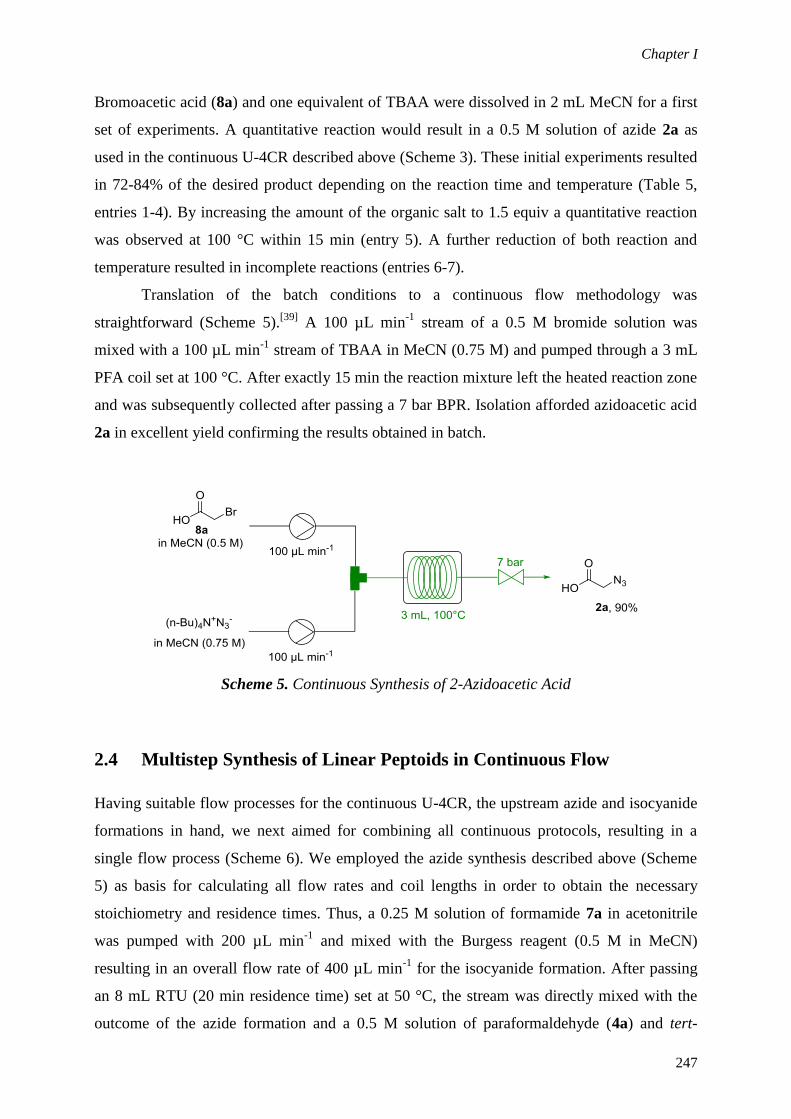
Chapter I
247
Bromoacetic acid (8a) and one equivalent of TBAA were dissolved in 2 mL MeCN for a first
set of experiments. A quantitative reaction would result in a 0.5 M solution of azide 2a as
used in the continuous U-4CR described above (Scheme 3). These initial experiments resulted
in 72-84% of the desired product depending on the reaction time and temperature (Table 5,
entries 1-4). By increasing the amount of the organic salt to 1.5 equiv a quantitative reaction
was observed at 100 °C within 15 min (entry 5). A further reduction of both reaction and
temperature resulted in incomplete reactions (entries 6-7).
Translation of the batch conditions to a continuous flow methodology was
straightforward (Scheme 5).[39]
A 100 µL min-1
stream of a 0.5 M bromide solution was
mixed with a 100 µL min-1
stream of TBAA in MeCN (0.75 M) and pumped through a 3 mL
PFA coil set at 100 °C. After exactly 15 min the reaction mixture left the heated reaction zone
and was subsequently collected after passing a 7 bar BPR. Isolation afforded azidoacetic acid
2a in excellent yield confirming the results obtained in batch.
Scheme 5. Continuous Synthesis of 2-Azidoacetic Acid
2.4 Multistep Synthesis of Linear Peptoids in Continuous Flow
Having suitable flow processes for the continuous U-4CR, the upstream azide and isocyanide
formations in hand, we next aimed for combining all continuous protocols, resulting in a
single flow process (Scheme 6). We employed the azide synthesis described above (Scheme
5) as basis for calculating all flow rates and coil lengths in order to obtain the necessary
stoichiometry and residence times. Thus, a 0.25 M solution of formamide 7a in acetonitrile
was pumped with 200 µL min-1
and mixed with the Burgess reagent (0.5 M in MeCN)
resulting in an overall flow rate of 400 µL min-1
for the isocyanide formation. After passing
an 8 mL RTU (20 min residence time) set at 50 °C, the stream was directly mixed with the
outcome of the azide formation and a 0.5 M solution of paraformaldehyde (4a) and tert-

Chapter I
248
butylamine (3a). The resulting output stream with an overall flow rate of 0.8 mL min-1
was
then heated in a 4 mL PFA tubing (5 min residence time) to 80 °C executing the intensified
U-4CR protocol. Analysis of the collected reaction mixture indicated a quantitative reaction
with the limiting formaldehyde reagent 7a being fully converted into peptoid 5a. After
purification, 80% of the target molecule was obtained which is in good agreement with the
previous batch and flow experiments. Notably, no purification step was required when
combining the different transformations and the fully continuous protocol afforded the
peptidomimetic compound within only 25 min overall reaction time in a process that avoided
the handling of potentially toxic and/or explosive intermediates.
Scheme 6. Synthesis of Linear Peptoid 5a via Isocyanide Synthesis (red), Azide Preparation
(green), and an U-4CR (blue) in a Single Continuous Operation

Chapter I
249
2.5 CuAAC in Continuous Flow
Copper-catalyzed 1,3-dipolar cycloadditions resulting in the 1,4-substituted 1,2,3-triazole
scaffold were carried out for the first time in a copper coil in 2009 by Bogdan and Sach,[46]
and since then have been applied in a multitude of synthetic strategies.[34]
Continuous
preparations of macrocyclic compounds using the copper-catalyzed Click strategy were
intensively studied by the groups of Collins[47,48]
and James.[35,49,50]
In the latter case, the use
of flow reactors made out of elemental copper turned out to be highly beneficial as the nature
of the coil itself avoided the necessity to add additional catalytically active species. Earlier
work from our laboratories revealed that these cycloadditions are not catalyzed by zerovalent
copper but more likely by a surface layer of Cu2O.[51]
Thus, a homogeneous reaction
mechanism was postulated resulting in leaching of the metal species when carried out
continuously.[51,52]
For the optimization study of the intermolecular CuAAC of linear peptoid 5a, a simple
continuous setup consisting of a syringe pump, a 20 mL copper coil and an adjustable back
pressure regulator was assembled (Table 6). Since literature conditions are typically carried
out in the presence of tris[(1-tert-butyl-1H-1,2,3-triazolyl)methyl]amine (TTTA) as ligand
and N,N-diisopropylethylamine (DIPEA) as base for better monomer-to-dimer ratios we
initiated our macrocyclization attempts using a similar approach (Table 6, entry 1).
Unfortunately, these conditions resulted in dimer 6a as main product in addition to the
generation of various unidentified byproducts. These compounds are most likely related to
higher oligomers or even polymeric material but could not be clearly identified.[53]
The
selectivity was even worse when we changed the ligand from TTTA to TBTA
(tris(benzyltriazolylmethyl)amine, entry 2). Interestingly, when the reaction using TTTA was
carried out without the addition of the base, a better conversion to the CuAAC products 6aα
and 6aβ was observed (entry 3). We next decided to process more diluted reaction mixtures
which demonstrated a slightly improved selectivity for monomer 6aβ (entries 4-5). Notably,
when we carried out a control experiment in the absence of TTTA only very small amounts of
the desired molecule were detected by HPLC analysis, almost selectively forming 6aα (entry
6). We concluded that a protocol selectively yielding monomer 6aβ with a suitable throughput
would not be achievable, and thus decided to intensify this additive-free process in order to
fully consume the linear precursor 5a. We anticipated that the resulting protocol would yield
the desired monomeric scaffold for homologs 5b-e as the resulting ring structures may be less
strained.[50]
Increasing the temperature to 140 °C resulted in full consumption of linear
peptoid 5a yielding 6aα almost selectively (entry 7). Since we realized that a slightly shorter

Chapter I
250
residence time provided significantly inferior results, we decided to extend the residence time
to 25 min to avoid incomplete cyclization procedures by using a flow rate of 0.8 mL min-1
(entries 8-9). Isolation using chromatographic techniques provided good isolated yields for
the complex cyclic peptoid 6aα.
Table 6. Process Intensification for the Continuous Macrocyclization Using a Copper Coila
entry c
[mM]
additive
(10mol%)
T
[°C]
t
[min] 5a
[%]b
6a[%]
b
6a[%]
b
1c
62.5 TTTA
100 20 17 44 5
2c 62.5 TBTA
100 20 9 27 8
3 62.5 TTTA 100 20 12 59 9
4 2.0 TTTA 100 20 3 67 23
5 2.0 TTTA 120 20 2 70 19
6 2.0 - 120 20 10 72 5
7 2.0 - 140 20 0 83 3
8 2.0 - 140 16 2 74 7
9 2.0 - 140 25 0 86(74)d 2
a Reactions were performed on a 0.140 mmol scale in MeCN/MeOH (1:1).
b Determined as peak area percent at
215 nm. c
2 equiv of DIPEA were added to the reaction mixture. d Isolated yield in parentheses. TTTA=(tris((1-
tert-butyl-1H-1,2,3-triazolyl)methyl)amine); TBTA = (tris(benzyltriazolylmethyl)amine)
When the same conditions were employed for the CuAAC of linear peptoid 5b - which only
differs from 5a by a single CH2 group - our hypothesis was confirmed (Table 7, entry 2).
Careful analysis revealed that the monomeric cyclopeptoid 6b was selectively formed instead
of the dimeric derivative. The same selectivity was obtained for linear peptoids 5c-5e and the
cyclic products 6c-6e could be isolated in good to excellent yields (entries 3-5). The structure
of compound 6e was confirmed X-ray crystallography.[54]
Not surprisingly, the structurally
different peptoids 5f and 5g smoothly cyclized leading to the desired 6- and 7-membered ring
structures (entries 6-7). A high ring strain may also be the reason for compound 5h to not
form a monomeric cyclopeptoid. However, also in this case reasonable amounts of the
dimeric structure 6h could be isolated.

Chapter I
251
Table 7. Continuous CuAAC Macrocyclization of Linear Peptoids using a Copper Coila
entry substrate product
1
2
3
4
5
6

Chapter I
252
entry substrate product
7
8
a Reactions were carried out using 2 mM solutions of the linear peptoids 5a-h in
MeCN:MeOH (1:1).
3. Conclusion
In summary, we have developed an efficient fully continuous multi-step strategy for the
synthesis of linear peptoids and a subsequent copper-catalyzed dipolar cycloaddition resulting
in their cyclic analogs. The whole continuous process is based on the synthesis of the peptoid
scaffold using an U-4CR. The limiting isocyanide was synthesized in a continuous process by
the dehydration of the corresponding amide using Burgess reagent. Since the following
CuAAC cyclization requires a potentially hazardous azide functionality, we developed a flow
protocol for its in-line synthesis by the nucleophilic substitution of a bromide precursor with
tetrabutylammonium azide. The individual steps could be successfully coupled without the
need of isolating any synthetic intermediate. The resulting convergent continuous synthesis is
characterized by an overall processing time of ca. 25 min generating the desired
peptidomimetics in good to excellent yields. The subsequent CuAAC macrocyclization was
realized using a continuous flow reactor made of copper avoiding a separate addition of a
catalytically active species. Depending on the nature of the linear precursor and the resulting
ring strain, either a dimeric or a monomeric form of the cyclic product was obtained.

Chapter I
253
4. Experimental Section
General Remarks. All Microwave-assisted reactions were carried out in a Biotage Initiator
2.5 instrument in Pyrex vessels (2-5 mL). Reaction temperature was controlled by an external
IR sensor. For continuous flow experiments, commercially available syringe pumps reagent
injector units and tube reactors were used (Asia Flow Chemistry modules, Syrris). The back
pressure was either controlled using static or adjustable regulation units.[39]
1H-NMR and
13C
spectra were recorded on a 300 MHz instrument using CDCl3 or DMSO-d6 as solvent.
Chemical shifts (δ) are expressed in ppm downfield from TMS as internal standard. The
letters s, d, t, q, qt and m are used to indicate a singlet, doublet, triplet, quadruplet, quintuplet
and multiplet, respectively. Melting points were determined on a standard melting point
apparatus. Analytical HPLC analysis was carried out on a C-18 reversed-phase (RP)
analytical column (150 × 4.6 mm, particle size 5 μm) at 37 °C using a mobile phase A
(water/acetonitrile 90:10 (v/v) + 0.1 % TFA) and B (MeCN + 0.1 % TFA) at a flow rate of 1.0
mL min-1
. The following gradient was applied: linear increase from solution 30% B to 100%
B in 8 min, hold at 100% solution B for 2 min. HRMS experiments were performed on an
TOF LC/MS instrument equipped with an ESI ion source (positive ionization mode). X-ray
diffraction measurements were performed on a standard CCD diffractometer by using
graphite monochromatized Mo Kα radiation. Column chromatography was carried out using
an automated flash chromatography system using petroleum ether/ethyl acetate mixtures as
eluent. Preparative HPLC separations were carried on a C-18 reversed-phase column (250 ×
16 mm, particle size 5 μm) at 25 °C using a mobile phase A (water/acetonitrile 90:10 (v/v))
and B (MeCN) at a flow rate of 8.0 mL min-1
. The following gradient was applied: linear
increase from solution 30% B to 100% B in 18 min, hold at 100% solution B for 4 min. TLC
analysis was performed on silica gel F254 plates. All compounds and solvents were obtained
from standard commercial vendors and used without further purification. Proof of purity was
obtained by 1H NMR and HPLC−UV spectroscopy.
Starting Materials. 4-(Prop-2-yn-1-yloxy)benzonitrile,[55]
(4-(prop-2-yn-1-yloxy)phenyl)-
methanamine,[56]
3-azidopropionic acid,[57]
4-azidobutanoic acid, 5-azidopentanoic acid,[58]
6-
azidohexanoic acid[59]
were prepared and characterized according to literature procedures.

Chapter I
254
N-(4-(Prop-2-yn-1-yloxy)benzyl)formamide (7a): A stirred mixture of 4-(prop-2-yn-1-
yloxy)phenyl)methanamine (1.7 g, 10.6 mmol) in 5 mL ethyl formate was refluxed overnight.
Afterwards, the solvent was removed under reduced pressure and the residue was purified by
flash chromatography to give the title compound in 90% yield (1.8 g, 9.5 mmol) as a colorless
solid, mp. 93-94 °C, Rf: 0.42 (95% EtOAc/petroleum ether). HRMS (ESI): m/z: calcd for
C11H12NO2 [M+H]+: 190.086255, found: 190.086639.
1H NMR (300 MHz, CDCl3, presence
of rotamers) δ 8.21 (s, 0.9H), 8.15 (d, J = 12 Hz, 0.1H), 7.30 – 7.13 (m, 2H), 6.98 – 6.88 (m,
2H), 6.10 (brs, 1H), 4.80 and 4.70 (2 d, J = 2.5 Hz, 2H), 4.41 and 4.35 (2 d, J = 5.8 Hz, 2H),
2.53 (t, J = 2.5 Hz, 1H). 13
C NMR (75 MHz, CDCl3, presence of rotamers) 164.6, 161.1,
157.2, 157.0, 130.7, 130.5, 129.1, 128.3, 115.3, 115.1, 114.9, 78.4, 75.7, 58.9, 55.8, 45.1,
41.5; FT-IR (KBr, cm−1
) 3269, 3217, 3041, 2920, 2889, 2111, 1642, 1538, 1218, 1174, 1113,
1026, 812, 787, 601.
Microwave Assisted Synthesis of 1-(Isocyanomethyl)-4-(prop-2-yn-1-yloxy)benzene 1a.
N-(4-(Prop-2-yn-1-yloxy)benzyl)formamide (7a) (0.5 mmol, 94 mg) and methyl N-
(triethylammoniumsulfonyl)carbamate (0.75 mmol, 179 mg) were dissolved in acetonitrile (2
ml) and heated to 50 °C for 20 min using microwave irradiation. The obtained yellow solution
was concentrated in vacuum and purified by flash chromatography to give the title compound
in 93% yield (79.0 mg, 0.46 mmol) as colorless solid, mp. 58-60 °C, Rf: 0.36 (10%
EtOAc/petroleum ether). HRMS (APCI): m/z: calcd for C10H9O [M-NC+H]+: 145.064791,
found: 145.064668; calcd for C8H9O [M-propargyl]-: 132.045487, found: 132.045744;
1H
NMR (300 MHz, CDCl3) δ 7.30 (d, J = 8.7 Hz, 2H), 7.02 (d, J = 8.7 Hz, 2H), 4.73 (d, J = 2.4
Hz, 2H), 4.60 (brs, 2H), 2.55 (t, J = 2.4 Hz, 1H). 13
C NMR (75 MHz, CDCl3) δ 157.5, 157.2,
128.1, 125.5, 115.4, 78.2, 75.8, 55.9, 44.9; FT-IR (KBr, cm−1
) 3249, 3071, 2963, 2922, 2865,
2159, 2123, 2039, 1613, 1588, 1509, 1453, 1184, 940, 778, 635.
Microwave Assisted Synthesis of 2-Azidoacetic Acid 2a. 2-Bromoacetic acid (1.0 mmol,
0.137 mg) and N,N,N,N-tetrabutylammonium azide (1.5 mmol, 0.426 mg) were dissolved in
acetonitrile (2 ml) and heated to 100 °C for 15 min using microwave irradiation. After cooling
to room temperature, the solvent was evaporated. The concentrate was dissolved in H2O and
acidified with HCl to pH = 1. The solution was extracted 3 x with Et2O and the combined
organic phases were dried over Na2SO4. Careful solvent evaporation under reduced pressure
resulted in 92% yield of the title compound (93 mg, 0.92 mmol). The data obtained by NMR
is identical to those reported in literature.[60]

Chapter I
255
General Procedure for Preparation of Linear Peptoids by the U-4CR in Batch (Table 2).
A sealed 2-5 mL microwave process vial containing a mixture of the isocyanide (1, 0.5
mmol), the corresponding acid (2, 1.0 mmol), the amine (3, 1.0 mmol), and paraformaldehyde
(4, 1.0 mmol) in 2 mL MeOH/MeCN (1:1) was kept for 4 min at 80 °C using a single mode
microwave reactor. After cooling to room temperature, the reaction mixture was concentrated
under reduced pressure and purified by flash column chromatography using petroleum
ether/ethyl acetate gradients to yield the corresponding linear peptoids.
2-Azido-N-(tert-butyl)-N-(2-oxo-2-((4-(prop-2-yn-1-yloxy)benzyl)amino)ethyl)acetamide
(5a). Prepared from paraformaldehyde (4a, 30 mg, 1.0 mmol), tert-butylamine (3a, 73 mg,
1.0 mmol), 2-azidoacetic acid (2a, 101 mg, 1.0 mmol) and isocyanide 1a (85 mg, 0.5 mmol).
Peptoid 5a was isolated in 84% yield (150 mg, 0.42 mmol) as a colorless oil. Rf: 0.50 (50%
EtOAc/petroleum ether). HRMS (ESI): m/z: calcd for C18H23N5O3Na [M+Na]+: 380.169311,
found: 380.169070. 1H NMR (300 MHz, CDCl3) δ 7.20 (d, J = 8.5 Hz, 2H), 6.93 (d, J = 8.5
Hz, 2H), 6.75 – 6.64 (m, 1H), 4.67 (d, J = 2.3 Hz, 2H), 4.36 (d, J = 5.6 Hz, 2H), 3.90 (s, 2H),
3.81 (s, 2H), 2.53 (t, J = 2.3 Hz, 1H), 1.38 (d, J = 11.6 Hz, 9H). 13
C NMR (75 MHz, CDCl3) δ
168.8, 168.7, 157.1, 156.9, 130.7, 129.1, 115.2, 78.4, 77.5, 77.1, 76.7, 75.7, 75.7, 58.8, 55.8,
52.6, 47.8, 43.1, 28.4; FT-IR (KBr, cm−1
) 3294, 2102, 1654, 1509, 1396, 1363, 1215, 1190,
1023, 933, 829, 641.
3-Azido-N-(tert-butyl)-N-(2-oxo-2-((4-(prop-2-yn-1-loxy)benzyl)amino)ethyl)propanamide (5b).
Prepared from paraformaldehyde (4a, 30 mg, 1.0 mmol), tert-butylamine (3a, 73 mg, 1.0
mmol), 3-azidopropionic acid (2b, 115 mg, 1.0 mmol), and isocyanide 1a (85 mg, 0.5 mmol).
Peptoid 5b was isolated in 86% yield (0.159 g, 0.43 mmol) as a colorless solid, mp. 92-94 °C.
Rf: 0.37 (50% EtOAc/petroleum ether). HRMS (ESI): m/z: calcd for C19H25N5O3Na [M+Na]+:
394.184961, found: 394.185216. 1H NMR (300 MHz, CDCl3) δ 7.21 (d, J = 8.4 Hz, 2H), 6.94
(d, J = 8.4 Hz, 2H), 6.46 (brt, J = 5.1 Hz, 1H), 4.68 (t, J = 2.4 Hz, 2H), 4.40 (d, J = 5.7 Hz,
2H), 3.98 (s, 2H), 3.60 (t, J = 6.2 Hz, 2H), 2.53 (t, J = 2.4 Hz, 1H), 2.46 (t, J = 6.2 Hz, 2H),
1.41 (s, 9H). 13
C NMR (75 MHz, CDCl3) δ 171.7, 169.1, 157.1, 130.6, 129.1, 115.2, 78.4,
75.7, 58.3, 55.8, 49.0, 47.6, 43.2, 35.3, 28.6; FT-IR (KBr, cm−1
) 3292, 2973, 2928, 2098,
1649, 1586, 1543, 1509, 1405, 1362, 1328, 1297, 1113, 807, 731, 671.
4-Azido-N-(tert-butyl)-N-(2-oxo-2-((4-(prop-2-yn-1-yloxy)benzyl)amino)ethyl)butanamide (5c).
Prepared from paraformaldehyde (4a, 30 mg, 1.0 mmol), tert-butylamine (3a, 73 mg, 1.0
mmol), 4-azidobutanoic acid (2c, 129 mg, 1.0 mmol) and isocyanide 1a (0.085 g, 0.5 mmol).

Chapter I
256
Peptoid 5c was isolated in 95% yield (181 mg, 0.47 mmol) as a colorless solid, mp. 93-95 °C,
Rf: 0.40 (50% EtOAc/petroleum ether). HRMS (ESI): m/z: calc. for C20H27N5O3Na [M+Na]+:
408.200611, found: 408.200814. 1H NMR (300 MHz, CDCl3) δ 7.15 (d, J = 8.6 Hz, 2H), 6.87
(d, J = 8.4 Hz, 2H), 6.44 (brt, J = 5.4 Hz, 1H), 4.61 (d, J = 2.4 Hz, 2H), 4.35 (d, J = 5.8 Hz,
2H), 3.91 (s, 2H), 3.17 (t, J = 6.4 Hz, 2H), 2.46 (t, J = 2.4 Hz, 1H), 2.22 (t, J = 6.8 Hz, 2H),
1.82 (qt, J = 6.6 Hz, 2H), 1.33 (s, 9H). 13
C NMR (75 MHz, CDCl3) δ 173.4, 169.5, 157.1,
130.8, 129.2, 115.2, 78.4, 75.7, 58.1, 55.8, 50.9, 49.1, 43.0, 32.8, 28.6, 24.4; FT-IR (KBr,
cm−1
) 3317, 3255, 3072, 2968, 2908, 2087, 1663, 1643, 1512, 1266, 1240, 1193, 1179, 1116,
934, 813, 607, 553.
5-Azido-N-(tert-butyl)-N-(2-oxo-2-((4-(prop-2-yn-1-yloxy)benzyl)amino)ethyl)pentanamide (5d).
Prepared from paraformaldehyde (4a, 30 mg, 1.0 mmol), tert-butylamine (3a, 73 mg, 1.0
mmol), 5-azidopentanoic acid (2d, 143 mg, 1.0 mmol) and isocyanide 1a (85 mg, 0.5 mmol).
Peptoid 5d was isolated in 86% yield (171 mg, 0.43 mmol) as a colorless solid, mp. 72-74 °C,
Rf: 0.42 (50% EtOAc/petroleum ether). HRMS (ESI): m/z: calcd for C21H29N5O3Na [M+Na]+:
422.216281, found: 422.216353. 1H NMR (300 MHz, CDCl3) δ 7.24 – 7.18 (m, 2H), 6.98 –
6.93 (m, 2H), 6.36 (brt, J = 5.5 Hz, 1H), 4.69 (d, J = 3.1 Hz, 2H), 4.43 (d, J = 5.8 Hz, 2H),
4.00 (s, 2H), 3.25 (t, J = 5.4 Hz, 2H), 2.53 (t, J = 2.4 Hz, 1H), 2.24 (t, J = 7.1 Hz, 2H), 1.70 –
1.60 (m, 2H), 1.58 – 1.48 (m, 2H), 1.41 (s, 9H). 13
C NMR (75 MHz, CDCl3) δ 174.0, 169.6,
157.2, 130.7, 129.1, 115.2, 78.3, 75.7, 58.0, 55.8, 51.2, 49.1, 43.1, 35.4, 28.8, 28.3, 22.4; FT-
IR (KBr, cm−1
) 3281, 3068, 2928, 2871, 2091, 1724, 1678, 1611, 1585, 1454, 1359, 1211,
1177, 1024, 752, 655, 576.
6-Azido-N-(tert-butyl)-N-(2-oxo-2-((4-(prop-2-yn-1-yloxy)benzyl)amino)ethyl)hexanamide (5e).
Prepared from paraformaldehyde (4a, 30 mg, 1.0 mmol), tert-butylamine (3a, 73 mg, 1.0
mmol), 6-azidohexanoic acid (2e, 155 mg, 1.0 mmol) and isocyanide 1a (85 mg, 0.5 mmol).
Peptoid 5e was isolated in 80% yield (165 mg, 0.40 mmol) as a colorless solid, mp. 88-90 °C,
Rf: 0.45 (50% EtOAc/petroleum ether). HRMS (ESI): m/z: calcd for C22H31N5O3Na [M+Na]+:
436.230574, found: 436.231116.1H NMR (300 MHz, CDCl3) δ 7.23 – 7.14 (m, 2H), 6.97 –
6.88 (m, 2H), 6.38 (brt, J = 5.6 Hz, 1H), 4.67 (d, J = 2.4 Hz, 2H), 4.40 (d, J = 5.8 Hz, 2H),
3.97 (s, 2H), 3.23 (t, J = 6.8 Hz, 2H), 2.53 (t, J = 2.4 Hz, 1H), 2.19 (t, J = 7.3 Hz, 2H), 1.65 –
1.50 (m, 4H), 1.39 (s, 9H), 1.35 – 1.25 (m, 2H). 13
C NMR (75 MHz, CDCl3) δ 174.2, 169.6,
157.1, 130.7, 129.1, 115.2, 78.4, 75.7, 57.9, 55.8, 51.2, 49.1, 43.0, 35.9, 28.8, 26.3, 24.7. FT-
IR (KBr, cm−1
) 3273, 3074, 2932, 2867, 2092, 1726, 1679, 1585, 1555, 1421, 1212, 1114,
1021, 751, 579, 552.

Chapter I
257
2-Azido-N-(2-(cyclohexylamino)-2-oxoethyl)-N-(prop-2-yn-1-yl)acetamide (5f). Prepared
from paraformaldehyde (4a, 30 mg, 1.0 mmol), propargylamine (3b, 55 mg, 1.0 mmol), 2-
azidoacetic acid (2a, 101 mg, 1.0 mmol) and cyclohexyl isocyanide (1b, 55 mg, 0.5 mmol).
Peptoid 5f was isolated in 90% yield (125 mg, 0.45 mmol) as a colorless solid, mp. 125-127
°C, Rf: 0.42 (50% EtOAc/petroleum ether). HRMS (ESI): m/z: calcd for C13H20N5O2 [M+H]+:
278.161151, found for [M+H]+: 278.161152.
1H NMR (300 MHz, CDCl3 mixture of rotamers)
1H NMR (300 MHz, CDCl3) δ 6.01 and 5.98 (2 brs, 1H), 4.25 and 4.09 (2 brs, 2H), 4.04 and
4.01 (2 s, 2H), 3.93 and 3.87 (2 brs, 2H), 3.82 – 3.54 (m, 1H), 2.33 and 2.26 (2 brs, 1H), 1.88
– 1.77 (m, 2H), 1.72 – 1.47 (m, 3H), 1.40 – 1.17 (m, 2H), 1.19 – 0.96 (m, 3H). 13
C NMR (75
MHz, CDCl3 mixture of rotamers) δ 168.1, 166.8, 165.9, 74.1, 73.7, 50.4, 50.1, 50.1, 48.9,
48.5, 38.2, 36.6, 32.9, 25.4, 24.7; FT-IR (KBr, cm−1
) 3298, 3259, 2927, 2852, 2102, 1670,
1637, 1554, 1457, 1370, 1082, 891, 657, 559.
3-Azido-N-(2-(cyclohexylamino)-2-oxoethyl)-N-(prop-2-yn-1-yl)propanamide (5g).
Prepared from paraformaldehyde (4a, 30 mg, 1.0 mmol), propargylamine (3b, 55 mg, 1.0
mmol), 3-azidopropionic acid (2b, 115 mg, 1.0 mmol) and cyclohexyl isocyanide (1b, 55 mg,
0.5 mmol). Peptoid 5g was isolated in 88% yield (128 mg, 0.44 mmol) as a colorless solid,
mp. 109-111 °C, Rf: 0.30 (50% EtOAc/petroleum ether). HRMS (ESI): m/z: calcd for
C14H22N5O2 [M+H]+: 292.176801, found 292.176016.
1H NMR (300 MHz, CDCl3 mixture of
rotamers) δ 5.97 (brs, 1H), 4.24 and 4.12 (2 d, J = 2.4 Hz, 2H), 4.00 and 3.91 (2 brs, 2H), 3.82
– 3.65 (m, 1H), 3.67 – 3.55 (m, 2H), 2.67 (t, J = 6.3 Hz, 1H), 2.45 (t, J = 6.2 Hz, 1H), 2.30
and 2.24 (2 t, J = 2.4 Hz, 1H), 1.90 – 1.75 (m, 2H), 1.72 – 1.48 (m, 3H), 1.39 – 1.19 (m, 2H),
1.17 – 0.96 (m, 3H). 13
C NMR (75 MHz, CDCl3 mixture of rotamers) δ 170.9, 170.7, 167.2,
166.4, 78.3, 73.7, 73.5, 51.3, 50.4, 48.8, 48.3, 47.1, 38.9, 36.6, 32.9, 32.8, 32.7, 32.5, 25.4,
25.3, 24.8, 24.7; FT-IR (KBr, cm−1
) 3316, 3239, 2942, 2925, 2855, 2114, 2084, 1649, 1549,
1463, 1433, 1237, 1053, 882, 720, 617.
Methyl-2-(2-(4-Azido-N-(2-ethynylphenyl)butanamido) acetamido)acetate (5h): Prepared
from paraformaldehyde (4a, 30 mg, 1.0 mmol), 2-ethynylaniline (3c, 117 mg, 1.0 mmol), 4-
azidobutanoic acid (2c, 129 mg, 1.0 mmol), methyl isocyanoacetate (1c, 50 mg, 0.5 mmol).
Peptoid 5f was isolated in 81% yield (146 mg, 0.41 mmol) as a brownish oil, Rf: 0.32 (50%
EtOAc/petroleum ether). HRMS (ESI): m/z: calcd for C17H20N5O4 [M+H]+: 358.150981,
found 358.151069. 1H NMR (300 MHz, CDCl3 mixture of rotamers) δ 7.54 and 7.52 (2 brs,
1H), 7.43 – 7.37 (m, 2H), 7.35 – 7.27 (m, 1H), 6.95 (brs, 1H), 4.77 (d, J = 15.5 Hz, 1H), 4.11

Chapter I
258
(dd, J = 18.2, 6.0 Hz, 1H), 3.88 (dd, J = 18.2, 4.9 Hz, 1H), 3.76 (d, J = 15.5 Hz, 1H), 3.69 (s,
3H), 3.26 (s, 1H), 3.25 – 3.16 (m, 2H), 2.20 – 2.07 (m, 2H), 1.88 – 1.76 (m, 2H). 13
C NMR
(75 MHz, CDCl3 mixture of rotamers) δ 173.3, 170.2, 168.9, 144.1, 134.1, 130.7, 129.1,
128.8, 121.3, 83.2, 79.4, 53.1, 52.4, 50.6, 41.1, 30.6, 24.3; FT-IR (KBr, cm−1
) 3288, 2951,
2094, 1746, 1654, 1532, 1485, 1448, 1435, 1252, 1020, 755, 657, 631.
Synthesis of Linear Peptoid 5a in a Continuous Multi-Step Approach (Scheme 5).
Isocyanide generation: A feed consisting of formamide 7a (0.25 mmol) dissolved in
acetonitrile (1 mL) was pumped with a flow rate of 200 µL min-1
and mixed in a T-shaped
mixing unit with a second feed with an identical flow rate containing a 0.5 M solution of
Burgess reagent (0.5 mmol in 1 mL acetonitrile). For a better control of the process, the
reagents were each stored in a 1 mL sample loop connected via a 6-way valve and
simultaneously injected into the flow system. After mixing, the resulting 400 µL min-1
stream
was passed through a PFA coil (0.8 mm inner diameter; 8 mL reactor volume, 20 min
residence time) set at 50 °C using an oil bath, theoretically resulting in an isocyanide stream
of 0.05 mmol min-1
.
Azide formation: A feed consisted of 2-bromoacetic acid 8a (2.0 mmol) dissolved in
acetonitrile (2 mL) was pumped with a flow rate of 100 µL min-1
and mixed in a T-shaped
mixing unit with a second feed with an identical flow rate containing a 1.5 M solution of
tetrabutylammonium azide (3.0 mmol in 2 mL acetonitrile). For a better control of the
process, the reagents were each stored in a 2 mL sample loop connected via a 6-way valve
and simultaneously injected into the flow system. After mixing, the resulting 200 µL min-1
stream was passed through a PFA coil (0.8 mm inner diameter; 3 mL reactor volume, 15 min
residence time) set at 100 °C using an oil bath, theoretically resulting in an azide stream of 0.1
mmol min-1
(2 equiv).
U-4CR: A solution of tert-butylamine 3a (0.5 M) and paraformaldehyde 4a (0.5 M) in
methanol was constantly pumped with a flow rate of 200 µL min-1
(0.1 mmol min-1
, 2 equiv)
and mixed with the outcome of the isocyanide generation and the azide formation in a cross
shaped mixing device. The resulting reaction stream (800 µL min-1
) was heated at 80 °C in a
PFA coil (0.8 mm inner diameter, 4 mL reactor volume, 5 min residence time). The reaction
mixture was collected after depressurization by passing a static 7 bar backpressure regulator.
Purification by flash column chromatography resulted in linear peptoid 5a in 80% yield(71
mg, 0.2 mmol) as a colorless oil. Data obtained by mass spectrometry, 1H NMR and
13C NMR
are identical to those from the corresponding batch experiment (see above).

Chapter I
259
General Procedure for the Continuous CuAAC Using a Copper Coil. A solution of the
respective linear peptoid 5a-h in MeCN/MeOH (1:1; 2 mM) was pumped with 800 µL min-1
through a copper coil (2 mm inner diameter, 20 ml internal volume) heated at 140 °C in a GC
oven. After passing a back pressure regulator set at 10 bar, the reaction mixture was collected
and the solvent removed under reduced pressure. Isolation by preparative HPLC resulted in
the cyclic peptoids 6a-h in analytical purity.
Cyclic Peptoid 6a: Prepared from peptoid 5a (50 mg, 0.140 mmol) in 70 mL MeCN/MeOH
(1:1). Isolation afforded the title compound in 74% yield (37 mg, 0.052 mmol) as a colorless
solid, mp. 254-256 °C (dec.). HRMS (ESI): m/z: calcd for C36H47N10O6 [M+H]+: 715.367456,
found: 715.360619. 1H NMR (300 MHz, DMSO-d6) δ 8.59 (brs, 2H), 8.10 (s, 2H), 7.25 (d, J
= 8.4 Hz, 4H), 7.03 (d, J = 8.4 Hz, 4H), 5.35 (s, 4H), 5.11 (s, 4H), 4.35 – 4.20 (m, 4H), 4.15
(s, 4H), 1.32 (s, 18H). 13
C NMR (75 MHz, DMSO-d6) δ 169.3, 167.1, 157.7, 142.7, 131.7,
129.2, 126.8, 115.0, 61.4, 58.2, 52.9, 47.2, 42.3, 28.4; FT-IR (KBr, cm−1
) 3303, 3075, 2977,
2931, 1658, 1612, 1585, 1543, 1509, 1463, 1435, 1364, 1218, 1191, 812, 586
Cyclic Peptoid 6b: Prepared from peptoid 5b (50 mg, 0.135 mmol) in 67.5 mL
MeCN/MeOH (1:1). Isolation afforded the title compound in 81% yield (39 mg, 0.11 mmol)
as a colorless solid, mp. 240-242 °C. HRMS (ESI): m/z: calcd for C19H26N5O3 [M+H]+:
372.201679, found: 372.202446.1H NMR (300 MHz, DMSO-d6) δ 8.43 (brs, 1H), 8.18 (s,
1H), 7.17 (d, J = 8.3 Hz, 2H), 6.97 (d, J = 8.3 Hz, 2H), 5.08 (s, 2H), 4.53 (t, J = 6.5 Hz, 2H),
4.23 (d, J = 4.9 Hz, 2H), 4.01 (s, 2H), 2.93 (d, J = 6.7 Hz, 2H), 1.31 (s, 9H). 13
C NMR (75
MHz, DMSO-d6) δ 171.1, 169.7, 157.5, 142.9, 131.9, 129.1, 125.2, 115.0, 61.5, 57.5, 48.0,
46.5, 42.2, 35.9, 28.6; FT-IR (KBr, cm−1
) 3318, 3131, 3076, 2970, 1676, 1637, 1606, 1509,
1294, 1093, 817, 596.
Cyclic Peptoid 6c: Prepared from peptoid 5c (50 mg, 0.130 mmol) in 65 mL MeCN/MeOH
(1:1). Isolation afforded the title compound in 81% yield (41 mg, 0.105 mmol) as a colorless
solid, mp. 259-261 °C. HRMS (ESI): m/z: calcd for C20H28N5O3 [M+H]+: 386.218666, found:
386.218942. 1H NMR (300 MHz, DMSO-d6) δ 8.26 (brs, 1H), 7.68 (s, 1H), 7.10 (d, J = 7.9
Hz, 2H), 6.81 (d, J = 7.9 Hz, 2H), 5.26 (s, 2H), 4.23 (s, 2H), 3.99 (brs, 2H), 3.75 (s, 2H), 1.91
(brs, 2H), 1.56 (brs, 2H), 1.29 (s, 9H). 13
C NMR (75 MHz, DMSO-d6) δ 172.7, 169.8, 157.5,
143.1, 132.0, 129.1, 128.9, 124.9, 115.0, 61.6, 57.3, 49.5, 48.1, 42.2, 32.3, 28.6, 26.4; FT-IR
(KBr, cm−1
) 3293, 2962, 2929, 1645, 1585, 1508, 1458, 1421, 1394, 1334, 1216, 1176, 999,
807, 668, 509.

Chapter I
260
Cyclic Peptoid 6d: Prepared from peptoid 5d (50 mg, 0.125 mmol) in 62.5 mL
MeCN/MeOH (1:1). Isolation afforded the title compound in 80% yield (40 mg, 0.10 mmol)
as a colorless solid, mp. 213-215 °C. HRMS (ESI): m/z: calcd for C21H30N5O3 [M+H]+:
400.234316, found: 400.234235. 1H NMR (300 MHz, DMSO-d6) δ 8.39 (brs, 1H), 8.20 (s,
1H), 7.19 (d, J = 8.2 Hz, 2H), 6.98 (d, J = 8.3 Hz, 2H), 5.09 (s, 2H), 4.34 (t, J = 6.2 Hz, 2H),
4.23 (d, J = 4.9 Hz, 2H), 3.98 (s, 2H), 2.30 – 2.15 (m, 2H), 1.83 – 1.70 (m, 2H), 1.54 – 1.36
(m, 2H), 1.30 (s, 9H). 13
C NMR (75 MHz, DMSO-d6) δ 173.4, 170.0, 157.5, 143.1, 132.1,
129.1, 124.8, 115.0, 61.6, 57.1, 49.7, 48.1, 42.2, 34.7, 29.8, 28.7, 22.2; FT-IR (KBr, cm−1
)
3353, 3125, 3078, 2978, 2965, 2938, 1645, 1508, 1300, 1060, 1032, 993, 979, 881.
Cyclic Peptoid 6e: Prepared from peptoid 5e (50 mg, 0.121 mmol) in 61 mL MeCN/MeOH
(1:1). Isolation afforded the title compound in 83% yield (41 mg, 0.10 mmol) as a colorless
solid, mp. 268-270 °C. HRMS (ESI): m/z: calcd for C22H32N5O3 [M+H]+: 414.248629, found:
414.249174.1H NMR (300 MHz, DMSO-d6) δ 8.42 (t, J = 6.2 Hz, 1H), 8.11 (s, 1H), 7.15 (d, J
= 8.6 Hz, 2H), 6.86 (d, J = 8.6 Hz, 2H), 5.31 (s, 2H), 4.31 (brs, 2H), 4.10 (brs, 2H), 3.85 (s,
2H), 1.80 – 1.60 (m, 4H), 1.37 (s, 9H), 1.29 – 1.18 (m, 2H), 0.66 – 0.52 (m, 2H).13
C NMR (75
MHz, DMSO-d6) δ 173.7, 170.0, 157.5, 143.0, 132.1, 129.1, 124.8, 114.9, 61.6, 57.0, 49.7,
48.1, 42.1, 35.2, 30.1, 28.7, 26.0, 24.6; FT-IR (KBr, cm−1
) 3348, 3130, 3077, 2940, 2873,
1508,1465, 1438, 1418, 1170, 1089, 846, 704, 580.
Cyclic Peptoid 6f: Prepared from peptoid 5f (50 mg, 0.180 mmol) in 90 mL MeCN/MeOH
(1:1). Isolation afforded the title compound in 86% yield (43 mg, 0.155 mmol) as a colorless
solid, mp. 236-238 °C (dec.). HRMS (ESI): m/z: calcd for C13H20N5O2 [M+H]+: 278.161151,
found: 278.160641.1H NMR (300 MHz, DMSO-d6) δ 7.92 (d, J = 7.8 Hz, 1H), 7.71 (s, 1H),
5.13 (s, 2H), 4.73 (s, 2H), 4.08 (s, 2H), 3.61 – 3.45 (m, 1H), 1.75 – 1.60 (m, 4H), 1.60 – 1.50
(m, 1H), 1.33 – 1.01 (m, 5H). 13
C NMR (75 MHz, DMSO-d6) δ 166.4, 163.0, 129.2, 129.0,
49.2, 48.7, 48.2, 43.5, 32.9, 25.6, 25.0; FT-IR (KBr, cm−1
) 3294, 2927, 2855, 1643, 1556,
1494, 1444, 1422, 1410, 1375, 1348, 1304, 1275, 1252, 1098, 988, 828, 693.
Cyclic Peptoid 6g: Prepared from peptoid 5g (50 mg, 0.172 mmol) in 86 mL MeCN/MeOH
(1:1). Isolation afforded the title compound in 91% yield (46 mg, 0.156 mmol) as a colorless
solid, mp. 151-153 °C. HRMS (ESI): m/z: calcd for C14H22N5O2 [M]+: 292.176801, found:
292.176707.1H NMR (300 MHz, CDCl3) δ 7.47 (s, 1H), 5.87 (d, J = 7.8 Hz, 1H), 4.69 (s,
2H), 4.67 – 4.61 (m, 2H), 4.00 (s, 2H), 3.68 – 3.53 (m, 1H), 3.17 – 3.09 (m, 2H), 1.79 – 1.68

Chapter I
261
(m, 2H), 1.66 – 1.46 (m, 3H), 1.33 – 1.16 (m, 2H), 1.13 – 0.92 (m, 3H). 13
C NMR (75 MHz,
CDCl3) δ 171.6, 166.7, 131.7, 131.5, 51.6, 48.5, 45.4, 43.0, 32.8, 32.6, 25.4, 24.7; FT-IR
(KBr, cm−1
) 3297, 3067, 2930, 2854, 11646, 1540, 1449, 1292, 1239, 1133, 1047, 891, 726,
644.
Cyclic Peptoid 6h: Prepared from peptoid 5h (50 mg, 0.14 mmol) in 70 mL MeCN/MeOH
(1:1). Isolation afforded the title compound in 71% yield (36 mg, 0.051 mmol) as a colorless
solid, mp. 236-238 °C (dec.). HRMS (ESI): m/z: calcd for C34H39N10O8 [M+H]+: 715.294685,
found: 715.294219. 1H NMR (300 MHz, DMSO-d6) δ 8.35 (t, J = 5.8 Hz, 2H), 8.06 – 8.00
(m, 2H), 7.80 (s, 2H), 7.63 – 7.55 (m, 2H), 7.53 – 7.35 (m, 4H), 4.89 and 4.84 (2 s, 2H), 4.63
– 4.51 (m, 2H), 4.32 – 4.17 (m, 2H), 3.95 – 3.79 (m, 4H), 3.63 (s, 6H), 2.30 – 1.78 (m, 8H),
1.31 – 1.12 (m, 2H). 13
C NMR (75 MHz, DMSO-d6) δ 171.5, 170.6, 168.7, 142.6, 138.8,
130.8, 129.6, 129.4, 128.7, 122.0, 52.2, 51.3, 48.6, 30.0, 25.4; FT-IR (KBr, cm−1
) 3282, 3083,
2932, 1750, 1658, 1552, 1487, 1372, 1175, 970, 759, 662, 552.
5. References
[1] (a) A. Grauer, B. König, Eur. J. Org. Chem. 2009, 5099; (b) T. Kimmerlin, D.
Seebach, J. Pept. Res. 2005, 65, 229. (c) A. L. Boyle, D. N. Woolfson, Chem. Soc.
Rev. 2011, 40, 4295.
[2] D. P. Ryan, J. M. Matthews, Curr. Opin. Struct. Biol. 2005, 15, 441.
[3] (a) J. Vagner, H. Qu, V. Hruby, J. Curr. Opin. Chem. Biol. 2008, 12, 292 (b) E.
Marsault, M. L. Peterson, J. Med. Chem. 2011, 54, 1961.
[4] (a) S. A. Fowler, H. E. Blackwell, Org. Biomol. Chem. 2009, 7, 1508; (b) J. A. Patch,
K. Kirshenbaum, S. L. Seurynck, R. N. Zuckermann, A. E. Barron, Pseudopeptides in
Drug Development, Nielsen, P. E., Ed.; Wiley-VCH, Weinheim, Germany, 2004, pp.
1-31.
[5] R. J. Simon, R. N. Kania, J. M. Zuckermann, V. D. Huebner, D. A. Jewell, S.
Banville, S. Ng, L. Wang, S. Rosenberg, C. K. Marlowe, Proc. Natl. Acad. Sci. 1992,
89, 9367.
[6] (a) K. Rajasekhar, N. Narayanaswamy, P. Mishra, S. N. Suresh, R. Manjithaya, T.
Govindaraju, ChemPlusChem, 2014, 79, 25; (b) R. N. Zuckermann, J. M. Kerr, S. B.
H. Kent, W. H. Moos, J. Am. Chem. Soc. 1992, 114, 10646.

Chapter I
262
[7] (a) Y. U. Kwon, T. Kodadek, J. Am. Chem. Soc. 2007, 129, 1508; (b) A. Broceta-
Unciti, F. Diezmann, C. Y. Ou-Yang, M. A. Fara, M. Bradley, Bioorg. Med. Chem.
2009, 17, 959; (c) N. C. Tan, P. Yu, Y. U. Kwon, T. Kodadek, Bioorg. Med. Chem.
Lett. 2008, 16, 5853.
[8] (a) C. W. Wu, T. J. Sanborn, K. Huang, R. N. Zuckermann, A. E. Barron, J. Am.
Chem. Soc. 2001, 123, 6778; (b) C. W. Wu, K. Kirshenbaum, T. J. Sanborn, J. A.
Patch, K. Huang, K. A. Dill, R. N. Zuckermann, A. E. Barron, J. Am. Chem. Soc.
2003, 125, 13525.
[9] A. S. Culf, R. J. Ouellette, Molecules, 2010, 15, 5282.
[10] (a) A. Dömling, Chem. Rev. 2006, 106, 17; (b) G. Koopmanschap, E. Ruijter, R. V. A.
Orru, Beilstein J. Org. Chem. 2014, 10, 544 ; (c) A. Dömling, W. Wang, K. Wang,
Chem. Rev. 2012, 112, 3083 ; (d) O. Pando, S. Stark, A. Denkert, A. Porzel, R.
Preusentanz, L. A. Wessjohann, J. Am. Chem. Soc. 2011, 133, 7692.
[11] For applications of the U-4CR in peptoid synthesis, see: (a) M. C. N. Brauer, R. A. W.
Neves Filho, B. Westermann, R. Heinke, L. A. Wessjohann, Beilstein J. Org. Chem.
2015, 11, 25; (b) A. Svithri, S. Thulasi, L. V. Ramavarma, J. Org. Chem. 2014, 79,
1683. (c) A. F. S. Barreto, O. E. Vercillo, L. A. Wessjohann, C. K. Z. Andrade,
Beilstein J. Org. Chem. 2014, 10, 1017; (d) D. G. Rivera, F. León, O. Concepción, F.
E. Morales, L. A. Wessjohann, Chem. Eur. J. 2013, 19, 6417: (e) A. F. de la Torre, D.
G. Rivera, M. A. B Ferreira, A. G. Corrêa, M. W. Paixão, J. Org. Chem. 2013, 78,
10221; (f) H. P. R. Mangunuru, H. Yang, G. Wang, Chem. Commun. 2013, 49, 4489;
(g) A. F. S. Barreto, O. W. Vercillo, M. A. Birkett, J. C. Caulfield, L. A. Wessjohann,
C. K. Z. Andrade, Org. Biomol. Chem. 2011, 9, 5024.
[12] (a) T. N. Glasnov, C. O. Kappe, Macromol. Rapid Commun. 2007, 28, 395; (b) D.
Obermayer, T. N. Glasnov, C. O. Kappe, J. Org. Chem. 2011, 76, 6657; (c) S. Sharma,
R. A. Maurya, K. Min, G. Jeong, D. Kim, Angew. Chem. Int. Ed. 2013, 52, 7564.
[13] (a) R. C. Cioc, E. Ruijter, R. V. A. Orru, Green Chem. 2014, 16, 2958; (b) A. Znabet,
M. M. Polak, E. Janssen, F. F. J. Kanter, N. J. Turner, R. V. A. Orru, E. Ruijter, Chem.
Commun. 2010, 46, 7918.
[14] O. Ovadia, Y. Linde, C. Haskell-Luevano, M. L. Dirain, T. Sheynis, R. Jelinek, C.
Gilon, A. Hoffman, Bioorg. Med. Chem. 2010, 18, 580.
[15] (a) S. Hess, O. Ovadia, D. E. Shalev, H. Senderovich, B. Qadri, T. Yehezkel, Y.
Salitra,T. Sheynis, R. Jelinek, C. Gilon, A. Hoffman, J. Med. Chem. 2007, 50, 6201;

Chapter I
263
(b) S. B. Y. Shin, B. Yoo, L. J. Todaro, K. Kirshenbaum, J. Am. Chem. Soc. 2007,
129, 3218.
[16] L. A. Wessjohann, C. K. Z. Andrade, O. E. Vercillo, D. G. Rivera, Target Heterocycl.
Systems 2006, 10, 24.
[17] (a) V. J. Hruby, F. Al-Obeidi, W. Kazmierski, Biochem. J. 1990, 268, 249; (b) S. Cho,
J. Choi, A. Kim, Y. Lee, Y.-U. Kwon, J. Comb. Chem. 2010, 12, 321.
[18] (a) E. Nnanabu, K. Burgess, Org. Lett. 2006, 8, 1259; (b) O. E. Vercillo, C. K. Z.
Andrade, L. A. Wessjohann, Org. Lett. 2008, 10, 205; (c) O. Roy, S. Faure, V. Thery,
C. Didierjean, C. Taillefumier, Org. Lett. 2008, 10, 921; (d) N. Maulucci, I. Izzo, G.
Bifulco, A. Aliberti, C. De Cola, D. Comegna, C. Gaeta, A. Napolitano, C. Pizza, C.
Tedesco, D. Flot, F. D. Riccardis, Chem. Commun. 2008, 3927; (e) B. Vaz, L.
Brunsveld, Org. Biomol. Chem. 2008, 6, 2988; (f) L. Guo, D. J. Zhang, Am. Chem.
Soc. 2009, 131, 18072; (g) A. A. Edwards, C. Taillefumier, Org. Lett. 2009, 11, 4100.
(h) J. H. Lee, A. M. Meyer, H. S. Lim, Chem. Commun. 2010, 46, 8615; (i) D.
Comegna, M. Benincasa, R. Gennaro, I. Izzo, F. De Riccardis. Bioorg. Med. Chem.
2010, 18, 2010; (j) S. N. Khan, A. Kim, R. H. Grubbs, Y. U. Kwon, Org. Lett. 2011,
13, 1582; (k) M. L. Huang, R. Bonneau, C. Wolf, K. Kirshenbaum, Org. Lett. 2012,
14, 926; (l) C. Tedesco, L. Erra, I. Izzo, F. De Riccardis, CrystEngComm 2014, 16,
3667.
[19] (a) G. D. Sala, B. Nardone, F. De Riccardis, I. Izzo, Org. Biomol. Chem. 2013, 11,
726; (b) R. Schettini, B. Nardone, F. De Riccardis, G. D. Sala, I. Izzo, Eur. J. Org.
Chem. 2014, 7793.
[20] (a) R. M. J. Liskamp, D. T. S. Rijkers, J. A. W. Kruijtzer, J. Kemmink,
ChemBioChem 2011, 12, 1626; (b) A. Isidro-Llobet, T. Murillo, P. Bello, A.
Cilibrizzi, J. T. Hodgkinson, W. R. J. D. Galloway, A. Bender, M. Welch, D. R.
Spring, Proc. Natl. Acad. Sci. 2011, 108, 17, 6793.
[21] (a) L. A. Wessjohann, D. G. Rivera, O. E. Vercillo, Chem. Rev. 2009, 109, 796; (b) D.
G. Rivera, O. E. Vercillo, L. A. Wessjohann, Org. Biomol. Chem. 2008, 6, 1787; (c)
D. G. Rivera, L. A. Wessjohann, Molecules 2007, 12, 1890.
[22] D. S. Pedersen, A. Abell, Eur. J. Org. Chem. 2011, 2399.
[23] (a) M. Meldal, C. W. Tornoe, Chem. Rev. 2008, 108, 2952; (b) H. C. Kolb, K. B.
Sharpless, Drug Discov. Today. 2003, 8, 1128; (c) D. Pasini, Molecules, 2013, 18,
9512.

Chapter I
264
[24] (a) Y. L. Angell, K. Burgess, Chem. Soc. Rev. 2007, 36, 1674; (b) J. M. Holub, K.
Kirshenbaum, Chem. Soc. Rev. 2010, 39, 1325; (c) P. Fabbrizzi, G. Menchi, A.
Guarna, A. Trabocchi, Curr. Med. Chem. 2014, 21, 1467; (d) W. Tang, M. L. Becker,
Chem. Soc. Rev. 2014, 43, 7013.
[25] V. Yoo, S. B. Y. Shin, M. L. Huang, K. Kirshenbaum, Chem. Eur. J. 2010, 16, 5528.
[26] (a) W. S. Horne, C. Olsen, J. M. Beierle, A. Montero, M. Ghadiri, Angew. Chem. Int.
Ed. 2009, 48, 4718; b) V. D. Bock, D. Speijer, H. Hiemstra, J. H. van Maarseveen,
Org. Biomol. Chem. 2009, 5, 971.
[27] J. M. Beierle, W. S. Horne, J. H. van Maarseveen, B. Waser, J. C. Reubi, M. Ghadiri,
Angew. Chem. Int. Ed. 2009, 48, 4725.
[28] (a) K. Pérez-Labrada, I. Brouard, I. Méndez, C. S. Pérez, J. A. Gavin, D. G. Rivera,
Eur. J. Org. Chem. 2014, 3671; (b) D. V. Vorobyeva, N. V. Sokolova, V. G.
Nenajdenko, A. S. Peregudov, S. N. Osipov, Tetrahedron, 2012, 68, 872; (c) P.
Pramitha, D. Bahulayan, Bioorg. Med. Chem. Lett. 2012, 22, 2598 ; (d) T.-F. Niu, C.
Cai, L. Yi, Helv. Chim. Acta 2012, 95, 87 ; (e) N. V. Sokolva, G. V. Latyshev, N. V.
Lukashev, V. G. Nenajdenko, Org. Biomol. Chem. 2011, 9, 4321.
[29] I. Akritopoulou-Zanze, V. Gracias, S. W. Djuric, Tetrahedron Lett. 2004, 45, 8439.
[30] For extensive treatises on microreactor and continuous flow technology, see: (a) Flow
Chemistry, F. Darvas, V. Hessel, G. Dorman, Eds.; De Gruyter, Berlin, 2014; (b)
Microreactors in Preparative Chemistry, W. Reschetilowski, Ed.; Wiley-VCH:
Weinheim, Germany, 2013; (c) Microreactors in Organic Synthesis and Catalysis,
2nd Ed., T. Wirth, Ed.; Wiley-VCH: Weinheim, Germany, 2013 ; (d) Handbook of
Micro Reactors, V. Hessel, J. C. Schouten, A. Renken, Y. Wang, J.-i. Yoshida, Eds.;
Wiley-VC: Weinheim, Germany, 2009; (e) Chemical Reactions and Processes under
Flow Conditions, S. V. Luis, E. Garcia-Verdugo, Eds.; RSC Green Chemistry, 2010.
[31] For recent reviews on flow chemistry, see: (a) K. F. Jensen, B. J. Reizmana, S. G.
Newman, S. G. Lab Chip 2014, 14, 3206; (b) C. Wiles, P. Watts, Green Chem. 2014,
16, 55; (c) S. G. Newman, K. F. Jensen, Green Chem. 2013, 15, 1456; (d) I. R.
Baxendale, L. Brocken, C. J. Mallia, Green Proc. Synth. 2013, 2, 211; (e) B. Gutmann,
D. Cantillo, C. O. Kappe, Angew. Chem. Int. Ed. 2015, DOI: 10.1002/anie.201409318.
[32] For reviews on continuous flow multi-step synthesis, see: (a) J. Wegner, S. Ceylan, A.
Kirschning, Adv. Synth. Catal. 2012, 354, 17; (b) D. Webb, T. F. Jamison, Chem. Sci.
2010, 1, 675; (c) D. T. McQuade, P. H. Seeberger, J. Org. Chem. 2013, 78, 6384; (d)
J. C. Pastre, D. L. Browne, S. V. Ley, Chem. Soc. Rev. 2013, 42, 8849.

Chapter I
265
[33] For a discussion on the conversion of batch microwave protocols to scalable
continuous flow processes, see: T. N. Glasnov, C. O. Kappe, Chem. Eur. J. 2011, 17,
11958.
[34] For a recent review about the utilization of copper flow reactors, see: (a) J. Bao, G. K.
Tranmer, Chem. Commun. 2015, 51, 3037; (b) For a review on CuAAC performed
under continuous flow conditions, see: C. O. Kappe, E. Van der Eycken, Chem. Soc.
Rev. 2010, 39, 1280.
[35] A. R. Bogdan, K. James, Chem. Eur. J. 2010, 16, 14506.
[36] For a recent continuous example of azide synthesis from the corresponding bromide
and its subsequent reaction in a CuAAC, see: P. Zhang, M. G. Russel, T. F. Jamison,
Org. Process Res. Dev. 2014, 18, 1567.
[37] C. O. Kappe, B. Pieber, D. Dallinger, Angew. Chem. Int. Ed. 2013, 52, 1088 and
references therein.
[38] For an example in which elevated temperatures negatively affected the U-4CR, see: A.
F. G. Gargano, S. Buchinger, M. Kohout, W. Lindner, M. J. Lämmerhofer, Org.
Chem. 2013, 78, 10077.
[39] For a detailed description of the continuous flow equipment used in this study, see the
Supporting Information.
[40] M. Mroczkiewicz, R. Ostaszewski, Tetrahedron, 2009, 65, 4025.
[41] A. Porcheddu, G. Giacomelli, M. Salaris, J. Org. Chem. 2005, 70, 2361.
[42] S. Faure, T. Hjelmgaard, S. P. Roche, D. J. Aitken, Org. Lett. 2009, 11, 1167.
[43] S. M. Creedon, H. K. Crowley, D. G. McCarthy, J. Chem. Soc., Perkin Trans. 1, 1998,
1015.
[44] M. E. Kopach M. M. Murray, T. M. Braden, M. E. Kobierski, O. L. Williams, Org.
Process. Res. Dev. 2009, 13, 152.
[45] For an application of TBAA in flow, see: J. C. Brandt, T. Wirth, Beilstein, J. Org.
Chem. 2009, 5, No. 30 [DOI: 10.3762/bjoc.5.30].
[46] A. R. Bogdan, N. W. Sach, Adv. Synth. Catal. 2009, 351, 849.
[47] A.-C. Bédard, S. Régnier, S. K. Collins, Green Chem. 2013, 15, 1962.
[48] A.-C. Bédard, S. K. Collins, Org. Lett. 2014, 16, 5286.
[49] A. R. Bogdan, K. James, Org. Lett. 2011, 13, 4060.
[50] A. R. Bogdan, S. V. Jerome, K. N. Houk, K. James, J. Am. Chem. Soc. 2012, 134,
2127.
[51] M. Fuchs, W. Goessler, C. Pilger, C. O. Kappe, Adv. Synth. Catal. 2010, 352, 323.

Chapter I
266
[52] For a recent comprehensive review on metal leaching in continuous flow systems, see:
D. Cantillo, C. O. Kappe, ChemCatChem, 2014, 6, 3286.
[53] For an example of polymer formation by intramolecular CuAAC, see: E. Schwartz, K.
Breitenkamp, V. V. Fokin, Macromolecules, 2011, 44, 4735.
[54] For details on the x-ray crystallography experiments, see the supporting information.
[55] M. Argentini, D. F. Dos Santos, R. Weinreich, H. J. Hansen, Inorg. Chem. 1998, 37,
6018.
[56] J. W. Wang, J. M. Han, J. Yan, Y. Ma, J. Pei, Chem. Eur. J. 2009, 15, 3585.
[57] C. Yang, J. Mi, Y. Feng, L. Ngo, T. Gao, L. Yan, Y. G. Zheng, J. Am. Chem. Soc.
2013, 135, 7791.
[58] G. Chouhan, K. James, K. Org. Lett. 2013, 15, 1206.
[59] H. Yamakoshi, K. Dodo, A. Palonpon, J. Ando, K. Fujita, S. Kawata, M. Sodeoka, J.
Am. Chem. Soc. 2012, 134, 20681.
[60] J. H. Shrimp, J. H. Jing Hu, M. Dong, B. S. Wang, R. MacDonald, H. Jiang, Q. Hao,
A. Yen, H. Lin, J. Am. Chem. Soc. 2014, 136, 5656.

Chapter I
267
6. Supporting Information
X-ray Crystallography. Crystals suitable for single crystal X-ray diffractometry were
removed from a vial and immediately covered with a layer of silicone oil. A single crystal was
selected, mounted on a glass rod on a copper pin, and placed in the cold N2 stream provided
by the cryometer. XRD data collection was performed on a diffractometer with use of Mo Kα
radiation (λ= 0.71073 Å) and a CCD area detector. Empirical asorption corrections were
applied using SADABS.[S1,S2]
The structures were solved with use of either direct methods or
the Patterson option in SHELXS and refined by the full-matrix least-squares procedures in
SHELXL.[S3,S4]
The space group assignments and structural solutions were evaluated using
PLATON.[S5,S6]
Non-hydrogen atoms were refined anisotropically. The hydrogen atom bonded
to N5 was located in a difference map. All other hydrogen atoms were located in calculated
positions corresponding to standard bond lengths and angles. CCDC 1050000 contains the
supplementary crystallographic data. This data can be obtained free of charge from The
Cambridge Crystallographic Data Centre via www.ccdc.cam.ac.uk/data_request/cif.
Table S1. Crystallographic data and details of measurement for compound 6e.
Mo K(=0.71073Å). R1 = / |Fo|- |Fc|/||Fd; wR2 = [w(Fo2-F2
2)2/w(Fo
2)2]
1/2
Compound 6e
Formula C22H31N5O3
Fw (g mol-1
) 413.52
a (Å) 16.3367(10)
b (Å) 13.1395(9)
c (Å) 10.2258(6)
α (°) 90
β (°) 90.818(2)
γ (°) 90
V (Å3) 2194.8(2)
Z 4
Crystal size (mm) 0.10 × 0.09 × 0.06
Crystal habit Colourless block
Crystal system Monoclinic
Space group P21/c
dcalc (mg/m3) 1.251
μ (mm-1
) 0.09
T (K) 100(2)
2θ range (°) 2.5–31.5
F(000) 888
Rint 0.046
independent reflns 7349
No. of params 278
R1, wR2 (all data) R1 = 0.0595, wR2 = 0.1239
R1, wR2 (>2σ)
R1 = 0.0455, wR2 = 0.1155

Chapter I
268
Figure S1. Crystal structure of 6e. All non-carbon atoms shown as 30% shaded ellipsoids.
Figure S2. Detailed description of the Synthesis of Linear Peptoid 5a via U-4CR in
Continuous Flow Mode

Chapter I
269
Figure S3. Detailed description of the Continuous Isocyanide Synthesis Employing Burgess
Reagent
Figure S4. Detailed description of the Continuous Synthesis of 2-Azidoacetic Acid

Chapter I
270
Figure S5. Detailed description of the Synthesis of Linear Peptoid 5a via Isocyanide
Synthesis (red), Azide Preparation (green), and an U-4CR (blue) in a Single Continuous
Operation
Figure S6. Detailed description of the Continuous CuAAC Macrocyclization of Linear
Peptoids using a Copper Coila

Chapter I
271
References
[S1] Bruker: APEX2 and SAINT. Bruker AXS Inc.: Madison, Wisconsin, USA, 2012.
[S2] R. Blessing, Acta Crystallogr. Sect. A 1995, 51, 33.
[S3] G. Sheldrick, Acta Crystallogr. Sect. A 1990, 46, 467.
[S4] G. Sheldrick, Acta Crystallogr. Sect. A 2008, 64, 112.
[S5] A. L. Spek, J. Appl. Crystallogr. 2003, 36, 7.
[S6] A. L. Spek, Acta Crystallogr. Sect. D 2009, 65, 148-155.


Summary & Concluding Remarks
273
Summary & Concluding Remarks
Many petrochemical products and bulk chemicals are prepared on an enormous scale by
continuous routes due to the numerous advantages related to environmental and economic
factors, safer processing and scalability. Meanwhile, the pharmaceutical and fine chemical
industry persists on conventional batch operations due to low production quantities and the
high flexibility gained by such standard techniques.
Nevertheless, within the last decades the advantages of flow processing were also
recognized in the synthetic community and small scale continuous flow devices (also referred
to as microreactors) entered many research laboratories.[1,2]
The multitude of benefits gained
by microreactor technology as the easy access of high temperature/pressure conditions,
excellent mass and heat transfer, reduction of safety hazards and scalability led to a plethora
of protocols for its implementation in organic synthesis. This is not just true for simple single
stage reactions but also for sophisticated multi-step protocols and even for total synthesis of
natural products.[3,4]
Moreover, modular approaches utilizing different continuous synthesis
and purification platforms where shown to be connected in an interchangeable fashion thus
providing high flexibility for fine chemical production.[5]
However, it has to be kept in mind
that not for all reactions a translation from batch to continuous flow mode is reasonable. The
decision whether to use a round-bottom flask or a microreactor has to be made on a case-by-
case basis. A categorization of organic transformation based on the reaction rate identifies
three reaction types which can benefit from continuous flow chemistry.[6]
Type A reactions are extremely fast (< 1s) and the overall rate is controlled by
mixing/mass transfer characteristics. Such transformations clearly benefit from the
enhanced mixing characteristics, and the improved heat transfer gained by
microreactor technology.
Type B reactions are slower (seconds to minutes) but often exothermic. Mixing is
less important than for type A reactions but heat transfer is of crucial importance to
avoid undesired temperature gradients.
Type C reactions are slow (minutes to hours) and continuous flow chemistry can
bring clear safety advantages especially in case of hazardous reagents/intermediates or
if process intensification under harsh conditions is of interest.

Summary & Concluding Remarks
274
Another driver for continuous flow chemistry is its application for multiphasic reaction
environments. In a Type C-single phase transformation safety concerns are clearly the most
important reasons for flow approaches. On the contrary, in case of e.g. biphasic gas/liquid
reactions the improved interfacial area can significantly contribute to process intensification.
Moreover, the easy access of high pressure regimes and the straightforward control of gaseous
reagents by thermal mass flow controlling units or membrane reactors is highly beneficial for
several transformations.
The first part of this thesis describes examples for gas/liquid reactions in continuous
flow and starts with a theoretical discussion of recent literature examples on aerobic oxidation
in such devices (Chapter A).
In chapter B the direct aerobic oxidation of 2-benzylpyridine derivatives could be
dramatically enhanced using a continuous flow methodology in a high temperature process
window at 200°C. The reaction time could be significantly reduced from hours to minutes and
molecular oxygen could be replaced by synthetic air as sole oxygen source. A crucial point
was the fact that conventional polar, aprotic solvents like NMP or DMSO were prone to
decomposition under the harsh reaction conditions. To overcome these issues, propylene
carbonate, a high boiling solvent with excellent oxidation stability could be utilized as
sustainable alternative. Good to excellent isolated yields for potential drug precursor
molecules were obtained within 13 min in a stainless steel coil, significantly enhancing the
original batch protocol.
A catalyst-free flow process for the in situ generation of diimide from hydrazine
hydrate and molecular oxygen and its application for the selective reduction of unsaturated
carboncarbon bonds could be successfully carried out as described in chapter C and D.
Various simple alkenes can be selectively reduced within 10 minutes at 100-120 °C and 20-25
bar in a virtually work-up free procedure. Moreover, it could be shown that the oxidation of
hydrazine hydrate, a time consuming step under conventional batch conditions, can be
dramatically enhanced. The obtained kinetic information led to the development of a multi-
injection principle applying periodic additions of fresh hydrazine hydrate to overcome
limitations due to over-oxidation and disproportionation of the reactive intermediate. Thus, an
increased effective residence times could be obtained in cases where less reactive olefins need
to be reduced.
As illustrative example, the selective reduction of artemisinic acid yielding the direct
precursor molecule for the antimalarial drug artemisinin could be successfully accomplished.
This industrially relevant reduction was achieved by using four consecutive liquid feeds and

Summary & Concluding Remarks
275
residence time units with 2 equivalents of O2, a total amount of 5 equivalents N2H4 H2O and
an overall reaction time of ~40 min. A comparison with other published procedures for this
reduction shows a >20 fold higher space-time-yield for the continuous process.
The examples in chapter B-D not only show how continuous flow processing can be
used to facilitate aerobic oxidation procedures but also how to circumvent severe explosion
risks of chemical transformations utilizing molecular oxygen. Since the possibility for flame
propagation is minimized in the small channel dimensions of a continuous flow microreactor
such oxidations can be carried out at high temperature/pressure conditions in a safe and
controllable manner.
A type A reaction sequence involving a gaseous reagent was described in chapter E.
Various carboxylic acids could be synthesized from terminal alkynes and heterocycles by an
lithiation-carboxylation sequence within ~3.5 seconds at room temperature. Similar reactions
in batch have to be carried out at very low temperatures temperatures to ensure adequate
mixing of the reactants and to prevent local overheating. By utilizing microreactor technology
a highly efficient mixing of two or more reagent streams can be easily achieved as diffusion
paths are reduced by order of magnitudes compared to conventional batch reactors.[1,2]
Consequently, continuous flow processing enables a very accurate control of the reaction time
(= residence time, tRes) allowing to perform such transformations at relatively high
temperatures. The presented method is characterized by mixing the substrate with a suitable
organolithium compound and the subsequent addition of CO2 as electrophile before
quenching with water. Importantly, low excess of the organometallic base and the gaseous
reagent could be used due the precise stoichiometry control in the continuous microreactor.
A different type of gas/liquid processing is reported in chapter F for the continuous
Bucherer-Bergs hydantoin synthesis. In this example a biphasic liquid/liquid reaction mixture
– consisting of an organic substrate (aldehyde or ketone) and an aqueous reagent stream
containing KCN and (NH4)2CO3 - enters the heated reaction zone. The utilization of a well-
defined segmented flow pattern circumvents solubility issues for unpolar starting materials
and significantly increases the interfacial area. Upon heating in the coil reactor, ammonium
carbonate decomposes into the final gaseous reagents (NH3, CO2). The lack of gaseous
headspace under high pressure conditions avoids sublimation/volatilization as observed in
batch procedures enabling a significant process intensification.
The construction of CO bonds via -CH bond activation of simple ethers using an
inexpensive copper catalyst in combination with a commercially available decane solution of
TBHP as stoichiometric oxidant in a single phase reaction is presented in batch and flow

Summary & Concluding Remarks
276
mode (Chapter G). For this type C reaction the potentially hazardous combination of an
organic peroxide and ethers as reagent/solvent at temperatures above 100°C was the main
driver for the development of a continuous flow protocol. Moreover, in case of low boiling
ethers, the necessary reaction temperature is inaccessible under standard reflux conditions.
Gratifyingly, high pressure flow protocols allow heating of the reaction mixture far above the
boiling point of such solvents in a safe and controllable manner offering the opportunity to
perform such reactions even on higher scales.
A solid/liquid protocol for the reduction of nitroarenes to the corresponding aniline
derivatives exemplifies the advantages of heterogeneous catalysis in continuous flow (Chapter
H).[1,2,7]
Thus, alumina supported Fe3O4 nanoparticles were prepared by a simple
impregnation methodology and filled into a dedicated packed-bed reactor. Continuous
reductions were performed utilizing hydrazine hydrate as reducing agent at 150°C at a back
pressure of 30 bar. Batch experiments are rather impractical and potentially hazardous as they
require simultaneous cooling from the outside in order to control the exotherm in these
reactions. Further, the continuous experiments do not require a catalyst separation resulting in
a more or less work-up free procedure. Careful optimization of all relevant process parameters
resulted in a stable reaction for more than 10 h at a productivity rate of 30 mmol h-1
and
virtually no leaching of the active material could be detected.
In the final section of this thesis a fully continuous multi-step strategy for the synthesis
of linear peptoids and a subsequent copper-catalyzed dipolar cycloaddition resulting in their
cyclic analogs is presented (Chapter I). The central transformation for the preparation of the
linear peptidomimetic compounds is an Ugi four component reaction which requires a toxic
and malodorous isocyanide building block. Moreover an azide functionality is necessary for
the final cyclization step. In order to avoid exposure to this hazardous intermediates, a
telescoped continuous multistep procedure not only provides a safer process but also avoids
unnecessary and time-consuming isolation steps for the preparation of such linear peptoids.
Thus, the azide functionalized carboxylic acid was prepared by a nucleophilic substitution of
the corresponding bromide in a coil reactor. Simultaneously, amide dehydration resulted in
the isocyanide building block in another flow unit. The resulting streams were merged with a
solution of an amine and an aldehyde for the final multicomponent reaction in a single, fully
continuous procedure. The convergent three-step procedure could be conveniently performed
within a total processing time of 25 minutes by connecting three independently optimized
flow protocols. The subsequent CuAAC macrocyclization was realized using a continuous
flow reactor made of copper avoiding a separate addition of a catalytically active species.

Summary & Concluding Remarks
277
Depending on the nature of the linear precursor and the resulting ring strain, either a dimeric
or a monomeric form of the cyclic product could be obtained at 140°C in 10 minutes.
In summary, this thesis provides several examples of synthetic transformations where
flow processing provides advantages compared to traditional flask chemistry. The main
drivers are on the one hand that safety concerns can be significantly reduced when working
with a continuous flow (micro-) reactor. Moreover, fast and exothermic reactions are easily
controlled by the excellent mass and heat transfer and the small volumes and channel
dimensions. On the other hand, working at elevated temperatures and high pressures can be
easily achieved often resulting in improved and highly intensified protocols. For biphasic
reactions the increased interfacial area provides another important reason to utilize this
enabling technology.
Several technologies and reactor designs have been used in the respective examples.
Noteworthy, a universal reactor design does not exist and all reaction parameters have to be
taken into account for developing a suitable continuous flow reactor. Thus, strong
collaborations between chemists and process engineers are of utmost importance for this
rapidly growing area.
References
[1] For reviews on flow chemistry, see: (a) B. Gutmann, D. Cantillo, C. O. Kappe, Angew.
Chem. Int. Ed. 2015, 54, 6688; (b) K. F. Jensen, B. J. Reizmana, S. G. Newman, Lab
Chip 2014, 14, 3206; (c) C. Wiles, P. Watts, Green Chem. 2014, 16, 55; (d) S. G.
Newman, K. F. Jensen, Green Chem. 2013, 15, 1456; (e) I. R. Baxendale, L. Brocken,
C. J. Mallia, Green Proc. Synth. 2013, 2, 211.
[2] For extensive treatises on microreactor and continuous flow technology, see: (a) Flow
Chemistry, (Eds.: F. Darvas, V. Hessel, G. Dorman), De Gruyter, Berlin, 2014; (b)
Microreactors in Preparative Chemistry, (Ed.: W. Reschetilowski), Wiley-VCH,
Weinheim, 2013; (c) Microreactors in Organic Synthesis and Catalysis, 2n Ed. (Ed.:
T. Wirth), Wiley-VCH, Weinheim, 2013; (d) Handbook of Micro Reactors (Eds.: V.
Hessel, J. C. Schouten, A. Renken, Y. Wang, J.-i. Yoshida), Wiley-VCH, Weinheim,
2009; (e) Chemical Reactions and Processes under Flow Conditions (Ed.: S. V. Luis,
E. Garcia-Verdugo), RSC Green Chemistry, 2010.

Summary & Concluding Remarks
278
[3] For reviews on continuous flow multi-step synthesis, see: (a) J. Wegner, S. Ceylan, A.
Kirschning, Adv. Synth. Catal. 2012, 354, 17; (b) D. Webb, T. F. Jamison, Chem. Sci.
2010, 1, 675; (c) D. T. McQuade, P. H. Seeberger, J. Org. Chem. 2013, 78, 6384;
[4] (a) J. C. Pastre, D. L. Browne, S. V. Ley, Chem. Soc. Rev. 2013, 42, 8849; (b) S.
Newton, C. F. Carter, C. M. Pearson, L. de C. Alves, H. Lange, P. Thansandote, S. V.
Ley, Angew. Chem. Int. Ed. 2014, 53, 4915.
[5] (a) D. Ghislieri, K. Gilmore, P. H. Seeberger, Angew. Chem. Int. Ed. 2015, 54, 678.
(b) K. Gilmore, D. Kopetzki, J. W. Lee, Z. Horvath, D. T. McQuade, A. Seidel-
Morgenstern, P. H. Seeberger, Chem. Commun. 2014, 50, 12652.
[6] P. Plouffe, A. Macchi, D. M. Roberge, Org. Proces. Res. Dev. 2014, 18, 1286.
[7] R. Munirathinam, J. Huskens, W. Verboom, Adv. Synth. Catal. 2015, 357, 1093.