OPERATION SERVICE & PARTS - Custom Truck One Source
87
A Product of Hi-Vac Corporation X15-SERIES A Product of Hi-Vac Corporaon • 117 Industry Road • Mariea, Ohio 45750 USA Corporate: Tel: 740.374-2306 • Toll Free USA: 800.752.2400 • Fax: 740.374.5447 Web: www.x-vac.com • E-mail: [email protected] OPERATION M A N U A L SERVICE & PARTS
-
Upload
khangminh22 -
Category
Documents
-
view
6 -
download
0
Transcript of OPERATION SERVICE & PARTS - Custom Truck One Source

A Product of Hi-Vac Corporation
X15-SERIES
A Product of Hi-Vac Corporation • 117 Industry Road • Marietta, Ohio 45750 USACorporate: Tel: 740.374-2306 • Toll Free USA: 800.752.2400 • Fax: 740.374.5447
Web: www.x-vac.com • E-mail: [email protected]
OPERATION
M A N U A L
SERVICE& PARTS

PRE-DELIVERY INSPECTION FORMCUSTOMER TRAINING FORM/DELIVERY CHECKLISTMESSAGE TO NEW OWNERWARNINGS
I. PRINCIPLES OF OPERATION PositiveDisplacementExhausterandWaterPumpUnits ControlsandGauges PowerDeckSystemsEngagement UnitPower PTO EngagingtheExhauster LowWaterWarningandColdWeatherConditions Hydraulics DashboardandControlpanelControls SideOperator’sStation AirPurgePumpPrimeColdWeatherBlowoutSystem ColdWeatherRecirculation WirelessRemote BoomUpSafetyAlarm TankUpSafetyAlarmOption LowWaterWarning VacuumBreaker DebrisProbeOption HydraulicBack-UpSystemOption CompartmentHeater WaterHeaterOption
II. HOW TO USE YOUR HYDRO EXCAVATOR UNIT ImportantSafeguards BeforeGoingtotheWork-Site HydroExcavatingattheWork-Site VacuumingattheWork-Site LeavingtheWork-Site DumpingtheDebrisTank CleaningtheDebrisTank
III. HELPFUL HINTS FOR USING YOUR HYDROEXCAVATION UNIT WaterLevelIndicators ColdWeatherStorage
TABLE OF CONTENTS
SECTION 1 OPERATIONS
A Product of Hi-Vac Corporation
OPERATIONS, SERVICE AND PARTS MANUAL

A Product of Hi-Vac Corporation
OPERATIONS, SERVICE AND PARTS MANUAL
Note: Someofthepartsinformationcontainedinthismanualhasbeenprovidedbytheoriginal partsmanufacturerandshouldonlybeusedasavisualreferencewhenordering.Foran accuratelistingofpartnumbersandcomponentsonaccessories,pleaserefertothe OptionalEquipmentsectionofthismanual.
I. PARTS SparePartsList
II. CONTROLS SideOperator’sPanel PendantControlAssembly(Optional) ElectricalRelatedBulletins WirelessRemoteControl VendorManuals III. POWER TRAIN PTO PTORemoteFill BlowerDriveSystem VendorManuals
1. CUSTOMER SERVICE AND PARTS ORDERS2. SALES TERMS3. CLAIMS PROCEDURE4. REPLACEMENT PART WARRANTY5. LIMITIED WARRANTY6. GENERAL MAINTENANCE SCHEDULE7. TROUBLESHOOTINGCOMMONPROBLEMS8. TORQUESPECIFICATIONS9. X-VACLUBRICATIONPOINTS&INTERVALS10. X-VACUNITWATERPUMP,EXHAUSTER,PTO,ANDHYDRAULICSYSTEMLUBRICATION INTERVALS11. FILTER REPLACEMENT SCHEDULES12. BOOMHOSEMAINTENANCE
SECTION 2 SERVICE
SECTION 3 PARTS

A Product of Hi-Vac Corporation
OPERATIONS, SERVICE AND PARTS MANUAL
III. WATER SYSTEMWaterPumpDriveSystem WaterPumpArea WaterHeaterPumpPrimingKitUnloaderValveY-StrainerGuns/Lances/NozzlesWaterSystemSchematic VendorManuals
IV. VACUUM SYSTEM BlowerandSilencers FinalFilterAssembly VacuumBreakerVendorManuals
V. HYDRAULIC SYSTEMHydraulicTank&HeatExchanger HydraulicPumps/Motor RearDoorCylinder RearDoorLocksHydrailicValvesBoomHydraulicMotorBoomControlValveAssemblyHydraulicFilters HydraulicVibrator HydraulicSchematic(s) VendorManuals
VI. ELECTRICAL SYSTEM Electricalschematic(s)
VIII. BODYAirPortal CycloneInstallation CompartmentHeaterGroundCablePolytankInstallationInstructionsPolytankRepairandRepairItems
SECTION 3 PARTS (Continued)

A Product of Hi-Vac Corporation
OPERATIONS, SERVICE AND PARTS MANUAL
IX. OPTIONAL EQUIPMENTAsShown
NOTE: The descriptions and instructions in this manual cover the standard design of the equipment and any common deviations when possible. This manual does not cover all design details and variations nor does it provide for every possible contingency which may be encountered. When information cannot be found in this manual, contact your nearest AQUATECH Parts and Service Center.
*When ordering parts always specify unit serial number.
SECTION 3 PARTS (Continued)

New
Mac
hine
Pre
-Del
iver
y In
spec
tion
Che
cklis
t
Hi-V
ac P
re-D
eliv
ery
Form
- M
arch
201
9
YN
CN
AY
NC
NA
Ret
urn
com
plet
ed fo
rm to
Hi-V
ac W
arra
nty
Coo
rdin
ator
- cu
stom
erse
rvic
e@hi
-vac
.com
All o
ptio
ns/a
cces
sorie
s op
erat
e co
rrec
tly
Com
men
tsPT
O o
il le
vel i
s co
rrec
tD
ebris
tank
rais
es a
nd lo
wer
s pr
oper
ly
Wat
er p
ress
ure
is c
orre
ct
All o
ptio
ns/a
cces
sorie
s ar
e co
rrec
t
Insp
ect h
ydro
-exa
cava
ting/
was
h-do
wn
reel
sTe
st s
peed
con
trol o
n se
wer
hos
e re
el p
ay in
/out
Deb
ris B
ody
& E
nclo
sure
Insp
ect r
ear d
oor s
eal
Insp
ect &
test
enc
losu
re h
eate
rsIn
spec
t & te
st w
ater
hea
ter
Vacu
um tu
bes
are
corr
ect t
ype
and
size
s
Insp
ect s
ewer
hos
e an
d hy
dro-
exac
avat
ion
hose
s
Dec
ant v
alve
wor
ks p
rope
rlyC
heck
tool
boxe
s/en
clos
ure
for p
acka
ged
acce
ssor
ies
Acce
ssor
ies/
Oth
er
Hos
e R
eel
Insp
ect w
ater
tank
s fo
r dam
age
Insp
ect d
rive
chai
n te
nsio
n on
sew
er h
ose
reel
Hos
e re
el s
win
gs a
nd p
ays
in a
nd o
ut c
orre
ctly
Hyd
raul
ic S
yste
mH
ydra
ulic
oil
leve
l is
corr
ect
Che
ck c
ylin
ders
, hos
es, v
alve
s fo
r oil
leak
sBo
om fu
nctio
ns p
rope
rlyR
ear d
oor o
pens
and
clo
ses
and
door
lock
s fu
nctio
n
Test
thro
ttle
cont
rol a
t con
trol p
anel
sTe
st w
irele
ss re
mot
e co
ntro
lsTe
st a
ll lig
hts,
stro
bes,
arr
ow b
oard
s, e
tc.
Enga
ge P
TO in
to w
ork
mod
eEn
gage
wat
er p
ump
Enga
ge b
low
er
Insp
ect c
ontro
l pan
els
for l
oose
wire
s/co
nnec
tors
Engi
ne o
il an
d co
olan
t lev
els
are
corr
ect
Insp
ect d
rive
lines
, tig
hten
bol
ts if
nec
essa
ryTi
re p
ress
ure
is c
orre
ctG
ener
al c
ondi
tion/
appe
aran
ce o
f cha
ssis
Elec
tric
al S
yste
m
Engi
ne &
Cha
ssis
Dea
ler N
ame
Dea
ler L
ocat
ion
Insp
ecte
d By
Cus
tom
er N
ame
Insp
ectio
n D
ate
Y=P
asse
d
N=F
aile
d C
=Cor
rect
ed
NA
=Not
App
licab
leY=
Pas
sed
N
=Fai
led
C=C
orre
cted
N
A=N
ot A
pplic
able
Gen
eral
Ope
ratio
n M
anua
l (pa
per &
ele
ctro
nic)
with
uni
tU
nit c
onfo
rms
with
cus
tom
er s
pecs
Wat
er S
yste
mIn
stal
l Y-S
train
er a
nd c
ap o
n su
ctio
n lin
eFi
ll w
ater
tank
s an
d ch
eck
for a
ny le
aks
Wat
er p
ump
oper
ates
cor
rect
ly
Che
ck e
ach
item
bel
ow. R
efer
to O
wne
rs' M
anua
l for
spe
cific
info
rmat
ion
rega
rdin
g sa
fety
, ope
ratio
n, a
nd m
aint
enan
ce o
f the
uni
t. In
dica
te in
the
appr
opria
te s
pace
as
each
item
has
bee
n pe
rform
ed. I
f the
item
is fo
und
to b
e no
t acc
etpa
ble,
des
crib
e ea
ch d
iscr
epan
cy in
the
com
men
ts s
pace
at t
he b
otto
m o
f the
form
. Im
med
iate
act
ion
mus
t be
take
n to
cor
rect
all
disc
repa
ncie
s. T
he m
achi
ne is
not
to b
e pl
aced
into
ser
vice
unt
il al
l dis
crep
anci
es h
ave
been
cor
rect
ed.
Mac
hine
Mod
el
Mac
hine
Ser
ial N
umbe
r
Hou
r Met
er R
eadi
ng


III OPERATIONS, SERVICE AND PARTS MANUAL
A Product of Hi-Vac Corporation
CUSTOMER TRAINING FORM/DELIVERLY CHECKLIST (Page 1 of 2)Operator and Service Personnel must be thoroughly instucted of the following: (Please initial on lines provided)
Power Take off (PTO)
• Maximumoperatingspeed _____________
• Howtoengageanddisengage _____________
• Drivetrainserviceandlubrication _____________
• Hydraulicpumplocationandalignment _____________
• PTOoillevel _____________
Hydraulic system • Oillevelinspectionandtimeinterval _____________
• Locationoffiltersandservice _____________
• Manualover-rideoperations _____________
• Locationofflowcontrolvalvesandexplanationofadjustments _____________
• Locationofhydraulicpressuregauge _____________
• Boomsystemoperation _____________
Pneumatic system
• Airreservoirregulator,filterandservice _____________
• OperationofPTO _____________
Water system
• Watertankinspectionandrepair _____________
• Drainvalves _____________
• Waterpumpdrivesystem _____________
• Oillevelinspection,timeinterval _____________
• Packinglubrication,timeinterval _____________
• Water“on/off”controls _____________
• Pressurereliefvalveandoperation _____________
• Returnlineballvalvesettingandservice _____________
• Handgunoperation _____________
• Winterrecirculation _____________
• Coldweatherstorage _____________
• Waterpressureoperation _____________
• Removaloficefromsystem _____________
• Suctionlinestrainer _____________
• Waterpumpserviceoillevel _____________

IV OPERATIONS, SERVICE AND PARTS MANUAL
A Product of Hi-Vac Corporation
CUSTOMER TRAINING FORM/DELIVERLY CHECKLIST (Page 2 of 2)Operator and Service Personnel must be thoroughly instucted of the following: (Please initial on lines provided)
Vacuum system and debris tank • Debristankinspection _____________
• Doorgasketcleaning _____________
• Exhausterlubricationoillevel _____________
• Primarysafetycut-offoperation,service _____________
• Vacuumgauge _____________
• Vacuumbreaker _____________
• Exhausterdrivesystemandcontrols _____________
• Centrifugalscrubberandcleanoutscreen _____________
• Reardooroperationandcontrols _____________
• Tanktippingoperation,controls,lubrication _____________
• Tankprop _____________
• Hydraulicdoorlocks _____________
• Withseparatoropen-explaincleaningandun-clogging _____________
• Withfinalfilterdooropen-explainfinalfiltercleaning _____________
• Waterdrainingsystem _____________
• Coldweatheroperation _____________
• Storage-drainingallwaterfromsystems _____________
Accessories supplied with unit
• Handgunassembly _____________
Options
• Waterheater _____________
• Equipmentcompartmentheater _____________
• Antifreezesystem _____________
THIS INSPECTION WAS PERFORMED BY:
Unit Serial Number:
Signature:
Title:
Date:

V
A Product of Hi-Vac Corporation
OPERATIONS, SERVICE AND PARTS MANUAL
INTRODUCTION
MESSAGE TO NEW OWNER ThankyouforpurchasingyourX-VACHydroExcavatorunit,themostadvancedAmerican-madehydroexcavationmachine.Ourqualityofdesignandmanufacturewillassureyouthegreatestreturnonyourequipmentinvestment.
Pleaseconsultthisowner’smanualasthefirststeptoresolvingquestionsyoumayhaveabouttheoperationorserviceofyourmachine.Ifyouarenotabletofindtheanswers,thenconsultwithyoursellingdealer.Finally,weatthefactorywillbehappytoprovideoperatingorserviceinformationthatthismanualoryourdealerareunabletoprovide.
Ourwarrantyspellsoutallyourrightsandexpectationswithregardtothisequipment.Pleaseconsultitforafulldefinitionofwhatiscovered.
Thank you again for selecting the equipment preferred by industry professionals throughout the world.
YournewX-VACHydroExcavatorunitincorporatestheverylatestinhydroexcavationtechnology.Thesoilcuttingactionresultsfromwatertravelingfromthestoragetankintothehighefficiencywaterpumpandbeingpumpedtothehosereelandnozzleathighpressureandlowvolume.Asaresult,themachinewillexcavateandoperateinafarsuperiormannerthanpreviouslyavailable.
Thevacuumsystemprovidedissuperiortoanyotheravailable.Itiscapableofbothwetanddryoperation,aswellasoperationunderwater.
Toachievemaximumresults,theoperatorsmustbecomethoroughlyfamiliarwiththeoperationofthemachineandcompletelyunderstandcorrectnozzleselectionandcleaningaccessoryuse.
Weareacompanythatiscommittedtocontinuallystrivingtobuildanevenbetterproduct.Manyideasforimprovementsinpreviousmodelshavecomefromusersinthefield.

VI
A Product of Hi-Vac Corporation
OPERATIONS, SERVICE AND PARTS MANUAL
WARNINGS
X-VAC HYDRO EXCAVATOR MACHINESX-VACHydroExcavatormachinesaredesignedtoremovematerialinanundergroundenvironment.Thesesystemsoperateunderhighpressureconditionswithlowwaterflow.Therefore,operatorsofthesesystemsmustbeawareofpossiblehazards.Thisisnotacompletelistofallpossiblehazards,butrepresentstypicalhazardsandtypesofhazards.Atalltimes,theoperatorisresponsiblefortheproperuseofthemachine.
Operators of X-VAC Hydro Excavator machines should be aware of the following safety warnings:
•Usingthismachineforpurposesotherthanhydroexcavationisnotrecommended.
•Waterhosethatisdamagedintothebraidedliningmustberepairedorreplaced.
•Fittingsusedonwaterhosemustbeofatypeandinstalledinamannerthatisapprovedby thehosemanufacturer.
•Thehandgunisdesignedtoshutoffautomaticallywhentheactuatorhandleisreleased. Neveruseaforwardjetnozzlethatwillnotturnoffwhenreleased.
• Thehandgunremainspressurizedafteruse.Aftershuttingoffwatersupply,squeezeactuatorhandletorelievepressurebeforestoringorbeforedisconnectingthehandgunfromhose.
•Neveroperatethewatersystemwiththereliefvalvesremoved,orimproperlyadjusted Themainreliefvalveissetat3500psi.Donotoperateatpressurereadingshigherthantheseunlessthemanualspecificallystatesthatthesystemhasbeendesignedforhigherpressures.
•Neverwalkunderraisedcomponentssuchashydraulicallyactuatedtanks,doors,etc. Wheneverthesecomponentsareraised,propsmustbeusedtoprotectworkerswhomust workunderthem.
•Neveroperatethemachineinastationarypositionwithoutfirstsettingthebrakes,andshiftingtherearaxleoutofthedriveline.Alwaysusewheelchocks.
•Nevermovethevehiclewiththeboominaraisedorotherwiseunsecuredposition.
•Alwaysturnoffunitpowerwhenmovingthevehicle.
•Alwayscheckforoverheadobstructionsbeforeoperatingboom.
YOUR LIFE COULD DEPEND ON IT!!!

PRINCIPLES OF OPERATION 1 AQUATECH OPERATIONS, SERVICE AND PARTS MANUAL
A Product of Hi-Vac Corporation
PRINCIPLES OF OPERATION
POSITIVE DISPLACEMENT EXHAUSTER AND WATER PUMP UNITSThismachineisacombinationvacuumandhighpressurewaterunitforexcavationofsoil.
Thevacuumpumpisarotarylobe,positivedisplacementexhauster.Duringoperationofthevacuumsystem,materialispickedupattheendofthesuctionlineandpneumaticallyconveyedthroughtheintaketubes,theboomhose,andtothedebristank.Asthematerialentersthelargerareaofthedebristankthevelocityoftheairflowisreducedandthematerialdropsoutoftheairstream,settlingatthebottomofthetank.Thespentairflowsthroughtheballcheckvalve,andthroughametalscreeninthecentrifugalscrubberexternallylocatedatthefrontofthebodyandthoughafinalscreenattheblowerinlet.Atthispointthefilteredairflowenterstheexhausterandisexpelledthroughasilencer/mufflertotheatmosphere.
Apositivedisplacementtriplexplungerwaterpumpprovidesthewaterpressureandwaterflowtothehydroexcavationnozzleattachedtotheendofthehandgunorlance.
Inthewatersystem,thewaterflowsfromthewatertanks,mountedoutboardofthedebristank,throughacrossovermanifold,throughthewaterpumpfeedline,intothesuctionsideofthepump.Thepressurizedwateristhenpumpedforwardtothewatercontrolvalveandrouted,dependingonthepositionofthevalve,eithertothehosereelforhydroexcavation,orbyreturnlinestothewatertank.Thevacuumandwatersystemcanbeusedsimultaneouslywhenexcavat-ingsoil.Thisallowsconveyanceofflushedoutmaterialsandwaterintothedebristank.
CONTROLS AND GAUGESItisimportantfortheoperatortofullyfamiliarizehim/herselfwiththelocation,appearanceandfunctionofthevariouscontrolsandgaugesonanynewX-VACHydroExcavator.Pleasereadthissectioncarefully,andrefertoitwheneveranysectionofthemanualdescribesacontrolwhichyoucannotidentify.
Severalcontrolsaremountedinthechassiscabitself.Thesecontrolsallowtheoperatortoengageanddisengagethewaterpump,exhauster,andhydraulicsystem.Inaddition,amainpower indicatorlightandswitch,andalowwaterwarninglightandswitchareamongthestandardcontrolsinthechassiscab.Thewaterpumpandexhausterareengagedanddisengagedbyelectro-pneumaticsolenoidvalves.Thesesolenoidsareoperatedbyelectrictoggleswitchesinthecab.Becauseeachmanufacturerwillhaveadifferentcablayout,evenamongmodelsofthesamemanufacturer,ourdescriptionoftheirlocationisgeneral.Inadditionthereisaswitchthatcontrolsthe“ON/OFF”functionofthewaterheaterandcompartmentheater.
POWER DECK SYSTEMS ENGAGEMENT Beforeengaginganyofthepowersystemsonthisvehicle,youmustfirstdeterminethatthereisatleast120psiintheairbrakesystem.Checktheairpressuregaugesonthedashboardtoconfirmthis.ThePTOisactuatedbymeansofelectro-pneumaticsolenoidvalves.WhileengagingPTOsystemsusingtheswitchesdescribedinthefollowingparagraphs,thevehicletransmissionmustbeputintoneutralandtheparkingbrakesset.Forvehicleswithstandardtransmissions,theclutchmustbedepressedaswell.
Caution! The transmission should never be operated in a gear range greater than indicated on either the dashboard label or unit identification sheet.
Failure to heed this caution may result in severe damage to the water pump or exhauster.
Please consult with the factory if the vehicle gear range is not specified.

PRINCIPLESOFOPERATION2 AQUATECH OPERATIONS, SERVICE AND PARTS MANUAL
A Product of Hi-Vac Corporation
PRINCIPLES OF OPERATION
UNIT POWERTheunitpowerswitchsuppliespowertoalltheotherswitchesandmountedequipment.Whenturningunitoff,thisswitchmustbethelastoneturnedoff.Pushuptoturnontheunitpowerswitchandpushdowntoturnitoff.Aredlightglowsinsidetheswitchtoindicatethattheunitpowerison.Withoutturningthisswitchon,nothingwillfunction.Theunitpowerswitchshouldbeturnedoffwhentransportingtheunitunlessusingcoldweatherrecirculation.
PTO Inordertokeepthetruckstationarywhileoperatingthewaterpump,exhausterorboth,therearaxlemustbedisengaged.ThiscanbedonebymovingtheswitchmarkedPTOtothe“Up”or“On”position.ThiswillcausethePTOtointernallyshiftpositionsanddisengagethereardrivetrainofthevehicle.Thisalsoengagesthehydraulicpumpsforsystemoperationsofallhydraulicfunctions(waterpump,boom,tailgate,andtuberack).
ENGAGING THE EXHAUSTERThesameprocedureusingtheswitchmarked(exhauster)willallowyoutoengagethevacuumsystem.Bothpowersystemscanberunsimultaneouslyifdesired.Whentheprocedureforengagingthedesiredsystemsiscomplete,selectthegearrangereferredtoonthedashboardlabel,ortheunitidentificationsectionofthismanual.Releasetheclutch.
LOW WATER WARNING AND COLD WEATHER CONDITIONSThelowwatercontrolisthecenterswitchonthedashboard.Onunitsequippedwiththelowwaterwarningsystem,aredlightwillglowintheswitchintheeventthatthewaterlevelisdepletedtoapre-determinedlevel.Awhitelightremainsonduringnormaloperations.Pushingtheswitchupturnsonthe“winter”lowwaterwarning.Pushingtheswitchdownturnsonthe“summer”lowwaterwarning.Thelowwaterswitchislabeled“winter”and“summer”.Duringcoldweather,32oF(0oC)orbelowfreezing,thisswitchshouldbesettothe“winter”position.Thiswillcausethelowwaterwarninglighttoilluminatewithmorewaterleftinthewatertank.Thisallowsmorewatertoremaininthetanktohelppreventpossiblefreezing.Duringwarmweather,theswitchcanbesettothe“summer”position,thisallowsmorewatertodepletefromthetanksbeforethelowwaterwarninglightglows.
HYDRAULICSThemaintowerPTOincorporatestwoadditionaloutputsfortheinstallationofthehydraulicpumptosupplypowertoallhydraulicfunctionsandthedrivesystemonthewaterpump.ThesepumpsareclosecoupledtothePTO.ThesedrivesareautomaticallyengagedwheneverthePTOswitchisactivatedinordertodisengagethemaindrivetothedifferentialofthevehicle.WhenthePTOswitchispositionedinthe“Off”positionfordrivemode,thehydraulicpumpdrivesaredisengaged.

DASHBOARD and CONTROL PANEL CONTROLSSeveralcontrolsaremountedintheChassisCabaswellasattheSideControlPanel.Thesecontrolsallowtheoperatortoengageanddisengagethewaterpump,exhauster,hydraulicsystem,andavacuumbreaker.Thewaterpump,exhauster,hydraulicsystem,andvacuumbreakerareengagedanddisengagedbyElectro-Pneumatic Solenoid Valves.Thesesolenoidsareoperatedbyelectrictoggleswitches.Becauseeachmanufacturerwillhaveadifferentcablayout,evenamongmodelsofthesamemanufacturer,locationsofcontrols&switcheswillvaryfromunittounit.
Electro-Pneumatic Solenoid Valves
PRINCIPLESOFOPERATION3 AQUATECH OPERATIONS, SERVICE AND PARTS MANUAL
A Product of Hi-Vac Corporation
PRINCIPLES OF OPERATION

PRINCIPLES OF OPERATION 4 AQUATECH OPERATIONS, SERVICE AND PARTS MANUAL
A Product of Hi-Vac Corporation
PRINCIPLES OF OPERATION
SIDE OPERATOR’S STATIONThereisanoperator’sstationatthepassengersideoftheunittoallowtheoperatortocontrolvaccuuming,pumping,andtankdumpingoperations.Thecontrolpanelcontainsswitchesforforthevariousoperationsandanemergencystopbutton(notshown).Theenginethrottlecontrolatthisstationallowstheoperatortocontrolenginespeed,andthereforehydraulicpressure.Operateengineat1500rpmduringtankdumpingandlockoperatingfunctions.Plasticlabelsateachswitchindicatethecorrectmanipulationoftheswitchforthefunctionitperforms.Consultthelabelingtobesureyouareoperatingthecontrolscorrectly.Ifthelabelsbecomeunreadableorareinadvertentlyremoved,consulttheinformationintheelectricalsectionforswitchoperation.

PRINCIPLESOFOPERATION5 AQUATECH OPERATIONS, SERVICE AND PARTS MANUAL
A Product of Hi-Vac Corporation
PRINCIPLES OF OPERATION
AIR PURGE PUMP PRIME & COLD WEATHER BLOWOUT SYSTEM(Page 1 of 2)
AIR PURGE PUMP PRIME Air Purge Pump Prime “Valve #1”(seenextpage)isprovidedtoassistthepurgeofairtrappedinsidethesuctionsectionofthewaterpump.Thereshouldbesufficientheadpressurefromthewaterinthewatertankstoexpellanyairtrappedonthesuctionsideofthepump.CloseAir Purge Pump Prime “Valve #1” (seenextpage)whenasolidwaterstreamrunsfromtheoverflowtube.
Air Purge Pump Prime “Valve #2” (seenextpage)isprovidedtoassistthepurgeofairtrappedinsidethedischargesectionofthewaterpump.Anytrappedairactsasaspringcushionforthecompressedwaterandcausesthewaterto“bounceback”againstthecushionofair.Thiscancausealoudknockingnoisefromthepumpareaandseverepulsatingofthesewerhose.Thisiscalled“cavitation”.Iftheairisnotexpelled,severedamagecanoccurinthepump.Openthevalvetoallowairtrappedinsidethepumptobeexpelled.Waterwillalsobeexpelledatthesametime.Runthepumpatanidlespeedforseveralminutesuntilallairisexpelled,thenslowlyincreasepumpspeed.Asthepumpdevelopsgreaterpressure,thewaterdischargedfromthevalvewillbecomeveryintense.Whenitisclearthatallairhasbeenexpelled,closetheAir Purge Pump Prime “Valve #2”(seenextpage)andincreasepumpspeed.Theknockingsoundshoulddisappear,andthepulsatingofthehosewillbeverymild.Thisisnormalforatriplexwaterpump.Atthispointitissafetooperatethejetting,hydroorhandgunoperation.Thisprocedureisusuallyonlynecessarywhenallwaterhasbeenpreviouslypurgedfromthesystem,thesuctionlinestrainerhasbeenremovedforcleaning,orthepumphasbeenrunoutofwater.
Note: Ifyouhaveconstantproblemswithcavitation,itislikelythatairisbeingsuckedintothepumpsomehow,oroneormorevalvespringshavebroken.Ifyouexperiencerepeatedcavitation,eventhoughthepumphasnotbeenrunoutofwater,youshouldrequestaninspectionofthewatersystemtodeterminethecause.
COLD WEATHER BLOWOUT The Schrader Air Valve(seenextpage)locatedonthetopofthewaterpump,isusedtopurgethepumpandwaterpipingofanytrappedwaterandreturnittothewatersuctionline.Byconnectingthepurgecoiledhoseassembly(notshown)totheForced Air Disconnet (seenextpage),andtheSchrader Air Valve,airisthenintroducedatthevalveandwaterisblownbacktothewatertank.TheBlowout Valve(seenextpage)mustbeopenpriortoapplyingairtotheSchrader Air Valve.

PRINCIPLES OF OPERATION 6 AQUATECH OPERATIONS, SERVICE AND PARTS MANUAL
A Product of Hi-Vac Corporation
PRINCIPLES OF OPERATION
AIR PURGE PUMP PRIME & COLD WEATHER BLOWOUT SYSTEM(Page 2 of 2)
Forced AirDisconnect
SchraderAir Valve
Air Purge Pump Prime “Valve #2”
Air Purge Pump Prime “Valve #1”

PRINCIPLES OF OPERATION 7 AQUATECH OPERATIONS, SERVICE AND PARTS MANUAL
A Product of Hi-Vac Corporation
PRINCIPLES OF OPERATION
COLD WEATHER RECIRCULATIONSide Operator’s Area: 1. AssurehosereelhoseisinsertedintotheQucik Connect.
Truck Cab: 1. Turnon Unit Power Switch andRecirculation Switch inthecab.2. Unitcannowbedriven.Asunitmoves,thewaterpumpwillcirculatewaterthroughoutthe systemandbacktothetank.
Caution! The pump systems should never be operated in a gear range greater than indicated on the dashboard and truck labeling. Failure to heed this caution may result in severe damage to the water pump or exhauster. Please consult with the factory if the vehicle gear range is not specified.
Suggestion: Alwayscarrythehandgunandnozzlesintheheatedcabofthetruckwhennotin usetopreventfreezing.
Note: Allunitssuppliedwithcoldweatherrecirculationareequippedwithtwolowwaterwarning sensorscontrolledbythe“Winter/Summer”Switchinthecab.Incoldweathertheswitch shouldbeinthe“Winter”position.Thisallowsmorewatertoremaininthetankto accommodaterecirculation.Duringwarmerweather,theswitchshouldbeinthe“Summer” position,providingmorewaterforhydroexcavationoperations.
Quick Connect
Hose Reel Hose
Unit Power Recirculation

PRINCIPLES OF OPERATION 8 AQUATECH OPERATIONS, SERVICE AND PARTS MANUAL
A Product of Hi-Vac Corporation
PRINCIPLES OF OPERATION
AARCOMM WIRELESS REMOTE OPTION
For directions on how to enable all functions, refer to the manufacturer’s manual located in the “Controls” section of this manual.

PRINCIPLES OF OPERATION 9 AQUATECH OPERATIONS, SERVICE AND PARTS MANUAL
A Product of Hi-Vac Corporation
PRINCIPLES OF OPERATION
BOOM UP SAFETY ALARM
Thisunithasbeenequippedwitha“Boom Up” Safety Alarm.TheLimit Switch,locatedneartheBoom Cradle,activatesanalarmthatalertstheoperatorintheeventtheboomhasnotbeenreturnedandseatedproperlyontheBoom Cradle.
Iftheboomisnotproperlyseated,the“Boom Up” Light willilluminateandthe“Boom Up” Alarm willsoundwhentheParking Brakeisreleased.
Limit SwitchBoom Cradle

PRINCIPLESOFOPERATION10 AQUATECH OPERATIONS, SERVICE AND PARTS MANUAL
A Product of Hi-Vac Corporation
PRINCIPLES OF OPERATION
TANK UP SAFETY ALARM OPTION
Thisunithasbeenequippedwitha“Tank Up” Safety Alarm.TheLimit Switch,locatedundertheDebris Tank,activatesanalarmthatalertstheoperatorintheeventtheDebris Tank hasnotbeenreturnedtoitsproperposition.
IftheDebris Tankhasnotbeenproperlylowered,the“Tank Up” Light willilluminateandthe“Tank Up” Alarm willsoundwhentheParking Brakeisreleased.
Debris Tank
Limit Switch

PRINCIPLES OF OPERATION 11 AQUATECH OPERATIONS, SERVICE AND PARTS MANUAL
A Product of Hi-Vac Corporation
PRINCIPLES OF OPERATION
LOW WATER WARNING (LIGHT & ALARM)
Onunitsequippedwiththelowwaterwarningsystem,aredlightlocatedontheSideOperator’sPanelwillglow,givingavisualsignaltotheoperatorwhenthewaterlevelhasbeendepletedtoapre-determinedlevel.
Analarm,locatedneartheSideOperator’sPanelhasalsobeenincluded,givingtheoperatoranaudilbesignalwhenthewaterlevelhasbeendepletedtoapre-determinedlevel.ThisalarmcanbeturnedoffbyusingthetoggleswitchprovideontheSideOperator’sPanel.

PRINCIPLESOFOPERATION12 AQUATECH OPERATIONS, SERVICE AND PARTS MANUAL
A Product of Hi-Vac Corporation
PRINCIPLES OF OPERATION
VACUUM BREAKER
TheVacuumBreakerSystemutilizesthestoredaironthetruckchassistocontrolanairactuatedbutterflyvalve.Thebutterflyvalveopenswhentheamountofvacuuminthesystemneedstobereduced.
ThevacuumbreakercanbecontrolledfromaswitchontheSideOpreator’sPanel,arotaryswitchontheRemotePendant(ifinstalled),andfromtheWirelessRemote.
OncetheVacuumBreakerisopenedatonelocation,itmustthenbeclosedbythesameswitch.Example:IfthevacuumbreakerisopenedusingtherotaryswitchontheRemotePendant,itcanonlybeclosedusingthesameswitchontheRemotePendant.
ThereisalightontheSideOpreator’sPaneltoindicatethevacuumbreakerhasbeenclosed.ThereisnolightindicationontheRemotePendant.

PRINCIPLESOFOPERATION13 AQUATECH OPERATIONS, SERVICE AND PARTS MANUAL
A Product of Hi-Vac Corporation
PRINCIPLES OF OPERATION
DEBRIS PROBE OPTION
TheDebris ProbeisusedtosetoffanalarmandilluminateawarninglightwhenapredeterminedlevelhasbeenreachedintheDebrisTank.Whenthisoccurs,theoperatorcanturnoffthealarmbyusingthetoggleswitch.
Theoperatorshoudthenfollowtheinstructionsfor“Dumping The Debris Tank”,outlinedinthe“Principles of Operation” sectionofthismanual.
DebrisProbe
Note: For information on this option, refer to the vendor literature (if included as an option) located in the “Controls” section and on the Digital Copy supplied with this unit.

PRINCIPLES OF OPERATION 14 AQUATECH OPERATIONS, SERVICE AND PARTS MANUAL
A Product of Hi-Vac Corporation
PRINCIPLES OF OPERATION
HYDRAULIC BACK-UP SYSTEM OPTION
HydraulicBack-Up
Pump
ThisunithasbeenequippedwithaHydraulic Back-Up System.IntheeventofaMainHydraulicPumpfailure,thissystemcanbeusedtocompletetaskssuchas:stowingtheboom,raising/loweringtheDebrisTank,andlocking/unlockingtheDebrisTankDoor.
ToengagetheHydraulic Back-Up System: 1. Turnthe“Unit Power” Switch inthecabtothe“On”position. 2. GototheOperator’s Panel andpress&holdthe “Hydraulic Override” switchtooperatethe “Boom”functionsorthe “Rear”functions. Caution! The Hydraulic Pump Motor installed on this system is an intermitent duty motor. It cannnot be run continuously for more than 5 minutes @ 1600psi. After 5 minutes the motor must rest for 4.5 minutes before the system can be restarted. Serious damage to the motor could occur if these steps are not followed.

COMPARTMENT HEATER
TheCompartment Heaterisusedtoheattheequipmentcompartmentduringcoldweatheroperationswhentheunitisinuse.Itisconnectedtothechassiswatersystembyvalvesmountedontheunit.Thesevalvesmustbeopenedtoallowthehotenginewatertoflowtothecompart-mentheater.Theyshouldbeclosedwhentheheaterisnolongerused.
TheflowofwatertotheCompartment Heater iscontrolledbyaPush/Pull Cable locatedonthepassengersideoftheenclosureneartheHydro-XHoseReel.Pushedallthewayin,theflowofhotwaterisclosedofftotheheater.Pulled,thehotwaterisallowedtoflowtotheheater.
TheCompartment HeaterfaniscontrolledbyaThermostat locatedneartheWaterPump.
Thereisan“On/Off”switchfortheCompartment Heater locatedinthecab.
PRINCIPLESOFOPERATION15 AQUATECH OPERATIONS, SERVICE AND PARTS MANUAL
A Product of Hi-Vac Corporation
PRINCIPLES OF OPERATION

PRINCIPLES OF OPERATION 16 AQUATECH OPERATIONS, SERVICE AND PARTS MANUAL
A Product of Hi-Vac Corporation
PRINCIPLES OF OPERATION
WATER HEATER OPTION
Thedieselfiredboilerisusedtoheatthewaterduringcoldweatheroperation.Itisconnectedintothewatersystemandwateralwaysrunsthroughit.
Toutilizetheboiler:
a)Set“Thermostat”todesiredtemperature. b)PlacetheSwitchtothe“On” positionfromunititself. b)EngagetheWaterPumpfromtheCab,ControlPanel,orWirelessRemote. c)Theboilerwillstartheatingwhenitsenseswaterflow.
Note: For information on this option, refer to the vendor literature (if included as an option) located in the “Water” section and on the Digital Copy supplied with this unit.

PRINCIPLES OF OPERATION 17 AQUATECH OPERATIONS, SERVICE AND PARTS MANUAL
A Product of Hi-Vac Corporation
PRINCIPLES OF OPERATION
HOW TO USE YOUR HYDRO EXCAVATOR UNIT
IMPORTANT SAFEGUARDS: 1. When entering any excavation, proceed as recommended in the APWA handbook on safety. Follow all state and federal regulations. 2. Use only genuine Hi-Vac hose and repair parts. 3. Use Cold Weather Recirculation in temperatures below 32o F. 4. Check hose and water network for weak, worn or leaking places. Repair or replace if necessary. 5. Check for overhead lines that could come in contact with the boom.
Before proceeding with the following instructions make certain that there is at least 120 psi of air pressure in the chassis air reservoir or damage to the PTO may result.
BEFORE GOING TO THE WORK-SITE: 1. Perform required maintenance as specified in the maintenance schedule. 2. Perform required maintenance on truck chassis as specified in truck chassis manual. 3. Check to see that the boom is secure in the boom rest and the boom pendant control secure in a tool box or in the cab. 4. Check to assure that all tools are secured, and that all cabinet doors are closed and latched. 5. Fill the water tank. Please refer to one or more of the following water level indicators. a. The sight tubes located on the rear of the water tanks shows the direct water level in all tanks. b. Low water warning light in the cab indicates low water.6. Inspect and clean water suction line strainer and exhauster final filter.
Before proceeding to drive this vehicle, special attention must be given to assure that the boom is resting properly in the travel position. Also, to avoid damage, be sure that the pendant control is properly wound and placed in a tool box or truck cab.
HYDRO EXCAVATING AT THE WORK-SITE:1. Position the unit as close to the work location as possible. Set the parking brake and block the wheels.2. Open the water pump supply valve completely.3. Disengage the rear axle by shifting the main drive of the tower PTO. The transmission must be in
neutral. On units with standard transmissions it is also advisable to depress the clutch pedal to the floor during this operation.
4. Engage water pump. Refer to the dashboard and truck labeling for the correct gear range in which to operate your Hydro Excavator machine. Select the correct gear range and proceed to the side operator’s station to operate the unit. Your Hydro Excavator machine must never be run at speeds higher than specified on the dashboard and truck labeling. Running the engine at a higher rpm may be unsafe and result in personal injury and damage. Upon such use, the warranty becomes null and void. If you cannot locate this information, please call your selling dealer, or the Hi-Vac Corporation direct at (740) 374 -2306.
5. At the side operator’s station, move throttle control lever up momentarily to increase engine speed, down to decrease. The needle on the tachometer indicates the engine speed.
Cold weather precautions: If the unit is subjected to freezing temperatures, ice will probably form in the hydro excavation hose and must be ejected for proper operation. Leave the hose in its traveling position, the engine at idle speed, and run water through the hose for at least one minute or until all ice is ejected. If pressure starts to rise, the hose is plugged.

PRINCIPLES OF OPERATION 18 AQUATECH OPERATIONS, SERVICE AND PARTS MANUAL
A Product of Hi-Vac Corporation
PRINCIPLES OF OPERATION
VACUUMING AT WORK SITE:1. Be sure that the unit operator is completely familiar with the wireless remote. 2. Place a sufficient number of intake and/or extension tubes on the boom hose to reach the
desired working depth.3. Engage exhauster. To increase the exhauster speed, increase engine RPM to working
speed, not to exceed maximum RPM and gear as noted on the dashboard and truck labeling.
4. Begin vacuuming debris and water. The vacuum tube can be positioned by use of the boom up/down control, and by physically moving the tube around inside the hole to reach all areas where debris has collected.
5. When vacuuming, the intake tube may be positioned just above the water level in the hole allowing a mixture of air, water, and debris to enter. When required, the unit is capable of removing debris from below water level with the intake tube completely submerged.
6. If during the vacuuming process, the debris tank becomes full, the ball check valve will close which is indicated by loss of vacuum at the intake tube. The vacuum breaker will also “whistle.” When the debris tank is full, follow the instructions for disengaging the exhauster PTO.
Caution!
To avoid overloading of the truck chassis, the debris tank and the water tanks must never be simultaneously loaded to full capacity. When traveling to the dump site with a fully loaded debris tank, a maximum of 1/4 tank of fresh water should be carried. This is sufficient to wash down the debris tank.
Do not operate the unit for long periods of time when the debris tank is full. It is extremely important to always remove as much water as possible from the debris tank before driving the vehicle. This will help eliminate overloaded conditions.
7. Excess water may be removed from the debris tank by opening the drain valve at the rear of the unit and allow the water to drain. Ensure the exhauster is not engaged.

PRINCIPLES OF OPERATION 19 AQUATECH OPERATIONS, SERVICE AND PARTS MANUAL
A Product of Hi-Vac Corporation
PRINCIPLES OF OPERATION
LEAVING THE WORK SITE:1. Before leaving the worksite for the dumpsite, assure the boom is in its travel position and properly latched.
2. Proceed to dumpsite.
DUMPING THE DEBRIS TANK:Caution!
When dumping this vehicle, always seek firm, level terrain on which to park the vehicle when setting up to dump. Never lift the tank when the unit is parked on a grade, or when the underlying ground is soft or unstable. Failure to follow these guidelines may result in a catastrophic accident in which the vehicle may tip over or the tank may shear from its mounting supports.
Do not attempt to raise the tank until the door has been opened to allow the debris to empty. Never drive this vehicle with the tank raised or the tank door opened.
Be sure the area above the vehicle is free of electrical lines or any other obstructions.
1. Position the truck at the dump site, set the parking brake, and block the wheels. 2. Procedure for opening the rear door and raising the tank:
Note: Maximum operating speed for opening the rear door is 1500 RPM. a. Disengage the rear axles. b. Rotate the boom to the rear. c. Your unit is equipped with hydraulic door locks, push and hold the toggle switch marked LOCKS upward to unlock the hydraulic door locks. d. Raise the door with the toggle switch marked DOOR located on the side control panel. Push the switch up and hold until the door is completely open. e. Push the switch up and hold to raise the debris tank as needed to allow the debris to completely dump out of the tank. f. After dumping is complete, pushi the switch and hold down until the tank is completely down on the sub frame. g. Close the door by pushing the toggle switch marked DOOR. If your unit is equipped with hydraulic door locks, lock the door by pushing the toggle switch marked LOCKS and holding until the locks are completely closed. h. Next, open the gate valve located at the bottom of the hopper mounted below the cyclone separator. Allow debris to drain. Close the gate valve. i. Open and clean the exhauster final filter.
Note: Make sure that the door is completely closed prior to closing the hydraulic locks.

PRINCIPLESOFOPERATION20 AQUATECH OPERATIONS, SERVICE AND PARTS MANUAL
A Product of Hi-Vac Corporation
PRINCIPLES OF OPERATION
CLEANING THE DEBRIS TANK:Connect the handgun to the quick disconnect at the 1/2” hose reel. Engage the water pump. Increase the engine RPM with the throttle until the water pressure reaches 800 PSI on the pressure gauge. Do not exceed this pressure setting when operating. The handgun should also be used to flush the cyclone and hopper.
HELPFUL HINTS FOR USING YOUR HYDROEXCAVATION UNIT
WATER LEVEL INDICATORS:It is important to pay attention to the amount of water remaining in the fresh water tanks when using the hose reel. There are two ways of determining the amount of water remaining: 1. The sight level tube located on the water tanks which shows water level in both tanks. 2. Low water warning light, will come on when there is approximately 3 minutes of operation time
remaining. (Optional)
COLD WEATHER STORAGE:The following procedure is required to prevent damage to the water pump and water system during cold weather conditions.
1. Open the drain in the water tank cross-over line, under truck chassis, behind the rear axle. Leave the drain cap off until the machine is ready to be used.
2. Drain water from tanks by tipping the tank slightly. Once the water is removed, lower the tank. 3. Remove the suction line filter, gasket and cover. 4. Turn the 3 way ball valve at rear reel water manifold to the “Hose Reel” position. 5. Engage water pump in accordance with normal procedure and run pump approximately 15 seconds. 6. Apply 75 to 100 PSI of air pressure, from an external source, to the air valve on the water pump to force the water from the water pump and hose reel. Do this until a solid stream of water no longer comes out of hose. 7. Tie or wire the sewer cleaning hose end securely to reel and rotate clock-wise as if retrieving the hose from sewer. Make certain the nozzle is removed. Rotate until water no longer comes out. 8. Open valve for handgun and push ball on male quick connect. 9. If equipped with cold weather recirculation option, open the ball valve to drain the water from the return line. Leave this valve open until ready to use again.
Caution! The implementation of this procedure must be performed immediately after hydro excavating operation or cold weather recirculation operation.
Caution! If general circumstances lead to the interruption of the procedure and there is a presumption of ice formation in the system, move to the unit to a heated garage immeadiately, let thaw out, and then proceed with the above steps.

SERVICE 1 AQUATECH OPERATIONS, SERVICE AND PARTS MANUAL
A Product of Hi-Vac Corporation
SERVICE
CUSTOMER SERVICE AND PARTS ORDERS:Hi-VacCorporationiscommittedtocustomersatisfaction.InadditiontoourAuthorizedDealernetworkthroughouttheworld,wemaintainafullstockofpartsandaccessoriesatourfactoryinMarietta,Ohio.Intheeventyouneedpartsorservice,firstcallyournearestAuthorizedDealer.Theirnameandnumbershouldbeshownontheunitinformationsheetlocatedatthefrontofthismanual.
Toassurepromptdeliveryandprocessingofyourpartsorders,pleasehavethefollowinginformationavailable,whenyouplaceyourorder:
1. Typeandserialnumbersfortheunitandchassis.ThisinformationisalsolocatedontheIdentifi-cationSheet.
2.Thepartnumber(s)oftherequireditems,alongwiththequantitydesired.3.SHIPPINGINSTRUCTIONS,whetheryourpartsaretobeshippednextdayair,seconddayair,
truck,oceanfreight,etc.Whenleftunspecified,ordersareshippedUPS,ortruckfreightifneces-saryduetoweightrestrictions.Wemusthaveyourstreetaddress:wecannotshiptoP.O.Boxnumbers.
4.Whenplacingorders-FIRST:ContactyournearestAuthorizedHi-VacDealer.Iftheyareunabletoassistyou,contactthePartsorCustomerServiceDepartmentsatHi-Vac:
Phone:740-374-2306
Everyeffortismadetoshipallin-stockpartsonthesamedaytheorderisreceived,whentheorderisplacedbeforenoon,EasternTime.Ordersreceivedafternoonareshippedthenextbusinessday.
SALES TERMS: Thedescriptionsandinstructionsincludedinthismanualcoverthestandarddesignoftheequipmentandanycommondeviationswhenpossible.Thismanualdoesnotcoveralldesigndetailsandvariationsnordoesitprovideforeverypossiblecontingencywhichmaybeencountered. Wheninformationcannotbefoundinthismanual,contactyournearestAquatech,Inc.PartsandServiceCenter,orphonetheHi-VacServiceDepartment. Allspecificationsgivenhavebeencalculatedatsealevel.Alldesignsandspecificationsaresubjecttochangewithoutnotice. NomaterialreturnswillbeacceptedunlessaccompaniedbyourMaterial Return Authorization form.Arestockingchargeof20%appliestoallReturnGoods.Minimumbillingof$100.00appliestoallorders.
CLAIMS PROCEDURE: WarrantyclaimsagainsttheCompanyshallbemadebythedeliveringdealerinaccordancewiththetermssetforthinthe“WarrantyRequestClaim”policystatementassetforthatthelatesteffectivedate. AllpartsaresuppliedF.O.B.bythefactoryinMarietta,Ohio.Nofreightallowancesaremade.Notraveltimeallowancesaremade.Thepurchasershallagreetothesetermsbyvirtueofacceptanceofthemachineorpurchasedpart.REPLACEMENT PART WARRANTY: Partsreplacedduringthewarrantyperiodwillbewarrantedonlyduringthetermoftheoriginalwarranty.Noextensionofwarrantyismadebyinstallationofthenewpart. Replacementpartspurchasedafterthewarrantyperiodwillcarryathirty(30)daywarrantyagainstdefectsinmaterialorworkmanship,orwhateverwarrantyshallbeofferedandbeenforceableupontheoriginalmanufacturer,whicheverislonger.Laborcostsincurredtoreplacedefectivepartsarespecificallyexcludedfromthiswarranty. ThepurchasershallberesponsibleforpaymentofthereplacementpartuntilsuchtimeastheoriginalmanufacturershallofferwarrantyreplacementtotheCompany,atwhichtimecreditwillbeissuedtothepurchaser.All such defective parts must be returned to the factory, freight pre-paid, for evaluation and determination of warranty by the original manufacturer. RequestsforreturnwillbemadeatthediscretionoftheCompany.Nopartshallhavebeenpreviouslydisassembledortamperedwithinanywaysoastovoidthemanufacturer’swarranty. TheCompany’ssoleresponsibilityunderthesetermsshallbethetimelyreturnofthedefectiveparttotheoriginalmanufacturerforwarrantyconsideration,andforsuchreasonablefollow-upactionasmaybenecessarytoexpeditetheclaim.Theoriginalmanufacturer’sdecisionshallbefinalandbindingonbothpurchaserandtheCompany.

SERVICE2 AQUATECH OPERATIONS, SERVICE AND PARTS MANUAL
A Product of Hi-Vac Corporation
SERVICE
LIMITED WARRANTY
Hi-Vac® Corporation (the "Company") hereby warrants to that each new X-VAC® Hydro Excavator (the "Unit") will be free of defects in material and workmanship. This Limited Warranty applies to the original end user and any transferee during the applicable time period, subject to the following terms and conditions:
1. Time Periods: The "Standard Warranty Period" is 12 months from date of
delivery to the original end user or 2,000 operating hours, whichever occurs first. Any Unit which has been used as a demonstration unit will, upon sale and delivery to the end user, have the same Limited Warranty as provided for herein.
Special Extended Warranties and Extended Time Periods: (a) Poly-graphite Tanks Warranty: 10 years against any factory
defect in material or workmanship and LIFETIME against leakage from corrosion or rust through.
(b) Debris Tanks Warranty: 10 years against any factory defect in material and LIFETIME against leaks due to corrosion or rust through.
(c) Water Pump Warranty: 5 years against water pump failure and/or factory defect in material or workmanship.
(d) Drive System: 5 years against drive system failure and/or any factory defect in material or workmanship. The Drive System warranty is non-transferrable
2. Exclusive Remedy: The exclusive remedy for any covered warranty claims is that Company shall repair or replace, or in lieu thereof may refund the purchase price, at is sole discretion, such defects of such Unit that the Company's examination discloses to be defective in material or factory workmanship, at Company's sole discretion. Any repairs or replacements are to be made at a location approved by Company (i.e. a selling distributor's location or the Company's facility) to assure the Unit performs according to its published specifications. 3 The Following Limitations Apply:
(a) This Limited Warranty applies only to the original end user during the applicable warranty time periods.
(b) Only a Unit which has been subjected to normal use and preventative maintenance per original Manufacturer recommendations contained in the Operator's Manuel delivered with the Unit is covered by this Limited Warranty.
(c) This Limited Warranty shall not apply to (and the Company shall not be responsible for) any of the following: items or parts of the Unit that are subject to misuse,
negligence, accident or improper maintenance by end user. normal maintenance and service adjustments, including, but
not limited to engine valve adjustments, fuel, air and hydraulic system cleaning, engine tune-up, clutch inspection and adjustment, etc.
standard consumables and preventative maintenance items or normal wear parts such as, but not limited to: oils, fluids, lubricants, hoses, gaskets, fuses, light bulbs, tires, batteries, belts, etc.
operation of the Unit in a manner or for a purpose not specifically recommended in writing by the Company.
repairs, modifications or alterations without the express written consent of the Company, which in the Company's sole judgment, have adversely affected the Unit's operation, stability, or functionality as originally designed and manufactured by Company.
(d) The Unit and supporting equipment may incorporate many component parts manufactured by companies other than Manufacturer; including, but not limited to the following: the truck chassis, engines, compressors, water pump, exhauster/vacuum pump, high pressure water hose, hydraulic pumps, motors and valves, batteries, drive belts, power take-off, axels, tires, electrical components and other specialized equipment. This Limited Warranty does not apply to such component parts or sub-systems. For equipment and components mentioned in this section, the end user will address warranty service and support
direct with the original manufacturer or nearest authorized servicing distributor for such component parts or sub-systems. While this Limited Warranty does not cover component parts and sub-systems manufactured by third parties, Company shall pass-through to end user any warranties (if any) from such component or sub-system manufacturer to the extent permitted and simply as a matter of customer service shall make good faith efforts to provide any relevant information or reasonable assistance to end user/purchaser related to contacting such third party vendors regarding their warranties.
(e) Any repair or replacement made to replace any defects in material or workmanship of the Unit is warranted solely for the duration of the unexpired Warranty Period. No extension of warranty is made by installation of the new part.
(f) Company reserves the right to request the return of failed or defective parts or components to Company's factory origin for evaluation subject to Company's return authorization process and procedure.
(g) Company will not be responsible or liable for defects, losses, damages or failures caused by end user's (or any third party's) unauthorized alternations, use of non-approved parts, unreasonable use, neglect, abuse, accident, negligent repair or failure to perform proper maintenance.
(h) It is the responsibility of the end user to report warranty claims in a timely manner. Damages resulting from failure to report such claims promptly are not covered under this warranty.
(i) The term "LIFETIME" means and applies to the original end user only and covers only the original end user's ownership period.
4. No Other Warranties. There are no other warranties made by company with respect to the Units, expressed or implied, other than the limited warranty as set forth above. This limited warranty supersedes any other warranty, promises or representations previously made or issued by company. THIS WARRANTY IS IN LIEU OF ALL OTHER WARRANTIES, EXPRESS OR IMPLIED, INCLUDING BUT NOT LIMITED TO, WARRANTIES OF MERCHANTABILITY OR FITNESS FOR A PARTICULAR PURPOSE AND COMPANY HEREBY EXCLUDES ALL SUCH WARRANTIES WHICH MIGHT OTHERWISE BE IMPLIED BY LAW, ALL OF WHICH ARE HEREBY DISCLAIMED. The Company makes no representation that the Unit has the capacity to perform any functions other than as contained in the Company's written literature, specifications or Owner's Manual accompanying delivery of the Unit. No person, affiliated company or distributor of Company's products, is authorized to alter the terms of this warranty, to give any other warranties or to assume any other liability on behalf of the Company in connection with the sale, servicing or repair of any Unit manufactured by the Company. 5. Design Changes/Product Improvements. The Company reserves the right to make design changes or improvements in its products from time to time without any obligation to change or improve any previously manufactured Units. 6. Limitation of Liability. Company's liability for breach of this Limited Warranty, whether a claim or lawsuit is brought in contract, tort, or strict liability, will be limited exclusively to repair or replacement of defects covered by the terms of this Limited Warranty. Company will not be liable for any direct or indirect, incidental, consequential, special or punitive damages of any kind which may result from defects in its Units, products, services, or from breach of this Limited Warranty, nor will Company be liable for any damages resulting from the end user’s loss of use of the Unit and/or its supporting equipment.

SERVICE3 AQUATECH OPERATIONS, SERVICE AND PARTS MANUAL
A Product of Hi-Vac Corporation
SERVICE
GENERAL MAINTENANCE SCHEDULE
(DAILY) 1. Inspectallhighpressurewaterlinesandhydroexcavationhoseforcutsand/orleaks. 2. Inspectalloillinesandconnectionsforcutsand/orleaks. 3. Inspectallvalves,linkages,andcontrolsforoperationandposition. 4. Inspectnozzlesforexcessivewearorobstructedorifices. 5. Inspectwaterpumpsuctionlinestrainer,cleanifnecessary. 6. Removeandcleanexhausterstrainerandcleanhousing.
(WEEKLY) 1. Inspectwaterpumpandexhausterforloosemountingboltsandproperalignment. 2. InspectdrivetrainandPTOshafts,universaljoints,andbearings. 3. Removeandcleanexhausterstrainerandcleanhousing. 4. Inspecthydraulicsystemfilterandcleanorreplaceifnecessary.
(BI-WEEKLY) 1. Inspectwaterpumpforexcessiveorabnormalwear.Removeanyforeignmaterial,dirt orrust.
(EVERY 6 MONTHS) 1. Inspectthevalvesandspringsinthewaterpump. 2. Inspectdebristankcoatingandre-coatasnecessary. 3. InspectPTOanddriveshaftsforlooseand/orwornbeltsandbearings. 4. Inspecttheexhaustsystemforleaksorheatingproblems.

SERVICE 4 AQUATECH OPERATIONS, SERVICE AND PARTS MANUAL
A Product of Hi-Vac Corporation
SERVICE
TROUBLESHOOTING COMMON PROBLEMSThe following is a list of possible problems which may be encountered during the life of this machine. Probable causes are listed in this section together with recommended solutions to these problems. If the resolution of these problems or any other problems are not readily apparent, contact your local authorized X-Vac dealer.
CONDITION: LOSS OF WATER PRESSUREPROBABLE CAUSES REMEDIESWorn nozzle orifices. Replace orifice or nozzle.
Wrong nozzle. Change to correct nozzle.
Inadequate engine speed. Adjust throttle cable and consult engine manual. Check for correct gear.
Gate valve in suction line partly closed. Open valve.
Leaks in the high pressure water system.
Locate and eliminate as required.
Water control valve leakage bypassing or recirculating water back to the water tank.
Clean, or replace seals.
Relief valve leaks or otherwise malfunctions.
Replace. Note: Valves are set at the factory and adjustment by inexperienced people could result in damage to equipment or possible injury to personnel.
Pump starved for water. Clean suction line and hose of obstructions, replace suction hose if it leaks or is collapsed.Clean suction line strainer. Open gate valve.
Transmission slipping. Adjust, consult chassis manual, check automatic transmission fluid level.
Gauge is inaccurate. Replace gauge.
Worn valves or valve components. Replace components as required.
CONDITION: WATER PRESSURE TOO HIGHPROBABLE CAUSES REMEDIESClogged nozzle. Clean jets.
Incorrect nozzle. Replace with correct nozzle.
Incorrect gear. Shift to proper gear.
Overspeeding engine. Reduce speed.
CONDITION: HAMMERING NOISE IN WATER PUMPPROBABLE CAUSES REMEDIESPump starved for water. Clean suction line and hose obstructions, replace suction hose
if it leaks or is collapsed. Clean suction line strainer. Open gate valve.
Valve stuck open with debris. Disassemble and remove debris.
Worn valves or seals. Inspect and replace as required.
Low oil level in water pump. Check oil level and fill to proper level. If pump has been operat-ing with inadequate lubrication, inspect bearings.
Air in pump. Bleed off air through blowout valves. Remove nozzle from hose, pump water through until it flows at a smooth steady stream.

SERVICE5 AQUATECH OPERATIONS, SERVICE AND PARTS MANUAL
A Product of Hi-Vac Corporation
SERVICE
CONDITION: LOSS OF VACUUM
PROBABLE CAUSES REMEDIESDebris tank is full and check ball is closed.
Drain or recycle water in debris tank. Dump debris tank.
Boom turret plugged. Remove turret and clear blockage.
Vacuum system leak. Inspect vacuum system for leaks, normally a high pitched sound is heard. Some areas to check first are: Rear door seal, tank closure seal, intake tube O-rings, portal gasket. Check to see that gate valves are closed, such as rear drain, and valves on the recycling system.
Blockage in the intake hose. Disengage exhauster pump and evacuate the vacuum from the tank. Inspect intake tubes. Remove the primary check valve cover and inspect the ball check. Lower the boom all the way to allow material to drop out through the hose. Pressure dis-charge through boom hose.
Inadequate engine speed. Check engine tachometer, adjust throttle cable, consult engine manual. Check for correct gear.
Loose exhauster pump drive belt. Tighten.
Faulty vacuum reading. Replace gauge.
Exhauster pump malfunction. Consult exhauster pump manual.
Sticking vacuum relief valves. Check to determine if they open at 15” Hg., Clean/lubricate/replace if necessary.
TROUBLESHOOTING COMMON PROBLEMSThe following is a list of possible problems which may be encountered during the life of this machine. Probable causes are listed in this section together with recommended solutions to these problems. If the resolution of these problems or any other problems are not readily apparent, contact your local authorized X-Vac dealer.

SERVICE 6 AQUATECH OPERATIONS, SERVICE AND PARTS MANUAL
A Product of Hi-Vac Corporation
SERVICE
ELECTRICAL SYSTEM
CONDITION PROBABLE CAUSES REMEDIESNO POWER Ignition/unit power switch not “on”. Turn ignition/unit power
switch “on”.BOOM VALVE NOT WORKING Faulty solenoid valve. Check for voltage at
solenoid. Replace.FUSE BLOWN (#1 TERMINAL BLOCK, #2 AMP REPLACEMENT).
1. Frayed or broken harness wire. 2. Short circuit in solenoid(s) wiring connection. 3. Switch terminal arcing within housing.
1. Repair or replace. 2. Check for pinched or bare wire connections. 3. Secure terminal to post connections on switch.
PTO WON’T RE-ENGAGE DRIVE AXLE.
Switches turned off in wrong sequence.
Unit power must be last switch turned off.
PTO DOES NOT DISENGAGE DRIVE AXLE.
Faulty solenoid valve Check for voltage at solenoid. Replace
PENDANT BOOM SWITCHES FUNCTION ERRATICALLY.
1. Push button, switch terminals loose or disconnected. 2. Push button switch contacts burned or disconnected. 3. Water in pendant
1. Tighten or reconnect. 2. Replace switch unit. 3. Dry out pendant control and seal leaks.
FLAPPER VALVE INTAKE CYLINDER ON BOOM INOPERATIVE.
1. Pneumatic valve solenoid coil burned out. 2. Valve spool stuck or unsealed. 3. Wiring from valve to control box broken or disconnected.
1. Test and replace if neces-sary. 2. Disassemble, clean, or replace. 3. Repair and replace.
IMPORTANT!Do not attempt to remedy any electrical problems without first examining the schematic wiring diagram and control wiring circuit drawing (see Electrical Section). Check truck chassis battery and cell condition. Use proper instrumentation for current and continuity test results.
(A) Continuity- Use OHM scale recorder or battery powered continuity test light.
(B) Current- The circuit must be opened to obtain current reading with the volt- meter; therefore, it is more convenient to use a 12 VDC test light.
TROUBLESHOOTING COMMON PROBLEMSThe following is a list of possible problems which may be encountered during the life of this machine. Probable causes are listed in this section together with recommended solutions to these problems. If the resolution of these problems or any other problems are not readily apparent, contact your local authorized X-Vac dealer.

SERVICE 7 AQUATECH OPERATIONS, SERVICE AND PARTS MANUAL
A Product of Hi-Vac Corporation
SERVICE
Torque Specifications Aquatech B-Series
Bright Cap Screws 1018 ft. lbs.
CAP SCREW DIAMETER YIELD STRENGTH PSI MIN. RECOMMENDED TORQUEUNC UNF
¼ 58000 11 135/16 58000 21 233/8 58000 38 40
7/16 58000 55 60½ 58000 85 95
9/16 55000 125 1405/18 55000 175 210
¾ 55000 300 3307/8 55000 450 4901 50000 680 715
1-1/8 50000 885 9901-1/4 40000 1255 13801-3/8 40000 1635 18751-1/2 40000 2180 2430
Heat Treated 1038 Hexagon Head Cap Screws, SAE Grade 5 ft. lbs.
CAP SCREW DIAMETER YIELD
STRENGTH PSIMIN.
TENSILE STRENGTH PSI
MIN.
RECOMMENDED TORQUE
UNC UNF¼ 90000 120000 11 13
5/16 90000 120000 21 233/8 90000 120000 38 40
7/16 90000 120000 55 60½ 90000 120000 85 95
9/16 90000 120000 125 1405/8 90000 120000 175 210¾ 90000 120000 300 330
7/8 81000 115000 450 4901 77000 115000 680 715
1-1/8 77000 105000 885 9901-1//4 77000 105000 1255 13801-3/8 77000 105000 1635 18751-1/2 77000 105000 2180 2430
Alloy Hexagon Head Cap Screws, SAE Grade 8 ft. lbs.
CAP SCREW DIAMETER YIELD
STRENGTH PSIMIN.
TENSILE STRENGTH PSI
MIN.
RECOMMENDED TORQUE
UNC UNF¼ 130000 150000 12 15
5/16 130000 150000 25 303/8 130000 150000 50 60
7/16 130000 150000 85 95½ 130000 150000 125 140
9/16 130000 150000 175 1955/8 130000 150000 245 270¾ 130000 150000 425 460
7/8 130000 150000 660 7001 130000 150000 990 1050
1-1/8 130000 150000 1470 16551-1//4 130000 150000 2100 23101-3/8 130000 150000 2750 31101-1/2 130000 150000 3640 4100
Alloy Cap Screws 1018 ft. lbs.

SERVICE 8 AQUATECH OPERATIONS, SERVICE AND PARTS MANUAL
A Product of Hi-Vac Corporation
SERVICE
X-VAC LUBRICATION POINTS
Note: Foritemdescriptionsandlubricationintervals,refertothe“X-Vac Standard Unit Lubrication Points Intervals”locatedwithinthe“Service”sectionofthismanual.
1 - BOOM WORM GEAR BEARINGS2 - BOOM TURRET GEAR
3 - BOOM EXTENSION TUBES
4 - REAR DOOR HINGE PINS5 - REAR DOOR CYLINDER PINS
6 - BOOM EXTENSION CYLINDER
7 - BOOM PIVOT PINS 8 - VACUUM TUBE O-RING

SERVICE 9 AQUATECH OPERATIONS, SERVICE AND PARTS MANUAL
A Product of Hi-Vac Corporation
SERVICE
X-VAC LUBRICATION POINTS
Note: Foritemdescriptionsandlubricationintervals,refertothe“X-Vac Standard Unit Lubrication Points Intervals”locatedwithinthe“Service”sectionofthismanual.
9 - BOOM LIFT CYLINDER
10 - TIPPING CYLINDER PINS
11 - DEBRIS TANK PIVOT PINS
12 - REAR DOOR LOCK WEDGE
13 - HOSE REEL SWIVEL

SERVICE10 AQUATECH OPERATIONS, SERVICE AND PARTS MANUAL
A Product of Hi-Vac Corporation
SERVICE
X-VAC STANDARD UNIT LUBRICATION POINTS INTERVALS
LUBRICATION CHARTRevised3/1/2019
ITEM CAPACITY OIL RECOMMENDATION AMBIENT TEMP. INTERVALAquatech Water Pump Gear Reduction Boxes ** 2.5 Quarts SAE 90 EP
SAE 60 EP WinterSAE 90 EP Summer
Cummins A1700 37hp 5 QuartsCummins A2300 50hp 7.5 QuartsCummins B3.3 65hp & 85hp 8 qts. (9 w/turbo)Cummins B3.9 116hp & 125hp ?Cummins B5.9 160hp ?
ISO VG100 EP3 Non-Corrosive Below 32°F (0°C)ISO VG220 EP5 Non-Corrosive Above 32°F (0°C)
General PN3 Regulating Valve 15.2 OuncesGeneral PN4 Regulating Valve 8.5 OuncesGeneral HF Series Water Pumps - Crankcase 2.13 QuartsGeneral MH Series Water Pumps - Crankcase 14.8 QuartsGeneral MK Series Water Pumps - Crankcase 14.25 QuartsGeneral MWR Series Water Pumps - Crankcase 9.5 QaurtsGeneral KL Series Water Pumps - Crankcase 3.75 QuartsGeneral MS Series Water Pumps - Crankcase 10.57 Quarts
General MS Series Water Pumps - Packings 1 squirt each zerk A111370 (3oz. tube) GreaseA111372 (12oz. tube) All 500 hrs
or 12 mo. ¤General EZ Series Water Pumps – Crankcase 14 oz. ISO VG100 (SAE30 ND)Giant Water Pumps – GP & LP Series see manual 80W90Giant Water Pumps – P200, P300 & P400 series see manual 20W50 Synthetic (Giant p/n 01153)
Hibon Blower model SIAV840 (vertical gears) .52 Gal. Drive End .45 Gal. Non D. E.
Hibon Blower model SIAV8702 (vertical gears) .79 Gal. Drive End.59 Gal. Non D. E.
Hibon Blower model TS56MV18 .5 Gal. Drive End1.11 Gal. Gear End
Hibon Blower models VTB810H & VTB820H (vert.) 1.23 pt. ea. endHi-Vac Bag Shaker Motor Gear Reducer 8 oz. Mobil SHC-634 (ISO 460 PAG) -10°F to 120°F Top OffHydraulic System (for all product lines) see manual AW46 (Formerly AW68 *) AllMD Pneumatic Blower ** see manual ISO VG220 EP5Myers C Series Pumps ** 2 Quarts SAE 30 Gear Oil All 300 hrsMyers D Series Pumps ** see manual Mobilgear 630 (ISO VG220 EP5) All 300 hrs
OMSI Direct/Mechanical Driven Units see manual SAE 80W90 (Moderate Duty Cycle)SAE 75W90 GL-5EP (Heavy/Severe) All 1000 hrs
OMSI PC4-3000 PowerClutch™ Driven Units 8 Quarts Mobil Delvac No.1 All 500 hrs
Robuschi Blower ** see manual ISO VG220 EP5
Roots 624 Blower (vertical gears) 32 oz. Drive End64 oz. Gear End
Roots 624 Blower (horizontal gears) 64 oz. Drive End96 oz. Gear End
Roots 824 Blower (vertical gears) 8 oz. Drive End2 pt. Gear End
Sutorbilt Blower see manual ISO VG220 EP5 0°C to 90°CUraca KD716GS Water Pump see manual SAE 75W90 GL5 SyntheticUraca P3-45 Water Pump see manual ISO VG220 EP5 or SAE 85W90Uraca MSSV Safety & Unloading Valve .5 L ISO VG46Uraca MSUV Safety & Unloading Valve .51 L ISO VG5
Above 80°C use Full Synthetic 12 Mo.
(VG) Viscosity Grade: a commercial rating of industrial lubricants. The grade numbers are approximately equal to the kinematic viscosity of the
lubricant in centistokes. A table is provided showing the range of viscosities acceptable for each grade under the current standard of the
International Organization for Standardization (ISO).
500 hrs or 6 mo. ¤
1000 hrs or 12 mo. ¤
500 hrs or 12 mo. ¤
Below 0°F (-18°C)0° to 32°F (-18° to 0°C)32° to 90°F (0° to 32°C)Above 90°F (32°C)
500 hrs
Mobil SHC-630 (ISO VG220 Synthetic)
Aquatech "Fab" Water Pump model 012 ** no record 1000 hrs
2 GallonsGaso 3364 Series Water Pumps ** 2000 hrs or 6 mo. ¤
ISO VG46 All
ISO VG220 R&O
ISO 100 (AGMA 3EP)………………..ISO 150 (AGMA 4EP)………………..ISO 220 (AGMA 5EP)………………..ISO 320 (AGMA 6EP)………………..
Winter & Summer
* Was changed in 2009 to accommodate the use of the Pall filters. ** Used pre Hi-Vac ¤ Whichever occurs first
Below 20°F-25°F to 20°FAbove -10°F
SAE 5W-30 - API Spec CH4 & up…...SAE 10W30 - API Spec CH4 & up…..SAE 15W40 - API Spec CH4 & up…..
12 mo.
32° to 113°F
All Keep Full
Note: synthetic has been recommended since 2005

B-SERIES FILTER CHANGE INTERVALS AND FILTER KITS
FILTERBREAK‐IN FILTER CHANGE
1st YEAR
CHANGE INTERVAL AFTER THE FIRST YEAR
A381152‐B1
0‐S‐KIT
(Even An
niversary Kit)
A381152‐B1
0‐P‐KIT
(Odd
Ann
iversary Kit)
A110516Hydraulic Spin‐
On
After the first
50 Hours
Every Year (Even & Odd Anniversary)
A110000‐3Hydraulic Reservoir
After the first
50 Hours
Every Year (Even & Odd Anniversary)
A383754‐EPall HP Element
(to March 2018)
121005071 A Parker HP Element
(Mar 2018 on)
A383767Last Chance Hydraulic
Every 2 Years (Odd Anniversary)
A383736‐EPneumatic Oil Separator
Every 2 Years (Odd Anniversary)
A383737‐EPneumatic Water
Separator
Every 2 Years (Odd Anniversary)
Every Year (Even & Odd Anniversary) orwhen the change indicator light stayssolidly on, whichever would occur first.NOTE: the light will flicker occasionallyduring normal operation.
After the first
50 Hours
Not available in a kit at this
time.
SERVICE 11 AQUATECH OPERATIONS, SERVICE AND PARTS MANUAL
A Product of Hi-Vac Corporation
SERVICE

FILTER REPLACEMENT SCHEDULE
ITEM DETAIL INSPECT SCHEDULE PART No.BLOWER INLET
FILTERCARTRIDGE
CHECK DAILY OR EACH
TIME UNIT IS DUMPED
CLEAN AND REINSTALL, REPLACE IF DAMAGED
A383165-M849
SERVICE12 AQUATECH OPERATIONS, SERVICE AND PARTS MANUAL
A Product of Hi-Vac Corporation
SERVICE

SERVICE13 AQUATECH OPERATIONS, SERVICE AND PARTS MANUAL
A Product of Hi-Vac Corporation
SERVICE
BOOM HOSE MAINTENANCE AND CARE:1. Excessiveendpullortwistingcandamageorweakenendconstruction.2. Neverdraglargehoses.Dolliesoraslingshouldbeusedduringtransfer.3. Inspecthoseregularly.Alighttapofahammerwilldetectweakorsoftareas
badlywornfromtheinside.4. Rotationofthehosedistributeswearandmaximizesservicelife.Different
colouredaxialpaintstripsat90°or180°nearthehoseendswillassistmainte-nancecrew.
Note: Thespaceoftimeelapsingbetweeneachrotationofthehosevaries individuallybetweendifferentapplications,dependingonsuchfactors
asthetypeofmaterial,flowrate,quantityofmaterialhandeled,etc. Bymeasuringthewearinthehoseonanumberofoccassionsat identicalintervaks,wearintensitycanbedeterminedandsuitable
timesforrotationcanbeplanned.
BOOM HOSE


PARTS
PARTS 1 AQUATECH OPERATIONS, SERVICE AND PARTS MANUAL
A Product of Hi-Vac Corporation
Catalog provided on Digital Copy

PARTS
PARTS 1 AQUATECH OPERATIONS, SERVICE AND PARTS MANUAL
A Product of Hi-Vac Corporation
RECOMMENDED SPARE PARTS LIST
PART # DESCRIPTIONA110516 FILTER ELEMENT,HYDRAULIC (FOR A110515)
A383754-E FILTER ELEMENT,HYDRAULIC (FOR A383754)A304482-E FILTER ELEMENT,HYDRAULIC (FOR A384096)A120866 SWITCH,TOGGLE,SPST,OFF-ON,LIGHTEDA120867 SWITCH,TOGGLE,SPDT,ON-OFF-ON,LIGHTEDA121735 BOOT,TOGGLE SWITCH13-0100 SWITCH,VACUUM,0-30” HGA131765 GAUGE,VACUUM/PRESSURE,FLANGE MOUNT,STABA131786 GAUGE,PRESSURE,0-5K PSI, W/FLANGE,STAB
A191100-NH GASKET,REAR DOOR,18’-6”,W/O HOLEA381701 DOOR SEAL
A381048-29 PLUNGER,FOR HES25 GENERAL PUMPA381048-48 VALVE ASSEMBLY,SUCTION/DISCHARGEA381048-51 VALVE GUIDE, HE SERIESA381048-52 SPRING, HE SERIESA381048-53 VALVE POPPET,HE SERIES
A381048-F1269 KIT,REPACKING,HE25 GENERAL PUMPA381048-F1274 KIT,REBUILD,HE25 SERIES
A130571-42 ELBOW,90D,SUPER SWIV,1/2”,MxF,BP,REEL

CONTROLS 1 AQUATECH OPERATIONS, SERVICE AND PARTS MANUAL
A Product of Hi-Vac Corporation
CONTROLS
SIDE OPERATOR’S PANEL
ITEM PART # DESCRIPTION QTY1 A383409 TACHOMETER,MURPHY,11-28VDC,7-21PUL/REV 12 A131765 GAUGE,VACUUM/PRESSURE,FLANGE MOUNT,STAB 13 A120040 HOURMETER,12/24V, 1
1 2
3

PENDANT CONTROL ASSEMBLY (OPTIONAL)PART #A383921
CONTROLS2 AQUATECH OPERATIONS, SERVICE AND PARTS MANUAL
A Product of Hi-Vac Corporation
CONTROLS

CONTROLS3 AQUATECH OPERATIONS, SERVICE AND PARTS MANUAL
A Product of Hi-Vac Corporation
CONTROLS

Bulletin No. AQPB-143Issued: 10/08/08 by RR - Revised 02/22/13
Subject: Throttle ControlsFile In Gauges/Controls Section
AIR VALVE TOGGLE SWITCH POTENTIOMETER TOGGLE SWITCH
(Early Version)
Mom. On - Off - Mom. On
A120855DPDT, 6 Blade Terminals Mom. On - Off - Mom. On
A111215 55054 A247069 A120861-2DPDT, 6 Screw Terminals SPDT, 3 Screw Terminals
A120724 (12V)
A111217 A120724-1 (12V)A120724-24 (24V) A383925
THROTTLE CONTROLSThis is an informational bulletin listing the various throttle controls found on the rear controlpanel of our B-Series jet-vac units.
Used on older models with pneumatic throttle control.Used in conjunction with the Air Throttle Actuator
pictured below.
Used on export and older domestic models with a linear throttle actuator.
Used in conjunction with one of the Electric Throttle Actuators pictured below.
Used on late model units with onboard computers commonly referred to as
an Electronic Control Module (ECM), Engine Control Unit (ECU) or
Central Control Module (CCM).
Used on units with Cummins ISC & ISM,
Mercedes, Detroit w/DDEC and some early
International T444E & DT466E engines.
Hi-Vac Corp. • 117 Industry Road • Marietta, Ohio 45750 • Tel. 740-374-2306 • Cust. Svc. Fax 740-374-3299
PLEASE NOTE: This throttle control has been replaced by p/nA383925 (pictured below), but please refer to Parts Bulletin AQPB-160 before ordering.
CONTROLS 4 AQUATECH OPERATIONS, SERVICE AND PARTS MANUAL
A Product of Hi-Vac Corporation
CONTROLS

CONTROLS5 AQUATECH OPERATIONS, SERVICE AND PARTS MANUAL
A Product of Hi-Vac Corporation
CONTROLS

Bulletin No. AQPB-101Issued: 08/01/05 by RR - Revised 05/18/16
Subject: TachometerFile In Gauges/Controls Section
Older Models Current Models Older Models Current Models
A121790 (NLA) A383409 A249256 (NLA) A383216 (Kit)Datcon Murphy Stewart Warner Murphy
0 to 4000 RPM range 0 to 4000 RPM range 0 to 3500 RPM range 0 to 4000 RPM range12V or 24V 11 - 28VDC 12V 11 - 28VDC
White lettering White lettering White & green lettering White letteringChrome Bezel Chrome Bezel Black Bezel Chrome Bezel
Light Blue Plastic housing White Plastic housing Shiny metal housing White Plastic housingLabel Markings: Label Markings: Label Markings: Label Markings:
103733 127A40HDP ATA-40 20700134 82644 ATS-40 20700227
Sender: A249257 Tach Only: A383216-TACHSender Only: TBA
Replaced by A383409 Note: This tach was formerly Replaced by A383216 Note: This tach was formerly
a 0 to 3000 RPM range tach a 0 to 3000 RPM range tach
which Murphy discontinued which Murphy discontinued
in circa 2011. Here is in circa 2011. Here isthe former tag info… the former tag info…
ATA-30-12 20700175 (12V) ATS-30-12 20700188 (12V)
B-SERIES TACHOMETERSThe tachometer (tach) pre-supplied in the rear control panel by our panel maker is bydefault an alternator pulse type. Occasionally we find that the alternator on the truckchassis does not have a tach signal terminal. In these cases the tach in the panel has tobe swapped out with a flywheel magnetic pulse (mag-pulse) type tach. A mag-pulse tachutilizes a sensor (sending unit) mounted over the flywheel ring gear. This swap is notreflected in the owners manuals or the unit's BOM (Bill of Material). Please use theinformation below to insure you are ordering the correct tach.
ALTERNATOR PULSE TACHOMETERS FLYWHEEL MAG-PULSE TACHOMETERS
CONTROLS 6 AQUATECH OPERATIONS, SERVICE AND PARTS MANUAL
A Product of Hi-Vac Corporation
CONTROLS

CONTROLS 7 AQUATECH OPERATIONS, SERVICE AND PARTS MANUAL
A Product of Hi-Vac Corporation
CONTROLS

AARCOMM WIRELESS REMOTE (OPTIONAL)PART# 121001268
CONTROLS 8 AQUATECH OPERATIONS, SERVICE AND PARTS MANUAL
A Product of Hi-Vac Corporation
CONTROLS

PTO-OMSI,10810113-04,TOWER,1:1PART #121000546
POWERTRAIN 1 AQUATECH OPERATIONS, SERVICE AND PARTS MANUAL
A Product of Hi-Vac Corporation
POWERTRAIN

POWERTRAIN2 AQUATECH OPERATIONS, SERVICE AND PARTS MANUAL
A Product of Hi-Vac Corporation
POWERTRAIN
KIT,REMOTE OIL LEVEL INSP/FILLING STATIONPART #A249437-2
Note:
ForunitsequippedwiththeoptionalPTORemoteFill,thetotalfluidrequirementisslightlymorethanwhatisspecifiedforthePTOitself.Refertothe“X-VACSTANDARDUNITWATERPUMP,EXHAUSTER,PTO,andHYDRAULICSYSTEMLUBRICATIONINTERVALS”sectioninthismanualforPTOcapacity.

BLOWER DRIVE SYSTEM
ITEM PART # DESCRIPTION QTY1 121000546 PTO-OMSI,10810113-04,TOWER,1:1 12 U3308-0269 DRIVESHAFT,HIBON 8702 13 U3308-0270 COMPANION FLANGE,BLOWER,HIBON 8702 14 A382758 BLOWER,HIBON 8702,BH-CCW 1
1
2
3
4
POWERTRAIN3 AQUATECH OPERATIONS, SERVICE AND PARTS MANUAL
A Product of Hi-Vac Corporation
POWERTRAIN

WATER SYSTEM
WATER SYSTEM 1 AQUATECH OPERATIONS, SERVICE AND PARTS MANUAL
A Product of Hi-Vac Corporation
WATER PUMP DRIVE SYSTEM
ITEM PART # DESCRIPTION QTY1 A381048 PUMP,WATER,GENERAL HF25A 12 A383725 HYDRAULIC FLANGE-PUMP,GENERAL 13 A384018 MOTOR, HYDRAULIC-LINDE 14 A383726 COUPLER,SHAFT 1
1 2 3
4

WATER SYSTEM
WATER SYSTEM 1 AQUATECH OPERATIONS, SERVICE AND PARTS MANUAL
A Product of Hi-Vac Corporation
ITEM PART # DESCRIPTION QTY1 A381048 PUMP,WATER,GENERAL HF25A 12 A131787 GAUGE,PRESSURE,0-5K PSI 13 22973C VALVE,UNLOADER,3/4”,26.4GPM/4060PSI MAX 14 A383075 REEL,HOSE 2
WATER PUMP AREA
1
2
3
4

WATER SYSTEM
WATERSYSTEM2 AQUATECH OPERATIONS, SERVICE AND PARTS MANUAL
A Product of Hi-Vac Corporation
KIT, PUMP PRIMINGPART #A304060
TEE-3/8” MALE RUNPART #TF3759X6
VALVE,BALL,1/2” FNPT,BRASSPART #A383039 PETCOCK,3/8”
PART #A151550
BUSHING,REDUCER,HEX,3/8”-1/4”,L,F.S.PART #A133620
VALVE,BLOWOFF,BRASS,1/4”NPT X SCHRADER
PART #A221441

WATER SYSTEM
WATERSYSTEM3 AQUATECH OPERATIONS, SERVICE AND PARTS MANUAL
A Product of Hi-Vac Corporation
VALVE,UNLOADER,3/4”,26.4GPM/4060PSI MAXPART #22973C

WATER SYSTEM
WATER SYSTEM 4 AQUATECH OPERATIONS, SERVICE AND PARTS MANUAL
A Product of Hi-Vac Corporation

WATER SYSTEM
WATERSYSTEM5 AQUATECH OPERATIONS, SERVICE AND PARTS MANUAL
A Product of Hi-Vac CorporationBulletin No. AQPB-156
Issued: 02/12/10 by RR - Revised 04/20/2015Subject: 2" Y-Strainer
File In Water Section, Low Pressure
ITEM DESCRIPTION PART NUMBER PART NUMBER
ASSY 2" Y-Strainer Assembly A240029 (NLA) A3840531 Replacement Body NSS A384053-62 Replacement Screen A240029-1 A384053-53 Replacement Gasket A240029-2 A384053-24 Replacement Cap A240029-3 A384053-15 Replacement Drain Plug Gasket -- A384053-46 Replacement Drain Plug -- A384053-37 Replacement Screen Gasket -- No longer Used*
* This is the comment we received from the manufacturer, "The o-ring never really mattered so we went ahead and changed the screen a little toremove the o-ring completely. The o-ring was really a perception thing more than a seal."
Effective October 1, 2014 the A240029 2" Y-Strainer has been replaced by part numberA384053. For your convenience, here is a component listing for both strainers. The maintell-tale difference in appearance is the cap. The A240029 cap has internal threads versusthe external threads on the cap for the A384053. The 2" Y-Strainer is found on B-3, SJ-600Pand JVLT water suction lines and is also used on the water fill pipe with strainer option onthe B-Series.
2" Y-STRAINER

WATER SYSTEM
VERTICAL HYDRO-EXCAVATION GUN & LANCES
ITEM DESCRIPTION PART NO. 1 Vertical Spray Gun – 32 GPM Max, 4000 PSI Max, 320°F Max A255080 2 ½”NPT Nipple (used to attach male & female couplers to gun) A131830 3 ½” Female Coupler with ½”FNPT threads A383062 4 ½” Male Coupler with ½”FNPT threads A383063 5 ½” NPT X 36” 304SS Lance A255099
½” NPT X 48” 304SS Lance A255100 ½” NPT X 60” 304SS Lance A255101 ½” NPT X 72” 304SS Lance A255102
inset ½”NPT Coupler (use to join lances together if male & female couplers are not desired)
C3309X8
Spray Nozzle Options… 6 Adapter, ¼”FNPT X ½”FNPT for installing following tips A255103
Spray Tip, ¼”MNPT, #30 Orifice - Solid Stream Pattern A249490 Spray Tip, ¼”MNPT, #30 Orifice - 15° Delta Pattern A249489-2 Spray Tip, ¼”MNPT, #30 Orifice - 50° Delta Pattern A249489-1 Spray Tip, ¼”MNPT, #30 Orifice - 95° Delta Pattern A249489
See separate flyers for other optional nozzle attachments.
Ergonomic vertical design minimizes arm fatigue – ideal for hydro-excavation. Gun has ½”FNPT inlet and outlet fittings.
WATER SYSTEM 6 AQUATECH OPERATIONS, SERVICE AND PARTS MANUAL
A Product of Hi-Vac Corporation

WATER SYSTEM
N
ROTAT
REP
OZZLE SIZE
NON
3.0 A254.0 A255.0 A256.0 A258.0 A2510.0 A2512.0 A25
TING H
PAIR KIT
ZZLE PART NUMBER 55200-3 55200-4 55200-5 55200-6 55200-8 55200-10 55200-12
HYDRO
S
REPAIR KIT NUMBER
A255200-3-A255200-4-A255200-5-A255200-6-A255200-8-A255200-10A255200-12
-EXCA
SPECIFICA• Minimu• Maximu• Maximu• Housin• Coating• Nozzle• Inlet Co
PART R @ 2-RK 2.1-RK 2.8-RK 3.5-RK 4.2-RK 5.70-RK 7.12-RK 8.5
AVATIO
ATIONSum Inlet Pressu
mum Inlet Pressmum Water Temng Material: Stag Material: UreTip Material:
onnection Thre
D
FLO000 PSI @ GPM 2.
8 GPM 3.5 GPM 4.2 GPM 4.7 GPM 6.
GPM 7.5 GPM 9.
ON NOZ
ure: 1000 PSI (sure: 3200 PSI mperature: 180ainless Steel ethane Tungsten Carbead: ½” FNPT
DIMENSION
OW RATE 2500 PSI @.4 GPM 2.2 GPM 3.0 GPM 4.7 GPM 5.3 GPM 6.9 GPM 8.5 GPM 1
ZZLE
(69 bar) (220 Bar) °F (82°C)
bide
S
@ 3000 PSI 2.6 GPM 3.5 GPM 4.3 GPM 5.2 GPM 6.9 GPM 8.7 GPM 0.4 GPM
WATER SYSTEM 7 AQUATECH OPERATIONS, SERVICE AND PARTS MANUAL
A Product of Hi-Vac Corporation

WATER SYSTEM
LINEAR HYDRO-EXCAVATION NOZZLE SPECIFICATIONS:
• Maximum Inlet Pressure: 3200 PSI (220 Bar) • Maximum Water Temperature: 180°F (82°C) • Housing Material: Stainless Steel • Coating Material: Urethane • Nozzle Tip Material: Tungsten Carbide • Nozzle Dimensions: 3.376”L x 3.390”W • 1/2” NPT Inlet with 30 Mesh Screen • Four 1/8” NPT Nozzle Pill Ports
NOZZLE KITS PART
NUMBER DESCRIPTION NOZZLE FLOW RATE @ 2000 PSI @ 2500 PSI @ 3000 PSI
A255201-7.2 A255201 Body with four A255201-2 Nozzle Pills 5.7 GPM 6.3 GPM 6.9 GPM
A255201-8.9 A255201 Body with two A255201-2 and two A255201-3 Nozzle Pills 7.1 GPM 7.9 GPM 8.7 GPM
A255201-12.5 A255201 Body with two A255201-3 and two A255201-4 Nozzle Pills 9.9 GPM 11.1 GPM 12.1 GPM
OR ASSEMBLE YOUR OWN CONFIGURATION Start with the A255201 body and then select 4 nozzle pills or plugs. Total flow equals the sum of the flows of the individual nozzle pills.
PART NUMBER DESCRIPTION COLOR PILL FLOW RATE
@ 2000 PSI @ 2500 PSI @ 3000 PSI A255201-1 1.0 Nozzle Pill, 1/8”NPT Blue .7 GPM .8 GPM .9 GPM A255201-2 2.0 Nozzle Pill, 1/8”NPT Yellow 1.4 GPM 1.6 GPM 1.7 GPM A255201-3 3.0 Nozzle Pill, 1/8”NPT Green 2.1 GPM 2.4 GPM 2.6 GPM A255201-4 4.0 Nozzle Pill, 1/8”NPT Orange 2.8 GPM 3.2 GPM 3.5 GPM A255201-5 5.0 Nozzle Pill, 1/8”NPT Purple 3.5 GPM 4.0 GPM 4.3 GPM A255201-PLUG SST Plug - 0 0 0
WATER SYSTEM 8 AQUATECH OPERATIONS, SERVICE AND PARTS MANUAL
A Product of Hi-Vac Corporation

VACUUM SYSTEM
VACUUM SYSTEM 1 AQUATECH OPERATIONS, SERVICE AND PARTS MANUAL
A Product of Hi-Vac Corporation
BLOWER & SILENCERS
ITEM PART # DESCRIPTION QTY1 A382758 BLOWER,HIBON SIAV-8702 12 A381606M SILENCER,INLET 13 A381985 SILENCER,EXHAUST 1
1
2
3

VACUUM SYSTEM
VACUUMSYSTEM2 AQUATECH OPERATIONS, SERVICE AND PARTS MANUAL
A Product of Hi-Vac Corporation
FINAL FILTER ASSEMBLY
ITEM PART # DESCRIPTION QTY1 121002936 FILTER HOUSING 12 121000613 DOOR, FILTER HOUSING 13 A381701 DOOR SEAL,FINAL FILTER 14 A383165-M849 CARTRIDGE, FILTER 1
* ITEM 3 AND 4 NOT VISIBLE
1 4
3 2

VACUUM SYSTEM
VACUUMSYSTEM3 AQUATECH OPERATIONS, SERVICE AND PARTS MANUAL
A Product of Hi-Vac Corporation
VACUUM BREAKER BUTTERFLY VALVEPART #U4307-0013

HYDRAULIC SYSTEM
HYDRAULIC SYSTEM 1 AQUATECH OPERATIONS, SERVICE AND PARTS MANUAL
A Product of Hi-Vac Corporation
HYDRAULIC TANK & HEAT EXCHANGER
ITEM PART # DESCRIPTION QTY1 U3907-0031 TANK,HYD,30 GAL,HVV 12 A383197 HEAT EXCHANGER,55,000 BTU/HR,12V 1
2
1

HYDRAULIC SYSTEM
HYDRAULICSYSTEM2 AQUATECH OPERATIONS, SERVICE AND PARTS MANUAL
A Product of Hi-Vac Corporation
HYDRAULIC PUMPS/MOTOR
ITEM PART # DESCRIPTION QTY1 A384015 PUMP,HYD,LOAD SENSE,CPAD,CSPL 12 A249456 PUMP,HYD 13 A381664 PUMP, HYDRAULIC 14 A384018 MOTOR, HYDRAULIC-LINDE 1
4
2
3
1

HYDRAULIC SYSTEM
HYDRAULICSYSTEM3 AQUATECH OPERATIONS, SERVICE AND PARTS MANUAL
A Product of Hi-Vac Corporation
REAR DOOR CYLINDER
ITEM PART # DESCRIPTION QTY1 A110015-1-RJ CYLINDER, HYDRAULIC, TANK DOOR, 5” X 6.75’ 12 A110019 VALVE, CHECK/RELIEF, INTEGRATED ASSEMBLY 13 A246183 PIN, PIVOT, REAR DOOR CYLINDER 24 08-0020 PIN,SPRING,1/4” DIA X 3-1/2”LG,PLN STL 4
3
1 4
2

HYDRAULIC SYSTEM
HYDRAULIC SYSTEM 4 AQUATECH OPERATIONS, SERVICE AND PARTS MANUAL
A Product of Hi-Vac Corporation
Bulletin No. AQPB-104Issued: 09/22/05 by RR - Revised 04/08/15
Subject: Hydraulic Door Lock CylinderFile In Hydraulic Section - Tank Hydraulics
1.) Cylinder - Not Sold Separately2.) A107179 1"-12 Jam Nut3.) A246121 Door Lock Wedge
CYLINDER PART NO. STAMPING NO. SEAL KIT PART NO.
A111065 NLA* 500-2600 or 70718300 NLA*
A111067 NLA* HV2.504 or HV2504 A111068
A246523-P SP-1526-000-00 orSI MM-DD-YYYY-XXX A111068-SI
Please use the information below when ordering a seal kit.
NOTE: If no stamping numbers can be found, replace complete cylinder.
(Replaces A110065 & A110067)
* Replace with the current part no. A246523-P Assembly
HYDRAULIC DOOR LOCKFor your convenience, here is information on the rear door lock cylinder use on the B andSJR series Aquatechs. Because the manufacturer is supplying the cylinders with the doorlock wedge, the cylinder only is not available separately as it was in the past.
Assembly consists of the following items:
ASSEMBLY PART NO. A246523-P

HYDRAULIC SYSTEM
HYDRAULICSYSTEM5 AQUATECH OPERATIONS, SERVICE AND PARTS MANUAL
A Product of Hi-Vac Corporation
VALVE,FLOW CONTROL-PRIORITY,3GPMPART #A110292-3
VALVE,HYDRAULIC-2 SPOOL,12VPART #A110503-1
HYDRAULIC VALVES
VALVE,HYDRAULIC-4 WAY,2 POSITIONA110428
VALVE,HYD,3-WAY,12VDC121003356

HYDRAULIC SYSTEM
HYDRAULIC SYSTEM 6 AQUATECH OPERATIONS, SERVICE AND PARTS MANUAL
A Product of Hi-Vac Corporation
MOTOR,HYDRAULIC-SLEW MASTERPART #A304676

HYDRAULIC SYSTEM
HYDRAULIC SYSTEM 7 AQUATECH OPERATIONS, SERVICE AND PARTS MANUAL
A Product of Hi-Vac Corporation
VALVE ASSEMBLY,BOOM CONTROL,4-SPOOL,12 VOLTPART # A246521

HYDRAULIC SYSTEM
HYDRAULIC SYSTEM 8 AQUATECH OPERATIONS, SERVICE AND PARTS MANUAL
A Product of Hi-Vac Corporation
HYDRAULIC FILTERS
ITEM PART # DESCRIPTION QTY1 A304482-E FILTER ELEMENT,6 MICRON,13” 12 A383754-E FILTER ELEMENT,HYDRAULIC 13 A110516 FILTER,HYDRAULIC,SPIN ON-25 MICRON 14 A383767 FILTER,HYD.,”LAST CHANCE” INLINE,120M 1
1
2
34
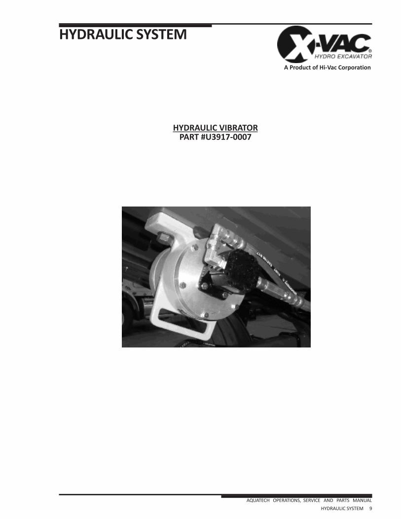
HYDRAULIC SYSTEM
HYDRAULIC SYSTEM 9 AQUATECH OPERATIONS, SERVICE AND PARTS MANUAL
A Product of Hi-Vac Corporation
HYDRAULIC VIBRATORPART #U3917-0007

BODY
BODY1 AQUATECH OPERATIONS, SERVICE AND PARTS MANUAL
A Product of Hi-Vac Corporation
AIR PORT TUBE,WEIGHTED BALLPART #A387389-3
ITEM PART # DESCRIPTION QTY1 A154080 COVER,PORTAL,12” 12 A154090 BAR,PORTAL 13 A190230 GASKET,PORTAL,12” 14 A222005 BALL,FLOAT,10” DIA. 15 A243860 BASKET ASSY,CHECK BALL 1
* ITEM 3, 4, AND 5 NOT VISIBLE
2
1
3
45

BODY
BODY2 AQUATECH OPERATIONS, SERVICE AND PARTS MANUAL
A Product of Hi-Vac Corporation
CYCLONE, REAR, DUAL SIDE MOUNTPART #121000196

BODY
COMPARTMENT HEATERPART #A381247
BODY3 AQUATECH OPERATIONS, SERVICE AND PARTS MANUAL
A Product of Hi-Vac Corporation

BODY
GROUND CABLE OPTION,50’REELPART #OPTION 240
BODY4 AQUATECH OPERATIONS, SERVICE AND PARTS MANUAL
A Product of Hi-Vac Corporation

BODY
POLYTANK INSTALLATION INSTRUCTIONS(New Style)
1. Placeleftrearandrightrearwatertanksontotankframeassembly.
2. Attachhosesandsuctionteeweldment.
3. Placeleftfrontandrightfrontwatertanksontotankframeassembly.
4. Attachshortandlonginterconnecthosesbetweenfrontandreartanks.
5. Attachcapsonfrontwatertanks.
6. Installretainingstraps.
Note: Foradetailedlistingofparts,refertodrawingA385300_T.
Front and Rear Water TankInter Connect Hoses
Hoses and
Suction Tee Weldment
Front Water Tank Caps
BODY5 AQUATECH OPERATIONS, SERVICE AND PARTS MANUAL
A Product of Hi-Vac Corporation
BODY
POLYTANK REPAIR
General Informafion
RepairstopolyethylenetankscanbeperformedeasilywithaminiInurnoftraining.Repairtechniciansmustexerciseprudentcautionagainstmeltingcompletelythroughthepolymaterial,butextremecautionisgenerallynotnecessary.Whatthismeansisthatthetechnicianmustrealizethatdireconsequencesarepossiblebutnotlikelyifhe/sheisreasonablycarel.
Typicalrepairswillinvolverepairoftwobasictypesofdamage:blernishestothesurface,andcracksorholesthroughthematerial.Adifferentrepairapproachwillbeappropriateforeachtypeofdamage.
Blemish Repairs
Blemishestothesurfaceofthepolytankcanusuallyberepairedbyfirstcleaningtheareatoremoveanygrease,oilordirt.Thenapplyheatusinganelectricheatgun.Suchguns,intherangeof1000to1300wattsallowtheapplicationofheatincontrollableamountstoavoidquickburnthroughwhichispossiblewithaflamesuchasfromapropanetorch.Aquatechdoesnotrecommendtheuseofatorchtorepairpolytanks.
Usingtheheatgun,andvaryingthedistanceofthegunfromthesurfaceofthematerial,worktheheat
inacircularmotionaroundtheblemishedareauntilthesurfacebeginstobecomeshiny.AtthispointthetechnicianshouldbecomeVelycarefulasthepolymaterialisbeginningtoliquefyandwillbegintoflow.Byallowingjustenoughflowtofillanysurroundingblemishes,andusingasmoothmetalobjectsuchasaspoonorspatula,thematerialcanbemanipulatedandbemadesmooth.Incaseswherethematerialmayhavebeenheavilygouged,andsomematerialhasbeenlost,theuseofastickofpolyethylenematerialmeltedintotheaffectedareacanhelpfillit,thenthetoolcanrestorethesmoothsurface.
Cracks and Holes
Whenacrackorholehasdevelopedinthepolyethylenematerialanotherapproachisadvisable.Cleaningtheaffectedareaisveryimportant.Itmaybenecessarytoscrapeawaysomeofthematerialifitisbadlycontaminatedwithgrease,oilordirt.Therepairisbestdonewhenitcanbeapproachedfrombothsides,althoughtherearecaseswherethiswillclearlybeimpossible.
Usinganelectricsolderinggunwithawide,flattipsuitableforworkingwithplastics,dipthehottipintogranulatedpolyethylene(providedbyAquatech)andworksmallamountsintothecrackorhole.Repeatasmanytimesasnecessarytobuildtheaffectedareauptothesurroundingsurface.Repeattheprocedureontheoppositesideifpossible.
Useasmoothmetaltoolsuchasaspoonorspatulatoworkthematerialtoconformwiththesurroundingsurface.Aheatgunmayusedasafinalsteptocompletelysmooththearea,butisnotrequired.
Areasrepairedwitheithertechniquewillhaveallthequalitiesandpropertiesofstrengthandstabilityastheoriginalarea.Repairedsectionscanbeputintoserviceimmediatelyuponcooling.
Recommended Tools
Toolsrecommendedareaheatgun,1000-1300watts.SeveralmanufacturersoffersuchaguninthepricerangeofUS$60.00toUS$150.00.SomemanufacturersincludeMaster,WellerandIdeal.Theseheatgunsarealsoexcellenttoolsforthinwallshrinktubingandspecialsolder/shrinkelectricalterminals.Asolderingguncapableofacceptingaltematetipsisalsorecommended.SuchsolderinggunscanbepurchasedatelectronicsupplyhousessuchasRadioShack,oratcommonretailoutletssuchasSears.Wellerisarespectedmanufacturerofgoodsolderingtools.Formingtoolswhicharemetalandsmoothcanbemadefromcommonitemssuchaskitchenutensils,orpurchasedfrombodyshopsuppliers.Sincemanydifferentapplicationsarepossible,experienceisthebestjudgeofwhichparticulartooltoobtain.
BODY6 AQUATECH OPERATIONS, SERVICE AND PARTS MANUAL
A Product of Hi-Vac Corporation

BODY
BODY7 AQUATECH OPERATIONS, SERVICE AND PARTS MANUAL
A Product of Hi-Vac Corporation
Bulletin No. AQPB-171Issued: 05/28/13 by RR
Subject: Water Tank RepairFile In: Poly Water Tank Section
ILLUSTRATION HI-VAC NO. DESCRIPTION
A385008 Black Epoxy Adhesive (includes two mixer tips)
A385009 Automix Applicator Gun
A385010 Mixer Tip = Bag of 6 (order only if extras are required)
A385011 Patching Screen
A385012 Aerosol Gray Primer (for hiding black adhesive on gray tanks)
Picture not available APOLY-001Gray Polyethylene Patching Material (for used with soldering iron and heat gun)
Hi-Vac Corp. • 117 Industry Road • Marietta, Ohio 45750 • Tel. 740-374-2306 • Cust. Svc. Fax 740-374-3299
POLY TANK REPAIR ITEMSThe following products are available for repairing cracks and holes in our polyethylene watertanks.