Owner's Manual Model: DP20-4H Drum Puller - Custom Truck ...
242
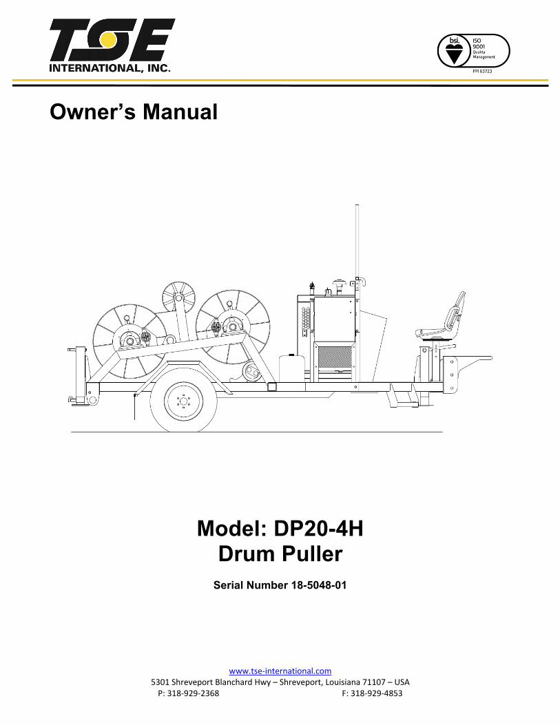
www.tse-international.com 5301 Shreveport Blanchard Hwy – Shreveport, Louisiana 71107 – USA P: 318-929-2368 F: 318-929-4853 Owner’s Manual Model: DP20-4H Drum Puller Serial Number 18-5048-01
-
Upload
khangminh22 -
Category
Documents
-
view
0 -
download
0
Transcript of Owner's Manual Model: DP20-4H Drum Puller - Custom Truck ...
www.tse-international.com 5301 Shreveport Blanchard Hwy – Shreveport, Louisiana 71107 – USA
P: 318-929-2368 F: 318-929-4853
Owner’s Manual
Model: DP20-4H Drum Puller
Serial Number 18-5048-01

C O N D U C T O R H A N D L I N G E Q U I P M E N T
5301 Shreveport-Blanchard Hwy Shreveport, Louisiana 71107
Toll Free: 800.825.2402 Telephone: 318.929.2368FAX: 318.929.4853
www.tse-international.com 1
DP-20-4HDRUM PULLER
At TSE, engineering is a process of continuous product improvement; therefore, specifications are subject to change without notice.
The TSE Model DP-20-4H is a versatile, hydraulically powered four drum puller designed for medium distribution stringing. It can also be used as a pilot line winder for heavier distribution. Power is transmitted from the engine to the reels through a common hydraulic drive train. A diamond leadscrew levelwind, accommodating one reel at a time, aids in an even wrap during pulling. Each reel is equipped with a mechanical clutch to allow selective reel rotation and a mechanical brake to retard overspin. The maximum desired linepull can be preset prior to pulling so that the reel drive will stall if a restriction to the line occcurs avoiding damage to the conductor, towers and hardware.
The central operator’s console allows the operator to completely control the pulling operation with optimum visibilty of the pulling rope. Operator controls include linepull, linespeed, holding brake and engine controls.
DIMENSIONS & WEIGHT (APPROX.)
Length ...................................................15’Width .....................................................8’Height ....................................................6’-4 “Weight ................................................... 7,820 lbs.
(with rope)
STANDARD FEATURES
• 2,000 lb. linepull capacity on single full drum of rope.• Proven hydrostatic pulling system with a hydraulic oil
cooler.• Four pulling reels, each with a capacity for 6,000’ of
1/2” diameter rope.• 35 hp water cooled diesel engine.• Single axle with leaf spring suspension.• Variable linespeed and linepull control.• Mechanical clutch and mechanical bronze brake for
each reel.• Spring applied-hydraulic pressure released holding brake.• Central operator’s position for maximum safety and
visibility.• Deluxe, adjustable operator’s seat and protective screen.• Engraved operator’s console.• Swing out automatic diamond leadscrew levelwind,
adjustable for individual use with all four reels.• Steel lockable battery box.• Front and rear drop leg mechanical jacks.
OPTIONAL EQUIPMENT
• Additional swing out automatic levelwind.• Lockable console cover.• Hydraulic front and/or rear jacks.

www.tse-international.com 5301 Shreveport Blanchard Hwy – Shreveport, Louisiana 71107 – USA
P: 318-929-2368 F: 318-929-4853
TSE International Inc. Warranty Policy
1. Contact the TSE International Inc. service department to discuss problem
and obtain a warranty claim number. Claim numbers will remain valid for 30 days allowing for sufficient time for submission to TSE. Warranties claimed without a valid claim number may be denied.
2. Please retain any defective parts for a period of 60 days. TSE reserves the right to inspect and/or evaluate any parts submitted for warranty consideration. Should TSE elect to inspect the parts, a RGA (Return Goods Authorization) number will be issued and the parts are to be returned prepaid to TSE. Items not returned within 30 days will result in the RGA closure and may result in a denial of the claim.
3. Warranty submission must be on the standard TSE International Inc. claim form. Claims that are not will be classified as pending until proper forms are submitted. All claims must have an estimated cost associated with each item under discrepancy.
4. Major subcomponents are warranted under separate manufacturer warranties. It is the responsibility of the owner/dealer of the equipment to fill out and register all subcomponent manufactures warranties. In the event of failure, arrangements can be made to deal with the subcomponent supplier directly. Examples for subcomponent manufactures are: Engines– John Deere, Cummins, Caterpillar, etc.
Claims submitted as per above TSE International Inc. Equipment Warranty policy will be resolved within 30 days of receipt
www.tse-international.com 5301 Shreveport Blanchard Hwy – Shreveport, Louisiana 71107 – USA
P: 318-929-2368 F: 318-929-4853
Recommendations for improving this publication are encouraged and should be forwarded to:
TSE INTERNATIONAL 5301 Shreveport-Blanchard Hwy.
Shreveport, Louisiana 71107 This is not a tension stringing operation procedures manual. No attempt is made or implied herein to instruct the user in methods peculiar to the individual application of the equipment described in this manual. The contents of this manual are intended as a basis of for operation, maintenance, and parts listing of the unit in its intended and anticipated use, as it stands alone in conjunction with other equipment. The Equipment described in this manual is potentially dangerous if improperly or carelessly operated. For the protection of personnel and equipment, only competently trained operators who are critically aware of the proper procedures, operating parameters, and limitations, potential dangers, and application of this equipment should be allowed to touch the controls at any time.

www.tse-international.com 5301 Shreveport Blanchard Hwy – Shreveport, Louisiana 71107 – USA
P: 318-929-2368 F: 318-929-4853
PREMIUM CUSTOMER SERVICES
TSE supports its innovative products with Premium Customer Service. Our comprehensive Service Department provides TSE customers with the service, parts,
and technical assistance they need to maintain their equipment in top operating condition.
For Customer Service on Your
Model
Serial No.
PLEASE CALL 1-800-825-2402
Our People Care: Our Equipment is the Proof.
SBates
Typewritten Text
SBates
Typewritten Text
SBates
Typewritten Text
SBates
Typewritten Text
SBates
Typewritten Text
SBates
Typewritten Text
SBates
Typewritten Text
SBates
Typewritten Text
SBates
Typewritten Text
SBates
Cross-Out
SBates
Typewritten Text
SBates
Typewritten Text
SBates
Typewritten Text
SBates
Typewritten Text
SBates
Typewritten Text
18-5048-01
SBates
Typewritten Text
SBates
Typewritten Text
SBates
Typewritten Text
DP20-4H
SBates
Typewritten Text
SBates
Typewritten Text
SBates
Typewritten Text
SBates
Typewritten Text
SBates
Typewritten Text
SBates
Typewritten Text
SBates
Typewritten Text
SBates
Typewritten Text
SBates
Typewritten Text
SBates
Typewritten Text
SBates
Typewritten Text
SBates
Typewritten Text
SBates
Typewritten Text
sbates
Typewritten Text
sbates
Typewritten Text
sbates
Typewritten Text
sbates
Typewritten Text
sbates
Typewritten Text
sbates
Typewritten Text
sbates
Typewritten Text
sbates
Typewritten Text
sbates
Typewritten Text
sbates
Typewritten Text
sbates
Typewritten Text
SBates
Typewritten Text
SBates
Typewritten Text
sbates
Typewritten Text
sbates
Typewritten Text
sbates
Typewritten Text
sbates
Typewritten Text
sbates
Typewritten Text
sbates
Typewritten Text
sbates
Typewritten Text
sbates
Typewritten Text
sbates
Typewritten Text
sbates
Typewritten Text
sbates
Typewritten Text
sbates
Typewritten Text
sbates
Typewritten Text
sbates
Typewritten Text
sbates
Typewritten Text
sbates
Typewritten Text
sbates
Typewritten Text
www.tse-international.com 5301 Shreveport Blanchard Hwy – Shreveport, Louisiana 71107 – USA
P: 318-929-2368 F: 318-929-4853
HOW TO ORDER REPLACEMENT PARTS
In order that we may promptly send the exact replacement part required in the least amount of down time for you, the information listed below is necessary. To order the replacement part, locate the part from the drawings in this manual and give the following information: 1. Unit Model No. (From the plates on the unit’s frame) 2. Unit Serial No. (From the plate on the unit’s frame, will contain numbers only) 3. Part Number (If available) 4. Description (If part no. not available) 5. Quantity Required On large components such as transmissions, engines, multiple pump drives, etc., the manufacturer’s serial number and spec. number is necessary to ensure receiving the proper replacement part.

www.tse-international.com 5301 Shreveport Blanchard Hwy – Shreveport, Louisiana 71107 – USA
P: 318-929-2368 F: 318-929-4853
WARNING The equipment described in this manual is neither designed nor intended for any application, alone or with in conjunction with any other equipment, that involves the lifting or moving of persons. Safe operation of this equipment is dependent on use in compliance with the procedures outline in this section and the maintenance and inspection procedures in SECTION Ill with consideration of prevailing conditions. The equipment described in this manual is potentially dangerous if improperly and carelessly operated. For the protection of personnel and equipment, only competently trained operators who are critically aware of the proper procedures, operating parameters and limitations, potential dangers, and application of this equipment should be allowed to touch the controls at any time. There is potential DANGER of ELECTRICAL SHOCK when operating this machine. Ground the unit in accordance with the regulations of the using organization. Various methods of bonding, isolation and grounding can be used; a means suitable to the user should be selected and rigidly adhered to by ALL operating personnel. Keep all shields and guards in place. Keep hands, feet and clothing away from power driven parts and moving parts. Observe all warning decals placed on the machine. Make certain all personnel are clear of this equipment before starting engine or operation. Before leaving the operators position, make sure that directional controls are in the neutral position and all brakes are set.
www.tse-international.com 5301 Shreveport Blanchard Hwy – Shreveport, Louisiana 71107 – USA
P: 318-929-2368 F: 318-929-4853
EQUIPMENT WARRANTY TSE International Inc. (hereinafter sometimes referred to as “TSE”) warrants that it will repair f.o.b. its factory, or furnish without charge f.o.b. its factory, a similar part to replace any material in its machinery which, during the earlier of 90 days after the said machinery is put into operation or six months after the date of shipment of the machinery from the plant, is proved to the satisfaction of the company to have been defective at the time it was sold, provided that all parts claimed defective shall be returned, properly identified, to TSE’s factory, charges prepaid. This Warranty to repair applies only to new and unused machinery, which, after shipment from the factory of TSE, has not been altered, changed, repaired or treated in any manner whatsoever unless such alteration, change, repair or treatment has been previously authorized in writing by TSE or has been performed by the authorized service representative of TSE. This Warranty to repair is the only Warranty either express, implied or statutory, upon which the said machinery is sold; the companies liability in connection with this transaction is expressly limited to the repair or replacement of defective parts, all other damages and warranties, statutory or otherwise, being hereby expressly waived by the purchaser. No representative of TSE has authority to change this Warranty or this contract in any manner whatsoever and no attempt to repair or promise to repair or improve the machinery covered by this contract by any representative of TSE shall waive any consideration of the contract or change or extend this Warranty in any manner whatsoever.
www.tse-international.com 5301 Shreveport Blanchard Hwy – Shreveport, Louisiana 71107 – USA
P: 318-929-2368 F: 318-929-4853
GROUNDING EQUIPMENT AND METHODS Grounding Equipment and Methods information is covered in the following publication: “IEEE GUIDE TO INSTALLATION OF OVERHEAD TRANSMISSION LINE CONDUCTORS IEEE STD 524-2003” The above publication is available through the following organization: THE INSTITUTE OF ELECTRICAL AND ELECTRONICS ENGINEERS, INC. 3 PARK AVENUE NEW YORK, NY 10016-5997 USA

www.tse-international.com 5301 Shreveport Blanchard Hwy – Shreveport, Louisiana 71107 – USA
P: 318-929-2368 F: 318-929-4853
DECALS Your equipment was shipped from the factory with the decals on the following sheet. Should any of these decals be missing, they could prevent the proper operation and/or maintenance of the unit which may result in personal injury or property damage. If any of these decals are missing, please contact us for a replacement. Order the decal(s) by stating the decal description, number, and quantity. TSE INTERNATIONAL 5301 SHREVEPORT-BLANCHARD HWY. SHREVEPORT, LA 71107 ATTENTION: SERVICE MANAGER TELEPHONE: 800-825-2402 FAX: 318-929-4853


CONTENTS DP20-4H
SECTION I INTRODUCTION SECTION II OPERATIONS
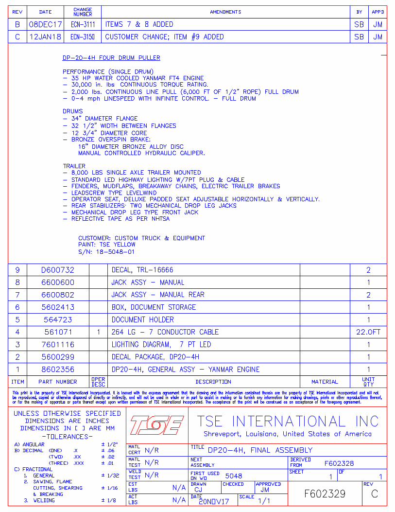
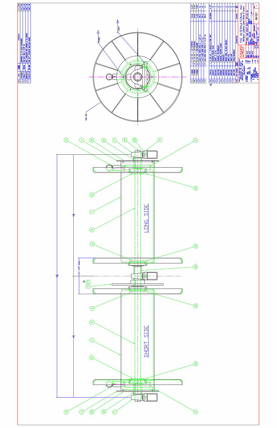
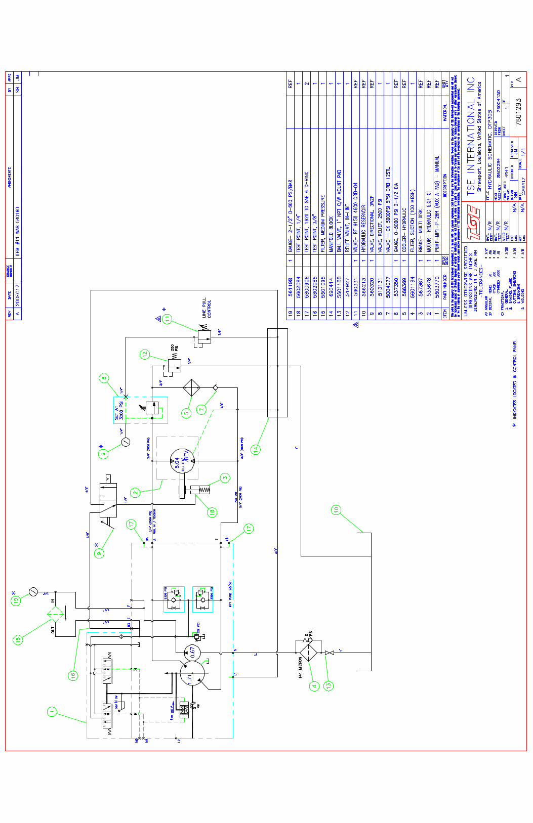
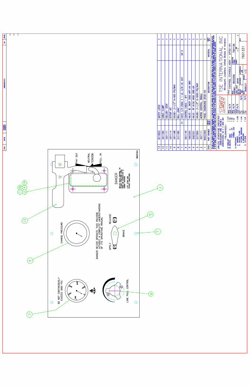
SECTION III MAINTENANCE SECTION IV PARTS LIST F602339-C FINAL ASSEMBLY – DP20-4H 8602356-B GENERAL ASSEMBLY – DP20-4H (Yanmar Engine) 861207-I REELS & SHAFT ASSEMBLY 780101-C DRIVE ASSEMBLY 7601293-A HYDRAULIC SCHEMATIC 7601116-C TRAILER LIGHTING DIAGRAM - LED 7601328-A ENGINE & PUMP ASSEMBLY 7601331 CONTROL PANEL ASSEMBLY SECTION V VENDOR INFORMATION ENGINE (Yanmar) PUMP MOTOR BRAKE GEARBOX AXLE

SECTION I INTRODUCTION
GENERAL DESCRIPTION The TSE Model DP20-4H is a trailer mounted four drum puller powered by a four cylinder diesel engine and hydrostatic transmission. The speed, torque, and direction of the transmission are regulated from the elevated, centrally located control panel to allow an infinitely variable control of line tension and speed within the specified performance parameters of the unit in both the pulling and tensioning mode of operation. Efficient cable wrapping is promoted by the leadscrew-type levelwind. WARNING/CAUTION: WHEN THIS SIGN APPEARS ON THESE PAGES, IT INDICATES WHERE SPECIAL ATTENTION SHOULD BE PAID TO THE INSTRUCTIONS GIVEN. PERSONAL INJURY OR DAMAGE TO THE EQUIPMENT MAY OCCUR IF THE INSTRUCTIONS ARE NOT FOLLOWED. DIMENSIONS Length 186 inches Width 96 inches Height 104 inches (Top of Operator Screen) PERFORMANCE 1 Full Reel 2,000 lbs @ 3.5 MPH 4 Reels Simultaneously 500 lbs @ 2.0 MPH Speed Range: 0-4 mph WARNING: THESE VALUES ARE A MAXIMUM AND MUST NOT BE EXCEEDED. REEL SPECIFICATIONS Reel Diameter: 34 inches Reel Width: 32 1/2 inches (Inside flanges) Drum Diameter 12 ¾ inches WARNING: THESE VALUES ARE A MAXIMUM AND MUST NOT BE EXCEEDED. UNDERCARRIAGE Axle Single 8,000 lb capacity Tires 215/75R17.5 Brakes 12 1/4" X 3 3/8” Electric Front Jack Manual Screw Type Rear Stabilizers Pin Type
SECTION II OPERATION
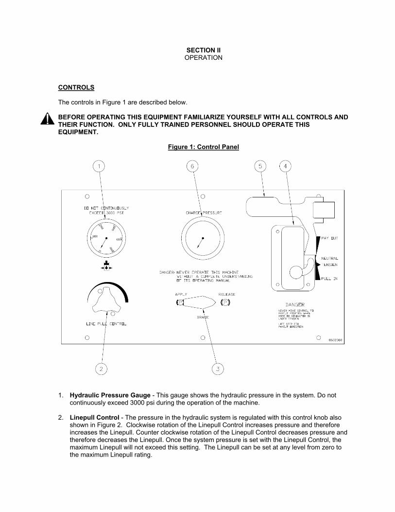
CONTROLS The controls in Figure 1 are described below. BEFORE OPERATING THIS EQUIPMENT FAMILIARIZE YOURSELF WITH ALL CONTROLS AND THEIR FUNCTION. ONLY FULLY TRAINED PERSONNEL SHOULD OPERATE THIS EQUIPMENT.
Figure 1: Control Panel
1. Hydraulic Pressure Gauge - This gauge shows the hydraulic pressure in the system. Do not
continuously exceed 3000 psi during the operation of the machine. 2. Linepull Control - The pressure in the hydraulic system is regulated with this control knob also
shown in Figure 2. Clockwise rotation of the Linepull Control increases pressure and therefore increases the Linepull. Counter clockwise rotation of the Linepull Control decreases pressure and therefore decreases the Linepull. Once the system pressure is set with the Linepull Control, the maximum Linepull will not exceed this setting. The Linepull can be set at any level from zero to the maximum Linepull rating.

Figure 2: Linepull Control Knob
3. Brake Control - The brake is spring applied and released by hydraulic pressure also shown in
Figure 3. To hold the reel stationary, turn the Reel Brake Lever to the APPLY position. Turn to the RELEASE position before driving the reel.
CAUTION: THE BRAKE IS DESIGNED TO HOLD THE CONDUCTOR UNDER STATIC CONDITIONS ONLY. WARNING: THE HOLDING POWER OF THE BRAKES AND PROPER FUNCTIONING OF ALL MACHINE CONTROLS MUST BE VERIFIED BEFORE THE UNIT IS PUT INTO SERVICE TO ENSURE SAFE OPERATION. THIS IS PARTICULARLY IMPORTANT WHEN STRINGING IN THE VICINITY OF ENERGIZED LINES.
Figure 3: Brake Control
4. Direction Control - The reel turning speed (Linespeed) and direction is controlled by a single
lever that regulates the degree of pump stroke in both directions from the NEUTRAL Position, also shown in Figure 4. Movement of the Direction Control Lever in either direction, away from the operator for ‘Pay Out’ and toward the operator for ‘Pull In’, increases the rotating speed of the reel. The reel will remain stationary with the Direction Control Lever in the NEUTRAL position.
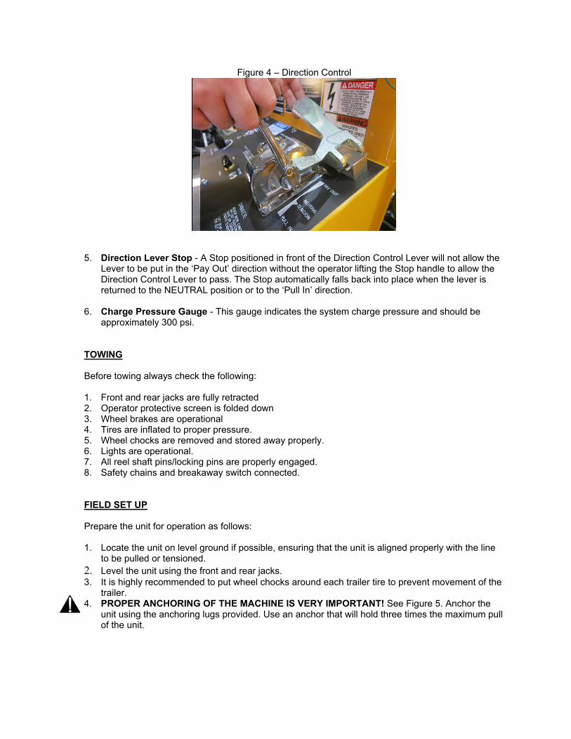
Figure 4 – Direction Control
5. Direction Lever Stop - A Stop positioned in front of the Direction Control Lever will not allow the
Lever to be put in the ‘Pay Out’ direction without the operator lifting the Stop handle to allow the Direction Control Lever to pass. The Stop automatically falls back into place when the lever is returned to the NEUTRAL position or to the ‘Pull In’ direction.
6. Charge Pressure Gauge - This gauge indicates the system charge pressure and should be
approximately 300 psi. TOWING Before towing always check the following: 1. Front and rear jacks are fully retracted 2. Operator protective screen is folded down 3. Wheel brakes are operational 4. Tires are inflated to proper pressure. 5. Wheel chocks are removed and stored away properly. 6. Lights are operational. 7. All reel shaft pins/locking pins are properly engaged. 8. Safety chains and breakaway switch connected. FIELD SET UP Prepare the unit for operation as follows: 1. Locate the unit on level ground if possible, ensuring that the unit is aligned properly with the line
to be pulled or tensioned. 2. Level the unit using the front and rear jacks. 3. It is highly recommended to put wheel chocks around each trailer tire to prevent movement of the
trailer. 4. PROPER ANCHORING OF THE MACHINE IS VERY IMPORTANT! See Figure 5. Anchor the
unit using the anchoring lugs provided. Use an anchor that will hold three times the maximum pull of the unit.

Figure 5: Anchoring Diagram
5. PROPER GROUNDING OF THE MACHINE IS VERY IMPORTANT! The machine is equipped
with two grounding bars. (See figure 5.) To protect against electrical hazards due to induction or electrical contact, the system must be connected to a proper ground rod or the electrical system neutral. Follow proper grounding procedures as required by IEEE and/or the applicable standards in your area. Use of a ground mat and a running ground on the conductor are highly recommended.
6. Put a hazard barrier around the perimeter of the unit to keep unauthorized personnel away from the equipment.
7. Perform daily inspection and preventive maintenance as required. PRE START CHECKLIST 1. Ensure that the Direction Control (4) is in the NEUTRAL position. 2. Ensure that the Brake Control (3) is in the APPLY position. ENGINE START-UP The engine manufacturer’s manual, included in the Section V, contains detailed technical information regarding the engine including start up procedure. Make sure you read and understand the operating instructions contained therein. . CAUTION: DO NOT ALTER THE RPM GOVERNER SETTING OF THE ENGINE. THE HYDRAULIC PUMP IS LIMITED TO A SPECIFIC MAXIMUM RPM AND CAN BE DAMAGED IF DRIVEN FASTER THAN THE GOVERNED ENGINE SPEED. STOPPING THE ENGINE 1. Move the Direction Control (4) to the NEUTRAL position. 2. Move the Brake Control (3) to the APPLY position. 3. Decrease the engine speed to idle. 4. Allow the engine to idle for a few minutes to cool down. 5. Shut down the engine.
HYDRAULIC WARM UP (COLD WEATHER START-UP) 1. Start the engine. 2. Leave the Direction Control (4) in the NEUTRAL position. 3. Allow the system to run slightly above idle for twenty minutes or until the indicator gauge on the
suction filter reads less than ten inches vacuum. 4. Ensure that the Brake Control (3) is in the APPLY position. 5. Increase engine speed to half-throttle. 6. Move the Direction Control (4) to approximately half-stroke in the PULL IN direction. 7. Turn in Linepull Control (2) clockwise until the Pressure Gauge (1) reads 1,000 psi. 8. Allow system to run for:
a. Ten minutes b. or until hydraulic oil reservoir feels warm to the touch c. or until the indicator gauge on the suction filter reads less than five inches vacuum
In extreme cold weather operations, special low temperature hydraulic oil is recommended. PULLING (BEGINNING WITH SLACK ROPE) The following procedure describes how to operate the DP20-4H when it is used as a puller and the rope is not under tension. CAUTION: DO NOT FOLLOW THIS PROCEDURE WHEN THERE IS TENSION ON THE PULLING ROPE.
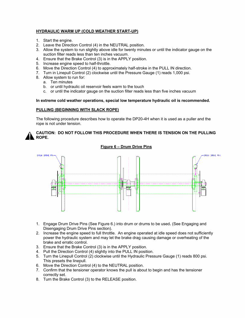
Figure 6 – Drum Drive Pins
1. Engage Drum Drive Pins (See Figure 6.) into drum or drums to be used. (See Engaging and
Disengaging Drum Drive Pins section). 2. Increase the engine speed to full throttle. An engine operated at idle speed does not sufficiently
power the hydraulic system and may let the brake drag causing damage or overheating of the brake and erratic control.
3. Ensure that the Brake Control (3) is in the APPLY position. 4. Pull the Direction Control (4) slightly into the PULL IN position. 5. Turn the Linepull Control (2) clockwise until the Hydraulic Pressure Gauge (1) reads 800 psi.
This presets the linepull. 6. Move the Direction Control (4) to the NEUTRAL position. 7. Confirm that the tensioner operator knows the pull is about to begin and has the tensioner
correctly set. 8. Turn the Brake Control (3) to the RELEASE position.

9. Slowly pull Direction Control (4) slightly to the PULL IN position. The pulling drum should start to turn and tighten the pulling rope. If the pulling rope remains stationary turn in the Linepull Control (2) clockwise slightly until the rope starts to move. When the rope starts to move, turn the Linepull Control (2) another ½ turn to have the relief pressure in the system set just slightly above the linepull at which you are working.
10. Slowly pull the Directional Control (4) more into the PULL IN position until the desired linespeed is achieved.
NOTE: It may be necessary to turn the Linepull Control (2) in several times from its initial setting as the pulling rope builds up on the pulling reel to maintain proper linepull and speed. Always turn the Linepull Control (2) in ½ turn further than what is required to move the rope and this will ensure the puller will stall if a snag in the pulling rope occurs. 11. To stop the pull, move the Direction Control (4) to the NEUTRAL position and turn the Brake
Control (3) to the APPLY position. RESUMING A PULL AFTER STOPPING This procedure describes how to start the pulling process after stopping while the pulling rope is still under tension. This procedure assumes the Linepull Control (2) setting has not been changed from the previous operating position during the stop. 1. Confirm that the tensioner operator knows the pull is about to begin and has the tensioner
correctly set. 2. Turn the Brake Control (3) to the RELEASE position. 3. Move the Direction Control (4) to the desired PULL IN position. NOTE: This should start the pulling rope moving again at the same linepull as when you stopped. If the pulling rope remains stationary, slowly turn the Linepull Control clockwise until the pulling rope starts to move. PAYING OUT (BEGINNING WITH SLACK ROPE) The following procedure describes how to pay out rope when it is not under tension. CAUTION: DO NOT FOLLOW THIS PROCEDURE WHEN THE ROPE IS UNDER TENSION. 1. Increase the engine speed to full throttle. An engine operated at idle speed does not sufficiently
power the hydraulic system and may let the brake drag causing damage or overheating of the brake.
2. Make sure the Brake Control (3) is in the APPLY position. 3. Turn the Linepull Control (2) fully counter clockwise to give zero linepull in the pull in direction. 4. Turn the Brake Control (3) to the RELEASE position. 5. Push the Direction Control (4) slowly into the PAY OUT position. You will have to lift the Direction
Lever Stop (5) to allow the Direction Control (4) to pass beyond the NEUTRAL position. Push Direction Control (4) more into the PAY OUT position to increase the speed.
WARNING: NEVER PUT THE DIRECTION CONTROL LEVER IN THE PAY OUT POSITION WHEN PULLING ROPE OR WHEN THE CONDUCTOR IS UNDER TENSION! 6. To stop, put the Direction Control (4) to the NEUTRAL position. The Direction Lever Stop (5) will
fall back into place restricting movement into the PAY OUT direction once again.
PAYING OUT (ROPE UNDER TENSION) This procedure describes how to ‘Pay Out’ or loosen a pulling rope when it is under tension. This situation may occur for example when the pulling rope is to be backed into a grip. Essentially the process is to tension out the rope at a controlled speed until the tension drops to zero, then use the procedure described in section above to continue to ‘PAY OUT’ the rope if desired. 1. Increase the engine speed to FULL throttle. An engine operated at idle speed does not
sufficiently power the hydraulic system, and may let the brake drag causing damage or overheating of the brake.
2. Move the Direction Control Lever (4) to the TENSION position. 3. Leave the Linepull Control (2) in the same position as when you stopped ‘PULLING’. 4. Turn the Brake Control (3) to the RELEASE position. This transfers the tension load in the rope
from the brake to the hydraulic system. 5. Turn the Linepull Control (2) counter-clockwise slowly, and this will start to allow the reel to pay
out the rope as it is pulled by the load on it. Continue to turn the Linepull Control (2) counter-clockwise until it is fully out and no tension remains in the rope.
FREEWHEELING PAY OUT WITH OVERSPIN BRAKE The freewheeling pay out mode disconnects the hydraulic drive system and allows the reels to rotate freely as the rope is pulled off. A drag brake prevents the reel from overspinning while in freewheel mode. This procedure is usually used when the pulling rope is being pulled from the puller end of the set-up to the tensioner end. 1. Place the Direction Control (4) in the NEUTRAL position. 2. Turn the Brake Control (3) to the APPLY position. 3. Shut off the engine. 4. Disengage the drum drive pin from drum or drums to be used. (See Engaging and Disengaging
Drum Drive Pins section). DANGER: THERE MUST BE NO LINEPULL ON THE DRUM AND NO TENSION ON THE DRIVE CHAIN WHEN ENGAGING & DISENGAGING THE DRUM DRIVE PINS. 5. Pull off the rope as required while controlling the reel with the Drag Brake to prevent overspin. 6. When Freewheel Pay-Out is complete, engage the Drum Drive Pins back into the drums. (See
Engaging and Disengaging Drum Drive Pins section). DANGER: Do not use the engine to line up the Drum Drive Pin holes, since shaft may turn as you are inserting the pin. ENGAGING AND DISENGAGING DRUM DRIVE PINS Note: This procedure must be done with no tension on the pulling rope. Note: Apply the brake using the Reel Brake Control (3) and shut down the engine when disengaging or engaging the drum drive pins. The Drum Drive Pins are spring loaded in the engaged position. To freewheel the drum simply pull the Drum Drive Pin out and rotate 90 degrees. To engage, pull the Drum Drive Pin out and rotate 90 degrees and the spring will attempt to engage it. You may have to turn the drum by hand until it engages.

SECTION III MAINTENANCE
SCOPE This section contains schedules, recommendations, and procedures designed to ensure that the equipment is prepared for safe and efficient operation and to prolong the service life of the equipment. These maintenance instructions constitute basic requirements for an operational environment that is not extreme in temperature, humidity, airborne abrasives, or other conditions which would require preventative maintenance techniques to combat. The using organization is encouraged to determine preventative maintenance requirements that are the result of environmental extremes. SERVCIE SAFETY PRECAUTIONS 1. Before performing maintenance or repair work on any equipment, consult the manufacturer’s
instruction manual and follow the recommended procedures. 2. When servicing or repairing the equipment, shut down the engine unless it is required to be
running for adjustment purposes. 3. Always use the proper tools for the job. Repair or replace any broken or damaged tools,
including lifting equipment immediately. 4. Keep your head, hands, feet, and loose clothing away from power-driven parts. 5. Pressure can be maintained in the hydraulic circuits long after the power source and pump have
been shut down. Relieve all trapped pressures before performing any service work to the hydraulic components.
6. When troubleshooting a hydraulic system for leaks, use a piece of cardboard or other material as detector rather than your hand. Pressurized hydraulic fluid escaping from a faulty component can penetrate the skin and cause serious injury.
7. Do not change the pressure setting of any hydraulic valves unless authorized instruction has been obtained.
8. Ensure that all tire and rim parts are undamaged and correctly assembled before inflating the tires.
9. Use an inflation cage, safety cables or some other safety device when inflating the tires. Do not exceed the tire manufacturer’s recommended maximum pressure
10. Use caution when draining hot fluids from the machine. Splashing hot fluid can cause serious burns.
11. Ensure that the equipment is blocked so that it cannot shift or move during servicing. 12. Install all applicable safety locks before working on a piece of equipment. Disconnect electrical
power before servicing electrical components.
FIRE PREVENTION Fires can create severe emergencies where both human life and property may be lost. Even when confined, a fire may cause very expensive damage to your equipment. Fire can strike at anytime, not only when the equipment is used, but also when lift unattended between work shifts and nobody is around to fight it. When working in a confined environment, it is impossible to prevent combustible dust from collecting in tight corners of the machine. This dust, in itself, may not cause a fire, however, when mixed with fuel, oil or grease in a hot an confined place, it can become a fire hazard. To reduce the chances for a fire to break out, follow the preventative instructions listed below: 1. Inspect the machine daily for potential fire hazards and make any necessary repairs up
immediately. 2. Always ensure that excess grease and oil accumulation, including spillage, are cleaned up
immediately. 3. Use only nonflammable cleaning agents for cleaning the machine or any machine component. 4. Store oily rags and other combustible materials in a fireproof location. 5. Before performing repair work such as welding, the area surrounding the repair location should
be cleaned and a fire extinguisher positioned close by. 6. Maintain a charged fire extinguisher on or near the machine at all times and know how to use it. INSPECTIONS Periodic inspection of the unit according to a regular schedule will establish the normal state of the unit for personnel associated with its operation and maintenance and provide a set of consistent conditions, which will tend to highlight any occurrence of a potentially hazardous malfunction. On a daily basis walk around the unit and look closely for any indication of the following: 1. Loose threaded connections. 2. Metal fatigue or excessive corrosion. 3. Abraded hose surfaces. 4. Hydraulic fluid leakage. 5. Possible obstruction of moving parts – especially in the drive train. To ensure proper operation and long life of your TSE International products, use only good quality lubricants and maintain a regular maintenance schedule as recommended by TSE International and our component suppliers. Prior to start-up of new TSE International products, all fluid levels are to be checked to ensure correct operating levels. All lubrication and maintenance points are to be inspected and lubricated as illustrated on the Lubrication and Maintenance Instructions sheet. While TSE International recommends specific intervals, they are intended as a minimum general guide for the maintenance of the equipment. Some job conditions and/or locations may dictate more frequent service intervals than have been recommended.

LUBRICATION DATA
LUBRICANT LUBRICANT INFORMATION GRADE
S TSE
PART # APPLICATION
AW46
TSE STANDARD HYDRAULIC FLUID (REFER TO HYDRAULIC OIL DECAL LOCATED ON HYDRAULIC RESERVOIR TO DETERMINE WHAT HYDRAULIC FLUID IS USED IN YOUR MACHINE)
ISO 46 567851 HYDRAULIC SYSTEM FLUID
UTILITY EP #2 GREASE
MULTIPURPOSE GREASE - - BEARINGS, SHAFTS, FRICTION COMPONENTS
LUBRIPLATE CHAIN & CABLE
FLUID PENETRATING FLUID
SAE 10 ISO 32
- CHAINS, WIRE ROPES, CABLES
SPARTAN EP150 INDUSTRIAL GEAR OIL ISO 150 -
GEARBOXES (REDUCERS) - SEE VENDOR LITERATURE FOR VARIATIONS AND AMOUNTS
SUPER MPGO 80W90
PETROLEUM OIL BLEND - - PUMP DRIVES
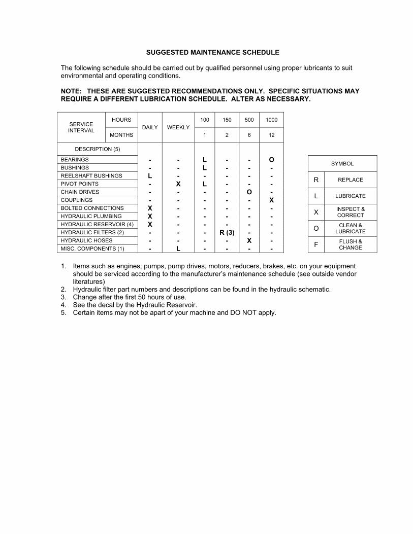
SUGGESTED MAINTENANCE SCHEDULE The following schedule should be carried out by qualified personnel using proper lubricants to suit environmental and operating conditions. NOTE: THESE ARE SUGGESTED RECOMMENDATIONS ONLY. SPECIFIC SITUATIONS MAY REQUIRE A DIFFERENT LUBRICATION SCHEDULE. ALTER AS NECESSARY.
SERVICE INTERVAL
HOURS
DAILY WEEKLY
100 150 500 1000
MONTHS 1 2 6 12
DESCRIPTION (5)
BEARINGS - - L - - O
SYMBOL BUSHINGS - - L - - - REELSHAFT BUSHINGS L - - - - -
R REPLACE PIVOT POINTS - X L - - - CHAIN DRIVES - - - - O -
L LUBRICATE COUPLINGS - - - - - X BOLTED CONNECTIONS X - - - - -
X INSPECT & CORRECT HYDRAULIC PLUMBING X - - - - -
HYDRAULIC RESERVOIR (4) X - - - - - O CLEAN &
LUBRICATE HYDRAULIC FILTERS (2) - - - R (3) - - HYDRAULIC HOSES - - - - X -
F FLUSH & CHANGE MISC. COMPONENTS (1) - L - - - -
1. Items such as engines, pumps, pump drives, motors, reducers, brakes, etc. on your equipment
should be serviced according to the manufacturer’s maintenance schedule (see outside vendor literatures)
2. Hydraulic filter part numbers and descriptions can be found in the hydraulic schematic. 3. Change after the first 50 hours of use. 4. See the decal by the Hydraulic Reservoir. 5. Certain items may not be apart of your machine and DO NOT apply.


Service Manual
Variable Displacement PumpsMP1
powersolutions.danfoss.com

Revision history Table of revisions
Date Changed Rev
July 2017 update ports and plugs 0103
April 2017 Add HDC 0102
August 2016 First edition 0101
Service ManualMP1
2 | © Danfoss | July 2017 AX00000244en-US0103
IntroductionOverview..............................................................................................................................................................................................5Warranty.............................................................................................................................................................................................. 5General Instructions........................................................................................................................................................................ 5
Remove the unit.......................................................................................................................................................................... 5Safety precautions............................................................................................................................................................................6Symbols used in Danfoss literature............................................................................................................................................7
Technical SpecificationDesign Specifications......................................................................................................................................................................8Technical Data................................................................................................................................................................................... 8Operating Parameters.....................................................................................................................................................................9Fluid Specifications..........................................................................................................................................................................9
OperationHigh Pressure Relief Valve (HPRV) and charge check....................................................................................................... 10Bypass Function..............................................................................................................................................................................10Charge Pressure Relief Valve (CPRV)....................................................................................................................................... 11Loop Flushing Valve......................................................................................................................................................................12Electrical Displacement Control (EDC)................................................................................................................................... 13
EDC principle..............................................................................................................................................................................13EDC operation............................................................................................................................................................................13EDC Control Signal Requirements......................................................................................................................................14EDC Solenoid Data................................................................................................................................................................... 14Control response.......................................................................................................................................................................15Response time, EDC................................................................................................................................................................. 15
Manual Over Ride (MOR).................................................................................................................................................. 15Hydraulic Displacement Control (HDC)................................................................................................................................. 17
HDC principle............................................................................................................................................................................. 17HDC operation........................................................................................................................................................................... 17Hydraulic signal pressure range..........................................................................................................................................18Pump output flow direction vs. control pressure......................................................................................................... 18Response time........................................................................................................................................................................... 18
Control response................................................................................................................................................................. 18Response time, HDC...........................................................................................................................................................19
Manual Displacement Control (MDC).....................................................................................................................................20MDC principle............................................................................................................................................................................ 20MDC General Information..................................................................................................................................................... 21MDC Shaft Rotation................................................................................................................................................................. 21Control Response......................................................................................................................................................................21Response time, MDC................................................................................................................................................................22Neutral Start Switch (NSS)..................................................................................................................................................... 22Case gauge port M14.............................................................................................................................................................. 23Lever..............................................................................................................................................................................................23
Forward-Neutral-Reverse electric control (FNR)................................................................................................................. 24FNR principle.............................................................................................................................................................................. 24Control Response......................................................................................................................................................................25Response time, FNR................................................................................................................................................................. 25
Control-Cut-Off valve (CCO valve)........................................................................................................................................... 26CCO solenoid data....................................................................................................................................................................27
Displacement limiter.....................................................................................................................................................................27Displacement change (approximate)................................................................................................................................27
Operating ParametersOverview........................................................................................................................................................................................... 28Input Speed......................................................................................................................................................................................28System Pressure..............................................................................................................................................................................28Charge Pressure..............................................................................................................................................................................29Charge Pump Inlet Pressure.......................................................................................................................................................29Case Pressure...................................................................................................................................................................................29Temperature.................................................................................................................................................................................... 29
Service ManualMP1
Contents
© Danfoss | July 2017 AX00000244en-US0103 | 3
Viscosity.............................................................................................................................................................................................30
Fluid and Filter MaintenanceFiltration System ............................................................................................................................................................................31
Pressure measurementsPort Locations and Gauge Installation................................................................................................................................... 32
Initial Startup ProcedureGeneral ..............................................................................................................................................................................................34Start-up Procedure........................................................................................................................................................................ 34
TroubleshootingOverview........................................................................................................................................................................................... 35Safety precautions......................................................................................................................................................................... 35Electrical troubleshooting.......................................................................................................................................................... 35System Operating Hot..................................................................................................................................................................36Transmission Operates Normally in One Direction Only.................................................................................................36System Does Not Operate in Either Direction..................................................................................................................... 36System noise or vibration........................................................................................................................................................... 37Neutral Difficult or Impossible to Find................................................................................................................................... 37Sluggish System Response......................................................................................................................................................... 38
AdjustmentsPump adjustment.......................................................................................................................................................................... 39Standard Procedures.................................................................................................................................................................... 39Charge Pressure Relief Valve......................................................................................................................................................39Displacement Limiter................................................................................................................................................................... 40Control Neutral Adjustment.......................................................................................................................................................41Mechanical/Hydraulic Neutral Adjustment..........................................................................................................................42
Minor RepairStandard Procedures, Removing the Pump.........................................................................................................................45EDC/HDC Control........................................................................................................................................................................... 45
Reassembly................................................................................................................................................................................. 46Replace Control Solenoids/Actuator Housing - MP1........................................................................................................ 47MDC Control.................................................................................................................................................................................... 48Charge pump...................................................................................................................................................................................50High Pressure Relief Valve (HPRV)............................................................................................................................................52Charge Pressure Relief Valve (CPRV)....................................................................................................................................... 53Loop Flushing (28/32).................................................................................................................................................................. 54
Loop Flushing Spool................................................................................................................................................................54Reassembly................................................................................................................................................................................. 54
Shaft Removal................................................................................................................................................................................. 55
Fastener Size and Torque ChartFastener Size and Torque............................................................................................................................................................58Plug Size and Torque.................................................................................................................................................................... 58
Service ManualMP1
Contents
4 | © Danfoss | July 2017 AX00000244en-US0103
Overview
This manual includes information on installation, maintenance, and minor repair of these pumps. Itincludes a description of the unit and its individual components, troubleshooting information, and minorrepair procedures.
Performing minor repairs may require the unit to be removed from the vehicle/machine. Thoroughlyclean the unit before beginning maintenance or repair activities. Since dirt and contamination are thegreatest enemies of any type of hydraulic equipment, follow cleanliness requirements strictly. This isespecially important when changing the system filter and when removing hoses or plumbing.
A worldwide network of Danfoss Global Service Partners is available for major repairs. Danfoss trains andcertifies Global Service Partners on a regular basis. You can locate your nearest Global Service Partnerusing the distributor locator at www.danfoss.com.
Warranty
Performing adjustments and minor repairs according to the procedures in this manual will not affect yourwarranty. Major repairs requiring the removal of a unit’s center section, servo sleeves, or front flangevoids the warranty unless a Danfoss Authorized Service Center performs them.
General Instructions
Follow these general procedures when repairing variable displacement pumps.
Remove the unit
If necessary, remove the unit from the vehicle/machine. Chock the wheels on the vehicle or lock themechanism to inhibit movement. Be aware that hydraulic fluid may be under high pressure and/or hot.Inspect the outside of the pump and fittings for damage. Cap hoses after removal to preventcontamination.
Keep it clean
Cleanliness is a primary means of assuring satisfactory pump life, on either new or repaired units. Cleanthe outside of the pump thoroughly before disassembly. Take care to avoid contamination of the systemports. Cleaning parts with a clean solvent wash and air drying is usually adequate.
As with any precision equipment, you must keep all parts free of foreign material and chemicals. Protectall exposed sealing surfaces and open cavities from damage and foreign material. If left unattended,cover the pump with a protective layer of plastic.
Replace all O-rings and Gaskets
We recommend you replace all O-rings and seals during service. Lightly lubricate O-rings with cleanpetroleum jelly prior to assembly.
Secure the unit
If removed from machine, place the unit in a stable position with the shaft pointing downward. Itwill be necessary to secure the pump while removing and torquing fasteners and components.
Service ManualMP1
Introduction
© Danfoss | July 2017 AX00000244en-US0103 | 5

Safety precautions
Always consider safety precautions before beginning a service procedure. Take the following generalprecautions whenever servicing a hydraulic system:
W Warning
Unintended machine movement
Unintended movement of the machine or mechanism may cause injury to the technician or bystanders.To protect against unintended movement, secure the machine or disable/disconnect the mechanismwhile servicing.
W Warning
Flammable cleaning solvents
Some cleaning solvents are flammable. To avoid possible fire, do not use cleaning solvents in an areawhere a source of ignition may be present.
W Warning
Fluid under pressure
Escaping hydraulic fluid under pressure can have sufficient force to penetrate your skin causing seriousinjury and/or infection. This fluid may also be hot enough to cause burns. Use caution when dealing withhydraulic fluid under pressure. Relieve pressure in the system before removing hoses, fittings, gauges, orcomponents. Never use your hand or any other body part to check for leaks in a pressurized line. Seekmedical attention immediately if you are cut by hydraulic fluid.
W Warning
Personal safety
Protect yourself from injury. Use proper safety equipment including safety glasses at all times.
W Warning
Hazardous material
Hydraulic fluid contains hazardous material. Avoid contact with hydraulic fluid. Always dispose of usedhydraulic fluid according to state and federal environmental regulations.
Service ManualMP1
Introduction
6 | © Danfoss | July 2017 AX00000244en-US0103

Symbols used in Danfoss literature
WARNING may result in injury Tip, helpful suggestion
CAUTION may result in damage to product orproperty
Lubricate with hydraulic fluid
Reusable part Apply grease / petroleum jelly
Non-reusable part, use a new part Apply locking compound
Non-removable item Inspect for wear or damage
Option - either part may exist Clean area or part
Superseded - parts are not interchangeable Be careful not to scratch or damage
Measurement required Note correct orientation
Flatness specification Mark orientation for reinstallation
Parallelism specification Torque specification
External hex head Press in - press fit
Internal hex head Pull out with tool – press fit
Torx head Cover splines with installation sleeve
O-ring boss port Pressure measurement/gauge location orspecification
The symbols above appear in the illustrations and text of this manual. They are intended to communicatehelpful information at the point where it is most useful to the reader. In most instances, the appearanceof the symbol itself denotes its meaning. The legend above defines each symbol and explains its purpose.
Service ManualMP1
Introduction
© Danfoss | July 2017 AX00000244en-US0103 | 7

Design Specifications
Features MP1
Design Axial piston pump with variable displacement using compact servo piston control.
Direction of input rotation Clockwise or counterclockwise
Recommended installation position
Pump installation position is discretionary, however the recommended control position ison the top or at the side with the top position preferred. If the pump is installed with thecontrol at the bottom, flushing flow must be provided through port M14 located on theEDC, HDC, FNR and MDC control. Vertical input shaft installation is acceptable. Thehousing must always be filled with hydraulic fluid. Recommended mounting for a multiplepump stack is to arrange the highest power flow towards the input source. ConsultDanfoss for nonconformance to these guidelines.
Filtration configuration Suction or charge pressure filtration
Technical Data
Feature 28 32 38 45
Displacement(cm3/rev [in3/rev])
28.0 [1.71] 31.8 [1.94] 38.0 [2.32] 45.1 [2.75]
Flow at rated (continuous) speed(l/min [US gal/min]) 95.3 [25.2] 108.1 [28.5] 125.3 [33.1] 149.5 [39.5]
Torque at maximum displacement(theoretical)(N•m/bar [lbf•in/1000psi])
0.45 [272.0] 0.51 [308.9] 0.60 [369.1] 0.72 [438.1]
Mass moment of inertia of rotatingcomponents(kg•m2 [slug•ft2])
0.0020 [0.0015] 0.0030 [0.0022]
Mass (Weight) dry (kg [lb]) 29.6 [65.3] 38 [83.8]
Oil volume (liter [US gal]) 1.5 [0.40] 2.0 [0.53]
Mounting flange ISO 3019-1 flange 101-2 (SAE B)
Input shaft outer diameter, splinesand tapered shafts
ISO 3019-1, outer Ø22mm - 4 (SAE B, 13 teeth)ISO 3019-1, outer Ø25mm - 4 (SAE B-B, 15 teeth)
ISO 3019-1, outer Ø22mm - 1 (Straight Key)ISO 3019-1, outer Ø31mm - 4 (19 teeth)ISO 3019-1, outer Ø25mm - 4 (Straight Key)ISO 3019-1, outer Ø25mm -3 (Conical keyed, taper 1:8)
Auxiliary mounting flange withmetric fasteners, shaft outerdiameter and splines
ISO 3019-1, flange 82-2, outer Ø16mm - 4 (SAE A, 9 teeth)ISO 3019-1, flange 82-2, outer Ø19mm - 4 (SAE A, 11 teeth)ISO 3019-1, flange 101-2, outer Ø22mm - 4 (SAE B, 13 teeth)ISO 3019-1, flange 101-2, outer Ø25mm - 4 (SAE B-B, 15 teeth)
Main port configuration A, B
ISO 11926-1 - 1 1/16 - 12 (Inch O-ring boss) ISO 11926-1 - 1 5/16 - 12 (Inch O-ring boss)
ISO 6149-1, M27x2 (Metric o-ring boss)ISO 6162, Ø19mm, (Split flange boss, M10x1.5)
ISO 6149-1 - M33x2 (Metric O-ring boss)
Case drain ports L1, L2ISO 11926-1, 1 1/16 -12 (Inch O-ring boss)ISO 6149-1, M27x2 (Metric O-ring boss)
Suction ports SISO 11926-1 - 1 1/16-12 (Inch O-ring boss)ISO 6149-1 - M27x2 (Metric O-ring boss)
ISO 11926-1 - 1 5/16-12 (Inch O-ring boss)ISO 6149-1 - M33x2 (Metric O-ring boss)
Other ports ISO 11926-1, (Inch O-ring boss)ISO 6149 -1, (Metric O-ring boss)
Customer interface threads Metric fasteners
Service ManualMP1
Technical Specification
8 | © Danfoss | July 2017 AX00000244en-US0103
Operating Parameters
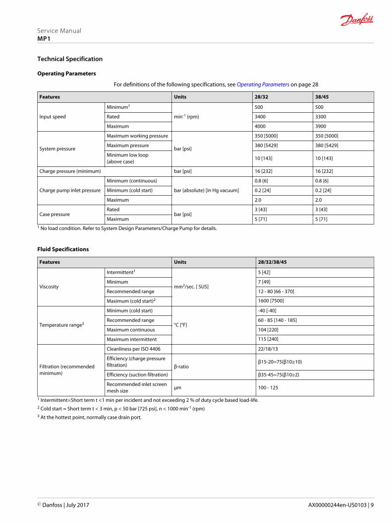
For definitions of the following specifications, see Operating Parameters on page 28
Features Units 28/32 38/45
Input speed
Minimum1
min-1 (rpm)
500 500
Rated 3400 3300
Maximum 4000 3900
System pressure
Maximum working pressure
bar [psi]
350 [5000] 350 [5000]
Maximum pressure 380 [5429] 380 [5429]
Minimum low loop(above case)
10 [143] 10 [143]
Charge pressure (minimum) bar [psi] 16 [232] 16 [232]
Charge pump inlet pressure
Minimum (continuous)
bar (absolute) [in Hg vacuum]
0.8 [6] 0.8 [6]
Minimum (cold start) 0.2 [24] 0.2 [24]
Maximum 2.0 2.0
Case pressureRated
bar [psi]3 [43] 3 [43]
Maximum 5 [71] 5 [71]1 No load condition. Refer to System Design Parameters/Charge Pump for details.
Fluid Specifications
Features Units 28/32/38/45
Viscosity
Intermittent1
mm2/sec. [ SUS]
5 [42]
Minimum 7 [49]
Recommended range 12 - 80 [66 - 370]
Maximum (cold start)2 1600 [7500]
Temperature range3
Minimum (cold start)
°C [°F]
-40 [-40]
Recommended range 60 - 85 [140 - 185]
Maximum continuous 104 [220]
Maximum intermittent 115 [240]
Filtration (recommendedminimum)
Cleanliness per ISO 4406 22/18/13
Efficiency (charge pressurefiltration) β-ratio
β15-20=75(β10≥10)
Efficiency (suction filtration) β35-45=75(β10≥2)
Recommended inlet screenmesh size
µm 100 - 125
1 Intermittent=Short term t <1 min per incident and not exceeding 2 % of duty cycle based load-life.2 Cold start = Short term t < 3 min, p < 50 bar [725 psi], n < 1000 min-1 (rpm)3 At the hottest point, normally case drain port.
Service ManualMP1
Technical Specification
© Danfoss | July 2017 AX00000244en-US0103 | 9
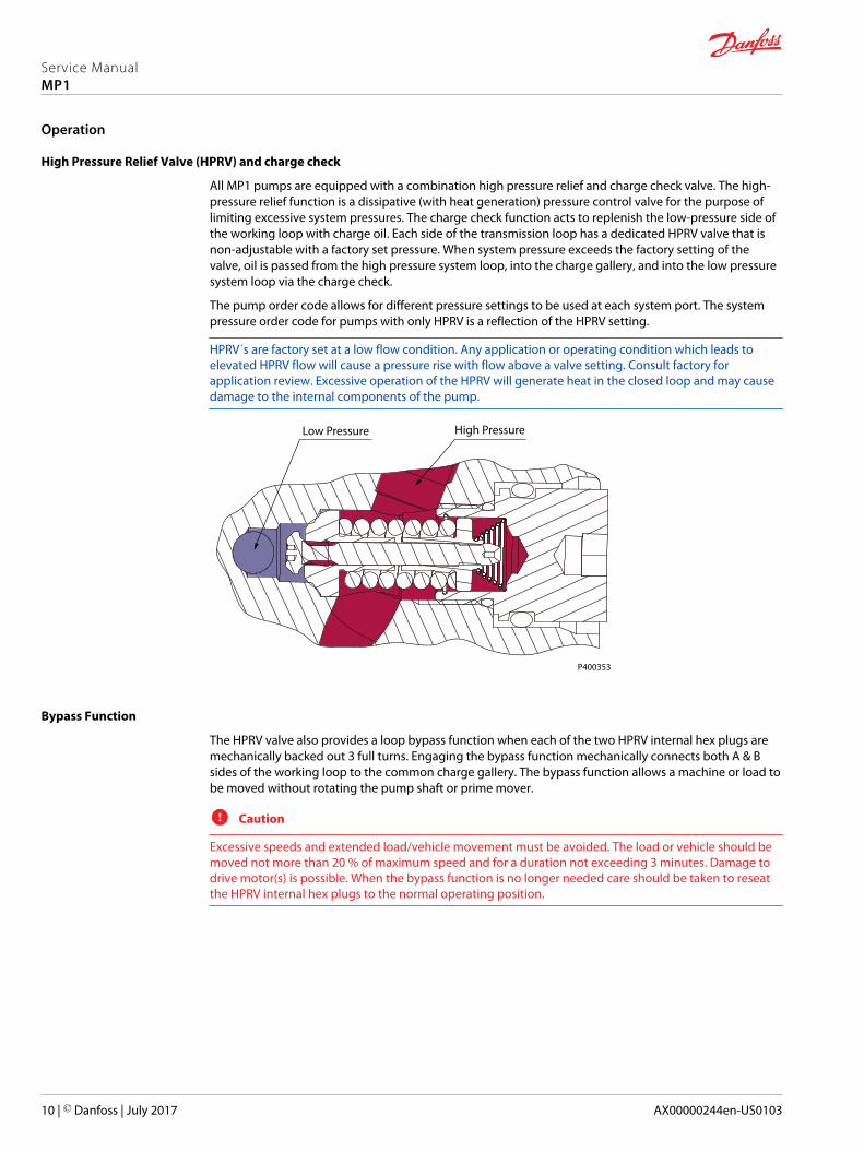
High Pressure Relief Valve (HPRV) and charge check
All MP1 pumps are equipped with a combination high pressure relief and charge check valve. The high-pressure relief function is a dissipative (with heat generation) pressure control valve for the purpose oflimiting excessive system pressures. The charge check function acts to replenish the low-pressure side ofthe working loop with charge oil. Each side of the transmission loop has a dedicated HPRV valve that isnon-adjustable with a factory set pressure. When system pressure exceeds the factory setting of thevalve, oil is passed from the high pressure system loop, into the charge gallery, and into the low pressuresystem loop via the charge check.
The pump order code allows for different pressure settings to be used at each system port. The systempressure order code for pumps with only HPRV is a reflection of the HPRV setting.
HPRV´s are factory set at a low flow condition. Any application or operating condition which leads toelevated HPRV flow will cause a pressure rise with flow above a valve setting. Consult factory forapplication review. Excessive operation of the HPRV will generate heat in the closed loop and may causedamage to the internal components of the pump.
P400353
High PressureLow Pressure
Bypass Function
The HPRV valve also provides a loop bypass function when each of the two HPRV internal hex plugs aremechanically backed out 3 full turns. Engaging the bypass function mechanically connects both A & Bsides of the working loop to the common charge gallery. The bypass function allows a machine or load tobe moved without rotating the pump shaft or prime mover.
C Caution
Excessive speeds and extended load/vehicle movement must be avoided. The load or vehicle should bemoved not more than 20 % of maximum speed and for a duration not exceeding 3 minutes. Damage todrive motor(s) is possible. When the bypass function is no longer needed care should be taken to reseatthe HPRV internal hex plugs to the normal operating position.
Service ManualMP1
Operation
10 | © Danfoss | July 2017 AX00000244en-US0103
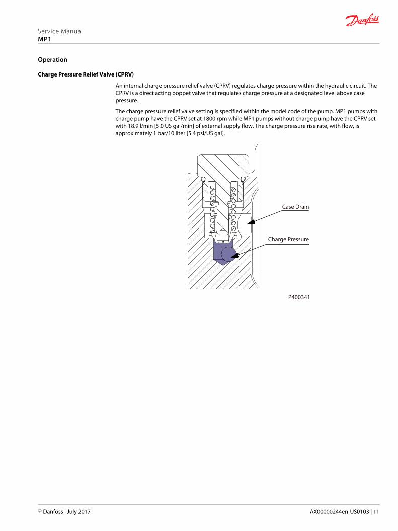
Charge Pressure Relief Valve (CPRV)
An internal charge pressure relief valve (CPRV) regulates charge pressure within the hydraulic circuit. TheCPRV is a direct acting poppet valve that regulates charge pressure at a designated level above casepressure.
The charge pressure relief valve setting is specified within the model code of the pump. MP1 pumps withcharge pump have the CPRV set at 1800 rpm while MP1 pumps without charge pump have the CPRV setwith 18.9 l/min [5.0 US gal/min] of external supply flow. The charge pressure rise rate, with flow, isapproximately 1 bar/10 liter [5.4 psi/US gal].
Charge Pressure
Case Drain
P400341
Service ManualMP1
Operation
© Danfoss | July 2017 AX00000244en-US0103 | 11

Loop Flushing Valve
MP1 pumps are available with an optional integral loop flushing. A loop flushing valve will remove heatand contaminants from the main loop at a rate faster than otherwise possible.
The MP1 loop flushing design is a simple spring centered shuttle spool with an orifice plug. The shuttleshifts at approximately 3.9 bar [55.7 psi]. The flushing flow is a function of the low loop system pressure(charge) and the size of the plug.
Working Loop (Low Pressure) Working Loop (High Pressure)
Shuttle Spool Orifice Plug
P400342
Loop flushing performance
25
20
35
40
45
30
15
10
5
00 4 8 10 12 14
Ch
arg
e p
ress
ure
[d
bar
]
Flow [lpm]
Ø1.6
Ø1.9
Oil Temp = 50°C (~30 mm2/S)
2 6
P400352
C Caution
When a MP1 pump is used with an external loop flushing shuttle valve, ensure that the charge setting ofthe pump matches the setting of the loop flushing shuttle valve. Contact your Danfoss representative forthe availability of additional charge relief settings.
Service ManualMP1
Operation
12 | © Danfoss | July 2017 AX00000244en-US0103

Electrical Displacement Control (EDC)
EDC principle
An EDC is a displacement (flow) control. Pump swashplate position is proportional to the input commandand therefore vehicle or load speed (excluding influence of efficiency), is dependent only on the primemover speed or motor displacement.
The Electrical Displacement Control (EDC) consists of a pair of proportional solenoids on each side of athree-position, four-way porting spool. The proportional solenoid applies a force input to the spool,which ports hydraulic pressure to either side of a double acting servo piston. Differential pressure acrossthe servo piston rotates the swashplate, changing the pump‘s displacement from full displacement inone direction to full displacement in the opposite direction. Under some circumstances, such ascontamination, the control spool could stick and cause the pump to stay at some displacement.
A serviceable 125 µm screen is located in the supply line immediately before the control porting spool.
EDC control
P003 191
EDC schematic
Feedback from Swash plate
PTF00B
M14
C1 C2
F00A
P003 478E
EDC operation
EDC’s are current driven controls requiring a Pulse Width Modulated (PWM) signal. Pulse widthmodulation allows more precise control of current to the solenoids. The PWM signal causes the solenoidpin to push against the porting spool, which pressurizes one end of the servo piston, while draining theother. Pressure differential across the servo piston moves the swashplate.
A swashplate feedback link, opposing control links, and a linear spring provide swashplate position forcefeedback to the solenoid. The control system reaches equilibrium when the position of the swashplatespring feedback force exactly balances the input command solenoid force from the operator. Ashydraulic pressures in the operating loop change with load, the control assembly and servo/swashplatesystem work constantly to maintain the commanded position of the swashplate.
The EDC incorporates a positive neutral deadband as a result of the control spool porting, preloads fromthe servo piston assembly, and the linear control spring. Once the neutral threshold current is reached,the swashplate is positioned directly proportional to the control current. To minimize the effect of thecontrol neutral deadband, we recommend the transmission controller or operator input deviceincorporate a jump up current to offset a portion of the neutral deadband.
The neutral position of the control spool does provide a positive preload pressure to each end of theservo piston assembly.
When the control input signal is either lost or removed, or if there is a loss of charge pressure, the spring-loaded servo piston will automatically return the pump to the neutral position.
Service ManualMP1
Operation
© Danfoss | July 2017 AX00000244en-US0103 | 13
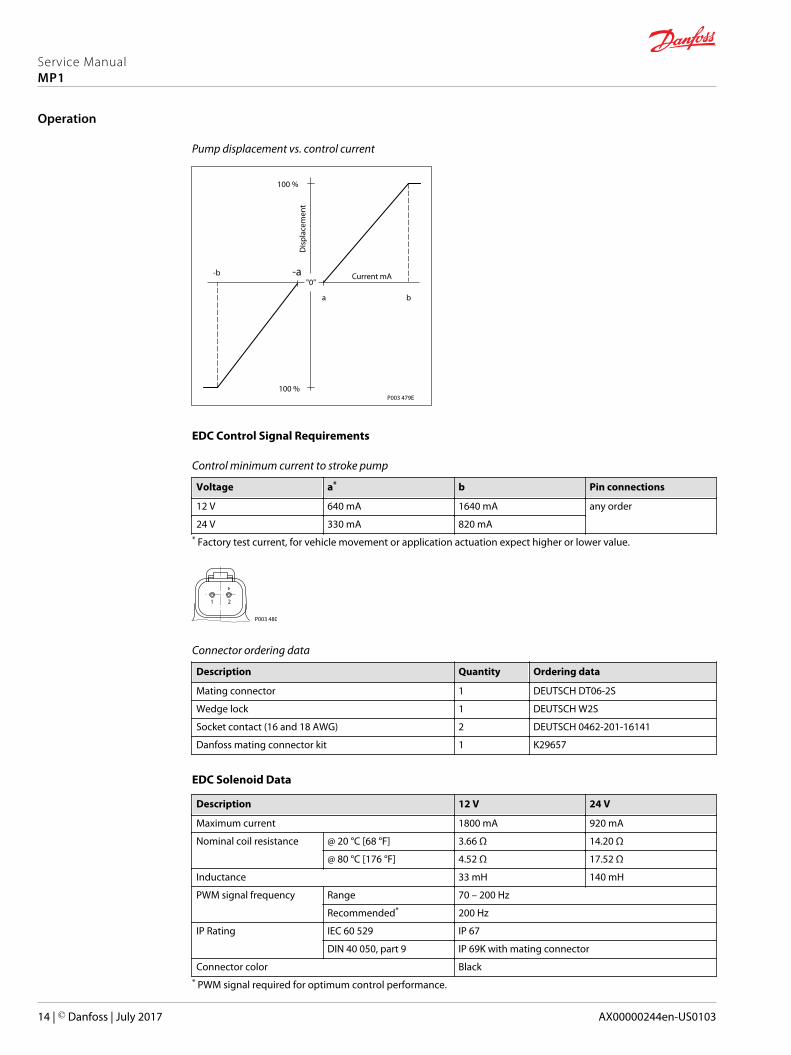
Pump displacement vs. control current
P003 479E
"0"-b -a
ba
100 %
100 %
Dis
plac
emen
t
Current mA
EDC Control Signal Requirements
Control minimum current to stroke pump
Voltage a* b Pin connections
12 V 640 mA 1640 mA any order
24 V 330 mA 820 mA* Factory test current, for vehicle movement or application actuation expect higher or lower value.
1 2
P003 480
Connector ordering data
Description Quantity Ordering data
Mating connector 1 DEUTSCH DT06-2S
Wedge lock 1 DEUTSCH W2S
Socket contact (16 and 18 AWG) 2 DEUTSCH 0462-201-16141
Danfoss mating connector kit 1 K29657
EDC Solenoid Data
Description 12 V 24 V
Maximum current 1800 mA 920 mA
Nominal coil resistance @ 20 °C [68 °F] 3.66 Ω 14.20 Ω
@ 80 °C [176 °F] 4.52 Ω 17.52 Ω
Inductance 33 mH 140 mH
PWM signal frequency Range 70 – 200 Hz
Recommended* 200 Hz
IP Rating IEC 60 529 IP 67
DIN 40 050, part 9 IP 69K with mating connector
Connector color Black* PWM signal required for optimum control performance.
Service ManualMP1
Operation
14 | © Danfoss | July 2017 AX00000244en-US0103

Pump output flow direction vs. control signal
Shaft rotation CW CCW
Coil energized* C1 C2 C1 C2
Port A out in in out
Port B in out out in
Servo port pressurized M4 M5 M4 M5* For coil location see Installation drawings.
Control response
MP1 controls are available with optional control passage orifices to assist in matching the rate ofswashplate response to the application requirements (e.g. in the event of electrical failure). The timerequired for the pump output flow to change from zero to full flow (acceleration) or full flow to zero(deceleration) is a net function of spool porting, orifices, and charge pressure. A swashplate responsetable is available for each frame indicating available swashplate response times. Testing should beconducted to verify the proper orifice selection for the desired response.
MP1 pumps are limited in mechanical orificing combinations. Mechanical servo orifices are to be usedonly for fail-safe return to neutral in the event of an electrical failure.
Typical response times shown below at the following conditions:
Δp 250 bar [3626 psi]
Viscosity and temperature 30 mm²/s [141 SUS] and 50 °C [122 °F]
Charge pressure 20 bar [290 psi]
Speed 1800 min-1 (rpm)
Response time, EDC
Strokingdirection
0.8 mm [0.03 in]orifice
1.0 mm [0.04 in]orifice
1.3 mm [0.05 in]orifice
No orifice
28/32 38/45 28/32 38/45 28/32 38/45 28/32 38/45
Neutral tofull flow
1.3 s 2.1 s 0.9 s 1.3 s 0.6 s 0.9 s 0.4 s 0.6 s
Full flow toneutral
1.0 s 1.5 s 0.7 s 0.9 s 0.4 s 0.6 s 0.2 s 0.3 s
Manual Over Ride (MOR)
Electro-hydraulic controls are available with a Manual Over Ride (MOR) either standard or as an option fortemporary actuation of the control to aid in diagnostics.
Unintended MOR operation will cause the pump to go into stroke. The vehicle or device must always bein a safe condition (i.e. vehicle lifted off the ground) when using the MOR function. The MOR plunger hasa 4 mm diameter and must be manually depressed to be engaged. Depressing the plunger mechanicallymoves the control spool which allows the pump to go on stroke. The MOR should be engagedanticipating a full stroke response from the pump.
W Warning
An o-ring seal is used to seal the MOR plunger where initial actuation of the function will require a forceof 45 N to engage the plunger. Additional actuations typically require less force to engage the MORplunger. Proportional control of the pump using the MOR should not be expected.
Refer to the control flow table in the size specific technical information for the relationship of solenoid todirection of flow.
Service ManualMP1
Operation
© Danfoss | July 2017 AX00000244en-US0103 | 15

P003 204
MOR-Schematic diagram (EDC shown)
Feedback from Swash plate
PTF00B
M14
C2C1
F00A
P003 205E
Service ManualMP1
Operation
16 | © Danfoss | July 2017 AX00000244en-US0103
Hydraulic Displacement Control (HDC)
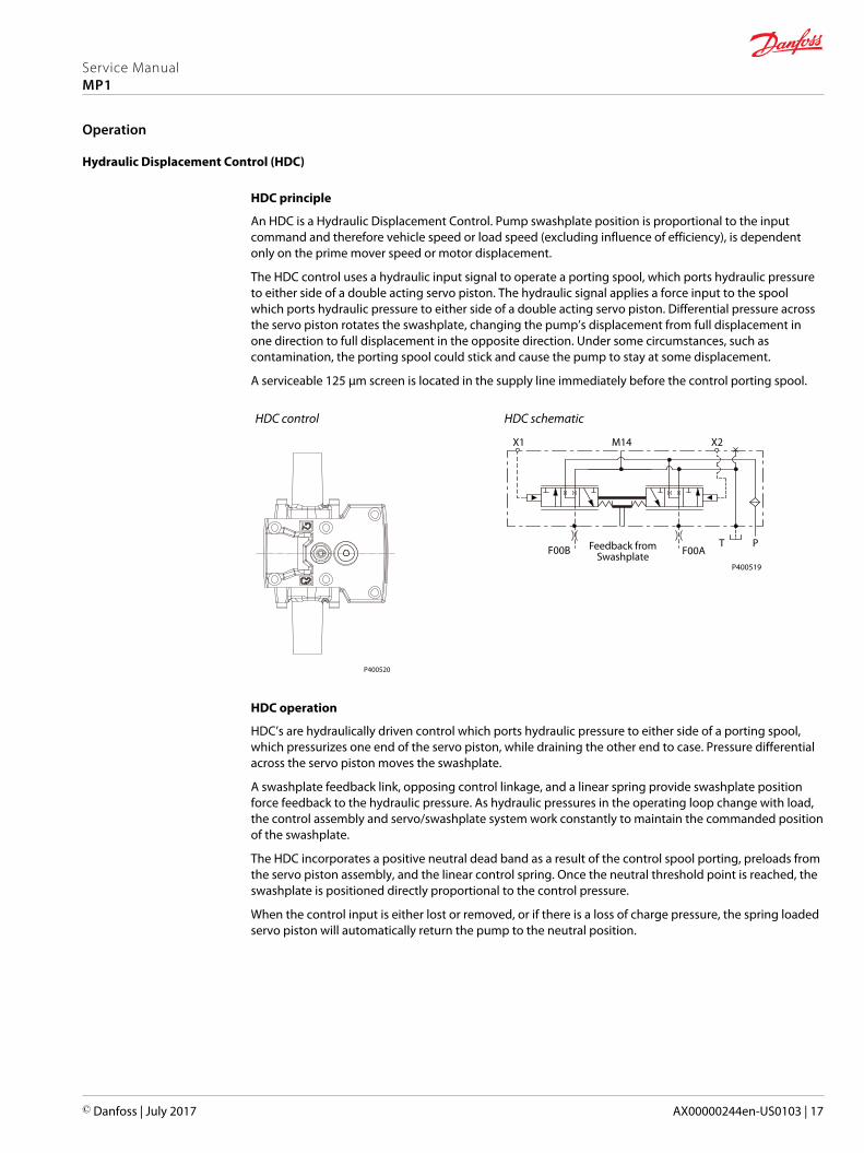
HDC principle
An HDC is a Hydraulic Displacement Control. Pump swashplate position is proportional to the inputcommand and therefore vehicle speed or load speed (excluding influence of efficiency), is dependentonly on the prime mover speed or motor displacement.
The HDC control uses a hydraulic input signal to operate a porting spool, which ports hydraulic pressureto either side of a double acting servo piston. The hydraulic signal applies a force input to the spoolwhich ports hydraulic pressure to either side of a double acting servo piston. Differential pressure acrossthe servo piston rotates the swashplate, changing the pump’s displacement from full displacement inone direction to full displacement in the opposite direction. Under some circumstances, such ascontamination, the porting spool could stick and cause the pump to stay at some displacement.
A serviceable 125 μm screen is located in the supply line immediately before the control porting spool.
HDC control
P400520
HDC schematic
P400519
X1
F00B F00AFeedback fromSwashplate
T P
X2M14
HDC operation
HDC’s are hydraulically driven control which ports hydraulic pressure to either side of a porting spool,which pressurizes one end of the servo piston, while draining the other end to case. Pressure differentialacross the servo piston moves the swashplate.
A swashplate feedback link, opposing control linkage, and a linear spring provide swashplate positionforce feedback to the hydraulic pressure. As hydraulic pressures in the operating loop change with load,the control assembly and servo/swashplate system work constantly to maintain the commanded positionof the swashplate.
The HDC incorporates a positive neutral dead band as a result of the control spool porting, preloads fromthe servo piston assembly, and the linear control spring. Once the neutral threshold point is reached, theswashplate is positioned directly proportional to the control pressure.
When the control input is either lost or removed, or if there is a loss of charge pressure, the spring loadedservo piston will automatically return the pump to the neutral position.
Service ManualMP1
Operation
© Danfoss | July 2017 AX00000244en-US0103 | 17
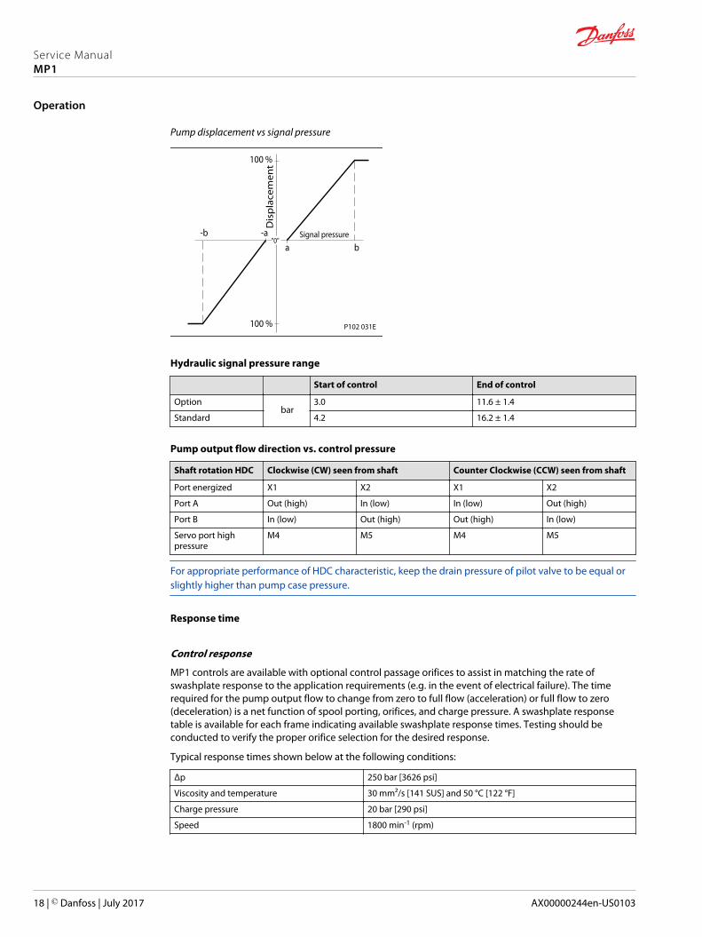
Pump displacement vs signal pressure
"0"Signal pressure
Dis
pla
cem
en
t
100 %
a b
-b -a
100 % P102 031E
Hydraulic signal pressure range
Start of control End of control
Optionbar
3.0 11.6 ± 1.4
Standard 4.2 16.2 ± 1.4
Pump output flow direction vs. control pressure
Shaft rotation HDC Clockwise (CW) seen from shaft Counter Clockwise (CCW) seen from shaft
Port energized X1 X2 X1 X2
Port A Out (high) In (low) In (low) Out (high)
Port B In (low) Out (high) Out (high) In (low)
Servo port highpressure
M4 M5 M4 M5
For appropriate performance of HDC characteristic, keep the drain pressure of pilot valve to be equal orslightly higher than pump case pressure.
Response time
Control response
MP1 controls are available with optional control passage orifices to assist in matching the rate ofswashplate response to the application requirements (e.g. in the event of electrical failure). The timerequired for the pump output flow to change from zero to full flow (acceleration) or full flow to zero(deceleration) is a net function of spool porting, orifices, and charge pressure. A swashplate responsetable is available for each frame indicating available swashplate response times. Testing should beconducted to verify the proper orifice selection for the desired response.
Typical response times shown below at the following conditions:
Δp 250 bar [3626 psi]
Viscosity and temperature 30 mm²/s [141 SUS] and 50 °C [122 °F]
Charge pressure 20 bar [290 psi]
Speed 1800 min-1 (rpm)
Service ManualMP1
Operation
18 | © Danfoss | July 2017 AX00000244en-US0103
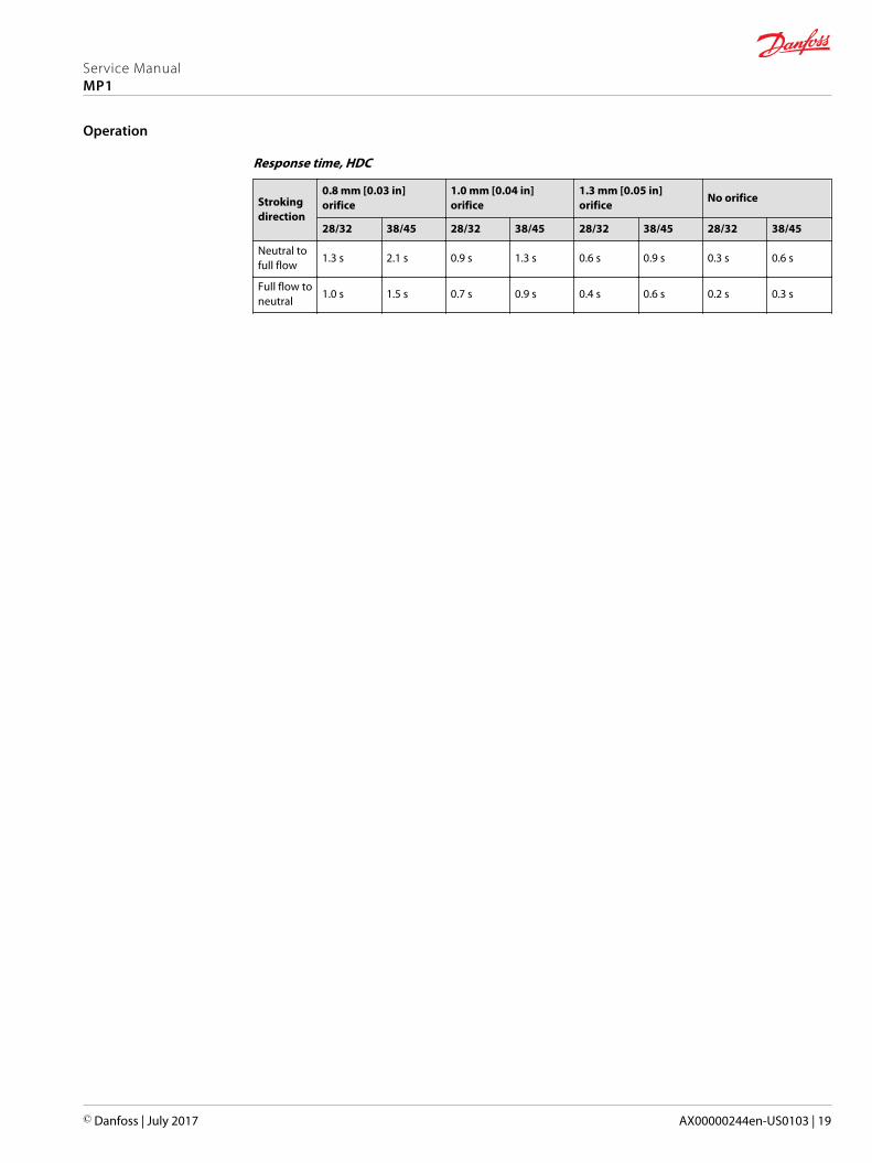
Response time, HDC
Strokingdirection
0.8 mm [0.03 in]orifice
1.0 mm [0.04 in]orifice
1.3 mm [0.05 in]orifice
No orifice
28/32 38/45 28/32 38/45 28/32 38/45 28/32 38/45
Neutral tofull flow
1.3 s 2.1 s 0.9 s 1.3 s 0.6 s 0.9 s 0.3 s 0.6 s
Full flow toneutral
1.0 s 1.5 s 0.7 s 0.9 s 0.4 s 0.6 s 0.2 s 0.3 s
Service ManualMP1
Operation
© Danfoss | July 2017 AX00000244en-US0103 | 19

Manual Displacement Control (MDC)
MDC principle
An MDC is a Manual proportional Displacement Control (MDC). The MDC consists of a handle on top of arotary input shaft. The shaft provides an eccentric connection to a feedback link. This link is connected onits one end with a porting spool. On its other end the link is connected the pumps swashplate.
This design provides a travel feedback without spring. When turning the shaft the spool moves thusproviding hydraulic pressure to either side of a double acting servo piston of the pump.
Differential pressure across the servo piston rotates the swash plate, changing the pump’s displacement.Simultaneously the swashplate movement is fed back to the control spool providing proportionalitybetween shaft rotation on the control and swashplate rotation.
The MDC changes the pump displacement between no flow and full flow into opposite directions. Undersome circumstances, such as contamination, the control spool could stick and cause the pump to stay atsome displacement.
A serviceable 125 μm screen is located in the supply line immediately before the control porting spool.
The MDC is sealed by means of a static O-ring between the actuation system and the control block. Itsshaft is sealed by means of a special O-ring which is applied for low friction. The special O-ring isprotected from dust, water and aggressive liquids or gases by means of a special lip seal.
Manual Displacement Control
P301 749
Pump displacement vs. control lever rotation
"0"Lever rotation"A"
Dis
plac
emen
t
100 %
a
-a
100 %
"B"-b-d
b c
d
-c
P301 752
MDC schematic diagram
P005 701
M14
M5 M4 M3
Where:Deadband on B side – a = 3° ±1°Maximum pump stroke – b = 30° +2/-1°Required customer end stop – c = 36° ±3°Internal end stop – d = 40°
Volumetric efficiencies of the system will have impacts onthe start and end input commands.
MDC torque
Torque required to move handle to maximum displacement 1.4 N•m [12.39 lbf•in ]
Torque required to hold handle at given displacement 0.6 N•m [5.31 lbf•in]
Maximum allowable input torque 20 N•m [177 lbf•in]
Service ManualMP1
Operation
20 | © Danfoss | July 2017 AX00000244en-US0103

MDC General Information
In difference to other controls the MDC provides a mechanical deadband. This is required to overcomethe tolerances in the mechanical actuation.
The MDC contains an internal end stop to prevent over travel. The restoring moment is appropriate forturning the MDC input shaft back to neutral only. Any linkages or cables may prevent the MDC fromreturning to neutral.
The MDC is designed for a maximum case pressure of 5 bar and a rated case pressure of 3 bar. If the casepressure exceeds 5 bar there is a risk of an insufficient restoring moment. In addition a high case pressurecan cause the NSS to indicate that the control is not in neutral. High case pressure may cause excessivewear.
Customers can apply their own handle design but they must care about a robust clamping connectionbetween their handle and the control shaft and avoid overload of the shaft.
Customers can connect two MDC’s on a tandem unit in such a way that the actuation force will betransferred from the pilot control to the second control but the kinematic of the linkages must ensurethat either control shaft is protected from torque overload. To avoid an overload of the MDC, customersmust install any support to limit the setting range of the Bowden cable.
C Caution
Using the internal spring force on the input shaft is not an appropriate way to return the customerconnection linkage to neutral.
MDC Shaft Rotation
CCW
CW
P301 753
MDC shaft rotation data
Pump shaft rotation* Clock Wise (CW) Counter Clock Wise (CCW)
MDC shaft rotation CW CCW CW CCW
Port A in (low) out (high) out (high) in (low)
Port B out (high) in (low) in (low) out (high)
Servo port high pressure M5 M4 M5 M4* As seen from shaft side.
Control Response
MP1 controls are available with optional control passage orifices to assist in matching the rate ofswashplate response to the application requirements. The time required for the pump output flow tochange from zero to full flow (acceleration) or full flow to zero (deceleration) is a net function of spoolporting, orifices, and charge pressure. A swashplate response table is available for each frame indicatingavailable swashplate response times. Testing should be conducted to verify the proper orifice selectionfor the desired response.
Service ManualMP1
Operation
© Danfoss | July 2017 AX00000244en-US0103 | 21
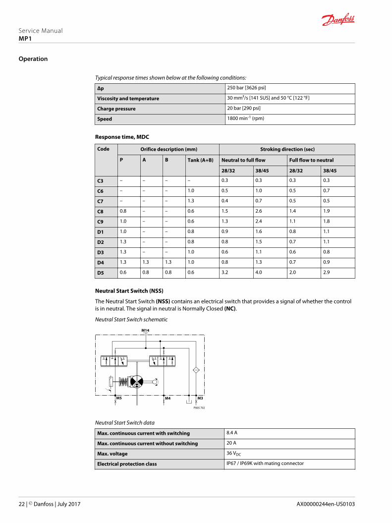
Typical response times shown below at the following conditions:
Δp 250 bar [3626 psi]
Viscosity and temperature 30 mm²/s [141 SUS] and 50 °C [122 °F]
Charge pressure 20 bar [290 psi]
Speed 1800 min-1 (rpm)
Response time, MDC
Code Orifice description (mm) Stroking direction (sec)
P A B Tank (A+B) Neutral to full flow Full flow to neutral
28/32 38/45 28/32 38/45
C3 – – – – 0.3 0.3 0.3 0.3
C6 – – – 1.0 0.5 1.0 0.5 0.7
C7 – – – 1.3 0.4 0.7 0.5 0.5
C8 0.8 – – 0.6 1.5 2.6 1.4 1.9
C9 1.0 – – 0.6 1.3 2.4 1.1 1.8
D1 1.0 – – 0.8 0.9 1.6 0.8 1.1
D2 1.3 – – 0.8 0.8 1.5 0.7 1.1
D3 1.3 – – 1.0 0.6 1.1 0.6 0.8
D4 1.3 1.3 1.3 1.0 0.8 1.3 0.7 0.9
D5 0.6 0.8 0.8 0.6 3.2 4.0 2.0 2.9
Neutral Start Switch (NSS)
The Neutral Start Switch (NSS) contains an electrical switch that provides a signal of whether the controlis in neutral. The signal in neutral is Normally Closed (NC).
Neutral Start Switch schematic
P005 702
M14
M5 M4 M3
Neutral Start Switch data
Max. continuous current with switching 8.4 A
Max. continuous current without switching 20 A
Max. voltage 36 VDC
Electrical protection class IP67 / IP69K with mating connector
Service ManualMP1
Operation
22 | © Danfoss | July 2017 AX00000244en-US0103

Case gauge port M14
The drain port should be used when the control is mounted on the unit’s bottom side to flush residualcontamination out of the control.
MDC w/h drain port shown
P400344
Case gauge port M14
MDC schematic diagram
P005 701
M14
M5 M4 M3
Lever
MDC controls are available with optional lever/handle. Standard orientation is 90° from input shaft asshown below.
Align with Settings (Y) module in the model code.
P400345
Service ManualMP1
Operation
© Danfoss | July 2017 AX00000244en-US0103 | 23

Forward-Neutral-Reverse electric control (FNR)
FNR principle
The 3-position FNR control uses an electric input signal to switch the pump to a full stroke position.Under some circumstances, such as contamination, the control spool could stick and cause the pump tostay at some displacement. A serviceable 125 μm screen is located in the supply line immediately beforethe control porting spool.
Forward-Neutral-Reverse electric control (FNR)
P003 193
FNR hydraulic schematic
P003 189
C2C1
F00A
M14
T PF00B
Pump displacement vs. electrical signal
P003 190E100 %
“0“
100 %
Voltage VDC
Dis
pla
cem
ent
Control current
Voltage Min. current to stroke pump Pin connections
12 V 750 mA any order
24 V 380 mA
1 2
P003 480
Connector ordering data
Description Quantity Ordering data
Mating connector 1 DEUTSCH DT06-2S
Wedge lock 1 DEUTSCH W2S
Socket contact (16 and 18 AWG) 2 DEUTSCH 0462-201-16141
Danfoss mating connector kit 1 K29657
Service ManualMP1
Operation
24 | © Danfoss | July 2017 AX00000244en-US0103

Solenoid data
Voltage 12 V 24 V
Minimum supply voltage 9.5 VDC 19 VDC
Maximum supply voltage (continuous) 14.6 VDC 29 VDC
Maximum current 1050 mA 500 mA
Nominal coil resistance @ 20 °C [70 °F] 8.4 Ω 34.5 Ω
PWM Range 70-200 Hz
PWM Frequency (preferred)* 100 Hz
IP Rating (IEC 60 529) + DIN 40 050, part 9 IP 67 / IP 69K (part 9 with mating connector)
Bi-directional diode cut off voltage 28 VDC 53 VDC
* PWM signal required for optimum control performance.
Pump output flow direction vs. control signal
Shaft rotation CW CCW
Coil energized* C1 C2 C1 C2
Port A in out out in
Port B out in in out
Servo port pressurized M5 M4 M5 M4* For coil location see Installation Drawings.
Control Response
MP1 controls are available with optional control passage orifices to assist in matching the rate ofswashplate response to the application requirements. The time required for the pump output flow tochange from zero to full flow (acceleration) or full flow to zero (deceleration) is a net function of spoolporting, orifices, and charge pressure. A swashplate response table is available for each frame indicatingavailable swashplate response times. Testing should be conducted to verify the proper orifice selectionfor the desired response.
Typical response times shown below at the following conditions:
Δp 250 bar [3626 psi]
Viscosity and temperature 30 mm²/s [141 SUS] and 50 °C [122 °F]
Charge pressure 20 bar [290 psi]
Speed 1800 min-1 (rpm)
Response time, FNR
Strokingdirection
0.8 mm [0.03 in]orifice
1.0 mm [0.04 in]orifice
1.3 mm [0.05 in]orifice
No orifice
28/32 38/45 28/32 38/45 28/32 38/45 28/32 38/45
Neutral tofull flow
2.1 s 2.6 s 1.1 s 1.6 s 0.8 s 1.1 s 0.7 s 0.7 s
Full flow toneutral
1.1 s 1.8 s 0.9 s 1.0 s 0.6 s 0.7 s 0.3 s 0.3 s
Service ManualMP1
Operation
© Danfoss | July 2017 AX00000244en-US0103 | 25

Control-Cut-Off valve (CCO valve)
The pump offers an optional control cut off valve integrated into the control. This valve will block chargepressure to the control, allowing the servo springs to de-stroke the pump regardless of the pump´sprimary control input. There is also a hydraulic logic port, X7, which can be used to control other machinefunctions, such as spring applied pressure release brakes. The pressure at X7 is controlled by the controlcut off solenoid. The X7 port would remain plugged if not needed.
In the normal (de-energized) state of the solenoid charge flow is prevented from reaching the controls. Atthe same time the control passages and the X7 logic port are connected and drained to the pump case.The pump will remain in neutral, or return to neutral, independent of the control input signal. Return toneutral time will be dependent on oil viscosity, pump speed, swashplate angle, and system pressure.
When the solenoid is energized, charge flow and pressure is allowed to reach the pump control. The X7logic port will also be connected to charge pressure and flow.
The solenoid control is intended to be independent of the primary pump control making the control cutoff an override control feature. It is however recommended that the control logic of the CCO valve bemaintained such that the primary pump control signal is also disabled whenever the CCO valve is de-energized. Other control logic conditions may also be considered.
EDC controls are available with a CCO valve.
The response time of the unit depends on the control type and the control orifices used.
The CCO-valve is available with 12 V or 24 V solenoid.
EDC+CCO
Hydraulic logic Port X7
P400346
EDC+CCO schematic
X7M14
C2C1
P400349
CCO connector
1 2
Connector ordering data
Description Quantity Ordering number
Mating connector 1 DEUTSCH DT06-2S
Wedge lock 1 DEUTSCH W2S
Socket contact (16 and 18 AWG) 2 DEUTSCH 0462-201-16141
Service ManualMP1
Operation
26 | © Danfoss | July 2017 AX00000244en-US0103
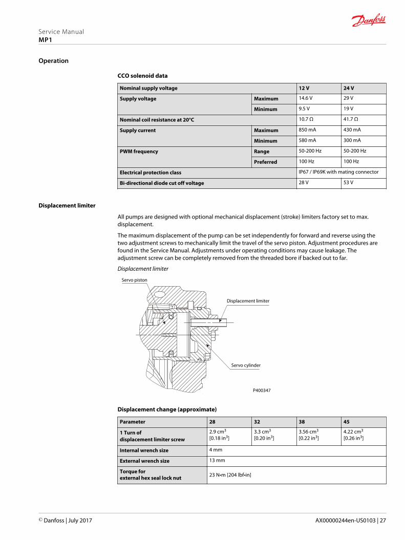
CCO solenoid data
Nominal supply voltage 12 V 24 V
Supply voltage Maximum 14.6 V 29 V
Minimum 9.5 V 19 V
Nominal coil resistance at 20°C 10.7 Ω 41.7 Ω
Supply current Maximum 850 mA 430 mA
Minimum 580 mA 300 mA
PWM frequency Range 50-200 Hz 50-200 Hz
Preferred 100 Hz 100 Hz
Electrical protection class IP67 / IP69K with mating connector
Bi-directional diode cut off voltage 28 V 53 V
Displacement limiter
All pumps are designed with optional mechanical displacement (stroke) limiters factory set to max.displacement.
The maximum displacement of the pump can be set independently for forward and reverse using thetwo adjustment screws to mechanically limit the travel of the servo piston. Adjustment procedures arefound in the Service Manual. Adjustments under operating conditions may cause leakage. Theadjustment screw can be completely removed from the threaded bore if backed out to far.
Displacement limiter
Servo piston
Displacement limiter
Servo cylinder
P400347
Displacement change (approximate)
Parameter 28 32 38 45
1 Turn ofdisplacement limiter screw
2.9 cm3
[0.18 in3]3.3 cm3
[0.20 in3]3.56 cm3
[0.22 in3]4.22 cm3
[0.26 in3]
Internal wrench size 4 mm
External wrench size 13 mm
Torque forexternal hex seal lock nut 23 N•m [204 lbf•in]
Service ManualMP1
Operation
© Danfoss | July 2017 AX00000244en-US0103 | 27
Overview
This section defines the operating parameters and limitations with regard to input speeds and pressures.
Input Speed
Minimum speed is the lowest input speed recommended during engine idle condition. Operating belowminimum speed limits pump’s ability to maintain adequate flow for lubrication and power transmission.
Rated speed is the highest input speed recommended at full power condition. Operating at or belowthis speed should yield satisfactory product life.
Maximum speed is the highest operating speed permitted. Exceeding maximum speed reduces productlife and can cause loss of hydrostatic power and braking capacity. Never exceed the maximum speedlimit under any operating conditions.
Operating conditions between Rated speed and Maximum speed should be restricted to less than fullpower and to limited periods of time. For most drive systems, maximum unit speed occurs duringdownhill braking or negative power conditions.
During hydraulic braking and downhill conditions, the prime mover must be capable of providingsufficient braking torque in order to avoid pump over speed. This is especially important to consider forturbocharged and Tier 4 engines.
W Warning
Unintended vehicle or machine movement hazard.Exceeding maximum speed may cause a loss of hydrostatic drive line power and braking capacity. Youmust provide a braking system, redundant to the hydrostatic transmission, sufficient to stop and hold thevehicle or machine in the event of hydrostatic drive power loss.
System Pressure
System pressure is the differential pressure between system ports A and B. It is the dominant operatingvariable affecting hydraulic unit life. High system pressure, which results from high load, reducesexpected life. Hydraulic unit life depends on the speed and normal operating, or weighted average,pressure that can only be determined from a duty cycle analysis.
Application pressure is the high pressure relief setting normally defined within the order code of thepump. This is the applied system pressure at which the driveline generates the maximum calculated pullor torque in the application.
Maximum working pressure is the highest recommended Application pressure. Maximum workingpressure is not intended to be a continuous pressure. Propel systems with Application pressures at, orbelow, this pressure should yield satisfactory unit life given proper component sizing.
Maximum pressure is the highest allowable Application pressure under any circumstance. Applicationpressures above Maximum Working Pressure will only be considered with duty cycle analysis and factoryapproval. Pressure spikes are normal and must be considered when reviewing maximum workingpressure.
All pressure limits are differential pressures referenced to low loop (charge) pressure. Subtract low looppressure from gauge readings to compute the differential.
Minimum low loop pressure (above case pressure) is the lowest pressure allowed to maintain a safeworking condition in the low side of the loop.
Service ManualMP1
Operating Parameters
28 | © Danfoss | July 2017 AX00000244en-US0103
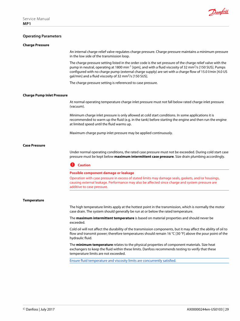
Charge Pressure
An internal charge relief valve regulates charge pressure. Charge pressure maintains a minimum pressurein the low side of the transmission loop.
The charge pressure setting listed in the order code is the set pressure of the charge relief valve with thepump in neutral, operating at 1800 min-1 [rpm], and with a fluid viscosity of 32 mm2/s [150 SUS]. Pumpsconfigured with no charge pump (external charge supply) are set with a charge flow of 15.0 l/min [4.0 USgal/min] and a fluid viscosity of 32 mm2/s [150 SUS].
The charge pressure setting is referenced to case pressure.
Charge Pump Inlet Pressure
At normal operating temperature charge inlet pressure must not fall below rated charge inlet pressure(vacuum).
Minimum charge inlet pressure is only allowed at cold start conditions. In some applications it isrecommended to warm up the fluid (e.g. in the tank) before starting the engine and then run the engineat limited speed until the fluid warms up.
Maximum charge pump inlet pressure may be applied continuously.
Case Pressure
Under normal operating conditions, the rated case pressure must not be exceeded. During cold start casepressure must be kept below maximum intermittent case pressure. Size drain plumbing accordingly.
C Caution
Possible component damage or leakageOperation with case pressure in excess of stated limits may damage seals, gaskets, and/or housings,causing external leakage. Performance may also be affected since charge and system pressure areadditive to case pressure.
Temperature
The high temperature limits apply at the hottest point in the transmission, which is normally the motorcase drain. The system should generally be run at or below the rated temperature.
The maximum intermittent temperature is based on material properties and should never beexceeded.
Cold oil will not affect the durability of the transmission components, but it may affect the ability of oil toflow and transmit power; therefore temperatures should remain 16 °C [30 °F] above the pour point of thehydraulic fluid.
The minimum temperature relates to the physical properties of component materials. Size heatexchangers to keep the fluid within these limits. Danfoss recommends testing to verify that thesetemperature limits are not exceeded.
Ensure fluid temperature and viscosity limits are concurrently satisfied.
Service ManualMP1
Operating Parameters
© Danfoss | July 2017 AX00000244en-US0103 | 29
Viscosity
Viscosity For maximum efficiency and bearing life, ensure the fluid viscosity remains in therecommended range.
The minimum viscosity should be encountered only during brief occasions of maximum ambienttemperature and severe duty cycle operation.
The maximum viscosity should be encountered only at cold start.
Service ManualMP1
Operating Parameters
30 | © Danfoss | July 2017 AX00000244en-US0103
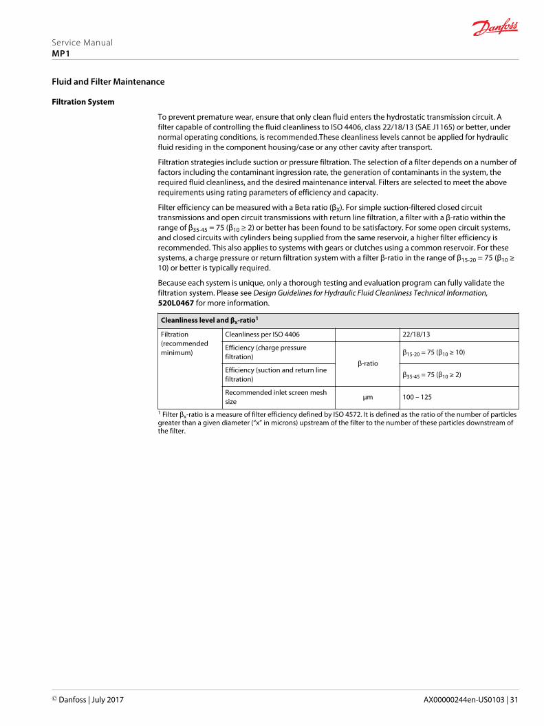
Filtration System
To prevent premature wear, ensure that only clean fluid enters the hydrostatic transmission circuit. Afilter capable of controlling the fluid cleanliness to ISO 4406, class 22/18/13 (SAE J1165) or better, undernormal operating conditions, is recommended.These cleanliness levels cannot be applied for hydraulicfluid residing in the component housing/case or any other cavity after transport.
Filtration strategies include suction or pressure filtration. The selection of a filter depends on a number offactors including the contaminant ingression rate, the generation of contaminants in the system, therequired fluid cleanliness, and the desired maintenance interval. Filters are selected to meet the aboverequirements using rating parameters of efficiency and capacity.
Filter efficiency can be measured with a Beta ratio (βX). For simple suction-filtered closed circuittransmissions and open circuit transmissions with return line filtration, a filter with a β-ratio within therange of β35-45 = 75 (β10 ≥ 2) or better has been found to be satisfactory. For some open circuit systems,and closed circuits with cylinders being supplied from the same reservoir, a higher filter efficiency isrecommended. This also applies to systems with gears or clutches using a common reservoir. For thesesystems, a charge pressure or return filtration system with a filter β-ratio in the range of β15-20 = 75 (β10 ≥10) or better is typically required.
Because each system is unique, only a thorough testing and evaluation program can fully validate thefiltration system. Please see Design Guidelines for Hydraulic Fluid Cleanliness Technical Information,520L0467 for more information.
Cleanliness level and βx-ratio1
Filtration(recommendedminimum)
Cleanliness per ISO 4406 22/18/13
Efficiency (charge pressurefiltration)
β-ratio
β15-20 = 75 (β10 ≥ 10)
Efficiency (suction and return linefiltration)
β35-45 = 75 (β10 ≥ 2)
Recommended inlet screen meshsize
µm 100 – 125
1 Filter βx-ratio is a measure of filter efficiency defined by ISO 4572. It is defined as the ratio of the number of particlesgreater than a given diameter (“x” in microns) upstream of the filter to the number of these particles downstream ofthe filter.
Service ManualMP1
Fluid and Filter Maintenance
© Danfoss | July 2017 AX00000244en-US0103 | 31
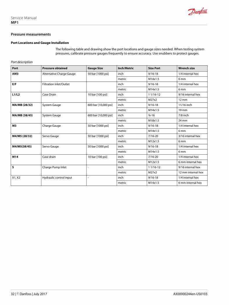
Port Locations and Gauge Installation
The following table and drawing show the port locations and gauge sizes needed. When testing systempressures, calibrate pressure gauges frequently to ensure accuracy. Use snubbers to protect gauges.
Port description
Port Pressure obtained Gauge Size Inch/Metric Size Port Wrench size
AM3 Alternative Charge Gauge 50 bar [1000 psi] inch 9/16-18 1/4 internal hex
metric M14x1.5 6 mm
E/F Filtration Inlet/Outlet inch 9/16-18 1/4 internal hex
metric M14x1.5 6 mm
L1/L2 Case Drain 10 bar [100 psi] inch 1 1/16-12 9/16 internal hex
metric M27x2 12 mm
MA/MB (28/32) System Gauge 600 bar [10,000 psi] inch 9/16-18 11/16 inch
metric M14x1.5 19 mm
MA/MB (38/45) System Gauge 600 bar [10,000 psi] inch ¾-16 7/8 inch
metric M18x1.5 24 mm
M3 Charge Gauge 50 bar [1000 psi] inch 9/16-18 1/4 internal hex
metric M14x1.5 6 mm
M4/M5 (28/32) Servo Gauge 50 bar [1000 psi] inch 7/16-20 3/16 internal hex
metric M12x1.5 6 mm
M4/M5(38/45) Servo Gauge 50 bar [1000 psi] inch 9/16-18 1/4 internal hex
metric M14x1.5 6 mm
M14 Case drain 10 bar [100 psi] inch 7/16-20 1/4 internal hex
metric M12x1.5 6 mm internal hex
S Charge Pump Inlet - inch 1 1/16-12 9/16 internal hex
metric M27x2 12 mm internal hex
X1, X2 Hydraulic control input - inch 9/16-18 1/4 internal hex
metric M14x1.5 6 mm internal hex
Service ManualMP1
Pressure measurements
32 | © Danfoss | July 2017 AX00000244en-US0103
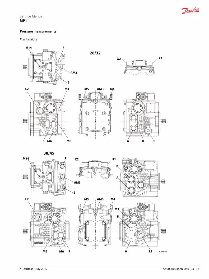
Port locations
L2
M14
M5M3
F
AM3
E
M4AM3
L1BAS AM MB
L2
M14
M5
F
AM3
E
M4AM3
L1
B
B
A
M3
AMAMB S
28/32X2 X1
38/45X2 X1
P109540
Service ManualMP1
Pressure measurements
© Danfoss | July 2017 AX00000244en-US0103 | 33
General
Follow this procedure when starting-up a new pump installation or when restarting an installation inwhich the pump has been removed and re-installed on a machine. Ensure pump has been thoroughlytested on a test stand before installing on a machine.
W Warning
Unintended movement of the machine or mechanism may cause injury to the technician or bystanders.To protect against unintended movement, secure the machine or disable/disconnect the mechanismwhile servicing.
Prior to installing the pump, inspect for damage that may have occurred during shipping.
Start-up Procedure
1. Ensure that the machine hydraulic oil and system components (reservoir, hoses, valves, fittings, andheat exchanger) are clean and free of any foreign material.
2. Install new system filter element(s) if necessary. Check that inlet line fittings are properly tightenedand there are no air leaks.
3. Install the pump. Install a 50 bar [1000 psi] gauge in the charge pressure gauge port M3.
4. Fill the housing by adding filtered oil in the upper case drain port. If the control is installed on top,open the construction plug in the top of the control to assist in air bleed.
5. Fill the reservoir with hydraulic fluid of the recommended type and viscosity. Use a 10-micron fillerfilter. Fill inlet line from reservoir to pump. Ensure construction plug in control is closed after filling.
6. Disconnect the pump from all control input signals.
7. Close construction plug removed in step 4.
C Caution
After start-up the fluid level in the reservoir may drop due to system components filling. Damage tohydraulic components may occur if the fluid supply runs out. Ensure reservoir remains full of fluidduring start-up.Air entrapment in oil under high pressure may damage hydraulic components. Check carefully forinlet line leaks.Do not run at maximum pressure until system is free of air and fluid has been thoroughly filtered.
8. Use a common method to disable the engine to prevent it from starting. Crank the starter for severalseconds. Do not exceed the engine manufacturer’s recommendation. Wait 30 seconds and then crankthe engine a second time as stated above. This operation helps remove air from the system lines.Refill the reservoir to recommended full oil level.
9. When the gauge begins to register charge pressure, enable and start engine. Let the engine run for aminimum of 30 seconds at low idle to allow the air to work itself out of the system. Check for leaks atall line connections and listen for cavitation. Check for proper fluid level in reservoir.
10. When adequate charge pressure is established (as shown in model code), increase engine speed tonormal operating rpm to further purge residual air from the system.
11. Shut off engine. Connect pump control signal. Start engine, checking to be certain pump remains inneutral. Run engine at normal operating speed and carefully check for forward and reverse controloperation.
12. Continue to cycle between forward and reverse for at least five minutes to bleed all air and flushsystem contaminants out of loop.
Normal charge pressure fluctuation may occur during forward and reverse operation.
13. Check that the reservoir is full. Remove charge pressure gauge. The pump is now ready for operation.
Service ManualMP1
Initial Startup Procedure
34 | © Danfoss | July 2017 AX00000244en-US0103

Overview
This section provides general steps to follow if you observe undesirable system conditions. Follow thesteps listed until you solve the problem. Some of the items are system specific. We reference the sectionin this manual of more information is available. Always observe the safety precautions listed in theIntroduction section and any precautions related to your specific equipment.
Safety precautions
C Caution
High inlet vacuum causes cavitation which can damage internal pump components.
W Warning
Escaping hydraulic fluid under pressure can have sufficient force to penetrate your skin causing seriousinjury and/or infection. Relieve pressure in the system before removing hoses, fittings, gauges, orcomponents.
W Warning
Unintended movement of the machine or mechanism may cause injury to the technician or bystanders.To protect against unintended movement, secure the machine or disable/disconnect the mechanismwhile servicing.
C Caution
Contamination can damage internal components and void the manufacturer’s warranty. Takeprecautions to ensure system cleanliness when removing and reinstalling system lines
W Warning
Hydraulic fluid contains hazardous material. Avoid contact with hydraulic fluid. Always dispose of usedhydraulic fluid according to state, and federal environmental regulations.
Electrical troubleshooting
Item Description Action
Control operates pump in one directiononly
Control coil failure Measure resistance at coil pins. Resistance should be14.20 ohms (24V) or 3.66 ohms (12V) at 20°C [70°F].Replace coil
No pump function No power to controller Restore power to controller
Erratic pump function Electrical connection to pump is bad Disconnect connection, check wires, reconnect wires
Filter bypass indicator switch Filter switch may be bad Check/replace filter switch. Add gauge to filterbypass port to verify proper fluid flow and verifyswitch operation by measuring resistance.open resistance=510 ohms, closed resistance=122ohms
Service ManualMP1
Troubleshooting
© Danfoss | July 2017 AX00000244en-US0103 | 35

System Operating Hot
Item Description Action
Oil level in reservoir. Insufficient hydraulic fluid will not meet cooling demandsof system.
Fill reservoir to proper level.
Heat exchanger. Heat exchanger is not sufficiently cooling the system. Check air flow and input air temperature for heatexchanger. Clean, repair or replace heat exchanger.
Charge pressure. Low charge pressure will overwork system. Measure charge pressure. Inspect and adjust or replacecharge relief valve. Inspect charge pump. Repair or replacecharge pump.
Charge pump inlet vacuum. High inlet vacuum will overwork system. A dirty filter willincrease the inlet vacuum. Inadequate line size will restrictflow.
Check charge inlet vacuum. If high, inspect inlet filter andreplace as necessary. Check for adequate line size, length orother restrictions.
System relief pressuresettings
If the system relief valves are worn, contaminated, or valvesettings are too low, the relief valves will be overworked.
Verify settings of high pressure relief valves and replacevalves as necessary.
System pressure. Frequent or long term operation over system relief settingwill create heat in system.
Measure system pressure. If pressure is too high, reduceloads.
Transmission Operates Normally in One Direction Only
Item Description Action
Open bypass valves. Open bypass causes one or both directions to beinoperative.
Close/repair bypass function.
Input to pump control. Input to control module is operating improperly. Check control input and repair or replace as necessary.
Control orifices Control orifice(s) are blocked. Clean control orifices.
Control screens Control screen(s) are blocked. Clean or replace control screens.
High pressure relief valves(HPRV)
Malfunctioning HPRV can affect one direction while theother functions normally.
Exchange HPRVs. If the problem changes direction, replacethe valve that does not operate correctly. Remember toreturn HPRVs to their original position afterward. Settingsmay be different for forward/reverse.
Servo pressure Servo pressure low or decaying. Check for torn/missing servo seals. Replace and retest.Refer to AX00000303 MP1 Repair Instructions for seallocations. Only a Danfoss Global ServicePartner may remove the servo piston without voiding thewarranty.
System Does Not Operate in Either Direction
Item Description Action
Oil level in reservoir Insufficient hydraulic fluid to supply system loop. Fill reservoir to proper level.
Pump control orifices Control orifices are blocked. Clean control orifices.
Pump control screens Control screens are blocked. Clean control screens. Refer to AX00000303 MP1 RepairInstructions for screen locations. If pump is being repairedfor warranty evaluation, repair must be done by a DanfossGlobal Service Partner.
Open bypass valve If bypass valves are open, the system loop becomesdepressurized.
Close bypass valves. Replace high pressure relief valve ifdefective.
Charge pressure with pumpin neutral
Low charge pressure insufficient to recharge system loop Measure charge pressure with the pump in neutral. Ifpressure is low, go to next step.
Pump charge relief valve A pump charge relief valve that is leaky, or contaminated,or set too low depressurizes the system.
Adjust or replace pump charge relief valve as necessary.
Service ManualMP1
Troubleshooting
36 | © Danfoss | July 2017 AX00000244en-US0103

Item Description Action
Charge pressure with pumpin stroke
Low charge pressure, resulting from elevated loop leakage,is insufficient control pressure to hold pump in stroke.
Isolate pump from motor. With pump in partial stroke andengaged for only a few seconds, check pump chargepressure. Low charge pressure indicates a malfunctioningpump. Good charge pressure indicates a malfunctioningmotor or other system component. Check motor chargerelief operation (if present).
Charge pump inlet filter A clogged filter under supplies system loop. Inspect filter and replace if necessary.
Charge pump A malfunctioning charge pump provides insufficientcharge flow.
Repair or replace the charge pump.
System pressure Low system pressure does not provide enough power tomove load.
Measure system pressure. Continue to next step.
System relief valves Defective high pressure relief valves cause slow systempressure.
Repair or replace high pressure relief valves.
Input to control Input is operating improperly. Repair/replace control.
System noise or vibration
Item Description Action
Reservoir oil level Low oil level leads to cavitation. Fill reservoir.
Aeration of the oil/pump inlet vacuum Air in system decreases efficiency of units andcontrols. Air in system is indicated by excessive noisein pump, foaming in oil, and hot oil.
Find location where air is entering into thesystem and repair leak.Check that inlet line is not restricted and is theproper size.
Cold oil If oil is under cold conditions, it may be too viscousfor proper function and pump cavitates
Allow the oil to warm up to it’s normal operatingtemperature with engine at idle speed.
Pump inlet vacuum High inlet vacuum causes noise/cavitation. Check that inlet line is not restricted and is theproper size.Check filter and bypass valve.
Shaft couplings A loose shaft coupling will cause excessive noise. Replace loose shaft coupling. Replace pumpshaft.
Shaft alignment Misaligned shafts creates noise Align shafts.
Charge/system relief valves Unusual noise may indicate sticking valves. Possiblecontamination.
Clean/replace valves and test pump.May be a normal condition.
Neutral Difficult or Impossible to Find
Item Description Action
Input to pump control Input to control module is operating improperly. Disconnect input and check to see if pump comes back toneutral. If Yes, input fault, replace/repair externalcontroller. If No, go to next step.
Pump control neutral Neutral set improperly. Shunt servo gauge ports M4 and M5 together withexternal hose and see if pump comes back to neutral. IfYes: control neutral improperly set. If no: balancetheswashplate (see Mechanical/hydraulic neutraladjustment). If you still cannot set neutral, replace thecontrol.
Service ManualMP1
Troubleshooting
© Danfoss | July 2017 AX00000244en-US0103 | 37

Sluggish System Response
Item Description Action
Oil level in reservoir Low oil level causes sluggish response. Fill reservoir.
High pressure relief valves/pressure limiter settings
Incorrect pressure settings affects system reaction time. Adjust or replace high pressure relief valves.
Low prime mover speed Low engine speed reduces system performance Adjust engine speed.
Charge pressure Incorrect pressure affects system performance Measure and adjust charge pressure relief or replacecharge pump.
Air in system Air in system produces sluggish system response Fill tank to proper level. Cycle system slowly for severalminutes to remove air from system.
Contaminated controlorifices
Control orifices are plugged. Clean control orifices.
Contaminated controlscreens
Control screens are plugged. Clean or replace control screens.
Pump inlet vacuum Inlet vacuum is too high resulting in reduced systempressure.
Measure charge inlet vacuum. Inspect line for proper sizing.Replace filter. Confirm proper bypass operation.
Service ManualMP1
Troubleshooting
38 | © Danfoss | July 2017 AX00000244en-US0103

Pump adjustment
This section offers instruction on inspection and adjustment of pump components. Read through theentire topic before beginning a service activity. Refer to Pressure measurements on page 32, for location ofgauge ports and suggested gauge size.
Standard Procedures
C Caution
Contamination can damage internal components and void your warranty. Take precautions to ensuresystem cleanliness when removing and reinstalling system lines
1. With the prime mover off, thoroughly clean the outside of the pump.
2. If removing the pump, tag each hydraulic line. When you disconnect hydraulic lines, cap them andplug each open port to prevent contamination.
3. Ensure the surrounding area is clean and free of contaminants like dirt and grime.
4. Inspect the system for contamination.
5. Check the hydraulic fluid for signs of contamination: oil discoloration, foam in the oil, sludge, or metalparticles.
6. If there are signs of contamination in the hydraulic fluid, replace all filters and drain the hydraulicsystem. Flush the lines and refill the reservoir with the correct filtered hydraulic fluid.
7. Before re-installing the pump, test for leaks.
Charge Pressure Relief Valve
This procedure explains how to check and adjust the charge pressure relief valve. Refer to model codelocated on serial number plate for charge relief setting.
1. Install a 50 bar [1000 psi] pressure gauge in charge pressure gauge port M3. Install a 10 bar [100 psi]gauge at case pressure port L1, L2. Operate the system with the pump in neutral (zero displacement)when measuring charge pressure.
Listed pressures assume a pump speed of 1800 min-1 (rpm) and charge flow of 26.5 l/min [7 US gal/min]. At higher pump speeds or higher charge flows the charge pressure will rise over the ratedsetting.
Service ManualMP1
Adjustments
© Danfoss | July 2017 AX00000244en-US0103 | 39

V100
QV110
V200
V300
V400
P108951
2. Add or remove shims (V200) until the desired setting is achieved.
3. Remove the gauges and plug the open ports.
Displacement Limiter
If your pump has displacement limiters, you will find them on either servo cover. You can limit forwardand reverse displacement independently.
C Caution
Before adjusting the displacement limiter, mark the position of the servo cylinder. Be sure the servocylinder does not turn when setting the displacement limiter locknut.
1. Loosen the lockingnut.
2. Rotate the adjusting screw to achieve the desired displacement.
3. After establishing the desired maximum displacement setting, hold the adjusting screw whiletorquing the locknut to the value shown.
P108965
Locknut
Adjusting screw
Service ManualMP1
Adjustments
40 | © Danfoss | July 2017 AX00000244en-US0103

Displacement limiter adjustment data
Displacement Locknut wrench size and torque Adjusting screwsize
Approximate displacement changeper revolution of adjusting screw
28 13 mm 23 N•m [17 lbf•ft] 4 mm internal hex 2.9 cm3 [0.18 in3]
32 13 mm 23 N•m [17 lbf•ft] 4 mm internal hex 3.3 cm3 [0.20 in3]
38 13 mm 23 N•m [17 lbf•ft] 4 mm internal hex 3.56 cm3 [0.22 in3]
45 13 mm 23 N•m [17 lbf•ft] 4 mm internal hex 4.22 cm3 [0.26 in3]
Control Neutral Adjustment
All functions of the control are preset at the factory. Adjust the pump to neutral with the pump runningon a test stand or on the vehicle/machine with the prime mover operating. If adjustment fails to givesatisfactory results, you may need to replace the control or coils. See Minor repair for details.
W Warning
Unintended movement of the machine or mechanism may cause injury to the technician or bystanders.To protect against unintended movement, secure the machine or disable/disconnect the mechanismwhile servicing.
1. Install a 50 bar [1000 psi] gauge in each of the two servo gauge ports (M4 and M5). Disconnect theexternal control input (electrical/hydraulic connections) from the control. Start the prime mover andoperate at normal speed.
2. Use a 4mm internal hex wrench to hold the neutral adjusting screw stationary while loosening thelocknut with a 13mm wrench.
3. Observe pressure gauges. If necessary, turn adjusting screw to reduce any pressure differential.
A small pressure differential of 1.5 bar [22 psi] or less is acceptable. Achieving zero differential isusually not possible.
Adjustment of the EDC/HDC is very sensitive. Be sure to hold the hex wrench steady while looseningthe locknut. Total adjustment is less than 120 degrees.
Control adjustment
P109037
Locknut
Adjusting screw
Servo gauge port M4
Servo gauge port M5
4. Rotate the neutral adjusting screw clockwise until the pressure increases on the gauge. Note theangular position of the wrench. Then rotate the neutral adjusting screw counter clockwise until the
Service ManualMP1
Adjustments
© Danfoss | July 2017 AX00000244en-US0103 | 41

pressure increases by an equal amount on the other gauge. Again note the angular position of thewrench.
The illustration shows how the cam on the adjusting pin rotates to adjust for neutral position afterthe pump is re-installed.
Neutral adjustment (EDC/HDC) (bottom view)
P109514
15 6
2
4
3
1. Control spool
2. Adjusting screw (cam)
3. Feedback pin
4. Maximum adjustment less than 120 deg.
5. Adjusting screw
6. Lock nut
5. Rotate the neutral adjusting screw clockwise half the distance between the wrench positions notedabove. The gauges should read the same pressure, indicating that the control is in its neutral position.
6. Hold the neutral adjusting screw stationary and tighten the lock nut. Torque to 10 Nm [7 lbf•ft]. Donot over torque the nut.
7. When the neutral position is set, stop the prime mover, remove the gauges, and install the gaugeport plugs. Reconnect the external control input.
A small pressure differential of 1.5 bar [22 psi] or less is acceptable. Achieving zero differential isusually not possible.
Mechanical/Hydraulic Neutral Adjustment
Servo Adjustment
1. Run prime mover at 1800 min-1(rpm).
2. If using a PWM signal, ensure the signal is off. Check the servo pressure gauges. Ensure the differentialbetween M4 and M5 is less than 1.5 bar [22 psi].
Service ManualMP1
Adjustments
42 | © Danfoss | July 2017 AX00000244en-US0103
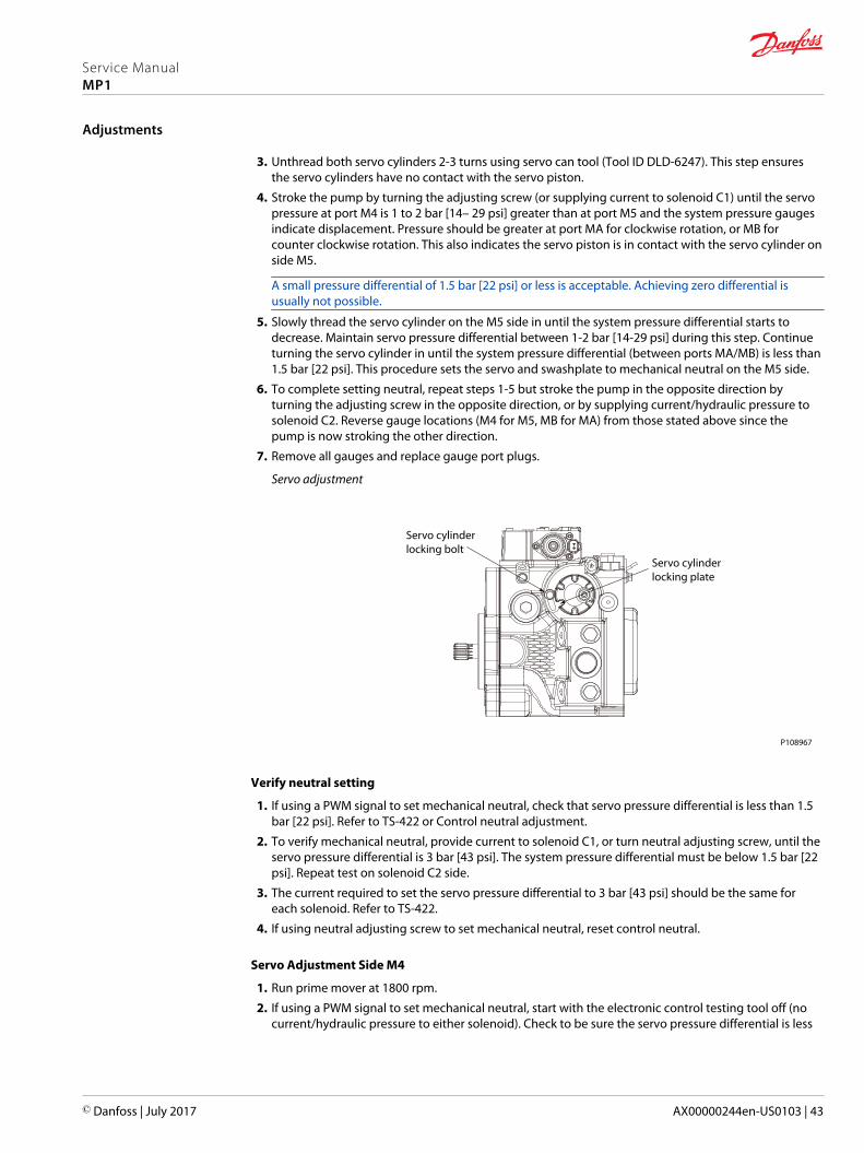
3. Unthread both servo cylinders 2-3 turns using servo can tool (Tool ID DLD-6247). This step ensuresthe servo cylinders have no contact with the servo piston.
4. Stroke the pump by turning the adjusting screw (or supplying current to solenoid C1) until the servopressure at port M4 is 1 to 2 bar [14– 29 psi] greater than at port M5 and the system pressure gaugesindicate displacement. Pressure should be greater at port MA for clockwise rotation, or MB forcounter clockwise rotation. This also indicates the servo piston is in contact with the servo cylinder onside M5.
A small pressure differential of 1.5 bar [22 psi] or less is acceptable. Achieving zero differential isusually not possible.
5. Slowly thread the servo cylinder on the M5 side in until the system pressure differential starts todecrease. Maintain servo pressure differential between 1-2 bar [14-29 psi] during this step. Continueturning the servo cylinder in until the system pressure differential (between ports MA/MB) is less than1.5 bar [22 psi]. This procedure sets the servo and swashplate to mechanical neutral on the M5 side.
6. To complete setting neutral, repeat steps 1-5 but stroke the pump in the opposite direction byturning the adjusting screw in the opposite direction, or by supplying current/hydraulic pressure tosolenoid C2. Reverse gauge locations (M4 for M5, MB for MA) from those stated above since thepump is now stroking the other direction.
7. Remove all gauges and replace gauge port plugs.
Servo adjustment
P108967
Servo cylinderlocking bolt
Servo cylinderlocking plate
Verify neutral setting
1. If using a PWM signal to set mechanical neutral, check that servo pressure differential is less than 1.5bar [22 psi]. Refer to TS-422 or Control neutral adjustment.
2. To verify mechanical neutral, provide current to solenoid C1, or turn neutral adjusting screw, until theservo pressure differential is 3 bar [43 psi]. The system pressure differential must be below 1.5 bar [22psi]. Repeat test on solenoid C2 side.
3. The current required to set the servo pressure differential to 3 bar [43 psi] should be the same foreach solenoid. Refer to TS-422.
4. If using neutral adjusting screw to set mechanical neutral, reset control neutral.
Servo Adjustment Side M4
1. Run prime mover at 1800 rpm.
2. If using a PWM signal to set mechanical neutral, start with the electronic control testing tool off (nocurrent/hydraulic pressure to either solenoid). Check to be sure the servo pressure differential is less
Service ManualMP1
Adjustments
© Danfoss | July 2017 AX00000244en-US0103 | 43

than 1.5 bar [22 psi]. Reference Danfoss testing specifications TS-422 or Control Neutral Adjustmentinstructions.
3. Turn neutral adjusting screw (or supply current/hydraulic pressure to solenoid C2) until the servopressure at port M5 is less than 1.5 bar [22 psi] greater than at port M4.
4. The system pressure differential must be greater than zero and the pressure at port A (B for clockwiserotation) must be greater than the pressure at port B (A for clockwise rotation). This step ensures theservo is in contact with the servo cylinder on side M4.
5. Slowly turn in the servo cylinder on the M4 side until the system pressure differential starts todecrease. The servo pressure differential must be less than 1.5 bar [22 psi] during this step. Continueturning in the servo cylinder until the system pressure differential is less than 1.5 bar [22 psi]. Thisprocedure sets the servo and swashplate to mechanical neutral.
Service ManualMP1
Adjustments
44 | © Danfoss | July 2017 AX00000244en-US0103
Standard Procedures, Removing the Pump
Before working on the pump, thoroughly clean the outside. If the pump has an auxiliary pump attached,remove both pumps as a single unit. Tag and cap all hydraulic lines as they are disconnected, and plug allopen ports to ensure that dirt and contamination do not get into the system.
C Caution
Contamination can damage internal components and void the manufacturer’s warranty. Takeprecautions to ensure system cleanliness when removing and installing system lines.
1. With the prime mover off, thoroughly clean all dirt and grime from the outside of the pump.
2. Tag, disconnect, and cap each hydraulic line connected to the pump. As hydraulic lines aredisconnected, plug each open port, to ensure that dirt and contamination do not get into the pump.
3. Remove the pump and its auxiliary pump (if applicable) as a single unit.
Be careful, do not damage solenoids and electrical connections when using straps or chains tosupport the pump.
4. Ensure the work surface and surrounding area are clean and free of contaminants such as dirt andgrime.
5. Inspect the system for contamination.
6. Look at the hydraulic fluid for signs of system contamination, oil discoloration, foam in the oil, sludge,or metal particles.
7. Before replacing the pump, replace all filters and drain the hydraulic system. Flush the system linesand fill the reservoir with the correct, filtered hydraulic fluid.
8. Fill the pump with clean, filtered hydraulic fluid.
9. Attach the pump to the prime mover. Torque mounting screws according to the manufacturersrecommendation.
10. Replace all hydraulic lines. Ensure the charge inlet line is filled with fluid.
EDC/HDC Control
Removal
Refer to removal illustration.
1. Using a 5 mm internal hex wrench, remove the six cap screws (D250).
2. Remove the control module and gasket (D150). Discard the gasket.
3. If necessary, remove orifices (F00A and F00B) using a 3 mm internal hex wrench. Tag and numberthem for reinstallation.
4. If necessary, remove ring (D098 - EDC only) and screen (D084). Discard the screen.
If dowel pins (D300) are removed, ensure they are replaced before reinstalling the control.
Service ManualMP1
Minor Repair
© Danfoss | July 2017 AX00000244en-US0103 | 45

P109513
D150
D250
D084
D098
D300 (2x)
F00B
F00A
D250
D150
EDC HDC
D084
Legend
Item Description Wrench size Torque
D084 Filter screen - -
D098 Retaining ring - -
D150 Control gasket - -
D300 Dowel pins - -
D250 Cap screw 5 mm internal hex 13 Nm [9.8 lbf•ft]
F00B Servo orifice 3 mm internal hex 7.9 Nm [5.8 lbf•ft]
F00A Servo orifice 3 mm internal hex 7.9 Nm [5.8 lbf•ft]
Inspection
Inspect the machined surfaces on the control and top of the pump. If you find any nicks or scratches,replace the component.
Reassembly
Ensure you install dowel pins (D300) in the housing before installing the control.
1. Install a new gasket (D150).
2. Install dowel pins (D300) in the housing.
W Warning
If the feedback pin comes off during operation, the pump will lose controllability causing apotentially hazardous situation. Insure feedback pin is properly torqued before continuing withreassembly.
Service ManualMP1
Minor Repair
46 | © Danfoss | July 2017 AX00000244en-US0103
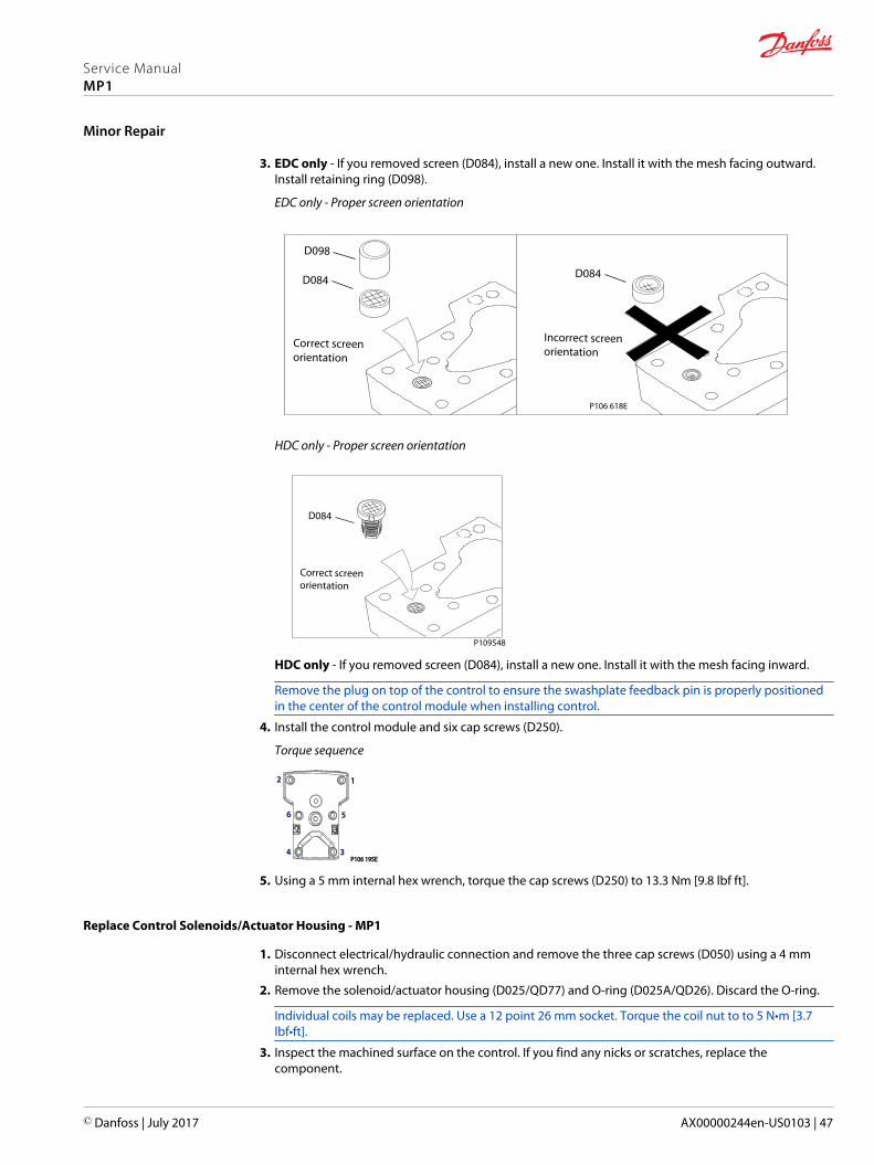
3. EDC only - If you removed screen (D084), install a new one. Install it with the mesh facing outward.Install retaining ring (D098).
EDC only - Proper screen orientation
P106 618E
D084D084
Incorrect screenorientation
Correct screenorientation
D098
HDC only - Proper screen orientation
D084
Correct screenorientation
P109548
HDC only - If you removed screen (D084), install a new one. Install it with the mesh facing inward.
Remove the plug on top of the control to ensure the swashplate feedback pin is properly positionedin the center of the control module when installing control.
4. Install the control module and six cap screws (D250).
Torque sequence
P106 195E P106 195E
2
34
56
1
5. Using a 5 mm internal hex wrench, torque the cap screws (D250) to 13.3 Nm [9.8 lbf ft].
Replace Control Solenoids/Actuator Housing - MP1
1. Disconnect electrical/hydraulic connection and remove the three cap screws (D050) using a 4 mminternal hex wrench.
2. Remove the solenoid/actuator housing (D025/QD77) and O-ring (D025A/QD26). Discard the O-ring.
Individual coils may be replaced. Use a 12 point 26 mm socket. Torque the coil nut to to 5 N•m [3.7lbf•ft].
3. Inspect the machined surface on the control. If you find any nicks or scratches, replace thecomponent.
Service ManualMP1
Minor Repair
© Danfoss | July 2017 AX00000244en-US0103 | 47

4. Lubricate new O-ring (D025A/QD26) using petroleum jelly and install.
5. Install solenoid/actuator housing with three cap screws (D050) using a 4 mm internal hex wrench.Torque screws to 5 N•m [4 lbf•ft].
6. Reconnect electrical/hydraulic connections and test the pump for proper operation.
For repair part information, see the Parts Manual for your model.
P109511
D025A
D050 (3X)
D025
D025A
D050 (3X)
D025
EDC HDC
D050
QD77
QD72
QD77
QD72
QD26
D050
QD26
Legend
Item Description Wrench size Torque
D025 Solenoid - -
D025A O-ring - -
D050 Cap screw 4 mm internal hex 5 Nm [4 lbf•ft]
QD26 O-ring - -
QD77 Actuator housing - -
QD72 Actuator pin - -
MDC Control
Removal
Refer to exploded diagram, below.
1. Using a 5 mm internal hex wrench, remove the six cap screws (D250).
2. Remove the control module and gasket (D150). Discard the gasket.
3. If necessary, remove servo orifices (F00A, F00B), supply orifice (F00P), and tank orifices (F00T) using a3 mm internal hex wrench. Tag and number them for reistallation.
4. If screen (D084) is clogged, use a hook to remove the retaining ring (D098) and the screen. Discardthe screen and replace with a new screen.
5. Before removing the control, note the position of the control lever for reassembly.
C Caution
Do not disassemble the control, otherwise the functionality of the control and the neutral position ofthe pump can be lost!
Service ManualMP1
Minor Repair
48 | © Danfoss | July 2017 AX00000244en-US0103

MDC Illustration
P108962
D250D065
QD75
D300 (2x)
D200
D150
MDC with neutral start switch
Y010
Y020
QD75
D065 D250
QD751
D084D098
F00T (2x)
F00B
F00P
F00A
MDC Legend
Wrench size and torque
Item Description Wrench size Torque
D065 O-ring plug 3/16 internal hex 12 N•m [9 lbf•ft]
D084 screen - -
D098 ring - -
D200 feedback pin 5 mm internal hex 13.3 Nm [9.8 lbf•ft]
D250 cap screw 5 mm internal hex 13.3 Nm [9.8 lbf•ft]
D80 solenoid - -
D81 Oring - -
QD75 neutral start switch - -
D751 Oring - -
QD73 plug 3/4 inch
F00A servo orifice 7/16 inch hex 7.9 Nm [5.8 lbf•ft]
F00B servo orifice 7/16 inch hex 7.9 Nm [5.8 lbf•ft]
F00P supply orifice 1/4 inch hex 14 Nm [10.8 lbf•ft]
F00T tank orifice 3 mm internal hex 2.5 Nm [1.8 lbf•ft]
Y020 cap screw 5 mm internal hex 13.3 Nm [9.8 lbf•ft]
Service ManualMP1
Minor Repair
© Danfoss | July 2017 AX00000244en-US0103 | 49
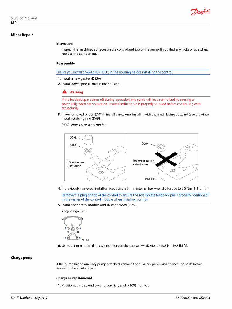
Inspection
Inspect the machined surfaces on the control and top of the pump. If you find any nicks or scratches,replace the component.
Reassembly
Ensure you install dowel pins (D300) in the housing before installing the control.
1. Install a new gasket (D150).
2. Install dowel pins (D300) in the housing.
W Warning
If the feedback pin comes off during operation, the pump will lose controllability causing apotentially hazardous situation. Insure feedback pin is properly torqued before continuing withreassembly.
3. If you removed screen (D084), install a new one. Install it with the mesh facing outward (see drawing).Install retaining ring (D098).
MDC - Proper screen orientation
P106 618E
D084D084
Incorrect screenorientation
Correct screenorientation
D098
4. If previously removed, install orifices using a 3 mm internal hex wrench. Torque to 2.5 Nm [1.8 lbf ft].
Remove the plug on top of the control to ensure the swashplate feedback pin is properly positionedin the center of the control module when installing control.
5. Install the control module and six cap screws (D250).
Torque sequence
P106 195E P106 195E
2
34
56
1
6. Using a 5 mm internal hex wrench, torque the cap screws (D250) to 13.3 Nm [9.8 lbf ft].
Charge pump
If the pump has an auxiliary pump attached, remove the auxiliary pump and connecting shaft beforeremoving the auxiliary pad.
Charge Pump Removal
1. Position pump so end cover or auxiliary pad (K100) is on top.
Service ManualMP1
Minor Repair
50 | © Danfoss | July 2017 AX00000244en-US0103
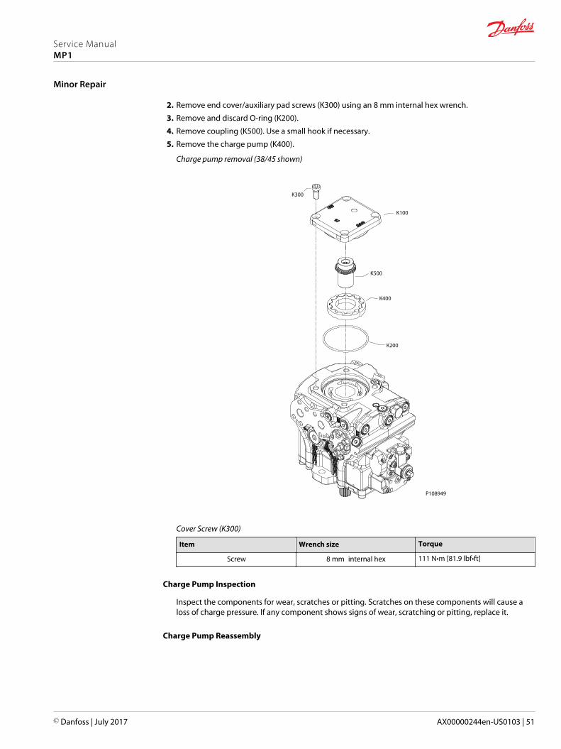
2. Remove end cover/auxiliary pad screws (K300) using an 8 mm internal hex wrench.
3. Remove and discard O-ring (K200).
4. Remove coupling (K500). Use a small hook if necessary.
5. Remove the charge pump (K400).
Charge pump removal (38/45 shown)
P108949
K100
K300
K500
K400
K200
Cover Screw (K300)
Item Wrench size Torque
Screw 8 mm internal hex 111 N•m [81.9 lbf•ft]
Charge Pump Inspection
Inspect the components for wear, scratches or pitting. Scratches on these components will cause aloss of charge pressure. If any component shows signs of wear, scratching or pitting, replace it.
Charge Pump Reassembly
Service ManualMP1
Minor Repair
© Danfoss | July 2017 AX00000244en-US0103 | 51
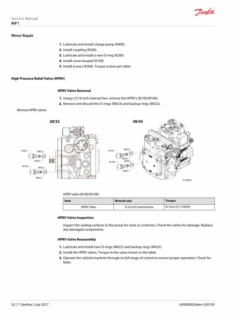
1. Lubricate and install charge pump (K400).
2. Install coupling (K500).
3. Lubricate and install a new O-ring (K200).
4. Install cover/auxpad (K100).
5. Install screws (K300). Torque screws per table.
High Pressure Relief Valve (HPRV)
HPRV Valve Removal
1. Using a 5/16 inch internal hex, remove the HPRV's (N100/M100).
2. Remove and discard the O-rings (M023) and backup rings (M022).
Remove HPRV valves
P108950
N100 M022
M023M100 M022
M023
N100 M022
M023
M100 M022
M023
38/4528/32
HPRV valve (N100/M100)
Item Wrench size Torque
HPRV Valve 5/16 inch internal hex 81 N•m [51.7 lbf•ft]
HPRV Valve Inspection
Inspect the sealing surfaces in the pump for nicks or scratches. Check the valves for damage. Replaceany damaged components.
HPRV Valve Reassembly
1. Lubricate and install new O-rings (M022) and backup rings (M023).
2. Install the HPRV valves. Torque to the value shown in the table.
3. Operate the vehicle/machine through its full range of control to ensure proper operation. Check forleaks.
Service ManualMP1
Minor Repair
52 | © Danfoss | July 2017 AX00000244en-US0103
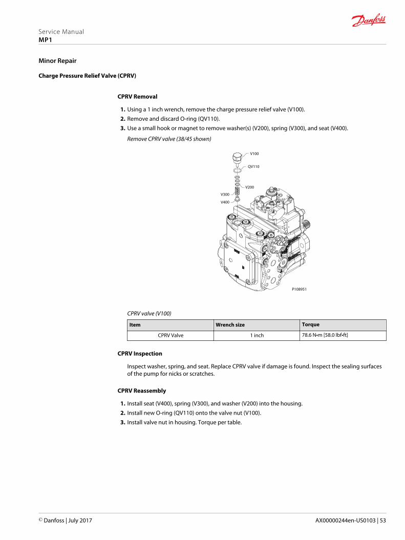
Charge Pressure Relief Valve (CPRV)
CPRV Removal
1. Using a 1 inch wrench, remove the charge pressure relief valve (V100).
2. Remove and discard O-ring (QV110).
3. Use a small hook or magnet to remove washer(s) (V200), spring (V300), and seat (V400).
Remove CPRV valve (38/45 shown)
V100
QV110
V200
V300
V400
P108951
CPRV valve (V100)
Item Wrench size Torque
CPRV Valve 1 inch 78.6 N•m [58.0 lbf•ft]
CPRV Inspection
Inspect washer, spring, and seat. Replace CPRV valve if damage is found. Inspect the sealing surfacesof the pump for nicks or scratches.
CPRV Reassembly
1. Install seat (V400), spring (V300), and washer (V200) into the housing.
2. Install new O-ring (QV110) onto the valve nut (V100).
3. Install valve nut in housing. Torque per table.
Service ManualMP1
Minor Repair
© Danfoss | July 2017 AX00000244en-US0103 | 53

Loop Flushing (28/32)
1. Using an 11/16 inch wrench, remove plug (L150).
2. Using a ¼ inch internal hex, remove plug (G115).
3. Remove and discard O-ring (9Q50A).
4. Remove loop flushing spool (L100)
5. Using a 3 mm internal hex, remove orifice (L200).
L150
L100
L200G115
P109066
9Q50A
Item Wrench size Torque
Plug (L150) 11/16 inch 45 N•m [33 lbf•ft]
Orifice (L200) 3 mm internal hex 2.5 N•m [1.8 lbf•ft]
Plug (G115) 1/4 inch 40 N•m [30 lbf•ft]
Loop Flushing Spool
Inspect loop flushing spool and spring. If damage or wear is found, replace spool and spring.
P109067
Reassembly
Service ManualMP1
Minor Repair
54 | © Danfoss | July 2017 AX00000244en-US0103
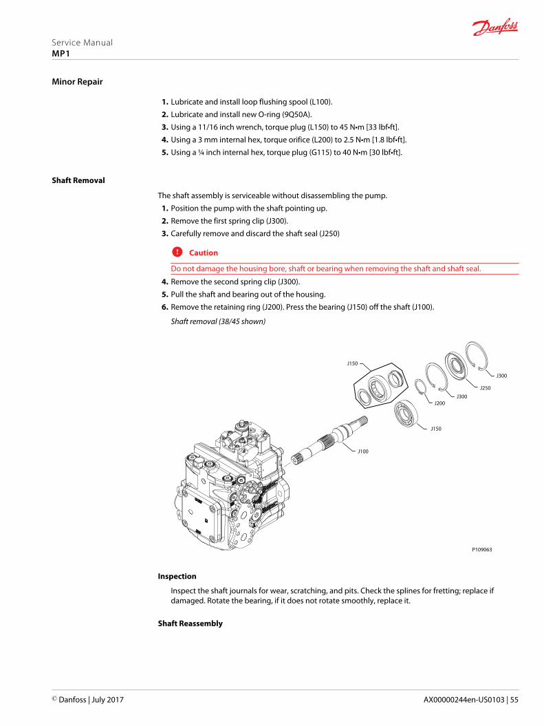
1. Lubricate and install loop flushing spool (L100).
2. Lubricate and install new O-ring (9Q50A).
3. Using a 11/16 inch wrench, torque plug (L150) to 45 N•m [33 lbf•ft].
4. Using a 3 mm internal hex, torque orifice (L200) to 2.5 N•m [1.8 lbf•ft].
5. Using a ¼ inch internal hex, torque plug (G115) to 40 N•m [30 lbf•ft].
Shaft Removal
The shaft assembly is serviceable without disassembling the pump.
1. Position the pump with the shaft pointing up.
2. Remove the first spring clip (J300).
3. Carefully remove and discard the shaft seal (J250)
C Caution
Do not damage the housing bore, shaft or bearing when removing the shaft and shaft seal.
4. Remove the second spring clip (J300).
5. Pull the shaft and bearing out of the housing.
6. Remove the retaining ring (J200). Press the bearing (J150) off the shaft (J100).
Shaft removal (38/45 shown)
P109063
J200J300
J300
J150
J100
J150
J250
Inspection
Inspect the shaft journals for wear, scratching, and pits. Check the splines for fretting; replace ifdamaged. Rotate the bearing, if it does not rotate smoothly, replace it.
Shaft Reassembly
Service ManualMP1
Minor Repair
© Danfoss | July 2017 AX00000244en-US0103 | 55
1. Press the bearing (J150) onto the shaft (J100) and replace the retaining ring (J200).
2. Install the shaft/bearing assembly into the pump.
3. Install first spring clip (J300).
4. Cover the shaft with a protective sleeve while installing the seal. Lubricate and install the seal.
5. Install the second spring clip (J300).
Service ManualMP1
Minor Repair
56 | © Danfoss | July 2017 AX00000244en-US0103

P108953G060
G020G025G065
G070G075
G010
G030
G040
G035
K300
D250
G045
G015
E085 E090
N100
M100
V100
H130H130
H130
G060
G010
G020G015G025
G070 G075
G010
G035
G030
G040
G065
38/45
28/32
G774G774
G774 G774
Service ManualMP1
Fastener Size and Torque Chart
© Danfoss | July 2017 AX00000244en-US0103 | 57
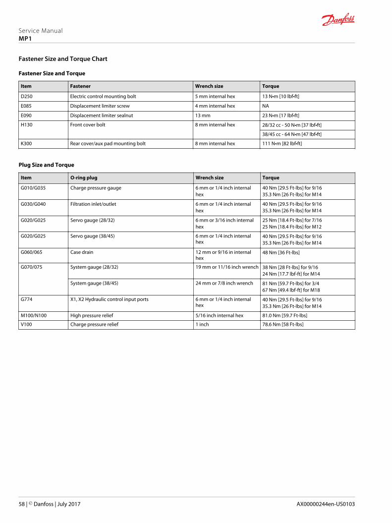
Fastener Size and Torque
Item Fastener Wrench size Torque
D250 Electric control mounting bolt 5 mm internal hex 13 N•m [10 lbf•ft]
E085 Displacement limiter screw 4 mm internal hex NA
E090 Displacement limiter sealnut 13 mm 23 N•m [17 lbf•ft]
H130 Front cover bolt 8 mm internal hex 28/32 cc - 50 N•m [37 lbf•ft]
38/45 cc - 64 N•m [47 lbf•ft]
K300 Rear cover/aux pad mounting bolt 8 mm internal hex 111 N•m [82 lbf•ft]
Plug Size and Torque
Item O-ring plug Wrench size Torque
G010/G035 Charge pressure gauge 6 mm or 1/4 inch internalhex
40 Nm [29.5 Ft-lbs] for 9/1635.3 Nm [26 Ft-lbs] for M14
G030/G040 Filtration inlet/outlet 6 mm or 1/4 inch internalhex
40 Nm [29.5 Ft-lbs] for 9/1635.3 Nm [26 Ft-lbs] for M14
G020/G025 Servo gauge (28/32) 6 mm or 3/16 inch internalhex
25 Nm [18.4 Ft-lbs] for 7/1625 Nm [18.4 Ft-lbs] for M12
G020/G025 Servo gauge (38/45) 6 mm or 1/4 inch internalhex
40 Nm [29.5 Ft-lbs] for 9/1635.3 Nm [26 Ft-lbs] for M14
G060/065 Case drain 12 mm or 9/16 in internalhex
48 Nm [36 Ft-lbs]
G070/075 System gauge (28/32) 19 mm or 11/16 inch wrench 38 Nm [28 Ft-lbs] for 9/1624 Nm [17.7 lbf-ft] for M14
System gauge (38/45) 24 mm or 7/8 inch wrench 81 Nm [59.7 Ft-lbs] for 3/467 Nm [49.4 lbf-ft] for M18
G774 X1, X2 Hydraulic control input ports 6 mm or 1/4 inch internalhex
40 Nm [29.5 Ft-lbs] for 9/1635.3 Nm [26 Ft-lbs] for M14
M100/N100 High pressure relief 5/16 inch internal hex 81.0 Nm [59.7 Ft-lbs]
V100 Charge pressure relief 1 inch 78.6 Nm [58 Ft-lbs]
Service ManualMP1
Fastener Size and Torque Chart
58 | © Danfoss | July 2017 AX00000244en-US0103

Service ManualMP1
© Danfoss | July 2017 AX00000244en-US0103 | 59

Service ManualMP1
60 | © Danfoss | July 2017 AX00000244en-US0103

Service ManualMP1
© Danfoss | July 2017 AX00000244en-US0103 | 61

Danfoss Power Solutions is a global manufacturer and supplier of high-quality hydraulic andelectronic components. We specialize in providing state-of-the-art technology and solutionsthat excel in the harsh operating conditions of the mobile off-highway market. Building onour extensive applications expertise, we work closely with our customers to ensureexceptional performance for a broad range of off-highway vehicles.
We help OEMs around the world speed up system development, reduce costs and bringvehicles to market faster.
Danfoss – Your Strongest Partner in Mobile Hydraulics.
Go to www.powersolutions.danfoss.com for further product information.
Wherever off-highway vehicles are at work, so is Danfoss. We offer expert worldwide supportfor our customers, ensuring the best possible solutions for outstanding performance. Andwith an extensive network of Global Service Partners, we also provide comprehensive globalservice for all of our components.
Please contact the Danfoss Power Solution representative nearest you.
Local address:
Danfoss Power Solutions GmbH & Co. OHGKrokamp 35D-24539 Neumünster, GermanyPhone: +49 4321 871 0
Danfoss Power Solutions ApSNordborgvej 81DK-6430 Nordborg, DenmarkPhone: +45 7488 2222
Danfoss Power Solutions (US) Company2800 East 13th StreetAmes, IA 50010, USAPhone: +1 515 239 6000
Danfoss Power Solutions Trading(Shanghai) Co., Ltd.Building #22, No. 1000 Jin Hai RdJin Qiao, Pudong New DistrictShanghai, China 201206Phone: +86 21 3418 5200
Danfoss can accept no responsibility for possible errors in catalogues, brochures and other printed material. Danfoss reserves the right to alter its products without notice. This also applies to productsalready on order provided that such alterations can be made without changes being necessary in specifications already agreed.All trademarks in this material are property of the respective companies. Danfoss and the Danfoss logotype are trademarks of Danfoss A/S. All rights reserved.
© Danfoss | July 2017 AX00000244en-US0103
Products we offer:
• Bent Axis Motors
• Closed Circuit Axial PistonPumps and Motors
• Displays
• Electrohydraulic PowerSteering
• Electrohydraulics
• Hydraulic Power Steering
• Integrated Systems
• Joysticks and ControlHandles
• Microcontrollers andSoftware
• Open Circuit Axial PistonPumps
• Orbital Motors
• PLUS+1® GUIDE
• Proportional Valves
• Sensors
• Steering
• Transit Mixer Drives
Comatrolwww.comatrol.com
Turolla www.turollaocg.com
Hydro-Gearwww.hydro-gear.com
Daikin-Sauer-Danfosswww.daikin-sauer-danfoss.com
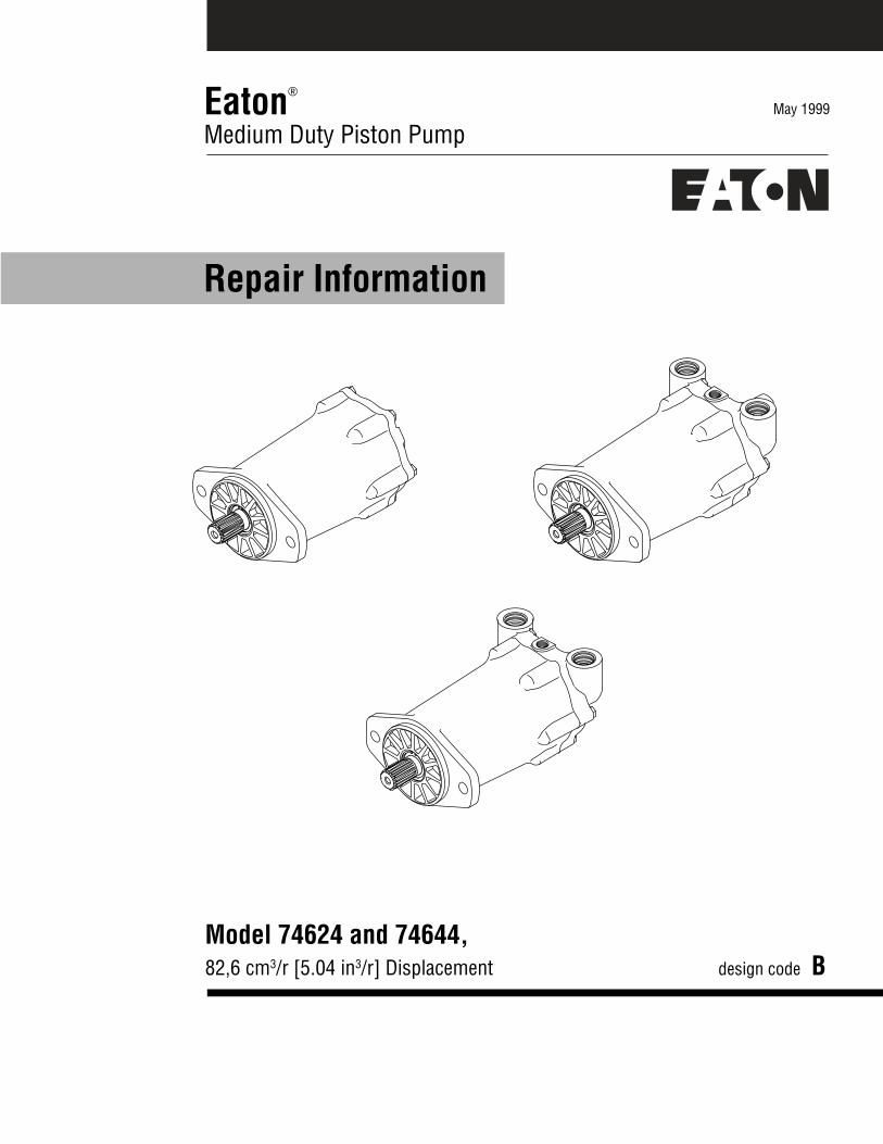
May 1999Eaton®
Medium Duty Piston Pump
Repair Information
Model 74624 and 74644,82,6 cm3/r [5.04 in3/r] Displacement design code B
2
Model 74624 and 74644
Introduction
Table of ContentsIntroduction ....................................................................................................... 2Identification ...................................................................................................... 3Required Tools .................................................................................................. 3Disassembly and Inspection .............................................................................. 4Reassembly ....................................................................................................... 5Main Parts Description ...................................................................................... 6Item numbers 1, 2, & 3 Descriptions ................................................................. 774624 Exploded View Drawing .......................................................................... 8Specific Parts List for 74624 model................................................................... 974644 Exploded View Drawing .......................................................................... 10Specific Parts List for 74644 model................................................................... 11Trouble Shooting ............................................................................................... 12
IntroductionThis manual provides service information for the Eaton Models 74624 and 74644 fixed displacement motor.Step by step instructions for the complete disassembly, inspection, and reassembly of the motor are given.The following recommendations should be followed to insure successful repairs.
Remove the motor from the application.
Cleanliness is extremely important.
Clean the port areas thoroughly before disconnecting the hydraulic lines.
Plug the motor ports and cover the open hydraulic lines immediately after they're disconnected.
Drain the oil and clean the exterior of the motor before making repairs.
Wash all metal parts in clean solvent.
Use compressed air to dry the parts. Do not wipe them dry with paper towels or cloth.
The compressed air should be filtered and moisture free.
Always use new seals when reassembling hydraulic motor.
For replacement parts and ordering information refer to parts list 06-161.
Lubricate the new rubber seals with a petroleum jelly (vaseline) before installation.
Torque all bolts over gasket joints, then repeat the torquing sequence to makeup for gasketcompression.
Verifying the accuracy of motor repairs on an authorized test stand is essential.

3
Model 74624 and 74644
Identification andTools RequiredIdentification Numbers
Stamped on each unit.
A - Product Number Description74624 = Fixed Motor 82,6 cm3/r [5.04 in3/r]
74644 = Fixed Motor thru Shaft for Brake Mount 82,6 cm3/r [5.04 in3/r]
B - Rotation,D = Dual
C - Sequential LettersD - Design Code Number
A B C D
Single Motor - Product Number
7 4 6 2 4 - D A H - 0 1
Testers Initials
Day of Month(two digits)
Month (two digits)
Serial Number Code:
B 93 01 31 JBRevision level
of parts list.
Last two digitsof year built.
( 93 for 1993 etc.)
Required Tools
1/2 in. Socket, w/ Ratchet WrenchExternal Retaining Ring Pliers (straight .090 tip)Internal Retaining Ring Pliers (straight .090 tip)O-ring PickTorque Wrench (54 N.m [40 lbf.ft] capacity)Hammer (soft face)Light Petroleum JellySeal Driver
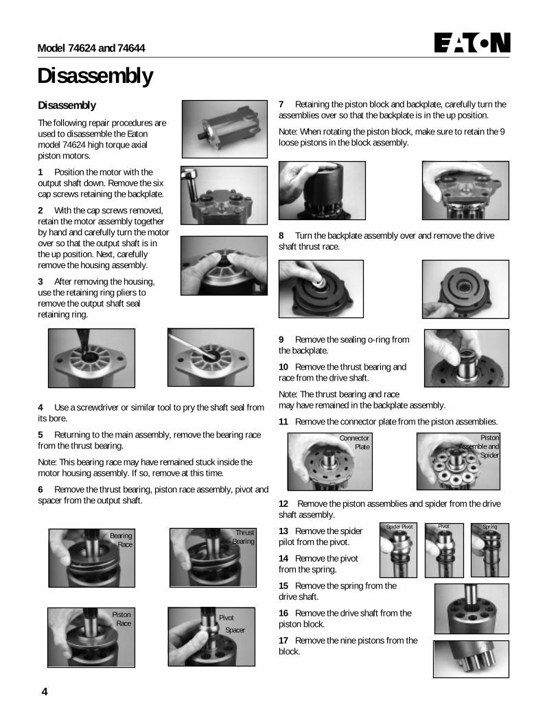
4
Model 74624 and 74644
DisassemblyDisassembly
The following repair procedures areused to disassemble the Eatonmodel 74624 high torque axialpiston motors.
1 Position the motor with theoutput shaft down. Remove the sixcap screws retaining the backplate.
2 With the cap screws removed,retain the motor assembly togetherby hand and carefully turn the motorover so that the output shaft is inthe up position. Next, carefullyremove the housing assembly.
3 After removing the housing,use the retaining ring pliers toremove the output shaft sealretaining ring.
4 Use a screwdriver or similar tool to pry the shaft seal fromits bore.
5 Returning to the main assembly, remove the bearing racefrom the thrust bearing.
Note: This bearing race may have remained stuck inside themotor housing assembly. If so, remove at this time.
6 Remove the thrust bearing, piston race assembly, pivot andspacer from the output shaft.
7 Retaining the piston block and backplate, carefully turn theassemblies over so that the backplate is in the up position.
Note: When rotating the piston block, make sure to retain the 9loose pistons in the block assembly.
8 Turn the backplate assembly over and remove the driveshaft thrust race.
9 Remove the sealing o-ring fromthe backplate.
10 Remove the thrust bearing andrace from the drive shaft.
Note: The thrust bearing and racemay have remained in the backplate assembly.
11 Remove the connector plate from the piston assemblies.
12 Remove the piston assemblies and spider from the driveshaft assembly.
13 Remove the spiderpilot from the pivot.
14 Remove the pivotfrom the spring.
15 Remove the spring from thedrive shaft.
16 Remove the drive shaft from thepiston block.
17 Remove the nine pistons from theblock.
BearingRace
ThrustBearing
PistonRace
Pivot
Spacer
ConnectorPlate
Spider Pivot Pivot Spring
PistonAssemble and
Spider

5
Model 74624 and 74644
9 Place the spring over the drive shaft and pivot onto thespring.
10 Lubricate and place spider pilot onto pivot.
11 Lubricate and install the spiderand the piston assemblies into pistonblock and onto pivot.
12 The connectorplate is flat on oneside. The flat side isshown.
13 Lubricate and place theconnector plate onto the pistonassemblies. The flat side ispositioned against piston assemblies.
14 Install bearing race, thrustbearing and second bearing raceonto shaft.
15 Lubricate and place thrust raceand/or races in backplate assembly.
16 Position new o-ring ontobackplate.
17 Align the holes of the backplateto the housing. Install cap screwsand torque 20,3-24,4 N·m [15 to 18lbf·ft].
18 Protecting the new shaft seal, install theseal over the output shaft and into the motorhousing slightly below the counterbore face.Position the retaining ring on top of the seal.
19 Using a seal driver or similartool, press the retaining ring andshaft seal into motor housing.
20 The unit is ready to test andreinstall.
Reassembly
Before reassembly the Eaton Model 74624 high torque axialpiston motor inspect all parts and replace if needed. New sealsshould be lubricated with petroleum jelly to assure properinstallation.
Lubricate all finished part surfacesfreely with clean hydraulic fluid toprovide start-up lubrication betweenthe rotating parts.
1 Looking at the piston block oneend has a beveled edge around theshaft bore as shown.
2 Install the drive shaft into thepiston block at the beveled edge end.Note that the retaining ring on thedrive shaft must be on the beveledside of the piston block.
3 Using the backplate as a meansof support, place the drive shaft andpiston block on the backplate withthe spline end of the drive shaft inthe up position.
4 Install the spacer and pivot onthe drive shaft.
5 Place the piston race assemblyover the drive shaft and onto pivot.
6 Place thrust bearing and raceonto piston race assembly.
7 Install the motor housingassembly over the drive shaft.
8 Carefully retaining theassemblies together, turn the motorhousing over and support it in thedrive shaft down position. Removethe backplate assembly. Install thenine pistons into the piston block.Insert the beveled end of the pistonsinto block and against the piston raceassembly. Caution: Do not installmore than one piston in the samebore.
Reassembly
Pivot
Spacer
Piston RaceAssemble
ThrustBearing &
Race
PivotSpring Spider Pilot

6
Model 74624 and 74644
Main Parts DescriptionItem Qty. Description1 1 Drive Shaft (See descriptions page 7)2 1 Backplate Assembly (See descriptions page 7)3 1 Housing Assembly (See descriptions page 7)4 1 Rotating Kit Assembly - Refer to specific parts list
+~ 5 1 Retaining Ring+~ 6 1 O-ring, 2,37 mm Dia. x 114,3 mm ID. [.0937 in. Dia. x 4.5 in. ID.]
7 1 Thrust Bearing8 2 Pivot9 1 Spider10 1 Key11 9 Piston12 9 Piston Assembly13 1 Connector Plate14 1 Spacer
+~ 15 1 Shaft Seal16 1 Bearing Race17 1 Piston Race S/A18 1 Spring - Refer to specific parts list18a 1 Spring - Refer to specific parts list18b 1 Spring - Refer to specific parts list19 1 Pilot - Refer to specific parts list19a 1 Pilot - Refer to specific parts list20 1 Thrust Bearing21 1 Bearing Race22 6 Cap Screws, 5/16-18, 25,4 mm [1 in.] Long - Refer to specific parts list22a 4 Cap Screws, 5/16-18, 38,1 mm [1.5 in.] Long - Refer to specific parts list
+~ 23 1 Retaining Ring24 A/R Trust Race25 1 Key - 74624-204, 74644-210 & 74644-215
~ 26 2 Retaining Ring27 1 Thrust Bearing28 2 Bearing Race
~ 29 1 Shaft Seal~ 30 1 Washer~ 31 1 Retaining Ring
32 2 Cap Screws, 5/16-18, 50,8 mm [2 in.] Long+~ 33 1 Retaining Ring
34 1 Key - Used with Shaft 74644-214 - Refer to specific parts list34a 1 Key - Used with Shaft 74644-209 & 74644-210 - Refer to specific parts list35 1 Plug S/A35-1 1 O-ring, 1,98 mm Dia. x 11,89 mm ID. [.078 in. Dia. x .468 in. ID.]36 A/R Washer37 A/R Washer38 1 Spring Collar
Seal Repair Kit+ 74640-904 Seal Repair Kit for 74624 rear or same side ported motor.~ 74640-910 Seal Repair Kit for 74644 Through shaft motor.

7
Model 74624 and 74644
Drive Shaft S/A - Item #1Item # Description1a 15 Tooth 16/32 Spline with Snap Ring
Groove with Snap Ring, .375-16 UNC-2BThread, 18.3 [.72] Min Full Thread, Shaft Ext39.6 [1.56]
1b 15 Tooth 16/32 Spline with Snap RingGroove, Shaft Ext 46 [1.81]
1c Taper 1:8, Dia 25.4 [1.00], Woodruff KeywayDia 25.4 [1.00] X 6.35 [.250], .625-18 UNC-2A Thread, Shaft Ext 69 [2.72]
1d 13 Tooth 16/32 Spline, Shaft Ext 41.1[1.62]1e Straight Shaft , Dia. 25,4 [1.00], Keyway 6,35
x 38,1 [.250 x 1.50], Shaft Ext. 63,5 [2.50]1f 15 Tooth 16/32 Spline Tapered 1:8 with .375-
16 UNC-2B Thread, 18.3 [.72] Min FullThread, Shaft Ext 46 [1.81]
Through Shaft (74644)Item # Description1g Front - 15 Tooth 16/32 Spline with Snap
Ring Groove with Snap Ring, .375-16UNC-2B Thread, 18.3 [.72] Min FullThread, Shaft Ext 39.6 [1.56]Rear - 15 Tooth 16/32 Spline, ShaftLength from Mounting Flange 258.6[10.18]
1h Front - 15 Tooth 16/32 Spline Tapered1:8 with .375-16 UNC-2B Thread, 18.3[.72] Min Full Thread, Shaft Ext 46 [1.81]Rear - Straight Shaft Dia 25.4 [1.00],Keyway 6.3 X 25.4 [.250 X 1.00], ShaftLength from Mounting Flange 274.3[10.80]
1i Front - Straight Shaft , Dia. 25,4 [1.00],Keyway 6,35 x 38,1 [.250 x 1.50], ShaftExt. 63,5 [2.50] (Key Included)Rear - Straight Shaft Dia 25.4 [1.00],Keyway 6.3 X 25.4 [.250 X 1.00], ShaftLength From Mounting Flange 274.3[10.80]
1j Front - 15 Tooth 16/32 Spline Tapered1:8 with .375-16 UNC-2B Thread, 18.3[.72] Min Full Thread, Shaft Ext 46 [1.81]Rear - 15 Tooth 16/32 Spline, with .375-16 UNC-2B Thread, 18.3 [.72] Min FullThread, Shaft Length from MountingFlange 274.3 [10.80]
1k Front - 15 Tooth 16/32 Spline, Shaft Ext46 [1.81]Rear - Straight Shaft Dia 22.22 [.875],Keyway 6.35 X 26.9 [.250 X 1.06], ShaftLength From Mounting Flange 271.5
[10.69] (Short Key Included)1l Front - Taper .125:1 Dia 22.22 [.875],
Woodruff Keyway Dia 15.75 [.620] X3.96 [.156], .500-20 UNF-2A Thread,Shaft Ext 57.9 [2.28]Rear - Straight Shaft Dia 25.4 [1.00],Keyway 6.35 X 38.4 [.250 X 1.51], ShaftLength from Mounting Flange 292.1[11.50]
1m Front - Taper .125:1 Dia 22.22 [.875],Woodruff Keyway Dia 15.75 [.620] X3.96 [.156], .500-20 UNF-2A Thread,Shaft Ext 57.9 [2.28]Rear - Straight Shaft Dia 25.4 [1.00],Shaft Length from Mounting Flange 254[10.00], Shaft End Hole Internal 6.40[.252] X 14 [.55] Deep
Backplate S/A - Item #2Item # Description2a Rear porting, through drain into mounting
flange.2b Rear porting, drain port horizontal top rear of
unit.2c Same side porting, drain port vertical top rear
of unit, two mounting holes bottom rear.2d Same side porting, drain port vertical top rear
of unit.
Housing for Through Shaft (74644)Item # Description2e Same side porting, drain port vertical top rear
of unit.
Housing S/A - Item #3Item # Description3a Through drain into mounting flange3b No drain in housing3c Special housing used with item 18 #17141-10
and item 19 #74600-620. Also has slotted 2bolt B flange.

8
Model 74624
Parts Drawing
2315
3-1
167
17
11
4
2
32
3222
22
2222
6
13
12
9
198
1836
3738
5
1
33
25
10
2-121
24
2120
814
3
2
22
2222
22
2222
6

9
Model 74624
Specific Parts List42647srebmuNtcudorP
AAD- BAD- DAD- EAD- GAD- HAD- JAD- LAD- MAD- NAD- PAD- RAD- SAD-
metIs'# s'# s'# s'# s'#
1 a1 b1 c1 d1 d1 e1 a1 e1 f1 f1 b1 b1 f1
2 a2 b2 b2 b2 b2 b2 b2 c2 c2 d2 b2 b2 d2
3 a3 b3 b3 c3 b3 b3 b3 b3 b3 b3 b3 b3 b3
4 4 4 4 4 4 4 4 4 4 4 4 a4 4
5 X X X X X X X X X X X X X
6 X X X X X X X X X X X X X
7 X X X X X X X X X X X X X
8 X X X X X X X X X X X X X
9 X X X X X X X X X X X X X
01 X X X X X X X X X X X X X
11 X X X X X X X X X X X X X
21 X X X X X X X X X X X X X
31 X X X X X X X X X X X X X
41 X X X X X X X X X X X X X
51 X X X X X X X X X X X X
61 X X X X X X X X X X X X X
71 X X X X X X X X X X X X X
81 81 b81 b81 a81 b81 b81 b81 b81 81 81 b81 b81
91 91 91 91 a91 91 91 91 91 a91 a91 91 91
02 X X X X X X X X X X X X X
12 X X X X X X X X X X X X X
22 22 22 22 22 22 22 22 a22 a22 a22 22 22 a22
32 X X X X X X X X X X X X
42 X X X X X X X X X X X X
52 X X
23 X X X X
33 X X
63 X X
73 X X
83 X X X
tiKriapeRlaeS04627 409- 409- 409- 409- 409- 409- 409- 409- 409- 409- 409- 409- 409-

10
Model 74644
Parts Drawing - Through Shaft
2315
3-1
16
7
17
11
4
2
32
3222
3535-1
22
22
22
6
13
12
9
2628
2728
2630
2931
19
8
1836
3738
5
1
34
10
2-1
814
3
33
25

11
Model 74644
44647srebmuNtcudorP
EAD- GAD- JAD- KAD- MAD- NAD- PAD- RAD- SAD-
metIs'# s'# s'# s'# s'#
1 g1 h1 i1 j1 k1 l1 m1 j1 j1
2 e2 e2 e2 e2 e2 e2 e2 e2 e2
3 b3 a3 b3 a3 b3 b3 b3 a3 b3
4 4 4 4 4 4 4 4 4 4
5 X X X X X X X X X
6 X X X X X X X X X
7 X X X X X X X X X
8 X X X X X X X X X
9 X X X X X X X X X
01 X X X X X X X X X
11 X X X X X X X X X
21 X X X X X X X X X
31 X X X X X X X X X
41 X X X X X X X X X
51 X X X X X X
61 X X X X X X X X X
71 X X X X X X X X X
81 81 81 81 81 81 81 81 81 81
91 91 a91 91 a91 a91 91 91 a91 a91
22 a22 a22 a22 a22 a22 a22 a22 a22 a22
32 X X X X X
52 X
62 X X X X X X X X X
72 X X X X X X X X X
82 X X X X X X X X X
92 X X X X X X X X X
03 X X X X X X X X X
13 X X X X X X X X X
23 X X X X X X X X X
33 X
43 43 43 a43
53 X X X
63 X X X X
73 X X X X
83 X X X X X X X X X
tiKriapeRlaeS04647 019- 019- 019- 019- 019- 019- 019- 019- 019-
Specific Parts List

Trouble ShootingIn trouble shooting a pump and motor system it is necessary to isolate the pump from the motor to determine which unit isactually malfunctioning. A worn pump or worn motor will give the same system indication. Therefore, it is advisable to first run apressure and flow check on the pump to make sure it is performing within its operating specifications. The following troubleshooting suggestions are based on the assumption that the pump’s flow and pressure settings meet operating specifications.
Possible Trouble
1. Motor turns while unloaded butslows down or stops whenload is applied.
2. Motor will not turn.
3. Motor free wheels.
4. Rapid tapping noise in motor.
5. Excessive case drain flow.
Causes
A. Scored back plate.
B. Scored connector plate.
C. Scored or worn piston shoes.
D. Low relief valve pressure.
A. Severely scored back plateand connector plate.
B. Contaminate particle holdingconnector off back plate.
A. Oil flow and pressure shut offgoing to motor.
A. Free floating pistons seatingon bearing race.
A. Excessive internal wear in.
Remedies
A. Remove backplate and examine surface condition of flat area, ifscored, replace back plate. Do not lap.
B. Disassemble motor, check finish on connector plate and backplate, replace of necessary.
C. Disassemble motor, examine condition of shoes on pistons,replace pistons as a complete set.
D. Check relief valve for proper pressure setting, adjust or replacerelief valve.
A. Disassemble motor completely. Inspect all parts, clean all parts,replace all worn parts and flush hydraulic system.
B. Disassembly motor, inspect and clean parts, replace necessaryparts.
A. When the hydraulic system is shut off, either by shutting off theengine on a closed loop system or returning the control valvespool to neutral on an open center system, the motor will freewheel after it has leaked off and allows the free floating pistons tocollapse. This is inherent in the design. On a closed loop orpropulsion system, the motor will not free wheel as long ascharge pressure is maintained to and from the motor.
A. When oil flow to the motor is shut off and the motor allowed tofree wheel, the free floating pistons will collapse into the pistonblock. When oil flow is reapplied to the motor the pistons will re-seat themselves against the bearing race and will cause a rapidtapping sound. This is not harmful to the motor as long as the oilflow into the motor does not exceed 10 GPM for the firstrevolution of the motor.
A. Disassemble motor, inspect parts and replace as necessary. Casedrain flow should not exceed 1.5 GPM at full pressure.

© 2008 Eaton CorporationAll Rights ReservedPrinted in USADocument No. E-MOPI-TS008-ESupersedes 07-134November 2008
EatonFluid Power GroupHydraulics Business USA14615 Lone Oak RoadEden Prairie, MN 55344USATel: 952-937-9800Fax: 952-294-7722www.eaton.com/hydraulics
EatonFluid Power GroupHydraulics Business EuropeRoute de la Longeraie 71110 MorgesSwitzerlandTel: +41 (0) 21 811 4600Fax: +41 (0) 21 811 4601
EatonFluid Power GroupHydraulics Business Asia Pacific 11th Floor Hong Kong New World Tower 300 Huaihai Zhong Road Shanghai 200021 China Tel: 86-21-6387-9988 Fax: 86-21-6335-3912

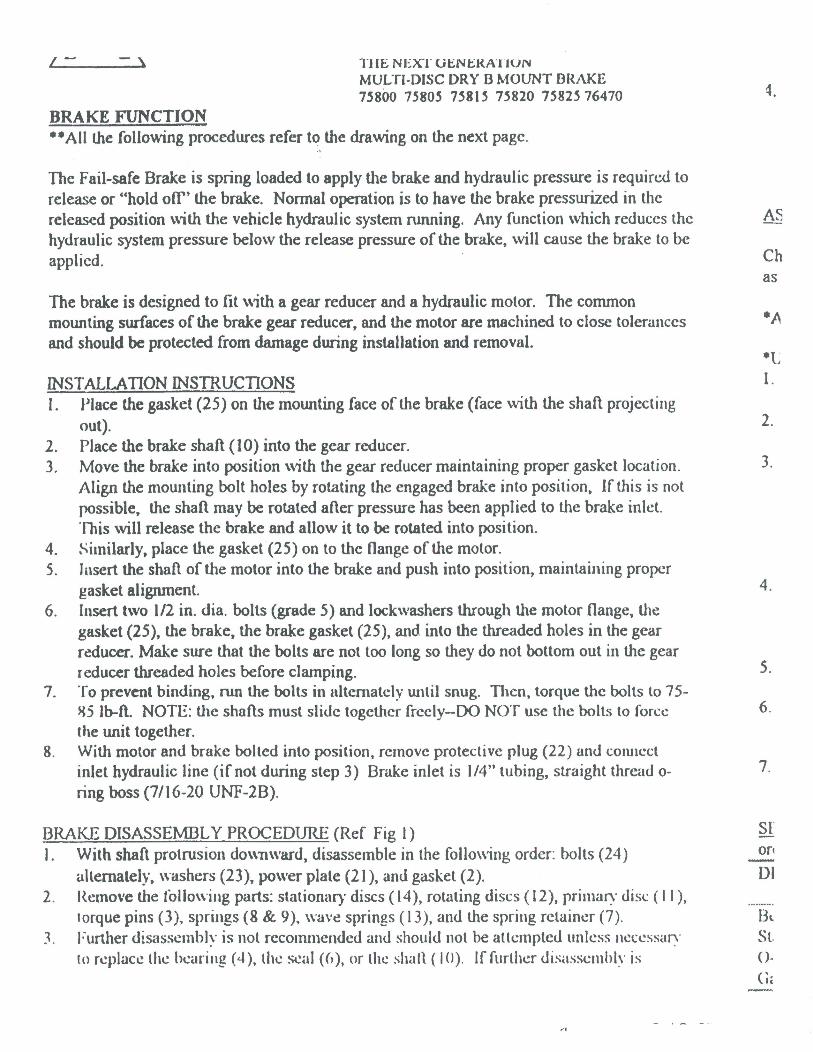

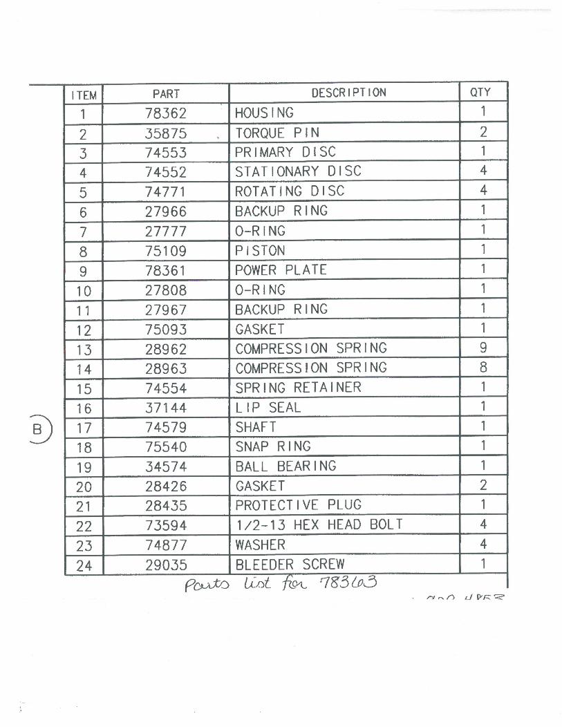

300
A T E XINCLUDED
MOBILE EQUIPMENT
AND WIND ENERGY SOLUTIONS
INDUSTRY PROCESS
AND AUTOMATION SOLUTIONS
Installation, use and service manual


1
USE, INSTALLATION AND MAINTENANCE MANUAL
1.0 - GENERAL INFORMATION 2
1.1 - PURPOSE OF THE MANUAL . . . . . . . . . . . . . . . . . . . . . . . . . . . . . . . . . . . . . . . . . . . . . . . . . . . . . . . . . . . . . . . . . . . . . . . . . . . . . . . . . . . . . . . . . . . . . . . . . . . . . . . . . . . . . . . . . . .2
1.2 - PRODUCT IDENTIFICATION. . . . . . . . . . . . . . . . . . . . . . . . . . . . . . . . . . . . . . . . . . . . . . . . . . . . . . . . . . . . . . . . . . . . . . . . . . . . . . . . . . . . . . . . . . . . . . . . . . . . . . . . . . . . . . . . . . . .3
1.3 - GLOSSARY AND TERMINOLOGY . . . . . . . . . . . . . . . . . . . . . . . . . . . . . . . . . . . . . . . . . . . . . . . . . . . . . . . . . . . . . . . . . . . . . . . . . . . . . . . . . . . . . . . . . . . . . . . . . . . . . . . . . . . .4
1.4 - REQUESTING TECHNICAL ASSISTANCE . . . . . . . . . . . . . . . . . . . . . . . . . . . . . . . . . . . . . . . . . . . . . . . . . . . . . . . . . . . . . . . . . . . . . . . . . . . . . . . . . . . . . . . . . . . . . . . . .4
1.5 - MANUFACTURER’S LIABILITY. . . . . . . . . . . . . . . . . . . . . . . . . . . . . . . . . . . . . . . . . . . . . . . . . . . . . . . . . . . . . . . . . . . . . . . . . . . . . . . . . . . . . . . . . . . . . . . . . . . . . . . . . . . . . . . . .4
1.6 - CONSIGNMENT CONDITIONS . . . . . . . . . . . . . . . . . . . . . . . . . . . . . . . . . . . . . . . . . . . . . . . . . . . . . . . . . . . . . . . . . . . . . . . . . . . . . . . . . . . . . . . . . . . . . . . . . . . . . . . . . . . . . . . . .4
2.0 - TECHNICAL INFORMATION 5
2.1 - DESCRIPTION OF THE GEAR UNIT . . . . . . . . . . . . . . . . . . . . . . . . . . . . . . . . . . . . . . . . . . . . . . . . . . . . . . . . . . . . . . . . . . . . . . . . . . . . . . . . . . . . . . . . . . . . . . . . . . . . . . . . .5
2.2 - CONFORMITY . . . . . . . . . . . . . . . . . . . . . . . . . . . . . . . . . . . . . . . . . . . . . . . . . . . . . . . . . . . . . . . . . . . . . . . . . . . . . . . . . . . . . . . . . . . . . . . . . . . . . . . . . . . . . . . . . . . . . . . . . . . . . . . . . . . . . . .5
2.3 - OPERATING LIMITS AND CONDITIONS . . . . . . . . . . . . . . . . . . . . . . . . . . . . . . . . . . . . . . . . . . . . . . . . . . . . . . . . . . . . . . . . . . . . . . . . . . . . . . . . . . . . . . . . . . . . . . . . . . . .5
3.0 - SAFETY INFORMATION 6
3.1 - SAFETY STANDARDS . . . . . . . . . . . . . . . . . . . . . . . . . . . . . . . . . . . . . . . . . . . . . . . . . . . . . . . . . . . . . . . . . . . . . . . . . . . . . . . . . . . . . . . . . . . . . . . . . . . . . . . . . . . . . . . . . . . . . . . . . . . .6
4.0 - HANDLING AND TRANSPORT 7
4.1 - PACKAGING . . . . . . . . . . . . . . . . . . . . . . . . . . . . . . . . . . . . . . . . . . . . . . . . . . . . . . . . . . . . . . . . . . . . . . . . . . . . . . . . . . . . . . . . . . . . . . . . . . . . . . . . . . . . . . . . . . . . . . . . . . . . . . . . . . . . . . . . . .7
4.2 - HANDLING INSTRUCTIONS . . . . . . . . . . . . . . . . . . . . . . . . . . . . . . . . . . . . . . . . . . . . . . . . . . . . . . . . . . . . . . . . . . . . . . . . . . . . . . . . . . . . . . . . . . . . . . . . . . . . . . . . . . . . . . . . . . . .7
4.2.1 - Moving the packages . . . . . . . . . . . . . . . . . . . . . . . . . . . . . . . . . . . . . . . . . . . . . . . . . . . . . . . . . . . . . . . . . . . . . . . . . . . . . . . . . . . . . . . . . . . . . . . . . . . . . . . . . . . . . . . . . . . . .8
4.2.2 - Moving the equipment . . . . . . . . . . . . . . . . . . . . . . . . . . . . . . . . . . . . . . . . . . . . . . . . . . . . . . . . . . . . . . . . . . . . . . . . . . . . . . . . . . . . . . . . . . . . . . . . . . . . . . . . . . . . . . . . . . . .8
4.3 - STORAGE . . . . . . . . . . . . . . . . . . . . . . . . . . . . . . . . . . . . . . . . . . . . . . . . . . . . . . . . . . . . . . . . . . . . . . . . . . . . . . . . . . . . . . . . . . . . . . . . . . . . . . . . . . . . . . . . . . . . . . . . . . . . . . . . . . . . . . . . . . .14
5.0 - INSTALLATION 15
5.1 - INSTALLING THE GEAR UNIT . . . . . . . . . . . . . . . . . . . . . . . . . . . . . . . . . . . . . . . . . . . . . . . . . . . . . . . . . . . . . . . . . . . . . . . . . . . . . . . . . . . . . . . . . . . . . . . . . . . . . . . . . . . . . . . .15
5.1.1 - Flanged execution. . . . . . . . . . . . . . . . . . . . . . . . . . . . . . . . . . . . . . . . . . . . . . . . . . . . . . . . . . . . . . . . . . . . . . . . . . . . . . . . . . . . . . . . . . . . . . . . . . . . . . . . . . . . . . . . . . . . . . . .15
5.1.2 - Foot mounting . . . . . . . . . . . . . . . . . . . . . . . . . . . . . . . . . . . . . . . . . . . . . . . . . . . . . . . . . . . . . . . . . . . . . . . . . . . . . . . . . . . . . . . . . . . . . . . . . . . . . . . . . . . . . . . . . . . . . . . . . . . . .17
5.1.3 - Shaft mounting . . . . . . . . . . . . . . . . . . . . . . . . . . . . . . . . . . . . . . . . . . . . . . . . . . . . . . . . . . . . . . . . . . . . . . . . . . . . . . . . . . . . . . . . . . . . . . . . . . . . . . . . . . . . . . . . . . . . . . . . . . . .18
5.1.4 - Installing accessories on solid input and output shafts . . . . . . . . . . . . . . . . . . . . . . . . . . . . . . . . . . . . . . . . . . . . . . . . . . . . . . . . . . . . . . . . . . . . . . . .19
5.2 - INSTALLING THE ELECTRIC MOTOR . . . . . . . . . . . . . . . . . . . . . . . . . . . . . . . . . . . . . . . . . . . . . . . . . . . . . . . . . . . . . . . . . . . . . . . . . . . . . . . . . . . . . . . . . . . . . . . . . . . . .21
5.3 - INSTALLING THE HYDRAULIC MOTOR. . . . . . . . . . . . . . . . . . . . . . . . . . . . . . . . . . . . . . . . . . . . . . . . . . . . . . . . . . . . . . . . . . . . . . . . . . . . . . . . . . . . . . . . . . . . . . . . . . .22
5.4 - CONNECTING THE HYDRAULIC BRAKE . . . . . . . . . . . . . . . . . . . . . . . . . . . . . . . . . . . . . . . . . . . . . . . . . . . . . . . . . . . . . . . . . . . . . . . . . . . . . . . . . . . . . . . . . . . . . . . . .23
5.5 - LUBRICATION . . . . . . . . . . . . . . . . . . . . . . . . . . . . . . . . . . . . . . . . . . . . . . . . . . . . . . . . . . . . . . . . . . . . . . . . . . . . . . . . . . . . . . . . . . . . . . . . . . . . . . . . . . . . . . . . . . . . . . . . . . . . . . . . . . . . . .28
6.0 - TESTING THE GEAR UNIT 29
7.0 - USING THE EQUIPMENT 29
8.0 - MAINTENANCE 30
8.1 - ROUTINE MAINTENANCE . . . . . . . . . . . . . . . . . . . . . . . . . . . . . . . . . . . . . . . . . . . . . . . . . . . . . . . . . . . . . . . . . . . . . . . . . . . . . . . . . . . . . . . . . . . . . . . . . . . . . . . . . . . . . . . . . . . . .31
8.2 - OIL CHANGES . . . . . . . . . . . . . . . . . . . . . . . . . . . . . . . . . . . . . . . . . . . . . . . . . . . . . . . . . . . . . . . . . . . . . . . . . . . . . . . . . . . . . . . . . . . . . . . . . . . . . . . . . . . . . . . . . . . . . . . . . . . . . . . . . . . . .32
8.3 - CHECKING OPERATIONAL EFFICIENCY . . . . . . . . . . . . . . . . . . . . . . . . . . . . . . . . . . . . . . . . . . . . . . . . . . . . . . . . . . . . . . . . . . . . . . . . . . . . . . . . . . . . . . . . . . . . . . . .32
8.4 - CLEANING. . . . . . . . . . . . . . . . . . . . . . . . . . . . . . . . . . . . . . . . . . . . . . . . . . . . . . . . . . . . . . . . . . . . . . . . . . . . . . . . . . . . . . . . . . . . . . . . . . . . . . . . . . . . . . . . . . . . . . . . . . . . . . . . . . . . . . . . . . .32
9.0 - REPLACING PARTS 33
9.1 - REMOVING THE MOTOR . . . . . . . . . . . . . . . . . . . . . . . . . . . . . . . . . . . . . . . . . . . . . . . . . . . . . . . . . . . . . . . . . . . . . . . . . . . . . . . . . . . . . . . . . . . . . . . . . . . . . . . . . . . . . . . . . . . . . .33
9.2 - DECOMMISSIONING THE GEAR UNIT . . . . . . . . . . . . . . . . . . . . . . . . . . . . . . . . . . . . . . . . . . . . . . . . . . . . . . . . . . . . . . . . . . . . . . . . . . . . . . . . . . . . . . . . . . . . . . . . . . . .33
10.0 - TROUBLESHOOTING 34
ANNEX 1 - CHECKING THE OIL LEVEL ON ATEX-SPECIFIED GEAR UNITS 35
ANNEX 2 - LUBRICANT CHARGE QUANTITY 36
RevisionsThe catalogue revision list is given on page 38. The most recent versions of the catalogue are available at www.bonfiglioli.com.

2
1.0 - GENERAL INFORMATION
1.1 - PURPOSE OF THE MANUAL
This Manufacturer’s manual provides information regarding the safe transport, handling, installation, mainte-
nance, repair, disassembly and dismantling of the gear unit.
All information for users and designers is given in the Sales Catalogue. As well as adhering to esta-
blished engineering practices, the information given in this manual must be read carefully and rigo-
rously applied.
Failure to observe the information provided herein may result in risks to personal health and safety, as well
as economic damages.
This information, provided in the Manufacturer’s original language (Italian), is also available in other langua-
ges to meet legal and commercial requirements.
The documentation must be stored by a person charged to do so in a suitable location so as to be always
available in good condition for consultation.
In case of loss or damage, replacement documentation must be requested directly from the Manufacturer,
quoting the code of this manual.
This manual reflects the state of the art at the time of commercialisation of the gear unit.
The Manufacturer reserves the right to modify, supplement and improve the manual, without the present pu-
blication being for that reason considered inadequate.
Particularly significant sections of the manual and important specifications are highlighted by symbols whose
meanings are explained below.
SYMBOLS:
DANGER - WARNING
This symbol indicates situations of danger, which if ignored, may result in serious injury to
the operator.
CAUTION - ATTENTION
This symbol indicates the need to adopt specific precautions to avoid personal injury and da-
mage, as well as economic damages.
IMPORTANT
This symbol indicates important technical information.
Instructions marked by these symbols and highlighted in yellow, apply exclusively to equipment
complying with “ATEX” Directive 94/9/EC.
The operations identified by these symbols must be executed by professionally qualified opera-
tors specially trained in the safety precautions required for working in potentially explosive atmo-
spheres.
Failure to observe these instructions may result in serious safety and environmental risks.

3
Manufacturer
Product identification
Bonfiglioli Trasmital product code
Reduction ratio
Serial number
Installation drawing code.
Date of manufacture
Client product code
Readability of the nameplate
The nameplate and the information on it must be readable and, consequently must be cleaned from time
to time.
Quote the nameplate data in all communications with the manufacturer, for example, when reque-
sting spare parts, information and assistance.
Nameplate data
Supplementary nameplate on ATEX-specified gear units
!"##$ %&$ %'()*&
++,)((-,++'
1.2 - PRODUCT IDENTIFICATION
The information identifying the product is shown on its nameplate. Gearmotors are equipped with two name-
plates; one on the gear unit which bears the gear unit data, and one on the motor (electric or hydraulic), bea-
ring the motor data.
The drawing below illustrates the layout of the data.
The gear unit’s identifying code is explained in the Sales Catalogue. If the gear unit is supplied fitted with an
electric motor (gearmotor), all information regarding the motor is supplied in the motor manual.

4
1.3 - GLOSSARY AND TERMINOLOGY
Some of the frequently occurring terms used in this manual are described below to unequivocally define their
meaning.
Routine maintenance
The set of operations required to preserve the functionality and efficiency of the gear unit. These operations
are usually scheduled by the Manufacturer, who defines the qualifications and tasks involved.
Reactive maintenance
The set of operations required to preserve the functionality and efficiency of the gear unit. These operations
are not scheduled by the Manufacturer and must be carried out by an expert maintenance technician.
Expert maintenance technician
An authorised technician with the qualifications, skills and mechanical and electrical training required to do
repairs and non-routine maintenance work on the gear unit.
Overhaul
An overhaul consists in the replacement of bearings and other mechanical components which have worn to
such an extent as to compromise the operation of the gear unit. An overhaul also includes verification of the
condition of all gear unit components (keys, seals, gaskets, vents, etc). If any such components are dama-
ged they must be replaced and the reason for the damage identified.
1.4 - REQUESTING TECHNICAL ASSISTANCE
For any technical service needs, contact the Manufacturer’s sales network quoting the information indicated
on the unit’s nameplate, the approximate hours of service and the type of defect.
1.5 - MANUFACTURER’S LIABILITY
The Manufacturer declines all liability in the event of:
• use of the gear unit in contravention of local safety at work legislation
• incorrect installation, disregard or incorrect application of the instructions provided in this manual
• incorrect or defective electrical/hydraulic power supply (gearmotors)
• modifications or tampering
• work done on the unit by unqualified or unsuitable persons.
The safety of the gear unit also depends on scrupulous observance of the instructions given in this manual,
and in particular:
• always operate the unit within its operating limits
• diligently observe the routine maintenance schedule
• only allow trained operators to inspect and service the unit
• only use original spare parts
• the configurations given in the gear unit catalogue are the only ones permitted
• do not attempt to use the unit in any other way
• the instructions given in this manual do not substitute but rather supplement the provisions of esta-
blished safety legislation.
1.6 - CONSIGNMENT CONDITIONS
Gear units are supplied by BONFIGLIOLI TRASMITAL in the following conditions:
• Configured for installation in the mounting position specified in the purchase order.
• Not charged with lubricant and with internal components protected by a film of oil compatible with the
recommended lubricant.
• All surfaces and mating parts are treated with rustproofing products.
• Mating surfaces are not painted while the unit’s exterior is treated with a coat of grey water-based
rustproofing primer (RAL 7042/C441). Application of a top coat is the responsibility of the Client.
• Tested to factory standards.
• Packaged suitably for the final destination.
5
SAFETY SPECIFICATIONS OF GEAR UNITS COMPLYING WITH DIRECTIVE 94/9/EC
• unit selection must be made with a higher safety service factor
• use only synthetic lubricants (oil and grease)
• VITON®
seal rings
• vent plugs with spring-loaded anti-intrusion valve
• oil plugs with aluminium washer
• oil seals with dust trap
• no metal moving parts external to the gear unit
• no plastic parts capable of building up an electrostatic charge, or, if present, duly shielded
• for installations in zones 21 and 22 the User must schedule and implement a regular cleaning
programme for all surfaces and recesses to avoid dust build ups of more than 5 mm in depth.
2.0 - TECHNICAL INFORMATION
2.1 - DESCRIPTION OF THE GEAR UNIT
The gear unit, driven by an electric or hydraulic motor, has been designed and constructed for integration
into an assembly of interlocking parts or mechanisms as part of a specific application.
Depending on the requirements of the application, the gear unit can be supplied in a variety of motor execu-
tions and configurations. It is capable of satisfying a range of specific requirements in the mechanical, chemi-
cal, agricultural and food industries, etc.
BONFIGLIOLI TRASMITAL supplies a range of accessories and optionals to make their products as versati-
le as possible. For further technical information and descriptions, refer to the corresponding Sales Catalo-
gue.
The User is responsible for using the products recommended for installation and maintenance of
2.2 - CONFORMITY
All gear units or gearmotors (when supplied with electric motor) are designed in compliance with the provi-
sions of applicable Essential Health and Safety Requirements, the “Machinery Directive” 98/37/EC and, if re-
quested, can be supplied with a Manufacturer’s Declaration - Annex IIB as provided by said Directive.
All BONFIGLIOLI gearmotor electric motors conform to the provisions of the Low Voltage Directive
73/23/EEC and the Electromagnetic Compatibility Directive 89/336/EEC.
Furthermore, if specified for use in potentially explosive atmospheres, the gear units are desi-
gned and constructed to conform with the Essential Health and Safety Requirements (EHSR) of
Annex II of the ATEX Directive 94/9/EC and conform to the following classification:
• Equipment group: II.
• Category: Gas 2G - Dust 2D.
• Zone: Gas 1 - Dust 21.
• Maximum surface temperature: temperature class T4 for 2G and 130°C for 2D.
2.3 - OPERATING LIMITS AND CONDITIONS
Modification of the motor execution or mounting position is only permitted if previously authorised
by BONFIGLIOLI TRASMITAL’s Technical Service.
Failure to obtain said authorisation renders the ATEX certification null and void.

6
Ambient conditions
• Ambient temperature: min. - 20°C; max. + 40°C.
• Do not use the gear unit, if not explicitly intended for the purpose, in a potentially explosive atmosphere or
where the use of explosion-proof equipment is specified.
• Lighting
If the unit is to be serviced in a poorly lit area, use additional lamps and ensure that the work is done
in compliance with the safety requirements of established legislation.
The nameplate specifications regarding the maximum surface temperature, refer to readings ta-
ken in normal ambient and installation conditions.
Even minimal variations to said conditions (e.g. smaller mounting cabinet) may have a significant
effect on the unit’s heat output.
The applications permitted by the Manufacturer are the industrial applications for which the
gear units have been designed.
3.0 - SAFETY INFORMATION
3.1 - SAFETY STANDARDS
• Carefully read the instructions given in this manual and those posted directly on the gear unit, especially
those regarding safety.
• Persons charged with working on the gear unit at any time in its service life must be trained specifically for
the purpose with special abilities and experience in the area as well as being equipped with the appropria-
te tools and individual safety equipment (as per Legislative Decree 626/94). Failure to meet these require-
ments constitutes a risk to personal health and safety.
• The gear unit must only be used for the applications permitted by the Manufacturer. Improper use can re-
sult in risks to personal health and safety and economic damages.
• Keep the gear unit at its maximum efficiency by following the routine maintenance schedule. Good mainte-
nance ensures the unit’s maximum performance, extended service life and continued compliance with sa-
fety regulations.
• When working on the unit in areas which are difficult to access or hazardous, ensure that adequate safety
precautions have been taken for the operator and others in compliance with established legislation on he-
alth and safety at work.
• All maintenance, inspection and repairs must only be carried out by an expert maintenance technician fully
familiar with the attendant hazards. It is therefore essential to implement operating procedures that ad-
dress potential hazards and their prevention for the entire machine. The expert maintenance technician
must always work with caution in observance of applicable safety standards.
• During operation wear only the apparel and safety equipment indicated in the User Instructions provided
by the Manufacturer or stipulated by legislation on safety at work.
• Replace worn components with original spare parts. Use the lubricants (oil and grease) recommended by
the Manufacturer.
• Do not dump polluting materials into the environment. Dispose of all such materials as stipulated by appli-
cable legislation.
• After replacing lubricants clean the gear unit’s surfaces and the walk-on surfaces around the work area.
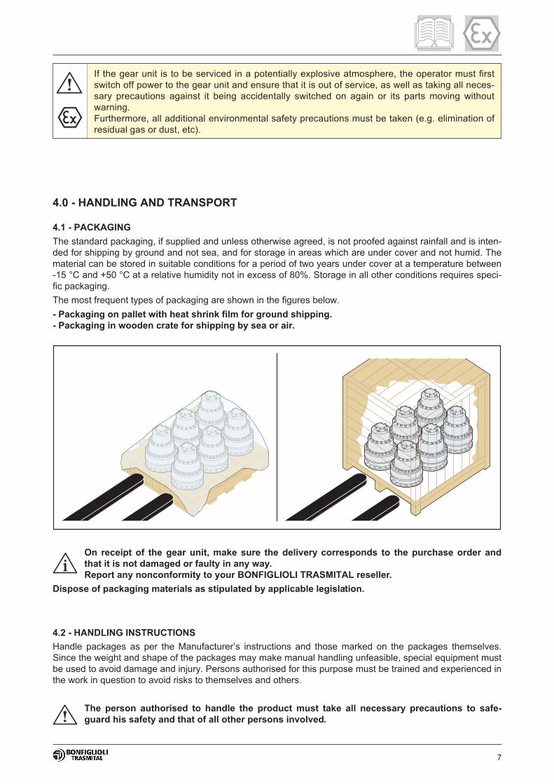
7
4.0 - HANDLING AND TRANSPORT
4.1 - PACKAGING
The standard packaging, if supplied and unless otherwise agreed, is not proofed against rainfall and is inten-
ded for shipping by ground and not sea, and for storage in areas which are under cover and not humid. The
material can be stored in suitable conditions for a period of two years under cover at a temperature between
-15 °C and +50 °C at a relative humidity not in excess of 80%. Storage in all other conditions requires speci-
fic packaging.
The most frequent types of packaging are shown in the figures below.
- Packaging on pallet with heat shrink film for ground shipping.
- Packaging in wooden crate for shipping by sea or air.
If the gear unit is to be serviced in a potentially explosive atmosphere, the operator must first
switch off power to the gear unit and ensure that it is out of service, as well as taking all neces-
sary precautions against it being accidentally switched on again or its parts moving without
warning.
Furthermore, all additional environmental safety precautions must be taken (e.g. elimination of
residual gas or dust, etc).
On receipt of the gear unit, make sure the delivery corresponds to the purchase order and
that it is not damaged or faulty in any way.
Report any nonconformity to your BONFIGLIOLI TRASMITAL reseller.
Dispose of packaging materials as stipulated by applicable legislation.
4.2 - HANDLING INSTRUCTIONS
Handle packages as per the Manufacturer’s instructions and those marked on the packages themselves.
Since the weight and shape of the packages may make manual handling unfeasible, special equipment must
be used to avoid damage and injury. Persons authorised for this purpose must be trained and experienced in
the work in question to avoid risks to themselves and others.
The person authorised to handle the product must take all necessary precautions to safe-
guard his safety and that of all other persons involved.

8
4.2.1 - Moving the packages
• Prepare a suitable, delimited area with a level floor or surface for unloading the packages.
• Prepare the equipment required to handle the package. The lifting and handling equipment (e.g. crane or
lift truck) must be of adequate capacity for the weight and size of the load, taking into account its attac-
hment points and centre of gravity. If required, this information is indicated on the package itself. Harness
heavy packages with chains, belts and steel ropes after checking that they are suitable for the weight of
the load, which is always indicated.
• When handling the load keep it level to avoid tipping and instability.
4.2.2 - Moving the equipment
All the following operations must be carried out with care and caution and without sudden
movements.
When lifting, use accessories such as eyebolts, screw clamps, snap hooks, straps, ropes and
hooks etc. which are certified and adequate for the load in question.
The weight of the product to be lifted is given in the Sales Catalogue.
The following pages illustrate in detail the different attachment methods for the various product series, sizes
and configurations described in this Manual.
The most suitable solution for lifting and handling the product in safety is indicated for each.
Symbols:
Type of lifting Manual With mechanical equipment
Symbol M A B
Approximate weight 15 Kg 15 Kg
Instruction —Recommended method for po-
sitioning
Recommended method for
handling and positioning
Warning — The load may be unstable The load may sway or oscillate
Solution —
Slide the lifting ring to align it
with the load’s centre of gra-
vity as shown in the diagrams
below
Lock the ropes below the ring
with a cable clamp or similar
device so as to prevent them
sliding, and lift the load
Observe all precautions regar-
ding the handling of loads
Stabilise the moving load by
hand
Observe all precautions regar-
ding the handling of loads
The load must not be allowed to sway by more than 15° in any direction when being lifted.
If swaying exceeds this amount, stop and repeat the lifting operation as instructed.

9
!"#$%!&
'%!"'() !"#$%! &
*!+($(%!,*-#$$!,.!%#$ /0&
!%! "#$!*!(!$
!,
#.%! 1#))!%)# #+(!$#($,%#.,(#.23
Identify the attachment points for lifting the gear unit. Refer to the diagrams given below.
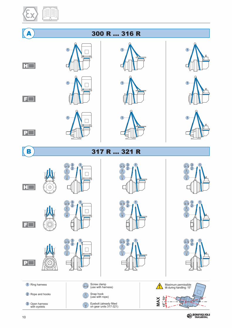
10
!%! "#$!*!(!$
!,
#.%!
!"#$%!&
'%!"'() !"#$%! &
*!+($(%!,*-#$$!,.!%#$ /0&
1#))!%)# #+(!$#($,%#.,(#.23
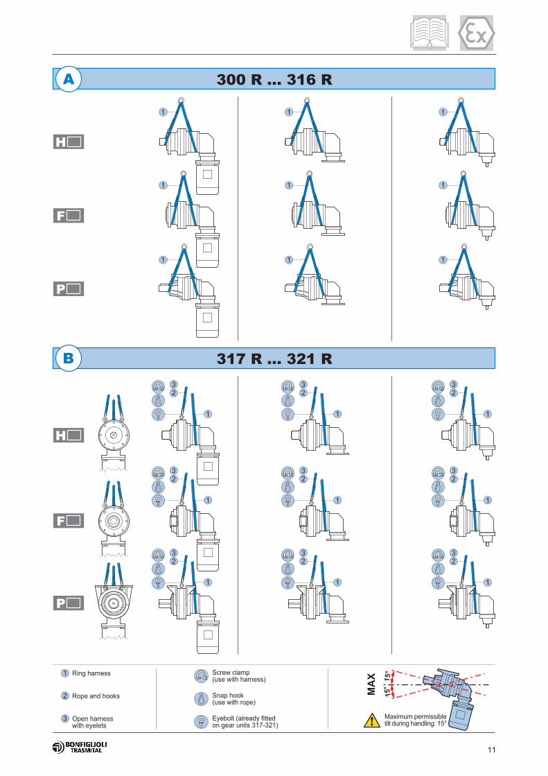
11
1#))!%)# #+(!$#($,%#.,(#.23
!"#$%!&
'%!"'() !"#$%! &
*!+($(%!,*-#$$!,.!%#$ /0&
!%! "#$!*!(!$
!,
#.%!

12
!"#$%!&
'%!"'() !"#$%! &
*!+($(%!,*-#$$!,.!%#$ /0&
!%! "#$!*!(!$
!,
#.%! 1#))!%)# #+(!$#($,%#.,(#.23

13
!"#$%!&
'%!"'() !"#$%! &
*!+($(%!,*-#$$!,.!%#$ /0&
!%! "#$!*!(!$
!,
#.%! 1#))!%)# #+(!$#($,%#.,(#.23

14
PRECAUTIONS to be taken when returning the gear unit to service after storage.
The output shafts and external surfaces must be thoroughly cleaned of all rustproofing product,
contaminants and other impurities (use a standard commercial solvent).
Do this outside the explosion hazard area.
The solvent must not touch the seal rings as this may damage them, causing them to leak
If the oil or protective material used during storage is not compatible with the synthetic oil used
during the machine’s operation, the interior of the unit must be thoroughly cleaned before filling
with the operating oil.
The service life of the bearing grease is reduced if the unit is stored for more than 1 year.
The bearing grease must be synthetic.
• Prepare the gear unit for lifting by attaching straps, hooks and screw clamps etc. to its attachment points.
Alternatively, use a pallet to move the load. If using a crane, first lift the gear unit vertically out of its packa-
ging.
• If using a lift truck or pallet truck, remove the packaging and insert the truck’s forks at the indicated posi-
tions.
• First lift the load very slowly to check that it is stable.
• Move the gear unit to the unloading area and lower it gently into position, taking care not to tip it suddenly
in transit.
If the gear unit is already equipped with an electric motor, do not use the eyebolts on the mo-
tor casing for lifting, unless expressly specified.
4.3 - STORAGE
The following recommendations should be followed when storing the gear unit.
1. Do not store the unit in excessively humid conditions or where it is exposed to the weather (do not store
outdoors).
2. Do not place the gear unit directly on the ground.
3. Place the gear unit on a stable base and make sure that it is not subject to accidental displacement.
4. Store the packaged gear unit (if allowed) in accordance with the instructions on the packaging itself.
If the gear unit is to be stored for more than 6 months, the following additional precautions must be taken:
5. Cover all machined external surfaces with a rustproofing product such as Shell Ensis or other product
with similar properties and application range.
6. Fill the unit with lubricating oil and make sure the vent plug is positioned uppermost. Before putting the
unit into service, the oil used for storage must be drained and replaced with the correct quantity of re-
commended operating lubricant.
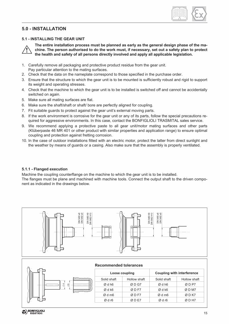
15
5.0 - INSTALLATION
5.1 - INSTALLING THE GEAR UNIT
The entire installation process must be planned as early as the general design phase of the ma-
chine. The person authorised to do the work must, if necessary, set out a safety plan to protect
the health and safety of all persons directly involved and apply all applicable legislation.
1. Carefully remove all packaging and protective product residue from the gear unit.
Pay particular attention to the mating surfaces.
2. Check that the data on the nameplate correspond to those specified in the purchase order.
3. Ensure that the structure to which the gear unit is to be mounted is sufficiently robust and rigid to support
its weight and operating stresses.
4. Check that the machine to which the gear unit is to be installed is switched off and cannot be accidentally
switched on again.
5. Make sure all mating surfaces are flat.
6. Make sure the shaft/shaft or shaft/ bore are perfectly aligned for coupling.
7. Fit suitable guards to protect against the gear unit’s external moving parts.
8. If the work environment is corrosive for the gear unit or any of its parts, follow the special precautions re-
quired for aggressive environments. In this case, contact the BONFIGLIOLI TRASMITAL sales service.
9. We recommend applying a protective paste to all gear unit/motor mating surfaces and other parts
(Klüberpaste 46 MR 401 or other product with similar properties and application range) to ensure optimal
coupling and protection against fretting corrosion.
10. In the case of outdoor installations fitted with an electric motor, protect the latter from direct sunlight and
the weather by means of guards or a casing. Also make sure that the assembly is properly ventilated.
5.1.1 - Flanged execution
Machine the coupling counterflange on the machine to which the gear unit is to be installed.
The flanges must be plane and machined with machine tools. Connect the output shaft to the driven compo-
nent as indicated in the drawings below.
Loose coupling Coupling with interference
Solid shaft Hollow shaft Solid shaft Hollow shaft
Ø d h6 Ø D G7 Ø d h6 Ø D P7
Ø d k6 Ø D F7 Ø d k6 Ø D M7
Ø d m6 Ø D F7 Ø d m6 Ø D K7
Ø d r6 Ø D E7 Ø d r6 Ø D H7
Recommended tolerances
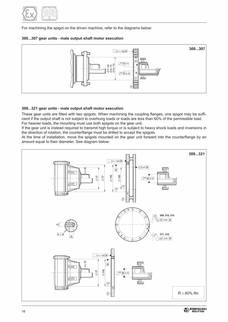
16
300...307
309...321 gear units - male output shaft motor execution
These gear units are fitted with two spigots. When machining the coupling flanges, one spigot may be suffi-
cient if the output shaft is not subject to overhung loads or loads are less than 60% of the permissible load.
For heavier loads, the mounting must use both spigots on the gear unit.
If the gear unit is instead required to transmit high torque or is subject to heavy shock loads and inversions in
the direction of rotation, the counterflange must be drilled to accept the spigots.
At the time of installation, move the spigots mounted on the gear unit forward into the counterflange by an
amount equal to their diameter. See diagram below:
0.07 BB
0.15B
0.1 / 100 B
3.2
3.2
3.2
b = d
0.1 / 100 B
B
0.15B
3.2
3.2
0.20 B
0.05 B
309...321
R 60% Rn
For machining the spigot on the driven machine, refer to the diagrams below:
300...307 gear units - male output shaft motor execution
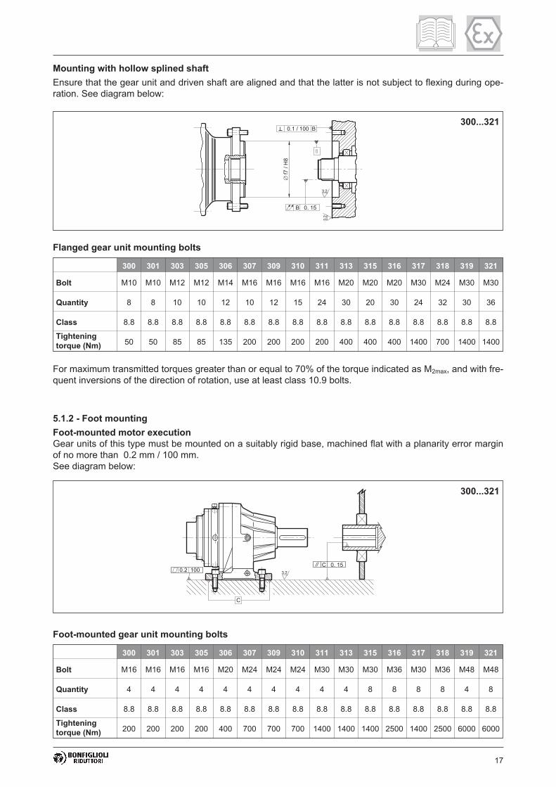
17
Mounting with hollow splined shaft
Ensure that the gear unit and driven shaft are aligned and that the latter is not subject to flexing during ope-
ration. See diagram below:
300...321
Flanged gear unit mounting bolts
For maximum transmitted torques greater than or equal to 70% of the torque indicated as M2max, and with fre-
quent inversions of the direction of rotation, use at least class 10.9 bolts.
300 301 303 305 306 307 309 310 311 313 315 316 317 318 319 321
Bolt M10 M10 M12 M12 M14 M16 M16 M16 M16 M20 M20 M20 M30 M24 M30 M30
Quantity 8 8 10 10 12 10 12 15 24 30 20 30 24 32 30 36
Class 8.8 8.8 8.8 8.8 8.8 8.8 8.8 8.8 8.8 8.8 8.8 8.8 8.8 8.8 8.8 8.8
Tightening
torque (Nm)50 50 85 85 135 200 200 200 200 400 400 400 1400 700 1400 1400
5.1.2 - Foot mounting
Foot-mounted motor execution
Gear units of this type must be mounted on a suitably rigid base, machined flat with a planarity error margin
of no more than 0.2 mm / 100 mm.
See diagram below:
300...321
300 301 303 305 306 307 309 310 311 313 315 316 317 318 319 321
Bolt M16 M16 M16 M16 M20 M24 M24 M24 M30 M30 M30 M36 M30 M36 M48 M48
Quantity 4 4 4 4 4 4 4 4 4 4 8 8 8 8 4 8
Class 8.8 8.8 8.8 8.8 8.8 8.8 8.8 8.8 8.8 8.8 8.8 8.8 8.8 8.8 8.8 8.8
Tightening
torque (Nm)200 200 200 200 400 700 700 700 1400 1400 1400 2500 1400 2500 6000 6000
Foot-mounted gear unit mounting bolts

18
5.1.3 - Shaft mounting
Mount the torque arm with bolts of at least class 8.8 tightened to a torque of 70% of their failure stress. Clean
and degrease both the internal coupling surface of the gear unit shaft and the external coupling surface of
the machine’s driven shaft.
Mount the shrink disk to the gear unit’s shaft after lightly lubricating its entire outer surface. Snug down a
first set of 3 bolts located at the corners of an equilateral triangle (for example: bolts in pos. 1-5-9 of the dia-
gram below). Fit the gear unit to the driven shaft.
Tighten down the bolts (following the triangular pattern) in a circular direction, repeating the operation seve-
ral times until all bolts are tightened to the torque specified in chart 2, in accordance with the type of
disk/gear unit.
N.B.: Do not tighten down diametrically opposed bolts in sequence.
3.2
3.2
3.2
3.2
300...321
Do not use molybdenum bisulphide or any other grease, which could reduce the friction of
the mating surfaces and affect the performance of the shrink disk.
300...321
300 301 303 305 306 307 309 310 311 313 315 316 317 318 319 321
Bolt M6 M6 M8 M8 M10 M10 M16 M16 M16 M16 M20 M20 M20 M20 M20 M24
Quantity 8 10 12 12 9 12 8 8 10 10 12 15 18 21 24 21
Class 10.9 10.9 10.9 10.9 10.9 10.9 10.9 10.9 10.9 10.9 10.9 10.9 10.9 10.9 10.9 10.9
Tightening
torque (Nm)12 12 30 30 58 58 250 250 250 250 490 490 490 490 490 840
Shrink disk mounting bolts

19
Locate the closed oil plug used during shipping and replace it with the vent plug supplied in the
shipment.
5.1.4 - Installing accessories on solid input and output shafts
Do not use hammers or other tools that might damage the gear unit’s shafts or bearings when
mounting external parts. Instead, proceed as illustrated in the diagram below:
Bolt (1) and spacer (2) are not included in the consignment.
To minimise the loads on the shaft bearings, when mounting transmission mechanisms with asymmetrical
hubs use the configuration shown in diagram (A) below:
Proceed with the installation as follows:
1. Place the gear unit in the vicinity of the installation area.
2. Mount the gear unit and secure it to the structure at the points provided. The gear unit should be secured
to the structure at all the mounting points (bores) on the mount provided (feet or flange).
3. Tighten down the mounting bolts and check that the service plugs are screwed down to the torques given
in the chart.
(A)
Mounting pulleys
Clean all parts before installing them. When installing belt drive pulleys, the shafts must be parallel with their
pulleys aligned.
Do not over tension the drive belt as this can damage the bearings.
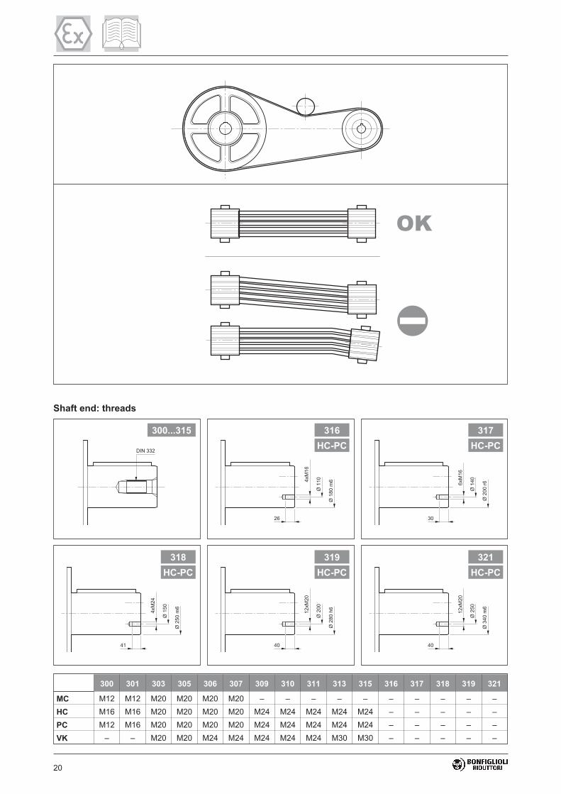
20
300 301 303 305 306 307 309 310 311 313 315 316 317 318 319 321
MC M12 M12 M20 M20 M20 M20 – – – – – – – – – –
HC M16 M16 M20 M20 M20 M20 M24 M24 M24 M24 M24 – – – – –
PC M12 M16 M20 M20 M20 M20 M24 M24 M24 M24 M24 – – – – –
VK – – M20 M20 M24 M24 M24 M24 M24 M30 M30 – – – – –
Shaft end: threads
!
316 317
319 321318
300...315
HC-PC HC-PC
HC-PCHC-PCHC-PC

21
Installing accessories on splined shafts
Do not use hammers or other tools that might damage the gear unit’s shafts or bearings when
mounting external parts. Instead, proceed as illustrated in the diagram below:
MZ-HZ
5.2 - INSTALLING THE ELECTRIC MOTOR
Further to all the precautions indicated above, when installing a standard IEC 72-1 electric motor, the follo-
wing precautions must also be observed:
• Do not force the coupling and do not use inappropriate tools during assembly. Take care not to damage
the flat/cylindrical coupling surfaces.
• Do not force the rotary coupling mechanisms with heavy overhung or thrust loads.
• To facilitate assembly, use a lubricating synthetic oil paste such as Klüberpaste 46 MR 401 or another pro-
duct with similar properties and application range.
• Provided all the above checks have been performed and passed and all other instruc-
tions in this manual have been strictly observed, an electric motor with ATEX rating
equal to or greater than that of the gear unit may be installed, thus forming a gearmotor
which itself complies with the provisions of Directive 94/9/EC.
If, instead, the assembly of the motor to the gear unit requires actions other than those
prescribed in this Manual or one or more of the manual’s prescriptions have not been
satisfied, the User shall be responsible for analysing the risks attendant on this particu-
lar motor/gear unit combination. The risk analysis is in any case obligatory if the motor
is powered by an inverter.
Only in this way, and subject to self-certification by the assembler, shall the assembly,
including the gear unit itself, be compliant with the requirements of Directive 94/9/EC.
Always use the stop end plate supplied with the gear unit.

22
5.3 - INSTALLING THE HYDRAULIC MOTOR
Connecting the hydraulic motor
Remove the protective plug.
Hydraulic motor mountings are available in two versions:
a) Version with O-ring oil gasket between motor flange and gear unit.
In this case, mount the gasket to ensure an oil tight seal between the motor and gear unit, taking care to fit it
correctly in its seat without damaging it.
b) Version with gasket already mounted to the coupling.
In this case no special intervention is required to ensure an oil tight seal since this is already provided by the
motor coupling. Merely smear the motor shaft with grease.
In both cases, clean the spigot and the coupling where the motor is to be fitted, fit the motor and tighten
down the flange mounting bolts.
Always use bolts rated to at least class 8.8.

23
5.4 - CONNECTING THE HYDRAULIC BRAKE
On gear units designed for coupling to hydraulic motors and fitted with a brake, connect the brake control fit-
ting to the hydraulic circuit at the time of assembly.
Start-up
The minimum pressure to release the brake (see chart) must be less than 320 bar.
Technical data
NOTE: The static torque Mbs is the maximum torque the brake can exert.
Under dynamic loads the braking torque is reduced. The actual Mbs values can vary from -5% to +15% of the
rating given in the chart.
4... 5... 6...
A B D F H K L B C E G K B C E G K L
Braking torque Mbs [daNm] 5 10 16 26 33 40 44 40 50 63 80 100 85 110 150 210 260 320
Minimum release
pressurebar 10 20 30 20 25 30 33 20 27 20 25 32 14 19 25 19 24 28
Max. pressure bar 320
Weight kg 10 18 35
Brake
Characteristics

24
Installing the gearmotor
If a gearmotor is supplied fully assembled, follow the precautions and instructions given above when moun-
ting to the machine.
For the electrical and hydraulic connection, refer instead to the two sample diagrams below. These are gene-
ric only since each specific installation has its own special requirements, which must be evaluated on a per
case basis by the Manufacturer.
Drive with electric motor.
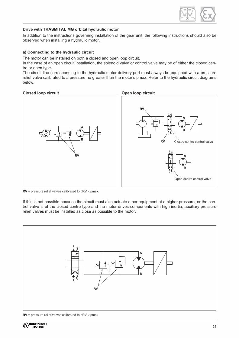
25
If this is not possible because the circuit must also actuate other equipment at a higher pressure, or the con-
trol valve is of the closed centre type and the motor drives components with high inertia, auxiliary pressure
relief valves must be installed as close as possible to the motor.
a) Connecting to the hydraulic circuit
The motor can be installed on both a closed and open loop circuit.
In the case of an open circuit installation, the solenoid valve or control valve may be of either the closed cen-
tre or open type.
The circuit line corresponding to the hydraulic motor delivery port must always be equipped with a pressure
relief valve calibrated to a pressure no greater than the motor’s pmax. Refer to the hydraulic circuit diagrams
below.
Closed loop circuit Open loop circuit
RV = pressure relief valves calibrated to pRV pmax.
Drive with TRASMITAL MG orbital hydraulic motor
In addition to the instructions governing installation of the gear unit, the following instructions should also be
observed when installing a hydraulic motor.
Closed centre control valve
Open centre control valve
RV = pressure relief valves calibrated to pRV pmax.

26
b) Connecting drain hole T
Standard motors are supplied without a drain hole. In this case the motor is equipped with internal drainage.
This meets the requirements of the majority of applications with intermittent duty and an average drive pres-
sure of less than 50% of the motor’s maximum rated pressure.
When duty is continuous or intermittent with an operating percentage greater than 50% and the average dri-
ve pressure is greater than 50% of the rated maximum pressure, the motor must be ordered with external
drainage and drain hole T must be connected to the tank. Refer to the diagrams below:
c) Brake control
Gearmotors equipped with a brake, are available in two motor executions:
B02P or P01S.
Brake control is internal on the B02P version, and is controlled directly by the motor.
The brake control pressure must instead be supplied by an auxiliary line of the brake control circuit on the
P01S version.
Refer to the diagrams below:
d) Type of hydraulic fluid
Use hydraulic mineral fluid with viscosity ISO VG 46 (46 Cst at t = 40°C).
During operation, the fluid temperature should remain within the range +30°C to +70°C.
B02P P01S
Internal drainage External drainage
Closed loop circuit Open loop circuit
P01S
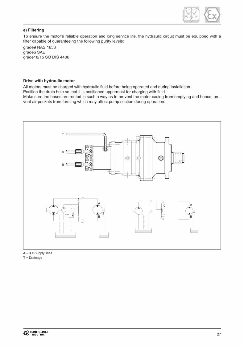
27
e) Filtering
To ensure the motor’s reliable operation and long service life, the hydraulic circuit must be equipped with a
filter capable of guaranteeing the following purity levels:
grade9 NAS 1638
grade6 SAE
grade18/15 SO DIS 4406
Drive with hydraulic motor
All motors must be charged with hydraulic fluid before being operated and during installation.
Position the drain hole so that it is positioned uppermost for charging with fluid.
Make sure the hoses are routed in such a way as to prevent the motor casing from emptying and hence, pre-
vent air pockets from forming which may affect pump suction during operation.
A - B = Supply lines
T = Drainage

28
INDUSTRIAL INSTALLATIONS MOBILE MACHINES
ISO standards .. with EP characteristics SAE standards .. with API GL5 characteristics
Ambient
temperature-10°C / +30°C +10°C / +45°C -20°C / +60°C -20°C / +30°C +10°C / +45°C
ISO VG 150 ISO VG 220 ISO VG 150-220 SAE 80W/90 SAE 85W/140
AGIP BLASIA 150 BLASIA 220 BLASIA S220 ROTRA MP ROTRA MP
ARAL DEGOL BG 150 DEGOL BG 220 DEGOL GS 220 GETRIEBEOL HYP GETRIEBEOL HYP
BP-MACHENERGOL
GR XP 150
ENERGOL
GR XP 220
ENERSYN
HTX 220HYPOGEAR EP HYPOGEAR EP
CASTROL ALPHA SP 150 ALPHA SP 220 ALPHASYN PG 150 HYPOY HYPOY
CHEVRONN.L. GEAR
COMPOUND 150
N.L. GEAR
COMPOUND 220
UNIVERSAL GEAR
LUBRICANTE
UNIVERSAL GEAR
LUBRICANTE
ELFREDUCTELF
SP150
REDUCTELF
SP 220
ELF ORITIS 125 MS
ELF SYNTHERMA P20TRANSELF8 TRANSELF8
ESSO SPARTAN EP 150 SPARTAN EP 220 GLYCOLUBE 220 GEAR OIL GX GEAR OIL GX
PONTONIC MP PONTONIC MP
FINA GIRAN 150 GIRAN 220
I.P. MELLANA150 MELLANA220 TELESIA OIL 150 PONTIAX HD PONTIAX HD
KLUBERKLUBEROIL
GEM1-150
KLUBEROIL
GEM1-320
KLUBERSYNT
GH 6-220
Q8 GOYA 150 GOYA 220 EL GRECO 220
MOBIL MOBILGEAR 629 MOBILGEAR 630 SHC 630 MOBILUBE HD MOBILUBE HD
SHELL OMALA EP150 OMALA EP220 TIVELA OIL SA SPIRAXHD SPIRAX HD
TOTAL CARTER EP 150 CARTER EP 220 TRANSMISSION TM TRANSMISSION TM
Synthetic oil.
Brake lubrication
The hydraulic multi-disk brakes are lubricated with the same oil as the gear unit.
Only synthetic lubricants may be used on gear units conforming to European Directive
94/9/EC. Refer to the above chart for the brand and type.
Plug thread Pitch Tightening torque
[Nm]
M14 1,5 15 - 20
M16 1,5 15 - 20
M18 1,5 15 - 20
M20 1,5 20 - 30
M22 1,5 20 - 30
M24 1,5 20 - 30
M30 2 30 - 40
M42 3 40 - 50
Plug thread Pitch Tightening torque
[Nm]
1/8" 28 10 - 15
1/4" 19 10 - 15
3/8" 19 15 - 20
1/2" 14 20 - 30
3/4" 14 20 - 30
1" 11 30 - 40
5.5 - LUBRICATION
Before starting up the gear unit, it must be charged with lubricant to the level corresponding to its specified
mounting position.
The lubricant and its relative viscosity should be selected from the following chart, in accordance with the
type of duty and ambient temperature.
If the gear unit is supplied ready charged with lubricant, replace the closed shipping plug with the
vent plug included in the shipment before installing it.
(A1)
(A2)

29
6.0 - TESTING THE GEAR UNIT
The gear unit has been factory tested by the Manufacturer. Before start-up, make sure that:
• the machine incorporating the gear unit complies with the provisions of the “Machinery Directive” 98/37/EC
and any other applicable safety legislation
• the gear unit’s mounting position in the installation corresponds to that prescribed and indicated on the na-
meplate
• the electrical power supply is suitable and operational as prescribed in EN 60204-1, and is grounded as
per EN 50014
• the motor’s electric power supply corresponds to that prescribed and is within +/-5% of the rated value
• the hydraulic system is suitable and operational, and the oil in the hydraulic motor’s lubrication circuit con-
forms to ISO VG 46. It must be filtered with a maximum grade of 10 µm and contamination level less than
or equal to class 9 as per NAS 1638 or 18/15 as per ISO/DIS 4406
• there are no signs of lubricant leaks from the plugs or gaskets
• the vent plug is not obstructed by dirt or paint
• the unit does not run noisily or with excessive vibration.
Before starting up the unit, check and make sure that:
• the unit is not assembled in a potentially explosive atmosphere (oil, acid, gas, vapour, radia-
tion) and is free of dust build ups greater than 5 mm in depth
• during operation the gear unit is sufficiently ventilated and is not subject to radiation from exter-
nal heat sources
• during operation the cooling air does not exceed 40 °C
• the oil level check and filler plugs and the vent plugs are all easily accessible
• all accessories mounted to the gear unit are ATEX certified
• gear units with hollow shafts, with or without shrink disk, have been correctly mounted as de-
scribed in this manual
• the gear unit has been thoroughly cleaned after installation
• all guards are installed to prevent accidental contact between operators and the unit’s rotary
moving parts, and seals are oil tight
7.0 - USING THE EQUIPMENT
Before putting the gear unit into service, the User must ensure that the plant in which it is installed complies
with all applicable directives, especially those regarding health and safety at work.
The gear unit may not be used in areas and environments:
• with highly corrosive/abrasive vapours, smoke or dust.
• in direct contact with loose food products.
Danger zones and exposed persons:
The danger zone of the gear unit is the protrusion of the shaft which constitutes a hazard for exposed
persons in direct contact with it (crushing, shearing, trapping). In particular, when the gear unit is
operating in automatic mode in an accessible area, the shaft must be protected by a guard.

30
8.0 - MAINTENANCE
Maintenance and replacement work must be carried out by expert maintenance technicians
trained in the observance of applicable laws on health and safety at work and the special am-
bient problems attendant on the installation.
Before doing any work on the unit, the operator must first switch off power to the gear unit
and ensure that it is out of service, as well as taking all necessary precautions against it being
accidentally switched on again or its parts moving without warning (due to suspended loads
or similar external factors).
Furthermore, all additional environmental safety precautions must be taken (e.g. elimination
of residual gas or dust, etc).
• Before doing any maintenance work, activate all the safety devices provided and, if necessary, inform per-
sons working in the vicinity. Cordon off the area around the unit and prevent access to any equipment
which, if activated, might be the cause of unexpected health and safety hazard.
• Replace worn components with original spare parts.
• Use the lubricants (oil and grease) recommended by the Manufacturer.
• When working on the gear unit always replace all gaskets and seals with original new ones.
• If a bearing requires replacement, it is good practice to also replace the other bearing supporting the same
shaft.
• We recommend replacing the lubricating oil after all maintenance work.
The above instructions are aimed at ensuring efficient and safe operation of the gear unit.
The Manufacturer declines all liability for injury to persons and damage to components due to the use of
non-original spare parts and non-routine work that modifies the safety requirements without the Manufactu-
rer’s express prior authorisation.
Refer to the specific spare parts catalogue when ordering spare parts for the gear unit.
Do not dump polluting liquids, worn parts and maintenance waste into the environment.
Dispose of all such materials as specified by applicable legislation.
• Observe the routine inspection and maintenance schedule to ensure the unit’s correct opera-
tion and the effectiveness of the explosion protection.
• Always apply fresh Loctite 510 or other product with similar properties and application range to
all disassembled threads.
• Before servicing or repairing internal components, allow the gear unit to cool down completely
before opening the casing so as to avoid burns from parts which are still hot.
• On completion of maintenance work, make sure that all safety measures and equipment have
been applied and reset.
• Clean the gear unit thoroughly after maintenance and repair work.
• On completion of maintenance, tighten all vent, filler and level plugs to their specified torques
(chart A1).
• On completion of any maintenance work all seals must be refitted and sealed as prescribed.
• Regardless of the type of gear unit, whenever a seal ring is replaced its lips should be smea-
red with a thin layer of grease (Fluorocarbon gel 880 ITP or other product with similar proper-
ties and application range) before assembly.
• Use only original spare parts for repairs.

31
8.1 - ROUTINE MAINTENANCE
Keep the gear unit at its maximum efficiency by following the routine maintenance schedule.
Good maintenance ensures the unit’s maximum performance, extended service life and conti-
nued compliance with safety regulations.
Frequency Component Type of check Action
at start Gear unit casing
Check that the external
temperature does not exceed
75-80 °C
Stop the machine and contact
Bonfiglioli Trasmital’s Technical
Service
after 200 hrs
Original consignment
lubricantReplace Replace with new lubricant
External fasteners Check locking torqueTighten down to specified
torque
1000 hrsExternal seals and
gaskets
Check oil level
Check for leaks by eye
Service or replace components
as required
2500 hrs Lubricant Replace Replace with new lubricant
5000 hrsGear unit seals and
gaskets
Inspect carefully for wear/age-
ing of external sealsReplace if aged/worn
For installations in zones 21 and 22 the User must schedule and implement a regular clea-
ning programme for all surfaces and recesses to avoid dust build-ups of more than 5 mm
in depth.
Every 1000 hrs. of operation or after 6 months:
• Measure the surface temperature at the coupling between the gear unit and motor, and at the
points which are most shielded from the motor’s cooling fan. The maximum temperature must
not be more than 75-80°C, nor may this value be exceeded during operation.
Every 5000 hrs. of operation:
• Change the synthetic oil and bearing grease if the gear unit is not life lubricated.
• Replace all externally accessible seal rings unless this has already been done as a result of
problems occurring before the scheduled maintenance deadline.
(A3)

32
8.2 - OIL CHANGES
1. Place an adequate container under the drain plug.
2. Remove the filler and drain plugs and allow the oil to drain out.
The oil will drain better if it is warm.
3. Wait for a few minutes until all the oil has drained out, then screw the drain plug back on after first chan-
ging the plug seal.
4. Fill with new oil until it reaches the level mark. Do not mix oils of different makes or specifications
and check that the oil is highly resistant to foaming and is EP rated.
5. Tighten down the filler plug after changing its seal.
The gear unit may be supplied with or without lubricant, as requested by the User. The quan-
tity of charge oil required is specified in the Sales Catalogue. This specification is however,
approximate, and reference must always be made to the mark on the level plug, the placement
of which depends on the mounting position specified in the purchase order.
Life lubricated gear units which are not subject to external contamination do not normally require pe-
riodic lubricant changes. If the same type of oil as that already in use is not available, drain the gear unit
casing completely and wash its interior thoroughly with a light solvent before refilling with the new lubricant.
If a leak is found, identify the cause of the fault and repair it before topping up the lubricant
and operating the unit.
Lubricants, solvents and detergents are toxic/harmful to health:
- they may cause irritation in direct contact with the skin
- they may cause intoxication if inhaled
- they may be fatal if swallowed.
Handle them with care using suitable individual safety equipment. Do not dump them into the environment
and dispose of in accordance with applicable legislation.
8.3 - CHECKING OPERATIONAL EFFICIENCY
• Remove any dust from the gear unit and motor casings.
• Check that the noise generated at continuous load does not vary. Excessive vibration or noise can indicate
wear of the gear train or failure of a bearing.
• Check the power absorption and voltage against the rated values given on the motor’s nameplate.
• Check the wear of the friction surfaces and braking gasket on the brake motors (if fitted) and, if necessary,
adjust the gap.
• Check for lubricant leaks from the gaskets/seals, plugs and casings.
• Check all bolted couplings for wear, deformation and corrosion and tighten them down fully, but without
over tightening.
8.4 - CLEANING
Remove all dust and process waste from the gear unit. Do not use solvents or other products that are incom-
patible with the unit’s construction material and do not direct high pressure jets of water at the gear unit.

33
9.0 - REPLACING PARTS
• Immediately replace parts and components if they are not able to guarantee safe and reliable ope-
ration.
• Never improvise repairs.
• The use of non-original spare parts not only renders the warranty null and void but can jeopardise
the gear unit’s operation.
9.1 - REMOVING THE MOTOR
If during operation the mobile coupling between the motor and gear unit has not rusted significantly, it should
be possible to remove the motor without applying excessive force.
If instead, it proves difficult to remove the motor, do not use screwdrivers or levers to apply force as this may
damage the flanges and mating surfaces, but proceed as illustrated below.
1. Drill and thread the motor shaft (fan side).
2. Screw an impact extractor tool into the bore.
3. Undo the bolts fixing the motor to the gear unit.
4. Detach the motor by means of the inertial force of the extractor.
9.2 - DECOMMISSIONING THE GEAR UNIT
The unit must only be taken out of service by operators trained in the observance of applicable laws on he-
alth and safety at work.
Do not dump non-biodegradable products, lubricants and non-ferrous materials (rubber, PVC, resins, etc.)
into the environment. Dispose of all such materials as stipulated by established environmental legislation.
Do not re-use parts or components which appear to be in good condition after they have been chec-
ked or replaced by qualified personnel and declared unsuitable for use.

34 34
10.0 - TROUBLESHOOTING
The following information is intended to serve as an aid in locating and eliminating defects and faults. In
some cases, problems may be caused by the plant or machine to which the gear unit is assembled and hen-
ce, the cause and remedy will be described in the Manufacturer’s technical documentation for the machi-
ne/plant in question.
FAULT CAUSE REMEDY
Bearing temperature too high
Oil level too low Top up oil level
Oil spent Replace oil
Defective bearings Contact authorised workshop
Operating temperature too high
Oil level too high Check oil level
Oil spent Replace oil
Contaminant in oil Replace oil
Abnormal running noise
Gears damaged Contact authorised workshop
Bearing axial backlash too high Contact authorised workshop
Bearings defective or worn Contact authorised workshop
Excessive load appliedCorrect load to rated values given
in Sales Catalogue
Contaminant in oil Replace oil
Abnormal noise at gear unit
mounting
Mounting bolts loose Tighten bolts to specified torque
Mounting bolts worn Replace bolts
Oil leaks
Oil level too high Check oil level
Casing/coupling seals inadequate Contact authorised workshop
Gaskets worn Contact authorised workshop
Gear unit does not run or runs
with difficulty
Oil viscosity too highReplace oil (see recommended
lubricant chart)
Oil level too high Check oil level
Excessive load appliedRedesign drive for actual load
required
Output shaft does not turn with
motor runningGears damaged Contact authorised workshop
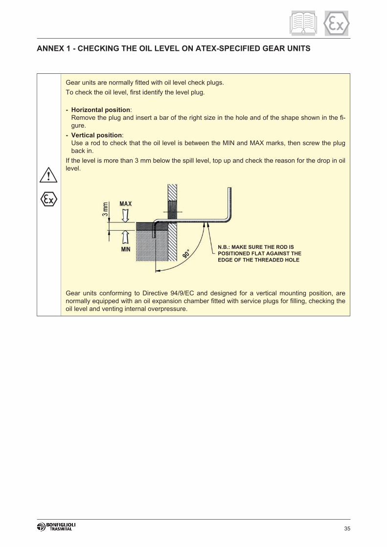
35
ANNEX 1 - CHECKING THE OIL LEVEL ON ATEX-SPECIFIED GEAR UNITS
Gear units are normally fitted with oil level check plugs.
To check the oil level, first identify the level plug.
- Horizontal position:
Remove the plug and insert a bar of the right size in the hole and of the shape shown in the fi-
gure.
- Vertical position:
Use a rod to check that the oil level is between the MIN and MAX marks, then screw the plug
back in.
If the level is more than 3 mm below the spill level, top up and check the reason for the drop in oil
level.
Gear units conforming to Directive 94/9/EC and designed for a vertical mounting position, are
normally equipped with an oil expansion chamber fitted with service plugs for filling, checking the
oil level and venting internal overpressure.
N.B.: MAKE SURE THE ROD IS
POSITIONED FLAT AGAINST THE
EDGE OF THE THREADED HOLE
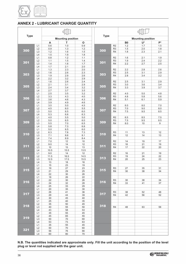
36
ANNEX 2 - LUBRICANT CHARGE QUANTITY
N.B. The quantities indicated are approximate only. Fill the unit according to the position of the level
plug or level rod supplied with the gear unit.
Type TypeMounting position Mounting position
A T O B0 U* P*
300
L1 0.6 1.0 0.9
300
R2 1.2 1.7 1.5
L2 0.9 1.3 1.2 R3 1.5 2.0 1.8
L3 1.2 1.6 1.5 R4 1.8 2.3 2.1
L4 1.5 1.9 1.8
301
L1 0.8 1.2 1.1
301
R2 1.6 2.1 1.9
L2 1.1 1.5 1.4 R3 1.9 2.4 2.2
L3 1.4 1.8 1.7 R4 2.2 2.7 2.5
L4 1.7 2.1 2.0
303
L1 1.3 2.3 2.0
303
R2 2.2 2.8 2.6
L2 1.6 2.6 2.3 R3 2.5 3.1 2.9
L3 1.9 2.9 2.6 R4 2.8 3.4 3.2
L4 2.2 3.2 2.9
305
L1 1.6 2.6 2.4
305
R2 2.5 3.1 2.9
L2 2.1 3.1 2.9 R3 3.0 3.6 3.4
L3 2.4 3.4 3.2 R4 3.3 3.9 3.7
L4 2.7 3.7 3.5
306
L1 2.5 3.5 3.2
306
R2 4.0 5.0 4.8
L2 3.3 4.3 4.0 R3 4.8 5.8 5.6
L3 3.6 4.6 4.3 R4 5.1 6.1 5.9
L4 3.9 4.9 4.6
307
L1 3.5 5.0 4.5
307
R2 6.0 8.0 7.0
L2 4.5 6.0 5.5 R3 7.0 9.0 8.0
L3 5.0 6.5 6.0 R4 7.5 9.5 8.5
L4 5.3 6.8 6.3
309
L1 4.0 5.5 5.0
309
R2 6.5 8.5 7.5
L2 5.0 6.5 6.0 R3 7.5 9.5 8.5
L3 5.5 7.0 6.5 R4 8.0 10 9
L4 5.8 7.3 6.8
310
L1 5.0 6.5 6.0
310L2 6.3 7.8 7.3 R3 11 13 12
L3 7.1 8.6 8.1 R4 12 14 13
L4 7.4 8.9 8.4
311
L1 7.0 12 10
311
R2 14 19 17
L2 9.0 14 12 R3 16 21 19
L3 10 15 13 R4 17 22 20
L4 10.5 15.5 13.5
313
L1 9.0 14 12
313
R2 16 21 19
L2 11.5 16.5 14.5 R3 19 24 22
L3 12.5 17.5 15.5 R4 20 25 23
L4 13 18 16
315
L1 15 23 19
315L2 19 27 23 R3 27 35 31
L3 21 29 25 R4 30 38 34
L4 22 30 26
316
L1 18 26 22
316L2 22 30 26 R3 30 38 34
L3 24 32 28 R4 33 41 37
L4 25 33 29
317
L1 20 35 30
317L2 26 41 36 R3 38 52 48
L3 29 44 39 R4 42 56 52
L4 30 45 40
318
L1 25 40 35
318L2 35 50 45
L3 40 55 50 R4 48 63 58
L4 43 58 53
319
L1 35 55 45
L2 45 65 55
L3 50 70 60
L4 53 73 63
321
L1 35 55 45
L2 50 70 60
L3 56 76 66
L4 60 80 70
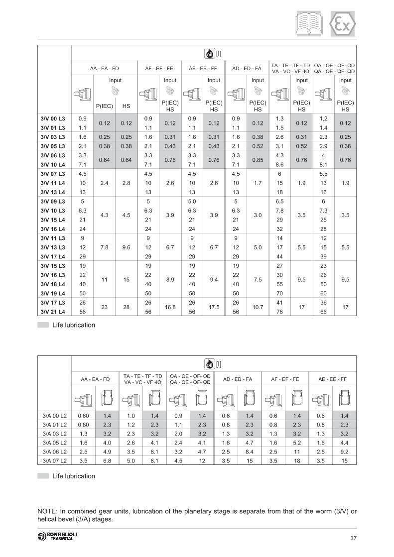
37
NOTE: In combined gear units, lubrication of the planetary stage is separate from that of the worm (3/V) or
helical bevel (3/A) stages.
AA - EA - FD AF - EF - FE AE - EE - FF AD - ED - FATA - TE - TF - TD
VA - VC - VF -IO
OA - OE - OF- OD
QA - QE - QF- QD
input input input input input input
P(IEC) HSP(IEC)
HS
P(IEC)
HS
P(IEC)
HS
P(IEC)
HS
P(IEC)
HS
3/V 00 L3 0.90.12 0.12
0.90.12
0.90.12
0.90.12
1.30.12
1.20.12
3/V 01 L3 1.1 1.1 1.1 1.1 1.5 1.4
3/V 03 L3 1.6 0.25 0.25 1.6 0.31 1.6 0.31 1.6 0.38 2.6 0.31 2.3 0.25
3/V 05 L3 2.1 0.38 0.38 2.1 0.43 2.1 0.43 2.1 0.52 3.1 0.52 2.9 0.38
3/V 06 L3 3.30.64 0.64
3.30.76
3.30.76
3.30.85
4.30.76
40.76
3/V 10 L4 7.1 7.1 7.1 7.1 8.6 8.1
3/V 07 L3 4.5
2.4 2.8
4.5
2.6
4.5
2.6
4.5
1.7
6
1.9
5.5
1.93/V 11 L4 10 10 10 10 15 13
3/V 13 L4 13 13 13 13 18 16
3/V 09 L3 5
4.3 4.5
5
3.9
5.0
3.9
5
3.0
6.5
3.5
6
3.53/V 10 L3 6.3 6.3 6.3 6.3 7.8 7.3
3/V 15 L4 21 21 21 21 29 25
3/V 16 L4 24 24 24 24 32 28
3/V 11 L3 9
7.8 9.6
9
6.7
9
6.7
9
5.0
14
5.5
12
5.53/V 13 L3 12 12 12 12 17 15
3/V 17 L4 29 29 29 29 44 39
3/V 15 L3 19
11 15
19
8.9
19
9.4
19
7.5
27
9.5
23
9.53/V 16 L3 22 22 22 22 30 26
3/V 18 L4 40 40 40 40 55 50
3/V 19 L4 50 50 50 50 70 60
3/V 17 L3 2623 28
2616.8
2617.5
2610.7
4117
3617
3/V 21 L4 56 56 56 56 76 66
oil [l]
Life lubrication
AA - EA - FDTA - TE - TF - TD
VA - VC - VF -IO
OA - OE - OF- OD
QA - QE - QF- QDAD - ED - FA AF - EF - FE AE - EE - FF
3/A 00 L2 0.60 1.4 1.0 1.4 0.9 1.4 0.6 1.4 0.6 1.4 0.6 1.4
3/A 01 L2 0.80 2.3 1.2 2.3 1.1 2.3 0.8 2.3 0.8 2.3 0.8 2.3
3/A 03 L2 1.3 3.2 2.3 3.2 2.0 3.2 1.3 3.2 1.3 3.2 1.3 3.2
3/A 05 L2 1.6 4.0 2.6 4.1 2.4 4.1 1.6 4.7 1.6 5.2 1.6 4.4
3/A 06 L2 2.5 4.9 3.5 8.1 3.2 4.7 2.5 8.4 2.5 11 2.5 9.2
3/A 07 L2 3.5 6.8 5.0 8.1 4.5 12 3.5 15 3.5 18 3.5 15
oil [l]
Life lubrication
38
INDEX OF REVISIONS (R)
We reserve the right to implement modifications without notice.This catalogue cannot be reproduced, even partially, without prior consent.
R1
Amended section 8.1 "Routine maintenance".
COD. 7.998.3.3.01.7 R1
31


w w w . b o n f i g l i o l i . c o m
300
MOBILE EQUIPMENT
AND WIND ENERGY SOLUTIONS
INDUSTRY PROCESS
AND AUTOMATION SOLUTIONS
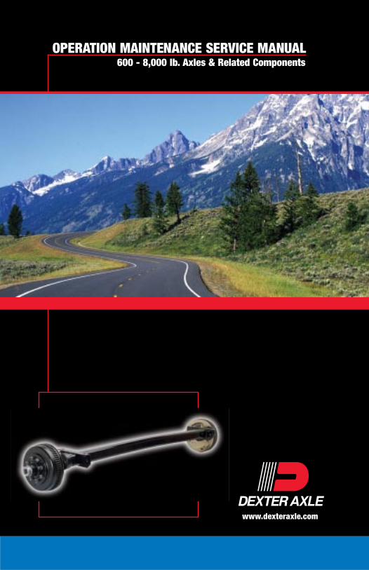
www.dexteraxle.com
OPERATION MAINTENANCE SERVICE MANUAL600 - 8,000 lb. Axles & Related Components

IntroductionThis manual is designed to provide information for you to understand, use,
maintain, and service your trailer running gear system. Your axles are
manufactured by Dexter Axle. The Dexter product line, the most complete
in the industry, is the result of over 30 years of experience in the design,
testing and manufacturing of trailer axles. The Dexter running gear system
consists of spindles, hubs, drums, and brakes which are engineered to
provide you the finest towing and stopping performance currently available
in the industry today.
Two Dexter philosophies are at work to provide you the best product
available and have enabled us to maintain our position of leadership. First,
we operate on the theory that “there is always a better way” for a product to
operate, to be manufactured, and/or to be serviced. We are constantly
striving to find that better way.
Secondly, we maintain wall-to-wall production control so that all the major
components of your running gear system are manufactured in Dexter
facilities under our strict quality control standards. These manufactured
components include the axle beam, hubs, drums, spindles, brakes, magnets,
and most of the steel stampings used in the attachment of your axle to your
trailer. Dexter has the most complete, state-of-the-art manufacturing facilities
which enable us to provide you, the trailer owner, with the finest product
possible.
For all your running gear needs...
Visit us online atwww.dexteraxle.com

-2-
Tabl
e of
Con
tent
sIntroduction
Important Safety Notice ......................................................................... 4
Getting Started - Setup and Adjustment ............................................... 4
Braking Systems - ElectricElectric Brakes ....................................................................................... 5
Features ................................................................................................. 6
Parking Brake Option .................................................................... 6
Self Adjusting Feature .................................................................. 6
Brake Controllers .......................................................................... 7
Typical Trailer Wiring .................................................................. 10
How To Use Your Electric Brakes Properly ............................... 11
Trailer Wire Size Chart ............................................................... 11
Synchronizing Your Trailer Brakes ............................................. 12
General Maintenance - Electric Brakes .............................................. 13
Brake Adjustment ....................................................................... 13
Brake Cleaning and Inspection .................................................. 14
Brake Lubrication ........................................................................ 14
Magnets ............................................................................................... 15
Shoes and Linings ............................................................................... 16
Introduction to Troubleshooting ........................................................... 17
Troubleshooting ................................................................................... 17
Troubleshooting Chart - Electric ................................................. 18
How to Measure Voltage ............................................................ 20
How to Measure Amperage ........................................................ 20
Magnet Amperes Chart .............................................................. 21
Braking Systems - HydraulicHydraulic Brakes ................................................................................. 23
Hydraulic Brake Operation .................................................................. 24
Duo-Servo ................................................................................... 24
Uni-Servo .................................................................................... 24
Self-Adjusting Mechanism for 121/4" Brakes .............................. 25
Hydraulic Parking Brake Option ................................................. 25
Disc Brakes ................................................................................. 27
Actuation Systems ............................................................................... 28
Electrical Schematic ................................................................... 28
Troubleshooting Guide ............................................................... 29
General Maintenance - Hydraulic Brakes ........................................... 31
Drum Brake Adjustment - Manual .............................................. 31
Wheel Cylinders .......................................................................... 32
Brake Lines ................................................................................. 32
Shoes and Linings ...................................................................... 32
Hardware ..................................................................................... 33
Instructions for Brake Caliper Kit - 3.5K Disc Brakes ................ 33
Instructions for Brake Rotor Kit - 3.5K Disc Brakes ................... 34
Instructions for Brake Rotor Kit - 6K or 8K Disc Brakes ............ 36
Instructions for Brake Pad Kit - 6K or 8K Disc Brakes .............. 37
Instructions for Brake Caliper Kit - 6K or 8K Disc Brakes ......... 39
Introduction to Troubleshooting ........................................................... 41
Troubleshooting Chart - Hydraulic ............................................. 42

-3-
Table of Contents
Hubs/Drums/BearingsHubs/Drums/Bearings ................................................................. 44
Hub Removal - Standard Bearings ............................................ 44
Brake Drum Inspection ............................................................... 45
Bearing Inspection ...................................................................... 46
Bearing Lubrication - Grease ..................................................... 47
Bearing Lubrication - Oil ............................................................. 48
Recommended Wheel Bearing Lubrication Specifications ........ 48
Seal Inspection and Replacement .............................................. 49
Bearing Adjustment and Hub Replacement ............................... 50
Typical E-Z Lube® After Spring 2002 ........................................ 50
E-Z Lube® Lubrication ................................................................ 51
Nev-R-Lube™ Drums/Bearings ........................................................... 52
Drum Removal ............................................................................ 52
Bearing Inspection ...................................................................... 53
Nev-R-Lube™ Bearing End Play Inspection .............................. 54
Bearing Replacement and Drum Installation ............................. 55
SuspensionsSuspension Systems ........................................................................... 57
Double Eye Leaf Springs ............................................................ 57
Grease Lubricated Suspension Bushings .................................. 58
Slipper Leaf Springs ................................................................... 58
Inspection and Replacement ...................................................... 59
Suspension Fastener Torque Values ......................................... 59
Torflex® Suspension .................................................................. 61
Airflex™ Suspension .................................................................. 62
Wheels and TiresWheels ................................................................................................. 66
Wheel Selection .......................................................................... 66
Torque Requirements ................................................................. 67
Wheel Torque Requirements ...................................................... 68
Maximum Wheel Fastener Torque ............................................. 69
Tires .................................................................................................... 70
Tire Wear Diagnostic Chart ........................................................ 71
Replacement Parts/KitsMagnet Replacement Kits ................................................................... 72
Brake Shoe Replacement Kits ............................................................ 72
Bearing Replacement Chart ................................................................ 73
Seal Replacement Reference ............................................................. 73
StorageStorage Preparation ............................................................................ 74
After Prolonged Storage - Inspection Procedures .............................. 75
Trip Preparation Checklist ................................................................... 76
Maintenance ScheduleMaintenance Schedule Chart .............................................................. 77
WarrantyDexter Axle Limited Warranty ............................................................. 78
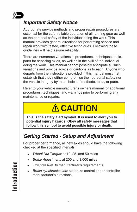
-4-
Important Safety Notice
Appropriate service methods and proper repair procedures are
essential for the safe, reliable operation of all running gear as well
as the personal safety of the individual doing the work. This
manual provides general directions for performing service and
repair work with tested, effective techniques. Following these
guidelines will help assure reliability.
There are numerous variations in procedures, techniques, tools,
parts for servicing axles, as well as in the skill of the individual
doing the work. This manual cannot possibly anticipate all such
variations and provide advice or cautions as to each. Anyone who
departs from the instructions provided in this manual must first
establish that they neither compromise their personal safety nor
the vehicle integrity by their choice of methods, tools, or parts.
Refer to your vehicle manufacturer's owners manual for additional
procedures, techniques, and warnings prior to performing any
maintenance or repairs.
! CAUTIONThis is the safety alert symbol. It is used to alert you to
potential injury hazards. Obey all safety messages that
follow this symbol to avoid possible injury or death.
Getting Started - Setup and Adjustment
For proper performance, all new axles should have the following
checked at the specified intervals:
” Wheel Nut Torque: at 10, 25, and 50 miles
” Brake Adjustment: at 200 and 3,000 miles
” Tire pressure: to manufacturer's requirements
” Brake synchronization: set brake controller per controller
manufacturer’s directions
Intr
oduc
tion
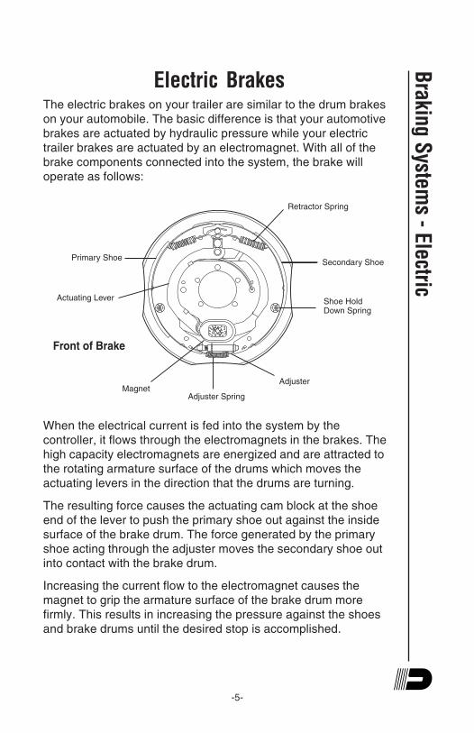
-5-
Electric BrakesThe electric brakes on your trailer are similar to the drum brakes
on your automobile. The basic difference is that your automotive
brakes are actuated by hydraulic pressure while your electric
trailer brakes are actuated by an electromagnet. With all of the
brake components connected into the system, the brake will
operate as follows:
When the electrical current is fed into the system by the
controller, it flows through the electromagnets in the brakes. The
high capacity electromagnets are energized and are attracted to
the rotating armature surface of the drums which moves the
actuating levers in the direction that the drums are turning.
The resulting force causes the actuating cam block at the shoe
end of the lever to push the primary shoe out against the inside
surface of the brake drum. The force generated by the primary
shoe acting through the adjuster moves the secondary shoe out
into contact with the brake drum.
Increasing the current flow to the electromagnet causes the
magnet to grip the armature surface of the brake drum more
firmly. This results in increasing the pressure against the shoes
and brake drums until the desired stop is accomplished.
Braking S
ystems - Electric
Primary Shoe
Actuating Lever
MagnetAdjuster Spring
Adjuster
Shoe Hold
Down Spring
Secondary Shoe
Retractor Spring
Front of Brake
-6-
FeaturesElectrically actuated brakes have several advantages over other
brake actuation systems.
1. They can be manually adjusted at the controller to provide
the correct braking capability for varying road and load
conditions.
2. They can be modulated to provide more or less braking
force, thus easing the brake load on the towing vehicle.
3. They have very little lag time from the moment the tow
vehicle’s brakes are actuated until the trailer brakes are
actuated.
4. In an emergency situation, they can provide some braking
independent of the tow vehicle.
Parking Brake Option (not available on all sizes)
Dexter electric brakes with parking brake option are mechanically
operated by a cable. Cable force applied to the parking lever
creates a torque through the pivot pin and cam assembly. Torque
transferred to the parking cam results in a spreading force
between the primary and secondary shoes. The shoes, in turn,
move towards the drum until contact is made. Friction generated
between the drum and lining contact surface keeps the drum from
rotating under normal loading conditions.
Self Adjusting Feature (121/4" brakes series only)
Forward self adjust electric brakes were introduced in October of
1996. This feature adjusts the brakes on both forward and
reverse stops. Brake adjustment occurs when lining wear results
in enough gap between the shoes and the brake drum surface.
This added clearance will allow the adjuster mechanism to rotate
the screw assembly at the bottom of the brake. That action
expands the distance between the shoes and thus closes the gap
to the drum surface.
Bra
king
Sys
tem
s -
Elec
tric

-7-
Brake Controllers
Electric brake controllers provide power to the magnets to actuate
the trailer brakes. Dexter Axle offers a state-of-the-art inertial
controller called the Predator Series™ DX2. This controller
features a patented pendulum design which senses the
deceleration of the towing vehicle and sends a proportional
voltage to the electric trailer brakes. Other features include a
visual gain setting for quick and easy adjustment and a digital
LED display to show the voltage output. A manual override sends
full voltage to the trailer brakes, regardless of gain setting, for
emergency conditions and also illuminates the brake lights to
warn of an impending stop.
Most electric brake controllers provide a modulation function that
varies the current to the electric brakes with the pressure on the
brake pedal or amount of deceleration of the tow vehicle.
Electronic or timing controllers do not provide proportional
modulation. These controllers tend to be inexpensive but not the
best choice for optimum braking. It is important that your brake
controller provide approximately 2 volts to the braking system
when the brake pedal is first depressed and gradually increases
the voltage to 12 volts as brake pedal pressure is increased. If
the controller "jumps" immediately to a high voltage output, even
during a gradual stop, then the electric brakes will always be fully
energized and will result in harsh brakes and potential wheel
lockup.
Braking S
ystems - Electric

-8-
Bra
king
Sys
tem
s -
Elec
tric Breakaway Battery
Provides power to actuate
trailer brakes in the event of
trailer breakaway.
Dexter Electric Brakes
Wired in parallel.
Breakaway Switch
Switches battery power
to brakes if
breakaway occurs.

-9-
Braking S
ystems - Electric
Controller
Electric brake controller
provides power to the
magnets to actuate the
trailer brakes.
Battery
Connect controller directly.
Connector
Used to connect and disconnect
trailer and tow vehicle.
(Always ground trailer brakes
through connector).

-10-
Bra
king
Sys
tem
s -
Elec
tric
Typical Trailer Wiring
BR
OW
N
BLUE
WHITE
RE
D
GREEN BLAC
K
BLA
CK
BROWNGREY
BLU
E
WH
ITE
ORANGE RED
GR
EE
N
7
1 2
3 4
5 6
YELLOW
7
1
2
3
4
5
6
YELLOW
9
8
DoubleFilamentBulb
License Tail &Running LightsTerminal #3
Battery ChargeTerminal #4 Black
Yellow Auxiliary CircuitTerminal #7
Stop & Left Turn SignalTo Terminal #5
Auxiliary CircuitTerminal #8
#1 Common Ground
GreyR
ed
Gre
en
Breakaway Switch
White Common GroundTerminal #1
OrangeAuxiliary CircuitTerminal #9
Batt.
Stop & Right Turn SignalTerminal #6
Electric BrakeTerminal #2 Blue
Electric BrakeGround Terminal#1 White
DoubleFilamentBulb
Bro
wn
Yellow
White
Green
Red
Black
Orange
Brown
Blue
Grey
#3 To Tail Running & License Lights
#5 Stop & Left Turn
#4 Battery Charge
#7 Aux. Circuit
#9 Aux. Circuit
#6 Stop & Right Turn
#2 Electric Brake
#8 Aux. Circuit
Clearance & Tail Lights
Stop & LH Turn
Ground
Auxiliary
Brakes
Stop &RH Turn
Battery Charge
Clearance & Tail Lights
Stop & LH Turn
Ground
Auxiliary
Brakes
Stop &RH Turn
Battery Charge
7-Circuit Receptacle
Auxiliary
Auxiliary
9-Circuit Receptacle
View Looking into Tow Vehicle Receptacle
Trailer Towing Vehicle
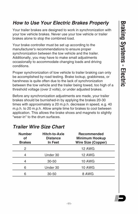
-11-
How to Use Your Electric Brakes Properly
Your trailer brakes are designed to work in synchronization with
your tow vehicle brakes. Never use your tow vehicle or trailer
brakes alone to stop the combined load.
Your brake controller must be set up according to the
manufacturer's recommendations to ensure proper
synchronization between the tow vehicle and the trailer.
Additionally, you may have to make small adjustments
occasionally to accommodate changing loads and driving
conditions.
Proper synchronization of tow vehicle to trailer braking can only
be accomplished by road testing. Brake lockup, grabbiness, or
harshness is quite often due to the lack of synchronization
between the tow vehicle and the trailer being towed, too high of a
threshold voltage (over 2 volts), or under adjusted brakes.
Before any synchronization adjustments are made, your trailer
brakes should be burnished-in by applying the brakes 20-30
times with approximately a 20 m.p.h. decrease in speed, e.g. 40
m.p.h. to 20 m.p.h. Allow ample time for brakes to cool between
application. This allows the brake shoes and magnets to slightly
"wear-in" to the drum surfaces.
Trailer Wire Size Chart
Number Hitch-to-Axle Recommended
of Distance Minimum Hookup
Brakes In Feet Wire Size (Copper)
2 12 AWG
4 Under 30 12 AWG
4 30-50 10 AWG
6 Under 30 10 AWG
6 30-50 8 AWG
Braking S
ystems - Electric
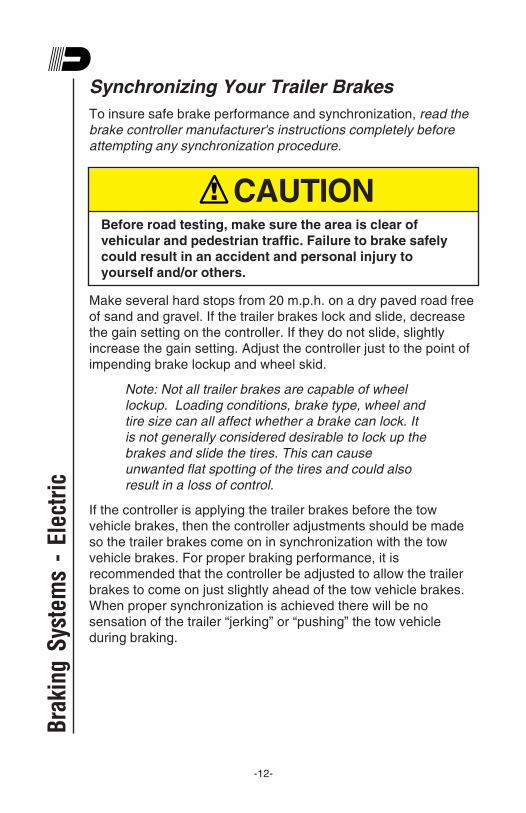
-12-
Bra
king
Sys
tem
s -
Elec
tric
Synchronizing Your Trailer Brakes
To insure safe brake performance and synchronization, read the
brake controller manufacturer's instructions completely before
attempting any synchronization procedure.
! CAUTIONBefore road testing, make sure the area is clear of
vehicular and pedestrian traffic. Failure to brake safely
could result in an accident and personal injury to
yourself and/or others.
Make several hard stops from 20 m.p.h. on a dry paved road free
of sand and gravel. If the trailer brakes lock and slide, decrease
the gain setting on the controller. If they do not slide, slightly
increase the gain setting. Adjust the controller just to the point of
impending brake lockup and wheel skid.
Note: Not all trailer brakes are capable of wheel
lockup. Loading conditions, brake type, wheel and
tire size can all affect whether a brake can lock. It
is not generally considered desirable to lock up the
brakes and slide the tires. This can cause
unwanted flat spotting of the tires and could also
result in a loss of control.
If the controller is applying the trailer brakes before the tow
vehicle brakes, then the controller adjustments should be made
so the trailer brakes come on in synchronization with the tow
vehicle brakes. For proper braking performance, it is
recommended that the controller be adjusted to allow the trailer
brakes to come on just slightly ahead of the tow vehicle brakes.
When proper synchronization is achieved there will be no
sensation of the trailer “jerking” or “pushing” the tow vehicle
during braking.

-13-
Braking S
ystems - Electric
General Maintenance - Electric BrakesBrake Adjustment
Most Dexter 121/4" electric brakes have a self adjusting feature. If
manual adjusting is required, use the following procedure:
Brakes should be adjusted (1) after the first 200 miles of
operation when the brake shoes and drums have “seated,” (2) at
3,000 mile intervals, (3) or as use and performance requires. The
brakes should be adjusted in the following manner:
1. Jack up trailer and secure on adequate capacity jack
stands. Follow trailer manufacturer's recommendations for
lifting and supporting the unit. Make sure the wheel and
drum rotates freely.
! CAUTIONDo not lift or support the trailer on any part of the axle or
suspension system. Never go under any trailer unless it
is properly supported on jack stands which have been
rated for the load. Improperly supported vehicles can fall
unexpectedly and cause serious injury.
2. Remove the adjusting hole cover from the adjusting slot on
the bottom of the brake backing plate.
3. With a screwdriver or standard adjusting tool, rotate the
starwheel of the adjuster assembly to expand the brake
shoes. Adjust the brake shoes out until the pressure of the
linings against the drum makes the wheel very difficult to
turn.
Note: For drop spindle axles, a modified adjusting
tool may be necessary.
4. Then rotate the starwheel in the opposite direction until the
wheel turns freely with a slight lining drag.
5. Replace the adjusting hole cover and lower the wheel to the
ground.
6. Repeat the above procedure on all brakes. For best results,
the brakes should all be set at the same clearance.
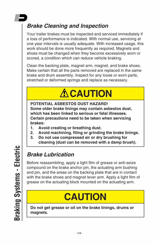
-14-
Bra
king
Sys
tem
s -
Elec
tric
Brake Cleaning and Inspection
Your trailer brakes must be inspected and serviced immediately if
a loss of performance is indicated. With normal use, servicing at
one year intervals is usually adequate. With increased usage, this
work should be done more frequently as required. Magnets and
shoes must be changed when they become excessively worn or
scored, a condition which can reduce vehicle braking.
Clean the backing plate, magnet arm, magnet, and brake shoes.
Make certain that all the parts removed are replaced in the same
brake and drum assembly. Inspect for any loose or worn parts,
stretched or deformed springs and replace as necessary.
! CAUTIONPOTENTIAL ASBESTOS DUST HAZARD!
Some older brake linings may contain asbestos dust,
which has been linked to serious or fatal illnesses.
Certain precautions need to be taken when servicing
brakes:
1. Avoid creating or breathing dust.
2. Avoid machining, filing or grinding the brake linings.
3. Do not use compressed air or dry brushing for
cleaning (dust can be removed with a damp brush).
Brake Lubrication
Before reassembling, apply a light film of grease or anti-seize
compound on the brake anchor pin, the actuating arm bushing
and pin, and the areas on the backing plate that are in contact
with the brake shoes and magnet lever arm. Apply a light film of
grease on the actuating block mounted on the actuating arm.
CAUTIONDo not get grease or oil on the brake linings, drums or
magnets.
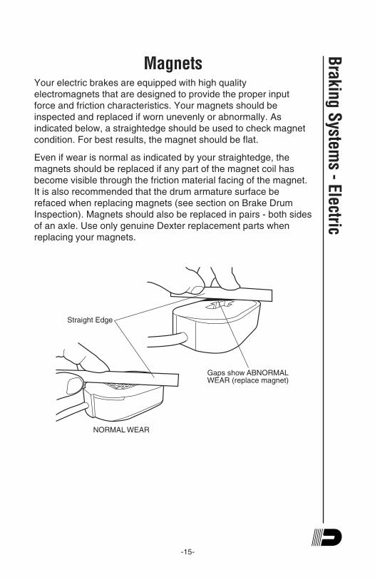
-15-
Braking S
ystems - Electric
MagnetsYour electric brakes are equipped with high quality
electromagnets that are designed to provide the proper input
force and friction characteristics. Your magnets should be
inspected and replaced if worn unevenly or abnormally. As
indicated below, a straightedge should be used to check magnet
condition. For best results, the magnet should be flat.
Even if wear is normal as indicated by your straightedge, the
magnets should be replaced if any part of the magnet coil has
become visible through the friction material facing of the magnet.
It is also recommended that the drum armature surface be
refaced when replacing magnets (see section on Brake Drum
Inspection). Magnets should also be replaced in pairs - both sides
of an axle. Use only genuine Dexter replacement parts when
replacing your magnets.
NORMAL WEAR
Gaps show ABNORMAL
WEAR (replace magnet)
Straight Edge
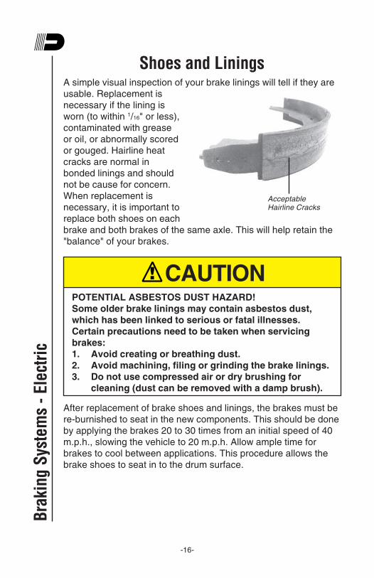
-16-
Shoes and LiningsA simple visual inspection of your brake linings will tell if they are
usable. Replacement is
necessary if the lining is
worn (to within 1/16" or less),
contaminated with grease
or oil, or abnormally scored
or gouged. Hairline heat
cracks are normal in
bonded linings and should
not be cause for concern.
When replacement is
necessary, it is important to
replace both shoes on each
brake and both brakes of the same axle. This will help retain the
"balance" of your brakes.
! CAUTIONPOTENTIAL ASBESTOS DUST HAZARD!
Some older brake linings may contain asbestos dust,
which has been linked to serious or fatal illnesses.
Certain precautions need to be taken when servicing
brakes:
1. Avoid creating or breathing dust.
2. Avoid machining, filing or grinding the brake linings.
3. Do not use compressed air or dry brushing for
cleaning (dust can be removed with a damp brush).
After replacement of brake shoes and linings, the brakes must be
re-burnished to seat in the new components. This should be done
by applying the brakes 20 to 30 times from an initial speed of 40
m.p.h., slowing the vehicle to 20 m.p.h. Allow ample time for
brakes to cool between applications. This procedure allows the
brake shoes to seat in to the drum surface.
Bra
king
Sys
tem
s -
Elec
tric
Acceptable
Hairline Cracks

-17-
Introduction to TroubleshootingProper brake function is critical to the safe operation of any
vehicle. If problems are encountered with your trailer braking
system, the following guide can be used to find the causes and
remedies for some of the more common problems. If you are
unsure or unable to resolve the problem, please contact your
nearest repair facility for professional assistance.
TroubleshootingMost electric brake malfunctions, that cannot be corrected by
either brake adjustments or synchronization adjustments, can
generally be traced to electrical system failure. Voltmeters and
ammeters are essential tools for proper troubleshooting of electric
brakes.
Mechanical causes are ordinarily obvious, i.e. bent or broken
parts, worn out linings or magnets, seized lever arms or shoes,
scored drums, loose parts, etc. Replace defective parts with
genuine Dexter replacements.
Please consult the following troubleshooting charts to determine
the causes and solutions for common problems found in trailer
braking systems.
! CAUTIONBest braking performance is achieved with a controller
setting that is just short of wheel lock up or slide. Overly
aggressive braking which results in wheel lock up and
sliding, can cause a dangerous loss of control and result
in personal injury or death.
Braking S
ystems - Electric

-18-
Troubleshooting
Open Circuits
Faulty Controller
Short Circuits
Grease or Oil onMagnets or Linings
Worn Linings or Magnets
Scored or GroovedBrake Drums
ImproperSynchronization
Underadjustment
ImproperSynchronization
SevereUnderadjustment
Corroded Connections
Glazed Linings
Overloaded Trailer
Underadjustment
Faulty Controller
Loose, Bent or BrokenBrake Components
Out-of-RoundBrake Drums
Insufficient Wheel Load
Faulty Controller
Broken Wires
Loose Connections
Find & Correct
Adjust Brakes
Test & Correct
Clean or Replace
Clean & CorrectCause of Corrosion
Replace
Machine or Replace
Correct
Adjust Brakes
Reburnish or Replace
Correct
Adjust
Correct
Test & Correct
Replace Components
Machine or Replace
Adjust System Resistorand Synchronize
Test & Correct
Repair or Replace
Find & Repair
No Brakes
Weak Brakes
Locking Brakes
Intermittent Brakes
Find & Correct
SYMPTOM CAUSES REMEDIES
Faulty Ground Find & RepairBra
king
Sys
tem
s -
Elec
tric

-19-
Braking S
ystems - Electric
Troubleshooting
Incorrect Adjustment
Broken Wires
Bad Connections
Underadjustment
Improper Controller
Faulty Controller
Underadjustment
Lack of Lubrication
Out-of-Round orCracked Brake Drums
Grease or Oil onLinings or Magnets
ImproperSynchronization
BrokenBrake Components
Incorrect BrakeComponents
Grease or Oil onLinings or Magnet
Faulty Controller
Overadjustment
Out-of-RoundBrake Drums
Incorrect BrakeComponents
Loose, Bent or BrokenBrake Components
Faulty BreakawaySwitch
Loose WheelBearing Adjustment
Adjust
Clean or Replace
Find & Repair
Find & Repair
Adjust
Correct
Change
Test & Correct
Adjust
Lubricate
Replace Component
Correct
Clean or Replace
Machine or Replace
Test & Correct
Readjust
Machine or Replace
Replace
Replace
Repair or Replace
Adjust
Bent Spindle Replace Axle
Harsh Brakes
Noisy Brake
Surging Brakes
Dragging Brakes
Brakes Pull to One Side
SYMPTOM CAUSES REMEDIES
CorrectWrong Magnet Lead Wire Color

-20-
How to Measure Voltage
System voltage is measured at the magnets by connecting the
voltmeter to the two magnet lead wires at any brake. This may be
accomplished by using a pin probe inserted through the insulation
of the wires. The engine of the towing vehicle should be running
when checking the voltage so that a low battery will not affect the
readings.
Voltage in the system
should begin at 0 volts
and, as the controller bar
is slowly actuated, should
gradually increase to
about 12 volts. If the
controller does not
produce this voltage
control, consult your
controller manual.
The threshold voltage of a controller is the voltage applied to the
brakes when the controller first turns on. Lower threshold voltage
will provide for smoother braking. If the threshold voltage is too
high, the brakes may feel grabby and harsh.
How to Measure Amperage
System amperage is the current flowing in the system when all
the magnets are energized. The amperage will vary in proportion
to the voltage. The engine of the tow vehicle should be running
with the trailer connected when checking the trailer braking
system.
One place to measure system amperage is at the BLUE wire of
the controller which is the output to the brakes. The BLUE wire
must be disconnected and the ammeter put in series into the line.
System amperage draw should be as noted in the following table.
Make sure your ammeter has sufficient capacity and note polarity
to prevent damaging your ammeter.
Bra
king
Sys
tem
s -
Elec
tric
VOLTMETER
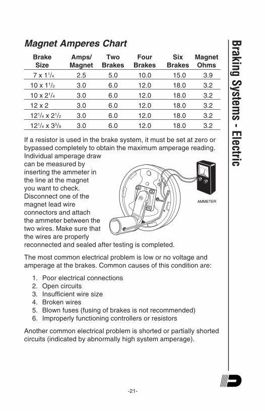
-21-
AMMETER
Magnet Amperes Chart
Brake Amps/ Two Four Six Magnet
Size Magnet Brakes Brakes Brakes Ohms
7 x 11/4 2.5 5.0 10.0 15.0 3.9
10 x 11/2 3.0 6.0 12.0 18.0 3.2
10 x 21/4 3.0 6.0 12.0 18.0 3.2
12 x 2 3.0 6.0 12.0 18.0 3.2
121/4 x 21/2 3.0 6.0 12.0 18.0 3.2
121/4 x 33/8 3.0 6.0 12.0 18.0 3.2
If a resistor is used in the brake system, it must be set at zero or
bypassed completely to obtain the maximum amperage reading.
Individual amperage draw
can be measured by
inserting the ammeter in
the line at the magnet
you want to check.
Disconnect one of the
magnet lead wire
connectors and attach
the ammeter between the
two wires. Make sure that
the wires are properly
reconnected and sealed after testing is completed.
The most common electrical problem is low or no voltage and
amperage at the brakes. Common causes of this condition are:
1. Poor electrical connections
2. Open circuits
3. Insufficient wire size
4. Broken wires
5. Blown fuses (fusing of brakes is not recommended)
6. Improperly functioning controllers or resistors
Another common electrical problem is shorted or partially shorted
circuits (indicated by abnormally high system amperage).
Braking S
ystems - Electric

-22-
Possible causes are:
1. Shorted magnet coils
2. Defective controllers
3. Bare wires contacting a grounded object
Finding the cause of a short circuit in the system is done by
isolating one section at a time. If the high amperage reading
drops to zero by unplugging the trailer, then the short is in the
trailer. If the amperage reading remains high with all the brake
magnets disconnected, the short is in the trailer wiring.
All electrical troubleshooting procedures should start at the
controller. Most complaints regarding brake harshness or
malfunction are traceable to improperly adjusted or non-
functioning controllers. See your controller manufacturer’s data
for proper adjustment and testing procedures. For best results, all
the connection points in the brake wiring should be sealed to
prevent corrosion. Loose or corroded connectors will cause an
increase in resistance which reduces the voltage available for the
brake magnets.
Bra
king
Sys
tem
s -
Elec
tric

-23-
Hydraulic BrakesDexter offers several varieties of hydraulic trailer brakes. Your
vehicle may be equipped with the traditional drum brakes or
you may have disc brakes.
The hydraulic brakes on your trailer are much like those on
your automobile or light truck. The hydraulic fluid from a master
cylinder or actuation system is used to actuate the wheel
cylinder which, in turn, applies force against the brake shoes
and drum. The main difference between automotive hydraulic
brakes and hydraulic trailer brakes is the trailers' actuation
system. These systems respond to the braking signal from the
tow vehicle and supply the required brake fluid volume and
pressure to the trailer brakes.
In the following pages you will find a more detailed description
of the hydraulic brakes and actuation system used on your
trailer.
CAUTIONThe operating pressure required for Dexter brakes:
• 7" diameter drum brakes
maximum operating pressure is 750 psi
• 10" diameter and larger drum brakes
maximum operating pressure is 1,000 psi
• Hydraulic disc brakes (all sizes)
maximum operating pressure is 1,600 psi
Braking S
ystems - H
ydraulic

-24-
Hydraulic Brake OperationDuo-Servo
The duo-servo brake uses a dual piston wheel cylinder to apply
the brakes. This type of brake is typically used in a vacuum/
hydraulic, electric/hydraulic or air/hydraulic system. A description
of operation of this brake is as follows:
When the brakes are applied, the double-acting wheel cylinder
moves the primary and secondary shoes towards the drum. The
frictional force between
the brake drum and lining
attempts to turn the
primary shoe into the
secondary shoe. The
secondary shoe is forced
onto the anchor pin and
from this point, the
secondary and primary
shoes attempt to "wrap
around". In essence, the
brake has utilized frictional
force to help the applying force on both shoes.
If the brakes are applied while the vehicle is backing, the shoes
rotate in the direction of the drum rotation. This causes the
secondary shoe to leave the anchor and causes the primary shoe
to move against the anchor. Action of the brake is the same in
reverse as forward.
Uni-Servo
This type of hydraulic brake utilizes a single acting cylinder. Upon
actuation, the primary shoe is pressed against the brake drum,
which causes the shoe to move in the direction of rotation. This
movement in turn actuates the secondary shoe through the
adjuster assembly. Braking in reverse is significantly less
effective than in the forward direction.
Another variation is called a “free backing” brake which is
commonly used on trailers with a surge hitch system. When
Bra
king
Sys
tem
s -
Hyd
raul
ic
Anchor Post
Retractor
Springs
Backing
Plate
Secondary
Shoe
Adjuster Spring
Adjuster Assembly
Primary Shoe
Hold Down
Spring
Actuating Pin
Hydraulic Wheel
Cylinder
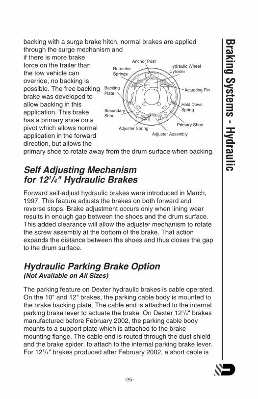
-25-
backing with a surge brake hitch, normal brakes are applied
through the surge mechanism and
if there is more brake
force on the trailer than
the tow vehicle can
override, no backing is
possible. The free backing
brake was developed to
allow backing in this
application. This brake
has a primary shoe on a
pivot which allows normal
application in the forward
direction, but allows the
primary shoe to rotate away from the drum surface when backing.
Self Adjusting Mechanismfor 121/4" Hydraulic Brakes
Forward self-adjust hydraulic brakes were introduced in March,
1997. This feature adjusts the brakes on both forward and
reverse stops. Brake adjustment occurs only when lining wear
results in enough gap between the shoes and the drum surface.
This added clearance will allow the adjuster mechanism to rotate
the screw assembly at the bottom of the brake. That action
expands the distance between the shoes and thus closes the gap
to the drum surface.
Hydraulic Parking Brake Option(Not Available on All Sizes)
The parking feature on Dexter hydraulic brakes is cable operated.
On the 10" and 12" brakes, the parking cable body is mounted to
the brake backing plate. The cable end is attached to the internal
parking brake lever to actuate the brake. On Dexter 121/4" brakes
manufactured before February 2002, the parking cable body
mounts to a support plate which is attached to the brake
mounting flange. The cable end is routed through the dust shield
and the brake spider, to attach to the internal parking brake lever.
For 121/4" brakes produced after February 2002, a short cable is
Braking S
ystems - H
ydraulic
Anchor Post
Retractor
Springs
Backing
Plate
Secondary
Shoe
Adjuster Spring
Adjuster Assembly
Primary Shoe
Hold Down
Spring
Actuating Pin
Hydraulic Wheel
Cylinder

-26-
installed directly into the backing plate to provide a convenient
means for the trailer manufacturer to attach an appropriate
operating system.
The internal parking brake lever of 10" and 12" Dexter brakes,
which is mounted to the secondary shoe, transfers applied cable
force through a parking strut which is attached to the primary
shoe. This transferred load generates a spreading force between
the primary and secondary shoes. The shoes move toward the
drum until contact is made. Friction generated between the drum
and lining contact surface results in parking brake capability.
The internal parking brake lever of Dexter 121/4" brakes transfers
the applied cable force through a cam mechanism. The cam
mechanism generates a spreading force between the primary and
secondary shoes. The shoes move toward the drum until contact
is made. Friction generated between the drum and lining contact
surface results in parking brake capability.
Bra
king
Sys
tem
s -
Hyd
raul
ic
Park Cable
Park Lever

-27-
Disc Brakes
Dexter Axle manufactures two types of disc brakes, the floating
caliper and the fixed caliper brake. With both styles, the disc
brake uses friction pads astride a ventilated rotor which is
attached to the wheel hub. When the brake is actuated, the pads
are pressed against the sides of the rotor causing drag to slow
the rotating disc. This action converts the kinetic energy (motion)
into heat. The heat is dissipated rapidly by the ventilated disc.
The floating caliper brake uses piston(s) situated on one side of
the brake rotor. Hydraulic fluid pressure pushes against the
piston(s) to apply the inboard brake pad. As the inboard pad
exerts force against the rotating rotor surface, the caliper moves
laterally towards the trailer frame and in turn applies an
equivalent force to the outboard brake pad against the rotor
surface. As the lining material wears, the caliper will automatically
maintain the proper lining to rotor clearance. The floating caliper
design is used on Dexter 3,500 lb., 10,000 lb., and 12,000 lb. axle
models.
The fixed caliper method uses pistons situated on both sides of
the rotor. During actuation,
hydraulic pressure pushes against
the pistons to apply the inboard
and outboard brake pads equally
to decelerate the rotating rotor.
The caliper is fixed and stays
stationary during brake actuation
and brake adjustment. Brake pad
to rotor clearance is maintained as
lining wear occurs via the brake
piston and internal caliper seal.
The fixed caliper design is used on
the Dexter 6,000 lb. and 8,000 lb.
axle models.
Disc brake effectiveness is the same going either in a forward or
reverse direction. All Dexter disc brakes should be actuated with
a braking system that is capable of providing a maximum
hydraulic pressure of 1,600 psi.
Braking S
ystems - H
ydraulic

-28-
Actuation SystemsTo effectively operate your hydraulic trailer brakes we
recommend the Dexter E/H electro/hydraulic actuator, controlled
by the Predator series DX2™ electronic brake controller. These
high performance hydraulic power modules will supply
pressurized brake fluid to your trailer brakes in proportion to the
amount of braking effort called for by the towing vehicles'
deceleration rate.
CAUTIONIt is the responsibility of the end user to ensure that their
in-cab electronic controller is compatible with the Dexter
E/H actuator. Dexter Axle attempts to provide
compatibility with most controllers available, but is
unable to anticipate design changes that might be
introduced by the various controller manufacturers.
The E/H 1000 will supply 1000 psi for your drum brakes and the
E/H 1600 will generate 1600 psi for maximum performance from
your Dexter disc brakes. The sealed, weather tight housing
contains the electronics necessary to control the high pressure
piston pump and proportioning valve for smooth, efficient braking.
Bra
king
Sys
tem
s -
Hyd
raul
ic
YELLOWORANGE/BLACK
MINIMUM9 AMP HR BATTERY
-29-
Braking S
ystems - H
ydraulicTroubleshooting Guide
Brakes are slow to respond
1. Re-bleed the trailer brakes and actuator.
2. If the trailer is equipped with drum brakes, readjust the
drum brakes to the brake manufacture's recommended
running clearance.
3. Slow response can be caused by trailer wiring that is too
small.
4. For trailers where the E/H unit is located less than 10 feet
from the tow vehicle, 12 gage wire is recommended for the
black and white wires between the tow vehicle and the E/H
unit. All other wires should be a minimum of 16 gauge.
5. For trailers where the E/H unit is located more than 10 feet
from the tow vehicle, 10 gage wire is recommended for the
black and white wires between the tow vehicle and the E/H
unit. All other wires should be a minimum of 16 gauge.
6. Slow response can be caused by improper adjustment of
the brake controller. On inertia-based electronic brake
controls, adjust the pendulum (inertia sensor) to a more
aggressive setting and/or increase the gain setting.
Unit will not run when the ignition is on and the brake pedal is
depressed
1. Verify that the trailer and tow vehicle are wired as detailed
on the electrical schematic.
2. With the ignition switch on and the brakes not applied, you
should have 12-13 volts between the black and white wires
on the E/H unit.
3. Clean and replace the ground between the trailer and the
E/H unit.
4. Test operation of the unit using the breakaway test
procedure.
Breakaway test procedure - do not leave the breakaway switch
pulled for more than two minutes during any of the steps outlined
below
1. Pull the breakaway switch on the trailer.
2. If the unit runs and builds pressure, that indicates the
-30-
actuator is functioning properly. The problem most likely is
a defective electronic brake controller in the tow vehicle or
defective wiring between the tow vehicle and the E/H unit.
3. If the unit runs but will not build pressure, the problem most
likely is a defective solenoid valve in the E/H unit and the
actuator should be returned for repair.
4. If the unit still does not run after the breakaway battery is
fully charged, verify that the voltage between the white wire
and yellow wire is at least 12 volts.
5. If the voltage is less than 12 volts, either the breakaway
switch or the breakaway wiring is defective.
6. If the voltage is greater than 12 volts, the E/H unit should
be returned for repair.
Trailer brakes too aggressive
1. Reduce the gain setting on the in-cab electronic brake
controller.
Bra
king
Sys
tem
s -
Hyd
raul
ic
-31-
General Maintenance - Hydraulic BrakesDrum Brake Adjustment - Manual
Most Dexter 121/4" electric brakes have a self adjusting feature. If
manual adjusting is required, use the following procedure:
Brakes should be adjusted (1) after the first 200 miles of operation
when the brake shoes and drums have “seated,” (2) at 3,000 mile
intervals, (3) or as use and performance requires. The brakes
should be adjusted in the following manner:
1. Jack up trailer and secure on adequate capacity jack
stands. Follow trailer manufacturer's recommendations for
lifting and supporting the unit. Make sure the wheel and
drum rotates freely.
! CAUTIONDo not lift or support the trailer on any part of the axle or
suspension system. Never go under any trailer unless it
is properly supported on jack stands which have been
rated for the load. Improperly supported vehicles can fall
unexpectedly and cause serious injury or death.
2. Remove the adjusting hole cover from the adjusting slot on
the bottom of the brake backing plate.
3. With a screwdriver or standard adjusting tool, rotate the
starwheel of the adjuster assembly to expand the brake
shoes. Adjust the brake shoes out until the pressure of the
linings against the drum makes the wheel very difficult to
turn.
Note: For drop spindle axles, a modified adjusting
tool may be necessary.
4. Then rotate the starwheel in the opposite direction until the
wheel turns freely with a slight lining drag.
5. Replace the adjusting hole cover and lower the wheel to the
ground.
6. Repeat the above procedure on all brakes. For best results,
the brakes should all be set at the same clearance.
Braking S
ystems - H
ydraulic

-32-
Bra
king
Sys
tem
s -
Hyd
raul
icMost of the brake components are very similar to those used in
electric brakes, and maintenance is comparable for the hub and
drum, shoes and linings, and bearings. Specific maintenance
activities are as follows:
Wheel Cylinders
Inspect for leaks and smooth operation. Clean with brake cleaner
and flush with fresh brake fluid. Hone or replace as necessary.
Brake Lines
Check for cracks, kinks, or blockage. Flush with fresh brake fluid.
Bleed system to remove all air. Replace as necessary.
Shoes and Linings
A simple visual inspection of your brake linings will tell if they are
usable. Replacement is necessary if the lining is worn (to within1/16" or less), contaminated with grease or oil, or abnormally
scored or gouged. Hairline heat cracks are normal in bonded
linings and should not be cause for concern. When replacement
is necessary, it is important to replace both shoes on each brake
and both brakes of the same axle. This will help retain the
“balance” of your brakes.
! CAUTIONPOTENTIAL ASBESTOS DUST HAZARD!
Some older brake linings may contain asbestos dust,
which has been linked to serious or fatal illnesses.
Certain precautions need to be taken when servicing
brakes:
1. Avoid creating or breathing dust.
2. Avoid machining, filing or grinding the brake linings.
3. Do not use compressed air or dry brushing for
cleaning (dust can be removed with a damp brush).

-33-
After replacement of brake shoes and linings, the brakes must be
re-burnished to seat in the new components. This should be done
by applying the brakes 20 to 30 times from an initial speed of 40
m.p.h., slowing the vehicle to 20 m.p.h. Allow ample time for
brakes to cool between applications. This procedure allows the
brake shoes to seat in to the drum surface.
Hardware
Check all hardware. Check shoe return spring, hold down
springs, and adjuster springs for stretch or wear. Replace as
required. Service kits are available.
Instructions for Brake Caliper Kit3.5K Disc Hydraulic Brakes
Notice to Buyer
It is recommended that all brakes be replaced at the same time to
insure balanced braking performance.
Remove the old brake caliper
1. Jack up trailer and secure on adequate capacity jack
stands. Follow trailer manufacturers recommendations for
lifting and supporting the unit.
! CAUTIONDo not lift or support the trailer on any part of the axle or
suspension system. Never go under any trailer unless it
is properly supported on jack stands which have been
rated for the load. Improperly supported vehicles can fall
unexpectedly and cause serious injury or death.
2. Remove the wheel from the hub, leaving the brake
exposed.
3. Disconnect the brake actuation system. Check that the
hydraulic system has zero pressure and that the hub and
rotor rotates freely.
Braking S
ystems - H
ydraulic

-34-
4. Remove the hose from the caliper. Then remove the two
caliper mounting bolts. Do not allow the caliper to hang
from the hose.
Installing the new brake caliper
1. First inspect the brake assembly for grooves, flaking,
cracks, heat checking, thickness variation, insufficient rotor
thickness, and look to see that the mounting hardware is
straight. Replace any component as needed (or desired)
per manufacturer recommendations.
2. Install the new caliper assembly. Make sure that the bleed
screw points up.
3. Remount the caliper assembly onto the caliper attaching
bracket. Ensure that there is thread locking compound on
the threads of the new mounting bolts. Torque mounting
bolts to 40-50 Ft. Lbs. Note: Use two lug nuts to secure
rotor against the hub face when reassembling the caliper.
After the caliper is assembled remove the lug nuts.
4. Reconnect the hose to the elbow adapter on the back of the
caliper and torque to 10-12 Ft. Lbs.
5. Reconnect the brake actuation system. Refer to your
actuation systems Operation Maintenance Service Manual
for proper operation.
6. Bleed and flush brake system per your actuation systems
Operation Maintenance Service Manual.
7. Remount the wheel. Refer to your Operation Maintenance
Service Manual for proper wheel nut torque procedures.
Instructions for Brake Rotor Kit3.5K Disc Hydraulic Brakes
Notice to Buyer
It is recommended that all brakes be replaced at the same time to
insure balanced braking performance.
Remove the old brake rotor
1. Jack up trailer and secure on adequate capacity jack
stands. Follow trailer manufacturers recommendations for
lifting and supporting the unit.
Bra
king
Sys
tem
s -
Hyd
raul
ic
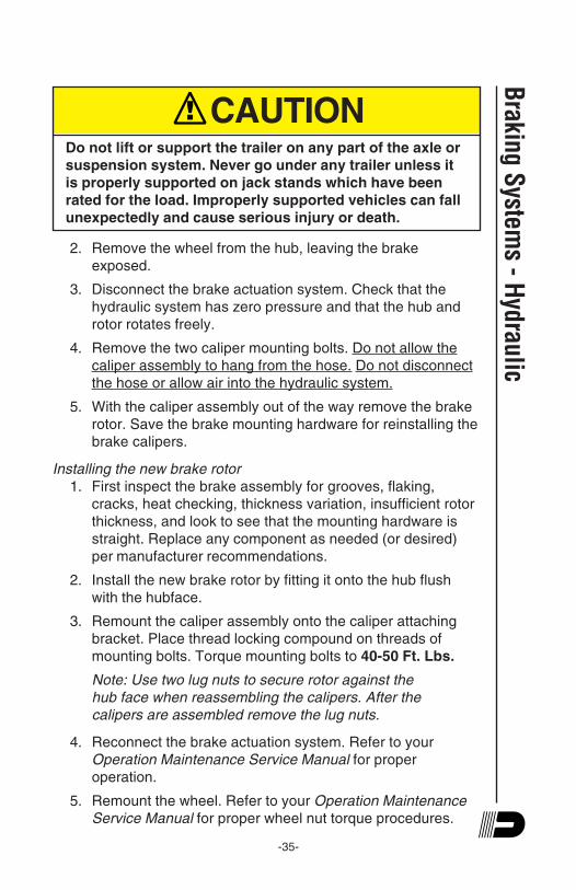
-35-
! CAUTIONDo not lift or support the trailer on any part of the axle or
suspension system. Never go under any trailer unless it
is properly supported on jack stands which have been
rated for the load. Improperly supported vehicles can fall
unexpectedly and cause serious injury or death.
2. Remove the wheel from the hub, leaving the brake
exposed.
3. Disconnect the brake actuation system. Check that the
hydraulic system has zero pressure and that the hub and
rotor rotates freely.
4. Remove the two caliper mounting bolts. Do not allow the
caliper assembly to hang from the hose. Do not disconnect
the hose or allow air into the hydraulic system.
5. With the caliper assembly out of the way remove the brake
rotor. Save the brake mounting hardware for reinstalling the
brake calipers.
Installing the new brake rotor
1. First inspect the brake assembly for grooves, flaking,
cracks, heat checking, thickness variation, insufficient rotor
thickness, and look to see that the mounting hardware is
straight. Replace any component as needed (or desired)
per manufacturer recommendations.
2. Install the new brake rotor by fitting it onto the hub flush
with the hubface.
3. Remount the caliper assembly onto the caliper attaching
bracket. Place thread locking compound on threads of
mounting bolts. Torque mounting bolts to 40-50 Ft. Lbs.
Note: Use two lug nuts to secure rotor against the
hub face when reassembling the calipers. After the
calipers are assembled remove the lug nuts.
4. Reconnect the brake actuation system. Refer to your
Operation Maintenance Service Manual for proper
operation.
5. Remount the wheel. Refer to your Operation Maintenance
Service Manual for proper wheel nut torque procedures.
Braking S
ystems - H
ydraulic
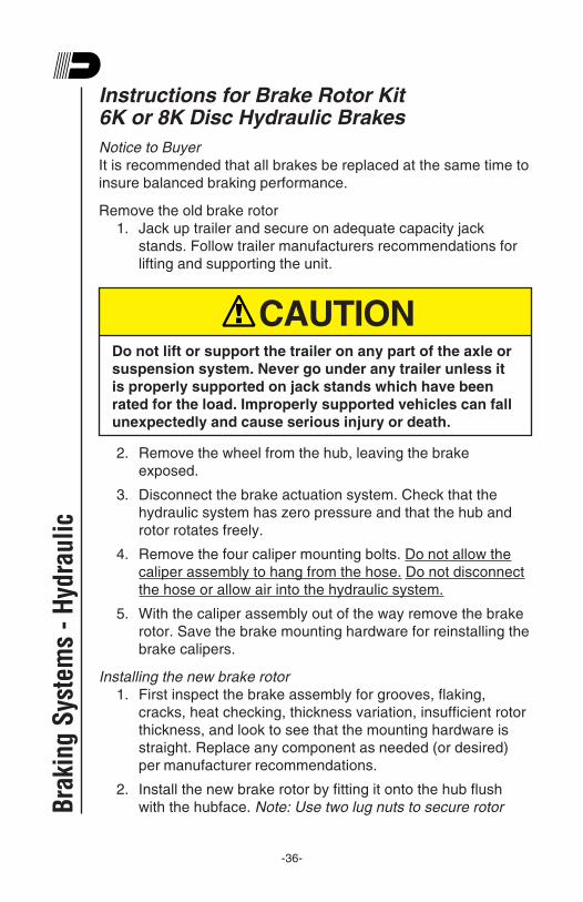
-36-
Instructions for Brake Rotor Kit6K or 8K Disc Hydraulic Brakes
Notice to Buyer
It is recommended that all brakes be replaced at the same time to
insure balanced braking performance.
Remove the old brake rotor
1. Jack up trailer and secure on adequate capacity jack
stands. Follow trailer manufacturers recommendations for
lifting and supporting the unit.
! CAUTIONDo not lift or support the trailer on any part of the axle or
suspension system. Never go under any trailer unless it
is properly supported on jack stands which have been
rated for the load. Improperly supported vehicles can fall
unexpectedly and cause serious injury or death.
2. Remove the wheel from the hub, leaving the brake
exposed.
3. Disconnect the brake actuation system. Check that the
hydraulic system has zero pressure and that the hub and
rotor rotates freely.
4. Remove the four caliper mounting bolts. Do not allow the
caliper assembly to hang from the hose. Do not disconnect
the hose or allow air into the hydraulic system.
5. With the caliper assembly out of the way remove the brake
rotor. Save the brake mounting hardware for reinstalling the
brake calipers.
Installing the new brake rotor
1. First inspect the brake assembly for grooves, flaking,
cracks, heat checking, thickness variation, insufficient rotor
thickness, and look to see that the mounting hardware is
straight. Replace any component as needed (or desired)
per manufacturer recommendations.
2. Install the new brake rotor by fitting it onto the hub flush
with the hubface. Note: Use two lug nuts to secure rotorBra
king
Sys
tem
s -
Hyd
raul
ic

-37-
against the hub face when reassembling the calipers. After
the calipers are assembled remove the lug nuts.
3. Remount the caliper assembly onto the caliper attaching
bracket. It may be necessary to push the piston into the
calipers to obtain enough clearance. Torque mounting bolts
to 25-35 Ft. Lbs.
4. Spin the rotor to ensure that there is enough clearance
between the rotor and the crossover brake line.
5. Reconnect the brake actuation system. Refer to your
Operation Maintenance Service Manual for proper
operation.
6. Remount the wheel. Refer to your Operation Maintenance
Service Manual for proper wheel nut torque procedures.
7. Spin the wheel to ensure that there is enough clearance
between the wheel, crossover brake line, and rotor.
Instructions for Brake Pad Kit6K or 8K Disc Hydraulic Brakes
Notice to Buyer
It is recommended that all brakes be replaced at the same time to
insure balanced braking performance.
Remove the old brake pads
1. Jack up trailer and secure on adequate capacity jack
stands. Follow trailer manufacturers recommendations for
lifting and supporting the unit.
! CAUTIONDo not lift or support the trailer on any part of the axle or
suspension system. Never go under any trailer unless it
is properly supported on jack stands which have been
rated for the load. Improperly supported vehicles can fall
unexpectedly and cause serious injury or death.
Braking S
ystems - H
ydraulic

-38-
2. Remove the wheel from the hub, leaving the brake
exposed.
3. Disconnect the brake actuation system. Check that the
hydraulic system has zero pressure and that the hub and
rotor rotates freely.
4. Remove the brake pad retaining bolt.
5. Remove the old pads from the caliper assembly. Save the
brake pad retaining hardware for reinstalling the new pads
onto the caliper.
! CAUTIONPOTENTIAL ASBESTOS DUST HAZARD!
Some older brake linings may contain asbestos dust,
which has been linked to serious or fatal illnesses.
Certain precautions need to be taken when servicing
brakes:
1. Avoid creating or breathing dust.
2. Avoid machining, filing or grinding the brake linings.
3. Do not use compressed air or dry brushing for
cleaning (dust can be removed with a damp brush).
Installing the new brake pads
1. First inspect the brake assembly for grooves, flaking,
cracks, heat checking, thickness variation, insufficient rotor
thickness, and look to see that the mounting hardware is
straight. Replace any component as needed (or desired)
per manufacturer recommendations.
2. Press the caliper pistons into the calipers until enough
clearance is available to fit the new pads between the
pistons and the rotor. Note: Use two lug nuts to secure rotor
against the hub face when reassembling the new pads.
After the pads are assembled remove the lug nuts.
3. Install the new brake pads by sliding them in one at a time
between the caliper pistons and the rotor. The pads are the
same for the inner and outer side of the rotor. Make sure
the brake lining side of the pad faces the rotor, and the
steel backing faces the caliper pistons.
Bra
king
Sys
tem
s -
Hyd
raul
ic

-39-
4. Align the brake pad mounting holes with the holes in the
caliper. Insert the brake pad retaining bolt and tighten nut
until snug against shoulder of bolt.
5. Reconnect the brake actuation system. Refer to your
Operation Maintenance Service Manual for proper
operation.
6. Remount the wheel. Refer to your Operation Maintenance
Service Manual for proper wheel nut torque procedures.
Instructions for Brake Caliper Kit6K or 8K Disc Hydraulic Brakes
Notice to Buyer
It is recommended that all brakes be replaced at the same time to
insure balanced braking performance.
Remove the old brake pads
1. Jack up trailer and secure on adequate capacity jack
stands. Follow trailer manufacturers recommendations for
lifting and supporting the unit.
! CAUTIONDo not lift or support the trailer on any part of the axle or
suspension system. Never go under any trailer unless it
is properly supported on jack stands which have been
rated for the load. Improperly supported vehicles can fall
unexpectedly and cause serious injury or death.
2. Remove the wheel from the hub, leaving the brake
exposed.
3. Disconnect the brake actuation system. Check that the
hydraulic system has zero pressure and that the hub and
rotor rotates freely.
4. Remove the hose from the caliper, then remove the four
caliper mounting bolts. Do not allow the caliper to hang
from the hose.
Braking S
ystems - H
ydraulic

-40-
Installing the new brake caliper
1. First inspect the brake assembly for grooves, flaking,
cracks, heat checking, thickness variation, insufficient rotor
thickness, and look to see that the mounting hardware is
straight. Replace any component as needed (or desired)
per manufacturer recommendations.
2. Assemble the new caliper assembly. Note: Use two lug
nuts to secure rotor against the hub face when
reassembling the calipers. After the brake is assembled
remove the lug nuts.
3. One caliper will be used on the inboard side, with the
hydraulic line fitting adapter installed on the top side of the
piston boss. The other caliper will be used on the outboard
side with the bleed screw installed at the top of the piston
boss. Install both of these calipers onto the attaching
bracket. Make sure that the bleed screw points up and is
located on the outboard caliper. Torque bolts to 25-35 Ft.
Lbs.
4. Connect the new crossover brake line on the bottom sides
of the piston boss on both calipers. Note: Make sure the
crossover line fits snug around the calipers and rotor
without touching the rotor. Spin the rotor to ensure there is
proper clearance. Torque the crossover line to 12-15 Ft.
Lbs. Torque the bleed screw and the hydraulic line fitting
adapter to 60-76 Inch Lbs.
5. Reassemble the brake pads into the disc brake. Make sure
to locate the brake lining side of the pads toward the rotor
surface, and the steel side of the pads toward the calipers.
Align the holes in the brake pads with the ones in the
calipers. Insert the brake pad retaining bolt and tighten nut
until snug against shoulder of bolt.
6. Reconnect the brake actuation system. Refer to your
Operation Maintenance Service Manual for proper
operation.
7. Bleed and flush brake system per your actuation systems
Operation Maintenance Service Manual.
8. Remount the wheel. Refer to your Operation Maintenance
Service Manual for proper wheel nut torque procedures.
9. Spin wheel to ensure proper clearance between the wheel,
crossover brake line, and the rotor.
Bra
king
Sys
tem
s -
Hyd
raul
ic

-41-
Introduction to TroubleshootingProper brake function is critical to the safe operation of any
vehicle. A properly installed vacuum/hydraulic, electric/hydraulic
or air/hydraulic system should not require any special attention
with the exception of routine maintenance as defined by the
manufacturer. If problems occur, the entire tow vehicle/trailer
braking system should be analyzed by a qualified mechanic.
Typical problems in a hydraulic braking system are:
• Air or vacuum leaks
” Hydraulic system leaks
” Air in brake lines
” Water or other impurity in brake fluid
” Rusted or corroded master or wheel cylinders
” Actuation system malfunction
Please consult the following troubleshooting charts to determine
the causes and solutions for common problems found in trailer
braking systems.
CAUTIONThe operating pressure required for Dexter brakes:
• 7" diameter brakes
maximum operating pressure is 750 psi
• 10" diameter and larger
maximum operating pressure is 1,000 psi
Braking S
ystems - H
ydraulic

-42-
Loose, Bent or BrokenBrake Components
Underadjustment
Out-of-Round Drums
Replace Components
Adjust
Machine or Replace
Locking Brakes
Incorrect TirePressure
Restricted BrakeLines or Hoses
Malfunctioning CylinderAssembly
Defective or DamagedShoe and Lining
Blocked MasterCylinder
Parking BrakeCable Frozen
Unmatched Tireson Same Axle
One Side Out-of-Adjustment
Improper LiningThickness or Location
Inflate Evenly on BothSides to Req. Pressures
Match Tires on Axle
Repair or Replace
Install New Shoe andLining-Complete Axle
Adjust
Replace Rubber PartsFill with DOT4 Fluid
Open with CompressedAir or Replace Cylinder
Free Cable and Lubricate
Install New Shoesand Linings
Pulls to One Side
Improper Fluid
Dragging
Check for Stuckor Sluggish Pistons
SYMPTOM CAUSES REMEDIES
Lack of Lubrication
Broken BrakeComponents
Incorrect BrakeComponents
Adjust
Lubricate
Replace Components
Correct
Underadjustment
Noisy Brakes
Troubleshooting
Bra
king
Sys
tem
s -
Hyd
raul
ic
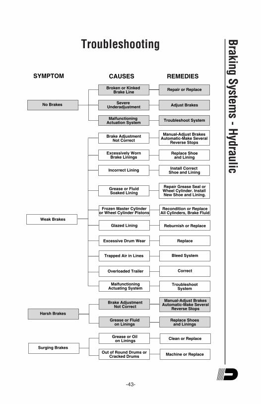
-43-
Broken or Kinked Brake Line
Malfunctioning Actuation System
Brake AdjustmentNot Correct
Excessively WornBrake Linings
Grease or FluidSoaked Lining
Glazed Lining
Excessive Drum Wear
Severe Underadjustment
Incorrect Lining
Trapped Air in Lines
Overloaded Trailer
Repair or Replace
Adjust Brakes
Troubleshoot System
Replace Shoeand Lining
Install Correct Shoe and Lining
Repair Grease Seal orWheel Cylinder. Install New Shoe and Lining.
Recondition or ReplaceAll Cylinders, Brake Fluid
Reburnish or Replace
Replace
Bleed System
Correct
No Brakes
Weak Brakes
Frozen Master Cylinderor Wheel Cylinder Pistons
Manual-Adjust BrakesAutomatic-Make Several
Reverse Stops
SYMPTOM CAUSES REMEDIES
MalfunctioningActuating System
TroubleshootSystem
Grease or Fluidon Linings
Replace Shoesand Linings
Manual-Adjust BrakesAutomatic-Make Several
Reverse StopsHarsh Brakes
Brake AdjustmentNot Correct
Machine or Replace
Surging Brakes
Grease or Oil on Linings
Out of Round Drums orCracked Drums
Clean or Replace
Troubleshooting
Braking S
ystems - H
ydraulic

-44-
Hub
s/D
rum
s/B
eari
ngs
Hubs/Drums/BearingsDexter Axle offers several types of bearing arrangements and
lubrications methods.
” Dexter’s standard wheel bearing configuration consists of
opposed tapered roller bearing cones and cups, fitted inside of a
precision machined cast hub. This method of using tapered roller
bearings requires that a minimal amount of axial end play be
provided at assembly. This end play is essential to the longevity
of the bearings service life. This design is typically lubricated with
grease, packed into the bearings. Oil lubrication is another
method which is available in some of the larger axle capacities.
” E-Z Lube® is another option chosen by some trailer
manufacturers. If your axle is equipped with the Dexter E-Z Lube®
feature, the bearings can be periodically lubricated without
removing the hubs from the axle. This feature consists of axle
spindles that have been specially drilled and assembled with
grease fittings in their ends. When grease is pumped into the
fitting, it is channeled to the inner bearing and then flows back to
the outer bearing and eventually back out the grease cap hole.
” Nev-R-Lube™ option is the latest innovation from Dexter.
Nev-R-Lube™ bearings are comprised of opposed tapered roller
bearing cones sealed inside of a precision ground, one piece
double cup arrangement. These bearings are designed with a
small amount of axial end play. This end play is essential to the
longevity of the bearings service life. They are lubricated,
assembled and sealed at the factory. No further lubrication is ever
needed.
Before attempting any disassembly of your Dexter axle, make
sure you read and follow the instructions for the appropriate axle
type.
Hub Removal - Standard Bearings
Whenever the hub equipment on your axle must be removed for
inspection or maintenance the following procedure should be
utilized.
1. Elevate and support the trailer unit per manufacturers’
instructions.

-45-
! CAUTIONYou must follow the maintenance procedures to prevent
damage to important structural components. Damage to
certain structural components such as wheel bearings
can cause the wheel end to come off of the axle. Loss of
a wheel end while the trailer is moving can cause you to
lose control and lead to an accident, which can result in
serious injury or death.
2. Remove the wheel.
3. Remove the grease cap by carefully prying progressively
around the flange of the cap. If the hub is an oil lube type,
then the cap can be removed by unscrewing it
counterclockwise while holding the hub stationary.
4. Remove the cotter pin from the spindle nut.
For E-Z Lube® axles produced after February 2002, a new
type of retainer is used. Gently pry off retainer from the nut
and set aside.
5. Unscrew the spindle nut (counterclockwise) and remove
the spindle washer.
6. Remove the hub from the spindle, being careful not to allow
the outer bearing cone to fall out. The inner bearing cone
will be retained by the seal.
7. For 7,200 lb. and 8,000 lb. axles, a hub puller may be
necessary to assist in drum removal.
Brake Drum Inspection
There are two areas of the brake drum that are subject to wear
and require periodic inspection. These two areas are the drum
surface where the brake shoes make contact during stopping and
the armature surface where the magnet contacts (only in electric
brakes).
The drum surface should be inspected for excessive wear or
heavy scoring. If worn more than .020" oversized, or the drum
has worn out of round by more than .015", then the drum surface
should be re-machined. If scoring or other wear is greater than
Hubs/D
rums/B
earings
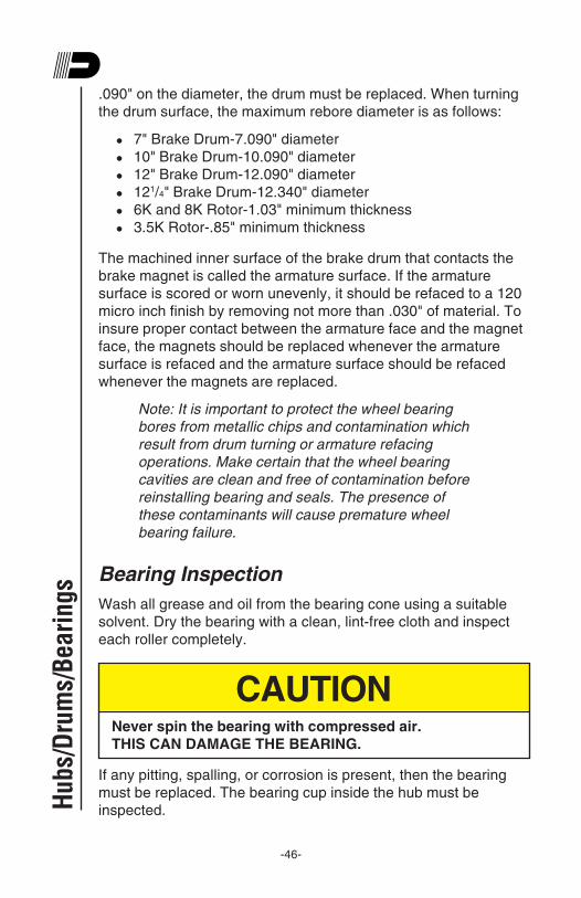
-46-
.090" on the diameter, the drum must be replaced. When turning
the drum surface, the maximum rebore diameter is as follows:
” 7" Brake Drum-7.090" diameter
” 10" Brake Drum-10.090" diameter
” 12" Brake Drum-12.090" diameter
” 121/4" Brake Drum-12.340" diameter
” 6K and 8K Rotor-1.03" minimum thickness
” 3.5K Rotor-.85" minimum thickness
The machined inner surface of the brake drum that contacts the
brake magnet is called the armature surface. If the armature
surface is scored or worn unevenly, it should be refaced to a 120
micro inch finish by removing not more than .030" of material. To
insure proper contact between the armature face and the magnet
face, the magnets should be replaced whenever the armature
surface is refaced and the armature surface should be refaced
whenever the magnets are replaced.
Note: It is important to protect the wheel bearing
bores from metallic chips and contamination which
result from drum turning or armature refacing
operations. Make certain that the wheel bearing
cavities are clean and free of contamination before
reinstalling bearing and seals. The presence of
these contaminants will cause premature wheel
bearing failure.
Bearing Inspection
Wash all grease and oil from the bearing cone using a suitable
solvent. Dry the bearing with a clean, lint-free cloth and inspect
each roller completely.
CAUTIONNever spin the bearing with compressed air.
THIS CAN DAMAGE THE BEARING.
If any pitting, spalling, or corrosion is present, then the bearing
must be replaced. The bearing cup inside the hub must be
inspected.Hub
s/D
rum
s/B
eari
ngs
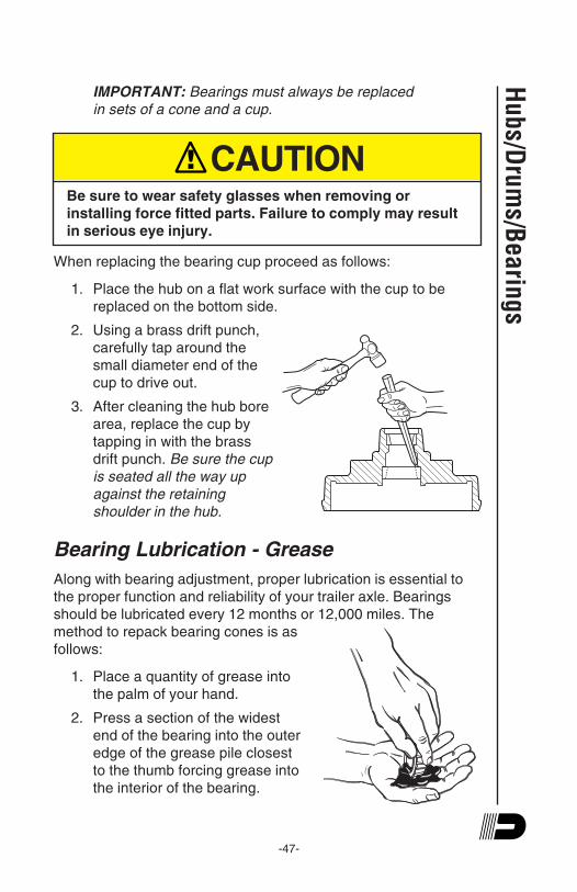
-47-
IMPORTANT: Bearings must always be replaced
in sets of a cone and a cup.
! CAUTIONBe sure to wear safety glasses when removing or
installing force fitted parts. Failure to comply may result
in serious eye injury.
When replacing the bearing cup proceed as follows:
1. Place the hub on a flat work surface with the cup to be
replaced on the bottom side.
2. Using a brass drift punch,
carefully tap around the
small diameter end of the
cup to drive out.
3. After cleaning the hub bore
area, replace the cup by
tapping in with the brass
drift punch. Be sure the cup
is seated all the way up
against the retaining
shoulder in the hub.
Bearing Lubrication - Grease
Along with bearing adjustment, proper lubrication is essential to
the proper function and reliability of your trailer axle. Bearings
should be lubricated every 12 months or 12,000 miles. The
method to repack bearing cones is as
follows:
1. Place a quantity of grease into
the palm of your hand.
2. Press a section of the widest
end of the bearing into the outer
edge of the grease pile closest
to the thumb forcing grease into
the interior of the bearing.
Hu
bs/D
rum
s/Be
arin
gs
-48-
3. Repeat this while rotating the bearing from roller to roller.
4. Continue this process until you have the entire bearing
completely filled with grease.
5. Before reinstalling, apply a light coat of grease on the
bearing cup.
Bearing Lubrication - Oil
If your axles are equipped with oil lubricated hubs, periodically
check and refill the hub as necessary with a high quality hypoid
gear oil to the level indicated on the clear plastic oil cap. The oil
can be filled from either the oil fill hole, if present, in the hub or
through the rubber plug hole in the cap itself.
Recommended Wheel BearingLubrication Specifications
Grease:Thickener Type ............................................. Lithium Complex
Dropping Point .................................. 215OC (419OF) Minimum
Consistency ........................................................... NLGI No. 2
Additives ........................ EP, Corrosion & Oxidation Inhibitors
Viscosity Index ..................................................... 80 Minimum
Approved Sources:
Mobil Oil .................................. Mobilgrease HP, Mobilith AW2
Exxon/Standard ...................................................... Ronex MP
Kendall Refining Co. ......................... Kendall L-427 Super Blu
Ashland Oil Co. ............................. Valvoline Multipurpose GM
76 Lubricants .................................................. 76 Multiplex EP
Citgo Petroleum .............................................. Lithoplex MP#2
Mystik ......................................... Mystik JT-6 Hi Temp Grease
Oil:SAE 90, SAE 80W-90, SAE 75W-90
Approved Sources:
Union Oil Co. ........................................Unocal MP Gear Lube
Exxon Co. USA ....................................... Gear Oil GX 80W-90
Mobil Oil Corp ..................................... Mobilube SHC 75W-90
Pennzoil Prod. Co. ............................ Gear Plus 80W-90 GL-5
Gear Plus Super 75W-90Hub
s/D
rum
s/B
eari
ngs

-49-
Note: The convenient lubrication provisions of the
E-Z Lube® and the oil lubrication must not replace
periodic inspection of the bearings.
Seal Inspection and Replacement
Whenever the hub is removed,
inspect the seal to assure that it
is not nicked or torn and is still
capable of properly sealing the
bearing cavity. If there is any
question of condition, replace
the seal. Use only the seals
specified in the Seal
Replacement Chart.
To replace the seal:
1. Pry the seal out of the hub with a screwdriver. Never drive
the seal out with the inner bearing as you may damage the
bearing.
2. Apply a PERMATEX
sealant to the outside of the
new seal.
Note: Permatex sealant
should not be used on
rubber encased seals.
3. Tap the new seal into place
using a clean wood block.
Hubs/D
rums/B
earings
Bad Seal: Nicks and Tears
(REPLACE SEAL)
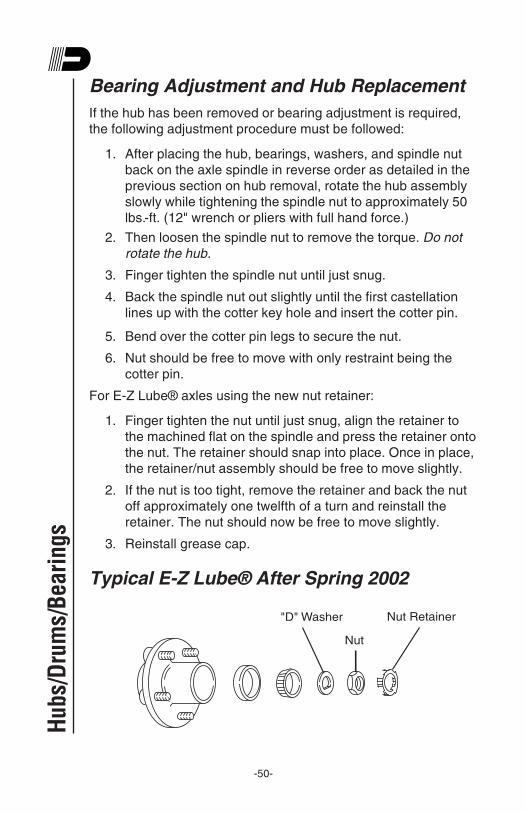
-50-
Bearing Adjustment and Hub Replacement
If the hub has been removed or bearing adjustment is required,
the following adjustment procedure must be followed:
1. After placing the hub, bearings, washers, and spindle nut
back on the axle spindle in reverse order as detailed in the
previous section on hub removal, rotate the hub assembly
slowly while tightening the spindle nut to approximately 50
lbs.-ft. (12" wrench or pliers with full hand force.)
2. Then loosen the spindle nut to remove the torque. Do not
rotate the hub.
3. Finger tighten the spindle nut until just snug.
4. Back the spindle nut out slightly until the first castellation
lines up with the cotter key hole and insert the cotter pin.
5. Bend over the cotter pin legs to secure the nut.
6. Nut should be free to move with only restraint being the
cotter pin.
For E-Z Lube® axles using the new nut retainer:
1. Finger tighten the nut until just snug, align the retainer to
the machined flat on the spindle and press the retainer onto
the nut. The retainer should snap into place. Once in place,
the retainer/nut assembly should be free to move slightly.
2. If the nut is too tight, remove the retainer and back the nut
off approximately one twelfth of a turn and reinstall the
retainer. The nut should now be free to move slightly.
3. Reinstall grease cap.
Typical E-Z Lube® After Spring 2002
"D" Washer
Nut
Nut Retainer
Hub
s/D
rum
s/B
eari
ngs
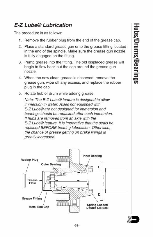
-51-
E-Z Lube® Lubrication
The procedure is as follows:
1. Remove the rubber plug from the end of the grease cap.
2. Place a standard grease gun onto the grease fitting located
in the end of the spindle. Make sure the grease gun nozzle
is fully engaged on the fitting.
3. Pump grease into the fitting. The old displaced grease will
begin to flow back out the cap around the grease gun
nozzle.
4. When the new clean grease is observed, remove the
grease gun, wipe off any excess, and replace the rubber
plug in the cap.
5. Rotate hub or drum while adding grease.
Note: The E-Z Lube® feature is designed to allow
immersion in water. Axles not equipped with
E-Z Lube® are not designed for immersion and
bearings should be repacked after each immersion.
If hubs are removed from an axle with the
E-Z Lube® feature, it is imperative that the seals be
replaced BEFORE bearing lubrication. Otherwise,
the chance of grease getting on brake linings is
greatly increased.
Inner Bearing
Outer Bearing
Rubber Plug
Grease Flow
Grease Fitting
Metal End CapSpring LoadedDouble Lip Seal
Hubs/D
rums/B
earings
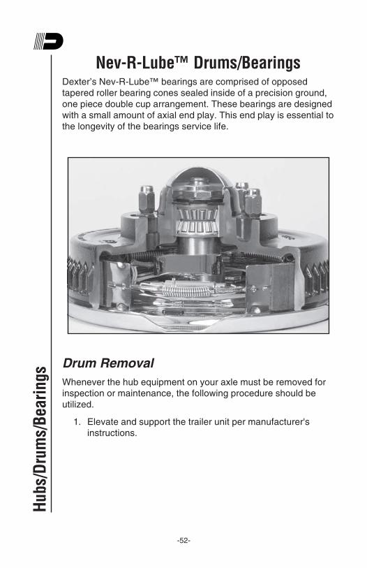
-52-
Nev-R-Lube™ Drums/BearingsDexter’s Nev-R-Lube™ bearings are comprised of opposed
tapered roller bearing cones sealed inside of a precision ground,
one piece double cup arrangement. These bearings are designed
with a small amount of axial end play. This end play is essential to
the longevity of the bearings service life.
Drum Removal
Whenever the hub equipment on your axle must be removed for
inspection or maintenance, the following procedure should be
utilized.
1. Elevate and support the trailer unit per manufacturer's
instructions.
Hub
s/D
rum
s/B
eari
ngs

-53-
! CAUTIONDo not lift or support the trailer on any part of the axle or
suspension system. Never go under any trailer unless it
is properly supported on jack stands which have been
rated for the load. Improperly supported vehicles can fall
unexpectedly and cause serious injury or death.
2. Remove the wheel.
3. Remove the grease cap from the hub by carefully prying
progressively around the flange.
4. Remove snap ring on the end of the spindle. Remove
“torque instruction” washer.
5. Unscrew the spindle nut (counterclockwise) and remove
the spindle washer.
6. Carefully remove the hub from the spindle. The
Nev-R-Lube™ bearing cartridge will remain in the hub.
Note: Do not remove cartridge bearing from the
hub bore unless replacement of the bearing
cartridge is intended. Special tools and techniques
are required for removal of the old bearing.
Bearing Inspection
Important:
1. Elevate and support the trailer unit per manufacturer's
instructions.
! CAUTIONDo not lift or support the trailer on any part of the axle or
suspension system. Never go under any trailer unless it
is properly supported on jack stands which have been
rated for the load. Improperly supported vehicles can fall
unexpectedly and cause serious injury or death.
Hubs/D
rums/B
earings

-54-
Hub
s/D
rum
s/B
eari
ngs
2. Check for excessive wheel end clearance by pulling the tire
assembly towards you and by pushing the assembly away
from you. Slight end play is acceptable.
3. Rotate tire slowly forwards and backwards. The wheel
assembly should turn freely and smoothly.
4. Excessive wheel end play, restriction to rotation, noise, or
“bumpy” rotation should be remedied by replacing the
bearing unit.
5. Bearing units should be inspected every year or 12,000
miles whichever comes first.
Note: A slight amount of grease weeping from the
seal area is normal. Excessive leakage may
indicate abnormal bearing operation.
Nev-R-Lube™ Bearing End Play Inspection
The following lists the maximum axial end play for each of the
sizes of Nev-R-Lube™ bearings and the amount of tilt that can be
expected. Since there are a large number of wheel and tire
combinations in use on trailers, the tilt is expressed in inches per
inch. The movement as measured at the tire tread can be found
by the following method:
Example: if the tilt value is shown as .003" per inch
and the tire measures 30" in diameter, simply
multiply .003" X 15" (1/2 tire diameter) = .045"
which is the total expected movement at the tires’
outer diameter.
Bearing size End play Resultant tilt value
35 MM .005" axial .003"/ per inch
42 MM .006" axial .005"/ per inch
50 MM .008" axial .004"/ per inch
It is important to note that most mounted tires will deflect fairly
easily when enough hand pressure is applied while shaking the
tire. Excessive pressure will result in the perception that the
bearings’ tilt is greater than it actually is. This same phenomenon
will occur when checking any wheel end, even those equipped
with conventional bearing sets.
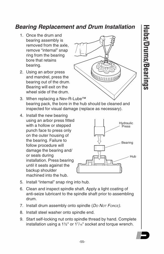
-55-
Bearing Replacement and Drum Installation
1. Once the drum and
bearing assembly is
removed from the axle,
remove “internal” snap
ring from the bearing
bore that retains
bearing.
2. Using an arbor press
and mandrel, press the
bearing out of the drum.
Bearing will exit on the
wheel side of the drum.
3. When replacing a Nev-R-Lube™
bearing pack, the bore in the hub should be cleaned and
inspected for visual damage (replace as necessary).
4. Install the new bearing
using an arbor press fitted
with a hollow or stepped
punch face to press only
on the outer housing of
the bearing. Failure to
follow procedure will
damage the bearing and/
or seals during
installation. Press bearing
until it seats against the
backup shoulder
machined into the hub.
5. Install “internal” snap ring into hub.
6. Clean and inspect spindle shaft. Apply a light coating of
anti-seize lubricant to the spindle shaft prior to assembling
drum.
7. Install drum assembly onto spindle (DO NOT FORCE).
8. Install steel washer onto spindle end.
9. Start self-locking nut onto spindle thread by hand. Complete
installation using a 1½" or 17/16" socket and torque wrench.
Hubs/D
rums/B
earings
Hub
Bearing
Hydraulic
Press
-56-
Hub
s/D
rum
s/B
eari
ngs
Nut should be torqued to 145-155 lb.-ft. (this torque will set
the internal bearing adjustment, no other adjustments are to
be made).
10. Install “torque instruction” washer onto end of spindle.
11. Install “external” snap ring onto end of spindle to retain
washer.
12. Inspect assembly for excessive end play, noise, and
rotation restriction prior to mounting final wheel end
hardware.
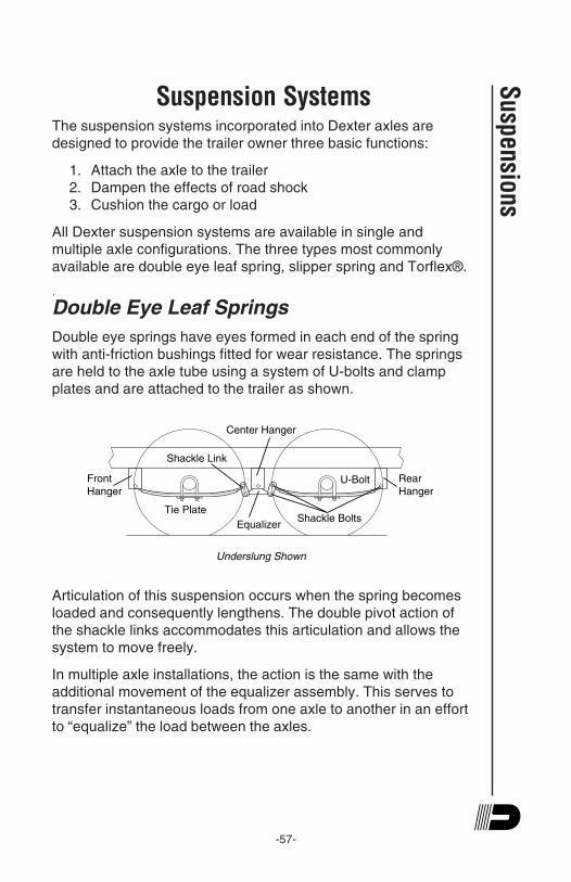
-57-
Suspension SystemsThe suspension systems incorporated into Dexter axles are
designed to provide the trailer owner three basic functions:
1. Attach the axle to the trailer
2. Dampen the effects of road shock
3. Cushion the cargo or load
All Dexter suspension systems are available in single and
multiple axle configurations. The three types most commonly
available are double eye leaf spring, slipper spring and Torflex®.
.
Double Eye Leaf Springs
Double eye springs have eyes formed in each end of the spring
with anti-friction bushings fitted for wear resistance. The springs
are held to the axle tube using a system of U-bolts and clamp
plates and are attached to the trailer as shown.
Center Hanger
Equalizer
Rear
Hanger
Front
Hanger
Tie Plate
U-Bolt
Shackle Bolts
Shackle Link
Underslung Shown
Articulation of this suspension occurs when the spring becomes
loaded and consequently lengthens. The double pivot action of
the shackle links accommodates this articulation and allows the
system to move freely.
In multiple axle installations, the action is the same with the
additional movement of the equalizer assembly. This serves to
transfer instantaneous loads from one axle to another in an effort
to “equalize” the load between the axles.
Suspensions

-58-
Grease Lubricated Suspension Bushings
Dexter Axle offers an optional heavy duty attaching parts kit for
double eye leaf spring suspensions up to 7,000 lb. axle capacity.
The kit contains extra heavy shackle links, bronze bushings for
the spring eyes and suspension bolts and equalizers equipped
with grease fittings to provide a convenient means to lubricate all
the pivot points. For availability, contact your nearest Dexter Axle
facility or visit us online at www.dexteraxle.com for a complete
listing of genuine repair parts.
Slipper Leaf Springs
Slipper springs have an eye formed in one end only with the other
end formed into a reverse curve. The attachment of these springs
is as follows:
1. The front eye is attached directly into the front hanger with
a bolt and nut.
2. The rear end of the spring is captured in the rear hanger or
equalizer with a “keeper bolt” that prevents the spring from
coming out when the trailer is jacked up for service.
The articulation of this suspension occurs when the rear end of
each slipper spring slides against the wear surfaces provided in
the rear hangers or equalizers. This suspension is also available
in single and multiple axle configurations.
Center HangerEqualizer
Rear
Hanger
Front
Hanger
Tie Plate
U-Bolt
Spring Eye Bolts Keeper Bolts
Overslung Shown
U-Bolt
Tie Plate
Sus
pens
ions
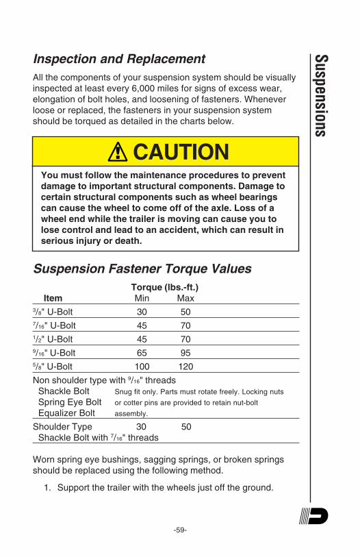
-59-
Inspection and Replacement
All the components of your suspension system should be visually
inspected at least every 6,000 miles for signs of excess wear,
elongation of bolt holes, and loosening of fasteners. Whenever
loose or replaced, the fasteners in your suspension system
should be torqued as detailed in the charts below.
! CAUTIONYou must follow the maintenance procedures to prevent
damage to important structural components. Damage to
certain structural components such as wheel bearings
can cause the wheel to come off of the axle. Loss of a
wheel end while the trailer is moving can cause you to
lose control and lead to an accident, which can result in
serious injury or death.
Suspension Fastener Torque Values
Torque (lbs.-ft.)
Item Min Max
3/8" U-Bolt 30 50
7/16" U-Bolt 45 70
1/2" U-Bolt 45 70
9/16" U-Bolt 65 95
5/8" U-Bolt 100 120
Non shoulder type with 9/16" threads
Shackle Bolt Snug fit only. Parts must rotate freely. Locking nuts
Spring Eye Bolt or cotter pins are provided to retain nut-bolt
Equalizer Bolt assembly.
Shoulder Type 30 50
Shackle Bolt with 7/16" threads
Worn spring eye bushings, sagging springs, or broken springs
should be replaced using the following method.
1. Support the trailer with the wheels just off the ground.
Suspensions
-60-
Sus
pens
ions
! CAUTIONDo not lift or support the trailer on any part of the axle or
suspension system. Never go under any trailer unless it
is properly supported on jack stands which have been
rated for the load. Improperly supported vehicles can fall
unexpectedly and cause serious injury or death.
2. After the unit is properly supported place a suitable block
under the axle tube near the end to be repaired. This block
is to support the weight of the axle only, so that suspension
COMPONENTS can be removed.
3. Disassemble the U-bolts, nuts, and tie plates.
4. Remove the spring eye bolts and remove the spring and
place on a suitable work surface.
5. If the spring eye bushings are to be replaced, drive out the
old bushing using a suitable drift punch.
! CAUTIONBe sure to wear safety glasses when removing or
installing force fitted parts. Failure to comply may result
in serious injury.
6. Drive the new bushing into the spring eye using a piloted
drift punch or a close fitting bolt inserted through the
bushing.
7. Reinstall repaired or replaced components in reverse order.
Note: For multiple axle units, the weight of each
axle must be supported as outlined in Step 2 before
disassembly of any component of the suspension
system.
If the equalizer or equalizer bushings must be replaced, follow the
instructions above for lifting and supporting the trailer unit and
then proceed as follows:
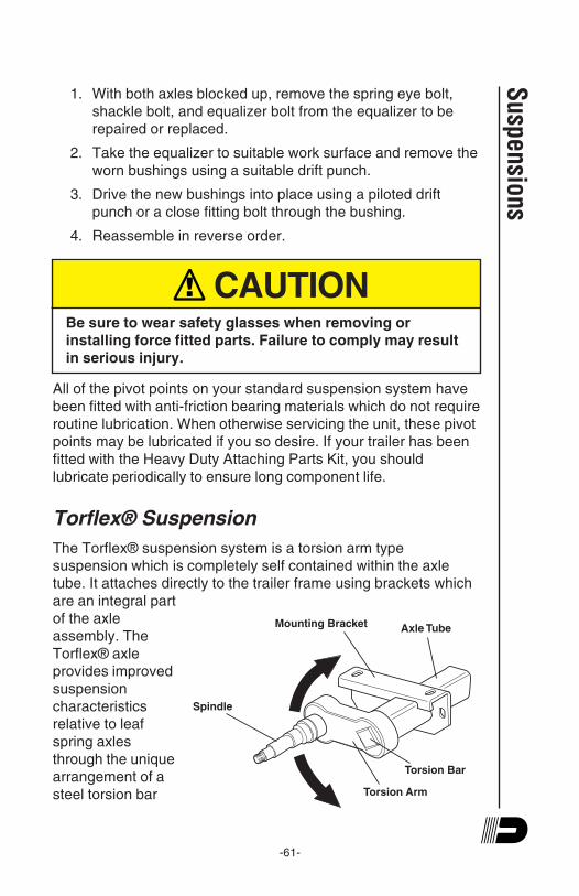
-61-
1. With both axles blocked up, remove the spring eye bolt,
shackle bolt, and equalizer bolt from the equalizer to be
repaired or replaced.
2. Take the equalizer to suitable work surface and remove the
worn bushings using a suitable drift punch.
3. Drive the new bushings into place using a piloted drift
punch or a close fitting bolt through the bushing.
4. Reassemble in reverse order.
! CAUTIONBe sure to wear safety glasses when removing or
installing force fitted parts. Failure to comply may result
in serious injury.
All of the pivot points on your standard suspension system have
been fitted with anti-friction bearing materials which do not require
routine lubrication. When otherwise servicing the unit, these pivot
points may be lubricated if you so desire. If your trailer has been
fitted with the Heavy Duty Attaching Parts Kit, you should
lubricate periodically to ensure long component life.
Torflex® Suspension
The Torflex® suspension system is a torsion arm type
suspension which is completely self contained within the axle
tube. It attaches directly to the trailer frame using brackets which
are an integral part
of the axle
assembly. The
Torflex® axle
provides improved
suspension
characteristics
relative to leaf
spring axles
through the unique
arrangement of a
steel torsion bar
Suspensions
Torsion Arm
Torsion Bar
Axle TubeMounting Bracket
Spindle

-62-
Sus
pens
ions
surrounded by four natural rubber cords encased in the main
structural member of the axle beam.
The wheel/hub spindle is attached to a lever, called the torsion
arm, which is fastened to the rubber encased bar. As load is
applied, the bar rotates causing a rolling/compressive resistance
in the rubber cords. This action provides the same functions as
conventional sprung axles with several operating advantages
including independent suspension.
Except for periodic inspection of the fasteners used to attach the
Torflex® axle to the vehicle frame, no other suspension
maintenance is required on Torflex® axles. They are, of course,
subject to the maintenance and inspection procedures regarding
brakes, hubs, bearings, seals, wheels, and tires as outlined in this
manual.
CAUTIONDO NOT WELD ON THE TORFLEX® BEAM. It has rubber
cords inside and the heat generated by welding could
damage the cords.
Airflex™ Suspension
The Dexter Airflex™ suspension is a unique combination of
Torflex® axle and conventional air suspension technology. This
low maintenance suspension system carries the load on a
cushion of air, usually supplied by an on-board compressor and
storage tank. A load leveling valve maintains a constant ride
height, regardless of load. As load is added to the trailer, the
valve will automatically signal the compressor to supply more air.
As loads are removed, the same valve will exhaust air to maintain
the same height and ride characteristics.
The Airflex™ suspension can be supplied with a dump valve
which allows the trailer to be lowered several inches to facilitate
loading or leveling. Once loaded, the valve is reversed and the
system is pressurized to raise the trailer back up to normal
running height.
-63-
Axle Adjustment
1. Support the trailer frame on a level surface. If the wheels
are already mounted, make sure they are clear of the
ground. If the air actuation system has been installed, make
sure the air pressure in the air bags is bled off before lifting
the trailer. CAUTION: Lifting the trailer with air system
pressurized will overextend the air bags and can result
in damage to the air bags.
! CAUTIONDo not lift or support the trailer on any part of the axle or
suspension system. Never go under any trailer unless it
is properly supported on jack stands which have been
rated for the load. Improperly supported vehicles can fall
unexpectedly and cause serious injury or death.
2. Measure from king pin to spindle center on each side. To
simplify this process, plumb lines may be dropped from the
king pin and from the centerline of each spindle end.
Measurements “A” and “B” can then be taped on the floor to
eliminate any miss measurement due to sagging of the tape
long measurements. Compare A and B measurements (see
Figure 1).
3. Loosen all the U-bolt nuts slightly and move the axle
assembly with the adjusting screws, located on the front
and rear of the axle seat. Move front axle to correct
alignment position based on previous findings of A and B
measurements. Make sure both front and rear adjusting
screws are snug after axle is realigned. Then, retighten the
U-bolt nuts to 100 to 120 lb ft.
Suspensions

-64-
Sus
pens
ions
4. Re-measure A and B, as before, to assure that “A” and “B”
dimensions are within 1/16" of each other. If dimensions are
not to specification, then repeat adjustment procedure.
Figure 1
-65-
Tandem Axle Adjustment
1. Adjust the second axle using it’s left hand spring seat
adjusters to assure distances “C” and “D” are within
tolerance.
2. Measure the distances “C” and “D” between the front and
rear tandem axles. These distances must be within 1/8" of
each other.
3. After alignment is completed make sure all nuts and bolts
are tightened to their respective torque values.
4. The limits of 1/16" and 1/8" appear very small in comparison
to the overall dimensions of the vehicle but they are
recognized as the maximum permissible limit of
misalignment. Also, the relatively small size of those limits
makes accurate measurements important.
Suspensions
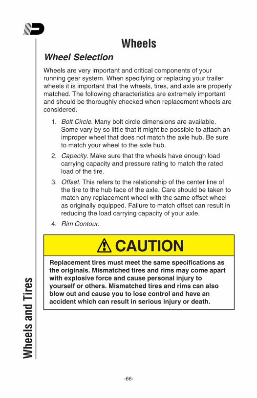
-66-
WheelsWheel Selection
Wheels are very important and critical components of your
running gear system. When specifying or replacing your trailer
wheels it is important that the wheels, tires, and axle are properly
matched. The following characteristics are extremely important
and should be thoroughly checked when replacement wheels are
considered.
1. Bolt Circle. Many bolt circle dimensions are available.
Some vary by so little that it might be possible to attach an
improper wheel that does not match the axle hub. Be sure
to match your wheel to the axle hub.
2. Capacity. Make sure that the wheels have enough load
carrying capacity and pressure rating to match the rated
load of the tire.
3. Offset. This refers to the relationship of the center line of
the tire to the hub face of the axle. Care should be taken to
match any replacement wheel with the same offset wheel
as originally equipped. Failure to match offset can result in
reducing the load carrying capacity of your axle.
4. Rim Contour.
! CAUTIONReplacement tires must meet the same specifications as
the originals. Mismatched tires and rims may come apart
with explosive force and cause personal injury to
yourself or others. Mismatched tires and rims can also
blow out and cause you to lose control and have an
accident which can result in serious injury or death.
Whe
els
and
Tire
s
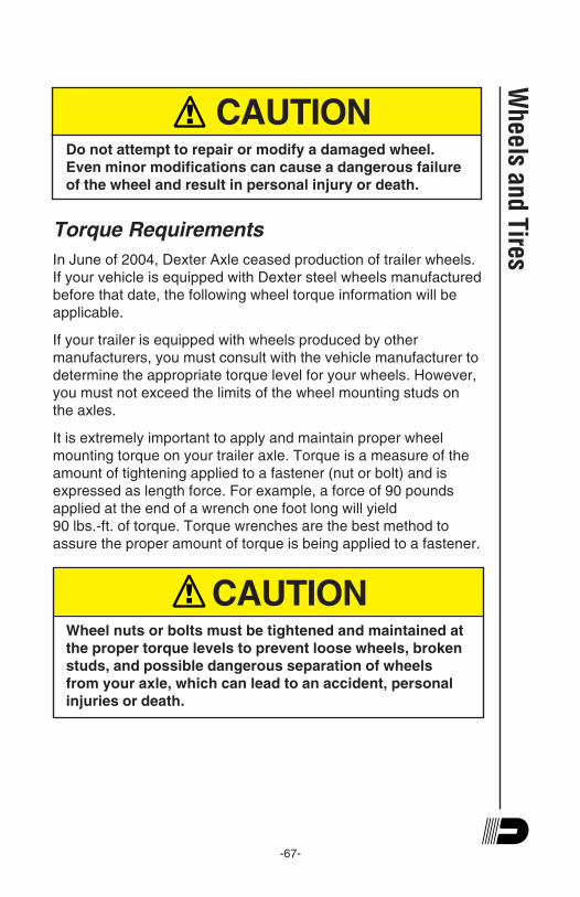
-67-
! CAUTIONDo not attempt to repair or modify a damaged wheel.
Even minor modifications can cause a dangerous failure
of the wheel and result in personal injury or death.
Torque Requirements
In June of 2004, Dexter Axle ceased production of trailer wheels.
If your vehicle is equipped with Dexter steel wheels manufactured
before that date, the following wheel torque information will be
applicable.
If your trailer is equipped with wheels produced by other
manufacturers, you must consult with the vehicle manufacturer to
determine the appropriate torque level for your wheels. However,
you must not exceed the limits of the wheel mounting studs on
the axles.
It is extremely important to apply and maintain proper wheel
mounting torque on your trailer axle. Torque is a measure of the
amount of tightening applied to a fastener (nut or bolt) and is
expressed as length force. For example, a force of 90 pounds
applied at the end of a wrench one foot long will yield
90 lbs.-ft. of torque. Torque wrenches are the best method to
assure the proper amount of torque is being applied to a fastener.
! CAUTIONWheel nuts or bolts must be tightened and maintained at
the proper torque levels to prevent loose wheels, broken
studs, and possible dangerous separation of wheels
from your axle, which can lead to an accident, personal
injuries or death.
Wheels and Tires

-68-
Be sure to use only the fasteners matched to the cone angle of
your wheel (usually 60o or 90o). The proper procedure for
attaching your wheels is as follows:
1. Start all bolts or nuts by hand to prevent cross threading.
2. Tighten bolts or nuts in the sequence shown for Wheel
Torque Requirements.
3. The tightening of the fasteners should be done in stages.
Following the recommended sequence, tighten fasteners
per wheel torque chart below.
4. Wheel nuts/bolts should be torqued before first road use
and after each wheel removal. Check and re-torque after
the first 10 miles, 25 miles, and again at 50 miles. Check
periodically thereafter.
Wheel Torque Requirements(For Dexter Steel Wheels Prior to June 2004)
Wheel Torque Sequence
Size 1st Stage 2nd Stage 3rd Stage
12" 20-25 35-40 50-75
13" 20-25 35-40 50-75
14" 20-25 50-60 90-120
15" 20-25 50-60 90-120
16" 20-25 50-60 90-120
16.5" x 6.75" 20-25 50-60 90-120
16.5" x 9.75" 55-60 120-125 175-225
14.5" Demount. Tighten sequentially to 85-95
17.5" Hub Pilot 50-60 100-120 190-210
Clamp Ring & Cone Nuts
17.5" Hub Pilot 50-60 90-200 275-325 5/8" Flange Nuts
4 BOLT 5 BOLT 6 BOLT 8 BOLT
1 1 1 1
22
2 2
3
3 33
44
4
4
55
5
66
78
Whe
els
and
Tire
s

-69-
Maximum Wheel Fastener Torque
The wheel mounting studs used on Dexter axles conform to the
SAE standards for grade 8. The maximum torque level that can
be safely applied to these studs is listed in the following chart:
Stud Size Max. Torque
1/2"-20 UNF, class 2A 120 lb ft.
9/16"-18 UNF, class 2A 170 lb ft.
5/8"-18 UNF, class 2A 325 lb ft.
! CAUTIONExceeding the above listed torque limits can damage
studs and/or nuts and lead to eventual fractures and
dangerous wheel separation.
Wheels and Tires

-70-
TiresBefore mounting tires onto the wheels, make certain that the rim
size and contour is approved for the tire as shown in the Tire and
Rim Association Yearbook or the tire manufacturers catalog.
Also, make sure the tire will carry the rated load. If the load is not
equal on all tires due to trailer weight distribution, use the tire
rated for the heaviest wheel position.
Note: The capacity rating molded into the sidewall
of the tire is not always the proper rating for the tire
if used in a trailer application. Use the following
guidelines:
1. LT and ST tires. Use the capacity rating molded into the
tire.
2. Passenger Car Tires. Use the capacity rating molded into
the tire sidewall divided by 1.10 for trailer use.
Use tire mounting procedures as outlined by the Rubber
Manufacturer's Association or the tire manufacturers.
Tire inflation pressure is the most important factor in tire life.
Inflation pressure should be as recommended by the
manufacturer for the load. Pressure should be checked cold
before operation. Do not bleed air from tires when they are hot.
Check inflation pressure weekly during use to insure the
maximum tire life and tread wear. The following tire wear
diagnostic chart will help you pinpoint the causes and solutions of
tire wear problems.
CAUTIONTire wear should be checked frequently because once a
wear pattern becomes firmly established in a tire it is
difficult to stop, even if the underlying cause is
corrected.
Whe
els
and
Tire
s

-71-
Tire Wear Diagnostic Chart
Wheels and Tires
Center Wear
Edge Wear
Side Wear
Toe Wear
Cupping
Flat Spots
Over Inflation
Under Inflation
Loss of camber
or overloading
Incorrect toe-in
Out-of-balance
Wheel lockup &
tire skidding
Adjust pressure to
particular load per
tire catalog
Adjust pressure to
particular load per
tire catalog
Make sure load doesn't
exceed axle rating.
Align at alignment shop.
Align at alignment shop.
Check bearing adjust-
ment and balance tires.
Avoid sudden stops
when possible and
adjust brakes.
Wear Pattern Cause Action
g
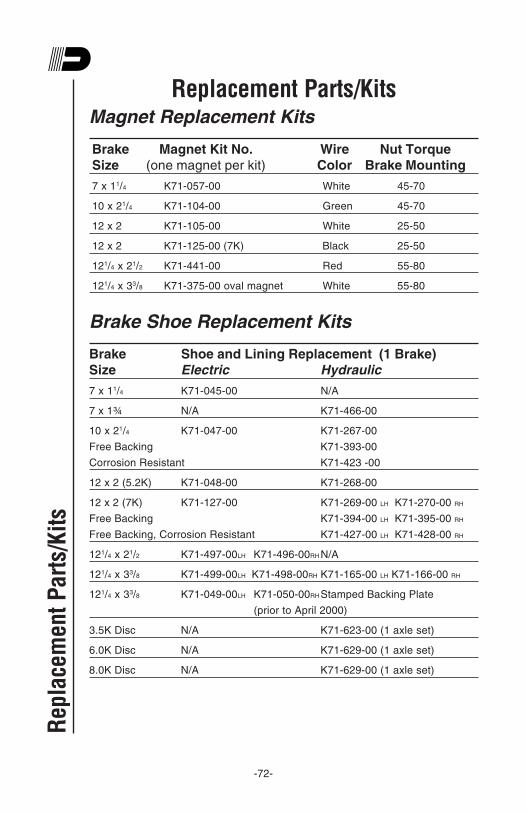
-72-
Replacement Parts/KitsMagnet Replacement Kits
Brake Magnet Kit No. Wire Nut Torque
Size (one magnet per kit) Color Brake Mounting
7 x 11/4 K71-057-00 White 45-70
10 x 21/4 K71-104-00 Green 45-70
12 x 2 K71-105-00 White 25-50
12 x 2 K71-125-00 (7K) Black 25-50
121/4 x 21/2 K71-441-00 Red 55-80
121/4 x 33/8 K71-375-00 oval magnet White 55-80
Brake Shoe Replacement Kits
Brake Shoe and Lining Replacement (1 Brake)
Size Electric Hydraulic
7 x 11/4 K71-045-00 N/A
7 x 1¾ N/A K71-466-00
10 x 21/4 K71-047-00 K71-267-00
Free Backing K71-393-00
Corrosion Resistant K71-423 -00
12 x 2 (5.2K) K71-048-00 K71-268-00
12 x 2 (7K) K71-127-00 K71-269-00 LH K71-270-00 RH
Free Backing K71-394-00 LH K71-395-00 RH
Free Backing, Corrosion Resistant K71-427-00 LH K71-428-00 RH
121/4 x 21/2 K71-497-00LH K71-496-00RH N/A
121/4 x 33/8 K71-499-00LH K71-498-00RH K71-165-00 LH K71-166-00 RH
121/4 x 33/8 K71-049-00LH K71-050-00RH Stamped Backing Plate
(prior to April 2000)
3.5K Disc N/A K71-623-00 (1 axle set)
6.0K Disc N/A K71-629-00 (1 axle set)
8.0K Disc N/A K71-629-00 (1 axle set)
Rep
lace
men
t P
arts
/Kit
s
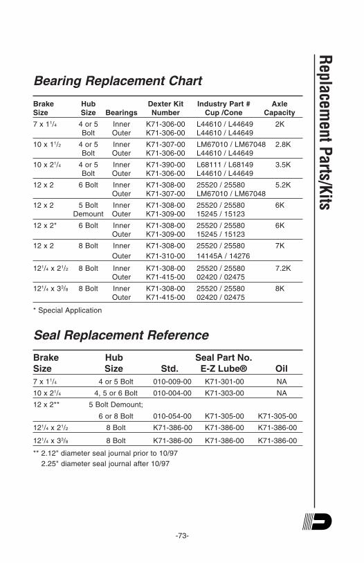
-73-
Bearing Replacement Chart
Brake Hub Dexter Kit Industry Part # AxleSize Size Bearings Number Cup /Cone Capacity
7 x 11/4 4 or 5 Inner K71-306-00 L44610 / L44649 2K
Bolt Outer K71-306-00 L44610 / L44649
10 x 11/2 4 or 5 Inner K71-307-00 LM67010 / LM67048 2.8K
Bolt Outer K71-306-00 L44610 / L44649
10 x 21/4 4 or 5 Inner K71-390-00 L68111 / L68149 3.5K
Bolt Outer K71-306-00 L44610 / L44649
12 x 2 6 Bolt Inner K71-308-00 25520 / 25580 5.2K
Outer K71-307-00 LM67010 / LM67048
12 x 2 5 Bolt Inner K71-308-00 25520 / 25580 6K
Demount Outer K71-309-00 15245 / 15123
12 x 2* 6 Bolt Inner K71-308-00 25520 / 25580 6K
Outer K71-309-00 15245 / 15123
12 x 2 8 Bolt Inner K71-308-00 25520 / 25580 7K
Outer K71-310-00 14145A / 14276
121/4 x 21/2 8 Bolt Inner K71-308-00 25520 / 25580 7.2K
Outer K71-415-00 02420 / 02475
121/4 x 33/8 8 Bolt Inner K71-308-00 25520 / 25580 8K
Outer K71-415-00 02420 / 02475
* Special Application
Seal Replacement Reference
Brake Hub Seal Part No.
Size Size Std. E-Z Lube® Oil
7 x 11/4 4 or 5 Bolt 010-009-00 K71-301-00 NA
10 x 21/4 4, 5 or 6 Bolt 010-004-00 K71-303-00 NA
12 x 2** 5 Bolt Demount;
6 or 8 Bolt 010-054-00 K71-305-00 K71-305-00
121/4 x 21/2 8 Bolt K71-386-00 K71-386-00 K71-386-00
121/4 x 33/8 8 Bolt K71-386-00 K71-386-00 K71-386-00
** 2.12" diameter seal journal prior to 10/97
2.25" diameter seal journal after 10/97
Replacem
ent Parts/K
its

-74-
StorageStorage Preparation
If your trailer is to be stored for an extended period of time or over
the winter, it is important that the trailer be prepared properly.
1. Remove the emergency breakaway battery and store
inside, out of the weather. Charge the battery at least every
90 days.
2. Jack up the trailer and place jack stands under the trailer
frame so that the weight will be off the tires. Follow trailer
manufacturer's guidelines to lift and support the unit. Never
jack up or place jack stands on the axle tube or on the
equalizers.
! CAUTIONDo not lift or support the trailer on any part of the axle or
suspension system. Never go under any trailer unless it
is properly supported on jack stands which have been
rated for the load. Improperly supported vehicles can fall
unexpectedly and cause serious injury or death.
3. Lubricate mechanical moving parts such as the hitch, and
suspension parts, that are exposed to the weather.
4. Boat trailer axles are subject to repeated immersion. Before
storing, remove brake drums; clean, dry and re-lubricate
moving brake components; inspect bearings - clean and re-
lubricate.
5. On oil lubricated hubs the upper part of the roller bearings
are not immersed in oil and are subject to potential
corrosion. For maximum bearing life, it is recommended
that you revolve your wheels periodically (every 2-3 weeks)
during periods of prolonged storage.
Sto
rage

-75-
After Prolonged Storage -Inspection Procedures
Before removing trailer from jack stands:
1. Remove all wheels and hubs or brake drums. Note which
spindle and brake that the drum was removed from so that
it can be reinstalled in the same location.
2. Inspect suspension for wear.
3. Check tightness of hanger bolt, shackle bolt, and U-bolt
nuts per recommended torque values.
4. Check brake linings, brake drums and armature faces for
excessive wear or scoring.
5. Check brake magnets with an ohmmeter. The magnets
should check 3.2 ohms. If shorted or worn excessively, they
must be replaced.
6. Lubricate all brake moving parts using a high temperature
brake lubricant (LUBRIPLATE or Equivalent).
CAUTIONDo not get grease or oil on brake linings or magnet face.
7. Remove any rust from braking surface and armature
surface of drums with fine emery paper or crocus cloth.
Protect bearings from contamination while so doing.
8. Inspect oil or grease seals for wear or nicks. Replace if
necessary.
9. Lubricate hub bearings. Refer to procedure in manual.
10.Reinstall hubs and adjust bearings per instructions in
manual.
11. Mount and tighten wheels per instructions in manual.
Storage
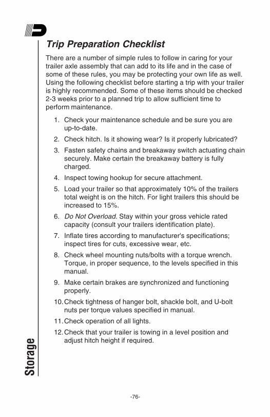
-76-
Trip Preparation Checklist
There are a number of simple rules to follow in caring for your
trailer axle assembly that can add to its life and in the case of
some of these rules, you may be protecting your own life as well.
Using the following checklist before starting a trip with your trailer
is highly recommended. Some of these items should be checked
2-3 weeks prior to a planned trip to allow sufficient time to
perform maintenance.
1. Check your maintenance schedule and be sure you are
up-to-date.
2. Check hitch. Is it showing wear? Is it properly lubricated?
3. Fasten safety chains and breakaway switch actuating chain
securely. Make certain the breakaway battery is fully
charged.
4. Inspect towing hookup for secure attachment.
5. Load your trailer so that approximately 10% of the trailers
total weight is on the hitch. For light trailers this should be
increased to 15%.
6. Do Not Overload. Stay within your gross vehicle rated
capacity (consult your trailers identification plate).
7. Inflate tires according to manufacturer's specifications;
inspect tires for cuts, excessive wear, etc.
8. Check wheel mounting nuts/bolts with a torque wrench.
Torque, in proper sequence, to the levels specified in this
manual.
9. Make certain brakes are synchronized and functioning
properly.
10.Check tightness of hanger bolt, shackle bolt, and U-bolt
nuts per torque values specified in manual.
11.Check operation of all lights.
12.Check that your trailer is towing in a level position and
adjust hitch height if required.
Sto
rage
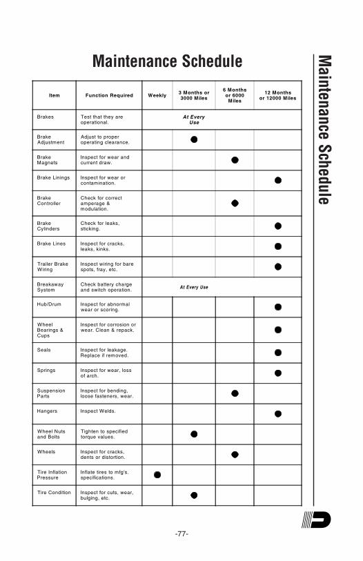
-77-
Maintenance Schedule
Main
tenance S
chedule
Item Function Required Weekly3 Months or3000 Miles
6 Monthsor 6000
Miles
12 Monthsor 12000 Miles
Brakes Test that they areoperational.
At EveryUse
BrakeAdjustment
Adjust to properoperating clearance.
BrakeMagnets
Inspect for wear andcurrent draw.
Brake Linings Inspect for wear orcontamination.
BrakeController
Check for correctamperage &modulation.
BrakeCylinders
Check for leaks,sticking.
Brake Lines Inspect for cracks,leaks, kinks.
Trailer BrakeWiring
Inspect wiring for barespots, fray, etc.
BreakawaySystem
Check battery chargeand switch operation.
At Every Use
Hub/Drum Inspect for abnormalwear or scoring.
WheelBearings &Cups
Inspect for corrosion orwear. Clean & repack.
Seals Inspect for leakage.Replace if removed.
Springs Inspect for wear, lossof arch.
SuspensionParts
Inspect for bending,loose fasteners, wear.
Hangers Inspect Welds.
Wheel Nutsand Bolts
Tighten to specifiedtorque values.
Wheels Inspect for cracks,dents or distortion.
Tire InflationPressure
Inflate tires to mfg's.specifications.
Tire Condition Inspect for cuts, wear,bulging, etc.

-78-
Dexter Axle Limited WarrantyWHAT PRODUCTS ARE COVERED
All Dexter trailer axles, suspensions, and brake control systems
excluding Dexter 6000 series Manufactured Housing Axles.
LIMITED 2 YEAR WARRANTY
Dexter Axle warrants to the original purchaser that its axles, suspension
systems, and E/H hydraulic brake actuators shall be free from defects
in material and workmanship for a period of two (2) years from the date
of first sale of the trailer incorporating such components.
LIMITED 5 YEAR WARRANTY
Dexter Axle warrants to the original purchaser that its Nev-R-Lube™
bearings and the suspension components only of its Torflex® axles
shall be free from defects in material and workmanship for a period of
five years from the date of first sale of the trailer incorporating such
components.
LIMITED 7 YEAR WARRANTY
Dexter Axle warrants to the original purchaser that its Predator Series™
electric brake controllers shall be free from defects in material and
workmanship for a period of seven (7) years from the date of purchase.
EXCLUSIVE REMEDY
Dexter Axle will, at its option, repair or replace the affected components
of any defective axle, repair or replace the entire defective axle, or
refund the then-current list price of the axle. In all cases, a reasonable
time period must be allowed for warranty repairs to be completed.
Allowance will only be made for installation costs specifically approved
by Dexter Axle.
WHAT YOU MUST DO
In order to make a claim under these warranties:
1. You must be the original purchaser of the vehicle in which the
Spring Suspension Axles or Torflex® Axles were originally
installed.
2. You must promptly notify us within the warranty period of any
defect and provide us with the axle serial number and any
substantiation which may include, but is not limited to, the return
of parts(s) that we may reasonably request.
3. The axles or suspensions must have been installed and
maintained in accordance with good industry practice and any
specific Dexter Axle recommendations, including those specified
in Dexter Axle’s publication “Operation Maintenance Service
Manual.”
War
rant
y
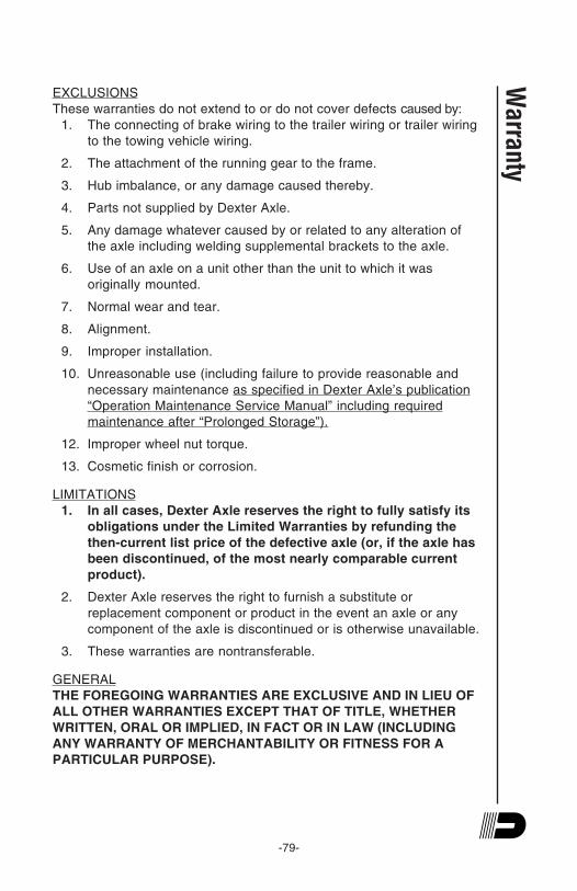
-79-
EXCLUSIONS
These warranties do not extend to or do not cover defects caused by:
1. The connecting of brake wiring to the trailer wiring or trailer wiring
to the towing vehicle wiring.
2. The attachment of the running gear to the frame.
3. Hub imbalance, or any damage caused thereby.
4. Parts not supplied by Dexter Axle.
5. Any damage whatever caused by or related to any alteration of
the axle including welding supplemental brackets to the axle.
6. Use of an axle on a unit other than the unit to which it was
originally mounted.
7. Normal wear and tear.
8. Alignment.
9. Improper installation.
10. Unreasonable use (including failure to provide reasonable and
necessary maintenance as specified in Dexter Axle’s publication
“Operation Maintenance Service Manual” including required
maintenance after “Prolonged Storage”).
12. Improper wheel nut torque.
13. Cosmetic finish or corrosion.
LIMITATIONS
1. In all cases, Dexter Axle reserves the right to fully satisfy its
obligations under the Limited Warranties by refunding the
then-current list price of the defective axle (or, if the axle has
been discontinued, of the most nearly comparable current
product).
2. Dexter Axle reserves the right to furnish a substitute or
replacement component or product in the event an axle or any
component of the axle is discontinued or is otherwise unavailable.
3. These warranties are nontransferable.
GENERAL
THE FOREGOING WARRANTIES ARE EXCLUSIVE AND IN LIEU OF
ALL OTHER WARRANTIES EXCEPT THAT OF TITLE, WHETHER
WRITTEN, ORAL OR IMPLIED, IN FACT OR IN LAW (INCLUDING
ANY WARRANTY OF MERCHANTABILITY OR FITNESS FOR A
PARTICULAR PURPOSE).
Warranty
-80-
These warranties give you specific legal rights, and you may also have
other rights which vary from state to state.
THE DURATION OF ANY IMPLIED WARRANTIES, INCLUDING THE
IMPLIED WARRANTIES OF MERCHANTABILITY AND FITNESS FOR
A PARTICULAR PURPOSE, ARE LIMITED TO THE DURATION OF
THE EXPRESS WARRANTIES HEREIN. DEXTER AXLE HEREBY
EXCLUDES INCIDENTAL AND CONSEQUENTIAL DAMAGES,
INCLUDING LOSS OF TIME, INCONVENIENCE, LOSS OF USE,
TOWING FEES, TELEPHONE CALLS OR COST OF MEALS, FOR
ANY BREACH OF ANY EXPRESS OR IMPLIED WARRANTY,
INCLUDING THE IMPLIED WARRANTIES OF MERCHANTABILITY
AND FITNESS FOR A PARTICULAR PURPOSE.
Some states do not allow limitations on how long an implied warranty
lasts, or the exclusion or limitation of incidental or consequential
damages, so the above exclusion or limitation may not apply to you.
Inquiries regarding these warranties should be sent to:
Dexter Axle
P.O. Box 250
Elkhart, Indiana 46515
War
rant
y

Dexter Online Parts Store
From magnet and seal kits to complete brake and hub kits, Dexter offers
a complete line of genuine replacement parts for your trailer. Most
products are available in-stock and ready to ship within 24 hours direct
to you from the factory. With dedicated customer support, quick
turnaround and a 30-day money back guarantee, the Dexter Online
Parts Store helps keep your trailer going.
• Hub Components
• Brake Components
• Suspension Components
• Complete Hub Kits
• Brake Assemblies & Kits
• Brake Controllers & Actuators
Ready for Immediate Shipment Direct to Your Door
Visit us online at www.dexteraxle.com
GENUINE

Service Record
Date Service Performed Mileage

Service Record
Date Service Performed Mileage

Service Record
Date Service Performed Mileage

Genuine Dexter axles and components are availablenationwide from our plant locations listed below or throughour network of distributors. Check our website for thedistributor nearest you.
Dexter Axle222 Collins Rd.Elkhart, IN 46516Fax (574) 295-8094Ph (574) 295-1900
Dexter AxleWest Pearl St.Fremont, IN 46737Fax (260) 495-1701Ph (260) 495-5100
Dexter AxlePerimeter RdMonticello, GA 31064Fax (706) 468-2966Ph (706) 468-6495
Dexter Axle1400 Victoria Ave.San Bernardino, CA 92408Fax (909) 799-6258Ph (909) 796-2908
Dexter Axle500 S.E. 27th St.El Reno, OK 73036Fax (405) 262-9089Ph (405) 262-6700
Dexter AxleRoad 75 EastAlbion, IN 46701Fax (260) 636-3030Ph (260) 636-2195
Dexter Axle11870 N. 650 EastN. Manchester, IN 46962Fax (260) 982-7511Ph (260) 982-4047
Company Headquarters2900 Industrial Parkway East
Elkhart, IN 46516Fax (574) 295-8666Ph (574) 295-7888
Dexter Axle1 Municipal Dr.Carrollton, MO 64633Fax (660) 542-1133Ph (660) 542-2232
NO PART OF THIS CATALOG MAY BE REPRODUCED WITHOUT DEXTER AXLE'S PERMISSION.
ALL PART NUMBERS, DIMENSIONS AND SPECIFICATIONS IN THIS CATALOG ARE SUBJECT
TO CHANGE WITHOUT NOTICE.
Visit us online at: www.dexteraxle.com

www.dexteraxle.com
2900 Industrial Parkway East • Elkhart, IN 46516
Fax: 574-295-8666 • Ph. 574-295-7888
2/07 © Dexter Axle 2007
LIT-001-00