
National Crane NBT40 - Custom Truck One Source
128
National Crane NBT40 Series Operator Manual
-
Upload
khangminh22 -
Category
Documents
-
view
1 -
download
0
Transcript of National Crane NBT40 - Custom Truck One Source

National Crane NBT40Series
Operator Manual


OPERATOR MANUALThis manual has been prepared for and is considered part of the
NBT40 Series CranesThis Manual is divided into the following sections:
SECTION 1 INTRODUCTION SECTION 2 SAFETY PRECAUTIONS SECTION 3 CONTROLS AND OPERATING PROCEDURES SECTION 4 SET-UP SECTION 5 LUBRICATION SECTION 6 MAINTENANCE CHECKLIST
NOTICE
The crane serial number is the only method your National Crane distribu-tor or the factory has of providing you with correct parts and service infor-mation.
The crane serial number is identified on the builder’s decal attached to theright side of the turret. Always furnish crane serial number whenordering parts or communicating service problems with your distributor orthe factory.
An untrained operator subjects himself and others to death or serious injury. Do not operate this crane unless:
• You are trained in the safe operation of this crane. Manitowoc is notresponsible for qualifying personnel.
• You read, understand, and follow the safety and operatingrecommendations contained in the crane manufacturer’s manuals andload charts, your employer’s work rules, and applicable governmentregulations.
• You are sure that all safety signs, guards, and other safety features arein place and in proper condition.
• The Operator Manual and Load Chart are in the holder provided oncrane.
DANGER!
Published 4-23-2018 Control # 239-11
© 2018 Grove U.S. L.L.C.
1
2
3
4
5
6

The original language of this publication is English.
WARNINGCalifornia Proposition 65
Breathing diesel engine exhaust exposes you tochemicals known to the State of California to causecancer and birth defects or other reproductive harm.
• Always start and operate the engine in a well-ventilated area.
• If in an enclosed area, vent the exhaust to theoutside.
• Do not modify or tamper with the exhaust system.
• Do not idle the engine except as necessary.
For more information go to www.P65warnings.ca.gov/diesel.
Battery posts, terminals, and related accessories containchemical lead and lead compounds, chemicals known tothe State of California to cause cancer, birth defects, andother reproductive harm. Wash hands after handling.
California Spark Arrestor
Operation of this equipment may create sparks that canstart fires around dry vegetation. A spark arrestor may berequired. The owner/operator should contact local fireagencies for laws or regulations relating to fire preventionrequirements.

NBT40 SERIES OPERATOR MANUAL TABLE OF CONTENTS
1
SECTION 1 . . . . . . . . . . . . . . . . . . . . . . . . . . . . . . . . . . . . . . . . . . . . IntroductionGeneral . . . . . . . . . . . . . . . . . . . . . . . . . . . . . . . . . . . . . . . . . . . . . . . . . . . . . . . . . . . . . . 1-1Supplemental Information . . . . . . . . . . . . . . . . . . . . . . . . . . . . . . . . . . . . . . . . . . . . . 1-1New Owner . . . . . . . . . . . . . . . . . . . . . . . . . . . . . . . . . . . . . . . . . . . . . . . . . . . . . . . . 1-1Basic Nomenclature . . . . . . . . . . . . . . . . . . . . . . . . . . . . . . . . . . . . . . . . . . . . . . . . . 1-1
SECTION 2 . . . . . . . . . . . . . . . . . . . . . . . . . . . . . . . . . . . . . . Safety PrecautionsSafety Messages . . . . . . . . . . . . . . . . . . . . . . . . . . . . . . . . . . . . . . . . . . . . . . . . . . . . . . . 2-1
General . . . . . . . . . . . . . . . . . . . . . . . . . . . . . . . . . . . . . . . . . . . . . . . . . . . . . . . . . . . 2-1Safety Alert Symbol . . . . . . . . . . . . . . . . . . . . . . . . . . . . . . . . . . . . . . . . . . . . . . . . . 2-2Signal Words. . . . . . . . . . . . . . . . . . . . . . . . . . . . . . . . . . . . . . . . . . . . . . . . . . . . . . . 2-2
General . . . . . . . . . . . . . . . . . . . . . . . . . . . . . . . . . . . . . . . . . . . . . . . . . . . . . . . . . . . . . . 2-2Accidents . . . . . . . . . . . . . . . . . . . . . . . . . . . . . . . . . . . . . . . . . . . . . . . . . . . . . . . . . . . . . 2-2Operator Information . . . . . . . . . . . . . . . . . . . . . . . . . . . . . . . . . . . . . . . . . . . . . . . . . . . . 2-2Operator Qualifications . . . . . . . . . . . . . . . . . . . . . . . . . . . . . . . . . . . . . . . . . . . . . . . . . . 2-3Operational Aids . . . . . . . . . . . . . . . . . . . . . . . . . . . . . . . . . . . . . . . . . . . . . . . . . . . . . . . 2-4
Rated Capacity Limiter (RCL) Systems (If Equipped). . . . . . . . . . . . . . . . . . . . . . . . 2-4Anti-Two-Blocking Device . . . . . . . . . . . . . . . . . . . . . . . . . . . . . . . . . . . . . . . . . . . . . 2-4Working Area Limiter (If Equipped). . . . . . . . . . . . . . . . . . . . . . . . . . . . . . . . . . . . . . 2-5
Crane Stability/Structural Strength . . . . . . . . . . . . . . . . . . . . . . . . . . . . . . . . . . . . . . . . . 2-5Load Charts . . . . . . . . . . . . . . . . . . . . . . . . . . . . . . . . . . . . . . . . . . . . . . . . . . . . . . . 2-6Work Site . . . . . . . . . . . . . . . . . . . . . . . . . . . . . . . . . . . . . . . . . . . . . . . . . . . . . . . . . 2-6
Wind Forces. . . . . . . . . . . . . . . . . . . . . . . . . . . . . . . . . . . . . . . . . . . . . . . . . . . . . . . . . . . 2-6Wind Speeds. . . . . . . . . . . . . . . . . . . . . . . . . . . . . . . . . . . . . . . . . . . . . . . . . . . . . . . 2-7Lifting Operations . . . . . . . . . . . . . . . . . . . . . . . . . . . . . . . . . . . . . . . . . . . . . . . . . . 2-20Counterweight. . . . . . . . . . . . . . . . . . . . . . . . . . . . . . . . . . . . . . . . . . . . . . . . . . . . . 2-21Outrigger Lift Off . . . . . . . . . . . . . . . . . . . . . . . . . . . . . . . . . . . . . . . . . . . . . . . . . . . 2-21Multiple Crane Lifts . . . . . . . . . . . . . . . . . . . . . . . . . . . . . . . . . . . . . . . . . . . . . . . . . 2-21Tilt-Up Panel Lifting. . . . . . . . . . . . . . . . . . . . . . . . . . . . . . . . . . . . . . . . . . . . . . . . . 2-21
Pile Driving and Extracting. . . . . . . . . . . . . . . . . . . . . . . . . . . . . . . . . . . . . . . . . . . . . . . 2-22Crane Equipment . . . . . . . . . . . . . . . . . . . . . . . . . . . . . . . . . . . . . . . . . . . . . . . . . . 2-22Crane Inspection. . . . . . . . . . . . . . . . . . . . . . . . . . . . . . . . . . . . . . . . . . . . . . . . . . . 2-22
Electrocution Hazard . . . . . . . . . . . . . . . . . . . . . . . . . . . . . . . . . . . . . . . . . . . . . . . . . . . 2-23Set-Up and Operation . . . . . . . . . . . . . . . . . . . . . . . . . . . . . . . . . . . . . . . . . . . . . . . 2-24Electrocution Hazard Devices. . . . . . . . . . . . . . . . . . . . . . . . . . . . . . . . . . . . . . . . . 2-24Electrical Contact . . . . . . . . . . . . . . . . . . . . . . . . . . . . . . . . . . . . . . . . . . . . . . . . . . 2-25Special Operating Conditions and Equipment . . . . . . . . . . . . . . . . . . . . . . . . . . . . 2-25Grounding the Crane . . . . . . . . . . . . . . . . . . . . . . . . . . . . . . . . . . . . . . . . . . . . . . . 2-25
Personnel Handling . . . . . . . . . . . . . . . . . . . . . . . . . . . . . . . . . . . . . . . . . . . . . . . . . . . . 2-26Environmental Protection. . . . . . . . . . . . . . . . . . . . . . . . . . . . . . . . . . . . . . . . . . . . . . . . 2-27Maintenance . . . . . . . . . . . . . . . . . . . . . . . . . . . . . . . . . . . . . . . . . . . . . . . . . . . . . . . . . 2-27
Service and Repairs . . . . . . . . . . . . . . . . . . . . . . . . . . . . . . . . . . . . . . . . . . . . . . . . 2-27Lubrication . . . . . . . . . . . . . . . . . . . . . . . . . . . . . . . . . . . . . . . . . . . . . . . . . . . . . . . 2-28Tires . . . . . . . . . . . . . . . . . . . . . . . . . . . . . . . . . . . . . . . . . . . . . . . . . . . . . . . . . . . . 2-29
Hoist Rope . . . . . . . . . . . . . . . . . . . . . . . . . . . . . . . . . . . . . . . . . . . . . . . . . . . . . . . . . . . 2-29Synthetic Hoist Rope . . . . . . . . . . . . . . . . . . . . . . . . . . . . . . . . . . . . . . . . . . . . . . . 2-29Wire Rope. . . . . . . . . . . . . . . . . . . . . . . . . . . . . . . . . . . . . . . . . . . . . . . . . . . . . . . . 2-29Sheaves . . . . . . . . . . . . . . . . . . . . . . . . . . . . . . . . . . . . . . . . . . . . . . . . . . . . . . . . . 2-30Batteries . . . . . . . . . . . . . . . . . . . . . . . . . . . . . . . . . . . . . . . . . . . . . . . . . . . . . . . . . 2-31Engine. . . . . . . . . . . . . . . . . . . . . . . . . . . . . . . . . . . . . . . . . . . . . . . . . . . . . . . . . . . 2-31
Transporting the Crane . . . . . . . . . . . . . . . . . . . . . . . . . . . . . . . . . . . . . . . . . . . . . . . . . 2-31Travel Operation . . . . . . . . . . . . . . . . . . . . . . . . . . . . . . . . . . . . . . . . . . . . . . . . . . . . . . 2-32Work Practices. . . . . . . . . . . . . . . . . . . . . . . . . . . . . . . . . . . . . . . . . . . . . . . . . . . . . . . . 2-33
Personal Considerations. . . . . . . . . . . . . . . . . . . . . . . . . . . . . . . . . . . . . . . . . . . . . 2-33Crane Access . . . . . . . . . . . . . . . . . . . . . . . . . . . . . . . . . . . . . . . . . . . . . . . . . . . . . 2-33Job Preparation. . . . . . . . . . . . . . . . . . . . . . . . . . . . . . . . . . . . . . . . . . . . . . . . . . . . 2-33
NATIONAL CRANE TOC-1

TABLE OF CONTENTS OPERATOR MANUAL NBT40 SERIES
Working . . . . . . . . . . . . . . . . . . . . . . . . . . . . . . . . . . . . . . . . . . . . . . . . . . . . . . . . . 2-33Lifting . . . . . . . . . . . . . . . . . . . . . . . . . . . . . . . . . . . . . . . . . . . . . . . . . . . . . . . . . . . 2-34Hand Signals . . . . . . . . . . . . . . . . . . . . . . . . . . . . . . . . . . . . . . . . . . . . . . . . . . . . . 2-35
Boom Extension . . . . . . . . . . . . . . . . . . . . . . . . . . . . . . . . . . . . . . . . . . . . . . . . . . . . . . 2-37Parking and Securing . . . . . . . . . . . . . . . . . . . . . . . . . . . . . . . . . . . . . . . . . . . . . . . . . . 2-37Shut-Down . . . . . . . . . . . . . . . . . . . . . . . . . . . . . . . . . . . . . . . . . . . . . . . . . . . . . . . . . . 2-37Cold Weather Operation. . . . . . . . . . . . . . . . . . . . . . . . . . . . . . . . . . . . . . . . . . . . . . . . 2-37Temperature Effects on Hook Blocks . . . . . . . . . . . . . . . . . . . . . . . . . . . . . . . . . . . . . . 2-38Temperature Effects on Hydraulic Cylinders . . . . . . . . . . . . . . . . . . . . . . . . . . . . . . . . 2-38Overload Inspection . . . . . . . . . . . . . . . . . . . . . . . . . . . . . . . . . . . . . . . . . . . . . . . . . . . 2-39
Boom Inspection . . . . . . . . . . . . . . . . . . . . . . . . . . . . . . . . . . . . . . . . . . . . . . . . . . 2-41Superstructure Inspection . . . . . . . . . . . . . . . . . . . . . . . . . . . . . . . . . . . . . . . . . . . 2-43Carrier Inspection . . . . . . . . . . . . . . . . . . . . . . . . . . . . . . . . . . . . . . . . . . . . . . . . . 2-45
SECTION 3 . . . . . . . . . . . . . . . . . . . . . . . . Controls and Operating ProceduresTruck Cab Controls. . . . . . . . . . . . . . . . . . . . . . . . . . . . . . . . . . . . . . . . . . . . . . . . . . . . . 3-2
Truck Cab Ignition Switch . . . . . . . . . . . . . . . . . . . . . . . . . . . . . . . . . . . . . . . . . . . . 3-2Power Take Off . . . . . . . . . . . . . . . . . . . . . . . . . . . . . . . . . . . . . . . . . . . . . . . . . . . . 3-2Park Brake . . . . . . . . . . . . . . . . . . . . . . . . . . . . . . . . . . . . . . . . . . . . . . . . . . . . . . . . 3-2Engine Speed Governor . . . . . . . . . . . . . . . . . . . . . . . . . . . . . . . . . . . . . . . . . . . . . 3-2Neutral Start/Safety Switch . . . . . . . . . . . . . . . . . . . . . . . . . . . . . . . . . . . . . . . . . . . 3-2
Outriggers. . . . . . . . . . . . . . . . . . . . . . . . . . . . . . . . . . . . . . . . . . . . . . . . . . . . . . . . . . . . 3-2Outrigger Controls . . . . . . . . . . . . . . . . . . . . . . . . . . . . . . . . . . . . . . . . . . . . . . . . . . 3-2Crane Level Indicators. . . . . . . . . . . . . . . . . . . . . . . . . . . . . . . . . . . . . . . . . . . . . . . 3-2Outrigger Controls . . . . . . . . . . . . . . . . . . . . . . . . . . . . . . . . . . . . . . . . . . . . . . . . . . 3-3
Crane Controls . . . . . . . . . . . . . . . . . . . . . . . . . . . . . . . . . . . . . . . . . . . . . . . . . . . . . . . . 3-4Load Chart . . . . . . . . . . . . . . . . . . . . . . . . . . . . . . . . . . . . . . . . . . . . . . . . . . . . . . . . 3-4Handheld Outrigger Controls . . . . . . . . . . . . . . . . . . . . . . . . . . . . . . . . . . . . . . . . . . 3-4Swing Brake Pedal . . . . . . . . . . . . . . . . . . . . . . . . . . . . . . . . . . . . . . . . . . . . . . . . . 3-6Boom Telescope Pedal (Optional). . . . . . . . . . . . . . . . . . . . . . . . . . . . . . . . . . . . . . 3-6Foot Throttle Pedal . . . . . . . . . . . . . . . . . . . . . . . . . . . . . . . . . . . . . . . . . . . . . . . . . 3-6Display Panel. . . . . . . . . . . . . . . . . . . . . . . . . . . . . . . . . . . . . . . . . . . . . . . . . . . . . . 3-6RCL and Minimum Wrap Bypass Switch . . . . . . . . . . . . . . . . . . . . . . . . . . . . . . . . . 3-7Hydraulic Oil Indicator . . . . . . . . . . . . . . . . . . . . . . . . . . . . . . . . . . . . . . . . . . . . . . . 3-7Swing Brake Indicator . . . . . . . . . . . . . . . . . . . . . . . . . . . . . . . . . . . . . . . . . . . . . . . 3-7Main Hoist Minimum Wrap Indicator . . . . . . . . . . . . . . . . . . . . . . . . . . . . . . . . . . . . 3-7Main Hoist Speed Switch. . . . . . . . . . . . . . . . . . . . . . . . . . . . . . . . . . . . . . . . . . . . . 3-7Hand Throttle Control . . . . . . . . . . . . . . . . . . . . . . . . . . . . . . . . . . . . . . . . . . . . . . . 3-7Emergency Stop Switch. . . . . . . . . . . . . . . . . . . . . . . . . . . . . . . . . . . . . . . . . . . . . . 3-8Crane Ignition Switch. . . . . . . . . . . . . . . . . . . . . . . . . . . . . . . . . . . . . . . . . . . . . . . . 3-8Aux Hoist Speed (Optional) . . . . . . . . . . . . . . . . . . . . . . . . . . . . . . . . . . . . . . . . . . . 3-8Auxiliary Hoist Minimum Wrap Indicator (Optional) . . . . . . . . . . . . . . . . . . . . . . . . . 3-8AC/Heater Vent . . . . . . . . . . . . . . . . . . . . . . . . . . . . . . . . . . . . . . . . . . . . . . . . . . . . 3-8Receptacle. . . . . . . . . . . . . . . . . . . . . . . . . . . . . . . . . . . . . . . . . . . . . . . . . . . . . . . . 3-8Radio Remote Switch (Optional) . . . . . . . . . . . . . . . . . . . . . . . . . . . . . . . . . . . . . . . 3-8Crane Power Switch . . . . . . . . . . . . . . . . . . . . . . . . . . . . . . . . . . . . . . . . . . . . . . . . 3-8Boom Work Light Switch (Optional). . . . . . . . . . . . . . . . . . . . . . . . . . . . . . . . . . . . . 3-8Cab Work Light Switch . . . . . . . . . . . . . . . . . . . . . . . . . . . . . . . . . . . . . . . . . . . . . . 3-8Skylight Wiper Switch . . . . . . . . . . . . . . . . . . . . . . . . . . . . . . . . . . . . . . . . . . . . . . . 3-8Windshield Wiper Switch . . . . . . . . . . . . . . . . . . . . . . . . . . . . . . . . . . . . . . . . . . . . . 3-8Crane Cab Climate Controls . . . . . . . . . . . . . . . . . . . . . . . . . . . . . . . . . . . . . . . . . . 3-8360°Swinglock Pedal (Optional) . . . . . . . . . . . . . . . . . . . . . . . . . . . . . . . . . . . . . . . 3-8Boom Lift Control Lever . . . . . . . . . . . . . . . . . . . . . . . . . . . . . . . . . . . . . . . . . . . . . . 3-9Hoist Control Lever . . . . . . . . . . . . . . . . . . . . . . . . . . . . . . . . . . . . . . . . . . . . . . . . . 3-9Hoist Rotation Indicator Display. . . . . . . . . . . . . . . . . . . . . . . . . . . . . . . . . . . . . . . . 3-9
TOC-2

NBT40 SERIES OPERATOR MANUAL TABLE OF CONTENTS
1
Hoist Rotation Indicator. . . . . . . . . . . . . . . . . . . . . . . . . . . . . . . . . . . . . . . . . . . . . . . 3-9Telescope Control Lever. . . . . . . . . . . . . . . . . . . . . . . . . . . . . . . . . . . . . . . . . . . . . . 3-9Warning Horn Button . . . . . . . . . . . . . . . . . . . . . . . . . . . . . . . . . . . . . . . . . . . . . . . . 3-9Swing Control Lever . . . . . . . . . . . . . . . . . . . . . . . . . . . . . . . . . . . . . . . . . . . . . . . . . 3-9Seat Back Adjustment. . . . . . . . . . . . . . . . . . . . . . . . . . . . . . . . . . . . . . . . . . . . . . . . 3-9Seat & Seat Frame Lever . . . . . . . . . . . . . . . . . . . . . . . . . . . . . . . . . . . . . . . . . . . . . 3-9Climate Control Unit . . . . . . . . . . . . . . . . . . . . . . . . . . . . . . . . . . . . . . . . . . . . . . . . . 3-9Swing Brake Switch . . . . . . . . . . . . . . . . . . . . . . . . . . . . . . . . . . . . . . . . . . . . . . . . . 3-9House Lock . . . . . . . . . . . . . . . . . . . . . . . . . . . . . . . . . . . . . . . . . . . . . . . . . . . . . . . 3-10Heater . . . . . . . . . . . . . . . . . . . . . . . . . . . . . . . . . . . . . . . . . . . . . . . . . . . . . . . . . . . 3-10Adjustable Swing Speed Valve . . . . . . . . . . . . . . . . . . . . . . . . . . . . . . . . . . . . . . . . 3-10Operating Procedures . . . . . . . . . . . . . . . . . . . . . . . . . . . . . . . . . . . . . . . . . . . . . . . . . . 3-11Equipment Familiarization. . . . . . . . . . . . . . . . . . . . . . . . . . . . . . . . . . . . . . . . . . . . 3-11Crane Cab Access . . . . . . . . . . . . . . . . . . . . . . . . . . . . . . . . . . . . . . . . . . . . . . . . . 3-11Equipment Checks . . . . . . . . . . . . . . . . . . . . . . . . . . . . . . . . . . . . . . . . . . . . . . . . . 3-11Cold Weather Operation . . . . . . . . . . . . . . . . . . . . . . . . . . . . . . . . . . . . . . . . . . . . . 3-12
Crane Warm-up Procedures . . . . . . . . . . . . . . . . . . . . . . . . . . . . . . . . . . . . . . . . . . . . . 3-12Engine. . . . . . . . . . . . . . . . . . . . . . . . . . . . . . . . . . . . . . . . . . . . . . . . . . . . . . . . . . . 3-12Transmission. . . . . . . . . . . . . . . . . . . . . . . . . . . . . . . . . . . . . . . . . . . . . . . . . . . . . . 3-12Hoist . . . . . . . . . . . . . . . . . . . . . . . . . . . . . . . . . . . . . . . . . . . . . . . . . . . . . . . . . . . . 3-13Swing Drive and Turntable Bearing . . . . . . . . . . . . . . . . . . . . . . . . . . . . . . . . . . . . 3-13Axles . . . . . . . . . . . . . . . . . . . . . . . . . . . . . . . . . . . . . . . . . . . . . . . . . . . . . . . . . . . . 3-13Hydraulic Oil System. . . . . . . . . . . . . . . . . . . . . . . . . . . . . . . . . . . . . . . . . . . . . . . . 3-13Anti-two-block Check . . . . . . . . . . . . . . . . . . . . . . . . . . . . . . . . . . . . . . . . . . . . . . . 3-13RCL Check . . . . . . . . . . . . . . . . . . . . . . . . . . . . . . . . . . . . . . . . . . . . . . . . . . . . . . . 3-13
Outrigger Setup . . . . . . . . . . . . . . . . . . . . . . . . . . . . . . . . . . . . . . . . . . . . . . . . . . . . . . . 3-14Proper Leveling of the Crane . . . . . . . . . . . . . . . . . . . . . . . . . . . . . . . . . . . . . . . . . 3-14Bubble Level Adjustment . . . . . . . . . . . . . . . . . . . . . . . . . . . . . . . . . . . . . . . . . . . . 3-14Setting the Outriggers . . . . . . . . . . . . . . . . . . . . . . . . . . . . . . . . . . . . . . . . . . . . . . . 3-14Outrigger Monitoring System (OMS) (Optional—Standard in North America) . . . . 3-15
hoist System Operation . . . . . . . . . . . . . . . . . . . . . . . . . . . . . . . . . . . . . . . . . . . . . . . . . 3-16Hoist Two Speed Operation . . . . . . . . . . . . . . . . . . . . . . . . . . . . . . . . . . . . . . . . . . 3-16
Work Site Location. . . . . . . . . . . . . . . . . . . . . . . . . . . . . . . . . . . . . . . . . . . . . . . . . . . . . 3-16Before Leaving the Truck Cab . . . . . . . . . . . . . . . . . . . . . . . . . . . . . . . . . . . . . . . . 3-16Stowing and Parking . . . . . . . . . . . . . . . . . . . . . . . . . . . . . . . . . . . . . . . . . . . . . . . . 3-17Unattended Crane. . . . . . . . . . . . . . . . . . . . . . . . . . . . . . . . . . . . . . . . . . . . . . . . . . 3-17Before Making the Lift . . . . . . . . . . . . . . . . . . . . . . . . . . . . . . . . . . . . . . . . . . . . . . . 3-17
Load Chart . . . . . . . . . . . . . . . . . . . . . . . . . . . . . . . . . . . . . . . . . . . . . . . . . . . . . . . . . . . 3-18Using the Load Chart . . . . . . . . . . . . . . . . . . . . . . . . . . . . . . . . . . . . . . . . . . . . . . . 3-18
Lifting the Load . . . . . . . . . . . . . . . . . . . . . . . . . . . . . . . . . . . . . . . . . . . . . . . . . . . . . . . 3-19Shut Down and Preparation for Road Travel. . . . . . . . . . . . . . . . . . . . . . . . . . . . . . . . . 3-19
SECTION 4 . . . . . . . . . . . . . . . . . . . . . . . . . . . . . . . . . . . . . . . . . . . . . . . . .Set-UpJib Safety Information . . . . . . . . . . . . . . . . . . . . . . . . . . . . . . . . . . . . . . . . . . . . . . . . . . . 4-1Jib Operation . . . . . . . . . . . . . . . . . . . . . . . . . . . . . . . . . . . . . . . . . . . . . . . . . . . . . . . . . . 4-2
Deployment Procedure . . . . . . . . . . . . . . . . . . . . . . . . . . . . . . . . . . . . . . . . . . . . . . . 4-2Stowing Procedure . . . . . . . . . . . . . . . . . . . . . . . . . . . . . . . . . . . . . . . . . . . . . . . . . . 4-3
Jib Removal . . . . . . . . . . . . . . . . . . . . . . . . . . . . . . . . . . . . . . . . . . . . . . . . . . . . . . . . . . . 4-5Jib Maintenance . . . . . . . . . . . . . . . . . . . . . . . . . . . . . . . . . . . . . . . . . . . . . . . . . . . . 4-5
Anti-two block Weight Installation . . . . . . . . . . . . . . . . . . . . . . . . . . . . . . . . . . . . . . . . . . 4-5Multi-part Line Reeving . . . . . . . . . . . . . . . . . . . . . . . . . . . . . . . . . . . . . . . . . . . . . . . . . . 4-5
Using Multiple Part Lines . . . . . . . . . . . . . . . . . . . . . . . . . . . . . . . . . . . . . . . . . . . . . 4-5Stow Pegs for hoist cable . . . . . . . . . . . . . . . . . . . . . . . . . . . . . . . . . . . . . . . . . . . . . . . . 4-5Multi-part Line Reeving . . . . . . . . . . . . . . . . . . . . . . . . . . . . . . . . . . . . . . . . . . . . . . . . . . 4-6
Using Multiple Part Lines . . . . . . . . . . . . . . . . . . . . . . . . . . . . . . . . . . . . . . . . . . . . . 4-6Installing Cable On The Hoist . . . . . . . . . . . . . . . . . . . . . . . . . . . . . . . . . . . . . . . . . . . . . 4-7Wedge Sockets . . . . . . . . . . . . . . . . . . . . . . . . . . . . . . . . . . . . . . . . . . . . . . . . . . . . . . . . 4-7
NATIONAL CRANE TOC-3

TABLE OF CONTENTS OPERATOR MANUAL NBT40 SERIES
Terminator Wedge Installation. . . . . . . . . . . . . . . . . . . . . . . . . . . . . . . . . . . . . . . . . 4-7Wedge Socket Installation . . . . . . . . . . . . . . . . . . . . . . . . . . . . . . . . . . . . . . . . . . . . 4-8Dead-end Rigging . . . . . . . . . . . . . . . . . . . . . . . . . . . . . . . . . . . . . . . . . . . . . . . . . . 4-9
SECTION 5 . . . . . . . . . . . . . . . . . . . . . . . . . . . . . . . . . . . . . . . . . . . . . LubricationGeneral. . . . . . . . . . . . . . . . . . . . . . . . . . . . . . . . . . . . . . . . . . . . . . . . . . . . . . . . . . . . . . 5-1Environmental Protection . . . . . . . . . . . . . . . . . . . . . . . . . . . . . . . . . . . . . . . . . . . . . . . . 5-1
Lubricants . . . . . . . . . . . . . . . . . . . . . . . . . . . . . . . . . . . . . . . . . . . . . . . . . . . . . . . . 5-1Arctic Conditions Below -9°C (15°F) . . . . . . . . . . . . . . . . . . . . . . . . . . . . . . . . . . . . 5-2Chassis Grease . . . . . . . . . . . . . . . . . . . . . . . . . . . . . . . . . . . . . . . . . . . . . . . . . . . . 5-2Low Temperature Grease . . . . . . . . . . . . . . . . . . . . . . . . . . . . . . . . . . . . . . . . . . . . 5-2Extreme Pressure Multipurpose Gear Lubricant (EPGL). . . . . . . . . . . . . . . . . . . . . 5-2Open Gear Lubricant . . . . . . . . . . . . . . . . . . . . . . . . . . . . . . . . . . . . . . . . . . . . . . . . 5-2Antifreeze/Coolant (for Cab Heater) . . . . . . . . . . . . . . . . . . . . . . . . . . . . . . . . . . . . 5-2Anti-wear Additives . . . . . . . . . . . . . . . . . . . . . . . . . . . . . . . . . . . . . . . . . . . . . . . . . 5-2Hydraulic Oil . . . . . . . . . . . . . . . . . . . . . . . . . . . . . . . . . . . . . . . . . . . . . . . . . . . . . . 5-2Standard Hydraulic Oil. . . . . . . . . . . . . . . . . . . . . . . . . . . . . . . . . . . . . . . . . . . . . . . 5-2Arctic Hydraulic Oil . . . . . . . . . . . . . . . . . . . . . . . . . . . . . . . . . . . . . . . . . . . . . . . . . 5-3Hydraulic Oil Inspection . . . . . . . . . . . . . . . . . . . . . . . . . . . . . . . . . . . . . . . . . . . . . . 5-3
Lubrication . . . . . . . . . . . . . . . . . . . . . . . . . . . . . . . . . . . . . . . . . . . . . . . . . . . . . . . . . . . 5-3Boom Lubrication . . . . . . . . . . . . . . . . . . . . . . . . . . . . . . . . . . . . . . . . . . . . . . . . . . . . . . 5-6
Internal Cable Sheave Lubrication. . . . . . . . . . . . . . . . . . . . . . . . . . . . . . . . . . . . . . 5-6Side and Bottom Boom Wear Pad Lubrication . . . . . . . . . . . . . . . . . . . . . . . . . . . . 5-7Top Boom Wear Pad Lubrication. . . . . . . . . . . . . . . . . . . . . . . . . . . . . . . . . . . . . . . 5-7Outrigger Beam Lubrication. . . . . . . . . . . . . . . . . . . . . . . . . . . . . . . . . . . . . . . . . . . 5-7Hoist Brake Oil. . . . . . . . . . . . . . . . . . . . . . . . . . . . . . . . . . . . . . . . . . . . . . . . . . . . . 5-7Hoist Gearbox Oil . . . . . . . . . . . . . . . . . . . . . . . . . . . . . . . . . . . . . . . . . . . . . . . . . . 5-8Swing Gearbox and Brake Oil . . . . . . . . . . . . . . . . . . . . . . . . . . . . . . . . . . . . . . . . . 5-9Hydraulic Oil Reservoir Level . . . . . . . . . . . . . . . . . . . . . . . . . . . . . . . . . . . . . . . . . 5-9
Air Conditioning . . . . . . . . . . . . . . . . . . . . . . . . . . . . . . . . . . . . . . . . . . . . . . . . . . . . . . . 5-9Wire Rope Lubrication . . . . . . . . . . . . . . . . . . . . . . . . . . . . . . . . . . . . . . . . . . . . . . . . . 5-10Carwell® Rust Inhibitor. . . . . . . . . . . . . . . . . . . . . . . . . . . . . . . . . . . . . . . . . . . . . . . . . 5-11
Protecting Cranes From Rusting . . . . . . . . . . . . . . . . . . . . . . . . . . . . . . . . . . . . . . 5-11Cleaning Procedures . . . . . . . . . . . . . . . . . . . . . . . . . . . . . . . . . . . . . . . . . . . . . . . 5-11Inspection and Repair . . . . . . . . . . . . . . . . . . . . . . . . . . . . . . . . . . . . . . . . . . . . . . 5-12Application . . . . . . . . . . . . . . . . . . . . . . . . . . . . . . . . . . . . . . . . . . . . . . . . . . . . . . . 5-12Areas of Application. . . . . . . . . . . . . . . . . . . . . . . . . . . . . . . . . . . . . . . . . . . . . . . . 5-13
SECTION 6 . . . . . . . . . . . . . . . . . . . . . . . . . . . . . . . . . . . Maintenance ChecklistCrane Inspection And Maintenance . . . . . . . . . . . . . . . . . . . . . . . . . . . . . . . . . . . . . . . . 6-1
Inspections. . . . . . . . . . . . . . . . . . . . . . . . . . . . . . . . . . . . . . . . . . . . . . . . . . . . . . . . 6-1Special Boom Inspection . . . . . . . . . . . . . . . . . . . . . . . . . . . . . . . . . . . . . . . . . . . . . 6-3Stability . . . . . . . . . . . . . . . . . . . . . . . . . . . . . . . . . . . . . . . . . . . . . . . . . . . . . . . . . . 6-3
Hoist Cable Inspection and Maintenance . . . . . . . . . . . . . . . . . . . . . . . . . . . . . . . . . . . . 6-3Keeping Records . . . . . . . . . . . . . . . . . . . . . . . . . . . . . . . . . . . . . . . . . . . . . . . . . . . 6-3Environmental Conditions . . . . . . . . . . . . . . . . . . . . . . . . . . . . . . . . . . . . . . . . . . . . 6-3Dynamic Shock Loads . . . . . . . . . . . . . . . . . . . . . . . . . . . . . . . . . . . . . . . . . . . . . . . 6-4Precautions and Recommendations During Inspection. . . . . . . . . . . . . . . . . . . . . . 6-4Inspection . . . . . . . . . . . . . . . . . . . . . . . . . . . . . . . . . . . . . . . . . . . . . . . . . . . . . . . . 6-4Wire Rope Replacement . . . . . . . . . . . . . . . . . . . . . . . . . . . . . . . . . . . . . . . . . . . . . 6-5Care of Wire Rope . . . . . . . . . . . . . . . . . . . . . . . . . . . . . . . . . . . . . . . . . . . . . . . . . . 6-5
Replacement Cable . . . . . . . . . . . . . . . . . . . . . . . . . . . . . . . . . . . . . . . . . . . . . . . . . . . . 6-5Crane Adjustments and Repairs. . . . . . . . . . . . . . . . . . . . . . . . . . . . . . . . . . . . . . . . . . . 6-6
Boom Extension Cable . . . . . . . . . . . . . . . . . . . . . . . . . . . . . . . . . . . . . . . . . . . . . . 6-6Jib Jack Service and Maintenance . . . . . . . . . . . . . . . . . . . . . . . . . . . . . . . . . . . . . 6-6
TOC-4

NBT40 SERIES OPERATOR MANUAL TABLE OF CONTENTS
1
Lubrication . . . . . . . . . . . . . . . . . . . . . . . . . . . . . . . . . . . . . . . . . . . . . . . . . . . . . . . . 6-6Rust Prevention . . . . . . . . . . . . . . . . . . . . . . . . . . . . . . . . . . . . . . . . . . . . . . . . . . . . 6-6Hydraulic System. . . . . . . . . . . . . . . . . . . . . . . . . . . . . . . . . . . . . . . . . . . . . . . . . . . . . . . 6-6Oil Cooler . . . . . . . . . . . . . . . . . . . . . . . . . . . . . . . . . . . . . . . . . . . . . . . . . . . . . . . . . 6-6Hydraulic System Trouble Diagnosis . . . . . . . . . . . . . . . . . . . . . . . . . . . . . . . . . . . . 6-6
Tire Load And Inflation Table. . . . . . . . . . . . . . . . . . . . . . . . . . . . . . . . . . . . . . . . . . . . . . 6-9Specifications. . . . . . . . . . . . . . . . . . . . . . . . . . . . . . . . . . . . . . . . . . . . . . . . . . . . . . . . . 6-13
Hydraulic . . . . . . . . . . . . . . . . . . . . . . . . . . . . . . . . . . . . . . . . . . . . . . . . . . . . . . . . . 6-13Air Conditioner . . . . . . . . . . . . . . . . . . . . . . . . . . . . . . . . . . . . . . . . . . . . . . . . . . . . 6-13Hoist System. . . . . . . . . . . . . . . . . . . . . . . . . . . . . . . . . . . . . . . . . . . . . . . . . . . . . . 6-13Counterweight. . . . . . . . . . . . . . . . . . . . . . . . . . . . . . . . . . . . . . . . . . . . . . . . . . . . . 6-14General . . . . . . . . . . . . . . . . . . . . . . . . . . . . . . . . . . . . . . . . . . . . . . . . . . . . . . . . . . 6-14Boom Weight . . . . . . . . . . . . . . . . . . . . . . . . . . . . . . . . . . . . . . . . . . . . . . . . . . . . . 6-14
Dimensional Drawing. . . . . . . . . . . . . . . . . . . . . . . . . . . . . . . . . . . . . . . . . . . . . . . . . . . 6-16
NATIONAL CRANE TOC-5

TABLE OF CONTENTS OPERATOR MANUAL NBT40 SERIES
TOC-6
THIS PAGE
BLANK
NBT40 SERIES OPERATOR MANUAL INTRODUCTION
1
SECTION 1INTRODUCTION
SECTION CONTENTS
General . . . . . . . . . . . . . . . . . . . . . . . . . . . . . . . . . . 1-1Supplemental Information. . . . . . . . . . . . . . . . . . . 1-1
National Crane Published 4-23-201
New Owner . . . . . . . . . . . . . . . . . . . . . . . . . . . . . . 1-1Basic Nomenclature. . . . . . . . . . . . . . . . . . . . . . . . 1-1
GENERAL
This manual has been compiled to assist you in properlyoperating and maintaining your Model NBT40 SERIESNational Crane (Figure 1-1). The NBT40 series includescrane models NBT36, NBT40, and NBT45.
Before placing the crane in service, all operators andpersons working around the crane must thoroughly read andunderstand the contents of this manual pertaining to Safety,Operation and Maintenance. Before moving a vehicleequipped with the crane, information relating to transportingthe vehicle must be read and observed.
This manual must be retained with the machine for use bysubsequent operating personnel.
Information in this manual does not replace federal, state orlocal regulations, safety codes or insurance requirements.
For detailed information concerning the operation andmaintenance of the RCL system installed on the crane, seethe manufacturer ’s manual supplied with the crane.Manufacturers of rated capacity limiters may refer to them intheir manuals as a load moment indicator (LMI), a hydrauliccapacity alert system (HCAS), or a safe load indicator (SLI);Manitowoc refers to these systems as a rated capacity limiter(RCL) throughout its Operator’s and Service Manuals.)
The NBT40 SERIES has been designed for maximumperformance with minimum maintenance. With proper care,years of trouble-free service can be expected.
Constant improvement and engineering progress makes itnecessary that we reserve the right to make specificationand equipment changes without notice.
National Crane and our Distributor Network want to ensureyour satisfaction with our products and customer support.Your local National Crane distributor is the best equippedand most knowledgeable to assist you for parts, service, andwarranty issues. They have the facilities, parts, factory
trained personnel, and the information to assist you in atimely manner. We request that you first contact them forassistance. If you feel you need factory assistance, pleaseask the National Crane distributor’s service management tocoordinate the contact on your behalf.
Supplemental Information
Supplemental Information regarding Safety & Operation,Specifications, Service & Maintenance, Installation, andparts for options such as remote controls, augers, varyingcontrol configurations, baskets, grapples, etc. are included inseparate manuals.
Whenever a question arises regarding your National Craneproduct or this publication, please consult your NationalCrane Distributor for the latest information. Your NationalCrane Distributor is equipped with the proper tools,necessary parts, and trained personnel to properly maintainand service your crane.
A Safety Compact Disc or a USB flash drive which includessections on Operation, Service and a Safety Video forNational Crane operators and owners is supplied when theequipment is purchased new. Additional copies are availablefrom your local National Crane distributor.
New Owner
If you are the new owner of a National Crane, please registerit with Manitowoc Crane Care so we have the ability tocontac t you i f t he need a r ises . Go to : h t tps : / /www.man i towoccranes .com/en /Par ts_Serv ices /ServiceAndSupport /ChangeOfOwnershipForm andcomplete the form.
Basic Nomenclature
The nomenclature used to describe parts of a National Craneare described in Figure 1-2. This nomenclature is usedthroughout this manual.
8 Control # 239-11 1-1

INTRODUCTION NBT40 SERIES OPERATOR MANUAL
FIGURE 1-1
1-2 Published 4-23-2018 Control # 239-11

NBT40 SERIES OPERATOR MANUAL INTRODUCTION
1
FIGURE 1-2
Item Component
1 Crane Cab
2 Crane Cab console
3 Operator’s Seat
4 Boom
5 Boom Nose
6 Boom Rest
7 Lift Cylinder
8 Downhaul Weight, Hook Block
9 Hoist, Hoist (9a Auxiliary, 9b Main)
11 Outrigger Beam
12 Outrigger Jack
13 Out Rigger Float
14 Outrigger Box
15 Boom Angle Indicator
16 Hoist Cable, Wire Rope
17 Jib
18 Turret
19 Stabilizer Front Outrigger (SFO), Front Outrigger Jack
20 Hydraulic Tank
21 Hydraulic Pump (not shown)
22 Hydraulic Remote Controller (HRC)
23 Truck Frame
24 Truck Bed
25 Torsion Box Frame, T-Box Frame
26 Sheave
Item Component
5
26
19
8
16
5 4
7
6
24
20
23 2521 14 12
1
2
1811
13
1
12
9
175
14
9a 9b
15
22
3
7474-1
7474-4
7474-2
7474-5
7474-3
National Crane Published 4-23-2018 Control # 239-11
1-3
INTRODUCTION NBT40 SERIES OPERATOR MANUAL
1-4 Published 4-23-201
NOTICE TO OWNER/USERIMMEDIATELY report all accidents, malfunctions, and equipment damages to yourlocal National Crane distributor. Following any accident or damage to equipment,the local National Crane distributor must be immediately advised of the incidentand consulted on necessary inspections and repairs. Should the National Cranedistributor not be immediately available, contact should be made directly withManitowoc Crane Care. The National Crane must not be returned to service until itis thoroughly inspected for any evidence of damage. All damaged parts must berepaired or replaced as authorized by your local National Crane distributor orManitowoc Crane Care.
8 Control # 239-11

NBT40 SERIES OPERATOR MANUAL SAFETY INFORMATION
SECTION 2
SAFETY PRECAUTIONS
SECTION CONTENTS
2
Safety Messages. . . . . . . . . . . . . . . . . . . . . . . . . . . 2-1General . . . . . . . . . . . . . . . . . . . . . . . . . . . . . . . . . 2-1Safety Alert Symbol . . . . . . . . . . . . . . . . . . . . . . . 2-2Signal Words . . . . . . . . . . . . . . . . . . . . . . . . . . . . 2-2General . . . . . . . . . . . . . . . . . . . . . . . . . . . . . . . . . . 2-2
Accidents. . . . . . . . . . . . . . . . . . . . . . . . . . . . . . . . . 2-2
Operator Information . . . . . . . . . . . . . . . . . . . . . . . 2-2
Operator Qualifications . . . . . . . . . . . . . . . . . . . . . 2-3
Operational Aids . . . . . . . . . . . . . . . . . . . . . . . . . . . 2-4Rated Capacity Limiter (RCL) Systems (If Equipped) . . . . . . . . . . . . . . . . . . . . . . . . . . . . . 2-4Anti-Two-Blocking Device. . . . . . . . . . . . . . . . . . . 2-4Working Area Limiter (If Equipped). . . . . . . . . . . . 2-5
Crane Stability/Structural Strength. . . . . . . . . . . . 2-5Load Charts . . . . . . . . . . . . . . . . . . . . . . . . . . . . . 2-6Work Site . . . . . . . . . . . . . . . . . . . . . . . . . . . . . . . 2-6
Wind Forces . . . . . . . . . . . . . . . . . . . . . . . . . . . . . . 2-6Wind Speeds . . . . . . . . . . . . . . . . . . . . . . . . . . . . 2-7Lifting Operations . . . . . . . . . . . . . . . . . . . . . . . . 2-20Counterweight. . . . . . . . . . . . . . . . . . . . . . . . . . . 2-21Outrigger Lift Off . . . . . . . . . . . . . . . . . . . . . . . . . 2-21Multiple Crane Lifts . . . . . . . . . . . . . . . . . . . . . . . 2-21Tilt-Up Panel Lifting . . . . . . . . . . . . . . . . . . . . . . 2-21
Pile Driving and Extracting . . . . . . . . . . . . . . . . . 2-22Crane Equipment . . . . . . . . . . . . . . . . . . . . . . . . 2-22Crane Inspection. . . . . . . . . . . . . . . . . . . . . . . . . 2-22
Electrocution Hazard . . . . . . . . . . . . . . . . . . . . . . 2-23Set-Up and Operation. . . . . . . . . . . . . . . . . . . . . 2-24Electrocution Hazard Devices. . . . . . . . . . . . . . . 2-24Electrical Contact . . . . . . . . . . . . . . . . . . . . . . . . 2-25Special Operating Conditions and Equipment . . 2-25Grounding the Crane . . . . . . . . . . . . . . . . . . . . . 2-25
National Crane Published 4-23-201
Personnel Handling. . . . . . . . . . . . . . . . . . . . . . . . 2-26
Environmental Protection. . . . . . . . . . . . . . . . . . . 2-27
Maintenance. . . . . . . . . . . . . . . . . . . . . . . . . . . . . . 2-27Service and Repairs . . . . . . . . . . . . . . . . . . . . . . 2-27Lubrication . . . . . . . . . . . . . . . . . . . . . . . . . . . . . . 2-28Tires. . . . . . . . . . . . . . . . . . . . . . . . . . . . . . . . . . . 2-28
Hoist Rope . . . . . . . . . . . . . . . . . . . . . . . . . . . . . . . 2-29Synthetic Hoist Rope . . . . . . . . . . . . . . . . . . . . . . 2-29Wire Rope . . . . . . . . . . . . . . . . . . . . . . . . . . . . . . 2-29Sheaves. . . . . . . . . . . . . . . . . . . . . . . . . . . . . . . . 2-30Batteries. . . . . . . . . . . . . . . . . . . . . . . . . . . . . . . . 2-31Engine . . . . . . . . . . . . . . . . . . . . . . . . . . . . . . . . . 2-31
Transporting the Crane. . . . . . . . . . . . . . . . . . . . . 2-31
Travel Operation . . . . . . . . . . . . . . . . . . . . . . . . . . 2-31
Work Practices. . . . . . . . . . . . . . . . . . . . . . . . . . . . 2-33Personal Considerations . . . . . . . . . . . . . . . . . . . 2-33Crane Access . . . . . . . . . . . . . . . . . . . . . . . . . . . 2-33Job Preparation . . . . . . . . . . . . . . . . . . . . . . . . . . 2-33Working . . . . . . . . . . . . . . . . . . . . . . . . . . . . . . . . 2-33Lifting . . . . . . . . . . . . . . . . . . . . . . . . . . . . . . . . . . 2-34Hand Signals . . . . . . . . . . . . . . . . . . . . . . . . . . . . 2-35
Boom Extension . . . . . . . . . . . . . . . . . . . . . . . . . . 2-37
Parking and Securing . . . . . . . . . . . . . . . . . . . . . . 2-37
Shut-Down . . . . . . . . . . . . . . . . . . . . . . . . . . . . . . . 2-37
Cold Weather Operation . . . . . . . . . . . . . . . . . . . . 2-37
Temperature Effects on Hook Blocks . . . . . . . . . 2-38
Temperature Effects on Hydraulic Cylinders . . . 2-38
Overload Inspection . . . . . . . . . . . . . . . . . . . . . . . 2-39Boom Inspection . . . . . . . . . . . . . . . . . . . . . . . . . 2-41Superstructure Inspection . . . . . . . . . . . . . . . . . . 2-43Carrier Inspection . . . . . . . . . . . . . . . . . . . . . . . . 2-45
SAFETY MESSAGES
General
The importance of safe operation and maintenance cannotbe overemphasized. Carelessness or neglect on the part ofoperators, job supervisors and planners, rigging personnel,
and job site workers can result in their death or injury andcostly damage to the crane and property.
To alert personnel to hazardous operating practices andmaintenance procedures, safety messages are usedthroughout the manual. Each safety message contains asafety alert symbol and a signal word to identify the hazard’sdegree of seriousness.
8 Control # 239-11 2-1

SAFETY INFORMATION NBT40 SERIES OPERATOR MANUAL
Safety Alert Symbol
Signal Words
NOTE: Emphasizes operation or maintenanceprocedures.
GENERAL
It is impossible to compile a list of safety precautionscovering all situations. However, there are basic principlesthat must be followed during your daily routine. Safety isyour primary responsibility, since any piece of equipmentis only as safe as the person at the controls.
Read and follow the information located in Model SpecificInformation near the end of this section.
This information has been provided to assist in promoting asafe working atmosphere for yourself and those around you.It is not meant to cover every conceivable circumstancewhich could arise. It is intended to present basic safetyprecautions that should be followed in daily operation.
This safety alert symbol means ATTENTION!Become alert - your safety is involved! Obey all safetymessages that follow this symbol to avoid possible deathor injury.
DANGERIdentifies hazards that will result in death or serious injuryif the message is ignored.
WARNINGIdentifies hazards that may result in death or seriousinjury if the message is ignored.
CAUTIONIdentifies hazards that could result in minor or moderateinjury if the message is ignored.
CAUTIONWithout the safety alert symbol, identifies hazards thatcould result in property damage if the message is ignored.
2-2 Published 4-23-201
Because you are the only part of the crane that can think andreason, your responsibility is not lessened by the addition ofoperational aids or warning devices. Indeed, you must guardagainst acquiring a false sense of security when using them.They are there to assist, not direct the operation. Operationalaids or warning devices can be mechanical, electrical,electronic, or a combination thereof. They are subject tofailure or misuse and should not be relied upon in place ofgood operating practices.
You are the only one who can be relied upon to assure thesafety of yourself and those around you. Be a professionaland follow the rules of safety.
Remember, failure to follow just one safety precaution couldcause an accident that results in death or serious injury topersonnel or damage to equipment. You are responsible forthe safety of yourself and those around you.
ACCIDENTS
Following any accident or damage to equipment, theNational Crane distributor must be immediately advised ofthe incident and consulted on necessary inspections andrepairs. Should the distributor not be immediately available,contact should be made directly with Manitowoc ProductSafety at the address below. The crane must not be returnedto service until it is thoroughly inspected for any evidence ofdamage. All damaged parts must be repaired or replaced asauthorized by your National Crane distributor and/orManitowoc Crane Care.
If this crane becomes involved in a property damage and/orpersonal injury accident, immediately contact your NationalCrane distributor. If the distributor is unknown and/or cannotbe reached, contact Product Safety at:
The Manitowoc Company, Inc.1565 East Buchanan TrailShady Grove, PA 17256-0021
Phone: 888-777-3378 (888-PSR.DEPT)Fax: 717-593-5152E-mail: [email protected]
OPERATOR INFORMATION
You must read and understand this Operator Manual andthe Load Chart before operating your new crane. You mustalso view and understand the supplied safety video. Thismanual and Load Chart must be readily available to theoperator at all times and must remain in the cab (if equipped)or operator’s station while the crane is in use.
The Operator Manual supplied with and considered part ofyour crane must be read and completely understood by eachperson responsible for assembly, disassembly, operationand maintenance of the crane.
8 Control # 239-11

NBT40 SERIES OPERATOR MANUAL SAFETY INFORMATION
2
No personnel shall be allowed to climb onto the crane orenter the crane cab or operator’s station unless performanceof their duties require them to do so, and then only withknowledge of the operator or other qualified person.
Allow No One other than the operator to be on the cranewhile the crane is operating or moving, unless they areseated in a two-man cab.
Do not remove the Load Chart, this Operator Manual, orany decal from this crane.
Inspect the crane every day (before the start of each shift).Ensure that routine maintenance and lubrication are beingdutifully performed. Don’t operate a damaged or poorlymaintained crane. You risk lives when operating faultymachinery - including your own.
If adjustments or repairs are necessary, the operator shallnotify the next operator.
OPERATOR QUALIFICATIONS
Qualified person is defined as one who by reason ofknowledge, training and experience is thoroughly familiarwith crane operations and the hazards involved. Such aperson shall meet the operator qualifications specified inOccupational Safety and Health Administration (OSHA)Regulations (United States Federal Law), in ASME B30.5American National Standard, or in any other applicablefederal, state or local laws.
Ensure that all personnel working around the crane arethoroughly familiar with safe operating practices. You mustbe thoroughly familiar with the location and content of alldecals on the crane. Decals provide important instructionsand warnings and must be read prior to any operational ormaintenance function.
National Crane Published 4-23-201
Refer to the Parts Manual for this crane for the locations of allsafety decals.
You must be familiar with the regulations and standardsgoverning cranes and i ts operat ion. Work pract icerequirements may vary slightly between governmentregulations, industry standards, and employer policies so athorough knowledge of all such relevant work rules isnecessary.
An untrained operator subjects himself and others to deathor serious injury.
You must not operate this machine unless:
• You have been trained in the safe operation of thismachine.
• You read, understand, and follow the safety andopera t ing recommendat ions con ta ined in themanufacturer’s manuals, your employer’s work rules,and applicable government regulations.
• You are sure the machine has been inspected andmaintained in accordance with the manufacturer ’smanuals and is operating properly.
• You are sure that all safety decals, guards, and othersafety features are in place and in proper condition.
Do not attempt to operate the crane unless you are trainedand thoroughly familiar with all operational functions.Controls and design may vary from crane to crane; therefore,it is important that you have specific training on the particularcrane you will be operating.
Training is ESSENTIAL for proper crane operation. Neverjeopardize your own well-being or that of others byattempting to operate a crane on which you have not beentrained.
You must be mentally and physically fit to operate a crane.Never attempt to operate a crane while under the influenceof medication, narcotics, or alcohol. Any type of drug couldimpair physica l , v isual and menta l react ions, andcapabilities.
8 Control # 239-11 2-3

SAFETY INFORMATION NBT40 SERIES OPERATOR MANUAL
As operator of this crane, you are granted the authority tostop and refuse to lift loads until safety is assured.
OPERATIONAL AIDS
Operational aids are accessories that provide information tofacilitate operation of a crane or that take control of particularfunctions without action of the operator when a limitingcondition is sensed. Examples of such devices include, butare not limited to, the following: anti-two-block device, ratedcapacity indicator, rated capacity limiter, boom angle orradius indicator, boom length indicator, crane level indicator,hoist drum rotation indicator, load indicator, and wind speedindicator.
National Crane remains committed to providing reliableproducts that enable users and operators to safely lift andposition loads. National Crane has been an industry leader inthe incorporation of operational aids into the design of itscranes. Federal law requires that cranes be properlymaintained and kept in good working condition. The manualsthat National Crane provides that are specific for each craneand the manufacturer’s manuals for the operational aidsshall be followed. If an operational aid should fail to workproperly, the crane user or owner must assure that repair orrecalibration is accomplished as soon as is reasonablypossible. I f immediate repair or recal ibrat ion of anoperational aid is not possible and there are exceptionalcircumstances which justify continued short-term use of thec rane when opera t iona l a ids a re inopera t i ve o rmalfunctioning, the following requirements shall apply forcontinued use or shutdown of the crane:
• Steps shall be taken to schedule repairs andrecalibration immediately. The operational aids shall beput back into service as soon as replacement parts, ifrequired, are available and the repairs and recalibrationcan be carried out. Every reasonable effort must bemade to expedite repairs and recalibration.
• When a Load Indicator, Rated Capacity Indicator, orRated Capacity Limiter is inoperative or malfunctioning,the designated person responsible for supervising theli ft ing operations shall establ ish procedures fordetermining load weights and shall ascertain that theweight of the load does not exceed the crane ratings atthe radius where the load is to be handled.
• When a Boom Angle or Radius Indicator is inoperativeor malfunctioning, the radius or boom angle shall bedetermined by measurement.
• When an Anti-Two-Blocking Device, Two-BlockingDamage Prevention Device or Two-Block WarningDevice is inoperative or malfunctioning, the designatedperson responsible for supervising the lifting operationsshall establish procedures, such as assigning anadditional signal person to furnish equivalent protection.This does not apply when lifting personnel in load-line
2-4 Published 4-23-201
supported personnel platforms. Personnel shall not belifted when anti-two-block devices are not functioningproperly.
• When a Boom Length Indicator is inoperative ormalfunctioning, the designated person responsible forsupervising the lifting operations shall establish theboom lengths at which the lift will be made by actualmeasurements or marking on the boom.
• When a Level Indicator is inoperative or malfunctioning,other means shall be used to level the crane.
Rated Capacity Limiter (RCL) Systems (If Equipped)
Your crane may be equipped with an RCL system which isintended to aid the operator. An RCL is a device thatautomatically monitors radius, load weight, and load ratingand prevents movements of the crane, which would result inan overload condition.
Test daily for proper operation. Never interfere with theproper functioning of operational aids or warning devices.
Under no condition should it be relied upon to replace theuse of Load Charts and operating instructions. Sole relianceupon these electronic aids in place of good operatingpractices can cause an accident.
Know the weight of all loads and always check the capacityof the crane as shown on the Load Chart before making anylifts.
NEVER exceed the rated capacity shown on the Load Chart.Always check the Load Chart to ensure the load to be liftedat the desired radius is within the rated capacity of the crane.
For detailed information concerning the operation andmaintenance of the RCL system installed on the crane, seethe RCL manufacturer’s manual supplied with the crane.Manufacturers of rated capacity limiters may refer to them intheir manuals as a load moment indicator (LMI), a hydrauliccapacity alert system (HCAS); National Crane refers to thesesystems as a rated capacity limiter (RCL) throughout itsOperator and Service Manuals.)
Anti-Two-Blocking Device
This crane should have a functional Anti-Two-Block andControl Lock-Out System. Test daily for proper operation.
Two-blocking occurs when the load block (hook block,headache ball, rigging, etc.) comes into physical contact withthe boom (boom nose, sheaves, boom extension, etc.). Two-blocking can cause hoist lines (wire rope), rigging, reeving,and other components to become highly stressed andoverloaded in which case the rope may fail allowing the load,block, etc. to free fall.
Two-blocking is more likely to occur when both the main andauxiliary hoist lines are reeved over the main boom nose and
8 Control # 239-11

NBT40 SERIES OPERATOR MANUAL SAFETY INFORMATION
2
boom ex tens ion nose respec t ive ly. An opera to r,concentrating on the specific line being used, may telescopeor lower the boom allowing the other hoist line attachment tocontact the boom or boom extension nose, thus causingdamage to the sheaves, or causing the rope to fail, droppingthe lifting device to the ground and possibly injuringpersonnel working below.
Caution must be used when lowering the boom, extendingthe boom or hoisting up. Let out load line(s) simultaneouslyto prevent two-blocking the boom tip(s) and the hook block,etc. The closer the load is carried to the boom nose the moreimportant it becomes to simultaneously let out hoist rope asthe boom is lowered. Keep load handling devices a minimumof 107 cm (42 in) below the boom nose at all times.
Two-blocking can be prevented. Operator awareness of thehazards of two-blocking is the most important factor inpreventing this condition. An Anti-Two-Block System isintended to assist the operator in preventing dangerous two-
National Crane Published 4-23-201
block conditions. It is not a replacement for operatorawareness and competence.
Never interfere with the proper functioning of operationalaids or warning devices.
Working Area Limiter (If Equipped)
This crane may be equipped with a working area limiter aspart of the RCL system, designated as either Work AreaDefinition System (WADS) or Working Range Limiter (WRL).You must read and understand the operator manual beforeoperating the working area limiter system. Become familiarwi th a l l proper operat ing procedures and wi th theidentification of symbol usage.
The working area limiter is intended to be used as an aid tothe operator. It is not a substitute for safe crane operatingpractices, experience and good operator judgements.
CRANE STABILITY/STRUCTURAL STRENGTH
To avoid death or serious injury, ensure that the crane is on afirm surface with load and crane’s configuration withincapacity as shown on the crane’s Load Chart and notes.
Ensure all pins and floats are properly installed and outriggerbeams are properly extended before lifting on outriggers. Onmodels equipped with outriggers that can be pinned at themid-extend position (vertical stripe, if applicable), theoutriggers must also be pinned when operating from the mid-extend position.
8 Control # 239-11 2-5

SAFETY INFORMATION NBT40 SERIES OPERATOR MANUAL
Use adequate cribbing under outrigger floats to distributeweight over a greater area. Check frequently for settling.
Read and follow the following safety decal for cranes withcenter front stabilizers.
Carefully follow the procedures in this Operator Manualwhen extending or retracting the outriggers. Death or seriousinjury could result from improper crane setup on outriggers.
The operator must select the proper Load Chart and RatedCapacity Limiter (RCL) System program for the outriggerposition selected.
Before swinging the superstructure over the side when theoutriggers are retracted, check the Load Chart for backwardsstability.
Long cantilever booms can create a tipping condition whenin an extended and lowered position. Retract the boomproportionally with reference to the capacity of the applicableLoad Chart.
Check crane stability before lifting loads. Ensure theoutriggers are firmly positioned on solid surfaces. Ensure thecrane is level, brakes are set, and the load is properly riggedand attached to the hook. Check the Load Chart against theweight of the load. Lift the load slightly off the ground andrecheck the stabil i ty before proceeding with the l ift.Determine the weight of the load before you attempt the lift.
Outrigger beams and jack cylinders (plus center frontstabilizer, if equipped) must be properly extended and set toprovide precise leveling of the crane. Tires must be clear ofthe ground before lifting on outriggers.
2-6 Published 4-23-201
KEEP THE BOOM SHORT. Swinging loads with a long linecan create an unstable condition and possible structuralfailure of the boom.
Load Charts
Load Charts represent the absolute maximum allowableloads, which are based on either tipping or structurallimitations of the crane under specific conditions. Knowingthe precise load radius, boom length, and boom angleshould be a part of your routine planning and operation.Actual loads, including necessary allowances, should bekept below the capacity shown on the applicable Load Chart.
Load Chart capacities are based on freely suspended loads.
You must use the appropriate Load Chart when determiningthe capability of the crane in the configuration required toperform the lift.
Maximum lifting capacity is available at the shortest radius,minimum boom length, and highest boom angle.
Do not remove the Load Charts from the crane.
Work Site
Prior to any operation, you must inspect the entire work site,including ground conditions, where the crane will travel andoperate. Be sure that the surfaces will support a load greaterthan the crane’s weight and maximum capacity.
Be aware of all conditions that could adversely effect thestability of the crane.
WIND FORCES
There are basic principles that must be followed whileoperating in windy conditions. This information has been
8 Control # 239-11

NBT40 SERIES OPERATOR MANUAL SAFETY INFORMATION
2
provided to assist in determining safe operation in windyconditions.
Always use extreme caution when windy conditions exist.NEVER exceed the rated capacity shown on the Load Chart.
Always check the Load Chart to ensure the load to belifted is within the rated capacity of the crane.
Wind can have a significant effect on loads that may be liftedby a crane. Wind forces act differently on a crane dependingupon the direction from which the wind is blowing (e.g., windon the rear of the boom can result in decreased forwardstability, wind on the underside of the boom can result in
National Crane Published 4-23-201
decreased backward stability, wind on the side of the boomcan result in structural damages, etc.)
Wind forces can exert extreme dynamic loads. NationalCrane recommends that a lift not be made if the wind cancause a loss of control in handling the load.
Wind forces can be determined by typical visible effects onthe landscape.To assist you in determining prevailing windconditions, refer to Table 2-1.
NOTE: The wind speed corresponding to the Beaufortscale in the table is mean wind speed at 10 m(33 ft) elevation over a period of 10 minutes.
Table 2-1 Beaufort Wind Scale
Maximum Wind Speed
Beaufort Number
Description m/s km/h mphVisible IndicatorEffects of wind as observed on land
Zero (0) Calm 0.3 1.1 0.7 Calm; smoke rises vertically
1 Light Air 1.5 5.4 3.4Smoke drift indicates wind direction. Leaves and wind vanes are stationary.
2 Light Breeze 3.3 11.9 7.4Wind felt on exposed skin. Leaves rustle. Wind vanes begin to move.
3Gentle Breeze
5.4 19.4 12.1Leaves and small twigs constantly moving. Light flags extended.
4Moderate Breeze
7.9 28.4 17.7 Dust and loose paper raised. Small branches begin to move.
5Fresh Breeze
10.7 38.5 23.9Branches of a moderate size move. Small trees in leaf begin to sway.
6Strong Breeze
13.8 49.7 30.9Large branches in motion. Whistling heard in overhead wires. Umbrella use becomes difficult. Empty plastic bins tip over.
7 High Wind 17.1 61.6 38.3 Whole trees in motion. Effort needed to walk against the wind.
8 Gale 20.7 74.5 46.3Some twigs broken from trees. Cars veer on road. Progress on foot is seriously impeded.
9 Strong Gale 24.4 87.8 54.6Some branches break off trees, and some small trees blow over. Construction/temporary signs and barricades blow over.
10 Storm 28.4 102.2 63.5 Trees are broken off or uprooted, structural damage likely.
Wind Speeds
The maximum permissible wind speed referred to in the loadcharts is the 3-second wind gust speed measured at theboom tip height and is designated as V(z). This value iseither recorded at boom tip or calculated based on meanwind speed recorded at crane operation site. For lift planningpurposes only, the 3-second wind gust speed, V(z), may becalculated based on mean wind speed reported at http://www.windfinder.com “Super Forecast”.
This 3-second wind gust is assumed to act on the entirecrane and the load. The wind effect on the load can beconservatively estimated as:
a) If V(z) is ≤ 13.4 m/s (30 mph), then the allowableload is the published rated capacity from the Load Chart.
b) If V(z) is > 13.4 m/s (30 mph) and is ≤ 20.1 m/s(45 mph), the allowable load is the published ratedcapacity multiplied by the Capacity Reduction Factorfrom Table 2-4 (metric) or (non-metric).
8 Control # 239-11 2-7

SAFETY INFORMATION NBT40 SERIES OPERATOR MANUAL
NOTE: This condition is limited to operation with the mainboom on fully extended outriggers only.
c) If V(z) is > 20.1 m/s (45 mph), then lifting is NOTpermitted. Cease lifting operations and lower and retractthe boom.
2-8 Published 4-23-201
In both cases a) and b) above, the lift may also be limited bythe projected wind area of the load Ap and by the wind dragcoefficient Cd: This limit can be determined by comparingthe Actual wind resistance area with the Allowable windresistance area.
Refer to Figure 2-1 for a simplified calculation method todetermine permissible wind speed.
8 Control # 239-11

NBT40 SERIES OPERATOR MANUAL SAF
National Crane Published 4-23-201
2
Calculate Allowable Load
Lifting is not permitted.Cease Lifting Operations.
Plan the lift when V(z) < calculated Maximum Permissible Wind Speed.
It is permissible to lift Allowable loadat this windspeed, V(z)
Maximum Permissible Wind Speed > V(z)?
YES
YES
NO
NO
NO
V(z) = 3 second gust wind speed at boom tip, m/s (mph)Ap = Projected Wind Area of Load, m2 (ft2)
Determine Maximum Permissible Wind Speed
Awr (Allow) >Awr (load) ?
Awr (load) = Actual Wind Resistance Area for the Load, m2(ft)Awr (Allow) = Allowable Wind Resistance Area of the Load, m2 (ft2Cd = air drag coefficient of load
Calculate Awr (load) = Ap X CdDetermine Cd of Load
Ap = maximum height X maximum length See Figure 2-2
Lifting is not permitted.Cease Lifting Operations
V(z) > 20.1 m/s (45 mph)13.4 m/s < V(z) < 20.1 m/s (30 mph < V(z) < 45 mph)
Use Main Boom onFully Extended Outriggers ONLY
V(z) < 13.4 m/s (30 mph)Main Boom
Allowable load =Published Rated Capacity
Allowable Load = Published Rated CapacityX Capacity Reduction Factor
(from Load Chart Notes)
Determine Ap
Ap / Allowable Load < 0.5 m2 /t ?(Ap / Allowable Load < 0.0025 ft2/lb)
Awr (Allow) = 1.2 m2/t(Awr (Allow) = 0.0059 ft2/lb)
From Table 2-2Calculate
Awr (Allow) of allowable load
YES
Calculate Ratio:Awr (load) / Awr (Allow)
From (Table 2-3)
Determine 3-Second Gust Wind Speed at boom tip,
V(z)
V(z) = [(z/10)0.14 + 0.4]v [m/s]V(z) = [(z/33)0.14 + 0.4]v [mph]
FIGURE 2-1
Simplified Method to Determine Maximum Permissible Wind Speed
8 Control # 239-11
ETY INFORMATION
2-9

SAFETY INFORMATION NBT40 SERIES OPERATOR MANUAL
Determination of 3-second wind gust speed at boom tip height:
The following example illustrates how to calculate 3-secondwind gust speed at boom tip height based on mean windspeed recorded by the device located at the crane operationsite:
V(z) is the 3-second wind gust speed at boom t ipheight Z then:
Metric, with Z [m] and V [m/s]
V(z) = [(Z/10)0.14 + 0.4] x V (2.1)
Non-metric, with Z [ft] and V [mph]
V(z) = [(Z/33)0.14 + 0.4] x V (2.2)
where:
V [m/s] [mph] - Mean wind speed at 10 m (22 ft)elevation (upper limit of Beaufort scale)
Example: Suppose you want to lift the load with themaximum boom tip height of 30 m (100 ft) and the recordedmean wind speed by the device located at the craneoperation site is 5.5 m/s (13 mph). This mean wind speed of5.5 m/s (13 mph) corresponds to Beaufort number 4 (seeTable 2-1). The maximum wind velocity according to theBeaufort scale of 4 is 7.9 m/s (17.7 mph).
The mean wind speed (upper limit of Beaufort number) at10 m (33 ft) height, to be used for calculation is:
V = 7.9 m/s (17.7 mph)
Boom tip height for this lift is Z = 30 m (100 ft)
then:
Metric, with Z [m] and V [m/s]
V(z) = [(30/10)0.14 + 0.4] x 7.9 = 12.4 m/s
Non-metric, with Z [ft] and V [mph]
V(z) = [(100/33)0.14 + 0.4] x 17.7 = 27.8 mph
Since V(z) is ≤ 13.4 m/s (30 mph), the allowable loads arethe published rated capacities from the Load Chart and canbe lifted at this condition.
2-10 Published 4-23-201
Size and Shape of the load:
These rated capacities are also based on the assumptionthat the Wind Resistance Area of load, Awr(load) is not more
than 0.0012 square meters per kilogram (0.0059 sq.ft perpound of load. (See below Formulas 2.4 and 2.5.)
The load capacities shall be reduced to account for the largerwind resistance area of load and 3-second wind gust speedat boom tip height. Use tag lines when the wind gust speed isabove 13.4 m/s (30 mph) to help control the movement of theload. National Crane recommends that a lift not be madeif the wind can cause a loss of control in handling theload.
The lift may also be limited by the projected wind area of theload Ap and by the wind drag coefficient Cd. This limit can bedetermined by comparing the actual wind resistance area ofthe load with the allowable wind resistance area.
Awr(load) = Ap x Cd (2.3)
where:
Awr(load) [m2] [ft2] . - Wind resistant area of the load
Ap [m2] [ft2] - projected wind area,
Cd - wind drag coefficient.
Ap is determined by using the calculation of maxi-mum height x maximum length (see Figure 2-3).
For Cd, refer to Table 2-2. If the Cd cannot be cal-culated or estimated, use a value of 2.4.
The allowable wind resistant area of the load Awr(allow) isequal to 0.0012 square meters per kilogram (0.0059 sq.ft perpound) of allowable load:
Metric, with m(load) [kg] - Mass of the allowable load
Awr(allow) = 0.0012 × m(load) (2.4)
Non-metric, with m(load) [lb] - Mass of the allowable load
Awr(allow) = 0.0059 × m(load) (2.5)
If Awr(load) is greater than Awr(allow), then lifting this load at
this wind speed V(z) is NOT permitted.
8 Control # 239-11

NBT40 SERIES OPERATOR MANUAL SAFETY INFORMATION
2
Calculation of Projected Wind Area (Ap):
Ap = 24 m2Ap = 8 m2
WindWind
8 m
1 m
3 m
8 m
1 m
3 m
Ap = 250 ft2Ap = 75 ft2
WindWind
25 ft
3 ft
10 ft
25 ft
3 ft
10 ft
8384-1
FIGURE 2-2
Determining Wind Drag Coefficient (Cd)
Table 2-2 shows the typical Shapes and corresponding WindDrag Coefficient (Cd) values.
National Crane Published 4-23-201
If the exact Wind Drag Coefficient of a shape is not known,use the maximum value of the shape’s range(Table 2-2).
If the wind drag coefficient of the load cannot be estimated ordetermined, it shall be assumed that (Cd) = 2.4.
8 Control # 239-11
2-11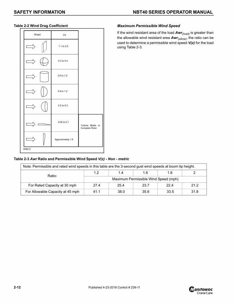
SAFETY INFORMATION NBT40 SERIES OPERATOR MANUAL
Table 2-2 Wind Drag Coefficient
8384-2
Shape Cd
1.1 to 2.0
0.3 to 0.4
0.6 to 1.0
0.8 to 1.2
0.2 to 0.3
0.05 to 0.1
Approximately 1.6
Turbine Blade orComplete Rotor
2-12 Published 4-23-201
Maximum Permissible Wind Speed
If the wind resistant area of the load Awr(load) is greater than
the allowable wind resistant area Awr(allow), the ratio can be
used to determine a permissible wind speed V(z) for the loadusing Table 2-3.
Table 2-3 Awr Ratio and Permissible Wind Speed V(z) - Non - metric
Note: Permissible and rated wind speeds in this table are the 3-second gust wind speeds at boom tip height.
Ratio:1.2 1.4 1.6 1.8 2
Maximum Permissible Wind Speed (mph)
For Rated Capacity at 30 mph 27.4 25.4 23.7 22.4 21.2
For Allowable Capacity at 45 mph 41.1 38.0 35.6 33.5 31.8
8 Control # 239-11

NBT40 SERIES OPERATOR MANUAL SAFETY INFORMATION
2
Rated Load Chart Example - Metric
FIGURE 2-38383-1
National Crane Published 4-23-2018 Control # 239-11
2-13
SAFETY INFORMATION NBT40 SERIES OPERATOR MANUAL
2-14 Published 4-23-201
Table 2-5 Awr Ratio and Permissible Wind Speed V(z) - Metric
Note: Permissible and rated wind speeds in this table are the 3-second gust wind speeds at boom tip height.
Ratio: 1.2 1.4 1.6 1.8 2
Maximum Permissible Wind Speed (m/s)
For Rated Capacity at 13.4 m/s 12.2 11.4 10.6 10.0 9.5
For Allowable Capacity at 20.1 m/s 18.3 17.0 15.9 15.0 14.2
Table 2-4 Example-Capacity Reduction Factors for Wind Speed V(z) Greater than 13.4 m/s - Metric
(Only for lifting with main boom on fully extended outriggers, with or without stowed extension)
For wind speed V(z) (3-second gust speed at boom tip height) V(z) > 13.4 m/s ≤ 20.1 m/s, the Reduced Capacity shall be calculated by multiplying the Published Rated Capacity by the following factors:
Main Boom Length in Meters
Wind SpeedV(z) > 13.4 m/s
< 20.1 m/s10.9 12.2 15.2 18.4 21.3 24.4 27.4 30.5 33.5
Factor 0.9 0.9 0.8 0.8 0.8 0.8 0.8 0.7 0.6
Wind resistance area of load, Awr(load) shall not exceed maximum allowable wind resistance area Awr(allow).
Maximum allowable wind resistance area, [m2] Awr(allow) = 0.0012 x calculated reduced capacity in kg.Wind resistance area of load, Awr(load) = projected wind area Ap x wind drag coefficient Cd for the load.
For wind resistance Area of load, Awr (load) > maximum allowable wind resistance area, Awr(allow) refer to crane Operator Manual.
Example and Sample Calculations (metric)
The following example illustrates how to calculate allowableload while operating in wind speed (3-second wind gustspeed) above 13.4 m/s (30 mph) and maximum permissiblewind speeds with various combinations of lifted load andwind resistance area.
NOTE: Permissible and calculated wind speeds in thisexample are the 3-second wind gust speeds atboom tip height V(z).
Example 1: Crane Configuration:
• boom length = 27.4 m,
• load radius = 9 m,
• wind speed is measured at V(z) ≤ 20.1 m/s.
From the Rated Load Char t Example - Metr ic(Figure 2-3), at maximum permissible wind speed, V(z) =13.4 m/s, the rated l i f t ing capacity m (a l l ow) for th isconfiguration is 15,050 kg.
The maximum allowable wind resistance area of load is
Awr(allow) = 0.0012 x m(load) (2.4)
Awr(allow) = 0.0012 x 15,050 = 18.06 m2
For the allowable wind speed > 13.4 m/s and ≤ 20.1 m/s,reduce the allowable load. Per Table 2-4, the Factor for mainboom length of 27.4 m is 0.8, the allowable load is:
m(allow) = 0.8 x 15,050 = 12,040 kg
This reduced capacity load has an allowable wind resistancearea of:
Awr(allow) = 0.0012 x 12,040 = 14.45 m2
Lifting Limits at wind speed V(z) ≤ 13.4 m/s at thisconfiguration:
• Maximum load 15,050 kg
• Maximum wind resistance area of load 18.06 m2
Lifting Limits at wind speed V(z) > 13.4 m/s and≤ 20.1 m/s, at this configuration:
• Maximum load 12,040 kg
• Maximum wind resistance area of load 14.45 m2
8 Control # 239-11

NBT40 SERIES OPERATOR MANUAL SAFETY INFORMATION
2
At wind speeds greater than 13.4 m/s, it is not permissible tolift a load greater than 12,040 kg, even if the wind resistance
area of the load is less than 14.45 m2.
Refer to the information from the above crane configuration,examine several load conditions.
Load example 1.1:
With known Wind Drag Coefficient of the load Cd, and
• load to be lifted of 11,200 kg,
• Projected Wind Area Ap = 9.20 m2,
• Wind Drag Coefficient Cd = 1.5
wind resistance area of load can be estimated as
Awr(load) = Ap x Cd = 9.2 x 1.5 = 13.8 m2
Refer to the above Lifting Limits at wind speed V(z)> 13.4 m/s and ≤ to 20.1 m/s. Comparing the load and windresistant area to the allowable:
• Is the load to be lifted less than allowable load?11,200 kg ≤ 12,040 kg YES
• Is Awr(load) less than Awr(allow) ?
13.8 m2 ≤ 14.45 m2 YES
Conclusion: This load is permissible to lift in wind speed upto 20.1 m/s.
Load example 1.2:
With unknown Wind Drag Coefficient of the load Cd,
• Load to be lifted of 10,000 kg,
• Projected Wind Area Ap = 5.45 m2,
• Wind Drag Coefficient Cd = unknown
NOTE: If exact Wind Drag Coefficient is not known, it shallbe assumed as 2.4.
• the wind resistance area of load can be estimated as
Awr(load) = Ap x Cd = 5.45 x 2.4 = 13.08 m2
Refer to the above Lifting Limits at V(z) > 13.4 m/sand ≤ 20.1 m/s. Comparing the load and wind resistant areato the allowable:
• Is the load to be lifted less than allowable load?10,000 kg ≤ 12,040 kg YES
• Is Awr(load) less than Awr(allow) ?
13.08 m2 ≤ 14.45 m2 YES
Conclusion: This load is permissible to lift in wind speed upto 20.1 m/s.
National Crane Published 4-23-201
Load example 1.3a:
With large wind resistance area of the load Awr(load),
• Load to be lifted of 14,000 kg,
• Projected Wind Area Ap = 21.85 m2,
• Wind Drag Coefficient Cd = 1.2
the wind resistance area of load can be estimated as:
Awr(load) = Ap X Cd = 21.85 x 1.2 = 26.22 m2
Refe r to the above Li f t ing L imi ts a t windspeed V(z) > 13.4 m/s and ≤ 20.1 m/s. Comparing the loadto the allowable:
• Is the load to be lifted less than allowable load?14,000 kg ≤ 12,040 kg NO
Conclusion: This load is NOT permissible to lift in windspeed up to 20.1 m/s.
Re fe r to the above Li f t ing L imi ts a t windspeed V(z) < 3.4 m/s. Comparing the load to the allowable:
• Is the load to be lifted less than allowable load?14,000 kg ≤ 15,050 kg YES
The maximum permissible wind speed for this load is13.4 m/s, depending on the wind resistance area of the load.
• Is Awr(load) less than Awr(allow)?
26.22 m2 ≤ 18.06 m2 NO
Conclusion: This load is NOT permissible to lift in windspeed at 13.4 m/s, but is permitted to lift at a reduced windspeed calculated as follows:
Ratio = 1.45
From Table 2-5, the maximum permissible wind speed atratio of 1.45 (rounded to next higher table value of 1.6) is10.6 m/s.
Conclusion: This load is permissible to lift in wind speed upto 10.6 m/s only.
Load example 1.3b:
With large wind resistance area of the load Awr(load) ,
• Load to be lifted of 8,000 kg,
• Projected Wind Area Ap = 15.25 m2,
• Wind Drag Coefficient Cd = 1.3
the wind resistance area of load can be estimated as
Awr(load) = Ap x Cd = 15.25 x 1.3 = 19.83 m2
Refer to the above Lifting Limits at wind speed V(z)> 13.4 m/s and ≤ 20.1 m/s. Comparing the load and windresistant area to the allowable:
8 Control # 239-11 2-15

SAFETY INFORMATION NBT40 SERIES OPERATOR MANUAL
• Is the load to be lifted less than allowable load?8,000 kg ≤ 12,040 kg YES
• Is Awr(load) less than Awr(allow)?
19.83 m2 ≤ 14.45 m2 NO
Conclusion: This load is NOT permissible to lift in windspeed up to 20.1 m/s, but permitted to lift at a reduced windspeed calculated as follows:
2-16 Published 4-23-201
Ratio = 1.37
From Table 2-5, the maximum permissible wind speed atratio of 1.37 (rounded to next higher table value of 1.4) is17.0 m/s.
Conclusion: This load is permissible to lift in wind speed upto 17.0 m/s only.
8 Control # 239-11

NBT40 SERIES OPERATOR MANUAL SAFETY INFORMATION
2
Rated Load Chart Example - Non-metric
FIGURE 2-48382-1
National Crane Published 4-23-2018 Control # 239-11
2-17
SAFETY INFORMATION NBT40 SERIES OPERATOR MANUAL
2-18 Published 4-23-201
Table 2-7 Awr Ratio and Permissible Wind Speed V(z) - Non-Metric
Note: Permissible and rated wind speeds in this table are the 3-second gust wind speeds at boom tip height.
Ratio:1.2 1.4 1.6 1.8 2
Maximum Permissible Wind Speed (mph)
For Rated Capacity@ 30 mph 27.4 25.4 23.7 22.4 21.2
For Allowable Capacity@ 45 mph 41.1 38.0 35.6 33.5 31.8
Table 2-6 Example-Capacity Reduction Factors for Wind Speed V(z) Greater than 30 mph - Non-metric
(Only for lifting with main boom on fully extended outriggers, with or without stowed extension)
For wind speed Vz (3-second gust speed at boom tip height) is greater > 30> mph ≤ 45 mph, the Reduced Capacity shall be calculated by multiplying the Published Rated Capacity by the following factors:
Main Boom Length in Feet
Wind SpeedVz> 30 mph
< 45 mph36 40 50 60 70 80 90 100 110
Factor 0.9 0.9 0.8 0.8 0.8 0.8 0.8 0.7 0.5
Wind resistance area of load, Awr(load), shall not exceed maximum allowable wind resistance area Awr(allow).
Maximum allowable wind resistance area in [ft2],Awr (allow) = 0.0059 x calculated reduced capacity in lb.
Wind resistance area of load, Awr(load) = projected wind area Ap x wind drag coefficient Cd for the load.
For wind resistance area of load, Awr (load) > maximum allowable wind resistance, Awr (allow), refer to crane Operator
Manual.
Example and Sample Calculations (Non-metric)
The following example illustrates how to calculate allowableload while operating in wind speed (3-second wind gustspeed) above 13.4 m/s (30 mph) and maximum permissiblewind speeds with various combinations of lifted load andwind resistance area.
NOTE: Permissible and calculated wind speeds in thisexample are the 3-second wind gust speeds atboom tip height V(z).
Example 2:
A crane is configured with:
• boom length = 90 ft,
• load radius = 40 ft, and
• wind speed is measured at V(z) ≤ 45 mph.
The Rated Load Chart Example - Non-metric (Figure 2-4),at maximum permissible wind speed, V(z) = 30 mph, the
rated lifting capacity m(al low) for this configuration is
25,200 lb.
The maximum allowable wind resistance area of load is:
Awr(allow) = 0.0059 x m(load) (2.5)
Awr(allow) = 0.0059 x 25,200 = 149 ft2
For the allowable wind speed > 30 mph and ≤ 45 mph,reduce the allowable load. , the Factor for a main boomlength of 90 ft is 0.8, thus the allowable load is:
m(allow) = 0.8 x 25,200 = 20,160 lb
This reduced capacity load has an allowable wind resistancearea of:
Awr(allow) = 0.0059 x 20,160 = 119 ft2
Lifting Limits at wind speed V(z) < 30 mph at thisconfiguration:
• Maximum load 25,200 lb
• Maximum wind resistance area of load 149 ft2
8 Control # 239-11

NBT40 SERIES OPERATOR MANUAL SAFETY INFORMATION
2
Example, wind speeds greater than 13.4 m/s is NOTpermissible to lift a load greater than 20,160 lb, even if thewind resistance area of the load is less than 119 ft2.
Refer to the above crane configuration for the following loadconditions:
Load example 2.1:
With known Wind Drag Coefficient of the load Cd,
• load to be lifted of 19,500 lb,
• Projected Wind Area Ap = 70 ft2,
• Wind Drag Coefficient Cd = 1.5
then the wind resistance area of load can be estimated as
Awr(load) = Ap x Cd = 70 x 1.5 = 105 ft2
Refer to the above Lifting Limits at wind speed V(z) > 30mph and ≤ 45 mph. Comparing the load and wind resistantarea to the allowable:
• Is the load to be lifted less than allowable load?19,500 lb ≤ 20,160 lb YES
• Is Awr(load) less than Awr(allow)?
105 ft2 ≤ 119 ft2 YES
Conclusion: This load is permissible to lift in wind speed upto 45 mph.
Load example 2.2:
With unknown Wind Drag Coefficient of the load Cd,
• Load to be lifted of 18,000 lb,
• Projected Wind Area Ap = 45 ft2,
• Wind Drag Coefficient Cd = unknown
NOTE: If exact Wind Drag Coefficient is not known, it shallbe assumed as 2.4.
the wind resistance area of load can be estimated as
Awr(load) = Ap x Cd = 45 x 2.4 = 108 ft2
Refer to the above Lifting Limits at wind speed V(z)> 30 mph and ≤ 45 mph. Comparing the load and windresistant area to the allowable:
• Is the load to be lifted less than allowable load?18,000 lb ≤ 20,160 lb YES
Li f t ing L imi ts a t w ind speed V(z ) > 30 mphand ≤ 45 mph at this configuration:
• Maximum load 20,160 lb
• Maximum wind resistance area of load 119 ft2
National Crane Published 4-23-201
• Is Awr(load) less than Awr(allow)?
108 ft2 ≤ 119 ft2 YES
Conclusion: This load is permissible to lift in wind speed upto 45 mph.
Load example 2.3a:
With large wind resistance area of the load Awr(load),
• Load to be lifted of 22,000 lb,
• Projected Wind Area Ap = 180 ft2,
• Wind Drag Coefficient Cd = 1.2
the wind resistance area of load can be estimated as:
Awr(load) = Ap x Cd = 180 x 1.2 = 216 ft2
Refer to the above Lifting Limits at wind speed V(z) >30 mph and ≤ 45 mph. Comparing the load to the allowable:
• Is the load to be lifted less than allowable load?22,000 lb ≤ 20,160 lb NO
Conclusion: This load is NOT permissible to lift in windspeed up to 45 mph.
Refer to the above Lifting Limits at wind speed V(z) up to30 mph. Comparing the load to the allowable:
Is the load to be lifted less than allowable load?22,000 lb ≤ 25,200 lb . . . . . . . . . . . . . . . . . . . . YES
The permissible wind speed for this load is 30 mph,depending on the wind resistance area of the load.
• Is Awr(load) less than Awr(allow),?
216 ft2 ≤ 149 ft2 . . . . . . . . . . . . . . . . . . . . . . . . . NO
Conclusion: This load is NOT permissible to lift in windspeed at 30 mph, but permitted to lift at a reduced windspeed calculated as follows:
Ratio = 1.45
From Table 2-7, the maximum permissible wind speed atratio of 1.45 (rounded to next higher table value of 1.6) is23.7 mph.
Conclusion: This load is permissible to lift in wind speed upto 23.7 mph only.
Load example 2.3b:
With large wind resistance area of the load Awr(load),
• Load to be lifted of 12,000 lb,
• Projected Wind Area Ap = 125 ft2,
• Wind Drag Coefficient Cd = 1.3
the wind resistance area of load can be estimated as:
Awr(load) = Ap x Cd = 125 x 1.3 = 162 ft2
8 Control # 239-11 2-19

SAFETY INFORMATION NBT40 SERIES OPERATOR MANUAL
Refer to the above Lifting Limits at wind speed V(z)> 30 mph and ≤ 45 mph. Comparing the load and windresistant area to the allowable:
• Is the load to be lifted less than allowable load?12,000 lb ≤ 20,160 lb YES
• Is Awr(load) less than Awr(allow),?
162 ft2 ≤ 119 ft2 NO
Conclusion: This load is NOT permissible to lift in windspeed up to 45 mph, but permitted to lift at a reduced windspeed calculated as follows:
Ratio = 1.37
From Table Table 2-7, the maximum permissible wind speedat ratio of 1.37 (rounded to next higher table value of 1.4) is38.0 mph.
Conclusion: This load is permissible to lift in wind speed upto 38.0 mph only.
Lifting Operations
Before lifting, position the crane on a firm surface, properlyextend and set the outr iggers, and level the crane.Depending on the nature of the supporting surface,adequate cribbing may be required to obtain a larger bearingsurface.
The crane is equipped with a bubble level that should beused to determine whether the crane is level. The load linecan also be used to estimate the levelness of the crane bychecking to be sure it is in-line with the center of the boom atall points on the swing circle.
If the boom extension, or auxiliary boom nose is to be used,ensure the electrical cable and the weight for the Anti-Two-Block Switch are properly installed and the Rated CapacityLimiter (RCL) is programmed for the crane configuration.Refer to the RCL operator manual supplied with the crane.
Verify the crane’s capacity by checking the Load Chartagainst the weight of the load. Then, lift the load slightly atfirst to ensure stability before proceeding with the lift.
Be sure the load is properly rigged and attached. Alwaysdetermine the weight of the load before you attempt to lift itand remember that all rigging (slings, etc.) and lifting devices(hook block, boom extension, etc.) must be considered partof the load.
Measure the load radius before making a lift and stay withinapproved lifting areas based on the range diagrams andworking area diagrams on the crane’s Load Chart.
Always keep the load as near to the crane and as close tothe ground as possible.
Do not overload the crane by exceeding the capacitiesshown on the appropriate Load Chart. Death or serious
2-20 Published 4-23-201
injury could result from the crane tipping over or failingstructurally from overload.
The crane can tip over or fail structurally if:
• The load and crane’s configuration is not within thecapacity as shown on the applicable Load Chart andnotes.
• The ground is soft and/or the surface conditions arepoor.
• Outriggers are not properly extended and set. Onmodels equipped with outriggers that can be pinned atthe mid-extend position, the outriggers must also bepinned when operating from the mid-extend position.
• Cribbing under the outrigger pads is inadequate.
• The crane is improperly operated.
Do not rely on the crane’s tipping to determine your liftingcapacity.
Be sure the hoist line is vertical before lifting. Do not subjectthe crane to side loading. A side load can tip the crane orcause it to fail structurally.
Load Chart capacities are based on freely suspended loads.Do not pull posts, pilings, or submerged articles. Be sure theload is not frozen or otherwise attached to the ground beforelifting.
If you should encounter a tipping condition, immediatelylower the load with the hoist line and retract or elevate theboom to decrease the load radius. Never lower or extend theboom; this will aggravate the condition.
Use tag lines whenever possible to help control themovement of the load.
When lifting loads, the crane will lean toward the boom andthe load will swing out, increasing the load radius. Ensure thecrane’s capacity is not exceeded when this occurs.
Do not strike any obstruction with the boom. If the boomshould accidentally contact an object, stop immediately.Inspect the boom. Remove the crane from service if theboom is damaged.
Never push or pull with the crane boom.
Avoid sudden starts and stops when moving the load. Theinertia and an increased load radius could tip the crane overor cause it to fail structurally.
Using only one hoist at a t ime when l i ft ing loads isrecommended. See “Tilt-Up Panel Lifting” on page 2-21 foradditional lifting instructions.
Always use enough parts-of-line to accommodate the load tobe lifted. Lifting with too few parts-of-line can result in failureof the hoist rope.
8 Control # 239-11

NBT40 SERIES OPERATOR MANUAL SAFETY INFORMATION
2
Counterweight
On cranes equipped with removable counterweights, ensurethe appropriate counterweight sections are properly installedfor the lift being considered.
Do not add material to the counterweight to increasecapacity. United States Federal law prohibits modification oradditions which affect the capacity or safe operation of theequipment without the manufacturer’s written approval.[29CFR 1926.1434]
Outrigger Lift Off
Regarding “lifting” of an outrigger pad during craningactivities, be advised that the rated loads for these cranes,as indicated on the crane’s Load Chart, do not exceed 85%of the tipping load on outriggers as determined by SAE J765JUNE2017 “Cranes Stability Test Code.” An outrigger padmay lift off the ground during operation of the crane within thecapacity limits of the Load Chart, yet the crane will not havereached instability. The “balance point” for stability testingaccording to SAE and National Crane criteria is a conditionof loading wherein the load moment acting to overturn thecrane is equal to the maximum moment of the craneavailable to resist overturning. This balance point or point ofinstability for a crane does not depend on “lifting” of anoutrigger but rather on comparison of the “opposing” loadmoments.
The occurrence of an outrigger lifting from the ground is oftenattributed to the natural flex in the crane’s frame. This mayhappen when lifting a load in certain configurations within thecapacity limits of the Load Chart and is not necessarily anindication of an unstable condition.
Provided the crane is properly set up, the crane is in goodworking condition, that all operator’s aids are properlyprogrammed, that the qualified crane operator adheres tothe instructions found in the applicable Load Chart, OperatorManual and decals on the crane, the crane should not beunstable.
Multiple Crane Lifts
Multiple crane lifts are not recommended.
Any lift that requires more than one crane must be preciselyplanned and coordinated by a qualified person. If it isnecessary to perform a multi-crane lift, the operator shall beresponsible for assuring that the following minimum safetyprecautions are taken:
• Secure the services of a qualified person to direct theoperation.
• Make sure all signals are coordinated through the liftdirector or person in charge of the lift.
• Coordinate lifting plans with the operators, designatedperson, and signal person prior to beginning the lift.
National Crane Published 4-23-201
• Maintain communication between all parties throughoutthe entire operation. If possible, provide approved radioequipment for voice communication between all partiesengaged in the lift.
• Use outriggers on cranes so equipped.
• Calculate the amount of weight to be lifted by each craneand attach slings at the correct points for proper weightdistribution.
• Ensure the load lines are directly over the attach pointsto avoid side loading and transfer of loading from onecrane to the other.
• Do not travel. Lift only from a stationary position.
Tilt-Up Panel Lifting
Requirements and recommendations regarding operationand use of Grove Cranes are stated on decals and in theOperator and Safety Handbook and other manuals providedwith each specific model machine. Using the subject crane toperform tilt-up panel lifting with two hoist lines poses new anddifferent hazards than does normal lifting use.
Therefore, the following additional precautions must betaken if it is necessary for the crane to be used to perform tilt-up panel lifting using a crane equipped with two hoists:
• The crane must be set up and operated in accordancewith Grove’s instructions in the Operator and SafetyHandbook, Load Capacity Chart, and decals affixed tothe crane.
• The hoist rope from the main hoist shall be reeved overthe main boom nose reeved for two parts of line.
• The hoist rope from the auxiliary hoist shall be reevedover the auxiliary boom nose reeved for one part of line.
• The load shall be connected with the main hoist lineconnected to the end closest to crane and the auxiliaryhoist line connected to the end farthest from the crane.
• The anti-two block system shall be installed andinspected to confirm that it is active to monitor both hoistlines.
• The RCL hoist selection shall be set to main hoist andtwo parts of line.
• The wire rope and sheaves shall be inspected prior toand following the lifting operations for chaffing orscrubbing.
• The total gross load shall not exceed 80% of thestandard load chart. The operator shall be responsible tocontrol this as the RCL does not have a feature to setreduced lifting limits.
• The auxiliary hoist line shall be considered part of thededucts to determine net allowable load.
8 Control # 239-11 2-21

SAFETY INFORMATION NBT40 SERIES OPERATOR MANUAL
• The panel shall be lifted so that the hoist lines are in linewith the crane.
• The load shall be controlled to prevent rotation of theload and to ensure the load stays in line with the boom.
• The load must be balanced with the auxiliary: load linenot taking more than half the load at any time during thelift. The RCL will not be providing coverage for the linepull of the auxiliary hoist line.
• The effect of wind loads on the crane and panel shall betaken into consideration. Operations shall be halted ifthe wind can cause a loss of control in handling the load.
• The main hoist line shall be used to raise the panel intothe vertical position.
Ensure that all personnel working on and around the craneare properly trained and thoroughly familiar with operationalfunctions of the crane and safe operating and work practices.Personnel should be thoroughly familiar with regulations andstandards governing cranes and their operation. Workpractices may vary slightly between government regulations,industry standards, local and job-site rules and employerpolicies so a thorough knowledge of and compliance with allrelevant work rules is necessary.
PILE DRIVING AND EXTRACTING
Pile driving and extracting are applications approved byNational Crane, provided all equipment is operated withinfactory guidelines. The following operating requirementsmust be used during pile driving and extracting with aNational mobile hydraulic crane:
Pile driving and pile extraction using a mobile craneintroduces many variable and unknown factors that must beconsidered when using a crane for this application. Becauseof these factors, discretion must be exercised when piledriving or pile extraction is being considered.
It is not the intention of National Crane to recommendspecific types or makes of pile driving and pile extractionequipment, but rather to advise of the operat ionalrequirements to help avoid the detrimental effects that piledriving and pile extraction can have on the crane.
In addition to the operating requirements that are detailed inthe operating manuals and on the load capacity chart, piledriving and extracting operations are approved by NationalCrane, provided all guidelines outlined below are followed:
• All pile driving and extracting operations shall berestricted to fully extended outriggers with all tires clearof the ground.
• The combined weight of the driver or extractor, piling,leads, attachments, etc., shall not exceed 80% of thepublished load chart values for on-outriggers operation.
• The pile driver or pile extractor and attachments shall bekept clear of the boom nose at all times.
2-22 Published 4-23-201
• The pile driver and piling shall be suspended from ahoist cable with sufficient line speed to meet or exceedthe rate of descent of the driver and piling to precludeimpact loading or vibration from being induced into theboom and crane structure.
• Pile driving or extracting shall be restricted to over themain boom only and shall not be permitted over a boomextension.
• Pile extraction using only the crane’s hoist line is unsafeand not permit ted s ince load values cannot beaccurately determined. Only pile extraction devices thatdo not transmit vibration or shock loading into the craneare permitted. All possible precautionary measures shallbe taken to prevent shock loads or vibration from beingimposed on crane components, either directly throughthe hoist cable or indirectly from ground borne vibration.
• The load lines shall be kept vertical at all times duringpile driving and pile extraction operations.
• The operator and other personnel associated with thepile driving and pile extraction operation shall have readand understood all safety standards applicable to craneoperations as well as being thoroughly trained in thesafe operation of pile driving and extracting equipment.
Crane Equipment
• Hoists shall be equipped with a cable follower to aid inproper spooling of cable.
• All cable retainer pins and cable guides/retainers shallbe in place.
• All boom extensions must be removed from the machinebefore pile driving or extraction begins.
• All hoist hooks shall be equipped with a positive lockinglatch.
Crane Inspection
• In addition to the crane's frequent and periodicinspections, dated daily records shall be maintainedshowing inspections were performed on the craneduring the time it was used for pile driving or extraction.
• All anti-two block warning devices and RCL systemsshall be inspected daily and verified to be functional.
• All areas of the crane subject to fatigue shall beinspected monthly, and before the crane is to return tolifting service.
• The boom shall be inspected daily to ensure all wearpads remain in place. Cranes which utilize pinned boomsections shall be inspected daily to ensure the pinningmechanism operates properly and to check for unduewear at the pins and pinning plates.
• The hoist cable shall be inspected daily to ensure nochafing or wear is occurring.
8 Control # 239-11

NBT40 SERIES OPERATOR MANUAL SAFETY INFORMATION
2
ELECTROCUTION HAZARD
Thoroughly read, understand, and abide by all applicablefederal, state, and local regulations regarding operation ofcranes near electric power lines or equipment.
United States federal law prohibits the use ofcranes closer than 6 m (20 ft) to power sourcesup to 350 kV and greater distances for highervoltages unless the line’s voltage is known[29CFR1910.180 and 29CFR1926.1400].
To avoid death or serious injury, National Cranerecommends that all parts of crane, boom, andload be kept at least 6 m (20 ft) away from allelectrical power lines and equipment less than350 kV.
NOTE: For detailed guidelines on operating near powerl ines, refer to the current edit ion of OSHA
National Crane Published 4-23-201
29CFR1926.1408 and ASME B30.5 AmericanNational Standard.
If operation within 3 m (10 ft) of any power lines cannot beavoided, the power utility must be notified and the powerl ines must be de-energized and grounded beforeperforming any work.
Electrocution can occur even without direct contact with thecrane.
WARNINGElectrocution Hazard!
National cranes are not equipped with all featuresrequired to operate within OSHA 29CFR1926.1408, TableA clearances when the power lines are energized.
Crane operation is dangerous when close to an energizedelectrical power source. Exercise extreme caution andprudent judgement. Operate slowly and cautiously when inthe vicinity of power lines.
Before operating this crane in the vicinity of electrical powerlines or equipment, notify the power utility company. Obtainpositive and absolute assurance that the power has beenturned off.
This crane is not insulated. Always consider all parts of theload and the crane, including the wire rope, hoist cable,pendant cables, and tag lines, as conductors. You, theoperator, are responsible for alerting all personnel ofdangers associated with electr ical power l ines and
equipment. Do not allow unnecessary personnel in thevicinity of the crane while operating. Permit no one to leanagainst or touch the crane. Permit no one, including riggersand load handlers, to hold the load, load lines, tag lines, orrigging gear.
If the load, wire rope, boom, or any portion of the cranecontacts or comes too close to an electrical power source,everyone in, on, and around the crane can be seriouslyinjured or killed.
Most overhead power lines are not insulated. Treat alloverhead power lines as being energized unless you havereliable information to the contrary from the utility companyor owner.
8 Control # 239-11 2-23

SAFETY INFORMATION NBT40 SERIES OPERATOR MANUAL
The rules in this Operator Manual must be followed at alltimes, even if the electrical power lines or equipment havebeen de-energized.
The safest way to avoid electrocution is to stay away fromelectrical power lines and electrical power sources.
It is not always necessary to contact a power line or powersource to become electrocuted. Electricity, depending onmagnitude, can arc or jump to any part of the load, load line,or crane boom if it comes too close to an electrical powersource. Low voltages can also be dangerous.
Set-Up and Operation
During crane use, assume that every line is energized (“hot”or “live”) and take the necessary precautions.
Set up the crane in a position such that the load, boom, orany part of the crane and its attachments cannot be moved towithin 6 m (20 ft) of electrical power lines or equipment. Thisincludes the crane boom (fully extended to maximum height,radius, and length) and all attachments (boom extensions,rigging, loads, etc.). Overhead lines tend to blow in the windso allow for l ines’ movement when determining safeoperating distance.
A suitable barricade should be erected to physically restrainthe crane and all attachments (including the load) fromentering into an unsafe distance from electrical power linesor equipment.
Plan ahead and always plan a safe route before travelingunder power lines. Rider poles should be erected on eachside of a crossing to assure suff ic ient clearance ismaintained.
United States OSHA regulations require a flagman whenoperating in close proximity to energized power lines.
Appoint a reliable and qualified signal person, equipped witha loud signal whistle or horn and voice communicationequipment, to warn the operator when any part of the crane
2-24 Published 4-23-201
or load moves near a power source. This person shall haveno other duties while the crane is working.
Tag lines should always be made of non-conductivematerials. Any tag line that is wet or dirty can conductelectricity.
Do not store materials under power lines or close toelectrical power sources.
Electrocution Hazard Devices
The use of insulated links, insulated boom cages/guards,proximity warning devices, or mechanical limit stops doesnot assure that electrical contact will not occur. Even if codesor regulations require the use of such devices, failure tofollow the rules listed here may result in serious injury ordeath. You should be aware that such devices havelimitations and you should follow the rules and precautionsoutlined in this manual at all times even if the crane isequipped with these devices.
Insulating links installed into the load line afford limitedprotection from electrocution hazards. Links are limited intheir l ift ing abilit ies, insulating properties, and otherproperties that affect their performance. Moisture, dust, dirt,oils, and other contaminants can cause a link to conductelectricity. Due to their capacity ratings, some links are noteffective for large cranes and/or high voltages/currents.
The only protection that may be afforded by an insulated linkis below the link (electrically downstream), provided the linkhas been kept clean, free of contamination, has not beenscratched or damaged, and is periodically tested (just beforeuse) for its dielectric integrity.
Boom cages and boom guards afford limited protection fromelectrocution hazards. They are designed to cover only theboom nose and a small portion of the boom. Performance ofboom cages and boom guards is limited by their physicalsize, insulating characteristics, and operating environment(e.g. dust, dirt, moisture, etc.). The insulating characteristicsof these devices can be compromised if not kept clean, freeof contamination, and undamaged.
Proximity sensing and warning devices are available indifferent types. Some use boom nose (localized) sensorsand others use full boom length sensors. No warning may begiven for components, cables, loads, and other attachmentslocated outside of the sensing area. Much reliance is placedupon you, the operator, in selecting and properly setting thesensitivity of these devices.
Never rely solely on a device to protect you and your fellowworkers from danger.
Some variables you must know and understand are:
• Proximity devices are advertised to detect the existenceof electricity and not its quantity or magnitude.
8 Control # 239-11

NBT40 SERIES OPERATOR MANUAL SAFETY INFORMATION
2
• Some proximity devices may detect only alternatingcurrent (AC) and not direct current (DC).
• Some proximity devices detect radio frequency (RF)energy and others do not.
• Most proximity devices simply provide a signal (audible,visual, or both) for the operator; this signal must not beignored.
• Sometimes the sensing portion of the proximity devicesbecomes confused by complex or differing arrays ofpower lines and power sources.
Do not depend on grounding. Grounding of a crane affordsl i t t le or no protect ion f rom electr ical hazards. Theeffectiveness of grounding is limited by the size of theconductor (wire) used, the condition of the ground, themagnitude of the voltage and current present, and numerousother factors.
Electrical Contact
If the crane should come in contact with an energized powersource, you must:
1. Stay in the crane work station. Don’t panic.
2. Immediately warn personnel in the vicinity to stay away.
3. Attempt to move the crane away from the contactedpower source using the crane’s controls which are likelyto remain functional.
4. Stay in the crane until the power company has beencontacted and the power source has been de-energized.No one must attempt to come close to the crane or loaduntil the power has been turned off.
Only as a last resort should an operator attempt to leave thecrane upon contacting a power source. If it is absolutelynecessary to leave the operator’s station, jump completelyclear of the crane. Do not step off. Hop away with both feettogether. Do not walk or run.
Following any contact with an energized electrical source,the National Crane distributor must be immediately advisedof the incident and consulted on necessary inspections andrepairs. Thoroughly inspect the rope and all points of contacton the crane. Should the distributor not be immediatelyavailable, contact Manitowoc Crane Care. The crane mustnot be returned to service until it is thoroughly inspected forany evidence of damage and all damaged parts are repairedor replaced as authorized by your National Crane distributoror Manitowoc Crane Care.
Special Operating Conditions and Equipment
Never operate the crane during an electrical thunderstorm.
National Crane Published 4-23-201
When operating near transmitter/communication towerswhere an electrical charge can be induced into the crane orload:
• The transmitter shall be deenergized OR,
• Tests shall be made to determine if an electrical chargewill be induced into the crane or load.
• The crane must be provided an electrical ground.
• If taglines are used, they must be non-conductive.
• Every precaution must be taken to dissipate inducedvoltages. Consult a qualified RF (radio frequency)Consultant. Also refer to local, state, and federal codesand regulations.
When operating cranes equipped with electromagnets, youmust take additional precautions. Permit no one to touch themagnet or load. Alert personnel by sounding a warningsignal when moving a load. Do not allow the cover of theelectromagnet power supply to be open during operation orat any time the electrical system is activated. Shut down thecrane completely and open the magnet controls switch priorto connecting or disconnecting magnet leads. Use only anon-conductive device when positioning a load. Lower themagnet to the stowing area and shut off power beforeleaving the operator’s cab (if equipped) or operator’s station.
Grounding the Crane
The crane may become charged with static electricity. Thismay occur especially when using outrigger pads made ofplastic or when the outrigger pads are packed with insulatingmaterial (e.g. wooden planks).
Use electrically conducting material for grounding.
1. Hammer a metal rod (3, Figure 2-5) (length ofapproximately 2.0 m (6.6 ft)) at least 1.5 m (5 ft) into theground.
2. Moisten the soil around the metal rod (3) for betterconductivity.
3. Clamp an insulated cable (2) to the metal rod (3), cross-section of at least 16 mm² (0.025 inches²).
WARNINGRisk of accidents due to electric shock!
Ground the crane before you start to work with it
• Near strong transmitters (radio transmitters, radiostations, etc.)
• Near high-frequency switching stations
• If a thunder storm is forecast
8 Control # 239-11 2-25

SAFETY INFORMATION NBT40 SERIES OPERATOR MANUAL
4. Connect the free end of the cable with a clamp (1) to agood electrically conductive location on the frame.
PERSONNEL HANDLING
The American Society of Mechanical Engineers publishesthe American National Standard entitled, Personnel LiftingSystems, ASME B30.23-2016:
This Volume establishes the design criteria, equip-ment characteristics, and operational proceduresthat are required when hoisting equipment withinthe scope of the ASME B30 Standard is used to liftpersonnel. Hoisting equipment defined by theASME 830 Standard is intended for material han-dling. It is not designed, manufactured, or intendedto meet the standards for personnel handling equip-ment, such as ANSI/SIA A92 (Aerial Platforms).The equipment and implementation requirementslisted in this Volume are not the same as that estab-lished for using equipment specifically designedand manufactured for lifting personnel. Hoistingequipment complying with the applicable Volumesof the ASME B30 Standard shall not be used to liftor lower personnel unless there are no less hazard-ous alternatives to providing access to the, areawhere work is to be performed. The lifting or lower-ing of personnel using ASME B30-compliant hoist-ing equipment is prohibited unless all applicablerequirements of this volume have been met.
This standard is consistent with the U.S. Department ofLabor, Occupational Safety and Health Administration(OSHA) regulat ions for Construct ion that state, in29CFRI926.1431:
WARNINGRisk of accidents due to electric shock!
Ensure that the connections between the cable and theclamp are electrically conductive.
Do not attach the clamp to parts that are screwed on, suchas valves, covers or similar parts.
FIGURE 2-5
2-26 Published 4-23-201
General requirements. The use of a crane or der-rick to hoist employees on a personnel platform isprohibited, except when the erection, use, and dis-mantling of conventional means of reaching theworksite, such as a personnel hoist, ladder, stair-way, aerial lift, elevating work platform or scaffold,would be more hazardous or is not possiblebecause of structural design or worksite conditions.
Additional requirements for crane operations are stated inASME B30.5, Mobile and Locomotive Cranes, ASME B30.8,Floating Cranes and Floating Derricks, and in OSHAregulations 29CFRI910.180 for General Industry and29CFRI926.1431 for Construction.
Use of a National crane to handle personnel is acceptableprovided:
• The requirements of the applicable national, state andlocal regulations and safety codes are met.
• A determination has been made that use of a crane tohandle personnel is the least hazardous means toperform the work.
• The crane operator shall be qualified to operate thespecif ic type of hoist ing equipment used in thepersonnel lift.
• The crane operator must remain at the crane controls atall times when personnel are off the ground.
• The crane operator and occupants have been instructedin the recognized hazards of personnel platform lifts.
• The crane is in proper working order.
• The crane must be equipped with a boom angleindicator that is visible to the crane operator.
• The crane's Load Chart is affixed at the operator’sstation and readily accessible to the operator. The totalweight of the loaded personnel platform and relatedrigging shall not exceed 50 percent of the rated capacityfor the radius and configuration of the crane.
• The crane is level within one percent of level grade andlocated on a firm footing. Cranes with outriggers shallhave them all deployed following manufacturer'sspecifications.
• The crane's Operator's Manual and other operatingmanuals are at the operator ’s station and readilyaccessible to the operator.
• The platform meets the requirements as prescribed byapplicable standards and regulations.
• For rope suspended platforms:
- The crane is equipped with a hook that can beclosed and locked, eliminating the throat opening.
- The crane is equipped with a functional Anti-Two-Block Device.
8 Control # 239-11

NBT40 SERIES OPERATOR MANUAL SAFETY INFORMATION
2
- The platform is properly attached and secured to theload hook.
• For boom mounted platforms:
- On cranes equipped with a boom mountedpersonnel platform, use only a platform approved byNational Crane.
- The platform is properly attached and secure.
To avoid death or serious injury:
• NEVER use this crane for bungee jumping or any formof amusement or sport.
• NEVER handle personnel on the loadline unless therequirements of applicable national, state and localregulations and safety codes are met.
• NEVER permit anyone to ride loads, hooks, slings orother rigging for any reason.
• NEVER get on or off a moving crane.
• NEVER allow anyone other than the operator to be onthis crane while the machine is operating or traveling.
The following standards and regulations regarding personnelhandling are available by mail at the following addresses:
• ASME (formerly ANSI) B30 Series American NationalSafety Standards For Cableways, Cranes, Derricks,Hoists, Hooks, Jacks, and Slings; ASME B30.5, MobileAnd Locomotive Cranes, and ASME B30.23, PersonnelLifting Systems, are available by mail from the ASME, 22Law Drive, Fairfield, New Jersey, 0700-2900
- or -
online at: www.asme.org/kb/standards
• US DOL/OSHA Rules and Regulations are available bymail from the Superintendent of Documents, PO Box371954, Pittsburgh, PA, 15250-7954.
ENVIRONMENTAL PROTECTION
Dispose of waste properly! Improperly disposing of wastecan threaten the environment.
Potentially harmful waste used in National cranes includes— but is not limited to — oil, fuel, grease, coolant, airconditioning refrigerant, filters, batteries, and cloths whichhave come into contact with these environmentally harmfulsubstances.
Handle and dispose of waste according to local, state, andfederal environmental regulations.
When filling and draining crane components, observe thefollowing:
• Do not pour waste fluids onto the ground, down anydrain, or into any source of water.
National Crane Published 4-23-201
• Always drain waste fluids into leak proof containers thatare clearly marked with what they contain.
• Always fill or add fluids with a funnel or a filling pump.
• Immediately clean up any spills.
MAINTENANCE
The crane must be inspected prior to use on each work shift.The owner, user, and operator must ensure that routinemaintenance and lubrication are being dutifully performed.Never operate a damaged or poorly maintained crane.
National Crane continues to recommend that cranes beproperly maintained, regularly inspected and repaired asnecessary. National Crane reminds crane owners to ensurethat all safety decals are in place and legible. National Cranecontinues to urge crane owners to upgrade their cranes withrated capacity limiter and control lever lockout systems for alllifting operations.
Shut down the crane while making repairs or adjustments.
Always perform a function check after repairs have beenmade to ensure proper operation. Load tests should beperformed when structural or lifting members are involved.
Follow all applicable safety precautions in this manual whenperforming crane maintenance as well as crane operations.
Keep the crane free of mud, dirt, and grease at all times.Dirty equipment introduces hazards, wears-out faster, andmakes proper maintenance difficult. Cleaning solutions usedshould be non-flammable, non-toxic and appropriate for thejob.
Routine maintenance and inspection of this crane must beperformed by a qualif ied person(s) according to therecommendat ions in the Mani towoc Crane CareMaintenance and Inspection Manual . Any questionsregarding procedures and specifications should be directedto your National Crane distributor.
Service and Repairs
Service and repairs to the crane must only be performed by aqualified person. All service and repairs must be performedin accordance with manufacturer’s recommendations, thismanual, and the service manual for this machine. If there isany question regarding maintenance procedures or
WARNINGFall Hazard!
Working at elevated heights without using proper fallprotection can result in severe injury or death.
Always use proper fall protection as required by local,state or federal regulations.
8 Control # 239-11 2-27

SAFETY INFORMATION NBT40 SERIES OPERATOR MANUAL
specifications, contact your National Crane distributor forassistance.
Qualified person is defined as one who by reason ofknowledge, training and experience is thoroughly familiarwith the crane’s operation and required maintenance as wellas the hazards involved in performing these tasks.
Training and qualification of maintenance and repairpersonnel are crane owner’s responsibility.
Any modification, alteration, or change to a crane whichaffects its original design and is not authorized and approvedby National Crane is strictly prohibited. All replacementparts must be National Crane approved. Such actioninvalidates all warranties and makes the owner/user liablefor any resultant accidents.
Hydraulic Fluid:
• Do not use your hand or any part of your body to checkfor hydraulic fluid leaks when the engine is running orthe hydraulic system is under pressure. Fluid in thehydraulic system can be under enough pressure that itwill penetrate the skin, causing serious injury or death.Use a piece of cardboard, or piece of paper, to searchfor leaks. Wear gloves to protect your hands fromspraying fluid.
• If any hydraulic fluid is injected into the skin, obtainmedical attention immediately or gangrene may result.
• Do not attempt to repair or tighten any hydraulic hose orfitting while the engine is running, or when the hydraulicsystem is under pressure.
• Never disconnect any hydraulic lines unless the boom isfully lowered, the engine is shut off, and the hydraulicpressure is relieved. To relieve hydraulic pressure, stopthe engine and move the hydraulic controls in bothdirections several times.
• Hot hydraulic fluid will cause severe burns. Wait for thefluid to cool before disconnecting any hydraulic lines.
• Hydraulic fluid can cause permanent eye injury. Wearappropriate eye protection.
Moving Parts:
• Do not place limbs near moving parts. Amputation of abody part may result. Turn off the engine and wait untilthe fan and belts stop moving before servicing crane.
• Pinch points, which result from relative motion betweenmechanical parts, are areas of the machine that can
2-28 Published 4-23-201
cause personal injury or death. Do not place limbs oryour body in contact with pinch points either on oraround the machine. Care must be taken to preventmot ion between pinch points when performingmaintenance and to avoid such areas when movementis possible.
• Do not allow persons to stand near extending orlowering outriggers. Foot crushing could occur
Before performing any maintenance, service or repairs onthe crane:
• The boom should be fully retracted and lowered and theload placed on the ground.
• Do not get under a raised boom unless the boom isblocked up safely. Always block up the boom beforedoing any servicing that requires the boom to be raised.
• Stop the engine and disconnect the battery.
• Controls should be properly tagged. Never operate thecrane if it is tagged-out nor attempt to do so until it isrestored to proper operating condition and all tags havebeen removed by the person(s) who installed them.
After maintenance or repairs:
• Replace all guards and covers that have been removed.
• Remove all tags, connect the battery, and perform afunction check of all operating controls.
• Consult with Manitowoc Crane Care to determine if loadtesting is required after a structural repair is performed.
Lubrication
The c rane mus t be lub r i ca ted accord ing to themanufacturer’s recommendations for lubrication points, timeintervals, and types. Lubricate at more frequent intervalswhen working under severe conditions.
Exercise care when servicing the hydraulic system of thecrane, as pressurized hydraulic oil can cause serious injury.The following precautions must be taken when servicing thehydraulic system:
• Follow the manufacturer’s recommendations whenadding oil to the system. Mixing the wrong fluids coulddestroy seals, causing component failure.
• Be certain all lines, components, and fittings are tightbefore resuming operation.
8 Control # 239-11

NBT40 SERIES OPERATOR MANUAL SAFETY INFORMATION
2
Tires
Inspect the tires for nicks, cuts, embedded material, andabnormal wear.
Ensure all lug nuts are properly torqued.
Ensure pneumatic tires are inflated to the proper pressure.When inflating tires, use a tire gauge, clip-on inflator, andextension hose which will permit standing clear of the tirewhile inflating.
HOIST ROPE
Synthetic Hoist Rope
For detailed information concerning synthetic hoist rope,refer to K100™ Synthetic Crane Hoist Line Manual P/N9828100734 available by contacting Manitowoc Crane Care.
During installation and setup, care must be taken to avoidoverlap and crossing of wire rope and synthetic hoist ropes.
Always make daily inspections of the hoist rope, keeping inmind that all hoist rope will eventually deteriorate to a pointwhere it is no longer usable. Refuse to work with worn ordamaged hoist rope.
During regular inspections, operator shall ensure that cranesurfaces such as wear pads, sheaves, etc have not beendamaged in a manner that can then damage the synthetichoist rope.
Example; if usage of a wire rope has cut grooves with sharpedges in a wear pad, they need to be addressed before thesynthetic hoist rope is used in that same position.
Wire Rope
Use only the rope specified by National Crane as indicatedon the crane’s Load Chart. Substitution of an alternate ropemay require the use of a different permissible line pull and,therefore, require different reeving.
NOTE: Rope may be purchased by contacting ManitowocCrane Care.
WARNINGPossible equipment damage and/or
personal injury!
Driving the crane with a tire and split-rim assembly underinflated at 80% or less of its recommended pressure cancause the wheel and/or tire to fail. Per OSHA Standard1910.177(f)(2), when a tire has been driven under inflatedat 80% or less of its recommended pressure, it must firstbe completely def lated, removed from the axle,disassembled, and inspected before re-inflation.
National Crane Published 4-23-201
Always make daily inspections of the rope, keeping in mindthat all rope will eventually deteriorate to a point where it isno longer usable. Refuse to work with worn or damagedrope. Rope shall be taken out of service when any of thefollowing conditions exist:
• For rotation-resistant running ropes: more than two (2)broken wires in a length of rope equal to six (6) times therope diameter, or more than four (4) broken wires in alength of rope equal to thirty (30) times the ropediameter.
• For running ropes other than rotation resistant: six (6)broken wires in one rope lay or three (3) broken wires inone strand.
• One valley break where the wire fractures betweenstrands in a running rope is cause for removal.
• Abrasion of the rope resulting in a 5% reduction in theoriginal wire diameter.
• Any kinking, bird caging, crushing, corrosion, or otherdamage resulting in distortion of the rope structure.
• Rope that has been in contact with a live power line orhas been used as a ground in an electric circuit (eg.welding) may have wires that are fused or annealed andmust be removed from service.
• In standing ropes, more than three (3) breaks in onerope lay in sections beyond the end connection or morethan two (2) broken wires at an end connection.
• Core deterioration, usually observed as a rapidreduction in rope diameter, is cause for immediateremoval of the rope.
The following is a brief outline of the basic informationrequired to safely use wire rope.
• Wire ropes wear out. The strength of a rope begins todecrease when the rope is put to use and continues todecrease with each use. Rope will fail if worn-out,over loaded, misused, damaged or improper lymaintained.
• The nominal strength, sometimes called catalogstrength, of a rope applies only to a new, unused rope.
• The nominal strength of a rope should be considered thestraight line pull which will actually break a new unusedrope. The nominal strength of a rope should never beused as its working load.
• Each type of fitting attached to a rope has a specificefficiency rating which can reduce the working load ofthe rope assembly or rope system.
• Never overload a rope. This means never use the ropewhere the load applied to it is greater than the workingload determined by the rope manufacturer.
8 Control # 239-11 2-29

SAFETY INFORMATION NBT40 SERIES OPERATOR MANUAL
• Never “shock load” a rope. A sudden application of forceor load can cause both visible external and internaldamage. There is no practical way to estimate the forceapplied by shock loading a rope. The sudden release ofa load can also damage a rope.
• Lubricant is applied to the wires and strands of a wirerope when it is manufactured. The lubricant is depletedwhen the rope is in service and should be replacedperiodically. Refer to the Service Manual for moreinformation.
• In the U.S.A., regular inspections of the rope andkeeping of permanent records signed by a qualifiedperson are required by OSHA for almost every ropeapplication. The purpose of the inspection is todetermine whether or not a rope may continue to besafely used on the application. Inspection criteria,including number and location of broken wires, wear andelongation, have been established by OSHA, ANSI,ASME and similar organizations. See the ServiceManual for inspection procedures.
When inspecting ropes and attachments, keep all partsof your body and clothing away from rotating hoist drumsand all rotating sheaves. Never handle the wire ropewith bare hands.
Some conditions that lead to problems in wire ropesystems include:
- Sheaves that are too small, worn or corrugatedcause damage to a rope.
- Broken wires mean a loss in strength.
- Kinks permanently damage a rope and must beavoided.
- Ropes are damaged by knots. Rope with knots mustnever be used.
- Environmental factors such as corrosive conditionsand heat can damage a wire rope.
- Lack of lubrication can significantly shorten theuseful life of a wire rope.
- Contact with electrical wires and resulting arcing willdamage a wire rope.
• An inspection should include verification that none of thespecified removal criteria for this usage are met bychecking for such things as:
- Surface wear; nominal and unusual.
- Broken wires; number and location.
- Reduction in diameter.
- Rope stretch (elongation).
- Integrity of end attachments.
2-30 Published 4-23-201
- Evidence of abuse or contact with another object.
- Heat damage.
- Corrosion.
NOTE: A more detailed rope inspection procedure is givenin the Service Manual.
• When a rope has been removed from service because itis no longer suitable for use, it must not be reused onanother application.
When installing a new rope:
• Keep all parts of your body and clothing away fromrotating hoist drums and all rotating sheaves.
• Never handle the rope with bare hands.
• Follow proper instructions for removing rope from a reel.
• Apply back tension to the storage/payoff reel of the newrope to insure tight, even spooling onto the hoist drum.
• Operate the new rope - first through several cycles atl igh t load and then th rough severa l cyc les a tintermediate load to allow the rope to adjust to operatingconditions.
When using a wedge socket:
• Always inspect socket, wedge, and pin for correct sizeand condition.
• Do not use parts that are damaged, cracked, ormodified.
• Assemble the wedge socket with live end of rope alignedwith the centerline of pin and assure proper length of tail(dead end) protrudes beyond the socket.
Sheaves
Inspect the boom nose and hook block sheaves for properoperation, excessive wear, and damage every 50 hours orweekly. Inoperable, damaged and/or worn sheaves causerapid deterioration of rope.
8 Control # 239-11

NBT40 SERIES OPERATOR MANUAL SAFETY INFORMATION
2
Ensure sheaves carrying ropes that can be momentarilyunloaded are equipped with close fitting guards or otherdevices to guide the rope back into the groove when the loadis reapplied. Ensure sheaves in the lower load block areequipped with close fitting guards that will prevent the ropesfrom becoming fouled when the block is lying on the groundwith loose ropes.
To attain maximum rope life and minimize hook blockrotation, it is recommended that even numbers of parts-of-line be used in multiple-part reeving whenever possible.
The use of nylon (polyamide) sheaves, as compared withmetallic sheaves, may change the replacement criteria ofrotation-resistant wire rope.
NOTE: The use of cast nylon (polyamide) sheaves willsubstantially increase the service life of rope.However, conventional rope retirement criteriabased only upon visible wire breaks may proveinadequate in predicting rope failure. The user ofcast nylon sheaves is therefore cautioned that aretirement criteria should be established basedupon the user’s experience and the demands of hisapplication.
Batteries
Battery electrolyte must not be allowed to contact the skin oreyes. If this occurs, flush the contacted area with water andconsult a doctor immediately.
When checking and maintaining batteries, exercise thefollowing procedures and precautions:
• Wear safety glasses when servicing batteries.
• If equipped, disconnect battery with the batterydisconnect switch before disconnecting the groundbattery cable.
• Do not break a live circuit at the battery terminal.Disconnect the ground battery cable first when removinga battery and connect it last when installing a battery.
• Do not short across the battery posts to check charge.Short circuit, spark, or flame could cause batteryexplosion.
• Maintain battery electrolyte at the proper level. Checkthe electrolyte with a flashlight.
• If applicable to your crane, check battery test indicatoron maintenance-free batteries.
• Check battery condition only with proper test equipment.Batteries shall not be charged except in an open, well-ventilated area that is free of flame, smoking, sparks,and fire.
National Crane Published 4-23-201
Engine
Fuel the crane only with the engine turned off. Do not smokewhile fueling the crane. Do not store flammable materials onthe crane.
Be familiar with the location and use of the nearest fireextinguisher.
Be careful when checking the engine coolant level. The fluidmay be hot and under pressure. Shut down the engine andallow the radiator time to cool before removing the radiatorcap.
Shut down the engine and disconnect the battery beforeperforming maintenance. If unable to do so for the taskrequired, keep hands clear of the engine fan and othermoving parts while performing maintenance.
Be careful of hot surfaces and hot fluids when performingmaintenance on or around the engine.
Do not use ether to start the engine on cranes equipped withintake manifold grid heaters.
TRANSPORTING THE CRANE
Before transporting the crane, check the suitability of theproposed route with regard to the crane height, width, length,and weight.
Check load limits of bridges on the travel route and ensurethey are greater than the combined weight of the crane andtransporting vehicle.
When loading or unloading the crane on a trailer or railroadcar, use a ramp capable of supporting the weight of thecrane.
Ensure the crane is adequately secured to the transportingvehicle.
Do not use the dead end lug on the boom nose for tyingdown the boom during transport. Damage to the lug andboom can result from usage as a tie down point.
Before transporting the crane on a road or highway, firstcheck state and local restrictions and regulations.
Either the hook block may be reeved over the main boomnose or the headache ball may be reeved over the mainboom nose or auxiliary boom nose; the other must beremoved. If the hook block or headache ball remains reevedon the boom, it must be secured at the tie down on the carrierto prevent swinging.
When using hookblock tie downs, excessive loading can beapplied by pulling the cable too tight, particularly whenreeved with multiple part lines. When the cable is hookedinto the hookblock tie down, the cable should be merely“snugged-up” with adequate slack provided at the center lineof sheave to anchor point and avoid contact with surroundingcomponents. Do not draw cable taut. Care must be
8 Control # 239-11 2-31

SAFETY INFORMATION NBT40 SERIES OPERATOR MANUAL
exercised anytime any crane function is being performedwhile the cable is hooked into the hookblock tie down.
TRAVEL OPERATION
Only the crane operator shall occupy the crane whentraveling.
When traveling, the boom should be completely retractedand lowered to the travel position. If equipped with boomrest, lower the boom into the boom rest and engage theturntable swing lock pin and/or 360 degree swing lock.
Strictly adhere to the guidelines and restrictions in the LoadChart for operations.
Traveling at high speeds, especially on rough ground, maycreate a bouncing effect that can result in loss of control. Ifbouncing occurs, reduce travel speed.
Stunt driving and horse-play are strictly prohibited. Neverallow anyone to hitch a ride or get on or off a moving crane.
Follow the instructions in this manual when preparing thecrane for travel.
If using a boom dolly/trailer, thoroughly read and understandall the steps and safety precautions in this manual for setupand travel.
When driving the crane, ensure the cab is level, if equippedwith a tilting cab.
Secure the hook block and other items before moving thecrane.
WARNINGCrushing Hazard!
Death or serious injury could result from being crushed byrevolving tires.
Keep Clear of revolving tires.
2-32 Published 4-23-201
Watch clearances when traveling. Do not take a chance ofrunning into overhead or side obstructions.
When moving in tight quarters, post a signal person to helpguard against collisions or bumping structures.
Before traveling a crane, check suitability of proposed routewith regard to crane height, width, and length.
Never back up without the aid of a signal person to verify thearea behind the crane is clear of obstructions and/orpersonnel.
On cranes equipped with air-operated brakes, do not attemptto move the crane until brake system air pressure is atoperating level.
Check load limit of bridges. Before traveling across bridges,ensure they will carry a load greater than the crane’s weight.
If it is necessary to take the crane on a road or highway,check state and local restrictions and regulations.
Keep lights on, use traffic warning flags and signs, and usefront and rear flag vehicles when necessary. Check state andlocal restrictions and regulations.
Always drive the crane carefully obeying speed limits andhighway regulations.
Stay alert at the wheel.
If equipped, ensure that the hoist access platform hand railand step are in the travel configuration.
Slopes:
- Refer to the Operation Section for more detailedinformation on traveling on slopes.
- Driving across a slope is dangerous, as unexpectedchanges in slope can cause tip over. Ascend ordescend slopes slowly and with caution.
- When operating on a downhill slope, reduce travelspeed and downshift to a low gear to permitcompression braking by the engine and aid theapplication of the service brakes.
8 Control # 239-11

NBT40 SERIES OPERATOR MANUAL SAFETY INFORMATION
2
WORK PRACTICES
Personal Considerations
Always adjust the seat and lock it in position, and fasten theseat belt securely before you start the engine.
Do not wear loose clothing or jewelry that can get caught oncontrols or moving parts. Wear the protective clothing andpersonal safety gear issued or called for by the jobconditions. Hard hat, safety shoes, ear protectors, reflectiveclothing, safety goggles, and heavy gloves may be required.
Crane Access
You must take every precaution to ensure you do not slipand/or fall off the crane. Falling from any elevation couldresult in serious injury or death.
Never exit or enter the crane cab or deck by any other meansthan the access system(s) provided (i.e., steps and grabhandles). Use the recommended hand-holds and steps tomaintain a three-point contact when getting on or off thecrane.
If necessary, use a ladder or aerial work platform to accessthe boom nose.
Do not make modifications or additions to the crane’s accesssystem that have not been evaluated and approved byManitowoc Crane Care.
Do not step on surfaces on the crane that are not approvedor suitable for walking and working. All walking and workingsurfaces on the crane should be clean, dry, slip-resistant,and have adequate supporting capacity. Do not walk on asurface if slip-resistant material is missing or excessivelyworn.
Do not use the top of the boom as a walkway.
Do not step on the outrigger beams or outrigger pads (floats)to enter or exit the crane.
Use the hoist access platform (if equipped) when working inthe hoist area.
Wear shoes with a highly slip-resistant sole material. Cleanany mud or debris from shoes before entering the crane cab/operator’s station or climbing onto the crane superstructure.Excessive dirt and debris on the hand-holds, access steps,
WARNINGFall Hazard!
Working at elevated heights without using proper fallprotection can result in severe injury or death.
Always use proper fall protection as required by local,state or federal regulations.
National Crane Published 4-23-201
or walking/working surfaces could cause a slipping accident.A shoe that is not clean might slip off a control pedal duringoperation.
Do not allow ground personnel to store their personalbelongings (clothing, lunch boxes, water coolers, and thelike) on the crane. This practice will prevent groundpersonnel from being crushed or electrocuted when theyattempt to access personal belongings stored on the crane.
Job Preparation
Before crane use:
• Barricade the entire area where the crane is working andkeep all unnecessary personnel out of the work area.
• Ensure that the crane is properly equipped includingaccess steps, covers, doors, guards, and controls.
• Conduct a visual inspection for cracked welds, damagedcomponents, loose pins/bolts, and wire connections.Any item or component that is found to be loose ordamaged (broken, chipped, cracked, worn-through, etc.)must be repaired or replaced. Inspect for evidence ofimproper maintenance (consult your Service Manual).
• Check for proper functioning of all controls and operatoraids (e.g. RCL).
• Check all braking (e.g. wheel, hoist, and swing brakes)and holding devices before operation.
You must ensure that the outriggers and stabilizers areproperly extended and set before performing any liftingoperations. On models equipped with outriggers that can bepinned at the mid-extend position, the outriggers must alsobe pinned when operating from the mid-extend position.
Clear all personnel from the outrigger area before extendingor retracting the outriggers. Carefully follow the proceduresin this Operator Manual when extending or retracting theoutriggers. Death or serious injury could result from impropercrane set up on outriggers.
Be familiar with surface conditions and the presence ofoverhead obstructions and power lines.
Working
Operator shall be responsible for all operations under his/herdirect control. When safety of an operation is in doubt,operator shall stop the crane’s functions in a controlledmanner. Lift operations shall resume only after safetyconcerns have been addressed or the continuation of craneoperations is directed by the lift supervisor.
Know the location and function of all machine controls.
Make sure all persons are away from the crane and theTravel Select Lever is in the “N” (Neutral) position with theparking brake engaged before starting the engine.
8 Control # 239-11 2-33

SAFETY INFORMATION NBT40 SERIES OPERATOR MANUAL
Sparks from the crane’s electrical system and/or engineexhaust can cause an explosion. Do not operate this cranein an area with flammable dust or vapors, unless goodventilation has removed the hazard.
Carbon monoxide fumes from the engine exhaust can causesuffocation in an enclosed area. Good ventilation is veryimportant when operating the crane.
Before actuating swing or any other crane function, soundthe horn and verify that all personnel are clear of rotating andmoving parts.
Never operate the crane when darkness, fog, or othervisibility restrictions make operation unsafe. Never operate acrane in thunderstorms or high winds.
Always be aware of your working environment duringoperation of the crane. Avoid contacting any part of the cranewith external objects.
C lea r a l l personne l f rom the coun terwe igh t andsuperstructure area before removing the counterweight.
Keep unauthorized personnel clear of the working areaduring operation.
Only the crane operator shall occupy the crane when inoperation.
You must always be aware of everything around the cranewhile lifting or traveling. If you are unable to clearly see in thedirection of motion, you must post a look out or signal personbefore moving the crane or making a lift. Sound the horn towarn personnel
Operate the equipment from the operator’s control station.Do not reach in a window or door to operate any controls.
Operate the crane slowly and cautiously, looking carefully inthe direction of movement.
A good practice is to make a “dry run” without a load beforemaking the first lift. Become familiar with all factors peculiarto the job site.
Ensure the rope is properly routed on the hook block andboom nose and that all rope guards are in place.
2-34 Published 4-23-201
Lifting
Use enough parts of line for all lifts and check all lines,slings, and chains for correct attachment. To obtainmaximum lifting capacities, the hook block must be set upwith enough parts of line. Too few parts of line can result infailure of the rope or hoist. No less than three wraps of wirerope should remain on the hoist drum. No less than eightwraps of synthetic rope should remain on the hoist drum.When slings, ties, hooks, etc., are used, make certain theyare correctly positioned and secured before raising orlowering the loads.
Be sure the rigging is adequate before lifting. Use tag lineswhen possible to position and restrain loads. Personnelusing tag lines should be on the ground.
Be sure good rigging practices are being used. Refuse touse any poorly maintained or damaged equipment. Neverwrap the hoist cable around a load.
If using a clam bucket, do not exceed 80% of the crane’scapacity.
Make certain the boom tip is centered directly over the loadbefore lifting.
Ensure that all slings, ties, and hooks are correctly placedand secured before raising or lowering the load.
8 Control # 239-11

NBT40 SERIES OPERATOR MANUAL SAFETY INFORMATION
2
Be sure the load is well secured and attached to the hookwith rigging of proper size and in good condition.
Check the hoist brake by raising the load a few inches,stopping the hoist and holding the load. Be sure the hoistbrake is working correctly before continuing the lift.
When lowering a load always slow down the load’s descentbefore stopping the hoist. Do not attempt to change speedson multiple-speed hoists while the hoist is in motion.
Watch the path of the boom and load when swinging. Avoidlowering or swinging the boom and load into groundpersonnel, equipment, or other objects.
Lift one load at a time. Do not lift two or more separatelyrigged loads at one time, even if the loads are within thecrane’s rated capacity.
Never leave the crane with a load suspended. Should itbecome necessary to leave the crane, lower the load to theground and stop the engine before leaving the operator’sstation.
Remember, all rigging equipment must be considered aspart of the load. Lifting capacities vary with working areas. Ifapplicable, permissible working areas are listed in the LoadChart. When swinging from one working area to another,ensure Load Chart capacities are not exceeded. Know yourcrane!
Stop the hook block from swinging when unhooking a load.
Swinging rapidly can cause the load to swing out andincrease the load radius. Swing the load slowly. Swing withcaution and keep the load lines vertical.
Look before swinging your crane. Even though the originalsetup may have been checked, situations do change.
Never swing or lower the boom into the carrier cab (ifapplicable).
Never push or pull loads with the crane’s boom; never drag aload.
Do not subject crane to side loading. A side load can tip thecrane or cause it to fail structurally.
National Crane Published 4-23-201
If the boom should contact an object, stop immediately andinspect the boom. Remove the crane from service if theboom is damaged.
When lifting a load the boom may deflect causing the loadradius to increase—this condition is made worse when theboom is extended. Ensure weight of load is within crane’scapacity on Load Chart.
Avoid sudden starts and stops when moving the load. Theinertia and an increased load radius could tip the crane overor cause it to fail structurally.
Use tag lines (as appropriate) for positioning and restrainingloads. Check the load slings before lifting.
Be sure everyone is clear of the crane and work area beforemaking any lifts.
Never swing over personnel, regardless of whether load issuspended from or attached to the boom.
Hand Signals
A single qualified signal person shall be used at all timeswhen:
• Working in the vicinity of power lines.
• The crane operator cannot clearly see the load at alltimes.
• Moving the crane in an area or direction in which theoperator cannot clearly see the path of travel.
At all times use standardized hand signals (Figure 2-6) -previously agreed upon and completely understood by theoperator and signal person.
If communication with the signal person is lost, cranemovement must be stopped until communications arerestored.
Keep your attention focused on the crane’s operation. If forsome reason you must look in another direction, stop allcrane movement first.
Obey a signal to stop from anyone.
8 Control # 239-11 2-35

SAFETY INFORMATION NBT40 SERIES OPERATOR MANUAL
8496-1
FIGURE 2-6
2-36
Published 4-23-2018 Control # 239-11
NBT40 SERIES OPERATOR MANUAL SAFETY INFORMATION
2
BOOM EXTENSION
To avoid death or serious injury, follow the procedures in thismanual during erection, stowage, and use of the boomextension.
Install and secure all pins properly.
Control movement of boom extension at all times.
Do not remove right side boom nose pins unless boomextension is properly pinned and secured on front and rearstowage brackets.
Do not remove all the pins from both front and rear stowagebrackets unless the boom extension is pinned to the rightside of the boom nose.
Properly inspect, maintain, and adjust boom extension andmounting.
When assembling and disassembling boom extensionsections, use blocking to adequately support each sectionand to provide proper alignment.
Stay outside of boom extension sections and lattice work.
Watch for falling or flying pins when they are being removed.
PARKING AND SECURING
When parking on a grade, apply the parking brake and chockthe wheels.
The Controls and Operating Procedures section of thismanual provides instructions for parking and securing acrane when it is to be left unattended. These instructions areintended to allow the crane to be placed in the most stableand secure position. However, National Crane recognizes
DANGERBoom Extension Hazard!
To avoid death or serious injury, follow procedures in LoadChart, safety, and operation manuals during erection,stowage and use of boom extension. Install and secure allpins properly and control boom extension movement at alltimes.
WARNING
Tipping Hazard!
When parking the crane and leaving it unattended followthe inst ruct ions for the Contro ls and Operat ingProcedures of this manual.
Failure to comply with these instructions may cause deathor serious injury
!
National Crane Published 4-23-201
that certain jobsite conditions may not permit the boom andboom extension of a crane to be fully lowered to the ground.When a qualified person at a jobsite determines that it is notpractical to lower the boom to the ground, we recommendthe following additional instructions be followed:
• The crane should be left in the smallest, most stable,val id operational configuration that the job sitepractically allows.
• The crane can not be left running, with a load on thehook, or in erection mode, or in wind conditions inexcess of allowed values.
• The boom should be retracted as far as is practical, thecrane configured in as stable a configuration as possible(boom angle, superstructure or ientat ion, boomextension angle, etc.)
• In high winds the boom and boom extensions should belowered, or secured. Changing weather conditionsincluding but not limited to: wind, ice accumulation,precipitat ion, f looding, l ightning, etc. should beconsidered when determining the locat ion andconfiguration of a crane when it is to be left unattended.
SHUT-DOWN
Use the following steps when shutting down the crane:
• Engage the parking brake.
• Fully retract and lower the boom.
• Engage the swing lock pin and/or 360 degree swinglock.
• Place controls in neutral position.
• Shut down the engine and remove the ignition key.
• Chock the wheels, if not on outriggers.
• Lock the operator’s cab (if applicable) and install vandalguards, if used.
COLD WEATHER OPERATION
Cold weather operation requires additional caution on thepart of the operator.
Check operating procedures in this manual for cold weatherstarting.
Don’t touch metal surfaces that could freeze you to them.
Clean the crane of all ice and snow.
Allow ample time for hydraulic oil to warm up.
In freezing weather, park the crane in an area where itcannot become frozen to the ground. The drive line can bedamaged when attempting to free a frozen crane.
8 Control # 239-11 2-37

SAFETY INFORMATION NBT40 SERIES OPERATOR MANUAL
If applicable to your crane, frequently check all air tanks forwater in freezing weather.
Never store flammable materials on the crane.
If cold weather starting aids are provided on your crane, usethem. The use of aerosol spray or other types of startingfluids containing ether/volatiles can cause explosions or fire.
TEMPERATURE EFFECTS ON HOOK BLOCKS
Hook Block Working Load Limit (WLL) is valid between 60°C(140°F) and the low temperature limit given on the hookblock identification plate with normal lifting precautions.
L i f t ing above 75% o f the Work ing Load L imi t , a ttemperatures between the service temperature given on theidentification plate and -40°C (-40°F), must be done at a slowand steady rate to avoid stress spikes.
75% of the Working Load Limit must not be exceeded whenlifting in temperatures below -40°C (-40°F).
TEMPERATURE EFFECTS ON HYDRAULIC CYLINDERS
Hydraulic oil expands when heated and contracts whencooled. This is a natural phenomena that happens to allliquids. The coefficient of expansion for API Group 1hydraulic oil is approximately 0.00077 cubic centimeters percubic centimeter of volume for 1°C of temperature change(0.00043 cubic inches per cubic inch of volume for 1°F oftemperature change). Thermal contraction will allow acylinder to retract as the hydraulic fluid which is trappedin the cylinder cools.
The change in the length of a cylinder is proportional to theextended length of the cylinder and to the change intemperature of the oil in the cylinder. For example, a cylinderextended 7.6 m (25 ft) in which the oil cools 15.5°C (60°F)would retract approximately 196 mm (7 3/4 in) [see Table 2-8]. A cylinder extended 1.5 m (5 ft) in which the oil cools15.5°C (60°F) would only retract approximately 38 mm (1 1/2 in). The rate at which the oil cools depends on many
2-38 Published 4-23-201
factors and will be more noticeable with a larger difference inoil temperature verses the ambient temperature.
Thermal contraction coupled with improper lubrication orimproper wear pad adjustments may, under certainconditions, cause a “stick-slip” condition in the boom. This“stick-slip” condition could result in the load not movingsmoothly. Proper boom lubrication and wear pad adjustmentis important to permit the boom sections to slide freely. Slowmovement of the boom may be undetected by the operatorunless a load is suspended for a long period of time. Tominimize the effects of thermal contraction or “Stick-slip” it isrecommended that the telescope control lever is activatedperiodically in the extend position to mitigate the effects ofcooling oil.
If a load and the boom is allowed to remain stationary for aperiod of time and the ambient temperature is cooler than thetrapped oil temperature, the trapped oil in the cylinders willcool. The load will lower as the telescope cylinder(s) retractsallowing the boom to come in. Also, the boom angle willdecrease as the lift cylinder(s) retracts causing an increasein radius and a decrease in load height.
This situation will also occur in reverse. If a crane is set up inthe morning with cool oi l and the dayt ime ambienttemperature heats the oil, the cylinders will extend in similarproportions.
Table 2-8 and Table 2-9 have been prepared to assist you indetermining the approximate amount of retraction/extensionthat may be expected from a hydraulic cylinder as a result ofchange in the temperature of the hydraulic oil inside thecylinder. The chart is for dry rod cylinders. If the cylinder rodis filled with hydraulic oil, the contraction rate is somewhatgreater.
NOTE: Operators and service personnel must be awarethat load movement, as a result of this phenomena,can be easily mistaken as leaking cylinder seals orfaulty holding valves. If leaking seals or faultyholding valves are suspected to be the problem,refer to Service Bulletin dealing with testingtelescope cylinders. (Service Bulletin 98-036applies to TMS700 and Service Bulletin G06-005Aapplies to RT890 and RT9130.
8 Control # 239-11

NBT40 SERIES OPERATOR MANUAL SAFETY INFORMATION
2
Table 2-8: Boom Drift Chart (Cylinder length change in inches)
Table 2-9 Boom Drift Chart (Cylinder length change in millimeters)
Coeff. = 0.00043 (in3/in3/ °F)STROKE Temperature Change (°F)
(FT.) 10 20 30 40 50 60 70 80 90 1005 0.26 0.52 0.77 1.03 1.29 1.55 1.81 2.06 2.32 2.5810 0.52 1.03 1.55 2.06 2.58 3.10 3.61 4.13 4.64 5.1615 0.77 1.55 2.32 3.10 3.87 4.64 5.42 6.19 6.97 7.7420 1.03 2.06 3.10 4.13 5.16 6.19 7.22 8.26 9.29 10.3225 1.29 2.58 3.87 5.16 6.45 7.74 9.03 10.32 11.61 12.9030 1.55 3.10 4.64 6.19 7.74 9.29 10.84 12.38 13.93 15.4835 1.81 3.61 5.42 7.22 9.03 10.84 12.64 14.45 16.25 18.0640 2.06 4.13 6.19 8.26 10.32 12.38 14.45 16.51 18.58 20.6445 2.32 4.64 6.97 9.29 11.61 13.93 16.25 18.58 20.90 23.2250 2.58 5.16 7.74 10.32 12.90 15.48 18.06 20.64 23.22 25.8055 2.84 5.68 8.51 11.35 14.19 17.03 19.87 22.70 25.54 28.3860 3.10 6.19 9.29 12.38 15.48 18.58 21.67 24.77 27.86 30.96
Length change in inches = Stroke (Ft.) X Temperature Change ( °F) X Coeff. (in3/in3/ °F) X 12 in/ft
Coef f . = 0.000774 (1/ °C)
STROKE Temperature Change (°C)
(m) 5 10 15 20 25 30 35 40 45 50 55
1.5 6 12 17 23 29 35 41 46 52 58 64
3 12 23 35 46 58 70 81 93 104 116 128
4.5 17 35 52 70 87 104 122 139 157 174 192
6 23 46 70 93 116 139 163 186 209 232 255
7.5 29 58 87 116 145 174 203 232 261 290 319
9 35 70 104 139 174 209 244 279 313 348 383
10.5 41 81 122 163 203 244 284 325 366 406 447
12 46 93 139 186 232 279 325 372 418 464 511
13.5 52 104 157 209 261 313 366 418 470 522 575
15 58 116 174 232 290 348 406 464 522 581 639
16.5 64 128 192 255 319 383 447 511 575 639 702
18 70 139 209 279 348 418 488 557 627 697 766
Length change in mm = Stroke (m) X Temperature Change ( °C) X Coef f . (1/ °C) X 1000 mm/m
M etric
OVERLOAD INSPECTION
This information supplements the Rated Capacity Limiter (RCL) manual supplied with each Grove crane.
When the RCL system has acknowledged an overload on your crane, you must carry out specified inspections on the crane.
National Crane Published 4-23-201
These inspections apply only to overloads up to 50%. For overloads of 50% or higher, crane operation must be stopped immediately and Crane Care must be contacted for corrective action.
The fo l lowing i l lust rat ions may not be an exactrepresentation of your crane and are to be used forreference only.
8 Control # 239-11 2-39

SAFETY INFORMATION NBT40 SERIES OPERATOR MANUAL
WARNINGOverload Hazard!
To avoid an accident caused by overload damage to your crane:
• Perform the inspections outlined in this publication for overloads up to 50%.
• Stop operating the crane and contact Manitowoc Crane Care immediately for overloads of 50% and higher.
2-40 Published 4-23-201
NOTE: If your crane is equipped with CraneSTAR, an overload warning will be posted to the web site for review by the crane owner.
Overload warnings do NOT indicate real time events! Warnings could be sent 24 hours (or more) after the actual event.
8 Control # 239-11
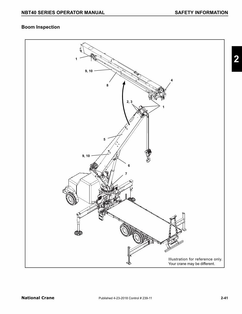
NBT40 SERIES OPERATOR MANUAL SAFETY INFORMATION
Boom Inspection
National Crane Published 4-23-201
2
4
8
1
7
5
6
1
2, 3
9, 10
9, 10
Illustration for reference only.Your crane may be different.
8 Control # 239-11
2-41
SAFETY INFORMATION NBT40 SERIES OPERATOR MANUAL
NOTE: The following checklist includes all features thatcan be found on Manitowoc cranes. Your cranemay not have some features.
2-42 Published 4-23-201
Overload less than 25%
1Sheaves, Rope Guides
Inspect all for damage.
2Collar-Wear Pads, Pad Retainers
Inspect for damage.
Overload from 25% to 49%
1Sheaves, Rope Guides
Inspect all for damage.
2Collar-Wear Pads, Pad Retainers
Inspect all for damage.
3 Collar-welds Inspect all for damage.
4 Pinning Areas Inspect all for cracks.
5Telescopic Sections
Inspect for bent or twisted sections. Check the boom for straightness.
6Lift Cylinder Head Area
Inspect for bends or cracked welds.
7Turret-Base Section
Inspect for cracked welds.
8 Jib SectionInspect for bent or twisted section. Check for straightness.
9 Welds Inspect for cracks.
10 PaintInspect for cracked paint which could indicate twisted, stretched, or compressed members.
8 Control # 239-11

NBT40 SERIES OPERATOR MANUAL SAFETY INFORMATION
Superstructure Inspection
National Crane Published 4-23-201
2
2
7
1
3
8
10,11
6
5 4
9
Illustration for reference only.Your crane may be different.
8 Control # 239-11
2-43
SAFETY INFORMATION NBT40 SERIES OPERATOR MANUAL
NOTE: The following checklist includes all features thatcan be found on Manitowoc cranes. Your cranemay not have some features.
2-44 Published 4-23-201
Overload less than 25%
1 Lift Cylinder Inspect for leaks.
2 Wire Rope Inspect all for damage.See topic in Introduction section of Service Manual.
3Turntable Bearing
Check bolts for proper torque.See topic in Swing section of Service Manual.
Overload from 25% to 49%
1 Lift Cylinder Inspect for leaks.
2 Wire Rope Inspect all for damage.See topic in Introduction section of Service Manual.
3Turntable Bearing
Check bolts for proper torque.See topic in Swing section of Service Manual.
4 Hoist/Drums Inspect each for damage.
5 Hoist Brakes Brakes must hold rated line pull.
6Bearing Main Boom Pivot Pin
Inspect for deformation, cracked welds.
7Lift Cylinder-Lower Mount
Inspect pin and welds.
8 Turret Area Inspect for deformation, cracked welds.
9Mounting Studs
Check bolts for proper torque.
10 Welds Inspect for cracks.
11 PaintInspect for cracked paint which could indicate twisted, stretched, or compressed members.
8 Control # 239-11

NBT40 SERIES OPERATOR MANUAL SAFETY INFORMATION
Carrier Inspection
National Crane Published 4-23-201
2
3
1
1
1
2
2
2
3
3
4
4
5, 6
Illustration for reference only.Your crane may be different.
8 Control # 239-11
2-45
SAFETY INFORMATION NBT40 SERIES OPERATOR MANUAL
NOTE: The following checklist includes all features thatcan be found on Manitowoc cranes. Your cranemay not have some features.
2-46 Published 4-23-201
Overload less than 25%
1Stabilizer Cylinders
Inspect for leaks.
2Outrigger Pads
Inspect for deformation and cracked welds.
Overload from 25% to 49%
1Stabilizer Cylinders
Inspect for leaks.
2Outrigger Pads
Inspect for deformation and cracked welds.
3Outrigger Beams
Inspect for deformation and cracked welds.
4Outrigger Boxes
Inspect for deformation and cracked welds.
5 Welds Inspect for cracks.
6 PaintInspect for cracked paint which could indicate twisted, stretched, or compressed members.
8 Control # 239-11

NBT40 SERIES OPERATOR MANUAL OPERATING CONTROLS & PROCEDURES
SECTION 3
CONTROLS AND OPERATING PROCEDURES
SECTION CONTENTS
3
Truck Cab Controls . . . . . . . . . . . . . . . . . . . . . . . . 3-2Truck Cab Ignition Switch . . . . . . . . . . . . . . . . . . . 3-2Power Take Off . . . . . . . . . . . . . . . . . . . . . . . . . . . 3-2Park Brake . . . . . . . . . . . . . . . . . . . . . . . . . . . . . . 3-2Engine Speed Governor . . . . . . . . . . . . . . . . . . . . 3-2Neutral Start/Safety Switch. . . . . . . . . . . . . . . . . . 3-2
Outriggers . . . . . . . . . . . . . . . . . . . . . . . . . . . . . . . . 3-2Outrigger Controls . . . . . . . . . . . . . . . . . . . . . . . . 3-2Crane Level Indicators . . . . . . . . . . . . . . . . . . . . . 3-2Outrigger Controls . . . . . . . . . . . . . . . . . . . . . . . . 3-3
Crane Controls . . . . . . . . . . . . . . . . . . . . . . . . . . . . 3-4Load Chart . . . . . . . . . . . . . . . . . . . . . . . . . . . . . . 3-4Handheld Outrigger Controls . . . . . . . . . . . . . . . . 3-4Swing Brake Pedal . . . . . . . . . . . . . . . . . . . . . . . . 3-6Boom Telescope Pedal (Optional) . . . . . . . . . . . . 3-6Foot Throttle Pedal . . . . . . . . . . . . . . . . . . . . . . . . 3-6Display Panel . . . . . . . . . . . . . . . . . . . . . . . . . . . . 3-6RCL and Minimum Wrap Bypass Switch . . . . . . . 3-7Hydraulic Oil Indicator. . . . . . . . . . . . . . . . . . . . . . 3-7Swing Brake Indicator . . . . . . . . . . . . . . . . . . . . . . 3-7Main Hoist Minimum Wrap Indicator . . . . . . . . . . . 3-7Main Hoist Speed Switch . . . . . . . . . . . . . . . . . . . 3-7Hand Throttle Control . . . . . . . . . . . . . . . . . . . . . . 3-7Emergency Stop Switch . . . . . . . . . . . . . . . . . . . . 3-8Crane Ignition Switch . . . . . . . . . . . . . . . . . . . . . . 3-8Aux Hoist Speed (Optional) . . . . . . . . . . . . . . . . . 3-8Auxiliary Hoist Minimum Wrap Indicator (Optional) . . . . . . . . . . . . . . . . . . . . . . . . . . . . . . . 3-8AC/Heater Vent. . . . . . . . . . . . . . . . . . . . . . . . . . . 3-8Receptacle . . . . . . . . . . . . . . . . . . . . . . . . . . . . . . 3-8Radio Remote Switch (Optional). . . . . . . . . . . . . . 3-8Crane Power Switch . . . . . . . . . . . . . . . . . . . . . . . 3-8Boom Work Light Switch (Optional) . . . . . . . . . . . 3-8Cab Work Light Switch . . . . . . . . . . . . . . . . . . . . . 3-8Skylight Wiper Switch . . . . . . . . . . . . . . . . . . . . . . 3-8Windshield Wiper Switch . . . . . . . . . . . . . . . . . . . 3-8Crane Cab Climate Controls . . . . . . . . . . . . . . . . . 3-8360°Swinglock Pedal (Optional) . . . . . . . . . . . . . . 3-8Boom Lift Control Lever . . . . . . . . . . . . . . . . . . . . 3-9Hoist Control Lever . . . . . . . . . . . . . . . . . . . . . . . . 3-9Hoist Rotation Indicator Display . . . . . . . . . . . . . . 3-9Hoist Rotation Indicator . . . . . . . . . . . . . . . . . . . . 3-9
National Crane Published 4-23-201
Telescope Control Lever . . . . . . . . . . . . . . . . . . . . 3-9Warning Horn Button . . . . . . . . . . . . . . . . . . . . . . . 3-9Swing Control Lever . . . . . . . . . . . . . . . . . . . . . . . 3-9Seat Back Adjustment . . . . . . . . . . . . . . . . . . . . . . 3-9Seat & Seat Frame Lever . . . . . . . . . . . . . . . . . . . 3-9Climate Control Unit. . . . . . . . . . . . . . . . . . . . . . . . 3-9Swing Brake Switch . . . . . . . . . . . . . . . . . . . . . . . . 3-9House Lock . . . . . . . . . . . . . . . . . . . . . . . . . . . . . 3-10Heater . . . . . . . . . . . . . . . . . . . . . . . . . . . . . . . . . 3-10Adjustable Swing Speed Valve . . . . . . . . . . . . . . 3-10
Operating Procedures. . . . . . . . . . . . . . . . . . . . . . 3-11Equipment Familiarization . . . . . . . . . . . . . . . . . . 3-11Crane Cab Access. . . . . . . . . . . . . . . . . . . . . . . . 3-11Equipment Checks. . . . . . . . . . . . . . . . . . . . . . . . 3-11Cold Weather Operation . . . . . . . . . . . . . . . . . . . 3-12
Crane Warm-up Procedures . . . . . . . . . . . . . . . . . 3-12Engine . . . . . . . . . . . . . . . . . . . . . . . . . . . . . . . . . 3-12Transmission . . . . . . . . . . . . . . . . . . . . . . . . . . . . 3-12Hoist. . . . . . . . . . . . . . . . . . . . . . . . . . . . . . . . . . . 3-13Swing Drive and Turntable Bearing . . . . . . . . . . . 3-13Axles . . . . . . . . . . . . . . . . . . . . . . . . . . . . . . . . . . 3-13Hydraulic Oil System . . . . . . . . . . . . . . . . . . . . . . 3-13Anti-two-block Check . . . . . . . . . . . . . . . . . . . . . . 3-13RCL Check . . . . . . . . . . . . . . . . . . . . . . . . . . . . . 3-13
Outrigger Setup . . . . . . . . . . . . . . . . . . . . . . . . . . . 3-14Proper Leveling of the Crane. . . . . . . . . . . . . . . . 3-14Bubble Level Adjustment . . . . . . . . . . . . . . . . . . . 3-14Setting the Outriggers . . . . . . . . . . . . . . . . . . . . . 3-14Outrigger Monitoring System (OMS) (Optional—Standard in North America) . . . . . . . . 3-15
hoist System Operation . . . . . . . . . . . . . . . . . . . . 3-16Hoist Two Speed Operation. . . . . . . . . . . . . . . . . 3-16
Work Site Location . . . . . . . . . . . . . . . . . . . . . . . . 3-16Before Leaving the Truck Cab. . . . . . . . . . . . . . . 3-16Stowing and Parking . . . . . . . . . . . . . . . . . . . . . . 3-17Unattended Crane . . . . . . . . . . . . . . . . . . . . . . . . 3-17Before Making the Lift . . . . . . . . . . . . . . . . . . . . . 3-17
Load Chart . . . . . . . . . . . . . . . . . . . . . . . . . . . . . . . 3-18Using the Load Chart. . . . . . . . . . . . . . . . . . . . . . 3-18
Lifting the Load . . . . . . . . . . . . . . . . . . . . . . . . . . . 3-19
Shut Down and Preparation for Road Travel . . . 3-19
8 Control # 239-11 3-1

OPERATING CONTROLS & PROCEDURES NBT40 SERIES OPERATOR MANUAL
This section contains information on the controls andoperating procedures to include:
• Truck Cab Controls
• Outrigger Controls
• Crane Controls
• Operating Procedures
• Outrigger Setup
• Hoist System Operation
• Work Site Location
• Load Chart
• Lifting the Load
• Shutdown and Preparation for Travel
TRUCK CAB CONTROLS
The truck cab controls described here are those controls thatare used in conjunction with the crane controls.
Truck Cab Ignition Switch
Truck cab ignition switch must be OFF in order for crane cabignition switch to be operable.
Power Take Off
Manual Shift Control
The PTO is engaged when the knob on the dash or floor ispulled out and disengaged when the knob is pushed in. Thetruck gear shift lever must be in neutral and the clutchdepressed whenever the knob is moved.
Air Shift Control
The PTO is engaged when the switch is moved to apply air toPTO and disengaged when switch is in off position. The truckgear shift lever must be in neutral and clutch depressedwhen switch is moved. The transmission selector lever mustbe returned to “N” for stationary vehicle operation. Thepower take-off may be disengaged while in any transmissionrange provided that the load has first been removed from thePTO.
Electric Shift Control
Full torque electric shift PTO’s are controlled by a switch. Tooperate, disengage the clutch, shift to fourth or fifth gear, andoperate the switch down to engage the PTO or up todisengage the PTO. Return the gear shift to neutral andengage the clutch.
3-2 Published 4-23-201
Power Shift Control
If the vehicle is equipped with automatic transmission, thepower take-off must be engaged with the engine at idle. Seetransmission manufacturer ’s instructions for specialprocedures.
Park Brake
The truck brake must be firmly set before leaving cab tobegin operation. If the ground surface is icy or slick or issloped, you may be required to help immobilize the truck withwheel chocks.
Engine Speed Governor
Some diesel engines are equipped with a variable speedgovernor which overrides the engine speed governor. Ifequipped, two knobs in the cab select between craneoperation and normal driving operation.
Neutral Start/Safety Switch
Truck must be equipped with neutral/start safety switch ontruck transmission. Check occasionally to ensure it isworking correctly and repair if it is not.
OUTRIGGERS
Outrigger Controls
The outrigger has two controls units, a hand-help controller(1, Figure 3-1) located in the crane cab and a ground stationcontrol box (2, Figure 3-1) located on the carrier frame. Eachcontroller contains the control switches for extending andretracting the outrigger beams, for raising and lowering theoutrigger stabilizer (jack) cylinders and for raising andlowering the center front stabilizer. The cab hand heldcontroller may be optional for some NBT40 series models.
Crane Level Indicators
The crane has one primary, two secondary level indicators.An optional secondary level indicator is available for thecrane cab. The primary level indicator is used to verify theaccuracy of the secondary level indicators.
The primary level indicator (7, Figure 3-1) is located behindthe turret bearing. The secondary level indicators are locatedin the outrigger control boxes (6, Figure 3-1).
The secondary level indicator is located in the crane cab (38,Figure 3-4)
8 Control # 239-11

3
NBT40 SERIES OPERATOR MANUAL OPERATING CONTROLS & PROCEDURES
.
FIGURE 3-1
2
7
5
4
1
3
8
54
4 3
2
4a6
7462-14
7448-15
7459-1
7462-22
National Crane Published 4-23-201
Outrigger Controls
The outrigger component controls are used to set theoutriggers. Check the load chart located in the crane cab forthe proper outrigger configuration.
Outrigger Control Boxes
The outrigger control boxes (2) are located on the side of thecrane (Figure 3-1) and contain the outrigger controls.
Handheld Outrigger Control
The handheld outrigger control (1, Figure 3-1) is available forthe crane cab.
Extend/retract Switch
The extend/retract switch (5, Figure 3-1) is used inconjunction with the outrigger selector switches to control theoutrigger functions.
Outrigger Selector Switches
The outrigger selector switches (4, Figure 3-1) are used toselect the outrigger component. To extend or retract anoutrigger component, first select the component with theoutrigger selector switch, then select extend or retract withthe extend/retract switch.
The ground station outrigger beam selector switch (4a,Figure 3-1) is used to operation the front or rear outriggerbeam on the same side of the crane the ground control is on.
NOTE: Dependent on the carrier wheelbase, it may benecessary to remove the rear outrigger pads priorto retracting the outrigger beam.
Item Description
1 Hand Held Outrigger Control
2 Outrigger Control Box
3 Front Center Stabilizer Switch
4 Outrigger Selector Switches
4a Outrigger Bean Selector
5 Extend/Retract Switch
6 Frame Level Indicator
7 Level Indicator
8 Cab Level Indicator
8 Control # 239-11 3-3

OPERATING CONTROLS & PROCEDURES NBT40 SERIES OPERATOR MANUAL
Front Center Stabilizer Switch
The center front stabilizer switch (3, Figure 3-1) is used tolower and raise the center front stabilizer. To operate thecenter front stabilizer, press the center front stabilizer switchand then press extend/retract switch.
NOTE: The center front stabilizer automatically retracts ifany of the other components are adjusted andmust be reset if lifting is to be continued.
4
1
Item Description
1 Outrigger Midspan Selector Pin
3
3
2
6
4
7448-1
57
3-4 Published 4-23-201
FIGURE 3-2
2 Outrigger Extension Beam
3 Level Indicators
4 Outrigger Jack
5 Outrigger Float Stow Peg
6 Outrigger Float
7 Ground Station O/R Controller
CRANE CONTROLS
The crane controls are located in the crane cab and are usedfor all crane functions. See (Figure 3-3) for crane cab itemnumber (#) identification. For best control response, run theengine at governed RPM when operating the crane.
NOTE: The operator must be in the crane cab seat and thearmrest must be lowered for the crane controls tooperate properly.
Load Chart
The load chart is stored in a pocket in the crane cab. Theload chart contains lifting capacities of the crane in allallowable lifting configurations.
Handheld Outrigger Controls
The handheld outrigger controls (1, Figure 3-3) are stored inthe crane cab and are used for outrigger operation from thecrane cab. Crane Power switch must be on, operator in seatwith armrest lowered.
8 Control # 239-11

3
NBT40 SERIES OPERATOR MANUAL OPERATING CONTROLS & PROCEDURES
FIGURE 3-3Item Description
1 Handheld Outrigger Control
2 Swing Brake Pedal
3 Boom Telescope Pedal (Optional)
4 Foot Throttle Pedal
5 Display Panel
6 RCL Bypass Switch (Momentary)
7 Hydraulic Oil Indicator/Engine Warning
8 Swing Brake Indicator
9 Main Hoist Minimum Wrap Indicator
10 Main Hoist Speed Switch
11 Hand Throttle Control
12 Emergency Stop Switch
13 Crane Ignition Switch
14 Hourmeter
15 Auxiliary Hoist Switch (Optional)
16 Auxiliary Hoist Minimum Wrap Indicator
17 AC/Heater Vent
18 Receptacle (12V)
19 Remote Power Switch (Optional)
20 Crane Power Switch
21 Boom Worklight Switch (Optional)
22 Cab Worklight Switch
23 Skylight Wiper Switch
24 Windshield Wiper Switch
25 Heater/Air Conditioner Function Switch
26 Heater/Air Temperature Control
27 Heater/Air Fan Speed
28 360° Swinglock Pedal
Item Description
1
3 4
56
7 8
9
10
11
1213
14
18
17
2022232425
26
15
17
211927
7462-6
7462-3
2 16
40
28
National Crane Published 4-23-2018 Control # 239-11
3-5
OPERATING CONTROLS & PROCEDURES NBT40 SERIES OPERATOR MANUAL
7462-5
7462-4
FIGURE 3-4
2930
3132
3334
17
38 35
3736
39
3-6 Published 4-23-201
Item Description Item Description
29 Boom Lift Control Lever 35 Seat Slide Handle
30 Hoist Up & Down Control (Rotate Indicator) 36 Seat Frame Slide Handle
31 Telescope Boom (Auxiliary Hoist Control) 37 Climate Control Unit
32 Warning Horn Button 38 Level
33 Turret Swing Control Lever 39 Swing Lock Control Switch
34 Seat Back Adjustment 40 House Lock (Figure 3-3)
Swing Brake Pedal
The swing brake pedal (2, Figure 3-3) is located on the leftside of the crane cab floor. The brake pedal is used toactivate the swing brake and momentarily hold the turret inposition.
Boom Telescope Pedal (Optional)
The telescope foot pedal (3, Figure 3-3) is used to extendand retract the boom when the crane is equipped with anauxiliary hoist. Rock the pedal forward to extend the boomand rock back to retract the boom.
Foot Throttle Pedal
The foot throttle (4, Figure 3-4) is located on the crane cabfloor and is used to control the engine speed. Depress the
CAUTIONDo not actuate the Swing Control Lever while the SwingBrake is engaged, as the turret may push through thebrake. Damage to the swing brake can occur.
foot throttle to accelerate the engine speed and release toreturn to idle.
The hand throttle (11, Figure 3-4) must be positioned asshown in Figure 3-6 to operate the foot throttle properly.
Display Panel
The display panel (5 Figure 3-3) is for the Rated CapacityLimiter (RCL), see operating instructions and screendisplays in this manual.
The RCL provides the crane operator with the informationrequired for the crane to perform safely within its designparameters. The RCL displays information on length andangle of boom, working radius, rated load, and total weightbeing lifted.
The RCL continuously monitors these parameters andprovides the operator with an updated readout of the cranestatus. If a nonsafe condition is approached, the RCL warnsthe operator with an alarm and locks out the crane functionsthat can aggravate the situation.
8 Control # 239-11

3
NBT40 SERIES OPERATOR MANUAL OPERATING CONTROLS & PROCEDURES
RCL and Minimum Wrap Bypass Switch
The RCL Bypass Switch (6, Figure 3-3) is a momentary on-off switch, turn the key to the On posit ion (right) todisengaged the RCL controls and minimum wrap lockoutcontrols. Releasing the key allows the RCL and minimumwrap controls to re-engage.
The RCL and 3 wrap system will be bypassed only as longas the switch (6, Figure 3-3) is in the On position.
Turning the key switch (6, Figure 3-3) to the On position re-engages the boom down, telescope out and hoist controls.These functions were disabled when an overload conditionwas sensed by the Rated Capacity Limiter (RCL). It isimportant to read and understand the RCL Override Warninginformation in the RCL Operator’s Manual before using theRCL Bypass switch (6) or the RCL on/off switch.
The bypass switch (6, Figure 3-3) will also re-engage themain and auxiliary hoist controls disabled by the minimumwrap indicator sensor system.
The RCL control can be turned completely off and back onusing the switch (1, Figure 3-5) located behind the cab seat.
Hydraulic Oil Indicator
DANGERThe RCL only aids the operator when properly
programmed with the proper load chart and crane configuration. To prevent injury or death to personnel, be
sure the RCL is programmed before crane operation.
!
FIGURE 3-5
7462-23
1 2
National Crane Published 4-23-201
The hydraulic oil temperature warning light (7, Figure 3-3) islocated on the crane cable console and illuminates when thehydraulic oil overheats. If overheating occurs, run the craneat idle with the controls in neutral until the light goes out.
Swing Brake Indicator
The swing brake indicator (8, Figure 3-3) is located on thecrane cab console. The indicator light is on when the swingbrake is activated.
Main Hoist Minimum Wrap Indicator
When the main hoist is down to the last cable wrap theminimum wrap indicator (9, Figure 3-3) will flash intermittentand the minimum wrap buzzer (2, Figure 3-5) will soundintermittently.
When the amount of cable left on the hoist reaches theminimum wrap; the indicator light will be constant, the buzzerwill be constant and the hoist will be disabled by theminimum wrap sensor system.
Main Hoist Speed Switch
The main hoist speed selector switch (10, Figure 3-3) islocated on the right seat armrest. It is a three position switch(on-off-on), placarded as rabbit (fast) hoist motor speed andturtle (slow) hoist motor speed.
Hand Throttle Control
The push/pull hand throttle (11, Figure 3-4) is located on thecrane cab console and has the following functions.
Increase Engine Speed - Push in and hold the center button(1, Figure 3-6); pull out on the knob (2) to accelerate theengine. Releasing button (1) will lock knob in place andmaintain engine speed.
Decrease Engine Speed - Push in and hold the center button(1, Figure 3-6); push the knob (2) in to slow the enginespeed.
Incremental Speed Adjustment - Rotate knob (2, Figure 3-6)clockwise to increase speed and counterclockwise todecrease engine speed.
The hand throttle must be positioned as shown in Figure 3-6to operate the foot throttle (4, Figure 3-4) properly.
NOTICEDo not operate the crane with overheated hydraulic oil ordamage to seals in the hydraulic components may result.
8 Control # 239-11 3-7

OPERATING CONTROLS & PROCEDURES NBT40 SERIES OPERATOR MANUAL
Emergency Stop Switch
The crane emergency stop switch (12, Figure 3-3) is locatedon the cab console and is used to shut down the truckengine. Push the red button in to shut down the engine,rotate the knob and pull out to resume normal operation.
Crane Ignition Switch
The crane ignition switch (13, Figure 3-3) is located on thecrane cab console and controls the truck engine and cranecab power. The igniton switch has four positions. OFF shutsdown engine and cab power, ON activates truck engineignition as well as all cab power, ACC is crane cab powerand Start is truck engine start.
The truck ignition key must be OFF before the truck enginecan be started from the crane cab.
Aux Hoist Speed (Optional)
The auxiliary hoist speed selector switch (15, Figure 3-3) islocated on the left seat armrest. It is a three position switch(on-on-on), placarded as rabbit (fast) hoist motor speed andturtle (slow) hoist motor speed.
Auxiliary Hoist Minimum Wrap Indicator (Optional)
When the auxiliary hoist is down to the last cable wrap theminimum wrap indicator (16, Figure 3-3) wi l l f lashintermittent and the minimum wrap buzzer (2, Figure 3-5) willsound intermittently.
When the amount of cable left on the hoist reaches theminimum wrap; the indicator light will be constant, the buzzerwill be constant and the hoist will be disabled by theminimum wrap sensor system.
AC/Heater Vent
The cab has air condit ioner and heating vents (17,Figure 3-3), located on the control panel, behind the panel.and to the left of the operator.
1
2
3
7462-9 FIGURE 3-6
3-8 Published 4-23-201
Receptacle
This 12 volt accessory outlet (18, Figure 3-3) is located onthe lower part of the front control panel and is designed tomate with most 12 volt adapter plugs.
Radio Remote Switch (Optional)
The radio remote switch (19, Figure 3-4) is used to enablethe radio remote controls. The crane function power switch,crane ignition (13) and truck igniton must all be OFF beforethe crane can be operated with a radio remote control.
Crane Power Switch
The crane function power switch (20, Figure 3-3) is locatedon the right overhead console. The switch has two positions:OFF takes all power from the joy stick controllers on the armrest, cab outrigger, and from the swing brake unlock(assuring the brake stays locked). The OFF positionprevents inadvertent operation of these functions andassures the swing brake is set when the crane is notpowered. The ON position will restore power to the joy stickcontrollers, the swing brake and the cab O/R hand controller.
Boom Work Light Switch (Optional)
The work light switch (21, Figure 3-3) is a two position rockerswitch, ON and OFF, located on the right overhead console.It turns the cab outside working lights on.
Cab Work Light Switch
The work light switch (22, Figure 3-3) is a two position rockerswitch, ON and OFF, located on the right overhead console.It turns on custom mounted boom lights.
Skylight Wiper Switch
The skylight wiper switch (23, Figure 3-3) is located in theoverhead console. This is Hi - Lo toggle type switch with 6intermitting positions, intermitting timing is 2-15 seconds.
Windshield Wiper Switch
The windshield wiper switch (24, Figure 3-3) is located in theoverhead console. This is Hi - Lo toggle type switch with 6intermitting positions, intermitting timing is 2-15 seconds,wiper washer timing is 3 seconds.
Crane Cab Climate Controls
The cab climate controls (25, 26, 27, Figure 3-3) are used toadjust the heating and air conditioning for operator comfort.
360°Swinglock Pedal (Optional)
The swinglock pedal (28) is located on the left side of thecrane cab floor. Apply the pedal to lock the turret, release thepedal to unlock the turret.
8 Control # 239-11

3
NBT40 SERIES OPERATOR MANUAL OPERATING CONTROLS & PROCEDURES
Boom Lift Control Lever
The boom lift control lever (29, Figure 3-4) is located on theright armrest and is used to raise and lower the boom. Pushthe lever forward to lower the boom and pull back to raise theboom.
Hoist Control Lever
The hoist control lever (30, Figure 3-4) is located on the rightarmrest. Push forward to lower the load and pull the leverback to raise the load.
Hoist Rotation Indicator Display
The display is located in the front overhead panel Figure 3-7.The LED display illuminates to indicate the current hoist inoperation and which direction the hoist is rotating.
Hoist Rotation Indicator
The hoist rotation indicator (RDI) is located on top of thehoist control lever (30, Figure 3-3). The indicator iselectronical ly driven by a signal from an electronictransmitter and sensor attached to the hoist. A pulsatingsignal is sensed by the operator ’s thumb during hoistoperation.
DANGER
Payout loadline before extending boom. Failure to do somay cause the loadline to break or damage the crane.
!
FIGURE 3-7
8425-6
Item Description
1 Main Hoist UP (Clockwise)
2 Main Hoist DOWN (Counterclockwise)
3 Auxiliary Hoist UP (Clockwise)
4 Auxiliary Hoist DOWN (Counterclockwise)
1
2
3
4
National Crane Published 4-23-201
Telescope Control Lever
When equipped without the auxiliary hoist the telescopeboom control lever (31, Figure 3-4) is on the left armrest.Push the lever forward to extend the boom and pull back toretract the boom.
Auxiliary Hoist (Optional)
If equipped with an auxiliary hoist the control lever (31,Figure 3-4) is on the left armrest, positioning the leverforward lets out hoist cable. Pulling the lever back reels thecable in.
Warning Horn Button
The warning horn button (32, Figure 3-4) is located on theswing joy stick. Push the switch to sound the horn to warnfellow workers of pending movement of crane.
Swing Control Lever
The swing control lever (33, Figure 3-4) is located on the leftarmrest and controls turret rotation. Push the lever forward torotate the turret clockwise and pull back to rotate the turretcounterclockwise.
The swing control lever can be used to slow and stop theswing by moving the control lever to the opposite direction ofthe swing. For example, if the lever is pushed forward for aclockwise swing, pull the lever back to slow and stop theswing.
Seat Back Adjustment
To adjust the back of the seat press the adjustment knob (34,Figure 3-4) and then adjust the seat as needed.
Seat & Seat Frame Lever
Moving the seat slide lever (35, Figure 3-4) will slide the seateither forward or backward, moving the seat frame lever (36)slides the seat and seat frame at the same time.
Climate Control Unit
Air Conditioner and Heating of the crane cab is provided bythe climate control unit (37, Figure 3-4) located under thecab seat.
Swing Brake Switch
The swing brake switch (39, Figure 3-4) is located on thecrane cab console and is used to activate the swing brake
CAUTIONDo not actuate the Swing Control Lever while the SwingBrake is engaged, as the turret may push thro8ugh thebrake. Damage to the swing brake can occur.
8 Control # 239-11 3-9

OPERATING CONTROLS & PROCEDURES NBT40 SERIES OPERATOR MANUAL
and park the turret in position. Press the switch to activatethe swing brake to keep the turret from rotating. The swingbrake indicator (8, Figure 3-3) is illuminated when the swingbrake switch is applied.
The back half of the switch (1, Figure 3-8) is designed with alocking mechanism to secure the swing brake in the lockedposition and prevent accidental movement of the cab &superstructure.
House Lock
The house lock control (40, Figure 3-3) is a manuallyoperated mechanical lock that when engaged preventsrotation of the crane superstructure.
To engage the lock center the boom over the front of the cabturn the T handle clockwise and push the knob back into thelocked position and move the superstructure left to right toalign the lock pin with the lock pin hole. To disengage, pullout on the T handle and turn counter clockwise to lock the Thandle and pin in position.
Heater
The diesel powered supplemental heater is stowed underthe cab support frame and supplies heat to the crane cab(36, Figure 3-4). The heater controls the temperature of thecrane cab by cycling coolant between the heater and theclimate control unit located under the cab seat. Controls (25,26, 27, Figure 3-3) for the heater are located on theoverhead control panel in the crane cab.
Heater Cold Weather Fuel Mixture
At temperatures below 20° F (-7° C), add a cold weatheradditive or mix kerosene with the diesel fuel at a 50/50 ratio,Add the mixture to the heater diesel fuel tank (1, Figure 3-9)located on the outside of the cab.
WARNINGDo not mix gasoline with diesel fuel.
FIGURE 3-81 7459-10
!
3-10 Published 4-23-201
Heater Coolant
The heater coolant bottle (1, Figure 3-10) is mounted to theturret and located inside the a/c compressor enclosure (2).The coolant should contain at a minimum a mixture of waterand enough antifreeze to prevent freezing or slushing.
Adjustable Swing Speed Valve
The crane is equipped with an adjustable swing speed valve(1, Figure 3-11) that sets the maximum swing speed of themachine. Turn the valve knob clockwise to increase andcounterclockwise to decrease speed.
1
7459-11 FIGURE 3-9
12
FIGURE 3-107462-23
8 Co
ntrol # 239-11
3
NBT40 SERIES OPERATOR MANUAL OPERATING CONTROLS & PROCEDURES
FIGURE 3-117459-9
1
National Crane Published 4-23-201
OPERATING PROCEDURES
You need to be familiar with the safety precautions outlinedin this manual before operating the crane.
Equipment Familiarization
All members of the crew should become familiar with thelocation and operation of the controls, the correct operatingprocedure, the maximum lifting capacities, and the SafetyPrecautions in Section 2 of this manual. Carefully follow theoperating procedures outlined below and the information inthe load charts located in the crane cab.
Crane Cab Access
To enter the cab, pull the ladder out from under the crane cabdoor and use the grab handles (1, Figure 3-12) inside thecab to enter the cab. Take all precautions not to fall off thecrane. Falling from any elevation can cause serious injury ordeath.
Equipment Checks
Prior to placing the unit in operation, do a complete walk-around visual inspection and look for structural damage,loose components, leaks, or other conditions that requiresimmediate correction for safe operation. The followingchecklist of items are suggested to ensure the crane isprepared for performing work operations. Check:
• for any unusual conditions such as pools of hydraulicfluid or lubricating oil under the chassis, any outriggerwhich may have crept down or up and any signs ofdamage or improper maintenance.
• the tires are inflated to the proper pressure.
• the level of the hydraulic reservoir.
1
1
FIGURE 3-127602-5
8 Control # 239-11
3-11
OPERATING CONTROLS & PROCEDURES NBT40 SERIES OPERATOR MANUAL
• the operation of the “stop” and horn circuits.
• for missing and loose bolts.
• for damaged structural members and welds.
• all rope guides and cable keepers.
• all sheaves for free turning.
• the hoist cable for kinks, broken strands or otherdamage in accordance with instructions on Hoist CableInspection and Maintenance, page 6-3.
• to see that the hydraulic hoses and fittings are in goodcondition and show no signs of leaking. The hosesshould be free from cuts and abrasions and there shouldbe no evidence of binding. Any damage or leakageshould be repaired immediately.
• the RCL and anti-two-block system for proper operation.
• the electrical wiring connecting the various parts of thesystem for physical damage.
NOTE: Consult the truck manufacturer’s manual forvehicle checks.
Cold Weather Operation
The following recommendations are for operating Nationalcranes in very low (i.e., sub-zero) temperatures.
Cranes should have appropriate hydraulic oil, lubricants, andother auxiliary items required for operation in sub-zerotemperatures. Operate individual crane functions to ensurethey are sufficiently warmed prior to performing a lift.
Operation of cranes at full rated capacities in temperaturesbetween -9°C (15°F) and -40°C (-40°F) or lower should beaccomplished only by competent operators who possess theskill, experience, and dexterity to ensure smooth operation.Shock loading shall be avoided.
Operation Below -40°CFor crane operation below -40°C, capacities shall be derated3.67 percent of the rated load shown on the capacity chartsfor each degree below -40°C.
Operation Below -40°FFor crane operation below -40°F, capacities shall be derated2 percent of the rated load shown on the capacity charts foreach degree below -40°F.
CRANE WARM-UP PROCEDURES
The following procedures detail the actions that must betaken to properly warm the different crane componentsbefore operating the crane.
NOTE: For temperatures below -9°C (15°F) refer to arcticlubricants and conditions in the Operator andService Manuals.
3-12 Published 4-23-201
Before starting the crane, ensure the appropriate lubricantsare used to provide lubrication for the prevailing ambienttemperatures in which the crane will operate in (a list oflubricants and their temperature ranges can be found in theLubrication section of your crane’s Operator Manual, bycontacting your local National distributor, or by contactingManitowoc Crane Care directly).
Engine
NOTE: For National Crane engine warm-up procedures,refer to chassis manufacturer’s manual.
Warm-up Procedures for All Temperature Ranges:
1. Upon startup, allow the engine to idle for 3 to 5 minutesbefore operating with a load.
2. Cold Engine Startup: After allowing the engine to warmby idling it for 3 to 5 minutes, slowly increase the enginespeed to provide adequate lubrication to the bearingsand to allow the oil pressure to stabilize.
Transmission
NOTE: For National Crane transmission warm-upprocedures, refer to chassis manufacturer ’smanual.
Operating the transmission with a sump temperature belownormal operating temperature is limited to:
• operating in the neutral gear or
• driving with an unloaded crane while not exceeding1500 engine RPM and not exceeding half throttle.
Alternate Warm-up Procedures for Truck Mount (TM/TMS) Cranes:
1. Setup the crane on outriggers.
2. Engage the transmission and allow crane to run at idleuntil the temperature of the transmission sump reachesnormal operating temperature.
CAUTIONCrane Damage Hazard!
Operating the crane with the incorrect lubricants andfluids for the prevailing ambient temperature and/or failingto adequately warm the crane prior to cold weatheroperation can lead to a failure of a crane component orsystem.
Always use Manitowoc recommended lubricants andfluids for the prevailing ambient temperature and properlystart and warm the crane using the cold weatherprocedures found in th is Operator Manual andsupplement before operating the crane at full load.
8 Control # 239-11

3
NBT40 SERIES OPERATOR MANUAL OPERATING CONTROLS & PROCEDURES
Hoist
Performing a warm-up procedure is recommended at everystartup and is required at ambient temperatures below 4°C(40°F).
Warm-up Procedures:
1. Without operating the hoist function, warm the hydraulicoil (see Hydraulic Oil System, page 3-13).
2. Once the hydraulic system is warm, operate theunloaded hoist, in both directions, at low speeds severaltimes to prime all hydraulic lines with warm hydraulic oiland to circulate gear lubricant through the planetarygear sets.
Swing Drive and Turntable Bearing
Warm-up Procedures for Temperatures Above -7°C(20°F):
1. Setup the crane on fully extended outriggers, with theboom fully retracted and near maximum lift angle with noload applied.
2. Rotate the superstructure at a speed of less than oneRPM for at least one complete revolution in onedirection, then rotate the superstructure at a speed ofless than one RPM for at least one complete revolutionin the opposite direction.
Warm-up Procedures for Temperatures Below -7°C(20°F):
1. Ensure the boom is fully retracted and near maximum liftangle with no load applied.
2. Rotate the superstructure at a speed of less than one-half RPM for at least two complete revolutions in onedirection, then rotate the superstructure at a speed ofless than one-half RPM for at least two completerevolutions in the opposite direction.
Axles
NOTE: For National Crane axle warm-up procedures, referto chassis manufacturer’s manual.
Hydraulic Oil System
Operating Limits and Warm-up Procedures:
• From 4°C to -10°C (40°F to 15°F): Crane operationwithout a load is allowed with medium engine RPM andmedium function speed (joystick position) until the fluidreaches at least 10°C (50°F). It is then recommendedthat all crane functions be cycled to remove cold fluidfrom all components and cylinders of the hydraulicsystem. If there is any unusual sound coming from thecrane’s hydraulic pumps or motors, stop the operation
National Crane Published 4-23-201
and engine immediately and contact a Nationaldistributor.
• From 10°C to 4°C (50°F to 40°F): Crane operation witha load is allowed with medium engine RPM and mediumfunction speed (joystick position) until the fluid reachesat least 10°C (50°F).
• From 95°C to 10°C (200°F to 50°F): Crane operationwith a load is allowed with no restrictions.
• Above 95°C (200°F): No crane operation is allowed. Letthe crane’s hydraulic oil cool by running the engine atidle with no functions actuated.
Anti-two-block Check
Check the anti-two-block alarm light and the audible alarmby lifting the anti-two-block weight until the switch isactivated. To check the anti-two-block switch:
• manually lift the weight.
• slowly raise the hoist cable.
• slowly extend (telescope) the boom.
If the crane is equipped with a jib that is deployed and riggedfor work, repeat the test procedure for the jib anti-two-blockswitch.
RCL Check
Perform the following checks to verify proper RCL operation.
• Check that the display of the main boom length agreeswith the actual boom length.
• Check that the display of the main boom angle agreeswith the actual boom angles.
• Check that the display of the operating radius of thecrane agrees with the actual radius.
Check the load display by lifting a load of known weight. Theaccuracy of the load indication shall be within the toleranceof SAE J159.
DANGERThe following tests must be performed with caution toprevent damage to the machine or injury to personnel.
DANGERIf the light and audible alarm do not function and the hoistdoes not stop, the system is not working properly andmust be corrected before operating the crane.
!
!
8 Control # 239-11 3-13

OPERATING CONTROLS & PROCEDURES NBT40 SERIES OPERATOR MANUAL
OUTRIGGER SETUP
Proper Leveling of the Crane
ASME B30.5 specifies that if a crane is not level within 1% ofgrade, the allowable capacities must be reduced. Therefore,when lifting on outriggers, it is essential that the crane is levelto within 1% of grade. The bubble level that is provided onthe crane is calibrated to be accurate within 1% of grade.
To properly level the crane, the boom must be positionedover the front of the crane, fully lowered to horizontal andfully retracted (for cranes fitted with a boom rest, the boomshall be stowed onto the rest). Raise and level the craneusing the outriggers; refer to Setting the Outriggers, page 3-14.
A working crane may settle during lifting operations.Frequently check the crane for level. When rechecking thecrane for level, the boom must be positioned over the front ofthe crane, fully lowered to horizontal and fully retracted (forcranes fitted with a boom rest, the boom shall be stowedonto the rest). If necessary, relevel the crane using theprocedures under Setting the Outriggers, page 3-14.
Bubble Level Adjustment
The bubble level adjustment should be checked periodically;if it is suspected that the bubble level indicator is out ofadjustment, verify and adjust the bubble level as follows:
1. Position the crane on a firm, level surface.
2. Extend and set the outriggers. Level the crane, asindicated by the bubble level indicator, using theoutriggers.
3. Place a miracle pointer level, carpenter level, or similartype device on a machined surface such as the turntablebearing or bearing mounting surfaces.
DANGER
A deviation between displayed and actual valuesindicates a malfunction and a RCL service representativeshall be called for repair and/or recalibration of RCLsystem.
DANGERDo not operate outriggers unless they are visible to eitherthe operator or a designated signal person to avoidcrushing injury.
!
!
3-14 Published 4-23-201
4. Using the outriggers, level the crane as indicated on theleveling device used in step 3.
5. Using the bubble level indicator mounting screws, adjustthe bubble level indicator to show level.
Setting the Outriggers
1. Position the outrigger floats directly out from eachoutrigger to where the outriggers will be properlyextended.
2. If extending the outrigger to the mid-extend or fullyextended position, depress the desired outriggerselector switch and hold the outrigger extend/retractswitch to EXTEND. The appropriate outrigger beambegins to extend.
NOTE: More than one outrigger beam can be extended ata time. However, to ensure that each outrigger isfully extended, repeat step 2 for each outriggerafter a multi-outrigger extension.
3. After deploying the four outrigger beams to one of thethree proper positions (fully retracted, mid-extend, fullyextended), depress the desired Stabilizer Switch on theOutrigger Selector Panel and hold the Outrigger
CAUTIONPossible Equipment Damage!
Always depress one of the outrigger selector switchesbefore positioning the outrigger extend/retract switch toextend or retract. Failure to do this may cause a hydrauliclock against the individual solenoid valves, preventingthem from opening.
WARNINGElectrocution Hazard!
To avoid death or serious injury, keep all parts of thismachine, the rigging, and materials being lifted at least 20feet away from electrical power lines and equipment.
WARNINGTipping Hazard!
All four outrigger beams must be deployed to one of threepositions before beginning operation, which include fullyretracted, mid-extend, or fully extended; do not operatethe crane with the outriggers in any other position.
8 Control # 239-11

3
NBT40 SERIES OPERATOR MANUAL OPERATING CONTROLS & PROCEDURES
Extension/Retraction Switch to EXTEND. Theappropriate stabilizer begins to move.
Extend each jack, positioning the float as necessary,until the locking levers of the float engage the jackcylinder barrel.
NOTE: More than one stabilizer can be extended at a time.
4. With each jack float firmly touching the ground, extendthe front stabilizers approximately 3 to 4 in (8 to 10 cm).Extend the rear stabilizers approximately 3 to 4 in (8 to10 cm).
5. Repeat step 4 until all wheels are clear of the groundand the crane is level as indicated by the bubble levelindicator (Figure 3-13). If it is suspected that the bubblelevel indicator is out of adjustment, verify and adjust thebubble level using the procedures under Bubble LevelAdjustment, page 3-14.
6. Lower the center front stabilizer (optional) only after allother outriggers are set. Press the front stabilizer switchto activate and the extend/retract switch to extend. Holdthe extend/retract switch for two seconds after thestabilizer contacts the ground. The front stabilizer isautomatically set at the correct ground pressure.
DANGERAfter the center front stabilizer is set, it automaticallyretracts if any other jack is adjusted. Reset the center frontstabilizer if this occurs.
Not LevelFIGURE 3-13
!
National Crane Published 4-23-201
Outrigger Monitoring System (OMS) (Optional—Standard in North America)
The Outrigger Monitoring System (OMS) aids the operator inaccurately programming the Rated Capacity Limiter (RCL)by automatically identifying the position of each outriggerbeam. The OMS uses four sensors, one per outrigger beam,to identify when an outrigger beam is positioned to one ofthree pre-defined locations, including fully retracted, mid-extend, and fully extended.
Set up of the outriggers is the same for cranes equipped withOMS; refer to “Setting the Outriggers” on page 2-14.
On cranes with OMS the symbols for the outriggers willdisplay on the crane’s remote control LCD Display screenand also on the RCL screen (if equipped), refer to Figure 3-14.
If the crane is setup on outriggers and “On Outriggers” ischosen when programming the RCL, then the OMS indicatesto the RCL the horizontal position of each of the fouroutrigger beams. Based on this information, the RCL willde fau l t to the most conserva t ive ou t r igger beamconfiguration (i.e. If three outriggers are fully extended andone is retracted, the RCL will select retracted as theoutrigger configuration). A confirmation of this configurationis all that is needed (see Figure 3-14). Refer to the RatedCapacity Limiter Operator’s Manual for detailed instructions.
WARNINGTipping Hazard!
The mid-extend outrigger beam lock pin must be engagedbefore operating on any beam from the mid-extendposition.
The proper load chart and RCL program must be selectedfor the current outrigger configuration.
8 Control # 239-11 3-15

OPERATING CONTROLS & PROCEDURES NBT40 SERIES OPERATOR MANUAL
HOIST SYSTEM OPERATION
The hoist may have lifting capabilities greater than that of thecrane limits. Therefore, care must be taken to ensure that theload lifted is within the crane rating. General rules for hoistoperation are:
• Unwind the hoist when extending the boom.
• Use the anti-two-block system only as an aid.
• Make sure the rope is not twisted or kinked and that it isproperly seated in the hoist and in sheaves.
Startup Graphic
Operational Graphic
FIGURE 3-14
8131-1
8131-2
3-16 Published 4-23-201
• Always have at least three full wraps of rope on thehoist.
• Check the hoist brake when approaching the load limit ofthe hoist. Raise the load a few inches and return thecontrol to neutral to check the brake.
• Do not drag the load with the hoist.
• Do not try to lift loads that are not free such as, frozendown material or poles.
• Keep tension on the rope to prevent it from becomingtwisted, kinked, or improperly seated on the hoist.
Hoist Two Speed Operation
The high speed increases hoist line speed over normaloperation. The high speed mode is activated by a switch (10,Figure 3-3) located on the crane cab console..
To start the high speed, depress the high speed switch andoperate the hoist lever on the armrest. Refer to the load chartfor more capacities
NOTE: Maximum Capacity with high speed on 5th layer.
• One Part Line - 5,000 lbs. (2272 kg)
• Two Part Line - 10,000 lbs. (4544 kg)
• Three Part Line - 15,000 lbs. (6818 kg)
• Maximum line speed on third layer - 351 FPM(107 mpm), fourth layer - 383 FPM (117 mpm)
WORK SITE LOCATION
Select a location that is firm, level, and dry. Avoid uneven,rocky or muddy terrain, steep grade or locations withoverhead obstructions. The outrigger stabilizers must besupported on a firm level surface at the fully retracted,mid-span, or fully extended positions. Avoid overhead powerlines.
Before Leaving the Truck Cab
• Position the truck so that the outriggers can be extendedwith no obstructions.
• Position the truck transmission to neutral.
• Set the truck park brake. Wheel chocks may also berequired.
• Engage the power takeoff.
• Turn the truck cab switch to OFF.
CAUTIONIf the high speed feature is run continuously or with anoverload, damage to the crane or truck could occur.
8 Control # 239-11

3
NBT40 SERIES OPERATOR MANUAL OPERATING CONTROLS & PROCEDURES
Stowing and Parking
When parking, the crane should be left in the smallest, most stable, valid operational configuration that the job site practically allows, do the following:
1. Park the crane on a stable surface.
2. Remove the load from the hook.
3. Stow the swingaway boom extension, if erected.
4. Fully retract the boom and position it in the normal travelposition, then perform the following and proceed toStep 6:
a. Engage the swing brake and/or swing lock pin.
b. Retract all jack cylinders and outrigger beams.
5. If it is not practical to fully retract the boom and place it inthe travel position, then perform the following andproceed to Step 6:
a. Make the crane as stable as possible, including,boom angle, superstructure orientation, jib angle,etc. In high winds, the boom and jibs should belowered or secured.
b. Engage the swing brake and/or swing lock pin.
6. Apply the parking brake.
7. Put all operating controls in the neutral position.
8. Position the Crane Function switch to OFF.
DANGERTruck must be in neutral when starting engine from cranecab to avoid sudden potential movement of truck.
WARNINGTipping Hazard!
Never park the crane near holes, or on rocky or extremelysoft surfaces. This may cause the crane to overturn.
Failure to comply with these instructions may cause deathor serious injury.
!
National Crane Published 4-23-201
9. Shut down the engine following the proper proceduresspecified in this manual and the applicable enginemanual.
10. Remove the keys.
11. Disconnect batteries, if machine will be inactive for over24 hours.
12. Close and lock all windows, covers, and doors.
Unattended Crane
The configuration in which the crane should be left whileunattended shall be determined by a qualified, designatedindividual familiar with the job site, configuration, conditions,and limitations.
Before Making the Lift
• Set the outriggers as described in the Crane Set-upsection in this manual.
• Prior to any fully retracted outrigger (0% extended)operation, extend jack cylinders with outriggers fullyretracted and level crane. Engage swing brake and raiseboom out of boom rest until the minimum boom angle forindicated boom length with no load is exceeded. DONOT release swing brake with boom below minimumindicated boom angle.
CAUTIONTo avoid possible engine fault codes and undesirableoperation, ensure the keyswitch has been off 2 minutesbefore disconnecting batteries.
WARNINGTipping Hazard!
Changing weather conditions including but not limited to:wind, ice accumulation, precipitation, flooding, lightning,etc. should be considered when determining the locationand configuration of a crane when it is to be leftunattended.
Failure to comply with these instructions may cause deathor serious injury.
8 Control # 239-11 3-17

OPERATING CONTROLS & PROCEDURES NBT40 SERIES OPERATOR MANUAL
• Program the RCL as specified in the RCL Operator’sManual which is located in the crane cab.
• Check all controls for proper operation. If any abnormaloperations are detected, the condition must be correctedbefore continuing.
• Check the work area for electric power lines.
LOAD CHART
Your unit is designed to provide satisfactory service if it is notloaded in excess of the maximum rated loads specified in theload chart. Overloading can create safety hazards, causestructural damage, and shorten the service life of the crane.
You must understand how to use the load charts located inthe crane cab. Make sure the load, the working area, and thecrane configuration are within the load limit specified in theload chart.
NOTE: Load handling devices (hook blocks and slings) areconsidered part of the load.
Using the Load Chart
NOTE: One of the most important tools of every crane isthe load chart found in the crane operator’s cab.
The load chart contains a large amount of information, whichmust be thoroughly understood by the operator.
The load chart contains outrigger capacity charts for fullyextended, mid extended, outriggers for the main boom andboom extension, and fully retracted outrigger beams for mainboom only.
Prior to any fully retracted outrigger (0% extended)operation, extend jack cylinders with outriggers fullyretracted and level crane. Engage swing brake and raiseboom out of boom rest until the minimum boom angle forindicated boom length with no load is exceeded. DO NOT
DANGER
Tipping Hazard!
Serious injury or death could result from improper crane set-up on fully retracted outriggers.
In fully retracted outrigger configuration, before slewing:
Ensure outriggers are properly set and crane is level peroperator manual.
Set swing brake to the locked position.
Raise boom to exceed minimum boom angle for givenboom length at no load indicated on load chart
DO NOT release swing brake with boom below minimumindicated boom angle.
!
3-18 Published 4-23-201
release swing brake with boom below minimum indicatedboom angle.
This condition is applicable when the load chart does notprovide a maximum boom length at 0 degree boom angle ina no load situation. This is designated by “N/A”.
The capacity charts are divided into structural strength andstability limits. This is shown by the bold line across the chart.Capacities above the line are structural strength limits andcapacities below the line are stability limits.
The left column is the load radius, which is the distance fromthe center of crane rotation to the load center of gravity. Thetop row lists various boom lengths ranging from fullyretracted to fully extended or boom extension lengths andoffsets. The number at the intersection of the left column andtop row is the total load capacity for that load radius andboom length or boom extension lengths offset. The numberin parentheses below the total load capacity is the requiredboom angle (in degrees) for that load. When the boom lengthor lift radius or both are between values listed, the smallestload shown at either the next larger radius or next longer orshorter boom length shall be used.
Another important section is the range diagram. The rangediagram shows the operating radius and tip height that canbe achieved at a given boom length and angle. If theoperator knows the radius and tip height required for aspecific lift, the angle and boom length can be quicklydetermined from the range diagram. Or, if the boom lengthand angle are known, the tip height and operating radius canbe quickly determined.
A lifting diagram is included to describe over side, over rear,and over front lifting areas. The lifting area diagram showsthat the locations of the outrigger stabilizer cylinders in thefully extended position are used to mark the boundaries ofthe lifting areas.
DANGER
Tipping Hazard!
Serious injury or death could result from improper crane set-up on fully retracted outriggers.
In fully retracted outrigger configuration, before slewing:
Ensure outriggers are properly set and crane is level peroperator manual.
Set swing brake to the locked position.
Raise boom to exceed minimum boom angle for givenboom length at no load indicated on load chart
DO NOT release swing brake with boom below minimumindicated boom angle.
!
8 Control # 239-11

3
NBT40 SERIES OPERATOR MANUAL OPERATING CONTROLS & PROCEDURES
A boom extension capacity chart and notes are included tolist the capacities for the extension length, load radius, andboom angle.
Another section contains the notes for lifting capacities. Besure to read and understand all the notes concerning liftingcapacities.
The load chart also gives weight reductions for load handling devices such as hook blocks, headache balls, boom extensions, etc., which must be taken into consideration as part of the load. Remember, the weight of any other load handling devices such as chains, slings, or
spreader bars must be added to the weight of the load.
LIFTING THE LOAD
The following general guidelines outl ine the properprocedure for making a lift after the crane has been properlyset up.
1. Position the crane in the work area and set theoutriggers. See “Outrigger Setup” on page 2-14 foroutrigger setup.
2. Program the RCL. Use the load chart to estimate thevalues.
3. Position the boom nose over the load. Do not try anddrag the load with the boom or hoist.
4. Perform the lift. Meter the controls when moving the loadto avoid sudden stops.
5. Retract and lower the boom after the lift is complete.
SHUT DOWN AND PREPARATION FOR ROAD TRAVEL
CAUTIONDisengage the hydraulic pumps for extended traveling,cold weather starting, or engine checks.
Check cold tire pressure prior to extended travel. Refer totire inflation decal on crane.
National Crane Published 4-23-201
1. Ensure the swingaway, if so equipped, is properlystowed and secured or removed from crane.
2. Retract and place the boom in boom rest.
3. Ensure the center front stabilizer is fully retracted, ifequipped.
4. Ensure the outrigger beams and jacks are fully retractedwith the floats properly stowed.
5. Engage the mechanical travel lock at each outriggerbeam.
6. Engage the swing brake.
7. Engage the swing lock.
8. Either the hook block may be reeved over the mainboom nose or the headache ball may be reeved over themain boom nose or auxiliary boom nose; the other mustbe removed and stowed securely before travelling. If thehook block or headache ball remains reeved on theboom, it must be secured at the tie down on the carrierprovided for that purpose.
9. Secure the hook block and A2B weight:
a. Slowly hoist up until there is a slight tension on thehoist cable. It may be necessary to override the A2Bfunction to tension the cable.
CAUTIONMachine Damage Hazard!
Do not travel with an empty hook in a position where it canswing freely. Either remove the hook block and/orheadache ball from the hoist cable(s) and stow securelyor make sure the hook block or headache ball is properlysecured to the tie down provided for that purpose.
Fully retract the outrigger jacks and properly store thefloats.
WARNING
Do not travel with swingaway extended to preventdamage to equipment.
Failure to comply with these instructions may cause deathor serious injury.
CAUTION
Outrigger beams must be pinned for travel.
If not pinned, outrigger beams may drift out during travel.
!
!
8 Control # 239-11 3-19

OPERATING CONTROLS & PROCEDURES NBT40 SERIES OPERATOR MANUAL
b. The the A2B weight needs to be resting on thewedge socket so that there is slack in the anti-two-block-chain.
NOTE: There needs to be enough slack in the A2B chainso that the A2B switch does not switch betweenopen and close during travel.
If the chain is too tight, road bounce causes theA2B switch to open and close numerous times andthis can damage the switch.
10. Turn off the ignition and all other switches in the cranecab.
11. Close and/or secure all windows and doors.
12. Exit the cab, lock the door, and stow the access ladder.
13. Secure any loads or lifting devices on truck bed or body.
14. Ensure tires are properly inflated.
15. Disengage the Power Take Off (PTO) and start truckfrom the truck cab.
3-20 Published 4-23-201
Release the park brake before moving truck.
FIGURE 3-15
Wedge socket with bracket to support the anti-two-block weight.
There needs to be slack in the anti-two-block chain in preparation for road travel. See page 4-5 for proper rigging of the anti-two-block weight.
8
Control # 239-11
NBT40 SERIES OPERATOR MANUAL SET-UP
SECTION 4
SET-UP
SECTION CONTENTS
Jib Safety Information . . . . . . . . . . . . . . . . . . . . . . 4-1Jib Operation. . . . . . . . . . . . . . . . . . . . . . . . . . . . . . 4-2Deployment Procedure . . . . . . . . . . . . . . . . . . . . . 4-2Stowing Procedure . . . . . . . . . . . . . . . . . . . . . . . . 4-3
Jib Removal. . . . . . . . . . . . . . . . . . . . . . . . . . . . . . . 4-5Jib Maintenance . . . . . . . . . . . . . . . . . . . . . . . . . . 4-5
Anti-two block Weight Installation . . . . . . . . . . . . 4-5
Multi-part Line Reeving . . . . . . . . . . . . . . . . . . . . . 4-5Using Multiple Part Lines . . . . . . . . . . . . . . . . . . . 4-5
National Crane Published 4-23-201
Stow Pegs for hoist cable. . . . . . . . . . . . . . . . . . . . 4-5
Multi-part Line Reeving. . . . . . . . . . . . . . . . . . . . . . 4-6Using Multiple Part Lines . . . . . . . . . . . . . . . . . . . . 4-6
Installing Cable On The Hoist. . . . . . . . . . . . . . . . . 4-7
Wedge Sockets . . . . . . . . . . . . . . . . . . . . . . . . . . . . 4-7Terminator Wedge Installation. . . . . . . . . . . . . . . . 4-7Wedge Socket Installation . . . . . . . . . . . . . . . . . . . 4-8Dead-end Rigging . . . . . . . . . . . . . . . . . . . . . . . . . 4-9
4
This section contains information on how to perform thefollowing tasks:
• Erect the jib
• Stow the jib
• Remove the jib
• Use multipart reeving
• Install the hoist cable
• Install the anti-two-block weight
• Install a wedge socket
• Counterweight
JIB SAFETY INFORMATION
1. The anti-two-block switch weight and cord must beattached to the jib when deployed.
2. Operate with jib by radius when main boom is fullyextended. If necessary, increase boom angle to maintainloaded radius.
When radius is between points listed on capacity chart,the load shown at the next longer radius shall be used.
DANGERDo not operate outriggers unless they are visible to eitherthe operator or a designated signal person to avoidcrushing injury.
!
3. Operate with jib by boom angle when main boom is notfully extended. Do not exceed rated jib capacities at anyreduced boom lengths.
When angle is between points listed on capacity chart,the load shown at next lower boom angle shall be used.
4. Ensure jib is stowed correctly (Figure 4-1):
a. Removal of swing around pins (C1, Figure 4-1),without proper installation of stow pin A and jibswing pin B, may allow jib to fall off.
b. Extending boom with jib stowed and failure toremove swing pins (C1, Figure 4-1), will damageunit upon extension.
5. Only swing jib into working or stowed position whenboom is horizontal, stow pin (A, Figure 4-1) and jib swingpin B, are removed and swing pins (C1) are in place. Jibcould swing uncontrollably if boom is not horizontal.
6. Crane shall be fully set up according to proper set-upprocedures outlined previously when stowing orunstowing jib.
7. Operate boom and turn functions very slowly andcarefully when using jib since jibs can increase boomlength by 50%.
8. Area where jib swings around must be clear ofobstructions and power lines when stowing andunstowing jib.
9. Use safety glasses when pounding pins with hammer.
10. Do not extend/retract boom unless boom is horizontalwhen stow pin (A, Figure 4-1) and jib swing pin (B) areremoved during stowing or unstowing procedures.
8 Control # 239-11 4-1

SET-UP NBT40 SERIES OPERATOR MANUAL
11. Always put spring clips in pins to ensure that they willstay in place.
12. When the jib is stowed, the boom can not be fullyretracted if a boom tip attachment option is installed.
Also, on manually extendable jib options:
1. Extension retaining pin (E) must always be installedwhen operating.
2. All swing around (stow and unstowing) operations shallbe done with jib retracted and pinned.
3. Extendable section may slide out of 1st section jib whenpin (E) is removed. Keep personnel clear of area.
JIB OPERATION
Deployment Procedure
1. Using boom telescope function, fully retract boom.
2. Using lift function, lower boom so that jib deploymentpins (C1, Figure 4-1) and (C2, Figure 4-1) are easilyaccessible from the ground.
NOTE: When lowering the boom below horizontal, twopersons may be required. With the telescopecontrol in neutral, the boom may creep out whenbelow horizontal.
3. Install pins (C1, Figure 4-1) in upper and lower jib earssecure with retainer spring clips. These pins are used asa pivot point to swing jib into the deployed position.
4. Locate the stowed position of pins (C2, Figure 4-1). If injib attachment holes or boom sheave case jib holes,remove pins from storage location.
5. Remove jib swing Pin (B, Figure 4-1) from top ear of jib.
6. Remove stow Pin (A, Figure 4-1) and stow in hookbracket (D), secure with spring clip.
7. Attach tag line to sheave case end of jib.
8. Using the lift function, raise the boom to the horizontalposition.
9. Using telescope function, slowly extend boomapproximately one foot. This procedure will pull the jibout of the jib stow bracket (H,Figure 4-1).
4-2 Published 4-23-201
.
10. Using tag line, swing jib into deployed position.
11. Remove cable keeper pins from boom sheave case andjib. Remove hook block. Pivot jib slightly to allow forloadline to be removed from boom sheave case.Remove loadline from boom sheave case and place inan area to minimize possible damage.
12. Pivot jib into place, visually aligning the upper (C2,Figure 4-1) pin holes. Install upper (C2) pin and springclip. A slight hammer strike may be necessary to installpins. Always use proper eye protection during this step.
13. Use the jib jack (F, Figure 4-1) to align lower (C2) pin.
a. Remove the jack handle (G, Figure 4-1) from theboom stowage bracket and check that the jackrelease valve is closed.
b. Extend the jack (F, Figure 4-1) so that the lower (C2)pin holes are aligned.
c. Install the lower (C2, Figure 4-1) pin and spring clip.
CAUTIONUse caution during this step. The jib is free to swing awayfrom the boom upon boom extension.
!
8 Control # 239-11

4
NBT40 SERIES OPERATOR MANUAL SET-UP
d. Open the jack release valve and retract the jack (F,Figure 4-1.
14. Using hoist function, un-spool enough loadline to reeveloadline over jib sheave case. Keep slight tension onloadline to avoid bird caging of loadline on hoist drum.
15. Route loadline over jib sheave and install keeper. Installline block to end of loadline.
16. Remove anti-two-block switch and weight/chainassembly and install on jib tip, see Figure 4-2. Be certainto use keeper provided with switch.
17. Disconnect anti-two- block cord going to boom anti-two-block switch and attach to quick coupler on jib anti-two-block wire on rear of jib between the upper and lower jibears.
18. Install jib swing pin (B, Figure 4-1) and spring clip into jibears.
19. For manually extendable jibs, pull extension retainingpin (E, Figure 4-1), and extend second section out bypulling on sheave case. The second section jib, as itextends, will hit a mechanical stop that allows forextension pin (E) installation. Install pin (E) and springclip.
20. Make ATB cord connections as required.
Stowing Procedure
Depending on the length of the jib extension being used; thecrane can be equipped with either a two section or onesection jib. Certain stowing instructions may only applied toone or the other and will be noted so.
DANGER
Visually check all pin positions and make sure the jib isfully retracted into side stow brackets, jib stow attachmentis secure, and all pins and spring clips are in their properlocations. Failure to proper secure the jib during stowingand erecting may allow the jib to fall. Serious personalinjury or death could result.
Always have at least one, if not both of the following inplace at all times:
• Side stow bracket completely engaged into stowhook with stow pin A properly in place.
• Both pins C1, Figure 4-1 in upper and lower jib holesproperly in place through mating holes on boom tip.
!
National Crane Published 4-23-201
1. Using lift function, lower boom so that jib deploymentpins (C1, Figure 4-1) and (C2, Figure 4-1) are easilyaccessible from the ground.
NOTE: When lowering the boom below horizontal, twopersons may be required. With the telescopecontrol in neutral, the boom may creep out whenbelow horizontal.
2. Two section jib - For manually extendable jibs, pullextension retaining pin (E, Figure 4-1) and fully retractextendable 2nd section jib into the 1st section. Retractionof 2nd section may be facilitated by attaching loadlinewedge socket to jib nose. Slowly activate the hoist upfunction until the 2nd section is fully retracted.
3. Two section jib - Reinstall extension retaining pin (E,Figure 4-1 through the 1st and 2nd section jib assemblyand install spring clip.
4. Remove loadline from jib sheave case. Place loadline inarea to avoid possible damage from stow procedure.
5. Disconnect anti-two-block wire connector at rear of thejib extension. Re-connect anti-two-block switchconnector on boom tip. Move weight/chain assembly toboom tip see Figure 4-2.
6. Attach tag line to sheave case end of jib.
7. Remove spring clips from pins (C2, Figure 4-1) on bothupper and lower jib ears.
8. Remove jib swing pin (B, Figure 4-1) from the boomnose.
9. Remove pins (C2, Figure 4-1) from upper and lower jibears. Do not remove (C1) pins at this time. C1 pins willbe used as a pivot point to swing jib into stow position. Aslight hammer strike may be necessary to remove pins.Always use proper eye protection during this step.
10. Raise the boom to the horizontal position.
11. Extend boom approximately 1 foot (.3m).
12. Using tag line attached to jib sheave case, slowly swingjib into stow position (parallel with 1st section boom),Pins (C1, Figure 4-1) are the jib pivot points during thisoperation.
:
13. Install jib swing pin (B, Figure 4-1) with spring clipthrough jib ear and boom sheave case holes. This pinwill keep the jib assembly in line (parallel) with the Ist
section boom.
NOTE: Jib swing pin (B, Figure 4-1) does not retain the jibin its stowed position on the Ist section boom.
CAUTIONUse caution when swinging jib to avoid unnecessaryimpact with 1st section boom.
8 Control # 239-11 4-3

SET-UP NBT40 SERIES OPERATOR MANUAL
Jib in Stow Position
C1
B
A
AD
Left Side
Right Side
JIb in Operating positionA
D
E
B
C
A Stow Pin
B Jib Swing Pin
C Jib Deployment Pins
D Hook Bracket
E Extension Retaining Pin
F Jib Jack
G Jack Handle
H Jib Stowage Bracket
C2
FIGURE 4-1
F
G
E
H
7462-27
7462-28
4-4
Published 4-23-2018 Control # 239-11
4
NBT40 SERIES OPERATOR MANUAL SET-UP
14. Using boom telescope function, slowly retract boom.
The jib stow bracket (H, Figure 4-1) on the side of the jibwill engage the side stow bracket (D) on the side of the
1st section boom; first lifting the jib and then engagingthe jib side stow bracket (H) and the stow bracket (D)completely upon full retraction of the boom.
15. Install stow pin (A, Figure 4-1) with spring clip into the jibstow bracket (H) on the jib. Complete engagement ofstow brackets and proper installation of pin A is criticalfor secure jib stow attachment.
16. Remove pins (C1 Figure 4-1) from upper and lower jibears. A slight hammer strike may be necessary toremove pins. Always use proper eye protection duringthis step.
17. Reinstall loadline over boom sheave case.
JIB REMOVAL
Should jib removal from the boom become necessary,proceed as follows:
1. Unstow and swing jib into position on the boom tipaccording to Steps 1 - 10 in the preceding jib deploymentsection.
2. Support and raise the jib at its balance point and removethe two swing around pins. Jib is now free of boom.
3. To install, proceed in reverse order of removal.
When the jib is stowed on side of crane, always leave theram and handle sleeve of the jib jack pushed all the waydown to reduce exposure to rusting.
Jib Maintenance
1. Lubricate as outlined in SECTION 5.
2. Check for free rotation of jib sheave daily when using jib.
ANTI-TWO BLOCK WEIGHT INSTALLATION
To prevent the hoist cable from slipping out of the ant-two-block weight, rig the weight as shown in Figure 4-2.
The A2B bracket is for single part line use only. Remove theA2B bracket shown in Figure 4-2 from the hoist cable whenchanging from a single part line to a multiple part line to allowthe hoist cable and wedge socket to reeve through thesheaves on the boom nose and the hookblock. Re-install theclamp and nuts to the cable before performing a lift.
National Crane Published 4-23-201
MULTI-PART LINE REEVING
Multi-part line reeving enables greater loads to be lifted thancan be lifted with single part line. However, loads are limitedby the stability and structural integrity of the crane. The loadmust be within the limits contained in the load chart.
Using Multiple Part Lines
The hoist data chart provides information for pull limitationson the hoist with various multipart reevings. These ratingsare based on providing the proper operating safety factor onthe cable suppl ied wi th the crane. Therefore, anyreplacement rope must meet the cable specification in thismanual.
The A2B bracket is for single part line use only. Remove theA2B bracket shown in Figure 4-2 from the hoist cable whenchanging from a single part line to a multiple part line to allowthe hoist cable and wedge socket to reeve through thesheaves on the boom nose and the hookblock. Re-install theclamp and nuts to the cable before performing a lift.
STOW PEGS FOR HOIST CABLE
Stow pegs located on top of the boom keep the hoist cablessecure when not reeved over the boom nose. The main hoistcable is stowed on the right peg and the auxiliary hoist cableis stowed on the left peg as viewed from the back of theboom.
FIGURE 4-2
The anti-two-block chain must be installed between the slot in the weight and the hoist cable.
Anti-two Block Weight
Hoist Cable
Slot
Chain Length 40 cm (16 inches) Do not shorten the chain.
Upper Link
Lower Link
The A2B bracket must be removed from the hoist cable when reeving for multi-part line.
8835
8 Control # 239-11
4-5
SET-UP NBT40 SERIES OPERATOR MANUAL
MULTI-PART LINE REEVING
Multipart line reeving enables greater loads to be lifted thancan be lifted with single part line. However, loads are limited
FIGURE 4-3
Main Hoist Cable Stow Peg
Auxiliary Hoist Cable Stow Peg
by the stability and structural integrity of the crane. The loadmust be within the limits contained in the load chart.
Using Multiple Part Lines
The hoist data chart provides information for pull limitationson the hoist with various multipart reevings. These ratingsare based on providing the proper operating safety factor onthe cable supplied with the machine. Therefore, anyreplacement rope must meet the cable specification in of thismanual.
The NBT36 is rated to lift 72,000 lbs (36 ton) at a 7 ft radiuswith all booms retracted with an seven part block
The NBT40 is rated to lift 80,000 lbs (40 ton) at a 7 ft radiuswith all booms retracted with an eight part block
The NBT45 is rated to lift 90,000 lbs (45 ton) at a 7 ft radiuswith all booms retracted with an eight part block.
All pulls shown in the following table are on the fourth layer.The line pulls increase and the speed decreases on the third,second, and first layers.
NOTE: Keep at least three wraps of loadline on the drum atall times.
Do not deadhead hook block against boom tipwhen extending the boom.
Refer to load charts for all layers and wire ropecapacities.
1 Part Line 2 Part Line 3 Part Line 4 Part Line 5 Part Line 6 Part Line 7 Part Line 8 Part Line
Maximum Pull
Normal Speed 11,250 Lbs
191 fpm
High Speed 5,000 Lbs 383 fpm
Maximum Pull
Normal Speed 22,500 Lbs
95 fpm
High Speed 10,000 Lbs
191 fpm
Maximum Pull
Normal Speed 33,750 Lbs
63 fpm
High Speed 15,000 Lbs
127 fpm
Maximum Pull
Normal Speed 45,000 Lbs
47 fpm
High Speed 20,000 Lbs
95 fpm
Maximum Pull
Normal Speed 56,250 Lbs
38 fpm
High Speed 25,000 Lbs
76 fpm
Maximum Pull
Normal Speed 67,500 Lbs
31 fpm
High Speed 30,000 Lbs
63 fpm
Maximum Pull
Normal Speed 78,750Lbs
27 fpm
High Speed 35,000 Lbs
54 fpm
Maximum Pull
Normal Speed 90,000Lbs
23 fpm
High Speed 40,000 Lbs
47 fpm
The hook block must be sized to the number of line parts. For example, do not use a six part line hook block on a three part line reeving. Contact your National Crane Distributor or Manitowoc Crane Care to order the proper hook block.
4-6 Published 4-23-2018 Control # 239-11

4
NBT40 SERIES OPERATOR MANUAL SET-UP
INSTALLING CABLE ON THE HOIST
NOTE: The cable should preferably be straightened before
installation on the hoist drum.
Install cable on the hoist drum in accordance with thefollowing procedure.
3. Position the cable over the boom nose sheave and routeto the hoist drum.
4. Position the hoist drum with the cable anchor slot on top.
5. Insert the cable through the slot and position around theanchor wedge (1) Figure 4-4.
NOTE: The end of the cable should be even with thebottom of the slot for the anchor wedge.
6. Position the anchor wedge in the drum slot; pull firmly onthe free end (2) of the cable to secure the wedge.
NOTE: If the wedge does not seat securely in the slot,carefully tap (3) the top of the wedge with a mallet.
CAUTIONIf cable is wound from the storage drum, the reel shouldbe rotated in the same direction as the hoist.
1
2
3
7312-4
FIGURE 4-48301
2
7196
National Crane Published 4-23-201
7. Slowly rotate the drum, ensuring the first layer of cable isevenly wound onto the drum.
8. Install the remainder of the cable, as applicable.
9. Attach the wedge socket to the free end of the cable asshown in (Figure 4-6). If you are using a terminatorwedge socket, see Figure 4-5.
10. Torque the clamp on the dead end of the cable to 95 ft-lb(128 Nm).
NOTE: The torque must be rechecked after the initialoperation of the crane. Be sure cable the clamp isattached to the dead end of the cable only.
11. Start winding the cable onto the hoist drum. Maintainabout 500 pounds (250 kg) of tension on the cable.
12. Keep the cable wraps tight against each other when thefirst half of the bare hoist is filling. The second half of thehoist should wrap tightly because the fleet angle of thecable tends to pull the cable to the center of the drumthus wrapping tightly.
13. Continue winding the cable on the second, third andfourth layer of the hoist. Keep the cable paying instraight to the boom to avoid side loading the boom. Thepreceding layers will wrap smoothly guided by the firstlayer wrapping.
WEDGE SOCKETS
To install a wedge socket:
• Make sure the wedge socket is the proper size for thecable.
• Do not mix components of different wedge socketmanufacturers.
• The wedge socket must meet the requirements of thewedge socket and wire rope manufacturers.
State and local laws may vary and require differentattachment methods depending upon work conditions. Theuser is responsible for alternate attachment methods.
Terminator Wedge Installation
The NBT40 SERIES is shipped with a terminator wedgesocket which is National Crane’s preferred type of socket(Figure 4-5). Other wedge socket types are shown onpage 4-8.
To attach a terminator wedge Figure 4-5, use the followingprocedure:
1. Match the socket, wedge, and clip to the wire rope andsize the rope with the go and no go hole in the socket.
• The wire rope must pass through the “go” hole andnot pass through the “no go” hole.
8 Control # 239-11 4-7

SET-UP NBT40 SERIES OPERATOR MANUAL
• If the wire rope passes through the “no go” hole, thewedge is the wrong size.
• If the wire rope does not pass through the “go” hole,the wedge is the wrong size.
2. Align the live end of rope, with center line of pin.
3. Secure dead end section of rope.
4-8 Published 4-23-201
4. Tighten nuts on clip to recommended torque.
5. Do not attach dead end to live end or install wedgebackwards.
6. Use a hammer to seat Wedge and Rope as deep intosocket as possible before applying first load.
FIGURE 4-5
Torque Value Table
Cable Size (inches) 3/8 7/16 1/2 9/16 5/8 3/4 7/8 1 1-1/8 1-1/4
Torque ft/lbs 45 65 65 95 95 130 225 225 225 360
Torque values shown are based upon clean dry threads free of lubrication.
Terminator Wedge Socket
Wedge Socket Installation
1. Inspect the wedge and socket. Remove any roughedges and burrs.
2. The end of the wire rope should be seized using soft, orannealed wire or strand. If the end of the rope is welded,the welded end should be cut off. Do not weld on size6X37 rope. This will allow the distortion of the ropestrands, caused by the bend around the wedge, toadjust themselves at the end of the line. Refer toSECTION 1 - INTRODUCTION in the Service Manualfor wire rope procedures.
3. Make sure the live-end (Figure 4-6) of the rope is directlyin line with the ears of the socket and the direction of pullto which the rope will be subjected. If the rope is loadedinto the socket incorrectly, under a load the rope willbend as it leaves the socket, and the edge of the socketwill wear into the rope causing damage to the rope andeventual failure.
.
4. Insert the end of the wire rope into the socket, form aloop in the rope, and route the rope back through thesocket allowing the dead-end (Figure 4-6) to protrudefrom the socket. Ensure the dead-end of the rope is ofsufficient length to apply end treatment to the dead-endafter the wedge has been seated.
Dead End Dead
End
Live End is Entering Wrong Side
Live End
20 x Cable Dia Minimum
RIGHT WRONG
FIGURE 4-6
Wedge Socket
8 Control # 239-11

4
NBT40 SERIES OPERATOR MANUAL SET-UP
5. Insert the wedge into the loop and pull the live-end of therope until the wedge and rope are snug inside thesocket. It is recommended that the wedge be seatedinside the socket to properly secure the wire rope byusing the crane’s hoist to first apply a light load to thelive-end.
6. After final pin connections are made, increase the loadsgradually until the wedge is properly seated.
7. The wire rope and wedge must be properly securedinside the socket before placing the crane into liftingservice. It is the wedge that secures the wire rope insidethe socket. The dead-end treatment is used to restrainthe wedge from becoming dislodged from the socketshould the rope suddenly become unloaded due to theheadache ball or hook block striking the ground, etc;refer to “Dead-end Rigging” on page 2-9.
Dead-end Rigging
Sketches A through F (Figure 4-7) illustrate various ANSIapproved methods for treating the dead-ends of wire ropeswhich exit a wedge socket assembly. While use of the loop-back method is acceptable, care must be exercised to avoidthe loop becoming entangled with tree branches and othercomponents during crane transport and with the anti-twoblock system and other components during use of the crane.
Of the methods shown below, Manitowoc prefers thatmethod A or F be used, i.e., clipping a short piece of wirerope to the dead-end or using a commercially availablespecialty wedge. Typically, it is recommended that the taillength of the dead-end should be a minimum of 6 ropediameters but not less that 6 in (15.2 cm) for standard 6 to 8strand ropes and 20 rope diameters but not less than 6 in(15.2 cm) for rotation resistant wire ropes.
When using method A, place a wire rope clip around thedead end by clamping a short extra piece of rope to the ropedead end. DO NOT CLAMP THE LIVE END. The U-boltshould bear against the dead end. The saddle of the clip
National Crane Published 4-23-201
should bear against the short extra piece. Torque the U-boltsaccording to the table titled Wire Rope Clip Torque Values(Table 4-1).
Other sources for information with which crane users shouldbe familiar and follow is provided by the American Society ofMechanical Engineers, American National Standard, ASMEB30.5, latest revised. ASME (formerly ANSI) B30.5 appliesto cableways, cranes, derricks, hoists, hooks, jacks, andsl ings. I t states, in sect ion 5-1.7.3, “ (c) Swagged,compressed, or wedge socket fittings shall be applied asrecommended by the rope, crane or fitting manufacture.”Wire ropes are addressed in ASME B30.5, section 5-1.7.2,ROPES, it states, in pertinent part, “(a) The ropes shall be ofa construct ion recommended by the rope or cranemanufacturer, or person qualified for that service.” Additionalinformation is published by the Wire Rope Technical Board inthe Wire Rope Users Manual, latest revised edition.
Table 4-1
Wire Rope Clip Torque ValuesClip Sizes Torque
Inches mm lb-ft Nm1/8 3.18 4.5 6
3/16 4.76 7.5 101/4 6.35 15 20
5/16 7.94 30 403/8 13.28 45 60
7/16 11.11 65 901/2 12.70 65 90
9/16 14.29 95 1305/8 15.88 95 1303/4 19.05 130 1757/8 22.23 225 3001 25.40 225 300
1-1/8 28.58 225 3001-1/4 31.75 360 4901-3/8 38.68 360 4901-1/2 38.10 360 490
8 Control # 239-11 4-9

SET-UP NBT40 SERIES OPERATOR MANUAL
FIGURE 4-7Wedge Socket
Specialty Clip
Specialty Wedge
4-10 Published 4-23-201
8 Control # 239-11
NBT40 SERIES OPERATOR MANUAL LUBRICATION
SECTION 5
LUBRICATION
SECTION CONTENTS
General . . . . . . . . . . . . . . . . . . . . . . . . . . . . . . . . . . 5-1Environmental Protection . . . . . . . . . . . . . . . . . . . 5-1Lubricants . . . . . . . . . . . . . . . . . . . . . . . . . . . . . . . 5-1Arctic Conditions Below -9°C (15°F). . . . . . . . . . . 5-1Chassis Grease . . . . . . . . . . . . . . . . . . . . . . . . . . 5-2Low Temperature Grease. . . . . . . . . . . . . . . . . . . 5-2Extreme Pressure Multipurpose Gear Lubricant (EPGL) . . . . . . . . . . . . . . . . . . . . . . . . . 5-2Open Gear Lubricant . . . . . . . . . . . . . . . . . . . . . . 5-2Antifreeze/Coolant (for Cab Heater) . . . . . . . . . . . 5-2Anti-wear Additives . . . . . . . . . . . . . . . . . . . . . . . . 5-2Hydraulic Oil . . . . . . . . . . . . . . . . . . . . . . . . . . . . . 5-2Standard Hydraulic Oil . . . . . . . . . . . . . . . . . . . . . 5-2Arctic Hydraulic Oil . . . . . . . . . . . . . . . . . . . . . . . . 5-3Hydraulic Oil Inspection . . . . . . . . . . . . . . . . . . . . 5-3
Lubrication . . . . . . . . . . . . . . . . . . . . . . . . . . . . . . . 5-3
Boom Lubrication . . . . . . . . . . . . . . . . . . . . . . . . . . 5-6
National Crane Published 4-23-201
Internal Cable Sheave Lubrication. . . . . . . . . . . . . 5-6Side and Bottom Boom Wear Pad Lubrication . . . 5-7Top Boom Wear Pad Lubrication. . . . . . . . . . . . . . 5-7Outrigger Beam Lubrication. . . . . . . . . . . . . . . . . . 5-7Hoist Brake Oil. . . . . . . . . . . . . . . . . . . . . . . . . . . . 5-7Hoist Gearbox Oil . . . . . . . . . . . . . . . . . . . . . . . . . 5-8Swing Gearbox and Brake Oil . . . . . . . . . . . . . . . . 5-9Hydraulic Oil Reservoir Level . . . . . . . . . . . . . . . . 5-9
Air Conditioning . . . . . . . . . . . . . . . . . . . . . . . . . . . 5-9
Wire Rope Lubrication . . . . . . . . . . . . . . . . . . . . . 5-10
Carwell® Rust Inhibitor. . . . . . . . . . . . . . . . . . . . . 5-11Protecting Cranes From Rusting . . . . . . . . . . . . . 5-11Cleaning Procedures . . . . . . . . . . . . . . . . . . . . . . 5-11Inspection and Repair . . . . . . . . . . . . . . . . . . . . . 5-12Application . . . . . . . . . . . . . . . . . . . . . . . . . . . . . . 5-12Areas of Application. . . . . . . . . . . . . . . . . . . . . . . 5-13
5
GENERAL
Following the designated lubrication procedure is importantin ensuring maximum crane lifetime and utilization. Theprocedures and lubrication charts in this section includeinformation on the types of lubricants used, the location ofthe lubrication points, the frequency of lubrication, and otherinformation. The information included in this section does notinclude lubrication requirements for the truck chassis. Referto appropriate truck manufacturer's manual for thisinformation.
ENVIRONMENTAL PROTECTION
Dispose of waste properly! Improperly disposing of wastecan threaten the environment.
Potentially harmful waste used in Manitowoc cranes includes— but is not limited to — oil, fuel, grease, coolant, airconditioning refrigerant, filters, batteries, and cloths whichhave come into contact with these environmentally harmfulsubstances.
Handle and dispose of waste according to local, state, andfederal environmental regulations.
When filling and draining crane components, observe thefollowing:
• Do not pour waste fluids onto the ground, down anydrain, or into any source of water.
• Always drain waste fluids into leak proof containers thatare clearly marked with what they contain.
• Always fill or add fluids with a funnel or a filling pump.
Immediately clean up any spills.
The service intervals specified are for normal operationwhere moderate temperature, humidity, and atmosphericconditions prevail. In areas of extreme conditions, theservice periods and lubrication specifications should bealtered to meet existing conditions. For information onextreme condition lubrication, contact your local NationalCrane Distributor or Manitowoc Crane Care.
Lubricants
Specific recommendations of brand and grade of lubricantsare not made here due to regional availability, operatingconditions, and the continual development of improvedproducts. Where questions arise, contact your NationalCrane Distributor or Manitowoc Crane Care.
8 Control # 239-11 5-1

LUBRICATION NBT40 SERIES OPERATOR MANUAL
Arctic Conditions Below -9°C (15°F)
In general, petroleum based fluids developed especially forlow temperature service may be used with satisfactoryresults. However, certain fluids, such as halogenatedhydrocarbons, nitro hydrocarbons, and phosphate esterhydraulic fluids, might not be compatible with hydraulicsystem seals and wear bands. If you are in doubt about thesuitability of a specific fluid, check with your authorizedNational Crane distributor or Manitowoc Crane Care.
NOTE: All fluids and lubricants may be purchased bycontacting the Manitowoc Crane Care PartsDepartment.
Regardless of temperature and oil viscosity, always usesuitable start-up procedures to ensure adequate lubricationduring system warm-up.
Chassis Grease
Lubricating grease of proper consistency is to be appliedperiodically at relatively frequent intervals with grease gunsthrough grease fittings. Minimum apparent viscosity of300 SUS (Saybolt Universal Seconds) at 100°F (38°C) isrecommended.
Low Temperature Grease
This special grease for low temperature remains plastic at-51° C (-60° F) with melting point of 138°C (280°F). Thegrease is a heavy duty extreme pressure type lubricant(Lubricate Low Temp or equal).
Extreme Pressure Multipurpose Gear Lubricant (EPGL)
This gear lubricant is compounded to achieve high loadcarrying capacity and meet the requirements of either API-GL-5 or MIL-L-2105C. Unless otherwise specif ied,SAE 80W-90 viscosity may be used for year round service.Low temperature usage is restricted as follows:
CAUTIONDo not use air pressure devices to apply chassis greaseotherwise damage to sealed fittings may result.
CAUTIONThe multipurpose grease installed during manufacture isof a lithium base. Use of a non-compatible grease couldresult in damage to equipment.
SAE Viscosity Number
Minimum Ambient Temperature C (F)
75W -40°C (-40°F)
80W -2°C (-15°F)
5-2 Published 4-23-201
Open Gear Lubricant
This is a special high-graphite adhesive lubricant that helpsto eliminate fretting corrosion, is water resistant, and forms adry lubrication film which does not attract dust. Lubricantmeets NLGI Class 1-2 specifications.
Antifreeze/Coolant (for Cab Heater)
The standard antifreeze/coolant filled from the factory isintended to provide protection against freeze-up down to-36° C (-34° F) and boil-over up to 129° C (265° F) using a15 psi pressure cap.
Anti-wear Additives
Excessive wear in the system may cause a loss in volumetricefficiency and cause shutdowns for maintenance. Anefficient anti-wear oil protects the components againstrusting, resists oxidation and helps prevent wear.
Hydraulic Oil
Oil in a hydraulic system serves as the power transmissionmedium, system lubricant and coolant. Selection of theproper oil is essential to ensure satisfactory systemperformance and life. The most important factors in selectingan oil for hydraulic service are viscosity and anti-wearadditives.
NOTE: When operating the crane in temperatures -9°C(15°F) and below, follow the procedures in thesection titled “Arctic Conditions Below -9°C (15°F)”on page-2.
Standard Hydraulic Oil
Temperature Above -9°C (15°F)
The factory fill standard hydraulic oil is SAE grade 10W-20Hydraulic Oil. This f luid is acceptable for operatingtemperatures above -9°C (15°F).
NOTE: On units equipped with self-leveling platforms, lowtemperature service oils are necessary to provide
85 -12°C (+10°F)
90 -7°C (+20°F)
140 +5°C (+40°F)
250 +10°C (+50°F)
CAUTIONOperation of the crane with incorrect hydraulic oil in subfreezing temperature (below 0° C,32° F) can causedamage to the extend cylinder.
SAE Viscosity Number
Minimum Ambient Temperature C (F)
8 Control # 239-11

5
NBT40 SERIES OPERATOR MANUAL LUBRICATION
proper boom functions at temperatures below -9°C(15°F).
Arctic Hydraulic Oil
Temperature Down to -9°C (15°F) to -29°C (-20°F)
For colder operating conditions, the standard fluid may bereplaced with a petroleum based fluid developed especiallyfor colder environments.
Temperature Down to -40°C (-40°F) and Below
Petroleum based fluids developed especially for lowtemperature service may be used with satisfactory results.However, certain fluids, such as hologenated hydrocarbons,nitro hydrocabons and phosphate ester hydraulic fluidsmight not be compatible with hydraulic system seals andwear bands. Arctic hydraulic oil is not recommended forservice in ambient temperatures above 0°C (32°F).
If you are in doubt about the suitability of a specific fluid,check with your authorized National Crane distributor orManitowoc Crane Care.
NOTE: All fluids and lubricants may be purchased bycontacting the Manitowoc Crane Care PartsDepartment.
Hydraulic Oil Inspection
Environmental and other conditions can dramatically affectthe condition of hydraulic oil and filters. Therefore, specificintervals for servicing/changing hydraulic oil, filters andhydraulic tank breathers cannot be set. However, it isimperative for the continued satisfactory performance thatinspections be performed on the basis of how and whereeach crane is used. Air borne and ingested contaminantscan significantly reduce the life of oil and the condition ofhydraulic oil filters and tank breathers.
Under normal operating conditions, it is recommended thathydraulic oil, filter and breathers be inspected at least everythree to six months and more frequently for severe operatingconditions. The inspections should be for air borne and/oringested par t ic les and water that deter iorate andcontaminate the oil. For example, if oil appears “milky” or nolonger has a transparent clear to amber color. The returnfilter by-pass indicator should be observed daily to determineif contaminant content is high. If the indicator reaches the redzone or indicates a by-pass condition, the hydraulic oil mustbe sampled. The hydraulic tank breather should also beinspected to assure that it is not restricting air flow into andout of the reservoir.
CAUTIONOperation of the crane with incorrect hydraulic oil in subfreezing temperature below 32°F (0°C) can causedamage to the extend cylinder.
National Crane Published 4-23-201
To inspect the hydraulic oil, fill a small glass container with asample of the reservoir oil and another glass container withfresh oil. Let the samples stand, undisturbed, for one or twohours. Then, compare the samples. If the reservoir oil isheavily contaminated with water, the sample will appear“milky” with only a small layer of transparent oil on top. If the“milky” appearance is due to air foaming, it will dissipate andthe oil should closely match the fresh oil. Remember,replacement oil must meet ISO 17/14 or better cleanlinesslevel and must meet John Deere Standard JDM J20C.Contact your National Crane distributor or Manitowoc CraneCare if you have any questions.
LUBRICATION
A regular frequency of lubrication must be established basedon component operating time. The most efficient method ofkeeping track of lube requirements is to maintain a job log ofcrane usage.
All oil levels are to be checked with the crane parked on alevel surface in transport position, and while the oil is cold,unless otherwise specified. On plug type check points, the oillevels are to be at the bottom edge of the fill port.
Over lubrication of non-sealed fittings will not harm thefittings or components, but under lubrication shortenslifetime.
Worn grease fittings that do not hold a grease gun, or thosethat have a stuck check ball, must be replaced.
When wear pads or rotation bearings are lubricated, cyclethe components and lubricate again to ensure completelubrication of the entire wear area.
NOTE:
DANGERDo not, under any circumstances, work at an elevatedheight without using proper fall protection as required bylocal, state or federal regulations.
CAUTIONLubrication intervals are to be used only as a guide.Actual intervals should be formulated by the operator tocorrespond accordingly to conditions such as continuousduty cycles and/or hazardous environments.
CAUTIONLubrication intervals are to be used only as a guide.Actual intervals should be formulated by the operator tocorrespond accordingly to conditions such as continuousduty cycles and/or hazardous environments.
!
8 Control # 239-11 5-3

LUBRICATION NBT40 SERIES OPERATOR MANUAL
The following describe the lubrication points and gives thelube type, lube interval, lube amount, and application ofeach. Each lubrication point is numbered, and this numbercorresponds to the index number shown on the Lubrication
5-4 Published 4-23-201
Chart (Figure 5-1). Lube description and symbols are foundin tables below.
Table 5-1
Symbol Description
Manitowoc Lube Specification
StandardCold Weather -
40°C (-40°F)
AFC Antifreeze/Coolant (for Cab Heater) 6829101130 6829104212
EP-MPG Extreme Pressure Multipurpose Grease 6829003477 6829104275
GL-5 GL-5 Gear Lubricant 6829012964 6829014058
HYDO Hydraulic Oil 6829006444 6829006993
EP-OGL Open Gear Lubricant, CEPLATTYN 300 Spray, NLGI Grade 1-2 6829102971 6829102971
AGMA EP-4 Extreme Pressure Gear Lubricant. 6829100213 6829103636
WRL Wire Rope Lubricant 6829015236 6829010993
EO-20W-20 Engine Oil (Light non-EP Oil), Mil-L-46152 6829005570 -
TES 295 TES295 Compliant Fluid - 6829101690
NOTE: Cold weather lubricants are not sufficient for temperatures below 40° C (-40° F). Use hydraulic tank heaters and insulate where appropriate.
8 Control # 239-11

NBT40 SERIES OPERATOR MANUAL LUBRICATION
Lubrication Points
National Crane Published 4-23-201
5 17
15
13
7
18
2
4
1
14
3
10a10b
6
8
12
11
16
FIGURE 5-1
5
14
Grease Tube
5
21
97471-1
25
2324
Table 5-2
5
Item ApplicationRecommendedLubricantProcedure Frequency
1 Hydraulic oil reservoir Hydraulic Oil Check fill changeWeekly As Required Semi-Annually
2 Oil filter, Hydraulic oil reservoir Change or cleanAfter first 40 Hrs. As indicated by gauge thereafter.
3 Magnetic Plug, Hydraulic oil reservoir Clean At oil filter service interval.
4 Breather, Hydraulic oil reservoir Clean Monthly
5Sheave pins: boom nose (5 plcs), jib (1 pl), hook block (1 pl), Aux Boom Nose (1 pl)
EP-MPG Grease gun Weekly
6 Boom pivot pin EP-MPG Grease gun Monthly
7 Lift cylinder pins - 2 ea. EP-MPG Grease gun Monthly
8 Control # 239-11
5-5
LUBRICATION NBT40 SERIES OPERATOR MANUAL
8 Turntable bearing EP-MPG Grease gun Weekly
9Pump Drive U-Joint - 2 ea. (If Equipped)
orPump Spline Shaft (Direct Mount)
Chassis Grease
Coupling Lube Spline Lubricant
ChangeCheck and Fill Change
After First 100 Operating HoursWeeklySemi-Annually
10a Main and Auxiliary Hoist gearbox. GL-5 Change/check & fillAfter First 100 Operating HoursWeeklyEvery 1000 hours or 6 months
10b Hoist brakeEO-20W-20 or TES295
Change/check & fillAfter First 100 Operating HoursWeeklyEvery 1000 hours or 6 months
11 Swing drive gearbox GL-5 Change After 100 operating hours
12 Swing gear teeth EP-OGL Spray Can Monthly
13 Boom Jib EP-MPG Brush, roller, or grease gun Monthly or as required
14 Outrigger beams, bottom, sides EP-MPG Brush or roller Monthly or as Required
15 Wire rope EP-OGL Brush or spray Semi-Annually
16 Diffuser strainer, Hydraulic oil reservoir Clean Semi-Annually with Oil Change
17aExtend Sheaves:2nd Section 127 ft and 142 ft booms each Side
Chassis Grease #200S Silver Streak Special Multi-Lube (light)
Grease Gun Weekly
17bExtend Sheaves:4th Section 127 ft and 142 ft booms, each side
Chassis Grease #200S Silver Streak Special Multi-Lube (light)
Grease GunWeekly
18Retract Sheaves - extend boom until retract sheave zerks are visible through access holes at center of boom.
Chassis Grease #200S Silver Streak Special Multi-Lube (light)
Grease Gun Weekly
19Wire Rope Jib Extension Cables (Not Shown)
WRL Spray or BrushAny Time Boom is Disassembled or 5 Years
20 Boom Wear Pads (Not Shown) EP-MPG See Boom Lubrication Monthly or as Required
21 Wire or Hose Rollers SAE 10 Oil Can Quarterly
21 Wire or Hose Rollers SAE 10 Oil Can Quarterly
22 Cab Heater Reservoir AFC Check/Fill/DrainWeekly/As Required/Semi-Annually
23 Hook Block Swivel Bearing EP-MPG Grease gun Monthly
24 Hook Block Sheaves EP-MPG Grease gun Monthly
25 Turntable Swing Lockpin EP-MPG Spray Monthly
NOTE: Lubricate items more frequently than interval indicated in table if environmental conditions and/or operatingconditions necessitate.
Item ApplicationRecommended
LubricantProcedure Frequency
BOOM LUBRICATION
Internal Cable Sheave Lubrication
5-6 Published 4-23-201
Lubrication of the extend and retract sheaves is as follows:
DANGERDo not, under any circumstances, work at an elevatedheight without using proper fall protection as required bylocal, state or federal regulations.
!
8 Control # 239-11

5
NBT40 SERIES OPERATOR MANUAL LUBRICATION
1. Locate the fittings as listed in the table above.
2. Lubricate the pins until a small amount of greaseextrudes from the pin.
Side and Bottom Boom Wear Pad Lubrication
Recommended lubricant is EP-3MG grease.
1. Fully extend and set the outriggers.
2. Lower the boom to horizontal.
3. Fully extend the boom and apply grease to all wear padcontact surfaces at the side and bottom of all boomsections with a brush or a 3 inch putty knife.
4. Raise the boom to 75° and retract the boom.
5. Extend and retract the boom several times until thegrease is evenly spread.
6. Repeat as necessary.
Top Boom Wear Pad Lubrication
Recommended lubricant is EP-3MG grease.
1. Fully extend and set the outriggers.
2. Lower the boom to horizontal.
3. Remove access plate at top rear of the base section.
4. Extend the boom until wear pads are centered in accessopening and apply grease to all wear pads and contactsurfaces at the top of all boom sections with a greasegun or a brush.
5. Raise the boom to 75°.
6. Extend and retract the boom several times until thegrease is evenly spread.
7. Repeat as necessary.
DANGERDo not, under any circumstances, work at an elevatedheight without using proper fall protection as required bylocal, state or federal regulations.
DANGERDo not, under any circumstances, work at an elevatedheight without using proper fall protection as required bylocal, state or federal regulations.
!
!
National Crane Published 4-23-201
Outrigger Beam Lubrication
Recommended lubricant is EP-3MG grease.
1. Fully extend and set the outriggers. Refer to(Figure 5-2.)
2. Apply grease to all wear pads and contact surfaces atthe side and bottom of all beam sections and lowersurface of the stabilizer/jacks with a suitable brush orputty knife.
3. Extend and retract the outriggers several times until thegrease is evenly spread.
4. Repeat as necessary.
Hoist Brake Oil
Check Hoist Brake Oil
To check the hoist brake oil, remove the inspection plug (2,Figure 5-3) and visually inspect the oil level. The oil shouldbe visible within the bottom of the inspection hole. If more oilis needed, add through the vent/fill (1) plug hole until oil is atthe bottom level of the inspection hole.
DANGERDo not, under any circumstances, work at an elevatedheight without using proper fall protection as required bylocal, state or federal regulations.
DANGERDo not, under any circumstances, work at an elevatedheight without using proper fall protection as required bylocal, state or federal regulations.
!
FIGURE 5-29001
!
8 Control # 239-11
5-7
LUBRICATION NBT40 SERIES OPERATOR MANUAL
Drain /Add New Hoist Brake Oil
To drain and add new oil:
• Remove the drain plug (3, Figure 5-3), inspection plug(2) and vent plug (1).
• Drain the brake oil.
• Reinstall drain plug (3) and add oil at the brake oil venthole (1) until oil is at the bottom level of the inspectionhole (2). See Table 5-2. The hoist brake fill capacityis 0.23 liter (.25 quart).
• Install the inspection plug (2) and the oil vent and fill plug(1).
NOTE: Brake lubricants are satisfactory for operation intemperatures from -23° C to 66° C (-10° F to +150° F). For operation outside thisrange, contact Mani towoc Crane Care forrecommendations.
.
Hoist Gearbox Oil
Check Hoist Gearbox Oil Level:
• Rotate the drum until the oil fill/vent plug (1, (Figure 5-4)is visible in the inspection hole.
DANGERDo not use EP type gear lubes in the brake section. Thismay prevent proper operation and cause the load to fallresulting in serious injury or death.
FIGURE 5-37462-21
1
2
3
!
5-8 Published 4-23-201
• Remove the fill/level plug (1) and visually inspect the oillevel. The oil should be level with the bottom of theinspection/fill hole. If more oil is needed, add oil. (SeeTable 5-2).
• Re-install fill/level plug (1).
Fill Hoist Gearbox with Oil.
• To fill with oil, rotate the drum so the gearbox fill/levelport (1, Figure 5-4) is visible through the upper hole.
• Remove fill/level plug (1) with a hex socket.
• Install a 1” pipe with elbow into the fill hole (1) to assistwith adding oil.
• Remove the vent plug (3) to assist with adding the oil.
• Fill gear box with 3.3 l (3.50 qt) of oil or until oil is at thebottom level of the inspection hole with gear lube oil.See Table 5-2.
• Drain and Fill Hoist Gearbox with Oil.
• To drain and add new oil, remove the vent plug(3, Figure 5-4) to assist with draining the oil.
• Remove fill/level plug (1) with a hex socket.
• Remove the drain plug (2) with a hex head socket.
• Screw a 1” pipe into the drain plug hole to assist withdraining the oil.
• Drain the oil.
• Remove the 1” drain pipe.
• Install oil drain plug (2).
• Install a 1” pipe with elbow into the fill hole (1) to assistwith adding oil.
• Fill gear box with 3.3 l (3.50 qt) of oil or until oil is at thebottom level of the inspection hole with gear lube oil.See (Table 5-2).
• Remove the 1” fill pipe.
• Install the inspection plug (1).
• Install the vent plug (3)
Hoist gear lubricants are satisfactory for operation intemperatures from -23° C to 66° C (-10° F to +150° F). Foroperation outside this range, contact Manitowoc Crane Carefor recommendations.
8 Control # 239-11

5
NBT40 SERIES OPERATOR MANUAL LUBRICATION
.
Swing Gearbox and Brake Oil
Check Swing Gearbox oil level:
The oil in the gearbox and brake sections is recommendedto be changed after first 50 hours of operation and every1000 hours or 6 months of usage. Gearbox oil is drained byremoving the drain plug and removing the fill/vent plug forease of draining.(Figure 5-5)
1. Examine the used oil for signs of significant metaldeposits and then dispose of it in a proper manner.
2. Replace the drain plug.
3. Fill the swing gearbox with the appropriate amount andtype of oil and replace fill/vent plug. See “Lubrication” onpage 5-3 of this manual.
Gearbox oil level inspection is achieved by removing thegearbox fill/vent plug and visually inspecting the oil level.Maximum oil level is to be 1” below the port for this gearboxwith 3.3 l (3.50 qt) of gear lube oil.
Gearbox lubricants are satisfactory for standard operation intemperatures from -23° C to 82° C (-10° F to +180° F). Foroperation outside this range, contact Manitowoc Crane Carefor recommendations.
FIGURE 5-48640-1
2
3
1
National Crane Published 4-23-201
Hydraulic Oil Reservoir Level
The hydraulic oil reservoir has a sight gauge (1, Figure 5-6)located on the side of the reservoir. The oil in the hydraulicreservoir is sufficient when the level is between the High andLow marks on the sight gauge with the crane parked on alevel surface in the transport position and the oil cold.
If the oil level is to low, add the recommended hydraulic oiluntil the oil level is even with the upper mark. If the oil level ishigh, drain oil until the oil level is even with the upper mark.
AIR CONDITIONING
When servicing air conditioner, evacuate system prior todisconnecting any components connected to the pressurized
FIGURE 5-57462-32
Fill/Vent
Drain
FIGURE 5-6
1
8 Control # 239-11
5-9
LUBRICATION NBT40 SERIES OPERATOR MANUAL
lines. Follow the specifications listed on section titled AirConditioner, page 9-32.
After servicing ensure air conditioning system is re-chargedwith refrigerant and oil according to specifications listed on(Table 5-2 on page 5-5).
WIRE ROPE LUBRICATION
Wire rope is lubricated during manufacture and the lubricantapplied does not last the life of the rope. The wire rope mustbe lubricated as part of a regularly scheduled maintenanceprogram. The lubricant applied must be compatible with theoriginal lubricant and not hinder visual inspection of the rope.Consult the rope manufacturer for proper lubricant. Thesections of rope which are located over sheaves orotherwise hidden during inspection and maintenanceprocedures require special attention.
The object of rope lubrication is to reduce internal friction andto prevent corrosion. The type and amount of lubricationapplied during manufacture depends on the rope size, type,and anticipated use. This lubrication provides the finishedrope with protection for a reasonable time if the rope isstored under proper conditions. When the rope is put intoservice, periodic applications of a suitable rope lubricant arenecessary. Characteristics of a good wire rope lubricant arethat it should be:
• free from acids and alkalis.
• have sufficient adhesive strength to remain on the rope.
5-10 Published 4-23-201
• of a viscosity capable of penetrating the intersticesbetween wires and strands.
• not be soluble in the medium surrounding it under theactual operating conditions (i.e. Water).
• have a high film strength.
• resistant to oxidation.
Before applying lubrication, accumulations of dirt or otherabrasive material should be removed from the rope. Cleanwith a stiff wire brush and solvent, compressed air, or livesteam. Lubricate the rope immediately after the rope iscleaned. Techniques that can be used include:
• bath
• dripping
• pouring
• swabbing
• painting
• pressure spray
Whenever possible, the lubricant should be applied at thetop of a bend in the rope, because at that point the strandsare spread by bending and are more easily penetrated.There should be no load on the rope while it is beinglubricated. The service l i fe of wire rope is direct lyproportional to the effectiveness of the method used andamount of lubricant that reaches the working parts of therope.
FIGURE 5-7
8 Control # 239-11
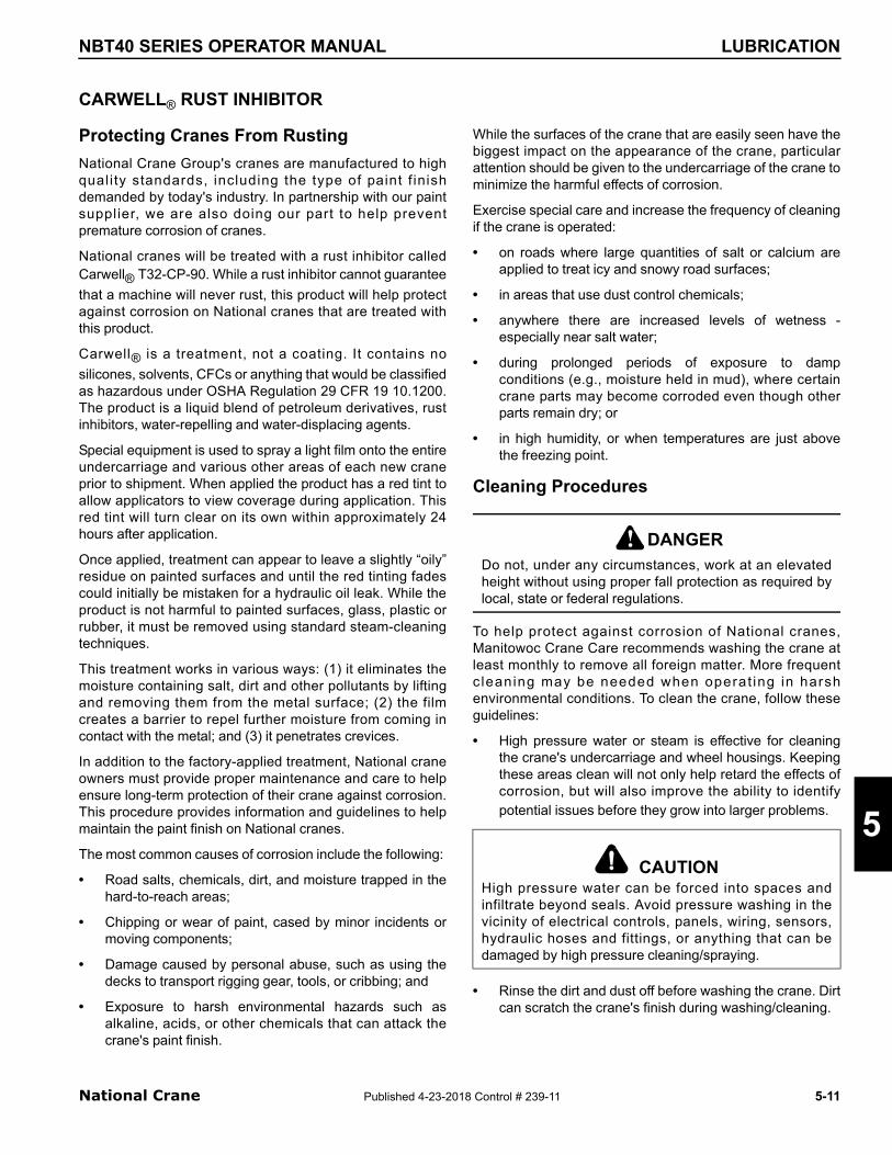
NBT40 SERIES OPERATOR MANUAL LUBRICATION
CARWELL® RUST INHIBITOR
5
Protecting Cranes From Rusting
National Crane Group's cranes are manufactured to highquali ty standards, including the type of paint f inishdemanded by today's industry. In partnership with our paintsupplier, we are also doing our part to help preventpremature corrosion of cranes.
National cranes will be treated with a rust inhibitor calledCarwell® T32-CP-90. While a rust inhibitor cannot guarantee
that a machine will never rust, this product will help protectagainst corrosion on National cranes that are treated withthis product.
Carwell® is a treatment, not a coating. It contains no
silicones, solvents, CFCs or anything that would be classifiedas hazardous under OSHA Regulation 29 CFR 19 10.1200.The product is a liquid blend of petroleum derivatives, rustinhibitors, water-repelling and water-displacing agents.
Special equipment is used to spray a light film onto the entireundercarriage and various other areas of each new craneprior to shipment. When applied the product has a red tint toallow applicators to view coverage during application. Thisred tint will turn clear on its own within approximately 24hours after application.
Once applied, treatment can appear to leave a slightly “oily”residue on painted surfaces and until the red tinting fadescould initially be mistaken for a hydraulic oil leak. While theproduct is not harmful to painted surfaces, glass, plastic orrubber, it must be removed using standard steam-cleaningtechniques.
This treatment works in various ways: (1) it eliminates themoisture containing salt, dirt and other pollutants by liftingand removing them from the metal surface; (2) the filmcreates a barrier to repel further moisture from coming incontact with the metal; and (3) it penetrates crevices.
In addition to the factory-applied treatment, National craneowners must provide proper maintenance and care to helpensure long-term protection of their crane against corrosion.This procedure provides information and guidelines to helpmaintain the paint finish on National cranes.
The most common causes of corrosion include the following:
• Road salts, chemicals, dirt, and moisture trapped in thehard-to-reach areas;
• Chipping or wear of paint, cased by minor incidents ormoving components;
• Damage caused by personal abuse, such as using thedecks to transport rigging gear, tools, or cribbing; and
• Exposure to harsh environmental hazards such asalkaline, acids, or other chemicals that can attack thecrane's paint finish.
National Crane Published 4-23-201
While the surfaces of the crane that are easily seen have thebiggest impact on the appearance of the crane, particularattention should be given to the undercarriage of the crane tominimize the harmful effects of corrosion.
Exercise special care and increase the frequency of cleaningif the crane is operated:
• on roads where large quantities of salt or calcium areapplied to treat icy and snowy road surfaces;
• in areas that use dust control chemicals;
• anywhere there are increased levels of wetness -especially near salt water;
• during prolonged periods of exposure to dampconditions (e.g., moisture held in mud), where certaincrane parts may become corroded even though otherparts remain dry; or
• in high humidity, or when temperatures are just abovethe freezing point.
Cleaning Procedures
To help protect against corrosion of National cranes,Manitowoc Crane Care recommends washing the crane atleast monthly to remove all foreign matter. More frequentc leaning may be needed when operat ing in harshenvironmental conditions. To clean the crane, follow theseguidelines:
• High pressure water or steam is effective for cleaningthe crane's undercarriage and wheel housings. Keepingthese areas clean will not only help retard the effects ofcorrosion, but will also improve the ability to identifypotential issues before they grow into larger problems.
• Rinse the dirt and dust off before washing the crane. Dirtcan scratch the crane's finish during washing/cleaning.
DANGERDo not, under any circumstances, work at an elevatedheight without using proper fall protection as required bylocal, state or federal regulations.
CAUTIONHigh pressure water can be forced into spaces andinfiltrate beyond seals. Avoid pressure washing in thevicinity of electrical controls, panels, wiring, sensors,hydraulic hoses and fittings, or anything that can bedamaged by high pressure cleaning/spraying.
!
8 Control # 239-11 5-11

LUBRICATION NBT40 SERIES OPERATOR MANUAL
• Hard to clean spots caused by road tar or bugs shouldbe treated and cleaned after rinsing and prior towashing. Do not use solvents or gasoline.
• Wash using only soaps and detergents recommendedfor automotive paint finishes.
• Rinse all surfaces thoroughly to prevent streakingcaused by soap residue.
• Allow the crane to dry thoroughly. You can acceleratedrying by using compressed air to remove excess water.
NOTE: Polishing and waxing (using an automotive-typewax) is recommended to maintain the original paintfinish.
Inspection and Repair
• Immediately following cleaning, Manitowoc Crane Carerecommends an inspection to detect areas that mayhave become damaged by stone chips or minormishaps. A minor scratch (one that has not penetratedto the substrate surface) can be buffed with anautomotive-type scratch remover. It is recommendedthat a good coat of automotive wax be applied to thisarea afterwards.
• All identified spots and/or areas that have beenscratched through to the metal should be touched upand repaired as soon as possible to prevent flashrusting. To repair a major scratch (down to bare metal) orminor damage, follow these procedures:
NOTE: Manitowoc Crane Care recommends that aqualified body repairman prepare, prime and paintany major scratch(es) or minor damage.
• For scratches and marks in highly visible areas:
• Sand to remove the scratch and feather outward fromthe mark to blend the repair into the original surface.Body putty may be applied as necessary to hide thedefect; then sand smooth.
• Cover all bare metal with a primer that is compatible withthe original paint finish
• and allow to dry thoroughly.
• Prepare the surface prior to applying the finish coat ofpaint.
CAUTIONTo the extent any damage is structural in nature,Manitowoc Crane Care must be contacted and consultedas to what repairs may be required.
5-12 Published 4-23-201
• Apply a finish coat paint using accepted blendingtechniques. Use of original paint colors is recommendedto insure the best color match possible.
For scratches and marks in areas of low visibility:
• Consider touching up the spots with a brush techniqueto cover the bare metal. This will retard the effects ofcorrosion and enable you to do the repair at a later timeduring a normal maintenance interval.
Spots should be touched up with quality paint. Primers tendto be porous; using a single coat of primer only will allow airand water to penetrate the repair over time.
Application
Depending upon the environment in which a crane is usedand/or stored, the initial factory application of Carwell® T32-
CP-90 should help inhibit corrosion for up to approximately12 months.
It is recommended that the treatment be periodicallyreapplied by the crane owner after that time to help continueto protect against corrosion of the crane and its components.
However, i f a crane is used and/or stored in harshenvironments (such as islands, coastal regions, industrialareas, areas where winter road salt is regularly used, etc.),reapplication of treatment is recommended sooner than 12months, e.g., repeat treatment in 6-9 months.
• Do not apply to recently primered and painted areas forat least 48 hours after paint is properly dried and cured.For minor touch up areas a 24 hour period is needed forcure time before applying treatment.
NOTE: Unit must be completely dry before applyingtreatment.
• Do not allow product to puddle or build-up on weatherstripping, rubber gaskets, etc. Unit should not havepuddles or runs evident anywhere.
• To ensure proper coverage of treatment, the productneeds to be fogged on the unit.
• Use of pressure pots to apply the treatment to the unitbeing processed is recommended.
• Carwell® treatment is available in 16 ounce spray
bottles from Manitowoc Crane Care (order part number8898904099).
• After application of the treatment is complete, wash orclean film residue from lights, windshield, grab handles,ladders/steps and all access areas to crane, asnecessary.
Please contact Manitowoc Crane Care should you have anyquestions.
8 Control # 239-11

NBT40 SERIES OPERATOR MANUAL LUBRICATION
Areas of Application
Refer to Figure 5-8
• The underside of the unit will have full coverage of therust inhibitor. These are the only areas that a full coat ofthe rust inhibitor is acceptable on the painted surfaces.Areas include; Valves, hose end and fittings, Swivel,pumps, axles, drivelines, transmission, slew ringfasteners and all interior surfaces of the frame.
• Frame application areas are; hose ends and fittings, allunpainted fasteners and hardware, all bare metalsurfaces, outrigger pads, and back up alarm hardware.
National Crane Published 4-23-201
• Superstructure applications are; hose end and fittings,wire rope on hoist roller tensioning springs on hoists, allunpainted fasteners and hardware, valves, slew ringfasteners and all bare metal surfaces.
• Boom applications areas are; pivot pins, hose end andfittings, jib pins and shafts, all bare metal surfaces,headache ball pins/ hook block pins and fasteners.
• All hardware, clips, pins, hose connections not paintedwill have treatment applied.
8 Control # 239-11 5-13
5

LUBRICATION NBT40 SERIES OPERATOR MANUAL
7650-52
1 3 4 5
9
7
12
4
10
14 17
2 8
1015 14 13
8 11
11
3
17 410 4 1577650-53
6
16
FIGURE 5-8
5-1
4 Published 4-23-2018 Control # 239-11
NBT40 SERIES OPERATOR MANUAL LUBRICATION
Item Description
1 Hoist Plumbing Connections
2 Tension Spring
3 Counterweight Pins
4All Hardware, Clips, Pins, Hose Connections not painted O/R Pins, Clips
5 Valvebank, Hose Connections inside turntable
6 Boom Extension Hardware (Optional)
7 Pivot Shaft
8 Boom Nose Pins, Clips
National Crane Published 4-23-201
9 Headache Ball/Hook block
10 O/R Pins, Clips
11 Mirror Mounting Hardware
12 Powertrain Hardware
13 O/R Hose Connections
14 Entire underside of unit
15 Turntable Bearing Fasteners
16 Wire Rope
17 Outrigger Beam Hardware
Item Description
8 Control # 239-11 5-15
5

LUBRICATION NBT40 SERIES OPERATOR MANUAL
5-16 Published 4-23-201
THIS PAGE BL
8 Control # 239-11
ANK

NBT40 SERIES OPERATOR MANUAL MAINTENANCE CHECKLIST
SECTION 6
MAINTENANCE CHECKLIST
SECTION CONTENTS
Crane Inspection And Maintenance . . . . . . . . . . . 6-1Inspections . . . . . . . . . . . . . . . . . . . . . . . . . . . . . . 6-1Special Boom Inspection . . . . . . . . . . . . . . . . . . . . 6-3Stability . . . . . . . . . . . . . . . . . . . . . . . . . . . . . . . . . 6-3
Hoist Cable Inspection and Maintenance . . . . . . . 6-3Keeping Records . . . . . . . . . . . . . . . . . . . . . . . . . . 6-3Environmental Conditions . . . . . . . . . . . . . . . . . . . 6-3Dynamic Shock Loads. . . . . . . . . . . . . . . . . . . . . . 6-4Precautions and Recommendations During Inspection. . . . . . . . . . . . . . . . . . . . . . . . . . 6-4Inspection . . . . . . . . . . . . . . . . . . . . . . . . . . . . . . . 6-4Wire Rope Replacement . . . . . . . . . . . . . . . . . . . . 6-5Care of Wire Rope. . . . . . . . . . . . . . . . . . . . . . . . . 6-5
Replacement Cable . . . . . . . . . . . . . . . . . . . . . . . . . 6-5
Crane Adjustments and Repairs . . . . . . . . . . . . . . 6-6Boom Extension Cable . . . . . . . . . . . . . . . . . . . . . 6-6
National Crane Published 4-23-2018
Jib Jack Service and Maintenance. . . . . . . . . . . . . 6-6Lubrication . . . . . . . . . . . . . . . . . . . . . . . . . . . . . . . 6-6Rust Prevention . . . . . . . . . . . . . . . . . . . . . . . . . . . 6-6
Hydraulic System . . . . . . . . . . . . . . . . . . . . . . . . . . . 6-6Oil Cooler . . . . . . . . . . . . . . . . . . . . . . . . . . . . . . . . 6-6Hydraulic System Trouble Diagnosis . . . . . . . . . . . 6-6
Tire Load And Inflation Table . . . . . . . . . . . . . . . . . 6-9
Specifications. . . . . . . . . . . . . . . . . . . . . . . . . . . . . 6-13Hydraulic . . . . . . . . . . . . . . . . . . . . . . . . . . . . . . . 6-13Air Conditioner . . . . . . . . . . . . . . . . . . . . . . . . . . . 6-13Hoist System . . . . . . . . . . . . . . . . . . . . . . . . . . . . 6-13Counterweight . . . . . . . . . . . . . . . . . . . . . . . . . . . 6-14General. . . . . . . . . . . . . . . . . . . . . . . . . . . . . . . . . 6-14Boom Weight . . . . . . . . . . . . . . . . . . . . . . . . . . . . 6-14
Dimensional Drawing. . . . . . . . . . . . . . . . . . . . . . . 6-16
6
CRANE INSPECTION AND MAINTENANCE
Regularly scheduled inspection and maintenance intervalsare required to keep the crane in peak operating condition.The following pages outline the inspection and maintenanceintervals.
Refer to the Service Manual for complete instructions onperforming maintenance on this crane.
Inspections
The inspection intervals listed below are to be conducted onthe unit to ensure safe and proper operation. Refer to theService Manual when installing missing or loose fasteners.Should a defect be found, a determination must be made asto whether the deficiency is a safety hazard or though not yeta safety hazard, needs to be monitored in the monthlyinspections.
WARNING
Fall Hazard!
Do not, under any circumstances, work at an elevatedheight without using proper fall protection as required bylocal, state or federal regulations
!
The inspections are separated into the following frequencyclassifications:
• Daily inspections - performed by the operator at the startof the day.
• Weekly inspections - performed by the operator.
• Monthly inspections - performed by maintenancepersonnel.
• Periodic inspections - performed by maintenancepersonnel at least every three months and includes alli tems l is ted under da i ly, week ly, and month lyinspections. Federal Laws through OSHA and ANSIB30.5 require that dated and signed records of theseperiodic inspections be kept. An inspection log book isavailable from your National Crane distributor orManitowoc Crane Care.
Daily Inspections/Pre-use
Check the following items:
WARNINGIf any defect determined during the inspection is a safetyhazard the machine must be removed from service andthe defect corrected.
!
Control # 239-11 6-1

MAINTENANCE CHECKLIST NBT40 SERIES OPERATOR MANUAL
1. Engine oil level.
2. Hydraulic oil level.
3. Radiator coolant level.
4. Loose parts or damage to structures or welds.
5. Operation of lights, safety equipment and gauges.
6. Condition of tires and suspension.
7. Condition of hoist cable and end attachment forcorrosion, severe kinking, crushing, cutting, or slippageof cable clamps or wedge socket.
8. Loose parts or damage to cable centering hook blocks.
9. Position of cable with guides and on sheaves.
10. Free turning of sheaves.
11. Lubrication as specified by the Lubrication, Section 5.
12. Evidence of oil leaks from hoses, gearboxes, or swivel.
13. Hand and foot controls for malfunction or incorrectadjustment.
14. Truck parking brake operation.
15. Boom proportioning to insure that all boom sectionsextend and retract equally.
16. All securing hardware such as cotter pins, snap rings,hairpins, pin keepers, and capscrews for properinstallation.
17. Proper condition and operation of RCL and anti-two-block systems to include the anti-two-block switchweight and chain at the boom tip (and extension tip ifequipped), power cords, audible alarms, and indicatorlights on the console.
18. Proper operation of the load hook safety latch.
19. Hooks and latches for excessive wear, cracks ordamage from heat or chemicals.
20. Drain holes at rear of the first section of the boom areclear of all obstructions.
21. All fasteners retaining the cable centering block are inplace and tight.
22. All safety covers for proper installation.
23. Boom lift and outrigger holding valves for properoperation.
24. Hoist brake for proper operation at hoist capacity load.
25. Control and drive mechanisms for excessive wear and/or contamination from lubricants, water or other foreignmatter.
Weekly Inspections
Check the following items:
6-2 Published 4-23-201
1. Battery water level.
2. Tire pressure.
3. Lubrication as specified by the Lubrication, Section 5.
4. Torque the T-box mounting bolts during the first month ofoperation and periodic inspections thereafter.
5. Torque the swing bearing mounting bolts during the firstmonth of operation and periodic inspections thereafter.
6. Torque the boom wear pad retaining bolts during firstmonth of operation, and monthly thereafter.
7. Check to see that this crane’s Operator’s Manual is withthe crane. If the manual is missing, obtain the serialnumber of the crane and order an operator’s manualimmediately.
Monthly Inspections
Check the following items:
1. All cylinders and valves for improper operation or signsof leaks.
2. Lubrication as specified by the Lubrication Points, page5-5.
3. Load hook for cracks or having more than 15 percentnormal throat opening or 10 degree twist.
4. All structural members (boom, sub-base, frame, turret,and outriggers) for bends, cracks, or broken members.
5. All welds for breaks or cracks.
6. All pins for proper installation.
7. All control, safety, and capacity placards for readabilityand secure attachment.
8. Cable clip bolts above wedge socket at end of loadlineshould be properly torqued, refer to the Service Manual.
9. All boom wear pad retaining bolts.
10. Boom extension cables for proper tension or evidence ofabnormal wear.
11. Sheaves and cable drums for wear and cracks.
12. Unwind the loadline and check according to cablemaintenance procedure.
Periodic/Annual Inspection
Check the following items:
1. All items listed under daily, weekly, and monthlyinspections.
2. Loose bolts and fasteners in all areas. Torque pinretainer bolts.
8 Control # 239-11

6
NBT40 SERIES OPERATOR MANUAL MAINTENANCE CHECKLIST
3. All pins, bearings, shafts, and gears for wear cracks ordistortion to include all pivot, outrigger and sheave pins,and bearings.
4. Boom angle and boom length indicator for accuracy overfull range.
5. Hydraulic systems for proper operating pressure.
6. Outrigger pads for excessive wear or cracks.
7. Cylinders for:
a. Damaged rods
b. Dented barrels
c. Drift from oil leaking by piston
d. Leaks at rod seals, welds, or holding valves.
8. PTO drive line system for proper alignment, lubricationand tightness.
9. Hydraulic hose and tubing for evidence of damage suchas blistering, crushing, or abrasion.
10. Top and bottom boom wear pads for excessive wear.
11. Inspect all electrical wires and connections for worn, cutor deteriorated insulation and bare wire. Replace orrepair wires as required.
12. Extend and retract cables, sheaves, pins, and bearingsfor wear or abrasion.
13. Main frame and jack mounting bolts for proper torque,refer to the Service Manual.
14. Rotation bearing and gearbox mounting bolts for propertorque, refer to the Service Manual.
15. Missing or unreadable warning labels.
16. Missing or unusable/unsafe condition of steps, ladders,handrails, guards or seat.
Special Boom Inspection
If the boom has not been disassembled and inspected in thelast seven years or 3,000 hours of use, the boom is to becompletely torn down to allow a thorough inspection of theextend and retract cables, sheaves, and pins.
• Manitowoc recommends that boom extension cables bereplaced every seven (7) years.
Stability
Stability of unit throughout working area. Check the stabilityprocedure in Installation Section of the Service Manualannually or when any changes are made to crane or truck.
National Crane Published 4-23-2018
HOIST CABLE INSPECTION AND MAINTENANCE
Wire rope should be inspected frequently/daily andperiodically/yearly in accordance with the followinginformation excerpted from a National Consensus Standardas re ferenced by Federa l Government Agenc ies .Recommended inspection intervals may vary from machineto machine and may vary based on environmentalconditions, frequency of lifts, and exposure to shock loads.The inspection time intervals may also be predetermined bystate and local regulatory agencies.
Any deterioration observed in the wire rope should be notedin the equipment inspection log and an assessmentconcerning wire rope replacement should be made by aqualified person. Manitowoc recommends that boomextension cables be replaced every seven (7) years.
NOTE: Wire rope may be purchased through ManitowocCrane Care.
Keeping Records
A signed and dated report of the wire rope’s condition ateach periodic inspection must be kept on file at all times. Thereport must cover all inspection points listed in this section.The information in the records can then be used to establishdata which can be used to determine when a wire ropeshould be replaced.
It is recommended that the wire rope inspection programinclude reports on the examination of wire rope removedfrom service. This information can be used to establish arelationship between visual inspection and the rope’s actualinternal condition at the time of removal from service.
Environmental Conditions
The life expectancy of wire rope may vary due to the degreeof environmental hostility and other conditions to which thesemechanical devices are subjected. Variation in temperature,continuous excessive moisture levels, exposure to corrosivechemicals or vapors or subjecting the wire rope to abrasivematerial may shorten normal wire rope life. Frequent/periodic inspections and maintenance of wire rope isrecommended for preventing premature wear and to insurelong-term satisfactory performance.
NOTE: Refer to Wire Rope Lubrication, page 5-10 for wirerope lubrication requirements.
WARNINGWorn or Damaged Equipment Hazard!
Never use a worn or damaged wire rope. Death or seriousinjury could result from using worn or damaged wire rope.
!
Control # 239-11 6-3

MAINTENANCE CHECKLIST NBT40 SERIES OPERATOR MANUAL
Dynamic Shock Loads
Subjecting wire rope to abnormal loads beyond theendurance limit will shorten the wire rope life expectancy.Examples of this type of loading are listed below.
• High velocity movement, for example; hoisting orswinging of a load followed by abrupt stops.
• Suspending loads while traveling over irregular surfacessuch as railroad tracks, potholes, and rough terrain.
• Lifting a load that is beyond the rated capacity of thelifting mechanism, such as overloading.
Precautions and Recommendations During Inspection
• Always use safety glasses for eye protection.
• Wear protective clothing, gloves, and safety shoes asappropriate.
• Measure the rope’s diameter across crowns of thestrands when determining if rope has become damaged,refer to Figure 6-1.
Inspection
All hoist cable in service needs to be inspected on a daily,monthly, and quarterly basis. Cable which has been idle for aperiod of a month or more must be given a thoroughinspection before it is placed in service. These inspectionsshould cover all types of deterioration including:
• Distortion such as kinking, crushing, un-stranding, birdcaging, main strand displacement or core protrusion.
• Loss of cable diameter in a short cable length orunevenness of outer strands indicates the cable needsto be replaced.
• Significant corrosion.
• Broken or cut strands.
• Number, distribution and type of visible broken wires.
A925
1
FIGURE 6-1
6-4 Published 4-23-201
• Core failure in rotation resistant ropes.
• Prior electrical contact with a power line or other electricarc damage.
• Significantly corroded, cracked, bent, or worn endconnections.
Only inspect the outer surface of a cable. Never attempt toopen the cable.
Pay particular attention to areas of the rope where wear andother damage is likely to occur:
• Pick-up Points: Sections of wire rope that are repeatedlystressed during each lift, such as those sections incontact with sheaves.
• End Attachments: The point where a fitting is attached tothe wire rope or the point where the wire rope is attachedto the hoist drum.
• Abuse Points: The point where the wire rope issubjected to abnormal scuffing and scraping.
Daily Inspections
All cable in continuous service must be inspected at thebeginning of each work day. Inspect the eye end and lengthof cable that is used in daily operation. The end should beinspected for abrasion, corrosion, broken wires, and loose orbroken servings. Inspect the remainder of the cable lengthused for daily operations for points showing kinks, sharpbends, or any other evidences of damage or excessive wear.
Monthly Inspections
Inspect the eye end and length of cable normally used indaily operations. Examine the rest of the cable for kinked,crushed or otherwise damaged points.
Periodic Inspections
Wire rope should be inspected periodically/annually, or at ashorter time interval, if necessitated by environmental orother adverse conditions, and shall cover the entire length ofthe wire rope. Periodic inspection should include all previousitems listed under Inspection, plus the following:
• Inspect for severely corroded or broken wires at endconnections.
• Inspect wire rope in areas subjected to rapiddeterioration such as:
- Sections in contact with saddles, equalizer sheaves,or other sheaves where wire rope travel is limited.
- Sections of wire rope at or near terminal ends wherecorroded or broken wires may protrude.
• Inspect boom nose sheaves, hook block sheaves, boomextension/extension sheaves, auxiliary boom nosesheaves, and hoist drums for wear. Damaged sheaves
8 Control # 239-11

6
NBT40 SERIES OPERATOR MANUAL MAINTENANCE CHECKLIST
or hoist drums can accelerate wear and cause rapiddeterioration of the wire rope.
Inspect the eye end of the cable for greater wear than therest of the cable. If the cable is in good condition, reverse thecable on the drum so that the wear is equalized along thetotal length of the cable.
Wire Rope Replacement
It is difficult to determine the exact time for replacement ofwire rope (hoist cable) since many variable factors areinvolved. Proper determination of the condition of a ropedepends upon the judgment of an experienced person. Thefollowing reasons are sufficient for consideration of ropereplacement:
• Six randomly distributed broken wires in one rope lay orthree broken wires in one strand in one lay. The rope isunsafe for further use if there are either three brokenwires in one strand (Breaks 2, 3, 4) or a total of sixbroken wires in all strands in any one lay.
• In rotation resistant ropes: two randomly distributedbroken wires in six rope diameters or four randomlydistributed broken wires in 30 rope diameters
• Wear of one-third the original diameter of outsideindividual wires. Worn rope, usually indicated by flatspots on the outer wires is unsafe for further use whenless than two-thirds the thickness of the outer wireremains.
• Necking down of the rope indicates core failure.
• Kinking, crushing, bird caging, or any other damageresulting in distortion of the rope structure.
• Evidence of heat damage.
• Reductions from nominal diameter of more than:
- 0.0156 in (.4 mm) for rope diameters to 0.313 in (8mm)
- 0.031 (.8 mm) for rope diameters 0.375 in (9.5 mm)to 0.50 in (12.7 mm)
1 2 3 4 5 6
National Crane Published 4-23-2018
- 0.047 in (1.2 mm) for rope diameters 0.561 in (14.3mm) to 0.75 in (19.1 mm)
- 0.063 (1.6 mm) for rope diameters 0.875 in (22.2mm) to 1.125 in (28.6 mm).
• One outer wire broken at its point of contact with the coreof the rope which has worked its way out of, andprotrudes or loops out from the rope structure.
Care of Wire Rope
Handle wire rope with care to prevent damage to theindividual wires which affect the overall strength andperformance of the rope. Do not allow the formation of kinks,because this displaces the strands of wire from their originalposition and relation to each other causing severe bendingand unequal tensions in the strands. This distortion and wiredisplacement cannot be corrected even under high tensionand a permanent weak point remains in the rope. Displacedor raised wires indicate a previous kink, but does not showthe damaged condition of the inner rope wires.
Never pull wire rope over a non-rotating support such as aspindle bar, a pin, or an inoperative sheave. This practicecauses severe abrasion to the outer strand wires. A properlyoperating sheave or snatch block is essential to safety andlong service life of the rope.
Do not use worn sheaves or sheaves with flat groovesbecause they do not provide sufficient support to prevent thedistortion and flattening of the rope. Sheaves with nicked orbroken flanges can cut or otherwise damage the rope.
An even distribution of rope coils over the hoist drum isessential to smooth operation. This prevents the rope fromcutting down through or crushing other coils on the drumresulting in damage to and difficulty in unwinding the rope.
REPLACEMENT CABLE
If the hoist cable needs to be replaced, care should be takenin selecting a suitable replacement cable. The cable strengthrequirements are shown on the crane load chart. The typesof cable are optional with 6 x 25 and Dyform being the mostcommon. A high strength, rotation resistant cable ispreferred and is furnished as standard by National Cranes.This cable eliminates single part line load spin and prolongscable life. It also eliminates load block spin up when multi-part reeving is used. .
Standard
9/16 in. (14.3mm) Dia. Wire cable:Rotation Resistant
18X25 Nominal Breaking Strength:19.25 Tons (17,463 kg)
Optional
Control # 239-11 6-5

MAINTENANCE CHECKLIST NBT40 SERIES OPERATOR MANUAL
CRANE ADJUSTMENTS AND REPAIRS
Before adjustments and repairs are started on a crane, readand be familiar with the safety information outlined underMaintenance, page 2-27.
Boom Extension Cable
If a cable replacement is required for the boom extensionsystem, the replacement cable must be obtained through theManitowoc Crane Care. Extension cables are pre-stretchedand have special connections for proper operation
Jib Jack Service and Maintenance
Important: Use only a good grade hydraulic jack oil,transmission oil, or turbine oil. Avoid mixing types of oil. Donot use brake fluid, alcohol, glycerin, detergent motor oil, ordirty oil. Improper fluid can cause serious internal damage tothe jack rendering it inoperative.
Adding Oil to the Jib Jack
To add oil to the jib jack, do the following:
1. Set the jack in an upright level position.
2. Lower the saddle and make sure the piston is fullydepressed.
3. Remove the oil filler plug.
4. Fill until the oil is level with the filler plug hole.
Changing the Jib Jack Oil
For best performance and longest life, replace the oil at leastonce a year. To change oil, do the following:
1. Remove the filler plug.
2. Lay the jack on its side and drain the oil into a suitabledrain pan. The oil will run slowly because air must enteras oil drains out.
9/16 in. (14.3mm) Dia. Wire cable:6X25 General Purpose
6X25 Nominal Breaking Strength:16.8 tons (15,241 kg)
6-6 Published 4-23-201
3. Be careful to prevent dirt or foreign matter from enteringthe system.
4. Replace with proper oil as described above.
Lubrication
Add proper lubrication oil to all pivoting sections every threemonths.
Rust Prevention
Check the ram every three months for any sign of rust orcorrosion. Clean as needed and wipe with an oil saturatedcloth.
NOTE: When not in use, always leave the saddle and ramall the way down.
HYDRAULIC SYSTEM
Oil Cooler
The heat exchanger must be kept clean for efficientoperation of the hydraulic cooler system. Wash the heatexchanger core frequently to eliminate oil film, road dirt, andother foreign object buildup on the heat exchanger fins.
Frequent inspection and tightening of hose clamp eliminatesthe possibility of end connection failure due to back pressurefrom a cold startup.
If the cooler system fails to provide adequate performance,reduced air or oil flow through the heat exchanger is theprobable cause. Inspect the cooling fan for proper operation.Any obstructions to air flow should be corrected (cooler tooclose to other truck components, foreign matter in heatexchanger fins, etc.) All hydraulic lines should be periodicallychecked for obstruct ions, hose kinks or other f lowrestrictions.
Hydraulic System Trouble Diagnosis
The following chart lists malfunctions which may occurduring equipment operation, followed immediately bypossible cause and possible solution. These are not allinclusive but are designed to help isolate the problem andshould be checked before calling the factory ServiceDepartment.
8 Control # 239-11

6
NBT40 SERIES OPERATOR MANUAL MAINTENANCE CHECKLIST
Condition Possible Cause Possible Solution
No response to control
RCL system inoperative.Insure the RCL system is working properly and the anti-two-block solenoid is powered.
Load too heavy. Check load chart.
PTO not engaged. Engage PTO.
Low hydraulic fluid supply. Check and fill as required.
Suction line blocked. Drain tank and hose and remove blockage.
Broken hydraulic pressure line. Replace as required.
Defective hydraulic pump. See Pump Service Manual.
Incorrect relief valve setting. Adjust relief).
Relief valve sticking. Clean relief.
Poor hydraulic system performance
Pump not operating at proper speed.Check PTO ratio, pump size and engine speed for proper oil flow.
Low hydraulic fluid supply. Check and fill as required.
Relief valve sticking. Remove and clean.
Relief setting too low. Readjust to proper setting.
Worn pump, motor or cylinder. Replace bad part.
Plugged filter. Change filter.
Boom holding valves out of adjustment. Adjust or clean as required.
Oil temperature too high.Run engine at idle with controls in the neutral position until hydraulic oil light goes out.
Hydraulic oil too cold or dirty. Warm oil or use less viscous oil.
Line restricted. Check lines; clean and repair as required.
Internal control valve crack. Replace valve.
Load too heavy. Check load chart and reduce load.
Swing moves erratic or sloppily (Standard system).
Loose turntable bearing. Torque bearing mounting bolts.
Loose swing gearbox mounting bolts. Tighten bolts.
Worn gears or bearing. Replace worn parts or adjust gearbox spacing.
Operator control of lever too erratic. Operate controls smoothly.
Motor counterbalance valves dirty or not set properly.
Clean or replace counterbalance valves.
Brake not holding properly.Replace worn brake parts or shim brake to proper torque.
Brake releasing at wrong time or erratically.Bleed air from brake with bleed screw on side of brake.
Swing speed adjustment set too low.Adjust or clean brake for proper release.
Adjust valve on turn motor.
National Crane Published 4-23-2018 Control # 239-11 6-7

MAINTENANCE CHECKLIST NBT40 SERIES OPERATOR MANUAL
Swing will not turn (Standard System)
Turn circuit relief valves sticking. Clean and check circuit pressure.
Turntable bearing drag. Lubricate thoroughly as rotating boom.
Brake not releasing properly.Check brake pilot pressure. Clean pilot line or adjust motor counterbalance valves.
Swing speed adjustment set too low.Adjust or clean brake for proper release.
Adjust valve on turn motor.
Excessive pump noise during operation.
Excessive pump speed.Adjust foot throttle or check for too high PTO ratio.
Low oil temperature. Allow unit to warm up.
Low hydraulic oil supply. Check and fill.
Suction line kinked, collapsed or blocked. Clear blockage.
Hydraulic oil too thick.Warm oil or use oil more applicable to environment.
Relief valve chattering. Dirt in relief valve or damaged relief.
Hydraulic tubing vibration. Check for loose tubing.
Tank breather plugged. Clean breather.
Cylinders drift
Not getting oil to cylinders. Clean and replace as required.
Worn or damaged piston seals. Replace as required.
Air in hydraulic oil. Cycle crane cylinder to remove air.
Loose holding valve. Tighten valve.
Dirt in holding or check valve. Clean valve.
Hoist will not lift or hold load.
Load too heavy.Check load and change to applicable multipart reeving.
Relief valve setting too low. Check and adjust if required.
Motor worn excessively. Replace motor.
Counterbalance valve defective or leaking. Clean and replace as necessary.
Anti-two-block system defective. Repair anti-two-block system.
Brake worn out. Repair or replace brake.
Hoist gearbox heats.Gearbox grease low. Check and fill as required.
Duty cycle too high. Reduce cycle time or speed of Hoist.
Boom chatters during extension/retraction or doesn't proportion properly.
Boom sections need lubrication. Grease boom.
Wear pads not shimmed correctly.Re-shim as described in boom assembly section.
Worn wear pads. Replace pads.
Extension cables out of adjustment. Readjust cables and tension properly.
Extend or retract cables broken. Disassemble, inspect, and replace cables.
Boom will not extend.
Proportioning cables not attached. Reconnect, replace and/or adjust cables.
Anti-two-block system shut down. Lower hook, and extend load.
Defective anti-two-block system Repair ATB if defective.
Condition Possible Cause Possible Solution
6-8 Published 4-23-2018 Control # 239-11

NBT40 SERIES OPERATOR MANUAL MAINTENANCE CHECKLIST
System is in a state of constant cut-out.
Blown fuse.Check fuse at crane cab console. Replace if necessary.
ATB switch open. Ensure that ATB switch is closed.
System cuts out too early or too late.
RCL programmed wrong. Reprogram RCL with correct lift values.
Jib Jack Troubleshooting
Will not lift load.No oil in system.
Release valve not closed.
Add oil to reservoir.
Turn handle clockwise tightly.
Will lift load only part way. Oil level low. Add oil to reservoir tank.
Will lift load but will not hold.
The following valve or valves leaking.
a. Suction valve
b. Delivery valve
c. Release valve
Replace jack
Packings worn or damaged. Replace jack
Jack will not lower.Release valve stuck, probably dirt or foreign matter.
Transfer load then replace dirty oil, flush oil reservoir with non-flammable solvent.
Poor lifting.Dirty oil.
Air in hydraulic system.
Change oil.
Purge air from system.
Poor pumping action.Oil seal for pump unit worn in out or damaged.
Replace jack.
Condition Possible Cause Possible Solution
TIRE LOAD AND INFLATION TABLE
Definite tire inflation pressures are established for each tiresize depending upon the load imposed on the tires. Forgreater stability, riding comfort and prolonged tire life, tiresshould be inflated for the loads carried. The “Load andinflation Table” shown below indicates the proper inflationpressure.
National Crane Published 4-23-2018
NOTE: The values in the tables below are as published bythe Tire and Rim Association 2005. Your vehiclemay be equipped with other tire sized or the samesize tires rated differently. Always check the tiresidewalls to verify the maximum capacity andinflation. Inflation pressure and loading must notexceed the values shown on the wheel or rim.
Tire and Load Inflation TablesLetters in parenthesis denote the load range for which the bold face loads are a maximum.
International load index numbers are shown after the load range. The load range letters and corresponding ply rating are shown below.
D = 8 ply • E = 10 ply • F = 12 ply • G = 14 plyH = 16 ply • J = 18 ply • L = 20 ply • M = 22 ply • N = 24 ply
Control # 239-11 6-9
6

MAINTENANCE CHECKLIST NBT40 SERIES OPERATOR MANUAL
Radial Ply Metric Tires for Trucks, Busses, and Trailers Used in Normal Highway ServiceRadial Ply Tires Mounted on 15° Drop Center Rims
Tire and Rim Association Standard
6-10 Published 4-23-2018 Control # 239-11

6
NBT40 SERIES OPERATOR MANUAL MAINTENANCE CHECKLIST
Radial Ply Metric Tires for Trucks, Busses, and Trailers Used in Normal Highway ServiceRadial Ply Tires Mounted on 15° Drop Center Rims
Tire and Rim Association Standard
Radial Ply Metric Tires for Trucks, Busses, and Trailers Used in Normal Highway ServiceRadial Ply Tires Mounted on 15° Drop Center Rims
Tire and Rim Association Standard
N
ational Crane Published 4-23-2018 Control # 239-11 6-11
MAINTENANCE CHECKLIST NBT40 SERIES OPERATOR MANUAL
Metric Wide Base Tires for Trucks, Busses, and Trailers Used in Normal Highway ServiceTires Used as Singles Mounted on 15° Drop Center Rims
Tire and Rim Association Standard
Radial Ply Tires for Trucks, Busses, and Trailers Used in Normal Highway ServiceRadial Ply Tires Mounted on 15° Drop Center Rims
Tire and Rim Association Standard
6-12 Published 4-23-2018 Control # 239-11

NBT40 SERIES OPERATOR MANUAL MAINTENANCE CHECKLIST
SPECIFICATIONS
Hydraulic
National Crane Published 4-23-2018
Hydraulic Pump......................................................................75.5 gpm (286 1/min) at 2200 rpm, Variabledisplacement, axial piston with load sense
Displacement .................................................................8.54 in3/rev (140 cc/rev)
Pressure Rating (rated).................................................. 4600 psi (320 bar)
Pressure Rating (peak ...................................................5075 psi (350 bar)
Case Refill Capacity........................................................37 gal (1.40 liter)
Minimum Operating Speed ............................................600 rpm
Outrigger System ...................................................................3250 (+/-100) psi
Air Conditioner .......................................................................3500 (+/-100) psi
Boom Up ................................................................................35 gpm at 4550 psi
Boom Down ...........................................................................17 gpm at 1000 psi
Telescope Extend ..................................................................35 gpm at 2900 psi
Telescope Retract ..................................................................17 gpm at 2250 psi
Aux/Main Hoist System & Relief.............................................35 gpm at 4300 psi
Swing .....................................................................................18 gpm at 3100 (+200/-00) psi
Swing Park Brake...................................................................Hydraulic released disc, released at 175 psi (12 bar)
Reservoir Capacity.................................................................100 gal (351.3 L)
Reservoir Return Filter ...........................................................5 micron
Reservoir Suction Filter..........................................................25 micron
Air Conditioner
Air Conditioner Hydraulic System ..........................................3500 (+/-100) psiMinimum Evacuation Time ....................................................30 minutes
Refrigerant Charge Levels .....................................................2.0 pounds (+/- 0.5 ounce)
Additional Pag Oil Required Above 6 ounces in Compressor 4.0 ounces
Hoist System
Wire Rope:Length............................................................................450 ft (137 m)
Diameter (Rotation Resistant)........................................5/8 in. (16 mm)
Nominal Breaking Strength ............................................56,400 lb (25,582 kg)
Operating Pressure................................................................4300 (+/-100) psi (296.5 bar)
Flow .......................................................................................35 gpm (2.21L/s)
Hoist Line Pull/Layer
Layer Low Speed kN (lb) High Speed kN (lb)
1 66.7 (15,000) 33.4 (7,516)
2 60.2 (13,529) 30.1 (6,765)
3 54.7 (12.299) 27.4 (6,150)
4 50.2 (11,275) 25.1 (5,637)
5 46.3 (10,407) 23.1 (5,204)
Control # 239-11 6-13
6

MAINTENANCE CHECKLIST NBT40 SERIES OPERATOR MANUAL
Line Speed (no load at high engine idle speed)
Layer Low Speed m/sec (ft/sec) High Speed m/sec (ft/sec)
1 43.9 (144) 87.5 (287)
2 48.5 (159) 97.2 (319)
3 53.3 (175) 107.0 (351)
4 58.2 (191) 116.7 (383)
5 63.1 (207) 126.5 (415)
Crane Operating Speeds
6-14 Published 4-23-201
(Performance based on full governed RPM and 37.8° C (100° F) hydraulic reservoir temperature.)
Rotation 360°......................................................................... 30 ± 7 sec (1.8 ± 0.2 rpm) Adjustment Knob Closed
Boom up -10° to 80° .............................................................. 34 ± 5 sec
Boom Down 80° to -10° ......................................................... 34 sec ± 5 sec
Boom Telescope ............................................................
Outrigger Beam Extend......................................................... 10 sec ±3 sec
Outrigger Beam Retract ........................................................ 10 sec ±3 sec
Outrigger Jack Extend........................................................... 10 sec ±3 sec
Outrigger Jack Retract .......................................................... 10 sec ±3 sec
Boom Telescope Speed (Angle 60°- no load at high engine speed)
Boom Length Extend Retract
9.44 - 31.39m (31 - 103ft) 105 sec (± 10 sec) 105 sec (± 10 sec)
9.44 - 38.70m (31 - 127ft) 120 sec (± 10 sec) 120 sec (± 10 sec)
10.36 - 43.28m (34 - 142ft) 135 sec (± 10 sec) 135 sec (± 10 sec)
11.88 - 49.07m (39 - 161ft) 150 sec (± 10 sec) 150 sec (± 10 sec)
Counterweight
NBT36Standard........................................................................ N/A
NBT40
Standard........................................................................ 1000 lbs
NBT40 + 1000 Option ................................................... 2000 lbs
NBT45
Standard........................................................................ 4500 lbs
NBT45 + 1000 Option ................................................... 5500 lbs
General
NBT36 ................................................................................... 36 tons (32.6 metric tons) at 7 ft (2.13 m) radiusNBT40 ................................................................................... 40 tons (36.3 metric tons) at 7 ft (2.13 m) radius
NBT45 ................................................................................... 45 tons (40.8 metric tons) at 7 ft (2.13m) radius
NBT36 127 ft Boom............................................................... 35,550 lbs (16,125.21 kg)
NBT40 127 ft Boom............................................................... 37,300 lbs (16,919 kg)
NBT45 127 ft Boom............................................................... 40,950 lbs (18,574.61 kg)
Boom Weight
103 ft Boom ........................................................................... 12,425 lbs (5,636 kg)127 ft Boom ........................................................................... 12,985 lbs (5,890 kg)
8 Control # 239-11

NBT40 SERIES OPERATOR MANUAL MAINTENANCE CHECKLIST
142 ft Boom............................................................................14,338 lbs (6,504kg)
161 ft Boom............................................................................17,526 lbs (7,950kg)
National Crane Published 4-23-2018 Control # 239-11 6-15
6

MAINTENANCE CHECKLIST NBT40 SERIES OPERATOR MANUAL
DIMENSIONAL DRAWING
6-16 Published 4-23-201
FIGURE 6-2
7488-5
7488-3
8 Control # 239-11

6
NBT40 SERIES OPERATOR MANUAL MAINTENANCE CHECKLIST
7488-4
7488-6
Natio
nal Cra ne Published 4-23-2018 Control # 239-11 6-17
MAINTENANCE CHECKLIST NBT40 SERIES OPERATOR MANUAL
6-18 Published 4-23-201
THIS PAGE
8 Control # 239-11
BLANK

NBT40 SERIES OPERATOR MANUAL
Accidents . . . . . . . . . . . . . . . . . . . . . . . . . . . . . . . . . . . . . . . . . . . . . . . . . . . . . . . . . . . . . 2-2Air Conditioning . . . . . . . . . . . . . . . . . . . . . . . . . . . . . . . . . . . . . . . . . . . . . . . . . . . . . . . . 5-9Anti-two block Weight Installation . . . . . . . . . . . . . . . . . . . . . . . . . . . . . . . . . . . . . . . . . . 4-5Boom Extension. . . . . . . . . . . . . . . . . . . . . . . . . . . . . . . . . . . . . . . . . . . . . . . . . . . . . . . 2-37Boom Lubrication. . . . . . . . . . . . . . . . . . . . . . . . . . . . . . . . . . . . . . . . . . . . . . . . . . . . . . . 5-6Carwell® Rust Inhibitor . . . . . . . . . . . . . . . . . . . . . . . . . . . . . . . . . . . . . . . . . . . . . . . . . 5-11Cold Weather Operation . . . . . . . . . . . . . . . . . . . . . . . . . . . . . . . . . . . . . . . . . . . . . . . . 2-37Crane Adjustments and Repairs . . . . . . . . . . . . . . . . . . . . . . . . . . . . . . . . . . . . . . . . . . . 6-6Crane Controls. . . . . . . . . . . . . . . . . . . . . . . . . . . . . . . . . . . . . . . . . . . . . . . . . . . . . . . . . 3-4Crane Inspection And Maintenance. . . . . . . . . . . . . . . . . . . . . . . . . . . . . . . . . . . . . . . . . 6-1Crane Stability/Structural Strength . . . . . . . . . . . . . . . . . . . . . . . . . . . . . . . . . . . . . . . . . 2-5Crane Warm-up Procedures . . . . . . . . . . . . . . . . . . . . . . . . . . . . . . . . . . . . . . . . . . . . . 3-12Dimensional Drawing. . . . . . . . . . . . . . . . . . . . . . . . . . . . . . . . . . . . . . . . . . . . . . . . . . . 6-16Electrocution Hazard . . . . . . . . . . . . . . . . . . . . . . . . . . . . . . . . . . . . . . . . . . . . . . . . . . . 2-23Environmental Protection. . . . . . . . . . . . . . . . . . . . . . . . . . . . . . . . . . . . . . . . . . . . . . . . 2-27Environmental Protection. . . . . . . . . . . . . . . . . . . . . . . . . . . . . . . . . . . . . . . . . . . . . . . . . 5-1Hoist Cable Inspection and Maintenance . . . . . . . . . . . . . . . . . . . . . . . . . . . . . . . . . . . . 6-3Hoist Rope . . . . . . . . . . . . . . . . . . . . . . . . . . . . . . . . . . . . . . . . . . . . . . . . . . . . . . . . . . . 2-29hoist System Operation . . . . . . . . . . . . . . . . . . . . . . . . . . . . . . . . . . . . . . . . . . . . . . . . . 3-16Hydraulic System. . . . . . . . . . . . . . . . . . . . . . . . . . . . . . . . . . . . . . . . . . . . . . . . . . . . . . . 6-6Installing Cable On The Hoist . . . . . . . . . . . . . . . . . . . . . . . . . . . . . . . . . . . . . . . . . . . . . 4-7Jib Operation . . . . . . . . . . . . . . . . . . . . . . . . . . . . . . . . . . . . . . . . . . . . . . . . . . . . . . . . . . 4-2Jib Removal . . . . . . . . . . . . . . . . . . . . . . . . . . . . . . . . . . . . . . . . . . . . . . . . . . . . . . . . . . . 4-5Jib Safety Information . . . . . . . . . . . . . . . . . . . . . . . . . . . . . . . . . . . . . . . . . . . . . . . . . . . 4-1Lifting the Load . . . . . . . . . . . . . . . . . . . . . . . . . . . . . . . . . . . . . . . . . . . . . . . . . . . . . . . 3-19Load Chart . . . . . . . . . . . . . . . . . . . . . . . . . . . . . . . . . . . . . . . . . . . . . . . . . . . . . . . . . . . 3-18Lubrication . . . . . . . . . . . . . . . . . . . . . . . . . . . . . . . . . . . . . . . . . . . . . . . . . . . . . . . . . . . . 5-3Maintenance . . . . . . . . . . . . . . . . . . . . . . . . . . . . . . . . . . . . . . . . . . . . . . . . . . . . . . . . . 2-27Multi-part Line Reeving . . . . . . . . . . . . . . . . . . . . . . . . . . . . . . . . . . . . . . . . . . . . . . . . . . 4-5Multi-part Line Reeving . . . . . . . . . . . . . . . . . . . . . . . . . . . . . . . . . . . . . . . . . . . . . . . . . . 4-6Operating Procedures . . . . . . . . . . . . . . . . . . . . . . . . . . . . . . . . . . . . . . . . . . . . . . . . . . 3-11Operational Aids . . . . . . . . . . . . . . . . . . . . . . . . . . . . . . . . . . . . . . . . . . . . . . . . . . . . . . . 2-4Operator Information . . . . . . . . . . . . . . . . . . . . . . . . . . . . . . . . . . . . . . . . . . . . . . . . . . . . 2-2Operator Qualifications . . . . . . . . . . . . . . . . . . . . . . . . . . . . . . . . . . . . . . . . . . . . . . . . . . 2-3Outrigger Setup . . . . . . . . . . . . . . . . . . . . . . . . . . . . . . . . . . . . . . . . . . . . . . . . . . . . . . . 3-14Outriggers . . . . . . . . . . . . . . . . . . . . . . . . . . . . . . . . . . . . . . . . . . . . . . . . . . . . . . . . . . . . 3-2Overload Inspection. . . . . . . . . . . . . . . . . . . . . . . . . . . . . . . . . . . . . . . . . . . . . . . . . . . . 2-39Parking and Securing . . . . . . . . . . . . . . . . . . . . . . . . . . . . . . . . . . . . . . . . . . . . . . . . . . 2-37Personnel Handling . . . . . . . . . . . . . . . . . . . . . . . . . . . . . . . . . . . . . . . . . . . . . . . . . . . . 2-26Pile Driving and Extracting. . . . . . . . . . . . . . . . . . . . . . . . . . . . . . . . . . . . . . . . . . . . . . . 2-22Replacement Cable . . . . . . . . . . . . . . . . . . . . . . . . . . . . . . . . . . . . . . . . . . . . . . . . . . . . . 6-5Safety Messages . . . . . . . . . . . . . . . . . . . . . . . . . . . . . . . . . . . . . . . . . . . . . . . . . . . . . . . 2-1Shut Down and Preparation for Road Travel. . . . . . . . . . . . . . . . . . . . . . . . . . . . . . . . . 3-19Shut-Down. . . . . . . . . . . . . . . . . . . . . . . . . . . . . . . . . . . . . . . . . . . . . . . . . . . . . . . . . . . 2-37Specifications. . . . . . . . . . . . . . . . . . . . . . . . . . . . . . . . . . . . . . . . . . . . . . . . . . . . . . . . . 6-13Stow Pegs for hoist cable . . . . . . . . . . . . . . . . . . . . . . . . . . . . . . . . . . . . . . . . . . . . . . . . 4-5Temperature Effects on Hook Blocks . . . . . . . . . . . . . . . . . . . . . . . . . . . . . . . . . . . . . . 2-38Temperature Effects on Hydraulic Cylinders . . . . . . . . . . . . . . . . . . . . . . . . . . . . . . . . . 2-38Tire Load And Inflation Table. . . . . . . . . . . . . . . . . . . . . . . . . . . . . . . . . . . . . . . . . . . . . . 6-9Transporting the Crane . . . . . . . . . . . . . . . . . . . . . . . . . . . . . . . . . . . . . . . . . . . . . . . . . 2-31Travel Operation . . . . . . . . . . . . . . . . . . . . . . . . . . . . . . . . . . . . . . . . . . . . . . . . . . . . . . 2-32Truck Cab Controls . . . . . . . . . . . . . . . . . . . . . . . . . . . . . . . . . . . . . . . . . . . . . . . . . . . . . 3-2Wedge Sockets . . . . . . . . . . . . . . . . . . . . . . . . . . . . . . . . . . . . . . . . . . . . . . . . . . . . . . . . 4-7Wind Forces. . . . . . . . . . . . . . . . . . . . . . . . . . . . . . . . . . . . . . . . . . . . . . . . . . . . . . . . . . . 2-6Wire Rope Lubrication . . . . . . . . . . . . . . . . . . . . . . . . . . . . . . . . . . . . . . . . . . . . . . . . . . 5-10Work Practices. . . . . . . . . . . . . . . . . . . . . . . . . . . . . . . . . . . . . . . . . . . . . . . . . . . . . . . . 2-33Work Site Location. . . . . . . . . . . . . . . . . . . . . . . . . . . . . . . . . . . . . . . . . . . . . . . . . . . . . 3-16
National Crane APL- 1

OPERATOR MANUAL NBT40 SERIES
THIS PAGE BLANK
APL- 2