Operation, Installation and Service Manual 0.12 NAVIKNOT ...
136
Northrop Grumman Sperry Marine B.V. (Representative Office) Woltmanstr. 19 • D-20097 • Hamburg, Germany Tel.: +49-40-299 00-0 • Fax: +49-40-299 00-146 • E-mail: [email protected] Operation, Installation and Service Manual MASTER 600 SD N.MILES DAILY TOTAL kn 1234.56 123456.7 12 8 . 0 0. 12 GPS QUAL. GOOD NAVIKNOT 600 SD Combined Satellite and Single-Axis Doppler Speed Log with Preamplifier D, Type 5005 056353/B, 18 Apr 2008
-
Upload
khangminh22 -
Category
Documents
-
view
4 -
download
0
Transcript of Operation, Installation and Service Manual 0.12 NAVIKNOT ...

Operation, Installation and Service Manual
MASTER600 SD
N.MILESDAILY
TOTALkn
1234.56
123456.7
12 8. 0
0.12
GPS QUAL.GOOD
NAVIKNOT 600 SD
Combined Satellite and Single-Axis Doppler Speed Log
with Preamplifier D, Type 5005
056353/B, 18 Apr 2008
Northrop Grumman Sperry Marine B.V. (Representative Office)Woltmanstr. 19 • D-20097 • Hamburg, Germany
Tel.: +49-40-299 00-0 • Fax: +49-40-299 00-146 • E-mail: [email protected]

056353/B NAVIKNOT 600 SD
© 2008 Northrop Grumman Sperry Marine B.V.This document and the information herein is the intellectual property of Northrop Grumman Sperry Marine B.V. [NGSM BV] and its associate companies and may not be copied or repro-duced without the express permission of NGSM BV.Specifications were correct at time of press but may be varied in accordance with NGSM BV’s policy of continuous product development.Any technical content should be verified with NGSM BV.
Sperry Marine, with worldwide headquarters in Charlottesville, VA, and major engineering and support offices in Melville, NY, New Malden, England, and Hamburg, Germany, is part of the Northrop Grumman Electronic Systems sector.
Revision Record
Rev. Date Remarks
B 18 Apr 2008 antenna unit orientation now optionally “forward” or “port”
A 28 Jan 2008 initial version;this manual is valid for NAVIKNOT 600 SD systems delivered with the Preamplifier D, type 5005.For early systems delivered with the SRD 331 Doppler Electronics Unit, refer to manual 056350.

NAVIKNOT 600 SD 056353/B
Safety Instructions
Safety Notice Conventions
The following safety notice conventions are followed throughout this manual:
DANGER A Danger notice contains an operating or main-tenance procedure, practice, condition, state-ment, etc., which, if not strictly observed, will
result in injury or death of personnel.
WARNING A Warning notice contains an operating or maintenance procedure, practice, condition, statement, etc., which, if not strictly observed, could result in injury or death of personnel.
CAUTION A Caution notice contains an operating or main-tenance procedure, practice, condition, state-ment, etc., which, if not strictly observed, could
result in damage to, or destruction of equip-
ment.
Note A Note contains an essential operating or main-tenance procedure, condition or statement, which is considered important enough to be highlighted.
Special safety symbols may be used in this manual to indicate:
Risk of electrical shock.
Used in conjunction with a Danger or Warning notice.
Electronic components sensitive to electrostatic discharge.Used in conjunction with a Caution notice.
i

056353/B NAVIKNOT 600 SD
General Safety Information for the Operator
General Safety Information for Service Personnel
Safety information relating to system configuration, maintenance, serv-icing and troubleshooting is presented in the respective chapters.
CAUTION In the “Manual” mode of operation, the NAVIKNOT 600 SD transmits valid output signals and data to the receiving equipment connected.
The function of the “Manual” mode is to maintain normal operation of speed receivers such as gyrocompasses, RADAR, ARPA etc., in case of failure of the log sensor.
When operating the NAVIKNOT 600 SD in the “Manual” mode, make sure that ship’s crew are aware of the fact that speed and distance infor-mation from the log is not valid.Operating the NAVIKNOT 600 SD in “Manual” mode may severely affect the proper function of all equipment which depends on accurate speed and/or distance data.
CAUTION The NAVIKNOT 600 SD is type approved as a speed and distance meas-uring equipment only.
While the satellite PCB contained in the NAVIKNOT 600 SD electronics unit produces position, heading and rate of turn data, these data are to be regarded internal and may not be used for navigation purposes. The data outputs on the satellite PCB may not be connected to external equip-ment.
Under no circumstances may the NAVIKNOT 600 SD be used as a substi-tute for mandatory equipment such as compasses or position receivers.
ii

NAVIKNOT 600 SD 056353/B
Contents
Chapter 1: Introduction
1.1 Design and Main Features........................................................................ 1-1
Data Outputs.............................................................................................. 1-2
1.2 Operating Principle ................................................................................... 1-3
1.3 Technical Data............................................................................................ 1-4
General....................................................................................................... 1-4NAVIKNOT Electronics Unit, Type 5004 .................................................. 1-5Satellite Antenna Unit............................................................................... 1-8Preamplifier D, Type 5005......................................................................... 1-8Doppler Transducers................................................................................. 1-9Control and Display Unit (CDU) ............................................................. 1-10
Chapter 2: Operation
2.1 Display and Operating Keys ..................................................................... 2-1
2.2 External control devices ........................................................................... 2-2
2.3 Power-up Sequence .................................................................................. 2-2
2.4 Display Indications in Normal Operational Mode .................................. 2-3
Main Display Pages................................................................................... 2-3Operating Status Indications.................................................................... 2-5
Master/Remote status................................................................... 2-5Manual speed input active ........................................................... 2-5Water speed not calibrated .......................................................... 2-5
2.5 Requesting Master Control ...................................................................... 2-6
2.6 Adjusting the display brightness............................................................. 2-6
2.7 Optional Functions.................................................................................... 2-7
Muting Alarms Remotely.......................................................................... 2-7Resetting/Acknowledging a Central Watch Alarm .................................. 2-7External Dimming ..................................................................................... 2-7Activating Double-Ended Ferry Mode ..................................................... 2-7
2.8 Operating Menu ........................................................................................ 2-8
Entering and Quitting the Menu Mode.................................................... 2-8Navigating the Menu ................................................................................ 2-9Selecting Parameter Settings ................................................................. 2-10Editing Parameter Values ....................................................................... 2-10
2.9 Manual Settings Menu ........................................................................... 2-11
Manual Settings – Overview ...................................................................2-11Manual Settings – Parameters ............................................................... 2-12
Speed Mode STW ....................................................................... 2-12Speed Mode SOG ....................................................................... 2-12Man. Speed Value ....................................................................... 2-12
iii
056353/B NAVIKNOT 600 SD
2.10 User Setup ...............................................................................................2-13
User Setup – Overview ........................................................................... 2-13User Setup – Parameters ........................................................................ 2-15
Damp. Time Display.................................................................... 2-15Damp. Time Output .................................................................... 2-15Damp. Time Docking................................................................... 2-15Reset Daily Miles ......................................................................... 2-15Total Miles Counter ..................................................................... 2-16LCD Color..................................................................................... 2-16Scale ............................................................................................. 2-16Software Version ......................................................................... 2-17
Chapter 3: Alarm System
3.1 Alarm Indication ........................................................................................ 3-1
Audible Alarm Indication.......................................................................... 3-1Single Beep: Invalid Action .......................................................... 3-1Continuous Beeping: Pending Alarm .......................................... 3-1
Visual Alarm Indication............................................................................. 3-1
3.2 Acknowledging Alarms/Muting the Audible Alarm...............................3-2
Local Alarm Acknowledge ........................................................................ 3-2External Alarm Mute ................................................................................. 3-2
3.3 Viewing the active alarms ........................................................................ 3-3
3.4 Error Messages .......................................................................................... 3-4
Chapter 4: Scheduled Maintenance
4.1 Maintenance by Shipboard Personnel .................................................... 4-1
NAVIKNOT Electronics Unit, CDU and Antenna Unit ............................. 4-1Doppler Transducer and Preamplifier D ..................................................4-1
Chapter 5: Installation
5.1 Mechanical Installation............................................................................. 5-1
Antenna Unit.............................................................................................. 5-1Doppler Transducer and Preamplifier D ..................................................5-2NAVIKNOT Electronics Unit ......................................................................5-2Control and Display Units.........................................................................5-3
Console Mounting.........................................................................5-3Console Frame Versions...............................................................5-3Units in Housing with Bracket......................................................5-3Connector Cables .......................................................................... 5-3
5.2 Electrical Installation................................................................................. 5-4
Preamplifier D Configuration.................................................................... 5-4Wiring Up the System...............................................................................5-4Configuring the CDU(s)............................................................................. 5-5
CDU Setup Access Code...............................................................5-5CDU Service Setup – Overview.................................................... 5-6CDU Service Setup – Parameters................................................. 5-7
Configuring System Parameters .............................................................. 5-8
iv

NAVIKNOT 600 SD 056353/B
Chapter 6: System Configuration
6.1 Service Setup Menu.................................................................................. 6-1
Setup Access Code.................................................................................... 6-1Service-Setup – Overview ........................................................................ 6-2Service Setup – Parameters ..................................................................... 6-8
Analog Output............................................................................... 6-8Pulse Output ................................................................................ 6-10RS-422 Output 1–3 ...................................................................... 6-13RS422 Output 4–6 ....................................................................... 6-15NMEA Input 1 .............................................................................. 6-16NMEA Input 2 .............................................................................. 6-17System Type ................................................................................ 6-18Sensor Sensitivity ....................................................................... 6-18Relay Speed Limit ....................................................................... 6-19Calibration ................................................................................... 6-21GSP Setup.................................................................................... 6-22Antenna Distances ...................................................................... 6-22Network Setup............................................................................. 6-22
6.2 GPS Setup................................................................................................ 6-23
GPS Setup Operation.............................................................................. 6-23GPS Setup – Overview............................................................................ 6-24GPS Setup – Parameters......................................................................... 6-25
Heading Selection ....................................................................... 6-25Align and Calibrate ..................................................................... 6-25
Chapter 7: Doppler Transducer Calibration
7.1 Sensor Sensitivity Setting ....................................................................... 7-1
7.2 Doppler Transducer Calibration ............................................................... 7-2
Editing the Calibration Table Directly ...................................................... 7-3Zero Point Calibration ............................................................................... 7-4
Manual Entry ................................................................................. 7-4Automatic Entry ............................................................................ 7-5
Calibration by Trial Runs........................................................................... 7-6Two Way Trial Run ........................................................................ 7-7One Way Trial Run ........................................................................ 7-9
Chapter 8: Troubleshooting
8.1 NAVIKNOT 600 SD Electronics Unit and CDU(s) .................................... 8-1
Location of Parts on the Processor PCB .................................................. 8-2Exchangeable Components, Processor PCB ........................................... 8-3Terminal Boards and Connectors, Processor PCB.................................. 8-3Diagnostic LEDs, Processor PCB.............................................................. 8-4Location of Parts on the Satellite PCB ..................................................... 8-5Connectors and Power Switch, Satellite PCB ......................................... 8-6Diagnostic LEDs, Satellite PCB................................................................. 8-6
8.2 Doppler Transducer and Preamplifier D .................................................. 8-7
v
056353/B NAVIKNOT 600 SD
Chapter 9: Corrective Maintenance
9.1 Exchanging the System Software ........................................................... 9-1
Downloading Software from the Flashboard.......................................... 9-1Exchanging the Flashboard.......................................................... 9-2
Uploading Software via the Service Interface.........................................9-3
9.2 Replacing RS-422 Output Driver ICs ........................................................9-3
9.3 Replacing Pulse Output Relays ................................................................ 9-3
Appendix
A Setup and Configuration Tables
B Drawings
vi

NAVIKNOT 600 SD 056353/B
Chapter 1: Introduction
1.1 Design and Main Features
The NAVIKNOT 600 SD is a compact solid-state microprocessor control-led system to determine a vessel’s longitudinal and transverse speeds and distance travelled over ground as well as longitudinal speed and distance travelled through the water.
The system complies with IMO resolutions A. 824(19) and A.694(17) and with EN/IEC standards 61023, 61162 and 60945. The NAVIKNOT 600 SD has been type-approved by Germanischer Lloyd, in accordance with the Maritime Equipment Directive 2002/75/EC and assigned certificate no. 44959-07 Lux.In accordance with the mutual recognition agreement (MRA), USCG approval no. 165.10/EC 0801/4477307 has been granted.
A basic system consists of the NAVIKNOT 600 SD Electronics Unit, a Control and Display Unit (CDU), a satellite antenna unit and the Doppler transducer (gate valve or tank mount) with Preamplifier D, type 5005. Up to three additional remote CDUs may be connected to the system.
Figure 1-1:
NAVIKNOT 600 SDsystem
electronics unittype 5004
antenna unit
CDU type 5002
Doppler transducer
gate valve tank mount
NAVIKNOT 600 SD
Electronics Unit with Antenna Unit,
Doppler Transducer with Preamplifier D
and Master CDU
or
Speed-5
0
510
15
20
25
X
X XXXX XXXXX XXXX X X X X XX X X XXXX X X X XX X X X X X XXXX X X
X XX X X X X XXX
XXX X X X X X X XXXXX
XX X X XX X X X X XX
X X X X X X XX X X X X
X XX XX XX XX XX X X
Accessories (optional)
Remote CDU(s)
digitalrepeaters
analoguerepeaters
to/from External Equipment
Analogue OutputSerial Output
Status Signals Out
Status Signals In
Pulse Output
Supplementary Ext. Data(True Heading, ROT)Serial Dim Command
MASTER600 SD
N.MILESDAILY
TOTALkn
1234.56
123456.7
12 8. 0
0.12
GPS QUAL.GOOD
MASTER600 SD
N.MILESDAILY
TOTALkn
1234.56
123456.7
12 8. 0
0.12
GPS QUAL.GOOD
Preamplifier Dtype 5005
Design and Main Features 1-1
056353/B NAVIKNOT 600 SD
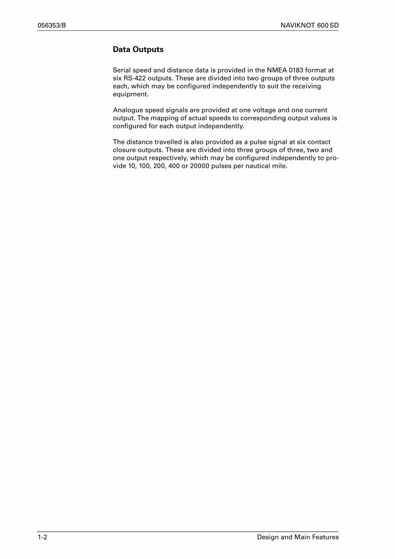
Data Outputs
Serial speed and distance data is provided in the NMEA 0183 format at six RS-422 outputs. These are divided into two groups of three outputs each, which may be configured independently to suit the receiving equipment.
Analogue speed signals are provided at one voltage and one current output. The mapping of actual speeds to corresponding output values is configured for each output independently.
The distance travelled is also provided as a pulse signal at six contact closure outputs. These are divided into three groups of three, two and one output respectively, which may be configured independently to pro-vide 10, 100, 200, 400 or 20000 pulses per nautical mile.
1-2 Design and Main Features

NAVIKNOT 600 SD 056353/B
1.2 Operating Principle
To determine the longitudinal and transverse ground speeds, the sys-tem makes use of a self-contained satellite sensing system, consisting of the satellite PCB with two GPS receivers inside the electronics unit and the antenna unit connected to it.The satellite PCB combines the data from the GPS receivers with data from built-in rate gyros to determine the vessel’s heading, velocity, course, and attitude. While the heading is referenced to the vessel’s fore-and-aft line, the velocity and course represent the vessel’s motion vector, i.e. the magnitude and direction of its motion over ground.
The sensed data are sent to the processing PCB inside the electronics unit, which resolves the velocity data into the vessel-referenced longitu-dinal and transverse ground speeds.
The speed vectors combined with the sensed rate of turn data are used to discern between translational and rotational movements of the ves-sel. These are used to determine the bow and stern transverse speeds shown on the “docking display” page.
To determine the longitudinal water speed, the system utilizes the princi-ple of Doppler-shifted sound waves.The transducer contains two transmitter/receiver windows, which trans-mit and receive signals in the forward and aft directions respectively. The sensing signals are high frequency sound pulses, generated by the preamplifier D, which also detects the return echo from the water in-between transmissions. The preamplifier processes the return signals and transmits the sensed speed in a digital format to the NAVIKNOT electronics unit.
Figure 1-2:
sensed and calculatedspeeds and directions
The electronics unit transmits all speed data to receiving external equip-ment and to the connected CDUs. From the longitudinal ground and water speeds, the electronics unit also calculates the distances travelled and maintains the total and daily mile counters for both the ground and water distances.
vessel's motion vectorover ground (course andvelocity; sensed)
longitudinal ground speed(calculated)
longitudinal water speed(sensed)
heading (sensed)
transverse ground speed(calculated)
Operating Principle 1-3

056353/B NAVIKNOT 600 SD
1.3 Technical Data
General
Ground Speed Range, Accuracies and Operating Parameters, Satellite
Sensing System
measuring range –99 to +99 kn longitudinal–99 to +99 kn transverse
accuracy of ground velocity 0.2 kn or 2% of true velocity
settling time, heading acquisition 4 min. coast time
Water Speed Range and Accuracy, Doppler Transducer
measuring range –50 to +50 kn
1 σ error of displayed speed for a period of five minutes (under good hydrostatic conditions, pitch angles < 5°)
±1% or 0.1 kn
1-4 Technical Data

NAVIKNOT 600 SD 056353/B
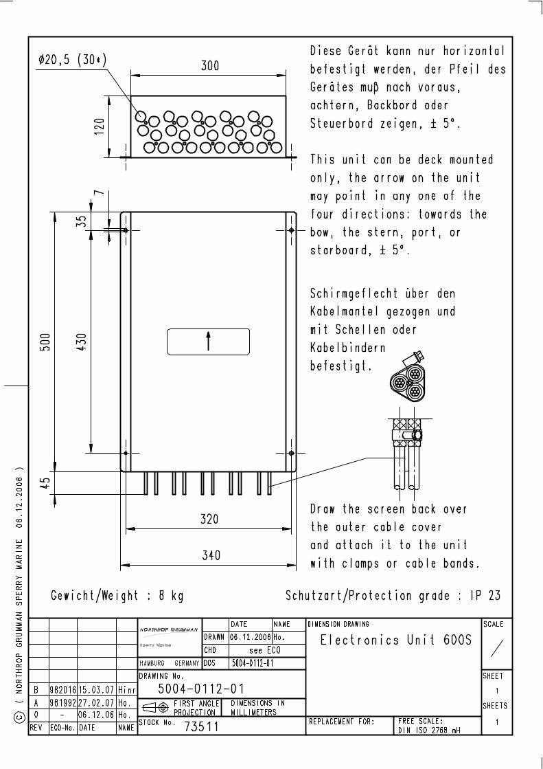
NAVIKNOT Electronics Unit, Type 5004
Environmental Requirements
ambient temperature, operation -15°C – +55°C
ambient temperature, storage -15°C – +55°C
protection grade IP 23 to DIN EN 60529
environmental conditions / EMC in accordance with IEC 60945
Power supply
supply voltage 24 VDC (18-36 V)
max. ripple content ±4 Vpp; extreme values may not exceed 36 V or fall below 18 V
power consumption 16 W max.
Magnetic Clearance
to standard magnetic compass 0.5 m
to steering magnetic compass 0.4 m
reduced, to standard magnetic compass 0.3 m
reduced, to steering magnetic compass 0.3 m
Dimensions and Weight
width 340 mm
height 120 mm
depth 545 mm
unit can be deck mounted only;sides of housing must be parallel or perpendicular to vessel’s cen-terline to within ±5°
weight 8.0 kg
Technical Data 1-5

056353/B NAVIKNOT 600 SD
Data Inputs
sensing and status from satellite PCB NMEA 0183 (proprietary sentences)
Doppler transducer speed data Sperry SRD 331 protocol
external data (supplementary, not required for basic system functionality)
NMEA 0183 / IEC 61162;true heading, rate of turn
control data from CDUs NMEA 0183 / IEC 61162(proprietary sentences)
serial dimming command NMEA 0183
Signal and Status Inputs
double ended ferry mode connection to P.Gnd via ext. contact, latching
ext. alarm acknowledge status (mute) connection to P.Gnd via ext. contact,momentary, normally open
ext. dim+ext. dim-
connection to P.Gnd via ext. contact, momentary, normally open
Data Outputs
serial data RS-422 outputs,group 1 (3x)
NMEA 0183 / IEC 61162;all or selected subset of:longitudinal and transverse ground speedslongitudinal water speeddistances travelledlog status (proprietary sentence)EMRI DIB10 docking display data (proprietary sentence)
serial data RS-422 outputs,group 2 (3x)
NMEA 0183 / IEC 61162;all or selected subset of:longitudinal and transverse ground speedslongitudinal water speeddistances travelledlog status (proprietary sentence)EMRI DIB10 docking display data (proprietary sentence)
control data to satellite PCB NMEA 0183, 8N1, 38400;configuration/status/alarms (pro-prietary sentences)
display data to CDUs NMEA 0183, 8N1, 38400;speeds/velocitydistances travelledheadingrate of turnstatus/alarms (proprietary sen-tences)
1-6 Technical Data

NAVIKNOT 600 SD 056353/B
Signal and Status Outputs
analogue speed output, voltage max. range -9.999 – 9.999 VDC;speed mapped to output voltage through definition of min. and-max. speed/voltage pairs
analogue speed output, current max. range 0 – 20 mA;speed mapped to output current through definition of min. and-max. speed/current pairs
pulse outputs, group 1(outputs 1,2 and 3)
10, 100, 200, 400 or 20000 p/nm
pulse outputs, group 2 outputs 4 and 5)
10, 100, 200, 400 or 20000 p/nm
pulse output 6 10, 100, 200, 400 or 20000 p/nmor ext. alarm mute
power failure/general alarmspeed log failure alarmspeed limit threshold alarmwatch alarm acknowledge
potential-free relay contacts,each rated30 VDC/1.0 A,100 VDC/0.3 A,125 VAC/0.5 A;
Technical Data 1-7

056353/B NAVIKNOT 600 SD
Satellite Antenna Unit
Preamplifier D, Type 5005
Dimensions and Weight
width 98 mm
height 144 mm
depth 776 mm
beam supporting the antennas must be aligned parallel or per-pendicular to vessel’s centerline to within ±9°
weight 1.9 kg approx.
Environmental Requirements
ambient temperature, operation –15 to +55 °C
ambient temperature, storage –25 to +70 °C
protection grade IP 65 to DIN EN 60529
environmental conditions / EMC in accordance with IEC 60945
Power Supply
supply voltage 24 VDC (18 - 36 V)
max. ripple content ±4 Vpp; extreme values may not exceed 36 V or fall below 18 V
power consumption 16 W max.
Dimensions and Weight
width 239 mm
height 285 mm
depth 83 mm
weight 3.0 kg
1-8 Technical Data

NAVIKNOT 600 SD 056353/B
Doppler Transducers
Common Operational Data
speed range -50 to +50 kn
radiated power (electrical) 10 W max.
signal mode pulse
frequency 2 MHz
number of beams 2
beam width 1.5°
beam angle 15° from vertical
minimum required bottom clear-ance
1.8 m
Transducer with Gate Valve
transducer for steel or aluminium vessels, single bottom
installation method from inside vessel, through hull fittings
ambient temperature, operation –2 to +40 °C
protection grade IP 68 to DIN EN 60529;submersible to 35 m
cable length 18 m (PN 60232) or36 m (PN 60296)
dimensions and weight see drawing 4983-0112-01
Tank Mount Transducer
transducer for steel vessels, single or double bottom
installation method from outside vessel; sensor can be exchanged without drydocking by a diver
ambient temperature, operation –2 to +40 °C
protection grade IP 68 to DIN EN 60529;submersible to 35 m
cable length 18 m (PN 73494) or36 m (PN 73496)
dimensions and weight see drawing 4978-0112-01
Technical Data 1-9

056353/B NAVIKNOT 600 SD
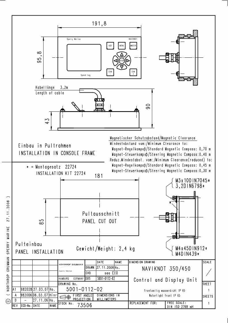
Control and Display Unit (CDU)
Environmental Requirements
ambient temperature, operation -15°C – +55°C
ambient temperature, storage -25°C – +70°C
protection grade, main CDU and 3x1 remote unit
IP 23 to DIN EN 60529
protection grade, 2x1 remote unit PN 73506: frontside IP 65 to DIN EN 60529, if installed with seal in console panel; IP 23 if installed in console framePN 73507 (in housing with bracket): IP 65 to DIN EN 60529
environmental conditions / EMC in accordance with IEC 60945
Power supply
supply voltage 24 VDC (18-36 V)
max. ripple content ±4 Vpp; extreme values may not exceed 36 V or fall below 18 V
power consumption 14 W max. (3x1 unit)4 W max. (2x1 unit)
Magnetic Clearance
to standard magnetic compass 0.70 m (3x1 unit)0.80 m (2x1 unit)
to steering magnetic compass 0.40 m (3x1 unit)0.50 m (2x1 unit)
reduced, to standard magnetic compass 0.45 m (3x1 unit)0.50 m (2x1 unit)
reduced, to steering magnetic compass 0.30 m (3x1 unit)0.30 m (2x1 unit)
1-10 Technical Data

NAVIKNOT 600 SD 056353/B
Dimensions and Weight, Main CDU and 3x1 remote unit
PN 73508 (for console mounting)
width 192 mm
height 96 mm
depth 43 mm; approx. 120 mm backward clearance from mounting surface required for connector cable and plug
weight 2.4 kg
PN 79489 (PN 73508 factory-assembled in console frame)
frame width 319 mm
frame height 127 mm
PN 73509 (in housing with bracket)
width 350 mm
max. height (unit in vertical position)
150 mm
max. depth (unit in horizon-tal position)
130 mm
weight 3.2 kg
Technical Data 1-11

056353/B NAVIKNOT 600 SD
Dimensions and Weight, 2x1 remote unit
PN 73506 (for console mounting)
width 192 mm
height 96 mm
depth 44 mm; approx. 100 mm backward clearance from mounting surface required for connector cable and plug
weight 2.4 kg
PN 79488 (PN 73506 factory-assembled in console frame)
frame width 223 mm
frame height 127 mm
PN 73507 (in housing with bracket)
width 256 mm
max. height (unit in vertical position)
155 mm
max. depth (unit in horizontal position)
116 mm
weight 3.2 kg
1-12 Technical Data

NAVIKNOT 600 SD 056353/B
Chapter 2: Operation
2.1 Display and Operating Keys
Figure 2-1:
NAVIKNOT 600 SDoperating unit
➀ Main Display: shows one of five selectable pages, indicating– Ground speeds, longitudinal and transverse– Water speed, longitudinal– “Docking” display (longitudinal and bow and stern trans-
verse ground speeds)– Satellite status page– Alarm page
➁ Sidebar: Shows additional information, indicating
• Operating mode (Master or Repeater).
• ➂ GPS signal and alarm status– GPS signal status (good/fair/poor)– In case of pending alarms, acknowledge status and error
code(s) are displayed, alternating with GPS signal status.
• ➃ Supplementary Data, depending on active main display page– on ground speed page: total and daily mile counters– on docking display page: heading, course over ground and
rate of turn– on satellite status page: GPS HDOP/VDOP, date and time– on alarm page: date and time
➄ ACK key. Acknowledges pending alarms; mute alarm buzzer.
➅ MENU key. Calls up or quits the menu mode.
➆ MASTER key. Requests Master operating mode for this unit.
➇ Navigation Keypad:
In normal operational mode,UP, DOWN keys scroll through main display pages.LEFT, RIGHT keys scroll through list of active alarms.In menu mode,UP, DOWN, LEFT, RIGHT keys navigate through the operating menu;ENTER confirms and stores settings made in the menu mode.
➈➉ DIM– / DIM+. Adjust the display brightness.
MASTER600 SD
N.MILESDAILY
TOTALkn
1234.56
123456.7
12 8. 0
0.12
GPS QUAL.GOOD
1 2 5 6 73
4 109 8
Display and Operating Keys 2-1

056353/B NAVIKNOT 600 SD
2.2 External control devices
Depending on the installation, external devices may be present to remotely control certain functions of the NAVIKNOT 600 SD:
• The audible alarm at the NAVIKNOT 600 SD the may be muted from a remote device, e.g. a central alarm panel.
• External pushbuttons may be used to adjust the display brightness.
• If connected to a central dimming system, the NAVIKNOT 600 SD may receive dimming commands via a serial data connection.
• An external selector switch may be used to activate or de-activate the double-ended ferry mode. In this mode, the NAVIKNOT 600 SD displays and transmits all speeds with the sign reversed.
2.3 Power-up Sequence
The individual components of the NAVIKNOT system are not equipped with power switches. All devices power up simultaneously, as soon as supply power is applied to the system.
Upon power up, the startup routine is executed:
The startup screen is shown and a system test sequence is executed.
A status line at the bottom of the screen indicates the progress and results of the following tests:RAM testI/O testChecksum testSetup Data test
After the system test, the indication “waiting for main unit” may be briefly shown at the CDU, while the Electronics Unit initializes itself.
As soon as the system is fully oper-ational, the actual speed over ground and the daily and total mile counters are displayed.
NAVIKNOT
System TestNN.NN
MASTER600 SD
N.MILESDAILY
TOTALkn
1234.56
123456.7
12 8. 0
0.12
GPS QUAL.GOOD
Note Should the NAVIKNOT electronics fail to establish communication with the CDU(s) after power-up, the indication “waiting for main unit” will be shown permanently at all connected CDUs. An audible alarm is sounded which must be locally acknowledged at each CDU.The NAVIKNOT system will not operate properly until the cause of failure is eliminated and should be powered down until it can be serviced.
2-2 External control devices
NAVIKNOT 600 SD 056353/B
2.4 Display Indications in Normal Operational Mode
Main Display Pages
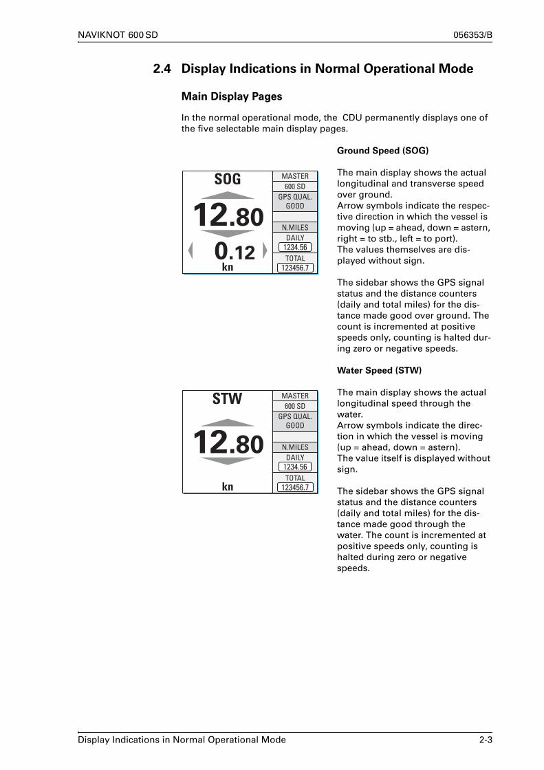
In the normal operational mode, the CDU permanently displays one of the five selectable main display pages.
Ground Speed (SOG)
The main display shows the actual longitudinal and transverse speed over ground.Arrow symbols indicate the respec-tive direction in which the vessel is moving (up = ahead, down = astern, right = to stb., left = to port).The values themselves are dis-played without sign.
The sidebar shows the GPS signal status and the distance counters (daily and total miles) for the dis-tance made good over ground. The count is incremented at positive speeds only, counting is halted dur-ing zero or negative speeds.
Water Speed (STW)
The main display shows the actual longitudinal speed through the water.Arrow symbols indicate the direc-tion in which the vessel is moving (up = ahead, down = astern).The value itself is displayed without sign.
The sidebar shows the GPS signal status and the distance counters (daily and total miles) for the dis-tance made good through the water. The count is incremented at positive speeds only, counting is halted during zero or negative speeds.
MASTER600 SD
N.MILESDAILY
TOTALkn
1234.56
123456.7
12 8. 0
0.12
GPS QUAL.GOOD
MASTER600 SD
N.MILESDAILY
TOTAL1234.56
123456.7kn
12 8. 0
GPS QUAL.GOOD
Display Indications in Normal Operational Mode 2-3

056353/B NAVIKNOT 600 SD
Docking Display
The main display shows a graphical representation of the vessel, indi-cating the actual longitudinal speed over ground as well as the trans-verse ground speeds at the bow and at the stern.Arrow symbols indicate the direc-tion in which the vessel is moving (up = ahead, down = astern, right = to stb., left = to port).The values themselves are dis-played without sign.
The sidebar shows the GPS signal status and the data used to calcu-late the speeds displayed, i.e. the vessel’s heading (ROT), the direc-tion of the motion vector (course over ground, COG) and the rate of turn (ROT).
Satellite Status
The main display shows the actual GPS position as received from the satellite PCB.A tabular overview is given of the satellites in view as well as the respective satellite’s signal-to-noise ratio, azimuth and elevation
The sidebar shows the GPS signal status, the current VDOP and HDOP figures and the date and time as received from the satellite PCB.
Alarm Page
The alarm page list the alarm mes-sages and acknowledge status of all active alarms.
The sidebar shows the date and time as received from the satellite PCB.
MASTER600 SD
COG
ROT °/min124.56
m/s
HDG123.45
2.4
GPS QUAL.GOOD
MASTER600 SD
GPS POSITION
N 5 4 °1 1 . 8 9 0 '
NO SAT SNR AZ EL
06 19 16 52 41
01 07 04 47 3102 11 16 43 2703 03 12 49 3304 22 09 41 3905 08 11 57 38
0W 0 7 °4 8 . 2 7 0 '
08 09 10 11 12
07
UTC-TIME
23.01.2008DATE
GPS QUAL.GOOD
12:34:56
GPS DOPV:1.6 H:1.1
MASTER600 SD
< (1/2) >ALARM NO: 30GPS TIMEOUT
ACTIVENOT ACKNOWLEDGED
UTC-TIME
23.01.2008DATE
GPS QUAL.GOOD
12:34:56
2-4 Display Indications in Normal Operational Mode

NAVIKNOT 600 SD 056353/B
Operating Status Indications
Master/Remote status
The indication “MASTER” is shown in the top right corner of the CDU which is currently assigned the operating master status. Other CDUs, if present, will show the indi-cation “REMOTE”
Manual speed input active
When the manual input mode has been activated in the manual set-tings menu, the indication “MAN” is shown in the top left corner of the speed display.
Water speed not calibrated
When the sensor calibration table is empty or calibration has been switched off, the indication “UNCAL” is shown in the bottom left corner of the speed display.
MASTER
REMOTE
MASTER
UNCAL kn 123456.7
Display Indications in Normal Operational Mode 2-5

056353/B NAVIKNOT 600 SD
2.5 Requesting Master Control
2.6 Adjusting the display brightness
In cases where more than one CDU is installed, only one of these is assigned master control while all others will operate as remote units.
Only from the master, the operator can access the operating and service menus, acknowledge alarms and scroll through the alarm list.
Remote CDUs permanently display speed and distance. The only keys functional at a remote CDU are the DIM-/DIM+ keys to adjust the bright-ness level, the UP and DOWN keys to scroll through the main display pages and the MASTER key, which requests master control to be trans-ferred to this CDU.
To request master control at a remote CDU:
Press the MASTER key.Master control is transferred and the mode indication changes from “REMOTE” to “MASTER”.
MASTER
REMOTE
Note Master control can only be requested from a CDU which is currently operating as remote unit.The current master cannot actively transfer control to a remote CDU.Any remote CDU may request master control at any time, i.e. control requests cannot be refused by the current master.
The brightness of the display and keypad illumination is adjusted via the DIM+/DIM- keys:
Press the DIM+ key to increase the illumination brightness.Press the DIM- key to reduce the illumination brightness.
MASTER600 SD
N.MILESDAILY
12 8. 0GPS QUAL.
GOOD
N.MILESDAILY
TOTALkn
1234.56
123456.7
12 8. 0
0.12
GOOD
Note The display brightness can only be adjusted in normal operational mode.The brightness setting is not retained between power-ups. The NAVIKNOT 600 SD always powers up at the second brightest level.
2-6 Requesting Master Control

NAVIKNOT 600 SD 056353/B
2.7 Optional Functions
The following functions may be available if the system is equipped with the respective external controls and configured accordingly.
Muting Alarms Remotely
On alarm, actuate the mute control at a remote device (e.g. a central alarm panel). The audible alarm is muted.
Resetting/Acknowledging a Central Watch Alarm
If connected to a central watch alarm facility ('dead man alarm'), the NAVIKNOT 600 SD will automatically reset the watch alarm timer when-ever a key is pressed on the unit.
Should a watch alarm be given, press any key at the NAVIKNOT 600 SD to acknowledge the alarm and reset the watch alarm timer.
External Dimming
If external DIM+/DIM- pushbuttons are installed, these operate in parallel with the builtin DIM+/DIM- keys.
For future applications, the NAVIKNOT 600 SD also possesses an input for serial data dimming commands from a central dimming facility.
Activating Double-Ended Ferry Mode
In certain installations, a switch may be installed to activate or de-acti-vate the double-ended ferry mode. If this mode is active, all speeds are displayed and transmitted with their sign reversed.
Note A remotely muted alarm remains in the pending (unacknowledged) state. The alarm is indicated as pending in the sidebar until the alarm is acknowledged at the NAVIKNOT 600 SD or the cause of the alarm is elim-inated.
Note In most installations where the double-ended ferry mode is used, it will be automatically activated via a general take-over system which transfers control between the forward and aft steering positions.
Optional Functions 2-7

056353/B NAVIKNOT 600 SD
2.8 Operating Menu
The manual settings, user and service setup sub-menus are accessed through a multilevel operating menu.
Entering and Quitting the Menu Mode
From the normal operational mode, press MENU to enter the menu mode.
The Main Menu screen is displayed.The keys of the navigation keypad may now be used to navigate the menu, to select parameter settings and to edit parameter values.
From the main menu screen, press MENU to return to the normal operational mode.
The Main Menu screen is closed and the normal oper-ational display reappears.
10°
MASTER600 SD
N.MILES12 8. 0GPS QUAL.
GOODMAIN MENU
MANUAL SETTINGSUSER SETUP SERVICE SETUP
>> >>
MAIN MENU
MANUAL SETTINGSUSER SETUP SERVICE SETUP
>> >> MASTER600 SD
N.MILES12 8. 0GPS QUAL.
GOOD
Note In the menu mode, the MASTER and the DIM-/DIM+ keys are disabled.Should an alarm condition occur while the menu mode is active, the audible alarm will sound, but the operator must return to normal opera-tional mode to view the alarm message and acknowledge the alarm.
2-8 Operating Menu

NAVIKNOT 600 SD 056353/B
Navigating the Menu
In the menu mode, the operator may navigate through the menu using the Right, Left, Up and Down arrow keys.
Arrow symbols (>) to the right of the window indicate that a sub-menu exists for the respective option.
Press ENTER to enter a sub-menu.
The arrow symbol (>) at the left of the window indicates the cursor position on the current menu level.
With the Up/Down arrow keys, move to the cursor to the required sub-menu posi-tion.
Press the Left arrow key to return to the next higher menu level.
Alternatively, MENU may be pressed to jump as high up as possible from the current level. In most cases, this will quit the menu immediately and return to normal opera-tional mode.
MAIN MENU
XXXXXXXX
XXXXXXXX
YYYYYYYY
YYYYYYYYXXXXXXXX
ZZZZZZZZ
MAIN MENU
XXXXXXXX
XXXXXXXXMAIN MENU
YYYYYYYYZZZZZZZZ
XXXXXXXXMAIN MENU
YYYYYYYY
XXXXXXXXMAIN MENU
YYYYYYYYZZZZZZZZ
XXXXXXXXMAIN MENU
YYYYYYYY
AAAAAAAABBBBBBBBCCCCCCCC
CCCCCCCCBBBBBBBBAAAAAAAA
CCCCCCCCBBBBBBBBAAAAAAAA
XXXXXXXXMAIN MENU
MAIN MENU
XXXXXXXX
XXXXXXXXMAIN MENU
YYYYYYYYZZZZZZZZ
XXXXXXXXMAIN MENU
YYYYYYYY
Operating Menu 2-9

056353/B NAVIKNOT 600 SD
Selecting Parameter Settings
In a number of sub-menus, the operator is expected to select parameter settings from a list of available options.
The available options and the current selection are indicated by different symbols:
Radio buttons: Allow to select exactly one of the available options.
: selected : deselected
Checkboxes: Allow to select or activate none, one or more of the available options.
: selected : deselected
Editing Parameter Values
In a number of sub-menus, parameters are set by editing a numerical value or an alphanumerical string.
To select parameter settings in a sub-menu:
With the Up/Down arrow keys, move to the required option.
Press ENTER to confirm and store the selection.
MENU leaves the option sub-menu without changes.
To edit a parameter value in the respective sub-menu:
With the Up/Down arrow keys, edit the character at the current cursor position.
With the Right/Left arrow keys, move the cursor for-ward/back to edit the next/previous character.
Press ENTER to confirm and store the new value.
MENU leaves the option sub-menu without changes.
OPTIONS
OPTION BOPTION A
OPTION C
OPTIONS
OPTION BOPTION A
OPTION C
OPTION BOPTION A
OPTION C
00000
10000
10000
VALUE:
VALUE
VALUE
2-10 Operating Menu

NAVIKNOT 600 SD 056353/B
2.9 Manual Settings Menu
The Manual Settings menu provides access to settings which the opera-tor may need to alter more or less frequently during normal operation.
Manual Settings – Overview
Figure 2-2:
Manual SettingsMAIN MENU
MANUAL SETTINGS
SPEED MODE STW>> >>
SPEED MODE STW water speed input mode
SPEED MODE SOG>> >>
SPEED MODE SOG ground speed input mode
MAN
SENSOR
MAN SPEED VALUE>> >>
MAN SPEED VALUE manual input value
speed: -99 – +99 kn
MAN
SENSOR
Manual Settings Menu 2-11

056353/B NAVIKNOT 600 SD
Manual Settings – Parameters
Speed Mode STW
Selects the input mode for water speed data.
Settings: MAN
The actual speed value is entered manually.This setting may be activated only temporarily, to generate water speed output data in case of failure of the Doppler transducer or for testing.
SENSOR
Speed data is read from the preamplifier D.This setting must be active at all times during normal opera-tion of the system.
Speed Mode SOG
Selects the input mode for ground speed data.
Settings: MAN
The actual speed value is entered manually.This setting may be activated only temporarily, to generate speed output data in case of failure of the satellite PCB or for testing. Using manual input, only longitudinal ground speed data is generated; transverse speeds are set to zero.
SENSOR
Speed data is read from the satellite PCB input.This setting must be active at all times during normal opera-tion of the system.
Man. Speed Value
Sets the input value in the manual input mode.
Value: -99.9 – 99.9 kn
2-12 Manual Settings Menu

NAVIKNOT 600 SD 056353/B
2.10 User Setup
The User Setup menu provides access to settings which the operator may need to alter only occasionally.
User Setup – Overview
Figure 2-3:
User SetupMAIN MENU
USER SETUP
DAMP. TIME DISPLAY>> >>
DAMP. TIME DISPLAY damping time constantfor speed display
damping time: 0 – 60 s
DAMP. TIME OUTPUT>> >>
DAMP. TIME OUTPUT damping time constantfor speed outputs
damping time: 0 – 60 s
water start value: 0.0 – 999999.9 NM
reset counters to zero whenuser setup is quit
WHITE
BLUE
BLACK
RESET DAILY MILES>> >>
RESET DAILY MILES daily miles counterreset
TOTAL MILES COUNTER>> >>
TOTAL MILES COUNTER
ground start value: 0.0 – 999999.9 NM
total miles counterstart values
LCD COLOR>> >>
LCD COLOR screen colour scheme
DAMP. TIME DOCKING>> >>
DAMP. TIME DOCKING damping time constantfor docking display
damping time: 0 – 60 s
contd. on next page
User Setup 2-13

056353/B NAVIKNOT 600 SD
Figure 2-4:
User Setup(cont.d)
SCALE >>
SCALE
SPEED SCALE
KN
M/S
FT/S
DOCKING SPEED SCALE
KN
M/S
FT/S
speed display units
contd. fromprevious page
SOFTWARE VERSION NN.NN
version ID (read-only)
>>
SOFTWARE VERSION NAVIKNOT El. Unitsoftware version
2-14 User Setup
NAVIKNOT 600 SD 056353/B
User Setup – Parameters
Damp. Time Display
Sets the damping time constant for the ground speed display.
The higher the time constant, the stronger sudden peaks of the actual speed will be damped in the ground speed display page.
Value: 0 – 60 s
Damp. Time Output
Sets the damping time constant for the speed outputs.
The higher the time constant, the stronger sudden peaks of the actual speed output will be damped. The output damping time constant is effective for both the analogue as well as the serial data outputs.
Value: 0 – 60 s
Damp. Time Docking
Sets the damping time constant for the docking display.
The higher the time constant, the stronger sudden peaks of the actual speed will be damped in the docking display page.
Value: 0 – 60 s
Reset Daily Miles
Sets the reset flag for the daily miles counter.
If the reset flag is set, the daily miles counter reset to zero as soon as the User Setup is quit.
Settings: ON (option checked)Reset daily miles counter when User Setup is quit
OFF (option unchecked)Leave daily miles counter untouched
User Setup 2-15

056353/B NAVIKNOT 600 SD
Total Miles Counter
Sets the total miles counters to desired start values.
Values: Water start value 0.0 – 999999.9 NM
Ground start value 0.0 – 999999.9 NM
Note The total miles counters may be set to any desired start value.A daily mile count may thus be larger than the corresponding total mile count if the daily counter is not reset after altering the total mile counter.
LCD Color
Selects the screen colour scheme for the normal operational display.
Settings: WHITE
Speed display and mile counters use black lettering on a white background.
BLUE
Speed display and mile counters use white lettering on a blue background.
BLACK
Speed display and mile counters use white lettering on a black background.
Scale
Selects the unit of measure for the speed displays.
The respective settings act on the actual speed displays at the CDU only and have no further effect on the output data, mile counters etc.
Speed Scale
Unit of measure for the ground speed display page
Settings: KN
Speed is displayed in knots.
M/S
Speed is displayed in metres per second.
FT/S
Speed is displayed in feet per second.
2-16 User Setup

NAVIKNOT 600 SD 056353/B
Docking Speed Scale
Unit of measure for the docking display page
Settings: KN
Speed is displayed in knots.
M/S
Speed is displayed in metres per second.
FT/S
Speed is displayed in feet per second.
Software Version
Displays the software version of the NAVIKNOT Electronics Unit.
Settings: none
The version ID is read-only.
User Setup 2-17

056353/B NAVIKNOT 600 SD
2-18 User Setup

NAVIKNOT 600 SD 056353/B
Chapter 3: Alarm System
3.1 Alarm Indication
Audible Alarm Indication
Single Beep: Invalid Action
Continuous Beeping: Pending Alarm
Visual Alarm Indication
A single short beep indicates that the operator attempted to carry out an invalid action.This is the case e.g. if the operator attempts to enter the menu mode from a remote unit.
Continuous on-off beeping indicates that a pending (unac-knowledged) alarm is present.Simultaneously, the corresponding error code is shown in the sidebar.
If an alarm is active and any other than the alarm page is currently selected as main display, an error code is shown in the sidebar which specifies the alarm at hand.
Active alarms have one of two possible states:
Pending (unacknowledged):The cause of the alarm is present and the operator has not yet acknowledged the alarm.The alarm display area background colour flashes red-white.
Acknowledged:The operator has acknowledged the alarm but the cause of the alarm is still present.The alarm display area background colour is solid red.
< (1/1) >ERROR: 030
< (1/1) >ERROR: 030
Alarm Indication 3-1

056353/B NAVIKNOT 600 SD
3.2 Acknowledging Alarms/Muting the Audible Alarm
Local Alarm Acknowledge
External Alarm Mute
To acknowledge a pending alarm at the NAVIKNOT 600 SD CDU:
Press ACK.
The audible alarm indication is muted.
If the system is connected to a cen-tral alarm facility and configured accordingly, the audible alarm indi-cation at the central alarm facility will also be muted.
< (1/1) >ERROR: 030
< (1/1) >ERROR: 030
Note When an alarm has been acknowledged, the ext. alarm status output remains active until the cause of the alarm is eliminated.When the cause of an alarm is eliminated, the alarm is acknowledged automatically and the alarm status is cleared.The NAVIKNOT 600 SD does not keep a history of past (inactive) alarms.
To mute the audible alarm externally (e.g. from a central alarm panel):
Actuate the external mute facility.
The audible alarm indication is muted.
The alarm state and visible indica-tion are not affected, i.e. the alarm remains in the pending state until it is locally acknowledged at the NAVIKNOT 600 SD CDU.
ext. alarm mute
< (1/1) >ERROR: 030
< (1/1) >ERROR: 030
3-2 Acknowledging Alarms/Muting the Audible

NAVIKNOT 600 SD 056353/B
3.3 Viewing the active alarms
In all main display pages except the alarm page, the total number of active alarms and the error code of the newest alarm are shown in the sidebar.
If more than one alarm is active, the Left or Right arrow keys will scroll through the respective error codes.
To view the detailed error message for the currently active alarms, select the alarm page for the main display.
The active alarms’ error codes and corresponding error message texts are displayed as well as the acknowledge status.
The Left or Right arrow keys scroll through the list of active alarms:
< (1/2) >ALARM NO: 30GPS TIMEOUT
ACTIVENOT ACKNOWLEDGED
< (2/2) >ALARM NO: 70
EXT IF. FAIL
ACTIVENOT ACKNOWLEDGED
Note As long as any pending (unacknowledged) alarms are present, these will automatically be redisplayed when other messages have been viewed, until all alarms have been acknowledged by the operator.
Viewing the active alarms 3-3

056353/B NAVIKNOT 600 SD
3.4 Error Messages
Table 3-1:
error messagescode message text cause corrective action
WAITING FOR MAIN UNIT(shown on startup screen)
Communcation between electron-ics unit and CDU(s) could not be estab-lished
Check operation of the electronics unit; Check cabling between CDU and electronics unit.If error persists, power down the system and call service.
001 LOSS OF GPS GPS receivers track less than five com-mon satellites (errors 002 and 003 arise as GPS is the only hdg. source available for the satellite PCB)
Check that both antennas have a clear view of the sky; check cabling between antennas and satellite PCB
002 SEL SRC INVALID
003 NO VALID SRC
030 GPS TIMEOUT Communication lost between satel-lite and processing PCBs
Check internal cabling between satellite and processing PCBs;check that satellite PCB is operating (power is on and internal 100 Hz clock is generated).
050 SRD TIMEOUT Transducer proto-col detection failed
Check that the preamplifier is operating;check that protocol is set to NMEA;check cabling between preampli-fier and NAVIKNOT electronics unit; check cabling between transducer and preamplifier;check transducer for proper opera-tion.
PREAMP D.TIMEOUT
Data lost from preamplifier D (pro-tocol detection suc-ceeded and valid data was received previously)
051 SCAN SRD SENSOR Transducer proto-col detection run-ning (NAVIKNOT electronics unit analyzes incoming data)
Error is cleared once transducer protocol has been determined. If error persists, check preamplifier D for proper operation.
3-4 Error Messages

NAVIKNOT 600 SD 056353/B
070 EXT IF. FAIL No valid data received at exter-nal input
Check that external source produces valid data; check cabling between external source and electronics unit.
071 EXT HDT TIMEOUT No valid external heading data received
Check that external source produces the required data and that it is not marked invalid.
072 EXT ROT TIMEOUT No valid external rate of turn data received
080 EXT DIM TIMEOUT No valid com-mands received at serial dim input.
Check connection between dimming device and elec-tronics unit.
096 EU TIMEOUT Communication lost between elec-tronics unit and CDU
Check basic opera-tion of the electron-ics unit (valid output generated at serial data / ana-logue outputs); check cabling between CDU and electronics unit.
code message text cause corrective action
Note In case of an “EU timeout” error, dashes will appear in the speed and dis-tance displays. The timeout will be shown as the only fault present, as the CDU receives no messages from the electronics unit when communica-tion is lost.
Error Messages 3-5

056353/B NAVIKNOT 600 SD
3-6 Error Messages
NAVIKNOT 600 SD 056353/B
Chapter 4: Scheduled Maintenance
4.1 Maintenance by Shipboard Personnel
NAVIKNOT Electronics Unit, CDU and Antenna Unit
The electronic components of the NAVIKNOT 600 SD system are solid-state devices and contain no consumable parts. Therefore, no set main-tenance schedule is required.
The satellite antenna unit should regularly be checked visually to detect any signs of mechanical damage or wear and to make sure it is still aligned correctly to the vessel’s fore and aft axis.
The CDU front plate should be kept clean and the system’s cables and connectors should regularly be checked visually to detect any signs of damage or deterioration.
Doppler Transducer and Preamplifier D
Depending on the type of transducer installed, certain maintenance pro-cedures are to be carried out at regular intervals, such as cleaning of the transducer face and lubrication/overhaul of the sea valve, if applicable.
The recommended maintenance schedule and procedures are described in the installation, maintenance and service instructions for the Doppler transducers and preamplifier D, document no. 005005-0125-001.
CAUTION The CDU front plate is made of clear polycarbonate.Do not clean the front plate with organic solvents, acetone or any other substance which could damage or discolor plastic.Use only water and soap or a mild detergent to clean the front plate.
Maintenance by Shipboard Personnel 4-1

056353/B NAVIKNOT 600 SD
4-2 Maintenance by Shipboard Personnel

NAVIKNOT 600 SD 056353/B
Chapter 5: Installation
5.1 Mechanical Installation
Antenna Unit
The antenna unit consists of a bow and stern GPS antenna mounted on a beam-shaped support. The arrow on the support must point either ahead or to the port side. The chosen orientation must be entered in the GPS setup menu during system configuration. Possible misalignment of up to ±9.9° may be electronically compensated for in the setup menu.
Figure 5-1:
antenna unitalignment
The location of the antenna must provide an unobstructed view of the sky. It should be clear of reflections from masts, out of the path of the radar beam, and out of the range of any object that may shadow or interfere with the reception of GPS signals.
The antenna support may be mounted directly onto the mounting sur-face or on a pedestal. The required mounting material is contained in the installation kit 4302244, included with the antenna.
Figure 5-2:
mounting material frominstallation kit 4302244
When installing the antenna unit, the cable assembly must be connected to the cables from the bow and stern antenna. After connecting the cables, secure them to the support with the wire clips and seal the cable connections with the self-fusing tape provided.
forward port
self fusing tape
wire clip
hex head screwlock washerjam nutflat washer
CAUTION Do not shorten or lengthen the antenna cables. The antennas’ output gain is matched to the cable length of 15 or 50 m respectively.Antenna unit 73513 may only be used with the 15 m cables supplied.Antenna unit 73514 may only be used with the 50 m cables supplied.
Mechanical Installation 5-1

056353/B NAVIKNOT 600 SD
Doppler Transducer and Preamplifier D
Details of the installation of the Doppler transducer and preamplifier D, type 5005, are contained in the installation, maintenance and service instructions for the Doppler transducers and preamplifier D, document no. 005005-0125-001, and in the dimension/installation drawing for the respective transducer.
In general, field service will attend a vessel after the transducer hard-ware has been installed mechanically by the shipyard. I.e., in case of the gate valve transducer, the gate valve will be installed and in case of the tank mount transducer, the cofferdam tank and transducer will be installed completely. In most cases, the vessel will be afloat at this point in time.The preamplifier D, type 5005, may be installed at the same time as the sensor or later, together with the other electronic components of the NAVIKNOT 600 SD system.
NAVIKNOT Electronics Unit
The electronics unit is to be installed at a protected location. In most cases, it will be mounted in the vicinity of the master CDU.
The electronics unit is to be attached to a level surface with four M6 screws (or nuts and bolts). For the dimensions of the housing, refer to drawing 5004-0112-01.
The electronics unit may be deck-mounted only and must face in either the forward, aft, port or starboard direction, relative to the vessel’s fore-and-aft line, to an accuracy within ±5°.
Figure 5-3:
electronics unitalignment
Note The installation kit contains connectors intended for use of the satellite PCB in the NAVISTAR satellite compass system. These are not required in the NAVIKNOT 600 SD system, at the electronics unit is delivered prewired with all internal connections between the satellite and process-ing PCBs being installed at the factory.Likewise, installation drawings referring to other parts than the antenna unit are not relevant in conjunction with the NAVIKNOT 600 SD system.
forward starboard aft port
5-2 Mechanical Installation

NAVIKNOT 600 SD 056353/B
Control and Display Units
Console Mounting
3x1 CDU (main or remote)
To mount a NAVIKNOT 3x1 CDU directly in a console panel (without con-sole frame), a panel cutout is required as shown in drawing 5002-0112-02 (see Appendix). Suitable fasteners for console mounting are pro-vided in the installation kit 22596, included with the CDU.
A backward clearance of approx. 120 mm from the mounting surface is required for the connector cable and plug.
2x1 CDU (remote)
To mount a 2x1 CDU directly in a console panel (without console frame), a panel cutout is required as shown in drawing 5001-0112-02 (see Appendix). Suitable fasteners for console mounting are provided in the installation kit 22724, included with the CDU.
A backward clearance of approx. 100 mm from the mounting surface is required to protect the connector cable from being bent too strongly at the cable gland.
Console Frame Versions
When ordered factory-assembled in a console frame, the CDU is already fastened to the frame. The required cutouts for standard 3x1 and 2x1 frames are shown in drawings 0031-0112-02 and 0021-0112-02 respec-tively (see Appendix).
If a custom frame is delivered, installation-specific dimensional draw-ings for the frame and cutout will be provided with the equipment.
Units in Housing with Bracket
The CDUs in housing with bracket are shown in dimensional drawings 5002-0112-02 and 5003-0112-002 respectively (see Appendix). The mounting brackets carry four holes of 5.3 mm dia. for fixing the bracket to any plane surface, such as a console panel, wall or ceiling. The required fasteners are to be provided by the shipyard or installer.
Connector Cables
The NAVIKNOT CDU connector cables terminate into a 7-wire pigtail for direct connection to the terminals at the Electronics Unit or to separate terminal blocks.
If required, separate terminal block is to be provided by the shipyard or installer.The installer must make sure that the ends of cable sheaths are firmly secured to the vessel structure with tie-wraps or other suitable means, so that the individual wires are free from tension at the terminals.
Mechanical Installation 5-3
056353/B NAVIKNOT 600 SD
5.2 Electrical Installation
Preamplifier D Configuration
The preamplifier D, as delivered by Sperry Marine, will be preconfigured for use within the NAVIKNOT system. However, the setting of configura-tion jumpers and dip-switch contacts as well as the transmit power adjustment should be checked prior to first-time operation.Details of the preamplifier configuration and transmit power adjustment are contained in the installation, maintenance and service instructions for the Doppler transducers and preamplifier D, document no. 005005-0125-001.
Wiring Up the System
Wire up the system according to the connection diagrams and other rel-evant documents provided.
If installation-specific connection diagrams have been provided for a given system, these supersede any connection information contained in standard connection diagrams.
If wiring up according to standard connection diagrams, make sure beforehand that all data and signals to receive from or transmit to exter-nal equipment comply to the NAVIKNOT Electronics Unit interface spec-ification, 5004-0120-001.
WARNING Hazardous voltage is present at the transducer terminals located on the
fore and aft channel transmit/receive PCBs in the preamplifier D.
Danger of electrical shock or burn when the transducer terminals are
touched while power is applied to the preamplifier.
Do not touch the transducer terminals and do not connect or disconnect
the transducer cable while power is applied to the preamplifier.
CAUTION When wiring up the system, make sure that the power supply for the NAVIKNOT system is switched off and is safeguarded against accidental switching-on.
CAUTION Components on the devices’ PCBs are sensitive to static discharge.Take the necessary precautions to prevent electrostatic discharges.
5-4 Electrical Installation

NAVIKNOT 600 SD 056353/B
Configuring the CDU(s)
If one CDU is installed only, the unit requires no further configuration.
In case more than one CDU is installed, each CDU must be assigned a unique ID through its local Service Setup menu.
CDU Setup Access Code
To prevent inadvertent or unauthorized changes to the CDU configura-tion, the local setup menu is protected by an access codes
To access the local CDU Service Setup:
From the normal operational mode, simultaneously press ENTER and MENU to call up the CDU’s local Service Setup menu mode.
When prompted for the setup code, enter code 600.
The CDU’s local Service Setup opens.
MASTER600 SD
N.MILES12 8. 0ENTER CODE
00 0
SERVICE SETUP
CDU IDDIMMING
+ GPS QUAL.GOOD
Electrical Installation 5-5

056353/B NAVIKNOT 600 SD
CDU Service Setup – Overview
Figure 5-4:
CDU Service SetupSERVICE SETUP
CDU ID>> >>
DIMMING>> >>
DIMMING settings forserial dimming
GROUP ID
dim group ID assignment: 00 – 99
DIM MIN VALUE
brightness percentage: 00 – 99
brightness percentage: 00 – 99
brightness percentage: 00 – 99
DIM VALUE 2
DIM MAX VALUE
CDU ID this CDU's local ID
ID: 0 – 9
. . .
CENTRAL DIM OFFSET
offset: -7 – +7
5-6 Electrical Installation

NAVIKNOT 600 SD 056353/B
CDU Service Setup – Parameters
CDU ID
Sets the CDU’s local ID.The ID serves to identify the individual CDUs in systems where one or more remote CDUs are installed. The electronics unit uses the ID to keep track of which CDU is currently assigned master command.
Setting: 0 – 9
Select an ID between “1” and “9” if more than one CDU is installed. A given ID may only be assigned to one CDU within the system.In a single-CDU system, select ID “0”.
Dimming
Group ID
Assigns the CDU to a dim group.The ID setting is only effective if dimming commands are read from the proprietary NMEA sentence $PPLAI.
Setting: 00 – 99
Select an ID between “01” and “09” to assign the CDU to the respective dim group.Selecting ID “00” lets the CDU accept any dim command received, regardless of group assignment.
Central Dim Offset
Sets a local offset for the brightness level.
Setting: -7 – +7
Select an offset as required to match the brightness of the CDU to that of other equipment controlled through the same dim command device.Offsets below 0 decrease, offsets above 0 increase the CDU’s overall brightness by the corresponding number of brightness levels. However, the offset will not alter the brightness beyond the min. and max levels respectively.The factory default for the offset is 0.
Dim Values (min. through max.)
Maps the ordered brightness setting as read from the serial dim com-mand to the NAVIKNOT 600 SD’s nine discrete brightness levels.
Settings: 00 – 99
For each brightness level, set the smallest intensity order at which the level should be active. If the order received is smaller than the set value, brightness is reduced to the next lower level.
Electrical Installation 5-7

056353/B NAVIKNOT 600 SD
Configuring System Parameters
When the system has been wired up, all configuration parameters are to be set to the required values in the Service Setup in order to make the NAVIKNOT system fully functional. For a description of the Service Setup, refer to Chapter 6, “System Configuration”.
After the initial system configuration, note all settings in the NAVIKNOT 600 SD system setup table (see Appendix). Send one copy of the filled-out table to Sperry Marine for inclusion in the ship’s file.
The operating parameters in the User Setup and Manual Settings menus should also be set as required for normal operation within the given sys-tem.
Note As the first step in an initial system configuration, call up the Service Setup and the system type parameter to “NAVIKNOT 600 SD“.Then, quit the setup menu and cycle the power to make sure that only those parameter settings and configuration options which apply to a NAVIKNOT 600 SD system are available through the Service Setup.
5-8 Electrical Installation

NAVIKNOT 600 SD 056353/B
Chapter 6: System Configuration
6.1 Service Setup Menu
The Service Setup menu provides access to the system parameters which configure the NAVIKNOT 600 SD according to the requirements of the installation at hand.
Setup Access Code
To prevent inadvertent or unauthorized changes to the system configu-ration, setup menus which are to be accessed by service personnel only are protected by access codes.
To access the Service Setup:
MAIN MENU
SERVICE SETUP
ENTER CODE
00 0
Go to the SERVICE SETUP.
When prompted for the setup code:
Enter code "600 "Press ENTER to confirm the code..
Page 1 of the Service Setup opens.SERVICE SETUP Page 1
NEXT PAGE (2)SYSTEM TYPE
Call up the Main Menu.
Service Setup Menu 6-1

056353/B NAVIKNOT 600 SD
Service-Setup – Overview
Figure 6-1:
Service Setup,page 1
SERVICE SETUP Page 1
NEXT PAGE (2)>> >>
skip to page 2
ANALOG OUTPUT>> >>
ANALOG OUTPUT settings for analoguespeed outputs
VOLTAGE
MINIMUM VOLTAGE
output value at min. speed: -9.999 – 9.999 V
MAXIMUM VOLTAGE
MINIMUM SPEED
MINIMUM SPEED
CURRENT
MINIMUM CURRENT
MAXIMUM CURRENT
MINIMUM SPEED
MINIMUM SPEED
output value at max. speed: -9.999 – 9.999 V
min. speed value: -99.9 – +99.9 kn
max. speed value: -99.9 – +99.9 kn
output value at min. speed: 0.00 – 20.00 mA
output value at max. speed: 0.00 – 20.00 mA
min. speed value: -99.9 – +99.9 kn
max. speed value: -99.9 – +99.9 kn
contd. on next page
SOURCE
STW
SOG
6-2 Service Setup Menu

NAVIKNOT 600 SD 056353/B
Figure 6-2:
Service Setup,page 1 (cont.d)
PULSE OUTPUT>> >>
PULSE OUTPUT settings for pulse outputs
PULSE OUTPUT 1–3
contd. on next page
contd. fromprevious page
SOURCE
STW
SOG
PULSE/NM
10 PULSE/NM
200 PULSE/NM
400 PULSE/NM
100 PULSE/NM
20000 PULSE/NM
PULSE OUTPUT 4–5
SOURCE
STW
SOG
PULSE/NM
10 PULSE/NM
200 PULSE/NM
400 PULSE/NM
100 PULSE/NM
20000 PULSE/NM
PULSE OUTPUT 6
SOURCE
STW
SOG
PULSE/MUTE
10 PULSE/NM
200 PULSE/NM
400 PULSE/NM
100 PULSE/NM
20000 PULSE/NM
MUTE RELAY
Service Setup Menu 6-3

056353/B NAVIKNOT 600 SD
Figure 6-3:
Service Setup,page 1 (cont.d)
RS422 OUTPUT 1-3>> >>
contd. fromprevious page
RS422 OUTPUT 4-6>> >>
RS422 OUTPUT 4–6 settings for RS-422 outputsgroup 2 (outp.4-6)
contd. on next page
RS422 OUTPUT 1–3 settings for RS-422 outputsgroup 1 (outp.1-3)
NMEA SETTINGS
BAUDRATE
9600 BAUD
38400 BAUD
4800 BAUD
DATA LOGGER
data logging function for factory use only;do not alter settings or access menuunless instructed by Sperry Marine.
MESSAGES
VBW
VHW
VLW
VLW extended
VTG
PPLAK
PEDIB
DRU
DPT
XDR
NMEA SETTINGS
BAUDRATE
9600 BAUD
38400 BAUD
4800 BAUD
MESSAGES
VBW
VHW
VLW
VLW extended
VTG
PPLAK
PEDIB
DRU
DPT
XDR
6-4 Service Setup Menu

NAVIKNOT 600 SD 056353/B
Figure 6-4:
Service Setup,page 1 (cont.d)
contd. fromprevious page
NMEA INPUT 1>> >>
NMEA INPUT 1 settings for NMEA input 1
NMEA INPUT 2>> >>
NMEA INPUT 2 settings for NMEA input 2
BAUDRATE
9600 BAUD
38400 BAUD
4800 BAUD
MESSAGES
ROT
DDC
HDT
PPLAI
BAUDRATE
9600 BAUD
38400 BAUD
4800 BAUD
MESSAGES
ROT
DDC
HDT
PPLAI
Service Setup Menu 6-5

056353/B NAVIKNOT 600 SD
Figure 6-5:
Service Setup,page 2
SERVICE SETUP Page 2
NEXT PAGE (1)>> >>
skip to page 1
SYSTEM TYPE>> >>
SYSTEM TYPE system type configuration
NAVIKNOT 600SD
type must be set to 600SD
SENSOR SENSITIVITY>> >>
SENSOR SENSITIVITY sensor/transducersensitivity value
RELAY SPEED LIMIT>> >>
RELAY SPEED LIMIT relay outputthreshold values
MINIMUM VALUE
min. threshold value: -99.9 – +99.9 knMINIMUM VALUE ON
MAXIMUM VALUE
MAXIMUM VALUE ON
max. threshold value: -99.9 – +99.9 kn
sensitivity: 0.50 – 1.50
CALIBRATION>> >>
CALIBRATION sensor calibration settings
CAL. TABLE ON
access calibration table entriesCAL. TABLE
ZERO POINT
calibrate zero point (0 kn)
TWO WAY TRIAL RUN
initiate two way calibration trial run
ONE WAY TRIAL RUN
initiate one way calibration trial run
contd. on next page
6-6 Service Setup Menu

NAVIKNOT 600 SD 056353/B
Figure 6-6:
Service Setup,page 2 (cont.d)
GPS SETUP>> >>
GPS SETUP access satellite PCB setup
access setup menu of the satellite PCB(sub-menu pages served from satellite PCB)
NETWORK SETUP >>
ANTENNA DISTANCES>> >>
ANTENNA DISTANCES GPS antenna distances
TO STERN
distance to stern, along X-axis: 0.0 – 999.9 m
TO BOW
distance to bow along X-axis: 0.0 – 999.9 m
TO CENTERLINE
distance to centerline along Y-axis: -99.9 – 99.9 m
NETWORK SETUP
for future use;not functional in currentl software release
contd. fromprevious page
Service Setup Menu 6-7

056353/B NAVIKNOT 600 SD
Service Setup – Parameters
Analog Output
Configures the analogue speed outputs (voltage and current output).
Source
Selects the data source for the analogue outputs.
Setting: SOG
The outputs provide the actual speed over ground
STW
The outputs provide the actual speed through the water
Voltage
Configures the analogue output voltage range.
The output voltage range is defined by two pairs of values:The minimum speed and associated minimum voltage determine the lower limit of the output range, while the maximum speed and associ-ated maximum voltage define its upper limit.
At speeds equal to or below the minimum speed, the output delivers the minimum voltage; at speeds equal or above the maximum speed, the output delivers the maximum voltage.
Speeds in-between the minimum and maximum speed are linearly mapped to the corresponding output voltage.
The absolute limits of the output are -9.999 V min. and 9.999 V max.
Example:Moving coil speed indicators are to be used which are scaled from -5 kn at zero deflection to +25 kn at a full-scale deflection of 10 VDC.The required settings are:min. voltage = 0.000 V; min. speed = -5 kn;max. voltage = 9.999 V; max. speed = +25 kn
Settings: Minimum Voltage
value: -9.999 – 9.999 VDC
Maximum Voltage
value: -9.999– 9.999 VDC
Minimum Speed
value: -99.9 – +99.9 kn
Maximum Speed
value: -99.9 – +99.9 kn
speed
MIN
volta
ge
MAX
6-8 Service Setup Menu

NAVIKNOT 600 SD 056353/B
Current
Configures the analogue output current range.
The output current range is defined by two pairs of values:The minimum speed and associated minimum current determine the lower limit of the output range, while the maximum speed and associ-ated maximum current define its upper limit.
At speeds equal to or below the minimum speed, the output delivers the minimum current; at speeds equal or above the maximum speed, the output delivers the maximum current.
Speeds in-between the minimum and maximum speed are linearly mapped to the corresponding output current.
The absolute limits of the output are 0.00 mA min. and 20.00 mA max.
Example:The speed range of -25 to +25 kn is to be mapped to a 4 – 20 mA output.The required settings are:min. current = 4.00 mA; min. speed = -25 kn;max. voltage = 20.00 mA; max. speed = +25 kn
Settings: Minimum Current
value: 0.00 – 20.00 mA
Maximum Current
value: 0.00 – 20.00 mA
Minimum Speed
value: -99.9 – +99.9 kn
Maximum Speed
value: -99.9 – +99.9 kn
speed
MINcu
rren
t
MAX
Service Setup Menu 6-9
056353/B NAVIKNOT 600 SD
Pulse Output
Configures the pulse signal outputs.
The outputs are divided into three individually configurable groups. Each group may be configured to deliver 10, 100, 200, 400 or 20000 pulses per nautical mile.The generated pulses possess a fixed “on” duty cycle of 100 ms for the 10, 100 or 200 pulse/NM setting, 50 ms for the 400 pulse/NM setting and 1 ms for the 20000 pulse/NM setting.
Group 3 (output 6) may alternatively be configured to generate an alarm mute signal. This signal, a 100 ms pulse, is used to mute the audible alarm indication at a central alarm facility when the respective alarm is acknowledged locally at the NAVIKNOT 600 SD CDU.
Pulse Output 1–3
Configures group 1 of the pulse outputs (outputs 1 – 3).
Pulse/NM
Selects the output pulse frequency.
Setting: 10 Pulse/NM
The output delivers 10 pulses per nautical mile.
100 Pulse/NM
The output delivers 100 pulses per nautical mile.
200 Pulse/NM
The output delivers 200 pulses per nautical mile.
400 Pulse/NM
The output delivers 400 pulses per nautical mile.
20000 Pulse/NM
The output delivers 20000 pulses per nautical mile.
Source
Selects the data source for pulse outputs 1 – 3.
Setting: SOG
The outputs provide the actual speed over ground
STW
The outputs provide the actual speed through the water
6-10 Service Setup Menu

NAVIKNOT 600 SD 056353/B
Pulse Output 4–5
Configures group 2 of the pulse outputs (outputs 4– 5).
Pulse/NM
Selects the output pulse frequency.
Setting: 10 Pulse/NM
The output delivers 10 pulses per nautical mile.
100 Pulse/NM
The output delivers 100 pulses per nautical mile.
200 Pulse/NM
The output delivers 200 pulses per nautical mile.
400 Pulse/NM
The output delivers 400 pulses per nautical mile.
20000 Pulse/NM
The output delivers 20000 pulses per nautical mile.
Service Setup Menu 6-11

056353/B NAVIKNOT 600 SD
Pulse Output 6
Configures group 3 of the pulse outputs (output 6).
Pulse / Mute
Selects the output pulse frequency or activates the alarm mute output function.
Setting: 10 Pulse/NM
The output delivers 10 pulses per nautical mile.
100 Pulse/NM
The output delivers 100 pulses per nautical mile.
200 Pulse/NM
The output delivers 200 pulses per nautical mile.
400 Pulse/NM
The output delivers 400 pulses per nautical mile.
20000 Pulse/NM
The output delivers 20000 pulses per nautical mile.
MUTE RELAY
When an alarm is acknowledged locally at the NAVIKNOT 600 SD CDU, the output delivers a pulse to mute the audible alarm indication at a central alarm facility.
Source
Selects the data source for pulse output 6.In case the alarm mute function is active, this setting is not effective.
Setting: SOG
The output provides the actual ground speed
STW
The output provides the actual water speed
6-12 Service Setup Menu

NAVIKNOT 600 SD 056353/B
RS-422 Output 1–3
Configures group 1 of the RS-422 serial data outputs (outputs 1–3).
Messages
Selects the NMEA sentences to transmit.
If the NAVIKNOT 600 SD cannot provide valid data for an NMEA sen-tence field, a null field (empty field) is sent. Status fields for invalid or unknown data are marked invalid (“V“). Other sentences than those described below must not be activated for the NAVIKNOT 600 SD.
Settings: VBW
Longitudinal and transverse ground speed and speed status (valid/invalid) are transmitted using the $--VBW sentence.
VLW / VLW extended
The distance travelled since last reset (daily miles) and total cumulative distance (total miles) are transmitted using the $--VLW sentence. The “extended” form of the sentence includes trailing fields for ground distances as per IEC 61162-1/Ed. 3. The non-extended form omits these fields.
VHW
Longitudinal water speed is transmitted using the $--VHW sentence.
VTG
The vessel’s speed over ground in the direction of its motion vector or “course over ground” is transmitted using the $--VTG sentence.
PEDIB
All relevant data to operate an EMRI DIB10 docking informa-tion display in slave mode is transmitted using EMRI’s pro-prietary $PEDIB sentence.
PPLAK
Log status and operating mode information is transmitted using the proprietary $PPLAK sentence.
Baudrate
Selects the transmit baudrate.
Settings: 4800 Baud
Data is transmitted at 4800 Baud(standard according to NMEA / IEC 61162-1)
9600 Baud
Data is transmitted at 9600 Baud(non-standard)
38400 Baud
Data is transmitted at 38400 Baud(high-speed according to IEC 61162-2)
Service Setup Menu 6-13

056353/B NAVIKNOT 600 SD
Data Logger
Puts the output into a special data logging mode.This option is intended for test purposes only and must never be acti-vated during normal operation. If the logging mode is made active, the serial data outputs 1–3 do no longer provide regular NMEA data.
6-14 Service Setup Menu
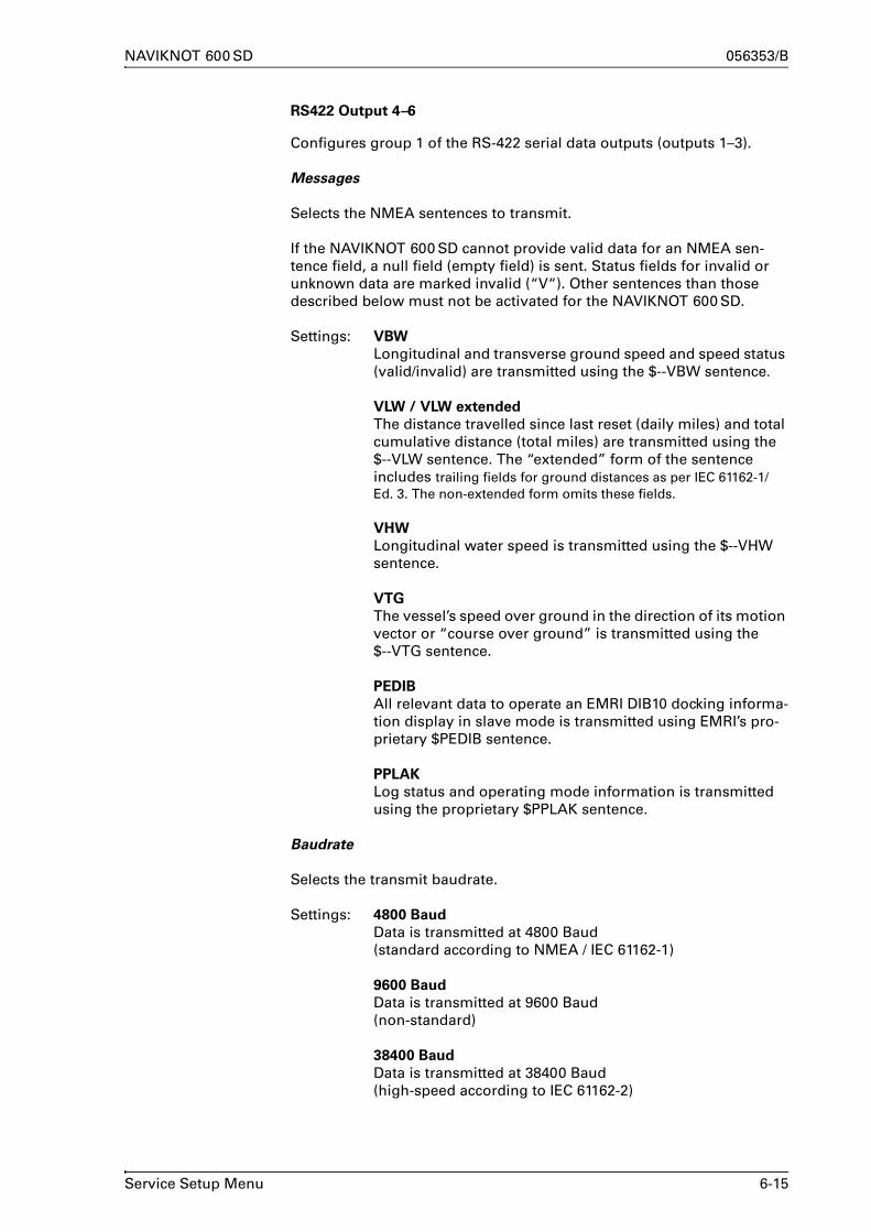
NAVIKNOT 600 SD 056353/B
RS422 Output 4–6
Configures group 1 of the RS-422 serial data outputs (outputs 1–3).
Messages
Selects the NMEA sentences to transmit.
If the NAVIKNOT 600 SD cannot provide valid data for an NMEA sen-tence field, a null field (empty field) is sent. Status fields for invalid or unknown data are marked invalid (“V“). Other sentences than those described below must not be activated for the NAVIKNOT 600 SD.
Settings: VBW
Longitudinal and transverse ground speed and speed status (valid/invalid) are transmitted using the $--VBW sentence.
VLW / VLW extended
The distance travelled since last reset (daily miles) and total cumulative distance (total miles) are transmitted using the $--VLW sentence. The “extended” form of the sentence includes trailing fields for ground distances as per IEC 61162-1/Ed. 3. The non-extended form omits these fields.
VHW
Longitudinal water speed is transmitted using the $--VHW sentence.
VTG
The vessel’s speed over ground in the direction of its motion vector or “course over ground” is transmitted using the $--VTG sentence.
PEDIB
All relevant data to operate an EMRI DIB10 docking informa-tion display in slave mode is transmitted using EMRI’s pro-prietary $PEDIB sentence.
PPLAK
Log status and operating mode information is transmitted using the proprietary $PPLAK sentence.
Baudrate
Selects the transmit baudrate.
Settings: 4800 Baud
Data is transmitted at 4800 Baud(standard according to NMEA / IEC 61162-1)
9600 Baud
Data is transmitted at 9600 Baud(non-standard)
38400 Baud
Data is transmitted at 38400 Baud(high-speed according to IEC 61162-2)
Service Setup Menu 6-15

056353/B NAVIKNOT 600 SD
NMEA Input 1
Configures the NMEA input 1.
Messages
Selects the NMEA sentences to receive.
Settings: HDT
Enables the input to receive true heading data from the$--HDT sentence.Selecting this option lets the system ignore heading data from the satellite PCB in favour of the external data.HDT (true heading) may be read from any source which meets or exceeds the performance specifications of the sat-ellite PCB’s heading output. Using external heading from a gyrocompass will improve the accuracy at which the ves-sel’s velocity over ground is resolved into the longitudinal and transverse ground speeds.
ROT
Enables the input to receive rate of turn data from the$--ROT sentence.Selecting this option lets the system ignore rate of turn data from the satellite PCB in favour of the external data.ROT (rate of turn) may be read from any source which meets or exceeds the performance specifications of the satellite PCB’s rate outputs.
DDC
Dimming commands are read from the $--DDC sentence.
PPLAI
Dimming commands are read from the proprietary $PPLAI sentence.
Baudrate
Selects the receive baudrate
Settings: 4800 Baud
Data is received at 4800 Baud(standard according to NMEA / IEC 61162-1)
9600 Baud
Data is received at 9600 Baud(non-standard)
38400 Baud
Data is received at 38400 Baud(high-speed according to IEC 61162-2)
6-16 Service Setup Menu

NAVIKNOT 600 SD 056353/B
NMEA Input 2
Configures the NMEA input 2.
Messages
Selects the NMEA sentences to receive.
Settings: HDT
Enables the input to receive true heading data from the$--HDT sentence.Selecting this option lets the system ignore heading data from the satellite PCB in favour of the external data.HDT (true heading) may be read from any source which meets or exceeds the performance specifications of the sat-ellite PCB’s heading output. Using external heading from a gyrocompass will improve the accuracy at which the ves-sel’s velocity over ground is resolved into the longitudinal and transverse ground speeds.
ROT
Enables the input to receive rate of turn data from the$--ROT sentence.Selecting this option lets the system ignore rate of turn data from the satellite PCB in favour of the external data.ROT (rate of turn) may be read from any source which meets or exceeds the performance specifications of the satellite PCB’s rate outputs.
DDC
Dimming commands are read from the $--DDC sentence.
PPLAI
Dimming commands are read from the proprietary $PPLAI sentence.
Baudrate
Selects the receive baudrate
Settings: 4800 Baud
Data is received at 4800 Baud(standard according to NMEA / IEC 61162-1)
9600 Baud
Data is received at 9600 Baud(non-standard)
38400 Baud
Data is received at 38400 Baud(high-speed according to IEC 61162-2)
Service Setup Menu 6-17

056353/B NAVIKNOT 600 SD
System Type
Configures the NAVIKNOT system type.
For the NAVIKNOT 600 SD, the type must be set to 600SD; all other options are to be ignored.
Settings: NAVIKNOT 600 SD
Sensor Sensitivity
Sets the sensitivity value for the Doppler transducer.
For a detailed explanation of the effect of the sensitivity setting, refer to chapter 7, “Doppler Transducer Calibration”.
Value: 0.5 – 1.5
6-18 Service Setup Menu

NAVIKNOT 600 SD 056353/B
Relay Speed Limit
Sets the lower and/or upper switching thresholds for the speed limit relay output.
The speed limit relay output provides a status signal to external equip-ment, to indicate that the actual speed has exceeded or fallen below a set threshold. This signal may be e.g. for speed-dependent rudder angle limiting or similar applications.
The switching behaviour of the limit relay is determined by the com-bined settings of two values, the minimum (lower threshold) and the maximum (upper threshold) value:
If only a minimum threshold value is set and active, the relay is attracted at speeds below and released at speeds above the threshold value.
If only a maximum threshold value is set and active, the relay is attracted at speeds above and released at speeds below the threshold value.
If both a minimum and a maximum threshold value are set and active, the relay is released at speeds below the min. value, attracted at speeds in-between both values and released again at speeds above the max. threshold.
If the max. threshold is set to a value below the min. threshold, the relay is attracted at speeds below the min. value, released at speeds in-between both values and attracted again at speeds above the max. threshold.
If both threshold values are de-activated or set to exactly the same value, the limit relay function is disabled.
speed
MIN
relay ON relay OFF
speed
MAX
relay ONrelay OFF
speed
MAX
relay OFFrelay ON
MIN
relay OFF
speed
MAX
relay OFF relay ON
MIN
relay ON
Service Setup Menu 6-19

056353/B NAVIKNOT 600 SD
Minimum Value
Sets the lower switching threshold for the limit relay.
Value: -99.9 – +99.9 kn
Minimum Value ON
Activates or de-activates switching at the lower threshold
Settings: ON (option checked)Switching is active at the lower threshold
OFF (option unchecked)Switching is inactive at the lower threshold
Maximum Value
Sets the upper switching threshold for the limit relay.
Value: -99.9 – +99.9 kn
Maximum Value ON
Activates ore de-activates switching at the upper threshold
Settings: ON (option checked)Switching is active at the upper threshold
OFF (option unchecked)Switching is inactive at the upper threshold
6-20 Service Setup Menu

NAVIKNOT 600 SD 056353/B
Calibration
Turns sensor calibration on or off, edits the calibration table and accesses the calibration trial run menus.
Cal. Table On
Activates or de-activates the calibration table.
Settings: ON (option checked)Calibration is active. The NAVIKNOT 600 SD corrects the data received from the preamplifier D according to the cali-bration table. The resulting calibrated speed is displayed and transmitted at the data outputs.
OFF (option unchecked)Calibration is disabled. The NAVIKNOT 600 SD does not apply any corrections to the data received from the pream-plifier D. Raw speed only is displayed and transmitted at the data outputs. The indication “Uncal” is shown on the CDU display as a reminder that calibration is disabled.
Cal. Table
Edits the calibration table entries directly.
Settings: refer to chapter 7, “Doppler Transducer Calibration”, for a detailed description of the calibration and related proce-dures
Zero Point
Sets the calibration zero point (correction value at a true speed of 0 kn).
Settings: refer to chapter 7, “Doppler Transducer Calibration”, for a detailed description of the calibration and related proce-dures
Two Way Trial Run
Accesses the sub-menu for conducting a two-way calibration trial run.
Settings: refer to chapter 7, “Doppler Transducer Calibration”, for a detailed description of the calibration and related proce-dures
One Way Trial Run
Accesses the sub-menu for conducting a one-way calibration trial run.
Settings: refer to chapter 7, “Doppler Transducer Calibration”, for a detailed description of the calibration and related proce-dures
Service Setup Menu 6-21

056353/B NAVIKNOT 600 SD
GSP Setup
Accesses the satellite PCB configuration menu
Settings: the GPS setup menu pages are directly served by the satel-lite PCB; refer to section 6.2, “GPS Setup”, for a detailed description of the GPS setup menu.
Antenna Distances
Configures the geometrical parameters of the GPS antenna location.
These values are required to correctly calculate of the bow and stern transverse speeds shown in the docking display page.
To Stern
Sets the distance from the antenna to the stern
Settings: 0.0 - 999.9 m
Distance from antenna to stern; measured along the vessel’s X-axis, i. e. parallel to the centerline
To Bow
Sets the distance from the antenna to the stern
Settings: 0.0 - 999.9 m
Distance from antenna to bow; measured along the vessel’s X-axis, i. e. parallel to the centerline
To Centerline
Sets the distance from the antenna to the centerline
Settings: -99.9 – +99.9 m
Distance from antenna to centerline (Y-offset); measured along the vessel’s Y-axis, i. e. perpendicular to the center-line; negative values indicate offset to port
Network Setup
This option is reserved for future applications. Settings are not relevant and have no effect in the current software release.
6-22 Service Setup Menu

NAVIKNOT 600 SD 056353/B
6.2 GPS Setup
To make the NAVIKNOT 600 SD system fully functional after the mechanical and electrical installation, the available heading sources, the orientations of the antenna and electronics units and the required align-ment correction for the antenna unit must be configured by accessing the GPS setup from the Service Setup menu.
When “GPS Setup” is selected from the Service Setup menu pages, the NAVIKNOT 600 SD electronics unit acts as a gateway to the satellite PCB’s own configuration and setup menu. The GPS setup pages are directly served by the satellite PCB. The indication “external” is shown at the top of the respective pages.
The appearance of the GPS setup pages and the operation of the menu differs slightly from other pages of the NAVIKNOT 600 SD setup.
GPS Setup Operation
(solid arrow): Indicates the current cursor position on the screen (equivalent to angle bracket symbol in the NAVIKNOT 600 SD setup).
(angle bracket): Indicates the currently active selection in case of mutually exclusive options (equivalent to radio buttons in the NAVIKNOT 600 SD setup).
ON/OFF: Indicates the currently active selection in case of independent options (equivalent to checkboxes in the NAVIKNOT 600 SD setup).
Right, Left, Up, and Down arrow keys: Move the cursor position within the GPS setup pages.The Up and Down keys also edit numerical values; the Right key also returns to next higher menu level when cursor is at leftmost position on the page.
ENTER key: Enters sub-menus, confirms numerical entries and selects or de-selects settings (on /off toggle).
Note Some of the available GPS configuration options do not apply to the NAVIKNOT 600 SD system. These must be left at the factory default set-tings as noted in the GPS setup descriptions below.
Note To enter numerical values or toggle settings on/off, the cursor must be positioned vertically and horizontally with the arrow keys to the respec-tive point of entry.
GPS Setup 6-23

056353/B NAVIKNOT 600 SD
GPS Setup – Overview
Figure 6-7:
GPS Setup pagesGPS SETUP (EXTERNAL)
TOP MENU
TOP MENU
Heading SelectionAlign and Calibrate
Align and CalibrateMag at Sea CalPort D Output Sel.NMEA Output Sel.
Heading SelectionAlign and Calibrate
Enter password toaccess setup menus
Enter code 000
Heading SelectionGPSON 123.4°
12.0°
MAGOFF ---.-°EXTOFF ---.-°
Diff. Limit
Align and CalibrateAntenna OrientationGyro OrientationHeading OffsetsR/P OffsetsNext Page
Heading Selection
GPS must be ON and activeMAG must be OFFEXT must be OFF
Diff. Limit setting not applicablein NAVIKNOT systems
Align and Calibrate
Antenna Orientation
Forward
Port
Gyro Orientation
Forward
Starboard
Aft
Port
Heading Offsets
GPS
delta: -9.9 – +9.9°
Software Version
view software version number(read-only)
MAG and EXT offsets notapplicable in NAVIKNOTsystems
R/P Offsets, Mag at Sea Cal.,NMEA Output Sel. and Port DOutput Sel. not applicable inNAVIKNOT systems
Menu protected by access code;enter code 600
Previous PageSoftware Version
6-24 GPS Setup

NAVIKNOT 600 SD 056353/B
GPS Setup – Parameters
Heading Selection
Align and Calibrate
Configures the heading sources available to the satellite PCB.The currently active source provides the heading sent from the satellite PCB to the NAVIKNOT 600 SD electronics unit.
Only the GPS source may be made active, i.e. the satellite PCB must always determine the vessel’s heading internally from the two GPS receivers’ signals.
The MAG and EXT source options are not applicable in the NAVIKNOT 600 SD system.
Settings: GPS
The GPS source must be enabled, i.e. set to ON at all times.
The GPS source will be activated automatically, if no other source is enabled.
MAG
The MAG source must be disabled, i.e. set to OFF at all times.
EXT
The EXT source must be disabled, i.e. set to OFF at all times.
Sets the mounting orientation and alignment correction values for the satellite PCB and the antenna unit respectively.
Access Code
The access to the Align and Calibrate menu pages is code-protected.To access the Align and Calibrate sub-menu, enter code 600.
Antenna Orientation
Configures the orientation of antenna assembly, relative to the vessel’s fore-and-aft line.
Settings: Forward
The arrow symbol on the antenna support beam points towards the bow.
Port
The arrow symbol on the antenna support beam points towards the port side.
GPS Setup 6-25

056353/B NAVIKNOT 600 SD
Gyro Orientation
Configures the orientation of the rate gyro assembly on the satellite PCB, relative to the vessel’s fore-and-aft line.
Settings: Forward
The arrow symbol on the electronics unit’s cover points towards the bow.
Starboard
The arrow symbol on the electronics unit’s cover points towards the starboard side.
Aft
The arrow symbol on the electronics unit’s cover points towards the stern.
Port
The arrow symbol on the electronics unit’s cover points towards the port side.
In all cases, the electronics unit must be mounted such that it is aligned with the respective direction to within ±5°.
Heading Offsets
Sets the correction values (“deltas”) to compensate for existing offsets of the heading sources relative to the vessel’s fore-and-aft line.
As only the GPS source is used within the NAVIKNOT 600 SD system, a delta value must be entered for the GPS source only. This compensates for misalignment of the GPS antenna support with the vessel’s fore-and-aft line
Settings: GPS
delta (correction value): -9.9 – +9.9°
Determine the existing misalignment by comparing the GPS heading as shown on the setup page with the true heading from the vessel’s heading reference (e.g. the gyrocompass).
Enter the required delta to match the GPS heading with the heading reference. The correction is effective immediately, so that the GPS heading displayed on screen should now exactly match with the reference.
MAG
Not applicable in NAVIKNOT systems; do not alter the fac-tory default setting (delta = 0.0°).
EXT
Not applicable in NAVIKNOT systems; do not alter the fac-tory default setting (delta = 0.0°).
6-26 GPS Setup

NAVIKNOT 600 SD 056353/B
R/P Offsets
Sets the correction values for misalignment of the PCB with the roll and pitch axes.
As roll and pitch angles from the satellite PCB are not evaluated in the NAVIKNOT 600 SD system, the R/P offsets are not applicable.Do not alter the factory default settings (roll and pitch delta = 0.0°)
Mag at Sea Cal.
Calibrates the magnetic heading sensor on the satellite PCB.
The magnetic heading sensor contained on the satellite PCB is not suita-ble for use within the NAVIKNOT 600 SD system. Therefore it must not be calibrated.Do not carry out the Mag. at Sea Cal. procedure. Leaving the sensor in the uncalibrated state will prevent it from being activated by accident.
Port D Output Sel.
Configures the data output port D on the satellite PCB.
The satellite PCB’s outputs to external equipment are not used in the NAVIKNOT 600 SD system.Do not alter the factory default setting (port D output = NMEA)
NMEA Output Sel.
Configures the NMEA heading data output sentence at ports C, D and H on the satellite PCB.
The satellite PCB’s outputs to external equipment are not used in the NAVIKNOT 600 SD system.Do not alter the factory default setting (all ports set to HDT)
Version Number
Displays the version number of the satellite PCB software.
Settings: none
the version number page is read-only.
GPS Setup 6-27

056353/B NAVIKNOT 600 SD
6-28 GPS Setup

NAVIKNOT 600 SD 056353/B
Chapter 7: Doppler Transducer Calibration
Once the NAVIKNOT 600 SD system has been installed and the basic configuration carried out, the Doppler transducer must be calibrated to make sure that the system’s speed and distance outputs meet the speci-fied accuracy.
7.1 Sensor Sensitivity Setting
The sensitivity value represents the ratio between the actual and nomi-nal speed output from the speed sensor. While primarily intended for use with NAVIKNOT EM-Log variants, the sensitivity setting may also be used in Doppler systems to linearly amplify or attenuate the raw speed data received from the preamplifier D
Normally, however, the sensitivity setting should be left at the factory default of 1 (unity gain) and the transducer data should be calibrated by means of the calibration table only.
Figure 7-1:
effect of thesensor sensitivity
raw speed data (input)
sens
itivi
ty-c
orre
cted
sp
eed
data
(out
put)
0.8
1.0
1.25
Note When setting the sensitivity to any other value than 1, bear in mind that the value does not equal the gain applied but, rather, its reciprocal. Thus, for example, a sensitivity value of 0.8 multiplies the raw speed by 1.25, while a value of 1.25 multiplies it by 0.8.
To set the sensitivity value:
1. Go to page 2 of the Serv-ice Setup and select the Sensor Sensitivity sub-menu.
2. With the Up/Down and Right/Left keys, set the sensitivity as required.
3. press ENTER to store the value and exit the sub-menu.
SERVICE SETUP Page 2
SENSOR SENSITIVITY
0.1 0
Sensor Sensitivity Setting 7-1

056353/B NAVIKNOT 600 SD
7.2 Doppler Transducer Calibration
To minimize the deviation between the vessel’s actual water speed and the speed displayed and transmitted, the NAVIKNOT 600 SD stores transducer-specific calibration data in a so-called calibration table.
The calibration table holds up to 21 entries (“calibration points”), each of which relates an uncalibrated raw value to a corresponding true water speed value. The entries holding the lowest and highest uncalibrated values determine the range over which calibration is effective.
The effects of setting calibration points (i.e. adding entries to the calibra-tion table) at different states of calibration are illustrated below.
Figure 7-2:
effect of calibrationtable entries
Note To calibrate speeds astern, at least one calibration point with a negative uncalibrated speed value must be stored. Otherwise, calibration is effec-tive for speeds ahead only.
➀ calibration table empty:linear transducer characteristic assumed;display and output = 0.0 kn at raw data value of 0.0 kn
➁ zero point calibratedlinear transducer curve is offset by zero point calibration value
➂ one additional point calibrated (highest table entry)calibration points joined by straight line (linear interpolation)
➃ additional intermediate points calibratedcalibrated range is split into linear segments of different slope
raw data (input)
calib
rate
d da
ta (o
utpu
t)
zero point(true water speed = 0.0 kn)
raw data (input)
calib
rate
d da
ta (o
utpu
t)
raw data (input)
calib
rate
d da
ta (o
utpu
t)
highest cal.table entry
intermediate cal.table entry
raw data (input)
calib
rate
d da
ta (o
utpu
t)
1 2
3 4
7-2 Doppler Transducer Calibration

NAVIKNOT 600 SD 056353/B
Editing the Calibration Table Directly
To add, edit or delete calibration points directly, go to page 2 of theService Setup and select the Calibration | Cal.Table sub-menu.The data stored at calibration point no. 00 is shown (dashes will appear if the table is empty).
To add or edit a calibration point:
1. With the Right/Left keys, select the calibration point to add or edit.Press ENTER to continue.
2. With the Up/Down keys (knots) and the Right/Left keys (tenths of knots), set the uncalibrated speed to the required value.The true speed indica-tion is altered by the same amount.Press ENTER to continue.
3. With the Up/Down keys and the Right/Left keys, now alter the true speed indication as required. The uncalibrated speed value is not altered.Press ENTER to store the edited data.
4. Press ENTER again to continue editing or MENU to quit the Cal.Table sub-menu.
To delete a calibration point:.
5. With the Right/Left arrow keys, select the calibra-tion point to delete.
6. With ENTER, go down to the “delete” option, press the Right or Left key to select “yes”, then press ENTER to delete the calibration point.
7. Select another calibra-tion point to delete or press MENU to quit the Cal.Table sub-menu.
SERVICE SETUP Page 2 CALIBRATION
CALIBRATION TABLE
CAL. NO
DELETE
UNCAL SPEED TRUE SPEED
- . -- - . --
10
NO
CALIBRATION TABLE
CAL. NO
DELETE
UNCAL SPEED TRUE SPEED
2 . 01+2 . 01+
10
NO
CALIBRATION TABLE
CAL. NO
DELETE
UNCAL SPEED TRUE SPEED
2 . 01+2 . 31+
10
NO
CALIBRATION TABLE
CAL. NO
DELETE
UNCAL SPEED TRUE SPEED
SERVICE SETUP Page 2 CALIBRATION
CALIBRATION TABLE
CAL. NO
DELETE
UNCAL SPEED TRUE SPEED
2 . 01+2 . 31+
10
NO
2 . 01+2 . 31+
10
YES
Note Upon quitting the Cal. Table sub menu, the entries are sorted and renum-bered according to their uncalibrated speed values. Point 00 always holds the entry with the smallest uncalibrated speed value.
Doppler Transducer Calibration 7-3

056353/B NAVIKNOT 600 SD
Zero Point Calibration
Before any entries for non-zero speeds are stored in the calibration table or calibration trial runs are conducted, the zero point calibration should be carried out.
The “zero point” refers to the calibration table entry which holds the uncalibrated (“raw“) speed value corresponding to a true water speed of zero knots. Two methods are available to calibrate the zero point: man-ual and auto.
Manual Entry
The manual entry method permits zero point calibration in waters which are not free of current. However, the longitudinal component of the cur-rent must be known and it must be small enough to regard the sensor as operating near zero speed.
Note Both the manual and the automatic zero point calibration require that the vessel is stationary.
To carry out the manual zero-point calibration:
1. Go to page 2 of the Service Setup;select the Calibration | Zero Point | Man Calibration sub-menu.
Three values are shown, the true speed, the uncalibrated speed and the calibration value (i.e. the difference of the two speeds).The uncalibrated speed is the raw speed value as currently received from the preamplifier D (not editable).The objective of the calibration is now to alter the calibration value until the displayed true speed value matches the known actual water speed.Thus, in waters free of current, the displayed true speed value must be brought to zero; in the presence of current, the true speed value must be made equal to the known longitudinal component of the current.
2. With the Right/Left arrow keys, alter the calibration value until the displayed true speed exactly matches the known actual water speed.
3. Press ENTER to confirm the setting and leave the manual calibration sub-menu.
SERVICE SETUP Page 2 CALIBRATION ZERO POINT
MAN CALIBRATION
-00.2+00.2-00.4
KNKN
TRUE SPEED UNCAL SPEED CAL VALUE
Note When the manual entry is stored, the true speed entered is automatically subtracted from both the uncalibrated and true speed values.Thus, the entry written to the table will always contain the uncalibrated value corresponding to a true speed of zero knots.
7-4 Doppler Transducer Calibration

NAVIKNOT 600 SD 056353/B
Automatic Entry
With the automatic entry method, the required zero point setting is determined automatically. Automatic entry may only be used when the vessel is stationary in waters free of current, i.e., if the actual water speed is known to be zero.
To carry out the automatic zero-point calibration:
1. Go to page 2 of the Service Setup;select the Calibration | Zero Point | Auto Calibration sub-menu.
As with the manual entry method, the true speed, the uncalibrated speed and the calibration value are shown.However, the true speed value is fixed to zero knots and cannot be adjusted by the operator. The uncalibrated speed is the raw speed value as currently received from the preamplifier D, thus the calibra-tion value will be equal to the uncalibrated speed with the sign reversed.
2. Press ENTER to confirm the setting and leave the auto calibration sub-menu.
SERVICE SETUP Page 2 CALIBRATION ZERO POINT
MAN CALIBRATION
+00.0+00.2-00.2
KNKN
TRUE SPEED UNCAL SPEED CAL VALUE
Doppler Transducer Calibration 7-5

056353/B NAVIKNOT 600 SD
Calibration by Trial Runs
Calibration by trial runs is the recommended method to calibrate the Doppler transducer in the NAVIKNOT 600 SD. system. The procedure resembles the familiar “milepost run”, but permits any known distance to be taken as the length of a run.
The known distance may be given by the distance between sidebearings to prominent landmarks. The regular procedure in this case is to start and stop the run clock exactly at the points in time when the landmarks are sighted athwartships.However, as the NAVIKNOT 600 SD obtains the vessel’s current position from the sattelite PCB, it is equally acceptable to start the run clock at a given point in time and to stop it as soon as a distance of at least one mile has been traversed.
Generally, for each correction value to be determined, a two way trial run should be carried out, i.e. the same known distance “l” should be traversed in opposite directions (runs A and B). This will make the effects of drift due to wind and current cancel out each other automati-cally. Only when no wind and current are present, a one way trial run may be carried out.
The first two or one way trial run should be carried out at maximum sea speed, to define the upper limit of the calibrated range. Additional trial runs may be carried out later at lower speeds to improve the accuracy within the calibrated range.
Figure 7-3:
calibrationby trial runs
➀ approach to run A or one-way run
➁ start of run A or one-way run
➂ end of run A or one-way run
➃ approach to run B
➄ start of run B
➅ end of run B
known distance "l"
7-6 Doppler Transducer Calibration

NAVIKNOT 600 SD 056353/B
Two Way Trial Run
Note During a two way trial run, the vessel’s heading during runs A and B should ideally be parallel to the direction of the effective drift, as the drift component perpendicular to the heading cannot be compensated for.
To carry out a two way trial run:
1. Bring the vessel on the required course for the approach to run A.
2. Approach the run with the speed (engine rev.s) at which the calibra-tion is to be carried out. Keep the heading and speed steady.
3. Go to page 2 of the Service Setup and select the Calibration | Two Way Trial Run sub-menu.The run clock is shown, indicating 00:00 s run time and the uncali-brated water speed as received from the preamplifier D.
4. Exactly at the start of run A (first landmark athwart-ships or “start” announced by supervisor), press ENTER to start the run clock.
5. Exactly at the end of run A (second landmark athwart-ships or “stop” announced by supervisor), press ENTER to stop the run clock.
The display now indicates the run distance, the average uncalibrated speed for the run, the true speed over ground (calculated from the run time and distance) and the calculated calibration value.
6. Press ENTER to store the run parameters.
The run clock is shown again, indicating 00:00 s run time and the uncalibrated water speed as received from the preamplifier D.
7. Turn the vessel around and bring it on the required course for the approach to run B. This is the exact reverse of the course maintained during run A.Approach the run with the same speed (engine rev.s) at which run A was carried out. Keep the heading and speed steady.
8. Exactly at the start of run B (second landmark athwart-ships or “start” announced by supervisor), press ENTER to start the run clock.
9. Exactly at the end of run B(first landmark athwart-ships or “stop” announced by supervisor), press ENTER to stop the run clock.
SERVICE SETUP Page 2 CALIBRATION
TWO WAY TRIALRUN
00:0020.2
TIME SPEED
SKN
00:02:3020.2
TIME SPEED
SKN
01.00020.220.0-0.2
DISTANCE UNCAL SPEED TRUE SPEED CAL VALUE
NMKNKN
00:0020.2
TIME SPEED
SKN
00:02:3020.2
TIME SPEED
SKN
01.00020.220.0-0.2
DISTANCE UNCAL SPEED TRUE SPEED CAL VALUE
NMKNKN
Doppler Transducer Calibration 7-7

056353/B NAVIKNOT 600 SD
The display again indicates the run distance, the average uncali-brated speed, the true speed over ground and the calculated calibra-tion value.
10. Press ENTER to store the run parameters.
The Two Way Trial Run sub-menu is quit automatically.
As the result of the two way trial run, one new entry will now be found in the calibration table.The uncalibrated speed stored at this entry is the average of the two averaged uncalibrated speeds from run A and run B.The true speed stored at this entry is the average of the two true speeds calculated for run A and run B.
7-8 Doppler Transducer Calibration

NAVIKNOT 600 SD 056353/B
One Way Trial Run
Note In a one way trial run, any drift due to wind and/or current will adversely affect the calibration. Conducting a one way trial run in the presence of drift, may degrade instead of improve the speed accuracy.
To carry out a one way trial run:
1. Bring the vessel on the required course for the approach to the run.
2. Approach the run with the speed (engine rev.s) at which the calibra-tion is to be carried out. Keep the heading and speed steady.
3. Go to page 2 of the Service Setup and select the Calibration | One Way Trial Run sub-menu.The run clock is shown, indicating 00:00 s run time and the uncali-brated water speed as received from the preamplifier D.
4. Exactly at the start of the run (first landmark athwart-ships or “start” announced by supervisor), press ENTER to start the run clock.
5. Exactly at the end of the run (second landmark athwartships or “stop” announced by supervisor), press ENTER to stop the run clock.
The display now indicates the run distance, the average uncalibrated speed for the run, the true speed over ground (calculated from the run time and distance) and the calculated calibration value.
6. Press ENTER to store the run parameters.
The One Way Trial Run sub-menu is quit automatically.
As the result of the trial run, one new entry will now be found in the cal-ibration table, holding the average uncalibrated speed and the calcu-lated true speeds for the run.
SERVICE SETUP Page 2 CALIBRATION
ONE WAY TRIALRUN
00:0020.2
TIME SPEED
SKN
00:02:3020.2
TIME SPEED
SKN
01.00020.220.0-0.2
DISTANCE UNCAL SPEED TRUE SPEED CAL VALUE
NMKNKN
Doppler Transducer Calibration 7-9

056353/B NAVIKNOT 600 SD
7-10 Doppler Transducer Calibration

NAVIKNOT 600 SD 056353/B
Chapter 8: Troubleshooting
8.1 NAVIKNOT 600 SD Electronics Unit and CDU(s)
The NAVIKNOT 600 SD electronics unit and the CDU are complex elec-tronic devices. In case of malfunction, it would neither be practical nor economical to carry out troubleshooting and servicing in the field down to the level of individual circuit components.
Unless instructed otherwise by Sperry Marine engineering, field service personnel should limit troubleshooting to the basic checks given below.
• For the electronics unit:
– Visual inspection of mechanical components, the processor and satellite PCBs and wiring.
– Continuity checks of wiring connections.– Checks for short circuit or overload conditions or reversed polar-
ity of the external supply powers.– Checks of the on-board supply voltages and I/O signals and data.
The presence of voltages, signals and data is indicated by diag-nostic LEDs on the PCB.Exact voltage levels must be checked with a voltmeter.The data content on serial I/O lines must be checked with the aid of suitable analyzing tools, such as PC-based protocol interpret-ers or terminal programs.
When components on the processor PCB, other than socketed ICs or the exchangeable system software flashboard, are assumed to cause malfunction, the complete PCB, Stock No. 20692, is to be exchanged.
When malfunction of the satellite PCB is assumed, the complete PCB, Stock No. 20711 is to be exchanged.
If malfunction of the electronics unit cannot be tracked down to one of the PCBs, the electronics unit as a whole is to be exchanged.
• For the CDU(s):
– Visual inspection of mechanical components and wiring.– Continuity checks of wiring connections at the terminals or termi-
nal block to which the 6-wire CDU connection cable is fastened.– Checks for the presence and correct polarity of the external sup-
ply power.
The CDU is not field-serviceable and should not be opened for trou-bleshooting purposes. Defective CDUs must be sent back to Sperry Marine for repair.
NAVIKNOT 600 SD Electronics Unit and CDU(s) 8-1

056353/B NAVIKNOT 600 SD
Location of Parts on the Processor PCB
Figure 8-1 below shows the locations of exchangeable components, connectors and diagnostic LED indicators of the processor PCB in the NAVIKNOT 600 SD electronics unit.
Figure 8-1:
location of parts on theprocessor PCB
8-2 NAVIKNOT 600 SD Electronics Unit and CDU(s)

NAVIKNOT 600 SD 056353/B
Exchangeable Components, Processor PCB
Table 8-1:
Exchangeablecomponents on the
processor PCB
Terminal Boards and Connectors, Processor PCB
Table 8-2:
Terminal boards andconnectors on the
processor PCB
Part Function Stock No.
Flash-board
Flahsboard (flash-memory card),pre-programmed with system software
020705-0000-000
IC 2 quad RS-422 output driver IC;drives serial data RS-422 outputs 1 to 3
046485-0000-000
IC 14 photocoupler/photo relay;pulse output 1 contact closure
042842-0000-000
IC 15 photocoupler/photo relay;pulse output 2 contact closure
042842-0000-000
IC 16 quad RS-422 output driver IC;drives serial data RS-422 outputs 4 to 6
046485-0000-000
IC 17 photocoupler/photo relay;pulse output 3 contact closure
042842-0000-000
IC 18 photocoupler/photo relay;pulse output 4 contact closure
042842-0000-000
IC 23 photocoupler/photo relay;pulse output 5 contact closure
042842-0000-000
IC 24 photocoupler/photo relay;pulse output 6 contact closure
042842-0000-000
Function
TB 1 24 VDC supply power in/out
TB 2 speed sensor interfaces, CDU interfaces
TB 3 serial data and pulse outputs
TB 4 analogue outputs, status in-/outputs, ext. data inputs
J 4 RS-232 service interface connector
J 5 USB programming connector (for factory use only)
J 7 Socket for exchangeable system software flashboard
NAVIKNOT 600 SD Electronics Unit and CDU(s) 8-3

056353/B NAVIKNOT 600 SD
Diagnostic LEDs, Processor PCB
As an aid in troubleshooting, a number of diagnostic LED indicators are provided on the processor PCB. These indicate the presence of supply voltages, activities on the serial data I/O lines and the current states of the status I/O ports.
Table 8-3:
Diagnostic LEDsLED Colour Indication
CR 6 red CPU status indicator, normally off, flashes at boot-up
CR 7 red CPU status indicator, normally off, flashes at boot-up
CR 12 green activity on Tx line, satellite PCB, TB 2.5/2.6
CR 13 green activity on Tx line, CDUs, TB 2.15/2.16, 2.19/2.20
CR 14 green activity on Rx line, CDUs, TB 2.13/2.14, 2.17/2.18
CR 15 green activity on Rx line, satellite PCB, TB 2.7/2.8
CR 16 green activity on Rx line, preamplifier D, TB 2.21/2.22
CR 20 green internal +12 VDC supply power present
CR 21 green internal +5 VDC supply power present
CR 22 red CPU status indicator, normally off, flashes at boot-up
CR 24 green activity on Tx line, preamplifier D, TB 2.23/2.24
CR 28 green internal +3.3 VDC supply power present (Vcc)
CR 29 green internal +1.2 VDC reference present
CR 30 green pulse relay output active, outp. 2, TB 3.15/3.16
CR 31 green pulse relay output active, outp. 1, TB 3.13/3.14
CR 35 green activity on Tx line, serial data outputs group 1,TB 3.1/3.2, 3.3/3.4, 3.5/3.6
CR 36 green activity on Tx line, serial data outputs group 2,TB 3.7/3.8, 3.9/3.10, 3.11/3.12
CR 39 green pulse relay output active, outp. 6, TB 3.23/3.24
CR 40 green pulse relay output active, outp. 4, TB 3.19/3.20
CR 41 green relay output active, log failure alarm, TB 4.19/4.20
CR 42 green relay output active, power failure alarm, TB 4.17/4.18
CR 43 green pulse relay output active, outp. 5, TB 3.21/3.22
CR 44 green pulse relay output active, outp. 3, TB 3.17/3.18
CR 45 green relay output active, watch alarm trigger, TB 4.23/4.24
CR 46 green relay output active, speed limit, TB 4.21/4.22
CR 55 green activity on Rx line, serial dim input, TB 4.28/4.29
CR 57 green status input active, double ended ferry, TB 4.11/4.12
CR 58 green status input active, ext. dim+, TB 4.15/4.16
CR 59 green status input active, ext. dim-, TB 4.13/4.14
CR 60 green status input active, ext. alarm mute, TB 4.9/4.10
8-4 NAVIKNOT 600 SD Electronics Unit and CDU(s)

NAVIKNOT 600 SD 056353/B
Location of Parts on the Satellite PCB
Figure 8-2 below shows the locations of relevant connectors, diagnostic LED indicators and the power switch of the satellite PCB inside the NAVIKNOT 600 SD electronics unit.
Figure 8-2:
location of parts on thesatellite PCB
NAVIKNOT 600 SD Electronics Unit and CDU(s) 8-5

056353/B NAVIKNOT 600 SD
Connectors and Power Switch, Satellite PCB
Table 8-4:
Connnectors andpower switch on the
satellite PCB
Diagnostic LEDs, Satellite PCB
Table 8-5:
Diagnostic LEDson the satellite PCB
Function
J 1 24 VDC supply power in from processor PCB;factory prewired:
satellite PCB processor PCB
J 1.1J 1.2
––
TB 1.3TB 1.4
J 2 serial data receive and transmit lines to/from processor PCB;factory prewired:
satellite PCB processor PCB
J 2.3J 2.4J 2.5J 2.6
––––
TB 2.5TB 2.6TB 2.8TB 2.7
ANT1 antenna connector, antenna 1 (bow or port)
ANT1 antenna connector, antenna 2 (stern or starboard)
S 1 power switch;must be switched on at all times
LED Colour Indication
DS 1 green GPS 1PPS;indicates reception of 1PPS timing pulse from GPS receivers
DS 2 green 100 Hz INT;flashes at internal 100 Hz clock rate
DS 3 green ADC cycle;flashes at cycle rate of on-board analog-to-digital converter
DS 4 red SYS FAIL;bright red at power-up and in case of system failure, remains dimly lit during normal operation.
DS 5 green 24 VDC supply power present
8-6 NAVIKNOT 600 SD Electronics Unit and CDU(s)

NAVIKNOT 600 SD 056353/B
8.2 Doppler Transducer and Preamplifier D
Failure to receive valid speed data from the preamplifier D, resulting in a “SRD Timeout” or “Preamp D Timeout” alarm, may be caused by a mechanical or electrical defect in the transducer or by a defective preamplifier.
The applicable troubleshooting procedures are described in the installa-tion, maintenance and service instructions for the Doppler transducers and preamplifier D, document no. 005005-0125-001.
Doppler Transducer and Preamplifier D 8-7

056353/B NAVIKNOT 600 SD
8-8 Doppler Transducer and Preamplifier D

NAVIKNOT 600 SD 056353/B
Chapter 9: Corrective Maintenance
The NAVIKNOT 600 SD CDU and the PCBs inside the NAVIKNOT elec-tronics unit are generally not field-serviceable on the component level. Defective devices must be sent back to Sperry Marine for repair.
The only corrective maintenance procedures which may be performed by field service personnel are the exchange of the system software in the electronics unit and the replacement of the RS-422 output drivers and the pulse output relays.
9.1 Exchanging the System Software
Downloading Software from the Flashboard
The NAVIKNOT 600 SD electronics unit keeps two separate copies of the system software, one in an onboard flash memory and the other on the exchangeable software flashboard 20705.
The system always boots up from the onboard memory. Should, at power-up, a different software version be found on the flashboard than is currently stored onboard, the software from the flashboard is auto-matically copied to the onboard memory and the system is restarted.
This allows both to upgrade to newer and to downgrade to previous releases by simply exchanging the flashboard.
CAUTION The NAVIKNOT 600 SD electronics unit contains electrostatic sensitive components.
Electrostatic discharge may permanently damage components.
When servicing the electronics unit, take precautions to prevent electro-static discharge. Avoid touching any of the electronic circuitry.
CAUTION It cannot be guaranteed that parameters settings in the User and Setup menus and the currently active manual settings are left intact during the software download.Before exchanging the flashboard, record all settings to be able to re-enter them manually, if required.
Exchanging the System Software 9-1

056353/B NAVIKNOT 600 SD
Exchanging the Flashboard
1. Power down the NAVIKNOT 600 SD system.
2. Open the electronics unit and locate the old flashboard in its socket (J7) on the PCB.
3. Carefully remove the plastic pin which secures the flashboard to the PCB.
4. Pull the old flashboard out of the socket, making sure to touch it at the edges only.
5. Insert the new flashboard into the socket.
6. Secure the flashboard with the plastic pin.
7. Power-up the NAVIKNOT 600 SD system.
8. The electronics unit will recognize the new flashboard and download the updated software to the onboard memory.
9. The CDU shows the “waiting for main unit” message for several minutes while the software is downloaded. During the down-load, the LEDs CR 6, 7 and 22 on the electronics unit PCB will flash in sequence.Upon completion of the down-load, the system automatically restarts.
NAVIKNOT
WAITING FOR MAIN UNIT
NN.NN
CAUTION Do not disconnect power or otherwise interrupt the power-up process after an exchange of the flashboard.
9-2 Exchanging the System Software

NAVIKNOT 600 SD 056353/B
Uploading Software via the Service Interface
The system software may also be uploaded from a PC or laptop via the RS-232 service interface on the electronics unit PCB.
At the time of writing of this manual, however, an upload program for field service use is not yet available. Sperry Marine will issue an official Service Bulletin as soon as such a program becomes available.
9.2 Replacing RS-422 Output Driver ICs
The RS-422 output drivers, ICs 2 and 16, are socketed 16-pin DIL chips. If failure or malfunction of RS-422 outputs is attributed to a defective driver IC, the respective chip can easily be replaced against a new one.
The driver ICs are standard quadruple RS-422 line drivers (MC3487), available from Sperry Marine Hamburg under part no. 46485.
9.3 Replacing Pulse Output Relays
The pulse output relays, ICs 14, 15, 17, 18, 23 and 24, are socketed solid state relays in a 6-pin DIL package.If failure of a pulse output is attributed to a defective relay, the respec-tive component can easily be replaced against a new one.
The pulse relays are photocoupler photo relays (TLP 598G), available from Sperry Marine Hamburg under part no. 42842.
Replacing RS-422 Output Driver ICs 9-3

056353/B NAVIKNOT 600 SD
9-4 Replacing Pulse Output Relays

NAVIKNOT 600 SD 056353/B
Appendix
A Setup and Configuration Tables
The following tables (blank forms) are appended to this manual:
B Drawings
The following drawings are appended to this manual:
Designation Drawing No.
NAVIKNOT 600 SD Setup Table 5004-0125-03
NAVIKNOT 600 SD Record of Calibration Trial Runs 5004-0125-05
Note After installation of the NAVIKNOT 600 SD, please return a filled-out copy of the Setup Table to Sperry Marine for inclusion in the ship’s file.When permanent changes are made to the system configuration, please return an updated copy of the Setup Table to Sperry Marine.
Designation Drawing No.
NAVIKNOT Electronics Unit; Dimension Drawing 5004-0112-01
NAVIKNOT Control and Display Unit 3x1 (in housing with bracket); Dimension Drawing
5002-0112-01
NAVIKNOT Control and Display Unit 3x1 (for console frame or panel mounting); Dimension Drawing
5002-0112-02
Console Frame Layout NAVIKNOT CDU 3x1; Dimen-sion Drawing
0031-0112-73
Console Cutout 3x1; Dimension Drawing 0031-0112-02
NAVIKNOT Control and Display Unit 2x1 (in housing with bracket); Dimension Drawing
5001-0112-01
NAVIKNOT Control and Display Unit 2x1 (for console frame or panel mounting); Dimension Drawing
5001-0112-02
Console Frame Layout NAVIKNOT CDU 2x1; Dimen-sion Drawing
0021-0112-86
Console Cutout 2x1; Dimension Drawing 0021-0112-02
NAVIKNOT Antenna 5008-0112-01
Satellite Speed Log NAVIKNOT 600 SD; Standard Connection Drawing
5002-0153-12
Note All appended documents and drawings are revision-controlled sepa-rately at Sperry Marine.In case of doubt, verify the current revision status of the drawings with Sperry Marine. This manual’s revision status does not change when the revision of an appended document or drawing changes.

056353/B NAVIKNOT 600 SD
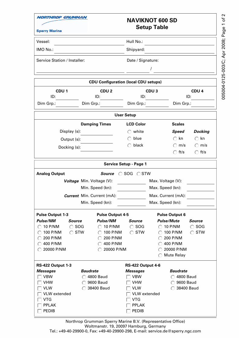
NAVIKNOT 600 SD
Setup Table
Service Station / Installer: Date / Signature:
/
Vessel:
IMO No.:
Hull No.:
Shipyard:
CDU Configuration (local CDU setups)
CDU 1
ID:
Dim Grp.:
CDU 2
ID:
Dim Grp.:
CDU 3
ID:
Dim Grp.:
CDU 4
ID:
Dim Grp.:
User Setup
Damping Times
Display (s):
Output (s):
Docking (s):
LCD Color
white
blue
black
Scales
Speed
kn
m/s
ft/s
Docking
kn
m/s
ft/s
Pulse Output 1-3
Pulse/NM
20000 P/NM400 P/NM200 P/NM100 P/NM10 P/NM
Source
SOGSTW
Pulse Output 4-5
Pulse/NM
20000 P/NM400 P/NM200 P/NM100 P/NM10 P/NM
Source
SOGSTW
Pulse Output 6
Pulse/Mute
Mute Relay20000 P/NM400 P/NM200 P/NM100 P/NM10 P/NM
Source
SOGSTW
RS-422 Output 1-3
Baudrate
38400 Baud9600 Baud4800 Baud
Messages
VBWVHWVLWVLW extendedVTGPPLAKPEDIB
RS-422 Output 4-6
Baudrate
38400 Baud9600 Baud4800 Baud
Messages
VBWVHWVLWVLW extendedVTGPPLAKPEDIB
Service Setup - Page 1
Current
Max. Speed (kn):
Max. Current (mA):
Min. Speed (kn):
Min. Current (mA):
Analog Output
Voltage
Max. Speed (kn):
Max. Voltage (V):
Min. Speed (kn):
Min. Voltage (V):
Source SOG STW
Northrop Grumman Sperry Marine B.V. (Representative Office) Woltmanstr. 19, 20097 Hamburg, Germany
Tel.: +49-40-29900-0, Fax: +49-40-29900-298, E-mail: [email protected]
0050
04-0
125-
003/
C; A
pr
2008
; Pag
e 1
of
2


Service Setup - Page 1, contd.
NMEA Input 1
Baudrate
4800 Baud9600 Baud38400 Baud
HDTROTDDCPPLAI
Messages
NMEA Input 2
Baudrate
38400 Baud9600 Baud4800 Baud
Messages
HDTROTDDCPPLAI
Service Setup - Page 2
System Type NAVIKNOT 600 SD
Value:Sensor Sensitivity
Relay Speed Limit Min.Value (kn):
Min. Value ON
Max.Value (kn):
Max. Value ON
Cal. Table ONCalibration
Calibration Table
Cal. No. Uncal. Sp True Spd. Cal. No. Uncal. Sp True Spd. Cal. No. Uncal. Sp True Spd.
0 7 14
1 8 15
2 9 16
3 10 17
4 11 18
5 12 19
6 13 20
Antenna Distances To Stern (m):
To Bow (m):
To Centerline (m):
Northrop Grumman Sperry Marine B.V. (Representative Office) Woltmanstr. 19, 20097 Hamburg, Germany
Tel.: +49-40-299 00-0, Fax: +49-40-299 00-298, E-mail: [email protected]
0050
04-0
125-
003/
C; A
pr
2008
; Pag
e 2
of
2
GPS Setup
(menu pages served
from satellite PCB)
Heading Selection
GPS:
MAG:
EXT:
Diff. Limit:
Align and Calibrate
Antenna Orientation
ForwardPort
Gyro Orientation
ForwardStarboardAftPort
Heading Offsets
EXT:
MAG:
GPS:
R/P Offsets, Mag at Sea Cal., NMEA Output Sel. and
Port D Output Sel. not applicable in NAVIKNOT systems
ON
OFF
OFF
not applicable
not applicable
not applicable


Northrop Grumman Sperry Marine B.V. (Representative Office) Woltmanstr. 19, 20097 Hamburg, Germany
Tel.: +49-40-29900-0, Fax: +49-40-29900-298, E-mail: [email protected]
Service Station / Installer: Date / Signature:
/
Vessel:
IMO No.:
Hull No.:
Shipyard:
Location of runs:
Remarks:
NAVIKNOT 600 SD
Record of Calibration Trial Runs
Run #:
run parameters computed values
elapsed time (s) distance (NM) heading (°) avg. uncal. spd. true water speed
Run A(or single run)
Run B(return run)
averaged values (cal. table entry)
Run #:
run parameters computed values
elapsed time (s) distance (NM) heading (°) avg. uncal. spd. true water speed
Run A(or single run)
Run B(return run)
averaged values (cal. table entry)
Run #:
run parameters computed values
elapsed time (s) distance (NM) heading (°) avg. uncal. spd. true water speed
Run A(or single run)
Run B(return run)
averaged values (cal. table entry)