Operating System/3 (OS/3) Integrated Communications Access ...
520
• • • Operating System/3 (OS/3) Integrated Communications Access Method (ICAM) Programmer Reference This Library Memo announces the release and availability of Update B to "SPERRY® Operating System/3 (OS/3) Integrated Communications Access Method (ICAM) Programmer Reference", UP-9749. This manual is one of a series to guide you in programming and using the integrated communications access method (ICAM). This programmer reference summarizes the information found in the other ICAM manuals. It covers all statements, commands, and macroinstructions used in preparing network definitions and communications user programs and in running ICAM utilities. It is intended as a quick-reference manual for those familiar with ICAM. This update describes the following enhancements for OS/3 release 10.0: • Corrections to the BUFFERS macroinstruction regarding how to specify remote workstations • A new remote device handler to support a MAPPER® 5 system • Support for the SPERRY Universal Terminal System (UTS 30) terminal as a remote workstation • Support for the IBERPAC packet switched public data network • Addition of a CALLING operand to the SUB macroinstruction to allow a DTE address to be included in a request packet for an IBERPAC packet switched public data network • Enhancements to the reverse charging option (SUB macroinstruction) for packet switching public data networks • A new SPR operand on the TERM macroinstruction to control the slow polling interval for a downed terminal polling group on a UNISCOPE® line • Support for UNIX* operating systems through the Remote Batch Processing (RBP) utility All other changes in this manual are corrections, deletions, or expanded descriptions applicable to items present in the software prior to the release level specified on the PSS page of the manual. Copies of Update B are now available for requisitioning. Either the update only or the complete manual with the update may be requisitioned by your local Sperry representative. To receive only the update, order UP-9749-B. To receive the complete manual, order UP-9749. *Trademark of AT&T Bell Laboratories Mailing Lists BZ, CZ, and MZ Mailing Lists BOO, B01, MBW, 28U, and 29U (Package B to UP-9749, 150 pages plus Memo) Library Memo for UP-9749-B May 1986
-
Upload
khangminh22 -
Category
Documents
-
view
0 -
download
0
Transcript of Operating System/3 (OS/3) Integrated Communications Access ...

•
•
•
Operating System/3 (OS/3)
Integrated Communications Access Method (ICAM) Programmer Reference
This Library Memo announces the release and availability of Update B to "SPERRY® Operating System/3 (OS/3) Integrated Communications Access Method (ICAM) Programmer Reference", UP-9749.
This manual is one of a series to guide you in programming and using the integrated communications access method (ICAM). This programmer reference summarizes the information found in the other ICAM manuals. It covers all statements, commands, and macroinstructions used in preparing network definitions and communications user programs and in running ICAM utilities. It is intended as a quick-reference manual for those familiar with ICAM.
This update describes the following enhancements for OS/3 release 10.0:
• Corrections to the BUFFERS macroinstruction regarding how to specify remote workstations
• A new remote device handler to support a MAPPER® 5 system
• Support for the SPERRY Universal Terminal System (UTS 30) terminal as a remote workstation
• Support for the IBERPAC packet switched public data network
• Addition of a CALLING operand to the SUB macroinstruction to allow a DTE address to be included in a request packet for an IBERPAC packet switched public data network
• Enhancements to the reverse charging option (SUB macroinstruction) for packet switching public data networks
• A new SPR operand on the TERM macroinstruction to control the slow polling interval for a downed terminal polling group on a UNISCOPE® line
• Support for UNIX* operating systems through the Remote Batch Processing (RBP) utility
All other changes in this manual are corrections, deletions, or expanded descriptions applicable to items present in the software prior to the release level specified on the PSS page of the manual.
Copies of Update B are now available for requisitioning. Either the update only or the complete manual with the update may be requisitioned by your local Sperry representative. To receive only the update, order UP-9749-B. To receive the complete manual, order UP-9749.
*Trademark of AT&T Bell Laboratories
Mailing Lists BZ, CZ, and MZ
Mailing Lists BOO, B01, MBW, 28U, and 29U
(Package B to UP-9749, 150 pages plus Memo)
Library Memo for UP-9749-B
May 1986

•
•
•

•
•
•
l,= __ Qe!!~tinsL~~~1~~.L~".LQ§L~L.-h-·-·=··-i j Integrated Communications l i Access Method (ICAM) I
Programmer Reference
This Library Memo announces the release and availability of Updating Package A to "SPERRY® Operating System/3 (OS/3) Integrated Communications Access Method (ICAM) Programmer Reference", UP-9749.
This manual is one of a series to guide you in programming and using the integrated communications access method (ICAM). This programmer reference summarizes the information found in the other ICAM manuals. It covers all statements, commands, and macroinstructions used in preparing network definitions and communications user programs and in running ICAM utilities. It is intended as a quick reference manual for those familiar with ICAM.
This update describes the following enhancements for OS/3 Release 9.0:
• Addition of X.21 circuit-switched public data networks for connection to the Universal Terminal System 20X (UTS 20X). New operands are provided in the network definition for this support .
• Additional capabilities for the ICAM trace facility .
• Input journalling for remote workstations .
• How to specify single- or dual-screen remote workstations.
All other changes in this manual are corrections, deletions, or expanded descriptions applicable to items present in the software prior to the release level specified on the PSS page of the manual.
Copies of Updating Package A are now available for requisitioning. Either the updating package only or the complete manual with the updating package may be requisitioned by your local Sperry representative. To receive only the updating package, order UP-9749-A. To receive the complete manual, order UP-9749.
Mailing Lists BZ, CZ, and MZ
1i
Mailing Lists BOO, 801, 28U, and 29U (Package A to UP-9749, 65 pages plus Memo)
Library Memo for UP-9749-A
January, 1985

- --------------------
•
•
•

•
•
• H
Integrated Communications Access Method {ICAM)
Environment: System 80
UP-9749

This document contains the latest information available at the time of preparation. Therefore, it may contain descriptions of functions not implemented at manual distribution time. To ensure that you have the latest information regarding levels of implementation and functional availability, please consult the appropriate release documentation or contact your local Sperry representative.
Sperry reserves the right to modify or revise the content of this document. No contractual obligation by Sperry regarding level, scope, or timing of functional implementation 1s either expressed or implied in this document. It is further understood that in consideration of the receipt or purchase of this document, the recipient or purchaser agrees not to reproduce or copy it by any means whatsoever, nor to permit such action by others, for any purpose without prior written permission from Sperry.
FASTRAND, +sPERRY, SPERRY, SPERRY+UNIVAC, SPERRY UNIVAC, UNISCOPE, UNISERVO, UNIVAC, and + are registered trademarks of the Sperry Corporation. ESCORT, MAPPER, PAGEWRITER, PIXIE, SPERRYLINK, and UNIS are additional trademarks of the Sperry Corporation.
© 1983 - SPERRY CORPORATION PRINTED IN U.S.A.
•
•
•

•
•
•
UP-9749
Part/Section Page
Number
Cover /Disclaimer
PSS 1
Preface 1 thru 4
Contents 1 thru 6
7
8 9 thru 13
1 Tab Breaker
1 thru 3
2 Tab Breaker
1
2
3
4 thru 9
10, 10a
11 thru 15
16 thru 18 1g
20
21
22
23
24 thru 26
27, 28
2g thru 40
41
42
43
44
45
46
47
48 thru 50
51, 52
53
54
55
56 thru 58
58a
5g thru 62
63 thru 65
66 thru 72
73 thru 76
77
78 thru 83
84
85 86
87 88 thru 91
·New page
•• Replaces title page
SPERRY OS/3 INTEGRATED COMMUNICATIONS ACCESS METHOD
PAGE STATUS SUMMARY
ISSUE: RELEASE LEVEL:
Update B - UP-9749 10.0 Forward
Update
Level Part/Section
Page Update
Number Level Part/Section
Ong. 2 92 thru 95 B 11
(cont) 96, 97 Orig.
B 98 thru 100 B
100a B·
Orig. 101 thru 104 B
105 thru 107 Orig.
Orig. 108 B
B 109 Orig. A 110 B 12
B 111, 112 Orig.
113 B B .. 114 thru 118 Orig. 13 Orig. 119 B
120 Orig. B .. 121 B 14
A 122, 123 Orig. Orig. 124, 125 B
A 126 thru 128 Orig. 15 Orig. 129, 130 B A 131 thru 133 Orig. Orig. 16 B 3 Tab Breaker B ..
Ong. 1 thru 92 Orig. B 17 A 4 Tab Breaker B ..
Ong. 1 thru 33 Orig.
B
Orig. 5 Tab Breaker B ..
B 1 thru 15 Orig. 18
Orig.
A 6 Tab Breaker B ..
B 1 thru 5 Orig. Appendix A A
B 7 Tab Breaker B ..
Orig. 1 A Appendix B
B 2 thru 7 Orig. Ong. 8 A B
Orig. 8 Tab Breaker B ..
B 1 thru 22 Orig. User Comment Ong. Form
A 9 Tab Breaker B ..
B 1 B B" 2 Orig. Orig. 3, 4 B
B 5 thru 24 Orig. Orig. 25, 26 B B 26a B'
A 27 thru 29 Orig. Ong.
B 10 Tab Breaker B ..
A 1 Orig. B
A
Ong
PSS 1 Update B
Page Update
Number Level
Tab Breaker B ..
1 Orig.
2 A 3, 4 B 5 thru 9 Orig.
10 A 11 Orig.
Tab Breaker B ..
1 Orig.
Tab Breaker B ..
1 thru 9 Orig.
Tab Breaker B ..
1 thru 18 Orig.
Tab Breaker B ..
1 thru 5 A
Tab Breaker B ..
1 thru 4 Orig.
Tab Breaker B ..
1 thru 18 B 18a, 18b B·
19 thru 22 Orig.
Tab Breaker B ..
1 Orig.
Tab Breaker B ..
1 thru 7 Orig.
Tab Breaker B ..
1 thru 5 Orig.
6 B
7, 8 Orig.
All the technical changes are denoted by an arrow (=) in the margin. A downward pointing arrow ( 1l) next to a line indicates that technical changes begin at this line and continue until an upward pointing arrow (n) is found. A horizontal arrow (=) pointing to a line md1cates a technical change in only that line. A horizontal arrow located between two consecutive lines indicates technical changes in both lines or deletions.

•
•
•

•
•
•
UP-9749 SPERRY OS/3 Preface 1 INTEGRATED COMMUNICATIONS ACCESS METHOD
Preface
This reference summarizes the information found in the other ICAM manuals. No introductory information or examples are given; however, it is a useful document for those familiar with ICAM who need a quick
reference to macroinstructions, formats, and tables.
This reference consists of the following sections:
• Section 1. ICAM overview
•
Gives an overview of ICAM with its interfaces.
Section 2. Writing a Network Definition
Summarizes the macroinstructions used to create a communication network and the ICAM resources
required.
• Section 3. Communications User Program Macroinstructions, Tables, and Error Codes
Describes the user program macroinstructions that are the user's link to the ICAM interfaces and facilities. Covers acquiring and releasing a network or line, sending or receiving messages, and
interrogation or altering of network status.
• Section 4. Message Processing Procedure Specification (MPPS)
Describes an extended set of CCA instructions available only to users of the standard interface (STDMCP) and the information management system (IMS) for additional message processing in the
network.
• Section 5. COBOL Message Control System (CMCS)
Describes the software interface between a COBOL user program and ICAM.
• Section 6. ICAM Device Emulation System (IDES)
•
Describes the network descriptor card and console keyins necessary for operation of the emulation
system .
Section 7. Journaling
Describes the statements needed for printouts of messages transmitted in a network, of network
statistics, and of a cold restart.

UP-9749 SPERRY OS/3 Preface 2 INTEGRATED COMMUNICATIONS ACCESS METHOD
• Section 8. NTR System Utility Program
Describes the remote job entry /remote batch processing between SPERRY System 80 and 1100 Data Processing Systems in an ICAM environment.
• Section 9. Remote Batch Processing (RBP)
Describes the macroinstructions and job control necessary to run remote processing jobs.
• Section 10. RPG II Telecommunications
Gives an overview of RPG telecommunications.
• Section 11 . Operating Procedures
Describes how to initialize and execute ICAM.
• Section 12. ICAM Cancel Codes
Lists the cancel codes and the cause of the cancelation.
• Section 13. Device Independent Control Expressions (DICE)
•
Describes the device independent control expressions.
Section 14. Communications Physical Interface (CPI)
Provides the error conditions and describes the tables associated with the communications physical interface.
• Section 15. ICAM Trace Facility (ITF)
Describes how to use the ICAM trace facility.
• Section 16. ICAM Edit Dump
Describes how to use the ICAM edit dump to format and print ICAM trace facility dumps.
• Section 17. Remote Terminal Processor (ATP)
Summarizes the macroinstructions, commands, and procedures needed to run a System 80 computer as a remote job entry terminal to an IBM host processor.
• Section 18. SLCA Dump Routine
Describes the SLCA dump routine.
• Appendix A. Coding Conventions
•
Describes the general convention for macroinstruction usage.
Appendix B. Codes and Abbreviations
Supplies the character code conversion tables, nonprintable control characters, and character code abbreviations.
•
•
•

•
•
•
UP-9749 SPERRY OS/3 Preface 3 INTEGRATED COMMUNICATIONS ACCESS METHOD
As one of a series, this manual is designed to guide in programming and using the OS/3 integrated communications access method. The user also may wish to refer to the current version of one of the other ICAM manuals. Complete manual names, their ordering numbers, and a general description of their contents and use are as follows:
• Integrated Communications Access Method (ICAM) Concepts and Facilities, UP-9744
Provides an overview of the facilities offered by ICAM including the hardware supported, the types of programs supported (assembler, COBOL, and RPG II), and the services provided (polling, queueing, buffering, etc).
• ICAM Network Definition and Operations User Guide, UP-9745
Describes how to define an ICAM network, submit it to the system generation procedure, and load and operate the resulting ICAM symbiont. Many sample network definitions are provided to make it easier to define the user ICAM network. In addition, most of the required hands on functions are described. These functions incude loading ICAM, establishing a dynamic session from a terminal, and communicating with ICAM.
• ICAM Standard MCP (STDMCP) Interface User Guide, UP-8550
The standard interface is a logical interface that provides a general communications capability with message queueing and a message processing capability.
This user guide provides all of the macroinstructions, programming requirements, and terminal information needed to interface with the standard interface.
The user needs this guide only when writing a communications program. Programs that use the standard interface directly must be coded in basic assembly language, which requires the OS/3 assembler.
Writing a program in COBOL requires the COBOL message control system utility. The user won't need this guide because the utility converts COBOL statements to instructions that this interface recognizes.
• ICAM Utilities User Guide, UP-9748
Describes the utilities provided by ICAM. These utilities enable the processor to emulate a SPERRY 1004 card processing system and provide facilities to submit batch jobs from a remote terminal and to produce printed reports from journal files. In addition, these utilities supply the software to create a module that converts communications requests in a COBOL program to instructions recognizable by the ICAM standard interface, trace the cause of ICAM operational problems, dump ICAM tables for diagnostic purposes, and dump the single line communications adapter.
• ICAM Direct Data Interface (DOI) User Guide, UP-8549
The direct data interface commonly supports ICAM utility programs and programs written in the RPG II language. If only an ICAM utility is used or a program is written in RPG II, this user guide is not needed because the utility programs and the RPG II compiler automatically convert any requests by a user program to the proper instructions needed to work with this interface.
The direct data interface also permits writing a specialized communications program. The user must take care of message buffering and queueing. To interface directly with the direct data interface, the program must be written in basic assembly language.

UP-9749 SPERRY OS/3 Preface 4
•
INTEGRATED COMMUNICATIONS ACCESS METHOD
ICAM Communications Physical Interface (CPI) User Guide, UP-9746
The communications physical interface requires the least amount of main storage, but it also provides a minimum amount of support. To use this interface requires considerable knowledge of data communications because the program must initialize the hardware, format all output messages using the appropriate protocol, perform any required translations, acknowledge and process all input messages, and perform all error detection and recovery procedures. In addition, the program must be written in BAL; therefore, the system must include the OS/3 assembler.
• ICAM Message Processing Procedure Specification (MPPS) User Guide, UP-8946
MPPS permits the user to write message processing routines and include them in the ICAM network. This makes it possible for ICAM to analyze and process input messages before they are made available to the user program, including the establishment of priority based on message content. Message processing routines can also be used to process output messages, including rerouting due to hardware and software error conditions.
The user does not need to include message processing routines in the network - they are totally optional; hence the need for this user guide depends on user requirements.
• Remote Terminal Processor (ATP) User Guide, UP-8990
The remote terminal processor is a data communications program that permits your SPERRY System 80 processor to function as a remote job entry terminal to one or more IBM host processors. With the SPERRY OS/3 integrated communications access method (ICAM) software, the remote terminal processor enables you to:
send jobs to an IBM host;
transmit and receive files on tape, punched cards, or diskette;
send messages to the central site; and
receive output data and console messages from the IBM host.
Remote terminal processor operations are directed from the OS/3 system console.
• NTR Utility User Guide, UP-9502
The NTR system utility allows a System 80 processor to operate as a remote job entry /batch terminal to a SPERRY Series 1100 system. The utility permits operation of reader, printer, and punch device-dependent files. It also supports user-own-code tasks to process device-independent files (e.g., tape, disk, paper tape).
•
•
•

UP-9749 SPERRY OS/3 Contents 1
INTEGRATED COMMUNICATIONS ACCESS METHOD
• Contents
PAGE STATUS SUMMARY
PREFACE
CONTENTS
1 . ICAM OVERVIEW
• 2. WRITING A NETWORK DEFINITION
BUFFERS 2-11
CCA 2-19
CPSTB 2-25
DISCFILE 2-28
DUST 2-31
ENDCCA 2-33
EUP 2-34
JRNFILE 2-39
LDTE 2-40
LINE 2-44
LOCAP 2-63
• LPORT 2-68
NODE 2-71
UP-9749 SPERRY OS/3 Contents 2 INTEGRATED COMMUNICATIONS ACCESS METHOD
PON 2-73 • PG ROUP 2-77
PRCS 2-79
PVC 2-83
ROTE 2-85
SESSION 2-88
SUB 2-92
TERM 2-96
TRUNK 2-122
VCGROUP 2-126
VLINE 2-128
3. COMMUNICATIONS USER PROGRAM MACROINSTRUCTIONS, TABLES, AND ERROR CODES
ACQUIRING AND RELEASING COMMUNICATIONS FACILITIES 3-1 • SENDING AND RECEIVING MESSAGES 3-1
OBTAINING AND ALTERING NETWORK STATUS 3-2
CA WAKE 3-3
CCACPY 3-4
CC RCA LL 3-9
CYIELD 3-10
DUST 3-11
DTFCP (Output File. PUTCP Related) 3-12
DTFCP (Input File. GETCP Related) 3-22
GA WAKE 3-30
GETCP 3-39 Message Transfer Units 3-40 Work Area Format 3-40 • LNEREL 3-41

UP-9749 SPERRY OS/3 Contents 3 INTEGRATED COMMUNICATIONS ACCESS METHOD
• LNEREQ 3-43
MCPCALL 3-45
MCTPKT 3-46
NATTACH 3-54
NDETACH 3-57
NETREL 3-59
NETREQ 3-61
PUTCP 3-65
QC LEAR 3-67
QDEPTH 3-70
QHOLD 3-75
QR ELSE 3-77
• QTRANS 3-79
RELEASM 3-81
SESCON 3-83
TRMREL 3-90
TRMREP 3-91
4. MESSAGE PROCESSING PROCEDURE SPECIFICATION (MPPS)
ADVANCE 4-3
BRANCH 4-4
CANCELM 4-5
DATSTP 4-6
DIRECT 4-7
ERRMSG 4-9
IFSOURCE 4-10
• INTERCPT 4-11
JOU RN 4-12

UP-9749 SPERRY OS/3 Contents 4 INTEGRATED COMMUNICATIONS ACCESS METHOD
MPSTART 4-13 • MSGLMT 4-14
MSGTYP 4-15
RECEND 4-16
RECH DR 4-17
REC PST 4-18
RECSEG 4-19
REROUTI 4-20
REROUTO 4-22
RETRANS 4-23
ROUTE 4-24
SEN END 4-26
SENHDR 4-27
SEN PST 4-28 • SENSEG 4-29
SEQIN 4-30
SEQOUT 4-31
SOURCE 4-32
TIMSTP 4-33
5. COBOL MESSAGE CONTROL SYSTEM (CMCS)
COBOL PROGRAM 5-1 Communications Descriptions 5-1 Hierarchical Queue Structures 5-2 Communications Functions 5-2 Program Execution 5-3
CREATING A COBOL COMMUNICATIONS NETWORK 5-4
ICAM NETWORK DEFINITION 5-4
CMCS MACROINSTRUCTIONS 5-5 • DB#END 5-7

UP-9749 SPERRY OS/3 Contents 5 INTEGRATED COMMUNICATIONS ACCESS METHOD
• DB#GEN 5-8
DB#IRT 5-10
DB#SNT 5-11
DB#SQT 5-12
CMCS MODULE GENERATION 5-13
II CMCS#NAM 5-14
CMCS#GEN 5-15
6. ICAM DEVICE EMULATION SYSTEM (IDES)
ICAM SYMBIONT 6-1
IDES NETWORK DEFINITION 6-1
PROGRAM INITIATION 6-4
CONSOLE CONTROL 6-5
• 7. JOURNALING
RECORD TYPES 7-1
ALLOCATING THE JOURNAL FILE 7-2
EXECUTING THE JOURNAL UTILITY 7-2
BSTAT 7-4
RESTART 7-5
SELECT 7-6
SUM 7-8
8. NTR SYSTEM UTILITY PROGRAM
NTR ICAM NETWORK DEFINITION 8-1
OSl3 SUPERVISOR 8-1
NTRGEN 8-3
• NTR INITIALIZATION 8-3
THE 1100 SERIES AND OSl3 SYSTEMS CONSOLE COMMUNICATIONS 8-3

UP-9749 SPERRY OS/3 Contents 6 INTEGRATED COMMUNICATIONS ACCESS METHOD
Operator Console Messages 8-4 • NTR Utility Messages 8-4
USER-OWN-CODE TASKS 8-7
CONSOLIDATED DATA MANAGEMENT MACROINSTRUCTIONS 8-7
NTR MACROINSTRUCTIONS 8-7
DEQ 8-8
ENQ 8-9
EQT 8-10
LOCAL 8-11
NTR 8-13
POOL 8-16
QUE 8-17
9. REMOTE BATCH PROCESSING (RBP) • ICAM SYMBIONT FOR RBP 9-1
RBP NETWORK DEFINITION 9-2
SPECIAL RBP MACROINSTRUCTIONS 9-4
BFILES 9-5
RBEGIN 9-6
REND 9-7
RNAME 9-8
RBP COMMANDS 9-9
RSTART 9-10
RSTOP 9-11
RLOGON 9-12
RLOGOFF 9-13
ROUT 9-14 • RMSG 9-16
RSTATUS 9-17
•
•
•
UP-9749 SPERRY OS/3 INTEGRATED COMMUNICATIONS ACCESS METHOD
SIZING AN RBP/ICAM LOAD MODULE
CONSOLE OPERATOR COMMUNICATIONS Shutdown Command Remote Batch Command Read Data Command
RBP CONTROL OF ICAM
ERRORS REQUIRING USER ACTION
REMOTE STATION LOGICAL STATES Inactive Remote Station Active Remote Station Processing Remote Station
JOB CONTROL CONSIDERATIONS Sending Output to Remote Terminals (DST) Job Control Stream Delimiters Entering Data from Remote Terminals (DATA)
REMOTE TERMINAL CONSIDERATIONS OCT 1000 IBM 2780 9300 System OCT 2000 1004
RBP MESSAGES
REMOTE STATION OUTPUT FORMAT Spacing after the Last Message Home Paper Unprintable Characters in Output
ERROR RECOVERY Communications Line Errors System Software/Hardware Formats Card Reader Errors Printer/Punch Errors
10. RPG 11 TELECOMMUNICATIONS
11. OPERATING PROCEDURES
GENERATING ICAM
ICAM INITIALIZATION AND SHUTDOWN Loading an ICAM Symbiont Loading a Communications User Program Global User Service Task (GUST) Initialization and Shutdown Initializing the Global User Service Task Shutting Down the Global User Service Task
Contents 7 Update B
9-19
9-20 9-21 9-21 9-21
9-22
9-22
9-23 9-23 9-23 9-23
9-24 9-24 9-24 9-24
9-25 9-25 9-26 9-26 9-26a 9-26a
9-27
9-27 9-27 9-27 9-28
9-28 9-28 9-28 9-28 9-29
11-1
11-2 11-2 11-3 11-4 11-4 11-6

UP-9749 SPERRY OS/3 Contents 8 INTEGRATED COMMUNICATIONS ACCESS METHOD Update A
OPERATOR COMMUNICATIONS 11-7 • ESTABLISHING A DYNAMIC SESSION 11-7 Sign-On Command ($$SON) 11-8 Sign-Off Command ($$SOFF) 11-9
WORKSTATION START-UP AND RELEASE 11-9 Start-Up Procedures for Local Workstations 11-9 Start-Up Procedures for Remote Workstations 11-9 Start-Up Procedures for a Terminal Used as a Workstation 11-10 Release Procedure for a Workstation 11-11
12. ICAM CANCEL CODES
13. DEVICE INDEPENDENT CONTROL EXPRESSIONS
(DICE)
DICE 1/0 COMMANDS, CODES, AND DEVICE INTERPRETATION 13-4
DICE PRIMARY AND AUXILIARY DEVICES 13-8
14. COMMUNICATIONS PHYSICAL INTERFACE (CPI) • CPIOCP DESCRIPTIONS 14-1
SLCA STATUS BYTES 14-11
CPIOCP ERROR CODE SPECIFICATIONS 14-12
SLCA SENSE BYTES 14-13
CROSS-REFERENCE OF LOGICAL AND HARDWARE COMMANDS 14-13
LINE LINK TABLE DESCRIPTIONS 14-16
15. ICAM TRACE FACILITY (ITF)
LOAD AND EXECUTE THE TRACE FACILITY 15-1
SELECT CATEGORIES AND EVENTS FOR TRACING (ENABLE) 15-2
TERMINATE TRACE CATEGORIES (DISABLE) 15-3
DISPLAY TRACE FACILITY STATUS (STATUS) 15-4
DISPLAY TRACE FACILITY COMMAND FORMATS (HELP) 15-5
INHIBIT THE TRACE FACILITY (PAUSE) 15-5 • DISPLAY THE TRACE BUFFERS (SNAP) 15-5

UP-9749 SPERRY OS/3 INTEGRATED COMMUNICATIONS ACCESS METHOD
• 16. ICAM EDIT DUMP
EXECUTE THE EDIT DUMP
SELECT A COMMAND OPTION
17. REMOTE TERMINAL PROCESSOR {RTP)
INSTALLATION AND GENERATION
GENERATE RTP PROGRAM Define RTP Program Options (GNOPT) Define RTP Lines and Virtual Terminals (GNVCT) RTP Generation Program Job Stream
GENERATE VERTICAL FORMAT BUFFERS Generate Automatic Vertical Format Buffer Table (VFBTABLE)
LINK RTP MODULES AND TABLES
EXECUTE RTP PROGRAM
CONSOLE COMMANDS
• Activate a Virtual Terminal (AC) Change Form or VFB Name in Printer Spool File (FB) Display Virtual Printer Status (PS) Sign Off Virtual Terminal (SO) Display Virtual Terminal Status (ST) Activate or Deactivate Unattended Sign-On Facility (SU) Shut Down the RTP Program (EOJ) Send a Message to the Host (SE)
RTP OPERATIONS Communicate with the Host Reestablish Communications after Abnormal Termination Communicate with the Host from the OS/3 Console Terminate Communications Shut Down the RTP Program Send Job to the Host Remote ID Record Format Receive Print and Punch Files from the Host Send and Receive Tape Files
18. SLCA DUMP ROUTINE
EXECUTE THE SLCA DUMP ROUTINE
•
Contents 9 Update B
16-2
16-3
17-1
17-2 17-2 17-4 17-7
17-8 17-9
17-10
17-10
17-11 17-12 17-14 17-14 17-15 17-15 17-16 17-16 17-16
17-16 17-16 17-17 17-17 17-18 17-18 17-18 17-18a 17-18b 17-18b
18-1
1-
1-
1-
•
+

UP-9749 SPERRY OS/3 INTEGRATED COMMUNICATIONS ACCESS METHOD
APPENDIXES
A. CODING CONVENTIONS
TYPES OF MACROINSTRUCTIONS
GENERAL FORMAT OF THE DECLARATIVE AND IMPERATIVE MACROINSTRUCTIONS Positional Parameters Keyword Parameters
MACROINSTRUCTION CODING CONVENTIONS
GENERAL FORMAT OF S-TYPE MACROINSTRUCTIONS S-Type/L-Form Macroinstruction S-Type/E-Form Macroinstruction SD-Type Macroinstruction
PROGRAMMING CONVENTIONS
B. CODES AND ABBREVIATIONS
USER COMMENT FORM
FIGURES
1-1.
3-1. 3-2. 3-3. 3-4. 3-5. 3-6. 3-7. 3-8. 3-9. 3-10. 3-11. 3-12. 3-13. 3-14. 3-15.
8-1.
14-1. 14-2.
ICAM Structure and Interface Organization
CCACPY Parameter List Functional Field Description CCACPY Terminal Name List Functional Field Description CCA Information Table Functional Field Description Output DTFCP Organization Input DTFCP Organization GAW AKE Parameter List Format and Functional Field Description Control Datagram Label Format User Message Work Area Format (GETCP) Message Control Table (MCT) Formaf and Functional Field Descriptions User Message Work Area Format (PUTCP) QCLEAR Parameter List Functional Field Description QDEPTH Work Area Field Descriptions RELEASM Parameter List Field Description SESCON Parameter List Formats TRMREP Work Area Field Description
OS/3 NTR Module Structure
Communications Physical Input/Output Control Packet (CPIOCP) Functional Field Description Line Link Table Functional Field Description
17-1 . VFBT ABLE Structure
Contents 10 Update B
A-1
A-1 A-2 A-2
A-3
A-5 A-5 A-5 A-6
A-6
1-2
3-5 3-6 3-7 3-15 3-24 3-31 3-35 3-40 3-48 3-66 3-68 3-72 3-81 3-85 3-92
8-2
14-1 14-16
17-10
•
•
•

UP-9749 SPERRY OS/3 INTEGRATED COMMUNICATIONS ACCESS METHOD
• TABLES
•
•
2-1. 2-2.
2-3. 2-4.
2-5.
2-5a.
2-6. 2-7. 2-8. 2-9. 2-10. 2-11. 2-12. 2-13. 2-14. 2-15. 2-16. 2-17. 2-18. 2-19. 2-20. 2-21. 2-22. 2-23. 2-24. 2-25. 2-26. 2-27. 2-28. 2-29. 2-30. 2-31. 2-32. 2-33.
3-1. 3-2. 3-3. 3-4. 3-5. 3-6. 3-7. 3-8. 3-9.
3-10 . 3-11.
Macroinstruction Use by Network Definition Type Order of Presentation for Macroinstructions in a Standard Interface and Transaction Control Interface Dedicated Network Definition Order of Presentation of Macroinstructions in a Global Network Definition Order of Presentation for ICAM Macroinstructions in a Definition for a Packet-Switched Public Data Network Order of Presentation for ICAM Macroinstructions in a Network Definition for a Circuit-Switched Public Data Network (Computer to Computer) Order of Presentation for ICAM Macroinstructions in a Network Definition for a Circuit-Switched Public Data Network (Computer to UTS 20X Terminal) Applicability of BUFFERS Macroinstruction and its Operands Applicability of CCA Macroinstruction and Its Operands Call Progress Signal Action Default Values Applicability of CPSTB Macroinstruction and Its Operands Applicability of DISCFILE Macroinstruction and Its Operands Applicability of DUST Macroinstruction and Its Operands Applicability of EUP Macroinstruction and Its Operands Applicability of JRNFILE Macroinstruction and Its Operands Applicability of LDTE Macroinstruction and Its Operands Applicability of LINE Macroinstruction and Its Operands Line Characteristics and TYPE Specifications Line Speed Values Maximum Line Speed of !CAM-Supported Terminals Applicability of LOCAP Macroinstruction and Its Operands Applicability of LPORT Macroinstruction and Its Operands Applicability of NODE Macroinstruction and Its Operands Applicability of PON Macroinstruction and Its Operands Applicability of PGROUP Macroinstructions and Its Operands Applicability of PRCS Macroinstruction and Its Operands How Process File Queues Are Accessed Applicability of PVC Macroinstruction and Its Operands Applicability of ROTE Macroinstruction and Its Operands Applicability of SESSION Macroinstruction and Its Operands Applicability of SUB Macroinstruction and Its Operands Applicability of TERM Macroinstruction and Its Operands Applicability of TRUNK Macroinstruction and Its Operands Applicability of VCGROUP Macroinstruction and its Operands Applicability of VLINE Macroinstruction and Its Operands
CCACPY Parameter List Detailed Field Description CCACPY Terminal Name List Detailed Field Description CCA Information Table Detailed Field Description CCACPY Error Conditions Output DTFCP File Table Detailed Field Description Error Indicators and Processing Flags in Output DTFCP File Table Auxiliary Device and Special Function Specifications in Output DTFCP File Table Input DTFCP File Table Detailed Field Descriptions Error Indicators and Processing Flags in Input DTFCP File Table Auxiliary Device and Special Function Flags in Input DTFCP File Table GAW AKE Parameter List Detailed Field Descriptions
3-12. GA WAKE Error Conditions
Contents 11 Update B
2-2
2-4 2-5
2-8
2-10
2-10a 2-11 2-20 2-26 2-27 2-28 2-31 2-35 2-39 2-42 2-46 2-51 2-52 2-53 2-64 2-69 2-71 2-74 2-77 2-80 2-82 2-83 2-86 2-89 2-93 2-98 2-123 2-126 2-129
3-5 3-6 3-7 3-8 3-16 3-18 3-20 3-25 3-27 3-28 3-32 3-33

UP-9749 SPERRY OS/3 INTEGRATED COMMUNICATIONS ACCESS METHOD
3-13. Control Datagram Parameter List Detailed Field Descriptions 3-14. LNEREL Error Conditions 3-15. LNEREQ Error Cdnditions 3-16. Message Control Table Detailed Field Descriptions 3-17. NA TT ACH Error Conditions 3-18. NDET ACH Error Conditions 3-19. NETREL Error Conditions 3-20. NETREQ Error Conditions 3-21. Message Unit Selection Flags (PUTCP) 3-22. QCLEAR Parameter List Detailed Field Descriptions 3-23. QCLEAR Error Conditions 3-24. QDEPTH Parameter List Detailed Field Descriptions 3-25. Relationship of Queues Generated and Message Count Returned for QDEPTH 3-26. QDEPTH Work Area Detailed Field Descriptions 3-27. QDEPTH Error Conditions 3-28. QHOLD Parameter List Detailed Field Descriptions 3-29. QHOLD Error Conditions 3-30. QRELSE Parameter List Detailed Field Descriptions 3-31. QRELSE Error Conditions 3-32. QTRANS Parameter List Detailed Field Descriptions 3-33. QTRANS Error Conditions 3-34. RELEASM Parameter List Detailed Field Descriptions 3-35. RELEASM Error Conditions 3-36. SESCON Parameter List Detailed Field Descriptions 3-37. Required and Optional SESCON Parameters 3-38. SESCON Macroinstruction Error Return Conditions 3-39. TRMREP Error Codes
4-1. MPPS Delimiter and Functional Macroinstructions 4-2. MPPS Error Conditions
5-1. Communications Descriptors 5-2. COBOL Communications Statements/Functions 5-3. Required ICAM Parameters for CMCS 5-4. COBOL/CMCS Relationships 5-5. ICAM/CMCS Relationships
6-1. ICAM Network Definition Macroinstructions for IDES 6-2. IDES Network Descriptor Statement Format 6-3. IDES Console Keyins
9...:.1. Operator Console Type-In Messages 8-2. Device Function Codes 8-3. Default Space Compression Characters (TRANS=NO) 8-4. Queue Control Block Detailed Field Descriptions 8-5. Queue Control Block Input Trailer Labels 8-6. Queue Control Block Output Trailer Labels 8-7. Queue Control Block Common Trailer Tables 8-8. Spacing Control Byte Description (SP 1 /SP2)
9-1. ICAM Network Definition Macroinstructions for RBP 9-2. 1004 Card Code Differences
Contents 12 Update 8
3-36 3-42 3-44 3-48 3-56 3-58 3-60 3-63 3-66 3-68 3-69 3-71 3-72 3-73 3-74 3-76 3-76 3-78 3-78 3-80 3-80 3-82 3-82 3-86 3-88 3-88 3-92
4-1 4-2
5-2 5-3 5-5 5-6 5-6
6-2 6-4 6-5
8-4 8-6 8-15 8-19 8-20 8-20 8-21 8-22
9-3 9-27
•
•
•
UP-9749 SPERRY OS/3 INTEGRATED COMMUNICATIONS ACCESS METHOD
• 12-1. ICAM Cancel Conditions
13-1. DICE Input/Output Commands, Codes, and Device Interpretation 13-2. DICE Primary Devices 13-3. DICE Usage for Auxiliary Devices
14-1. Control Packet Detailed Field Description 14-2. Standard Processor Hardware Status Byte Settings 14-3. CPIOCP Format Error Code Specifications 14-4. Sense Bytes Settings for CPIOCP Word 5 14-5. Cross-Reference of Logical Command Functions and Hardware Command Codes 14-6. Channel and SLCA ID Assignments 14-7. Line Link Table Detailed Field Descriptions 14-8. Port Control Word Settings for Asynchronous Line Speeds
16-1. ICAM Tables and Edit Dump Options
A-1. TM#DSECT Proc Call Details A-2. TN#DSECT Proc Call Details A-3. TU#DSTZ DSECT Names
B-1. Character Codes B-2. SEL and MCC Characters B-3. Nonprintable Character Codes B-4. EBCDIC and ASCII Character Assignments in Binary Notation • B-5. EBCDIC and ASCII Character Assignments in Hexadecimal Notation
B-6. Common Abbreviations
•
Contents 13 Update B
12-1
13-4 13-8 13-9
14-2 14-11 14-12 14-13 14-13 14-16 14-17 14-18
16-4
A-6 A-7 A-7
B-2 B-4 B-4 B-5 B-6 B-7
~--

•
•
•

•
1 . ICAM Overview
•
•

----------~--·~-------------.
•
•
• ---~~~---~.---··-·-"------- --- - --

•
•
•
UP-9749 SPERRY OS/3 1--1 INTEGRATED COMMUNICATIONS ACCESS METHOD
The integrated communications access method (ICAM) provides data communications support in an OS/3 environment. Four interfaces are provided. Each interface provides characteristics suited to different communications programming needs. The interfaces are:
1 . Communications physical interface
2. Direct data interface
3. Standard interface
4. Transaction control interface (supports the information management system (IMS))
Figure 1-1 shows the support provided by each ICAM interface and how the interfaces relate to the OS/3 supervisor and the various user programs.
All of these interfaces require a network definition, and ICAM provides a set of macroinstructions with each interface to define it. This network definition is submitted to the OS/3 system generation process, which uses it to create an ICAM symbiont. Each network definition creates a communications control area (CCA) within the symbiont, and you may create several in the same symbiont. At run time, the ICAM symbiont is loaded into main storage, and a user program (or in a global network environment, a special !CAM-supplied program named the global user service task) activates the CCA. Additionally, with_ the standard and transaction control interfaces, ICAM supports optional message processing procedure specification (MPPS) routines as part of a CCA.
In addition to the network definition, you must provide a user program to receive messages from and send messages to ICAM. This may be a program you write yourself or a program supplied by Sperry, such as IMS.
Each of the interfaces is described as follows:
The communications physical interface (CPI) permits experienced programmers to write physical level communications programs. ICAM support consists of only the ICAM channel control routines. This interface uses the communication physical input/output control packet (CPIOCP) for control. You create these in your program as a set of defined constants. CCRCALL is the imperative macroinstruction.
The direct data interface (DOI) provides a communications capability in an absolute minimum configuration that also provides reasonable device independence. DOI supports both interactive and batch modes of operation. Data transfer to and from remote devices is directly into and out of buffer areas supplied by your program. No message queueing, network buffering, or message processing (MPPS) is provided. Buffer chaining is provided along with the capability to detect buffer late conditions. In addition, an end-of-message condition code enables your program to exercise control over communications lines and devices without special calls to ICAM. The control table used in this interface is the message control table (MCT). You use the MCTPKT macroinstruction to create these MCTs in your program. Message transfer is initiated by the imperative MCPCALL macroinstruction.
The standard interface (STDMCP) provides a queued message processing interface. You specify queues in the network definition using LINE, TERM, PRCS, and LOCAP macroinstructions, as appropriate.
Your user program must be written in assembly language to process messages destined for and received from devices such as terminals or other programs defined in the network. You may write your applications program in COBOL if you use the COBOL message control system (CMCS) utility. (See the current version of the ICAM utilities user guide, UP-9748.)

c" .,.. __
!CCl'ICAu.J
DDO U$ERPROGAAM
]MCl"CALL]
$T[JMCP
USER PROGRAM
~f.!.·~@
"' 'MS
fMREAoiMWAiTE] PROGRAM I COMMUl\llCATIONS
""" sVc NOTE(D sVc NrirE(!) s~c NO-TEQ) sVc NciTEQ)
--j-r------ - --- --- -t-4---------- - -- ---- -i--1- ---- - - - --- -- ----- -t=t--- - - - --- - ---- --
! ' r-dt© f---- -- _-:.-__ -~ 1----.~J;-F-=- -- - -- -- -- ---~-I ---=--;;ohr.H-- - - - - --- --- ----, 1--- -;.;1E<D-r---- -- - - - - ---- - -, I jsvc DECODE CCRU MESSAGE CONTROL 1 l SVC OE CODE OOI MESSAGE CONTROi. I l SVC OECOOE STDMCP MESSAGE CONTROL I I ECODE TCI MESSA.GE CONTROl
I i PAOGFIAM : 1 I PflOGRAM I l PftOGAAM : I SVC D PROGRA-."-----.
I I I l=_ I l:j USER MESSAGE STAGlfllG I I USER MESSAGE STAGING I I I OUST I OUST GETCP PUTCP I I DUST
I 1 I I 1' I I I l)IRfCT DATA I I I INTERF ... CE ! MESSAGE QUEUEING BUfFERl/\I(, : I MESSAGE 0UEUE!NG18UFFERING
I I 1
I l'llET~~~Kc~!~~"aGLe1~~~;11~c. I I I NETWORK MESSAGE STAGING ANO CONTROL !CNCI
COMMU!ljlCA I COMMU"'ICA : I ICAM ACTIVITY ICA,M ACT1VITY ..... QI COJll'J"fin)l TIOl'OS I ICA!YI ACTIVITY MISIAQ.l_CQNT'*OI,;. ! TIONS I f ICAM "'-CT1111Tv MISSAQIE CQHlAOI..
CONTROL TA"M.tlHTf•lo(:f COf\lTRQL I COlllTROL t ....... fill1'1#fl~ CONfROL I CONTROL TAILf»iii1'fiAFACE AREA I AREA I I
CCRU ll'llT£RFACE CODE l REMOTE DEVICE MAl'llDLERS I REMOTE DEVICE HANDLERS : I REMOTE DEVICE HANDLERS
1 I
: ~•:'flONIJ'tl¥11CAL. GOtiWUNICATUlNSf't'l-YSK:AL. CD1JWUN1i:.-,r10ffJ.,.,~cAL. I l cc..uN1e,-.no..11••f•t1CAL I ffnP:FA.13 f ~Tl•~f I WTlff.AC! : I t#TIIAFACI I
I I I I t I I I PHYSICAL l'OCONTROLSYSTEM I PHYSICAL I OCOPllTROL SYSTEM I L PHYSICAL I OCO ... TROL SYSTEM I I PHYSICAL 11QCONTROL SYSTEM
I_ ---------1-- -- -~ L------------1- --------_J ~--------- ---i- ----- ---- _: ~-------:_ ___ -- -------- _J
NOTES:
~___._}__ -
SVSTEM80 l SINGLE LINE COMMUNICATIONS
~---•-D_A_PTER 1SlCA~
6 REMOTE TERM•NALS
© User gein1 control by ICAM activity control clearing the CYIELO flag in the user's task control block (TCBL
Lower lwel inttrfM:et common to other MCP1
Figure 1-1. /CAM Structure and Interface Organization
• •
"'" SYSTEJA SOFTWARE
•
z -t m Cl :c )> -I m 0 (") 0 s:
c "ti cC ...... ~
s: (/) c "ti zm - :c (") :c )> -< ::lo 0 (/) z-._ (/) w )> (") (") m (/) (/)
s: m -I :J: 0 0
_. I
"->

•
•
•
UP-9749 SPERRY OS/3 1-3 INTEGRATED COMMUNICATIONS ACCESS METHOD
When ICAM receives an incoming message, it queues it to a line, terminal, process file, or locap file queue as specified in the network definition. Your program obtains the message by issuing a GETCP macroinstruction that points to the work area in your program where you want the message placed and to a file table created by an input DTFCP macroinstruction. The file table tells ICAM how you want ICAM to supply the message to your program.
When your program sends a message to a destination, it constructs the message in a work area and issues a PUTCP macroinstruction. The PUTCP macroinstruction points to the work area where the message is stored and to the output file table that tells ICAM how you want the message handled. ICAM queues the message for output and sends it as soon as the destination is ready.
ICAM provides global network support. A global network allows more than one communications program to access its facilities concurrently. Global networks support computer-to-computer communications using both distributed communications architecture (DCA) and non-DCA networks. In addition, DCA global networks support circuit-switched and packet-switched public data networks.
The transaction control interface (TC/) supports the unique requirements of the information management system (IMS). This interface provides for automatic scheduling of transactions as each message arrives in the system.
ICAM support for IMS is described in the IMS system support functions user guide, UP-8364 (current version) .

•
•
•

•
2. Writing a Network Definition
•
•

•
•
•

•
•
•
UP-9749 SPERRY OS/3 INTEGRATED COMMUNICATIONS ACCESS METHOD
2-1 Update A
Defining the network is one of the first steps that must be undertaken to begin communications. This step, needed whether establishing one or more networks, involves specifying the lines, terminals, buffers, and queues in each network. These items are specified by using the network definition macroinstructions described in this · section in alphabetic order. Shaded operands represent default values for the macroinstructions. How to define a network for an ICAM utility is presented in the respective utility section in this manual.
The macroinstructions included in this section are listed with a brief description as follows:
Macro
BUFFERS
CCA
CPSTB
DISC FILE
DUST
EN DCC A
EUP
JRNFILE
LDTE
LINE
LOCAP
LPORT
NODE
PON
PG ROUP
PRCS
PVC
ROTE
SESSION
SUB
TERM
Description
Establishes network and activity request packet pools and creates other resources needed by ICAM
Identifies the beginning of a network, the type of network, ICAM features, and journaling requirements
Defines entries in a call progress signal table for a circuit-switched public data network
Defines a disk file for use by ICAM
Creates a list of destinations (a distribution list) in your network
Indicates the end of a network definition
Formats output messages to terminals
Defines a journal file
Defines the attributes of local data terminal equipment in a circuit-switched public data
network
Establishes the characteristics of each communications line in your communications network
Creates a locap file for your programs that use global networks
In distributed communications architecture, enables ICAM to record and control activity at a logical port
Defines a remote computer node in a multinode global network
Defines attributes of a public data network
Specifies polling groups and polling intervals for remote workstations and the Universal
Terminal System 20X (UTS 20X).
Defines a process file for temporary storage of messages
Defines a permanent virtual circuit on a packet-switched public data network
Defines the attributes of remote data terminal equipment in a circuit-switched public data network
Defines a static session in a global network
Defines a remote subscriber on a packet-switched public data network
Defines the characteristics of each terminal

UP-9749 SPERRY OS/3 2-2 INTEGRATED COMMUNICATIONS ACCESS METHOD
Macro Description
TRUNK Defines a trunk on a packet-switched public data network
VCGROUP Defines a virtual circuit group on a DDX or PSS packet-switched public data network
VLINE Defines the physical link between two computer nodes in a multinode global network
Preceding the macroinstruction descriptions are four tables. Table 2-1 lists the macroinstructions and defines the types of networks in which they are used. Tables 2-2, 2-3, 2-4, and 2-5 illustrate the proper order of presentation of macroinstructions for the standard interface, transaction control interface, packet
switched public data network, and circuit-switched public data network.
Table 2-1. Macroinstruction Use by Network Definition Type (Part 1 of 2)
Global Networks
Dedicated Networks Public
Data Networks
Macro "O "O Main Use Name Q) Q)
.r:. .r:. (,.) (,.)
• • .... .... en • • en Q) - -~ -~
0. 0. "O <t ~ u u ~ oU CIJ CIJ
~ ~ c: c .:. .... • :::=. :::=. '+:i I ·s Q)
0 c c - - c: < .ii:
u I- I- u ~ ::i 0 u l: (,.)
co c I- CIJ CIJ I- c ~.s c u 0.
BUFFERS R R R 13 R R R R R R Establishes network and activity request packet pools
CCA R R R R R R R R R R Identifies the beginning of a network, ICAM features, journaling requirements, etc
CPS TB - - - - - - - - 0 - Indicates status of a circuit-switched public data network
DISCFILE - R 0 0 0 - 0 0 0 0 Defines a disk file for use by ICAM
DLIST - 0 0 0 0 - 0 0 0 0 Creates a list of destinations in your network (R) (R)
ENDCCA R R R R R R R R R R Indicates the end of a network definition
EUP - 0 0 0 0 0 - - - - Formats output messages to terminals (-)
JRNFILE - 0 0 0 0 - 0 - - 0 Defines a journal file
LDTE - - - - - - - - R - Defines attributes of a local data terminal equipment in a circuit-switched public data network
LINE R R R R R R 0 0 0 0 Establishes the characteristics of each line in a communications network
LOCAP - - - R R R 0 0 0 0 Creates a locap file for user programs that use global networks
•
• i
•

•
•
•
UP-9749
Macro Name
LP ORT
NODE
PDN
PGROUP
PRCS
PVC
ROTE
SESSION
SUB
TERM
TRUNK
VCGROUP
VLINE
SPERRY OS/3 INTEGRATED COMMUNICATIONS ACCESS METHOD
2-3 Update A
Table 2-1. Macroinstruction Use by Network Definition Type (Part 2 of 2)
Global Networks
Dedicated Networks Public
Data Networks
"O "O Main Use Cl> Cl> .r: .r: (,J (,J .... .... • • -~ -~
Vi • • Vi Cl>-
0.. 0.. "O <r en en ~ u u ~ oU .:.
~ ~ co .t:: - ==- '~ I Cl> . - - <r :l .>t: 0 0 - c 0 - - ~ :l 0 u ~ (,J u I- I- u 11'
0 I- en CJ) I- 0 ~ E. 0 i:3 0..
- - - - - - - R R - Defines a logical port for distributed communications architecture (DCA)
- - - - - - R - - - Defines a remote computer node in a multinode (non-DCA) global network
- - - - - - - - R R Defines a circuit-switched or packet-switched public data network
- - - 0 0 0 - - - - Specifies a poll group for remote workstations (-)
- 0 0 0 0 - 0 0 0 0 Defines a process file for temporary storage of (R) (R) messages
- - - - - - - - - 0 Defines a permanent virtual circuit on a packet-switched public data network
- - - - - - - - R - Defines attributes of a remote data terminal equipment in a circuit-switched public data network
- - - 0 0 - 0 - 0 0 Defines a static session in a global network
- - - - - - - - - R Defines a remote subscriber on a packet-switched public data network
R R R R R R 0 0 0 0 Defines the characteristics of each terminal
- - - - - - - - - R Defines a trunk on a packet-switched public data network
- - - - - - - - - 0 Defines a virtual circuit group on a packet-switched public data network
- - - - - - R R R R Defines the physical link between two computer nodes in a multinode global network, or between the data terminal equipment and the data circuit terminating equipment in a public data network.
• Includes NTR and RBP network definitions. •• Legend in parentheses is for COBOL (CMCS) applications.
LEGEND:
R Required
0 Optional
Not applicable
t

UP-9749 SPERRY OS/3 2-4 INTEGRATED COMMUNICATIONS ACCESS METHOD
Table 2-2. Order of Presentation for Macroinstructions in a Standard Interface and Transaction Control Interface Dedicated Network Definition (Part 1 of 2)
Macro Remarks
CCA, Identifies the beginning of a network definition
BUFFERS Generates required system resources
LINE, Defines the characteristics of the first line
TERM, Specifies the characteristics of the first terminal on this line
TERM Specifies the characteristics of the last terminal on this line n
LINE Specifies the characteristics of the last line in the system n
TERM, Specifies the terminal definitions for the last line in this network
EUP, Specifies optional end user profile for message format editing, if used
TERM n
EUP n
DISCFILE, Specifies the first disk file used with this network
DISCFILE Specifies the last disk file used n
JRNFILE, Specifies the first journal file for this network
JRNFILE Specifies the last journal file for this network n
DUST, Specifies one or more distribution lists for this network definition
DUST n
PRCS, Specifies the first process file for this network
PRCS Specifies the last process file used in this network n
MPSTART, Specifies the beginning of the first optional message processing routine (MPPS)*
MPPS macros Message processing routine macroinstructions
•
•
•

•
•
•
UP-9749 SPERRY OS/3 2-5 INTEGRATED COMMUNICATIONS ACCESS METHOD
Table 2-2. Order of Presentation for Macroinstructions in a Standard Interface and Transaction Control Interface Dedicated Network Definition (Part 2 of 2)
Macro
MPSTART n
Remarks
Specifies the beginning of the last optional message processing routine
MPPS macros Message processing routine macroinstructions
ENDCCA1
CCA n
EN DCC A n
Specifies the end of this network definition
Specifies the start of the last dedicated network definition
Specifies the end of the last dedicated network definition
• Message processing procedure specification (MPPS) routines are described in the current version of the MPPS user guide, UP-8946.
Table 2-3. Order of Presentation of Macroinstructions in a Global Network Definition (Part 1 of 3)
Macroinstruction Remarks Name
CCA Specifies the beginning of a global network definition
BUFFERS Specifies required system resources
LOCAP 1 Specifies all local user programs, i.e., in this node
LOCAP n
LINE, Specifies the characteristics of all local lines
PGROUP Specifies a poll group when using remote workstations only
TERM, Specifies the characteristics of the terminal on this line
EUP1
Spec1f1es end user profile for this terminal (message formatting function)
PG ROUP
TERM n
EUP n

UP-9749 SPERRY OS/3 2-6 INTEGRATED COMMUNICATIONS ACCESS METHOD
Table 2-3. Order of Presentation of Macroinstructions in a Global Network Definition (Part 2 of 3)
Macroinstruction Name
LINE n
PG ROUP
TERM,
EUP,
PGROUP
TERM n
EUP n
DISCFILE,
DISCFILE n
JRNFILE,
JRNFILE n
PRCS,
PRCS n
DUST,
DUST n
SESSION,
SESSION n
MPSTART,
MPSTART n
Remarks
Specifies the first disk file used for this network
Specifies the last disk file
Specifies the first iournal file for this network
Specifies the last iourna! file
Specifies the first local process file in this network
Specifies the last local process file in this network
Specifies one or more distribution lists for this network
Spec1f1es the first static local session between local end users. (Local means in this computer node)
Specifies the last static local session
Spec1f1es MPPS 1f required The required MPPS macros follow the MPST ART statements.
•
•
•

UP-9749 SPERRY OS/3 2-7 INTEGRATED COMMUNICATIONS ACCESS METHOD
• Table 2-3. Order of Presentation of Macroinstructions in a Global Network Definition (Part 3 of 3)
Macroinstruction Remarks
Name
VLINE, Specifies the first VLINE for this network and the resources associated with it
LPORT Specifies the logical ports for VLINE, when distributed communications architecture is defined.
LP ORT
TERM ,,
TERM
PRCS
> Resources defined in a remote computer node
PRCS
LOCAP
NODE 11
• SESSION
} Remote static session
SESSION
VLINE Spec1f1es the last VLINE for this network and the resources associated with it n
LPORT Specifies logical ports for distributed communications architecture in VLINEn.
LPORT
TERM
TERM
PRCS Resources defined in the remote computer node
PRCS
NODE
LOCAP
• SESSION
} Remote static session
SESSION
EN DCC A Specifies the end of this global network definition

UP-9749 SPERRY OS/3 2-8 INTEGRATED COMMUNICATIONS ACCESS METHOD
Table 2-4. Order of Presentation for /CAM Macroinstructions in a Definition for a Packet-Switched Public Data Network (Part 1 of 2)
Macroinstruction Name
CCA
BUFFERS
LOCAP 1_n
LINE 1
LINE n
TERM 1_n
TERM n-n
DISCFILE l -n
JRNFILEl-n
PRCSl-n
SESSION 1_n
MPSTART l-n
PON
TRUNK1
VLINE1
VCGROUPl-n
SUB,
Pvc 1_n
LOCAP l-n
TERM 1_n
PRCSl-n
SESSIONl-n
Remarks
Description of Local (Non-PON) Communications
Begins the network definition
Specifies system resources
Creates locap files for local users
Describes the first local communications line
Describes the terminals on the first line
Describes the last local communications line
Describes the terminals on this last local line
Declares any disk files used for disk buffering or journaling
Declares iournal files needed
Declares any local process files needed
Declares any required local static sessions
Describes any local message processing routines
Description of Packet-Switched Environment
Begins the definition of a packet-switched public data network. Defines the carrier, its type, and packet size.
Declares the attributes of the first logical link between this data terminal equipment (DTE), and the public data networks data circuit terminating equipment (DCE)
Describes the physical link that connects this data terminal equipment and the public data networks data circuit terminating equipment.
Defines any permanent or switched virtual circuit groups on this trunk. (Used only with DDX or PSS public data networks.)
Defines the attributes of the first remote subscriber on this trunk.
Identifies any permanent virtual circuits on this trunk used with the subscriber just defined.
Identifies any remote subscriber programs (locap files)
Identifies any remote subscriber terminals
Identifies any remote subscriber process files
Defines static sessions between end users over a permanent virtual circuit. Only one static session per PVC.
•
•
•

•
•
•
UP-9749 SPERRY OS/3 2-9 INTEGRATED COMMUNICATIONS ACCESS METHOD
Table 2-4. Order of Presentation for /CAM Macroinstructions in a Definition for a Packet-Switched Public Data Network (Part 2 of 2)
Macroinstruction Name
SUB n
PVC n-n
LOCAP n-n
TERM n-n
PRCS n-n
SESSION 1_n
TRUNK n
VLINE n
VCGROUP l-n
SUB,
PVC 1_n
LOCAP l-n
TERM 1_n
PRCS 1 _n
SESSION 1_n
SUB n
Pvc 1_n
LOCAP l-n
TERM 1_n
PRCS l-n
SESSION1 -n
EN DCC A
Remarks
Description of Packet-Switched Environment (cont)
Defines the attributes of the last remote subscriber on this trunk
Identifies any permanent virtual circuits on this trunk used with the subscriber just defined
Identifies any remote subscriber programs (locap files)
Identifies any remote subscriber terminals
Identifies any remote subscriber process files
Defines static sessions between end users over a permanent virtual circuit. Only one static session per PVC.
Declares the attributes of the last logical link between this data terminal equipment (DTE), and the public data network's data circuit terminating equipment (DCE)
Describes the physical link that connects this data terminal equipment and the public data networks data circuit terminating equipment
Defines any permanent or switched virtual circuit groups on this trunk. (Used only
with DDX or PSS public data networks.)
Defines the attributes of the first remote subscriber on this trunk
ldent1f1es any permanent virtual circuits on this trunk used with the subscriber JUSt defined
ldent1f1es any remote subscriber programs (locap files)
ldent1f1es any remote subscriber terminals
ldent1f1es any remote subscriber process files
Defines static sessions between end users over a permanent virtual circuit. Only one static session per PVC
Defines the attributes of the last remote subscriber on this trunk
ldent1f1es any permanent virtual c1rcu1ts on this trunk used with the subscriber JUSt
defined
ldent1f1es any remote subscriber programs (locap files)
ldent1f1es any remote subscriber terminals
Identifies any remote subscriber process files
Defines static sessions between end users over a permanent virtual circuit for this trunk Only one static session per PVC.
ldent1f1es the end of this CCA

UP-9749 SPERRY OS/3 INTEGRATED COMMUNICATIONS ACCESS METHOD
2-10 Update A
Table 2-5. Order of Presentation for /CAM Macroinstructions in a Network Definition for a Circuit-Switched Public Data Network (Computer to Computer)
Macroinstruction Name
CCA
BUFFERS
LOCAP l-n
LINE1
TERM 1_n
LINE n
TERM 1_n
DISCFILE l -n
PRCS 1_n
DUST
MPSTART l-n
PON
LDTE1
CPSTBl-n
VLINE1
RDTE1
LPORT l-n
LOCAP l-n
PRCS 1_n
TERM 1_n
LDTE n
CPSTB 1_n
VLINE n
RDTE1
LPORT l-n
LOCAP l-n
TERM 1_n
PRcs 1_n
EN DCC A
Remarks
Description of Local (Non-PON) Communications
Start of network definition
Specifies system resources
Creates locap files for local users
Describes the first local communications line
Describes the terminals on the first line
Describes the last local communications line
Describes the terminals on the last local line
Specifies network disk files
Specifies local process files
Specifies network distribution lists
Specifies start of MPPS statements
Description of Circuit-Switched Environment
Start of circuit-switched environment
Defines the attributes of the first local DTE in the network
Defines a table of actions for ICAM if network cannot be established
Describes the physical link that connects this DTE to its DCE
Defines the attributes of the first remote DTE in this network
Defines a logical port
Defines any remote DTE programs (locap files)
Defines any remote DTE process files
Defines any remote DTE terminals
Defines the attributes of the last local DTE in the network
Defines a table of actions for ICAM if network cannot be established
Describes the physical link that connects this DTE to its DCE
Defines the attributes of the first remote DTE in this network
Defines a logical port
Defines any remote DTE programs (locap files)
Defines any remote DTE terminals
Defines any remote DTE process files
Identifies end of ICAM network definition
•
•
•

•
•
•
UP-9749 SPERRY OS/3 INTEGRATED COMMUNICATIONS ACCESS METHOD
2-10a Update A
Table 2-5a. Order of Presentation for /CAM Macroinstructions in a Network Definition for a Circuit-Switched Public Data Network (Computer to UTS 20X Terminal)
Macroinstruction Name
CCA
BUFFERS
LOCAP 1_n
LINE 1
LINE n
TERM 1_n
TERM 1_n
DISCFILE 1 _n
PRCS 1_n
DLIST
MPSTART 1
_n
PON
LDTE1
CPSTB 1_n
LINE1
RDTE1
PG ROUP
ROTE n
PGROUP
TERM 1_n
ENDCCA
Remarks
Description of Local (Non-PON) Communications
Start of network definition
Specifies system resources
Creates locap files for local users
Describes the first local communications line
Describes the terminals on the first line
Describes the last local communications line
Describes the terminals on the last local line
Specifies network disk files
Specifies local process files
Specifies network distribution lists
Specifies start of MPPS statements
Description of Circuit-Switched Environment
Start of circuit-switched environment
Defines the attributes of the first local DTE in the network
Defines a table of actions for ICAM if network cannot be established
Describes the physical link that connects this DTE to its DCE
Defines the attributes of the first remote DTE in this network
Defines the polling internal for a group of terminals
Identifies any remote terminals
Defines the attributes of the nth remote DTE in this network
Defines the polling group for a group of terminals
Identifies any remote terminals
Identifies end of ICAM network definition

•
•
•

•
•
•
UP-9749 SPERRY OS/3 2-11 INTEGRATED COMMUNICATIONS ACCESS METHOD
BUFFERS
Creates a network buffer and an activity request packet pool for ICAM use. Both pools are located within the network communications control area. Statistical areas may also be specified to keep track of ICAM use of the pools and adjust pool sizes.
This macroinstruction must be specified in all network definitions except the communications physical interface, but only once in each network definition.
Format:
LABEL l:\ OPERATION l:\
not used BUFFERS
OPERAND
[num,size] [,thresh] [,EXPFACT={ii} ']
ARP= integer
[,STAT=YES]
[,THOLD=n]
[,UDUCT=o1~m} f, rhresh }])]
[' L INKPAK=({11m} I {i~ze} [' {l;~esh}]) J [,RTIMER={llnJ
Table 2-6 shows the applicability of each operand to the various types of network definitions .

UP-9749
BUFFERS
SPERRY OS/3 INTEGRATED COMMUNICATIONS ACCESS METHOD
Table 2-6. Applicability of BUFFERS Macroinstruction and its Operands
Macro: BUFFERS
ICAM Network Type and Kind of Program Supported
Operand Name
Direct ,Data
Interface
DOI
NTR
RBP
RPG
IDES
·suFFERS R R
num
size
thresh
ARP R R
EXPFACT·· 0 0
LINK PAK
RT I MER
STAT 0 0
THOLD 0 0
UDUCT ~
*Shows macro applicability
LEGEND:
u I-
R
R
R
0
R
0
0
Dedicated
Networks
c... u ~ 0 IC/)
R
R
R
0
R
0
0
R = Required 0 = Optional
R
R
R
0
R
0
0
Global Networks
ll. u ~ 0 IC/)
R
R
R
0
R
0
0
u I-
R
R
R
0
R
0
0
...J
0 al 0 u
R
R
R
0
R
0
0
- = Not applicable
R
R
0
0
~ <( OU .!: 0 ... ' - c: :I 0 ~z
R
R
R
0
R
0
0
<( u 0
R
R
R
0
R
0
0
0
0
0
111 ... Cl)
111 .:it. 0 ...
0 .!::! ~ - ... ..c qi
~z
R
R
R
0
R
0
R
0
0
2-12
•
•
•
UP-9749
• Operands:
num
size
•
•
SPERRY OS/3 2-13 INTEGRATED COMMUNICATIONS ACCESS METHOD
BUFFERS
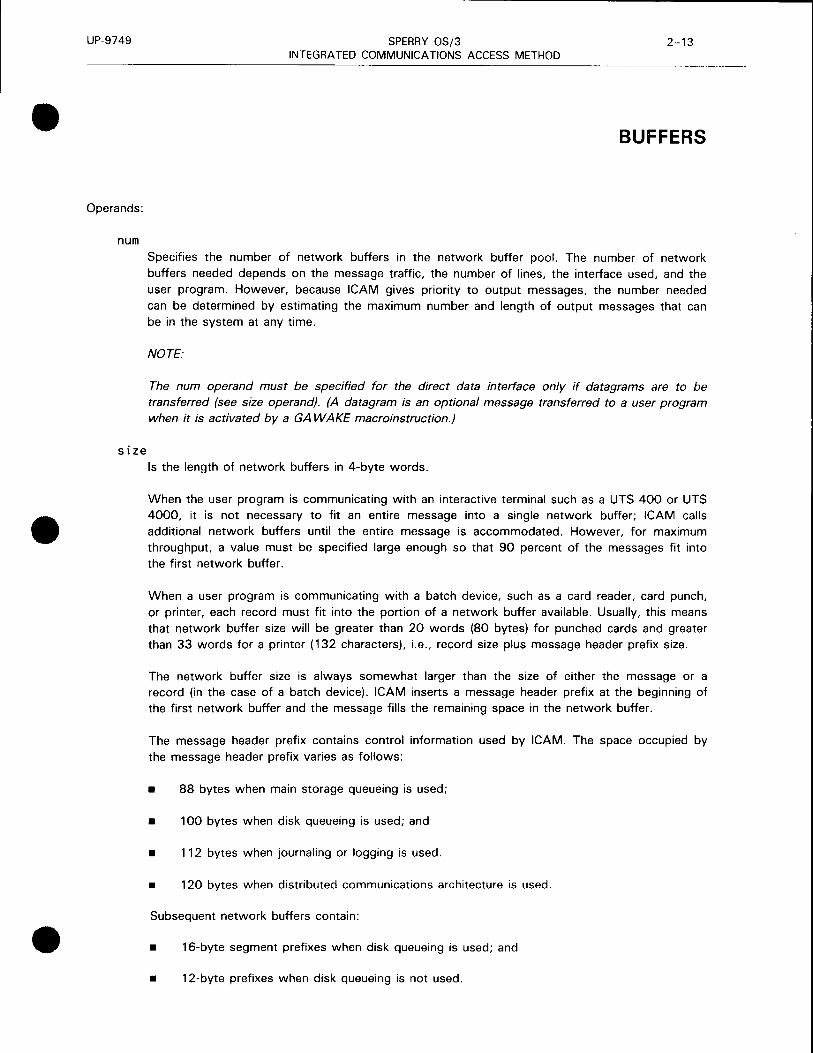
Specifies the number of network buffers in the network buffer pool. The number of network buffers needed depends on the message traffic, the number of lines, the interface used, and the user program. However, because ICAM gives priority to output messages, the number needed can be determined by estimating the maximum number and length of output messages that can be in the system at any time.
NOTE:
The num operand must be specified for the direct data interface only if datagrams are to be transferred (see size operand). (A datagram is an optional message transferred to a user program when it is activated by a GA WAKE macroinstruction.)
Is the length of network buffers in 4-byte words.
When the user program is communicating with an interactive terminal such as a UTS 400 or UTS 4000, it is not necessary to fit an entire message into a single network buffer; ICAM calls additional network buffers until the entire message is accommodated. However, for maximum throughput, a value must be specified large enough so that 90 percent of the messages fit into the first network buffer.
When a user program is communicating with a batch device, such as a card reader, card punch, or printer, each record must fit into the portion of a network buffer available. Usually, this means that network buffer size will be greater than 20 words (80 bytes) for punched cards and greater than 33 words for a printer ( 132 characters), i.e., record size plus message header prefix size.
The network buffer size is always somewhat larger than the size of either the message or a record (in the case of a batch device). ICAM inserts a message header prefix at the beginning of the first network buffer and the message fills the remaining space in the network buffer.
The message header prefix contains control information used by ICAM. The space occupied by the message header prefix varies as follows:
• 88 bytes when main storage queueing is used;
• 100 bytes when disk queueing is used; and
• 112 bytes when journaling or logging is used.
• 120 bytes when distributed communications architecture is used.
Subsequent network buffers contain:
• 16-byte segment prefixes when disk queueing is used; and
• 12-byte prefixes when disk queueing is not used.

UP-9749 SPERRY OS/3 2-14 INTEGRATED COMMUNICATIONS ACCESS METHOD
BUFFERS
These prefixes are used to link the network buffers when more than one is needed to hold a message. Each network buffer is filled with the message starting at the first byte following the
message header prefix and segment prefixes.
NOTES:
1. The num and size operands must not be specified if a program is using the direct data interface unless the program is to receive datagrams. If so, sufficient network buffers must be specified to hold all datagrams that can be present until they are delivered. All network buffers used to hold datagrams contain a 12-byte message header prefix.
2. If a global network is used with dynamic sessions, the network buffer size must be at least 208 (decimal) bytes (52 words). This size, which includes the message header, ensures that any messages generated by the OS/3 command language processor as a result of a program or terminal operator attempting to establish a dynamic session will fit into a single network buffer.
thresh Specifies a threshold value that is the minimum number of network buffers that can be inactive before ICAM temporarily stops polling for input. This allows ICAM to concentrate on sending output until enough network buffers become available to resume input. A value can be specified of 10 to 15 percent of the number of buffers specified in the num operand.
When used in conjunction with buffer pool expansion, ICAM attempts to expand the buffer pool when the threshold value is reached. If ICAM is able to expand the buffer pool, processing continues because more buffers are available for use. Otherwise, threshold processing takes place as just described.
NOTES:
1. This operand is not used in the direct data interface.
2. If this operand is specified, a threshold for activity request packets is also established that is approximately 10 percent of the number of packets specified.
3. /CAM always checks to see whether sufficient buffers are available in the network buffer pool without entering threshold processing before it honors an output request. If not, the program receives control at its no-buffer-available (NOBA V) address, and the output request is rejected. This prevents output requests from causing the loss of input messages in process when a threshold condition occurs.
4. A threshold must be specified of at least enough network buffers to hold one message.
EXPFACT=n
Specifies an ICAM buffer pool expansion factor. You may specify 0 to 100 (percent). The default value is 25.
•
•
•

•
•
•
UP-9749 SPERRY OS/3 2-15 INTEGRATED COMMUNICATIONS ACCESS METHOD
BUFFERS
ICAM automatically expands the number of buffers in a given buffer pool by the factor you specify in this operand whenever the number of inactive buffers in that pool equals the value you specify in the thresh operand. This operand applies to all ICAM buffer pools except RTIME (network buffer, ARP, UDUCT, LINKPAC, etc). but only the pool that reaches the threshold value is expanded. If the first increment is exhausted, additional increments are added until peak requirements are met or main storage resources are exhausted.
If you specify EXPFACT=O, no buffer pool expansion is performed. However, the buffer pool services expansion routine is automatically included in ICAM unless you specify BPOOLEXP=NO in the MCP portion of COMMCT at system generation.
ARP= integer Creates an act1v1ty request packet pool. The number specified is the number of 14-word (56 byte) activity request packets available to ICAM to perform its functions.
Activity request packets are essential to ICAM, so enough of them must be assigned. The following is recommended, based on the interface chosen:
Interface
Standard
Transaction control
Direct data
DCA sessions
Circuit-switched public data network (must be DCA)
Minimum Number of Packets
5 + 4 per network + 2 per process file + special functions
7 + 4 per network + special functions
4 per line + 4 per network + special functions
6 + 6 per line + special functions
6 + 10 per line + special functions

UP-9749 SPERRY OS/3 INTEGRATED COMMUNICATIONS ACCESS METHOD
2-16 Update B
BUFFERS
Interface
Packet-switched public data network (must be DCA)
Special functions:
Minimum Number of Packets
Use the formula:
num=vc +tr ks+ tse.ss
where:
vc
tr ks
Is the number of virtual circuits on all packet-switched public data networks.
Is the number of trunks in the ICAM network.
tsess Is the maximum number of sessions that may be active simultaneously on all virtual circuits.
• If the user program issues multiple output messages to multidrop lines, one activity request packet must be added for each terminal.
• If a long series of requests to ICAM with IRL set is issued, one activity request packet must be added for each call over 3.
• With distributed data processing, six activity request packets must be allowed for ICAM, six for each configured line or DCP channel, and one for each session allowed. DMI users should allow three activity request packages for each interactive session and three for each DDP session.
STAT=YES
Creates network data buffer pool and activity request packet pool statistics areas that keep track of pool usage.
THOLD=n
Specifies a threshold for activity request packets used with the direct data interface only. With the direct data interface, the thresh operand does not apply; therefore, if a threshold on activity request packets is desired, this operand must be specified. There is no chance of running out of activity request packets; this operand can be omitted to save storage.
t UDUCT=({.m} [' 'tltesh}])
Specifies the number of user data unit control tables, which are 28-word areas that control data transmission and supply information about messages (senders, receivers, ports, and sessions) in distributed data processing and for remote workstations.
•
•
•

•
•
•
UP-9749 SPERRY OS/3 INTEGRATED COMMUNICATIONS ACCESS METHOD
2-17 Update B
BUFFERS
For distributed data processing terminal-oriented configurations, allow at least three UDUCTs for ICAM and four per configured port. In processor-to-processor configurations, allow at least 10 UDUCTs for nodes with a single port. For nodes with multiple ports, calculate minimum UDUCTs with the formula:
UDUCTs = (6 x number of ports) + 6
At your option, set the threshold value to 3.
·NOTE:
Specifying too few UDUCTs for the ports on both processors in processor-to-processor configurations could cause an unrecoverable hold condition.
When using remote workstations, calculate the minimum number of user data unit control tables (UDUCTs) with the formula:
num = 2 x number of TERM macroinstructions specified for remote workstations
and set the threshold number by:
thresh= 10% of value specified for num
LINKPAK=({;.~m} I t:~ze} c {~;resh}])
num
Specifies the number, size, and threshold value of link buffers. You use these with distributed data processing, remote workstation support, and public data networks.
Specifies the number of link buffers. For distributed data processing and for circuit-switched public data networks, specify 45 times the number of communications lines using distributed data processing.
For a packet-switched public data network, determine the maximum number you need by using the following formula, and add to it any other link buffer needs in the network.
num = (maximum ws or mpm (whichever is larger) + mpm + ws) * maxsess
where:
num
WS
mpm
Is the number of link buffers for this packet-switched public data network.
Is the window size .
Is the number of data packets required to hold the largest message passed over the circuit. Compute mpm by dividing the length of the largest message by the value specified in the PKTSIZ operand on the PDN macroinstruction (rounded to the next whole word).

UP-9749 SPERRY OS/3 INTEGRATED COMMUNICATIONS ACCESS METHOD
2-18 Update B
BUFFERS
size
maxsess Is the maximum number of sessions to be multiplexed over this session.
When using remote workstations, calculate the minimum number of link buffers with the formula:
num = 3 x number of TERM macroinstructions specified for remote
workstations
Size is the length of the link buffer in words (one word equals four bytes). For remote workstations, distributed data processing, or circuit-switched public data networks only, specify 80.
If you are using both distributed data processing and a packet-switched public data network, try the formula and specify the larger of the two.
The formula for determining size for a packet-switched public data network is:
size= C1bprfx + 2hdr + 3hdr + mxdta) I 4
where:
1 bpr fx
2hdr
3hdr
Is the length of the link buffer prefix (40 bytes).
Is the length of the level 2 header (2 bytes).
Is the length of the level 3 modulus for the public data network (36 bytes for modulus 8, and 4 bytes for modulus 128).
mxdta
Is the value specified on the PKTSIZ operand of the PDN macroinstruction.
4 Converts all of the previous to words.
thresh
Specifies a threshold value for distributed data processing or remote workstations. Specify 23 for distributed data processing. It is not required for public data networks.
For remote workstations use the formula:
thresh= 10% of value specified for num
RTIME=Cnum)
Specifies the number of 3-word timer stack entries used with distributed data processing. Maximum number needed should equal the number of ports plus the number of active sessions. The default value is 50.
•
•
•

•
•
•
UP-9749 SPERRY OS/3 2-19 INTEGRATED COMMUNICATIONS ACCESS METHOD
CCA
Identifies the beginning of an ICAM network definition, the type of network, and the kind of support ICAM provides in the network.
This macroinstruction is used in all network definitions, but it may be specified only once in each network definition.
The operands in this macroinstruction cover several different types of network definitions, both global and dedicated, as shown in Table 2-7. NO indicates that the operand does not apply to that type of network definition at all. YES indicates that the operand is either optional or required. The operand description must be read to see whether it applies to the application being used.
Format:
LABEL 60PERATiON6
lnetwork-1 name PIOCS
CCA
OPERAND
[ { <St~HCP> }] TYPE= CGBL,,node) CODI, level)
{TC I)
[,DUSTERR=INLINE]
[,PASSWORD=password]
[,SAVE=YESJ
[,CCAID=identifier]
[,DCA=YESJ
[EATURES=(::~~~~:~~~~:::~~ART] )~ [,SEGMENTS][,DATIME])[,MONITOR]~
[
' JRN IN IT=([, RESTART] [, PERF ])~ [,STATJ[,JOURNJ [,ODNRJ
[,GAWAKE=YES]
[,USERS=number]

UP-9749
CCA
SPERRY OS/3 INTEGRATED COMMUNICATIONS ACCESS METHOD
Table 2-7. Applicability of CCA Macroinstruction and Its Operands (Part 1 of 2)
Macro: ICAM Network Type and Kind of Program Supported CCA
Operand Direct Name Data
interface Dedicated
DOI Networks
NTR
RBP ~ Cl.
RPG ::::E u :::. ::::E
Cl u ....
IDES .... CJ)
"CCA R R R R
label R R R R
CCAID= 0 0 0 0
DCA= - - - -
DUSTERR= 0 - - 0
FEATURES= 0 0 0 0
AUTOBUF - - - -
BASIC 0 - 0 0
DA TIME - - - 0
OPCOM 0 0 0 0
OUTDELV - - - 0
RESTART - - - 0
SEGMENTS - - - 0
MONITOR 0 0 0 0
GA WAKE= 0 - 0 0
JRNINIT= - - 0 0
JOURN - - 0 0
ODNR - - 0 0
*Shows macro applicability
LEGEND: R Required 0 Optional
Not applicable
::r 0 al c.. 0 u ~ ::::E
Cl CJ)
u .... ::::E
CJ)
u
R R
R R
0 0
- -
- 0
R 0
- -
- -
R 0
0 0
- 0
0 0
R 0
0 0
- 0
0 0
0 0
- 0
cs PS
~ ::::E :::. -u ....
R
R
0
-
-
0
-
-
-
0
-
0
-
0
0
0
0
0
Global Networks
....J
0 al 0 u
R
R
0
-
-
R
-
-
R
0
-
0
R
0
0
0
0
-
~ <{ - OU ::::E c: Cl Cl ·;: ' - c:
:::J 0 ::::E z
R R
R R
0 0
- -
- -
0 0
- -
- -
- 0
0 0
- 0
- 0
- 0
0 0
0 0
- 0
- 0
- 0
Circuit-switched Packet-switched
<{ u Cl
R
R
0
R
-
0
-
-
0
0
0
0
0
0
R
0
0
0
co ... "' co-" Cl .. 0
u ~ :E OJ ~z
cs
R
R
0
R
-
0
-
-
0
0
0
0
0
0
0
0
0
0
PS
R
R
0
R
-
0
-
0
0
0
0
0
0
0
0
0
0
0
2-20 Update B
•
•
•

•
•
•
UP-9749
Label:
SPERRY OS/3 INTEGRATED COMMUNICATIONS ACCESS METHOD
Table 2-7. Applicability of CCA Macroinstruction and Its Operands (Part 2 of 2)
Macro: CCA
ICAM Network Type and Kind of Program Supported
Operand Name
PERF
RESTART
STAT
PASSWORD
SAVE
TYPE
USERS
LEGEND
Direct Data
Interface
DOI
NTR
RBP
RPG
IDES
0 0
R R
R 0
Required Optional Not applicable
::::.
u I-
0
0
0
0
R
Dedicated
Networks
c.. u ~ 0 IC/)
0
0
0
0
0
::::; 0 CD 0 u (/)
u ~ u
0
0
0
0
R
R
cs PS
a.. u ~ 0 IC/)
0
0
0
0
R
Global Networks
--u I-
0
0
0
0
R
-' 0 CD 0 u
0
0
0
0
R
R
~ 0
0
R
Circuit-switched Packet-switched
~ <t OU . :: 0 .. ' - c: ::J 0 ~z
0
0
0
R
<t u 0
0
0
0
R
Ill .. If) Ill~ 0 ..
0 .!:! ~ - .. .Q Q)
~z
CS PS
0 0
0 0
0 0
R R
2-21 Update A
CCA
network-name Is a 1- to 4-character label, beginning with an alphabetic character, that identifies this network. This is the label referred to when requesting a dedicated network or releasing a dedicated network. When a global network is used, this is the name the global user service task (GUST) uses to activate the global network. Do not use labels beginning with LD or LT. These prefixes have special meaning for system generation.
PIOCS
Required label only for a communications physical interface network, or a nonphysical interface to support single-line communications adapter dump.
NOTE:
Physical 1/0 CCA must be the last CCA defined in a multiple CCA generation.

UP-9749 SPERRY OS/3 2-22 INTEGRATED COMMUNICATIONS ACCESS METHOD
CCA
Operands:
Ty p E = (~!J'l:>Ml:P> Indicates this is a standard interface dedicated network definition.
TYPE=CGBL,,node)
GBL
node
Indicates this is a standard interface global network definition.
Is a 1- to 4-character computer node identifier that identifies this computer. Any non null character may be specified if your global network resides in one computer only.
NOTE:
Two commas must follow the GBL operand.
TYPE=CDDI,level)
DOI Indicates this is a direct data interface network definition.
level Is the level of direct data interface support needed; 3, 2, or 1 must be specified.
3 - provides full direct data interface support including:
• RPG telecommunication and NTR, RBP, and IDES utilities
• Batch mode operation
• Multiple output message control table (MCT) support for UNISCOPE and UTS 400 terminals
• Auxiliary device support
• Wait for end of message in the last line buffer logic
2 - provides the same support as 3, except batch mode of operation is not provided.
1 - provides minimum support without any of the items listed for 3. It is for use in
systems having minimal main storage available.
TYPE=CTCI> Indicates this is a transaction control interface dedicated network definition supporting the information management system (IMS).
•
•
•

•
•
•
UP-9749 SPERRY OS/3 INTEGRATED COMMUNICATIONS ACCESS METHOD
2-23 Update B
CCA
DUSTERR=INLINE Specifies that, if an error occurs during DUST macroinstruction processing, all returns are inline. If you don't specify DUSTERR=INLINE and an error occurs during DUST macroinstruction processing, ICAM returns control at the NETREQ macroinstruction ERRET= address you specify, using rules for error processing up to and including OS/3 7. 1.
NOTE:
The DUSTERR=INLINE specification is correct only when your program is coded to match the operand you specify.
PASSWORD=password Is a 1- to 8-character password further identifying this network. A specified password must be used in all requests for this network.
SAVE=YES Saves a copy of this network definition in the system object library ($Y$0BJ) file on the system resident volume. When using this network definition in conjunction with a COBOL program (and with the COBOL message control system (CMCS)), this operand must be specified .
CCAID= identifier Specifies a 1- to 8-character identifier - a word, a label, a code, etc - that is printed on each page of the network definition assembly listing and the summary report at the end of the listing. This makes it easier to locate the network.
DCA=YES Indicates support of distributed communications architecture. This operand is also required for all remote workstations and packet-switched public data networks and the NORDIC circuit-switched public data network. Note that you must also specify GA WAKE= YES.
FEATURES=
AUTOBUF Includes automatic line buffering routines to support field-written remote device handlers. This operand is not specified when using remote device handlers provided by Sperry. This operand is used in a communications physical interface.
OP COM Specifies support of unsolicited console type-ins to ICAM. This feature is not supported for the NTR networks.
BASIC Includes a basic (minimum) teletypewriter or UNISCOPE remote device handler in !CAM. This operand is not specified when using a more sophisticated version of either handler.
OUTDELV Specifies the !CAM output delivery notice feature.

UP-9749
CCA
SPERRY OS/3 2-24 INTEGRATED COMMUNICATIONS ACCESS METHOD
RESTART Includes disk queueing routines to enable a warm restan. Warm restart has ICAM recover messages from disk storage queues in the event of a system failure or when a network is closed before all messages on disk are delivered.
SEGMENTS Includes routines to send or receive messages in segments.
DA TIME Has ICAM date and time stamp all queued messages.
MONITOR Specifies the system activity monitor is to be linked into the communications control area.
JRNINIT=
RESTART
PERF
STAT
Specifies maintaining restan records. ICAM writes restart records to a history file to permit disk queues to be rebuilt by a journal utility should ICAM fail due to a queueing disk failure.
Specifies maintaining line and terminal performance records.
Specifies maintaining network buffer and activity request packet pool statistics.
JOU RN
ODNR
Specifies gathering journal records that contain the full text of messages passing through ICAM plus certain control information.
Specifies maintaining output delivery notice records. These refer to journal records and signify that the referenced message was dequeued for delivery to a terminal or a communications user program or that a message was canceled.
GAWAKE=YES Specifies the ICAM GA WAKE feature, which enables any task to activate an ICAM user program that has yielded, and optionally sends to the user program a message known as a datagram.
USERS=number This operand applies only to the communications physical interface and is the decimal number of physical user programs that will use the physical network.
•
•
•

•
•
•
UP-9749 SPERRY OS/3 2-25 INTEGRATED COMMUNICATIONS ACCESS METHOD
CPSTB
Creates a call progress signal table to report status when circuit-switched public data networks are unable to establish a circuit immediately. Enables you to build your own table of actions instead of using the values supplied by ICAM shown in Table 2-8.
The call progress signal table is identified by the label of the first CPSTB macroinstruction and the label of the CPSTB macroinstruction containing an END operand.
Table 2-9 describes the interface and type of network definition in which the macroinstruction is used. It also details the applicability of each operand in the macroinstruction.
Format:
LABEL L.OPERATIONL. OPERAND
Label:
[symbol] CPS TB
symbol
CPS={n } (n1,n2,nn)
['NOR= ({;t ca - nor}, {~cam -nor}) J [' TBR\t.;lca-tbr}, {~cam-tbr})]
[' TBD={,i~·ime-before-disconnect}]
[,END=cpstb-symbol]
Is a 1- to 4-character label that identifies the start of a call progress signal table. This label is used only on the first of a series of one or more CPSTB macroinstructions.
Operands:
CPS={n } (n1,n2,nn)
Specifies the 2-character identification number of the desired call progress signal.
n Specifies a single call progress signal to be handled by ICAM according to the parameters specified in this macroinstruction.
n1,n2,nn Specifies a series of call progress signals to be handled according to the parameters specified in this macroinstruction .
NOR= {;lea-nor}, {~cam-nor}
slca-nor Specifies the number of times (0-63) the single line communications adapter (SLCA) attempts to reestablish a connection to the remote data terminal equipment.

UP-9749 SPERRY OS/3 2-26 INTEGRATED COMMUNICATIONS ACCESS METHOD
CPS TB •
icam-nor Specifies the number of times the ICAM system attempts to reestablish a connection if the SLCA fails to reconnect. The range is 0 to 32, 767.
TBR= {slca-tbr} '{icam-tbr}
• • slca-tbr Specifies the time in seconds (0-255) between retries by the SLCA to reestablish a connection to remote data terminal equipment.
icam-tbr Specifies the time in seconds (0-254) between retries by ICAM to reestablish a connection to remote data terminal equipment.
TBD={~ime-before-disconnect}
Specifies the time in seconds (0-254) that ICAM waits following a call progress signal where the data terminal equipment is expected to wait (01, 02, 03, on Table 2-8) before terminating the connection to a public data network.
END=cpstb-symbol Specifies that this is the last CPSTB macroinstruction in a series of one or more CPSTB macroinstructions. You must specify the label of the first CPSTB macroinstruction.
Table 2-8. Call Progress Signal Action Default Values
SLCA ICAM Call Progress Signal
NOR TBR TED NOR TBR
01 T Prm1nal catlerl 0 0 50 0 0 02 Redirected call 0 0 I 2 0 0 ! 03 Connect when free 0 0 I 2 0 0 20 No connection 3 5
I 0 10 300
2 1 Number busy 3 5 0 50 I 300 22 Locat procedure error 3 2 0 0 0 23 Selection signal trans
mission error 3 2 0 50 300 41 Access barred 1 0 0 0 0 42 Changed number 1 0 0 0 0 43 Not obtainable 1 0 0 0 0 44 Out of order 1 0 0 50 1200 45 Controlled not ready 3 2 0 50 50 45 Uncontrolled not ready 3 2 0 50 1200 47 DCE power off 1 2 0 50 1200 48 Invalid facility request 1 0 0 0 0 I 49 Network fault local 3 2 0 0 0
I 51 Call information 1 0 0 0 0 52 Incompatible user 1 0 0 0 0 51 Network congestmn 3 2 0 50 300 71 Long-term network
congestion 1 10 0 50 300 81 Reg1strat1on /cancellation
confirmed 0 0 0 0 0 82 Red1rect1on active 0 0 0 0 0 83 Red1rec11on inactive 0 0 0 0 0
LEGEND
NOR Number of retries (to reestablish connection) TBO Time (m seconds) before disconnect TBR Time (1n seconds) between retries (wait for network to respond or clear)
DCE Data c1rcu1t-term1natmg equipment
•
•

UP-9749
•
•
•
SPERRY OS/3 INTEGRATED COMMUNICATIONS ACCESS METHOD
Table 2-9. Applicability of CPSTB Macroinstruction and Its Operands
Macro: CPS TB
ICAM Network Type and Kind of Program Supported
Operand Name
·cPSTB
label
CPS=
NOR~
TBR~
TBD=
Direct Data
Interface
DOI
NTR
RBP
RPG
IDES
·shows macro applicability
LEGEND
R = Required O Optional
Dedicated
Networks
- 1 -
Q. u ::!: c ~ (/)
Not applicable
::::.
Global Networks
....J 0 CD 0 u
::!: c
~< OU ·= c ... ' - c: :I 0 ::!: z
1
< u c
ra ... IJl ra .:,t c ..
0 .!: ~ - ... ..c Q)
~z
0
R
R
0
0
0
0
2-27 Update B
CPSTB

t
UP-9749 SPERRY OS/3 INTEGRATED COMMUNICATIONS ACCESS METHOD
DISCFILE
The DISCFILE macroinstruction can create two types of disk file for use by ICAM:
2-28 Update B
1. The DISCFILE macroinstruction with the MSGSIZE operand to specify a disk buffering file. This file is required with the transaction control interface. It is not used with the standard interface.
2. The DISCFILE macroinstruction with the FILEDIV operand to specify a disk queueing file. This file is optional with the standard interface or a transaction control interface.
DISCFILE macroinstructions should be grouped together following the CCA, BUFFERS, LINE, and TERM macroinstructions. In a transaction control interface, the DISCFILE macroinstruction must follow the last TERM macroinstruction. In a disk queueing network, the first DISCFILE macroinstruction must follow at least one PRCS, TERM, VLINE, or PON macroinstruction.
Table 2-10 describes the interface and type of network definition in which you can use this macroinstruction. It also details the applicability of each operand in the macroinstruction.
Format:
LABEL tc.OPERATION6 OPERAND
file-name DISCFILE {
MSGSIZE=n } FILEDIV=n[,VERIFY=YES]
Table 2-10. Applicability of DISCFILE Macroinstruction and Its Operands
Macro: ICAM Network Type and Kind of Program Supported DISCFILE
Operand Direct Name Data
Interface Dedicated
Global Networks DOI Networks
NTR _,
RBP iii
0 "' c.. CD 0.. iii _, ., <( - "' RPG ~ u 0 u :?! "8u "'.>t. 0 <( c ~ :?! ~ :?! CD ~ c: c u 0 c c 0 c ·;; ' c " ~ u VJ u 3 c: ::5 Qj f- u f- u :?! ~ IDES f- VJ
:?! VJ f- ~z
u
'DISCFILE R - - - - - - - - -lrl1sk l>~ifferinqJ
label R i - - - - - - - -
I
MSGSIZE ·. R - - - - - - - - -
I 'DISCFILE 0 0 0 0 0 0 - I 0 0 0 (disk
(jueue1ny)
label R R R R R R - R R R
FILEDIV ~ - R R R R R R - R R R
VERIFY·· - - 0 0 0 0 0 0 - 0 0 0
'Shows macro applicability LEGEND· R ~ Required 0 ~ Optional - ~ Not applicable
•
•
•

•
•
•
UP-9749 SPERRY OS/3 2-29 INTEGRATED COMMUNICATIONS ACCESS METHOD
DISCFILE
Label:
file-name
Operands:
Is a 1- to 7-character name identifying this disk file. This name must match the file name on an LFD statement in the user program job control stream.
MSGSIZE=n This operand is required for a disk buffering file and is used only with a transaction control interface. It specifies the size, in bytes, of the largest input message.
FILEDIV=n This operand is required for a disk queueing file and is used with a standard interface or a transaction control interface. It gives the percentage of disk queueing space to be allocated for a control area. There are two ways to determine the percentage to allocate for a control area. In either case, the percentage specified must equal at least one disk track. If sufficient space is not provided, programs are cancelled with an error code of 480.
1 . Rule of thumb estimate:
Number of disk buffers
Under 300 300-1000 1000-3000 Over 3000
NOTE:
Approximate FILEDIV allocation
10-20% (depending on number of queues) 5% 3% 1-2%
If only one cylinder is allocated for the disk queueing file, specify at least 15 for the FILEDIV.
2. Calculated percentages:
The control area requires:
• one 256-byte sector for every 2000 disk buffers in the file;
• one sector for each queue using the file; and
• one sector for file descriptor records .

UP-9749 SPERRY OS/3 2-30 INTEGRATED COMMUNICATIONS ACCESS METHOD
DISCFILE
FILEDIV percentage = number of sectors needed for control area total number of sectors in the file
Example 1 (large file):
Assume that buffer size is 128 words, or 512 bytes, the size of two sectors. This means that a file holding 5000 disk buffers is 10,000 sectors in size.
File holds 5000 buffers: 5000/2000 (rounded up) 24 queues use the file Needed for file descriptor records
Number of sectors needed Size of file 28/10,000 (rounded up) = 1%
Example 2 (small file):
3 sectors 24 sectors
1 sector
28 sectors 10,000 sectors
Assume that buffer size is 64 words. or 256 bytes. the same size as a sector. The file holds 140 disk buffers and is 140 sectors in size.
File holds 140 buffers: 140/2000 (rounded up) 10 queues use the file Needed for descriptor records
Number of sectors needed Size of file
12/140 (rounded up) 10%
NOTE:
1 sector 10 sectors
1 sector
12 sectors 140 sectors
If the number of cylinders needed is equivalent to less than one cylinder, allocate one cylinder and specify at least 15 for FILDIV.
VERIFY=YES
Specifies verification, or parity check, of each block written to a disk queueing file. This operand must be included to ascertain whether messages written to the disk queueing file are complete and accurate.
•
•
•

•
•
•
UP-9749 SPERRY OS/3 2-31 INTEGRATED COMMUNICATIONS ACCESS METHOD
DUST
Specifies a static list of message destinations within the network definition. An output request that references a DUST is the equivalent of multiple output requests that reference every destination in the DUST. The destinations specified may include process files, locap files, terminals, or other DUSTs. Specified DUSTs cannot themselves contain DUSTs. A DUST created within a network is unchangeable for the life of the network.
Table 2-11 describes the interface and type of network definition in which you can use this macroinstruction. It also details the applicability of each operand in the macroinstruction.
Format:
LABEL 6.0PERATION6. OPERAND
dlist-name DLIST destination1,destination2 •••
Table 2- 11. Applicability of DUST Macroinstruction and Its Operands
Macro: DUST
ICAM Network Type and Kind of Program Supported
Operand Name
·ousT
label
dest-1
dest-2
dest-n
Direct Data
Interface
DOI
NTR
RBP
RPG
IDES
*Shows macro applicability
LEGEND:
::::.
u I-
0
R
R
R
0
Dedicated
Networks
I!. u ~ c 1-r.n
0
R
R
R
0
:J 0 Ill 0 2 en u ~ u
R
R
R
R
0
0.. u ~ c 1-r.n
0
R
R
R
0
::::.
(.) I-
0
R
R
R
0
R = Required 0 = Optional - = Not applicable
Global Networks
...J
0 Ill 0 u
R
R
R
R
0
~ <t ou .5 c .... ' - c: :I 0 ~z
0
R
R
R
0
<t u c
0
R
R
R
0
0
R
R
R
0

UP-9749 SPERRY OS/3 2-32 INTEGRATED COMMUNICATIONS ACCESS METHOD
DUST
Label:
dlist-name Is a 1- to 4-character name of the distribution list.
Operands:
destination1,destination2 ••• Identify at least two destinations, which may be process files, locap files, other distribution lists, or terminals.
NOTES:
1. DUST macroinstructions can be incorporated in the communications user program; however, at least one DUST macroinstruction (with two valid destinations) must be included in the network definition. This must be done, even if it is not used, to incorporate DUST processing code into /CAM at system generation time.
2. A destination name may appear only once a DUST or a group of DUSTs in the scope of a PUTCP request. or a message processing routine ROUTE macroinstruction.
3. Unpredictable results occur if a DUST is used to send output to an auxiliary device not on line.
4. A DUST must not be nested more than once, i.e., a DUST referenced by a DUST cannot reference a third DUST.
•
•
•

UP-9749 SPERRY OS/3 2-33 INTEGRATED COMMUNICATIONS ACCESS METHOD
• ENDCCA
Indicates the end of a network definition.
Format:
LABEL 60PERATION6 OPERAND
not used ENDCCA not used
•
•

UP-9749 SPERRY OS/3 2-34 INTEGRATED COMMUNICATIONS ACCESS METHOD
EUP
Generates a profile containing the criteria used by the ICAM message format editing facility (format edit) to edit output messages.
Table 2-12 describes the interface and type of network definition in which you can use this macroinstruction. It also details the applicability of each operand in the macroinstruction.
Format:
LABEL 60PERATION6
[symbol] EUP
OPERAND
PRFN=profile-number
,EUF=1DCT l TTY
U64
U80
Clw[,lines][,RET])
[,EDT=char]
[,ETB=(ch1[,ch2][,ch3J>l
[,CMWO=YES]
•
•
•

•
•
•
UP-9749
Operands:
SPERRY OS/3 INTEGRATED COMMUNICATIONS ACCESS METHOD
Table 2-12. Applicability of EUP Macroinstruction and Its Operands
Macro: EUP
ICAM Network Type and Kind of Program Supported
Operand Name
*EUP
label
EUF=
OCT
TTY
U64
U80
EDT=
ETB=
CMWO=
PRFN=
Direct Data
Interface
DOI
NTR
RBP
RPG
IDES
*Shows macro applicability
LEGEND:
0
R
R
0
0
0
0
0
0
0
R
Dedicated
Networks
c.. u ~ c ~ en
0
R
R
0
0
0
0
0
0
0
R
:::i 0 ai 0 ~ en u ~ u
0
R
R
0
0
0
0
0
0
0
R
0.. u ~ c ~ en
0
R
R
0
0
0
0
0
0
0
R
0
R
R
0
0
0
0
0
0
0
R
R = Required 0 = Optional - = Not applicable
Global Networks
...I 0 ai 0 u
0
R
R
0
0
0
0
0
0
0
R
~< OU .Sc ... ' - c: :I 0 ~z
< u c
ca ... Cl)
ca .:it c ... 0
.!:! ~ - ...
.l:l G>
~z
2-35
EUP
PRFN=profile-number Assigns a number to this profile and associates it with an assignment in one related TERM macroinstruction. For example, if this profile is identified as 5 (PRFN=5), then PROFIL=5 must be specified in the associated TERM macroinstruction that uses it. This number must be unique in the network definition, even if an identical profile definition is used with another terminal.

UP-9749
EUP
EUF=
SPERRY OS/3 2-36 INTEGRATED COMMUNICATIONS ACCESS METHOD
Describes the page and line profile created.
EUF=DCT Establishes a line width of 132 characters and 54 lines per page for the OCT 500 series and OCT 1000 terminals.
EUF=TTY Establishes a line width of 72 characters for teletypewriter terminals. There is no limit on the number of lines per page (continuous).
EUF=U64 Establishes a line width of 64 characters for UNISCOPE terminals. There is no limit on the number of lines displayed (continuous).
EUF=U80 Establishes a line width of 80 characters for UNISCOPE terminals. There is no limit on the number of lines displayed (continuous).
When one of these options is specified, format editing avoids splitting contiguous character strings by scanning each line from right to left for a character specified in the EDT operand. If the EDT character is found, the data to the left is output as a line. If no EDT character is specified, the space character (4016) is used. DICE sequence characters are not included in the line width count. If a line is not to be broken, an EDT character must be specified that will never be found.
EUF=Clw[,lines][,RET])
lw Specifies the number of characters sent in a single line. It may be specified with or without the lines subparameter and is used to specify line widths different from those already discussed.
When lw is used in conjunction with the ETB or EDT operands, output is transmitted when any of the arguments are satisfied. If both operands are specified, EDT receives the priority. Note that, when lw is specified, any DICE character sequences are included in the line width count.
lines Specifies the number of lines output before format edit inserts a home paper DICE sequence or returns control to the user program. Home paper occurs after the number of lines specified, regardless of the number of messages it takes to reach the value. If the RET
suboperand is not specified, a home paper DICE is issued when the Jines suboperand is satisfied. This suboperand cannot be specified without the Jw suboperand.
•
•
•

•
•
•
UP-9749
RET
SPERRY OS/3 2-37 INTEGRATED COMMUNICATIONS ACCESS METHOD
EUP
Returns control to the user program after the number of lines specified in the lines suboperand are sent. The output delivery notice request feature must be specified in your network definition.
If a message contains additional data after the number of lines specified has been sent, the additional data is lost. No notice of this is sent to the user program.
When this format is specified, format edit avoids splitting contiguous characters by scanning each line from left to right for a character specified in either the EDT or ETB operands. If both are found, EDT gets priority. If neither is found, the lw parameter takes precedence.
EDT=char Specifies a single character used as follows:
• To determine the length of an output line. When lw, ETB, and EDT operands are used in combination, line composition ends when one of the operands is satisfied.
•
•
As a line editing argument when EUF=DCT, EUF=TTY, EUF=U64, or EUF=UBO is specified. After the line is initially composed according to the line width for the terminal specified, editing scans from right to left to avoid splitting contiguous characters between output lines. If EDT is not specified, editing scans for a space character, hexadecimal 40.
When specified as 10, it may be used in conjunction with ETB to identify a 4-character DICE sequence for determining the length of a line. The 4-character sequence is never transmitted.
NOTE:
The EDT operand must be specified in hex without an X or surrounding apostrophes. For instance, X'05' should be expressed as EDT=05.
ETB=Cch1[,ch2][,ch3]) Specifies a 1- to 3-character sequence that indicates the end of a line in addition to or instead of the character defined in the EDT operand or the lw suboperand. Format edit searches each message from left to right, and when an ETB sequence is found, the line is sent to the terminal. The ETB sequence found in the message is not sent. Note that this operand may be specified only when the lw suboperand is specified.
NOTE:
The ETB operand must be specified in hex without an X or surrounding apostrophes. For instance, X'05' should be expressed as ETB=05.
CMWO=YES Causes the computer message waiting sentinel not to be transmitted in an output message. This enables a message to be displayed at certain terminals without operator intervention .

UP-9749 SPERRY OS/3 2-38 INTEGRATED COMMUNICATIONS ACCESS METHOD
EUP
Programming Notes:
1 . Each EUP macroinstruction must immediately follow its associated TERM macroinstruction in your network definition.
2. Format edit deletes all characters specified by EDT and ETB operands. Program-generated data not specified as editing parameters is forwarded to the device handler.
3. When format edit is used to break a message into lines addressed to the OCT 1000, a maximum line width of 132 characters must be observed. This may be done by specifying a line width of 132 or less, or by specifying an editing argument that occurs before the limits are reached.
4. DICE sequences found in a message, specified by EDT and ETB operands, are discarded and not sent to the terminal.
5. Format edit automatically retries output messages in case of trouble. If it can't transmit a message, it returns the status to ICAM. ICAM reissues the entire message. Reprint of several lines already successfully delivered may be given.
6. Each EUP macroinstruction profile must relate to only one TERM macroinstruction.
7. When the EUF=DCT, TTY, U64, or USO parameter is specified and a line contains more than one EDT character, only the first EDT character is recognized as a line delimiter and is deleted. Additional EDT characters on the line are printed out as text characters.
•
•
•
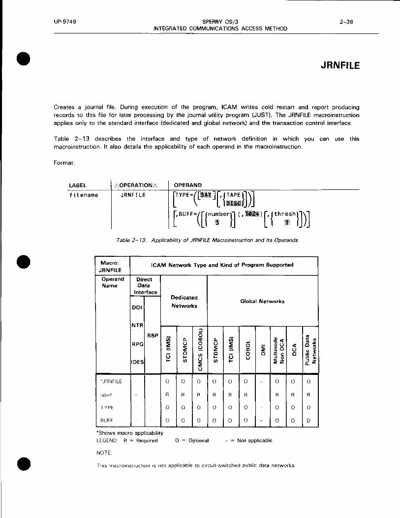
•
•
•
UP-9749 SPERRY OS/3 2-39 INTEGRATED COMMUNICATIONS ACCESS METHOD
JRNFILE
Creates a journal file. During execution of the program, ICAM writes cold restart and report producing records to this file for later processing by the journal utility program (JUST). The JRNFILE macroinstruction applies only to the standard interface (dedicated and global network) and the transaction control interface.
Table 2-13 describes the interface and type of network definition in which you can use this macroinstruction. It also details the applicability of each operand in the macroinstruction.
Format:
LABEL 60PERATIONL:. OPERAND
filename JRNFILE
Table 2-13. Applicability of JRNFILE Macroinstruction and Its Operands
Macro: ICAM Network Type and Kind of Program Supported JRNFILE
Operand Direct Name Data
Interface
DOI
NTR
RBP
RPG
IDES
• JRNFILE - -
labPI - -
TYPE - -
BUFF - -
*Shows macro applicability
LEGEND R = Required
NOTE
Dedicated
Networks
:J"
U) 0
c. II)
~ (.) 0 :::. ~ ~ u 0 en t-- (.) t-- en
:? (.)
0 0 0
R R R
0 0 0
0 0 0
0 = Optional
Global Networks
U) c.. Cl) <( (.) ~
...,j
~ (.) 0 - <( ~ II) ~ .5 0 (.) 0 0 0 .... ' 0 u - c: t-- (.) ::I 0 en t-- ~z
0 0 0 - 0 0
R R R - R R
0 0 0 - 0 0
0 0 0 - 0 0
- = Not applicable
This macroinstruction is not applicable to circuit-switched public data networks.
n:I .... <I) n:I .:t. 0 ...
0 .!:! ~ - .... ..c Cl)
~z
0
R
0
0

UP-9749 SPERRY OS/3 2-40 INTEGRATED COMMUNICATIONS ACCESS METHOD
JRNFILE
Label:
filename
Operands:
Is the logical file name. This label identifies the journal file and is required. It is referenced by (and must be identical to) the following:
• the filename operand of the JOURN macroinstruction;
• the filename operand of the MPPS JOURN macroinstruction; and
• the file name on the LFD statement in the program job control stream.
TYPE=<llli\11R> Journal file is a disk system access technique (SAT) file. Standard labels are assumed.
TYPE=C,lil, TAPE) Journal file is a tape system access technique file. Standard labels are assumed.
Creates staging areas in which records are constructed for output to the journal file.
number Number of staging areas required for this file. The permitted values are from 3 to 10; the default is 3. In most cases, three staging areas are adequate. More staging areas may be needed for a tape journal file or if some messages are very large.
'Dll'.l Size of each staging area, in bytes.
thresh Specifies the minimum number of inactive staging areas permitted. The permitted values are from 0 to the number of staging areas specified; the default is 1 .
•
•
•

•
•
•
UP-9749 SPERRY OS/3 INTEGRATED COMMUNICATIONS ACCESS METHOD
2-41 Update A
LDTE
Defines the attributes of local data terminal equipment (LDTE) in a circuit-switched public data network. Table 2-14 describes the interface and type of network definition in which this macroinstruction is used. It also details the applicability of each operand in the macroinstruction.
Format:
Label:
LABEL
symbol
symbol
60PERATION6
LDTE
OPERAND
[ADDRESS=number]
[1NID={~S}]
[' OUTI D= ~~ n
Specifies the 1- to 4-character label of this macroinstruction.
Operands:
ADDRESS=number Specifies the address (calling number) of this local DTE.
INID={:sl
NO
YES
Specifies that incoming calling line identification is not validated.
Specifies that ICAM is to validate calling line identification for all incoming calls to this local data terminal equipment .
t

UP-9749
LDTE
SPERRY OS/3 INTEGRATED COMMUNICATIONS ACCESS METHOD
Table 2-14. Applicability of LDTE Macroinstruction and its Operands
Macro: LDTE
ICAM Network Type and Kind of Program Supported
Operand Name
•LDTE
label
ADDRESS cc
INID=
OUTID ~·
CPSTBL~
OUTBARD=
LGROUP=
Direct Data
Interface
DOI
NTR
RBP
RPG
IDES
*Shows macro applicability LEGEND
Dedicated
Networks
a.. u ~ 0 IC/)
:::; 0 CD 0 S?. CJ)
u ~ u
a.. u ~ 0 IC/)
= Not applicable
u I-
Global Networks
-' 0 CD 0 u
~<I: OU co ·;:; ' - c ::i 0 ~z
<I: u 0
Ill ... "' Ill~ 0 ...
0 .!::! ~ :0 ; ~z
R
R
0
0
0
0
0
0
2-42 Update B
OUTID=t~S}
NO
YES
Specifies no validation of called line identification for outgoing calls.
Specifies that ICAM is to validate all called line identification for outgoing calls from this local data terminal equipment. The public data network reports the called number to ICAM before making a connection, and this provides a check that the public data network has correctly interpreted the called number.
•
•
•
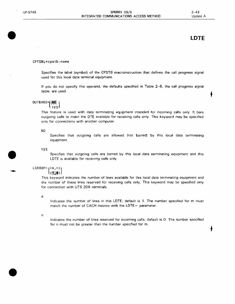
•
•
•
UP-9749 SPERRY OS/3 INTEGRATED COMMUNICATIONS ACCESS METHOD
2-43 Update A
LDTE
CPTSBL=cpstb-name
Specifies the label (symbol) of the CPSTB macroinstruction that defines the call progress signal used for this local data terminal equipment.
If you do not specify this operand, the defaults specified in Table 2-8, the call progress signal table, are used.
OUTBARD={ Ii } YES
This feature is used with data terminating equipment intended for incoming calls only. It bars outgoing calls to make the DTE available for receiving calls only. This keyword may be specified only for connections with another computer.
NO
YES
Specifies that outgoing calls are allowed (not barred) by this local data terminating equipment.
Specifies that outgoing calls are barred by this local data terminating equipment and this LDTE is available for receiving calls only.
LGROUP= {<~:in)} ( ,.,.)
This keyword indicates the number of lines available for this local data terminating equipment and the number of these lines reserved for receiving calls only. This keyword may be specified only for connection with UTS 20X terminals.
m
n
Indicates the number of lines in this LDTE; default is 1. The number specified for m must match the number of CACH macros with the LDTE= parameter.
Indicates the number of lines reserved for incoming calls; default is 0. The number specified for n must not be greater than the number specified for m .
t

UP-9749 SPERRY OS/3 INTEGRATED COMMUNICATIONS ACCESS METHOD
2-44 Update B
LINE
Specifies the characteristics of each local line in a dedicated or global communications network. These characteristics include:
• the general type of remote device handler needed to support the terminals on the line;
• features of the line; and
• queue arrangements used by terminals on the line.
One instruction must be coded for each communications line.
Table 2-15 describes the interface and type of network definition in which you can use this macroinstruction. It also details the applicability of each operand in the macroinstruction.
Format:
LABEL L.OPERATIONL.
line-name LINE
OPERAND
DEVICE= (DCT475)
(DCT500 [' {~~.;o}]) (DCT1000,BATCH)
CDCT1000[,18UJ{J[,UNISCOPEJ)
(DCT2000 [' {~~2 }])
(TTY[{~)]) <uNrscoJ:>e[, KA 1 > (1004)
(9200)
(9300)
(ssc, j~ .. ~~~~~uffer - length) [ J::.~~~c )ll\ \ l216 lTRANSCOD ~) (3271)
(INV3271) (LWS[,KAJ)
CRWS)
CRDHA[,RDHB][,RDHCJ[,RDHDJ)
(UTSX)
(MAP5RDH)
[
,TYPE=([ line-speed]['{~~:~}] [,CRTS] [, FLDQ] )\l [,FULLJ[,NIDLE][,SWCH][,SYNC][,X21] ~
[,CALL=phone-number]
(continued)
•
•
•

UP-9749
• LABEL
line-name
•
•
SPERRY OS/3 INTEGRATED COMMUNICATIONS ACCESS METHOD
·.OPERATION.·
LINE
OPERAND
[,CHAN=channel-number] [,ID=slca-numberJ [,DIALER= (slca-number[,eon] [,prtJ) J
['INPUT= ({~:;e} [,blanks] [,filename])]
[' LBL= { ~~~ -buff er - length}]
[LOW= {;;~:name}]
[MED I UM= {::~:name}]
[HIGH= {;;~:name}] [,RDHLQ=YES]
[' RECONECT= {~~~UES}]
[,RETRY=Cinput-number,output-number}]
[' STATS={~~s}] [,TIMEOUT=Cinput-time,output-time)]
['XLATE=({~~:el;, ;d;}, {~~:elo, ;do})] [,CIRCSW=CDATEX,n,m)]
2-45
LINE

----------------------------------------------UP-9749
LINE
SPERRY OS/3 INTEGRATED COMMUNICATIONS ACCESS METHOD
Table 2-15. Applicability of LINE Macroinstruction and Its Operands
Macro: ICAM Network Type and Kind of Program Supported LINE
Operand Direct Name Data
Interface
DOI
NTR
RBP
RPG
IDES
'LINE R R
label R R
CALL 0 0
CHAN 0 0
CIRCSW- 0 0
DEVICE R R
DIALER c 0 0
HIGH - -
ID 0 0
INPUT - -
LBL 0 0
LOW~ - -
MEDIUM - - -
RDHLO ~ - -
RECONECT~ 0 -
RETRY~ 0 0
STATS~ 0 0
TIMEOUT~ 0 0
TYPE~ R R
XLATE~ 0 0
'Shows macro applicability LEGEND
Dedicated
Networks
ii) c. ~ u
:? u 0
~ ~ cJJ
R R
R R
0 0
0 0
0 0
R R
0 0
0 0
0 0
0 0
0 0
0 0
0 0
- -
0 0
0 0
0 0
0 0
R R
0 0
R ~ Required 0 ~ Opuonal
Global Networks
:J 0 al c.. ii) ..... ~<I: 0 u ~ 0 - OU <I: ~ :? al :? c: 0 u
0 0 0 ·;: .
0 cJJ u - c: u ~ u :l 0
:? cJJ ~ :? z
u
R R R R R 0 0
R R R R R R R
0 0 0 0 0 0 0
0 0 0 0 0 0 0
0 0 0 0 0 0 0
R 0 R R R R R
0 0 0 0 0 0 0
0 - - - - - -
0 0 0 0 0 0 0
0 0 0 0 0 0 0
0 0 0 0 0 0 0
0 - - - - - -
0 - - - - - -
- - - - - - -
0 0 0 0 0 0 0
0 0 0 0 0 0 0
0 0 0 0 0 0 0
0 0 0 0 0 0 0
R R R R R R R
0 0 0 0 0 0 0
Not applicable
.,, .. "' .,, .>/. 0 ~
0 .!::! 3: :0 ; ~z
0
R
0
0
0
R
0
-
0
0
0
-
-
-
0
0
0
0
R
0
2-46 Update B
•
•
•
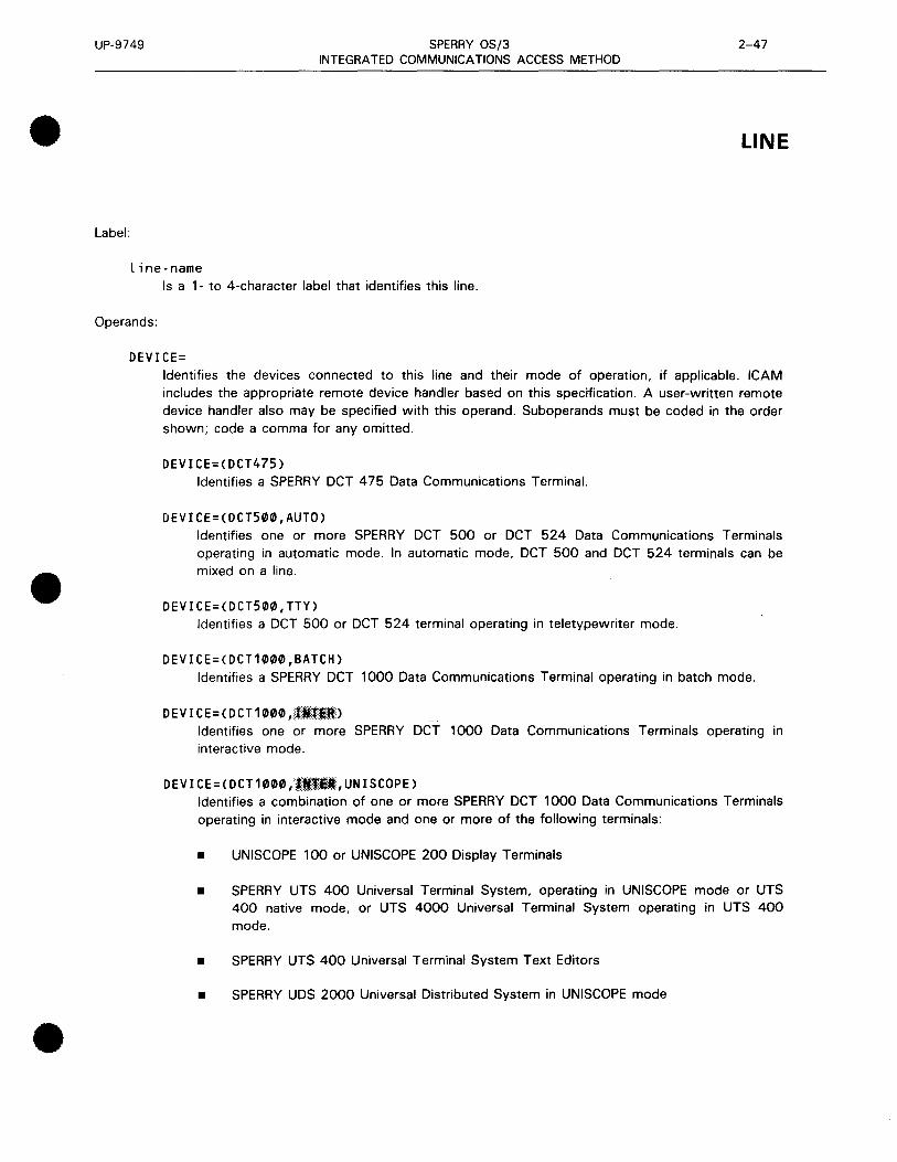
•
•
•
UP-9749 SPERRY OS/3 2-47 INTEGRATED COMMUNICATIONS ACCESS METHOD
LINE
Label:
line-name Is a 1- to 4-character label that identifies this line.
Operands:
DEVICE= Identifies the devices connected to this line and their mode of operation, if applicable. ICAM includes the appropriate remote device handler based on this specification. A user-written remote device handler also may be specified with this operand. Suboperands must be coded in the order shown; code a comma for any omitted.
DEVICE=CDCT475) Identifies a SPERRY DCT 475 Data Communications Terminal.
DEVICE=(DCT500,AUT0) Identifies one or more SPERRY DCT 500 or DCT 524 Data Communications Terminals operating in automatic mode. In automatic mode, DCT 500 and DCT 524 terminals can be mixed on a line .
DEVICE=(DCT500,TTY) Identifies a DCT 500 or DCT 524 terminal operating in teletypewriter mode.
DEVICE=CDCT1000,BATCH) Identifies a SPERRY DCT 1000 Data Communications Terminal operating in batch mode.
DEVICE=CDCT1000,llf:ll) Identifies one or more SPERRY DCT 1000 Data Communications Terminals operating in interactive mode.
DEVICE=CDCT1000,llifll,UNISCOPE) Identifies a combination of one or more SPERRY DCT 1000 Data Communications Terminals operating in interactive mode and one or more of the following terminals:
• UNISCOPE 100 or UNISCOPE 200 Display Terminals
• SPERRY UTS 400 Universal Terminal System, operating in UNISCOPE mode or UTS 400 native mode, or UTS 4000 Universal Terminal System operating in UTS 400 mode.
• SPERRY UTS 400 Universal Terminal System Text Editors
• SPERRY UDS 2000 Universal Distributed System in UNISCOPE mode

UP-9749
LINE
SPERRY OS/3 INTEGRATED COMMUNICATIONS ACCESS METHOD
DEVICE=(DCT2000,{ 1 ~~}) DCT2000
Identifies a SPERRY OCT 2000 Data Communications Terminal.
84 or 132
2-48 Update B
Is the line buffer length in bytes. This specification must correspond to the print line length specified for this device in the FEATURES operand of the TERM macroinstruction. If 84 is specified (or defaulted) for line buffer length, 80 must be specified (or defaulted) for print line length; if 132 is specified for line buffer length, 128 must be specified for print line length.
DEVICE=(TTY,33), DEVICE=CTTY,35), or DEVICE=(TTY,37) Identifies a TELETYPE* Model 33, 35, or 37 using ASCII.
NOTE:
For the UTS 10 teletypewriter model single station display terminal, specify DEVICE=(TTY) .
DEVICE=CUNISCOPE> Identifies one or more of the following terminals:
• UNI SCOPE 100 or 200
• UTS 400 operating similar to a UNISCOPE or UTS 400 native mode
• UTS 400 text editor
• UTS 4000 universal terminal system
• UTS 20, UTS 30, or UTS 40
• UDS 2000 similar to a UNISCOPE terminal
• V77 series data processing system emulating a UNISCOPE 100 terminal
DEVICE=(UNISCOPE,KA) Identifies one or more SPERRY UTS 400/4000 Universal Terminal Systems that utilize Katakana/English keyboards. Applies only to terminals operating in native mode.
DEVICE=(1004) Identifies a SPERRY 1004 Card Processor operating under control of an RMS 1 plug board.
DEVICE=C9200)
•
•
Identifies a SPERRY 9200 Data Processing System (using REM-1 protocol) that is emulating • a SPERRY 1004 Card Processor operating under the control of an RMS 1 plugboard.
*Trademark of the Teletype Corporation

•
•
•
UP-9749 SPERRY OS/3 INTEGRATED COMMUNICATIONS ACCESS METHOD
2-49 Update B
LINE
DEVICE=C9300) Identifies a SPERRY 9300 Data Processing System (using REM-1 protocol) that is emulating a SPERRY 1004 Card Processor operating under the control of an RMS 1 plugboard.
o Ev I c E=(BS c, {·.l·······i···•·n·········e··· - bu ff er - length}' l··A·.·S···C···. ·I·····I·····• ....•. ·.· .. ·. }) TOGGLE EBC~IC
216 TRANS COD
BSC Identifies a binary synchronous controlled device. Must be specified for IBM* 2780 and 3741 Data Communications Terminals and for SPERRY UDS 2000 emulating IBM 2780 or 3741 or a UNIX** O/S emulating IBM 2780.
line-buffer-length Specifies line buffer length in bytes. Calculate as follows:
2m + mn for nontransparent mode
4m + mn for transparent mode
where:
m = number of records per block
n = number of data characters per record
TOGGLE Indicates this line requires multiple line buffers to improve throughput; ICAM calculates line buffer length from the line speed specified with the TYPE operand, or a line buffer length can be specified with the LBL operand. Do not specify for IBM 2780 or 2780 EM terminals.
If line-buffer-length and TOGGLE are omitted, a default line buffer length of 216 is assumed.
ASCII Indicates messages are in ASCII.
EBCDIC Indicates messages are in EBCDIC. The SPERRY UDS 2000 (emulating an IBM 2780/3741) uses EBCDIC.
TRANS COD Indicates messages are in TRANSCODE.
DEVICE=C3271) Identifies one or more IBM 3270 terminal systems operating in the BSC polling/selecting mode.
• Trademark of International Business Machines
··UNIX is a trademark of AT&T Bell Laboratories

UP-9749
LINE
t
SPERRY OS/3 INTEGRATED COMMUNICATIONS ACCESS METHOD
DEVICE=CINV3271) Identifies a 3271 emulator line to an IBM host (IBM 3270 emulator).
DEVICE=CLWS[,KA])
2-50 Update B
Identifies a local workstation terminal or a local workstation with Katakana support that is accessed through ICAM.
If specifying Katakana support for local workstations, input and output data translation must be suppressed, XLATE=(NO,NO); or substitute translation tables, XLATE= (labeli,idi,labelo,ido) must be specified.
DEVICE=CRWS)
Identifies a remote workstation. This workstation may be a SPERRY Universal Terminal System (UTS 20, UTS 30, or UTS 40) as designated by the TERM macroinstruction.
When you specify this operand, you must also specify DCA=YES and GAWAKE=YES in the CCA macroinstruction, and a PGROUP macroinstruction for each polling group.
DEVICE=(RDHA[,RDHB][,RDHC][,RDHD])
Includes one to four user-written remote device handlers in the ICAM symbiont. Assemble the handlers prior to network generation, assign RDHA, RDHB, RDHC, or RDHD as its module name, and store it in the SG$0BJ library on the system resident volume.
DEVICE=CUTSX)
Identifies a line for use with an X.21 circuit-switched PDN for connection to a UTS 20X terminal.
DEVICE=(MAPSRDH)
Specifies this line requires the MAPPER 5 remote device handler in order to interface with a MAPPER 5 system.
When you specify DEVICE=(MAP5RDH):
• Line buffer length (see LBL operand) is forced to a minimum of 700 words.
• FEATURES operand on the TERM macroinstruction must be specified as FEATURES=(U200, 1920 ... ).
TYPE=c i ne - speed [ { ~~:~}] [,CRTS] [, F LDQ] [,FULL] [, N IDLE] [, SWCH] [,SYNC][, X21])
Identifies tne characteristics of this line. Table 2-16 lists the TYPE specifications associated with particular line characteristics, plus other required operands. Line-speed, if required, must be the first TYPE specification; code a comma if it is omitted. The other suboperands may be coded in any order.
•
•
•

UP-9749 SPERRY OS/3 2-51 INTEGRATED COMMUNICATIONS ACCESS METHOD
• LINE
Table 2-16. Line Characteristics and TYPE Specifications
Line Characteristic TYPE Specifications Other Operands
Baud rate line-speed
Automatic dialing AUTO, SWCH@ CALL= DIALER= ID=
Operator dialing SWCH CALL= The ID operand is optional.
Automatic answering SWCH, UNAT ID= (unattended answering)
Dedicated line Code a comma to override ID= SWCH default
Two-way simultaneous transmission FULL (full-duplex) • Two-way simultaneous transmission FULL, FLDQ for NTR and ILA
Two-way alternate transmission Default condition (half-duplex)
Synchronous transmission SYNC
Asynchronous transmission Default condition for teletypewriters; for other devices, a comma is coded to override SYNC default
Request-to-send signal CRTS
No line turnaround(}) NIDLE
Automatic line turnaround Default condition (half-duplex synchronous line)
G) Applies to synchronous, 2-way alternate transmission on UNISCOPE/UTS 400/UTS 4000 terminals only
@ DA TEX-L always requires the specification of both AUTO and SWCH .
•

UP-9749
LINE
SPERRY OS/3 2-52 INTEGRATED COMMUNICATIONS ACCESS METHOD
line-speed Specifies the rate in bits-per-second at which data is exchanged between terminals connected to this line and ICAM.
The speed you specify is only used by the ICAM software to establish an internal buffer; therefore, it need not match the line speed of your line exactly. However, the value you specify must be one of those provided in Table 2-17. In general, the larger the value you specify, the better your performance will be for that line; however, additional main storage would be required. Table 2-18 indicates maximum line speeds for !CAM-supported terminals.
Table 2-17. Line Speed Values
Asynchronous Line Speeds Synchronous Line Speeds
50 2000 75 2400
110 4800 134 7200 150 9600 300 48000 600 56000 900 64000
1200 1800 2400 3600 4800 7200 9600
•
•

UP-9749
•
•
•
SPERRY OS/3 INTEGRATED COMMUNICATIONS ACCESS METHOD
Table 2-18. Maximum Line Speed of /CAM-Supported Terminals
Terminal
UNISCOPE 100 and 200 Display Terminals
SPERRY UTS 20/30/40 Single Station Terminals
SPERRY UTS 400 Universal Terminal System
SPERRY UTS 4020/4040 Universal Terminal System
SPERRY OCT 4 7 5 Data Communications Terminal
SPERRY OCT 500/524 Data Communications Terminals
SPERRY OCT 1000 Data Communications Terminal
SPERRY OCT 2000 Data Communications Terminal
SPERRY UDS 2000 Universal Distributed System
TELETYPE Models 33, 35
TELETYPE Model 37
SPERRY UTS 10 Universal Terminal System Single Station in Teletypewriter Mode
IBM 2780 Data Communications Terminal
IBM 3270 Data Communications Terminal System
IBM 3741 Data Communications Terminal
SPERRY 1004/ 1005 Card Processor
SPERRY 9200/9300 Data Processing System
UNIX O/S (5000/20, 40, 60, 80 and 7000/40)
MAPPER 5 system
Baud Rate*
9,600
9,600
9,600
19,200
110
300
9,600
2,400
9,600
110
150
9,600
4,800
7,200
9,600
9,600
56,000
4,800
19,200
2-53 Update B
LINE
*Bits per second, maximum
AUTO
UNAT
Indicates this line is equipped for automatic dialing. Applies only to switched lines. Note that AUTO and UNAT are mutually exclusive.
Indicates the computer automatically answers incoming calls (unattended answering) from the terminals on this line via the switched telephone network without operator intervention. Applies only to switched lines. Not available if FEATURES=BASIC is specified in the CCA macroinstruction.
t

UP-9749
LINE
CRTS
FLDQ
FULL
SPERRY OS/3 2-54 INTEGRATED COMMUNICATIONS ACCESS METHOD
Indicates the request-to-send signal is cleared in output/output messages sequences. This inhibits the sync character from being sent.
Specifies 2-way simultaneous queueing. Input and output messages are queued to and from a 2-way simultaneous communications line. For standard remote device handlers, this feature is available only with NTR and intelligent line adapter (ILA) lines; it can also be used with user-written remote device handlers. If FLDQ is specified, FULL also must be specified.
Indicates this line is capable of 2-way simultaneous transmission (full-duplex operation). The ICAM remote device handlers do not operate terminals in this mode (except as described under FLDQ) but can take advantage of this line characteristic to decrease turnaround time. Omit for 2-way alternate transmission (half-duplex operation).
NOTE:
If an /CAM remote device handler uses 2-way alternate protocol (half-duplex), the line must be defined as 2-way alternate also. All /CAM remote device handlers utilize 2-way alternate protocol except NTR, UDLC, ABM, and level 2 X.25 public data networks.
If 2-way simultaneous protocol is used, the same protocol must be specified in the /CAM generation (LINE and CACHJ.
The 2-way simultaneous modems and lines may be used with 2-way alternate protocol, if required.
NIDLE
SWCH
SYNC
No automatic line turnaround is desired. Automatic line turnaround prepares the line for output immediately after completion of input. This applies only to synchronous line with 2-way alternate transmission and UNISCOPE and UTS 400 terminals.
Indicates this line is switched, i.e., it must be dialed, either automatically or manually.
This is the default condition for all devices. If the line is dedicated, a comma must be coded to override the default. For example:
TYPE=C110,),ID=4
Specifies a dedicated line with a line speed of 110, using port 4.
Indicates the hardware of this line is set for the synchronous transmission of data. Must be specified for UDS 2000.
If omitted, asynchronous transmission is assumed for teletypewriter devices and synchronous transmission for all other devices. To indicate asynchronous transmission for nonteletypewriter devices, a comma must be coded to override the default.
•
•
•

•
•
•
UP-9749
X21
SPERRY OS/3 INTEGRATED COMMUNICATIONS ACCESS METHOD
2-55 Update A
LINE
Indicates that this line is used with an X.21 circuit-switched PON for connection to a UTS 20X terminal. When this option is specified, SWCH must also be specified.
CALL=phone-number Is a numeric or alphanumeric telephone number used to dial a terminal. Must be specified for either automatic or operator dialing. In automatic dialing, a hyphen in the phone number causes a 1. 1 second pause. This delay is necessary whenever a connection must be made before more diai characters are sent. The maximum number of automatic dialing digits and hyphens permitted in the phone number is 48. The maximum number of operator dialing digits is 11. Operator dialing numbers with more than 11 digits are truncated at the console.
NOTE:
Do not specify the call operand if you specify unattended answering (UNA T).
CHAN=channel-number Specifies the input/output microprocessor (IOMP) to which the single-line communications adapter (SLCA) is connected .
For System 80 models 3 through 6, this operand is optional. If specified, the only value permitted is CHAN=2. The default is CHAN=2. Up to eight SLCAs (10=8 to ID= 15) can be specified for these models.
For System 80 model 8 with one IOMP, this operand is optional. If specified, the only value permitted is CHAN=13. The default is CHAN=13. Up to 14 SLCAs (10=1to10=15) can be specified for the IOMP.
For System 80 model 8 with two IOMPs, this operand is required. You must specify CHAN= 13 for one IOMP and CHAN= 15 for the other. Up to 14 SLCAs (ID= 1 to ID= 15) can be specified
for each IOMP.
ID=slca-number Specifies the address on the input/output microprocessor (IOMP) channel where the single line communications adapter (SLCA) this line uses is connected. Sica-number is specified in decimal.
Required for private lines and switched lines with automatic dialing or unattended answering. For lines with automatic dialing, you must specify an ID and DIALER operand for the automatic calling unit used.
For the System 80 models 3 through 6, you can specify up to eight SLCAs, 10=8 to ID= 15. For the model 8, you can specify up to 14 SLCAs for each IOMP, ID= 1 to ID= 15.
Whenever you do not specify an ID operand, ICAM assigns an slca-number based on the requirements specified in the TYPE operand .
If you specify the ID operand but not the CHAN operand and you are using a model 8, CHAN
defaults to 13.
DIALER=Cslca-number,[eonJ,prt) Identifies the location of an automatic dialer. Specify this operand only for lines with automatic
dialing by the computer.
t

UP-9749
LINE
SPERRY OS/3 INTEGRATED COMMUNICATIONS ACCESS METHOD
2-56 Update B
slca-number
eon
prt
Specifies the SLCA number where the dialer is located. Specify an SLCA number that is not used by any LINE or VLINE macroinstruction in this network definition.
Specifies an optional end-of-number character required by some automatic calling units. Refer to the operating instructions for your automatic calling unit to see if it requires one.
Each single-line communications adapter can accept up to three automatic calling units. Specify a decimal number 0, 1, or 2 that identifies the port on the SLCA where the automatic calling unit is installed. If no value is specified, 1 is the default.
NOTE:
Do not specify DIALER if you specify unattended answering (UNA T).
INPUT=({~:;e}[,blanks][,filename])
Establishes a destination for input messages for all of the terminals on this line unless overidden by an INPUT operand in a TERM macroinstruction.
NOTE:
You must specify this operand for all terminals on this line - either here or in a TERM macroinstruction.
name
Is a 1- to 4-character name that matches the label field of a LOCAP, PRCS, MPPS, or TERM macroinstruction. This is the name addressed on GETCP calls to a process file or to a LOCAP file to retrieve input messages from a terminal. Depending on the name specified, input messages from all terminals on this line are directed to:
• the low priority queue of a user program defined by the label of a LOCAP macroinstruction (global networks only);
• the low priority queue of a process file, defined by the label of a PRCS macroinstruction;
• the low priority queue of a terminal, defined by the label of a TERM macroinstruction (this causes message switching because a message, input from a terminal on this line, is immediately placed on the output queue of another terminal); or
• a destination determined by an MPPS routine, with the name of the routine defined by the label of an MPPS macroinstruction. An MPPS routine is the only permitted input destination with the transaction control interface.
•
•
•
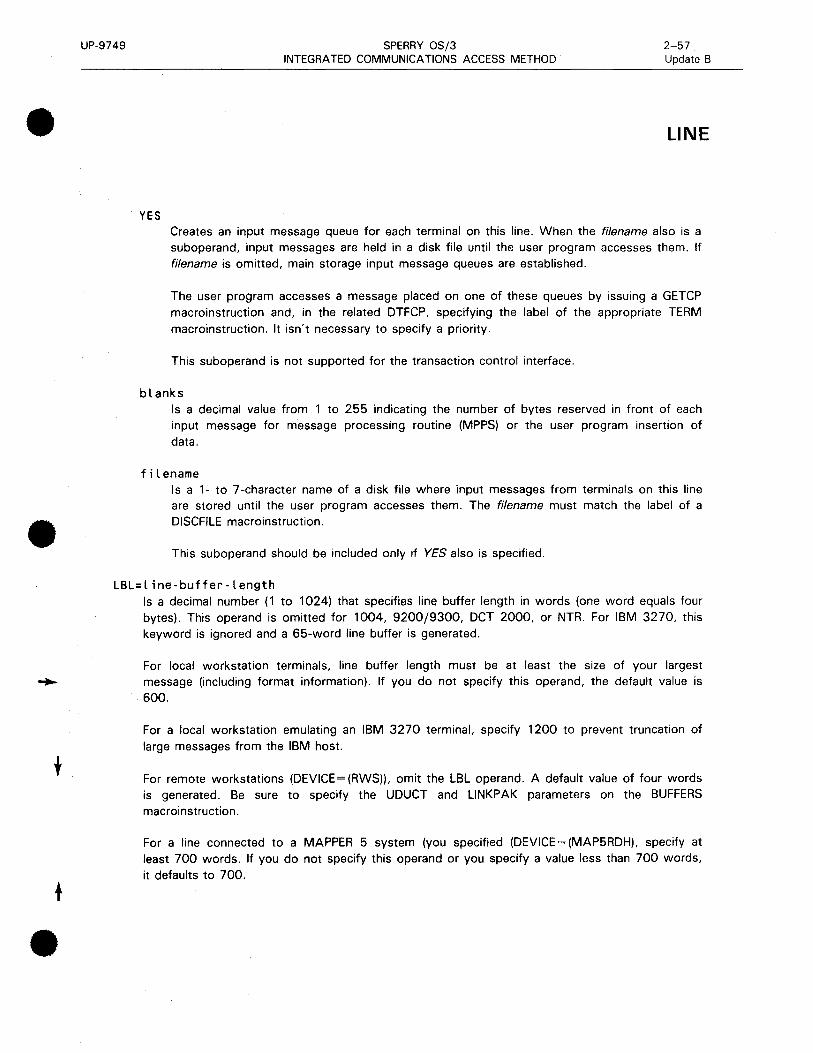
•
•
•
UP-9749
YES
SPERRY OS/3 INTEGRATED COMMUNICATIONS ACCESS METHOD
2-57 Update B
LINE
Creates an input message queue for each terminal on this line. When the filename also is a suboperand, input messages are held in a disk file until the user program accesses them. If filename is omitted, main storage input message queues are established.
The user program accesses a message placed on one of these queues by issuing a GETCP macroinstruction and, in the related DTFCP, specifying the label of the appropriate TERM macroinstruction. It isn't necessary to specify a priority.
This suboperand is not supported for the transaction control interface.
blanks Is a decimal value from 1 to 255 indicating the number of bytes reserved in front of each input message for message processing routine (MPPS) or the user program insertion of data.
filename Is a 1- to 7-character name of a disk file where input messages from terminals on this line are stored until the user program accesses them. The filename must match the label of a DISCFILE macroinstruction .
This suboperand should be included only if YES also is specified.
LBL=line-buffer-length Is a decimal number ( 1 to 1024) that specifies line buffer length in words (one word equals four bytes). This operand is omitted for 1004, 9200/9300, OCT 2000, or NTR. For IBM 3270, this keyword is ignored and a 65-word line buffer is generated.
For local workstation terminals, line buffer length must be at least the size of your largest message (including format information). If you do not specify this operand, the default value is 600.
For a local workstation emulating an IBM 3270 terminal, specify 1200 to prevent truncation of large messages from the IBM host.
For remote workstations (DEVICE=(RWS)), omit the LBL operand. A default value of four words is generated. Be sure to specify the UDUCT and LINKPAK parameters on the BUFFERS macroinstruction.
For a line connected to a MAPPER 5 system (you specified (DEVICE=(MAP5RDH), specify at least 700 words. If you do not specify this operand or you specify a value less than 700 words, it defaults to 700 .

UP-9749
LINE
SPERRY OS/3 INTEGRATED COMMUNICATIONS ACCESS METHOD
2-58 Update B
For all other devices, if LBL is omitted, the following default values are generated, based on the line-speed specification in the TYPE parameter.
line Speed (maximum baud rate)
Up to 2,400
From 2.401 to 4,800
From 4,801 to 9,600
From 9,601 to 19 ,200
Default Value (words)
20
40
80
160
LOW=filename Creates a low priority output queue for this line on a disk file named in a DISCFILE macroinstruction.
LOW=MAIN Creates a low priority output queue for this line in main storage.
MED IUM=f i l ename Creates a medium priority output queue for this line on a disk file named in a DISCFILE macroinstruction.
MEDIUM=MAIN Creates a medium priority output queue for this line in main storage.
HIGH=filename Creates a high priority output queue for this line on a disk file named in a DISCFILE macroinstruction.
HIGH=MAIN Creates a high priority output queue for this line in main storage.
NOTE:
If the LOW, MEDIUM, and HIGH operands are omitted, a low priority output queue is created in main storage for this line, except when specifying global networks. If any LOW, MEDIUM, or HIGH operand in a TERM macroinstruction is specified, it overrides this macroinstruction for that terminal only, and a terminal output queue is created. Line queueing must not be specified for global networks.
•
•
•

•
•
•
UP-9749 SPERRY OS/3 INTEGRATED COMMUNICATIONS ACCESS METHOD
2-58a Update B
RDHLQ=YES Allows a message to be sent to a terminal while a previous message sent to another terminal on this multistation line is being transferred to an auxiliary device. This operand is applicable to user-written remote device handlers only. When this operand is included, terminal queueing must be specified for each terminal on this line.
RECONECT= Provides immediate logical reconnection of unattended (call-in) lines when the original caller disconnects. ICAM does not notify the user or the operator console of the reconnection; however, a LINE DOWN message is sent to the console if the reconnection fails. This keyword is valid only in a dedicated network.
RECONECT=QUEUES All output queues, including INTERCEPT, are cleared before reconnection.
RECONECT=YES Output queues remain intact at reconnection; next caller receives queued output.
NOTE:
Do not specify this operand for local workstations (DEVICE=(LWS)) .

•
•
•

•
•
•
UP-9749 SPERRY OS/3 2-59 INTEGRATED COMMUNICATIONS ACCESS METHOD
LINE
RETRY=(input-number,output-number) Number of retries before ICAM marks a terminal down and slow polls it. Input-number and
output-number values range from 1 to 255.
input-number Number of times the remote device handler resends a poll because of an error (such as parity errors or time-out).
output-number Number of times the remote device handler tries to send a particular output message.
For binary synchronous communication devices, input retries apply only the host bidding for the line. All other retries are considered output retries. For OCT 2000, both input and output retries are determined by the output-number value.
This operand does not apply to local workstation terminals, OCT 475, OCT 500/524, UTS 10, or TELETYPE. If omitted for other devices, the following default values are generated:
Device Type Input Output
BSC 6 4
UNISCOPE/DCT 1000 6 4
OCT 2000 4
1004 /9200 /9300 6 4
IBM 3270 4 6
IBM 3270 Emulator 6 4
STATS=iO Terminal statistics are not accumulated for this line.
STAT!=YES Terminal statistics are accumulated for each terminal on this line.
TIMEOUT=(input-time,output-time) Time-out values, in seconds, for input and output messages. The input-time and output-time range from 1 to 32, 767. If time-out occurs, ICAM retries the number of times specified in the RETRY operand. No entries are made for OCT 500/524, UTS 10, or TELETYPE. This operand does not apply to local workstation terminals.
input-time The number of seconds in which terminals on this line must:
• respond to polls; or
• fill one of the line's pair of line buffers.

UP-9749
LINE
SPERRY OS/3 2-60 INTEGRATED COMMUNICATIONS ACCESS METHOD
For binary synchronous communications (BSC) controlled devices, the input-time value is used when input text is expected or during receipt of input text. For DCT 500/524, UTS 10, and TELETYPE, this value applies to input text after the first input text character is received.
output-time The number of seconds in which terminals on this line must acknowledge receipt of a message sent by the host processor. This operand does not apply to local workstation terminals.
If omitted for other devices, the following default values are generated:
Device Type Input Output
BSC 3 20
UNISCOPE/DCT 1000/UTS 400/UTS 4000 3 20
DCT 500/524/TTY /UTS 10 512 20
DCT 2000 9 20
1004/9200/9300 4 20
IBM 3270 3 20
3270 emulator 300 3
NOTE:
The TIMEOUT operand is ignored by the 32 70 emulator and need not be specified.
XL ATE=({::" l;, i di}, {::elo, ;do}) Determines what translation tables, if any, are used for input and output on this line. If omitted, standard ICAM translation tables are used in both input and output. This operand is overridden for a specific terminal if an XLA TE operand is included for that terminal in the TERM macroinstruction. For IBM 3270 terminal systems or local workstations with Katakana support, the user must specify either XLATE=(NO,NO) or user-specified input and output translation tables.
labeli Is the name of a user-specified input translation table. The name must correspond to the label of a translation table generated in this network definition. The same input translation table can be named in any number of LINE and TERM macroinstructions.
•
•
•

•
•
•
UP-9749
idi
NO
SPERRY OS/3 2-61 INTEGRATED COMMUNICATIONS ACCESS METHOD
LINE
Is a decimal number, 1 to 240, further identifying the translation table named in the labeli suboperand. The idi numbers provide an index to the addresses of input translation tables. A different number should be used for each labeli name; if the same number is used with more than one labeli name, only the last labeli name is used.
Input from devices on this line is not translated.
Standard ICAM translation table is used for input from devices on this line. For IBM 3270 terminals, this parameter is ignored.
labelo
ido
NO
Is the name of a user-supplied output translation table. The name must correspond to the label of a translation table generated in this network definition. The same output translation table may be named in any number of LINE and TERM macroinstructions.
Is a decimal number, 1 to 240, further identifying the translation table named in the labelo operand. This number provides an index to the addresses of output translation tables. A different number should be used for each labelo name; if the same number is used with more than one labelo name, only the last labelo name is used.
Output to devices on this line is not translated.
Standard ICAM translation table is used for output to devices on this line. For IBM 3270 terminals, this parameter is ignored.
NOTE:
The idi and ido suboperands index separate input and output tables; that is, up to 240 input tables and 240 output tables are allowed and idi and ido values can be duplicated. Consecutive numbers must be assigned, starting with 1, to save main storage space.
CIRCSW=CDATEX,n,m) Specifies a logical connection of one or more physical links (lines) to a DATEX-L circuit-switched public data network.
DAT EX Specifies the public data network.
n Is the number of physical lines connected to the network.
m Is the number of lines dedicated to incoming calls.

UP-9749 SPERRY OS/3 2-62 INTEGRATED COMMUNICATIONS ACCESS METHOD
LINE
NOTES:
1. When specifying this operand, the keyword parameter DIALER= must also be specified.
2. When specifying this operand, the value specified by the ID= keyword parameter represents the first physical line in a group of circuit-switched lines. The remaining lines in the group must be on succeeding ascending parts. This applies to the DIALER= keyword also.
•
•
•

•
•
•
UP-9749 SPERRY OS/3 INTEGRATED COMMUNICATIONS ACCESS METHOD
2-63 Update B
LOCAP
Creates a local (in this computer) or remote (in a different computer) locap file for programs that use a global network (includes public data networks).
A locap file acts as an intermediary for the user program, i.e., messages destined for the user program are queued to this locap file by ICAM until the user program issues a GETCP request for them. In order to access this locap file (i.e., to be able to issue GETCPs to it), the user program must issue an NATT ACH interface macroinstruction with the APPS operand specified the same as the label of this macroinstruction.
Table 2-19 describes the interface and type of network definition in which you may use this macroinstruction. It also details the applicability of each operand in the macroinstruction.
Format:
LABEL 60PERATION6 OPERAND ~~~~~--+~~~~~~~~
looap-name LOCAP TYPE=m~:})
[,DUSTERR=INLINE]
[,LOW={M~IN }'J f1lerame
[,MEDIUM= {'~~IN }~
f 1 l ename :J
[,HIGH={M~IN }] filename
[,REMOTE=({node) })~
subname,PDN j [,JOBNAME=jobname] [,JOBINIT=CLOAD,REPORT)] [, IAS=<YES,OFF)]
[' PROTYP=f~!~:ENT }] [,MODE=SYSTEM]

UP-9749
LOCAP
SPERRY OS/3 INTEGRATED COMMUNICATIONS ACCESS METHOD
Table 2-19. Applicability of LOCAP Macroinstruction and Its Operands
Macro: LOCAP
ICAM Network Type and Kind of Program Supported
Operand Name
·LOCAP
label
DUS TERR
HIGH
/AS
JOB/NIT
JOBNAME
LOW
MEDIUM
MODE
PROTYP
REMOTE
TYPE
Direct Data
Interface
DOI
NTR
RBP
RPG
IDES
*Shows macro applicability
LEGEND
Dedicated
Networks
R = Required 0 = Optional
Global Networks
R R
R R
0
0 0
0 0
0 0
R R
-' 0 m 0 u
R
R
0
0
R
- = Not applicable
i 0
R
R
0
R
GI <(
'8 u ·= 0 ... - c :I 0 ~z
R
R
0
0
0
0
R
R
R
0
R
0
0
0
0
R
R
R
0
0
0
0
0
R
2-64 Update B
•
•
•

•
•
•
UP-9749 SPERRY OS/3 2-65 Update B
Label:
INTEGRATED COMMUNICATIONS ACCESS METHOD
LOCAP
locap-name Identifies this locap file. It is the name the user program must specify in the APPS operand of an NA TT ACH interface macroinstruction when it requests attachment to this global network. Other communications user programs direct messages to this locap file by means of this label.
Operands:
TYPE=C$JDMCP> Indicates the standard interface is used to communicate with this locap file.
TYPE=CDMI) Indicates the demand mode interface is used to communicate with this locap file.
Required if ICAM supports interactive services; allows terminals to be used as workstations or remote workstations, or for distributed data processing.
TYPE=(TCI) Specifies the transaction control interface for the information management system (IMS) .
DUSTERR=INLINE Specifies that all returns are inline if an error occurs during DUST macroinstruction processing. If you don't specify DUSTERR=INLINE and an error occurs during DUST NETREQ macroinstruction processing, ICAM returns control at the ERRET=address you specify.
NOTE:
The DUSTERR=INLINE specification is correct only when your program is coded to match the operand you specify.
LOW, MEDIUM, and HIGH operands:
Generate up to three input queues for messages destined for this locap file. It is necessary to have at least one of these queues for direct communications between user programs in a local or multicomputer global network or if any terminals specify this locap file in the INPUT operand of
the TERM macroinstruction.
LOW=MAIN Creates a main storage input queue with low priority.
LOW=filename Specifies a 1- to 7-character name of a disk file for low priority messages created by means of a DISCFILE macroinstruction .
MEDIUM=MAIN Creates a main storage input queue with medium priority.
UP-9749 SPERRY OS/3 2-66 INTEGRATED COMMUNICATIONS ACCESS METHOD
LOCAP
MED IUM=f i l ename Specifies a 1- to 7-character name of a disk file for medium priority messages created by means of a DISCFILE macroinstruction.
HIGH=MAIN Creates a main storage queue with high priority.
HIGH=filename Specifies a 1- to 7-character name of a disk file for high priority messages created by means of a DISCFILE macroinstruction.
REMOTE=( node) The 1- to 4-character name of the remote computer node where this locap file is actually located. This is the same name specified in the node suboperand of the CCA macroinstruction that begins a global network definition in the remote computer. If this locap macroinstruction describes a locap file that resides in this computer, this operand must not be specified.
REMOTE=Csubname,PDN) Defines a locap file in a packet-switched public data network (PON) environment that physically exists in a remote node.
subname
PON
Specifies the symbolic name of the SUB macroinstruction that defines the remote subscriber.
Specifies a packet-switched public data network.
JOBNAME=jobname Is the 1- to 8-character name specified in the job control JOB statement that identifies the jobstream that executes the COBOL program. If omitted, the label of this locap macroinstruction is used.
JOBINIT=CLOAD,REPORT)
Controls the scheduling of a COBOL communications program when initial input is received, and the reporting of same by means of a datagram.
LOAD Indicates that the COBOL program is automatically loaded and executed when the initial message is received.
REPORT Indicates that the COBOL program receives a report of the initial message.
•
•
•

•
•
•
UP-9749 SPERRY OS/3 2-67 INTEGRATED COMMUNICATIONS ACCESS METHOD
LOCAP
IAS=(YES,OFF) Specifies that interactive services are required (YES) and that DICE is not required (OFF). This operand is required when TYPE= (DMI) is specified.
PROTYP=r~:::ENT} Specifies the type of editing and data handling protocol required when a distributed communications processor is an intermediate or remote node. Use the default (PROTYP=DICE) for all interfaces except the demand mode interface (DMI) for interactive services or distributed data processing. For these, specify PROTYP=XPARENT.
MODE=SYSTEM Specifies the use of the locap file by a remote workstation in system mode for entry to interactive services. Only one locap of this type is permitted in a network containing remote workstations, and TYPE=DMI must be specified .

UP-9749 SPERRY OS/3 2-68 INTEGRATED COMMUNICATIONS ACCESS METHOD
LPORT
Creates a remote session entry table for each single logical port used in distributed communications architecture. ICAM uses the information in this table to record and control activity on the port.
LPORT is used for DCA global networks using the standard interface, IMS, DDP, and circuit-switched public data networks.
Table 2-20 describes the interface and type of network definition in which you can use this macroinstruction. It also details the applicability of each operand in the macroinstruction.
Format:
LABEL 60PERATION6
[symbol] LPORT
OPERAND
LINE=name
,REMOTE=name
,PORT=nnnn
,EU1=name
,EU2=name
,USERTP={=.l
[' NUMSS= {;~n}]
[ CATP={.:}J
[RI={i}] [,RWNDW=n]
•
•
•

•
•
•
UP-9749
Operands:
SPERRY OS/3 INTEGRATED COMMUNICATIONS ACCESS METHOD
Table 2-20. Applicability of LPORT Macroinstruction and Its Operands
Macro: LPORT
ICAM Network Type and Kind of Program Supported
Operand Name
Direct .Data
Interface
DOI
NTR
RBP
RPG
~DES
*LPORT
CATP=
EU1 = -
EU2= -
LINE= -
NUMSS= -
PORT= -
PRI= -
REMOTE= -
RWNDW= -
USERTP= -
*Shows macro applicability
LEGEND:
R
0
Required
Optional
Not applicable
Dedicated
Networks
:J' 0 al 0 2 rn u :!: u
Q. u :!: 0 .... rn
PS
cs Packet-switched
Circuit-switched
0 ....
Global Networks
-' 0 al 0 u
~ <t OU .: 0 .... ' - c:
::J 0 :!: z
<t u 0
R
0
R
R
R
0
R
0
R
0
R
2-69
LP ORT
CS PS
R
0
R
R
R
0
R
0
R
0
R
LINE=name Is the 1- to 4-character label from the VLINE macroinstruction. The name must begin with an alphabetic character.

UP-9749 SPERRY OS/3 2-70 INTEGRATED COMMUNICATIONS ACCESS METHOD
LPORT
REMOTE=name Is the 1- to 4-character name of the destination TYPE= operand of the CCA macroinstruction.
node. Must be the same as specified in the
PORT=nnnn Is the 4-digit port number in the range of 1 to 4096.
EU1=name Is the label of the TERM, PRCS, or LOCAP macroinstruction defining the local end user.
EU2=name Is the label of the LOCAP or PRCS macroinstruction defining the remote end user or process file.
USERTP={:L} Indicates that the session operates through the demand mode, transaction control, or standard interface for DCA global networks. Specify STDMCP for circuit-switched public data networks.
NUMSS=nnn Indicates the number of system sessions ( 1-256) that use the specified port. The default value is 1.
CATP= Defines the class of recovery procedure implemented by port flow control and system session control.
CATP=B Indicates use of dynamic sessions without provision for ICAM error recovery.
CATP=C
PRI=n
Indicates use of dynamic sessions with prov1s1on for error recovery by port flow control and provision of assurance units by the distributed data processing interface to ICAM.
Indicates priority from 1 to 4. The default is 4. The highest priority is 1.
RWNDW=n Indicates the port window level. The window level specifies the maximum number of unacknowledged messages outstanding before port-level protocol output transmissions stop. The port is set on hold and any subsequent output is queued. When the number or unacknowledged input messages reaches window-1, the port generates a separate acknowledgment. The recommended value for this operand is 2 except for a distributed communications processor, which must then be 4.
•
•
•

•
•
•
UP-9749 SPERRY OS/3 2-71 INTEGRATED COMMUNICATIONS ACCESS METHOD
NODE
Defines a remote node and the session path between this node and the remote node. It is used for multiple node global networks; it should not be specified for dedicated networks, single node global networks (i.e., networks that reside in this computer only), or distributed communications architecture networks.
Table 2-21 describes the interface and type of network definition in which you can use this macroinstruction. It also details the applicability of each operand in the macroinstruction.
Format:
LABEL
symbol
Label:
symbol
60PERATION6 OPERAND
NODE VLI NE=(v line- name, subchan[{it.i ndow}])
Table 2-21. Applicability of NODE Macroinstruction and Its Operands
Macro: NODE
ICAM Network Type and Kind of Program Supported
Operand Name
•NODE
label
VLINE ~·
Direct Data
Interface
DDI
NTR
RBP
RPG
IDES
·shows macro applicability
LEGEND
u .....
Dedicated
Networks
Cl. (.)
~ 0 ..... en
R = Required 0 = Optional
~ 0 IX)
0 2 en (.)
~ (.)
Q. (.)
~ 0 ..... en
(.) .....
Global Networks
...I 0 IX)
0 (.)
II>< '8 (.) ·= 0 .. ' - c: :::s 0 ~z
R
R
R
- = Not applicable
< (.) 0
Specifies a required 1- to 4-character name of a remote node. The name specified must be the same as the node suboperand of the TYPE operand in the CCA macroinstruction that begins the global network definition in the remote computer node.

UP-9749 SPERRY OS/3 2-72 INTEGRATED COMMUNICATIONS ACCESS METHOD
NODE
Operands:
VLINE=Cvline-name,subchan,window) Points to the physical link and specifies the logical subchannel on the link that is used by ICAM to communicate control information between this node and the remote computer node.
vline-name Is a 1- to 4-character name that is the same as the label of the VLINE macroinstruction that links this node to a remote node.
subchan Is a decimal number, 1 to 4095, that identifies the logical subchannel of the link, described by the vline-name suboperand 1, over which the ICAM transfers control information between nodes.
NOTE:
Each logical subchannel can be defined only once; i.e., the same logical subchannel cannot be defined in more than one NODE or SESSION macroinstruction in the same computer node.
window Is the number of buffers (packets) that can be sent or received on a specific subchannel before an acknowledgment is expected. If omitted, the value 1 is used. Always specify a value of 1 or default the operand.
•
•
•

•
•
•
UP-9749 SPERRY OS/3 INTEGRATED COMMUNICATIONS ACCESS METHOD
2-73 Update B
PON
Specifies the name and attributes of the public data network to which you have subscribed. This macroinstruction must appear once in an ICAM global network definition after you have declared all of the macroinstructions for local communications.
This macroinstruction must not be specified for a DA TEX-L public data network.
Table 2-22 describes the interface and type of network definition in which you can use this macroinstruction. It also details the applicability of each operand in the macroinstruction.
Format:
LABEL LOPERATIONL
symbol PON
OPERAND ~~~~~~~~~~~~~~~~~~~~~
CARRIER= DATAPAC DA TEX DDX IBERPAC NORDIC PSS TRANSPAC
[,TYPE= {CIRCUIT} J
PACKET
[,PKTSIZ=size]
[,MXCALL={.;}]

UP-9749
PDN
SPERRY OS/3 INTEGRATED COMMUNICATIONS ACCESS METHOD
Table 2-22. Applicability of PON Macroinstruction and Its Operands
Macro: PON
ICAM Network Type and Kind of Program Supported
Operand Name
•PDN
label
CARRIER~
DATAPAC
DA TEX
DDX
IBERPAC
NORDIC
PSS
Direct .Data
Interface
DOI
NTR
RBP
RPG
IDES
I -
TRANSPAC -
L3MODE =
MXCALL=
PKTSIZ=
TYPE=
·shows macro applicability LEGEND
Required cs
Dedicated
Networks
ll. u ~ 0 ~ CJ')
:::.
u ~
- I -
C1rcu1t-sw1tched R
0 Optional PS ~ Packet-switched
Not applicable
NOTE:
Global Networks
_, 0 Ill 0 u
~ <( OU .!: 0 ... ' - c ::J 0 ~z
This macroinstruction is not applicable to the DA TEX-L public data network.
<( u 0
CS PS
R R
R R
R R
0
0
0
0
0
0
0
0
0
R 0
2-74 Update B
•
•
•
•
•
•
UP-9749 SPERRY OS/3 2-75 Update 8 INTEGRATED COMMUNICATIONS ACCESS METHOD
PON
Label:
symbol Is a required 1- to 4-character label for this macroinstruction.
Operands:
CARRIER= DATAPAC DA TEX DDX IBERPAC NORDIC PSS TRANSPAC
Specifies the name of the public data network common carrier you are using. All networks are packet-switched except NORDIC.
DATAPAC Specifies the Canadian DAT APAC public data network .
DA TEX Specifies the German DA TEX-P public data network.
DDX Specifies the Japanese DDX public data network.
IBERPAC Specifies the Spanish public data network.
NORDIC
PSS
Specifies the Denmark, Finland, Norway, and Sweden NORDIC circuit-switched public data network.
Specifies the United Kingdom PSS public data network.
TRANSPAC Specifies the French TRANSPAC public data network.
TYPE={CIRCUIT} PACKET
Specifies the type of service supplied by the public data network described in the CARRIER
operand.
CIRCUIT Specifies a circuit-switched public data network.
PACKET Specifies a packet-switched public data network.

UP-9749
PON
SPERRY OS/3 INTEGRATED COMMUNICATIONS ACCESS METHOD
2-76 Update B
L3MOD= {~;f 8}
Specifies the modulus of the level 3 send and receive window. That is, it is the number of packets that may be sent or received in one level 3 window.
PKTSIZ=size This operand applies only to packet-switched networks and specifies the maximum size in bytes of the data portion of a data packet. Specify a value according to the following list:
DATAPAC DA TEX DDX PSS TRANSPAC IBERPAC
NOTE:
128 or 256 128 or 256 256 128 or 256 128 or 256 128 or 256
(Default is 128.) (Default is 128.) (Default is 256.) (Default is 128.) (Default is 128.) (Default is 128.)
For PSS and IBERPAC, the size used for input and output negotiation is the size specified by PKTSIZ.
MXCALL= {;.}
For packet-switched networks only, specifies the number of times (between 0 and 15) ICAM attempts to establish a connection over a switched virtual circuit to a remote subscriber.
•
•
•
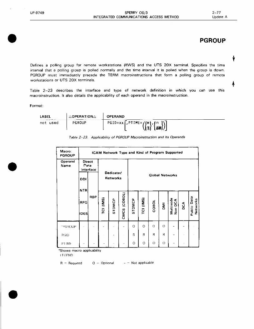
•
•
•
UP-9749 SPERRY OS/3 INTEGRATED COMMUNICATIONS ACCESS METHOD
2-77 Update A
PG ROUP
Defines a polling group for remote workstations (RWS) and the UTS 20X terminal. Specifies the time interval that a polling group is polled normally and the time interval it is polled when the group is down. PGROUP must immediately precede the TERM macroinstructions that form a polling group of remote workstations or UTS 20X terminals.
Table 2-23 describes the interface and type of network definition in which you can use this macroinstruction. It also details the applicability of each operand in the macroinstruction.
Format:
LABEL
not used
L'.OPERATIONL'. OPERAND
PGROUP PG I D=xx ['PT IME= ({;}I {~1})] Table 2-23. Applicability of PGROUP Macroinstruction and Its Operands
Macro: PG ROUP
ICAM Network Type and Kind of Program Supported
Operand Name
'PGROUP
pc;10
PTIME
Direct f"ata
Interface
DOI
NTR
RBP
RPG
IDES
- -
-
*Shows macro applicability
lEGEND
::::.
u ~
-
-
Dedicatet'
Networks
c.. u ~ 0 ~ (/)
-
-
R = Required 0 = Optional
::; 0 al 0 ~ (/)
u ~ u
-
-
-
Q.
u ~ 0 ~ (/)
0
R
0
u ~
0
R
0
Global Networks
-' 0 al 0 u
0
R
0
0
R
0
Cl)<
]u ·= 0 ... ' - c: ::I 0 ~z
-
-
-
- = Not applicable
< u 0
-
-
-
nl ... "' nl ~ 0 ...
0 .!::! ~ - ... .0 Cl)
~z
t

UP-9749 SPERRY OS/3 2-78 INTEGRATED COMMUNICATIONS ACCESS METHOD
PG ROUP
Operands:
PGID=xx Specifies the 2-digit hexadecimal value of the polling group remote identifier (rid).
PT IME=({ ;} , {.~.,}) Specifies the normal and slow polling intervals for this polling group.
m
n
Specifies the normal polling interval for this polling group in seconds. Specify a value from 1 to 255.
Specifies the slow polling interval for this polling group in seconds when the polling group is down. Specify a value from 1 to 255.
•
•
•

•
•
•
UP-9749 SPERRY OS/3 2-79 INTEGRATED COMMUNICATIONS ACCESS METHOD
PRCS
Creates a process file for temporarily storing messages. Messages are stored in a process file in any of three ways:
1. ICAM places messages coming from terminals in a process file if a process file was identified on the INPUT operand of the LINE or TERM macroinstruction.
2. A message processing routine can place messages in a process file; the message processing routine is identified on the INPUT operand of the LINE or TERM macroinstruction.
3. The user program can place messages in a process file with PUTCP macroinstructions.
4. Messages can be placed on a process file by means of a OTRANS macroinstruction.
The user program accesses the messages in a process file by issuing a GETCP macroinstruction.
A process file consists of one, two, or three queues in main storage or on disk, for low, medium, and high priority messages. If the user program requests these messages without a priority level, the messages are accessed in order of priority - first the high priority messages, followed by the medium, and then the low priority messages. If the user program does specify a priority level, the queues are accessed as shown in Table 2-25 .
Process files are used in standard interface and transaction control interface networks. COBOL programs using the COBOL message control system require at least one process file for each program. Since the COBOL message control system needs only one queue for each process file, the MEDIUM and HIGH operands should not be used when defining a process file for it. Use the LOW operand to specify whether the single queue should be on disk or in main storage.
Table 2-24 describes the interface and type of network definition in which you can use this macroinstruction. It also details the applicability of each operand in the macroinstruction.
Format:
LABEL 60PERATION6
pres-name PRCS
OPERAND
['LOW= {;~~;.name}]
[MEDIUM={::~:name}]
[HIGH={::~ :name}]
[,REMOTE=({node-id })]
subname,PDN

UP-9749
PRCS
Label:
SPERRY OS/3 INTEGRATED COMMUNICATIONS ACCESS METHOD
Table 2-24. Applicability of PRCS Macroinstruction and Its Operands
Macro: PRCS
ICAM Network Type and Kind of Program Supported
Operand Name
Direct Data
Interface
DOI
NTR
RBP
RPG
~DES
•PRCS
label
HIGH -
LOW· -
MEDIUM -
REMOTEc -
*Shows macro applicability
LEGEND
0
R
0
0
0
Dedicated
Networks
c. u ~ 0 .... (/)
0
R
0
0
0
R = Required 0 =Optional
::J 0 al 0 2 (/)
u ~ u
R
R
0
0
0
ll. u ~ 0 .... (/)
0
R
0
0
0
(.) ....
0
R
0
0
0
Global Networks
....I
0 al 0 u
R
R
0
0
0
~ <( oo .: 0 ... ' - c: :::J 0 ~z
0
R
0
0
0
0
- = Not applicable
<( u 0
0
R
0
0
0
0
pres-name A 1- to 4-character label that identifies this process file.
Operands:
LOW=filename
Ill ... Ill Ill .:t 0 ...
0 .!: ~ ::c ; ~z
0
R
0
0
0
0
2-80
Creates a low priority queue for this process file on a disk file named in a DISCFILE macroinstruction.
LOW=MAIN Creates a low priority queue for this process file in main storage.
•
•
•
•
•
•
UP-9749 SPERRY OS/3 2-81 INTEGRATED COMMUNICATIONS ACCESS METHOD
PRCS
MEDIUM=filename Creates a medium priority queue for this process file on a disk file named in a DISCFILE macroinstruction.
MEDIUM=MAIN Creates a medium priority queue for this process file in main storage.
HIGH=filename Creates a high priority queue for this process file on a disk file named in a DISCFILE
macroinstruction.
HIGH=MAIN Creates a high priority queue for this process file in main storage.
NOTE:
If the LOW, MEDIUM, and HIGH operands are omitted, a low priority queue is created for this process file in main storage. See Table 2-25 for the relationship between queue specifications and the way
the user program accesses messages from the process file .
REMOTE=(node-id) Identifies a remote node where this process file is located. The node-id must match the label on the NODE macroinstruction that refers to the remote computer node. This operand is used only
in a multinode global network. It allows the user program to:
• access messages coming from terminals attached to another computer system;
• access messages from programs using another computer system; and
• send messages to programs using another computer system.
REMOTE=(subname,PDN) For packet-switched public data networks, specifies this process file is located in a remote data terminal equipment and associates it with the proper subscriber to a trunk. Each remote process file must be described following the subscriber (SUB macroinstruction) to which it belongs.
subname
PON
Specifies the symbolic name of the SUB macroinstruction in a packet-switchecl public data network that defines the remote node where this process file resides.
Specifies this is a public data network user .

UP-9749 SPERRY OS/3 2-82 INTEGRATED COMMUNICATIONS ACCESS METHOD
PRCS • Table 2-25. How Process File Queues Are Accessed
Queues Accessed by GETCP/PUTCP PRCS Queues Specified
Priority Level
Medium No Priority Level
Low (L) (Ml
High (H) Low Medium High
No No No L L L L No No Yes H H H H No Yes No M M M M No Yes Yes H,M M M H Yes No No L L L L Yes No Yes H,L L L H Yes Yes No M,L L M M Yes Yes Yes H,M,L L M H
•
•

•
•
•
UP-9749 SPERRY OS/3 2-83 INTEGRATED COMMUNICATIONS ACCESS METHOD
PVC
Declares the attributes of a permanent virtual circuit connecting a local and a remote subscriber; that is, the
most recently declared local subscriber declared by a TRUNK macroinstruction and the most recently declared remote subscriber declared by a SUB macroinstruction.
Permanent virtual circuits are effectively point-to-point, nonswitched circuits over which only data, reset, interrupt, and flow control packets can flow.
Table 2-26 describes the interface and type of network definition in which you can use this macroinstruction. It also details the applicability of each operand in the macroinstruction.
Format:
LABEL
symbol
60PERATION6
PVC
OPERAND
LCN=number
[' LCGN={t;umber }]
[,IWS=number]
[, OWS=number]
Table 2-26. Applicability of PVC Macroinstruction and Its Operands
Macro: PVC
ICAM Network Type and Kind of Program Supported
Operand Name
"PVC
lu lw I
LCN
LCGN
IWS
ows
Direct Data
Interface
DOI
NTR
RBP
RPG
IDES
-
-
-
-
-
-
iii ~ --u ....
-
-
-
-
-
-
Dedicated
Networks
c.. u ~ 0 .... (/)
-
-
-
-
-
-
::; 0 CD 0 ~ (/)
u ~ u
-
-
-
-
-
-
0.. iii u ~ ~ 0 u .... (/) ....
- -
- -
- -
- -
- -
- -
• Shows macro applicability •• Packet-switched only
Global Networks
...J ~ ct 0 - OU CD ~ c: 0
·~ ' 0 0 - c: u :I 0 ~2
- - -
- - -
- - -
- - -
- - -
- - -
LEGEND R = Required 0 = Optional - = Not applicable
ct u 0
-
-
-
-
-
-
!9 ca rn o~ l..l 0 :: ~ .J:I .... :I Ill 0.. z • •
0
R
R
0
0
0

UP-9749 SPERRY OS/3 INTEGRATED COMMUNICATIONS ACCESS METHOD
PVC
Label:
symbol Is a required 1- to 4-character label that identifies this permanent virtual circuit.
Operands:
LCN=number
Specifies the logical channel number of this permanent virtual circuit. Specify as follows:
DATAPAC 1-4095 DA TEX 1-4095 DDX 1-255 IBERPAC 1-4095 PSS 1-255 TRANSPAC 0-4095
One line can specify up to 4,096 permanent virtual circuits.
2-84 Update B
•
LCGN={ltmber} •
For DDX and PSS public data networks, specifies the logical channel group number. For DDX, valid values are 0 to 15. For PSS, valid values are 0 to 7.
IWS=number For DDX, IBERPAC, and PSS public data networks, specifies the input window size. Window size is the maximum number of unacknowledged packets allowed in a transmission. For DDX, valid values are 1 to 15 and the default is 15. For PSS, valid values are 1 to 7 and the default is 7. Valid values for IBERPAC are 2-7, and the default is 2.
OWS=number For DDX, PSS, and IBERPAC public data networks, specifies the output window size. Window size is the maximum number of unacknowledged packets allowed in a transmission. For DDX, valid values are 1 to 15 and the default is 15. For PSS, valid values are 1 to 7 and the default is 7. Valid values for IBERPAC are 2-7, and the default is 2.
•

•
•
•
UP-9749 SPERRY OS/3 INTEGRATED COMMUNICATIONS ACCESS METHOD
2-85 Update A
ROTE
Defines the attributes of a remote data terminal equipment (ROTE) in a circuit-switched public data network.
Table 2-27 describes the interface and type of network definition in which this macroinstruction is used. It also details the applicability of each operand in the macroinstruction.
Format:
LABEL
symbol
Label:
symbol
60PERATION
ROTE
6 OPERAND
[ADDRESS=rdte-address]
[,ABBADDR=abbr-address]
[,DIRECT=t~:sn
[,CUGADDR=user-grp-id]
Specifies the 1- to 4-character label of this macroinstruction .
t

UP-9749
ROTE
SPERRY OS/3 INTEGRATED COMMUNICATIONS ACCESS METHOD
Table 2-27. Applicability of ROTE Macroinstruction and Its Operands
Macro: ROTE
ICAM Network Type and Kind of Program Supported
Operand Name
Direct Data
Interface
DOI
NTR
RB?
RPG
IDES
ROTE•
label
ADDRESS= -
ABBADDR= -
DIRECT=
CUGADDR= -
TIMER=
OSCO
DSCI
• Shows macro applicability LEGEND
R Required
0 - Optional
Not applicable
Dedicated
Networks
c. u :E 0 IC/)
~ u :E 0 IC/)
•• Circuit-switched only
Global Networks
..... 0 IO 0 u
41 <(
~u .: 0 .. ' - c: :I 0 :E z
<( u 0
~ ca "' o~ (,) 0 :: i: .c .. :I G> ~z
* *
R
R
0
0
0
0
0
0
0
2-86 Update B
•
•
•

UP-9749 SPERRY OS/3 INTEGRATED COMMUNICATIONS ACCESS METHOD
2-87 Update A
• Operands:
•
•
ADDRESS=rdte-address Specifies the normal full address of the remote data terminal equipment. This operand is required when the address-call facility is used or when INID or OUTID is specified by the LDTE macroinstruction.
ABBADDR=abbr-address Specifies the 2-character abbreviated address of the remote data terminal equipment. This operand must not be specified if the DIRECT= YES or CUGADDR operand is specified.
DIRECT={~~}
Specifies that this remote data terminal equipment is using the direct-call facility. This operand must not be specified if the ABBADDR or CUGADDR operand is specified.
CUGADDR=user-grp-id Specifies the closed-user-group number to use when calling this remote data terminal equipment. This operand must not be specified if the DIRECT=YES or ABBADDR operand is specified.
TIMER={;;;}
Specifies the time in seconds the connection of this remote data terminal equipment is held when t there is no activity. The range is 0-32767. This operand applies only when connection is to another computer. If 0 is specified, the equipment is not disconnected .
OSCO={;~ •• } Specifies the timne in seconds the connection of this remote data terminating equipment is held when there is no activity after output. The range is 0-32767. This operand applies only when connection is to a UTS 20X terminal. If 0 is specified, the equipment is not disconnected.
DSC I={;;}
Specifies the time in seconds the connection of this remote data terminating equipment is held when there is no activity after input. The range is 0-32767. This operand applies only when connections is to a UTS 20X terminal. If 0 is specified, the equipment is not disconnected.
+

UP-9749 SPERRY OS/3 2-88 INTEGRATED COMMUNICATIONS ACCESS METHOD
SESSION
Defines a static session between two global network end users. It identifies the logical subchannel of the VLINE on which data flows when a session is between two end users residing in different nodes. It is also used to declare a static session over a permanent virtual circuit (PVC) in a packet-switched public data network.
NOTE:
If a session is to be established dynamically, do not specify this macroinstruction.
For sessions between two local end users, only the end user parameters EU1 and EU2 are required.
Table 2-28 describes the interface and type of network definition in which you can use this macroinstruction. It also details the applicability of each operand in the macroinstruction.
Format:
LABEL 60PERATION6
SESSION
OPERAND
[,PRIMARY]
EU1=Cname),EU2=Cname) [,VLINE=Cvline-name,subchan[,window])] [,NODE=Cnode-id)]
[,ACK={~~}] [,PVC=name]
•
•
•

UP-9749
•
•
SPERRY OS/3 2-89 INTEGRATED COMMUNICATIONS ACCESS METHOD
SESSION
Table 2-28. Applicability of SESSION Macroinstruction and Its Operands
Indicates that this session is between an end user (such as a terminal) and a locap file, which is the exclusive recipient of that end user's input. A primary session is used when a communications user program is loaded and executed due to an initial input message received. If the user program is not to be scheduled due to an initial input message, this operand must be omitted. Only one session may be defined as a primary session. This operand is positional and, if specified, must be entered first.
NOTE:
In multiple sessions to the same process file, only one session may specify the PRIMARY operand.

UP-9749 SPERRY OS/3 2-90 INTEGRATED COMMUNICATIONS ACCESS METHOD
SESSION
EU1=Cname> Is a 1- to 4-character name of a local end user as defined in the label field of a LOCAP, TERM, or PRCS macroinstruction in this network definition.
EUZ=Cname)
Is a 1- to 4-character name of a local or remote end user as defined in the label field of a LOCAP, TERM, or PRCS macroinstruction.
VLINE=Cvline-name,subchan[,window])
Points to the physical link and defines the logical subchannel on that link used by ICAM to communicate control information between this computer node and the remote computer node.
NOTE:
This operand must not be specified for two end users in the same computer node or for end users in DCA networks.
vline-name
Is the 1- to 4-character label of a VLINE macroinstruction that describes the physical link over which session data between two end users flows.
subchan
Is a decimal number, from 1 to 4095, that defines the logical subchannel of the link upon which session data flows.
NOTES:
1. Each logical subchannel can only be defined once; i.e., the same logical subchannel cannot be defined in more than one NODE or SESSION macro in the same computer node.
2. The subchannel number specified in a multinode global network must be identical in the corresponding SESSION macroinstruction in the remote node where EU2 is actually located.
window
Is the number of packets sent or received on a specific subchannel before an acknowledgment is expected.
NODE=Cnode-id)
Specifies a 1- to 4-character name of a remote computer node. The name specified must be the same as the node suboperand of the TYPE keyword in the CCA macroinstruction that begins the global network definition in the remote computer node.
•
•
•

•
•
•
UP-9749 SPERRY OS/3 2-91 INTEGRATED COMMUNICATIONS ACCESS METHOD
SESSION
NOTE:
If this macroinstruction describes two end users in this computer node, the NODE operand must not be specified. The NODE operand is also not specified if a distributed communications architecture network is defined.
ACK= YES
Is used with multinode global networks and indicates that each message must be successfully queued in this receiving computer node before it is released from the output queue in the sending node. This is known as end-to-end acknowledgment.
ACK=NO Specifies that end-to-end acknowledgment is not performed.
PVC=name Specifies the symbolic name of the permanent virtual circuit in a packet-switched public data network for this static session. The name must be the same as the label of the PVC macroinstruction that defines the permanent virtual circuit.
Only one static session can be defined for each permanent virtual circuit. All SESSION macroinstructions associated with a given trunk must be grouped following the end user declarations for that trunk.
NOTE:
You cannot establish static sessions over switched virtual circuits .

t
UP-9749
SUB
SPERRY OS/3 INTEGRATED COMMUNICATIONS ACCESS METHOD
2-92 Update B
Declares the attributes of a remote subscriber data terminal equipment (DTE) in a packet-switched public data network.
One or more SUB macroinstructions must appear following each TRUNK macroinstruction. You establish logical connections between local and remote data terminal equipment by relating TRUNK and SUB statements. All remote subscribers declared in SUB macroinstructions following a TRUNK macroinstruction can communicate with the local data terminal equipment using that trunk.
Table 2-29 describes the interface and type of network definition in which you may use this macroinstruction. It also details the applicability of each operand in the macroinstruction.
Format:
LABEL t:.OPERATIONt:.
symbol SUB
OPERAND
CALLNO=dte-address
[' CUG={l,l osed- user - group- code}]
[ REVCHG={~ l ~
['MUX={~~~~l}]
[CATP={~}] [,IWS=input-window-size]
[,OWS=output-window-size]
[,NEGO={N[O] }]
Y[ES]
[CALLING= {~~~:SJ}]
•
•
•

•
•
•
UP-9749
Label:
symbol
SPERRY OS/3 INTEGRATED COMMUNICATIONS ACCESS METHOD
Table 2-29. Applicability of SUB Macroinstruction and Its Operands
Macro: SUB
Operand Name
SUB*
label
CALLING
CALLNO
CUG
REV CHG
l\/IUX •
CATP
IWS c
ows~
NEGO=
ICAM Network Type and Kind of Program Supported
Direct Data
Interface
DOI
NTR
RBP
RPG
IDES (.) I-
Dedicated
Networks
c.. u ~ 0 1-rJ)
...J 0 cc 0 S?. rJ)
u ~ u
0.. u ~ 0 1-rJ)
:::. (.) I-
Global Networks
...J 0 cc 0 u
~ <{ OU .!: 0 ... ' - c: :l 0 ~2
<{ u 0
*Shows macro applicability **Packet-switched only
LEGE: ND
R = Required 0 = Optional Not applicable
Is a required 1- to 4-character label used to reference this macroinstruction .
Operands:
CALLNO=dte-address
<a
~~ 0 ... (,J 0 :: ~ .0 QI
~2 • •
0
R
0
R
0
0
0
0
0
0
0
2-93 Update B
SUB
Specifies the level 3 DTE address of the remote subscriber. You obtain this information from the public data network at subscription time.

t
UP-9749
SUB
SPERRY OS/3 INTEGRATED COMMUNICATIONS ACCESS METHOD
2-94 Update B
CUG={;Losed-user-group-code}
Specifies the closed user group code for this subscriber. Permits a group of users to communicate with each other, but prevents communications with others not in the group. The default, O, is the value assigned to all users that do not belong to a closed user group. Valid values for this group are 0-99.
REVCHG={~ ~~~]} ACP REQ
YES specifies that the local subscriber accepts collect calls from the remote subscriber. NO specifies that collect calls are not accepted.
ACP
REQ
Specifies that the local subscriber will only accept (not request) collect calls from the remote subscriber.
Specifies that the local subscriber will only request (not accept) collect calls to the remote subscriber.
MUX= {=~~~)}
YES specifies that all dynamic sessions with this subscriber are multiplexed over a single virtual circuit. NO specifies that messages are not multiplexed.
CATP=m
Specifies the category of procedure used by this remote subscriber for system session control and port flow control.
F Specifies an OS/3-to-VS/9 public data network connection.
G Specifies host-to-host dynamic sessions over switched or permanent virtual circuits, or host-to-SPERRY Universal Terminal System 4000 (UTS 4000) packet-switched terminal over switched virtual circuits. This protocol is the primary category of procedure and is supported for all networks.
H For DDX-P networks only, specifies host-to-foreign node over permanent virtual circuits using static sessions. You specify both category H and noncategory H subscribers on the same trunk.
•
•
•

•
•
•
UP-9749 SPERRY OS/3 INTEGRATED COMMUNICATIONS ACCESS METHOD
2-95 Update B
SUB
IWS=input-window-size For DDX-P, PSS, and IBERPAC public data networks only, specifies the level-3 input window size used for all switched virtual circuit connections between the local data terminal equipment and this remote subscriber. Valid values for DDX-P are 1 to 15 and the default is 15. Valid values for PSS are 1 to 7 and the default is 2. Valid values for IBERPAC are 2-7, and the default is 2.
OWS=output-window-size For DDX-P, PSS, and IBERPAC public data networks only, specifies the level-3 output window size used for all switched virtual circuit connections between the local data terminal equipment and this remote subscriber. Other networks use the WS parameter in the TRUNK macroinstruction to specify this value. Valid values for DDX-P are 1 to 15 and the default is 15. Valid values for PSS are 1 to 7 and the default is 2. Valid values for IBERPAC are 2-7, and the default is 2.
NEGO={N[NOJ } Y[YESJ
Specifies the level-3 negotiator option. This operand is valid for PSS and IBERPAC public data networks only.
CALL I NG={~~~;]} Specifies whether the local DTE address is included in the call request packet for switched virtual circuits (SVCs). This operand applies only to the IBERPAC public data networks.
NO The local DTE address is not included in the call request packet.
YES The local DTE address is included in the call request packet .
t

UP-9749 SPERRY OS/3 2-96 INTEGRATED COMMUNICATIONS ACCESS METHOD
TERM
Specifies the characteristics of each terminal in the communications network. One of these macroinstructions must be supplied for each terminal; it must be placed following the LINE macroinstruction that specifies the communications line to which it is attached.
Table 2-30 describes the interface and type of network definition in which you can use this macroinstruction. It also details the applicability of each operand in the macroinstruction.
Format:
LABEL 60PERATION6 OPERAND
term-name TERM FEATURES=
(continued)
•
•
•

•
•
•
UP-9749
LABEL
term-name (cont)
SPERRY OS/3 2-97
INTEGRATED COMMUNICATIONS ACCESS METHOD
60PERATIONL:.
TERM
OPERAND
FEATURES= (cont) {
2780} BSC
[,max-output-record-length]
[,{max-no-records/block}]
MULTI
[' { ::~=:: y }]
TERM
[,TRANSPARENT] [,transparent-input-record-length] [,max-block-length]
['{:~~~~;}] [ , NOS TX]
MODEL3 MODEL4
(3271 [' { ~!~:~::}] [' {:::·}] [' { ~~::M}]) c277
·m:H) r-.':~.';~m·~ xiq) J ['PINTV={~:nths-of-seconds}]
[,AUX1=(aux-dev-id)[, ... ,AUX44=(aux-dev-id)JJ
[,INPUT=({~:;e}[,blanks][,filename])]
[,LOW={;~~:name}]
['MED I UM={;~~ :name}]
[,HIGH={:~~:name}] [,ALTD=alt-dest]
[,INTERCPT={Y~S }] filename
[,REMOTE=({node- id })l
subname, PDN [,PT] 'J I [,DICE={ON } I {NEWLINE}]
1 [,XLATE=(
0
fi{FYESFORMS }]['{YES }U)~ I ~~~beli,idi ~~belo,idoU J
(continued)

UP-9749
TERM
LABEL
term-name (cont)
SPERRY OS/3 INTEGRATED COMMUNICATIONS ACCESS METHOD
60PERATION6
TERM
OPERAND
[,PROFIL=n] [I INHIBIT=YES] [,MSGWAIT=(message)] [,ANSWER=(integer,C,text)] [,PLIMIT=integer] [,INONLY=YES] [I OUTONL Y=YES l [I TCTUPD=YES l [,DISIN=n] [,DISOUT=n]
[' INRECSZomJJ
[,DVCGID=terminal-group-name]
[ PROTYPo m~d]
[RBATCH=f~~S}] [ SPR={ ~;conds }]
Table 2-30. Applicability of TERM Macroinstruction and Its Operands (Part 1 of 3)
Macro: ICAM Network Type and Kind of Program Supported TERM
Operand Direct Name ,Data
Interface Dedicated
Global Networks DOI Networks
NTR ::;
RBP Iii
0 Iii
la c. cc a. ~ <t ... Cl)
RPG ~ () 0 () ~ ...J la .:t: 0 - 0 () c ...
:::. ~ ~ ~ cc ~ .5: c <t .~ ~ 0 0 0 0 .!::: C: u
u (,/) u 0 :c t I- () I- () :I 0 * IDES I- (,/)
~ (,/) I- ~z * a=:: z
() +-
TERM* R R R R R R R R R 0 0 0
ldbel R R R R R R R R R R R R
ADDR 0 0 0 0 0 0 0 0 0 0 0 R
ALTD - - - 0 0 0 - 0 - - - -
ANSWER 0 0 0 0 0 0 0 0 - - - -
2-98 Update B
•
•
•

UP-9749
•
•
•
SPERRY OS/3 INTEGRATED COMMUNICATIONS ACCESS METHOD
Table 2-30. Applicability of TERM Macroinstruction and Its Operands (Part 2 of 3)
Macro: ICAM Network Type and Kind of Program Supported TERM
Operand Direct Name Data
Interface Dedicated
Global Networks DOI Networks
NTR :::;
RBP $
0 <ll 0.. cc a.. $ ~ <(
... Ill ..... <ll .)/. RPG :!: u 0 u :!: 0 - OU <( Cl ...
~ ~ :!: cc ~ .!: Cl u 0
Cl Cl 0 Cl ... ' Cl .!:? ~ u CJ) - c: * - ... I- u I- u u :::l 0 * .Q cu
IDES I- CJ) :!:
CJ) I- ~z ~z u +-
AUX1 0 0 0 0 - 0 0 - 0 0 0 0
- - - - - - - - - - - -
AUX44 0 0 0 0 - 0 0 - 0 0 0 0
DICE 0 0 0 0 R 0 0 R 0 0 0 0
DISIN - - - - - - - - - - - Ott
DISOUT - - - - - - - - - - - Ott
DVCGID~ - - - - - - - - - - R -
FEATURES R R R R R R R R R R R R
HIGH - - 0 0 0 0 0 0 - 0 - 0
INHIBIT 0 - - 0 0 0 - 0 0 - -
INONLY 0 0 0 0 0 0 0 0 0 0 0 0
INPUT - - 0 0 0 0 0 0 - 0 0 0
INRECSIZE - 0 - - - - - - - - - -
INTERCPT - - - 0 0 0 - 0 - - - -
LOW - - 0 0 0 0 0 0 - 0 - 0
MEDIUM - - 0 0 0 0 0 0 - 0 - 0
MSGWAIT 0 - 0 0 - 0 0 - - - - -
OUTONLY 0 0 0 0 0 0 0 0 0 0 0 0
2-99 Update B
TERM
t

UP-9749 SPERRY OS/3 INTEGRATED COMMUNICATIONS ACCESS METHOD
TERM
Table 2-30. Applicability of TERM Macroinstruction and Its Operands (Part 3 of 3)
Macro: ICAM Network Type and Kind of Program Supported TERM
Operand Direct Name Data
Interface Dedicated
Global Networks DOI Networks
NTR ::;
RBP in
0 in
(ll c.. al a. ~ od: ... Ill
RPG ~ u 0 u ~ ~ (ll ~ 0 - OU 0 ....
~ ~ ~ ::::. al ~ C:· 0 od: (.J 0 0 0 0 0 ·;::; ' u
:: ~ (/) - c: 0 u I- u I- (.) u :::l 0 • ..C GI IDES I- (/)
~ (/) I- ~z * ~z
u +-
PINTV= 0 0 0 0 0 0 0 0 0 0 0 -
PLIMIT= 0 - - 0 - - -- - - - - -
PROFIL= - - 0 0 0 0 0 0 - - - -
PROTYP - - - - - - - - - - 0 -
RBATCH - - - - - - - - - - 0 -
REMOTE - - - - - - - - - R R R
TCTUPD= 0 0 0 0 0 0 0 0 0 0 0 0
XLATE 0 - - 0 0 0 0 0 - 0 0 0
• Shows macro applicability •• Also circuit-switched PDNs t Packet-switched PDNs only
LEGEND: tt DA TEX-L PON only
R = Required 0 = Optional - = Not applicable
2-100 Update B
•
•
•

•
•
•
UP-9749
Label:
SPERRY OS/3 INTEGRATED COMMUNICATIONS ACCESS METHOD
2-lOOa Update B
term-name Is a 4-character label that identifies this terminal.
Operands:
FEATURES=
Identifies the characteristics of this terminal and the features supported.
NOTE:
If a FEATURES operand consists of a string of suboperands, they are positional. Except for the last suboperand, code a comma for each suboperand defaulted.
(TTY)
Identifies this terminal as a teletypewriter or as a SPERRY UTS 10 Universal Terminal System (UTS 10) single station.
({~~~:;!)) DCT524
Identifies this terminal as a SPERRY 475, 500, or 524 Data Communications Terminal.
CDCT1000) Identifies this terminal as a SPERRY OCT 1000 Data Communications Terminal.
e100 c {:~:ff}]) Identifies this terminal as a UNISCOPE 100 Display Terminal or a SPERRY UTS 400 Universal Terminal System operating like a UNISCOPE terminal; terminal set to display 960 or 1024 characters (12 x 80 or 16 x 64 screen). Also identifies a UDS 2000 Universal Distributed System operating in UNISCOPE mode or a V77 Series Data Processing System emulating a UNISCOPE 100 Display Terminal.

•
•
•

UP-9749
•
•
•
SPERRY OS/3 INTEGRATED COMMUNICATIONS ACCESS METHOD
2-101 Update B
TERM
(U200 [ r~:;: }]) Identifies this terminal as a UNISCOPE 200 Display Terminal or a SPERRY UTS 400 Universal Terminal System operating like a UNISCOPE terminal set to display 1536 or 1920 characters (24 x 64 or 24 x 80 screen).
Specifies a SPERRY UTS 400 or UTS 4000 Universal Terminal System (UTS 400 or UTS 4000) operating in the UTS 400 mode set to display 960, 1024, 1536, or 1920 characters.
SBT
PR
CP
cc
Specifies the screen bypass feature. The sid assigned must be one greater than the last terminal in the group. (See ADDR operand.)
Specifies PROTECT /FCC is set to PROTECT. Terminal is operated as a UNISCOPE device but is limited to 15 protection changes per line. Special function keys 5-22 and Katakana are disabled.
Specifies the U2 mode of the character protection feature and that this terminal is configured as a UNISCOPE device with up to 80 protection changes per line. Special function keys 5-22 are enabled, and Katakana is disabled.
Specifies this terminal as one of a UTS 400 cluster. A cluster is defined as:
• two or more terminals attached to a UTS 400 controller; or
• one or more terminals attached to a master UTS 400 terminal.
Specify CC for all terminals in the cluster.
Do not specify CC for a stand-alone UTS 400 terminal or a UTS 400 controller with only one terminal.
NOTE.
If this terminal functions as a UTS 400 or UTS 4000, do not specify PR or CP.
(U20 [ {192i& ll [I SBT l [I cc l ['{PRIMARY }])
960 fJ SECONDARY
Specifies this is a SPERRY Universal Terminal System 20 (UTS 20) set to display 960 or 1920 characters. You can specify the UTS 20 as a single-station terminal, a UTS 200 local workstation (LWS), a remote workstation (RWS), a workstation attached to a UTS 4020 or UTS 4040 cluster controller, or a workstation attached to a UTS 4020 or UTS 4040 cluster controller in a packet-switched public data network.

UP-9749
TERM
t
SPERRY OS/3 INTEGRATED COMMUNICATIONS ACCESS METHOD
2-102 Update B
NOTE:
The local workstation (L WS) functions in a· single-station mode; therefore, you must define a LINE macroinstruction for each L WS TERM macroinstruction.
SBT
cc
Specifies that this terminal has the screen bypass feature. The sid assigned must be one greater than the last actual terminal in the group. (See ADDR operand.)
Specifies that this terminal is a UTS 20W workstation connected to a UTS 4020 or UTS 4040 cluster controller. This operand is not used for workstations connected to a cluster controller in a public data network, nor for a single-station UTS 20 terminal (RWS).
PRIMARY/SECONDARY Specifies the primary or secondary screens on a dual screen UTS 20 remote workstation. This is an optional parameter; if omitted, the workstation is designated as a single screen local workstation. If the workstation is designated as a dual screen remote workstation, two TERM macroinstructions are required, one for each of the two screens. The macroinstruction definitions are the same except that the first TERM macroinstruction must specify PRIMARY and the following TERM macroinstruction must specify SECONDARY. In addition, the station address (sid) you specify for the secondary display screen must be one higher than that specified for the primary display screen.
NOTE:
If you specify PRIMARY/SECONDARY for a remote workstation, you must specify REMWORKSTA TION AMOUNT=n and SCRENMEM=2 in the I/OGEN section of your system generation. If you do not specify PRIMARY/SECONDARY for a remote workstation, specify REMWORKSTA TION AMOUNT=n SCRENMEM= 1.
( U40 [' {9 •. 6 .. ·.~· .. · .. }] [,CC][' {PR I MARY }]) 12.2• SECONDARY
Specifies a SPERRY Universal Terminal System 30 or 40 (UTS 30 or UTS 40) set to display 960 or 1920 characters. This operand may specify a single-station terminal, a remote workstation (RWS), a UTS 400 local workstation (LWS), or a UTS 40W workstation connected to a SPERRY Universal Terminal System 4020/4040 (UTS 4020/4040) cluster controller.
NOTE:
Local workstations (UTS 40D) are single stations; therefore, you must not assign more than one local workstation to a line.
The UTS 30 terminal is supported as a UTS 40 terminal or RWS.
•
•
•

UP-9749
•
•
•
SPERRY OS/3 INTEGRATED COMMUNICATIONS ACCESS METHOD
PRIMARY/SECONDARY
2-103 Update B
TERM
Specifies the primary or secondary screens on a dual-screen UTS 40 remote workstation. If omitted, the workstation is designated as a single-screen remote ..,_
( U400TE)
workstation. If the workstation is designated as a dual-screen remote workstation, two TERM macroinstructions are required, one for each of the two screens. The macroinstruction definitions are the same except that the first TERM macroinstruction must specify PRIMARY and the following TERM macroinstruction must specify SECONDARY. In addition, the station address (sid) for the secondary display screen must be one higher than that specified for the primary display screen.
NOTES:
1. If you specify PRIMARY/SECONDARY for a remote workstation, you must specify REMWORKSTA TION AMOUNT=n and SCRENMEM=2 in the I/OGEN section of your system generation. If you do not specify PRIMARY/SECONDARY for a remote workstation, specify REMWORKSTA T/ON AMOUNT=n SCRENMEM = 1.
2. You don't have to specify PR/MARY/SECONDARY if LINE type is UN/SCOPE.
Identifies this terminal as a SPERRY UTS 400 Text Editor (TE). The screen size is 1920 characters (24 x 80 characters).
(1004 [I {~~~~fl) Identifies this terminal as a SPERRY 1004 Card Processor System and the data line terminal (DL T 1 or DL T3) used. The extra comma denotes an unused suboperand. Also used to identify a V77 Series Data Processing System emulating a 1004 remote card processor system.
(DCT2000 [I SBLK] ['~~8])
Identifies the terminal device as a SPERRY OCT 2000 terminal and indicates the features it contains. SBLK indicates that the OCT 2000 contains the short block feature. The 128 indicates that the OCT 2000 is set to receive and print 128 characters rather than 80 characters.
Identifies this terminal as a SPERRY 9200 System connected to ICAM as a communications terminal. The 96, 120, or 132 identifies the length of a print line. DLT3 or DLT1 identifies the data line terminal used. The extra comma denotes an unused suboperand .
(9300 [ '{~~~~}]) Identifies this terminal as a SPERRY 9300 System connected to ICAM as a communications terminal. DL T3 or DL T 1 identifies the data line terminal used. The extra comma denotes an unused suboperand.
t

UP-9749
TERM
SPERRY OS/3 INTEGRATED COMMUNICATIONS ACCESS METHOD
2-104 Update B
({2780}[,max-output-record-length]['{max-no-records/block}] BSC MULTI [' {~:~~::v }] [,TRANSPARENT] [,transparent - input - record-length]
[,max-block-length] [{§ff 'NOSTXJ)
Establishes the requirements for binary synchronous communications as follows:
2780
BSC
Specifies this terminal is an IBM 2780 or 3741, UDS 2000 terminal, or UNIX 0/S emulating an IBM 2780. When this operand is selected, all hardware requirements of the terminal are handled. This operand incorporates the terminal mode of the BSC remote device handler. If only FEATURES=(2780) is specified, it defaults to FEATURES= (2780,80,2,SECOND).
Specifies communications are between this computer and a remote computer or between this computer and any terminal that adheres to standard binary synchronous communications protocol (BSC). This operand incorporates the general mode of the BSC remote device handler. If only FEATURES=(BSC) is specified, it defaults to FEATURES= (BSC,80, 1,SECOND,,80,84).
max-output-record-length Is a decimal number that specifies the output print line length. The default is 80.
{max-no-records/blocks} MULTI
Is a decimal number that specifies the maximum number of records that may be transmitted in a block. If MUL Tl is specified, 7 is used. The default is 2 .
. {~:~~!:~} Specifies the remote device handler priority.
TRANSPARENT Specifies this terminal includes the transparency feature. This may be specified only if DEVICE=(BSC,,EBCDIC) also is specified in the LINE macroinstruction.
transparent-input-record-length Is a decimal number that specifies the fixed length of transparent input records. If 0 is specified, single-record transparent input of arbitrary length is assumed. In this case, ITB, OLE, and STX characters are passed to the user program if they are present in a message . The default is 80 characters. This suboperand is valid only if the TRANSPARENT suboperand also is specified.
•
•
•
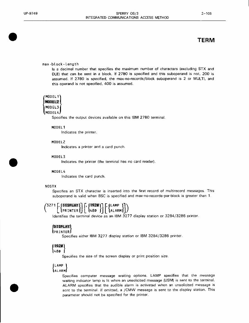
UP-9749
•
•
•
SPERRY OS/3 2-105 INTEGRATED COMMUNICATIONS ACCESS METHOD
TERM
max-block-length Is a decimal number that specifies the maximum number of characters (excluding STX and DLE) that can be sent in a block. If 2780 is specified and this suboperand is not, 200 is assumed. If 2780 is specified, the max-no-records/block suboperand is 2 or MUL Tl, and this operand is not specified, 400 is assumed.
{E} Specifies the output devices available on this IBM 2780 terminal.
MODEL1 Indicates the printer.
MODEL2 Indicates a printer and a card punch.
MODEL3 Indicates the printer (the terminal has no card reader).
MODEL4 Indicates the card punch.
NOS TX Specifies an STX character is inserted into the first record of multirecord messages. This suboperand is valid when BSC is specified and max-no-records-per-block is greater than 1.
(3271 [ {::~~~:!}] [ {:::;'}] t {~~::M}]) Identifies the terminal device as an IBM 3277 display station or 3284/3286 printer.
{::~~~::} Specifies either IBM 3277 display station or IBM 3284/3286 printer.
{~:;'} Specifies the size of the screen display or print position size.
{LAMP } ALARM
Specifies computer message waiting options. LAMP specifies that the message waiting indicator lamp is lit when an unsolicited message (USM) is sent to the terminal. ALARM specifies that the audible alarm is activated when an unsolicited message is sent to the terminal. If omitted, a /CMW message is sent to the display station. This parameter should not be specified for the printer.

UP-9749
TERM
SPERRY OS/3 2-106 INTEGRATED COMMUNICATIONS ACCESS METHOD
('
277
• G~:H J Identifies the terminal device as an emulated IBM 3277 display station.
PASS
On input and output, the message text is passed between your program and the IBM host with no modification performed. The DICE specification is ignored. The message text contains the IBM defined orders (i.e., set buffer address, attribute byte), and input messages contain the IBM command sequence.
STRIP
CONV
Provides for passing of unformatted (screen) data between your program and the IBM host. On input (from the IBM host), all IBM orders are stripped from the message; DICE is ignored. On output, the text is not modified. If you specify DICE=ON, the DICE sequence at the beginning of the message is converted to the cursor address.
Message text field control characteristics are converted between IBM attribute byte (A TB) orders and UTS 4000 field control character sequences. Conversion between DICE and set buffer address (SBA) is performed if DICE=ON. Conversion between all other IBM orders and UTS ESC sequences is performed as described in the ICAM standard MCP interface (STDMCP) user guide, UP-8550 (current version).
CALL=phone-number
Specifies a numeric or alphanumeric telephone number used to dial a data terminal equipment (DTE) on a DATEX-L public data network.
ADDR= l rid- s id } dev-addr
nn,nn
Identifies the remote identifier and station identifier for a specific terminal, the device address for a local workstation terminal, or the screen number for a packet-switched PDN UTS 4000 terminal.
ADDR=(rid,sid) Is the hardware address of a polled terminal as wired into the terminal by field installation technicians. This operand must be specified for polled terminals such as:
• UNISCOPE 100/200
• SPERRY UTS 400 or UTS 4000 (all versions)
• SPERRY DCT 1000
• SPERRY DCT 500 operating in automatic mode
•
•
•

•
•
•
UP-9749 SPERRY OS/3 2-107 INTEGRATED COMMUNICATIONS ACCESS METHOD
TERM
• IBM 3270 terminal system
• IBM 3270 emulator
NOTES:
1. The packet-switched UTS 4000 is addressed by screen number. AOOR=(nn, nJ defines a 2-character ASCII number such as:
30,31 = 1 30,32 = 2
30,39 = 9 31,30 = 10
2. This operand should not be specified for single-station teletypewriters, such as the SPERRY OCT 500.
rid
sid
Is two hexadecimal digits that identify the remote device address wired in the terminal. The allowable range of addresses is 211e to 4F1e. For the IBM 3270 terminal, rid specifies the IBM control unit (CU) address .
Is two hexadecimal digits that identify the station address wired in the terminal. The allowable range of addresses is 511e to 6F1e. For the IBM 3270 terminal, sid specifies the device (dev) address.
NOTES:
1. The rid/sid combination must be unique for each terminal on a line.
2. For OCT 500 terminals operating in automatic mode, rid/sid definitions must be unique for each terminal on a line. However, any ASCII value may be used.
3. For UN/SCOPE 100/200, UTS 400 or UTS 4000, and OCT 1000 terminals using polling groups:
• All terminals in a polling group must have the same rid (sids within a polling group must be unique).
• TERM macroinstructions for terminals in a polling group must be contiguous in the user network definition.
4. For the UTS 400 terminals, each terminal in a polling group (master/slaves to terminal controller/slaves) must use the same rid. The sid for each terminal must be assigned in contiguous ascending order with the master (or the primary terminal) designated as the lowest value sid. If the screen bypass function is utilized, the sid designated for this function must be the next available sid (one greater than the sid assigned to the last actual terminal in the group) .

t
UP-9749
TERM
5.
SPERRY OS/3 INTEGRATED COMMUNICATIONS ACCESS METHOD
2-108 Update B
When specifying terminal addresses for the non-PDN UTS 20 (with screen bypass feature) and UTS 40, the dual screens are separately addressed and require separate and distinct definitions.
You must specify two TERM macroinstructions (each appropriately defining one rid, sid) for each UTS 40 and dual-screen UTS 20. The addresses must be consecutive.
6. For IBM 3270 emulated terminals, the CU/DEV addresses identifying the IBM control unit and device addresses must:
• match the addresses generated in the IBM host; and
• conform to the address values and sequences as specified for the IBM 3277 display station.
ADDR=Cdev-addr) Identifies a specific local workstation terminal address allocated to ICAM. For Models 4 and 6, the range of allowable addresses is 311 to 318, 331 to 338, 341 to 348, 351 to 358, 361 to 368, and 371 to 378. For a Model 8, the allowable range of addresses is C 11 to C 18, C31 to C38, C41 to C48, C51 to C58, C61 to C68, C71 to C78, and C81 to C88.
NOTE:
Your hardware configuration determines the actual optional device addresses in the 340, 350, 360, and 370 ranges. For more details, see OS/3 hardware and software summary, UP-8868 (current version).
ADDR=(nn,nn) The UTS 20(W) and UTS 40(W) workstations attached to the UTS 4020 or UTS 4040 in a packet-switched public data network are addressed by screen number. The number consists of a 2-digit ASCII number that represents a decimal equivalent as follows:
NOTE:
30,31 = 1 30,32 = 2
30,39 = 9 31,30 = 10
Do not specify the ADDR operand for single-station teletypewriters, such as the DCT 500 or the UTS 10.
PI NTV= {;;;,~ths - of - seconds}
Is the time in tenths-of-seconds between polls to this terminal. A value from 1 to 2550 ( 1/10 second to 255 seconds) may be specified. This operand applies to UNISCOPE 100 and 200, SPERRY OCT 1000, SPERRY UTS 400/UTS 4000 terminals, and IBM 3270 terminal system. With polling groups, only the time specified for the first terminal in the polling group is used . That is, if PINTV is specified for a subsequent terminal in the same polling group, this operar1d is ignored.
•
•
•

•
•
•
UP-9749 SPERRY OS/3 2-109 INTEGRATED COMMUNICATIONS ACCESS METHOD
TERM
A polling timer is established for each terminal (or group of terminals, i.e., a polling group) in a network definition. Each of these polling timers is incremented at a fixed interval. This interval is 0. 1, 0.2, 0.5, or 1 second, depending on the smallest interval you specify for any terminal in the network. For example, if you define a network of two terminals and you specify PINTV = 50 for the first terminal and PINTV = 53 for the second terminal, the first terminal is polled every 5 seconds and the second terminal is polled every 6 seconds. This is because the basic timer interval is 1 second and the 5.3-second specification (PINTV=53) is rounded to 6 seconds. If, however, you added a third terminal to the network to be polled every 0.1 second (PINTV= 10), the basic timer interval would be 0. 1 second and all three terminals would be polled as specified; that is, 5, 5.3, and 0.1 second intervals, respectively.
If the smallest PINTV value is specified and there is a syntax error, e.g., an alphabetic character is specified, system generation will display the message:
INVALID PARAMETER VALUE
However, if the smallest PINTV value is specified as an invalid number, e.g., PINTV=3, no error message is displayed. In both cases, a polling increment of 1 second is used .
AUX1=(aux-dev-id)[, .•• ,AUX44=Caux-dev-id)] The AUXn operands specify device addresses for auxiliary devices connected to this terminal. All terminals associated with ICAM include at least one input and/or output device, which is considered the primary device for 1/0 operations. This operand must not be specified for these primary devices. However, in addition to the primary device, a terminal may also support a number of secondary devices, known as auxiliary devices. This operand may be used to identify these auxiliary devices.
Operands AUX 1 through AUX44 create a displacement table of device addresses (dids) for the auxiliary devices connected to this terminal. In the communications user program, the "n" value of the AUXn operand is used in the device field (TM#DDVC) of a destination DTFCP when a PUTCP request is issued to send a message to an auxiliary device. In addition, the "n" value is placed into the TM#PDVC field of an input DTFCP by ICAM to indicate the auxiliary device that sent the message when a message is accessed by means of a GETCP.
The AUXn operands must be specified in sequential order, e.g., from AUX 1 to AUX 12 (if 12 are necessary). The exception is when the tape drives on a tape cassette system are specified. Each device requires two dids, but only one "n" is specified, even though two are used. For example, for a tape drive, AUX1 =(TCS,73,74) might be specified. The second drive would be defined as AUX3=(TCS,75,76). Notice that AUX2 was not specified, and that the next available AUXn is 5.
How the auxiliary devices are defined on the terminals depends upon the kind of terminal. The following paragraphs describe how to specify the possible device addresses for each type of terminal supported by ICAM .

UP-9749
TERM
• OCT 1000
SPERRY OS/3 INTEGRATED COMMUNICATIONS ACCESS METHOD
2-110 Update B
The primary input and output devices for the OCT 1000 terminal are the keyboard and printer, respectively. In addition, up to three auxiliary devices can be defined for a OCT 1000 terminal. The AUXn parameter is:
•
AUXn=(1m )) PRNTR
where:
PTP
Identifies the paper tape punch.
PTR
Identifies the paper tape reader.
PCH Identifies the card punch.
RDR
Identifies the card reader.
PRNTR
Identifies the auxiliary printer.
The following values are substituted for the designated parameters.
Device Device Address (Hex.) Parameter Wired in OCT 1000
PTP 70 PTR 7C PCH 78 RDR 7A PRNTR 7F
UNISCOPE/UTS 400/UTS 20/UTS 30/UTS 40/Remote Workstations
The primary input/output devices are the keyboard and printer. The allowable range for auxiliary device addresses is 731s to 7E1s (701s, 71 is, 721s, and 7F1s are reserved). Device addresses 201s through 6F1s may be specified to designate auxiliary devices attached to a UTS 4000 terminal.
•
•
•

•
•
•
UP-9749 SPERRY OS/3 2-111
INTEGRATED COMMUNICATIONS ACCESS METHOD
TERM
The AUXn operand is used as follows:
For printers:
where:
COP
CQP
TP
did
Identifies the communications output printer, the 0768 printer subsystem, the 0797 printer
subsystem, or the 0798 printer subsystem.
Identifies the 0791 correspondence quality printer subsystem.
Identifies the 800 terminal printer .
Specifies two hexadecimal digits giving the device address in the printer.
For diskette or tape cassette:
AUXn=(TCS, did,, di d2) Identifies one of the two cassette or diskette drives (n) on the cassette or disk subsystem regardless of the type of operation (n + 1 is also valid except for write operations).
where:
•
TCS
did,
did2
Identifies the tape cassette system (TCS) or diskette subsystem for the UTS 400 or UNISCOPE terminal, or a diskette subsystem for the UTS 4000 terminal.
Specifies two hexadecimal digits giving the output device (write) address for one of the two
drives.
Specifies two hexadecimal digits giving the input device (read) address for the same drive.
OCT 500. OCT 524, OCT 475, and TTY
In addition to the primary input and output devices of the keyboard and the printer, the DCT 500, DCT 475, and TTY supply auxiliary device support for the paper tape reader and punch . The DCT 524 supplies auxiliary device support for the write and read cassette systems.
AUXn= ({ :~:})

UP-9749 SPERRY OS/3 INTEGRATED COMMUNICATIONS ACCESS METHOD
TERM
where:
PTP Identifies the paper tape punch or the cassette write head for the OCT 524.
PTR Identifies the paper tape reader or the cassette read head for the OCT 524.
The following values are substituted for the designated parameters:
Device Parameter
PTP PTR
Device Address (Hex.) Wired in OCT 500
75 76
• 1004 card processor and 9200 and 9300 systems
2-112
The primary input and output devices for the 1004 card processor are the card reader and page printer. In addition, the 1004 card processor, the 9200 system, and the 9300 system provide auxiliary device support for a single card punch. For these systems, the AUXn parameter is:
AUX1=(PCH)
where:
PCH Identifies the card punch.
• OCT 2000
The primary input and output devices for the OCT 2000 are the card reader and the page printer. In addition, the OCT 2000 supplies auxiliary device support for a single card punch. For the OCT 2000, the AUXn parameter is:
AUX1=(PCH)
where:
PCH Identifies the card punch.
• UTS 400 (model II) local workstation
Up to four printers (PRNTR) can be specified for a UTS 400. The AUXn parameter is:
AUXn=(PRNTR) where:
n Specifies a number from 1 to 4.
•
•
•

•
•
•
UP-9749 SPERRY OS/3 INTEGRATED COMMUNICATIONS ACCESS METHOD
NOTES:
2-113 Update B
TERM
1. Do not specify auxiliary printers for UTS 20 local workstations.
2. For a printer attached to a UTS 400 local workstation, wait 60 seconds after input for notification of start of printing (time-out) before checking on the printer.
INPUT=({~:;e}[,blanks][,filename])
Establishes a destination for messages input at this terminal.
NOTE:
You must specify the INPUT operand for each terminal on a line - either here or in a LINE macroinstruction for the line to which this terminal is connected. If you specify this operand in both the LINE macroinstruction and the TERM macroinstruction, TERM destination is used.
name
YES
Is a 1- to 4-character name that matches the label of a LOCAP, PRCS, MPPS, or TERM macroinstruction. This is the name addressed on GETCP calls to a process file or a LOCAP file to retrieve input messages from this terminal. Depending on the name specified, input messages from this terminal are directed to:
• the low priority queue of a communications user program defined by the label of a LOCAP macroinstruction (global networks only);
• the low priority queue of a process file, defined by the label of a PRCS macroinstruction;
• the low priority queue of a terminal, defined by the label of a TERM macroinstruction (this causes message switching because a message input from a terminal on this line is immediately placed on the output queue of another terminal); or
• a destination determined by MPPS, with the name of the routine defined by the label of an MPPS macroinstruction. This is the only destination that may be specified for the transaction control interface.
Creates an input message queue for this terminal. If the filename suboperand is included, input messages are held in a disk file until the program accesses them. If filename is omitted, a main storage input message queue is established. The user program accesses a message placed on this input message queue by issuing a GETCP
macroinstruction, and in the related DTFCP, specifying the name of this TERM macroinstruction. Do not specify a priority .
blanks
Is a decimal value from 1 to 255 that indicates the number of bytes (blank characters) reserved in front of each input message for MPPS or for the program insertion of data.

UP-9749
TERM
SPERRY OS/3 2-114 INTEGRATED COMMUNICATIONS ACCESS METHOD
filename Is a 1- to 7-character name of a disk file where messages input from this terminal are stored until the user program accesses them. The filename must match the label of a DISCFILE macroinstruction. This suboperand may be included only if YES also is specified.
LOW, MEDIUM, and HIGH operands: These operands create low, medium, and high priority terminal output queues in main storage or on disk for this terminal. They override any created by means of the LOW, MEDIUM, and HIGH operands in the LINE macroinstruction.
LOW=filename Creates a low priority output queue for this terminal on a disk file named in a DISCFILE macro instruction.
LOW=MAIN Creates a low priority output queue for this terminal in main storage.
MEDIUM=filename Creates a medium priority output queue for this terminal on a disk file named in a DISCFILE macroinstruction.
MEDIUM=MAIN Creates a medium priority output queue for this terminal in main storage.
If omitted, a medium priority queue is not created.
HIGH=filename
Creates a high priority output queue for this terminal on a disk file named in a DISCFILE macroinstruction.
HIGH=MAIN Creates a high priority output queue for this terminal in main storage.
If omitted, a high priority queue is not created.
ALTD=alt-dest
Defines the label of an alternate process file, terminal, or locap file where output messages are sent if this terminal is unable to receive them for any reason.
If this terminal is marked down by ICAM before ICAM dequeues the output and you have specified AL TD, ICAM sends the message to the alternate destination. If AL TD is not specified but an intercept queue is available (see INTERCPT operand), ICAM places the message 'on the intercept queue.
In addition, if you have a message processing (MPPS) routine in your network, this is the name of the alternate destination (Al TD) the message processing routine may refer to in a DIRECT, REROUTI, or REROUTO macroinstruction.
•
•
•

•
•
•
UP-9749 SPERRY OS/3 2-115 INTEGRATED COMMUNICATIONS ACCESS METHOD
TERM
If the terminal is marked down during the actual output processing of a given message, the AL TD parameter or the TERM macroinstruction is not referenced by !CAM unless the MPPS
REROUTO with AL TD operand is executed.
NOTES:
1. Alternate destinations must not form a loop (terminals designating each other as alternatives); otherwise, system looping can occur.
2. AL TD cannot redirect multiple destination messages queued in main storage. However, any multiple destination message going to all disk queues may be redirected.
INTERCPT={YES } filename
YES creates a main storage queue for output messages for this terminal when line queueing is used for output messages. If filename is specified, the intercept queue is placed on a disk file identified by means of the label of a DISCFILE macroinstruction. The intercept queue can be used by !CAM or by a message processing routine to temporarily store messages. If there is a message processing routine, and it detects an error in an output message to this terminal (such as a bad destination), it can send the message to this intercept queue, where it is held until the user program releases the intercept queue by means of a RELEASM macroinstruction.
Both !CAM and the message processing routine can send messages to an intercept queue for line/terminal-down situations if an alternate destination is not specified (see AL TD operand). However, when the destination terminal becomes operable, !CAM automatically releases any messages held on the intercept queue. If this operand is not specified, an intercept queue is not created for this terminal.
NOTES:
1. Multiple destination messages can be redirected to an intercept queue only if they are on disk.
2. When using this feature, line queueing must be specified.
REMOTE=(subname,PDN[,PT]) For packet-switched public data networks only, specifies that this terminal is:
• a terminal attached to a remote host; or
• a workstation attached to a UTS 4000 series packet-switched cluster controller.
Terminals or workstations in these categories must be defined with their TERM macroinstructions following the SUB macroinstruction defining their common subscriber.
subname Specifies the symbolic name of the SUB macroinstruction that defines the remote host or cluster controller for this terminal or workstation.

UP-9749
TERM
PON
PT
SPERRY OS/3 2-116 INTEGRATED COMMUNICATIONS ACCESS METHOD
Specifies that this is a public data network user.
Specifies that this terminal is a workstation attached to a cluster controller. This operand is not used for terminals attached to a remote host.
DICE=({:FJ, {:~M~ }) Describes how device independent control expressions (DICE) are used with this terminal. The default is DICE=(ON,NEWLINE).
Indicates that the ICAM remote device handler places DICE into all input messages.
OFF Indicates that DICE characters are not placed in input messages.
'.·. r1u Indicates that, on output, a set coordinates or a forms control with clear DICE is converted to a new line positional control DICE, with DICE m field equal to 001s and the n field equal to 001s.
FORMS Indicates that, on output, a set coordinates DICE is converted to a forms control DICE.
NOTES:
1. NEWLINE and FORMS apply to all devices except cathode-ray tube devices and the COBOL message control system (CMCS). NEWLINE is always assumed for the IBM 3270 terminal system since the IBM 3284/3286 printers do not have a form feed feature.
2. DICE=(ON) must be specified when using the COBOL message control system.
XLATE=([{~.,;. ;d;}] [ ~elo, ;do}]) The XLA TE operand specifies a translation table for input from this terminal and for output going to this terminal. User translation tables, those supplied by ICAM, or no translation at all can be specified. If this operand is omitted, the translation tables established for this line, by means of the LINE macroinstruction, are used.
For IBM 3270 terminal systems and local workstations with Katakana support, specify XLATE = (NO,NO).
The XLA TE operand is divided into two similar suboperands; the first suboperand is concerned with input translation, and the second is concerned with output translation.
•
•
•

UP-9749
•
•
•
SPERRY OS/3 2-117
INTEGRATED COMMUNICATIONS ACCESS METHOD
TERM
Input translation is specified as:
Indicates that the standard translation table is used for input from this terminal.
NO Indicates that no translation takes place for input received from this terminal.
L abe L i
id i
Specifies the name of a user-supplied input translation table. The name specified must correspond to that specified for a user-generated translation table assembled in this
network.
Is a decimal number, 1 to 240, identifying a user-generated input translation table within this network.
This number makes it easy for ICAM to tell whether the same input translation table already exists in the network. If the same number is used with a different labeli name, the table name used is the last one specified. The same input translation table may be identified in any number of LINE or TERM macroinstructions.
The default is the input translation table defined for this line (by means of the LINE macroinstruction), with which this terminal is associated.
Output translation is specified as:
Indicates that the standard translation table is used for output to this terminal.
NO Means that output to this terminal is not translated.
Labelo
ido
Specifies the name of a user-supplied output translation table for this terminal. The name specified must correspond to that specified for a user-generated translated table assembled in this network.
Is a decimal number, 1 to 240, that identifies a user-generated output translation table assembled within this network.
This number makes it easy for ICAM to tell whether the same output translation table already exists in the network. If the same number is used with another labelo name, the table name used is the last one specified. The same output translation table can be specified in any number of LINE or TERM macroinstructions .
The default is the output translation table defined for this line (by means of the LINE macroinstruction), with which this terminal is associated.

UP-9749 SPERRY OS/3 2-118 INTEGRATED COMMUNICATIONS ACCESS METHOD
TERM
Programming Notes:
1 . The XLA TE operand specified by means of the LINE macroinstruction is used for all terminals on this line, for which an XLATE operand is not specified. If an XLATE operand is specified in this macroinstruction, it overrides the line information for this terminal only.
2. The idi and ido suboperands refer to separate input and output translation tables, i.e., up to 240 input translation tables and 240 output translation tables may be specified.
3. Any user-written translation tables may be included at the end of the network definition before the ENDCCA macroinstruction.
4. Continuation of assembler DC statements is not acceptable; therefore, each DC statement should have a closing apostrophe in column 71 or before.
5. Standard translation tables are either 128 or 256 bytes long; user-written tables should normally be one of these two lengths.
PROFIL=n Assigns a profile number used with the message format editing facility. The number assigned must agree with one assigned in an EUP macroinstruction by means of its PRFN operand.
NOTE:
If the same editing profile for several terminals is used, multiple EUP macroinstructions must be specified, with each assigned a different PRFN number. The same physical profile must not be
specified to more than one terminal.
INHIBIT=YES Has ICAM ignore all subsequent input from this terminal following successful input of a message. This inhibition remains in force until a successful output transmission is completed. Any messages sent from this terminal following the first successful one are lost. This allows setting up an inquiry/response relationship with this terminal, i.e., one message is followed by a single response.
MSGWAIT=Cmessage) Defines a 4-character computer message waiting message that is sent to this terminal to inform the terminal operator of a waiting message. The terminal operator must respond with BEL (control G) and ETX (control C) before the waiting message is sent to the terminal.
This operand is used only with SPERRY OCT 475, OCT 500, OCT 524, or TTY terminals. It is also required for IBM 3270 terminals.
If this operand is not specified, the message: /CMW
is used, but any 4-character message can be specified.
•
•
•

•
•
•
UP-9749 SPERRY OS/3 INTEGRATED COMMUNICATIONS ACCESS METHOD
2-119 Update B
TERM
NOTE:
No carriage return or line feed characters accompany the default message. However, carriage return and line feed characters can be inserted as the first or last two characters of the 4-character message operand, leaving two printable characters in the message. This may be accomplished by multipunching carriage return (0-9-5) and line feed ( 12-9-8-5) or by multipunching a DICE expression with a OLE (12-11-9-8-1) and the function code for new line (4). In either situation, the remote device handler
will insert appropriate time fill for carriage return and line feed.
ANSWER=(integer,C,text) Specifies a site identification constant that ICAM can use to verify site identifier codes (site IDs) for SPERRY 1004 and SPERRY 9200 or 9300 systems.
integer
c
text
Is a decimal number that indicates the number of characters in the third suboperand (text).
Indicates the text suboperand is alphanumeric.
Is the alphanumeric site identifier. The number of characters specified must be the same as specified in the integer suboperand.
PLI MIT= integer Is the maximum number of messages to be accepted from this terminal in a single polling pass. If omitted, all messages ready for transmission are accepted.
This operand is used for polled terminals serviced by a user-written remote device handler. This operand must not be specified for a remote device handler supplied by Sperry.
INONLY=YES Specifies that this terminal is a send-only device; i.e., traffic always flows from the terminal to ICAM.
OUTONLY=YES Specifies that this terminal is a receive-only device; i.e., traffic always flows from ICAM to the terminal.
TCTUPD=YES Specifies this UNISCOPE terminal can communicate with OS/3 interactive services and another program such as IMS or a user-written program when signed on ($$SON) to dynamic sessions (a LOCAP macroinstruction specified as TYPE= DMI).
Do not specify this operand if this macroinstruction defines a local or remote workstation.
This operand controls the DICE status and translation tables used between this terminal and interactive services. If you specify TCTUPD=YES, ICAM uses the proper DICE status and translation tables when you sign on to interactive services. When you sign on to your user program or IMS, ICAM uses the DICE status and translation tables you specify in the DICE= and
XLA TE= operands.

UP-9749 SPERRY OS/3 2-120 INTEGRATED COMMUNICATIONS ACCESS METHOD
TERM
DISIN=n
Applies only to DA TEX-L circuit-switched public data networks. Specifies the time, in poll interval periods, that a terminal remains connected to the network after a message is received. (See PINTV keyword.) If omitted, the terminal is disconnected immediately after the completed message is received and acknowledged.
DISOUT=n Applies only to DA TEX-l circuit-switched public data networks. Specifies the time, in poll interval periods, that a terminal remains connected to the network after a message is transmitted. If omitted, the terminal is disconnected from the network immediately after the message is transmitted and acknowledged.
INRECSZ={:l l 128
Specifies ·the input record size for a batch terminal in bytes. It is valid only for the following devices:
• SPERRY OCT 2000, 1004 (REM 1), 9200, 9300 (REM 1), OCT 1000 (batch), and BSC
• IBM 2780
NOTE:
The INRECSZ operand must not be used in conjunction with the REMOTE operand.
DVCGID=terminal-group-name Specifies the name of a remote terminal group in a DCA network. The DVCGID operand is required for DCA networks and must be one of the following names:
• Interactive terminals
INT 11 for OCT 500
INT101 for TTY 33/35
INT21 for OCT 1000
INT31 for UNISCOPE
INT 41 for UTS 400
INT51 for all others
•
•
•

•
•
•
UP-9749 SPERRY OS/3 INTEGRATED COMMUNICATIONS ACCESS METHOD
• Batch terminals
RB512780 for BSC 2780
RB513780 for BSC 3780
RB511004 for 1004
RB510000 for all others
2-121 Update B
TERM
Although DVCGID is not required for REM-1 devices, the REM-1 devices generate a 5-character site ID that is used as the group name in a DCP generation.
PROTYP={DEV l I NT - 1
RB-2
Describes how data is presented by the terminal. DEV specifies device dependent for terminals attached to a remote OS/3 host. INT-1 and RB-2 specify interactive or batch terminals respectively attached to a distributed communications processor.
RBATCH={NO } YES
Indicates that this terminal is used for remote batch jobs. If omitted, interactive is assumed. When RBA TCH =YES is specified, the operand XLATE = (NO,NO) must be specified if the batch terminals are attached to a distributed communications processor.
SPR={.·.s .. ·•· .. ··· .. ·.e·····.·.· .• conds} fl.f Specifies the slow polling interval in seconds for a downed polling group. If not specified, a value of 60 is used.
This operand applies to UNISCOPE lines only and need only be specified on the first terminal in each polling group .
t
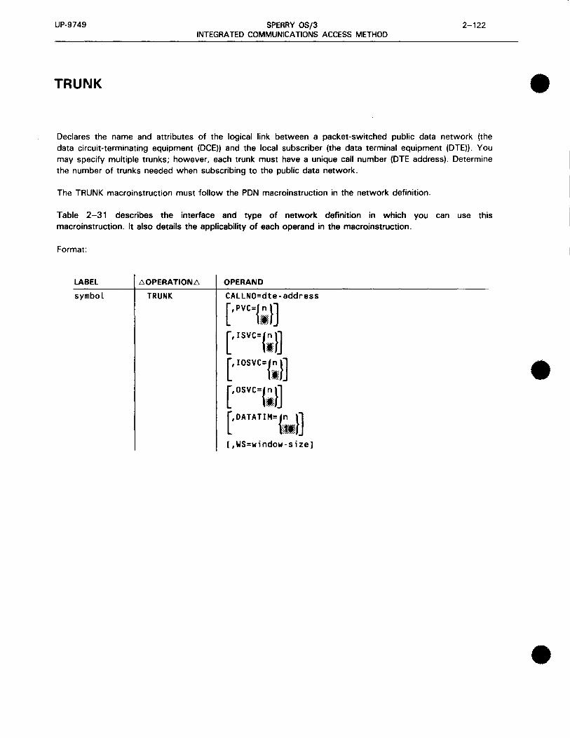
UP-9749 SPERRY OS/3 2-122 INTEGRATED COMMUNICATIONS ACCESS METHOD
TRUNK
Declares the name and attributes of the logical link between a packet-switched public data network (the data circuit-terminating equipment (DCE)) and the local subscriber (the data terminal equipment (DTE)). You may specify multiple trunks; however, each trunk must have a unique call number (DTE address). Determine the number of trunks needed when subscribing to the public data network.
The TRUNK macroinstruction must follow the PON macroinstruction in the network definition.
Table 2-31 describes the interface and type of network definition in which you can use this macroinstruction. It also details the applicability of each operand in the macroinstruction.
Format:
LABEL 60PERATION6 OPERAND
symbol TRUNK CALLNO=dte-address
[,Pvc={I,}] [' rsvc={I}]
[, IOSVC={.".}]
I
[,OSVC={.;!}]
[ ' DATATIM={;~ .. ·}] • [,WS=window-size]
•
•
•

•
•
•
UP-9749
Label:
SPERRY OS/3 INTEGRATED COMMUNICATIONS ACCESS METHOD
Table 2-31. Applicability of TRUNK Macroinstruction and Its Operands
Macro: TRUNK
Operand Name
TRUr-JK
label
CALLNO
DATA TIM
IOSVC
ISVC
osvc
PVC
ws
ICAM Network Type and Kind of Program Supported
Direct Data
Interface
DOI
NTR
RBP
RPG
IDES u I-
Dedicated
Networks
c. (.)
~ 0 ..... (/)
::J 0 m 0 ~ (/) (.)
~ (.)
Cl. (.)
~ 0 ..... (/)
(.) .....
Global Networks
...J 0 m 0 (.)
GI ct "8 (.) .: 0 ... ' - c: :I 0 ~z
ct (.) 0
·shows macro appl1cabil1ty .. Packet-switched only
LEGEND R = Required 0 = Optional - = Not Applicable
ftl ... I/)
~~ u 0 =~ .Q ... :I GI 11.z • •
R
R
R
0
0
0
0
0
0
2-123
TRUNK
symbol
Is a 1- to 4-character label used to reference this macroinstruction.
Operands:
CALLNO=dte-address
Specifies the level-3 DTE address of the local subscriber. The address is available from the public data network at subscription time. Note this is not the DTE address of the remote subscriber defined in the SUB macroinstruction.

UP-9749 SPERRY OS/3 INTEGRATED COMMUNICATIONS ACCESS METHOD
2-124 Update B
TRUNK
PVC={;} Specifies the number of permanent virtual circuits provided by the public data network at subscription' time. The number specified must agree with the number of PVC macroinstructions specified for this trunk and the number of permanent virtual circuits that can handle data assigned at subscription time.
Valid values for this operand are 0-4095.
For DATAPAC, DATEX-P, and IBERPAC, do not include logical channel 0 in the count. Although channel 0 is provided in these networks, it is used for control purposes only and it is not usable for data. This operand is not valid for the DDX and PSS networks.
ISVC=t;.} Specifies the number of incoming switched virtual circuits to receive incoming calls only. Determine this value at subscription time.
Valid values for this operand are 0-4095. This operand is not valid for the DDX and PSS networks.
IOSVC={;} Specifies the number of switched virtual circuits that can receive incoming calls from and send outgoing calls to remote subscribers. Determine this value at subscription time.
Valid values for this operand are 0-4095. This operand is not valid for the DDX and PSS networks.
OSVC={;J Specifies the number of switched virtual circuits that are used to make outgoing calls only. Determine this value at subscription time.
Valid values for this operand are 0-4095. This operand is not valid for DDX and PSS networks .
•
•
•

•
•
•
UP-9749 SPERRY OS/3 INTEGRATED COMMUNICATIONS ACCESS METHOD
2-125 Update B
TRUNK
DAT AT IM={;.;.,~} Specifies the level-3 time-out value in seconds for a data packet. Valid values are 1 to 120 seconds for all public data networks.
WS=window-size Specifies the level-3 window size for flow control of both input and output data packets; it applies to both switched and permanent virtual circuits on this trunk. Specify a value of 1 to 6 for TRANSPAC, DATAPAC, or DATEX-P networks. This operand is not valid for DDX, PSS, and IBERPAC.
Default values are as follows:
DAT AP AC 4 DATEX-P 4 DDX Not used IBERPAC Not used PSS Not used TRANSPAC 2

UP-9749 SPERRY OS/3 2-126 INTEGRATED COMMUNICATIONS ACCESS METHOD
VCGROUP
Defines the attributes of a permanent or switched virtual circuit group on a DDX or PSS packet-switched public data network for the most recently defined trunk macroinstruction.
Table 2-32 describes the interface and type of network definition in which you can use this macroinstruction. It also details the applicability of each operand in the macroinstruction.
Format:
LABEL
symbol
60PERATION6
VCGROUP
OPERAND
LCGN=group-number
, TYPE={~~~C }
osvc IOSVC
,NUMBER=n
Table 2-32. Applicability of VCGROUP Macroinstruction and Its Operands
Macro: ICAM Network Type and Kind of Program Supported VCGROUP
Operand Direct Name Data
Interface Dedicated
Global Networks DOI Networks
NTR :::;
RBP u; 0 u; GI <{ c. II) a. ....I RPG ~ (.) 0 (.) ~ 0 - -g (.) <{
~ 2 ~ II) ~ .: 0 (.) 0 0 0 0 .. ' 0
C3 (/) C3 - c .... .... (.) :I 0
~DES .... (/) (.) (/) .... ~z ~ (.)
VCGROUP - - - - - - - - - - -
label - - - - - - - - - - -
LCGN - - - - - - - - - - -
TYPE - - - - - - - - - - -
NUMBER - - - - - - - - - - -
·shows macro applicability ""DDX and PSS networks only LEGEND
R = Required 0 = Optional - = Not applicable
.. .. Ul
~~ uo =~ J:I ti l.z • •
0
R
R
R
R
•
•
•

•
•
•
2-127 UP-9749 SPERRY OS/3
INTEGRATED COMMUNICATIONS ACCESS METHOD
VCGROUP
Label:
symbol Is a required 1- to 4-character label used to reference this macroinstruction.
Operands:
LCGN=group-number Specifies the logical channel group number of this group. For DDX you must specify a value of 0 to 15. For PSS you can specify a value of 0-7, depending on the circuit type: PVC 0, 1 SVC
(IN) 2,3 SVC (1/0) 4,5 SVC (OUT) 6,7
,TYPE={~~~C) osvc IOSVC
Specifies the composition of a logical channel group.
PVC Permanent virtual circuits only.
!SVC Incoming switched virtual circuits only.
osvc Outgoing switched virtual circuits only.
IO SVC Switched virtual circuits for both incoming and outgoing calls.
NUMBER=n Specifies the number of virtual circuits in this logical channel group. Never specify zero.
Valid values are 1-255 .

UP-9749 SPERRY OS/3 2-128 INTEGRATED COMMUNICATIONS ACCESS METHOD
VLINE
Specifies the physical link that connects two computer nodes in a global network system. In a public data network environment, it defines the physical line that connects the data terminal equipment (DTE) and the data terminal communications equipment (DCE).
VLINE is used with computer-to-computer global network or public data network definitions only; it is not used in dedicated network definitions or global network definitions where the end users reside in the same computer node.
NOTES:
1. Although you do not need to specify it, VLINE requires a 2-way simultaneous (full-duplex) line.
2. Specify all resources that pertain to a particular VLINE before defining any additional VL/NES.
Table 2-33 describes the interface and type of network definition in which you can use this macroinstruction. It also details the applicability of each operand in the macroinstruction.
Format:
LABEL 6 OPERATION 6
symbol VLINE
OPERAND
ID=slca-number
[,CHAN=channel-number]
,DEVICE= {~::A} LAPB X25
[, K ={.~.al ue}]
I;
r. RETRY=({ n Im })~ L 1B:ii±R ~
[TIMEOUT=({-}) J
•
•
•

UP-9749
•
•
•
SPERRY OS/3 INTEGRATED COMMUNICATIONS ACCESS METHOD
Table 2-33. Applicability of VL/NE Macroinstruction and Its Operands
Macro: VLINE
ICAM Network Type and Kind of Program Supported
Operand Name
·vLINE
label
ID=
CHAN=
CMDADDR"
DEVICE=
K=
LBUF=
RETRY=
RSPADDR=
TIMEOUT=
TYPE=
Direct Data
Interface
DOI
NTR
RBP
RPG
IDES
*Shows macro applicability
LEGEND:
u I-
Dedicated
Networks
Cl.. u ~ 0 IC/)
R = Required 0 = Optional
Global Networks
:::J 0 al 0 2 Cl)
u ~ u
0.. u ~ 0 IC/)
- = Not applicable
-' 0 al 0 u
~ <( OU ·= 0 ... ' - c: :J 0 ~z
R
R
0
0
R
0
0
0
0
0
<( u 0
R
R
0
0
0
R
0
0
0
0
0
0
ca ... Cl! ca ~ 0 ..
0 .!:! ~ - ... .rJ Q)
~z
R
R
0
0
0
R
0
0
0
0
0
R
2-129 Update B
VLINE

UP-9749
VLINE
Label:
SPERRY OS/3 INTEGRATED COMMUNICATIONS ACCESS METHOD
2-130 Update B
symbol
Operands:
Is a 1- to 4-character required name of this physical link. It is also referenced in the NODE and SESSION macroinstructions.
ID=slca-number In a model 3 through 6 processor, the slca-number is specified as a number from 8 to 15 identifying the line number of the single line communications adapter.
In a model 8 processor, slca-number can be from 1 to 15.
CHAN=channel-number Specifies the input/output microprocessor (IOMP) to which the single-line communications adapter (SLCA) is connected.
For System 80 models 3 through 6, this operand is optional. If specified, the only value permitted is CHAN=2. The default is CHAN=2. Up to eight SLCAs (ID=8 to ID= 15) can be specified for these models.
For System 80 model 8 with one IOMP, this operand is optional. If specified, the only value permitted is CHAN=13. The default is CHAN=13. Up to 14 SLCAs (ID=1 to ID=15) can be specified for the IOMP.
For System 80 with two IOMPs, this operand is optional. If specified, you must also specify the ID= operand. The only values permitted are CHAN= 13 and CHAN= 15. Up to 14 SLCAs (using ID= 1 to ID= 15) can be specified for each IOMP.
DEVICE={ ~~:A} LAPB
X25 Specifies the type of protocol used on this physical link.
ABM
LAPA
LAPB
Specifies communications between two OS/3 DCA termination systems in a distributed communications architecture data processing environment. This operand must be specified for circuit-switched public data networks.
Specifies CCITT recommendation X.25 link access procedure (LAP) protocol. This operand is used only for the DAT APAC packet-switched public data network.
Specifies CCITT recommendation X.25 link access procedure B (LAPB). This operand is used for DATAPAC, DATEX, DDX, PSS, TRANSPAC, or IBERPAC public data networks.
•
•
•

•
•
•
UP-9749
X25
SPERRY OS/3 2-131 INTEGRATED COMMUNICATIONS ACCESS METHOD
VLINE
Specifies link access procedure (LAP) as the line protocol for this link in a multinode global network not using distributed communications architecture; that is, you did not specify DCA=YES in the CCA macroinstruction.
K=value • Specifies the number of frames (K window value) that can be sent or received across this
virtual link before an acknowledgment is required. You can specify a value of 1 to 7 subject to the following guidelines:
If you specify OEVICE=ABM or DEVICE=X25, you must specify K= 1.
• If you specify DEVICE=LAPA or DEVICE=LAPB, we recommend you specify K=7.
RETRY=Cn,m) Specifies the number of retries that the remote device handler attempts before an error message is sent to the operator.
n
m
Is a decimal value, from 1 to 255, that specifies the maximum number of times a command or data message is sent due to the lack of an acknowledgment. If an output message is not acknowledged, the remote device handler waits the time specified in the TIMEOUT operand and retransmits the message. This sequence of timing out and retransmission continues until the value specified in this operand is satisfied; at this time, an error message is sent to the operator.
Is a decimal value, from 1 to 255, that specifies the number of attempts the remote device handler makes to write a command, data, or response due to a hardware failure or a time-out. The remote device handler receives a report on whether the message was sent; if not, it retransmits the message until the value specified in m is reached. At this time, a message is sent to the computer operator.
The default is RETRY=(10, 10). The default values of 10 are required if DEVICE=(ABM) is specified.
TIMEOUT=Cn,m) Specifies the time-out period the ICAM remote device handler waits for a response to an output message and the maximum time it is to allow for a line buffer to empty or terminate. Do not specify this operand if DEVICE=(ABM) is specified.
n
m
Is the maximum time in seconds ( 1 to 32000) that the ICAM remote device handler is to wait for an acknowledgment before retransmitting the data message or command. (See RETRY.)
Is the maximum time in seconds (1 to 32000) to empty or terminate a line buffer.
The default is TIMEOUT=(4,20).

UP-9749 SPERRY OS/3 . 2-132 INTEGRATED COMMUNICATIONS ACCESS METHOD
VLINE
LBUF=<number,size,threshold) Generates a buffer pool associated with this physical link. The operand defines the number of buffers created, the size of each buffer, and a threshold value. Do not specify this operand if DEVICE= (ABM) is specified.
number
size
Is a decimal value that specifies how many buffers are created. At least 19 buffers must be created.
Is the maximum number of words (4-byte words) of data that can be transferred across the virtual line within one information frame. ICAM breaks up user messages into segments that fit into the buffer size specified and places them into the buffers before transferring the data. The actual size of a buffer is the size specified, plus line protocol framing characters.
threshold Is a decimal number of inactive VUNE buffers. When this minimum is reached, ICAM ceases solicitation of further input until a safe level is reached. Specify a value 10 to 15 percent of the numbers specified for number. The default is LBUF=(19,64, 1).
TYPE= {,tine,- speed}, J~,~1: ···•· •··· } , (~W,CH .. ,} BM ..-11 l!lama
line-speed
X21
Specifies the line speed (baud) at which data is transferred between the two computers described in this macroinstruction. This speed is a function of the modems used. Acceptable values are 2400, 4800, 9600, 19200, 40800, 50000, 56000, and 64000. For public data networks, acceptable values are 2400, 4800, and 9600 (packet-switched) and 600, 2400, 4800, and 9600 (circuit-switched).
Specifies a CCITT X.21 interface between the data terminating equipment (DTE) and the data circuit tem1inating equipment (DCE). Must be specified for all circuit-switched networks and for DA TEX-P networks using X .21 leased lines.
RS232C
SWCH
Specifies an EIA RS-232C interface between the data terminating equipment (DTE) and the data circuit terminating equipment (DCE). Valid for packet-switched networks only.
Specifies a circuit-switched public data network. Initiates call connect procedures.
LEASED Specifies this line is leased, i.e., a private line. This operand must be specified for packet-switched public data networks.
CMDADDR= {i~!}
Specifies the universal data link control frame level address used to transmit commands and receive responses. Indicated by decimal number from 1 to 255.
•
•
•

•
•
•
UP-9749 SPERRY OS/3 INTEGRATED COMMUNICATIONS ACCESS METHOD
2-133
VLINE
RSPADDR={~}
Specifies the universal data link control frame level address used to transmit responses and
receive commands. Indicated by a decimal number from 1 to 255.
NOTE:
When there are two balanced stations on a point-to-point link, the CMDADDR address specified for
each must equal the RSP ADDR address specified for the other .

•
•
•

I~---
•
•
•
3. Communications User Program Macroinstructions, Tables, and Error Codes

•
•
•

•
•
•
UP-9749 SPERRY OS/3 3-1 INTEGRATED COMMUNICATIONS ACCESS METHOD
Each user program has a set of macroinstructions it uses to work with a particular ICAM interface. The major functions performed by all user programs fall into three categories:
1 . Acquiring and releasing communications facilities
2. Sending and receiving messages
3. Obtaining and altering network status
This section contains all of the macroinstructions your program needs to use these categories. Included with each macroinstruction description are the parameter lists, tables, and error codes that relate to a given macroinstruction. For example, if you need to look at the structure of a DTFCP file table, go to the DTFCP macroinstruction that creates the file table.
All of the macroinstructions in this section are in alphabetical order with no regard to the type of interface or the kind of function that the macroinstruction performs. Imperative macroinstructions are mixed with declarative macroinstructions, and those that pertain to the direct data interface are alphabetically arranged with those that pertain to the standard and communications physical interfaces. An exception to this is the tables required for the communications physical interface; they are in Section 14. Another exception is the specialized programs supplied by ICAM, such as CMCS, NTR, RBP, and IDES. They are summarized in their
own sections.
ACQUIRING AND RELEASING COMMUNICATIONS FACILITIES
The macroinstructions contained in this group are used to:
• acquire and initialize a network;
• begin processing for an entire network, a line in a network, or one or more terminals on a line;
• terminate processing for a network, a line, or one or more terminals; and
• release messages held on an intercept queue for downed terminals.
LNEREQ, LNEREL, or NETREL may not be used when running in transient mode either from the program or the system console.
SENDING AND RECEIVING MESSAGES
The macroinstructions composing this group transfer messages between ICAM and your program. Each of the interfaces has a DTF-type information packet that contains fields for error flag settings when errors are encountered .

UP-9749 SPERRY OS/3 3-2 INTEGRATED COMMUNICATIONS ACCESS METHOD
OBTAINING AND ALTERING NETWORK STATUS • The macroinstructions composing this group are used to:
• suspend and resume the transmission of messages from queues;
• interrogate network status;
• interrogate and alter terminal specifications;
• interrogate and alter polling sequences; and
• interrogate CCA tables.
•
•

•
•
•
UP-9749 SPERRY OS/3 3-3 INTEGRATED COMMUNICATIONS ACCESS METHOD
CA WAKE
Function:
Activates a communications program in a CYIELD condition. If your program is operating in a multitask environment, any noncommunications task or island code can activate a communications task by issuing CA WAKE. This gives control to the communications task at the instruction immediately following CYIELD.
Format:
LABEL L.OPERATIONL. OPERAND
[symbol] CAWAKE
Label:
[symbol]
Is an optional alphanumeric character string (symbolic name) from one to eight characters long that identifies the specific instruction.
Programming Notes:
You can use either the CAW AKE or GAW AKE macroinstruction to activate a communications program, but the two instructions have these important differences:
1. CA WAKE can activate another communications program only within the same job; GA WAKE can be issued from any program (even a noncommunications program) and activate any communications program in any job.
2. Your program can issue datagrams using GAWAKE, but not with CAWAKE.
3. When you issue CAWAKE, control is given to the activated program at the instruction following CYIELD. When you issue GAWAKE with the TYPE=OUTPUT operand, control is given to the activated program at the entry address designated when GAW AKE was issued with the TYPE=INPUT operand.
Error Processing:
ICAM always returns control inline following the CA WAKE macroinstruction. No return codes are supplied. Only one type of error can occur during macroinstruction processing - your program is canceled with error code 95 7 when the program issuing the CAW AKE has no active communications task .

UP-9749 SPERRY OS/3 3-4 INTEGRATED COMMUNICATIONS ACCESS METHOD
CCACPY
Function:
Used with the standard interface. Retrieves line name, logical line number, terminal index, line terminal count, and device control tables from the communications control area and stores the information where specified in your program. You can use this macroinstruction to verify terminal names for user program traffic and find invalid names before the first request is issued.
Figure 3-1 and Table 3-1 give the format of the parameter list generated by this macroinstruction, along with the parameter list details. Figure 3-3 gives the CCA information table format, while Table 3-3 gives the information table field descriptions.
Format:
LABEL .60PERATION.6 OPERAND
[symbol] CCACPY
Parameters:
{
workarea 1-address, length 1 , l workarea2 -address,length 2
( 1)
workarea1-address
Specifies the address in your program where the names of active terminals are stored. The end of the terminal name list is marked by a word of hexadecimal F(FFFFFFFF1s). Figure 3-2 and Table 3-2 give the format and details of the terminal name list that you construct in your program.
( 1)
Register 1 contains the address of a user-generated parameter list.
length1
Number of bytes in workarea1.
workarea2-address
Specifies the address in your program where the CCA information is to be stored. The end of the information table is marked by a full word of hexadecimal F(FFFFFFFF1s).
length2
Indicates the number of bytes in workarea2.
•
•
•
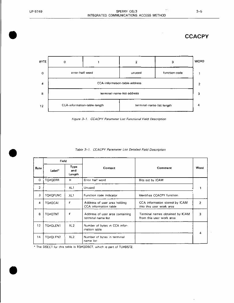
UP-9749 SPERRY OS/3 3-5 INTEGRATED COMMUNICATIONS ACCESS METHOD
• CCACPY
BYTE 0 1 1 2 3 WORD
0 error-half word unused function-code
4 CCA-information-table-address 2
8 terminal-name-list-address 3
12 CCA-information-table-length terminal-name-list-length 4
Figure 3-1. CCACPY Parameter List Functional Field Description
• Table 3-1. CCACPY Parameter List Detailed Field Description
Field
Byte Type Content Comment Word Label* and
Length
0 TQ#QERR H Error half word Bits set by !CAM
2 XL1 Unused 1
3 TQ#QFUNC XL1 Function code indicator Identifies CCACPY function
4 TQ#QCAI F Address of user area holding CCA information stored by !CAM 2 CCA information table into this user work area
8 TQ#QTNT F Address of user area containing Terminal names obtained by !CAM 3 terminal name list from this user work area
12 TQ#QLEN1 XL2 Number of bytes 1n CCA infor-mation table
4 14 TQ#QLEN2 XL2 Number of bytes in terminal
name list
* The DSECT for this table is TQ#QDSCT, which is part of TU#DSTZ .
•

UP-9749 SPERRY OS/3 3-6 INTEGRATED COMMUNICATIONS ACCESS METHOD
CCACPY • BYTE 0 I 1 l 2 l 3 WORD
0 terminal name 1
4 terminal name 2 2
8 terminal name 3 3
terminal name n
n FF ] FF ] FF l FF n
Figure 3-2. CCACPY Terminal Name List Functional Field Description
• Table 3-2. CCACPY Terminal Name List Detailed Field Description
Field
Byte Type Content Comment Word
Label* and Length
0 TQ#CTRMI CL4 Terminal name Table consists of a series of these 1 items.
* The DSECT for the table is TO#CCINP, which is part of TU#DSTZ.
•
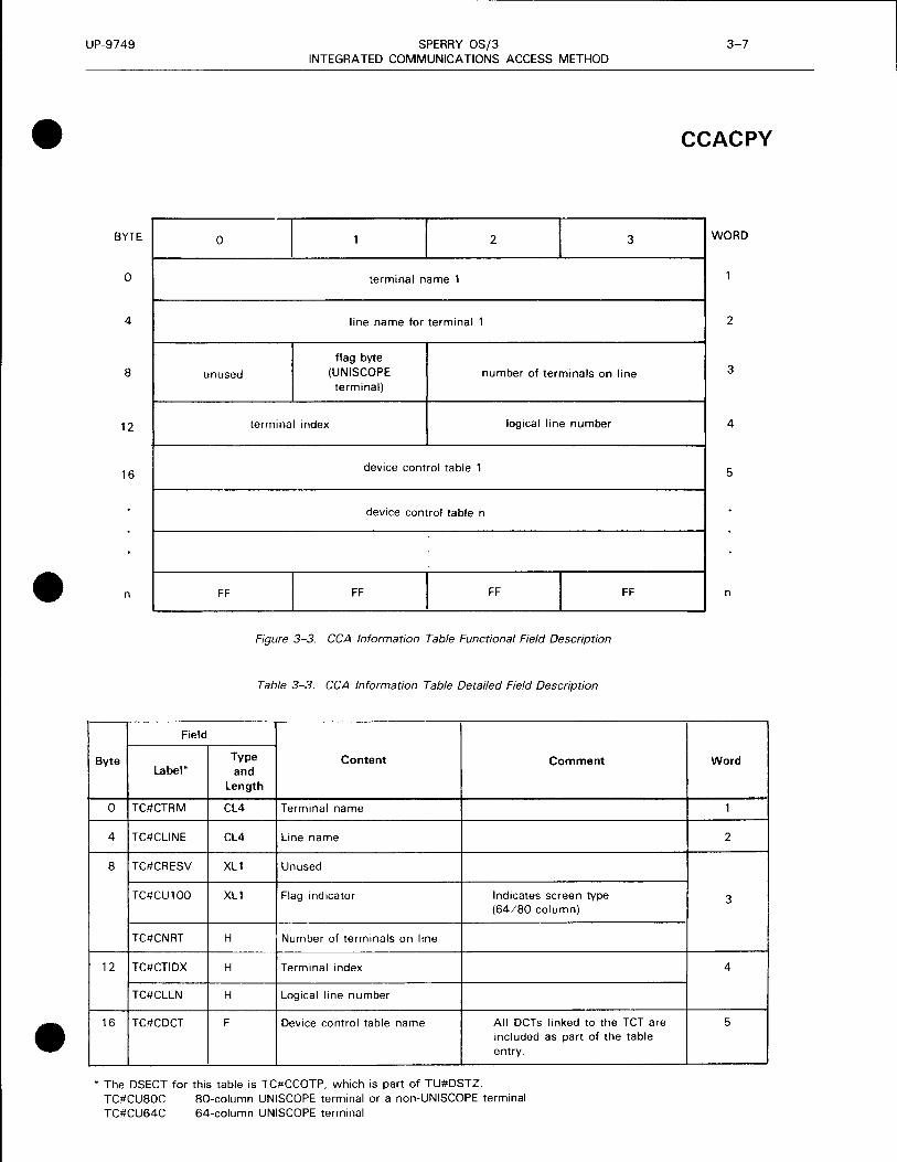
UP-9749 SPERRY OS/3 3-7 INTEGRATED COMMUNICATIONS ACCESS METHOD
• CCACPY
BYTE 0 1 2 l 3 WORD
0 terminal name 1
4 line name for terminal 1 2
flag byte 8 unused (UNISCOPE number of terminals on line 3
terminal)
12 terminal index logical line number 4
16 device control table 1 5
device control table n
• n FF FF FF l FF n
Figure 3-3. CCA Information Table Functional Field Description
Table 3-3. CCA Information Table Detailed Field Description
Field
Byte Type Label* and
Content Comment Word
Length
0 TC#CTRM CL4 Terminal name 1
4 TC#CLINE CL4 Line name 2
8 TC#CRESV XL1 Unused
TC#CU100 XL1 Flag indicator Indicates screen type 3 (64/80 column)
TC#CNRT H Number of terminals on line --!---
12 TC#CTIDX H Terminal index 4
TC#CLLN H Logical line number
• 16 TC#CDCT F Device control table name All DCTs linked to the TCT are 5 included as part of the table entry.
* The DSECT for this table is TC#CCOTP, which is part of TU#DSTZ. TC#CUSOC SO-column UNISCOPE terminal or a non-UNISCOPE terminal TC#CU64C 64-column UNISCOPE terminal

UP-9749 SPERRY OS/3 3-8 INTEGRATED COMMUNICATIONS ACCESS METHOD
CCACPY
Error Processing:
When you specify DUSTERR=INLINE in the CCA and LOCAP macroinstructions, and an error occurs during macroinstruction processing, control returns inline to the address following the CCACPY macroinstruction.
When you don't specify DUSTERR=INLINE, errors are returned at the specified NETREQ/NATTACH ERRET=address.
Register 1 contains the address of the CCACPY parameter table. Register 0 contains:
• zeros in bytes 0, 1, and 3; and
• TQ#QERR error codes in byte 2.
Table 3-4 describes the error conditions detected during the execution of this macroinstruction.
Table 3-4. CCACPY Error Conditions
Byte Error*
Cause/Condition Code
TQ#QERR TQ#QTNF Terminal not found
TQ#QTLG Data beyond table or program area
TQ#QTNFW Parameter list not on full-word boundary
TQ#QNDTH Invalid work area length or no work area specified in parameter list
* The DSECT for this table is TQ#QDSCT, which is part of TU#DSTZ.
•
•
•

•
•
•
UP-9749 SPERRY OS/3 3-9 INTEGRATED COMMUNICATIONS ACCESS METHOD
CC RCA LL
Function:
Provides entry to the communications physical interface (CPI) and identifies the associated CPIOCP.
Format:
LABEL
[symbol]
Label:
symbol
L.OPERATIONL.
CCR CALL
OPERAND
{cpiocp-label}[,IRL=NO] ( 1)
An alphanumeric character string up to six characters long uniquely identifying this instruction.
Parameters:
cpiocp-label
( 1 )
Identifies the symbolic name of the communications physical input-output control packet (CPIOCP) .
Indicates that the address of the CPIOCP to be accessed is contained in register 1.
IRL=NO May be used by the remote device handler to indicate that the CPIOCP does not request immediate return line of control following execution of the instructions generated by the macro .

UP-9749 SPERRY OS/3 3-10 INTEGRATED COMMUNICATIONS ACCESS METHOD
CYIELD
Function:
Used with TCI, standard, CPI, and DOI interfaces. Releases control of your program to ICAM while waiting for a communications 1/0 completion or an ICAM event. You issue the CYIELD macroinstruction in your program following a series of Get/Put macroinstructions with IRL set or when you want your program to be dormant until an ICAM event occurs. Such an event could be another program sending you a datagram, or ICAM sending you a control datagram as a result of a terminal user or another program signing on for a dynamic session. CYIELD is not necessary if you issue a request without IRL set.
Format:
LABEL l10PERATIONl1 OPERAND
[symbol] CY I ELD
Error Processing:
CYIELD always returns control inline. No return codes are supplied. Only one type of error can occur during macroinstruction processing - your program is canceled with error code 450 when the task issuing the CYIELD is not an active communications task.
•
•
•
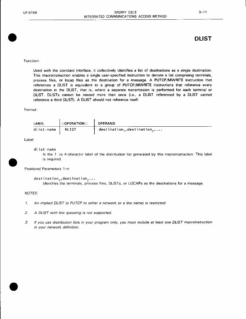
•
•
•
UP-9749 SPERRY OS/3 3-11 INTEGRATED COMMUNICATIONS ACCESS METHOD
DUST
Function:
Used with the standard interface, it collectively identifies a list of destinations as a single destination. This macroinstruction enables a single user-specified instruction to denote a list comprising terminals, process files, or locap files as the destination for a message. A PUTCP/MWRITE instruction that references a DUST is equivalent to a group of PUTCP /MWRITE instructions that reference every destination in the DUST, that is, where a separate transmission is performed for each terminal or DUST. DUSTs cannot be nested more than once (i.e., a DUST referenced by a DUST cannot reference a third DUST). A DUST should not reference itself.
Format:
LABEL L':.OPERATIONL':. OPERAND
dlist-name DLIST destination 1 ,destination2 ••••
Label:
dlist-name Is the 1- to 4-character label of the distribution list generated by this macroinstruction. This label is required .
Positional Parameters 1-n:
destination1,destination
2 •••
Identifies the terminals, process files, DLISTs, or LOCAPs as the destinations for a message.
NOTES:
1. An implied DUST (a PUTCP to either a network or a line name) is restricted.
2. A DUST with line queueing is not supported.
3. If you use distribution lists in your program only, you must include at least one DUST macroinstruction in your network definition .

UP-9749 SPERRY OS/3 3-12 INTEGRATED COMMUNICATIONS ACCESS METHOD
DTFCP Output File, PUTCP Related
Function:
Creates a control table for handling output messages.
Figure 3-4 shows the organization of the output DTFCP table, and Table 3-5 provides detailed field descriptions.
Format:
LABEL L.OPERATIONL. OPERAND
symbol DTFCP TYPE=PT,[NOBAV=symbol]
Label:
[
DEST={ <D,distribution- l ist-name[,U] )~
(P,{process-filename})
locap-name
<T,terminal-name)
[, ERRET=symbol]
[LEVEL={~t~~ •. H ~ tiiR MEDIUM
TOP
[ ,UNIT=LINE]
symbol Is an alphanumeric character string from one to four characters long that identifies this output file DTFCP.
Parameters:
TYPE=PT Specifies that the file table generated is used by ICAM's Put processing routines.
NOBAV=symbol An entry point (label) in your program where PUTCP processing returns control if no network buffer is available for a message. If omitted, error return is inline. If IRL is set, error return is the completion address. Although specifying NOBAV is optional, we highly recommend that you use it.
•
•
•

•
•
•
UP-9749 SPERRY OS/3 3-13 INTEGRATED COMMUNICATIONS ACCESS METHOD
DTFCP Output File, PUTCP Related
DEST=<D,distribution-list-name[,U])
D Final destinations are specified on a distribution list.
distribution-list-name
u
Label of the distribution list (DLIST) macroinstruction that specifies the final destinations.
The distribution list is defined in a user program. Must be used whenever a PUTCP is being
done to a user-defined DLIST.
DEST=(P,{process-filename}) locap-name
p
The final destination is a process file or user program locap file.
process-filename Label of the process file (PRCS) macroinstruction in the CCA.
locap-name User program locap file label in a global network definition (LOCAP macroinstruction).
DEST=(T,terminal-name)
T Final destination is a terminal.
terminal-name The label of the output terminal (TERM) in the CCA.
If the DEST operand is omitted, the TM#DENA field in the DTFCP table must be set by the user
program before the first PUTCP macroinstruction is executed.
ERRET=symbol A user program entry point (label) to which PUTCP processing returns if it detects an error (other
than no buffer available).
If omitted, processing control returns to the next instruction in your program. In either case, error
indicators are set in the associated DTFCP table.
If output delivery notification is selected, do not specify this operand, as this field is used by the output delivery notice parameter. In this case, no ERRET is available. Error return is inline and an IRL should not be used.
LEVEL=HIGH Output messages are directed to the high priority queue of the specified destination .
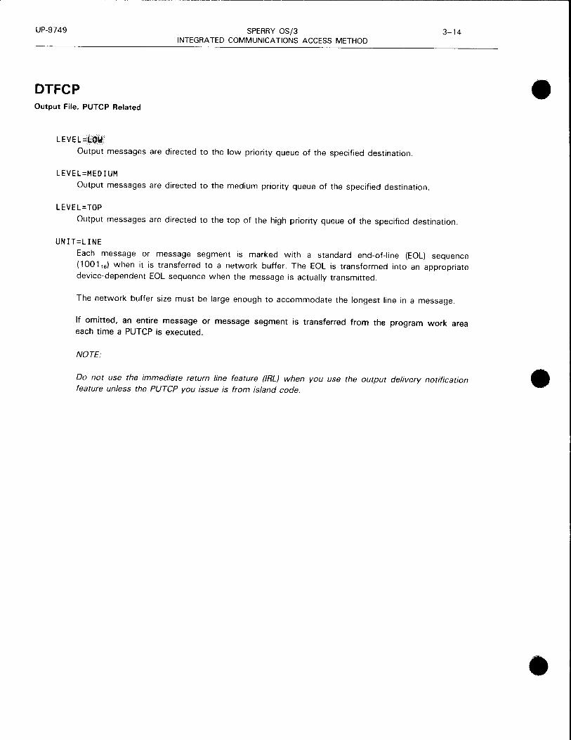
UP-9749 SPERRY OS/3 3-14 INTEGRATED COMMUNICATIONS ACCESS METHOD
DTFCP Output File, PUTCP Related
LEVEL=LOW
Output messages are directed to the low priority queue of the specified destination.
LEVEL=MEDIUM
Output messages are directed to the medium priority queue of the specified destination.
LEVEL=TOP
Output messages are directed to the top of the high priority queue of the specified destination.
UNIT=LINE
Each message or message segment is marked with a standard end-of-line (EOL) sequence ( 1001 16) when it is transferred to a network buffer. The EOL is transformed into an appropriate device-dependent EOL sequence when the message is actually transmitted.
The network buffer size must be large enough to accommodate the longest line in a message.
If omitted, an entire message or message segment is transferred from the program work area each time a PUTCP is executed.
NOTE:
Do not use the immediate return line feature (IRL) when you use the output delivery notification feature unless the PUTCP you issue is from island code.
•
•
•

UP-9749
• BYTE
0
4
8
12
• 16
20
24
28
•
SPERRY OS/3 3-15 INTEGRATED COMMUNICATIONS ACCESS METHOD
DTFCP Output File, PUTCP Related
output file name (from label) (TM#DNAM or TM#DDST)
destination routing name (label of TERM. PRCS, LOCAP or DUST to which message is directed)
(TM#DENA)
TM#DAUX device information
auxiliary device special function
(TM#DSPEC)
auxiliary device index
(TM#DDVC)
PUTCP processing flags
(TM#DDTF)
no buffer available address or IRL completion address (TM#DNBA)
start/end of message and
auxiliary device information (TM#DSEG)
error return address or ODNR 4-byte message identifier (TM#DERA)
NOTE
replacement text (TM#DRPL)
Shaded areas are system-supplied parameters; clear areas are program-supplied parameters.
Figure 3-4. Output DTFCP Organization
WORD
2
3
4
5
6
7
8

UP-9749 SPERRY OS/3 3-16 INTEGRATED COMMUNICATIONS ACCESS METHOD
DTFCP • Output Fite, PUTCP Related
Table 3-5. Output DTFCP File Table Detailed Field Description (Pan 1 of 2)
Field
Byte Type Set** Content Word Label* and
Length D u p
0 TM#DIND XL2 R Processing flags and indicators; refer to 1 Table 3-6. Indicates status of current message and result of latest PUTCP.
2 TM#DERR XL2 R Error flags and indicators; refer to Table 3-6. Nonzero only if TM#DIER set in TM#DIND.
4 TM#DNAM CL4 R Output file DTFCP name (from label field) 2 or TM#DDST or destination floating queue name
8 TM#DENA CL4 R R Destination name: label of TERM, PRCS, 3 or DUST to which messages are directed.
12 TM#DAUX CL2 R Auxiliary device information for device 4 handler; refer to Table 3-7.
12 TM#DSPEC Auxiliary function code • 13 TM#DDVC Logical auxiliary device number
14 TM#DDTF XL1 Optional flags to control PUTCP processing
TM#DUDL 0 0 Destination is defined by a DUST in user's program
TM#DFQR 0 Floating queue request flag
TM#DLTR 0 Line transfer requested
TM#DDIND Destination is indirect; message put on queue associated with DNAM
TM#ETOP 0 Top message (priority function codes)
TM#EHIG 0 High priority
TM#EMED 0 Medium priority
TM#ELOW R Low priority
•

•
•
•
UP-9749 SPERRY OS/3 3-17 INTEGRATED COMMUNICATIONS ACCESS METHOD
DTFCP Output File. PUTCP Related
Table 3-5. Output DTFCP File Table Detailed Field Description (Part 2 of 2)
Field
Byte Type Se~**
label* and length D u
15 TM#DSEG XL1
TM#DHS 0
TM#DMS 0
TM#DQHLD 0 TM#DQRLS 0
TM#DAFN 0
TM#DBEOF R
TM#DHDR 0
TM#DTND R
16 TM#DCHD AL
20 TM#DNBA AL 0 0
24 TM#DERA AL 0 0
28 TM#DRPL AL
* DSECT label is TM#DEST
•• D - field normally set by parameters in DTFCP call U - field can be set by user program before PUTCP P - field set by software processors R - required; always set 0 - optional
Content Word
p
Segment definitions
Hold segment for modification
Modify segment (overlay first four bytes with DICE sequence)
Queue hold in effect Queue release in effect
Set auxiliary device function
Batch device end-of-file segment
Start of header
End of text
R Message header address in CCA; working 5 storage for PUTCP processing. Not addressable by your program.
No buffer available (NOBAV) address in 6 your program. Zero if not supplied.
ERRET address in your program. Zero if 7 not supplied.
l-
Replacement text. Used with TM#DMS to 8 specify modification to start of segment.

UP-9749 SPERRY OS/3 3-18 INTEGRATED COMMUNICATIONS ACCESS METHOD
DTFCP • Output File, PUTCP Related
Table 3-6. Error Indicators and Processing Flags in Output DTFCP File Table (Part 1 of 2)
Label
Condition/Cause Consequences Go to
Byte Bit* ERRET?
TM#DIND TM#DIRL Immediate return line Set by user
TM#DODNR Output delivery notification request Line status and identifier received in ERRET address
TM#DIER Indicates an error has occurred during Refer to specific error flag. Yes PUTCP processing. TM#DERR and TM#DERR + 1 should be tested for the type of error.
TM#DllL The TM#DDTF byte of the DTFCP PUTCP processing was completed with No contains an invalid priority or low priority assumed. none at all.
TM#DIMH A PUTCP was executed when no The contents of your work area No message was in process, and flag were accepted by the MCP as a complete TM#DHDR in byte TM#DSEG was message and transmitted to the specified not set. destination.
TM#DIMA An incomplete multisegment or multi- Previous message is discarded; current No line message was aborted in response message is started normally. to a request from your program.
TM#DIMP TM#DTND not set. Indicates a message Message is assumed to be multiple No in process. i.e., PUTCP processing has segment or line. processed the first or intermediate • line of a message.
TM#DllM Invalid modification. TM#DMS was set No text replacement. Message is No but no segment held for modification. still put.
TM#DERR Error flags are set in TM#DERR Message transfer is not initiated or and TM#DERR + 1 when the PUTCP completed; refer to specific error cannot proceed. If TM#DIER 1s conditions for further consequence. not set, these two bytes are all zeros.
TM#DEIN Invalid/missing destination name: DTFCP is unusable. Yes TM#DENA does not match the label of any TERM, PRCS, or DLIST in the CCA.
TM#DEWA Work area address or size invalid: not PUTCP with valid work area address Yes within your program boundaries. can be performed.
TM#DENB Network buffers not available for Control goes to NOBA V address. No header (first segment/line, whole message)_••
TM#DEIA Header address (TM#DCHD) invalid: Before next PUTCP, TM#DCHD must your program has altered header be set to zero. If error occurred in the address working storage in the middle of a message, the previous DTFCP. segments/lines are lost.
•

•
•
•
UP-9749 SPERRY OS/3 3-19 INTEGRATED COMMUNICATIONS ACCESS METHOD
DTFCP Output File, PUTCP Related
Table 3-6. Error Indicators and Processing Flags in Output DTFCP File Table (Part 2 of 2)
Label
Condition/Cause Consequences Go to
Byte Bit* ERRET?
TM#DERR+ 1 TM#DEDU Invalid DUST entry; a destination Message queued for transmission Yes name within a DUST does not to all destinations on the DUST match any TERM or PRCS name from the second up to (not including) in the network. Generation of a the invalid one. Message is not new network may be required to transmitted to the first, the invalid, correct the error. or any subsequent destinations.
TM#DIRLE Immediate return line error flag set. No data is transferred from the work Yes Indicates that IRL was requested area of your program. You may supply without supplying a completion a completion address and reissue the address in TM#DNBA. PUTCP.
TM#DODNE Output delivery notice was requested No data is moved from the work area of Yes without supplying an address in your program. Your program may enter TM#DERA. an address in TM#DERA and execute
another PUTCP with TM#DODNR set.
TM#DIRLE Indicates that a PUTCP was issued No data is moved from your program. Yes and with both IRL and output delivery You may reissue the PUTCP with only TM#DODNE notice requested. The put is invalid. one flag set.
* Bit label positions in each byte do not indicate value. Actual values are contained in the DTFCP .
Flag TM#DENB indicates no network buffer is available for the current message, segment, or line. If the PUTCP was for the transfer of a complete message, the first segment, or the first line of a message, the data in your work area will be intact. The work area prefix value, however, may have been altered. When buffers are available, you must restore the original work area prefix byte count and execute a PUTCP to reinitiate transfer of the message.
If tl)e current PUTCP is for the transfer of a segment or line other than the first, previously transferred segments or lines are not affected. In this case, reinitiation of the message transfer should begin with the current segment or line.
Your program can assist in recovery from a no-buffer condition by executing GETCPs to dequeue input messages, thereby freeing buffers for use. Frequent occurrence of this error may indicate a need to generate a new network making an adjustment to the number and/or size of buffers.
Flag TM#DENB may also be set by ICAM when the length of a message to a batch device exceeds the space available in a network buffer. Generation of a new network, increasing the buffer size, is indicated .

UP-9749 SPERRY OS/3 3-20 INTEGRATED COMMUNICATIONS ACCESS METHOD
DTFCP • Output File, PUTCP Related
Table 3-7. Auxiliary Device and Special Function Specifications in Output DTFCP File Table (Part 1 of 2)
Label Function Remarks
TM#DADBS Backspace tape cassette one block TCS on UNISCOPE display terminal only
TM#DADPF Print form UTS 400 only
TM#DADSR Search tape cassette TCS on UNISCOPE display terminal only; message text is search argument.
TM#DADRA Report current address from tape cassette TCS on UNISCOPE display terminal only
TM#DADRD Read a block (magnetic or paper tape) TCS or UNISCOPE display terminal or DCT 524. Paper tape reader on OCT 500 or TTY
TM#DADWR Write a block (magnetic or paper tape) TCS on UNISCOPE display terminal or DCT 524. Paper tape reader on DCT 500 or TTY
TM#DADXA Transfer all UTS 400 only
TM#DADXC Transfer changed UTS 400 only
TM#DADXV Transfer variable UTS 400 only
TM#DCSHT Send halt BSC terminal • TM#DFSMW Light computer message waiting and sound DCT 1000 audible alarm
TM#DFSMW Send message-waiting or sound bell UNISCOPE display terminal. UTS 400/UTS 4000, TTY, DCT 500, DCT 524. or DCT 475
TM#DPRE Prevent nonsignificant space suppression UNISCOPE display terminal only (primary or auxiliary)
TM#DTAT Transparent UNISCOPE auxiliary device
TM#DCRVI RVI (BSC) BSC terminal
TM#DCTRN Transparent BSC BSC terminal
TM#DADWR Load program on diskette UTS 400 ++
TM#DTAT
TM#DCNCH Send no change indicator 1004 slave handler
TM#DCRDF Send read function. Initiate output. 1004 slave handler
TM#DCSOL Send offline function 1004 slave handler
TM#DCINI Send ready and site-id; start polling 1004 slave handler
TM#DCPRA Send abort print 1004 slave handler
TM#DCPUA Send abort punch 1004 slave handler •

•
•
•
UP-9749 SPERRY OS/3 3-21 INTEGRATED COMMUNICATIONS ACCESS METHOD
DTFCP Output File, PUTCP Related
Table 3-7. Auxiliary Device and Special Function Specifications in Output DTFCP File Table (Part 2 of 2)
Label Function Remarks
TM#DCBCN Send BSC connect sequence BSC terminal
TM#DCMWK Computer message waiting UNISCOPE terminal
TM#DCBDC Send BSC DLE EOT BSC terminal
NOTES:
1. All labels are set in TM#DSPEC.
2. Labels starting with TM#DAD denote auxiliary device functions. Other labels apply to special 1/0 functions and do not require the specification of an auxiliary device function .

UP-9749 SPERRY OS/3 3-22 INTEGRATED COMMUNICATIONS ACCESS METHOD
DTFCP Input File, GETCP Related
Function:
Defines an input file for your program. It is used in conjunction with the GETCP macroinstruction to retrieve messages from the queues of a process file, locap file, or a terminal's input message queue. Figure 3-5 shows the organization of the input DTFCP table, and Table 3-8 provides detailed field descriptions.
Format:
LABEL .6.0PERATION.6. OPERAND
symbol DTFCP TYPE=GT
[,ERRET=symbol]
Label:
[EVEL= {[.~ [,NOMAV=symbol]
[,UNIT=LINE]
[,DATIME=YES]
[ ,NOTLST=symbol]
[ ,ODN=YES]
symbol Is an alphanumeric character string from one to four characters long that identifies this input file DTFCP. This label must match the label of corresponding PRCS, LOCAP, or TERM macroinstruction in the CCA.
Parameters:
TYPE=GT Specifies that the file table generated is used by the ICAM Get processing routines.
ERRET=symbol Specifies an entry point (label) in your program to which GETCP processing can return if it encounters an error condition other than no message available.
If omitted, processing control returns to the next instruction in the program. In either case, error
indicators are set in the associated DTFCP table.
LEVEL--Queues are accessed in descending order of priority.
LEVEL=HIGH High priority queue is accessed.
•
•
•

•
•
•
UP-9749 SPERRY OS/3 3-23 INTEGRATED COMMUNICATIONS ACCESS METHOD
DTFCP Input File, GETCP Related
LEVEL= LOW Low priority queue is accessed. If MPPS is not supported, this is the only level available.
LEVEL=MEDIUM Medium priority queue is accessed.
NOMAV=symbol An entry point (label) in your program to which GETCP processing returns if no message is
available. To try again, the program must execute another GETCP instruction.
If omitted, your program is suspended until a message becomes available. If IRL is in effect, this address becomes the completion address activated when a message becomes available.
UNIT=LINE Indicates that a single line of a message is to be transferred to your program work area each time a GETCP macroinstruction referencing this file is executed. The work area must be large
enough to accommodate the largest line.
If omitted, an entire message or a message segment is transferred into the work area each time
a GETCP macroinstruction is executed .
DATIME=YES Places the date and time of the message in the DTFCP.
NOTLST=symbol Specifies the address of a list of a process file, locap, or terminal name. Each list entry must be
four bytes.
ODN=YES Specifies that a word is to be generated in the DTFCP for the output delivery notification
identifier if the ODN option is selected on the GETCP .

UP-9749 SPERRY OS/3 3-24 INTEGRATED COMMUNICATIONS ACCESS METHOD
DTFCP • Input File. GETCP Related
BYTE WORD
0
4 2
8 3
12 4
16 5
20 no message available address or IRL completion address
6 (TM#PNMA or TM#PCMPA)
error return address 7 • 24 (TM#PERA)
TM#PAUX device information
28 auxiliary device/ auxiliary 8 special function device index
(TM#PSPEC) (TM#PDVC)
32 9
36 10
40 11
44 12
48 output delivery notification identifier (TM#PODNN)* 13
NOTE:
Shaded areas are system-supplied parameters; clear areas are user-supplied parameters.
•Word 3 is generated only if the ODN=YES parameter is specified.
Figure 3-5. Input DTFCP Organization •

UP-9749 SPERRY OS/3 3-25 INTEGRATED COMMUNICATIONS ACCESS METHOD
• DTFCP Input File. GETCP Related
Table 3-8. Input DTFCP File Table Detailed Field Descriptions (Part 1 of 2)
Field
Byte Type
Set•• Content Word
label* and length D u p
0 TM#PIND XL2 R Processing flags and indicators; see Table 3-9. 1 Status of current message and result of latest GETCP.
2 TM#PERR XL2 R Error flags and indicators; see Table 3-9. Nonzero only if TM#PIER set in TM#PIND.
4 TM#PNAM CL4 R Process file, locap file, or terminal 2 name. Specified from the DTFCP label field
or within the user program. Corresponds to PRCS, LOCAP, or TERM macro-instruction in CCA network definition.
8 TM#PSRC CL4 R Name (label) of source. Normally a terminal 3 name; if TM#PISR is set in TM#PIND, the source is a user program, not a terminal.
• 12 Reserved H 4
14 TM#PDTF XL 1 0 0 Optional flags to control GETCP processing
TM#PDTSP Date/time request
TM#PINPN Input notice request
TM#PCSD Reserved for COBOL MCS
TM#PLTR Each GETCP delivers one line to work area. Set by UNIT-LINE
TM#EAVL Available message. Controls level of queue from which message is taken. See LEVEL parameters of DTFCP macroinstruction.
TM#EHIG High priority
TM#EMED Medium priority
TM#ELOW Low priority
15 TM#PSEG XL 1 0 Contains two message processing bits. Used when getting incomplete messages because work area is too small or when not accessing segments/lines in normal sequence.
TM#PNHD Get new header; skip remainder of current message. GETCP yields next message or first segment/line of next message.
TM#PSHD Start header; revert processing to beginning of current message. GETCP yields first segment/ line of current message.
16 TM#PCHD A R Message header address in CCA, working storage 5 for GETCP processing. Not addressable by user program.
20 TM11PNMA A 0 0 No message available (NOMA V) address 6 or in user program or IRL completion
• TM#PCMPA address. Zero if not supplied.
24 TM#PERA A 0 0 ERRET address in user program. Zero if not 7 supplied.

UP-9749 SPERRY OS/3 3-26 INTEGRATED COMMUNICATIONS ACCESS METHOD
DTFCP • Input File. GETCP Related
Table 3-8. Input DTFCP File Table Detailed Field Descriptions (Pan 2 of 2)
Field
Byte Type
Set•• Content Word
label* and length D u p
28 TM#PAUX H 0 8
TM#PSPEC 0 Flags for special 1/0 functions. conditions. and auxiliary device input. See Table 3-10.
29 TM#POVC 0 Auxiliary device number if message received from auxiliary device (01 16 thru OC, 6). Valid only if TM#PAUXD is set in TM#PSPEC.
30 TM#PRSG H R Number of remaining segments in current message
32 TM#PAINT A 0 Address input notice list 9
TM#PLEN Process file DSECT length
Following fields present with date/time stamp
36 TM#PDATE PL4 0 Date 10
40 TM#PTIME PL5 0 Time 11, 12
45 XL3 Not used
TM#POLEN Length with date/time • 48 TM#PODNN CL4 0 Output delivery notice (ODN) information 13
• DSECT label is TM#PRCS
•• D Field normally set by parameter in DTFCP macro U Field can be set by user program before GETCP P Field set by software processor R Required; always set 0 Optional
•

UP-9749 SPERRY OS/3 3-27 INTEGRATED COMMUNICATIONS ACCESS METHOD
• DTFCP Input File. GETCP Related
Table 3-9. Error Indicators and Processing Flags in Input DTFCP File Table (Part 1 of 2)
Label
Condition/Cause Consequences ..Jo to
Byte Bit* ERR ET?
TM#PIND TM#PIRL Immediate return line Set by user; never cleared by ICAM
TM#PIER Message not obtained. Check TM#PERR Depends on type of error Yes and TM#PERR+ 1 for exact cause.
TM#PllL Priority level invalid. TM#PDTF of the GETCP processing was done with No DTFCP contained an invalid or zero AVAIL assumed. priority value.
TM#PISR Message entered system from a user None: informational only No program, not a terminal.
TM#PBEOF Indicates an end of file was detected None: informational only No in the input message from a batch device.
TM#PIMD Work area did not accommodate Additional GETCPs must be done No entire text of message. to get remainder of message.
TM#PIHD .. Start of new message; indicates the Informational No message header has been transferred to your work area.
• TM#PIET .. End of present message; ICAM Next GETCP will obtain a new No indicates the data at the end of the message. message has been transferred to your work area. The message is complete.
TM#PIND+ 1 TM#PIDL Data lost. Your program has canceled Remainder of previous message is No a message. Previous message was not available. truncated because TM#PNHD was set when GETCP was executed. (Refer to TM#PSEG.)
TM#PDTER Invalid date/time request: date/time No stamping requested, but CCA configured doesn't provide this option.
TM#PERR These bits are set only if TM#PIER was set in TM#PIND.
TM#PEIN Invalid end user specification: DTFCP is unusable. No data is moved Yes an error occurred while attempting to into your work area. Correct get a message from the name specified the invalid file name or CCA in TM#PNAM (TM#PNAM doesn't match generation and reissue the GETCP. label of any end user in CCA; no valid OCT configured for end user specified; inconsistent message information between OCT and DTFCP).
TM#PELR Line request not available. Return to user Yes
TM#PEWA Work area size ~ 0. or work area Message not transferred Yes ending address not within your pro· gram boundaries or not on half-word boundary.
TM#PENA Invalid notice list address: address Abort GETCP Yes specified in TM#PAINT is not within bounds of user region.
TM#PEIA Message header address (TM#PCHD) Before next GETCP, TM#PCHD Yes invalid; your program has altered must be set to zero. If error oc-
• header address working storage in curred in the middle of a message, the DTFCP. the remainder of the message is lost.

UP-9749 SPERRY OS/3 3-28 INTEGRATED COMMUNICATIONS ACCESS METHOD
DTFCP • Input File. GETCP Related
Table 3-9. Error Indicators and Processing Flags in Input DTFCP File Table (Part 2 of 2)
label
Condition/Cause Consequences Go to
Byte Bit* ERRET?
TM#PERR+1 TM#PEID Invalid deferral request. A deferred The second deferral request was Yes GETCP or input message notification not processed. was issued against an end user that already has a deferral request out-standing.
• Bit label positions in each byte do not indicate value. Actual values are contained in the DTFCP.
•• TM#FIHD and TM#FIET are both set if a complete message was transferred into the work area.
Table 3-10. Auxiliary Device and Special Function Flags in Input DTFCP File Table (Part 1 of 2)
Label* Function/Condition Remarks
TM#PFRMW or Message-waiting or bell TM#PCMWK
Interactive terminal • TM#PFKY1 or Function key 1 UNISCOPE/UTS 400/ TM#PCFK1 UTS 4000 terminal
TM#PFKY2 or Function key 2 UNISCOPE/UTS 400/ TM#PFKY2 UTS 4000 terminal
TM#PFKY3 or Function key 3 UNISCOPE/UTS 400/ TM#PCFK3 UTS 4000 terminal
TM#PFKY4 or Function key 4 UNISCOPE/UTS 400/ TM#PCFK4 UTS 4000 terminal TM#PFKY5 Function key 5 UTS 400/UTS 4000 terminal
TM#PFKY6 Function key 6 UTS 400/UTS 4000 terminal
TM#PFKY7 Function key 7 UTS 400/UTS 4000 terminal
TM#PFKY8 Function key 8 UTS 400/UTS 4000 terminal
TM#PFKY9 Function key 9 UTS 400/UTS 4000 terminal
TM#PFKY10 Function key 10 UTS 400/UTS 4000 terminal
TM#PFKY11 Function key 11 UTS 400/UTS 4000 terminal
TM#PFKY12 Function key 12 UTS 400/UTS 4000 terminal
TM#PFKY13 Function key 13 UTS 400/UTS 4000 terminal •

UP-9749 SPERRY OS/3 3-29
INTEGRATED COMMUNICATIONS ACCESS METHOD
• DTFCP Input File. GETCP Related
Table 3-10. Auxiliary Device and Special Function Flags in Input DTFCP File Table (Part 2 of 2)
Label* Function/Condition Remarks
TM#PFKY14 Function key 14 UTS 400/UTS 4000 terminal
TM#PFKY15 Function key 15 UTS 400/UTS 4000 terminal
TM#PFKY16 Function key 16 UTS 400/UTS 4000 terminal
TM#PFKY17 Function key 17 UTS 400/UTS 4000 terminal
TM#PFKY18 Function key 18 UTS 400/UTS 4000 terminal
TM#PFKY19 Function key 19 UTS 400/UTS 4000 terminal
TM#PFKY20 Function key 20 UTS 400/UTS 4000 terminal
TM#PFKY21 Function key 2 1 UTS 400/UTS 4000 terminal
TM#PFKY22 Function key 22 UTS 400/UTS 4000 terminal
• TM#PCRRD Received read during output 1004 terminal
TM#PCRHT Received halt 1004 terminal
TM#PCRHV Received halt, go voice ( 1004) 1004 terminal or or parity error (TTY /OCT 500) TTY /OCT 500 Series terminal
TM#PCRER Received end read 1004 terminal
TM#PCRDY/ Received ready 1004 terminal TM#PCRDV
TM#PCOFF Received offline 1004 terminal
TM#PCAPR Received abort print Batch terminal
TM#PCAPU Received abort punch Batch terminal
TM#PCRVI Received RVI BSC terminal
TM#PXEOT Operator pressed hang-up key UTS 400/UTS 4000 terminal
TM#PPOC Firmware completed power-on UTS 400/UTS 4000 terminal confidence test
TM#PCBRK Break or interrupt received TTY /OCT 500 Series terminal
* All labels set in TM#PSPEC .
•

UP-9749 SPERRY OS/3 3-30 INTEGRATED COMMUNICATIONS ACCESS METHOD
GA WAKE
Function:
Used by any OS/3 task to wake up a registered ICAM user task. Any ICAM user task other than a direct data interface (DOI) or physical user can register as a recipient by issuing the GAW AKE macroinstruction to itself with an input packet. Figure 3-6 and Table 3-11 describe the parameter list generated by this macroinstruction.
Format:
LABEL 60PERATION6 OPERAND
[symbol] GAWAKE [
TYPE={ INPUT }] OUTPUT
[,ENTRY=label]
[,APPS=name]
[,BUFADR=label]
[,BUFLTH=n]
[,MF={L }]
CE,packet-address)
Parameters:
TYPE
Defines the packet being generated. If TYPE= INPUT, then keyword parameter ENTRY= label must be defined; if TYPE keyword parameter is omitted with no MF= or MF=L, then the packet generated will be OUTPUT.
ENTRY= label
Specifies the address within the user program to receive control when the user program is activated by another program. This operand is required when TYPE=INPUT is specified. It is not valid for TYPE=OUTPUT.
APPS=name
Only necessary when output packet is being generated.
BUFADR=label
Identifies the label address of the user program storage area for the datagram information. When TYPE= INPUT, this area defines where the data information from the caller is to be transferred. When TYPE=OUTPUT, this storage area contains the data to be transferred to the recipient. If BUFADR is omitted, no data is transferred. If dynamic sessions are used, BUFADR must be specified.
See the discussion on datagram processing within this macroinstruction description.
BUFL TH=n
This is a decimal number (maximum 32, 767) specifying the current size of the storage area in bytes. If omitted, the packet will be generated so that no data is transferred. The minimum length for dynamic sessions is 40 bytes.
•
•
•

UP-9749
• MF=
•
•
SPERRY OS/3 3-31 INTEGRATED COMMUNICATIONS ACCESS METHOD
GA WAKE
Defines how this macro is specified:
If MF is not specified, both the imperative call and the associated parameter list are generated inline.
If MF=L is specified, only the parameter list is generated.
If MF=(E,packet address) is specified, only the imperative call is generated.
Error Unused Length of output buffer
flags
Unused Address of output buf
Recipient's locap name
a. Output
Error User program entry address
flags
No. of bytes inputs Input buffer length
Status Address of input buffer
Byte
Sender's locap name
b. Input
Figure 3-6. GA WAKE Parameter List Format and Functional Field Description

UP-9749
GA WAKE
SPERRY OS/3 INTEGRATED COMMUNICATIONS ACCESS METHOD
Table 3-11. GA WAKE Parameter List Detailed Field Descriptions
Label Type and Content Length
Output Parameter List
TN#KOFLG* XL 1 Error flags and indicators; see Table 3-12.
TN#KOOP Output packet indicator
TN#KORGS Send no data
TN#KORBU Send data in buffers
TN#KOP1 XL1 Open
TN#KOBLT H Length of output buffer
TN#KOP2 XL1 Open
TN#KOBAD AL3 Address of output buffer
TN#KOBAU Full-word address of output buffer
TN#KORLN F Recipient's LOCAP name (APPS)
TN#KOSIZ Size of output packet
Input Parameter List
TN#KIFLG** XL1 Error flags and indicators; see Table 3-12.
TN#KllP Input packet indicator
TN#KIRGS Receives no data
TN#KIRBU Receives data in buffer
TN#KGAWK AL3 GAW AKE entry address
TN#KGWKE Full-word entry address
TN#KIANB H Number of bytes input
TN#KIBLT H Length of input buffer
TN#ISTA XL1 Status byte
TN#IBAD AL3 Address of input buffer
TN#ISLN F Sender's LOCAP name
* DSECT label (for output) is TN#KGAWO. •• DSECT label (for input) is TN#KGA WI.
3-32
•
•
•

•
•
•
UP-9749 SPERRY OS/3 3-33 INTEGRATED COMMUNICATIONS ACCESS METHOD
GA WAKE
Error Processing:
ICAM returns control inline to the address following the GAWAKE macroinstruction. After macroinstruction processing, register 1 contains the address of the GA WAKE parameter table. When byte 3 of register 0 contains a zero, the processing was successful. When it contains any of the codes shown in Table 3-12, an error has occurred.
Table 3-12. GA WAKE Error Conditions
Error Code Condition/Cause
TN#ZER1 Parameter table not word aligned
TN#ZER2 Address of parameter table out of range
TN#ZER3 No length specified for given buffer
TN#ZER4 Given buffer is out of range
TN#ZER5 Recipient not ready or NA TT ACH must be done before GA WAKE
TN#ZER6 Recipient does not accept datagrams
TN#ZER7 ICAM resources not available
TN#ZER8 ICAM not configured for datagrams
TN#ZER9 ICAM resources not available
TN#ZER10 Open
TN#ZER11 ICAM resources not available
TN#ZER22 Entry address not aligned
TN#ZER23 Entry address out of range
TN#ZER24 Input length not specified
TN#ZER25 Input buffer not in range
TN#ZER26 NATT ACH not done (input)
NOTES:
1. ICAM always returns errors inline, regardless of whether you specify DUSTERR=INLINE in the CCA and LOCAP macroinstructions.
2. ICAM returns these error codes only in byte 3 of register 0.
3 . The equates for these error codes are defined in the DSECT for the GAW AKE parameter list. (See Table 3-11.)

UP-9749 SPERRY OS/3 3-34 INTEGRATED COMMUNICATIONS ACCESS METHOD
GA WAKE
Datagram Processing:
A calling sequence to obtain a DSECT to cover the input datagram at the user program storage area address specified in the BUFADR= operand is:
name CONTDG MF=CD,xxx)
where:
name
Is an 8-character alphanumeric name that is used to reference the DSECT.
D Indicates a DSECT request.
xxx
Any 3-character alphanumeric prefix to generate unique labels for the DSECT.
Figure 3-7 and Table 3-13 describe the format and give a detailed description of the input datagram.
•
•
•

UP-9749
•
•
•
SPERRY OS/3 INTEGRATED COMMUNICATIONS ACCESS METHOD
OPEN DATAGRAM
$ I $ KQTYP (function code)
(from) K1 CGI (calling end user name)
K1SSI (ICAM session ID)
K1 DEV (device ID of batch) reserved
K1FU (from user type) J K 1 RW2 (remote WS) KRSID (WS rod/sid)
K 1 FL6 (flags) reserved
CLOSE DAT AGRAM
$ ] $ ] KQTYP (function code)
K2SSU (user session ID)
number of sessions I reserved
reserved
reserved
ABORT DAT AGRAM
$ 1 $ ] KQTYP (function code)
K3SSU (user session ID)
K 3RSC (reason code I J reserved
K3DO iDMI packets)
reserved
OPNACC DAT AGRAM
$ 1 $ j KQTYP (function code)
K4SSU (user session ID)
K4SSI (ICAM session IOI
K4FU (from user type)
reserverl
reserverl
OPNREJ DAT AGRAM
$ I $ I KQTYP (function code)
K5SSU (user session ID)
K 5RSC (reason code) l ff~Sf!fVfHi
reserved
reserved
CLSCNF DAT AGRAM
$ ] $ ] KQTYP (function code)
K6SSU (user session ID)
number of sessions l unused
K6DO (DMI packets returned)
resPrverl
NOTE
3-35
GA WAKE
KQTY1 (KOPEN)
MYI D
MYI D
KQT'.'2 (KCLOSE)
KQTY3 (KABRT)
KOTY4 (KOPAC)
MYI D
MYI
MYI
KQTY5 (KOPRJ)
D
D
KOTY6 (KCLCF)
Each control rlata9ram label 1s prefixed by a 1 to 3-character label you specify 1n your CONTDTG DSECT call
Figure 3-7. Control Datagram Label Format

UP-9749 SPERRY OS/3 3-36 INTEGRATED COMMUNICATIONS ACCESS METHOD
GA WAKE • Table 3-13. Control Datagram Parameter list Detailed Field Descriptions (Part 1 of 3)
Byte Label* Type and
Content Word Length
0 K$$ H Must be $$ to be a 1 control datagram
2 KQTYP H Function code
3 (KOFUN) (XL1) (Function code) KOTY 1 (KOPEN) Open request KOTY2 (KCLOS) Close request KOTY3 (KABRT) Abort request KOTY4 (KOPAC) Open accept KOTY5 (KOPRJ) Open reject KOTY6 (KCLCF) Close confirm
For Open Datagram
4 K1CGI F From name 2
8 K1SSI F ICAM session ID 3
12 K1DEV H Device ID of batch 4 • 14 K1RE H Reserved
16 K1FU x From user type 5 KREMT KTERM KL CUP KPRCS KTELC KPDNS
17 K1RW2 x Remote workstation KPRSC user KSESC KSZSL KATA KFNKY KSYRQ KSTRV KDTRV
18 KRSID H Rid/sid of workstation
20 K1FL6 x Flags 6
x Reserved
21 K1NOS H Reserved
•

UP-9749 SPERRY OS/3 3-37 INTEGRATED COMMUNICATIONS ACCESS METHOD
• GA WAKE
Table 3-13. Control Datagram Parameter List Detailed Field Descriptions (Part 2 of 3)
Byte Label* Type and
Content Word Length
For Close Datagram
4 K2SSU F User"s session ID 2
8 K2ASC H Active session count 3
10 K2R1 H Reserved
12 K2R2 2F Reserved 4, 5
For Abort Datagram
4 K3SSU F User's session ID 2
8 K3RSC H Reason code 3
• 10 K3R1 H Reserved
12 K3DQ F DMI packets 4
16 K3R2 F Reserved 5
For OPNACC Datagram
4 K4SSU F User" s session ID 2
8 K4SSI F ICAM's session ID 3
12 K4FU x User type 4 XL3 Reserved
16 K4NQS H Reserved 5 H Reserved
20 K4R1 F Reserved 6
For OPNREJ Datagram
4 K5SSU F User"s session ID 2
I s K5RSC H Reason code 3
r 10
- - f------
K5R1 H Reserved
•

UP-9749 SPERRY OS/3 INTEGRATED COMMUNICATIONS ACCESS METHOD
GA WAKE
Table 3-13. Control Datagram Parameter List Detailed Field Descriptions (Part 3 of 3)
·,
Byte Label* Type and
Content Length
For OPNREJ Datagram (cont)
12 K5R2 2F Reserved
For CLSCNF Datagram
4 K6SSU F User's session ID
8 K6ASC H Active session count
10 K6R1 H Reserved
12 K6DQ F DMI packets returned
16 KOR2 F Reserved
KLSZ EQU Length of table
* Labels are prefixed by default prefix I or by a 1- to 3-character prefix assigned by MF parameter on the CONTDTG DSECT macro call.
Word
4, 5
2
3
4
5
3-38
•
•
•

•
•
•
UP-9749 SPERRY OS/3 3-39 INTEGRATED COMMUNICATIONS ACCESS METHOD
GETCP
Function:
Label:
Used with the standard interface, it accesses messages received by ICAM and identifies the area in the user program into which the message unit is to be transferred.
LABEL D.OPERATIOND. OPERAND
GE TCP {
filename}'{workarea-address} (1) (0)
[symbol]
[symbol] Is an alphanumeric character string from one to eight characters long that identifies and addresses this information.
Parameters:
filename Identifies the symbolic name of the input file DTFCP with which the message is controlled .
( 1)
Indicates that the address of the DTFCP to be accessed is contained in register 1.
workarea-address Identifies the user program area into which the message unit is to be transferred.
(0)
Indicates that the address of the subject work area is contained in register 0.
NOTE:
This address is the address of the work area prefix, which must be on a half-word boundary.
Error Processing:
1 . ICAM always returns control to the address specified in the DTFCP macroinstruction ERRET = or NOMAV= keywords, even if you specify DUSTERR=INLINE in your CCA and LOCAP macroinstructions. If you don't specify an ERRET= address, control is turned inline following the macroinstruction.
2. GETCP processing returns error indications for your program in two bytes of the input DTFCP file table. The bytes are labeled TM#PERR and TM#PERR+ 1. Flag TM#PIER is also set in status byte
TM#PIND whenever an error flag is set in one of the two TM#PERR bytes .
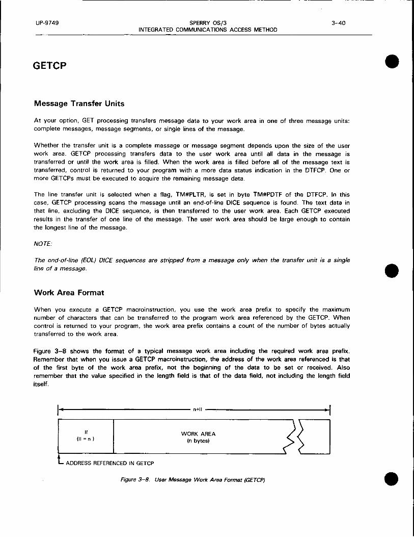
UP-9749 SPERRY OS/3 3-40 INTEGRATED COMMUNICATIONS ACCESS METHOD
GETCP
Message Transfer Units
At your option, GET processing transfers message data to your work area in one of three message units: complete messages, message segments, or single lines of the message.
Whether the transfer unit is a complete message or message segment depends upon the size of the user work area. GETCP processing transfers data to the user work area until all data in the message is transferred or until the work area is filled. When the work area is filled before all of the message text is transferred, control is returned to your program with a more data status indication in the DTFCP. One or more GETCPs must be executed to acquire the remaining message data.
The line transfer unit is selected when a flag, TM#PL TR, is set in byte TM#PDTF of the DTFCP. In this case, GETCP processing scans the message until an end-of-line DICE sequence is found. The text data in that line, excluding the DICE sequence, is then transferred to the user work area. Each GETCP executed results in the transfer of one line of the message. The user work area should be large enough to contain the longest line of the message.
NOTE:
The end-of-line (EOL) DICE sequences are stripped from a message only when the transfer unit is a single line of a message.
Work Area Format
When you execute a GETCP macroinstruction, you use the work area prefix to specify the maximum number of characters that can be transferred to the program work area referenced by the GETCP. When control is returned to your program, the work area prefix contains a count of the number of bytes actually transferred to the work area.
Figure 3-8 shows the format of a typical message work area including the required work area prefix. Remember that when you issue a GETCP macroinstruction, the address of the work area referenced is that of the first byte of the work area prefix, not the beginning of the data to be set or received. Also remember that the value specified in the length field is that of the data field, not including the length field itself.
!------------------- n+ll ----------------.. ,
I ;, WORK AREA JO
(II = n ) (n bytes) < l ADDRESS REFERENCED IN GETCP
Figure 3-8. User Message Work Area Format (GETCPJ
•
•
•

• UP-9749 SPERRY OS/3 3-41
INTEGRATED COMMUNICATIONS ACCESS METHOD
LNEREL
Function:
Used with the standard and DDI interfaces, it terminates the linkage between a channel and a line described in a communications network. Linkage termination occurs after validation of the LNEREL macro call. Any output messages that have not been processed remain on the output queues. If the line is later reopened via an LNEREO macro call, any remaining output messages on the output queues will then be processed.
Format:
LABEL 60PERATION6 OPERAND
[symbol] LNEREL line-name
,MF= (Hl[{~ef;x code}]) ·(E'{~;;ameter list label})
L
• Parameters:
•
line-name
MF=
Identifies the line for which the LNEREL functions are to be initiated.
Identifies a parameter list whose address may be explicitly specified or implicitly passed to the called routine through register 1. Refer to S-type macroinstructions described in Appendix A.
Error Processing:
When you specify DUSTERR = INLINE in the CCA macroinstruction and an error occurs during macroinstruction processing, control returns inline to the address following the LNEREL macroinstruction. When you don't specify DUSTERR=INLINE, errors are returned at the specified NETREQ ERRET= address.
Register 1 contains the address of the LNEREL parameter table. Register 0 contains:
• zeros in bytes 0 and 1;
• TO#LER 1 error codes in byte 2; and
• TQ#LER2 error codes in byte 3.
Table 3-14 describes the error conditions that may be detected during the execution of this macroinstruction.

UP-9749 SPERRY OS/3 3-42 INTEGRATED COMMUNICATIONS ACCESS METHOD
LNEREL • Table 3-14. LNEREL Error Conditions
-Byte Error Code Cause/Condition Result
-TQ#LER1 TU#DDTAE LNEREL table outside user region When you specify DUSTERR =
INLINE, control is returned inline TU#DDTBE LNEREL table not full-word aligned following this request.
When you don't specify TU#DDTLE LNEREL table length incorrect DUSTERR= INLINE,
control is returned TU#DFE LNEREL table flags incorrect at the address specified
in the ERRET operand of the NETREQ macro-instruction. The request is not honored. -
TO#LER2 TU#DLNNE Line name specified does not exist
TU#DLAR Line name specified has already been released or was never requested.
NOTE:
The DSECT for this table is TQ#DSCTS. •
•

•
•
•
UP-9749 SPERRY OS/3 3-43 INTEGRATED COMMUNICATIONS ACCESS METHOD
LNEREQ
Function:
Used with the standard and DDI interfaces, it initiates the required linkage between a channel and a line described in a communications network. This instruction affects all the terminals on a line, as defined in the network definition. On polled lines, the LNEREQ instruction initiates the necessary polling procedures.
NOTE:
The functions performed by this instruction can be initiated as a parameter to the NETREO macroinstruction.
Format:
LABEL
[symbol]
Parameters:
line-name
L.OPERATIONL.
LNEREQ
OPERAND
line-name
,MF=
' L
Identifies the line for which the LNEREL functions are to be initiated.
MF= Identifies a parameter list whose address may be explicitly specified or implicitly passed to the called routine through register 1. Refer to S-type macroinstructions described in Appendix A.
Error Processing:
When you specify DUSTERR = INLINE in the CCA macroinstruction and an error occurs during macroinstruction processing, control returns inline to the address following the LNEREQ macroinstruction. When you don't specify DUSTERR=INLINE, errors are returned at the specified NETREQ ERRET = address.
Register 1 contains the address of the LNEREQ parameter table. Register 0 contains:
• zeros in bytes 0 and 1;
• TQ#LER1 error codes in byte 2; and
• TQ#LER2 error codes in byte 3 .

UP-9749 SPERRY OS/3 3-44 INTEGRATED COMMUNICATIONS ACCESS METHOD
LNEREQ
Table 3-15 describes the error conditions that may be detected during the execution of this macroinstruction.
Table 3-15. LNEREQ Error Conditions
Byte Error Code Cause/Condition Result
TQ#LER1 TU#DDTAE LNEREQ table outside user region When you specify DUSTERR= INLINE, control is returned inline
TU#DDTBE LNEREQ table not full-word aligned following this request. When you don't specify DUSTERR = INLINE, control is returned at the address specified in the ERRET operand of the NETREQ macro-instruction. This request is not honored.
TQ#LER2 TU#DLNNE Line name specified nonexistent
TU#DLAR Line name specified already active
TU#DNLLT Line cannot be mapped; no available port
TU#DNCCT No available communications adapter (CA) subsystems available for this line
TU#DLCAE CA initialization error
TU#DIAL Autodial line could not be dialed
NOTE:
The DSECT for this table is TQ#DSCTS.
•
•
•

•
•
•
UP-9749 SPERRY OS/3 3-45
INTEGRATED COMMUNICATIONS ACCESS METHOD
MCPCALL
Function:
Produces an SVC interrupt and passes control and the address of a message control table (MCT) to the ICAM direct data interface for processing by one of the remote device handler routines.
Format:
LABEL
[symbol]
Label:
[symbol]
L'.OPERATION L'.
MCPCALL
OPERAND
{met-packet-label} ( 1)
Is an alphanumeric character string from one to eight characters long that identifies and addresses this instruction.
Parameters:
met-packet-label Identifies the symbolic name of the MCT packet to be accessed.
( 1)
Indicates that the address of the MCT packet to be accessed is contained in register 1 .

UP-9749 SPERRY OS/3 3-46 INTEGRATED COMMUNICATIONS ACCESS METHOD
MCTPKT
Function:
Used with the direct data interface, it creates a message control table (MCT) used in conjunction with the MCPCALL macroinstruction to send and receive messages.
Figure 3-9 shows the format and functional field descriptions of the MCT created by this macroinstruction. Table 3-16 provides detailed field descriptions.
Format:
LABEL L.OPERATIONL'.i OPERAND
met-name MCTPKT completion-address
Label:
'{~~~~BCH} RECEIVE
RECVBCH
[,IRL]
,BUFFERA=label,BAL=length
[,BUFFERB=label,BBL=length]
[,ID=<psub1,psub2,psub3)]
[,EOM=dsect-labels]
[,ENDBUF=n]
met-name
Is a 1- to 8-character label that identifies the starring address of this message control packet.
Operands:
completion-address
Is a 1- to 8-character address in your program where you want control passed when a function is complete.
SEND/SENDBCH
Specifies this MCT is related to an output command for an interactive device or an output command for a batch device.
RECEIVE/RECVBCH
IRL
Specifies this MCT is related to an input command for an interactive device or an input command for a batch device.
Sets the immediate return line bit in the MCT packet to return control to your program before function completion.
•
•
•

•
•
•
UP-9749 SPERRY OS/3 3-47 INTEGRATED COMMUNICATIONS ACCESS METHOD
MCTPKT
BUFFERA=label Specifies the address of the initial buffer for the function to be performed.
BAL= length Specifies the decimal length of the initial buffer. (See BUFFERA operand.) You may specify up to 32, 767 bytes.
BUFFERB=label Specifies the address of the replacement buffer for the function to be performed.
BBL= length Specifies the decimal length of the replacement buffer. (See BUFFERS operand.) You may specify up to 32, 767 bytes.
ID=(psub1,psub2,psub3) Three positional suboperands that specify the line, terminal, and auxiliary device related to this MCT. Specify these in decimal.
psub1 Is a 1- to 2-digit decimal number that identifies the logical line involved. Specify in the order they occur in your network definition.
For example, the first line (defined by a LINE macroinstruction) would be 1 and the twentieth line would be 20.
psub2 Is a 1- to 2-digit decimal number that identifies the logical terminal involved. Specify in the order they occur in your network definition.
For example, the first terminal on a line (defined by a TERM macroinstruction) would be 1 and the fifth terminal would be 5.
psub3 Is a 1- to 2-digit decimal number that specifies the auxiliary device index for the auxiliary device involved. (See the UAXn operand in the TERM macroinstruction description in the ICAM network definition and operations user guide, UP-9745 (current version).
EOM=dsect-labels Describes the end of message processing you want the direct data interface remote device handler to perform for you. (See Table 3-1.) You can request several functions by performing an OR operation for several labels.
For example, the operand EOM=label1++1abel2++1abel3 would cause three functions defined by the labels to be performed.
ENDBUF=n Identifies the output buffer that contains the end of message functions. Specify 1 if they are in the initial buffer or specify 2 if they are in a replacement buffer.
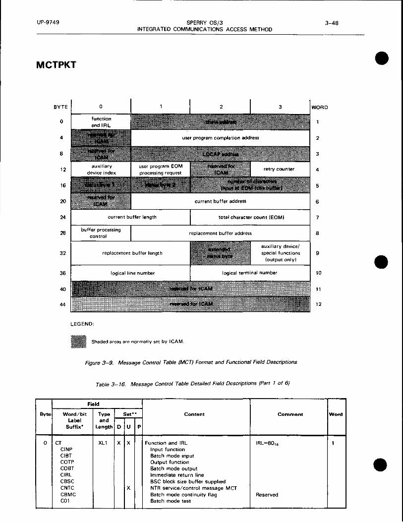
UP-9749 SPERRY OS/3 INTEGRATED COMMUNICATIONS ACCESS METHOD
MCTPKT
Byte
0
BYTE
0
4
8
12
16
20
24
28
32
36
40
44
0
current buffer length
buffer processing control
replacement buffer length
logical line number
current buffer address
total character count (EOMI
replacement buffer address
auxiliary device/ special functions
(output only)
LEGEND:
Shaded areas are normally set by ICAM.
Figure 3-9. Message Control Table (MCT) Format and Functional Field Descriptions
Table 3-16. Message Control Table Detailed Field Descriptions (Pan 1 of 6)
Field
Word/bit Type Set** Content Comment Label and
Suffix* Length D u p
CT XL1 x x Function and IRL IRL=8016
CINP Input function CIBT Batch mode input COTP Output function COBT Batch mode output CIRL Immediate return line CBSC BSC block size buffer supplied CNTC x NTR service/control message MCT CBMC Batch mode continuity flag Reserved C01 Batch mode test
3-48
• WORD
2
3
4
5
6
7
8
9 • 10
11
12
Word
1
•

UP-9749 SPERRY OS/3 3-49 INTEGRATED COMMUNICATIONS ACCESS METHOD
• MCTPKT
Table 3-16. Message Control Table Detailed Field Descriptions (Part 2 of 6)
Field
Byte Word/bit Type Set** Content Comment Word Label and
Suffix* Length D u p
1 CCHN AL3 x Chain address Reserved 1 (cont)
4 CRV1 XL1 Reserved 2
5 CCA AL3 x x Completion address
8 CJBF Reserved 3
9 CJBF+1 AL3 x LOCAP address Reserved for ICAM
12 COIN (CDID) XL1 x x Auxiliary device index 4 (CADN)
13 CEOM XL1 x EOM processing request CTll Mark terminal inhibit input CTEI Mark terminal enable input • CLCT Accept truncation as normal CNIP Do not allow input after output CIAO 3-second input after output
(default)
14 RESV XL1 x Reserved Reserved
15 CRTC XL1 x Retry counter Output counter
16 CST1 (CSTS) XL1(2) x Status byte 1 (status half word) 5 CSIT Bad siteid or undefined rid/sid CNAX Auxiliary device down CRIR Ring indicator received CURE Unrecoverable buffer late Lost message CLNO Line down or not open Fatal CDNA Term/device down or not Retry input
available CIVF Invalid line or buffer format Correct code CBLI Input buffer late Retry CIPE Input parity /block check error Retry CIAB Abort input Terminal command CBLO Output buffer late Retry COPE Output parity/block check error Retry COAB Abort output Terminal command COBK Break received CNOR Normal buffer completion CNEM Normal end-of-message CTEM EOM with legal truncation
(CPGE) (XL2) x (TCI output paging flags) (CSCH) (XL2) x (UNISCOPE auxiliary device retry
select count half word ) • 17 CST2 (CSRC) XL1 x Status byte 2 (UNISCOPE auxiliary device retry
select count)
18 CRCC H x Number of characters in EOM buffer

UP-9749 SPERRY OS/3 3-50 INTEGRATED COMMUNICATIONS ACCESS METHOD
MCTPKT • Table 3-16. Message Control Table Detailed Field Descriptions (Pan 3 of 6)
Field
Byte Word/bit Type Set** Content Comment Word Label and
Suffix* Length D u p
I ~o CNUl Xll x Reserved Reserved 6
21 CBFC XL3 x x Current buffer address
24 CBAL H x x Current buffer length 7
26 CCHC H x Total character count (EOM)
28 CCKB Xll Buffer processing control byte 8 CCBS x Buffer is EOM. Interface to ROH Informational CX20 x Check byte set CCSG Continuous segment flag - TCI output CEMl x First buffer in EOM User sets CEMC x Set EOM and check byte CEM2 x Replacement buffer is EOM User sets CLBW Last output buffer to ROH Informational COMT x Output buffer late CBBS x Buffer byte set •
29 CBFR AL3 x x Replacement buffer address
32 CBBL H x x Replacement buffer length 9 CONP TCI deliver'!'_ notice
33 COFG TCI output flags CENI x Clear inhibit before output EOM
34 CSTB Xll x Extended status byte
General error conditions CATA Input - Invalid terminal address CRNB Input - Network buffer late CRBI Input - Bad input text
OCT 500 Series. OCT 1000 and TTY special function:
CMWT BEL character received
CBRK OCT 500 Series and TIY special function:
BREAK signal received
CTOI OCT 500 Series and TTY error codes: Time-out during input (missing User responsibility for
ETX) error recovery. CTRE OCT 500 magnetic tape read error
UNISCOPE/DCT 1000 error codes:
• CAFE SLCA reported error on last input retry.
CRBH ROH detected error in put
message on last input retry.
COFE SLCA reported error on output.

UP-9749 SPERRY OS/3 3-51 INTEGRATED COMMUNICATIONS ACCESS METHOD
• MCTPKT
Table 3-16. Message Control Table Detailed Field Descriptions (Part 4 of 6)
Field
Byte Word/bit Type Set** Content Comment Word Label and
Suffix* Length D u p
34 COMA Negative acknowledge (no traffic) 9 (cont) to output. (cont)
COLE DCT 1000 messages length exceeded buffer size (interactive) of 160 characters.
CDTO Prolonged busy on DCT 1000 output (e.g., due to an out-of-paper condition)
CCTD Configuration table data for user CAST Port input abort CELD Error log data
UNISCOPE special functions: CMWK Message wait key
• CFK1 Function key 1 CFK2 Function key 2 CFK3 Function key 3 CFK4 Function key 4
UTS 400 special functions: CMWK Message wait key CFK1 Function key 1 CFK2 Function key 2 CFK3 Function key 3 CFK4 Function key 4 CFK5 Function key 5 CFK6 Function key 6 CFK7 Function key 7 CFKB Function key 8 CFK9 Function key 9 CFK10 Function key 10 CFK11 Function key 11 CFK12 Function key 12 CFK13 Function key 13 CFK14 Function key 14 CFK15 Function key 15 CFK16 Function key 16 CFK17 Function key 17 CFK18 Function key 18 CFK19 Function key 19 CFK20 Function key 20 CFK22 Function key 22 CPOC Firmware completed power on
confidence (POC) test. CEOT Operator pressed hang-up key
• UNISCOPE auxiliary device status CDS1 Status 1 - READY status but
TCS function is inoperative CDS2 Status 2 - Printer out of paper, Rewind tape with mode
LJ printer inoperative, printer on search. If the in test mode. TN#MCST1

UP-9749 SPERRY OS/3 3-52 INTEGRATED COMMUNICATIONS ACCESS METHOD
MCTPKT • Table 3-16. Message Control Table Detailed Field Descriptions (Part 5 of 6)
Field
Byte Word/bit Type Set** Content Comment Word Label and
Suffix* Length D u p
34 CDS3 Status 3 - Error on data read status is TN#MCOPE, 9 (cont) write/search the user must resubmit (cont)
the TCS function with a retry count of 1 or greater in the TN#MCRTC field. The ROH will send a backward-one-block command followed by the TCS function. If the data error persists, the error recovery attempts must be terminated by the user by submitting the TCS function with a retry count of one in the TN#MCRTC field. This will be the final attempt. If the final attempt fails • with another data error. the MCT is returned with a TN#MCST1 status of TN#MCNAX and a TN#MCSTB status of TN#MCDS3.
CDS4 Status 4 - No response from device or trying to read blank tape.
Batch handlers COVR Oversize output sent CRRD Received read request during output CDIS Received EQT (disconnect status) CRFA Requeue file active on the dev session CMAC Manual action complete CRHT Received halt CRHV Received halt-go-voice CRER Received end read CROY Received ready COFF Received offli ne CAPR Received abort print CAPU Received abort punch CRVI Received RVI (BSC) CRTN BSC ROH Transparent input
1004 slave handler CSND Get cards to send CHGR Received halt-go-voice function CEOJ Offline sent (go to EOJ) CYLD MCT returned for HALT. do
CY I ELD CSNT ~ecial function set • 35 CAD XL1 x Auxiliary device/special functions
(output)

•
•
•
UP-9749 SPERRY OS/3 3-53 INTEGRATED COMMUNICATIONS ACCESS METHOD
MCTPKT
Table 3-16. Message Control Table Detailed Field Descriptions (Part 6 of 6)
Field
Byte Word/bit Type Set** Content Comment Word Label and
Suffix* Length D u p
35 I UNISCOPE, UTS 400, OCT 1000, 9 (cont) OCT 500, (cont)
OCT 4 75, and TIY ROH CCMW, UNISCOPE or UTS 400 CSMW or computer message waiting MCMWS CCMW OCT 1 000 computer message
waiting CXPI Peripheral init-command
indicator CPRT Print (write) CRDB Read a block - TCS CBOB Backward one block - TCS CSRH Search - TCS CRPA Report address - TCS CPRF Print form (UTS 400) CXAL Transfer all (UTS 400) CXVR Transfer variable (UTS 400) CXCG Transfer changed (UTS 400) CPRE Prevent space suppression
i~:RT! Load program on diskette CTAT (UTS 400)
CTAT Transparent auxiliary transfer
Batch handlers: CSHT Send halt CTRN Send transparent (BSC) CSRV Send RVI (BSC)
CBCN Send BSC connect sequence (input) CBDC Send BSC OLE EQT (input, output) CTIF Terminate input file CMAR Manual action request
1004 slave handlers: CNCH Send no change indicator CRDF Initiate output CSOL Send offline function CINI Start polling CPRA Send abort print to host CPUA Send abort punch to host
36 CUD H x Logical line number 10
38 CTIN (CSID) H x Logical terminal number
40 Reserved for ICAM 11
44 Reserved for ICAM 12
*All labels have the prefix TN#M. The DSECT label of this table is TN#MCTDS. **D indicates set be declarative macro.
U indicates to be set by user. P indicates set by software processor.

UP-9749 SPERRY OS/3 3-54 INTEGRATED COMMUNICATIONS ACCESS METHOD
NATTACH
Function:
Attaches user to a global network.
Format:
LABEL 60PERATION6 OPERAND
[symbol] NATTACH
Parameters:
network-name
network-name
,APPS=name
,ERRET=symbol
I :::~s~~}[lf :~;~lcod•m (E'{~~;ameter-list-label})
L
Specifies the name of the global network.
APPS=name
Identifies a 1- to 4-character LOCAP name registered in the global network. This allows an applications program to be addressable in a similar fashion to lines, terminals, and process files.
ERRET=symbol Specifies an entry point (a symbolic address) where ICAM returns control after detecting output delivery notification (ODNR) or macroinstruction errors. In addition, when you do not specify DUSTERR=INLINE, the LOCAP macroinstruction, ICAM returns to this entry point for errors associated with imperative macroinstructions your program issues.
NOTE:
A program in a global environment, which must use the NA TTACH macroinstruction instead of NETREQ, cannot control communications lines. Therefore, line down notifications go to GUST rather than to your program's ERRET address, as they do for programs in a dedicated environment.
•
•
•

•
•
•
UP-9749 SPERRY OS/3 3-55 INTEGRATED COMMUNICATIONS ACCESS METHOD
NATTACH
PASSWORD=password
MF=
One to eight characters that identify the network password. This parameter is required unless no password was specified when the network was generated.
Identifies a parameter list whose address may be explicitly specified or implicitly passed to the called routine through register 1. See Appendix A.
If this parameter is omitted, both a parameter list required by the called ICAM routine and the linkage to it are generated.
Error Processing:
When you specify DUSTERR = INLINE in the LOCAP macroinstruction and an error occurs during macroinstruction processing, control returns inline to the location following the NA TT ACH macroinstruction. When you don't specify DUSTERR= INLINE, errors are returned at the specified NA TT ACH ERRET = address.
Register 1 contains the address of the NA TT ACH parameter table. Register 0 contains:
• zeros in bytes 0, 1, and 3; and
• TO#NER 1 error codes in byte 2.
Table 3-17 describes the error conditions detected during the execution of this macroinstruction.
Whenever the status of the permanent virtual circuit {pvc) changes, you receive the up or down flag and the pvc number in register 0. Byte 1 contains the status byte (X'41' for pvc up; X'42' for pvc down). Bytes 2 and 3 contain the virtual circuit number. Register 1 contains the 4-character name of the remote locap file .

UP-9749 SPERRY OS/3 3-56 INTEGRATED COMMUNICATIONS ACCESS METHOD
NATTACH • Table 3- 17. NA TT A CH Error Conditions
Byte Error Code Cause/Condition Result
TQ#NER1 TU#DDTAE NA TT ACH table outside user region When you specify DUSTERR =
INLINE, control is returned TU#DDTBE NA TT ACH table not full-word aligned inline following the request.
The request is not honored. TU#DERRA Error return address not in user region When you don't specify
DUSTERR = INLINE, TU#DNAPP APPS-name requested does not match any control is returned at the
LOCAP name. address specified in the ERRET operand of the
TU#DCAPP APPS-name requested is already attached NATT ACH macroinstruction. to another CUP.
TU#DNADU Duplicate NA TT ACH from same user
TU#DRAPP APPS-name requested is a remote LOCAP.
TU#DGSHT NA TT ACH while GUST shutdown in progress
TU#DGBL Your program attempted an NATTACH to a global CCA that was not active. • TU#DPASS Invalid password
•

•
•
•
UP-9749 SPERRY OS/3 3-57
INTEGRATED COMMUNICATIONS ACCESS METHOD
NDETACH
Function:
Detaches the applications program from the global CCA network. No other macros except GA WAKE
will be accepted until another NA TT ACH is issued.
Format:
LABEL .60PERATION.6 OPERAND
[symbol] NDETACH network-name
,HF= ~n[ rfh oodem (E'{~~;ameter list-label})
L
Parameters:
network-name Specifies the network to be released as defined by the CCA macroinstruction.
MF= Identifies a parameter list whose address may be explicitly specified or implicitly passed to the called routine through register 1. Refer to S-type macroinstructions described in Appendix A.
Error Processing:
When you specify DU STERR= INLINE in the LOCAP macroinstruction and an error occurs during macroinstruction processing, control returns inline to the address following the NDET ACH macroinstruction. When you don't specify DUSTERR = INLINE, errors are returned at the specified NA TT ACH ERRET = address.
Register 1 contains the address of the NDET ACH parameter table. Register 0 contains:
• zeros in bytes 0, 1, and 3; and
• TQ#NER 1 error codes in byte 2.
Table 3-18 describes the error conditions that may be detected during the execution of this
macroinstruction .
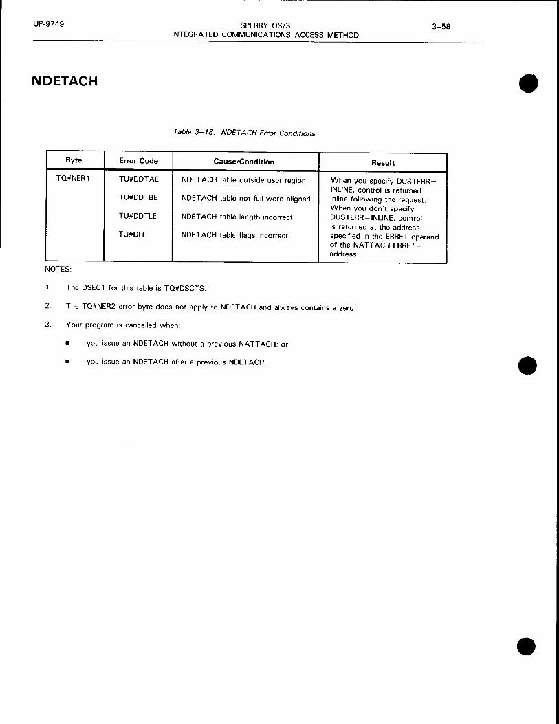
UP-9749 SPERRY OS/3 3-58 INTEGRATED COMMUNICATIONS ACCESS METHOD
NDETACH
Table 3-18. NDETACH Error Conditions
Byte Error Code Cause/Condition
TQ#NER1 TU#DDTAE NDET ACH table outside user region
TU#DDTBE NDET ACH table not full-word aligned
TU#DDTLE NDET ACH table length incorrect
TU#DFE NDET ACH tabl€ flags incorrect
NOTES:
1. The DSECT for this table is TQ#DSCTS.
Result
When you specify DUSTERR= INLINE, control is returned inline following the request. When you don"t specify DUSTERR=INLINE, control is returned at the address specified in the ERRET operand of the NA TT ACH ERRET = address.
2. The TQ#NER2 error byte does not apply to NDET ACH and always contains a zero.
3. Your program is cancelled when:
• you issue an NDET ACH without a previous NA TT ACH; or
• you issue an NDET ACH after a previous NDET ACH .
•
•
•

•
•
•
UP-9749 SPERRY OS/3 3-59 INTEGRATED COMMUNICATIONS ACCESS METHOD
NETREL
Function:
Used with the standard (dedicated network) and DOI interfaces, it releases the facilities composing a communications network. The releasing of facilities occurs after validation of the NETREL macro call. Messages remaining on main storage queues are lost after NETREL is executed. Messages remaining on disk queues are not lost unless a NETREQ macroinstruction without REST ART= YES was used to initiate the networks. However, these messages could be lost if the last user of ICAM does a NETREL since ICAM will terminate and go out of main storage. To avoid losing any messages, use the QDEPTH macroinstruction or a programming delay prior to issuing NETREL.
Format:
LABEL L.OPERATIONL. OPERAND
[symbol] NETREL network-name
,MF= ~n[{;efo oode}]) (E'{~~;ameter list-label})
L
Parameters:
network-name Specifies the network to be released as defined by the CCA macroinstruction.
MF= Identifies a parameter list whose address may be explicitly specified or implicitly passed to the called routine through register 1. Refer to S-type macroinstructions described in Appendix A.
Error Processing:
When you specify DUSTERR = INLINE in the CCA macroinstruction and an error occurs during macroinstruction processing, control returns inline to the address following the NETREL macroinstruction. If you don't specify DUSTERR=INLINE, errors are returned at the specified NETREQ ERRET= address.
Register 1 contains the address of the NETREL parameter table. Register 0 contains:
• zeros in bytes 0, 1, and 3; and
• TQ#NER 1 error codes in byte 2.
Table 3-19 describes the error conditions that may be detected during the execution of this macroinstruction.

UP-9749 SPERRY OS/3 3-60 INTEGRATED COMMUNICATIONS ACCESS METHOD
NETR EL • Table 3-19. NETREL Error Conditions
...!L
Byte Error Code Cause/Condition Result
TQ #NER1 TU#DDTAE NETREL table outside user region When you specify DUSTERR =
INLINE, control is returned TU#DDTBE NETREL table not full-word aligned inline following this request.
When you don't specify TU#DDTLE NETREL table length incorrect DUSTERR = INLINE, control
is returned at the address TU#DFE NETREL table flags incorrect specified in the ERRET operand
of the NETREQ macroinstruction.
NOTE S:
1. The DSECT for this table is TQ#DSCTS.
2. The TQ#NER2 error byte does not apply to NETREL and always contains a zero.
3. Your program is cancelled with error code 450 when you issue a NETREL after a previous NETREL.
•
•

•
•
•
UP-9749 SPERRY OS/3 3-61 INTEGRATED COMMUNICATIONS ACCESS METHOD
NETREQ
Function:
Used with the standard and DDI interfaces, it activates a previously defined communications network.
Format:
LABEL .60PERATION.6
[symbol] NETREQ
Parameters:
network-name
OPERAND
network-name
,ERRET=symbol
[' LNEREQ= { ~~!~) }] [,PASSWORD=password]
[,RESTART=YES]
['FATAL= t!~~) }] ,MF
0 ({~ )[ rf;x oodel]) (E'{~~;ameter list label})
L
Specifies the network to be activated.
ERRET=symbol Specifies an entry point (a symbolic address) where ICAM reports errors and returns control after detecting output delivery notification (ODNR) on communications line down errors. In addition, when you do not specify DUSTERR=INLINE in the CCA macroinstruction, ICAM returns to this entry point for errors associated with imperative macroinstructions your program issues .

UP-9749 SPERRY OS/3 3-62 INTEGRATED COMMUNICATIONS ACCESS METHOD
NETREQ
When you specify DUSTERR=INLINE in the CCA macroinstruction, control returns inline to the location following the NETREQ macroinstruction. If you do not specify DUSTERR=INLINE, error returns are directed to the address specified in the ERRET= operand. In addition, register 1 contains the address of the NETREQ parameter table, and register 0 contains:
• zeros in bytes 0 and 1;
• TQ#NER 1 error codes in byte 2; and
• TQ#NER2 error codes in byte 3.
Table 3-20 describes NETREQ errors.
If you specify LNEREQ =YES, and a line error occurs while initializing one or more lines, you can control whether the network is opened and initialized through the FAT AL= operand.
LNEREQ=CMfii> All the lines in the communications network are activated when the network is activated.
LNEREQ=CNO) No line request functions are initiated. Instead, your program must issue an LNEREQ macroinstruction for each line to be activated.
PASSWORD=password Is a character string, from one to eight characters long, that identifies the ICAM password, if any, embedded in the network to be activated. The password in a network is specified by the optional PASSWORD parameter of the CCA macroinstruction. This parameter must be specified if, in fact, a password is in the subject network.
If omitted, the network must have been generated without a password specified for the NETREQ macroinstruction to be accepted.
RESTART=YES Specifies that a warm restart is to be performed on all disk queues associated with the named network. This causes all queues to be refreshed to the last point at which a queue checkpoint was taken and the queues placed on hold.
If omitted, a normal NETREQ is performed, initializing all queues as empty.
NOTES:
1. This parameter should not be used the first time a network is requested since there is no information on disk with which to refresh the queues.
2. When specified for a network with all main storage queues, the parameter is meaningless and is ignored.
FATAL=<lll> All network request (NETREQ) errors (TQ#NER1 and TQ#NER2) are treated as fatal errors. The network is not opened or initialized.
•
•
•

•
•
•
UP-9749 SPERRY OS/3 3-63
INTEGRATED COMMUNICATIONS ACCESS METHOD
NETREQ
FATAL=(NQ)
MF=
Network request (NETREQ) errors reported in TQ#NER2 are not treated as fatal errors, and the network is opened and initialized with errors. Any error in TO#NER 1, regardless of the FAT AL keyword, is always fatal and the network is not opened or initialized.
NOTES:
1. TU#JERR (journal file initialization error), reported in TO#NER2, is always treated as a fatal error, and the network is not opened or initialized.
2. To determine which lines have failed, issue a separate LNEREO for each line, and lines with any errors reported in TO#NER2, other than TU#DLAR, are the problem lines for NETREQ.
Identifies a parameter list whose address may be explicitly specified or implicitly passed to the called routine through register 1. Refer to S-type macroinstructions described in Appendix A.
Table 3-20. NETREQ Error Conditions (Pan 1 of 2)
Byte Error Code Cause/Condition Result
TQ#NER1 TU#DDTAE NETREQ table outside user region Control is always returned inline following this
TU#DDTLE NETREQ table length incorrect request. The request is not honored.
TU#DDTBE NETREQ table not full-word aligned
TU#DERRA Error return address not in user region
TU#DPASS Invalid password; password does not When you specify DU STERR= match password on CCA INLINE, control is returned macroinstruction inline following this request.
When you don't specify TU#DDSKE Disk error opening a file DUSTERR = INLINE,
control is returned at TU#DDSKA Attached error occurred - disk queueing the address specified at
the ERRET operand of the TU#DDSKR A disk error occurred while reading a file NETREQ macroinstruction.
- disk queueing The request is not honored.
TU#DRAN Network requested already active
TU#DDSKF File error (file characteristics do not match those in CCA) - disk queueing
TU#DUSAT User saturation - ICAM user slot unavailable to log in user
TU#DCSAT CCA ARP saturation; unable to acquire ARP from CCA to process
TU#DGBL Job other than GUST attempted NETREQ of global CCA

UP-9749 SPERRY OS/3 3-64 INTEGRATED COMMUNICATIONS ACCESS METHOD
NETREQ • Table 3-20. NETREQ Error Conditions (Part 2 of 2)
Byte Error Code Cause/Condition Result
TQ#NER2 TU#DNLLT One or more lines in the network could not be When you specify mapped to a physical port. For workstations, DUSTERR=INLINE. the workstation to be linked to ICAM control is returned inline was not physically present. following this request. The
request is or is not TU#DNCCT No available CA tables for one or more lines honored, depending on the
FAT AL= keyword TU#DLNNE Line name specified nonexistent specification. If several errors
occur, these flags may be TU#DLCAE CA initialization error ORed together.
TU#DLAR Line name specified already active. For workstations, the workstation to be linked to ICAM was physically present but not available.
TU#DIAL Autodial line could not be dialed
TU#JERR Journal file initialization error When you specify DUSTERR=INLINE. control is returned inline • following this request. The request is not honored.
NOTE:
User must decide if warm restart is desired.
a. If warm restart is not required, reinitialize the disk queueing file.
b. If warm restart is required, determine if buffer size in network was changed since disk queueing file was created.
( 1) If changed. restore buffer size in network and regenerate.
(2) If not changed, user is probably opening a nondisk queueing file.
•

•
•
•
UP-9749 SPERRY OS/3 3-65 INTEGRATED COMMUNICATIONS ACCESS METHOD
PU TCP
Function:
Used with the standard interface, it transfers messages from a user program work area to ICAM.
Format:
LABEL 60PERATION6 OPERAND
PUTCP {filename}'{workarea-address} ( 1) (0)
[symbol]
Label:
[symbol l Is an alphanumeric character string from one to eight characters long that identifies and addresses this instruction.
Parameters:
filename Identifies the symbolic name of the output file DTFCP with which the message is controlled.
( 1)
Indicates that the address of the DTFCP is contained in register 1 .
workarea-address Identifies the user program area containing the message unit to be transferred.
(0) Indicates that the address of the subject work area is contained in register 0.
NOTE:
This address is that of the work area prefix, which must be on a half-word boundary.
Error Processing:
Two bytes of the output DTFCP file table, TM#DERR and TM#DERR+ 1, are used to return PUTCP processing error indications for the user program. The flags in the two TM#DERR bytes indicate the type of error detected; however, flag TM#DIER in byte TM#DIND indicates an error status. TM#DIER is always set in addition to a TM#DERR byte flag.
ICAM always returns control to the address you specify in the DTFCP macroinstruction (ERRET = or NOMA V = keywords) even if you specify DUSTERR = INLINE in the CCA or LOCAP macroinstruction. If you do not specify an ERRET address, control is returned inline .

UP-9749 SPERRY OS/3 3-66 INTEGRATED COMMUNICATIONS ACCESS METHOD
~~~~~~~~~~~~~~~~~~~~-
PU TCP
Message Transfer Units:
Messages may be transferred from your user work area to ICAM in three message units: complete messages, message segments, or single lines of a message. Two flags, TM#DHDR and TM#DTND in byte TM#DSEG, plus flag TM#DL TR in byte TM#DDTF, are provided for you to select the message transfer unit. Table 3-21 shows the appropriate settings for the flags in relation to the message unit to be transferred.
Table 3-21. Message Unit Selection Flags (PUTCP)
Byte Byte TM#DSEG TM#DDTF
Message Unit Flag Flag Flag
TM#D HOR TM#DTND TM#DLTR
Put Complete Message Set Set Reset Put First Segment Set Reset Reset Put Intermediate Segments Res et Reset Reset Put Last Segment Res et Set Reset Put First Line Set Reset Set Put Intermediate Line Res et Reset Set Put Last Line Res et Set Set/Reset
Work Area Format:
When you execute a PUTCP macroinstruction, you use the work area prefix to specify the total byte count to be sent from your program work area.
Figure 3-10 shows the format of a typical message work area including the required work area prefix. When you issue a PUTCP macroinstruction, the address of the work area referenced is that of the first byte of the work area prefix, not the beginning of the data to be sent or received. Also remember that the value specified in the length field is that of the data field, not including the length field itself.
I n+ll -----------!
I~ -(11-~'n)-4-l~~-w-~~-~:~_A~~~JD l ADDRESS REFERENCED IN PUTCP
Figure 3-10. User Message Work Area Format (PUTCP)
•
•
•

•
•
•
UP-9749 SPERRY OS/3 3-67 INTEGRATED COMMUNICATIONS ACCESS METHOD
QC LEAR
Function:
Used with standard interface. Clears queues specified in the operand field of all messages without transmitting them. All associated network buffers are released. The function can apply to a single queue, the queues associated with a single terminal, locap file, process file, or all queues associated with a line.
Figure 3-11 shows the QCLEAR parameter list organization, and Table 3-22 describes its contents.
Format:
LABEL 60PERATION6 OPERAND
[symbol] QC LEAR L,line-name
P '{process file-name} [!HIGH}~ locap-name LOW
MED
T, teem ina l -name [ { ~~~"}]
( 1 )
Parameters:
L
p
T
( 1 )
Clears all messages on all output queues associated with the line named in the line-name operand.
NOTE:
When multiple programs send messages to terminals connected to the same line in a global environment, one program can inadvertently clear messages placed on output queues by another program. In this case, it may be desirable to clear queues individually by using the T operand.
The clear function pertains to all the queues associated with a specific process file/locap file or to a specific queue of the file.
The clear function pertains to all the queues associated with a specific terminal (terminal name) or to a specific queue of the specified terminal.
The address of a QCLEAR parameter list is contained in register 1 .

UP-9749 SPERRY OS/3 3-68 INTEGRATED COMMUNICATIONS ACCESS METHOD
QC LEAR • line-name
Specifies the line associated with the queue or queues.
process file-name Specifies the process file associated with the queue or queues.
locap-name Specifies the user program (locap-file) associated with the queue or queues.
terminal-name Specifies the terminal with the queue or queues.
lH IGH) LOW MED
Specifies queue to be cleared. If omitted, all queues associated with name are cleared.
BYTE 0 2 3 WORD
0 error code flag byte function code • 4 line, process file, or terminal name 2
8 K unused 3
12 unused 4
Figure 3-11. QCLEAR Parameter List Functional Field Description
Table 3-22. QCLEAR Parameter List Detailed Field Descriptions
Field
Byte Type Content Comment Word Label and
Length
0 TQ#QERR H Error flags Set by ICAM 1
2 TQ#QFLAG YL1 Type indicator Differentiates P, L, and T types
3 TQ#QFUNC YL1 Function indicator Indicates which macroinstruction was coded
4 TQ#QPLTN CL4 Process file, line, or terminal name 2 • NOTE:
The DSECT for this table is TQ#QDSCT, which is part of TU#DSTZ.
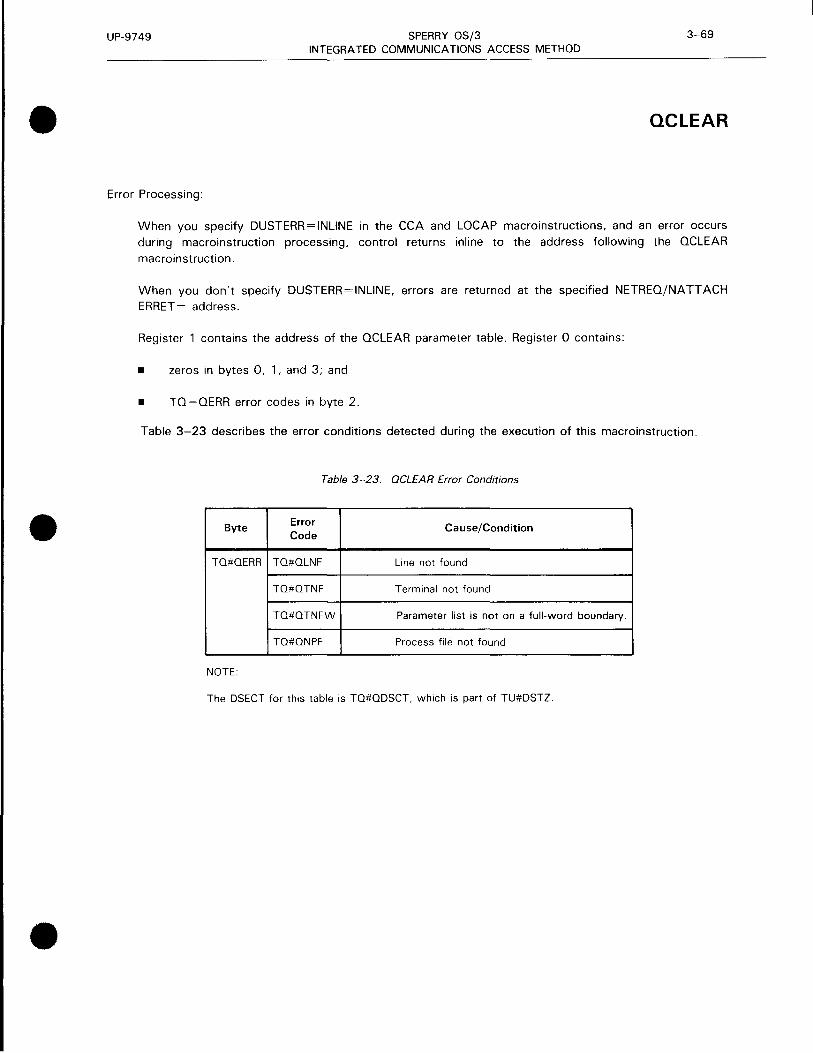
•
•
•
UP-9749 SPERRY OS/3 3-69 INTEGRATED COMMUNICATIONS ACCESS METHOD
QC LEAR
Error Processing:
When you specify DUSTERR=INLINE in the CCA and LOCAP macroinstructions, and an error occurs during macroinstruction processing, control returns inline to the address following the OCLEAR
macroinstruction.
When you don't specify DUSTERR = INLINE, errors are returned at the specified NETREQ/NATT ACH ERRET = address.
Register 1 contains the address of the QCLEAR parameter table. Register 0 contains:
• zeros in bytes 0, 1, and 3; and
• TQ=QERR error codes in byte 2.
Table 3-23 describes the error conditions detected during the execution of this macroinstruction.
Table 3-23. OCLEAR Error Conditions
Byte Error Cause/Condition Code
TQ#QERR TQ#QLNF Line not found
TQ#QTNF Terminal not found
TQ#QTNFW Parameter list is not on a full-word boundary.
TQ#QNPF Process file not found
NOTE:
The DSECT for this table is TQ#QDSCT, which is part of TU#DSTZ .

UP-9749 SPERRY OS/3 3-70 INTEGRATED COMMUNICATIONS ACCESS METHOD
QDEPTH
Function:
Used with standard interface, it indicates the number of messages on the queues of a locap file, process file, or a terminal. The number of messages in each queue is stored in a user-specified work area. This instruction is not applicable to DOI users.
Table 3-24 illustrates the contents of the QDEPTH parameter list.
Table 3-25 shows how queues are generated and how message counts are returned.
Format:
LABEL 6.0PERATIOND. OPERAND
[symbol] QOEPTH
(
P,{process file-name},workarea-name,workarea-length) locap-name
T,terminal-name,workarea-name,
workarea-length ( 1)
Parameters:
p
T
( 1)
Message counts are to be returned for the one to three queues associated with the specified process file.
Message counts are to be returned for all the destination queues associated with specified terminal.
The address of a QDEPTH parameter list identifying the queue to be examined and the work area address is contained in register 1 .
process file-name Process file name (label of PRCS macroinstruction) for which the message counts are to be obtained.
•
•
•

•
•
•
UP-9749 SPERRY OS/3 3-71 INTEGRATED COMMUNICATIONS ACCESS METHOD
QDEPTH
locap-name Locap file name (label of LOCAP macroinstruction) for which the message counts are to be obtained.
terminal-name Terminal name (label of TERM macroinstruction) for which queue message counts are to be obtained.
workarea-name Label of the area in your program where the message counts are to be stored.
Figure 3-12 describes the organization of the QDEPTH work area, and Table 3-26 details its contents.
workarea-length Specifies the work area length in bytes.
Table 3-24. ODEPTH Parameter List Detailed Field Descriptions
Field Byte Type and Content Comment Word
Label Length
0 TQ#QERR H Error flags Set by ICAM 1
2 TQ#QFLAG YL 1 Type indicator Differentiates P, L, and T types
3 TQ#QFUNC YL 1 Function indicator Indicates which macroinstruction was coded
4 TQ#QPLTN CL4 Process file, line, or terminal name 2
8 TQ#QWALG YL1 Work area length in bytes 3
9 TQ#QWORK A3 Work area address
NOTE:
The DSECT for this table is TQ#QDSCT, which is part of TU#DSTZ .

UP-9749 SPERRY OS/3 INTEGRATED COMMUNICATIONS ACCESS METHOD
QDEPTH
Table 3-25. Relationship of Queues Generated and Message Count Returned for QOEPTH
Queue Specified Queue Generated in Network and Default Priority Level
LOW MED HIGH LOW Was Queue Defaulted?
MED Was Queue Defaulted?
HIGH
NO NO NO L YES L YES L
NO NO YES H YES H YES H
NO YES NO M YES M NO M
NO YES YES M YES M NO H
YES NO NO L NO L YES L
YES NO YES L NO H YES H
YES YES NO L NO M NO M
YES YES YES L NO M NO H
NOTE:
Count returned is equal to that found on:
L Low priority queue M Medium priority queue H High priority queue
BYTE
0
4
8
12
16
20
24
28
0 2 3
work area length number of queues
name specified in ODEPTH macroinstruction
internal name of low priority queue
number of messages on low priority queue
internal name of medium priority queue (2nd half)
internal name of medium priority queue (1st half)
number of messages on medium priority queue
internal name of high priority queue
number of messages on high priority queue
name of intercept queue (2nd half)
name of intercept queue (1st half)
number of messages on intercept queue
*Intercept queues are created only for terminals, not used for process files or locap files.
Figure 3- 12. QDEPTH Work Area Field Descriptions
3-72
• Was Queue Defaulted?
YES
NO
YES
NO
YES
NO
YES
NO • WORD
2
3
4
5
6
7 • 8
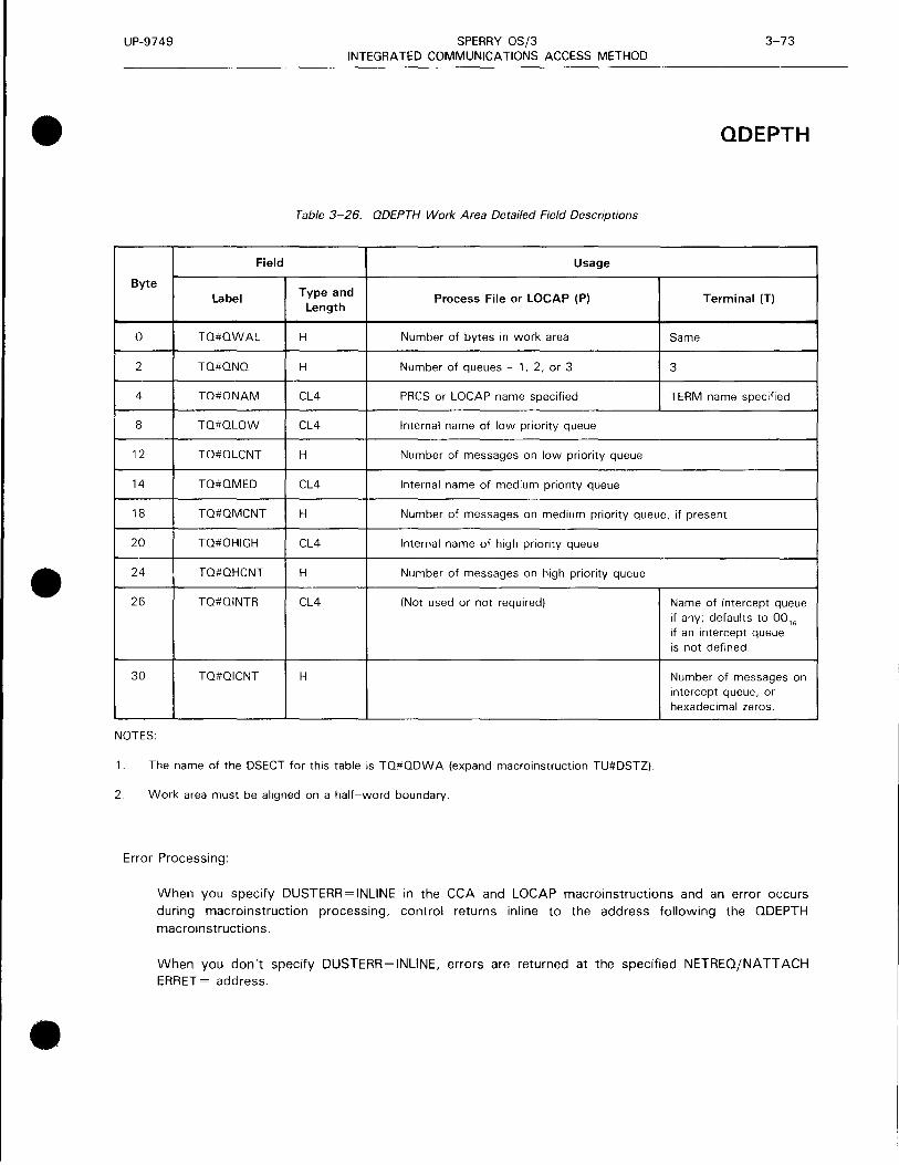
•
•
•
UP-9749 SPERRY OS/3 3-73 INTEGRATED COMMUNICATIONS ACCESS METHOD
QDEPTH
Table 3-26. QDEPTH Work Area Detailed Field Descriptions
Field Usage
Byte Type and Label Process File or LOCAP (P) Terminal (T)
Length
0 TQ#QWAL H Number of bytes in work area Same
2 TQ#QNQ H Number of queues - 1, 2, or 3 3
4 TQ#ONAM CL4 PRCS or LOCAP name specified TERM name specified
8 TO#OLOW CL4 Internal name of low priority queue
12 TO#OLCNT H Number of messages on low priority queue
14 TQ#QMED CL4 Internal name of medium priority queue
18 TO#OMCNT H Number of messages on medium priority queue, if present
20 TO#OHIGH CL4 Internal name of high priority queue
24 TQ#OHCNT H Number of messages on high priority queue
26 TQ#OINTR CL4 (Not used or not required) Name of intercept queue if any; defaults to 00 16
if an intercept queue is not defined.
30 TO#OICNT H Number of messages on intercept queue, or hexadecimal zeros.
NOTES:
1. The name of the DSECT for this table is TO#ODWA (expand macroinstruction TU#DSTZ).
2. Work area must be aligned on a half-word boundary.
Error Processing:
When you specify DUSTERR=INLINE in the CCA and LOCAP macroinstructions and an error occurs during macroinstruction processing, control returns inline to the address following the QDEPTH macroinstructions.
When you don't specify DUSTERR=INLINE, errors are returned at the specified NETREQ/NATTACH ERRET = address .

UP-9749 SPERRY OS/3 3-74 INTEGRATED COMMUNICATIONS ACCESS METHOD
QDEPTH • Register 1 contains th e address of the QDEPTH parameter table. Register 0 contains:
• zeros in bytes 0 , 1, and 3; and
• TQ = QERR error codes in byte 2.
Table 3-27 describes the error conditions detected during the execution of this macroinstruction.
Table 3-27. QDEPTH Error Conditions
Byte Error Cause/Condition Code
TO#OERR TQ#QTNF Terminal not found
TO#QNPF Process file not found
TQ#QTLG Data beyond table or program area
TO#OTNFW Parameter list not on full-word boundary
TQ#QNDTH Invalid work area length or no • work area in parameter list.
NOTE:
The DSECT fo r this table is TO#QDSCT, which is part of TU#DSTZ.
•

•
•
•
UP-9749 SPERRY OS/3 3-75 INTEGRATED COMMUNICATIONS ACCESS METHOD
QHOLD
Function:
Used with standard interface, it suspends transmission of output messages from a queue or group of queues. The suspension can apply to a single queue, the queues associated with a single terminal, or all the queues associated with a line. The suspension remains in effect until a QRELSE macroinstruction is issued by your program or if the system operator issues a UP command at the system console. The user program (or the MPPS) may continue to transfer messages to a suspended queue. This instruction is not applicable to DOI users. Table 3-28 describes the parameter list associated with this macroinstruction.
Format:
LABEL 60PERATION6 OPERAND
[symbol] QHOLD
Parameters:
L
T
( 1)
The hold function pertains to all the queues associated with all the terminals defined as part of the specified line (line name).
The hold function pertains to all the queues associated with a specific terminal (terminal name) or to a specific priority queue of the specific terminal.
The address of a QHOLD parameter list is contained in register 1 .
Line-name
The line associated with the queue or queues.
terminal-name The terminal with the queue or queues.
!HIGH} LOW MED
Names the queue to be suspended .

UP-9749 SPERRY OS/3 3-76 INTEGRATED COMMUNICATIONS ACCESS METHOD
QHOLD
Table 3-28. OHOLD Parameter List Detailed Field Descriptions
Field
Byte Type Content Comment Word Label* and
Length
0 TQ#QERR H Error flags Set by ICAM 1
2 TQ#QFLAG YL1 Type indicator Differentiates P, L, and T types
3 TQ#QFUNC YL1 Function indicator Indicates which macroinstruction was coded
4 TQ#QPLTN CL4 Process file, line, or terminal name 2
*DSECT is TQ#QDSCT, which is part of TU#DSTZ.
Error Processing:
When you specify DUSTERR=INLINE in the CCA and LOCAP macroinstruction and an error occurs during macroinstruction processing, control returns inline to the address following the QHOLD macroinstruction. When you don't specify DUSTERR=INLINE, errors are returned at the specified
NETREQ/NATT ACH ERRET = address.
Register 1 contains the address of the QHOLD parameter table. Register 0 contains:
• zeros in bytes 0, 1, and 3; and
• TQ#QERR error codes in byte 2.
Table 3-29 describes the error conditions detected during the execution of this macroinstruction.
Table 3-29. QHOLD Error Conditions
Byte Error Cause/Condition Code
TQ#QERR TQ#QLNF Line not found
TQ#QTNF Terminal not found
TQ#QTNFW Parameter list is not on full-word boundary.
NOTE:
The DSECT for this table is TQ#QDSCT, which is part of TU#DSTZ.
•
•
•

•
•
•
UP-9749 SPERRY OS/3 3-77 INTEGRATED COMMUNICATIONS ACCESS METHOD
QR ELSE
Function:
Used with standard interface, it allows transmission of output messages from a queue or group of queues. This instruction is not applicable to DOI users. Table 3-30 describes the parameter list associated with this macroinstruction.
Format:
LABEL 60PERATION6 OPERAND
[symbol] QR ELSE
Parameters:
L
T
( 1)
All queues associated with a specific line are to be released.
All the queues associated with a specific terminal or with a specific priority of the named terminal are to be released.
Register 1 contains the address of a parameter list identifying the queue or queues to be released.
line-name Specifies the line associated with the queue or queues.
terminal-name
Specifies the terminal associated with the queue or queues.
{HIGH} LOW MED
Only the specified priority queue is to be released .

UP-9749 SPERRY OS/3 3-78 INTEGRATED COMMUNICATIONS ACCESS METHOD
QR ELSE
Table 3-30. QRELSE Parameter List Detailed Field Descriptions
Field
Byte Type Content Comment Word Label* and
Length
0 TQ#QERR H Error flags Set by ICAM 1
2 TQ#QFLAG YL1 Type indicator Differentiates P, L, and T types
3 TQ#QFUNC YL1 Function indicator Indicates which macroinstruction was coded
4 TQ#QPTLN CL4 Process file. line, or terminal name 2
*DSECT TQ#QDSCT, which is part of TU#DSTZ.
Error Processing:
When you specify DUSTERR = INLINE in the CCA and LOCAP macroinstructions, and an error occurs during macroinstruction processing, control returns inline to the address following the QRELSE macroinstruction. When you don't specify DUSTERR=INLINE, errors are returned at the specified NETREQ/NA TT ACH ERRET = address.
Register 1 contains the address of the QRELSE parameter table. Register 0 contains:
• zeros in bytes 0, 1, and 3; and
• TQ#QERR error codes in byte 2.
Table 3-31 describes the error conditions detected during the execution of this macroinstruction.
Table 3-31. QRELSE Error Conditions
Byte
TQ#QERR
NOTE:
Error Code
TQ#QLNF
TQ#QTNF
Cause/Condition
Line not found
Terminal not found
The DSECT for this table is TQ#QDSCT, which is part of TU#DSTZ.
•
•
•

•
•
•
UP-9749 SPERRY OS/3 3-79 INTEGRATED COMMUNICATIONS ACCESS METHOD
QTRANS
Function:
Used with the standard interface, it transfers the messages from a queue of one process file, locap file, or terminal to another. If positional parameters 3 and 4 are omitted, each message of positional parameter 1 is queued to the destination specified in the message header. If positional parameter 3 is given, each message of positional parameter 1 is placed on the corresponding priority queue of positional parameter 3. This macroinstruction is not supported on disk queues. Table 3-32 shows the parameter list associated with this macroinstruction.
Format:
LABEL LOPERATIONL OPERAND
[symbol] QTRANS
IHLename, [{ill"ff ,f;Lename, I rmnJ) ( 1)
Parameters:
f i L ename 1
( 1)
Specifies the name of the process file, locap file, or terminal queue from which messages are to be transferred.
The address of a user-generated OTRANS parameter list is contained in register 1.
{ill"} Specifies the queue from which messages are transferred. Default is ALL.
f i L ename2
Specifies the name of the process file, terminal queue, DUST, or locap file to which messages are to be transferred.
lHIGH) LOW MED
Specifies the queue to which messages are to be transferred. Default causes messages to be queued to the corresponding priority queue from which it was transferred .

UP-9749 SPERRY OS/3 3-80 INTEGRATED COMMUNICATIONS ACCESS METHOD
QT RANS
Table 3-32. QTRANS* Parameter List Detailed Field Descriptions
Field
Byte Type Content Comment Word Label** and
Length
0 TQ#QERR H Error flags Set by ICAM
2 TQ#QFLAG YL1 Type indicator Differentiates P, L and T types
3 TQ#QFUNC YL1 Function indicator Indicates which macroinstruction 1 was coded
4 TQ#QPLTN CL4 Process file, line, or terminal name 2
8 TQ#QWALG YL 1 Work area length in bytes Used only by QDEPTH
9 TQ#QWORK A3 Work area address Used only by QDEPTH 3
• For QTRANS functions, TQ#QFN 1 and TQ#QFN2 are equivalents for TQ#QPL TN and TQ#QW ALG corresponding to the two file names.
** DSECT TQ#QDSCT, which is part of TU#DSTZ.
Error Processing:
When you specify DUSTERR=INLINE in the CCA and LOCAP macroinstructions, and an error occurs during macroinstruction processing, control returns inline to the address following the OTRANS macroinstruction.
When you don't specify DUSTERR=INLINE, errors are returned at the specified NETREO/NATTACH ERRET= address. Register 1 contains the address of the QTRANS parameter table. Register 0 contains:
• zeros in bytes 0, 1, and 3; and
• TQ#QERR error codes in byte 2.
Table 3-33 describes the error conditions detected during the execution of this macroinstruction.
Table 3-33. QTRANS Error Conditions
Byte Error Code Cause/Condition
TQ#QERR TQ#QLNF Line not found
TQ#QTNF Terminal not found
TQ#QNPF Process file not found
TQ#QIQT Invalid queue priority
NOTE:
The DSECT for this table is TQ#QDSCT, which is part of TU#DSTZ.
•
•
•

•
•
•
UP-9749 SPERRY OS/3 3-81 INTEGRATED COMMUNICATIONS ACCESS METHOD
RELEASM
Function:
Used with the standard interface, it resets the intercept queue hold bit in an intercept queue control table to release intercepted messages and permit transmissions to that terminal to resume. This instruction is used in conjunction with the INTERCPT macroinstruction. Figure 3-13 shows the organization of the parameter MPPS list associated with this macroinstruction. Table 3-34 details its contents.
Format:
LABEL 60PERATION6 OPERAND
[symbol].
Parameter:
terminal-name
RELEASM {terminal-name} ( 1)
Terminal for which the intercept queue is to be released .
( 1 )
Register 1 contains the address of the RELEASM parameter list.
BYTE 0 J 1 2
error half word unused
byte 0
4 terminal name
Figure 3-13. RELEASM Parameter List Functional Field Description
3 WORD
function indicator
2

UP-9749 SPERRY OS/3 3-82 INTEGRATED COMMUNICATIONS ACCESS METHOD
RELEASM
Table 3-34. RELEASM Parameter List Detailed Field Descriptions
Field
Byte Type Content Word Label and
Length
0 TQ#QERR H Error half word
2 XLl Not used 1
3 TQ#QFUNC XLl Function indicator
4 TQ#QPLTN CL4 Terminal name 2
Error Processing:
When you specify DUSTERR=INLINE in the CCA and LOCAP macroinstructions, and an error occurs during macroinstruction processing, control returns inline to the address following the RELEASM macroinstruction. When you don't specify DUSTERR= INLINE, errors are returned at the specified NETREO/NA TT ACH ERRET = address.
Register 1 contains the address of the RELEASM parameter table. Register 0 contains:
• zeros in bytes 0, 1, and 3; and
• TQ#QERR error codes in byte 2.
Table 3-35 describes the error conditions detected during the execution of this macroinstruction.
Table 3-35. RELEASM Error Conditions
Byte
TQ#OERR
NOTE:
Error Code
TQ#QTNF
Cause/Condition
Terminal not found
The DSECT for this table is TQ#QDSCT, which is part of TU#DSTZ.
•
•
•

•
•
•
UP-9749 SPERRY OS/3 3-83 INTEGRATED COMMUNICATIONS ACCESS METHOD
SESCON
Function:
Lets the user program open, close, accept, reject, abort, or confirm the closing of a dynamic session with another end user. An end user is a terminal, a process file, or another program.
In a public data network, this macroinstruction can be used to declare a dynamic session over a permanent virtual circuit.
This macroinstruction is used to create the SESCON executable code and related parameter list, or to create the executable code only or the parameter list only. Six different kinds of SESCON parameter lists can be created, depending on the type of function desired. The six parameter lists are shown in Figure 3-14. The figure shows:
• the contents of each field;
• the operand in the SESCON macroinstruction used to create the field;
• the label of each field from the DSECT; and
• whether ICAM or the user program normally controls the contents of the field .
Table 3-36 shows the formats of the parameter lists.
Table 3-37 shows the required and optional parameters the user program supplies.
Format:
LABEL t:o OPERATION t:o
[symbol] SES CON
Label:
symbol
OPERAND
FUNCT= OPEN
CLOSE
ABORT
OP NA CC
OPNREJ
CLSCNF ,MYID=four-char-id
,TONAME=end-user-name
[,INQNAME=input-destination-name]
[,PVC=name]
,HF= (tn[{rfo rnde}])
(E'{~~;ameter list-label})
L
Is a 1- to 8-character label that identifies the executable code, parameter list generated by this macroinstruction, or its DSECT when the MF=(D) operand is specified.

UP-9749 SPERRY OS/3 3-84 INTEGRATED COMMUNICATIONS ACCESS METHOD
SES CON
Operands:
FUNCT= Specifies the function this macroinstruction performs.
This operand is required except when MF={D) is specified.
FUNCT=OPEN This is a request to establish a session.
FUNCT=CLOSE This is a request to close a session in progress in an orderly manner.
FUNCT=ABORT This is a request to abort a session because your program detected an error.
FUNCT=OPNACC This is a request to accept a session initiated by another end user.
FUNCT=OPNREJ This is a request to reject a session initiated by another end user.
FUNCT=CLSCNF This is a request to confirm the closing of a session initiated by another end user.
MYID=four-char-id MYID is a 4-character identifier the user program assigns to a dynamic session. ICAM places this identifier in all datagrams it delivers to the user program that relate to a particular session. The user program supplies MYID when it issues a TYPE=OPEN or TYPE=OPNACC SESCON
macroinstruction.
TONAME=end-user-name Specifies the name of the end user as stated during network definition. This parameter is required for FUNCT=OPEN only.
INQNAME=input-destination-name Destination queue for input messages coming from a terminal included in the session being opened or accepted.
Messages coming from a terminal are normally placed on a queue defined by the INPUT operand of that terminal's TERM macroinstruction. However, messages for this session can be placed on a different queue, such as the low priority queue of a process file, locap file, or terminal output queue. If the input traffic is to go to the destination specified in the TERM macroinstruction, default this operand.
PVC=name An optional parameter for public data networks indicating that the dynamic session is through a permanent virtual circuit. The name is the symbolic name of a PVC macroinstruction in the network definition that defines a permanent virtual circuit connecting two end users.
•
•
•

•
•
•
UP-9749 SPERRY OS/3 3-85 INTEGRATED COMMUNICATIONS ACCESS METHOD
SES CON
MF= Identifies a parameter list whose address may be explicitly specified or implicitly passed to the called routine through register 1. Refer to S-type macroinstructions described in Appendix A.
Figure 3-14 shows that SESCON parameter list formats vary according to type.
OPEN
TQL TH (length) I TQTYP {function code)
(to) S 1 Cl (called end user name)
S 1 SSU {user session ID)
S 1 IPQ {input queue name)
Reserved - must be zero
S 1 PVC {permanent virtual circuit)
CLOSE
TQL TH {length) I TQTYP {function code)
S2SSI {ICAM session id)
ABORT
TOL TH {length) I TQTYP {function code)
S3SSI (ICAM session ID)
OPNACC
TOL TH {length) T TOTYP {function code)
S4SSI {ICAM session ID)
S4SSU {user session ID)
S41PQ {input queue name)
OPNREJ
TOL TH (length) I TQTYP {function code)
SSSSI {ICAM session ID)
CLSCNF
TQL TH (length) I TOTYP (function code)
S6SSI {ICAM session ID)
NOTE:
TONAME
MYID
INONAME
PVC
TQTY1 {TOPEN)
TQTY2 {TCLOS)
TQTY3 {TABRT)
TOTY4 ~------------ {TOPAC)
MYID
I NON AME
TOTY5 {TOPRJ)
TQTY6 (TCLCF)
Each session control parameter list label is prefixed by the 1- to 3-character label you specify in your SESCON DSECT call. ICAM's session id is given to you in an open or open accept datagram. You must then place it in all subsequent SESCON parameter lists before issuing the actual macroinstruction service request {call).
Figure 3- 14. SESCON Parameter List Formats

UP-9749 SPERRY OS/3 3-86 INTEGRATED COMMUNICATIONS ACCESS METHOD
SES CON • Table 3-36. SESCON Parameter List Detailed Field Descriptions (Pan 1 of 2)
Byte Label Type and
Content Word Length
0 TOLTH H Length of packet 1
2 RTN x Return function
2 TOTYP H Function code
3 (FUNC) (X) Function code
TQTY1 (TOPEN) Open request
TOTY2 (TCLOS) Close request
TQTY3 (TABRT) Abort request
TOTY4 (TOPAC) Open accept
TQTY5 (TOPRJ) Open reiect
TOTY6 (TCLCF) Close confirm
TQTYA DMI raise credit limit • TOTYB DMI lower credit limit
TOTYC Resiliency-port abort
TQTYD Queuer-send AV
For Open Request SESCON
4 S1CI F To name-called end user 2
8 S1SSU F User"s session ID 3
12 S11PO F Input queue name 4
16 S1PPR H Reserved 5
18 S1DEV H
20 S1PVC F PVC for public data networks 6
For Close Request SESCON
4 S2SSI F ICAM's session ID 2
For Abort SESCON
4 S3SSI F ICAM's session ID 2
8 S3RCD H Reason code 3 • 10 H Unused

•
•
•
UP-9749 SPERRY OS/3 3-87 INTEGRATED COMMUNICATIONS ACCESS METHOD
SES CON
Table 3-36. SESCON Parameter List Detailed Field Descriptions (Part 2 of 2)
Byte Label Type and
Content Word Length
For Open Accept SESCON
4 S4SSI F ICAM's session ID 2
8 S4SSU F User's session ID 3
12 S41PO F Input queue name 4
For Open Reject SESCON
4 S5SSI F ICAM"s session ID 2
8 S5RCD H Reason code 3
H Unused
For Close Confirm SESCON
4 S6SSI F ICAM's session ID 2
NOTES:
1 . Each session control parameter list label is prefixed by the 1- to 3-character label you specify in your SESCON DSECT call.
2. ICAM session ID is a 4-character session identifier established by ICAM. It identifies a particular dynamic session. Your program receives the session identifier in a control datagram, and it must save it (unchanged) and use it in any subsequent SESCON call that relates to that session - that is, when your program accepts, rejects, aborts, closes, or confirms a closed session. Your program moves the session identifier to the appropriate field in a SESCON parameter list prior to issuing the SESCON call. If your program initiates a session, the session identifier is delivered to your program with the open accept datagram. If your program is the one called, the session identifier is delivered in the open datagram. Figure 3-14 shows the organization of the different SESCON parameter lists and the labels used for the session identifier field in each .
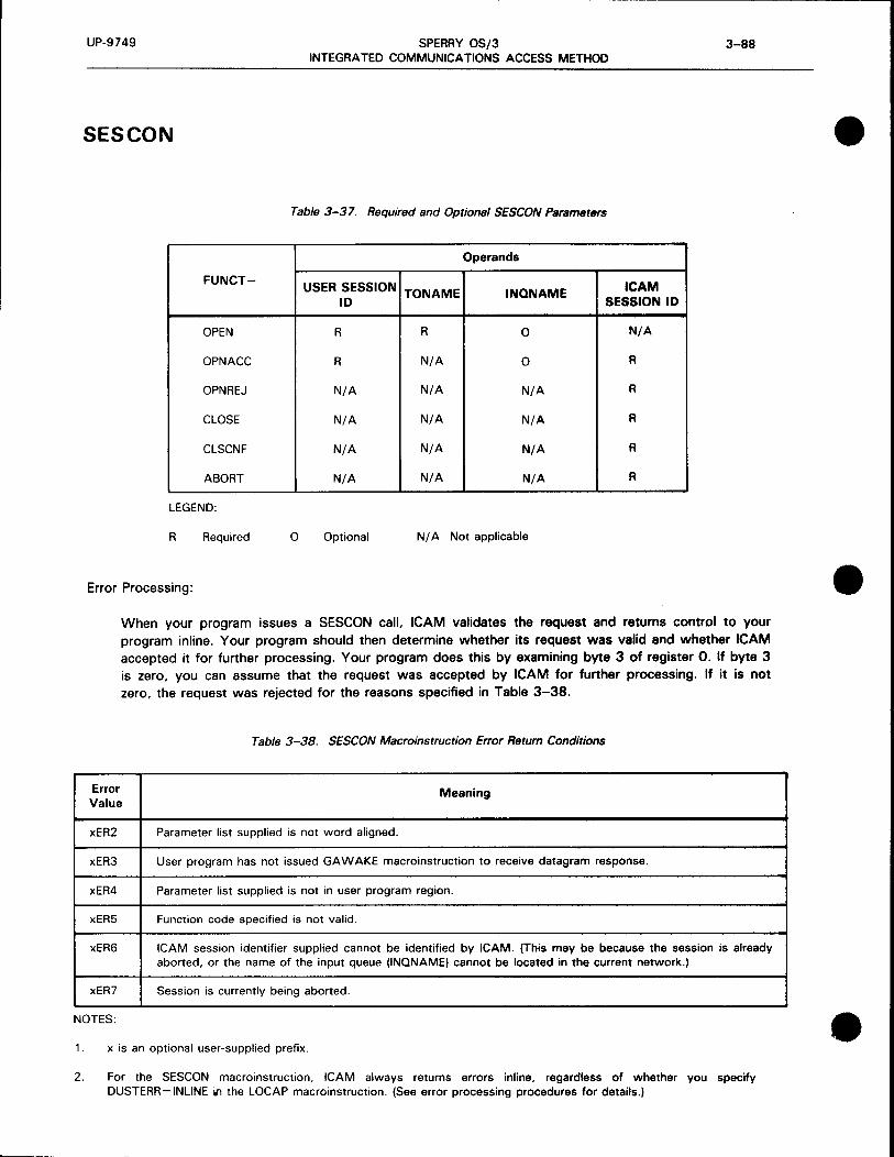
UP-9749 SPERRY OS/3 3-88 INTEGRATED COMMUNICATIONS ACCESS METHOD
SES CON
Table 3-37. Required and Optional SESCON Parameters
Operands
FUNCT= USER SESSION ICAM
ID TONAME INQNAME
SESSION ID
OPEN R R 0 N/A
OPNACC R N/A 0 R
OPNREJ N/A N/A N/A R
CLOSE N/A N/A N/A R
CLSCNF N/A N/A N/A R
ABORT N/A N/A N/A R
LEGEND:
R Required 0 Optional N/ A Not applicable
Error Processing:
When your program issues a SESCON call, ICAM validates the request and returns control to your program inline. Your program should then determine whether its request was valid and whether ICAM accepted it for further processing. Your program does this by examining byte 3 of register 0. If byte 3 is zero, you can assume that the request was accepted by ICAM for further processing. If it is not zero, the request was rejected for the reasons specified in Table 3-38.
Table 3-38. SESCON Macroinstruction Error Return Conditions
Error Value
Meaning
xER2
xER3
xER4
xER5
xER6
xER7
NOTES:
Parameter list supplied is not word aligned.
User program has not issued GA WAKE macroinstruction to receive datagram response.
Parameter list supplied is not in user program region.
Function code specified is not valid.
ICAM session identifier supplied cannot be identified by ICAM. (This may be because the session is already aborted, or the name of the input queue (INQNAME) cannot be located in the current network.)
Session is currently being aborted.
1. x is an optional user-supplied prefix.
2. For the SESCON macroinstruction, ICAM always returns errors inline, regardless of whether you specify DUSTERR=INLINE il1 the LOCAP macroinstruction. (See error processing procedures for details.)
•
•
•

•
•
•
UP-9749 SPERRY OS/3 3-89 INTEGRATED COMMUNICATIONS ACCESS METHOD
SES CON
Programming Notes:
1. If the parameter list option MF= L is used and a macroinstruction is not used to specify the following fields, the fields must be properly set in the parameter list before the user program issues the SESCON call. (If the MF=L option is not used, the fields are properly set by the macroinstruction.) P notes may be generated to indicate that certain fields are required. The following describes the type of SESCON function, the related field to be defaulted, the parameter list field name, and the required
value.
SESCON SESCON Parameter Value
Function Operand List Field Required
OPEN IN ON AME xS1 IPO X' 4040404040' (4 spaces)
OPNAC INONAME xS41PO X'4040404040' (4 spaces)
where:
x Is a 1-character user-supplied optional prefix .

UP-9749 SPERRY OS/3 3-90 INTEGRATED COMMUNICATIONS ACCESS METHOD
TRMREL
Function:
Disconnects a terminal from a circuit-switched DA TEX-L public data network. You can use this instead of specifying the DISIN/DISOUT operands of the TERM macroinstruction in your network definition.
Format:
LABEL 60PERATION6 Operand
[symbol] TR MR EL terminal-name
[MF={L 1n
(• {~~;••eter-l;st-address})~
Label:
symbol A 1- to 4-character label identifying this macroinstruction.
Positional Parameter 1 :
terminal-name
MF=
The network definition symbolic name of the terminal (TERM) to be disconnected.
Identifies a parameter list whose address may be explicitly specified or implicitly passed to the called routine through register 1 . See S-type macroinstructions described in the ICAM concepts and facilities, UP-9744 (current version).
If this parameter is omitted, both a parameter list required by the called ICAM routine and the linkage to it are generated.
Error Processing:
ICAM returns control inline to the address following the TRMREL macroinstruction. After macroinstruction processing, register 1 contains the address of the TRMREL parameter table. Register 0 contains one of the following codes:
0 = circuit disconnected sucessfully 4 = invalid terminal name 8 = register 1 contents invalid (address of user parameter list)
NOTE:
For the TRMREL macroinstruction, /CAM always returns errors inline, regardless of whether you specify DUSTERR=INLINE in your program's CCA and LOCAP macroinstructions.
•
•
•

•
•
•
UP-9749 SPERRY OS/3 3-91 INTEGRATED COMMUNICATIONS ACCESS METHOD
TRMREP
Function:
Used with the standard and DDI interfaces, it changes the phone number in the line control table.
Format:
LABEL t:c.OPERATIONt:c. OPERAND
[symbol] TRMREP line-name,terminal-name,workarea-address
,FIELDS=CCALL)
Parameters:
line-name Line to which the subject terminal is connected.
terminal-name The subject terminal.
workarea-address The address of the work area in your program that contains a new phone number that replaces the number in the line control table.
FIELDS=( CALL>
NOTES:
The phone number in the line control table phone directory is to be replaced with the number in the field of the work area starting at work area + 29, the first digit is the number of digits in the phone number. Number of digits must not exceed 48. A hyphen causes a delay ( 1 . 1 sec) when autodialing.
1. The TRMREP macro must be issued after network activation, but to an inactive line, that is, at any time before issuing a LNEREQ macro to an inactive line or after issuing an LNEREL macro to an active line.
2. The phone number information in the work area stans at byte 29. (See Figure 3-15.) The first byte of this information contains the total count, in binary, of the number of dialing digits in the phone number. The phone number then follows in decimal characters .

UP-9749
TRMREP
BYTE 0
Error Processing:
SPERRY OS/3 3-92 INTEGRATED COMMUNICATIONS ACCESS METHOD
Not Used
Figure 3-15. TRMREP Work Area Field Description
One byte containing length, in binary, of the following phone number.
Phone Number 1 - 48 Bytes
When you specify DUSTERR=INLINE in the CCA and LOCAP macroinstructions and an error occurs during macroinstruction processing, control returns inline to the address following the TRMREP macroinstruction. When you don't specify DUSTERR=INLINE, errors are returned at the specified NETREQ/NATTACH ERRET= address.
Register 1 contains the address of the TRMREP parameter table. Register 0 contains:
• zeros in bytes 0, 1, and 3; and
• TQ#QERR error codes in byte 2.
Table 3-39 describes the error conditions detected during the execution of this macroinstruction.
Byte
TQ#QERR
NOTE:
Table 3-39. TRMREP Error Codes
Error Code
TQ#QLNF
TQ#QTNF
TQ#QTLG
TQ#QNDTH
Cause/Condition
Line not found
Terminal not found
Data beyond table or program area
Phone number too long
The DSECT for this table is TQ#QDSCT, which is part of TU#DSTZ.
•
•
•

•
•
•
4. Message Processing Procedure Specification (MPPS)

•
•
•

•
•
•
UP-9749 SPERRY OS/3 4-1 INTEGRATED COMMUNICATIONS ACCESS METHOD
The message processing procedure specification (MPPS) macros are an extension of the communications control area (CCA). They are available to users of the standard interface and resident transaction control interface. These macros (Table 4-1) control the processing and destination of every message transmitted or received by the communications network in this interface. In addition, the MPPS macroinstruction set includes the MPST ART macroinstruction, which is used to denote the beginning of the MPPS specification and must be coded first.
Table 4-1. MPPS Delimiter and Functional Macroinstructions (Part 1 of 2)
Receive Group Macroinstructions Send Group Macroinstructions
Subgroup Delimiter Functional Subgroup Delimiter Functional
Receive segment RECSEG JOURN0 Send SENSEG JOURN0 segment
Receive header RECHDRCD ADVANCE Send SENHDRCD ADVANCE header
BRANCH BRANCH
DATSTP DATSTP
DIRECT@ JOURN0
IFSOURCE MSGTYP
JOURN0 SEOOUT
MSGLMT TIMSTP
MSGTYP
ROUTE@
SEQIN
SOURCE
TIMSTP
Receive end RECENDCD CANCELM Send SENEND0 ERR MSG end
ERR MSG© INTERCPT
JOURN0 JOURN0
REROUT1 REROUTO
RETRANS
Receive post RECPSTCD Send SENPSTCD post
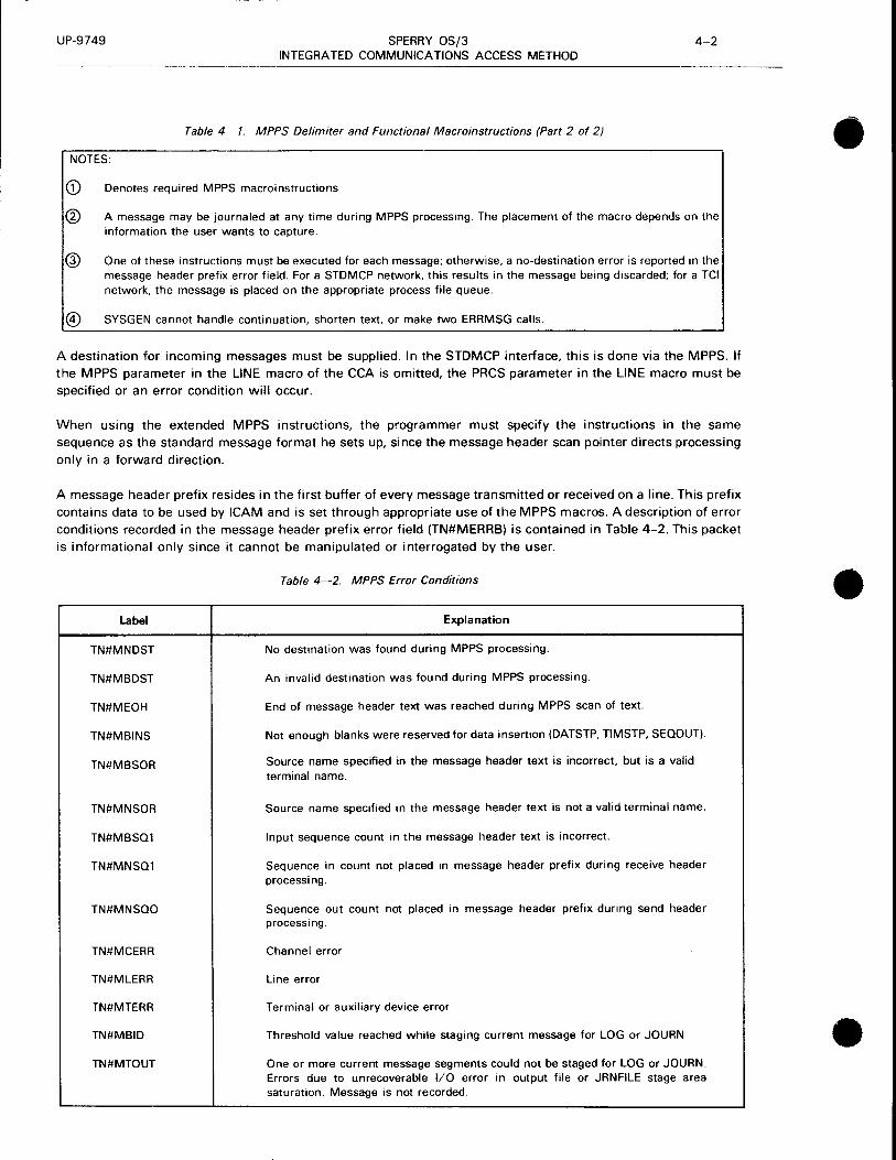
UP-9749 SPERRY OS/3 4-2 INTEGRATED COMMUNICATIONS ACCESS METHOD
Table 4-1. MPPS Delimiter and Functional Macroinstructions (Part 2 of 2)
NOTES:
G) Denotes required MPPS macroinstructions
@ A message may be journaled at any time during MPPS processing. The placement of the macro depends on the information the user wants to capture.
@ One of these instructions must be executed for each message; otherwise, a no-destination error is reported in the message header prefix error field. For a STDMCP network, this results in the message being discarded; for a TCI network, the message is placed on the appropriate process file queue.
® SYSGEN cannot handle continuation, shorten text, or make two ERRMSG calls.
A destination for incoming messages must be supplied. In the STDMCP interface, this is done via the MPPS. If
the MPPS parameter in the LINE macro of the CCA is omitted, the PRCS parameter in the LINE macro must be
specified or an error condition will occur.
When using the extended MPPS instructions, the programmer must specify the instructions in the same
sequence as the standard message format he sets up, since the message header scan pointer directs processing
only in a forward direction.
A message header prefix resides in the first buffer of every message transmitted or received on a line. This prefix
contains data to be used by ICAM and is set through appropriate use of the MPPS macros. A description of error
conditions recorded in the message header prefix error field (TN#MERRB) is contained in Table 4-2. This packet
is informational only since it cannot be manipulated or interrogated by the user.
Label
TN#MNDST
TN#MBDST
TN#MEOH
TN#MBINS
TN#MBSOR
TN#MNSOR
TN#MBSQ1
TN#MNSQ1
TN#MNSQO
TN#MCERR
TN#MLERR
TN#MTERR
TN#MBID
TN#MTOUT
Table 4-2. MPPS Error Conditions
Explanation
No destination was found during MPPS processing.
An invalid destination was found during MPPS processing.
End of message header text was reached during MPPS scan of text.
Not enough blanks were reserved for data insertion (DATSTP, TIMSTP, SEQOUT).
Source name specified in the message header text is incorrect, but is a valid terminal name.
Source name specified in the message header text is not a valid terminal name.
Input sequence count in the message header text is incorrect.
Sequence in count not placed in message header prefix during receive header processing.
Sequence out count not placed in message header prefix during send header processing.
Channel error
Line error
Terminal or auxiliary device error
Threshold value reached while staging current message for LOG or JOURN
One or more current message segments could not be staged for LOG or JOURN. Errors due to unrecoverable 1/0 error in output file or JRNFILE stage area saturation. Message is not recorded.
•
•
•

•
•
•
UP-9749 SPERRY OS/3 4-3 INTEGRATED COMMUNICATIONS ACCESS METHOD
ADVANCE
Function:
Advances the message header scan pointer over message header text fields that are not to be processed by the MPPS. If the end of header is reached during execution of an ADVANCE instruction, the end-of-header flag is set in the message header prefix error field and processing control is transferred to the RECEND or SENEND macroinstruction, as applicable. Messages should be in uppercase EBCDIC for proper comparison.
Format:
LABEL L.OPERATIONL. OPERAND
[symbol] ADVANCE integer[,character-string]
Parameters:
integer Is a decimal number specifying the number of nonblank character positions to advance the message header scan pointer if positional parameter 2 is omitted, or a decimal number from 1 to 8 specifying the number of characters contained in positional parameter 2 .
character-string From one to eight alphanumeric characters identifying the character string the message header scan pointer is to look for when advancing. The scan pointer stops, pointing to the last character referenced by this parameter, after it has advanced past all previously identified characters in the character string, uninterrupted by any nonreferenced characters, excluding blanks.
NOTE:
This parameter must be expressed in alphanumeric format and may not reference any blank characters .

UP-9749 SPERRY OS/3 4-4 INTEGRATED COMMUNICATIONS ACCESS METHOD
BRANCH
Function:
Transfers processing control unconditionally to another portion of the MPPS to allow the program to bypass processing not required for a particular message type. This macroinstruction can appear only in a RECHDR/SENHDR subgroup.
Format:
LABEL 6.0PERATION6. OPERAND
[symbol] BRANCH symbolic-branch-address
Parameter:
symbolic-branch-address
Specifies the symbolic address of the macroinstruction to which control is transferred.
•
•
•

•
•
•
UP-9749 SPERRY OS/3 4-5 INTEGRATED COMMUNICATIONS ACCESS METHOD
CANCELM
Function:
As an input error procedure, eliminates all reference to an input message where a specified error occurred, by preventing its inclusion in an input queue. This macroinstruction can appear only in a RECEND subgroup.
Format:
LABEL LOPERATIONL OPERAND
[symbol] CANCELM mask
Parameter:
mask Is a logical expression specifying the bits in the error field of the message header prefix to be tested. (Refer to Table 4-2.) If any of the specified error bits are set, the message is, essentially, thrown away .

UP-9749 SPERRY OS/3 4-6 INTEGRATED COMMUNICATIONS ACCESS METHOD
DATSTP
Function:
Inserts the current date in the message header segment of an incoming or outgoing message. Either a calendar or ordinal date may be selected. This instruction may appear in the receive-header or send-header subgroups. If there is not enough room in the message header segment to insert the current date in the form specified (MPPS keyword description in Section 3). the bad insertion flag is set in the error field of the message header prefix and processing continues with the next macroinstruction in the MPPS.
If it is determined by the DA TSTP macro code that there is enough room in the message header to insert the date, all the previously scanned message header data is shifted left the appropriate number of characters and the date is inserted. At the conclusion of this operation, the scan pointer, which never moves during the execution of an insert data instruction (DATSTP, TIMSTP, and SEQOUT), points to the last character in the date stamp because of the shift-left operation.
The macroinstruction can appear only in a RECHDR/SENHDR subgroup.
Format:
LABEL 60PERATION6 OPERAND
[symbol] DATSTP
Parameters:
J
Indicates that the date is to be inserted in ordinal form: 6 yy ddd .
••• Indicates that the date is to be inserted in calendar form: .6.xx/xx/xx.
•
•
•

•
•
•
UP-9749 SPERRY OS/3 4-7 INTEGRATED COMMUNICATIONS ACCESS METHOD
DIRECT
Function:
Directs an incoming message to the destination specified in the operand field. (Compare with ROUTE macroinstruction.) If an invalid destination is specified in this instruction, the bad destination flag is set in the error field of the message header prefix and processing with the macroinstruction next in line. This macroinstruction can appear only in a RECHDR subgroup.
Format:
LABEL 60PERATION6
[symbol] DIRECT
Parameters:
AL TD
OPERAND
ALTO, D,distribution-list-name
P,{process-filename} locap-filename
SOURCE, T,terminal-name
[{'~"}~ [, FSEL] Ill: M
Indicates that the alternate destination of the source terminal contains the destination code for this message.
D
Indicates that positional parameter 2 is the name of a distribution list.
distribution-list-name
Specifies the name of a distribution list defined in the CCA.
p
Indicates that positional parameter 2 is the name of a process file or locap file.
process-filename
Specifies the name of a communications user program (CUP) file defined in the CCA.
locap-filename Specifies the name of a locap file.
SOURCE Indicates that the message is routed back to its originator.

UP-9749 SPERRY OS/3 4-8 INTEGRATED COMMUNICATIONS ACCESS METHOD
DIRECT
T Indicates that positional parameter 2 is the name of a terminal.
terminal-name
FSEL
Specifies the name of the terminal entries defined in the communications control area (CCA).
Indicates the high, low, or medium priority queue, respectively, of the identified destination.
Indicates that the terminal specified by positional parameter 2 is the name of a OCT 500 terminal with fast-select list to which the message should be directed.
If omitted, the specified destination is assumed to be not a fast-select device.
NOTE:
Every time an MPPS DIRECT macro is executed, the destination name and corresponding queue address are updated; therefore, the message will be sent only to the destination specified by the last input destination macro. In order to have the message sent to more than one destination, a DUST could be specified on the DIRECT or REROUTI macro call or more than one destination name (including a DUST) could be specified in the message text referenced during the execution of a ROUTE macro.
•
•
•

•
•
•
UP-9749 SPERRY OS/3 4-9 INTEGRATED COMMUNICATIONS ACCESS METHOD
ERR MSG
Function:
If a specified error occurs, this macroinstruction causes an error message to be sent to a designated output terminal.
This macroinstruction can appear only in a RECEND/SENEND subgroup.
Format:
LABEL 60PERATION6 OPERAND
[symbol] ERRMSG mask,{terminal-name },'error-text' SOURCE process-filename
. locap-filename
Parameters:
mask Is a logical expression specifying the bits in the error field of the message header prefix to be tested. (Refer to Table 4-2.) If any of the specified bits are set, the error message comprising positional parameter 3 is output to the device identified by positional parameter 2.
terminal-name Identifies the output terminal to which the error message in positional parameter 3 is output.
SOURCE Specifies that error messages are to be returned to the source terminal that caused the error condition.
process-filename Identifies the process file to which the error message in positional parameter 3 is output.
locap-filename Identifies the locap file to which the error message in positional parameter 3 is output.
'error-text' Specifies the text of the error message to be output to the terminal specified in positional parameter 2. The text must be enclosed in apostrophes .

UP-9749 SPERRY OS/3 4-10 INTEGRATED COMMUNICATIONS ACCESS METHOD
IFSOURCE
Function:
As an input procedure, allows processing of an incoming message if the source terminal name in the message header prefix matches a specific terminal name.
This macroinstruction can appear only in a RECHDR subgroup.
Format:
LABEL LOPERATIONL OPERAND
[symbol] IFSOURCE terminal-name,symbolic-address
Parameters:
terminal-name Identifies a specific terminal name to be compared with the source terminal name in the message header prefix. If a match is detected, control passes to the symbolic address specified in positional parameter 2; otherwise, processing continues with the next inline functional instruction.
symbolic-address The symbolic address of another functional macroinstruction to which control is transferred if a match is detected between positional parameter 1 and the source terminal name.
•
•
•
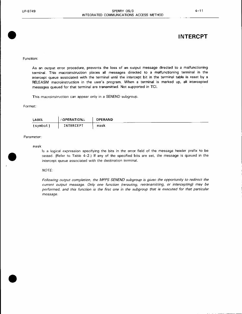
•
•
•
UP-9749 SPERRY OS/3 4-11 INTEGRATED COMMUNICATIONS ACCESS METHOD
INTERCPT
Function:
As an output error procedure, prevents the loss of an output message directed to a malfunctioning terminal. This macroinstruction places all messages directed to a malfunctioning terminal in the intercept queue associated with the terminal until the intercept bit in the terminal table is reset by a RELEASM macroinstruction in the user's program. When a terminal is marked up, all intercepted
messages queued for that terminal are transmitted. Not supported in TCI.
This macroinstruction can appear only in a SENEND subgroup.
Format:
LABEL L:o.OPERATIONL:o. OPERAND
[symbol] INTERCEPT mask
Parameter:
mask Is a logical expression specifying the bits in the error field of the message header prefix to be tested. (Refer to Table 4-2.) If any of the specified bits are set. the message is queued in the
intercept queue associated with the destination terminal.
NOTE:
Following output completion, the MPPS SENEND subgroup is given the opportunity to redirect the current output message. Only one function (rerouting, retransmitting, or intercepting) may be performed, and this function is the first one in the subgroup that is executed for that particular
message .
- - --- --------------------------

UP-9749 SPERRY OS/3 4-12 INTEGRATED COMMUNICATIONS ACCESS METHOD
JOU RN
Function:
This macroinstruction is used to place a message header prefix and message text or just the message header prefix into the specified journal file. If the JOURN macroinstruction is placed after a RECSEG or SENSEG macroinstruction, every input or output message segment is placed in the journal file. If the JOURN follows a RECHDR, every input header segment is placed in the journal file. If it follows a SENHDR or SENEND, every output header segment before transmission or after transmission, respectively, is placed in the file. If a JOURN macroinstruction follows a RECEND, only the final input segment of each message is journaled.
Format:
LABEL 60PERATION6 OPERAND
[symbol] JOURN filename
Parameter:
filename Identifies the file to which the journal entries are to be written. This name must correspond to the label field of the JRNFILE macro in the CCA.
•
•
•
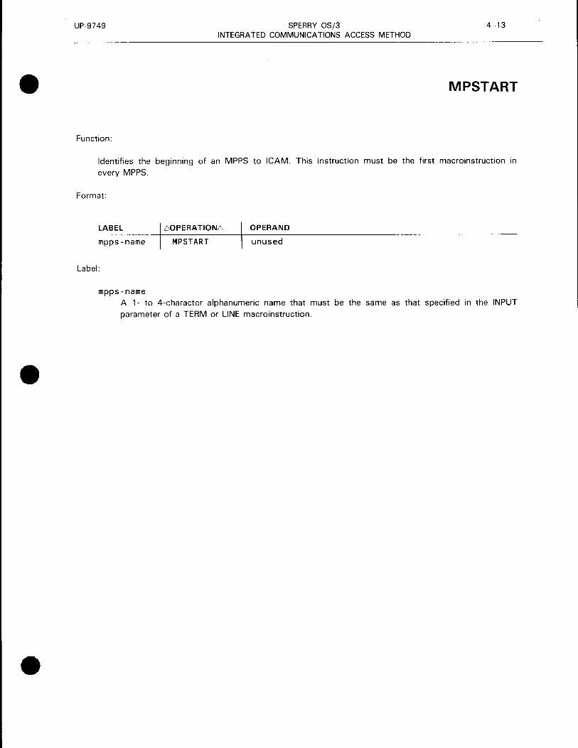
•
•
•
UP-9749 SPERRY OS/3 4-13 INTEGRATED COMMUNICATIONS ACCESS METHOD
MPSTART
Function:
Identifies the beginning of an MPPS to ICAM. This instruction must be the first macroinstruction in
every MPPS.
Format:
LABEL 60PERATION6 OPERAND
mpps-name MP START unused
Label:
mpps-name A 1- to 4-character alphanumeric name that must be the same as that specified in the INPUT parameter of a TERM or LINE macroinstruction .

UP-9749 SPERRY OS/3 4-14 INTEGRATED COMMUNICATIONS ACCESS METHOD
MSGLMT
Function:
Limits the number of messages that can be transmitted by a terminal during a single polling pass. This instruction is for optional use for user-written handlers with polled lines and may appear in the receive-header or receive-end subgroup; however, it may be executed only once per message.
Format:
LABEL LOPERATIONL OPERAND
[symbol] MSGLMT [{i;•essage- limit}]
Parameter:
message-limit
Is a decimal integer specifying the maximum number of messages to be accepted from a terminal during one polling pass. When the maximum number of messages is transmitted by a terminal, the polling mechanism advances to the next terminal in the polling sequence. This message limit applies to all the terminals connected to lines controlled by the MPPS in which it appears.
If omitted, only one message is accepted.
•
•
•

•
•
•
UP-9749 SPERRY OS/3 4-15 INTEGRATED COMMUNICATIONS ACCESS METHOD
MSGTYP
Function:
Separates incoming or outgoing messages into two or more types to allow for different processing of each type. Use of this instruction is optional, and it may appear in both the receive-header and send-header subgroups. Messages should be in uppercase EBCDIC for proper comparison.
Format:
LABEL L.OPERATIONL. OPERAND
[symbol] MSGTYP [integer,character-string,symbolic-address]
Parameters:
integer
Specifies a decimal number, from 1 to 8, that indicates the number of characters in positional parameter 2.
If omitted, processing continues with the next inline functional instruction.
character-string
Specifies a string of up to eight alphanumeric characters, including special symbols, that identifies a particular message type. This character string is compared with the message type field in the message header currently being processed. If a match is detected, the scan pointer is updated and processing continues with the macroinstructions immediately following this instruction. If no match is detected, the scan pointer is not moved, and processing control is transferred to the symbolic address identified by positional parameter 3. If end of header is reached while scanning for message type, the end-of-header flag is set in the error field of the message header prefix and processing control is transferred to the RECEND or SENEND macroinstruction, as applicable.
If omitted, processing continues with the next inline instruction.
symbolic-address
Specifies the symbolic address of another functional or delimiter macroinstruction to which control is transferred if no match is detected between the characters composing positional parameter 2 and the message type field in the message header.
If omitted, processing continues with the next inline instruction .
..
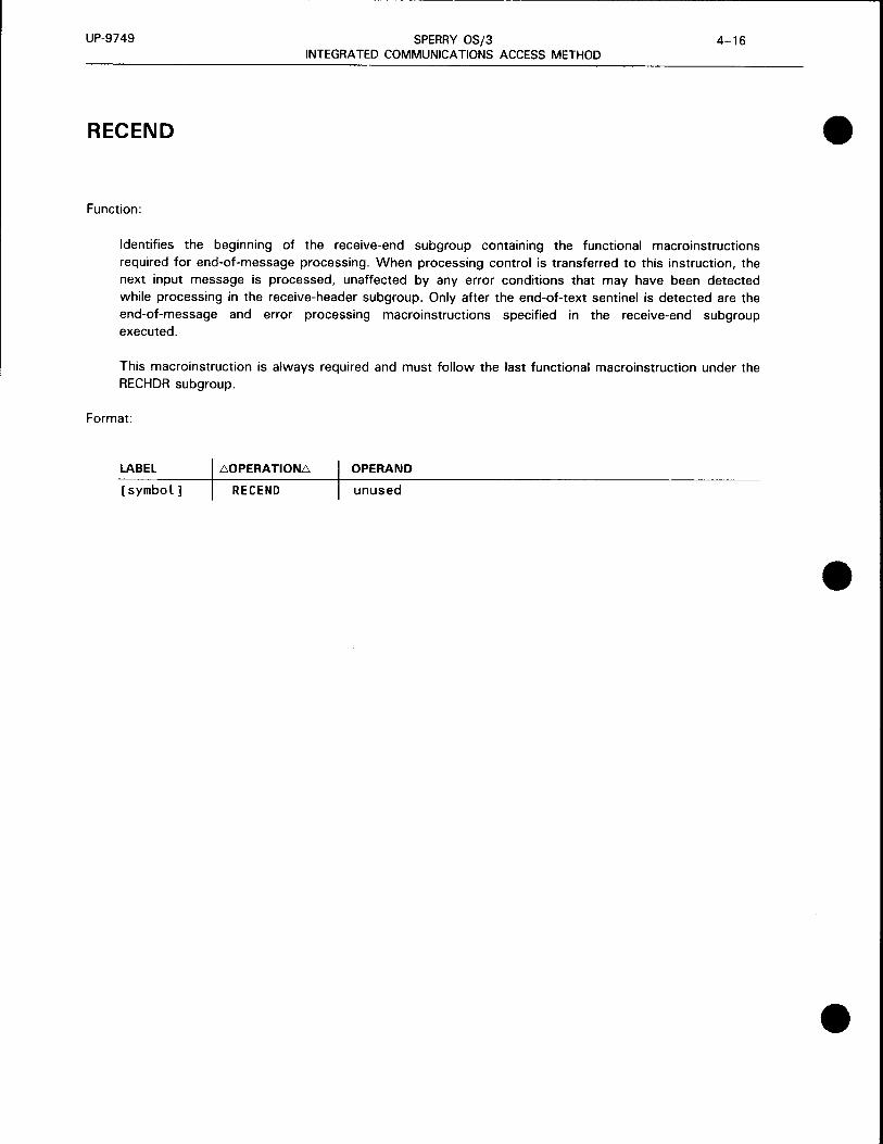
UP-9749 SPERRY OS/3 4-16 INTEGRATED COMMUNICATIONS ACCESS METHOD
RECEND
Function:
Identifies the beginning of the receive-end subgroup containing the functional macroinstructions required for end-of-message processing. When processing control is transferred to this instruction, the next input message is processed, unaffected by any error conditions that may have been detected while processing in the receive-header subgroup. Only after the end-of-text sentinel is detected are the end-of-message and error processing macroinstructions specified in the receive-end subgroup executed.
This macroinstruction is always required and must follow the last functional macroinstruction under the RECHDR subgroup.
Format:
LABEL 60PERATION6 OPERAND
[symbol] REC END unused
•
•
•

•
•
•
UP-9749 SPERRY OS/3 4-17 INTEGRATED COMMUNICATIONS ACCESS METHOD
RECH DR
Function:
Identifies the beginning of the receive-header subgroup containing the functional macroinstruction related to processing a message header for incoming messages. If it is determined that the segment being processed is a header segment, the functional macroinstructions included in the receive-header subgroup are executed. Also, the message header scan pointer is set at this time. If the segment contains text only, the receive-header coding is bypassed. This instruction must immediately follow the RECSEG subgroup (if present) or MPST ART macroinstruction.
Format:
LABEL 60PERATION6 OPERAND
[symbol] RECHDR unused

UP-9749 SPERRY OS/3 4-18 INTEGRATED COMMUNICATIONS ACCESS METHOD
REC PST
Function:
Required to signify the end of all instructions in the receive-segment, receive-header, and receive-end subgroups. The instruction must be the last instruction in the receive group. If a valid destination has not been received for a given message, the message will be cancelled.
Format:
LABEL 60PERATION6 OPERAND
[symbol] RECPST unused
•
•
•

•
•
•
UP-9749 SPERRY OS/3 4-19 INTEGRATED COMMUNICATIONS ACCESS METHOD
RECSEG
Function:
Identifies the beginning of the receive-segment subgroup, which is concerned with processing header and text segments of incoming messages. This instruction is not needed if processing on text segments by the MCP is not required.
Format:
LABEL iiOPERATION.".i OPERAND
[symbol] RECSEG unused

UP-9749 SPERRY OS/3 4-20 INTEGRATED COMMUNICATIONS ACCESS METHOD
REROUTI
Function:
As an input error procedure, reroutes an input message, where a specified error occurred, to a designated terminal. The message may be rerouted to its originator, to an alternate destination as specified in the terminal table of the source terminal, or to any other specific terminal.
Format:
LABEL
[symbol]
Parameters:
mask
60PERATION6
REROUTI
OPERAND
mask, ALTO process-filename
SOURCE terminal-name
locap-filename
dlist
[{~}]
Is a logical expression that selects the error indicators set in the error field of the message header prefix to be tested. Refer to Table 4-2.
ALTO Indicates that the alternate destination field of the source terminal contains the destination code for this message.
process-filename Identifies a specific process file to which the message is to be directed.
SOURCE Indicates that the message must be rerouted to its originator.
terminal-name Identifies a specific terminal to which the message is to be directed.
locap-filename Name of locap file to which message is rerouted.
dl i st Name of a distribution list.
•
•
•

UP-9749
•
•
•
SPERRY OS/3 4-21 INTEGRATED COMMUNICATIONS ACCESS METHOD
REROUTI
Identifies the high, low, or medium priority queue, respectively, of the destination identified by the positional parameter 2.
NOTE:
Every time an MPPS REROUTI macro is executed, the destination name and corresponding queue address are updated; therefore, the message will be sent only to the destination specified by the last input destination macro. In order to have the message sent to more than one destination, a DUST could be specified on the DIRECT or REROUTI macro call or more than one destination name (including a DUST) could be specified in the message text referenced during the execution of a ROUTE macro .

UP-9749 SPERRY OS/3 4-22 INTEGRATED COMMUNICATIONS ACCESS METHOD
REROUTO
Function:
As an output error procedure, directs an output message, where a specified error occurred, to another destination. The message may be directed to the alternate destination specified in the terminal table of the intended terminal, to a specific terminal, or to a process file.
Format:
LABEL L'.OPERATIONL'. OPERAND
[symbol] REROUTO
mask '{;~:~~ss-f i lename} f' (.;)] terminal-name L\M locap-filename
Parameters:
mask
ALTD
Is a logical expression that selects error indicators set in the error field of the message header prefix to be tested. Refer to Table 4-2.
Indicates that the alternate destination field of the intended terminal contains the destination code for this message.
process-filename Identifies a specific process file to which the message is to be directed.
terminal-name Identifies a specific terminal to which the output message is to be directed.
locap-filename
lH} :1?·l·•·.· -~,:
M
Name of locap file to which message is rerouted.
Identifies the high, low, or medium priority queue, respectively, of the specified destination.
If omitted, the low priority queue is assumed.
NOTE:
Following output completion, the MPPS SENEND subgroup is given the opportunity to redirect the current output message. Only one function (rerouting, retransmitting, or intercepting) may be performed, and this function is the first one in the subgroup that is executed for that particular message.
•
•
•

•
•
•
UP-9749 SPERRY OS/3 4-23 INTEGRATED COMMUNICATIONS ACCESS METHOD
RETRANS
Function:
As an output error procedure, retransmits the output message if a specified error occurred. The number of transmissions attempted is a characteristic of the device handler.
Format:
LABEL 60PERATION6 OPERAND
[symbol] RE TRANS mask
Parameter:
mask
Is a logical expression that selects the error indicators set in the error field of the message header prefix to be tested. Refer to Table 4-2.
NOTE:
Following output completion, the MPPS SENEND subgroup is given the opportunity to redirect the current output message. Only one function (rerouting, retransmitting, or intercepting) may be performed, and this function is the first one in the subgroup that is executed for that particular message .

UP-9749 SPERRY OS/3 4-24 INTEGRATED COMMUNICATIONS ACCESS METHOD
ROUTE
Function:
Scans the destination field of incoming messages in the message header to determine the routing of each message. Unlike the DIRECT macroinstruction, this instruction enables the originator of each message to specify its destinations. If end of header is reached during the scan, bad destination and end-of-header flags are set in the message header prefix error field. Control is then passed to the RECEND macroinstruction.
Format:
LABEL L:.OPERATIONL:. OPERAND
[symbol] ROUTE eoa- character [, ;nteger J l {~ }] Parameters:
eoa-character
Identifies the 1-byte EBCDIC character that is to terminate scanning of the message header destination field.
integer
{~}
Is a decimal number, from 1 to 4, specifying the number of nonblank characters in each destination code present in the message header. This parameter can be used only when all the destination codes present in the destination field are equal in length.
If omitted, the destination codes are assumed to be of varying lengths from one to four characters and are separated by one or more blank characters.
Indicates the high, low, or medium priority queue, respectively, of the specified destination.
•
•
•

UP-9749
•
•
•
SPERRY OS/3 4-25 INTEGRATED COMMUNICATIONS ACCESS METHOD
ROUTE
NOTES:
1. If an invalid destination is detected during the scan, the MPPS bad destination flag is set; however, scanning will continue until the EDA character is found. Output will be to all valid destinations, provided error processing does not alter the destination.
2. If a terminal operator wishes to route a message to more than one location, he may specify the label of one or more terminal names, process file names, or the DLST destinations in the input text. Multiple ROUTE macros should not be issued to route messages because each time a ROUTE macro is issued, the destination names and queue address are updated. This causes the message to be sent to the destinations detected during the last execution.
3. The ROUTE function scans the message text for terminal operator specified destinations. To allow for multiple destinations, the routine builds a dummy DUST and places each destination found in the input text into it. Because the DUST processor allows only one nesting of DUSTs, a nested DUST cannot be handled as a destination for a message. Only the dummy DUST is handled as a valid destination for the message.
4. If end of header (in the network buffer) is reached during the scan, the MPPS end-of-header and bad destination flags are set.

UP-9749 SPERRY OS/3 4-26 INTEGRATED COMMUNICATIONS ACCESS METHOD
SEN END
Function:
Identifies the beginning of the send-end subgroup containing the functional macroinstructions required for end-of-message processing. The functional macroinstructions in this subgroup are executed only after an entire message has been sent to a remote terminal. After output complete is detected, control passes to the error processing macroinstructions following the SENEND macroinstruction. The SENEND macroinstruction is required and should follow the SENHDR subgroup.
Format:
LABEL 60PERA TION6 OPERAND
[symbol] SEN END unused
•
•
•
•
•
•
UP-9749 SPERRY OS/3 4-27 INTEGRATED COMMUNICATIONS ACCESS METHOD
SENHDR
Function:
Identifies the beginning of the send-header subgroup, which contains the functional macroinstructions required to process the message header segment of outgoing messages. If it is determined that the segment being processed is a header segment, the functional macroinstructions in the send-header subgroup are executed. If the segment contains text only, the send-header subgroup is bypassed. This instruction is required and must immediately follow either the SENSEG subgroup or RECPST
instruction.
Format:
LABEL i'>OPERATIONL°'> OPERAND
[symbol] SENHDR unused

UP-9749 SPERRY OS/3 4-28 INTEGRATED COMMUNICATIONS ACCESS METHOD
SEN PST • Function:
Required to signify the end of all instructions in the send group.
Format:
LABEL 60PERATION6 OPERAND
[symbol] SENPST unused
•
•

•
•
•
UP-9749 SPERRY OS/3 4-29 INTEGRATED COMMUNICATIONS ACCESS METHOD
SENSEG
Function:
Identifies the beginning of the send-segment subgroup, which is concerned with the processing of both header and text segments of outgoing messages. This macroinstruction is not needed if processing of text segments by ICAM is not required. If present, this instruction should be the first in the send group and should immediately follow the RECPST macroinstruction.
Format:
LABEL 60PERATION6 OPERAND
[symbol J SENSEG unused

UP-9749 SPERRY OS/3 4-30 INTEGRATED COMMUNICATIONS ACCESS METHOD
SEQIN
Function:
Verifies the source terminal message sequence number in the header segment of an incoming message. If the message sequence number is out of sequence, the bad sequence flag is set in the error field of the message header prefix and processing continues with the next inline instruction. If end of header is reached during this scan, the end-of-header flag is set and control is transferred to the RECEND macroinstruction. Messages should be uppercase EBCDIC for proper sequence checking.
Format:
LABEL 60PERATION6 OPERAND
[symbol] SEQIN [integer]
Parameter:
integer
Is a decimal number, from 1 to 5, indicating the number of nonblank characters composing the input sequence number in the input sequence count field of a message header. This parameter can be used only when all the input sequence numbers are equal in length (i.e., 001 through 999).
If omitted, the input sequence numbers are assumed to be of varying lengths and are separated from the subsequence fields by one or more blank characters.
•
•
•

• UP-9749 SPERRY OS/3 4-31
INTEGRATED COMMUNICATIONS ACCESS METHOD
SEQOUT
Function:
Inserts an output sequence number in the sequence header of an outgoing message in the form of 6nnnn, where the number of digits (n) is specified by parameter 1. If not enough room is in the message header to insert the sequence number (refer to INPUT keyword description of the TERM macroinstruction in Section 2), the bad insertion flag is set in the error field of the message header prefix and processing continues with the next inline macroinstruction. If the output sequence number can be inserted in the message header, the data already in the message header is shifted left the appropriate number of character positions and the output sequence number is inserted. In either event, the scan pointer does not move from its original position. If an output sequence number is inserted, however, the scan pointer points to the last (units) digit of the sequence number as a result of the shift-left operation. Output sequence numbers are recycled automatically when they reach their maximum limit.
Format:
LABEL '°"OPERATION'°" OPERAND
[symbol] SEQOUT integer
• Parameter:
•
integer Is a decimal number, from 2 to 6, specifying the number of places the output sequence number is to occupy. In the first example shown, all output sequence numbers would be in the form 600 through 699. In the second example, the output sequence numbers would take the form 600000 through 699999 .

UP-9749 SPERRY OS/3 4-32 INTEGRATED COMMUNICATIONS ACCESS METHOD
SOURCE
Function:
Verifies the source terminal identification as it is coded in the source terminal field of the message header segment of incoming messages. This instruction compares the source terminal field of the message header with the source terminal field in the message header prefix.
If the source name specified in the message header does not agree with the source code in the message header prefix, and it is not a valid source terminal name as known by ICAM, the invalid source flag is set in the error field of the message header prefix. If the source name specified in the message header does not agree with the source code in the message header prefix, but is a valid source terminal name, the bad source flag is set. In both cases, processing continues with the next inline macroinstruction. Messages should be in uppercase EBCDIC for proper comparison.
If the end of header is reached while scanning the source terminal identification field, the end-of-header flag is set and processing control is transferred to the RECEND macroinstruction.
Format:
LABEL L'>.OPERATIONL'>. OPERAND
[symbol] SOURCE [integer]
Parameter:
integer
Is a decimal number, 1 to 4, indicating the number of nonblank characters in the source terminal identification field. This parameter should be specified only when all source terminal identification codes, which are to be processed by this particular SOURCE macroinstruction, are of equal length.
If omitted, the source terminal identification codes are assumed to be of varying length from one to four characters and are separated from subsequent fields by one or more blank characters.
•
•
•
•
•
•
UP-9749 SPERRY OS/3 4-33 INTEGRATED COMMUNICATIONS ACCESS METHOD
TIMSTP
Function:
Inserts the current time of day in the message header segment of incoming or outgoing messages. The format of the time stamp is 6hh:mm. At the conclusion of this instruction, the message header scan pointer points to the last (units) minute digit. If not enough room is in the message header to insert the current time of day, the bad insertion flag is set in the error field of the message header prefix and processing is transferred to the next inline macroinstruction. If the time can be inserted, the data already scanned is shifted left six character positions and the time is inserted.
Format:
LABEL L.OPERATIONL. OPERAND
[symbol] TIMSTP unused

•
•
•

•
5. COBOL Message Control System (CMCS)
•
•

---------------~--~---------------.
•
•
•

•
•
•
UP-9749 SPERRY OS/3 5-1 INTEGRATED COMMUNICATIONS ACCESS METHOD
The COBOL message control system (CMCS) provides the software interface between a COBOL user program and !CAM. The design of CMCS is defined by the requirements of the American National Standard COBOL, X3.23-1974 (ANSI '74).
CMCS:
• resolves the differences between a COBOL program and !CAM terminologies;
• initiates the !CAM communications functions; and
• translates !CAM error and status conditions to the ANSI '74 format.
CMCS uses the STDMCP interface to acquire the necessary communications features that are required by the COBOL program.
A detailed explanation of COBOL communications is presented in the 197 4 American National Standard COBOL programmer reference, UP-8613 (current version).
COBOL PROGRAM
ANSI '74 COBOL defines three types of communications facilities. They are:
• symbolic sources;
• symbolic destinations; and
• symbolic queues.
Each facility can have a 1- to 12-character name. The symbolic source and destination names are assigned to the message source and destination. The symbolic queue names are assigned to all input queues that can be configured into a hierarchical queue structure.
Communications Descriptors
The communications descriptors (CD) located in the COBOL program are the facility interface areas to CMCS. The CDs (Table 5-1) contain the symbolic names of the facilities related to a particular communications function to be performed .

UP-9749 SPERRY OS/3 INTEGRATED COMMUNICATIONS ACCESS METHOD
Table 5-1. Communications Descriptors
Input CD
Name Size (bytes)
Symbolic queue 12 Symbolic subqueue 1 12 Symbolic subqueue 2 12 Symbolic subqueue 3 12 Message date 6 Message time 8 Symbolic source 12 Text length 4 End key 1 Status key 2 Message count 6
Output CD
Destination count 4 Text length 4 Status key 2 Error key no. 1 1 Symbolic destination name no. 1 12 Error key no. n 1 Symbolic destination name no. n 12
NOTES:
At compilation time, the ERROR KEY and SYMBOLIC DESTINATION names are repeated as many times as the OCCUR statement indicates.
At execution time, the count inserted into the DESTINATION COUNT field determines the number of destination messages that are actually sent.
Hierarchical Queue Structures
5-2
The queue structure consists of a series of levels extending up to three subqueue levels. The COBOL program can then indicate the number and sequence of the input queues to be accessed via the symbolic queue names in the input communications descriptor. Whenever a message or part of a message is dequeued from an input queue, CMCS updates the input CD with the applicable symbolic queue names.
Communications Functions
Five COBOL verbs perform communications functions. They are: ACCEPT, DISABLE, ENABLE, RECEIVE, and SEND. Table 5-2 lists the statements and their functions.
•
•
•

•
•
•
UP-9749 SPERRY OS/3 5-3 INTEGRATED COMMUNICATIONS ACCESS METHOD
Table 5-2. COBOL Communications Statements/Functions
Statement Function
ACCEPT MESSAGE Requests a count of available input messages within a symbolic queue structure specified in an COUNT input CD. CMCS places the count in the message count field of the input CD.
DISABLE Breaks the logical connection between a communications device and the input or output queues. There are three DISABLE variations:
1. DISABLE OUTPUT associated with an output CD and is performed for all symbolic destinations in the CD.
2. DISABLE INPUT associated with an input CD and is performed for all communications devices that route messages to input queues in the specified symbolic queue structure.
3. DISABLE INPUT TERMINAL associated with an input CD but only performed for communications devices named in the symbolic source field of input CD.
ENABLE Establishes the logical connection between a communications device and the input/output queues. ENABLE has the same three variations as DISABLE.
RECEIVE Requests the transfer of a message or message segment from an input queue designated by the input CD symbolic queue names to work area in the COBOL program.
May optionally include a NO DATA phrase telling CMCS to return control to the COBOL program's NO DATA phrase address when no available message is found on any input queue in the specified queue structure. If NO DAT A phrase is absent, control is not returned to the COBOL CUP until a message is available on one of the specified queues . During execution of the RECEIVE, CMCS updates the applicable fields in the input CD with: symbolic source name, text length, message time and date, and status.
SEND Requests the transfer of message text from a COBOL program's work area to the output queues of all symbolic destinations in the named output CD.
May optionally have ADVANCING phrase specifying vertical positioning information. Applies to complete message or segments.
NOTES:
1. When input or output is disabled, the COBOL program can dequeue any messages already on input queues and continue to enqueue messages on output queues.
2. Both DISABLE and ENABLE statements have related COBOL passwords. Up to 10 characters are permitted for the password.
3. In COBOL, a complete MESSAGE can be subdivided into SEGMENTS that can be subdivided into PORTIONS of SEGMENTS. The indication of the message unit being transferred is a part of the SEND statement. Message text is not transmitted to a communications device until the complete message has been enqueued on the output queues.
Program Execution
A COBOL program can be executed by the operator ijob control procedures) or automatically by the first
input message received.
If the program is executed by operator action, the symbolic queue and subqueue name fields in the CD FOR
INITIAL INPUT are not updated and remain space-filled .
If the program is executed automatically, one of the input CDs must include the phrase FOR INITIAL INPUT.

UP-9749 SPERRY OS/3 5-4 INTEGRATED COMMUNICATIONS ACCESS METHOD
At initialization time, CMCS updates the CD with all related symbolic queue names that apply to the input queue containing the message. The message remains enqueued until retrieved by the COBOL program with a RECEIVE statement. The ICAM network definition must also include:
CCA GAWAKE=YES LOCAP JOBINIT=CLOAD,REPORT),JOBNAME=GBLCMCS SESSION PRIMARY
CREATING A COBOL COMMUNICATIONS NETWORK
The procedure for creating a COBOL communications network must be performed in the following order:
1 . ICAM network definition
2. CMCS module generation
3. COBOL compile and link
4. ICAM symbiont and GUST load and execute
5. COBOL load module load and execute
The procedure is explained fully in the OS/3 ICAM utilities user guide, UP-9748 (current version). However, this section includes important features of the ICAM network definition and CMCS module generation.
ICAM NETWORK DEFINITION
CMCS supports both global and dedicated networks. A global network is specified via the CCA TYPE=GBL macroinstruction, and a dedicated network is specified via the CCA TYPE=STDMCP. The remote scheduling of a COBOL program upon receipt of the first message from a communications device is only supported in global networks. However, the remote scheduling does not include any system-to-terminal dialog until a message is sent to the initiating terminal by the COBOL program. Any delay or failure in loading or scheduling the COBOL program is not identified at the initiating terminal.
When coding the CMCS module, the symbolic queue structure is part of the network and is determined at CMCS generation time and not at COBOL compilation time.
Table 5-3 presents the required ICAM CCA generation macroinstructions.
•
•
•

•
•
•
UP-9749 SPERRY OS/3 5-5 INTEGRATED COMMUNICATIONS ACCESS METHOD
Table 5-3. Required /CAM Parameters for CMCS
Macroinstruction Parameter Function
TYPE= (STDMCP) Generates a dedicated or global standard interface network or
TYPE= (GBL,,node)
CCA SAVE=YES Causes the network to be saved in object module format for CMCS use
FEATURES= (DA TIME) Causes the data and time stamping ICAM module to be included at ICAM generation time
GAWAKE=YES Used in a global network to allow automatic scheduling of the COBOL program
LOCAP (global only) JOBNAME = jobname Specifies the jobname of the filed control stream in $Y$JCS scheduling the COBOL program CUP for execution
JOBINIT=(LOAD, REPORT) Specifies the remote scheduling of the program
TERM DICE=ON Specifies DICE sequence insertion on input messages supporting message segmentation
INPUT= Specifies the label of LOCAP, PRCS, TERM, or MPPS macroinstruction
LOW= Specifies a low priority output queue . DUST destination-name At least two valid destination names must be specified for ICAM
configuration purposes
PRCS LOW= Specifies a low priority input queue
SESSION PRIMARY Specifies a static session between the LOCAP of the COBOL (global only) EU1 =(name) program and the process file that is supplying messages to the
EU2=(name) LOCAP
CMCS MACROINSTRUCTIONS
CMCS consists of a data base section and a processing section. The data base section contains the COBOL/ICAM cross-reference tables and ICAM control tables, and the processing section contains the executable CMCS code.
CMCS is generated by macroinstructions DB#GEN, DB#SOT, DB#SNT, DB#IRT, and DB#END. The keyword parameters associated with these macroinstructions supply the required data to establish the COBOL/ICAM relationships. Table 5-4 summarizes the COBOL-related macroinstruction parameters; Table 5-5 summarizes the !CAM-related macroinstruction parameters .

UP-9749 SPERRY OS/3 INTEGRATED COMMUNICATIONS ACCESS METHOD
Table 5-4. COBOL/CMCS Relationships
COBOL Program CMCS Macroinstruction
ENABLE/DISABLE password as defined in working storage DB#GEN CPASS=password
Number of output communications descriptors defined DB#GEN OUTCD-=number in data d1v1s1on
Symbolic name supplied with the SYMBOLIC QUEUE clause DB#SQT SYMQ=symbolic-queue-name in the input CD defining the queue structure
5-6
Symbolic name supplied with SYMBOLIC-SUB-OUEUE-1, DB#SQT SUBQl =name. SUBQ2-name. SUBQ3=name SYMBOLIC SUB-OUEUE-2, SYMBOLIC SUB-QUEUE-3 in the input CD
Symbolic name supplied with either SYMBOLIC SOURCE or DBllSNT SYMN symbolic-name SYMBOLIC DESTINATION in input or output CD
Table 5-5. ICAM/CMCS Relationships
ICAM Symbol Parameter
CCA network·name
CCA PASSWORD name
LOCAP symbol (appl1cat1on-name)
LINE PRCS-process filename
PRCS pres-name
TERM terminal-name
CMCS Macroinstruction
DBllGEN NNAME=network-name
DBllGEN NPASS =name
DBllGEN ANAME=name
DB#SQT and DB#IRT PFILE=filename
DB#SQT and DB#IRT PFILE=filename
DBllSNT TERM~term1nal-name DBlllRT TERM=terminal-name
•
•
•

•
•
•
UP-9749 SPERRY OS/3 5-7 INTEGRATED COMMUNICATIONS ACCESS METHOD
DB#END
Function:
Designates the end of the CMCS module generation. This must be the last macroinstruction in the
CMCS control stream.
Format:
LABEL iiOPERATIONL'i OPERAND
not used DB#END not used

UP-9749 SPERRY OS/3 5-8 INTEGRATED COMMUNICATIONS ACCESS METHOD
DB#GEN
Function:
Starts the CMCS data base module generation. Supplies the network name and type, any passwords with an optional listing, the number of output communication descriptors, and (if a global network is being used) the application name assigned to the COBOL program.
Format:
LABEL L'iOPERATIONL'i OPERAND
not used DB#GEN
Parameters:
NNAME=network-name
NNAME=network-name
[' NTYPE= ~'.,:t }] [,NPASS=network-password]
,CPASS=COBOL-user password
[OUTCD={~}]
[PWSUP={~S}] [,ANAME=apps-name]
Identifies the configured network. This name must agree with the network name in the label field on the CCA network name in the label field on the CCA network macroinstruction.
If omitted, an error PNOTE is displayed and the job is terminated.
NTYPE={~~~} Indicates whether the network is dedicated or global.
NPASS=network-password
Identifies the network password (PASSWORD parameter in the CCA macroinstruction). If no password was given at network generation, omit this parameter.
CPASS=COBOL-user password Identifies the password specified in the COBOL program.
If omitted, a PNOTE error message is printed and the job terminates.
OUTCD={~}
Indicates the number in decimals of output communication descriptors (CD) defined in the COBOL program.
•
•
•

•
•
•
UP-9749 SPERRY OS/3 5-9 INTEGRATED COMMUNICATIONS ACCESS METHOD
DB#GEN
PWSUP= {;.:IS} Indicates whether to suppress the printing of all passwords in the assembly listing (except for the image of the DB#GEN macroinstruction). Printing of the DB#GEN card can be suppressed by
preceding it with a PRINT OFF assembly directive.
ANAME=apps-name Indicates the application name associated with the COBOL program. This name was specified in the symbol field in the LOCAP macroinstruction. This parameter is required in a global
environment.
If the parameter is omitted but required, the job is terminated and a diagnostic message is
displayed .

UP-9749 SPERRY OS/3 5-10 INTEGRATED COMMUNICATIONS ACCESS METHOD
DB#IRT
Function:
Generates an input routing table (IRT) that defines the routing of messages from the terminals to a specific process file. Each entry contains a process file name and index values for the terminals in the SNT that may have messages routed to the process file. The IRT is dependent on the routing performed by MPPS or line macroinstructions. There is only one IRT per CMCS.
Format:
LABEL L'>OPERATIONL'>
not used DB# IRT
Parameters:
PFILE=process-filename
OPERAND
PFILE=process-filename
,TERM=(terminal-name-1,terminal-name-2,
.•• terminal-name-n)
Is the 1- to 4-character name assigned to the PRCS macroinstruction in the CCA and on the DB#SQT macroinstruction.
TERM=(terminal-name-1 thru n>
Identifies the terminals that may have input messages routed to the process file via the MPPS. If the MPPS is not used, all terminal names specified on the TERM macroinstructions with each line must be used.
•
•
•

•
•
•
UP-9749 SPERRY OS/3 5-11 INTEGRATED COMMUNICATIONS ACCESS METHOD
DB#SNT
Function:
Creates an entry in the symbolic name table (SNT). The entry contains the name of an ICAM source or destination (terminal name or process file name) and the applicable COBOL symbolic source or destination name. Since a process file can be a valid destination with the STDMCP interface, any process file used in this manner must have an SNT entry. There is only one SNT per CMCS.
Format:
LABEL L'.OPERATIONL'. OPERAND
not used DB#SNT
Parameters:
SYMN=symbolic-name
SYMN=symbolic-name
'{PFILE=process-filename} TERM=terminal-name
Is the 1- to 12-character symbolic name identifying either the source or destination terminal. This name is identical to the data name specified in either the SYMBOLIC SOURCE or DESTINATION clause in the COBOL CD section.
PFILE=process-filename Is the 1- to 4-character name assigned to the PRCS macroinstruction in the CCA. (A process file can be both the source and destination for the message.)
TERM=terminal-name Is the 1- to 4-character name assigned to the TERM macroinstruction in the CCA.
If both parameters are omitted, a PNOTE is displayed and no table entry is generated.
IN IT={ Y~:S} NI
If YES is specified, CMCS automatically activates this source or destination terminal or process
file.
If NO is specified or the parameter omitted, the COBOL ENABLE or DISABLE statements are required to activate or deactivate either the terminal or process file .

UP-9749 SPERRY OS/3 5-12 INTEGRATED COMMUNICATIONS ACCESS METHOD
DB#SQT
Function:
Defines an entry in a symbolic queue table (SQT) and relates the COBOL and ICAM queue names. Specify only one DB#SQT for each process file. There can be multiple SOTs but the input queue can be used only once in all SQTs.
Format:
LABEL L'>OPERA TIONL:'> OPERAND
not used DB#SQT
Parameters:
PFILE=process-filename
PFILE=process-filename
[,SYMQ=symbolic-queue-name]
[,SUBQ1=sub-queue-1 name]
[,SUBQ2=sub-queue-2 name]
[,SUBQ3=sub-queue-3 name]
Is the filename specified on the PRCS macroinstruction in the ICAM CCA.
If omitted, an error PNOTE is displayed and no table entry is generated.
SYMQ=symbolic-queue-name
Is the 1- to 12-character data name specified in the CD section in the COBOL program identifying the entire queue structure.
SUBQ1=sub-queue-1 name
Is the 1- to 12-character data name specified on the symbolic sub-queue-1 clause in the CD section in the COBOL program indicating the first subqueue level.
SUBQ2=sub-queue-2 name
Is the 1- to 12-character data name that was specified on the symbolic sub-queue-2 clause in the CD section in the COBOL program indicating the second subqueue level.
SUBQ3=sub-queue-3 name
Is the 1- to 12-character data name that was specified on the symbolic sub-queue-3 clause in the CD section in the COBOL program indicating the third subqueue level.
•
•
•

•
•
•
UP-9749 SPERRY OS/3 5-13 INTEGRATED COMMUNICATIONS ACCESS METHOD
CMCS MODULE GENERATION
The CMCS object module is generated by a CMCS generation program that is initiated through a canned job control stream called CMCS#GEN. The information needed by the generation program to generate the proper CMCS module is submitted to the program through:
• A jproc call, CMCS#NAM
Parameters associated with this call specify the name for the generated CMCS module, the library in which the file is to reside, and the ICAM network with which it is to interface.
• The CMCS macroinstructions
Macroinstructions and their associated parameters are used by the CMCS#GEN program to build the appropriate module.
The CMCS generation program can be initiated through a console command or through job control with a I I RUN job control statement. If initiated through a console keyin, the control stream must be in the card reader when the keyin is made. If initiated through job control, the control stream follows the 11 FIN card of the control stream that initiates the generation program. The device assignment set identifies the user library where the CMCS object module is to be placed and is not required if you use the system object library $Y$0BJ.
The object module, CCA, and user library names are supplied on a single card (CMCS#NAM) as keyword parameters associated with a jproc call. The jproc is part of the filed job control stream (CMCS#GEN) and places the supplied names in the appropriate job control directives.
The CMCS macroinstructions generate various sections of the CMCS object module. The macroinstructions make up a data deck that is read by the CMCS#GEN job to create a temporary source module. The data deck is terminated by a 11 FIN card .

UP-9749 SPERRY OS/3 INTEGRATED COMMUNICATIONS ACCESS METHOD
II CMCS#NAM
Function:
Controls the CMCS job step execution in the filed job control stream.
Format:
II CMCS#NAM MOD=module-name,NET=network-name,FILE={filename}
$Y$0BJ
Parameters:
MOD=module-name Is the 1- to 8-character name identifying the CMCS object module.
NET=network-name Is the 1- to 8-character name identifying the ICAM CCA (label-name).
FILE=filename
5-14
Is the 1- to 8-character name identifying the user library or the system's object module library ($Y$0BJ).
NOTES:
1. Omitting the CCA-name, library-filename, or an error detected by the validation program causes the CMCS#GEN job to terminate. An appropriate error message is displayed on the system console and the output listing.
2. The job control device assignment set is required only if you are using your own library. The LFD name must be the same as the file name specified on the FILE parameter.
3. The CMCS#NAM jproc card and the JCL device assignment set make up the data deck terminated by a 11 FIN card. This data deck must precede the CMCS macroinstruction cards that make up the second deck.
•
•
•

•
•
•
UP-9749 SPERRY OSl3 5-15 INTEGRATED COMMUNICATIONS ACCESS METHOD
CMCS#GEN
Function:
A canned job control stream residing in the system job control library ($Y$JCS) used to generate and
validate the CMCS module.
The CMCS#GEN canned job control stream can be initiated at the system console by using a RUN command or through job control by using a 11 RUN job control statement.
Format 1 (system console entry):
Ru CMCS#GEN,, PAR={ v ..... :s} II
Format 2 (job control entry):
II RUN CMCS#GEN,,PAR={~S}
Parameters:
PAR=YES Indicates that the card deck contains the CMCS#NAM jproc, a device assignment set (if required), and the CMCS generation macroinstructions. The CMCS module is generated if this parameter is specified.
PAR=ll Indicates that the card deck contains the CMCS generation macroinstructions only. The macroinstructions are validated but the module is not generated if this parameter is specified .

•
•
•
•
6. ICAM Device Emulation System (IDES)
•
•

•
•
• ----------~---- -- -- .

•
•
•
UP-9749 SPERRY OS/3 6-1 INTEGRATED COMMUNICATIONS ACCESS METHOD
The ICAM device emulation £ystem (IDES) provides an interface between ICAM batch remote device handlers (ROH) and System 80 data processing system card reader, card punch, and printer peripherals. IDES allows System 80 to be used as an emulated 1004 card processing system, a OCT 2000 data communications terminal, or an IBM 2780 data communications terminal.
The computer system using the System 80 as a remote batch terminal is referred to as the host. The host may be another System 80, a Series 90 or Series 1100 data processing system, an IBM 360/370 system, or any computer system capable of supporting the emulated remote batch terminals for reading and punching of card images and handling of print images.
ICAM SYMBIONT
An ICAM symbiont is required for IDES that includes a direct data interface (DOI) communications control area (CCA). Creating an ICAM symbiont is fully described in the current versions of the ICAM network definition and operations user guide, UP-9745 and the OS/3 system installation user guide/programmer reference, UP-8839.
To summarize, define an ICAM network (network definition) for each type of network (CCA) needed. You may create a symbiont with only an IDES capability or with an IDES network and other types of networks. Then, submit your symbiont definition to the OS/3 system generation process, which automatically includes the proper object modules needed and links them into a load module known as an ICAM symbiont.
IDES NETWORK DEFINITION
The macroinstructions used to define a network for IDES in the correct order of presentation are:
Macroinstruction Meaning
CCA 1 Start of a network definition and its type
BUFFERS Specifies resources required for network
LINE Characteristics of the IDES line
TERM Defines terminal emulated on this line
EN DCC A Specifies the end of the network definition
CCA n
Start of a subsequent network definition for IDES
EN DCC A
NOTE:
A separate IDES network definition is required for each line. Also, execute a separate IDES program for each IDES network.

· UP-9749 SPERRY OS/3 6-2 INTEGRATED COMMUNICATIONS ACCESS METHOD
Table 6-1 lists the ICAM network definition macroinstructions with specific application for IDES. For a complete description of the ICAM network definition macroinstructions, see the current version of the OS/3 integrated communications access method (ICAM) network definitions and operations user guide, UP-9745.
Table 6-1. /CAM Network Definition Macroinstructions for IDES (Part 1 of 2)
Mecroinstruction Operand Meaning
BUFFERS •.. ARP= i n I e Ce r Number of act1v1ty request packets (ARPS) you want made available to ICAM to run this network
l.STAT=YES) Includes software to keep track of network buffer and
ARP pool act1v1ty
NOTE
Three commas must precede the first keyword operand !BUFFERS .. .ARP-10.STAT.-YES)
CCA TYPE=( DOI. 3) Spec1f1es the direct data interface With batch level support
( .PASSWORD=password) 1 to 8·character password to further identify this
network
I .CCAID=ident 1f 1er) 1 to 8-character identifier printed at top of network defmll1on listing and summary report at the end of the listing to 1dent1fy CCA code
ENDCCA Indicates the end of a network defin1t1on
LINE Describes the type of system being emulated
DEVICE= ( 1004EMl Specifies this hne supports a System 80 computer emulating a SPERRY 1004 Card Processor System.
Specifies this line supports a System 80 computer
(DC T 2EM [{~~2}]) emulating a SPERRY DCT 2000 Data Communications Terminal (94 and 132 represent line buffer lengths).
Specifies this line supports binary synchronous
("'· 1' "' '''"'.""""I [ ("'" lJ) communications. Must be specified for a System 80 computer to emulate an IBM 2780 terminal. TOGGLE and
TOGGLE ll¢1HC i TRANSCOD are not valid for IBM 27BOEM.
TRANSCOD
r-:' TYPE - (line-speed) - Specifies the characteristics of this communications line
[{~~~~}] I . SWCH I I . SY NC I I . CRTS I I. FLDQ I
L.. \ I . f UL L I .... I .CALL- phone-number) Telephone number used for automatic or operator manual
dialing to a terminal
I . ID=ca-port-number I Port on communications adapter
[. DI ALER= (ca - port - number) I . eon 1] Spec1f1es port on communications adapter to which an automatic dialer is attached
•
•
I
•

UP-9749 SPERRY OS/3 6-3 INTEGRATED COMMUNICATIONS ACCESS METHOD
• Table 6-1. /CAM Network Definition Macroinstructions for IDES (Part 2 of 2)
Macroinstruction Operand Meaning
LI NE I. RETRYc( input-number . 0 u t put -number)] Specifies number of retries you want ICAM to make
(cont ) before marking a terminal on this lme down
I. STATS-YES] Spec1f1es you want ICAM to accumulate term ma I stat1st1cs for each terminal on this lme
[.TIMEOUT-(input-time.output-t1me] Spec1f1es amount of time tn seconds you want ICAM to wait before time-out occurs
[""'~ ([l~'''. '. 'l] [ 1:~·'. '"l]~ Spec1f1es translation tables used for this terminal only
TERM FEATURES• 2780EM Spec1f1es this computer emulates an IBM 2780 terminal
I . max - output - record-length[ to allow commun1cat1ons between this computer and a
[{max-no-records/block}] host computer This operand incorporates the emulation mode (slave mode) version of the BSC remote device
MULTI handler
[ {SECOND }] PRIMARY
[.TRANSPARENT]
[.transparent· input-record- I en gt h I [.max-block-length)
['"""'~ MODEL2
MODELJ
MOD El 4 • (DCT2EM [ {ATTENDED }]) Specifies this computer emulates a OCT 2000 terminal. UNATTENDED When emulating the OCT 2000, the remote device handler
1s ordinarily operated m unattended mode. However, when processing remotely to an 1100 Series system, the attended mode must be used. If attended mode is specified, the remote device handler does not wait for a poll from the host before transmitting. If the host is not ready, and no response is received from the host, the remote device handler retransmits status to your program. In unattended mode, the remote device handler waits for a poll from the host before transmitting text.
Specifies this computer emulates a 1004 card processor system. This operand enables this
IT NH I processor to appear to be a 1004 or a 9200/ 9300 processor running a REM 1 package.
[ ""' rn ::: · , · · · · · ii [ 1 ::: · , · · · · ii~ Specifies translation tables used for this terminal only
I . AUX I ( PCH I I Spec1f1es an auxd1ary punch device is used
•

UP-9749 SPERRY OS/3 6-4 INTEGRATED COMMUNICATIONS ACCESS METHOD
PROGRAM INITIATION
You initiate IDES by entering a job control stream that executes the IDES program TZ$SME (for EBCDIC card images) or TZ$SMF (for Fieldata).
A network descriptor statement in the job control stream identifies the IDES network for this line and provides information needed to initialize the network.
The format and parameters of the network descriptor card are listed in Table 6-2. Note that some parameters are optional but, when specified, must be coded in the columns shown in the table. Parameters may be separated by either commas or spaces.
Table 6-2. IDES Network Descriptor Statement Format
Columns Contents Description
1-8 NETWORK= Identifies card as network descriptor. (Required)
9-12 network-name 4-character network name. Corresponds to the label of the CCA macroinstruction in the ICAM network definition. (Required)
14-21 password 8-character password. Corresponds to the password in the CCA macroinstruction. (Optional)
23-26 line-name 4-character line name as defined in the label field of the LINE macroinstruction. (Required)
28-31 device-type 4-character device type. Specifies mode of operation (1004, 2000, or 2780). (Required)
33-37 site-id 5-character site-id. (Required in 1004 mode only.) Specifies the remote site-id to be sent to the host to establish communications.
39-40 NO or blank NO inhibits IDES from issuing breakpoints to the printer when end-of-file is received from the remote device handler. When left blank, breakpoints are issued.
42-43 NO or blank NO inhibits IDES from issuing breakpoints to the card punch when end-of-file is received from the remote device handler. When left blank, breakpoints are issued.
45-46 NO or blank NO inhibits skip to top-of-form when overflow is detected on the printer. When left blank, skip to top-of-form is issued.
•
•
•

•
•
•
UP-9749 SPERRY OS/3 6-5 INTEGRATED COMMUNICATIONS ACCESS METHOD
A typical job control stream for initiating IDES is shown in the following example:
1. II JOB SLAV II II 2 2. II DVC 20 II LFD PRINTER 3. II DVC 30 II LFD TY#CDIN 4. II DVC 40 II LFD PUNCH 5. II EXEC TZ$SME 6. II EXEC TZ$SMF
/$ 7. NETWORK=NET1,DDIDRIVE,LNE1,1004,00001
I* !& //FIN
CONSOLE CONTROL
The operator/command interface is through unsolicited console commands and console messages that allow the System 80 operator to control the operation of the remote/host environment. Table 6-3 lists the console keyins.
Table 6-3. IDES Console Keyins
Mode Kevin Meaning
1004 2000 2780
ABPR Abort printer x ABPU Abort punch x ABTI Abort input being received from host x x ABTO Abort output being sent to host x x x HALT Temporarily halt communications x OFLN Terminate normally x x x
SEND Send card deck to host x x x
TERM Terminate abnormally x x x TRSP Send transparent data x
NOTE:
The absence of an X in the mode column for a specific keyin indicates that the keyin, if made while running in that mode, will be ignored.
See the OS/3 system messages programmer/operator reference, UP-8076 (current version) for a listing of all IDES messages .

•
•
•

•
7. Journaling
•
•

•
•
•

• UP-9749 SPERRY OS/3
INTEGRATED COMMUNICATIONS ACCESS METHOD 7-1 Update A
The journal utility produces printed reports that list the text of incoming and outgoing messages; the number of messages sent or received; and the extent to which network buffers and activity request packet pools were used.
When ICAM fails due to a disk queueing problem, the journal utility also has a feature that permits the recovery of messages queued on disk. The journal utility rebuilds message queues so message flow can be resumed by means of a warm restart.
Obtaining these printed reports and re-creating the disk queueing file is the final half of a 2-part process. First, ICAM creates and stores records in a journal file, created by using the JRNFILE macroinstruction. The other macroinstructions and operands that are essential to building records in this file are: the ST AT= YES operand of the BUFFERS macroinstruction; the JOURN macroinstruction, used with the message processing routine; the ST A TS= YES operand of the TERM and LINE macroinstruction; the JRNINIT operand of the TERM and LINE macroinstruction; and the JRNINIT operand of the CCA macroinstruction. If input records to be journalled are from a remote workstation, the LINE macroinstruction must be specified as DEVICE= (RWS).
RECORD TYPES
1 . Journal Records (JOURN)
Contain the text of messages plus a date and time. The time is when the messages became journal records.
t
• 2. Output Delivery Notification Records (ODNR)
•
Contain the date and time a message was transmitted successfully and contain the same sequence
number as the journal record to which it refers.
3. Line and Terminal Performance Records (PERF)
Contain the total number of messages sent or received by each terminal or remote workstation on a ~
line and the number of times each was polled.
4. Buffer Statistic Records (ST ATS)
Contain the number of network buffers and activity request packets and the extent to which each was
used.
5. Restart Records (REST ART)
Contain a copy of each message as it was queued on disk .

UP-9749 SPERRY OS/3 7-2 INTEGRATED COMMUNICATIONS ACCESS METHOD
ALLOCATING THE JOURNAL FILE
When you define a journal file in your network definition, you must also allocate the file through OS/3 job control and assign the file in the job control stream each time you execute your program. (If you use a global network, you assign the file in the job control stream for GUST instead of your individual programs.) The file name on the LFD statement must match the label on the JRNFILE macroinstruction.
The journal file may be on tape or disk, depending on your TYPE operand specification on the JRNFILE macroinstruction.
To allocate a disk journal file, you include an EXT job control statement on which you identify the file as a system access technique (SAT) file and specify its size in either blocks (256 bytes in length) or cylinders:
II EXT ST,C,,BLK,<256,4000) or
II EXT ST,C,,CYL,10
If you use a tape journal file, you do not specify a space allocation, but you can assign as many tape volumes as you need. To assign a single volume tape file, you include a device assignment like the following in your program's job control stream:
II DVC 90 II VOL TAPE01 II LBL JRNFILE II LFD JRNFILE
To assign a multivolume tape journal file, you include a device assignment similar to the following in your program's job control stream:
II DVC 90 II VOL TAPE01,TAPE02,TAPE03 II LBL JRNFILE,TAPE01 II LFD JRNFILE
If you want to continue writing to a tape journal file used in a previous execution, code the EXTEND parameter of the LFD statement as follows:
II LFD JRNFILE,,EXTEND
EXECUTING THE JOURNAL UTILITY
You execute the journal after ICAM shutdown. The journal utility does not need an active ICAM network.
The following coding example shows a typical job control stream to execute the journal utility. The job stream always contains device assignments for a printer and for the journal file. The journal utility requires the LFD-name INPUT1 for the journal file. When you execute the journal utility to re-create the disk queueing file using the REST ART control statement, you also need a device assignment for the new disk queueing file. You also assign an output file on disk or tape when you use the SELECT control statement with the FILE parameter.
•
•
•

•
•
•
UP-9749 SPERRY OS/3 INTEGRATED COMMUNICATIONS ACCESS METHOD
II JOB jobname,,,7000 II DVC 20 II LFD PRNTR II !JV! 90 //'JOE !il0309 ii lftJ INPUl1
~~ i>V'.~'~~',l~~,1\ti~i'1C~iil':~~' ~'~l!\~il!;;;ji,I'~'~ :~~ll~~:~' t~~l~':~',v II OPTION JOBDUMP II EXEC JUST 1$ t.. control statement (preceded by at least one blank space)
I* I& II FIN
LEGEND:
Tape
Disk
JUST - journal utility name
7-3

UP-9749 SPERRY OS/3 7-4 INTEGRATED COMMUNICATIONS ACCESS METHOD
BSTAT • Function:
Produces a printed report that shows network buffer and activity request packet utilization.
Format:
BSTAT
NOTE:
BST A T must be preceded by at least one space character.
•
•

•
•
•
UP-9749 SPERRY OS/3 7-5 INTEGRATED COMMUNICATIONS ACCESS METHOD
RESTART
Function:
Re-creates the disk queue message file, making a warm restart possible.
Format:
RESTART FILE=Cfilename1C,filename 2, ••• filenamenl>
Parameter:
FILE=filename Provides name of the disk file onto which the messages are re-created.
The REST ART control statement uses a different job control stream than that for the other control statements. Two files are always assigned. The input file, which contains the journal records, can be disk or tape. The output file is always on disk because it replaces the disk queueing file. An example:
II II II II II II 1$
I* I& II
NOTE:
JOB SAMPLE,,,7000
DVC 20 II LFD PRNTR
DVC 50 II VOL A531CM
DVC 51 II VOL NEWFIL
OPTION JOB DUMP
EXEC JUST
RESTART FILE=OUTFIL
FIN
II LBL HISTORY-FILE II LFD INPUT1
II LBL NEW-HISTORY II LFD OUTFIL
REST ART must be preceded by at least one space character .

UP-9749 SPERRY OS/3 7-6 INTEGRATED COMMUNICATIONS ACCESS METHOD
SELECT
Function:
Produces a printed report of the selected record types. When the FILE parameter is used, writes the selected records to a disk or tape file for later printing.
Format:
SELECT [FILE=filename]
Parameters:
[,JEC=Crecord-code1, record-code2, ••• ,record-coden>l
[,DATE=yyddd1-yyddd2J [,TIME=hhmmss1-hhmmss2J
FILE=filename Names a tape or disk file to which the records are written. The journal utility uses this file later to produce printed reports. This file name must match the LFD name given to the tape or disk. If omitted, the selected records are printed.
JEC=Crecord-code> Prints out or writes one or more of the following records:
JOU RN Complete messages with header
ODNR Message delivery notices
STATS ICAM operational status
PERF ICAM activity request packet and buffer usage
If this operand is omitted, all four are printed out or written. RESTART cannot be used.
DATE=Cyyddd) Prints out or writes the records that bear the date specified, or the records that fall between the range specified by using both operands. The selection is inclusive. A hyphen separates both operands.
yy Is the last digits of the year.
ddd Is the day of the year, from 1 to 366.
-------"·-----~---
•
•
•

•
•
•
UP-9749 SPERRY OS/3 7-7 INTEGRATED COMMUNICATIONS ACCESS METHOD
SELECT
TIME=<hhmmss>
NOTE:
Prints out or writes the records that bear the time specified, or the records that fall between the range specified by using both operands. The selection is inclusive. A hyphen separates both operands.
hh Is the hour, from 00 to 23.
mm Is the minutes, from 00 to 59.
SS Is the seconds, from 00 to 59.
SELECT must be preceded by at least one space character .

UP-9749
SUM
Function:
SPERRY OS/3 INTEGRATED COMMUNICATIONS ACCESS METHOD
7-8 Update A
Generates a summary report of network activity by polled terminals or remote workstations, including such data as total messages sent and received, retransmits, polls sent, and no traffic responses.
Format:
SUM [TERMS=Cterm-name1,term-name2, •.• ,term-namen>]
[,TERMD=(term-name1,term-name2, ••. ,term-namen>]
Parameters:
TERMS=(term-name) Gathers only the data received by the terminals or remote workstations you specify. The name can be from one to four characters.
TERMD=(term-name)
NOTE:
Gathers only the data sent by the terminals or remote workstations you specify. The name can be from one to four characters.
SUM must be preceded by at least one space character.
•
•
•

•
8. NTR System Utility Program
•
•

•
•
•

•
•
•
UP-9749 SPERRY OS/3 8-1 INTEGRATED COMMUNICATIONS ACCESS METHOD
The nine thousand remote (NTR) utility (Figure 8-1) enables a System 80 computer system to function as a remote job entry /batch terminal to an 1100 Series data processing system. NTR uses an ICAM 2-way simultaneous (full duplex) remote device handler (ROH) and an NTR system utility module. The module provides data transfer between two computer systems, as well as operator communications, 1100 RSI remote console capability, error recovery procedures, and processing of status and command information
between the two systems.
NTR uses the ICAM direct data interface (DOI) as its communications interface to the remote system. ICAM, therefore, is concerned with the network definition (CCA) to support a direct data interface and the deferred user service transient (DUST) functions necessary to acquire and release a given line or network.
NTR ICAM NETWORK DEFINITION
To generate a network definition for NTR, specify the following:
Macroinstruction
CCA
LINE
TERM
OS/3 SUPERVISOR
Operand
TYPE=CNTR)
DEVICE=CNTR), TYPE=(line-speed,FULL,SYNC)
FEATURES= ( NTR)
The supervisor must contain the following resident modules in the SUPGEN RESMOD parameter:
SM$ASCKE, SM$ATCH, SM$GTPUT, SM$LOCK, SM$STXIT, and SM$T ASK
You should also specify:
• SPOOLING=INPUT or SPOOLING=REMOTE
• SPOOLICAM = nn
• SPOOLBURST =YES

SPOOLED FILES
, __ --
READER
---~--------~- -
PUNCH
PRINTER
DISK FILE
*Multitasked job executable under OS/3 system
•
OS/3 CONSOLE
NTR SYSTEM UTILITY*
USEROWN-CODE
TASK (data files or 1100
job streams)
Figure 8-1. OS/3 NTR Module Structure
•
REMOTE DEVICE
HANDLER
OTHER DATABASE
DEVICE FILES
{
PAPER TAPE ODR ETC
System 80
1100 SERIES DATA
PROCESSING SYSTEM
•
z -I m Gl :0 )> -I m c () 0 s:
c ..,, «> ....., -i>co
s: (/) c..,, zm - :0 () :0 )> -< ::lo 0 (/) z-(/) w )> () () m (/) (/)
s: m -I :i:: 0 c
00 I
N

•
•
•
UP-9749 SPERRY OS/3 8-3 INTEGRATED COMMUNICATIONS ACCESS METHOD
NTRGEN
ICAM and NTR (NTRGEN) can be generated independent of system generation. The ICAM network definition must be loaded before execution of NTR. Generation of an NTR module is a 2-step process:
1. Running an NTRGEN deck through the OS/3 SYSGEN parameter processor (RU SG$PARAM)
2. Running SG$NTRMK to assemble and link the NTR modules in the NTRGEN deck
NTRGEN must be the first card in the NTR generation deck. See the current version of the OS/3 system installation user guide/programmer reference, UP-8839, to generate an NTR network. NTRGEN uses the NTR and LOCAL macroinstructions to define the network.
The COMMCT section of the SYSGEN is described in the ICAM network definition and operations user guide, UP-9745 (current version), and the SUPGEN and I/OGEN sections are explained in the OS/3 system installation user guide/programmer reference, UP-8339 (current version).
NTR INITIALIZATION
After ICAM is initialized and NTR is generated, a standard job control deck specifying the devices to be used and an execute card with an NTR name corresponding to the applicable NTRGEN is placed into the input device. NTR is brought up by doing a RUN type-in from the console. When NTR READY appears on the console, the operator makes physical connection by a dial-up. When connection is complete, a sign-on
request type-in is performed .
The 1100 Series system responds with a SIGN-ON COMPLETE message on the operator console. The 1100 Series system and the OS/3 system can then send messages.
THE 1100 SERIES AND OS/3 SYSTEMS CONSOLE COMMUNICATIONS
The 1100 Series system operator can make unsolicited type-ins to the OS/3 console. The format is:
UR 'site-id' message
The message appears on the OS/3 console for interpretation by the operator. The 1100 Series system also can send a display message for a device. The interpretation and significance are determined by the site.
The OS/3 operator can make unsolicited type-ins to the 1100 Series system console. The format is:
DISPLAY 'message'
The message appears on the 1100 Series system console for interpretation by the operator .

UP-9749 SPERRY OS/3 8-4 INTEGRATED COMMUNICATIONS ACCESS METHOD
Operator Console Messages
The OS/3 operator communicates with the 1100 Series system via any number of unsolicited type-ins (Table 8-1 ). Table 8-2 lists the device function codes. The general format of an unsolicited type-in to an
OS/3 program is:
j0 type-in
where:
Is the job number of the program (e.g., the NTR utility).
0 Signifies tliat this is unsolicited (i.e., it is not an answer to a question on the console).
type- in Is the text to be sent to the program.
Most of the NTR type-ins have two forms:
• A full text message with optional parameters
• An abbreviated message (keyin) with optional parameters
NTR Utility Messages
The OS/3 operator is responsible for answering error and status messages generated by the NTR utility. Messages and appropriate responses are contained in the OS /3 system messages programmer I operator
reference, UP-8076 (current version).
Table 8-1. Operator Console Type-In Messages (Part 1 of 3)
Type-In Message Keyin Meaning Comment
TERM DEV n 4n Terminate file for device n. If n=15, then terminate site. Output files are discarded by the 1100 Series system.
SUSPEND DEV n 085n 1100 Series system immediately suspends· operation on device n.
RESUME DEVn OA5n 1100 Series system resumes previously suspended device.
LOCK TERM DEV n 015n 1100 Series system takes an No further files are sent by the end-of-file and locks out the 1100 Series system for device n. device.
REOUEUE DEV n 025n 1100 Series system requeues 1100 Series system restarts from the file being processed on the the beginning of the current device. output file on device n.
LOCK/REOUEUE DEV n 035n 1100 Series system requeues A subsequent UNLOCK must be the file being processed and sent to the 1100 Series system locks out all devices of the for the same type of device as same type as device n. device n.
•
•
•

UP-9749 SPERRY OS/3 8-5 INTEGRATED COMMUNICATIONS ACCESS METHOD
• Table 8-1. Operator Console Type-In Messages r(Part 2 of 3)
Type-In Message Key in Meaning Comment
RESEND xx DEV n xx8n Request 1100 Series system to reprint (or repunch) xx pages/cards to device n.
FORWARD xx DEV nn xx9n Request 1100 Series system to skip forward xx' times 10 pages (for cards) for device n.
DISPLAY FILES DEV n OE5n 1100 Series system sends to
See note following table. console an indication of each file queued to device n or to the site (n = 15)
DISPLAY QUEUE DEV n OD5n 1100 Series system sends to console a description of the -total output queued to device nor to the site (n= 15).
UNLOCK DEV n 055n 1100 Series system initiates the previously locked device.
COMP-ACT/TERM 065n 1100 Series system completes the current files of the active devices and terminates the site.
• COMP-QUEUE/TERM 075n 1100 Series system processes all files queued and terminates the site.
LOCKOUT DEV n 095n Lock out davice n. No subsequent files are sent to device n after the current file (if any) is finished.
INIT DEV n [ALT] 3n Send initialize device message The file parameter is used with a [FILE file-id] for input device n. spooled file to specify the file
ID of the spooled cards. If not specified, file is on cards. The ALT parameter specifies that the device is transmitting a file whose origin is nonstandard.
SIGN-ON [site-id] 3F Send sign-on message. Site-id Sign-on must be first traffic to [site-id] is a 6-character site 1100 Series system.
identification used in place of the SITE=id operand of the NTR macroinstruction.
FUNCTION CODE xx7n Establish function code fc fc DEV n for input device n. (See Table 8-2.)
RESUME Fl LE DEVn OOAn Request OS/3 NTR to resume processing file on device n.
DI SPLAY 'message' N/A Send the message to the A null message is not allowed. 1100 Series system console. DISPLAY is not allowed if CON • message is active.

UP-9749
[ Type-In Message
CON 'message' C
TRANS= l ~~S ~ /), DEV /).n
COMPRESS=
l ~~s l /),DEV /).n
NOTE:
SPERRY OS/3 INTEGRATED COMMUNICATIONS ACCESS METHOD
Table 8-1. Operator Console Type-In Messages (Part 3 of 3)
Keyin
N/A
N/A
N/A
Meaning
Send message to 1100 RSI. C
is any nonblank character to
signify continuation of console
mode. If C is blank, console
mode is terminated after message.
Set TRANS feature to YES or NO for device n.
Set COMPRESS feature to YES
or NO for device n.
Comment
See DISPLAY comment.
Device n must be assigned.
Device n must be assigned.
For input devices only.
8-6
When you request status of NTR files queued for System 80, you cannot use the general request DISPLAY QUEUE DEV 15 for NTR networks including CMS 1100. You must use a specific device file status request, such as DISPLAY QUEUE DEV n, where n is a device number from 0 to 14.
Table 8-2. Device Function Cfldes
Funct(l) Code 1 TRANS= YES TRANS= NO@
Card Readers and Input Devices
Read Send Send
01 Hex fieldata@ Fieldata Fieldata
02 EBCDIC Fieldata Fieldata
03 Hex fieldata@ ASCII ASCII
04 EBCDIC ASCII ASCII
05 EBCDIC Fieldata Fieldata
06 EBCDIC ASCII ASCII
Card Punches and Nonprinter Output Devices
Receive Punch Receive
01 Fieldata Hex fieldata@ Fieldata 02 Fieldata EBCDIC Fieldata 03 ASCII Hex fieldata@ ASCII 04 ASCII EBCDIC ASCII 05 Fieldata EBCDIC Fieldata 06 ASCII EBCDIC ASCII
Printers
Receive Print Receive
00 Fieldata EBCDIC Fieldata
01 ASCII EBCDIC ASCII 02 Fieldata EBCDIC Fieldata 03 ASCII EBCDIC ASCII
NOTES:
G) The function code os controlled by the 1 100 Series system for all data sent to NTR.
For TRANS=NO. NTR passes the data untranslated. Fieldata/ASCll is the standard 1100 correspondence for the device type and function code.
@ Hex fieldata is the hexadecimal equivalent of fieldata (Hollerith punch card codes).
•
•
•

UP-9749 SPERRY OS/3 8-7 INTEGRATED COMMUNICATIONS ACCESS METHOD
• USER OWN-CODE TASKS
•
•
To handle device independent files, such as tape or disk, a user own-code task is required. This task is a user-written routine that uses the QUE, ENO, DEQ, POOL, and EOT macroinstructions with the consolidated data management OPEN, CLOSE, DMINP, and DMOUT macroinstructions.
CONSOLIDATED DATA MANAGEMENT MACROINSTRUCTIONS
The imperative consolidated data management macroinstructions available for user tasks are OPEN, CLOSE, DMINP, and DMOUT. These are used with local devices to open a file, close a file, retrieve a record from a file on an input device, and output a record to a file on an output device. The CDIB and RIB declarative macroinstructions supply the file and device information required by the imperative macroinstructions.
For more information, refer to the current versions of the OS/3 consolidated data management concepts and facilities, UP-8825, and to the consolidated data management macroinstructions user guide, UP-8826.
Summarizing the formats:
LABEL L.OPERATIONL.
[symbol] OPEN
[symbol] CLOSE
[symbol] DMINP
[symbol] DMOUT
where:
cdib-name
OPERAND
cdib-name, rib-name
cdib-name
cdib-name, work-area
cdib-name, work-area
Is the symbolic address of the CDIB that contains the name assigned to the file by an LFD job control statement.
rib-name Is the symbolic address of the RIB associated with the file to be opened.
work-area Is the symbolic address of the work area that is to receive a record from a local file or the symbolic address of a work area that contains a record to be sent to a local file.
NTR MACROINSTRUCTIONS
The macroinstructions used with NTR are listed in alphabetical order on the following pages. Included are both NTR generation and user own-code macroinstructions .
•
•

UP-9749 SPERRY OS/3 8-8 INTEGRATED COMMUNICATIONS ACCESS METHOD
DEQ
Function:
Is a user own-code task macroinstruction. Interrogates the queue control block on local input tasks to determine the device number and device interface table. The buffer address returned in register 0 by the ENO macro is then placed on the image queue of the designated device interface table just located.
If an ENO macro was issued and the buffer obtained is not processed (no DEQ performed), the buffer must be returned to the NTR buffer pool by issuing a POOL macro. Failure to issue a POOL macro could gradually deplete the buffer pool.
Format:
LABEL
[symbol]
Label:
symbol
.6 OPERATION .6
DEQ
OPERAND
{queue-name,buff-addr} (2),(0)
Is an alphanumeric character string that identifies and addresses this specific operation.
Parameters:
queue-name Specifies the label (address) of the QUE macro defining the device queue to be acted upon.
(2)
Indicates that register 2 is preloaded with the address of the QUE declarative macro.
buff-addr Specifies the address of the buffer to be queued.
(0)
Indicates that register 0 is preloaded with the address of the buffer to be queued.
•
•
•
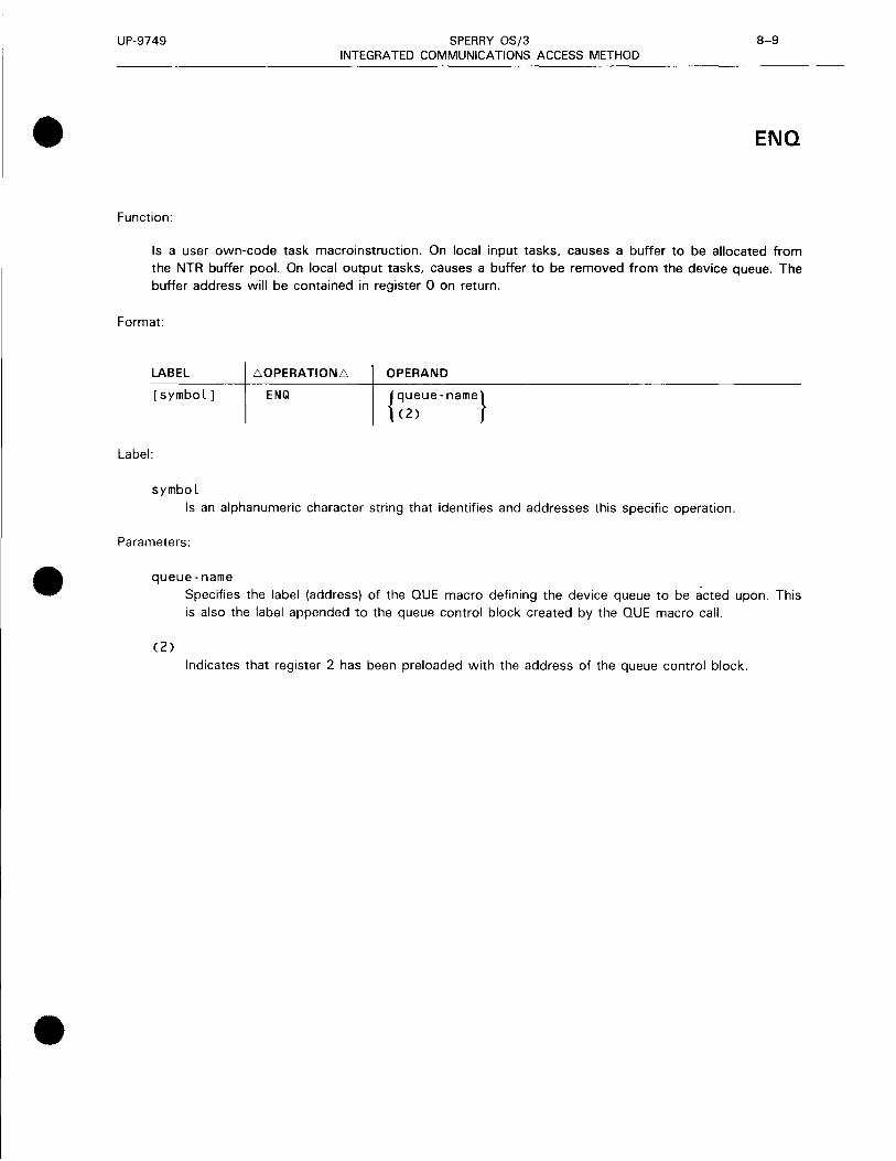
•
•
•
UP-9749 SPERRY OS/3 8-9 INTEGRATED COMMUNICATIONS ACCESS METHOD
ENQ
Function:
Is a user own-code task macroinstruction. On local input tasks, causes a buffer to be allocated from the NTR buffer pool. On local output tasks, causes a buffer to be removed from the device queue. The buffer address will be contained in register 0 on return.
Format:
LABEL
[symbol]
Label:
symbol
Li OPERATION Li
ENQ
OPERAND
{queue-name} (2)
Is an alphanumeric character string that identifies and addresses this specific operation.
Parameters:
queue-name
(2)
Specifies the label (address) of the QUE macro defining the device queue to be acted upon. This is also the label appended to the queue control block created by the QUE macro call.
Indicates that register 2 has been preloaded with the address of the queue control block .

UP-9749 SPERRY OS/3 8-10 INTEGRATED COMMUNICATIONS ACCESS METHOD
EQT
Function:
Is a user own-code task macroinstruction. Causes the NTR main task to interrogate the device interface table to see whether an initiate device request is outstanding. If it is, control is given at the queue control block entry address. If it isn't, the task is detached.
Format:
LABEL
[symbol]
Label:
symbol
.60PERATION.6
EOT
OPERAND
{queue - name} <2>
Is an alphanumeric character string that identifies and addresses this specific operation.
Parameters:
queue-name Specifies the label (address) of the QUE macro defining the device to be acted upon.
<2> Indicates that register 2 has been preloaded with the address of the queue control block.
•
•
•

•
•
•
UP-9749 SPERRY OS/3 8-11 INTEGRATED COMMUNICATIONS ACCESS METHOD
LOCAL
Function:
Is an NTRGEN macroinstruction. Defines a characteristic of a local user task to be linked. Parameters are delimited by one or more spaces between.
Format:
Li OPERATION Li OPERAND
LOCAL TASKNAME=taskname LiBLKSIZE=image-buffer-size
rliCOMPRESS={ .. "'.~•?i }] LiDEV I CE=n L Tll
eFUNCD={;~nction-codes}] LiLFD=fi lename
rliTRANS={~~r.}] lliTYPE={:~~~:ER}~ rL.VFBLEN={[n }}LJ L iss. L •U 1&!111·1.!
foVFBDEN={.~ .•• }] rliVFBHOME={:~+}] L Ii L I • [L.VFBFORM=formname]
Parameters:
TASK NAME Is a 1- to 6-character name of the task.
BLKSIZE Is the maximum image buffer size; should be a multiple of 12 for the card punch.
COMPRESS Specifies the compress feature for reader input devices sending to the 1100 Series system. For TRANS=YES, the space compression character is EBCDIC space (X'40'). For TRANS=NO, the space compression character is obtained from Table 8-3.
DEVICE Specifies the logical device number· (one or two digits) with which the control block is associated. The device numbers can be obtained from the 1100 SYSGEN listing.
FUN CD
LFD
Specifies the decimal function code for each image sent to the 1100 Series system. (See Table 8-2 for function codes.)
Is the name of the logical file as it appears on the job control stream / / LFD statement .

UP-9749 SPERRY OS/3 8-12 INTEGRATED COMMUNICATIONS ACCESS METHOD
LOCAL
TRANS Specifies the translate feature for the device indicated by this macroinstruction.
NO Images are not translated by NTR. See Table 8-3 for the space compression character for each function code.
-TYPE
Images received from or sent to the 1100 Series system are translated, respectively, to or from EBCDIC via the function code. The space compression character is the EBCDIC space (X'40').
Specifies the device type for the LOCAL macroinstruction.
VFBLEN Specifies the number of lines (1-192) on the printer form.
VFBDEN Specifies the number of print lines per inch (6 or 8).
VFBHOME Specifies the location (line 1 to line 192) of the home paper position.
VFBFORM Specifies the name (1 to 8 alphanumeric characters) to be associated with the form.
•
•
•

•
•
•
UP-9749 SPERRY OS/3 8-13 INTEGRATED COMMUNICATIONS ACCESS METHOD
NTR
Function:
Is an NTRGEN macroinstruction. Defines the characteristics of an NTR network and links NTR LOCALs or user own-code tasks.
Format:
LABEL LOPERATIONL OPERAND
NTR NTRNAME=ntrnameL[NTRVOL=ntrvsnL] BLOCKIN=line-buffer-sizeLBLOCKOUT=line-buffer-sizeL LINE=line-nameLNET=network-nameL
SITE= i c:IL.TASK=task -namer{,:}]
eNTRMOD=name [{~}]]el I NESP= {;;.}]
[LPRTSPnn=hh][LNPRTSPnn=hh]
Parameters:
NTRNAME Is the name of the NTR module.
NTRVOL Specifies the volume serial number for the SYSRES volume on which the NTR system utility module is to reside. The NTR module is copied into the $Y$LOD library of the specified volume.
If omitted, the volume serial number defaults to that of the OS/3 SYSRES volume that is used to generate the NTR utility program.
BLOCK IN Specifies the line buffer size in bytes for transmission from the 1100 Series system to the OS/3 system (SOH through BCC) as specified by the 1100 Series system. For 1100 Series system versions 33 and earlier, the line buffer size is either 240 bytes or 246 bytes when through half-word CTMC; for later versions, the entry is configurable but must not exceed 9999 bytes.
BLOCKOUT
LINE
NET
Specifies the line buffer size in bytes for transmission from the OS/3 system to the 1100 Series system (SOH through BCC) as specified by the 1100 Series system. For 1100 Series system versions 33 and earlier, the line buffer size is 121 bytes; for later versions, the entry is configurable but must not exceed 9999 bytes.
Is the line name as specified in the label of the ICAM network definition LINE macroinstruction .
Is the network name as specified in the label of the ICAM network definition CCA macroinstruction.
-- _________________________________________________ ......

UP-9749 SPERRY OS/3 8-14 INTEGRATED COMMUNICATIONS ACCESS METHOD
NTR
SITE
TASK
s
•
Specifies the full 6-character site identification that the OS/3 processor uses to sign on. This should match the site id configured on your 1100 Series system. If this keyword is not specified, the sign-on command must include the site id. See Table 8-1.
Specifies a 1- to 6-character name of tasks not given in this run but defined by a previous LOCAL keyword parameter T ASKNAME or an object module name of a user own-code task. This keyword can be specified up to 14 times, but the total TASK keywords plus LOCAL keyword sets must not exceed 14. (Only object modules are permitted for user own-code tasks.)
Specifies the LOCAL task was placed in $Y$SRC of your SYSRES volume by a previous SG$PARAM job. The task must be assembled by an SG$NTRMK job stream .
Specifies that this is an object module. If omitted, the module is assumed to reside in $Y$0BJ of the SYSRES volume.
NTRMOD
s
•
Is the name of the previously generated NTR module. If used, NTRMOD must be the first parameter specified; all other parameters except NTRVOL, NTRNAME, and TASK are ignored, and a diagnostic message is written in the output listing.
Identifies a source module .
Identifies an object module. If omitted, the module is assumed to reside in $Y$0BJ of the SYSRES volume.
LINESP Specifies the line speed to be used, where n is assumed to be 96 for 9600 baud if unspecified.
PRTSPnn Specifies, for printer-type devices, a hexadecimal byte for space decompression (LOCAL and QUE, TRANS=NO) that corresponds to the 2-decimal-digit function code nn. (See Table 8-3.)
NPRTSPnn Specifies, for nonprinter devices, a hexadecimal byte for space compression or decompression (LOCAL and QUE, TRANS=NO) that corresponds to the 2-decimal-digit function code nn. (See Table 8-3.)
•
•
•

UP-9749 SPERRY OS/3 8-15 INTEGRATED COMMUNICATIONS ACCESS METHOD
• NTR
Table 8-3. Default Space Compression Characters (TRANS=NO)
hh - (hexadecimal)
nn (decimal) Printers Non printers
(PRTSP) (NPRTSP)
00 05 FF 01 20 05 02 05 05 03 20 20 04 FF 20 05 FF 05 06 FF 20
07-14 FF FF
•
•

UP-9749 SPERRY OS/3 8-16 INTEGRATED COMMUNICATIONS ACCESS METHOD
POOL
Function:
Is a user own-code task macroinstruction. Used for output tasks to return the specified buffer to the buffer pool and input tasks at normal end-of-file.
Format:
LABEL
[symbol]
Label:
symbol
60PERATION6
POOL
OPERAND
{buff - addr} (0)
Is an alphanumeric character string that identifies and addresses this specific operation.
Parameter:
buff-addr
(0)
Specifies the address of the buffer to be returned to the pool.
Indicates that register 0 has been preloaded with the address of the buffer to be returned to the pool.
•
•
•

•
•
•
UP-9749 SPERRY OS/3 8-17 INTEGRATED COMMUNICATIONS ACCESS METHOD
QUE
Function:
Defines a queue control block that describes the characteristics of a buffer queue as well as entry points for task initiation and termination. The NTR imperative macroinstructions reference the queue control block for buffer queue management. Tables 8-4 through 8-7 describe the queue control block
fields.
Format:
LABEL 60PERATION6
que-name QUE
Label:
OPERAND
BLKSIZE=n,DEVICE=n,ENTRY=symbol, EOFADDR=symbol,LFD=filename[,CNTRL=YES]
[ ' COMPRESS={.~.o .. :.·:.•··:.}] :'.¥:6S
[FUNCTION={;:;!}] [TRANS={;~~}] [' TYPEFLE= {~~~~T}] [, VARIABLE=YES]
[,TRANSIZE=n]
que-name Is an alphanumeric character string that identifies and addresses the queue control block. This
label is used as an imperative macro parameter.
Parameters:
BLKSIZE Specifies the maximum image buffer size for this device; should be a multiple of 12 for a card
punch.
DEVICE Specifies the logical device number (one or two digits) with which the control block is associated. For the device numbers 1-9, only one digit must be specified. For device numbers 10-14, two digits must be specified. See 1100 SYSGEN listing for device numbers.
ENTRY Specifies the label (address) in the user program to receive control when the specified device is
initiated.
EOFADDR
LFD
Specifies the label (address) in the user program to receive control when NTR detects an end of file on data to a specified device or when a terminate command is received from the 1100 or
OS/3 system operator.
Specifies a file name to be associated with the QUE as contained on the job stream / / LFD
statement.

UP-9749 SPERRY OS/3 8-18 INTEGRATED COMMUNICATIONS ACCESS METHOD
QUE
CNTRL Specifies that two bytes of spacing control information precede each data image and are the first two bytes in the buffer (output devices only). See Table 8-8 for a detailed description of the two spacing bytes.
COMPRESS Specifies the compress feature for reader input devices sending to the 1100 Series system. For TRANS=YES, the space compression character is EBCDIC space (X'40'). For TRANS=NO, the space compression character is obtained from Table 8-3.
FUNCTION Specifies the action to be taken by the receiving system on data transmitted by this device. The function codes are listed in TablP- 8-2. This optional parameter applies only to local input data. The default value specifies 'read EBCDIC, send ASCII'.
TRANS Specifies the translate feature for the device indicated by this macroinstruction.
NO Images are not translated by NTR. See Table 8-3 for the space compression character for each function code.
Images received from or sent to the 1100 Series system are translated, respectively, to or from EBCDIC via the function code. The space compression character is the EBCDIC space (X'40').
TYPEFLE Specifies the direction of data flow controlled by the queue control block. Input is the default if the keyword is omitted.
VARIABLE
NOTE:
Specifies that the data image is variable length and begins with a 4-byte header (for input NTR user own-code devices). The format of the image deallocated (DEQ) is expected (by NTR) to be the same as OS/3 data management variable-length records:
Byte 0
length of actual data + 4
2 3 4-N
actual data
Keyword BLKSIZE should be specified as the maximum actual data size + 4.
TRANSIZE=n Allows the NTR generation process to provide adequate buffer space.
•
•
•
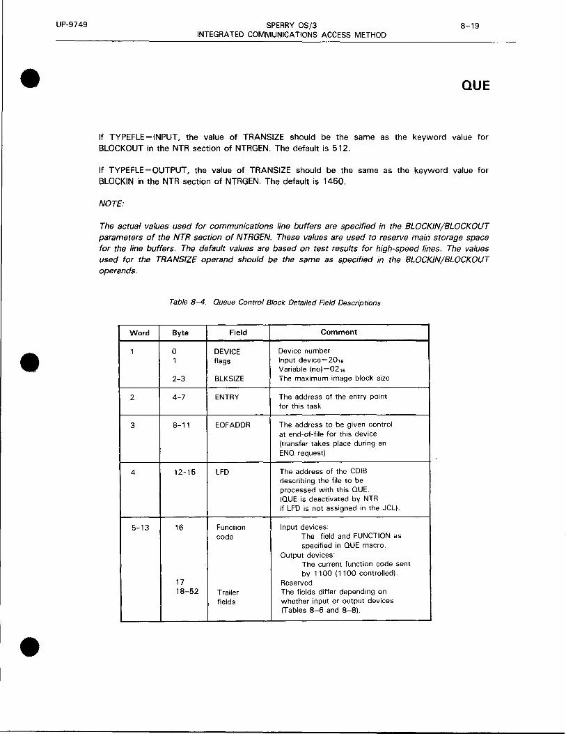
UP-9749
•
•
•
SPERRY OS/3 8-19 INTEGRATED COMMUNICATIONS ACCESS METHOD
QUE
If TYPEFLE=INPUT, the value of TRANSIZE should be the same as the keyword value for BLOCK OUT in the NTR section of NTRGEN. The default is 512.
If TYPEFLE = OUTPu'r, the value of TRANSIZE should be the same as the keyword value for BLOCKIN in the NTR section of NTRGEN. The default is 1460.
NOTE:
The actual values used for communications line buffers are specified in the BLOCKIN/BLOCKOUT parameters of the NTR section of NTRGEN. These values are used to reserve main storage space for the line buffers. The default values are based on test results for high-speed lines. The values used for the TRANSIZE operand should be the same as specified in the BLOCKIN/BLOCKOUT operands.
Table 8-4. Queue Control Block Detailed Field Descriptions
Word Byte Field Comment
1 0 DEVICE Device number 1 flags Input device=201s
Variable (no)=021s 2-3 BLKSIZE The maximum image block size
2 4-7 ENTRY The address of the entry point for this task
3 8-11 EOFADDR The address to be given control at end-of-file for this device (transfer takes place during an ENO request)
4 12-15 LFD The address of the CDIB describing the file to be processed with this QUE. (QUE is deactivated by NTR if LFD is not assigned in the JCL).
5-13 16 Function Input devices: code The field and FUNCTION as
specified in QUE macro. Output devices:
The current function code sent by 1100 ( 1100 controlled).
17 Reserved 18-52 Trailer The fields differ depending on
fields whether input or output devices (Tables 8-6 and 8-8) .

UP-9749 SPERRY OS/3 8-20 INTEGRATED COMMUNICATIONS ACCESS METHOD
QUE • Table 8-5. Queue Control Block Input Trailer Labels
Byte Field Comment
18 Reserved
19 Image count Current number of images on the device entry for this QUE
20-27 Reserved
28-31 Save area Address of 18-word save area address provided for this task by NTR
(Register 13 is preloaded with this address upon entry to task.)
32-48 File-ID Current file-id (only NTR input LOCALS)
49 Reserved
50-52 Flags Additional flags controlled by NTR •
Table 8-6. Queue Control Block Output Trailer Labels
Byte Field Comment
18-19 Image count Current number of images on the device entry for this QUE
20-27 Reserved
28-31 Save area Address of 18-word save area address provided for this task by NTR
(Register 1 3 is preloaded with this address upon entry to task.)
32-33 Reserved
34-41 1100 RUNID EBCDIC RUNID for this file or x·oo· if not found
42-49 Form name First eight EBCDIC characters of 1100 special forms request or 4X'OOFF' if 1100 command to return to standard forms
50-52 Flags Additional flags controlled by NTR •

UP-9749 SPERRY OS/3 8-21 INTEGRATED COMMUNICATIONS ACCESS METHOD
• QUE
Table 8-7. Queue Control Block Common Trailer Labels
Byte Field Comments
53-55 Reserved
56-59 Device This field contains the device characteristics obtained from the physical unit block (PUB) at characteristics NTR initialization time.
60-63 Image buffer Image buffers are now allocated on a device basis. This field contains the address of the queue address buffer queue control information.
64-67 Line buffer This field contains the address of the queue control information for communications line queue address buffers.
For TYPEFLE =INPUT, each device has two communications line buffers for double buffering.
For TYPEFLE =OUTPUT, space is reserved for two communications line buffers per device for double buffering.
All communication line buffers for TYPEFLE=OUTPUT are controlled by the same queue control information block .
• 68 Current This field contains the current function code in effect for the device. function code
69-71 Translate This field contains the current translate table address in effect for the device. table address
•
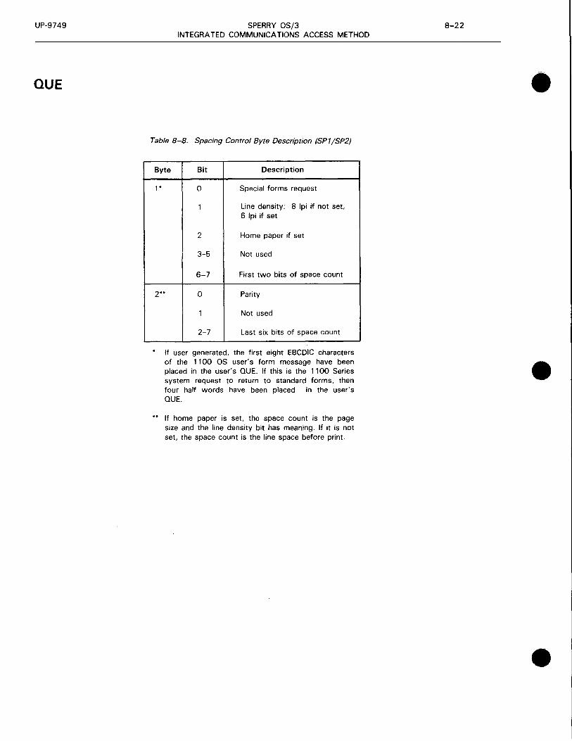
UP-9749
QUE
SPERRY OS/3 INTEGRATED COMMUNICATIONS ACCESS METHOD
Table 8-8. Spacing Control Byte Description (SP1/SP2)
Byte Bit Description
1 * 0 Special forms request
Line density: 8 lpi if not set, 6 lpi if set
2 Home paper if set
3-5 Not used
6-7 First two bits of space count
2·· 0 Parity
Not used
2-7 Last six bits of space count
If user generated, the first eight EBCDIC characters of the 1100 OS user's form message have been placed in the user's QUE. If this is the 1100 Series system request to return to standard forms, then four half words have been placed in the user's QUE.
If home paper is set, the space count is the page size and the line density bit has meaning. If it is not set, the space count is the line space before print.
•
•
•

•
9. Remote Batch Processing (RBP)
•
•

•
•
•

•
•
•
UP-9749 SPERRY OS/3 INTEGRATED COMMUNICATIONS ACCESS METHOD
9-1 Update B
Remote batch processing (RBP) software provides a means to submit jobs from a remote station and receive output at one or more remote stations. RBP operates as a system symbiont and is loaded either by
the console operator or automatically by the OS/3 system when spooled output is available for transmission.
RBP supports the following batch devices referred to as remote stations:
• SPERRY OCT 1000 (batch mode)
• SPERRY OCT 2000
• SPERRY 1004 (RMS 1)
• SPERRY 9200 /9300 (REM 1)
• SPERRY UDS 2000 (batch mode binary synchronous device emulating an IBM 2780/3741)
• IBM 2780 (ASCII and EBCDIC nontransparent modes)
• UNIX operating system
RBP allows the user to:
• Control the operating environment of the remote station
• Control the input to the system (You can cancel a card reader jam and continue precessing without restarting the job.)
• Monitor job status and receive automatic notification of job completion
• Specify that job output be returned either immediately or on command
• Stop job output to the remote station and either cancel or restart it on command
• Send messages to another remote station or to the central site operator
ICAM SYMBIONT FOR RBP
An ICAM network must be defined for each type of communications control area (CCA) in the symbiont. A symbiont can be created:
• with remote batch processing capability (RBP CCA);
• with remote batch processing and standard interface (dedicated or global) capability (RBP and standard interface CCA); or
• with remote batch processing, standard interface, direct data interface, etc, capabilities as needed.
Submit the symbiont definition to the OS/3 system generation process that automatically includes the proper object modules needed and links them into the ICAM symbiont load module .

UP-9749 SPERRY OS/3 9-2 INTEGRATED COMMUNICATIONS ACCESS METHOD
Creating an ICAM symbiont is described in the current versions of the ICAM network definition and • operations user guide, UP-9745, and the OS/3 system installation user guide/programmer reference, UP-8839.
RBP NETWORK DEFINITION
When you define a remote batch processing network, you use five standard ICAM network definition macroinstructions and four special RBP macroinstructions. Following is the order of presentation required for an RBP network definition and the purpose of each macroinstruction.
Macroinstruction
CCA
BUFFERS
TERM
TERM
BF I LES
RBEGIN
RNAME n
REND
EN DCC A
Meaning
Start of a network definition and its type (RBP 1 or RBP2)
Specifies resources required for the network
Characteristics of this line
Defines the remote batch device or terminal on this line
Characteristics of last line in this network
Defines the remote batch device or terminal on this line
Extends the number of main storage staging areas for high traffic situations
Begins a userid table for RBP
Specifies the userid, account number, and optional password for each valid user
Specifies the end of the userid table
Specifies the end of this network
Table 9-1 describes the five standard ICAM network definition macroinstructions (BUFFERS, CCA, ENDCCA, LINE, and TERM) required for RBP.
•
•

UP-9749
• Macroinstruction
BUFFERS
CCA
ENOCCA
• l IN E
I
I
'
.._ l
•
SPERRY OS/3 INTEGRATED COMMUNICATIONS ACCESS METHOD
9-3 Update B
Table 9-1. !CAM Network Definition Macroinstructions for RBP (Part 1 of 2)
Operand Meaning
n um. s 1 z e Number of network buffers and size of each in 4 ·byte
words
NOTE
Speufy at least 7 line 1t mµut and output traffic flow at ttw sctrne time. al least 6 line 1f input and output traffic
alternate Size must be 1n multiples of 64 words
ARP=1nteger Nl11nber of act1v1ty request packets (ARPs) ym1 want made
iivallable to ICAM to run this network
I . ST AT =YE S I Includes software
ARP pool act1v1ty
to keeµ track of network buffer and
I. THOlO=n I Include~ soflw<:1re for threshold processing of act1v1ty
rt!quest packets
TYPE={iRBPl)} RBP1 rne<-1ns RBP software is fully resident RBP2 means
I RB P 2 I RBP software is a multiphase load rnodule
I .PASSWORO=password I 1 lo 8 character password to further identify this
rwtwork
I CCAI0=1dent 1 f ier I 1 to 8 character 1c1en11f1er you want printed on top of
rielwork def1n111on l1st1ng and summary report at the end
of l1st1ny tu 1dentdy CCA cod~
lnd1catt~s f'!nd of a network def1n1t1on
DEV ICE= I OCT 1000. BATCH! 0f~~u1tw~ tyrw of terminal (remotf~ station) used on this
(OCT2000 [ l~~2l]) line
I l 0 0 4 I
csc {''"'buffer length} [{::~~:c }]) r 0 G G l E
216 TRANSCOO
I 9 2 0 0 I
I 9 3 0 0 I
[ ""(l' 1::::1r)] sw~cd1es charac!Prist1cs of this cornmun1ca11ons ltne
I
I SWCHI I
I SYNC I
I CAll=phone- numb e r I Tf•lepl1une numher used for automatic or operator manual
cl1al1n\.1 to a remote batch device or terminal
-·
[ 10 r· port numbeif J adapter single line Port on commun1cat1ons or
s I ca numb e r communicat1ons adapter that this line uses
I DI Al E R=i ca po r t numb e r I I eon I I
I Sµeufies port on cornmun1cat1ons adapter to which
r1n dulornat1c cl1aler is attached
I l Bl= I 1 n e ·buffer I en gt h I L1rw buffer lengP1 in 4 byte words
t

t
UP-9749 SPERRY OS/3 INTEGRATED COMMUNICATIONS ACCESS METHOD
9-4 Update B
Table 9- 7. /CAM Network Definition Macroinstructions for RBP (Part 2 of 2)
Mecroinstruction Operand Meaning
LI llE I .RETRY=( input-number.output-number) I Spec1f1es number of retries you want ICAM to make before assigning a down status to the remote batch
(cont) device or terminal on this hne
I. STATS=YES I Spec1f1es that you want ICAM to accumulate stat1st1cs for the remote batch device or terminal on this line
I. TIMEOUT=( 1 npu t -tome.output tome) I Spec1f1es amount of time in seconds you want ICAM to wait before t1me·out occurs
[ "'""(~ :::" '. '· 11 :::·'. '"~] Spec1f1es translatmn tables you want ICAM to use
TE RM FEATURES= (1884 [-. {~~~}]) Specifies type of remote station ami its charactenst11 . .:s
(OCT 1988)
(DCT2888[. 128)( .SBLK))
9288
rm:J] [ l~rn 9398 .. t•tr•}]
DLT I
{:'~~·} ' I . max - o u t p u t - r e co rd - I en & I h )
[ {max - no - records I b Io ck}] MULTI
[ {U~H8 }] PRIMARY
[ . max - b I o ck - I en gt h I
[ '"'"] ••ua MODEL3
,I MODEL4 I
[""({~iU)J Specifies peripheral equipment attached to remote batch device or terminal; i.e .• paper tape punch (PTP). paper tape reader (PTR). card reader (RDR). card punch (PCH), or printer (PRNTR)
-----
["' "~( [F: .. · " , d,} J [ F0be 1 o '"Jl)]
Specifies transla11on tables to be used for this remotP hatch device or terminal only
••• fH
I----l.ANSWER=iont . c _ text l I Specifies a sue 1dent1f1cat1on code (int is number of
characters in text)
[ INRECSZ={~J] I Specifies input record size tcharacters) for this remote batch terminal
l
SPECIAL RBP MACROINSTRUCTIONS
In addition to the normal set of network definition macroinstructions, RBP uses four special macroinstructions. These are described on the following pages.
I
•
•
•

•
•
•
UP-9749 SPERRY OS/3 9-5 INTEGRATED COMMUNICATIONS ACCESS METHOD
BFILES
Function:
Extends the number of main storage staging areas used by RBP for queueing messages and output files. This macroinstruction is required for networks where status messages or output files are generated or requested faster than they can be sent over communications lines and printed or punched.
Format:
LABEL 60PERATION6 OPERAND
BF ILES RBPA=m,STAT=n
Parameters:
RBPA=m Specifies the total number of special RBP activity request packets to be generated. Default is 10 times the number of remote stations defined in the network. These packets are used to schedule RBP activities. For each remote station, one activity request packet is needed for input, one for output, and one for the current activity. In addition, if output becomes available by means of requests or job termination, one activity request packet is needed for each job or job step that has output associated with it.
If this special RBP activity request packet pool is depleted, the remote batch processing task is cancelled.
STAT=n Specifies the total number of status message buffers to be generated. Default is 10 times the number of terminals .

UP-9749 SPERRY OS/3 9-6 INTEGRATED COMMUNICATIONS ACCESS METHOD
RBEGIN • Function:
Specifies the beginning of the CCA network definition userid table for remote batch processing.
Forma't:
LABEL 60PERATION6 OPERAND
[symbol] RBEGIN
•
•

UP-9749 SPERRY OS/3 9-7 INTEGRATED COMMUNICATIONS ACCESS METHOD
• REND
Function:
Specifies the end of the CCA network definition userid table for remote batch processing.
Format:
LABEL I 60PERATION6 \ OPERAND
REND
•
•
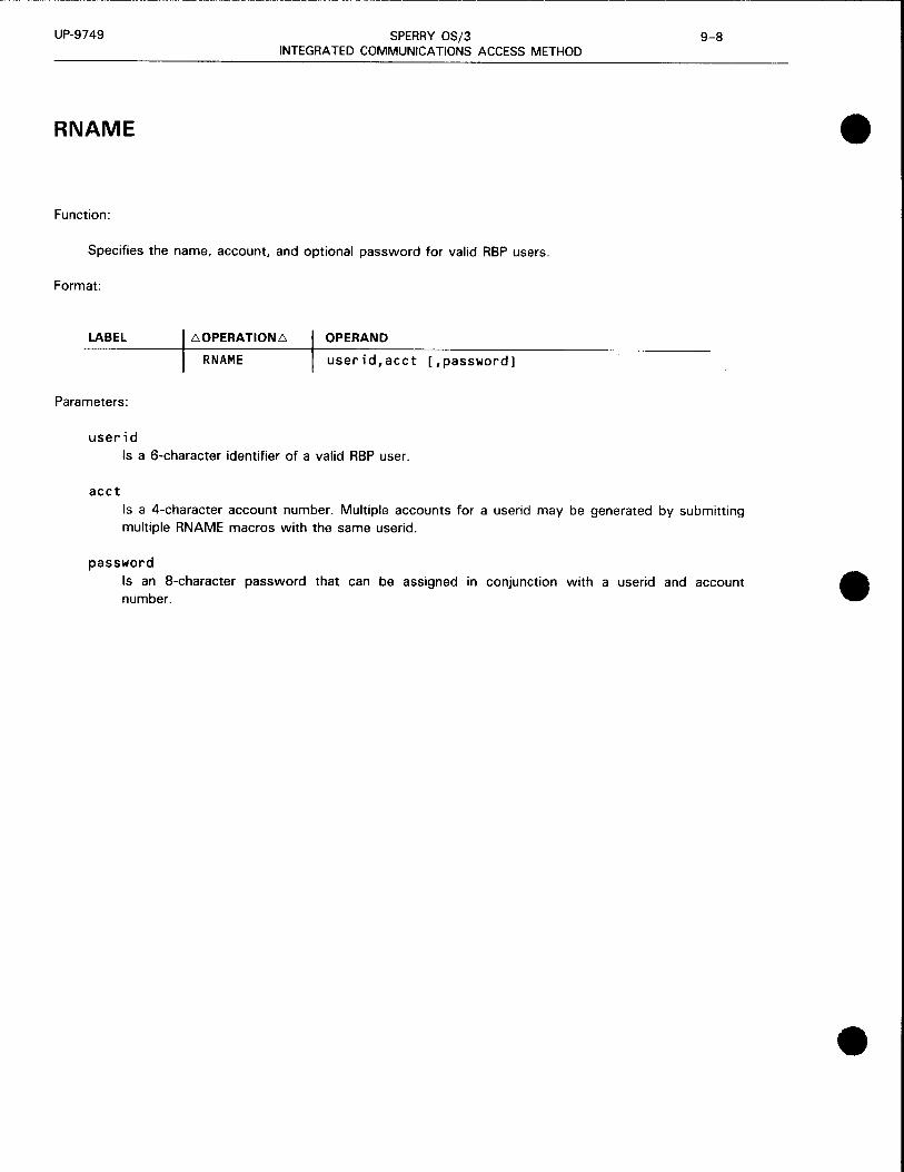
UP-9749 SPERRY OS/3 9-8 INTEGRATED COMMUNICATIONS ACCESS METHOD
RNAME
Function:
Specifies the name, account, and optional password for valid RBP users.
Format:
LABEL t::,.OPERATIONt::,. OPERAND
RN AME userid,acct [,password]
Parameters:
user id Is a 6-character identifier of a valid RBP user.
acct Is a 4-character account number. Multiple accounts for a userid may be generated by submitting multiple RNAME macros with the same userid.
password Is an 8-character password that can be assigned in conjunction with a userid and account number.
•
•
•

UP-9749 SPERRY OS/3 9-9 INTEGRATED COMMUNICATIONS ACCESS METHOD
• RBP COMMANDS
•
•
RBP commands are used to communicate with the central processing system from a remote station. The commands are interspersed between job entries in the remote input stream. They are processed exclusively by the RBP symbiont and are not passed to the OS/3 job control or spooling functions.
Each RBP command is submitted on a punched card and is identified by a slash (/) in column 1 followed by the command starting in column 2. One or more spaces must separate the command from the parameters.
The RBP commands are:
RS TART RS TOP RLOGON RLOGOFF ROUT RMSG RSTATUS

UP-9749 SPERRY OS/3 9-10 INTEGRATED COMMUNICATIONS ACCESS METHOD
RSTART
Function:
The RST ART command logically attaches a remote station to the remote batch processing system. Once attached, the remote station can monitor the system for output directed to it and gain access to the central system by logging on. Also, the RST ART command identifies the remote station.
The RST ART command must be the first statement submitted at an inactive remote station. If you want to resume remote batch processing activity after your remote station has been logically detached from the system (after an RSTOP command or a system failure}, you must resubmit the RSTART command.
Format:
/RSTARTt.termid
Parameter:
term id Specifies the remote station name as defined by the label of the TERM macroinstruction in the ICAM remote batch processing network definition. It consists of one to four alphanumeric characters, the first of which must be alphabetic. The remote batch processing software requires unique remote station names. This command will be rejected if the system already has an attached remote station with this name.
•
•
•

•
•
•
UP-9749 SPERRY OS/3 9-11 INTEGRATED COMMUNICATIONS ACCESS METHOD
RSTOP
Function:
The RSTOP command logically detaches a remote station from the system. Prior to detachment, all queued messages directed to the remote station are transmitted. No job output is returned to the remote station after the RSTOP command is processed. The last message transmitted indicates that the remote station is logically detached. No further communication occurs until the remote station resumes remote batch processing activity with an RST ART command. If the line connection is via the switched (dialed) network, the remote station is disconnected.
Format:
/RS TOP

UP-9749 SPERRY OS/3 9-12 INTEGRATED COMMUNICATIONS ACCESS METHOD
RLOGON
Function:
The RLOGON command identifies the remote station to the remote batch processing symbiont. The system validates the userid, account number, and password in the RLOGON command, and, if accepted, grants access to the system. The user can then begin requesting the use of remote batch processing facilities.
During the processing of a valid RLOGON command, the spool file is automatically searched for any immediate output belonging to the current userid. This output, including remote log, print, and punch files, is sent to the remote station without the need to input a ROUT command. If this automatic process is not desired, specify the RESTART=NO parameter.
The RLOGON command remains in effect until another RLOGON, RLOGOFF, or an RSTOP command is issued.
A user cannot log on at more than one remote station at a time. To change remote stations, log off at the current remote station before logging on at a new remote station.
Format:
/RLOGON~userid,acct[,password]
Parameters:
user id Specifies the 6-character identification of the user.
acct Specifies the 4-character account number.
password Specifies the 8-character password as specified by the RNAME macro.
Indicates that the spool files should be automatically searched for any immediate output belonging to the userid specified in parameter 1 .
RESTART=NO Indicates that the spool files should not be automatically searched. To obtain any immediate output already queued, a ROUT command must be issued. (This is done to begin output on a certain page or card.)
•
•
•

•
•
•
UP-9749 SPERRY OS/3 9-13 INTEGRATED COMMUNICATIONS ACCESS METHOD
RLOGOFF
Function:
The RLOGOFF command terminates a remote batch processing job. It must always be used in conjunction with an RLOGON command when a remote station job is terminated. To change remote stations, log off at the current remote station before logging on at a new one.
Format:
/RLOGOFF

UP-9749 SPERRY OS/3 9-14 INTEGRATED COMMUNICATIONS ACCESS METHOD
ROUT
Function:
The ROUT command allows the remote user to retrieve deferred job output or to delete the job from the system. Output may be resumed with the record being output when interrupted or at a specific page or card number. If the job is not complete when the command is processed, RBP returns a message indicating this, and the command must be resubmitted after the job has completed.
The RBP system returns an invalid request response if the user is not a valid recipient or if the job is not in the system. A user is automatically the recipient of the job output log for each job he submits; however, to be a valid recipient of print or punch output, his userid must appear on the appropriate DST job control statement.
The user may delete only print/punch files for which he is a valid rec1p1ent. The RBP system returns an invalid request if the user attempts to delete files that do not belong to him. Files may be deleted at any time after they are completed.
Format:
/ROUTt.{J=jobname} l{BEGIN [,P=±n] [,C=±n]}] U=ALL . : .
U=userid DELETE
Parameters:
J=jobname Indicates that the request is for the specific job named in the parameter.
U=ALL Indicates that the request is for all output in the system for which you are a valid recipient. You receive all available output of jobs submitted by you and of jobs submitted by other users which name you as a valid recipient. If the userid ALL is in the RBP system, you receive all output for which you are a valid recipient.
U=userid Indicates that the request pertains only to the jobs submitted by the named user. If you give your own userid, you receive or delete all output from jobs you submitted. If you give another userid, you receive output from all jobs submitted by the named user that designate you as a valid recipient.
BEGIN Specifies that job output is to begin with the first record in the output file, whether or not output was previously discontinued.
BEGIN [,P=±n] [,=±n] Specifies where printing or punching is to start when output resumes after being discontinued . This option is valid only with /ROUT J=jobname.
where:
P=+ or P=n Specifies the actual page number where printing of the suspended print file should resume.
•
•
•

•
•
•
UP-9749 SPERRY OS/3 9-15 INTEGRATED COMMUNICATIONS ACCESS METHOD
ROUT
P=-n Specifies that printing should resume n pages previous to where the printing terminated.
NOTE:
When the terminated print file is the job log, printing resumes at the start of the log regardless of the P= ± parameter.
C=±n or C=n
C=-n
Specifies the actual card number where punching of the suspended punch file should resume.
Specifies that punching should resume n cards previous to where the punching terminated.
Any print or punch files for the specified job name that were not output before termination begin output at the beginning of the file.
CONTI NOE Specifies that job output is to resume with the record that was being written when the output was discontinued. If the job output is not in a discontinued state, output begins with the first record in the output file. CONTINUE is the default specification.
When this option is used after output files have terminated abnormally, the following actions occur:
• Files that were terminated abnormally resume output as follows:
Print files resume printing at the pages following the last complete page indicated as having been successfully output.
Punch files resume punching with the card following the last card indicated as having been successfully output.
When using buffered terminals, this may sometimes result in duplicate pages or cards when restarting due to the buffers being able to contain multiple pages or cards. However, there will not be any pages or cards lost.
• Files that were not output prior to termination begin output at the beginning of the file.
DELETE When used with J = jobname, specifies that the named job is to be deleted from the system. The job must belong to the user who is currently logged on at the remote station.
When used with U =use rid, specifies that all current jobs submitted by the named user are to be deleted from the system. The only valid user is the one who is currently logged on at the remote station. The system returns a message specifying the name of each deleted job.
DELETE is not used with U =ALL.

UP-9749 SPERRY OS/3 9-16 INTEGRATED COMMUNICATIONS ACCESS METHOD
RMSG
Function:
This command allows a user to send a message to the console operator or to another remote station. Messages can be directed to other RBP users by means of their user identifier (userid), or to a remote station identified by a terminal identifier (term id).
Messages are delivered only to users currently logged on. If you send a message to both a userid and a termid, RBP attempts to send the message to the location defined by the userid first. If the userid is not active, remote batch processing attempts to send the message to the location defined by termid. If this location is not active, the message is rejected. Note that 2-line messages requiring two status message buffers are generated and sent to the specified destination. (Refer to the BFILES macroinstruction for more information.)
Format:
/RMSG~M=C'text',U=userid,T=termid
Parameters:
M=C'text' Specifies the message text to be sent. The text must be framed by apostrophes and is limited to a maximum of 39 printable characters and blanks. Embedded apostrophes are not permitted. When a second apostrophe is detected, scan for text is halted.
U=userid Specifies the user that is to receive the message. The message is rejected if the user is not active. A userid of OS3CTR will direct the message to the central operator console.
T=termid Specifies the remote station that is to receive the message. The message is rejected if the remote station is not currently attached to the system. The message is sent to the central computer console if the RBP network name is specified. (The name of the network is the same as the label of the CCA macroinstruction in the ICAM network definition.)
•
•
•

•
•
•
UP-9749 SPERRY OS/3 9-17 INTEGRATED COMMUNICATIONS ACCESS METHOD
RSTATUS
Function:
The RST A TUS command allows the user to determine the status of one or more jobs submitted from remote stations. RBP returns the status of only those jobs current in the system for which the requestor is a valid recipient. Status can be requested for a specific job, for jobs submitted by a specific user, or for those jobs submitted from the remote station that are currently in the system.
You receive a response for each job that satisfies the command. Each response contains the job name, submitting userid, submitting termid, destination userid, and one of the following indications:
• IN RUN PROCESSOR
• ON JOB QUEUE
• JOB IS EXECUTING
• JOB TERMINATED NORMALLY
• JOB TERMINATED ABNORMALLY
• JOB PROCESSED AND BEING RETAINED
• JOB NOT IN SYSTEM OR ALREADY PROCESSED
• OUTPUT AVAILABLE
NOTE:
Each response is a 2-line message and requires two status message buffers (see BF/LES macroinstruction).
Format:
/RSTATUS~1J=jobn~me} U=user1d
T=termid
Parameters:
J=jobname Specifies the job name for which status is requested. If the user issuing the request is not a valid
recipient, the request is denied .

UP-9749 SPERRY OS/3 9-18 INTEGRATED COMMUNICATIONS ACCESS METHOD
RSTATUS
U=userid Specifies a userid for which job status is requested, If a userid is, 11pecified that relates to submitted jobs, status for all jobs submitted under that u·serid is received. If a userid is specified that relates to a job recipient, status for all jobs that pertain to that destination only is received. This is often the same userid as the job submitter.
T=termid Specifies this request is for all current jobs in the system submitted from this remote station. A report is made for all jobs in this category regardless of the submitting user.
•
•
•

•
•
•
UP-9749 SPERRY OS/3 9-19 INTEGRATED COMMUNICATIONS ACCESS METHOD
SIZING AN RBP/ICAM LOAD MODULE
The formula for determining the size of an RBP /ICAM load module is:
base size = prologue + CCA + general information table + resident root elements
+ remote device handler + remote batch interface code
where:
prologue
CCA
Consists of 1 preamble (256 bytes) and 3 task control blocks (200 bytes each) for a total
prologue size of 856 bytes.
Is 9308 bytes.
general information table Is 484 bytes for a 1-line configuration. Add 56 bytes for each additional communications adapter
channel (CACH) in the SYSGEN.
resident root elements Is 16 ,582 bytes for all root elements (object modules).
remote device handler
Terminal Size in Bytes
2780 3568
DCT 2000 2224
DCT 1000 BATCH 9506
9200/9300/1004 2432
remote batch interface code
Size in Bytes
Name Resident Overlay
TZ$RSVS 1296 3008
TZ$RSPNH 2496 TZ$RSPPS 1106 TZ$RSPRT 3008
TZ$RCMDX 2848 2848
TZ$RCMD 2216 TZ$RMGR 640
TZ$RFILE 2240
TZ$ROPR 1528 1528
TZ$RSPIN 1120
Totals 18,498 7384

UP-9749 SPERRY OS/3 INTEGRATED COMMUNICATIONS ACCESS METHOD
Minimum size for an R8P interface is:
Base size = 856 + 9308 + 484 + 16,582 + x + y = 27,230 + x + y
where:
x Is the remote device handler size.
y
Is the remote batch processing inte rface code size (resident or overlay).
The total minimum sizing for a remote batch p rocessing network is:
Configuration Mode 27 80
Resident (R8P 1) Decimal Hexadecimal
Overlayed (R8P2) Decimal Hexadecimal
296 49, C09 0
182 38, 952 6
OCT 2000
47,952 8850
36,838 8FE6
CONSOLE OPERATOR COMMUNIC ATIONS
OCT 1000
55,234 D7C2
44, 120 AC58
9200/9300/ 1004
48, 160 8C20
37,046 9086
9-20
The OS/3 console operator communicates wit h the R8P !CAM symbiont by means of console commands.
Format:
cc,x
where:
Cn or Mn Is a 2-character remote batch proc essing ICAM symbiont identifier (C 1-C9) or (M 1-M9).
cc Is a 2-character command code.
x
Is an optional operand associated w ith the command.
•
•
•

UP-9749 SPERRY OS/3 9-21 INTEGRATED COMMUNICATIONS ACCESS METHOD
• Shutdown Command
•
•
The SH (shutdown) command enables the central processor console operator to initiate an orderly shutdown of the remote batch processing network.
Format:
00 6 {~~} 6 SH [,D]
where:
SH
D
Specifies shutdown and removes the ICAM symbiont from the system when RBP is the only active ICAM interface or idles RBP when other ICAM interfaces are active in the same ICAM symbiont.
Indicates to the system that a dump is to be produced during termination of the ICAM symbiont. Note that the console operator cannot obtain a dump of a ICAM symbiont by using the OS/3 CANCEL command. This is because the CANCEL command always results in an end-of-symbiont condition.
Remote Batch Command
The RB (remote batch) command enables the central processor console operator to reactivate remote batch processing from its idle state after shutdown processing is complete.
Format:
00 D {~~} 6 RB
where:
RB Specifies that remote batch processing is to be activated.
Read Data Command
The RD (read data) command enables the central processor operator to read batch jobs or data files from the central card reader under control of the remote batch processing software.
Format:
01/J {
Cn} _:~ RD Mn

UP-9749
where:
RD
SPERRY OS/3 9-22 INTEGRATED COMMUNICATIONS ACCESS METHOD
Starts the reading of batch jobs or data files from the central processor card reader under control of remote batch processing.
RBP CONTROL OF ICAM
The console operator loads the RBP ICAM symbiont by voice communications with a remote operator, or by a predetermined arrangement unique to the installation, e.g., time of day.
If an ICAM symbiont is generated that supports another user interface in addition to RBP, the RBP network is automatically initialized (ready for dial-in) whenever the symbiont is loaded for the non-RBP interface. This allows RBP activity to run concurrently with the normal communications user programs. To run RBP before any non-RBP user interface, the ICAM symbiont must be loaded by the console operator by typing in the 2-character symbiont name on the console. Refer to the ICAM network definition and operations user guide, UP-9745 (current version).
After the ICAM symbiont is loaded and initialization is complete, the ICAM READY message appears at the operator console. Connections to the various remote stations can now be made. If you have a direct connect (private) line, no intervention is required.
The central processor console operator must dial the appropriate remote station and then reply Y when the connection is made. Then, the MC# 100 message is sent to the remote station. Once this message is
•
received, the remote station can begin sending input. RBP continues to accept input until EOT is received. •
The RBP symbiont is removed from the OS/3 system after activity is complete, as determined by voice communications between the central processor and remote station operators. RBP shutdown requires the SH command. Operations may be reestablished by reloading the RBP ICAM symbiont or by using the RB console command.
ERRORS REQUIRING USER ACTION
The following errors require user action:
• For any of the LINE or TERM DOWN messages, RBP goes into an elapsed time place to go (ETPTG) sequence. In this sequence, RBP issues a HOME PAPER command followed by the OS/3 BATCH MONITORING message every 60 seconds. When the output is successful and additional input can be received, a TERM MARKED UP message is sent to the system console.
• Each remote device handler has its own retry count that is performed before a terminal or remote device is set down. When RBP is notified of the downed terminal, the associated output spool file is repositioned to the top of the current page before it is closed; however, the input spool file remains open unless the error was a disconnect.
To receive output following a downed terminal situation, the ROUT command must be issued.
To continue input, only the additional input is sent. The entries in the job control stream are not resubmitted. •

•
•
•
UP-9749 SPERRY OS/3 9-23 INTEGRATED COMMUNICATIONS ACCESS METHOD
• When a disconnect is received, the console operator is notified. When the remote station operator wants to resume RBP activity, the start-up sequence (RST ART,RLOGON), along with the other commands, must be issued.
REMOTE STATION LOGICAL STATES
All remote stations in the remote batch processing system are considered to be in one of three mutually exclusive logical states: inactive, active, or processing.
Inactive Remote Station
An inactive remote station is logically detached from the remote batch processing system. All remote stations are in an inactive state at central system start-up and are placed in an inactive state when the system closes down.
Active Remote Station
Active remote stations are logically attached to the central system. Remote stations enter the active state when the central system receives an RST ART command from an inactive remote station or an RLOGOFF command from a processing remote station. The central system can initiate messages queued for the active remote station (RMSG command with T=termid parameter). Normal status messages and job output cannot be sent .
RBP can receive only an RLOGON or an RSTOP command from an active remote station. All other input commands are rejected.
Processing Remote Station
A processing remote station is one that is logged on to the system. An active remote station enters the processing stata when RBP receives a valid RLOGON command. All job entries and remote batch processing can be submitted at a processing remote station.
Remote station users should either use the RSTOP remote station command to disc!'onnect the communications line or guarantee that there is no user currently logged on when the phone connection is broken.
In RBP, the central processor card reader, line printer, and operator console are considered logical remote stations. Unlike stations located at remote sites, the central devices are always considered to be in a processing state with a fixed userid of OS3CTR and a fixed termid that is the RBP network name specified in the label of the CCA macroinstruction.
These IDs are valid operands for the RMSG and RST A TUS commands. Card reader input is initiated by an RD console command. Line printer output is controlled by the central spoolout mechanism .

UP-9749 SPERRY OS/3 9-24 INTEGRATED COMMUNICATIONS ACCESS METHOD
JOB CONTROL CONSIDERATIONS
When entering remote batch jobs and data, there are several job control considerations. These are:
• DST job control statement
• Job control stream delimiters
• DAT A job control statement
Sending Output to Remote Terminals (DST)
The DST statement gives the destination of the spooled output file and is included in the device assignment set for the print or punch file. You can send output to more than one destination by listing several destinations on one DST statement or by including several DST statements. When you omit the DST statement, job output is directed to the central printer or punch. However, the job log is printed at your
site.
The format of the DST statement is:
//[symbol] DST dest-1[,dest-2, .•• ,dest-16]
where:
dest Is 1 to 6 alphanumeric characters and must match a userid defined by an RNAME macroinstruction in the ICAM network definition. In addition to valid userids, the nam~ OS3CTR or CENTRAL can be used to specify the printer at the central site.
Job Control Stream Delimiters
The remote batch processor writes the job control stream (starting with a JOB statement and ending with a FIN statement) to a job control stream (JCS) spool file. The run processor reads the job stream from the spool file.
Each job does not have to end with a FIN statement. The /& statement signals the end of a job but does not close the spool file. The FIN statement causes RBP to close the spool file and call the run processor. When you end each job with a FIN statement, you create a separate spool file for each job, and a separate copy of the run processor is called in to read each job.
Entering Data from Remote Terminals (DATA)
You use the DAT A job control statement to submit a data file from a remote station (or from the central card reader on behalf of a remote station). The DAT A statement identifies the file and is followed by the card data. The end of the data file is signaled by a FIN statement or another DAT A statement.
The remote batch processor writes the data (but not the DAT A and FIN statements) to an input reader spool file. Your jobs access data from this spool file.
•
•
•

UP-9749 SPERRY OS/3 INTEGRATED COMMUNICATIONS ACCESS METHOD
9-25 Update B
• The format of the DAT A statement for remote batch processing is:
•
•
II DATA FILEID=file-identifier[,RETAIN]
The job control stream must contain a device assignment set for a card file. If you have included an LBL job control statement in the device assignment set, the file identifier specified on the DAT A card must match the LBL statement's file identifier. If there is no LBL statement, the file identifier on the DAT A card must be a concatenation of the job name and the file name from the LFD job control statement. Either way, an association is made between the file you define in your job control stream and the subfile.
The RETAIN parameter is used to maintain the subfile after it is processed. If you specify RETAIN, only the DE SPL,RDR console command can delete the subfile. The following example shows the use of the RETAIN parameter:
II DATA FILEID=BALANCEREAD,RETAIN
l Data cards
II FIN
Any parameters on the DAT A statement other than FILEID and RETAIN are ignored by the remote batch processor.
Data file input and job input cannot be mixed. If a JOB statement is encountered while an input reader RDR spool file is open, the job input is spooled to the open file. If a DAT A statement is encountered while a JCS spool file is open, the control statement may be ignored completely (if it immediately follows a /&) or written to the open file.
A job may access an existing data file that has been retained; the file has been retained by specifying the RETAIN parameter on the DAT A statement.
REMOTE TERMINAL CONSIDERATIONS
UNIX System
To connect a UNIX system to ICAM, the UNIX system is defined in the ICAM generation as a 2780 BSC terminal (TERM macro) and a user of RBP (CCA macro).
Specify:
CCA TYPE=({:::~}) LINE DEVICE=CBSC ... )
TERM FEATURES=C2780 ... )
See Table 9-1.
A 2780 emulator must be installed on the UNIX system .
t
UP-9749
OCT 1000
• Input
SPERRY OS/3 INTEGRATED COMMUNICATIONS ACCESS METHOD
9-26 Update B
RBP does not support keyboard input from the OCT 1000. Input must be transmitted from either the card reader or the paper tape reader. The auxiliary device must be specified as an operand on the TERM macroinstruction in the ICAM RBP network definition (i.e., AUX1 =(RDR), AUX2=(PRNTR)).
• Creating a paper tape for input
An input paper tape can be created by:
Offline card to paper tape punch
Offline keyboard to paper tape punch
Alpha characters must be in uppercase. Padding of blanks up to column 80 is not necessary; however, the TRANSMIT key must be pressed after the last character on each card image.
• Output
The selection of the output device is controlled by RBP and the OCT 1000 line handler. However, the first AUXn parameter on the TERM macro must be specified as AUX 1 = (PCH) for card punch output. Any attempt to override the software output device selection via the manual switch may cause printed output to be punched and punched output to be printed.
IBM 2780
When sending output to an IBM 2780, do not attempt to overprint (print and no advance followed by a print and advance). If you do this, the second line is always printed on the line following the first line. This is a basic problem with any function that ends in no advance; e.g., space-before-printing or skip-to-channel-n-before-printing. Note that output to an IBM 2780 is printed differently than output to a central printer.
Remote batch processing does not support transmission of transparent punched card output; e.g., a LIBS object module on punched cards.
9300 System
• REM 1 READY Message
The REM 1 READY message is printed by REM 1 on the SPERRY 9300 printer without any spacing before or after the print line. The OS/3 BATCH MONITORING message is preceded by a home paper and followed by 34 blank lines (so the message can be seen above the print bar at both the 9300 and 1004). Depending upon the order in which these messages are placed in the 9300 line buffer, the REM 1 READY and BATCH MONITORING messages may be printed on the same line, one on top of the other.
•
•
•

•
•
•
UP-9749 SPERRY OS/3 9-26a Update B
•
INTEGRATED COMMUNICATIONS ACCESS METHOD
@RUN Card
The @RUN card is required by REM 1 to process all input transmissions except the first. Since this card is not a remote batch processing command, one of several error messages should result if it is the first card processed by remote batch processing in any given input session. However, the remote batch processing software ignores the @RUN card if it is the first card in an input transmission and no remote batch processing status message results.
OCT 2000
If output is for the SPERRY OCT 2000 punch, the BEL alarm sounds after the remote station operator responds to the MOUNT SPECIAL CARDS message, if it is required. The operator then readies the device for punching and sends the appropriate input response.
When punching is complete, the alarm does not sound. The remote station operator must set the device back to print mode before the OS/3 BATCH MONITORING message completes its retries or the message cannot be printed. However, input can be sent if the device is placed in transmit mode.
1004
The 80-column card codes for the SPERRY 1004 differ from that of other card readers supported on the system. Table 9-2 lists the code differences .

•
•
• ---------------· ,_,_ ___ ,

•
•
•
UP-9749 SPERRY OS/3 9-27 INTEGRATED COMMUNICATIONS ACCESS METHOD
Table 9-2. 1004 Card Code Differences
1004 Graphics EBCDIC Extended 1004 (80-Column Card Code) l Hollerith
- 12-8-6 12 ? 0-8-7 12-0 !(exclamation) 11-8-2 11-0 & (ampersand) 12 2-8 = 8-6 3-8 · (apostrophe) 8-5 4-8 : (colon) 8-2 5-8 > 0-8-6 6-8 @ 8-4 7-8 ) 11-8-5 12-4-8 [ 12-8-7 12-5-8 < 12-8-4 12-6-8 # 8-3 12-7-8
l 8-7 11-5-8 L,. 12-8-2 11-7-8
* 11-8-7 0-2-8 ( 12-8-5 0-4-8 % 0-8-4 0-5-8 J:l 0-8-5 0-7-8
RBP MESSAGES
All RBP status messages are prefixed with an ICAM identifier (MC#nnn) and a time stamp (hhmm). Refer to the OS/3 system messages programmer/operator reference, UP-8076 (current version) for all RBP
messages.
The maximum number of status messages that RBP can stage in main storage at a time is 10 times the number of terminals. In addition, the maximum number of job complete notifications that can be handled at any one time is eight. These limits can be extended with the BFILES macroinstruction.
REMOTE STATION OUTPUT FORMAT
Spacing after the Last Message
When output is complete, the OS/3 BATCH MONITORING message is sent to the remote station. Following this message, the paper is advanced so that the message can be read above the print bar at the 9300 and
1004.
This same spacing takes place when the MOUNT SPECIAL FORMS/CARDS message is printed at a remote
station.
Home Paper
RBP homes paper before it begins output. If file separators are desired, RBP homes before and after it prints the file separator. If file separators are not printed, RBP homes neither before nor after printing any
file, except for the log, which it homes before printing.

UP-9749 SPERRY OS/3 9-28 INTEGRATED COMMUNICATIONS ACCESS METHOD
Unprintable Characters in Output
If an output file contains X' 1 O' characters that are not a part of valid DICE sequences. they may appear graphically as blanks at the central printer, and unpredictable line spacing problems can occur at the remote station.
ERROR RECOVERY
Communication Line Errors
The only unrecoverable line error considered by remote batch processing is a disconnect. In a disconnect, the remote station operator can reestablish a connection when desired.
Recoverable line errors such as software time-outs do not cause the line to be disconnected. Recovery from these errors is handled by ICAM remote device handlers.
Discontinued output can be restarted from the beginning, from a specific page or card, or can be continued following the last valid output record by the remote operator submitting the ROUT command.
System Software/Hardware Faults
Remote print or punch files can be recovered from these faults by a warm restart at initial program load (IPL). They can be reinitiated by the remote station operator, after logging back on by submitting a ROUT command. Immediate files can be automatically recovered through the REST ART feature of the RLOGON command.
The RST ART, RSTOP sequence, when submitted from the central processor card reader using an RD command, allows the central processor operator, following a warm restart, to initiate output that belongs to a remote userid. If the remote station is logically active during this process, the RST ART command is rejected with an MC# 123 message.
All succeeding input is processed as coming from the central processor card reader (0S3CTR) and not a remote station.
Once a remote station operator identifies his terminal by sending the RSTART command, he can receive output by using the RESTART=YES parameter on the RLOGON command or via the ROUT command. The central processor console operator cannot initiate output for him.
Card Reader Errors
If the card reader runs out of cards or jams while a job stream or data file is being spooled, the spool file remains open until additional input is transmitted. All new input is spooled to the currently open file, until a 11 FIN is detected.
•
•
•

•
•
•
UP-9749 SPERRY OS/3 9-29 INTEGRATED COM MUNI CATIONS ACCESS METHOD
Printer/Punch Errors
To continue printing without sending a ROUT command, the remote station operator must halt the output device before the ICAM remote device handler returns a time-out status to RBP. This is accomplished by sending a HALT keyin from the 1004 or 9300 or lifting the lid on the printer of the DCT 1000. Once the problem is corrected, printing is resumed by sending a READY from the 1004 or 9300 or closing the lid at the DCT 1000.
If a time-out status is returned to RBP, the line is marked down and the spool file closed. The line is marked up automatically when the device begins to respond to the polls, but a ROUT command is required to resume output.
For the 1004 or 9300, punch output error processing is the same as printer output error processing .

•
•
•

•
10. RPG II Telecommunications
•
•

•
•
•

UP-9749 SPERRY OS/3 10-1 INTEGRATED COMMUNICATIONS ACCESS METHOD
• RPG II runs as a utility to ICAM. RPG II telecommunications programs use the direct data interface (DOI) level 3. The DDI interface serves only as an entry point to ICAM, and the DDI macroinstructions are not available to the RPG II user. Thus, the only operation you need do with ICAM is define the communications network. Details on how to define a network are in the ICAM network definition and operations user guide, UP-9745 (current version).
•
•
The following is an example of an RPG II telecommunications system generation. Note that no network
buffers are specified in the BUFFERS macroinstruction.
Example:
COMM CT NET3
10 16
CCA TYPE=CDDI,3) BUFFERS 000,ARP=15
LNE1 LINE DEVICE=(1004),TYPE=C2000,SYNC,SWCH,UNAT),ID=08 TEN4 TERM FEATURES=C1004),ANSWER=C5,C,1004),AUX1=(PCH) LNE2 LINE DEVICE=CUNISCOPE),TYPE=C2000,SYNC,SWCH,UNAT),ID=09 SCP1 TERM ADDR=C28,51),FEATURES=CU200) SCP2 TERM ADDR=C28,52),FEATURES=CU200) SCP3 SCP4
END II FIN
TERM TERM ENDCCA MCP
ADDR=C29,53),FEATURES=CU200) ADDR=C29,54),FEATURES=CU200)
MCPNAME=C7 CACH=C08,NET3,01) CACH=C09,NET3,02)
72
For additional information concerning RPG II telecommunications programs, refer to the RPG II user guide, UP-8067 (current version), or the RPG II programmer reference, UP-8044 (current version). These manuals illustrate the use of the control card, file description, and telecommunications specifications forms in
preparing an RPG II telecommunications program .

•
•
•

•
11 . Operating Procedures
•
•

•
•
•

•
•
•
UP-9749 SPERRY OS/3 11-1 INTEGRATED COMMUNICATIONS ACCESS METHOD
GENERATING ICAM
The communications system is created as part of the system generation (SYSGEN) process outlined in the system installation user guide/programmer reference, UP-8839 (current version). There can be as many as 18 different ICAM symbionts in your system, creating each one in a separate system generation.
To generate an ICAM symbiont, the parameters are coded in the COMMCT phase of system generation. The COMMCT parameters include the network definition macroinstructions in Section 2 of this manual, plus the message control program (MCP) parameters described in the system installation user guide/programmer reference, UP-8839 (current version). The COMMCT phase is submitted to the parameter processor SG$PARAM, which validates the specifications and produces a listing. Then, the prefiled job control stream SG$COMMK is run to assemble and link the ICAM symbiont into the $Y$LOD library on the system resident disk volume.
The parameter processor provides default values for operands that are omitted or incorrectly stated. Certain default values are interrelated; that is, the default values for some operands depend on the values supplied for other operands. These default values are indicated in the macroinstruction formats by shading or are explained in the text.
More than one network definition can be included in an ICAM symbiont by coding multiple sets of network definition macroinstructions in the COMMCT phase. There is a limit of four on the number of network definitions for the standard, transaction control and direct data interfaces; one communications physical interface network definition also can be included. The CCAMOD parameter can be coded in place of network definition macroinstructions to include a network definition that is stored in the $Y$SRC library on the system resident volume. The CCAMOD parameter must be followed by ENDCCA. To create an ICAM module containing multiple network definitions, the COMMCT phase would look something like this:
10 16
COMM CT Phase name CCA
) Network definition
ENDCCA CCA
) Netwock definition 2
ENDCCA
CCAMOO=NET 1) ENDCCCA Network definitions filed in $Y$SRC
CCAMOD=NET2 ENDCCA
} MCP pacomete" MCP
END Phase delimiter

UP-9749 SPERRY OS/3 11-2 Update A INTEGRATED COMMUNICATIONS ACCESS METHOD
To include interactive workstations in the SYSGEN:
• During SUPGEN, specify the number of communications links (SLCAs) in the system with the COMM parameter.
• During I/OGEN, specify the maximum number of communications terminals supported by interactive services, using the REMWORKST A TION parameter. Specify SCRENMEM to indicate single- or dual-screen devices. Specfiy REMPRINTER for remote printers connected to remote workstations to allow remote spoolout.
• During COMMCT, specify:
TYPE= (GBL,,node) in the CCA macroinstruction;
IAS=(YES,OFF) for local workstations or MODE=SYSTEM for remote workstations, and TYPE= (DM 1) for both types in the LOCAP macroinstruction; and
TCTUPD =YES in the TERM macroinstruction for each local workstation (not needed for remote workstations).
In addition, be sure that the workstations have the field protect feature. See the OS/3 interactive services commands and utilities user guide/programmer reference, UP-8845 (current version) for using terminals as workstations.
ICAM INITIALIZATION AND SHUTDOWN
The ICAM load module created at SYSGEN is a symbiont. That is, when loaded into main storage, it becomes part of the supervisor. ICAM must be loaded before executing any communications user programs. When a global network is used, ICAM is loaded. Then, the global user service task (GUST) is executed before running user programs. ICAM resides in main storage until the last communications user program is terminated (unless you specify the KEEP parameter); with a global network, it remains in main storage until all user programs are completed and GUST is shut down. Then, ICAM shuts itself down (unless KEEP is specified).
Loading an ICAM Symbiont
ICAM must always be loaded in an idle system to avoid main storage fragmentation. ICAM is loaded from the system console by keying in the operator command:
6 [KEEP]
where:
Cn or Mn
KEEP
Is the name specified on the MCPNAME parameter in the COMMCT phase of system generation.
Keeps the ICAM symbiont loaded until cancelled by the system operator or if ICAM suffers an unrecoverable error.
•
•
•

UP-9749 SPERRY OS/3 INTEGRATED COMMUNICATIONS ACCESS METHOD
11-3 Update B
• ICAM can also be loaded from a job control stream with the statement:
•
•
II CCL'{~~} 6KEEP'
This allows ICAM to be loaded from a workstation instead of from the console. It also allows ICAM to be loaded as part of the information management system (IMS) execution job or as part of a job that executes GUST.
The CC job control statement can be loaded in two ways:
1. In a job control stream that only loads ICAM:
2.
II JOB jobname
II CC '{~~}KEEP'
I&
If using embedded data in a GUST job, use a // PAUSE command after the // CC command to prevent GUST from issuing a NETREQ before ICAM is ready.
In a job control stream that executes the user program or, if a global network is being used, in a job control stream that executes GUST. The CC job control statement immediately follows the JOB statement.
f\JOTES:
1. /CAM messages are still directed to the system console, even if it is loaded from a workstation.
2. If you use embedded data in the GUST job, include a PAUSE command after the CC command. This keeps GUST from issuing the NETREQ before /CAM is ready.
When ICAM is successfully loaded, the message
ICAM 10.0 READY
is displayed on the system console.
Loading a Communications User Program
With a dedicated network, the communications programs can be loaded after the ICAM READY message is received. With a global network, the global user service task is executed, then the communications programs.
A communications program loads the same way as any other user program. That is, a job control stream is submitted that defines the devices, program name, and any data associated with the user program. A printer must be always be assigned; if disk buffering, disk queueing, or journaling is requested in the network definition, a device assignment must be included for each file defined. When a global network is used, the device assignments are omitted from this job control stream and included in the run stream for the global user service task so they are available to all users of the global network.

UP-9749 SPERRY OS/3 INTEGRATED COMMUNICATIONS ACCESS METHOD -
Global User Service Task (GUST) Initialization and Shutdown
11-4 Update B
Before the user program can request attachment to a global network, the global user service task program, ML$$GI, must be executed. The GUST start-up information is obtained either through embedded data in the job control stream or by reply to messages from the system console.
When a virtual line (VLINE) using X.25 protocol is included in your network, the JOB statement for the GUST job must allocate 6000 bytes of main storage. Otherwise, no allocation is necessary on the JOB statement.
All disk and tape files defined in the global network definition with DISCFILE or JRNFILE macroinstructions must be assigned in the global user service task job stream, rather than in the job streams for user programs.
When GUST is executed, it determines whether to send messages to the system console or to retrieve embedded data from the job control stream to obtain information needed to load your global network. If embedded data is not present in a job stream, the computer operator must respond to each message described in the subsequent text. Embedded data consists of GUST commands in the job control stream formatted the same as required for console messages.
The messages given here are only those pertaining to initialization and shutdown. All global user service task messages can be found in the OS/3 system messages programmer /operator reference, UP-8076 (current version).
Initializing the Global User Service Task
After the ICAM READY message is received on the system console, GUST can be loaded. (When using embedded data, a PAUSE statement before EXEC ML$$GI keeps GUST from issuing the NETREQ before ICAM READY.)
If embedded data is used, the information requested by the MC#420 and MC#421 messages must appear in column 1 between the /$ and /* of the job control stream. If no embedded data is used, the following message is sent by GUST:
MC#420 ENTER NETREQ: CCA,PASS,RESTART,LNEREQ
Meaning:
GUST is requesting the name, password, restart, and line information associated with the global network to be initiated. Virtual lines (VLINEs) and remote workstation (RWS) lines are brought up by GUST automatically. Do not specify them as part of the response.
ccaname ['[password] [,restart] ['l * .. · }~] ALL.[, YJ l i ne - 1 [ , l i ne - 2, . . • J [ , *]
•
•
•

UP-9749 SPERRY OS/3 11-5 INTEGRATED COMMUNICATIONS ACCESS METHOD
• where:
•
•
ccaname Is the name of the global network to be activated. This name must be the same as the label of the CCA macroinstruction that begins the network definition for the global network.
password Is a 1- to 8-character password.
restart
Determines the type of restart GUST requests for the network. Specify Y for GUST to set a restart flag to initiate a warm restart, i.e., messages are recovered from existing disk files. Specify N for normal initialization, i.e., new disk files are created if required.
l:t.J;, [,Y]
Specifies that GUST is to issue line requests for all lines defined in the global network. If *, ALL, or line-names are not specified, GUST activates all lines in the network using fatal error recovery procedures; however, if any line requests are in error, the network is not activated. If ALL,Y is specified, line errors are treated as nonfatal and the network is activated.
line-1,line-2, •••
*
Specifies the local lines for which line requests are to be issued by the global user service task. The names specified must be identical to those specified in the label field of the related LINE macroinstructions. Virtual lines (VLINE) and remote workstation (RWS) lines are brought up by GUST automatically. Do not specify them.
Asterisk indicates that line requests are to be issued only to the lines indicated and that message MC#421 is to be issued to obtain the names of additional lines to be activated.
If no line request information is specified, GUST defaults to ALL.
Message:
MC#421 ENTER LNEREQS: LINE-1,LINE-2, ... *OR BLANK
Meaning:
The operator responded to the MC#420 message or the previous embedded data command ended with an asterisk (*). Additional lines can be activated by supplying the following:
Response:
[line-name-1[,line-name-2], ..• ][,*l

UP-9749 SPERRY OS/3 11-6 INTEGRATED COMMUNICATIONS ACCESS METHOD
where:
Line-name-1,Line-name-2, ••.
*
Are the names of local lines to be activated by means of line requests. GUST issues an LNEREQ statement for each line name specified. The line name must be identical to that specified in the label field of the related LINE macroinstruction. Virtual lines (VLINEs) and remote workstation (RWS) lines are brought up by GUST automatically. Do not specify them.
Signals GUST to repeat this request for more line names.
If this message is received and no lines are to be activated, a blank character should be issued or, for embedded data, a blank card.
Message:
MC#430 GUST ACTIVE FOR CCA nnnn
Meaning:
The network requested is loaded and ready for processing. No response is required. nnnn is the name of the global network loaded.
Shutting Down the Global User Service Task
All ICAM commands are the same for both dedicated networks and global networks with one exception. If the following command is issued for a global network, all of the programs are canceled and an error code 470 is issued. However, all outstanding messages to the system console must be answered before GUST shutdown can complete.
Command:
00 ss GU S,xxxx
where:
00 Transfers messages to the ICAM symbiont.
SS
Is the name of the ICAM symbiont loaded (C1-C9 or M1-M9).
GU Indicates this command is for the global user service task.
s Indicates shutdown is required.
xx xx
•
•
Is the name of the global network. It must be the same as the label of the CCA macroinstruction • in the global network definition. If the label is less than four characters, it must be padded with blanks on the right.

UP-9749 SPERRY OS/3 11-7 INTEGRATED COMMUNICATIONS ACCESS METHOD
• If this command is entered incorrectly, it is ignored, and the following message is displayed:
•
•
Message:
MC#400 GU - - - - - - - - - - - - - - INVALID COMMAND
Meaning:
The blanks are replaced by whatever type-in is entered. The entire command must be reentered.
If the shutdown request is accepted, the following message is displayed when shutdown processing is complete:
MC#401 GUST SHUTDOWN COMPLETE
To resume communications processing, the entire ICAM start-up procedures must be repeated. Never cancel the GUST job with the system CANCEL command. The CANCEL command will be rejected and the GUST shutdown command requested.
OPERATOR COMMUNICATIONS
The system console operator can change the communications environment or advise ICAM of some external event by entering input messages to ICAM at the system console. These messages are called console type-ins and can be either unsolicited commands or responses to ICAM messages. For example, with a command, the operator decides to put a line or a terminal down (DO) or to reactivate (UP) one. With a response, the operator responds to an ICAM request to manually dial a telephone number.
Refer to the System 80 operations handbook, UP-8859 (current version) for all console commands and responses.
ESTABLISHING A DYNAMIC SESSION
ICAM processes terminal operator requests to dynamically establish or end a communications session. The terminal operator enters sign-on or sign-off commands to communicate with a user program, a process file, another terminal in the network, or to end a session with one of these. Standard terminal dialog is available with global networks that provide dynamic session establishment.
When the command processor receives a valid sign-on command, the message:
SPERRY-UNIVAC DCA NETWORK, LEVEL n.n NODE ID xxxx
is sent to the initiating terminal immediately.
where:
n.n
Is the operating system release level.

UP-9749 SPERRY OS/3 11-8 INTEGRATED COMMUNICATIONS ACCESS METHOD
xx xx
Is the global network node identifier specified in the TYPE operand of the CCA macroinstruction in the network definition.
If the sign-on request is honored, the message:
SESSION PATH OPEN
is sent to the initiating terminal; and if the session is between terminals, the two messages are then sent to the requested terminal.
If the request for session establishment is rejected, the message:
SESSION PATH CLOSED
is sent to the initiating terminal.
If a request for sign-off (of an established session) is issued by another terminal or a user program, the messages:
SESSION PATH CLOSED $$SOFF
are sent to the terminal following session disestablishment.
If the user program aborts an established session, the message:
SESSION PATH ABORTED
is sent to the affected terminal.
If an invalid command is entered at a terminal, the message:
INVALID $$ COMMAND
is returned to the terminal.
Sign-On Command ($$SON)
This command establishes a session with a user program, process file, or another terminal.
Format:
SSSONt.xxxxyyyy
where:
xx xx Is the logical name of the terminal from which this command is issued, i.e., the label of the TERM macroinstruction defined in the network definition.
•
•
•

•
•
•
UP-9749 SPERRY OS/3 11-9 INTEGRATED COMMUNICATIONS ACCESS METHOD
yyyy Is the logical name of:
• a user program (as defined in the label of a LOCAP macroinstruction defined in the network definition);
• a process file (as defined in the label of a PRCS macroinstruction); or
• another terminal (as defined in the label of a TERM macroinstruction).
Sign-Off Command ($$SOFF)
This command ends a dynamic session.
If the terminal is connected to ICAM by means of a dial line, and this command is issued, ICAM holds the telephone connection for 60 seconds after it has ended (disestablished) the session, so a subsequent sign-on command can be issued to reestablish another session without needing to redial.
Format:
$$SOFF
WORKSTATION START-UP AND RELEASE
ICAM supports local workstations, remote workstations, and certain terminals used as workstations.
Start-Up Procedures for Local Workstations
• A LOGON command is required first for all uses of a local workstation.
• To communicate with a user program or IMS, allocate the local workstation to ICAM. ICAM attempts to secure workstation mode when a line request (LNEREQ) is issued as follows:
In a dedicated network, issued as part of a network request (NETREQ) or explicit request of the line (LNEREQ)
In a global network with static sessions, issued during GUST processing
In a global network with dynamic sessions, issued when a sign-on command ($$SON) is entered in system mode
• If the local workstation is not allocated by one of these methods or the line is marked down, activate the local workstation line with an UP command.
Start-Up Procedures for Remote Workstations
Remote workstations are supported in global networks only and require the use of dynamic sessions. They are essentially communications terminals and always require the use of ICAM.

t
UP-9749 SPERRY OS/3 11-10 Update A
•
INTEGRATED COMMUNICATIONS ACCESS METHOD
During GUST initialization, GUST issues a line request to each remote workstation line .
For a private line, the remote workstation is in workstation mode immediately as polling begins.
For a switched line (dial up), the remote workstation is in workstation mode when a connection is made.
• Because a remote workstation provides both system mode and workstation mode, separate concurrent dynamic sessions can be opened.
To establish a system mode session, enter a LOGON command in system mode or press the transmit key (or any function key) to display the LOGON menu. Once the LOGON procedure is complete, use the terminal as a local workstation.
To establish a workstation mode session with a user program or IMS, enter a $$SON command from system mode.
• If a remote workstation goes down, it can be reactivated with the UP command. Then, repeat the start-up procedure (i.e., LOGON, $$SON).
•
•
If a UTS 40 or UTS 40 CP /M is used as a remote workstation and auxiliary output is flowing, do not put the workstation in system mode.
If interactive services has not attached, a remote workstation operator will receive a SESSION PA TH CLOSED message when attempting to sign on. Wait a few seconds and retry.
Start-Up Procedures for a Terminal Used as a Workstation
JCAM supports terminals as workstations only in a global network with dynamic sessions.
Normally, a line request is issued during GUST processing to activate the communications line. The GUST program asks the console operator which lines to activate and issues line requests based on the response.
• If the terminal is on a private line, polling begins immediately.
• If the terminal is on a switched line (dial up), make the phone call when needed.
To establish a dynamic session with interactive services, enter a $$SON command using the demand mode interface (DMI) locap file name as the to name. Then:
• After interactive services displays an OS/3 logo, proceed as instructed by interactive services.
• After a sign-on to interactive services, the terminal can no longer communicate with IMS or a standard interface program until after a $$SOFF command is issued.
Interactive services simulates both workstation mode and system mode. To enter system mode, press the message wait key.
•
•
•

•
•
•
UP-9749 SPERRY OS/3 11-11 INTEGRATED COMMUNICATIONS ACCESS METHOD
Release Procedure for a Workstation
Release a workstation from ICAM as follows:
• For a dedicated network, execute a NETREL or LNEREL command from the user program, or enter a DO command from the operator's console.
• For a global network in a static session, issue an NDET ACH macroinstruction from the user program or enter a DO command from the system console.
• For a global network in a dynamic session, issue a $$SOFF command in data mode from the workstation, or execute an NDET ACH macroinstruction from the user program, or enter a DO command from the operator's console .

•
•
•

•
12. ICAM Cancel Codes
•
•

---------------
•
•
•

UP-9749 SPERRY OS/3 12-1
INTEGRATED COMMUNICATIONS ACCESS METHOD
• Table 12-1 lists the ICAM cancel codes.
Table 12-1. /CAM Cancel Conditions
Code Cause/Condition
Cancel
400 CCR user has CPIOCP address (register 1) error or CPIOCP chain address error. Addresses must be on full-word boundary and within your program region.
401 CCR user cannot be assigned a network task identity. The maximum number of CCR users for which ICAM has been configured would be exceeded by this request.
410 DDI user has an illegal MCT address in register 1.
411 DDI user cannot be rescheduled because ARP pool is empty or format edit is unable to obtain an ARP.
420 GET /PUT user has an illegal DTF address in register 1.
421 GET /PUT user cannot be rescheduled because ARP pool is empty.
430 TCl/RBP user cannot be rescheduled because ARP pool is empty.
440 DUST user has made a NETREQ or MOPEN call but has no CCA.
441 DUST user has made a valid DUST call but ARP pool is empty.
442 DUST user has made a DUST call other than NETREQ without previously doing a NETREO or MOPEN to • open the network.
443 DUST user has made an invalid overlay call.
444 DUST user has made a NETREQ or MO PEN but no user control slot is available (i.e., the maximum number of users has been exceeded).
445 Overlay control cannot find GUST generation table.
449 ICAM user program is cancelled because the operator cancelled ICAM.
450 Invalid ICAM SVC call due to one of the following:
1 ICAM macroinstruction did not follow SVC instruction or ICAM not configured for macroinstruction used.
2. Network was not requested, in progress, or being released.
460 ICAM has experienced a program exception within itself and is canceling itself and all users.
461 ICAM has experienced an unrecoverable disk error and is canceling itself and all users.
462 ICAM is canceling itself because the current version of the supervisor overlays the buffer control words that ICAM is configured to use.
463 System space for ICAM was not allocated.
464 System space for ICAM has been exceeded.
470 Canceled as a result of global user service task shutdown commands
• 480 Disk queueing has experienced an unrecoverable disk error and is canceling the user of the file in error.
481 Disk queueing 1s unable to secure an ARP for processing
630 ICAM not present or properly 1n1t1al1zed

•
•
•

•
•
•
13. Device Independent Control Expressions (DICE)

•
•
•

•
•
•
UP-9749 SPERRY OS/3 13-1 INTEGRATED COMMUNICATIONS ACCESS METHOD
Device independent control expressions (DICE) are used to control the print or display format of messages. They provide device independence because they are interpreted by the remote device handlers that in turn translate them into control characters understandable to the individual terminals. Therefore, the same DICE sequence can be used to control the format of a message being sent to different device types.
DICE sequences are inserted into a message either automatically by ICAM or manually by the user. Automatic DICE insertion is provided on a per terminal basis through the DICE operand of the TERM macroinstruction. The format of this operand is:
where:
OFF
Specifies that the ICAM remote device handler should insert DICE sequences into all messages input from this terminal. The DICE sequences are inserted so that the output message format is identical to or as close to the input format as possible.
Specifies that no DICE characters be inserted into any input message.
itiiW!;;~,le· Indicates that, on output, a set coordinates DICE or a forms control with clear DICE sequence is converted to a new line positional control DICE with the m and n fields set to 001s .
FORMS
Indicates that, on output, a set coordinates DICE is converted to a forms control DICE.,
NOTES:
1. NEWLINE and FORMS apply to all devices except cathode ray tube devices and the COBOL message control system (CMCS).
2. NEWLINE is always assumed for the IBM 3270 terminal system, since the IBM 3284/3286 printers do not have a form feed feature.
3. DICE=(ON) must be specified if using the COBOL message control system.
Users can insert DICE sequences into output messages by using DICE macroinstructions or DICE hexadeximal notation within their communications programs. Output messages can be formatted for several different terminal types using a single DICE sequence. The format of the DICE macroinstructions is:
LABEL 60PERATION6 OPERAND
[symbol] dice-macroinstruction m,n

UP-9749 SPERRY OS/3 13-2 INTEGRATED COMMUNICATIONS ACCESS METHOD
Label:
[symbol]
Operation:
An optional alphanumeric character string, from one to eight characters long, that identifies the specific instruction line.
dice-macroinstruction
Specifies the appropriate name from the macroinstruction column of Table 13-1 for the desired DICE sequence.
Positional Parameter 1 :
m
..
A decimal number indicating either a specific line or row number to which the terminal advances before beginning output or the number of lines or rows from the current position that the terminal is to advance before outputting a message .
Positional Parameter 2:
n A decimal number indicating either a specific column or space location to which the terminal advances before beginning output or the number of columns or spaces from the current position that the terminal is to advance before outputting a message.
The values specified for m and n are taken together to position the output message correctly. These values must not exceed the screen or print page size of the terminal. Values that do exceed the valid sizes will produce unpredictable results. If 0 is specified for m or n on a DICE macroinstruction calling for a specific location, the 0 is interpreted as a 1 since column and row numbering begins at 1.
The user can also enter DICE sequences for output messages by specifying the DICE hexadecimal notation in the communications programs. The format of the notation is:
Format:
select function m field n field
character code
where:
select character Is a hexadecimal character (101s) designating the start of a DICE sequence. This character, a data link escape (OLE) control character in EBCDIC, must be used only to designate the start of a DICE sequence.
function code Defines the device sequence that is recognized by the RDHs on input. On output, this code is a 1-byte field defining the operation to be performed on the text message. (DICE function codes are listed in Table 13-1).
•
•
•

•
•
•
UP-9749 SPERRY OS/3 13-3 INTEGRATED COMMUNICATIONS ACCESS METHOD
m field Is a hexadecimal value specifying the line or row where output is to begin or the number of lines or rows to advance from the current position before beginning output.
n field Is a hexadecimal value specifying the column or space where output is to begin or the number of columns or spaces to advance from the current position before beginning output.
The ICAM remote device handlers provide device independent support for three classes of remote terminal devices:
• Hard copy character-oriented devices
• Hard copy page printer devices
• CRT terminals
Table 13-2 defines the primary output device and the primary input device for each terminal type. Table 13-3 lists the auxiliary devices by each terminal.
The following applies to the use of DICE with UNISCOPE, UTS 400, and UTS 4000 terminals.
• If you specify DICE= OFF
The ICAM remote device handler passes the start of text character (STX) to your program as the first byte of data. For example, in a message containing a start of entry character (RS), the following data is received in the text portion of your input work area:
S E V Y X N S R
T S T u S rest-of-text
X C L
• If you specify DICE=OFF
In a message containing a start of entry character (RS), the following data is received in the text portion of your input work area:
E V Y X N S R
}•scu S T S rest-of-text u C L
270Byyxx000F1E }Hexadecimal EBCDIC
• If you specify DICE= ON
The start of text character (STX) is suppressed by the remote device handler, and control character sequences are converted to DICE sequences. For example, in a message containing a start of entry
character (RS), the following text is received in the text portion of your work area:
4-character-dice-sequence R rest-of-text
s
Note that start of text (STX) and end of text (ETX) characters are always removed by the remote device handlers; they are never supplied to your program as text.
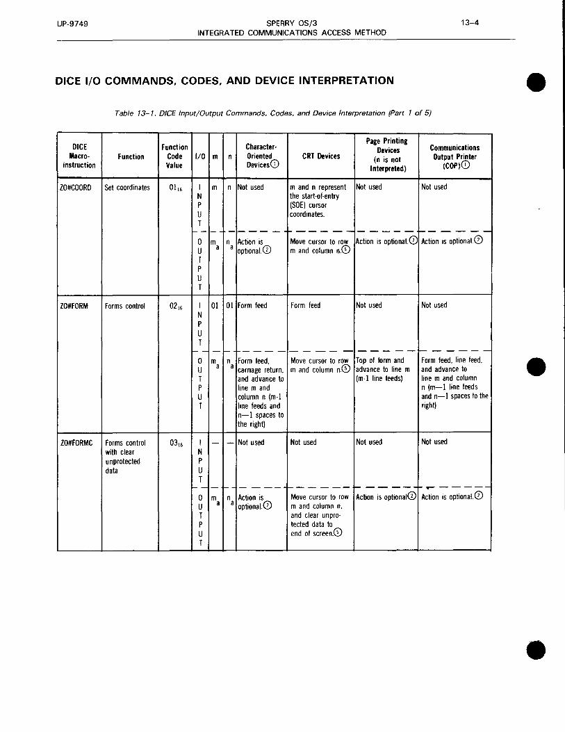
UP-9749 SPERRY OS/3 13-4 INTEGRATED COMMUNICATIONS ACCESS METHOD
DICE 1/0 COMMANDS, CODES, AND DEVICE INTERPRETATION • Table 13-1. DICE Input/Output Commands, Codes, and Device Interpretation (Part 1of5)
DICE Function Character-Page Printing
Communications Devices Macro- Function Code 1/0 m n Oriented CRT Devices (n is not Output Printer
instruction Value Devices CD Interpreted) (COP)G)
ZO#COORD Set coordinates 0116 I m n Not used m and n represent Not used Not used N the start-of-entry p (SOE) cursor u coordinates. T
1-- -- ----- +----------- I-- - - - --1
0 m n Action is Move cursor to row Action is optional. CD Action is optional. 0 u a a optional. 0 m and column n.© T p u T
ZO#FORM Forms control 0216 I 01 01 Form feed Form feed Not used Not used N p u T
I- -I - I- +-- - - - - --- - ----- f------0 m n Form feed, Move cursor to row Top of form and Form feed, line feed, u a a carriage return, m and column n.© advance to line m and advance to T and advance to (m-1 line feeds) line m and column • p line m and n (m-1 line feeds u column n (m-1 and n-1 spaces to the T line feeds and right)
n-1 spaces to the right)
ZO#FORMC Forms control 0316 I - - Not used Not used Not used Not used with clear N unprotected p data u
T 1-- - +- - - 1---------- f- -- ---+-..------
0 m n Action is Move cursor to row Action is optional0 Action is optional. 0 u a a optional.CD m and column n. T and clear unpro-p tecled data to u end of screen.© T
•

UP-9749 SPERRY OS/3 13-5 INTEGRATED COMMUNICATIONS ACCESS METHOD
• Table 13- 1. DICE Input/Output Commands, Codes, and Device Interpretation (Part 2 of 5)
DICE Function Character-Page Printing
Communications Devices Macro- Function Code 1/0 m n Oriented CRT Devices (n is not Output Printer
instruction Value Devices0 Interpreted) (COP)0
ZO#POS New line control 0415 I 00 00 Carriage return. Cursor return© Not used Not used N line feed© p u T
I-- - I- - -----r----- t-- -- --t-------0 m n Carriage return, Move cursor to Advance (m+ 1) Line feed, followed u r r line feed, fol- beginning of next lines. by m line feeds and T lowed by m line line. Then move n spaces to the p feeds and n cursor m lines right. u spaces to the down and n col-T right umns to the right©
ZO#POSC New line control 0515 I - - Not used Not used Not used Not used with clear N
p u T
1-- t--- - t----- t------ ----- 1-------0 m n Carriage return, Same as 04 16 ex- Advance (m+ 1) Line feed, followed u r r line feed, fol- cept area between lines. by m line feeds and
• T lowed by m line start and end posi- n spaces to the right p feeds and n lions is cleared.© u spac!'!s to the T right
ZO#CUR Current position 0615 I 01 00 Line feed© Line feed© End of input card Not used control N
p u T
I- - - I-- ---- ----- t------ r------0 m n m line feeds Move cursor m lines Advance m lines. Insert n spaces if u r r and n spaces to down and n columns nonsignificant space T the right to the right.© suppression is allowed. p If not, insert n DC3 u characters; m is not T interpreted. 0
ZO#CURC Current position 0715 I - - Not used Not used Not used Not used control N with clear p
u T
I- - - - I----- ------ _____ _, ------0 m n m line feeds Insert n spaces if Advance m lines. Insert n spaces if u r r and n spaces to nonsignificant space nonsignificant space T the right suppression is suppression is allowed. p allowed. If not, insert If not, insert n DC3 u n DC3 characters; m characters; m is not T is not interpretedJB interpreted.©
•
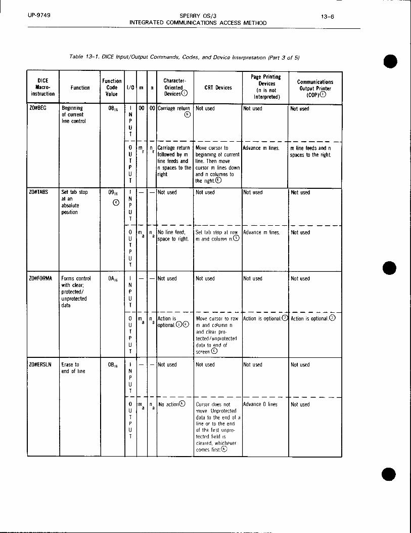
UP-9749 SPERRY OS/3 13-6 INTEGRATED COMMUNICATIONS ACCESS METHOD
Table 13-1. DICE Input/Output Commands, Codes, and Device Interpretation (Part 3 of 5)
DICE Macro
instruction
ZO#BEG
ZO#TABS
Function
Beginning of current line control
Set tab stop at an absolute position
ZO#FORMA Forms control with clear; protected/ unprotected data
ZO#ERSLN Erase to end of line
Function Code 1/0 m n
CharacterOriented Devices(i)
CRT Devices
Page Printing Devices
(n is not Interpreted)
Communications Output Printer
(COP)(i) Value
I 00 00 Carriage return Not used Not used Not used N © p u T
1---- - ----+------ ------+-------0 m n Carriage return Move cursor to U r r followed by m beginning of current
Advance m lines. m line feeds and n spaces to the right
T line feeds and line. Then move P n spaces to the cursor m lines down U right and n columns to T the right.©
I - - Not used Not used Not used Not used N p u T
t--1-t--1 ----------1-------------0 m n No line feed, Set tab stop at row Advance m lines. Not used U a a space to right. m and column n.CD T p u T
I - - Not used Not used Not used Not used N p u T
1----- - -----------~------ -------0 m n Action is Move cursor to row Action is optional. G: Action is optional. 0 U a a optional.CD© m and column n T and clear pro· P tected/unprotected U data to end of T screen.©
I - - Not used Not used Not used Not used N p u T
1--1- - -1-- - - -~ - -- - -- - - - - +- - - - - ~
0 m n No action© Cursor does not Advance 0 lines. Not used u a a move. Unprotected T data to the end of a p
u T
line or to the end of the first unpro· tected field 1s cleared. whichever comes first©
•
•
•

•
•
•
UP-9749 SPERRY OS/3 13-7 INTEGRATED COMMUNICATIONS ACCESS METHOD
Table 13-1. DICE Input/Output Commands, Codes, and Device Interpretation (Part 4 of 5)
NOTES:
CD Most character-oriented terminals can be strapped to handle the carriage return (CR) character and the line feed (LF) character as follows:
• CR
1. print mechanism moves to beginning of the same line; or
2. print mechanism moves to the beginning of the same line followed by a line feed.
• LF
1. line feed (no column change); or
2. line feed followed by return of the print mechanism to the begining of the new line.
To achieve device independence between terminal types, the character-oriented terminals must use the first option for CR and the first option for LF if the device macroinstruction is ZO#CUR or ZO#BEG.
The first option should be used if the character-oriented terminals are a part of a message switch environment.
Certain terminals do not have a form feed capability (i.e., some TIY terminals). For these terminals, the DICE expressions that specify form feed will result in line feed instead.
The set coordinates macroinstruction (ZO#COORD) or the forms control with clear macroinstruction (ZO#FORMC), when acted upon by character-oriented or page-printing terminals, will vary in its action, depending on the usage of the DICE keyword parameter of the TERM macroinstruction at network definition time:
TERM
If FORMS is specified, ZO#COORD will be interpreted as the form control macroinstruction.
If NEWLINE is specified, ZO#COORD and ZO#FORMC will result in a carriage return, line feed for character-oriented terminals, or advance one line for page-oriented terminals (m and n are not interpreted).
If the DICE parameter is not specified, the default option will be to NEWLINE.
@ The UNISCOPE display terminal suppresses nonsignificant spaces on each line (except for the line containing the cursor) when text is transmitted to the processor or printed locally on the COP or TP. Your program may send data to the UNISCOPE screen containing significant blank segments that include the last column of the screen. If this data is transmitted from the terminal to the processor or is printed locally on the COP or TP, the blank segments must consist of nonspace characters that are nondisplayable. The DC3 character meets these qualifications. The ICAM interface provides your program with the capability to prevent nonsignificant space suppression on the UNISCOPE display terminal. The "current position control with clear" is the only DICE macroinstruction that can be used to perform a clear function if your program is preventing nonsignificant space suppression.
NOTE:
The ASCII-to-EBCDIC translation table is modified so that the DC3 character is translated to space 4016 for input from the UNISCOPE display terminal.

UP-9749 SPERRY OS/3 13-8 INTEGRATED COMMUNICATIONS ACCESS METHOD
Table 13-1. DICE Input/Output Commands, Codes, and Device Interpretation (Part 5 of 5)
@) When using DICE function code 0916 for setting a tab stop, m and n=O will result in a tab stop being placed at the current cursor location (no cursor positioning is performed). This applies to UNISCOPE and UTS 400 devices only. For TTYs and OCT 500 terminals, a space character is inserted.
When m or n > maximum allowable, m or n action will vary depending on the remote terminal:
• UNISCOPE display terminals: Wraparound will occur on screen.
• Character-oriented terminals: Will give different results depending on the characteristics of the device.
@ For an IBM 3270 display terminal, the m and n values are used to set buffer address to [80 x (m-1) + (n-1)) or [40 x (m-1) + (n-1)].
@ DICE functions are supported for the IBM 3270 display or printer.
DICE PRIMARY AND AUXILIARY DEVICES
Table 13-2. DICE Primary Devices
Terminal Type Primary Output Primary Input
Device Device
Character-oriented terminals Printer Keyboard
Page printing terminals Printer Card reader
CRT termnials Screen Keyboard
•
•
•

•
•
•
UP-9749 SPERRY OS/3 13-9 INTEGRATED COMMUNICATIONS ACCESS METHOD
Table 13-3. DICE Usage for Auxiliary Devices
Remote Terminals Auxiliary Device DICE Usage
UNISCOPE Tape cassette system (TCS) DICE is applied to the COP CD
Communications output printer (COP) 800 terminal printer (TP)
UTS 400 Tape cassette system (TCS) DICE is applied to the COP. (i) Communications output printer (COP) 800 terminal printer (TP) Diskette
UTS 4000 Diskette DICE is applied to 0797 printer the COP.CD 0798 printer 0791 printer Magnetic stripe reader
DCT 1000 Card reader/card punch DICE is applied as if the Paper tape reader /punch output/input is to/from
the primary device, even DCT 500/TTY Paper tape reader /punch though it is for the auxiliary
device.@ DCT 524 Tape cassette (TCS) in paper tape
read and write only
Batch terminals Punch DICE is used for end of network buffer sentinel.
' No form control action is taken.
NOTES:
CD If the print transparent option is not used, DICE is applied to the UNISCOPE screen even though the output is sent to an auxiliary device of the UNISCOPE terminal. In this case, the format of the data printed on the COP or TP is identical to the screen format. Nonsignificant space suppression by the UNISCOPE terminal may have to be prevented to keep the formats identical. (See note 3 to Table 13-1.)
The full capability of DICE cannot be applied to the COP because of hardware characteristics. All data to a UNISCOPE auxiliary device passes through the UNISCOPE terminal. When DICE is applied to the COP, the use of print transparent mode means that no carriage returns are transferred to the COP. Line feeds and form feeds take a memory position in the UNISCOPE memory and are nondisplayable. These characters are passed to the COP where:
An LF causes a line feed followed by return of the print mechanism to the beginning of the new line.
An FF causes a page eject and positioning of the print mechanism at the beginning of the first line of the form.
The COP has no tabbing capability.
The above characteristics are reflected in the interpretation of DICE output function codes for the COP as shown in Table 13-1.
For messages sent to a UNISCOPE auxiliary device with transparent transfer, the cursor to home (ESC e) sequence is inserted at the beginning of the text by the RDH.
The control characters that are generated from the DICE function are always created for the primary device of a character-oriented device, even though the user program is sending to an auxiliary device. The message and these control characters (carriage returns, line feeds, form feeds, and spaces) will be punched/written by the output auxiliary device that was specified by the user program or was switch-selected by the terminal operator. If the punched/written data is later read by the terminal's input auxiliary device, the carriage returns, line feeds, and form feeds are converted to input DICE as specified in Table 13-1 .

•
•
•

l
•
14. Communications Physical Interface (CPI}
•
•

•
•
•

•
•
•
UP-9749 SPERRY OS/3 14-1 INTEGRATED COMMUNICATIONS ACCESS METHOD
The communications physical interface (CPI) allows experienced programmers to write physical level communications control programs.
This interface requires the least amount of main storage, since it consists of only the ICAM channel control routine (CCR); it also provides the fewest services. The programmer must take care of device and line protocol, polling, most error detection and recovery, and message management. Since the programmer must provide all of these services, the interface does not require a complex network definition. Just two statements are required: CCA and ENDCCA.
The interface uses an activity request packet called the communications physical 1/0 control packet (CPIOCP). This CPIOCP is entirely user constructed according to the format defined in Figure 14-1 and Table 14-1. CCRCALL is the imperative macroinstruction for entry and execution in this interface.
Table 14-2 describes hardware status byte settings and Table 14-3 describes the CPIOCP error codes, both as defined in Table 14-1. Table 14-4 describes the SLCA sense bytes. Table 14-5 gives a cross-reference between logical and hardware command codes. Table 14-6 specifies the channel and SLCA ID assignments.
Figure 14-2 and Table 14-7 describe the line link table. Table 14-8 summarizes System 80 port control word asynchronous line speeds.
CPIOCP DESCRIPTIONS
Byte
0
4
8
12
16
20
24 time allocation (in seconds) (TN#PTIME) buffer 1ength (TN#PBL TH)
28
32
36
40
44
48
52
logical command function
iTN#PFUNCJ
control flags (TN#PFLGS)
channel number (TN#PCHNL)
LEGEND
System-supplied parameters
CPIOCP chain address (TN#PLINK)
ROH line control table address user program line request fields (TN#PLCT)
SLCA number (TN#PPORTI
port number
(TN#PS80Pi
reserved for ICAM (TN#PBFST)
reserved for ICAM (TN#PBCUR)
reserved (TN#PS80F)
Word
2
3
4
5
6
8
9
10
11
12
13
14
Figure 14-1. Communications Physical Input/Output Control Packet (CPIOCP) Functional Field Description

UP-9749 SPERRY OS/3 14-2 INTEGRATED COMMUNICATIONS ACCESS METHOD
Table 14- 1. Control Packet• Detailed Field Description (Part 1 of 1 OJ • Field
Word Word/Bit Type Set by Content Conment Byte
Label and Suffix•• Length User CCR
1 RTY Xll x x IRL and activity control fields The IRL bit is set only by you. When 0 Bit 0 = IRL set, you get an immediate return in-Bit 1-7 = activity control fields line after CPIOCS has acted upon
the CCRCALL. If the CCRCALL references chained CPIOCPs, the IRL only has significance in the first CPIOCP. While CPIOCS is executing a CPIOCP or has CPIOCPs 1 on its line queues, it uses activity control's chain field for work fields:
Byte 0 = bits 0-1 of TN#PFUNC bits 2-3 used to control buffers greater than 1024
Byte 1 = bits 2-7 of TN#PFUNC Byte 2 = bits 0-6 of TN#PMUX
RESV XL3 x x Activity control chain field and CPIOCS sets TN#PRESV to 0 before CPIOCS work fields returning CPIOCPs to you. You • must sef TN#PRESV to 0 in all
chained CPIOCPs before executing CCRCALL.
2 FCPL XL4 x Completion address When chained CPIOCPs are 4 scheduled back to you, only the completion address of the first CPIOCP in the chain is used. If you set byte 1 to EE16, you will not be
• scheduled control when this CPIOCP function is complete. The CPIOCPs will be unchained normally and then dropped from all CCR queues. This facility is NOT recommended for normal user operations.
3 TNDX Xll x User flag 8 TRTS Clear REQUEST TO SEND signal LIDL No line turnaround
LOCA AL3 LOCAP address 9
4 RIM Xll x Primary logical status This field will be set to 0 by 12 ITST CPIOCS when CPIOCP is first
Idle time status - line received. information not especially • related to message completion.

UP-9749 SPERRY OS/3 14-3 INTEGRATED COMMUNICATIONS ACCESS METHOD
• Table 14-1. Control Packet• Detailed Field Description (Part 2 of 10)
Field
Word/Bit Type Set by Content Comment Byte Word Label and Suffix•• Lencth User CCR
4 HDWR Hardware error - do not retry. (cont) ROGE Program error
LLE Link level exception - line error but retry is indicated.
ERND Erroneous function/message completion.
END Function/message completion ti on
DETL Xll x Detailed logical status This field will be set to 0 by 13 CPIOCS when CPIOCP is first received.
For ITST RING Ring interrupt BRK Break
For HDWR CREJ Command reject
• BUSO Bus-out check CHSl Auto sense error CHS2 Incorrect length CHS3 Program check CHS4 Protection check CHS5 Data check CHS6 Control check CHS7 Interface control check CHS8 Chaining check
DSRF Data set ready off OPNL Open line DCON Disconnect NOOP Device (SLCA not operational, unit
exception)
For ROGE FRMT CPIOCP format or procedure Refer to Table 14-3. When this error
error is reported by user program interface code, even more detailed status is reported in TN#PSEN2.
AATH Attach error DTCH Detach error LPHE Load program phase error LRLE User program line request line
• error Requested line is already allocated.
MNCE Maximum number of user program task identities exceeded·

UP-9749 SPERRY OS/3 14-4 INTEGRATED COMMUNICATIONS ACCESS METHOD
Table 14-1. Control Packet• Detailed Field Description (Part 3 of 10) • Field
Word/Bit Type Set by Content Comment Byte Word Label and
Suffix•• Lencth User CCR
4 For LLE (cont) ORUN Input overrun
URNO Space to mark ASS Output sequence abort DCHK Data Check: LRC/CRC or char-
acter parity error IORN Idle overrun ABRT Abort TIMD CPIOCP time-out TIMP SLCA time-out CARF Carrier off GSSE General subsystem error
For ERNO IMPR Status condition improper An example is no hardware sense
bits returned for a SENSE command.
For END EOM Successful function/message
completion • BCI Buffer completion The interpretation of the value (bits) notification in this field is dependent on the value
of TN#PRIM.
GIVB Return of CPIOCPs due to subsequent CPIOCP requesting immediate turn-off function
STAT XL2 Hardware status See Table 14-2 Byte 0 = device status Byte 1 = channel status
5 SENS XL2 Sense bytes SENl x Hardware sense byte 2 These fields will be set to 0 by 16
CPIOCS when CPIOCP is received. SEN2 x Hardware sense byte 3 When TN#PRIM = TN#PROGE, and 17
TN#PDETL = TN#PFRMT, then TN#PSEN2 will be set to the values
or in Table 14-3 when an error has been detected by the user program interface code. If device errors occur, sense bytes 2 and 3 are reported here. See Table 14-3.
CFEC x CCRU CPIOCP format error code 17 •

UP-9749 SPERRY OS/3 14-5 INTEGRATED COMMUNICATIONS ACCESS METHOD
• Table 14-1. Control Packet* Detailed Field Description (Part 4 of 10)
Field
Word Word/Bit Type Set by Content Convnent Byte
Label and Suffix•• Lqth User CCR
5 RBC XL2 x Residual byte count for output, This field will be set to 0 by CPIOCS 18 (cont) or input character count for input when CPIOCP is first received.
When the input character count is reported in more than one CPIOCP (buffer chaining) for a particular message, each CPIOCP contains the total accumulated count thus far. This field is not for immediate commands (commands that do not result in device or channel status).
6 CMMD Xll x x Hardware command code NOTE: 20 When this field is not set to 0 by you, CPIOCS will not translate the logical command function in TN#PFUNC (bits 2-7) to obtain proper hardware command code. Whatever value was last • here or whatever value you set will be issued to the SLCA.
BADR XL3 x x Line buffer address 21
7 TIME XL2 x x Time allocation in seconds The CPIOCP at the head of any 24 CPIOCS line queue, when this field is not 0, is decremented by 1 each time CCRs timer services is notified that 1 second has elapsed. When this field decrements to 0, a HALT DEV command is issued, and the CPIOCPs are scheduled back to you with TN#PRIM = TN#PLLE and TN#PDETL = TN#PTIMD. If, however, the logical command function (TN#PFUNC, bits 2-7) was set to TN#PIDLT, a HALT DEV command is issued, but the CPIOCP is scheduled back to you with TN#PRIM = TN#PEND and TN#PDETL = TN#PEOM. The accuracy of this field can be off by minus 1 second, depending on when CCRs timer service is next
• notified that 1 second has elapsed .

UP-9749 SPERRY OS/3 14-6 INTEGRATED COMMUNICATIONS ACCESS METHOD
Table 14-1. Control Packet• Detailed Field Description (Part 5 of 10) • Field
Word Word/Bit Type Set by Content Comment Byte
label and SuffiJ•• lencth User CCR
7 NOTE: (cont) Because this field is decremented
by CCRs timer services, you must be careful to reset this field before reusing this CPIOCP for another CCRCALL.
BLTH XL2 x x Line buffer length Both TN#PTIME and TN#PBL TH 26 are used by the user program for Line Request.
8 FUNC Xll x Logical command function plus 28 start and end of message/ function flags
FS Start of message When TN#PFS is set to 1, it indicates that this CPIOCS is the first CPIOCP for a particular message or function. When it is set to 0, it means that chained CPIOCPs are being used to • output or input a message and this particular CPIOCP is not the first one.
FL End of message When TN#PFL is set to 1, it indicates that this CPIOCP is the last CPIOCP for a particular message or function. The setting of this bit for the last CPIOCP of an output message is par-ticularly critical. When TN#PFL is set to 0, it means CPIOCP is being used in buffer chaining and that it is not the last CPIOCP of the chain. When you know that a particular CPIOCP is the only one used to perform a function, TN#PFS and TN#PFL should both be set (TN#PFSL).
FSL Start and end of message/function Refer to Table 14-5 for a cross-referencing of the logical command
Bits 2-7 specify the logical function, the hardware command command function code, and the hardware command
code as it is represented in TN#PCMMD.
•

UP-9749 SPERRY OS/3 14-7 INTEGRATED COMMUNICATIONS ACCESS METHOD
• Table 14-1. Control Packet* Detailed Field Description (Part 6 of 10)
Field
Word/Bit Type Set by Content Conment Byte Word Label and Suffix•• Lencth User CCR
8 WAIT Wait for interrupt No SIO instruction is issued. (cont) A CPIOCP for this function is
issued only to receive notification of an interrupt when no message processing is in progress, such as the RING interrupt. If an interrupt other than unit check is received for a line with no CPIOCP active on the CPIOCS line queue, the interrupt will be ignored.
IOFF Immediate port turn off Return all CPIOCPs currently on the CPIOCS line queue, marking the head CPIOCP with a status of TN#PRIM = TN#PEND and TN#PDETL = TN#PGIVB. Then,
• perform a HALT DEV command .
SEND Enable data output for output/ This output function should be used input mode of operation instead of TN#PRTS for all output
messages unless you know that sub-sequent output messages will follow with no intervening input. This function enables the SLCA fast turnaround logic which drops the request-to-send load and prepares for input.
DIAL Dial If either a CPIOCP or an SLCA SPAC Send space (asynchronous only) time-out occurs for this function,
the status returned is TN#PRIM = TN#PEND and TN#PDETL = TN#PEOM.
SMRK Send mark (asynchronous only) This command disables interrupts and must be used with caution.
SIDL Send idle EDI Enable data input ON Same as TN#PEDI NSYN New sync LSYN Immediate look for sync No data transfer is processed. OFF Port turn off No immediate status
•

UP-9749 SPERRY OS/3 14-8 INTEGRATED COMMUNICATIONS ACCESS METHOD
Table 14-1. Control Packet• Detailed Field Description (Pan 7 of 10) • Field
Word/Bit Type Set .hY Content Comment Byte Word Label and Suffix•• Len1th User CCR
8 DISC Disconnect (cont) SBSY Set busy
LACL LA clear DSRM Enable data set ready monitor FLDX Set full duplex TEST LA test MOOT Modem test LATO Line adapter turn off RTS Enable data output for output/ This output function does not clear
output sequence of message request-to-send as does TN#PSEND.
IDLT Send idle and wait for CPIOCP This send idle function does not time-out - not an immediate result in an immediate command. command. Status is not returned to you
until the hardware interrupts or until a CPIOCP time-out occurs. If a CPIOCP or an SLCA time-out occurs for this function, the status returned is TN#PRIM = TN#PEND and TN#PDETL = TN#PEOM. • LB14 Load port control word
(bytes 1-4) LB24 Load control bytes 2, 3, 4 LB34 Load control bytes 3, 4 LB4 Load control byte 4 LCDl Load control character detect
table 1 LCD2 Load control character detect
table 2 LCll Load control interpretation
table 1 RPCW Read port control word RCDl Read control character detect
table 1 RCD2 Read control character detect
table 2 RCll Read control interpretation
table 1 BNOP NO-OP
BRRM read random access memory
BLMA Load memory address
BLRM Load random access memory •

UP-9749 SPERRY OS/3 14-9 INTEGRATED COMMUNICATIONS ACCESS METHOD
• Table 14-1. Control Packet* Detailed Field Description (Part 8 of 10)
Field
Word/Bit Type Set by Content Convnent Byte Word Label and
Suffix•• Length User CCR
8 BDIA Diagnostic modem test
(cont) LREL User program line release
LREQ User program line request
RLLT User program read line link table
NREQ User program network request
NREL User program network release
LINK XL3 x x CPIOCP chain address field 29
9 FLGS XL! x x Control flags 32
• CIX x - Suppress buffer completion Whenever a buffer completion
interrupt scheduling interrupt occurs, the CPIOCP for that buffer will be scheduled back to you unless this flag is set. When this flag is set, the scheduling will be delayed.
ESO x Error schedule only When this flag is set, the schedul-ing of the CPIOCP back to you will be delayed if it has a successful completion status (TN#PRIM = TN#PEND and TN#PDETL = TN#PEOM or TN#PBCI).
NOTE: The last CPIOCP in a chain must
not have this flag set.
•

UP-9749 SPERRY OS/3 14-10 INTEGRATED COMMUNICATIONS ACCESS METHOD
Table 14-1. Control Packet• Detailed Field Description (Part 9 of 10) • Field
Word Word/Bit Type Set by Content Comment Byte
Label and Suffix•• Length User CCR
9 TRNP BSC is now operating in (cont) transparent mode.
cc x Condition code The SIO condition code for the last command· issued for this CPIOCP is saved here. 00, = successful 01, = unsuccessful, status
pending 10, = busy 11, = illegal port (e.g., 101, or 131,) or SLCA not operational.
LCT XL3 x x Multipurpose field: 33 x RDH line control table address; or The RDH line control table is
where RDH saves line information. x x User program line request
fields
RQFG Xll x Line request flag field 33 • TN#PRQFG = TN#PLCT
RFDQ - Request full-duplex queueing RFUL - Request full-duplex line
DSPL Xll x x CA tables discipline ID 34 TN#PDSPL = TN#PLCT + 1
UDID - User discipline ID
CAID Xll x x CA tables ID 35 TN#PCAID = TN#PLCT + 2
LCTF Full word address TN#PLCTF = TN#PFLGS + TN#PLCT
10 MUX 36 CHNL XU x Channel number PORT Xll x SLCA number
SBOP Xll x Port number
SBOF Xll x X-21 control flag
MOTO X.21 map port 0 to 0
ICIO X.21 implicit chain IORBs •

UP-9749 SPERRY OS/3 14-11 INTEGRATED COMMUNICATIONS ACCESS METHOD
• Table 14-1. Control Packet* Detailed Field Description (Part 10 of 10)
Field
Word/Bit Type Set by Content Comment Byte Word Label and ~x•• Length User CCR
11 BFST XL4 x Reserved for ICAM 40
12 BCUR XL4 x Reserved for ICAM 44
13 S80S XL4 x Sense bytes (0-3) Reserved for ICAM 48
14 XL4 x Sense bytes (4-7) Reserved for ICAM 52
SLCA STATUS BYTES
Table 14-2. Standard Processor Hardware Status Byte Settings
Bit Hexadecimal
Status Value
• Device status
Attention 0 80
Status modifier 1 40
Control unit end 2 20
Busy 3 10
Channel end 4 08
Device end 5 04
Unit check 6 02
Unit exception 7 01
Channel status
Unassigned 0 80
Incorrect length 1 40
Program check 2 20
Invalid address 3 10
Channel data check 4 08
Interface control check 5 04 • Channel control check 6 02
Buffer terminate 7 01
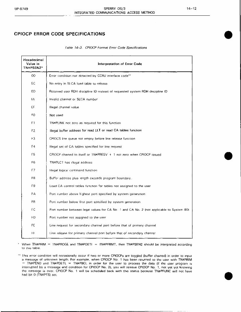
UP-9749 SPERRY OS/3 INTEGRATED COMMUNICATIONS ACCESS METHOD
CPIOCP ERROR CODE SPECIFICATIONS
Hexadecimal Value in
TN#PSEN2*
00
EC
ED
EE
EF
FO
F1
F2
F3
F4
F5
Table 14-3. CPIOCP Format Error Code Specifications
Interpretation of Error Code
Error condition not detected by CCRU interface code**
No entry in SLCA load table to release
Received user ROH discipline ID instead of requested system ROH discipline ID
Invalid channel or SLCA number
Illegal channel value
Not used
TN#PLINK not zero as required for this function
Illegal buffer address for read LL T or read CA tables function
CPIOCS line queue not empty before line release function
Illegal set of CA tables specified for line request
CPIOCP chained to itself or TN#PRESV + 1 not zero when CPIOCP issued
F6 TN#PLCT has illegal address.
F7 Illegal logical command function
F8 Buffer address plus length exceeds program boundary.
F9 Load CA control tables function for tables not assigned to the user
FA Port number above highest port specified by system generation
FB Port number below first port specified by system generation
14-12
FC Port number between legal values for CA No 1 and CA No. 2 (not applicable to System 80)
FD Port number not assigned to the user
FE Line request for secondary channel port before that of primary channel
FF Line release for primary channel port before that of secondary channel
* When TN#PRIM to this table.
TN#PROGE and TN#PDETL TN#PFRMT, then TN#PSEN2 should be interpreted according
•• This error condition will occasionally occur if two or more CPIOCPs are toggled (buffer chained) in order to input a message of unknown length. For example, when CPIOCP No. 1 has been returned to the user with TN#PRIM = TN#PEND and TN#PDETL = TN#PBCI, in order for the user to process the data (if the user program is interrupted by a message end condition for CPIOCP No. 2), you will reissue CPIOCP No. 1, not yet yet knowing the message is over. CPIOCP No. 1 will be scheduled back with this status because TN#PFUNC will not have had bit 0 (TN#PFS) set.
•
•
•

UP-9749 SPERRY OS/3 14-13 INTEGRATED COMMUNICATIONS ACCESS METHOD
• SLCA SENSE BYTES
Table 14-4. Sense Bytes Settings for CPIOCP Word 5
Sense TN#PRIM TN#PDETL
Bit ARP Status ARP Status Byte Primary Detail
2 0 TN#PHDWR TN#PCREJ 1 TN#PLLE TN#PIORN 2 TN#PHDWR TN#PBUSO 3 TN#PLLE TN#PABRT 4 TN#PLLE TN#PDCHK 5 TN#PLLE TN#PORUN 6 TN#PITST TN#PRING 7 TN#PLLE TN#PCARF
3 0 TN#PITST TN#PBRK 1 TN#PHDWR TN#PDCON 2 TN#PHDWR TN#POPNL 3 TN#PLLE TN#PTIMP 4 TN#PERND TN#PIVCB 5 TN#PLLE TN#PURNO 6 TN#PHDWR TN#PDSRF 7 TN#PLLE TN#PASS
• CROSS-REFERENCE OF LOGICAL AND HARDWARE COMMANDS
Table 14-5. Cross-Reference of Logical Command Functions and Hardware Command Codes (Part 1 of 3)
TN#PFUNC TN#PFUNC Hardware
Logical Command Command Hardware Command (Bits 2-7) (Bits 2-7)
Function Code in Name DSECT Label Hex Value TN#PCMMD
TN#PWAIT 3F Wait for interrupt - -
TN#PIOFF ()() Immediate port turn off 2E Clear active
TN#PDTR 01 Set data terminal ready 02 Set data terminal ready 2E Clear active
TN#PSEND 02 Enable data output (half- 81 EDO with fast turnaround duplex line) clear of request to send Enable data output (full- 81 EDO without fast turnaround duplex line) clear of request to send
TN#PDIAL 03 Dial 05 Dial
TN#PSPAC 04 Send space 11 Send space
• TN#SMRK 05 Send mark 2D Send mark
TN#PSIDL 06 Send idle (immediate 29 Send idle command)

UP-9749 SPERRY OS/3 14-14 INTEGRATED COMMUNICATIONS ACCESS METHOD
Table 14-5. Cross-Reference of Logical Command Functions and Hardware Command Codes (Pan 2 of 3) • TN#PFUNC TN#PFUNC
Hardware
(Bits 2-7) (Bits 2-7) logical Command Command Hardware Command
DSECT label Hex Value Function Code in Name
TN#PCMMD
TN#PEDI 07 Enable data input (half- 02 Enable data input duplex line) Enable data input (full- 13 Disconnect duplex line)
TN#PNSYN 08 New sync 2A New sync
TN#PlSYN 09 look for sync 26 Look for sync
TN#POFF OA Port turn off 2E Clear active
TN#PDISC OB Disconnect 33 Disconnect
TN#PSBSY oc Set busy 3F Set busy
TN#PLACL OD Line adapter clear 2F Line adapter clear
TN#PDSRM OE Enable data set ready monitor 37 Enable data set ready monitor
TN#PFLDX OF Set full duplex 3B Set full duplex
TN#PTEST 10 Line adapter test 2B line adapter test
TN#PMODT 11 Modem test 27 Modem test • TN#PLATO 12 Line adapter turn off 23 Turn off
TN#PRTS 13 Enable data output/output 01 Enable data output with sequence of messages no fast turnaround clear
of request-to-send
TN#PIDLT 14 Send idle (not immediate) 09 Send idle
TN#PLB14 15 Load port control word 15 Load control bytes 1. 2. 3, (bytes 1-4) and 4
TN#PLB24 16 Load control bytes 2, 3, and 4 55 Load control bytes 2. 3, and 4
TN#PLB34 17 Load control bytes 3 and 4 95 Load control bytes 3 and 4
TN#PLB4 18 Load control byte 4 D5 Load control byte 4
TN#PLCD1 19 Load control character 19 Load control character detect table 1 detect table 1
TN#PLCD2 1A Load control character 59 Load control character
detect table 2 detect table 2
TN#PLCD3 1B Load control character 99 Load control character detect table 3 detect table 3
TN#PLCD4 1C Load control character 09 load control character detect table 4 detect table 4
TN#PRCl1 10 Load control interpretation 10 Load control interpretation • table 1 table 1

UP-9749 SPERRY OS/3 14-15 INTEGRATED COMMUNICATIONS ACCESS METHOD
• Table 14-5. Cross-Reference of Logical Command Functions and Hardware Command Codes (Part 3 of 3)
TN#PFUNC TN#PFUNC Hardware
Logical Command Command Hardware Command (Bits 2-7) (Bits 2-7) Function Code in Name
DSECT Label Hex Value TN#PCMMD
TN#PRCl2 1E Load control interpretation 5D Load control interpretation table 2 table 2
TN#PRCl3 1F Load control interpretation 9D Load control interpretation table 3 table 3
TN#PRCl4 20 Load control interpretation DD Load control interpretation table 4 table 4
TN#PRPCW 21 Read port control word 16 Read port control word
TN#PRCDl 22 Read control character lA Read control character detect table 1 detect table 1
TN#PRCD2 23 Read control character 5A Read control character detect table 2 detect table 2
TN#PRCD3 24 Read control character 9A Read control character detect table 3 detect table 3
TN#PRCD4 25 Read control character DA Read control character
• detect table 4 detect table 4
TN#PLCl1 26 Read control interpretation 1E Read control interpret~tion table 1 table 1
TN#PLCl2 27 Read control interpretation 5E Read control interpretation table 2 table 2
TN#PLCl3 28 Read control interpretation 9E Read control interpretation table 3 table 3
TN#PLC14 29 Read control interpretation DE Read control interpretation table 4 table 4
2A Undefined 2E Clear active
TN#PLREL 28 User program line release 2F Line adapter clear
TN#PLREQ 2C User program line request - -
TN#PRLLT 2D User program read line - -
link table
TN#PCATD 2E User program read CA - -
tables directory
TN#PNREO 2F User program network - -request
TN#PNREL 30 User program network 2F Line adapter clear release
•

UP-9749 SPERRY OS/3 INTEGRATED COMMUNICATIONS ACCESS METHOD
Table 14-6. Channel and SLCA ID Assignments
Model CHANNEL (Byte 1) SLCA ID (Byte 2)
3-6 02 08-0F
8 (single IOMP) OD 01-0F
(dual IOMP) OD/OF 01-0F
LINE LINK TABLE DESCRIPTIONS
BYTE
0
4
8
12
16
20
24
28
32
36
40
44
NOTE:
0 2
Thirty-two bytes of
information for ICAM
use only. These bytes are
not transferred by the
read LL T function.
ml shaded areas are system-supplied parameters.
Figure 14-2. Line Link Table Functional Field Description
3
14-16
•
WORD
2
3
4
5 • 6
7
8
9
10
11
12
•

•
•
•
UP-9749 SPERRY OS/3 INTEGRATED COMMUNICATIONS ACCESS METHOD
Table 14-7. Line Link Table** Detailed Field Descriptions (Part 1 of 2)
Field
Byte Type Set By Content Label
Suffix• and
Length u .. , CCR
32 FXFG XL1 x CPIOCS line flags
DSRO Data set ready off
DIAG Diagnostic trace enabled FOQ Full-duplex queueing
FULL Full-duplex line
33 LTCB XL3 x Task control block address
36 OLIO XL1 x Port ID for dial adapter
or its companion data port t 37 PSID XLl x Companion port ID
for this primary or secondary channel port t t
38 CATI XL1 x This port's index to ICAM CA tables directory
39 OFST XL1 x AUTOBUFFER offsets
10FF 1st buffer offset - Bits 0-3
COFF Continuation buffers offset - Bits 4-7
TYPE XL1 x Line type
40 SOL Single line dial adapter port MDL Multiline dial adapter port PRIM Primary channel port
SEC Secondary channel port
IOST PIOST
ILA ILA port
41 DEV XL1 x Device type FPOL Polled OCT 500 Flag FASC ASCII OCT 500/TTY Flag A500 Automatic 500 or OCT 52 U100 UNISCOPE 100/0CT 1000. DCT2 OCT 2000 OCT1 9000 computer - 1004 mode OCT9 9000 computer - 929 mode 1004 1004 9200 9200 9300 9300 BTMT BSC terminal, TRANSCODE BCBT BSC CPU batch, TRANSCODE BCIT BSC CPU interac, TRANSCODE BTME BSC terminal, EBCDIC BCBE BSC CPU batch, EBCDIC BCIE BSC CPU interactive, EBCDIC BTMA BSC terminal, ASCII BCBA BSC CPU batch, ASC 11 BCIA SSC CPU interactive, ASCII TN4E 1004 emulation line
NTR 1100 Series
•All labels have the prefix TN#P . .. The DSECT label of this table is TN#PLINE.
tTN#PTYPE, subfield TN#PSDL or TN#PMDL Indicates port is for autodial adapter. ttTN#PSPED. subfield TN#PACU indicates port is associated with an autodialer.
Comment
Set by CPIOCS Set by CCRU interface code for line request
Set by OUST for ROH Set by CCRU interface code (line request) for CCRU
Set by SYSGEN and ICAM initialization Set by SYSGEN
Set by CCRU interface code
Set by ROH or by
interface code (line request}
The offset specification is in words. There must be a minimum of one for each subfield if autobuffer logic is going to be used.
Set by SYSGEN
Port set by SYSG EN
Set by OUST
TN#PTYPE, subfields TN#PPRIM and TN#PSEC indicate whether this port is a primary or secondary channel.
14-17
Word
9
10
•
11
•

UP-9749 SPERRY OS/3 INTEGRATED COMMUNICATIONS ACCESS METHOD
Table 14-7. Line Link Table** Detailed Field Descriptions (Part 2 of 2)
Field
Byte Type Set By Con-t eo-• Label Suffix• Md
Length u- CCR
42 SPED XL1 x Flags and Ii ne speed Set by SYSGEN. FOX Bit 0 Full-duplex line SWT Bit 1 Switched line ACU Bit 2 Autodialer associated with this port SYN Bit 3 Synchronous line
Time speed (4 bits} RATE Bits 4-7 - Asynchronous value is identical
to value specified in port control word
- Synchronous value: B·oooo· = 2000 bps
B'OOOl • = 2400 bps
B'001 o· = 4800 bps 9600 B'0011 • = 9600 bps LHSP B'01 oo· = over 9600 bps
43 FLGT XL1 x Flags DOWN Bit 0 Line down } ALLO Bit 1 Line allocated Set by DUST APND Bit 2 Line allocation pending EON Bit 3 End-of-number digit required } for use with this autodialer Set by SYSGEN NEP Bit 6 No physical line
44 PCW XL4 x Port control word Set by DUST during line-request processing
•All labels have the prefix TN#P . .. The DSECT label of this table is TN#PLINE.
tTN#PTYPE. subfield TN#PSDL or TN#PMDL Indicates port is for autodial adapter. ttTN#PSPED, subfield TN#PACU indicates port is associated with an autodialer.
TN#PTYPE. subfields TN#PPRIM and TN#PSEC indicate whether this port is a primary or secondary channel.
Table 14-8. Port Control Word Settings for Asynchronous Line Speeds
Bits Asychronous Speed
4 5 6 7
0 0 0 0 Not used (Invalid*) 0 0 0 1 50 bps 0 0 1 0 75 0 0 1 1 110 0 1 0 0 134 0 1 0 1 150 0 1 1 0 300 0 1 1 1 600 1 0 0 0 900 1 0 0 1 1200 1 0 1 0 1800 1 0 1 1 2400 1 1 0 0 3600 1 1 0 1 4800 1 1 1 0 7200 1 1 1 1 9600
*Results in program alert sense and unit check status
14-18
• Word
11
12
•
•
•
15. ICAM Trace Facility (ITF)
•
• -~,----------------------

.I
•
•
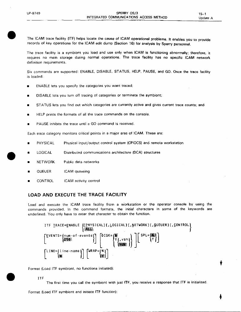
•
•
•
UP-9749 SPERRY OS/3 INTEGRATED COMMUNICATIONS ACCESS METHOD
15-1 Update A
The !CAM trace facility (ITF) helps locate the cause of ICAM operational problems. It enables you to provide records of key operations for the ICAM edit dump (Section 16) for analysis by Sperry personnel.
The trace facility is a symbiont you load and use only when ICAM is functioning abnormally; therefore, it requires no main storage during normal operations. The trace facility has no specific ICAM network definition requirements.
Six commands are supported: ENABLE, DISABLE, STATUS, HELP, PAUSE, and GO. Once the trace facility is loaded:
• ENABLE lets you specify the categories you want traced;
• DISABLE lets you turn off tracing of categories or terminate the symbiont;
• ST A TUS lets you find out which categories are currently active and gives current trace counts; and
• HELP prints the formats of all the trace commands on the console.
• PAUSE inhibits the trace until a GO command is received.
Each trace category monitors critical points in a major area of !CAM. These are:
• PHYSICAL Physical input/output control system (CPIOCS) and remote workstation
• LOGICAL Distributed communications architecture (DCA) structures
• NETWORK Public data networks
• QUEUER ICAM queueing
• CONTROL ICAM activity control
LOAD AND EXECUTE THE TRACE FACILITY
Load and execute the ICAM trace facility from a workstation or the operator console by using the commands provided. In the command formats, the initial characters in some of the keywords are underlined. You only have to enter that character to obtain the function.
ITF !RACE=£NABLE {~illrICAL][,bOGICAL][,~ETWORK][,QUEUER][,~0NTROL}
[£VENTS={.n .... ,LJ.I,"····.·.·.·-.· .. of -events}] [DI SK={lt . } ] [ SPL={•}] llll\l Y{,vsn} Y
1111!
[LINE={!~ine-name }] [WRAP=~}]
Format (Load ITF symbiont, no functions initiated):
ITF The first time you call the symbiont with just ITF, you receive a response that ITF is initialized.
Format (load ITF symbiont and initiate ITF function):
t

t
t
UP-9749 SPERRY OS/3 INTEGRATED COMMUNICATIONS ACCESS METHOD
Format (Issue commands to already loaded ITF symbiont):
00 ITF _IRACE=1m~~~·10ill\SICAL] [,!:OGICAL] [,~ETWORKJ [,gUEUER] [,~ONTROLJ}
§0
['VENTS= {ii-of - events I] [Qr SK= i'l 'M) )] ~PL= l'l] [~INE={l ine-name}] [~RAP={~![}· J
I,
SELECT CATEGORIES AND EVENTS FOR TRACING (ENABLE)
15-2 Update A
The ENABLE command initiates one or more of the trace categories and specifies the number of events to be traced. The trace facility dynamically acquires main storage based on the number of trace events. The trace facility ignores category entries it does not recognize. If it cannot recognize any or if you did not specify any, it initiates all categories.
When you enter this command, a response is displayed on the screen. The response format is the same as for the STATUS command. However, because the Er..JABLE command is initiated at the beginning of the ITF operation, only the indication of the trace categories enabled provides any useful information.
Format:
00 ITF IRACE=£NABLE {[EHYSICAL][,!:OGICAL][,~ETWORK][,9UEUERJ[,~ONTROL]}
~VENTS= l •of - events l] [Q l SK ={'i • •l) J [ ~p L= ~)]
[~INE={~~ne-name}] [~RAP={i;:tj
where:
{[i~~S I CAL] [, !:OG I CAL] [, ~ETWORK] [, 9UEUER] [, ~ONTROL]}
Specifies the categories for which a trace is desired. The default is all categories. If some categories have been previously enabled, the default enables the remaining disabled categories.
EHYSICAL
Traces events pertaining to the communications input/output control system (CPIOCS) and remote workstations.
!:OGICAL
Traces events pertaining to distributed communications architecture (DCA) structures.
~ETWORK
Traces events pertaining to public data networks (PDN).
9UEUER
Traces events pertaining to !CAM queueing.
•
•
•

•
•
UP-9749 SPERRY OS/3 INTEGRATED COMMUNICATIONS ACCESS METHOD
15-3 Update A
~ONTROL
Traces events pertaining to ICAM activity control.
~VENTS= {mi of - events}
Specifies how many events you want traced. You can specify a value from 1 to 9999 up to the amount of main storage available. (See Table 8-1 for main storage requirements.)
If disk tracing is active, the number of events cannot be changed until the disk tracing is disabled.
DISK={I\ l y {',1;~}
Specifies disk tracing (Y,vsn). To indicate where the disk files are to reside, a 6-character volume serial number (vsn) must be specified when using the Y option. (ITF dynamically creates two disk files, ITF1 and ITF2). If you specify DISK=Y without a vsn, the disk pack that was assigned as SYSRUN at system initial program load (IPL) time is used for the ITF disk files.
You can specify disk tracing without spooling, but you cannot specify spooling without disk tracing.
SP L ={ffeti\.} - ~~~~ y
Specifies spooling of disk files (Y). Spooling cannot be enabled unless disk tracing is specified (DISK= Y, vsn).
b. I NE={,:·.·.·l.·.·.··.i ne - name} ,{fj;
Specifies a specific communication line to be traced. Line-name is the name specified in the ICAM network definition as the line label. If there are two network definitions in the system with the same label, only the first one will be traced. The PHYSICAL category must be enabled for the LINE parameter to be active.
~RAP={ •. :~:.:.} ~L Specifies that the trace area will be overwritten after it is filled.
NOTES:
1. Parameters can be in any order following the TRACE parameter.
2. The DISK, SPL, LINE, and WRAP parameters can be enabled or disabled without specifying categories or events unless you want to change those categories.
TERMINATE TRACE CATEGORIES (DISABLE)
The DISABLE command terminates the trace facility or any of the parameters previously enabled by an ENABLE command. With this command, no individual parameters can be changed, only disabled.
• To disable the trace facility completely, specify:
00 ITF TRACE=DISABLE
t

UP-9749 SPERRY OS/3 INTEGRATED COMMUNICATIONS ACCESS METHOD
15-4 Update A
If you wish to disable only certain trace categories or individual parameters while keeping the trace facility active for the remaining categories or parameters, disable only those parameters not desired.
Format:
00 ITF !RACE=QISABLE lEHYSICAL][,kOGICAL][,~ETWORK][,QUEUER][,~ONTROL]
The status of the ICAM symbiont determines how you terminate the trace facility:
• ICAM and ITF are loaded:
Terminate the trace facility with 00 ITF T=D.
• ICAM is terminated and the message ICAM END OF SYMBIONT is displayed on the console:
The trace facility is automatically terminated with ICAM.
NOTES:
1. Before terminating the trace facility, use the /CAM edit dump (Section 16) or /TF spooling (if you are using disk storage) to print the events it has traced and recorded.
2. All disk files created by the trace facility are dynamically allocated and erased when ITF is terminated.
3. Always terminate the trace facility before terminating /CAM.
4. If you disable disk tracing, spooling is also disabled automatically.
t DISPLAY TRACE FACILITY STATUS (STATUS)
Displays the status of the trace facility. In response to a STATUS command, the trace facility lists:
• the categories being traced;
• the size of the dynamically acquired storage area (how many trace events it can hold);
Format:
00 ITF !RACE=§TATUS or !RACE=?
Responses:
MC#159 ITF - TRACING ENABLED
MC#162 ITF - CATEGORY=PNLQC EVENTS=0250 BUFF ADDR=091218
MC#163 ITF - WRAP=YES LINE= DISK=NO VOL= SPL=NO WRAP CNT=0000 GAP CNT=0000
•
•
•

• UP-9749 SPERRY OS/3
INTEGRATED COMMUNICATIONS ACCESS METHOD
DISPLAY TRACE FACILITY COMMAND FORMATS (HELP)
15-5 Update A
The HELP command causes the trace facility to print all of the acceptable command formats on the console or workstation.
Format:
00 ITF J:jELP
INHIBIT THE TRACE FACILITY (PAUSE)
The PAUSE command inhibits further entries into the trace until a GO command is received.
Format:
00 ITF TRACE=~AUSE
00 ITF T=P
DISPLAY THE TRACE BUFFERS (SNAP)
The SNAP command enables an unedited printout of ITF dynamic trace buffers.
Format:
• 00 ITF SNAP
•

• I
•
•

•
16. ICAM Edit Dump
•
•

•
•
• ---------------- -·

•
•
•
UP-9749 SPERRY OS/3 16-1 INTEGRATED COMMUNICATIONS ACCESS METHOD
The ICAM edit dump is a symbiont that dumps selected groups of ICAM tables for diagnostic purposes. It supplements the OS/3 system dump (SYSDUMP).
You can use the edit dump to snapshot ICAM while 1t 1s running. Use it any time ICAM has a program exception. When you take both an edit dump and a system dump, run the edit dump before the system dump.
The ICAM tables that you can dump are:
• General information tables
ICAM general information table
GUST general information table
Activity control queues
CCA address table
• Line link table
• ITF trace
• ICAM task control blocks
MCP task control block
Subtask task control block
• CCA control section
• ARP buffer pool
• Network buffer pool
• UDUCT (DCA user data unit control table) buffer pool
• Link buffer pool
• Destination table
• End user tables
Communication user programs
Line vector table
Terminal control table
Process file
Distribution list

UP-9749 SPERRY OS/3 16-2 INTEGRATED COMMUNICATIONS ACCESS METHOD
• Hexadecimal dump of CCA
• RIM (remote interface manager) queues
• Session analysis (session control entries)
EXECUTE THE EDIT DUMP
To load the edit dump symbiont, type in:
IED
Three messages are displayed on the console or workstation screen in series. You must respond to each message before the next message is displayed. Edit dump executes after you respond to the last message.
Message:
TERMINATE AFTER DUMP (Y)ES OR (N)O?
Response:
(Y)ES Terminate edit dump after processing command in last message.
(N)O Do not terminate; more dumps will be taken. You can respond with N, NO, or any other
character.
Message:
OUTPUT REASON FOR DUMP OR (N)O!
Response:
State the reason for the dump. Limit your explanation to 40 characters. An EQT entry results in a
blank page.
Message:
IEDrs0-ENTER COMMAND OR (H)ELP
where r is the major release ID and is the subordinate release ID, e.g., 8.2.
Response:
Enter the command that gives you the type of dump you want (Table 16-1). If you are not sure which command is best, enter H or HELP and a table of the available commands is displayed.
After processing a command, edit dump terminates if you responded YES to the first message. If you responded NO, edit dump displays the second message again. In response to T, edit dump terminates without a message.
•
•
•

UP-9749 SPERRY OS/3 16-3 INTEGRATED COMMUNICATIONS ACCESS METHOD
• SELECT A COMMAND OPTION
•
•
Although several options are available when you select the tables to be dumped, the two that you should use are Y and A. If you suspect that you have a problem with physical 1/0 or action control (ACTCON), enter a Y to get the tables needed for diagnostics related to those components. For problems in other segments of ICAM, enter an A to get the appropriate tables.
The other command options provide smaller selected groups of tables suitable for limited purposes. The command options are described as follows:
Command
A
B
C, name-1
D, name-1
E, name-2.
s
y
NOTES:
Description
Dumps all tables except line link tables and end user tables
Buffer pools only
Dumps all tables except line link tables, ITF trace, and CCA hex dump. Name is the label of the CCA macro.
Dumps all tables except line link tables and end user tables. Name is the label of the CCA macro.
Dumps end user tables. Name is the label of the LINE, TERM, LOCAP, PRCS, or DUST macroinstruction .
Dumps ICAM trace facility (ITF). Includes the general information tables.
Dumps RIM queues and session control entries
Physical 1/0 or ACTCON dump. Dumps all tables except the hexadecimal dump of the CCA.
1. If you do not include a name (CCA macroinstruction label) or specify an invalid name or options C or 0, nothing is displayed on the console to indicate this.
2. If you do not include a name (macroinstruction label) or specify an invalid name for option E, the message END USER NOT IN CCA appears on the printout from the edit dump .

UP-9749 SPERRY OS/3 16-4 INTEGRATED COMMUNICATIONS ACCESS METHOD
Table 16-1. /CAM Tables and Edit Dump Options • Command Options
ICAM Tables A B c D E I s y Comments
General information tables x x x x x • ICAM general information table
• GUST general information table
• Activity control queues
• Primary address table
Line link table x
ITF trace x x x x The ITF trace is dumped only if the ICAM trace facility is loaded.
ICAM task control blocks x x x x Both the MCP task control block (TCB) and the subtask control block dumps include the following tables:
• Last activity control function
• TCB extensions
• TCB blocks
• ILR trace areas
• ILR save areas
CCA control section x x x x x
Buffer pools x x x x x For the buffer pools (ARP. network, UDUCT. link). trailing words of all zeros are deleted from the buffer displays.
Destination table x x x x • Hexadecimal dump of CCA x x
RIM queues x x x x x x
Session analysis x x x x x A session analysis for each session control entry.
End user tables x x x The end user tables in the dump are formatted as follows:
• • Communications user program
- LOCAP - User task control block (TCB) - Last activity control function - TCB extension - TCB stacks - ILR trace area - ILR save area - QUEUE analysis
• Line vector table - Type - Line buffers - Port analysis
• Terminal control table - Type - Line type - Device control table - Queue analysis
• Process file - File specification - Queue analysis • • Distribution list

•
17. Remote Terminal Processor (RTP)
•
•

•
•
•

UP-9749 SPERRY OS/3 INTEGRATED COMMUNICATIONS ACCESS METHOD
17-1 Update B
• The remote terminal processor (RTP) is a data communications program that permits your SPERRY System 80 processor to function as a remote job entry terminal to one or more IBM host processors. Generate the IBM host communications lines as transparent. RTP enables you to send jobs to an IBM host; transmit and receive files on tape; transmit files from diskette; send messages to the central site; and receive print or punch files and console messages from the IBM host.
•
•
INSTALLATION AND GENERATION
The following steps outline the procedure for installing and generating your RTP system.
1 . Receive and install RTP tapes or diskettes in accordance with the standard software installation procedure.
2. Generate the OS/3 system including features required for RTP. The system must include ICAM by using the communications physical interface (CPI) to define the lines included in the RTP network.
3. Generate your RTP program by coding the RTP generation stream and running the add RTP source job:
RU ADDSRC
These new source, object, and load modules replace any previous version in $Y$SRC, SG$0BJ, or $Y$LOD.
Upon completion of the add source job, run the RTP generation program:
RV ARTP,,SR=RTPTABLE,OT=Y
4. Generate vertical format buffer (VFB) tables:
a. Code VFB generation parameters and run VFBT ABLE generation job:
RU RTPVFB
b. Code automatic VFB tables and run VFBT ABLE generation job:
RU ARTP,,SR=N,OT=Y
5. Link all of the various defined modules and tables by running the RTP link job:
RV LINKRT
6. Execute the RTP program by coding the RTP execution job control stream and running the job stream by using your assigned job name .
t

t
UP-9749 SPERRY OS/3 INTEGRATED COMMUNICATIONS ACCESS METHOD
GENERATE RTP PROGRAM
17-2 Update B
You must define all the resources needed by the RTP including the communication lines and virtual terminals attached to each line, the buffers, and the tapes.
• GNOPT Defines the RTP options
• GNVCT Defines the lines and terminals
After you code your generation statements, you must run two jobs, ADDSRC and ARTP. These jobs generate the RTP program and the tables that the program uses.
Define RTP Program Options (GNOPT)
GNOPT defines the features you want included in your RTP program.
Format:
GNOPT [CBUFL EN=nr:JJ [COM BU F S=i; l] [ NUMTANKS= l;. )] [' NUMTAPs=t; }] L PUN= { ~:s }] [, svsTEM=SJI]
[' TANKLEN=G~: }] [ TBUF LEN={;.}] [ UNAT={ ~~s}]
Parameters:
CBUFLEN={ ;.)
Communications line buffer length in bytes. Must be equal to or greater than the largest message sent from the host.
COMBUFS={~}
Number of communication line buffers. Include at least six. Maximum number in a system is 32.
NUMT ANK S=t;l}
Number of internal data buffers for compression and decompression*. Valid entries are 10 to 160. Specify five tanks for each communications buffer (COMBUFS) specified.
NUMTAPS={~}
Number of concurrent tape operations. Must be less than or equal to the number of tape drives on your system. If you specify that tape support is provided (NUMT APS= n), you must also specify PUN=YES. The maximum is the number of logical paths generated, multiplied by 2.
This option links the tape processing modules. It has nothing to do with the way the tapes are used on a given line or lines.
• Required for compatibility with IBM multicaring data compression
•
•
•
•
•
•
UP-9749 SPERRY OS/3 17-3 Update B
PUN=
YES
NO
INTEGRATED COMMUNICATIONS ACCESS METHOD
Punch modules are included in RTP. If you specify NUMTAPS=n, you must also specify PUN=YES even if you don't have a punch and don't expect to receive punch files. It is sufficient to generate OS/3 with a dummy punch and include a punch DVC-LFD sequence in your RTP run deck.
If tape is used, you must configure OS/3 and RTP to think there is a real punch; then, when RTP is loaded, this unit is set to DOWN and AVAILABLE.
Punch modules are not included.
SYSTEM=80
Specifies the SPERRY System 80 hardware is used for RTP execution.
TANK LEN={ 120}
132 Length, in bytes, of the internal data buffers (tanks). Your entry must match the length of your maximum print line.
TB U FL EN= { ~0 } Length, in bytes, of the tape buffers. Decimal numbers from 1 to 8192. Set tape buffer length equal to the largest anticipated tape block. If no tape operations, specify TBUFLEN=O.
UNAT=
Unattended sign-on module is to be included in the RTP load module. The unattended feature presumes that the host is connected by a dedicated facility. When triggered by an unsolicited operator entry of SU, the unattended facility attempts to activate any dedicated line that is currently available.
NO Does not support unattended sign-on.
YES
Supports unattended sign-on .
t

t
UP-9749 SPERRY OS/3 INTEGRATED COMMUNICATIONS ACCESS METHOD
Define RTP Lines and Virtual Terminals (GNVCT)
17-4 Update B
The GNVCT generation statement defines the lines and virtual terminals used by RTP. A GNVCT statement is required for each virtual terminal (logical path).
Format:
GNVCT [C HAN80={ ! ;} ] [ DI ALU P={ ~S}] [ DUPLE X=1 ~}]
['JOB ID={.~ obname - size} '{~bname - line - number} '{k~•bname -off set}]
[ 'LAST={ ill }] [' LNECOD={.A···s····.·~:·I····.··I···.• .. •.· .. ,}] [ NUMPRT={ .•• ~.·· }] r, NUMPUN={.n.· ..... }] y Es 11:e.QlC .I L I
[OS=mmJ. PORTID=n] [' RDELAY=1~l] [ RETRY=1; nr ID=1~'~rl] [RI DLOC=t;.fi}] [SON={ ~~;,;,~;;er - string'}]
[STD FM={;}] r TAPE=r~:s}] [ TDELAY={;,.}]
[TIMEOUT={.;,}] [ VFB=r~;~~.name}]
Parameters:
CHAN80= { :!J Specifies the communications channel (not the SLCA number) used. Leading zeros are not permitted.
DIALUP= Dedicated or switched line .
•• Directly connected line (causes generation of a procedure note (PNOTE)).
YES Specifies a switched line.
DUPLEX= Specifies the line as 2-way simultaneous (full-duplex) or 2-way alternate (half-duplex).
F
H
Two-way simultaneous line.
Two-way alternate line. Specify this for all System 80 configurations, both 2-way alternate and 2-way simultaneous.
•
•
•

•
•
•
UP-9749
JOB ID=
SPERRY OS/3 INTEGRATED COMMUNICATIONS ACCESS METHOD
17-5 Update B
Describes the name of a job as found in files received from the host by its size, line number, and location.
{ J,obname - size} I
Length of job name. The maximum value is 255.
{ L?bname - l i ne - number}
•• Line number where the job name is located. The maximum value is 255.
{ ' . .J.~;bname - off set} • Character position of the start of the job name. The maximum value is 255.
LAST= Specifies this virtual terminal definition as the last definition in the RTP generation stream.
NO Not the last definition.
YES
The last or the only definition .
LNECOD= Specifies the line discipline of the host. End-of-transmission block (ETB) is hexadecimal 26 in ASCII and hexadecimal 17 in EBCDIC for the SIGNON and SIGNOFF image.
ASCII Line discipline is ASCII. Messages are translated to ASCII.
iRP<l:~ Line discipline is EBCDIC.
NUMPRT={ ..•• ~ •••. ,} l
Number of printers available. The maximum is seven.
NUMPUN={;}
Number of punches available. The maximum is seven.
OS= Specifies the job processing environment of the host system.
Houston automatic spooling program.
JES2 Job entry system 2.
JES3 Job entry system 3.
t

t
UP-9749 SPERRY OS/3 INTEGRATED COMMUNICATIONS ACCESS METHOD
17-6 Update B
PORTID=n
Specifies the communications adapter or single line communications adapter assigned to a virtual terminal that is line-connected to the host. Valid entries are 8 to 15. Must be specified without leading zeros.
RDELAY={ n } 20
Specifies the time in seconds between scans of the input queue; 1 to 256 seconds.
RETRY={;}
Number of times RTP will retry a communications operation. Decimal numbers from 1 to 64.
R I D = { .;.0. + L o9t¢•t .;pa,t~E numb~!7. } The remote ID assigned to RTP by the host with a maximum length of 3 characters, right-justified and zero-filled. If omitted, the logical-path number is used as the rightmost character.
These ID numbers are used in some console messages, and are a constant for comparing jobs sent to the host. If the ID characters are used in SIGNON, they must be specified with a SON= keyword.
RI DLOC= {;.}
Specifies the SIGNON image position where 1, 2, or 3-character remote ID begins. RIDLOC is a bridge between the older and newer versions of RTP and does not cause the RID= to be placed in the SIGNON image.
SON= {~.;;.;; •• ;~.~.er - st r i ng '}
A SIGNON image is maintained for each logical path consisting of the characters /*SIGNON. If any other characters are to be sent to the host, they must start with the keyword (SON=) followed by the character string, within quotes.
Example:
SON=' REMOTE 114 ROUTE1 PASSWORD=XYZ'
The literal declared with SON is inserted starting at column 1 O of the SIGNON image. Therefore, all SIGNONs are preceded by /*SIGNON6, where 6 specifies a space.
STDFM=g}
Number of forms printed on standard paper. Specify all forms at the top of the VFBT ABLE. Valid entries are 1 to 255. The number of host forms using defined or defaulted standard forms for OS/3 must be the same. For example, when there is more than one GNVCT call, the value specified for the STDFM parameter must be the same for each GNVCT call.
NOTE:
When generating more than one virtual terminal, specify the same value for the STDFM parameter in every GNVCT statement.
•
•
•

•
•
UP-9749 SPERRY OS/3 INTEGRATED COMMUNICATIONS ACCESS METHOD
TAPE=
Specifies whether this virtual terminal supports tape operations.
NO Does not support tape operations (causes generation of a PNOTE).
YES Supports tape transmission and reception.
TDELAY={ ~.,}
17-7 Update B
Specify only if the host system runs under HASP, or if using 50 kB lines with tape transmission. Otherwise, omit this parameter.
TIMEOUT{~}
Time (in seconds) RTP waits for completion of a communications operation before assuming that an error occurred. Specify 1 to 255 seconds.
VFB={ vfb.-.name} NON.E
Specifies the VFB name for standard forms.
NOTE:
If you omit this parameter or specify NONE, include a VFB named NONE in your VFB table.
RTP Generation Program Job Stream
To generate your program, you must submit your generation cards to an RTP generation program. Code the following control stream and insert the generation cards where indicated:
10 16
ELE 01,S,RTPTABLE
RTPTABLE START 0
II FIN
NOTES:
GNOPT parameter,parameter, ••• ,
parameter
GNVCT TYP=DC,REMOTE=Cparams),
PORTID=77,parameter
END
EOD
72
x
x
1. At least one blank space must appear before the ELE statement. The statement must not start in column 1.
Continuation cards are permitted for the RTP generation parameters. To indicate continuation, place a comma after the last parameter on the card and place an X in column 72. Start the continuation card in column 16.
t
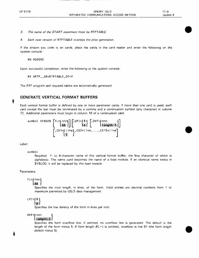
t
UP-9749 SPERRY OS/3 INTEGRATED COMMUNICATIONS ACCESS METHOD
3. The name of the ST ART statement must be RTPT ABLE.
4. Each new version of RTPT ABLE overlays the prior generation.
17-8 Update B
If the stream you code is on cards, place the cards in the card reader and enter the following on the system console:
RU ADDSRC
Upon successful completion, enter the following at the system console:
RV ARTP,,SR=RTPTABLE,OT=Y
The RTP program and required tables are automatically generated.
GENERATE VERTICAL FORMAT BUFFERS
Each vertical format buffer is defined by one or more parameter cards. If more than one card is used, each card except the last must be terminated by a comma and a continuation symbol (any character) in column 72. Additional parameters must begin in column 16 of a continuation card.
symbol VFBGEN
Label:
symbol Required 1- to 4-character name of this vertical format buffer, the first character of which is alphabetic. The name used becomes the name of a load module. If an identical name exists in $Y$LOD, it will be replaced by this load module.
Parameters:
FL={~in} Specifies the total length, in lines, of the form. Valid entries are decimal numbers from 1 to maximum permitted by OS/3 data management.
LPI=t:.} Specifies the line density of the form in lines per inch.
OV F = { '.~il1~~.1W:~:} Specifies the form overflow line. If omitted, no overflow line is generated. The default is the
•
•
length of the form minus 5. If form length (FL=) is omitted, overflow is line 61 (the form length • default minus 5).

•
•
•
UP-9749 SPERRY OS/3 INTEGRATED COMMUNICATIONS ACCESS METHOD
CD1={ •. f~';ine},CD2=l ine, ... ,CD15=l ine .Ii
17-9 Update B
Specifies the line or lines where an associated skip code is entered into the vertical format buffer. CD= specifications may be entered in any order and may be sublisted such as CDn=(line,line, ... ,line). If a line is repeated, the last skip code associated with that line is used.
CD 1, skip code 1, is assumed to be the IBM home paper code. The SPERRY home paper code (07) is entered into the line designated for CD 1. If CD 1 is omitted, line 5 will contain the 07 home paper code. Because CD 1 is treated as home paper, it should be less than any other CD= line number.
A CD7 = causes generation of hexadecimal OD in the specified lines because 07 is the SPERRY home paper code.
All other CD= specifications generate equivalent hexadecimal codes.
For details on the conversion of skip codes, see the OSl3 Basic Data Management User Guide, UP-8068 (current version).
Example:
STD0
10 16
VFBGEN FL=66,LPI=6,CDI=1,CD2=7,CD3=13,CD4=19,CD5=25, CD6=31,CD7=37,CD8=43,CD10=55,CD11=61,0FV=64
72
c
After coding the appropriate parameter cards, you must submit them to the VFB generation program. Place the cards, followed by a 11 FIN job control card, in the card reader and enter the following at the system console:
RU RTPVFB, ,VFB=vfbname[, TEST={,~}]
Execution of the RTPVFB job stream assembles the vertical format buffer. The name specified on the RTPVFB call line is the name assigned to the VFB load module. It must correspond to the name on the first VFBGEN card. If TEST= is specified as N or defaulted, the assembled VFB is linked and written to $Y$LOD. If TEST=Y is specified, no load module is generated.
The appropriate vertical format buffers are automatically generated.
Generate Automatic Vertical Format Buffer Table (VFBTABLE)
The RTP uses a 2-column vertical format buffer name table (VFBT ABLE) that lists the IBM printer form name and related RTP VFB name to automatically load the proper VFB when a host requests a special print form .
t

-- ----------------------------------------
UP-9749 SPERRY OS/3 INTEGRATED COMMUNICATIONS ACCESS METHOD
17-10 Update B
You generate the VFBT ABLE by coding a series of source statements and submitting them to the VFBTABLE generation program. (See Figure 17-1.) The last entry in the VFBTABLE must be ENDVENDV. Even if the VFBT ABLE function is not needed, you must generate a VFBT ABLE containing only the entry ENDVENDV.
Host Form Name RTP VFB Name
xxx1 yyy1
xxx2 xxx2
ENDV ENDV
Figure 17-1. VFBTABLE Structure
Sample VFBT ABLE generation:
10 16
VFBTABLE
DC C'FRM1STD0
DC c I FRM2STD0
DC C'1024W2W2
DC C'CORPSPFZ
DC C'ENDVENDV' END
II FIN
Standard form
Standard form
Special form
Special form
End of VFBT ABLE
After coding, place in card reader and enter the following at the system console:
RU ARTP,,SR=N,OT=Y
The VFBTABLE is generated and placed in your OS/3 system object module library (SY$0BJ).
LINK RTP MODULES AND TABLES
After you generate your RTP program and all required tables including vertical format buffer tables, link the modules together by using the following command at the system console:
RV LINKRT
EXECUTE RTP PROGRAM
To execute your RTP program, you must code and run a job control stream. The job control stream assigns the resources required by the RTP and executes the program. But before running the job control stream, you must initialize the ICAM symbiont by using the following console type-in:
Cn or Mn
•
•
•
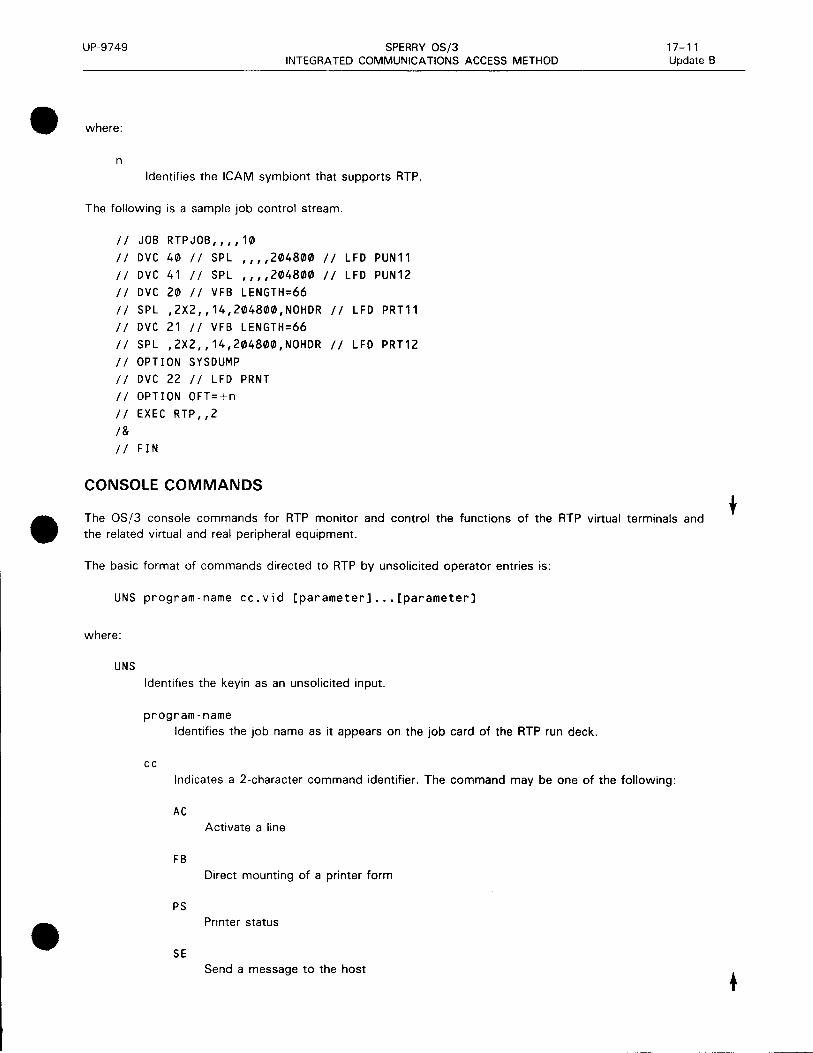
•
•
•
UP-9749 SPERRY OS/3 INTEGRATED COMMUNICATIONS ACCESS METHOD
where:
n Identifies the ICAM symbiont that supports RTP.
The following is a sample job control stream.
II JOB RTPJOB,,,,10
II DVC 40 II SPL ,,,,204800 II LFD PUN11
II DVC 41 II SPL ,,,,204800 II LFD PUN12
II DVC 20 II VFB LENGTH=66
II SPL ,2X2,,14,204800,NOHDR II LFD PRT11
II DVC 21 II VFB LENGTH=66
II SPL ,2X2,,14,204800,NOHDR II LFD PRT12
II OPTION SYSDUMP
II DVC 22 II LFD PRNT
II OPTION OFT=+n
II EXEC RTP,, 2
I& II FIN
CONSOLE COMMANDS
17-11 Update B
The OS/3 console commands for RTP monitor and control the functions of the RTP virtual terminals and the related virtual and real peripheral equipment.
The basic format of commands directed to RTP by unsolicited operator entries is:
UNS program-name cc.vid [parameter] •.• [parameter]
where:
UNS
Identifies the keyin as an unsolicited input.
program-name
Identifies the job name as it appears on the job card of the RTP run deck.
cc Indicates a 2-character command identifier. The command may be one of the following:
AC Activate a line
FB Direct mounting of a printer form
PS Printer status
SE Send a message to the host
t

t
UP-9749
so
ST
SU
vid
SPERRY OS/3 INTEGRATED COMMUNICATIONS ACCESS METHOD
Signoff
RTP line status
Unattended sign-on
17-12 Update B
Indicates a single-digit (1-7) virtual terminal number that the command applies to. Specifying the remote ID, instead of the line number, is not permitted.
parameter Specifies the various parameter options described here.
NOTE:
When numeric values are permitted in commands, they cannot have leading zeros.
Activate a Virtual Terminal (AC)
Activates a specified virtual terminal (line) and notifies the host processor of the action by sending it a SIGNON card image. Communications with the host processor can begin immediately after it acknowledges the SIGNON message.
Format:
LINS pcogcam-nome AC -vi d [. CD=AJ [CH= {:nr-DX=F J [ -ID= id] [ - JL=n] [. JO=nJ [ -JS=nJ
NOTE:
[
OS=/HASP)][.PT=n][.SO=column, 1 literal 1 ][.SW=Y][.-]
lJES2
JES3
All keyword parameters are optional; use them only when you want to modify the virtual terminal upon line activation.
Parameters:
.CD=A Assumes that EBCDIC is used to delimit messages, unless CD=A specifies ASCII.
.CH={~n The System 80 channel is 2, 13, or 15.
•
•
•

•
•
•
UP-9749
.DX=F
SPERRY OS/3 INTEGRATED COMMUNICATIONS ACCESS METHOD
17-13 Update B
Assumes a 2-way communication link, alternate half-duplex (HDX). unless .DX=F specifying full-duplex (FOX) .
. ID= id 1-, 2-, or 3-character remote ID required by a host system .
. JL=n Line-number where job name is to appear.
.JO=n Offset to start of the job-name ( 120 or less) .
. JS=n Number of characters in a job name (eight or less) .
. OS=J~:~~} lJES3 Specifies the host's spooling system .
. PT=n System 80 SLCA .
. SO=column, 'literal' Describes fields to be inserted into the SIGNON image sent to the host. Repeat until all fields are entered. The column is the position where the string literal is to begin. Column must be greater than 0 and less than 81.
If f*SIGNON is included, the column pos1t1on must be greater than 9. The parameters are checked to ensure that they are within the SO-character boundaries of the SIGNON image .
. SW=Y Assumes a dedicated line, unless .SW= Y specifies a switched line. Default is dedicated.
Specifies that an activate (AC) command is continued. The command processor solicits more input .
t

t
UP-9749 SPERRY OS/3 INTEGRATED COMMUNICATIONS ACCESS METHOD
Change Form or VFB Name in Printer Spool File (FB)
Resets the host's form name and the associated OS/3 VFB name in a designated printer's spool file.
17-14 Update B
Enter this command at any time. Used when RTP issues a PR#05 message telling the operator that it was unable to locate a specified VFB in $Y$LOD.
Format:
UNS program-name FB.vid.PRn[.F=form-name][.C=VFB-name]
Parameters:
PRn
Printer spool file to alter.
F-. -
1- to 4-character name of a form received from the host.
C-. -1- to 4-character name of an OS/3 VFB that is stored in $Y$LOD.
Display Virtual Printer Status (PS)
Displays information about all virtual printers belonging to a virtual terminal:
• Forms currently set up for each virtual printer
• The active or idle status of each virtual printer
• The number of print lines received but not breakpointed
Format:
UNS RTPJOB PS.vid
where:
PRn
Virtual printer whose status is displayed.
ACTIVE
Virtual printer currently (NOW) receiving data, or currently idle (NOT).
JOB= job-name
Job name of the file being received.
FORM=form-name
IBM form name the printer is set up to receive.
VFB=vfb-name
Vertical format buffer that is loaded into the real printer when the file is printed.
•
•
•
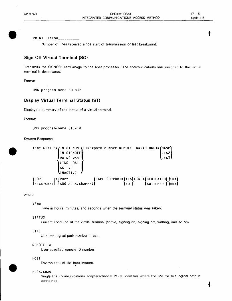
•
•
•
UP-9749 SPERRY OS/3 INTEGRATED COMMUNICATIONS ACCESS METHOD
PRINT LINES= _________ _
Number of lines received since start of transmission or last breakpoint.
Sign Off Virtual Terminal (SO)
17-15 Update B
Transmits the SIGNOFF card image to the host processor. The communications line assigned to the virtual terminal is deactivated.
Format:
UNS program-name SO.vid
Display Virtual Terminal Status (ST)
Displays a summary of the status of a virtual terminal.
Format:
UNS program-name ST.vid
System Response:
time STATUS= IN SIGNON
IN SIGNOFF
DOING WABT
LINE LOST
ACTIVE
INACTIVE
LINE=path number REMOTE ID=RID HOST=1HASP} JES2
JES3
{PORT }={Port }TAPE SUPPORT={YES}LINE={DEDICATED}{FDX} SLCA/CHAN S80 SLCA/Channel NO SWITCHED HDX
where:
time Time in hours, minutes, and seconds when the terminal status was taken.
STATUS Current condition of the virtual terminal (active, signing on, signing off, waiting, and so on).
LINE Line and logical path number in use.
REMOTE ID User-specified remote ID number.
HOST Environment of the host system . .
SLCA/CHAN Single line communications adapter /channel PORT identifier where the line for this logical path is connected.
t

t
UP-9749 SPERRY OS/3 INTEGRATED COMMUNICATIONS ACCESS METHOD
TAPE SUPPORT Specifies whether a tape drive is supported.
LINE=
Specifies whether the line is switched or dedicated, full-duplex (FOX) or half-duplex (HDX).
Activate or Deactivate Unattended Sign-On Facility (SU)
17-16 Update B
Activates or deactivates the unattended sign-on facility. After the facility is activated, the system attempts to sign on to each inactive, dedicated logical path specified every 5 minutes whenever the line is inactive.
Format:
UNS program-name SU.vid.{ON} OFF
Parameters:
vid
ON
OFF
Sequence number of the virtual terminal for which the unattended sign-on facility is to be activated or deactivated. The RMxxx form is not accepted.
Activates the unattended sign-on facility.
Deactivates the unattended sign-on facility. It does not issue a SIGNOFF or terminate RTP.
Shut Down the RTP Program (EOJ)
Terminates the RTP program. All virtual terminals must be signed off before entering this command.
Format:
UNS RTPJOB EOJ
Send a Message to the Host (SE)
Sends an OS/3 console message to the host operator as specified by the virtual terminal's logical path.
Format:
UNS program-name SE.vid.message
RTP OPERATIONS
Communicate with the Host
Issue the activate (AC) command at the OS/3 console unless unattended sign-on has been generated, in which case connection is made automatically. The next step depends on how the SPERRY system is connected to the IBM host: direct connect or dial-up.
•
•
•

•
•
•
UP-9749 SPERRY OS/3 INTEGRATED COMMUNICATIONS ACCESS METHOD
17-17 Update B
For a directly connected host processor, ATP transmits an enquiry (ENO) control sequence and, when acknowledged, ATP then sends the SIGNON card image to the host. Communications processing can then begin.
For dial-up, ATP responds to the AC command with the message:
CM#14 CONNECT LINE - DIAL HOST OR WAIT FOR RING
The operator must make the connection for ATP. Approximately 2 minutes are allowed to make the connection and for the host to acknowledge the connection.
If a connection is not made within the allowed time or if no acknowledge is received on a dedicated circuit, ATP issues the following message:
CM#21 LINE CONNECTION TIME HAS EXPIRED - REACTIVATE
Reissue the AC command to attempt another connect. Once a dialed line is connected, the ENO and SIGNON are sent as for a dedicated line.
Reestablish Communications after Abnormal Termination
After an abnormal termination, use the AC command to reestablish communications because the IBM host normally retransmits any files interrupted by the termination .
NOTE:
If you operate with unattended sign-on, RTP tries to reestablish communications every 5 minutes after an abnormal termination. If files were being transmitted when the abnormal termination occurred, use the SU command to deactivate the facility until the host or the virtual terminal is ready to receive retransmitted files.
Communicate with the Host from the OS/3 Console
• To send a message to the host, enter:
UNS program-name
Logical path number
A period followed by your message
Example:
UNS RTPJOB SE.1.$DA
Sends the message '$DA' to the host .
• All messages from the IBM host to OS/3 system are displayed on the system console. For example:
UNS RTPJOB RM104 $10.11.24 OK
Identifies the terminal, RM 104, follpwed by the message sent.
t
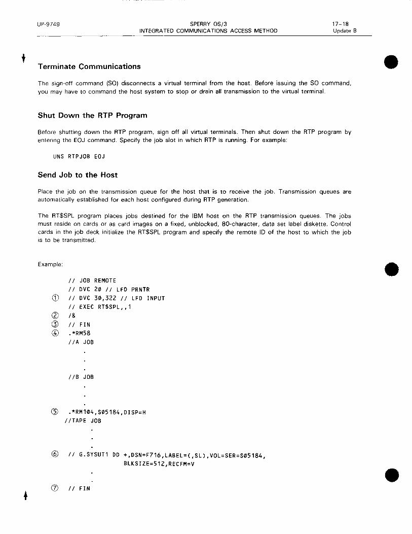
t
UP-9749 SPERRY OS/3 INTEGRATED COMMUNICATIONS ACCESS METHOD
Terminate Communications
17-18 Update B
The sign-off command (SO) disconnects a virtual terminal from the host. Before issuing the SO command, you may have to command the host system to stop or drain all transmission to the virtual terminal.
Shut Down the RTP Program
Before shutting down the RTP program, sign off all virtual terminals. Then shut down the RTP program by entering the EOJ command. Specify the job slot in which RTP is running. For example:
UNS RTPJOB EOJ
Send Job to the Host
Place the job on the transmission queue for the host that is to receive the job. Transmission queues are automatically established for each host configured during RTP generation.
The RT$SPL program places jobs destined for the IBM host on the RTP transmission queues. The jobs must reside on cards or as card images on a fixed, unblocked, 80-character, data set label diskette. Control cards in the job deck initialize the RT$SPL program and specify the remote ID of the host to which the job is to be transmitted.
Example:
II JOB REMOTE
II DVC 20 // LFD PRNTR
CD II DVC 30,322 II LFD INPUT
II EXEC RT$SPL,,1
(?) !& ~ II FIN @ .*RM58
//A JOB
//B JOB
~ .*RM104,S05184,DISP=H
//TAPE JOB
@ II G.SYSUT1 DD +,DSN=F716,LABEL=C,SL),VOL=SER=S05184, BLKSIZE=512,RECFM=V
(J) II FIN
•
•
•

•
•
•
UP-9749 SPERRY OS/3 INTEGRATED COMMUNICATIONS ACCESS METHOD
17-18a Update B
Remote ID Record Format
The remote ID record format immediately precedes the first input record to RT$SPL. All parameters of the remote ID record are optional but. if specified, must be coded in the order shown. The parameters specified are applied to all job streams processed until another remote ID record is read.
Format:
. *RMr r r, [{spool - label}] , [DI SP=1:.''.H_., .. ,_,':·,··.)]' [CLASS=lll] DATA I: 1 R 2
where:
.*RMrrr Is a 1-, 2-, or 3-digit remote record identifier. The record starts in column 1.
{spool - Label} DATA
Spool-label is a 1- to 8-character label to be entered on the RDR spool file for all input job streams following this record. This name replaces the label entered from the // JOB record. If a label is not specified here, the name from the // JOB record is used. Spool labels for job streams are prefixed with RTP for identification.
DAT A specifies that a data file follows this record, not a job stream. The spool label for a data file is RTP.
DISP= Specifies the disposition of the job stream on the OS/3 spooler.
H
Place jobs on a hold queue.
Place jobs on a normal queue.
R
Jobs are retained on the spool file after transmission to the host.
CLASS= Specifies the priority of the job stream on the OS/3 spooler. RTP transmits the job streams to the host on a first-in, first-out basis within the priority class.
Normal priority.
High priority.
2 Preemptive priority .
t

UP-9749 SPERRY OS/3 INTEGRATED COMMUNICATIONS ACCESS METHOD
Receive Print and Punch Files from the Host
17-18b Update B
Print and punch files received from the host are first spooled in. If only standard forms are required, spooling directs the file to the proper printer or punch. If special forms are required, the operator must mount the proper form.
To receive print and punch files:
1. Command the host to stop or drain the virtual terminal print or punch device. (Optional)
2. Establish the virtual terminal, virtual printer, or punch to receive the specific forms. (Printer status can be determined with the PS command.)
3. Insert the proper FB command. (Print files only)
4. Inform the host system of the setup.
5. Command the host to start the printer or punch file. (Required only if step is used)
6. Receive the file. (For print or punch files that require special forms, the operator must mount the special form and notify the host.)
Send and Receive Tape Files
Magnetic tape files for RTP are specified as card image (punch) files. RTP can activate one input and one output tape file for each virtual terminal generated (GNVCT).
When sending or receiving tape files, the tape must be available when the RTP job is run. If the tape is not available and the console operator responds with a C to the JC 10 MOUNT DEV message, the RTP job run
is canceled.
• Sending Tape Files
When a host-destined job stream requires a magnetic tape file for a particular job, you must insert a 11 DD control statement following the remote ID record.
•
•
•

UP-9749 SPERRY OS/3 17-19 INTEGRATED COMMUNICATIONS ACCESS METHOD
• The DD control statement, formatted for RTP, initiates the start of tape transmission. Columns 1 to 69 are used for tape parameter information. If more than one card is needed or if you want to place parameters on separate cards, interrupt the field after a complete parameter (including the comma that follows it) at or before column 69. Code 11 in columns 1 and 2 of the fol!owing card and continue the tape parameter specifications starting in column 10. No coding is permitted in columns 70 through 80 on any RT$SPL tape parameter card.
•
•
Format:
Label:
//lddname )DD{+),BLKSIZE=block-size['{DSNAME}=data-set-name] procstepname. & DSN
ddname U
['LABEL= {llita - set - seq-num}, {;IJ J [, VOL=SER=vol - ser i a L - num]
[REC FM=1 ~~[RTCH={ rn [DEN={~~ [•UN IT={:~~:- addcess \]
//{ddname } procstepname.ddname
The 11 characters in columns and 2 are required for RTP. The ddname or procstepname.ddname, starting in column 3, is not used by RTP but is provided for use by the IBM host. The label must conform to the rules described for the host system in the appropriate IBM JCL manual.
Parameters:
Identifies this DD statement as an RTP instruction. This positional parameter must be the first parameter in the statement. It specifies whether a blank precedes each transmitted tape record.
+
&
u
A blank preceding each record.
No blank preceding each record. The tape format is the same as card reader format.
A blank preceding each record and the block size given as the first two characters of each physical block (REC FM= U implied).
BLKSIZE=block-size Specifies the block size of the data set (file). The parameter must be one to four numeric characters.

UP-9749 SPERRY OS/3 17-20 INTEGRATED COMMUNICATIONS ACCESS METHOD
{DSNAME}=data-set-name • DSN
Specifies the name of the data set. Data-set-name can contain from 1 to 44 characters, including ampersands and apostrophes, with no blanks or commas. If the name consists of more than 17 characters, only the rightmost 17 are entered in the parameter and are used in the HOR 1 label.
DSNAME must be coded for standard labeled tapes. It is optional for nonlabeled tapes, but can be coded for identification purposes:
LABEL= {~ata-set-seq-num}'{;I}
{~ata-set-seq-num}
Specifies the relative position of a data set on a tape volume. It can be one to four numeric characters.
Specifies whether the data set has no labels (NL) or has standard or standard mixed with user labels (SL). User labels are bypassed and, therefore, not processed.
Coding Rules:
a. The subparameters are positional. Indicate the absence of the first one by a comma.
b. If you do not specify the second subparameter, omit the parentheses.
c. Standard labels can be in the IBM BPS, TOS, DOS, or OS formats.
d. If the data set sequence number is omitted or specified as zero, it defaults to 1.
VOL=SER=vol-serial-num Specifies the serial number of the volume containing the data set. The number must consist of six nonblank characters.
The serial number is required for all standard labeled tapes. It is optional for nonlabeled tapes, but can be coded for identification of the external tape label.
RECFM=m
F
u
v
Fixed-length records. F is the default value unless U is specified as the first DD parameter.
Undefined records. U is the default value if U is specified as the first DD parameter.
Variable-length records.
•
•

•
•
•
UP-9749 SPERRY OS/3 17-21 INTEGRATED COMMUNICATIONS ACCESS METHOD
Specifies options (parity, translation, and data conversion) for 7-track tapes. When used, the DEN parameter must also be specified. This parameter is required for 7-track tapes. If not specified, 9-track tape is assumed.
c Data conversion feature with odd parity and no translation.
E Even parity with no conversion and no translation.
T Odd parity with no conversion. BCD to EBCDIC translation is required when reading.
ET
Even parity with no conversion. BCD to EBCDIC translation is required when reading.
DEN=m
Specifies tape recording density and is required for 7-track tape. DEN is optional for 9-track tape and, if omitted, the density specified on the OS/3 SYSGEN is used.
Density (bits/inch) (bpi)
0 200 1 556 2 800 3 1600
UNIT={TAPE } unit-address
This parameter is not used by ATP but is accepted for compatibility.
NOTE: You can insert comments at the end of the statement following a separation of at least one blank.
• Receiving Tape Files
First, notify the host that an ATP workstation punch is set up to receive the forms specified in the magnetic tape file special forms queue entry.
When the host is ready to send the card-image file, the host specifies the volume serial number of the tape to be created, and RTP acquires a tape device from the OS/3 system.
The operator mounts the appropriate tape volume, as specified by the OS/3 system, and preps the tape with the correct volume serial number. Unlabeled tapes must have a leading tape mark .

UP-9749 SPERRY OS/3 17-22 INTEGRATED COMMUNICATIONS ACCESS METHOD
For multivolume files, all volumes of the same file must be mounted on the same tape device. If the file is labeled, prep each additional volume with a VOL 1 record. For unlabeled tapes, each additional volume must have a leading tape mark. In either case, OS/3 will ask the operator to mount a scratch volume.
As the last record of a magnetic tape file is received and ending file labels are processed and written, RTP verifies that the correct number of blocks were received. If so, the operator is informed of a normal tape transmission termination.
RTP closes the tape file and releases the tape drive to OS/3 for use by other jobs.
•
•
•

•
18. SLCA Dump Routine
•
•

- - ---------------------
•
•
•

UP-9749 SPERRY OS/3 18-1 INTEGRATED COMMUNICATIONS ACCESS METHOD
• The SLCA dump routine (DSLCA) is used to obtain a printed listing of the contents of the random access memory (RAM) of a single line communications adapter.
•
•
EXECUTE THE SLCA DUMP ROUTINE
The DSLCA routine is executed in response to a system console keyin. The format of the console command is:
RV SLCADUMP
[
'ID={ :mn}~[, TYPE=t] tillli, \~!litl::i
where:
ID=ccnn Identifies the channel and line number of the single line communications adapter. The default is 0208 for System 80 models 3-6 and 1301 for model 8. If you enter a 2-digit number, that value is accepted as the line nunmber and a channel number of 02 (models 3-6) or 13 (model 8) is assumed.
Valid channel and line numbers are:
Model
3-6 8
Channel Number
02 13 or 15
Line number
08 through 15 01 through 15
The line number must match the ID specification on the LINE macroinstruction in the ICAM network definition.
TYPE=t Is a 1-digit number between 1-5 that identifies the type of single line communications adapter. This specification is optional for types 1-3 and required for type 5.
Before executing the dump routine, the console operator must make certain that the communications line to which the single line communications adapter is attached is idle. That is, your program has issued a line release or the operator has downed (DO) the line. Note that an autodial SLCA cannot be dumped because it has no storage area. If a dump is attempted, an error message is displayed on the operator's console .

•
•
•

•
Appendix A. Coding Conventions
•
•

•
•
•

UP-9749 SPERRY OS/3 A-1
INTEGRATED COMMUNICATIONS ACCESS METHOD
• TYPES OF MACROINSTRUCTIONS
•
Three types of macroinstructions enable communication between basic assembly language communications
programs and ICAM. They are:
1 . Declarative
2. Imperative
3. S-type
Declarative macroinstructions generate nonexecutable code in your program. They are used to define control tables, e.g., DTFCP and MCTPKT in your applications program. You must always isolate these from the executable portion of your program.
Imperative macroinstructions generate executable code in your program. They request supervisor services or direct the operation of your program. Some examples of imperative macroinstructions are PUTCP, GETCP, NETREQ, and NATT ACH.
S-type macroinstructions permit you to separate the executable portion of macrogenerated code (E-form) from the nonexecutable (L-form) portion.
Many ICAM macroinstructions create both executable code and a parameter list. Some of these macroinstructions include a MF= operand. The MF= operand allows you to specify whether the macroinstruction you are coding is the executable portion only or the declarative portion (the parameter list) only. This feature allows you to create a single parameter list and point to it from many execut~ble (E-form) macroinstructions of the same name. You can dynamically alter the parameter list as needed, thus saving considerable main storage. If you do not use the S-type feature (MF=). a complete parameter list is incorporated into your program each time you use the macroinstruction.
GENERAL FORMAT OF THE DECLARATIVE AND IMPERATIVE MACROINSTRUCTIONS
The general format of these macroinstructions is:
LABEL
symbolic
name
L':.OPERATIONL':.
macro
mnemonic
OPERAND
parameters
A symbolic name can appear in the label field. It can have a maximum of eight characters and must begin with an alphabetic character.
The appropriate macroinstruction mnemonic must appear in the operation field to identify the operator or service requested.
When parameters are specified in the operand field, they must be positional parameters or keyword
parameters as required by the particular function.
• Assembler rules regarding blank columns and continuation of the operand field must be followed.
Parameters must not be separated by blanks.

UP-9749 SPERRY OS/3 A-2 INTEGRATED COMMUNICATIONS ACCESS METHOD
Positional Parameters
Positional parameters must be written in the order specified in the operand field and must be separated by commas. When a positional parameter is omitted, the comma must be retained to indicate the omission, except for the case of omitted trailing parameters.
Example:
The TRMREP macroinstruction has three mandatory positional parameters (line-name, terminal-name, workarea-address) and one optional parameter (FIELDS= CALL).
Format:
LABEL 60PERATION6
[symbol] TRMREP
This macroinstruction may be written:
OPERAND
line-name,terminal-name,workarea-address
[,FIELDS=CALL]
TRMREP
TRMREP
lne1,trm1,TRWA
lne1,trm1,TRWA,FIELDS=C666-5708)
Keyword Parameters
A keyword parameter consists of a word or a code immediately followed by an equal sign, which is, in turn, followed by a specification. Keyword parameters can be written in any order in the operand field. Commas are required only to separate parameters.
Example:
The DTFCP macroinstruction has one mandatory keyword parameter (TYPE) and six optional keyword parameters (UNIT, LEVEL, NOMAV, ERRET, DATIME, and NOTLST).
Format:
LABEL 60PERATION6
[symbol] DTFCP
OPERAND
TYPE=GT
[,UNIT=LINE]
[ LEVEL={:;~!UHr AVAIL LJ
[,NOMAV=symbol]
[,ERRET=symbol]
[,DATIME=YES]
[, NOTLST=symbo l]
•
•
•

•
•
•
UP-9749 SPERRY OS/3 iNTEGRA TED COMMUN!CA TIONS ACCESS METHOD
This macroinstruction may be written:
DTFCP
DTFCP
DTFCP
DTFC:P
TYPE=GT,UNIT=LINE,LEVEL=HIGH
TYPE=GT
TYPE=GT,UNIT=LINE,NOMAV=nohit,ERRET=err1
TYPE=GT,LEVEL=AVAIL,NOMAV=nohit,OATIME=YES
MACROINSTRUCTION CODING CONVENTIONS
The conventions used to delineate macroinstructions are:
• Capital letters, commas, parentheses, and equal signs must be coded exactly as shown.
Examples:
R
ALL start-addr,end-adr ( 1)
SIZE=
A-3
• Lowercase letters and words are generic terms representing information that must be supplied. Such :owercase ~erms may contain hyphens and acronyms (for readability) .
Examples:
name
start-addr
number-of-bytes
param-1
ccb-name
• Information contained within braces represents mandatory entries - one of which must be chosen.
Examples:
{input-area} ( 1)
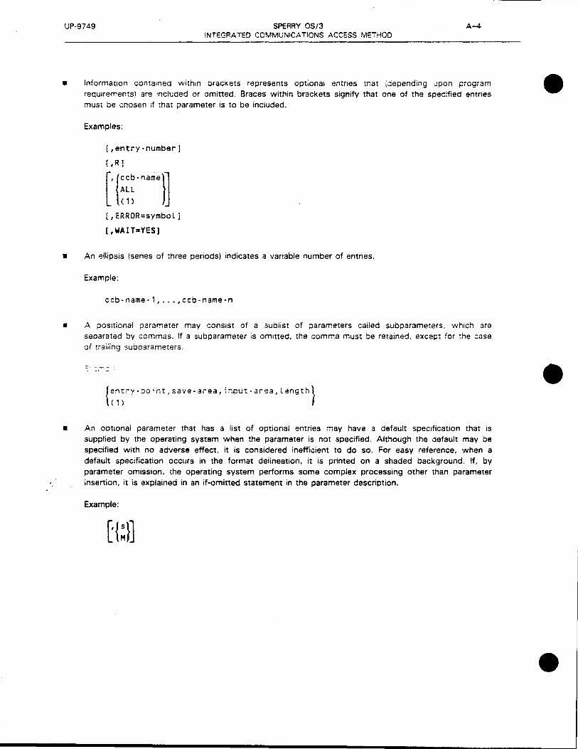
UP-9749 SPERRY 05/3 A-4
•
INTEGRATED COMMUNICATIONS ACCESS METHOD
Information contained within oracKets represents optional entries mat (aepending upon prog;am requirements) are included or omitted. Braces within brackets signify that one of the specified entries must be chos&n 1f that parameter is to be included.
Examples:
[,entry-number]
[IR l
[,ERROR=symbol]
[,WAIT=YES]
• An ellipsis (series of three periods) indicates a variable number of entries.
Example:
ccb-name-1, •.• ,ccb-name-n
• A positional parameter may consist of a sublist of parameters called subparameters. which are separated by commas. If a subparameter is omitted, the comma must be retained, except for the case of traiiing subparameters.
---- -
{entry-point,save-area,ir.put-area,Length} ( 1)
• An optional parameter that has a list of optional entries may have a default specification that is supplied by the operating system when the parameter is not specified. Although the default may be specified with no adverse effect, it is considered inefficient to do so. For easy reference. when a default specification occurs in the format deiineation. it is printed on a shaded background. If, by parameter omission. the operating system performs some complex processing other than parameter insertion, it is explained in an if-omitted statement in the parameter description.
Example:
•
•
•

•
•
•
UP-9749 SPERRY OS/3 A-5 INTEGRATED COMMUNICA TiONS ACCESS METHOD
GENERAL FORMAT OF S-TYPE MACROINSTRUCTIONS
As we mentioned earlier, the S-type macroinstruction is unique in !CAM. It is used either when the number of parameters to be passed to the called routine cannot be contained in the parameter registers or to change the parameter list. The parameters are placed in a parameter list whose address is passed to the called subroutine in register 1. There are four S-type macroinstructions (NETREQ, NETREL, LNEREQ, and LNEREL) and three S-types:
1. S-type/L-form
2. S-type/E-form
3. SD-type
NOTE:
All S-type macroinstructions are provided with L- and £-forms unless otherwise stated under the individual descriptors. In some cases, a 0-form may be provided to facilitate DSECT generation.
S-Type/L-Form Macroinstruction
The L-form macroinstruction generates a parameter list at the place the macroinstruction is encountered. The E-form macroinstruction, which is discussed next, points to the parameter list generated by the L-form. When the program is coded, the L-form macroinstructions should be placed among the define constants (OCs) or define storage statements (DSs) since they do not receive control and contain no executable code . The format of the l-form macroinstruct1on is:
LABEL
symbol
!:.OPERATIONL
{
LNEREQ} LNEREL
NETREQ
NETREL
OPERAND
MF=L
Note that the label field is a required entry since it becomes the label of the generated parameter list and is referred to by the E-form macroinstruction. The assembler recognizes the L-form by MF=L in the operand field.
S-Type/E-Form Macroinstruction
The E-form macroinstruction points to a previously generated parameter list. Normally, it points to the parameter list generated by the L-form macroinstruction, but it can point to any parameter list.
The format of the E-form macroinstruction is:
LABEL
symbol
L.OPERATIONL.
{
LNEREQ} LNEREL
NETREQ
NE TR EL
OPERAND
MF=E,{parameter-list-address} ( 1)

UP-9749 SPERRY OS/3 A-6 INTEGRATED COMMUN!CA T!ONS ACCESS METHOD
The :abei f;eld 1S a :equired entry because ·t ~ecornes tt:e !larr:e 'Jf the ;JaraIT'e~2r '!sr ref 1=ren:2·:! "J'/ :re ~~form macroinstruction. The assembler recognizes the E-form by MF=E in the operand field. The parameter :ist address indicates the location of the list used by the E-form macroinstruction or loads the address .Jf ;i1e L-form parameter list prior to execution via an MVC instruction into register 1
SD-Type Macroinstruction
The SD-type macroinstruction is an extension to the S-type macro1nstruction. It provides the same support while adding the capability of prefixing a character to the labels the macroinstruction generates or describing more than one parameter list.
The format of the SD-type macroinstruction is:
LABEL
[symbol]
b.OPERATIONc.
{
LNEREQ} LNEREL
NETREQ
NETREL
OPERAND
MF=D[,prefix-code]
Here, the symbol is an optional entry, unlike the L- and E-forms. The assembler recognizes :he SD-type by the MF= D in the operand field and also specifies that a DSECT statement is generated to precede the actuai data description. The prefix-code identifies a single character tnat is prefixed to all labels genwated bv :his macroinstruction. If the prefix-code 1s omitted. the prefix ::raracter defaults to a 1. To suooress :he cr2fix -:haracter, an aster1st<. •\ ~List ~e spec:'.fied.
PROGRAMMING CONVENTIONS
Declarative macros are provided for each interface> except the communications physical interface to fill in
the respective information packets with required parameters. The functional field descriptions show system-supplied information in shaded areas. The detailed field descriptions define fields and, bytes and whether they are set by the declarative macro, the user, or system software. Labels used in these tables are divided into prefix a11d suffix. These labels are the actual DSECTs used to construct the packets. They may be called upon to supply volatile values or to address portions of the constructed table. (See Tables A-1, A-2. and A-3.)
Table A-1. TM#DSECT Proc Call Derails
Operand Specification
DSECTName Description User
Interface Individual Group Selection Selection
TM#ARP Mun ARP NIA ARP97 NIA TM#PRCS Process file DTF STOMCP PRCS GETPUT TM#DEST Destination file DTF STDMCP DEST GETPUT TM#TCS Transaction control table TCI TCS USERTCI TM#TTT Transaction terminal table TCI TTT USERTCI TM#TOMSG Output message prefix TCI OMSG USERTCI TM#TJMSG Input message prefix TCI IMSG USERTCI TM#EQUS Delivery notification status (EQUATEs) TCI EQUS USERTCI TM#TPTAB• Process file table TCI PTAB NIA
•Available to IMS only
•
•
•

•
•
•
UP-9749 SPERRY OS/3 !NTC:GRA i"ED COMMUNICATIONS ACCESS METHOD
Table A-2. TN#OSECT Proc Call Details
Operand
User Specification
DSECT Name Description Interface
Individual Selection
TN#ARP Activity control SVC decode ARP NIA ACT ARP TM#ARP MUST ARP NIA ARP97 TN#ACTB Basic activity control table NIA BAST AB TN#BPOOL ARP/buffer pool control table NIA SPOOL TN#CNTRL CCA control section N/A CCACON TN#PARP CPIOCP packet CPI CPIOCP TN#DCT Auxiliary device control table DUST OCT TN#EDTBL Destination table N/A DESTBL TN#DLIST Distribution/fast select list NIA DUST TQ#DSCTStt NETREQ/NETREL DUST macro table DUST ** TQ#LINEtt Line request/release DUST macro table DUST .. TN#GEN ICAM general information table N/A GENT AB TN#GTCBS User TCB directory and activity queue table N/A GENT AB TN#LCT LINE macro table (LCT) N/A LCT TN#PLINE CACH macro table (line link table (LLT)) N/A LLT TN#MCTDS Message control table (MCT) DOI MCT TN#MSG Network buffer prefix N/A MSG PRE TN#VARP Overlay control/operator communications ARP NIA OVARP TN#l'PRCS PRCS macro table NIA PRCS TN#TCT TERM macro table (TCT) NIA TCT TN#ARTME
I Timer activity request packet NIA TIMARP
TN#QCT Queue control table N/A OCT TN#KGAWI GAWAKE input parameter list N1A ** TN#KGAWO GAWAKE output parameter list N/A *+
* Executing the TN11DSECT call with no operands specified defaults to all requested •• Obtained only through group selection t Obtained only through individual selection tt Error code equates for NETREQ/NETREL and LNEREQ/NETREL DUST macros
Table A-3. TU#OSTZ DSECT Names
DSECT Name Description
TQ#QDSCT Parameter list for QHOLD, QRELSE, QDEPTH, and QCLEAR TQ#QDWA QDEPTH output definition TC#CCINP CCACPY terminal input definition TC#CCOTP CCACPTY output definition
Group Selection
BACTGRP t BACTGRP t CCAGRP PIOCRP CCAGRP CCAGRP CCAGRP DUST DUST BACTGRP BACTGRP CCAGRP PIOGRP DDIGRP t t CCAGRP CCAGRP DOIG RP CCAGRP GA WAKE GAW AKE
A-7
I
J

•
•
•

•
· Appendix B. Codes and Abbreviations
•
•

•
•
•

•
•
•
UP-9749 SPERRY OS/3 B-1 INTEGRATED COMMUNICATIONS ACCESS METHOD
This appendix describes the character codes used in data communications. Table B- i lists the characters and their equivalents in Hollerith code, ASCII, XS-3, EBCDIC, and Fieldata. The hexadecimal representation of the bit configurations is shown in parentheses in the table.
Table 8-2 lists the SEL (select) character codes for the ASCII version and the MCC (message control character) codes for the XS-3 version.
Table 8-3 shows the bit configurations associated with common communications nonprintable characters.
Tables B-4 and B-5 list EBCDIC and ASCII character assignments.
Table 8-6 lists common abbreviations .

UP-9749
Graphic Hollerith
A 12-1 B 12-2 c 12-3 0 112-4 E 12-S
T 12-6 F G 112-7
I
H I J
K L M N 0
p
Q R s T
u v '>/
>< y
z Q l 2 3 4
5 6 7 8 9
It
$ %
(apostrophe)
( ) +
(minus)
12-8 12-9 11-1
11-2 11-3 11-4 11-5 11-6
I 11-1
111-8 11-9
' 0-2 I o-3
·J-4 i ')-5 ! 0-'3
'. ·)-d i
I 0-9
0 1 2 3 4
5 6 7 8 9
12-8-7 8-3
11-8-3 0-8-4 8-5
12-s-s 11-S-5 12-S-6 0-8-3 11
r
I !
I
I l ' I
l
SPERRY 05/3 B-2 INTEGRATED COMMUNICATIONS ACCESS METHOD
Table 8-·l Character Codes !Parr 1 of 2;
ASCII
lOQ 0001 (41) 100 0010 (42) 100 QQll (43) lOQ 0100 (44) lQO 0101 (4S)
lQQ 0110 (46) 100 0111 (47) lQO lQOQ (48) lQQ 1001 (49) 100 lOlQ (4A)
100 1011 (48) 100 1100 {4CJ 100 1101 (40) 100 1110 i4E) 100 1111 (4F)
101 0000 (SO) 101 QOQl (Sl) lQl OOlQ (52) 101 0011 ( 53) 101 0100 \54l
101 0101 '.55) lQl 0110 '56) !Cl Jlll ,57~
101 lOOl
101 lOlQ
011 OQOO 011 0001 011 0010 011 0011 011 0100
:3
(5Ai
(3Q) (31) (32) (33) (34)
011 0101 (3S) Oll 0110 (36) 011 0111 (37) 011 1000 (38) 011 1001 (39)
XS-3
Ql 0100 ( 14) Ql 0101 (l S) 01 QllO (16) 01 0111 (17)
I 01 lQQO '.18)
I 01 lQOl 119)
I 01 1010 (lA)
01 lQll (16) 01 llOQ (1C1 lQ QlOO (24)
10 0101 (25) 10 0110 (26) 10 0111 (27) 10 1000 (28) 10 1001 (29)
lQ lOlQ i2Al
I 10 lQll (26) I I 10 1106 (2Cl I
I 11 0101 '35) i
11 0110 (36) i I
11 0111 37,' 11 ;ooo ·3&J 1
~ 1 :CD! · ~.9-. : :Jl C 3A.
1; l:Jll 3B) '
i 11 1100 i3C) i
1 OQ OQ 00 OQ 00
0011 OlQO 0101 OllG Qll l
(03) (04) 10S) (06) (07)
00 lQOO (08) QQ 1001 (09) 00 1010 (QA)
00 1011 (08) 00 1100 (QC)
010 0001 (21) I 10 OCli. (23) 010 0011 (23) 01 1101 (10) 010 0100 (24) 10 0010 (22) 010 0101 (26) 11 QOOl (31) 010 0111 (27) 10 OQOO (20)
010 1000 (28) 010 1001 (29) 010 1011 (28) 010 1100 (2C) 010 1101 (20)
10 1101 (20) 11 1111 (3F) 11 0011 (33) 11 QOlO (32) 00 0010 (02)
EBCDIC
1100 0001 1100 0010 1100 QOll 1100 0100 1100 OlQl
11 OQ OllQ llQQ Ql l l llQQ lOQQ llOQ lQQl 1101 0001
1101 0010 1101 0011 1101 0100 1101 0101 1101 0110
1101 0111 11 Ql 1000 llQl lQQl 1110 OQlO 1110 0011
1110 0 i OQ 1110 0101 lllG 0110 •:10 0111 1110 1000
(Cl l (C2l (C3l (C4'1 (CS)
(C6l (C7) (CS) (C9) (01)
(02) (03) (04) (05)
(06)
(07) (08) (09) !E2J ; E3)
I E4,r I ES; ES
( E7i
1.E8l
l Fieldata
! OQ 0110 (Q6)
I ~~ 0111 (Q7) lQQQ (Q8)
I OQ lQOl (09)
! OQ lQlO (QA)
I
I
I
I l ' i I
00 l 011 (06) OQ 1100 (QC) OQ 1101 (QO) OQ 1110 (OE) 00 1111 (OF)
01 0000 (10) 01 0001 (11) 01 0010 (12) 01 0011 ( 13) 01 0100 \ 14)
01 01 Ql ( l S) 01 OllQ (16) 01 0111 ( 17) 01 1000 I 18) '.)l 1001 '19 i
01 lOlO I lA)
" l 0: l "18' ~l l:·JO 1lC1 '}l 1:01 •10) ·11 1110 1 lEl
1110 100 l ;E9l I 01 1111
1111 OOQO 1111 0001 1111 0010 1111 0011 1111 0100
(FO) 1' 11 OOQQ 1.Fll 11 11001
(30) (31) (32) (33) (34)
(F2) 11 QOlO (F3) 11 0011 (F4) 11 OlQO
1111 0101 (FS) 1111 0110 (F6) 1111 0111 (F7) 1111 1000 (F8) 1111 1001 (F9)
QlOl lQlO (SA) 0111 1011 (7B) QlOl lQll (58)
OllQ 1100 (6C) 0111 1101 (70)
QlOO 1101 (401 0101 1101 (501 QlQO 1110 (4E) OllQ 1011 (6B) 0110 QOOO (60)
11 0101 (35) 11 0110 (36) 11 0111 (37) 11 1000 (38) 11 1001 (39)
10 llQl (20) 00 OQll (03) 10 Qlll (27) lQ lQlO (2A) 11 1010 (3A)
10 lQOl (29) 10 OOQO (20) 10 0010 (22) lQ 11 lQ (2El 10 OQOl (21)
• '
I
I I I I I
' i
•
•

UP-9749 SPERRY OS/3 B-3 INTEGRATED COMMUNICATIONS ACCESS METHOD
• Table 8-1. Character Codes (Part 2 of 2)
Graphic Hollerith ASCII XS-3 EBCDIC Fieldata
& 12 010 0110 (26) 01 0000 (10) 0101 0000 ( 50) 10 0110 (26)
* 11-8-4 010 1010 (2A l 10 0001 (21) 0101 1100 ISC l 10 1000 (28) 12-8-3 010 1110 (2E) 01 0010 (12) 0100 1011 (46) 11 1101 130) 8-2 011 1010 (3Al 01 0001 ( 11) 0111 1010 17A) 10 1011 (26)
I 0-1 010 1111 12F) 11 0100 (34) 0110 0001 16 l) 11 1100 \3C) (virgule)
. 11-8-6 011 1011 (36) 00 1110 (OE) 0101 1110 :SE) 11 1011 (38)
< 12-8-4 011 1100 (3C) 01 1110 ( 1 El 0100 1100 14C i 10 0011 (23)
= 8-6 ' 011 1101 \30) 01 1111 (1 F) 0111 1110 !)El 10 0100 \24)
> 0-8-6 011 1110 (3E) 11 1110 (3E) 0110 1110 (6E) 10 0101 (2S)
? 0-8-7 011 1111 (3F) 01 0011 (13) 0110 1111 (6F) 10 1100 (2C)
J:t<D 0-8-S 11 1101 \30) 11 1110 (3E) '
I
[0 12-8-7 i 101 1011 \58) 00 1111 . \OF) 0100 1010 (4Al Too 0001 tOl) ! I
I \® l 101 1100 \5C 1 10 1111 12F) i I ]@ I ! I T
i I 11-8-2 101 1101 (SDl 00 0001 ( 01) 0100 1111 (4F) I oo 0010 102\ I I I '
• \CD : 12 2 10 1111 2F 00 0100 04 l I -8- i I I I l i ) !
I T I l I
I
! I I '
~ 8-4 I 100 0000 1401 I 10 1110 '2E I I 0111 1100 i7C) I 00 0000 '00) I i I
l 12-0 l 111 1010 (78) ! (CO) I I 1100 0000 i I I I
I © ' 12-11 I I 111 1111 (7C) i 0110 1010 (6A) I I (absolute) I i
I 11-0 111 1101 (70) 1101 0000 (DO) I
"® I
I 8-7 010 0010 (22) 0111 1111 (7F) --
® 0-8-S 101 1111 (SF) 0110 1101 (60) (underscore)
,.,.® 101 1110 (SE) 0101 1111 (SF) (circumflex)
blank 010 0000 (20) 00 0000 (00) 0100 0000 (40) 00 0101 (05) (blank)
\(grave) 8-1 110 0000 (60) 0111 1001 (79)
NOTES
G) Available only with the A/H print bar
0 Available only with the A/H and ASCII print bars
@ Available only with the ASCII print bar
• @ Available only with the EBCDIC print bar
@ Available only with the ASCII and EBCDIC print bars

UP-9749
I I
SPERRY OS/3 INTEGRATED COMMUNICATIONS ACCESS METHOD
Table 8-2. SEL 3nd MCC Characters
Select Message
Character Binary Control
(SELi Code Charac:ter (MCC)
Printer 01 0/1* 0000 Printer 0 'l* Punch 01 0.'l 0001 Punch 0 'l
Peripheral 3 01 0/1 0010 Peripheral 3 O.'l Peripheral 4 01 0 'l 0011 Peripheral 4 Q/l
Peripheral 5 01 0 'l 0100 Peripheral 5 0 ·1 Peripheral 6 01 i) 'l 0101 Peripheral 6 0:1
•Alternating duplicate block protect bit .. Form feed or vertical tab. if applicable
Table 8-3. Nonprintable Character Codes
Code
Character
Binary Cade
XX** 000 xx 001 xx 010 xx 01 l xx 100 xx 101
ASCll XS-3 EBCDIC
SOH l ooo 0001 101) 0000 0001 101)
SOM I 00 0000 <001
I STX I QCO 0010 (02} 0000 0010 102)
I
ETX i 000 0011 ·03; JCOO 0011 oo· ~1
I
:::·t1 - -
::OT 000 O!CO 'Q4\ : J JOO! <21 1011 ~l ! l .3n
ACK 000 0110 106) 00 0101 tOSl 0010 l l 10 t2Ei
NAK 00! 0101 r l Sl 00 0100 IQ4) 0011 1101 r30l
ACK* 00 OllO 106)
SYN 001 0110 (16) 11 0101 (35) OOli 0010 (32)
BEL 000 0111 \07) 10 0000 120) 0010 1111 (2F)
EM 001 1001 ( 19) 0001 1001 (19)
XMIT
START** Dill 0001 ( 11) 10 OOll (231
NO OATA**.
VT 000 1011 (08) ll 0000 (30) 0000 1011 (08)
FF 000 llOO (OCJ 10 1000 (28) 0000 1100 (OC)
BS 000 1000 (08) 0001 0110 (16)
HT 000 1001 (09) 0000 0101 (05)
LF 000 1010 (QA) 0010 0101 (251
CR 000 1101 (00) 0000 1101 (00)
. The special ACK is a last message acknowledgment that is transmitted by the SPERRY 1004/1005 Systems. The OCT accepts this as a positive acknowledgment .
.. These are DC 1 characters.
B-4
•
! •
•

•
Bit 0000 0001
Value ASC EBC ASC EBC
0000 NUL NUL DLE DLE
0001 SOH SOH DC1 DC1
0010 STX STX DC2 DC2
0011 ETX ETX DC3 DC3
0100 EOT PF DC4 RES
0101 ENO HT NAK NL
0110 ACK LC SYN BS
Bit 0111 BEL DEL ETB IL Positions 4,5,6, 7 1000 BS CAN ~AN
1001 HT EM EM
1010 LF SMM SUB cc
1011 VT VT ESC
1100 FF FF FS IFS
1101 CR CR GS IGS
* 1110 so so RS IRS
1111 SI SI us IUS
• Used for start-of-entry character (Ll.)
• Table B--4. EBCDIC and ASCII Character Assignments in Binary Notation
Bit Positions 0, 1, 2, 3
0010 0011 0100 0101 0110 0111 1000 1001 1010
ASC EBC ASC EBC ASC EBC ASC EBC ASC EBC ASC EBC ASC EBC ASC EBC ASC EBC
SP DS 0 @ SP p & - p
! sos 1 A o a I q a j ,..,
.. FS 2 SYN B R b r b k s
# 3 c s c s c I t
$ BYP 4 PN D T d t d m u
% LF 5 RS E u e u e n v
& ETB 6 UC F v f v f 0 w
ESC 7 EOT G w g w g p x
( 8 H x h x h q v
) 9 I y i v i r z
. SM J [ z ! j I z
+ K [ $ k { #
< DC4 L < \ . I % I @
- ENO = NAK M ( I ) m - }
ACK > N + /\ n > - =
I BEL ? SUB 0 l - /\ 0 ? DEL ..
1011 1100 1101
ASC EBC ASC EBC ASC EBC
{ }
A J
B K
c L
D M
E N
F 0
G p
H o
I R
1110
ASC EBC
\
s
T
u
v
w
x
y
z
1111
ASC EBC
0
1
2
3
4
5
6
7
8
9
•
z ~ m Gl :xi :t> ~ m 0 (")
0 s:
c " '° -...J .j:>. (£)
s: (J)
c " zm - :xi (") :xi :t> -< ::::! 0 0 (J) z-._ (J) w :t> (") (") m (J) (J)
s: m ~ I 0 0
OJ I
C.11
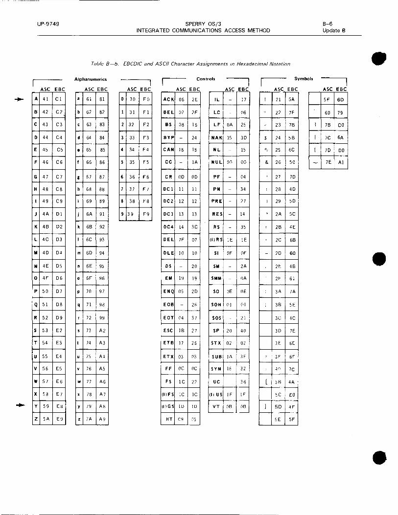
UP-9749 SPERRY OS/3 INTEGRATED COMMUNICATIONS ACCESS METHOD
Table 8-5. EBCDIC and ASCII Character Assignments in Hexadecimal Notation
Alphanumerics Controls I Symbols
ASC EBC ASC EBC ASC EBC ASC EBC ASC EBC ASC EBC
A 41 Cl a Gl 81 0 30 FO ACK OG 2E IL - 17 ! 21 SA
B 42 C2 b G2 82 1 31 Fl BEL 07 2F LC T - OG " 22 7F
c 43 C3 c G3 83 2 32 F2 BS 08 JG LF OA 2S :: 23 7B l
D 44 C4 d G4 84 3 33 F3 BYP - 24 NAK JS 3D $ 24 SB I
E 4S cs • GS SS 4 34 F4 CAN 18 18 NL - JS 00 2S GC I
F 4G CG f G5 BG s 3S FS cc - IA NUL on 00 & 2G so -G 47 C7 g G7 87 6 3G FG CR OD OD PF - 04 27 7D
H 48 cs h GS 88 7 37 F7 DC 1 11 11 PN - 34 I 28 4D
I 49 C9 i G9 89 8 38 FS DC2 12 12 PRE - 27 I 29 SD
J 4A Dl j GA 91 9 39 F9 DC3 13 13 RES - 14 * 2A SC
K 48 D2 k GB 92 DC4 14 3C RS - 3S 2B 4E
L 4C D3 I GC 93 DEL 7F 07 (I) RS IE IE 2C GB
M 4D D4 m GD 94 OLE 10 10 SI OF OF - 2D 60
N 4E DS n GE 9S OS - 20 SM - 2A 2E 4B
0 4F DG 0 GF 9G EM 19 19 SMM - OA 2F GI
p so D7 p 70 97 ENQ 05 2D so OE OE 3A 7A
Q S l DB q 71 98 EOB - 26 SOH 01 (II ; 3B SE
R S2 D9 r 72 99 EQT 04 37 sos 21 3C 4C
s S3 E2 s 73 A2 ESC IB 27 SP 20 40 30 7E
T S4 E3 I 74 A3 ETB 17 26 STX 02 02 3E 6E
u SS E4 u 7S A4 ETX 03 03 SUB IA 3F 7 3F GF
v SG ES y 7G AS FF oc oc SYN 16 32 40 7C --
w S7 EG w 77 AG FS JC 22 UC -- 3G [ 5B 4A
x SS E7 x 78 A7 (I) FS IC IC (I) US IF IF SC EO
y S9 ES y 79 AS (I) GS JD lD VT OB OB l 50 4F
z SA E9 z 7A A9 HT 09 05 5E SF
B-6 Update B
ASC EBC
5F 60
GO 79
7B co
7C GA
7D DO
7E Al
•
•
•
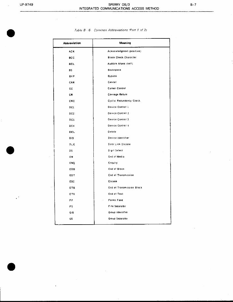
UP-9749 SPERRY OS/3 8-7 INTEGRATED COMMUNICATIONS ACCESS METHOD
• Table 8-6. Common Abbreviations (Part 1 of 2)
Abbreviation Meaning
ACK Acknowledgment (positive)
BCC Block Check Character
BEL Audible Alarm (bell)
BS Backspace
BYP Bypass
CAN Cancel
cc Cursor Control
CR Carriage Return
CRC Cycl 1c Redundancy Check
DC! Device Control 1
DC2 Device Control 2
DC3 Device Control 3
OC4 Device Control 4
DEL Delete
010 Device Identifier
• I OLE Data Link Escape
OS 01g1t Select
EM End of Media
ENQ Enquiry
EOB End of Block
EQT End of Transm1 ssion
ESC Escape
ETB End of Transm1 ss1on Block
ETX End of Text
FF Forms Feed
FS File Separator
GIO Group Identifier
GS Group Separator
•

UP-9749 SPERRY OS/3 B-8 INTEGRATED COMMUNICATIONS ACCESS METHOD
Taoie 8-6. Common Abbre~1ations 1Part 2 of 2) • Abbntviation Meaning
HT Horizontal Tabulator
IL Idle !Synchronous)
ITS End of Intermediate Transmission ~lock
LC Lowercase
LF Line Feed
LRC Long1tud1nal Redunc!ancy Check
NAK Negative Acknowlec!gment
NL New Line
NUL Null Character (tome or soace fill character)
PF Puncn Off
PN Punch On
PRE Prefix
RES Restore
RIO Remote 1aent1T1er
RS Record Separator/ReJCer Stop
RV! Rev'?rse !nterrupt
! Si
• Si:! \Aoae
SOA Syncnronous Data Aaaoter
SMM Start of Manual Message
so Shift Out
SOM Start of Message
SCH Start of Heac!1ng
sos Start of S1gn1ficance
SP Space
STX Start of Text
SUB Subs to lute Character
TM Tape Mark
SYN Synchron1zat1on Character
TTO Temporary Text Deck
UC Uppercase
us Unit Separator
VT Vertical Tabulator
WACK Wait before Transmit Positive Acknowledgment
WAST Wan before Transmit
•

CUT
-
•
•
USER COMMENT SHEET
We will use your comments to improve subsequent editions.
NOTE: Please do not use this form as an order blank.
(Document Title}
(Document No.) (Revision No.) (Update No.)
Comments:
From:
(Name of User)
(Business Address}
Fold on dotted lines, and mail. (No postage stamp is necessary if mailed in the U.S.A.) Thank you for your cooperation

FOLD
FOLD
BUSINESS REPLY MAIL FIRST CLASS PERMIT NO. 21 BLUE BELL, PA.
POSTAGE WILL BE PAID BY ADDRESSEE
SPERRY CORPORATION
ATTN: SYSTEM PUBLICATIONS
P 0 BOX 500 BLUE BELL, PENNSYLVANIA 19422-9990
NO POSTAGE NECESSARY IF MAILED
IN THE UNITED STATES
1 ••• 111.1 ••• 1 •• 1 •• 1.1 •• 1.11.1 •• 1.1 •• 1.1 •• 11 •••• 1.1.1

•
•
•
-'LSPE~Y .,r
USER COMMENTS
We will use your comments to improve subsequent editions.
NOTE: Please do not use this form as an order blank.
(Document Title)
(Document No.) (Revision No.) (Update Level)
Comments:
From:
(Name of User)
(Business Address)
Fold on dotted lines, and mail. (No postage is necessary if mailed in the U.S.A.) Thank you for your cooperation

FOLD
FOLD
BUSINESS REPLY MAIL FIRST CLASS PERMIT NO. 2 1 BLUE BELL PA.
POSTAGE WILL BE PAID BY ADDRESSEE
SPERRY CORPORATION
ATTN: Documentation Quality Control Group C/0 SYSTEM PUBLICATIONS
P.O. BOX 500 BLUE BELL PENNSYLVANIA 19422-9990
1 ••• 111.1 ••• 1 •• 1 •• 1.1 •• 1.11.1 •• 1.1 •• 1.1 •• 11 •••• 1.1.1
NO POSTAGE NECESSARY IF MAILED
IN THE UNITED STATES
_I
•
•