Millstone, Unit 2, Final - Section "A" Operating (Folder 3).
189
-
Upload
khangminh22 -
Category
Documents
-
view
0 -
download
0
Transcript of Millstone, Unit 2, Final - Section "A" Operating (Folder 3).


JOB PERFORMANCE MEASURE APPROVAL SHEET
I. JPM Title: SRO Shift Turnover
ID Number: JPM-A1 SRO
II. Initiated:
R. J. Ashey Developer
Ill. Reviewed: ; nical Reviewer
IV. Approved:
User Department Supervisor
Revision: - 0
1 /28/05 Date
Date
Date

JOB PERFORMANCE MEASURE WORKSHEET
-. -
Facility: MP-2 Examinee:
I will explain the initial conditions, which step(s) to simulate or discuss, and provide initiating cues. When you complete the task successfully, the objecfive for this job performance measure will be satisfied. You may use any approved reference materials normally available in the Control Room, including logs. Make all written reports, oral reports, alarm acknowledgments, and log entries as if the evolution was actually being performed.
JPM Number: JPM-A1 SRO Rev. 0
Task Title: SRO Shift Turnover
System: Conduct of Operations
Time Critical Task: Yes No X
Validated Time (minutes): 20
Task No.(s): NUTIMS # 11 9-02-034
Applicable To: SRO X RO PEO
K/A No.: 2.1.3 K/A Rating: 3.0/3.4
Method of Testing:
Si m u I a ted Perform a nce : X Actual Performance:
Location: -.
Classroom: X
Task Standards:
Required Materials Iprocedures, equipment):
GeneraL References:
Simulator: X In-Plant: X
At the completion of this JPM, the SRO has performed a review of turn over documents and found incorrect information related to a shift turnover
0 Shift Manager Log (eSOMS) 0
0
0
MP-14-OPS-GDL200, Attachment 2, MP2/3 Shift Turnover Report MP-14-OPS-GDL200, Operations Standards, Section 3.6 and Section 3.7 (Rev. 009) DNOS-0306, Dominion Nuclear Standards, “Shift Turnover”
0
0
MP-14-OPS-GDL200, Operations Standards, Section 3.6 and Section 3.7 (Rev. 009) DNOS-0306, Dominion Nuclear Standards, “Shift Turnover”
READ TO THE EXAMINEE * * * * * * * *
Page 2 of 7

JOB PERFORMANCE MEASURE WORKSHEET
JPM Number: JPM-A1 SRO Rev. 0
Initiating Cues: Review the required documents prior to assuming shift duties. I will act as the off going US. Document any problems, if any, on this sheet and report your conclusions to the off going US.
Initial Conditions: You are the oncoming US and have just arrived in the control room for the beginning of your shift. The eSOMS program is NOT available; however, a hard copy of the Narrative Log for the off-going shift has been printed out. The IT Department is presently working to restore the program.
Simulator Requirements: N/A
NOTES TO EXAMINER * * * * * * * *
1. Critical steps for this JPM are indicated with an "X". For the examinee to achieve a satisfactory grade,
When examinee states what hidher simulated action/observation would be, read the appropriate "Cue".
critical steps must be completed correctly.
2 .
3. If necessary, question examinee for details of simulated actions / observations (i.e. "What are you looking at?" or "What are you observing?").
4. Under circumstances must the examinee be allowed to manipulate any devices during the Derformance of this JPM (in-plant onlv).
Page 3 of 7

PERFORMANCE INFORMATION
JPM ID NUMBER: JPM-AlSRO TITLE: SRO Shift Turnover
START TIME:
STEP I Performance Steps: Obtain the documents that need to be reviewed prior to assuming shift duties.
GRADE- - X Standards: Examinee requests the documents that he/she would review. As a minimum, the list should include the following:
MP-14-OPS-GDL200. Attachment 2: MP2/3 Shift Turnover Report Control Room Log book (ie. eSOMS Narrative Log)
The examinee may include additional documents for review 1;. e.. Surveillance Schedule, Temporary Modifications, Red Tag Index, Night Order Log (for any new night orders), Radwaste Log Book (eSOMS). Radwaste Night Order Book, or Control Room Daily Surveillance MODES 1 &2, SP 2619A-001 (NOT required)]. (There is NO requirement to review these documents prior to assuming the shift, but they may be utilized in a turnover.)
Cue 0 Provide the MP2/3 Shift Turnover Report and the SM Log (eSOMS Narrative Log).
0 Inform the examinee that NO surveillances are scheduled for hislher shift.
0 If requested, provide MP-14-OPS-GDL200, Operations Standards, and /or DNOS-0306, Shift Turnovers
(The above listed additional documents will NOT be available to the examinee. If the examinee does request them, state that they are in use by other individuals, but will be provided prior to the completion of shift turnover.)
Comments: 0 MP-14-OPS-GDL200, Attachment 2, MP2/3 Shift Turnover Report lists items that should be reviewed prior to assuming shift duties. The examinee may also refer to MP-14-OPS-GDL200, Operations Standards, Attachment 3, Operating Practices, and/or DNOS-0306. Shift Turnovers, for any additional requirements.
0
Page 4 of 7
- -
PERFORMANCE INFORMATION
JPM ID NUMBER: JPM-AlSRO TITLE: SRO Shift Turnover
STEP 2 - X Performance Steps: Review the MP2/3 Shift Turnover Report and the SM Log (eSOMS Narrative Log) and ask the off-going operator about anything out of the ordinary.
GRADE- - X Standards: During the review of the SM log (eSOMS Narrative log) and the MP2/3Shift Turnover Report, the examinee should recognize that there is a problem with taking the ‘B’LPSI out of service while Facility 2 is protected. The examinee should also note that there is NO entry on the MP2/3 Turnover Sheet for the “B“ LPSl Pump under either the TS LCO and TRM ACTION Statements or Plant Systems And Alternate Plant Configurations.
Cue: 0 If necessary, review equipment out of service. The ‘B’ LPSl Pump is being removed from service to perform the scheduled PMs.
Comments:
Comments: After this step is completed, the JPM is considered complete.
STOP TIME:
Page 5 of 7
VERIFICATION OF JPM COMPLETION
For examinee to achieve a satisfactory grade, ALL critical steps must be completed correctly. If task IS
Time Critical, it MUST be completed within the specified time to achieve a satisfactory grade
1
Job Performance Measure No. JPM-A1 SRO Rev.
Date Performed:
0 -
Operator:
Eva I ua tor( s):
Time Critical Task7 Yes No X
Validated Time (minutes): 20
Actual Time to Complete (minutes):
Result of JPM: (Denote by an for satisfactory or a ,Q for unsatisfactory)
Areas for Improvement:
Page 6 of 7

EXAMINEE HANDOUT
JPM ID Number: JPM-IASRO
lnitiatinq Cues:
Initial Conditions:
0
Review the required documents prior to assuming shift duties. I will act as the off going US. Document any problems, if any, on this sheet and report your conclusions to the off going US.
0 You are the oncoming US and have just arrived in the control room for the beginning of your shift. The eSOMS program is NOT available; however, a hard copy of the Narrative Log for the off-going shift has been printed out. The IT Department is presently working to restore the program.
--
Page 7 of 7

USE AS STAND ALONE JPM
JOB PERFORMANCE MEASURE APPROVAL SHEET
I JPM Title: SRO AWO Acceptance
ID Number: JPM-A2SRO
It. Initiated:
R. J. Ashev
Revision: 0 -
1/28/05 Date Developer
I I I . Reviewed:
Technical Reviewer
IV. Approved:
User Department Supervisor
Date
Date
Nuclear Training Supervisor Date
USE AS STAND ALONE JPM

JOB PERFORMANCE MEASURE APPROVAL SHEET
I JPM Title: SRO AWO Acceptance
ID Number: JPM-AZSRO Revision: 0
1 1 . Initiated:
I I I. Reviewed:
J{* echnical Reviewer
IV. Approved:
dgl User Department Supervisor
1/28/05 Date
/&A- Date
Date

A/I & Date
Added "as a post maintenance test procedure" to step #3 per comments from the NRC
Validation Week.
1 1-30-2004
6 0212512005
(DAW
SUMMARY OF CHANGES
DESCRIPTION I REV'CHANGE Developed new JPM I 0
2

JOB PERFORMANCE MEASURE WORKSHEET
Facility: MP-2 Examinee: --
JPM Number: J PM-A2 S RO Rev. 0
Task Title: SRO AWO Acceptance
System: Equipment Control
Time Critical Task: Yes No X
Validated Time (minutes): 20
Task No.(s): NUTIMS # I 19-01-098
Applicable To: SRO X RO PEO
KIA No.: 2.2.21 KIA Rating: 2.313.5
Method of Testing:
Simulated Performance: X Actual Performance:
Location:
Classroom: X Simulator: In-Plant:
Task Standards: - At the completion of this JPM, the examinee will recommend the correct PMT, HPSI Pump IST (SP2604AO-001).
Required Materials - MP-20-WP-GDL40 “Pre and Post Maintenance Testing” fprocedures, equipment): - MP-20-WP-GDL30 “Work Performance”
- MP-20-WP-GDL20 “Work Order Preparation” -
- Training AWO
SP2604AO “HPSI Pump Inservice Testing, 2 1,750 psia, Facility 1“
General References: MP-20-WP-GDL20, MP-20-WP-GDL40, MP-20-WP-GDL30
READ TO THE EXAMINEE * * * * * * * *
I will explain the initial conditions, which step(s) to simulate or discuss, and provide initiating cues. When you complete the task successfully, the objective for this job performance measure will be satisfied. You may use any approved reference materials normally available in the Control Room. including logs. Make all written reports, oral reports, alarm acknowledgments. and log entries as if the evolution was actually beinq performed.
3
JOB PERFORMANCE MEASURE WORKSHEET
- JPM Number: JPM-A2SRO Rev. 0
Initiating Cues: - You are the WC-SRO. The AWO for “A” HPSl pump bearing replacement has been returned you. Determine and list below what must be accomplished to close out the AWO.
- Inform the examiner of your completion of this JPM by discussing the conclusions of your evaluation of the work package and your recommendations.
Initial Conditions: - The “ A HPSl Pump bearing replacement was done as on line maintenance, with the plant at 100% power.
- Tagging clearing and restoration activities are being done by other members of the crew.
Simulator Requirements: None
NOTES TO EXAMINER * * * * *
1. Critical steps for this JPM are indicated with an “X”. For the examinee to achieve a satisfactory grade,
When examinee states what hidher simulated action/observation would be, read the a p p ro pr i a t e “Cue” .
critical steps must be completed correctly.
2.
3. If necessary, question examinee for details of simulated actions / observations (Le. “What are you looking at?” or “What are you observing?”).
Under NO circumstances must the examinee be allowed to manipulate any devices during the performance of this JPM (in-plant only).
4.
4
PERFORMANCE INFORMATION
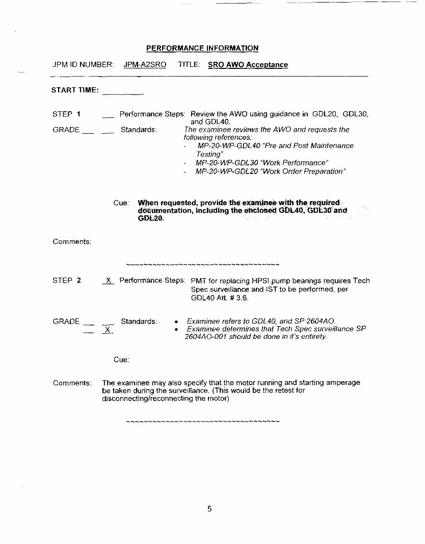
JPM ID NUMBER: JPM-A2SRO TITLE: SRO AWO Acceptance -..
START TIME:
STEP 1 - Performance Steps: Review the AWO using guidance in GDL20, GDL30, and GDL40.
GRADE Standards : The examinee reviews the A WO and requests the following references: -
- MP-20- WP-GDL30 “Work Performance” -
MP-20-WP-GDL40 “Pre and Post Maintenance Testing”
MP-20- WP-GDL20 “Work Order Preparation”
Cue: sted, provide ion, including d
Comments:
STEP 2 X Performance Steps: PMT for replacing HPSl pump bearings requires Tech Spec surveillance and IST to be performed, per GDL40 Att. ## 3.6.
GRADE- Stand a rds : Examinee refers to GDL40, and SP 2604AO. - - x Examinee determines that Tech Spec surveillance SP
2604A 0-00 I should be done in it’s entirety.
Cue:
Comments: The examinee may also specify that the motor running and starting amperage be taken during the surveillance. (This would be the retest for disconnectingheconnecting the motor)
5
JP - ID NUh
PERFORMANCE INFORMATION
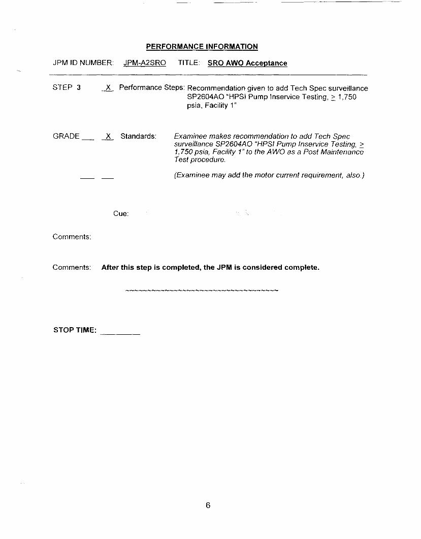
BER: JPM-A2SRO TITLE: SRO AWO Acceptance
STEP 3 -& Performance Steps: Recommendation given to add Tech Spec surveillance SP2604AO “HPSI Pump Inservice Testing, 2 1,750 psia, Facility 1”
GRADE- - X Standards: Examinee makes recommendation to add Tech Spec surveillance SP2604AO “HPSI Pump Inservice Testing, 2 1,750 psia, Facility I ” to the A WO as a Post Maintenance Test procedure.
(Examinee may add the motor current requirement, also.) - -
Cue:
Comments:
STOP TIME:
6

VERIFICATION OF JPM COMPLETION
Job Performance Measure No. JPM-AZSRO Rev.
Date Performed:
Operator:
Evaluator(s):
0 -
For examinee to achieve a satisfactory grade, ALL critical steps must be completed correctly. If task is Time Critical, it MUST be completed within the specified time to achieve a satisfactory grade.
Time Critical Task? Yes No X
Validated Time (minutes):
Actual Time to Complete (minutes): 20
Result of JPM: (Denote by an S for satisfactory or a for unsatisfactory)
Areas for Improvement:
7

EXAMINEE HANDOUT L-
JPM Number: JPM-A2RO Rev. O
Initiating Cues: - You are the WC-SRO. The AWO for "A" HPSl pump bearing replacement has been returned you. Determine and list below what must be accomplished to close out the AWO.
- Inform the examiner of your completion of this JPM by discussing the conclusions of your evaluation of the work package and your recommendations.
Initial Conditions: - The "A" HPSl Pump bearing replacement was done as on line maintenance, with the plant at 100% power.
- Tagging clearing and restoration activities are being done by other members of the crew.
8

JOB PERFORMANCE MEASURE APPROVAL SHEET
I. JPM Title: SRO Review and Approve a Radioactive Liquid Waste Release Permit
ID Number: J PM-A3S RO
II. Initiated:
W h T R. J. Ashe Developer
IV. Approved:
User Department Supervisor
5 Nuclear Traini Supervisor
01/27/05 Date
Date
Date

JOB PERFORMANCE MEASURE WORKSHEET
Facility: MP-2 Examinee:
JPM Number: JPM-A3SRO Rev. 0
Task Title: SRO Review and Amrove a Radioactive Liauid Waste Release Permit
System: Radiation Control
Time Critical Task: Yes No X
Validated Time (minutes): 10
Task No.(s): NUTIMS # 119-02-026
Applicable To: SRO X RO PEO
K/A No.: 2.3.6 K/A Rating: 2.V3.1
Method of Testing:
Simulated Performance: X
Location:
Classroom: X
Task Standards:
Actual Performance:
Simulator: X In-Plant: X
At the completion of this JPM, the examinee will have discovered a plant operating condition that will NOT allow authorizing a radioactive liquid waste discharge.
Required Materials iprocedures, equipment):
SP 261 7A Aerated and Clean Radioactive Liquid Waste Disc ha rg es Chem Form 2864-1, Millstone Unit 2 Liquid Discharge Permit Number 2000
General References: SP 2617A, Steps 4.2.6 and 4.2.7 (Rev. 027-05)
READ TO THE EXAMINEE * * * * * * * *
1 will explajn the initial conditions, which step(s) to simulate or discuss, and provide initiating cues. When you complete the task successfully, the objective for this job performance measure will be satisfied. You may use any approved reference materials normally available in the Control Room, including logs. Make all written reports, oral reports, alarm acknowledgments, and 10s entries as if the evolution was actually beinq performed.
2

JOB PERFORMANCE MEASURE WORKSHEET
4. Under NO circumstances must the examinee be allowed to manipulate any devices during
JPM Number: JPM-A3S Rev. 0
Initiating Cues: As the SM, you have directed the Radwaste PEO to make preparations to discharge the AWMT. Perform the required actions to authorize the discharge, or list the discrepancies below that would keep you from authorizing the discharge.
Initial Conditions:
Simulator Requirements: N/A
No other radioactive discharges are in progress. SP 2617A, section 4.2; steps 4.2.1 through 4.2.5 have been completed. Chemistry sample results are acceptable. RM-9116 is operable. AWMT level is 89%. The plant is in MODE 5 preparing the RCS for refueling. 2 Circulating Water Pumps operating, 2 Service Water Pumps operating. It is one hour past high tide.
NOTES TO EXAMINER * * * * * * * *
1. Critical steps for this JPM are indicated with an “X“. For the examinee to achieve a satisfactory grade,
When examinee states what hidher simulated action/observation would be, read the a p p ro p r i a t e ”C u e”.
If necessary, question examinee for details of simulated actions / observations (Le. ”What are you looking at?” or “What are you observing?”).
critical steps must be completed correctly.
2.
3.
3
PERFORMANCE INFORMATION
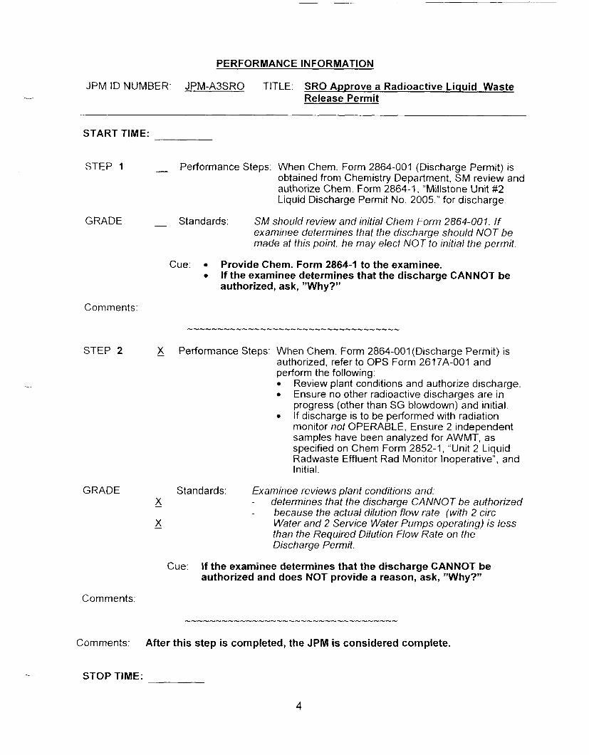
JPM ID NUMBER: JPM-A3SRO TITLE: SRO Approve a Radioactive Liquid Waste -.- Release Permit
..
START TIME:
STEP 1 - Performance Steps: When Chem. Form 2864-001 (Discharge Permit) is obtained from Chemistry Department, SM review and authorize Chem. Form 2864-1, “Millstone Unit #2 Liquid Discharge Permit No. 2005,” for discharge.
GRADE - Standards : SM should review and initial Chem Form 2864-001. If examinee determines that the discharge should NOT be made at this point. he may elect NOT to initial the permit.
Cue: 0 Provide Chem. Form 2864-1 to the examinee. 0 If the examinee determines that the discharge CANNOT be
authorized, ask, ”Why?”
Comments:
STEP 2 - X Performance Steps: When Chem. Form 2864-001 (Discharge Permit) is authorized, refer to OPS Form 2617A-001 and perform the following:
Review plant conditions and authorize discharge. Ensure no other radioactive discharges are in progress (other than SG blowdown) and initial. If discharge is to be performed with radiation monitor not OPERABLE, Ensure 2 independent samples have been analyzed for AWMT, as specified on Chem Form 2852-1, “Unit 2 Liquid Radwaste Effluent Rad Monitor Inoperative”, and Initial.
GRADE Standards: Examinee reviews plant conditions and:
- x - determines that the discharge CANNOT be authorized
- x because the actual dilution flow rate (with 2 circ Water and 2 Service Water Pumps operating) is less than the Required Dilution Flow Rate on the Discharge Permit.
Cue: If the examinee determines that the discharge CANNOT be authorized and does NOT provide a reason, ask, ”Why?”
Comments:
Comments: After this step is completed, the JPM is considered complete.
STOP TIME:
4

VERIFICATION OF JPM COMPLETION
Job Performance Measure No. JPM-A3SRO
Date Performed:
Operator:
Eva I ua tor (s) :
Rev 0
For examinee to achieve a satisfactory grade, correctly. If task is Time Critical, it MUST be completed within the specified time to achieve a satisfactory grade.
critical steps must be completed
Time Critical Task? Yes No X
Validated Time (minutes): 10
Actual Time to Complete (minutes):
Result of JPM: (Denote by an 3 for satisfactory or a u for unsatisfactory)
Areas for Improvement:
5

EXAMINEE HANDOUT
JPM ID Number:
Initiating Cues:
Initial Conditions:
JPM-A3SRO
As the SM. you have directed the Radwaste PEO to make preparations to discharge the AWMT. Perform the required actions to authorize the discharge, or list the discrepancies below that would keep you from authorizing the discharge.
No other radioactive discharges are in progress. SP 261 7A, section 4.2; steps 4.2.1 through 4.2.5 have been completed. Chemistry sample results are acceptable. RM-9116 is operable. AWMT level is 89%. The plant is in MODE 5 preparing the RCS for refueling. 2 Circulating Water Pumps operating, 2 Service Water Pumps operating. It is one hour past high tide.
6

RIR TRAINING O N L V - O ~ - O ~ SIGNATURE O N FI
Approved Approval Date
09- 12-03
Effective Date
MILLSTONE UNIT #2 LIQUID DISCHARGE PERMIT NO. 2000 ( S P4 30 7 5)
... Tank ................ : AWMT Date/time sampled ......... : [Today] 07: 15 06:25 Sampled by.. .... : c Date/time on recirc ........ : [Today]
(AWMT limit = 45 ppm; CWMT limit = 22.5 ppm) Minimum Recirc Time ..... : 0.5 hr w/ mixer; 4.0 hr w/ pump
Boric acid conc (ppm). ..... : 237 pH (>2 pH ~ 1 2 . 5 ) : 8.8 Eff. Monitor Bkg = (cpm)..:
TSS (ppm) ..................... : 8.8
1.65E+04
<<< 2 circulating water pumps must be in operation during this discharge >>> During Unit 2 shutdown a minimum dilution flow rate of 20,000 gpm is allowable
with the discharge rate limited to 30.5 gpm.
Isotope Activity MPC Activity / M PC (uCi/ ml) (uCi / ml)
MN-54 CO-57 CO- 58 CO-60 AGl10M SB- 125 XE- 133 CS- 134 CS- 137 1-3
Totals
4.766E-06 3.166E-07 4.45 1E-06 1.032E-04 9.981E-06 7.137E-06 3.095E-06 7.43 1E-07 2.167E-06 3.780E-02 1.328E-04
1.000E-04 4.000E-04 9.000E-05 3.000E-05 3.000E-05 1.000E-04
9.000E-06 2.000E-05 3.000E-03
(@I
4.766E-02 7.9 14E-04 4.945E-02 3.442E+OO 3.327E-0 1 7.137E-02
8.257E-02 1.084E-0 1 1.260E+O 1 1.673E+O 1
(@) No gasses or H-3 included in totals, however, H-3 is in Activity/MPC col.
INIT L Diluted gas concentration (uCi/ml) = 3.517E-09c
Minimum recirc time is ........ : 0.5 hr w/mixer; 4.0 hr w/pump Administrative quarterly release limit (Ci) ............. :
Estimated volume this discharge .......................... : Estimated activity this discharge .......................... : Est total activity released this quarter (Ci) ............ :
5.000E-02 3.4903-03
4000. 2.0 1 1E-03 5.501E-03
Total activity released this quarter (Ci) ................. :
S.M. init (1) Reduction factor.. ........................................... : 5.9763-02
(2) Required dilution flow rate ............................. : 308000. (gpm) 3 circ water,
(5) Liquid effluent monitor alarm setting
2 service water pump(s) (3) Normal rate limit (flow rate =#1*#2*0.1) .......... : 350 (gpm)
(ALARM) .... : 107,348 (CPm)
Maximum approved rate ....................................... : 350 kpm) ‘Authorization required to exceed normal rate limit.)
Source check performed . ........................................
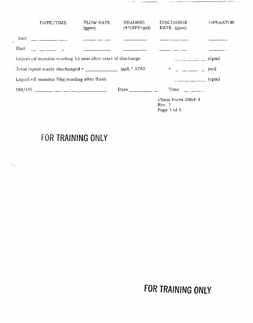
DISCHARGE
J _.
End
DATE /TIME FLOW RATE READING DISCHARGE OPERATOR (wm) (4*DIFF=gal) RATE (gpm)
Liquid eff monitor reading 15 min after start of discharge ( C P 4
(ml) - Total liquid waste discharged = (gal) * 3785 -
Liquid eff monitor Bkg reading after flush ( C P 4
S M / U S Date Time
Chern Form 2864-1 Rev. 1 Page 1 of 1
FOR TRAINING ONLY
FOR TRAINING ONLY
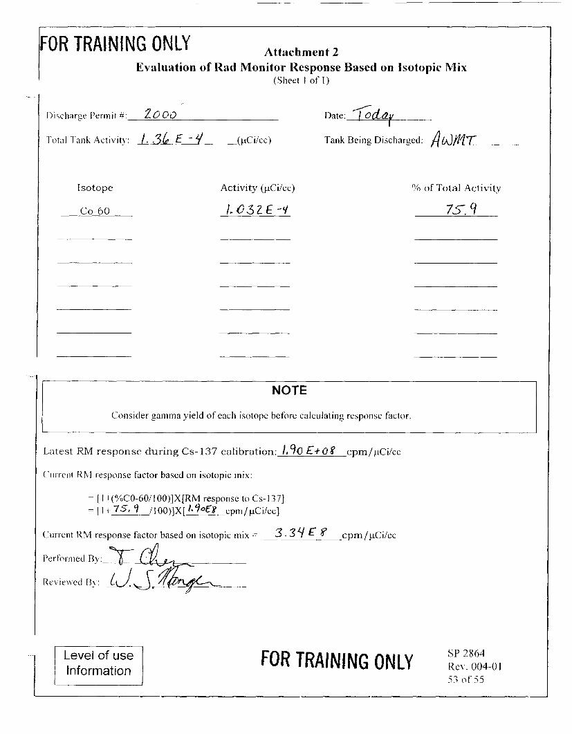
IFOR TRAINING ONLY Attachment 2 Evaluation of Rad Monitor Response Based on Isotopic Mix
(Sheet I of I )
/ Date: / Od?
Tank Being Discharged: A(,@'l7
Isotope
CO-60
Activity (pCi/cc)
l.o3ZE-C/
YO of Total Activity
7 5 . 9
NOTE
Consider gamma yield of each isotope before calculating response factor
,atest RM response during Cs- 137 calibration: E+ 0 8 cpm/pCi/cc
' u i w n t R b l response factor based on isotopic mix:
= [ I+(%C0-60/100)]X[RM response to Cs-1371 = [I+ 751 /lOO)]X[ /*9°Eg cprn/pCi/cc]
'un-ent RM response factor based on isotopic mix = 3 - 3 4 8 cpm/pCi/cc
Level of use Information
FOR TRAINING ONLY

JOB PERFORMANCE MEASURE APPROVAL SHEET
I JPM Title: Classifv the Event
ID Number: JPM-A4SRO
11. Initiated:
R. J. Ashey Developer
I I I. Reviewed:
IV. Approved:
User Department Supervisor
112 1 I05 Date
Date
Date

SUMMARY OF CHANGES
All 8 Date
12/06/2004
(SRM)
DESCRIPTION REVlCHANG E
Developed new JPM 0
2

PERFORMANCE INFORMATION
JPM ID NUMBER: JPM-A4SRO TITLE: Classify The Event ~
JOBPERFORMANCEMEASUREWORKSHEET
Facility MP-2 Examinee:
JPM Number: J P M-A4 S R 0 Rev 0
Task Title: Classify the Event
System Admin
Time Critical Task: Yes No X
Validated Time (minutes): 20
Task No.(s): NUTIMS # 303-05-091
Applicable To: SRO X RO PEO
KIA No.: 2.4.41 K/A Rating: 2.3/4.1
Method of Testing:
Simulated Performance:
Location:
Classroom: X
Task Standards:
Required Materials (procedures, equipment):
General References:
Actual Performance: X
Simulator: X In-Plant: X
At the completion of this JPM the examinee will determine the classification of the scenario to be an AlertlC1.
MP-26-EPI-FAP06-002, Rev. 003 “EAL Tables” MP-26-EPI-FAP06-005, Rev. 000-003, “Control Room Protective Action Recommendation” MP-26-EPI-FAPOI -001 “Control Room-Director of Station Emergency Operations (CR DSEO)” MP-26-EPA-REF02 “MP2 EAL Technical Basis Document” MP-26-EPI-FAPO6, Rev. 000-006, “Classification PAR”
EP-MP-26-EPI-FAPO6, Rev. 000-006, “Classification PAR”
I READ TO THE EXAMINEE * * * * * * * *
I will explain the initial conditions, which step(s) to simulate or discuss. and provide initiating 1 cues. When you complete the task successfully, the objective for this job performance measure will be satisfied. You may use any approved reference materials normally available in the Control Room, including logs. Make all written reports, oral reports, alarm acknowledgments, and log entries as if the evolution was actually being performed.
3

PERFORMANCE INFORMATION
JPM ID NUMBER. JPM-A4SRO TITLE Classify The Event - JOB PERFORMANCE MEASURE WORKSHEET
JPM Number: J PM-A4 S R 0 Rev. 0
lnitiatinq Cues: You are the Shift Manager. Classify the event you have just completed on the simulator. o o
You are to consider all plant conditions during the scenario. Your classification should reflect the most severe classification level reached.
Initial Conditions: As observed during the previous simulator session.
Simulator Requirements: Simulator scenario that was run for the evaluation. (ES04LI-l)
NOTES TO EXAMINER * * * * * * * *
1. Critical steps for this JPM are indicated with an "X". For the examinee to achieve a satisfactory grade, ALL critical steps must be completed correctly.
When examinee states what hidher simulated action/observation would be, read the appropriate "Cue".
If necessary, question examinee for details of simulated actions / observations (i.e. "What are you looking at?" or "What are you observing?").
Under NO circumstances must the examinee be allowed to manipulate any devices during the Derformance of this JPM (in-dant onlv).
2 .
3.
4.
4

PERFORMANCE INFORMATION
JPM ID NUMBER: JPM-A4SRO TITLE: Classifv The Event
START TIME:
STEP 1 X Performance Steps:
GRADE X Standards:
X - -
0
0
Examinee obtains MP-26-EPI-FAP06-002 “Millstone Unit 2 Emergency Action Levels” and classifies the simulator event that was just completed.
Examinee determines the classification is Barrier Failure, BA I ; Alert Charhe-One. Based on RCS Barrier, RCB4, Reactor Coolant leak > CVCS capacity AND entry into EOP-2534, Steam Generator Tube Rupture or EOP 2540, Functional Recovely, io address Steam Generator Tube Rupture.
Cue:
Comments: All required reference material is available in the simulator.
------5-5--5---I-Y--~--------------
5

PERFORMANCE INFORMATION
JPM ID NUMBER: JPM-A4SRO TITLE: Classify The Event
STEP 2 X Performance Steps: Examinee obtains MP-26-EPI-FAP06-002 “Millstone Unit 2 Emergency Action Levels” and classifies the event from the supplied handout. Examinee obtains EP-MP-26-EPI-FAPO6, Rev. 000-006, “Classification PAR” and MP-26-EPI- FAP06-005, Rev. 000-003, “Control Room Protective Action Recommendation”, and determines the appropriate PAR for the event from the supplied handout.
GRADE X Standards:
X - -
Based on:
Examinee determines the classification is Barrier Failure, BG 1; General Emergency Alpha.
o
o
Fuel Clad Barrier, Potential Loss, FCB4, RVl MS reading = 0% RCS Barrier, RCB4, Loss? Reactor Coolant leak > CVCS capacity AND entry into EOP-2534. Steam Generator Tube Rupture or EOP 2540, Functional Recovery, to address Steam Generator Tube Rupture. CTMT Barrier, CNB3, Loss. Primary to secondary > Tech Spec limits and a Prolonged release from affected S/G to environment when used for cooldown.
o
Examinee determines that the PAR is to evacuate Zones A, B, and E. All other zones must be sheltered.
Cue: Provide the examinee with the handout for Event #2.
Comments:
Comments:
All required reference material is available in the simulator.
After this step is completed, the JPM is considered complete.
STOP TIME:
6
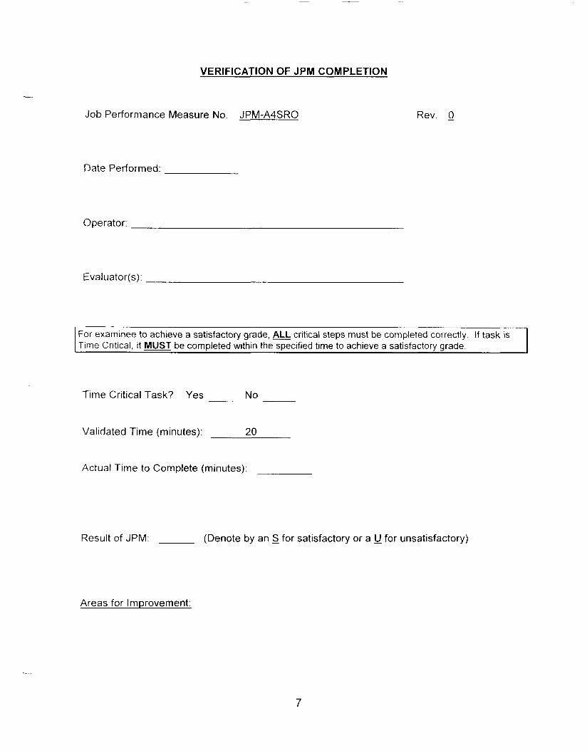
VERIFICATION OF JPM COMPLETION
-- Job Performance Measure No. JPM-A4SRO Rev. 0
Date Performed:
Operator:
Evaluator( s) :
For examinee to achieve a satisfactory grade, & critical steps must be completed correctly. If task is Time Critical, it MUST be completed within the specified time to achieve a satisfactory grade.
Time Critical Task? Yes No
Validated Time (minutes): 20
Actual Time to Complete (minutes):
Result of JPM: (Denote by an S for satisfactory or a u for unsatisfactory)
Areas for Improvement:
7

EXAMINEE HANDOUT
JPM ID Number: JPMA4SRO
lnitiatinq Cues:
Initial Conditions:
Rev. 0
You are the Shift Manager. Classify the event you have just completed on the simulator. o o
You are to consider all plant conditions during the scenario Your classification should reflect the most severe classification level reached.
As observed during the previous simulator session.
Classification Level NRC:
State:
Basis:
8

This event is a continuation of the previous simulator scenario. Time '0' starts shortly after the simulator scenario is terminated. Use all previously available information from the scenario to assist in determining the classification and direction are at 7 mph from 235" for the remainder of this event.
any applicable PAR for this event. Assume wind speed
l o
12 min I
-____ 1 14min
, 15 min 1 -
k- 22 min
32 min
38 rnin
I nforma t ion Report to the Control Room, "There is a large steam leak in the Enclosure Building by #2 Atmospheric Dump Valve. It appears to be a flange leak, but I can't get close enough to verify that."
Observe NO change in Enclosure Building pressure. Determine that the steam leak is NOT large enough to impact any Safety Function. Continue with EOP 2540.
#2 Atmospheric Dump Valve has failed closed and CANNOT be opened from C- 05 or locally due to the steam leak. RCS temperature is rising slowly.
Direction is given to use # I Atmospheric Dump Valve to stabilize the plant and to feed # I SG as required to maintain level 40-70%.
#I Atmospheric Dump Valve is throttled open to stabilize RCS temperature and feed is available to #I S/G.
Several Radiation Monitors are in alarm, including the following:
CTMT HI RANGE Rad Monitors, RM-8240 and RM-8241; reading 3.5 R/hr and rising
"A" Main Steam Line Rad Monitors, RM-4299A and RM-4299B; reading 2.5 Rlhr and rising.
Refuel Bridge Rad Monitor, RM-7891, reading is pegged high
Personnel Access Rad Monitor, RM-7890; reading is pegged high
Report to the control room that an RCS sample was taken a few minutes ago. The sample has a dose rate of 31 mR/hr/ml at one foot from the sample container.
ZEDE at the site boundary is 1.2 R/hr and stable. 0 CTMT HI RANGE Rad Monitors, RM-8240 and RM-8241, now reading 43
R/hr and stable. Highest recorded reading was 45 R/hr.
" A Main Steam Line Rad Monitors, RM-4299A and RM-4299B, now reading 22 R/hr and stable. Highest rercorded reading was 25 R/hr.
0
Source PEO
PPOlUS
SPO
u s
SPO
PPO
Chemistry / RMT 1
RMT 2
PPO
Classification Level NRC:
State:
Basis:
PAR.
9

JOB PERFORMANCE MEASURE APPROVAL SHEET
I JPM Title: SRO Tag Clearance Approval
ID Number: JPM-ASSRO
1 1 . Initiated:
I l l . Reviewed:
Developer
R. J. Ashe Technical Reviewer
IV. Approved:
N /A User Department Supervisor
01 127105 Date
Date
Date

SUMMARY OF CHANGES
I All & Date
11-23-2005
( S R W
DESCRIPTION REVKHANGE
Developed new JPM 0
2
JOB PERFORMANCE MEASURE WORKSHEET
-- Facility: MP-2 Examinee:
JPM Number: JPM-A5SRO Rev. 0
Task Title. Perform Tagging Operations
System: Administrative
Time Critical Task: Yes No X
Vattdated Time (minutes): 15
Task No.(s): NUTIMS #119-03-170
Applicable To: SRO X RO PEO
KIA No.: 2.2.13 K/A Rating: 3.6/3.8
Method of Testing:
Simulated Performance: Actual Performance: X
Location:
Classroom: X
Task Standards: -
Required Materials (procedures, equipment): -
Simulator: X In-Plant: X
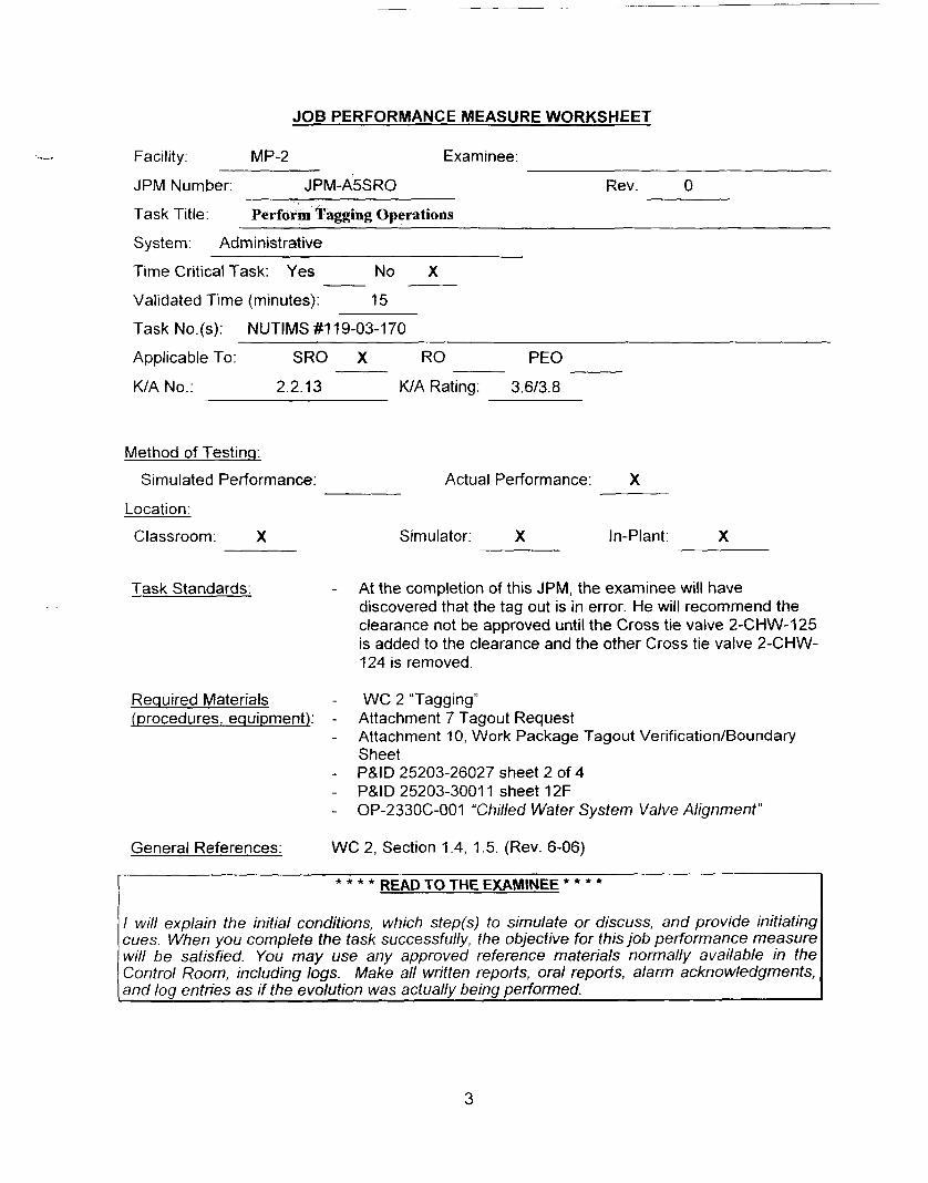
At the completion of this JPM, the examinee will have discovered that the tag out is in error. He will recommend the clearance not be approved until the Cross tie valve 2-CHW-125 is added to the clearance and the other Cross tie valve 2-CHW- 124 is removed.
WC 2 “Tagging” Attachment 7 Tagout Request Attachment 10, Work Package Tagout VerificatiordBoundary Sheet P&ID 25203-26027 sheet 2 of 4 P&ID 25203-3001 1 sheet 12F OP-233OC-001 “Chilled Water System Valve Alignment”
General References: WC 2, Section 1.4, 1.5. (Rev. 6-06)
I READ TO THE EXAMINEE * * * * * * * *
I will explain the initial conditions, which step(s) to simulate or discuss, and provide initiating cues. When you complete the task successfully, the objective for this job performance measure will be satisfied. You may use any approved reference materials normally available in the Control Room, including logs. Make all written reports, oral reports, alarm acknowledgments, and log entries as if the evolution was actually being performed.
3
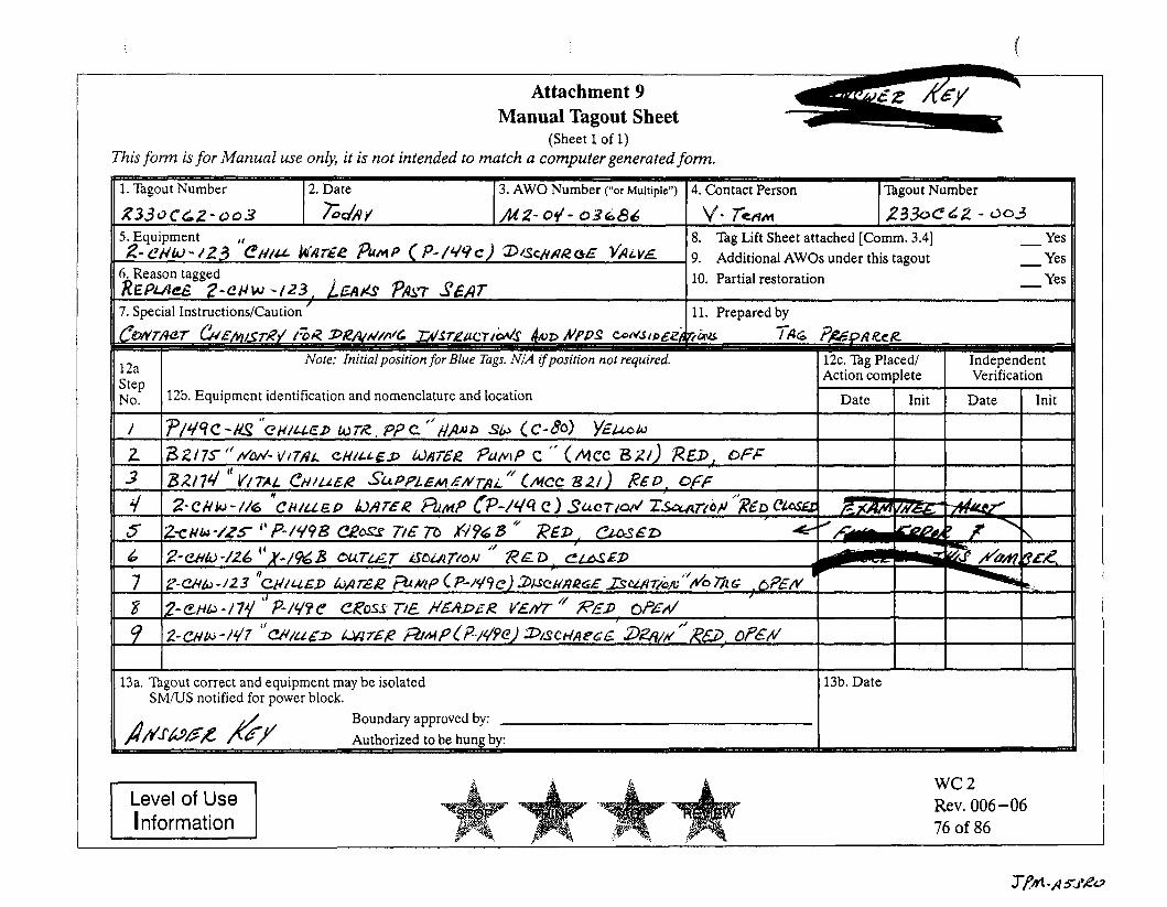
Attachment 9 Manual Tagout Sheet
(Sheet 1 of 1) This form is for Manual use on&, it is not intended to match a computer generated form.
Yea 10. Partial restoration - 6. Reason tagged REQUeE Z-CHW -123, LEAKC PAT SEAT 7. Special Instructions/Caution ' I 11. Prepared by
Action complete Verification
12b. Equipment identification and nomenclature and location Date Init Date Init
~ P / ~ ~ C - U ! ' ' C H / L L E D b T R PPC"AAU0 Sb CC-80) YEboW
13a. Tagout correct and equipment may be isolated SMWS notified for power block.
13b. Date I Boundary approved by:
Level of Use wc 2 Rev. 006-06 76 of 86
JOB PERFORMANCE MEASURE WORKSHEET
JPM Number: JPM-A5SRO Rev. 0
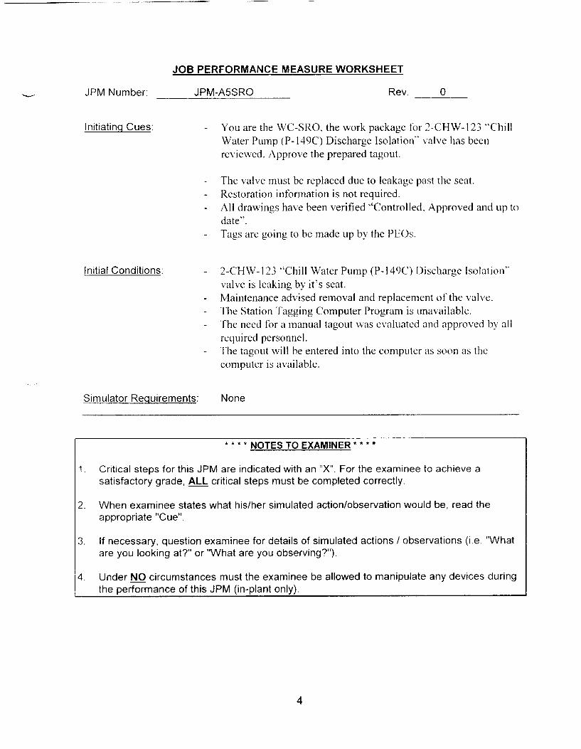
Initiating Cues. - You are the WC-SRO, the work package tor 2-CHW-123 “Chill Water Pump (P- 149C) Discharge Isolation“ \ d v e has been revie\\ ed. Approve the prepared tagout.
-
- -
The \.alve must be replaced due to leakage past tlie seat. Restoration information is not required. All drawings have been verified “Controlled, Approved and up to date”. Tags are going to be made up by the PEOs. -
Initial Conditions. - 2-CHW- 123 “Chill Water Pump (P-l49C) Discharge Isolation” valve is leaking bq it’s seat. Maintenance advised removal and replacenient of tlie \ d v e . The Station Tagging Computer Program is unavailable. The need for a manual tagout \\as evaluated and approired b! a11 required personnel. The tagout n i l 1 be entered into the coniputcr as soon as tlie computer is available.
- -
-
-
Simulator Requirements: None
NOTES TO EXAMINER * * * * * * *
1 . Critical steps for this JPM are indicated with an “X”. For t he examinee to achieve a satisfactory grade, ALL critical steps must be completed correctly.
2. When examinee states what hidher simulated action/observation would be, read the appropriate ”Cue”.
3. If necessary, question examinee for details of simulated actions / observations (1.e. ”What are you looking at?” or “What are you observing?”).
4. Under NO circumstances must the examinee be allowed to manipulate any devices during the performance of this JPM (in-plant only).
4

PERFORMANCE INFORMATION
JPM ID NUMBER: JPM-ASSRO TITLE: SRO Tag Clearance Approval -’
START TIME:
STEP 1 J- Performance Steps:
GRADE X Standards:
- Review prepared Manual tag out, referring to appropriate sections of WC- 2, the P&ID drawings, and the valve alignment OP233OC-001.
The examinee reviews Manual tag out sheet using WC-2, “Tagging‘: Attachments 9, 10, & 16 as necessary
The examinee also refers to the P&IDs for the Chill Water system, and the valve alignment OP 233OC-001. Using the following references:
P&/D 25203-26027 sheet 2 of 4 P&ID 25203-3001 1 sheet 12F OP-233OC-001 “Chilled Water System Valve Alignment” WC-2 “Tagging” Att. 9,10, & 16.
Cue: When requested, provide the examinee with the required documentation , in c I u d i n g WC 2, “Tagging ” .
Comments:
5
P E RFO R MAN C E I N F 0 R mJl AT1 0 J
JPM ID NUMBER: JPM-A5SRO TITLE: SRO Tag Clearance Approval \
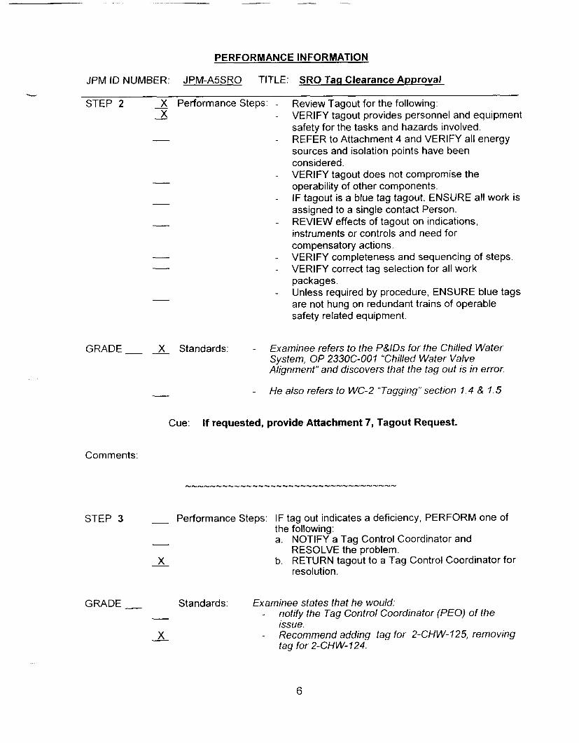
STEP 2 - X Performance Steps: - Review Tagout for the following: - X - VERIFY tagout provides personnel and equipment
- - REFER to Attachment 4 and VERIFY all energy safety for the tasks and hazards involved.
sources and isolation points have been considered. VERIFY tagout does not compromise the operability of other components. IF tagout is a blue tag tagout, ENSURE all work is assigned to a single contact Person. REVIEW effects of tagout on indications, instruments or controls and need for compensatory actions. VERIFY completeness and sequencing of steps. VERIFY correct tag selection for all work packages. Unless required by procedure, ENSURE blue tags are not hung on redundant trains of operable safety related equipment.
-
-
-
- -
-
GRADE X Standards: - Examinee refers to the P&IDs for the Chilled Water System, OP 233OC-001 “Chilled Water Valve Alignment” and discovers that the fag out is in error.
He also refers to WC-2 “Tagging” section 1.4 & 1.5 - -
Cue: If requested, provide Attachment 7, Tagout Request.
Comments:
STEP 3 - Performance Steps: IF tag out indicates a deficiency, PERFORM one of the following:
- a. NOTIFY a Tag Control Coordinator and RESOLVE the problem.
b. RETURN tagout to a Tag Control Coordinator for resolution.
GRADE __ Standards: Examinee states that he would: - - notify the Tag Control Coordinator ( E O ) of the
issue. 2 - Recommend adding tag for 2-CHW- 125, removing
tag for 2-CHW-124.
6

--
PERFORMANCE INFORMATION
JPM ID NUMBER: JPM-ASSRO TITLE: SRO Tag Clearance Approval
Cue: If examine does not recommend the tag out be modified then, ask the examinee for his recommendations.
Comments: - The order may differ slightly provided the examinee ensures the tag out is changed.
Comments: After this step is completed, the JPM is considered complete.
STOP TIME:
7

VERIFICATION OF JPM COMPLETION
Job Performance Measure No. JPM-A5SRO 0 Rev. -
Date Performed:
Operator:
Eva I u at or( s) :
1 For examinee to achieve a satisfactory grade, critical steps must be completed correctly If task is 1 Time Critical, it MUST be completed within the specified time to achieve a satisfactory grade.
Time Critical Task? Yes No
Validated Time (minutes): 15
Actual Time to Complete (minutes):
Result of JPM: (Denote by an S for satisfactory or a !) for unsatisfactory)
Areas for Improvement:
8
EXAMINEE HANDOUT
JPM Number. JPM-ASSRO Rev 0
I n i t i a ting Cues:
Initial Conditions:
You are the M;C-SRO, the work package for 3-CHW- I23 ”Chill Water Pump (P- I49C) Discharge Isolation“ \ al\.e has been re\tie\x ed. Approve the prepared tagout.
The \-al\.e must be replaced due to leakage past the seat. Restoration information is not required. A11 dra\\ings 1xn.e been verified “Controlled. Appro\’ed and up to
date“.
2-CI IW’-l23 “Chill Water Pump (P- 149c‘) 1)ischrrrge Isolation” \ al\ e is leaking by it‘s seat. Alaintenance ridvised removal and replacement of the \ alve ‘The Station I‘agging Computer Program is una\ ailable. I he need for a manual tagout \\as e\.aluated and approved by all required personnel. The tagout \ \ i l l be entered into the computcr as soon as the computcr is a\ ailable.
9

Attachment 9 Manual Tagout Sheet
(Sheet 1 of 1) This form is for Manual use onb, it is not intended to match a computer generated form. ONLY
9. Additional AWOs under this tagout 10. Partial restoration
13a. %gout correct and equipment may be isolated I 13b. Date II SMiUS notified for power block. I -- - . - --
Boundary approved by: Authorized to be hung by:
~~

c

JOB PERFORMANCE MEASURE APPROVAL SHEET
I JPM Title: Manual Makeup to the VCT
ID Number. JPM-S 1
II. Initiated:
I I I. Reviewed:
IV. Approved:
Revision: 0
Developer
R. J. Ashdy U Technical Reviewer
JA - . - User Department Supervisor
1/21/2005 Date
Date
Date
Date

JOB PERFORMANCE MEASURE WORKSHEET
Facility: MP-2 Examinee :
JPM Number: JPM-SI Rev. 0
Task Title: Manual Makeup to the VCT
System: CVCS
X No ___ Time Critical Task: Yes
Validated Time (minutes): 10
Task No.(s): NUTIMS #004-01-194
Applicable To: SRO X RO X PEO
KIA No. 004-A2.06 KIA Rating 4.214.3
Method of Testinq
Si m u I at ed Perform a nce : Act u a I Perform an ce : X
Location: -
Classroom: Simulator: X In-Plant:
Task Standards: At the completion of this JPM, the examinee has completed a Manual blended make up to the VCT.
Required Materials iprocedures, equipment):
OP 2304C, and 2208 Attachment 4
General References: OP 2304C Rev 021 -10, Section 4.9
* * * * READ TO THE EXAMINEE * * * *
I will explain the initial conditions, which step(s) to simulate or discuss, and provide initiating cues. When you complete the task successfully, the objective for this job performance measure will be satisfied. You may use any approved reference materials normally available in the Control Room, including logs. Make all written reports, oral reports, alarm acknowledgments, and log entries as if the evolution was actually being performed.
2
~~ ___ _ _ ~ ~ ~-
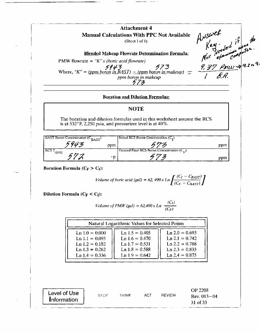
Attachment 4 Manual Calculations With PPC Not Available p / 3 4 (Sheet 1 of 1)
Blended Makeup Flowrate Determination Formula: lg - dG4 iM
PMW flowrate = “K”x (boric acidflowrate)
Where, “ K = @Dm boron in BAST) - (qm boron in makeup) 5943 5573 E 37 PjW
1 44 -
ppm boron in makeup 5-73
BAST Boron Concentration (C BAST)
PPm f94’3 57x “F
RCS TAVG
Initial RCS Boron Concentration (C,)
$79 PPm
973 PPm
Desired Final RCS Boron Concentration (C,)
Volume of boric acid (gal) = 62, 490x Ln LE123
Ln 1.4 = 0.336
Dilution Formula (CF < CI):
Ln 1.9 = 0.642 I I Ln 2.4 = 0.875 I
(Cl) (CF)
Volume of PMW (gal) = 62,490 x Ln -
Natural Logarithmic Values for Selected Points I
Ln 1.2 = 0.182 Ln 1.3 = 0.262
Ln 2.2 = 0.788 Ln 2.3 = 0.833
OP 2208
31 of 33 ACT REVIEW Rev. 013-04 Level of Use THINK srw
nformation

JOB PERFORMANCE MEASURE WORKSHEET
JPM Number: JPM-SI Rev. 0
lnitiatinq Cues: - The Unit Supervisor has directed you to perform a manual blended makeup to the VCT and raise VCT level by 2% while maintaining the PMW and Boric Acid flow controllers in the “AUTO” mode of operation. Use OP 2304C starting with step 4.9.2.
-
-
When makeup is completed, return the system lineup to normal.
The examiner will act as the US.
Initial Conditions: -
-
-
RCS boron concentration is 573 ppm
In-service Boric Acid Storage Tank concentration is 5,943 ppm
No manual leak rate is in progress.
Simulator Requirements:- Initialize at any IC with charging, letdown, and makeup to the VCT available. Verify RCS boron (Cb) = 573 on the simulator. Verify “A” BAST pp selected to ‘lead’ (C-02) Verify “A” BAST concentration = 5943 ppm Verify VCT level 5 82% Set the PMW and BA Controllers 210Y and 210X setpoint to zero.
NOTES TO EXAMINER * * * * * * * *
1. Critical steps for this JPM are indicated with an “X”. For the examinee to achieve a satisfactory grade, ALL critical steps must be completed correctly.
When examinee states what hidher simulated action/observation would be, read the appropriate “Cue”
If necessary, question examinee for details of simulated actions / observations (i.e. What are you looking at?” or “What are you observing?”).
2.
3.
3

JPM ID NUMBER: JPM-SI
PERFORMANCE INFORMATION
TITLE: Manual Makeup to the VCT
START TIME:
STEP I - Performance Steps: Ensure PMW is available and at least one charging pump operating.
GRADE - Standards: Examinee observes red indicating lights lit on C-02 for
- PMWpumps - and charging pumps.
Cue
Comments:
STEP 2 - X Performance Steps: Determine the required ratio of Boric Acid flow to PMW flow.
GRADE - - X Standards: Examinee uses either OP 2208 or PPC to determine that the ratio of Boric Acid to PMW flow is I gallon to 9.2 to 9.5 gallons, respectively.
cue
Comments: PMW value does not have to be calculated to the decimal points if done by hand.
STEP 3 - Pe dorm ance Steps : Ensure the following are closed: - Makeup valve stop, CH-512 (C-04) - VCT makeup bypass, CH-196 (C-02) - RWST isolation, CH-192 (C-02)
4

PERFORMANCE INFORMATION
JPM ID NUMBER: JPM-SI TITLE: Manual Makeup to the VCT
GRADE - - Stand a rd s: Examinee observes the green lights ‘only’ lit for CH-512 on C-04, Ch-196 and CH-192 on C-02
Cue
Comments:
STEP 4 - Performance Steps: Determine the desired VCT level change in % level and total gallons required.
GRADE - - Standards: Examinee states that a 2% level rise is required and using 34 gal/%, a total of 68 gallons is required.
Cue I f not stated, solicit information.
Comments: VCT %/gal. is listed on the VCT Label on C-02.
5

PERFORMANCE INFORMATION
JPM ID NUMBER: JPM-SI TITLE: Manual Makeup to the VCT
STEP 5
GRADE -
Comments:
STEP 6
GRADE -
- X Performance Steps: Reset PMW and BA controllers (FC-21OX & FC-21OY), to zero.
Standards: For each controller, examinee checks:
-
-
-
- - ‘I” indicated, - X
x presses and holds “SEL” button until “TOTAL RST”is
Presses “R/L” button to shift controller to “R” (resets
Presses ”SEL” to display controller number.
displayed.
totalizer), then back to ‘I”. -
Cue
Manual Leak Rate Determination is not in progress (Step 4.9.7.b is N/A)
_--5--_--_--_--_----__5______5__1__
- Performance Steps: Start PPC trend of VCT level (L226).
- Standards: Examinee starts PPC trend and displays it on PPC monitor,
Cue
Comments:
6
PERFORMANCE INFORMATION
JPM ID NUMBER: JPM-SI TITLE: Manual Makeup to the VCT
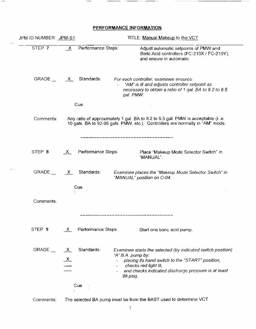
STEP 7 3 Performance Steps: Adjust automatic setpoints of PMW and Boric Acid controllers (FC-210X I FC-21OY), and ensure in automatic.
GRADE - X Standards: For each controller, examinee ensures: - “AM” is lit and adjusts controller setpoint as
necessary to obtain a ratio of 1 gal. BA to 9.2 to 9.5 gal. PMW.
Cue
Comments: Any ratio of approximately 1 gal. BA to 9.2 to 9.5 gal. PMW is acceptable (i .e. 10 gals. BA to 92-95 gals. PMW, etc.). Controllers are normally in “AM” mode.
STEP 8 X Performance Steps: Place “Makeup Mode Selector Switch” in “MAN U A L” .
- GRADE - & Standards: Examinee places the “Makeup Mode Selector Switch” in
“MANUAL” position on C-04.
Cue
Comments:
STEP 9 - X Performance Steps: Start one boric acid pump.
GRADE - X Standards: Examinee starts the selected (by indicated switch position) ‘ X ” B.A. pump by:
- x - placing its hand switch to the ”START“position, - - checks red light lit, - - and checks indicated discharge pressure is at least
98 psig.
Cue
Comments: The selected BA pump must be from the BAST used to determine VCT
7

PERFORMANCE INFORMATION
JPM ID NUMBER: JPM-SI TITLE: Manual Makeup to the VCT
blend. (The “ A is the selected pump and should be used)
STEP 10 - X Performance Steps: Open Makeup Stop Valve, CH-512
GRADE - X Standards: Examinee places CH-512 switch to “0PEN”on C-04 and ensures red light only is lit.
Cue
Comments: Examinee may check that the “M” of “AM” extinguishes on the makeup controllers.
STEP 11 - Performance Steps: Ensure flows have stabilized at setpoints of the flow controllers.
GRADE - - Standards: Examinee watches flow controllers on C-04 to ensure flow begins and then stabilizes at the calculated setpoints.
Cue
Comments: The flow values may vary depending upon how many GPM of BA are used.
STEP 12 - Performance Steps: Monitor VCT level and pressure as indicated on Pl-225 and Ll-226.
GRADE - - Stand a rd s : Examinee observes indications on C-02 or PPC
Cue
Comments:

PERFORMANCE INFORMATION
JPM ID NUMBER: JPM-SI TITLE: Manual Makeup to the VCT
STEP 13 - X Performance Steps: When desired VCT level is reached Close “Makeup Vlv Stop” CH-512, on C-04
GRADE - Standards: Examinee observes that: - - 2% level has been added to the VCT - X - and closes CH-512.
- Observes green light lit for valve and flow stops.
Cue
STEP 14 - X Performance Steps: Stop “Boric Acid” pump, P-I 9A or 6.
GRADE - Standards: Examinee
- to stop - x - takes the “A” Boric Acid Pump hand switch on C-02
___. - verifies the green light is lit and the red light is out - verifies discharge pressure is zero with no flow.
Cue
Comments:
STEP 15 - X Performance Steps: Places the “Make Up Mode Select’’ switch in “Dilute” on C-04.
GRADE - - X Standards: Examinee takes handswifch and turns if from the “Manual” to “Dilute” position.
Cue
9

PERFORMANCE INFORMATION
JPM ID NUMBER: JPM-SI TITLE: Manual Makeup to the VCT
Comments: After this step is completed, the JPM is considered complete.
...................................
STOP TIME:
10

VERIFICATION OF JPM COMPLETION
Job Performance Measure No. JPM-SI
Date Performed:
Rev. 0
Operator:
Evaluator(s):
For examinee to achieve a satisfactory grade, ALL critical steps must be completed correctly. If task is Time Critical, it MUST be completed within the specified time to achieve a satisfactory grade.
Time Critical Task? Yes No X
Validated Time (minutes): 10
Actual Time to Complete (minutes):
Result of JPM: (Denote by an S for satisfactory or a JJ for unsatisfactory)
Areas for Improvement:
11

EXAMINEE HANDOUT
JPM ID Number:
Initiating Cues: - The Unit Supervisor has directed you to perform a manual blended makeup to the VCT and raise VCT level by 2Y0while maintaining the PMW and Boric Acid flow controllers in the "AUTO" mode of operation. Use OP 2304C starting with step 4.9.2.
- When makeup is completed, return the system lineup to normal.
- The examiner will act as the US
- No manual leak rate is in progress.
Initial Conditions: - RCS boron concentration is 573 ppm
- In-service Boric Acid Storage Tank concentration is 5,943 ppm
12

JOB PERFORMANCE MEASURE APPROVAL SHEET
I. JPM Title: Filtinn #1 Safety Injection Tank
ID Number: JPM-S2 Revision: 0
II. Initiated:
R. J. Ashey U
Developer
1 /24/05
Date
Ill. Reviewed:
IV. Approved:
w
User Department Supervisor
Nuclear Trai ing Supervisor t
Date
Date

SUMMARY OF CHANGES
All 8 Date
01/18/2005
DESCRIPTION REVICHANGE
Develop new JPM using 23060. 0
Page 2 of 13

JOB PERFORMANCE MEASURE WORKSHEET
Facility: MP-2 Examinee:
JPM Number: JPM-S2 Rev. 0
Task Title:
System: Safety Injection
Time Critical Task: Yes No X
Validated Time (minutes): 25
Task No.(s): NUTIMS #006-02-017
Fill #I Safety Injection Tank
Applicable To: SRO X RO X PEO
K/A No.: 006-AI. 13 K/A Rating: 3.U3.7
Method of Testing:
Simulated Performance : Actual Performance: X
Location:
Classroom: Simulator: X In-Plant:
Task Standards: The examinee will start filling the #1 SIT using the “A” HPSl Pump The “A” HPSl Pump will trip on overload. The examinee will align the “B” HPSl Pump to Facility 1 and complete filling the #1 SIT using the “B” HPSl Pump.
Required Materials SP 26060 (procedures,equipment): OP 2343
OP 2308 ARP 2590A-001
General References: SP 26060, Section 4.1 OP 2343, Section 4.7 OP 2308, Section 4.1 ARP 2590A-001
READ TO THE EXAMINEE * * * * * * * *
I will explain the initial conditions, which step(s) to simulate or discuss, and provide initiating cues. When you complete the task successfully, the objective for this job performance measure will be satisfied. You may use any approved reference materials normally available in the Control Room, including logs. Make all written reports, oral reports, alarm acknowledgments, and loa entries as if the evolution was actuallv beina oerformed.
Page 3 of 13

JOB PERFORMANCE MEASURE WORKSHEET
r NOTES TO EXAMINER * * * * * * * *
JPM Number: JPM-S2
I the performance of this JPM (in-plant only).
Rev. 0
Initiating Cues: 0 You are the PPO. 0 The Unit Supervisor has directed you to fill the # I SIT using
the “A“ HPSl Pump per OP-23060, “Safety Injection Tanks, RCS > 1750 psia”.
0 The examiner will act as the Unit Supervisor and/or PEO
Initial Conditions: 0
0
0
0
0
The plant is at 100% power, NOPINOT.
No equipment is out of service.
Bus 24E is aligned to Bus 24C. A PEO is available at the “A” HPSl Pump.
The “A” HPSI has been checked and is ready to start.
Initialize at a normal 100% power (IC-93) with # I SIT at the low level alarm, above 200 psig, and enter the following: - S104A on BT 48 ( “ A HPSI Pump >20 amps) “A” HPSI Pp
Trip - I/O on Annunciator C-01 A-I (“A’ HPSl Pump
OverloadPTrip) on C-01 on BT 49 (“A” HPSl Pump >2
- IDT SIMT39(1) set to 7.3e4 (#I SIT at 55.2%) Pressurize # I SIT to approximately 218 psig.
Simulator Requirements: --
amps)
1.
2 .
3.
4.
Critical steps for this JPM are indicated with an “X”. For the examinee to achieve a satisfactory grade, critical steps must be completed correctly.
When examinee states what hidher simulated action/observation would be, read the appropriate !‘Cue”.
If necessary, question examinee for details of simulated actions / observations (Le. “What are you looking at?” or “What are you observing?”).
Under NO circumstances must the examinee be allowed to manipulate any devices during
PERFORMANCE INFORMATION
JPM ID NUMBER: JPM-S2 TITLE: Fill #1 Safetv lniection Tank
~~ ~
START TIME:
STEP 1
GRADE __
Comments:
STEP 2
GRADE __
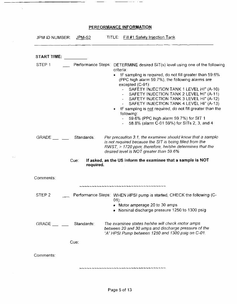
__ Performance Steps: DETERMINE desired SIT(s) level using one of the following criteria: 0 IF sampling is required, do not fill greater than 59.6%
(PPC high alarm 59.7%), the following alarms are excepted (C-01):
- - - -
SAFETY INJECTION TANK 1 LEVEL HI" (A-10) SAFETY INJECTION TANK 2 LEVEL HI" (A-I 1) SAFETY INJECTION TANK 3 LEVEL HI" (A-12) SAFETY INJECTION TANK 4 LEVEL HI" (A-I 3)
0 IF sampling is not required, do not fill greater than the following: - -
59.6% (PPC high alarm 59.7%) for SIT 1 58.8% (alarm C-01 59Oh) for SITS 2, 3, and 4
- Standards: Per precaution 3.1, the examinee should know that a sample is not required because the SIT is being filled from the RWST, > 1720 ppm; therefore, he/she determines that the desired level is NOT greater than 59.6%
Cue: If asked, as the US inform the examinee that a sample is NOT required.
- Performance Steps: WHEN HPSl pump is started, CHECK the following (C-
Motor amperage 20 to 30 amps Nominal discharge pressure 1250 to 1300 psig
01):
__ Standards: The examinee states he/she will check motor amps between 20 and 30 amps and discharge pressure of the "A" HPSl Pump between 1250 and 1300 psis on C-07.
Cue:
Comments:

PERFORMANCE INFORMATION
JPM ID NUMBER: JPM-S2 TITLE: Fill # I Safety Injection Tank
X STEP 3 -
GRADE X --
X -- --
Performance Steps: IF filling SIT I, PERFORM the following (C-01): a. VERIFY open “SI-611, FILL & DRN.” b. IF required, START one of the following HPSl
pumps: ”P-41A, HPSl PP A ’ “P-41B, HPSl PP B” “P-41C, HPSl PP C”
Standards: The examinee performs the following: On C-01, opens SI-61 I, Fill and Drain, and observes the red light is lit. Places the “A” HPSl Pump. handswitch on C-01 to start. - Observes that the pump trips. - Observes no pump amps or pressure. - Observes an amber light above the pump handswitch. - Observes Annunciator C-O1,A I “HPSI PUMP A
0 VERL OA D/TRIP” Reports io the US that the ‘HA’ HPSl has tripped and annunciator A-I on C-01 is lit. May ask the PEO at the pump to report any abnormal conditions. Initiates Annunciator Response Procedure, ARP 2590A- 001. Recommend placing the “B” HPSI in service on Facility 1. Closes SI-611 to place the plant in a known stable condition.
Cue:
Page 6 of 13

PE RFO RMANC E IN FORMAT10 N
JPM ID NUMBER: JPM-S2 TITLE: Fill #1 Safety lniection Tank
STEP 4 __ Performance Steps: Refer to the following LCOs and determine applicability:
TRM 3.1.2.1 0 Tech Spec 3.5.2 0 Tech Spec 3.5.3
GRADE- - Standards: The examinee informs the US to determine applicability ofTRM3.1.2.1and TS3.5.2and3.5.3
Cue: Report as the US that you will check the TS applicability.
Comments: This action is directed in ARP 2590A-001 “HPSI Pp. ‘A’ OverloadlTrip”
STEP 5 Performance Steps: 0 Refer to OP 2308, High Pressure Safety Injection System, and place “B” HPSI Pp. on Facility 1.
0 Determine the cause of the pump trip and submit a trouble report.
GRADE- ___ Standards: 0 The examinee refers to OP 2308, High Pressure Safety lnjection System, Section 4 . 1 . The examinee requests the US to have a CR/TR written and have the cause of the trip determined.
0
Cue: 0 The US acknowledges the request. 0 When asked, provide the examinee with OP 2308, High
Pressure Safety Injection System, Section 4.1
Comments:
Page 7 of 13

PERFORMANCE INFORMATION
JPM ID NUMBER: JPM-S2 TITLE: Fill # I Safety lniection Tank
STEP 6 Performance Steps: If shifting from “A” pump to “B” pump, perform the following: - Verify “B” HPSl aligned to Facility 1 per OP 2343. - Enter TSAS 3.5.2 - Place P41A, “HPSI PP A,” in PTL - Remove P41B, “HPSI PP B,” from PTL. - Exit TSAS 3.5.2
GRADE- __ Standards: The examinee references OP 2343 to determine if the “B” HPSI is aligned to Facility 1 or he/she determines that “B” HPSl is aligned to Facility I because Bus 24E is aligned to Bus 24C.
--
Cue:
Per OP 2308, the examinee will: - -
Inform the US to log into TSAS 3.5.2 On C-01, place the “A” HPSl Pump handswitch in Pull- To-Lock. On C-01, remove the ‘‘6” HPSl Pump from Pull- To Lock. Inform the US to log out of TSAS 3.5.2.
-
-
0
0
If asked, provide the examinee with OP 2343, 4160 Volt Electrical System. If the examinee begins to verify all the steps to align the ‘By HPSl to Facility 1, as the US inform the examinee the ‘B’ HPSl is aligned and the steps in 2343 are complete. If examinee asks for a PEO to check “B” HPSl Pump, report that the pump is ready to start.
0
Page 8 of 13

PERFORMANCE INFORMATION
JPM ID NUMBER: JPM-S2 TITLE: Fill # I Safety Injection Tank
STEP 7 - Performance Steps: WHEN HPSl pump is started, CHECK the following (C- 01):
Motor amperage 20 to 30 amps 0 Nominal discharge pressure 1250 to 1300 psig
GRADE- __ Standards: The examinee states he/she will check motor amps between 20 and 30 amps and discharge pressure of the "B" UPS1 Pp between 1250 and 1300 psis on C-01.
Cue:
Comments: This step may or may NOT be repeated by the examinee
STEP 8 X Performance Steps: IF filling SIT 1, PERFORM the following (C-01): a. VERIFY open "SI-61 I, FILL & DRN." b. IF required, START one of the following HPSI pumps:
"P-41A, HPSl PP A' "P-41B, HPSl PP B" "P-41C, HPSl PP C"
GRADE Standards: The examinee performs the following: 0
0
-- X
-- X
On C-01, examinee opens (or ensures open) 3 - 6 1 1, Fill and Drain, and observes the red light is lit. Places the "B" HPSl Pump. handswitch on C-01 to start and observes the proper indications on the "B" UPS/ Pump.
Cue: If requested, as the PEO, report that the pump is running with NO abnormal indications.
Comments: The examinee must realize that she/he must return to 23060 and commence with step 4.1.3.
Page 9 of 13

PERFORMANCE INFORMATION
JPM ID NUMBER: JPM-S2 TITLE: Fill #1 Safetv lniection Tank
STEP 9
GRADE -
Comments:
STEP 10
GRADE __
X Performance Steps: Throttle open SI-618, Hdr - l A Ck Vlv Lkg Drn Stop, not to exceed 300 psig, as indicated in Recirc Hdr Press, PI-305.
X Standards: While observing Recirc Header Pressure indicator, PI-305, the examinee throttles open SI-618, Hdr - l A Ck Vlv Lkg Drn Stop, to a pressure less than 300 psig, but greater than #1 SIT pressure. Examinee observes rise in # I SIT level.
Cue:
X Performance Steps: Close SI-618 when any of the following occur: SI TK1 LVL, L311 is at the desired level (PPC) SI TK 1 PRESS, P311, is at 225 psig (PPC) SI TK 1 PRESS, P-311, is at 225 psig (C-01) #I SIT High Pressure alarm is annunciated on the PPC.
- X Standards: When any of the following occur, the examinee will close SI-618: SI TK1 LVL, L311 is at the desired level of 59.6% (PPC) SI TK 1 PRESS, P311, is at 225 psig (PPC) SI TK 1 PRESS, P-311, is at 225 psis (C-01) #l SIT High Level alarm is annunciated on the PPC at 59.8%.
Cue:
Comments: SIT pressure of 225 psig should be the most limiting parameter. Depending on the flow rate, this could take 5 to 10 minutes.
-5--_r---L--I_---_-___55__5___5____
Page 10 of 13
PERFORMANCE INFORMATION
JPM ID NUMBER: JPM-S2 TITLE: Fill #1 Safety Injection Tank
STEP 11 Performance Steps: When filling is complete, Stop the “B” HPSl Pump.
GRADE- - X Standards: Examinee stops the “B” HPSI Pump.
Cue:
Comments: This JPM is complete when the examinee stops the “B” HPSl Pump. The examinee does NOT have to wait for Safety Injection to Loop 1A and 2B to lower to between 225 and 275 psig.
STOP TIME:
Page 11 of 13

VERIFICATION OF JPM COMPLETION
Job Performance Measure No. JPM-S2 Rev. 0
Date Performed:
Operator:
Evaluator( s):
For examinee to achieve a satisfactory grade, critical steps must be completed correctly. If task is Time Critical, it MUST be completed within the specified time to achieve a satisfactory grade.
Time Critical Task? Yes No
Validated Time (minutes): 25
Actual Time to Complete (minutes):
Result of JPM: (Denote by an s for satisfactory or a u for unsatisfactory)
Areas for Improvement:
Page 12 of 13

EXAMINEE HANDOUT
JPM Number: JPM-S2 Rev. 0
Initiating Cues: 0 You are the PPO. 0 The Unit Supervisor has directed you to fi l l the #1 SIT using
the “A” HPSl Pump per OP-23060, “Safety Injection Tanks, RCS > 1750 psia”.
0 The examiner will act as the Unit Supervisor and/or PEO.
initial Conditions: 0
0
0
0
0
The plant is at 100% power, NOPINOT.
No equipment is out of service.
Bus 24E is aligned to Bus 24C.
A PEO is available at the “A” HPSI Pump. The “A” HPSl has been checked and is ready to start
Page 13 of 13

JOB PERFORMANCE MEASURE APPROVAL SHEET
I JPM Title: Start Ch RCP
ID Number: JPM-S3
11. Initiated: 44ye Danie A. P t ne
I 1 1 . Reviewed:
Developer
&(& DuffvAs ev
Technical Reviewer
IV. Approved:
User Department Supervisor
Revision: 0 -
01 11 8/05 Date
Date
Date
Date

SUMMARY OF CHANGES
1 A/I&Date I DESCRIPTION 1 REVlCHANGE
0 I 1 10/27/2005 I Developed this new JPM
2

JOB PERFORMANCE MEASURE WORKSHEET
Facility: MP-2 Examinee:
JPM Number: JPM-S3 Rev. 0
Task Title: Start a Reactor Coolant Pump
System: Reactor Coolant Pump
Time Critical Task: Yes No X
Validated Time (minutes): 15 min.
Task No.(s):
Applicable To: SRO X RO X PEO
K/A No.: 003 A2.03 KIA Rating: 2.7/3.1
NUTIMS # 003 01 031
Method of Testing:
Si m u I ated Performance: Actual Performance: X
Location: ~ ..
Classroom: Simulator: X In-Plant:
Task Standards: The examinee will start the RCP, monitor critical RCP parameters including alarms and secure the RCP per OP 2301C and/or ARP 25908-083.
Required Materials Lprocedures,equipment):
OP 2301C, Reactor Coolant Pumps Annunciator Response Procedure, ARP 2509B-083, C-03, BA-19
Genera I Ref e re n ces :
READ TO THE EXAMINEE * * * * * * * * 1 I will explain the initial conditions, which step(s) to simulate or discuss, and provide initiating cues. When you complete the task successfully, the objective for this job performance measure will be satisfied. You may use any approved reference materials normally available in the Control Room, including logs. Make all written reports, oral reports, alarm acknowledgments, and log entries as if the evolution was actually being performed.
3
JOB PERFORMANCE MEASURE WORKSHEET
JPM Number: JPM-S3 Rev. 0
Initiating Cues: The US has directed you to start the 'A' RCP i n accordance with OP 2301 C. Reactor Coolant Pumps, section 4.1.
Initial Conditions: A plant heat-up is in progress following an outage for unplanned maintenance. - - Three RCPs are running. - -
The RCS is at normal pressure and Tc is > 500°F.
All parameters for the 'A' RCP are normal for this condition. OP-2301 C: section 4.1 is complete up to step 4.1.10.
Simulator Requirements: Initialize at zero power, ARI. (IC-93) then trip rods. - 'A' RCP is secured. - RCS is at - 505 O F . - Plant is stable. A malfunction to lower the level in the Upper Oil Reservoir will be inserted after the "A" RCP is started.
NOTES TO EXAMINER * * * * *
1. Critical steps for this JPM are indicated with an "X". For the examinee to achieve a 1 satisfactory grade, critical steps must be completed correctly.
2. When examinee states what hidher simulated action/observation would be, read appropriate "Cue".
If necessary, question examinee for details of simulated actions / observations (i. are you looking at?" or "What are you observing?").
3.
he
. "What
4. Under circumstances must the examinee be allowed to manipulate any devices during the performance of this JPM (in-plant only).
4

-..-
PERFORMANCE INFORMATION
JPM ID NUMBER: JPM-S3 TITLE: Start 4’h RCP
START TIME:
STEP 1 - Performance Steps: Observe controlled bleedoff flow on PPC or PR-150A (C-04R) between 0.75 and 2.0 gpm.
GRADE Standards: Examinee displays and monitors “A” RCP bleedoff flow on the PPC, or on C-04R.
Cue:
Comments:
STEP 2 2 Performance Steps: Place “RCP-A LIFT PPS” switch to “START” (C-03)
GRADE X Standards: Examinee places the ‘A’ RCP Lift Pump switch to start and observes the red light lit.
Cue: e examinee ind lift pump must run for 2 , inform the exa inutes have elapsed.
Comments: Annunciator AB-18 on C-02/3, RCP A ANTIREV ROT FLOW LO, will reset.
5

PERFORMANCE INFORMATION
JPM ID NUMBER: JPM-S3 TITLE: Start 4‘h RCP
STEP 3 2 Performance Steps: Place the “RCP-A, P-40A switch to START
GRADE X Standards: Examinee places the ‘A’ RCP switch on C-03 to the start position and observes: - Red light lit - The ammeter peg high and decay off.
Cue: Booth Instructor - RCIZA (20%) When the examinee starts the “A” RCP, insert a malfunctidn to cause the upper oil reservoir level to lower.
Comments:
STEP 4 - X Performance Steps: Place the “RCP-A LIFT PPS” to “AUTO”
~. GRADE X Standards: When annunciator C-04 AA-4 is not lit, examinee places the ‘A’RCP Lift Pp. switch on C-03 to AUTO.
Cue:
Comments:
6
PERFORMANCE INFORMATION
JPM ID NUMBER: JPM-S3 TITLE: Start 4th RCP
STEP 5 A Performance Steps: Observe annunciator BA19 on C-02/3, RCP A UPPER OIL RSVR LEVEL LO.
GRADE- - X Standards: Examinee observes annunciator BA 19 on C-OZ3, RCP A UPPER OIL RSVR LEVEL LO, and informs the US. Examinee refers to ARP 25908-083 or recommends that the associated ARP be referenced.
Cue: Acknowledge the recommendation and direct the examinee to implement the recommended ARP.
Comments:
STEP 6 A Performance Steps: Check ‘A‘ RCP upper reservoir oil level indication and determine rate of level decrease.
GRADE X Standards: Examinee - - - or - -
displays the “RCP A Motor Data” display on the PPC monitors “L156” (Upper Reservoir Level). calculates the rate of level decrease
monitors “L 7 56” on C-04R calculates the rate of level decrease
Cue:
Comments:
7

PERFORMANCE INFORMATION
JPM ID NUMBER: JPM-S3 TITLE: Start 4‘h RCP
STEP 7 - Performance Steps: Monitor “A” RCP bearing temperatures and oil levels (C-04R or PPC)
GRADE Standards: The examinee monitors “A” RCP bearing temperatures and oil level by: -
or - monitoring parameters on C-04R
displaying the “RCP A Motor Data” display on the PPC
Cue:
Comments:
STEP 8 X Performance Steps: If oil level is rapidly lowering, -
- stop the “ A RCP -
trip the Rx and Turbine
refer to EOP 2525, Standard Post Trip Actions ._ -
GRADE X Standards: Examinee secures the ‘ X ” RCP. Examinee reports that tripping the Reactor and Turbine is NOT applicable in this condition.
Cue: ommendation. d direct the examin
ff the “A” Lift P ed off after the
Comments: Turning off the “A” Lift Pump is NOT a required action, but may be recommended to limit the loss of oil in the upper reservoir.
Comments: After this step is completed, the JPM is considered complete.
STOP TIME:
8

VERIFICATION OF JPM COMPLETION
Job Performance Measure No. JPM-S3 Rev. - 0
Date Performed:
Operator:
Evaluator(s):
For examinee to achieve a satisfactory grade, critical steps must be completed correctly. If task is Time Critical, it MUST be completed within the specified time to achieve a satisfactory grade.
Time Critical Task? Yes No
Validated Time (minutes): 15
Actual Time to Complete (minutes):
Result of JPM: (Denote by an S for satisfactory or a u for unsatisfactory)
Areas for Improvement:
9
EXAMINEE HANDOUT
JPM ID Number: JPM-S3
Initiatinq Cues: The US has directed you to start the ‘A’ RCP in accordance with OP 2301 C, Reactor Coolant Pumps, section 4.1.
Initial Conditions: A plant heat-up is in progress following an outage for unplanned maintenance. - - Three RCPs are running. - -
The RCS is at normal pressure and Tc is > 500°F.
All parameters for the ‘A’ RCP are normal for this condition. OP-2301 C, section 4.1 is complete up to step 4.1.10.
10

JOB PERFORMANCE MEASURE APPROVAL SHEET
I JPM Title: Perform TDAFP Operability Test
ID Number: JPM-S4
II Initiated.
Developer
Ill. Reviewed:
R. J. Ashey Technical Reviewer
IV. Approved:
User Department Supervisor
Revision: 0
01/24/05 Date
Date
Date
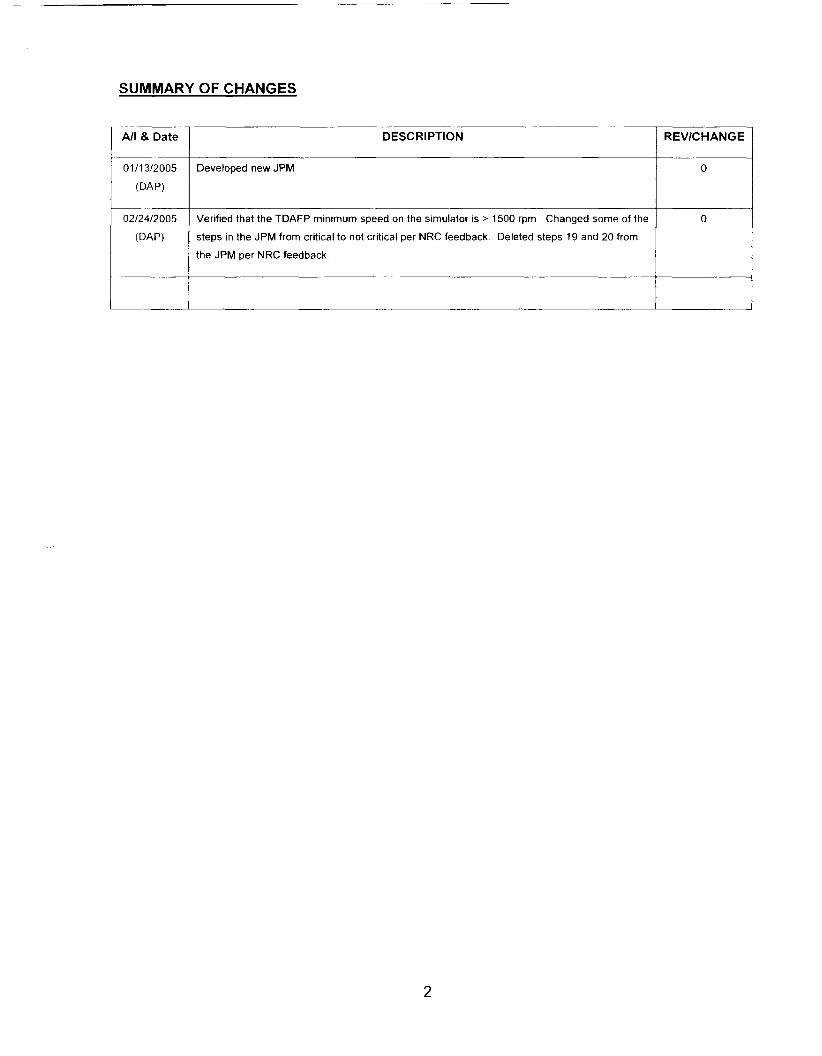
SUMMARY OF CHANGES
02/24/2005
(DAP)
I REV’CHANGE I DESCRIPTION I *’I& Date I
Verified that the TDAFP minimum speed on the simulator is > 1500 rpm. Changed some of the
steps in the JPM from critical to not critical per NRC feedback. Deleted steps 19 and 20 from
the JPM per NRC feedback.
0
I 01/13/2005 I Developed new JPM I 0 I
2
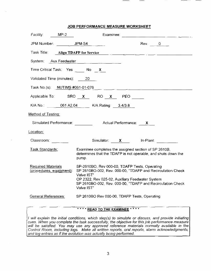
JOB PERFORMANCE MEASURE WORKSHEET
Facility: MP-2 Examinee:
JPM Number: JPM-S4 Rev. 0
Task Title: Align TDAFP for Service
System: Aux Feedwater
Time Critical Task: Yes No X
Validated Time (minutes): 20
Task No.(s): NUTIMS #061-01-076
Applicable To: SRO X RO X PEO
KIA No.: 061 A2.04 KIA Rating: 3.413.8
Method of Testing:
Simulated Performance: Actual Performance: X
Location:
Classroom:
Task Standards:
Required Materials (procedures, equipment):
General References:
Simulator: X In-Plant:
Examinee completes the assigned section of SP 2610B, determines that the TDAFP is not operable, and shuts down the Pump.
SP-261 OBO, Rev OOO-OO, TDAFP Tests, Operating SP 261 060-002, Rev. OOO-OO, “TDAFP and Recirculation Check Valve I S T OP 2322, Rev 025-02, Auxiliary Feedwater System SP 261 OBO-002, Rev. OOO-OO, “TDAFP and Recirculation Check Valve IST”
SP 261 OB0 Rev OOO-OO, TDAFP Tests, Operating
READ TO THE EXAMINEE * * * * * * * *
I will explain the initial conditions, which step(s) to simulate or discuss, and provide initiating cues. When you complete the task successfully, the objective for this job performance measure will be satisfied. You may use any approved reference materials normally available in the Control Room, including logs. Make all written reports, oral reports, alarm acknowledgments, and 104 entries as if the evolution was actuallv being performed.
3
JOB PERFORMANCE MEASURE WORKSHEET
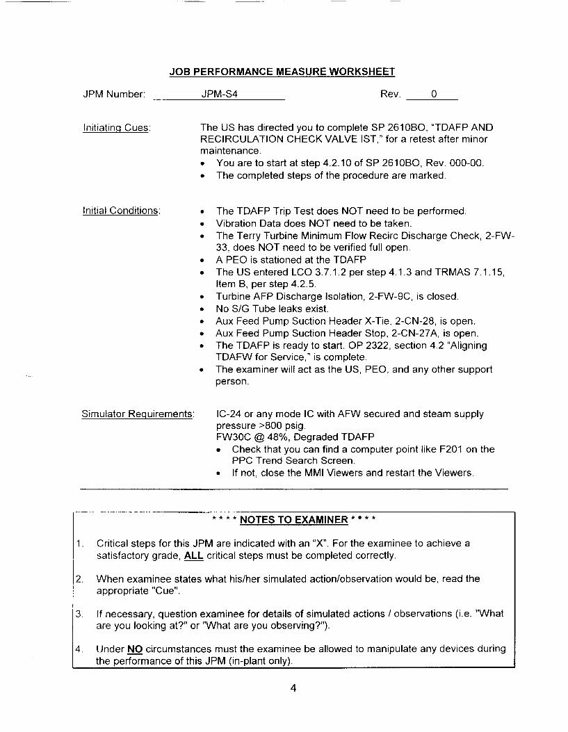
JPM Number: JPM-S4 Rev. 0
Initiating Cues: The US has directed you to complete SP 261080, "TDAFP AND RECIRCULATION CHECK VALVE IST," for a retest after minor maintenance .
Initial Conditions:
Simulator Requirements:
You are to start at step 4.2.10 of SP 2610B0, Rev. 000-00. The completed steps of the procedure are marked.
The TDAFP Trip Test does NOT need to be performed. Vibration Data does NOT need to be taken. The Terry Turbine Minimum Flow Recirc Discharge Check, 2-FW- 33, does NOT need to be verified full open. A PEO is stationed at the TDAFP The US entered LCO 3.7.1.2 per step 4.1.3 and TRMAS 7.1.15, Item B, per step 4.2.5. Turbine AFP Discharge Isolation, 2-FW-9C, is closed. No S/G Tube leaks exist. Aux Feed Pump Suction Header X-Tie, 2-CN-28, is open. Aux Feed Pump Suction Header Stop, 2-CN-27A, is open. The TDAFP is ready to start. OP 2322, section 4.2 "Aligning TDAFW for Service," is complete. The examiner will act as the US, PEO, and any other support person.
IC-24 or any mode IC with AFW secured and steam supply pressure >800 psig. FW3OC @ 48%, Degraded TDAFP
Check that you can find a computer point like F201 on the PPC Trend Search Screen.
0 If not, close the MMI Viewers and restart the Viewers.
NOTES TO EXAMINER * * * * * * *
1 . Critical steps for this JPM are indicated with an "X". For the examinee to achieve a satisfactory grade, ALL critical steps must be completed correctly.
When examinee states what hidher simulated action/observation would be, read the appropriate "Cue".
If necessary, question examinee for details of simulated actions / observations (Le. "What are you looking at?" or "What are you observing?").
2.
3.
4. Under circumstances must the examinee be allowed to manipulate any devices during the performance of this JPM (in-plant only).
4

PERFORMANCE INFORMATION
JPM ID NUMBER: JPM-S4 TITLE: Perform TDAFP Operability Test
START TIME:
STEP 1 X Performance Steps: Refer To OP 2322, Auxiliary Feedwater System,” and START TDAFP from Control Room.
GRADE X Standards: Examinee obtains OP 2322, Auxiliary Feedwater, section 4.3.
Cue:
Comments:
-------5-------55--5---------------
STEP 2 - Performance Steps: - Refer To Section 4.2, and ENSURE TDAFP and stem leakoff drains are aligned for service.
GRADE Standards: Examinee states that Section 4.2 is complete.
Cue:
Comments: Per the Initial Conditions, Section 4.2 has been performed.
5

PERFORMANCE INFORMATION
JPM ID NUMBER: JPM-S4 TITLE: Perform TDAFP Operability Test
STEP 3
GRADE __
Comments:
STEP 4
GRADE __
__ Performance Steps: If SG tube leaks are known to exist and it is necessary to operate TDAFP, as necessary, Record pump operating times in SM Log Book.
__ Standards: Examinee states that NO tube leaks exist
Cue:
Per Initial Conditions, NO tube leakage exists.
__ Performance Steps: Ensure one or both of the following are open (C-05): - -
NO. 1 TDAFP Sply VIV, MS-201 NO. 2 TDAFP Slpy VIV, MS-202
__ Standards: Examinee verifies that the following valves have red open lights lit. (C-05):
NO. I TDAFP SPLY VLV. MS-201 NO. 2 TDAFP SPLY VLV, MS-202
Cue:
Comments:
6
PERFORMANCE INFORMATION
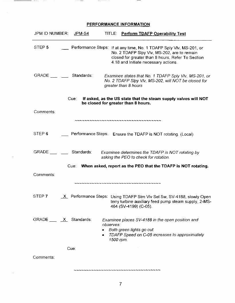
JPM ID NUMBER: JPM-S4 TITLE: Perform TDAFP Operability Test
STEP 5 - Performance Steps: If at any time, No. 1 TDAFP Sply Vlv, MS-201, or No. 2 TDAFP Slpy Vlv, MS-202, are to remain closed for greater than 8 hours, Refer To Section 4.18 and Initiate necessary actions.
GRADE- - Standards: Examinee states that No. 7 TDAFP Sply Vlv, MS-207, or No. 2 TDAFP Slpy Wv, MS-202, will NOT be closed for greater than 8 hours
Cue: If asked, as the US state that the steam supply valves will NOT be closed for greater than 8 hours.
Comments:
STEP 6 - Performance Steps: Ensure the TDAFP is NOT rotating. (Local)
GRADE Standards: Examinee determines the TDAFP is NOT rotating by asking the PEO to check for rotation.
Cue: When asked, report as the PEO that the TDAFP is NOT rotating.
Comments:
STEP 7 X Performance Steps: Using TDAFP Stm Vlv Sei Sw, SV-4188, slowly Open terry turbine auxiliary feed pump steam supply, 2-MS- 464 (SV-4199) (C-05).
GRADE X Standards: Examinee places SV-4788 in the open position and observes:
Both green lights go out. TDAFP Speed on C-05 increases to approximately 7500 rpm.
Cue:
Comments:
7

PERFORMANCE INFORMATION
JPM ID NUMBER: JPM-S4 TITLE: Perform TDAFP Operabilitv Test
STEP 8 Performance Steps: To warm turbine and lubricate bearings, OPERATE TDAFP at a minimum speed of 1,500 rpm for at least 2 minutes.
GRADE X Standards: Examinee waits for 2 minutes.
Cue: When appropriate, inform the examinee that 2 minutes has past. The TDAFP is warm.
Comments:
STEP 9 X Performance Steps: When at least 2 minutes has elapsed, adjust the “SPD CNTL switch to maintain the following: - -
Turbine speed between 1500 to 4200 rpm. Discharge pressure 2 1080 psig.
GRADE __ __ X Standards: When 2 minutes has elapsed, the examinee adjusts the SPD “CNTL to maintain the following as monitored on C- 05 or the PPC: - -
Turbine speed between I, 500 and 4,200 rpm Pump discharge pressure greater than or equal to 1,080 psig
Cue:
Comments:
STEP I O - Performance Steps: If mechanical seal leakage of TDAFP is greater than 1 quart per minute, Notify system engineer.
GRADE Standards: Examinee asks PEO to determine magnitude of mechanical seal leakage.
(less than 1 quart te). Cue: sked as the PEO, at mechanical seal leakage is
Comments: The examinee should now return to SP 261060.
8

PERFORMANCE INFORMATION
JPM ID NUMBER: JPM-S4 TITLE: Perform TDAFP Operability Test
STEP 11 - Performance Steps: Operate TDAFP at 1,500 to 1,600 for greater than two minutes.
GRADE Standards: Examinee states that the TDAFP has already been run at 1500 rpm for 2 minutes in OP 2322.
Cue:
Comments:
STEP 12 X Performance Steps: When TDAFP has operated for greater than two minutes, adjust TDAFP “SPD CNTL” switch (C-05) and establish 4,200 rpm (4,150 to 4,250 rpm).
GRADE - - X Standards: Examinee adjusts the SPD “CNTL to establish 4,200 rpm as read on C-05.
Cue:
Comments:
STEP 13 - Performance Steps: IF mechanical seal leakage of TDAFP is greater than one quart per minute, NOTIFY System Engineer.
GRADE Standards : The examinee states that mechanical seal leakage has already been verified at less than one quart per minute.
Cue: If requested, as PEO, report that mechanical seal leakoff is still less than one quart per minute.
Comments:
9
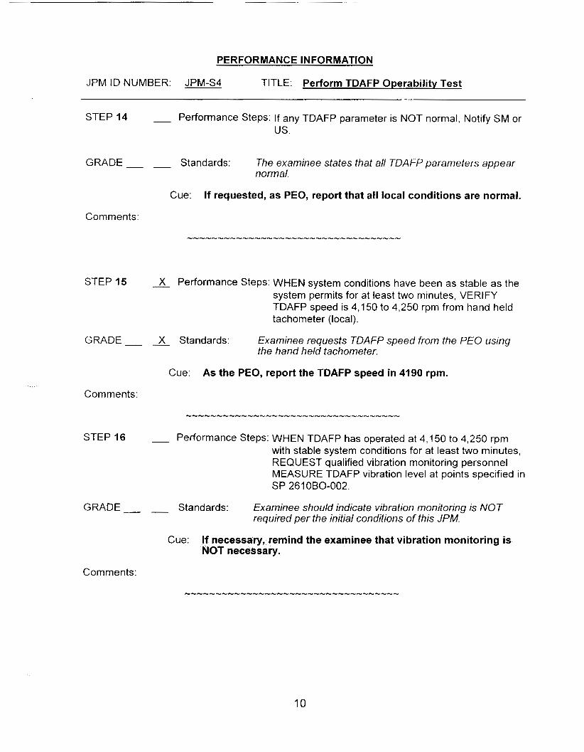
PERFORMANCE INFORMATION
JPM ID NUMBER: JPM-S4 TITLE: Perform TDAFP Operabilitv Test
STEP 14 - Performance Steps: If any TDAFP parameter is NOT normal, Notify SM or us.
GRADE Standards: The examinee states that all TDA FP parameters appear normal.
Cue: If requested, as PEO, report that all local conditions are normal.
Comments:
STEP 15 x Performance Steps: WHEN system conditions have been as stable as the system permits for at least two minutes, VERIFY TDAFP speed is 4,150 to 4,250 rpm from hand held tachometer (local).
the hand held tachometer. GRADE X Standards: Examinee requests TDAFP speed from the PEO using
Cue: As the PEO, report the TDAFP speed in 4190 rpm.
Comments:
STEP 16 - Performance Steps: WHEN TDAFP has operated at 4,150 to 4,250 rpm with stable system conditions for at least two minutes, REQUEST qualified vibration monitoring personnel MEASURE TDAFP vibration level at points specified in SP 2610B0-002.
GRADE Standards: Examinee should indicate vibration monitoring is NOT required per the initial conditions of this JPM.
Cue: If necessary, remind the examinee that vibration monitoring is NOT necessary.
Comments:
10

PERFORMANCE INFORMATION
JPM ID NUMBER: JPM-S4 TITLE: Perform TDAFP Operability Test
STEP 17 Performance Steps: Refer To SP 2610B0-002 and PERFORM the following: x a. RECORD TDAFP speed from hand held
x b. RECORD TDAFP recirculation flow from portable
x c. RECORD TDAFP discharge pressure (PPC
J- d. RECORD TDAFP suction pressure (PI-5401,
x e. CALCULATE AP corrected to rated speed. x f. RECORD TDAFP AP corrected to rated speed
tachometer and DOCUMENT results.
flowmeter at FP-9863 and DOCUMENT results.
P5284).
local).
and DOCUMENT results.
GRADE Standards: Examinee requests the required information from the PEO and records the following in SP 2610B0-002:
- - X 41 90 rpm in 4.2.18.a, “Hand held Tach” - - X - 60 gpm in 4.2.18.b, “Recirc Flow’’ - - X - 11 16 psis in 4.2.18.c, “Discharge Press” - - X - 16 psig in 4.2.18. d, “Suction Press” - - - Marks UNSAT on SP 261 080-002 for “Acceptable”
-
and “Normal”
Cue: rt as PEO that TDAFP is still 4190 rpm. rt as PEO that TDAFP rt as PEO that TDAFP
c flow is 60 gpm. n pressure is 16 psig.
Comments: The following is a guideline for determining TDAFP corrected discharge pressure. The actual data may be slightly different.
TDAFP discharge pressure, (PPC point P5284) = 11 10 psiq TDAFP suction pressure, (PI-5401) = 16 psig TDAFP Speed Handheld tachometer = 4190 rpm
1. 4200+ 4190 = 1.00238 Recorded Speed Speed Correction Ratio
2. 1.00238 (squared) = 1.0048
3. 1110 16 = 1094 Speed Correction Ratio Speed Correction Factor
TDAFP Disch Press TDAFW Suct Press Uncorrected D/P I099 - 4. 1094 X 1.0048 -
Uncorrected DIP Speed Correction Factor DIP Corrected to Rated Pump Speed (Note 3)
11

PERFORMANCE INFORMATION
JPM ID NUMBER: JPM-S4 TITLE: Perform TDAFP Operability Test
STEP 18 X Performance Steps: IF any Data Section data NOT within “Acceptable” limits, Refer To Attachment 1 and PERFORM applicable actions.
GRADE Standards : The examinee: - - X
- - X - -
-
- -
Determines that the data is NOT within “Acceptable” limits and refers to Attachment 1. Notifies the US that the pump failed the surveillance. Advises the US to carry out the steps in Attachment 7.
Cue: As the US, acknowledge the need to perform the steps of Attachment 1.
Comments: After this step is completed, the JPM is considered complete.
STOP TIME:
12

VERIFICATION OF JPM COMPLETION
Job Performance Measure No. JPM-S4 Rev. - 0
Date Performed:
Operator:
Eva luat or( s) :
For examinee to achieve a satisfactory grade, If task is Time Critical, .it MUST be completed within the specified time to achieve a satisfactory grade.
critical steps must be completed correctly.
Time Critical Task? Yes No
Validated Time (minutes): 20
Actual Time to Complete (minutes):
Result of JPM: (Denote by an 3 for satisfactory or a u for unsatisfactory)
Areas for Improvement:
13

EXAMINEE HANDOUT
JPM Number: JPM-S4 Rev. 0
Initiating Cues: The US has directed you to complete SP 261060, “TDAFP AND RECIRCULATION CHECK VALVE IST,” for a retest after minor maintenance.
Initial Conditions: 0
0
0
You are to start at step 4.2.10 of SP 261 OBO, Rev. 000-00. The completed steps of the procedure are marked.
The TDAFP Trip Test does NOT need to be performed. Vibration Data does NOT need to be taken. The operation of the Terry Turbine Minimum Flow Recirc Discharge Check, 2-FW-33, does NOT need to be verified. A PEO is stationed at the TDAFP The US entered LCO 3.7.1.2 per step 4.1.3 and TRMAS 7.1.15, Item B, per step 4.2.5. Turbine AFP Discharge Isolation, 2-FW-9C, is closed. No S/G Tube leaks exist. Aux Feed Pump Suction Header X-Tie, 2-CN-28, is open. Aux Feed Pump Suction Header Stop, 2-CN-27A, is open. The TDAFP is ready to start. OP 2322, section 4.2 “Aligning TDAFW for Service,” is complete. The examiner will act as the US, PEO, and any other support person.
14

----
I.
JOB PERFORMANCE MEASURE APPROVAL SHEET
JPM Title: “A” DG Operabilitv Test (Alternate Path)
ID Number: JPM-S5
II. Initiated:
Developer
Ill. Reviewed:
IV. Approved:
Technical Reviewer ”
User Department Supervisor
Revision: - 0
1/18/05 Date
( j Z {fl Date
Date
Date

SUMMARY OF CHANGES
A/I B Date DESCRIPTION REVICHANGE
01/18/2005
( D W
2
Modified JPM 223 Rev1 by using a different malfunction to develop this JPM. 0
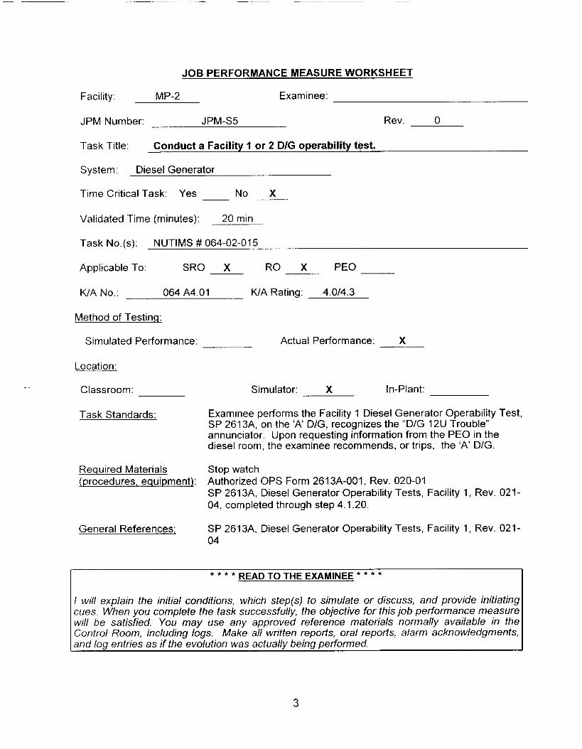
JOB PERFORMANCE MEASURE WORKSHEET
Facility: MP-2 Examinee:
JPM Number: JPM-S5 Rev. 0
Task Title: Conduct a Facility 1 or 2 DIG operability test.
System: Diesel Generator
Time Critical Task: Yes No X
Validated Time (minutes): 20 min
Task No.(s): NUTIMS # 064-02-015
Applicable To: SRO X RO X PEO
K/A No.: 064 A4.01 K/A Rating: 4.0/4.3
Method of Testing:
Si rn u I a ted Perform an ce : Actual Performance: X
Location:
Classroom: -
Task Standards:
Simulator: X In-Plant:
Examinee performs the Facility 1 Diesel Generator Operability Test, SP 2613A, on the ‘A’ D/G, recognizes the “D/G 12U Trouble” annunciator. Upon requesting information from the PEO in the diesel room, the examinee recommends, or trips, the ‘A’ DIG.
Required Materials Stop watch iprocedures, equipment): Authorized OPS Form 261 3A-001, Rev. 020-01
SP 2613A, Diesel Generator Operability Tests, Facility 1, Rev. 021- 04, completed through step 4.1.20.
General References: SP 261 3A, Diesel Generator Operability Tests, Facility 1, Rev. 021- 04
READ TO THE EXAMINEE * * * * * * * *
I will explain the initial conditions, which step(s) to simulate or discuss, and provide initiating cues. When you complete the task successfully, the objective for this job performance measure will be satisfied. You may use any approved reference materials normally available in the Control Room, including logs. Make all written reports, oral reports, alarm acknowledgments, and log entries as if the evolution was actually being performed.
3
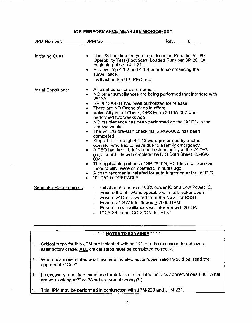
JOB PERFORMANCE MEASURE WORKSHEET
JPM Number: JPM-S5 Rev. 0
Initiating Cues:
Initial Conditions:
0
Simulator Requirements:
The US has directed you to perform the Periodic 'A' DIG Operability Test (Fast Start, Loaded Run) per SP 2613A, beginning at step 4.1.21 Review step 4.1.2 and 4.1.4 prior to commencing the surveillance. I will act as the US, PEO, etc.
All plant conditions are normal. NO other surveillances are being performed that interfere with 261 3A. SP 2613A-001 has been authorized for release. There are NO Ozone alerts in affect. Valve Alignment Check, OPS Form 2613A-002 was performed two weeks ago NO maintenance has been performed on the " A DG in the last two weeks. The 'A' DIG pre-start check list, 2346A-002, has been completed. Steps 4.1.1 through 4.1.18 were performed by another operator who had to leave due to a family emergency. A PEO has been briefed and is standing by at the 'A' D/G gage board. He will complete the D/G Data Sheet, 2346A- 004. The applicable portions of SP 261 9G, AC Electrical Sources Inoperability, were completed 5 minutes ago. A chart recorder is installed for auto triggering at the 'A' DIG. "B" D/G is OPERABLE.
- - - - - -
Initialize at a normal 100% power IC or a Low Power IC. Ensure the 'B' D/G is operable with its breaker open. Ensure 24C is powered from the NSST or RSST. Ensure Z1 SW total flow is 2 2000 GPM. Ensure no surveillances will interfere with 261 3A. I/O A-36, panel CO-8 'ON' for BT37
NOTES TO EXAMINER * * * * * *
1. Critical steps for this JPM are indicated with an "X". For the examinee to achieve a satisfactory grade,
When examinee states what hidher simulated action/observation would be, read the appropriate "Cue".
If necessary, question examinee for details of simulated actions / observations (Le. "What are you looking at?" or "What are you observing?").
This JPM may be performed in conjunction with JPM-220 and JPM 221.
critical steps must be completed correctly.
2.
3.
4.
4
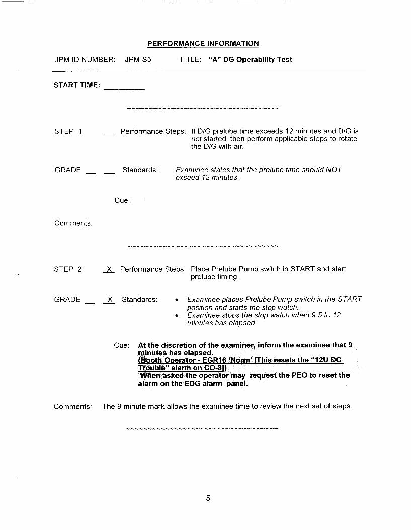
PERFORMANCE INFORMATION
JPM ID NUMBER: JPM-S5 TITLE: “A” DG Operability Test
START TIME:
STEP I - Performance Steps: If DIG prelube time exceeds 12 minutes and D/G is not started, then perform applicable steps to rotate the D/G with air.
GRADE __ - Standards: Examinee states that the prelube time should NOT exceed 12 minutes.
Cue:
Comments:
STEP 2 X Performance Steps: Place Prelube Pump switch in START and start prelube timing.
GRADE __ __ X Standards: Examinee places Prelube Pump switch in the START position and starts the stop watch. Examinee stops the stop watch when 9.5 to 12 minutes has elapsed.
Cue:
Comments: The 9 minute mark allows the examinee time to review the next set of steps.
5

PERFORMANCE INFORMATION
JPM ID NUMBER: JPM-SS TITLE: “A” DG Operability Test
STEP 3 X Performance Steps: When 9% to 12 minutes has elapsed, perform the following:
Start the chart recorder 0 Simultaneously place the “A” DG Manual Start-
Stop switch in START and start the stop watch.
GRADE - - X Standards: When 9% to 12 minutes has elapsed, examinee informs the PEO to start the chart recorder Examinee simultaneously places the “A” DG Manual Start-Stop switch in START and starts the stop watch.
Cue: Inform examinee that the chart recorder is running.
Comments:
STEP 4 Performance Steps: When diesel Ready To Load alarm is lit, stop the stop watch.
GRADE __ - X Standards: After approximately 8 seconds, the examinee observes the “Ready To Load annunciator (A-34, C-08) and stops the stop watch.
Cue:
Comments: The Ready to Load alarm will be annunciated in less than 15 seconds.
STEP 5 - Performance Steps: ENSURE “PRESSS DELAY CIRCUIT ENERGIZED” light is lit after 25 seconds.
GRADE __ - Standards : The examinee asks the PEO at the ‘A’ D/G to report when the “PRESS DELAY CIRCUIT ENERG1ZED”light is lit and monitors clock.
Cue: Wait approximately 25 seconds and report the “PRESS DELAY CIRCUIT ENERGIZED” light is lit.
Comments:
6
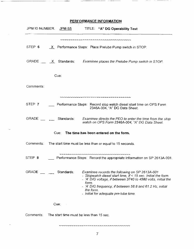
PERFORMANCE INFORMATION
JPM ID NUMBER: JPM-S5 TITLE: “A” DG Operability Test
GRADE __ __ X Standards: Examinee places the Prelube Pump switch in STOP
Cue:
Comments:
STEP 7 __ Performance Steps: Record stop watch diesel start time on OPS Form 2346A-004, “A” DG Data Sheet.
GRADE - __ Standards: Examinee directs the P€O to enter the time from the stop watch on OPS Form 2346A-004, “A” DG Data Sheet.
Cue: The time has been entered on the form.
Comments: The start time must be less than or equal to 15 seconds.
GRADE - __ Standards: Examinee records the following on SP 261 3A-001 - Stopwatch diesel start time, if < 15 sec. initial the form. - ‘A’ D/G voltage, if between 3740 to 4580 volts, initial the
form. - ‘A’ D/G frequency, if between 58.8 and 61.2 Hz, initial
the form. - Initial for adequate pre-lube time.
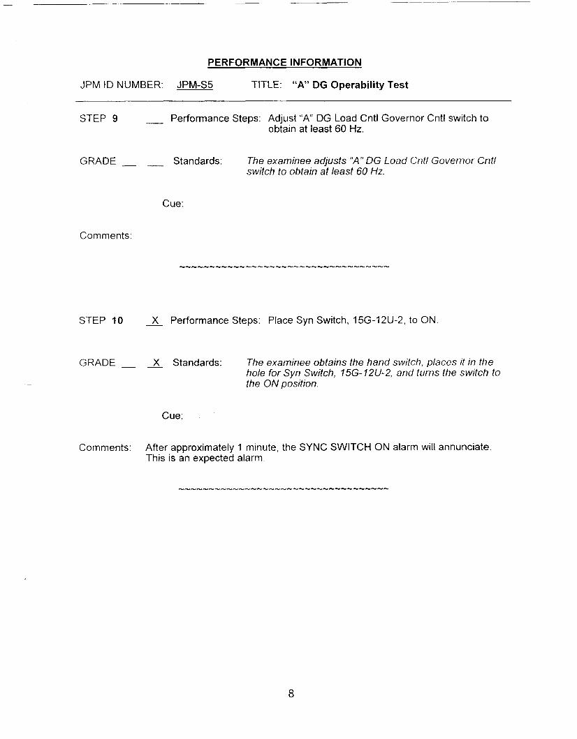
PERFORMANCE INFORMATION
JPM ID NUMBER: JPM-S5 TITLE: “A” DG Operability Test
STEP 9 __ Performance Steps: Adjust “A” DG Load Cntl Governor Cntl switch to obtain at least 60 Hz.
GRADE - __ Standards: The examinee adjusts “A” DG Load Cntl Governor Cntl switch to obtain at least 60 Hz.
Cue:
Comments:
STEP 10 - X Performance Steps: Place Syn Switch, 15G-12U-2, to ON
GRADE __ __ X Standards: The examinee obtains the hand switch, places it in the hole for Syn Switch, 15G-12U-2, and turns the switch to the ON position.
Cue:
Comments: After approximately 1 minute, the SYNC SWITCH ON alarm will annunciate. This is an expected alarm.
8

PERFORMANCE INFORMATION
JPM ID NUMBER: JPM-SS TITLE: “A” DG Operability Test
STEP 11 - X Performance Steps: Adjust “ A DG Voltage Cntl Reg Auto Cntl switch to match generator voltage with bus voltage.
GRADE- - X Standards: The examinee will place the “A” DG Voltage Cntl Reg Auto Cntl switch in either RAISE or LOWER to match the lncoming voltage with the Running voltage.
Cue:
Comments:
STEP 12 - X Performance Steps: Turn “A” DG Volt Cntl Trans Sw to MAN.
GRADE __ - X Standards: The examinee places the “A” DG Volt Cntl Trans Sw in MAN.
Cue:
Comments:
STEP 13 - X Performance Steps: Adjust “ A DG Voltage Cntl Reg Man Cntl switch to match generator voltage with bus voltage.
GRADE - - X Standards: The examinee place the “A” DG Voltage CnN Reg Man Cntl switch in either RAlSE or LOW€R to match the lncoming voltage with the Running voltage.
Cue:
Comments:

PERFORMANCE INFORMATION
JPM ID NUMBER: JPM-S5 TITLE: “A” DG Operability Test
STEP 14 __ X Performance Steps: Turn “A” DG Volt Cntl Trans Sw to AUTO.
GRADE __ - X Standards: The examinee places the “A” DG Volt Cntl Trans Sw in AUTO.
Cue:
Comments:
STEP 15 __ X Performance Steps: Turn Unit Parallel Sel Sw/lZU to UNIT PARALLEL and observe Unit Parallel white light lit.
GRADE __ __ X Standards: The examinee will place the Unit Parallel Sel Sw/l2U to the UNIT PARALLEL position and observe Unit Parallel white light is lit.
Cue:
Comments:
STEP 16 - Performance Steps: To ensure slow rotation (0.5 to 1 rpm) of sychroscope in fast direction, adjust “A” SG Load Cntl Governor Cntl switch to raise or lower engine speed.
GRADE - __ Standards: The examinee will place the “A” SG Load Cntl Governor Cntl switch in the RAISE or LOWER position to ensure the syncroscope is rotating at approximately 0.5 to 1 rpm in the fast direction.
Cue:
Comments:

PERFORMANCE INFORMATION
JPM ID NUMBER: JPM-S5 TITLE: “A” DG Operability Test
STEP 17 __ X Performance Steps: When synchroscope needle passes “1 1 o’clock‘’ position, simultaneously close DG A Fdr Bkr, 15G- 12U-2 (A312)
GRADE __ - X Standards: When synchroscope needle passes “1 1 o’clock’’ position, The examinee will simultaneously close the “A” DG Output Breaker, 15G-12U-2 (A31 2 ) .
Cue:
Comments: Due to the operating characteristics of the simulator, the “A” DG Output Breaker may NOT close or may trip. This does NOT constitute a failure of the JPM. The examinee may be given additional opportunities to reset and close the breaker.
STEP 18 - X Performance Steps: Adjust “A” DG Load CNTL Governor Cntl switch to load the “A” DG to between 1,350 and 1,450 kW at a rate of 250 to 300 kW per minute. While raising “A“ DG load, Adjust “A” DG Voltage Cntl Reg Auto Cntl to maintain a kvar loading at approximately 50% of the kW loading.
0
GRADE - - X Standards: The examinee will use the “A” DG Load Cntl Governor Cntl switch to load the “A” DG to between 1,350 and 1,450 kW at a rate of 250 to 300 kWper minute. While raising “A” DG load, the examinee will adjust “A” DG Voltage Cntl Reg Auto Cntl to maintain a kvar- loading at approximately 50% of the k W loading.
0
Cue:
Comments: Annunciator (A-36, C-08) “DIESEL GENERATOR 12U TROUBLE”, will be annunciated when load is raised to approximately 500 kW. The examinee may NOT notice the annunciator until load is raised to the directed range.
11

PERFORMANCE INFORMATION
JPM ID NUMBER: JPM-S5 TITLE: “A” DG Operability Test
STEP 19 - X Performance Steps: Observe Annunciator (A-36, C-08) “DIESEL GENERATOR 12U TROUBLE”
GRADE - __ X Standards: The examinee will observe and annunciator (A-36, C-08) “DIESEL GENERATOR 12U TROUBLE’.
Cue:
Comments:
STEP 20 __ X Performance Steps: Send an operator to the ‘A’ D/G panel C-38 to determine cause of the annunciator.
GRADE __ __ X Standards: The examinee directs the PEO in the ’A’ D/G room to report the cause of the annunciator.
Cue: As the PEO, report that annunciator (B-1, C-38) “LUBE OIL PRESSURE LOW” is lit.
If the examinee requests a report of lube oil pressure, report ‘A’ DIG Lube Oil pressure = 19 psig and decreasing slowly.
If requested the PEO reports that the ARP for alarm B-I on C-38 is missing.
Comments: Due to the seriousness of the annunciator, the examinee may NOT wait for a report on lube oil pressure or for referring to the ARP for (B1 , C-38) “Low Lube Oil Pressure” before (recommend) tripping the “A” DG. (See next step)
12
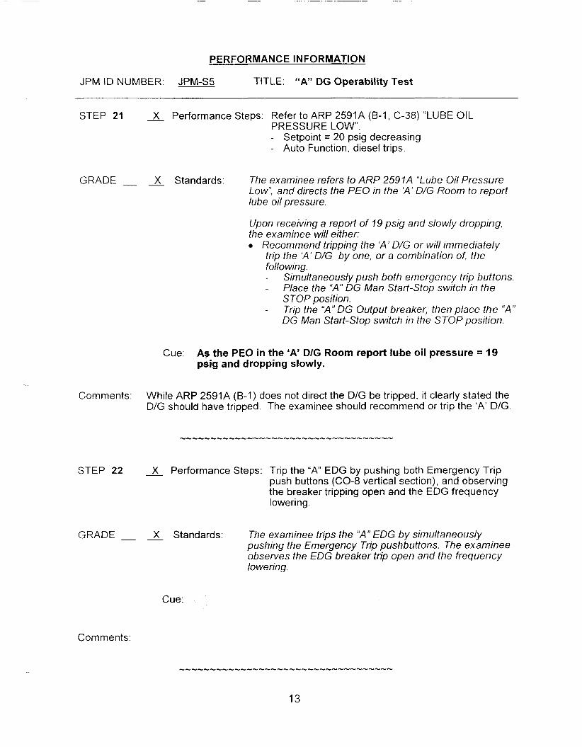
PERFORMANCE INFORMATION
JPM ID NUMBER: JPM-S5 TITLE: “A” DG Operability Test
STEP 21
GRADE -
Comments:
STEP 22
GRADE __
X Performance Steps: Refer to ARP 2591A (B-1, C-38) “LUBE OIL PRESSURE LOW”. - Setpoint = 20 psig decreasing - Auto Function, diesel trips.
Standards: The examinee refers to ARP 2591A “Lube Oil Pressure Low”, and directs the PEO in the ‘A’ DIG Room to report lube oil pressure.
Upon receiving a report of 19 psis and slowly dropping, the examinee wil/ either:
Recommend tripping the ‘A’ D/G or will immediately trip the ‘A’ D/G by one, or a combination of, the following. - -
-
Simultaneously push both emergency trip buttons. Place the “A” DG Man Start-Stop switch in the STOP position. Trip the “A” DG Output breaker, then place the “A” DG Man Start-Stop switch in the STOP position.
Cue. As the PEO in the ‘A’ DIG Room report lube oil pressure = 19 psig and dropping slowly.
While ARP 2591A (B-I) does not direct the DIG be tripped, it clearly stated the DIG should have tripped. The examinee should recommend or trip the ‘A’ D/G.
X Performance Steps: Trip the “A” EDG by pushing both Emergency Trip push buttons (CO-8 vertical section), and observing the breaker tripping open and the EDG frequency I owe ri n g .
- X Standards: The examinee trips the “A” EDG by simultaneously pushing the Emergency Trip pushbuttons. The examinee observes the EDG breaker trip open and the frequency lowering.
Cue:
Comments:

PERFORMANCE INFORMATION
JPM ID NUMBER: JPM-S5 TITLE: "A" DG Operability Test
Comments: After this step is completed, the JPM is considered complete.
STOP TIME:
14

VERIFICATION OF JPM COMPLETION
Job Performance Measure No. JPM-S5 Rev. - 0
Date Performed:
Operator:
Eva I uat or( s) :
For examinee to achieve a satisfactory grade, critical steps must be completed correctly. If task is Time Critical, it MUST be completed within the specified time to achieve a satisfactory grade.
Time Critical Task? Yes No X
Validated Time (minutes): 20 minutes
Actual Time to Complete (minutes):
Result of JPM: (Denote by an S for satisfactory or a u for unsatisfactory)
Areas for Improvement:
15

IC-93 Low Power JPMs
A - B - AS1 Upper 4.73 4.69 AS1 Lower 4.73 4.70 Nuclear Power k99 4.87
AT Power 3.90 4.09
TcoId Cal. 4.80 4.61
C - D
4.70 4.70 4.72 4.69
4.87 2 4.06
4.90 4.90
L

EXAMINEE HANDOUT
JPM ID Number: JPM-S5
lnitiatinq Cues: The US has directed you to perform the Periodic 'A' DIG Operability Test (Fast Start, Loaded Run) per SP 261 3A, beginning at step 4.1.21 Review step 4.1.2 and 4.1.4 prior to commencing the surveillance . I will act as the US, PEO, etc.
Initial Conditions: 0
0
0
0
All plant conditions are normal. NO other surveillances are being performed that interfere with 261 3A. SP 261 3A-001 has been authorized for release. There are NO Ozone alerts in affect. Valve Alignment Check, OPS Form 261 3A-002 was performed two weeks ago NO maintenance has been performed on the "A" DG in the last two weeks. The 'A' D/G pre-start check list, 2346A-002, has been completed. Steps 4.1.1 through 4.1 .I 8 were performed by another operator who had to leave due to a family emergency. A PEO has been briefed and is standing by at the 'A' DIG gage board. He will complete the DIG Data Sheet, 2346A- 004. The applicable portions of SP 26196, AC Electrical Sources Inoperability, were completed 5 minutes ago. A chart recorder is installed for auto triggering at the 'A' DIG. "B" D/G is OPERABLE.
16

JOB PERFORMANCE MEASURE APPROVAL SHEET
I. JPM Title: nge Safety Channel a ower Channel Calibration
ID Number:
II. Initiated:
JPM-S6
R. J. AsHey U Developer
Ill. Reviewed:
IV. Approved:
Revision: 0 -
111 0/05
Date
&A-
~
User Department Supervisor Date
Nuclear Trai ng Supervisor if -
Date
SUMMARY OF CHANGES
All 8 Date DESCRIPTION REVlCHANGE
Page 2 of 9
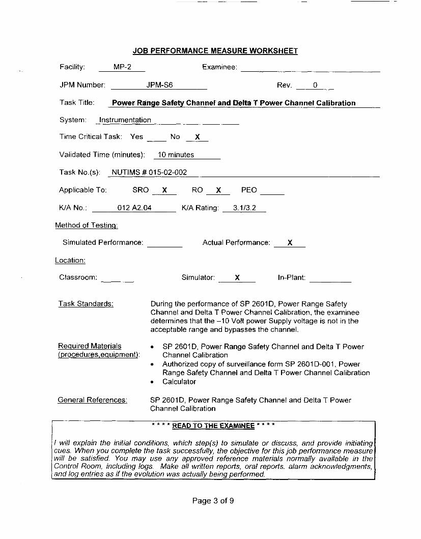
JOB PERFORMANCE MEASURE WORKSHEET
Facility: MP-2 Examinee:
JPM Number: JPM-S6 Rev. 0
Task Title: Power Range Safety Channel and Delta T Power Channel Calibration
System: Instrumentation
Time Critical Task: Yes No X
Validated Time (minutes): 10 minutes
Task No.(s): NUTIMS # 015-02-002
Applicable To: SRO X RO X PEO
K/A No.: 01 2 A2.04 K/A Rating: 3.1/3.2
Method of Testing:
Simulated Performance: Actual Performance: X
Location:
Classroom:
Task Standards:
Required Materials iprocedures,equiDment):
General References:
Simulator: X In-Plant:
During the performance of SP 2601 D, Power Range Safety Channel and Delta T Power Channel Calibration, the examinee determines that the -1 0 Volt power Supply voltage is not in the acceptable range and bypasses the channel.
0 Calculator
SP 2601D, Power Range Safety Channel and Delta T Power Channel Calibration Authorized copy of surveillance form SP 2601 D-001, Power Range Safety Channel and Delta T Power Channel Calibration
SP 2601 D, Power Range Safety Channel and Delta T Power Channel Calibration
READ TO THE EXAMINEE * * * * * * * *
I will explain the initial conditions, which step(s) to simulate or discuss, and provide initiating cues. When you complete the task successfully, the objective for this job performance measure will be satisfied. You may use any approved reference materials normally available in the Control Room, including logs. Make all written reports, oral reports, alarm acknowledgments, and log entries as if the evolution was actually being performed.
Page 3 of 9
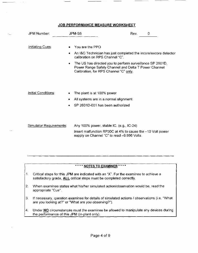
JOB PERFORMANCE MEASURE WORKSHEET
-.- JPM Number: JPM-S6 Rev. 0
lnitiatinq Cues: You are the PPO
An I&C Technician has just completed the incore/excore detector calibration on RPS Channel “C”.
The US has directed you to perform surveillance SP 2601D, Power Range Safety Channel and Delta T Power Channel Calibration, for RPS Channel “C” only.
0
Initial Conditions:
0
The plant is at 100% power
All systems are in a normal alignment
SP 2601 D-001 has been authorized
Simulator Requirements: Any 1OOoh power, stable IC. (e.g., 1‘2-24)
Insert malfunction RP30C at 4% to cause the -1 0 Volt power supply on Channel “C” to read -9.996 Volts.
NOTES TO EXAMINER * * * * * * *
1. Critical steps for this JPM are indicated with an “X”. For the examinee to achieve a satisfactory grade, critical steps must be completed correctly.
2. When examinee states what hisiher simulated action/observation would be, read the appropriate “Cue”.
3. If necessary, question examinee for details of simulated actions I observations (Le. “What are you looking at?“ or “What are you observing?”).
4. Under NO circumstances must the examinee be allowed to manipulate any devices during the performance of this JPM (in-plant only).
Page 4 of 9

PERFORMANCE INFORMATION
JPM ID NUMBER: JPM-S6 TITLE: Power Range Safety Channel and Delta T Power Channel Calibration
START TIME:
STEP 1 X Performance Steps: Place Meter Input switch to “METER INPUT.”
GRADE X Standards: Examinee places RPS Channel “C” Meter Input switch to “METER INPUT position.
Cue:
Comments:
STEP 2 - X Performance Steps: Press and hold the “ZERO” test button.
GRADE X Standards: Examinee presses and holds the “ZERO” test button on RPS Channel “C”,
Cue:
Comments:
STEP 3 - X Performance Steps: When voltage is observed, release test button and
GRADE X Standards: Examinee observes a voltage of O.OOO+O 003 volts,
record respective voltage on applicable form.
releases the test button, and records this value on SP 26010-001, page 2, step 4. I. IC for Channel “C”
Cue:
Comments:
Page 5 of 9

PERFORMANCE INFORMATION
JPM ID NUMBER: JPM-S6 TITLE: Power Range Safety Channel and Delta T Power Channel Calibration
STEP 4 X Performance Steps: Press and hold the “+lOV” test button.
GRADE X Standards: Examinee presses and holds the “+?OV” test button on RPS Channel “C?
Cue:
Comments:
STEP 5 - X Performance Steps: When voltage is observed, release test button and record respective voltage on applicable form.
GRADE X Standards: Examinee observes a voltage of +IO. OOO+O. 003 volts, releases the test button, and records this value on SP 260?D-O07, page 2, step 4 . 1 . 7 ~ for Channel “C”
Cue:
Comments:
STEP 6 A Performance Steps: Press and hold the ‘ I - 1 O V test button.
GRADE- - X Standards: Examinee presses and holds the “-?OV” test button on RPS Channel “C”.
Cue:
Comments:
STEP 7 J- performance Steps: When voltage is observed, release test button and
GRADE X Standards: Examinee observes a voltage of -9.996 volts, releases
record respective voltage on applicable form.
the test button, and records this value on SP 26010-001, page 2, step 4.7.1c.for Channel “C”
Cue:
Comments:
Page 6 of 9
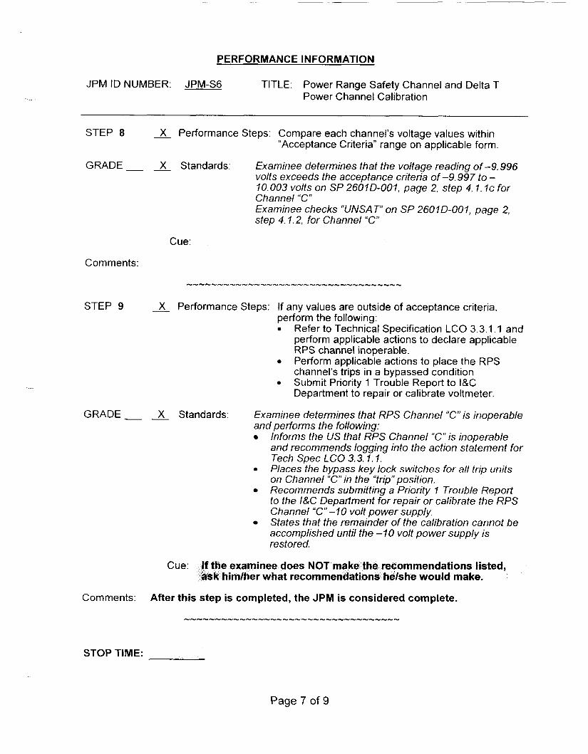
PERFORMANCE INFORMATION
JPM ID NUMBER: JPM-S6 TITLE: Power Range Safety Channel and Delta T Power Channel Calibration
STEP 8 X Performance Steps: Compare each channel’s voltage values within “Acceptance Criteria” range on applicable form.
GRADE X Standards: Examinee determines that the voltage reading of-9.996 volts exceeds the acceptance criteria of-9.997 to - 10.003 volts on SP 26010-001, page 2, step 4.1. IC for Channel “C” Examinee checks “UNSAT” on SP 26010-001, page 2, step 4.1.2, for Channel “C”
Cue:
Comments:
STEP 9 X Performance Steps: If any values are outside of acceptance criteria, perform the following: 0 Refer to Technical Specification LCO 3.3.1.1 and
perform applicable actions to declare applicable RPS channel inoperable. Perform applicable actions to place the RPS channel’s trips in a bypassed condition. Submit Priority 1 Trouble Report to I&C Department to repair or calibrate voltmeter.
0
GRADE X Standards: Examinee determines that RPS Channel “C” is inoperable and performs the following:
Informs the US that RPS Channel “C” is inoperable and recommends logging into the action statement for Tech Spec LCO 3.3.1. I. Places the bypass key lock switches for all trip units on Channel “C” in the “trip” position. Recommends submitting a Priority I Trouble Report to the I&C Department for repair or calibrate the RPS Channel “C”-IO volt power supply. States that the remainder of the calibration cannot be accomplished until the -10 volt power supply is restored.
0
Cue: inee does NOT m mendations listed, r what recomme e would make.
Comments: After this step is completed, the JPM is considered complete.
STOP TIME:
Page 7 of 9

VERIFICATION OF JPM COMPLETION
Job Performance Measure No. JPM-S6 Rev.
Date Performed:
Operator:
Evaluator( s) :
0 -
For examinee to achieve a satisfactory grade, ALL critical steps must be completed correctly. If task is Time Critical, it MUST be completed within the specified time to achieve a satisfactory grade.
Time Critical Task? Yes No X
Validated Time (minutes): 10 minutes
Actual Time to Complete (minutes):
Result of JPM: (Denote by an S for satisfactory or a u for unsatisfactory)
Areas for Improvement:
Page 8 of 9

EXAMINEE HANDOUT
JPM ID Number: JPM-S6
Initiating Cues:
Initial Conditions:
0 You are the PPO
0 An I&C Technician has just completed the incore/excore detector calibration on RPS Channel “C”.
The US has directed you to perform surveillance SP 2601D, Power Range Safety Channel and Delta T Power Channel Calibration, for RPS Channel “C” only.
0
0 The plant is at 100% power
All systems are in a normal alignment
SP 26010-001 has been authorized
Page 9 of 9
JOB PERFORMANCE MEASURE APPROVAL SHEET
I JPM Title: Placing “B” RBCCW Pump and Heat Exchanger in Service and Removing “A” RBCCW Pump and Heat Exchanger
ID Number: JPM-S7
I I . Initiated:
I I I. Reviewed:
Revision: 0
1 /I 8/05
Developer Date
Technical Reviewer
IV. Approved:
User Department Supervisor
Da’te
Date
Date

SUMMARY OF CHANGES
A/I 8 Date DESCRIPTION REWCHANGE
...
2

JOBPERFORMANCEMEASUREWORKSHEET
Facility: MP-2 Examinee:
JPM Number: JPM-S7 Rev. 0
Task Title:
System: Plant Service - Reactor Building Closed Cooling Water
Time Critical Task: Yes No X
Validated Time (minutes): 30 minutes
Task No.(s): NUTIMS # 076-01-043
Applicable To: SRO X RO X PEO
K/A No.: 008 A4.01 KIA Rating: 3.3/3.1
Method of Testing:
Simulated Performance: Actual Performance: X
Location:
Classroom: Simulator: X I n-Plant:
Task Standards: The examinee places "6" RBCCW Pump and Heat Exchanger in service in place of "A" RBCCW Pump and Heat Exchanger.
Required Materials (procedures,equipment):
OP 2330A, RBCCW System, Sections 4.1, 4.2 and 4.16. OP 2326A, Service Water System, Sections 4.9 and 4.1 1
General References:
READ TO THE EXAMINEE * * * * * * * * I I will explain the initial conditions, which step(s) to simulate or discuss, and provide initiating cues. When you complete the task successfully, the objective for this job performance measure will be satisfied. You may use any approved reference materials normally available in the Control Room, including logs. Make all written reports, oral reports, alarm acknowledgments, and log entries as if the evolution was actually being performed.
3

JOB PERFORMANCE MEASURE WORKSHEET
JPM Number: JPM-Si’ Rev. 0
Initiating Cues: 0
0
0
Initial Conditions:
Simulator Requirements:
0
0
You are the SPO. Preventive Maintenance is scheduled on the “A” RBCCW Heat Exchanger and Pump. The US directs you to place the “B” RBCCW pump and “B” RBCCW HX in service and to remove the “A“ RBCCW pump and “A” RBCCW HX from service per OP 2330A, sections 4.2 (Pump first) and OP 2326A section 4.9. I will act as the US/PEO as needed
“ A & “C” RBCCW Pumps and Heat Exchangers are in service Bus 24E is aligned to Bus 24C. “6 RBCCW Pump breaker (A504) racked up. The SIAS/LNP Actuation Signal HS 61 19D (A504) is in the BLOCK position. The “6” RBCCW HX is presently being used for minimum flow for “ A Service Water header. Injection temperature is 44°F. All other plant conditions are normal.
Initialize to any IC with: 0 A normal RBCCW lineup (“A” & “C” pumps and heat
exchangers in service; “B RBCCW Heat Exchanger used for minimum flow for “A Service Water header) Bus 24E aligned to Bus 24C. SIASLNP Actuation Signal HS 61 19D (A504) in the BLOCK position.
0
0
Insert a malfunction to cause fouling of the “B RBCW Heat Exchanger after it is placed in service. (SW03B @ 100% on BT- 47 , ramp in at 10 sec.)
NOTES TO EXAMINER * * * * * * * *
1.
2.
3.
4. Under
Critical steps for this JPM are indicated with an “X”. For the examinee to achieve a satisfactory grade, When examinee states what hidher simulated action/observation would be, read the appropriate “Cue”. If necessary, question examinee for details of simulated actions / observations (Le. ”What are you looking at?” or ”What are you observing?”).
circumstances must the examinee be allowed to manipulate any devices during the performance of this JPM (in-plant only).
critical steps must be completed correctly.
4

PERFORMANCE INFORMATION
JPM ID NUMBER: JPM-S7 TITLE: Placing “6” RBCCW Pump and Heat Exchanger in Service and Removing “A” RBCCW Pump and Heat Exchanger
START TIME:
STEP I __ Performance Steps:
GRADE Standards:
Verify the following: “B” RBCCW Pump switch is in Pull-To- Lock. (C-06) “RBCCW PP B HDR B SUCT, RB- 21 1 D,” is closed and “RBCCW PP B HDR A SUCT, RB-21 lC, ” is open (C-06) “HDR B HX-B OUT, RB-4.1 D,” is closed 0
(C-06)
Examinee observes: The “B” RBCCW pump handswitch is in the Pull- To-Lock position. The green light for “RBCCW PP B HDR B SUCT, RB-211 D,” is lit. The red light for “RBCCW PP B HDR A SUCT, RB- 21 lC,” is lit. The green light for “HDR B HX-B OUT, RB-4.1 D,” is lit.
Cue:
Comments: The examinee may dispatch a PEO to locally monitor the pump swap.
STEP 2 Performance Steps: Verify open PP DIS HDR A/B X-TIE, RB-251A. (C-06).
GRADE X Standards: Examinee places the handswitch for PP DIS HDR A/R X- TIE, RB-251A, in the open position and observes the red light lit.
Cue:
Comments: PP DIS HDR N B X-TIE, RB-251A, may be open or closed initially. If the valve is initially open, the examinee will only observe the red light lit.
5

PERFORMANCE INFORMATION
JPM ID NUMBER: JPM-S7 TITLE: Placing “B” RBCCW Pump and Heat Exchanger in Service and Removing “A” RBCCW Pump and Heat Exchanger
STEP 3 __ Performance Steps: Log into TS 3.7.3.1
GRADE Standards: ,Examinee informs the US of the need to log into TSAS 3.7.3.1.
Cue: US acknowledges the need to enter TSAS 3.7.3.1
Comments:
................................... STEP 4 - X Performance Steps: Start “RBCCW PP B.” (C-06)
GRADE X Standards: Examinee momentarily places the “B” RBCC W Pump handswitch in the Start position and observes the red light for the “B” RBCC W Pump is lit.
If asked, report as the PEO that the pump is running normally. Cue:
Comments:
STEP 5 __ Performance Steps: Check alarm RBCCW PUMP B SIAS/LNP START MANUALLY BLOCKED” (AA-20, C-06/07) lit.
GRADE Standards: Examinee observes alarm RBCCW PUMP B SIAS/LNP START MANUALLY BLOCKED” (AA-20, C-06/07) is lit.
Cue:
Comments:
6

PERFORMANCE INFORMATION
JPM ID NUMBER: JPM-S7 TITLE: Placing “ 6 RBCCW Pump and Heat Exchanger in Service and Removing “A” RBCCW Pump and Heat Exchanger
STEP 6
GRADE __
- Performance Steps: Check the following for the “B” RBCCW Pump: 0 Normal running amps (36 to 44 amps) 0 Pump discharge pressure (1 05 to1 35 psig)
- Standards: Examinee observes the following indications on C-06 for the “B” RBCCW Pump:
0
Normal running amps of 36 to 44 amps Pump discharge pressure of 105 to 135 psig
Cue: e or high discharge normal for two pumps
Comments:
STEP 7
GRADE -
Comments:
STEP 8
GRADE -
__ Performance Steps: Close “ A RBCCW Pump Discharge Stop, 2-RB-3A
- Standards: Examinee directs a PEO to close “A” RBCCW Pump Discharge Stop, 2-RB-3A.
Cue: as the PEO, -3A is
closed.
It would normally take 1-2 minutes to close “A” RBCCW Pump Discharge Stop, 2-RB-3A.
- X Performance Steps: Stop “A” RBCCW PP A” and place switch in Pull-To- Lock. (C06)
- X Standards: Examinee places the “A” RBCCW Pump handswitch in the Pull-To-Lock position and observes pump amps lower to “0” and the green light is lit.
Cue:
Comments:
7

PERFORMANCE INFORMATION
JPM ID NUMBER: JPM-S7 TITLE: Placing “B” RBCCW Pump and Heat Exchanger in Service and Removing “A” RBCCW Pump and Heat Exchanger
STEP 9 - X Performance Steps: Place “SIAS/LNP Actuation Signal HS 61 19D” (A504)
GRADE X Standards: Examinee directs a PEO to place SlAS/LNP Actuation
is in the NORMAL position.
Signal HS 67190 (A504) is in the NORMAL position and observes the following:
“RBCCW PUMP 8 SiAS/LNP START MANUALLY BLOCKED” annunciator clears. RBCCW HDR A FLOW HI annunciator is NOT lit.
Cue:
Comments:
Booth Operator - CCR4O set to Normal. When directed, as the PEO, report that the “SIASILNP Actuation Signal HS 61 19D” (A504) is in the NORMAL position.
GRADE Standards: Examinee informs the US of the need to exit TSAS - 3.7.3.1.
Cue: US acknowledges the need to exit TSAS 3.7.3.1
Comments:
-------_------------5__________u___
STEP 11 __ Performance Steps: Open “A” RBCCW Pump Discharge Stop, 2-RB-3A.
GRADE Standards: Examinee directs a PEO to open “A” RBCCW Pump Discharge Stop, 2-RB-3A.
Cue: n directed, ge Stop, 2-
8
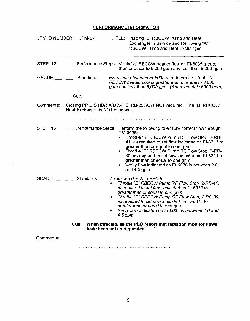
PERFORMANCE INFORMATION
JPM ID NUMBER: JPM-S7 TITLE: Placing “B” RBCCW Pump and Heat Exchanger in Service and Removing “A” RBCCW Pump and Heat Exchanger
STEP 12
GRADE -
Comments:
STEP 13
GRADE __
__ Performance Steps: Verify “A” RBCCW header flow on Fl-6035 greater than or equal to 6,000 gpm and less than 8,000 gpm.
- Standards: Examinee observes Fl-6035 and determines that “A” RBCCW header flow is greater than or equal to 6,000 gpm and less than 8,000 gpm. (Approximately 6300 gpm)
Cue:
Closing PP DIS HDR A/B X-TIE, RB-251A, is NOT required. The “B” RBCCW Heat Exchanger is NOT in service.
__ Performance Steps: Perform the following to ensure correct flow through RM-6038:
Throttle “6” RBCCW Pump RE Flow Stop, 2-RB- 41, as required to set flow indicated on FI-6313 to greater than or equal to one gpm. Throttle “C” RBCCW Pump RE Flow Stop, 2-RB- 39, as required to set flow indicated on Fl-6314 to greater than or equal to one gpm. Verify flow indicated on Fl-6038 is between 2.0 and 4.5 gpm.
- Standards: Examinee directs a PEO to: Throttle “B” RBCC W Pump RE Flow Stop, 2-RB-4 1, as required to set flow indicated on FI-6313 to greater than or equal to one gpm. Throttle “C” RBCCW Pump RE Flow Stop, 2-RB-39, as required to set flow indicated on Fl-6314 to greater than or equal to one gpm. Verify flow indicated on Fl-6038 is between 2.0 and 4.5 gpm.
Cue: en directed, rt that radiation monitor flows ve been set as
Comments:
9

PERFORMANCE INFORMATION
JPM ID NUMBER: JPM-S7 TITLE: Placing “B” RBCCW Pump and Heat Exchanger in Service and Removing “A” RBCCW Pump and Heat Exchanger
STEP 14 - Performance Steps: Refer to OP 2326A, “Service water System”, and establish Service water flow through the “B” RBCCW Heat Exchanger.
GRADE Standards: Examinee obtains OP 2326A, “Service water System ”, and selects section 4.9, Placing “B” RBCCW Heat Exchanger in Service and Removing “A RBCCW Heat Exchanger From Service”
Cue: Provide OP 2326A, Service Water, when requested.
Comments:
STEP 15 - Performance Steps: Ensure the following are closed: “B” Service Water Header to “B” RBCCW Heat Exchanger, 2-SW-7A “B” RBCCW Heat Exchanger to “B” Discharge Header, 2-SW-1 OA.
GRADE- - Standards: Direct a PEO to verify the following valves are closed:
0
“5” Service Water Header to “€3” RBCCW Heat Exchanger, 2-S W-7A “B” RBCCW Heat Exchanger to “B” RBCCW Discharge Header, 2-S W- 1 OA.
As the PEO, report that 2-SW-7A and 2-SW-1OA are closed.
_ _
Cue:
Comments:
10

PERFORMANCE INFORMATION
JPM ID NUMBER: JPM-S7 TITLE: Placing “B” RBCCW Pump and Heat Exchanger in Service and Removing “A” RBCCW Pump and Heat Exchanger
STEP 16 - Performance Steps: Open the following: “ A Service Water Header to “B” RBCCW Heat Exchanger, 2-SW-7B “B” RBCCW Heat Exchanger to “A“ Discharge Header. 2-SW-?OB.
GRADE Standards: Direct a PEO to verify the following valves are open: 0 “A’’ Service Water Header to “B” RBCC W Heat
Exchanger, 2-S W- 7B 0 “B” RBCCWHeat €xchanger to “A”RBCCW
Discharge Header, 2-S W-IUB.
Cue: As the PEO, report that 2SW-7B and 2-SW-1OB are open.
Comments:
STEP 17 - Performance Steps: At “B” RBCCW Heat Exchanger temperature controller, TIC-6307, ensure the following:
Mode switch in “A” (inside controller) Temperature control knob set greater than 200°F.
GRADE Standards: Direct a PEO to perform the following: 0
s Ensure the mode switch is in “A” (inside controller) Set the temperature control knob to greater than 200°F.
Cue: As the PEO, inform t nee that the tempera ntroller is in automatic t
Comments:
STEP 18 - Performance Steps: Ensure “B” RBCCW Heat Exchanger temperature control valve is in either “Summer Valve, 2-SW-8.16” or “Winter Valve. 2-SW-246”.
GRADE- - Standards: Examinee directs the PEO to ensure the “B” RBCC W temperature control valve is in the “Wintef‘ mode.
Cue: Report that e.
Comments:

PERFORMANCE INFORMATION
JPM ID NUMBER: JPM-S7 TITLE: Placing “6” RBCCW Pump and Heat Exchanger in Service and Removing “A“ RBCCW Pump and Heat Exchanger
STEP 19 - Performance Steps: Log into TS Action Statement 3.7.4.1
GRADE Standards: Examinee informs the US of the need to enter TSAS 3.7.4. I .
Cue: Acknowledge the need to enter TSAS 3.7.4.1.
Comments:
STEP 20 - X Performance Steps: Open “B” RBCCW Heat Exchanger SW Outlet, 2-SW- 96.
GRADE X Standards: Examinee directs the PEO to open “B” RBCCW Heat Exchanger SW Outlet, 2-SW-9B.
Cue: Booth Operator - SWR24 set to 100%. When directed, as the PEO, report that “6” RBCCW Heat Exchanger SW Outlet, 2-SW- 96 is open.
-
.-- Comments:
STEP 21 - X Performance Steps: Slowly lower “6” RBCCW Heat Exchanger temperature control knob to setting specified by the Control Room.
GRADE- - X Standards: Examinee directs the PEO to slowly lower the “6” RBCCW Heat Exchanger TCV to 75°F.
Cue: Booth Instructor - Set CCRO3 to 75. As the PEO, inform the examinee that the temperature controller has been set to 75°F.
Comments:
12
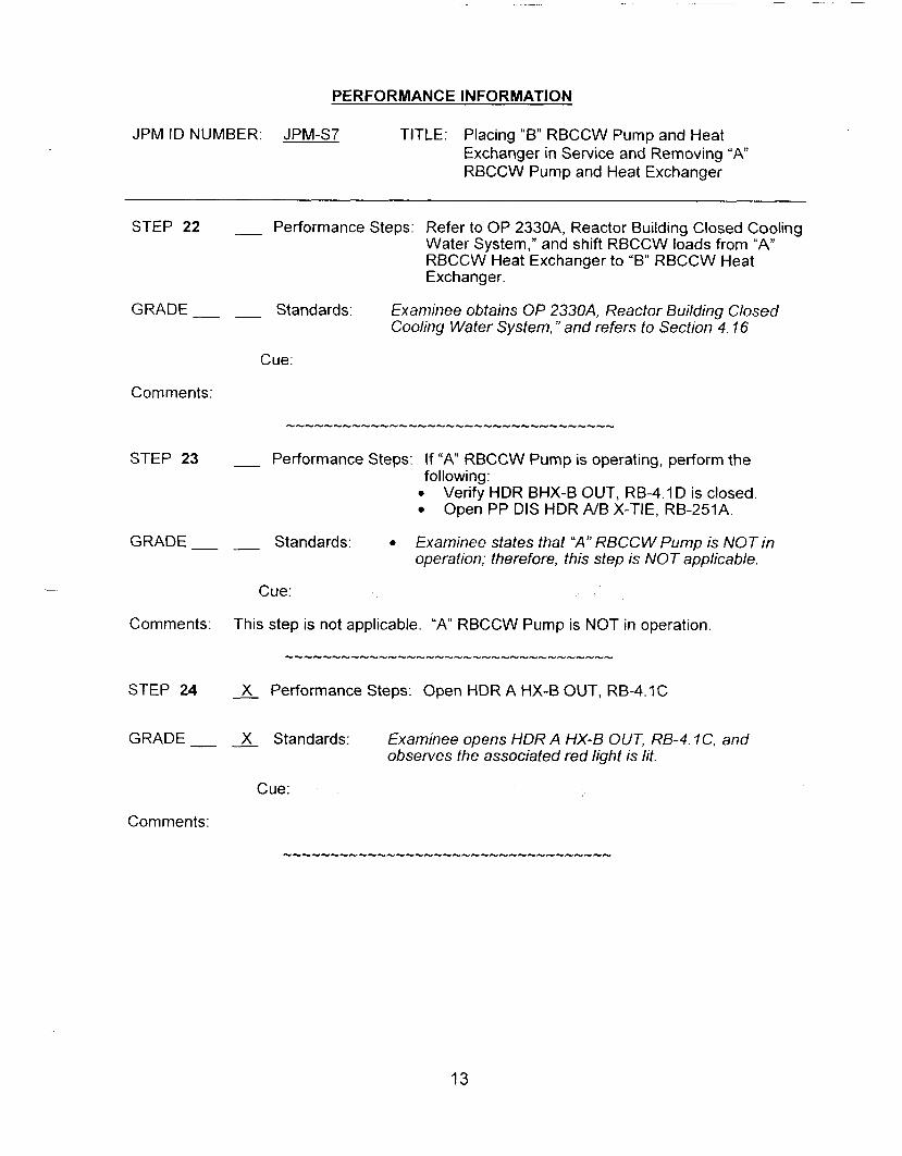
PERFORMANCE INFORMATION
JPM ID NUMBER: JPM-S7 TITLE: Placing “B” RBCCW Pump and Heat Exchanger in Service and Removing “ A RBCCW Pump and Heat Exchanger
STEP 22 - Performance Steps: Refer to OP 2330A, Reactor Building Closed Cooling Water System,” and shift RBCCW loads from “A” RBCCW Heat Exchanger to “B” RBCCW Heat Exchanger.
GRADE- - Standards: Examinee obtains OP 2330A, Reactor Building Closed Cooling Water System, ” and refers to Section 4.16
Cue:
Comments:
STEP 23 - Performance Steps: If “ A RBCCW Pump is operating, perform the
Verify HDR BHX-B OUT, RB-4.1D is closed. Open PP DIS HDR A/B X-TIE, RB-251A.
operation; therefore, this step is NOT applicable.
following: 0
GRADE Standards: 0 Examinee states that ”A” RBCCW Pump is NOT in
Cue: -
Comments: This step is not applicable. “A” RBCCW Pump is NOT in operation
STEP 24 __ X Performance Steps: Open HDR A HX-B OUT, RB-4.1C
GRADE X Standards: Examinee opens HDR A HX-€3 OUT, RB-4. IC, and observes the associated red light is lit.
Cue:
Comments:
13

PERFORMANCE INFORMATION
JPM ID NUMBER: JPM-S7 TITLE: Placing “6” RBCCW Pump and Heat Exchanger in Service and Removing “A RBCCW Pump and Heat Exchanger
STEP 25 __ Performance Steps: Monitor header “A“ flow on Fl-6035 to ensure it remains stable.
GRADE- - Standards: Examinee monitors flow on Fl-6035 and observes stable flow at approximately 6300 gpm.
Cue:
Comments:
STEP 26 - X Performance Steps: Close HDR A HX-A OUT, RB-4.1A.
GRADE X Standards: Examinee closes HDR A HX-A OUT, RB-4. I A and observes the associated green light is lit.
Cue:
Comments: When RB-4.1A is closed, the malfunction to foul the “6” RBCCW Heat Exchanger will be inserted.
STEP 27 - Performance Steps: If required, Refer to OP 2326A, Service Water System, and isolate service water flow to “A” RBCCW Heat Exchanger.
GRADE- - Standards: Examinee determines that the “A” RBCCW Heat Exchanger should NOT be isolated at this time.
Cue: isolate the “A” R 8 /her that the heat ork control gr
Comments:
14
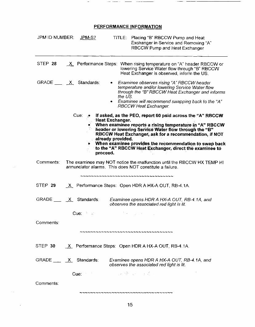
PERFORMANCE INFORMATION
JPM ID NUMBER: JPM-S7 TITLE: Placing “B” RBCCW Pump and Heat Exchanger in Service and Removing “A” RBCCW Pump and Heat Exchanger
STEP 28 - X Performance Steps: When rising temperature on “A“ header RBCCW or lowering Service Water flow through “B” RBCCW Heat Exchanger is observed, inform the US.
GRADE- - X Standards: Examinee observes rising “A” RBCC W header temperature and/or lowering Service Water flow through the “B” RBCCW Heat Exchanger and informs the US. Examinee will recommend swapping back to the “A” RBCCW Heat Exchanger.
Cue:
endation, if NOT
Comments: The examinee may NOT notice the malfunction until the RBCCW HX TEMP HI annunciator alarms. This does NOT constitute a failure.
STEP 29 __ X Performance Steps: Open HDR A HX-A OUT, RB-4.1A.
GRADE X Standards: Examinee opens HDR A HX-A OUT, RB-4. ?A, and observes the associated red light is lit.
Cue:
Comments:
STEP 30 - X Performance Steps: Open HDR A HX-A OUT, RB-4.1A
GRADE X Standards: Examinee opens HDR A HX-A OUT, RB-4.1 A, and observes the associated red light is lit.
Cue:
Comments:
15

PERFORMANCE INFORMATION
JPM ID NUMBER: JPM-S7 TITLE: Placing “B” RBCCW Pump and Heat Exchanger in Service and Removing “A” RBCCW Pump and Heat Exchanger
STEP 31 __ X Performance Steps: Open HDR A HX-A OUT, RB-4.1A
GRADE X Standards: Examinee opens HDR A HX-A OUT, RB-4. ?A, and observes the associated red light is lit.
Cue:
Comments:
STEP 32 - X Performance Steps: Open HDR A HX-A OUT, RB-4.1A.
GRADE X Standards: Examinee opens HDR A HX-A OUT, RB-4. ?A, and observes the associated red light is lit.
Cue:
STEP 33 X Performance Steps: Open HDR A HX-A OUT, RB-4. ?A.
GRADE X Standards: Examinee opens HDR A HX-A OUT, RB-4. ?A, and observes the associated red light is lit.
Cue:
Comments:
STEP 34 __ Performance Steps: Monitor header “A” flow on Fl-6035 to ensure it
GRADE Standards: Examinee monitors flow on Fl-6035 and observes stable
remains stable.
flow at approximately 6300 gpm.
Cue:
Comments:
16
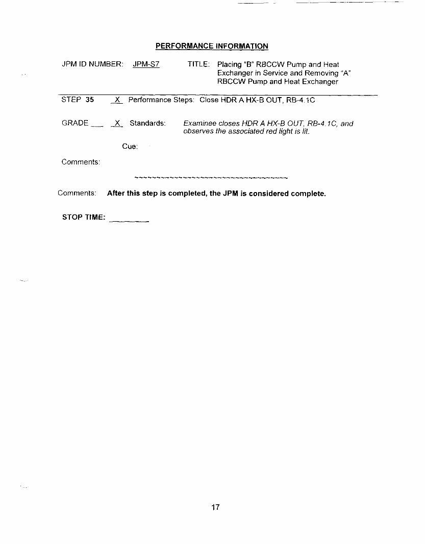
PERFORMANCE INFORMATION
JPM ID NUMBER: JPM-S7 TITLE: Placing “B” RBCCW Pump and Heat Exchanger in Service and Removing “A” RBCCW Pump and Heat Exchanger
STEP 35 - X Performance Steps: Close HDR A HX-B OUT, RB-4.1C
GRADE- - X Standards: Examinee closes HDR A HX-8 OUT, RB-4. IC, and observes the associated red light is lit.
Cue:
Comments:
Comments: After this step is completed, the JPM is considered complete.
STOP TIME:
17

VERIFICATION OF JPM COMPLETION
Job Performance Measure No. JPM-S7 Rev.
Date Performed:
Operator:
Evaluator(s):
- 0
For examinee to achieve a satisfactory grade, A& critical steps must be completed correctly. If task is Time Critical, it MUST be completed within the specified time to achieve a satisfactory grade.
Time Critical Task? Yes No X
Validated Time (minutes): 30
Actual Time to Complete (minutes):
Result of JPM: (Denote by an S for satisfactory or a u for unsatisfactory)
Areas for Improvement:
18

EXAMINEE HANDOUT
JPM ID Number: JPM-S7
lnitiatinq Cues: 0
0
0
Initial Conditions: 0
e
0
0
e
You are the SPO. Preventive Maintenance is scheduled on the “A” RBCCW Pump and Heat Exchanger. The US directs you to place the “B” RBCCW pump and “B” RBCCW HX in service and to remove the “A” RBCCW pump and “ A RBCCW HX from service per OP 2330A, sections 4.2 (Pump first) and OP 2326A section 4.9. I will act as the US/PEO as needed
“A” & “C” RBCCW Pumps and Heat Exchangers are in service Bus 24E is aligned to Bus 24C. “B RBCCW Pump breaker (A504) racked up. The SIAS/LNP Actuation Signal HS 61 19D (A504) is in the BLOCK position. The “B” RBCCW HX is presently being used for minimum flow for “A” Service Water header. All other plant conditions are normal.
19

JOB PERFORMANCE MEASURE APPROVAL SHEET
I JPM Title: Change the Alarm Setpoint of the SJAE RM 5099
01 I24105
11. Initiated:
Developer
1 1 1 . Reviewed: hP4 Duffy As ey
Technical Reviewer
IV. Approved:
N$4 User Department Supervisor
Nuclear Train' g Supervisor B
Date
Date
Date
Date

SUMMARY OF CHANGES
1 I DESCRIPTION REVCHANGE
1 01/19/2005 Developed new JPM. I 0
2

JOB PERFORMANCE MEASURE WORKSHEET
Facility: MP-2 Examinee:
JPM Number: JPM-S8 Rev. 0
Task Title: Operate the SJAE RM. (RM-5099)
System: Radmonitor
Time Critical Task: Yes No X
Validated Time (minutes): 20
Task No.(s): NUTIMS # 073-01-050
Applicable To: SRO X RO X PEO
K/A No.: 071 A4.25 WA Rating: 3.213.2
Method of Testing:
Simulated Performance: Actual Performance: X
Location:
Classroom: Simulator: X In-Plant:
Task Standards: The examinee will adjust the setpoint of the Steam Jet Air Ejector Radmonitor as specified on the attached SP2833-007.
Required Materials 0
Lprocedures, equipment): Setpoint Change Request. 0
SP2833-007 "SJAE Radmonitor MR 5099 & PPC Alarm
OP2383C Rev.012-02 "Radiation Monitor Alarm Setpoint Control.
General References:
READ TO THE EXAMINEE * * * * * * * *
I will explain the initial conditions, which step(s) to simulate or discuss, and provide initiating cues. When you complete the task successfully, the objective for this job performance measure will be satisfied. You may use any approved reference materials normally available in the Control Room, including logs. Make all written reports, oral reports, alarm acknowledgments, and log entries as if the evolution was actually being performed.
3

JOB PERFORMANCE MEASURE WORKSHEET
JPM Number: JPM-S8 Rev. 0
Initiating Cues: The US has assigned you to change the setpoint of the SJAE Radmonitor (RM5099) in accordance with OP 2383C, "Radiation Monitor Alarm Setpoint Control", section 4. I .
Initial Conditions: The latest RCS samples have indicated a rise in RCS gaseous isotopic results. Due to this rise in fission product gasses, chemistry has requested a change to the SJAE RM (RM 5099) setpoint. - Chemistry has provided an approved "SJAE Radmonitor Setpoint
Change Request, SP-2833-007. The Radiation Monitor System Engineer has referenced EN-2 1235 and verified that the new setpoint does not exceed the maximum setpoint. The S/G Blowdown Radmonitor (RM-4262) is in service.
-
-
Simulator Requirements: -
- -
Any IC in Mode 1 or 2 with the Steam Jet Air Ejector System in service. Ensure the S/G Blowdown Radmonitor is in service. Insert Remote Function, RMR37A (R15099)to allow changing the alarm setpoint of RM-5099 from RC-14.
NOTES TO EXAMINER * * * * * *
1. Critical steps for this JPM are indicated with an "X". For the examinee to achieve a satisfactory grade,
When examinee states what hisiher simulated action/observation would be, read the appropriate "Cue".
If necessary, question examinee for details of simulated actions / observations (i.e. "What are you looking at?" or "What are you observing?").
Under NO circumstances must the examinee be allowed to manipulate any devices during the performance of this JPM (in-plant only).
critical steps must be completed correctly.
2.
3.
4.
4

PERFORMANCE INFORMATION
JPM ID NUMBER: JPM-S8 TITLE: Change the Setpoint of the SJAE RM 5099
START TIME:
STEP I X Performance Steps: OBTAIN keys for the following (Operations key locker): - -
Rl-5099 "NORM/SUPV." switch on RC-14D. RADMONITOR BYPASS, HS 5099E" switch on RC-14A.
GRADE X Standards: The examinee retrieves the two keys from the key locker by C-2 I and takes them around to RC- 7 4.
Cue:
Comments:
STEP 2 X Performance Steps: As appropriate, PLACE "RADMONITOR BYPASS, HS 5099E" switch to "RM 5099 OUT" or "BOTH OUT."
GRADE X Standards: The examinee inserts the key into HS5099€, and places HS5099E switch on RC-14A to "RM 5099 OUT" position.
Cue:
Comments:
STEP 3 - Performance Steps: IF "RADMONITOR BYPASS, HS 5099E" switch is in "BOTH OUT," Refer To REMODCM IV.C.l and DETERMINE applicability.
GRADE Standards: HS 5099E is nof in "BOTH OUT" per the previous step. The REMODCM 1 V. C. I does not have to be referenced.
Cue:
Comments: This step is not applicable.
STEP 4 A Performance Steps: PLACE RI-5099 "NORM/SUPV." switch to "SUPV."
GRADE- - X Standards: The examinee inserts the key into the "NORM/SUPV. " switch, selects uSUPV,: and observes the red SUPV MODE light is lit.
- Cue:
Comments:
5

- -
PERFORMANCE INFORMATION
JPM ID NUMBER: JPM-S8 TITLE: Chanqe the Setpoint of the SJAE RM 5099
STEP 5 - X Performance Steps: Using SP 2833-007, “SJAE Radiation Monitor RM 5099 & PPC Alarm Setpoint Change Request,” ENTER new alarm setpoint. a. PRESS “CH 1.” b. PRESS “0, I’ “0, I’ “9. ” c. PRESS “ITEM.” d. Enter new value using scientific notation. e. PRESS “ENTER” f. PRESS TH.1.”
GRADE X Standards: At RC-140, the examinee performs the following steps on the RM-5099 insert. - PRESS “CH 1. I‘ - PRESS 099 and observes 009 on the display. - PRESS the “ITEM. ” Button and observe the button is
lit when pressed and light goes out when button is released. Press 4 12+02 and observes 4.12 E2 on the display.
- - X - PRESS “ENTER” and observe 4.12 E‘2 - - X - PRESS “CH1 and observe present radiation monitor
reading of 9.80 E‘ 1.
X X X
- - - - - -
X - - -
Cue: “SJAE Radiation Monitor Request.”
Comments: If an error is made while entering information into the RM-5099 Insert, the CLEAR button may be used to start over.
STEP 6 A Performance Steps: PRESS C/S” button and VERIFY button is lit.
GRADE Standards: The examinee: - - X - presses the CIS button - - - verifies the button lights.
Cue:
Comments:
6
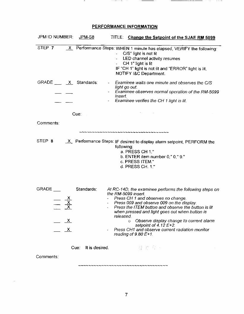
PERFORMANCE INFORMATION
JPM ID NUMBER: JPM-S8 TITLE: Change the Setpoint of the SJAE RM 5099
STEP 7 X Performance Steps: WHEN 1 minute has elapsed, VERIFY the following: C/S" light is not lit
CH I" light is lit
-
- LED channel activity resumes - IF "CH 1" light is not lit and "ERROR" light is lit, NOTIFY I&C Department.
GRADE- - X Standards: - Examinee waits one minute and observes the C/S light go out.
- - - Examinee observes normal operation of the RM-5099 Insert.
- - - Examinee verifies the CH I light is lit.
Cue:
Comments:
STEP 8 Performance Steps: IF desired to display alarm setpoint, PERFORM the following:
a. PRESS CH 1." b. ENTER item number 0," 0," 9." c. PRESS ITEM." d. PRESS CH. 1 .I'
GRADE - Standards: At RC-140, the examinee performs the following steps on the RM-5099 insert.
- -
- - X - Press CH I and observes no change. - - X Press 009 and observe 009 on the display. - - X Press the ITEM button and observe the button is lit
when pressed and light goes out when button is released.
- - X o Observe display change to current alarm
- - X - Press CHI and observe current radiation monitor reading of 9.80 E+?.
setpoint of 4.12 €+2.
Cue: It is desired.
Comments:
7
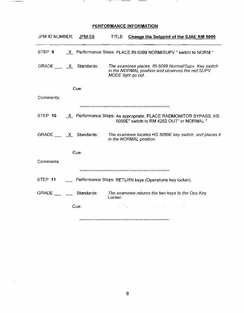
PERFORMANCE INFORMATION
JPM ID NUMBER: JPM-S8 TITLE: Change the Setpoint of the SJAE RM 5099
STEP 9 X Performance Steps: PLACE Rl-5099 NORM/SUPV." switch to NORM."
GRADE X Standards: The examinee places Rl-5099 NormaVSupv. Key switch in the NORMAL position and observes the red SUPV MODE light go out.
Cue:
Comments:
STEP I O - x PerfOrmance Steps: As appropriate, PLACE RADMONITOR BYPASS, HS 5099E" switch to RM 4262 OUT" or NORMAL."
GRADE X Standards: The examinee locates HS 5099E key switch, and places it in the NORMAL position.
Cue:
Comments:
STEP 11 - Performance Steps: RETURN keys (Operations key locker).
GRADE Standards: The examinee returns the two keys to the Ops Key Locker.
Cue:
8
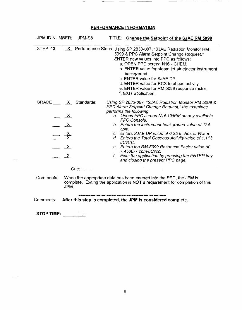
PERFORMANCE INFORMATION
JPM ID NUMBER: JPM-S8 TITLE: Change the Setpoint of the SJAE RM 5099
STEP 12 X Performance Steps: Using SP 2833-007, “SJAE Radiation Monitor RM 5099 & PPC Alarm Setpoint Change Request,” ENTER new values into PPC as follows:
a. OPEN PPC screen N16 - CHEM. b. ENTER value for steam jet air ejector instrument
c. ENTER value for SJAE DP. d. ENTER value for RCS total gas activity. e. ENTER value for RM 5099 response factor. f. EXIT application.
background.
GRADE- - X Standards: Using SP 2833-007, “SJAE Radiation Monitor RM 5099 8, PPC Alarm Setpoint Change Request, ” the examinee performs the following.
X a.
X b.
X C. X d.
X e.
X f.
- -
- -
- - - -
- -
- -
Cue:
Opens PPC Green N16-CHEM on any available PPC Console. Enters the instrument background value of 124 cpm. Enters SJAE DP value of 0.35 Inches of Water. Enters the Total Gaseous Activity value of 1.1 13 uc/7cc. Enters the RM-5099 Response Factor value of 7.45OE-7 cpm/uCi/cc. Exits the application by pressing the ENTER key and closing the present PPC page.
Comments: When the appropriate data has been entered into the PPC, the JPM is complete. Exiting the application is NOT a requirement for completion of this JPM.
STOP TIME:
9

VERIFICATION OF JPM COMPLETION
Job Performance Measure No. JPM-S8 Rev.
Date Performed:
Operator:
Evaluator(s):
- 0
For examinee to achieve a satisfactory grade, critical steps must be completed correctly. If task is Time Critical, it MUST be completed within the specified time to achieve a satisfactory grade.
Time Critical Task? Yes No
Validated Time (minutes):
Actual Time to Complete (minutes):
Result of JPM: (Denote by an S for satisfactory or a u for unsatisfactory)
Areas for Improvement:
10

EXAMINEE HANDOUT
JPM Number: JPM-S8 Rev. 0
initiating Cues: The US has assigned you to change the setpoint of the SJAE Radmonitor (RM5099) in accordance with OP 23832. “Radiation Monitor Alarm Setpoint Control”. section 4.1.
Initial Conditions: The latest RCS samples have indicated a rise in RCS gaseous isotopic results. Due to this rise in fission product gasses. chemistry has requested a change to the SJAE RM (RM 5099) setpoint. - Chemistry has provided an approved “SJAE Radmonitor Setpoint
Change Request, SP-2833-007. The Radiation Monitor System Engineer has referenced EN-2 1235 and verified that the new setpoint does not exceed the maximum setpoint. The S/G Blowdown Radmonitor (RM-4262) is in service.
-
-
11


JOB PERFORMANCE MEASURE APPROVAL SHEET
I. JPM Title: Removing Section 201B-2, of Battery Charger 201B , From Service
ID Number: JPM-PI Revision: - 0
It. Initiated:
Developer
II I. Reviewed:
IV. Approved:
User Department Supervisor
03-03-05 Date
Date
Date

SUMMARY OF CHANGES
(DAW
(DAP)
1 i All 8 Date
L'hanged lo use C n a h - as oomanyo s r u c i o n s T f l V -
plant 2016-1 has no physical obstructions.
DESCRIPTION I REVlCHANGE
-
2
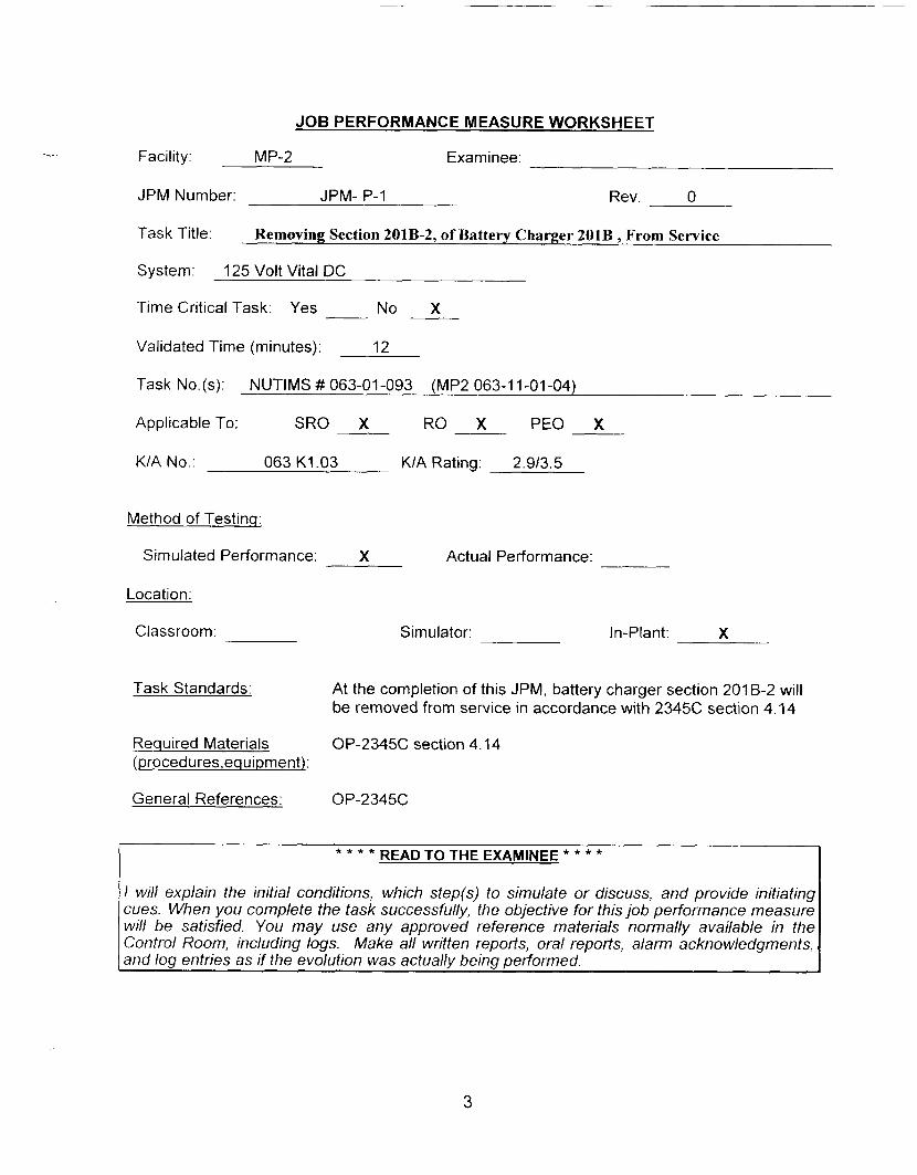
...
JOB PERFORMANCE MEASURE WORKSHEET
Facility: MP-2 Examinee:
JPM Number: JPM- P-1 Rev. 0
Task Title:
System: 125 Volt Vital DC
Time Critical Task: Yes No X
Removing Section 201B-2, of Battery Charger 201B, From Service
Validated Time (minutes): 12
Task No.(s): NUTIMS ## 063-01-093 (MP2 063-1 1-01-04)
Applicable To: SRO X RO X PEO X
K/A No.: 063 K1.03 KIA Rating: 2.9/3.5
Method of Testinq:
Si m u I a t e d Pe rfo r m a n ce : X Actual Performance:
Location:
Classroom: Simulator: In-Plant: X
Task Standards: At the completion of this JPM, battery charger section 201 B-2 will be removed from service in accordance with 2345C section 4.14
Required Materials OP-234% section 4.14 Lprocedures,equipment):
General References: OP-234%
READ TO THE EXAMINEE * * * * * * * *
I will explain the initial conditions, which step(s) to simulate or discuss, and provide initiating cues. When you complete the task successfully, the objective for this job performance measure will be satisfied. You may use any approved reference materials normally available in the Control Room, including logs. Make all written reports, oral reports, alarm acknowledgments, and log entries as if the evolution was actually being performed.
3
JOB PERFORMANCE MEASURE WORKSHEET
JPM Number: JPM- P-1 Rev. 0
Initiating Cues: The US has directed you to remove battery charger section 201 B-2 from service, in preparation for preventive maintenance.
Initial Conditions: Battery Charger 201 B is operating with both sections in service.
Si m u I a t o r Req u i re men t s : N/A
NOTES TO EXAMINER * * * * * * * *
1. Critical steps for this JPM are indicated with an "X". For the examinee to achieve a satisfactory grade, critical steps must be completed correctly.
2. When examinee states what hidher simulated action/observation would be, read the appropriate "Cue".
If necessary, question examinee for details of simulated actions / observations (i.e. "What are you looking at?" or "What are you observing?").
3.
4. Under circumstances must the examinee be allowed to manipulate any devices during the performance of this JPM (in-plant onlv).
4

- -
PERFORMANCE INFORMATION
JPM ID NUMBER: JPM- P-I TITLE: Removing Section 201B-2, of Battery Charger 2018, From Service
START TIME:
STEP 1 - Performance Steps: ENSURE total charger “DC OUTPUT“ current less than 400 amps.
GRADE Standards : Examinee observes “DC OUTPUT‘ammeter on the Termination Cabinet.
Cue: Amperage is c 400 amps.
Comments:
STEP 2 __ Performance Steps: PLACE “MODE SEL.” Switch in “DE. B”
GRADE Standards: - Examinee indicates the following on the “Termination Cabinet”; -
-
-
the “MODE SEL.”switch is being turned to the “DIS B. ” position. the “BATTERY CHARGER 201B-2 ALARMS DISABLED” red light lights the ‘CURRENT SHARING DISABLED” red light lights.
Cue: - -
-
“MODE SEL.” Switch is in the “DIS B.” position “BATTERY CHARGER 20lB-2 ALARMS D1SABLED”red light is lit. “CURRENT SHARING D1SABLED”red light is l i t .
Comments:
5
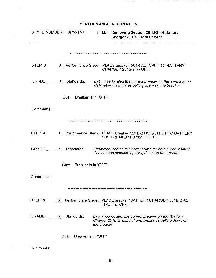
PERFORMANCE INFORMATION
JPM ID NUMBER: JPM- P-1 TITLE: Removing Section 201 B-2, of Battery Charger 201B, From Service
STEP 3 X Performance Steps: PLACE breaker “201B AC INPUT TO BATTERY CHARGER 201 B-2” in OFF.
GRADE X Standards: Examinee locates the correct breaker on the Termination Cabinet and simulates pulling down on the breaker.
Cue: Breaker is in “OFF
Comments:
STEP 4 3 Performance Steps: PLACE breaker “201 B-2 DC OUTPUT TO BATTERY BUS BREAKER D0202” in OFF.
GRADE X Standards: Examinee locates the correct breaker on the Termination Cabinet and simulates pulling down on the breaker.
Cue: Breaker is in “OFF”
Comments:
STEP 5 X Performance Steps: PLACE breaker “BATTERY CHARGER 201 B-2 AC INPUT” in OFF.
GRADE X Standards: Examinee locates the correct breaker on the “Battery Charger 2018-2” cabinet and simulates pulling down on the breaker.
Cue: Breaker is in “OFF”
Comments:
6
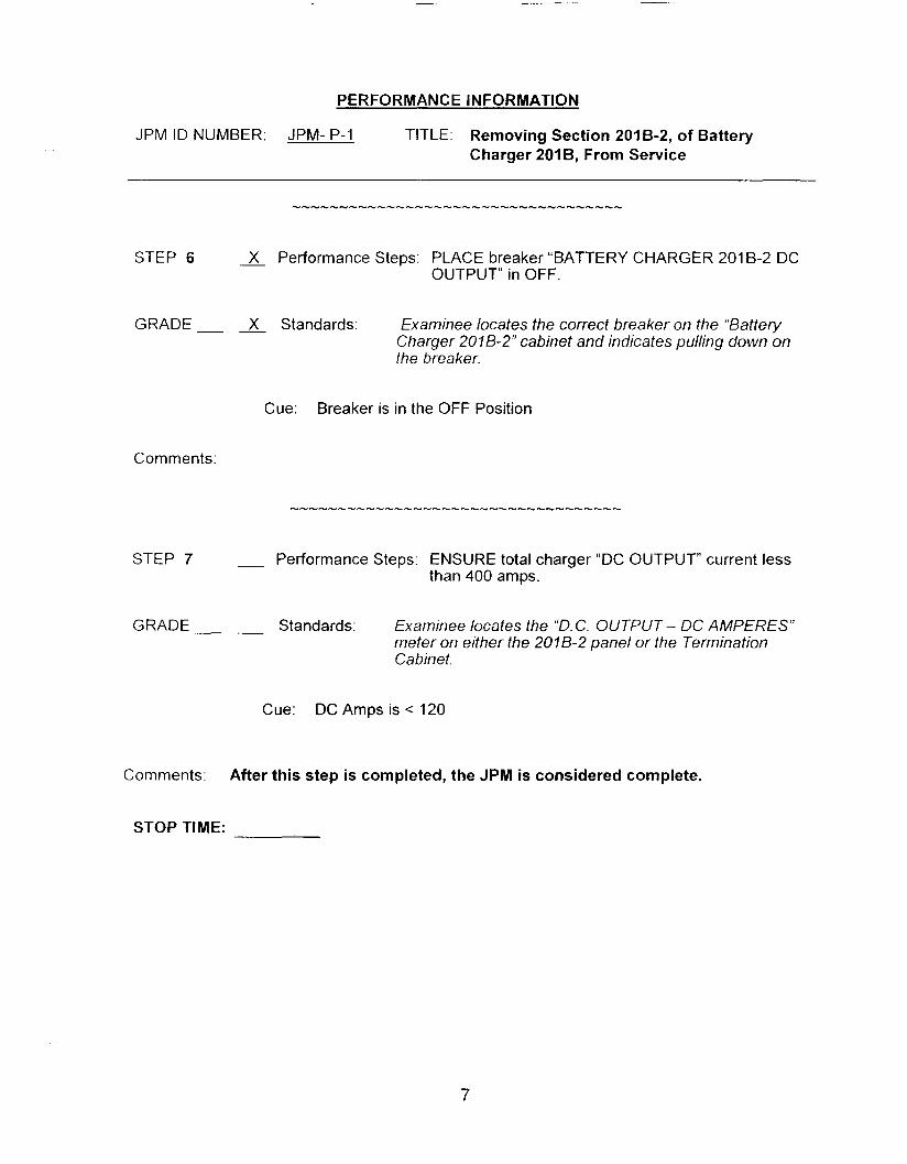
PERFORMANCE INFORMATION
JPM ID NUMBER: JPM- P-1 TITLE: Removing Section 201 6-2, of Battery Charger 201 B, From Service
STEP 6 X Performance Steps: PLACE breaker “BATTERY CHARGER 201 B-2 DC OUTPUT in OFF.
GRADE X Standards: Examinee locates the correct breaker on the “Battery Charger 2018-2” cabinet and indicates pulling down on the breaker.
Cue: Breaker is in the OFF Position
Comments:
STEP 7 - Performance Steps: ENSURE total charger “DC OUTPUT” current less than 400 amps.
GRADE Standards: Examinee locates the “D.C. OUTPUT- DC AMPERES” meter on either the 2078-2 panel or the Termination Cabinet.
Cue: DC Amps is < 120
Comments: After this step is completed, the JPM is considered complete.
STOP TIME:
7

VERIFICATION OF JPM COMPLETION
Job Performance Measure No. JPM-P-1 Rev.
Date Performed:
0 -
Operator:
Evaluator(s):
For examinee to achieve a satisfactory grade, & critical steps must be completed correctly. If task is Time Critical, it MUST be completed within the specified time to achieve a satisfactory grade.
Time Critical Task? Yes No X
12 Validated Time (minutes):
Actual Time to Complete (minutes):
Result of JPM: (Denote by an S for satisfactory or a u for unsatisfactory)
Areas for Improvement:
8

EXAMINEE HANDOUT
JPM ID Number: JPM-P1
lnitiatinq Cues:
Initial Conditions:
The US has directed you to remove battery charger section 201 B-2 from service, in preparation for preventive maintenance.
Battery Charger 201 6 is operating with both sections in service.
9

JOB PERFORMANCE MEASURE APPROVAL SHEET ---
I. JPM Title: Loss of SDC I Vent the ‘A’ LPSl PP.
ID Number: JPM-P2
II. Initiated:
Developer
Ill. Reviewed:
Technical Reviewer
IV. Approved: 4- User Department Supervisor
k Nuclear Tra’ ing Supervisor
Revision: 0 -
01/25/05 Date
!/26/&- Date
Date
Date
SUMMARY OF CHANGES
DESCRIPTION
Developed new JPM
REWCHANGE
0
2

JOB PERFORMANCE MEASURE WORKSHEET
Facility: MP-2 Examinee:
JPM Number: JPM- P2 Rev. 0
Task Title: Loss of SDC / Vent the ‘A’ LPSl Pp.
System: ECCS
Time Critical Task: Yes No X
Validated Time (minutes): 13
Task No.(s): NUTIMS # 000-14-021 (000-016-04-04)
Applicable To: SRO X RO X PEO X
K/A No.: 005 A2.03
Method of Testing:
Simulated Performance: X
K/A Rating: 2.9/3.1
Actual Performance:
Location:
Classroom: Simulator: In-Plant: X
Task Standards: At the completion of this JPM, the examinee will have simulated venting the “A” LPSl Pp. per AOP 2572, “Loss of SDC”.
Required Materials fprocedures, equipment]:
AOP 2572 “Loss of SDC”, step 4.15
General References: AOP 2572
READ TO THE EXAMINEE * * * * * * * *
1 will explain the initial conditions. which step(s) to simulate or discuss. and provide initiating cues. When you complete the task successfully, the objective for this job performance measure will be satisfied. You may use any approved reference materials normally available in the Control Room, including logs. Make all written reporfs, oral reports, alarm acknowledgments, and log entries as if the evolution was actually being performed.
3

JOB PERFORMANCE MEASURE WORKSHEET
JPM Number: JPM-P2 Rev. 0
Initiating Cues: The US has directed you to vent the ‘A’ LPSl Pump per AOP 2572 “Loss of Shutdown Cooling”, step 4.15.
Initial Conditions: The plant is at the center line of the hot leg to replace an RCP seal. The ‘A’ LPSl Pp started to show indications of air binding.
- -
-
-
The ‘A’ LPSl Pp is secured. RCS level has been raised and the SDC suction piping evacuated. -’
The pump is placed in a safe condition and is ready to vent. RCS temperature is approximately 85°F.
Simulator Requirements: N/A
NOTES TO EXAMINER * * * * * * * *
1. Critical steps for this JPM are indicated with an “X”. For the examinee to achieve a satisfactory grade, & critical steps must be completed correctly.
When examinee states what hislher simulated action/observation would be, read the a p p r o p r i a te “Cue”.
If necessary, question examinee for details of simulated actions / observations (i.e. ”What are you looking at?” or “What are you observing?”).
2.
3.
4. Under circumstances must the examinee be allowed to manipulate any devices during the performance of this JPM (in-plant only).
4

PERFORMANCE INFORMATION
JPM ID NUMBER: JPM-P2 TITLE: Loss of SDC I Vent the ‘A’ LPSl Pp. -- START TIME:
STEP 1 X Performance Steps: CONNECT vent hose to SI-21A, (“A” LPSl Pp. vent).
GRADE __ Standards: Examinee does the following:
- 2. Verifies SI-21A is closed. x - x - X
x 6. Simulates installing the “female Camlock vent pipe
I . Locates SI-21A on the “A’! LPSl Pp. casing
3. Locates the “vent pipe fitting” in the vent rig box. located at the base of the LPSl Pp.
4. Locates the ’Dipe wrench” in the vent rig box. located at the base of the LPSl Pp.
5. Simulates removing the “pipe cap” at the end of the extension pipe of SI-2 I A.
fitting” on the extension pipe of SI-21A 7. Simulate connecting the Tygon Hose to the “vent
pipe fitting”. 8. Simulate running and securing the Tygon Hose to a
floor drain. -
Cue: 3. see comments below 5. pipe cap is removed 6. vent fitting is installed 7. see comments below 8. Tygon hose is secured If the fitting will NOT couple to the Tygon tube when the examinee simulates connecting the Tygon tube to the vent fitting, tell the examinee that it doesn’t couple correctly.
Comments: There may be several vent fittings in the box at the base of the LPSl Pump. Visually determine that the fitting selected by the examinee will couple up to the fitting on the end of the Tygon tube.
The examinee should then find the correct fitting.
5

PERFORMANCE INFORMATION
JPM ID NUMBER: JPM-P2 TITLE: Loss of SDC I Vent the ‘A’ LPSl Pp. L
STEP 2 X Performance Steps: Slowly open SI-21A ( “ A LPSl Pp vent)
GRADE X Standards: Examinee simulates cracking open SI-21A
Cue: Inform the examinee that large air bubbles are visible in the water.
Comments: -
-
The examinee should indicate that s/he would continue to vent until air free water is observed. The note in the procedure defines air-free as bubbles the size of bubbles in carbonated water or soda.
STEP 3 2 Performance Steps: Close SI-21A when air-free water is observed
GRADE- - X Standards: The examinee simulates closing SI-21A when soda water like bubbles are observed.
Cue: Soda water like bubbles are observed.
Comments: Ensure the examinee understands the information given in the note. This may be done when the examinee asks if the bubbles are like those in soda water. If the examinee gives no indication, ask the examinee to describe the conditions that would indicate the pump is properly vented.
Comments: After this step is completed, the JPM is considered complete.
STOP TIME:
6
VERIFICATION OF JPM COMPLETION
Job Performance Measure No. JPM- P2 Rev 0 -
Date Performed:
Operator:
Evaluator( s) :
For examinee to achieve a satisfactory grade, ALL critical steps must be completed correctly. If task is Time Critical, it MUST be completed within the specified time to achieve a satisfactory grade.
Time Critical Task? Yes No X
Validated Time (minutes): 13
Actual Time to Complete (minutes):
Result of JPM: (Denote by an S for satisfactory or a u for unsatisfactory)
Areas for Improvement:
7

EXAMINEE HANDOUT
JPM Number: JPM-P2 Rev. 0
lnitiatinq Cues: The US has directed you to vent the 'A' LPSl Pump per AOP 2572 "Loss of Shutdown Cooling", step 4.15.
Initial Conditions: The plant is at the center line of the hot leg to replace an RCP seal. The 'A' LPSl Pp started to show indications of air binding.
- -
-
-
The 'A' LPSl Pp is secured. RCS level has been raised and the SDC suction piping evacuated. The pump is placed in a safe condition and is ready to vent. RCS temperature is approximately 85°F.
8

JOB PERFORMANCE MEASURE APPROVAL SHEET
I. JPM Title: Cross-Tie Station Air With Unit 3 to Supplv Unit 2 Instrument Air
ID Number: JPM-P3 Revision: - 0
1 0/25/04 Developer Date
Ill. Reviewed:
IV. Approved:
User Department Supervisor Date
Date

--
SUMMARY OF CHANGES
A/'8Date I DESCRIPTION
10/25/2004 I Developed new JPM.
,
I REVICHANGE I
O 1
2 of 9
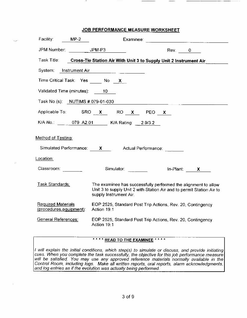
JOB PERFORMANCE MEASURE WORKSHEET
Facility MP-2 Examinee
JPM Number JPM-P3 Rev 0
Task Title
System. Instrument Air
Time Critical Task. Yes No X
Cross-Tie Station Air With Unit 3 to Supply Unit 2 Instrument Air
Validated Time (minutes). 10
Task No (s)’ NUTIMS # 079-01-030
Applicable To: SRO X RO X PEO X
KIA No.: 079 A2.01 WA Rating: 2.913.2
Method of Testing:
Simulated Performance: X Actual Performance:
Location:
Classroom: Simulator: In-Plant: X
Task Standards: The examinee has successfully performed the alignment to allow Unit 3 to supply Unit 2 with Station Air and to permit Station Air to supply Instrument Air.
Required Materials (procedures,equipment): Action 19.1
EOP 2525, Standard Post Trip Actions, Rev. 20, Contingency
General References: EOP 2525, Standard Post Trip Actions, Rev. 20, Contingency Action 19.1
READ TO THE EXAMINEE * * * * * * * *
I will explain the initial conditions, which step(s) to simulate or discuss, and provide initiating cues. When you complete the task successfully, the objective for this job performance measure will be satisfied. You may use any approved reference materials normally available in the Control Room, including logs. Make all written reports, oral reports, alarm acknowledgments, and log entries as if the evolution was actually being performed.
3 of 9

JOB PERFORMANCE MEASURE WORKSHEET
JPM Number: JPM-P3 Rev. 0
Initiatinq Cues: The Unit Supervisor has directed you to cross-tie Station Air from Unit 3 to allow Station Air to supply Instrument Air in accordance with EOP 2525, Contingency Action step 19.1.
Initial Conditions: 0
0
0
0
Unit has tripped from 100% power. The RSST failed resulting in a loss of off site power. Both Emergency Diesels have energized their respective buses. Instrument Air header pressure is reading 85 psig and lowering. Unit 3 has informed the Unit Supervisor that they are able to supply Station Air to Unit 2. SA-10.1, Station Air to Instrument Air Cross-Tie, is open.
Simulator Requirements: N/A
NOTES TO EXAMINER * * * * *
1. Critical steps for this JPM are indicated with an "X". For the examinee to achieve a satisfactory grade,
When examinee states what hidher simulated action/observation would be, read the a p pro pr i a te "Cue".
If necessary, question examinee for details of simulated actions / observations (Le. "What are you looking at?" or "What are you observing?").
critical steps must be completed correctly.
2.
3.
4. Under circumstances must the examinee be allowed to manipulate any devices during the performance of this JPM (in-plant only).
4 of 9

PERFORMANCE INFORMATION
JPM ID NUMBER: JPM-P3 TITLE: Cross-Tie Station Air With Unit 3 to Supply Unit 2 Instrument Air
START TIME:
STEP 1 - Performance Steps: Ensure SA-26, SA-11.1 Outlet Bypass, is open.
GRADE Standards: Examinee checks SA-26, SA-11. I Outlet Bypass, open attempting to rotate the valve handwheel in the counter clockwise direction.
Cue: SA-26 is open.
Comments: SA-26 is located on the 14’6’ elevation of the Turbine Building near the Instrument Air Dryer.
STEP 2 - X Performance Steps: Open SA-12, SA-11 .l Inlet Bypass.
GRADE- - X Standards: Examinee opens SA-12, SA-11. I Inlet Bypass, by rotating the valve handwheel in the counter clockwise direction.
Cue: SA-12 is open when the examinee simulates opening the valve.
Comments: SA-12 is located on the 14’6’ elevation of the Turbine Building near the Instrument Air Dryer.
5 of 9
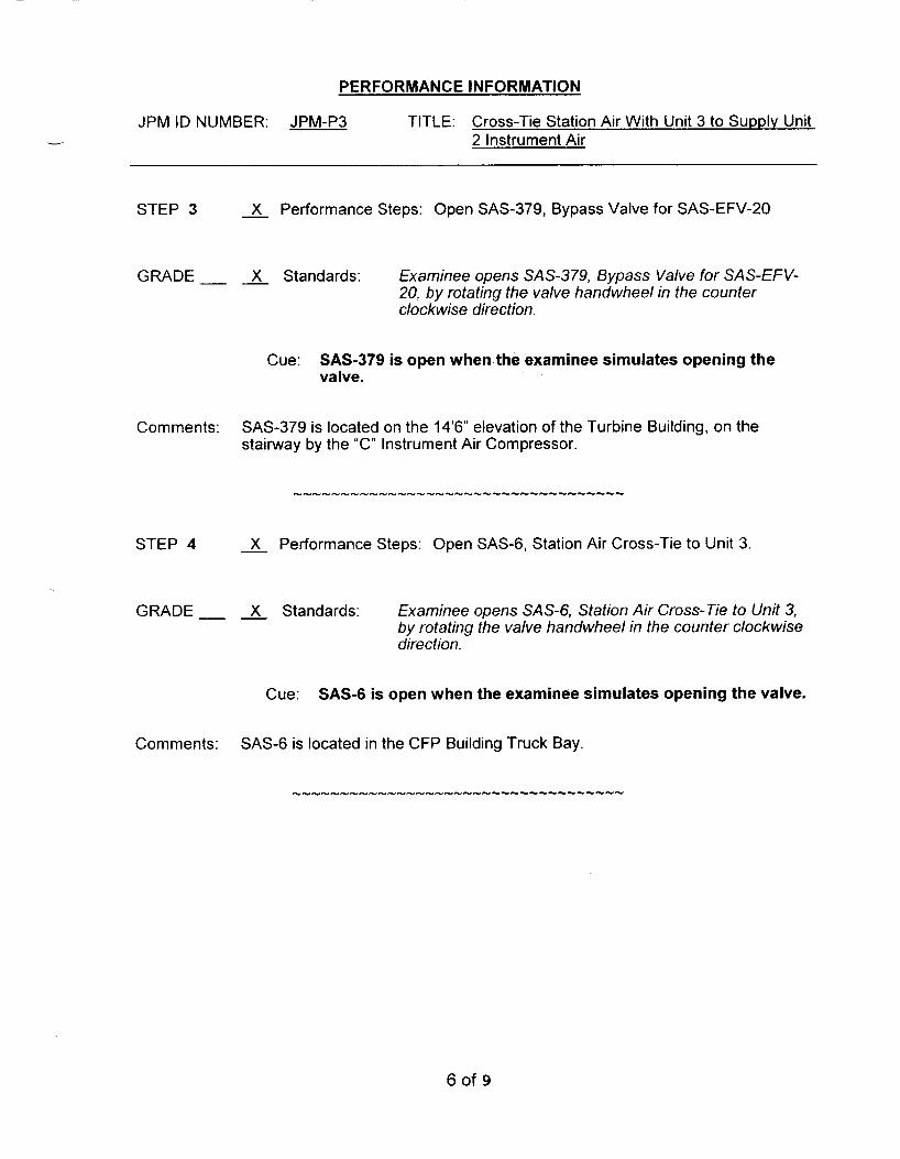
PERFORMANCE INFORMATION
JPM ID NUMBER: JPM-P3 TITLE: Cross-Tie Station Air With Unit 3 to Supply Unit -- 2 Instrument Air
STEP 3 X Performance Steps: Open SAS-379, Bypass Valve for SAS-EFV-20
GRADE X Standards: Examinee opens SAS-379, Bypass Valve for SAS-EFV- 20, by rotating the valve handwheel in the counter clockwise direction.
Cue: SAS-379 is open when the examinee simulates opening the valve.
Comments: SAS-379 is located on the 14’6” elevation of the Turbine Building, on the stairway by the “C” Instrument Air Compressor.
STEP 4 X Performance Steps: Open SAS-6, Station Air Cross-Tie to Unit 3.
GRADE X Standards: Examinee opens SAS-6, Station Air Cross-Tie to Unit 3, by rotating the valve handwheel in the counter clockwise direction.
Cue: SAS-6 is open when the examinee simulates opening the valve.
Comments: SAS-6 is located in the CFP Building Truck Bay
6 of 9
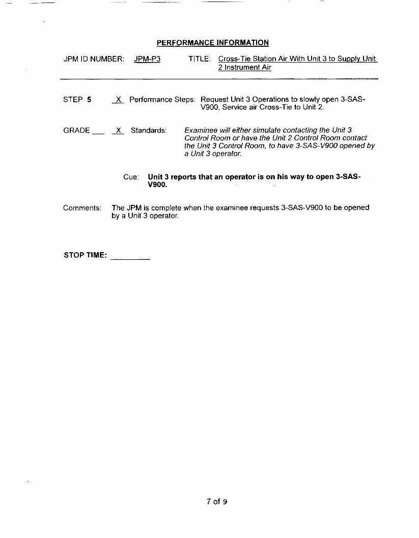
PERFORMANCE INFORMATION
JPM ID NUMBER: JPM-P3 TITLE: Cross-Tie Station Air With Unit 3 to Supply Unit 2 Instrument Air
STEP 5 X Performance Steps: Request Unit 3 Operations to slowly open 3-SAS- V900, Service air Cross-Tie to Unit 2.
GRADE- - X Standards: Examinee will either simulate contacting the Unit 3 Control Room or have the Unit 2 Control Room contact the Unit 3 Control Room, to have 3-SAS-V900 opened by a Unit 3 operator.
Cue: Unit 3 reports that an operator is on his way to open 3-SAS- v900.
Comments: The JPM is complete when the examinee requests 3-SAS-V900 to be opened by a Unit 3 operator.
STOP TIME:
7 of 9

VERIFICATION OF JPM COMPLETION
Job Performance Measure No. JPM-P3 Rev
Date Performed:
Operator:
Evaluator(s):
- 0
For examinee to achieve a satisfactory grade, & critical steps must be completed correctly. If task is Time Critical, it MUST be completed within the specified time to achieve a satisfactory grade.
Time Critical Task? Yes No X
Validated Time (minutes): 10
Actual Time to Complete (minutes):
Result of JPM: (Denote by an S for satisfactory or a u for unsatisfactory)
Areas for Improvement:
8 of 9
JOB PERFORMANCE MEASURE APPROVAL SHEET
I JPM Title: Local Manual Operation of the “A” Atmospheric Dump Valve
ID Number: JPM-093 Revision: - 9
II. Initiated:
Ill. Reviewed:
IV. Approved:
Developer
Fviewer
User Department Supervisor
1 /18/05 Date
&dc Date
Date
I Date

JOB PERFORMANCE MEASURE WORKSHEET
READ TO THE EXAMINEE * * * * * * *
.- Facility: MP-2 Examinee:
JPM Number: JPM-093 Rev. 9
Task Title y System: Main Steam
Time Critical Task: Yes No X
Validated Time (minutes): 15
Task No.(s): NUTIMS# 035-01-029
Applicable To: SRO X RO X PEO X
KJA No. 041 A203 KIA Rating 2.8J3.1
Method of Testinq:
Sim uI a ted Perform a nce: X Act u a I Perform an ce :
Location:
Classroom: Simulator: In-Plant: X
Task Standards: Examinee has taken local manual control of the “A” ADV and placed in to 25% open per EOP 2541, Appendix 36, ADV Local Operation.
Required Materials I Proced ures, equipment):
EOP 2541, Appendix 36, ADV Local Operation
General References: EOP 2541, Appendix 36, ADV Local Operation
I will explain the initial conditions, which step(s) to simulate or discuss, and provide initiating cues. When you complete the task successfully, the objective for this job performance measure will be satisfied. You may use any approved reference materials normally available in the Control Room, including logs. Make all written reports, oral reports, alarm acknowledgments, and log entries as if the evolution was actually being performed.

- lnitiatinq Cues:
Initial Conditions:
JOB PERFORMANCE MEASURE WORKSHEET
- The US directs you to take local manual control of the “A” Atmospheric Dump Valve and open the valve to 25% in accordance with EOP 2541 Appendix 36.
- A loss of I.A. has occurred in the plant.
- The plant has tripped and the decision has been made to use the “A’ Atmospheric Dump Valve to remove decay heat.
Simulator Requirements: N/A
NOTES TO EXAMINER * * * * * * * *
1. Critical steps for this JPM are indicated with an “X”. For the examinee to achieve a satisfactory grade, critical steps must be completed correctly.
2. When examinee states what hidher simulated action/observation would be, read the appropriate ”Cue”.
3. If necessary, question examinee for details of simulated actions / observations (;.e. “What are you looking at?” or ”What are you observing?”).
4. Under NO circumstances must the examinee be allowed to manipulate any devices during the Derformance of this JPM.

PERFORMANCE INFORMATION
JPM ID NUMBER JPM-093 TITLE Local Manual Operation of the “A” Atmospheric Dump Valve L
START TIME:
STEP 2 - Performance Steps: Check local ambient air temperatures less than 120°F.
GRADE - - Standards: Examinee observes local thermometer (TI-81 30C) in the East 38’6” penetration room to determine ambient air temperature is less than 120°F.
TI- 8130C is located just inside the inner door to the right.
Cue: If asked, as Health Physics, state that radiological conditions are normal. Room temperature is as indicated.
Comments:
STEP 2 __ Performance Steps: If local operation of the ADV is desired, refer to Attachment 36-A, Establishing Local ADV Control.
GRADE - - Standards: Examinee obtains Attachment 36-A, Establishing Local AD V Control.
Cue: If requested, provide a copy of Attachment 36-A Establishing Local ADV Control.
Comments:
I
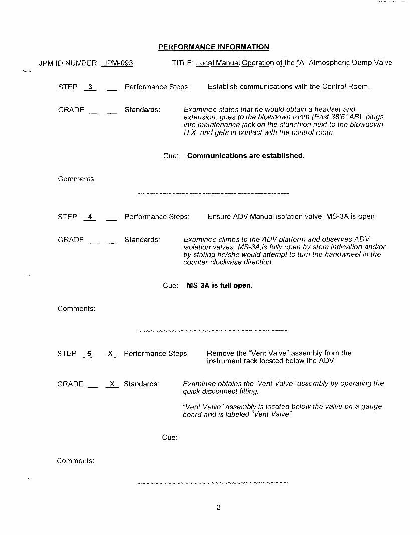
PERFORMANCE INFORMATION
JPM ID NUMBER. JPM-093 TITLE: Local Manual Operation of the “A“ Atmospheric Dump Valve --.--
STEP 3 __ Performance Steps: Establish communications with the Control Room
GRADE - - Standards: Examinee states that he would obtain a headset and extension, goes to the blowdown room (East 38’6’:AB). plugs into maintenance jack on the stanchion next to the blowdown H.X. and gets in contact with the control room.
Cue: Communications are established.
Comments:
STEP 4 __ Performance Steps: Ensure ADV Manual isolation valve, MS-3A is open.
GRADE _. __ Standards: Examinee climbs to the ADV platform and observes ADV isolation valves, MS-3A, is fully open by stem indication and/or by stating he/she would attempt to turn the handwheel in the counter clockwise direction.
Cue: MS3A is full open.
Comments:
STEP 5 X Performance Steps: Remove the “Vent Valve” assembly from the instrument rack located below the ADV.
GRADE __ - X Standards: Examinee obtains the ‘Vent Valve” assembly by operating the quick disconnect fitting.
“Vent Valve” assembly is located below the valve on a gauge board and Is labeled “Vent Valve“.
Cue:
Comments:
2

PERFORMANCE INFORMATION
JPM ID NUMBER: JPM-093 TITLE: Local Manual Operation of the “A” Atmospheric Dump Valve
STEP 6 __ Performance Steps: Ensure the “Vent Valve” assembly is closed.
GRADE - __ Standards: ,Examinee verifies the vent valve is in the closed position by turning the handwheel in the clockwise direction until it stops
Cue:
Comments:
...................................
STEP 7 __ X Performance Steps: Close the instrument air isolation valve to the ADV
GRADE __ __ X Standards:
Cue:
Examinee locates the 1. A. isolation for 2- MS- 190A (located on the Ctmt wall behind the ADV) and states that he/she would close it position by turning the handwheel in the clockwise direction until it stops.
- Ask examinee how s/he would reach the air supply to MS-190A. The examinee should use the ladder that is chained to the cat walk. LA. isolation to 2-MS-190A is closed. -
Comments:
STEP -8- ___ X Performance Steps: Remove the vent cap from the quick disconnect at the top of the ADV operator diaphragm.
GRADE - __ X Standards: Examinee states that he/she would remove the cap from the quick disconnect at the top of the valve operator diaphragm.
Cue: The vent cap is removed.
Comments:
3

PERFORMANCE INFORMATION
JPM ID NUMBER: JPM-093 TITLE: Local Manual Operation of the “A” Atmospheric Dump Valve - STEP -9- Performance Steps: Insert the “Vent Valve” assembly into the quick
disconnect.
GRADE - __ X Standards: Examinee inserts the “Vent Valve“ assembly into the quick disconnect on top of the ADV operator diaphragm.
Cue: The vent valve is inserted.
Comments:
STEP 2 X Performance Steps: Open the vent valve assembly to ensure air has been vented off the ADV operator.
GRADE - __ X Standards: To vent off the air from the ADV operator, the examinee opens the vent valve on the Vent Valve assembly by turning the handwheel in the clockwise direction until it stops.
Cue: The air from the operator has been vented off.
Comments:
STEP 11 __ Performance Steps: Ensure that the ADV is closed
GRADE __ __ Standards: Examinee observes AD V position indicator and determines that the ADV is closed.
Cue: The ADV is closed.
Comments:
4

PERFORMANCE INFORMATION
JPM ID NUMBER: JPM-093 TITLE: Local Manual Operation of the “ A Atmospheric Dump Valve --
STEP 12 X Performance Steps: Remove the handwheel restraining device.
GRADE __ - X Standards: Examinee states that he would remove the restraining device
Cue: Restraining devSce is removed.
Comments:
STEP 13 X Performance Steps: Position the ADV as directed by the Control Room
GRADE __ - X Standards: Examinee states that he/she would rotate the handwheel in the clockwise direction to position the valve to 25% open by the local stern position indication.
Cue: The ADV is 25% open.
Comments:
Comments: When it has been simulated that manual control has been taken and the valve is 25% open, then this JPM is complete.
STOP TIME:
5

VERIFICATION OF JPM COMPLETION
Job Performance Measure No. JPM -093 9 Rev. -
Date Performed:
Operator:
Eva I ua t or( s) :
For examinee to achieve a satisfactory grade, critical steps must be completed correctly. If task is Time Critical, it MUST be completed within the specified time to achieve a satisfactory grade.
Time Critical Task? Yes No X
Validated Time (minutes): 15
Actual Time to Complete (minutes):
Result of JPM: (Denote by an S for satisfactory or a u for unsatisfactory)
Areas for Improvement:
EXAMINEE HANDOUT
JPM ID Number: 093
lnitiatinq Cues: - The US directs you to take local manual control of the “A” Atmospheric Dump Valve and open the valve to 25% in accordance with EOP 2541 Appendix 36.
Initial Conditions: - A loss of I.A. has occurred in the plant.
- The plant has tripped and the decision has been made to use the “A” Atmospheric Dump Valve to remove decay heat.