Operating Manual FM 302 0203-21 - Projekt Elektronik
126
AM BORSIGTURM 54 13507 BERLIN TEL. 030 / 43 03 22 40 MESS - UND REGELUNGSTECHNIK GMBH FAX 030 / 43 03 22 43 Copyright Projekt Elektronik GmbH 20.10.2021 Projekt Elektronik Operating Manual Made in Germany
-
Upload
khangminh22 -
Category
Documents
-
view
0 -
download
0
Transcript of Operating Manual FM 302 0203-21 - Projekt Elektronik

AM BORSIGTURM 54
13507 BERLIN
TEL. 030 / 43 03 22 40
MESS - UND REGELUNGSTECHNIK GMBH FAX 030 / 43 03 22 43
Copyright Projekt Elektronik GmbH 20.10.2021
Projekt Elektronik
Operating Manual
Made in Germany

Projekt Elektronik MESS - UND REGELUNGSTECHNIK GMBH Page 2
1. Warning
Observe personal protection rules!
Please read this Operating Manual carefully! When measuring magnetic fields, consider and observe the regulations concerning potential dangers caused by DC and AC magnetic fields. The direct influence of magnetic fields (for limits see DIN VDE 0848) may be harmful to one's health. The operation of cardiac pacemakers may be affected dangerous! Examples for sources of potentially hazardous magnetic fields:
• ultrasonic sources • induction heaters and furnaces • magnetic resonance tomographs • medical magnetic fields More information can be obtained in the following documentation: • Electromagnetic Compatibility (Elektromagnetische Verträglichkeit),
VDE, Vol. 1 to 4
• DIN VDE 0848

Projekt Elektronik MESS - UND REGELUNGSTECHNIK GMBH Page 3
2. Technical Advice
Please read this Operating Manual carefully!
2.1 Transverse Probe
The transverse probe has a blue protective cap which have to be unscrewed before measurement. Utmost care and attention are needed if magnets have to be measured that are not mechanically fixed. Clashing poles can destroy the Hall element! As the Hall element (ceramic) is very sensitive to pressure or shock, mechanical stress must be avoided (risk of breakage)!
2.2 Transverse Probe Brass
When measuring fields of B > 20 mT and f > 10 kHz, the probe brass should not be operated for more than 1 min in order to prevent excessive heating of the brass tube with the Hall element inside! Attention should be paid to the fact that at the probe a connection exist between plug shield, plug case, cable shield and brass tube. If used with Teslameter FM 302, AS-probe adapter or AS-Adapter 3 the shield is connected to GND. Possibly an isolated installation of the probe and/or plug would be necessary to prevent an unintended connection between measuring ground and protective earth.
2.3 Transverse Probe Hot
The transverse probe has a protective cap which have to be drawn off before measurement. Only the probe, the handle and the cable are temperature-resistant. The probe connector with the electronic may only be operated up to +50 °C.

2. Technical Advice
Projekt Elektronik MESS - UND REGELUNGSTECHNIK GMBH Page 4
2.4 Transverse Probe Flex
The transverse probe has a protective cap which have to be drawn off before measurement. Only the probe itself is temperature-resistant. The handle, the cable and the probe connector with the electronic may only be operated up to +50 °C. No pressure shall be applied to the hall element (ceramic) because it is very pressure sensitive (risk of breaking)!
2.5 Transverse Probe Wire
The wire probes are very sensitive. The wires of the probe may not be bend at the element and may not be pulled. Only the probe itself is temperature-resistant. The handle, the cable and the probe connector with the electronic may only be operated up to +50 °C. No pressure shall be applied to the hall element (ceramic) because it is very pressure sensitive (risk of breaking)!
2.6 Axial Probe UAP
To be able to gain best stability in the 2 µT range the probe should be switched on for at least 30 minutes. The axis of the compensation potentiometer should not be exposed to bending forces to prevent the axis and the potentiometer from damage.
2.7 AS-Probe Adapter
Attention should be paid that in the adapter cable, there is a connection between GND and connector shield, connector housing as well as cable shield. At brass probes this is also connected to shield. Possibly an isolated installation of the probe is necessary to prevent an unintended connection between measuring GND and protective earth.

2. Technical Advice
Projekt Elektronik MESS - UND REGELUNGSTECHNIK GMBH Page 5
2.8 AS-Adapter 3
One should be aware, that the probes and all outputs have a common ground. Especially when using the brass version of AS-probes (AS-NTM, AS-LTM) an isolation between probe and other parts of the measurement setup can be necessary. It should be noted that the three adapter cables (X, Y, Z) and the probes provide a connection between the GND and the cable shield as well as the connector shield and connector housing. Possibly an isolated installation of the probe is necessary to prevent an unintended connection between measuring GND and protective earth.
2.9 ESD
Electrostatic discharges (> 0.5 kV) to the sensor can damage it. Structural safety measures would affect measurement accuracy due to loss of sensitivity.
2.10 Minimum Operation Conditions (EMC)
Measurement results may vary up to 2 % in the presence of strong HF fields (> 3 V/m).
2.11 Ground Connection / Earthing
It should be observed, that in the probe a connection between plug shield, plug case and cable shield is made. At bass probes, this is also connected to the shield. If used with Teslameter FM 302, AS-probe adapter or AS-Adapter 3 the shield is connected to GND. Possibly an isolated installation of the probe is necessary to prevent an unintended connection between measuring GND and protective earth.

Projekt Elektronik MESS - UND REGELUNGSTECHNIK GMBH Page 6
3. Table of Contents
1. Warning .............................................................................................................. 2
2. Technical Advice ............................................................................................... 3
2.1 Transverse Probe ....................................................................................... 3
2.2 Transverse Probe Brass ............................................................................. 3
2.3 Transverse Probe Hot ................................................................................. 3
2.4 Transverse Probe Flex ............................................................................... 4
2.5 Transverse Probe Wire ............................................................................... 4
2.6 Axial Probe UAP ......................................................................................... 4
2.7 AS-Probe Adapter ....................................................................................... 4
2.8 AS-Adapter 3 .............................................................................................. 5
2.9 ESD 5
2.10 Minimum Operation Conditions (EMC) ....................................................... 5
2.11 Ground Connection / Earthing .................................................................... 5
3. Table of Contents .............................................................................................. 6
4. List of Figures ................................................................................................. 11
5. Description ...................................................................................................... 14
5.1 Purpose of a Magnetic Field Meter ........................................................... 14
5.2 General Description of Operation ............................................................. 14
5.2.1 Teslameter FM 302 ....................................................................... 14
5.2.1.1 Control Software FM 302 Control .................................... 16
5.2.2 AS-Active-Probe ............................................................................ 17
5.2.2.1 Probe Extension Cord ..................................................... 18
5.2.3 AS-Probe Adapter ......................................................................... 18
5.2.4 AS-Adapter 3 ................................................................................. 19
5.3 Items Supplied .......................................................................................... 21
6. Operation ......................................................................................................... 22
6.1 Introduction ............................................................................................... 22
6.2 Safety Notes ............................................................................................. 22
6.3 Teslameter FM 302 ................................................................................... 23
6.3.1 Controls and Connectors ............................................................... 23
6.3.1.1 Housing ........................................................................... 24
6.3.1.2 Handle ............................................................................. 24
6.3.1.3 top hat rail adapter (optional) ........................................... 24
6.3.1.4 Power Switch ................................................................... 24
6.3.1.5 Keypad ............................................................................ 24
6.3.1.6 Display ............................................................................. 25
6.3.1.7 Key “zero” – Offset Compensation .................................. 27
6.3.1.8 Key “DC AC” – Measuring Mode ..................................... 29

3. Table of Contents
Projekt Elektronik MESS - UND REGELUNGSTECHNIK GMBH Page 7
6.3.1.9 Key “gain” – Measuring Range ....................................... 30
6.3.1.10 Key “unit” – Unit .............................................................. 30
6.3.1.11 Key “rel abs” – Relative Measurement ............................ 30
6.3.1.12 Key “min max” – Minimal Measurement, Maximal Measurement, Absolute Maximal Measurement ............. 31
6.3.1.13 Key “time” – Measuring Time .......................................... 32
6.3.1.14 Key “filter” – Filter ........................................................... 33
6.3.1.15 Acoustic Feedback ......................................................... 34
6.3.1.16 Analog Output ................................................................. 34
6.3.1.17 Probe Connector ............................................................. 35
6.3.1.18 USB Interface ................................................................. 35
6.3.1.19 Power Connector ............................................................ 35
6.3.1.20 Battery Compartment ...................................................... 35
6.3.2 Usage of The Teslameter FM 302 ................................................ 36
6.3.2.1 Time Response of Display and Analog Output ............... 37
6.3.2.2 Power Supply .................................................................. 38
6.3.2.3 Battery / Accumulator Operation ..................................... 38
6.3.2.4 Power Adapter Operation ............................................... 38
6.3.2.5 USB Operation ................................................................ 39
6.3.2.6 Display of Units with older AS-Active-Probe ................... 40
6.3.3 USB Interface ............................................................................... 41
6.3.3.1 General ........................................................................... 41
6.3.3.2 Driver Installation Windows............................................. 41
6.3.3.3 Driver Installation Linux .................................................. 41
6.3.3.4 Configuration of the Virtual Serial Port ............................ 42
6.3.3.5 General about Commands .............................................. 42
6.3.3.6 Command “amax” ........................................................... 43
6.3.3.7 Command “absolute” ...................................................... 43
6.3.3.8 Command “coupling” ...................................................... 43
6.3.3.9 Command “default” ......................................................... 44
6.3.3.10 Command “digits” ........................................................... 44
6.3.3.11 Command “filter” ............................................................. 44
6.3.3.12 Command “fmstatus” or “status” ..................................... 45
6.3.3.13 Command “gain” ............................................................. 45
6.3.3.14 Command “inttime” or “time” ........................................... 46
6.3.3.15 Command “keys” ............................................................ 46
6.3.3.16 Command “logging” ........................................................ 47
6.3.3.17 Command “maximum” .................................................... 47
6.3.3.18 Command “minimum” ..................................................... 48
6.3.3.19 Command “range” ........................................................... 48
6.3.3.20 Command “relative” ........................................................ 48
6.3.3.21 Command “serial” ........................................................... 49
6.3.3.22 Command “sound” .......................................................... 49
6.3.3.23 Command “unit” .............................................................. 50

3. Table of Contents
Projekt Elektronik MESS - UND REGELUNGSTECHNIK GMBH Page 8
6.3.3.24 Command “version” ......................................................... 50
6.3.3.25 Command “zero” ............................................................. 51
6.3.4 Control Software FM 302 Control .................................................. 52
6.3.4.1 General Description ......................................................... 52
6.3.4.2 Installation ....................................................................... 53
6.3.4.3 Connection to Teslameter FM 302 .................................. 53
6.3.4.4 Display and Setting of parameters .................................. 54
6.3.4.5 Oscilloscope Display ....................................................... 55
6.3.4.6 Logging of Measured Values ........................................... 56
6.3.4.7 Limit Comparator ............................................................. 59
6.3.4.8 Restore Factory Settings ................................................. 61
6.3.4.9 Uninstall ........................................................................... 61
6.3.4.10 Source Code ................................................................... 61
6.4 AS-Active-Probe ....................................................................................... 62
6.4.1 Polarity 62
6.4.1.1 Transverse Probe ............................................................ 62
6.4.1.2 Axial Probe ...................................................................... 62
6.4.2 Angle of Field ................................................................................ 63
6.4.3 Measuring Arrangement ................................................................ 63
6.4.4 Precision and Repeatability ........................................................... 65
6.4.5 Winding up of Cables .................................................................... 65
6.4.6 Transverse Probe AS-NTP 0,6 ...................................................... 65
6.4.7 Transverse Probe Brass AS-NTM, AS-NTM-2, AS-LTM ............... 66
6.4.8 Transverse Probe Hot AS-NTP-Hot-05 ......................................... 66
6.4.9 Transverse Probe Flex AS-NTP-Flex, AS-NTP-Flex 0,6 ............... 66
6.4.10 Transverse Probe Wire AS-NCu-Wire ........................................... 67
6.4.11 Transverse Probe AS-VTP ............................................................ 67
6.4.12 Axial Probe AS-HAP, AS-NAP, AS-LAP ........................................ 68
6.4.13 Axial Probe AS-UAP GEO-X, AS-UAP Lot .................................... 68
6.4.14 Usage of the AS-Active-Probes ..................................................... 70
6.4.14.1 Usage with the Teslameter FM 302 ................................. 70
6.4.14.2 Usage as Autonomous Transducer ................................. 70
6.4.14.3 Usage with the AS-Probe Adapter ................................... 72
6.4.14.4 Usage with the AS-Adapter 3 .......................................... 72
6.4.15 Zero Chamber (optional) ............................................................... 72
6.4.16 Test Curves / Linearity Curves (optional) ...................................... 73
6.5 AS-Probe Adapter ..................................................................................... 75
6.5.1 Controls and Connectors ............................................................... 75
6.5.2 Structure ........................................................................................ 76
6.5.2.1 Supply Voltage Inputs...................................................... 77
6.5.2.2 Power LED ...................................................................... 77
6.5.2.3 Probe Supply ................................................................... 77
6.5.2.4 Probe Signal Input ........................................................... 77
6.5.2.5 Measurement Signal Output ............................................ 78

3. Table of Contents
Projekt Elektronik MESS - UND REGELUNGSTECHNIK GMBH Page 9
6.5.2.6 Gain Switch ..................................................................... 78
6.5.3 Adapter Cable ............................................................................... 78
6.5.4 Usage of the AS-probe adapter .................................................... 79
6.6 AS-Adapter 3............................................................................................ 80
6.6.1 Controls and Connectors .............................................................. 80
6.6.2 Overview of Controls and Connections ......................................... 80
6.6.2.1 Supply Voltage Inputs ..................................................... 82
6.6.2.2 Power LED ...................................................................... 82
6.6.2.3 Probe Supply .................................................................. 82
6.6.2.4 Probe Signal Input .......................................................... 82
6.6.2.5 Measurement Signal Output ........................................... 82
6.6.2.6 Gain Switch ..................................................................... 83
6.6.3 Adapter Cable ............................................................................... 83
6.6.4 Usage of the AS-Adapter 3 ........................................................... 85
7. Technical Specifications ................................................................................ 88
7.1 Teslameter FM 302 (without AS-Active-Probe): ....................................... 88
7.2 AS-Active-Probes ..................................................................................... 92
7.2.1 Sensitivity Classes – Overview ..................................................... 94
7.2.2 AS-active-probes – Overview Normal ........................................... 98
7.2.3 AS-active-probes – Overview Earth Magnetic Field ...................... 99
7.2.4 AS-active-probes – Overview High Field ...................................... 99
7.2.5 AS-active-probes – Overview Low Field ..................................... 100
7.2.6 AS-active-probes – Overview Very Low Field ............................. 100
7.2.7 AS-active-probes – Overview Further Data ................................ 101
7.2.8 Axial Probe 12 T (AS-HAP) ......................................................... 102
7.2.9 Transverse Probe 2000 mT (AS-NTP 0,6) .................................. 103
7.2.10 Transverse Probe Brass 2000 mT (AS-NTM) ............................. 104
7.2.11 Transverse Probe Brass with Very High Precision 2000 mT (AS-NTM-2) 105
7.2.12 Axial Probe 2000 mT (AS-NAP) .................................................. 106
7.2.13 Transverse Probe Hot with Improved Temperature Characteristics 2000 mT (AS-NTP-Hot-05) ......................................................... 107
7.2.14 Transverse Probe Flex 2000 mT (AS-NTP-Flex) ........................ 108
7.2.15 Transverse Probe Flex 2000 mT (AS-NTP-Flex 0,6) ) ............... 109
7.2.16 Transverse Probe Wire 2000 mT (AS-NCu-Wire) ....................... 110
7.2.17 Transverse Probe Brass 200 mT (AS-LTM) ................................ 111
7.2.18 Axial Probe 200 mT (AS-LAP) .................................................... 112
7.2.19 Transverse Probe 20 mT (AS-VTP) ........................................... 113
7.2.20 GEO-X Axial Probe 200 µT (AS-UAP GEO-X)............................ 114
7.2.21 Lot Axial Probe 200 µT (AS-UAP Lot) ......................................... 115
7.3 AS-Probe Adapter .................................................................................. 116
7.4 AS-Adapter 3.......................................................................................... 118

3. Table of Contents
Projekt Elektronik MESS - UND REGELUNGSTECHNIK GMBH Page 10
8. Maintenance .................................................................................................. 120
8.1 Visual Inspection ..................................................................................... 120
8.2 Checking Battery .................................................................................... 120
8.3 Maintaining Accumulators ....................................................................... 120
8.4 Cleaning.................................................................................................. 121
8.5 Warranty Provisions ................................................................................ 121
9. Customer Service .......................................................................................... 122
9.1 Calibration............................................................................................... 122
9.2 Repairs ................................................................................................... 122
9.3 Follow-up Orders .................................................................................... 122
9.4 Disposal .................................................................................................. 122
10. EU Declaration of Conformity ...................................................................... 123
11. Index ............................................................................................................... 124
Operating Manual FM 302 0203-21.docx

Projekt Elektronik MESS - UND REGELUNGSTECHNIK GMBH Page 11
4. List of Figures
Figure 1 Example of an order of FM 302 with three probes and options ................ 21
Figure 2 Controls and connectors FM 302 .............................................................. 23
Figure 3 Keypad of Teslameter FM 302 ................................................................. 24
Figure 4 Display of Teslameter FM 302 .................................................................. 25
Figure 5 Display of serial number and firmware version ......................................... 25
Figure 6 Display of Teslameter FM 302 .................................................................. 25
Figure 7 Display without probe ............................................................................... 26
Figure 8 Display while range overflow .................................................................... 26
Figure 9 Display polarity of magnet ........................................................................ 26
Figure 10 Display battery state ............................................................................... 27
Figure 11 Display supply by power adapter or USB ............................................... 27
Figure 12 Display while offset compensation process ............................................ 28
Figure 13 Display error message offset out of range .............................................. 28
Figure 14 Display reset offset compensation .......................................................... 28
Figure 15 Display measuring mode ........................................................................ 29
Figure 16 Display in relative measurement ............................................................. 31
Figure 17 Display in minimal measurement ............................................................ 31
Figure 18 Display in maximal measurement ........................................................... 32
Figure 19 Display in absolute maximal measurement ............................................ 32
Figure 20 Display measuring timeout ..................................................................... 33
Figure 21 Display filter length ................................................................................. 33
Figure 22 Usage of Teslameter FM 302 ................................................................. 36
Figure 23 Time response ........................................................................................ 37
Figure 24 Display with not representable unit ......................................................... 40
Figure 25 Control software FM 302 Control ............................................................ 52
Figure 26 Value display of the control software ...................................................... 54
Figure 27 Control of keypad lock and acoustic feedback ........................................ 54
Figure 28 Control of the FM 302 settings ................................................................ 55
Figure 29 Oscilloscope-like display ......................................................................... 56
Figure 30 Setting logging parameter ....................................................................... 56
Figure 31 Log file example...................................................................................... 57
Figure 32 Single value logging ................................................................................ 57
Figure 33 Continuous value logging ....................................................................... 58
Figure 34 Log preview ............................................................................................ 59
Figure 35 Limit comparator ..................................................................................... 59
Figure 36 Oscilloscope display with limits of limit comparator ................................ 60
Figure 37 Reset to the factory settings ................................................................... 61
Figure 38 polarity transverse probe ........................................................................ 62
Figure 39 polarity axial probe .................................................................................. 62
Figure 40 Trigonometric of the measuring arrangement ......................................... 63
Figure 41 Measuring arrangement bar magnet ....................................................... 64
Figure 42 Measuring arrangement cylindrical coil ................................................... 64
Figure 43 Transverse probe 0,6 .............................................................................. 65
Figure 44 Transverse probe brass .......................................................................... 66
Figure 45 Transverse probe Hot ............................................................................. 66
Figure 46 Transverse probe Flex ............................................................................ 66

4. List of Figures
Projekt Elektronik MESS - UND REGELUNGSTECHNIK GMBH Page 12
Figure 47 Transverse probe Flex 0,6...................................................................... 67
Figure 48 Transverse probe Wire ........................................................................... 67
Figure 49 Transverse probe AS-VTP ..................................................................... 67
Figure 50 Axial probe ............................................................................................. 68
Figure 51 Axial probe AS-UAP GEO-X................................................................... 68
Figure 52 Axial probe AS-UAP Lot ......................................................................... 68
Figure 53 Controls connector AS-UAP ................................................................... 69
Figure 54 Usage of AS-active-probe with FM 302 .................................................. 70
Figure 55 Usage AS-probe at ±3 V......................................................................... 71
Figure 56 Pin configuration AS-probe at ±3 V ........................................................ 71
Figure 57 Structure AS-active-probe ...................................................................... 72
Figure 58 Zero Chamber ........................................................................................ 73
Figure 59 Typical test curves / linearity curves ....................................................... 74
Figure 60 Controls and connections AS-probe adapter .......................................... 75
Figure 61 Structure AS-probe adapter.................................................................... 76
Figure 62 Adapter cable ......................................................................................... 78
Figure 63 Connection AS-probe adapter ................................................................ 79
Figure 64 Controls and connectors AS-Adapter 3 .................................................. 80
Figure 65 Structure AS-Adapter 3 .......................................................................... 81
Figure 66 Adapter cable „X, Y, Z” ........................................................................... 84
Figure 67 Connection AS-Adapter 3 with 1-axis AS-active probes ......................... 86
Figure 68 Connection AS-Adapter 3 with 3-axis AS-active probe .......................... 87
Figure 69 AS-NTP 0,6 transverse probe ................................................................ 92
Figure 70 AS-NTM, AS-LTM and AS-NTM-2 transverse probe brass .................... 92
Figure 71 AS-NTP-Hot-05 transverse probe .......................................................... 92
Figure 72 AS-NTP-Flex transverse probe .............................................................. 92
Figure 73 AS-NTP-Flex 0,6 transverse probe ........................................................ 92
Figure 74 AS-VTP transverse probe....................................................................... 92
Figure 75 AS-NCu-Wire transverse probe Wire ..................................................... 93
Figure 76 AS-NAP, AS-LAP and AS-HAP axial probe............................................ 93
Figure 77 AS-UAP GEO-X axial probe ................................................................... 93
Figure 78 AS-UAP Lot axial probe ......................................................................... 93
Figure 79 Size axial probe 12 T (AS-HAP) ........................................................... 102
Figure 80 Size transverse probe 2000 mT (AS-NTP 0,6) ..................................... 103
Figure 81 Size transverse probe brass 2000 mT (AS-NTM) ................................. 104
Figure 82 Size transverse probe brass 2000 mT (AS-NTM-2) ............................. 105
Figure 83 Size axial probe 2000 mT (AS-NAP) .................................................... 106
Figure 84 Size transverse probe Hot 2000 mT (AS-NTP-Hot-05) ........................ 107
Figure 85 Size transverse probe Flex 2000 mT (AS-NTP-Flex) ........................... 108
Figure 86 Size transverse probe Flex 2000 mT (AS-NTP-Flex 0,6) ..................... 109
Figure 87 Size transverse probe Wire 2000 mT (AS-NCu-Wire) .......................... 110
Figure 88 Size transverse probe brass 200 mT (AS-LTM) ................................... 111
Figure 89 Size axial probe 200 mT (AS-LAP) ....................................................... 112
Figure 90 Size transverse probe 20 mT (AS-VTP) ............................................... 113
Figure 91 Size GEO-X axial probe 200 µT (AS-UAP GEO-X) .............................. 114

4. List of Figures
Projekt Elektronik MESS - UND REGELUNGSTECHNIK GMBH Page 13
Figure 92 Size Lot axial probe 200 µT (AS-UAP Lot) ........................................... 115
Figure 93 AS-probe adapter ................................................................................. 116
Figure 94 AS-Adapter 3 ........................................................................................ 118

Projekt Elektronik MESS - UND REGELUNGSTECHNIK GMBH Page 14
5. Description
5.1 Purpose of a Magnetic Field Meter
The Teslameter FM 302, the AS-active-probes, the AS-probe adapter and the AS-Adapter 3 form a handy measuring system which allows to measure magnetic fields in a wide scope of application. This includes alternating fields of electromagnets as well as constant magnetic fields of permanent magnets. For normal use of the instrument, please refer to section 6 Operation.
5.2 General Description of Operation
The measuring system consists of the Teslameter FM 302 and/or AS-probe adapter and/or AS-Adapter 3 at least one pluggable AS-active-probe which contains the sensor. By the use of pluggable probes, the system may be fast and easily adopted to different measuring tasks. Depending on the probe, fields from a few nano-Tesla up to 12 Tesla can be measured. After plugging in the desired probe one can start to measure immediately without adjustment of zero and scale since the AS-active-probes have an active electronic which matches the properties of the sensor to the measuring range of the probe. There are different probes available which fulfill the requirements - to the geometry of the cavity to be measured, - to the strength of the magnetic flux, - to the treatment, - to the size of the active sensor area, - or to the operating temperature. The selection of probes is regularly extended. This is done especially by requests of customers.
5.2.1 Teslameter FM 302
The Teslameter FM 302 has a 4 ½ digit display and three measuring ranges. The sensitivity of the ranges depends on the used probe and differ in factor 10 and factor 100. The polarity is displayed by the sign. The displayed unit can be switched between Tesla, Gauss, Oersted, A/m and (with firmware version 1.4 and later and hardware version V2) A/cm. The Teslameter FM 302 can used to measure steady as well as alternating magnetic fields up to 100 kHz (depending on the probe type).

5. Description
Projekt Elektronik MESS - UND REGELUNGSTECHNIK GMBH Page 15
For DC-fields it is displayed (with firmware version 1.4 and later) if there is a north pole or south pole under the probe. For AC-fields alternatively the mean value (DC) or the effective value (true RMS) can be displayed (see section 6.3.2 Usage of The Teslameter FM 302). Another feature of the Teslameter FM 302 is the calibrated analog output, which is useful for display purposes (oscilloscope, plotter), data logging (computer) and field control. Here the measured signal in DC or AC coupling can be selected. The operation of the Teslameter FM 302 is done via the keypad with 8 keys which allow to set the functions of the device. For example the measuring time can be adjusted to meet the requirements of the respective measuring task, depending if a rather fast capturing of measured values or low noise measured values are more important. For further filtering a digital filter can be activated which works as a moving average filter on the measured values. In addition to absolute measurement the Teslameter FM 302 offers a function to relative measurement and for measuring the minimal, maximal and (with firmware version 1.4 and later) absolute maximal value. Moreover the Teslameter FM 302 features a USB interface which allows to control the device and read out the measured values. There are even more control options available. Also the device can be powered via the USB connection. At the computer side the Teslameter FM 302 appears as a virtual serial port so it is easy to integrate the device into existing systems. The Teslameter FM 302 with its AS-active-probes is not disturbed in its function by stronger magnetic fields. The device works reliable even at a DC field of 350 mT. Neither the actual measurement nor the communication with the computer is interfered. It has just to be considered the occurring action of force of the device. The main reasons are the battery and the probe connector.

5. Description
Projekt Elektronik MESS - UND REGELUNGSTECHNIK GMBH Page 16
5.2.1.1 Control Software FM 302 Control
The Teslameter FM 302 is delivered with a control software. The software allows to control all settings of the Teslameter via the PC. Thereby the software offers the complete range of functions which are possible with the commands via the USB interface. Besides the simple display of the measured value the software offers an oscilloscope like display of the last 100 measured values. The time axis depends on the selected measuring time. The scale of the amplitude axis is given by the connected probe and the selected sensitivity of the FM 302. Additionally a higher sensitivity (x1, x10, x100, x1000) of the measurement range can be activated. The created chart can be saved in different graphic formats. The control software do not just allow to display the measured values of the FM 302 but also allows to save them into a log file. For this two different modes are offered. In the mode “single value logging” single measured values can be saved with a key press (mouse or keyboard). This mode is suitable for manual controlled measurements where a number of single values has to be measured. Otherwise in the mode “continuous value logging” the measured value are automatically stored continuously into the log. This mode is suitable to record traces over longer periods of time. For storing there can be chosen from two different formats. The log can be saved in classic csv format (comma separated values) where the single data blocks are separated by a comma and the period is used as decimal separator. Alternatively the semicolon may be used for separating the data blocks which makes available the comma as decimal separator. This settings simplifies the import into software with German localization. As another function the software offers a limit comparator. An upper and a lower limit may be entered. The software shows if the current measured value is below the lower limit, between both limits or above the upper limit. This function allows e.g. the quick incoming inspection of permanent magnets. The polarity can be ignored while checking the compliance with the given limits. Additionally the set limits can be displayed in the oscilloscope-like display.

5. Description
Projekt Elektronik MESS - UND REGELUNGSTECHNIK GMBH Page 17
5.2.2 AS-Active-Probe
The AS-active-probes are active probes to measure the magnetic induction. In contrast to most other available probes, the AS-probes contain an active electronic so that a calibrated analog signal is available at the plug. The transverse probe made of glass fiber fabric (AS-NTP 0,6) with their slight thickness make it possible to measure in narrow air gaps and difficult-to-reach locations. For transportation the probe is protected by a cap. Further-more the probe carrier is temperature resistant up to 100 °C. For rough operating conditions the transverse probe is provided in a design with brass protective tube (AS-LTM, AS-NTM). However they are thicker than the AS-NTP 0,6. The transverse probes AS-NTP-Flex and AS-NTP-Flex 0,6 are made with a strip of very thin, extreme flexible and bendable material. They are qualified to measure remarkable hard to reach locations and smallest air gaps. Furthermore the probe carrier is temperature resistant up to 100 °C at the AS-NTP-Flex and even up to 150 °C at the AS-NTP-Flex 0,6. The transverse AS-VTP is suitable especially for the measurement of small fields. It qualifies due to their small zero drift and their low noise. The probe AS-NCu-Wire is an extra thin sensor connected with very light wires. Thus the probe is suited to measure at closed quarters and to mount into complex measurement setups. At very high demands to accuracy and temperature stability the probe AS-NTM-2 may be used. Linearity error and temperature drift have been highly reduced compared to the other probes. The transverse high-temperature probe AS-NTP-Hot-05 is designed to measure even at high temperatures up to 150 °C and at low temperatures down to –40 °C. The probe itself and the probe cable are constructed to permanently endure those temperatures.

5. Description
Projekt Elektronik MESS - UND REGELUNGSTECHNIK GMBH Page 18
The also available axial probes (AS-LAP, AS-NAP, AS-HAP) have a small diameter and thus are suitable to measure fields in small coils. With the axial AS-UAP probes particularly small fields can be measured with a resolution down to one nano Tesla. Furthermore it has the facility to compensate ±70 µT which for example provides the possibility to compensate the earth magnetic field. So only differences are measured which can be done with higher resolution. The AS-UAP probe is available in two types. The AS-UAP GEO-X probe is suitable for general measuring tasks while the AS-UAP Lot probe with their special plummet housing with weighted tip is mainly suitable for measuring the vertical component of the earth magnetic field. All AS-active-probes can be used without the Teslameter as transducer at an PLC, see section 6.4.14.2 Usage as Autonomous Transducer.
5.2.2.1 Probe Extension Cord
Based on the fact, that the AS-active-probes are active probes, whose electronic outputs a calibrated voltage signal related to the measured flux density, a probe extension cord can be inserted between AS-active-probe and Teslameter FM 302, AS-Adapter 3 or PLC without negative influence on the measuring signal. So even wider distances between measured object and measuring device can be bridged. Appropriated extension cords are optional available in different lengths.
5.2.3 AS-Probe Adapter
The AS-probe adapter is designed to autonomously operate our AS-active-probes without Teslameter. As a result of the wide supply voltage range of 9 VDC to 36 VDC the AS-probe adapter may be used universal in different system configurations. Furthermore the AS-probe adapter galvanically isolates the power supply from the probe supply and the measuring electronic.

5. Description
Projekt Elektronik MESS - UND REGELUNGSTECHNIK GMBH Page 19
The AS-probe adapter provides high stable ±3 V necessary to supply the AS-active-probes. To ease the connection of the AS-active-probe to existing analog inputs with ±10 V input range, the AS-probe adapter contains an integrated amplifier. This amplifies the output signal of the AS-active-probes from ±2 V to ±10 V. With a switch, an additionally 10times higher gain can be chosen which allows to perform even sensitive measurements. The analog output of the adapter is calibrated and thus can be used e.g. for displaying magnetic pulses in the µs-range (oscilloscope), recording of measurements and for field control. The bandwidth of the analog output reaches from DC to a least 100 kHz. Therefore it is suitable for measuring both constant magnetic fields and alternating magnetic fields. Included in delivery is an adapter cable which allows the easy connection of the 15-pole SubD connector of the AS-active-probes with the screw terminals of the AS-probe adapter.
5.2.4 AS-Adapter 3
The AS-Adapter 3 is used for the autonomous operation of 1-axis and 3-axis AS active probes. The signals from all 3 probes are available simultaneously and in parallel via the BNC connections or via the terminal contacts. The AS-Adapter 3 supplies the AS active probes with ± 3 V in a highly stable manner. The probe signals are amplified with x5 or x50, so that with ± 2 V or ± 0.2 V they can output ± 10 V for a PLC system and Provide oscilloscope. The wide supply voltage range is 9 VDC to 36 VDC. The signals and supply of the probes are galvanic isolated from the operating voltage.
The analog output of the AS-adapter 3 is calibrated and thus can be used e.g. for displaying magnetic pulses in the µs-range (Oscilloscope), recording of measurements and for field control. The bandwidth of the analog output reaches from DC to a least 100 kHz. Therefore it is suitable for measuring both constant magnetic fields and alternating magnetic fields. The actual usable bandwidth depends on used AS-active probe. After connecting the desired probe, the measurement can start without adjusting zero and scale because all AS-active probes are calibrated. Hence replacement probes can be used at any time.
5. Description
Projekt Elektronik MESS - UND REGELUNGSTECHNIK GMBH Page 20
All of our AS-active probes may be connected to the AS-Adapter 3. This allows the fast adaptation to different measuring task by simply plugging in a different probe. Depending on the type of AS-active probe fields from a few nano Tesla up to 12 Tesla can be measured. Further information can be found in the data sheet of the AS-active probes. The AS-Adapter 3 has table feet’s and a DIN rail holder mount for cabinet device mounting.

5. Description
Projekt Elektronik MESS - UND REGELUNGSTECHNIK GMBH Page 21
5.3 Items Supplied
The delivered content depends on the concrete order. It may contained::
Teslameter FM 302 AS-Probe Adapter - case with replacement battery - 5 m adapter cable for probe connection - factory calibration certificate - factory calibration certificate - 1.8 m USB cord - 9 V plug-in power supply unit for - CD with drivers and control software AS-probe adapter (optional) - power adapter (optional) - top hat rail adapter fixed to the device AS-Adapter 3
(optional) - 3 pieces 5 m adapter cable for probe connection AS-active-probe - factory calibration certificate - factory calibration certificate - 9 V plug-in power supply unit for - zero chamber (optional) AS-probe adapter (optional) - test curve / linearity curve (optional) - probe extension cord (optional) operating manual
Figure 1 Example of an order of FM 302 with three probes and options

Projekt Elektronik MESS - UND REGELUNGSTECHNIK GMBH Page 22
6. Operation
6.1 Introduction
This Operating Manual should be read carefully before measuring instrument is operated for the first time. Projekt Elektronik GmbH will not be responsible for damage to the instrument caused by disregarding this Operating Manual. Neither will responsibility be assumed for consequential damage resulting from such mishandling of the instrument. Also before initial operation, the content of the case should be checked for completeness of the items supplied (see section 5.3 Items Supplied)!
6.2 Safety Notes
In order to ensure safe operation of the instrument, be sure to observe the following recommendations: • The magnetic field meter was tested after manufacture for compliance
with all applicable safety standards and regulations. To preserve this condition and to ensure safe operation, the user should be sure to observe all safety notes and cautions included in this Operating Manual.
• Before measurements, check your probe, probe cord, probe housing, Teslameter housing, AS-Probe Adapter-housing, AS-Adapter 3-housing, power adapter and power cord for damage.
• If you believe that the instrument cannot be operated safely any longer, switch it OFF, mark it accordingly and keep it in a manner to prevent unintentional use.
Safe operation will not be possible if the unit, the probe, any connecting cable, the battery or the accumulator, power adapter or power cord show visible damage, or if the unit fails to operate.
• This instrument must not be handled by children!
• Due attention should be given to the accident prevention rules issued by authorized bodies, especially to any rules concerning electromagnetic fields.

6. Operation
Projekt Elektronik MESS - UND REGELUNGSTECHNIK GMBH Page 23
6.3 Teslameter FM 302
6.3.1 Controls and Connectors
Housing Power switch 2 line LCD display USB connector Keypad Power input Analog output Battery compartment Probe connector
Figure 2 Controls and connectors FM 302

6. Operation
Projekt Elektronik MESS - UND REGELUNGSTECHNIK GMBH Page 24
6.3.1.1 Housing
The screwed housing is a plastics material resistant to scratches and fracture to protect the electronics from outside influence.
6.3.1.2 Handle
The handle swings out of the bottom and can be used to support the Teslameter FM 302 on a horizontal surface or - if replaced - to suspend it.
6.3.1.3 top hat rail adapter (optional)
With the optionally available top hat rail adapter fix mounted to the Teslameter FM 302, the device can be mounted to a top hat rail. For release the locking bar has to be pulled up with a screw driver.
6.3.1.4 Power Switch
On the left side of the Teslameter FM 302 is a sliding switch to switch it on and off.
6.3.1.5 Keypad
The Teslameter FM 302 has a keypad which allows to control major device functions. For the usage of the single keys see section 6.3.1.7 to 6.3.1.14.
Figure 3 Keypad of Teslameter FM 302 The control with the keypad can be locked with a command via the USB interface (see section 6.3.3.15 Command “keys). After switching the device off and on again, the keys are unlocked.

6. Operation
Projekt Elektronik MESS - UND REGELUNGSTECHNIK GMBH Page 25
6.3.1.6 Display
The Teslameter FM 302 has a two-line LCD display. After power on the device initializes itself. During that the display shows the manufacturer and device name.
Figure 4 Display of Teslameter FM 302 Afterwards the display shows the device number / serial number and the firmware version.
Figure 5 Display of serial number and firmware version
Figure 6 Display of Teslameter FM 302 In the upper line on the left side it is shown if DC fields or AC fields are measured. Next to it the current measured value is displayed 4½ -digit. In measuring mode DC that is the mean value of the probe signal. In AC the effective value (true RMS) of the alternating component of the probe signal is displayed. See also section 6.3.1.8 Key “DC AC” – Measuring Mode. Positive measurement results are displayed without a sign. Rightmost the unit of the measured value is displayed. The unit can be switched between Tesla, Gauss, Oersted, A/m and (with firmware version 1.4 and later and hardware version V2) A/cm. See also section 6.3.1.10 Key “unit” – Unit.

6. Operation
Projekt Elektronik MESS - UND REGELUNGSTECHNIK GMBH Page 26
The prefix of the unit and the resolution and consequently the position of the decimal point of the measured value are derived from the sensitivity of the connected probe and the selected measuring range. See also Table 4 at page 95. If no probe is connected to the device, the display shows “no probe“ instead of measured value and unit.
Figure 7 Display without probe If the measured value is to large for the selected measuring range the display shows “overload”.
Figure 8 Display while range overflow In the lower line of the display in absolute measurement left the currently selected range (B3, B2, B1) is displayed. See also section 6.3.1.9 Key “gain” – Measuring Range to change the measuring range. Next to it, it is displayed (with firmware version 1.4 and later) if there is a north pole or south pole under the probe. Also see 6.4.1 Polarity.
Figure 9 Display polarity of magnet In the lower left the state of the power supply of the Teslameter FM 302 is displayed. A full battery symbol denotes, that the Teslameter FM 302 is running on battery and that the voltage of the battery is sufficient to power the device. An empty battery symbol signalizes that the voltage of the battery has run significantly low and the battery should replaced (see section 8.2 Checking Battery and 8.3 Maintaining Accumulators).
6. Operation
Projekt Elektronik MESS - UND REGELUNGSTECHNIK GMBH Page 27
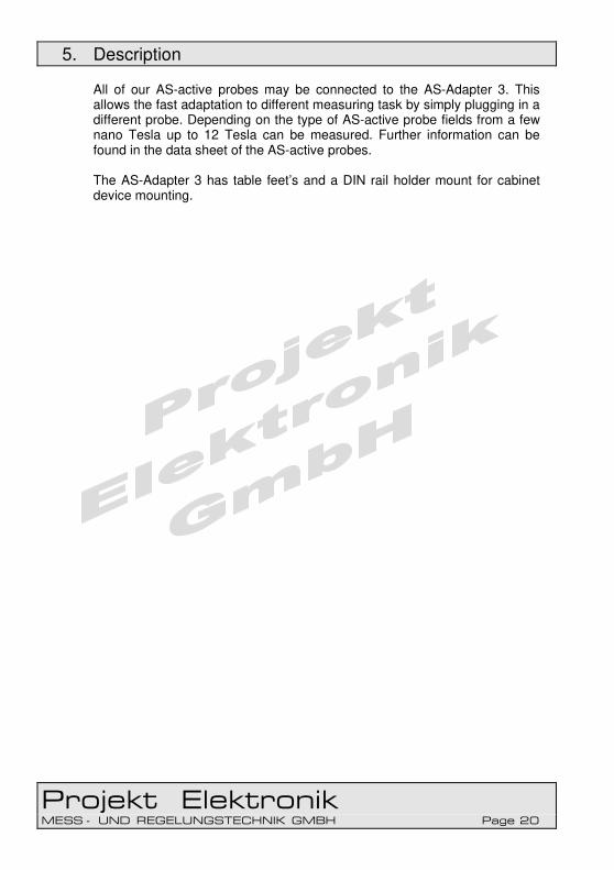
Figure 10 Display battery state If the Teslameter FM 302 is powered with a power adapter “EXT” is shown instead of the battery symbol. If the device is connected via USB and is powered via the USB connection the display shows “USB”.
Figure 11 Display supply by power adapter or USB In the measuring modes relative measurement, minimal measurement, maximal measurement and (with firmware version 1.4 and later) absolute maximal measurement the lower line shows the measuring mode in the left and the reference value or minimal or maximal value with unit in the right. If the Teslameter FM 302 runs on battery as power supply and if the battery is nearly empty, instead of the unit, the empty battery symbol is shown in lower right. The update rate of the display is determined by the setting of the measuring time. Each time the measuring time has passed a new measured value is available and printed out at the display. To set the measuring time see section 6.3.1.13 Key “time” – Measuring Time.
6.3.1.7 Key “zero” – Offset Compensation
The Teslameter FM 302 offers the possibility to compensate an offset of the zero point. The compensation range is > ±4500 digit of the most sensitive measuring range. With a measuring range of 2 mT that means a compensation range of > ±450 µT. With this function a deviation of the zero point caused by temperature change of sensor and electronic can be removed. The possibility to compensate the offset is only available in the measuring mode DC. After pressing the key “zero” the device automatically performs the compensation. The message “zeroing” is displayed and a number of dots shows the progress of the compensation process.

6. Operation
Projekt Elektronik MESS - UND REGELUNGSTECHNIK GMBH Page 28
Figure 12 Display while offset compensation process If the offset is larger than the compensation range, the error message “offset out of range” is displayed. The compensation is reset to zero.
Figure 13 Display error message offset out of range To reset the compensation to zero, the key “zero” has to be pressed a second time while the compensation process is running. The FM 302 confirms the reset of the compensation with the message “reset zero to midscale”.
Figure 14 Display reset offset compensation There are two possibilities to compensate the zero point.
• At the AS-UAP probes in the less sensitive range and all other AS-probes in the most sensitive range and measuring mode DC the measuring direction of the probe is positioned orthogonal to the earth magnetic field in east-west direction. With the “zero” key a compensation of the zero point is performed. Afterwards the probe should show the same value only differing in the sign if aligned in north-south and south-north direction. The typical value of the earth magnetic field in the area of Europe is 30 µT to 50 µT.
• If a zero chamber is at hand after inserting the probe the offset compensation can be performed by pressing the “zero” key.
6. Operation
Projekt Elektronik MESS - UND REGELUNGSTECHNIK GMBH Page 29
The offset compensation is an additive correction which doesn’t have an impact on the linearity. See also section 6.3.3.25 Command “zero” for controlling the offset compensation via the USB interface. Optional a zero chamber is attainable for our instruments (see also 6.4.15 Zero Chamber (optional)). Further information about the zero chamber and its use can be found in our application note PE012 – zero chamber - zero adjustment.
6.3.1.8 Key “DC AC” – Measuring Mode
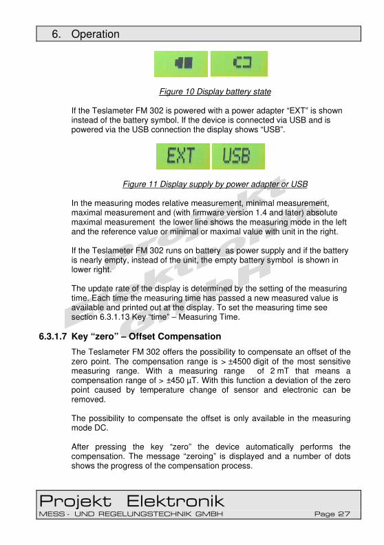
With the key “DC AC” the measure mode is switched between DC field and AC field measurement. Correspondingly the coupling is switched. The selected measuring mode is shown in the upper left of the display.
Figure 15 Display measuring mode DC: The LCD display shows the arithmetic mean of the magnetic field
signal. The signal of the magnetic field in the frequency range from 0 to
100 kHz (-3 dB) is available at the analog output.
AC: In this position the true effective value (true RMS) of an overlaying alternating field in the range of 5 Hz to 100 kHz (-3 dB) is displayed.
The analog output provides the time response of the overlaying AC-field in the range of 5 Hz to 100 kHz.
For the time response of the display and the analog output see section 6.3.2.1 Time Response of Display and Analog Output. See also section 6.3.3.8 Command “coupling” for controlling the measuring mode via the USB interface.

6. Operation
Projekt Elektronik MESS - UND REGELUNGSTECHNIK GMBH Page 30
6.3.1.9 Key “gain” – Measuring Range
With the key “gain” the measuring range can be selected. There are available the three ranges B3, B2 and B1. These correspond to a sensitivity of x1, x10 and x100 of the analog signal. The selected measuring range is shown in the lower left of the display. To which measuring range the ranges B1, B2 and B3 correspond can be read on the imprint of the connector housing of the probe. According to the chosen range the decimal point and the unit prefix is set at the display. The chosen range determines the sensitivity of the display and the analog output. See also section 6.3.3.13 Command “gain” for controlling the measuring range via the USB interface.
6.3.1.10 Key “unit” – Unit
With the key “unit” the unit to display the measured value can be selected. One can choose from the units Tesla, Gauss, Oersted, A/m and (with firmware version 1.4 and later and hardware version V2) A/cm. Every key press cyclically chooses the next unit. A/cm is available with firmware version 1.4 and later and hardware version V2. The prefix of the display unit is automatically set depending on the type of the connected probe and the chosen measuring range. For exemptions see section 6.3.2.6 Display of Units with older AS-Active-Probe. See also section 6.3.3.23 Command “unit” for controlling the unit via the USB Interface.
6.3.1.11 Key “rel abs” – Relative Measurement
With this key the measuring mode is set to relative measurement. With pressing the key, the current measured value is taken as reference value and shown with unit in the lower line of the display. From now on the measured values in the upper display line are shown relative to this reference value.

6. Operation
Projekt Elektronik MESS - UND REGELUNGSTECHNIK GMBH Page 31
Figure 16 Display in relative measurement relative value = absolute value – reference value If the key is pressed again, the Teslameter FM 302 switches back to the measuring mode absolute measurement. The relative measurement has no influence on the analog output of the Teslameter FM 302. The analog output always delivers the current absolute signal. See also section 6.3.3.20 Command “relative” and 6.3.3.7 Command “absolute” for switching between absolute measurement and relative measurement via the USB interface.
6.3.1.12 Key “min max” – Minimal Measurement, Maximal Measurement, Absolute Maximal Measurement
With this key it is switched cyclically between the measuring modes minimal measurement, maximal measurement, (with firmware version 1.4 and later) absolute maximal measurement and absolute measurement. In minimal measurement the upper display line shows still the current measured value while the lower line displays the mathematical smallest value since start of the measuring mode. -100 mT < +200 mT → display -100 mT
Figure 17 Display in minimal measurement

6. Operation
Projekt Elektronik MESS - UND REGELUNGSTECHNIK GMBH Page 32
In maximal measurement the upper display line shows still the current measured value while the lower line displays the mathematical greatest value since start of the measuring mode. 100 mT > -200 mT → display 100 mT
Figure 18 Display in maximal measurement In absolute maximal measurement the upper display line shows still the current measured value while the lower line displays the greatest absolute value since start of the measuring mode. |-200 mT| > |+100 mT| → display 200 mT Absolute maximal measurement is available with firmware version 1.4 and later.
Figure 19 Display in absolute maximal measurement The minimal measurement or maximal measurement has no influence to on analog output of the Teslameter FM 302. The analog output always delivers the current absolute signal. See also section 6.3.3.18 Command “minimum”, 6.3.3.17 Command “maximum” 6.3.3.6 Command “amax” and 6.3.3.7 Command “absolute” for switching between minimal measurement, maximal measurement and absolute measurement via the USB interface.
6.3.1.13 Key “time” – Measuring Time
With the key “time” the measuring time is set. This also sets the update rate of the display. Each time the measuring time has passed a new measured value is available and printed out at the display.

6. Operation
Projekt Elektronik MESS - UND REGELUNGSTECHNIK GMBH Page 33
The internal sample rate of the Teslameter FM 302 is 10 Hz. From the samples taken during the measuring time, the measured value is computed. So a longer measuring time reduces the noise of the measured values. With the key “time” the measuring times 100 ms, 200 ms, 500 ms, 1 s 2 s and 5 s can be set. A short press of the key displays the currently set measuring time. Subsequent presses cyclically rise the measuring time.
Figure 20 Display measuring timeout After a fast change of the flux density it is advisable to wait filter x time before using the measured value. The setting of the measuring time has no influence on the analog output of the Teslameter FM 302. The analog output always delivers the unfiltered absolute signal with full bandwidth. See also section 6.3.3.14 Command “inttime” or “time” for extended possibilities for controlling the measuring time via the USB interface.
6.3.1.14 Key “filter” – Filter
With the key “filter” an additional moving average filter of selectable length can be activated. As the filter works moving about the measured values, the update rate of the display is kept unchanged. With the key “filter” a filter length of 1 (filter off) 2, 4, 8, 16, 32 or 64 measured values can be set. A larger filter length results in less noise of the measured values. A short press of the key displays the currently set filter length. Subsequent presses cyclically rise the filter length.
Figure 21 Display filter length

6. Operation
Projekt Elektronik MESS - UND REGELUNGSTECHNIK GMBH Page 34
After a fast change of the flux density it is advisable to wait filter x time before using the measured value. The setting of the filter length has no influence on the analog output of the Teslameter FM 302. The analog output always delivers the unfiltered absolute signal with full bandwidth. See also section 6.3.3.11 Command “filter” for extended possibilities for controlling the measuring time via the USB interface.
6.3.1.15 Acoustic Feedback
Every new setting is acknowledged acoustically by a two-tone. At an error message the feedback is a disharmonic tone. See also section 6.3.3.22 Command “sound” for switching acoustic feedback on and off via the USB interface.
6.3.1.16 Analog Output
The calibrated analog output is a BNC female connector. The output impedance is 50 Ohm. With the key “gain” the sensitivity (see section 6.3.1.9 Key “gain” – Measuring Range) of the analog output is set, too. The coupling (DC or AC) is determined by the setting of the measuring mode(see section 6.3.1.8 Key “DC AC” – Measuring Mode). The settings done with key “time” (see section 6.3.1.13 Key “time” – Measuring Time) and “filter” (see section 6.3.1.14 Key “filter” – Filter) have no influence on the analog output. The analog output always delivers the unfiltered absolute signal with full bandwidth. Also the measuring modes relative measurement (see section 6.3.1.11 Key “rel abs” – Relative Measurement) as well as minimal measurement, maximal measurement and absolute maximal measurement (see section 6.3.1.12 Key “min max” – Minimal Measurement, Maximal Measurement) do not influence the analog output. The output voltage range is ±2.3 V. The transfer factor depends on the set measuring range. For example a measuring range of 2000 mT results in a transfer factor of 1 V/T.

6. Operation
Projekt Elektronik MESS - UND REGELUNGSTECHNIK GMBH Page 35
6.3.1.17 Probe Connector
The AS-active-probes will be connected to this connector. Thereby the probes should also be screwed. To connect / disconnect the probe the Teslameter FM 302 should be switched off. Plugging in the AS-UAP-probe care should be taken not to mechanically stress the control elements at the probe connector. If no AS-probe is connected to the Teslameter FM 302 the display shows “no probe”“ (see also section 6.3.1.6 Display).
6.3.1.18 USB Interface
The Teslameter FM 302 offers a USB interface compatible to USB 1.1 and USB 2.0. To this port a USB cord with type B plug can be connected to connect the Teslameter FM 302 with a PC. A suited cable is included in delivery (see also section 5.3 Items Supplied). Via the USB interface the Teslameter FM 302 may be controlled and the measured values read out (see also section 6.3.3 USB Interface). . Also the device can be powered via the USB connection so the battery is preserved and there is no need for a power adapter.
6.3.1.19 Power Connector
If the instrument is powered externally, it is supplied with 9 V through this connector. (see section 6.3.2.4 Power Adapter Operation). The inner port is the negative supply voltage.
6.3.1.20 Battery Compartment
The battery compartment houses the 9 V battery or a 9 V accumulator (see section 8.2 Checking Battery and 8.3 Maintaining Accumulators). To open the battery compartment the cap at the rear of the device is drawn away.

6. Operation
Projekt Elektronik MESS - UND REGELUNGSTECHNIK GMBH Page 36
6.3.2 Usage of The Teslameter FM 302
Usually the AS-active-probe is simply connected to the Teslameter. The Measurement can be started immediately. Also all extended possibilities of the Teslameter FM 302 are usable in that way. The calibrated analog output can be connected with e.g. with an oscilloscope to display fast signal sequences A cable with BNC connector has to be used. To control via USB interface the FM 302 has to be connected to the computer. The connection also can be made to a USB hub. Therefore an ordinary cable with USB-B connector has to be used. Such a cable is included in delivery.
Figure 22 Usage of Teslameter FM 302

6. Operation
Projekt Elektronik MESS - UND REGELUNGSTECHNIK GMBH Page 37
To power the device externally a 9 V power supply can be uses. A suitable power adapter may optionally ordered with the FM 302. Alternatively the device can be powered via the USB connection. See also section 6.3.2.2 Power Supply.
6.3.2.1 Time Response of Display and Analog Output
Mode: DC AC
Figure 23 Time response For the upper bandwidth see the technical date of the probe (see section 7.2 Technical Specifications - AS-Active-Probes).

6. Operation
Projekt Elektronik MESS - UND REGELUNGSTECHNIK GMBH Page 38
6.3.2.2 Power Supply
The Teslameter FM 302 may be powered by three different ways. The device can run from an internal battery / accu (see section 6.3.2.3 Battery / Accumulator Operation), an external 9 V power adapter (see section 6.3.2.4 Power Adapter Operation) or from the USB connection (see section 6.3.2.5 USB Operation). The instrument automatically is powered from the power adapter or, while available, the USB connection and uses the battery only if no other power source is available. So the battery is preserved. The switching between the different sources is done automatically and without interrupting the operation of the device. The state of the power supply is shown in the display of the Teslameter FM 302 (see also section 6.3.1.6 Display).
6.3.2.3 Battery / Accumulator Operation
− Open the case (printed lettering up) and remove the Teslameter FM 302.
− Take the desired probe, connect to Teslameter FM 302 and screw.
− At the AS-NTP 0,6 probe unscrew and remove the protective cap. At the AS-NTP-Flex probe and AS-NTP-Hot-05 probe careful draw of the protective cap.
− Switch the instrument ON with the power switch on the left hand side (see section 6.3.1.4 Power Switch).
− Set the desired parameters with the keys of the keypad. Especially set the appropriate measuring range with key “gain” (see section 6.3.1.9 Key “gain” – Measuring Range and measuring mode DC or AC/RMS with key “DC AC” (see section 6.3.1.8 Key “DC AC” – Measuring Mode.
− The magnetic field can now be measured with the probe.
− The battery life (operating time) is approx. 20 hours, depending on the probe type.
6.3.2.4 Power Adapter Operation
− Open the case (printed lettering up) and remove the Teslameter FM 302 and the power adapter.

6. Operation
Projekt Elektronik MESS - UND REGELUNGSTECHNIK GMBH Page 39
− Take the desired probe, connect to Teslameter FM 302 and screw.
− Plug the power adapter into a 230 VAC mains socket.
− Plug the small plug from the power adapter into the 9 V-power connector at the lower left side of the Teslameter FM 302 (see section 6.3.1.19 Power Connector).
− At the AS-NTP 0,6 probe unscrew and remove the protective cap. At the AS-NTP-Flex probe and AS-NTP-Hot-05 probe careful draw of the protective cap.
− Switch the instrument ON with the power switch on the left hand side (see section 6.3.1.4 Power Switch).
− Set the desired parameters with the keys of the keypad. Especially set the appropriate measuring range with key “gain” (see section 6.3.1.9 Key “gain” – Measuring Range and measuring mode DC or AC/RMS with key “DC AC” (see section 6.3.1.8 Key “DC AC” – Measuring Mode.
− The magnetic field can now be measured with the probe.
6.3.2.5 USB Operation
− Open the case (printed lettering up) and remove the Teslameter FM 302.
− Take the desired probe, connect to Teslameter FM 302 and screw.
− Connect the USB port of the Teslameter FM 302 (see section 6.3.1.18 USB Interface) and the USB port of the PC with a USB cord.
− At the AS-NTP 0,6 probe unscrew and remove the protective cap. At the AS-NTP-Flex probe and AS-NTP-Hot-05 probe careful draw of the protective cap.
− Switch the instrument ON with the power switch on the left hand side (see section 6.3.1.4 Power Switch).
− Set the desired parameters with the keys of the keypad or the USB commands. Especially set the appropriate measuring range with key “gain” (see section 6.3.1.9 Key “gain” – Measuring Range and measuring mode DC or AC/RMS with key “DC AC” (see section 6.3.1.8 Key “DC AC” – Measuring Mode.
− The magnetic field can now be measured with the probe.

6. Operation
Projekt Elektronik MESS - UND REGELUNGSTECHNIK GMBH Page 40
6.3.2.6 Display of Units with older AS-Active-Probe
The AS-active-probes are coded with information to display the measuring range and unit. To, in contrast to the Teslameter FM 205, show not only the unit Tesla but also Gauss, Oersted and A/m at the Teslameter FM 302 an extension of that coding was necessary. Since September 2011 the AS-active-probes have the extended coding. At the AS-active-probes without extended coding, the Teslameter FM 302 is unable to distinct between probes for the low and probes for the ultralow range. Therefore instead of a unit “??” is displayed. Switching the unit via key or interface command is not possible in that case, too.
Figure 24 Display with not representable unit The display of the decimal point however is correspondent to the ranges of the probes. The information about the unit can be found, like at the Teslameter FM 205, at the imprint of the probe. The AS-active-probes for normal or high range with production date before September 2011 are not affected by this problem. AS-active-probes with older production date may be upgraded with the extended coding.

6. Operation
Projekt Elektronik MESS - UND REGELUNGSTECHNIK GMBH Page 41
6.3.3 USB Interface
6.3.3.1 General
The USB interface of the Teslameter FM 302 is realized with the FT232R, a USB-to-serial converter from Future Technology Devices International Ltd. (FTDI, http://www.ftdichip.com/). That means, that the Teslameter FM 302 creates a virtual serial port after it has been connected to a PC. For communication every ordinary terminal or terminal program is suited. The control takes place text oriented which makes it easy to integrate the Teslameter into existing environments. The necessary USB driver can be found at the CD which is included in delivery (see also section 5.3 Items Supplied). The newest drivers can be found at the homepage of FTDI under the menu Drivers – VCP Drivers (http://www.ftdichip.com/Drivers/VCP.htm).
6.3.3.2 Driver Installation Windows
Windows 7 and above contain the driver for the FTDI chip. Connect the instrument to a free USB port of your computer. Windows automatically detects the new device and installs the driver. This may take a moment. Alternatively the driver from the included CD or from the website of FTDI can be used. Further installation guides for different versions of Windows are available (in English language) at the homepage of FTDI. (http://www.ftdichip.com/Support/Documents/InstallGuides.htm)
6.3.3.3 Driver Installation Linux
Linux contains the necessary drivers since kernel version 2.6.31. A separate driver installation is not necessary.

6. Operation
Projekt Elektronik MESS - UND REGELUNGSTECHNIK GMBH Page 42
6.3.3.4 Configuration of the Virtual Serial Port
To communicate with the Teslameter FM 302 the virtual serial port has to be configured as follows.
baud rate 9600 data bits 8 parity none stop bits 1 flow control non
6.3.3.5 General about Commands
The Teslameter FM 302 has a simple command structure consisting of the command name followed by one optional parameter. Command and parameter are separated by a space. Supplementary whitespaces will be tolerated. Every command line is finished with a newline character (LF/10d/0Ah). A preceding carriage-return character (CR/13d/0Ch) will be tolerated too. All commands (but not the parameters) may abbreviated as long as they are distinguishable. The commands are not case-sensitive. typographic convention of the examples: normal script output FM 302 bold script input user [ ] optional-brackets; brackets are not entered

6. Operation
Projekt Elektronik MESS - UND REGELUNGSTECHNIK GMBH Page 43
6.3.3.6 Command “amax”
command: amax without parameter switches to absolute maximal measurement
see also section 6.3.1.12 Key “min max” – Minimal Measurement, Maximal Measurement, Absolute Maximal Measurement example: amax
display is amax
6.3.3.7 Command “absolute”
command: absolute without parameter switches to absolute measurement
see also section 6.3.1.11 Key “rel abs” – Relative Measurement example: absolute
display is absolute
6.3.3.8 Command “coupling”
command: coupling [{DC|AC}] without parameter shows the currently set measuring mode / coupling. with parameter switches to selected measuring mode parameter DC, AC
see also section 6.3.1.8 Key “DC AC” – Measuring Mode examples: coupling
coupling is DC
coupling AC
coupling is AC

6. Operation
Projekt Elektronik MESS - UND REGELUNGSTECHNIK GMBH Page 44
6.3.3.9 Command “default”
command: default without parameter reset instrument to factory configuration
example: default
factory settings restored
6.3.3.10 Command “digits”
command: digits [digits] without parameter shows number of blinded out decimals with parameter blinds out given number of decimals parameter 0, 1
examples: digits
decimals blinded out 0
digits 1
decimals blinded out 1
6.3.3.11 Command “filter”
command: filter [taps] without parameter shows current filter length with parameter sets filter length to given value parameter 1 ≤ taps ≤ 64
see also section 6.3.1.14 Key “filter” – Filter examples: filter
filter is 5
filter 10
filter is 10

6. Operation
Projekt Elektronik MESS - UND REGELUNGSTECHNIK GMBH Page 45
6.3.3.12 Command “fmstatus” or “status”
command: fmstatus status
without parameter shows the list of current settings example: status
FM 302 status
-------------
serial no. is 1808827582
firmware version is v1.4
coupling is DC
analog gain is x1
unit is T
range is 2000.0 mT
integration time is 500 ms
filter is 1
decimals blinded out 1
zero compensation value is 0
sound is on
keys are unlocked
external offset is 400000
external slope is 0
factory offset is 0
factory slope is 25100
factory calibration active
6.3.3.13 Command “gain”
command: gain [{1|10|100}] without parameter shows current sensitivity with parameter sets the measuring range to the given sensitivity parameter 1, 10, 100
see also section 6.3.1.9 Key “gain” – Measuring Range examples: gain
analog gain is x1

6. Operation
Projekt Elektronik MESS - UND REGELUNGSTECHNIK GMBH Page 46
gain 10
analog gain is x10
6.3.3.14 Command “inttime” or “time”
command: inttime [time] time [time]
without parameter shows the current measuring time in milli-seconds with parameter sets the measuring time to the given value (interpreted
as milli-seconds, rounded to a multiple of 100 ms) parameter 100 ≤ time ≤ 25500
see also section 6.3.1.13 Key “time” – Measuring Time examples: time
integration time is 500 ms
time 1250
integration time is 1300 ms
6.3.3.15 Command “keys”
command: keys [{on|off}] without parameter shows if the keypad is locked or not with parameter switches keypad on (unlocked) or off (locked)
After switching the device off and on again, the keys are unlocked.
parameter on, off examples: keys
keys are unlocked
keys off
keys are locked

6. Operation
Projekt Elektronik MESS - UND REGELUNGSTECHNIK GMBH Page 47
6.3.3.16 Command “logging”
command: logging [{number|off|on}] without parameter switches between permanent logging and no logging with parameter The parameter “on” switches to permanent logging.
The parameter “off” deactivates a running logging. Also the number of values to log may be given
parameter on, off, 1 ≤ number ≤ 65534 examples: logging
logging is on
1462.7 mT
1462.1 mT
logging off
logging is off
logging 2
logging 2 records
1247.0 mT
1248.7 mT
6.3.3.17 Command “maximum”
command: maximum without parameter switches to maximal measurement
see also section 6.3.1.12 Key “min max” – Minimal Measurement, Maximal Measurement, Absolute Maximal Measurement example: maximum
display is max

6. Operation
Projekt Elektronik MESS - UND REGELUNGSTECHNIK GMBH Page 48
6.3.3.18 Command “minimum”
command: minimum without parameter switches to minimal measurement
see also section 6.3.1.12 Key “min max” – Minimal Measurement, Maximal Measurement, Absolute Maximal Measurement example: minimum
display is min
6.3.3.19 Command “range”
command: range without parameter shows the current measuring range determined by
probe and gain setting example: range
range is 2000.0 mT
6.3.3.20 Command “relative”
command: relative [{reference|set}] without parameter show the current measuring mode and if in relative
measurement the reference value with parameter “set” as parameter switches to relative measurement
and takes the current measured value as reference value. A number as parameter switches to relative measurement and uses the given number as reference (interpreted in the currently set unit and rounded to the current resolution).
parameter „set“ or a reference value The given reference value may not exceed the display range of the Teslameter FM 302 of 25100 digit. Float point numbers with “.” as decimal separator and numbers in scientific notation (e.g. 12E-2) are accepted.

6. Operation
Projekt Elektronik MESS - UND REGELUNGSTECHNIK GMBH Page 49
see also section 6.3.1.11 Key “rel abs” – Relative Measurement examples: relative
display is relative, reference = 1247.8 mT
relative set
display is relative, reference = -23.3 mT
relative 1.2706
display is relative, reference = 1.3 mT
unit Gs
unit is Gs
relative 1.2706
display is relative, reference = 1.271 kGs
6.3.3.21 Command “serial”
command: serial without parameter shows the serial number of the device
example: relative
serial no. is 1109827002
6.3.3.22 Command “sound”
command: sound [{on|off}] without parameter shows if acoustic feedback is activated or deactivated with parameter switches acoustic feedback on or off parameter on, off
see also section 6.3.1.15 Acoustic Feedback examples: sound
sound is on
6. Operation
Projekt Elektronik MESS - UND REGELUNGSTECHNIK GMBH Page 50
sound off
sound is off
6.3.3.23 Command “unit”
command: unit [{T|G|Gs|Oe|A/m|A/cm}] without parameter shows currently set unit with parameter sets unit to given unit
The unit prefix of the display is automatically set depending on the probe and selected measuring range
parameter T, G, Gs, Oe, A/m, A/cm A/cm is available with firmware version 1.4 and later and hardware version V2. see also section 6.3.1.10 Key “unit” – Unit exceptions see section 6.3.2.6 Display of Units with older AS-Active-Probe. examples: unit
unit is T
unit a/m
unit is A/m
6.3.3.24 Command “version”
command: version without parameter shows the version of the installed firmware
example: version
firmware version is v1.4
6. Operation
Projekt Elektronik MESS - UND REGELUNGSTECHNIK GMBH Page 51
6.3.3.25 Command “zero”
command: zero [{offset|set}] without parameter shows the current value of the offset compensation with parameter With “set” as parameter the automatic offset
compensation process is started. If a number is given as parameter, it is taken as new value for the offset compensation. The exact transfer factor is device dependent.
parameter set, -39320 ≤ offset ≤ 26213 see also section 6.3.1.7 Key “zero” – Offset Compensation examples: zero
zero compensation value is -7365
zero set
zeroing.....
zero compensation value is 10610
zero -12345
zero compensation value is -12345

6. Operation
Projekt Elektronik MESS - UND REGELUNGSTECHNIK GMBH Page 52
6.3.4 Control Software FM 302 Control
Figure 25 Control software FM 302 Control
6.3.4.1 General Description
Included in delivery is a control software for the Teslameter FM 302. The software allows to control all settings of the Teslameter via the PC. Thereby the software not only allows to control the settings accessible via the keypad of the device, but offers the complete range of functions which are possible with the commands via the USB interface. The software runs on all platforms where the Microsoft .NET Framework 4.0 is available. Currently (September 2011) that are all Windows version from Windows XP on. Detailed information are available at http://msdn.microsoft.com/en-us/library/bb882520.aspx

6. Operation
Projekt Elektronik MESS - UND REGELUNGSTECHNIK GMBH Page 53
The provided source code demonstrates the software control of the device and can be used as a base for the development of an own software. All in all the software is given as a demo only. The usage in a productive environment is done at your own risk.
6.3.4.2 Installation
The software FM 302 Control is delivered with a ClickOnce installation routine. To install the software the setup.exe has to be executed which
can be found at the CD in the folder D:\FM 302 Control\ and there in
the subfolder with the current version. The installation runs automatically and starts FM 302 Control afterwards. To run the software the Microsoft .NET Framework 4.0 is necessary. If that is not available at the computer, it is automatically installed by the installation routine too. During installation an entry in the start menu is created so for later use the software can be started via Start → program → Projekt Elektronik GmbH → FM 302 Control.
6.3.4.3 Connection to Teslameter FM 302
To use the software FM 302 Control the Teslameter FM 302 has to be connected to the USB port of the PC. After the start of FM 302 Control select the virtual serial port created by the FM 302 in the drop down box in the upper right. Then click “Connect” to establish the connection. If the Teslameter is connected to the PC after the software has been started, the new interface will appear automatically in the list after a few moments. If the connection was established successfully the other controls of the software are enabled. The currently set parameters of the Teslameter FM 302 are read out and the selection fields are preset with these values. Furthermore the firmware version and the serial number of the FM 302 are shown. The graphical user interface of FM 302 Control clearly shows the extended possibilities of the USB interface commands.

6. Operation
Projekt Elektronik MESS - UND REGELUNGSTECHNIK GMBH Page 54
6.3.4.4 Display and Setting of parameters
The software has a display field whose design is based on the display of the real device. Like at the device the current measured value plus the measuring mode and its value are displayed. Additionally the measuring range (“range”) is shown which is defined by the connected probe and the sensitivity set at the FM 302.
Figure 26 Value display of the control software With checking “keyboard” and “sound” the keypad respectively the acoustic feedback can be activated/deactivated.
Figure 27 Control of keypad lock and acoustic feedback We recommend to always lock the keypad of the Teslameter while using the control program. This prevents from making settings at the device which maybe are not reflected correctly by the control software. In the drop down boxes the corresponding parameter is set. Therefor one of the preset values may be chosen or where permitted an arbitrary value (in the defined borders) may be entered. Selected values are taken immediately. Values entered with the keyboard are taken when the cursor leaves the input field (e.g. by clicking into an other field). The input field will be updated with the value actually confirmed by the FM 302. For the exact function and the value range of the parameters see the descriptions in section 6.3.3 USB Interface.

6. Operation
Projekt Elektronik MESS - UND REGELUNGSTECHNIK GMBH Page 55
Figure 28 Control of the FM 302 settings
6.3.4.5 Oscilloscope Display
Besides the simple display of the measured value the software offers an oscilloscope-like display of the last 100 measured values. The time axis depends on the selected measuring time. The used scaling is displayed below the diagram. The scale of the amplitude axis is given by the connected probe and the selected sensitivity of the FM 302. It covers the full range of values possible in the set configuration. In measuring mode relative measurement the baseline is moved corresponding to the set reference value. See also section 6.3.1.11 Key “rel abs” – Relative Measurement and section 6.3.3.20 Command “relative. To better display the change of small values, with the drop down box below left at the display a higher sensitivity (x1, x10, x100, x1000) can be set. The displayed value range is reduced accordingly. By pressing the button “save image” the current image will be saved. The file format can be chosen from the formats JPEG, PNG, BMP, TIFF, GIF and EMF. For the display the values are taken from the digital sampling. With minimum measuring time of 0.1 s the maximal possible sampling rate is 10 Hz. For displaying faster signals a real oscilloscope can be connected to the analog output of the Teslameter FM 302.

6. Operation
Projekt Elektronik MESS - UND REGELUNGSTECHNIK GMBH Page 56
Figure 29 Oscilloscope-like display
6.3.4.6 Logging of Measured Values
The control software not only permits to display the measured values of the FM 302 but also to save them into a log file. There are two different modes and two different file formats to chose from. The selection can be made in the section “logging”.
Figure 30 Setting logging parameter It is always stored one measured value per line with the current time stamp with 0.1 s resolution, the current measured value and its unit. If one of the measuring modes relative measurement, maximal measurement or minimal measurement is active the corresponding mode abbreviation and the corresponding reference or measured value and its unit is also stored. Below is printed an extract from a log file as an example. The measured values are chronological one below the other. The last measured value is at the lowest line.

6. Operation
Projekt Elektronik MESS - UND REGELUNGSTECHNIK GMBH Page 57
2012-03-28 12:48:39,0; 0,67; mT; min; -0,81; mT
2012-03-28 12:48:39,5; 0,57; mT; min; -0,81; mT
2012-03-28 12:48:40,0; -1,47; mT; min; -0,81; mT
2012-03-28 12:48:40,5; -7,33; mT; min; -1,47; mT
2012-03-28 12:48:41,0; -19,95; mT; min; -7,33; mT
2012-03-28 12:48:41,5; -35,88; mT; min; -19,95; mT
2012-03-28 12:48:42,0; -51,29; mT; min; -35,88; mT
2012-03-28 12:48:42,5; -46,67; mT; min; -51,29; mT
2012-03-28 12:48:43,0; -23,17; mT; min; -51,29; mT
2012-03-28 12:48:43,5; 5,86; mT; min; -51,29; mT
Figure 31 Log file example
For storing the log file there can be chosen from two different formats The log can be saved in classic csv format (comma separated values). In this format the single data blocks are separated by a comma. The period is used as decimal separator. Alternatively the semicolon may be used for separating the data blocks which makes available the comma as decimal separator. The second format simplifies the import into software with German localization. The created log files can easily be imported to every common program for data evaluation like Microsoft Excel, OpenOffice Calc, Mathlab or gnuplot. This allows to individually evaluate and process the measured data. Depending on the selection in the logging settings, the corresponding logging section is enabled. In the mode “single value logging” single measured values can be saved with a key press (mouse or keyboard). At every press of the button “log value” the current measured value is stored to the log. This mode is suitable for manual controlled measurements where a number of single values has to be measured.
Figure 32 Single value logging In contrast in the mode “continuous value logging” the measured value are automatically stored continuously into the log. This mode is suitable to record traces over longer periods of time.

6. Operation
Projekt Elektronik MESS - UND REGELUNGSTECHNIK GMBH Page 58
A click on the button “start” starts the recording of measured values. With a click on “stop” the recording is halted. By clicking “start” again the logging can be continued. The new measured values are appended to the existing log. To reduce the amount of data at long time recordings it is possible to write only every x-th value to the log. X can be set between 1 (take every measured value) and 10,000. The logging cycle given by measuring time and setting of x is displayed at the window. In that way intervals between 100 ms and barely 3 days can be set. By checking the check box “log overload” it can be determined if an “overload” is written to the log file in case of exceeding the measuring range or if no value is logged in this case.
Figure 33 Continuous value logging Switching between the modes “single value logging” and “continuous value logging” is possible at any time. New measured values are always appended to the existing log. The software shows a preview of the log with the last 20 stored values. At this preview the last logged value is at the top. With the button “clear log” the existing log can be erased. With the button “save loge” the recorded log can be stored. The log is kept in the program so it can be continued afterwards.

6. Operation
Projekt Elektronik MESS - UND REGELUNGSTECHNIK GMBH Page 59
Figure 34 Log preview
6.3.4.7 Limit Comparator
Furthermore, the software offers a limit comparator function. Here an upper and a lower limit can be defined. Thereupon the software shows if the current measured value is below the lower limit (“to low”), between the limits (“OK”) or above the upper limit (“to high”). The corresponding field thereby changes its color from dark to light.
Figure 35 Limit comparator

6. Operation
Projekt Elektronik MESS - UND REGELUNGSTECHNIK GMBH Page 60
The limits are taken in the unit, the current measured value is display in. If the display unit or the sensitivity is changed or if even the probe is change, an adjustment of the limits may be necessary in some cases. The limits may have positive, negative or mixed sign. Greater and less are taken in the mathematical way where –10 is greater than –20. The upper limit has to be greater or equal than the lower limit. Otherwise the software will display a warning message and disable the display of the relation of the current measured value and the display of the limits in the oscilloscope display. If the check box “show in graph” is checked, the limits are shown as colored dashed lines in the oscilloscope display.
Figure 36 Oscilloscope display with limits of limit comparator

6. Operation
Projekt Elektronik MESS - UND REGELUNGSTECHNIK GMBH Page 61
6.3.4.8 Restore Factory Settings
With “restore defaults” the Teslameter FM 302 can be reset to the factory settings. Here too see the description in section 6.3.3.9 Command “default”.
Figure 37 Reset to the factory settings
6.3.4.9 Uninstall
FM 302 Control can be uninstalled under Start → Settings → Control Panel → Add or Remove Programs.
6.3.4.10 Source Code
FM 302 Control was written in Visual Basic 2010 Express. At the CD in the folder FM 302 Control there is a subfolder with the
current version. In this folder is a subfolder Source which contains the
Visual Basic project with the complete source code. The source may be used as a base to develop an own software or to integrate in an existing system.

6. Operation
Projekt Elektronik MESS - UND REGELUNGSTECHNIK GMBH Page 62
6.4 AS-Active-Probe
6.4.1 Polarity
6.4.1.1 Transverse Probe
A positive reading is obtained when the lines of magnetic force enter the white ceramic surface of the flexible transverse probe or the engraved black cross of the transverse probe brass. In this case the Teslameter FM 302 will (with firmware version 1.4 and later) display a south pole.
Figure 38 polarity transverse probe
6.4.1.2 Axial Probe
A positive reading is obtained when the lines of magnetic field left the black end face of the axial probe at right angle. In this case the Teslameter FM 302 will (with firmware version 1.4 and later) display a south pole.
Figure 39 polarity axial probe
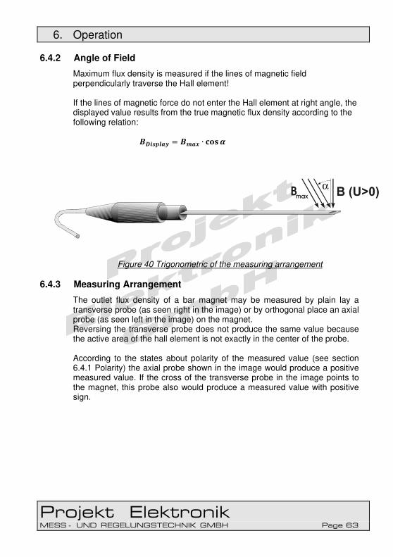
6. Operation
Projekt Elektronik MESS - UND REGELUNGSTECHNIK GMBH Page 63
6.4.2 Angle of Field
Maximum flux density is measured if the lines of magnetic field perpendicularly traverse the Hall element! If the lines of magnetic force do not enter the Hall element at right angle, the displayed value results from the true magnetic flux density according to the following relation: �������� = ��� ∙ ���
Figure 40 Trigonometric of the measuring arrangement
6.4.3 Measuring Arrangement
The outlet flux density of a bar magnet may be measured by plain lay a transverse probe (as seen right in the image) or by orthogonal place an axial probe (as seen left in the image) on the magnet. Reversing the transverse probe does not produce the same value because the active area of the hall element is not exactly in the center of the probe. According to the states about polarity of the measured value (see section 6.4.1 Polarity) the axial probe shown in the image would produce a positive measured value. If the cross of the transverse probe in the image points to the magnet, this probe also would produce a measured value with positive sign.

6. Operation
Projekt Elektronik MESS - UND REGELUNGSTECHNIK GMBH Page 64
Figure 41 Measuring arrangement bar magnet The field within a cylindrical coil is measurable with an axial probe. If a probe is feed into the coil the lines of field are along the probe axis. For the axial probe that is also the measuring direction. At the transverse probe the lines of field would be perpendicular to the measuring direction so no useable measuring signal may be generated. Like at the bar magnet with both probe types the outlet flux density may be measured. Here too the polarity (see section 6.4.1 Polarity) of the axial probe shown in the image will produce a positive measured value. If the cross of the transverse probe in the image points to the coil, this probe also would produce a measured value with positive sign.
Figure 42 Measuring arrangement cylindrical coil

6. Operation
Projekt Elektronik MESS - UND REGELUNGSTECHNIK GMBH Page 65
6.4.4 Precision and Repeatability
The flux density is a vector. To measure the exact value of that vector, the probe has to be highly perpendicular to the direction of the flux density. For example to measure a flux density of 1 T accurate to 1 mT, the angle deviation may not be lager than 2.56 °. To further illustration: At a rotation with a radius of 100 mm this is only a distance of 4.47 mm. The repeatability extremely depends on the quality of the mechanically fixation of the probe.
6.4.5 Winding up of Cables
Cables always should be wound up in a way that no knots or twists occur. To ease you the winding up of the cable we have collected and mentioned below some instructions available on the Internet.
• https://www.youtube.com/watch?v=0yPcJD7RVuY • https://www.youtube.com/watch?v=pEd7ru24Vx0 • https://www.youtube.com/watch?v=3j1Wdc-ymbI
• https://www.popularmechanics.com/technology/how-to/tips/a-solution-for-tangled-headphones-15413257
6.4.6 Transverse Probe AS-NTP 0,6
Figure 43 Transverse probe 0,6 The transverse probe has a blue protective cap which have to be unscrewed before measurement. Utmost care and attention are needed if magnets have to be measured that are not mechanically fixed. Clashing poles can destroy the Hall element! As the Hall element (ceramic) is very sensitive to pressure or shock, mechanical stress must be avoided (risk of breakage)!

6. Operation
Projekt Elektronik MESS - UND REGELUNGSTECHNIK GMBH Page 66
6.4.7 Transverse Probe Brass AS-NTM, AS-NTM-2, AS-LTM
Figure 44 Transverse probe brass
For fields of B > 20 mT and f > 10 kHz , probes brass should not be operated for more than 1 min in order to prevent excessive heating of the brass tube with the Hall element inside! Attention should be paid to the fact that at the probe a connection exist between GND, cable shield, plug housing and brass tube. Possibly an isolated installation of the probe can be necessary to prevent an unintended connection between measuring ground and protective earth.
6.4.8 Transverse Probe Hot AS-NTP-Hot-05
Figure 45 Transverse probe Hot The transverse probe has a protective cap which have to be drawn off before measurement. Only the probe, the handle and the cable are temperature-resistant. The probe connector with the electronic may only be operated up to +50 °C.
6.4.9 Transverse Probe Flex AS-NTP-Flex, AS-NTP-Flex 0,6
Figure 46 Transverse probe Flex

6. Operation
Projekt Elektronik MESS - UND REGELUNGSTECHNIK GMBH Page 67
Figure 47 Transverse probe Flex 0,6 The transverse probe has a protective cap which have to be drawn off before measurement. Only the probe itself is temperature-resistant. The handle, the cable and the probe connector with the electronic may only be operated up to +50 °C. No pressure shall be applied to the hall element (ceramic) because it is very pressure sensitive (risk of breaking)!
6.4.10 Transverse Probe Wire AS-NCu-Wire
Figure 48 Transverse probe Wire The wire probes are very sensitive. The wires of the probe may not be bend at the element and may not be pulled. Only the probe itself is temperature-resistant. The handle, the cable and the probe connector with the electronic may only be operated up to +50 °C. No pressure shall be applied to the hall element (ceramic) because it is very pressure sensitive (risk of breaking)!
6.4.11 Transverse Probe AS-VTP
Figure 49 Transverse probe AS-VTP
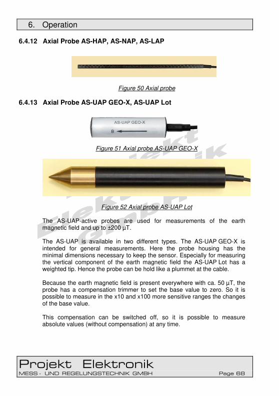
6. Operation
Projekt Elektronik MESS - UND REGELUNGSTECHNIK GMBH Page 68
6.4.12 Axial Probe AS-HAP, AS-NAP, AS-LAP
Figure 50 Axial probe
6.4.13 Axial Probe AS-UAP GEO-X, AS-UAP Lot
Figure 51 Axial probe AS-UAP GEO-X
Figure 52 Axial probe AS-UAP Lot The AS-UAP-active probes are used for measurements of the earth magnetic field and up to ±200 µT. The AS-UAP is available in two different types. The AS-UAP GEO-X is intended for general measurements. Here the probe housing has the minimal dimensions necessary to keep the sensor. Especially for measuring the vertical component of the earth magnetic field the AS-UAP Lot has a weighted tip. Hence the probe can be hold like a plummet at the cable. Because the earth magnetic field is present everywhere with ca. 50 µT, the probe has a compensation trimmer to set the base value to zero. So it is possible to measure in the x10 and x100 more sensitive ranges the changes of the base value. This compensation can be switched off, so it is possible to measure absolute values (without compensation) at any time.

6. Operation
Projekt Elektronik MESS - UND REGELUNGSTECHNIK GMBH Page 69
To be able to gain best stability in the 2 µT range the probe should be switched on for at least 30 minutes.
Figure 53 Controls connector AS-UAP connector housing switch for compensation trimmer for compensation The axis of the compensation trimmer should not be bend to not damage the axis or the trimmer.

6. Operation
Projekt Elektronik MESS - UND REGELUNGSTECHNIK GMBH Page 70
6.4.14 Usage of the AS-Active-Probes
6.4.14.1 Usage with the Teslameter FM 302
Usually the AS-active-probe is simply connected to the Teslameter. The measurement can be started immediately.
Figure 54 Usage of AS-active-probe with FM 302 Also all extended possibilities of the Teslameter FM 302 like calibrated analog output, control via USB interface or power supply with power adapter are usable in that way. Further details can be found in section 6.3.2 Usage of The Teslameter FM 302.
6.4.14.2 Usage as Autonomous Transducer
Our AS-active-probes can be operated stand-alone. Therefore they simply have to be supplied with ± 3 V (± 1 %) with max. 20 mA. The analog output signal can be feed e.g. into the input of a programmable amplifier of a PLC.

6. Operation
Projekt Elektronik MESS - UND REGELUNGSTECHNIK GMBH Page 71
Figure 55 Usage AS-probe at ±3 V The pin configuration of the probe is shown in the graphic below. All other pins are reserved for future use ore are only relevant in combination with the Teslameter FM 302. These pins have to remain unconnected.
Figure 56 Pin configuration AS-probe at ±3 V Like shown in the inner structure schematic the output signal at pin 1 is always referred to the ground signal at pin 2 and 3. This ground and the supply voltages +3 V (pin 4) and –3 V (pin 5) have to be provided from the outside. The AS-active-probes may not be powered with asymmetric voltages. It should be observed, the in the probe a connection between plug shield, plug case and cable shield is made. At probes with brass protective tube, this is also connected to shield. If used with Teslameter FM 302, AS-probe adapter or AS-Adapter 3 the shield is connected to GND. Possibly an isolated installation of the probe is necessary to prevent an unintended connection between measuring GND and protective earth.

6. Operation
Projekt Elektronik MESS - UND REGELUNGSTECHNIK GMBH Page 72
Figure 57 Structure AS-active-probe
6.4.14.3 Usage with the AS-Probe Adapter
To simplify the usage of the AS-active-probe as autonomous transducer, the AS-probe adapter can be used. It provides high stable ±3 V to supply the probe and amplifies the output signal to ±10 V. For further details see section 6.5.4 Usage of the AS-probe adapter.
6.4.14.4 Usage with the AS-Adapter 3
Up to three AS probes simultaneously can be operated on the AS-Adapter 3. The AS-Adapter 3 ensures the supply of all connected probes. Further details can be found in chapter 6.6.4 Usage of the AS-Adapter 3.
6.4.15 Zero Chamber (optional)
Optional a zero chamber is attainable for our instruments. The zero chamber is a one side closed pipe of good magnetic shielding metal where in the inside the magnetic field is strongly attenuated compared to the outer field. Normally at least the earth’s magnetic field has to be shielded. In addition there may be other interfering fields from the environment.

6. Operation
Projekt Elektronik MESS - UND REGELUNGSTECHNIK GMBH Page 73
Figure 58 Zero Chamber If necessary the zero point of an AS-active-probe may be checked and adjusted with the help of a zero chamber. Therefor the AS-probe is feed into the zero chamber. Now one can assume that the magnetic field is sufficient shielded. With the “zero” key of the Teslameter FM 302 (see section 6.3.1.7 Key “zero” – Offset Compensation) the display may set to zero in the most sensitive range. Further information about the zero chamber and its use can be found in our application note PE012 – zero chamber - zero adjustment.
6.4.16 Test Curves / Linearity Curves (optional)
Test Curves / linearity curves are optionally available for the AS-active-probes. The test curves / linearity curves are used for determining exact field values at up to five temperatures. These three curves serve to determine the deviation of the measuring instrument for specific field strength and temperature readings so as to correct the field values displayed. So a measurement accuracy of 0.1% is achievable. Each AS-active-probe have its own individual test curve / linearity curve. If an AS-probe is replaced, the test curve / linearity curve have to be renewed too. Examples of typical test curves / linearity curves can be found at our application note PE003 – Test Curves / Linearity Curves. The test curve / linearity curve serves as a test record. The following illustration shows an exemplary set of test curves / linearity curves:

6. Operation
Projekt Elektronik MESS - UND REGELUNGSTECHNIK GMBH Page 74
Figure 59 Typical test curves / linearity curves
-25
-20
-15
-10
-5
0
5
10
15
20
25
210-1-2
ΔB
[ mT ]
B
[ T ]
0,2 %
±0,2 mT
0°C
20°C
40°C

6. Operation
Projekt Elektronik MESS - UND REGELUNGSTECHNIK GMBH Page 75
6.5 AS-Probe Adapter
6.5.1 Controls and Connectors
Figure 60 Controls and connections AS-probe adapter supply voltage inputs GND for probe supply and
probe signal measurement signal output probe signal input ±3 V for probe supply power LED gain switch

6. Operation
Projekt Elektronik MESS - UND REGELUNGSTECHNIK GMBH Page 76
6.5.2 Structure
Figure 61 Structure AS-probe adapter The AS-probe adapter basically consists of two components, the voltage converter and the amplifier. The voltage converter has a wide input range which allows to supply the adapter with any constant voltage between 9 V and 36 V. The voltage converter also generates a galvanic isolation form the supply voltage. The potential difference between primary and secondary side is limited to 130 V by a varistor. Therefore the potential difference during operation should not exceed 100 V. The voltage converter generates high stable ±3 V necessary to supply the AS-active-probes. Furthermore it provides the voltage to supply the rest of the circuit. The amplifier boosts the probe signal from ±2 V to ±10 V (gain x5). With a switch an again ten times higher amplification (x50) can be selected. In this setting ±0.2 V are converted to ±10 V.

6. Operation
Projekt Elektronik MESS - UND REGELUNGSTECHNIK GMBH Page 77
6.5.2.1 Supply Voltage Inputs
With these inputs the AS-probe adapter is connected to the power supply. The adapter can be supplied with a DC voltage between 9 V and 36 V. Since the adapter internally uses a DC/DC converter the current consumption depends on the supply voltage. The higher the supply voltage, the lower the current which is drawn by the adapter. The input is equipped with an inverse polarity protection diode. Furthermore besides an overvoltage suppressor the input has a protection circuit which shortens the input in case of permanent overvoltage to protect the circuit. In this case the also integrated resettable fuse will trigger after a few moments. The threshold of the protection circuit is ~39 V. To reset the triggered protection circuit the adapter has to be disconnected from the power supply.
6.5.2.2 Power LED
This LED lights up if the adapter is correctly supplied with power. If the LED does not light up even though the adapter is connected to power supply maybe the overvoltage protection circuit has triggered.
6.5.2.3 Probe Supply
At these outputs the ±3 V necessary to supply the AS-active-probe is available. The outputs deliver a maximum current of 20 mA. The supply of the probe and the input of the probe signal use the same GND connection
6.5.2.4 Probe Signal Input
At this input the measurement signal delivered from the probe is connected. The maximal converted input voltage range is ±2 V with gain x5 and ±0.2 V with x50. The supply of the probe and the input of the probe signal use the same GND connection

6. Operation
Projekt Elektronik MESS - UND REGELUNGSTECHNIK GMBH Page 78
6.5.2.5 Measurement Signal Output
At this output the amplified measurement signal is available. At maximum amplitude the maximal output current is 2 mA. Correspondingly the load has to be at least 5 kΩ. For smaller amplitudes the output can deliver even higher currents. The outcome of the given current drive capability is that higher capacitive loads results in a reduction of bandwidth. Unloaded the amplifier has a bandwidth of >100 kHz whereby even fast transient signals can be transferred.
6.5.2.6 Gain Switch
With this switch the gain can be switched between x5 (±2 V → ±10 V) and x50 (±0.2 V → ±10 V).
6.5.3 Adapter Cable
With the AS-probe adapter an adapter cable is delivered. This cable has a 15pol SubD female connector at one site and four single wires at the other side. Therefore with this cable a AS-active-probe can easily be connected to the AS-probe adapter. The cable can be extended at the side of the SubD connector with probe extension cords as well as at the side of the single wires.
Figure 62 Adapter cable
The assignment of the single wires to the corresponding pins of the probe and the connectors of the AS-probe adapter can be found in the table below.

6. Operation
Projekt Elektronik MESS - UND REGELUNGSTECHNIK GMBH Page 79
wire color probe function connector adapter white probe signal IN ± yellow +3 V ±3V + green -3 V ±3V - brown ground IN ┴
Table 1
One should be aware, that the probes and all outputs have a common ground. Especially when using the brass version of AS-probes (AS-NTM, AS-LTM) an isolation between probe and other parts of the measurement setup can be necessary.
6.5.4 Usage of the AS-probe adapter
To use the AS-probe adapter three connections have to be made. At first the AS-active-probe is connected via the delivered adapter cable with the connectors “±3V” and “IN” of the AS-probe adapter. For connection assignment of the adapter cable see Table 1 on page 79. For power supply the input “PWR” has to be connected to a power supply which delivers a DC voltage between 9 V and 36 V. As third the output “OUT” has to be connected with the analog input of a data acquisition system like e.g. a PLC. The gain switch is set to the desired position (x5 or x50).
Figure 63 Connection AS-probe adapter

6. Operation
Projekt Elektronik MESS - UND REGELUNGSTECHNIK GMBH Page 80
6.6 AS-Adapter 3
6.6.1 Controls and Connectors
Figure 64 Controls and connectors AS-Adapter 3
Power LED Clamping contacts for output signals X, Y, Z
Clamping contacts for Power and PE
gain switch
Bridge for connection of Ground connection and GND
BNC Sockets output signals OUT X, OUT Y, OUT Z
Clamping contacts for input signals IN X, IN Y, IN Z
6.6.2 Overview of Controls and Connections
The AS adapter 3 consists of two components, the voltage converter and the amplifiers. The voltage converter has a wide-range input whereby the AS adapter 3 can be supplied with an operating voltage range of 9 VDC to 36 VDC. The signals and supply of the probes are galvanically isolated from the operating voltage. The potential difference between the primary and secondary side is limited to 130 V by a varistor.
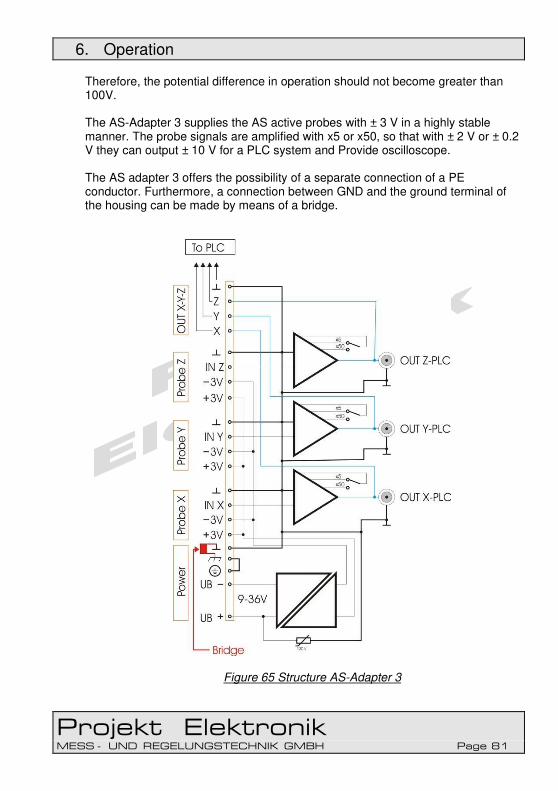
6. Operation
Projekt Elektronik MESS - UND REGELUNGSTECHNIK GMBH Page 81
Therefore, the potential difference in operation should not become greater than 100V. The AS-Adapter 3 supplies the AS active probes with ± 3 V in a highly stable manner. The probe signals are amplified with x5 or x50, so that with ± 2 V or ± 0.2 V they can output ± 10 V for a PLC system and Provide oscilloscope. The AS adapter 3 offers the possibility of a separate connection of a PE conductor. Furthermore, a connection between GND and the ground terminal of the housing can be made by means of a bridge.
Figure 65 Structure AS-Adapter 3
6. Operation
Projekt Elektronik MESS - UND REGELUNGSTECHNIK GMBH Page 82
6.6.2.1 Supply Voltage Inputs
With these inputs the AS-probe adapter is connected to the power supply. The adapter can be supplied with a DC voltage between 9 V and 36 V. Since the adapter internally uses a DC/DC converter the current consumption depends on the supply voltage. The higher the supply voltage, the lower the current which is drawn by the adapter. The input is equipped with an inverse polarity protection diode. Furthermore besides an overvoltage suppressor the input has a protection circuit which shortens the input in case of permanent overvoltage to protect the circuit. In this case the also integrated resettable fuse will trigger after a few moments. The threshold of the protection circuit is ~39 V. To reset the triggered protection circuit the adapter has to be disconnected from the power supply.
6.6.2.2 Power LED
This LED lights up if the adapter is correctly supplied with power. If the LED does not light up even though the adapter is connected to power supply maybe the overvoltage protection circuit has triggered.
6.6.2.3 Probe Supply
At these outputs, the AS-active probes required for supply are ± 3 V highly accurate. The outputs deliver a maximum current of 20 mA per AS-active probe. The supply for the probes and the inputs for the probe signals use the same GND connection.
6.6.2.4 Probe Signal Input
At this input the measurement signal delivered from the probe is connected. The maximal converted input voltage range is ±2 V with gain x5 and ±0.2 V with x50. The supply of the probe and the input of the probe signal use the same GND connection.
6.6.2.5 Measurement Signal Output
At this output the amplified measurement signal is available. At maximum amplitude the maximal output current is 2 mA. Correspondingly the load has to be at least 5 kΩ. For smaller amplitudes the output can deliver even higher currents.
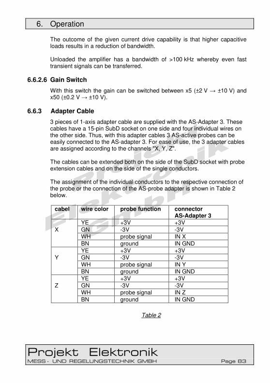
6. Operation
Projekt Elektronik MESS - UND REGELUNGSTECHNIK GMBH Page 83
The outcome of the given current drive capability is that higher capacitive loads results in a reduction of bandwidth. Unloaded the amplifier has a bandwidth of >100 kHz whereby even fast transient signals can be transferred.
6.6.2.6 Gain Switch
With this switch the gain can be switched between x5 (±2 V → ±10 V) and x50 (±0.2 V → ±10 V).
6.6.3 Adapter Cable
3 pieces of 1-axis adapter cable are supplied with the AS-Adapter 3. These cables have a 15-pin SubD socket on one side and four individual wires on the other side. Thus, with this adapter cables 3 AS-active probes can be easily connected to the AS-adapter 3. For ease of use, the 3 adapter cables are assigned according to the channels "X, Y, Z". The cables can be extended both on the side of the SubD socket with probe extension cables and on the side of the single conductors. The assignment of the individual conductors to the respective connection of the probe or the connection of the AS-probe adapter is shown in Table 2 below.
Table 2
cabel wire color probe function connector AS-Adapter 3
YE +3V +3V X GN -3V -3V
WH probe signal IN X BN ground IN GND YE +3V +3V
Y GN -3V -3V WH probe signal IN Y BN ground IN GND YE +3V +3V
Z GN -3V -3V WH probe signal IN Z BN ground IN GND

6. Operation
Projekt Elektronik MESS - UND REGELUNGSTECHNIK GMBH Page 84
Figure 66 Adapter cable „X, Y, Z”

6. Operation
Projekt Elektronik MESS - UND REGELUNGSTECHNIK GMBH Page 85
Attention should be paid that there is a connection between GND and cable shield as well as the connector housing in the adapter cable. At brass probes this is also connected to GND. Possibly an isolated installation of the probe is necessary to prevent an unintended connection between measuring GND and protective earth.
6.6.4 Usage of the AS-Adapter 3
There are three connections to use the AS-Adapter3. First, the AS active probes are connected to the "± 3V" and "IN X", "IN Y", "IN Z" terminals of the AS adapter 3 using the 3 enclosed adapter cables. For pin assignment of the adapter cable, see table 2 on page 80. For power supply, the input "Power" is connected to a voltage source, which provides a DC voltage between 9 V and 36 V. Third, the outputs "OUTX", "OUTY", "OUTX" are connected to the analog input of a measuring transducer, such as a PLC or connected to an oscilloscope. The gain switch is moved to the desired position (x5 or x50). On the following pages 86 and 87 two different connection options are shown.

6. Operation
Projekt Elektronik MESS - UND REGELUNGSTECHNIK GMBH Page 86
Figure 67 Connection AS-Adapter 3 with 1-axis AS-active probes

6. Operation
Projekt Elektronik MESS - UND REGELUNGSTECHNIK GMBH Page 87
Figure 68 Connection AS-Adapter 3 with 3-axis AS-active probe

Projekt Elektronik MESS - UND REGELUNGSTECHNIK GMBH Page 88
7. Technical Specifications
7.1 Teslameter FM 302 (without AS-Active-Probe):
Measuring modes DC / AC(RMS) Ranges 3 ranges per probe,
see technical specification of the AS-probes sensitivity x1; x10; x100 Bandwidth (-3 dB) DC: DC – ≥100 kHz AC: <5 Hz – ≥100 kHz depends also on the used probe Measurement uncertainty DC in x1: <0,1 % ±2 Digit (at 23 °C ±1 °C) in x10: <0,1 % ±5 Digit (at 23 °C ±1 °C) in x100: <0,1 % ±20 Digit (at 23 °C ±1 °C) after offset compensation with zero-function Adjustable offset ±4500 digit at most sensitive range (x100) Measurement uncertainty RMS 16.7 Hz: ≤-0.3 dB (at 23 °C ±1 °C) 50 Hz: ≤ -0.1 dB (at 23 °C ±1 °C) with level ≥5 % of range, sine wave Temperature coefficient max. ±0.01 %/K, typ. <±0.003 %/K Zero drift max. ±3 digit/1K, typ. ±1 digit/1K (DC at most
sensitive range Input resistance 10 kΩ ±0.1 % Operation keypad with 8 keys USB interface Operation temperature range +5 °C to +50 °C Storage temperature range -10 °C to +50 °C Max. relative humidity 70 % at +35 °C Operation in magnetic field undisturbed up to at least 350 mT observe action of force! Power 9 V battery at least 400 mAh battery or accumulator, life time > 20 h, depending on probe type, jack for 9 V power adapter 9 V DC, 40 mA, minus at inner port USB interface (low power device) Dimension:
Length 166 mm (without connected plugs) Width 88 mm (without connected plugs) Thickness 31 mm Weight 225 g (without 9 V battery) 271 g (with 9 V battery)

7. Technical Specifications
Projekt Elektronik MESS - UND REGELUNGSTECHNIK GMBH Page 89
LCD display:
Display 4½ digit two line LCD display Display range ±25100 digit Resolution 1/20.000 of each measurement range of probe (e.g. 0.1 mT at range of 2 T) Measuring modes mean value (DC) true effective value (AC / true RMS) Polarity sign (in DC) N(orth pole) or S(outh pole) (in DC) (with firmware version 1.4 and later) Measuring modes absolute measurement relative measurement minimal measurement maximal measurement absolute maximal measurement (with firmware version 1.4 and later) Display unit Tesla, Gauss, Oersted, A/m A/cm (with firmware version 1.4 and later and hardware version V2) Update rate given by measuring time Rise time RMS meas. typ. 0.3 s Measuring time settable 0.1 s (10 Hz) to 5 s (via keypad) or 25.5 s (via USB interface) Digital filter moving average filter with settable filter length 1 to 64 values Analog output:
Output voltage ±2.7 V Factor ±2 V per full scale of probe (e.g. range 2 T → factor 1 V/T) see also Table 5 at page 96 Bandwidth (-3 dB) DC: DC – ≥100 kHz AC: <5 Hz – ≥100 kHz depends also on the used probe Rise time < 2 µs Output connector BNC Output impedance 47 Ω

7. Technical Specifications
Projekt Elektronik MESS - UND REGELUNGSTECHNIK GMBH Page 90
USB Interface:
Connector USB-B jack Standard USB 1.1 / USB 2.0 compatible Driver Windows, Linux, Mac PC interface creates a virtual serial port Control via ASCII-commands Control Software at CD:
control possibilities all control possibilities accessible via the USB interface measured value display current measured value as number with unit value of the set display mode as number with unit oscilloscope-like display limit comparator oscilloscope display last 100 measured values display range as given by probe and sensitivity setting x1, x10, x100, x1000 file format as JPEG, PNG, BMP, TIFF, GIF or EMF image data logging single values via key press or continuously automatic Log format comma separated and period as decimal separator (CSV) semicolon separated and comma as decimal separator time stamp with 0.1 s resolution, measured value, unit Limit comparator with lower and upper limit display if measured value below, between or above limits possibility to ignore polarity display of the limits in oscilloscope display

7. Technical Specifications
Projekt Elektronik MESS - UND REGELUNGSTECHNIK GMBH Page 91
System requirements Windows with .NET Framework 4.0 available (since Windows XP) .NET Framework 4.0 (will be installed by control software) Source code as Visual Basic 2010 Express project Technical specifications are subject to change without prior notice!
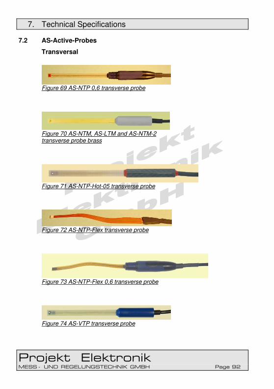
7. Technical Specifications
Projekt Elektronik MESS - UND REGELUNGSTECHNIK GMBH Page 92
7.2 AS-Active-Probes
Transversal
Figure 69 AS-NTP 0,6 transverse probe
Figure 70 AS-NTM, AS-LTM and AS-NTM-2 transverse probe brass
Figure 71 AS-NTP-Hot-05 transverse probe
Figure 72 AS-NTP-Flex transverse probe
Figure 73 AS-NTP-Flex 0,6 transverse probe
Figure 74 AS-VTP transverse probe

7. Technical Specifications
Projekt Elektronik MESS - UND REGELUNGSTECHNIK GMBH Page 93
Figure 75 AS-NCu-Wire transverse probe Wire Axial
Figure 76 AS-NAP, AS-LAP and AS-HAP axial probe
Figure 77 AS-UAP GEO-X axial probe
Figure 78 AS-UAP Lot axial probe

7. Technical Specifications
Projekt Elektronik MESS - UND REGELUNGSTECHNIK GMBH Page 94
7.2.1 Sensitivity Classes – Overview
Every AS-active-probe delivers a calibrated, analog output signal whose level depends on the measured field. Our probes are offered in different sensitivity classes. Table 3 shows the measuring ranges and transfer factors in dependence of the class.
class range probe without Teslameter
transfer factor probe
High: (1) 20 T 200 kG 15.915 MA/m 2 V / 20 T (1)
Normal: 2 T 20 kG 1591.5 kA/m 2 V / 2 T
Low: 0.2 T 2 kG 159.15 kA/m 2 V / 0,2 T
Verylow: 20 mT 200 G 15.915 kA/m 2 V / 20 mT
Ultralow: 200 µT 2 G 159.15 A/m 2 V / 200 µT
Table 3
(1) calibrated up to 12 T The Teslameter FM 302 offers the opportunity to switch the sensitivity between x1, x10 and x100. Thus with every probe a wide measuring range can be covered. Furthermore the Teslameter FM 302 offers switching of the display unit. Table 4 shows the resulting measuring ranges and Table 5 the transfer factors for the analog output.

7. Technical Specifications
Projekt Elektronik MESS - UND REGELUNGSTECHNIK GMBH Page 95
class ranges with Teslameter FM 302 (FM 205) range x1, x10, x100
High(1): x1 x10 x100
20.0002000.0200.00
T mT mT
200.0020.0002000.0
kG kG G
200.0020.0002000.0
kOe kOe Oe
Normal: x1 x10 x100
2000.0200.0020.000
mT mT mT
20.0002000.0200.00
kG G G
20.0002000.0200.00
kOe Oe Oe
Low: x1 x10 x100
200.0020.0002.0000
mT mT mT
2000.0200.0020.000
G G G
2000.0200.0020.000
Oe Oe Oe
Verylow: x1 x10 x100
20.0002.0000200.00
mT mT µT
200.0020.0002.0000
G G G
200.0020.0002.0000
Oe Oe Oe
Ultralow: x1 x10 x100
200.0020.0002.0000
µT µT µT
2.0000200.0020.000
G mG mG
2.0000200.0020.000
Oe mOe mOe
class ranges with Teslameter FM 302 (FM 205) range x1, x10, x100
High(1): x1 x10 x100
15.9151591.5159.15
MA/m kA/m kA/m
159.1515.9151591.5
kA/cm kA/cm A/cm
Normal: x1 x10 x100
1591.5159.1515.915
kA/m kA/m kA/m
15.9151591.5159.15
kA/cm A/cm A/cm
Low: x1 x10 x100
159.1515.9151.5915
kA/m kA/m kA/m
1591.5159.1515.915
A/cm A/cm A/cm
Verylow: x1 x10 x100
15.9151.5915159.15
kA/m kA/m A/m
159.1515.9151.5915
A/cm A/cm A/cm
Ultralow: x1 x10 x100
159.1515.9151.5915
A/m A/m A/m
1.5915159.1515.915
A/cm mA/cm mA/cm
Table 4
(1) calibrated up to 12 T

7. Technical Specifications
Projekt Elektronik MESS - UND REGELUNGSTECHNIK GMBH Page 96
class transfer factors with Teslameter FM 302 (FM 205) range x1, x10, x100
High: x1 x10 x100
2 V / 20 T (1) 2 V / 2 T 2 V / 0,2 T
Normal: x1 x10 x100
2 V / 2000 mT 2 V / 200 mT 2 V / 20 mT
Low: x1 x10 x100
2 V / 200 mT 2 V / 20 mT 2 V / 2 mT
Verylow: x1 x10 x100
2 V / 20 mT 2 V / 2 mT 2 V / 200 µT
Ultralow: x1 x10 x100
2 V / 200 µT 2 V / 20 µT 2 V / 2 µT
Table 5
(1) calibrated up to 12 T
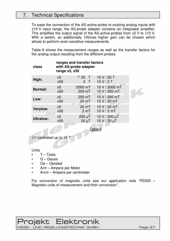
7. Technical Specifications
Projekt Elektronik MESS - UND REGELUNGSTECHNIK GMBH Page 97
To ease the connection of the AS-active-probe to existing analog inputs with ±10 V input range, the AS-probe adapter contains an integrated amplifier. This amplifies the output signal of the AS-active-probes from ±2 V to ±10 V. With a switch, an additionally 10times higher gain can be chosen which allows to perform even sensitive measurements. Table 6 shows the measurement ranges as well as the transfer factors for the analog output resulting from the different probes.
class ranges and transfer factors with AS-probe adapter range x5, x50
High: x5 x50
(1) 20 T 2 T
10 V / 20 T 10 V / 2 T
Normal: x5 x50
2000 mT 200 mT
10 V / 2000 mT 10 V / 200 mT
Low: x5 x50
200 mT 20 mT
10 V / 200 mT 10 V / 20 mT
Verylow: x5 x50
20 mT 2 mT
10 V / 20 mT 10 V / 2 mT
Ultralow: x5 x50
200 µT 20 µT
10 V / 200 µT 10 V / 20 µT
Table 6
(1) calibrated up to 12 T Units • T – Tesla • G – Gauss • Oe – Oersted
• A/m – Ampere per Meter • A/cm – Ampere per centimeter For conversion of magnetic units see our application note “PE005 – Magnetic units of measurement and their conversion”.

7. Technical Specifications
Projekt Elektronik MESS - UND REGELUNGSTECHNIK GMBH Page 98
7.2.2 AS-active-probes – Overview Normal
For most application our AS-active-probe of class normal are suited. The fields typically occurring in technical areas can be measured with this probes.
class model type linearity error (2) thick mm
operation temp. °C
Normal:
AS-NTP 0,6 T < 0.5 % ±0.2 mT 0.6 ± 0.1 5 – 100 (4)
AS-NTM T-Ms < 0.2 % ±0.2 mT 1.4 ± 0.1 5 – 50
AS-NTM-2 T-Ms < 0.05% ±0.2 mT 1.4 ± 0.1 5 – 50
AS-NAP A < 0.5 % ±0.2 mT Ø 6.0 5 – 50
AS-NTP-Hot-05 T < 0.5 % ±0.2 mT 1.5 ± 0.1 -40 – 150 (3)
AS-NTP-Flex T < 0.5 % ±0.2 mT
up to 1.5 T 0.6 ± 0.1 5 – 100 (4)
AS-NTP-Flex 0,6
T < 0.5 % ±0.2 mT 0.6 ± 0.1 5 – 150 (4)
AS-NCu-Wire T < 0.5 % ±0,2 mT
up to 1.5 T 0.6 ± 0.1 5 – 100 (5)
Table 7
(2) at +20 °C or +25 °C (3) probe, handle and cable = -40 °C to +150 °C; probe plug = +5 °C to +50 °C (4) at first 70 mm = +5 °C to +100 °C; handle, cable and probe plug = +5 °C to +50 °C (5) at first 150 mm = +5 °C to +100 °C; handle, cable and probe plug = +5 °C to +50 °C (7) at first 70 mm = +5 °C to +150 °C;
handle, cable and probe plug = +5 °C to +50 °C

7. Technical Specifications
Projekt Elektronik MESS - UND REGELUNGSTECHNIK GMBH Page 99
7.2.3 AS-active-probes – Overview Earth Magnetic Field
For the measurement of very small fields like e.g. the earth magnetic field we offer our probes of class Ultralow. With the possibility of compensation of ±70 µT the overlaying earth magnetic field can be masked. So even very small stray and noise fields can be measured with this probes.
class model type linearity error (2) thick mm
operation temp. °C
Ultralow:
AS-UAP GEO-X A < 0.8 % ±0.2 µT Ø 17 5 – 50
AS-UAP Lot A < 0.8 % ±0.2 µT Ø 18.8 5 – 50
Table 8
(2) at +20 °C or +25 °C
7.2.4 AS-active-probes – Overview High Field
Especially for the measurement of very high field the probe AS-HAP of class High has been developed. Such high permanent fields are normally only achieved with superconductors. Temporary they can be generated with other setups, too.
class model type linearity error (2) thick mm
operation temp. °C
High: AS-HAP A < 2.0 % ±20 mT Ø 6.4 5 – 50
Table 9 (2) at +20 °C or +25 °C

7. Technical Specifications
Projekt Elektronik MESS - UND REGELUNGSTECHNIK GMBH Page 100
7.2.5 AS-active-probes – Overview Low Field
If only small fields shall be measured, also the probes of class Low can be used.
class model type linearity error (2) thick mm
operation temp. °C
Low:
AS-LTM T-Ms < 0.2 % ±0.1 mT 1.4 ± 0.1 5 – 50
AS-LAP A < 0.5 % ±0.1 mT Ø 6.0 5 – 50
Table 10
(2) at +20 °C or +25 °C
7.2.6 AS-active-probes – Overview Very Low Field
For even smaller fields, probes of class verylow can be used. Typically they are used to measure residual magnetism at produced parts or to control compliance with limit values (e.g. employee safety, pacemaker).
class model type linearity error (8) thick mm
operation temp. °C
Verylow: AS-VTP T < 0.5 % ±10 mT 1.7 ± 0.1 5 – 50
Table 11
(8) at +23 °C

7. Technical Specifications
Projekt Elektronik MESS - UND REGELUNGSTECHNIK GMBH Page 101
7.2.7 AS-active-probes – Overview Further Data
class model bandwidth (-3 dB)
active area temperature coefficient or. error
High: AS-HAP DC – 35 kHz 0.2 mm² -0.05 %/K
Normal:
AS-NTP 0,6 DC – 35 kHz 0.2 mm² -0.03 %/K
AS-NTM DC – 25 kHz 0.2 mm² -0.03 %/K
AS-NTM-2 DC – 25 kHz 0.12 mm² ±0,005 %/K
AS-NAP DC – 35 kHz 0.2 mm² -0.03 %/K
AS-NTP-Hot-05 DC – 35 kHz 0.5 mm² ±1.0% ±0.4 mT (6)
AS-NTP-Flex DC – 0.5 kHz 2 mm² -0.03 %/K
AS-NTP-Flex 0,6
DC – 35 kHz 0.2 mm² -0.03 %/K
AS-NCu-Wire DC – 35 kHz 2 mm² -0.03 %/K
Low:
AS-LTM DC – 10 kHz 0.2 mm² -0.03 %/K
AS-LAP DC – 10 kHz 0.2 mm² -0.03 %/K
Verylow: AS-VTP DC – 1 kHz 0.02 mm² ±0.03 %/K
Ultralow:
AS-UAP GEO-X
DC – 0.5 kHz Ø 5 mm x 22 mm
±0.1 %/K
AS-UAP Lot DC – 0.5 kHz Ø 5 mm x 22 mm
±0.1 %/K
Table 12
(6) in range of –10 °C to +150 °C

7. Technical Specifications
Projekt Elektronik MESS - UND REGELUNGSTECHNIK GMBH Page 102
7.2.8 Axial Probe 12 T (AS-HAP)
Figure 79 Size axial probe 12 T (AS-HAP)
Ranges (with FM 302) ±0.2 T; ±2 T; ±20 T (calibrated up to ±12 T) Stem size (L x Ø) 180 mm x 6.4 mm CFRP Effective area 0.2 mm² Transfer factor 0.1 V/T Bandwidth (-3 dB) 0 – 35 kHz Rise time <3 µs Linearity error <2,0 % ±20 mT (at 20 °C) Temperature coefficient max. -0.1 %/K, typ. -0.05 %/K (0 to 50 °C) Zero drift max. ±0.05 mT/K, typ. 0.03 mT/K (DC) Noise typ. 173 µTRMS (10 Hz – 10 kHz) typ. 43 µTPP (DC – 10 Hz, 50 s) Operation temperature +5 °C to +50 °C Storage temperature -10 °C to +60 °C Max. relative humidity 70 % at +35 °C Power ±3 V through FM 302, AS-probe adapter, AS-Adapter 3 or PLC Connector 15 pol. SubD Output impedance <1 Ω Length of cable 2.95 m Technical specifications are subject to change without prior notice!

7. Technical Specifications
Projekt Elektronik MESS - UND REGELUNGSTECHNIK GMBH Page 103
7.2.9 Transverse Probe 2000 mT (AS-NTP 0,6)
Figure 80 Size transverse probe 2000 mT (AS-NTP 0,6) Ranges (with FM 302) ±20 mT; ±200 mT; ±2000 mT Stem size (L x W x T) 70 mm x 5 mm x 0,6 mm GFRP Effective area 0.2 mm² Transfer factor 1 V/T Bandwidth (- 3 dB) 0 - 35 kHz Rise time <3 µs Linearity error <0.5 % ±0.2 mT (at 20 °C ±1 °C) Temperature coefficient max. -0.05 %/K, typ. -0.03 %/K (0 to 50 °C) Zero drift max. ±0.020 mT/K, typ. ±0.010 mT/K (DC) Noise typ. 21 µTRMS (10 Hz – 10 kHz) typ. 18 µTPP (DC – 10 Hz, 50 s) Operation temperature +5 °C to +100 °C (only at first 70 mm) +5 °C to +50 °C (grip, cable, probe connector) Storage temperature -10 °C to +60 °C Max. relative humidity 70 % at +35 °C Power ±3 V through FM 302, AS-probe adapter, AS-Adapter 3 or PLC Connector 15 pol. SubD Output impedance <1 Ω Length of cable 1.5 m Technical specifications are subject to change without prior notice!

7. Technical Specifications
Projekt Elektronik MESS - UND REGELUNGSTECHNIK GMBH Page 104
7.2.10 Transverse Probe Brass 2000 mT (AS-NTM)
Figure 81 Size transverse probe brass 2000 mT (AS-NTM) Ranges (with FM 302) ±20 mT; ±200 mT; ±2000 mT Stem size (L x W x T) 70 mm x 5 mm x 1,4 mm Brass Effective area 0.2 mm² Transfer factor 1 V/T Bandwidth (-3 dB) 0 - 25 kHz Rise time <6 µs Linearity error <0.2 % ±0.2 mT (at 20 °C ±1 °C) Temperature coefficient max. -0.05 %/K, typ. -0.03 %/K (0 to 50 °C) Zero drift max. ±0.020 mT/K, typ. ±0.010 mT/K (DC) Noise typ. 21 µTRMS (10 Hz – 10 kHz) typ. 18 µTPP (DC – 10 Hz, 50 s) Operation temperature +5 °C to +50 °C Storage temperature -10 °C to +60 °C Max. relative humidity 70 % at +35 °C Power ±3 V through FM 302, AS-probe adapter, AS-Adapter 3 or PLC Connector 15 pol. SubD Output impedance <1 Ω Length of cable 1.5 m Technical specifications are subject to change without prior notice!

7. Technical Specifications
Projekt Elektronik MESS - UND REGELUNGSTECHNIK GMBH Page 105
7.2.11 Transverse Probe Brass with Very High Precision 2000 mT (AS-NTM-2)
Figure 82 Size transverse probe brass 2000 mT (AS-NTM-2) Ranges (with FM 302) ±20 mT; ±200 mT; ±2000 mT Stem size (L x W x T) 70 mm x 5 mm x 1,4 mm Brass Effective area 0.12 mm² Transfer factor 1 V/T Bandwidth (- 3 dB) 0 – 25 kHz Rise time <6 µs Linearity error <0.05 % ±0.2 mT (DC, at 20 °C ±1 °C) Temperature coefficient max. ±0.005 %/K (5 °C to 50 °C) Zero drift max. ±0.005 mT/K, typ. ±0.003 mT/K Noise typ. 21 µTRMS (10 Hz – 10 kHz) typ. 12 µTPP (DC – 10 Hz, 50 s) Operation temperature +5 °C to +50 °C Storage temperature -10 °C to +60 °C Max. relative humidity 70 % at +35 °C Power ±3 V through FM 302, AS-probe adapter, AS-Adapter 3 or PLC Connector 15 pol. SubD Output impedance <1 Ω Length of cable 1.5 m Technical specifications are subject to change without prior notice!

7. Technical Specifications
Projekt Elektronik MESS - UND REGELUNGSTECHNIK GMBH Page 106
7.2.12 Axial Probe 2000 mT (AS-NAP)
Figure 83 Size axial probe 2000 mT (AS-NAP) Ranges (with FM 302) ±20 mT; ±200 mT; ±2000 mT Stem size (L x Ø) 180 mm x 6.0 mm CFRP Effective area 0.2 mm² Transfer factor 1 V/T Bandwidth (- 3 dB) 0 - 35 kHz Rise time <3 µs Linearity error <0.5 % ±0.2 mT (at 20 °C ±1 °C) Temperature coefficient max. -0.05 %/K, typ. -0.03 %/K (0 to 50 °C) Zero drift max. ±0.020 mT/K, typ. ±0.010 mT/K (DC) Noise typ. 21 µTRMS (10 Hz – 10 kHz) typ. 18 µTPP (DC – 10 Hz, 50 s) Operation temperature +5 °C to +50 °C Storage temperature -10 °C to +60 °C Max. relative humidity 70 % at +35 °C Power ±3 V through FM 302, AS-probe adapter, AS-Adapter 3 or PLC Connector 15 pol. SubD Output impedance <1 Ω Length of cable 1.5 m Technical specifications are subject to change without prior notice!

7. Technical Specifications
Projekt Elektronik MESS - UND REGELUNGSTECHNIK GMBH Page 107
7.2.13 Transverse Probe Hot with Improved Temperature Characteristics 2000 mT (AS-NTP-Hot-05)
Figure 84 Size transverse probe Hot 2000 mT (AS-NTP-Hot-05)
Ranges (with FM 302) ±20 mT; ±200 mT; ±2000 mT Stem size (L x W x T) 70 mm x 6 mm x 1,4 mm GFRP Effective area 0.5 mm2 Transfer factor 1 V/T Bandwidth (- 3 dB) 0 - 35 kHz Rise time <3 µs Linearity error <0.5 % ±0.2 mT (at 20 °C ± 1 °C) Temperature error <±1.0 % ±0.4 mT (-10 °C to +150 °C) Noise typ. 21 µTRMS (10 Hz – 10 kHz) typ. 18 µTPP (DC – 10 Hz, 50 s) Operation temperature -40 °C to +150 °C (only probe, grip and cable) +5 °C to +50 °C (probe connector) Storage temperature -10 °C to +60 °C Max. relative humidity 70 % at +35 °C Power ±3 V through FM 302, AS-probe adapter, AS-Adapter 3 or PLC Connector 15 pol. SubD Output impedance <1 Ω Length of cable 2.95 m
Technical specifications are subject to change without prior notice!

7. Technical Specifications
Projekt Elektronik MESS - UND REGELUNGSTECHNIK GMBH Page 108
7.2.14 Transverse Probe Flex 2000 mT (AS-NTP-Flex)
Figure 85 Size transverse probe Flex 2000 mT (AS-NTP-Flex) Ranges (with FM 302) ±20 mT; ±200 mT; ±2000 mT Stem size (L x W x T) 70 mm x 4 mm x 0,55 mm (on the top) Kapton Effective area 2 mm2 Transfer factor 1 V/T Bandwidth (-3 dB) 0 - 0.5 kHz Rise time <0.2 ms Linearity error <0.5 % ±0.2 mT (0 to ±1.5 T, at 20 °C ±1 °C) Temperature coefficient max. -0.05 %/K, typ. -0.03 %/K (0 to 50 °C) Zero drift max. ±0.020 mT/K, typ. ±0.010 mT/K (DC) Noise typ. 7,5 µTRMS (10 Hz – 1 kHz) typ. 13 µTPP (DC – 10 Hz, 50 s) Operation temperature +5 °C to +100 °C (only at first 70 mm) +5 °C to +50 °C (grip, cable, probe connector) Storage temperature -10 °C to +60 °C max. relative humidity 70 % at +35 °C Power ±3 V through FM 302, AS-probe adapter, AS-Adapter 3 or PLC Connector 15 pol. SubD Output impedance <1 Ω Length of cable 1.5 m Technical specifications are subject to change without prior notice!

7. Technical Specifications
Projekt Elektronik MESS - UND REGELUNGSTECHNIK GMBH Page 109
7.2.15 Transverse Probe Flex 2000 mT (AS-NTP-Flex 0,6) )
Figure 86 Size transverse probe Flex 2000 mT (AS-NTP-Flex 0,6)
Ranges (with FM 302) ±20 mT; ±200 mT; ±2000 mT Stem size (L x W x T) 70 mm x 5 mm x 0,6 ±0,1 mm Kapton Effective area 0.2 mm2 Transfer factor 1 V/T Bandwidth (- 3 dB) 0 - 35 kHz Rise time <3 µs Linearity error <0.5 % ±0.2 mT (at 20 °C ±1 °C) Temperature coefficient max. -0.05 %/K, typ. -0.03 %/K (0 to 50 °C) Zero drift max. ±0.020 mT/K, typ. ±0.010 mT/K (DC) Noise typ. 21 µTRMS (10 Hz – 10 kHz) typ. 18 µTPP (DC – 10 Hz, 50 s) Operation temperature +5 °C to +150 °C (only at first 70 mm) +5 °C to +50 °C (grip, cable, probe connector) Storage temperature -10 °C to +60 °C max. relative humidity 70 % at +35 °C Power ±3 V through FM 302, AS-probe adapter, AS-Adapter 3 or PLC Connector 15 pol. SubD Output impedance <1 Ω
Length of cable 1.5 m
Technical specifications are subject to change without prior notice!

7. Technical Specifications
Projekt Elektronik MESS - UND REGELUNGSTECHNIK GMBH Page 110
7.2.16 Transverse Probe Wire 2000 mT (AS-NCu-Wire)
Figure 87 Size transverse probe Wire 2000 mT (AS-NCu-Wire)
Ranges (with FM 302) ±20 mT; ±200 mT; ±2000 mT Sensor thickness / guide 0,6 ±0,1 mm x approximately 150 mm Effective area 2 mm x 1 mm Transfer factor 1 V/T Bandwidth (-3 dB) 0 – 35 kHz Rise time <3 µs Linearity error <0.5 % ±0,2 mT (0 to ±1.5 T, at 20 °C ±1 °C) Temperature coefficient max. -0.05 %/K, typ. -0.03 %/K (0 to 50 °C) Zero drift max. ±0.020 mT/K, typ. ±0.010 mT/K (DC) Noise typ. 25 µTRMS (10 Hz – 10 kHz) typ. 15 µTPP (DC – 10 Hz, 50 s) Operation temperature +5 °C to +100 °C (only at first 150 mm) +5 °C to +50 °C (grip, cable, probe connector) Storage temperature -10 °C to +60 °C Max. relative humidity 70 % at +35 °C Power ±3 V through FM 302, AS-probe adapter, AS-Adapter 3 or PLC Connector 15 pol. SubD Output impedance <1 Ω Length of cable 1.5 m
Technical specifications are subject to change without prior notice!

7. Technical Specifications
Projekt Elektronik MESS - UND REGELUNGSTECHNIK GMBH Page 111
7.2.17 Transverse Probe Brass 200 mT (AS-LTM)
Figure 88 Size transverse probe brass 200 mT (AS-LTM) Ranges (with FM 302) ±2 mT; ±20 mT; ±200 mT Stem size (L x W x T) 70 mm x 5 mm x 1.4 ±0.1 mm Brass Effective area 0.2 mm2 Transfer factor 10 V/T Bandwidth (-3 dB) 0 to 10 kHz Rise time <30 µs Linearity error <0.2 % ±0.1 mT (at 25 °C ±1 °C) Temperature coefficient max. -0.05 %/K, typ. -0.03 %/K (0 to 50 °C) Zero drift max. ±0.010 mT/K, typ. ±0.005 mT/K (DC) Noise typ. 14 µTRMS (10 Hz – 10 kHz) typ. 34 µTPP (DC – 10 Hz, 50 s) Operation temperature +5 °C to +50 °C Storage temperature -10 °C to +60 °C max. relative humidity 70 % at +35 °C Power ±3 V through FM 302, AS-probe adapter, AS-Adapter 3 or PLC Connector 15 pol. SubD Output impedance <1 Ω Length of cable 1.5 m
Technical specifications are subject to change without prior notice!

7. Technical Specifications
Projekt Elektronik MESS - UND REGELUNGSTECHNIK GMBH Page 112
7.2.18 Axial Probe 200 mT (AS-LAP)
Figure 89 Size axial probe 200 mT (AS-LAP) Ranges (with FM 302) ±2 mT; ±20 mT; ±200 mT Stem size (L x Ø) 180 mm x 6.0 mm CFRP Effective area 0.2 mm2 Transfer factor 10 V/T Bandwidth (-3 dB) 0 – 10 kHz Rise time <30 µs Linearity error <0.5 % ±0.1 mT (at 25 °C ±1 °C) Temperature coefficient max. -0.05 %/K, typ. -0.03 %/K (0 to 50 °C) Zero drift max. ±0.010 mT/K, typ. ±0.005 mT/K (DC) Noise typ. 14 µTRMS (10 Hz – 10 kHz) typ. 34 µTPP (DC – 10 Hz, 50 s) Operation temperature +5 °C to +50 °C Storage temperature -10 °C to +60 °C Max. relative humidity 70 % at +35 °C Power ±3 V through FM 302, AS-probe adapter, AS-Adapter 3 or PLC Connector 15 pol. SubD Output impedance <1 Ω Length of cable 1.5 m
Technical specifications are subject to change without prior notice!
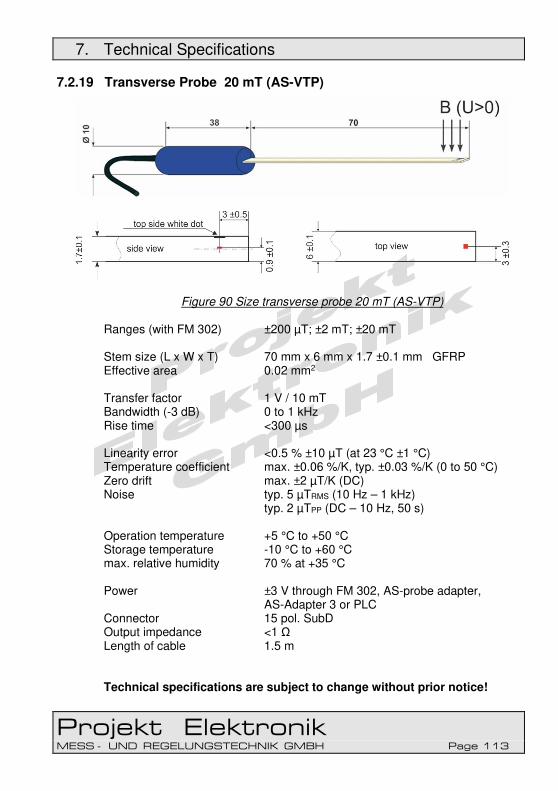
7. Technical Specifications
Projekt Elektronik MESS - UND REGELUNGSTECHNIK GMBH Page 113
7.2.19 Transverse Probe 20 mT (AS-VTP)
Figure 90 Size transverse probe 20 mT (AS-VTP) Ranges (with FM 302) ±200 µT; ±2 mT; ±20 mT Stem size (L x W x T) 70 mm x 6 mm x 1.7 ±0.1 mm GFRP Effective area 0.02 mm2 Transfer factor 1 V / 10 mT Bandwidth (-3 dB) 0 to 1 kHz Rise time <300 µs Linearity error <0.5 % ±10 µT (at 23 °C ±1 °C) Temperature coefficient max. ±0.06 %/K, typ. ±0.03 %/K (0 to 50 °C) Zero drift max. ±2 µT/K (DC) Noise typ. 5 µTRMS (10 Hz – 1 kHz) typ. 2 µTPP (DC – 10 Hz, 50 s) Operation temperature +5 °C to +50 °C Storage temperature -10 °C to +60 °C max. relative humidity 70 % at +35 °C Power ±3 V through FM 302, AS-probe adapter, AS-Adapter 3 or PLC Connector 15 pol. SubD Output impedance <1 Ω Length of cable 1.5 m Technical specifications are subject to change without prior notice!

7. Technical Specifications
Projekt Elektronik MESS - UND REGELUNGSTECHNIK GMBH Page 114
7.2.20 GEO-X Axial Probe 200 µT (AS-UAP GEO-X)
Figure 91 Size GEO-X axial probe 200 µT (AS-UAP GEO-X) Ranges (with FM 302) ±2 µT; ±20 µT; ±200 µT Case size (L x Ø) 64 mm x 17 mm Effective volume Ø 5 mm x 22 mm Transfer factor 1 V / 100 µT Bandwidth (-3 dB) 0 – 800 Hz (2 µT- / 20 µT-range) 0 – 500 Hz (200 µT-range) Rise time <0.3 ms Linearity error <0.8 % ±0.2 µT (at 25 °C) Temperature coefficient max. ±0.1 %/K (10 °C to 50 °C) Zero drift max. ±10 nT/K Hysteresis max. 0.1 % of value magnetic flux density max. ±200 µT or 140 µTeff Noise typ. 4,5 nTRMS (10 Hz – 1 kHz) typ. 6 nTPP (DC – 10 Hz, 50 s) Operation temperature +5 °C to +50 °C Storage temperature -10 °C to +60 °C Max. relative humidity 70 % at +35 °C Power ±3 V through FM 302, AS-probe adapter, AS-Adapter 3 or PLC Connector 15 pol. SubD Output impedance <1 Ω Length of cable 1.5 m Technical specifications are subject to change without prior notice!

7. Technical Specifications
Projekt Elektronik MESS - UND REGELUNGSTECHNIK GMBH Page 115
7.2.21 Lot Axial Probe 200 µT (AS-UAP Lot)
Figure 92 Size Lot axial probe 200 µT (AS-UAP Lot) Ranges (with FM 302) ±2 µT; ±20 µT; ±200 µT Case size (L x Ø) 150 mm x Ø 18,8 mm Brass Effective volume Ø 6 mm x 25 mm Transfer factor 1 V / 100 µT Bandwidth (-3 dB) 0 – 800 Hz (2 µT- / 20 µT-range) 0 – 500 Hz (200 µT-range) Rise time <0.3 ms Linearity error <0.8 % ±0.2 µT (at 25 °C) Temperature coefficient max. ±0.1 %/K (10 °C to 50 °C) Zero drift max. ±10 nT/K Hysteresis max. 0.1 % of value magnetic flux density max. ±200 µT or 140 µTeff Noise typ. 4,5 nTRMS (10 Hz – 1 kHz) typ. 6 nTPP (DC – 10 Hz, 50 s) Operation temperature +5 °C to +50 °C Storage temperature -10 °C to +60 °C Max. relative humidity 70 % at +35 °C Power ±3 V through FM 302, AS-probe adapter, AS-Adapter 3 or PLC Connector 15 pol. SubD Output impedance <1 Ω Length of cable 1.5 m Technical specifications are subject to change without prior notice!
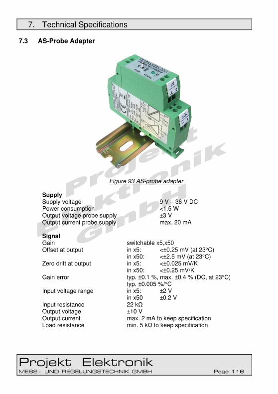
7. Technical Specifications
Projekt Elektronik MESS - UND REGELUNGSTECHNIK GMBH Page 116
7.3 AS-Probe Adapter
Figure 93 AS-probe adapter Supply Supply voltage 9 V – 36 V DC Power consumption <1.5 W Output voltage probe supply ±3 V Output current probe supply max. 20 mA Signal Gain switchable x5,x50 Offset at output in x5: <±0.25 mV (at 23°C) in x50: <±2.5 mV (at 23°C) Zero drift at output in x5: <±0.025 mV/K in x50: <±0.25 mV/K Gain error typ. ±0.1 %, max. ±0.4 % (DC, at 23°C) typ. ±0.005 %/°C Input voltage range in x5: ±2 V in x50 ±0.2 V Input resistance 22 kΩ Output voltage ±10 V Output current max. 2 mA to keep specification Load resistance min. 5 kΩ to keep specification

7. Technical Specifications
Projekt Elektronik MESS - UND REGELUNGSTECHNIK GMBH Page 117
Short-circuit proof yes Output resistance <1 Ω Bandwidth (-3 dB) 100 kHz depends also on the used probe Isolation Galvanic isolation supply – signal: 100VDC, 70VAC with varistor protection mechanics Housing Phoenix COMBICON DIN-rail housing width 20 mm Operation temperature +5 °C to +50 °C Storage temperature -10 °C to +50 °C Adapter cable for probe connection: Connectors probe side: 15pol SubD female connector adapter side: 4 single wires Structure 4pol, shielded shield and connector housing connected to analog ground! Length 5 m Technical specifications are subject to change without prior notice!
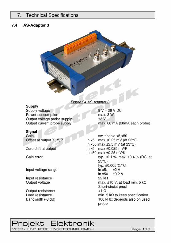
7. Technical Specifications
Projekt Elektronik MESS - UND REGELUNGSTECHNIK GMBH Page 118
7.4 AS-Adapter 3
Figure 94 AS-Adapter 3 Supply Supply voltage 9 V – 36 V DC Power consumption max. 3 W Output voltage probe supply ±3 V Output current probe supply max. 60 mA (20mA each probe) Signal Gain switchable x5,x50 Offset at output X, Y, Z: in x5: max ±0.25 mV (at 23°C) in x50: max ±2.5 mV (at 23°C) Zero drift at output in x5: max ±0.025 mV/K in x50: max ±0.25 mV/K Gain error typ. ±0.1 %, max. ±0.4 % (DC, at
23°C) typ. ±0.005 %/°C Input voltage range in x5: ±2 V in x50 ±0.2 V Input resistance 22 kΩ Output voltage max. ±10 V, at load min. 5 kΩ
Short-circiut proof Output resistance <1 Ω Load resistance min. 5 kΩ to keep specification Bandwidth (-3 dB) 100 kHz; depends also on used
probe

7. Technical Specifications
Projekt Elektronik MESS - UND REGELUNGSTECHNIK GMBH Page 119
Isolation Galvanic isolation supply – signal: 100VDC, 70VAC With
varistor protection Bridge option: PE-GND
Bridge option: GND-Case Mechanics Case Alu-Style-Case isolated with
bumpers, DIN rail with table feet, Operating temperature +5°C bis +50°C Storage temperature -10°C bis +65°C Dimensions 135 x 105 x 53 mm (L x B x H) Weight (incl. Adapter Cable) 1045 g Adapter Cable for Probe Connection For 3x 1-axis AS-Active probe or 1x 3-achsige AS-Active probe
Connector 3 piece:
probe side: 3x15polige SubD socket
Adapter side: 3x4 single leads Setup 4pole, screened screen and socket house to analog-ground! Length 5 m
Technical specifications are subject to change without prior notice!

Projekt Elektronik MESS - UND REGELUNGSTECHNIK GMBH Page 120
8. Maintenance
8.1 Visual Inspection
Be sure before any measurement that the probe itself, the probe cable, the probe housing, the Teslameter housing, the power adapter and the power cord are undamaged and in a proper safety condition. Check that the housing shows no cracks.
Check the cables for breakage or chafing.
Check the probe for cracks or similar damage.
Check the power adapter for cracks.
8.2 Checking Battery
To check the battery of the Teslameter FM 302 open the battery compartment on the rear (remove and lift the lid from the instrument). The battery can be removed now. Check the battery for leaked fluid at regular three-months intervals, but in any case after extended inactivity. If the battery is low (see section 6.3.1.6 for FM 302), replace it by a fresh 9 V E-block, e.g. Panasonic type 6LR61. Pay attention to polarity when inserting a new battery!
8.3 Maintaining Accumulators
If the instrument is run with a 9 V block accumulator, it must be checked for leaked fluid at regular monthly intervals, but after extended inactivity at any rate. Accumulators have a self-discharge. That means that the accumulator looses charge even if the device is switched off. To check the accumulator of the Teslameter FM 302 open the battery compartment on the rear (remove and lift the lid from the instrument). The accumulator can be removed now.

8. Maintenance
Projekt Elektronik MESS - UND REGELUNGSTECHNIK GMBH Page 121
If the rechargeable battery is low (see section 6.3.1.6 for FM 302), it have to be recharged using a suitable charger. Pay attention to polarity when inserting the accumulator!
8.4 Cleaning
Do not use a strong cleaner on the instrument. Clean the instrument with a soft cloth moistened slightly with soap suds or methylated spirits.
8.5 Warranty Provisions
Projekt Elektronik Mess- und Regelungstechnik GmbH guarantees for the duration of two years after delivery that the device will function dependably. Warranty repairs occurring within this period will be carried out free of charge. Violation of the rules set forth in this Operating Manual voids any warranty claims. No responsibility will be assumed for damage resulting from such actions. The opening of or willful damage to the device will void all warranty claims!
Great care should be used when using movable magnets. Clashing poles can destroy the Hall element! Since the Hall element (ceramic) is very pressure sensitive, all mechanical stress must be avoided (danger of breakage)!

Projekt Elektronik MESS - UND REGELUNGSTECHNIK GMBH Page 122
9. Customer Service
9.1 Calibration
As manufacturer we recommend the regularly recalibration (ca. once per year). We have available the test equipment necessary for this device and have the confirmation about the traceability to national standards (PTB). The confirmation is given with a factory calibration certificate. If measurements require the linearity curve (see section 6.4.16 Test Curves / Linearity Curves (optional)), it must be re-created during calibration after readjustment. This requirement should be noted in the order.
9.2 Repairs
For repairs send the instrument to the following address: Projekt Elektronik Mess- und Regelungstechnik GmbH Am Borsigturm 54 Tel. +49 (0)30 - 43 03 22 40 13507 Berlin Fax +49 (0)30 - 43 03 22 43
9.3 Follow-up Orders
Follow-up orders can be placed at Projekt Elektronik Mess- und Regelungstechnik GmbH by letter, telephone or fax.
9.4 Disposal
Should disposal of the instrument be necessary, it can be returned to Projekt Elektronik Mess- und Regelungstechnik GmbH Am Borsigturm 54 13507 Berlin freight/postage prepaid, together with a declaration of assignment. Spent batteries or accumulators must not be discarded to general garbage! Spent batteries or accumulators should be turned over to an approved hazardous waste collection site.

Projekt Elektronik MESS - UND REGELUNGSTECHNIK GMBH Page 123
10. EU Declaration of Conformity
EU Declaration of Conformity Name of manufacturer Projekt Elektronik Mess- und Regelungstechnik GmbH Manufacturer's address Am Borsigturm 54 D-13507 Berlin Germany Tel.: +49 (0)30 - 43 03 22 40 Fax.: +49 (0)30 - 43 03 22 43 http://www.projekt-elektronik.com Email: [email protected] declares that this product Teslameter FM 302 Series F827 with AS-active-probes Series F788, F792 and F797 with AS-probe adapter Series F852 with AS-Adapter 3 Series F901 Short description The Teslameter FM 302, AS-probe adapter,
AS-Adapter 3 with its AS-active-probes is a measuring instrument for the measurement of the magnetic induction, especially of the static magnetic induction.
under EMC directive 2014 / 30 / EU and RoHS directive 2011 / 65 / EU complies with the following standards and/or standardizing documents EN 61326 – 1:2013 Supplemental information As to the restrictions regarding
EN 61000-4-3 see also Minimum Operation Conditions (EMC) on page 5
Berlin, 11. November 2020 Dipl.-Ing. Hartmut Heinze Managing Director / CE Coordinator

Projekt Elektronik MESS - UND REGELUNGSTECHNIK GMBH Page 124
11. Index
A
absolute .......................................................43 absolute maximal measurement 15, 27, 31, 34, 43, 89 absolute maximum .......................................43 absolute measurement ........ 15, 26, 31, 43, 89 absolute signal ........................... 31, 32, 33, 34 absolute value ..............................................31 AC ................ 15, 25, 29, 34, 37, 38, 39, 43, 89 AC field .................................. 2, 14, 15, 25, 29 accumulator ........................... 35, 38, 120, 122 accumulator operation .................................38 accuracy ................................................ 65, 73 acoustic feedback .................................. 34, 49 adapter cable ............................. 19, 21, 78, 83 analog output .....15, 23, 29, 30, 31, 32, 33, 34, 37, 70, 89 angle of field ................................................63 AS-active-probe .14, 17, 18, 21, 35, 40, 62, 70, 73, 92 AS-Adapter 3 ................. 5, 19, 21, 72, 80, 118 AS-HAP ............................................... 68, 102 AS-LAP ................................................ 68, 112 AS-LTM ......................................... 66, 92, 111 AS-NAP ............................................... 68, 106 AS-NCu-Wire ................................. 67, 93, 110 AS-NTM ......................................... 66, 92, 104 AS-NTM-2 ...................................... 66, 92, 105 AS-NTP 0,6 ................................... 65, 92, 103 AS-NTP-Flex ................................. 66, 92, 108 AS-NTP-Flex 0,6 .................................. 66, 109 AS-NTP-Hot-05 .............................. 66, 92, 107 AS-Probe Adapter .......... 4, 18, 21, 72, 75, 116 AS-UAP GEO-X ............................. 68, 93, 114 AS-UAP Lot ................................... 68, 93, 115 AS-VTP ......................................... 67, 92, 113 average filter .................................... 15, 33, 89 axial probe ... 18, 62, 63, 68, 93, 102, 106, 112, 114, 115
B
bandwidth 33, 34, 37, 78, 83, 88, 89, 102, 103, 104, 105, 106, 107, 108, 110, 111, 112, 113, 114, 115, 117 bar magnet ..................................................63 battery ................. 21, 26, 27, 35, 38, 120, 122 battery compartment ...................... 23, 35, 120 battery life ....................................................38 battery operation ..........................................38 battery symbol ....................................... 26, 27
BNC connector ...................................... 34, 89
C
calibration .................................................. 122 calibration certificate ............................ 21, 122 case ................................................ 21, 38, 39 cleaning ..................................................... 121 coil ........................................................ 18, 64 command absolute ...................................... 43 command amax ........................................... 43 command coupling ...................................... 43 command default ......................................... 44 command digits ........................................... 44 command filter ............................................. 44 command fmstatus ...................................... 45 command gain ............................................. 45 command inttime ......................................... 46 command keys ............................................ 46 command logging ........................................ 47 command maximum .................................... 47 command minimum ..................................... 48 command range .......................................... 48 command relative ........................................ 48 command serial ........................................... 49 command sound .......................................... 49 command status .......................................... 45 command time ............................................. 46 command unit .............................................. 50 command version ........................................ 50 command zero ............................................. 51 compensation .............................................. 68 control software ......................... 16, 21, 52, 90 coupling ..................................... 15, 29, 34, 43 customer service ....................................... 122 cylindrical coil .............................................. 64
D
damage ....................................... 22, 120, 121 DC .......... 15, 25, 27, 29, 34, 37, 38, 39, 43, 89 DC AC key ...................................... 29, 38, 39 DC field ............................................. 2, 14, 25 decimal point ................................... 26, 30, 40 declaration of conformity ............................ 123 default ......................................................... 44 device number ............................................. 25 digits ............................................................ 44 discharges ..................................................... 5 display ................................................... 25, 32 disposal ..................................................... 122 driver ..................................................... 41, 90 driver installation ......................................... 41

11. Index
Projekt Elektronik MESS - UND REGELUNGSTECHNIK GMBH Page 125
E
earth magnetic field ................... 18, 28, 68, 72 effective value ........................... 15, 25, 29, 89 ESD ............................................................... 5
F
factory calibration certificate ................ 21, 122 filter ........................................... 15, 33, 44, 89 filter key ....................................................... 33 filter length ....................................... 33, 44, 89 firmware .......................................... 25, 50, 53 flux density ...................................... 18, 63, 65 FM 302 Control ...................................... 16, 52 fmstatus ....................................................... 45 follow-up orders ......................................... 122 format .................................................... 16, 90
G
gain ............................................................. 45 gain key ........................................... 30, 38, 39
H
Hall element .................... 3, 4, 63, 65, 67, 121 handle ......................................................... 24 hazard ........................................................... 2 HF fields ........................................................ 5 housing ............................................ 23, 24, 69
I input resistance ........................... 88, 116, 118 installation ............................................. 41, 53 installation control software .......................... 53 installation driver .......................................... 41 inttime .......................................................... 46 items supplied ................................. 21, 35, 41
J
jack (9 V) ......................................... 35, 39, 88
K
key DC AC ....................................... 29, 38, 39 key filter ....................................................... 33 key gain ........................................... 30, 38, 39 key min max ................................................ 31 key rel abs ................................................... 30 key time ....................................................... 32 key unit ........................................................ 30 key zero ....................................................... 27 keypad ................................. 15, 23, 24, 46, 88 keypad lock ........................................... 24, 46 keys ............................................................. 46
L
LCD display .......................... 14, 25, 29, 37, 89 limit ............................................................. 16 limit comparator ..................................... 16, 59 limits .............................................................. 2 linearity curve ........................................ 21, 73 lines of field ..................................... 62, 63, 64 lines of force ................................................ 62 Linux ........................................................... 41 log file ......................................................... 56 logging ........................................................ 47
M
magnetic field meter .................................... 14 mains socket ............................................... 39 maintenance ............................................. 120 maximal measurement ... 15, 27, 31, 34, 47, 89 maximum .................................................... 47 mean value ................................ 15, 25, 29, 89 measurement accuracy ............................... 73 measuring arrangement .............................. 63 measuring direction ..................................... 64 measuring mode 25, 27, 29, 30, 31, 34, 37, 43, 47, 48, 55, 88, 89 measuring range 14, 26, 27, 30, 34, 40, 45, 48, 54 measuring time ............... 15, 27, 32, 46, 55, 89 min max key ................................................ 31 minimal measurement .... 15, 27, 31, 34, 48, 89 minimum ..................................................... 48 moving average filter ....................... 15, 33, 89
N
no probe ................................................ 26, 35 noise ....33, 102, 103, 104, 105, 106, 107, 108, 110, 111, 112, 113, 114, 115
O
offset ............................................... 27, 51, 88 offset compensation ........................ 27, 51, 88 operating time ............................................. 38 operation ..................................................... 22 outlet flux density .................................. 63, 64 output impedance 89, 102, 103, 104, 105, 106, 107, 108, 110, 111, 112, 113, 114, 115 overload ................................................ 26, 58
P
personal protection rules ............................... 2 pin configuration .......................................... 71

11. Index
Projekt Elektronik MESS - UND REGELUNGSTECHNIK GMBH Page 126
polarity ..................... 14, 15, 26, 62, 63, 64, 89 positive display value ...................................25 positive reading ............................................62 power adapter ....21, 22, 27, 35, 37, 38, 39, 88, 120 power adapter operation ........................ 35, 38 power input ............................................ 35, 39 power supply ................................... 26, 37, 38 power switch .................................... 24, 38, 39 power-LED ...................................................77 precision ......................................................65 prefix ................................................ 26, 30, 50 probe cap .....................................................17 probe connector ...........................................35 probe extension cord ............................. 18, 21 probe selector ..............................................78 protective cap ........ 3, 4, 17, 38, 39, 65, 66, 67 protective earth ........................ 3, 5, 66, 71, 85
R
range ............................................... 48, 54, 88 range overflow .............................................26 reference value ................................ 30, 48, 55 rel abs key ...................................................30 relative .........................................................48 relative measurement ... 15, 27, 30, 34, 48, 55, 89 repair ................................................. 121, 122 repeatability .................................................65 resolution ............................................... 26, 89 RMS .............................. 15, 25, 29, 38, 39, 89
S
safety ...........................................................22 sample rate ............................................ 33, 55 sensitivity ......................................... 26, 30, 34 serial ............................................................49 serial number ................................... 25, 49, 53 sign .................................................. 14, 25, 62 sliding switch ...............................................24 sound ..................................................... 34, 49 source ..........................................................61 source code ..................................... 53, 61, 91 status ...........................................................45 structure AS-active-probe ............................72 subsequent damage ............................ 22, 121
T
technical advice ............................................ 3 time ..............................................................46
time key ....................................................... 32 time response ........................................ 29, 37 top hat rail adapter ...................................... 24 traceability ................................................. 122 transfer factor 34, 89, 102, 103, 104, 105, 106, 107, 108, 110, 111, 112, 113, 114, 115 transverse probe . 3, 17, 38, 39, 62, 63, 65, 67, 92, 93, 103 transverse probe ....................................... 113 transverse probe brass ...... 3, 66, 92, 104, 105, 111 transverse probe Flex ......... 4, 66, 92, 108, 109 transverse probe Flex 0,6 ............................ 92 transverse probe Hot ................. 3, 66, 92, 107 transverse probe Wire ............... 4, 67, 93, 110
U
uninstall ....................................................... 61 unit ..................... 14, 25, 26, 27, 30, 40, 50, 89 unit key ........................................................ 30 update rate ................................ 27, 32, 33, 89 USB cord ......................................... 21, 35, 39 USB driver ................................................... 41 USB interface 15, 24, 27, 35, 38, 41, 52, 88, 90 USB operation ............................................. 39
V
version ............................................ 25, 50, 53 visual Inspection ........................................ 120
W
warning ......................................................... 2 warranty .............................................. 22, 121 wide input range .......................................... 76 winding up of cables .................................... 65 Windows ..................................................... 41
Z
zero ............................................................. 51 zero chamber ............................ 21, 28, 29, 72 zero drift .................................................... 110 zero key ...................................................... 27 zero point .. 27, 28, 73, 88, 102, 103, 104, 105, 106, 108, 111, 112, 113, 114, 115