Operating Instructions - SPECTRON TP CA72TP-A/B
64
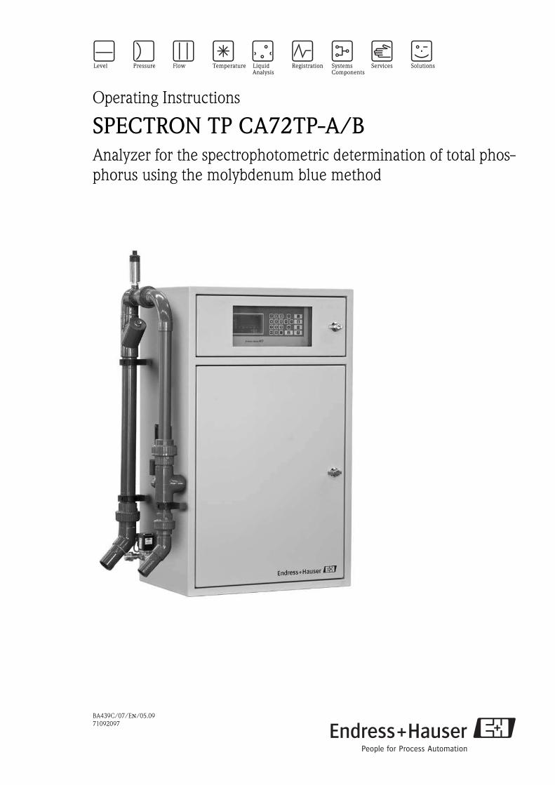
BA439C/07/EN/05.09 71092097 Operating Instructions SPECTRON TP CA72TP-A/B Analyzer for the spectrophotometric determination of total phos- phorus using the molybdenum blue method
-
Upload
khangminh22 -
Category
Documents
-
view
1 -
download
0
Transcript of Operating Instructions - SPECTRON TP CA72TP-A/B
BA439C/07/EN/05.0971092097
Operating Instructions
SPECTRON TP CA72TP-A/B
Analyzer for the spectrophotometric determination of total phos-phorus using the molybdenum blue method

SPECTRON TP CA72TP
2 Endress+Hauser

SPECTRON TP CA72TP
Endress+Hauser 3
Table of contents
1 Safety instructions . . . . . . . . . . . . . . . . 5
1.1 Designated use . . . . . . . . . . . . . . . . . . . . . . . . . . . . 51.2 Installation, commissioning and operation . . . . . . . . 51.3 Operational safety . . . . . . . . . . . . . . . . . . . . . . . . . . 51.4 Return . . . . . . . . . . . . . . . . . . . . . . . . . . . . . . . . . . . 61.5 Notes on safety conventions and icons . . . . . . . . . . . 6
2 Identification . . . . . . . . . . . . . . . . . . . . 7
2.1 Device designation . . . . . . . . . . . . . . . . . . . . . . . . . 72.2 Scope of delivery . . . . . . . . . . . . . . . . . . . . . . . . . . . 82.3 Certificates and approvals . . . . . . . . . . . . . . . . . . . . 8
3 Installation . . . . . . . . . . . . . . . . . . . . . . 9
3.1 The analyzer at a glance . . . . . . . . . . . . . . . . . . . . . 93.2 Incoming acceptance, transport, storage . . . . . . . . . 113.3 Installation conditions . . . . . . . . . . . . . . . . . . . . . . 113.4 Installation instructions . . . . . . . . . . . . . . . . . . . . . 133.5 Post-installation check . . . . . . . . . . . . . . . . . . . . . . 13
4 Wiring . . . . . . . . . . . . . . . . . . . . . . . . 14
4.1 Electrical connection . . . . . . . . . . . . . . . . . . . . . . . 144.2 Signal terminals . . . . . . . . . . . . . . . . . . . . . . . . . . . 154.3 Switching contacts . . . . . . . . . . . . . . . . . . . . . . . . 16
5 Operation . . . . . . . . . . . . . . . . . . . . . . 17
5.1 Display and operating unit . . . . . . . . . . . . . . . . . . . 175.2 Local operation . . . . . . . . . . . . . . . . . . . . . . . . . . . 175.3 Operation in the measuring mode . . . . . . . . . . . . . 18
6 Commissioning the analyzer . . . . . . . 20
6.1 CLR start . . . . . . . . . . . . . . . . . . . . . . . . . . . . . . . . 206.2 Adapting the configuration data . . . . . . . . . . . . . . . 216.3 Calibration . . . . . . . . . . . . . . . . . . . . . . . . . . . . . . 26
7 Programming . . . . . . . . . . . . . . . . . . . 27
7.1 SETTING programming menu . . . . . . . . . . . . . . . . 277.2 LISTS programming menu . . . . . . . . . . . . . . . . . . . 287.3 TEST programming menu . . . . . . . . . . . . . . . . . . . 307.4 PRINTER programming menu . . . . . . . . . . . . . . . . 31
8 Method. . . . . . . . . . . . . . . . . . . . . . . . 32
8.1 General information . . . . . . . . . . . . . . . . . . . . . . . 328.2 Measurement methods . . . . . . . . . . . . . . . . . . . . . 328.3 Spectrophotometric determination of total phosphorus
using the molybdenum blue method . . . . . . . . . . . 338.4 Measurement optimization . . . . . . . . . . . . . . . . . . 34
9 Service . . . . . . . . . . . . . . . . . . . . . . . . 36
9.1 Maintenance schedule . . . . . . . . . . . . . . . . . . . . . . 369.2 Visual inspection . . . . . . . . . . . . . . . . . . . . . . . . . . 379.3 Releasing block of pump P1 (overload protection) . 379.4 Changing the tube of pump P1 . . . . . . . . . . . . . . . 389.5 Manually checking the delivery volume of pump P2 40
9.6 Changing the tube of pump P2 . . . . . . . . . . . . . . . . 429.7 Calibrating pumps P1, P3, P4 and P5 . . . . . . . . . . . 459.8 Calibrating the measuring system . . . . . . . . . . . . . . 479.9 Optics chamber maintenance . . . . . . . . . . . . . . . . . 509.10 Topping up reagent . . . . . . . . . . . . . . . . . . . . . . . . 539.11 Removal from service . . . . . . . . . . . . . . . . . . . . . . . 55
10 Troubleshooting. . . . . . . . . . . . . . . . . . 56
10.1 Troubleshooting instructions . . . . . . . . . . . . . . . . . 5610.2 Error messages . . . . . . . . . . . . . . . . . . . . . . . . . . . . 5610.3 Return . . . . . . . . . . . . . . . . . . . . . . . . . . . . . . . . . . 6010.4 Disposal . . . . . . . . . . . . . . . . . . . . . . . . . . . . . . . . . 60
11 Technical data . . . . . . . . . . . . . . . . . . . 61
11.1 Input . . . . . . . . . . . . . . . . . . . . . . . . . . . . . . . . . . . 6111.2 Output . . . . . . . . . . . . . . . . . . . . . . . . . . . . . . . . . 6111.3 Power supply . . . . . . . . . . . . . . . . . . . . . . . . . . . . . 6111.4 Performance characteristics . . . . . . . . . . . . . . . . . . 6111.5 Environment . . . . . . . . . . . . . . . . . . . . . . . . . . . . . 6211.6 Process . . . . . . . . . . . . . . . . . . . . . . . . . . . . . . . . . 6211.7 Mechanical construction . . . . . . . . . . . . . . . . . . . . 6211.8 Human interface . . . . . . . . . . . . . . . . . . . . . . . . . . 62

SPECTRON TP CA72TP
4 Endress+Hauser

SPECTRON TP CA72TP Safety instructions
Endress+Hauser 5
1 Safety instructions
1.1 Designated use
The analyzer is a compact photometric analytical system.It is designed for monitoring the content of phosphorus in sewage treatment plants and surface waters.
The CA72TP is particularly suited to the following applications: Monitoring the sewage treatment plant outlet Monitoring process waters Monitoring surface waters Monitoring cooling tower water
Any use other than that described here compromises the safety of persons and the entire measuring system and is therefore not permitted.The manufacturer is not liable for damage resulting from improper or non-designated use.
1.2 Installation, commissioning and operation
Note the following points: Installation, commissioning, operation and maintenance of the measuring system must only be
carried out by trained technical personnel.The technical personnel must be authorized for the specified activities by the owner/operator.
The electrical connection may only be performed by an electrical technician. The technical personnel must have read and understood these Operating Instructions and must
follow the instructions they contain. Before commissioning the entire measuring point, make sure all the connections are correct.
Ensure that electrical cables and tube connections are not damaged. Do not operate damaged products. Secure them against unintentional commissioning. Mark the
damaged product as defective. Measuring point faults may only be rectified by authorized and specially trained personnel. If faults cannot be rectified, the products must be taken out of service and secured against unin-
tentional commissioning. Repairs not described in these Operating Instructions may only be carried out directly at the man-
ufacturer’s or by the service organization.
1.3 Operational safety
The analyzer is designed to meet state-of-the-art safety requirements, has been tested and left the factory in a condition in which it is safe to operate.Relevant regulations and European standards have been observed.
As the user, you are responsible for complying with the following safety conditions: Installation instructions Local prevailing standards and regulations.

Safety instructions SPECTRON TP CA72TP
6 Endress+Hauser
1.4 Return
If the analyzer has to be repaired, please send the analyzer cleaned to your sales center.Use the original packaging when returning the device.
Please enclose a duly completed "Declaration of Contamination and Cleaning" form with the pack-aging and shipping documents (copy the second-last page of these Operating Instructions). The device cannot be repaired if a duly completed form is not enclosed!
1.5 Notes on safety conventions and icons
#Warning!This symbol alerts you to hazards. Failure to heed the warning can result in serious damage to equip-ment or personal injury.
"Caution!This symbol alerts you to possible faults which could arise from incorrect operation. Failure to heed the caution can result in damage to equipment.
!Note!This symbol indicates important items of information.

SPECTRON TP CA72TP Identification
Endress+Hauser 7
2 Identification
2.1 Device designation
2.1.1 Nameplate
Compare the order code on the nameplate (on the analyzer) with the product structure and your order.
2.1.2 Product structure
Select one feature from each section in the following structure:
You can select more than one element from the following list. These are optional items and do not have to be ordered:
Fig. 1: Nameplate
You can find the following information on the nameplate: Order code (device version) Serial number Measuring range Outputs and communication Power supply Degree of protection (Permitted) ambient temperature
Measuring range
A 0.05 - 2 mg total P/l (blue)
B 0.1 - 5 mg total P/l (blue)
C 0.3 - 8 mg total P/l (yellow)
D 0.5 - 25 mg total P/l (yellow)
Power supply
0 230 VAC 50/60 Hz
1 115 VAC 50/60 Hz
Sample conditioning
A Not selected
B 1 x PA-2; PVC; 1 - 8 m3/h wastewater
C 1 x PA-3; PVC; 0,1 - 1 m3/h wastewater
Device language, documentation
1 German
2 English
Data storage medium
A Not selected
B Disk drive
C SD card slot
CA72TP- Order code
Analyzer mounting (optional, select one option only)
E1 Wall mounting
E2 Base
Communication (optional, select one option only)
F1 RS 232 unidirectional
F2 PROFIBUS DP
Accessories, enclosed (optional, multiple selection possible)
H1 Maintenance kit for measuring range A, B
H2 Maintenance kit for measuring range C, D
H3 Maintenance kit for sample conditioning PA-2
H4 Maintenance kit for sample conditioning PA-3

Identification SPECTRON TP CA72TP
8 Endress+Hauser
! Note!To complete your order code, simply add the optional features to the end of the order code. If you have any questions, please contact your local sales office.
2.2 Scope of delivery
The scope of delivery comprises: 1 analyzer with power plug 1 accessories pack 1 manufacturer's certificate 1 set of Operating Instructions in English 1 set of Operating Instructions for the heater control system
2.3 Certificates and approvals
2.3.1 4 mark
Declaration of Conformity
The product meets the legal requirements of the harmonized European standards. The manufac-turer confirms the product complies with the standards by affixing to it the 4 mark.

SPECTRON TP CA72TP Installation
Endress+Hauser 9
3 Installation
3.1 The analyzer at a glance
3.1.1 Front view
Fig. 2: Analyzer, front view
1
2
3
4
5
6
7
8
9
10
Main switch
Sample conditioning PA-2 (option) with screen cartridge
Measuring cell ventilation
Solenoid valve MV1 (inlet of optics chamber)
Peristaltic pump P1 with tube bed and throttle
Solenoid valve MV2 (outlet of optics chamber)
Solenoid valve MV3
Solenoid valve MV4
Sample outlet
Container with standard solutions
11
12
13
14
15
16
17
18
19
Display and operating unit
Operating unit
Pump P2
Reciprocating piston pump P5
Optics chamber
Reciprocating piston pump P3
Reciprocating piston pump P4
Container with reagent solutions 1, 2 and 3
Container with cleaning solution

Installation SPECTRON TP CA72TP
10 Endress+Hauser
Sample is transported to the device via the sample conditioning system (2). Pump P1 (5) conveys the sample into the analytical part of the device. The solenoid valve MV1 (4) redirects the sample flow into the optics chamber (15) for sample dosing. Once sufficient sample has been dosed, MV1 switches to the sample outlet (9).The solenoid valve MV2 (6) seals the optics chamber (15) for the duration of the measurement. The reciprocating piston pump P3 (16) doses reagent 1 (18) into the optics chamber. Once the oxidation time elapses, the reciprocating piston pumps P3 (17) and P5 (14) doses the reagent 2 and 3 (18) into the optics chamber. On completion of the color reaction, the absorption is measured via the optical measuring unit. The absorption is then evaluated by the computing unit and shown on the display (11).When measurement is completed, the solenoid valve MV2 (6) opens and the sample flows into the sample outlet (9). If necessary, pump P2 (13) doses cleaning solution (19) into the optics chamber (15).
3.1.2 Rear view
The special key supplied opens the doors on the rear of the analyzer.
# Warning! Risk of electric shock! First switch off the main switch and then open the rear of the device.
Fig. 3: Analyzer, rear view
1
2
3
4
Electronics with terminals
Motor of pump P2
Motor of reciprocating piston pump (P3, P4, P5)
Spectrometer electronics
5
6
7
8
Optical unit light
Heater control
Pump control system P1 and P2
Leak detector

SPECTRON TP CA72TP Installation
Endress+Hauser 11
3.2 Incoming acceptance, transport, storage
Make sure the packaging is undamaged!Notify the supplier of any damage to the packaging.Keep the damaged packaging until the matter has been settled.
Make sure the contents are undamaged!Notify the supplier of any damage to the delivery contents.Keep the damaged products until the matter has been settled.
Check that the scope of delivery is complete and matches your order and the shipping documents. Use the handles provided to transport the analyzer. Pack the device for storage and transportation in such a way that it is reliably protected against
impact and moisture. The original packaging offers the best protection. Furthermore, the permit-ted ambient conditions must also be observed.
If you have any questions, please contact your supplier or your local sales center.
3.3 Installation conditions
3.3.1 Design, dimensions
Fig. 4: Dimensions including sample conditioning PA-2 (option)
The wet part is provided with a front door (swivel radius 525 mm (2.07 inch)), and the electronics part is provided with a front door with a window (290 x 130 mm) (1.14 x 0.51 inch).
! Note! Please note that the device dimensions can increase on account of optional fittings (e.g. sample con-ditioning systems).
650 (25.6)9
90
(40
.0)
775 (30.5) 400 (15.8)
11
05
(43
.5)
mm (inch)
Installation SPECTRON TP CA72TP
12 Endress+Hauser
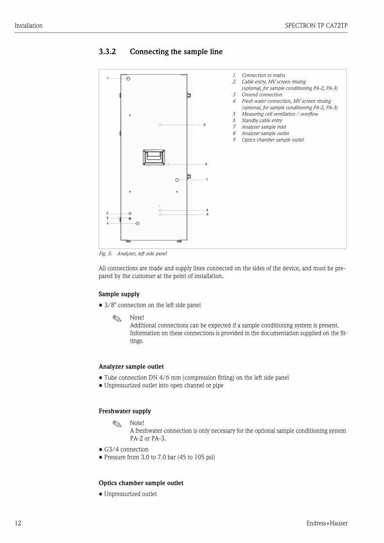
3.3.2 Connecting the sample line
All connections are made and supply lines connected on the sides of the device, and must be pre-pared by the customer at the point of installation.
Sample supply
3/8" connection on the left side panel
! Note! Additional connections can be expected if a sample conditioning system is present. Information on these connections is provided in the documentation supplied on the fit-tings.
Analyzer sample outlet
Tube connection DN 4/6 mm (compression fitting) on the left side panel Unpressurized outlet into open channel or pipe
Freshwater supply
! Note! A freshwater connection is only necessary for the optional sample conditioning system PA-2 or PA-3.
G3/4 connection Pressure from 3.0 to 7.0 bar (45 to 105 psi)
Optics chamber sample outlet
Unpressurized outlet
1 Connection to mains
2 Cable entry, MV screen rinsing
(optional, for sample conditioning PA-2, PA-3)
3 Ground connection
4 Fresh water connection, MV screen rinsing
(optional, for sample conditioning PA-2, PA-3)
5 Measuring cell ventilation / overflow
6 Standby cable entry
7 Analyzer sample inlet
8 Analyzer sample outlet
9 Optics chamber sample outlet
Fig. 5: Analyzer, left side panel

SPECTRON TP CA72TP Installation
Endress+Hauser 13
3.4 Installation instructions
# Warning! Risk of electric shock! Disconnect the device from the power supply (unplug the power supply con-nector). The line filter, overvoltage module and main switch are still energized even when the main switch is switched off.
Proceed as follows to install the analyzer at the designated site:
1. Set up the analyzer at the designated site.2. Check whether the 3-way ball cock in your analyzer is closed.3. Connect the sample supply (siehe Kapitel 3.3.2 "Connecting the sample line").4. If you have a sample conditioning system, connect the freshwater connection (siehe Kapitel
3.3.2).5. Check that the system is leaktight:
– Switch on the wastewater pump– Check the connecting tubes for leaks– Switch off the wastewater pump
6. Connect the tubes for ventilation and the sample outlet.
! Note! When setting up the unit in enclosed areas, make sure there is sufficient ventilation!When commissioning the analyzer in enclosed areas, observe the following:
– Check whether the medium that is directed through the sample conditioning sys-tem gives off toxic gases (e.g. H2S ...).
– The ventilation of the sample conditioning system must be ensured externally via a tube.
– Sufficient ventilation must be ensured if servicing the sample conditioning sys-tem.
7. If you have ordered inactive reagents, produce the reagent solutions in accordance with the mixing guidelines supplied, and produce the standard solutions in accordance with chapter 9.8.2 "Producing calibration standards" .
8. Place the canisters of the (active) standard , reagent and cleaning solution in the analyzer as specified on the labeling.
9. Connect the canisters to the appropriate tubes:
10. Close the tube bed of pumps P1 and P2. Make sure that the tube coming from the tension side is straight.
11. Connect the signal outputs, limit value alarms and error alarm contacts as per chapter 4 "Wir-ing":– Connect signal cable for fault messages to connector I– Connect signal cable for limit value alarm to connector II– Guide the cables through the EMC shield box on the analyzer side
!Note! Make sure the cables fed in have sufficient play for you to be able to reach the analyzer from the rear at a later stage.
12. Plug the mains plug into the socket (230 V, 50/60 Hz or optionally 115 V, 50/60 Hz) or con-nect the power cable in accordance with see chapter 4 "Wiring".
3.5 Post-installation check
After mounting, check all the connections to ensure they are secure and leak-tight. Make sure the tubes cannot be removed unless force is applied. Check all tubes for damage.
Solution Function
Reagent 1Reagent 2 PH-A1Reagent 3 PH-A2Standard 1Standard 2Cleaning solution
Pump P3Pump P4Pump P5Solenoid valve MV4 (left)Solenoid valve MV4 (right)Pump P2

Wiring SPECTRON TP CA72TP
14 Endress+Hauser
4 Wiring
4.1 Electrical connection
# Warning! Risk of electric shock! Make sure you switch off the main switch before you open the rear of the device! The electrical connection may only be performed by an electrical technician. The electrical technician must have read and understood these Operating Instructions and must
follow the instructions they contain. Prior to commencing the connection work, make sure no voltage is applied at any cable.
4.1.1 Electrical connection at a glance
# Warning! Risk of electric shock! Disconnect the device from the power supply (unplug the power supply con-nector). The line filter, overvoltage module and main switch are still energized even when the main switch is switched off.
! Note! You must open the rear, upper door of the analyzer to reach the terminal strip. The special key of the analyzer is required for this purpose.
4.1.2 Terminal assignment
! Note! The following diagrams illustrate an example of the terminal assignment of the mains connection for your analyzer. The terminal assignment and cable colors shown can deviate from the actual ter-minal assignment and cable colors!To connect your analyzer, only use the terminal assignment on the adhesive label inside the
device!
Connection to mains
230 V / L / N / PE / 50 Hz / 16 A, terminal contacts at line filter
Fixed connection with cable entry Pg11 or connection with plug with grounding contact
230 V / 60 Hz / 16 A version available on request 115 V / 60 Hz / 16 A version available on request
Fig. 6: Sample wiring diagram for connection to mains
# Warning! Ensure that the analyzer is sufficiently grounded via the mains connection.(The following must apply: 50 V < R Imax , where Imax is the maximum current above which the error current protection switch is triggered, and R is the resistance between the protective ground and the device ground.)If this cannot be ensured, the device must be grounded locally on site.

SPECTRON TP CA72TP Wiring
Endress+Hauser 15
Power distribution diagram
Fig. 7: Power distribution terminal assignment
4.2 Signal terminals
The signal outputs are located on the right-hand side panel of your analyzer:
Fig. 8: Signal outputs of the analyzer
Cable Function Relay Type Function
A
1
2
3
4
5
6
7
8
9
10
11
12
13
Main switch power distribution
230 V - spectrometer electronics
230 V - power supply, pump P3
230 V - power supply, pump P4
230 V - power supply, pump P5
Option
MV 1 sample to measuring cell
MV 2 measuring cell seal
MV 3 sample/standard switchover
MV 4 standard 1/standard 2 switchover
Standard 2
MV 5 screen rinsing
Option
230 V - power supply, heater control
1
2
3
4
5
6
7
8
4 A
4 A
4 A
4 A
4 A
4 A
4 A
Reed
MV 1 sample to measuring cell
MV 2 measuring cell seal
MV 3 sample/standard switchover
MV 4 standard 1/standard 2 switchover
MV 5 screen rinsing (option)
Option
Heater control
Activation, P3, cable 2A
pri
nte
r
digital
out
digital
out
digital
out
digital
out
II
I
III
IV
40
41+
-
+
-
RS
232
0/4-20
mA
0/4-20
mA
1

Wiring SPECTRON TP CA72TP
16 Endress+Hauser
Signal outputs
Computer interface (option)
Computer interface RS 232 (option) on request; nine-pin D-Sub connection to COM2
4.3 Switching contacts
Fig. 9: Example of electronics frame wiring diagram
Pump control system and spectrometer control system
Fig. 10: Example of wiring diagram for pump control system and spectrometer control system
Connec-
tion
Name Function
I Reed relay, fault message Floating contact (normally closed); max. 250 mA, max. 50 V
II Reed relay, limit value alarm Floating contact (normally closed); max. 250 mA, max. 50 V
III Activation of pump P4, P5
IV Option
40 Current output, channel 1 0 or 4 mA = start of measuring range; 20 mA = end of measuring range
Galvanically isolated; load max. 500 Ω (normally closed)
41 Option
Cable Function Cable Function
20
23
24
25
29
Pump control system
Relay module
Option
Option
Leak detector
24 VAC
24 VDC
DI 7
31
37
39
COM1
COM2
Pump control system
Standby (IN)
Relay module data
Spectrometer electronics
RS 232 (option)
FO 1+2
DI 5
SPECTRON TP CA72TP Operation
Endress+Hauser 17
5 Operation
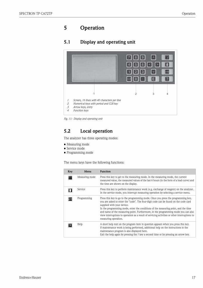
5.1 Display and operating unit
Fig. 11: Display and operating unit
5.2 Local operation
The analyzer has three operating modes:
Measuring mode Service mode Programming mode
The menu keys have the following functions:
Key Menu Function
Measuring mode Press this key to get to the measuring mode. In the measuring mode, the current measured value, the measured values of the last 6 hours (in the form of a load curve) and the time are shown on the display.
Service Press this key to perform maintenance work (e.g. exchange of reagent) on the analyzer. In the service mode, you interrupt measuring operation by selecting a service menu.
Programming Press this key to go to the programming mode. Once you press the programming key, you are asked to enter the "code". The four-digit code can be found on the code card supplied with your device.In the programming mode, enter the conditions of the measuring point, and the time and name of the measuring point. Furthermore, in the programming mode you can also view interruptions to operation as a result of servicing activities or other interruptions to measuring operation.
Help A short help text on the program item in question appears when you press this key.If maintenance work is being performed, additional help on the instructions in the maintenance program is also displayed here.Exit the help again by pressing the ? key a second time or by pressing an arrow key.
1
2
3
4
Screen, 16 lines with 40 characters per line
Numerical keys with period and CLR key
Arrow keys, entry
Function keys
?
Operation SPECTRON TP CA72TP
18 Endress+Hauser
The remaining operating keys have the following functions:
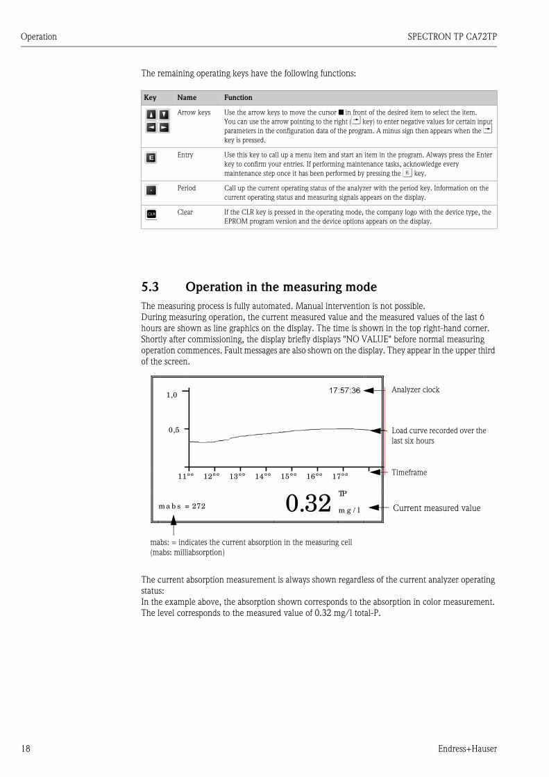
5.3 Operation in the measuring mode
The measuring process is fully automated. Manual intervention is not possible.During measuring operation, the current measured value and the measured values of the last 6 hours are shown as line graphics on the display. The time is shown in the top right-hand corner. Shortly after commissioning, the display briefly displays "NO VALUE" before normal measuring operation commences. Fault messages are also shown on the display. They appear in the upper third of the screen.
The current absorption measurement is always shown regardless of the current analyzer operating status:In the example above, the absorption shown corresponds to the absorption in color measurement. The level corresponds to the measured value of 0.32 mg/l total-P.
Key Name Function
Arrow keys Use the arrow keys to move the cursor in front of the desired item to select the item.You can use the arrow pointing to the right (T key) to enter negative values for certain input parameters in the configuration data of the program. A minus sign then appears when the T key is pressed.
Entry Use this key to call up a menu item and start an item in the program. Always press the Enter key to confirm your entries. If performing maintenance tasks, acknowledge every maintenance step once it has been performed by pressing the F key.
Period Call up the current operating status of the analyzer with the period key. Information on the current operating status and measuring signals appears on the display.
Clear If the CLR key is pressed in the operating mode, the company logo with the device type, the EPROM program version and the device options appears on the display.
E
.
1,0
0,5
11°° 12°° 13°° 14°° 15°° 16°° 17°°
ma b s = 272
0.32
TP m g / l
mabs: = indicates the current absorption in the measuring cell(mabs: milliabsorption)
Analyzer clock
Load curve recorded over the last six hours
Timeframe
Current measured value
SPECTRON TP CA72TP Operation
Endress+Hauser 19
5.3.1 Scaling the line graphics
The measuring curve is scaled on the screen. The scales of the display can be adjusted in the PRO-GRAMMING/SETTING /SCALE menu in line with the measuring ranges to be expected.
5.3.2 Recording mode
Press the U key during measuring operation to enter the "recording mode". With the arrow keys, scroll through the measured values recorded over the last 10 days. The load curve, date and time are displayed.
V 1 day earlier
W 1 day later
U 2 hours earlier
T 2 hours later
Once you have selected a period or a corresponding load curve which you want to view in greater detail, press the F key.
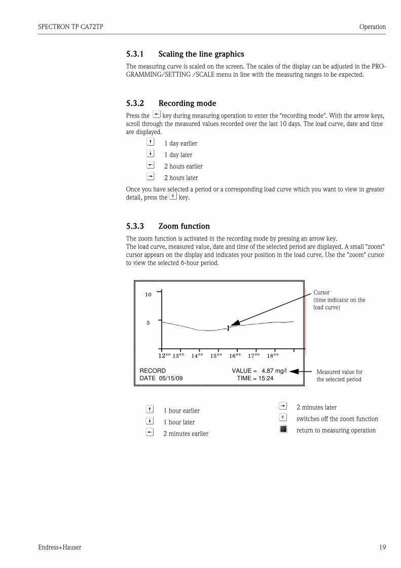
5.3.3 Zoom function
The zoom function is activated in the recording mode by pressing an arrow key.The load curve, measured value, date and time of the selected period are displayed. A small "zoom" cursor appears on the display and indicates your position in the load curve. Use the "zoom" cursor to view the selected 6-hour period.
10
5
12°° 13°° 14°° 15°° 16°° 17°° 18°°
AUFZEIC HNUNG
DATUM 29.08.07
MESSWERT
ZEIT
= 4 .87 m g / l
= 15:30
Cursor(time indicator on the load curve)
Measured value for the selected period
RECORD VALUE = 4.87 mg/l
DATE 05/15/09 TIME = 15:24
V 1 hour earlier
W 1 hour later
U 2 minutes earlier
T 2 minutes later
F switches off the zoom function
return to measuring operation

Commissioning the analyzer SPECTRON TP CA72TP
20 Endress+Hauser
6 Commissioning the analyzer
6.1 CLR start
You must perform a CLR start the first time you commission your analyzer. Here, the analyzer soft-ware is loaded with the factory settings and any changes made previously are deleted.
Proceed as follows to perform a CLR start:
! Note! There should not be any disk in the disk drive (option) when you press the CLR key!
1. Press the CLR key and hold it down for approx. 5 seconds. Switch on the main switch at the same time.
The application is loaded from the ROM.
2. Release the CLR key again.
The initial program screen appears on the display with the company logo and the program number of the software loaded.
Fig. 12: Program startup displayed
3. Press the F key.A diagram with specifications for the tap position of the device appears on the display. Only confirm this point once you have completed all the tasks displayed in the diagram.
Following the CLR start, you have to adapt the analyzer to the conditions of your measuring point. Read chapter "Measurement optimization" for this purpose. In the programming menu, then adapt the configuration data of your analyzer to suit your measuring point.
Endress+Hauser Conducta GmbH+Co. KG
GB STIP 64823 GROSS-UMSTADT GERMANY
TEL +49-60787860, FAX +49-607878688
CA72TP-xxxxx VERS. xxx
SPECTRON TP CA72TP Commissioning the analyzer
Endress+Hauser 21
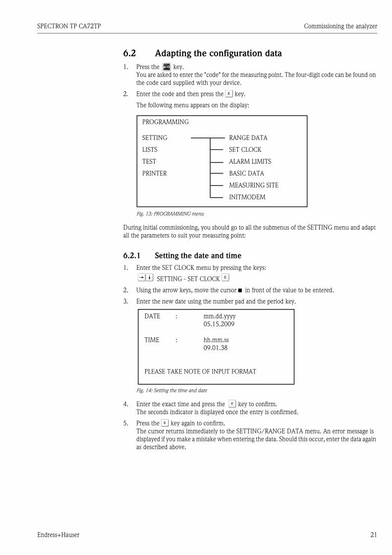
6.2 Adapting the configuration data
1. Press the key.You are asked to enter the "code" for the measuring point. The four-digit code can be found on the code card supplied with your device.
2. Enter the code and then press the F key.
The following menu appears on the display:
Fig. 13: PROGRAMMING menu
During initial commissioning, you should go to all the submenus of the SETTING menu and adapt all the parameters to suit your measuring point:
6.2.1 Setting the date and time
1. Enter the SET CLOCK menu by pressing the keys:
TW SETTING - SET CLOCK F
2. Using the arrow keys, move the cursor in front of the value to be entered.
3. Enter the new date using the number pad and the period key.
Fig. 14: Setting the time and date
4. Enter the exact time and press the F key to confirm.The seconds indicator is displayed once the entry is confirmed.
5. Press the F key again to confirm.The cursor returns immediately to the SETTING/RANGE DATA menu. An error message is displayed if you make a mistake when entering the data. Should this occur, enter the data again as described above.
PROGRAMMING
SETTING RANGE DATA
LISTS SET CLOCK
TEST ALARM LIMITS
PRINTER BASIC DATA
MEASURING SITE
INITMODEM
DATE : mm.dd.yyyy05.15.2009
TIME : hh.mm.ss09.01.38
PLEASE TAKE NOTE OF INPUT FORMAT

Commissioning the analyzer SPECTRON TP CA72TP
22 Endress+Hauser
6.2.2 Configuring the measuring range data
Here you can adapt the measuring-specific settings of your analyzer to suit your measuring point.
1. Enter the RANGE DATA menu by pressing the keys:
T SETTING - RANGE DATA F
Fig. 15: Configuring the measuring range data
2. Using the arrow keys, move the cursor in front of the value to be changed.
3. Enter the new value and press the F key to confirm.Example: For calibration n day = 1.00, press the "1" key and then press the F key.
4. If you do not want to change a value, press the F key directly.
Here you can find information on all the parameters in the RANGE DATA menu:
Menu item Parameter Description
RANGE DATA
CALIBRATION n DAY Activates automatic calibration every n days;Basic setting: 1.00 (1 calibration per day)Entry options: max. = 7.00 (1 calibration every 7 days),
min. = 0.25 (4 calibrations per day)
SCREEN FLUSH/DAY This parameter is only required when using sample conditioning systems. These are available as an option. Information on this parameter is provided in the Operating Instructions of the sample conditioning system.
CAUSTIC FLUSH n DAY Activates automatic cleaning of the optics chamber with an alkali every n days;Basic setting: 1.00 (1 alkaline rinse per day)Entry options: max. = 7.00 (1 alkaline rinse every 7 days),
min. = 0.25 (4 alkaline rinses per day)
DAYBREAK Time when the day changes. This is needed for calculating maximum values, minimum value and mean values, for creating the daily report and determin-ing the time when automatic events start, e.g. automatic calibration.Basic setting: 0.00
RANGE Defines the measuring range (see chapter 8 "Method");Basic setting: 1.00Entry options: 1.00, 2.00 or 3.00;
Range 2 and 3 cannot be used for CA72TP-C/D
OPERATION MODE 0/1/2
Deactivates/activates parameters 1 and 2 on analyzers with two measuring systems:Basic setting: 0.00 (parameter 1 or 2)Entry options: 0.00, 1.00 or 2.00;
1 and 2 cannot be used for CA72TP-*
PAR 1 SCALE For selecting the scale end value of the display, printout and 0/4 mA signal output; here, enter the maximum concentration in mg/l total-P/l that occurs at your measuring point.Basic setting: 2.00
RANGE DATA
CALIBRATION n DAYSCREEN FLUSH/DAYCAUSTIC FLUSH n DAYDAYBREAKRANGEOPERATION MODE 0/1/2PAR 1 SCALE
STANDARD 1STANDARD 2
: 1.00: 1.00: 1.00: 0.00: 1.00: 0.00: 2.00: 0.20: 2.00

SPECTRON TP CA72TP Commissioning the analyzer
Endress+Hauser 23
6.2.3 Configuring the limit values
Here, you can define the limit values that you want to monitor at your measuring point. The collec-tive alarm contact is opened when an alarm is triggered.
Enter the ALARM LIMITS menu by pressing the keys:
TWW SETTING - ALARM LIMITS F
Here you can find information on all the parameters in the ALARM LIMITS menu:
6.2.4 Configuring the basic data
In many analyzers, it is absolutely essential to adapt the basic data after a CLR start. Enter the values specified in the chapter "Method".
Enter the BASIC DATA menu by pressing the keys:
TWWW SETTING - BASIC DATA F
Here you can find information on all the parameters in the BASIC DATA menu:
STANDARD 1 Concentration information of standard solution 1 in mg/l total-P;Basic setting: 0.20
STANDARD 2 Concentration information of standard solution 2 in mg/l total-P;Basic setting: 2.00
Menu item Parameter Description
ALARM LIMITS
DELAY (sec) Amount of time in seconds the system waits before a limit value alarm is acti-vated;Basic setting: 0.00
PAR 1 UPPER LIMIT Limit value for the alarm that signals the value is overshot in mg/l total-P;Basic setting: 8000.00
PAR 1 LOWER LIMIT Limit value for the alarm that signals the value is undershot in mg/l total-P;Basic setting: 0.00
SLOPE ALARM / 2 MIN Limit value for the slope alarm in mg/l total-P;The alarm is triggered if the measured value increases by more than this value from one measuring point to the next measuring point (within 2 min).Basic setting: 8000.00
Menu item Parameter Description
BASIC DATA
METHOD Definition of the measuring method (see chapter "Method");No adjustment needs to be made for commissioning.Basic setting: 5.00
Q P1 [ml/min] Delivery rate of pump P1 in ml/min during measuring operation;No adjustment needs to be made for commissioning.Basic setting: 5.00
REACTION TIME MEAS. Time in seconds for the color reaction in measuring operation;For commissioning, accept the values recommended in chapter "Method".Basic setting: 180.00
REACTION TIME CAL. Time in seconds for the color reaction in the calibration for the standard con-centration in question;Basic setting: 180.00
Menu item Parameter Description

Commissioning the analyzer SPECTRON TP CA72TP
24 Endress+Hauser
6.2.5 Name of the measuring site
Enter the MEASURING SITE menu by pressing the keys:
TWWWW SETTING - MEASURING SITE F
For identification purposes, the measuring site can be assigned a name with a maximum of 24 char-acters, or a maximum of 4 characters for disk recording. To enter the name of the measuring site, use the arrow keys VW to select the letters or characters. Use the arrow keys UT to move the cursor to the next character. You can give a name to the files for disk recording under FILE XXXX.
6.2.6 INITMODEM menu
This menu is not relevant for controlling the CA72TP-*.
6.2.7 Documentation of all the data configured
Once you have entered all the configuration values, document your entries in the blank form on the next page.
! Note!Copy this form before you enter your values. You can then continue to document your entries if you make changes to the settings at a later stage.
MEAS. DELAY MIN Shortest interval in seconds between two measuring cycles;Basic setting: 120.00
MEAS. DELAY MAX Longest interval in seconds between two measuring cycles;Basic setting: 180.00
THRESHOLD MB [%] Percentage difference between two consecutive measured values which causes the lower REACTION TIME MEAS. to be selected if the value is exceeded. Otherwise the MEAS. DELAY MAX is activated to save reagent.Basic setting: 20.00
T-FLUSH [sec] This parameter is only required when using sample conditioning systems. These are available as an option. Information on this parameter is provided in the Operating Instructions of the sample conditioning system.
EXCHANGE TIME Time in seconds for replacing the sample in the sample tubes;Basic setting: 10.00
OFFSET PAR 1 Correction value to offset deviations in the photometric measurement result. Negative values can also be entered. The offset is subtracted from the result determined. Basic setting: 0.00
DC OUT 0/4 - 20 mA Sets the signal output to 4-20 mA or 0-20 mA. Basic setting: 4.00Entry options: 0.00 or 4.00
Menu item Parameter Description

SPECTRON TP CA72TP Commissioning the analyzer
Endress+Hauser 25
Enter the values and data configured for commissioning here:
Date:
REACTION PARAMETERS(Special menu, see chapter 8.4)
PUMP PARAMETERS(Special menu, see chapter 8.4)
V.OPTICS CHAMBER
SAMPLE PORTION
REAG 1 PORTION
REAG 2+3 PORTION
PATH LENGTH
OXIDATION TIME MEAS
OXIDATION TIME CAL.
______________
______________
______________
______________
______________
______________
______________
Q P1 100%
Q P2 100%
Q P3 / 15 STROKES
Q P4+P5/ 15 STROKES
______________
______________
______________
______________
RANGE DATA BASIC DATA
CALIBRATION n DAY
SCREEN FLUSH/DAY
CAUSTIC FLUSH n DAY
DAYBREAK
RANGE
OPERAT. MODE 0/1/2
PAR 1 SCALE
STANDARD 1
STANDARD 2
______________
______________
______________
______________
______________
______________
______________
______________
______________
METHOD
Q P1[ml/min]
REACTION TIME MEAS.
REACTION TIME CAL.
MEAS. DELAY MIN
MEAS. DELAY MAX
THRESHOLD MB [%]
T-FLUSH [sec]
EXCHANGE TIME
OFFSET PAR 1
______________
______________
______________
______________
______________
______________
______________
______________
______________
______________
Commissioning the analyzer SPECTRON TP CA72TP
26 Endress+Hauser
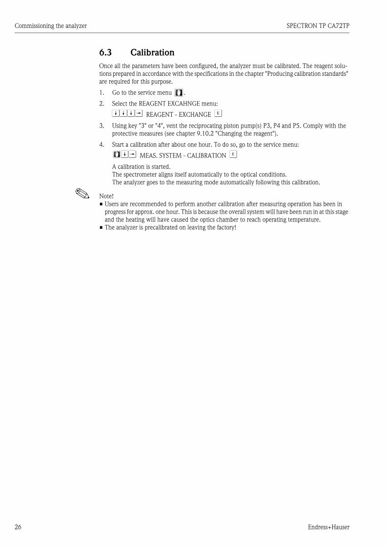
6.3 Calibration
Once all the parameters have been configured, the analyzer must be calibrated. The reagent solu-tions prepared in accordance with the specifications in the chapter "Producing calibration standards" are required for this purpose.
1. Go to the service menu .
2. Select the REAGENT EXCAHNGE menu:
WWWT REAGENT - EXCHANGE F
3. Using key "3" or "4", vent the reciprocating piston pump(s) P3, P4 and P5. Comply with the protective measures (see chapter 9.10.2 "Changing the reagent").
4. Start a calibration after about one hour. To do so, go to the service menu:
WT MEAS. SYSTEM - CALIBRATION F
A calibration is started.The spectrometer aligns itself automatically to the optical conditions.The analyzer goes to the measuring mode automatically following this calibration.
! Note! Users are recommended to perform another calibration after measuring operation has been in
progress for approx. one hour. This is because the overall system will have been run in at this stage and the heating will have caused the optics chamber to reach operating temperature.
The analyzer is precalibrated on leaving the factory!

SPECTRON TP CA72TP Programming
Endress+Hauser 27
7 Programming
You should adapt the parameters of your analyzer to the conditions at your measuring point to: Maximize the effectiveness of your analyzer Get the right measuring results Minimize reagent consumption
Proceed as follows to go to the programming menu:
1. Press the key.You are asked to enter the "code" for the measuring point. The four-digit code can be found on the code card supplied with your device.
2. Enter the code and then press the F key.
The following menu appears on the display:
Fig. 16: SETTING menu
7.1 SETTING programming menu
You have to switch to the SETTING programming menu to adapt your analyzer parameters to the conditions of your measuring point:
T SETTING - RANGE DATA F
! Note!The analyzer may only be programmed by individuals specially appointed to perform such work (e.g. shift manager, production manager)!More information on this menu is provided in chapter 6.2 "Adapting the configuration data".
PROGRAMMING
SETTING RANGE DATA
LISTS SET CLOCK
TEST ALARM LIMITS
PRINTER BASIC DATA
MEASURING SITE
INITMODEM

Programming SPECTRON TP CA72TP
28 Endress+Hauser
7.2 LISTS programming menu
Enter the LISTS menu by pressing the keys:
WT PROGRAMMING - LISTS F
Fig. 17: LISTS menu
In this menu, you can print configuration data, measured values, load curves and reports if a printer is connected (option) or show this information in part on the display:
Menu item Parameter Description
LISTS
INPUT DATA Logs the current RANGE DATA, BASIC DATA and ALARM LIMITS
CURVES/RECORDS: Logs selected daily load curves and reports from the picklist (14 days)
TODAY’S RECORD The daily report is printed out when a new measurement day commences (from day changeover to day changeover).
MAX MIN AVERAGE Logs the maximum, minimum and average measured values for the 14 days saved
MAINTENANCE RECORD Log of all maintenance operations sorted by activity; select the operations to list them on the display. If a printer is connected, the information is printed out directly. Both the time and the date of the event are listed.
PROGRAMME STARTED Logs the date and time of the CLR start
CHANGE DATA Logs the date and time when configuration data are changed
PUMP 1 REPLACE TUBE Logs the date and time when the tube of pump P1 is changed
PUMP 2 REPLACE TUBE Logs the date and time when the tube of pump P2 is changed
CAL. OPTICS Logs the date and time when the spectrophotometric measure-ment was calibrated;In the case of Method 4, the axis intercept X0 (offset) and the slope of the calibration line (see chapter 9.8 "Calibrating the measuring system") are documented, as are the absorption val-ues for standard solution 1 and 2 (on a separate line).In the case of Method 5, the absorption from the oxidation time for standard solution 1 and 2 is also displayed.Please note that failed calibrations are indicated by an asterisk (*). In such situations, the system continues to work with the old calibration values.
CAL. PUMPS Logs the date and time of a pump calibration. Furthermore, the calculated delivery volume and the pump number (1, 3, 4) are documented on a second line.
OPTICS CHAMBER Logs the date and time when the corresponding point in the service menu is selected.
PROGRAMMING
SETTING
LISTS INPUT DATACURVES/RECORDS
TEST TODAY’S RECORDMAX MIN AVERAGE
PRINTER MAINTENANCE RECORDALARM RECORDSHOW COMPLETE RECORDSRECORD ON DISK

SPECTRON TP CA72TP Programming
Endress+Hauser 29
SCREEN FLUSH This parameter is only required when using sample condition-ing systems. These are available as an option. Information on this parameter is provided in the Operating Instructions of the sample conditioning system.
BYPASS-SCREEN Logs the date and time when the corresponding point in the service menu is selected.
REAGENT EXCHANGE Logs the date and time when the corresponding point in the service menu is selected.
STANDBY Option for accessories
SETTING OPTICS Logs the duration of a spectrometer analysis in milliseconds and the intensity found during zero measurement in the calibration;This information is only important for service technicians.
CAUSTIC FLUSH Logs the date and time of alkaline rinsing.
CAL. ELECTRODE CHAMBER This parameter is only relevant if using analyzers with two mea-suring systems. Information on this parameter is provided in the Operating Instructions of the analyzer.
ALARM RECORD Logs all the alarms with the date and time of the event. Select this list to view it on the display or print it out if a printer is con-nected.
POWER CUT Logs when a power failure took place.
POWER ON Logs when the power was reestablished.
OUT OF RANGE ON Logs when the measuring range of the analyzer is exceeded. Please note that this can also include incorrect calibrations or lack of reagent.
OUT OF RANGE OFF Logs when overranging stopped;"NO VALUE" appears on the display for the period between OUT OF RANGE ON and OUT OF RANGE OFF".
LECKAGE Logs a leak in the device; the device switches automatically to a standby state.
SHOW COMPLETE RECORDS Displays all the saved events in chronological order; the last 200 events are saved in the list.
RECORD ON DISK Saves selected daily load curves and reports to a disk; the mea-sured data for the last 10 days can be called up from the ana-lyzer.
DISK ERROR Logs errors when saving data to a disk (data storage medium missing, write protection activated, not enough storage space etc.)
Menu item Parameter Description

Programming SPECTRON TP CA72TP
30 Endress+Hauser
7.3 TEST programming menu
The TEST programming menu contains test programs for testing the function of the analyzer. Enter the TEST menu by pressing the keys:
WWT PROGRAMMING - TEST F
Fig. 18: TEST menu
! Note!Before running the test programs select the MEASUREMENT OFF parameter to ensure an alarm is not triggered.
PROGRAMMING
SETTING
LISTS
TEST TEST OF INPUTSTEST OF OUTPUTS
PRINTER TEST FREQUENCY I/OTEST COMMEASUREMENT OFF
Menu item Parameter Description
TEST
TEST OF INPUTS
OPTICS Test program for the optical measuring system. Here you can see what absorption value the spectrometer sends the analyzer for analysis. If you use this menu item without selecting MEASUREMENT OFF beforehand, measuring operation continues in the background. You are then able to view the analysis for all two methods simultaneously for the current range (see setting for RANGE DATA). This helps you decide what method is best for your measuring point.
DIGITAL INPUTS Displays the switching states of the switch inputs
TEST OF OUTPUTS
DC-SIGNAL Sets the analog current outputs to any value between 0 and 20 mA
PUMPS Parameter for testing the function of the pumps (see chapter 9)
DIGITAL OUTPUTS Functional test of the switch outputs; displays the switching states of the switch outputs
Assignment of the switch outputs:
1 = MV1 Sample in cell OFF Sample past cell ON
2 = MV2 Measuring cell closed OFF Measuring cell open ON
3 = MV3 Sample OFF STANDARD ON
4 = MV4 Standard 1 OFF Standard 2 ON
5 = MV5 Option
6 = MV6 Option
7 = Heater OFF ON
8 = Pump P3 switch between ON/OFF = 1 pump stroke
9 = Fault message
10 = Limit value alarm
11 = Pump P4 switch between ON/OFF = 1 pump strokePump P5 switch between ON/OFF = 1 pump stroke(double assignment with P4 and P5)
12 = Option
TEST FREQUENCY I/O Tests the inputs and outputs to check the function of the I/O card; to test the frequency inputs and outputs, the outputs can be set to a certain fre-quency and be read out from one input after bridging the connections.

SPECTRON TP CA72TP Programming
Endress+Hauser 31
7.4 PRINTER programming menu
Enter the PRINTER menu by pressing the keys:
WWWT PROGRAMMING - PRINTER F
This menu is only relevant for the optional printer (accessory). Information on the PRINTER pro-gramming menu is provided in the Operating Instructions of the printer.
TEST COM Displays the transmission data for the RS232 interface (option)
MEASUREMENT OFF Disables measuring operation; the MEASUREMENT OFF operating status is displayed to perform tests without triggering an alarm.
PRINTER Optional
Menu item Parameter Description

Method SPECTRON TP CA72TP
32 Endress+Hauser
8 Method
8.1 General information
Phosphoric compounds can occur in natural bodies of water and wastewater in both a dissolved and undissolved state, and can be determined if the sample is pretreated appropriately. The total phos-phorus content is determined following previous digestion with an oxidizer and subsequent deter-mination as an orthophosphate.The CA72TP-A/B analyzer uses the "molybdenum blue method", which is particularly sensitive to low phosphate content.
8.2 Measurement methods
Light passing through the measuring cell and the sample can be absorbed by the sample (the beam of light becomes weaker). If the light is absorbed in the visible range of the spectrum (380 nm - 780 nm), the sample exhibits a coloration that is also visible to the human eye. Substances that color the sample can be quantified on the basis of how intense the coloration is. The more intense the color-ation, the greater the absorption of light.The diode array spectrometer found in the measuring device measures the absorption of the probe at a wavelength range between 380 nm and 780 nm. According to Lambert Beer's Law, the con-centration of a substance causing coloration is proportional to the absorption caused by the sample:
Absorption = concentration x constant of proportionality(Lambert Beer)
Since most substances absorb differently at different wavelengths (different constants of proportion-ality), one can distinguish a substance from other absorbing substances using the special "form" of the absorption spectrum (all absorptions at all wavelengths beside one another) of a substance. As a spectrometer is used, the analyzer knows the entire absorption spectrum. This is taken into consid-eration when analyzing the measuring results in order to clear interference influences.
The SPECTRON TP CA72TP-A/B uses the following methods to analyze the absorption:
Method 4
This method involves linear analysis of the absorptions. The absorption values from measuring the coloration at the end of the color reaction (reaction time) are averaged and analyzed.
Method 5
This method also involves linear analysis of the absorptions. Here, the difference between the absorption during the oxidation time (raw absorption) and the actual absorption from the color reac-tion is calculated and used to determine the measured value.
Method 5 is selected as the standard method. It has the advantage that the measurement result is not affected by turbidity or inherent color.
SPECTRON TP CA72TP Method
Endress+Hauser 33
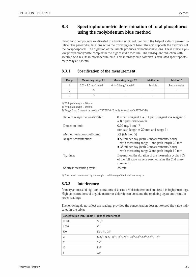
8.3 Spectrophotometric determination of total phosphorus
using the molybdenum blue method
Phosphoric compounds are digested in a boiling acidic solution with the help of sodium peroxodis-ulfate. The peroxodisulfate ions act as the oxidizing agent here. The acid supports the hydrolysis of the polyphosphates. The digestion of the sample produces orthophosphate ions. These create a yel-low phosphomolybdate complex in the highly acidic medium. The subsequent reduction with ascorbic acid results in molybdenum blue. This intensely blue complex is evaluated spectrophoto-metrically at 735 nm.
8.3.1 Specification of the measurement
1 1 With path length = 10 mm With path length = 10 mm
8.3.2 Interference
Primary amines and high concentrations of silicate are also determined and result in higher readings.High concentrations of organic matter or chloride can consume the oxidizing agent and result in lower readings.
The following do not affect the reading, provided the concentration does not exceed the value indi-cated in the table:
Range Measuring range 11)
1) With path length = 20 mm
Measuring range 22)
2) With path length = 10 mm
Method 4 Method 5
1 0.05 - 2.0 mg/l total-P 0.1 - 5.0 mg/l total-P Possible Recommended
2 -3)
3) Range 2 and 3 cannot be used for CA72TP-A/B (only for version CA72TP-C/D)
- - -
3 -3) - - -
Ratio of reagent to wastewater: 0.4 parts reagent 1 + 1.1 parts reagent 2 + reagent 3 + 8.5 parts wastewater
Detection limit: 0.02 mg/l total-P(for path length = 20 mm and range 1)
Method variation coefficient: 5% (Method 5)
Reagent consumption: 50 ml per day (with 2 measurements/hour) with measuring range 1 and path length 20 mm
35 ml per day (with 2 measurements/hour) with measuring range 2 and path length 10 mm
T90 time: Depends on the duration of the measuring cycle; 90% of the full scale value is reached after the 2nd mea-surement1)
1) Plus a dead time caused by the sample conditioning of the individual analyzer
Shortest measuring cycle: 25 min
Concentration [mg/l (ppm)] Ions or interference
10 000 SO42–
1 000 Cl–
500 Na+, K+, Ca2+
50 CO32–, NO3
–, Fe2+, Fe3+, Zn2+, Cu2+, Ni2+, Cr3+, Co2+, Hg2+
25 Sn2+
10 Pb2+
5 Ag+

Method SPECTRON TP CA72TP
34 Endress+Hauser
8.4 Measurement optimization
8.4.1 General information
It is essential to calibrate the analyzer to obtain precise measurement results. Since the measuring task for the device turns out to be different when the device has been in operation for several weeks, the standard concentrations selected have to be reexamined. You can improve the accuracy of the measurement by choosing the right calibration standard.
Only measure as frequently as is really required. This helps you save reagent. With the MEAS. DELAY MIN, MEAS. DELAY MAX and THRESHOLD MB parameters, the analyzer also allows you reduce the frequency of measurement when there is little change in the measured value.
Example: MEAS. DELAY MIN = 120 secMEAS. DELAY MAX = 600 secTHRESHOLD MB = 20 %
If a new measured value deviates 20% or more from the previous measured value, the system selects the short MEAS. DELAY MIN (120 sec.) as the interval between the next measurement. If the mea-sured value deviates less than 20% from the previous value (e.g. at night), the analyzer waits 600 sec. between two measurements.
! Note!In the PROGRAMMING / TEST OF OUTPUTS / OPTICS menu, you can view the measured values for the current range for the two methods simultaneously with measurement running in the back-ground.You do not have to recalibrate the analyzer if you change method.
8.4.2 Special menu
In addition to configuration data in the measuring range and basic data menus, system-internal set-tings are entered and changed in the special menu. In contrast to all other data, the data in the spe-cial menu are retained even if a CLR start is performed.Proceed as follows to go to the special menu:
1. Go to the programming section . Once the code is entered, the cursor is located at the top left-hand corner.
2. Now press the "5" key three times.
REACTION PARAMETERS submenu
Pressing the "1" key takes you to the REACTION PARAMETERS submenu:
0.5 Cr6+, can be eliminated by increasing the amount of ascorbic acid added
Concentration [mg/l (ppm)] Ions or interference
Menu item Parameter Description
REACTION PARAMETERS
V.OPTICS CHAMBER Enter the volume of the optics chamber in milliliters here. Basic setting: 6.50 ml for 20 mm path Optional: 4.50 ml for 10 mm path
SAMPLE PORTIONREAG 1 PORTIONREAG 2+3 PORTION
These three parameters determine the ratio for mixing the sample with reagents REG1, REG2 and REG3.Please make sure that the sum of these numbers/parts is 100!
PATH LENGTH Information on the path length (10.00 mm or 20.00 mm);This cannot be changed by the customer
SPECTRON TP CA72TP Method
Endress+Hauser 35
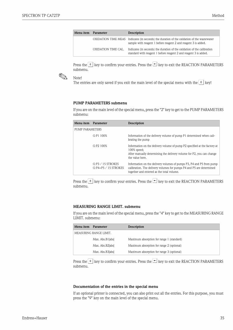
Press the F key to confirm your entries. Press the U key to exit the REACTION PARAMETERS submenu.
! Note!The entries are only saved if you exit the main level of the special menu with the F key!
PUMP PARAMETERS submenu
If you are on the main level of the special menu, press the "2" key to get to the PUMP PARAMETERS submenu:
Press the F key to confirm your entries. Press the U key to exit the REACTION PARAMETERS submenu.
MEASURING RANGE LIMIT. submenu
If you are on the main level of the special menu, press the "4" key to get to the MEASURING RANGE LIMIT. submenu:
Press the F key to confirm your entries. Press the U key to exit the REACTION PARAMETERS submenu.
Documentation of the entries in the special menu
If an optional printer is connected, you can also print out all the entries. For this purpose, you must press the "9" key on the main level of the special menu.
OXIDATION TIME MEAS Indicates (in seconds) the duration of the oxidation of the wastewater sample with reagent 1 before reagent 2 and reagent 3 is added.
OXIDATION TIME CAL. Indicates (in seconds) the duration of the oxidation of the calibration standard with reagent 1 before reagent 2 and reagent 3 is added.
Menu item Parameter Description
Menu item Parameter Description
PUMP PARAMETERS
Q P1 100% Information of the delivery volume of pump P1 determined when cali-brating the pump
Q P2 100% Information on the delivery volume of pump P2 specified at the factory at 100% speed;After manually determining the delivery volume for P2, you can change the value here.
Q P3 / 15 STROKESQ P4+P5 / 15 STROKES
Information on the delivery volumes of pumps P3, P4 and P5 from pump calibration. The delivery volumes for pumps P4 and P5 are determined together and entered as the total volume.
Menu item Parameter Description
MEASURING RANGE LIMIT.
Max. Abs.B1[abs] Maximum absorption for range 1 (standard)
Max. Abs.B2[abs] Maximum absorption for range 2 (optional)
Max. Abs.B3[abs] Maximum absorption for range 3 (optional)

Service SPECTRON TP CA72TP
36 Endress+Hauser
9 Service
Press the key:
Fig. 19: SERVICE menu
" Caution!Risk of injury and infection!When performing maintenance work on the device, always wear protective gloves to prevent dam-age to the skin and infection through contact with wastewater.
The program guides you step by step through the maintenance tasks. Measuring operation is inter-rupted if you select a program item in the service menu. Perform the maintenance task and confirm each step shown on the display by pressing the F key once you have performed the step. Pressing the F key by way of confirmation takes you to the next step in the program. The measuring device returns automatically to the measuring mode once the last step displayed has been confirmed.
9.1 Maintenance schedule
SERVICE
PUMPS PUMP 1 REPLACE TUBE
MEAS.SYSTEM PUMP 2 REPLACE TUBE
CLEANING CALIBRATE PUMPS
REAGENT
Timeframe Maintenance
Daily Visual inspection (see chapter 9.2 "Visual inspection")
Every 2 weeks Replace standard solutions (see chapter 9.10.2 "Changing the reagent")
Every 2 weeks Replace reagents (see chapter 9.10.2 "Changing the reagent")
Every 6 weeks Measure the capacity of pumps P1, P3, P4+P5 (see chapter 9.7 "Calibrating pumps P1, P3, P4 and P5")
Every 6 weeks Check the sample drain tube and clean if necessary
Every 3 months Replace pump tubes P1, P2 (see chapter 9.4 "Changing the tube of pump P1" and see chap-ter 9.6 "Changing the tube of pump P2" )
If required Clean the optics chamber (see chapter 9.9 "Optics chamber maintenance")
If required Replace the cleaning solution (see chapter 9.10.2 "Changing the reagent")

SPECTRON TP CA72TP Service
Endress+Hauser 37
9.2 Visual inspection
Briefly check the following:
1. Are the time and date OK?
2. Is the measurement in the standard range?
3. Are the measured values plausible?
# Warning!When working with reagents, please observe the warnings on the safety data sheets. Wear protec-tive clothing, protective gloves and protective goggles.
4. Is the sample supply line OK?To check, place a receptacle under the 3-way cock and open the cock slightly in the direction of the receptacle.
5. Is the solenoid valve MV2 leak-tight?Inspect the solenoid valve MV2 for any drops forming in the tube.
6. Are sufficient amounts of standard and reagent solutions available?Make sure that sufficient amounts of reagent and standard solution are still available in the can-isters.
7. Are the pump tubes OK?Check the pump tubes for embrittlement, leaks and drop formation.
8. If a printer is available (option):– Is the printer connected and online?– Take the load curves/reports for the day out of the printer and document them in the plant
operations log.
9.3 Releasing block of pump P1 (overload protection)
The peristaltic pump P1 is fitted with an overload protection system to protect it against overload. The overload protection system can be triggered if the tube bed is set too tightly or if the pump head is blocked. This causes the pump to switch off.Eliminate the source of the problem by checking the tube bed and loosening it if necessary. Also check the pump head and loosen it if it is too tight.
# Warning! Danger of crushing or pinching! Do not reach into the pump head when the pump is in operation! When working with reagents, please observe the warnings on the safety data sheets. Wear pro-
tective clothing, protective gloves and protective goggles. If the liquid comes into contact with the eyes or skin, wash the affected area with plenty of water
and seek medical attention. In the case of acidic reagents, there is a risk of splashing and the danger of extreme heat genera-
tion! For this reason, never add water to the reagents!
1. Once you switch off the wastewater pump, select:
T PUMPS - PUMP 1 REPLACE TUBE F
2. Using the T key, start the peristaltic pump briefly.
If this measure did not achieve the desired result, go to the programming menu:

Service SPECTRON TP CA72TP
38 Endress+Hauser
3. PROGRAMMING - TEST - TEST OF OUTPUTS - PUMPS - PUMP NO. 1 F
The overload switch for pump P1 is closed.
4. Reactivate analyzer operation by pressing the key.
9.4 Changing the tube of pump P1
# Warning! Danger of crushing or pinching! Do not reach into the pump head when the pump is in operation! When working with reagents, please observe the warnings on the safety data sheets. Wear pro-
tective clothing, protective gloves and protective goggles. If the liquid comes into contact with the eyes or skin, wash the affected area with plenty of water
and seek medical attention. Never add water to the reagents! In the case of acidic reagents, there is a risk of splashing and the
danger of extreme heat generation!
! Note!If the device has a drain valve on the optics chamber, drain the optics chamber as described below before replacing the tube.
1. Select:
T PUMPS - PUMP 1 REPLACE TUBE F
Fig. 20: PUMP 1 REPLACE TUBE service menu
2. Remove the Plexiglas disk by loosening the two knurled nuts:
Fig. 21: Loosening the knurled nuts
3. Close the 3-way cock in the direction of the sample supply line.
TEST PUMPS
PUMP NO. 1 0 % 0.0 mlPUMP NO. 2 0 % 0.0 µl
SERVICE
PUMPS PUMP 1 REPLACE TUBE
MEAS.SYSTEM PUMP 2 REPLACE TUBE
CLEANING CALIBRATE PUMPS
REAGENT
1 Knurled nut

SPECTRON TP CA72TP Service
Endress+Hauser 39
4. To drain the pump tube, place a receptacle under the 3-way cock and open the cock in the direction of the receptacle.
Opening the tube bed
5. Then open the tube bed throttle:
Fig. 22: Opening the tube bed throttle
6. Then open the tube bed:
Fig. 23: Opening the tube bed
# Warning!Use a twist-and-pull movement to make it easier to release the tube. This also prevents abrasions to the skin.
Releasing and removing the pump tube from the tube connection nipples
7. Turn the tube clockwise and counterclockwise to release it from the tube connection nipples:
Fig. 24: Releasing the tube connection nipples
8. Remove the tube.

Service SPECTRON TP CA72TP
40 Endress+Hauser
Fitting the pump tube on the tube connection nipples
9. Insert the new tube into the pump.
10. Position the tube on the tube connection nipples and fit it in place by turning the tube in a clockwise direction. Once fitted, ensure that the tube does not exhibit any twists or bends.
Closing the tube bed
11. Push the tube bed onto the retaining bolt in such a way that the tube coming from the tension side is straight.
12. Lubricate the tube with silicone grease, if necessary, and close the tube bed throttle.
13. Check the contact pressure of the tube bed and, if necessary, correct the setting of the setscrew on the tube bed throttle.
Checking pump startup
14. Select:
T PUMPS - PUMP 1 REPLACE TUBE F
15. Using the T key, start the peristaltic pump briefly and then stop the pump again.
16. The pump head should turn smoothly, without jerks or jolts.
If the pump does not start, the setscrew of the tube bed throttle is set too tightly. Slacken the setscrew slightly.
Opening the sample supply
17. Operate the 3-way cock as indicated in the system diagram on the display.
The measuring device returns to the measuring mode and initially displays the message "OHNE MESSWERT".
9.5 Manually checking the delivery volume of pump P2
# Warning! Danger of crushing or pinching! Do not reach into the pump head when the pump is in operation! When working with reagents, please observe the warnings on the safety data sheets. Wear pro-
tective clothing, protective gloves and protective goggles. If the liquid comes into contact with the eyes or skin, wash the affected area with plenty of water
and seek medical attention. Never add water to the reagents! In the case of acidic reagents, there is a risk of splashing and the
danger of extreme heat generation!
! Note!The delivery volume is determined when you manually check the pump. You need a stop watch and a graduated cylinder that can hold 10 ml.
1. Select:
PROGRAMMING - TEST - TEST OF OUTPUTS - PUMPS - PUMP NO. 2 F
2. To stop the pump, enter "0"% for PUMPE NR. 2
TEST PUMPS
PUMP NO. 1 0 % 0.0 mlPUMP NO. 2 0 % 0.0 µl
SPECTRON TP CA72TP Service
Endress+Hauser 41
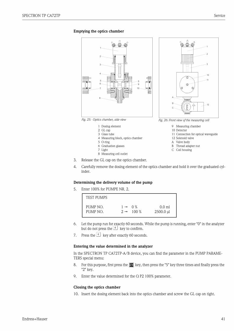
Emptying the optics chamber
3. Release the GL cap on the optics chamber.
4. Carefully remove the dosing element of the optics chamber and hold it over the graduated cyl-inder.
Determining the delivery volume of the pump
5. Enter 100% for PUMPE NR. 2.
6. Let the pump run for exactly 60 seconds. While the pump is running, enter "0" in the analyzer but do not press the F key to confirm.
7. Press the F key after exactly 60 seconds.
Entering the value determined in the analyzer
In the SPECTRON TP CA72TP-A/B device, you can find the parameter in the PUMP PARAME-TERS special menu:
8. For this purpose, first press the key, then press the "5" key three times and finally press the "2" key.
9. Enter the value determined for the Q P2 100% parameter.
Closing the optics chamber
10. Insert the dosing element back into the optics chamber and screw the GL cap on tight.
Fig. 25: Optics chamber, side view Fig. 26: Front view of the measuring cell
1 Dosing element2 GL cap3 Glass tube4 Measuring block, optics chamber5 O-ring6 Graduation glasses7 Light8 Measuring cell outlet
9 Measuring chamber10 Detector11 Connection for optical waveguide12 Solenoid valveA Valve bodyB Thread adapter nutC Coil housing
TEST PUMPS
PUMP NO. 1 0 % 0.0 mlPUMP NO. 2 100 % 2500.0 µl
Service SPECTRON TP CA72TP
42 Endress+Hauser
Activating measuring operation
11. Reactivate analyzer operation by pressing the key.
9.6 Changing the tube of pump P2
The peristaltic pumps used in the analyzer combine the methods of vacuum pumps and displace-ment pumps to convey the medium. The delivery rate depends on the elasticity of the pump tubes. The elasticity of the pumps is reduced and the delivery rate drops with increasing mechanical load. This wear depends on the level of stress and load (cleaning interval, pump contact pressure). Cali-bration can offset this wear effect to a certain extent. If the tubes lose too much elasticity, the deliv-ery rate of the pumps can no longer be reproduced. This results in incorrect measurements, or even damage to the analyzer by the cleaning solution. For this reason, the tube of pump P2 has to be replaced when it loses its elasticity.
# Warning! When working with reagents, please observe the warnings on the safety data sheets. Wear pro-
tective clothing, protective gloves and protective goggles. If the liquid comes into contact with the eyes or skin, wash the affected area with plenty of water
and seek medical attention.
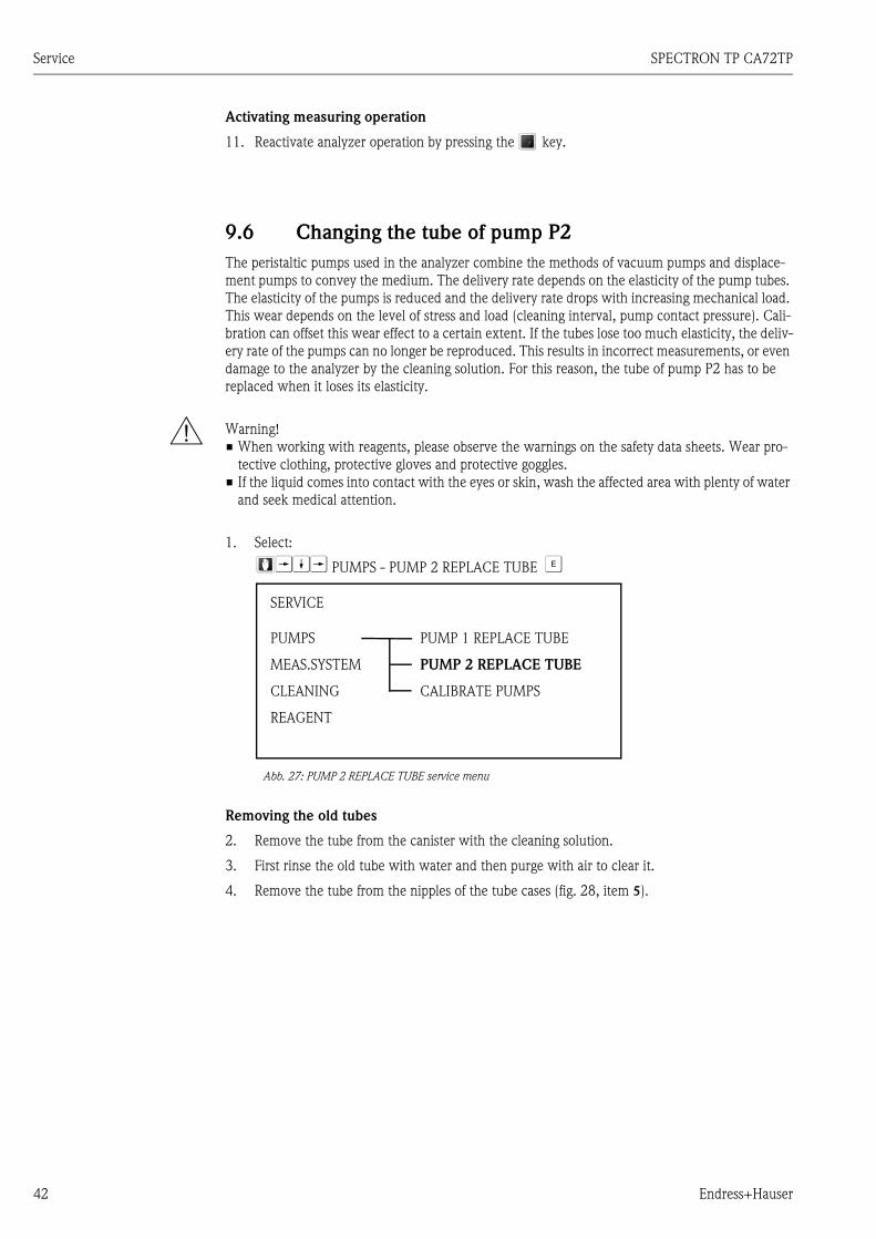
1. Select:
TWT PUMPS - PUMP 2 REPLACE TUBE F
Abb. 27: PUMP 2 REPLACE TUBE service menu
Removing the old tubes
2. Remove the tube from the canister with the cleaning solution.
3. First rinse the old tube with water and then purge with air to clear it.
4. Remove the tube from the nipples of the tube cases (fig. 28, item 5).
SERVICE
PUMPS PUMP 1 REPLACE TUBE
MEAS.SYSTEM PUMP 2 REPLACE TUBE
CLEANING CALIBRATE PUMPS
REAGENT

SPECTRON TP CA72TP Service
Endress+Hauser 43
5. Release the tube case:
– Press against the lower holder (fig. 28, item 3 or fig. 29) to release the tube from the holder:
– Release the tube from connection block P2 (fig. 30) and the reagent connection block.
– You can now remove the tube case along with the pump tube: fig. 31
Fig. 31: Removing the tube case, P2
– Remove the old tube from the case and dispose of it in an environmentally friendly way.
– Clean the tube case and the pump head (fig. 28, item 1) with water.
Fig. 28: Cleaning pump P2
1
2
3
4
5
Pump head
Upper holder of the tube case
Lower holder of the tube case
Guide on pump tube
Nipple with guide
Fig. 29: Lower holder, pump P2 Fig. 30: Tube connection to connection block,
pump P2

Service SPECTRON TP CA72TP
44 Endress+Hauser
Installing the new tube
6. Position the new tube on the tube case.
7. First pull both ends of the tube downwards and then press the guide on the tube into the nipple on the tube case. Make sure it is positioned correctly.
8. First place the tube case into the upper holder (fig. 28, item 2) of the pump and then press the case into the lower holder (item 3). Make sure that the tube case is arranged correctly (fig. 32)
9. If necessary, spray the new pump tube, the tube cases and the pump heads with silicone spray.
10. Reconnect the reagent tube to the canister.
11. After installing, refill the tube with cleaning solution.
12. Perform a calibration (see chapter 9.8 "Calibrating the measuring system").
" Caution!Make sure you connect the new pump tube to the right connections on the P2 and reagent connec-tion blocks!
Setting the pump contact pressure
If you cannot fill the tube without air bubbles, adjust the setscrew for the pump contact pressure:
13. Release the setscrew (fig. 33, item 3) to the point where no more sample is conveyed.
14. Tighten the screw just to the point where sample is conveyed.
15. Tighten the screw one more complete revolution.
" Caution!Set the contact pressure of the tube in such a way that no medium is conveyed to the canister. Oth-erwise, the cleaning solution becomes unusable immediately.For this reason, always perform tests with distilled water only.
Activating measuring operation
16. Reactivate analyzer operation by pressing the key.
Fig. 32: Cleaning pump P2, top view
1 Cleaning solution
Fig. 33: Cleaning pump P2
3 Setscrew for contact pressure

SPECTRON TP CA72TP Service
Endress+Hauser 45
9.7 Calibrating pumps P1, P3, P4 and P5
The SPECTRON TP has a program item that performs calibration for pumps P1, P3, P4 and P5.
You require a 10 ml and 25 ml graduated beaker for this purpose.
1. Select:
TWWT PUMPS - CALIBRATE PUMPS F
Fig. 34: PUMPS/CALIBRATE PUMPS service menu
2. First of all, the optics chamber is filled with standard solution twice to rinse out any reagent residue.
3. You are then prompted to unscrew the dosing element of the optics chamber:
– Release the GL cap on the optics chamber.
– Carefully remove the dosing element of the optics chamber and hold it over the graduated cylinder.
– Press the F key.
Fig. 35: Optics chamber, side view Fig. 36: Front view of the measuring cell
1 Dosing element2 GL cap3 Glass tube4 Measuring block, optics chamber5 O-ring6 Graduation glasses7 Light8 Measuring cell outlet
9 Measuring chamber10 Detector11 Connection for optical waveguide12 Solenoid valveA Valve bodyB Thread adapter nutC Coil housing
SERVICE
PUMPS PUMP 1 REPLACE TUBE
MEAS.SYSTEM PUMP 2 REPLACE TUBE
CLEANING CALIBRATE PUMPS
REAGENT

Service SPECTRON TP CA72TP
46 Endress+Hauser
4. The following appears on the display:
Fig. 37: PUMPS/CALIBRATE PUMPS service menu
5. You can now select the pump you want to calibrate. Using the "1", "3" or "4" key, select the desired pump and follow the instructions.
! Note! You require a 25 ml graduated beaker.
If bubbles are visible in the dosing tubes, remove the bubbles by pressing the T key. As soon as pump calibration is completed, the display goes to the main level.
6. Put the GL cap back on the optics chamber.
7. You can now calibrate additional pumps.
! Note!Always calibrate pump P1 after replacing the pump tube. Pumps P2, P3, P4 and P5 do not neces-sarily have to be calibrated.
All the pumps are calibrated at the factory so you do not have to calibrate the pumps when you put the measuring device into operation for the first time.
PUMP CALIBRATION
KEY (1) PUMP 1
KEY (3) PUMP 3
KEY (4) PUMP 4+5
F TO CONFIRM

SPECTRON TP CA72TP Service
Endress+Hauser 47
9.8 Calibrating the measuring system
The analyzer measuring system can be calibrated automatically or manually. The analyzer is cali-brated using two standard solutions with different known concentrations of the substance to be measured.During the calibration procedure, the two standard solutions are supplied to the system one after the other.The measuring system measures the absorption and assigns it to the particular standard concentra-tion. The system then uses the mathematical ratio between the concentration and measuring signal to calculate the slope and the intercept of the calibration line. Both the intercept and the slope (in relation to 1 mg total-P/l) are saved under KAL OPTIK in the maintenance list report.
Fig. 38: Analyzer calibration line
9.8.1 Determining the standard concentrations
The right choice of standard concentration is critical to the accuracy of the measurement method. Before specifying the concentrations of the standard solutions, determine the concentration range in which the analyzer should measure. The standard solutions should cover the most frequent con-centrations. Please note, however, that the concentration ratio between the two standard solutions should be between 1:5 and 1:20.
If a limit value is to be monitored, it makes sense for the concentration of the limit value to corre-spond to the concentration of a standard solution since this guarantees maximum precision when monitoring.
! Note!Please note that no measurement method can measure accurately over a range greater than 1:20.
Example:Concentration to be measured: 0.1 - 2 mg/l total-PMost frequent concentration: 1 to 2 mg/l total-PLimit value to be monitored: 2 mg/l total-P
0.2 - 2 mg/l total-P should be selected as the standard solutions here. The system can then measure accurately in the range from 0.2 - 2 mg/l total-P (taking the measuring range of the system into account). Higher measured value deviation can be expected below a concentration of 0.2 mg/l total-P and above a concentration of 2 mg/l total-P.
Measured signal
Concentration C2C1
Slope
Offset
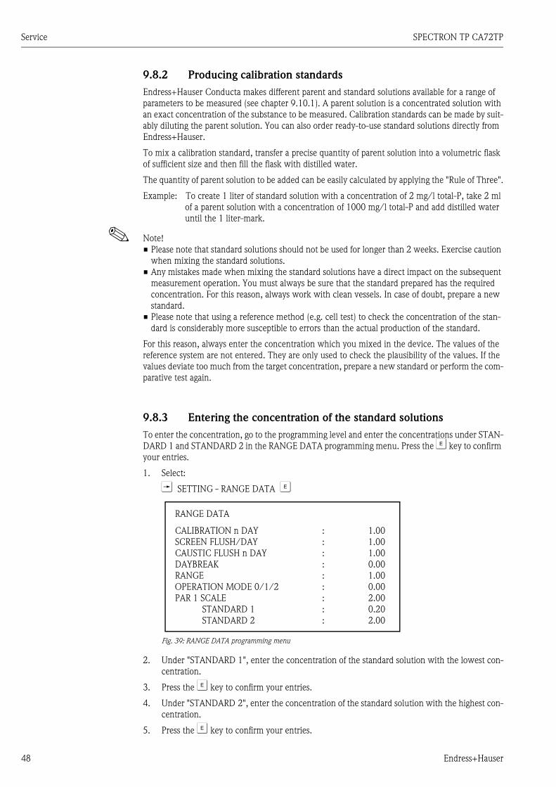
Service SPECTRON TP CA72TP
48 Endress+Hauser
9.8.2 Producing calibration standards
Endress+Hauser Conducta makes different parent and standard solutions available for a range of parameters to be measured (see chapter 9.10.1). A parent solution is a concentrated solution with an exact concentration of the substance to be measured. Calibration standards can be made by suit-ably diluting the parent solution. You can also order ready-to-use standard solutions directly from Endress+Hauser.
To mix a calibration standard, transfer a precise quantity of parent solution into a volumetric flask of sufficient size and then fill the flask with distilled water.
The quantity of parent solution to be added can be easily calculated by applying the "Rule of Three".
Example: To create 1 liter of standard solution with a concentration of 2 mg/l total-P, take 2 ml of a parent solution with a concentration of 1000 mg/l total-P and add distilled water until the 1 liter-mark.
! Note! Please note that standard solutions should not be used for longer than 2 weeks. Exercise caution
when mixing the standard solutions. Any mistakes made when mixing the standard solutions have a direct impact on the subsequent
measurement operation. You must always be sure that the standard prepared has the required concentration. For this reason, always work with clean vessels. In case of doubt, prepare a new standard.
Please note that using a reference method (e.g. cell test) to check the concentration of the stan-dard is considerably more susceptible to errors than the actual production of the standard.
For this reason, always enter the concentration which you mixed in the device. The values of the reference system are not entered. They are only used to check the plausibility of the values. If the values deviate too much from the target concentration, prepare a new standard or perform the com-parative test again.
9.8.3 Entering the concentration of the standard solutions
To enter the concentration, go to the programming level and enter the concentrations under STAN-DARD 1 and STANDARD 2 in the RANGE DATA programming menu. Press the F key to confirm your entries.
1. Select:
T SETTING - RANGE DATA F
Fig. 39: RANGE DATA programming menu
2. Under "STANDARD 1", enter the concentration of the standard solution with the lowest con-centration.
3. Press the F key to confirm your entries.
4. Under "STANDARD 2", enter the concentration of the standard solution with the highest con-centration.
5. Press the F key to confirm your entries.
RANGE DATA
CALIBRATION n DAYSCREEN FLUSH/DAYCAUSTIC FLUSH n DAYDAYBREAKRANGEOPERATION MODE 0/1/2PAR 1 SCALE
STANDARD 1STANDARD 2
: 1.00: 1.00: 1.00: 0.00: 1.00: 0.00: 2.00: 0.20: 2.00

SPECTRON TP CA72TP Service
Endress+Hauser 49
9.8.4 Starting the calibration
There are two types of calibration: manually-activated calibration and automatically-activated cali-bration. Use manually-activated calibration to make the system operational again after it has been cleaned or serviced.
! Note!Please note modifications to the measuring system (optics) may cause deviations in the subsequent measurements. For this reason, always activate a manual calibration after modifying the measuring system.
Manual calibration
To start the manual calibration, select:
WT MEAS.SYSTEM - CALIBRATION F
Fig. 40: MEAS.SYSTEM/CALIBRATION service menu
Automatic calibration
The measuring device can also be calibrated automatically. This ensures that the measuring system always returns precise measurement results. At the same time, automatic calibration also checks the operational reliability of the overall system.
1. Select:
T SETTING - RANGE DATA F
Fig. 41: RANGE DATA programming menu
2. Under "CALIBRATION n DAY", enter the number of calibrations which the measuring device should perform per day. It is generally not necessary to perform more than one calibration per day.
3. Press the F key to confirm your entries.
SERVICE
PUMPS
MEAS.SYSTEM CALIBRATION
CLEANING
REAGENT
RANGE DATA
CALIBRATION n DAYSCREEN FLUSH/DAYCAUSTIC FLUSH n DAYDAYBREAKRANGEOPERATION MODE 0/1/2PAR 1 SCALE
STANDARD 1STANDARD 2
: 1.00: 1.00: 1.00: 0.00: 1.00: 0.00: 2.00: 0.20: 2.00

Service SPECTRON TP CA72TP
50 Endress+Hauser
9.9 Optics chamber maintenance
Structure and design
The optics chamber comprises a rectangular measuring block (4) with a fitted dosing element (1), a light (7), a detector (9) and spectrometer electronics.
9.9.1 Cleaning the optics chamber
! Note!The measuring cell can be cleaned manually. However, this is normally not necessary.
1. If you do, however, decide to clean the optics chamber, place a large collecting vessel under the optics chamber.
2. Select:
WWT CLEANING - OPTICS CHAMBER F
Fig. 44: CLEANING / OPTICS CHAMBER service menu
The optics chamber is prerinsed with standard solution.
Fig. 42: Optics chamber, side view Fig. 43: Front view of the measuring cell
1 Dosing element2 GL cap3 Glass tube4 Measuring block5 O-ring6 Graduation glasses7 Light8 Optics chamber outlet
9 Measuring chamber10 Detector11 Connection for optical waveguide12 Solenoid valveA Valve bodyB Thread adapter nutC Coil housing
SERVICE
PUMPS
MEAS.SYSTEM
CLEANING OPTICS CHAMBER
REAGENT

SPECTRON TP CA72TP Service
Endress+Hauser 51
#Warning!! When working with reagents, please observe the warnings on the safety data sheets.
Wear protective clothing, protective gloves and protective goggles. If the liquid comes into contact with the eyes or skin, wash the affected area with
plenty of water and seek medical attention.
3. Release the GL cap (fig. 43, item 2) from the dosing element (1).
4. Remove the dosing element with the GL cap and screw the GL cap onto the glass sealing cap (accessory).
5. Now clean the optics chamber from above.
Cleaning the graduation glasses
Proceed as follows if you want to clean the graduation glasses in the optics chamber:
1. Release the thread adapter nut of the optical waveguide cable (11) on the detector (10) and remove the optical waveguide cable from the detector.
2. Seal the end of the optical waveguide cable with a protection cap.
3. Unscrew the detector (10) from the holder.
4. Remove the detector holder.
5. At the rear of the device, release the cable connection of the light.
6. Unscrew the light (7) from the holder and remove the light.
7. Release the light holder from the measuring block (4) and remove it.
8. Remove the graduation glasses (6) using the suction cup (accessory).
! Note! When removing the graduation glasses, make sure you do not damage the sealing O-rings (5). Replace them if necessary.
9. Clean the graduation glasses.
Cleaning the measuring block
10. Operate the main switch on the device and switch the device off.
# Warning!! Risk of electric shock!
11. Allow the analyzer heater to cool.
# Warning!! Danger! Hot surfaces! The analyzer heater has to cool down before cleaning is com-menced!
12. Release the thread adapter nut of the solenoid valve MV2 (B) completely, unfasten the coil housing (C) and remove it from the valve body (A).
" Caution!Do not turn the coil housing around its axis!
13. Remove the three slotted screws located at the top of the measuring block and remove the glass tube (3) of the dosing element along with the O-ring (5) and the retaining ring.
14. Unscrew the heating sleeve and remove the heater along with the glass tube.
# Warning!! Danger! Hot surfaces! The analyzer heater has to cool down before it can be removed!
15. Now clean all the bores of the measuring block thoroughly with demineralized water and a bottle brush.
16. Also clean all the removed parts thoroughly.

Service SPECTRON TP CA72TP
52 Endress+Hauser
Assembly
17. After cleaning, fit the glass tube (3) of the dosing element on top of the measuring block (4) together with the retaining ring and O-ring (5).
18. Press down the glass tube until the stop and tighten the three slotted screws.
19. Release the fixing sleeve.
20. Then guide the heater together with the glass tube into the bore until the stop.
21. Now move the heater sleeve together with the large O-ring to the left and screw on the sleeve fingertight.
22. Then screw on the fixing sleeve slightly.
23. Place the coil housing of the solenoid valve (C) into the valve housing (A) in such a way that the device socket is pointing to the right.
" Caution!When inserting the coil housing, make sure the coil housing does not turn around its axis!
The O-ring can be wetted slightly with demineralized water to make insertion easier.
24. Tighten the thread adapter nut (B) of the solenoid valve by hand.
25. Insert the O-rings (5).
26. Place the graduation glasses (6) into the optics chamber with the suction cup. Make sure that the suction cup is clean and does not leave any marks on the glasses.
27. Screw on the detector holder (10). Make sure the marking is pointing upwards.
28. Screw on the light holder.
29. Then screw on the detector (10).
" Caution!When installing the detector make sure that the markings on the detector holder and the detector are aligned with one another.
30. Insert the optical waveguide cable (11) and tighten the thread adapter nut.
31. Check it is well sealed.
32. Screw on the light (7).
33. Now fit the connecting cable on the light and tighten the nut fingertight.
34. Unscrew the GL cap (2) of the dosing element from the safety glass.
35. Fit the dosing element (1) on the glass holder of the optics chamber and tighten it.
" Caution!When inserting the dosing element, make sure that the three Teflon tubes are pointing straight towards the optics chamber and not towards the glass tube or the optics cham-ber body! If necessary, realign the tubes with the optics chamber.
36. Switch on the main switch again.
37. Confirm that cleaning has been performed by pressing the F key.
Manual calibration
38. Trigger a calibration manually after two to three measuring cycles (see chapter "Calibrating the measuring system").
! Note! The analyzer has to be recalibrated after disassembling a component of the optical sys-tem (light, detector, optical waveguide, etc.).

SPECTRON TP CA72TP Service
Endress+Hauser 53
9.10 Topping up reagent
# Warning! When working with reagents, please observe the warnings on the safety data sheets. Wear protective clothing, protective gloves and protective goggles. If the liquid comes into contact with the eyes or skin, wash the affected area with plenty of water
and seek medical attention. Never add water to the reagents! In the case of acidic reagents, there is a risk of splashing and the
danger of extreme heat generation!
9.10.1 Reagents
Only use genuine containers for the measurement. We are not liable for any damage resulting from the use of other chemicals.
The following reagent components are needed to determine the total phosphorus content:
Parent solution
1000 mg/l (1000 ppm) PO4-P; for preparing standard solutions 1 and 2 Order numbers:
1000 ml (33.8 fl.oz.): CAY248-V10C00AAE100 ml (3.38 fl.oz.): CAY248-V01C00AAE
Standard solutions ready for use, per 1 liter (33.8 fl.oz.)
Standard 1.0 mg/l (1 ppm) PO4 - P; Order No. CAY242-V10C01AAE Standard 1.5 mg/l (1.5 ppm) PO4 - P; Order No. CAY242-V10C03AAE Standard 2.0 mg/l (2 ppm) PO4 - P; Order No. CAY242-V10C02AAE Standard 5 mg/l (5 ppm) PO4 - P; Order No. CAY242-V10C05AAE Standard 10 mg/l (10 ppm) PO4 - P; Order No. CAY242-V10C10AAE Standard 15 mg/l (15 ppm) PO4 - P; Order No. CAY242-V10C15AAE Standard 20 mg/l (20 ppm) PO4 - P; Order No. CAY242-V10C20AAE Standard 25 mg/l (25 ppm) PO4 - P; Order No. CAY242-V10C25AAE Standard 30 mg/l (30 ppm) PO4 - P; Order No. CAY242-V10C30AAE Standard 40 mg/l (40 ppm) PO4 - P; Order No. CAY242-V10C40AAE Standard 50 mg/l (50 ppm) PO4 - P; Order No. CAY242-V10C50AAE
Reagent set, active
Digestion agent sodium peroxodisulfate R1, 40 g (1.41 oz., powder) Ascorbic acid R2 + molybdate reagent R3 Order No. CAY246-V10AAE
Reagent set, inactive
Digestion agent sodium peroxodisulfate R1, 40 g (1.41 oz., powder) Per 1 l (33.8 fl.oz.), ascorbic acid R2 and molybdate reagent R3 Order No. CAY246-V10AAH
Cleaner solution
Alkaline cleaner Order No. CAY247-V10AAE

Service SPECTRON TP CA72TP
54 Endress+Hauser
Reagent 1 (sodium peroxodisulfate R1) contains the oxidizing agent and is prepared on site in accor-dance with the mixing instructions supplied.
Reagent 2 (ascorbic acid) and reagent 3 (molybdate reagent) are available as a reagent pack as active and inactive reagents. The active reagent can be used directly but can only be stored for a limited period. It also has to be stored in a dark place at 4 to 8 °C (39 to 46 °F).The inactive reagent can be stored in a dark place as per the best-before date but must be prepared following the mixing instructions before it can be used.
9.10.2 Changing the reagent
1. To change the reagent, go to the service menu:
WWWT REAGENT - EXCHANGE F
Fig. 45: REAGENT / EXCHANGE service menu
Subsequent screen:
Fig. 46: Subsequent screen
2. Remove the cover from the new reagent.
3. Open the cover of the canister in the device and remove together with the tube projecting into the canister.
! Note!It is advisable to have a damp cloth at hand to clean up any drops of reagent that may accidentally drip.
4. Remove the empty canister.
5. Put a new canister into the device.
6. Connect the canisters to the appropriate tubes:
7. Press key "3" and "4" to convey reagent until bubble-free reagent is conveyed.
SERVICE
PUMPS
MEAS.SYSTEM
CLEANING
REAGENT EXCHANGE
REAGENT EXCHANGE
!!! ATTENTION CAUSTIC !!!
OBSERVE SAFETY REGULATIONS
REAGENT EXCHANGE FINISHED ?
Solution Function
Reagent 1Reagent 2 PH-A1Reagent 3 PH-A2Standard 1Standard 2Cleaning solution
Pump P3Pump P4Pump P5Solenoid valve MV4 (left)Solenoid valve MV4 (right)Pump P2

SPECTRON TP CA72TP Service
Endress+Hauser 55
9.11 Removal from service
You must take the analyzer out of service before dispatching it or in the event of extended breaks in operation.
# Warning! When working with reagents, please observe the warnings on the safety data sheets. Wear protective clothing, protective gloves and protective goggles. If the liquid comes into contact with the eyes or skin, wash the affected area with plenty of water
and seek medical attention. Never add water to the reagents! In the case of acidic reagents, there is a risk of splashing and the
danger of extreme heat generation!
" Caution!Prior to taking the analyzer out of service, you must rinse all the tubes thoroughly with distilled water.
Proceed as follows:
1. Switch off the wastewater pump.
2. Feed the reagent back into the canister by opening the lower connection on pump P3.
3. Disconnect the connecting tube of pump P2 from the lower tube connector of P2 in accor-dance with the instructions in chapter "Changing the tube of pump P2" and leave the reagent flow back into the canister.
4. Connect the empty tube back to the tube connector .
5. Take a collecting vessel containing approx. 2 l of distilled water.
6. Remove the reagent canister and put the collecting vessel with the distilled water in its place.
7. To rinse the pump tubes of pump P3, P4 and P5, select:
WWWT REAGENT - EXCHANGE F
8. Repeatedly press keys "3" or "4" to rinse the tubes of pump P3 or P4 and P5 with the distilled water from the collecting vessel.
9. Trigger automatic cleaning of the measuring cell:
WWT CLEANING - OPTICS CHAMBER F
10. Clean the optics chamber manually in accordance with Kapitel "Optics chamber maintenance"
11. Release the tube bed throttle of pump P1.
12. Hold a collecting tray under the 3-way cock and seal off the supply of sample.
13. Remove the canisters.
14. Operate the main switch on the device and switch the device off.
! Note! Keep open reagents and standard solutions refrigerated. Observe the best-before date.

Troubleshooting SPECTRON TP CA72TP
56 Endress+Hauser
10 Troubleshooting
10.1 Troubleshooting instructions
The analyzer's simple design means it is not very susceptible to errors. Nevertheless, errors at the measuring point cannot be ruled out completely.The following section thus contains possible errors, the causes behind such errors and instructions on how to rectify the errors.
10.2 Error messages
10.2.1 Implausible measured values
Error message on the display Cause Countermeasures
"Spectrometer ???" No communication possible with the spectrometer.
Transmission cables or contacts not OK.
Check the connecting cable running from COM1 to COM3 on the spectrometer.
Power supply to the spectrometer dis-connected.
Check the power supply to the spectrome-ter.(When the analyzer is switched on and off at the main switch, the red LED of the spectrometer flashes briefly.)
"Out of range" An error occurred when determining the measured value. The measure-ment was rejected and a new measur-ing cycle initiated.
Real measured value overshooting
Error in optical path
The measuring range limit was reached. The error is displayed when the maximum absorption level permitted is overshot.
Is the optical wave cable mounted? Is the LED lit?
If everything is OK and the error message continues to appear on the display, switch off the measuring device and switch it back on again and trigger a calibration.
Check: If so If not
1. Are the values of the last calibration OK (in the normal range, no asterisks)?
2 see chapter 10.2.2 "Implausible calibra-tion values"
2. Is reagent still present?? 4 3
3. Top up the reagent. Problem solved? 16 4
4. Is the reagent conveyed free from air bubbles? 6 5
5. Rectify defect in leak tightness in the flow. Problem solved? 16 6
6. Is there sample at the 3-way ball cock?Hold a beaker under the 3-way cock and turn the cock in the direction of the beaker.
8 7

SPECTRON TP CA72TP Troubleshooting
Endress+Hauser 57
10.2.2 Implausible calibration values
7. Check the sample supply path and the wastewater pump.
Problem solved? 16 8
8. Check the heater:Is the detector or the measuring cell warm?
10 9
9. Check the heater, the heating regulator, relay No. 7 and the power supply.
Problem solved? 16 10
10. Does MV1 switch?In the PROGRAMMING/TEST/TEST OF OUT-PUTS/DIGITAL OUTPUTS mode, check whether MV1 switches electrically when switch output 1 is actuated.
12 11
11. Check whether the corresponding relay, the fuse, the electrical connection and the solenoid valve are func-tioning correctly.
Problem solved? 16 12
12. Is sample dripping into the measuring cell?Lift up the dosing element approx. 2 cm and check whether sample drips into the measuring cell during a new measuring cycle.
14 13
13. Check the sample path from the 3-way cock to the dos-ing element and eliminate any clogging.
Problem solved? 16 14
14. Is MV3 leak-tight?Remove the tube for standard 1 from the storage con-tainer. Standard may not be conveyed during normal operation.
16 17
15. Replace the seal of solenoid valve MV3. Problem solved? 16
16. Trigger a calibration. Problem solved? 17
17. Notify the Service department of Endress+Hauser Con-ducta GmbH&Co.KG, Division STIP.Use the service information sheet at the end of this chap-ter
Tel:+49 6078 786-20Fax: +49 06078 786-88
Check: If so If not
1. Is sufficient standard in the standard containers? 3 2
2. Top up the standard solutions. Problem solved? 20 3
3. Are the standard solutions conveyed free from air bubbles? 5 4
4. Check all the seals and tubes along the delivery path. Problem solved? 20 5
5. Is reagent still present? 7 6
6. Top up the reagent solutions. Problem solved? 20 7
7. Is the reagent conveyed free from air bubbles? 9 8
8. Rectify defect in leak tightness in the flow of reagent. Problem solved? 20 9
9. Are solenoid valves MV3 and MV4 leak-tight? Is sample possibly mixing with standard, or is standard 1 mixing with standard 2? Remove the tube for standard 1 and 2 from the canister. Close the 3-way cock in the direction of the sample supply. Attach a tube with an ID of 4 mm (ID 3.2 inch) or less to the 3-way cock and place it in a beaker with water. Go to PROGRAMMING/TEST/TEST OF OUT-PUTS/PUMPS and set P1 to 100%. Change to PROGRAM-MING/TEST/TEST OF OUTPUTS/DIGITAL OUTPUTS and check whether only the specific sample or standard is con-veyed when switch output 3 and 4 are actuated.
11 10
10. Replace the seal of solenoid valve MV 3 and/or MV4. Problem solved? 20 11
Check: If so If not

Troubleshooting SPECTRON TP CA72TP
58 Endress+Hauser
11. Does solenoid valve MV1 switch?In the PROGRAMMING/TEST/TEST OF OUTPUTS/DIGI-TAL OUTPUTS mode, check whether MV1 switches electri-cally when switch output 1 is actuated.
13 12
12. Check whether the corresponding relay, the fuse, the electri-cal connection and the solenoid valve are functioning cor-rectly.
Problem solved? 20 13
13. Is sample dripping into the optics chamber?Lift up the dosing element approx. 2 cm and check whether sample drips into the optics chamber during a new measur-ing cycle.
15 14
14. Check the sample path from solenoid valve MV3 to the dos-ing element and eliminate any clogging.
Problem solved? 20 15Optical measure-ment
15. Check the spectrometric measurement:Are the glasses of the optics chamber clean?If X0 is unusually high (print on the left-hand side of the MAINTENANCE RECORD CAL.OPTICS). Disassemble the optical wave cable and the detector (see chapter 9.9 "Optics chamber maintenance") and empty the optics chamber with the service key.
17 16
16. Clean the graduation glasses of the optics chamber (see chap-ter 9.9 "Optics chamber maintenance").
Problem solved? 20 17
17. Is the slope unusually low or high? 15 21
18. Are the standard solutions OK?(Test with another method or prepare new standards. In doing so, please follow the instructions under Kapitel "Pro-ducing calibration standards").
21 19
19. Replace the standard solutions with new ones. Problem solved? 20 2
20. Trigger a calibration (see chapter 9.8 "Calibrating the mea-suring system").
Problem solved? 21
21. Notify the Service department of Endress+Hauser Conducta GmbH&Co.KG, Division STIP.Use the service information sheet at the end of this chapter.
Tel:+49 6078 786-20Fax: +49 6078 786-88
Check: If so If not

SPECTRON TP CA72TP Troubleshooting
Endress+Hauser 59
Service information sheet for SPECTRON TP
If problems occur, fill in this information sheet and fax it along with a description of the problem to Endress+Hauser Conducta GmbH&Co.KG Division STIP: Fax: +49 6078 78688
Name: Device number: Tel.:
Visual inspection and trouble-shooting
Bypass and measuring cell outlet free from pressure?
SPECIAL MENU DATAKey "1" Key "2"
V.OPTICS CHAMBERSAMPLE PORTIONREAG 1 PORTIONREAG 2+3 PORTIONPATH LENGTHOXIDATION TIME MEASOXIDATION TIME CAL.
=======
Q P1 100%Q P2 100%Q P3 / 15 HÜBEQ P4+P5/ 15 HÜBE
====
If you have a printer, you can print out the data in the pro-gramming mode by pressing key "5" 3 times and then key "9"!
RANGE DATA BASIC DATA
CALIBRATION n DAYSCREEN FLUSH/DAYCAUSTIC FLUSH n DAYDAYBREAKRANGEOPERATION MODE 0/1/2PAR 1 SCALE STANDARD 1 STANDARD 2
=========
METHODQ P1[ml/min]REACTION TIME MEAS.REACTION TIME CAL.MEAS. DELAY MINMEAS. DELAY MAXTHRESHOLD MB[%]T-FLUSH [sec]EXCHANGE TIMEOFFESET PAR 1
==========
If you have a printer, you can print out the measuring range data and the basic data under PROGRAMMING/LISTS/ INPUT DATA.
Description of the measuring point Description of the medium
IndustrialMunicipalInletSludge activationSecondary clarificationOther (short description)Ambient temperature:
Turbidity (low, medium, high):Coloration (description of the color)Salt content mg/l:FibrousOily or greasySludge volume:Total solids:Sample temperature:
Print out information from the programming mode/list, or note down this information on another sheet:
The alarm messages before and after the error occurred:PROGRAMMING/LISTS/ALARM RECORDThe last three calibration value records PROGRAMMING/LISTS/MAINTENANCE RECORD/CAL.OPTICS.If a printer is available, print out the load curves for the 3 days before and after the error occurred.
If available, note down the comparative measurements. CA72TP- : Comparative measurement:
Performed with?

Troubleshooting SPECTRON TP CA72TP
60 Endress+Hauser
10.3 Return
If the analyzer has to be repaired, please send the analyzer cleaned to your sales center.Use the original packaging when returning the device.
Please enclose a duly completed "Declaration of Contamination and Cleaning" form with the pack-aging and shipping documents (copy the second-last page of these Operating Instructions). The device cannot be repaired if a duly completed form is not enclosed!
10.4 Disposal
The device contains electronic components and must therefore be disposed of in accordance with regulations on the disposal of electronic waste.Please observe local regulations.

SPECTRON TP CA72TP Technical data
Endress+Hauser 61
11 Technical data
11.1 Input
11.2 Output
11.3 Power supply
! Note! The SPECTRON TP CA72TP is suitable for connection to industrial mains support according to EN 61326-1, class A.
11.4 Performance characteristics
Measured variable Total phosphorus (TP) [mg/l]
Measuring range 0.05 to 2 mg/l (CA72TP-A) 0.1 to 5 mg/l (CA72TP-B)
Wavelength 735 nm
Output signal 0/4 to 20 mA, galvanically isolated
Signal on alarm Limit value alarm, fault message and two optional contacts (0.25 A / 50 V)
Load Max. 500 ΩLoading capacity 230 V AC, max. 2 A
Assignment See fig. 7
Supply voltage 230 V AC, 50/60 Hz
Power consumption 161 VA
Current consumption 0.7 A
Fuses 1 x 16 A FF (power distribution connection)1 x 2 A T (electronics power unit)
Maximum measured error ±5 % of end of measuring range
Measuring interval Approx. 2 measurements per hour (at a digestion time of 15 min.)
Time between two measurements tmeas = sample dosing (150 s) + oxidation time (960 s) + color reaction time (180 s) + measured value calculation (180 s) + discard sample + break in measuring (optional) + rinse time (210 s) = 28 min
Only the oxidation time can be set (0 to 3600 s)
Sample requirement 40 ml (1.35 fl.oz.) / measurement
Reagent requirement Oxidizing agent REG1: 370 ml (12.5 fl.oz.) / month with 30-minute measur-ing interval
REG2 + REG3: 500 ml (16.9 fl.oz.) / month with 30-minute measuring inter-val(for measuring ranges 5 mg/l and under, the amount of REG1-REG3 required is reduced by 30%)
Cleaning solution: 250 ml (8.45 fl.oz.) / month with one cleaning per day
Calibration interval Selectable, 1-4 calibrations per day up to one calibration per week Standard: once per day at ambient temperatures < 30 °C (86 °F)
Rinsing interval Alkaline rinsing: Selectable, 4 rinses per day up to one rinse per week

Technical data SPECTRON TP CA72TP
62 Endress+Hauser
11.5 Environment
11.6 Process
11.7 Mechanical construction
11.8 Human interface
Maintenance interval 6 months (typical)
Maintenance effort Daily: visual inspection Every 2 weeks: replace or top up reagents and standards Every 6 weeks: clean sample conditioning system (if available) Every 12 weeks: replace pump tubes and calibrate all pumps
Ambient temperature range 0 to 40 °C (32 to 100 °F)
Humidity 10 to 90 %, non-condensating
Degree of protection IP54
Sample temperature 5 to 40 °C (40 to 104 °F)
Sample flow rate 5 to 12 ml/min (0.17 to 0.4 fl.oz./min); pay attention to delivery rate of the pump!
Consistency of sample Low level of solids, particle size < 500 ppm
Sample outlet Unpressurized
Design, dimensions see chapter 3 "Installation"
Weight Approx. 83 kg (183 lbs)
Material HousingFront windowValve sealsPump tubesPump and pump sealsReagent and sample tubesTubes for exhaust air and ventila-tionDischarge tubes
Aluminum, powder-coatedGlass, conductive coatingEPDM, PTFEEPDM, Tygon®PTFEPTFE, PFANorprene, PEPTFE, PE
Display and operating elements DisplayLCD graphic display, 16 lines, 40 characters per line, backlitKeyboard21 operating keys, 13 x 13 mm with pressure point
Serial interface RS232

P/S
F/K
on
taX
IV
Because of legal regulations and for the safety of our employees and operating equipment, we need the "Declaration of Hazardous Materialand De-Contamination", with your signature, before your order can be handled. Please make absolutely sure to attach it to the outside of thepackaging.Aufgrund der gesetzlichen Vorschriften und zum Schutz unserer Mitarbeiter und Betriebseinrichtungen, benötigen wir die unterschriebene"Erklärung zur Kontamination und Reinigung", bevor Ihr Auftrag bearbeitet werden kann. Bringen Sie diese unbedingt außen an derVerpackung an.
Serial number
Seriennummer ________________________Type of instrument / sensor
Geräte-/Sensortyp ____________________________________________
Process data/Prozessdaten Temperature _____ [°F] [°C]
Conductivity / ________
_____
Leitfähigkeit
/
[µS/cm]
Temperatur Pressure _____ [psi] [ Pa ]
Viscosity _____ [cp] [mm /s]
_____
_____
/
/
Druck
Viskosität2
corrosiveätzend
harmlessunbedenklich
other *sonstiges*
toxicgiftig
Processmedium
IdentificationCAS No.
flammableentzündlich
harmful/irritant
gesundheits-schädlich/
reizend
Medium /concentrationMedium /Konzentration
Returned partcleaned with
Medium forprocess cleaning
Medium and warnings
Warnhinweise zum Medium
* explosive; oxidising; dangerous for the environment; biological risk; radioactive* explosiv; brandfördernd; umweltgefährlich; biogefährlich; radioaktiv
Please tick should one of the above be applicable, include safety data sheet and, if necessary, special handling instructions.Zutreffendes ankreuzen; trifft einer der Warnhinweise zu, Sicherheitsdatenblatt und ggf. spezielle Handhabungsvorschriften beilegen.
Description of failure / Fehlerbeschreibung __________________________________________________________________________
______________________________________________________________________________________________________________
______________________________________________________________________________________________________________
“We hereby certify that this declaration is filled out truthfully and completely to the best of our knowledge.We further certify that the returnedparts have been carefully cleaned. To the best of our knowledge they are free of any residues in dangerous quantities.”“Wir bestätigenw
bestätigen, die vorliegende Erklärung nach unserem besten Wissen wahrheitsgetreu und vollständig ausgefüllt zu haben. Wireiter, dass die zurückgesandten Teile sorgfältig gereinigt wurden und nach unserem besten Wissen frei von Rückständen in gefahrbringen-
der Menge sind.”
(place, date / Ort, Datum)
Company data /Angaben zum Absender
Company / ________________________________
_________________________________________________
Address /
_________________________________________________
_________________________________________________
Firma ___
Adresse
Phone number of contact person /
____________________________________________
Fax / E-Mail ____________________________________________
Your order No. / ____________________________
Telefon-Nr. Ansprechpartner:
Ihre Auftragsnr.
Medium zurEndreinigung
Medium zurProzessreinigung
Medium imProzess
Used as SIL device in a Safety Instrumented System / Einsatz als SIL Gerät in Schutzeinrichtungen
RA No.
Erklärung zur Kontamination und ReinigungDeclaration of Hazardous Material and De-Contamination
Please reference the Return Authorization Number (RA#), obtained from Endress+Hauser, on all paperwork and mark the RA#clearly on the outside of the box. If this procedure is not followed, it may result in the refusal of the package at our facility.
Bitte geben Sie die von E+H mitgeteilte Rücklieferungsnummer (RA#) auf allen Lieferpapieren an und vermerken Sie dieseauch außen auf der Verpackung. Nichtbeachtung dieser Anweisung führt zur Ablehnung ihrer Lieferung.
Name, dept./Abt. (please print / )bitte Druckschrift Signature / Unterschrift

www.endress.com/worldwide
BA439C/07/EN/05.09Printed in Germany / FM+SGML 6.0 / DT