Contribution to the modelling of the viscoelastic behavior of ...
Upload
univ-lyon3Category
view
0download
0
On the use of a loudspeaker for measuring the
viscoelastic properties of sound absorbing materials
Olivier Doutres, Nicolas Dauchez, Jean-Michel Genevaux, Guy Lemarquand
To cite this version:
Olivier Doutres, Nicolas Dauchez, Jean-Michel Genevaux, Guy Lemarquand. On the use of aloudspeaker for measuring the viscoelastic properties of sound absorbing materials. Journal ofAcoustical Society of America, 2008, 124 (6), pp.EL335-40. <hal-00323570>
HAL Id: hal-00323570
https://hal.archives-ouvertes.fr/hal-00323570
Submitted on 24 Sep 2008
HAL is a multi-disciplinary open accessarchive for the deposit and dissemination of sci-entific research documents, whether they are pub-lished or not. The documents may come fromteaching and research institutions in France orabroad, or from public or private research centers.
L’archive ouverte pluridisciplinaire HAL, estdestinee au depot et a la diffusion de documentsscientifiques de niveau recherche, publies ou non,emanant des etablissements d’enseignement et derecherche francais ou etrangers, des laboratoirespublics ou prives.
Doutres et al.
On the use of a loudspeaker for measuring the viscoelastic properties of sound
absorbing materials
Olivier Doutres, Nicolas Dauchez, Jean-Michel Genevaux, and Guy Lemarquand
LAUM, CNRS, Universite du Maine, Av. O. Messiaen, 72095 LE MANS, France
[email protected], [email protected], jean-
[email protected], [email protected]
1
Doutres et al.
Abstract
This paper investigates the feasibility to use an electrodynamic
loudspeaker to determine viscoelastic properties of sound absorbing
materials in the audible frequency range. The loudspeaker compresses
the porous sample in a cavity and a measurement of its electrical
impedance allows to determine the mechanical impedance of the
sample: no additional sensors are required. Viscoelastic properties
of the material are then estimated by inverting a 1D Biot model.
The method is applied to two sound absorbing materials (glass wool
and polymer foam). Results are in good agreement with classical
compression quasistatic method.
PACS numbers: 43.20.Ye, 43.20.Jr, 43.38.Dv
2
Doutres et al.
1. Introduction
Characterization of sound absorbing materials, like mineral wool or polymer foam, in
the context of building or transport applications, requires the determination of viscoelastic
properties of the skeleton1. Classical methods to measure viscoelastic properties of porous
materials can be sorted in two groups: the quasi-static methods neglect the inertial effects of
the frame and give relevant information in the low frequency range before the first resonance
of the system2,3 (usually for f < 100 Hz); the dynamic methods are based on the vibration of
a porous sample4, or of a structure which includes a porous layer5, and give information at the
resonance frequencies of the structure. More recently methods based on the propagation on
surface waves at the free surface of a porous layer have been investigated6,7. These methods
require the use of an actuator, usually a shaker, and specific sensors: accelerometer, force
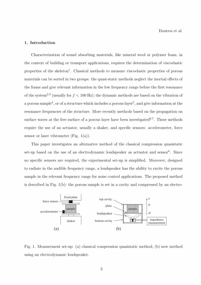
sensor or laser vibrometer (Fig. 1(a)).
This paper investigates an alternative method of the classical compression quasistatic
set-up based on the use of an electrodynamic loudspeaker as actuator and sensor8. Since
no specific sensors are required, the experimental set-up is simplified. Moreover, designed
to radiate in the audible frequency range, a loudspeaker has the ability to excite the porous
sample in the relevant frequency range for noise control applications. The proposed method
is described in Fig. 1(b): the porous sample is set in a cavity and compressed by an electro-
shaker
fixed plate
force sensor
accelerometersample
(a) (b)
plate
top cavity
bottom cavity
sample
loudspeaker
impedance measurement
-d
x
0
Fig. 1. Measurement set-up: (a) classical compression quasistatic method; (b) new method
using an electrodynamic loudspeaker.
3
Doutres et al.
dynamic loudspeaker. Measurement of the electrical impedance of the loudspeaker allows to
determine the mechanical impedance of the sample by inverting an electroacoustic model.
The viscoelastic properties of the porous frame are then estimated using the classical Biot
model9,10.
First part of the paper presents the experimental setup. The principle of measurement
and the poroelastic model used for the determination of the viscoelastic properties are then
described. Results for two porous materials are finally compared with the classical compres-
sion quasistatic method of Fig. 1(a).
2. Measurement set-up
The experimental setup to validate the proposed electrodynamic technique is presented
in Fig. 1(b) . A loudspeaker of 71 mm diameter is mounted between two cavities and applies
static and dynamic strains to a porous sample set in the top cavity. The sample diameter is
smaller than the one of the cavity to avoid any lateral strain. The depth of the cavity can be
adjusted to the size of the porous sample to impose a static compression (see Table 2). The
cavity is used to simplify the inversion procedure and to limit the effect of air pumping3.
A circular aluminium plate of 1 mm thickness is bonded on the loudspeaker cone to
ensure a planar and unidirectional compression of the porous sample. The association of the
plate and the cone is called the diaphragm. It has its first resonance frequency around 2 kHz
and is considered to behave as a rigid body far below this frequency.
Measurement of the electrical impedance is performed with a Precision Magnetic Anal-
yser (Wayne Kerr PMA 3260A) using a sine step signal from 25 Hz to 200 Hz.
4
Doutres et al.
3. Principle of measurement
3.1 Determination of the sample mechanical impedance
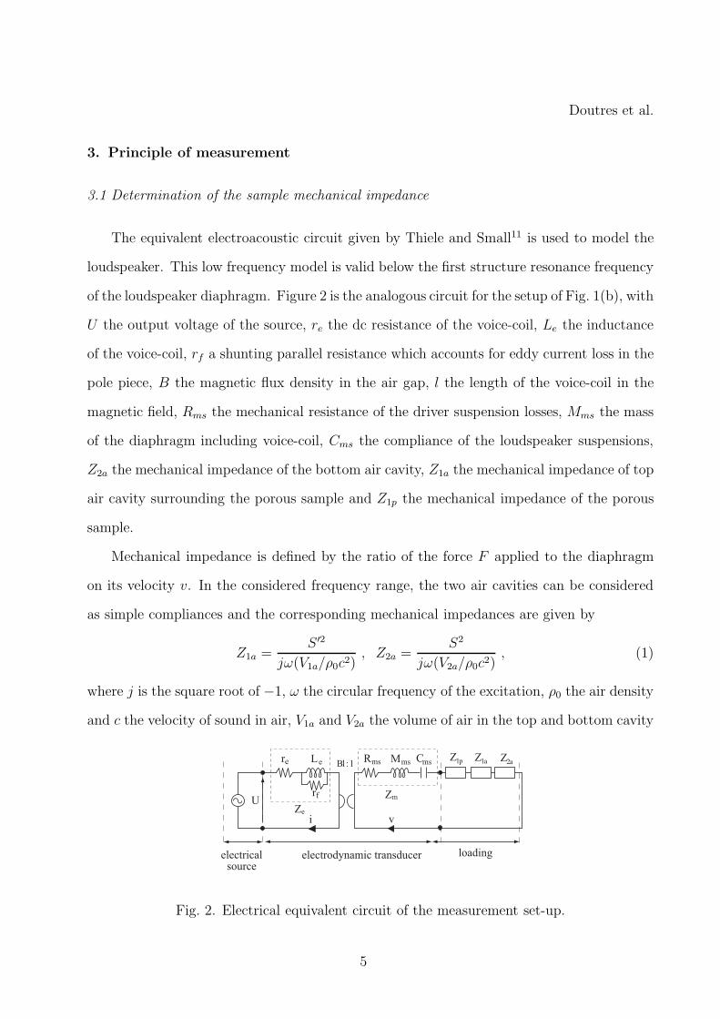
The equivalent electroacoustic circuit given by Thiele and Small11 is used to model the
loudspeaker. This low frequency model is valid below the first structure resonance frequency
of the loudspeaker diaphragm. Figure 2 is the analogous circuit for the setup of Fig. 1(b), with
U the output voltage of the source, re the dc resistance of the voice-coil, Le the inductance
of the voice-coil, rf a shunting parallel resistance which accounts for eddy current loss in the
pole piece, B the magnetic flux density in the air gap, l the length of the voice-coil in the
magnetic field, Rms the mechanical resistance of the driver suspension losses, Mms the mass
of the diaphragm including voice-coil, Cms the compliance of the loudspeaker suspensions,
Z2a the mechanical impedance of the bottom air cavity, Z1a the mechanical impedance of top
air cavity surrounding the porous sample and Z1p the mechanical impedance of the porous
sample.
Mechanical impedance is defined by the ratio of the force F applied to the diaphragm
on its velocity v. In the considered frequency range, the two air cavities can be considered
as simple compliances and the corresponding mechanical impedances are given by
Z1a =S ′2
jω(V1a/ρ0c2), Z2a =
S2
jω(V2a/ρ0c2), (1)
where j is the square root of −1, ω the circular frequency of the excitation, ρ0 the air density
and c the velocity of sound in air, V1a and V2a the volume of air in the top and bottom cavity
U
Bl : 1
i
electrodynamic transducer loadingelectrical source
Rms Mms
Zm
Cmsre Le
Ze
rf
Z1p Z1a Z2a
v
Fig. 2. Electrical equivalent circuit of the measurement set-up.
5
Doutres et al.
respectively, S the equivalent surface area of the diaphragm in contact with the bottom
cavity and S ′ the equivalent surface area of the upper face of the diaphragm in contact with
the air layer in the top cavity.
The electrical impedance of the circuit (Fig. 2) writes
Zvc =U
i= Ze +
(Bl)2
Zm + [Z1p + Z1a + Z2a]with (2)
Ze = re +jωLerf
jωLe + rf
and (3)
Zm = Rms + jωMms +1
jωCms
. (4)
Hence, the mechanical impedance of the sample can be derived from the measurement
of Zvc, the properties of the loudspeaker and of the two air cavities as
Z1p =(Bl)2
Zvc − Ze
− (Zm + Z1a + Z2a) . (5)
3.2 Determination of the loudspeaker properties
The properties of the loudspeaker are determined from the measurement of the electrical
impedance without porous sample in the top cavity. In that case, the equivalent electrical
circuit model gives
Zvc = Ze +(Bl)2
Zm + [Z1a + Z2a]. (6)
with Z1a = S2ρ0c2/jωV1a and V1a the volume of the top cavity. The model is fitted on the
measurement using a non-linear least squares method to get re, Le, rf , Bl, Rms, Cms and
Mms.
3.3 Calculation of the material viscoelastic properties
The viscoelastic properties of the porous frame are estimated from the impedance Z1p
by inverse method using Biot model. In the considered model, the material is isotropic and
the displacements of the frame and air are one-dimensional along the sample thickness (x
6
Doutres et al.
direction in Fig. 1(b)). The porous material is considered as infinite in the lateral directions
and the effects of the boundary conditions are neglected. This assumption is valid for porous
materials such as glass wool with a Poisson’s ratio equal to 0 but it can induce an evaluation
discrepancy for foam materials which can bulge sideways when compressed between two rigid
plates12.
The mechanical impedance can be derived analytically from the calculation of the total
stress (σtxx) applied by the porous sample to the vibrating diaphragm
Zth1p(ω) =
F
v=
S′′
p σtxx
ωuw
, (7)
with S′′
p the surface area of the porous sample in contact with the vibrating diaphragm
(S′′
p = Sp − S′
p) and uw the amplitude of the displacement imposed by the diaphragm.
According to Biot theory9,10, two compressional waves propagate in a porous media having
a one dimensional behavior. These waves are characterized by a complex wave number
δi (i = 1, 2) and a displacement ratio µi. The total stress exerted by the sample to the
diaphragm is thus the sum of the stress exerted by the fluid and solid phases characterized
by these two waves as
σtxx = σs
xx + σfxx (8)
=[
(P + Q) + µ1(R + Q)]
δ1 cos(δ1d)D1 +[
(P + Q) + µ2(R + Q)]
δ2 cos(δ2d)D2 .
In these equations, d is the sample thickness, P and R are the bulk modulus of the solid
and fluid phases, respectively, and Q quantifies the potential coupling between the two
phases. Expression of these two last coefficients can be found in reference10. D1 and D2 are
the amplitude coefficients of the two compressional waves and can be determined from the
boundary conditions applied to the sample. Here, the displacement is zero at x = 0 and is
equal to the one of the diaphragm at x = −d which gives
D1 =uw(µ2 − 1)
sin(δ1d)(µ1 − µ2), D2 =
uw(1 − µ1)
sin(δ2d)(µ1 − µ2). (9)
7
Doutres et al.
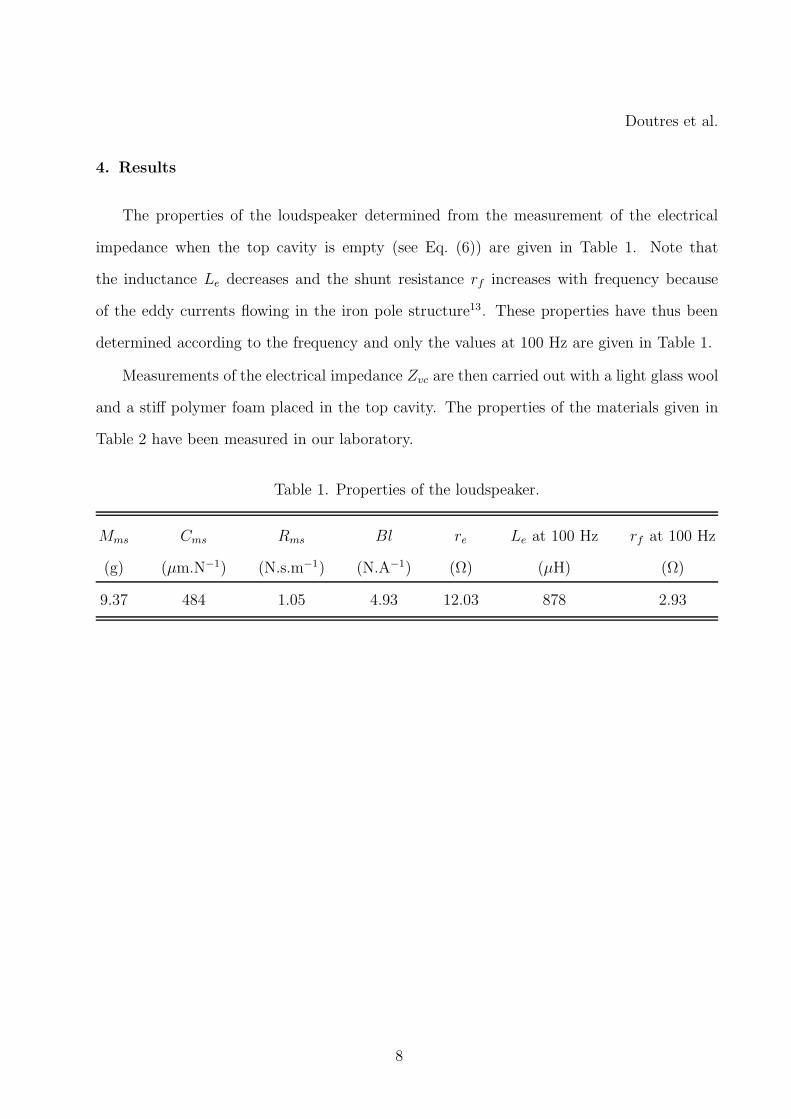
4. Results
The properties of the loudspeaker determined from the measurement of the electrical
impedance when the top cavity is empty (see Eq. (6)) are given in Table 1. Note that
the inductance Le decreases and the shunt resistance rf increases with frequency because
of the eddy currents flowing in the iron pole structure13. These properties have thus been
determined according to the frequency and only the values at 100 Hz are given in Table 1.
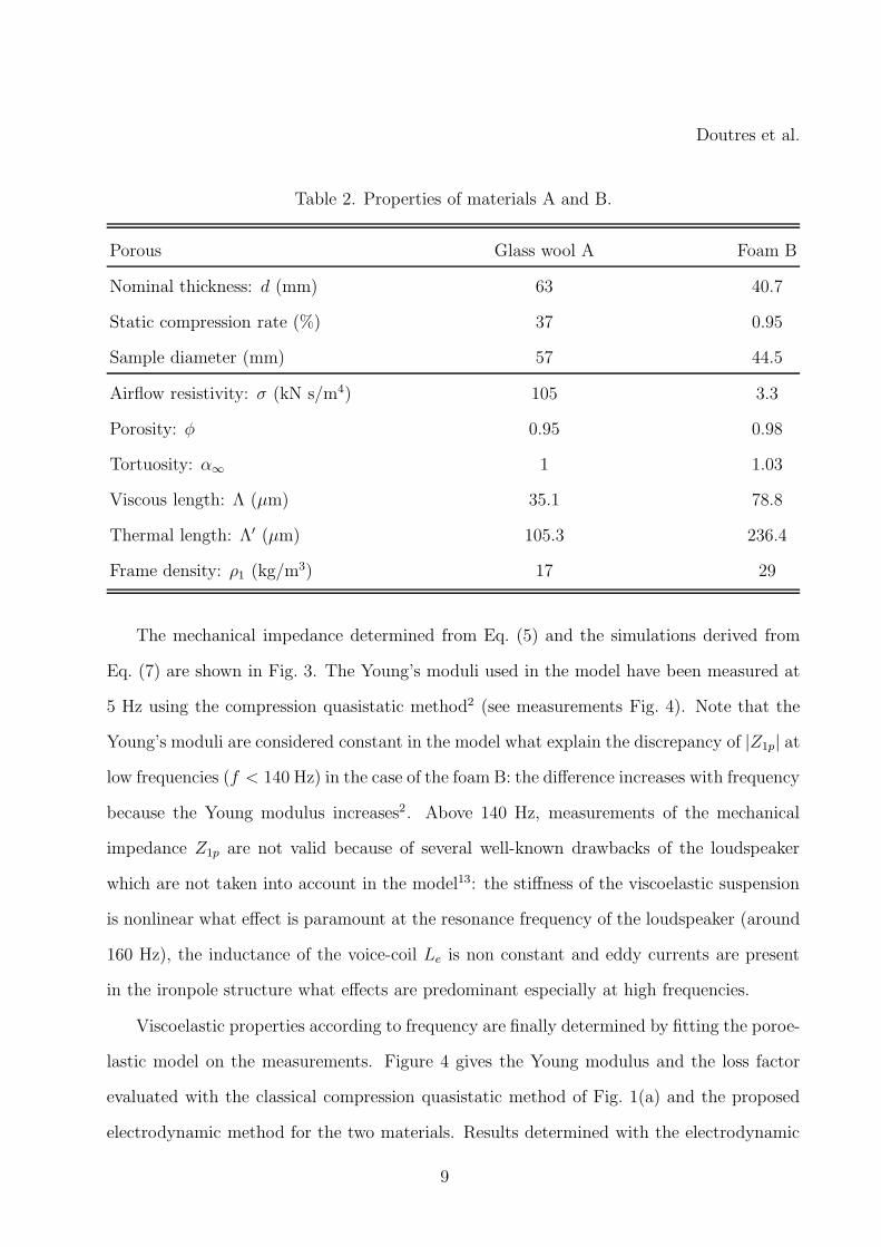
Measurements of the electrical impedance Zvc are then carried out with a light glass wool
and a stiff polymer foam placed in the top cavity. The properties of the materials given in
Table 2 have been measured in our laboratory.
Table 1. Properties of the loudspeaker.
Mms Cms Rms Bl re Le at 100 Hz rf at 100 Hz
(g) (µm.N−1) (N.s.m−1) (N.A−1) (Ω) (µH) (Ω)
9.37 484 1.05 4.93 12.03 878 2.93
8
Doutres et al.
Table 2. Properties of materials A and B.
Porous Glass wool A Foam B
Nominal thickness: d (mm) 63 40.7
Static compression rate (%) 37 0.95
Sample diameter (mm) 57 44.5
Airflow resistivity: σ (kN s/m4) 105 3.3
Porosity: φ 0.95 0.98
Tortuosity: α∞ 1 1.03
Viscous length: Λ (µm) 35.1 78.8
Thermal length: Λ′ (µm) 105.3 236.4
Frame density: ρ1 (kg/m3) 17 29
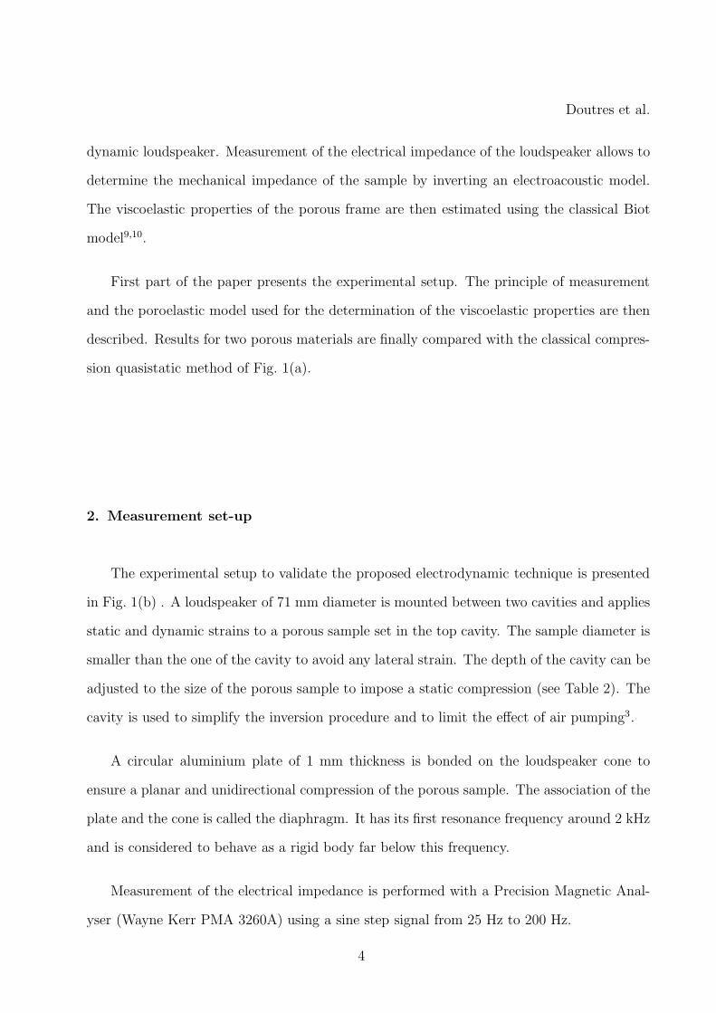
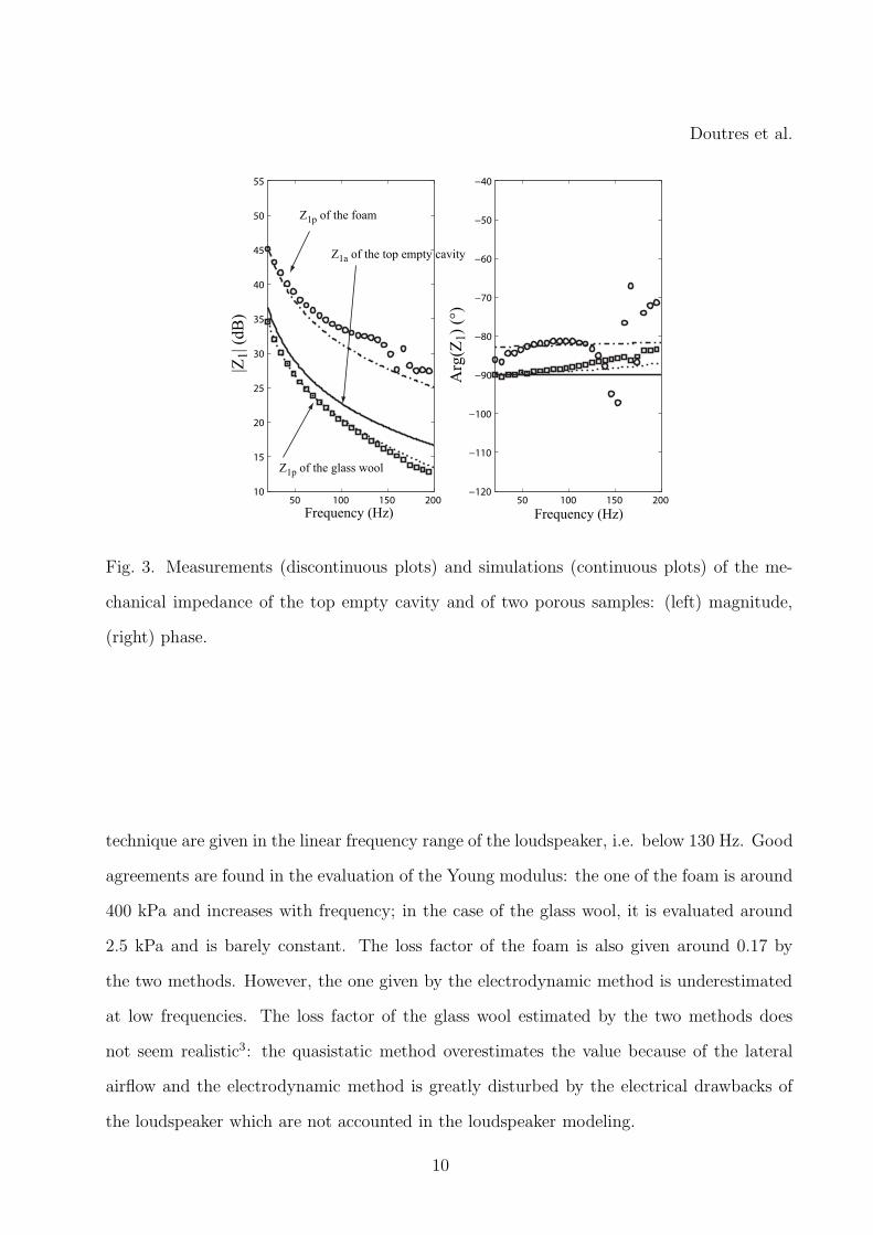
The mechanical impedance determined from Eq. (5) and the simulations derived from
Eq. (7) are shown in Fig. 3. The Young’s moduli used in the model have been measured at
5 Hz using the compression quasistatic method2 (see measurements Fig. 4). Note that the
Young’s moduli are considered constant in the model what explain the discrepancy of |Z1p| at
low frequencies (f < 140 Hz) in the case of the foam B: the difference increases with frequency
because the Young modulus increases2. Above 140 Hz, measurements of the mechanical
impedance Z1p are not valid because of several well-known drawbacks of the loudspeaker
which are not taken into account in the model13: the stiffness of the viscoelastic suspension
is nonlinear what effect is paramount at the resonance frequency of the loudspeaker (around
160 Hz), the inductance of the voice-coil Le is non constant and eddy currents are present
in the ironpole structure what effects are predominant especially at high frequencies.
Viscoelastic properties according to frequency are finally determined by fitting the poroe-
lastic model on the measurements. Figure 4 gives the Young modulus and the loss factor
evaluated with the classical compression quasistatic method of Fig. 1(a) and the proposed
electrodynamic method for the two materials. Results determined with the electrodynamic
9
Doutres et al.
50 100 150 20010
15
20
25
30
35
40
45
50
55
50 100 150 200−120
−110
−100
−90
−80
−70
−60
−50
−40
Frequency (Hz)
|Z1| (
dB
)
Frequency (Hz)
Arg
(Z1)
(°)
Z1a of the top empty cavity
Z1p of the glass wool
Z1p of the foam
Fig. 3. Measurements (discontinuous plots) and simulations (continuous plots) of the me-
chanical impedance of the top empty cavity and of two porous samples: (left) magnitude,
(right) phase.
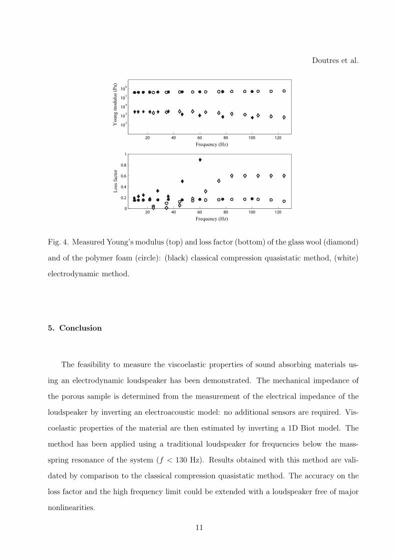
technique are given in the linear frequency range of the loudspeaker, i.e. below 130 Hz. Good
agreements are found in the evaluation of the Young modulus: the one of the foam is around
400 kPa and increases with frequency; in the case of the glass wool, it is evaluated around
2.5 kPa and is barely constant. The loss factor of the foam is also given around 0.17 by
the two methods. However, the one given by the electrodynamic method is underestimated
at low frequencies. The loss factor of the glass wool estimated by the two methods does
not seem realistic3: the quasistatic method overestimates the value because of the lateral
airflow and the electrodynamic method is greatly disturbed by the electrical drawbacks of
the loudspeaker which are not accounted in the loudspeaker modeling.
10
Doutres et al.
20 40 60 80 100 120
102
103
104
105
106
Frequency (Hz)
Young m
odulu
s (P
a)
20 40 60 80 100 1200
0.2
0.4
0.6
0.8
1
Frequency (Hz)
Loss
fac
tor
Fig. 4. Measured Young’s modulus (top) and loss factor (bottom) of the glass wool (diamond)
and of the polymer foam (circle): (black) classical compression quasistatic method, (white)
electrodynamic method.
5. Conclusion
The feasibility to measure the viscoelastic properties of sound absorbing materials us-
ing an electrodynamic loudspeaker has been demonstrated. The mechanical impedance of
the porous sample is determined from the measurement of the electrical impedance of the
loudspeaker by inverting an electroacoustic model: no additional sensors are required. Vis-
coelastic properties of the material are then estimated by inverting a 1D Biot model. The
method has been applied using a traditional loudspeaker for frequencies below the mass-
spring resonance of the system (f < 130 Hz). Results obtained with this method are vali-
dated by comparison to the classical compression quasistatic method. The accuracy on the
loss factor and the high frequency limit could be extended with a loudspeaker free of major
nonlinearities.
11

Doutres et al.
Acknowledgments
The authors thanks the C.N.R.S., Region Pays de la Loire and the European Commission
(CREDO project) for their financial support.
References and links
1 O. Doutres, N. Dauchez and J.M. Genevaux, ”Validity of the limp model for porous
materials: A criterion based on the Biot theory”, J. Acoust. Soc. Am., 122, 2038-2048
(2007).
2 M. Etchessahar, S. Sahraoui, L. Benyahia and J. F. Tassin ”Frequency dependence of
elastic properties of acoustic foams”, J. Acoust. Soc. Am. 117, 1114-1121 (2005).
3 V. Tarnow, ”Dynamic measurements of the elastic constants of glass wool”, J. Acoust.
Soc. Am. 118, 3672-3678 (2005).
4 T. Pritz, ”Dynamic Youngs modulus and loss factor of plastic foams for impact sound
isolation”, J. Sound . Vib. 178, 315-322 (1994).
5 L. Jaouen, A. Renault and M. Deverge, ”Elastic and damping characterizations of acous-
tical porous materials: Available experimental methods and applications to a melamine
foam”, Appl. Acoust., doi:10.1016/j.apacoust.2007.11.008 (2008).
6 L. Boeckx, P. Leclaire, P. Khurana, C. Glorieux, W. Lauriks and J.F. Allard, ”Investi-
gations of the phase velocities of guided acoustic waves in soft porous layers”, J. Acoust.
Soc. Am. 117, 545-554 (2005).
7 J.-F. Allard, B. Brouard, N. Atalla and S. Ghinet, ”Excitation of soft porous frame
resonances and evaluation of rigidity coefficients”, J. Acoust. Soc. Am. 121, 78-84 (2007).
8 H.O. Taylor, ”Tube Method of Measuring Sound Absorption”, J. Acoust. Soc. Am. 24,
701-7014 (1952).
9 M. A. Biot, ”The theory of propagation of elastic waves in a fluid-saturated porous solid.
I. Low frequency range. II. Higher frequency range”, J. Acoust. Soc. Am. 28, 168-191
12
Doutres et al.
(1956).
10 J. F. Allard, Propagation of Sound in Porous Media: Modelling Sound Absorbing Mate-
rials, (Elsevier, New York, 1993).
11 R.H. Small, ”Closed-bocloudspeakers systems, part 1: analysis”, J. Audio Eng. Soc. 20,
798-808 (1972).
12 C. Langlois, R. Panneton and N. Atalla, ”Polynomial relations for quasi-static mechanical
characterization of isotropic poroelastic materials”, J. Acoust. Soc. Am. 110, 3032-3040
(2001).
13 R. Ravaud, G. Lemarquand and T. Roussel, ”Time-varying non linear modeling of elec-
trodynamic loudspeakers”, Appl. Acoust., doi:10.1016/j.apacoust.2008.05.009 (2008).
13
Copyright © 2022 FDOKUMEN