Graphical representation of non-absorbing polarization devices
10
15 September 2000 Ž . Optics Communications 183 2000 347–356 www.elsevier.comrlocateroptcom Graphical representation of non-absorbing polarization devices Carlos R. Fernandez-Pousa a , Ignacio Moreno a, ) , Noureddine Bennis b , ´ Carlos Gomez-Reino c , Carlos Ferreira b ´ a Departament de Ciencia i Tecnologia de Materials, UniÕersitat Miguel Hernandez, AÕda. Ferrocarril s r n, ` ´ ( ) E-03202 Elche Alicante , Spain b Departamento InteruniÕersitario de Optica, UniÕersidad de Valencia, C r Dr. Moliner 50, E-46100 Burjassot, Spain c Laboratorio de Optica. Departamento de Fısica Aplicada e Escola de Optica e Optometrıa. UniÕersidade de Santiago de Compostela, ´ ´ Campus Sur, E-15706 Santiago de Compostela, Spain Received 7 March 2000; received in revised form 22 June 2000; accepted 18 July 2000 Abstract A graphical representation of general non-absorbing polarization devices operating under normal plane-wave incidence is presented. The representation is based on a four-dimensional spherical parametrization of the Jones matrix of this kind of polarization devices. The graphical representation takes the form of a solid cylinder. The projection of the point representing the device over the base of the cylinder gives the corresponding polarization eigenvectors represented in the complex plane, while the height of the point in the cylinder is the phase of its eigenvalue. Some simple examples like wave-plates and rotators are discussed. The representation may represent a useful tool to identify the operation regimes of polarization modifying elements, for instance electro-optic devices. In this sense, the representation is also applied to the case of a twisted nematic liquid crystal display. q 2000 Elsevier Science B.V. All rights reserved. Ž . Keywords: Polarization; Anisotropic media crystal optics ; Birefringence; Liquid-crystal devices; Polarization-sensitive devices; Spatial light modulators 1. Introduction Polarization devices have been widely used as a tool for generation, analysis and modulation of to- w x tally polarized light 1–3 . Their mathematical de- scription depends on the way that light polarization is described. The usual methods are by means of Jones vectors or Stokes parameters, the latter being capable to describe also partially polarized and unpo- ) Corresponding author. Tel.: q 34-96-665-8409; fax: q 34-96- 665-8793; e-mail: [email protected] larized light. In these two descriptions, polarization devices act as linear transformations, represented by Jones or Mueller matrices, respectively. The complex plane is a useful graphical represen- tation for completely polarized states of light. On the other hand, Poincare sphere is a graphical representa- ´ tion of the light states through Stokes parameters. However, a graphical representation of the devices is lacking. In this paper we present a geometrical repre- sentation of polarization devices, based on Jones matrix formalism, which serves to identify non-ab- sorbing polarization devices operating under normal 0030-4018r00r$ - see front matter q 2000 Elsevier Science B.V. All rights reserved. Ž . PII: S0030-4018 00 00900-7
-
Upload
independent -
Category
Documents
-
view
0 -
download
0
Transcript of Graphical representation of non-absorbing polarization devices
15 September 2000
Ž .Optics Communications 183 2000 347–356www.elsevier.comrlocateroptcom
Graphical representation of non-absorbing polarization devices
Carlos R. Fernandez-Pousa a, Ignacio Moreno a,), Noureddine Bennis b,´Carlos Gomez-Reino c, Carlos Ferreira b´
a Departament de Ciencia i Tecnologia de Materials, UniÕersitat Miguel Hernandez, AÕda. Ferrocarril srn,` ´( )E-03202 Elche Alicante , Spain
b Departamento InteruniÕersitario de Optica, UniÕersidad de Valencia, CrDr. Moliner 50, E-46100 Burjassot, Spainc Laboratorio de Optica. Departamento de Fısica Aplicada e Escola de Optica e Optometrıa. UniÕersidade de Santiago de Compostela,´ ´
Campus Sur, E-15706 Santiago de Compostela, Spain
Received 7 March 2000; received in revised form 22 June 2000; accepted 18 July 2000
Abstract
A graphical representation of general non-absorbing polarization devices operating under normal plane-wave incidence ispresented. The representation is based on a four-dimensional spherical parametrization of the Jones matrix of this kind ofpolarization devices. The graphical representation takes the form of a solid cylinder. The projection of the point representingthe device over the base of the cylinder gives the corresponding polarization eigenvectors represented in the complex plane,while the height of the point in the cylinder is the phase of its eigenvalue. Some simple examples like wave-plates androtators are discussed. The representation may represent a useful tool to identify the operation regimes of polarizationmodifying elements, for instance electro-optic devices. In this sense, the representation is also applied to the case of atwisted nematic liquid crystal display. q 2000 Elsevier Science B.V. All rights reserved.
Ž .Keywords: Polarization; Anisotropic media crystal optics ; Birefringence; Liquid-crystal devices; Polarization-sensitive devices; Spatiallight modulators
1. Introduction
Polarization devices have been widely used as atool for generation, analysis and modulation of to-
w xtally polarized light 1–3 . Their mathematical de-scription depends on the way that light polarizationis described. The usual methods are by means ofJones vectors or Stokes parameters, the latter beingcapable to describe also partially polarized and unpo-
) Corresponding author. Tel.: q34-96-665-8409; fax: q34-96-665-8793; e-mail: [email protected]
larized light. In these two descriptions, polarizationdevices act as linear transformations, represented byJones or Mueller matrices, respectively.
The complex plane is a useful graphical represen-tation for completely polarized states of light. On theother hand, Poincare sphere is a graphical representa-´tion of the light states through Stokes parameters.However, a graphical representation of the devices islacking. In this paper we present a geometrical repre-sentation of polarization devices, based on Jonesmatrix formalism, which serves to identify non-ab-sorbing polarization devices operating under normal
0030-4018r00r$ - see front matter q 2000 Elsevier Science B.V. All rights reserved.Ž .PII: S0030-4018 00 00900-7
( )C.R. Fernandez-Pousa et al.rOptics Communications 183 2000 347–356´348
plane-wave incidence. This definition includes sim-ple devices like wave-plates and polarization rota-tors, and any combination of these elements. Thegraphical representation takes the form of a solidcylinder. It can be a useful tool to identify theoperation mode when the device depends on a exter-
Žnal parameter typically an external voltage in elec-.tro-optic displays . For instance liquid crystal dis-
Ž .plays LCD’s can be also represented in the cylindersince they may be regarded as a stack of anysotropic
w xwave-plate layers 4,5The plan of this paper is the following. In Section
2 we describe a general four-dimensional Cartesianparametrization of the matrix representing the non-absorbing polarization devices in Jones formalism, aswell as some of its general properties. In Section 3,after a change to spherical variables, eigenvectorsand eigenvalues of this matrix are presented. This isused to represent polarization devices in a solidcylinder in Section 4. Section 5 presents the loci inthis cylinder corresponding to symmetry propertiesof reciprocal polarization devices previously ana-
w xlyzed in Ref. 6 . In Section 6 we address the repre-sentation of simple polarization devices, like wave-plates, rotators and a combination of a centeredwave-plate and a 90 degrees rotation. This last exam-ple represents the limit of operation of large bire-
w xfringence for a 90-twist LCD 4,5 . This device isanalyzed in detail in Section 7.
2. Cartesian parametrization of non-absorbingpolarization devices
Assuming Jones formalism, outgoing light from apolarization device is represented by a 2=1 com-
Ž . tplex vector of the form V s E , E , where Eout x y x
and E are the complex components of the electricy
field in x and y directions in the laboratory frame,respectively, and t means the transposed matrix.Propagation is assumed in the positive z direction. IfV is the Jones vector representing the incomingin
light, both vectors are related by
V sM PV 1Ž .out d in
where M is the 2=2 Jones matrix of the device. Ifd
we assume that this device does not absorb light,
then M is a unitary matrix, i.e., it satisfies thed
condition M PM† sM† PM sI where the symbold d d d
† means the hermitic matrix, and I is the identityw xmatrix 7 . In other words, M belongs to the two-di-d
Ž .mensional unitary group U 2 . Therefore, its deter-Ž . Ž .minant is a pure phase, say det M sexp y2 ib ,d
w xand then M can be represented as 2–7 :d
M sexp yib MŽ .d
Xy iY Zy iWsexp yib , 2Ž . Ž .ž /yZy iW Xq iY
in terms of the global phase shift of the device, b ,Ž .and four real parameters X, Y, Z, W such that
2 2 2 2 Ž .X qY qZ qW s1 so that det M s1, i.e. Mis an element of the two-dimensional special unitary
Ž .group SU 2 . This way of writing the matrix of Eq.Ž . Ž .2 , in terms of the parameters X, Y, Z, Wrepresents a generalization of a previous existingparametrization which has been applied to liquid
w xcrystal displays 8 . This representation uses threeŽ . 2 2parameters X, Y, Z with the restriction X qY
qZ 2 s1.Ž .The overall phase in Eq. 2 is not of concern to
us, since the polarization transformation capabilitiesof the device do not depend on b. Therefore, non-absorbing polarization devices can be represented by
Ž .elements of the group SU 2 , parametrized by Carte-Ž .sian coordinates X, Y, Z, W in a three-dimensional
sphere in four-dimensional Euclidean space. How-Ž .ever, the general parametrization given by 2 is not
unique, if we allow constant phases to be factoredout. Indeed, if we assume a different decomposition
Ž X. Xof the same device as M sexp yib M withdŽ X. Ž . Ž .det M s1, then, since det M sexp y2 ib , it isd
necessary that 2bX s2bq2kp, for k any integer
number. This means that the original parametrizationof M is determined up to a minus sign:
M sexp yib Msexp yib" ip yM . 3Ž . Ž . Ž . Ž .d
ŽIf we restrict the study to the matrix M, points X,. Ž .Y, Z, W and yX, yY, yZ, yW parametrize
Ž .matrices differing up to a constant phase exp "ipand therefore, these points must represent the samedevice. This observation will be used in the follow-ing.
The Cartesian coordinates chosen to present theŽ .matrix M in Eq. 2 are essentially the Cayley–Klein
( )C.R. Fernandez-Pousa et al.rOptics Communications 183 2000 347–356´ 349
or Euler parameters describing rotations in terms ofw x2=2 complex matrices 9 . Let us recall that any
Ž .matrix M in SU 2 can be decomposed as:
Mse Iq i e s qe s qe s 4Ž . Ž .0 1 1 2 2 3 3
where s , s , and s are the Pauli matrices:1 2 3
0 1 0 yi 1 0s s ,s s ,s s ,1 2 3ž / ž / ž /1 0 i 0 0 y1
5Ž .
and e , e , e and e are real numbers named the0 1 2 3
Cayley–Klein or Euler parameters. Therefore, fromŽ .Eq. 2 , it is easy to identify Xse , Ysye ,0 3
Zse and Wsye . These four real parameters are2 1
known to describe a rotation in three-dimensionalEuclidean space, up to an overall minus sign. Thisequivalence between three-dimensional rotations andpolarization devices is easily visualized with the aidof the Poincare’s sphere. If the device changes thestate of polarization of light, but maintains the de-gree of polarization, the transformation induced inthe polarization is visualized as a rotation in thePoincare sphere. This general transformation is de-´
Žscribed in Jones formalism, with the matrix M see,for instance, the second proof of theorem I in Ref.w x .11 and references therein .
3. Spherical parametrization of non-absorbing po-larization devices
Ž .Since only three parameters of X, Y, Z, W inŽ .Eq. 2 are independent, we seek for a three dimen-
sional graphical representation of the device. Animmediate idea consists in representing the deviceinside a three-dimensional solid sphere with a vari-able radius, for instance 1yW 2. However, this rep-resentation does not give an easy identification of the
Žeigenstates of the device i.e., the incident polariza-.tion states that leave the device without change . The
determination of the eigenstates of the device can beuseful to optimize modulation properties of electro-
w xoptical displays 10,11 .Thus, we use a more convenient representation
based on four-dimensional spherical coordinates. Thiswill allow to parametrize the M matrices in a form
directly related to the Jones vector of the polarizationeigenstates of the device, and represent them in asolid cylinder as it is described in the next section.
Ž .Since the four parameters X, Y, Z, W vary inw xthe range y1,q1 we can set:
Xscos f 6aŽ . Ž .1
Yssin f cos f 6bŽ . Ž . Ž .1 2
Zssin f sin f cos f 6cŽ . Ž . Ž . Ž .1 2 3
Wssin f sin f sin f 6dŽ . Ž . Ž . Ž .1 2 3
w xwhere the angle f belongs to the range 0,2 p3
while the angles f and f belong to the range1 2w x0,p . The inverse relations are
f scosy1 X 7aŽ . Ž .1
Yy1f scos 7bŽ .2 2ž /'1yX
f sarg Zq iW 7cŽ . Ž .3
where arg stands for the argument of the complexnumber.
Therefore, with this notation, polarization devicesare represented by three angles. Another parametriza-tion of this kind was used in the early literature of
w xthe subject 12 . In that work, theorem I states thatthe matrix M of a general non-absorbing polarizationdevice can be represented as a combination of tworotators of angles u and u , represented by matrices1 2
( . ( .M u and M u , respectively, and a wave-ROT 1 ROT 2
plate introducing a phase-shift d which is centeredin the laboratory frame, represented by the matrix
Ž .M d ,0 , so that:WP
MsM u PM d ,0 PM u . 8Ž . Ž . Ž . Ž .ROT 1 WP ROT 2
This three-angle parametrization is different from thespherical parametrization presented here, which isadapted to the description of the polarization eigen-states and eigenvalues.
The calculation of the eigenvectors of a polariza-w xtion device has been extensively published 2–4,11 .
In the case of a non-absorbing polarization device,the eigenvectors of the matrix M can be calculated

( )C.R. Fernandez-Pousa et al.rOptics Communications 183 2000 347–356´350
Ž .from Eq. 2 . In terms of the spherical angles, theratios between the complex amplitudes E and E ofx y
" w xthe eigenvectors V take the following form 7qE 1 pyqz s s exp i f q 9aŽ .3q ž /1E 2x tan f2ž /2yE 1 pyyz s s tan f exp i f y 9bŽ .2 3y ž /ž /E 2 2x
and their corresponding eigenvalues l" are
l"sexp "if 10Ž . Ž .1
These equations show that the eigenvectors of thedevice depend only on the angles f and f , while2 3
Žthe eigenvalues are phase-only values as expected.for a non-absorbing device with phase equal to
"f . Notice that the above indetermination associ-1Ž .ated to the constant phase exp "ip results only in
an indetermination of the sign of the eigenvalues," Ž ."l . We shall refer to the positive negative eigen-
Žvector to that one associated to the positive nega-. Ž .tive value f in exponent of Eq. 10 .1
Once the eigenvalues and eigenvectors are known,the original matrix M can be recovered by a simplechange of basis:
M X ,Y ,Z,W sU† f ,f PD f PU f ,fŽ . Ž . Ž . Ž .2 3 1 2 3
11Ž .where
exp if 0Ž .1D f s" 12aŽ . Ž .1 ž /0 exp y ifŽ 1
andŽ .U f ,f2 3
f f2 2 Ž .sin yi cos exp yif3ž / ž /2 2s
f f2 2� 0Ž .yi cos exp qif sin3ž / ž /2 2
12bŽ .
4. Solid cylinder representation
The complex plane is a useful graphical represen-tation for completely polarized light, directly related
w xto the Jones vectors 1 . The state of polarization ischaracterized by a complex number equal to the ratio
between the complex amplitudes of the Jones vectorzsE rE . Points lying in the pure imaginary axisy x
correspond to elliptical states where the major andminor axes of the ellipse are parallel to the coordi-nate system axes. Points lying in the pure real axiscorrespond to linearly polarized light. In particularthe origin of the complex plane represents linearpolarized light oriented in x direction, while theinfinity corresponds to linear polarized light orientedin y direction. Finally, those points located in theunitary radius circle are polarized states where theamplitudes in x and y direction have the samemodulus.
ŽThe representation of the two eigenstates Eqs.Ž . Ž ..9a and 9b in the complex plane is shown in Fig.1. Because they are two orthogonal states they lie inopposite directions respect to the origin of the com-plex plane. One modulus is the inverse of the other,
Ž .being equal to 1rtan f r2 for the case with eigen-2q Ž . Ž .value l sexp qif while being tan f r2 for1 2
y Ž .the case with eigenvalue l sexp yif . Let us1
note that always one of the two eigenvectors lieinside the circle of unity radius. In the limit case
Ž . Ž .where 1rtan f r2 s tan f r2 s"1 both states2 2
are in the border of the circle.The proposed graphical representation for non-ab-
sorbing polarization devices consists in a three-di-mensional representation in the form of a solid cylin-
Fig. 1. Complex representation of the two polarization eigenstatesof a non-absorbing device as a function of the two sphericalangles f and f .2 3
( )C.R. Fernandez-Pousa et al.rOptics Communications 183 2000 347–356´ 351
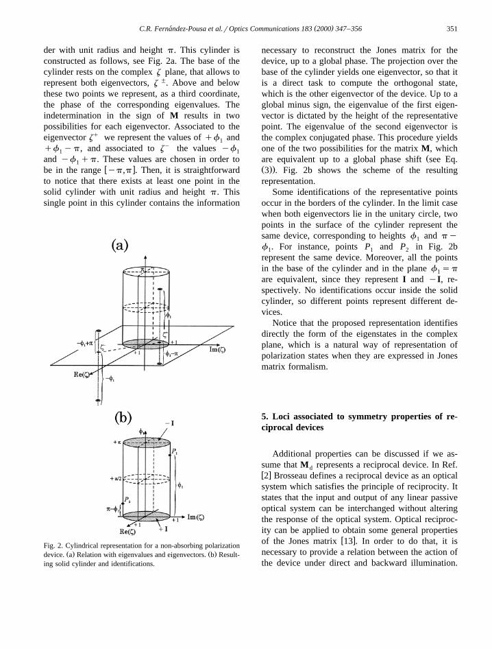
der with unit radius and height p. This cylinder isconstructed as follows, see Fig. 2a. The base of thecylinder rests on the complex z plane, that allows torepresent both eigenvectors, z ". Above and belowthese two points we represent, as a third coordinate,the phase of the corresponding eigenvalues. Theindetermination in the sign of M results in twopossibilities for each eigenvector. Associated to theeigenvector zq we represent the values of qf and1
qf yp, and associated to zy the values yf1 1
and yf qp. These values are chosen in order to1w xbe in the range yp,p . Then, it is straightforward
to notice that there exists at least one point in thesolid cylinder with unit radius and height p. Thissingle point in this cylinder contains the information
Fig. 2. Cylindrical representation for a non-absorbing polarizationŽ . Ž .device. a Relation with eigenvalues and eigenvectors. b Result-
ing solid cylinder and identifications.
necessary to reconstruct the Jones matrix for thedevice, up to a global phase. The projection over thebase of the cylinder yields one eigenvector, so that itis a direct task to compute the orthogonal state,which is the other eigenvector of the device. Up to aglobal minus sign, the eigenvalue of the first eigen-vector is dictated by the height of the representativepoint. The eigenvalue of the second eigenvector isthe complex conjugated phase. This procedure yieldsone of the two possibilities for the matrix M, which
Žare equivalent up to a global phase shift see Eq.Ž ..3 . Fig. 2b shows the scheme of the resultingrepresentation.
Some identifications of the representative pointsoccur in the borders of the cylinder. In the limit casewhen both eigenvectors lie in the unitary circle, twopoints in the surface of the cylinder represent thesame device, corresponding to heights f and py1
f . For instance, points P and P in Fig. 2b1 1 2
represent the same device. Moreover, all the pointsin the base of the cylinder and in the plane f sp1
are equivalent, since they represent I and yI, re-spectively. No identifications occur inside the solidcylinder, so different points represent different de-vices.
Notice that the proposed representation identifiesdirectly the form of the eigenstates in the complexplane, which is a natural way of representation ofpolarization states when they are expressed in Jonesmatrix formalism.
5. Loci associated to symmetry properties of re-ciprocal devices
Additional properties can be discussed if we as-sume that M represents a reciprocal device. In Ref.dw x2 Brosseau defines a reciprocal device as an opticalsystem which satisfies the principle of reciprocity. Itstates that the input and output of any linear passiveoptical system can be interchanged without alteringthe response of the optical system. Optical reciproc-ity can be applied to obtain some general properties
w xof the Jones matrix 13 . In order to do that, it isnecessary to provide a relation between the action ofthe device under direct and backward illumination.

( )C.R. Fernandez-Pousa et al.rOptics Communications 183 2000 347–356´352
˜Let M denote the matrix for the device underdw xbackward illumination. It is related to M by 6 :d
˜ tM ss PM Ps 13Ž .d 3 d 3
˜In this equation, both M and M describe the actiond d
of the device when incoming light is expressed intwo different right-handed reference frames whichcorrespond to forward and backward propagation,respectively. The use of two reference frames re-
Ž .quires the introduction of s in Eq. 13 to imple-3Žment the relative inversion of axes for an applica-
w x.tion to reflective polarization systems see Ref. 14 .The comparison of the action of the device underforward or backward illumination, together with rela-
Ž .tion 13 , can be used to deduce the cancellation ofŽ . w xsome of the parameters X, Y, Z, W 6 , a fact that
reflects a symmetry property of the display. Thecancellation of one of these parameters defines par-ticular regions on the cylinder, and they can besummaryzed as follows:
1. If the response of the device under inverseillumination is exactly equal to the response underdirect illumination, then Ws0 and consequentlyf s0 if Z)0, or f sp if Z-0. These devices3 3
Ž .are represented in the cylinder by the plane Re z s0 and the corresponding eigenvectors are alwaysellipses with axes centered on the coordinate axis.
2. If the response of the device under inverseillumination is equal to the response under directillumination, up to inversion in one of the twotransverse axes, then Zs0 and consequently f s3
pr2 if W)0, or f s3pr2 if W-0. In this case3
Ž .the devices are represented in the plane Im z s0and the eigenvectors are always linearly polarizedstates.
3. If the response of the device under inverseillumination is equal to the response under directillumination, up to a rotation of "90 degrees, then
< "<Ys0. Consequently, f spr2 and thus z s1,2
so that the devices lie in the surface of the cylinder.The eigenstates have the same modulus in x and ydirections.
Fig. 3a–Fig. 3c show the representation in thecylinder of the regions corresponding to symmetryproperties 1, 2 and 3 respectively.
6. Examples
In this section we analyze some well knownpolarization devices and their representation in thecylinder.
6.1. Rotators
As a first example, we will consider a rotator ofangle u , whose Jones matrix is:
cos u ysin uM u s . 14Ž . Ž .ROT ž /sin u cosu
This is an example of reciprocal device that verifiesproperty 1. In this case, the parameters for the
< "<representation are f su , z s1 and f s0 if1 3
sin u-0, or f sp if sin u)0. Fig. 4 shows the3
Ž . Ž . Ž .Fig. 3. a Devices verifying symmetry property 1, b Devices verifying symmetry property 2, c Devices verifying symmetry property 3.
( )C.R. Fernandez-Pousa et al.rOptics Communications 183 2000 347–356´ 353
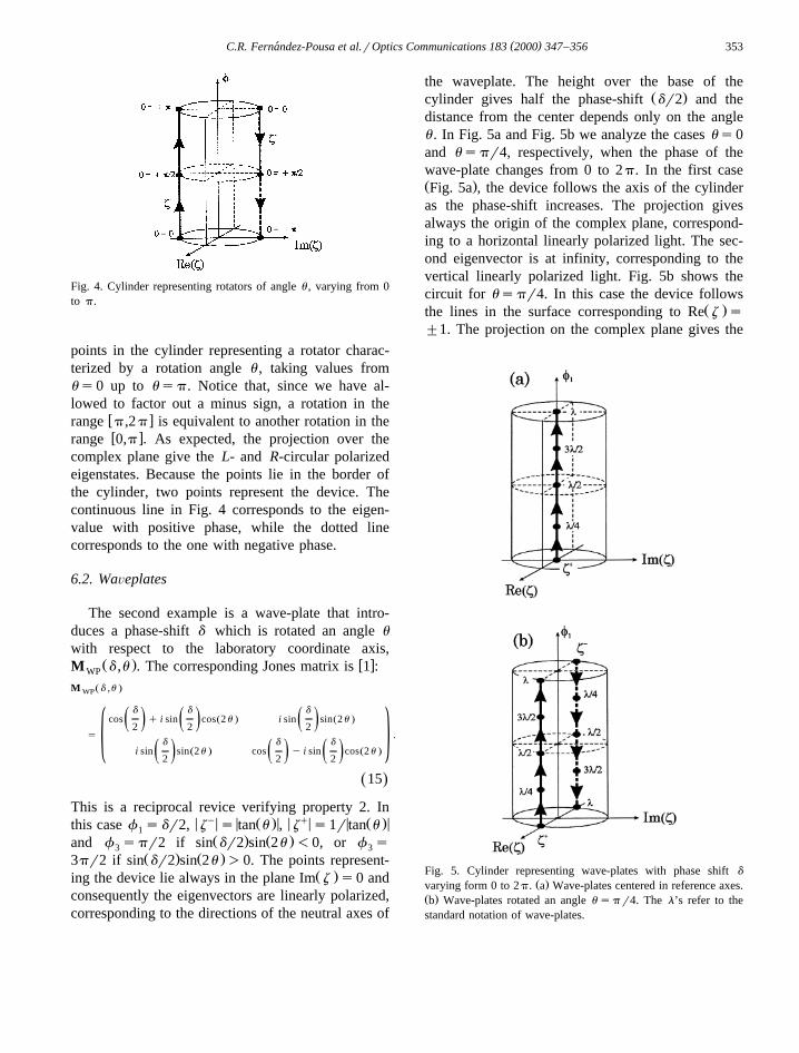
Fig. 4. Cylinder representing rotators of angle u , varying from 0to p.
points in the cylinder representing a rotator charac-terized by a rotation angle u , taking values fromus0 up to usp. Notice that, since we have al-lowed to factor out a minus sign, a rotation in the
w xrange p,2 p is equivalent to another rotation in thew xrange 0,p . As expected, the projection over the
complex plane give the L- and R-circular polarizedeigenstates. Because the points lie in the border ofthe cylinder, two points represent the device. Thecontinuous line in Fig. 4 corresponds to the eigen-value with positive phase, while the dotted linecorresponds to the one with negative phase.
6.2. WaÕeplates
The second example is a wave-plate that intro-duces a phase-shift d which is rotated an angle u
with respect to the laboratory coordinate axis,Ž . w xM d ,u . The corresponding Jones matrix is 1 :WP
Ž .M d ,uWP
d d dŽ . Ž .cos q i sin cos 2u i sin sin 2už / ž / ž /2 2 2
s .d d d� 0Ž . Ž .i sin sin 2u cos y i sin cos 2už / ž / ž /2 2 2
15Ž .
This is a reciprocal revice verifying property 2. In< y< < Ž . < < q< < Ž . <this case f sdr2, z s tan u , z s1r tan u1
Ž . Ž .and f spr2 if sin dr2 sin 2u -0, or f s3 3Ž . Ž .3pr2 if sin dr2 sin 2u )0. The points represent-
Ž .ing the device lie always in the plane Im z s0 andconsequently the eigenvectors are linearly polarized,corresponding to the directions of the neutral axes of
the waveplate. The height over the base of theŽ .cylinder gives half the phase-shift dr2 and the
distance from the center depends only on the angleu . In Fig. 5a and Fig. 5b we analyze the cases us0and uspr4, respectively, when the phase of thewave-plate changes from 0 to 2p. In the first caseŽ .Fig. 5a , the device follows the axis of the cylinderas the phase-shift increases. The projection givesalways the origin of the complex plane, correspond-ing to a horizontal linearly polarized light. The sec-ond eigenvector is at infinity, corresponding to thevertical linearly polarized light. Fig. 5b shows thecircuit for uspr4. In this case the device follows
Ž .the lines in the surface corresponding to Re z s"1. The projection on the complex plane gives the
Fig. 5. Cylinder representing wave-plates with phase shift d
Ž .varying form 0 to 2p. a Wave-plates centered in reference axes.Ž .b Wave-plates rotated an angle u spr4. The l’s refer to thestandard notation of wave-plates.
( )C.R. Fernandez-Pousa et al.rOptics Communications 183 2000 347–356´354
Ž .two linearly polarized states oriented at " pr4 .Again two lines are present in the graphic represent-
Žing the eigenvalues with positive phase continuous. Ž .line and negative phase dotted line .
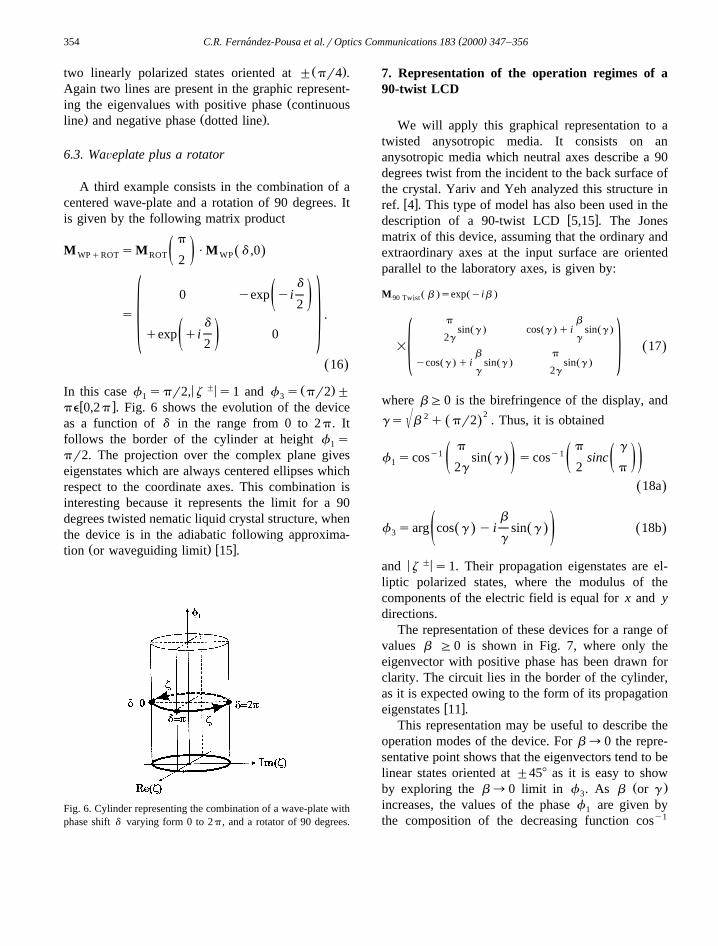
6.3. WaÕeplate plus a rotator
A third example consists in the combination of acentered wave-plate and a rotation of 90 degrees. Itis given by the following matrix product
pM sM PM d ,0Ž .WPqROT ROT WPž /2
d0 yexp yiž /2
s .d
qexp qi 0� 0ž /2
16Ž .
< "< Ž .In this case f spr2, z s1 and f s pr2 "1 3w xpe 0,2 p . Fig. 6 shows the evolution of the device
as a function of d in the range from 0 to 2p. Itfollows the border of the cylinder at height f s1
pr2. The projection over the complex plane giveseigenstates which are always centered ellipses whichrespect to the coordinate axes. This combination isinteresting because it represents the limit for a 90degrees twisted nematic liquid crystal structure, whenthe device is in the adiabatic following approxima-
Ž . w xtion or waveguiding limit 15 .
Fig. 6. Cylinder representing the combination of a wave-plate withphase shift d varying form 0 to 2p, and a rotator of 90 degrees.
7. Representation of the operation regimes of a90-twist LCD
We will apply this graphical representation to atwisted anysotropic media. It consists on ananysotropic media which neutral axes describe a 90degrees twist from the incident to the back surface ofthe crystal. Yariv and Yeh analyzed this structure in
w xref. 4 . This type of model has also been used in thew xdescription of a 90-twist LCD 5,15 . The Jones
matrix of this device, assuming that the ordinary andextraordinary axes at the input surface are orientedparallel to the laboratory axes, is given by:
Ž . Ž .M b sexp yib90 Twist
=
p bŽ . Ž . Ž .sin g cos g q i sin g
2g g17Ž .
b p� 0Ž . Ž . Ž .ycos g q i sin g sin gg 2g
where bG0 is the birefringence of the display, and22(gs b q pr2 . Thus, it is obtainedŽ .
p p gy1 y1f scos sin g scos sincŽ .1 ž /ž /ž /2g 2 p
18aŽ .
bf sarg cos g y i sin g 18bŽ . Ž . Ž .3 ž /g
< "<and z s1. Their propagation eigenstates are el-liptic polarized states, where the modulus of thecomponents of the electric field is equal for x and ydirections.
The representation of these devices for a range ofvalues b G0 is shown in Fig. 7, where only theeigenvector with positive phase has been drawn forclarity. The circuit lies in the border of the cylinder,as it is expected owing to the form of its propagation
w xeigenstates 11 .This representation may be useful to describe the
operation modes of the device. For b™0 the repre-sentative point shows that the eigenvectors tend to belinear states oriented at "458 as it is easy to show
Ž .by exploring the b™0 limit in f . As b or g3
increases, the values of the phase f are given by1
the composition of the decreasing function cosy1
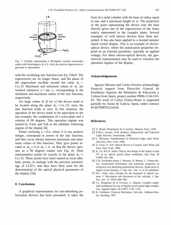
( )C.R. Fernandez-Pousa et al.rOptics Communications 183 2000 347–356´ 355
Fig. 7. Cylinder representing a 90-degrees twisted anysotropicmedia with birefringence b G0. Only the positive eigenvector-ei-genvalue is represented.
Ž Ž ..with the oscillating sinc function see Eq. 18a . Theeigenvectors are no longer linear, and the phase ofthe eigenvalues oscillate around the value f s1Ž .pr2 . Maximum and minimum values of f are1
reached whenever gs tan g , corresponding to theminimum and maximum values of the sinc function,respectively
Ž .For large values of b or g the device tends toŽ .be located along the plane f s pr2 , since the1
sinc function tends to zero. In this situation, theoperation of the device tends to be equivalent to thelast example, the combination of a wave-plate and arotation of 90 degrees. This operation regime wasnamed by Yariv and Yeh as the adiabatic following
w xregime of the display 4 .Points verifying gskp, where k is any positive
integer, correspond to zeroes of the sinc function,and they occur always between maximum and mini-mum values of this function. They give points lo-cated at f s0 or f sp, so that the device oper-3 3
Ž .ates as a 90 degrees rotator see Fig. 4 . Theirrepresentative points lie exactly in the plane f s1Ž .pr2 . These points have been named as local adia-batic points, in analogy with the previous terminol-ogy of LCD’s, and they have been used for thedetermination of the optical physical parameters of
w xthe display 16 .
8. Conclusions
A graphical representation for non-absorbing po-larization devices has been presented. It takes the
form of a solid cylinder with the base of radius equalto one, and a maximum height of p. The projectionof the point representing the device over the basedirectly gives one of the eigenvectors of the Jonesmatrix represented in the complex plane. Severalexamples of well known devices have been pre-sented. It has also been applied to a twisted nematicliquid crystal display. This is an example of electro-optical device, where the polarization properties de-pend on an external parameter, typically an appliedvoltage. For these electro-optical devices, the geo-metrical representation may be used to visualize theoperation regimes of the display.
Acknowledgements
Ignacio Moreno and Carlos Ferreira acknowledgefinancial support from Direccion General de´Ensenanza Superior del Ministerio de Educacion y˜ ´Cultura from Spain, project number PB96-1134-C02-02. The work of Carlos Gomez-Reino is supported´partially by Xunta de Galicia, Spain, under contractPGIDT99PXI22201B.
References
w x1 S. Huard, Polarisation de la lumiere, Masson, Paris, 1994.`w x2 R.M.A. Azzam, N.M. Bashara, Ellipsometry and Polarized
Light, Elsevier, Amsterdam, 1980.w x3 C. Brosseau, Fundamentals of Polarized Light, John Wiley
and Sons, New York, 1998.w x4 A. Yariv, P. Yeh, Optical Waves in Crystals, John Wiley and
Sons, New York, 1984.w x5 K. Lu, B.E.A. Saleh, Theory and design of the liquid crystal
TV as an optical spatial phase modulator, Opt. Eng. 29Ž .1990 240–246.
w x6 C.R. Fernandez-Pousa, I. Moreno, N. Bennis, C. Gomez-Re-´ ´ino, Generalized formulation and symmetry properties ofreciprocal non-absorbing polarization devices, Application toliquid crystal displays, J. Opt. Soc. Am. A, to be published.
w x7 R.C. Jones, New calculus for the treatment of optical sys-tems. I. Description and discussion of the calculus, J. Opt.
Ž .Soc. Am. 31 1941 488–493.w x8 J.L. Bougrenet de la Tocnaye, L. Dupont, Complex ampli-
tude modulation by use of liquid-crystal spatial light modula-Ž .tors, Applied Optics 36 1997 1730–1741.
w x9 H. Goldstein, Classical Mechanics, 2nd edn., Addison-Wes-ley, Reading, 1987.

( )C.R. Fernandez-Pousa et al.rOptics Communications 183 2000 347–356´356
w x10 J.L. Pezzaniti, R.A. Chipman, Phase-only modulation of atwisted nematic liquid-crystal TV by use of the eigenpolar-
Ž .ization states, Optics Letters 15 1993 1567–1569.w x11 J.A. Davis, I. Moreno, P. Tsai, Polarization eigenstates for
twisted nematic liquid crystal displays, Applied Optics 37Ž .1998 937–945.
w x12 H. Hurwitz, R.C. Jones, New calculus for the treatment ofoptical systems. II Proof of three equivalence theorems, J.
Ž .Opt. Soc. Am. 31 1941 493–499.w x13 N. Vansteenkiste, P. Vignolo, A. Aspect, Optical reversibility
theorems for polarization: application to remote control ofŽ .polarization, J. Opt. Soc. Am. A 10 1993 2240–2245.
w x14 J. Goodman, Introduction to Fourier Optics, 2nd edn., Mc-Graw-Hill, New York, 1996.
w x15 P. Yeh, C. Gu, Optics of Liquid Crystal Displays, JohnWiley and Sons, New York, 1999.
w x16 I. Moreno, N. Bennis, J.A. Davis, C. Ferreira, Twist angledetermination in liquid crystal displays by location of local
Ž .adiabatic points, Opt. Commun. 158 1998 231–238.