Periodic Architecture for High Performance Shock Absorbing ...
10
Periodic Architecture for High Performance Shock Absorbing Composites Abha Misra 1 & Praveen Kumar 2 1 Department of Instrumentation and Applied Physics, 2 Department of Materials Engineering, Indian Institute of Science, Bangalore 560012 (India). A novel composite architecture consisting of a periodic arrangement of closely-spaced spheres of a stiff material embedded in a soft matrix is proposed for extremely high damping and shock absorption capacity. Efficacy of this architecture is demonstrated by compression loading a composite, where multiple steel balls were stacked upon each other in a polydimethylsiloxane (PDMS) matrix, at a low strain-rate of 0.05 s 21 and a very high strain-rate of .2400 s 21 . The balls slide over each other upon loading, and revert to their original position when the load is removed. Because of imposition of additional strains into the matrix via this reversible, constrained movement of the balls, the composite absorbs significantly larger energy and endures much lesser permanent damage than the monolithic PDMS during both quasi-static and impact loadings. During the impact loading, energy absorbed per unit weight for the composite was ,8 times larger than the monolithic PDMS. C omposites are often prepared with multiple constituents having widely different properties to meet critical requirements of an application. The desired properties of composites are sometimes contradictory, and attainment of these properties often involves design of novel material architectures, such as placement of a few volume fraction of percolating carbon nanotubes (CNTs), nano-sized metallic wires, etc. in a non-conducting soft matrix, like polymers, etc. to achieve different functionalities such as flexible electrical conductors 1–3 , uniform placement of particulates of a high conducting-high melting material, such as Cu, in continuous channels of mechanically soft matrix, such as In, for enhancing the thermal conductivity of a composite while maintaining the high compliance 4,5 , etc. The common theme in these efficient architectures is the controlled placement of different constituents adhering to a specified design; this allows efficient division of the functionality amongst the con- stituents leading to the desired behavior of the material. This work proposes a novel architecture for manufac- turing composites with superior damping and shock absorption properties. Elastomeric polymers based composites are important damping and shock absorption materials 6–9 . A few tunable properties of polymers, such as the ability to endure very large strains 9,10 , high energy absorption to weight ratio 7 , easy placement of a continuous coating on large structures 9 , etc., have made polymer based composites as the material of choice for shock absorption applications 7 . Various composites, such as carbon-black, SiC and other nanoparticles reinforced polymers 1,10–14 , laminated composites with interlayers of polymers and metals 6,15,16 , and polymers reinforced with fibers of glass, carbon and specialized polymers 17,18 , etc., have been particularly developed to improve the damping properties of monolithic polymers. This improvement primarily occurs through increase of one or a combination of more of the following: (i) number of the micro-fracture sites, (ii) volume fraction of the strain induced crystallites in the polymer matrix, and (iii) the strength of the composites without compromising its strain endurance limit. However, one of the inherent drawbacks in these composites is that their improved properties are based on a certain combination of particular materials and therefore they do not have the generality of the architecture or the specific design based composites. The latter allows tailoring the properties of a composite by placing the micro-constituents in a certain fashion; this provides an additional valuable tool for further improving the damping and shock absorbing capabilities of even an existing composite material. This work proposes and validates the damping and shock absorbing capability of a composite archi- tecture consisting of a chain like periodic inclusions of a stiff material into a polymer matrix. Results Quasistatic behavior. Figure 1a, b show stress-strain behavior of monolithic polydimethylsiloxane (PDMS) during the first and the second loading-unloading cycles, respectively. A finite non-zero stress-strain OPEN SUBJECT AREAS: MECHANICAL ENGINEERING POLYMERS COMPOSITES MECHANICAL PROPERTIES Received 31 December 2012 Accepted 3 June 2013 Published 24 June 2013 Correspondence and requests for materials should be addressed to P.K. (praveenk@ materials.iisc.ernet.in) SCIENTIFIC REPORTS | 3 : 2056 | DOI: 10.1038/srep02056 1
-
Upload
khangminh22 -
Category
Documents
-
view
0 -
download
0
Transcript of Periodic Architecture for High Performance Shock Absorbing ...
Periodic Architecture for HighPerformance Shock AbsorbingCompositesAbha Misra1 & Praveen Kumar2
1Department of Instrumentation and Applied Physics, 2Department of Materials Engineering, Indian Institute of Science, Bangalore560012 (India).
A novel composite architecture consisting of a periodic arrangement of closely-spaced spheres of a stiffmaterial embedded in a soft matrix is proposed for extremely high damping and shock absorption capacity.Efficacy of this architecture is demonstrated by compression loading a composite, where multiple steel ballswere stacked upon each other in a polydimethylsiloxane (PDMS) matrix, at a low strain-rate of 0.05 s21 and avery high strain-rate of .2400 s21. The balls slide over each other upon loading, and revert to their originalposition when the load is removed. Because of imposition of additional strains into the matrix via thisreversible, constrained movement of the balls, the composite absorbs significantly larger energy and enduresmuch lesser permanent damage than the monolithic PDMS during both quasi-static and impact loadings.During the impact loading, energy absorbed per unit weight for the composite was ,8 times larger than themonolithic PDMS.
Composites are often prepared with multiple constituents having widely different properties to meet criticalrequirements of an application. The desired properties of composites are sometimes contradictory, andattainment of these properties often involves design of novel material architectures, such as placement of a
few volume fraction of percolating carbon nanotubes (CNTs), nano-sized metallic wires, etc. in a non-conductingsoft matrix, like polymers, etc. to achieve different functionalities such as flexible electrical conductors1–3, uniformplacement of particulates of a high conducting-high melting material, such as Cu, in continuous channels ofmechanically soft matrix, such as In, for enhancing the thermal conductivity of a composite while maintaining thehigh compliance4,5, etc. The common theme in these efficient architectures is the controlled placement of differentconstituents adhering to a specified design; this allows efficient division of the functionality amongst the con-stituents leading to the desired behavior of the material. This work proposes a novel architecture for manufac-turing composites with superior damping and shock absorption properties.
Elastomeric polymers based composites are important damping and shock absorption materials6–9. A fewtunable properties of polymers, such as the ability to endure very large strains9,10, high energy absorption to weightratio7, easy placement of a continuous coating on large structures9, etc., have made polymer based composites asthe material of choice for shock absorption applications7. Various composites, such as carbon-black, SiC andother nanoparticles reinforced polymers1,10–14, laminated composites with interlayers of polymers and metals6,15,16,and polymers reinforced with fibers of glass, carbon and specialized polymers17,18, etc., have been particularlydeveloped to improve the damping properties of monolithic polymers. This improvement primarily occursthrough increase of one or a combination of more of the following: (i) number of the micro-fracture sites, (ii)volume fraction of the strain induced crystallites in the polymer matrix, and (iii) the strength of the compositeswithout compromising its strain endurance limit. However, one of the inherent drawbacks in these composites isthat their improved properties are based on a certain combination of particular materials and therefore they donot have the generality of the architecture or the specific design based composites. The latter allows tailoring theproperties of a composite by placing the micro-constituents in a certain fashion; this provides an additionalvaluable tool for further improving the damping and shock absorbing capabilities of even an existing compositematerial. This work proposes and validates the damping and shock absorbing capability of a composite archi-tecture consisting of a chain like periodic inclusions of a stiff material into a polymer matrix.
ResultsQuasistatic behavior. Figure 1a, b show stress-strain behavior of monolithic polydimethylsiloxane (PDMS)during the first and the second loading-unloading cycles, respectively. A finite non-zero stress-strain
OPEN
SUBJECT AREAS:MECHANICAL
ENGINEERING
POLYMERS
COMPOSITES
MECHANICAL PROPERTIES
Received31 December 2012
Accepted3 June 2013
Published24 June 2013
Correspondence andrequests for materials
should be addressed toP.K. (praveenk@
materials.iisc.ernet.in)
SCIENTIFIC REPORTS | 3 : 2056 | DOI: 10.1038/srep02056 1
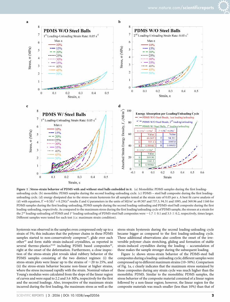
hysteresis was observed in the samples even compressed only up to astrain of 5%; this indicates that the polymer chains in these PDMSsamples started to non-conservatively compress10, glide over eachother10 and form stable strain-induced crystallites, as reported inseveral thermo-plastics19,20 including PDMS based composites20,right at the onset of the deformation. Furthermore, a close inspec-tion of the stress-strain plot reveals ideal rubbery behavior of thePDMS samples consisting of the two distinct regimes: (i) thestress-strain plots were linear up to the strains of ,20 to 25%, and(ii) the stress-strain behavior became non-linear at higher strains,where the stress increased rapidly with the strain. Nominal values ofYoung’s modulus were calculated from the slope of the linear regionof curves and were equal to 2.2 and 3.6 MPa, respectively for the firstand the second loadings. Also, irrespective of the maximum strainincurred during the first loading, the maximum stress as well as the
stress-strain hysteresis during the second loading-unloading cyclebecame bigger as compared to the first loading-unloading cycle.These additional observations also confirm the onset of the irre-versible polymer chain stretching, gliding and formation of stablestrain-induced crystallites during the loading – accumulation ofthese makes the sample stronger during the subsequent loading.
Figure 1c shows stress-strain behavior of the PDMS-steel ballcomposites during a loading–unloading cycle; different samples werecompressed up to different maximum strains (10–50%). Comparisonof Fig. 1a, c clearly indicates that the maximum stress sustained bythese composites during any strain cycle was much higher than themonolithic PDMS. Similar to the monolithic PDMS samples, thestress behavior of the composite material consisted of a linear regionfollowed by a non-linear region; however, the linear region for thecomposite materials was much smaller (less than 10%) than that of
Figure 1 | Stress-strain behavior of PDMS with and without steel balls embedded in it. (a) Monolithic PDMS samples during the first loading-
unloading cycle. (b) monolithic PDMS samples during the second loading-unloading cycle. (c) PDMS – steel ball composite during the first loading-
unloading cycle. (d) energy dissipated due to the stress-strain hysteresis for all samples tested at the strain rate of 0.05 per s. A best fit curve analysis of
(d) with equation, C~0:5Ee2z0:25Ge4 results E and G parameters in the units of MJ/m3 as 49.507 and 737.3, 94.31 and 1095, and 369.96 and 1160 for
PDMS samples during the first loading-unloading, PDMS sample during the second loading-unloading and PDMS-steel ball composite during the first
loading-unloading, respectively. As compared to the maximum stress during the first loading/unloading cycle of PDMS sample, the stresses at a strain for
the 2nd loading-unloading of PDMS and 1st loading-unloading of PDMS-steel ball composites were ,1.7 6 0.1 and 3.5 6 0.2, respectively, times larger.
Different samples were tested for each test (i.e. maximum strain condition).
www.nature.com/scientificreports
SCIENTIFIC REPORTS | 3 : 2056 | DOI: 10.1038/srep02056 2
the monolithic PDMS samples. Young’s modulus, as calculated fromthe linear region of the stress-strain plot of the PDMS-steel ballcomposites, was in between 3.8 and 6.8 MPa, which was almost 2to 3 times more than that of the monolithic PDMS sample. It isinteresting to note that Young’s modulus of these composites, whichcontained almost 60% of steel, was only 2 to 3 times larger than thatof PDMS. This will be explained later while discussing the deforma-tion mechanism of these composites.
Figure 1d compares the total strain energy dissipated during astress-strain hysteresis of the monolithic PDMS and the PDMS-steelball composites. For all the samples tested in this study, the energydissipated during the hysteresis seems to non-linearly depend on themaximum imposed strain. Consistent with the aforementionedobservation of the larger stress-strain hysteresis for the PDMS-steelball composites, Figure 1d also shows much larger energy dissipationin the PDMS-steel ball composites at any strain. Moreover, the non-linearity in the composite material is much larger as compared to thePDMS samples. This shows that the performance of the compositesfor the damping or shock absorption becomes more efficient at largerstrains; this being a major advantage associated with this novel archi-tecture over the base material and the detailed physical mechanismfor the same will be discussed later.
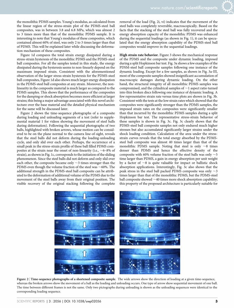
Figure 2 shows the time-sequence photographs of a compositeduring loading and unloading segments of a test (refer to supple-mental material 1 for videos showing the movement of steel ballsduring deformation). Following the sequential photographs of twoballs, highlighted with broken arrows, whose motion can be consid-ered to be on the plane normal to the camera line-of-sight, revealsthat the steel balls did not deform during the loading-unloadingcycle, and only slid over each other. Perhaps, the occurrence of asmall peak in the stress-strain profile of these ball filled PDMS com-posites at the strain near the onset of non-linearity (i.e., ,6–8% ofstrain), as shown in Fig. 1c, corresponds to the initiation of the slidingphenomenon. Since the steel balls did not deform and only slid overeach other, the composite became only ,3 times stronger than thePDMS even though the volume fraction of the steel was ,60%. Theadditional strength in the PDMS-steel ball composite can be attrib-uted to the deformation of additional volume of the PDMS due to themovement of the steel balls away from their original position. Thevisible recovery of the original stacking following the complete
removal of the load (Fig. 2i, vi) indicates that the movement of thesteel balls was completely reversible, macroscopically. Based on thefacts that the stacking of the steel ball was fully recovered and theenergy absorption capacity of the monolithic PDMS was enhancedduring the sequential loadings (as shown in Fig. 1), it can be specu-lated that the energy absorption capability of the PDMS-steel ballcomposites would improve in the sequential loadings.
High strain rate behavior. Figure 3 shows the mechanical responseof the PDMS and the composite under dynamic loading, imposedduring a split Hopkinson bar test. Fig. 3a shows a few examples of thePDSM-steel ball composite samples following one instance of thedynamic loading. Except for a few samples, as shown in Fig. 3a-III,most of the composite samples showed insignificant accumulation ofmacroscopic damages during dynamic loading. On the otherhand, the structural integrity of all monolithic PDMS samples wascompromised, and the cylindrical samples of ,1 aspect ratio turnedinto thin broken discs following one instance of dynamic loading. Afew representative strain rate versus time plots are shown in Fig. 3b.Consistent with the tests at the low strain rates which showed that thecomposites were significantly stronger than the PDMS samples, theimposed strain rates on the composites were significantly smallerthan that incurred by the monolithic PDMS samples during a splitHopkinson bar test. The representative stress-strain behavior ofthese samples is shown in Fig. 3c. Fig. 3c clearly shows that thePDMS-steel ball composite samples not only endured much higherstresses but also accumulated significantly larger strains under theshock loading condition. Calculation of the area under the stress-strain curves reveals that the total energy absorbed by the PDMS-steel ball composite was almost 40 times larger than that of themonolithic PDMS sample. Noting that steel is only ,8 timesdenser than PDMS and hence the effective density of thecomposite with 60% volume fraction of the steel balls was only ,5time larger than PDMS, a gain in energy absorption per unit weightby a factor of ,8 is quite valuable for impact or ballistic shockabsorption applications. Interestingly, Fig. 3c also shows that thepeak stress in the steel ball packed PDMS composite was only ,3times larger than that of the monolithic PDMS, but the PDMS-steelball composite showed ,40 times more shock absorption capability;this property of the proposed architecture is particularly suitable for
Figure 2 | Time-sequence photographs of a shortened composite sample. The wide arrows show the direction of loading at a given time-sequence,
whereas the broken arrows show the movement of a ball as the loading and unloading occurs. One type of arrow show sequential movement of one ball.
The time between different frames is not the same. Only two pictographs during unloading is shown as the unloading sequences were identical to the
corresponding loading sequence.
www.nature.com/scientificreports
SCIENTIFIC REPORTS | 3 : 2056 | DOI: 10.1038/srep02056 3
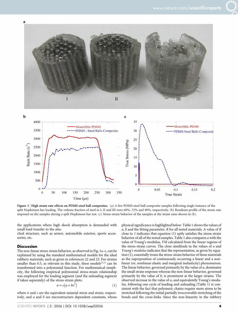
the applications where high shock absorption is demanded withsmall load transfer to the atta-ched structure, such as armor, automobile exterior, sports acces-sories, etc.
DiscussionThe non-linear stress-strain behavior, as observed in Fig. 1a–c, can beexplained by using the standard mathematical models for the idealrubbery materials, such as given in references 22 and 23. For strainssmaller than 0.5, as relevant in this study, these models22,23 can betransformed into a polynomial function. For mathematical simpli-city, the following empirical polynomial stress-strain relationshipwas employed for the loading segment (and the unloading segmentif taken separately) of the stress-strain plots:
s~e azbe3� �
ð1Þ
where s and e are the equivalent uniaxial stress and strain, respect-ively, and a and b are microstructure dependent constants, whose
physical significance is highlighted below. Table 1 shows the values ofa, b and the fitting parameter, R for all tested materials. A value of Rclose to 1 indicates that equation (1) aptly satisfies the stress-strainbehavior of all of the tested samples. Table 1 also compares a with thevalue of Young’s modulus, YM calculated from the linear regions ofthe stress-strain curves. The close similitude in the values of a andYoung’s modulus indicates that the representation, as given by equa-tion (1), essentially treats the stress-strain behavior of these materialsas the superposition of continuously occurring a linear and a non-linear (or, nonlinear elastic and marginal inelasticity) phenomenon.The linear behavior, governed primarily by the value of a, dominatesthe small strain response whereas the non-linear behavior, governedprimarily by the value of b, is prominent at the larger strains. Theobserved increase in the value of a, and equivalently Young’s modu-lus, following one cycle of loading and unloading (Table 1) is con-sistent with the fact that polymeric chains require more stress to bestretched following the initial partially irrecoverable stretching of thebonds and the cross-links. Since the non-linearity in the rubbery
Figure 3 | High strain rate effects on PDMS-steel ball composites. (a) A few PDMS-steel ball composite samples following single instance of the
split Hopkinson bar loading. The volume fraction of steel in I, II and III were 60%, 72% and 40%, respectively. (b) Resultant profile of the strain rate
imposed on the samples during a spilt Hopkinson bar test. (c) Stress-strain behavior of the samples at the strain rates shown in (b).
www.nature.com/scientificreports
SCIENTIFIC REPORTS | 3 : 2056 | DOI: 10.1038/srep02056 4
polymers arise due to stretching of the bonds and the cross-links,sliding of the polymeric chains over each other and reduction in theopen-space (or, free-volume) between the polymeric chains22, thesignificant increase in the value of ‘‘b’’ following the first loadingand unloading cycle of the monolithic PDMS can be attributed tothe associated non-recoverability of the aforementioned microscopicfeatures. It is interesting to note that the monolithic PDMS (and thePDMS-steel ball composites) did not change macroscopically follow-ing the initial loading and unloading cycles; however, the aforemen-tioned microscopic features of these samples evolved; parameters aand b efficiently captured these microscopic changes. Therefore, thetwo constants of equation (1), a and b, can be thought as microstruc-tural parameters controlling the linear and non-linear behaviors ofthe materials, respectively; larger the values of these parameters,stronger will be the polymer based material.
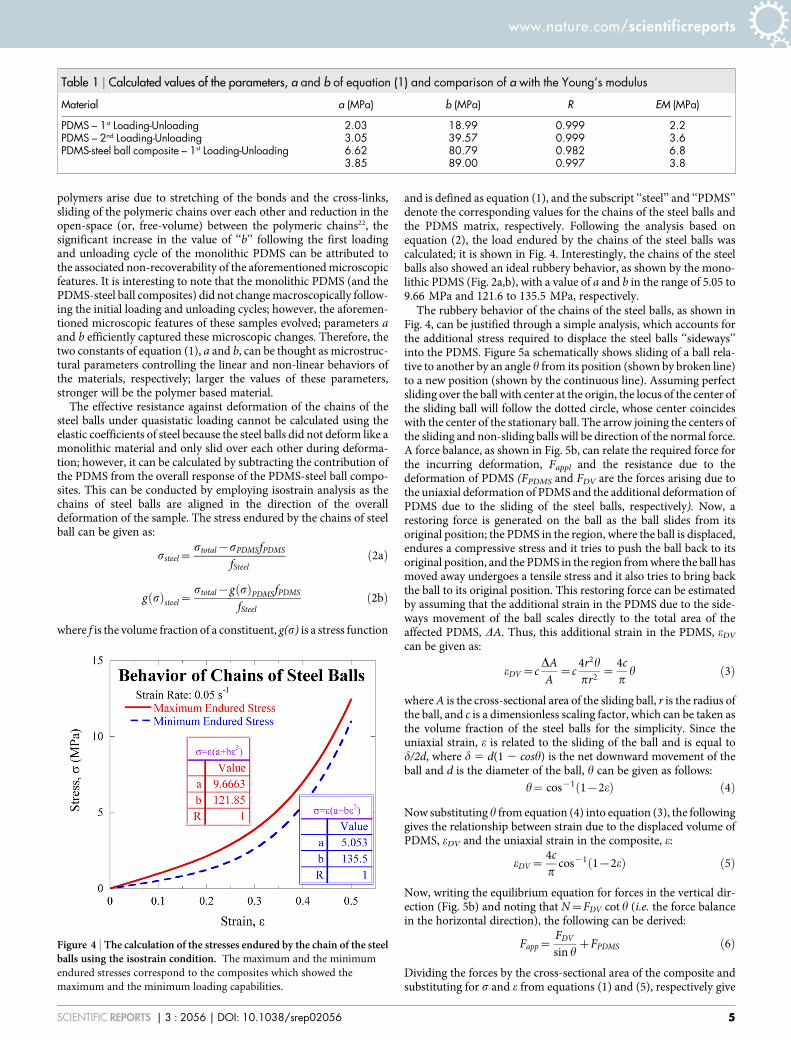
The effective resistance against deformation of the chains of thesteel balls under quasistatic loading cannot be calculated using theelastic coefficients of steel because the steel balls did not deform like amonolithic material and only slid over each other during deforma-tion; however, it can be calculated by subtracting the contribution ofthe PDMS from the overall response of the PDMS-steel ball compo-sites. This can be conducted by employing isostrain analysis as thechains of steel balls are aligned in the direction of the overalldeformation of the sample. The stress endured by the chains of steelball can be given as:
ssteel~stotal{sPDMSfPDMS
fSteelð2aÞ
g sð Þsteel~stotal{g sð ÞPDMSfPDMS
fSteelð2bÞ
where f is the volume fraction of a constituent, g(s) is a stress function
and is defined as equation (1), and the subscript ‘‘steel’’ and ‘‘PDMS’’denote the corresponding values for the chains of the steel balls andthe PDMS matrix, respectively. Following the analysis based onequation (2), the load endured by the chains of the steel balls wascalculated; it is shown in Fig. 4. Interestingly, the chains of the steelballs also showed an ideal rubbery behavior, as shown by the mono-lithic PDMS (Fig. 2a,b), with a value of a and b in the range of 5.05 to9.66 MPa and 121.6 to 135.5 MPa, respectively.
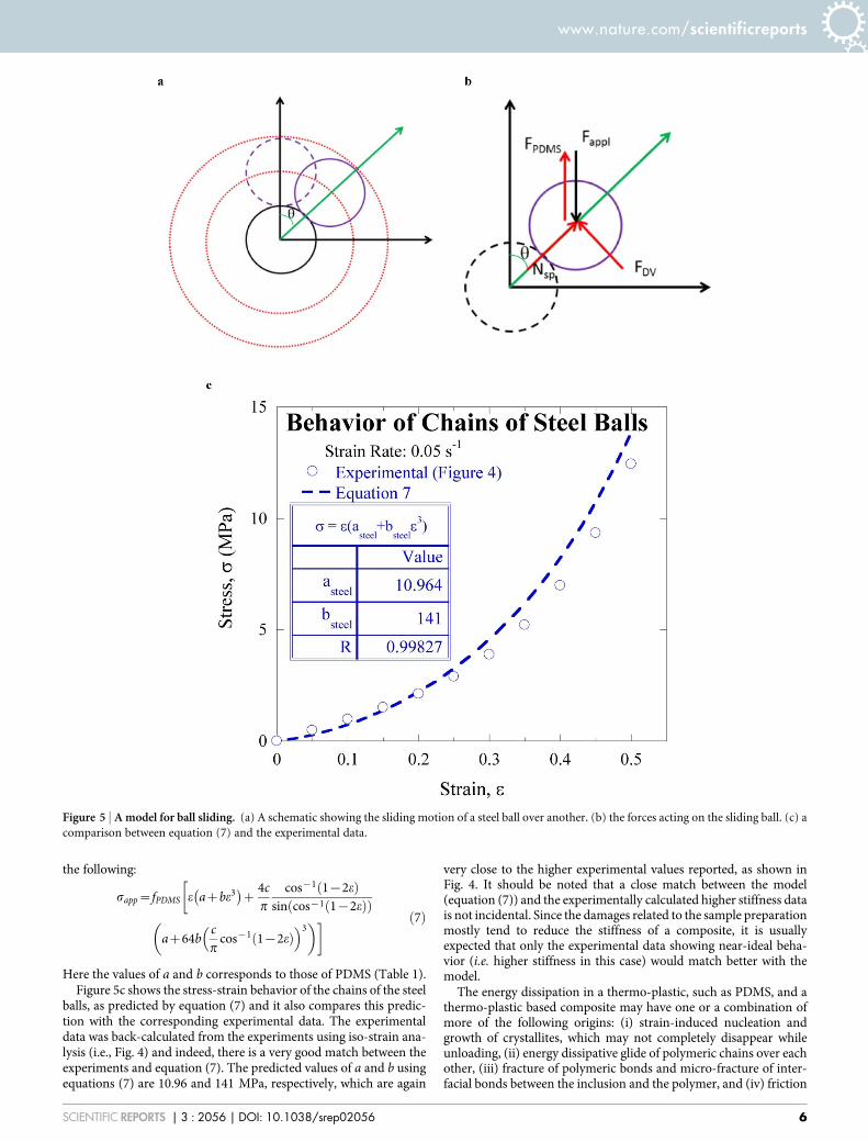
The rubbery behavior of the chains of the steel balls, as shown inFig. 4, can be justified through a simple analysis, which accounts forthe additional stress required to displace the steel balls ‘‘sideways’’into the PDMS. Figure 5a schematically shows sliding of a ball rela-tive to another by an angle h from its position (shown by broken line)to a new position (shown by the continuous line). Assuming perfectsliding over the ball with center at the origin, the locus of the center ofthe sliding ball will follow the dotted circle, whose center coincideswith the center of the stationary ball. The arrow joining the centers ofthe sliding and non-sliding balls will be direction of the normal force.A force balance, as shown in Fig. 5b, can relate the required force forthe incurring deformation, Fappl and the resistance due to thedeformation of PDMS (FPDMS and FDV are the forces arising due tothe uniaxial deformation of PDMS and the additional deformation ofPDMS due to the sliding of the steel balls, respectively). Now, arestoring force is generated on the ball as the ball slides from itsoriginal position; the PDMS in the region, where the ball is displaced,endures a compressive stress and it tries to push the ball back to itsoriginal position, and the PDMS in the region from where the ball hasmoved away undergoes a tensile stress and it also tries to bring backthe ball to its original position. This restoring force can be estimatedby assuming that the additional strain in the PDMS due to the side-ways movement of the ball scales directly to the total area of theaffected PDMS, DA. Thus, this additional strain in the PDMS, eDV
can be given as:
eDV~cDAA
~c4r2h
pr2~
4cp
h ð3Þ
where A is the cross-sectional area of the sliding ball, r is the radius ofthe ball, and c is a dimensionless scaling factor, which can be taken asthe volume fraction of the steel balls for the simplicity. Since theuniaxial strain, e is related to the sliding of the ball and is equal tod/2d, where d 5 d(1 2 cosh) is the net downward movement of theball and d is the diameter of the ball, h can be given as follows:
h~ cos{1 1{2eð Þ ð4Þ
Now substituting h from equation (4) into equation (3), the followinggives the relationship between strain due to the displaced volume ofPDMS, eDV and the uniaxial strain in the composite, e:
eDV~4cp
cos{1 1{2eð Þ ð5Þ
Now, writing the equilibrium equation for forces in the vertical dir-ection (Fig. 5b) and noting that N~FDV cot h (i.e. the force balancein the horizontal direction), the following can be derived:
Fapp~FDV
sin hzFPDMS ð6Þ
Dividing the forces by the cross-sectional area of the composite andsubstituting for s and e from equations (1) and (5), respectively give
Table 1 | Calculated values of the parameters, a and b of equation (1) and comparison of a with the Young’s modulus
Material a (MPa) b (MPa) R EM (MPa)
PDMS – 1st Loading-Unloading 2.03 18.99 0.999 2.2PDMS – 2nd Loading-Unloading 3.05 39.57 0.999 3.6PDMS-steel ball composite – 1st Loading-Unloading 6.62 80.79 0.982 6.8
3.85 89.00 0.997 3.8
Figure 4 | The calculation of the stresses endured by the chain of the steelballs using the isostrain condition. The maximum and the minimum
endured stresses correspond to the composites which showed the
maximum and the minimum loading capabilities.
www.nature.com/scientificreports
SCIENTIFIC REPORTS | 3 : 2056 | DOI: 10.1038/srep02056 5
the following:
sapp~fPDMS e azbe3� �
z4cp
cos{1 1{2eð Þsin cos{1 1{2eð Þð Þ
�
az64bcp
cos{1 1{2eð Þ� �3
� � ð7Þ
Here the values of a and b corresponds to those of PDMS (Table 1).Figure 5c shows the stress-strain behavior of the chains of the steel
balls, as predicted by equation (7) and it also compares this predic-tion with the corresponding experimental data. The experimentaldata was back-calculated from the experiments using iso-strain ana-lysis (i.e., Fig. 4) and indeed, there is a very good match between theexperiments and equation (7). The predicted values of a and b usingequations (7) are 10.96 and 141 MPa, respectively, which are again
very close to the higher experimental values reported, as shown inFig. 4. It should be noted that a close match between the model(equation (7)) and the experimentally calculated higher stiffness datais not incidental. Since the damages related to the sample preparationmostly tend to reduce the stiffness of a composite, it is usuallyexpected that only the experimental data showing near-ideal beha-vior (i.e. higher stiffness in this case) would match better with themodel.
The energy dissipation in a thermo-plastic, such as PDMS, and athermo-plastic based composite may have one or a combination ofmore of the following origins: (i) strain-induced nucleation andgrowth of crystallites, which may not completely disappear whileunloading, (ii) energy dissipative glide of polymeric chains over eachother, (iii) fracture of polymeric bonds and micro-fracture of inter-facial bonds between the inclusion and the polymer, and (iv) friction
Figure 5 | A model for ball sliding. (a) A schematic showing the sliding motion of a steel ball over another. (b) the forces acting on the sliding ball. (c) a
comparison between equation (7) and the experimental data.
www.nature.com/scientificreports
SCIENTIFIC REPORTS | 3 : 2056 | DOI: 10.1038/srep02056 6
between the sliding inclusions, as well as between inclusions and thematrix. The observation of monotonous enhancement of thestrength in the non-linear region of the stress-strain plot of themonolithic PDMS as well as the PDMS-steel ball composite(Fig. 1a–c) suggest occurrence of the strain-induced crystallizationof the PDMS matrix, as reported in other thermo-plastic based mate-rials including PDMS based composites19,20. The formed crystallitesremained stable during unloading, as revealed by the steeper slopeduring the initial unloading (Figure 1a–c)21. This hypothesis is fur-ther supported by the higher stress as well as larger hysteresis duringthe second loading-unloading cycle of the monolithic PDMS samplesas compared to the first loading-unloading cycle. For the PDMS-steelcomposite, equation (5) predicts that the strain in the PDMS, espe-cially in the regions close to steel balls, will sustain much higherstrains as the steel balls slide over each other. This is also supportedby the early onset of the non-linearity in these samples (Fig. 1c).Therefore, the strain-induced crystallization of PDMS will be morevigorous in the PDMS-steel ball composite; this dramaticallyenhances the energy dissipation in these composites as comparedto the monolithic PDMS. Nevertheless, the stresses in the PDMSregion in the vicinity of the sliding balls are also very high (equations1, 5), and this will also increase the severity of the energy dissipativeglide of the polymeric chains, as well as fracture of polymeric bondsin these regions; this deformation behavior is consistent with theobservation of localization of deformation in the narrow ligamentsin thermoplastic vulcanizate24. Furthermore, the friction between thesliding steel balls as well as between the steel balls and the adjacentpolymer will add on to the net dissipation of the strain energy in thePDMS-steel ball composite. Since the surface of the steel balls werevery smooth (chrome plated) as well as contact area between steelballs was very small, the majority of the friction-induced dissipativeenergy would be produced due to the sliding between the steel ballsand the PDMS. Friction between PDMS and steel balls depends onthe shearing and fracture of the adhesion bonds between the con-tacting surfaces, and the plastic deformation as well as abrasion of theasperities25. Since the steel balls were mechanically implanted insidethe PDMS matrix, the contribution from shearing and fracture ofadhesion bonds between the contacting surfaces to the total dissipa-tion energy should be negligible as compared to the deformation andthe abrasion of PDMS asperities. Furthermore, since the frictionforce between steel balls and the PDMS increases with the normal(and equivalently, the applied) force25 and the loading rate26, theenergy dissipation due to this mechanism will greatly enhance athigher loads and during high strain rate loadings; both aspects ofthis dissipative mechanism is highly desirable in a shock absorptionand damping application. Although the quantification of the relativecontributions of the aforementioned different energy dissipativemechanisms is beyond the scope of the present work, it is reasonableto speculate that the localized strain-induced recrystallization of thePDMS matrix and the friction between the steel balls and the PDMSmay primarily be responsible for the damping and shock absorptionin the materials tested in this study.
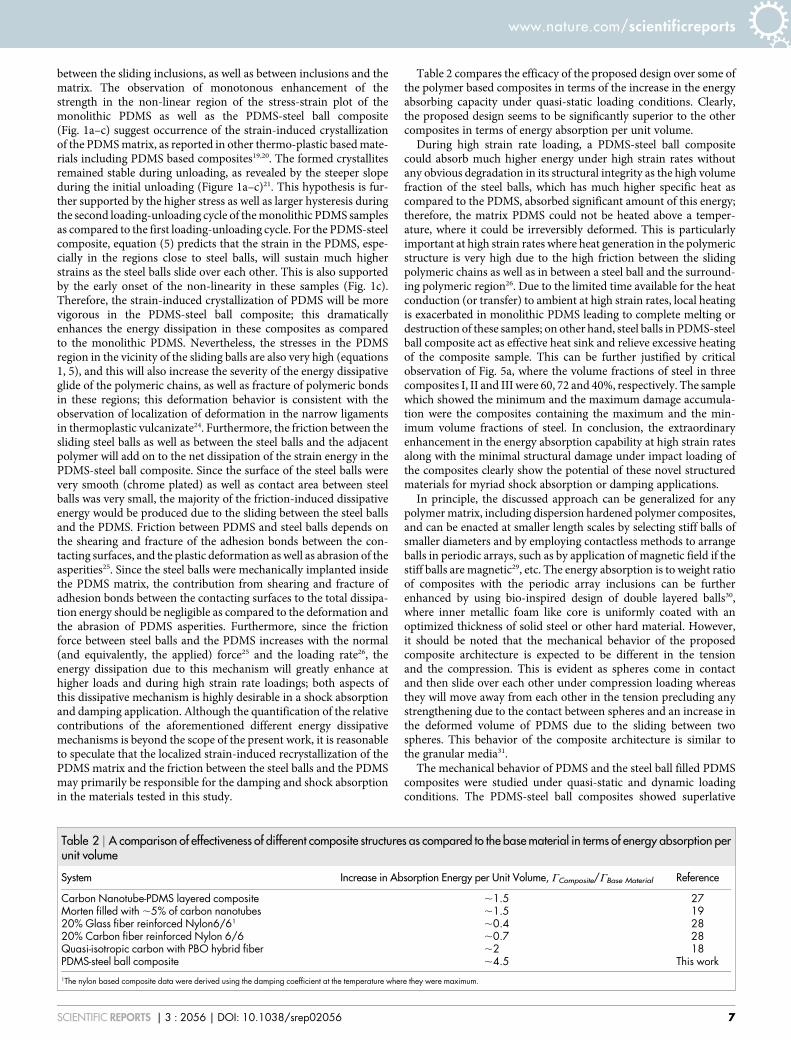
Table 2 compares the efficacy of the proposed design over some ofthe polymer based composites in terms of the increase in the energyabsorbing capacity under quasi-static loading conditions. Clearly,the proposed design seems to be significantly superior to the othercomposites in terms of energy absorption per unit volume.
During high strain rate loading, a PDMS-steel ball compositecould absorb much higher energy under high strain rates withoutany obvious degradation in its structural integrity as the high volumefraction of the steel balls, which has much higher specific heat ascompared to the PDMS, absorbed significant amount of this energy;therefore, the matrix PDMS could not be heated above a temper-ature, where it could be irreversibly deformed. This is particularlyimportant at high strain rates where heat generation in the polymericstructure is very high due to the high friction between the slidingpolymeric chains as well as in between a steel ball and the surround-ing polymeric region26. Due to the limited time available for the heatconduction (or transfer) to ambient at high strain rates, local heatingis exacerbated in monolithic PDMS leading to complete melting ordestruction of these samples; on other hand, steel balls in PDMS-steelball composite act as effective heat sink and relieve excessive heatingof the composite sample. This can be further justified by criticalobservation of Fig. 5a, where the volume fractions of steel in threecomposites I, II and III were 60, 72 and 40%, respectively. The samplewhich showed the minimum and the maximum damage accumula-tion were the composites containing the maximum and the min-imum volume fractions of steel. In conclusion, the extraordinaryenhancement in the energy absorption capability at high strain ratesalong with the minimal structural damage under impact loading ofthe composites clearly show the potential of these novel structuredmaterials for myriad shock absorption or damping applications.
In principle, the discussed approach can be generalized for anypolymer matrix, including dispersion hardened polymer composites,and can be enacted at smaller length scales by selecting stiff balls ofsmaller diameters and by employing contactless methods to arrangeballs in periodic arrays, such as by application of magnetic field if thestiff balls are magnetic29, etc. The energy absorption is to weight ratioof composites with the periodic array inclusions can be furtherenhanced by using bio-inspired design of double layered balls30,where inner metallic foam like core is uniformly coated with anoptimized thickness of solid steel or other hard material. However,it should be noted that the mechanical behavior of the proposedcomposite architecture is expected to be different in the tensionand the compression. This is evident as spheres come in contactand then slide over each other under compression loading whereasthey will move away from each other in the tension precluding anystrengthening due to the contact between spheres and an increase inthe deformed volume of PDMS due to the sliding between twospheres. This behavior of the composite architecture is similar tothe granular media31.
The mechanical behavior of PDMS and the steel ball filled PDMScomposites were studied under quasi-static and dynamic loadingconditions. The PDMS-steel ball composites showed superlative
Table 2 | A comparison of effectiveness of different composite structures as compared to the base material in terms of energy absorption perunit volume
System Increase in Absorption Energy per Unit Volume, CComposite/CBase Material Reference
Carbon Nanotube-PDMS layered composite ,1.5 27Morten filled with ,5% of carbon nanotubes ,1.5 1920% Glass fiber reinforced Nylon6/61 ,0.4 2820% Carbon fiber reinforced Nylon 6/6 ,0.7 28Quasi-isotropic carbon with PBO hybrid fiber ,2 18PDMS-steel ball composite ,4.5 This work1The nylon based composite data were derived using the damping coefficient at the temperature where they were maximum.
www.nature.com/scientificreports
SCIENTIFIC REPORTS | 3 : 2056 | DOI: 10.1038/srep02056 7

mechanical behavior as compared to the monolithic PDMS samples-under quasi-static loading conditions, it showed both high stress foran imposed strain and the high energy absorption during the stress-strain hysteresis, and under dynamic loading condition, it not onlyretained the structural integrity but also showed orders of magnitudehigher energy absorption capability. The deformation mechanism inthese PDMS-steel ball composites consisted of: (i) sliding of the steelballs over each other, (ii) deformation of an additional volume of thePDMS during this sliding process providing the composite with anextra strength, and (iii) reversion back of the steel balls to theiroriginal position upon the removal of the load. The replacement ofa continuous steel rod with multiple disjoint balls forming a periodicchain like structure is the key to the extraordinary shock absorptionand damping behaviors of these PDMS-steel ball composites at boththe low and the high strain rates.
MethodsSample preparation. PDMS monomer and the appropriate cross linker were mixedin a 1051 ratio and then poured into an aluminum mold of 13.5 mm inner diameterand 11.7 mm height. Consequently, the fluid mixture was cured at 80uC for 60minutes to produce the monolithic PDMS samples of the same dimensions as of theinterior of the mold. For preparing PDMS samples with a periodic arrangement of thesteel balls, the above mold was modified by affixing a 5 3 6 array of steel rods of0.78 mm diameter and 20 mm length to its base. The center to center spacingbetween the steel rods was 1.5 mm. Following the curing of the PDMS in thismodified mold, the steel rods were pulled out creating through holes of 0.78 mmdiameter in the otherwise solid PDMS sample. Ten chrome-plated stainless steel ballsof 1.17 mm diameter were mechanically inserted in the already existing holes in thecured PDMS resulting in a periodic stacking of balls in each hole. A schematic of theresulting PDMS-steel balls composite is shown in Fig. 6. Since the implantation ofthe steel balls inside the cured PDMS was purely mechanical, no chemical interactionvia interfacial bonding occurred. Therefore, the chemical composition and behaviorof the PDMS matrix of the PDMS-steel ball composite is expected to be same as that ofthe monolithic PDMS. The volume fraction of the steel in the prepared PDMS-steelball composite was ,60%. The PDMS-steel ball composite samples had the sameheight and diameter as the monolithic PDMS samples.
Quasi-static and high strain rate compression testing. At first, both monolithicPDMS and the PDMS-steel ball composites were compressed to different engineeringstrains, ranging from 5 to 50%, at a nominal strain rate of 0.05 s21. After compressionto the set strains, the samples were unloaded at the same strain rate of 0.05 s21. A fewof the monolithic PDMS samples were also tested through another loading andunloading cycle to determine the effect of the cumulative damage accumulation onthe stress-strain behavior of the polymer matrix. To minimize the effect of bulgingwhile compressing these samples, an iron encapsulation with an inner diameter of13.5 mm was placed around each sample. Even though this type of adaptation
produced hydrostatic stresses and hence tri-axial state of stress in the sample, itallowed continuation of these tests up to very large compressive strains. If the ironencapsulation was not placed, the transparent PDMS matrix allowed directvisualization of the movement of the steel balls during a mechanical test. Hence in-situ video imaging during a few of the tests was conducted with a standard opticalcamera operating at a rate of 20 frames per second.
A comparison of the behavior of these samples, i.e. monolithic PDMS and PDMS –steel ball composites, under dynamic or shock loading conditions was conductedusing the split Hopkinson bar technique. After a sample was placed in a steelencapsulation attached to the split Hopkinson bar test set-up, an incident bar hit thesample and the signals pertaining to the strain rate and stress data were recorded.Reloading of the sample was precluded by attaching momentum traps to both theincident and the transmission bars. The tested samples were visually inspected for thesigns of macroscopic damages. Strain rates of .2400 s21 were recorded during splitHopkinson bar test.
1. Balazs, A. C., Emrick, T. & Russell, T. P. Nanoparticle-polymer Composites:Where Two Small Worlds Meet. Science 314, 1107–1110 (2006).
2. Thostenson, E. T., Ren, Z. & Chou, T. W. Advances in the science and technologyof carbon nanotubes and their composites: a review. Comp. Sci. Technol. 61,1899–912 (2001).
3. Qian, D., Dickey, E. C., Andrews, R. & Rantell, T. Load transfer and deformationmechanisms in carbon nanotube-polystyrene composites. Appl. Phys. Lett. 76,2868–2870 (2000).
4. Dutta. et al. Liquid Phase Sintered Solders with Indium as Minority Phase for NextGeneration Thermal Interface Material Applications. J. Elect. Mater. 38,2735–2745 (2009).
5. Kumar, P. & Awasthi, S. Mechanical and Thermal Modeling of In-Cu Compositesfor Thermal Interface Materials Applications. J. Comp. Mater. DOI: 10.1177/0021998313486502.
6. Heinrich, G., Kluppel, M. & Vilgis, T. A. Reinforcement of elastomers. CurrentOpinion Solid State Mater. Sci. 6, 195–203 (2002).
7. Hogg, P. J. Composites in Armor. Science 314, 1100–1101 (2006).8. Sarva, S. S., Deschanel, S., Boyce, M. C. & Chen, W. Stress-Strain Behavior of a
Polyurea and a Polyurethane from Low to High Strain Rates. Polymer as aCommunication 48, 2208–2213 (2007).
9. Qiao, P., Yang, M. & Bobaru, F. Impact Mechanics and High-Energy AbsorbingMaterials: Review. J. Aerospace Eng. 21, 235–248 (2008).
10. Ward, I. M. & Sweeney, J. An introduction to the mechanical properties of solidpolymers. (John Wiley and Sons Ltd., 2004).
11. Medalia, A. I. Effect of Carbon Black on Dynamic Properties of RubberVulcanizates. Rubber Chem. Technol. 51, 437–523 (1978).
12. Heinrich, G. & Vilgis, T. A. Contribution of entanglements to the mechanicalproperties of carbon black-filled polymer networks. Macromolecules 26,1109–1119 (1993).
13. Choi, S. S. Filler–polymer interactions in both silica and carbon black-filledstyrene–butadiene rubber compounds. J. Polym. Sci. B 39, 439–445 (2001).
14. Fiedler, B., Gojny, F. H., Wichmann, M. H. G., Nolte, M. C. M. & Schulte, K.Fundamental aspects of nano-reinforced composites. Comp. Sci. Technol. 66,3115–3125 (2006).
15. Yu, C., Gao, H., Yu, H., Jiang, H. & Cheng, G. J. Laser dynamic forming offunctional materials laminated composites on patterned three-dimensionalsurfaces with applications on flexible microelectromechanical systems. Appl.Phys. Lett. 95, 091108–091110 (2009).
16. Landolt, J. H., Magalhaes, P. H., Novoa, P. R., Viana, J. & Marques, A. T. Lowvelocity impact of thermosetting composite systems modified with rubber andcork powders. Sci. Eng. Comp. Mater. 12, 103–108 (2011).
17. van der Jagt, O. C. & Beukers, A. The potential of a new rigid-rod polymer fibre(‘M5’) in advanced composite structures. Polymer 40, 1035–1148 (1999).
18. Larsson, F. & Svensson, L. Carbon, polyethylene and PBO hybrid fibre compositesfor structural lightweight armour. Comp. A 33, 221–231 (2002).
19. Koerner, H., Price, G., Pearce, N. A., Alexander, M. & Vaia, R. A. Remotelyactuated polymer nanocomposites – stress-recovery of carbon-nanotube-filledthermoplastic elastomer. Nature Mater. 3, 115–120 (2004).
20. Paul, J., Sindhu, S., Nurmanwati, M. H. & Valiyaveettil, S. Mechanics ofprestressed polydimethylsiloxane-carbon nanotube composite. Appl. Phys. Lett.89, 184101 (2006).
21. Toki, S., Fujimaki, T. & Okuyama, M. Strain-induced crystallization of naturalrubber as detected real-time by wide-angle X-ray diffraction technique. Polymer41, 5423–5429 (2000).
22. Roylance, D. In. Engineering viscoelasticity (2001) – date of access: 28th December,2012. web.mit.edu/course/3/3.11/www/modules/visco.pdf.
23. Huang, R. C. & Anand L. In. Innovation in Manufacturing Systems andTechnology (IMST) (2005) – date of access: 28th December, 2012. http://hdl.handle.net/1721.1/7456.
24. Boyce, M. C., Kear, K., Socrate, S. & Shaw, K. Deformation of thermoplasticvulcanizates. J. Mech. Phys. Solids 49, 1073–1098 (2001).
25. Quaglini, V. & Dubini, P. Friction of polymers sliding on smooth surface. Adv.Tribology 2011, 178943 1–8 (2011).
26. Li, J., Zhou, F. & Wang, X. Modify the friction between steel ball and PDMS diskunder water lubrication by surface texturing. Meccanica 46, 499–507 (2011).
Figure 6 | A schematic of the PDMS-steel ball composite.
www.nature.com/scientificreports
SCIENTIFIC REPORTS | 3 : 2056 | DOI: 10.1038/srep02056 8

27. Misra, A., Raney, J. R., De Nardo, L., Craig, A. E. & Daraio, C. Synthesis andcharacterization of carbon nanotube-polymer multilayer structures. ACS Nano 5,7713–7721 (2011).
28. Senthilvelan, S. & Gnanamoorthy, R. Damping Characteristics of Unreinforced,Glass and Carbon Fiber Reinforced Nylon 6/6 Spur Gears. Polym. Test. 25, 56–62(2006).
29. Jin, S., Tiefel, T. H. & Wolfe, R. Directionally-conductive, optically-transparentcomposites by magnetic alignment. IEEE Trans. Magnetics 28, 2211–2213 (1992).
30. McKittrick. et al. Energy absorbent natural materials and bioinspired designstrategies: A review. Mater. Sci. Eng. C 30, 331–342 (2010).
31. Majumdar, T. S. & Behringer, R. P. Contact force measurements and stress-induced anisotropy in granular materials. Nature 435, 1079–1082 (2005).
AcknowledgementsAuthors would like to thank Dr. Maen Alkhader of GLCIT, California Institute ofTechnology, Pasadena, CA (USA) for his help in conducting the high strain rateexperiments. Financial support from IISc-JATP is acknowledged.
Author contributionsA.M. designed and carried out the experiments. P.K. and A.M. analyzed the data and wrotethe manuscript.
Additional informationSupplementary information accompanies this paper at http://www.nature.com/scientificreports
Competing financial interests: The authors declare no competing financial interests.
How to cite this article: Misra, A. & Kumar, P. Periodic Architecture for High PerformanceShock Absorbing Composites. Sci. Rep. 3, 2056; DOI:10.1038/srep02056 (2013).
This work is licensed under a Creative Commons Attribution-NonCommercial-NoDerivs 3.0 Unported license. To view a copy of this license,
visit http://creativecommons.org/licenses/by-nc-nd/3.0
www.nature.com/scientificreports
SCIENTIFIC REPORTS | 3 : 2056 | DOI: 10.1038/srep02056 9

DOI: 10.1038/srep03638
CORRIGENDUM: Periodic Architecture for High Performance Shock AbsorbingComposites
Abha Misra & Praveen Kumar
The Acknowledgements section in this Article is incomplete; it should also contain the following statement:‘‘We would also like to thank Dr. Chiara Daraio of ETZ Zurich and Dr. Jordan R. Raney of Baylor University,
Waco for discussion and development of the idea and US Army Research Office (under ICB contract) for partialfinancial support.’’
SUBJECT AREAS:MECHANICAL
ENGINEERING
POLYMERS
COMPOSITES
MECHANICAL PROPERTIES
SCIENTIFIC REPORTS:3 : 2056
DOI: 10.1038/srep02056(2013)
Published:24 June 2013
Updated:8 January 2014
SCIENTIFIC REPORTS | 4 : 3638 | DOI: 10.1038/srep03638 1