perception des perturbations climatiques, savoirs locaux et ...
Upload
independentCategory
view
1download
0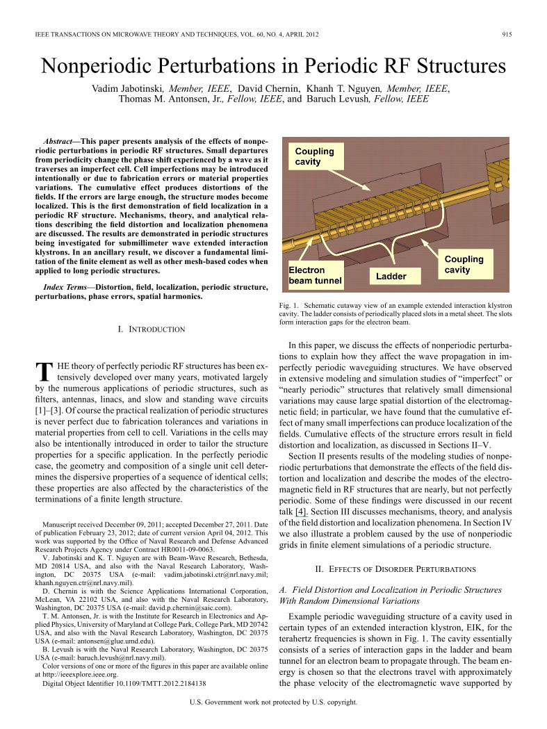
IEEE TRANSACTIONS ON MICROWAVE THEORY AND TECHNIQUES, VOL. 60, NO. 4, APRIL 2012 915
Nonperiodic Perturbations in Periodic RF StructuresVadim Jabotinski, Member, IEEE, David Chernin, Khanh T. Nguyen, Member, IEEE,
Thomas M. Antonsen, Jr., Fellow, IEEE, and Baruch Levush, Fellow, IEEE
Abstract—This paper presents analysis of the effects of nonpe-riodic perturbations in periodic RF structures. Small departuresfrom periodicity change the phase shift experienced by a wave as ittraverses an imperfect cell. Cell imperfections may be introducedintentionally or due to fabrication errors or material propertiesvariations. The cumulative effect produces distortions of thefields. If the errors are large enough, the structure modes becomelocalized. This is the first demonstration of field localization in aperiodic RF structure. Mechanisms, theory, and analytical rela-tions describing the field distortion and localization phenomenaare discussed. The results are demonstrated in periodic structuresbeing investigated for submillimeter wave extended interactionklystrons. In an ancillary result, we discover a fundamental limi-tation of the finite element as well as other mesh-based codes whenapplied to long periodic structures.
Index Terms—Distortion, field, localization, periodic structure,perturbations, phase errors, spatial harmonics.
I. INTRODUCTION
T HE theory of perfectly periodic RF structures has been ex-tensively developed over many years, motivated largely
by the numerous applications of periodic structures, such asfilters, antennas, linacs, and slow and standing wave circuits[1]–[3]. Of course the practical realization of periodic structuresis never perfect due to fabrication tolerances and variations inmaterial properties from cell to cell. Variations in the cells mayalso be intentionally introduced in order to tailor the structureproperties for a specific application. In the perfectly periodiccase, the geometry and composition of a single unit cell deter-mines the dispersive properties of a sequence of identical cells;these properties are also affected by the characteristics of theterminations of a finite length structure.
Manuscript received December 09, 2011; accepted December 27, 2011. Dateof publication February 23, 2012; date of current version April 04, 2012. Thiswork was supported by the Office of Naval Research and Defense AdvancedResearch Projects Agency under Contract HR0011-09-0063.V. Jabotinski and K. T. Nguyen are with Beam-Wave Research, Bethesda,
MD 20814 USA, and also with the Naval Research Laboratory, Wash-ington, DC 20375 USA (e-mail: [email protected];[email protected]).D. Chernin is with the Science Applications International Corporation,
McLean, VA 22102 USA, and also with the Naval Research Laboratory,Washington, DC 20375 USA (e-mail: [email protected]).T. M. Antonsen, Jr. is with the Institute for Research in Electronics and Ap-
plied Physics, University ofMaryland at College Park, College Park, MD 20742USA, and also with the Naval Research Laboratory, Washington, DC 20375USA (e-mail: [email protected]).B. Levush is with the Naval Research Laboratory, Washington, DC 20375
USA (e-mail: [email protected]).Color versions of one or more of the figures in this paper are available online
at http://ieeexplore.ieee.org.Digital Object Identifier 10.1109/TMTT.2012.2184138
Fig. 1. Schematic cutaway view of an example extended interaction klystroncavity. The ladder consists of periodically placed slots in a metal sheet. The slotsform interaction gaps for the electron beam.
In this paper, we discuss the effects of nonperiodic perturba-tions to explain how they affect the wave propagation in im-perfectly periodic waveguiding structures. We have observedin extensive modeling and simulation studies of “imperfect” or“nearly periodic” structures that relatively small dimensionalvariations may cause large spatial distortion of the electromag-netic field; in particular, we have found that the cumulative ef-fect of many small imperfections can produce localization of thefields. Cumulative effects of the structure errors result in fielddistortion and localization, as discussed in Sections II–V.Section II presents results of the modeling studies of nonpe-
riodic perturbations that demonstrate the effects of the field dis-tortion and localization and describe the modes of the electro-magnetic field in RF structures that are nearly, but not perfectlyperiodic. Some of these findings were discussed in our recenttalk [4]. Section III discusses mechanisms, theory, and analysisof the field distortion and localization phenomena. In Section IVwe also illustrate a problem caused by the use of nonperiodicgrids in finite element simulations of a periodic structure.
II. EFFECTS OF DISORDER PERTURBATIONS
A. Field Distortion and Localization in Periodic StructuresWith Random Dimensional Variations
Example periodic waveguiding structure of a cavity used incertain types of an extended interaction klystron, EIK, for theterahertz frequencies is shown in Fig. 1. The cavity essentiallyconsists of a series of interaction gaps in the ladder and beamtunnel for an electron beam to propagate through. The beam en-ergy is chosen so that the electrons travel with approximatelythe phase velocity of the electromagnetic wave supported by
U.S. Government work not protected by U.S. copyright.

916 IEEE TRANSACTIONS ON MICROWAVE THEORY AND TECHNIQUES, VOL. 60, NO. 4, APRIL 2012
Fig. 2. Field distortion and localization in the 17-cell EIK cavity at -pointobtained for different values of the variation coefficient of the gapwidths.
Fig. 3. Model geometry of the EIK periodic structure. The period length(gap-to-gap distance) is 133.5 m. Cross-sectional view to the right shows thewidth of the interaction gap. This width determines the -frequency and isthe most critical structure property to the errors.
the circuit, thereby ensuring an efficient interaction between thebeam and the cavity mode. One common choice for cavity modeis the -mode for which the structure electric field reachesits maxima inside each gap. The frequency of the -mode islargely determined by the gapwidth (long direction transverseto the beam tunnel). It is consequently important to considerthe effects of perturbations in the gapwidths from cell to cell,e.g., due to fabrication tolerances, on the cavity mode fields andfrequencies.The field profiles in Fig. 2 demonstrate impact of variations
in the gapwidth on the EIK cavity eigenfields at -point. Themodel geometry is presented in Fig. 3. To carry out the anal-ysis we have randomly generated realizations for the gapwidthsassuming Gaussian distribution with the mean valueor m and the variable variance with the corre-sponding variation coefficient defined as a ratio .“Realization” here is a set of the gapwidths that populate thestructure and subscript refers to the structure property beingconsidered on variations such as the gapwidth in the present dis-cussion. We then calculated the structure fields using the 3-Dfinite element electromagnetic simulation code ANALYST [5].We observe that the 0.1% m gapwidth vari-
ations cause distinct field distortion as compared to the perfect
Fig. 4. Effect of gapwidth realizations at 1% variation coefficient of the gap-widths, which corresponds to standard deviation m.
Fig. 5. 3-D -field magnitude plots for the structure without, , andwith, , perturbations corresponding to the field profiles displayed inFig. 4.
structure with and larger variations result in local-ization. We call “field distortion” the changes in the structurefield pattern due to perturbations, for example, variations inthe gapwidth. “Localization” is a stronger degree of the distor-tion when the field is dumped as a function of axial distancewithin the structure. We will show that the field distortion andlocalization are caused by different physical mechanisms andare described by different equations. Distorted field patterns likethose in Fig. 2 may greatly reduce the interaction efficiency be-tween the electron beam and the cavity fields. Correspondingly,the implications for fabrication tolerances for these micro-fab-ricated structures are significant.Different realizations of the structure gapwidths produce sim-
ilar degree of field distortion as seen in Fig. 4 with the corre-sponding 3-D -field plots shown in Fig. 5. It is noteworthythat although the localization position may vary for different re-alizations it tends to cluster toward the structure edges.The effect of the errors on the structure dispersive properties
is shown in Fig. 6. We find that the greatest changes occur athighly nonlinear portions of the dispersion characteristic, cir-cled areas in Fig. 6. As seen in Fig. 7 variations in the gap-width result in the shift of the -frequency that is also quitesignificant.

JABOTINSKI et al.: NONPERIODIC PERTURBATIONS IN PERIODIC RF STRUCTURES 917
Fig. 6. Dispersion diagram of the 17-cell structure considered for operationnear the -point at 673.4 GHz. The slope of the beam Doppler line corre-sponds to the beam electrons in the structure accelerated to the energy of 24.6keV, at which the velocity of the beam electrons equals to the phase velocity ofthe considered mode at 673.4 GHz as needed for the beam to wave inter-action to occur. Circled areas show highly nonlinear portions of the dispersioncharacteristic that are most sensitive to the dimensional variations.
Fig. 7. Effect of the gapwidth variations on the -frequency. Vertical dottedlines show the scatter range in the eigenfrequency values obtained for differentrealizations of a given variation coefficient , varied from 0 to 2%, which cor-responds to m. The solid blue line (in online version) shows theaverage frequency calculated by averaging over all realizations for each valueof the variation coefficient.
The following (1) shows analytical solution for such fre-quency shift . The derivation details are in Section III
(1)
where is the eigenfrequency sensitivity to perturbation,, is the perturbing property (gapwidth in the present con-
sideration), is the operating point phase advance angle, andand are the characteristics of the dispersion at the -point
Fig. 8. Strong localization as operating point , frequency branch (2)in Fig. 6, is in the nonlinear region of the dispersion characteristic.
that are coefficients in the power series expansion for the fre-quency shift versus the phase deviation around
(2)
In case of we consider the dispersion is highlynonlinear as opposed to the linear character at .The top two expressions in (1) describe the frequency shift incase of the highly nonlinear dispersion, circled areas in Fig. 6,and the last formula is for the near to linear dispersion, whichcan take place approximately in the middle of a passband.The , , and values needed to calculate the frequency
shift can be obtained from the eigensolutions of the per-fect structure. For the example structure shown in Fig. 3these values for the vicinity of the -point at 673.4 GHzare as follows: GHz m, GHz rad,
GHz rad . Then (1) describes the linear fre-quency decrease with the gapwidth variations, which is in fullagreement with the computer simulations shown in Fig. 7.Equation (1) as well as its general form derived in Section III isapplicable to any types of RF circuits at any operating point onthe dispersion curve.The effects of the structure dispersive properties such as
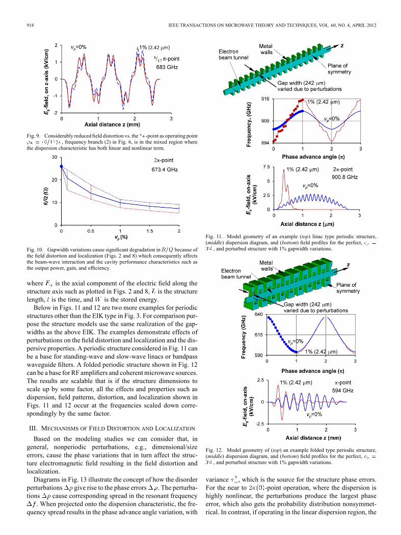
nonlinear or linear dispersion character are illustrated in Figs. 8and 9. For the -point at 673.4 GHz where the dispersion ishighly nonlinear GHz rad GHz radone can notice strong localization at 2.42- m gapwidth vari-ation, , Fig. 8. Furthermore for another point on thedispersion characteristic, for instance, the -point at683 GHz where the dispersion has both linear and nonlinearterm GHz rad GHz rad thesame 2.42- m gapwidth variation tends to produce consider-ably smaller distortion of the structure field as seen in Fig. 9.Fig. 10 shows changes in the structure at the –point
at 673.4 GHz due to gapwidth variations. The values pro-vide an important quantitative measure of how significantly thefield distortion impacts the beam-wave interaction and thus theklystron performance characteristics such as the output power,gain, and efficiency. Here is the shunt impedance, is thequality factor, and is defined as follows:
918 IEEE TRANSACTIONS ON MICROWAVE THEORY AND TECHNIQUES, VOL. 60, NO. 4, APRIL 2012
Fig. 9. Considerably reduced field distortion vs. the -point as operating point, frequency branch (2) in Fig. 6, is in the mixed region where
the dispersion characteristic has both linear and nonlinear term.
Fig. 10. Gapwidth variations cause significant degradation in because ofthe field distortion and localization (Figs. 2 and 8) which consequently affectsthe beam-wave interaction and the cavity performance characteristics such asthe output power, gain, and efficiency.
where is the axial component of the electric field along thestructure axis such as plotted in Figs. 2 and 8, is the structurelength, is the time, and is the stored energy.Below in Figs. 11 and 12 are two more examples for periodic
structures other than the EIK type in Fig. 3. For comparison pur-pose the structure models use the same realization of the gap-widths as the above EIK. The examples demonstrate effects ofperturbations on the field distortion and localization and the dis-persive properties. A periodic structure considered in Fig. 11 canbe a base for standing-wave and slow-wave linacs or bandpasswaveguide filters. A folded periodic structure shown in Fig. 12can be a base for RF amplifiers and coherentmicrowave sources.The results are scalable that is if the structure dimensions toscale up by some factor, all the effects and properties such asdispersion, field patterns, distortion, and localization shown inFigs. 11 and 12 occur at the frequencies scaled down corre-spondingly by the same factor.
III. MECHANISMS OF FIELD DISTORTION AND LOCALIZATION
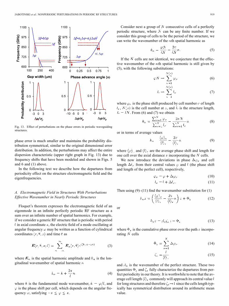
Based on the modeling studies we can consider that, ingeneral, nonperiodic perturbations, e.g., dimensional/sizeerrors, cause the phase variations that in turn affect the struc-ture electromagnetic field resulting in the field distortion andlocalization.Diagrams in Fig. 13 illustrate the concept of how the disorder
perturbations give rise to the phase errors . The perturba-tions cause corresponding spread in the resonant frequency. When projected onto the dispersion characteristic, the fre-
quency spread results in the phase advance angle variation, with
Fig. 11. Model geometry of an example (top) linac type periodic structure,(middle) dispersion diagram, and (bottom) field profiles for the perfect,, and perturbed structure with 1% gapwidth variations.
Fig. 12. Model geometry of (top) an example folded type periodic structure,(middle) dispersion diagram, and (bottom) field profiles for the perfect,, and perturbed structure with 1% gapwidth variations.
variance , which is the source for the structure phase errors.For the near to -point operation, where the dispersion ishighly nonlinear, the perturbations produce the largest phaseerror, which also gets the probability distribution nonsymmet-rical. In contrast, if operating in the linear dispersion region, the
JABOTINSKI et al.: NONPERIODIC PERTURBATIONS IN PERIODIC RF STRUCTURES 919
Fig. 13. Effect of perturbations on the phase errors in periodic waveguidingstructures.
phase error is much smaller and maintains the probability dis-tribution symmetrical, similar to the original dimensional errordistribution. In addition, the perturbations may affect the entiredispersion characteristic (upper right graph in Fig. 13) due tofrequency shifts that have been modeled and shown in Figs. 5and 6 and (1) above.In the following text we describe how the departures from
periodicity effect on the structure electromagnetic field and theeigenfrequencies.
A. Electromagnetic Field in Structures With PerturbationsEffective Wavenumber in Nearly Periodic Structures
Floquet’s theorem expresses the electromagnetic field of aneigenmode in an infinite perfectly periodic RF structure as asum over an infinite number of spatial harmonics. For example,if we consider a generic RF structure that is periodic with periodin axial coordinate , the electric field of a mode oscillating atangular frequency may be written as a function of cylindricalcoordinates and time as
(3)
where is the spatial harmonic amplitude and is the lon-gitudinal wavenumber of spatial harmonic
(4)
where is the fundamental mode wavenumber, , andis the phase shift per cell, which depends on the angular fre-
quency , satisfying .
Consider next a group of consecutive cells of a perfectlyperiodic structure, where can be any finite number. If weconsider this group of cells to be the period of the structure, wecan write the wavenumber of the th spatial harmonic as
(5)
If the cells are not identical, we conjecture that the effec-tive wavenumber of the th spatial harmonic is still given by(5), with the following substitutions:
(6)
(7)
where is the phase shift produced by cell number of length, is the cell number at , and is the structure length,
. From (6) and (7) we obtain
(8)
or in terms of average values
(9)
where and are the average phase shift and length forone cell over the axial distance incorporating the cells.We now introduce the deviations in phase and cell
length from their central values and (the phase shiftand length of the perfect cell), respectively,
(10)
(11)
Then using (9)–(11) find the wavenumber substitution for (1)
(12)
or
(13)
where is the cumulative phase error over the path incorpo-rating cells
(14)
(15)
and is the wavenumber of the perfect structure. These twoquantities and fully characterize the departures from per-fect periodicity in our theory. It is worthwhile to note that the av-erage cell length commonly will approach its central valuefor long structures and therefore since the cells length typ-ically has symmetrical distribution around its arithmetic meanvalue.
920 IEEE TRANSACTIONS ON MICROWAVE THEORY AND TECHNIQUES, VOL. 60, NO. 4, APRIL 2012
1) Spatial Modulation of the Field by Phase Errors: Struc-tures consisting of a finite number of nearly identical cells sup-port standingwaves consisting of a superposition of forward andbackward traveling waves. In a case in which there is no dissi-pation on the circuit, obtain the axial field on axis by solving theMaxwell’s equations and using the Floquet’s series (3) with theeffective wavenumber from (13)
(16)
where are the expansion harmonic coefficients. Presence ofin (16) indicates that the cumulative phase error produces
spatial modulation of the structure field. In particular, for theand operating modes (14) yields
.(17)
Equation (17) explicitly shows that for the and operatingmodes, the departures from perfect periodicity result in spatial,or axial, modulation of the field, following to the common factorof .
B. Cumulative Phase Error
Cumulative phase error determines a degree to which per-turbations affect the structure electromagnetic field. The cumu-lative phase error is a random function given by a sum of randomvariables of phase errors of individual cells (14). The cumula-tive phase error is the key function to study the properties on thedisorder effects.Applying the central limit theorem [6], present in the form
(18)
Here , is the standard normal randomvariable coefficient, and and are the phase error arithmeticmean and variance, defined as follows:
(19)
(20)
and the phase error quadratic mean
Note that representation (18) is valid for any distribution ofthe phase error, which has an existing variance. In the case ofan infinite structure, , the first term in sum (18) describes
the cumulative phase error while the second term becomes neg-ligible. For a finite length structure, the central limit theoremadds the second term to (18) that takes into consideration “slow”statistical convergence to the average. This second term maybecome dominating at the smaller numbers and the greaterphase error variations .The first term describes field distortion, which occurs over
larger number of the structure cells. The second term describesfield localization, which explains the rapid drop in the structurefield magnitude from the peak to almost zero levels over smallernumber of cells. Since the second term introduces the randomcoefficient and thus uncertainty, we shall consider the ob-tained then cumulative phase error from (18) with the referenceto a certain probability. Presenting the cumulative phase erroras a sum of two terms (18) and specifying these terms is one ofthe major findings of the presented theory.
C. Field Distortion
Using (2) express the phase error through the perturba-tion, e.g., dimensional error, Appendix I
(21)
where and . Then obtain thecumulative phase error due to distortion as described by the firstterm in (18) and determined by (19) in the form
(22)
where
(23)
, , ,and is a non-zero/infinity function
that can be chosen arbitrary for convenience. For example
and then
linear dispersion regionmixed dispersion
nonlinear dispersion(band edge).
(24)
Note that here
(25)
For the above determined values, and are two disorderinvariants that fully describe the distortion process. These in-variants in turn are determined by the parameters and .Referring to a physical content, presents a measure of thedisorder, characterizes the degree of perturbations relative

JABOTINSKI et al.: NONPERIODIC PERTURBATIONS IN PERIODIC RF STRUCTURES 921
Fig. 14. Universal function for the cumulative phase error due to distortion.
to the wave group velocity, and relates to the structure sus-ceptibility to the perturbations.Using power series expansions of integral (23) from
Appendix II obtain asymptotic estimates for
non-linear dispersionlargernear-to-linear dispersionsmaller .
(26)
Asymptotic estimates (26) allow evaluation for the structurelength in the extreme cases of nonlinear and near to lineardispersion so to keep and thereby the field decrease dueto distortion within a given tolerance level . In particular,for the and operating modes with the respect of the spatialharmonics series expansions (17) obtain
nonlinear dispersion
near-to-linear dispersion.(27)
For the -point at 673.4 GHz for the structure in Fig. 3,m and , (27) yields the length ,
which is consistent with the computed field profiles in Fig. 2.Fig. 14 displays a universal function that describes the cumu-
lative phase error (22) due to distortion in the , invariants.For numerical integration we used a transformed form of (23)shown in Appendix III to avoid singularities.The next plots in Figs. 15 and 16 are extracted from the uni-
versal function and explicitly show the cumulative phase errorand the structure half-length, respectively, the major character-istics of distortion. The zero phase error in Fig. 15 and singu-larity points in Fig. 16 correspond to a transition position be-tween the nonlinear and linear regions on the dispersion curvewhere the expected phase error vanishes (zero of the uni-versal function in Fig. 14 at ) as opposed to thenonzero variance . We observe also that at linear dispersionthe phase error and thus the field distortion are reduced to zero.Fig. 17 shows the disorder values for the example structure inFig. 3 determined for the modes in the frequency branch (2) at
Fig. 15. Cumulative phase error due to distortion. Dot marker refers to the con-sidered -point at 673.4 GHz displayed in Fig. 6 for m (1%) vari-ations in the gapwidth. Two curves correspond to different values of .
Fig. 16. Structure length limitation due to distortion. Two curves correspondto different values of .
Fig. 17. Disorder invariant calculated for the structure modes in the fre-quency branch (2). The structure model and its dispersion diagram are given inthe above Figs. 3 and 6, respectively.
m. The results show the modes including those withcloser to 1.846, which are to have the reduced field distor-
tion as described by the first term in (18). However the total cu-mulative phase error (18) can remain significant because of thenonzero variance that gives rise to the field localization de-scribed by the second term in (18) and discussed in Sections IVand V.
D. Field Localization
Write (18) in the form
(28)
922 IEEE TRANSACTIONS ON MICROWAVE THEORY AND TECHNIQUES, VOL. 60, NO. 4, APRIL 2012
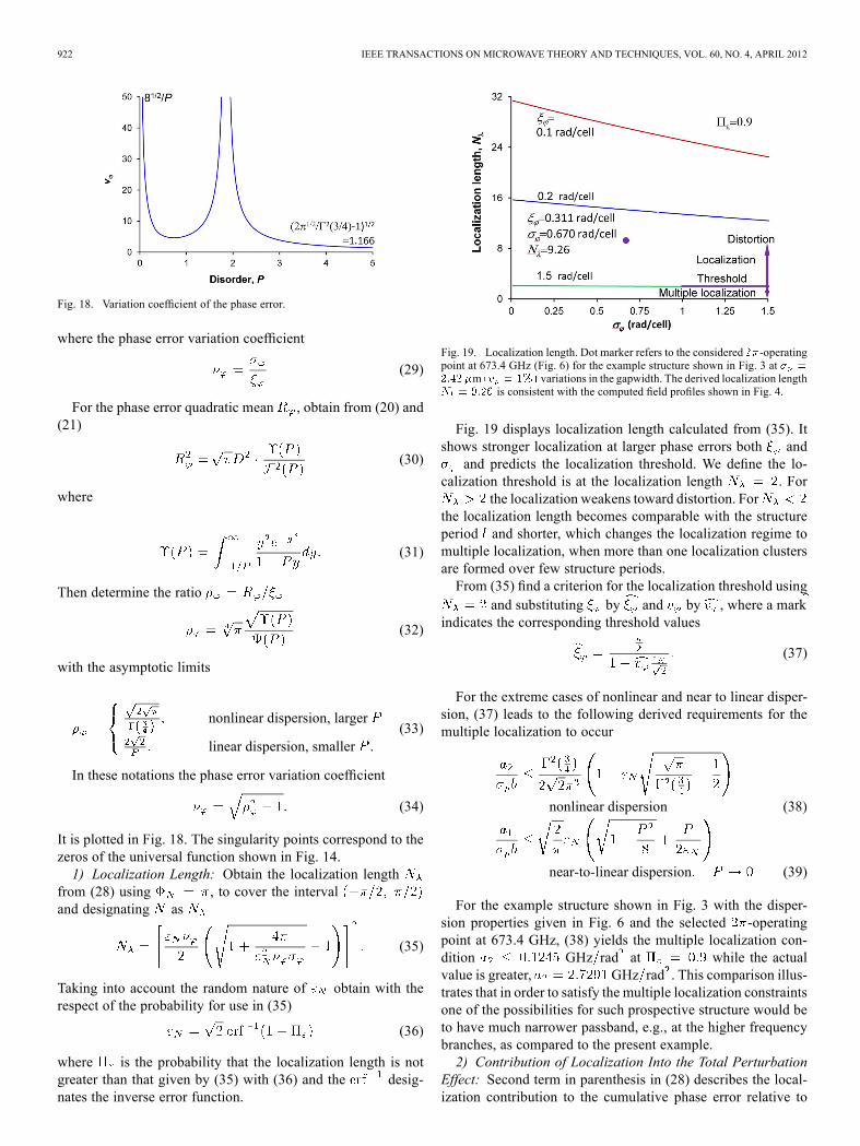
Fig. 18. Variation coefficient of the phase error.
where the phase error variation coefficient
(29)
For the phase error quadratic mean , obtain from (20) and(21)
(30)
where
(31)
Then determine the ratio
(32)
with the asymptotic limits
nonlinear dispersion, larger
linear dispersion, smaller .(33)
In these notations the phase error variation coefficient
(34)
It is plotted in Fig. 18. The singularity points correspond to thezeros of the universal function shown in Fig. 14.1) Localization Length: Obtain the localization length
from (28) using , to cover the intervaland designating as
(35)
Taking into account the random nature of obtain with therespect of the probability for use in (35)
(36)
where is the probability that the localization length is notgreater than that given by (35) with (36) and the desig-nates the inverse error function.
Fig. 19. Localization length. Dot marker refers to the considered -operatingpoint at 673.4 GHz (Fig. 6) for the example structure shown in Fig. 3 at
m variations in the gapwidth. The derived localization lengthis consistent with the computed field profiles shown in Fig. 4.
Fig. 19 displays localization length calculated from (35). Itshows stronger localization at larger phase errors both and
and predicts the localization threshold. We define the lo-calization threshold is at the localization length . For
the localization weakens toward distortion. Forthe localization length becomes comparable with the structureperiod and shorter, which changes the localization regime tomultiple localization, when more than one localization clustersare formed over few structure periods.From (35) find a criterion for the localization threshold using
and substituting by and by , where a markindicates the corresponding threshold values
(37)
For the extreme cases of nonlinear and near to linear disper-sion, (37) leads to the following derived requirements for themultiple localization to occur
nonlinear dispersion (38)
near-to-linear dispersion (39)
For the example structure shown in Fig. 3 with the disper-sion properties given in Fig. 6 and the selected -operatingpoint at 673.4 GHz, (38) yields the multiple localization con-dition GHz rad at while the actualvalue is greater, GHz rad . This comparison illus-trates that in order to satisfy the multiple localization constraintsone of the possibilities for such prospective structure would beto have much narrower passband, e.g., at the higher frequencybranches, as compared to the present example.2) Contribution of Localization Into the Total Perturbation
Effect: Second term in parenthesis in (28) describes the local-ization contribution to the cumulative phase error relative to
JABOTINSKI et al.: NONPERIODIC PERTURBATIONS IN PERIODIC RF STRUCTURES 923
Fig. 20. Distortion over spatial modulation wavelength.
the distortion contribution. Introducing the spatial modulationwavelength and substituting by obtain from (28)
(40)
where is the spatial modulation wavelength due to both dis-tortion and localization and is due to distortion only thewavelength at . From here the ratio de-scribing contribution of the localization into the total effect ofperturbations is as follows
distortionlocalization.
(41)Using from (36) obtain
(42)
Here is the probability that the localization contribution intothe total perturbations effect will be not smaller than that givenby (40). Fig. 20 illustrates the results calculated atand with the respect of the correlation factor .3) Correlation: The correlation occurs due to coupling be-
tween the structure cells and results in additional increase in thephase error variations and thereby causes stronger localization.We shall consider the cell wave admittances for the phase
error calculations, Appendix IV. The admittance for the cellnumber in the structure of cells with the respect of couplingcan be determined by a linear combination
(43)
where is the admittance weight function that shows whatfraction of the cell admittance is coupled to cell . Here thecells and are called analyzing and contributing, respectively.For the simplest model of a periodic coupled structure such as
a ladder of parallel impedances the weight function obviouslyyields
(44)
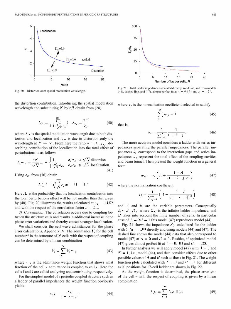
Fig. 21. Total ladder impedance calculated directly, solid line, and frommodels(44), dashed line, and (47), almost perfect fit at and .
where is the normalization coefficient selected to satisfy
(45)
that is
(46)
The more accurate model considers a ladder with series im-pedances separating the parallel impedances. The parallel im-pedances correspond to the interaction gaps and series im-pedances represent the total effect of the coupling cavitiesand beam tunnel. Then present the weight function in a generalform
(47)
where the normalization coefficient
(48)
and and are the variable parameters. Conceptually, where is the infinite ladder impedance, and
takes into account the finite number of cells. In particularcase of this model (47) reproduces model (44).Fig. 21 shows the impedance calculated for the ladder
with directly and using models (44) and (47). Thedashed line shows the model (44) data that also correspond tomodel (47) at and . Besides, if optimized model(47) gives almost perfect fit at and .In further analysis we will apply model (47) with and
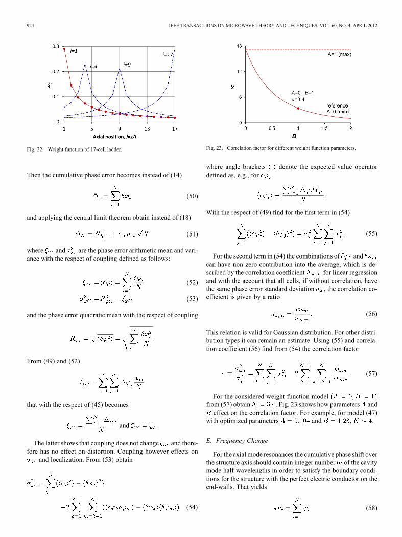
, i.e., model (44), and then consider effects due to otherpossible values of and such as those in Fig. 21. The weightfunction plots calculated with and for differentaxial positions for 17-cell ladder are shown in Fig. 22.As the weight function is determined, the phase error
of the cell with the respect of coupling is given by a linearcombination
(49)
924 IEEE TRANSACTIONS ON MICROWAVE THEORY AND TECHNIQUES, VOL. 60, NO. 4, APRIL 2012
Fig. 22. Weight function of 17-cell ladder.
Then the cumulative phase error becomes instead of (14)
(50)
and applying the central limit theorem obtain instead of (18)
(51)
where and are the phase error arithmetic mean and vari-ance with the respect of coupling defined as follows:
(52)
(53)
and the phase error quadratic mean with the respect of coupling
From (49) and (52)
that with the respect of (45) becomes
and
The latter shows that coupling does not change and there-fore has no effect on distortion. Coupling however effects on
and localization. From (53) obtain
(54)
Fig. 23. Correlation factor for different weight function parameters.
where angle brackets denote the expected value operatordefined as, e.g., for
With the respect of (49) find for the first term in (54)
(55)
For the second term in (54) the combinations of andcan have non-zero contribution into the average, which is de-scribed by the correlation coefficient for linear regressionand with the account that all cells, if without correlation, havethe same phase error standard deviation , the correlation co-efficient is given by a ratio
(56)
This relation is valid for Gaussian distribution. For other distri-bution types it can remain an estimate. Using (55) and correla-tion coefficient (56) find from (54) the correlation factor
(57)
For the considered weight function modelfrom (57) obtain . Fig. 23 shows how parameters andeffect on the correlation factor. For example, for model (47)
with optimized parameters and , .
E. Frequency Change
For the axial mode resonances the cumulative phase shift overthe structure axis should contain integer number of the cavitymode half-wavelengths in order to satisfy the boundary condi-tions for the structure with the perfect electric conductor on theend-walls. That yields
(58)
JABOTINSKI et al.: NONPERIODIC PERTURBATIONS IN PERIODIC RF STRUCTURES 925
where is the cell phase shift, which we consider as a func-tion of the mode frequency and variable property , i.e.,
(59)
Introducing the property perturbation from its central value
(60)
write the Taylor series expansion for the phase shift (59)
(61)
where is the phase shift by a non-perturbed cell at fre-quency . From (58) and (61) obtain
(62)
where are the -order central moments of
(63)
In a common case of the symmetrical distribution of , themoments . Considering small perturbations obtainfrom (62) for further analysis
(64)
Writing (2) in the form
(65)
obtain auxiliary expressions
(66)
Then using Appendix V find
(67)
From (64)–(67) obtain equation for the structure eigenfre-quency , which is shifted from its ideal value due to theperturbations .
(68)
Several particular solutions of this (68) for the band edge andmodes as well as for the intermediate operating modes are
presented in (1).
IV. LIMITATION OF THE FINITE-ELEMENT METHODFOR LONG PERIODIC STRUCTURES
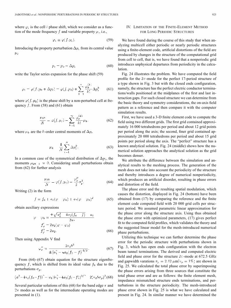
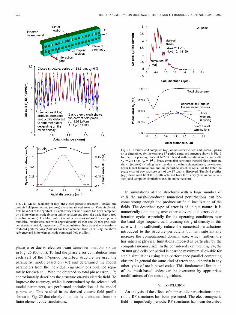
We have found during the course of this study that when an-alyzing multicell either periodic or nearly periodic structuresusing a finite-element code, artificial distortions of the field areproduced by changes in the structure of the computational gridfrom cell to cell, that is, we have found that a nonperiodic gridintroduces unphysical departures from periodicity in the calcu-lation.Fig. 24 illustrates the problem. We have computed the field
profile for the -mode for the perfect 17-period structure ofa type shown in Fig. 3 but with the closed ends configuration,namely, the structure has the perfect electric conductor termina-tions/walls positioned at the midplanes of the first and last in-teraction gaps. For such closed structure we can determine fromthe basic theory and symmetry considerations, the on-axis fieldpattern as a reference and then compare it with the computersimulation results.First, we have used a 3-D finite element code to compute the
field using two different grids. The first grid contained approxi-mately 16 000 tetrahedrons per period and about 12 grid pointsper period along the axis; the second, finer grid contained ap-proximately 20 000 tetrahedrons per period and about 15 gridpoints per period along the axis. The “perfect” structure has aknown analytical solution. Fig. 24 (middle) shows how the nu-merical solution approaches the analytical solution as the gridbecomes denser.We attribute the difference between the simulation and an-
alytical results to the meshing process. The generation of themesh does not take into account the periodicity of the structureand thereby introduces a degree of numerical nonperiodicity,which produces an artificial disorder, resulting in phase errorsand distortion of the field.The phase error and the resulting spatial modulation, which
causes the distortion, displayed in Fig. 24 (bottom) have beenobtained from (17) by comparing the reference and the finiteelement code computed field with 20 000 grid cells per struc-ture period. We assumed parametric linear approximation forthe phase error along the structure axis. Using thus obtainedthe phase error with optimized parameters, (17) gives perfectfit to the computed field profiles, which validates the theory andthe suggested linear model for the mesh-introduced numericalphase perturbations.Utilizing this technique we can further determine the phase
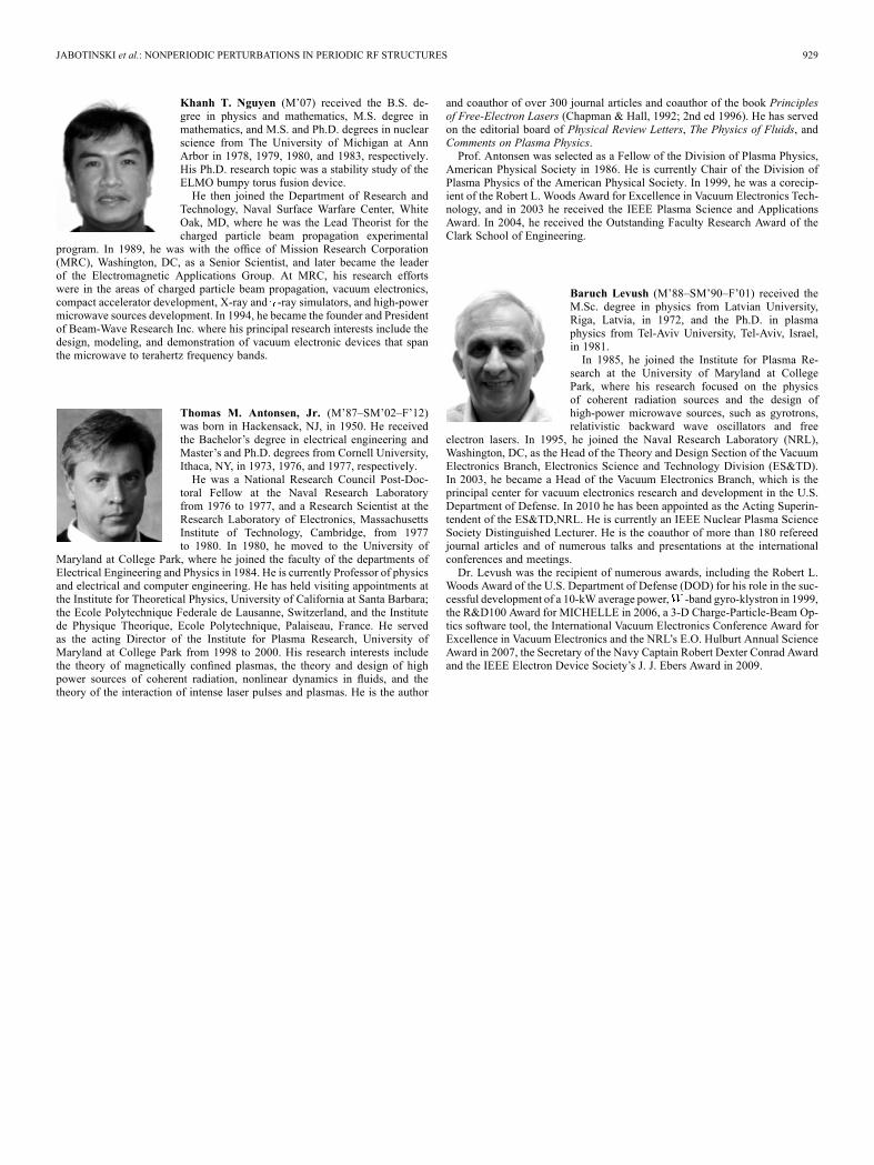
error for the periodic structure with perturbations shown inFig. 3, which has open ends configuration with the electronbeam tunnel terminations. The derived and computed electricfield and phase error for the structure -mode at 672.5 GHzand gapwidth varations m are shown inFig. 25. We calculated the total phase error by superimposingthe phase errors arising from three sources that constitute thetotal phase error and are as follows: the finite element mesh,impedance mismatched structure ends terminations, and per-turbations in the structure periodicity. The mesh-introducedphase error shown in Fig. 25 is what we have calculated andpresent in Fig. 24. In similar manner we have determined the
926 IEEE TRANSACTIONS ON MICROWAVE THEORY AND TECHNIQUES, VOL. 60, NO. 4, APRIL 2012
Fig. 24. Model geometry of (top) the closed periodic structure , (middle) theon-axis field patterns, and (bottom) the cumulative phase error. On-axis electricfield (middle) of the “perfect” 17-cell cavity versus distance has been computedby a finite element code (blue in online version) and from the basic theory (redin online version). The blue dashed (in online version) and solid lines representnumerical results obtained with approximately 16 000 and 20 000 grid cellsper structure period, respectively. The cumulative phase error due to mesh-in-troduced perturbations (bottom) has been obtained from (17) using the abovereference and finite element code computed field profiles.
phase error due to electron beam tunnel terminations shownin Fig. 25 (bottom). To find the phase error contribution fromeach cell of the 17-period perturbed structure we used theparametric model based on (47) and determined the modelparameters from the individual eigensolutions obtained sepa-rately for each cell. With the obtained so total phase error, (17)approximately describes the structure on-axis electric field. Toimprove the accuracy, which is constrained by the selected cellmodel parameters, we performed optimization of the modelparameters. This resulted in the derived electric field profileshown in Fig. 25 that closely fits to the field obtained from thefinite element code simulations.
Fig. 25. Derived and computed (top) on-axis electric field and (bottom) phaseerror determined for the example 17-period perturbed structure shown in Fig. 3for the -operating mode at 672.5 GHz and with variations in the gapwidth
m . Phase errors that constitute the total phase error areshown (bottom) including the errors due to the finite element mesh, the electronbeam tunnel terminations, and the perturbed structure cells. For the latter thephase error of one structure cell of the 17 total is displayed. The field profiles(top) show good fit of the results obtained from the theory (blue in online ver-sion) and computer simulations (red in online version).
In simulations of the structures with a large number ofcells the mesh-introduced numerical perturbations can be-come strong enough and produce artificial localization of thefields. The described type of error is of unique nature. It isnumerically dominating over other conventional errors due toiteration cycles especially for the operating conditions nearthe band edge frequencies. Increasing the grid density in thiscase will not sufficiently reduce the numerical perturbationsintroduced to the structure periodicity but will substantiallyincrease the computational domain size, which furthermorehas inherent physical limitations imposed in particular by thecomputer memory size. In the considered example, Fig. 24, the20 000 grid cells per period is near the maximum allowable forstable simulations using high-performance parallel computingclusters. In general the same kind of errors should persist in anyother types of mesh-based codes. This fundamental limitationof the mesh-based codes can be overcome by appropriatemodifications of the mesh algorithms.
V. CONCLUSION
An analysis of the effects of nonperiodic perturbations in pe-riodic RF structures has been presented. The electromagneticfield in imperfectly periodic RF structures has been described

JABOTINSKI et al.: NONPERIODIC PERTURBATIONS IN PERIODIC RF STRUCTURES 927
taking into consideration that small departures from periodicitychange the phase shift experienced by a wave as it traverses animperfect cell. It was shown that the cumulative phase error pro-duces spatial modulation of the field, which causes the field dis-tortion. Larger perturbations lead to stronger field distortion andresult in localization. This is the first demonstration of field lo-calization in a periodic RF structure. The physical mechanismsof field distortion and localization have been suggested and dis-cussed including methods for finding the cumulative phase errorand taking into account that over shorter lengths inside the struc-tures the averaging of perturbations occurs slower that largelyexplains the localization phenomena. Presented theory providesanalytical relations describing the field distortion and localiza-tion including the localization length. Application examples ofthe numerical simulation techniques for analysis of the multi-cell coupled cavity structures have been considered. In an ancil-lary result a fundamental limitation of finite element and othermesh-based codes when applied to long periodic structures hasbeen discovered and discussed.The presented theory and approach utilizing in particular the
central limit theorem can be common for describing many phys-ical phenomena that are random by nature, such as the chargedand neutral particles transport in accelerators, space, plasma, at-mosphere, solid state, and continuous medium, electromagneticwave propagation, radiation-to-matter interaction, and varietyof thermodynamic systems. Because of randomness such sys-tems when changing from one state (initial) to another (final)undergo what we can consider as transient states. In the initialand final states the systems follow the physical mechanisms thatobey the statistical laws. In the transient states where, e.g., time,space, or number of particles/cells is limited the same systemsexhibit different behavior because they do not satisfy yet theconditions to converge to the statistical laws. In these views, wehave described the localization and distortion of the electromag-netic modes in the periodic RF structures with perturbations.
APPENDIX I
Phase Error Due to Perturbation: Phase error causedby perturbation for the structure cell number can be de-termined by
(A1.1)
that yields
(A1.2)
where and . From (2),
(A1.3)
which in combination with (2) gives
(A1.4)
From (A1.2) and (A1.4) obtain for (21)
(A1.5)
APPENDIX II
Integral for the Field Distortion Phase Error: Split theintegration path in (23) in two intervals as follows:
(A2.1)
where and
. Then obtain power series ex-pansions for the integrals as shown in (A2.2) and (A2.3) atthe bottom of this page. Here and are the lower and theupper incomplete gamma-functions, respectively. Integralis dominating for linear dispersion with smaller and integralis dominating for nonlinear dispersion with larger . The
obtained expansions are necessary for asymptotic estimates ofthe cumulative phase error and the structure length evaluationas shown in (26) and (27).
APPENDIX III
Avoiding Singularity in Numerical Integration of :Integrating (23) by parts write
(A3.1)
(A2.2)
(A2.3)

928 IEEE TRANSACTIONS ON MICROWAVE THEORY AND TECHNIQUES, VOL. 60, NO. 4, APRIL 2012
Since the first term vanishes obtain in the form that doesnot contain singularities and ready for numerical integration
(A3.3)
APPENDIX IV
Admittance Weight Function for Phase Error Calculation:The cell number phase error
where , is the cell wavenumber, and .Introducing the wave admittance for the cell and for theunaltered cell write
where is the magnetic constant. Then obtain
Since the phase error is proportional to the admittance error ifthe admittance weight function can be used for phase
error calculations. In more general case of variations in the cellperiods, , the admittance weight function is still applicableeither approximately or with the corresponding selection of thestructure model (47) parameters and .
APPENDIX V
Second Derivative of the Cell Phase Shift With the Respectto Perturbations: Write the first derivative
Then the second derivative can be obtained in the form
Since in the majority of cases for small perturbationsand obtain
ACKNOWLEDGMENT
The authors appreciate the many helpful discussions withJ. Calame of NRL and R. Dobbs and A. Roitman of CPI/Canada.This work was approved for public release, distribution unlim-ited. The views expressed are those of the author and do notreflect the official policy or position of the Department of De-fense or the U.S. Government.
REFERENCES
[1] A. S. Gilmour Jr., Principles of Traveling Wave Tubes. Boston, MA:Artech House, 1994.
[2] B. Levush, T. M. Antonsen Jr., A. Bromborsky, W. R. Lou, and Y.Carmel, “Theory of relativistic backward-wave oscillators with end re-flections,” IEEE Trans. Plasma Sci., vol. 20, no. 3, pp. 263–280, Jun.1992.
[3] W. Main, Y. Carrnel, K. Ogura, J. Weaver, G. S. Nusinovich, S.Kobayashi, J. P. Tate, J. Rodgers, A. Bromborsky, S. Watanabe, M. R.Amin, K. Minami, W. W. Destler, and V. Granatstein, “Electromag-netic properties of open and closed overmoded slow-wave resonatorsfor interaction with relativistic electron beams,” IEEE Trans. PlasmaSci., vol. 22, no. 5, pp. 566–577, Oct. 1994.
[4] V. Jabotinski, D. Chernin, T. Antonsen, and B. Levush, “Non-peri-odic perturbations in periodic RF structures,” in IEEE MTT-S Microw.Symp. Dig., Jun. 5–10, 2011, pp. 1–4.
[5] “3D FEM analysis software for solving complex problems,” Microw.J., vol. 52, pp. 104–104, Jul. 2009.
[6] A. A. Borovkov, Probability Theory. Boca Raton, FL: CRC, 1999.
Vadim Jabotinski (M’11) received the M.S. de-gree in radio-physics and electronics from theDnepropetrovsk State University, Dnepropetrovsk,Ukraine, in 1983.He joined the Research Center for Directed Energy
Sources, Dnepropetrovsk, Ukraine, where in 1995 hebecame Head of the Electron Beam Processes Sec-tion andworked on the theory and applications of par-ticle beams, accelerators, and microwave and radia-tion sources in collaborationwith the Budker Instituteof Nuclear Physics of Russian Academy of Sciences
in Novosibirsk and the departments of RF and solid-state physics at the Dne-propetrovsk State University. In 1996, he joined the Institute for Materials andAdvanced Processes, University of Idaho,Moscow, to pursue his research on thephysics of radiation-to-matter interaction and theory of power particle beams.From 2001 to 2008, he was a Senior Scientist at FM Technologies, Chantilly,VA, where he developed new approaches for high and low energy particle ac-celerators. Since 2009, he is with Beam-Wave Research as a Senior Scientistand also with the Vacuum Electronics Branch, U.S. Naval Research Laboratory,Washington, DC, where he works on the theory and modeling of the terahertzwaveguiding structures, beam-wave interaction, and new concepts for electronbeam sources and vacuum electronics. His research interests include the theoryand new phenomena in electromagnetism, RF physics, and particle beams, com-putational methods for waveguiding structures and submillimeter-wave radia-tion sources.Mr. Jabotinski is a member of the American Physical Society and the Min-
erals, Metals and Materials Society.
David Chernin received the A.B. and Ph.D. degreesin applied mathematics from Harvard University,Cambridge, MA, in 1971 and 1976, respectively.From 1976 to 1978, he was a member of the
Institute for Advanced Study, Princeton, NJ, wherehe worked on problems in magnetic confinementfusion. From 1978 to 1981, he was Senior Scientistat Maxwell Laboratories, San Diego, CA, wherehe worked on the design and analysis of excimerlasers and high power X-ray sources. Since 1984 hehas been at the Science Applications International
Corporation, McLean, VA, where he has conducted research on the theoryand simulation of beam-wave interactions in particle accelerators, and on thedesign, simulation, and analysis of vacuum electron devices in collaborationwith the Vacuum Electronics Branch, Naval Research Laboratory, Washington,DC. From 2005 to 2008, he served as Chief Scientist for SAIC’s Technologyand Advanced Systems business unit.Dr. Chernin is a member of the American Physical Society.
JABOTINSKI et al.: NONPERIODIC PERTURBATIONS IN PERIODIC RF STRUCTURES 929
Khanh T. Nguyen (M’07) received the B.S. de-gree in physics and mathematics, M.S. degree inmathematics, and M.S. and Ph.D. degrees in nuclearscience from The University of Michigan at AnnArbor in 1978, 1979, 1980, and 1983, respectively.His Ph.D. research topic was a stability study of theELMO bumpy torus fusion device.He then joined the Department of Research and
Technology, Naval Surface Warfare Center, WhiteOak, MD, where he was the Lead Theorist for thecharged particle beam propagation experimental
program. In 1989, he was with the office of Mission Research Corporation(MRC), Washington, DC, as a Senior Scientist, and later became the leaderof the Electromagnetic Applications Group. At MRC, his research effortswere in the areas of charged particle beam propagation, vacuum electronics,compact accelerator development, X-ray and -ray simulators, and high-powermicrowave sources development. In 1994, he became the founder and Presidentof Beam-Wave Research Inc. where his principal research interests include thedesign, modeling, and demonstration of vacuum electronic devices that spanthe microwave to terahertz frequency bands.
Thomas M. Antonsen, Jr. (M’87–SM’02–F’12)was born in Hackensack, NJ, in 1950. He receivedthe Bachelor’s degree in electrical engineering andMaster’s and Ph.D. degrees from Cornell University,Ithaca, NY, in 1973, 1976, and 1977, respectively.He was a National Research Council Post-Doc-
toral Fellow at the Naval Research Laboratoryfrom 1976 to 1977, and a Research Scientist at theResearch Laboratory of Electronics, MassachusettsInstitute of Technology, Cambridge, from 1977to 1980. In 1980, he moved to the University of
Maryland at College Park, where he joined the faculty of the departments ofElectrical Engineering and Physics in 1984. He is currently Professor of physicsand electrical and computer engineering. He has held visiting appointments atthe Institute for Theoretical Physics, University of California at Santa Barbara;the Ecole Polytechnique Federale de Lausanne, Switzerland, and the Institutede Physique Theorique, Ecole Polytechnique, Palaiseau, France. He servedas the acting Director of the Institute for Plasma Research, University ofMaryland at College Park from 1998 to 2000. His research interests includethe theory of magnetically confined plasmas, the theory and design of highpower sources of coherent radiation, nonlinear dynamics in fluids, and thetheory of the interaction of intense laser pulses and plasmas. He is the author
and coauthor of over 300 journal articles and coauthor of the book Principlesof Free-Electron Lasers (Chapman & Hall, 1992; 2nd ed 1996). He has servedon the editorial board of Physical Review Letters, The Physics of Fluids, andComments on Plasma Physics.Prof. Antonsen was selected as a Fellow of the Division of Plasma Physics,
American Physical Society in 1986. He is currently Chair of the Division ofPlasma Physics of the American Physical Society. In 1999, he was a corecip-ient of the Robert L. Woods Award for Excellence in Vacuum Electronics Tech-nology, and in 2003 he received the IEEE Plasma Science and ApplicationsAward. In 2004, he received the Outstanding Faculty Research Award of theClark School of Engineering.
Baruch Levush (M’88–SM’90–F’01) received theM.Sc. degree in physics from Latvian University,Riga, Latvia, in 1972, and the Ph.D. in plasmaphysics from Tel-Aviv University, Tel-Aviv, Israel,in 1981.In 1985, he joined the Institute for Plasma Re-
search at the University of Maryland at CollegePark, where his research focused on the physicsof coherent radiation sources and the design ofhigh-power microwave sources, such as gyrotrons,relativistic backward wave oscillators and free
electron lasers. In 1995, he joined the Naval Research Laboratory (NRL),Washington, DC, as the Head of the Theory and Design Section of the VacuumElectronics Branch, Electronics Science and Technology Division (ES&TD).In 2003, he became a Head of the Vacuum Electronics Branch, which is theprincipal center for vacuum electronics research and development in the U.S.Department of Defense. In 2010 he has been appointed as the Acting Superin-tendent of the ES&TD,NRL. He is currently an IEEE Nuclear Plasma ScienceSociety Distinguished Lecturer. He is the coauthor of more than 180 refereedjournal articles and of numerous talks and presentations at the internationalconferences and meetings.Dr. Levush was the recipient of numerous awards, including the Robert L.
Woods Award of the U.S. Department of Defense (DOD) for his role in the suc-cessful development of a 10-kW average power, -band gyro-klystron in 1999,the R&D100 Award for MICHELLE in 2006, a 3-D Charge-Particle-Beam Op-tics software tool, the International Vacuum Electronics Conference Award forExcellence in Vacuum Electronics and the NRL’s E.O. Hulburt Annual ScienceAward in 2007, the Secretary of the Navy Captain Robert Dexter Conrad Awardand the IEEE Electron Device Society’s J. J. Ebers Award in 2009.
Copyright © 2022 FDOKUMEN