On the assessment of train crankshafts fatigue life based on ...
12
HAL Id: hal-01599983 https://hal.archives-ouvertes.fr/hal-01599983 Submitted on 7 Nov 2018 HAL is a multi-disciplinary open access archive for the deposit and dissemination of sci- entific research documents, whether they are pub- lished or not. The documents may come from teaching and research institutions in France or abroad, or from public or private research centers. L’archive ouverte pluridisciplinaire HAL, est destinée au dépôt et à la diffusion de documents scientifiques de niveau recherche, publiés ou non, émanant des établissements d’enseignement et de recherche français ou étrangers, des laboratoires publics ou privés. On the assessment of train crankshafts fatigue life based on LCF tests and 2D-FE evaluation of J-integral Ahmed Ktari, Nader Haddar, Farhad Rezai-Aria, Hassine Ferid Ayedi To cite this version: Ahmed Ktari, Nader Haddar, Farhad Rezai-Aria, Hassine Ferid Ayedi. On the assessment of train crankshafts fatigue life based on LCF tests and 2D-FE evaluation of J-integral. Engineering Failure Analysis, Elsevier, 2016, 66, pp.354-364. 10.1016/j.engfailanal.2016.05.011. hal-01599983
-
Upload
khangminh22 -
Category
Documents
-
view
1 -
download
0
Transcript of On the assessment of train crankshafts fatigue life based on ...
HAL Id: hal-01599983https://hal.archives-ouvertes.fr/hal-01599983
Submitted on 7 Nov 2018
HAL is a multi-disciplinary open accessarchive for the deposit and dissemination of sci-entific research documents, whether they are pub-lished or not. The documents may come fromteaching and research institutions in France orabroad, or from public or private research centers.
L’archive ouverte pluridisciplinaire HAL, estdestinée au dépôt et à la diffusion de documentsscientifiques de niveau recherche, publiés ou non,émanant des établissements d’enseignement et derecherche français ou étrangers, des laboratoirespublics ou privés.
On the assessment of train crankshafts fatigue life basedon LCF tests and 2D-FE evaluation of J-integral
Ahmed Ktari, Nader Haddar, Farhad Rezai-Aria, Hassine Ferid Ayedi
To cite this version:Ahmed Ktari, Nader Haddar, Farhad Rezai-Aria, Hassine Ferid Ayedi. On the assessment of traincrankshafts fatigue life based on LCF tests and 2D-FE evaluation of J-integral. Engineering FailureAnalysis, Elsevier, 2016, 66, pp.354-364. �10.1016/j.engfailanal.2016.05.011�. �hal-01599983�
On the assessment of train crankshafts fatigue life based on LCFtests and 2D-FE evaluation of J-integral
Ahmed�Ktari�a,b,⁎,�Nader�Haddar�a,�Farhad�Rezai-Aria�b,�Hassine�Ferid�Ayedi�a�a� Laboratoire�de�Génie�des�Matériaux�et�Environnement�(LGME),�ENIS,�BP�1173-3038,�Université�de�Sfax,�Tunisiab� Université�de�Toulouse,�INSA,�UPS,�Mines�Albi,�ISAE,�ICA�(Institut�Clément�Ader),�Route�de�Tiellet,�Campus�Jarlard,�Albi,�France
a b s t r a c t
Low cycle fatigue (LCF) tests were carried out on forged carbon steel (AISI 4130) used in V12Diesel engine crankshafts, at room temperature and 300 °C, under total strain control. Thesetests were performed in order to study the cyclic mechanical behavior, lifetime and damagemechanisms of the material. Then, a Chaboche nonlinear isotropic-kinematic hardeningmodel available in the commercial FE code Abaqus was identified and a 2D-FE evaluation ofJ-integral, chosen as a crack driven force, has been carried out to estimate the crankshaft lifeunder cyclic bending loads when a macroscopic crack propagates. It has been found that i) ma-terial lifetime was not affected by temperature at the studied domain, ii) the fractured surfacesexamined with SEM exhibit typical features of ductile fracture behavior, and iii) the number ofcycles spent until the total crankshaft fracture is relatively short compared to its total fatiguelife.
Keywords:Fatigue behaviorLifetime predictionFracture mechanismsBehavior lawJ-integral
1. Introduction
Over the last few decades, the improvement of the engine components and structures lifetime has become strongly requireddue to several economic and environmental reasons. Therefore, the forging process has grown to be one of the most interestingprocesses thanks to its aptitude to make up components with interesting mechanical properties [1,2].
The present paper is interested in the LCF behavior of AISI 4130 Forged steel used in crankshaft applications and FE simulationof crack growth on these structures under cyclic loads. The Crankshaft is a structural component commonly made up of a forgingprocess. It converts the linear piston movement into rotary motion while the force connecting rod is transformed into torque. Ingeneral, after the forging process, crankshafts undergo a heat treatment to improve their mechanical properties (toughness, sur-face hardness and high fatigue resistance), thus allowing a higher resistance to the complex multi-axial thermo-mechanical loads.These severe loadings can occasionally cause fatigue failure [3–6] which is a damage process caused by the initiation and propa-gation of cracks under cyclic mechanical and/or thermal loadings.
The fatigue life of crankshaft structures has been widely studied in literature. Several authors have been interested in itsmanufacturing process [7–8] when they studied the influence of the residual stresses induced by the fillet rolling process onthe fatigue process of a ductile cast iron crankshaft section under bending. Others are interested in crankshafts fatigue lifeunder service conditions like Williams and Fatemi [9]. These authors have compared the fatigue behavior of forged steel and duc-tile iron crankshafts from a one-cylinder engine and found that, for a given bending moment amplitude, the forged steel
⁎ Corresponding author at: Laboratoire de Génie des Matériaux et Environnement (LGME), ENIS, BP 1173-3038, Université de Sfax, Tunisia.E-mail address: [email protected] (A. Ktari).
crankshaft had a factor of six longer life than the ductile cast iron crankshaft. Henry et al. [10] has studied the durability of crank-shafts based on a three-dimensional mechanical analysis. With consideration of rotating external bearing loads, torsional vibra-tions and internal centrifugal loads, a three-dimensional finite element analysis followed by a local boundary element analysiswas used for stress calculations. Metkar et al. [11] has conducted a comparative study of two methods of fatigue life assessmentof a single cylinder diesel engine crankshaft by using fracture mechanics approach based on linear elastic fracture mechanics(LEFM) and a developed critical distance approach (CDA).
As mentioned above, several efforts have been devoted to investigate the crankshaft fatigue life. However, the fatigue behaviorof the AISI 4130 obtained from the forging process also the FE computation of crack growth on crankshaft have not been wellinvestigated. Hence, this paper aims to study i) the LCF behavior of the forged steel and ii) investigates the train crankshafts fa-tigue life based on 2D-FE evaluation of J-integral calculated around crack tip.
2. Material and methods
2.1. Material and specimens manufacturing
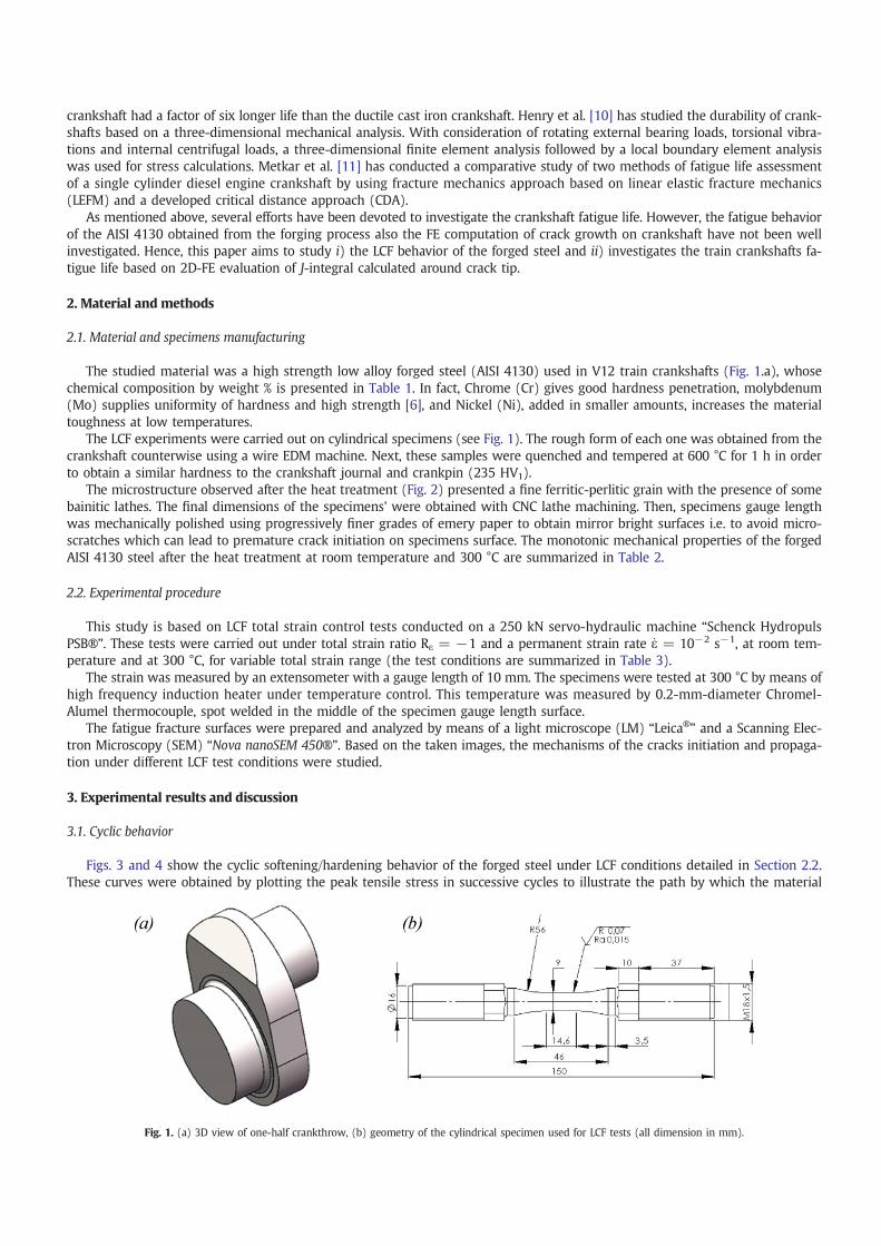
The studied material was a high strength low alloy forged steel (AISI 4130) used in V12 train crankshafts (Fig. 1.a), whosechemical composition by weight % is presented in Table 1. In fact, Chrome (Cr) gives good hardness penetration, molybdenum(Mo) supplies uniformity of hardness and high strength [6], and Nickel (Ni), added in smaller amounts, increases the materialtoughness at low temperatures.
The LCF experiments were carried out on cylindrical specimens (see Fig. 1). The rough form of each one was obtained from thecrankshaft counterwise using a wire EDM machine. Next, these samples were quenched and tempered at 600 °C for 1 h in orderto obtain a similar hardness to the crankshaft journal and crankpin (235 HV1).
The microstructure observed after the heat treatment (Fig. 2) presented a fine ferritic-perlitic grain with the presence of somebainitic lathes. The final dimensions of the specimens' were obtained with CNC lathe machining. Then, specimens gauge lengthwas mechanically polished using progressively finer grades of emery paper to obtain mirror bright surfaces i.e. to avoid micro-scratches which can lead to premature crack initiation on specimens surface. The monotonic mechanical properties of the forgedAISI 4130 steel after the heat treatment at room temperature and 300 °C are summarized in Table 2.
2.2. Experimental procedure
This study is based on LCF total strain control tests conducted on a 250 kN servo-hydraulic machine “Schenck HydropulsPSB®”. These tests were carried out under total strain ratio Rε = −1 and a permanent strain rate _ε = 10−2 s−1, at room tem-perature and at 300 °C, for variable total strain range (the test conditions are summarized in Table 3).
The strain was measured by an extensometer with a gauge length of 10 mm. The specimens were tested at 300 °C by means ofhigh frequency induction heater under temperature control. This temperature was measured by 0.2-mm-diameter Chromel-Alumel thermocouple, spot welded in the middle of the specimen gauge length surface.
The fatigue fracture surfaces were prepared and analyzed by means of a light microscope (LM) “Leica®” and a Scanning Elec-tron Microscopy (SEM) “Nova nanoSEM 450®”. Based on the taken images, the mechanisms of the cracks initiation and propaga-tion under different LCF test conditions were studied.
3. Experimental results and discussion
3.1. Cyclic behavior
Figs. 3 and 4 show the cyclic softening/hardening behavior of the forged steel under LCF conditions detailed in Section 2.2.These curves were obtained by plotting the peak tensile stress in successive cycles to illustrate the path by which the material
Fig. 1. (a) 3D view of one-half crankthrow, (b) geometry of the cylindrical specimen used for LCF tests (all dimension in mm).

reaches its final cyclic flow stress level. The specimen fatigue lifetime, which corresponds to the macroscopic crack growth, is de-fined as a 10% stress drop compared to the stabilized stress.
During the first few cycles, the forged steel response (Fig. 3) of the tests conducted under a total strain range of ±0.75% and±1%, at room temperature, shows a cyclic hardening, named primary cyclic hardening, followed by a cyclic softening (i.e. thepeak tensile stress (σmax) decreases gradually with a significant rate of change). It also presents a secondary cyclic hardeningfew cycles before the specimens failure. In contrast with the cyclic behavior observed under large total strain range, the one ob-served under small total strain range (±0.3% and ±0.4%) seems to be simpler i.e.: only a cyclic softening was observed duringLCF tests). The forged steel behavior observed at 300 °C shows the presence of two phases (Fig. 4): a cyclic hardening followedby cyclic softening. This hardening/softening behavior appears to be depending on applied strain amplitude; it is more pro-nounced when total strain range is larger. In addition, the duration of the hardening phase is wider than that obtained atroom temperature.
3.2. LCF lifetime and damage mechanisms
At present, several classical methods have been used to describe the failure in isothermal and uni-axial specimens such asManson-Coffin (Eq. (1)) [12,13], Smith-Watson-Topper [14] or Ostergren [15].
Δε2
¼Δεplastic
2þ Δεelastic
2¼ ε0f 2 # Nf
! "cþσ 0
f
E2 # Nf
! "bð1Þ
where σf′ and εf′ represent the fatigue strength and ductility coefficient, respectively, and c and b the fatigue strength and ductilityexponents, respectively, and E the elastic modulus.
Nevertheless, these criteria are not adaptable to some structures which undergo a severe anisothermal multiaxial servicesloading. Hence, several energetic approaches have been proposed to predict the structures lifetime. These approaches can takeinto account the multi-axial loading character and the effect of temperature variation. These criteria are based on the dissipated
Table 1Chemical analysis of the forged steel (AISI 4130).
Elements C Si Mn P S Cr Mo Ni
Weight % 0.263 0.236 0.55 0.01 0.006 1.02 0.176 0.196
Fig. 2. Microstructure of AISI 4130 forged steel after heat treatment.
Table 2Monotonic mechanical properties of the AISI 4130 forged steel at room temperature and 300 °C.
T (°C) E (GPa) Re (MPa) R0.2 (MPa) Rm (MPa) Power law exponent (n)
25 °C 198 408 556 808 5.6300 °C 176 288 459 799 5.4

energy per cycle as a damage parameter [16–19] and defined as (Eq. (2)):
WpNβf ¼ c: ð2Þ
This damage induced in the material due to the cyclic loading can be estimated using the energy denoted as W [20–22]. Theenergy is presented by the area within the stabilized stress–strain hysteresis loops. The fatigue parameters are calculated from thestabilized cycle as (Eq. (3)):
W ¼Z
cycle
σ : εplastic dt≈Δσ # Δεplastic ð3Þ
where σ is the axial stress and _εp is the axial plastic strain rate.Fig. 5 shows that the influence of temperature on the forged steel (AISI 4130) fatigue lifetime is negligible. This can be ex-
plained by the low variation of the mechanical behavior between room temperature and 300 °C (Figs. 3 and 4).The fractographic analysis carried out by LM on the broken specimens obtained at room temperature reveals the presence of
three characteristic zones of fatigue fracture (Fig. 6.a–b).
Table 3Summary of test conditions for low cycle fatigue.
Specimen T (°C) ε (%) f (Hz)
1 25 ±1 0.252 25 ±0.75 0.3333 25 ±0.4 0.6254 25 ±0.3 0.8335 300 ±0.75 0.3336 300 ±0.5 0.57 300 ±0.4 0.6258 300 ±0.3 0.833
Fig. 3. Cyclic behavior of the forged carbon steel (AISI 4130) at room temperature.
Fig. 4. Cyclic behavior of the forged carbon steel (AISI 4130) at 300 °C.

The first one corresponds to the crack initiation zone which probably initiates from small surface defects and then propagates.These features are approximated as semi-elliptical cracks. For the total strain range ±0.3% the fractured surfaces present only onecrack initiation site, whereas the surface which corresponds to ±1% presents secondary sites (Fig. 6.b). This can be explained bythe high plastic strain generated at this test. It can also be the consequence of some micro-defects in specimen gauge surface. Thesecond and the final zones correspond to fatigue fractured surface and monotonic overload surfaces, respectively. The typical ex-amples of SEM micrographs of fracture surfaces near the crack initiation site are revealed in Fig. 6 (details “A” and “B”).
The SEM observation of the fatigue propagation surface carried out under a total strain range of ±0.3% shows a fatigue stri-ations for short cracks length as well as the long one (near the final fatigue fractured zone (Fig. 7.b). These fatigue striations in-dicate that the local fatigue crack growth is about 0.93 μm/cycle in the end of the fatigue fractured surface. The presence of thesefatigue striations can be explained by the ductile behavior of the forged steel at the room temperature [3]. The SEM micrographsof the final overload fracture (Fig. 7.c) shows spherical dimples which correspond to the micro-voids characteristic of monotonicductile fracture (Fig. 7).
Fig. 5. LCF life of AISI 4130 forged steel at room temperature and 300 °C.

Fig. 6. LM images showing the typical fatigue features of the specimen fractured surfaces at room temperature and their corresponding crack initiation SEM imagezones, (a) ε ± 0.3%, Nf = 14,736; (b); ε ± 1%, Nf = 187.
Fig. 7. SEM observation of the fatigue fractured surface obtained under LCF test (room temperature, ε = ±0.4); (a) mixed zone, (b) fatigue striations, (d) EDXanalysis of particle “A”.

The fractured surface which corresponds to the total strain range ±1% reveals ductile micro-mechanisms which appear at theend of the fatigue fractured zone (Fig. 7). This phenomenon may be referred to as the small cavity or microvoid locking by theMnS inclusions (Fig. 7.d). When microvoid growth is important, it is usually terminated by void-linking or coalescence, leadingto an elliptical form with long axis perpendicular to stress direction, which causes crack propagation (Fig. 8). The microvoidlocking is generally prevalent at sufficiently low stress triaxiality defined as the ratio of the mean stress and von Mises equivalentstress. Many experiments suggested a decrease of material ductility with increasing stress triaxiality [23–26].
4. Crankshaft fatigue life assessment
The fatigue design of crankshafts depends on the precise evaluation of the local stress and strain in the structure using a FEAnalysis. Indeed, the purpose of a robust cyclic plasticity model of the studied forged steel appears to be with a great interest to.
4.1. Mechanical cyclic behavior of AISI 4130
The adopted methodology follow up to model the mechanical behavior of the studied material is described in this section. Allpresented computations have been performed on a 2.5 GHz bi-processor with 6 GB of RAM. We assume that the forged steelobeys to an elastoplastic constitutive law. The viscous effects are neglected due to the relative low temperature range of the testedspecimens varying from room temperature to 300 °C. A Chaboche nonlinear isotropic-kinematic hardening model available in thecommercial FE code “Abaqus®”, is chosen to simulate the cyclic mechanical behavior of the studied material [27]. The evolutionlaw of this model consists of two components: a nonlinear kinematic hardening component, which describes the translation ofthe yield surface in stress space through the backstress α; and an isotropic hardening component, which describes the changeof the equivalent stress defining the size of the yield surface σ0, as a function of plastic deformation. The kinematic hardeningcomponent is defined to be an additive combination of a purely kinematic term (linear Ziegler hardening law) and a relaxationterm, which introduces the nonlinearity.
_α ¼ C1σ0 σ−αð Þ _εpl−γα _εpl
C is the initial kinematic hardening modulus, and γ determines the rate at which the kinematic hardening modulus decreaseswith increasing plastic deformation. When γ is zero, the linear Ziegler hardening law is recovered. The isotropic hardening
Fig. 8. SEM observation of the void growth and coalescence in the AISI 4130 forged steel at room temperature (ε = ±1).
Table 4Material parameters identified for Chaboche isotropic-kinematic non-linear hardening law.
E (GPa) υ σ0 (MPa) Q (MPa) b C (GPa) γ (MPa)
198 0.3 330 −65 7 82 260
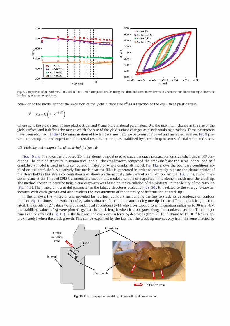
behavior of the model defines the evolution of the yield surface size σ0 as a function of the equivalent plastic strain,
σ0 ¼ σ0 þ Q 1−e−b#εpl# $
where σ0 is the yield stress at zero plastic strain and Q and b are material parameters. Q is the maximum change in the size of theyield surface, and b defines the rate at which the size of the yield surface changes as plastic straining develops. These parametershave been obtained (Table 4) by minimization of the least squares distance between computed and measured stresses. Fig. 9 pre-sents the computed and experimental material response at the quasi-stabilized hysteresis loop in terms of axial strain and stress.
4.2. Modeling and computation of crankshaft fatigue life
Figs. 10 and 11 shows the proposed 2D finite element model used to study the crack propagation on crankshaft under LCF con-ditions. The studied structure is symmetrical and all the crankthrows composed the crankshaft are the same, hence, one-halfcrankthrow model is used in this computation instead of whole crankshaft model. Fig. 11.a shows the boundary conditions ap-plied on the crankshaft. A relatively fine mesh near the fillet is generated in order to accurately capture the characteristics ofthe stress field in this stress concentration area shows a schematically side view of a crankthrow section (Fig. 11.b). Two-dimen-sional plane strain 8-noded CPE8R elements are used in this model a sample of magnified finite element mesh near the crack tip.The method chosen to describe fatigue cracks growth was based on the calculation of the J-integral in the vicinity of the crack tip(Fig. 11.b). The J-integral is a useful parameter in the fatigue structures evaluation [28–30]. It is related to the energy release as-sociated with crack growth and also involves the measurement of the intensity of deformation at crack tip.
In this analysis the J-integral was provided for fourteen contours surrounding the tips to study its dependence on contournumber. Fig. 12 shows the evolution of ΔJ values obtained for contours surrounding one tip for the different crack length simu-lated. The calculated ΔJ values were quasi-identical at contours 9–14 which correspond to an integration radius up to 30 μm. Nextthe stabilized values of ΔJ were plotted against the crack length when it propagates along the crankweb section. Three majorzones can be revealed (Fig. 13). In the first one, the crack driven force ΔJ decreases (from 28 10−3 N/mm to 17 10−3 N/mm, ap-proximately) when the crack growth. This can be explained by the fact that the crack tip moves away from the zone affected by
Fig. 9. Comparison of an isothermal uniaxial LCF tests with computed results using the identified constitutive law with Chaboche non-linear isotropic-kinematichardening at room temperature.
Fig. 10. Crack propagation modeling of one-half crankthrow section.
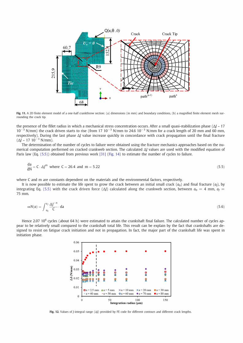
the presence of the fillet radius in which a mechanical stress concentration occurs. After a small quasi-stabilization phase (ΔJ ~ 1710−3 N/mm) the crack driven starts to rise (from 17 10−3 N/mm to 24.6 10−3 N/mm for a crack length of 20 mm and 60 mm,respectively). During the last phase ΔJ value increase quickly in concordance with crack propagation until the final fracture(ΔJ ~ 17 10−3 N/mm).
The determination of the number of cycles to failure were obtained using the fracture mechanics approaches based on the nu-merical computation performed on cracked crankweb section. The calculated ΔJ values are used with the modified equation ofParis law (Eq. (5.5)) obtained from previous work [31] (Fig. 14) to estimate the number of cycles to failure.
dadN
¼ C # Δ Jm where C ¼ 26:4 and m ¼ 5:22 ð5:5Þ
where C and m are constants dependent on the materials and the environmental factors, respectively.It is now possible to estimate the life spent to grow the crack between an initial small crack (a0) and final fracture (af), by
integrating Eq. (5.5) with the crack driven force (ΔJ) calculated along the crankweb section, between a0 = 4 mm, af =75 mm.
⇒N að Þ ¼Z a f
a0
Δ J−n
C# da ð5:6Þ
Hence 2.07 106 cycles (about 64 h) were estimated to attain the crankshaft final failure. The calculated number of cycles ap-pear to be relatively small compared to the crankshaft total life. This result can be explain by the fact that crankshafts are de-signed to resist on fatigue crack initiation and not in propagation. In fact, the major part of the crankshaft life was spent ininitiation phase.
Fig. 11. A 2D finite element model of a one-half crankthrow section: (a) dimensions (in mm) and boundary conditions, (b) a magnified finite element mesh sur-rounding the crack tip.
Fig. 12. Values of J-integral range (ΔJ) provided by FE code for different contours and different crack lengths.

5. Conclusion
In the present paper, the LCF behavior, fatigue lifetime, and damage mechanisms of the AISI 4130 forged steel used in crank-shafts are studied at room temperature and at 300 °C. The LCF behavior, observed until specimen fracture, exhibits a notable cyclicsoftening behavior at room temperature and a cyclic hardening followed by a cyclic softening behavior at 300 °C.
The fatigue lifetime is predicted for both studied temperature using Manson Coffin Basquin and Charkaluk energy criterion asinitiation criteria. Results have shown that lifetime is not affected by temperature at the studied domain.
The SEM of the fractured surfaces at the room temperature has shown that crack initiation sites are located on the specimensurfaces. This indicates that surface micro-defects and/or the extrusion/intrusion mechanisms are probably the principal causes ofcrack initiation. The fatigue fractured surfaces reveal the presence of striations which cover the whole observed surfaces. Thesestriations prove the ductile behavior of the material LCF fracture. This behavior is also highlighted with the presence of voidlocking by the MnS inclusions (observed easily for tests conducted under large total strain).
A 2D-FE model was carried out to study the crack propagation on crankshaft under LCF conditions. The FE evaluation of J-in-tegral calculated around the crack tip was shown that the number of cycles spent until the total crankshaft fracture is relativelyshort compared to its total fatigue life.
Acknowledgments
The authors would like to thank Hsan MAAZOUN engineer and maintenance departement head at SNCFT (Société Nationaledes Chemins de Fer Tunisien) for the forged steel material support. The authors are also grateful to Manel BACCAR, a PhD studentat Ecole des Mines d'Albi for her help in LCF tests achievement.
Fig. 13. Evolution of crack driven force (ΔJ) along the crankweb section.
Fig. 14. Evolution of the crack growth rate (da/dN) of AISI 4130 forged steel with ΔJ at room temperature [24].

References
[1] D.M. Huang, H.L. Wang, X. Chen, Y. Chen, H. Guo, Influence of forging process on microstructure and mechanical properties of large section Ti–6.5Al–1Mo1V–2Zralloy bars, Trans. Nonferrous Metals Soc. China 23 (2013) 2276–2282.
[2] T.Y. Sunay, M. Sahi, S. Altintas, The effects of casting and forging processes on joint properties in friction-welded AISI 1050 and AISI 304 steels, Int. J. Adv. Manuf.Technol. 44 (2009) 68–79.
[3] A. Ktari, N. Haddar, H.F. Ayedi, Fatigue fracture expertise of train engine crankshafts, Eng. Fail. Anal. 18 (2011) 1085–1093.[4] F.J. Espadafor, J.B. Villanueva, M.T. Garcia, Analysis of a diesel generator crankshaft failure, Eng. Fail. Anal. 16 (2009) 2333–2341.[5] M. Fonte, M. de Freitas, Marine main engine crankshaft failure analysis: a case study, Eng. Fail. Anal. 16 (2009) 1940–1947.[6] H. Bayrakçeken, S. Tasgetiren, F. Aksoy, Failure of a single cylinder engines crank shafts, Eng. Fail. Anal. 14 (2007) 725–730.[7] K.S. Choi, J. Pan, Simulations of stress distributions in crankshaft sections under fillet rolling and bending fatigue tests, Int. J. Fatigue 31 (2009) 544–557.[8] W.Y. Chien, J. Pan, D. Close, S. Ho, Fatigue analysis of crankshaft sections under bending with consideration of residual stresses, Int. J. Fatigue 27 (2005) 1–19.[9] J. Williams, A. Fatemi, Fatigue Performance of Forged Steel and Ductile Cast Iron Crankshafts, The University of Toledo, 2007 (01-1001).
[10] J. Henry, J. Toplosky, M. Abramczuk, Crankshaft Durability Prediction a New 3-D Approach, SAE Paper 920087, Societyof Automotive Engineers, Warrendale (PA),1992.
[11] R.M. Metkar, V.K. Sunnapwar, S.D. Hiwase, V.S. Ankid, M. Dumpa, Evaluation of FEM based fracture mechanics technique to estimate life of an automotive forgedsteel crankshaft of a single cylinder diesel engine, Procedia Eng. 51 (2013) 567–572.
[12] S. Manson, Behavior of materials under conditions of thermal stress, Technical Report NACA-TN-2933, Vol. 105, 1953.[13] L.F. Coffin, A study of the effects of cyclic thermal stresses on a ductile metal, ASME 76 (1954) 931–950.[14] K.N. Smith, P. Watson, T.H. Topper, A stress-strain function for the fatigue of metal, J. Mater. 5 (1970) 767–778.[15] W.J. Ostergren, A damage function and associated failure equation for predicting hold time and frequency effects in evaluated temperature, low cycle fatigue, J.
Test. Eval. 4 (1976) 327–339.[16] R.P. Skelton, Energy criteria for high temperature low cycle fatigue, Mater. Sci. Technol. 7 (1991) 427–439.[17] R.P. Skelton, Cyclic hardening, softening, and crack growth during high temperature fatigue, Mater. Sci. Technol. 9 (1992) 1001–1008.[18] E. Charkaluk, A. Bignonnet, A. Constantinescu, K. Dang Van, Fatigue design of structures under thermomechanical loadings, Fatigue Fract. Eng. Mater. Struct. 25
(2002) 1199–1206.[19] V. Maurel, L. Rémy, F. Dahmen, N. Haddar, An engineering model for low cycle fatigue life based on a partition of energy and micro-crack growth, Int. J. Fatigue 3
(2009) 952–961.[20] C.E. Feltner, J.D. Morrow, Micro-plastic strain hysteresis energy a criterion for fatigue fracture, Trans. ASME (1961).[21] J. Morrow, Cyclic plastic strain energy and fatigue of metals, Internal Friction Damping and Cyclic Plasticity, STP, Vol. 378, ASTM 1965, pp. 45–87.[22] N.E. Dowling, Fatigue failure predictions for complicated stress-stain histories, J. Mater. 7 (1972) 71–87.[23] J.W. Hancock, A.C. Mackenzie, On the mechanics of ductile failure in high-strength steels subjected to multi-axial stress-states, J. Mech. Phys. Solids 24 (1976)
147–169.[24] G.R. Johnson,W.H. Cook, Fracture characteristics of threemetals subjected to various strains, strain rates, temperatures and pressures, Eng. Fract. Mech. 21 (1985)
31–48.[25] L. Driemeier, M. Brünig, G. Micheli, M. Alves, Experiments on stress-triaxiality dependence of material behavior of aluminum alloys, Mech. Mater. 42 (2010)
207–217.[26] A. Khan, H. Liu, A new approach for ductile fracture prediction on al 2024-T351 alloy, Int. J. Plast. 35 (2012) 1–12.[27] H. Karlsson, ABAQUS Theory Manual – Version 6.7, Abaqus, Inc., 2007[28] L. Rémy, J. Petit, Thermomechanical fatigue in the automotive industry, Temperature-Fatigue Interaction, first ed.Elsevier Science LTD and ESIS, 2002.[29] N.K. Simha, F.D. Fischer, G.X. Shan, C.R. Chen, O. Kolednik, J-integral and crack driving force in elastic–plasticmaterials, J. Mech. Phys. Solids 56 (2008) 2876–2895.[30] Y. Asada, T. Shimakawa, M. Kitagawa, T. Kodaira, Y. Wada, T. Asayama, Analytical evaluation method of J-integral in creep-fatigue fracture for type 304 stainless
steel, Nucl. Eng. Des. 133 (1992) 361–367.[31] A. Ktari, M. Baccar, M. Shah, N. Haddar, H.F. Ayedi, F. Rezai-Aria, A crack propagation criterion based on ΔCTODmeasured with 2D-digital image correlation tech-
nique, Fatigue Fract. Eng. Mater. Struct. 36 (2014) 682–694.