OCT 1 7199 - International Nuclear Information System (INIS)
222
FINAL ENVIRONMENTAL ASSESSMENT MARYS LAKE 69/115-kV TRANSMISSION LINE UPGRADE AND SUBSTATION EXPANSION PROJECTS •fr. • * ifXtifc AM Estes Park, Larimer County, Colorado U.S. Department of Energy Western Area Power Administration Rocky Mountain Customer Service Region Loveland, Colorado and Platte River Power Authority Fort Collins, Colorado OF THIS DOCUMENT IS UNLIMITED DOE/EA 1074 si FJ n e OCT 1 7199 May 1996
-
Upload
khangminh22 -
Category
Documents
-
view
1 -
download
0
Transcript of OCT 1 7199 - International Nuclear Information System (INIS)
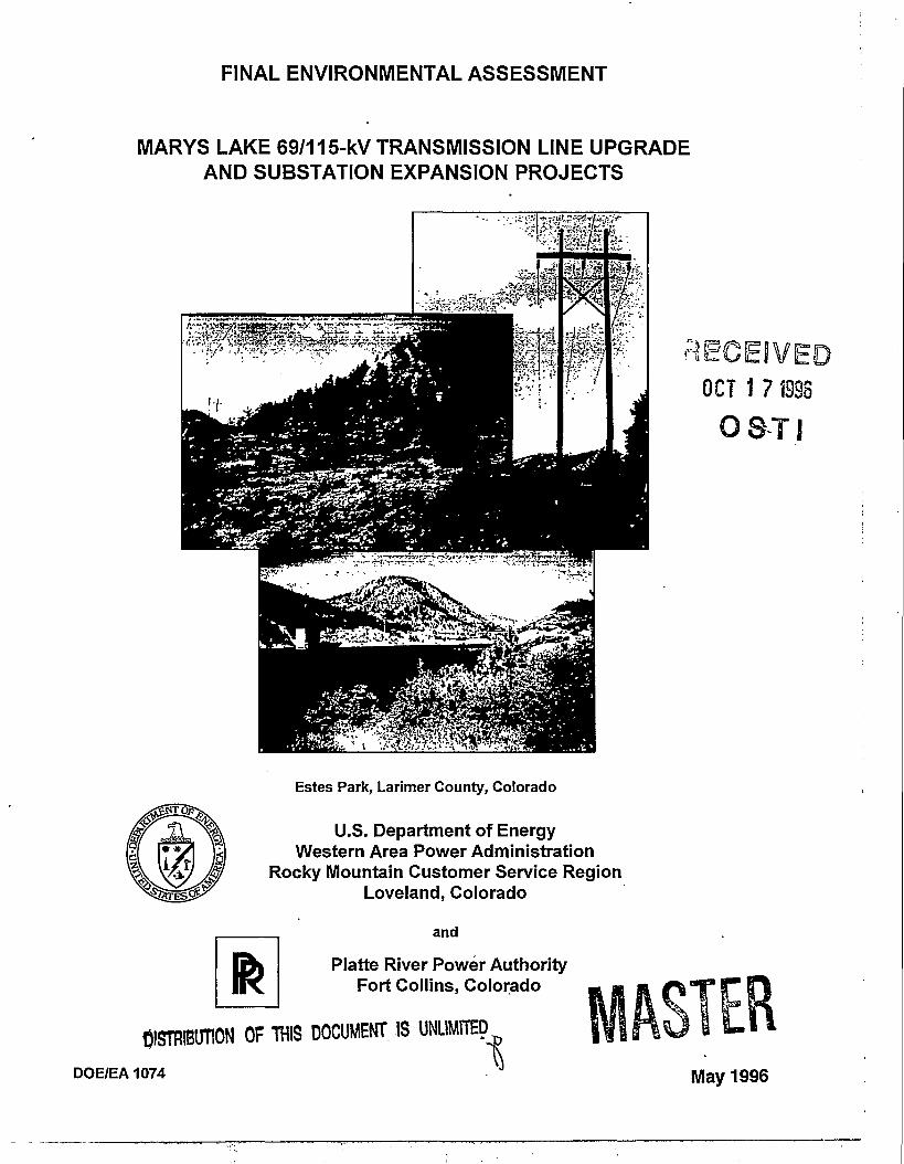
FINAL ENVIRONMENTAL ASSESSMENT
MARYS LAKE 69/115-kV TRANSMISSION LINE UPGRADEAND SUBSTATION EXPANSION PROJECTS
•fr.
• *
ifXtifc
AM
Estes Park, Larimer County, Colorado
U.S. Department of EnergyWestern Area Power Administration
Rocky Mountain Customer Service RegionLoveland, Colorado
and
Platte River Power AuthorityFort Collins, Colorado
OF THIS DOCUMENT IS UNLIMITED
DOE/EA 1074
si F J
n eOCT 1 7199
May 1996

DISCLAIMER
Portions of this document may be illegiblein electronic image products. Images areproduced from the best available originaldocument

DEPARTMENT OF ENERGY
Western Area Power Administration
Marys Lake 69/115-kV Transmission Line Upgrade and Substation Expansion Projects, EstesPark, Larimer County, Colorado
AGENCY: Western Area Power Administration, DOE.
ACTION: Finding of no significant impact
SUMMARY: Western Area Power Administration (Western) and the Platte River Power
Authority (Platte River) propose to upgrade portions of the existing electric transmission and
substation system that serves the Town of Estcs Park, Colorado. The existing transmission lines
between the Estes Power Plant Switchyard and the Marys Lake Substation include a 115,000 volt
(115-kV) line and 69,000 volt (69-kV) line. Approximately one mile is a double-circuit
115/69-kV line on steel lattice structures, and approximately two miles consists of separate
single-circuit 115-kV and a 69-kV lines, constructed on wood H-Frame structures. Both lines
were constructed in 1951 by the U.S. Bureau of Reclamation. Upgrading the existing 69-kV
transmission line between the Marys Lake Substation and the Estes Power Plant Switchyard to
115-kV and expanding the Marys Lake Substation was identified as the most effective way in
which to improve electric service to Estes Park.
Western prepared an environmental assessment (EA) titled "Environmental Assessment for the
Marys Lake 69/115-kV Transmission Line Upgrade and Substation Expansion Projects"
(DOE/EA-1074). The EA contains an analysis of the proposed construction, operation, and
maintenance of the transmission line. Information and analysis contained in the EA is
summarized in this Finding of No Significant Impact (FONSI) under "SUPPLEMENTARY
INFORMATION".
ftSTRIBUTlOM OF THIS DOCUMENT !S
FOR FURTHER INFORMATION CONTACT:
Mr. Stephen A. Fausett- Regional Manager
Rocky Mountain Customer Service Region •Western Area Power AdministrationP.O. Box 3700Loveland, CO 80539 (970) 490-7201
Additional information and copies of the EA and FONSI are available to all interested persons
and the general public from the person named above. For general information on DOE National
Environmental Policy Act (NEPA) activities contact:
Carol M. Borgstrom
Director, Office of NEPA Oversight, EH-42
U.S. Department of Energy
1000 Independence Avenue, SW
Washington, DC 20585
(202) 586-4600 or (800) 472-2756.
SUPPLEMENTARY INFORMATION: Western and the Plattc.River propose to upgrade
portions of the existing electric transmission and substation system mat serves the Town of Estes
Park, Colorado. The existing transmission lines between the Estes Power Plant Switchyard and
the Marys Lake Substation include a 115,000 volt (115-kV) line and 69,000 volt (69-kV) line.
Approximately one mile is a double-circuit 115/69-kV line on steel lattice structures, and
approximately two miles consists of separate single-circuit 115-kV and a 69-kV lines,
constructed on wood H-Frame structures. Both lines were constructed in 1951 by the U.S.
Bureau of Reclamation. The existing transmission lines are on rights-of-way (ROW) that vary
fiom 75 feet to 120 feet and are owned by Western. There arc 48 landowners adjacent to the
existing ROW. All of the houses were built adjacent to the existing ROW after the transmission
lines were constructed.
Upgrading the existing 69-kV transmission line between the Marys Lake Substation and the
Z

Estes Power Plant Switchyard to 115-kV and expanding the Marys Lake Substation was
identified as the most effective way in which to improve electric service to Estes Park. The
proposed project involves:
• Removing a 115-kV to 69-kV transformer at the Estes Power Plant Switchyard and
performing other associated work as required to allow upgrading the three-mile
transmission line from 69-kV to 115-kV;
• Begin operating ar 115-kV the one-mile section of the existing 69-kV portion of the
double-circuit transmission line between the Estes Power Plant Switchyard and the East
Portal of the Adams Tunnel. This existing transmission line section has been in place
since 1951 on steel-lattice towers, and is already insulated for operation at 115-kV;
• Removing two miles of existing 69-kV transmission line on wood H-frame structures
between the Estes Power Plant Switchyard (beginning after the one-mile section of
- double-circuit, steel-lattice towers) and the Marys Lake Substation, and rebuilding this
section to operate at 115-kV utilizing wood H-framc construction and connecting this line
at Marys Lake Substation; and
• Installing a 115-kV to 69-kV transformer at the Marys Lake Substation and performing
other associated work to maintain a 69-kV connection between the Marys Lake
Substation and the East Portal of the Adams Tunnel.
The primary purpose and need of the proposed project is to improve the reliability of electric
service to the Town of Estes Park. Lack of reliability has been a historical concern, and
reliability will always be less than desired until physical improvements are made to the electrical
facilities serving Estcs Park.
Western and Platte River conducted public workshop/scoping meetings hi Estcs Park to discuss
the project on June 14,1995, October 4,1995, and February 15,1996. An agency workshop/
scoping meeting was also conducted between 1:00 p.m. and 4:00 pan. on June 14S1995. The
purpose of the workshop/scoping meeting was to describe the project, initiate a project mailing
list, share information with the public and agencies, and to receive input and comments to
identify issues, concerns, and prioritize considerations for the environmental assessment
As part of its marketing policies, Western encourages energy conservation through the promotion
of efficient and economic uses of energy, and through the use of renewable resources; such as,
hydro, wind, solar, and geothermal energy sources. However, the purpose and need for the
Marys Lake transmission line and substation upgrade project can not be met by energy
conservation. The purpose of this project is to improve the reliability of electric service to the
Town of Estcs Park by providing a second transmission source to the Marys Lake Substation and
modifying the configuration at the Estes Power Plant Switchyard. Therefore, energy
conservation is not considered as a reasonable alternative for This project
Several actions were considered as alternatives to the Proposed Action including the "no action"
alternative, alternative electrical systems, alternative structure designs, alternative methods of
construction, and alternative routes.
Under the No Action Alternative, Western and Platte River would not upgrade the existing
69-kV transmission line to 115-kV and the associated work at the Estes Power Plant Switchyard
and the Marys Lake Substation would not be performed. Structures and hardware would be
repaired and/or replaced as required during regular maintenance operations and in response to
emergency outages on the transmission lines and at the substations. These repairs would have to
be made with increasing frequency in the future as the facilities increase in age. The No Action
Alternative would not provide the required reliability to Estes Park and therefore is not
considered as a reasonable alternative for this project
Electric system planning studies for the project area were conducted and 32 system alternatives
were identified and evaluated. Of these alternatives, 28 would not provide the required loop
service to the Marys Lake Substation and therefore, would not address the purpose and need for
the project Four of these alternatives, including the Proposed Action, would provide the

required loop service to the Marys Lake Substation. Electric System Alternative I, the Proposed
Action, was selected. This alternative would provide loop service to Marys Lake Substation by
upgrading the existing 69-kV transmission line between the Marys Lake Substation and the Estcs
Power Plant This would result in two direct 115-kV connections between Marys Lake
Substation and Estcs Power Plant
Several potential alternative routes were identified based on the review of aerial photography and
field reconnaissance. The alternative routes included utilizing the existing ROW, Prospect
Mountain-West; Highway 7-North, Highway 7-South, Fish Creek-North, and Fish Creek-South.
All of these alternatives, except the existing ROW had impacts which resulted in them not being
carried forward for full analysis in the EA. Utilizing the existing 69-kV ROW is Western and
Platte River's proposed route. This alternative has more advantages and fewer constraints than
the other alternative routes, and was carried forward for full evaluation as the Proposed Action in
the EA. The Proposed Action alternative consists of upgrading the existing single-circuit 69-kV
transmission line to 115-kV on wood H-frame structures.
Conventional overhead and underground construction alternatives were considered. The primary
disadvantages of underground transmission line construction would include cost; the time and .
expense required to locate and repair problems if outages occur, and the recurring environmental
impacts associated with searching for and repairing problems. Rather than limiting construction
disturbances to relatively small areas around each structure location for an overhead line, a
continuous linear disturbance would result from underground construction. This may result in
increased impacts to the soil, water quality, cultural resources, and biological resources that
could be avoided by spanning with overhead construction. The impacts to vegetation would
likely be significant due to the sensitive nature of the area due to the altitude, short growing
season, and reclamation difficulties associated with the south-facing slopes. Specific
underground route alternatives were not considered and conventional overhead construction was
selected for the proposed project

Although existing land uses in the study area are generally sensitive to the construction and
operation of transmission lines, the proposed project would result in reduced impacts to these
land uses over the long-terra because fewer new landowners would be impacted. Currently, the
existing ROW crosses or is adjacent to 89 existing residential parcels. An additional 7 new
residential parcels and 5 commercial parcels are adjacent to or would be crossed by the proposed
project, and no new ROW would be required. This.results in a total impact to 101 parcels. The
alternative routes would impact 126,266,318,216, and 268 parcels, respectively.
The Proposed Action would result in no long-term effects on the existing or planned land uses •
because the existing ROWs that have been in-placc for over 40 years would be used. Local land
use planning has considered the existing use of the transmission line corridor. This would be no
significant impacts to existing or planned land uses. The project would have minor short-term
effects on existing residents due to noise, air quality, area traffic, and vegetation disturbances
related to construction of the line. These effects would be limited primarily to short-term
emissions from construction vehicles and fugitive dust generated by construction activities.
Construction is scheduled to begin in the Spring and proceed through October in a sequential
manner. The peak number of workers in the area at any one time would be 12-16. Cross-country
travel along the ROW would only be necessary between three to four spans in the area that
parallels Peak View Drive. All disturbed areas would be reseeded to minimize erosion and
restored, as nearly as feasible, to their original condition. Except where clearing is required at
the structure locations, vegetation would be protected from damage.
The operation of the transmission line would not present a safety or electrical hazard to the
general public. Western and Platte River are committed to programs and policies that ensure a
safe and healthy environment Safety and health are essential elements of the working
environment and are demonstrated daily in everyday work practices. By far, the greatest hazard
from transmission lines is direct contact with the conductors. Power lines, as with electrical
wiring in homes and businesses, can cause serious electric shocks if precautions are not taken to
minimize shock hazard. All of Western's transmission lines are designed and constructed in
6

accordance with the National Electrical Safety Code (NESC) siandards.
Impacts to the visual resources that could result from the construction, operation and subsequent
reclamation of the proposed project would include any visibility of the modified landform, color
and texture, potential glare from new conductors, and any dust resulting from construction.
Visual resources were identified as an important issue by the Rocky Mountain National Park and
several citizens through the public/agency scoping meetings. The primary visual concerns
identified focused on physical disturbances on the existing ROW, the guy wires associated with
the three-pole angle structures, the disturbance at Marys Lake Substation, and the existing
distribution line that parallels portions of the transmission line adjacent to the residential area.
As a result of these concerns, the environmental studies assessed the visual impacts of the
proposed action. The results indicated that the overall visual contrast of the project would be
moderate to weak, and the project would be located in an area characterized as a Class 6 variety
class. When comparing the visual contrast and the landscape variety class, the overall scenic
quality was assessed to be weak. There would be no significant impacts to visual resources.
The proposed project would result in a small short-term increase in population in Estes Park due
to employment of contract construction workers. As the Estes valley experiences a nearly
four-fold increase during the summer months, this construction force represents an insignificant
increase. Based on housing data available from the U.S. Census, the rental vacancy rate of 6.3
percent and 448 housing unit vacancies for seasonal, recreational, or occasional use should be
more than adequate for the temporary population increase associated with construction.
It is unlikely thai the proposed project would have a perceptible impact on the area economy as it
will not affect tourist visitation to the Rocky Mountain National Park and Estes Park. The
short-term nature of project construction and the limited number of workers employed would
result in limited positive economic impacts to Estes Park in the form of increased spending on
lodging, meals, and other consumer goods and services.

Construction, operation, and maintenance of the proposed project would not increase or decrease
the need for police, fire, medical, or other community resources in the project area,' Although
construction of the project could temporarily increase the local population, the increase for
services by those associated with construction would be insignificant as the local population
increases significantly on an annual basis during tourist seasons. There would be no significant
impacts.
This EA was prepared with DOE's environmental justice guidelines in mind. The proposed
project is located within an area characterized by a uniform population. The largest segment of
the population in Estes Park, or nearly 99 percent, was described by the 1990 census as White,
including those of Hispanic origin; other races made up a little less than one percent of the
population. The project area is represented by a range of upper-middle income levels and fairly
uniform backgrounds. Therefore, this project will not disproportionately impact minority and
low-income populations.
The project would have no effect on soils as long as disturbances arc revegetated to prevent
erosion. Western's Standard Construction Practices include procedures to prevent soil erosion.
The project would have no effect on geology and there are no geologic hazards present which
would have an effect on the project
The Proposed Action would not physically affect any identified surface water resources. The
Proposed Action would only span Marys Lake at the existing location, and any new disturbance
10 (he banks or channels for pole placement would not result in significant impacts. Access to
the transmission lines would occur on existing roads. Western and Platte River employ best
management practices for sediment control. Western's Standard Construction Practices include
procedures to prevent soil erosion into surface water bodies. These practices also include
procedures to prevent spills into surface water bodies.
The Proposed Action would not affect any ground water resources. The water table along the
8

existing transmission ROW is approximately 42 feet below the ground surface. The placement
of the proposed wood H-fiame poles would be a maximum of only 8-10 feet into the ground.
There are no wells located within the existing transmission line ROW.
No feature of the proposed project is located within a designated floodplain. There would be no
flood-related impacts associated with the proposed project
Impacts to the existing wildlife resource is expected to be minimal. This consideration is based
on both the nature of the project and the existing condition of the habitats in the area. Since there
would be minimal new disturbance for the Proposed Action, no wildlife habitats would be
permanently impacted. Some species such as elk and deer may be temporarily displaced during
construction. However, this displacement would be temporary and all habitats would be
available immediately after construction. In addition, construction disturbances are not expected
to be greater than human disturbances already occurring within the project area. There would be
no significant impacts.
Several threatened, endangered, candidate or sensitive species are known to occur or potentially
occur in the study area, based on information provided by the U.S. Fish and Wildlife Service
(USFWS), the Colorado Division of Wildlife (CDOW), and the Colorado Natural Heritage
Program (CNHP). These species include the peregrine falcon, bald eagle, and greenback
cutthroat trout. Since none of these species are known to occur in the project area, none are
expected to be affected by the Proposed Action and no mitigation is recommended.
The existing 69-kV transmission line currently spans a wetlands area. The EA recommends that
the new 115-kV structures be located so that this wetland will be spanned, and the installation of
a temporary fence to restrict any access across the wetland during construction. These
recommendations would be implemented and there would be no impact to wetlands by the
Proposed Action. There are no important habitats that would be impacted by the Proposed
Action.
Construction of ihe Proposed Action would not impact any significant archaeological or historic
sites as no significant resources were encountered during an archaeological survey of the existing
ROW. For compliance with the National Historic Preservation Act, Section 106, Western and
Plane River consulted with the Colorado State Historic Preservation Officer (SHPO). On
November 2,1995, the SHPO concurred with the determination that no historic properties will
be affected by the project.
The project would have very minor, local, short-term effects on air quality, limited primarily to
short-term emissions from construction vehicles and fugitive dust generated by construction, • . • i
activities. The upgrade of the 69-kV line to 115-kV would have no measurable effects on ozone
levels. The project would have no effect on climate. There would be no significant impacts.
Potentially important fossil bearing locales arc not present along the route of the Proposed
Action. Therefore, the project is not expected to affect paleontological resources.
DETERMINATION: The analyses contained in the EA indicate that the proposed action is not a
major Federal action significantly affecting the quality of the human environment, within the
meaning of NEPA. Western has determined that preparation of an EIS is not required and is,
therefore, issuing this FONSI.
o, ^-/uo^^-/
Issued at Loveland, Colorado, ^-/uo^^- ^S> f 1996.
JMShafer /AdministratorWestern Area Power Administration
10
FINAL ENVIRONMENTAL ASSESSMENT
MARYS LAKE 69/115-kV TRANSMISSION LINE UPGRADEAND SUBSTATION EXPANSION PROJECTS
Estes Park, Larimer County, Colorado
U.S. Department of EnergyWestern Area Power Administration
Rocky Mountain Customer Service RegionLoveland, Colorado
and
Platte River Power AuthorityFort Collins, Colorado
DOE/EA1074 May 1996

TABLE OF CONTENTS
SUMMARY S-1
1.0 PURPOSE AND NEED 1-11.1 Introduction 1-11.2 Purpose and Need for Action 1-11.3 Public Involvement and Scoping 1-2
1.3.1 June 14,1995 Public Workshop/Scoping Meetings 1-21.3.2 October 4,1995 Public Workshop 1-91.3.3 February 15,1996 Public Meeting 1-9
2.0 DESCRIPTION OF ALTERNATIVES INCLUDING THE PROPOSED ACTION 2-12.1 No Action Alternative 2-12.2 Conservation of Energy Alternative •. 2-12.3 Electric System Alternatives 2-12.4 Alternative Routes Considered 2-52.5 Design Alternatives 2-14
2.5.1 Underground Construction 2-142.5.2 Overhead Construction 2-17
2.6 Helicopter Construction 2-172.7 Proposed Action 2-18
2.7.1 Alternative A - The Proposed Action 2-182.7.2 Structure Alternatives to the Proposed Action 2-21
2.8 Comparison of Alternatives 2-22
3.0 AFFECTED ENVIRONMENT 3-13.1 Study Area Definition and Description 3-13.2 Environmental Resources and Conditions 3-13.3 Human Environment 3-1
3.3.1 Land Use 3-13.3.2 Electrical Characteristics and Public Safety 3-113.3.3 Visual Resources 3-203.3.4 Socioeconomics 3-22
3.4 Natural Environment 3-243.4.1 Earth Resources 3-243.4.2 Biological Resources 3-27
3.5 Cultural Environment 3-363.6 Resources Identified As Not Requiring Detailed Study 3-36
3.6.1 Air Quality 3-363.6.2 Climate 3-363.6.3 Paleontology 3-36
4.0 ENVIRONMENTAL CONSEQUENCES 4-14.1 Human Environment 4-1
4.1.1 Land Use 4-14.1.2 Electrical Characteristics and Public Safety 4-14.1.3 Visual Resources 4-84.1.4 Socioeconomics 4-11
4.2 Natural Environment 4-124.2.1 Earth Resources 4-124.2.2 Biological Resources 4-12
4.3 Cultural Environment 4-15
5.0 CONSULTATION AND COORDINATION 5-15.1 List of Agencies Contacted 5-15.2 Workshops/Meetings and Hearings 5-25.3 List of Agencies, Organizations, and Persons to Whom Copies of the
Environmental Assessment are Sent 5-2

TABLE OF CONTENTS (Continued)
6.0 LIST OF PREPARERS 6-1
Appendices
Appendix A BibliographyAppendix B Glossary, Acronyms, And AbbreviationsAppendix C Consultation SummariesAppendix D Biological AssessmentAppendix E Floodplains/wetlands AssessmentAppendix F Electric And Magnetic Field (Emf) Characteristics/bibliographyAppendix G Alternative Route Impact EvaluationAppendix H Standard Construction PracticesAppendix I Photographic SimulationsAppendix J Construction and Restoration Guidelines
Figures
Figure 1-1, Existing Utilities 1-3Figure 1-2 Proposed Action 1-5Figure 1-3 Proposed Action 1-5Figure 2-1 Electric System Alternatives 2-3Figure 2-2 Opportunity/Constraint Composite 2-7Figure 2-3 Alternative Transmission Line Routes, Including the Proposed Action 2-9Figure 2-4 Alternate Structure Types 2-15Figure 3-1 Existing Land Use 3-3Figure 3-2 Existing Zoning 3-5Figure 3-3 Visual Resources 3-9Figure 3-4 Earth Resources 3-25Figure 3-5 Vegetation Communities and Potential Sensitive Plant Habitats 3-29Figure 3-6 Wildlife Resources and Potential Sensitive Wildlife Habitats 3-31Figure D-1 Proposed Action D-9Figure 1-1 Proposed Action, H-Frame Structure 1-1Figure I-2 Proposed Action, H-Frame Structure at Marys Lake I-3Figure I-3 Proposed Action, Expansion of Marys Lake Substation I-5Figure I-4 Proposed Action, Screening of Marys Lake Substation I-7Figure I-5 Screening of Marys Lake Substation (After 10-years of Growth) I-9Figure 1-6 Alternative A1, Single-Circuit Single Steel Pole 1-11Figure I-7 Alternative A2, Double-Circuit, Single Steel Pole 1-13Figure I-8 Alternative A3, Self-Supported Angle Structure 1-15
Tables
Table 1-1 Marys Lake 69/115-kV Transmission Line Upgrade and Substation ExpansionProjects 1-10
Table 2-1 Transmission Line Routing Exclusion, Avoidance, and Opportunity Criteria 2-6Table 2-2 Alternative Route Impact Evaluation Summary 2-11Table 2-3 Typical Personnel and Equipment for Transmission Line Construction 2-19Table 2-4 Typical Transmission Line Characteristics 2-22Table 2-5 Relative Cost Comparisons 2-24Table 3-1 Audible Noise (AN) Levels 3-12Table 3-2 Audible Noise Decibel Ratings of Some Common Noises 3-12Table 3-3 Electric Field Levels 3-14Table 3-4 Magnetic Field Levels 3-16

TABLE OF CONTENTS (Continued)
Table 3-5 Magnetic Field Environment 3-17Table 3-6 Magnetic Field Standards 3-18Table 3-7 Population Growth in Estes Park and Estes Valley 3-22Table 3-8 Threatened, Endangered, and Other Species of Concern 3-33Table4-1 Audible Noise (AN) Leveis 4-2Table 4-2 Electric Field Levels 4-3Table 4-3 Magnetic Field Levels 4-5Table 4-4 Vegetation Impacts 4-13Table 6-1 List Of Preparers 6-1Table D-1 Threatened, Endangered, and Other Species of Concern D-2
in
SUMMARY
Western Area Power Administration (Western) and the Platte River Power Authority (Platte River) proposeto upgrade portions of the existing electric transmission and substation system that serves the Town ofEstes Park, Colorado. The existing transmission lines between the Estes Power Plant Switchyard and theMarys Lake Substation include a 115,000 volt (115-kV) line and 69,000 volt (69-kV) line. Approximatelyone mile is a double-circuit 115/69-kV line on steel lattice structures, and approximately two miles consistsof separate single-circuit 115-kV and a 69-kV lines, constructed on wood H-Frame structures. Both lineswere constructed in 1951 by the U.S. Bureau of Reclamation. The existing transmission lines are onrights-of-way (ROW) that vary from 75 feet to 120 feet and are owned by Western. There are 48landowners adjacent to the existing ROW. All of the houses were built adjacent to the existing ROW afterthe transmission lines were constructed.
Upgrading the existing 69-kV transmission line between the Marys Lake Substation and the Estes PowerPlant Switchyard to 115-kV and expanding the Marys Lake Substation was identified as the most effectiveway in which to improve electric service to Estes Park. The proposed project involves:
• Removing a 115-kV to 69-kV transformer at the Estes Power Plant Switchyard and performing otherassociated work as required to allow upgrading the three-mile transmission line from 69-kV to 115-kV;
• Begin operating at 115-kV the one-mile section of the existing 69-kV portion of the double-circuittransmission line between the Estes Power Plant Switchyard and the East Portal of the AdamsTunnel. This existing transmission line section has been in place since 1951 on steel-lattice towers,and is already insulated for operation at 115-kV;
• Removing two miles of existing 69-kV transmission line on wood H-frame structures between theEstes Power Plant Switchyard (beginning after the one-mile section of double-circuit, steel-latticetowers) and the Marys Lake Substation, and rebuilding this section to operate at 115-kV utilizingwood H-frame construction and connecting this line at Marys Lake Substation; and
• Installing a 115-kV to 69-kV transformer at the Marys Lake Substation and performing otherassociated work to maintain a 69-kV connection between the Marys Lake Substation and the EastPortal of the Adams Tunnel.
The primary purpose and need of the proposed project is to improve the reliability of electric service to theTown of Estes Park. Lack of reliability has been a historical concern, and reliability will always be lessthan desired until physical improvements are made to the electrical facilities serving Estes Park.
The electrical load of Estes Park has grown at a consistent rate and is now at a level that prevents theunrestricted exchange of load between the Marys Lake Substation and Estes Substation using the Town'sdistribution system. This has significant implications to Estes Park because the load served from theMarys Lake Substation cannot be fully restored following an unexpected outage until the faulty equipmentis repaired, nor can maintenance be performed without possibly interrupting electric service. Since thedistribution system within the Town is no longer capable of providing backup service to Marys LakeSubstation during times of high customer usage, it is desirable to provide a second transmission source toMarys Lake Substation.
A joint study of the electrical system in the geographic area encompassing Estes Park and extending toGranby was conducted by all affected parties, and was completed in July 1994. Participants in the studywere the Town, Western, Platte River, United States Bureau of Reclamation, Northern Colorado WaterConservancy District, and Tri-State Generation and Transmission. The objective of this study was todetermine the short- and long-term transmission requirements. Thirty-two electric system alternativeswere evaluated. The proposed project is one of the electric system alternatives recommended from thisstudy.
The proposed project would provide a second transmission source to the Marys Lake Substation andwould modify the configuration at the Estes Power Plant Switchyard. The reliability would be equivalent to
S-1
that provided to the other urban areas served at wholesale by Platte River, and reflects a significantimprovement
Western and Platte River conducted public workshop/scoping meetings in Estes Park to discuss theproject on June 14,1995, October 4,1995, and February 15,1996. The public workshop/scopingmeetings were advertised in the local newspaper, through public service announcements on the localradio station, and on the local cable television channels. The public workshop/scoping meetings wereheld between 7:00 p.m. and 9:00 p.m. on each of these dates. An agency workshop/ scoping meetingwas also conducted between 1:00 p.m. and 4:00 p.m. on June 14,1995. The format for theworkshop/scoping meetings consisted of a welcome/sign-in area and six information stations: (1) ProjectNeed and Benefits (Electric System Planning); (2) Transmission Line and Substation Engineering; (3)Electrical Characteristics; (4) Visual Characteristics; (5) Environmental Planning; and (6) Land Rights.The purpose of the workshop/scoping meeting was to describe the project, initiate a project mailing list,share information with the public and agencies, and to receive input arid comments to identify issues,concerns, and prioritize considerations in the Environmental Assessment.
As part of its marketing policies, Western encourages energy conservation through the promotion ofefficient and economic uses of energy, and through the use of renewable resources such as hydro, wind,solar, and geothermal energy sources. However, the purpose and need for the Marys Lake transmissionline and substation upgrade project can not be met by energy conservation. The purpose of this project isto improve the reliability of electric service to the Town of Estes Park by providing a second transmissionsource to the Marys Lake Substation and modifying the configuration at the Estes Power PlantSwitchyard. Therefore, energy conservation is not considered as a reasonable alternative for this project.
.Several actions were considered as alternatives to the Proposed Action including the "no action"alternative, alternative electrical systems, alternative structure designs, alternative methods ofconstruction, and alternative routes.
Under the No Action Alternative, Western and Platte River would not upgrade the existing 69-kVtransmission line to 115-kV and the associated work at the Estes Power Plant Switchyard and the MarysLake Substation would not be performed. Structures and hardware would be repaired and/or replaced asrequired during regular maintenance operations and in response to emergency outages on thetransmission lines and at the substations. These repairs would have to be made with increasingfrequency in the future as the facilities increase in age. The No Action Alternative would not provide therequired reliability to Estes Park and therefore is not considered as a reasonable alternative for thisproject.
Electric system planning studies for the project area were conducted and 32 alternatives were identifiedand evaluated. Of these alternatives, 28 would not provide the required loop service to the Marys LakeSubstation and therefore, would not address the purpose and need for the project Four of thesealternatives, including the Proposed Action, would provide the required loop service to the Marys LakeSubstation. Electric System Alternative I, the Proposed Action, was selected. This alternative providesloop service to Marys Lake Substation by upgrading the existing 69-kV transmission line between theMarys Lake Substation and the Estes Power Plant. This results in two direct 115-kV connections betweenMarys Lake Substation and Estes Power Plant.
After the electric system configuration was determined, a route selection process was used to identify andevaluate potential routes for providing the required looped electric transmission service between the EstesPower Plant Switchyard and the Marys Lake Substation. This process involved several steps including:
• Collection of environmental, human, and cultural resource data;• Mapping of environmental and human resources;• Identification of exclusion, avoidance, and opportunity areas for transmission line siting based on
resource sensitivity;• Evaluation of potential routes;• Selection of alternatives to be carried forward for full analysis in the environmental report; and• Presentation of the results in public workshops/meetings.
S-2
Several potential alternative routes were identified based on the review of aerial photography and fieldreconnaissance. The alternative routes included utilizing the existing ROW, Prospect Mountain-West,Highway 7-North, Highway 7-South, Fish Creek-North, and Fish Creek-South. All of these alternatives,except the existing ROW had impacts which resulted in them not being carried forward for full analysis inthe EA. Utilizing the existing 69-kV ROW is Western and Platte River's proposed route. This alternativehas more advantages and fewer constraints than the other alternative routes, and was carried forward forfull evaluation as the Proposed Action in the EA. The Proposed Action alternative consists of upgradingthe existing single-circuit 69-kV transmission line to 115-kV on wood H-frame structures.
Wood H-frame and single pole tubular steel structures are the structure design alternatives mosttechnically and economically feasible for this upgrade. Approximately two miles of the existing 69-kVtransmission line is constructed as a single-circuit line on wood H-frame structures that parallels anexisting 115-kV transmission line that is also constructed on wood H-frame structures.
Alternative structures include a single-circuit single steel pole tubular structure, and a double-circuit singlesteel pole tubular structure. Single steel pole structures are taller than wood H-frame structures becausethe conductors are arranged in a vertical configuration, and they are more costly. An additionalalternative structure type was considered as a result of comments received at the public workshop held onOctober 4,1995. This alternative would utilize self-supported structures at the angle points of the wood H-frame alternative in order to eliminate the guy wires and to reduce the visual and land use impacts. Theself-supported angle structures would be used only for the upgraded line.
Conventional overhead and underground construction alternatives were considered. The primarydisadvantages of underground transmission line construction include cost; the time and expense requiredto locate and repair problems if outages occur; and the recurring environmental impacts associated withsearching for and repairing problems. Rather than limiting construction disturbances to relatively smallareas around each structure location for an overhead line, a continuous linear disturbance results fromunderground construction. This may result in increased impacts to the soil, water quality, culturalresources, and biological resources including sensitive habitats that support threatened and endangeredspecies that could be avoided by spanning with overhead construction. The impacts to vegetation wouldlikely be significant due to the sensitive nature of the area due to the altitude, short growing season, andreclamation difficulties associated with the south-facing slopes. Specific underground route alternativeswere not considered and conventional overhead construction was selected for the proposed project.
As an alternative to conventional overhead construction, the use of a helicopter to transport crews and/orstructures and/or equipment into each structure site were also considered for this project. In most areasalong the proposed route, using helicopters would not be warranted by the terrain or by the expectedimpacts to environmental resources. Helicopters are sometimes utilized for portions of a project beingconstructed by conventional methods. In these cases, helicopters are used for delivering materials,setting poles, and conductor stringing.
Based on the selected route, type of structures, and type of construction, evaluation criteria wasdeveloped to assess the natural, human, and cultural environments. This analysis was quantified bydetermining the number of occurrences of the various environmental factors along each segment of eachalternative. The criteria used in the impact evaluation included:
• Land use impacts such as existing residential parcels adjacent to, or crossed by, right-of-way; newresidential parcels adjacent to, or crossed by, ROW; commercial parcels adjacent to, or crossed by,ROW; locations that would prohibit other development of property; parcels crossed where new ROWwould be required; crossings through a developed park, or recreation areas; and crossings requiring asignificant increase in construction time, traffic delays, or expense;
• Visual impacts including structures visible from primary transportation routes; existing residences fromwhich the transmission line would be visible; new residences from which the transmission line wouldbe visible; commercial developments from which the transmission line would be visible; structuresvisible from recreation areas; structures skylined; prominent deviations in the alignment; andstructures visible in scenic landscapes;
S-3

• Physical and biological environmental impacts such as structures in very steep slopes (>50%) withsoils susceptible to erosion, slump and creep; structures in steep soils (25-50%) with slopessusceptible to erosion, slump and creep; water crossings; wells within the ROW; structures in thefloodplain; acres of trees removed; structures through riparian habitat; structures potentially impactingthreatened & endangered species; acres of wildlife habitat removed; spans that may increasepotential for bird collisions; instances requiring construction to be scheduled to avoid nesting orbreeding periods critical to sensitive species; and miles of new ROW disturbance;
• Impact to cultural resources including structures potentially affecting archaeological sites; andstructures potentially affecting historic sites; and
• Construction related impacts included miles of helicopter construction; structures with difficult access;structures that would result in conflicts with the operation of an airport, heliport or landing strip;number of angles in the alignment of 41 ° to 90°; and number of angles in the alignment of 2° to 40°.
Although existing land uses in the study area are generally sensitive to the construction and operation oftransmission lines, the proposed project would result in reduced impacts to these land uses over the long-term because fewer new landowners would be impacted. Currently, the existing ROW crosses or isadjacent to 89 existing residential parcels. An additional 7 new residential parcels and 5 commercialparcels are adjacent to or would be crossed by the proposed project, and no new ROW would be required.This results in a total impact to 101 parcels. The alternative routes would impact 126, 266, 318, 216, and268 parcels.
The Proposed Action would result in no long-term effects on the existing or planned land uses becausethe existing ROWs that have been in-place for over 40 years would be used, and local land use planninghas considered the existing use of the transmission line corridor. The project would have minor short-termeffects on existing residents due to noise, air quality, area traffic, and vegetation disturbances related toconstruction of the line. These effects would be limited primarily to short-term emissions from constructionvehicles and fugitive dust generated by construction activities. Construction is scheduled to begin in theSpring and proceed through October in a sequential manner. The peak number of workers in the area atany one time would be 12-16. Cross-country travel along the ROW would only be necessary betweenthree to four spans in the area that parallels Peak View Drive. All disturbed areas would be reseeded tominimize erosion and restored, as nearly as feasible, to their original condition. Except where clearing isrequired at the structure locations, vegetation would be protected from damage.
The operation of the transmission line would not present a safety or electrical hazard to the general public.Western and Platte River are committed to programs and policies that ensure a safe and healthyenvironment. Safety and health are essential elements of the working environment and are demonstrateddaily in everyday work practices. By far, the greatest hazard from transmission lines is direct contact withthe conductors. Powerlines, as with electrical wiring in homes and businesses, can cause serious electricshocks if precautions are not taken to minimize shock hazard. All of Western's transmission lines aredesigned and constructed in accordance with the National Electrical Safety Code (NESC) standards.
The additional corona resulting from upgrading the existing 69-kV transmission line to 115-kV will not bediscernable.
The Audible Noise (AN) resulting from the proposed upgrade would not be significant. The calculatedaverage (L50) value for wet weather at the edge of the ROW is 36.2 dBA, and the calculated average fairweather noise level at the edge of the ROW is 11.2 dBA for the Proposed Action. These values representslight increases of 1.0 to 7.1 dBA for the edges of the ROW.
The existing transmission lines have been in service for over 40 years and interference to radio (Rl) andtelevision (TVI) have not been significant problems. It was reported during the initial public workshop/scoping meeting that Rl on car radios occurs when driving in the vicinity of the transmission lines. Whilethere may be several reasons for this interference, including weak signal strength, it is also likely that thecause is related to loose or dirty insulators, or by loose hardware and can be corrected by maintenance.The interference to radio (Rl) and television (TVI) is not anticipated to significantly increase with theproposed upgrade, and would be similar for alt alternatives. It is the policies of Western and Platte River
S-4

to investigate Rl and TVi problems and to correct those caused by their facilities. Western routinelyinvestigates Rl and TVI complaints and is prepared to resolve any interference problems resulting fromthe operation of the proposed project
The maximum electric field in the ROW at the smallest conductor ground clearance of 22 feet isapproximately 1.55-kV/m with the Proposed Action. These field levels are approximately the same as theexisting conditions for the east/south edge of the ROW and the maximum in the ROW, and slightly higherfor the westfnorth edge of the ROW.
In general, the electric fields around these lines are not great enough to produce perceivable shocks topersons contacting grounded objects. Spark discharge shocks theoretically could occur under theproposed transmission line upgrade just as they could under the existing transmission lines. However, themagnitude of the electric field is low enough for all of the alternatives that this type of shock rarely, if ever,would occur and then only in a small area under the transmission lines near mid-spans. The groundingpolicies of Western and Platte River eliminate the possibility of nuisance shocks due to induced currentsfrom stationary objects such as fences and buildings.
The maximum magnetic field resulting from the Proposed Action at the edge of the ROW for normaloperations and normal loading is 21.81 mG. The magnetic field level resulting from the Proposed Actionwould be slightly higher at the east/south edge of the ROW adjacent to the existing 115-kV line (21.71 mGvs. 14.88 mG), and significantly reduced at the west/north edge of the ROW (21.71 mG vs. 47.10 mG).The maximum magnetic field level in the ROW would also be significantly reduced under the ProposedAction (21.81 mG vs. 54.23 mG). These reductions are due to the use of taller structures, more evenlybalanced line loading, and the use of less current to deliver the same amount of power with the upgraded115-kV line.
The question of whether exposure to the electric and magnetic fields (EMF) from electrical sourcescauses biological or human health effects is a subject which has been researched for the past threedecades. The voltage and current on the existing and proposed transmission lines, like others in theUnited States, vary at a frequency of 60 Hz, or 60 cycles per second. Much of this research has involvedfields at frequencies other than, and much different from, 60 Hz power frequency fields. Results of theresearch have led several scientific panels of independent experts to find that there is no basis toconclude that exposure to power frequency (60 Hz) electric and/or magnetic fields cause any specific orgeneral diseases or illnesses, including cancer.
Impacts to the visual resources that could result from the construction, operation and subsequentreclamation of the proposed project would include any visibility of the modified landform, color and texture,potential glare from new conductors, and any dust resulting from construction. Visual resources wereidentified as an important issue by the Rocky Mountain National Park and several citizens through thepublic/agency scoping meetings. The primary visual concerns identified focused on physical disturbanceson the existing ROW, the guy wires associated with the three-pole angle structures, the disturbance atMarys Lake Substation, and the existing distribution line that parallels portions of the transmission lineadjacent to the residential area. The overall visual contrast of the project was assessed to be moderate toweak, and the project is located in an area characterized as a Class B variety class. When comparing thevisual contrast and the landscape variety class, the overall scenic quality was assessed to be weak.
The proposed project would result in a small short-term increase in population in Estes Park due toemployment of contract construction workers. As the Estes valley experiences a nearly four-fold increaseduring the summer months, this construction force represents an insignificant increase. Based on housingdata available from the U.S. Census, the rental vacancy rate of 6.3 percent and 448 housing unitvacancies for seasonal, recreational, or occasional use should be more than adequate for the temporarypopulation increase associated with construction.
It is unlikely that the proposed project would have a perceptible impact on the area economy as it will not• affect tourist visitation to the Rocky Mountain Park and Estes Park. The short-term nature of projectconstruction and the limited number of workers employed should result in limited positive economicimpacts to Estes Park in the form of increased spending on lodging, meals, and other consumer goodsand services.
S-5
Construction, operation, and maintenance of the proposed project should not increase or decrease theneed for police, fire, medical, or other community resources in the project area. Although construction ofthe project could temporarily increase the local population, the increase for services by those associatedwith construction would be insignificant as the local population increases significantly on an annual basisduring tourist seasons.
This EA was prepared with DOE's environmental justice guidelines in mind. The proposed project islocated within an area characterized by a uniform population. The largest segment of the population inEstes Park, or neariy 99 percent, was described by the 1990 census as White, including those of Hispanicorigin; other races made up a little less than one percent of the population. The project area isrepresented by a range of upper-middle income levels and fairly uniform backgrounds. Therefore, thisproject will not disproportionately impact minority and low-income populations.
The project would have no effect on soils as long as disturbances are revegetated to prevent erosion.Western's Standard Construction Practices include procedures to prevent soil erosion. The project wouldhave no effect on geology and there are no geologic hazards present which would have an effect on theproject
The Proposed Action would not physically affect any identified surface water resources. The ProposedAction would only span Marys Lake at the existing location and any new disturbance to the banks orchannels for pole placement would not result in significant impacts. Access to the transmission lineswould occur on existing roads. Western and Platte River employ best management practices for sedimentcontrol. Western's Standard Construction Practices include procedures to prevent soil erosion intosurface water bodies. These practices also include procedures to prevent spills into surface water bodies.
The Proposed Action would not affect any ground water resources. The water table along the existingtransmission ROW is approximately 42 feet below the ground surface. The placement of the proposedwood H-frame poles would be a maximum of only 8-10 feet into the ground. There are no wells locatedwithin the existing transmission line ROW.
No feature of the proposed project is located within a designated floodplain. There would be no flood-related impacts associated with the proposed project.
Impacts to the existing wildlife resource is expected to be minimal. This consideration is based on boththe nature of the project and the existing condition of the habitats in the area. Since there is no newdisturbance planned for the Proposed Action, no wildlife habitats would be permanently impacted. Somespecies such as elk and deer may be temporarily displaced during construction. However, thisdisplacement would be temporary and all habitats would be available immediately after construction. Inaddition, construction disturbances are not expected to be greater than human disturbances alreadyoccurring within the project area.
Several threatened, endangered, candidate or sensitive species are known to occur or potentially occur inthe study area, based on information provided by the U.S. Fish and Wildlife Service (USFWS), theColorado Division of Wildlife (CDOW), and the Colorado Natural Heritage Program (CNHP). Thesespecies include the peregrine falcon, bald eagle, and greenback cutthroat trout. Since none of thesespecies are known to occur in the project area, none are expected to be affected by the Proposed Actionand no mitigation is recommended.
The existing 69-kV transmission line currently spans a wetlands area. The EA recommends that the new115-kV structures be located so that this wetland will be spanned, and the installation of a temporaryfence to restrict any access across the wetland during construction. If these recommendations areimplemented, there would be no impact to wetlands by the Proposed Action. There are no importanthabitats that would be impacted by the Proposed Action.
Construction of the Proposed Action would not impact any significant archaeological or historic sites as nosignificant resources were encountered during an archaeological survey of the existing ROW. Forcompliance with the National Historic Preservation Act, Section 106, Western and Platte River consulted
S-6

with the Colorado State Historic Preservation Officer (SHPO). On November 2,1995, the SHPOconcurred with the determination that no historic properties will be affected by the project.
The project would have very minor, local, short-term effects on air quality, limited primarily to short-termemissions from construction vehicles and fugitive dust generated by construction activities. The upgradeof the 69-kV line to 115-kV would have no measurable effects on ozone levels. The project would have noeffect on climate.
Potentially important fossil bearing locales are not present along the route of the Proposed Action.Therefore, the project is not expected to affect paleontological resources.
S-7

1.0PURPOSE AND NEED
1.1 Introduction
Western Area Power Administration (Western) and the Platte River Power Authority (Platte River) proposeto upgrade portions of the existing electric transmission and substation system that serves the Town ofEstes Park, Colorado. The existing transmission lines between the Estes Power Plant Switchyard and theMarys Lake Substation include a 115,000 volt (115-kV) line and 69,000 volt (69-kV) line. Approximatelyone mile is a double-circuit 115/69-kV line on steel lattice structures, and approximately two miles consistsof separate single-circuit 115-kV and a 69-kV line, constructed on wood H-Frame structures (Figure 1-1).Both lines were constructed in 1951 by the U.S. Bureau of Reclamation. The existing transmission linesare on rights-of-way (ROWs) that vary from 75 feet to 120 feet and are owned by Western. There are 48landowners adjacent to the existing ROW. All of the houses were built adjacent to the existing ROW afterthe transmission lines were constructed.
Upgrading the existing 69-kV transmission line between the Marys Lake Substation and the Estes PowerPlant Switchyard to 115-kV and expanding the Marys Lake Substation was identified as the most effectiveway in which to improve electric service to Estes Park. The proposed project involves:
• Removing a 115 to 69-kV transformer at the Estes Power Plant Switchyard and performing otherassociated work as required to allow upgrading the three-mile transmission line from 69-kV to115-kV;
• Begin operating at 115-kV, the one-mile section of the existing 69-kV portion of the double-circuittransmission line between the Estes Power Plant Switchyard and the East Portal of the AdamsTunnel. This existing transmission line section has been in place since 1951 on steel-lattice towers,and is already insulated for operation at 115-kV;
• Removing two miles of existing 69-kV transmission line on wood H-frame structures between theEstes Power Plant Switchyard (beginning after the one-mile section of double-circuit, steel-latticetowers) and the Marys Lake Substation, and rebuilding this section to operate at 115-kV utilizingwood H-frame construction and connecting this line at Marys Lake Substation; and
• Installing a 115 to 69-kV transformer at the Marys Lake Substation and performing other associatedwork to maintain a 69-kV connection between the Marys Lake Substation and the East Portal of theAdams Tunnel.
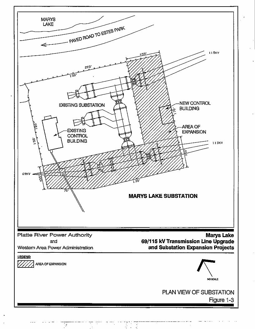
The Proposed Action is illustrated on Figures 1-2 and 1-3.
1.2 Purpose and Need for Action
Western and Platte River (the project sponsors) need to upgrade portions of the existing Estes-MarysLake 69-kV transmission line and upgrade electrical equipment at Marys Lake and Estes substations thatserve the town of Estes Park. The purpose of this upgrade is to improve reliability of electric service whichhas historically been a concern.
Between the years 1985 and 1990 (inclusive), there were seven incidents where electric service was lostto the entire Town. In addition, there were 15 incidents where electrical service was lost to half of theTown, one involving Estes Substation and 14 involving Marys Lake Substation. This was unsatisfactory tothe citizens, and this dissatisfaction was clearly communicated to the Electric Department of the Town andthe transmission providers, Western and Platte River. A task force of technical experts was formed in1990 to analyze the situation and recommend solutions. Some equipment was repaired, calibrated, andtested, resulting in a significant improvement in reliability. Since 1991, there have been four incidentswhere electric service was lost to half of Estes Park, one involving Estes Substation and three involvingMarys Lake Substation.
1-1
During the review conducted in 1990, it was noted that reliability could not be brought up to a standardbefitting an urban area (for example, Loveland, Longmont, and Fort Collins) until facility additions weremade. The fixes that were implemented did improve the situation but the reliability is still less thandesired. Marys Lake Substation, which serves the west side of Estes Park, is fed by a single (radial)three-mile line that is also the outlet for the Marys Lake Power Plant. This radial transmission line willnever provide acceptable reliability to the Marys Lake Substation, and an alternate transmission source isrequired. The Estes Power Plant Switchyard, which is in the east part of Estes Park, serves Marys LakeSubstation and Estes Substation. It is also susceptible to electrical disturbances that cause the entireTown to lose electric service. The configuration of the facilities at the Estes Power Plant Switchyard wouldneed to be reconfigured to minimize this risk.
The electrical load of Estes Park has grown at a consistent rate and is now at a level that prevents theunrestricted exchange of load between the Marys Lake Substation and Estes Substation using the Town'sdistribution system. This has significant implications to Estes Park because the load served from theradial Marys Lake Substation cannot be fully restored following an unexpected outage until the faultyequipment is repaired, nor can maintenance be performed without possibly interrupting electric service.Since the distribution system within the Town is no longer capable of providing backup service to MarysLake Substation during times of high customer usage, it is desirable to provide a second transmissionsource to Marys Lake Substation.
A joint study of the electrical system in the geographic area encompassing Estes Park and extending toGranby was conducted by all affected parties, and was completed in July 1994. Participants in the studywere the Town, Western, Platte River, United States Bureau of Reclamation, Northern Colorado WaterConservancy District, and Tri-State Generation and Transmission. The objective of this study was todetermine the short- and long-term transmission requirements. Thirty-two electric system alternativeswere evaluated. The proposed project (Figure 1-2) is one of the electric system alternativesrecommended in this study.
The proposed project would provide a second transmission source to the Marys Lake Substation andwould modify the configuration at the Estes Power Plant Switchyard. The reliability would be equivalent tothat provided to the other urban areas served at wholesale by Platte River, and reflects a significantimprovement.
1.3 Public Involvement and Scoping
Public workshop/scoping meetings were held in Estes Park to discuss the project on June 14,1995, andOctober 4,1995. The public workshop/scoping meetings were held between 7:00 p.m. and 9:00 p.m. oneach of these dates. An agency workshop/scoping meeting was also conducted between 1:00 p.m. and4:00 p.m. on June 14,1995. The format for the workshop/scoping meetings consisted of a welcome/sign-in area and six information stations: (1) Project Need and Benefits (Electric System Planning); (2)Transmission Line and Substation Engineering; (3) Electrical Characteristics; (4) Visual Characteristics;(5) Environmental Planning; and (6) Land Rights. The purpose of the workshop/scoping meeting was todescribe the project, initiate a project mailing list, share information with the public and agencies, and toreceive input and comments to identify issues, concerns, and prioritize considerations in theEnvironmental Assessment.
1.3.1 June 14, 1995 Public Workshop/Scoping Meetings
The agency workshop/scoping meeting was attended by six (6) agency personnel representing the RockyMountain National Park, the U.S. Bureau of Reclamation, the Town of Estes Park, the Estes ValleyRecreation and Park District, and the Northern Colorado Water Conservation District.
The public workshop/scoping meeting was held between 7:00 p.m. and 9:00 p.m. and was attended bytwenty-seven (27) citizens.
1-2

•&&*'* 'fei^-;
11'•''• ''**'$ V : 7 > \ STUgYapEABOliNDAlf
Platte River Power Authorityand
Western Area Power Administration
Marys Lake69/115 kV Transmission Line Upgrade
and Substation Expansion ProjectsLEGEND
' STUDY AREA BOUNDARY
• OVERHEAD ELECTRIC DISTRIBUTION UNES*
IWATERUNES
3 EXISTING ELECTRIC TRANSMISSION UNES
B EXISTING 69,000 VOLTTRANSMISSION UNE
- EXISTING 116,000 VOLTTRANSMISSION UNE
~! EXISTING DOUBLE CIRCUIT 69/115,000 VOLT• TRANSMISSION UNE ON STEEL STRUCTURES
- OVERHEAD DISTRIBUTION UNE (WESTERN)
» UNDERGROUND DISTRIBUTION UNE (WESTERN)
Source: Town ofEats Park*
0 2000 Fool
EXISTING UTILITIESFigure 1-1

This page left intentionally blank.
1-4

Platte River Power Autorityand
Western Area Power Administration
Marys Lake69/115 kV Transmission Line Upgrade
and Substation Expansion ProjectsLEGEND" • — — STUDY AREA BOUNDARY
I EXISTING DOUBLE CIRCUIT 69/115,000 VOLT1 TRANSMISSION UNE ON STEEL STRUCTURES
TO REMAIN; BEGIN OPERATING 69,000 VOLTCIRCUIT AT115,000 VOLTS
• REMOVE EXISTING 69,000 VOLT WOODH-FRAME STRUCTURES AND REPLACEWITH 115,000 VOLTTRANSMISSION UNEON WOOD H-FRAME STRUCTURES
' EXISTING 115.00OVOLTTRANSMISSIONUNE ON WOOD H-FRAME STRUCTURESTO REMAIN
aaaaaaaa EXISTING 69,000 VOLTTRANSMISSION UNETO BE REMOVED
;:: c:: en ES : I : : I : I
• = EXISTING 69,000 VOLTTRANSMISSION UNETO REMAIN
'-» CONSTRUCT NEW 69,000 VOLTTRANSMISSIONUNE
0 . 2000 Foot
PROPOSED ACTION
Figure 1-2

This page left intentionally blank.
1-6
MARYSLAKE
NEW CONTROLBUILDING
EXISTING SUBSTATION
AREA OFEXPANSIONEXISTING
CONTROLBUILDING
69KV
U5KV
115KV
MARYS LAKE SUBSTATION
Platte River Power Author i tyand
Western Area Power Administration
Marys Lake69/115 kV Transmission Line Upgrade
and Substation Expansion Projects
LEGEND
AREA OF EXPANSION
NO SCALE
PLAN VIEW OF SUBSTATIONFigure 1-3

This page left intentionally blank.
1-8
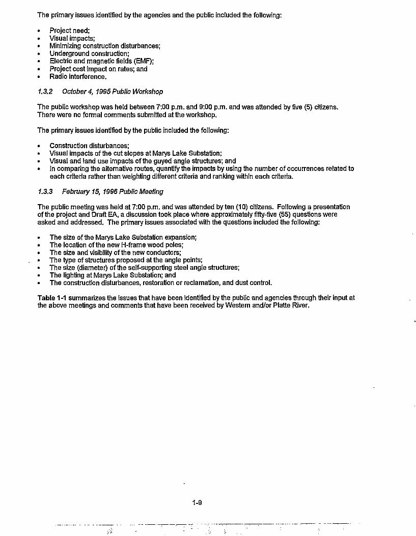
The primary issues identified by the agencies and the public included the following:
Project need;Visual impacts;Minimizing construction disturbances;Underground construction;Electric and magnetic fields (EMF);Project cost impact on rates; andRadio interference.
1.3.2 October 4, 1995 Public Workshop
The public workshop was held between 7:00 p.m. and 9:00 p.m. and was attended by five (5) citizens.There were no formal comments submitted at the workshop.
The primary issues identified by the public included the following:
• Construction disturbances;• Visual impacts of the cut slopes at Marys Lake Substation;• Visual and land use impacts of the guyed angle structures; and• In comparing the alternative routes, quantify the impacts by using the number of occurrences related to
each criteria rather than weighting different criteria and ranking within each criteria.
1.3.3 February 15, 1996 Public Meeting
The public meeting was held at 7:00 p.m. and was attended by ten (10) citizens. Following a presentationof the project and Draft EA, a discussion took place where approximately fifty-five (55) questions wereasked and addressed. The primary issues associated with the questions included the following:
The size of the Marys Lake Substation expansion;The location of the new H-frame wood poles;The size and visibility of the new conductors;The type of structures proposed at the angle points;The size (diameter) of the self-supporting steel angle structures;The lighting at Marys Lake Substation; andThe construction disturbances, restoration or reclamation, and dust control.
Table 1 -1 summarizes the issues that have been identified by the public and agencies through their input atthe above meetings and comments that have been received by Western and/or Platte River.
1-9
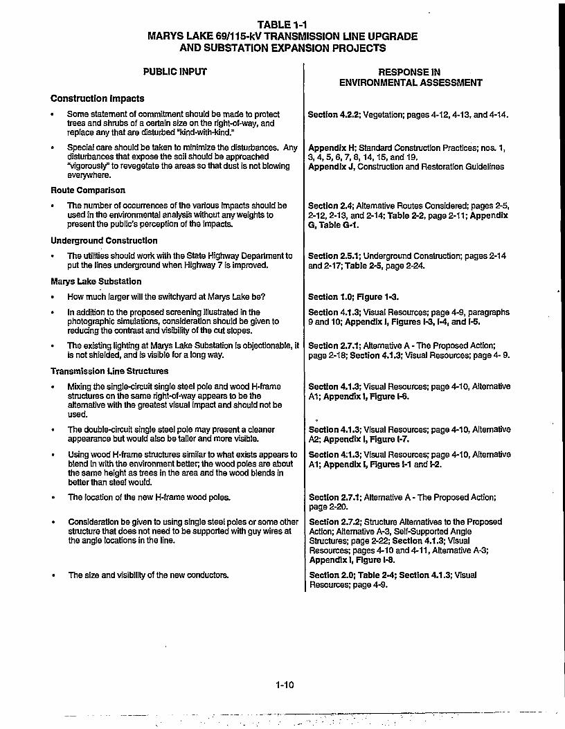
TABLE 1-1MARYS LAKE 69/115-kV TRANSMISSION LINE UPGRADE
AND SUBSTATION EXPANSION PROJECTS
PUBLIC INPUT
Construction Impacts
• Some statement of commitment should be made to protecttrees and shrubs of a certain size on the right-of-way, andreplace any that are disturbed "kind-with-kind."
• Special care should be taken to minimize the disturbances. Anydisturbances that expose the soil should be approached"vigorously" to revegetate the areas so that dust is not blowingeverywhere.
Route Comparison
• The number of occurrences of the various impacts should beused in the environmental analysis without any weights topresent the public's perception of the impacts.
Underground Construction
• The utilities should work with the State Highway Department toput the lines underground when Highway 7 is improved.
Marys Lake Substation
• How much larger will the switchyard at Marys Lake be?
• In addition to the proposed screening illustrated in thephotographic simulations, consideration should be given toreducing the contrast and visibility of the cut slopes.
• The existing lighting at Marys Lake Substation is objectionable, itis not shielded, and is visible for a long way.
Transmission Line Structures
• Mixing the single-circuit single steel pole and wood H-framestructures on the same right-of-way appears to be thealternative with the greatest visual impact and should not beused.
• The double-circuit single steel pole may present a cleanerappearance but would also be taller and more visible.
• Using wood H-frame structures similar to what exists appears toblend in with the environment better, the wood poles are aboutthe same height as trees in the area and the wood blends inbetter than steel would.
• The location of the new H-frame wood poles.
Consideration be given to using single steel poles or some otherstructure that does not need to be supported with guy wires atthe angle locations in the line.
The size and visibility of the new conductors.
RESPONSE INENVIRONMENTAL ASSESSMENT
Section 4.2.2; Vegetation; pages 4-12,4-13, and 4-14.
Appendix H; Standard Construction Practices; nos. 1,3,4,5,6,7,8,14,15, and 19.Appendix J, Construction and Restoration Guidelines
Section 2.4; Alternative Routes Considered; pages 2-5,2-12,2-13, and 2-14; Table 2-2, page 2-11; AppendixG, Table G-1.
Section 2.5.1; Underground Construction; pages 2-14and 2-17; Table 2-5, page 2-24.
Section 1.0; Figure 1-3.
Section 4.1.3; Visual Resources; page 4-9, paragraphs9 and 10; Appendix I, Figures 1-3,1-4, and 1-5.
Section 2.7.1; Alternative A • The Proposed Action;page 2-18; Section 4.1.3; Visual Resources; page 4- 9.
Section 4.1.3; Visual Resources; page 4-10, AlternativeA1; Appendix I, Figure 1-6.
Section 4.1.3; Visual Resources; page 4-10, AlternativeA2; Appendix I, Figure 1-7.
Section 4:1.3; Visual Resources; page 4-10, AlternativeA1; Appendix I, Figures 1-1 and 1-2.
Section 2.7.1; Alternative A - The Proposed Action;page 2-20.
Section 2.7.2; Structure Alternatives to the ProposedAction; Alternative A-3, Self-Supported AngleStructures; page 2-22; Section 4.1.3; VisualResources; pages 4-10 and 4-11, Alternative A-3;Appendix I, Figure 1-8.
Section 2.0; Table 2-4; Section 4.1.3; VisualResources; page 4-9.
1-10

2.0DESCRIPTION OF ALTERNATIVES INCLUDING THE PROPOSED ACTION
Several actions were considered as alternatives to the Proposed Action including the "no action" alternative,alternative electrical systems, alternative structure designs, alternative methods of construction, and alternativeroutes. Some alternatives were dropped from detailed study for various reasons. All considered alternatives arelisted below and the reasons some were excluded from further consideration are described.
2.1 No Action Alternative
Under the No Action Alternative, Western and Platte River would not upgrade the existing 69-kV transmission lineto 115-kV and the associated work at the Estes Power Plant Switchyard and the Marys Lake Substation would notbe performed. Structures and hardware would be repaired and/or replaced as required during regular maintenanceoperations and in response to emergency outages on the transmission lines and at the substations. These repairswould have to be made with increasing frequency in the future as the facilities increase in age.
Implementation of this alternative-would preclude most of the impacts to the environment that would be associatedwith the other alternatives. Minor impacts would be associated with the increasingly frequent repair andmaintenance activities. However, if this alternative were adopted, other actions would be required to improve theelectric system that serves Estes Park and to provide adequate reliability. Whatever actions are taken to improvethe Town's electric system reliability would have environmental impacts.
The No Action Alternative would not provide the required reliability to Estes Park and, therefore, would not addressthe purpose and need for the project. As a result, the No Action Alternative is not considered a reasonablealternative for this project.
2.2 Conservation of Energy Alternative
As part of its marketing policies, Western encourages energy conservation through the promotion of efficient andeconomic uses of energy, and through the use of renewable resources such as hydro, wind, solar, and geothermalenergy sources. However, the purpose and need for the Marys Lake 69/115-kV transmission line upgrade andsubstation expansion projects cannot be met by energy conservation. The purpose of this project is to improvereliability of electric service by providing a second transmission source to the Marys Lake Substation and modifyingthe configuration at the Estes Power Plant Switchyard. Therefore, energy conservation is not considered as areasonable alternative for this project.
2.3 Electric System Alternatives
Electric "system" alternatives refer to the various possible solutions to an electrical problem in a given area. Forexample, the addition of a transformer to an existing substation or the construction of a new substation could be twopossible alternatives to resolving a particular electrical system problem. A highly desirable characteristic of atransmission system is that each substation would be supplied by two circuits (ideally not on the same ROW) tomaintain service during equipment outages. Electrical loads supplied from a substation having only one line feedinginto it would be subject to frequent interruptions because of the lack of an alternative source to feed the substation(such as the existing situation at Marys Lake Substation). Any outage suffered on the single feed line wouldlikewise interrupt power to any load fed from the substation.
Electric system planning studies for the project area were undertaken in 1994 as part of the Windy Gap-Estes ParkPlanning Study, July 1994. Thirty-two alternatives were identified and evaluated. Of these alternatives, 28 wouldnot provide the required looped service to the Marys Lake substation and therefore would not address the purposeand need for the project. Four of these alternatives, including the Proposed Action, would provide the requiredlooped service to the Marys Lake Substation. These alternatives are described below.
Electric System Alternative I
This alternative would provide a second transmission source (or looped service) to the Marys Lake Substation. Thiswould be accomplished by upgrading a section of the existing Estes Powerplant Switchyard to East Portal 69-kVtransmission line to 115-kV. This line passes near the Marys Lake Substation and connects the Adams Tunnel
2-1

(East Portal) circuit to the Estes Powerplant. The upgraded line section would be routed into Marys LakeSubstation. A 115/69-kV transformer would be installed at Marys Lake Substation to serve the remainder of the 69-kV line to East Portal. The existing 115/69-kV transformer at Estes Powerplant Switchyard would be removed andthe switchyard reconfigured to provide greater reliability without bypassing the switchyard as in Alternatives III andIV described below.
Because there is already one 115-kV connection between Marys Lake Substation and Estes PowerplantSwitchyard, this alternative would result in a second 115-kV connection to Marys Lake Substation, thus providinglooped service. This alternative represents the Proposed Action.
The Proposed Action includes maintaining the existing 69-kV Adams Tunnel circuit in service (i.e., connected to theelectrical system) until either the circuit or the 115/69-kV transformer fails. This would maximize the service life ofthe tunnel circuit The existing circuit through the Adams tunnel was installed in the early 1950s. Due to theadvanced age of the cable, there is the potential for the cable to fail. When this occurs, studies will be performed todetermine if the cable should be replaced or abandoned.
Results of the Windy Gap-Estes Park Planning Study show that the east and west slope electrical systems canoperate independently at the present time when the Adams Tunnel circuit is open. If future studies indicate thetunnel circuit is not necessary, the decision may be made to abandon the circuit if its replacement is cost prohibitive.
Electric System Alternative II
This alternative would provide the same looped service to Marys Lake Substation as Alternative I. However, underthis alternative, a 115/69-kV transformer would not be installed at Marys Lake Substation and the Adams Tunnelcircuit would be open (i.e., not connected electrically to Marys Lake Substation or Estes Powerplant Switchyard.)
Electric System Alternative III
This alternative would provide the same looped service to Marys Lake Substation as Alternatives I and II. However,for this alternative the upgraded line would not connect at Estes Powerplant Switchyard but would instead bypassthe switchyard and connect directly to the existing Estes-Lyons 115-kV transmission line, providing a direct 115-kVconnection between Marys Lake Substation and Lyons Substation. This Alternative creates a much longertransmission line, therefore increasing line exposure to lightning and other weather-related hazards. As inAlternative II, a 115/69-kV transformer would not be installed at Marys Lake Substation and the Adams Tunnelcircuit would be open.
Electric System Alternative IV
This alternative would provide the same looped service to Marys Lake Substation as Alternatives I, II and III.However, for this alternative the upgraded line would not connect at Estes Powerplant Switchyard but would insteadbypass the switchyard and connect directly to the existing Estes-Pole Hill 115kV transmission line, providing a direct115-kV connection between Marys Lake Substation and Pole Hill Powerplant. This Alternative also creates a muchlonger transmission line, therefore increasing line exposure to lightning and other weather-related hazards. As inAlternatives II and III, a 115/69-kV transformer would not be installed at Marys Lake Substation and the AdamsTunnel circuit would be open. This Alternative would require the construction of an additional 115-kV transmissionline.
These electric system alternatives that would provide the required loop service to the Marys Lake Substation areillustrated on Figure 2-1.
2-2

HORSESHOE
r.ESTESPARK Estes Power\ j ^PlantSwiUHiyt
LONEIHEE "RESERVOIR I ILONETREE
Platte River Power Authorityand
Western Area Power Administration
Marys Lake69/115 kV Transmission Line Upgrade
and Substation Expansion Projects
LEGEND
— • EXISTING 115,000 VOLTTRANSMISSION UNES
— EXISTING 69.000 VOLTTRANSMISSION UNE
= ELECTRIC SYSTEM ALTERNATIVES I AND II-UPGRADE EXISTING 69,000 VOLTTRANSMISSIONUNE T0115,000 VOLTS
— ELECTRIC SYSTEM ALTERNATIVE III
— ELECTRIC SYSTEM ALTERNATIVE IV
Z'2 CITY BOUNDARIES0 3MIIQS
ELECTRIC SYSTEM ALTERNATIVES
Figure 2-1

This page left intentionally blank.
2-4

2.4 Alternative Routes Considered
After the preferred electric system configuration was selected, a route selection process was used to identify andevaluate potential routes for providing the required looped electric transmission service between the Estes PowerPlant Switchyard and the Marys Lake Substation. This process involved several steps including:
• Collection of environmental, human, and cultural resource data;• Mapping of environmental and human resources;• Identification of exclusion, avoidance, and opportunity areas for transmission line siting based on resource
sensitivity;• Evaluation of potential routes;• Selection of routes to be carried forward for full analysis in the Environmental Assessment; and• Presentation of the results in a public meeting.
Information on environmental resources within the study area was collected from existing published andunpublished documents and files, contacts with governmental agencies, review of aerial photography, and fieldreconnaissance. Resource opportunity/constraint maps were then prepared for the resources that could bemapped. These resources were categorized as exclusion, avoidance, or opportunity for transmission line siting.These opportunity/constraint maps were based on the criteria presented in Table 2-1 as applied to the collecteddata and field observations.
Several potential alternative routes were identified based on the review of aerial photography and fieldreconnaissance. The alternatives were then compared to the resource opportunity/constraint map, Figure 2-2.These alternative routes, illustrated on Figure 2-3, are described below, along with the advantages anddisadvantages of each. The advantages and disadvantages of each were evaluated to determine which alternativesto carry forward for full evaluation in the Environmental Assessment. The evaluation of alternative routes isdiscussed at the end of this section.
Alternative A. Existing 69-kV ROW. This route would follow the existing 69-kV ROW from the Estes PowerPlant Switchyard to the Marys Lake Substation. This route consists of links 1,2, 3 and 4 as shown on Figure 2-3and Table 2-2.
Advantages: This alternative would utilize an existing Western ROW with existing access roads. It would notrequire any physical modifications for the approximate one-mile section of existing double-circuit 115/69-kV that isalready constructed to operate at 115-kV. Use of the existing ROW and similar wood H-frame structures wouldminimize visual impacts, potential collision hazards for raptors and other avian species, and environmentaldisturbances.
Disadvantages: The south-southeast facing slope of Prospect Mountain presents sensitive conditions for re-establishing vegetation. Therefore, construction disturbances must be minimized and special care taken to assuresuccessful revegetation. The existing route is adjacent to 48 residences, commercial properties, and/or institutionalland ownerships.
This alternative has more advantages and fewer constraints than the other alternative routes. It has been carriedforward for full evaluation as the Proposed Action in this Environmental Assessment.
Alternative B. Prospect Mountain - West. This route would follow the steel lattice double-circuit portion of theexisting transmission line from the Estes Power Plant Switchyard to the top of the penstocks. The new 115-kVcircuit would then cross Prospect Mountain on the north and west sides, and then angle south to intersect with theexisting alignment along Marys Lake Road. This alternative route consists of links 1,2,5 and 4 as shown on Figure2-3 and Table 2-2.
Advantages: This alternative provides greater electric system reliability (due to the physical separation betweenthe two transmission lines, there is less of a chance that both 115-kV lines would be taken out ofservice by a lightning strike or other natural or accidental force.) for approximately two-thirds of thenew 115-kV circuit. It would not require any physical modifications for the approximate one-milesection of existing double-circuit 69,000/115-kV that is already constructed to operate at 115-kV.Also, fewer residences would be adjacent to the ROW.
2-5

Table 2-1Transmission Line Routing
Exclusion, Avoidance, and Opportunity Criteria
Exclusion Areas
Avoidance Areas
Opportunity Areas
Placement of a new transmission line over existing residences or otheroccupied buildings.Designated or registered national parks; memorial parks; historic sitesand landmarks; natural landmarks; monuments; and wilderness areas.Areas critical to the lifestages of threatened or endangered animal andplant species.
Existing or planned urban land uses, including residential, commercial,and industrial areas.Occupied dwellings, and impacts to landscaping and homeimprovements.Incompatible land uses including landfills, road or street expansions,mines, and gravel pits.Designated or registered national historic districts; wildlife areas; wild,scenic or recreational rivers; wildlife refuges; and grasslands.Designated or registered state wild, scenic or recreational rivers; gamerefuges; game management areas; forests; forest management lands;and grasslands.Properties eligible for listing on the National Register of HistoricProperties.County parks and recreational areas; municipal parks; and parksowned or administered by other governmental subdivisions.Woodlands and wooded areas.Open space, shelterbelts, riparian areas, and other areas ofconservation, recreational or ecological importance.Areas which are geologically unstable or highly erosive.Areas of recreational significance which are not designated asexclusion zones.Reservoirs and municipal water supplies.Water sources for organized rural water districts.Irrigated land, where the project would interfere with irrigation.Prime and unique farmlands.
Existing utility ROWs (e.g., electric, gas, water, etc.).Along street and utility ROWs.Along section or property lines.Following natural features that provide a backdrop for screening toreduce visibility.
2-6

;f- '" . f t - X ! " "• ""' -\ft ' f *•
• ?«'
V " ' • - ' , ' / / > ' / " ; • ; " i r ° •'4 ' . ^ , W ^ f l ^ % . « J ,,-,f>r.°"c . .SVWTCHYABD - •...
I / ^Platte River Power Authority
andWestern Area Power Administration
Marys Lake69/115 kV Transmission Line Upgrade
and Substation Expansion Projects
8
T OPPORTUNITY AREAS
AVOIDANCE AREAS
EXCLUSION AREAS
LINK NUMBER
' • • EXISTING TRANS^BSSIONUNERIGHT-OFWAY(ALTERNATTVEAPROPOSED ACTION)
H I ALTERNATIVE CORRIDORS
• - STUDYAREABOUNOARY
ALTERNATIVE ROUTE UNKS
A-PROPOSED ACTION(Existing Right-cr-Way)
B-PROSPECTMOUNTAIN 1-2-5-4C-H1GHWAY7-NORTH 1-6-7-4D-HIGHWAY 7-SOUTH 1 * 9E- RSH CREEK-NORTH 8-7-4F-RSH CREEK-SOUTH M
0 . 2000 Fool
OPPORTUNITY/CONSTRAINT COMPOSITEFigure 2-2

This page left intentionally blank.
2-8

Platte River Power Authorityand
Western Area Power Administration
Marys Lake69/115 kV Transmission Line Upgrade
and Substation Expansion ProjectsLEGEND
ALTERNATIVE ROUTE LINKSA - PROPOSED ACTION 1-2-3-4
(Existing Right-of-way)B - PROSPECT MOUNTAINC-HIGHWAY 7-NOHTHD-HIGHWAY 7-SOUIHE-F1SH CREEK-NORTHF- FISH CREEK-SOUTH
8 UNK NUMBER— • - — — EWSTINGTONSMISSIONLINE
RIGHT-OF WAY (ALTERNATIVE A.PROPOSED ACTION)
1-2-5-41-6-7-41-6-98-7-48-9
2000 Feet
J ALTERNATIVE CORRIDORS
- STUDYABEABOUNDARY
ALTERNATIVE TRANSMISSION UNE ROUTESINCLUDING THE PROPOSED ACTION
Rgure 2-3
This page left intentionally blank.
2-10

Table 2-2Alternative Route Impact
Evaluation Summary
Alternative Route
Links
Link Total1
Route TotalOccurrences2
Rank Total3
Route Rank byTotal
Occurrences
Route Rank byRank Totals
Alt. A
1
29
2
196
3
192
4
16
433
72
1
1
Alt. B
1
29
2
196
5
303
4
16
544
98
2
3
Alt. C
1
29
6
508
7
88
4
16
641
91
5
2
Alt.D
1
29
6
508
9
206
743
108
6
4
Alt. E
8
482
7
88
4
20
590
110
3
5
Alt.F
8
402
9
206
608
121
4
6
1 These numbers represent the total number of occurrences of various environmental factors (land use, visual, physical resources, biological resources, cultural resources,etc.) that occur within the corridor of each route link or segment (1 through 9).
2 These numbers represent the totals of the number of occurrences for each alternative (A through F).
3 For each environmental factor evaluated, a rank was assigned to each criteria as compared to the other alternatives with 1 being best (least occurrences) and 6 being worst(most occurrences). This number totals all of the rankings for each alternative.
2-11

Disadvantages: This Alternative would require the clearing of existing vegetation for the ROW and building newaccess roads for construction, operation, and maintenance. The visual impacts to much of theTown and to Rocky Mountain National Park would be greater than the other Alternatives due to theforested ROW that would be cleared. The financial costs would also be higher.
This alternative was rejected because of the anticipated visual and environmental impacts, and the increased costs.Therefore, it was not carried forward for detailed analysis in the Environmental Assessment.
Alternative C. Highway 7 - North. This route would follow Colorado Highway 7 south from the Estes PowerPlant Switchyard to Fish Creek; it would then follow Fish Creek to the west and intersect with the existing alignmentalong Marys Lake Road. Single steel pole structures would have to be used with all of the conductors hanging overthe highway to minimize the ROW requirements, thus resulting in taller structures. The line would have to crossback and forth across the highway in order to locate the structures where adequate ROW exists. This alternativeroute consists of links 1, 6, 7 and 4 as shown on Figure 2-3 and Table 2-2.
Advantages: This alternative provides greater reliability for the new 115-kV circuit for the same reasons stated forAlternative B.
Disadvantages: This route would cross 97 parcels where new ROWs would be required; greater impacts wouldresult with existing land uses along Colorado Highway 7; 72 existing residential parcels would becrossed by or are adjacent to the ROW; this route would impact 69 new residential parcels; visualimpacts resulting from the structure heights and criss-crossing the highway to locate the newtransmission line where adequate ROW exists; new access roads would need to be constructedacross the undeveloped areas adjacent to the intermittent stream between Marys Lake andColorado Highway 7 for construction, operation, and maintenance; and increased costs.
This route was rejected because of the number of residential parcels where new ROWs would be required; theanticipated visual impacts resulting from criss-crossing Colorado Highway 7, a major entrance into the Town and adesignated state scenic highway, and the difficulty in acquiring the required ROWs. Therefore, this alternative wasnot carried forward for detailed analysis in the Environmental Assessment
Alternative D. Highway 7 - South. This route would follow Colorado Highway 7 south to a point approximatelydue east of the south shoreline of Marys Lake. It would then follow a west and northwesterly route around the southand west sides of Marys Lake to the Marys Lake Substation. This alternative route consists of links 1,6 and 9 asshown on Figure 2-3 and Table 2-2.
Advantages: This alternative provides greater reliability for the new 115-kV circuit for the same reasons stated forAlternatives B and C.
Disadvantages: This route would cross 112 parcels where new ROWs would be required; 88 existing residentialparcels would be crossed by or are adjacent to the ROW; this route would impact 91 newresidential parcels; the visual impacts would be the same as described for Alternative C.
This route was rejected because of the anticipated visual impacts resulting from criss-crossing Colorado Highway 7,a major entrance into the Town, and was not carried forward for detailed analysis in the Environmental Assessment.
Alternative E. Fish Creek - North. This route would follow U.S. Highway 36 east from the Estes Power PlantSwitchyard on the south side of the highway to the west side of the lake west of Fish Creek Road; continuesoutheasterly between the lake and the recreation fields; then head south and westerly along Fish Creek Road andFish Creek, crossing Colorado Highway 7 and intersecting with the existing alignment along Marys Lake Road. Thisalternative route consists of links 8, 7 and 4 as shown on Figure 2-3 and Table 2-2.
Advantages: This alternative provides greater reliability for the new 115-kV circuit for the same reasons stated forAlternatives B through D.
Disadvantages: This route would impact 96 new residential parcels; land use limitations along U.S. Highway 36,where there is an existing double circuit 115-kV transmission line; new visual impacts would becreated; environmental impacts associated with constructing new access roads for construction,
2-12

operation, and maintenance along Fish Creek; locating structures in an active gravel pit area; andincreased costs.
This route was rejected because of the new visual and land use impacts, and was not carried forward for detailedanalysis in the Environmental Assessment.
Alternative F. Fish Creek - South. This route would follow U.S. Highway 36 east from the Estes Power PlantSwitchyard along the south side of the highway to the west side of the lake west of Fish Creek Road; continuesoutheasterly between the lake and the recreation fields; then head south and westerly along Fish Creek Road andFish Creek to Colorado Highway 7; continue south along Colorado Highway 7 to a point approximately due east ofthe south shoreline of Marys Lake; then head west and northwesterly around the south and west sides of MarysLake to the Marys Lake Substation. This alternative route consists of links 8 and 9 as shown on Figure 2-3 andTable 2-2.
Advantages: This alternative provides greater reliability for the new 115-kV circuit for the same reasons stated forAlternatives B through E.
Disadvantages: This route would impact 118 new residential parcels; land use limitation along U.S. Highway 36,where there is an existing double circuit 115-kV transmission line; new visual impacts would becreated; environmental impacts associated with constructing new access roads for construction,operation, and maintenance in the area south and east of Marys Lake; locating structures in anactive gravel pit area; and increased costs.
This route was rejected because of the new visual and land use impacts, and was not carried forward for detailedanalysis in the Environmental Assessment.
Evaluation of Alternative Routes. Evaluation criteria were developed to assess the natural, human, and culturalenvironment; identify constraints and opportunities; and prioritize project route alternatives. This analysis wasquantified by determining the number of occurrences of the various environmental factors along each segment ofeach alternative. These line links or segments are identified by number on Figure 2-3 and Table 2-2. Threeevaluations were then performed: (1) the first utilizing weight factors assigned by the environmental consultant; (2)the second utilizing weight factors recommended by the public; and (3) the third utilizing only the number ofoccurrences for each criteria. The weight factors were assigned to reflect the relative impacts associated with eachfactor; the higher the weight, the greater the impact The weights ranged from 1 to 10, with 10 representing thehighest degree of impact. Theoretically, the alternatives with the least occurrences - or lowest numerical scores -represent the alternatives from which the environmentally preferred alternative will be selected. All three methods ofevaluation showed the Proposed Action (route Alternative A) to have the lowest potential environmental effect.Through public comment received at the October 4,1995 public workshop, it was decided to use the "unweighted"analysis as this method appears to better represent the public's perception of the actual impacts associated with theproject. The criteria used in the impact evaluation included:
• Land use impacts such as existing residential parcels adjacent to, or crossed by, ROW; new residential parcelsadjacent to, or crossed by, ROW; commercial parcels adjacent to, or crossed by, ROW; locations that wouldprohibit other development of property; parcels crossed where new ROW would be required; crossings throughdeveloped park or recreation areas; and crossings requiring a significant increase in construction time, trafficdelays, or expense;
• Visual impacts including structures visible from primary transportation routes; existing residences from whichthe transmission line would be visible; new residences from which the transmission line would be visible;commercial developments from which the transmission line would be visible; structures visible from recreationareas; structures skylined; prominent deviations in the alignment; and structures visible in scenic landscapes;
• Physical and biological environmental impacts such as structures on very steep slopes (>50%) with soilssusceptible to erosion, slump and creep; structures on steep soils (25-50%) with slopes susceptible to erosion,slump and creep; water crossings; wells within the ROW; structures in the floodplain; acres of trees removed;structures through riparian habitat; structures potentially impacting threatened & endangered species; acres ofwildlife habitat removed; spans that may increase potential for bird collisions; instances requiring construction tobe scheduled to avoid nesting or breeding periods critical to sensitive species; and miles of new ROWdisturbance.;
2-13

• Impacts to cultural resources including structures potentially affecting archaeological sites; and structurespotentially affecting historic sites; and
• Construction related impacts including miles of helicopter construction; structures with difficult access;structures that would result in conflicts with the operation of an airport, heliport or landing strip; number ofangles in the alignment of 41° to 90°(requiring heavier or guyed-structures and resulting in greater visualimpacts; and number of angles in the alignment of 2° to 40°.
The impact evaluation for the preliminary routes described above, utilizing the unweighted assessment issummarized below in Table 2-2. The entire assessment is included in Appendix G.
2.5 Design Alternatives
2.5.1 Underground Construction
While underground construction is frequently used for lower voltage distribution lines, such construction for highvoltage transmission lines has been used only occasionally in densely populated urban areas where adequate ROWis not available for overhead construction. In such situations, the costs associated with underground constructionare generally offset by the costs associated with acquiring the necessary land rights for conventional overheadconstruction, and by the amount of energy delivered and purchased by the larger populations and businesses withinthe more densely developed areas. The placement of lower voltage electric distribution lines underground is morefeasible and less costly because there are fewer environmental impacts associated with insulating each phaseconductor from the others and from the surrounding environment, and of dissipating the heat the conductorsgenerate. These same considerations are larger problems with high voltage transmission lines.
A comment received from the public at the June 14,1995 public workshop/scoping meeting suggested that onereason for the public interest in underground construction, other than for visual and aesthetic reasons, is theperception that the electric and magnetic field (EMF) levels will be reduced or eliminated and therefore, no longer beof concern. In reality, while electric fields are eliminated, the magnetic fields can not be screened and the levels thatresult from different types of underground construction can vary from a few milligauss (mG) to levels higher thanthose associated with the same line constructed overhead. This is due to two factors: (1) the type of undergroundconstruction (discussed below); and (2) a person standing in the center of the ROW is closer to an underground linethan an overhead line. Other reasons for considering underground construction include the elimination of potentialimpacts on bird populations from collisions with overhead ground wires; and narrower ROWs are required than foroverhead construction, thus reducing certain land use impacts.
The primary disadvantages of underground transmission line construction include cost; the time and expenserequired to locate and repair problems if outages occur; and the recurring environmental impacts associated withsearching for and repairing problems. The cost to place a 115-kV transmission line underground is approximatelythree to ten times per mile more than the cost for conventional overhead construction. These estimates vary greatlydepending on the type of underground construction used, and the soil and rock characteristics. Rather than limitingconstruction disturbances to relatively small areas around each structure location for an overhead line, a continuouslinear disturbance is necessary. This may result in increased impacts to the soil, water quality, cultural resources,and biological resources including sensitive habitats that support threatened and endangered species that could beavoided by spanning with overhead construction. The impacts to vegetation would likely be significant due to thesensitive nature of the area due to the altitude, short growing season, and reclamation difficulties associated withthe south-facing slopes.
2-14

ALTERNATIVE STRUCTURE TYPES
ft—fig -a/tr Dlunlbf OwtwdBraondW*
huiakirQnyor™ BctrM\ GvuiuO of
P t F f e l
BOW*
Att inul lv i A - Prapoiwl ActionT V l WWoodH^nnw
ElngloChult Structure
Alt»miUv»A-J
SlngteOroit StructureEte.ISlnal.Pol.
OoubtoClmilt Structure
ANGLE STRUCTURE ALTERNATIVES
BOW
AItanutlv*A-3StK-Suppoltod SMIAngltSmidurw to b . u»Kl wWiAHomiUvo A In P U M otQuyed-Afiglo Structure
Guyad Anglo stiuctura (Wood)undwt thMKMt tnA
Marys Lake69/115 kV Transmission Line Upgradtand Substation Expansion Project;
Platte River Power Authorityand
Western Area Power Administration
Not to Scale
ALTERNATIVE STRUCTURE TYPEFigure 2-t-
Note BduhgR0Wmdihh7S'k)W

This page left intentionally blank.
2-16

If only sections of the transmission line were to be placed underground, large transition structures are needed at anypoint where a transition is made between overhead and underground construction.
Underground transmission lines are expected to have a shorter service life than overhead transmission lines: 25-30years versus 40-50 years. The reliability of underground and overhead transmission lines is comparable.Overhead transmission lines that are subject to weather (particularly heavy, wet snow and icing conditions) mayexperience relatively frequent failures. However, these failures can generally be repaired within a relatively shortperiod of time. Failures of underground transmission lines from dig-ins or mechanical failure (usually associatedwith splices) may be less frequent but repairs can require several weeks to locate and correct the problem.
There are three types of underground construction methods that are used for transmission lines:
• High pressure oil-filled pipe type cable (HPOF)• Self-contained oil-filled (SCOF) type cable• Solid dielectric
The HPOF carries the three insulated phase conductors of a circuit in a steel pipe filled with cooling fluid, a syntheticoil, for insulating purposes. Pumps and pumping stations are required, generally at each end of an undergroundtransmission line to maintain the synthetic oil in an agitated state to insulate the conductors. The HPOFconstruction provides the greatest reduction in EMF levels due to the close spacing of the phases of the circuitwhich results in cancellation of the magnetic field associated with each phase. The EMF is further reduced by fieldsinduced in the steel pipe that contains the three cables. Reliability of the HPOF system is substantially better thanthat of the other types of underground construction. This is due to the protection from dig-ins provided by the steelpipe. The cost of HPOF systems are in the middle range for underground electric construction. The disadvantagesassociated with HPOF construction include the possibility of oil spills in the event of a failure; the subsequent risk offire; and the outage time, expense, and impacts that would recur in the event of a failure.
The SCOF system contains each phase conductor in a separate, fluid-filled cable that is laid separately in a widetrench. The SCOF type construction has thus far proven to be less reliable than the HPOF system, the EMFreduction is considerably less than the HPOF system (due to the arrangement and spacing of conductors), and theSCOF system cost is slightly greater than HPOF. The time and expense required to repair a SCOF system in theevent of a failure would be slightly less than with the HPOF system. However, the environmental impacts would befar greater due to the disturbances resulting from three trenches that are required for each of the three phaseconductors.
The solid dielectric system, while popular in Europe and Japan, has not been widely used in the United States. Thissystem is installed in a relatively wide trench with each of the three phase conductors separated for heat dissipation.As a result of this separation of the phases, the EMF reduction is not as effective as with the HPOF system. Soliddielectric underground systems are less reliable than either the HPOF or SCOF construction methods, and are alsoless costly.
It is the policy of Platte River and its members, including the Town of Estes Park, that all electric transmission linesconstructed at 115-kV or higher will be designed for overhead construction. Exceptions to this policy will beconsidered if the capital cost differential between overhead and underground construction is funded or committed inadvance by an outside party. As no such funds or commitment have been made, specific underground routealternatives were not considered. Western supports this policy for this project.
2.5.2 Overhead Construction
Overhead construction is the conventional method for constructing higher voltage transmission lines. Severaloptions were evaluated for overhead construction including various routes and structural designs.
2.6 Helicopter Construction
More unconventional construction methods, such as the use of a helicopter to transport crews and/or structuresand/or equipment into each structure site were considered for this project. In most areas along the proposed route,using helicopters was not warranted by the terrain or by the expected impacts to environmental resources.However, portions of the route represented by Alternative B could possibly require the use of helicopters.
2-17

Helicopters are sometimes utilized for portions of a project being constructed by conventional methods. In thesecases, helicopters are used for delivering materials, setting poles, and conductor stringing. Helicopter constructionwould not be necessary for the Proposed Action.
2.7 Proposed Action
Of the several alternatives considered for this project, those that were considered viable are described below andare evaluated in detail in this Environmental Assessment
2.7.1 Alternative A - The Proposed Action
Upgrading the existing 69-kV transmission line between the Marys Lake Substation and the Estes Power PlantSwitchyard to 115-kV and expanding the Marys Lake Substation was identified as the most effective way in which toimprove electric service to Estes Park.
The Proposed Action involves:
• Removing a 115 to 69-kV transformer at the Estes Power Plant Switchyard and performing other associatedwork as required to allow upgrading the three-mile transmission line from 69-kV to 115-kV;
• Begin operating, at 115-kV, the one-mile section of the existing 69-kV portion of the double-circuit transmissionline between the Estes Power Plant Switchyard and the East Portal of the Adams Tunnel. This existingtransmission line section has been in place since 1951 on steel-lattice towers, and is already insulated foroperation at 115-kV;
• Removing two miles of existing 69-kV transmission line on wood H-frame structures between the Estes PowerPlant Switchyard (beginning after the one-mile section of double-circuit, steel-lattice towers) and the MarysLake Substation, and rebuilding this section to operate at 115-kV utilizing wood H-frame construction andconnecting this line at Marys Lake Substation; and
• Installing a 115 to 69-kV transformer at the Marys Lake Substation and performing other associated work tomaintain a 69-kV connection between the Marys Lake Substation and the East Portal of the Adams Tunnel.
The Proposed Action alternative consists of upgrading the existing single-circuit 69-kV transmission line to 115-kV.Wood H-frame and single pole tubular steel structures are the structure design alternatives most technically andeconomically feasible for this upgrade.
Approximately one mile of the existing 69-kV transmission line is constructed as a double-circuit line with a 115-kV-transmission line on steel lattice structures. Because the size of the existing conductor used for the 69-kV
transmission line is adequate for 115-kV operation, and because the existing 69-kV transmission line is insulated for115-kV operation, no physical alterations are proposed for this portion of the line.
Approximately two miles of the existing 69-kV transmission line is constructed as a single-circuit line on wood H-frame structures that parallels an existing 115-kV transmission line that is also constructed on wood H-framestructures. The only structure type that will preserve the technical and visual unity of the proposed upgrade is awood-pole H-frame type, similar to what presently exists. This is the alternative proposed by Western and PlatteRiver.
The wood-pole H-frame type structure is illustrated on Figure 2-4, and in photographic simulations in Appendix I.Guyed three-pole structures would be used at angle points.
The yard lighting at Marys Lake Substation will be modified to be directed down and shielded from the sides, similarto the new street lighting used by the Town of Estes Park. Brighter lighting may be required for use in emergencysituations requiring night-time work at the substation.
The Proposed Action is shown on Figure 1-2 and with other alternatives on Figure 2-3.
2-18

Construction. Most conventional, above-ground transmission lines are constructed in a relatively standardmanner. This involves the movement of construction vehicles and equipment over the ground on a system ofaccess ways that are either on, or in reasonable proximity to, the transmission line ROW. However, continuousaccess is required along the ROW. In general, on terrain with less than 12 to 15 percent slope, constructionvehicles and equipment can move overland without requiring the construction of an improved road. On steeperterrain, however, an access way must be constructed by blading and grading. The Proposed Action may require theconstruction of three new spur roads for access to structures to the northwest of Devon Drive. If these accessspurs are necessary, they would be approximately 100 to 150 feet in length, and approximately 10 feet in width.After construction, the spurs would be removed and reclaimed.
Conventional construction is the logical practice in areas where access already exists or on relatively gentle ormoderately sloping terrain. One of these conditions exists along most of the existing ROW, and along most of thealternative routes, with the exception of Alternative B. With this exception, Western and Platte River have assumedconventional above-ground construction would be used for all of the project alternatives. Typical personnel andequipment required for conventional above-ground construction are described in Table 2-3.
Table 2-3Typical Personnel and Equipment for
Transmission Line Construction
Activity
Surveying
Site Preparation
Construction Yard Preparation
Structure Demolition
Materials Hauling
Foundation Excavation
Structure Assembly
Structure Erection
Groundwire and ConductorStringing
Cleanup
Seeding
Number of Persons
4
2
2
6-12
8-12
4-8
6-12
4-6
5-10
3-6
1-2
Equipment
Pickup Truck
Blade, Pickup Truck
Blade, Pickup Truck
Crane, Flatbed Truck, PickupTrucks, Tractor Trailer
Tractor Trailer, Crane, FlatbedTruck, Pickup Trucks
Tractor with Auger, Backhoe,Pickup Trucks
Crane, Flatbed Truck, PickupTrucks
Crane (50 to 100 ton capacity),Pickup Trucks
Reel Trailer, Tensioner, Puller,Digger, Winch Truck, BucketTrucks, Pickup Trucks
Flatbed and Pickup Trucks
Hydroseeder, Tractor, and DiscPlow and/or Pickup Trucks
Note: Most of the activities above are expected to progress sequentially, and the peak number of people at any one time duringconstruction is expected to be 12-16.
Construction would begin in the Spring and continue through October and would proceed in the following sequentialmanner:
2-19

ROW Access. Cross-country travel along the ROW would only be necessary between three to four spans in thearea that parallels Peak View Drive.
Surveying. The transmission line ROW would be surveyed. The survey would locate the transmission line alongthe centerline, determine profiles for conductor clearances, and locate structures.
Line Removal. The portion of the existing 69-kV transmission line constructed on wood H-frame structures wouldbe removed. The conductors would be wound on reels, and the hardware removed. The existing H-framestructures would then be removed. The poles may be cut off at ground level or pulled completely out of the groundand removed. The holes would be backfilled and compacted. Some poles may be salvaged or sold by thecontractor, and some poles may eventually be disposed at approved landfills.
Structure Spotting. Western uses a computer software program (TLCADD) which selects transmission linestructure locations and structure types/heights. The program provides opportunities to identify zones in which sitesare undesirable either due to existing obstructions (such as driveways, roads, fence lines and other utilities orprohibitively expensive due to lack of access, or inadequate soil conditions. New impacts would be minimized byplacing the new wood poles as close as possible to the location of the existing poles. The new locations may beshifted a maximum of 5-10 feet.
Materials Handling and Hauling. Construction materials would be stored at a temporary staging area. The stagingarea would serve as a reporting location for workers, parking space for vehicles, and as a storage area formaterials. Materials would be hauled to the staging area using existing roads and streets.
Structure Assembly. A truck-mounted auger would excavate holes for the new structures. Erection crews wouldthen assemble the new structures at the individual sites. Alternately, portions of the structures may be assembledat the staging area and then hauled to the site. The new structures will be set in place and the structure holes willbe backfilled using the soil from the excavations. Excess soil would be spread evenly around the base of the polesor removed from the site. Insulators and hardware would then be hung.
Conductor Stringing. Reels of conductor would be delivered to wire-handling sites, located at each end of the woodH-frame structure segments. The conductor pulling, sagging and clipping operations would take place quickly.Tension-stringing methods, which do not allow the conductor to touch the ground, would be used. Steel-pullingcables would be pulled down the line through large pulleys hanging from the insulator attached to each structure.These pulling cables and pulleys would pull the conductor into place under tension for the entire length of theproject In some instances, helicopters are used for conductor stringing.
Cleanup and Restoration. Old wood poles, waste construction materials and rubbish from all construction areaswould be collected, hauled away, and disposed at approved sites. All disturbed areas not returned to cultivationwould be reseeded to minimize erosion. The intent would be to restore all construction areas, as nearly as feasible,to their original condition. Any damaged gates, fences, or landscaping would be repaired. Except where clearing isrequired at the structure locations, vegetation would be protected from damage. All destruction, scarring, damage,and defacing of the landscape would be repaired. Landowners would be compensated for damage or repair.
Safety Program. The contractor would be required to prepare and conduct a safety program (subject toWestern/Platte River approval) in compliance with all applicable Federal, state, and local safety standards andrequirements and Western/Platte River general practices and policies.
Standard construction mitigation practices are described in Appendix H. Western will have a construction inspectoron site during all phases of construction. The construction inspector will be responsible for ensuring standardpractices and specific environmental mitigation measures are implemented by the contractor.
Operation and Maintenance
The day to day operation of the transmission lines would be directed by system dispatchers in power controlcenters. These dispatchers use communication facilities to operate circuit breakers that control the transfer ofpower through the lines. These circuit breakers also operate automatically to ensure safety, e.g., in the event of astructure or conductor failure.
2-20
Western's preventative maintenance program for transmission lines would include routine aerial and ground patrols.Aerial patrols would be conducted four times per year. Ground patrols would be conducted once a year to detectequipment needing repair or replacement (i.e., structures, insulators, and conductors). In addition, climbinginspections would be conducted on an on-going basis, with each structure being climbed and inspected once everyfive years.
Maintenance may include repairing damaged conductors, inspection and repair of structures, and replacing . .damaged and broken insulators. In addition to maintaining the structures, conductors, and ROW, Western wouldmaintain gates installed by Western. Transmission lines are sometimes damaged by storms, floods, vandalism, oraccidents and require immediate repair. Emergency repair would involve prompt movement of crews to repair thedamage and replace any equipment If access roads are damaged as a result of the repair activities, Westernwould repair them as required.
Various practices may be used at structures and along the transmission line ROW to prevent undesirablevegetation. Because of the semiarid, urban, and agricultural nature of the project area, very minor and infrequentmeasures would be necessary to control vegetation. Herbicides would not normally be used within the transmissionline ROW unless requested by the landowner for the purposes of reducing noxious weeds around transmission linestructures.
Abandonment. At the end of the useful life of the proposed project, the transmission lines would either be replacedor removed. In either case, the ground wires, conductors, insulators, and hardware would be dismantled andremoved from the ROW. The structures would be removed along with any concrete foundations. Areas disturbedduring the dismantling process would be regraded and reseeded.
Schedule. The project is scheduled for construction in 1997 and 1998. The following project schedule outlinesmajor project milestones:
Conduct Public Meeting/Workshop - Summer/Fall, 1995Issue Environmental Assessment - Spring 1996Complete Final Design - Spring 1997Select Construction Contractor - Spring 1997Complete Construction - Spring 1998
2.7.2 Structure Alternatives to the Proposed Action
Alternative A1 - Single Steel Pole Structures
Alternative A1 is the same as the Proposed Action except that single-circuit single steel pole structures would beused instead of the wood H-frame poles for the two miles where the 69-kV line will be upgraded to 115-kV. Thisalternative would follow the same route as Alternative A, the Proposed Action, along the existing ROW. Thisalternative structure type is shown on Figure 2-4. Construction would also be the same as described for AlternativeA.
Alternative A2 - Double-Circuit Single Steel Pole Structures
Alternative A2 is the same as the Proposed Action except that both the existing 115-kV line and the new 115-kV linewould be placed on double-circuit single steel pole structures for the two miles where the line will be upgraded. Thisalternative would follow the same route as Alternative A, the Proposed Action, along the existing ROW. Thisalternative structure type is shown on Figure 2-4. Construction would also be the same as described for AlternativeA.
Alternative A3 - Self-Supported Angle Structures
Alternative A3 is the same as the Proposed Action except that a self-supported structure would be used at the anglepoints along the route instead of guyed three-pole structures similar to those on the existing lines. This alternativewas considered as a result of comments received at the public workshop held on October 4,1995. This alternativewas considered as an option to reduce the visual and land use impacts associated with the guyed three-polestructures. The existing and proposed wood pole angle structures have a diameter of approximately 15 to 18
2-21

inches at the base and approximately 8 inches at the top of the poles. The self-supported angle structures wouldhave a diameter of approximately 34 inches at the base and approximately 15 inches at the top. This alternativestructure type is shown on Figure 2-4 and photo simulation I-8 in Appendix I. Construction would also be the sameas described for Alternative A. If this alternative is selected, the self-supported angle structures would be used onlyfor the upgraded line.
The typical physical design characteristics for the existing, proposed, and alternative structure types are presentedin Table 2-4.
Description of DesignComponent
Voltage
ROW Width
Average Span
Maximum Span
Average Height ofStructures/Range
Structure Diameter atBase
Temporary Land Disturbedat Base
Permanent Land Disturbedat Base
Minimum GroundClearance BeneathConductor (at maximumsag at 120 degrees F)
Maximum Height ofMachinery that can beOperated Safely UnderLine
Circuit Configuration
Conductor Size (circularmils)
Table 2-4Typical Transmission Line Characteristics
(Approximate Figures)
ExistingTransmission Line
69,000
751 -120"
700'
875'
43"-79'
15"-18"
900 sq. ft.
36 sq. ft.
22'
15'
Horizontal
336,400
Proposed Action
115,000
80"
700"
875'
43"-79'
15"-18"
900 sq. ft.
36 sq. ft.
22'
15*
Horizontal
336,400
Single-CircuitSingle Steel Pole
Structure
115,000
80'
600'
760'
85'-105'
18" -24"
900 sq. f t
9 sq. ft.
23'
16'
Vertical - Delta
336,400
Double-CircuitSingle Steel Pole
Structure
115,000
100'
600'
760'
85'-105' '
24" - 30"
900 sq. ft.
9 sq. ft.
23"
16' ,
Vertical
336,400
*Note: The structure diameter at the base of the self-supported angle structures, Alternative A3, would beapproximately 34 inches. The structures are illustrated in photo simulation I-8 in Appendix I.
2.8 Comparison of Alternatives
The Proposed Action would utilize an existing Western ROW, most of which is accessible by existing roads. Itwould not require any physical modifications for the approximate one-mile section of existing double-circuit of115/69-kV that is already constructed to operate at 115-kV. Use of the existing ROW and similar wood H-framestructures would minimize visual impacts, potential collision hazards for raptors and other avian species, andenvironmental disturbance.
2-22
Below, the effects of each alternative is compared to the Proposed Action.
No Action Alternative and Conservation of Energy. These alternatives would not meet the purpose and need of theproject.
Routing Alternatives. Six different alternative routes were examined. These alternatives are described in Section2.4. Routing along the existing ROW (the Proposed Action) was considered to be the only viable alternative route.
Structure Design Alternatives. Wood H-frame and single pole tubular steel structures are the structure designalternatives most technically and economically feasible. The only structure type that will preserve the technical andvisual unity of the proposed upgrade is a wood H-frame, similar to what presently exists. This is the alternativeproposed by Western and Platte River. The single pole tubular structures would be taller than the wood H-frames,and would result in greater visual impacts because of their height and the need for additional structures.
Single steel poles were also considered at the angle points along the route instead of the guyed three-polestructures. This alternative was considered as an option to reduce the visual and land use impacts associated withthe guyed poles.
Construction Alternatives. The cost of underground construction would be several times greater than conventionaloverhead construction of the Proposed Action, and therefore was not considered to be feasible. There would alsobe significant long-term environmental impacts associated with undergorund construciton along the existing ROW.
Relative Cost Estimates. The relative costs of the route, structure and underground construction alternatives arepresented in Table 2-5. The alternatives to be evaluated in detail in Chapter 4 include Alternatives A (the ProposedAction), A1.A2, and A3.
2-23
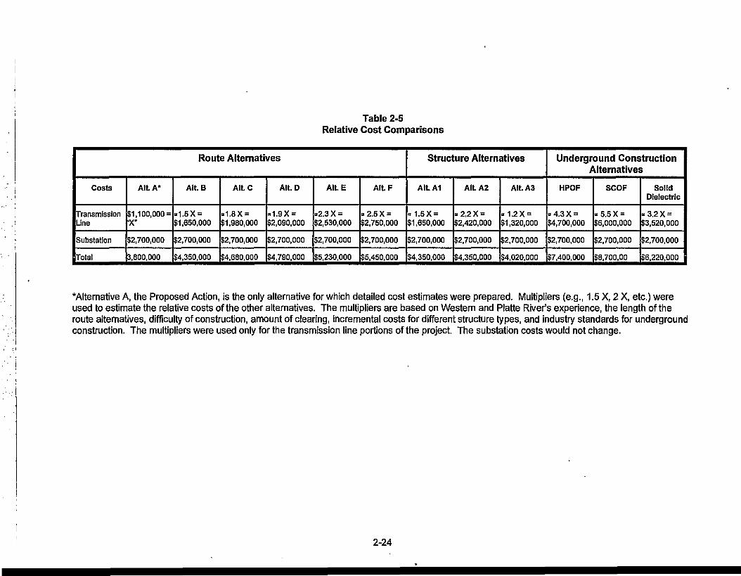
Table 2-5Relative Cost Comparisons
Route Alternatives
Costs
TransmissionLine
Substation
Total
Alt. A*
$1,100,000 =X"
$2,700,000
3,800,000
AILB
*1.5X =$1,650,000
$2,700,000
$4,350,000
Alt.C
»1.8X =$1,980,000
$2,700,000
$4,680,000
Alt. D
-1.9X =$2,090,000
$2,700,000
$4,790,000
Alt. E
«2.3 X =$2,530,000
$2,700,000
$5,230,000
Alt. F
»2.5X =$2,750,000
$2,700,000
$5,450,000
Structure Alternatives
Alt. A1
«1.5X =$1,650,000
$2,700,000
$4,350,000
AU.A2
-2 .2X =$2,420,000
$2,700,000
$4,350,000
Alt. A3
«1.2X =$1,320,000
$2,700,000
$4,020,000
Underground ConstructionAlternatives
HPOF
«4.3X =$4,700,000
$2,700,000
$7,400,000
SCOF
«5.5X =$6,000,000
$2,700,000
$8,700,00
SolidDielectric
« 3.2 X =$3,520,000
$2,700,000
$6,220,000
*Alternative A, the Proposed Action, is the only alternative for which detailed cost estimates were prepared. Multipliers (e.g., 1.5 X, 2 X, etc.) wereused to estimate the relative costs of the other alternatives. The multipliers are based on Western and Platte River's experience, the length of theroute alternatives, difficulty of construction, amount of clearing, incremental costs for different structure types, and industry standards for undergroundconstruction. The multipliers were used only for the transmission line portions of the project. The substation costs would not change.
2-24

3.0AFFECTED ENVIRONMENT
This chapter presents a description of the study area's environmental conditions that could be affected byor affect transmission line construction, operation and maintenance. The development of projectalternatives considered the information compiled for this chapter.
3.1 Study Area Definition and Description
The study area is comprised of approximately 3.75 square miles (approximately 2,400 acres) of landincluding portions of the Town of Estes Park and Larimer County (County). The study area boundarieswere selected to include potential alternative routes through the Town and County between the two endpoints of the project, the Estes Park Power Plant Switchyard and the Marys Lake Substation. In general,the study area is bounded by U.S. Highway 36 on the north; the existing transmission line ROW, the EstesPark Tramway, and existing residential developments on the northwest; Marys Lake Road on the westand southwest; just beyond the southern shoreline of Marys Lake on the south; and Fish Creek Road onthe east.
The study area consists of three distinct physiographic areas. The western portion is dominated by thesteep slopes of Prospect Mountain where there are residential developments on the gentler slopes; themid-slopes of the central portion consist primarily of residential, commercial, and transportation land uses;and the eastern portion is the Fish Creek valley and adjacent residential, public, recreation and openspace land uses.
3.2 Environmental Resources and Conditions
The description of the affected environment is organized to discuss the environmental issues that wereraised during project scoping (see Chapter 1, Section 1.3). They are discussed in their relative order ofimportance for this project. The issues most frequently raised during scoping are discussed first whilethose receiving less comment are discussed later.
The resources associated with the human environment that were assessed for impacts from the proposedproject include existing and planned land use, visual resources, socioeconomics, and electricalcharacteristics and public safety. Assessment of the cultural environment includes a detailed survey ofcultural resources. The natural resources evaluated include air quality, water resources, threatened andendangered species and wetlands/important habitats, floodplains, soils, geology, physiography, andpaleontology. Limited field verification for biological resources and land use conditions were conducted aspart of the analysis process.
The agencies that were consulted during the collection of data are listed in Chapter 5.0, Consultation andCoordination. Publications and other sources of information used in preparation of this EnvironmentalAssessment are presented in Appendix A. Additional references on electric and magnetic fields (EMF)are provided in Appendix F.
Environmental information was mapped at a scale of 1 inch equals 800 feet. The base map was derivedfrom the USGS 1:24,000 scale (1 inch equals 2,000 feet) topographic 7.5 minute series quadrangles(Estes Park, Glen Haven, Longs Peak, and Panorama Peak).
The resources identified as not requiring detailed study are included at the end of this section.
3.3 Human Environment
3.3.1 Land Use
Current land use and land ownership in the project area and vicinity were mapped and tabulated. Inaddition, current and proposed land management plans for the area and their constraints were identified.These include the Larimer County Land Use Plan and the Estes Park Comprehensive Plan. Recreationdata for the area has been updated with data from county and local sources. A field reconnaissance of
3-1

the Marys Lake project area was conducted on May 30,1995. Land uses along the proposed power lineupgrade were identified. Land use and zoning designations for the area were also identified from land useand zoning maps provided by the Town.
Portions of the existing Marys Lake transmission line lie within the town of Estes Park, and the remainderof the line lies outside of the town limits in Larimer County. The Roosevelt National Forest surroundsEstes Park and the project area to the east and the south. The Forest boundary is located 2 miles to theeast and approximately 0.8 miles to the south of Marys Lake Power Plant. A major use of the area isrecreation, including activities such as sightseeing, camping, hiking, hunting, and fishing. The Estes Parkarea provides access to the adjacent Rocky Mountain National Park, whose east entrance is locatedapproximately 1.5 miles northwest of the Marys Lake Power Plant along Marys Lake Road.
Most of the land along the existing transmission line ROW is private. Some of the land is owned by thefederal government The land around Marys Lake and Lake Estes, including both power plants, is ,administered by the U.S. Bureau of Reclamation. A portion of the transmission line corridor outside theTown limits is also owned by the U.S. Bureau of Reclamation.
The Larimer County Land Use Plan was adopted in 1988 for the purpose of guiding developmentdecisions in the unincorporated area of Larimer County. The plan has designated the Town of Estes Parkand the surrounding valley area with the land use category of Municipal Expansion Area/ UrbanDevelopment Area. This classification provides areas for projected future municipal boundaries. Withinthese areas, general urban development is expected, including commercial, residential, industrial andpublic uses. However, within Estes Park, densities are lower than those found in and adjacent to othermunicipalities in the county and densities within the projected future boundaries are expected to be thesame as those in the existing areas.
The Estes Park Draft Comprehensive Plan has been developed and is currently being reviewed forapproval in order to prepare the final draft. The Plan was designed to meet the needs of the entire EstesValley. The Plan study area consists of the town of Estes Park and the areas within Larimer County thatare inside the geographic confines of the Valley, including the entire proposed project area. The Planemphasizes the desires of the community in relation to the physical and natural features of the area.Community values such as the desire for a strong commercial core are balanced with the desire tominimize development in sensitive areas.
Existing Land Use. Existing land uses in the project area consist primarily of residential, institutional,commercial, recreation and open space, and agriculture (grazing). These uses are generally sensitive tothe construction and operation of a transmission line. Existing land uses in incorporated andunincorporated portions of the project area were provided by the Estes park Community DevelopmentDepartment and are shown in Figure 3-1. Approximately 0.6 miles of the northern portion of thetransmission line is located within the town limits of Estes Park. The remaining 2.4 miles are located southand west of the town limits in unincorporated Larimer County.
Residential subdivisions and isolated residences are located throughout the project area. The Town ofEstes Park is located in the northern and eastern portions of the project area, and includes moderate andhigh density residential areas. Residential areas are also located west of Prospect Mountain in thewestern part of the project area. Isolated residences are scattered throughout most of the project area.Most of the project area is zoned for residential uses (Figure 3-2). Residential zoning designations withinthe Estes Park town limits include single family residential, multi-family residential, condominium, andresidential unimproved. The Larimer County zoning designation of Estate consists of a residential usewith a density of 5 acres per unit In the project area, most of the condominium and multi-familyresidences are located along Colorado Highway 7.
There are approximately 89 residences along links 2 and 3 of the existing ROW, all of which wereconstructed after the existing transmission lines were built. There are approximately 7 new residencesadjacent to or crossed by the ROW along links 2 and 3. (Refer to Table 1 in Appendix G.)
3-2

Platte River Power Authorityand
Western Area Power Administration
Marys Lake69/115 kV Transmission Line Upgrade
and Substation Expansion Projects
LEGEND
^ ^ B ACCOMMODATIONS ^ H i MULTIPLE FAMILY
M M AGRICULTURE B B 1 OFHCEM l COMMERCIAL I 1 RESIDENTIAL UNIMPROVED
I I COMMERCIAL UI«3EVELOPED M M R&ML
1 M B CONDOMINIUM I I SINGLE FAMILY RESIDENTIAL
M M INSTITUTIONAL
— — — • EXISTING 69,000 VOLT TRANSMISSION LINE
— ^ ^ — — EXISTING 115,000 VOLT TRANSMISSION UNE
Source; Town of Exes Parit
2000 Feet
EXISTING LAND USEFigure 3-1

This page is intentionally left blank.
3-4

Platte River Power Authorityand
Western Area Power Administration
Marys Lake69/115 kV Transmission Line Upgrade
and Substation Expansion Projects
LEGEND
ACCOMODATIONS
COMMERCIAL
ESTATE
ESTATE
TOURIST
ESTES-TOWN
|^BB COMMERCIAL OUTLYING-TOWN
I | RESTRICTED INDUSTRIAL-TOWN
I I RESIDENTIALMULTIPLE FAMILY-TOWN
H RESIDENTIAL 182 FAMILY-TOWN
. . . . . . . EXISTING 69,000 VOLT TRANSMISSION LINE
EXISTING115,000VOLTTRANSMISSIONUNE
Source Town ofEsta Park
0 ' ZOOOFeat
EXISTING TOWN OF ESTES PARK ANDLARIMER COUNTY ZONING
Figure 3-2

This page is intentionally left blank.
3-6

Institutional land uses include schools, hospitals, and government owned land or facilities. In the projectarea, the largest areas of institutional uses include lands adjacent to Marys Lake and Lake Estes. WithinEstes Park, areas zoned for institutional uses consist of municipal land and facilities, including schoolsand hospitals. A large institutional use area occupies the land south of U.S. Highway 36 and Lake Estes,between Colorado Highway 7 and Fish Creek Road. The area contains municipal recreational facilities,and an elementary school, a middle school, and a high school. Other institutional facilities located withinthe Town limits include a hospital, a water treatment plant, the municipal building, and police and fireprotection facilities. Electric power plants are located at Marys Lake and at Lake Estes. The open spacesurrounding the power plants and transmission facilities at both lakes are also used for recreation.
Commercial and retail development is clustered in the northern portion of the project area, close todowntown Estes Park along U.S. Highway 36 and Colorado Highway 7. Commercial establishments arealso sparsely scattered throughout the area. The Town and the county have designated these land useareas as commercial, commercial undeveloped, retail, office, and accommodations. About four percent ofthe existing line crosses through lands within the town limits that are zoned for commercial use. As shownon Table G-1 in Appendix G, there are approximately 5 commercial parcels adjacent to or crossed by theexisting ROW along links 1,2 and 3.
Estes Park and the adjacent Rocky Mountain National Park are popular destinations for people seeking avariety of recreation activities. Numerous recreation opportunities exist on public lands in the vicinity ofEstes Park, and include sightseeing, hiking, camping, picnicking, fishing, hunting, cross-country skiing,mountain climbing, and bicycling. The number of visitors utilizing these opportunities in the RockyMountain National Park was 3,153,695 in 1994 (Estes Park, 1995). There are five campgrounds in thepark which include 577 sites in the summer and 186 sites in the winter. There are seven privatecampgrounds in the Estes Park area. Lodging and accommodations in the Estes Park area include 110lodging establishments and 3,500 rooms.
The town features several attractions for both residents and visitors. Recreation sites within the projectarea include an aerial tramway to the top of Prospect Mountain; camping and fishing at Marys Lake; andboating, fishing, picnicking, and a hiking trail at Lake Estes. The area south of Lake Estes, betweenColorado Highway 7 and Fish Creek Road includes a museum, Stanley Park, rodeo grounds, and a golfcourse. There is a paved biking and hiking path along Colorado Highway 7 within the town limits. Anunpaved trail is located along Fish Creek, and is used for hiking, horseback riding, and biking. Figure 3-3shows recreation facilities in the project area.
Marys Lake Campground is located on the north side of the lake, east of Peak View Road, across from theexisting transmission line. The facilities include a campground with 150 sites, which accommodate tentsand RVs between May 15 and September 30. Fishing on the lake is for brown and rainbow trout. Thereis no boating on the lake.
The Estes Power Plant and the Estes Power Plant Switchyard are located on the southwestern side ofLake Estes. The lake is a regional recreational area, and features several recreation facilities. There areseveral picnic areas located around the lake. The nearest of these to the power plant facilities is theCherokee Draw picnic area, the western edge of which lies about 800 feet east of the switchyard. TheLake Estes Golf Course is located on the north side of the lake, across from the power plant. The LakeEstes Trail is a pedestrian and bicycle path along the northern border of the lake. It connects with theEstes Park Downtown Riverwalk. In addition, there is fishing and boating on the lake. The Lake EstesMarina is located on the northeastern shore of the lake.
There are no other areas of special concern located in the vicinity of the proposed transmission line. Theproject is not located in or near any Wilderness Area or Wilderness project area. The nearest wildernessarea is the Cache la Poudre located approximately 15 miles northeast of the project area. Theprojectroute does not cross any existing or potential wild and scenic rivers.
Portions of the project area in unincorporated areas have been designated as agricultural use areas.Agriculture in the Estes Valley consists primarily of grazing. Some land in the vicinity of Marys Lake isused for grazing horses. The designated land use for Prospect Mountain, located in the center of theproject area, is also agriculture. However, there is no evidence of any agricultural use of ProspectMountain. The agricultural portions of the project area are surrounded by residential developments.
3-7

There are several child care facilities located in Estes Park. Most of these are located in the vicinity of thethree schools in the area south of Stanley Park.
There are several areas of open space located along the existing transmission line ROW. These areasare not formally designated as open space, and are either located on government-owned lands or onprivate lands zoned for residential use. Some of the public lands contain recreation facilities. Includedare Bureau of Reclamation lands located at both ends of the existing transmission line around Marys Lakeand Lake Estes. These lands contain recreational facilities operated by the Estes Valley Recreation andPark District (EVRPD), which include the Lake Estes Marina, a 9-hole golf course, and picnic facilities atLake Estes. The EVRPD also maintains an 18-hole golf course on Colorado Highway 7, the picnic andsoftball area at Stanley Park, tennis courts, a swimming pool operated jointly with schools, and MarysLake Campground. Lake Estes Marina and Marys Lake Campground are leased to private operators.
Other open space areas along the existing transmission line ROW are not designated or zoned forrecreational use, but may be informally used by the public for recreation, or as alternative routes used asshortcuts. Prospect Mountain consists of a large area of open space on private lands on the slopes aboveexisting residential use areas. Trails cross the slopes, originating primarily from the residences below.Rock climbing occurs on bolted routes on rock outcrops near the summit of the mountain. Open spacewithin the town limits are located along the existing transmission line ROW on the west side of the StanleyAvenue crossing. A well defined trail crosses the space, indicating regular use. Within both the Townlimits and residential subdivisions in the unincorporated areas, the existing transmission line ROW adjoinsthe yards of several residences.
Local electric distribution lines are located throughout the project area. These lines are shown on Figure1-1.
U.S. Highways 34 and 36 are the primary transportation routes through Estes Park. U.S. Highway 34 isan east-west route that connects the Estes Valley with the cities of Loveland and Greeley to the east. Thehighway is the primary access route into Rocky Mountain National Park, and continues through the parkas the Trail Ridge Road. U.S. Highway 36 is a north-south route that connects Estes Park to Boulder andDenver to the south. The two highways converge at the eastern entrance to the park.
Access to the project area is available from several state, county, and city roads. The primary routethrough the project area is Colorado Highway 7, which is a north-south road connecting Estes Park withAllenspark to the south. Numerous side roads connect the highway with residential and commercial areaswithin the project area.
Planned Land Use
Planned uses in the proposed project study area were determined from zoning maps (Figure 3-2), fieldobservations, and interviews with local planning officials. Future development of Estes Valley wouldprobably follow the existing pattern of compact or urban development close to the downtown core of EstesPark. Development as one moves away from the downtown area would also follow the existing pattern oflower density commercial, accommodation and residential uses. Future development in the Valley isconstrained by environmental features such as steep slopes, visually sensitive areas, and wildlife andflood hazards. In recognition of Estes Park's role as the gateway community to Rocky Mountain NationalPark, lands in the vicinity of the park are proposed to have lower densities of development in order toprovide a transition to park lands.
Future development in the currently undeveloped portion of Prospect Mountain would be limited due to theconstraints of steep slopes and the high visibility of the area. The area would most likely continue as openspace.
The Marys Lake area is developed primarily with low density residential uses. The area provides atransition between the more intensely developed portions of Estes Valley and rural areas, and is locatednear the natural resources of Larimer County public lands, including Rocky Mountain National Park,National Forest lands and Bureau of Reclamation land. Future development in this area will be consistentwith existing uses.
3-8

- 1 IROCKY
FC03EVEITNATIONALFOREST
LARIMER COUNTY
Platte River Power Authorityand
Western Area Power Administration
Marys Lake69/115 kV Transmission Line Upgrade
and Substation Expansion Projects
^ SCENIC HIGHWAY
2 ] SCENIC AREA
7)71 RECREATION FACILITIES AND OPEN SPACE^ 1 WITHIN ESTESPARKTOWN LIMITS
A RECREATION FACUTIES
— STUDY AREA BOUNDARY
- - EXISTING 69,000 VOLT TRANSMISSION LINE
EXISTING 115,000 VOLT TRANSMISSION UNE
TRAILS
Sources; Urban Trails in Colorado; North Front Range,Larmier County Maps
VIEWING POINTS FORVISUAL SIMULATIONS
SCENIC AREA
RETENTION
| . . | MODIFICATION
MAXIMUM MODIFICATION0 • 2000 Feet
VISUAL RESOURCES
Figure 3-3

This page is intentionally left blank.
3-10
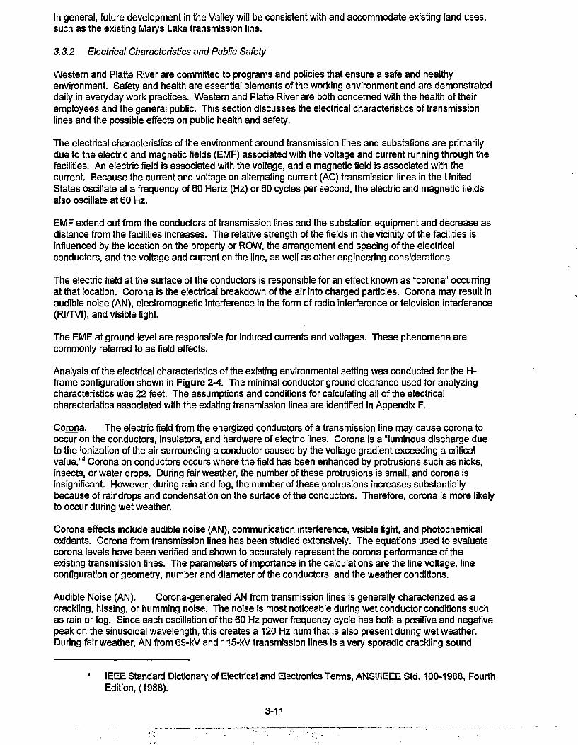
In general, future development in the Valley will be consistent with and accommodate existing land uses,such as the existing Marys Lake transmission line.
3.3.2 Electrical Characteristics and Public Safety
Western and Platte River are committed to programs and policies that ensure a safe and healthyenvironment. Safety and health are essential elements of the working environment and are demonstrateddaily in everyday work practices. Western and Platte River are both concerned with the health of theiremployees and the general public. This section discusses the electrical characteristics of transmissionlines and the possible effects on public health and safety.
The electrical characteristics of the environment around transmission lines and substations are primarilydue to the electric and magnetic fields (EMF) associated with the voltage and current running through thefacilities. An electric field is associated with the voltage, and a magnetic field is associated with thecurrent. Because the current and voltage on alternating current (AC) transmission lines in the UnitedStates oscillate at a frequency of 60 Hertz (Hz) or 60 cycles per second, the electric and magnetic fieldsalso oscillate at 60 Hz.
EMF extend out from the conductors of transmission lines and the substation equipment and decrease asdistance from the facilities increases. The relative strength of the fields in the vicinity of the facilities isinfluenced by the location on the property or ROW, the arrangement and spacing of the electricalconductors, and the voltage and current on the line, as well as other engineering considerations.
The electric field at the surface of the conductors is responsible for an effect known as "corona" occurringat that location. Corona is the electrical breakdown of the air into charged particles. Corona may result inaudible noise (AN), electromagnetic interference in the form of radio interference or television interference(RI/TVI), and visible light.
The EMF at ground level are responsible for induced currents and voltages. These phenomena arecommonly referred to as field effects.
Analysis of the electrical characteristics of the existing environmental setting was conducted for the H-frame configuration shown in Figure 2-4. The minimal conductor ground clearance used for analyzingcharacteristics was 22 feet. The assumptions and conditions for calculating all of the electricalcharacteristics associated with the existing transmission lines are identified in Appendix F.
Corona. The electric field from the energized conductors of a transmission line may cause corona tooccur on the conductors, insulators, and hardware of electric lines. Corona is a luminous discharge dueto the ionization of the air surrounding a conductor caused by the voltage gradient exceeding a criticalvalue."4 Corona on conductors occurs where the field has been enhanced by protrusions such as nicks,insects, or water drops. During fair weather, the number of these protrusions is small, and corona isinsignificant. However, during rain and fog, the number of these protrusions increases substantiallybecause of raindrops and condensation on the surface of the conductors. Therefore, corona is more likelyto occur during wet weather.
Corona effects include audible noise (AN), communication interference, visible light, and photochemicaloxidants. Corona from transmission lines has been studied extensively. The equations used to evaluatecorona levels have been verified and shown to accurately represent the corona performance of theexisting transmission lines. The parameters of importance in the calculations are the line voltage, lineconfiguration or geometry, number and diameter of the conductors, and the weather conditions.
Audible Noise (AN). Corona-generated AN from transmission lines is generally characterized as acrackling, hissing, or humming noise. The noise is most noticeable during wet conductor conditions suchas rain or fog. Since each oscillation of the 60 Hz power frequency cycle has both a positive and negativepeak on the sinusoidal wavelength, this creates a 120 Hz hum that is also present during wet weather.During fair weather, AN from 69-kV and 115-kV transmission lines is a very sporadic crackling sound
IEEE Standard Dictionary of Electrical and Electronics Terms, ANSI/IEEE Std. 100-1988, FourthEdition, (1988).
3-11
which is barely perceptible. Transmission line AN is measured and predicted in units of decibels (A-weighted), abbreviated dBA. The A-weighted sound level scale weights the various frequencycomponents of a noise to correspond to the way that the human ear responds, or hears the noise.
Transmission line noise is commonly expressed in terms of exceedance levels; e.g., L50 refers to thenoise levels in dBA that are exceeded 50 percent of the time. Separate exceedance levels are generallygiven for fair weather and wet weather. The L50 wet weather level corresponds closely to an averagevalue over all wet weather conditions for a long period of time, usually one year. The overall averagenoise level depends on the amount of foul weather at a particular location.
AN levels for the edge of the ROW of the existing lines during fair and wet weather are shown on Table 3-1 . The average (L50) values for wet weather at the edges of the ROW of the existing 115-kV line and 69-kV line are 35.2 and 29.1 dBA respectively. The calculated average fair weather noise levels at the edgesof the ROW are 10.2 and 4.1 dBA for the 115-kV and 69-kV lines respectively.
Table 3-1AudibleNofeefAN)
Location
Existing 69/115-kV East/South Edge ROW (115-kV)Transmission West/North Edge ROW (69-kV)Lines Maximum in ROW
Typical noise levels encountered in everyday life are shown
Levels
Fair Weather L50 Wet Weather L50AN (dBA) AN (dBA)
10.24.110.7
on Table 3-2.
Table 3-2Audible Noise Decibel Ratings of Some Common
Typical DecibelLevel (dBA) Common Noises
Noises
Resulting
35.229.1 ,35.7 '
Effect
30
40
50
60
Lowest Level Audible to Human Ear
Quiet Library, Soft Whisper
Quiet Office, Living Room
Light Traffic, Refrigerator
Air Conditioner, Conversation
Audible Noise From
Electric Transmission
Lines Generally Occurs in
This Range
708090100
Busy Traffic, Noisy RestaurantSubway, Heavy City TrafficTruck Traffic, Shop Tools, Lawn MowerChain Saw, Pneumatic Drill
<J» Critical Level Begins
120140180
Rock Concert, ThunderclapJet PlaneRocket Pad During Launch
Danger Level
Hearing Loss
Source: American Academy of Otolaryngology.
Radio Interference/Television Interference (RI/TVI). Corona on transmission line conductors cangenerate electromagnetic noise at the frequencies at which radio and television signals are transmitted.
3-12
This noise can cause interference (primarily with AM radio stations) with the reception of these signals andis called radio interference (RI) and television interference (TVI), depending on the frequency.
Another more prevalent source of RI and TVI from electrical systems is spark gaps on distribution and lowvoltage transmission lines. If for some reason, such as mechanical failure, vibration, or corrosion, aconnection between two parts that is usually conducting becomes nonconducting, a voltage can developacross the gap between the two components. If the voltage is large enough, a spark occurs which maygenerate RI, TVI, and sometimes AN. This type of interference is primarily a fair weather phenomenon.Water tends to short out the gaps during foul weather. Spark gaps will occur more often on old lines withloose or damaged hardware, or dirty insulators, than on new lines. Western conducts routinemaintenance on transmission lines to minimize these occurrences.
Corona-generated interference can conceivably cause disruption on other communication bands such asthe citizens (CB) and mobile bands. However, complaints or interference from transmission lines to CBradio are rare. This is because the high operating frequency of CB (about 27 megaHertz, MHZ) is abovethe frequency of most corona-generated noise. A more likely cause of interference to CB is spark gaps ona transmission or distribution line. Mobile radio communications are not susceptible to transmission lineinterference because they are generally frequency modulated (FM). Routine maintenance also minimizesthese occurrences.
Visible Light. Corona is visible as a bluish glow or as bluish plumes. Corona on the conductors of theexisting transmission lines may be observable under the darkest and/or wettest conditions, when thecorona is most intense. Even then, it would probably be visible only with the aid of binoculars. Without aperiod of adaptation for the eyes, and without intentionally looking for the corona, it is generally notnoticeable on lines below 345-kV.
Photochemical Oxidants. When corona is present, the air surrounding the conductors is ionized andchemical reactions may take place producing small amounts of ozone and other oxidants. Measurementsin the laboratory and near transmission lines have shown that the amount of oxidants produced byoperating transmission lines is usually not measurable for 230-kV lines and is barely measurable for largerlines.
Electric Fields. The electric field associated with a high voltage transmission line extends from theenergized conductors to other objects such as the ground, towers, vegetation, buildings, and vehicles.The electric field strength is associated with the voltage of the transmission line and is expressed in unitsof volts/meter (V/m) or kilovolts/meter (kV/m). The unperturbed electric field at a height of one meter, or3.3 feet, above the ground is used to describe the field under transmission lines. This quantity is easilymeasured or calculated. The most important parameters for determining the ground level electric field of atransmission line are conductor height above ground, line voltage, and phasing of nearby conductors.
Because of practical considerations, measured values of electric fields can, and do, deviate slightly fromcalculated values. Nearby objects can significantly shield (reduce) the electric field near ground level.5 Itis common practice to calculate the electric fields for a line under specific operating conditions. Thecomputed electric field profiles at 1 meter above ground for the existing conductor configurations areshown on Table 3-3. The maximum electric field in the ROW at the smallest conductor ground clearanceof 22 feet is approximately 1.53-kV/m. As shown in Table 3-3, the resultant maximum edge of ROWelectric field is also approximately 1.53-kV/m.
Deno&Silva(1987).
3-13

Location
Existing 115-kV and 69-kVTransmission Lines
Table 3-3Electric Field Levels
East/SouthEdge of ROW
(kV/m)115-kV
1.53
West/NorthEdge of ROW
(kV/m)69-kV
0.90
Maximum inROW (kV/M)
1.53
The National Electrical Safety Code (NESC), in effect, limits the maximum electric field under transmissionlines with voltages greater than 98-kV. It requires that the conductor clearance at a conductortemperature of 120° F be sufficient to keep the induced short-circuit current to the largest anticipatedvehicle to less than 5 milliamperes (mA).6 Because the induced current is proportional to the electric field,this criteria establishes the maximum field that can occur for a known vehicle.
Shock Hazards. By far, the greatest hazard from transmission lines is direct contact with theconductors. Powerlines, as with electrical wiring in homes and businesses, can cause serious electricshocks if precautions are not taken to minimize shock hazard. All of Western and Platte River'stransmission lines are designed and constructed in accordance with the NESC standards. The NESCstandards specify the minimum allowable distance between the lines and the ground or other objects.These requirements determine the edge of the ROW, the height of the conductors, and the closest point tothe conductors that buildings and vehicles can safely be allowed.
Still, extreme caution must be taken when operating tall equipment, such as cranes and drilling equipment,and when moving irrigation pipe near any powerline. Vehicles and large equipment up to 15 feet in height,including antennas, can normally travel safely under Western and Platte River's transmission lines. Treesadjacent to transmission lines should not be felled onto the lines. Kites should not be flown neartransmission lines, and only nonmetallic string should be used. Western and Platte River provide freeinformation for people living near transmission lines; Western's booklet is titled "Living and WorkingAround High Voltage Power Lines." This booklet is available from Western's Loveland Area Office (1-800-472-2306).
Irrigation systems can be operated safely near transmission lines if certain precautions are taken:
• Irrigation equipment should not be raised to a vertical position anywhere near a powerline sinceirrigation pipe is often long enough to reach within flashover distance of the conductors.
• Steady streams of water contacting the conductor can provide a direct path to ground for the currentor flashover. Therefore, irrigation nozzle risers should be equipped with spoilers and automaticshutoffe.
• Magnetically induced voltages can occur on long sections of irrigation pipe and other metallic,conducting, objects such as fences. Maintenance of long pipe systems should be done perpendicularto the transmission line and the system should be grounded at each end.
• Transferred potential during electrical faults can be avoided by not burying portions of the irrigationsystem or pipe near structures or structure grounding systems.
When there is any doubt, questions should be referred to Western at 1-800-472-2306.
Large fires near transmission lines represent a potential electrical hazard. Hot gases and smoke cancreate a conductive path to ground. Flashovers can cause electrical shocks to people near the line andalso cause outages. Storage of flammables and construction of flammable structures on Western or
National Electrical Safety Code (1993) fi232D3c.
3-14
Platte River's ROW are prohibited. Refueling should not be done near transmission lines unlessnecessary. If refueling is necessary, proper grounding is recommended. Transmission lines can interferewith circuits used to detonate explosives, and explosives can also damage power lines. Western or thelocal utility should be contacted before initiating blasting.
Tall objects, including transmission line structures, are the most likely points to be struck by lightningduring a thunderstorm. Western and Platte River transmission lines are designed with overhead groundwires and grounded structures to protect the system from lightning. If lightning strikes the overheadground wire, the strike is conducted to ground at the structure locations.
Induced Currents. When a conducting object, such as a vehicle, is in an electric field, currents andvoltages are induced, or flow, in the object The magnitude of the induced current depends on the electricfield strength, the size and shape of the object, and the degree of grounding.7 If the object is completelygrounded, then the induced current flows to earth and is called the short-circuit current of the object. Inthis case, the voltage on the object is effectively zero. If the object is completely insulated (not grounded),then it assumes some voltage relative to ground. These induced currents and voltages can represent apotential source of nuisance shocks.
Steady-State Currents. Steady-state currents are those that flow continuously after a person contacts anobject and provides a path to ground (acts as a conductor) for the induced current The response ofpersons to such currents has been extensively studied and levels of response documented.8 Primaryshocks are those that can result in direct physiological harm. The lowest category of primary shocks is"let go" which represents the steady-state current that cannot be released voluntarily. The let go thresholdwas established for adult males at 9.0 milliAmperes (mA) and 6.0 mA for adult females. These thresholdshave been established for adult men weighing 180 pounds and adult women weighing 120 pounds. Let gothresholds for adults have been established from actual experimentation. Thresholds for children,however, have been derived from the data for adults, since no actual measurements were taken fromchildren. The derivation of a threshold for children was based on body weight, and is generally acceptedas 5.0 mA - the value adopted by the NESC. No information is readily available on the body weight of thechildren for whom the 5.0 mA threshold was adopted. Primary shocks are not possible from the inducedcurrents under the existing lines because of the relatively low field strengths and the grounding practicesof Western.
Spark Discharge Shocks. Induced voltages appear on objects such as vehicles and people partiallyinsulated from ground by non-conducting materials such as rubber tires or shoe soles. If the voltage issufficiently high, then a spark discharge shock will occur when two objects come very close together(withing a fraction of a centimeter).9 Such shocks are similar to "carpet" shocks, which occur whenreaching for a door knob after walking across a carpet on a dry day. Spark discharge shocks theoreticallycould occur under the existing and proposed transmission lines. However, the magnitude of the electricfield is low enough that this type of shock rarely occurs and then only under certain conditions.
Handling conducting objects under the transmission line can also result in spark discharges that are anuisance. Irrigation pipe, and other similar objects, should be carried as low to the ground as possible andpreferably unloaded at a distance from the transmission lines to eliminate spark discharge nuisanceshocks. The primary hazard with irrigation pipe, and other similar objects, is direct contact with theconductors.
Magnetic Fields. The magnetic field associated with a high voltage transmission line surrounds theconductor and decreases with increasing distance from the conductor. The magnetic field is expressed inunits of magnetic flux density or gauss (G), or milligauss (mG). The magnetic field at a height of 1 meter,or 3.3 feet, above the ground is used to describe the magnetic field under transmission lines. Thisquantity can be measured or calculated. The most important parameters for determining the ground level
7 Deno & Silva (1984), Silva, et al. (1985).
« E. G., Keesey (1969).
9 Deno & Silva (1985).
3-15

magnetic field of a transmission line are conductor height above ground, the proximity of other conductors,and the current flowing in the conductors.
When public concerns about fields from powerlines were first raised over 20 years ago, the focus was onelectric fields. Subsequent research has suggested that magnetic fields are probably more important tostudy. Although electric fields are easily shielded by trees, buildings, etc., magnetic fields can not beshielded. Magnetic fields travel through most materials including iron, steel, lead and the earth's soil. Infact, the earth exhibits a static, or direct current (DC) magnetic field resulting from charges moving deepwithin the molten core of the planet. The earth's magnetic field in northern Colorado is approximately 550mG.
Table 3-4 provides the calculated magnetic field levels at 1 meter above the ground for the existing69/115-kV transmission lines. Since the magnetic field levels are directly influenced by source current,these calculations have been performed for a variety of loading scenarios. As the table shows, themaximum field at the edge of the ROW for peak operations and peak loading is 47.10 mG.
Location
Existing 69-kV and 115-kVTransmission Lines
Table 3-4Magnetic Field Levels
East/SouthEdge of ROW
(mG)115-kV
14.88
West/NorthEdge of ROW
(mG)69-kV
47.10
Maximum inROW (mG)
54.23
Table 3-5 provides the magnetic field levels of common household appliances. As Tables 3-4 and 3-5demonstrate, the magnetic field levels from the existing lines are similar to those encountered in everydaylife.
Magnetically Induced Currents and Voltages. Alternating magnetic fields induce voltages at the openends of conducting loops. The conducting loop can be formed by a fence, an irrigation pipe, a pipeline, anelectrical distribution line, a telephone line, and other similar objects. The earth, to which one end of theconductor is grounded, forms the other portion of the loop. The possibility for a shock exists if a personcloses the loop at the open end by contacting both the ground and the conductor. However, electric fields,and not magnetic fields, are the predominant source of induced currents.
Magnetically induced currents from powerlines have been extensively investigated.10 Shocks due tomagnetically induced currents and voltages are of the same type as those due to electric field inducedcurrents and voltages. In the case of magnetic induction, the voltages are generally quite low, and thecurrents are limited as compared to those induced by electric fields.
See e.g., IEEE (1974); Taflove & Dabkowski (1979); Taflove, et al. (1979); Jaffa & Stewart (1981);Jaffa (1981); Olsen & Jaffa (1984).
3-16
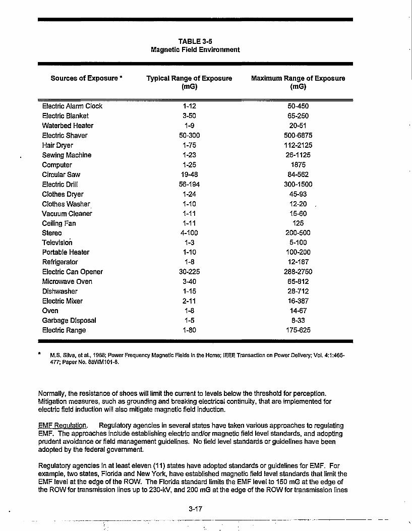
Sources of Exposure *
Electric Alarm Clock
Electric BlanketWaterbed Heater
Electric Shaver
Hair DryerSewing Machine
Computer
Circular SawElectric Drill
Clothes DryerClothes WasherVacuum CleanerCeiling FanStereoTelevisionPortable HeaterRefrigerator
Electric Can Opener
Microwave Oven
DishwasherElectric Mixer
OvenGarbage Disposal
Electric Range
TABLE 3-5Magnetic Field Environment
Typical Range of Exposure(mG)
1-12
3-501-9
50-300
1-751-23
1-25
19-48
56-194
1-24
1-101-111-11
4-1001-31-10
1-830-225
3-40
1-152-11
1-81-5
1-80
Maximum Range of Exposure(mG)
50-450
65-25020-51
500-6875
112-212526-1125
187584-562
300-1500
45-93
12-20 .15-60125
200-5005-100
100-20012-187
288-275065-812
28-71216-387
14-678-33
175-625
M.S. Silva, et al., 1988; Power Frequency Magnetic Fields in the Home; IEEE Transaction on Power Delivery; Vol. 4:1:465-477; Paper No. 88WM101-8.
Normally, the resistance of shoes will limit the current to levels below the threshold for perception.Mitigation measures, such as grounding and breaking electrical continuity, that are implemented forelectric field induction will also mitigate magnetic field induction.
EMF Regulation. Regulatory agencies in several states have taken various approaches to regulatingEMF. The approaches include establishing electric and/or magnetic field level standards, and adoptingprudent avoidance or field management guidelines. No field level standards or guidelines have beenadopted by the federal government.
Regulatory agencies in at least eleven (11) states have adopted standards or guidelines for EMF. Forexample, two states, Florida and New York, have established magnetic field level standards that limit theEMF level at the edge of the ROW. The Florida standard limits the EMF level to 150 mG at the edge ofthe ROW for transmission lines up to 230-kV, and 200 mG at the edge of the ROW for transmission lines
3-17

with voltages greater than 230-kV. New York has adopted an interim standard of 200 mG at the edge ofthe ROW. These standards are not scientifically-based but rather were based on the highest EMF levelsassociated with existing transmission facilities and were adopted to maintain the status quo while EMFresearch continues. EMF standards are shown in Table 3-6.
Stateor Group
Florida
New York
International RadiationProtection Association(IRPA) and InternationalNon-Ionizing RadiationCommittee (INIRC)
National RadiationProtection Board (NRPB)
Table 3-6Magnetic Field Standards
Standard at EdgeofROW(mG)
150 mG200 mG
200 mG
1,000 mG
20,000 mG
Comments
Up to 230-kV Transmission LinesTransmission Lines Larger Than 230-kV
Interim Standard
General Public(Occupational Exposure is 5,000 - 50,000mG; 250,000 mG if limbs only are exposed)
United Kingdom
At least nine (9) states have endorsed policies requiring utilities to apply prudent avoidance or fieldmanagement techniques when selecting routes for new transmission lines. These states includeCalifornia, Colorado, Connecticut, Illinois, New Jersey, Ohio, Rhode Island, Texas, and Wisconsin. Ingeneral, the prudent avoidance/field management guidelines require utilities to provide information to stateutility regulators regarding the EMF considerations that have been taken into account in routing, designing,and operating transmission lines. The EMF prudent avoidance considerations adopted by the ColoradoPublic Utilities Commission in Docket No. 92R-259E modified Rule 18 of the PUC's Electric Rules are asfollows:
• "The utility shall include the concept of prudent avoidance with respect to planning, siting,construction, and operation of transmission facilities."
• "Prudent avoidance shall mean the striking of a reasonable balance between the potential healtheffects of exposure to magnetic fields and the cost impacts of mitigation of such exposure, takingsteps to reduce the exposure at reasonable or modest cost."
• "Such steps might include, but are not limited to:
(1) Design alternatives considering the spatial arrangement of phasing of conductors;(2) Routing lines to limit exposures to areas of concentrated population and group
facilities such as schools and hospitals;(3) Installing higher structures;(4) Widening right of way corridors; and(5) Burial of lines."
The National Electric and Magnetic Research and Communication Program. Since EMFs are createdduring the generation, transmission, distribution, and use of electricity, everyone in the United States isexposed to various types and levels of EMF. Over the past 20 years, there has been an increasing publicconcern that exposure to electric and/or magnetic fields may result in adverse human health effects. Toaddress these concerns, the Energy Policy Act of 1992 included provisions for a five (5) year NationalEMF Research and Communication Program. The goals of this program are:
3-18
1. To determine if there are adverse effects on human health from EMF exposure;2. To assess human exposures to EMF;3. To develop options to reduce EMF exposures from various utility, residential, commercial, industrial,
and transportation sources; and4. To respond to the needs of the public, decision makers, and other interested parties by
communicating understandable, credible, and balanced information of the results of EMF research.
The National EMF Research and Communication Program is intended to be national in scope, presentinga framework that will allow federal agencies, states, businesses, research organizations, unions,universities, and concerned citizens to sponsor, conduct, coordinate, or otherwise participate in EMFresearch and communications. The program goals, objectives and activities are the result of collaborationwith the EMF research community, citizens, government and private sector policy makers, and otherinterested parties.
The program plan recommends activities that should be considered for the next five (5) years in fourrelated program areas: (1)Scientific Research; (2) Engineering Research; (3) Communications; and(4) Policy Support.
The plan recommends the timing or sequencing of these activities and presents preliminary costs(unconstrained by availability of resources) to implement activities for the five-year period. The .greatestfunding emphasis is placed on the EMF Scientific Research component to determine if EMF exposuresresult in health effects, and emphasizes research on those potential health outcomes of greatest concern.
The scientific research program component seeks to determine the biological effects of EMF exposure onhumans, animals, tissues, and cells; the mechanisms of interaction underlying these effects; biologicalindicators of exposure; and the association between EMF exposure and human health risks through well-defined epidemiologic studies.
The engineering research program component will assess EMF exposures and develop and evaluatetechnologies for mitigating fields and options for managing EMF exposures. The communicationsprogram component will gather, develop, and disseminate scientific and technical information on EMFissues in an easily understandable format. The EMF policy support program component will assist policymakers in developing effective public policies based on sound research findings and legal, economic,sociologic, and other studies.
The plan addresses research and communication activities from a national perspective. Therefore, thefederal government is not intended to be the only sponsor of the activities presented. The followingcontributors will be instrumental in implementing and coordinating national EMF research andcommunication:
• The EMF Research and Public Information Dissemination Program (RAPID) established by theEnergy Policy Act of 1992. This is a federal program that authorizes $65 million over five years to beappropriated to DOE for EMF research and information dissemination. Non-federal sources willcontribute at least 50% of the total funding for all activities under the program. The health researchactivities and related communication efforts will be directed by the National Institute of EnvironmentalHealth Sciences (NIEHS) in cooperation with DOE, while DOE will direct the engineering researchprogram and related communication efforts. A federal EMF Interagency Committee will facilitate thecoordination of federal activities and develop the research agenda.
• Other Federal Agencies. In addition to DOE and NIEHS, several other federal agencies areinvolved in EMF research and communication including: the Environmental Protection Agency; theFood and Drug Administration; the National Cancer Institute; the National Institute of OccupationalSafety and Health; the National Institute of Standards and Technology; the Occupational Safety andHealth Administration; the Department of Transportation; and the Department of Defense. Exclusiveof the Department of Energy ($5 million), and the Department of Defense ($4 million), other federalagencies have funded approximately $6 million for EMF activities in fiscal year 1992.
• States and Private Sector Organizations. New York, Florida, and California are among thestates that presently support EMF research activities.' In the private sector, the Electric PowerResearch Institute is the major EMF research sponsor, with a 1993 budget of approximately $15
3-19
million for EMF health effects studies, field characterization and management research, andinformation services.
The EMF-related activities of various federal agencies will be coordinated through the InteragencyCommittee referred to above. The Interagency Committee will also maintain a liaison with state andprivate sector organizations to ensure the coordination of research activities nationwide. The EnergyPolicy Act of 1992 requires the Director of NIEHS to report the research findings from the National EMFResearch and Communication Program to the Congress by March 31,1997.
Future actions will be driven largely by the results of the research conducted under the National EMFResearch and Communication Program. If scientists widely conclude that exposure to EMF posesadverse health effects, then the required actions to reduce or eliminate EMF exposure could be veryexpensive. The costs of mitigating EMF associated with existing and new electric transmission lines willvary with various geographic, engineering, and environmental factors. Nevertheless, the cost estimatesthat are beginning to emerge range from the tens of billions to hundreds of billions of dollars nationwide toreduce exposure from all transmission and distribution lines.
3.3.3 Visual Resources
Existing Conditions. The existing conditions relevant to the visual resources in Estes Park and theproject study area have not been formally inventoried or classified. Data collected for preparation of thevisual resource assessment includes photography of the project area taken from several observationpoints, 7.5-minute USGS topographic maps, and aerial photography. Views representative of the projectfrom area residences and Marys Lake Road are shown in the "existing condition" photographs on Figures1-1 through I-8 in Appendix I.
The basis of the U.S. Forest Service Visual Management System (VMS) was utilized to assess theimpacts to the visual resources. The VMS uses three visual resource inventory components to developVisual Quality Objectives (VQOs): (1) variety classes; (2) sensitivity analysis; and (3) visibility. VQO classdesignations are used to manage the visual resource. These designations define the acceptable level ofchange that a proposed project or management action may introduce into the landscape.
Variety Class. Refining the landscape character types (e.g., alluvial valleys, uplands, mountains, etc.)into smaller units of similar physiographic and visual characteristics define the boundaries of variety classunits. The greater the diversity of line, form, color and texture the greater the potential for high scenicvalue. The following three variety class designations are used to describe the aesthetic quality of thenatural landscape.
Class A. Outstanding areas where characteristic features of landform, rock, water, and vegetation aredistinctive or unique in the context of the surrounding region. These features exhibit considerable varietyin line, form, color and texture.
Class B. Above average areas in which features provide variety in line, form, color and texture; andalthough the combinations are not rare in the surrounding region, they provide sufficient visual diversity tobe considered moderately distinctive.
Class C. Common areas where characteristic features have moderate-to-little variety in line, form, coloror texture in relation to the surrounding region.
Sensitivity Analysis. The existing transmission lines have contributed to the visual character of theproject area for more than 40 years. The existing visual impacts are most evident from foreground viewsfrom within the residential subdivisions, Prospect Drive, and Marvs Lake Road. The existina woodJi-

Foreground (Fg). (0 - .5 mile) - The limit of a viewed area in which details are perceived and obvious.Textural and other aesthetic qualities of vegetation are normally perceptible within this zone.
Middleground (Mg). (.5 - 3 to 5 miles) - This zone includes viewed areas in which details of foliage andfine textures cease to be perceptible. Vegetation begins to appear as outlines or patterns.
Background (Bg). (3-5 to 10 miles) - That portion of the landscape where texture and color are weak andlandform becomes the most dominant element
Visibility also accounts for the specific viewing conditions that could affect how a viewer sees from aviewpoint: including terrain backdrop, vegetation screening, and viewer position. For example, distantmountains that are a backdrop to the viewed area may reduce the level of change noticed in thelandscape.
Visual Quality Objectives. VQOs are designed to provide objectives for visual management of theland. VQOs are based on several factors, including the public's concern for scenic quality (sensitivitylevels), where the area is viewed from, and the diversity of the natural features in the characteristiclandscape. These designations define the acceptable level of change that a proposed project ormanagement action may introduce into the landscape. The Forest Service VMS Manual (Forest Service1974) identifies five VQO classifications. These VQOs include:
Preservation (P). This VQO allows ecological changes only. Management activities, except for verylow visual impact recreation facilities, are prohibited.
Retention (R). This VQO provides for management activities which are not visually evident. Activitiesmay only repeat line, form, color and texture which are frequently found in the characteristic landscape.Any changes in their quality of size, amount, intensity, direction, pattern, etc., should not be evident.Immediate reduction in line, form, color and texture contrast should be accomplished either duringoperation or immediately after operations cease.
Partial Retention (PR). This VQO allows new lines, forms, color and texture to be introduced, but thechanges must remain subordinate to the characteristic landscape. The activities may also introduce line,form, color or texture that are found infrequently or not at all in the characteristic landscape as long asthey remain subordinate. Reduction of the contrast should be accomplished within the first year afteroperations cease.
Modification (M). This VQO allows activities that visually dominate the original characteristic landscapewhen the activities borrow from the naturally established line, form, color or texture, and at a similar scaleso that its visual characteristics are those of natural occurrences within the surrounding areas or charactertype. Reduction of the contrast should be accomplished within the first year after operations cease, or at aminimum, should meet existing regional guidelines.
Maximum Modification (MM). This VQO allows management activities and landform alterations thatdominate the characteristic landscape. When viewed as background, the visual characteristic must bethose of natural occurrences within the surrounding area or character type. When viewed as foregroundor middle ground, they may not appear to completely borrow from the naturally established line, form,color or texture. Activities may also be out of scale or contain detail that is incongruent with naturaloccurrences as seen in the foreground or middle ground. Reduction of the contrast should beaccomplished within five years after operations cease.
The visual resources for lands surrounding the proposed project facilities have not been assessed. Dueto the urban character and degree of development in the project area, this analysis assumes VQOs of"Maximum Modification" for the densely developed areas near the intersection of U.S. Highway 36 andColorado Highway 7 and in the commercial and residential areas adjacent to Highway 7, "Modification" forthe less densely developed residential areas, and for the areas around Marys Lake and the east side ofProspect Mountain, and "Retention" for the upper slopes of the north and west sides of ProspectMountain. These VQOs are illustrated on Figure 3-3.
3-21

Landscape Character Types. There are four general landscape character types in the project area: (1)coniferous forest; (2) montane meadow; (3) sagebrush shrubland; and (4) wetlands. These landscapecharacter types are representative of the differences in physiography and vegetation found in the area.These landscape character types are illustrated on Figure 3-5, on page 3-29.
The combination of vegetation and development of this area is very complex and, thus, provides a highabsorption capability.
3.3.4 Socioeconomics
This section describes the existing socioeconomic structure of the Town of Estes Park and thesurrounding unincorporated areas of Estes Valley, and includes population, the economy, housing, andcommunity services. This data will be used to examine the impacts to aspects of the socioeconomicenvironment that would result from implementation of the proposed project or the alternatives, anddetermine whether these impacts would be beneficial or negative. Available socioeconomic data wascollected from local, state, and federal government sources.
The Town and the surrounding unincorporated areas of the Estes Valley in Larimer County comprise thestudy area for socioeconomic resources. Estes Park is located approximately 70 northwest of Denver andmay be reached from the east by U.S. Highways 34 and 36, and Colorado Highway 7. The regionfeatures numerous attractions and activities, and is a popular year-round tourist destination. In addition toEstes Park, the region includes the Rocky Mountain National Park and Roosevelt National Forest. Othercommunities in the vicinity of Estes Park are Glen Haven, Allenspark, and Meeker Park.
Population. Historically, population trends in Larimer County have been tied to resource development,particularly agriculture and tourism. The creation of Rocky Mountain National Park in 1917 helpedestablish Estes Park as a popular resort community. Tourist-related services provide employment for asignificant portion of the population. The population of Estes Park and the Estes Valley has shown steady igrowth in the past 25 years, reflecting the region's continuing popularity and growth as a touristdestination. In the years between 1970 and 1980, the population of Estes Park increased by 67 percent,from 1,616 to 2,703. The population grew to 3,672 in 1990, an increase of 36 percent. Population growthand further development of the area are issues that currently concern residents of the valley. Table 3-7summarizes population growth in Estes Park.
Table 3-7Population Growth in Estes Park and Estes Valley
Year Estes Park Town Limits Estes Valley
1970 1,616 3,554
1980 2,703 6,773
1990 3,672 9,139
1992 3,870 9,200
1995 projected 4,258 10,595
Source: Estes Park, 1995
The year-round population of Estes Park in 1992 was 3,870 people. The population in the Estes Valleywas approximately 9,200. The population in the valley grows to nearly 40,000 in the summer months(League of Women Voters, 1993). This increase results from the influx of people who utilize the region'ssummer homes, recreation activities, and job opportunities with the government and recreation industry.
3-22

Economy and Employment. The major industry in the Estes Park area is summer tourism. Estes Park isthe gateway to Rocky Mountain National Park, the number one tourist attraction in the state of Colorado.Estes Park is a resort town which provides lodging and other resort services to the more than 3 millionyearly visitors to the area (Blackhurst and Rosener, 1995). Service oriented industries and governmentemploy the largest number of workers in Estes Park. Support services for tourists and residents accountfor about 60 percent of employment. Government jobs account for 22 percent. Approximately 10 percentwork in the professions, and the remaining 8 percent work in light manufacturing industries (League ofWomen Voters, 1993).
Housing. The 1990 U.S. Census of Population and Housing estimates a total of 77,811 housingunits in Larimer County, of which 44,297 units, or 57 percent, are owner occupied. Approximately 2,006housing units are in the Town of Estes Park. Owner occupied housing units account for 822, or 41percent of units in the Town. Housing units for seasonal, recreational, or occasional use account for 448of vacancies in the town. The homeowner vacancy rate is 2.5 percent and the rental vacancy rate is 6.3percent (U.S. Census 1990).
Community Services. The project area is located in the Park R-3 School District. The District servesthe towns of Allenspark, Pinewood Springs, and Glen Haven as well as Estes Park. There are 3 schoolsin the district, including an elementary school, a middle school, and a high school. In addition, there is aresidential high school located in Estes Park.
Law enforcement in Estes Park and the Estes Valley is provided by the Estes Park Police Department andthe Larimer County Sheriffs Department Estes Park is patrolled by the Estes Park Police Department.The areas outside the town limits are patrolled by Larimer County, and the Colorado State Highway Patrol.The police department employs 16 full-time officers, and 7 additional part-time members hired for summertraffic control. The sheriffs department employs 5 deputies and the highway patrol employs 2 officers forthe area. The town jail in the municipal building is used only as a holding facility.
Fire protection services in Estes Park are provided by a volunteer fire department manned by a crew of 33volunteers. The fire department has mutual aid agreements with the fire departments in LovelandPinewood Springs, Glen Haven, and Allenspark. Fire houses are located in Estes Park and at the eastend of Rocky Mountain National Park.
There is one medical center in Estes Park which provides comprehensive health care facilities, including ahospital, skilled nursing facility, retirement cottages, specialty clinics and Home Health Care/Hospice. Thehospital has 16 beds, a fully equipped emergency room, 24-hour ambulance service, emergency airtransport, and surgical facilities. The medical center also provides emergency service to Rocky MountainNational Park (League of Women Voters, 1993).
Electricity was provided to about 7,800 customers in 1994 by the Town of Estes Park Light and PowerDepartment. Electric power is purchased from the Platte River Power Authority.
Drinking water is provided to Estes Park by the Water Department of the Department of Public Works,which operates and maintains 3 water treatment plants. In addition, there are 6 private water companiesin the area.
The Estes Park Sanitation District provides treatment of sewage in Estes Park. The Upper ThompsonSanitation District provides sewage treatment for areas not served by the Estes Park Sanitation District.Both districts operate treatment plants which discharge effluent into the Big Thompson River (Estes Park,1995).
Local government agencies in the Estes Park area operate and maintain several recreational facilities.The facilities operated by the Estes Park Recreation and Park District (EVRPD) include the Lake EstesMarina, a 9-hole golf course, and picnic facilities at Lake Estes. The EVRPD also maintains an 18-holegolf course between Highway 7 and Fish Creek Road, the picnic and softball area of Stanley Park, tenniscourts, a swimming pool operated jointly with schools, and Marys Lake Campground. The Lake EstesMarina and Marys Lake Campground are leased to private operators.
3-23

3.4 Natural Environment
3.4.1 Earth Resources '
Soils. Detailed soils mapping is not available for the Estes Park area. Therefore, soils have beenidentified using the General Soils Map of Colorado (Heil et al. 1977). Soils within the project area includetwo general soil mapping units: 1) Typic Cryoboralfs, skeletal - Rock Outcrop: sloping to steep and 2)Aridic Argiborolls, loamy - Rock Outcrop: moderately steep and steep.
The first mapping unit consists of an intermingling of several types of soils found on the slopes of ProspectMountain. Typic Cryoboralfs, skeletal are the predominant type. These are light colored, moderatelydeep to deep, well-drained, clayey to sandy soils. Most layers have more than 35 percent gravel, cobbles,and stones by volume. Typic Cryoboralfs commonly have moderate to low shrink-swell potential,moderate frost action potential, and moderate permeability.
The second mapping unit consists of an intermingling of several types of soils found in Stanley and Estesparks and Marys Lake valley. Aridic Argiborolls, loamy are the predominant type. These are dark colored,moderately deep to deep, well- to excessively-drained, loamy soils. Most layers have less than 35 percentrock fragments by volume. Aridic Argiborolls commonly have moderate shrink-swell potential, moderatefrost action potential, and moderate permeability. Sensitive soils are shown on Figure 3-4.
Geology. The proposed project is located on the eastern slope of the Southern Rocky Mountains.This is an area of high mountains, and rugged topography with local relief exceeding 6000 feet. Theproject area itself includes Estes Park (a broad northeast-southwest trending montane valley) andProspect Mountain (a granitic dome). Elevations range from 7500 feet at the north end of the project areaat the Estes Park Power Plant to 8900 feet at the summit of Prospect Mountain. Therefore, total projectarea relief is 1400 feet. Slopes range from gentle (2 to 5 percent) east of the power plant to extremelysteep (more than 100 percent) on portions of Prospect Mountain.
The project area lies in an area of ancient granitic and metamorphic bedrock which was uplifted andexposed during the Laramide Orogeny, a long period of mountain-building between 2 and 65 million yearsbefore the present Two bedrock formations are exposed at the surface of the project area: Silver PlumeGranite and Biotite Schist (Braddock and Cole 1990).
Bedrock in this area is cut by inactive faults in several locations (Braddock and Cole 1990). An east-westoriented fault zone runs along the southern margin of Prospect Mountain to the north of Marys Lake.Another roughly parallels the Fish Creek valley on the east side of the project area.
The study area lies within Seismic Risk Zone 1 (Algermissen 1969). Minor damage to structures fromdistant earthquakes is a possibility. Two intensity IV (minor) earthquakes have been centered within 20miles of the proposed project (Stover et al. 1988). Moderate (intensity VII) earthquakes have beencentered within 50 miles of the proposed project. None of these seismic events would have had ameasurable impact within the study area. Potential landslide areas are shown on Figure 3-4.
Surface Water. There are two perennial streams and two major reservoirs in the project area. The BigThompson River bounds the north side of the project area and Fish Creek flows north through the easternquarter of the project area. Lake Estes is at the northern terminus of the existing transmission lines andMarys Lake is located in the southwestern corner of the project area. Two intermittent streams drain eastto Fish Creek from Marys Lake and the adjacent area. Water resources in the area are predominatelyused for power generation. There is one ditch on Fish Creek and two small reservoirs. The Luce Ditch isused for irrigation and recreation. The transmission line ROW does not intersect any of these water rights(Colorado Division of Water Resources, 1995b). The surface water resources are shown on Figure 3-4.
Ground Water. There are approximately 190 well permits in the project area with well depths rangingfrom 10 feet to 760 feet (Colorado Department of Water Resources, 1995a). The average depth is 202feet Well yield, depth and water level information is available in whole or in part for 108 of these wells.Only eight wells appear to be less than 50 feet deep; two are located in the alluvium of the Big ThompsonRiver upstream of Lake Estes; one is located in the Beaver Point community; one is located along FishCreek; and four are located in colluvial materials on the east side of Prospect Mountain, near the transmis-sion line.
3-24

)•« i > A Y - ' - ' > •;
.\ » \ A ' -.-./ \ / .y
^ " • • • • 5 ' ~ 1 - ' : "
vj-..ltiO\IA\V.rVl)\ ••-•Jt^lL "'it J ''. Jl,
Mo.unfa j'u
> : - ^, > ) ) / " ' - \
it I t . ' . '- \ r - 7
: i J
' its-! 'd-> 'llf / I A . •'USGS
•flBv
J—a TT^1/^ >a - >^jLD 0 - - - - ° 7/ ti" JZt
»O.V. 0 ' il.\\.,>i«4_.
-USGS.Gaging
^Station
•-*>
&.-'XI?H53 7?
w5T
J1.V1—1
- #
535?=j
-_0 If' r7j i l
-Jf-ik-,
»#•
\
/. - ^
Ji
L'M
?/7i
. V'-
-J-A T-.:
rm., - ^ i )
f°1
itha in^ ( ^1 {S (BI'IJ
\ ^ X.:iflfc
i,ws
•-vs-
R*> -\\ivv\
-. :e;:§ > • •
• s . * )•**<* • " " *
Platte River Power Authorityand
Western Area Power Administration
Marys Lake69/115 kV Transmission Line Upgrade
and Substation Expansion ProjectsLEGEND
WEIL ADJUDICATION
SPECIFIC LOCATION UNKNOWN
100 YEAR FLOOD PLAIN
VERY STEEP SLOPES (>50%)
STEEP SLOPES (25%-50%)
SURFACE WATER
— — —STUDYAREA BOUNDARY
- - - - - - - EXISTING 69,000 VOLTTRANSMISSION LINE
EXISTING 115,000 VOLTTRANSMISSION LINE
O WELL PERMIT
0 . 2000FM1
EARTH RESOURCESFigure 3-4

This page intentionally left blank.
3-26

Forty-seven wells are adjudicated for one or more of the following uses in the project area: domestic,household use only, stock watering, irrigation, commercial, and industrial use. There is almost no publiclyavailable information for groundwater quality in the Estes Park Area. The ground water resources areshown on Figure 3-4.
Floodplains. The Federal Emergency Management Agency (FEMA) maps floodplains for the NationalFlood Insurance Program, particularly special flood hazard areas inundated by 100-year and 500-yearfloods. This program is delegated to local political entities. Larimer County, Colorado maps 0801010251B and 080101 0239C, and Town of Estes Park, Colorado maps 5N 72W30NWand 5N 73W25 SEportray those floodplains closest to the proposed project, and are included herein by reference. Thefloodplains in the vicinity of the project are shown on Figure 3-4.
3.4.2 Biological Resources
Vegetation. Four natural vegetation habitat types occur along the existing ROW. These habitat typesinclude coniferous forest, montane meadow, sagebrush shrubland, and wetlands, and are shown onFigure 3-5. An additional habitat type (urban plantings) is shown and includes exotic and introducedtrees, shrubs, and ornamentals primarily associated with adjacent homes.
Coniferous Forest. The coniferous forest habitat type occurring within and around the existing ROW isdominated by ponderosa pine {Pinus ponderosa). Associated species in the overstory include RockyMountain juniper {Juniperus scopulorum). Mid-story associates include wax currant {Ribes cereum),buckbrush {Ceanothus fendleri), common juniper {Juniperus communis), antelope bitterbrush {Purshiatridentata), and rubber rabbitbrush {Chrysothamnus nauseosus). Understory species include mountainball cactus {Pediocactus simpsonii), common wild geranium {Geranium caespitosum), one-sidedpenstemon {Penstemon secundiflorus), western yarrow {Achillea lanulosa), sulphur flower {Eriogonumumbellatum), sand lily (Leucochnum montanum), needle and thread {Stipa comata), blue grama{Bouteloua gracilis), spike fescue {Leucopoa kingii), and mountain muhly {Muhlenbergia montana). Thishabitat type is the most dominant along the ROW and includes approximately 7.07 acres. Signs ofovergrazing by elk are apparent.
Montane Meadow. This habitat type is characterized by dry to slightly mesic soil conditions, occurringprimarily on south-facing slopes. No true overstory was present, but some shrubby vegetation exists. Bigsagebrush {Artemisia tn'dentata ssp. vaseyana) and antelope bitterbrush were observed, but are limitedand sporadic. Understory species include blue grama, junegrass {Koleria macrantha), mountain muhly,pasque flower {Pulsatilla patens), common dandelion {Taraxacum officinale), wooly cinquefoil {Potentillahippiana), wild iris {Iris missouriensis), and mountain pussytoes {Antennaria parvifolia). This habitat typeincludes approximately 2.94 acres and was limited along the ROW.
Sagebrush Shrubland. Mountain big sagebrush, big sagebrush {Artemisia tridentata ssp. tridentata), andoccasional bitterbrush and chokecherry {Prunus virginiana) occur along the ROW. The understorycomponent of this habitattype is moderately sparse and is dominated by Wood's rose {Rosa woodsii),cheatgrass {Bromus tectorum), blue grama, mountain muhly, western wheatgrass {Agropyron smithii),fringed sage {Artemisia frigida), wavyleaf thistle {Cirsium undulatum), wild tarragon {Artemisiadracunculus), kochia {Kochia scoparia), and prickly pear cactus {Opuntia polyacantha). This habitat typewas observed across about one-third of the ROW and includes approximately 5.69 acres.
Wetlands. Two small wetlands were observed during the site visit One wetland was discrete,originating from a small seep at the base of a finger of the southeast-facing Prospect Mountain. Thesecond wetland was observed just south of Peak View Drive below the road and formed a large wetmeadow. Both wetlands had substantial surface water sheeting across them. The seep is intermittent,but the wet meadow is a perennial surface water source. These wetlands were dominated by grass-likesedges and rushes. These species include baltic rush {Juncus balticus), spike rush {Eeocharis palustris),bur-reed {Sparganium angustifolium), and subalpine rush {Juncus mertensianus). Associated forbspecies included wild iris, pasque flower, common yellow evening-primrose {Oenothera strigosa), one-sided penstemon, and mariposa lily {Calochortus gunnisonii). The wetlands include approximately 1.74acres.
Wildlife. Species occurring within the general project area are typically upland in nature. Althoughaquatic habitats exist they are limited in aerial extent. Species expected to occur within the area include
3-27

elk (CLervus elaphus), mule deer( Odocoileus hemionus), coyote (Cam's latrans), black bear (Ursusamercanus), porcupine (Erethizon dorsatum), skunk [Mephitis ssp.), deer mice {Peromyscusmaniculatus), Cooper's hawk (Accipiter cooperii), red-tailed hawk (Buteojamaicensis), Steller's jay(Cyanocitta cristata,) and black-capped chickadee (Parus atricapillus). Aquatic resources are restricted toMarys Lake. Species expected to occur there are rainbow trout, brook trout, fathead minnows, carp, andsuckers. The USFWS has indicates the following threatened, endangered, and candidate wildlife speciesas potentially occurring within the general project area: bald eagle, peregrine falcon, greenback cutthroattrout, northern goshawk, boreal toad, and fringed-tailed myotis (Carlson 1995).
Habitats within the project area are comprised of four main types: coniferous forest, montane meadow,wetlands, and sagebrush shrubland. Wildlife species are expected to utilize all habitat types within theROW. Also interspersed within the ROW are numerous homes and existing road ROWs. In generalthese areas are not highly conducive to wildlife habitation. Wildlife habitats are shown on Figure 3-6.
In general the area does not contain areas of high quality wildlife habitat Elk and deer utilize the areaprimarily as winter range. However, some year-round use may occur (Bogart 1995) (refer to Figure 3-6).Raptor species such as red-tailed hawks, and Cooper's hawks may nest in the area. However, no nestswere observed during the field reconnaissance. Species including coyotes and black bears may utilizehabitats temporarily. However, better habitats occur in areas surrounding the project area. Passerine andsongbird populations utilize the area and their density and populations would vary by season. Skunks anddeer mice would be expected to occur near buildings and other disturbed sites.
Listed Threatened. Endangered, and Other Species of Concern. Twenty six threatened, endangered,candidate or sensitive species are known to occur or potentially occur in the study area, based oninformation provided by the USFWS, the Colorado Division of Wildlife (CDOW), and the Colorado NaturalHeritage Program (CNHP). Table 3-8 provides information regarding each of these species. Listedspecies are discussed below.
Five plants were identified by the Colorado Natural Heritage Program for consideration and avoidancewithin the parameters of the transmission line upgrade project These species included purple lady'sslipper (Cypripedium fasciculatum), Rocky Mountain cinquefoil (Potentilla effusa var. rupincola), gay-feather (Uatris ligustylis), broad-leafed twayblade (Listera convallarioides), and wood lily (Lilium ,philadelphicum). No suitable habitat for any of these species lies within the proposed impact area. Table3-8 presents the potential habitat requirements and the impacts analysis conclusion for each species.
Of the sixteen threatened, endangered and sensitive species of wildlife identified through agency contacts,nine have been eliminated from further consideration. These species were eliminated based on a lack ofsuitable habitat within the project area (Table 3-8). The species eliminated include the regal fritillarybutterfly, Mexican spotted owl, eskimo curlew, mountain plover, whooping crane, black-footed ferret,boreal owl, Preble's jumping mouse, and swift fox.
Peregrine Falcon. The peregrine falcon is a federally-listed endangered species. Peregrines typicallyoccur along river systems or reservoirs where an adequate food supply, primarily waterfowl and otherbirds, are available. Roost sites are generally cliffs, bluffs or large rock outcrops. Peregrines are knownto occur within the general project area. The closest known nest site occurs almost a mile from thesouthern terminus of the project area. However, this site has not been occupied since 1990. The nextclosest sites occur four miles east and 8 miles north of the project area (Craig 1995). Peregrine falconsare known to occur within the general project area. In May of 1994 a male peregrine was killed as theresult of a line strike. The CDOW determined that the bird, which had been released into Rocky MountainNational Park, had struck the wire while chasing prey. The strike occurred on a distribution line in thesouthern portion of Estes Park (Craig 1996).
3-28
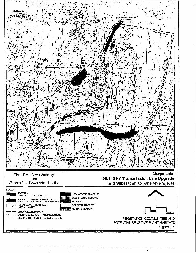
C ' ~ nfcn''. I />> / ,•:--?. •
"~- \& * •£•- . ' • - 7 / ^
Platte River Power Authorityand
Western Area Power Administration
Marys Lake69/115 kV Transmission Line Upgrade
and Substation Expansion ProjectsLEGEND
POTENTIALBLUE-EYED GRASS HABITAT
POTENTIAL LARIMER ALETES ANDROCKV MOUNTAIN CINQUEFOIL HABITAT
POTENTIAL WEBER MONKEY-FLOWER HABITAT
— — STUDY AREA BOUNDARYEXISTING 69,000 VOLTTRANSMISSIONUNEEXISTING 115,000 VOLTTRANSMISSIONUNE
URBAN/EXOTIC PLANTINGS
SAGEBRUSH SHRUBLAND
WETLANDS
CONIFEROUS FOREST
MONTANE MEADOW
2000 Feel
VEGETATION COMMUNITIES ANDPOTENTIAL SENSITIVE PLANT HABITATS
Figure 3-5

This page intentionally left blank.
•3-30

Sl^f^sr
""f>i.» '-UifivsV
Platte River Power Authorityand
Western Area Power Administration
Marys Lake69/115 kV Transmission Line Upgrade
and Substation Expansion Projects
LEGENDPOTENTIAL BOREAL TOAD ANDGREENBACK CUTTHROATTROUT HABITAT
I POTENTIAL BOREAL TOAD HABITAT
POTENTIAL NORTHERN GOSHAWKAND FRINGED-TAILED MYOTIS HABITAT
DENSELY DEVELOPED URBAN AREA
, MULE DEER AND ELK RANGE,AND DWARF SHREW HABITAT
' STUDY AREA BOUNDARYEXISTING 69,000 VOLTTRANSMISSION LINE
• EXISTING 115,000 VOLTTRANSMISSION LINE
WILDLIFE RESOURCES ANDPOTENTIAL SENSITIVE WILDUFE HABITATS
Figure 3-6
2000 Feel

this page intentionally left blank
3-32

Table 3-8Threatened, Endangered, and Other Species of Concern
Common StatusName/Scientific Name
Habitat Requirements Potential for Impacts
Peregrine falcon {Falco Endangeredperegrinusy
Bald eagle (Haliaeetus ThreatenedleucocephalusY
Greenback cutthroat trout Threatened(Onchorhynchus clarkistomias)1
Boreal toad (Bufo boreas C2boreasY
Northern goshawk (AccipHer C2gentilisy
Fringed-tailed myotis (Myotis C2thysanodes pahasapensisY
Larimer aletes (Aletes C2humilisy
Pale blue-eyed grass C2(Sisyrinchium pallidum)1
Weber monkey-flower C2(Mimulus gemmiparvsy
Rocky cliffs, marshes, and openwater.
Reservoirs, areas of open water,and big game winter range.
Mountain and foothill headwaters ofthe South Platte and Arkansas riverdrainages.
Marshes, wet meadows, beaverponds, shallow lakes, and alongstreams ranging from 8,000 to12,900 feet in elevation.
Nest within coniferous and mixedconiferous-deciduous forests ongentle to moderate slopes withnortherly exposures.
Ponderosa pine woodlands,greasewood, oakbrush, andsaltbush shrublands.
Cracks and crevices on rockygranite outcrops dominated byponderosa pine and on cool, north-facing, near-vertical cliffs.
Poorly drained mid-elevation wetmeadows from 7,000 to 10,000 feetin elevation.
Moist soils of forest seeps or springsprotected by granite overhangsbetween elevations of 8,500 to10,500 feet.
Whooping crane (Grusamericana)2
Eskimo curlew (Numeniusborealis)2
Mountain plover (Chadadriusmontanus)2
Mexican spotted owl (Strixoccldentalls luclda)2
Black-footed ferret (Mustelanlgripes)2
Swift fox (Vulpes velox)2
Prebles meadow jumpingmouse (Zapus hudsoniuspreblei)2
Endangered
Endangered
Candidate forlisting
Threatened
Endangered
Candidate forlisting
Candidate forlisting
Mudflats, agricultural areas,wetlands.
Plowed fields, shorelines of lakesand reservoirs. None observed inColorado since 1882.
Shortgrass prairies, dry mudflats,and shorelines of dry reservoirs.
Dense uneven aged mixed-coniferor ponderosa pine forests with ahigh canopy closure.
Prairie dog colonies
Short- and mid-grass prairies.
A prairie species occurring in lushvegetation along watercourses andherbaceous understories inwoodlands
Moderate, suitable habitatoccurs within the ROW.
Moderate; suitable habitatoccurs within the ROW.
None; no suitable habitat.
Moderate; suitable habitatoccurs within the ROW.
Moderate; suitable habitatoccurs within the ROW.
Moderate; suitable habitatoccurs within the ROW.
None; habitat does notoccur within ROW.
Low; wetlands will beprotected through mitigationmeasures, i.e., silt fencing.
None; no suitable habitatwithin ROW.
None; no suitable habitat.
None; no suitable habitat.
None; no suitable habitat.
None; no suitable habitat.
None; no suitable habitat.
None; no suitable habitat.
None; no suitable habitat.
3-33
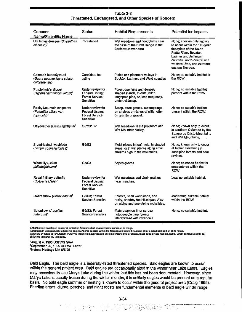
Table 3-8Threatened, Endangered, and Other Species of Concern
Common StatusName/Scientific Name
Habitat Requirements Potential for Impacts
Ute ladies-tresses (Spiranthesdiluvialis)2
Threatened
Colorado butterflyweed(Gaura neomexicana subsp.coloradensis)2
Purple lady's slipper[Cypripedium fasciculatumf
Rocky Mountain cinquefoil(Potentilla effusa var.rupincola)3
Broad-leafed twayblade(Lisfera convallarioidesf
Wood lily (Uliumphiladelphicum)3
Regal fritillary butterfly(Speyeria idattaf
Dwarf shrew (Sorex nanus)3
Boreal owl (Aegoliusfunerous)3
Candidate forlisting
Under review forFederal Listing;Forest ServiceSensitive
Under review forFederal Listing;Forest ServiceSensitive
Gay-feather (Uatris ligustylis)3 G57/S1S2
G5/S2
G5/S3
Under review forFederal Listing;Forest ServiceSensitive
G5/S3; ForestService Sensitive
G5/S2; ForestService Sensitive
Wet meadows and floodplains nearthe base of the Front Range in theBoulder-Denver area
Plains and piedmont valleys inBoulder, Larimer, and Weld counties
Forest openings and denselyshaded stands, in duff underlodgepole pine, or, less frequently,under Abies sp.
Steep, often granite, outcroppingson shelves or niches of cliffs, oftenon granite or gravel.
Wet meadows in the piedmont andWet Mountain Valley.
Moist places in leaf mold, in shadedareas, or in wet places along smallstreams high in the mountains.
Aspen groves
Wet meadows and virgin prairiesnear marshes.
Forests, open woodlands, androcky, shrubby foothill slopes. Alsoon alpine and sub-alpine rockslides.
Mature spruce-fir or spruce-fir/lodgepole pine forestsinterspersed with meadows.
None; species only knownto occur within the 100-yearfloodplain of the SouthPlatte River, Boulder,Larimer and Jeffersoncounties, north-central andwestern Utah, and extremeeastern Nevada.
None; no suitable habitat inthe ROW.
None; no suitable habitatpresent within the ROW.
None; no suitable habitatpresent within the ROW.
None; known only to occurin southern Colorado by theSangre de Cristo Mountainsand Wet Mountains.
None; known only to occurat higher elevations insubalpine forests and coolravines.
None; no aspen habitat isencountered within theROW
Low; no suitable habitat.
Moderate; suitable habitatwithin the ROW.
None; no suitable habitat.
Endangered2 Species in danger of extinction throughout all or a significant portion of its range.Threatened2 Species likely to become an endangered species within the foreseeable future throughout all or a significant portion of its range.Category 2= Species for which the USFWS indicates that proposing to list as endangered or threatened is possibly appropriate, but for which conclusive data onbiological vulnerability is lacking.
'August 4,1995 USFWS letterSeptember 26,1995 USFWS Letter'Natural Heritage List 6/5/95
Bald Eagle. The bald eagle is a federally-listed threatened species. Bald eagles are known to occurwithin the general project area. Bald eagles are occasionally sited in the winter near Lake Estes. Eaglesmay occasionally use Marys Lake during the winter, but this has not been documented. However, sinceMarys Lake is usually frozen during the winter months, it is unlikely eagles would be present on a regularbasis. No bald eagle summer or nesting is known to occur within the general project area (Craig 1995).Feeding areas, diurnal perches, and night roosts are fundamental elements of bald eagle winter range.
3-34
Although eagles can fly as far as 24 km (15 miles) to and from these elements, they primarily occur whereall three elements are available in comparatively close proximity (Swisher 1964). None of these elementsoccur along the project ROW.
Greenback Cutthroat Trout. The greenback cutthroat trout is federally-listed as a threatened species.Greenback cutthroat trout typically occurs in mountain and foothill headwaters of the South Platte andArkansas river drainages (Behnke 1992). The greenback is known to have been stocked in LarimerCounty in the North Fork of the Big Thompson and Roaring Fork Rivers. It is anticipated that it hasextended it range from these stockings (Carlson 1995). This species is easily displaced by non-nativetrout species (Behnke 1992).
The Ute ladies'-tresses is a federally listed threatened species. Ute ladies'-tresses is a member of theorchid family. The species is a perennial plant with stems 20 to 50 centimeters tall, arising fromtuberously thickened roots. The species is characterized by whitish, stout, ringent flowers. It blooms,generally, from late July through August. It is endemic to moist soils in mesic or wet meadows nearsprings, lakes, or perennial streams. The elevational range of known Ute ladies'-tresses occurrences is4,300 to 7,000 feet.
Other Species. The remaining species of concern are Category Two species. Although Category Twospecies have no protection under the Endangered Species Act (1972), as amended, it is within the spirit ofthe Act to address potential effects to these species to avoid future listing as either threatened orendangered. These species include the boreal toad, northern goshawk, fringed-tailed myotis (Carlson1995), Larimer aletes (Aletes humilis), pale blue-eyed grass (Sisyrinchium pallidum), and Weber monkey-flower (Mimulus gemmiparus) (USFWS).
The boreal toad is restricted to wetland and riparian corridors above 8,000 feet in elevation. Within theseareas they typically occur within marshes, wet meadows, and the margins of streams, lakes, beaverponds, and glacial kettle lakes (Hammerson 1986). The boreal toad may occur within wetland habitatslocated in the project area (Hammerson and Langlois 1981). However, the presence of the boreal toadhas not been documented within the project area (Pague 1995).
The northern goshawk generally nest in mixed coniferous and deciduous forests. They typically occur onmoderate slopes (0-30%), with north-northeast exposures. Typically these areas are near small quietephemeral streams (Reynolds et al. 1992). Although goshawks may occur in the area, none have beendocumented by either the CDOWorCHNP (Craig 1995 and Pague 1995).
Fringed-tailed myotis occur in coniferous forest at moderate elevations. This bat species may occur inponderosa pine, pinyon-juniper, greasewood, saltbush, and scrub oak habitats (CDOW1984). Thisspecies may occur in the area (Bissell 1978). However, they have not been documented (Pague 1995).
Larimer aletes is a member of the parsley family. The species has thick leathery leaves and it formsconspicuous clumps and mats on rock walls. Larimer aletes bloom in mid- to late-summer and the flowersare yellow. It occurs in cracks and crevices on rocky granite outcrops where it is shaded by ponderosapine and on cool, north-facing, near-vertical cliffs.
Pale blue-eyed grass is a member of the iris family. It blooms in late July and August and has a pale blueflower atop a slender grass-like stem. It inhabits poorly drained mid-elevation meadows from 7,000 to10,000 feet in elevation. It is associated with the Greenland primrose, grasses, and grass-like plants.
Weber monkey-flower is a member of the figwort family. It blooms from June through early August, hasyellow flowers, and is small in stature. It typically grows in moist soils of forest seeps or springs protectedby granite overhangs between elevations of 8,500 to 10,500 feet. It has also been discovered growing onan alluvial fan deposited by the Long Lake flood. It grows in association with other monkey-flowers.
Colorado butterflyweed is a member of the evening-primrose family. The species has not been found inthe state of Colorado since 1988 (CNPS 1989). However, several isolated populations have been foundin Wyoming. The plant occupies moist prairie meadows along the Front Range from Castle Rock,Colorado to Cheyenne, Wyoming in the transition zone between streams and floodplains. The plant growsin a candelabra shape up to four feet tall. It flowers from July through September.
3-35

The dwarf shrew occupies a variety of habitat types. These shrews have been observed from the edgesof alpine and subalpine rockslides to spruce-fir bogs. In addition, coniferous forests, sedge marshes, drybrushy hillsides, and open woodlands may be utilized. The dwarf shrew can also tolerate arid to semi-aridconditions, and have been observed up to half a mile from water sources (Fitzgerald et al 1994).
Potential habitats for these species are shown on Figures 3-5 and 3-6.
3.5 Cultural Environment
There are no known cultural resources in the immediate project area. The general region contains twohistoric debris scatters, several historic buildings in Estes Park, and a small number of prehistoric lithicscatters in the area. The existing ROW associated with the Proposed Action is on relatively steep (10-25% grade) rocky and unconsolidated slopes that are removed from water sources or other attractiveresources.
An archaeological survey of the Proposed Action resulted in the recording of two prospect pitsapproximately 120 meters apart. Both are mostly backfilled and the brush regrowth indicates that they areprobable 50-70 years old. There were no artifacts or debris found.
3.6 Resources Identified As Not Requiring Detailed Study
The environmental resource areas that were considered, but which are not described in detail in thisanalysis, include the following:
3.6.1 Air Quality
The project would have very minor, local, short-term effects on air quality, limited primarily to short-termemissions from construction vehicles and fugitive dust generated by construction activities. The upgradeof the 69-kV transmission line to 115-kV would have no measurable effects on ozone levels. !
3.6.2 Climate
The project would have no effect on climate.
3.6.3 Paleontology
Potentially important fossil bearing locales are not present along the route of the Proposed Action.Therefore, the project is not expected to affect paleontological resources.
3-36

4.0ENVIRONMENTAL CONSEQUENCES
This chapter presents an assessment of the environmental consequences associated with the projectalternatives, primarily the Proposed Action, with respect to each of the environmental conditions asdescribed in Chapter 3. The analyses that have been conducted utilize a variety of terms to assess theeffects that would result with respect to each resource. The terms used to assess the effects areidentified and defined below.
cumulative: increasing in effect by successive additions; accumulated.
essential/essentially: basically, inherently
impact to influence or change.
long-term: a long period of time (for the purposes of this project, more than five (5) years)
minimal: small quantity or degree.
moderate: within reasonable limits; avoiding extremes; of medium quality.
short-term: a short period of time (for the purposes of this project, less than five (5) years).
significant/significantly, important, exceeding a defined impact threshold.
slight/slightly, lacking weight, strength, significance, etc.; small in amount or extent
strong: having a powerful effect.
weak, not strong; unconvincing; lacking force, power, effectiveness, or authority.
4.1 Human Environment
4.1.1 Land Use
Existing Land Use. As the existing transmission lines and ROWs have been in-place for over 40 years,there would be essentially no new long-term effects on the existing land uses. Construction of theProposed Action would result in several short-term effects primarily as a result of construction andreclamation of disturbances. The project would have very minor, short-term effects on air quality andnoise. The air quality effects would be limited primarily to emissions from construction vehicles, andfugitive dust and noise would be generated ruing construction activities. These effects would be limited toline construction that would proceed along the existing ROW during 1997 and 1998. The noise generatedby the Proposed Action would be 1 dBA greater than the existing conditions at the edges of the ROW; thisincrease would not be perceptible. Traffic congestion in the vicinity of the project would also increaseslightly on a short-term basis with a number of 12 to 16 people working on the project at any one timeduring peak periods of construction. The primary impact to existing land uses would be the disturbance ofexisting vegetation at the structure locations and by the construction of temporary spur roads for access toup to three structure locations. Generally, access to each structure location would be from existing roads.Cross-country travel along the ROW would only be necessary between three to four spans in the area thatparallels Peak View Drive. Disturbed areas would be reseeded and restored, as nearly as feasible, totheir original condition. More specific construction and restoration guidelines are included in Appendix J.
Planned Land Use. There would be essentially no effects on planned land uses because the existingROWs that have been in-place for over 40 years would be used, and local land use planning hasconsidered the existing use of the transmission line corridor.
4.1.2 Electrical Characteristics and Public Safety
This section discusses the environmental effects of the project alternatives including the Proposed Actioncompared to the existing conditions relative to public health and safety. Analysis of the electricalcharacteristics of the existing environmental setting was conducted for the configuration shown in Figure2-4. The minimal conductor ground clearance used for analyzing characteristics was 22 feet.
4-1

Corona. The additional corona resulting from upgrading the existing 69-kV transmission line to 115-kVwill not be discernable.
Audible Noise (AN). AN levels for the edge of the ROW of the alternatives including the Proposed Actionduring fair and foul weather are shown on Table 4-1. The calculated average (L50) value for wet weatherat the edge of the ROW is 36.2 dBA for the Proposed Action.
Table 4-1Audible Noise (AN) Levels
Alternative
Alternative A - TheProposed Action
Alternative A1 -Single-circuit SingleSteel Pole Structures
Alternative A2 -Double-circuit SingleSteel Pole Structures
Alternative A3 - Self-supported AngleStructures
Location
East/South Edge ROWWest/North Edge ROWMaximum in ROW
East/South Edge ROWWest/North Edge ROWMaximum in ROW
East/South Edge ROWWest/North Edge ROWMaximum in ROW
East/South Edge ROWWest/North Edge ROWMaximum in ROW
Fair Weather L50 AN(dBA)
11.211.211.8
10.77.711.2
9.69.612.2
11.211.211.8
Wet Weather L50 AN(dBA)
36.236.236.8
35.732.736.2
34.634.637.2
36.236.236.8
The calculated average fair weather noise level at the edge of the ROW is 11.2 dBA for the ProposedAction. These values represent a slight increases for the edges of the ROW when compared to theexisting conditions illustrated in Table 3-1. The AN levels for Alternatives A1 and A2 would range from 7.7dBA to 10.7 dBA during fair weather, and 32.7 dBA to 35.7 dBA during wet wether at the edges of theROW. The AN levels associated with Alternative A3 would be the same as for the Proposed Action.Table 3-2 provides a comparison of common noises.
Radio Interference/Television Interference (RI/TVI). The existing transmission lines have been inservice for over 40 years and interference to radio (Rl) and television (TVI) have not been significantproblems. It was reported during the initial public workshop/ scoping meeting that RI on car radios occurswhen driving in the vicinity of the transmission lines. While there may be several reasons for thisinterference, including weak signal strength, it is also likely that the cause is related to loose or dirtyinsulators, or by loose hardware, and can be corrected by maintenance.
The interference to radio (Rl) and television (TVI) is not anticipated to significantly increase with theproposed upgrade, and would be similar for all alternatives. The primary source of this interference is stillanticipated to be spark gaps. This is a condition generally found in older transmission lines and theupgrade should eliminate or improve potential existing problems. The policies of Western and Platte Riverare to investigate Rl and TVI problems and to correct those caused by Western and/or Platte Riverfacilities. Western routinely investigates Rl and TVI complaints and is prepared to resolve anyinterference problems resulting from the operation of the proposed project.
Visible Light It is not anticipated that the visibility of corona would be any more noticeable after theupgrade, with any of the alternatives, than the visibility of corona from the existing transmission lines. Thisis because the visibility is not cumulative, or additive, but is dependent on weather conditions, andbecause of the construction materials used and maintenance of the line hardware to minimize the corona(e.g., the use of corona rings and corona-free hardware).
4-2

Photochemical Oxidants. Because the resolution of ozone instrumentation is approximately 1.0parts per billion (ppb), it is very unlikely that corona-generated ozone from the proposed project couldeven be measured.
Electric Fields. The computed electric field profiles at one meter above ground for the alternativesincluding the Proposed Action are shown on Table 4-2. The maximum field in the ROW at the smallestconductor ground clearance of 22 feet is approximately 1.55-kV/m with the Proposed Action. These fieldlevels are approximately the same as the existing conditions for the east/south edge of the ROW and themaximum in the ROW, and slightly higher for the west/north edge of the ROW.
Table 4-2Electric Field Levels
Alternative
Existing Conditions
Alternative A - Proposed Action
Alternative A1 - Single-circuit Single SteelPole Structures
Alternative A2 - Double-circuit SingleSteel Pole Structures
Alternative A3 - Self-supported AngleStructures
East/SouthEdge of ROW
(kV/m)
1.53
1.55
1.48
0.25
1.55
West/NorthEdge of ROW
(kV/m)
0.90
1.55
0.83
0.25
1.55
Maximum inROW(kV/m)
1.53
1.55
1.81
1.09
1.55
The maximum electric field levels associated with Alternative A1 would be slightly higher (1.81-kV/m), andAlternative A2 would be slightly lower (1.09-kV/m) than the Proposed Action. The electric field levelsassociated with Alternative A3 would be the same as the Proposed Action.
Induced Currents. In general, the electric fields around these lines are not great enough to produceperceivable shocks to persons contacting grounded objects. It is the policy of Western and Platte Riverthat special cases such as long fences parallel to the transmission line can be addressed on a case-by-case basis.
Steady-State Currents. The maximum induced current criterion for vehicles is 5 mA. Potential steady-state current shocks from vehicles under the proposed transmission line upgrade will be less than 5 mAfor the largest vehicle anticipated and will not be perceptible for most vehicles. This standard would bemaintained for all of the alternatives.
Several factors tend to reduce the opportunity for secondary shocks to occur. If activities are distributedover the whole ROW, then only a small percentage of time will be spent in areas where the field is at orclose to the maximum value.11 The vehicular traffic in high-field-strength areas in limited since clearancesare generally higher over road crossings, and farm machinery on soil or vegetation tends to reduce shockcurrents substantially. Because of these factors, most steady-state current shocks are below the 1.1 mAperception level for 50 percent of men and, in fact, less than the 0.5 mA standard for maximum leakagecurrent from portable appliances. Thus, steady-state current shocks will rarely be perceptible and ifperceptible will represent a nuisance rather than a hazard.
Siiva (1985); Silva, Zaffonella & Hummon (1985).
4-3
Potential steady-state current shocks from vehicles under the existing transmission lines are at or belowthe secondary shock level, where secondary shocks are defined as those that could cause an involuntaryand potentially harmful movement but cause no direct physiological harm.
Spark Discharge Shocks. Spark discharge shocks theoretically could occur under the proposedtransmission line upgrade just as they could under the existing transmission lines. However, themagnitude of the electric field is low enough for all of the alternatives that this type of shock rarely, if ever,would occur and then only in a small area under the transmission lines near mid-spans. As with theexisting transmission lines, handling conducting objects under the lines can also result in spark dischargesthat are a nuisance. Irrigation pipe, and other similar objects, should be carried as low to the ground aspossible and preferably unloaded at a distance from the transmission lines to eliminate spark dischargenuisance shocks. The primary hazard with irrigation pipe, and other similar objects, is direct contact withthe conductors.
Field Perception. It is unlikely that the electric field under the proposed transmission line upgrade wouldbe perceivable directly when standing on the ground. This would be true for all of the alternatives. Whenworking on top of equipment there would probably be enough extraneous skin stimulation during normalactivities to preclude any perception of the field.
Electric Field Mitigation. The grounding policies of Western and Platte River eliminate thepossibility of nuisance shocks due to induced currents from stationary objects such as fences andbuildings. Since the electric field extends beyond the ROW, grounding requirements extend beyond theROW for very large objects or extremely long fences. Electric fences require a special groundingtechnique because they can only operate if they are insulated. Mobile objects such as vehicles and farmmachinery cannot be grounded permanently like a fence or building. Limiting coupled currents to personsfrom such objects are accomplished in three ways:
1. The NESC requires that the conductor clearance for lines with voltage exceeding 98-kV be such as tokeep the induced short-circuit current to the largest anticipated vehicle under the line less than 5 mA.
2. A second method of reducing potential currents to persons is through the intentional use of grounds.For example, a chain or other conductor can be dragged by a vehicle; a ground strap can be attachedto the vehicle when it is stopped.
3. The very nature of large vehicles and their use tend to provide some grounding and reduce theelectrical resistance of the vehicle to ground. Tires tend to be conductive, farm machinery is usually indirect contact with the soil, and conducting vegetation is in contact with equipment. Because of thesefactors, the realization of a well insulated (worst-case) vehicle is a remote possibility.
Electric field reduction and the accompanying reduction in induced characteristics such as shocks is alsoaccomplished by conductive shielding. Persons inside a conducting vehicle cab or canopy will beshielded from the electric field.12 Similarly, a row of trees or a lower voltage distribution line will reduce thefield on or near the ground.13 Metal pipes, wiring, and other conductors in a residence or building willshield the interior from the electric field due to the transmission lines. Thus, impacts of electric fieldcoupling can be mitigated through grounding policies and adherence to the NESC. Worst-case levels areused for safety analysis, but, in practice, currents and voltages are reduced considerably by inadvertentgrounding. Shielding by conducting objects, such as vehicles and vegetation, also reduces the potentialfor electric field effects.
Magnetic Fields. Table 4-3 provides the calculated magnetic field levels at one meter above theground for the alternatives including the Proposed Action. Since the magnetic field levels are directlyinfluenced by source current, these calculations have been performed for a variety of loading scenarios.As the table shows, the maximum field resulting from the Proposed Action at the edge of the ROW forpeak loading is 21.81 mG.
The magnetic field level resulting from the Proposed Action would be slightly higher at the east/south edgeof the ROW adjacent to the existing 115-kV line, and significantly reduced at the west/north edge of the
12 Silva, etal. (1985).
13 Deno& Silva (1987).
4-4

ROW. The maximum magnetic field level in the ROW would also be significantly reduced under theProposed Action. These reductions are due to the use of taller structures, more evenly balanced lineloading, and the use of less current to deliver the same amount of power with the upgraded 115-kV line.
Alternative
Existing Conditions
Alternative A - TheProposed Action
Alternative A1 -Single-circuit SingleSteel Pole Structures
Alternative A2 -Double-circuit SingleSteel Pole Structures
Alternative A3 - Self-supported AngleStructures
Table 4-3Magnetic Field Levels
Line Loading17.5 MVA
(87.9 AMPs)
Peak Loading
Peak Loading
Peak Loading
Peak Loading
Peak Loading
East/SouthEdge of ROW
(inG)
14.88
21.71
19.83
2.66
21.71
West/NorthEdge of ROW
(mG)
47.10
21.71
11.43
2.66
21.71
Maximum inROW(mG)
54.23
21.81
21.49
11.94
21.81
The magnetic field levels resulting from Alternative A1 would also be slightly higher at the east/south edgeof the ROW and significantly reduced at the west/north edge of the ROW and for the maximum in theROW when compared to the existing conditions shown on Table 3-4.
The magnetic field levels resulting from Alternative A2 would be significantly lower for all conditions due tothe taller structures located in the center of the ROW, the line geometry that places the conductors closertogether, and using reverse phasing for maximum magnetic field cancellation.
The magnetic field levels resulting from Alternative A3 would be the same as the Proposed Action.
Magnetically Induced Currents and Voltages. As with the existing transmission lines, alternatingmagnetic fields induce voltages at the open ends of conducting loops. The possibility for a shock exists ifa person closes the loop at the open end by contacting both the ground and the conductor. Since themagnetic fields associated with the proposed upgraded transmission line will generally be less than theexisting configuration, any magnetically-induced voltages or currents will be less than with the existingconfiguration. This would be true for all alternatives. It is unlikely that magnetically-induced voltages andcurrents would have an adverse impact.
Magnetic induction effects from the existing and proposed transmission lines are minimal because ofWestern and Platte River's knowledge of the phenomenon, and grounding practices and other mitigationmeasures. It is therefore unlikely that magnetically induced voltages and currents would have an adverseimpact.
Magnetic Field Mitigation. As a comparison of Tables 3-4 and 4-3 illustrates, the magnetic fieldlevels at the edge of the ROW would be slightly higher along the existing 115-kV line (21.71 mG versus14.88 mG), and significantly lower along the upgraded line (21.71 mG versus 47.10 mG). The maximum
4-5

magnetic field level in the ROW would also be reduced significantly (21.81 mG versus 54.23 mG). This isdue to higher current levels required for the existing 69-kV transmission line to deliver the same amount ofpower as can be delivered with less current on a 115-kV transmission line. The two 115-kV lines alsoallow for more balanced loading which reduces the magnetic field levels.
Potential Human Health Effects. The question of whether exposure to power-frequency (60 Hz)electric and/or magnetic fields can cause biological responses or even health effects has been the subjectof considerable research for the past three decades. A number of potential health effects have beenexamined, including alterations in cellular properties that could lead to the development of cancer,alterations in reproductive function, and other alterations in the normal functioning of the human body. Athorough review of scientific evidence relevant to this topic would lead to an examination of over 10,000scientific reports. This review focuses on the aspects that have received the most recent and mostthorough attention, namely magnetic field exposure and the possibility of the development of cancer.
This review's conclusions are consistent with recent reviews of the EMF biological and health literature byU.S. and International scientific and regulatory agencies. Over twenty independent scientific groups in thepast 18 years have evaluated the evidence from human, animal and exposure assessment research onthe potential health effects associated with exposure to electric and magnetic fields.
Site Specific Exposure Assessment. In any analysis about possible health impacts of a givenexposure (such as exposure to 60-Hz electric and/or magnetic fields), it is important to specify thecharacteristics of the exposures. The expected levels of electric and magnetic fields associated with thisproject (Tables 3-3 and 4-3) fall within the range of values commonly found in residences and offices, andalso fail within the range examined in the epidemiologic studies discussed below and by all of the expertpanels that have reviewed this issue. It should be noted that these field levels are considerably lower thanthose commonly used in laboratory research.
The Health Issue. In the late 1960's and early 1970's the possibility of adverse health effects resultingfrom exposures to electric fields received considerable attention. After considerable research failed toconfirm the original reports from the Soviet Union that gave rise to the concern, in the 1980's interestshifted primarily to magnetic fields. The main reason was the publication by Wertheimer and Leeper in1979 of a paper reporting an association between the appearance and distance of power lines near aresidence and childhood cancer. The shift away from the examination of electric fields appears justifiedby subsequent studies that are unanimous in failing to report even a weak association between measuredelectric fields and cancer in either children or adults.
In order to analyze the possibility that any exposure, such as that to 60-Hz magnetic fields, could presenta health risk to humans, one must consider the results from three complementary areas: epidemiologicand laboratory research studies, as well as exposure assessment Epidemiologic studies have examinedpossible associations between the electric and/or magnetic fields from power lines and human healthrisks. Laboratory studies have examined the biological responses, both in humans, whole animals and inisolated cells and tissues, to electric and/or magnetic fields. Exposure assessment studies attempt toquantify the exposure that individuals may receive in the course of their normal life at home, in schools, atwork, etc. It is generally agreed that the use of epidemiologic, laboratory, and exposure assessment dataprovides important complementary information needed for any balanced evaluation of potential risk.
Cancer
Epidemiologic Studies. Epidemiology is the science that examines the patterns of disease within humanpopulations. The objective of epidemiology is to evaluate and measure the associations between *exposures to environmental factors (e.g., asbestos, smoking cigarettes) and health outcomes (e.g.,pleural mesothelioma, lung cancer). Epidemiologic studies look for associations between the exposure ofa group of people to an agent (possible risk factor) and the occurrence of disease in that group.Epidemiology deals with people in their natural environment, so exposures cannot be controlled or limitedto the factors being studied. Thus, epidemiology is an observational science, not an experimentalscience. That is, epidemiology only addresses possible associations with disease outcome; it does notdemonstrate whether or not a particular agent does or does not cause disease.
A positive association between an environmental exposure and a disease cannot be established by asingle epidemiologic study, but rather requires positive evidence from a collection of epidemiologic studies
4-6

conducted with sound methods. Since all associations are not causal, there is a need to identifyobjectively, exposures that may be causally related to disease. The most widely used of these criteriawere originally set forth by the noted epidemiologist Sir Bradford Hill, and have subsequently been usedby the Surgeon General of the United States and others in evaluating associations. According to the Hillcriteria, some characteristics of the data add weight to the argument that the two factors may be related ascause and effect; these include: strong associations; consistency within and across studies, biologicalplausibility derived from laboratory data, and a dose-response relationship.
For epidemiologic studies to show an association between exposure to an agent and a specific healthoutcome, they must include accurate exposure assessments. There are many difficulties however, withdetermining people's exposure to 60-Hz magnetic fields. Ideally, exposure in the studies would beassessed by measurements of total personal exposure of each individual. Since epidemiologic studiesrequire either the reconstruction of exposures that occurred in the past, or a limited sample of ongoingexposure, none of the studies to date have studied total personal exposure. Since studies could not bedesigned to directly measure an individual's total exposure, researchers have used surrogate (substitute)exposure measures to magnetic fields.
In residential epidemiologic studies, surrogate measures of field exposures include wiring codes14,distance from the line or source15, calculated fields16 and spot or longer-term measurements17. As statedpreviously, a major problem and scientific limitation of these studies is that the estimation of exposure tomagnetic fields falls well short of total personal exposure.
Some published studies have examined possible associations between childhood cancer and surrogatemeasures of magnetic field exposure from electrical facilities. Some of these residential studies have .shown a weak but statistically significant association between surrogate measures and some types ofchildhood cancer (Wertheimer and Leeper, 1979; Savitzetal, 1988; London etal, 1991; Feychting andAhlbom, 1992; 1993; Ahlbom et al, 1993; Olsen et al, 1993; Verkasalo et al, 1993). That is, children withcancer were reported to be more likely to live in homes with a higher wire code (or other surrogatemeasure) than were healthy children. It is noteworthy that in the studies that made spot and/or 24-72 hourcontinuous magnetic field measurements in the homes to estimate exposure, the investigators did notreport a statistically significant association between childhood cancer and measured fields, (Savitz et al,1988; London et al, 1991; Feychting and Ahlbom, 1992; 1993). Also noteworthy is that the associationsreported in the childhood cancer studies are not consistent with respect to cancer type. For example,sometimes an association is reported for childhood leukemia (Wertheimer and Leeper, 1979; London etal,1991; Feychting and Ahlbom, 1992; 1993) sometimes with brain tumors (Tomenius, 1986; Savitz et al,1988) and sometimes for other cancers (Olsen et al, 1992). It is not known why in some studies cancerappears to be associated with some types of surrogate measures (e.g., wire codes or calculated fields)but is not significantly associated with other types of surrogate measures (e.g., actual measurements ofmagnetic fields). This area continues to be the focus of ongoing research.
Laboratory Studies. A wide range of magnetic field intensities at 60-Hz have been studied in thelaboratory to attempt to elicit biological responses. At present, there is no accepted physical mechanismthat can readily explain how a cell could respond to 60-Hz magnetic fields of low intensities (e.g., less than200-500 mG). Nor is there a consistent, reproducible body of laboratory data that suggests that 60-Hzmagnetic fields can cause, promote or enhance the development of cancer. Most of the relevantlaboratory studies have been conducted at intensities that greatly exceed the magnetic field intensitiesanticipated for the normal loads of the present project (see Table 4-3; typically, cancer laboratory studies
14 A wiring code is a description of the types, thickness and proximity of power lines outside of aresidence. A two-level wire code was first introduced in 1979 by Wertheimer and Leeper, andsubsequently refined into a five-level wire code in 1982. Variations of the 1982 code have been usedby Savitz et al (1988) and others.
15 Since the strength of the magnetic field decreases with increasing distance from the source, distancehas been used as a very crude surrogate measure of magnetic field exposure (e.g., Feychting andAhlbom, 1992; 1993.)
16 The magnetic fields associated with the operation of power lines can be determined with the use ofwell-validated computer models, such as the ones used in the PTI report that is relied upon here.This method actually provides a direct measure of indoor field levels, usually at a single time and;few locations (e.g., Savitz et al, 1988; London et al, 1991, Feychting and Ahlbom, 1992,1993.)
4-7
have been conducted at magnetic field intensities of 1,000-20,000 mG). Thus, laboratory studiesconducted to date cannot provide support for the Hill criterion that demands biological plausibility ofobserved epidemiologic associations.
Expert Panel Reviews of the Emf Health Issue. Many different groups of expert scientists have reviewedthe data relevant to the question of whether exposure to power frequency electric and magnetic fields isassociated with adverse health effects. All of these groups have concluded that the body of data, as largeas it is, does not support the conclusion that exposure to power-frequency electric or magnetic fields (atintensities that span the lowest recorded environmental levels to those that far exceed environmental andusual occupational exposures) causes cancer or otherwise constitutes a health hazard. Although someepidemiologic studies using surrogate measures have reported associations, other studies have not.However, because of the few residential studies that have pointed to possible positive associationsbetween exposure and development of cancer, all of the expert panels have acknowledged the need forfurther research and monitoring of the issue (e.g., CPUC/CDHS, 1989; IRPA/INIRC, 1990; ACGIH, 1991;NRPB, 1992,1993; Illinois, 1992; ORAU, 1992,1993; ICNIRP, 1993; INSERM, 1993; Danish Ministry ofHealth, 1993; AMA, 1994).
Summary. In summary, a universal deficiency in the epidemiologic literature concerns exposure assess-ment The weakness of the reported associations, the lack of consistency within and across studies, andthe deficiencies in exposure assessment in the epidemiologic studies conducted to date indicate that, as awhole, these studies do not support the conclusion that exposure to power-frequency magnetic fields is acause of cancer. This conclusion is founded on all of the available data, and derives from the wellestablished approach (the Hill Criteria) for evaluating the extent to which associations observed inepidemiologic studies could support a cause and effect relationship. This conclusion is also consistentwith the conclusions reached by numerous independent scientific groups that have evaluated this body ofresearch.
EMF Regulation. The EMF prudent avoidance considerations adopted by the Colorado Public UtilitiesCommission (CPUC) have been reviewed by Western and Platte River with respect to planning, siting,construction, and operation of the project transmission facilities.
4.1.3 Visual Resources
Impacts to the visual resources that could result from the construction, operation and subsequentreclamation of the proposed project would include any visibility of the modified landform, color and texture,potential glare from new conductors, any dust resulting from construction, and visibility from existing andnew residences, commercial developments, primary transportation routes, recreation areas, structuresvisible in scenic landscapes, and structures that are skylined.
Visual resources were identified as an important issue by the Rocky Mountain National Park and severalcitizens through the public/agency scoping meetings. The primary visual concerns identified focused onphysical disturbances on the existing ROW, the guy wires associated with the three-pole angle structures,the disturbance at Marys Lake Substation, and the existing distribution line that parallels portions of thetransmission line.
Portions of the existing transmission lines and the proposed project are visible in the foreground andmiddleground views from within the adjacent residential subdivisions, Peak View Drive, and Marys LakeRoad. The visual impacts were analyzed by field observations and through the use of computergenerated photographic simulations. Photographic simulations of the proposed project and alternativesare presented in Appendix I in Figures 1-1 through I-8.
Initially, an assessment of the visibility of the proposed project was conducted. The results of thisassessment are detailed in Table G-1 in Appendix G. Following is a summary of the visual impacts ofthe proposed project:
Number of structures visible from primary transportation routes 5
Number of existing residences from which the transmission line would be visible 230
Number of new residences from which the transmission line would be visible 16
4-8

Number of commercial developments from which the transmission line would be visible 28
Number of structures visible from recreation areas 6
Number of structures skylines 5
Number of prominent deviations in the alignment which increase visibility 3
Number of structures visible in scenic landscapes 6
While the number of existing residences from which the transmission line would be visible (230) is quitelarge, these residences are currently impacted by the existing 115-kV and 69-kV transmission lines thatwere constructed prior to when the homes were built, and would continue to be impacted by the 115-kVline even if the upgraded 69/115-kV line was constructed in another location. The remaining occurrencesof visual impacts are not significant.
The basis of the U.S. Forest Service VMS was then utilized to assess the visual impacts to the existinglandscape. The Forest Service VMS is described in Chapter 3. Visual impacts would be consideredsignificant if the construction, operation and reclamation of the project ROW is found to be inconsistentwith the VQO (Visual Quality Objective) of Modification presented in Chapter 3. The locations selected asobservation points from which to conduct the VMS assessment are shown on Figure 3-3.
The sensitivity analysis, visibility, and compliance with the VQOs are assessed below for each alternative.
Comparison of Alternatives
No Action. There would be no impacts to visual resources other than those associated with the existingelectric facilities.
Alternative A - The Proposed Action. The Proposed Action is described in detail in Section 1.1 andSection 2.2.3. As previously described, the Proposed Action would utilize wood H-frame type structuressimilar to the existing transmission lines, and non-specular conductors the same size (336,400 mils) asthe existing conductors. This structure type is illustrated on Figure 2-4 and by photographic simulation inFigure 1-1.
This alternative crosses each of the four vegetation habitat types identified in the project area: (1)coniferous forest; (2) montane meadow; (3) sagebrush shrubland; and (4) wetland. Based on the VMSmethodology, the project area is classified as a Variety Class B, above average.
Utilizing the wood-pole H-frame type structure has several benefits including: (1) the structure is notrequired to be as tall as other structure types because the conductors are arranged horizontally instead ofvertically; (2) the shorter size, color and wood materials make this structure type less conspicuous; (3) thestructural integrity and support provided by the two pole configuration of the H-frame structure allow forgreater span lengths, and thus, less structure sites; and (4) it is similar to other structures used in the areafor the 115-kV transmission line and distribution lines and would, therefore, not introduce a new elementinto the landscape.
The visual contrasts (the landform line, form, color and texture) associated with the wood H-framestructures of the transmission line and expansion of the substations range from moderate to weakdepending on the viewing point In general, the foreground views result in moderate contrasts and themiddleground and background views result in weak contrasts. Overall, the contrasts resulting from thetransmission line were assessed to be weak due to the variety of the existing landscape and urbandevelopment, the wood material and color of the H-frame structures, and the use of non-specularconductors the same size as the existing conductors.
The visual impacts associated with views from Marys Lake Road and Marys Lake are shown in Figures I-2,1-3,1-4,1-5. Figure I-2 illustrates the addition of a wood H-frame structure on the east side of MarysLake. Other modifications in this area include the removal of approximately Vz mile of existing 69-kVtransmission line on wood H-frame structures along the north side of Marys Lake Road, and the additionof approximately % mile of 69-kV transmission line on wood H-frame structures west of Marys Lake alongthe road to Marys Lake Substation. The area of expansion of Marys Lake Substation is shown on Figure1-3. Figures I-3,1-4 and I-5 illustrate the visual impact of the expansion of the existing Marys Lake
4-9

Substation, proposed screening, and proposed screening after 10-years growth, respectively. The yardlighting at Marys Lake Substation will be modified to be directed down and shielded from the sides, similarto the new street lighting used by the Town of Estes Park. Brighter lighting may be required for use inemergency situations requiring night-time work at the substation.
The Modification VQO assigned to the Marys Lake area would allow activities that visually dominate theoriginal characteristics landscape when the activities borrow from the naturally established line, form, colorand texture at a similar scale so that its visual characteristics are those of natural occurrences within thesurrounding areas or character type. The contrasts resulting from expansion of the Marys LakeSubstation were assessed to be moderate due to the increased scale of the facilities and landformmodifications which will result in additional color contrasts from excavated rock. This contrast will bereduced by excavating to the west into the hillside rather than parallel to Marys Lake, and by proposedlandscape screening, and possibly by the use of rock-staining techniques.
The contrasts resulting from expansion of the Estes Power Plant Switchyard were assessed to be weakas the scale of the proposed expansion is small when compared to the existing facility and equipment.
The scenic quality of the project area was determined by comparing the visual contrasts to the varietyclass. The overall visual contrast of the project was assessed to be moderate to weak, and the project islocated in an area characterized as a Class B variety class. When comparing these two elements, theoverall scenic quality was assessed to be weak.
Based on these assessments, the proposed project would comply with the VQO of Modification.
Alternative A1 - Single-circuit. Single Steel Pole Structures. This alternative would utilize the sameexisting ROW but would replace the existing wood H-frame structures with single steel poles; theexpansion of the substations would be the same. This structure type results in a taller visual profile andwould require that the structures be placed closer together. This structure type is shown on Figure 2-4and by photographic simulation in Figure I-6.
The visual contrasts resulting from Alternative A1 are assessed to be strong due to the taller profile of thepoles, the need to space the poles closer together, the color contrasts resulting from the steel poles,additional impacts to vegetation that would result from additional structures, and the mixing of steel polesnext to the existing wood H-frame structures. In addition, since the span lengths of the existing wood H-frame structures and the steel pole structures would be different, there would be a visual perception ofeven more structures and clutter. I
In general, the foreground views would result in strong contrasts due to the increased height, the need toplace the structures closer together, and the mixture of wood and steel structures. The middlegroundviews would result in moderate to strong impacts, and the background views would result in weak tomoderate contrasts. Overall, the contrasts resulting from Alternative A-1, using single steel poles for thetransmission line, would be moderate to strong.
The scenic quality of the project area is weak, the same as Alternative A. Alternative A1, while having agreater visual impact than the Proposed Action, would also comply with the VQO of Modification.
Alternative A2 - Double-circuit Single Steel Pole Structures. This alternative would also utilize thesame existing ROW but would replace the existing wood H-frame structures of both existing transmissionlines with single steel poles; the expansion of the substations would be the same. The double-circuitsingle steel pole structures, while reducing the overall number of structures in the area, would also resultin a taller visual profile and be spaced closer together. This structure type is shown on Figure 2-4 and byphotographic simulation in Figure 1-7.
The visual contrasts resulting from Alternative A2 are assessed to be moderate due to the taller profile ofthe poles, the need to space the poles closer together, the color contrasts resulting from the steel poles,and additional impacts to vegetation that would result from additional structures.
In general, the foreground views would result in strong contrasts due to the increased height and the needto place the structures closer together. The middleground views would result in moderate impacts, andthe background views would result in weak contrasts. Consolidating both existing transmission lines on
4-10

double-circuit single steel pole structures would result in somewhat less visual impact than Alternative A1where the structure types are mixed. Overall, the contrasts resulting from Alternative A2, using double-circuit single steel pole structures for the transmission line, would be moderate.
The scenic quality of the project area is weak, the same as Alternative A. Alternative A2, while having agreater visual impact than the Proposed Action, and would also comply with the VQO of Modification.
Alternative A3 - Self-supported Angle Structures. This alternative would be the same as theProposed Action but would replace the existing guyed three-pole angle structures of the upgraded linewith self-supported steel structures; the expansion of the substations would be the same. The self-supported angle structures, while reducing the number of guy wires at the angles in the line, would alsoresult in a taller and more prominent visual profile, and would mix the use of new steel poles with theexisting guyed three-pole wood angle structures that would remain on the existing 115-kV line. Thediameter at the base of the self-supported angle structure would be approximately 34 inches as comparedto approximately 15 to 18 inches for the wood poles. The diameter at the top of these structures would beapproximately 15 inches versus 8 inches for the wood poles. This structure type is shown on Figure 2-4and by photographic simulation in Figure 1-8.
The visual contrasts at the angle sites resulting from Alternative A3 are assessed to be moderate due tothe taller profile of the structures, the color contrasts resulting from mixing the steel and existing woodpoles, and additional impacts to vegetation that would result from additional structures.
In general, the foreground views would result in strong contrasts due to the increased height and bulk ofthe structures. The middleground views would result in moderate impacts, and the background viewswould result in weak contrasts. Overall, the contrasts resulting from Alternative A3 using self-supportedangle structures for the transmission line would be moderate.
The scenic quality of the project area is weak, the same as Alternative A. Alternative A3, while having agreater visual impact than the Proposed Action, and would also comply with the VQO of Modification.
4.1.4 Socioeconomics
Population. The proposed project would result in a small short-term increase in population in Estes Parkdue to employment of contract construction workers. As described in Table 2-4, the number of workersthat would be employed would be approximately 12-16 during the peak of construction. As the Estesvalley experiences a nearly four-fold increase during the summer months (League of Women Voters,1993), this construction force represents an insignificant increase.
Economy and Employment. It is unlikely that the proposed project would have a perceptible impact onthe area economy as it will not affect tourist visitation to the Rocky Mountain Park and Estes Park. Theshort-term nature of project construction and the limited number of workers employed should result inlimited positive economic impacts to Estes Park in the form of increased spending on lodging, meals, andother consumer goods and services.
Housing. As previously described, construction of the proposed project could temporarily increase thelocal population by 12 to 16 people (or 24 to 48, if all families temporarily relocated to Estes Park). Basedon housing data available from the U.S. Census, the rental vacancy rate of 6.3 percent and 448 housingunit vacancies for seasonal, recreational, or occasional use should be more than adequate for thetemporary population increase associated with construction.
Community Services. Construction, operation, and maintenance of the proposed project should notincrease or decrease the need for police, fire, medical, or other community resources in the project area.Although construction of the project could temporarily increase the local population, the increase forservices by those associated with construction would be insignificant as the local population increasessignificantly on an annual basis during tourist seasons.
Executive Order 12898. On February 11,1994, Executive Order 12898, "Federal Actions to AddressEnvironmental Justice in Minority Populations and Low-Income Populations" (Order) was published in theFederal Register (59 FR 7629). The Order requires federal agencies to identify and addressdisproportionately high and adverse human health or environmental effects of its programs, policies, and
4-11
activities on minority populations and low-income populations. Currently, no formal guidelines have beenadopted to implement the Order. However, the Environmental Protection Agency (EPA) has publishedrelevant studies and information on environmental justice and is leading an interagency task force toaddress the issues of environmental justice. Western, through the Department of Energy (DOE), is aparticipating member of this task force. In July 1993, DOE distributed a memorandum stating theDepartment's commitment to environmental justice, providing information to better understandenvironmental justice issues, and requesting input as to how DOE should consider environmental justicein its NEPA documents (DOE Memorandum of July 22,1993, from the Office of NEPA Oversight).
This Environmental Assessment was prepared with these guidelines in mind. The proposed project islocated within an area characterized by a uniform population. The proposed project is located on anexisting ROW. Approximately one-quarter of the project is within commercial areas and the remainingthree-quarters is bordered by residential and open areas. The largest segment of the population, or nearly99 percent, was described by the 1990 census as White, including those of Hispanic origin; other racesmade up slightly less than one percent of the population. The project area is represented by a range ofupper-middle income levels and fairly uniform backgrounds. Therefore, this project will notdisproportionately impact minority and low-income populations.
4.2 Natural Environment
4.2.1 Earth Resources
Soils. The project would have no effect on soils as long as disturbances are revegetated to preventerosion and soil compaction is minimized. None of the soils that would be disturbed by the ProposedActon are considered "highly erosive." No prime agricultural soils would be disturbed by the ProposedAction. Western's Standard Construction Practices (see Table 2-5) include procedures to prevent soilerosion.
Geology. The project would have no effect on geology and there are no geologic hazards present whichwould have an effect on the project.
Surface Water. The Proposed Action would not physically affect any identified surface water resources.The Proposed Action would only span Marys Lake at the existing location and any new disturbance to thebanks or channels for pole placement would not result in significant impacts. Access to the transmissionlines would occur on existing roads. Western and Platte River employ best management practices forsediment control. Western's Standard Construction Practices (see Table 2-5) include procedures toprevent soil erosion from affecting surface water bodies. These practices also include procedures toprevent spills into surface water bodies.
Ground Water. The Proposed Action would not affect any ground water resources. The water table alongthe existing transmission ROW is approximately 42 feet below the ground surface. The placement of theproposed wood H-frame poles would penetrate a maximum of only 8-10 feet into the ground. There areno wells located within the existing transmission line ROW.
Roodplains. No feature of the proposed project is located within a designated floodplain. There wouldbe no flood-related impacts associated with the proposed project.
4.2.2 Biological Resources
Vegetation.
Impacts Common to All Alternatives. Impacts to vegetation caused by the Proposed Action alternativeswould be primarily confined to the immediate area of the structure assembly and erection. These areas havea relatively small extent Roads, each approximately 150 x 10 feet in size, may be constructed to supplyaccess to the ROW in three areas of poor accessibility. The anticipated impacts to each vegetation type areshown on Table 4-4.
Loss of native vegetation. Direct impacts to vegetation occur with the loss of cover and biomass as thevegetative layer is scraped away and removed at each structure site. These impacts would be short-term asvegetation (either in the form of natural reintroduction or reclamation seeding) grows back. It should be
4-12

emphasized that generally natural succession will quickly revegetate the vast majority of the disturbed sites.The temporary roads would also be reclaimed with a suitable native seed mix.
Some impacts could be long-term if the existing seed source is lost with the removal of the topsoii. Someareas may not readily revegetate. If the topsoii (the first 12-inches or so of soil with organic matter in it) isturned under and diluted with soils with no organic matter, the substrate may not adequately be able to supporta seed bed. Therefore, natives may not re-establish and barren or weedy spots could remain.
UrbanPlantings
Sagebrush
Wetlands
ConiferousForest
MontaneMeadow
Total
Table 4-4Vegetation Impacts
Transmission ROW
Total AcreswithinCorridor
307,969 ft2
(7.07 acres)
247,856 ft2
(5.69 acres)
75,794 ft2
(1.74 acres)
652,093 ft2
(14.97 acres)
128,066 ft2
(2.94 acres)
1,411,787 ft2
(32.41 acres)
Short-termImpacts
0
5,663 ft2
(0.13 acre)
0*
6,098 ft?(0.14 acre)
3,485 ft2
(0.08 acre)
15,246 ft2
(0.35 acre)
Long-termImpacts
0
218 ft2
(0.005 acre)
0*
261ft2
(0.006 acre)
131ft2
(0.003 acre)
610 ft2
(0.014 acre)
Marys Lake Substation
Total Acres
0
0
0
15,448 ft2
(0.35 acre)
0
15,448 ft2
(0.35 acre)
Short-termImpacts
0
0
0
15,448 ft2
(0.35 acre)
0
15,448 ft2
(0.35 acre)
Long-termImpacts
0
0
0
15,448 ft2
(0.35 acre)
0
15,448 ft2
(0.35 acre)
The impacts illustrated on this table are based on an 80-foot wide ROW and approximately 17,648 linear feet (approximately 3.1 miles)of transmission line. It is also assumed that the new wood poles would be placed close (within 50 feet) of the locations of the existingpoles.
'Although wetland areas are crossed by the project, it is assumed that these areas will be spanned and access restricted by fencing(refer to 4.2.2 Biological Resources, Vegetation).
Indirect impacts include the compaction of soils and the invasion of weedy annuals onto the disturbed siteswithin the analysis areas.
Compaction of Soils. Soils would be disturbed at each structure location by vehicle movement andstructure assembly and erection. Compacted soils leave little opportunities for perennial seed germination,root growth, and plant establishment. Thus, native vegetation could become displaced in a limited area.Plants would not become established and bare areas could remain. These barren areas would also besusceptible to wind and water erosion.
Opportunities created for weedy species invasion. With soil disturbance and exposure come thepotential opportunities for weedy plant invasion. Weed seed is carried from site to site on the tires ofequipment and vehicles, in soils, and on clothing. Many weedy species are annuals and need very minimalrequirements for establishment and propagation. As weedy species increase, native plants are oftendisplaced. This displacement leads to a decrease in palatable and suitable forage for wildlife, in nesting andresting habitat for birds, and natural diversity indicative of natural ecosystems. If best management practicesare followed, establishment of weedy species will be minimal.
4-13

Best Management Practices to Minimize Impacts to Vegetation Resources from Alternatives:
1. A native seed mix should be developed and used to reseed the disturbed areas after construction of thetransmission line.
2. Reclamation should be conducted shortly after the construction is completed to eliminate opportunitiesfor weedy annual species.
3. Minimize soil compaction by vehicle use between structure sites. Disk the compacted soils afterconstruction is completed to break-up the hard soils. Soils will be stabilized and reclaimed as soon aspossible after construction is completed.
4. Perform as much of the work as possible during the non-growing season (November through March).During this time, plants are dormant and less susceptible to trampling. Plan construction during the dryseason to reduce, to the maximum extent, the potential for water erosion.
5. Use existing roads for the construction of the line whenever possible. This will help to minimize impactsto surrounding vegetation communities. Except where clearing of vegetation is required (at the structuresites and along the temporary access roads), all vegetation will be protected from damage by constructionoperations.
6. Any erosion/reclamation problems will be corrected immediately upon discovery. The ROW will beinspected regularly both during and after construction to insure that problem erosion areas are identifiedand revegetated promptly.
7. Delay the clearing of the vegetation from the structure sites until absolutely necessary, thereby reducingthe time that bare soil is exposed. This will control erosion and minimize weedy plant opportunities.
8. Special emphasis will be taken to minimize vehicular traffic over soils susceptible to wind and watererosion.
9. Silt-fencing will be used to delineate the east and west wetland boundaries within the ROW. Access tothe wetlands will be restricted and no driving in-between structures associated with the wetland areas willbe allowed. The structures would be accessed from the northwest and north on Highway 7.
10. Wetlands will be spanned by the transmission line to eliminate the potential for impacts to them. If a polemust be placed within wetlands, the acreage would be calculated and the U.S. Army Corps of Engineerswould be notified, if necessary, in writing for appropriate permitting.
Western has developed a good record over the past 15 years with respect to restoring disturbances resultingfrom construction activities. Initially, construction impacts are minimized by restrictions placed on thecontractor in the project construction specifications. Western also assigns inspectors to the project on a dailybasis to see that the specifications are being followed. The construction specifications require the contractorto minimize impacts and then to repair any disturbances that occur. In the event that the contractor does aninadequate job of restoration, Western is responsible for solving the problem on an individual's propertyimmediately and settles with the contractor separately. More specific construction and restoration guidelinesare included in Appendix J.
Wildlife. Impacts to the existing wildlife resource is expected to be minimal. This consideration is basedon both the nature of the project and the existing condition of the habitats in the area. Since there is no newdisturbance planned for the Proposed Action, no wildlife habitats would be permanently impacted. Somespecies such as elk and deer may be displaced during construction. However, this displacement would betemporary and all habitats would be available immediately after construction. In addition, constructiondisturbances are not expected to be greater than human disturbances already occurring within the projectarea.
Bird species may have the greatest potential for impacts from the Proposed Action. Birds may potentiallycollide or be electrocuted by the line. Collisions are generally of greatest concern on transmission lines, whileelectrocution is of greatest concern with distribution lines (APLIC 1994). Although all birds may collide withtransmission lines, waterfowl are the most common species associated with collisions. Waterfowl collide with
4-14

lines due to their low altitude and high speed daily flights (APLIC 1994). Electrocution is typically of greatestconcern for raptors due to their large wingspans. However, the spacing and configuration of transmissionlines for 69-kV lines and larger do not pose an electrocution hazard to raptors.
The following considerations reduce the potential for impacts to birds by the proposed action. First, theexisting line does not have a history of bird electrocutions or collisions (T. McCormick Pers. Comm. 1995).Since the line would be placed in the same corridor, the potential for collisions is not expected to increase.Second, the line would be constructed using guidelines described in Suggested Practices for RaptorProtection on Power Lines: State of the Art in 1981, thereby reducing the potential for both electrocutions andcollisions (Olendorff et al. 1981). Third, the new line would be slightly higher and support a larger diameterline. Mr. Jerry Craig, the CDOW raptor biologist, emphasized that by placing the line within the existingcorridor the potential for bird collisions would be greatly reduced over that of a new line (Craig 1995).
Although the potential for collisions exists along the entire line, the potential for impact is greatest in the areaof Marys Lake. The new line crossing the lake is an additional obstacle for birds using the area. The new linewould be placed within 35 feet, and on the same plane as the existing line. This new line may increase thepotential for collisions. However, studies have indicated that by routing lines adjacent to each other thepotential for collisions is reduced since the birds only have to fly over one obstacle (APLIC 1994).
Listed Threatened. Endangered and Other Species of Concern. Several threatened, endangered, candidateor sensitive species are known to occur or potentially occur in the project area, based on information providedby the U.S. Fish and Wildlife Service (USFWS), and the Colorado Division of Wildlife (CDOW). These speciesare identified and the potential for impacts to each is discussed in Table 3-8.
Construction impacts to the peregrine falcon, bald eagle, and northern goshawk are expected to be minimal.This is based on the fact that no nests are known to occur within the project area. Although once the line isin place and a potential for collisions with these species exists, the potential for collision exists now and therisk may be somewhat decreased by using larger conductor which would be more visible to flying birds.
Impacts to the fringed-tailed myotis may occur during the construction phase of the project. Construction ofthe project may temporarily displace individuals occurring in the area. However, no individuals have beendocumented to occur in the area (Pague 1995). Once the line is in place no additional impacts to this speciesare expected since habitat would not be affected.
Impacts to both the boreal toad and dwarf shrew may occur during the construction phase of the project.Impacts to the boreal toad would be offset through the implementation of the wetland mitigation measures.By fencing the wetlands and prohibiting access into these areas, potential impacts to the toad should beeliminated. If present, impacts to the dwarf shrew may occur as the result of construction, but would be limitedto loss of individuals. However, no additional impacts to either species are expected upon completion of theproject.
Wetlands/Important Habitats.
No wetlands or important habitats would be impacted by the Proposed Action. It is assumed that the wetlandsshown on Figure 3-5 would be spanned and access would be restricted during construction.
4.3 Cultural Environment
Construction of the Proposed Action would not impact any significant archaeological or historic sites as nosignificant resources were encountered during an archaeological survey of the existing ROW. For compliancewith the National Historic Preservation Act, Section 106, Western and Platte River consulted with the ColoradoState Historic Preservation Officer (SHPO). On November 2, 1995, the SHPO concurred with thedetermination that no historic properties will be affected by the project.
4-15

CONSULTATION AND COORDINATION
5.1 List of Agencies Contacted
Arapahoe Business CouncilHarvey Spoonhunter Chairman
Bureau of Indian AffairsL.W. Bill Collier
Colorado Department of Public Health and Environment, Water Quality DivisionBill Crick Hydraulic Engineer
Colorado Division of WildlifeDon BogartJerry Craig Raptor Biologist
Colorado Natural Heritage Program, Colorado State UniversitySusan Spakman BotanistKatherine E. Pague Senior Information Officer
Colorado State Historical Preservation Officer (SHPO)James Hartman SHPO
Estes Park Urban Renewal AuthorityArt Anderson Executive Director
Estes Valley Improvement AssociationMargaret Clark President
Estes Valley Recreation and Park DistrictStan Grugler
Federal Emergency Management Agency, Denver District
Larimer County Parks and Recreation DepartmentJohn McFarland Director
Larimer County Planning DepartmentJohn Barnett Director
Town of Estes ParkBob Joseph PlannerWilliam Linnane Public Works DirectorSteve Stamey Department of Community Development
U.S.D.A. Arapahoe-Roosevelt National ForestLaura Hundnell Soil ConservationistMike Lloyd District Ranger
U.S.D.I. Bureau of ReclamationJohn Girard Physical Scientist
U.S.D.I. National Park Service, Rocky Mountain National ParkA. Duran Jones SuperintendentLawrence Gamble Land Use Specialist
U.S. Fish and Wildlife ServiceLeRoy W. Carlson Colorado Field Supervisor
UTE Mountain UTE TribeJudy Knight-Frank Chairperson
5-1

5.2 Workshops/Meetings and Hearings
June 8,1995 Public Hearing with Estes Park
June 14,1995 Agency Workshop/Scoping Meeting
June 14,1995 Public Workshop/Scoping Meeting
October 4,1995 Public Workshop
5.3 List of Agencies, Organizations, and Persons to Whom Copies of the Environmental Assessmentare Sent
TrusteeFamily Trust of Courtney A. McCord1720 Regal ROW #135Dallas, TX 75235
ManagerO'Shea, Ltd.1027 Romany RoadKansas City, MO 64113
Mr. Vaughn AffleckU.S. Bureau of ReclamationEastern Colorado Area Office11056 West County Road 18ELoveland, CO 80537
Mr. Robert E. Alsup555-A Devon DriveEstes Park, CO 80517
Mr. Art AndersonExecutive DirectorEstes Park Urban Renewal AuthorityP.O. Box 1200Estes Park, CO 80517
Mr. Lee M. BarbourP.O. Box 110368Aurora, CO 80042
Mr. and Mrs. Rod BartelsBox 4020Estes Park, CO 80517
Mr. & Mrs. Eric W. Blackhurst•P.O. Box 334Estes Park, CO 80517
Mr. Don BogartColorado Division of Wildlife317 West ProspectFort Collins, CO 80526
Mr. and Mrs. Dennis K. BrownP.O. Box 3222Estes Park, CO 80517
Mr. Raymond F. BushP.O. Box 2733Estes Park, CO 80517
Mr. LeRoy CarlsonColorado State SupervisorU.S. Fish & Wildlife Service730 Simms Street, Room 290Golden, CO 80401
Ms. Margaret ClarkPresidentEstes Valley Improvement AssociationP.O. Box 597Estes Park, CO 80517
Ms. Donna ClarkP.O. Box 20637Estes Park, CO 80511
Mr. Bill CollierBureau of Indian Affairs, WCD Office ComplexP.O. Box 368Anadarko, OK 73005-0368
Ms. Catherine M. Conroy690 High Street, #3Estes Park, CO 80517
Mr. Bernie DannelsBox 1611Estes Park, CO 80517
Mr. H.B. DannelsMayorTown of Estes ParkP.O. Box 1200Estes Park, CO 80517
5-2
Mr. Douglas A. Deats415 Elm Avenue, #1Estes Park, CO 80517
Mr. Robert L. DekkerMayor ProTemTown of Estes ParkP.O. Box 1200Estes Park, CO 80517
Mr. Rodney R. FarmerP.O. Box 2414Estes Park, CO 80517
Mr. Larry GambleRocky Mountain National ParkEstes Park, CO 80517
Mr. Stan GenglerEstes Valley Recreation & Park DistrictP.O. Box 1379Estes Park, CO 80517
Mr. Bob GoehringTown of Estes Park Water DepartmentEstes Park, CO 80517
Mr. Truman E. GrayP.O. Box 4808Estes Park, CO 80517
Ms. Joan B. GriffenTrustee410 Glen Arbor RoadKansas City, MO 64114
Mr. and Mrs. John Gulliksen620 Landers StreetEstes Park, CO 80517
Ms. Mary A. GuyerP.O. Box 2078Estes Park, CO 80517
Mr. James HartmannState Historical Preservation OfficerColorado Historical Society1300 BroadwayDenver, CO 80203-2137
Mr. George T. HillsP.O. Box 20602Estes Park, CO 80517
Mr. George Hockman1625 Prospect Est DriveEstes Park, CO 80517
Mr. and Mrs. Ronald L. Hodges2660 Kohler DriveBoulder, CO 80303
Mr. and Mrs. Robert HowellP.O. Box 897Estes Park, CO 80517
Ms. Jessie M. HulbertMs. Lavine McDowellP.O. Box 4426Estes Park, CO 80517
Mr. A. Duran JonesSuperintendentRocky Mountain National ParkEstes Park, CO 80517
Mr. Evan Jones1711 Dekker CircleEstes Park, CO 80517
Mr. Leon KemperP.O. Box 2385Estes Park, CO 80517
Ms. Carolyn KilgoreP.O. Box 2625Estes Park, CO 80517
Ms. Judy Knight-FrankChairpersonUte Mountain Ute TribeTribal Office BuildingTowac, CO 81334
Mr. and Mrs. Robert J. Kunis1065 Prospect Mountain DriveEstes Park, CO 80517
Mr. Dennis M. Larue61 Deer Mountain CourtLivermore, CO 80536
Mr. Russell LeggInterim DirectorLarimer County Planning DepartmentP.O. Box 1190Fort Collins, CO 80522-1190
Mr. William F. LinnanePublic Works DirectorTown of Estes ParkP.O. Box 1200Estes Park, CO 80517
5-3

Mr. Mike UoydDist. Ranger, USDA Forest ServiceEstes-Poudre DistrictRoosevelt National Forest1311 South College AvenueFort Collins, CO 80524
Mr. Rob LudlumP.O. Box 291Allenspark, CO 80510
Mr. Mike MagnelsenBox 1200Estes Park, CO 80517
Mr. Cecil R. McGiothlin446 Elm AvenueEstes Park, CO 80517-7635
Trustee Maryella Pearson TrustP.O. Box 93Estes Park, CO 80517
Mr. Rex G. Maughan1200 South PriestTempe, AZ 85281
Mr. John McFarlandDirectorLarimer County Parks & Recreation Department1800 South County Road 31Loveland, CO 80537
Mr. Michael E. MillerTrusteeTown of Estes ParkP.O. Box 1200Estes Park, CO 80517
Mr. George Mojica13302 SE 122nd Avenue, #D-9Clackamas, OR 97015
Mr. Gary P. MurphyP.O. Box 95Estes Park, CO 80517
Mr. Charles L MyersP.O. Box 3302Estes Park, CO 80517
Mr. James E. NeeringP.O. Box 1293Estes Park, CO 80517
Mr. Gary R. NelsonP.O. Box 3126Estes Park, CO 80517
Mr. and Mrs. Gary Nelson411 Columbine AvenueEstes Park, CO 80517
Mr. Eric R. NorthcuttP.O. Box 3221Estes Park, CO 80517
Mr. Frank Parks555B Devon DriveEstes Park, CO 80517
Mr. J. Donald PauleyTrusteeTown of Estes ParkP.O. Box 1552Estes Park, CO 80517
Mr. Gordon M. PedersenP.O. Box 4334Estes Park, CO 80517
Ms. Marilyn F. Pickens119 34th Street, SECedar Rapids, IA 52403
Mr. Morris E. PikeRR #6,18 Brian DriveBloomington, IL 61704
Mr. Pete Piper1621 Juniper DriveP.O. Box 3802Estes Park, CO 80517
Ms. Mary PratkelisMs. Irene Pratkelis4964 Valkyrie DriveBoulder, CO 80301
Mr. and Mrs. Jerry L. RamseyP.O. Box 1976Estes Park, CO 80517
Mr. Robin Wade Randall409 Columbine AvenueEstes Park, CO 80517
Lynn RavelingNorthern Colorado Water Conservation District1250 N. WilsonLoveland, CO
Mr. King Recen721 High StreetEstes Park, CO 80517
Mr. and Mrs. Harold Rehn409 Steel Court M RouteEstes Park, CO 80517
5-4

Mr. Darell Shull1101 Prospect Mountain RoadMoraine RouteEstes Park, CO 80517
Mr. Harvey SpoonhunterChairman, Arapahoe Business CouncilP.O. Box 396Fort Washakie,WY 82514
Mr. Steve StameyCommunity Development DirectorTown of Estes ParkP.O. Box 1200Estes Park, CO 80517
Ms. Lynette R. StemmermanP.O. Box 485Farmington, NM 87415
Mr. Keith D. StephensonP.O. Box 3516Estes Park, CO 80517
Mr. Frank A. StetsonP.O. Box 541Estes Park, CO 80517
Mr. Norman D. Swanson3306 Walden AvenueSioux City, IA 51106
Mr. & Mrs. Robert TrumbullP.O. Box 3350Estes Park, CO 80517
Mr. George H. VolksP.O. Box 4734Estes Park, CO 80517
Mr. John WardP.O. Box 4019Estes Park, CO 80517
Mr. and Mrs. Kenneth M. Wenzel510 Moraine RouteEstes Park, CO 80517
Mr. Rich Widmer913 Village Green LaneEstes Park, CO 80517
Mr. Peter Wright1313 Greenhills CourtDuncanville, TX 75137
Mr. John Witherspoon1010 Bankfield CourtNaperville, IL 60540
Mr. William OwenP. O. Box 37058Raytown, MO 64138
Mr. Warren Pedersen785 Prospect Mountain RoadEstes Park, CO 80517
Ms. Anne VickeryColorado Mountain Club5255 Pennsylvania AvenueBoulder, CO 80303
Ms. Susan BakerConservation ChairP.O. Box 1176Loveland, CO 80539
Ms. Madeline Framson1155 South St. Vrain,#C-8Estes Park, CO 80517
Mr. Daniel BrownP.O. Box613Estes Park, CO 80517
Mr. Tim AsburyP.O. Box 1707Estes Park, CO 80517
5-5

6.0LIST OF PREPARERS
Table 6-1List Of Preparers
NAME EDUCATION/EXPERIENCE RESPONSIBILITY
PLATTE RIVER POWER AUTHORITY
Thomas McCormick, P.E.
Duane Braunagle
John Fooks
Mark Curtis, P.E.
John Collins
Stephanie Lane
Rae Todd
B.S. Mathematics; B.S. Civil Engineering18 Years Electric Utility Experience
M.S. Electrical Engineering23 Years Electric Utility Experience
B.S. Chemistry21 Years Electric Utility Experience
B.S. Electrical Engineering13 Years Electric Utility Experience
B.S. Electrical Engineering10 Years Electric Utility Experience
B.S. Chemical Engineering8 Years Electric Utility Experience
M Visual Communications & Design20 Years Electric Utility Experience
Project Management; Project Designand Engineering; Coordination; andReview
Electric System Planning; ProjectPurpose and Need
EMF Communications andCoordination
Detailed Design and Coordination ofElectric Substations andTransmission Lines
Transmission Planning Studies
EMF Communications
Public Relations
WESTERN AREA POWER ADMINISTRATION
Rodney Jones
Stacy Padget
Ken Olgilvie
Chuck Miller, P.E.
David Gaul
Carrie Ashton
M.S.E. Environmental Engineering25 Years Electric Utility Experience
B.S. Electrical Engineering12 Years Electric Utility Experience
B.S. Electrical Engineering19 Years Electric Utility Experience
B.S. Mechanical Engineering; M.S.Mechanical Engineering12 Years Electric Utility Experience
B.A.18 Years Electric Utility Experience
B.A.11 Years Electric Utility Experience
Western Project Management;Coordination; Review; andEnvironmental Compliance
Project Engineering
EMF Coordination andCommunications
Power facility construction
Land Rights and ROW
Land Rights and ROW
6-1

NAME
SALAZAR ASSOCIATES
Germaine Reyes-French
GREYSTONE
Table 6-1List Of Preparers
EDUCATION/EXPERIENCE
INTERNATIONAL, INC.
B.S. Zoology20 Years Electric Utility and PipelineExperience
RESPONSIBILITY
Project Coordination and Review
Larry Keith
Randy Schroeder
Dave Cameron
Mike Bonar
Lisa Welch
Darcy Tiglas
Catherine Begej
Byron Walker, P.E.
Don Douglas
Will Mahoney, P.G.
Mike Metcalf
Mark Laverty
Eric Cowan
B.L.A. Landscape Architecture20 Years Professional Experience
M.S. Environmental ScienceB.S. Natural Resource Management18 Years Professional Experience
M.S. Animal EcologyB.S. Biology16 Years Professional Experience
B.S. Environmental Biology5 Years Professional Experience
B.S. Earth Sciences4 Years Professional Experience
M.S. Range ScienceB.A. Biology and Political Science7 Years Professional Experience
B.S. Environmental Geology16 Years Professional Experience
M.S. Civil Engineering35 Years Professional Experience
M.S. Meteorology25 Years Professional Experience
M.A. GeographyB.A. Geology13 Years Professional Experience
M.A. Anthropology23 Years Professional Experience
Associate of Occupational Studies8 Years Professional Experience
Drafting, Computer, and BusinessStudies3 Years Professional Experience
Greystone Project Management;Environmental AssessmentDocumentation; Coordination; LandUse; Visual Resources; EMFCoordination and Communications
Review; Environmental Compliance;Environmental AssessmentDocumentation
Wildlife; Threatened & EndangeredSpecies; Biological Assessment
Wildlife; Threatened & EndangeredSpecies; Biological Assessment
Land Use; Recreation;Socioeconomics
Vegetation; Wetlands; Floodplains;Threatened & Endangered Species
Water Resources
Water Resources; Floodplains
Air Resources
Soils; Geology
Archaeology; Cultural Resources
Photographic Simulations; Graphicsand Exhibit Preparation
Photographic Simulations; Graphicsand Exhibit Preparation
A.S. CONSULTING & RESEARCH
Antonio Sastre, Ph.D. Ph.D. Applied Mathematics24 years experience in biomedicalresearch and EMF
Potential Health Effects Associatedwith EMF; Chapter 4; and AppendixF, EMF Bibliography
6-2

APPENDIX ABIBLIOGRAPHY

APPENDIX ABIBLIOGRAPHY
Algermissen, S.T. 1969. Seismic Risk Studies in the United States. Presented to the Fourth WorldConference on Algermissen, S.T. 1969. Seismic Risk Studies in the United States. Presented to theFourth World Conference on Earthquake Engineering, Santiago, Chile, January 14,1969. U.S. Dept.of Commerce, ESSA, Coast & Geodetic Survey. Arwyn Map Company. Undated. Larimer CountyMaps. Arwyn Map Co., Arvada, Colorado.
Avian Power Line Interaction Committee (APLIC). 1994. Mitigating Bird Collisions with Power Lines: TheState of the Art in 1994. Edison Electric Institute, Washington, D.C.
Behnke, R.J. 1992. Native Trout of Western North America. Amer. Fish. Soc. Monograph 6., Bethesda,Maryland.
Bissell, S.J. 1978. Colorado mammal Distribution Latilong Study. Colo. Div. of Wildl., Denver, CO.
Blackhurst and Rosener Realty and Investments, Ltd. 1995. Straight Scoop; Facts About Estes Park,Colorado.
Bogart, D. 1995. Personal Communication. Environmental Biologist. Colo. Div. of Wildl., Ft. Collins, CO.
Braddock, W.A. and J.C. Cole. 1990. Geologic Map of Rocky Mountain National Park and Vicinity,Colorado. U.S. Geol. Surv. Map 1-1973.
Carlson, L. W. 1995. Personal Communication. Colorado Field Supervisor. USDI, fish and Wild. Serv.,Golden, CO.
CDOW. 1984. The Bats of Colorado: Shadows in the Night. Coio. Div. of Wildl., Denver, CO.
Colorado Division of Parks and Outdoor Recreation. 1992. Urban Trails in Colorado; North Front Range.Colorado Trails Guides. Colo. Div. of Parks and Outdoor Recreation, Colorado Lottery. Denver,Colorado.
Colorado Department of Labor and Employment 1991. Colorado Labor Force Review, Data Supplement,1991. Colo. Dept. of Labor and Employment, Labor Market Information. Denver, Colorado.
Colorado Department of Water Resources, 1995a. Water Rights Report, July 1,1994, selected locationsin Division 1, Water District 4, Larimer County. Denver, CO.
Colorado Department of Water Resources, 1995b. Well Permit Retrieval, May 19,1995, for SelectedLocations in Larimer County. Denver, CO.
Craig, J. 1995. Personal Communication. Raptor Biologist. Colo. Div. of Wildl., Ft. Collins, CO.
Craig, J. 1996. Personal Communication. Raptor Biologist. Colo. Div. of Wildl., Ft. Collins, CO.
Estes Park, Town of. 1995. Map of Power Distribution Lines in the Town of Estes Park. Provided by theLight and Power Department, town of Estes Park.
Estes Park League of Women Voters. 1993. Know Your Government in Estes Valley, 1993. Estes Park,Colorado.
Estes Valley Recreation and Park District. 1995. 1995 Guide. EVRPD, Estes Park, Colorado.
A-1
Estes Park, Town of. 1995. Map of Existing Town Zoning, Marys Lake Transmission Line. Provided bythe Community Development Department, town of Estes Park.
Estes Park, Town of. 1995. Estes Park Community Profile. Community Development Department, townof Estes Park, Colorado.
Estes Park, Town of. 1995. Map of Existing County Zoning, Marys Lake Transmission Line. Provided bythe Community Development Department, town of Estes Park.
Estes Park, Town of. 1995. Map of Existing Land Use, Marys Lake Transmission Line. Provided by theCommunity Development Department, town of Estes Park.
Fitzgerald, J.P. C.A. Meaney, and D.M. Armstrong. 1994. Mammals of Colorado. Denver Museum of Nat.Hist, and Univ. Press of Colo., Niwot, CO.
Hammerson, G.A. and D. Langlois. 1981. Colorado Reptile and Amphibian Distribution Latilong Study. 2nded., Colo. Div. of Wildl., Denver, CO.
Hammerson, G.A. 1986. Amphibians and Reptiles in Colorado. Colo. Div. of Wildl., Denver, CO.
Heil, R.D, D.S. Romine, D.C. Moreland, R.K. Dansdill, R.H. Montgomery, and J.E. Cipra. Soils ofColorado. Colo. St. Univ. Exp. Sta. Ft Collins Bull. 566S.
Marys Lake Campground, Inc. 1994. Guide to Marys Lake Campground. Publ. by American GuideServices, Inc.
McCormick, T. 1995. Personal Communication. System Design Supervisor, Platte River Power Authoritywith M. Bonar, Greystone, Englewood, CO.
Olendorff, R.R., A.D. Miller, and R.M. Lehman. 1981. Suggested Practices for Raptor Protection on PowerLines: State of the Art in 1981. Raptor Research Foundation, Inc. St. Paul, Minn. Raptor ResearchReport No. 4.
Park School District R-3.1995. Park School District information brochure. Estes Park, Colorado.
Prague, K.E. 1995. Personal Communication. Senior Information Manager. Colo. Nat. Heritage Pro., Ft.Collins, CO.
Reynolds, R.T, R.T. Graham, M.H. Reiser, R.L. Bassett, P.L. Kennedy, D.A. Boyce Jr., G. Goodwin, R.Smith, and E.L. Fisher. 1992. Management Recommendations for the Northern Goshawk in theSouthwestern United States. USDA, For. Serv., Albuquerque, New Mexico. Gen. Tech. Rep. RM-217.
Stover, C.W., B.G. Reagor, and ST. Algermissen. 1988. Seismicity Map of the State of Colorado. U.S.Geol. Surv. Map MF-2036.
Swisher, J.F. 1964. A Roosting Area of the Bald Eagle in Northern Utah. Wilson Bull. 76(2): 186-187.
The Colorado Native Plant Society. 1989. Rare Plants of Colorado. Rocky Mountain Nature Association.
U.S. Dept of Commerce. 1990. 1990 Census of Population and Housing. Summary Population andHousing Characteristics; Colorado. USDOC Economics and Statistics Administration, Bureau of theCensus.
U.S. Dept. of Commerce. 1990. 1990 Census of Population. Social and Economic Characteristics;Colorado. USDOC Economics and Statistics Administration, Bureau,of the Census.
A-2
USDI, Bureau of Reclamation, 1994. Annual Operating Plans, Colorado-Big Thompson Project,Fryingpan-Arkansas Project, North Platte Project, Western Division System-Power Operations, WaterYear-1993 Operations, Water Year-1994 Outlook. Billings, MT.
USGS, 1994. Water Resources Data Colorado Water Year 1994, Volume 1. Missouri River Basin,Arkansas River Basin and Rio Grande Basin. U.S. Geological Survey Water-Data Report CO-94-1.Denver, CO.
A-3

APPENDIX BGLOSSARY, ACRONYMS, AND ABBREVIATIONS

APPENDIX B.,.„„„...„., ,...„,..,...„„.„..,,„..„.,.._...,..,,.....„..,... ,.„.„....,.__....„, ....,, GLOSSARY, ACRONYMS, AND ABBREVIATIONS
Glossary
alluvial valley -A valley containing stream-deposited silt, sand, and gravel.
ampere - The unit of measurement of electric current. It is proportional to the quantity of electrons flowingpast a given point in a conductor in one second.
aridic argiborolls - A soil which has developed in a cool, dry climatic regime and has an organic-richsurface horizon.
avian - Pertaining to or characteristic of birds.
biotite schist - A medium grained rock produced by recrystallization by intense heat and/or pressure. Itsprincipal component is biotite, a member of the mica family of minerals. The mica crystals areoriented in a subparallel form.
circuit - A conductor or system of conductors through which an electric current is intended to flow.
clipping - Refers to the attachment of conductors (or wires) to insulators during construction of an electrictransmission line.
colluvial -Consisting of a mixture of soil and angular fragments of rock which have accumulated at thefoot and on slopes of mountainsides under the influence of gravity.
conductive shielding - A housing, screen, or other object, usually conducting, that substantially reducesthe effect of electric or magnetic fields on its one side and upon devices or circuits on its other side.
conductor - Any material which is capable of carrying an electrical current.
coniferous - Referring to a cone-bearing, usually evergreen, tree
creep - An imperceptibly slow, relatively continuous downslope movement of rock and soil.
current - The movement of electricity through a conductor.
decibels (dBA) - Units for describing amplitude of sound frequencies to which the human ear is sensitive.
deciduous - Trees or shrubs which loose their leaves each year during a cold or dry season.
dielectric - A medium which does not conduct electricity.
double circuit - A transmission line consisting of two systems of conductors (or wires) through whichelectric current flows.
electric and magnetic fields (EMF) - Invisible lines of force, produced by voltage and current, thatsurround any electrical device or electrical power line.
epidemiologyl - The study of patterns and possible causes of diseases in human populations.
extremely low frequency (ELF)
fault - A fracture in bedrock along which there has been vertical and/or horizontal movement caused bydifferential forces in the earth's crust.
figwort - A plant characterized by loose, branching clusters of small purple or green flowers.
B-1

flashover - An unintended electrical arc between electrical wires or devices.
forb - A broad-leaved flowering plant.
fugitive dust - Airborne particles generated from open sources and not discharged in a confined flowstream such as an exhaust.
granitic bedrock - A coarse grained rock consisting chiefly of quartz and feldspar which has been formedby the slow cooling of molten magma within the earth's crust.
hematology -The science dealing with all aspects of blood.
in vitro - Taking place in an artificial environment outside a living organism.
in vivo - Taking place within a living organism.
kettle lake -A lake formed in a depression created by slow melting of a detached mass of glacial ice withinglacial deposits of boulders, cobbles, sand, and silt.
mesic - A habitat characterized by moderate moisture and temperature conditions and by a profusion ofplant life.
metamorphic bedrock - A class of rock which has recrystallized within the earth's crust in response tointense pressure and/or heat.
milligauss - A measurement of electrical current (mg).
orogeny - The process of forming mountains particularly from uplift caused by differential forces within theearth's crust.
ozone - A molecule containing three oxygen atoms (O3) produced by passage of an electrical sparkthrough air or oxygen (O2).
paleontology - The science which deals with the history and evolution of life on earth.
passerine - A taxonomic order which includes perching birds and songbirds.
penstock - A pipe or other conduit used to carry water to a electrical power generating device.
photochemical oxidant - Any chemical which enters into oxidation reactions in the presence of light orother radiant energy.
physiographic - Pertaining to the genesis and evolution of landforms.
raptor -A bird which preys on living animals.
riparian -Pertaining to the area adjacent to a river or stream.
rush - A grasslike marsh plant having pliant hollow or pithy stems.
sagging - The act of applying a predetermined tension to a conductor.
scarify - To soften or slit the outer coat of a seed in order to speed up the germination process.
scatter (archeological) - Random evidence of prior disturbance that is distributed about an area ratherthan concentrated in a single location.
sedge -Plants which resemble grasses but have hollow rather than woody stems.
seismic - Pertaining to or produced by earthquakes.
B-2

shelterbelt -A linear band of trees planted at a right angle to the prevailing wind to protect crops from soilblowing and reduce evaporation.
single circuit - A transmission line consisting of one system of conductors (or wires) through whichelectric current flows.
skyline -The outline of an object such as a transmission structure as seen against the sky without otherbackground.
slump - Downslope movement of a mass of soil and/or rock as a unit.
spark gap - Any short air space between two conductors electrically insulated from or remotely electricallyconnected to each other.
tension-stringing - The use of "pullers" and "tensioners" to keep the conductor under tension andpositive control during the stringing phase, thus keeping it clear of the earth and other obstacles whichcould cause damage.
turbidity - A measurement of the total suspended solids in water.
typic cryoboralfs - A soil which has developed in a cold, relatively moist climatic regime and has asubsurface horizon with clay accumulation.
volt - The unit of electrical pressure.
wetland - A landscape characterized by shallow or standing water for at least part of the year withvegetation rising above the water level.
B-3

Abbreviations and Acronyms
A-weightedACAIBSANBgBPACBCDOWCountyCPUCdBADCDOEe.g.ELFEMFEPAEVRPDFEMAFEMFSACFgFMGHPOFHzINIRCIRPAkV/mL50MmAmGMgMHZMMNESCNIEHSNRPBNYSPLPORAUOrder
OTAPPlatte RiverppbPRRRAPIDRlRI/TV!ROWSCOFSHPOTVIUSFWSV/mVMSVQOWESTWestern
Scale for recording noise levelsAlternating Current
American Institute of Biological SciencesAudible NoiseBackgroundBonneville Power AdministrationCitizens Band radioColorado Division of WildlifeLarimer CountyColorado Public Utilities CommissionDecibels, A-weighted scaleDirect CurrentDepartment of EnergyExempli gratia, [L.], for exampleExtremely Low FrequencyElectric and Magnetic FieldsEnvironmental Protection AgencyEstes Valley Recreation and Parks DistrictFederal Emergency Management AgencyFlorida Electric and Magnetic Fields Science Advisory CommissionForegroundFrequency ModulatedGauss ,High Pressure Oil-FilledHertzInternational Non-Ionizing Radiation CommitteeInternational Radiation Protection AssociationKilovolts Per MeterAverage Occurrence 50% of the TimeMeterMilliamperesMillegaussMiddlegroundMegahertzMaximum ModificationNational Electrical Safety CodeNational Institute of Environmental Health SciencesNational Radiation Protection BoardNew York State Power Line ProjectOak Ridge Associated UniversitiesExecutive Order 12898; Federal Actions to Address Environmental Justice inMinority Populations and Low-Income PopulationsOffice of Technology AssessmentPreservation
Platte River Power AuthorityParts Per BillionPartial RetentionRetentionEMF Research and Public Information Dissemination ProgramRadio InterferenceRadio Interference/Television InterferenceRight-Of-WaySelf-Contained Oil-FilledState Historic Preservation Officer
Television InterferenceU.S. Fish and Wildlife ServiceVolts Per MeterVisual Management SystemVisual Quality ObjectiveWest Energy Supply and Transmission AssociatesWestern Area Power Administration
B-4

APPENDIX CCONSULTATION SUMMARIES
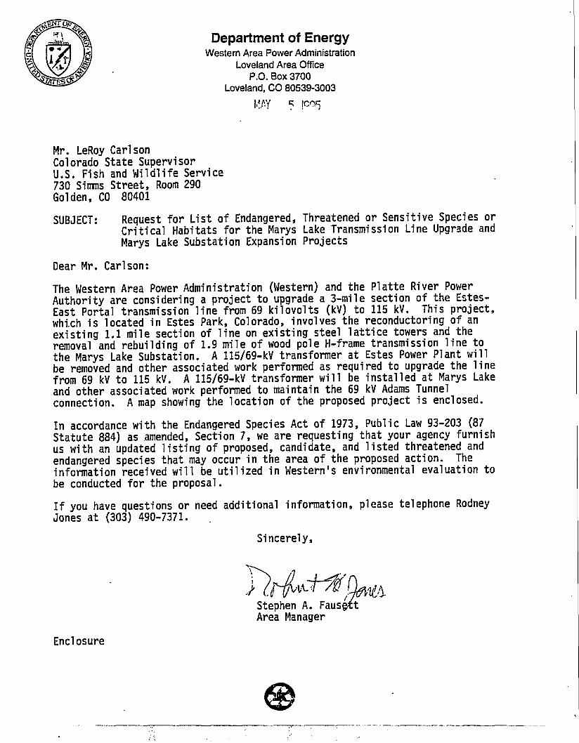
Department of EnergyWestern Area Power Administration
Loveland Area OfficeP.O. Box 3700
Loveland, C O 80539-3003
Mr. LeRoy CarlsonColorado State SupervisorU.S. Fish and Wildlife Service730 Simms Street, Room 290Golden, CO 80401
SUBJECT: Request for List of Endangered, Threatened or Sensitive Species orCritical Habitats for the Marys Lake Transmission Line Upgrade andMarys Lake Substation Expansion Projects
Dear Mr. Carlson:
The Western Area Power Administration (Western) and the Platte River PowerAuthority are considering a project to upgrade a 3-mile section of the Estes-East Portal transmission line from 69 kilovolts (kV) to 115 kV. This project,which is located in Estes Park, Colorado, involves the reconductoring of anexisting 1.1 mile section of line on existing steel lattice towers and theremoval and rebuilding of 1.9 mile of wood pole H-frame transmission line tothe Marys Lake Substation. A 115/69-kV transformer at Estes Power Plant willbe removed and other associated work performed as required to upgrade the linefrom 69 kV to 115 kV. A 115/69-kV transformer will be installed at Marys Lakeand other associated work performed to maintain the 69 kV Adams Tunnelconnection. A map showing the location of the proposed project is enclosed.
In accordance with the Endangered Species Act of 1973, Public Law 93-203 (87Statute 884) as amended, Section 7, we are requesting that your agency furnishus with an updated listing of proposed, candidate, and listed threatened andendangered species that may occur in the area of the proposed action. Theinformation received will be utilized in Western's environmental evaluation tobe conducted for the proposal.
If you have questions or need additional information, please telephone RodneyJones at (303) 490-7371.
Sincerely,
Stephen A. Faus^Area Manager
Enclosure
cc: (with enclosure)Mr. Don BogartWildlife BiologistColorado Division of Wildlife317 West Prospect StreetFort Collins, CO 80526
Mr. Thomas McCormickProject ManagerPlatte River Power Authority2000 E. Horsetooth RoadFort Collins, CO 80525
Mr. Larry KeithDivision Manager, Utility ServicesGreystone5990 Greenwood Plaza Blvd.Suite 250Englewood, CO 80111

I •)
.'."."" ••••'• Be.ivei
(Jonfei'eneepm
iJ i- \ 1 ' • '^-:
s a *-=*- /
Emerald9S37
erSta M t n
Campground
i" ) '•ites"Park 1
'.r^Estes Park"
H • C^l" a.1 ' J J tZ t it
Existing 115-kV [•Prospect-'8900 ^
Mounta in /^Existing (59-kV
•^^Transmission Line)?
PBvrerplan
**=^ Marys £*Powerplant \i\
FOREST' BOUNDARY
Marys Lake69/115kVTransmission LineUpgrade
and
Marys LakeSubstationExpansionProjects
ExistingTransmission LineConfiguration
Map from Estes Park, COUSGS 7.5'(1:24,000)1961 photo revised 1977andLongs Peak, COUSGS7.51 (1:24,000)1961 photo revised 1978

GREYSTONEEnvironmental Planners, Scientists, and Engineers
May 25, 1995
Susan Spakman; j&i'fsrrU tColorado Natural Heritage Program103 Natural Resources BuildingColorado State UniversityFort Collins, Colorado 80523
Dear Susan,
Greystone is in the process of developing an environmental document for a proposedtransmission line upgrade in Estes Park, Colorado. We would like to request data regardingthreatened, endangered, and sensitive plant and wildlife locations in the area. We are alsointerested in any critical or important habitats that may occur in the area. The followingprovides a project description.
The Western Area Power Administration (Western) and the Platte River Power Authorityare considering a project to upgrade a 3-mile section of the Estes-East Portal transmissionline from 69 kilovolts (kV) to 115 kV. This project* involves the reconductoring of an existing1.1 mile section of h'ne on existing steel lattice towers from the Estes Park Power Plant andthe removal and rebuilding of the remaining 1.9 miles of wood pole H-frame transmissionline to the Marys Lake Substation. A 115/69 transformer at Estes Power Plant will beremoved and other associated work preformed as required to upgrade the line from 69 kVto 115 kV. A 115/69-kV transformer will be installed at Marys Lake and other associatedwork preformed to maintain the 69 kV Adams Tunnel connection. A map showing thelocation of the proposed project is enclosed. The proposed project is contained within T5N,R73W Sections 25, 30, 31, and 36 and in T4N R73W Section 2.
If you have any questions or need additional information, please feel free to contact me at(303) 850-0930.
Sincerely,
Mike BonarWildlife Ecologist
5990 Greenwood Plaza Blvd. • Suite 250 • Englewood, CO 80111(303)850-0930 • Fax (303) 721-9298
TELEPHONECONTACT REPORT
D OUTGOING CALL D INCOMING CALL
project: ftowufS Laje Project No.: HI3-O-3Date:
CONTACT
Name: Toinf\
TRIe: » ' /•/
Organization: U5hl
Phone:
of-WI'd
Address/Location:
GREYSTONE EMPLOYEE
Subject of Discussion: T
Items Discussed: /fe» toill send
6A ^
fbr
P\CL/\
Action To Be Taken: Route To:
Page of.GRE\STONE-

Colo:University
Colorado Natural Heritage ProgramCollege of Natural Resources
T s i QQC 103 Natural ResourcesJune D, iy?J F o r t Collins. Colorado 80523-1401
(970)491-1309FAX: (970) 491-0279
Mr. Mike BonarGreystone5990 Greenwood Plaza Blvd., Suite 250Englewood, CO 80111
Dear Mr. Bonar:
The Colorado Natural Heritage Program (CNHP) is in receipt of your recent request forinformation regarding the proposed transmission line upgrade in Estes Park. In response, CNHPhas searched it's Biological and Conservation Datasystem for natural heritage resources(occurrences of significant natural communities and rare, threatened or endangered plants andanimals) documented from the Long's Peak and Estes Park quads. According to the informationcurrently in our files, there are occurrences of five rare plants, one rare invertebrate, and tworare vertebrates in the general vicinity of Estes Park, Colorado.
The species reported below are all documented by records for which precise locationalinformation is not available. Some of these records are quite dated as well. Therefore, wecannot say with anycertainty whether or not these species actually occur in the project area.In any case, their presence in the vicinity indicates the potential for them to be found if suitablehabitat exists. • - - • - • . . .
Cypripedium fasciculatum (Purple lady's slipper) was documented in 1935, and again in 1993.This species is known from forest openings and densely shaded stands, in duff under lodgepolepine or, less frequently, under Abies species (Coles 1994, Jennings 1995). Purple lady's slipperis ranked common throughout its range (G4), but is considered uncommon to rare in Colorado(S3). Cypripedium fasciculatum is listed as a Sensitive Species by the U.S. Forest Service, andis currently under review for federal listing.
Potentilla effusa var. rupincola (Rocky Mountain cinquefoil) was documented in 1897. Thisspecies has been found in steep, often granite, outcroppings on shelves or niches of cliffs, oftenon granite or gravel. This sub-species is extremely rare throughout its range (Tl) and very rarein Colorado-(S2). Potentilla effusa-vat-, rupincola is listed as a. Sensitive Species by the U.S.Forest Service, and is under review for federal listing.
Qonservancy*

Liatris ligustylis (Gay-feather) was documented in 1893. This plant has been found in wet haymeadows and wet open places (Weber 1987, Weber 1990). Although Gay-feather is thought tobe common throughout its range (G5?), it is ranked very rare to extremely rare in Colorado(S1S2).
Listera convallarioides (Broad-leafed twayblade) was documented in 1927. This plant is knownfrom moist places in leaf mold, in shaded areas or in wet places along small streams high in themountains (Cronquist, et. al. 1977). Broad-leafed twayblade is ranked common across its range(G5) but very rare in Colorado (S2).
Lilium philadelphicwn (Wood lily) was documented in 1897. This plant has been found in moistwoods, thickets, and wet meadows (Kettler 1993). Wood lily is ranked common throughout itsrange (GS) and uncommon to rare in Colorado (S3).
Speyeria idalia (Regal fritillary) has been documented near Estes Park, but no observation dateis available. This butterfly has been found in wet meadows and virgin prairies near marshes(Ferris and Brown 1981). Regal fritillary is ranked uncommon to rare throughout its range (G3)and extremely rare in Colorado (SI). Speyeria idalia is listed as a Sensitive Species by the U.S.Forest Service and is under review for federal listing.
One breeding occurrence of Aegolius funereus (Boreal owl) was documented in 1979. Thisspecies breeds in mature spruce-fir or sprace-fir/lodgepole pine forests interspersed withmeadows (Palmer 1984, Ryder et. al. 1987). Although Boreal owl is considered common acrossits range (G5), it is ranked very rare in Colorado (S2). Aegolius funereus is listed as a SensitiveSpecies by the U.S. Forest Service.
Sorex nanus (Dwarf shrew) has been documented in the vicinity, but no observation date isavailable. This mammal is known from forests, open woodlands, and rocky, shrubby foothillslopes, and also from alpine and sub-alpirie rockslides (Armstrong 1972). Dwarf shrew isranked common across its range (G5) and uncommon to rare in Colorado (S3). Sorex nanus islisted as a Sensitive Species by the U.S. Forest Service.
The Colorado Division of Wildlife has legal authority over wildlife in the state. CDOW wouldtherefore be responsible for the evaluation of and final decisions regarding any potential effectsa proposed project may have on wildlife. If you would like more specific information regardingthese or other animal species in the vicinity of the area of interest, please contact the ColoradoDivision of Wildlife.
While the information contained herein represents a thorough search of the CNHP's Biologicaland Conservation Datasystem, any absence of data does not necessarily mean that other naturalheritage resources do not occur on or adjacent to the project site, but rather that our files do notcurrently contain information to document their presence. Also, although every attempt is made

to provide the most current and precise infonnation possible, please be aware that some of oursources provide a higher level of accuracy than others, and some interpretation may be required.CNHP's datasystem is constantly updated and revised. Please contact CNHP for an update onthis natural heritage information if a significant amount of time passes before it is utilized.
Sincerely,
Katherine E. PagueSenior Information Manager
cc: CDOW

REFERENCES:
Armstrong, David M. 1972. Distribution of Mammals in Colorado. Monograph of theMuseum of Natural History, the University of Kansas. University of Kansas PrintingService, Lawrence. 415 pp.
Coles, Janet. 1994. Personal communication about Rare Plant Guide species.
Cronquist, A., A.H. Holmgren, N.H. Holmgren, J.L. Reveal, and P.K. Holmgren. 1977.Intermountain Flora, vol. 6. Columbia University Press, New York. 584 pp.
Ferris, Clifford and F.M. Brown. 1981. Butterflies of the Rocky Mountain States.University of Oklahoma Press, Norman. 442 pp.
Jennings, W.F. 1995. Personal communication about Rare Plant Guide species.
Kettler, S.M., N.D. Lederer, D. Bacher, and S. Spademan. 1993. Pike and San IsabelNational Forests and Comanche and Cimarron National Grasslands Plants of SpecialConcern. Colorado Natural Heritage Program, Ft. Collins, Colorado.
Palmer, D.A. 1984. Current status of the boreal owl in Colorado. C.F.O. Journal 18:662.
Ryder, R.A., et. al. 1987. Distribution and status of the boreal owl in Colorado.Pages 169-174 in Nero, R.W., et. al., eds. Biology and Conservation of Northern ForestOwls. USDA Forest Service, Gen. Tech. Rep. RM-142.
Weber, W.A. 1987. Colorado Flora: Western Slope. Colorado Associated University Press,Boulder, Colorado. 530 pp.
Weber, W.A. 1990. Colorado Flora: Eastern Slope. University of Colorado, Niwot,Colorado. 396 pp.

PAGE 01
STATE OF COLO ADOCOUMiDO DKPA 0 * FTJILIC HEALTH AMD EIVZB01MBBT
Dtdkmad to pnttedng *nd knpromt tfm h—Hh tndmvimnttMnt of tt»p9oph of Colorado
r r Ocaad Jnaetioa of f ie*
^SSHSdfr— — * ^ ? ^ ^ ^ - (303)2«t-7Jtly
M 530 4210E.11*Mane 003) MM000 OOTMr,C«(omloi022U71S
780
FATER QUALITY CONTROL DIVISION.'303)692-3500 FAX (303)782-0390
4ttahn.Ma.MrH
FAX TRANSMISSION SHEET
IMMEDIATE DELIVERY TO,
V
,7/ Cr/c K - ^ :IKCWON OF WATER QUALITY DIVISIOW (^XfCm«\ci
,TE SENT:. TIME SEHT:
IMBER OF PAGES TO FOLLOW
INSTRUCTIONS:.
, 6
o
Jt
« «ay Pl»«" call (303J CJ2-3500. Th»al you in in

Colorado Department of Health Ground Water Quality DataDate: 06/22/95 Report of Inorganic Analysis
/Stem- QUALDATPage 1
Well Permit:County: LARIMBRSampler:
Location: SW SB Sec 26 T9W R73WSample Date: 01/01/88Agency: ROCKY MTN CONSULTANTS
Analysis Date: /EPA Method:
Lab Name: CENREF LABSNotes on Analysis: IlfOROA IICS
Well Name: MW-4Perforated: 0.0' to 0.0
Aquifer: UNCONPINED?Yield: 0 Depth: 0
Notes on Sample: SAMPLE DATE UNCERTAIN-SOMETIME IN 19018
"-" =Not Detected at Level ,"0.0"=Not Analysed
Water Temperature, deg. CField pH, standard unitsField Conductivity, umhoa/cmChloride, total,Nitrate, total as N,Nitrite, total as N,pH,Sulfate, total,Copper, diss.,Iron, diss.,Manganese, diss.,Zinc, diss.,
rag/1mg/1mg/18.U.mg/1ug/1ug/1ug/1ug/1
0.00.00414
-065844
1180016487
00800160600000
n *00IJ 0 0

Colorado Department of Health Ground Water Quality DataDate: 06/22/95 Report of Inorganic Analysis
Well Permit:County: LARIMERSampler:
Location: SW SE Sec 26 TSample Date: 01/01/89Agency: ROCKY MTN CONSULTANTS
stem- QUALDATPage 1
R73W
Analysis Date: / /EPA Method:
Lab Name: CBNRB? LABSNotes on Analysis: INORGA IICS
Well Name: MW-4Perforated: 0.0' to 0.0 •
Aquifer: UNCONFINBD?Yield: 0 Depth: 0 .0
Notes on Sample: SAMPLE DATB UNCERTAIN-80MBTIMS IN 19
'-" =Not Detected at Level ,"0.0"=Not Analysed
Water Temperature, dog. CField pH, standard unitsField Conductivity, umhos/cmChloride, total,Nitrate, total as N,Nitrite, total as N,PH,Sulfate, total.Copper, diss.,Iron, diss.,Manganese, diss.,Zinc, diss.,'
mg/1mg/1mg/1B.U.mg/1ug/1ug/1ug/1ug/1
0.00.004087-0652205
40900520663
003501913000000000
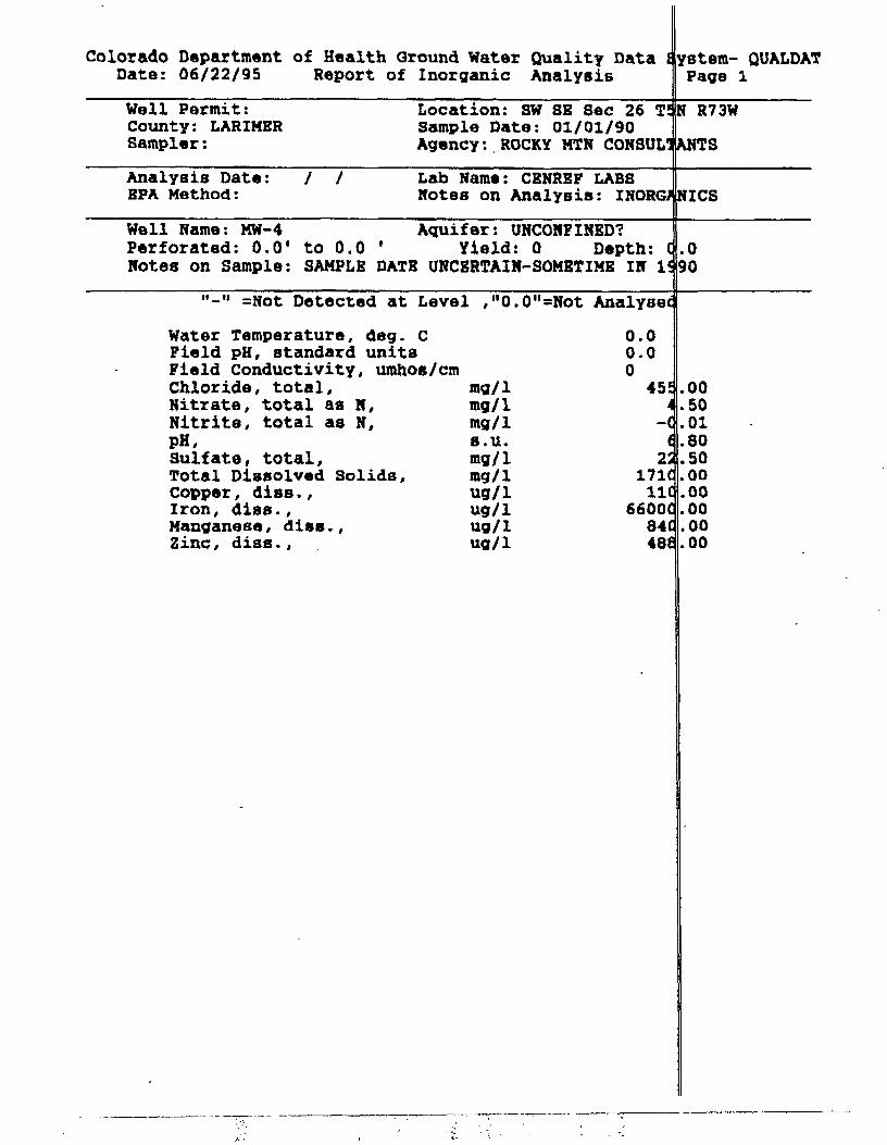
Colorado Department of Health Ground Water Quality DataDate: 06/22/95 Report of Inorganic Analysis
system- QUALDATPage 1
Well Permit:County: LARIMERSampler:
Location: SW SE Sec 26 T^N R73WSample Date: 01/01/90Agency: ROCKY MTN CONSULTANTS
Analysis Date: / /BPA Method:
Lab Name: CENREF LABSNotes on Analysis: INORGANICS
Well Name: MW-4Perforated: 0.01
Aquifer: UNCONFINED?to 0.0 ' Yield: 0 Depth:
Notes on Sample: SAMPLE DATE UNCERTAIN-SOMETIME IN 1<.090
"-" =Not Detected at Level ,"0.
Water Temperature, deg. CField pH, standard unitsField Conductivity, umhos/cmChloride, total.Nitrate, total as N,Nitrite, total as N,PH,Sulfate, total,Total Dissolved Solids,Copper, disB.,Iron, dias.,Manganese, diss.,Zinc, diss.,
mg/1mg/1mg/1s.u.mg/1mg/1ug/1ug/1ug/1ug/1
0"=Not Analysec
0.00.0045!
-(i2:
171(IK
6600C84(48<
.00
.50
.01
.80
.50
.00
.00
.00
.00
.00

06/23/1995 09:08 303-782-0398 CDH WQCD WQCC
Colorado Department of Health Ground Water Quality Data iData: 06/22/95 Report of Inorganic Analysis
PAGE 05
ystem- QUALDATPage 1
Well Permit:County: LARIMERSampler:
Location: SW SB Sec 26Sample Date: 01/01/92Agency: ROCKY MTN CONSUL
R73W
Analysis Date: /EPA Method:
Lab Name: CBNREF LABSNotes on Analysis: INOR
Well Name: MW-4 Aquifer: UNCONFINBD?Perforated: 0.0' to 0.0 ' Yield: 0 Depth:Notes on Sample: SAMPLE DATE UNCERTAIN-SOMETIME IN
"-" =Not Detected at Level ,"0.0M=Not Analysed
Water Temperature, dog. CField pH, standard unitsField Conductivity, umhos/cmChloride, total, mg/1Nitrate, total as N, mg/1Nitrite, total as N, mg/1pK, s.u.Sulfate, total, mg/1Total Dissolved Solids, mg/1Copper, diss., ug/1Iron, diBS., ug/1Manganese, dies., ug/1Zinc, digs., ug/1
0.00.0050C
63
00lq
284
i3id
32806C
.50
.01
.32
.00
.00
.00
.00
.0000
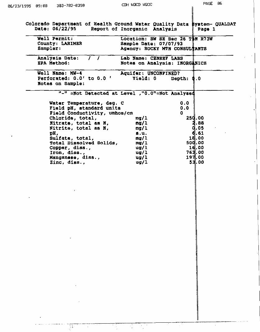
06/23/1995 89:08 303-782-0390 CDH WQCD WQCC PAGE 06
Date. Report of InorganicQuality DataAnalysis
iystem- QUALDATPage 1
Well Permit:County: LARIMERSampler:
Location: SW SB Sec 26 T$N R73WSample Date: 07/07/93Agency: ROCKY MTN CONSULfANTS
Analysis Date: /EPA Method:
Lab Name: CENREF LABSNotes on Analysis: INORC lies
Well Name: MW-4Perforated: 0.01 to 0.0 'Notes on Sample:
Aquifer: UNCONFINED?Yield: 0 Depth: <j .0
"-" =Not Detected at Level ,"0.0"=Not Analysed
Water Temperature, deg. cField pH, standard unitsField Conductivity, umhoB/cmChloride, total,Nitrate, total as N,Nitrite, total as N,PH,Sulfate, total.Total Dissolved Solids,Copper, diss.,Iron, diss.,Manganese, diss.,Zinc, diss.,
mg/1mg/1mg/1s.u.mg/1mg/1ug/1ug/1ug/1ug/1
0.00.002S(•
4
(
<
It5001676319753
.00
.88
.05
.61
.00
.00
.00
.00
.00
.00
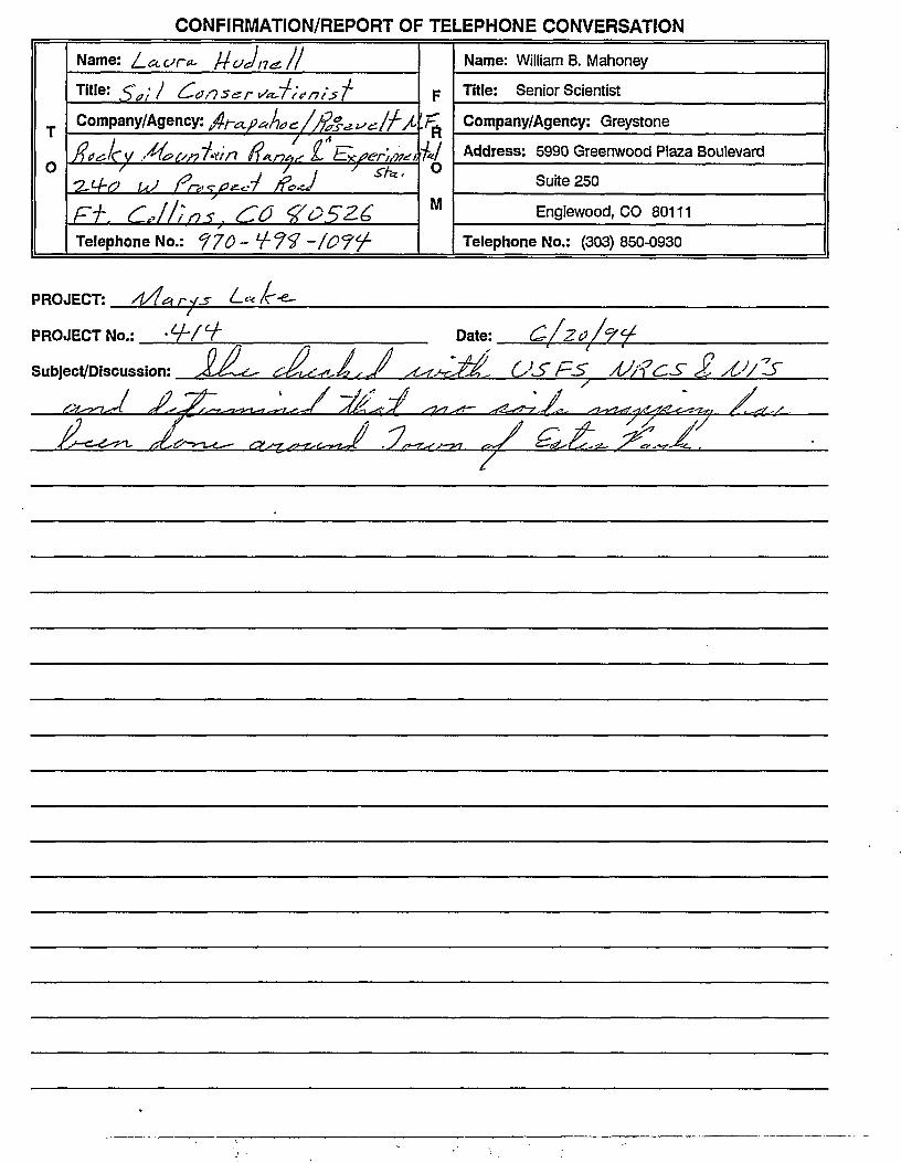
CONFIRMATION/REPORT OF TELEPHONE CONVERSATION
T
0
Name: La.vn*-Tit Ie: Sa/' 1 CarCompany/Agency: t
R lew M "/'
F+. <lJhmTelephone No.: f
A j
nr<x.p*ht
•. £0
IIt'rtni'ft
*e-//?Js*"*l7LA'/ -«
U ' «*'
F
•rt\/ , /
0
M
Name: William B. Mahoney
Title: Senior Scientist
Company/Agency: Greystone
Address: 5990 Greenwood Plaza Boulevard
Suite 250
Englewood, CO 80111
Telephone No.: (303) 850-0930
PROJECT:
PROJECT No.:
Subject/Discussion:
Date:
USFS £
« J

United StatesDepartment ofAgriculture
ForestService
Arapaho andRoosevelt NFPawnee NG
Estes-Poudre Ranger District1311 S. College Ave.Fort Collins, CO 80524(970) 498-2775
Reply To: 1950
Date: June 29, 1995
GREYSTONE ENVIRONMENAL PLANNERS5990 GREENWOOD PLAZA BLVD. SUITE 250ENGLEWOOD, CO 80111
Dear Mr. Keith:
Your letter of June / as teed for comments on the proposed upgrading of the MarysLake powerline near Estes Park. We will not be able to attend your agencyscoping meeting, but we forsee no adverse effects on National Forest lands inthe area. Thank you for including us in your mailing and for allowing us tocomment.
Sincerely,
MICHAEL D. LLOYDDISTRICT RANGER

United States Department of the Interior
FISH AND WILDLIFE SERVICEEcological Services
Colorado Field Office730 Simms Streer. Suite 290
Golden, Colorado 80401IN REPLY REFER TO:
ES/CO: REAMail Stop 65412
AUG 41995
C
OFFICIAL FILE COPYWESTERN
LcvelaiyJ «raa OK
AUG 111995lAUl !.*• *J
i>S=n TsixaCw£9g3u - 5 *
(fc«»To L-rtlb j .--v_
1
1
** "'I1
Mr. Stephen A. Fausett, Area ManagerDepartment of EnergyWestern Area Power AdministrationLoveland Area OfficeP.O. Box 3700Loveland, Colorado 80539-3003
Dear Mr. Fausett:
In response to your letter of May 5, 1995, the U.S. Fish and Wildlife Service (Service) isproviding the compendium of federally listed and candidate animal and plant species orcritical habitats that may occur in the vicinity of the Marys Lake Transmission Line Upgradeand Marys Lake Substation Expansion Projects near Estes Park, Larimer County, Colorado.This office reviewed the proposed work, and we offer the following comments.
The federally listed species that could occur throughout the project area are the endangeredperegrine falcon, Falco peregrinus, the threatened bald eagle, Haliaeetus leucocephalus, andthe threatened greenback cutthroat trout, Onchorhynchus clarM stomias.
The bald eagle and peregrine falcon also are species that have the potential to be present at ornear the proposed project area. Projects involving new construction and potential forelectrocution of these species or collisions with the lines are of chief concerns to the Service.For bald eagles, the Service is most concerned with construction activities occurring on ornear wetlands, lakes, and large trees. For peregrines, the Service is most concerned withconstruction or reconstruction activities in areas near falcon nests. The Colorado Division ofWildlife (CDOW) constantly updates its falcon nest data base with yearly surveys throughoutthe state. We suggest you contact Jerry Craig with CDOW in Fort Collins to find out if anyeagles, falcons, or other raptors would be disturbed by the project.
The greenback cutthroat trout was stocked in Larimer County in the North Fork of the BigThompson and Roaring Rivers and may have extended its range by now. Your agency shoulddetermine if any activity related to the project will impact this trout or its habitat (destructionor pollution of riverine habitat). Construction activities associated with the project, such asroad building, may cause erosion that will degrade the quality of the greenback's habitats.
The Service also is interested in the protection of species which are candidates for officiallisting as threatened or endangered species fFederal Register, Vol. 56, No. 225, November

Stephen A. Fausett, Area Manager 2
21, 1991; Vol 55, No. 35, February 21, 1990) under the Endangered Species Act of 1973(ESA), as amended (16 U.S.C. 1531 et §eg.). While these species presently have no legalprotection under the ESA, it is within the spirit of this act to consider project impacts topotentially sensitive candidate species. It is the intention of the Service to protect thesespecies before human-related activities adversely impact their habitat to a degree that theywould need to be listed and, therefore, protected under the ESA. Additionally, we wish tomake you aware of the presence of Federal candidates should any be proposed or listed priorto the time that all actions related to the project are completed. If any candidate species willbe unavoidably impacted, appropriate mitigation should be proposed and discussed with thisoffice prior to commencement of project activities.
Amphibian: Boreal toad, Bufo boreas boreas, Category 2Bird: Northern goshawk, Acdpiter gentilis, Category 2Mammal: Fringed-tailed myotis, Myotis thysanodes pahasapensis, Category 2Plants: Larimer aletes, Aletes humilis, Category 2
Pale blue-eyed grass, Sisyrinchium pallidum, Category 2Weber monkey-flower, Mimulus gemmparus, Category 2
Northern goshawks are known to nest within the boundaries of the Roosevelt National Forestand are present west and east of U.S. Highway 287 in northern Larimer County. Theactivities that could impact raptors in forested areas would be timber clearance, roadconstruction during nesting season, transmission or power lines along hunting or migratingroutes, etc. Any foreseeable impacts to raptors should be avoided; but if there might beunavoidable impacts, mitigation measures should be discussed with this office.
The Service recommends that all new/rebuilt power lines conform to the design criteria of thepublications by Ohlendorff. R.R.. A.D. Miller and R. N. Lehman. 1981. Suggestedpractices for raptor protection on power lines. The state of the art in 1981. and Thompson.L.S. 1978. Mitigation through engineering and habitat modification. Pages 51-92 in MX.Avery. ed. Impacts of transmission lines on birds in flight. U.S. Fish and Wildlife Service.Washington. D.C.. Raptors and other migratory species are protected in accordance withthe Eagle Protection Act (16 U.S.C. 66-6680) and other Federal laws. Electrocution fromcollision with power lines could be a potential "take" of migratory birds.
Electrocution and collision protection measures should not be restricted to areas of knownbird concentrations or within known migratory routes. The reason being that due to thecharacteristic behavior of raptors and waterfowl, the areas utilized by these birds areconstantly changing; therefore, they can be expected to cross the project's service area even •when they have not yet been observed in the area.
Boreal toads are known to exist along the Continental Divide. Road construction andmaintenance activities and excavations are of particular concern to the Service as they mightimpact it if they occur in wetlands and riparian corridors above 8,000 feet in elevation.
Stephen A. Fausett, Area Manager 3
According to Rare Plants of Colorado, Weber monkey-flower "grows in the moist soil offorest seeps or springs protected by granite overhangs, at elevations of 8,500-10,500 feet. . .it often grows in association with other monkey-flowers. The pale blue-eyed grass is not agrass at all but a member of the iris family. It inhabits poorly drained mid-elevationmeadows, 7,000 to 10,000 feet, dominated by true grasses and other grass-like plants."Larimer aletes "grows in cracks and crevices on rocky granite outcrops where it is shaded byponderosa pine and on cool, north-facing, near vertical cliffs. It has thick leathery leaves thathelp maintain moisture. In the few canyons where it grows, the plant forms conspicuousclumps and mats on rock walls, and when in bloom present a showy yellow display." Thesespecies may be present in the project area.
The Service regards wetlands and riparian habitats as important resources due to their highvalue for fish and wildlife, erosion control, ground water recharge and water supply, floodcontrol, and others. Therefore, we recommend the proposed project areas be inventoried forwetlands and riparian habitats. Wetlands should be defined according to "Classification ofWetlands and Deepwater Habitats of the United States" (Cowardin, et al., 1977). Werecommend that any adverse impacts to wetlands within the project areas be avoided (Section404 of the Clean Water Act regulates the fill of wetlands on public and private land). Ifunavoidable impacts to wetlands or riparian habitats are identified during the line constructionitself, the Service should be contacted prior to any operations (including but not limited tofilling, trampling, timber harvesting, road construction and use, etc.) that would affectwetlands. The Service has National Wetland Inventory (NWT) maps of the project areaavailable. Maps can be obtained by calling 1-800-USA-MAPS.
For more detailed information on animal and plant distribution, habitat needs, and othercharacteristics contact:
Animals: Don Bogart, CDOW Northeastern Regional Office at (970) 484-2836.
Plants: Colorado Natural Areas Program of the Division of Parks and Outdoor Recreationat (970) 491-1309, and/or the Colorado Native Plant Society of the RockyMountain Nature Association.
The CDOW should be contacted regarding possible impacts to native fauna, especially Statelisted endangered or threatened species. If you wish to inspect the NWI maps of the area ofthe project or if the Service can be of further assistance, please contact Bernardo Garza ofthis office at (303) 231-5280.
Sincere!
LeRoy W. CarlsonColorado Field Supervisor

Stephen A. Fausett, Area Manager
cc: CDOW, Fort Collins, CO (Attn. Don Bogart)Reading fileProject file
Reference: JBG*ES\MARYSLAK.WPF
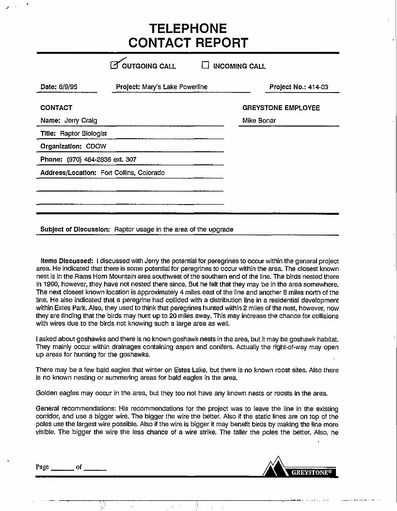
TELEPHONECONTACT REPORT
OUTGOING CALL • INCOMING CALL
Date: 8/9/95 Project: Mary's Lake Powerline Project No.: 414-03
CONTACT GREYSTONE EMPLOYEE
Name: Jerry Craig Mike Bonar
Title: Raptor Biologist
Organization: CDOW
Phone: (970) 484-2836 ext. 307
Address/Location: Fort Collins, Colorado
Subject of Discussion: Raptor usage in the area of the upgrade
Items Discussed: I discussed with Jerry the potential for peregrines to occur within the general projectarea. He indicated that there is some potential for peregrines to occur within the area. The closest knownnest is in the Rams Horn Mountain area southwest of the southern end of the line. The birds nested therein 1990, however, they have not nested there since. But he felt that they may be in the area somewhere.The next closest known location is approximately 4 miles east of the line and another 8 miles north of theline. He also indicated that a peregrine had collided with a distribution line in a residential developmentwithin Estes Park. Also, they used to think that peregrines hunted within 2 miles of the nest, however, nowthey are finding that the birds may hunt up to 20 miles away. This may increase the chance for collisionswith wires due to the birds not knowing such a large area as well.
I asked about goshawks and there is no known goshawk nests in the area, but it may be goshawk habitat.They mainly occur within drainages containing aspen and conifers. Actually the right-of-way may openup areas for hunting for the goshawks.
There may be a few bald eagles that winter on Estes Lake, but there is no known roost sites. Also thereis no known nesting or summering areas for bald eagles in the area.
Golden eagles may occur in the area, but they too not have any known nests or roosts in the area.
General recommendations: His recommendations for the project was to leave the line in the existingcorridor, and use a bigger wire. The bigger the wire the better. Also if the static lines are on top of thepoles use the largest wire possible. Also if the wire is bigger it may benefit birds by making the line morevisible. The bigger the wire the less chance of a wire strike. The taller the poles the better. Also, he
Page of.

Telephone Contact Report (Cont.)
strongly recommended that the line be upgraded in place. A new right-of-way increases the chance ofstrikes and increases the potential for more adverse impacts to the birds. Right now the birds haveadapted to the existing line decreasing the potential for any adverse impacts.
Action To Be Taken: Route To:
Larry
Page. of
MEMO TO FILE
Job No.:Date:From:
414, Mary's Lake8/15/95Cathy Begej
I talked with an individual from the Denver District FEMA office who advised me on the classifications forfloodplains. The 'A' designations refer to the 100-year storm floodplain. The specific numbers (i.e. 'A2' vs 'A7'refer to different flood hazard risks associated with insurance premiums. The 'X' category came out in themid-80s to replace the 'B', 'C, and 'D' categories. The shaded 'X' replaced the 'B' category of the 500-yearfloodplain, the unshaded 'X' replaced the 'C (minimal hazard) and 'D' (undetermined but possible floodzones). There may be both designations within a county's maps, depending on how recently panels wererevised based on hydrologic studies.
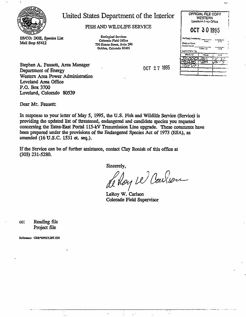
United States Department of the InteriorFISH AND WILDLIFE SERVICE
ES/CO: DOE, Species list
Mail Stop 65412
Ecological ServicesColorado Field Office
730 Simou Street, Suite 290Golden, Colorado 80401
OCT 2 7 1995
OFFICIAL FILE COPYWESTERN
OCT 3 01995
%.*» 7 a - w t
X££t«2_Stephen A. Fausett, Area ManagerDepartment of EnergyWestern Area Power AdministrationLoveland Area OfficeP.O. Box 3700Loveland, Colorado 80539
Dear Mr. Fausett:
In response to your letter of May 5, 1995, the U.S. Fish and Wildlife Service (Service) isproviding the updated list of threatened, endangered and candidate species you requetedconcerning the Estes-East Portal 115-kV Transmission line upgrade. These comments havebeen prepared under the provisions of the Endangered Species Act of 1973 (ESA), asamended (16 U.S.C. 1531 et. seq.).
If the Service can be of further assistance, contact Clay Ronish of this office at(303) 231-5280.
Sincerely,
LeRoy W. CarlsonColorado Field Supervisor
cc: Reading fileProject file
Reference: CRR«SPECLIST.O26

rnKc wo COUNTIES ->
U. S. Fish and Wildlife ServiceEcological Services
Colorado Field Office
(Effective September 26, 1995)
FEDERALLY LISTED AND CANDIDATE SPECIES & THEIR STATUS IN COLORADOi
American peregrine falcon, Falco peregrinus, Listed Endangered
Bald eagle, Haliaeetus leucocephalus, Listed Threatened
Whooping crane, Grus americana, Listed Endangered
Least tern (interior population), Sterna antillarum, Listed Endangered
Piping plover, Charadrius melodus, Listed Threatened
Eskimo curlew, Numenius borealis, Listed Endangered
Mountain plover, Charadrius montanus, Candidate for listing
Southwestern willow flycatcher, Empidonax trailli extimus, Listed Endang.
Mexican spotted owl, Strix occidentalis lucida, Listed Threatened
Boreal toad, Bufo boreas boreas, Candidate for listing
Black-footed ferret, "Mustela nigripes, Listed Endangered
Preble's meadow jumping mouse, Zapus hudsonius preblei, Candidate
Swift fox, Vulpes velox, Candidate for listing
Razorback sucker, Xyrauchen texanus, Listed Endangered
Bonytail chub, Gila elegans, (presumed-historical) Listed Endangered
Greenback cutthroat trout, Oncorhynchus clarki stomias, List. Threat.
Arkansas darter, Etheostoma cragini, Candidate for listing
Colorado squawfish, Ptychocheilus lucius, Listed Endangered
ADAMS
•
•
/
/
/
/
/
/
ALAMOSA
/
/
/
/
ARAPAH0E
/
/
/
/
/
/
ARCHULETA
•
•
©
BACA
/
/
/
/
/
/
/
/
S
BENT
/
/
•
•
/
/
B0ULDER
•
•
/
/
•
/
/
/
/
/
/
CHAFFEE
•
/
/
/
CHEYENNE
•
/
/
/
CLEAR
CREEK
/
/
/
/
C0NEJ0S
/
/
/
/
/
/
C0
sTILLA
V
/
/
/
cROWLEY
/
•
/
/
/
CU
sTER
•
/
/
•
•
DELTA
•
/
/
/
ID
DENVER
/
/
/
/
•
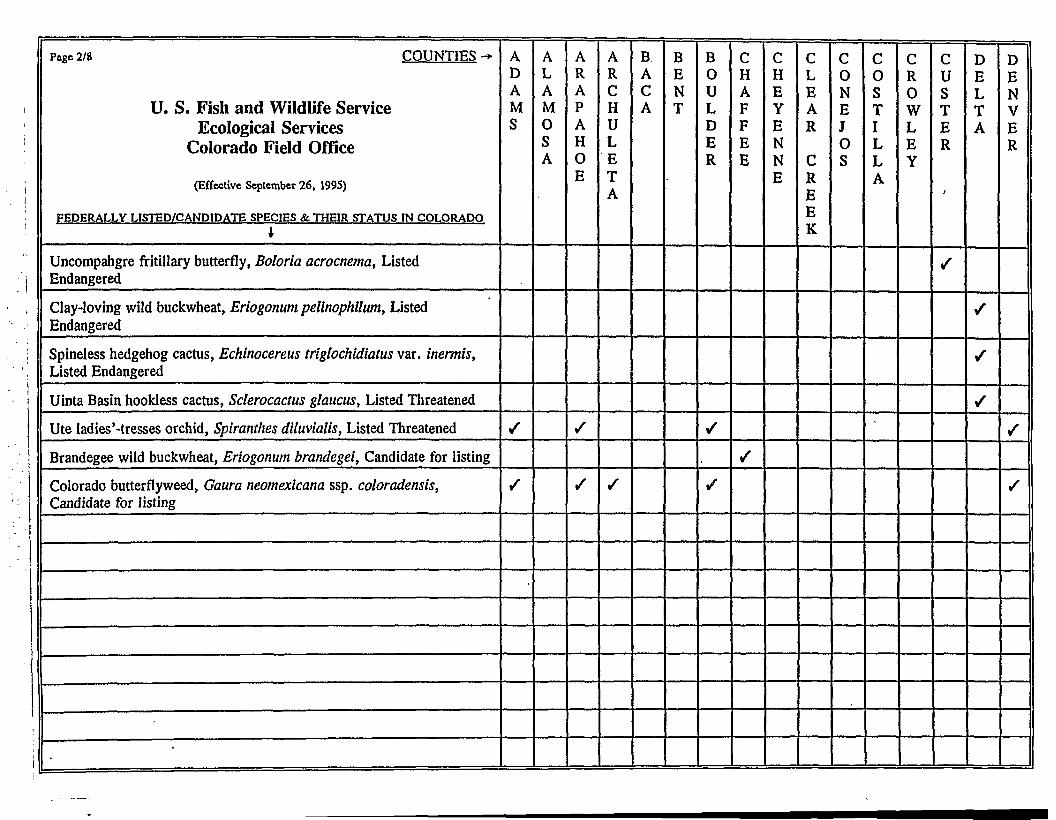
Pace 2/8 COUNTIES -*
U. S. Fish and Wildlife ServiceEcological Services
Colorado Field Office
(Effective September 26, 1995)
FEDERALLY LISTED/CANDIDATE SPECIES & THEIR STATUS IN COLORADOi
Uncompahgre fritillary butterfly, Boloria acrocnema, ListedEndangered
Clay-loving wild buckwheat, Eriogonum pelinophilum, ListedEndangered
Spineless hedgehog cactus, Echinocereus triglochidiatus var. inermis,Listed Endangered
Uinta Basin hookless cactus, Sclerocactus glaucus, Listed Threatened
Ute ladies'-tresses orchid, Spiranthes diluvialis, Listed Threatened
Brandegee wild buckwheat, Eriogonum brandegei, Candidate for listing
Colorado butterflyweed, Gaura neomexicana ssp. coloradensis,Candidate for listing
-
ADAMS
/
ALAM0SA
ARAPAH0E
/
/
ARCHULETA
/
BACA
BENT
B0ULDER
/
•
CHAFFEE
/
CHEYENNE
CLEAR
CREEK
C0NEJ0S
C0STILLA
CR0WLEY
CUSTER
I
/
DELTA
/
•
DENVER
/
/

rase J/» COUNTIES -*
U. S. Fish and Wildlife Service• Ecological ServicesColorado Field Office
(Effective September 26, 1995)
FEDERALLY LISTED SPECIES & THEIR STATUS IN COLORADOi
American peregrine falcon, Falco peregrinus, Listed Endangered
Bald eagle, Haliaeetus leucocephalus, Listed Threatened
Whooping crane, Grus americana, Listed Endangered
Least tern (interior population), Sterna amillarum, Listed Endangered
Piping plover, Charadrius melodus, Listed Threatened
Eskimo curlew, Numenius borealis, Listed Endangered
Mountain plover, Charadrius montanus, Candidate for listing
Southwestern willow flycatcher, Empidonax trailli extimus, ListedEndangered
Mexican spotted owl, Strix occidentalis lucida, Listed Threatened
Black-footed ferret, Mustela nigripes, Listed Endangered
Swift fox, Vulpes velox, Candidate for listing
Prebie's meadow jumping mouse, Zapus hudsonius preblei, Candidate
Greenback cutthroat trout, Oncorhynchus clarki stomias, ListedThreatened
Razorback sucker, Xyrauchen texanus, Listed Endangered
Bonytail chub, Gila elegans, (presumed-historical) Listed Endangered
Arkansas darter, Etheostoma cragini, Candidate for listing
Colorado squawfish, Ptychocheilus lucius, Listed Endangered
Pawnee montane skipper, Hesperia leonardus montana, List. Threat.
D0L0RES
/
/
/
/
DOUG
.LAS
/
/
/
/
/
/
/
/
/
EAGLE
•
ELBERT
/
•
/
/
/
/
/
EL
PASO
•
•
•
•
•
/
/
FREM0NT
•
•
/
/
GARFIELD
•
•
/
o
/
©
GILPIN
GRAND
/
/
/
/
GUNNIS0N
•
•
HINSDALE
/
•
•
HUERFAN0
•
•
•
•
/
/
/
JACKS0N
•
•
•
JEFFERS0N
•
•
•
/
/
/
KIOWA
•
•
•
•
•
•
/
/
KIT
CARS0N
•
•
•
•
/
/
/

Pace 4/8 COUNTIES-*
U. S. Fish and Wildlife ServiceEcological Services
Colorado Field Office
(Effective September 26, 1995)
FEDERALLY LISTED SPECIES & THEIR STATUS IN COLORADOi
Uncompahgre fritillary butterfly, Boloria acrocnema, ListedEndangered
Boreal toad, Bufo boreas boreas, Candidate for listing
Brandegee wild buckwheat, Eriogonum brandegei, Candidate for listing
Colorado butterflyweed, Gaura neomexicana ssp. coloradensis,Candidate for listing
Uinta Basin hookless cactus, Sclerocactus glaucus, Listed Threatened
Osterhout milkvetch, Astragalus osterhoutii, Listed Endangered
Debeque phacelia, Phacelia submutica, Candidate for listing
Ute ladies'-tresses orchid, Spiranthes diluvialis, Listed Threatened
North Park phacelia, Phacelia formosula, Listed Endangered
Penland beardtongue, Penstemon penlandii, Listed Endangered
Parachute beardtongue, Penstemon debilis, Candidate for listing
D0L0RES
D0UGLAS
/
EAGLE
/
ELBERT
EL
PAS0
/
/
/
FREM0NT
•
GARFIELD
/
•
/
GILPIN
/
GRAND
/
/
/
GUNNIS0N
HINSDALE
•
HUERFAN0
JACKS0N
/
•
JEFFERS0N
/
/
KI0WA
KIT
CARS0N
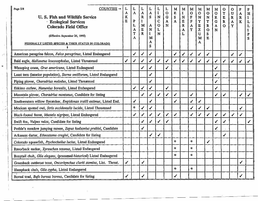
Paee5/8 COUNTIES->
U. S. Fish and Wildlife ServiceEcological Services
Colorado Field Office
(Effective September 26, 1995)
FEDERALLY LISTED SPECIES & THEIR STATUS IN COLORADO*
American peregrine falcon, Falco peregrinus, Listed Endangered
Bald eagle, Haliaeetus leucocephalus, Listed Threatened
Whooping crane, Grus americana, Listed Endangered
Least tern (interior population), Sterna antillarum, Listed Endangered
Piping plover, Charadrius melodus, Listed Threatened
Eskimo curlew, Numenius borealis, Listed Endangered
Mountain plover, Charadrius montanus, Candidate for listing
Southwestern willow flycatcher, Empidonax trailli extimus, Listed End.
Mexican spotted owl, Strix occidentalis lucida, Listed Threatened
Black-footed ferret, Mustela nigripes, Listed Endangered
Swift fox, Vulpes velox, Candidate for listing
Preble's meadow jumping mouse, Zapus hudsonius preblei, Candidate
Arkansas darter, Etheostotna cragini, Candidate for listing
Colorado squawfish, Ptychocheilus lucius, Listed Endangered
Razorback sucker, Xyrauchen texanus, Listed Endangered
Bonytail chub, Gila elegans, (presumed-historical) Listed Endangered
Greenback cutthroat trout, Oncorhynchus clarki stomias, List. Threat.
Humpback chub, Gila cypha, Listed Endangered
Boreal toad, Bufo boreas boreas, Candidate for listing
LAKE
/
/
/
LA
PLATA
/
/
/
/
<D
/
LARIMER
/
/
/
/
/
/
/
/
/
/
/
LAS
ANIMAS
/
/
/
/
/
/
•
/
/
/
/
/
LINCOLN
/
/
•
L0GAN
/
/
/
•
/
/
MESA
/
/
•
•
<D
ID
ID
<D
/
MINERAL
/
/
M0FFAT
/
/
/
/
/
/
<D
ID
<D
©
MONTEZUMA
•
•
/
/
/
M0NTROSE
•
•
•
M0RGAN
/
•
•
•
•
/
/
/
OTER0
/
•
/
/
/
0
uRAY
/
/
/
PARK
•
•
•
/
/
PHILLIPS
•
•

ji
>
Pace 6/8 COUNTIES -*
U. S. Fish and Wildlife ServiceEcological Services
Colorado Field Office
(Effective September 26, 1995)
FEDERALLY LISTED SPECIES & THEIR STATUS IN COLORADOI
Uncompahgre fritillary butterfly, Boloria acrocnema, ListedEndangered
Pawnee montane skipper, Hesperia leonardus montana, ListedThreatened
Sleeping Ute milkvetch, Astragalus tortipes, Candidate for listing
Clay-loving wild buckwheat, Eriogonum pelinophilum, ListedEndangered
Mesa Verde cactus, Sclerocactus mesae-verdae, Listed Threatened
Mancos milkvetch, Astragalus humillimus, Listed Endangered
Uinta Basin hookless cactus, Sclerocactus glaucus, Listed Threatened
Debeque phacelia, Phacelia submutica, Candidate for listing
Penland eutrema, Eutrema penlandii, Listed Threatened
Knowlton's cactus, Pediocactus knowltonii, Listed Endangered
Piceance twinpod, Physaria obcordata, Listed Threatened
Ute ladies'-tresses orchid, Spiranthes diluvialis, Listed Threatened
Colorado butterfly weed, Gaura neomexicana ssp. coloradensis,Candidate for listing
Spineless hedgehog cactus, Echinocereus triglochidiatus var. inermis,Listed Endangered
-
LAKE
/
LA
PLATA
/
LARIMER
/
/
LAS
ANIMAS
-
LINC0LN
L0GAN
MESA
/
/
MINERAL
M0FFAT
M0NTEZUMA
/
/
/
M0NTR0SE
•
•
M0RGAN
•
OTER0
0URAY
/
/
PARK
/
/
PHILLIPS

Paw 7/8 COUNTIES-U. S. Fish and Wildlife Service
Ecological ServicesColorado Field Office
(Effective September 26, 1995)
FEDERALLY LISTED SPECIES & THEIR STATUS IN COLORADOi
American peregrine falcon, Falco peregrinus, Listed Endangered
Bald eagle, Haliaeetus leucocephalus, Listed Threatened
Whooping crane, Grus americana, Listed Endangered
Least tern (interior population), Sterna antillarum, Listed Endangered
Piping plover, Charadrius melodus, Listed Threatened
Eskimo curlew, Numenius borealis, Listed Endangered
Mountain plover, Charadrius montanus, Candidate for listing
Southwestern willow flycatcher, Empidonax trallli extimus, Listed Endang.
Mexican spotted owl, Strix occidentalis luclda, Listed Threatened
Black-footed ferret, Mustela nigripes, Listed Endangered
Preble's meadow jumping mouse, Zapus hudsonius preblei, Candidate
Swift fox, Vulpes velox, Candidate for listing
Pawnee montane skipper, Hesperia leonardus montana, Listed Threatened
Uncompahgre fritillary butterfly, Boloria acrocnema, Listed Endangered
Colorado squawfish, Ptychocheilus lucius, Listed Endangered
Arkansas darter, Etheostoma cragini, Candidate for listing
Greenback cutthroat trout, Oncorhynchus clarki stomias, Listed Threatened
Boreal toad, Bufo boreas boreas, Candidate for listing
Penland eutrema, Eutrema penlandii, Listed Threatened
PITKIN
•
/
/
PR0WERS
/
•
/
/
/
/
/
/
PUEBL0
s
•
/
/
/
/
/
/
RI0
BLANC0
•
•
©
/
RI0
GRANDE
/
/
•
•
/
/
R0UTT
•
/
/
SAGUACHE
•
•
/
/
/
/
SAN
JUAN
/r/
/
/
/-
sAN
MIGUEL
•
•
/
/
SEDGWICK
/
/
•
/
•
SuMMIT
/
/
/
/
TELLER
•
/
/
/
WASHINGT0N
•
/
/
/
/
/
/
/
WELD
•
/
/
/
/
/
/
/
/
/
YUMA
•
•
/
/
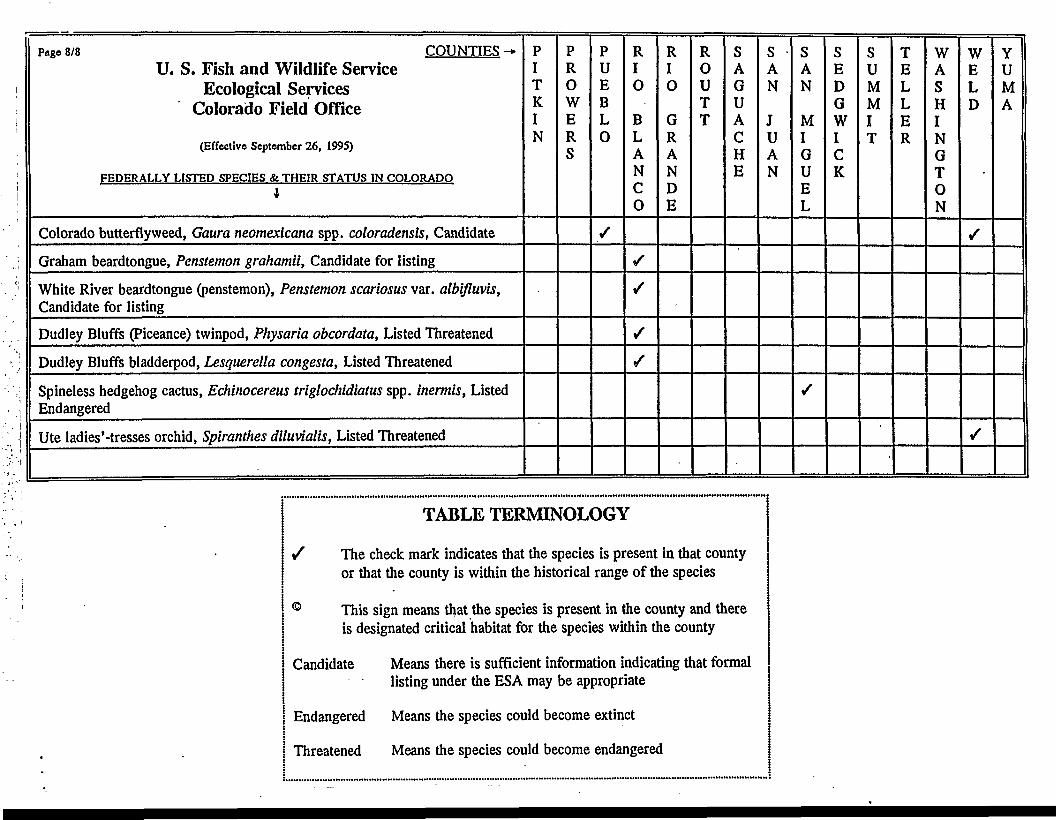
tt
j
Paee 8/8 COUNTIES -*U. S. Fish and Wildlife Service
Ecological ServicesColorado Field Office
(Effective September 26, 1995)
FEDERALLY LISTED SPECIES & THEIR STATUS IN COLORADOI
Colorado butterfly weed, Gaum neomexlcana spp. coloradensls, Candidate
Graham beardtongue, Penstemon grahamii, Candidate for listing
White River beardtongue (penstemon), Penstemon scariosus var. albifluvis,Candidate for listing
Dudley Bluffs (Piceance) twinpod, Physaria obcordata, Listed Threatened
Dudley Bluffs bladderpod, Lesquerella congesta, Listed Threatened
Spineless hedgehog cactus, Echinocereus triglochidiatus spp. inermis, ListedEndangered
Ute ladies'-tresses orchid, Spiranthes diluvialis, Listed Threatened
PITKIN
PR0WERS
PUEBL0
/
RI0
BLANC0
/
/
/
/
RI0
GRANDE
R0UTT
SAGUACHE
SAN
JUAN
SAN
MIGUEL
/
SEDGWICK
SUMMIT
TELLER
WASHINGT0N
WELD
/
/
YUMA
TABLE TERMINOLOGY
/ The check mark indicates that the species is present in that countyor that the county is within the historical range of the species
© This sign means that the species is present in the county and thereis designated critical habitat for the species within the county
Candidate Means there is sufficient information indicating that formallisting under the ESA may be appropriate
Endangered Means the species could become extinct
Threatened Means the species could become endangered

Department of EnergyWestern Area Power Administration
Loveland Area OfficeP.O. Box 3700
- Loveland, CO 80539-3003
OCT 3 I 1995
V3\ nrrn
NOV G
OFFICIAL 'r\'Jz CC-WESTcSH
• Low..'- " - « -
NOV 81955
AcicnTiXjn
IWOCCP^TO:
Ii
£;
•;•' / /
y•
Mr. James E. HartmannState Historical Preservation OfficerColorado Historical Society1300 BroadwayDenver, CO 80203-2137
Dear Mr. Hartmann:
The Western Area Power Administration (Western) has considered the effects on culturalresources of upgrading the Estes Park-Marys Lake Transmission Line in northeastern Colorado.Per 36 CFR 800.4. Western has determined that there- are no historic properties. The submissionof this documentation.fulfills Western's responsibilities under Section 106 of the NationalHistoric Preservation Act.
I. Description of the Undertaking -Western and the Platte River Power Authority are planninga project to upgrade a 3-mile section or the Estes^East Portal transmission line from 69 kilovolts(kV) to 115 kV. This project, which is located in Estes Park, Colorado, involves the removal andrebuilding of 1.9 mile of wood pole H-frame transmission line between Estes Switchyard and theMarys Lake Substation. A 115/69-kV transformer at Estes Power Plant will be removed andother associated work performed as required to upgrade the line from 69 kV to 115 kV. A115/69-kV transformer will be installed at Marys Lake and other associated work performed tomaintain the 69 kV Adams Tunnel connection. The project is located in Larimer County (mapenclosed).
It is anticipated that existing access and access roads will be used for construction of the project.Should additional new access be required for the project, Western will consult with your officeon the need for cultural resource surveys.
II. Methodology and Reporting - The entire transmission line right-of-way was surveyed onAugust 15,1995, by Metcalf Archaeological Consultants, Inc. The right-of-way was surveyedusing zig-zag transects and covered. 38 acres. A-Limited-Results Cultural Resource Survey Formwas completed for this survey (enclosed).
III. Resources Located, Identified, and Evaluated (Significance Criteria Considered) - Oneisolated find was recorded during the survey (see enclosure). The isolated find, 5LR1901, is twoprospect pits located 120m apart. No artifacts were te.and in association with the pits. No othercultural resources were recorded.

IV. Effects Determinations and Compliance Decisions - Effects determinations are theresponsibility of the lead agency. Western has considered the nature of the undertaking and thepresence of historic properties that may possess the qualities of integrity and meet at least one ofthe other criteria necessary to be considered for inclusion in the National Register of HistoricPlaces. Western has determined that there are no historic properties. Western considers that thestipulations of Section 106 of the National Historic Preservation Act, as amended, and theimplementing regulations, 36 CFR 800, have been satisfied.
If you have any questions regarding this determination, please telephone Rodney Jones at(970) 490-7371 or Mary Barger at (303) 275-1714.
Sincerely,
Stephen A. FausejArea Manager
Enclosure
I concur > ^ - ~ - / v . C^L <%>* Date^lState Historic Preservation OfficerC/

United States Department of the Interior
FISH AND WILDLIFE SERVICE
ES/CO: DOE, EAMail Stop 65412
Ecological ServicesColorado Field Office
730 Simms Street, Suite 290Golden, Colorado 80401
2 8 1996
OFFICIAL FILE COPYWESTERN
MAY 2 9 1996
Rtjiy _rO«?cf
_J.n<+?Y f7_rfJ
bi'.t
j
r1
Stephen A. Fausett, Area ManagerDepartment of EnergyWestern Area Power AdministrationLoveland Area OfficeP.O. Box 3700Loveland, Colorado 80539
Dear Mr. Fausett:
This responds to your February 5, 1996 letter regarding comments on Appendix D of thedraft environmental assessment for the proposed Mary's Lake 69/115-kV Transmission LineProject.
The U.S. Fish and Wildlife Service, concurs with your finding of no affect for listed specieson this project.
We recommend that you contact the Colorado Division of Wildlife to address any concerns itmay have for the State of Colorado.
If the Service can be of further assistance, contact Clay Ronish of this office at (303) 231-5280.
Sincerelv
1. CarlsonColorado Field Supervisor
cc: Reading fileProject file
Reference:
<_RR«SPECUST.050

APPENDIX DBIOLOGICAL ASSESSMENT

APPENDIX DBIOLOGICAL ASSESSMENT
Section 7(c) of the Endangered Species Act, as amended, requires federal agencies to determine if theiraction "may affect" any federally listed threatened or endangered species. This Biological Assessmentwas prepared by Western Area Power Administration (Western) and Platte River Power Authority (PlatteRiver) to assess potential impacts to threatened and endangered species, and to meet their obligationsunder the Endangered Species Act.
The U.S. Fish and Wildlife Service (USFWS), in response to a request from Western, indicated that threethreatened or endangered species and six candidate species may occur within the project area (Carlson1995). Information provided by USFWS, the Colorado Division of Wildlife (CDOW), and the ColoradoNatural Heritage Program (CNHP) indicates an additional seventeen species potentially occur within theproject area. Table D-1 identifies the 26 species and summarizes the potential for impacts to eachspecies.
D.1 Project Description
Western and the Platte River propose to upgrade portions of the existing electric transmission andsubstation system that serves the Town of Estes Park, Colorado. The existing transmission lines betweenthe Estes Power Plant Switchyard and Marys Lake Substation include a 115-kV transmission line and a69-kV transmission line. Approximately one mile is a double circuit 115/69-kV line on steel latticestructures, and approximately two miles consists of separate single circuit 115-kV and a 69-kV line,constructed on wood H-Frame structures (Figure D-1). Both lines were constructed in 1951 by the U.S.Bureau of Reclamation. The existing transmission lines are on rights-of-way (ROW) owned by Westernthat vary in width from 75 to 120 feet. There are 48 landowners adjacent to the existing ROW. All of thehouses were built adjacent to the existing ROW after the transmission lines were constructed.
Upgrading the existing 69-kV transmission line between the Marys Lake Substation and the Estes PowerPlant Switchyard to 115-kV and expanding the Marys Lake Substation was identified as the most effectiveway in which to improve electric service to Estes Park. The proposed project involves:
• Removing a 115-kV to 69-kV transformer at the Estes Power Plant Switchyard and performing otherassociated work as required to allow upgrading the three-mile transmission line from 69-kV to 115-kV;
• Begin operating at 115-kV, the one-mile section of the existing 69-kV portion of the double-circuittransmission line between the Estes Power Plant Switchyard and the East Portal of the AdamsTunnel. This existing transmission line section has been in place since 1951 on steel-lattice towers,and is already insulated for operation at 115-kV;
• Removing two miles of existing 69-kV transmission line on wood H-frame structures between theEstes Power Plant Switchyard (beginning after the one-mile section of double circuit steel-latticetowers) and the Marys Lake Substation, and rebuilding this section to operate at 115-kV utilizing woodH-frame construction and connecting this line at Marys Lake Substation: and
• Installing a 115 to 69-kV transformer at the Marys Lake Substation and performing other associatedwork to maintain a 69-kV connection between the Marys Lake Substation and the East Portal of theAdams Tunnel.
A detailed description of the construction and operation activities associated with these actions ispresented in Section 2.7 of the Environmental Assessment.
D.2 LISTED THREATENED AND ENDANGERED SPECIES
Of the eight (8) listed threatened and endangered species known to occur or potentially occur in LarimerCounty, the four (4) species that may occur in the project area are discussed below.
D-1
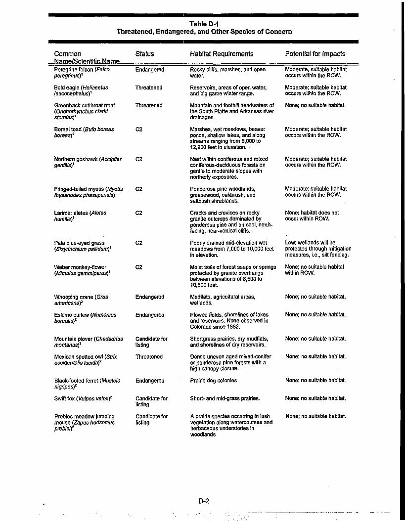
Table D-1Threatened, Endangered, and Other Species of Concern
Common StatusName/Scientific Name
Habitat Requirements Potential for Impacts
Peregrine falcon (Falco EndangeredperegrinusY
Bald eagle (Haliaeetus Threatenedleucocephalusf
Greenback cutthroat trout Threatened{Onchorhynchus clarkistomiasY
Boreal toad (Bufo boreas C2boreasY
Northern goshawk (Accipiter C2gentilisY
Fringed-tailed myotis (Myotis C2thysanodes phasapensisY
Larimer aletes (Aletes C2humilisY
Pale blue-eyed grass C2(Sisyrinchium pallldumY
Weber monkey-flower C2(Mimulus gemmiparusY
Rocky cliffs, marshes, and openwater.
Reservoirs, areas of open water,and big game winter range.
Mountain and foothill headwaters ofthe South Piatte and Arkansas riverdrainages.
Marshes, wet meadows, beaverponds, shallow lakes, and alongstreams ranging from 8,000 to12,900 feet in elevation. -
Nest within coniferous and mixedconiferous-deciduous forests ongentle to moderate slopes withnortherly exposures.
Ponderosa pine woodlands,greasewood, oakbrush, andsaltbush shrublands.
Cracks and crevices on rockygranite outcrops dominated byponderosa pine and on cool, north-facing, near-vertical cliffs.
Poorly drained mid-elevation wetmeadows from 7,000 to 10,000 feetin elevation.
Moist soils of forest seeps or springsprotected by granite overhangsbetween elevations of 8,500 to10,500 feet.
Whooping crane (Grusamericana)2
Eskimo curlew (Numeniusborealis)2
Mountain plover (Chadadriusmontanus)2
Mexican spotted owl (Strixoccidentalis lucida)2
Black-footed ferret (Mustelanigripes)2
Swift fox (Vulpes velox)2
Prebles meadow jumpingmouse (Zapus hudsoniusprebleif
Endangered
Endangered
Candidate forlisting
Threatened
Endangered
Candidate forlisting
Candidate forlisting
Mudflats, agricultural areas,wetlands.
Plowed fields, shorelines of lakesand reservoirs. None observed inColorado since 1882.
Shortgrass prairies, dry mudflats,and shorelines of dry reservoirs.
Dense uneven aged mixed-coniferor ponderosa pine forests with ahigh canopy closure.
Prairie dog colonies
Short- and mid-grass prairies.
A prairie species occurring in lushvegetation along watercourses andherbaceous understories inwoodlands
Moderate, suitable habitatoccurs within the ROW.
Moderate; suitable habitatoccurs within the ROW.
None; no suitable habitat.
Moderate; suitable habitatoccurs within the ROW.
Moderate; suitable habitatoccurs within the ROW.
Moderate; suitable habitatoccurs within the ROW.
None; habitat does notoccur within ROW.
Low; wetlands will beprotected through mitigationmeasures, i.e., silt fencing.
None; no suitable habitatwithin ROW.
None; no suitable habitat.
None; no suitable habitat.
None; no suitable habitat.
None; no suitable habitat.
None; no suitable habitat.
None; no suitable habitat.
None; no suitable habitat.
D-2

Table D-1Threatened, Endangered, and Other Species of Concern
CommonName/Scientific; Name
Status Habitat Requirements Potential for Impacts
Ute ladies'-tresses (Spiranthesdiluvialis)2
Threatened
Colorado butterflyweed(Gaura neomexicana subsp.coloradensis)2
Purple lady's slipper(Cypripedium fasciculatum)3
Rocky Mountain cinquefoil{Potenfflla effusa var.rup'mcolaf
Broad-leafed twayblade(LJstera convallarioides)3
Wood lily (JLJllumphiladelphicum)3
Regal fritillary butterfly(Speyeria Idaliaf
Dwarf shrew (Sorex nanus)3
Boreal owl (Aegoliusfunerous)3
Candidate forlisting
Under review forFederal Listing;Forest ServiceSensitive
Under review forFederal Listing;Forest ServiceSensitive
Gay-feather (Liatris ligustylis)3 G57/S1S2
G5/S2 '
G5/S3
Under review forFederal Listing;Forest ServiceSensitive
G5/S3; ForestService Sensitive
G5/S2; ForestService Sensitive
Wet meadows and floodplains nearthe base of the Front Range in theBoulder-Denver area
Plains and piedmont valleys inBoulder, Larimer, and Weld counties
Forest openings and denselyshaded stands, in duff underlodgepole pine, or, less frequently,under Abies sp.
Steep, often granite, outcroppingson shelves or niches of cliffs, oftenon granite or gravel
Wet meadows in the piedmont andWet Mountain Valley.
Moist places in leaf mold, in shadedareas, or in wet places along smallstreams high in the mountains.
Aspen groves
Wet meadows and virgin prairiesnear marshes.
Forests, open woodlands, androcky, shrubby foothill slopes. Alsoon alpine and sub-alpine rockslides.
Mature spruce-fir or spruce-fir/lodgepole pine forestsinterspersed with meadows.
None; species only knownto occur within the 100-yearfloodplain of the SouthPlatte River, Boulder,Larimer, and JeffersonCounties, North-Central andWestern Utah, and extremeEastern Nevada.
None; no suitable habitat inthe ROW.
None; no suitable habitatpresent within the ROW.
None; no suitable habitatpresent within the ROW.
None; known only to occurin southern Colorado by theSangre de Cristo Mountainsand Wet Mountains.
None; known only to occurat higher elevations insubalpine forests and coolravines.
None; no aspen habitat isencountered within theROW
Low; no suitable habitat.
Moderate; suitable habitatwithin the ROW.
None; no suitable habitat.
Endangered- Species In danger of extinction throughout all or a significant portion of its range.
Threatened* Spedes likely to become an endangered spedes within the foreseeable future throughout all or a significant portion of its range.
Category 2= Spedes for which the USFWS Indicates that proposing to list as endangered or threatened is possibly appropriate, but for which conclusive data onbiological vulnerability is lacking.
•August 4,1995 USFWS letter'September 26,1995 USFWS Letter'Natural Heritage List 6/5/95
Peregrine Falcon. The peregrine falcon is a federally-listed endangered species. Peregrines typicallyoccur along River systems or reservoirs where an adequate food supply, primarily waterfowl and otherbirds, are available. Roost sites are generally cliffs, bluffs or large rock outcrops. Peregrines are knownto occur within the general project area. The closest known nest site occurs almost a mile from thesouthern terminus of the project area. However, this site has not been occupied since 1990. The nextclosest sites occur four miles east and 8 miles north of the project area (Craig 1995). Peregrine falconsare known to occur within the Estes Park vicinity. In May of 1994 a male peregrine was killed as the result
D-3

of a line strike with a distribution power line. The CDOW, determined that the bird, which had beenreleased in to Rocky Mountain National Park, had struck the power line while chasing prey. The strikeoccurred on a distribution line in the southern portion of Estes Park (Craig 1995).
Bald Eagle. The bald eagle is a federally-listed threatened species. Bald eagles are known to occurwithin the general project area. Bald eagles are occasionally sited in the winter near Lake Estes. Eaglesmay occasionally use Marys Lake during the winter, but this has not been documented. However, sinceMarys Lake is usually frozen during the winter months, it is unlikely eagles would be present on a regularbasis. No bald eagle summer or nesting is known to occur within the general project area (Craig 1995).Feeding areas, diurnal perches, and night roosts are fundamental elements of bald eagle winter range.Although eagles can fly as far as 24 km (15 miles) to and from these elements, they primarily occur whereall three elements are available in comparatively close proximity (Swisher 1964). None of these elementsoccur along the project ROW.
The following considerations reduce the potential for impacts from the project to peregrine falcon and baldeagle. First, the existing transmission lines do not have a history of bird electrocutions or collisions (T.McCormick, personal communication 1995). The existing lines do not cross habitats that would providemigration or feeding corridors. Since the new line would be placed in the same corridor as the existingtransmission line, the potential for collisions is not expected to increase. Second, the line would beconstructed using guidelines described in Suggested Practices for Raptor Protection on Power Lines:State of the Art in 1981, (Olendorff et al 1981) thereby reducing the potential for both electrocutions andcollisions. Third, the new transmission line would be slightly higher above the ground and would have alarger diameter conductor than the existing line. Mr. Jerry Craig, the CDOW raptor biologist, emphasizedthat by placing the line within the existing corridor the potential for bird collisions would be greatly reduced(Craig, personal communication, 1995).
Although the potential for bird collision exists along the entire line, the potential for impact is greatest in thearea of Marys Lake. The new 115-kV transmission line crossing of the lake will be an additional obstaclefor birds using the area. The old 69-kV transmission line did not cross the lake. The new 115-kV linewould span the lake within 35 feet, and on the same horizontal plane, as an existing, adjacent, 115-kVtransmission line. The placement of a second transmission line across Marys Lake may increase thepotential for bird collision. However, studies have indicated that by routing transmission lines adjacent toeach other the potential for collisions is reduced since the birds only have to fly over one obstacle (APLIC1994).
Greenback Cutthroat Trout. The greenback cutthroat is federally-listed as a threatened species.Greenback cutthroat typically occurs in mountain and foothill headwaters of the south Platte and ArkansasRiver drainages (Behnke 1992). The greenback has been stocked in Larimer County in the North Fork of.the Big Thompson River and Roaring Forks River. It is anticipated that it has extended its range fromthese stockings (Carlson 1995). This species is easily displaced by non-native trout species (Behnke1992). The proposed project would not affect aquatic resources. Therefore, no effects on greenback troutare expected.
Ute Ladies'-Tresses Orchid. The Ute ladies'-tresses orchid is a federally-listed threatened species. Uteladies'-tresses is a member of the orchid family. It is a perennial plant with stems 20 to 50 centimeterstall, arising from tuberously thickened roots. The species is characterized by whitish, stout, ringentflowers. It blooms, generally, from late July through August. It is endemic to moist soils in mesic or wetmeadows near springs, lakes or perennial streams. The elevation range of know populations is 4,300 to7,000 feet This species has been reported in Larimer County along the Front Range. Suitable habitat forthe orchid does not exist within the project ROW.
D.3 CANDIDATE SPECIES
The remaining species of concern are primarily Category Two (C2) species. Although C2 species haveno protection under the Endangered Species Act (1972), as amended, it is within the spirit of the Act toaddress potential effects to these species and other sensitive species to avoid future listing as eitherthreatened or endangered. Sensitive wildlife species include the boreal toad, northern goshawk, fringed-tailed myotis, and the dwarf shrew, considered a sensitive species by the Forest Service. Sensitive plantspecies include the Larimer aletes, pale blue-eyed grass, Weber monkey-flower and Coloradobutterflyweed.
D-4
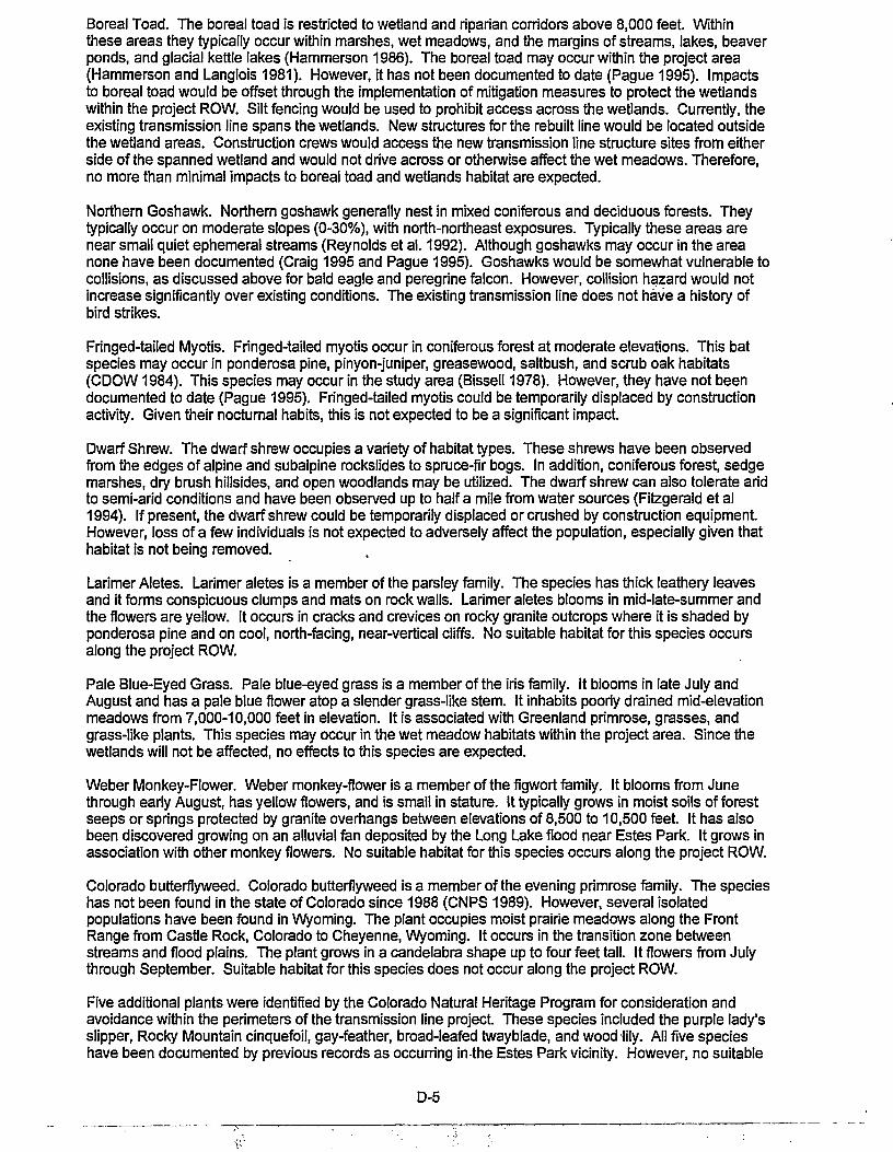
Boreal Toad. The boreal toad is restricted to wetland and riparian corridors above 8,000 feet. Withinthese areas they typically occur within marshes, wet meadows, and the margins of streams, lakes, beaverponds, and glacial kettle lakes (Hammerson 1986). The boreal toad may occur within the project area(Hammerson and Langlois 1981). However, it has not been documented to date (Pague 1995). Impactsto boreal toad would be offset through the implementation of mitigation measures to protect the wetlandswithin the project ROW. Silt fencing would be used to prohibit access across the wetlands. Currently, theexisting transmission line spans the wetlands. New structures for the rebuilt line would be located outsidethe wetland areas. Construction crews would access the new transmission line structure sites from eitherside of the spanned wetland and would not drive across or otherwise affect the wet meadows. Therefore,no more than minimal impacts to boreal toad and wetlands habitat are expected.
Northern Goshawk. Northern goshawk generally nest in mixed coniferous and deciduous forests. Theytypically occur on moderate slopes (0-30%), with north-northeast exposures. Typically these areas arenear small quiet ephemeral streams (Reynolds et al. 1992). Although goshawks may occur in the areanone have been documented (Craig 1995 and Pague 1995). Goshawks would be somewhat vulnerable tocollisions, as discussed above for bald eagle and peregrine falcon. However, collision hazard would notincrease significantly over existing conditions. The existing transmission line does not have a history ofbird strikes.
Fringed-tailed Myotis. Fringed-tailed myotis occur in coniferous forest at moderate elevations. This batspecies may occur in ponderosa pine, pinyon-juniper, greasewood, saltbush, and scrub oak habitats(CDOW1984). This species may occur in the study area (Bissell 1978). However, they have not beendocumented to date (Pague 1995). Fringed-tailed myotis could be temporarily displaced by constructionactivity. Given their nocturnal habits, this is not expected to be a significant impact.
Dwarf Shrew. The dwarf shrew occupies a variety of habitat types. These shrews have been observedfrom the edges of alpine and subalpine rockslides to spruce-fir bogs. In addition, coniferous forest, sedgemarshes, dry brush hillsides, and open woodlands may be utilized. The dwarf shrew can also tolerate aridto semi-arid conditions and have been observed up to half a mile from water sources (Fitzgerald et al1994). If present, the dwarf shrew could be temporarily displaced or crushed by construction equipment.However, loss of a few individuals is not expected to adversely affect the population, especially given thathabitat is not being removed.
Larimer Aletes. Larimer aletes is a member of the parsley family. The species has thick leathery leavesand it forms conspicuous clumps and mats on rock walls. Larimer aletes blooms in mid-late-summer andthe flowers are yellow. It occurs in cracks and crevices on rocky granite outcrops where it is shaded byponderosa pine and on cool, north-facing, near-vertical cliffs. No suitable habitat for this species occursalong the project ROW.
Pale Blue-Eyed Grass. Pale blue-eyed grass is a member of the iris family. It blooms in late July andAugust and has a pale blue flower atop a slender grass-like stem. It inhabits poorly drained mid-elevationmeadows from 7,000-10,000 feet in elevation. It is associated with Greenland primrose, grasses, andgrass-like plants. This species may occur in the wet meadow habitats within the project area. Since thewetlands will not be affected, no effects to this species are expected.
Weber Monkey-Flower. Weber monkey-flower is a member of the figwort family. It blooms from Junethrough early August, has yellow flowers, and is small in stature. It typically grows in moist soils of forestseeps or springs protected by granite overhangs between elevations of 8,500 to 10,500 feet. It has alsobeen discovered growing on an alluvial fan deposited by the Long Lake flood near Estes Park. It grows inassociation with other monkey flowers. No suitable habitat for this species occurs along the project ROW.
Colorado butterflyweed. Colorado butterflyweed is a member of the evening primrose family. The specieshas not been found in the state of Colorado since 1988 (CNPS 1989). However, several isolatedpopulations have been found in Wyoming. The plant occupies moist prairie meadows along the FrontRange from Castle Rock, Colorado to Cheyenne, Wyoming. It occurs in the transition zone betweenstreams and flood plains. The plant grows in a candelabra shape up to four feet tall. It flowers from Julythrough September. Suitable habitat for this species does not occur along the project ROW.
Five additional plants were identified by the Colorado Natural Heritage Program for consideration andavoidance within the perimeters of the transmission line project. These species included the purple lady'sslipper, Rocky Mountain cinquefoil, gay-feather, broad-leafed twayblade, and wood lily. All five specieshave been documented by previous records as occurring in the Estes Park vicinity. However, no suitable
D-5

habitat for any of these species lies within the project area. Table D-1 presents the potential habitatrequirements and impact assessment for these species.
D.4 SUMMARY
Of the 26 threatened, endangered and sensitive species identified through agency contacts, 19 have beeneliminated from further consideration (Table D-1). These species were eliminated based on a lack ofsuitable habitat within the project area or "footprint". Seven species, the peregrine falcon, bald eagle,boreal toad, northern goshawk, fringed-tailed myotis, dwarf shrew, and pale blue-eyed grass, havesuitable habitat within the project right-of-way.
Construction impacts to the endangered peregrine falcon, the threatened bald eagle and the candidatenorthern goshawk are expected to be minimal. This is based on the fact that no nests are known to occurwithin the project area. The new line would present a potential collision hazard for these species.However, the collision hazard would be the same as existing conditions since the new 115-kVtransmission line would replace an existing 69-kV transmission line. The existing corridor does not have ahistory of bird collisions and is not along a migration or hunting corridor. The project does not affectaquatic habitats and therefore the threatened greenback cutthroat trout would not be affected.
The boreal toad, fringed-tailed myotis, dwarf shrew, and pale blue-eyed grass, if present, could beaffected by the construction phase of the project. Impacts to the boreal toad and pale blue-eyed grasswould be offset through the implementation of the wetland mitigation measures. By fencing the wetlandsand prohibiting access across these areas, potential impacts to the toad and iris should be eliminated.The fringed-tailed myotis may be temporarily displaced by construction activity. If present, a fewindividual dwarf shrew might be crushed by construction equipment This would not likely affect shrewpopulations.
Western, as lead federal agency for the project, has determined that the proposed action is unlikely toadversely affect any federally-listed threatened or endangered species.
D.5 REFERENCES
Avian Power Line Interaction Committee (APLIC). 1994. Mitigating Bird Collisions with Power Lines: TheState of the Art in 1994. Edison Electric Institute, Washington, D.C.
Behnke, R.J. 1992. Native Trout of Western North America. Amer. Fish. Soc. Monograph 6., Bethesda,Maryland.
Bissell, S.J. 1978. Colorado mammal Distribution Latilong Study. Colo. Div. of Wildl., Denver, CO.
Bogart, D. 1995. Personal Communication. Environmental Biologist. Colo. Div. of Wildl., Ft. Collins, CO.
Carlson, L W. 1995. Personal Communication. Colorado Field Supervisor. USDI, fish and Wild. Sen/.,Golden, CO.
Craig, J. 1995. Personal Communication. Raptor Biologist. Colo. Div. of Wildl., Ft. Collins, CO.
Craig, J. 1996. Personal Communication. Raptor Biologist. Colo. Div. of Wildl., Ft. Collins, CO.
CDOW. 1984. The Bats of Colorado: Shadows in the Night. Colo. Div. of Wildl., Denver, CO.
Fitzgerald, J.P. C.A. Meaney, and D.M. Armstrong. 1994. Mammals of Colorado. Denver Museum of Nat.Hist and Univ. Press of Colo., Niwot, CO.
Hammerson, G.A. and D. Langlois. 1981. Colorado Reptile and Amphibian Distribution Latilong Study. 2nded., Colo. Div. of Wildl., Denver, CO.
Hammerson, G.A. 1986. Amphibians and Reptiles in Colorado. Colo. Div. of Wildl., Denver, CO.
McCormick, T. 1995. Personal Communication. System Design Supervisor, Platte River Power Authoritywith M. Bonar, Greystone, Englewood, CO.
D-6
Olendorff, R.R., A.D. Miller, and R.M. Lehman. 1981. Suggested Practices for Raptor Protection on PowerLines: State of the Art in 1981. Raptor Research Foundation, Inc. St. Paul, Minn. Raptor ResearchReport No. 4.
Prague, K.E. 1995. Personal Communication. Senior Information Manager. Colo. Nat Heritage Pro., Ft.Collins, CO.
Reynolds, R.T, R.T. Graham, M.H. Reiser, R.L Bassett, P.L Kennedy, D.A. Boyce Jr., G. Goodwin, R.Smith, and E.L. Fisher. 1992. Management Recommendations for the Northern Goshawk in theSouthwestern United States. USDA, For. Serv., Albuquerque, New Mexico. Gen. Tech. Rep. RM-217.
Swisher, J.F. 1964. A Roosting Area of the Bald Eagle in Northern Utah. Wilson Bull. 76(2): 186-187.
The Colorado Native Plant Society. 1989. Rare Plants of Colorado. Rocky Mountain Nature Association.
D-7

\ • / in
Platte River Power Autorityand
Western Area Power Administration
Marys Lake69/115 kV Transmission Line Upgrade
and Substation Expansion ProjectsEGEND
• SlUDYAREABOUNDAHV
B rj rj • EXISTINGDOUBLECtRCUIT69/115,000VOLT• • • • • • TRANSMISSION UNE ON STEEL STRUCTURES
TO REMAIN; BEGIN OPERATING 69,000 VOLTCIRCUIT AT 115,000 VOLTS
- - - - - - REMOVE EXISTING 69,000 VOLT WOODH-FRAME STRUCTURES AND REPLACEWrTH115,000VOLTTRANSMISSIONUNEON WOOD H-FRAME STRUCTURES
i EXISTING 115.000VOLTTRANSMISSIONUNE ON WOOD H-FRAME STRUCTURESTO REMAIN
O D o a u o D a EXISTING 69,000 VOLT TRANSMISSION UNETO BE REMOVED
• EXISTING 69,000 VOLT TRANSMISSION UNETO REMAIN
' CONSTRUCT NEW 69,000 VOLTTRANSMISSION
UNE
0 2000 Foot
PROPOSED ACTIONFigure D-1

APPENDIX EFLOODPLAINS/WETLANDS ASSESSMENT

APPENDIX EFLOODPLAINS/WETLANDS ASSESSMENT
This Floodplains/Wetlands Assessment only addresses the Proposed Action, which consists ofdismantling the existing 69-kV wood-pole transmission line, and rebuilding a 115-kV transmission linesonto new wood H-frame pole structures. About two miles of existing transmission line ROW would beaffected.
In accordance with Executive Orders 11988 and 11990 and U.S. Department of Energy procedures,floodplains and wetlands were identified, mapped, and integrated into the planning and alternativesselection process.
No floodplains occur in or adjacent to the existing ROW. Two small wetlands exist along the existingROW (refer to Figure 3-5). One originates from a small seep at the base of a finger of the southeast-facing Prospect Mountain. The second wetland is just south of Peak View Drive. It is assumed that thewetlands would be spanned and access would be restricted by fencing during construction. The ProposedAction will have no effects on floodplains or wetlands.
The following sources of information were used for identification of floodplains and wetlands:
• Federal Emergency Management Agency Flood Insurance Rate Maps, Larimer County, ColoradoMaps 0801010251B and 0801010239C, and Town of Estes Park, Colorado Maps SN72WandSN73W2.5SE.
• Reconnaissance of the proposed route by an experienced wetland scientist in May, 1995.
E-1

APPENDIX FELECTRIC AND MAGNETIC FIELD (EMF) CHARACTERISTICS/ BIBLIOGRAPHY

APPENDIX FEMF BIBLIOGRAPHY
LABORATORY RESEARCH
CELL AND TISSUE (IN VITRO) STUDIES
Blackman, C.F., L.S. Kinney, D.E. House, and W.T. Joines. 1989. Multiple Power-Density Windows andTheir Possible Origin. Bioelectomagnetics 10:115-28.
Liboff, A.R. 1989. The Ion cyclotron Resonance: A Physical Basis for the ELF Interaction With BiologicalSystems. Extremely Low Frequency Elecfromagnetic Fields: The Question of Cancer. B.W.,Wilson, R.g., Stevens, and LE. Anderson (eds). Columbus, OH: Battelle Presss.
Loscher, W.; Mevissen, M.; Lehmacher, W.; Stamm, A. 1993. Tumor promotion in a breast cancer modelby exposure to a weak alternating magnetic field. Cancer Letters 71:75-81.
Loscher, W.; Wahnschaffe, U.; Mevissen, M.; Lerchl, A.; Stamm, A. 1994. Effects of weak alternatingmagnetic fields on nocturnal melatonin production and mammary carcinogenesis in rats. Oncology51:288-295.
McCann, J., F. Dietrich, C. Rafferty, and A. Martin. 1993. A Critical Review of the Genotoxic Potential ofElectric and Magnetic Fields. Mutation Research 296:221-40.
McLean, J. R. N.; Stuchly, M. A.; Mitchel, R. E. J.; Wilkinson, D.; Yang, H.; Goddard, M.; Lecuyer, D. W.;Schunk, M.; Calgary, E.; Morrison, D. 1991. Cancer promotion in a mouse-skin model by a 60-Hzmagnetic field: II. Tumor development and immune response. Bioelectromaqnetics 12:273-287.
Mevissen, M.; Stamm, A.; Buntenkotter, S.; Zwingelberg, R.; Wahnschaffe, U.; Loscher, W. 1993. Effects ofmagnetic fields on mammary tumor development induced by 7,12-dimethylbenz(a)anthracene inrats. Bioelectromaqnetics 14:131-143.
Murphy, J., D. Kaden, J. Warren, and A. Sivak. 1993. Power Frequency Electric and Magnetic Fields: AReview of Genetic Toxicology. Mutation Research 296:221-40.
Parkinson, W.C., and C.T. Hanks. 1989. Search for Cyclotron Resonance in Cells in v'rtro.Bioelectomagnetics 10:129-45.
Rannug, A.; Ekstrom, T.; Mild, K. H.; Holmberg, B.; Gimenez-Contil, I.; Slaga, T. J. 1993a. A study on skintumour formation in mice with 50 Hz magnetic field exposure. Carcinogenesis 14:573-578.
Rannug, A.; Holmberg, B.; Mild, K. H. 1993b. A rat liver foci promotion study with 50-Hz magnetic fields.Environ. Res. 62:223-229.
Rannug, A.; Holmberg, B.; Ekstrom, T.; Mild, K. H.; Gimenez-Conti, I.; Slaga, T. J. 1994. Intermittent 50 Hzmagnetic field and skin tumor promotion in SENCAR mice. Carcinogenesis 15:153-157.
Reiter, R. J. 1993. Reported effects on the arcadian production of melatonin. J. Cell. Biochem.51:394-403.
414-APP.F F-1

Stuchly, M. A.; Lecuyer, D. W.; McLean, J. R. N. 1991. Cancer promotion in a mouse-skin model by a60-Hz magnetic field: I. Experimental design and exposure system. Bioelectromagnetics12:261-271.
Stuchly, M. A.; McLean, J. R. N.; Burnett, R.; Goddard, M.; Lecuyer, D. W.; Mitchel, R. E. J. 1992.Modification of tumor promotion in the mouse skin by exposure to an alternating magnetic field.Cancer Letters 65:1-7.
Weaver, J.C. and R.D. Astumian. 1990. The Response of Living Cells to Very Weak Electric Fields: TheThermal Noise Limit. Science 247:459-62.
Wilson, B.W.; Anderson, L.E.; Hilton, D.I.; Phillips, R.D. 1981. Chronic exposure to 60-Hz electric fields:Effects on pineal function in the rat. Bioelectromagnetics 2:371-380.
WHOLE ANIMAL (IN VIVO) STUDIES
Dowman, R., J.R. Wolpaw, R F. Seegal, and S. Satya-Murti. 1989. Chronic Exposure of Primates to 60-HzElectric and Magnetic Fields. III. Neurophysiological Effects. Bioelectromagnetics 10:303-17'.
Fam, W. Z.; Mikhail, E. L. 1993. Three-generation animal study of the carcinogenesis of a 25-mT, 60-Hzmagnetic field. Annual Review of Research on Biological Effects of Electric and Magnetic Fieldsfrom the Generation. Delivery and Use of Electricity, p. 10.
Liboff, A.R., J.R. Thomas, and J. Schrot. 1989. Intensity Threshold for 60-Hz Magnetically InducedBehavioral Changes in Rats. Bioelectromagnetics 10:111 -113.
Rommereim, D.N., R.L. Rommereim, M.R. Sikov, R.L. Buschbom, and L.E. Anderson. 1990.Reproduction, Growth and Development of Rats During Chronic Exposure to Multiple Strengths of60-Hz Electric Fields. Fundamental and Applied Toxicology 14:608-21.
Seegal, R.F., J.R. Wolpaw, and R. Dowman. 1989. Chronic Exposure of Primates to 60-Hz Electric andMagnetic Fields. II. Neurochemical Effects. Bioelectromagnetics 10:289-301.
Wilson, B.W., E.K. Chess, and LE. Anderson. 1987. 60-Hz Electric-Field Effects on Pineal MelatoninRhythms: Time Course for Onset and Recovery. Bioelectromagnetics 7:239-42.
Wolpaw, J.R., R.F. Seegal, and R. Dowman. 1989. Chronic Exposure of Primates to 60-Hz Electric andMagnetic Fields. I. Exposure System and Measurements of General Health and Performance.Bioelectromagnetics 10:277-88.
HUMAN STUDIES
Graham, C , M.R. Cook, and H.D. Cohen. 1990. Immunological and Biochemical Effects of 60-Hz Electricand Magnetic Fields in Humans. Kansas City, MO: Midwest Research Institute, January 30,1990.DOE/CE/76246-T1. Prepared for U.S. Department of Energy Office of Energy Storage andDistribution.
Graham, C ; Cook, M. R.; Cohen, H. D.; Riffle, D. W.; Hoffman, S. J.; McClemon, F. J.; Smith, D.;Gerkovich, M. M. 1993. EMF suppression of nocturnal melatonin in human volunteers. AnnualReview of Research on Biological Effects of Electric and Magnetic Fields from the Generation.Delivery and Use of Electricity, p. 98-99.
414-APP.F F-2
Graham, C ; Cook, M. R.; Cohen, H. D.; Riffle, D. W. 1994. Nocturnal melatonin levels in men exposed tomagnetic fields: a replication study. Annual Review of Research on Biological Effects of Electricand Magnetic Fields from the Generation. Delivery and Use of Electricity, p. 51-52.
DOSIMETRY
Bracken, T. D. 1994a. The EMDEX Project: Residential Study. Volume 1: Summary. EPRITR-104325-V1.
Bracken, T. D.1994b. The EMDEX Project: Residential Study. Volume 2: Project Description and Results.EpriTR-104325-V2.
Bracken, T. D. 1994c. The EMDEX Project: Residential Study. Volume 3: Appendices. Epri TR-104325-V3.
Deno, D.W. 1977. Currents Induced in the Human Body by High-Voltage Transmission Line ElectricFields. IEEE Transactions on Power Apparatus and Systems PAS-96:1517-26.
Dovan, T.; Kaune, W. T.; Savitz, D. A. 1993. Repeatability of measurements of residential magnetic fieldsand wire codes. Bioelectromaqnetics 14:145-159.
Kaune, W.T. and R.D. Phillips. 1980. Comparison of the Coupling of Grounded Humans, Swine, and Ratsto Vertical, 60-Hz Electric Fields. Bioelectromagnetics 1:117-29.
Tenforde, T.S. 1986. Interaction of ELF Magnetic Fields with Living Matter. Polk and Postow (eds). CRCHandbook of Biological Effects of Electromagnetic Fields. CRC Press, Inc. Boca Raton, Florida.
Tenforde, T.S. and W.T. Kaune. 1987. Interaction of Extremely Low Frequency Electric and magneticFields With Humans. Health Physics 53:585-606.
EPIDEMIOLOGY STUDIES
Afifi, A., R.S. Banks, L.I. Kheifets, and B. Newman. 1990. Proceedings: Discussion of an EMF Protocol.Palo Alto, CA: EPRI, July 1990. EPRI EN-6829. Prepared by Robert S. Banks Associates, Inc.Minneapolis, MN.
Ahlbom, A.; Feychting, M.; Koskenvuo, M.; Olsen, J. H.; Pukkala, E.; Schulgen, G.; Verkasalo, P. 1993.Electromagnetic fields and childhood cancer. Lancet 342:1295-1296.
Ahlbom, A.; Feychting, M.; Koskenvuo, M.; Olsen, J. H.; Pukkala, E.; Schulgen, G.; Verkasalo, P. 1993.Electromagnetic fields and childhood cancer. Lancet 342:1295-1296.
Armstrong, B.; Theriault, G.; Guenel, P.; Deadman.J.; Goldberg, M.; Heroux, P. 1994. Associationbetween exposure to pulsed electromagnetic fields and cancer in electric utility workers in Quebec,Canada, and France. Am. J. Epidemiol. 140:805-820.
Barnes, F., H. Wachtel, D. Savitz, and J. Fuller. 1989. Use of Wiring Configuration and Wiring Codes forEstimating Externally Generated Electric and magnetic Fields. Bioelectromagnetics 10:13-21.
Bowman, J.D., D.H. Garabrant, E. Sobel, and J.M. Peters. 1988. Exposures to Extremely Low Frequency(ELF) Electromagnetic Fields in Occupations with Elevated Leukemia Rates. Applied IndustrialHygiene 6:189-94.
Bracken, T.D. 1986. Analysis ofBPA Occupational Electric Field Exposure Data. Portland, OR: T.DanBracken, Inc. January 1986, DOE/BP-36303-1. Prepared for Bonneville Power Administration.
414-APP.F F-3

Broadbent, D.E., M.H.P. Broadbent, J.C. Male, and M.R.L. Jones. 1985. Health of Workers Exposed toElectric Fields. British Journal of Industrial Medicine. 42:75-84.
Bunin, G.R., E. Ward, S. Kramer, C.A. Rhee, and AT. Meadows. 1990. Neuroblastoma and ParentalOccupation. American Journal of Epidemiology 131:776-80.
Calle, E.E. and D.A. Savitz. 1985. Leukemia in Occupational Groups With Presumed Exposure toElectrical and Magnetic Fields, (letter). New England Journal of Medicine 313:1476-77.
Caola, R.J., D.W. Deno, and V.S. W. Dymek. 1983. Measurements of Electric and Magnetic Fields in andAround Homes Near A 500-kV Transmission Line. IEEE Transactions on Power Apparatus andSystems PAS-102:3338-47.
Coleman, M., C.M.J. Bell, and R. Skeet. 1983. Leukemia Incidence in Electrical Workers, (letter). TheLancet i:982-83.
Coleman, M.P., C.M.J. Bell, H.L. Taylor, and M. Primic-Zakelj. 1989. Leukemia and Residence NearElectricity Transmission Equipment: A Case-Control Study. British Journal of Cancer 60:793-98.
Deadman, J.E., M. Camus, B.G. Armstrong, P. Herouz, D. Dyr, M. Plante, and G. Theriault. 1988.Occupational and Residential 60-Hz Electromagnetic Fields and High-Frequency ElectricTransients: Exposure Assessment using a New Dosimeter. American Industrial HygieneAssociation Journal 49:409-19.
Deno, D.W. 1987. Sources and Structures of Magnetic Fields in and Around Homes Near a 500-kVTransmission Line. IEEE Transactions on Power Apparatus and Systems PAS-102:3338-47.
Dlugosz, L.J., T. Byers, J. Vena, and M. Zielezny. 1989. Ambient 60-Hz Magnetic Flux Density in anUrban Neighborhood. Bioelectromagnetics 10:187-96.
EMDEX Project: Technology Transfer and Occupational Measurements, Vols. 1-3. Palo Alto, CA: EPRI,November 1990, EPRI EN-7048. Prepared by T. Dan Bracken, Inc., Portland, OR.
Feychting, M. and Ahlbom, A. 1994. Magnetic fields, leukemia, and central nervous system tumors inSwedish adults residing near high-voltage power lines. Epidemiology 5:501-509.
Feychting, M.; Ahlbom, A. 1992. Magnetic fields and cancer in people residing near Swedish high voltagepower lines. Institutetfor Miijomedicin (IMM) Report 6/92.
Feychting, M. and Ahlbom, A. 1993. Magnetic fields and cancer in children residing near Swedishhigh-voltage power lines. Am. J. Epidemiol. 138:467-480.
Feychting, M. and Ahlbom, A. 1993. Magnetic fields and cancer in children residing near Swedishhigh-voitage power lines. Am. J. Epidemiol. 138:467-48000.
Feychting, M. and Ahlbom, A. 1992. Magnetic Fields and Cancer in People Residing Near Swedish HighVoltage Power Lines. Institute for Miijomedicin, Karolinska Instituted Stockholm, June, 1992.
Feychting, M. and Ahlbom, A. 1993. Magnetic fields and cancer in children residing near Swedishhigh-voltage power lines. Am. J. Epidemiol. 138:467-480.
Feychting, M. And A. Ahlbom. 1992. Magnetic Fields and Cancer in People Residing Near Swedish HighVoltage Power Lines. IMM Institutet for Miijomedicin, Karolinska Institutet, Stockholm.
414-APP.F F-4

Floderus, B.; Persson, T.; Stenlund, C ; Wennberg, A.; Ost, A.; Knave, B. 1993. Occupational exposure toelectromagnetic fields in relation to leukemia and brain tumors: A case-control study in Sweden.Cancer Causes Control 4:465-476.
Floderus, B., S. Tornqvist, and C. Stenlund. 1994. Incidence of Selected Cancer in Swedish RailwayWorkers, 1961 -79. Cancer Causes and Control 5:189-94.
Floderus, B.; Persson, T.; Stenlund, C ; Under, G.; Johansson, C ; Kiviranta, J.; Parsman, H.; Lindblom, M.;Wennberg, A.; Ost, A.; Knave, B. 1992. Occupational exposure to electromagnetic fields in relationto leukemia and brain tumors. A case-control study. Natl. Inst. of Occupational Health, Solna,Sweden.
Floderus, B., T. Persson, C. Stenlund, G. Under, C. Johannson, J. Kiviranta, H. Parsman, M. Undbolm, A.Wennberg, A. Ost, and B. Knave. 1992. Occupational Exposure to Electromagnetic Fields inRelations to Leukemia and Brain Tumors. A Case-Control Study. Litohuset, National Institute ofOccupational Health.
Florig, H.K., J.F. Hoburg, and M.G. Morgan. 1987. Electric Field Exposure from Electric Blankets. IEEETransactions on Power Delivery PWRD-2:527-36.
Florig, H.K., and M.G. Morgan. 1988. Measurements of Housing Density Along Transmission Lines.Bioelectromagnetics 987-94.
Fulton, J.P., S. Cobb, L. Preble, L. Leone, and E. Forman. 1980. Electrical Wiring Configurations andChildhood Leukemia in Rhode Island. American Journal of Epidemiology 111:292-96.
Gauger, J.R. 1986. Household Appliance Magnetic Field Survey. IEEE Transactions on Power Apparatusand Systems PAS-104:2436-44.
Guenel, P., P. Raskmark, X. Andersen, and E. Lynge. 1993. Incidence of Cancer in Persons withOccupational Exposure to Electromagnetic Fields in Denmark. British Journal of IndustrialMedicine 50:758-764.
Jacobs, P.D., and F.M. Dietrich. 1984. Measurements of Transmission Line Electric Fields in a ResidentialEnvironment. IEEE Transactions on Power Apparatus and Systems PAS-103:2237-43.
Kaune, W.T., R.G. Stevens, N.J. Callahan, R.K. Severson, and D.B. Thoma. 1987. Residential Magneticand Electric Fields. Bioelectromagnetics 8:315-35.
Knave, B., F. Gamberale, S. Bergstrom, E. Birke, A. Iregren, B. Kolmodin-Hedman, and A. Wennberg.1979. Long-Term Exposure to Electric Fields. A Cross-Sectional Epidemiologic Investigation ofOccupationally Exposed Workers in High-Voltage Substations. Scandinavian Journal of Work,Environment and Health 5:115-25.
Lin, R.S., P.C. Dischinger, J. Conde, and K.P. Farrell. 1985. Occupational Exposure to ElectromagneticFields and the Occurrence of Brain Tumors. Journal of Occupational medicine 27:413-19.
London, S.J., D.C. Thomas, J.D. Bowman, E. Sobel, T.C. Cheng and J.M. Peters. 1991. Exposure toResidential Electric and Magnetic Fields and risk of Childhood Leukemia. American Journal ofEpidemiology 134:923-37.
414-APP.F F-5

London, S.J.; Thomas, D.C.; Bowman, J.D.; Sobel, E.; Cheng, T.; Peters, J.M. Exposure to residentialelectric and magnetic fields and risk of childhood leukemia. American Journal of Epidemiology.134:923-937,1991.
London, S. J.; Thomas, D. C ; Bowman, J. D.; Sobel, E.; Cheng, T-C; Peters, J. M. 1991. Exposure toresidential electric and magnetic fields and risk of childhood leukemia. Am. J. Epidemiol.134:923-937.
Lovely, R. H.; Buschbom R. L.; Slavich, A. L.; Anderson, L. E.; Hansen N. H.; Wilson B. W. 1994. Adultleukemia risk and personal appliance use: a preliminary study. Am. J. Epidemiol. 140:510-517.
Matanowski, G.M., E A Elliott, and P.N. Breysse. 1989. Cancer Incidence in New York TelephoneWorkers. Poster presented November 15,1989 at EPRI/DOE Contractors Review.
McDowall, M.E. 1983. Leukemia Mortality in Electrical Workers in England and Wales, (letter). TheLancet i:246.
McDowall, M.E. 1986. Mortality of Persons Resident in the Vicinity of Electricity Transmission Facilities.British Journal of Cancer 53:271 -79.
McMahan, S. 1994. Depression Research. Doctoral Dissertation. School of Social Ecology, University ofIrvine, Irvine, California.
Milham, S. Jr.. 1988. Increased Mortality in Amateur Radio Operators Due to Lymphatic andHematopoietic Malignancies. American Journal of Epidemiology 127:50-54.
Milham, S. Jr.. 1985. Mortality in Workers Exposed to electromagnetic fields. Environmental HealthPerspectives 62:297-300.
Milham, S. Jr. 1982. Mortality From Leukemia in Workers Exposed to Electrical and Magnetic Fields. NewEngland Journal of Medicine 307:249.
Myers, A., A.D. Clayden, R.A. Cartwright, and S.C. Cartwright. 1990. Childhood Cancer and OverheadPowerlines: A case-Control Study. British Journal of Cancer 62:1008-14.
Nordeson, I., K. Hansson-Mild, U. Ostman, and H. Ljungberg. 1988. Chromosomal Effects inLymphocytes of 400-kV Substation Workers. Radiation and Environmental Biophysics 27:39-47.
Nordstrom, S., E. Birke, and L. Gustavsson. 1983. Reproductive Hazards Among Workers at High-Voltage Substations. Bioelectromagnetics 4:91 -101. i
Norris, W.T., J.C. Male, and B.J. Maddock. 1987. Magnetic and Electric Power Frequency Fields in theHome. Twenty-Third Hanford Life Sciences Symposium. Interaction of Biological Systems withStatic and ELF Electric and Magnetic Fields; October 2-4, 1984, Richland, Washington. L.E.Anderson, B.J. Kelman, and R.J. Weigel (eds). Richland, WA: Pacific Northwest Laboratory, 1987,197-205. Available from NTIS as CONF-84101.
Olsen, J. H.; Nielsen, A., Schulgen, G. 1993. Residence near high voltage facilities and risk of cancer inchildren. British Medical J. 307:891-895.
Olsen, J.H., A. Nielsen, and G. Schulgen. 1993. Residence Near High Voltage Facilities and Risk ofCancer in Children. British Medical Journal 307:891 -895.
414-APP.F F-6
Olsen, J. H.; Nielsen, A., Schulgen, G. 1993. Residence near high voltage facilities and risk of cancer inchildren. British Medical J. 307:891-895.
Pearce, N.E., R.A. Sheppard, J.K. Howard, J. Fraser, and B.M. Lilley. 1985. Leukemia in ElectricalWorkers in New Zealand (letter). The Lancet i:811-12.
Peters, J.M., S. Preston-Martin, S.J. London, J.D. Bowman, J.D. Buckley, and D.C. Thomas. 1994.Processed Meats and Risk of Childhood Leukemia (California, USA). Cancer Causes and control5:195-202.
Peters, J.M., D.C. Thomas, J.D. Bowman, E. Sobel, S.J. London, and T.C. Chen. 1991. Exposure toResidential Electric and Magnetic Fields and Risk of Childhood Leukemia. Palo Alto, CA: EPRI,November 1991, EPRI EN-7464. Prepared by University of Southern California, Los Angeles, CA.
Petridou, E., D. Kassimos, M. Kamanti, H. Kosmidis, S. Haidas, V. Flytzani, D. Tong, and D. Trichopoulos.1993. Age of Exposure to'lnfections and Risk of Childhood Leukemia. British Medical JournalSeptember 25:307:774.
Poole, C. R. Kavet, D.P. Funch, K. Donelan, J.M. Charry, and N A Dreyer. 1993. Depressive Symptomsand Headaches in Relation to Proximity to Residence to an Alternating-Current Transmission LineRight-of-Way. American Journal of Epidemiology 137(3):318-30.
Preston-Martin, S., J.M. Peters, M.C. Yu, D.H. Garabrant, and J.D. Bowman. 1988. MyelogenousLeukemia and Electric Blanket Use. Bioelectromagnetics 9:207-13.
Sahl, J. D.; Kelsh, M. A.; Greenland, S. 1993. Cohort and nested case-control studies of hematopoieticcancers and brain cancer among electric utility workers. Epidemiology 4:104-114.
Sahl J., J.M. Kelsh, and S. Greenland. 1993. Mortality Study on Electric Utility Workers at SouthernCalifornia Edison. March 1993 Epidemiology.
Savitz, D.A. 1987a. Case-Control Study of Childhood Cancer and Residential Exposure to Electric andMagnetic Fields. Final Report to the New York State Department of Health. Power Lines Project.
Savitz, D.A. 1987b. Final Results of Case-Control Study of Childhood Cancer and Electromagnetic FieldExposure, Abstract and Presentation to the DOE/EPRI Contractors Review. Kansas City,Missouri. November 1987.
Savitz, D.A.; Kaune, W.T. 1993. Childhood cancer in relation to a modified residential wire code.Environmental Health Perspectives. 101:76-80.
Savitz, D.A.; Wachtel, H.; Barnes, F A ; John, E.M.; Tvrdik, J.G. 1988. Case-control study of childhoodcancer and exposure to 60-hertz magnetic fields. American Journal of Epidemiology. 128:21-38.
Savitz, D.A., and W.T. Kaune. 1993. Childhood Cancer in Relation to a Modified Residential Wire Code.Environmental Health Perspectives 101 (1):76-80.
Savitz, D A ; Loomis, D.P. 1995. Magnetic field exposure in relation to leukemia and brain cancer mortalityamong electric utility workers. Am. J. Epidemiol. 141:123-134.
Savitz, D.A.; Wachtel, H.; Barnes, F.A.; John, E.M.; Tvrdik, J.G. 1988. Case-control study of childhoodcancer and exposure to 60-hertz magnetic fields. Am. J. Epidemiol. 128:21-38.
414-APP.F F-7
Savitz, D.A., C.A. Boyle, and P. Holmgreen. 1994. Prevalence of Depression Among Electrical Workers.American Journal of Industrial Medicine 25:165-76.
Savitz, D.A., and E.E. Calle. 1987. Leukemia and Occupational Exposure to Electromagnetic Fields.Review of Epidemiologic Surveys. Journal of Occupational Medicine. 29:47-51.
Savitz, D A , and W.T. Kaune. 1993. Childhood Cancer in Relation to a Modified Residential Wire Code.Environmental Health Perspectives 101(1):76-80.
Savitz, D A , H. Wachtel, F A Barnes, E.M. John, and J.G. Tvrdik. 1988. Case-Control Study of ChildhoodCancer and Exposure to 60-Hertz Electric and Magnetic Fields. American Journal of Epidemiology128:21-38.
Savitz, D.A., E.M. John, and R.C. Kleckner. 1990. Magnetic Field Exposure From Electric Blankets andChildhood Cancer. American Journal of Epidemiology 131:763-73.
Severson, R.K., R.G. Stevens, W.T. Kaune, D.B. Thomas, L.D. Heuser, and L.E. Sever. 1988. AcuteNonlymphocytic Leukemia and Residential Exposure to Power Frequency Magnetic Fields.American Journal of Epidemiology 128:10-20.
Severson, R.K.; Stevens, R.G.; Kaune, W.T.; Thomas, D.B.; Heuser, L; Davis, S; Sever, L.E. 1988. Acutenonlymphocytic leukemia and residential exposure to power frequency magnetic fields. Am. J.Epidemiol. 128:10-20.
Silva, M., H. Hummon, D. Rutter, and C. Hooper. 1989. Power Frequency Magnetic Fields in the Home.IEEE Transactions on Power Delivery 4:465-78.
Skyberg, K., I.L.-Hansteen, and A.I. Vistnes. 1993. Chromosome Aberrations in Lymphocytes of High-Voltage Laboratory Cable Splicers Exposed to Electromagnetic Fields. Scandinavian Journal ofWork, Environment and Health 19:29-34.
Stevens, R.G. 1986. Epidemiological Studies of Cancer and Residential Exposure to ElectromagneticFields. Final Report. Power Lines project 21082-18. Albany, New York. Health Research, Inc.
Stevens, R. G. 1993. Electric power and the risk of breast cancer. Radiation Research 133:132-134.
Stevens, R. G. 1987. Electric power use and breast cancer: A hypothesis. Am. J. Epidemiol. 125:556-561.
Stuchly, M A and D.W. Lecuyer. 1989. Exposure to Electromagnetic Fields in Arc Welding. HealthPhysics 56:597-602.
Stuchly, M A 1986. Human Exposure to Static and Time-Varying Magnetic Fields. Health Physics• 51:215-25.
Swedish National Electrical Safety Board. 1993. Magnetic Fields and Cancer, 1993. Internal Report.
Theriault, G.; Goldberg, M.; Miller, A. B.; Armstrong, B.; Guenel, P.; Deadman, J.; Imbemon, E.; To, T.;Chevalier, A.; Cyr, D.; Wall, C. 1994. Cancer risks associated with occupational exposure tomagnetic fields among electric utility workers in Ontario and Quebec, Canada, and France: 1970-1989. Am. J. Epidemiol. 139:550-572.
Theriault, G., M. Goldberg, A.B. Miller, B. Armstrong, P. Guenel, J. Deadman, E. Imbernon, T. To, A.Chevalier, D. Cyr, and C. Wall. 1994. Cancer Risks Associated with Occupational Exposure to
414-APP.F F-8

Magnetic Fields Among Electric Utility Workers in Ontario and Quebec, Canada, and France:1970-1989. American Journal of Epidemiology 139(6):550-571.
Tomenius, L. 1986. 50-Hz Electromagnetic Environment and Incidence of Childhood Tumors in StockholmCounty. Bioelectromagnetics 7:191-208.
Tomenius, L, L. Hellstrom and B. Enander. 1982. Electrical Constructions and 50-Hz Magnetic Fields atthe Dwellings of Tumor Cases (0-18) Years of Age in the County of Stockholm. Presented at theInstitute Symp. Occup. Health Saf. Min. Tunneling. Prague. June 21 to 25,1982.
Tomenius, L 1986. 50-Hz electromagnetic environment and the incidence of childhood tumors inStockholm County. Bioelectromaanetics (Sweden). 7:191-207.
Tornqvist, S., S. Norrell, A. Ahlbom, and B. Knave. 1986. Cancer in the Electric Power Industry. BritishJournal of Industrial Medicine 43:212-13.
Tornqvist, S., B. Knave, A. Ahlbom, and T. Persson. 1991. Incidence of Leukemia and Brain Tumors inSome Electrical Occupations. British Journal of Industrial Medicine 48:597-603.
Vena, J.E.; Freudenheim, J.L; Marshall, J.R.; Laughlin, R.; Swanson, M.; Graham, S. 1994. Risk ofpremenopausal breast cancer and use of electric blankets. Am. J. Epidemiol. 140:974-979.
Verkasalo, P. K.; Pukkala, E.; Hongisto, M. Y.; Valjus, J. E.; Jarvinen, P. J.; Heikkila, K. V.; Koskenvuo, M.1993. Risk of cancer in Finnish children living close to power lines. British Medical Journal307:895-898.
Verkasalo, P.K., E. Pukkala, M.Y. Hongisto, J.E. Valjus, P.J. Jarvinen, K.V. Heikkila, and M. Koskenvuo.1993. Risk of Cancer in Finnish Children Living Close to Power Lines. British Medical JournalOctober 9:307:895-99.
Verkasalo, P. K.; Pukkala, E.; Hongisto, M. Y.; Valjus, J. E.; Jarvinen, P. J.; Heikkila, K. V.; Koskenvuo, M.1993. Risk of cancer in Finnish children living close to power lines. British Medical Journal307:895-898.
Wachtel, H., F.A. Barnes, and D. Savitz. 1987. Two Alternative Interpretations on the Denver-BoulderELRF Epidemiology Study. Abstract presented at the Bioelectromagnetics Society Meeting.Portland, Oregon. June 21-25,1987.
Wertheimer, N; Leeper, E. 1979. Electrical wiring configurations and childhood cancer. American Journalof Epidemiology. 109:273-284.
Wertheimer, N. And E. Leeper.. 1989. Fetal Loss Associated with Two Seasonal Sources ofElectromagnetic Field Exposure. American Journal of Epidemiology 129:220-24.
Wertheimer, N. And E. Leeper.. 1986. Possible Effects of Electric Blankets and Heated Waterbeds onFetal Development. Bioelectromagnetics 7-A2-22.
Wertheimer, N. And E. Leeper.. 1982. Adult Cancer Related to Electrical Wires Near the Home.International Journal of Epidemiology 11:345-55.
Wertheimer, N. And E. Leeper. 1979. Electrical Wiring Configurations and Childhood Cancer. AmericanJournal of Epidemiology199:273-84.
414-APP.F F-9

Wright, W.E., J.M. Peters, and T.M. Mack. 1982. Leukemia in Workers Exposed to Electrical and Magneticfields, (letter). The Lancet YvA160-61.
Zaffanella, LE. 1989. Pilot Study of Residential Power Frequency Magnetic Fields. Palo Alto, CA: EPRI,September 1989, EPRI EL-6509. Prepared by General Electric Company, Lennox, MA.
EXPERT PANEL REVIEWS
American Institute of Biological Sciences (AIBS). 1985. Biological and Human Health Effects of ExtremeLow Frequency Electromagnetic Fields. Report of the committee on Biological Effects of ExtremelyLow Frequency Electric and Magnetic fields. Graves, H.B., Chairman, American Institute of !
Biological Sciences. Arlington, VA.
American Institute of Biological Sciences. 1985. Biological and Human Health Effects of Extremely LowFrequency Electromagnetic Reids. Post-1977 Literature Review. Report of the committee onBiological and Human Health Effects of Extremely Low Frequency Electromagnetic Fields.Arlington, VA. Available from NTIS as ADA152731.
American Conference of Governmental Industrial Hygienists 1994-1995. Threshold Limit Values forChemical Substances and Physical Agents. Cincinnati, OH. 1994. ISBN: 1-882417-03-8.
American Medical Association (AMA) 1994. Report "7" to the Council of Scientific Affairs. Chicago, Illinois.
California Public Utilities Commission/California Department of Health Services (CPUC/CHDS). 1989.Potential Health Effects of Electric and Magnetic Fields from Electric Power Facilities. September15,1989.
Danish Ministry of Health's Group of Experts on Non-Ionising Radiation. 1993. The Risk of Cancer inChildren Living in Residences Exposed to 50-Hz Magnetic Fields from High-Tension Lines. Pts. I &JL. Danish Ministry of Health.
Environmental Protection Agency. 1990. DRAFT - Evaluation of the Potential Carcinogenicity ofElectromagnetic Fields. Office of Health and Environmental Assessment. EPA/600/6-90-005B.
Florida Electric and Magnetic Fields Science Advisory Commission (FEMFSAC). 1985. Biological Effectsof 60-Hz Power Transmission Lines. Report Submitted to the Department of EnvironmentalRegulation. Tallahassee, Florida.
Florida Electric and Magnetic Fields Science Advisory Commission. 1985. Biological Effects of 60-HzPower Transmission Lines. Prepared for Florida Department of Environmental Regulation,Tallahassee, and funded by Florida Electric Power Coordinating Group, Inc., Tampa. Availablefrom NTIS as PB85200871.
Illinois Department of Public Health; The Illinois Environmental Protection Agency. 1992. Report to theIllinois State Legislature: Possible Health Effects of Extremely Low Freguencv Electric andMagnetic Field Exposure: A Review. March, 1992.
Institut National de la Sante etde la Recherche Medical (INSERM). 1993. Health Effects of Very LowFreguencv Electric and Magnetic Fields. National Institute of Health and Medical Research[France].
414-APP.F F-10

International Non-ionizing Radiation Committee of the International Radiation Protection Association(IRPA/INIRC). 1990. Interim guidelines on limits of exposure to 50/60-Hz electric and magneticfields. Health Physics. 58:113-122.
International Commission on Non-Ionizing Radiation Protection (ICNIRP). 1993. Press Release,Neuherberg, Germany, May 12,1993
National Radiological Protection Board (NRPB). Electromagnetic Fields and the Risk of Cancer. Report ofan Advisory Group on Non-ionising Radiation. Vol. 3, No. 1,1992. ISBN 0-85951-346-7.
National Academy of Science. 1977. Biological Effects of Electric and Magnetic Fields Associated WithProposed Project Seafarer: Report of Committee on Biosphere Effects of Extremely-Low-Frequency Radiation. Division of Medical Sciences, Assembly of Life Sciences, National ResearchCouncil. Washington, DC: National Academy of Sciences, 1977.
National Radiological Protection Board (NRPB). 1993. Electromagnetic Fields and the Risk of Cancer.Report of an Advisory Group on Non-ionising Radiation Press Release.
Oak Ridge Associated Universities Panel (ORAU). 1993. EMF and cancer. Science. 260:13-16.
Oak Ridge Associated Universities Panel (ORAU). 1992. Health effects of low-freouencv electric andmagnetic fields. Oak Ridge Associated Universities for the Committee on Interagency RadiationResearch and Policy Coordination (CIRRPC), ORAU 92/F8, June, 1992.
Western Energy Supply and Transmission (WEST) Associates. 1986. A Critical Review of the ScientificLiterature and Low Frequency Electric and Magnetic Fields: Assessment of Possible Effects onHuman Health and Recommendations for Research. Energy Task Force project ET-84-11.Project Manager: Southern California Edison. Rosemead, California.
World Health Organization. 1984. Environmental Health Criteria for Low Frequency (ELF) Fields.Environmental Health Criteria 35. Geneva: Switzerland.
World Health Organization. 1984. Environmental Health Criteria 35. Extremely Low Frequency (ELF)Fields. Geneva: Switzerland. Prepared under joint sponsorship of the United Nations EnvironmentProgramme, the World Health Organization, and the International Radiation Protection Association.ISBN 92-4-154095-8.
World Health Organization. 1987. Environmental health Criteria 69. Extremely Low Frequency (ELF)Fields. Geneva: Switzerland. Prepared under joint sponsorship of the United Nations EnvironmentProgramme, the World Health Organization, and the International Radiation Protection Association.ISBN 92-4-154269-1.
SCIENTIFIC OPINION
Adey, W.R. 1981. Tissue Interactions With Nonionizing Electromagnetic Fields. Physiological Review61:435-514.
Ahlbom, A. 1988. A Review of the Epidemiologic Literature on Magnetic Fields and Cancer. ScandinavianJournal of Work, Environment and Health 14:337-43.
Ahlbom, A. Et al. 1987. Biological Effects of Power fields. New York State power Lines Project, ScientificAdvisory Panel Report. July 1,1987.
414-APP.F F-11
Ahlbom, A., E.N. Abert, A.C. Fraser-Smith, A.J. Grodzinsky, M.T. Marron, A.O. Matin, M.A. Persinger, M.L.Shelanski, and E.R. Wolpow. 1987. Biological Effects of Power Line Fields. New York StatePower Lines Project Scientific Advisory Panel Final Report. Albany: New York State Department ofHealth, July 1,1987. Available from NTIS as DE88002346/WDE.
Aldrich, T.E. and C.E. Easterly. 1985. Handbook of Epidemiological Methods With Special Emphasis onExtremely Low-Frequency Electromagnetic Fields. Oak Ridge, TN: Oak Ridge nationalLaboratory, November 1985. Available from NTIS as ORNL-6237. !
Aldrich, T.E. and C.E. Easterly. 1987. Electromagnetic Fields and Public Health. Environmental HealthPerspective 75:159-71.
Chernoff, N., J. Rogers, R. Kavet. 1992. A Review of the Literature on Potential Reproductive andDevelopment Toxicity of Electric and magnetic Fields. Toxicity 74:91 -126.
Coleman, M. And V. Beral. 1988. A Review of Epidemiological Studies of the Health Effects of Living Nearor Working With Electricity Generation and Transmission Equipment. International Journal ofEpidemiology 17:1 -13.
Creasey, W.A. and R.B. Goldberg. 1989. Extremely Low Frequency Electric and magnetic Fields andCancer: A Literature Review. Palo Alto, CA: EPRI, December 1989, EPRI EN-6674. Prepared byInformation Ventures, Inc., Philadelphia, PA.
Justesen, D.R., J.M. Peters, J.D. Sahl, A.R. Sheppard, R.F. Smith, and W.E. Wright. 1986. A CriticalReview of the Scientific Literature on Low-Frequency Electric and magnetic Fields: Assessment ofPossible Effects on Human Health and Recommendations for Research. Project ET-84-11.Western Energy Supply and Transmission (WEST) Associates, July 15,1986. Projectmanagement provided by Southern California Edison Company, Rosemead.
Kavet. R.I. and R.S. Banks. 1986. Emerging Issues in Extremely-Low-Frequency Electric and MagneticField Health Research. Environmental Research 39:386-404.
Lee, J.M., J.H. Brunke, G.E. Lee, G.L. Reiner an F.L. Shon. 1985. Electrical and Biological Effects ofTransmission Lines: A Review. Bonneville Power Administration, U.S. Department of Energy.Portland, Oregon. Report DOE/BPA-524.
Lee Jr., J.M., V.L. Chattier, D.P. Hartmann, G.E. Lee, K.S. Pierce, R.L. Shon, R.D. Stems, and M.T.Zeckmeister. 1989. Electrical and Biological Effects of Transmission Lines. A Review. DOE/BPA-945. Portland, OR: U.S. Department of Energy, Bonneville Power Administration.
Liburdy, R. P.; Harland, J. D.; Herleman, C ; Dunham, E. 1993. Human breast cancer growth, melatonin,and magnetic fields: 60-Hz magnetic fields block melatonin's natural oncostatic action on MCF-7cell growth. Annual Review of Research on Bioloaical Effects of Electric and Magnetic Fields fromthe Generation. Delivery and Use of Electricity, p. 95.
Marino, A.A. and D.M. Morris. 1985. Chronic Electromagnetic Stressors in the Environment: A Risk inHuman Cancer. Journal of Environmental Sciences and Health 3:189-219.
Meyer, R.E., T.E. Aldrich, and C.E. Easterly. 1989. Effects of Noise and Electromagnetic Fields onReproductive Outcomes. Environmental Health Perspectives 81:193-200.
Michaelson, S.M. 1987. Influence of Power Frequency Electric and Magnetic Fields on Human Health.Annals of the New York Academy of Sciences. Environmental Science 502:55-75.
414-APP.F F-12

Miller, M.W. 1980. Electric Wiring Configuration and Childhood Cancer - Comment. American Journal ofEpidemiology 112:165.
Nair, I., M.G. Morgan, and H.K. Florig. 1989. Biological Effects of Power Frequency Electric and MagneticFields. Background Paper. OTA-BP-E-53. Washington, DC: U.S. Government Printing Office,May 1,1989. Prepared by the Department of Engineering and Public Policy, Carnegie MellonUniversity, Pittsburgh, PA, for the U.S. Congress Office of Technology Assessment.
Roth, H.D. 1985. An Evaluation of Published Studies Analyzing the Association of Carcinogenesis WithExposure to magnetic Fields (EA-3904). Roth Associates for Electric Power Research Institute.Palo Alto, California.
Savitz, D A , N.E. Pearce, and C. Poole. 1989. Methodological Issues in the Epidemiology ofElectromagnetic Fields and Cancer. Epidemiologic Reviews 11:59-78.
Savitz, D.A. and E.E. Calle. 1987. Leukemia and Occupational Exposure to Electromagnetic Fields:Review of Epidemiologic Surveys. Journal of Occupational Medicine 29:47-51.
Stern, R.M. 1987. Cancer Incidence Among Welders: Possible Effects of Exposure to Extremely LowFrequency (ELF) Electromagnetic Radiation and to Welding Fumes. Environmental HealthPerspectives 76:221-29.
Stevens, R.G. 1987. Electric Power Use and Breast Cancer: A Hypothesis. American Journal ofEpidemiology 125:556-61.
Washburn, E. P.; Orza, M. J.; Berlin, J. A.; Nicholson, W. J.; Todd, A. C ; Frumkin, H.; Chalmers, T. C.1993. Residential proximity to electricity transmission and distribution equipment and risk ofleukemia, lymphoma, and nervous system tumors: overview, evaluation and meta-analysis.Annual Review of Research on Biological Effects of Electric and Magnetic Fields from theGeneration. Delivery and Use of Electricity, p. 116.
EFFECTS ON VEGETATION
Hodges, T.K. and C.A. Mitchell. 1984. Influence of High Intensity Electric Fields on Yield of Sweet cornand Dent Corn -1982. A Report for the American Electric Power Service Corporation, NorthLiberty, IN.
Hodges, T.K. and C.A. Mitchell. 1989. Growth and Yield of Field Crops in the Proximity of an Ultra-HighVoltage Electric Test Line. American Electric Power System, North Liberty, IN 38 pp.
McKee, G.W. et al. 1978. Effects of 60-Hz High Intensity Electric Fields on Living Plants, IEEETransactions Power Apparatus System 97:1177-1181.
McKee, G.W. et al. 1985. Effects of 60 Hz Electric Fields on Living Plants Exposed for Extended Periods.EA-4159 Research Project 1064, Prepared by Westinghouse Electric Corporation andPennsylvania State University, for Electric Power Research Institute (EPRI), Palo Alto, CA.
Rogers, L.E., et al. 1982. Environmental Studies of a 1100-kV Prototype Transmission Line. Prepared forBonneville Power Administration, U.S. Department of Energy, Portland, OR.
414-APP.F F-13
EFFECTS ON LIVESTOCK AND HONEY BEES
Algers, B., I. Ekesbo and K. Hennichs. 1981. The Effects of Ultra High-Voltage Transmission Lines on theFertility of Dairy Cow. A Preliminary Study, Report No. 5. Swedish University of AgriculturalSciences, Department of Animal Hygiene with Farrier's School, Skara, Sweden.
Algers, B. And J. Hunltgren. 1987. Effect of Long-Term Exposure to a 400-kV, 50-Hz Transmission Lineon Estrous And Fertility of Cows. Preventive Veterinary Medicine 5:21-36.
Amstutz, H.E. and D.B. Miller. 1980. A Study of Farm Animals Near 765-kV Transmission Lines. BovinePractitioner 15:51-62.
Bindokas, V.P., J.R. Gauger, and B. Greenberg. 1988a. Exposure Scheme Separates Effects of ElectricShock and Electric Field for Honey Bees (Apis mellifera L.) Bioelectromagnetics 9:275-284.
Bindokas, V.P., J.R. Gauger, and B. Greenberg. 1988b. Mechanisms of Biological Effects observed inHoney Bees (Apis mellifera L.) Hived Under Extra High Voltage Transmission Lines: ImplicationsDerived from Bee Exposure to Simulated Intense Electric Fields and Shocks. Bioelectromagnetics9:285-301.
Gustafson, R.J. and V.D. Albertson. 1982. Neutral-to-Earth Voltage and Ground Current Effect inLivestock Facilities. IEEE Transactions on Power Apparatus and Systems PAS-101 (7):2090-2095.
Hennichs, K. 1982. Cows Exposed to 400-kV Lines, Inventory and Fertility Study. Report No. 7. SwedishUniversity of Agricultural Science, Department of Animal Hygiene with Farrier's School. Skara,Sweden.
Lee, J.M., et al. 1989. Electrical and Biological Effects of Transmission Lines: A Review. BonnevillePower Administration, U.S. Department of Energy, Portland, OR. Report DOE/BP-945.
Mahmond, A.A., D.R. Zimmerman and CD. Cowan. 1982. A Study of Swine Performance and FarmMachinery Safety Under 345-kV Lines. Paper Presented to the Missouri Valley ElectricAssociation, Fifty-Third Annual Engineering Conference. April, 1982. Kansas City, MO.
Mahmond, A.A. and D.R. Zimmerman. 1984. Reproductive Performance of Pigs Exposed to High VoltageElectric Field: Second Generation. ASAE Paper No. 8403034, Presented at 1984 SummerMeeting of American Society of Agricultural Engineers, June 24-27,1984. Knoxville, TN.
Williams, J.H. and E.J. Beiler. 1979. An Investigation of Dairy Farm Operations in Association with 765-kVTransmission in Ohio. Ohio Power Siting Commission and Cleveland Electric IlluminatingCompany. Cleveland, OH.
ELECTRICAL CHARACTERISTICS AND HAZARDS
Bonneville Power Administration. 1979. Tips on How to Behave Near High Voltage Power Lines.Bonneville Power Administration. Portland, Oregon. Report No. DO/E/BP-8.
Chartier, V.L. no date. Radio Interference Limits that Exist in Five Countries. Contribution to IEEE TaskForce. Bonneville Power Authority, Vancouver, BC.
Dabkowski, J. And A. Taflova. 1979. Mitigation of Buried Pipeline Voltages Due to 60-Hz AC InductiveCoupling: Part Il-Pipeline Grounding methods. IEEE Transactions on Power Apparatus andSystems PAS(98):1814-1823.
414-APP.F F-14
Electric Power Research Institute (EPRI). 1982. Transmission Line Reference Book - 345-KV and Above.. Second Edition.
Elek, G.R. and B.E. Rokas. 1979. A Case of Inductive coordinations. IEEE Transactions on PowerApparatus and Systems PAS(96):834-840.
Ewy, K.A., D.R. Kaliesen, LE. Stetson and R.E. Hanson. 1981 Investigation of Power Line and IrrigationSystem Compatibility. IEEE Paper 81 WM 204-4. Presented at the IEEE Power EngineeringSociety Winter Meeting, February 1-6,1981. Atlanta: GA.
Herrold, J.E. 1979. Health and Safety Effects of EHV Transmission Lines: A Review of the Literature.Michigan Public Service Commission, April, 1979 Lansing, Ml.
IITRI. 1979. The effects of 60-Hz Electric and Magnetic Fields on Implanted Cardiac Pacemakers. EPRIReport EA-1174.
Institute of Electronic and Electrical Engineers (IEEE). 1972. EHV Transmission Line Corona Effects.72CH0644-5PWR.
Institute of Electronic and Electric Engineers. 1971. Radio Noise Design Guide for High-VoltageTransmission Lines. Radio Noise Subcommittee Report, Working Group No. 3, Paper 70TP631-PWR.
Institute of Electronic and Electric Engineers. 1976. The Location, Correction, and Prevention of Rl andTVI Sources from Overhead power Lines. IEEE, 76-CH1163-R-PWR, Interference Sources,Complaint Statistics, and Limits.
Jaffa, K.C. 1981. Magnetic Field Induction from Overhead Transmission and Distribution Power Lines onParallel Fences. IEEE Transactions on Power Apparatus and Systems PAS(100):1624-1636.
Jaffa, K.C. and J.B. Stewart. 1981. Magnetic Field Induction from Overhead Transmission and DistributionLines on Buried Irrigation Pipelines. IEEE Transactions on Power Apparatus Systems PAS(8):315-335.
Mohan, N., F. Mahjouri and J.R. Gemayel. 1982. Electrical Induction on Fences Due to Faults on AdjacentHVDC Transmission Lines. IEEE Transactions on Power Apparatus and Systems PAS(101):2851-59.
National Research Council. 1986. The Earth's Electrical Environment. National Academy Press,Washington, DC.
Olsen, R.G. and K.C. Jaffa. 1984. Electromagnetic Coupling from Power Lines and Magnetic Field SafetyAnalysis. IEEE Power Engineering Society Paper No. 84WM189-7.
Silva, M. Et al. 1988. Power Frequency Magnetic Fields in the Home. IEEE Transactions on PowerDeliver. 4(1):465-477. Paper No. 88WM101-8.
Taflove, A. And J. Dabkowski. 1979. Prediction Method for Buried Pipeline voltages Due to 60-HzInductive Coupling: Part 1 -Analysis. IEEE Transactions on Power Apparatus and Systems.PAS(98):780-787.
414-APP.F F-15

Taflove, A., M. Genge and J. Dabkowski. 1979. Mitigation of Buried Pipeline voltages Due to 60-Hz ACInductive Coupling: Part 1 - Design of Joint Rights-of-way. IEEE Transactions of Power Apparatusand Systems PAS (98):1806-1813.
U.S. Environmental Protection Agency (EPA). 1974. Information on Levels on Environmental NoiseRequisite to Protect Public Health and Welfare with an Adequate margin of Safety. Washington,DC.
University of Rochester. 1985. Evaluation of the Effects of Electric Fields on Implanted CardiacPacemakers. EPRI Report EA-3917.
MISCELLANEOUS
Carstensen, E.L. 1987. Biological Effects of Transmission Line Fields. New York: Elsevier SciencePublishing Co., Inc. ISBN 0-444-01018-1.
Sheppard, A.R. and M. Eisenbud. 1977. Biological Effects of Electric and Magnetic Fields of ExtremelyLow Frequency. New York: New York University Press. ISBN 0-8147-2562-7.
App-A.414 F-16

EMF COMPARISON OF PARALLEL EXISTING 115/69KV LINES MAXIMUM POWER FLOWSVERSUS PROPOSED 115/115KV LINES MAXIMUM POWER FLOWS ON H-FRAME
STRUCTURES
i
50-
40-
30-
10-
01
•• i
MM
r ~
MMM M MMM IdHH a aHM
HH ***
)
/
—
/
———
r "J
X
—
1
—
1
/f
—
\\
n
—
V
t—
\ \
i—— j —
j
i —
Ni—
h1—
H H t!H M
.
Id wM No o o o o o o o o o o o o o
d o c p i o ^ f t M r g ^ f ( D c oo o o o o o o0 0 ^3 C^ ^^ CO CO ^ iT - CM CM CM CM CM CO
DISTANCE FROM CENTERLINE OF PARALLEL CIRCUITS (FEET)
• 115/69KV EXISTING (10 MVA & 25 MVA FLOWS) -*-115/115KV PROPOSED (17.5 MVA & 17.5 MVA FLOWS)

EMF COMPARISON OF FIELD MEASURED VALUE VERSUS CALCULATED VALUE OFEXISTING 115/69KV LINES ON JUNE 5,1995 AT 2:30 PM
Eo
I(9
50-
40
30-
20
10-
o.
--
>-iM h-i M M • H • HM M M wM M M •
>-<H
S
_ j
11 S
1
MNN
1
M
"
MMM
• • •
t
•
M M M
- .
i
Mo o o
• r r r i
o o o o o o o o o o o o o o^ r r 4 o c a ( o ^ f r v i N ^ r c o o o o N
I I • • I I
DISTANCE FROM CENTERLINE OF PARALLEL CIRCUITS (FEET)
-115/69KV MEASURED 06/05/95 (4 MVA & 4 MVA FLOWS) —*-115/69KV CALCULATED (4 MVA & 4 MVA FLOWS)
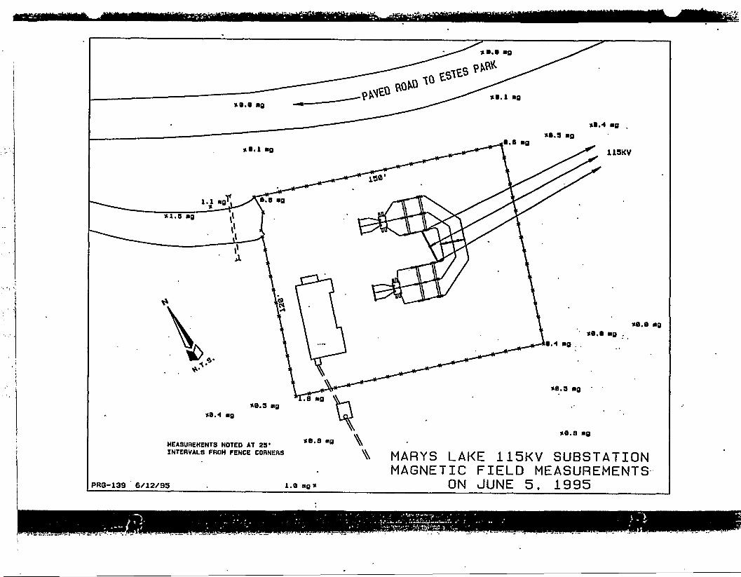
»B.axe.t ag .
ag
»0.9 ag
XB.8 ag
HEASUREHENTS NOTED AT 23*INTERVALS FROM FENCE CORNERS
PRG-139 6/12/95 1.a ng *
MARYS LAKE 115KV SUBSTATIONMAGNETIC FIELD MEASUREMENTS
ON JUNE 5. 1995

COMBINED OUTPUT: AUDIBLE NOISE. RADIO NOI8E1 TVI, OZONE CONCENTRATION. GROUND GRADIENT* MAGNETIC FLD
E8TE8 POWER PLANT SWITCHYARD TO MARY?CAKr-SUBSTATIONPARALLEL U9KV AND 69KV TRANSMISSION LINES . . .
— -ACNAME DC
Cl " ACBl ACA! AC
ACACACACACAC• A C
Oil012C2B2A2021022
LATERAL"DI8T(FEET)-42. 00-30. 00-18. 00-36.00-24. 0020.0030.0040.0029.0039.00
BUNDLE—CTR HT(FEET)22.0022.0022.0032.0032.0022.00
' 22.0022.0032.0032: 00
NO."OF
COND—1 "•11 "
- COND;DIAM(IN)
0. 720"0.7200.7200.360•0.3600.7200.7200.7200.3600. 360
-AN EF PHASE CURRENT—PHASE ORAD. LOSSES(KV) (DEO)
73.0373.03
—oroo0.00
120.0, 0.6
EQV: VOLTAGE;--tINE=NEUTRA!8PA(IN)
"O;O0"0.000.000.001
0.000.00
o:oo0.000. 00
o;oo
NE" iKAX—CORONA
(KV)-71.-37-. 71. 97(
71. 97- - 0:00-
0.0042.94
~ 42: 94"42.940.00
0.043. 82 240. 0"43:82—12070"43. 82 0. 00. 00 O. 0
0:00 0:00 o;o"
90.2"0:0.0
T209. 2--209.-2-209. 2
0.0OVO
(KW/MI)"07132-0.2080. 142
(AMP) (DEO) (KV/CM)—3072— 24070—12792-90.2 120.0 13.43
0. 0 12. 66070 1781 070000.0 1. 90 0.000
240. 0 7. 89 0. 00712070 8733 0.009—0.0 7.67 0.0090.0 0.94 0.000
1707 07000"
iowort I*.
"0. 0'
AN MIC. HT- 9. 0 FT ALTITUDE- 7S00. 0 FT.RI ANT. HT- 3.0 FT. " RI FREQ. - I. 000 MHZTV ANT. HT- 10. 0 FT TV FREO. - 79. 000 MHZ
E-FIELD DET. HT- 3. 3 FT WIND VEL. - 1.00 HI/HRM -FIELD DET." HT«~3. 3 FT RAIN RATE*-0.047~IN/HR "OZONE DET. HT- 0.0 FT OND COND. - 4.00 MMHO/M
LATERAL DI8T-FROM
REFERENCE(FEET)
-300.0-290. 0-280. 0-270. 0--260. O-290. 0-240. 0
-—-230. 0-220. O-210. O-200.0 ~--190. 0-180. 0
— -170.0 ~-160. O-190. 0-140. O-130. 0-120. O.
<-uo. o -•-100. O-90.0-80. O-70.0-60.0
~ "-SO. 0-40.0-30. 0-20.0 •-10.0
-AUDIBLE NOISe~-RADIO INTERFERENCE-(RAIN) (FAIR) (RAIN) (FAIR)LSO LSO L50 ' L90DBA ••• DBA " DBUV/M DBUV/M
TOTAL(RAIN)DBUV/M
-7.1
39.239.739: 334.2
(RAIN)(MIND)^""PPB7
0.000000-07000000"0. OOOOOO0.OOOOOO0:000000~0. OOOOOO
0.oooooo707000000"o.ooooooo.oooooo0700000 o~:0.oooooo0.oooooo07000000'o. oooooo0. oooooo070000006.ooooooo.oooooo0:oooooo0.oooooo0.ooooooO.'DOODO0. ooooooo. oooooo
0000
o. oooooo0. 023312•070600 n "0. 079904
£=ELECTR IC=MRONETIC-FIELD FIELD
INTENSITY INTENSITYKV/M • —"-~OAUSS —'
• 0.009 •• 0.00012 ,! 07006 OTOOOra
0.0060.007
-0.008'0.0090.010-0701 r
0.000140. 0001970700019, -• :0.00016 :,: 0.00P17 ;<;;..;W.OOOlB0.00019 '0. 00020
• - 1
0.000220. 0002407000290. 000260. 000270:000270. 000270.0002707000280. 000340.0009707001090.002170.00442
0. 01488: 01923
1.426u.021IB' 0.02093.
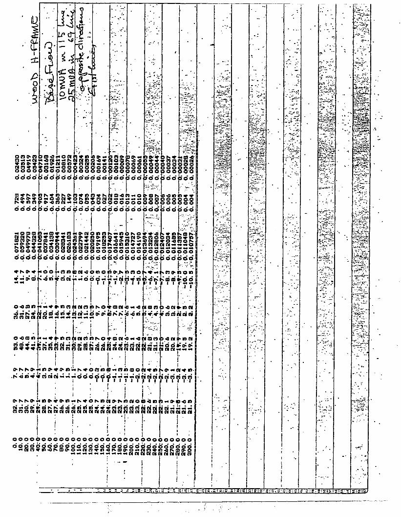
1i•0
•O O ^ W€!»«•««
oooo
. 72B
0.
. 494
0.
. 997
0.
. 349
0.
OOOO
•M o 00 00
••
i• -
• * •
ii
11h
) O 4 ; J O N I
f n«<**po3 O O O O O> d d p d d i
iaxojN*
1:"0
h
'••; •
j .r ,
siiiii:s do* i
' -
• -
* • < • « * . -
, • v" :
• » -»• •
- .
. — * .
J5S
-
• * i . • <i! « * , • • -
'"» "\*rr
is§§§§sddddo'do'ci
IIIidd
*• ON
SS8id doododcido'cioddpddddo'
-
<IMtlOI)nSxl)6NO • «* -Q
-
rnnitSSn} O O O O O) P O O O P. • • I • • •
>oopoo
o<ann w3 O O P P Q3 O O p O O
>OO' 3OO
• - • . • • " '
SnS>npS"fnSnK?SHSS3o>(5EI!i58§*§SBSi>!oooo'dddd
«r -« o* m
O-0tD*>
o-oo«
>ooboo
< o o\4*n<
-nt>t
•*•* • t» n n i
« t« IV • • »^ »•» »^ » . ^ wm m ^ i
3OOOOOOOOOOO
DM41•««4O<
!]
I
adciodd. idd
BflO!, T «
1 I"
9<0Di
II ««<O 1
innnnnnunoinnnnannn> i !
• !)»«
1
iNtonina tooi
» o oidd
nmn
w o n
I N N
( * «
NHjn*«oMw-.--.ooopoo-Yt77^7«5"i : . ' . i
o.NNO.-«D.iro.nlN*ON«»i»o.NrIMOI
nnnnifSnMMnNnMSSNNNSnSnnnclicii
ij
; 1i* i
' : i ! 1
oooooooooooooooooooooooooc
^ *^ *• >oooooiddt
* Cl 0M.„.»do*' "• v Vi
COOrTT
• . -
triciwacit
94«»nn
j "i
•????•?
innnnni
IOOOOOoooooooooooooooooooooooooooooop
«Mn»o4MH>ojijijn»i)'Oj>ojo«jjnjtnjjNajjo
• i
; : i* 1
j* * ;
• • , - - - 2 Z Z 2 1 = ! - - - - S } , 5 ,
i
•
i
• •
•
•
i
:t;
\
' - 1J »
A. • . - . f . . - j : - - • » ! . , .
I
> -*
^ ~ ' *
. - . " . * . ; :
• ^
• "*? r
- ' •
•
•
*
. - •
•
• -
•
•
•
-
-
•
':• V-
• * • » " * • . * » «
• " ? *•"•!><2 V .* v^T
•^ - ' I »*.*•
^ -**! /• ?• *
\-^»'-"
- i"
***
' ^ "
•
-
! •
1
-
- . . .
- 4
»
c
- - .* -* j
.V* " -
-
. - •
" -* . . l
•
-
*
1
••
I
ii
ii . - . . . n . . . |
-
1
- - •
* $ &
£-"*•*£*-
*?°^" . •* *
%* *^*
'-I- ""• . - •
-*-?**. I*
; * ' • " "
» '
\
* - ••••* '
. . .
" • -
[
%%
" * " * •
- -I *
^^^^
SS
. — <". ""•y-. ;•
i ";• • »
'••''"?'?•)'•
??%>£&:
w^ • * * *
• • * ,
• # :
• ' . " .

OCT 24 '95 HKKH t&O DiVi.=jiun JKIJ C C S
uoeoeeeQooo
i £§52 ! ItkZ epoopoopoopooooopooooooo-
saopoopoopooooopeopdddo'b'ddidddb'dddddddddddpdo'p'dob'd
n
Zti66666666'6 i-'Sz «- s
Qt KM^Ufi" • • •<tSBt, OOOOOOOOOO
bl i z ) f H UJ - • • • • •'•
• >-J<*B«DWOOJ>O*OO
ooooeoooaooooooooooooooooooooo <

C", ' KJl-aarn rnrt-i L&U c o aci3 \ j
&o>ed >d
OO' >OO XO.p:

UUrPUT: AUDIBLE NfllSC. RADIO NOISE, TVI . OZONE CONCENTRATION. GROUND GRADIENT. MAGNETIC FLD
. LOWER.PLANr.3VUTCH/£RD...T0 hARYS.LAHE-SUBSIATim
•It-i nsi 'v on HUDD H-FKAME AND HSKV ON SINCLE STEEL POLE
NAME
CI . .GiSi
un612C?JB2.. ...A2
ACnc—ACAC'»CACACAC
.v:,-,r.
LATENAL.DISTtFEETI.-42. OO_.
• -30. 00 •- 18. COr36. 00 .-24. 0022. SO
BUNDLE ..CTR HT(FEET)-22. .0032 0022.00
. 32.0032.0022.00
. ..37—50 34_SQ._£2.5030. 00
47.00S3. 50
•NO.OF
COND..I _.11
• t-1!
. 1_t1
. CnMU__EOV. ...OIAM(IN)
o ?eo..0 7200. 7200. 2e>i}0.3600 7200—Z2Q...0 7200 360
SPA(IN)
VOLTAGE.—AN<KV)
_Q.flD-_. .71.57—o. no0.00
. 0. 00 .0. 000. 00
—Q..OO—O. 000. CO
71 5771 57
.. Q.QO-0.00
71. 57 "—71..S7..-71 570. 00
_LitJ£=NEUXflAL——EF PHASE
(KV> (D6Q)-73-0a_ 24O_O~,73 03 ISO. O73 03 0.0_.O.tiQ__ .0-0..
0.00 0.073. 03 240. 0
.J73-03. -iao.,.0-7U. 03 O. 0
0. 00 0. 0
i MAK fOROMACURRENT—PHASE CRAD;.., LOSSES
(AMP) (DEO) <KV/CM) (KU/MI)
B7 9S7. 9
O.I)0.0
87.9_..-__BX_SL_i2a
B7. 9 0, O0.0 0 0
120 0 13. 48 0 .2130. 0 12. 47 O. 128
- . 0_O 1-52 ,0. OOP.0.0 1.83 .0.000
240.0 12,43 0! 189n H I T ' f\ mo
11.883. 63
0.0946.000
AN HiC. KT» 5.0 FT ALTITUDE^ 7S00 0 FT. E-FIELD D£T. HT«= 3 .3 FTHI ANT. HT* 3.0 FT RI FPEB = 1 OOO MHZ M-FIELD OCT.. HT= 3.3 FT '
T-. HT.«. JlQ-O-ET TV_FIlEa..=.. 7S.IH3O-MHZ OZONE -DfiT. MTa 0. 0 F-T--
WIND VEL. • 1.00 Mt/HR •RAIN RATE- 0. 047 JfN/HR •CND CDNf> — 4 00 MHHO/M $.'.'••
_,'»ITPAL OiST AUDIBLE NOISE MADID INTERFERENCE 'TVI OZONE ELECTRIC MAGNETIC._. fROil ...{RAitlJ (FAIHJ . iftAINl (FAIR) IQTAI lUhlUl :. EJELD F a E L O — —HF-FfMEKCE LSO LSO LSO LSO (RAIN) ' (MIND). INTENSITY INTENSITY
DBA. DBA OBUV/H DBUV/M DBUV/H . PPB ' KV/M • OAUSS V:
0. OOOOOO O. 0060. OOOOOO O. 006
-.r-.5~S— 0- OOOOOO iK-OOh-0. OOOOOO O. 007O. OOOOOO 0. 007
o. 000220. 000230. 00023,0.00027
o • nnifity •••• yt, :^...;;y •<' -ft'•'••'•••,>.•. '•'•;':• •
ino
LOS
I-'
0 OOOOOOo oooooq
- 0..OOOOOO—
o. oooooo0. 0000000. OOOOOQ0. OOOOOO0. OOOOOO
O. 008.O. 008
0.0003SO. 00038
o. oiq .0. 011,O. 012 •
i ." ' , ^ 7 — :
2.0..-.0. OOOOOO0.OOOOOOo. oooood 'O..OOOOOO— -0. OOOOOO
o. odoooo,-O, OOOOOOr- - •0. OOOOOO0. OOOOOO
Jt—aoooooOf—14.2 O. OOOOOO17 5 O. OOOOOO
0.014O. 016
. OL-0200.026O. 03«
0. QOO64O. 0OO73O. 0OO940.000970.00113'
* . I * ! -
0.0650. 09i
0.00161o; 00199-a aoasi-
0.2290; 377 0:.0044S
80.-5-22.8
• • 20. 5
it. OOOOOO
5 2 . 35.2.
O. 02397* '- 0 .061919 .
0. O7547A ;
1 HO1.658
—1^4800.6421. 441.
0. 009630. 01477o.qivga-0,0214?^' '•o..ba696":'V'-
0.0l74»'' -'
••}?••.'-•
14. 2 O 070271 0 950 0.01422
5)o

f
*
r no cdc
o-cv
-5
m o
§ |000tn ^OO
nuv i
•
-
•
•
• *
n in o••• • 5-«-«coocd o c
«r S3•4 d c
o»o'-
« » rJOCO.O C
doe
. . .
r
r
.:-'
«»• gg?ooo
IS. 1*1 «# ••* * - **i/> w r
ooe
0»~ 0•<r» o(DO »O O C
ooodq
23
«r • *
«r f»
a e<
,rlr,r
•
O O Cooc
r
• ' . - . .>• : .
»• • * r
- -K*.
"• ".
• .-• • " * .
nn'rON J:SOC
ddqodc
>r>iR cjo> o r
-oqoocdd dticdddd
i
• •i
o 5 a wo- <
io- in dn*c
N m jv ? 5o o q o o a. o S 3 8 8 2dbdoddooQ
O -C IT
N «T J <D N C
•
ooc
«O Q ITAn 4ooc
o o c
*•" . *
« .. ,
'• - "•"*" •
. \
- ~ . . >
Z r ' ,
• ; ' ~ ' : .
o c5 cS8lo'6c
•
i'Nnoj«oo-8 8 c!e»oco o qooc
•
N •" *O 01 <tf <0 -0 flfs »> <*< <r lf» N
•
' *
••7. . '•*?f''
* "• T
_ ** ™ •**
•-'.••.
nwnooo«P3Cf» nno o essisss
OOQOOC
(• N <| 1W "•'•C
ooqoocdddddc
me- JtsVi^
Sodooaooooocooooooooaoooooc
.: r i ii j i
{D f*X * i O ^ O tf>'t« ( • ift C$ <f 09
•
•a m i « •• ff:
i tt In tt *** &* ^ *O V tfy fW * (^ 9* Qt |s r i 4 s l C 4
; • . 1 :• 1i • • '
•
«d pi d a iri w d ffli -Q *' ri •» o o' s• i '
i
I
m ru c* w w ra « w cu w r» n*
i
*' •si a N <i < i) T • ri ri ri ?i •• j - - •) ci 6 o o 6 o" o ; c<« « ,•I *; . j i i! i i i: i i ••
• ' i ' '
o *>:
0) PI
1!
• *..-••«**,« J«J»J*J.c.J...«
i ; ! •'•
•
•
" V
•l5H|!t
:";~ "si
'.*•'. J . - '
joini
god
od
373
is
o
o
1
;
ra
o
T
DOOodoQcoqdscaoooooooodooooodoo ^ Oi 2* O o* 9 *~ 5 5 *5 " * " ~" ~ 3* ^ 5 9n ** fl £ & 7 o fi'rt^tfS ^ f*- fli ".»• o *< rt ifr * in OK Q (
'; ; . i\W \— r-T • • » • 1
i i '
1
\ * '"•'
* '
ii j
i "r
i i.. '• i 'ii •
i
i •
•
:
.
•
. • • .
*e * r .*
'» . r •
SJ'Ji •*.£*
•
. -
' "• 1• 1
1
t1 . 1
•
!
•
' i • : ! «
i
i
i
i
; . •i
I
•
. i
i :! !-••
i
1 •
i: .I *
•
I; •
\ I <1
1
* .*
' :• •
_ .* *
: •
> • •
* % . '
- • ' • > : , > •
• * • " #
. "•*, T .
• * • • . " •
- . ' •
t
•
'.•*'••?'"•
- ydf"
Vv":-1••'•f - ' -
Si", ' Tt i»- • *• • '
- ~*'. -
• i !
•"
•i
i •
•1 '
•
•
*
' .
;
! - •
I
1
i
.
11
|
1
-
I
I1
i 1 "! • •
•
^ ^
P
ISl~* * • " , ^
; ^ - • • >
* ' \ :
• • • * * *
•
• -

NOV 03 _'95 .03:28PM PRPfl
1"303 229 5219- P.2
dddddo'ddo'dddddo'ddaddd-idit
jdddddq q.9 oddSooooood0 +1
d d d d d d dddd d. dodo d
i io d d -*' * « ni in
i •• ! ; i
s ffl' 0> d M n V
ji
2 2 2
1 oS •* « *
ninini
d d
n) 01 n c> «JJ 0 CJmtf-'in A
' ni ni <w ni ri ri in' ri «r • + titi-6 <61> K cd ai o» d •« ni ni ni
j I ! : ; : -7~r
1 niruoi n 1
3c +
•
C3 +• j • u; a.
+ HB|t• < . —fJ•+ o u i u^yuuu+ < a t <*<<<.<
i• ul :• X / '•f z <nuou<a«0
00000000009000000000009000000000

-tr-\3 L ,.—u f : t. . • • «. i. • v i.
•
I •
:.' .1
:« " . I
V "
pppooppooop
• • ? < • • • • . • •
000000000000000000006000ppp000
>i -o
U » M N U MMCBI>0I>p
I • ;
UMMUUNUUIUItMiaNiuuuuduudiuuu
u*9>cpoijvjbiow«)»**eo-»I
( : I i ! i j~ v m IB m o * 9 p j - M (o u -f * J* • >J p P r W
j
j•f •"
i: I !
•.•».. >.»,•• »d>»>-ip>*>-*>>«>«»IUIUIllUMf)R}UUI
P!p!*!*r'N!uti>U4>0«l(h^Ma4Q^j)«>U'M4pN(
I t i I I j. 1 u U'd) M M •• •» 6 ; i p p ;• M M 9] * u j • p.p lu J
eeAoQ9ogoooooodoo
I i\I I O I»N|IN»IIUUII
-rrvi--
p p < > p o $ o o <p p p jp o p; > p p; i p p p cI tI1 _ _I >0O$0oo
^288S8Soo i —loacoo
lOMr - ~
SS ^ ooocIIOOOC
"O U . o 6I2S 622..E0E.NOiSIAia Q"83 bddd Wd82:E0 S6, E0 AOKJ

APPENDIX GALTERNATIVE ROUTE IMPACT EVALUATION
Kmssstttt^w&s^^

Table G1
Preliminary Alternative RouteImpact Evaluation Criteria
Alternative
Criteria
Route
Links
Alt. A
1 2
Environmental Planning (Natural, Human
Land Use - Number ofexisting residentialparcels adjacent to, orcrossed by, right-of-way
Land Use - Number ofnew residential parcelsadjacent to, or crossedby, right-of-way
Land Use - Number ofcommercial parcelsadjacent to, or crossed .by, right-of-way
Land Use - Number ofoccurrences that wouldprohibit otherdevelopment of property
Land Use - Number ofparcels crossed wherenew right-of-way wouldbe required
Occurrences
Impact Total
Criteria Ranking
Occurrences
Impact Total
Criteria Ranking
Occurrences
Impact Total
Criteria Ranking
Occurrences
Impact Total
Criteria Ranking
Occurrences
Impact Total
Criteria Ranking
0 48
3
and
41
4 1
Cultural)
0
89
0
2
0
i
3
1
2
i
t
0
5
4
r
1
\
0
0
0
0
0
1
0
c
1
0
)
0
0
Alt
2
48
.B
5
7
4
Alt. C
1
0
55
0
1
3 57 0
60
2
0
0
2
i
0
c
1
0
t
0
\
0
>
7
r
0
0
0
0
6 7
65 7
4
0
72
3
0 61 8 0
69
3
2 25 1 0
28
6
0 0 1 0
1
3
0 89 8 0
97
5
i
1
0
Alt. D
6
65
9
23
.88
5
0 61 30
91
4
2 25 0
27
5
0 0 1
1
3
0 89 23
112
6
i
8
49
Alt. E
7
7
4
0
56
2
88 8 0
96
5
3 1 0
4
2
0 1 0
1
3
52 8 0
60
3
Alt. F
8 9
49 23
72
3
88 30
118
6
3 0
3
1
0 1
1
3
52 23
75
4
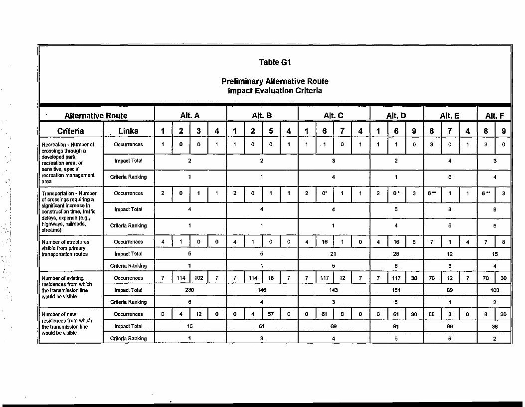
Table G1
Preliminary Alternative RouteImpact Evaluation Criteria
Alternative
Criteria
Recreation - Number ofcrossings through adeveloped park,recreation area, orsensitive, specialrecreation managementarea
Transportation - Numberof crossings requiring asignificant Increase inconstruction time, trafficdelays, expense (e.g.,highways, railroads,streams)
Number of structuresvisible from primarytransportation routes
Number of existingresidences from whichthe transmission linewould be visible
Number of newresidences from whichthe transmission linewould be visible
Route
Links
Occurrences
Impact Total
Criteria Ranking
Occurrences
Impact Total
Criteria Ranking
Occurrences
Impact Total
Criteria Ranking
Occurrences
Impact Total
Criteria Ranking
Occurrences
Impact Total
Criteria Ranking
Alt. A
1
1
2
4
7
2
0
r
1
0
A
1
1
j
1
114
3
0
i
1
\
0
102
4
1
1
0
7
230
0
i
4
5
12 0
16
1
Alt. B
1
1
2
4
7
2
0
*
1
0
A
1
1
£
1
114
5
0
1
\
0
18
4
1
1
0
7
146
0
A
4
\
57 0
61
3
Alt.C
1
1
6
. 1
70
4
1
3
4
2 0* 1 1
4
1
4 16 1 0
21
5
7 117 12 7
143
3
0 61 8 0
69
4
Alt. D
1
1
6
1
9
0
2
1
2 0* 3
5
4
4 16 8
28
6
7 117 30
154
5
0 61 30
91
5
Alt. E
8
3
70
4
1
4
6
6 " 1 1
8
5
7 1 4
12
3
70 12 7
89
1
88 8 0
96
6
Alt.F
8
3
9
0
3
4
6 " 3
9
6
7 8
15
4
70 30
100
2
8 30
38
2

Alternative
Criteria
Number of Commercialdevelopments fromwhich the transmissionline would be visible
Number of structuresvisible from recreationareas
Number of structuresskylined
Number of prominentdeviations in thealignment
Number of structuresvisible in sceniclandscapes
Number of structures invery steep slopes(>50%) with soilssusceptible to erosion,slump and creep
Route
Links
Occurrences
Impact Total
Criteria Ranking
Occurrences
Impact Total
Criteria Ranking
Occurrences
Impact Total
Criteria Ranking
Occurrences
Impact Total
Criteria Ranking
Occurrences
Impact Total
Criteria Ranking
Occurrences
Impact Total
Criteria Ranking
Table G1
Preliminary Alternative Route° Impact Evaluation Criteria
Alt. A
1
8
2
18
3
1
4
1
28
2 0
\
2 2
6
2
0
r
2
i
0
>
1
I
3
0
0
0
0
0
t
1
0
>
4
5
0
2
0
o
1
Alt. B
1
8
2
18
5
0
4
1
27
3
2 0 14 2
18
6
2 2 6 0
10
6
0 0 2 0
2
1
0 0 14 2
16
4
0 0 6 0
6
6
Alt. C
1
8
6
48
7
0
4
1
57
6
2 0 2 2
6
2
2 2 0 0
4
1
0 6 3 0
9
5
0 0 8 2
10
2
0 0 0 0
0
1
Alt.D
1
8
6
48
9
0
56
5
2 0 2
4
1
2 2 0
4
1
0 6* 3
9
5
0 0 13
13
3
0 0 3
3
4
i
8
6
Alt. E
7
0
4
1
7
11
2
2 2
15
5
8 0 0
8
4
5 3 0
8 -
3
16 8 2
26 -
5
0 0 0
0
1
Alt. F
8
6
9
0
6
1
11 2
13
4
8 0
8
4
5 3
8
3
16 13
29
6
0 3
3
4
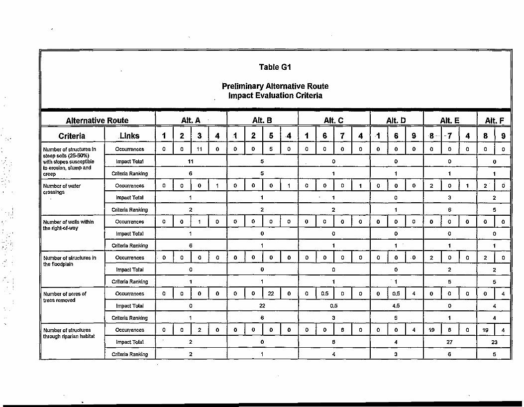
Alternative
Criteria
Number of structures insteep soils (25-50%)with slopes susceptibleto erosion, slump andcreep
Number of watercrossings
Number of wells withinthe right-of-way
Number of structures inthe floodplain
Number of acres oftrees removed
Number of structuresthrough riparian habitat
Route
Links
Occurrences
Impact Total
Criteria Ranking
Occurrences
Impact Total
Criteria Ranking
Occurrences
Impact Total
Criteria Ranking
Occurrences
Impact Total
Criteria Ranking
Occurrences
Impact Total
Criteria Ranking
Occurrences
Impact Total
Criteria Ranking
Table G1
Preliminary Alternative RouteImpact Evaluation Criteria
Alt. A
1
0
2
0
3
11
40
11
0
0
0
0
0
£
0
1
*•
0
1
t
0
c
1
0
c
1
0
>
0
I
1
)
0
)
0
)
2
>
1
0
0
0
0
Alt. B
1
0
0
2
0
s
c
0
5
5
0
4
0
1
1
0
0
0
0
c
1
0
c
1
0
0
)
0
)
22
0
0
0
22
0
e
0
c
1
0
>
0
Alt.C
1
0
0
0
0
0
6
0
c
1
0
1
0
c
1
0
c
1
0.5
70
)
0
0
)
0
)
0
4
0
1
0
0
0
0.5
0
*
0
E
i
J
8
J
\
0
Alt. D
1
0
6
0
9
0
0
1
0 0 0
0
1
0 0 0
0
1
0 0 0
0
1
0 0.5 4
4.5
5
0 0 4
4
3
i
8
0
Alt.E
70
4
0
0
1
2 0 1
3
6
0 0 0
0
1
2 0 0
2
5
0 0 0
0
1
19 8 0
27
6
Alt.F
8
0
9
0
0
1
2 0
2
1
0
C
1
2
5
c
0
i
t
19
0
)
0
I
4
I
\
4
23
t

Alternative
Criteria
Number of structurespotentially impactingThreatened &Endangered species
Number of acres ofwildlife habitat removed
Number of spans thatmay increase potentialfor bird collisions
Number of structurespotentially affectingarchaeological sites
Number of structurespotentially affectinghistoric Sites
Route
Links
Occurrences
Impact Total
Criteria Ranking
Occurrences
Impact Total
Criteria Ranking
Occurrences
Impact Total
Criteria Ranking
Occurrences
Impact Total
Criteria Ranking
Occurrences
Impact Total
Criteria Ranking
Table G1
Preliminary Alternative RouteImpact Evaluation Criteria
Alt. A
1
0
0
0
0
0
2
0
i -
1
0
c
1
0
c
1
0
c
1
0
c
1
3
2
>
0
)
0
)
0
)
0
)
4
0
0
0
0
0
Alt. B
1
0
2
0
5
22
4
0
22
4
0 0 22 0
22
6
0 0 12
12
0
2
0 0 0 0
0
1
0 0 0 0
0
1
Alt. C
1
0
6
0
78
4
0
8
3
0 0.5 0 0
0.5
2
0 6 8 0
14
3
0 0 0 0
0
1
0 0 0 0
0
1
Alt. D
1
0
6
0
9
4
4
2
0 0.5 4
4.5
4
0 6 12
18
4
0 0 0
0
1
0 0 0
0
1
i
8
19
Alt. E
7
8
4
0
27
6
0.5 0 0
0.5
2
15 8 0
23
5
0 0 0
0 .»
1
0 0 0
0
1
Alt. F
8
19
9
4
23
5
0.5 4
4.5
4
15 12
27
6
0 0
0
1
0 0
0
1
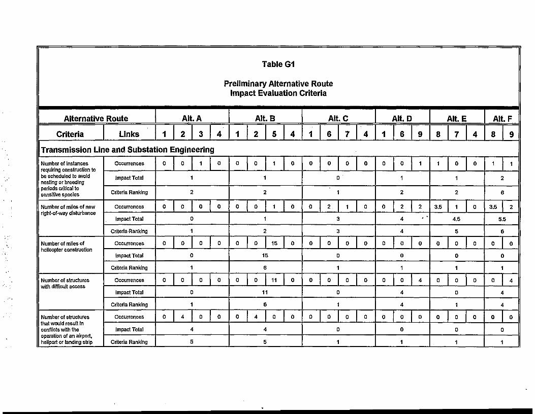
Table G1
Preliminary Alternative RouteImpact Evaluation Criteria
Alternative
Criteria
Route
Links
Alt. A
1 2 3 4
Transmission Line and Substation Engineering
Number of instancesrequiring construction tobe scheduled to avoidnesting or breedingperiods critical tosensitive species
Number of miles of newright-of-way disturbance
Number of miles ofhelicopter construction
Number of structureswith difficult access
Number of structuresthat would result inconflicts with theoperation of an airport,heliport or landing strip
Occurrences
Impact Total
Criteria Ranking
Occurrences
Impact Total
Criteria-Ranking
Occurrences
Impact Total
Criteria Ranking
Occurrences
Impact Total
Criteria Ranking
Occurrences
Impact Total
Criteria Ranking
0 0
1
1 0
2
0 0
c
1
0 0
c
1
0 0
c
1
0 4
t
J
0 0
>
0 0
)
0 0
)
0 0
I
Alt. B
1
0
2 5
0 1
4
0
1
2
0 0 1 0
1
2
0 0 15 0
15
6
0 0 11 0
11
6
0 4 0 0
4
5
Alt. C
1
0
0
0
0
0
6
0
c
1
2
0
C
1
0
c
1
0
c
1
7
0
)
1
J
\
0
)
0
)
0
)
4
0
0
0
0
0
i
1
0
Alt. D
6
0
9
1
1
2
0 2
4
2
4
0 0 0
0
1
0 0 4
4
4
0 0 0
0
1
i
8
1
Alt. E
7
0
4
0
1
2
3.5 1 0
4.5
5
0 0 0
0
1
0 0 0
0
1
0 0 0
0
1
AltF
8
1
i
3.5
9
1
>
2
5.5
e
0
C
1
0
A
A
0
c
1
i
0
)
4
I
\
0
)

Alternative Route
Criteria
Number of angles in thealignment of 41 °-90°
Number of angles in thealignment of 2 ° -40°
Links
Occurrences
Impact Total
Criteria Ranking
Occurrences
Impact Total
Criteria Ranking
Link Totals
Alternative Route Impact Totals
Alternative Route Rank Totals
Alternative Route Ranking
Table G1
Preliminary Alternative RouteImpact Evaluation Criteria
Alt. A
1
0
2
0
3
1
4
1
2
1
1 0 2 0
3
2
29 196 192 16
433
72
1
Alt. B
1
0
2
0
5
2
4
• 1
3
2
1 0 1 0
2
1
29 196 303 16
544
98'
3
Alt. C
1
0
6
2
7
0
4
1
3
2
1 6* 3 0
10
6
29 508 88 16
641
91
2
Alt. D
1
0
6
2
9
2
4
4
1 6* 0
7
5
29 SOS 206
743
108
4
i
8
5
Alt. E
7
0
4
1
6
5
3 3 0
6
4
482 88 20
590
110
5
Alt. F
8
5
9
2
7
6
3 0
3
2
402 206
608
121
6

APPENDIX HSTANDARD CONSTRUCTION PRACTICES
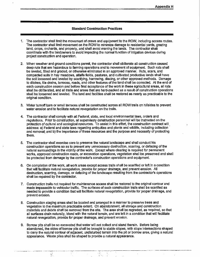
Appendix H
Standard Construction Practices
1. The contractor shall limit the movement of crews and equipment to the ROW, including access routes.The contractor shall limit movement on the ROW to minimize damage to residential yards, grazingland, crops, orchards, and property, and shall avoid marring the lands. The contractor shallcoordinate with the landowners to avoid impacting the normal function of irrigation devices duringproject construction and operation.
2. When weather and ground conditions permit, the contractor shall obliterate all construction causeddeep ruts that are hazardous to farming operations and to movement of equipment. Such ruts shallbe leveled, filled and graded, or otherwise eliminated in an approved manner. Ruts, scars, andcompacted soils in hay meadows, alfalfa fields, pastures, and cultivated productive lands shall havethe soil loosened and leveled by scarifying, harrowing, discing, or other approved methods. Damageto ditches, tile drains, terraces, roads, and other features of the land shall be corrected. At the end ofeach construction season and before final acceptance of the work in these agricultural areas, all rutsshall be obliterated, and all trails and areas that are hard-packed as a result of construction operationsshall be loosened and leveled. The land and facilities shall be restored as nearly as practicable to theoriginal condition.
3. Water turnoff bars or small terraces shall be constructed across all ROW trails on hillsides to preventwater erosion and to facilitate natural revegetation on the trails.
4. The contractor shall comply with all Federal, state, and local environmental laws, orders andregulations. Prior to construction, all supervisory construction personnel will be instructed on theprotection of cultural and ecological resources. To assist in this effort, the construction contract willaddress: a) Federal and state laws regarding antiquities and plants and wildlife, including collectionand removal; and b) the importance of these resources and the purpose and necessity of protectingthem.
5. The contractor shall exercise care to preserve the natural landscape and shall conduct hisconstruction operations so as to prevent any unnecessary destruction, scarring, or defacing of thenatural surroundings in the vicinity of the work. Except where clearing is required for permanentworks, approved construction roads, or excavation operations, vegetation shall be preserved and shallbe protected from damage by the contractor's construction operations and equipment.
6. On completion of the work, all work areas except access trails shall be scarified or left in a conditionthat will facilitate natural revegetation, provide for proper drainage, and prevent erosion. Alldestruction, scarring, damage, or defacing of the landscape resulting from the contractor's operationsshall be repaired by the contractor.
7. Construction trails not required for maintenance access shall be restored to the original contour andmade impassable to vehicular traffic. The surfaces of such construction trails shall be scarified asneeded to provide a condition that will facilitate natural revegetation, provide for proper drainage, andprevent erosion.
8. Construction staging areas shall be located and arranged in a manner to preserve trees andvegetation to the maximum practicable extent. On abandonment, all storage and constructionmaterials and debris shall be removed from the site. The area shall be regraded, as required, so thatall surfaces drain naturally, blend with the natural terrain, and are left in a condition that will facilitatenatural revegetation, provide for proper drainage, and prevent erosion.
9. Borrow pits shall be so excavated that water will not collect and stand therein. Before beingabandoned, the sides of borrow pits shall be brought to stable slopes, with slope intersections shapedto carry the natural contour of adjacent, undisturbed terrain into the pit or borrow area, giving a naturalappearance. Waste piles shall be shaped to provide a natural appearance.

Standard Construction Practices
10. Construction activities shall be performed by methods that prevent entrance or accidental spillage ofsolid matter, contaminants, debris, and other objectionable pollutants and wastes into flowing streamsor dry water courses, lakes, and underground water sources. Such pollutants and wastes include, butare not restricted to, refuse, garbage, cement, concrete, sanitary waste, industrial waste, radioactivesubstances, oil and other petroleum products, aggregate processing tailings, mineral salts, andthermal pollution.
11. Dewatering work for structure foundations or earthwork operations adjacent to, or encroaching on,streams or water courses will not be performed without prior approval from appropriate stateagencies.
12. Excavated material or other construction materials shall not be stockpiled or deposited near or onstream banks, lake shorelines, or other water course perimeters where they can be washed away byhigh water or storm runoff or can in any way encroach upon the actual water source itself.
13. Waste waters from construction operations shall not enter streams, water courses, or other surfacewaters without use of such turbidity control methods as settling ponds, gravel-filter entrapment dikes,approved flocculating processes that are not harmful to fish, recirculation systems for washing ofaggregates, or other approved methods. Any such waste waters discharged into surface waters shallbe essentially free to settleable material. Settleable material is defined as that material that will settlefrom the water by gravity during a 1-hour quiescent period.
14. The contractor shall utilize such practicable methods and devices as are reasonably available tocontrol, prevent, and otherwise minimize atmospheric emissions or discharges of air contaminants.
15. Equipment and vehicles that show excessive emissions of exhaust gases due to poor engineadjustments, or other inefficient operating conditions, shall not be operated until corrective repairs oradjustments are made.
16. Burning or burying of waste materials on the ROW or at the construction site will not be allowed. Thecontractor shall remove all waste materials from the construction area. All materials resulting from thecontractor's clearing operations shall be removed from the ROW.
17. The contractor shall make all necessary provisions in conformance with safety requirements formaintaining the flow of public traffic and shall conduct his construction operations so as to offer theleast possible obstruction and inconvenience to public traffic.
18. Western will apply necessary mitigation to eliminate problems of induced currents and voltages ontoconductive objects sharing a ROW, to the mutual satisfaction of the parties involved. Western willinstall fence grounds on all fences that cross or are parallel to the proposed line.
19. The contractor will span riparian areas located along the ROW and avoid physical disturbance toriparian vegetation. Equipment and vehicles will not cross riparian areas on the ROW duringconstruction and operation activities. Existing bridges or fords will be used to access the ROW oneither side of riparian areas.

APPENDIX IPHOTOGRAPHIC SIMULATIONS

Existing ConditionIllustrating existing 115,000 volt transmission line (left)
and existing 69,000 volt transmission line (right).
Photographic SimulationIllustrating upgrade of existing 69,000 volt transmission line
to 115,000 volts using wood H-frame structure.
Proposed Action, H-Frame Structure Figure 1-1

Existing ConditionIllustrating existing 115,000 volt transmission line crossing
Marys Lake
Photographic SimulationIllustrating new 115,000 volt transmission line (left) on wood
H-frame structure next to existing 115,000 volt wood H-framestructure.
Proposed Action, H-Frame Structure at Marys Lake Figure 1-2

Existing ConditionMarys Lake Substation
Photographic SimulationIllustrating the Expansion of Marys Lake Substation.
Proposed Action, Expansion of Marys Lake Substation Figure 1-3

Photographic SimulationIllustrating the Expansion of Marys Lake Substation.
Photographic SimulationIllustrating screening of Marys Lake Substation utilizing 10-15'
trees.
Proposed Action, Screening of Marys Lake Substation Figure 1-4
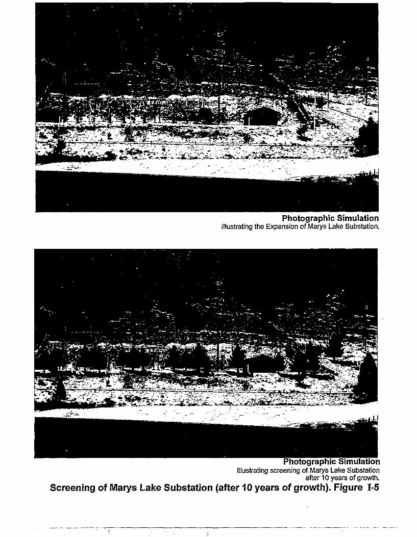
Photographic SimulationIllustrating the Expansion of Marys Lake Substation.
Photographic SimulationIllustrating screening of Marys Lake Substation
after 10 years of growth.
Screening of Marys Lake Substation (after 10 years of growth). Figure 1-5

Existing ConditionIllustrating existing 115,000 volt transmission line (left)
and existing 69,000 volt transmission line (right).
Photographic SimulationIllustrating upgrade of existing 69,000 volt transmission line
to 115,000 volts using single steel pole structure.
Alternative A1, Single-Circuit Single Steel Pole Figure 1-6
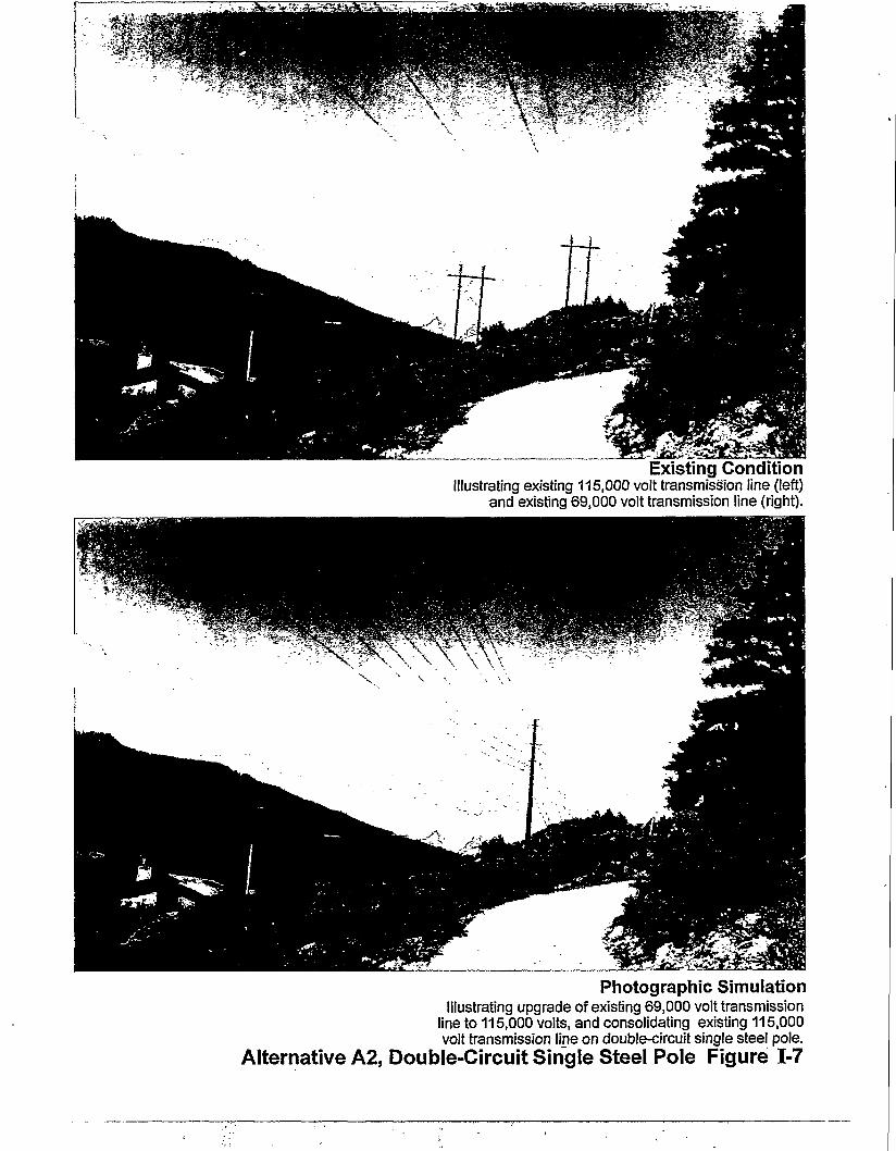
Existing ConditionIllustrating existing 115,000 volt transmission line (left)
and existing 69,000 volt transmission line (right).
Photographic SimulationIllustrating upgrade of existing 69,000 volt transmission
line to 115,000 volts, and consolidating existing 115,000volt transmission line on double-circuit single steel pole.
Alternative A2, Double-Circuit Single Steel Pole Figure 1-7

Existing ConditionIllustrating existing guyed-angle structures.
Photographic SimulationIllustrating self-supported angle structure.
Alternative A3, Self-Supported Angle Structure Figure 1-8

APPENDIX JCONSTRUCTION AND RESTORATION GUIDELINES
The following discussion outlines Western's construction and restoration guidelines for the Marys Lake transmissionline upgrade and substation project It includes special measures developed for the project as well as routine practicesused by Western on all of its construction projects.
1) Prior to construction, Western's Land Division will provide notice to each individual landowner regarding accessfor construction on their property. Landowners having specific concerns regarding disturbance to vegetationespecially to trees, shrubs and other landscape features should notify the Lands Division at this time.
2) Appropriate landowner comments will be incorporated into the construction specifications prepared for thecontract Special requirements including minimizing disturbance to vegetation will be reviewed with theconstruction contractor during the preconstruction conference held for the project
3) Western's Environmental Division will consult with the Natural Resources Conservation Service (formerly theSCS) regarding appropriate erosion control and revegetation techniques for this high elevation, southern exposuresite. Western will perform both a preconstruction and post construction review with the NRCS. Recommendationsprovided by NRCS will be incorporated into the construction specifications or any site-specific revegetation plansprepared for individual properties.
4) Western's Environmental Division will visit the site during construction and consult with the onsite inspectorregarding compliance with all proposed environmental mitigation measures including those associated withrestoration.
5) Culverts, waterbars and diversion ditches will be used as necessary to control runoff and erosion during and afterconstruction.
6) Restoration and erosion control will begin immediately following clean-up. All proposed restoration techniqueswould be reviewed and approved by the NRCS. Preconstruction drainage patterns will be restored.
7) If new graded access roads are necessary, the top 4-6 inches of seedbank and topsoil would be stripped, stockpiledand later respread following final clean-up. Areas that are not graded but are used for cross county access will beevaluated individually. All disturbed areas, including any ruts, compaction, or erosion rills will be treated, andseeded if necessary to facilitate recovery.
8) Clean straw mulch, tackifier, jute netting, excelsior matting or other appropriate material will be used to mulch andprotect cut slopes steeper than 2:1 or areas prone to wind or water erosion.
9) One year following construction and implementation of the erosion control measures, the site will be reviewed withNRCS to assess the revegetation efforts and identify any problem areas. Problem areas are sites where lack of soilstabilization will prevent long-term recovery of the site by native vegetation. Remedial action plans will bedeveloped and implemented as necessary until soil stabilization is achieved.
10) Finally, the Lands Department will be available following construction to settle any damage claims filed by thelandowners.