Observations on the Design and Refurbishment of Modular ...
13
V. Ponnampalam, H. Madrio and E. Ancich 279 Sustainable Bridges: The Thread of Society AP-G90/11_079© ABC 2011 Observations on the Design and Refurbishment of Modular Expansion Joints Geoff Taplin 1 and Tom McMurchy 1 1 AECOM, Melbourne, Victoria, Australia Abstract Modular bridge expansion joints (MBEJs) are utilised when the movement range at a bridge expansion gap exceeds around 300 mm, with the largest MBEJ installed to date accommodating a movement range in excess of 2100 mm. Traditionally MBEJs have been specified on a performance basis, with the detailed design of the MBEJ being undertaken by the successful supplier. Some MBEJs have given problems in-service, related to both design and construction deficiencies. In Australia the RTA carried out research into the behaviour of MBEJs on a number of their bridges, and published RTA QA Specification B316 which sets out the requirements for the design, fabrication, testing, supply, and installation of MBEJs. This specification enables bridge authorities in Australia to specify MBEJs to an appropriate level of detail, and avoid the high-level performance specification that has given rise to some in- service problems in the past. This paper will make some observations from the design of new MBEJs recently installed in Australia, and the refurbishment of existing MBEJs, with particular reference to RTA Specification B316 and to the current state of knowledge with regard to this type of expansion joint. Background Notwithstanding an increase in the use of integral bridges, most bridges are designed and constructed with at least one expansion joint to enable the expansion and contraction of the bridge to occur relatively free of restraint. The type of expansion joint used is primarily a function of the amount of movement that must be accommodated. Common practice in Australia would be to specify a silicone sealant for small movements (for example the XJS joint), a strip seal for movements up to about 80 mm, and a finger joint for movements from about 80 to 300 mm. Where the movement range exceeds about 300 mm current practice is to specify a modular bridge expansion joint (MBEJ).
-
Upload
khangminh22 -
Category
Documents
-
view
2 -
download
0
Transcript of Observations on the Design and Refurbishment of Modular ...

V. Ponnampalam, H. Madrio and E. Ancich 279 Sustainable Bridges: The Thread of Society AP-G90/11_079© ABC 2011
Observations on the Design and Refurbishment of Modular Expansion Joints
Geoff Taplin1 and Tom McMurchy1
1AECOM, Melbourne, Victoria, Australia
Abstract Modular bridge expansion joints (MBEJs) are utilised when the movement range at a bridge expansion gap exceeds around 300 mm, with the largest MBEJ installed to date accommodating a movement range in excess of 2100 mm. Traditionally MBEJs have been specified on a performance basis, with the detailed design of the MBEJ being undertaken by the successful supplier. Some MBEJs have given problems in-service, related to both design and construction deficiencies. In Australia the RTA carried out research into the behaviour of MBEJs on a number of their bridges, and published RTA QA Specification B316 which sets out the requirements for the design, fabrication, testing, supply, and installation of MBEJs. This specification enables bridge authorities in Australia to specify MBEJs to an appropriate level of detail, and avoid the high-level performance specification that has given rise to some in-service problems in the past. This paper will make some observations from the design of new MBEJs recently installed in Australia, and the refurbishment of existing MBEJs, with particular reference to RTA Specification B316 and to the current state of knowledge with regard to this type of expansion joint.
Background
Notwithstanding an increase in the use of integral bridges, most bridges are designed and constructed with at least one expansion joint to enable the expansion and contraction of the bridge to occur relatively free of restraint. The type of expansion joint used is primarily a function of the amount of movement that must be accommodated. Common practice in Australia would be to specify a silicone sealant for small movements (for example the XJS joint), a strip seal for movements up to about 80 mm, and a finger joint for movements from about 80 to 300 mm. Where the movement range exceeds about 300 mm current practice is to specify a modular bridge expansion joint (MBEJ).
280 Geoff Taplin and Tom McMurchy
MBEJs can be thought of as a series of strip seal joints placed side by side – a series of elastomeric glands between support beams. Unlike most strip seal joints the components of a MBEJ are manufactured from steel not aluminium. A typical MBEJ is shown in Figure 1.
Figure 1 Typical modular bridge expansion joint
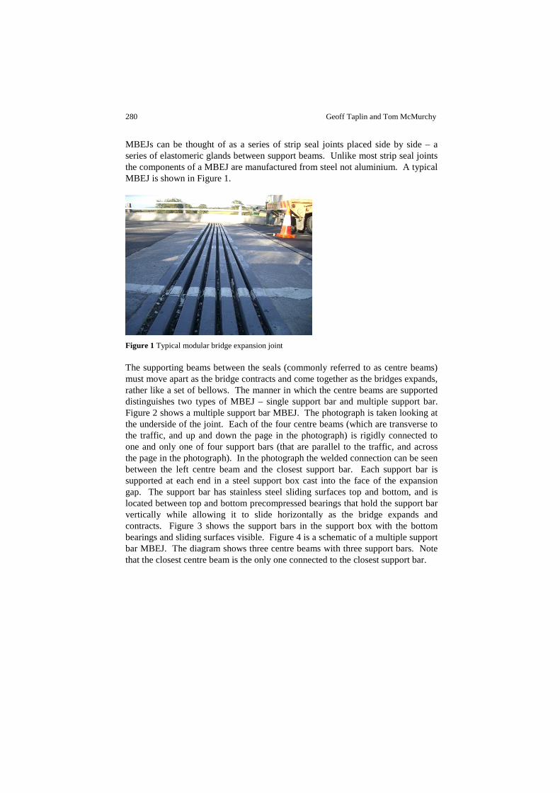
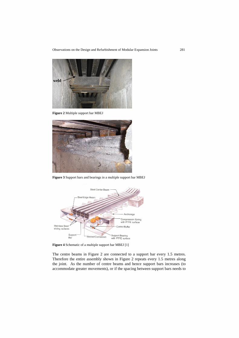
The supporting beams between the seals (commonly referred to as centre beams) must move apart as the bridge contracts and come together as the bridges expands, rather like a set of bellows. The manner in which the centre beams are supported distinguishes two types of MBEJ – single support bar and multiple support bar. Figure 2 shows a multiple support bar MBEJ. The photograph is taken looking at the underside of the joint. Each of the four centre beams (which are transverse to the traffic, and up and down the page in the photograph) is rigidly connected to one and only one of four support bars (that are parallel to the traffic, and across the page in the photograph). In the photograph the welded connection can be seen between the left centre beam and the closest support bar. Each support bar is supported at each end in a steel support box cast into the face of the expansion gap. The support bar has stainless steel sliding surfaces top and bottom, and is located between top and bottom precompressed bearings that hold the support bar vertically while allowing it to slide horizontally as the bridge expands and contracts. Figure 3 shows the support bars in the support box with the bottom bearings and sliding surfaces visible. Figure 4 is a schematic of a multiple support bar MBEJ. The diagram shows three centre beams with three support bars. Note that the closest centre beam is the only one connected to the closest support bar.
Observations on the Design and Refurbishment of Modular Expansion Joints 281
Figure 2 Multiple support bar MBEJ
Figure 3 Support bars and bearings in a multiple support bar MBEJ
Figure 4 Schematic of a multiple support bar MBEJ [1]
The centre beams in Figure 2 are connected to a support bar every 1.5 metres. Therefore the entire assembly shown in Figure 2 repeats every 1.5 metres along the joint. As the number of centre beams and hence support bars increases (to accommodate greater movements), or if the spacing between support bars needs to
weld

282 Geoff Taplin and Tom McMurchy
be reduced (to reduce the span of the centre beam for example), it becomes impossible to fit all of the support bars into the available space. To overcome this problem the single support bar MBEJ was developed. Rather than each centre beam being rigidly connected to one support bar, all centre beams are connected to the same support bar. The connection is in the form of a yoke which allows each centre beam to slide independently along the support bar. The support bar is still supported on sliding surfaces at the end to accommodate the bridge movement. Figure 5 shows a large single support bar MBEJ from underneath. It should be apparent that it would not be physically possible to build this joint as a multiple support bar MBEJ.
Figure 5 Single support bar MBEJ [2]
Problems with MBEJs
Dexter et al [3] summarised the performance requirements of MBEJs as:
• Protect bridge members from surface drainage • Support highway traffic over the gap between bridge components • Accommodate predicted and unanticipated movements of the bridge
He went on to note that unfortunately many MBEJs have required significant maintenance and even replacement. He identified three types of problems:
• Improper design or installation • Wear and tear of the elastomeric parts • Fatigue cracking of steel parts and their connections
Crocetti and Edlund [4] reported that premature fatigue failures of MBEJs have occurred in Europe. Problems with MBEJs have been experienced in Australia.
Observations on the Design and Refurbishment of Modular Expansion Joints 283
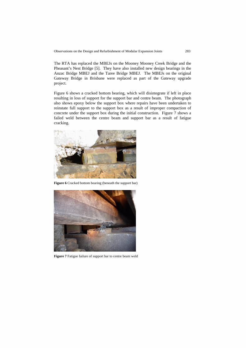
The RTA has replaced the MBEJs on the Mooney Mooney Creek Bridge and the Pheasant’s Nest Bridge [5]. They have also installed new design bearings in the Anzac Bridge MBEJ and the Taree Bridge MBEJ. The MBEJs on the original Gateway Bridge in Brisbane were replaced as part of the Gateway upgrade project. Figure 6 shows a cracked bottom bearing, which will disintegrate if left in place resulting in loss of support for the support bar and centre beam. The photograph also shows epoxy below the support box where repairs have been undertaken to reinstate full support to the support box as a result of improper compaction of concrete under the support box during the initial construction. Figure 7 shows a failed weld between the centre beam and support bar as a result of fatigue cracking.
Figure 6 Cracked bottom bearing (beneath the support bar)
Figure 7 Fatigue failure of support bar to centre beam weld
284 Geoff Taplin and Tom McMurchy
Design guidelines for MBEJs
Traditionally MBEJs have been specified on a performance basis with the detailed design of the joint being undertaken by the successful supplier. Evidence from MBEJ failures around the world is that the proprietary modular expansion joints do not always have adequate robustness to withstand the loading that they are subjected to. This, combined with poor installation quality, has led to the problems that are being experienced. In the USA investigations into MBEJ failures have been undertaken since at least the early 1990’s [6]. Research to improve MBEJ performance, particularly aimed at reducing the incidence of fatigue failures, was undertaken over the subsequent decade by Dexter and fellow researchers [3] leading to the publication of NCHRP reports 402 [7] and 467 [8]. In Europe established design guidelines have existed in Germany [9] and Austria [10] for many years. Because of the problems that the RTA has experienced with modular joints, they instigated an extensive internal R&D program into this issue. As a result they developed RTA QA Specification B316 ‘Modular Bridge Expansion Joints’ (B316) for the design and installation of modular joints [11]. Their work has been extensively published in Australian, American and European technical journals [12-15]. Several joints have now been installed in Australia that conform, at least in part, to the requirements of B316. These guidelines will be very beneficial for designers and specifiers in ensuring that MBEJs installed in future Australian bridges will provide good service.
Bearing precompression
An issue that is not clearly described in the literature and design guidelines for MBEJs is the appropriate level of precompression in the top and bottom bearings that hold the support bar vertically. Inadequate bearing compression is believed to have been a contributing factor to the failures shown in Figures 6 and 7 – this is discussed below. The MBEJ shown in Figures 6 and 7 predates the publication of B316 and was a proprietary design. Figure 8 is a schematic cross section of a MBEJ. For simplicity one centre beam is shown, located at midspan of the support bar. The top and bottom bearings (shown as springs) hold the support bar vertically. The MBEJ is assembled with an interference fit (top and bottom bearing heights plus support bar depth is greater than internal depth of support box) so the bearings are precompressed. The bearings are in series, so the

Observations on the Design and Refurbishment of Modular Expansion Joints 285
precompression force is the same in top and bottom bearings and the stiffness k of
a bearing pair (top + bottom) is given by KbKt
1
K
1
+= where t and b represent
the top and bottom bearings respectively. If a wheel load P is applied to the support bar through the centre beam the bearings act in parallel, so the stiffness of a bearing pair K = Kt + Kb. The wheel load will reduce the compression in the top bearing and increase the compression in the bottom bearing.
Figure 8 Schematic cross section of a MBEJ
To illustrate this some bearing stiffness values taken from test data will be used. The tests were part of an investigation into bearing failure in a MBEJ. The static load-displacement curves for the bearings are shown in Figure 9.
�
�
�
�
�
� �
� �
���
� �
� � � � �
� ���� �����
��� ���� ������������� � ���
!���"�#���$!���%"� ��&
�#���'!���%"� ��&
Figure 9 Static load-displacement test for top and bottom bearings
From the data in Figure 9 the linearised top bearing stiffness is 2 kN/mm, and the linearised bottom bearing stiffness is 6 kN/mm. Hence the stiffness of the bearing pair in series is 1.5 kN/mm. For an interference fit of 6 mm the precompression in the bearings is 9 kN, the top bearing is compressed 4.5 mm and the bottom bearing is compressed 1.5 mm. The stiffness of each bearing pair in parallel is 8 kN/mm. A static wheel load P (Figure 8) of 32 kN (16 kN per bearing pair) will
P
top bearing
support bar centre beam
bottom bearing

286 Geoff Taplin and Tom McMurchy
displace the support bar by 2 mm, and will contribute a tension in each top bearing of 4 kN and a compression in each bottom bearing of 12 kN. If the load P exceeds 72 kN the top bearing will decompress, and so the stiffness of each bearing pair will reduce by 25% - from 8 kN/mm to 6 kN/mm (the stiffness of the bottom bearing only). Loss of precompression leads to a marked reduction in stiffness of the MBEJ support, and a non-linear response. The situation is more complex because the bearing stiffness is dependent on the rate of loading. The same bearings were subjected to dynamic loading and the linearised dynamic stiffnesses were 9 kN/mm and 24 kN/mm for the top and bottom bearings respectively. Figure 10 is the calculated load-deflection curves for the support bar for both static and dynamic loading. The change in stiffness after decompression of the top bearing is evident, as is the much stiffer response under dynamic loading. It is important that this non-linear behaviour is correctly modelled in order to calculate the stress in the MBEJ components under ultimate and fatigue loading conditions.
�� �������� �� ����� ������ ���
� � � � � �
� �� ���� �����
����� � ����� � �������! #"�$�$���% �'&� �%!� ()()�
*�+ ,�+ - .!*�+ - / / 0�1�*#*2�3 0�,�4)- .5*�+ - / / 0�1�*#*
Figure 10 Calculated load-deflection curves for the support bar shown in Figure 8
Specific design requirements
RTA Specification B316 is the principal reference for the design of MBEJs in Australia. B316 provides design vertical loads for ultimate limit states (ULS) and fatigue limit states (FLS) as follows:
1. Apply the A160 axle load to the MBEJ, positioned to maximise the design actions. The A160 axle load comprises two wheel loads, W = 80 kN.
2. Apportion a fraction 6 of the wheel load W to each centre beam based on the geometry of the joint and the wheel footprint within the limits of 0.5 ≤ β ≤ 0.8.

Observations on the Design and Refurbishment of Modular Expansion Joints 287
3. Apply a load factor of 1.8 for the ultimate limit state (ULS), and 0.6 for the fatigue limit state (FLS).
4. Unless an experimental modal analysis study of the proposed joint configuration is undertaken, apply a dynamic amplification factor (DAF) as follows (for a single support bar MBEJ):
a. For the ultimate limit state, DAF = 1.675 applied downwards b. For the fatigue limit state, DAF = 1.675 applied downwards and 0.825 acting upwards (total stress range DAF = 2.5)
The RTA have undertaken testing to show that the measured peak-to-peak stress range can exceed 2.5 and even 3 times the static stress, so a DAF of 2.5 is clearly not conservative for all cases. Typical values of β could be 0.7 for ULS and 0.6 for FLS. Therefore typical design loads could be: P_ULS = 80 x 0.7 x 1.8 x 1.675 = 169 kN P_FLS_down = 80 x 0.6 x 0.6 x 1.675 = 48 kN P_FLS_up = 80 x 0.6 x 0.6 x 0.825 = 24 kN P_FLS_range = 48 + 24 = 72 kN The extent to which the applied wheel load distributes between adjacent support bars (ie transversely across the carriageway) is a function of the stiffness of the centre beam, support bar and bearings. B316 also requires:
• For both ULS and FLS this vertical load is to be combined with a horizontal load (in the direction of traffic) equal to 35% of the vertical load without any DAF
• Bearing precompression is not to be lost at the FLS • Fatigue stress range shall not exceed the cut-off limit
Based on experience from involvement in the specification and design of MBEJs in accordance with B316, it is very difficult to provide a MBEJ design that is fully compliant with all requirements of B316. The following observations are provided on the design requirements for the purpose of discussion. Experimental modal analysis study: B316 allows the measured behaviour of a manufacturer’s MBEJ to be used to determine the DAF only if the measurements were undertaken as part of an experimental modal analysis (EMA) of a dynamically similar MBEJ. It would be advantageous to relax this requirement so as to be able to utilise appropriate measurements from installed joints of a similar type even if EMA was not

288 Geoff Taplin and Tom McMurchy
undertaken. B316 actually requires an EMA to be submitted even if it is not utilised in the design (Clause 1.6(e)), which does not seem to be a necessary requirement. Ultimate limit state load: The ULS design loads are based upon the ULS joint gap combined with the ULS wheel load. This is not consistent with AS5100.2 where serviceability temperature effects (which affect the joint gap) and not ULS temperature effects would be combined with the ULS wheel load. Serviceability temperature effects would reduce the joint gap and hence the proportion of a wheel load carried by one centre beam. The ULS wheel load assumes the same wheel footprint as at SLS (250 mm x 400 mm). As discussed by Forster et al [16], the tyre contact area varies with the wheel load, and can reasonably be assumed to be much greater at ULS loading because tyre pressure does not increase with load. Increasing the contact area would reduce the proportion of a wheel load carried by one centre beam, and may also reduce that proportion below the current minimum β value of 0.5. At ULS the top bearing will almost certainly be decompressed, so the stiffness of the support will be at a minimum, increasing the stress in the centre beam. This combined with the magnitude of the ULS load as currently specified makes it difficult to design a conforming joint. Fatigue limit state load: Fatigue stress commonly controls the design of MBEJs. The specified uplift DAF of 0.825 corresponds to theoretical damping of around 11% of critical for damped free vibration. The RTA have measured real damping that is both greater and less than this. The DAF can also be contributed to by in phase loading from multiple axles crossing the joint, which can be a very severe loading condition. Damping is contributed from many sources, but the bearings make a major contribution. As discussed above, bearings can become decompressed if the bearing precompression is inadequate. Decompressed bearings increase the DAF in two ways – they reduce the support stiffness and they do not contribute to damping. It is therefore important that bearing precompression is not lost at the FLS (in accordance with B316 requirements). How much precompression is required to achieve this? For the real bearing stiffnesses and the uplift fatigue loading quoted above, it would require up to 18 kN of precompression to prevent decompression of the bottom bearing during uplift, based on the simple analysis model presented and assuming load applied to a centre beam adjacent to the edge of the joint. High levels of precompression are of concern. The precompression force creates friction that resists sliding between the bearings and the support bar, and increasing this friction force is not desirable for proper functioning of the joint. Ancich [17] has reported that excessive precompression (and hence friction)

Observations on the Design and Refurbishment of Modular Expansion Joints 289
contributed to failures of the Anzac Bridge MBEJ. It would be nice to know if the high uplift DAFs that were measured on real joints were measured when the bottom bearing decompressed. If this were the case, the high DAFs were caused by improper design or construction, and requiring all joints to be designed for such high DAFs may lead to potential secondary problems with sliding friction. B316 requires vertical and horizontal loading to be combined for fatigue assessment. The horizontal loading is specified as 35% of the vertical, and this makes a large contribution to the calculated stress as it bends the centre beam about the weak axis. it also causes torsion which must be taken into account in the fatigue analysis. Horizontal loading of 35% of vertical would not be expected during normal traffic running. Horizontal loading of this magnitude is generated by severe braking, or possibly severe acceleration, and should be considered as an ultimate load case. A much more modest level of horizontal loading would be appropriate for the fatigue loading case. Fatigue categories for typical MBEJ details are provided in B316. When assessing the fatigue limit state for infinite cycles of loading (which is the appropriate number of cycles for MBEJs) the usual requirement would be to keep the fatigue stress below the endurance limit (or the constant amplitude fatigue limit as it is called in AS5100). The B316 requirement that the fatigue stress must be below the cut-off limit (which is the limit below which stress cycles can be ignored when doing a Miner’s type summation for variable amplitude loading) is a much more onerous requirement – a 45% reduction in the allowable fatigue stress. In service the MBEJ will undoubtedly experience loads exceeding the FLS design load, however based upon the work of Fisher et al [18], even for poor fatigue details up to 1 in 10,000 load cases can exceed the constant amplitude fatigue limit before that limit should be considered invalid. The constant amplitude fatigue limit would seem to be the more appropriate fatigue stress limit.
Conclusion
Some MBEJs have experienced problems in service related to both design and quality of installation. Design guidelines exist in the USA, Europe and Australia. The Australian design guidelines, RTA QA Specification B316, will be very beneficial for designers and specifiers in ensuring that MBEJs installed in future Australian bridges will provide good service. Bearing precompression is an important aspect of MBEJ design, and is not clearly described in the literature and design guidelines. Some aspects of B316 are very difficult to comply with in the design of MBEJs, and some observations about specific requirements of B316 are made for the purpose of discussion.

290 Geoff Taplin and Tom McMurchy
References
[1] WABO External Sales Presentation (2004) Degussa.
[2] Bradford P. (2006) Equidistance in Modular Expansion Joints. 6th World Congress on Joints, Bearings, and Seismic Systems for Concrete Structures.
[3] Dexter R. Osberg C. Mutziger M. (2001) Design specification installation and maintenance of modular bridge expansion joint systems. J. Bridge Engrg. Nov/Dec.
[4] Crocetti R. Edlund B. (2003) Fatigue Performance of Modular Bridge Expansion Joints. J. Perf. Constr. Fac. 17, 167.
[5] Forster G. (2004) Selection of Option for Replacement of Major Bridge Expansion Joints. 5th Austroads Bridge Conference.
[6] Van Lund J. (1993) Improving the quality and durability of modular bridge expansion joints. Transportation Research Record No. 1393.
[7] Dexter R.J. Connor R.J. Kaczinski M.R. (1997) Fatigue design of modular bridge expansion joints. NCHRP Report 402, Transportation Research Board, National Research Council, Washington, DC, USA.
[8] Dexter R.J. Mutziger M.J. Osberg C.B. (2002) Performance testing for modular bridge joint systems. NCHRP Report 467, Transportation Research Board, National Research Council, Washington, DC, USA.
[9] German Federal Ministry of Transport (1993) TL/TP-FÜ 92 Technical delivery and inspection specifications for watertight expansion joints of road and foot bridges.
[10] Austrian Research Council for Roads and Traffic (1999) RVS 15.45 Bridge equipment expansion joints.
[11] Roads and Traffic Authority NSW (2005) RTA QA Specification B316 Modular bridge expansion joints.
[12] Ancich E.J., Brown S., Chirgwin G. (2004) Modular Deck Joints – Investigations into structural behaviour and some implications for new joints. 5th Austroads Bridge Conference.
[13] Ancich E.J. Bhavnagri V. (2006) Fatigue comparison of modular bridge expansion joints using multiple bridge design code approaches. 6th World Congress on Joints, Bearings, and Seismic Systems for Concrete Structures.
[14] Ancich E.J. Bradford P. (2006) Modular bridge expansion joint dynamics. 6th World Congress on Joints, Bearings, and Seismic Systems for Concrete Structures.
[15] Ancich E.J. Forster G. Bhavnagri V. (2006) Modular bridge expansion joint specifications and load testing. 6th Austroads Bridge Conference.
[16] Forster G. Bhavnagri V. Anzar M. (2009) Modified Wheel Loads and Design of Anchorages for Bridge Deck Joints. 7th Austroads Bridge Conference.
[17] Ancich E.J. Chirgwin G.J. (2006) Fatigue proofing of an in-service modular bridge expansion joint. 6th World Congress on Joints, Bearings, and Seismic Systems for Concrete Structures.

Observations on the Design and Refurbishment of Modular Expansion Joints 291
[18] Fisher J.W. Nussbaumer A. Keating P.B. Yen B.T. (1993) Resistance of welded details under variable amplitude long-life fatigue loading. NCHRP Report 354, Transportation Research Board, National Research Council, Washington, DC, USA.