Cementless Total Hip Arthroplasty with Medial Wall Osteotomy ...

| D I S T A L R A D I O U L N A R J O I N T S Y M P O S I U M |
Oblique Ulnar Shortening Osteotomy Witha New Plate and Compression SystemAnthony J. Lauder, MDDepartment of Orthopaedic Surgery and RehabilitationUniversity of Nebraska College of MedicineOmaha, NE
Shai Luria, MDHand and Microvascular SurgeryUniversity of Washington Hand Surgery InstituteDepartment of Orthopaedics and Sports MedicineUniversity of WashingtonSeattle, WA
Thomas E. Trumble, MDUniversity of Washington Hand Surgery InstituteDepartment of Orthopaedics and Sports MedicineUniversity of WashingtonSeattle, WA
| ABSTRACT
Ulnocarpal abutment or the ulnocarpal impaction syn-
drome occurs when excessive loads exist between the
distal ulna and ulnar carpus. This overloading occurs as
a result of the distal ulnar articular surface being more
distal than the ulnar articular surface of the distal radius.
This situation has been termed positive ulnar variance,
and it can quickly lead to ulnar-sided wrist degenerative
changes and functional losses. Patients often have
vague, ulnar-sided complaints of chronic pain and
swelling with an insidious onset that does not correlate
with any specific traumatic event. Many procedures
have been developed to alleviate this condition, but the
gold standard for correcting positive ulnar variance is
the ulnar shortening osteotomy. The goals of the
shortening procedure are to relieve pain and prevent
arthritis by reestablishing a neutral or slightly negative
ulnar variance. We describe a new plate and compres-
sion system in which an oblique ulnar diaphyseal
osteotomy is both completed and stabilized through
the same jig-based system.
Keywords: ulnar shortening, osteotomy, impaction,
variance
| HISTORICAL PERSPECTIVE
Ulnar variance, defined as the difference in length
between the distal ulnar corner of the radius and
distalmost aspect of the dome of the ulnar head, is
positive when the dome of the distal ulna is more distal
than the ulnar corner of the distal radius (Fig. 1).
Generally, the radius receives 82% of the load borne
through the wrist, whereas the ulna receives 18% of the
force. However, Palmer and Werner1 showed that loads
through the distal ulna can change and are directly
related to ulnar variance. Increasing ulnar length by 2.5
mm raises ulnar loads to 42%, whereas a decrease in
length of 2.5 mm lowers the force seen at the distal ulna
to 4.3%. Furthermore, that same study revealed that
73% of wrists with triangular fibrocartilage complex
(TFCC) tears had either ulnar positive or neutral
variance. This indicates that overloading of the ulnar
wrist can ultimately lead to injury and degeneration of
the TFCC.
The ulnar shortening osteotomy was first described
by Milch2 in 1941 for a 17-year-old patient with an
ulnar positive wrist after a distal radius fracture. Milch’s
technique entailed resection of a portion of the distal
ulna with wire fixation at the osteotomy site. Since its
inception, numerous authors have described various
osteotomy types, including transverse,3,4 oblique (of
varying degrees),4Y8 sliding (long oblique),9 and step-
cut.10 Several commercially available systems have
Techniques in Hand and Upper Extremity Surgery 11(1):66–73, 2007 � 2007 Lippincott Williams & Wilkins, Philadelphia
Address correspondence and reprint requests to Anthony J. Lauder,MD, 981080 Nebraska Medical Center, Omaha, NE 68198-1080.E-mail: [email protected].
Techniques in Hand and Upper Extremity Surgery66
Copyr ight © Lippincott Williams & Wilkins. Unauthorized reproduction of this article is prohibited.
been developed to facilitate bony contact, compression,
and rigid fixation at the osteotomy site.4,8,9
Attempting to elucidate which osteotomy provides
both stability and rapid healing potential, while remain-
ing easy to perform, can be an arduous task. Many
authors have reported good results with the osteotomy
methods mentioned. In 1995, Wehbe and Cautilli3
reported on their results for ulnar shortening using a
transverse osteotomy and the Arbeitsgemeinschaft fur
Osteosynthese (AO) small distractor. In their 24 patients
with ulnar impaction syndrome, they had no nonunions
and an average time to healing of 9.7 weeks. They did
have 3 delayed unions, but these reportedly healed
without incident by 28, 34, and 36 weeks.
In 2005, Darlis et al10 reported their results on 29
patients who underwent a step-cut osteotomy of the ulna
for various pathological conditions. Average time to
union was 8.3 weeks, and they had no delayed unions or
nonunions. Although these authors deem this a simple
technique, it does require more cuts than transverse or
oblique osteotomies.
Many surgeons today prefer an oblique osteotomy
based in large part on a 1993 study by Rayhack et al.4
That study compared 23 transverse osteotomies, in
which a specialized external compression device was
used, with 17 oblique osteotomies, in which a cutting
guide designed by the lead author was used. Average
healing time for the transverse osteotomies was 21
weeks compared with 11 weeks for the oblique group.
Furthermore, 1 nonunion was noted for the transverse
group. Importantly, Rayhack et al4 also reported on the
biomechanical differences between the 2 constructs.
Cadaveric data revealed no significant difference be-
tween the oblique or transverse cuts in regard to
anteroposterior or lateral bending strength. The oblique
osteotomy, however, was found to be significantly
stiffer in torsion.
The excellent results reported by Rayhack et al4 have
largely been substantiated by several other authors using
different systems for performing oblique osteotomies.
Reporting on 27 patients (30 osteotomies), Chun and
Palmer5 described their results for the oblique osteo-
tomy using a freehand technique. The wrists were graded
both preoperatively and postoperatively with a modified
Gartland and Werley11 system. Preoperatively, 28 wrists
were graded poor, and 2 fair. Postoperatively, 24 wrists
were graded excellent, 4 good, 1 fair, and 1 poor.
They had no nonunions. Chen and Wolfe6 also
reported good results for the oblique osteotomy using
a freehand technique and an AO compression device.
Preoperatively, 14 wrists were graded fair, and 4 poor,
whereas postoperatively, 13 were graded excellent,
3 good, and 2 fair. They also had no nonunions. Most
recently, Mizuseki et al8 reported their results for
24 oblique osteotomies created by their own device.
Healing time averaged 8.1 weeks, and they had no
nonunions.
| INDICATIONS/CONTRAINDICATIONS
The most common indication for implementing the
shortening osteotomy is pain stemming from an ulnar
impaction syndrome. Other less common indications
include nonrepairable tears of the TFCC, previous radial
FIGURE 1. Ulnar variance is the difference in lengthbetween the ulnar corner of the radius and the articulardome of the distal ulna. UV indicates ulnar variance.Reprinted with permission from Trumble TE. Distal radio-ulnar joint and triangular fibrocartilage complex. In:Trumble TE, ed. Principles of Hand Surgery and Therapy.Philadelphia, PA: WB Saunders; 1999:130.
FIGURE 2. Patients with overloading of the distal ulna orTFCC pathology will often have tenderness and/orswelling in an area just distal to the ulnar styloid.
Volume 11, Issue 1 67
A New System for Oblique Ulnar Shortening Osteotomy
Copyr ight © Lippincott Williams & Wilkins. Unauthorized reproduction of this article is prohibited.
head excision and associated Essex-Lopresti lesions,
attritional lunotriquetral ligament tears, ulnar nonun-
ions, radial malunions, and early posttraumatic distal
radioulnar joint arthritis. Importantly, the ulnar shorten-
ing osteotomy should not be performed in isolation for
radial malunions that include deformity other than just
shortening. Furthermore, the shortening should not be
performed alone in Essex-Lopresti situations, where the
radial head has been previously excised. In this instance,
continued shortening of the radius would be expected,
unless the osteotomy was performed in conjunction with
a radial head replacement.
A preoperative workup should include information
on antecedent trauma, duration of symptoms, and the
location of pain. Patients who benefit from an ulnar
shortening osteotomy generally relate a history of ulnar-
sided wrist pain that is exacerbated by pronation/
supination activities and forceful grip. Often, there will
be a history of prior trauma that led to an ulnar positive
wrist that now impacts on the ulnar carpus. On
examination, many patients will have swelling and
tenderness localized to the TFCC and distal ulna
(Fig. 2). The ulnar impaction maneuver, performed
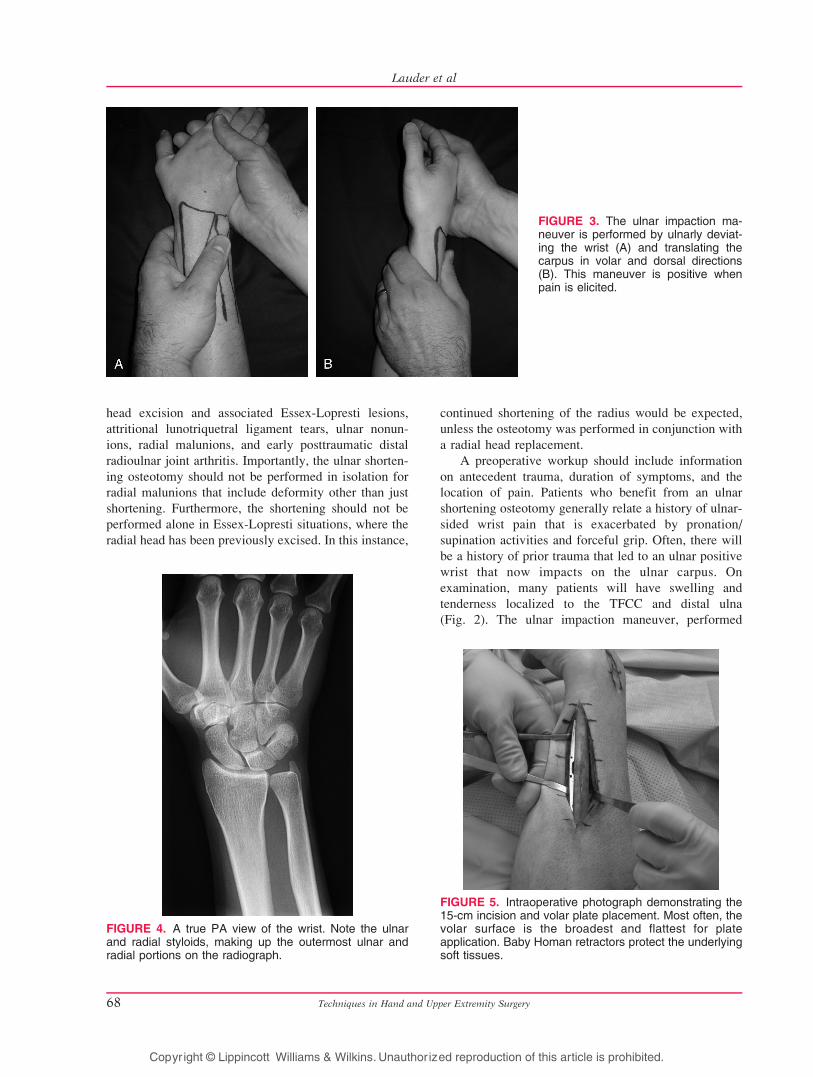
FIGURE 4. A true PA view of the wrist. Note the ulnarand radial styloids, making up the outermost ulnar andradial portions on the radiograph.
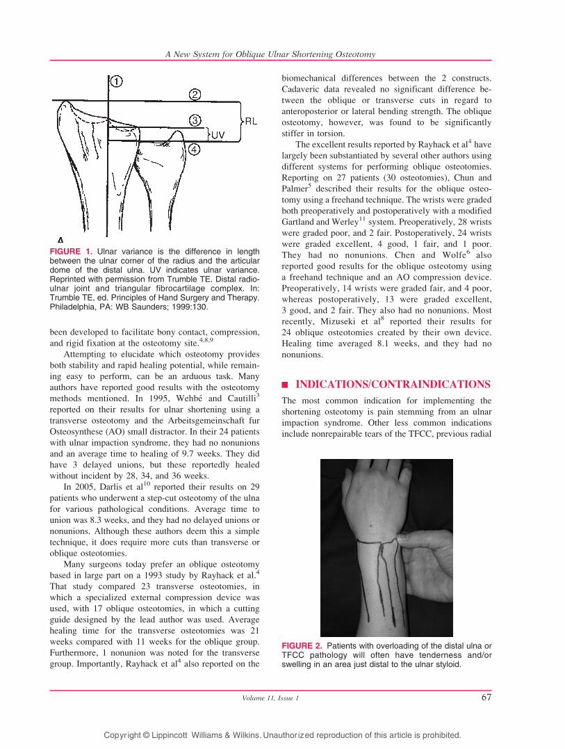
FIGURE 3. The ulnar impaction ma-neuver is performed by ulnarly deviat-ing the wrist (A) and translating thecarpus in volar and dorsal directions(B). This maneuver is positive whenpain is elicited.
FIGURE 5. Intraoperative photograph demonstrating the15-cm incision and volar plate placement. Most often, thevolar surface is the broadest and flattest for plateapplication. Baby Homan retractors protect the underlyingsoft tissues.
Techniques in Hand and Upper Extremity Surgery68
Lauder et al
Copyr ight © Lippincott Williams & Wilkins. Unauthorized reproduction of this article is prohibited.

by moving an ulnarly deviated wrist in a volar and
dorsal direction, can help elicit pain that stems from
the TFCC and ulnar impaction (Figs. 3A, B).
Radiographic evaluation begins with plain postero-
anterior (PA) and lateral radiographs of the affected
wrist. The PA view should be taken with the shoulder
abducted to 90 degrees, elbow flexed to 90 degrees, and
the wrist in neutral rotation. A true PA view should have
the ulnar styloid at the far ulnar position (Fig. 4). The
importance of a true PA view stems from the fact that
rotation at the wrist can increase (pronation) or decrease
(supination) ulnar variance. Plain radiographs of the
contralateral wrist may be helpful for determining the
amount one wants to shorten the ulna. Contralateral
views are not as useful, however, when that wrist is also
ulnar positive. A magnetic resonance image or arthro-
gram may be a reasonable adjunct to the radiographic
evaluation when the surgeon suspects an acute, possibly
repairable, tear of the TFCC. Trumble et al12 combined
arthroscopic repairs of the TFCC with ulnar shortening
osteotomies. Their patients regained 83% of their total
range of motion and 81% of their grip strength when
compared with the contralateral side. In 19 of 21
patients, pain symptoms improved from complaints of
pain even with routine activities to having complete
relief of pain with all activities postoperatively. The
other 2 patients had decreased levels of pain after
surgery but continued to have occasional discomfort
with some heavy activities.
| TECHNIQUE
SetupThe required and optional equipment needed for the
ulnar shortening osteotomy is minimal. The procedure,
as described here, does require an ulnar shortening
system from Trimed (Valencia, Calif). Other equip-
ments required for this procedure include a radiolucent
lateral arm board, a fluoroscopy machine, a wire driver
and drill, a lobster claw reduction forceps, a set of
baby Homan retractors, and a sagittal saw and saw
blade (0.4-mm thick; 25-mm long). As previously stated,
other systems and techniques are available for comple-
tion of the osteotomy and shortening of the ulna.
In the supine position, the patient should have a
pneumatic tourniquet placed as high as possible onto the
arm. The arm in its entirety should rest comfortably on a
radiolucent hand table.
FIGURE 6. A, The plate is initially secured with 3 screwson the same side as the lag screw. On the other side, ascrew is inserted into the slot at the point farthest from thelag screw. Two 0.62-in Kirschner wires are insertedthrough the combination pin/drill guide in separate slotsat a point farthest from the lag screw. B, A close-up viewof the Kirschner wires being inserted at a point farthestfrom the lag screw. Inserting the Kirschner wires and slotscrew away from the lag screw will allow for in-linecompression after the osteotomy is completed.
FIGURE 7. The A and B guides for completing theosteotomies. Note that the A guides are available for 2-,3-, 4-, or 5-mm resections.
Volume 11, Issue 1 69
A New System for Oblique Ulnar Shortening Osteotomy
Copyr ight © Lippincott Williams & Wilkins. Unauthorized reproduction of this article is prohibited.
Surgical ExposureAfter exsanguinating the arm and inflating the tourni-
quet, a skin incision is made along the subcutaneous
border of the ulna. This incision should begin 1 to 2 cm
proximal to the ulnar styloid and continue proximally
for 15 cm. Incisions at or distal to the ulnar styloid must
be made carefully to avoid injury to the dorsal sensory
branch of the ulnar nerve. The incision is continued
between the interval separating the extensor carpi
ulnaris (ECU) and the flexor carpi ulnaris (FCU). The
periosteum of the ulna is then incised, and the FCU and
ECU are reflected using an elevator and baby Homan
retractors. Care must be taken to avoid injury to the
ulnar artery and nerve, which lie just radial to the FCU.
A substantial portion of each muscle must be reflected
to adequately visualize the ulna in preparation for the
osteotomy.
Initial Plate ApplicationWhenever possible, the plate should be applied to the
volar surface of the ulna (Fig. 5). Not only is there
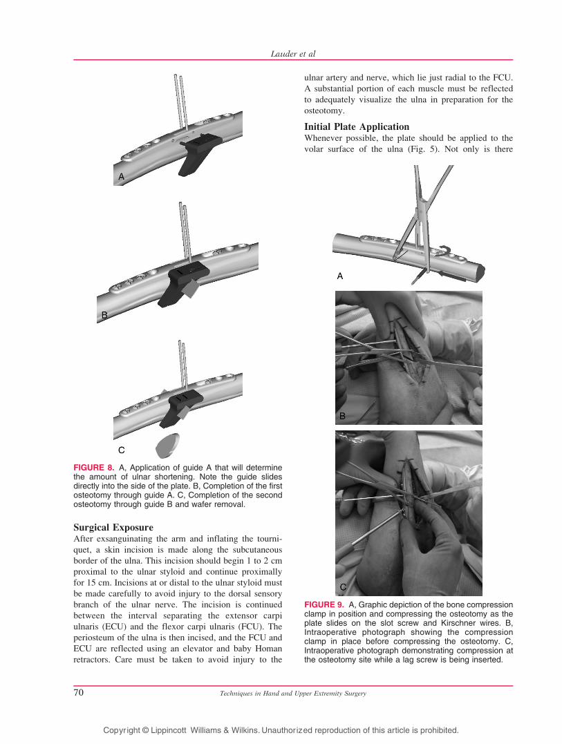
FIGURE 8. A, Application of guide A that will determinethe amount of ulnar shortening. Note the guide slidesdirectly into the side of the plate. B, Completion of the firstosteotomy through guide A. C, Completion of the secondosteotomy through guide B and wafer removal.
FIGURE 9. A, Graphic depiction of the bone compressionclamp in position and compressing the osteotomy as theplate slides on the slot screw and Kirschner wires. B,Intraoperative photograph showing the compressionclamp in place before compressing the osteotomy. C,Intraoperative photograph demonstrating compression atthe osteotomy site while a lag screw is being inserted.
Techniques in Hand and Upper Extremity Surgery70
Lauder et al
Copyr ight © Lippincott Williams & Wilkins. Unauthorized reproduction of this article is prohibited.
more soft tissue padding, but this side also tends to be
the flattest surface of the ulna, allowing for the best
plate-to-bone contact. If the volar surface is not
practical, then the surgeon should choose the flattest
side that is still amenable to adequate soft tissue
coverage. Occasionally, it is necessary to use plate
benders to contour the plate to account for variations in
ulnar shape. Plates can also be bent to overcompensate
for the normal curvature of the ulna. This will help
prevent gapping at the osteotomy site at the time
compression is applied.
The position of the lag screw is dependent on both
the arm being operated on and the location of the plate.
For example, in a right-sided osteotomy with a volarly
placed plate, the lag screw hole will be distal to the
osteotomy site. If, however, the plate is set dorsally in a
right-sided osteotomy, then the lag screw hole will need
to be positioned proximal to the osteotomy. The
opposite is true for left-sided plates, with the lag screw
being placed proximally in volar plates and distally in
dorsal plates. Regardless of the orientation of the plate
or which ulna is being osteotomized, it is critical that
the 2 small holes on the side of the plate be easily
accessible for mounting of the cutting guides.
The plate is provisionally secured to the ulna with
the help of the ulnar plate clamp. Using the 2.3-mm drill
bit, 3.2-mm-diameter self-tapping screws are used to fix
the plate to the ulna on the same side as the lag screw.
When dealing with brittle bone, the 2.3-mm drill holes
can be tapped to precut screw threads. A fourth screw is
placed in the slotted screw hole to affix the plate both
proximal and distal to the planned osteotomy site. This
screw should be placed at the end of the slot farthest
from the lag screw. This allows for compression after
the osteotomy is completed. At this point, the combina-
tion pin/drill guide is applied. Two 0.62-in Kirschner
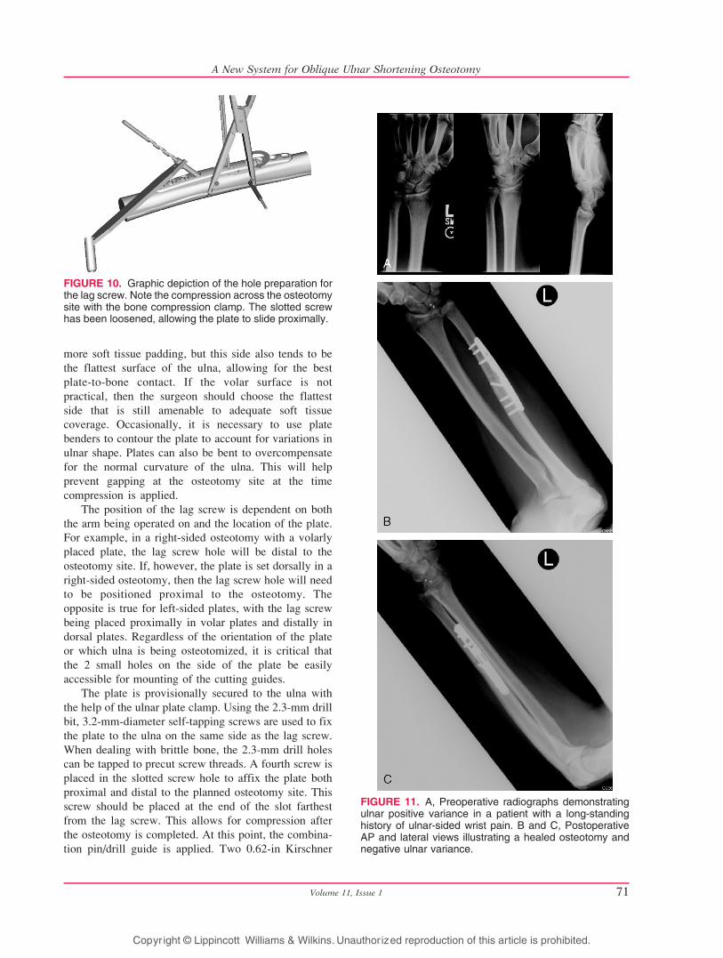
FIGURE 10. Graphic depiction of the hole preparation forthe lag screw. Note the compression across the osteotomysite with the bone compression clamp. The slotted screwhas been loosened, allowing the plate to slide proximally.
FIGURE 11. A, Preoperative radiographs demonstratingulnar positive variance in a patient with a long-standinghistory of ulnar-sided wrist pain. B and C, PostoperativeAP and lateral views illustrating a healed osteotomy andnegative ulnar variance.
Volume 11, Issue 1 71
A New System for Oblique Ulnar Shortening Osteotomy
Copyr ight © Lippincott Williams & Wilkins. Unauthorized reproduction of this article is prohibited.
wires are placed in the slots of the guide that are
away from the lag screw hole (Figs. 6A, B). The
shorter (50-mm) Kirschner wire is placed first,
followed by the longer (100-mm) wire. The differing
Kirschner wire lengths and the guide ensure that the
pins will remain parallel during insertion. The pin/
drill guide is now removed.
Ulnar OsteotomyCorrelating to measurements made from preoperative
radiographs for ulnar variance, a cutting guide is selected
for the intended amount of resection (2Y5 mm). In
general, the shortening should result in a neutral to
slightly negative ulnar variance. Marked A and B, these
cutting guides are designed with pegs that can only be
inserted so that the osteotomy cuts are made perpendic-
ular to the path of the planned lag screw. Guide A is
placed first. This guide defines the width of the
osteotomy and is marked as A-2, A-3, A-4, or A-5 mm
(Fig. 7). Five millimeters is usually the maximum
correction required, but it can be more in certain trauma
situations. After placing the baby Homan around the
ulna to protect the adjacent soft tissues, the osteotomy is
completed. Use of saline irrigation is recommended to
cool the saw blade and prevent thermal injury. Guide A
is then replaced with the cutting guide B. Once the
sequential osteotomies have been completed, the bone
wafer is detached from its soft tissue attachments and
excised (Figs. 8AYC). Of paramount importance for the
procedure is to keep the plate firmly fixed to the ulna to
ensure parallel osteotomy cuts. Therefore, screws should
be checked during the osteotomy and retightened as
necessary to prevent plate slippage.
Lag Screw Application and Plate StabilizationThe peg of the bone compression clamp is inserted into
the side of the plate. The cannulated portion of the
clamp is then used as a drill guide to place a third 0.062-
in Kirschner wire low on the bone between the slotted
hole and the 2 parallel Kirschner wires previously
inserted. The position of this third wire creates com-
pression forces perpendicular to the osteotomy. The
screw in the slotted hole is then loosened to allow
compression at the osteotomy using the bone compres-
sion clamp (Figs. 9AYC). Once compression has been
achieved, the slot screw should be retightened. At this
time, radiographs should be obtained to determine if the
ulnar variance has been corrected to neutral or slightly
negative. It is important to check that plate contact has
not changed because of a changing radius of curvature
of ulna from shortening. If this does occur, the plate
may need to be bent a second time to afford better
conformity and plate contact.
To insert the lag screw, the pin/drill guide can be
reapplied or the surgeon can freehand the trajectory of
the screw by using a standard drill guide. A 3.2-mm
drill bit is used first for the near cortex (Fig 10). This is
followed by the 2.3-mm drill bit, which is sent through
the far cortex. The lag screw should be tapped to
guarantee good purchase of the screw threads. Insert a
lag screw of appropriate length (normally 18Y20 mm).
The final 2 screws adjacent to the slotted hole are
inserted followed by removal of the drill guide,
compression clamp, and 3 Kirschner wires. Final radio-
graphs should be obtained to ensure proper screw
lengths (Figs. 11AYC).
The wound is then irrigated and the tourniquet is
released to check for active bleeding. Wound margins
can be injected with bupivacaine and epinephrine for
both hemostasis and postoperative analgesia. A drain is
placed in the fascial interval between the FCU and
ECU. This fascial interval is then closed to avoid
muscle herniations. The subcutaneous and skin layers
are closed separately with interrupted sutures. A long-
arm, well-padded splint is then applied.
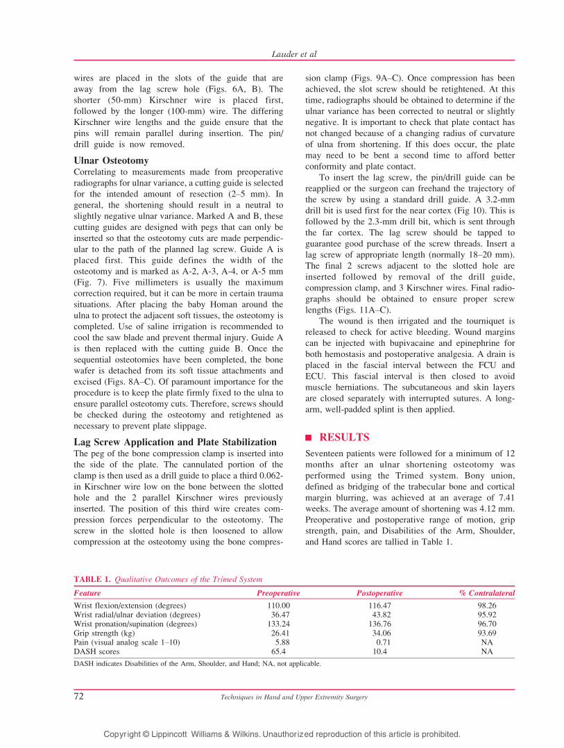
| RESULTS
Seventeen patients were followed for a minimum of 12
months after an ulnar shortening osteotomy was
performed using the Trimed system. Bony union,
defined as bridging of the trabecular bone and cortical
margin blurring, was achieved at an average of 7.41
weeks. The average amount of shortening was 4.12 mm.
Preoperative and postoperative range of motion, grip
strength, pain, and Disabilities of the Arm, Shoulder,
and Hand scores are tallied in Table 1.
TABLE 1. Qualitative Outcomes of the Trimed System
Feature Preoperative Postoperative % Contralateral
Wrist flexion/extension (degrees) 110.00 116.47 98.26Wrist radial/ulnar deviation (degrees) 36.47 43.82 95.92Wrist pronation/supination (degrees) 133.24 136.76 96.70Grip strength (kg) 26.41 34.06 93.69Pain (visual analog scale 1Y10) 5.88 0.71 NADASH scores 65.4 10.4 NA
DASH indicates Disabilities of the Arm, Shoulder, and Hand; NA, not applicable.
Techniques in Hand and Upper Extremity Surgery72
Lauder et al
Copyr ight © Lippincott Williams & Wilkins. Unauthorized reproduction of this article is prohibited.

| COMPLICATIONS
In general, complications are few in a properly performed
shortening procedure. In our 17 patients who underwent
an osteotomy using the Trimed system, we found that the
most common complication was irritation over the plate
because of prominence. Four patients ultimately required
reoperation for plate removal. Although infection,
delayed union, nonunion, and nerve palsies are certainly
possible complications, we did not encounter any of these
situations in our series. Avoiding thermal injury during
the osteotomy and assuring good bony apposition will
help minimize any risk of delayed union or nonunion.
Surgeons should be cognizant of the path of the dorsal
sensory branch of the ulnar nerve, especially when
incisions are made distal to the ulnar styloid. Consistent-
ly, tenderness around the hardware has been the most
common adverse outcome in studies evaluating similar
plate and screw systems.6,8,10
| REHABILITATION
Patients are seen at 2 weeks for their first postoperative
visit. Sutures are removed, and compliant patients are
fitted with a removable long-arm splint fabricated by one
of our hand therapists. This allows for removal during
showers and commencement of elbow flexion and
extension exercises. Noncompliant patients are placed
into a long-arm cast. At 6 weeks, radiographs are
obtained, and gentle wrist range of motion is started if
there are early signs of bony consolidation. If there are
more signs of bony union at 9 weeks, then the patients are
instructed to begin gentle strengthening exercises.
| CONCLUSION
The ulnar shortening osteotomy has become the gold
standard for correcting ulnar-sided wrist symptoms
caused by positive ulnar variance. Fortunately, the
complications are minimal, with the most common
reason for reoperation being irritation because of
hardware prominence. Several systems and techniques
exist for performing the shortening, all with their own
advantages and disadvantages. We believe that this
new system presented here provides technical advan-
tages by eliminating the need for freehand cuts while
providing a means of compression through a unique
plate design.
| REFERENCES
1. Palmer AK, Werner FW. Biomechanics of the distal
radioulnar joint. Clin Orthop. 1984;187:26Y35.
2. Milch H. Cuff resection of the ulna for malunited Colles’
fracture. J Bone Joint Surg Am. 1941;23A:311Y313.
3. Wehbe MA, Mawr B, Cautilli DA. Ulnar shortening using
the AO small distractor. J Hand Surg [Am]. 1995;20A:
959Y963.
4. Rayhack JM, Gasser SI, Latta LL, et al. Precision oblique
osteotomy for shortening of the ulna. J Hand Surg [Am].1993;18A:908Y918.
5. Chun S, Palmer AK. The ulnar impaction syndrome:
follow-up of ulnar shortening osteotomy. J Hand Surg[Am]. 1993;18A:46Y53.
6. Chen NC, Wolfe SW. Ulna shortening osteotomy using
a compression device. J Hand Surg [Am]. 2003;28A:
88Y93.
7. Labosky DA, Waggy CA. Oblique ulnar shortening
osteotomy by a single saw cut. J Hand Surg [Am]. 1996;
21A:48Y59.
8. Mizuseki T, Tsuge K, Ikuta Y. Precise ulna-shortening
osteotomy with a new device. J Hand Surg [Am]. 2001;
26A:931Y939.
9. Horn PC. Long ulnar sliding osteotomy. J Hand Surg[Am]. 2004;29A:871Y876.
10. Darlis NA, Ferraz IC, Kaufmann RW, et al. Step-cut distal
ulnar-shortening osteotomy. J Hand Surg [Am]. 2005;
30A:943Y948.
11. Gartland JJ Jr, Werley CW. Evaluation of healed Colles’
fractures. J Bone Joint Surg Am. 1981;63A:895Y907.
12. Trumble TE, Gilbert M, Vedder N. Ulnar shortening
combined with arthroscopic repairs in the delayed man-
agement of triangular fibrocartilage complex tears. J HandSurg [Am]. 1997;22A:807Y813.
Volume 11, Issue 1 73
A New System for Oblique Ulnar Shortening Osteotomy
Copyr ight © Lippincott Williams & Wilkins. Unauthorized reproduction of this article is prohibited.
Copyright © 2022 FDOKUMEN