Object shape reconstruction through NURBS surface interpolation
21
International Journal of Production Research, Vol. 45, No. 2, 15 January 2007, 287–307 Object shape reconstruction through NURBS surface interpolation PRALAY PAL*y and R. BALLAVz yTata Technologies, MSD, Tata Motors Premises, Jharkhand District, Jamshedpur, 831010 India zDepartment of Production Engineering & Management, National Institute of Technology, Jharkhand District, Jamshedpur, 831014 India (Revision received March 2006) The skinning of point cloud models has become one of the most popular reverse- engineering exercises for rapid product development in most manufacturing sectors. Common methods such as ‘polygon generation and segmentation’ and ‘direct surface fitting on segmented data’ exhibit shape loss, distortion, continuity problems and a large number of orphan surface patches. The current work discusses data processing through ‘data rarefaction’ to optimize a data set for true object shape and NURBS-based surface interpolation on rarefied data for a reconstruction with good accuracy. For originally rarefied data, on the other hand, conventional subdivision techniques are applied to construct logical points before surface fitting. NURBS interpolation technology ensures accurate surfaces within a limited computation of knot vectors, weight vectors, bi-directional control net and IGES interface file writing. A few reconstruction examples with their results are shown with computation issues and analysis. Keywords: Point cloud data; Matrix inversion; Rarefaction; IGES; Subdivision 1. Introduction Cost competitiveness, a stricter adherence to quality standards and a shorter time to market are conventionally three of the most important factors for the success of a manufacturing organization. However, innovation, perhaps, has become the most influencing factor for the success of leadership companies round the world. The high- end hardware and software systems available today in the field of engineering design and manufacture have made cycle time reduction a certainty and innovation a reality. Complex products are quickly introduced to the market through design and manufacturing cycles each time with an innovative value addition. Reverse engineering has proved to be a workhorse concept that has made innovations possible with every product launch. ‘Reverse engineering’ includes digital recon- struction and surface modelling using discrete-point data sets that facilitates rapid *Corresponding author. Email: [email protected] International Journal of Production Research ISSN 0020–7543 print/ISSN 1366–588X online ß 2007 Taylor & Francis http://www.tandf.co.uk/journals DOI: 10.1080/00207540600688481
-
Upload
independent -
Category
Documents
-
view
1 -
download
0
Transcript of Object shape reconstruction through NURBS surface interpolation
International Journal of Production Research,Vol. 45, No. 2, 15 January 2007, 287–307
Object shape reconstruction through
NURBS surface interpolation
PRALAY PAL*y and R. BALLAVz
yTata Technologies, MSD, Tata Motors Premises,
Jharkhand District, Jamshedpur, 831010 India
zDepartment of Production Engineering & Management,
National Institute of Technology, Jharkhand District,
Jamshedpur, 831014 India
(Revision received March 2006)
The skinning of point cloud models has become one of the most popular reverse-engineering exercises for rapid product development in most manufacturingsectors. Common methods such as ‘polygon generation and segmentation’ and‘direct surface fitting on segmented data’ exhibit shape loss, distortion, continuityproblems and a large number of orphan surface patches. The current workdiscusses data processing through ‘data rarefaction’ to optimize a data set fortrue object shape and NURBS-based surface interpolation on rarefied data for areconstruction with good accuracy. For originally rarefied data, on the otherhand, conventional subdivision techniques are applied to construct logical pointsbefore surface fitting. NURBS interpolation technology ensures accurate surfaceswithin a limited computation of knot vectors, weight vectors, bi-directionalcontrol net and IGES interface file writing. A few reconstruction examples withtheir results are shown with computation issues and analysis.
Keywords: Point cloud data; Matrix inversion; Rarefaction; IGES; Subdivision
1. Introduction
Cost competitiveness, a stricter adherence to quality standards and a shorter time to
market are conventionally three of the most important factors for the success ofa manufacturing organization. However, innovation, perhaps, has become the most
influencing factor for the success of leadership companies round the world. The high-
end hardware and software systems available today in the field of engineering designand manufacture have made cycle time reduction a certainty and innovation a
reality. Complex products are quickly introduced to the market through design and
manufacturing cycles each time with an innovative value addition. Reverseengineering has proved to be a workhorse concept that has made innovations
possible with every product launch. ‘Reverse engineering’ includes digital recon-
struction and surface modelling using discrete-point data sets that facilitates rapid
*Corresponding author. Email: [email protected]
International Journal of Production Research
ISSN 0020–7543 print/ISSN 1366–588X online � 2007 Taylor & Francis
http://www.tandf.co.uk/journals
DOI: 10.1080/00207540600688481
digital shape generation for downstream activities such as shape editing, engineeringanalysis, optimization and manufacturing of a part or a product.
This paper discusses a comprehensive way of fitting NURBS surfaces on pointcloud data with extreme through-point accuracy, minimum shape and geometry loss,and quicker reconstruction. Processing point cloud data before surface fitting isan important function and a method has been developed to prepare a logicalrarefied data set out of a dense data set in which data points are sequencedfor reconstruction. The logical selection sets are constructed in such a way thatthese strictly entertain only negligibly small shape losses and ensure a fastestreconstruction process with an optimum number of data points.
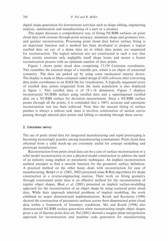
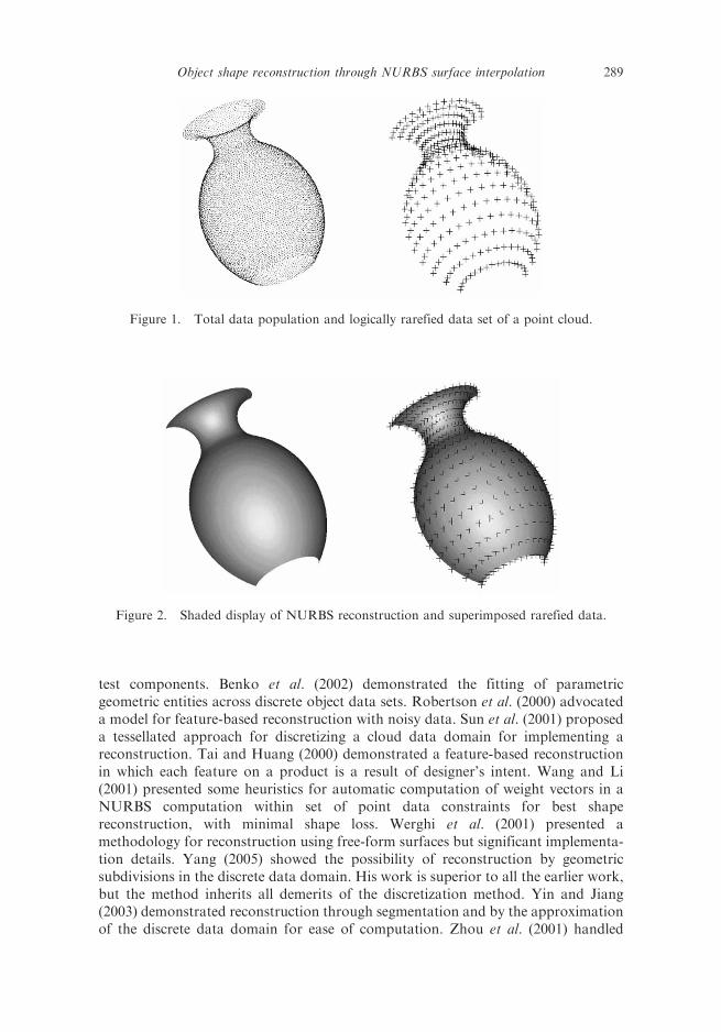
Figure 1 shows point cloud data comprising 13 159 Cartesian coordinates.This resembles the external shape of a metallic pot, which is an object of rotationalsymmetry. The data are picked up by using some mechanical sensory device.The display is made in Ideas computer-aided design (CAD) software after convertingdata point coordinates to an IGES file for visualization. A logically sequenced arrayof rarefied data points originated from the main population is also displayedin figure 1. This rarefied data is of 18� 18 dimension. Figure 2 displaysreconstructed NURBS surface using rarefied data and a superimposed rarefieddata on a NURBS surface for deviation measurement. Since a NURBS surfacepasses through all the points, it is concluded that a 100% accurate and automaticreconstruction rate has been achieved. Note that the manual fitting of surfacepatches is always a tedious task since it involves construction of section curvespassing through selected data points and lofting or meshing through these curves.
2. Literature survey
The use of point cloud data for integrated manufacturing and rapid prototyping isbecoming increasingly popular among manufacturing communities. Point cloud dataobtained from a solid mock-up are extremely useful for concept modelling andprototype manufacture.
Reconstruction from point cloud data can be a case of surface reconstruction or asolid model reconstruction or just a physical model construction to address the needof an industry using implicit or parametric techniques. An implicit reconstructionmethod attempts to find a smooth function for the geometric surface definition.A practical method on the other hand, deals with reconstruction for ease ofmanufacturing. Benko et al. (2001, 2002) presented some B-Rep algorithms for shapeconstruction in a reverse-engineering exercise. Their work on fitting geometrythrough constrained point data is an effective method for the reconstruction ofregular object shapes. Blasi et al. (2001) presented an implicit surface-modellingapproach for the reconstruction of an object shape by using scattered point clouddata. While their approach inherited problems of implicit modelling, the workexhibited no major demonstrated implementations. Kruth and Kersterns (1998)showed the construction of parametric surfaces across three-dimensional point clouddata within a framework of boundary conditions. Ma and Kruth (1998) alsodemonstrated NURBS surface generation when reconstructing simple object shapesgiven a set of discrete point data set. Pal (2001) showed a tangent plane interpolationapproach for reconstruction and machine code generation for manufacturing
288 P. Pal and R. Ballav
test components. Benko et al. (2002) demonstrated the fitting of parametricgeometric entities across discrete object data sets. Robertson et al. (2000) advocateda model for feature-based reconstruction with noisy data. Sun et al. (2001) proposeda tessellated approach for discretizing a cloud data domain for implementing areconstruction. Tai and Huang (2000) demonstrated a feature-based reconstructionin which each feature on a product is a result of designer’s intent. Wang and Li(2001) presented some heuristics for automatic computation of weight vectors in aNURBS computation within set of point data constraints for best shapereconstruction, with minimal shape loss. Werghi et al. (2001) presented amethodology for reconstruction using free-form surfaces but significant implementa-tion details. Yang (2005) showed the possibility of reconstruction by geometricsubdivisions in the discrete data domain. His work is superior to all the earlier work,but the method inherits all demerits of the discretization method. Yin and Jiang(2003) demonstrated reconstruction through segmentation and by the approximationof the discrete data domain for ease of computation. Zhou et al. (2001) handled
Figure 1. Total data population and logically rarefied data set of a point cloud.
Figure 2. Shaded display of NURBS reconstruction and superimposed rarefied data.
Object shape reconstruction through NURBS surface interpolation 289
dense scattered points for surface reconstruction and their method was similar to thediscretization of data domain.
Work by Catmull and Clark (1978) and Doo and Sabin (1978) marked thebeginning of subdivision for surface modelling for digital reconstruction of objectshapes. Though the basic ideas behind subdivision are very old, it was only recentlythrough that concept of subdivision that surfaces have found their way into wideapplications in computer graphics and computer-assisted geometric design (CAGD).The scheme produces surfaces that are C2 continuous except at extraordinaryvertices, where they are C1. The tangent plane continuity of the scheme was analysedby Ball and Storry (1988), and C1 continuity was investigated by Peters and Reif(1998). Woo et al. (2002) described a logical segmentation method for fitting surfacepatches across a set of point cloud data. Jung and Kim (2000) described thebasics of NURBS surfaces and investigated reconstruction performances withparameterization methods.
The research direction in digital reconstruction seems to be bifurcated into twodistinct schools of thought: subdivision and polygon mesh method and direct curvesand surface-fitting method. Both systems have their own merits and faults.The present research concentrates on direct surface fitting onto both rarefied anddense point data sets without considering segmentation. This method obviouslyeliminated the errors and difficulties of conventional pure subdivision andsegmentation methods and no contemporary literature has been found to describea reconstruction method without a segmentation technique.
3. NURBS interpolation and parameterization for reconstruction
3.1 NURBS defined for reconstruction
NURBS is a state-of-the-art technology for shape reconstruction, which is perhapsthe best solution for reverse engineering as well. A NURBS curve is defined by Jungand Kim (2000) as:
CðuÞ ¼
Pmi¼0 Ni, pðuÞwiPiPmi¼0 Ni, pðuÞwi
¼Xmi¼0
Ri, pðuÞPi a � u � b, ð1Þ
where {wi} are weights, {Pi} are control points, and {Ni,p(u)} are the normalizedB-spline basis functions of p degree. The weight wi determines the influence of theith control vector Pi on the curve. The ith basis function Ni,p(u) defined on a knotvector U¼ {u0, u1, . . . , umþpþ1} is recursively defined by:
Ni, pðuÞ ¼ ðu� uiÞNi, p�1ðuÞ
uiþp � uiþ ðuiþpþ1 � uÞ
Niþ1, p�1ðuÞ
uiþpþ1 � uiþ1, ð2Þ
where
Ni, 0ðuÞ ¼1 if ui � u � uiþ1
0 otherwise
�:
290 P. Pal and R. Ballav
The non-periodic knot vector customarily has the form:
U ¼ f�, . . . ,�, upþ1, . . . , um,�, . . . ,�g,
where � and � appear (pþ 1) times at the ends. This special arrangement at the endsguarantees that the initial and final control points, respectively, coincide with theinitial and final data points. Throughout this paper, it is assumed that the parameterlies in the range u 2 ½0, 1� and the weight wi is set to 1. A NURBS surface is defined asa tensor product form by:
Sðu, vÞ ¼
Pmi¼0
Pnj¼0 Ni, pðuÞNj, qðvÞwi, jPijPm
i¼0
Pnj¼0 Ni, pðuÞNj, qðvÞwi, j
, ð3Þ
where {wi,j} are weights, {Pi,j} are control points, and {Ni,p(u)} and {Nj,q(v)} are thenormalized B-spline basis functions defined on the non-periodic knot vectorsU¼ {0, 0, . . . , 0, upþ1, . . . , um, 1, 1, . . . , 1} and V¼ {0, 0, . . . , 0, vqþ1, . . . , vn, 1, 1, . . . , 1},respectively, where p and q are the degrees in the u and v directions.
3.2 NURBS surface interpolation
To determine a NURBS curve interpolating (mþ 1) data points {Qk}, it suffices tohave (mþ 1) independent conditions. If one assigns a parameter value �uk to each datapoint and select a knot vector U and a weight vector W, one can set up the curveinterpolation problem as:
Qk ¼ Cð �ukÞ ¼Xmi¼0
PiRi, pð �ukÞ for k ¼ 0, . . . ,m ð4Þ
or in matrix form:
R0, pð �u0Þ R1, pð �u0Þ � � � Rm, pð �u0ÞR0, pð �u1Þ R1, pð �u1Þ � � � Rm, pð �u1Þ
. . . � � � � � � � � �
R0, pð �umÞ R1, pð �umÞ � � � Rm, pð �umÞ
2664
3775 �
P0
P1
� � �
Pm
2664
3775 ¼
Q0
Q1
� � �
Qm
2664
3775, ð5Þ
where the rational functions {Ri,p(u)} are defined by:
Ri, pðuÞ ¼wiNi, pðuÞPmi¼0 wiNi, pðuÞ
: ð6Þ
3.3 Parameterization
Although there are many ways to determine the parameter value �ui, the followingparameterization methods are well cited:
Uniform method:
�u0 ¼ 0, �u1 ¼ 1
uk ¼k
mfor k ¼ 1, . . . ,m� 1:
ð7Þ
Object shape reconstruction through NURBS surface interpolation 291
Chord length method:
�u0 ¼ 0, �u1 ¼ 1
�ui ¼ �ui�1 þQi �Qi�1
�� ��Pmj¼0 Qj �Qj�1
�� �� : ð8Þ
For the chord length method, the knot vector U is defined by:
U ¼ f0, 0, . . . , 0, upþ1, . . . , um, 1, 1, . . . , 1g, ð9Þ
where
ujþp ¼1
p
Xjþp�1
i¼j
�ui for j ¼ 1, . . . ,m� p:
Using equations (4)–(9), the set of the control points {Pi} can easily be calculatedfrom the data points {Qk}. Once a common knot vector is selected for each of the uand v directions, interpolation of a set of (mþ 1)� (nþ 1) array data points {Qk,l},(k¼ 0, . . . ,m and l¼ 0, . . . , n) by a NURBS surface can be accomplished by applyingthe technique of NURBS curve interpolation twice; the curve interpolation isemployed in one, say u, direction for the data points for each ‘fixed’ �vl, to obtaina set of the ‘intermediate’ control points Cj. To obtain the array of the control points{Pi,j} for an interpolating surface, then interpolation is applied to these intermediatepoints for each fixed �uk, which are treated as a sequence of data points to beinterpolated. For the control points, the data points are expressed by:
Qk, l ¼Xmi¼0
Xnj¼0
Pi, jRi, pð �ukÞRj, qð �vlÞ
¼Xnj¼0
Xmi¼0
Pi, jRi, pð �ukÞ
" #Rj, qð �vlÞ:
¼Xnj¼0
Cjð �ukÞRj, qð �vlÞ ð10Þ
In our computation, we have used a ‘uniform method’ for the parameterization ofsurfaces, i.e. determining values of parameters u and v.
4. Object shape data-processing through logical rarefaction and insertion
It has been noticed that current processes available for digital reconstruction throughgeneration of additional points in a cloud data domain by logical subdivisions and,thereby, creating ‘subdivision surfaces’ lacks versatility. There is probably no need ofa so-called ‘subdivision’ if a cloud data domain is too dense and accurate but toorarefied. On the other hand, some additional logical data points need to beinterpolated if a cloud data domain is initially too rarefied to define an object shapecorrectly. A logical subdivision under such circumstance may be somewhat useful,but still there is every chance of getting an arbitrary geometry that can deviate from
292 P. Pal and R. Ballav
an actual object shape. So far as achieving a smooth geometry out of rarefied datasets is concerned, this inaccuracy could be approved and compromised. In thefollowing sections, two cases of reconstruction, i.e. handling rarefied data and denserdata for the shape reconstruction using NURBS surface, are discussed. This sectionexplains the actual original contribution made in this work, which is not availablein the literature.
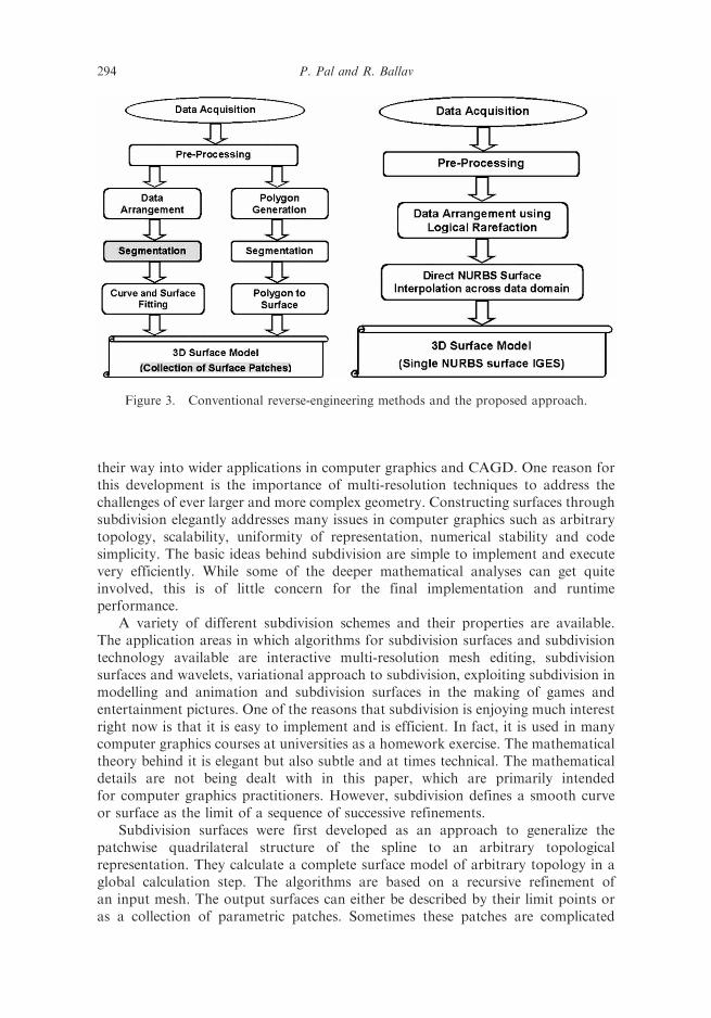
There are two distinct schools of thought in the area of reverse-engineering.In this discussion, reverse-engineering signifies generating surface models comprisingorphan surface patches or a single surface patch using point cloud data or a set ofdiscrete object shape information. Figure 3(a) represents two conventional conceptsof reverse-engineering and both the concepts are equally prevalent and predominantin the reverse-engineering field and they are available in the commercially availableRE packages. One technique is obviously the polygon generation (tessellation)method in which a cloud data domain is subdivided and discretized using computedpolygons. Then the domain is segmented and orphan surface patches are fittedagainst each segment. The matching of neighbourhood surface edges is judiciouslymanaged with C0 and C1 continuity. The second method is obviously a directfitting of curves and surfaces by considering logical points within the segmenteddata domain.
The technique of data-processing adopted in the current work is a mixedapproach. The proposed model is more efficient than tessellation in two ways.First, the proposed ‘logical rarefaction’ works on the same principle of degree ofobject shape variation along a particular direction, which is adopted in a tessellationprocess. If shape variation in terms of normal definition at an incremental locationcrosses a threshold value measured with respect to a previously measured normalincluded in the rarefaction list, logical data are recorded. That is why close points arerecorded in regions of small radii of curvature or abrupt shape variation, and distantpoints are recorded in the region of smooth transitions and larger surface radii.This is similar to tessellation where denser polygons are constructed in regions ofgross shape variation. For our face example in figures 13 and 14, the nose, lipsand chin areas show considerable variations and the forehead and cheek areas showgradual transitions with higher radii values.
Second, the proposed reconstruction method is mainly attributed to a ‘directcurves and surface fitting’ approach, with rarefied points and all the time the processaims at constructing a single NURBS surface instead of segmentation and generatinga collection of orphan surface patches. A single surface reconstruction canalways avoid continuity problems and large number of orphan surface patches.Another important advantage with the proposed method is that there is a veryhigh ‘through-point accuracy’ of the reconstruction output unlike triangulationor purely subdivision methods, which all work based on approximation. Thesefeatures together are claimed to be unique, which has never been reported in anyprevious work.
4.1 Enriching rarefied data region with subdivision points
The papers of Catmull and Clark (1978) and Doo and Sabin (1978) marked thebeginning of subdivision for surface modelling. Although the basic ideas behindsubdivision are very old, it was only recently that subdivision surfaces have found
Object shape reconstruction through NURBS surface interpolation 293
their way into wider applications in computer graphics and CAGD. One reason forthis development is the importance of multi-resolution techniques to address thechallenges of ever larger and more complex geometry. Constructing surfaces throughsubdivision elegantly addresses many issues in computer graphics such as arbitrarytopology, scalability, uniformity of representation, numerical stability and codesimplicity. The basic ideas behind subdivision are simple to implement and executevery efficiently. While some of the deeper mathematical analyses can get quiteinvolved, this is of little concern for the final implementation and runtimeperformance.
A variety of different subdivision schemes and their properties are available.The application areas in which algorithms for subdivision surfaces and subdivisiontechnology available are interactive multi-resolution mesh editing, subdivisionsurfaces and wavelets, variational approach to subdivision, exploiting subdivision inmodelling and animation and subdivision surfaces in the making of games andentertainment pictures. One of the reasons that subdivision is enjoying much interestright now is that it is easy to implement and is efficient. In fact, it is used in manycomputer graphics courses at universities as a homework exercise. The mathematicaltheory behind it is elegant but also subtle and at times technical. The mathematicaldetails are not being dealt with in this paper, which are primarily intendedfor computer graphics practitioners. However, subdivision defines a smooth curveor surface as the limit of a sequence of successive refinements.
Subdivision surfaces were first developed as an approach to generalize thepatchwise quadrilateral structure of the spline to an arbitrary topologicalrepresentation. They calculate a complete surface model of arbitrary topology in aglobal calculation step. The algorithms are based on a recursive refinement ofan input mesh. The output surfaces can either be described by their limit points oras a collection of parametric patches. Sometimes these patches are complicated
Figure 3. Conventional reverse-engineering methods and the proposed approach.
294 P. Pal and R. Ballav
to describe and evaluate. Furthermore, subdivision algorithms tend to oscillatearound extraordinary vertices. For these reasons, subdivision surfaces are not yetwidely used in mechanical engineering.
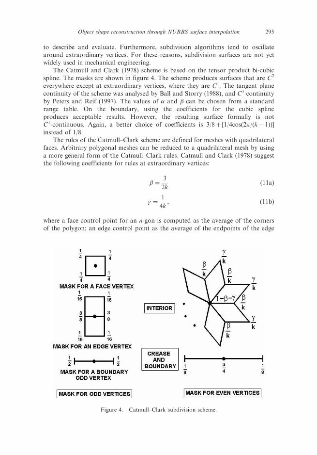
The Catmull and Clark (1978) scheme is based on the tensor product bi-cubicspline. The masks are shown in figure 4. The scheme produces surfaces that are C2
everywhere except at extraordinary vertices, where they are C1. The tangent planecontinuity of the scheme was analysed by Ball and Storry (1988), and C1 continuityby Peters and Reif (1997). The values of � and � can be chosen from a standardrange table. On the boundary, using the coefficients for the cubic splineproduces acceptable results. However, the resulting surface formally is notC1-continuous. Again, a better choice of coefficients is 3/8þ [1/4cos(2�/(k� 1))]instead of 1/8.
The rules of the Catmull–Clark scheme are defined for meshes with quadrilateralfaces. Arbitrary polygonal meshes can be reduced to a quadrilateral mesh by usinga more general form of the Catmull–Clark rules. Catmull and Clark (1978) suggestthe following coefficients for rules at extraordinary vertices:
� ¼3
2kð11aÞ
� ¼1
4k, ð11bÞ
where a face control point for an n-gon is computed as the average of the cornersof the polygon; an edge control point as the average of the endpoints of the edge
Figure 4. Catmull–Clark subdivision scheme.
Object shape reconstruction through NURBS surface interpolation 295
and newly computed face control points of adjacent faces; and the formula for evencontrol points can be chosen in different ways; the original formula is:
p jþ1ðvÞ ¼k� 2
kpjðvÞ þ
1
k2
Xk�1
i¼0
pjðviÞþ1
k2
Xk�1
i¼0
pjþ1ðvfiÞ: ð12Þ
We have applied the Catmull–Clark subdivision scheme to generate additionallogical points to populate an originally rarefied data whenever required.
4.2 Proposed rarefaction approach for denser data region
Figure 3(b) shows the flow of the proposed approach compared with theconventional approaches.
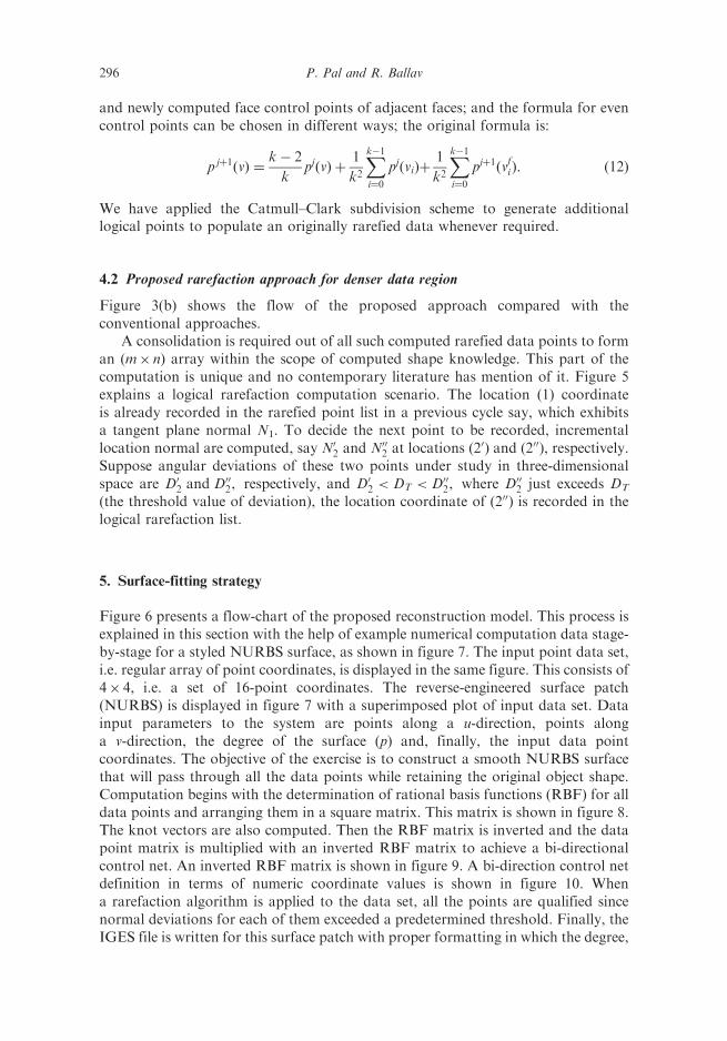
A consolidation is required out of all such computed rarefied data points to forman (m� n) array within the scope of computed shape knowledge. This part of thecomputation is unique and no contemporary literature has mention of it. Figure 5explains a logical rarefaction computation scenario. The location (1) coordinateis already recorded in the rarefied point list in a previous cycle say, which exhibitsa tangent plane normal N1. To decide the next point to be recorded, incrementallocation normal are computed, say N0
2 and N002 at locations (2
0) and (200), respectively.Suppose angular deviations of these two points under study in three-dimensionalspace are D0
2 and D002, respectively, and D0
2 < DT < D002, where D00
2 just exceeds DT
(the threshold value of deviation), the location coordinate of (200) is recorded in thelogical rarefaction list.
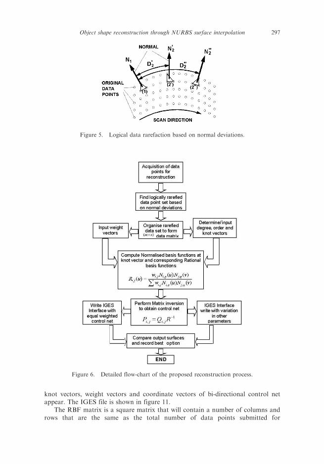
5. Surface-fitting strategy
Figure 6 presents a flow-chart of the proposed reconstruction model. This process isexplained in this section with the help of example numerical computation data stage-by-stage for a styled NURBS surface, as shown in figure 7. The input point data set,i.e. regular array of point coordinates, is displayed in the same figure. This consists of4� 4, i.e. a set of 16-point coordinates. The reverse-engineered surface patch(NURBS) is displayed in figure 7 with a superimposed plot of input data set. Datainput parameters to the system are points along a u-direction, points alonga v-direction, the degree of the surface (p) and, finally, the input data pointcoordinates. The objective of the exercise is to construct a smooth NURBS surfacethat will pass through all the data points while retaining the original object shape.Computation begins with the determination of rational basis functions (RBF) for alldata points and arranging them in a square matrix. This matrix is shown in figure 8.The knot vectors are also computed. Then the RBF matrix is inverted and the datapoint matrix is multiplied with an inverted RBF matrix to achieve a bi-directionalcontrol net. An inverted RBF matrix is shown in figure 9. A bi-direction control netdefinition in terms of numeric coordinate values is shown in figure 10. Whena rarefaction algorithm is applied to the data set, all the points are qualified sincenormal deviations for each of them exceeded a predetermined threshold. Finally, theIGES file is written for this surface patch with proper formatting in which the degree,
296 P. Pal and R. Ballav
knot vectors, weight vectors and coordinate vectors of bi-directional control netappear. The IGES file is shown in figure 11.
The RBF matrix is a square matrix that will contain a number of columns androws that are the same as the total number of data points submitted for
Figure 5. Logical data rarefaction based on normal deviations.
Figure 6. Detailed flow-chart of the proposed reconstruction process.
Object shape reconstruction through NURBS surface interpolation 297
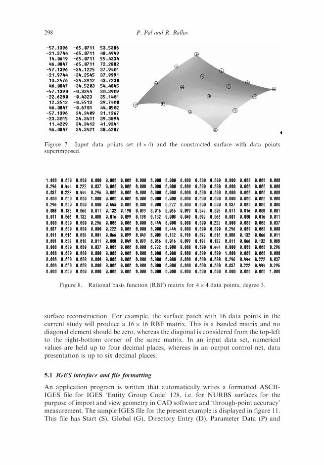
surface reconstruction. For example, the surface patch with 16 data points in thecurrent study will produce a 16� 16 RBF matrix. This is a banded matrix and nodiagonal element should be zero, whereas the diagonal is considered from the top-leftto the right-bottom corner of the same matrix. In an input data set, numericalvalues are held up to four decimal places, whereas in an output control net, datapresentation is up to six decimal places.
5.1 IGES interface and file formatting
An application program is written that automatically writes a formatted ASCII-IGES file for IGES ‘Entity Group Code’ 128, i.e. for NURBS surfaces for thepurpose of import and view geometry in CAD software and ‘through-point accuracy’measurement. The sample IGES file for the present example is displayed in figure 11.This file has Start (S), Global (G), Directory Entry (D), Parameter Data (P) and
Figure 7. Input data points set (4� 4) and the constructed surface with data pointssuperimposed.
Figure 8. Rational basis function (RBF) matrix for 4� 4 data points, degree 3.
298 P. Pal and R. Ballav
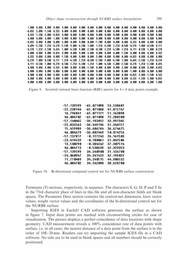
Terminate (T) sections, respectively, in sequence. The characters S, G, D, P and T liein the 73rd character place of lines in this file and all non-character fields are blankspaces. The Parameter Data section contains the control-net dimension, knot vectorvalues, weight vector values and the coordinates of the bi-directional control net forthe NURBS surface.
Importing IGES in Euclid3 CAD software generates the surface as shownin figure 7. Input data points are marked with circumscribing circles for ease ofvisualization. The picture displays a perfect coincidence of data locations with shapegeometry. CAD measurement reveals a 100% coincidence rate of data points withsurface, i.e. in all cases; the nearest distance of a data point from the surface is in theorder of 10E–20mm. Readers can try importing the sample IGES file in a CADsoftware. No tabs are to be used in blank spaces and all numbers should be correctlypositioned.
Figure 9. Inverted rational basis function (RBF) matrix for 4� 4 data points example.
Figure 10. Bi-directional computed control net for NURBS surface construction.
Object shape reconstruction through NURBS surface interpolation 299
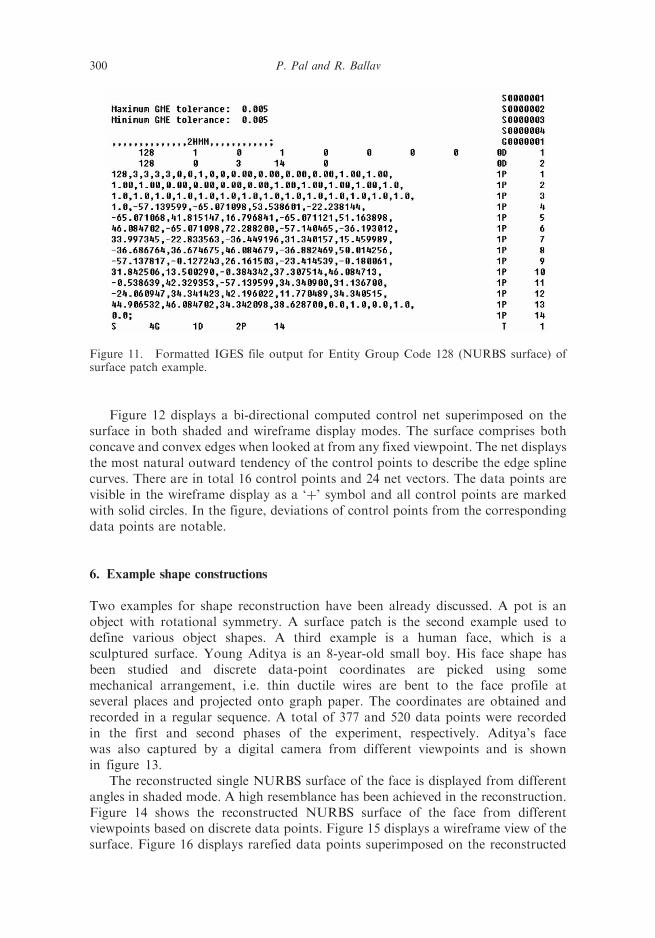
Figure 12 displays a bi-directional computed control net superimposed on thesurface in both shaded and wireframe display modes. The surface comprises bothconcave and convex edges when looked at from any fixed viewpoint. The net displaysthe most natural outward tendency of the control points to describe the edge splinecurves. There are in total 16 control points and 24 net vectors. The data points arevisible in the wireframe display as a ‘þ’ symbol and all control points are markedwith solid circles. In the figure, deviations of control points from the correspondingdata points are notable.
6. Example shape constructions
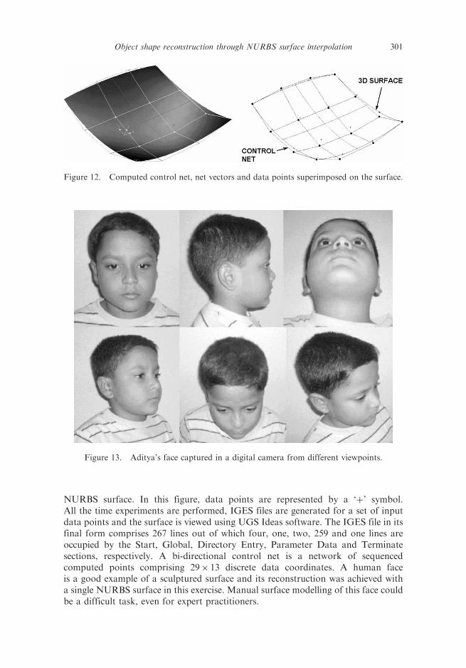
Two examples for shape reconstruction have been already discussed. A pot is anobject with rotational symmetry. A surface patch is the second example used todefine various object shapes. A third example is a human face, which is asculptured surface. Young Aditya is an 8-year-old small boy. His face shape hasbeen studied and discrete data-point coordinates are picked using somemechanical arrangement, i.e. thin ductile wires are bent to the face profile atseveral places and projected onto graph paper. The coordinates are obtained andrecorded in a regular sequence. A total of 377 and 520 data points were recordedin the first and second phases of the experiment, respectively. Aditya’s facewas also captured by a digital camera from different viewpoints and is shownin figure 13.
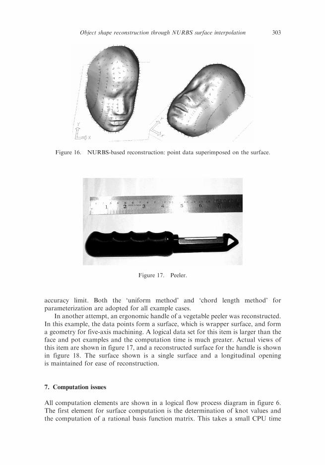
The reconstructed single NURBS surface of the face is displayed from differentangles in shaded mode. A high resemblance has been achieved in the reconstruction.Figure 14 shows the reconstructed NURBS surface of the face from differentviewpoints based on discrete data points. Figure 15 displays a wireframe view of thesurface. Figure 16 displays rarefied data points superimposed on the reconstructed
Figure 11. Formatted IGES file output for Entity Group Code 128 (NURBS surface) ofsurface patch example.
300 P. Pal and R. Ballav
NURBS surface. In this figure, data points are represented by a ‘þ’ symbol.All the time experiments are performed, IGES files are generated for a set of inputdata points and the surface is viewed using UGS Ideas software. The IGES file in itsfinal form comprises 267 lines out of which four, one, two, 259 and one lines areoccupied by the Start, Global, Directory Entry, Parameter Data and Terminatesections, respectively. A bi-directional control net is a network of sequencedcomputed points comprising 29� 13 discrete data coordinates. A human faceis a good example of a sculptured surface and its reconstruction was achieved witha single NURBS surface in this exercise. Manual surface modelling of this face couldbe a difficult task, even for expert practitioners.
Figure 12. Computed control net, net vectors and data points superimposed on the surface.
Figure 13. Aditya’s face captured in a digital camera from different viewpoints.
Object shape reconstruction through NURBS surface interpolation 301
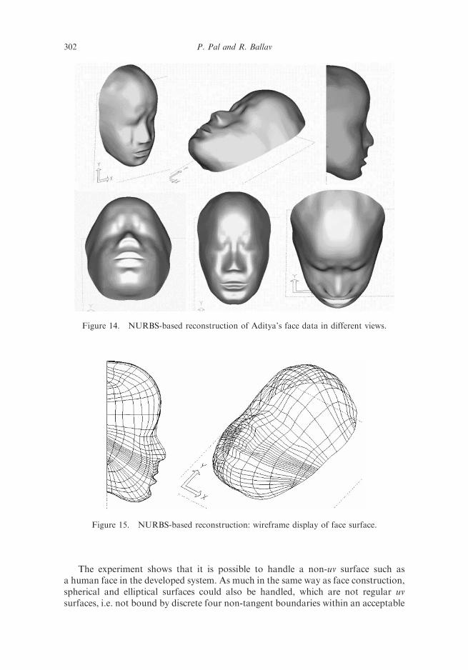
The experiment shows that it is possible to handle a non-uv surface such asa human face in the developed system. As much in the same way as face construction,spherical and elliptical surfaces could also be handled, which are not regular uvsurfaces, i.e. not bound by discrete four non-tangent boundaries within an acceptable
Figure 14. NURBS-based reconstruction of Aditya’s face data in different views.
Figure 15. NURBS-based reconstruction: wireframe display of face surface.
302 P. Pal and R. Ballav
accuracy limit. Both the ‘uniform method’ and ‘chord length method’ forparameterization are adopted for all example cases.
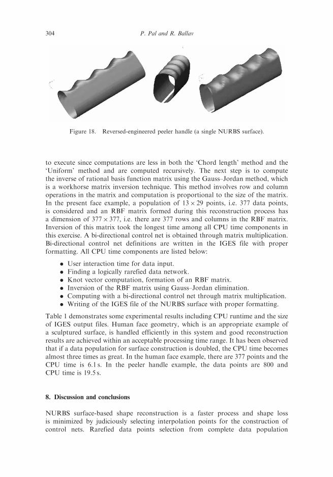
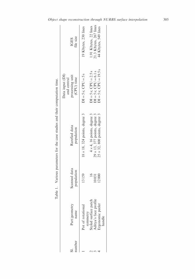
In another attempt, an ergonomic handle of a vegetable peeler was reconstructed.In this example, the data points form a surface, which is wrapper surface, and forma geometry for five-axis machining. A logical data set for this item is larger than theface and pot examples and the computation time is much greater. Actual views ofthis item are shown in figure 17, and a reconstructed surface for the handle is shownin figure 18. The surface shown is a single surface and a longitudinal openingis maintained for ease of reconstruction.
7. Computation issues
All computation elements are shown in a logical flow process diagram in figure 6.The first element for surface computation is the determination of knot values andthe computation of a rational basis function matrix. This takes a small CPU time
Figure 16. NURBS-based reconstruction: point data superimposed on the surface.
Figure 17. Peeler.
Object shape reconstruction through NURBS surface interpolation 303
to execute since computations are less in both the ‘Chord length’ method and the‘Uniform’ method and are computed recursively. The next step is to computethe inverse of rational basis function matrix using the Gauss–Jordan method, whichis a workhorse matrix inversion technique. This method involves row and columnoperations in the matrix and computation is proportional to the size of the matrix.In the present face example, a population of 13� 29 points, i.e. 377 data points,is considered and an RBF matrix formed during this reconstruction process hasa dimension of 377� 377, i.e. there are 377 rows and columns in the RBF matrix.Inversion of this matrix took the longest time among all CPU time components inthis exercise. A bi-directional control net is obtained through matrix multiplication.Bi-directional control net definitions are written in the IGES file with properformatting. All CPU time components are listed below:
. User interaction time for data input.
. Finding a logically rarefied data network.
. Knot vector computation, formation of an RBF matrix.
. Inversion of the RBF matrix using Gauss–Jordan elimination.
. Computing with a bi-directional control net through matrix multiplication.
. Writing of the IGES file of the NURBS surface with proper formatting.
Table 1 demonstrates some experimental results including CPU runtime and the sizeof IGES output files. Human face geometry, which is an appropriate example ofa sculptured surface, is handled efficiently in this system and good reconstructionresults are achieved within an acceptable processing time range. It has been observedthat if a data population for surface construction is doubled, the CPU time becomesalmost three times as great. In the human face example, there are 377 points and theCPU time is 6.1 s. In the peeler handle example, the data points are 800 andCPU time is 19.5 s.
8. Discussion and conclusions
NURBS surface-based shape reconstruction is a faster process and shape lossis minimized by judiciously selecting interpolation points for the construction ofcontrol nets. Rarefied data points selection from complete data population
Figure 18. Reversed-engineered peeler handle (a single NURBS surface).
304 P. Pal and R. Ballav
Table
1.
Variousparametersforthecase
studiesandtheircomputationtime.
Sl.
number
Part/geometry
name
Scanned
data
population
Rarefied
data
population
Data
input(D
I)andcentral
processingunit
(CPU)time
IGES
file
size
1Potofrotational
symmetry
13159
18�18,324points,degree3
DI¼5s;CPU¼5s
19Kbytes,230lines
2Styledsurface
patch
16
4�4,16points,degree3
DI¼5s;CPU¼2.5s
1.91Kbytes,22lines
3Aditya’sface
profile
10031
29�13,377points,degree3
DI¼5s;CPU¼6.1s
21.3
Kbytes,267lines
4Ergonomic
peeler
handle
12000
25�32,800points,degree3
DI¼5s;CPU¼19.5s
44Kbytes,549lines
Object shape reconstruction through NURBS surface interpolation 305
eliminates the need for tessellation and saves computation time. But when cloud dataare insufficient to represent shape definition, subdivision has also been applied togenerate additional control points. Good accuracy in the desired shape reconstruc-tion is achieved within an acceptable computation time range. Some typical shapesapparently not definable by square surface patches (u – v) can also be reconstructedwith the help of a single NURBS patch by adopting this method such as for a sphereor a human face. The IGES file interface writing capability of NURBS surfaceshas the added advantages of viewing, visualizing and measuring the error of theconstructed surfaces in a CAD package. The proposed reconstruction model isintelligent in the reorganization of data-points and seems to have good industrialapplicability where modelling and manufacturing sculptured surface are bottleneckareas. A neural network could be applied in this work with properly designedalgorithms based on feature recognition in discrete raw shape data. The proposedmodel is simple, fast and reasonably accurate and, hence, it could be appropriatefor real-time applications in manufacturing sectors.
A.1. Appendix: Nomenclature
{Pi} control points,{wi} weights,U non-periodic knot vector,
Ni,p(u) p-th-degree B-spline normalized basis functions defined on knot vectorU,Ri,p(u) p-th-degree B-spline normalized rational basis functions defined on U,S(u, v) parametric NURBS surface with parameters u, v,C(u) parametric curve with parameter u,Qk data point,Rij rational basis function corresponding to data point (i, j),N1 normal vector at data point location (1),
N02, N
002 normal vectors at incremental data point locations (20) and (200),
respectively,D0
2,D002 angular deviations of N0
2, N002 from N1, respectively,
DT threshold deviation tolerable by shape discretization interpolation,�,�, � coefficients of geometric subdivision for extraordinary vertices,
k valence of the boundary vertex,pjþ1(v) even control point on the subdivision surface,
v fixed vertex in the subdivision surface under construction,vi vertices adjacent to v on level j,vfi face vertices on level jþ 1 corresponding to faces adjacent to v.
References
Ball, A.A. and Storry, D.J.T., Conditions for tangent plane continuity over recursivelygenerated B-spline surfaces. ACM Trans. Graphics, 1988, 7(2), 83–102.
Benko, P., Kos, G., Varady, T., Andor, L. and Martin, R.R., Constrained fitting inreverse-engineering. Comput.-Aid. Geometr. Des., 2002, 19, 173–205.
306 P. Pal and R. Ballav
Benko, P., Martin, R.R. and Varady, T., Algorithms for reverse-engineering boundaryrepresentation models. Comput.-Aid. Des., 2001, 33(11), 839–851.
Blasi, F., Monno, G. and Uva, A.E., Implicit surfaces modeling for objects reconstructionfrom scattered 3D points clouds, in Proceedings of the XIIth ADM InternationalConference, Italy, 2001.
Catmull, E. and Clark, J., Recursively generated B-spline surfaces on arbitrary topologicalmeshes. Comput.-Aid. Des., 1978, 10(6), 350–355.
Doo, D. and Sabin, M., Analysis of the behaviour of recursive division surfaces nearextraordinary points. Comput.-Aid. Des., 1978, 10(6), 356–360.
Jung, H.B. and Kim, K., A new parameterisation method for NURBS surface interpolation.Int. J. Adv. Manuf. Tech., 2000, 16, 784–790.
Kruth, J.P. and Kersterns, A., Reverse-engineering modeling of free-form surface from pointclouds subject to boundary condition. J. Mat. Proc. Tech., 1998, 76(1–3), 120–127.
Ma, W. and Kruth, J.P., NURBS curve and surface fitting for reverse-engineering.Int. J. Adv. Manuf. Tech., 1998, 14(12), 918–927.
Pal, P., An easy rapid prototyping technique with point cloud data. Rapid Prototyp. J., 2001,7(2), 82–89.
Peters, J. and Reif, U., Analysis of algorithms generalizing B-spline subdivision. SIAM J.Num. Anal., 1998, 13, 728–748.
Robertson, C., Fisher, R.B., Werghi, N. and Ashbrook, A.P., Fitting of constrainedfeature models to poor 3D data, in Proceedings of the Adaptive Computing in Designand Manufacture (ACDM 2000) Conference, Plymouth, UK, 2000, pp. 149–160.
Sun, W., Bradley, C., Zhang, Y.F. and Loh, H.T., Cloud data modelling employing a unifiednon-redundant triangular mesh. Comput.-Aid. Des., 2001, 33(2), 183–193.
Tai, C. and Huang, M., The processing of data points basing on design intent inreverse-engineering. J. Mach. Tool. Manuf., 2000, 40, 1913–1927.
Wang, X.-B. and Li, S.-Y., Automatic calculation of initial weights for NURBS. Acta Aero.Astro. Sinica, 2001, 22(2), 184–189.
Werghi, N., Fisher, R.B. and Robertson, C., Constrained object reconstruction incorporatingfree-form surfaces, in Proceedings of the IXth Spanish Symposium on PatternRecognition and Image Analysis, Benicassim, Spain, 2001, pp. 273–280.
Woo, H., Kang, E., Wang, S. and Lee Kwan, H., A new segmentation method for pointcloud data. Int. J. Mach. Tool. Manuf., 2002, 42, 167–178.
Yang, X., Surface interpolation of meshes by geometric subdivisions. Comput.-Aid. Des., 2005,37(5), 497–508.
Yin, Z. and Jiang, S., Automatic segmentation and approximation of digitized pointsfor reverse-engineering. Int. J. Prod. Res., 2003, 41(13), 3045–3058.
Zhou, R.R., Zhang, L.Y., Su, X. and Zhou, L.S., Research on the algorithm of surfacereconstruction from dense scattered points. Chin. J. Softw., 2001, 13(2), 249–255.
Object shape reconstruction through NURBS surface interpolation 307