Numerical Investigation of Sorption Enhanced Steam Methane Reforming Process Using Computational...
16
Numerical Investigation of Sorption Enhanced Steam Methane Reforming Process Using Computational Fluid Dynamics Eulerian-Eulerian Code A. Di Carlo,* E. Bocci, F. Zuccari, and A. Dell’Era CIRPS-InteruniVersity Research Center for Sustainable DeVelopment, UniVersity of Rome “La Sapienza”, Rome, Italy This paper highlights the use of a fluidized bed reactor of 10 cm i.d. for producing hydrogen by sorption- enhanced steam methane reforming (SE-SMR). The model used for the hydrodynamic behavior of the bed is Eulerian-Eulerian. The kinetics of the steam methane reforming, water-gas shift, and carbonation reactions are based on literature values. Intra- and extraparticle mass transfer effects are considered together with the kinetics in the chemical models. The bed is composed of an Ni catalyst and calcined dolomite. A static bed height of 20 cm is investigated. A volume ratio of dolomite/catalyst is varied from 0-5 during the simulation. Dry hydrogen mole fraction of >0.93 is predicted for temperatures of 900 K and a superficial gas velocity of 0.3 m/s with a dolomite/catalyst ratio >2. Furthermore, the bubble formation in the fluidized bed influence product yields and product oscillations are observed. Another important aspect is that when the dolomite/ catalyst ratio is higher than 2 the necessary heat for the reforming endothermic reaction can be almost entirely supplied by the exothermic reaction of carbonation. Introduction Hydrogen is considered to be an important potential energy carrier; however, its advantages are unlikely to be realized unless efficient means to produce it with reduced generation of CO 2 can be found. Sorption-enhanced steam methane reforming (SE-SMR) is a potential route to energy efficient hydrogen production with CO 2 capture. The reactions with CaO as sorbent are when a kinetic approach is used the following reaction must also be considered: CO 2 is converted into a solid carbonate as soon as it is formed, shifting the reversible reforming and water-gas shift reactions beyond their conventional thermodynamic limits. Regeneration of the sorbent (the reverse reaction 3) releases relatively pure CO 2 , suitable for geological and deep-ocean storage or industrial usage. The CaO-CO 2 reaction has been found to consist of two stages, a fast stage followed by an extremely slow stage. 1 As the reaction produces an expanded solid product, the slow stage is believed to be controlled by product-layer diffusion. The sudden change from a fast to a slow stage of reaction is of interest with respect to CaO-based sorbents for CO 2 removal. Alvarez and Abanades 1 attributed the sharp transition to a critical thickness of the product layer. The findings of Abanades and Alvarez 2 suggest that the pore size distribution plays a crucial role for the CaO-CO 2 reaction. When the pore size distribution changes during calcination/carbonation cycles, the reactivity of the sorbent is altered accordingly. The proportion of the maximum conversion attributable to the reaction-controlled phase diminishes with the number of capture-and-release cycles due to a change in the particle morphology resulting from sintering. Thus, the maximum conversion achieved during carbonation of a fixed duration decreases with cycle number as it is limited by the rate of conversion during the (slow) diffusion- controlled phase. Bhatia and Perlmutter 3 first suggested that the diffusion-controlled phase may involve a solid-state mass transfer mechanism. Strategies for enhancing multicycle per- formance include steam hydration and thermal treatments (e.g., the works of Manovic and Anthony 4,5 and Lysikov et al. 6 ). In the work of Kuramoto et al., 7 an intermediate hydration treatment was found to enhance the reactivity and durability of the sorbents for multicycle CO 2 sorption. Because of the presence of eutectics in the CaO-Ca(OH) 2 -CaCO 3 ternary system, the formation of sorbent melts was observed in repetitive calcination-hydration-carbonation reactions at elevated pres- sures at 923 and 973 K. Even under eutectic conditions, the sorbents retained their high reactivity for CO 2 sorption. Tailored CaO-based sorbents, whereby the active material is supported on high surface area solids, such as alumina (Al 2 O 3 ) or mayenite (Ca 12 Al 14 O 33 ) have also been proposed (e.g., the works of Li et al. 8 and Feng et al. 9 ). In order to be competitive with the alternative strategy of simply using large quantities of limestone, tailored sorbent materials must achieve a significantly enhanced average conversion through a much larger number of cycles, in order to offset the economic penalties associated with their manufacture. For example, Li et al. 10 estimated that CaO/Ca 12 Al 14 O 33 (75/25 wt %) was approximately on par with CaO in terms of the cost of electricity and CO 2 mitigation for coal combustion with CO 2 removal from the flue gas. Calcium-based natural sorbents have the advantage of being low cost and readily available, but as mentioned previously, they have been proven to be unable to maintain their capture capacity over multiple reforming/regeneration cycles. 11 Re- cently, it has been reported that lithium-containing materials (mainly Li 2 ZrO 3 and Li 4 SiO 4 ) are promising candidates with high CO 2 capture capacity and high stability. Numerical studies have already been carried out with these new sorbents by Rusten et al., 12,13 Ochoa-Fernandez et al. 14 and Lindborg et al. 15 However, kinetic limitations are still the main drawback as * To whom correspondence should be addressed. E-mail: [email protected]. CH 4 + H 2 O S 3H 2 + CO - 206.2 kJ/kmol (1) CO + H 2 O S H 2 + CO 2 + 41.2 kJ/kmol (2) CaO + CO 2 S CaCO 3 + 178 kJ/kmol (3) CH 4 + 2H 2 O S 4H 2 + CO 2 - 165.0 kJ/kmol (4) Ind. Eng. Chem. Res. 2010, 49, 1561–1576 1561 10.1021/ie900748t 2010 American Chemical Society Published on Web 01/19/2010
-
Upload
unimarconi -
Category
Documents
-
view
2 -
download
0
Transcript of Numerical Investigation of Sorption Enhanced Steam Methane Reforming Process Using Computational...
Numerical Investigation of Sorption Enhanced Steam Methane Reforming ProcessUsing Computational Fluid Dynamics Eulerian-Eulerian Code
A. Di Carlo,* E. Bocci, F. Zuccari, and A. Dell’Era
CIRPS-InteruniVersity Research Center for Sustainable DeVelopment, UniVersity of Rome “La Sapienza”,Rome, Italy
This paper highlights the use of a fluidized bed reactor of 10 cm i.d. for producing hydrogen by sorption-enhanced steam methane reforming (SE-SMR). The model used for the hydrodynamic behavior of the bed isEulerian-Eulerian. The kinetics of the steam methane reforming, water-gas shift, and carbonation reactionsare based on literature values. Intra- and extraparticle mass transfer effects are considered together with thekinetics in the chemical models. The bed is composed of an Ni catalyst and calcined dolomite. A static bedheight of 20 cm is investigated. A volume ratio of dolomite/catalyst is varied from 0-5 during the simulation.Dry hydrogen mole fraction of >0.93 is predicted for temperatures of 900 K and a superficial gas velocityof 0.3 m/s with a dolomite/catalyst ratio >2. Furthermore, the bubble formation in the fluidized bed influenceproduct yields and product oscillations are observed. Another important aspect is that when the dolomite/catalyst ratio is higher than 2 the necessary heat for the reforming endothermic reaction can be almost entirelysupplied by the exothermic reaction of carbonation.
Introduction
Hydrogen is considered to be an important potential energycarrier; however, its advantages are unlikely to be realized unlessefficient means to produce it with reduced generation of CO2
can be found. Sorption-enhanced steam methane reforming(SE-SMR) is a potential route to energy efficient hydrogenproduction with CO2 capture. The reactions with CaO as sorbentare
when a kinetic approach is used the following reaction mustalso be considered:
CO2 is converted into a solid carbonate as soon as it is formed,shifting the reversible reforming and water-gas shift reactionsbeyond their conventional thermodynamic limits. Regenerationof the sorbent (the reverse reaction 3) releases relatively pureCO2, suitable for geological and deep-ocean storage or industrialusage. The CaO-CO2 reaction has been found to consist oftwo stages, a fast stage followed by an extremely slow stage.1
As the reaction produces an expanded solid product, the slowstage is believed to be controlled by product-layer diffusion.The sudden change from a fast to a slow stage of reaction is ofinterest with respect to CaO-based sorbents for CO2 removal.Alvarez and Abanades1 attributed the sharp transition to a criticalthickness of the product layer. The findings of Abanades andAlvarez2 suggest that the pore size distribution plays a crucialrole for the CaO-CO2 reaction. When the pore size distributionchanges during calcination/carbonation cycles, the reactivity ofthe sorbent is altered accordingly. The proportion of themaximum conversion attributable to the reaction-controlled
phase diminishes with the number of capture-and-release cyclesdue to a change in the particle morphology resulting fromsintering. Thus, the maximum conversion achieved duringcarbonation of a fixed duration decreases with cycle number asit is limited by the rate of conversion during the (slow) diffusion-controlled phase. Bhatia and Perlmutter3 first suggested that thediffusion-controlled phase may involve a solid-state masstransfer mechanism. Strategies for enhancing multicycle per-formance include steam hydration and thermal treatments (e.g.,the works of Manovic and Anthony4,5 and Lysikov et al.6). Inthe work of Kuramoto et al.,7 an intermediate hydrationtreatment was found to enhance the reactivity and durability ofthe sorbents for multicycle CO2 sorption. Because of thepresence of eutectics in the CaO-Ca(OH)2-CaCO3 ternarysystem, the formation of sorbent melts was observed in repetitivecalcination-hydration-carbonation reactions at elevated pres-sures at 923 and 973 K. Even under eutectic conditions, thesorbents retained their high reactivity for CO2 sorption.
Tailored CaO-based sorbents, whereby the active material issupported on high surface area solids, such as alumina (Al2O3)or mayenite (Ca12Al14O33) have also been proposed (e.g., theworks of Li et al.8 and Feng et al.9). In order to be competitivewith the alternative strategy of simply using large quantities oflimestone, tailored sorbent materials must achieve a significantlyenhanced average conversion through a much larger numberof cycles, in order to offset the economic penalties associatedwith their manufacture. For example, Li et al.10 estimated thatCaO/Ca12Al14O33 (75/25 wt %) was approximately on par withCaO in terms of the cost of electricity and CO2 mitigation forcoal combustion with CO2 removal from the flue gas.
Calcium-based natural sorbents have the advantage of beinglow cost and readily available, but as mentioned previously,they have been proven to be unable to maintain their capturecapacity over multiple reforming/regeneration cycles.11 Re-cently, it has been reported that lithium-containing materials(mainly Li2ZrO3 and Li4SiO4) are promising candidates withhigh CO2 capture capacity and high stability. Numerical studieshave already been carried out with these new sorbents by Rustenet al.,12,13 Ochoa-Fernandez et al.14 and Lindborg et al.15
However, kinetic limitations are still the main drawback as* To whom correspondence should be addressed. E-mail:
CH4 + H2O S 3H2 + CO - 206.2 kJ/kmol (1)
CO + H2O S H2 + CO2 + 41.2 kJ/kmol (2)
CaO + CO2 S CaCO3 + 178 kJ/kmol (3)
CH4 + 2H2O S 4H2 + CO2 - 165.0 kJ/kmol (4)
Ind. Eng. Chem. Res. 2010, 49, 1561–1576 1561
10.1021/ie900748t 2010 American Chemical SocietyPublished on Web 01/19/2010
shown by Ochoa-Fernandez et al.14 Furthermore, the cost ofsynthetic sorbents, such as Li2ZrO3, would require them tosustain >10 000 cycles to compete with natural sorbents.11 Thesorbent used in this study is instead dolomite, because of itsfavorable multicycle properties, compared to calcite. Initialcalcination completely decomposes both the MgCO3 and CaCO3;however, the carbonation conditions are at such high temper-atures that only CaO forms carbonate. The extra pore volumecreated by MgCO3 decomposition is thought to be responsiblefor the more favorable cycling performance. In any case,dolomite does not show such high stability compared withsynthetic sorbents and also demonstrates fragmentation behaviorat elevated temperature, but its low cost makes it preferable forthis study. Considering that only CaO is the active part ofdolomite for CO2 capture at the reforming temperatures, thedolomite is often referred to as CaO when considering sorbentconversion in this paper.
Regarding modeling of SE-SMR using Ca-based sorbents,Lee et al.16 modeled the transient behavior in a packed-bedreactor, using their own apparent kinetics that were determinedusing thermogravimetric analysis (TGA) for carbonation. Xiuet al.17 developed a model for separation- enhanced steamreforming, using a pressure swing adsorption (PSA) system witha hydrotalcite-based CO2 sorbent. Ding and Alpay18 investigateda tubular reactor, both experimentally and theoretically, for theenhanced steam reforming reaction, again using a hydrotalcitebased CO2 sorbent and a nonlinear (Langmuir) adsorptionequilibrium. Fixed-bed reactors are the predominant type in theliterature for both experimental and modeling investigations.However, they are unlikely to be applied to the SE-SMR processon an industrial scale where continuous regeneration of thesorbent is required. Fluidized-bed reactors are common inprocesses where catalysts must be continuously regenerated,while also facilitating heat transfer, temperature uniformity, andhigher catalyst effectiveness factors. Fluidized beds operate indifferent flow regimes such as bubbling or fast fluidization.Prasad et al.19 modeled a novel reactor-regenerator configu-ration in which a sorbent was added to assist hydrogenpermselective membranes in breaking the thermodynamicequilibrium of SMR. They chose a fast fluidized bed as areformer and found that increasing the CaO particle size, byimplementing a slip-factor to their model, gave a higherhydrogen yield, as the residence time for carbonation increased.Coupling two bubbling beds would have the advantage of arelatively long residence time for the sorbent, compared to fastfluidized beds, as well as low rates of attrition, because of lowgas and particle velocities. Johnsen et al.20 conducted anexperimental investigation on a bubbling fluidized-bed reactor.The reactor was operated cyclically and batchwise, alternatingbetween reforming/carbonation conditions and higher-temper-ature calcination conditions to regenerate the sorbent. Anequilibrium H2 concentration of 98% on a dry basis was reachedat 873 K and 1 atm, with Arctic dolomite as the CO2 acceptor.On the basis of the reforming conditions used in the reformerof the experimental study, a steady-state model of a dualbubbling fluidized bed reactor system was then investigated21
using the Davidson bubble model22 in order to consider theinteraction between the bubble and emulsion phase.
The aim of this work, by contrast, is to evaluate the behaviorof the fluidized bed reformer/carbonization reactor in anunsteady state condition using the recent CFD Eulerian-Eulerian(E-E)23 multiphase model, adopting the above-mentionedcalcined dolomite as sorbent. The kinetic and mass transfereffect of the reforming and carbonization reaction are therefore
interfaced with the hydrodynamic E-E model in order toconsider the interaction between the emulsion and bubble phasesand to assess the influencing factor for the bubble formation inthe reaction yields (gas bypass, reaction products decreasingdue to the low contact between reagent, catalyst, and sorbent).
Reactor Configuration
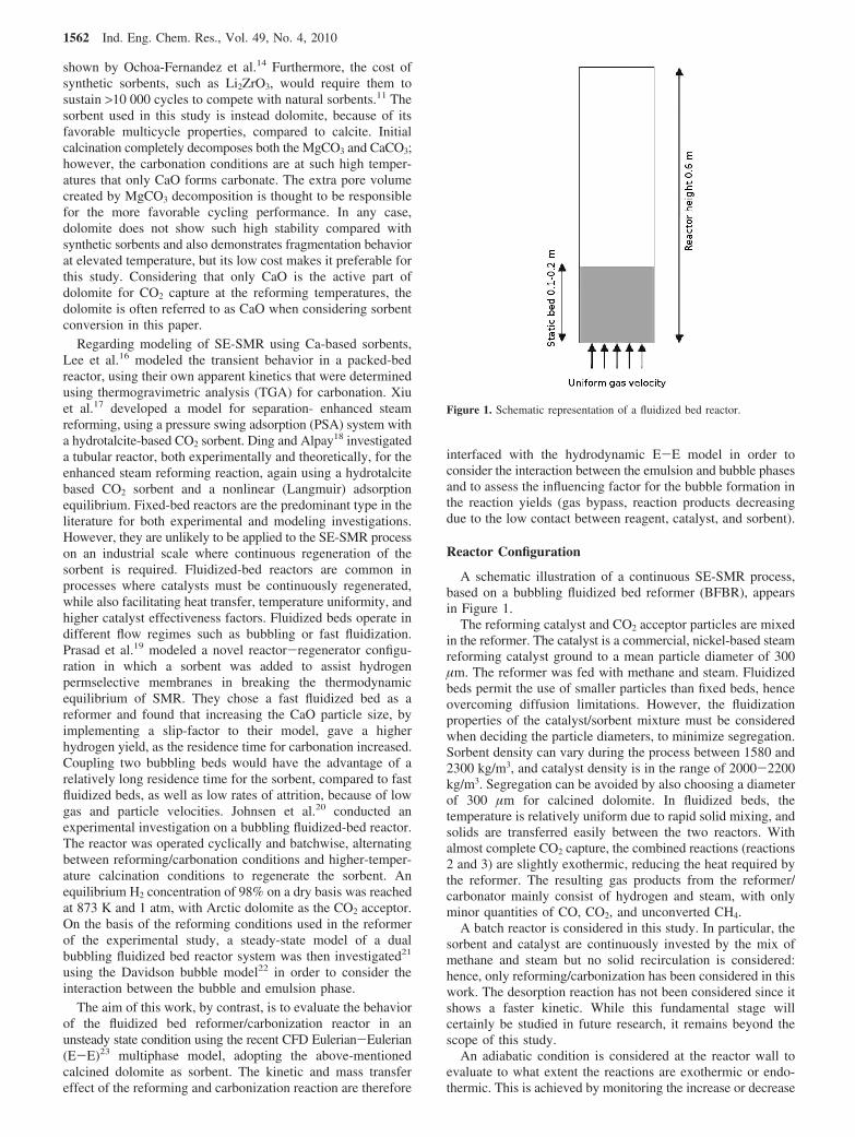
A schematic illustration of a continuous SE-SMR process,based on a bubbling fluidized bed reformer (BFBR), appearsin Figure 1.
The reforming catalyst and CO2 acceptor particles are mixedin the reformer. The catalyst is a commercial, nickel-based steamreforming catalyst ground to a mean particle diameter of 300µm. The reformer was fed with methane and steam. Fluidizedbeds permit the use of smaller particles than fixed beds, henceovercoming diffusion limitations. However, the fluidizationproperties of the catalyst/sorbent mixture must be consideredwhen deciding the particle diameters, to minimize segregation.Sorbent density can vary during the process between 1580 and2300 kg/m3, and catalyst density is in the range of 2000-2200kg/m3. Segregation can be avoided by also choosing a diameterof 300 µm for calcined dolomite. In fluidized beds, thetemperature is relatively uniform due to rapid solid mixing, andsolids are transferred easily between the two reactors. Withalmost complete CO2 capture, the combined reactions (reactions2 and 3) are slightly exothermic, reducing the heat required bythe reformer. The resulting gas products from the reformer/carbonator mainly consist of hydrogen and steam, with onlyminor quantities of CO, CO2, and unconverted CH4.
A batch reactor is considered in this study. In particular, thesorbent and catalyst are continuously invested by the mix ofmethane and steam but no solid recirculation is considered:hence, only reforming/carbonization has been considered in thiswork. The desorption reaction has not been considered since itshows a faster kinetic. While this fundamental stage willcertainly be studied in future research, it remains beyond thescope of this study.
An adiabatic condition is considered at the reactor wall toevaluate to what extent the reactions are exothermic or endo-thermic. This is achieved by monitoring the increase or decrease
Figure 1. Schematic representation of a fluidized bed reactor.
1562 Ind. Eng. Chem. Res., Vol. 49, No. 4, 2010
of the outlet gas temperature and temperature distribution inthe reactor. The use of one particle as sorbent and catalyst, asdepicted in similar study developed by Lindborg et al.,15 wouldbe preferable; internal resistance to mass transport would bereduced. Satrio et al.24 previously prepared small sphericalpellets having a layered structure such that each pellet consistsof a highly reactive lime or dolime core enclosed within a porousbut strong protective shell made of alumina in which a nickelcatalyst was loaded. The material served two functions cata-lyzing the reaction of hydrocarbons with steam to producehydrogen while simultaneously absorbing carbon dioxide formedby the reaction. In the work of Martavaltzi and Lemonidou,25
a new hybrid material, NiO-CaO-Ca12Al14O33, for applicationin SE-SMR has been synthesized. Development of a particlethat can work at the same time as both sorbent and catalyst isa promising technology. Further numerical and experimentaltests at the particle and microreactor level should certainly becarried out to prove this technology and to apply it at the bench-scale and industrial fluidized bed level. In this research the useof two different particles was preferred for the two differentpurposes: Ni/MgAl2O4 as a catalyst for steam methane reformingand calcined dolomite as sorbent for CO2 capture. The use of amultifluid model for enabling the distinction of particles withdifferent physical and chemical properties is therefore necessaryas also confirmed by Lindborg et al.15 For instance differentia-tion between catalytic and CO2-accepting particles may intro-duce an extra diffusional limitation in the transport of CO2 fromthe catalyst to the sorbent which may in turn affect conversion.15
Model
The model adopted is based on the fundamental concept ofinterpenetrating continua for multiphase mixtures. Accordingto this theory, different phases can be present at the same timein the same computational volume. Such an idea is madepossible by the introduction of a new dependent variable, theconcentration, εi, of each phase i. In this study, the phasesconsidered were the gas phases and two particle phases: onefor the catalyst particles and a second one for the dolomiteparticles. The fundamental equations of mass, momentum,chemical species, and energy conservation are then solved foreach considered phase. Appropriate constitutive equations mustbe specified in order to describe the physical rheologicalproperties of each phase and to complete the conservationequations. In this model, solids viscosity and pressure arederived by considering the random fluctuation of particlevelocity and its variations due to particle-particle collisionsand the actual flow field. Such a random value of kinetic energy,or granular temperature, can be predicted by solving, in additionto the mass and momentum equations, a fluctuating kineticenergy equation for the particles. Solids viscosity and pressurecan then be computed as a function of granular temperature atany time and position. Particles are considered smooth, spherical,inelastic, and undergoing binary collisions. The adoption of thesecond approximation distribution function allows us to applythe theory to both dense and diluted two-phase flows. A morecomplete discussion of the implemented kinetic theory modelcan be found in the work of Gidaspow.23
Hydrodynamic Model. The accumulation of mass in eachphase is balanced by the convective mass flow and the sourceterm due in this case to the CO2 capture and CaCO3 formation(i ) gas, solid(catalyst), solid(dolomite)):
where ε is the volume fraction of each phases, V the velocityvector, and F the density. Mass exchanges between phases mi,due to the carbonation reaction are explained below. Themomentum balance for the gas phase is given by theNavier-Stokes equation, modified to include an interphasemomentum transfer term. Due to CO2 capture reaction, mass istransferred from the gas phase to the dolomite phase. This affectsthe continuity equation (eq 5) and a source (or sink) term mustbe considered for both phases. At the same time, the masstransfer from the gas phase to the dolomite phase varies thephase momentum and a source (or sink) term in the momentumtransport equation must be also considered (see the work ofGidaspow23). The approach illustrated in ref 26 was adopted inthis work. The gas momentum balance is
Where g refers to the gas phase, c, to the catalyst, and d, to thedolomite solid phases, p is the thermodynamic pressure, isthe interface momentum transfer coefficient, and τg is the gasphase viscous stress tensor.
The solid phase momentum balance for dolomite is
The solid phase momentum balance for the catalyst is
Where s refers to the solid phases (catalyst, c, and dolomite,d). The conservation of energy for the three phases are for gas,g, catalyst, c, and dolomite, d:
Where H is the specific enthalpy of the different phases, k isthe thermal conductivity, h is the convection coefficientbetween phases, T is the temperature of the phases, and S isthe rate of the reactions which occur in the different solidphases:
• reactions 1, 2, and 4 in catalyst particles• reaction 3 in dolomite particles Lastly ∆H is the heat of
reaction.The fluctuation energy conservation of solid phases (dolomite
and catalyst) is
Where Θ is the granular temperature of dolomite and catalyst,kΘ is the diffusion coefficient for granular temperature, and γΘ
is the collision dissipation of energy. Constitutive equations arerequired to complete the governing relations. The momentum
∂
∂t(εiFi) + ∇ · (εiFiVji) ) mi (5)
∂
∂t(εgFgVjg) + ∇ · (εgFgVjgVjg) ) ∇ · τg + εgFggj - εg∇p -
∑s)c,d
gs(Vjg - Vjs) - mgVjg (6)
∂
∂t(εsFsVjd) + ∇ · (εsFsVjdVjd) ) ∇ · τs + εsFsgj - εs∇p - ∇pd -
∑j)g,c
dj(Vjd - Vjj) + mgVjg (7)
∂
∂t(εsFsVjc) + ∇ · (εsFsVjcVjc) ) ∇ · τs + εsFsgj - εs∇p - ∇pc -
∑j)g,d
cj(Vjc - Vjj) (8)
∂
∂t(εiFiHi) + ∇ · (εiFiVjiHi) ) -εi
∂p∂t
+ τi:∇ · Vji + ∇ki∇Ti +
∑i*j
[hij(Tj - Ti) - ij(Vjj - Vji)2] + ∑
k
Sk∆Hk (9)
32[ ∂
∂t(εsFsΘs) + ∇ · (εsFsVjsΘs)] ) (-psIj + τs):∇ · Vjs +
∇ · (kΘs∇Θs) - γΘs (10)
Ind. Eng. Chem. Res., Vol. 49, No. 4, 2010 1563
exchange coefficients can be calculated by specifying dragfunctions. In this study, the Gidaspow23 model for gas-solidphases interaction was applied while the symmetric Syamlaland O’Brien27 model was applied for the solid-solid phaseinteraction. The correlations for momentum exchange coef-ficients are provided in Table 1. Other constitutive equationsare summarized in Table 2.
Regarding thermal conductivity, a modification of the formproposed by Kuipers et al28 was applied in order to use itfor two solid phases (catalyst and dolomite) and one gasphase.
Regarding heat transfer coefficient, a correlation proposedby Gunn29 for granular flows was chosen (see Table 3.
Values of 0.9 were selected for the restitution coefficients ofdolomite and catalyst. Values of 0.9 can give good predictionsof fluidized bed behavior as demonstrated by Lindborg et al30
and Taghipour et al.31
Chemical Model
Reforming. In order to compute the kinetic expression ofcatalyzed reactions, various processes which act as resistancesto the reactions must be considered. For a single porous particle,these are
• Gas film layer resistance: reagents and products diffusedfrom the gas to the external surface or from the externalsurface to the gas of the catalytic particle, respectively.
• Pore diffusion resistance: As the interior of the particlecontains the highest catalytic surface area, the reactionsoccur primarily inside the particle. Reagents and productsmust diffuse inside the particle.
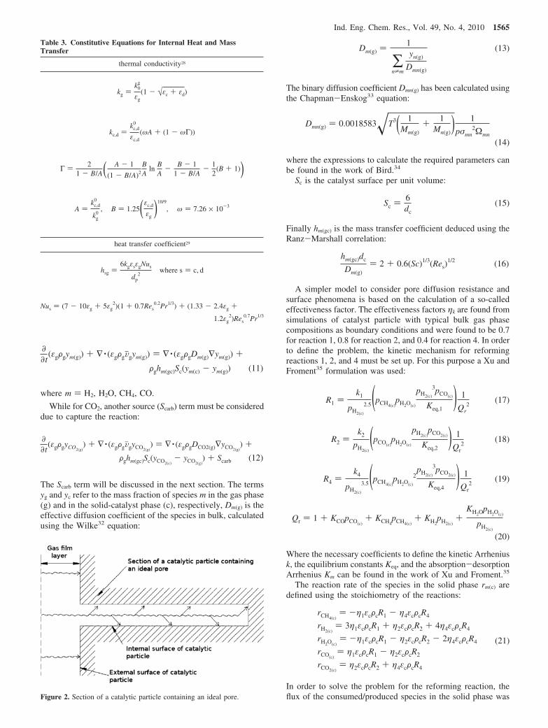
• Surface phenomena resistance: the reagents moving insidethe catalyst must be absorbed on a solid surface and reactfollowing the kinetic mechanism, and then, the productsmust be deabsorbed from the solid surface to the gas phase.
The three phenomena are summarized in Figure 2.As shown in Figure 2, the gas film layer resistance can be
considered in series, with the parallel composed of pore diffusionresistance and surface phenomena resistance. Therefore toconsider the different mechanisms, two types of the samechemical species must be considered one in the gas phase (g)and the other in the solid-catalyst phase (c). The followingchemical species balance can be derived:
Table 1. Drag Coefficient
Gidaspow drag coefficient
gs )34
CD
εsεgFg · |Vjg - Vjs|
dsεg
-2.65 for εg g 0.8
gs ) 150εs
2µg
εsds2+ 1.75
εsFg|Vjg - Vjs|
dsfor εg < 0.8
where
CD ) 24εgRes
[1 + 0.15(εgRes)0.687]
and
Res )Fgds|Vjg - Vjs|
µg
symmetric Syamlal and O’Brien
dc )3(1 + edc)(π
2+ Cdc
fr π8
4 )εcεdFcFd(dd + dc)2gdc°
2π(Fddd3 + Fcdc
3)|Vjd - Vjc|
where
Cdcfr ) coefficient of friction between particle phases
gdc° ) radial distribution of particle phases
Table 2. Constitutive Equations for Internal Momentum Transfer
solid phase stress tensor
τs ) εsµs(∇Vjs + ∇VjsT) + εs(λs -
23
µs)∇ · VjsIj with s ) c, d
radial distribution function
gss° ) [1 - ( εs
εs,max)1/3]-1
diffusion coefficient of granular temperature (Gidaspow)
kΘs)
150Fsds√πΘs
384(1 + ess)gss° [1 + 65
εsgss°(1 + ess)]2+ 2Fsdsεs
2gss°(1 + ess)Θs
π
collision dissipation energy
γΘs)
12(1 - ess2)gss°
ds√πFsεs
2Θs3/2
solid pressure
ps ) εsFsΘs + 2Fs(1 + ess)εs2gss°Θs
solid shear viscosity
µs ) µscoll + µs
kin
solid collision viscosity
µscoll ) 4
5εsFsdsgss°(1 + ess)(Θs
π )1/2
kinetic viscosity (Gidaspow)
µskin )
10Fsds√Θsπ96εs(1 + ess)gss° [1 + 4
5gss°εs(1 + ess)]2
bulk viscosity
λs )43
εsFsdsgss°(1 + ess)(Θs
π )1/2
1564 Ind. Eng. Chem. Res., Vol. 49, No. 4, 2010
where m ) H2, H2O, CH4, CO.
While for CO2, another source (Scarb) term must be considereddue to capture the reaction:
The Scarb term will be discussed in the next section. The termsyg and yc refer to the mass fraction of species m in the gas phase(g) and in the solid-catalyst phase (c), respectively, Dm(g) is theeffective diffusion coefficient of the species in bulk, calculatedusing the Wilke32 equation:
The binary diffusion coefficient Dmn(g) has been calculated usingthe Chapman-Enskog33 equation:
where the expressions to calculate the required parameters canbe found in the work of Bird.34
Sc is the catalyst surface per unit volume:
Finally hm(gc) is the mass transfer coefficient deduced using theRanz-Marshall correlation:
A simpler model to consider pore diffusion resistance andsurface phenomena is based on the calculation of a so-calledeffectiveness factor. The effectiveness factors ηk are found fromsimulations of catalyst particle with typical bulk gas phasecompositions as boundary conditions and were found to be 0.7for reaction 1, 0.8 for reaction 2, and 0.4 for reaction 4. In orderto define the problem, the kinetic mechanism for reformingreactions 1, 2, and 4 must be set up. For this purpose a Xu andFroment35 formulation was used:
Where the necessary coefficients to define the kinetic Arrheniusk, the equilibrium constants Keq, and the absorption-desorptionArrhenius Km can be found in the work of Xu and Froment.35
The reaction rate of the species in the solid phase rm(c) aredefined using the stoichiometry of the reactions:
In order to solve the problem for the reforming reaction, theflux of the consumed/produced species in the solid phase was
Table 3. Constitutive Equations for Internal Heat and MassTransfer
thermal conductivity28
kg )k0
g
εg(1 - √εc + εd)
kc,d )kc,d
0
εc,d(ωA + (1 - ωΓ))
Γ ) 21 - B/A( A - 1
(1 - B/A)2
BA
lnBA
- B - 11 - B/A
- 12
(B + 1))
A )kc,d
0
kg0
, B ) 1.25(εc,d
εg)10/9
, ω ) 7.26 × 10⁻³
heat transfer coefficient29
hsg )6kgεsεgNus
dp2
where s ) c, d
Nus ) (7 - 10εg + 5εg2)(1 + 0.7Res
0.2Pr1/3) + (1.33 - 2.4εg +
1.2εg2)Res
0.7Pr1/3
Figure 2. Section of a catalytic particle containing an ideal pore.
∂
∂t(εgFgym(g)) + ∇ · (εgFgVjgym(g)) ) ∇ · (εgFgDm(g)∇ym(g)) +
Fghm(gc)Sc(ym(c) - ym(g)) (11)
∂
∂t(εgFgyCO2(g)
) + ∇ · (εgFgVjgyCO2(g)) ) ∇ · (εgFgDCO2(g)∇yCO2(g)
) +
Fghm(gc)Sc(yCO2(c)- yCO2(g)
) + Scarb (12)
Dm(g) )1
∑n*m
yn(g)
Dmn(g)
(13)
Dmn(g) ) 0.0018583T3( 1Mm(g)
+ 1Mn(g)
) 1
pσmn2Ωmn
(14)
Sc )6dc
(15)
hm(gc)dc
Dm(g)) 2 + 0.6(Sc)1/3(Res)
1/2 (16)
R1 )k1
pH2(c)
2.5(pCH4(c)pH2O(c)
pH2(c)
3pCO(c)
Keq,1) 1
Qr2
(17)
R2 )k2
pH2(c)
(pCO(c)pH2O(c)
pH2(c)pCO2(c)
Keq,2) 1
Qr2
(18)
R4 )k4
pH2(c)
3.5(pCH4(c)pH2O(c)
2pH2(c)
3pCO2(c)
Keq,4) 1
Qr2
(19)
Qr ) 1 + KCOpCO(c)+ KCH4
pCH4(c)+ KH2
pH2(c)+
KH2OpH2O(c)
pH2(c)
(20)
rCH4(c)) -η1εcFcR1 - η4εcFcR4
rH2(c)) 3η1εcFcR1 + η2εcFcR2 + 4η4εcFcR4
rH2O(c)) -η1εcFcR1 - η2εcFcR2 - 2η4εcFcR4
rCO(c)) η1εcFcR1 - η2εcFcR2
rCO2(c)) η2εcFcR2 + η4εcFcR4
(21)
Ind. Eng. Chem. Res., Vol. 49, No. 4, 2010 1565

set as equal to the flux from the gas phases to the solid phasesand vice versa:
In previous work by Rusten et al.,12 a different sorbentLi2ZrO3 has been investigated for the SE-SMR. In their paper,Rusten et al.12 simulate SE-SMR using heterogeneous modelsand pseudohomogeneous models that include an efficiencyfactor. SMR has been determined to be strongly intraparticulardiffusion-controlled, and to check whether this is also the casefor SE-SMR, heterogeneous models were formulated. Dryhydrogen mole fractions did not show significant differencesin the reactor performances for the pseudohomogeneous, one-particle heterogeneous, and two-particle heterogeneous models.No advantage of heterogeneous models was therefore observedunder standard conditions, because the capture of CO2 is thelimiting step of the process. In contrast with SMR, where thereactions are very fast, the capture kinetics are slow, comparedwith diffusion processes. If CO2 acceptors with faster kineticswere used, heterogeneous or pseudoheterogeneous models withefficiency factors would be necessary. As shown by Rusten etal.12 the use of a heterogeneous model would be useless, albeitnot wrong, if the same conditions were applied. In this study,the use of a heterogeneous model was preferred becausedifferent materials and conditions were used in the simulation.In the current work, calcined dolomite is used instead ofLi2ZrO3. Calcined dolomite can work at higher temperature(873-973 K) than Li2ZrO3 (858 K). Johnsen36 has demonstrateda faster kinetic of calcined dolimite compared to that of Li2ZrO3.Ochoa-Fernandez et al.14 report that the slow sorption kineticsof Li2ZrO3 at low partial carbon dioxide pressures are causedby a second-order concentration dependency, a different scenariocompared with the sorption kinetics of CaO. Further investiga-tion is required to evaluate if the same results obtained by Rustenet al.12 could also be applied to CaO based sorbents. This ishowever beyond the scope of the present work.
Term Sk in eq 9 for reactions 1, 2, and 4 is
CO2 Capture. To describe the chemical mechanism for CO2
capture, a shrinking unreacted core model (SCM) was chosen.A recent comprehensive literature review of carbonation modelswas provided by Stanmore and Gilot.37 For noncatalyticreactions, two simple idealized models are widely used: theprogressive-conversion model (PCM) and the shrinking unre-acted-core model (SCM).38 The PCM assumes that intraparticlediffusion is fast compared to the chemical reaction, making auniform reacting particle. It is well-known that carbonationproceeds through a slow diffusional limited regime at higherconversion levels. The noncatalytic gas-solid reaction betweenCaO and CO2 is known to proceed through two rate-controllingregimes.39,40,3 Initially, a rapid chemically controlled stage israte-determining, before the rate of reaction decreases due todiffusion limitations caused by the very slow diffusion throughthe product layer. The PCM model is not suitable for describingthis regime. The classic SCM model however assumes that thereaction occurs first at the outer skin of the particle. The zoneof reaction then moves into the solid, leaving behind completelyconverted material, known as the product layer in the case ofthe carbonation. Thus, at any time, there exists an unreactedcore of material which shrinks in size during the reaction. Duringformation of the product layer, the CO2 in the exterior of theparticle has an extra diffusion limitation and reacts with more
difficulty with the unreacted core. This mechanism may explainthe two rate-controlling regimes discussed above. More complexmechanisms could probably be applied,37 but SCM applied toCO2 capture has been demonstrated to give acceptable results,as shown by Johnsen.36
Three resistances to reaction for the gas-solid reactionbetween CO2 and calcined dolomite must be considered:
• external mass transfer• intraparticle diffusion taking into consideration the internal
mass transfer due to resistance to the product layer• chemical reaction.
In this case, the three resistances occur in series and the algebraiccombination is simply handled by the classic Ohm’s lawtreatment of resistances in series, eliminating intermediateconcentration terms, and yielding a relationship for the rate ofreaction with the driving force expressed in terms of bulkconcentration. The following assumptions were applied:
• CaO and inert material (mainly MgO) are uniformlydistributed in the dolomite pellet. Carbonation of MgO isthermodynamically unfavorable at temperatures above 500°C at ambient pressure and is therefore considered inert.However, MgO is still a significant part of the total volumeof the particle.
• single spherical particle• constant particle size.
To account for a nonlinear dependency of partial pressure, theSCM rate expression was modified using the formulationproposed by Johnsen et al.21 to include a parameter, n ) 0.66.Considering X as the conversion of CaO, the final rateexpression, Scarb of eq 12 is
Where PCO2and PCO2,eq
are the partial pressures (Pa) in the bulkphase and at equilibrium respectively, k3 is the Arrhenius ofreaction 3, De is the effective diffusivity, hCO2(gd) is the externalmass transfer coefficient, and X is the CaO conversion. Theequilibrium pressure of carbon dioxide (in atmospheres) isexpressed as a function of temperature
The three denominator groups of eq 24 are calculated as follows:Chemical Reaction. k3 is calculated as an Arrhenius type
expression defined as:
The pre-exponential factor and the activation energy are definedin Table 4
Table 4. Carbonation Experimental Parameters Adopted
Dpl (m2/s)21 7.7 × 10⁻⁹
k0 (m/s)21 3.05Ea (kJ/mol)21 32.6VCaCO3
(cm3/mol)41 36.9VCaO (cm3/mol)41 16.9VMgCO3
(cm3/mol)41 27.5VMgO (cm3/mol)41 11.1f41 0.574FD (kg/m3)41 2851δCaO, MgO
41 (m) 1.50 × 10⁻⁶
Fghm(gc)Sc(ym(c) - ym(g)) ) rm(c)Mm (22)
Sk ) ηkεcFcRk (23)
Scarb ) εdFdMCO2×
6dd
(1 - X)2/3 1RT
(pCO2- pCO2,eq
)0.66
1k3
+
dd
2[(1 - X)1/3 - (1 - X)2/3]
De+ (1 - X)2/3
hCO2(gd)
(24)
pCO2,eq) 4.137 × 10⁷e[20474/(T-273.15)] (25)
k3 ) k0e-Ea/RT (26)
1566 Ind. Eng. Chem. Res., Vol. 49, No. 4, 2010
Intraparticle Diffusion. The model in Stendardo and Fos-colo41 was used. It is assumed that the fresh solid sorbentcontains only CaCO3, with mass fraction f, and MgCO3, withmass fraction (1 - f). Before calcination, the particle internalporosity, ε0, is zero, and the dolomite theoretical density, Fd, isobtained from knowledge of the molar volumes of CaCO3 andMgCO3:
N0Ca and N0Mg indicate the number of calcium and magnesiumcarbonate moles respectively per unit volume of dolomiteparticle. We also consider that both carbonates are completelytransformed into the respective oxides as a result of a calcinationprocess, so the particle porosity at the beginning of the gasdecarbonation step is given by
Magnesium carbonate decomposes at a much lower temper-ature than calcium carbonate, so at the temperature envisagedfor this application (about 873 K), it would not contribute toCO2 capture (it stabilizes the particle structure and providesadditional voidage); as a result, the particle void fraction as afunction of CaO conversion, X, is given by
The mass transport rate within the pore volume is governedby two different phenomena: bulk diffusion and Knudsendiffusion. The first is a function of temperature and pressure(the molecular velocity and the mean free path). Bulk diffusivityis evaluated using eqs 13 and 14.
Knudsen diffusion, Dk, depends on the molecular velocityand the pore radius:
Assuming a cylindrical pore structure for the solid particleallows rav to be related to the void fraction ε and the pore surfaceper unit particle volume, σ:
In our idealized picture of dolomite, σ is in turn obtainable asa function of the grain size (of CaO and MgO, respectively)and calcium oxide conversion:
δCaO and δMgO are the average diameters of calcium andmagnesium oxide grains, respectively. It is worth noting herethat, as has been assumed above, when a calcium oxide grainis fully carbonated the associated porosity and pore surface arebrought to zero. From eqs 32 and 28, it is possible to calculaterav (eq 31) and therefore Dk with eq 30 The overall porediffusivity is calculated using the Bosanquet equation as reportedin the work of Hayes42 combining molecular and Knudsendiffusion:
This equation is probably not as rigorous as the dusty gas modelbut gives consistent predictions as indicated in the works ofStendardo and Foscolo,41 Johnsen et al.,21 and Zevenhoven etal.43 when applied to a SCM sorption reaction. The advantageof this equation is faster computation compared with the rigorousdusty gas model. Finally, it was possible to calculate the De,0
as
Equation 34 may be simplified using the assumption of Smith44
for macropore particles such as dolomite.
As shown in the work of Zevenhoven,43 it is possible to calculateDe of eq 24 as a function of X:
The parameters for finally defining intraparticle diffusion aregiven in Table 4
External Mass Transfer. For the calculation of h aRanz-Marshall correlation was used similar to eq 16. A similarspecies balance equation can be written for CaCO3 and CaOreferring to the solid-dolomite phase:
where k ) CaO, CaCO3 and νk is equal to 1 for CaCO3 and -1for CaO. It is now possible to define m of eqs 5-7: it is themass flow rate of CO2 subtracted from the gas phase andaccumulated in the solid-dolomite phase as CaCO3:
The carbonation rate parameters to solve the equation systemas indicated in Johnsen et al.21 and Stendardo and Foscolo41
are given below in Table 4.The term of eq 9 is
The partial differential equation system (eqs 5-12 and 37) wassolved with a finite volume method, using Fluent softwarecoupled with a Newton-Raphson method for the algebraicsystem 22 developed in C language and interfaced as a userdefined function (UDF) in Fluent. A k-ε realizable methodmodel was used for turbulence. In Table 5, the initial andboundary condition used that was used.
A quadratic mesh of ∆x ) ∆y ) 2.5 mm was evaluated togive accurate results. The Euler implicit method was chosenfor time integration, while a second order upwind discretizationscheme was used for space discretization. To give an asymmetriccondition, a heterogeneity was introduced into the bed by tiltingthe gravity vector 1% during the first second of simulation. The
Fdf
MCaCO3
VCaCO3+
Fd(1 - f)
MMgCO3
VMgCO3) N0CaVCaCO3
+
N0MgVMgCO3) 1 (27)
(1 - ε0) ) N0CaVCa + N0MgVMg (28)
(1 - ε) ) N0Ca[VCaO(1 - X) + VCaCO3X] + N0MgVMgO )
1 - ε0 + N0CaX(VCaCO3- VCaO) (29)
Dk ) 23
rav 8RTπMCO2(c)
(30)
rav ) 2εσ
(31)
σ ) [N0CaVCaO6
δCaO(1 - X) + N0MgVMgO
6δMgO] (32)
Dov ) 11
DCO2(g)+ 1
Dk
(33)
De,0 ) Dovετ
(34)
De,0 ) Dovε2 (35)
De ) De,01 + AX1 + BX
with A )1 - ε0
ε0B )
ADe,0
Dpl
(36)
∂
∂t(εdFdyk(d)) + ∇ · (εdFdVjdyk(d)) ) νk
Mk
MCO2
Scarb (37)
m ) Scarb (38)
S3 )Scarb
MCO2
(39)
Ind. Eng. Chem. Res., Vol. 49, No. 4, 2010 1567
effect of this had only minor effects on the statistical behaviorof the fluid flow.
Model ValidationsEntire Process
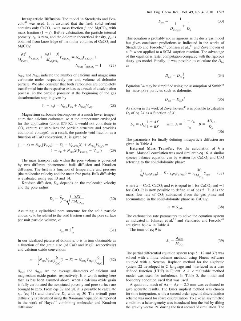
In order to validate the model, some preliminary calculationswere carried out and the results were compared with experi-mental data. As shown in Figure 3, the physical rig consistedof
• a pipeline for water, steam generation, and methane feeding• fluidized bed reactors composed of a windbox of 20 cm
high and 10 cm i.d. and a zone of reaction 60 cm high and10 cm i.d. A sintered steel plate was used as distributor toguarantee the required pressure drop in order to maintaina homogeneous velocity at the inlet to the bed.
• cooling and drying system• gas chromatography analyzersVarian microGC. The col-
umns used were CP-Molsieve 5 and PoraPLOT U. The gascarrier type was N2. A thermal conductivity detector wasused.
A Watson Marlow series 400 pump was used to feed theplant with deionized water. The flow rate was controlled by aDwyer variable area flowmeter. Water was vaporized at 190°C. The steam generator employed was a single-loop propor-tional-integral-derivative (PID) controller series 96 Watlowto maintain constant temperature. In particular, a J thermocouplewas used as temperature sensor.
The methane flow rate was controlled by a Dwyer variablearea flowmeter.
Steam and methane were mixed to feed the fluidized bedreactor.
The mix (steam and methane) was first heated to 823 K byelectrical resistance, in the windbox: here, another single-loopPID controller series 96 Watlow with a K thermocouple wasused.
Finally, the mix was fed to the reactor bed, where the processtemperature (873-973 °C) was controlled by a further series96 Watlow with a K thermocouple.
Two further K thermocouples were installed to monitor thetemperature inside the fluidized bed: one at a 2 cm distancefrom the distributor and the other at 15 cm from the distributor.The uniformity of temperature monitored by these two sensorsassured the fluidization of the bed and therefore the perfectmixing condition. A pressure probe was then installed to monitorthe process pressure.
At the exit of the reactors, a cyclone and an antiparticulatefilter were installed for particulate abatement, thereby preventingpipe plugging at the rig outlet.
The syngas was finally cooled and dried by three impingementbottles in a water bath and a silica gel fixed bed, respectively.The dried syngas was then analyzed by the Varian microGCsystem. A Ni-based steam-reforming catalyst by Haldor Topsoewas used with calcined Pilkington dolomite. The catalyst andsorbent were first ground and then sieved to obtain, for both, agranulometric distribution with a Sauter diameter of around 300µm. Before the real tests, a cold test was developed at 2.5 timesumf using just nitrogen for 30 min to evaluate if segregationwould occur. No segregation was observed at the end of theexperiment. At startup H2/N2 (30/70%) was fed to the reactor,to reduce NiO to Ni and to ensure an active catalyst. Thisoperation continued for 30 min at 873 K at umf. The true testwas then started.
A fluidization velocity 3 times umf (= 0.15 m/s) and an S/Cratio of 4 were chosen for the real tests.
Table 6 gives a summary of the parameters chosen for thetests.
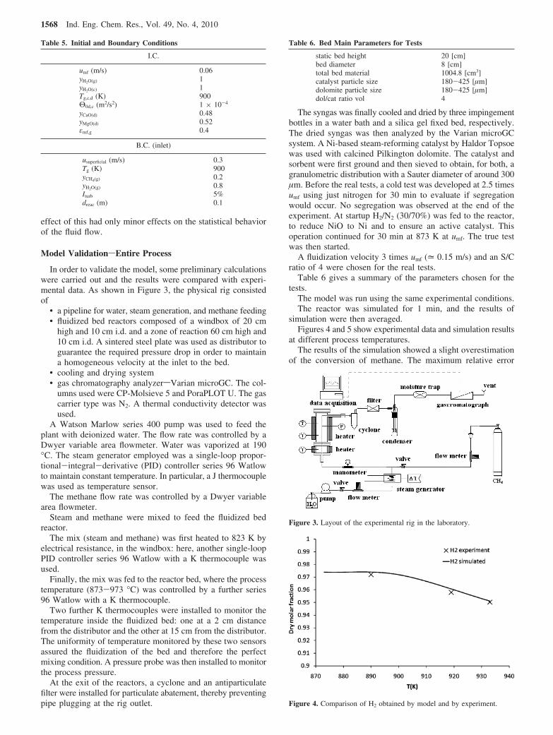
The model was run using the same experimental conditions.The reactor was simulated for 1 min, and the results of
simulation were then averaged.Figures 4 and 5 show experimental data and simulation results
at different process temperatures.The results of the simulation showed a slight overestimation
of the conversion of methane. The maximum relative error
Table 5. Initial and Boundary Conditions
I.C.
umf (m/s) 0.06yH2O(g) 1yH2O(c) 1Tg,c,d (K) 900Θ0d,c (m2/s2) 1 × 10⁻⁴
yCaO(d) 0.48yMgO(d) 0.52εmf,g 0.4
B.C. (inlet)
usuperficial (m/s) 0.3Tg (K) 900yCH4(g) 0.2yH2O(g) 0.8Iturb 5%dreac (m) 0.1
Table 6. Bed Main Parameters for Tests
static bed height 20 [cm]bed diameter 8 [cm]total bed material 1004.8 [cm3]catalyst particle size 180-425 [µm]dolomite particle size 180-425 [µm]dol/cat ratio vol 4
Figure 3. Layout of the experimental rig in the laboratory.
Figure 4. Comparison of H2 obtained by model and by experiment.
1568 Ind. Eng. Chem. Res., Vol. 49, No. 4, 2010
between experimental and simulated data was 24% for CO2,15% for CH4, and 1.5% for H2. It can therefore be stated thatthe simulation results are in good agreement with the experi-mental results. It must be noticed that during experimentalactivities significant fine powders generation was observed onlyduring the first period, while it could be neglected, even ifpersistent, in the remaining test period.
Model ValidationsHydrodynamic
Bubble Size and Bubble Rise Velocity. In validating themodel, some preliminary calculations were carried out in orderto verify if the model can predict bubble size and bubble risevelocity. Bubble size has always been considered an importantvariable in fluidized beds, since it controls most of the ratephenomena in the bed such as particle circulation rate, gasdispersion and heat transfer, and bubble rise velocity. As statedin the Davidson and Harrison22 model, if the fast bubblecondition is achieved, a gas cloud is formed around bubblesand the gas contained in the bubble phase may miss theopportunity to mix with the solid present in the emulsion phase.The particles used in the simulation, in all operative conditions,were Geldart B particles as depicted in the scaling relations ofGibilaro.45
The system was simulated using a similar composition to theone expected by a chemical equilibrium calculation of theprocess. The control volume was therefore fed with a syngascomposed of 60% H2, 35% H2O, 1% CH4, 2% CO, and 2%CO2. Only hydrodynamic behavior was investigated in thissimulation, not the chemistry of the process. A dol/cat ratio of5 was chosen and a static bed of 20 cm. The superficial velocitywas set to 0.3 m/s at 873 K.
A bubble was defined as an area where the solid volumefraction is below 20%. Similar procedures developed byLindborg et al.30 were used.
The control volume was divided into four convenient zonesof different heights: 0-0.05, 0.05-0.1, 0.1-0.2, and 0.2 m bedexpanded surface height. A simulation of a 7 s run was carriedout, with the results of the last 3 s recorded every 0.02 s. Thiswas sufficient to obtain a large quantity of data. In each section,the bubble diameter was determined from an ensemble averageof area equivalent diameters of circular bubbles (db ) 2/N∑i(Ai/π)1/2).
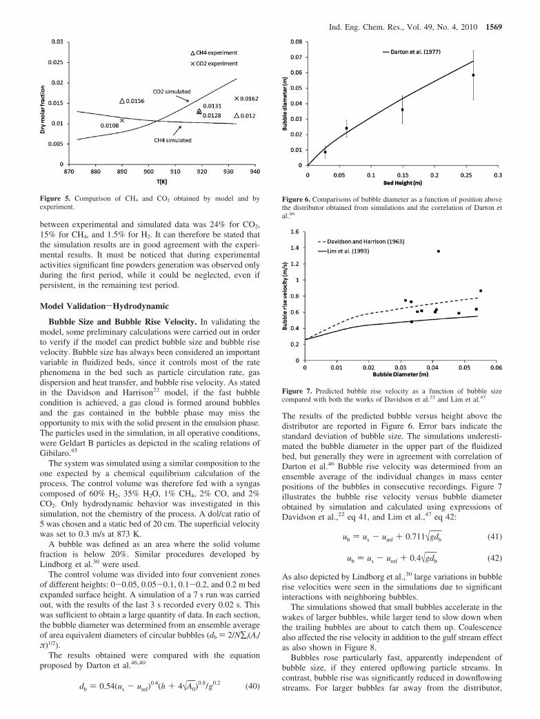
The results obtained were compared with the equationproposed by Darton et al.46,40
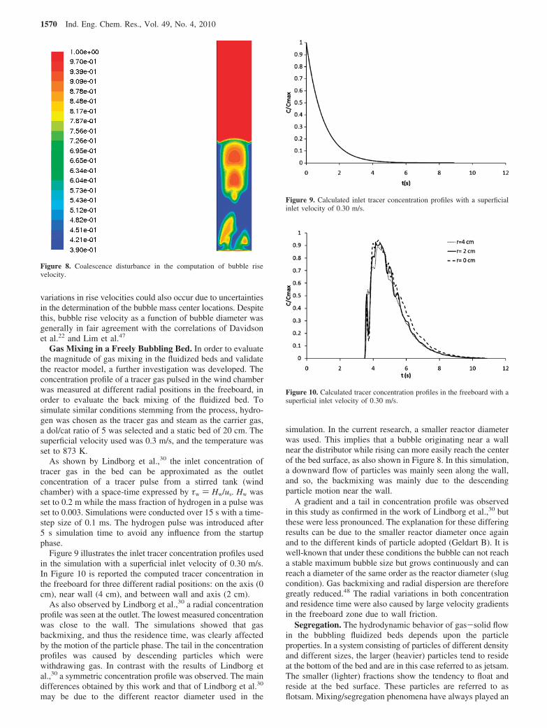
The results of the predicted bubble versus height above thedistributor are reported in Figure 6. Error bars indicate thestandard deviation of bubble size. The simulations underesti-mated the bubble diameter in the upper part of the fluidizedbed, but generally they were in agreement with correlation ofDarton et al.46 Bubble rise velocity was determined from anensemble average of the individual changes in mass centerpositions of the bubbles in consecutive recordings. Figure 7illustrates the bubble rise velocity versus bubble diameterobtained by simulation and calculated using expressions ofDavidson et al.,22 eq 41, and Lim et al.,47 eq 42:
As also depicted by Lindborg et al.,30 large variations in bubblerise velocities were seen in the simulations due to significantinteractions with neighboring bubbles.
The simulations showed that small bubbles accelerate in thewakes of larger bubbles, while larger tend to slow down whenthe trailing bubbles are about to catch them up. Coalescencealso affected the rise velocity in addition to the gulf stream effectas also shown in Figure 8.
Bubbles rose particularly fast, apparently independent ofbubble size, if they entered upflowing particle streams. Incontrast, bubble rise was significantly reduced in downflowingstreams. For larger bubbles far away from the distributor,
Figure 5. Comparison of CH4 and CO2 obtained by model and byexperiment.
db ) 0.54(us - umf)0.4(h + 4√A0)
0.8/g0.2 (40)
Figure 6. Comparisons of bubble diameter as a function of position abovethe distributor obtained from simulations and the correlation of Darton etal.46
Figure 7. Predicted bubble rise velocity as a function of bubble sizecompared with both the works of Davidson et al.22 and Lim et al.47
ub ) us - umf + 0.711√gdb (41)
ub ) us - umf + 0.4√gdb (42)
Ind. Eng. Chem. Res., Vol. 49, No. 4, 2010 1569
variations in rise velocities could also occur due to uncertaintiesin the determination of the bubble mass center locations. Despitethis, bubble rise velocity as a function of bubble diameter wasgenerally in fair agreement with the correlations of Davidsonet al.22 and Lim et al.47
Gas Mixing in a Freely Bubbling Bed. In order to evaluatethe magnitude of gas mixing in the fluidized beds and validatethe reactor model, a further investigation was developed. Theconcentration profile of a tracer gas pulsed in the wind chamberwas measured at different radial positions in the freeboard, inorder to evaluate the back mixing of the fluidized bed. Tosimulate similar conditions stemming from the process, hydro-gen was chosen as the tracer gas and steam as the carrier gas,a dol/cat ratio of 5 was selected and a static bed of 20 cm. Thesuperficial velocity used was 0.3 m/s, and the temperature wasset to 873 K.
As shown by Lindborg et al.,30 the inlet concentration oftracer gas in the bed can be approximated as the outletconcentration of a tracer pulse from a stirred tank (windchamber) with a space-time expressed by τw ) Hw/us. Hw wasset to 0.2 m while the mass fraction of hydrogen in a pulse wasset to 0.003. Simulations were conducted over 15 s with a time-step size of 0.1 ms. The hydrogen pulse was introduced after5 s simulation time to avoid any influence from the startupphase.
Figure 9 illustrates the inlet tracer concentration profiles usedin the simulation with a superficial inlet velocity of 0.30 m/s.In Figure 10 is reported the computed tracer concentration inthe freeboard for three different radial positions: on the axis (0cm), near wall (4 cm), and between wall and axis (2 cm).
As also observed by Lindborg et al.,30 a radial concentrationprofile was seen at the outlet. The lowest measured concentrationwas close to the wall. The simulations showed that gasbackmixing, and thus the residence time, was clearly affectedby the motion of the particle phase. The tail in the concentrationprofiles was caused by descending particles which werewithdrawing gas. In contrast with the results of Lindborg etal.,30 a symmetric concentration profile was observed. The maindifferences obtained by this work and that of Lindborg et al.30
may be due to the different reactor diameter used in the
simulation. In the current research, a smaller reactor diameterwas used. This implies that a bubble originating near a wallnear the distributor while rising can more easily reach the centerof the bed surface, as also shown in Figure 8. In this simulation,a downward flow of particles was mainly seen along the wall,and so, the backmixing was mainly due to the descendingparticle motion near the wall.
A gradient and a tail in concentration profile was observedin this study as confirmed in the work of Lindborg et al.,30 butthese were less pronounced. The explanation for these differingresults can be due to the smaller reactor diameter once againand to the different kinds of particle adopted (Geldart B). It iswell-known that under these conditions the bubble can not reacha stable maximum bubble size but grows continuously and canreach a diameter of the same order as the reactor diameter (slugcondition). Gas backmixing and radial dispersion are thereforegreatly reduced.48 The radial variations in both concentrationand residence time were also caused by large velocity gradientsin the freeboard zone due to wall friction.
Segregation. The hydrodynamic behavior of gas-solid flowin the bubbling fluidized beds depends upon the particleproperties. In a system consisting of particles of different densityand different sizes, the larger (heavier) particles tend to resideat the bottom of the bed and are in this case referred to as jetsam.The smaller (lighter) fractions show the tendency to float andreside at the bed surface. These particles are referred to asflotsam. Mixing/segregation phenomena have always played an
Figure 8. Coalescence disturbance in the computation of bubble risevelocity.
Figure 9. Calculated inlet tracer concentration profiles with a superficialinlet velocity of 0.30 m/s.
Figure 10. Calculated tracer concentration profiles in the freeboard with asuperficial inlet velocity of 0.30 m/s.
1570 Ind. Eng. Chem. Res., Vol. 49, No. 4, 2010

important role in bubbling fluidized beds consisting of particlesof different sizes and/or densities. The model proposed in thiswork used two different particles of different density: sorbentand catalyst. A further validation of the model was carried outto verify if it can predict segregation of particles.
Two cases were investigated:(1) A binary mixture composed of 50% by weight of 500 µm
catalyst and 50% by weight of 200 µm sorbent. A superficialvelocity of 0.18 m/s was chosen. The superficial velocitychosen is 1.2-1.4 times the minimum fluidization velocityof the jetsam (catalyst) and 11-13 times the minimumfluidization velocity of the flotsam (sorbent).
(2) A binary mixture composed of 20% by weight of 300 µmcatalyst and 80% by weight of 300 µm sorbent, similar tothat used in the SE-SMR simulations of the next sections.A superficial velocity of 0.2 m/s was chosen. The superficialvelocity chosen is 4.5-5.5 times the minimum fluidizationvelocity of the jetsam (catalyst) and 6-7.5 times theminimum fluidization velocity of the flotsam (sorbent).
The temperature for both cases was set to 900 K while the staticbed height was 20 cm. The control volume was fed with asyngas composed of 60% H2, 35% H2O, 1% CH4, 2% CO, and2% CO2. This composition is similar to that expected from aSE-SMR process. For each binary system there is a criticalvelocity UT0 below which the system rapidly segregates andabove which it rapidly mixes. The empirical equation proposedin ref 49 was used to estimate the UT0 (eq 43):
A critical velocity of 0.2-0.22 m/s was obtained for the firstcase (1): under such conditions, the system segregates; the modelshould predict segregation.
The profile of the mass fraction of the jetsam obtained bysimulation is shown in Figure 11 after 4 s. As shown the modelpredicted the segregation of heavier and larger particles. A criticalvelocity of 0.01-0.02 m/s was obtained for the second case (2).In this case the system should not show significant segregation ofheavier particles. This result was confirmed by the simulation(Figure 12) where no significant segregation was observed.
As shown in Figures 11 and 12, the model was able to predictthe segregation even if further experimental investigations arenecessary in order to verify this assumption.
Results and Discussion
A first simulation of the process was carried out using asuperficial velocity of 0.3 m/s, a static bed of 20 cm high, and
a steam to carbon ratio of 4. An initial simulation of a bedcompletely filled with catalyst particles was carried out merelyto verify if it is possible to achieve SMR equilibrium composi-tion. The SE-SMR was then simulated using two different dol/cat ratios, the first equal to 2 and the second equal to 5. A dol/cat ratio of 5 is probably more suitable for a cost-effectiveprocess.
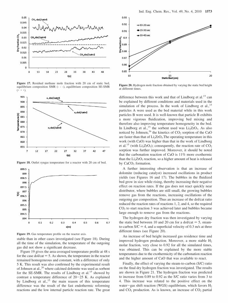
Figures 13-15 clearly show the effect of bubbles on productyields and in particular on H2 production. The gas flowingthrough the bubbles did not react because of the lower mass of
Figure 11. Mass fraction profile of jetsam showing segregation behavior.
UT0
Umf,F) [Umf,J
Umf,F]1.2
+ 0.9(FJ
FF- 1)1.1(dJ
dF) - 2.2xj-1/2H*
(43)
Figure 12. Mass fraction profile of jetsam showing no segregation.
Figure 13. (a) Void fraction and (b) H2 molar fraction (wet) for 20 cm ofstatic bed and dol/cat ) 5 at 15 s.
Ind. Eng. Chem. Res., Vol. 49, No. 4, 2010 1571
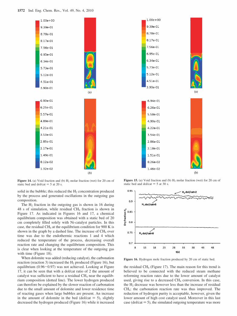
solid in the bubble; this reduced the H2 concentration producedby the process and generated oscillations in the outgoing gascomposition.
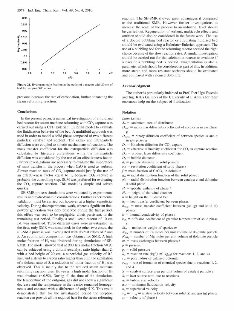
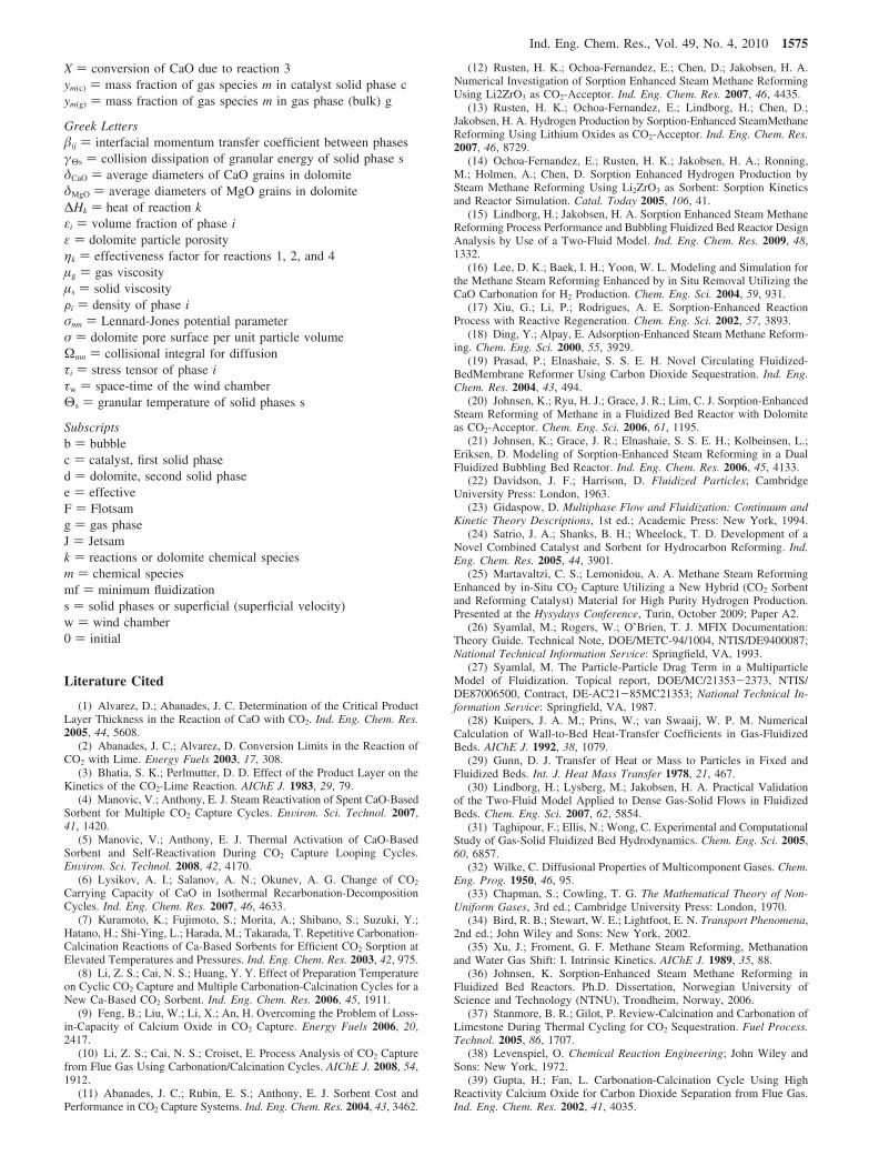
The H2 fraction in the outgoing gas is shown in 16 during48 s of simulation, while residual CH4 fraction is shown inFigure 17. As indicated in Figures 16 and 17, a chemicalequilibrium composition was obtained with a static bed of 20cm completely filled solely with Ni-catalyst particles. In thiscase, the residual CH4 at the equilibrium condition for 900 K isshown in the graph by a dashed line. The increase of CH4 overtime was due to the endothermic reactions 1 and 4 whichreduced the temperature of the process, decreasing overallreaction rate and changing the equilibrium composition. Thisis clear when looking at the temperature of the outgoing gaswith time (Figure 18).
When dolomite was added (reducing catalyst), the carbonationreaction (reaction 3) increased the H2 produced (Figure 16), butequilibrium (0.96-0.97) was not achieved. Looking at Figure17, it can be seen that with a dol/cat ratio of 2 the amount ofcatalyst was sufficient to have a residual CH4 near the equilib-rium composition (dotted line). The lower hydrogen producedcan therefore be explained by the slower reaction of carbonationdue to the small amount of dolomite and lower residence timeof reacting gases when large bubbles are present. An increasein the amount of dolomite in the bed (dol/cat ) 5), slightlydecreased the hydrogen produced (Figure 16) while it increased
the residual CH4 (Figure 17). The main reason for this trend isbelieved to be connected with the reduced steam methanereforming reaction rates due to the lower amount of catalystused, giving rise to a decreased CH4 conversion. In this case,the H2 decrease was however less than the increase of residualCH4: the carbonation reaction rate was thus improved. Thereduction of hydrogen purity is acceptable, however, given thelower amount of high cost catalyst used. Moreover in this lastcase (dol/cat ) 5), the simulated outgoing temperature was more
Figure 14. (a) Void fraction and (b) H2 molar fraction (wet) for 20 cm ofstatic bed and dol/cat ) 5 at 20 s.
Figure 15. (a) Void fraction and (b) H2 molar fraction (wet) for 20 cm ofstatic bed and dol/cat ) 5 at 30 s.
Figure 16. Hydrogen mole fraction produced by 20 cm of static bed.
1572 Ind. Eng. Chem. Res., Vol. 49, No. 4, 2010
stable than in other cases investigated (see Figure 18). Duringall the time of the simulation, the temperature of the outgoinggas did not show a significant decrease.
Figure 19 gives the area-averaged temperature profile at 48 sfor the case dol/cat ) 5. As shown, the temperature in the reactorremained homogeneous and constant, with a difference of only5 K. This result was also confirmed by the experimental resultof Johnsen at al.,20 where calcined dolomite was used as sorbentfor the SE-SMR. The results of Lindborg et al.15 showed bycontrast a temperature difference of 20-25 K. As explainedby Lindborg et al.,15 the main reason of this temperaturedifference was the result of the fast endothermic reformingreactions and the low internal particle reaction rate. The great
difference between this work and that of Lindborg et al.15 canbe explained by different conditions and materials used in thesimulation of the process. In the work of Lindborg et al.,15
particles A were used as the bed material while in this workparticles B were used. It is well-known that particle B exhibitsa more vigorous fluidization, improving bed mixing andtherefore also improving temperature homogeneity in the bed.In Lindborg et al.,15 the sorbent used was Li2ZrO3. As alsonoticed by Johnsen,36 the kinetics of CO2 sorption of the CaOare faster than that of Li2ZrO3.The operating temperature in thiswork (with CaO) was higher than that in the work of Lindborget al.15 (with Li2ZrO3); consequently, the reaction rate of CO2
sorption was further improved. Moreover, it should be notedthat the carbonation reaction of CaO is 11% more exothermicthan the Li2ZrO3 reaction, so a higher amount of heat is releasedby CaCO3 formation.
A further interesting observation is that an increase ofdolomite (reducing catalyst) increased oscillations in productyields (see Figures 16 and 17). The bubbles in the fluidizedbed grow in size while rising, thereby increasing their negativeeffect on reaction rates. If the gas does not react quickly neardistributor, where bubbles are still small, the growing bubblesremove gas from the reactions, increasing oscillations of theoutgoing gas composition. Thus an increase of the dol/cat ratioreduced the reaction rates of reactions 1, 2, and 4, so the requiredCO2 to start reaction 3 was achieved later and bubbles becamelarge enough to remove gas from the reactions.
The hydrogen dry fraction was then investigated by varyingthe static bed between 10 and 20 cm for a dol/cat ) 5, steam-to-carbon S/C ) 4, and a superficial velocity of 0.3 m/s at threedifferent times (see Figure 20).
An increase of bed height increased gas residence time andimproved hydrogen production. Moreover, a more stable H2
molar fraction, very close to 0.92 for all the simulated times,was obtained. This can be explained by the more stabletemperatures due to the exothermicity of the carbonation reactionand the higher amount of CaO that was available to react.
Finally, the effect of varying the steam-to-carbon (S/C) ratioon the final dry hydrogen fraction was investigated. The resultsare shown in Figure 21. The hydrogen fraction was predictedto increase from 0.89 to 0.92 as the S/C ratio varies from 3 to4. This increase was related to the positive effect on thewater-gas shift reaction (WGS) equilibrium, which favors H2
and CO2 production. As is known, an increase of CO2 partial
Figure 17. Residual methane mole fraction with 20 cm of static bed,equilibrium composition SMR (- - -), equilibrium composition SE-SMR( · · · ).
Figure 18. Outlet syngas temperature for a reactor with 20 cm of bed.
Figure 19. Gas temperature profile on the reactor axis.
Figure 20. Hydrogen mole fraction obtained by varying the static bed heightat different times.
Ind. Eng. Chem. Res., Vol. 49, No. 4, 2010 1573
pressure increases the rate of carbonation, further enhancing thesteam reforming reaction.
Conclusions
In the present paper, a numerical investigation of a fluidizedbed reactor for steam methane reforming with CO2 capture wascarried out using a CFD Eulerian-Eulerian model to evaluatethe fluidization behavior of the bed. A multifluid approach wasused in order to model a solid phase composed of two differentparticles: catalyst and sorbent. The extra- and intraparticlediffusion were coupled to kinetic mechanisms of reactions. Themass transfer coefficient for the extraparticle diffusion wascalculated by literature correlations while the intraparticlediffusion was considered by the use of an effectiveness factor.Further investigations are necessary to evaluate the importanceof mass transfer in the process when CaO is used as sorbent.Slower reaction rates of CO2 capture could justify the use ofan effectiveness factor equal to 1, because CO2 capture isprobably the controlling step. SCM was preferred for evaluatingthe CO2 capture reaction. This model is simple and solvedquickly.
SE-SMR process simulations were validated by experimentalresults and hydrodynamic considerations. Further experimentalvalidation must be carried out however at a higher superficialvelocity. During the experimental work, whereas significant fine-powder generation was only observed during the first period,this effect was seen to be negligible, albeit persistent, in theremaining test period. Finally, a small-scale reactor of 10 cmi.d. was simulated. Three different cases were investigated: inthe first, only SMR was simulated; in the other two cases, theSE-SMR process was investigated with dol/cat ratios of 2 and5. An equilibrium composition was obtained for SMR. A highmolar fraction of H2 was observed during simulations of SE-SMR. The model showed that at 900 K a molar fraction >0.93can be achieved using a dolomite/catalyst ratio higher than 2,with a bed height of 20 cm, a superficial gas velocity of 0.3m/s, and a steam to carbon ratio higher than 3. In the simulationof a dol/cat ratio of 5, a reduction of molar fraction of H2 wasobserved. This is mainly due to the reduced steam methanereforming reaction rates. However, a high molar fraction of H2
was obtained (∼0.92). During all the time of the simulation,the temperature of the outgoing gas did not show a significantdecrease and the temperature in the reactor remained homoge-neous and constant with a difference of only 5 K. This resultdemonstrated that for the investigated period the sorptionreaction can provide all the required heat for the steam reforming
reaction. The SE-SMR showed great advantages if comparedto the traditional SMR. However further investigations toincrease the scale of the process to an industrial level shouldbe carried out. Regeneration of sorbent, multicycle effects andattrition should also be considered in the future work. The useof a double bubbling bed reactor or circulating fluidized bedshould be evaluated using a Eulerian-Eulerian approach. Theuse of a bubbling bed for the reforming reactor seemed the rightchoice because of the slow reaction rates. A similar investigationshould be carried out for the calcination reactor to evaluate ifa riser or a bubbling bed is needed. Fragmentation is also aparameter which should be considered as part of this. In addition,more stable and more resistant sorbents should be evaluatedand compared with calcined dolomite.
Acknowledgment
The author is particularly indebted to Prof. Pier Ugo Foscoloand Ing. Katia Gallucci of the University of L’Aquila for theirenormous help on the subject of fluidization.
Notation
Latin LettersA0 ) catchment area of distributorDm(g) ) molecular diffusivity coefficient of species m in gas phase
gDmn(g) ) binary diffusion coefficient of between species m and n
in gas phase gDk ) Knudsen diffusion for CO2 captureDe ) effective diffusivity coefficient for CO2 in capture reactionDpl ) product layer diffusivity coefficientDb ) bubble diameterds ) particle diameter of solid phase sess ) restitution coefficient of solid phase sf ) mass fraction of CaCO3 in dolomitegss° ) radial distribution function of the solid phase sgcd° ) radial distribution function between catalyst c and dolomite
d solid phaseHi ) specific enthalpy of phase iHw ) height of the wind chamberh ) height on the fluidized bedhij ) heat transfer coefficient between phaseshm(gs) ) mass transfer coefficient between gas (g) and solid (s)
phaseski ) thermal conductivity of phase ikΘs ) diffusion coefficient of granular temperature of solid phase
sMm ) molecular weight of species mN0Ca ) number of Ca moles per unit volume of dolomite particleN0Mg ) number of Mg moles per unit volume of dolomite particlemi ) mass exchanges between phases ip ) pressureps ) solid pressureRk ) reaction rate (kg/(s m3 kgcat) for reactions 1, 2, and 4)rav ) pore radius of calcined dolomiterm(c) ) rate of formation of chemical species due to reactions 1, 2,
and 4Sc ) catalyst surface area per unit volum of catalyst particle cSk ) heat source term due to reactionsub ) bubble rise velocityumf ) minimum fluidization velocityus ) superficial velocityVgs ) -Vsg ) relative velocity between solid (s) and gas (g) phasesVi ) velocity of phase i
Figure 21. Hydrogen mole fraction at the outlet of a reactor with 20 cm ofbed for varying S/C ratios.
1574 Ind. Eng. Chem. Res., Vol. 49, No. 4, 2010
X ) conversion of CaO due to reaction 3ym(c) ) mass fraction of gas species m in catalyst solid phase cym(g) ) mass fraction of gas species m in gas phase (bulk) g
Greek Lettersij ) interfacial momentum transfer coefficient between phasesγΘs ) collision dissipation of granular energy of solid phase sδCaO ) average diameters of CaO grains in dolomiteδMgO ) average diameters of MgO grains in dolomite∆Hk ) heat of reaction kεi ) volume fraction of phase iε ) dolomite particle porosityηk ) effectiveness factor for reactions 1, 2, and 4µg ) gas viscosityµs ) solid viscosityFi ) density of phase iσmn ) Lennard-Jones potential parameterσ ) dolomite pore surface per unit particle volumeΩmn ) collisional integral for diffusionτi ) stress tensor of phase iτw ) space-time of the wind chamberΘs ) granular temperature of solid phases s
Subscriptsb ) bubblec ) catalyst, first solid phased ) dolomite, second solid phasee ) effectiveF ) Flotsamg ) gas phaseJ ) Jetsamk ) reactions or dolomite chemical speciesm ) chemical speciesmf ) minimum fluidizations ) solid phases or superficial (superficial velocity)w ) wind chamber0 ) initial
Literature Cited
(1) Alvarez, D.; Abanades, J. C. Determination of the Critical ProductLayer Thickness in the Reaction of CaO with CO2. Ind. Eng. Chem. Res.2005, 44, 5608.
(2) Abanades, J. C.; Alvarez, D. Conversion Limits in the Reaction ofCO2 with Lime. Energy Fuels 2003, 17, 308.
(3) Bhatia, S. K.; Perlmutter, D. D. Effect of the Product Layer on theKinetics of the CO2-Lime Reaction. AIChE J. 1983, 29, 79.
(4) Manovic, V.; Anthony, E. J. Steam Reactivation of Spent CaO-BasedSorbent for Multiple CO2 Capture Cycles. EnViron. Sci. Technol. 2007,41, 1420.
(5) Manovic, V.; Anthony, E. J. Thermal Activation of CaO-BasedSorbent and Self-Reactivation During CO2 Capture Looping Cycles.EnViron. Sci. Technol. 2008, 42, 4170.
(6) Lysikov, A. I.; Salanov, A. N.; Okunev, A. G. Change of CO2
Carrying Capacity of CaO in Isothermal Recarbonation-DecompositionCycles. Ind. Eng. Chem. Res. 2007, 46, 4633.
(7) Kuramoto, K.; Fujimoto, S.; Morita, A.; Shibano, S.; Suzuki, Y.;Hatano, H.; Shi-Ying, L.; Harada, M.; Takarada, T. Repetitive Carbonation-Calcination Reactions of Ca-Based Sorbents for Efficient CO2 Sorption atElevated Temperatures and Pressures. Ind. Eng. Chem. Res. 2003, 42, 975.
(8) Li, Z. S.; Cai, N. S.; Huang, Y. Y. Effect of Preparation Temperatureon Cyclic CO2 Capture and Multiple Carbonation-Calcination Cycles for aNew Ca-Based CO2 Sorbent. Ind. Eng. Chem. Res. 2006, 45, 1911.
(9) Feng, B.; Liu, W.; Li, X.; An, H. Overcoming the Problem of Loss-in-Capacity of Calcium Oxide in CO2 Capture. Energy Fuels 2006, 20,2417.
(10) Li, Z. S.; Cai, N. S.; Croiset, E. Process Analysis of CO2 Capturefrom Flue Gas Using Carbonation/Calcination Cycles. AIChE J. 2008, 54,1912.
(11) Abanades, J. C.; Rubin, E. S.; Anthony, E. J. Sorbent Cost andPerformance in CO2 Capture Systems. Ind. Eng. Chem. Res. 2004, 43, 3462.
(12) Rusten, H. K.; Ochoa-Fernandez, E.; Chen, D.; Jakobsen, H. A.Numerical Investigation of Sorption Enhanced Steam Methane ReformingUsing Li2ZrO3 as CO2-Acceptor. Ind. Eng. Chem. Res. 2007, 46, 4435.
(13) Rusten, H. K.; Ochoa-Fernandez, E.; Lindborg, H.; Chen, D.;Jakobsen, H. A. Hydrogen Production by Sorption-Enhanced SteamMethaneReforming Using Lithium Oxides as CO2-Acceptor. Ind. Eng. Chem. Res.2007, 46, 8729.
(14) Ochoa-Fernandez, E.; Rusten, H. K.; Jakobsen, H. A.; Ronning,M.; Holmen, A.; Chen, D. Sorption Enhanced Hydrogen Production bySteam Methane Reforming Using Li2ZrO3 as Sorbent: Sorption Kineticsand Reactor Simulation. Catal. Today 2005, 106, 41.
(15) Lindborg, H.; Jakobsen, H. A. Sorption Enhanced Steam MethaneReforming Process Performance and Bubbling Fluidized Bed Reactor DesignAnalysis by Use of a Two-Fluid Model. Ind. Eng. Chem. Res. 2009, 48,1332.
(16) Lee, D. K.; Baek, I. H.; Yoon, W. L. Modeling and Simulation forthe Methane Steam Reforming Enhanced by in Situ Removal Utilizing theCaO Carbonation for H2 Production. Chem. Eng. Sci. 2004, 59, 931.
(17) Xiu, G.; Li, P.; Rodrigues, A. E. Sorption-Enhanced ReactionProcess with Reactive Regeneration. Chem. Eng. Sci. 2002, 57, 3893.
(18) Ding, Y.; Alpay, E. Adsorption-Enhanced Steam Methane Reform-ing. Chem. Eng. Sci. 2000, 55, 3929.
(19) Prasad, P.; Elnashaie, S. S. E. H. Novel Circulating Fluidized-BedMembrane Reformer Using Carbon Dioxide Sequestration. Ind. Eng.Chem. Res. 2004, 43, 494.
(20) Johnsen, K.; Ryu, H. J.; Grace, J. R.; Lim, C. J. Sorption-EnhancedSteam Reforming of Methane in a Fluidized Bed Reactor with Dolomiteas CO2-Acceptor. Chem. Eng. Sci. 2006, 61, 1195.
(21) Johnsen, K.; Grace, J. R.; Elnashaie, S. S. E. H.; Kolbeinsen, L.;Eriksen, D. Modeling of Sorption-Enhanced Steam Reforming in a DualFluidized Bubbling Bed Reactor. Ind. Eng. Chem. Res. 2006, 45, 4133.
(22) Davidson, J. F.; Harrison, D. Fluidized Particles; CambridgeUniversity Press: London, 1963.
(23) Gidaspow, D. Multiphase Flow and Fluidization: Continuum andKinetic Theory Descriptions, 1st ed.; Academic Press: New York, 1994.
(24) Satrio, J. A.; Shanks, B. H.; Wheelock, T. D. Development of aNovel Combined Catalyst and Sorbent for Hydrocarbon Reforming. Ind.Eng. Chem. Res. 2005, 44, 3901.
(25) Martavaltzi, C. S.; Lemonidou, A. A. Methane Steam ReformingEnhanced by in-Situ CO2 Capture Utilizing a New Hybrid (CO2 Sorbentand Reforming Catalyst) Material for High Purity Hydrogen Production.Presented at the Hysydays Conference, Turin, October 2009; Paper A2.
(26) Syamlal, M.; Rogers, W.; O’Brien, T. J. MFIX Documentation:Theory Guide. Technical Note, DOE/METC-94/1004, NTIS/DE9400087;National Technical Information SerVice: Springfield, VA, 1993.
(27) Syamlal, M. The Particle-Particle Drag Term in a MultiparticleModel of Fluidization. Topical report, DOE/MC/21353-2373, NTIS/DE87006500, Contract, DE-AC21-85MC21353; National Technical In-formation SerVice: Springfield, VA, 1987.
(28) Kuipers, J. A. M.; Prins, W.; van Swaaij, W. P. M. NumericalCalculation of Wall-to-Bed Heat-Transfer Coefficients in Gas-FluidizedBeds. AIChE J. 1992, 38, 1079.
(29) Gunn, D. J. Transfer of Heat or Mass to Particles in Fixed andFluidized Beds. Int. J. Heat Mass Transfer 1978, 21, 467.
(30) Lindborg, H.; Lysberg, M.; Jakobsen, H. A. Practical Validationof the Two-Fluid Model Applied to Dense Gas-Solid Flows in FluidizedBeds. Chem. Eng. Sci. 2007, 62, 5854.
(31) Taghipour, F.; Ellis, N.; Wong, C. Experimental and ComputationalStudy of Gas-Solid Fluidized Bed Hydrodynamics. Chem. Eng. Sci. 2005,60, 6857.
(32) Wilke, C. Diffusional Properties of Multicomponent Gases. Chem.Eng. Prog. 1950, 46, 95.
(33) Chapman, S.; Cowling, T. G. The Mathematical Theory of Non-Uniform Gases, 3rd ed.; Cambridge University Press: London, 1970.
(34) Bird, R. B.; Stewart, W. E.; Lightfoot, E. N. Transport Phenomena,2nd ed.; John Wiley and Sons: New York, 2002.
(35) Xu, J.; Froment, G. F. Methane Steam Reforming, Methanationand Water Gas Shift: I. Intrinsic Kinetics. AIChE J. 1989, 35, 88.
(36) Johnsen, K. Sorption-Enhanced Steam Methane Reforming inFluidized Bed Reactors. Ph.D. Dissertation, Norwegian University ofScience and Technology (NTNU), Trondheim, Norway, 2006.
(37) Stanmore, B. R.; Gilot, P. Review-Calcination and Carbonation ofLimestone During Thermal Cycling for CO2 Sequestration. Fuel Process.Technol. 2005, 86, 1707.
(38) Levenspiel, O. Chemical Reaction Engineering; John Wiley andSons: New York, 1972.
(39) Gupta, H.; Fan, L. Carbonation-Calcination Cycle Using HighReactivity Calcium Oxide for Carbon Dioxide Separation from Flue Gas.Ind. Eng. Chem. Res. 2002, 41, 4035.
Ind. Eng. Chem. Res., Vol. 49, No. 4, 2010 1575
(40) Lee, D. K. An Apparent Kinetic Model for the Carbonation ofCalcium Oxide by Carbon Dioxide. Chem. Eng. J. 2004, 100, 71.
(41) Stendardo, S.; Foscolo, P. U. Carbon Dioxide Capture withDolomite: a Model for Gas-Solid Reaction within the Grains of aParticulate Sorbent. Chem. Eng. Sci. 2009, 64, 2343.
(42) Hayes, R. E.; Kolaczkowski, S. T. Introduction to CatalyticCombustion; Gordon and Breach: Amsterdam, 1997.
(43) Zevenhoven, C. A. P.; Yrjas, K. P.; Hupa, M. M. HydrogenSulfide Capture by Limestone and Dolomite at Elevated Pressure. 2.Sorbent Particle Conversion Modeling. Ind. Eng. Chem. Res. 1996, 35,943.
(44) Smith, J. M. Chemical Engineering Kinetics, 3rd ed.; McGraw-Hill: New York, 1981.
(45) Gibilaro, L. G. Fluidization Dynamics; Butterworth Heinemann:Oxford, 2001.
(46) Darton, R. C.; LaNauze, R. D.; Davidson, J. F.; Harrison, D. BubbleGrowth Due to Coalescence in Fluidised Beds. Trans. Inst. Chem. Eng.1977, 55, 274.
(47) Lim, K. S.; Gururajan, V. S.; Agarwal, P. K. Mixing of Homoge-neous Solids in Bubbling Fluidized Bed: Theoretical Modelling andExperimental Investigation Using Digital Image Analysis. Chem. Eng. Sci.1993, 48, 2251.
(48) Pell, M.; Dunson, J. B. Gas-Solid Operations and Equipment. InPerry’s Chemical Engineers’ Handbook, 7th ed.; Perry, R. H., Green, D. W.,Maloney, J. O., Eds.; McGraw-Hill: New York, 1997; Chapter 17, pp 1-59.
(49) Rowe, P. N.; Yates, J. G. Fluidized-Bed Reactors. In ChemicalReaction and Reactor Engineering, 1st ed.; Carberry, J. J., Varma, A., Eds.;Marcel Dekker: New York, 1986; pp 441-498.
ReceiVed for reView May 8, 2009ReVised manuscript receiVed December 21, 2009
Accepted December 29, 2009
IE900748T
1576 Ind. Eng. Chem. Res., Vol. 49, No. 4, 2010