Numerical and experimental modal analysis of the reed and ...
11
HAL Id: hal-00111390 https://hal.archives-ouvertes.fr/hal-00111390 Submitted on 26 Sep 2019 HAL is a multi-disciplinary open access archive for the deposit and dissemination of sci- entific research documents, whether they are pub- lished or not. The documents may come from teaching and research institutions in France or abroad, or from public or private research centers. L’archive ouverte pluridisciplinaire HAL, est destinée au dépôt et à la diffusion de documents scientifiques de niveau recherche, publiés ou non, émanant des établissements d’enseignement et de recherche français ou étrangers, des laboratoires publics ou privés. Numerical and experimental modal analysis of the reed and pipe of a clarinet Matteo Facchinetti, Xavier Boutillon, Andrei Constantinescu To cite this version: Matteo Facchinetti, Xavier Boutillon, Andrei Constantinescu. Numerical and experimental modal analysis of the reed and pipe of a clarinet. Journal of the Acoustical Society of America, Acoustical Society of America, 2003, 113 (5), pp.2874-2883. 10.1121/1.1560212. hal-00111390
-
Upload
khangminh22 -
Category
Documents
-
view
3 -
download
0
Transcript of Numerical and experimental modal analysis of the reed and ...
HAL Id: hal-00111390https://hal.archives-ouvertes.fr/hal-00111390
Submitted on 26 Sep 2019
HAL is a multi-disciplinary open accessarchive for the deposit and dissemination of sci-entific research documents, whether they are pub-lished or not. The documents may come fromteaching and research institutions in France orabroad, or from public or private research centers.
L’archive ouverte pluridisciplinaire HAL, estdestinée au dépôt et à la diffusion de documentsscientifiques de niveau recherche, publiés ou non,émanant des établissements d’enseignement et derecherche français ou étrangers, des laboratoirespublics ou privés.
Numerical and experimental modal analysis of the reedand pipe of a clarinet
Matteo Facchinetti, Xavier Boutillon, Andrei Constantinescu
To cite this version:Matteo Facchinetti, Xavier Boutillon, Andrei Constantinescu. Numerical and experimental modalanalysis of the reed and pipe of a clarinet. Journal of the Acoustical Society of America, AcousticalSociety of America, 2003, 113 (5), pp.2874-2883. �10.1121/1.1560212�. �hal-00111390�

Numerical and experimental modal analysis of the reedand pipe of a clarineta)
Matteo L. FacchinettiLaboratoire de Me´canique des Solides and Laboratoire d’Hydrodynamique, CNRS-E´ cole Polytechnique,91128 Palaiseau Cedex, France
Xavier Boutillonb)
Laboratoire d’Acoustique Musicale, CNRS-Universite´ Paris 6-Ministere de la Culture, 11 rue de Lourmel,75015 Paris, France
Andrei ConstantinescuLaboratoire de Me´canique des Solides, CNRS-E´ cole Polytechnique, 91128 Palaiseau Cedex, France
A modal computation of a complete clarinet is presented by the association of finite-element models of the reed and of part of the pipe with a lumped-element model of the rest of the pipe. In the first part, we compare modal computations of the reed and the air inside the mouthpiece and barrel with measurements performed by holographic interferometry. In the second part, the complete clarinet is modeled by adjoining a series of lumped elements for the remaining part of the pipe. The parameters of the lumped-resonator model are determined from acoustic impedance measurements. Computed eigenmodes of the whole system show that modal patterns of the reed differ significantly whether it is alone or coupled to air. Some modes exhibit mostly reed motion and a small contribution of the acoustic pressure inside the pipe. Resonance frequencies measured on a clarinet with the mouthpiece replaced by the cylinder of equal volume differ significantly from the computed eigenfrequencies of the clarinet taking the actual shape of the mouthpiece into account and from those including the ~linear! dynamics of the reed. This suggests revisiting the customary quality index based on the alignment of the peaks of the input acoustical impedance curve.
I. INTRODUCTION
The clarinet is usually considered as the association of alinear resonator, the pipe, and a nonlinear excitor, the reed,subject to the air flow from the mouth. Alternatively, one canconsider the air column and the reed as a linear system sub-ject to nonlinear boundary conditions. This is the approachretained in this article where the reed is considered as a lin-ear mechanical system coupled to the pipe and where theinteraction with the player is not treated. Nonlinear phenom-enon such as the interaction between the reed and the jetacross the reed-slit, the contact forces between the reed andthe lay, and the interaction between the reed and the player’slip will be included in a subsequent piece of work as nonlin-ear boundary conditions to the normal modes that are de-scribed here. Humidity of the reed and the player’s lip alsohave a damping role which is not considered in this modalanalysis of a pipe coupled to a~dry! reed.
Acoustical studies of the clarinet have so far represented
the mouthpiece of a wind instrument by its equivalent vol-ume. This study goes beyond this approximation and pre-sents the three-dimensional distribution of the pressure in theupper part of the instrument.
Studies of the pipe of the clarinet have traditionally beenexpressed in the frequency domain and were based on mea-surements or computations of input acoustic impedance.However, numerical simulations of this instrument operate inthe time domain and are usually based on the reflection func-tion of the pipe. Recent experimental studies have adoptedthe time domain approach with direct measurements of thisreflection function. Abundant literature extensively coversthese subjects: for general presentations, see Refs. 1–4.
Studies of the reeds are far less extensive and the me-chanical behavior of cane is still subject to discussion. Thesimplest reed model, a spring, is implicitly used by reed-makers when they rate them by their so-called ‘‘strength,’’which corresponds to the mechanical compliance. Experi-mental studies have proposed values for the compliance ofthe reed.1,5,6Associated with various models of the pipe andexcitation, this model has been used in numerical simulationswhich were successful in describing basic features of thedynamics of clarinet-like system.7–9 Music-oriented algo-rithms have also been proposed in which the values of theparameters describing the excitor and the resonator are ad-justed in order to obtain realistic sounds instead of accuratelydescribing their mechanical behavior.10,11 However, thismodel is obviously insufficient to describe quality-based cri-teria: otherwise all reeds in a given commercial box~with
a!Part of this work was presented in ‘‘Application of modal analysis andsynthesis of reed and pipe to numerical simulations of a clarinet,’’ invitedpaper at the 140th meeting of the ASA, Newport Beach, CA, December2000 @J. Acoust. Soc. Am.108, 2590~A!#, in ‘‘Etude modale d’une clari-nette,’’ Proceedings of the Colloque National en Calcul de Structures,Giens, France, May 2001, and in ‘‘Modal analysis of a complete clarinet,’’Proceedings of the International Conference on Acoustics, Rome, Italy,September 2001.
b!Electronic mail: [email protected]; present address: Labora-toire de Mecanique des Solides, E´ cole Polytechnique, 91128 PalaiseauCedex, France.
1
similar strength!would suit a given player, but this is not thecase.
The next modeling step is the single-degree-of-freedomoscillator. Although some simulation algorithms12 have beenvery successful in producing realistic sounds,13,14 this is notsufficient in itself to assert the physical validity of a model.One degree of freedom is not sufficient to account for criteriasuch as reed quality. Stewart and Strong15 and Sommerfeldand Strong16 used a refined model of the reed as a nonuni-form beam. In the latter study, the pipe was only slightlysimplified compared to a real clarinet and the player’s aircolumn ~including the lungs!was also taken into account.There is no fundamental difference between this simulationand those based on a simple oscillator model for the reedsince the interaction with the rest of the system is averagedalong the beam. The beam model is needed if one wants totake into account the curved shape of the mouthpiece onwhich the reed beats during large amplitude motions.Gazengel17 derived a simple oscillator model from a beamequation. In his time-domain simulation, the mass of the os-cillator is recalculated at each time step as a function of theposition of the reed, introducing by this means the nonlinearbehavior of the reed contact.
Modeling the reed as a continuous system is the currentstate of research. Several examples of modal analysis ofclarinet reeds with holographic interferometry have been pre-sented in conferences over the recent years,18–20 but neverpublished. One example of finite-element modeling based onmeasurements of the mechanical properties of cane has beenreported.21 Another~unpublished!pioneering study has beendone by Pinard and Laine when they were students at theEcole Polytechnique~France!. The experimental modalanalysis and the finite-element modeling of isolated reedsthat are presented in the following are a development of thisunpublished work. To our knowledge, no model of the reedas a continuous system in association with the air column hasbeen proposed.
The model proposed here is aimed at overcoming sev-eral limitations of previous approaches. Besides giving ameans to review the approximations of the classical model,this new approach is also a first step toward numerical simu-lations of the instrument based on modal projection22,23
rather than on propagation schemes represented by reflectionfunctions.
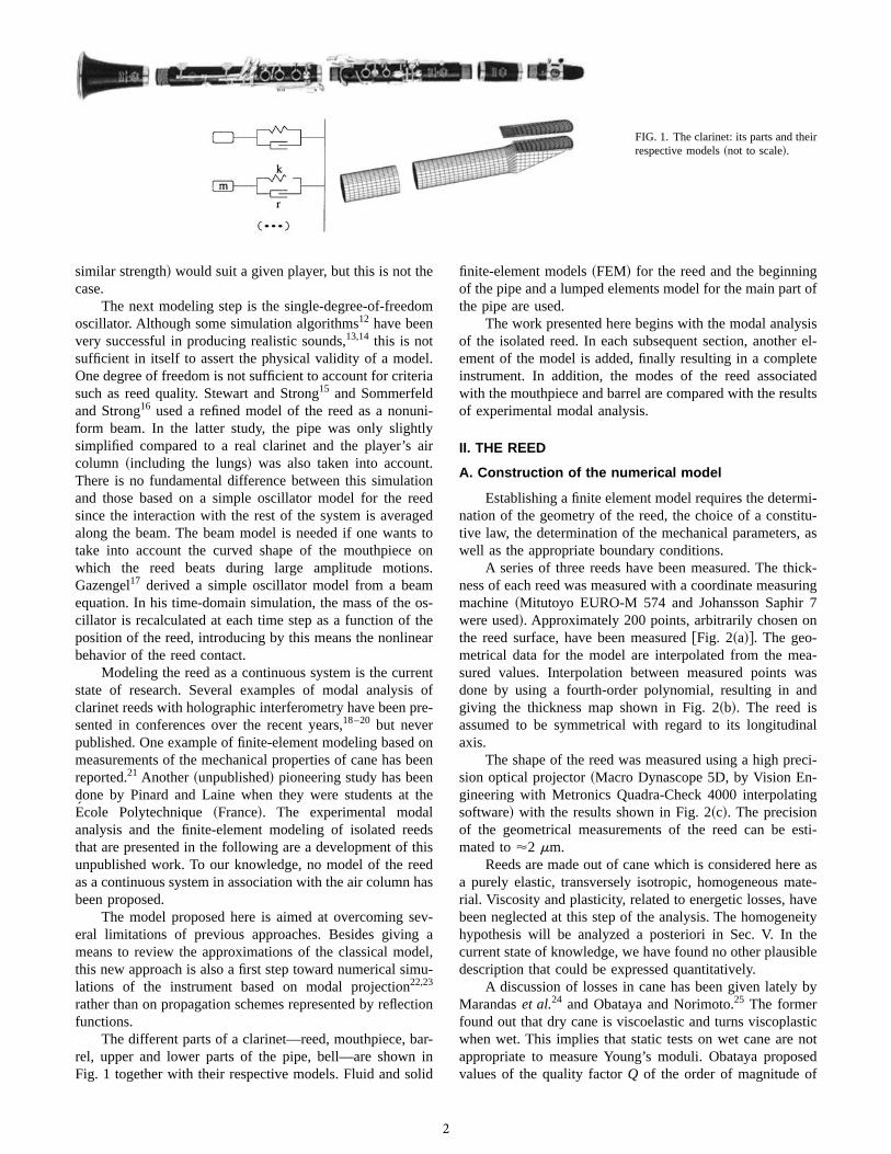
The different parts of a clarinet—reed, mouthpiece, bar-rel, upper and lower parts of the pipe, bell—are shown inFig. 1 together with their respective models. Fluid and solid
finite-element models~FEM! for the reed and the beginningof the pipe and a lumped elements model for the main part ofthe pipe are used.
The work presented here begins with the modal analysisof the isolated reed. In each subsequent section, another el-ement of the model is added, finally resulting in a completeinstrument. In addition, the modes of the reed associatedwith the mouthpiece and barrel are compared with the resultsof experimental modal analysis.
II. THE REED
A. Construction of the numerical model
Establishing a finite element model requires the determi-nation of the geometry of the reed, the choice of a constitu-tive law, the determination of the mechanical parameters, aswell as the appropriate boundary conditions.
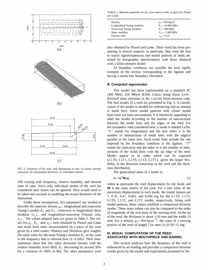
A series of three reeds have been measured. The thick-ness of each reed was measured with a coordinate measuringmachine~Mitutoyo EURO-M 574 and Johansson Saphir 7were used!. Approximately 200 points, arbitrarily chosen onthe reed surface, have been measured@Fig. 2~a!#. The geo-metrical data for the model are interpolated from the mea-sured values. Interpolation between measured points wasdone by using a fourth-order polynomial, resulting in andgiving the thickness map shown in Fig. 2~b!. The reed isassumed to be symmetrical with regard to its longitudinalaxis.
The shape of the reed was measured using a high preci-sion optical projector~Macro Dynascope 5D, by Vision En-gineering with Metronics Quadra-Check 4000 interpolatingsoftware!with the results shown in Fig. 2~c!. The precisionof the geometrical measurements of the reed can be esti-mated to'2 mm.
Reeds are made out of cane which is considered here asa purely elastic, transversely isotropic, homogeneous mate-rial. Viscosity and plasticity, related to energetic losses, havebeen neglected at this step of the analysis. The homogeneityhypothesis will be analyzed a posteriori in Sec. V. In thecurrent state of knowledge, we have found no other plausibledescription that could be expressed quantitatively.
A discussion of losses in cane has been given lately byMarandaset al.24 and Obataya and Norimoto.25 The formerfound out that dry cane is viscoelastic and turns viscoplasticwhen wet. This implies that static tests on wet cane are notappropriate to measure Young’s moduli. Obataya proposedvalues of the quality factorQ of the order of magnitude of
FIG. 1. The clarinet: its parts and theirrespective models~not to scale!.
2
100 varying with frequency, relative humidity, and internalstate of cane. Since only individual modes of the reed areconsidered here losses can be ignored. They would need tobe taken into account in modeling the actual dynamics of theinstrument.
Under these assumptions, five parameters are needed todescribe the material: densityrs , longitudinal and transverseYoung’s moduliEL andET , transverse to longitudinal shearmodulus GLT , and longitudinal-transverse Poisson rationLT . The values adopted here are given in Table I. The val-ues forrs , EL , andnLT were obtained by Pinard and Laineand result from static measurements on a piece of dry canegiven by a reed maker. Obataya and Norimoto give roughlythe same value for the main Young’s modulusEL of dry canein the frequency that is relevant here~2–6 kHz!. Their mea-surements show that this value decreases linearly with therelative humidity level~RH!, EL decreasing by around 30%for a variation of 100% in RH. The other parameters were
also obtained by Pinard and Laine. Their work has been pio-neering in several respects. In particular, they were the firstto match eigenfrequencies and modal patterns of reeds ob-tained by holographic interferometry with those obtainedwith a finite-element model.
As boundary condition, we consider the reed rigidlyclamped on the section corresponding to the ligature andhaving a stress-free boundary elsewhere.
B. Computed eigenmodes
This model has been implemented on a standard PC~450 MHz, 250 Mbyte RAM, Linux! using linear Love–Kirchoff plate elements in theCAST3M finite-element code.The first modes of a reed are presented in Fig. 3. A classifi-cation of the modes is needed for referencing and an attemptis made here. Since modal patterns with closed modallines have not been encountered, it is intuitively appealing tolabel the modes according to the number of intersectionsbetween the nodal lines and the edges of the reed. Forthe symmetric reed considered here, a mode is labeledLnTm.‘‘ L’’ stands for longitudinal and the first indexn is thenumber of intersections of nodal lines with the edge~s!parallel to the main axis. Such nodal lines include the oneimposed by the boundary condition at the ligature. ‘‘T’’stands for transverse and the indexm is the number of inter-sections of the nodal lines with the tip edge of the reed.Modes appear in an order which can be expected(L1T0, L1T1, L2T0, L1T2, L2T1), given the larger flex-ibility in the direction transverse to the reed and the thick-ness distribution.
The generalized mass of a mode is:
m5uTM su, ~1!
whereu represents the reed displacement for the mode andM is the mass matrix of the reed. For a unit value of themaximum displacement in each mode, the modal masses are7, 0.35, 0.47, 0.063, and 0.094 mg for theL1T0, L1T1,L2T0, L1T2, and L2T1 modes, respectively. Along withmodal patterns, these values establish a comparison betweenmodes. These mass values can also be compared to the orderof magnitude of the real mass of the moving reed. At the tipof the reed, the thickness is about 1/10 mm and the width 13mm. For a densityrs5450 kg m23, the mass of a movingportion of the reed of lengthl ~in mm! is (0.593l ) mg.
III. MODAL COMPUTATION OF THE REEDASSOCIATED WITH MOUTHPIECE AND BARREL
This section analyzes how the dynamics of the reed isinfluenced by air loading and provides a comparison betweenresults given by the model and experiments presented in Sec.
FIG. 2. Geometry of the reed, with dimensions in mm:~a! points actuallymeasured,~b! interpolated thickness,~c! estimated contour.
TABLE I. Material properties for dry cane used in reeds, as given by Pinardand Laine.
Density rs5450 kg/m3
Longitudinal Young modulus EL510 000 MPaTransverse Young modulus ET5400 MPaShear modulus GLT51300 MPaPoisson ratio nLT50.22
3

II. The system considered now is composed of the reed, themouthpiece, and the barrel and is represented using acoupled fluid–solid model.
A. Numerical model
The full model of reed, mouthpiece, and open barrel isshown in Fig. 4. The internal shape of the mouthpiece~aSelmer HS* ) has been carefully measured by means of thecoordinate measuring machine used for the reed. The barrelis considered as a cylindrical bore with a diameter of 15 mm.The air volume inside the mouthpiece and the barrel is mod-eled with linear tetrahaedric and prismatic finite elements ofcompressible elastic fluid.
The acoustic pressure at points of the open air surfacesis considered to be zero. The normal derivative of the acous-tic pressure on the walls of the mouthpiece and the barrel,corresponding to air flow, is also set to zero. The boundarycondition coupling the reed and the mouthpiece involves thestress in the solid and the velocity of the fluid and will begiven explicitly in the following.
The eigenvalue problem for a coupled solid–fluid sys-tem is expressed in the continuous formulation by thefollowing:26
div C¹u2v2rsu50, ~2!
div1
r f“p1v2
1
c2r fp50, ~3!
where p represents the acoustic pressure in the fluid. Thedensities of solid and fluid arers andr f , respectively. Thespeed of sound isc, the angular frequency of the motion isv,andC denotes the elasticity matrix of the solid.
The boundary conditions coupling the fluid and the solidparts are
s"n52pn, ~4!
]p
]n5r fv
2u"n, ~5!
wheren represents the unit vector normal to the solid surfaceands5C¹u the stress tensor.
In order to formulate these equations as a standard ei-genvalue problem, a new variablep52(1/v2)p must beintroduced.26 The equations and boundary conditions become
div C¹u2v2rsu50, ~6!
div1
r f“p2
1
c2r fp50, ~7!
v2p1p50, ~8!
s"n52pn, ~9!
]p
]n52r fu"n. ~10!
To the preceding equations, we can associate the follow-ing LagrangianL denoting the variational formulation of theproblem:
FIG. 3. First five computed modes of an isolated reed. Modes are labeledaccording to the number of modal lines perpendicular to the main axis~Ln!and parallel to it~Tm!.
FIG. 4. Reed and volume of air inside the mouthpiece mounted on an openbarrel.
4

L51
2 EVs
¹uC¹u dv11
2 EV f
1
r fc2 p2 dv
2v2S 1
2 EVs
rsu2 dv2
1
2 EV f
1
r fc2 ~“p!2dv
2EV f
1
r fc2 pp dv2E
]Vps"n dsD , ~11!
whereVs andV f represent the solid and fluid volumes, re-spectively, and]V represents the boundary between thesevolumes.
Finally, the problem is expressed in its discrete form bythe following eigenvalue problem:
S F K s 0 0
0 K f 0
0 0 0G2v2F M s 0 2N
0 0 K f
2NT K fT 2M f
G D F uppG5F 0
00G ,
whereK s ~respectively,K f) and M s ~respectively,M f) arerigidity and mass matrices of the solid~respectively, fluid!part of the system andN is the operator corresponding to thecoupling boundary condition~10! related to the normal vec-tor n. Details of the derivation can be found in Ref. 26.
B. Experimental modal analysis
An experimental modal analysis on reeds by means ofholographic interferometry was performed in order to checkthe validity of the numerical model of the reed coupled to air.Recent works have been reported in shortcommunications.18–20 For various reeds mounted on amouthpiece under dry conditions Pinard and Laine observedone mode corresponding to a longitudinal flexion at around2200 Hz; one family of modes around 3500–3700 Hz, withpatterns varying from reed to reed, some of them being in-
dicative of torsion, others being closer to flexion; and onefamily of modes around 5800–6000 Hz, with more complexpatterns.
In measurements presented here, the reed was attachedto the mouthpiece exactly as on the real instrument. Since theligature was producing strong light reflexions, it wasreplaced with adhesive tape placed slightly further from thetip. A sinusoidally driven loudspeaker was placed closeto the reed to excite its vibration. For determining the reso-nance frequencies a very thin PVDF piezoelectric film@poly~vinylidenefluoride!, thickness 0.05 mm, mass 0.06 g,of which only a part was actually moving#was glued ontothe lower thicker part of the reed, yielding the average de-formation near the ligature. Resonance frequencies were de-termined using the maximum of the piezoelectric signal. Theexperiments were performed under natural humidity. A satu-rated atmosphere would have been preferable but was notpossible with the interferometry equipment.
The eigenmodes were visualized by means of lasertransmission interferometry. Complete details of the imple-mentation of this classical method are described in Ref. 27.The images in Fig. 5 represent variations of equal normal-displacement of the reed. The resolution of the system is halfthe wavelength of the laser, approximately 0.3mm.
The reed was measured either alone, associated with anopen mouthpiece, or with the mouthpiece mounted on anopen barrel. The first four measured modes shown in Fig. 5correspond to the barrel configuration~see Fig. 4!. They arecompared with the corresponding computed modal patterns~see the next section for computation of the eigenmodes!ontop. Results of the holographic measurements show that themaximum displacement of the reed is negligible compared tothe distance between the mouthpiece and the reed at thatlevel of excitation. Thus one can be confident that contactbetween the reed and the lay, which could possibly make thesystem nonlinear, does not occur.
FIG. 5. Projection of four eigenmodes on the reed~seethe text for labels!. Top pictures: computed normalizedeigenmodes of the association of a reed with mouth-piece and barrel. In this representation, a cyclic grayscale produces fringes of equal differences in normaldisplacement, allowing a comparison with the modalpatterns observed experimentally. Bottom pictures:modal patterns measured by holographic interferometryon one good reed mounted on the mouthpiece attachedto the barrel. The resonance is not very sharp owing todamping, hence the rounded eigenfrequencies. The pho-tographed section of the reed does not have the sameheight between the various experiments and the simu-lations.
5

C. Results
A comparison between computed and measured modesis displayed in Fig. 5 for the situation described by Fig. 4. Inthis comparison with holographic measurements, the ‘‘liga-ture’’ of the reed had to be placed slightly beyond its normalposition. This led to a slightly more flexible reed than in thenormal situation. When the reed is coupled to air, one shouldstress that eigenmodes concern the whole system, not just thereed. Strictly speaking, expressions such as ‘‘reed modes’’are inappropriate and refer instead to modes for which en-ergy is mostly localized in the reed. Each mode has beenlabeled using the notation proposed earlier. The ‘‘R’’ prefixindicates that we regard the result just as theprojectionof thefour first eigenmodes on the reed subspace. In order to sim-plify the discussion, we have not attempted to label the airconfiguration. One can notice that theL2T2 pattern did notappear in the isolated reed case. One can also notice that theL1T0 pattern of the reed appears in the two first modes ofthe coupled system.
The computed modes appear in the same order as themeasured ones with eigenfrequencies deviating by 10%–20% from measured resonance frequencies. The modal pat-terns are globally the same despite the fact that no real reedis symmetric whereas the numerical model has been chosensymmetric. As expected, the modes are mainly localized atthe tip of the reed where it becomes very thin, showing theimportance of a precise measurement of the geometry. Al-though some of the mechanical parameters come themselvesfrom a fit between observation and computation of modes ofan isolated reed, the mixed fluid–solid model can be consid-ered as valid within the range of approximations retainedhere.
Real reeds have natural asymmetries due to their geom-etry or to nonuniform mechanical properties. One noticesthat the asymmetry seems stronger for the lowest mode thanfor any other one.
D. Sensitivity analysis
The sensitivity analysis of the eigenfrequencies to varia-tions in mechanical parameters describing the reed and inacoustical properties of the air is presented in Table II. Theair volume is that of Fig. 4. Parameters are varied by 5%above and below their average values~i.e., 10% overall!andthe corresponding overall variations of eigenfrequencies arereported. The value of the Poisson ratio appears to be irrel-
evant. Eigenfrequencies 1190, 2680, and 4010 Hz vary lin-early with the speed of sound. This is also almost the case forthe mode at 5280 Hz. Without looking at the modal patternof air pressure or reed displacement, one can infer that theycorrespond to ‘‘ ‘air modes,’’ with energy mostly localized inthe ~short! pipe. Conversely, the mode at 3700 Hz is notinfluenced by air characteristics; sensitivity to the shearmodulusGLT indicates that the reed is subject to torsion~seethe second mode of Fig. 3! and is poorly coupled to the pipe~Fig. 6!. To a lesser degree, this is also the case of the modeat 6300 Hz. The mode at 4740 reveals a (EL /rs)
1/2 depen-dency of the eigenfrequency. It is mostly a ‘‘reed mode’’involving primarily a longitudinal deformation. The mode at2010 Hz is apparently a mode in which air and reed arestrongly coupled. It is interesting to notice that the transverseYoung’s modulus does not seem to influence any frequency.The measurement of its precise value is therefore less par-ticularly important.
E. Evolution of the eigenfrequencies
Another way of examining how the reed is coupled tothe acoustic field is to follow the evolution of the eigenfre-quencies when the reed is loaded by the air volume ofmouthpiece and barrel. A decrease of the eigenfrequenciesand a dominance of the longitudinal flexion occurs in theeigenmodes~Fig. 7!.
The frequencies of the first two modes of the$reed,mouthpiece, barrel%system are mainly imposed by the reso-nance of the air cavity. In both modes, the reed undergoesmainly longitudinal flexion. The frequency of the torsionmodeL1T1 ~3257 Hz for the isolated reed!does not vary
FIG. 6. Computed eigenmode at 4119 Hz in a mixed solid-air situation:acoustic pressure inside the mouthpiece and barrel.
TABLE II. Sensitivity analysis: changes in eigenfrequencies when mechanical characteristics of the reed andacoustical properties of the air vary. Changes are given in % for a 10% variation of each parameter.
D510%mean values
EL
104 MPaET
400 MPaGLT
1300 MPanLT
0.22rs
450 kg m23c
340 m s21r f
1.23 kg m23
1190 Hz 0 0 0 0 0 9.8 02010 Hz 2.4 0 0 0 22.2 0.7 20.42680 Hz 0.1 0 0 0 20.2 9.6 03700 Hz 1.5 0 3.1 0 24.6 0 04010 Hz 0.2 0 0 0 20.2 9.3 04740 Hz 4.9 0 0 0 24.8 2.7 20.15280 Hz 0.6 0 0 0 20.9 8.1 20.16300 Hz 1.7 0.9 4.9 0 26.4 3.2 0
6

significantly, meaning that this mode is weakly coupled tothe air cavity. The same phenomenon can be noticed for themodeL1T2 at 5840 Hz for the isolated reed. One can con-clude from Fig. 7 and from the observation of the ratheruniform pressure in the pipe at these modes~not shown here!that this mode also is weakly coupled to the pipe.
IV. MODAL COMPUTATION OF THE WHOLE CLARINET
In order to simulate the modal behavior of the completeclarinet, we have associated a finite-element model of'10cm of pipe with lumped elements representing the rest of thepipe and matching its acoustic input impedance. This can bedone since at the outlet of the barrel, the acoustic field con-sists essentially of plane waves. An example of acoustic pres-sure in the mouthpiece is represented in Fig. 8. The mode isthat of a complete clarinet and corresponds to the lowestmode at 311 Hz of the medium C]fingering combined withthe opening of the register key~see the following for thecomplete list of modes in this configuration!. The length ofmouthpiece represented here is 32 mm and corresponds tothe tapered part. One can see that the acoustic waves canalready be considered as plane waves within a very goodapproximtation.
The lumped-element oscillators~shown in generic formin Fig. 1! are coupled to the finite-element barrel by means
of a rigid plate of negligible mass, as shown in Fig. 9. Theplate and the lumped-element oscillators are supposed tomove only in the longitudinal axis of the instrument. Thelumped elements are placed at the~virtual! junction betweenthe barrel and the lower part of the clarinet.
It is now explained how the numerical values of thelumped elements are calculated on the basis of measure-ments provided by Gibiat28 on several notes of a Noblet B[clarinet. Results of these measurements are supposed to rep-resent theinput acoustical impedance of the instrument. Inorder to measure this input impedance, a reference plane wasdefined by Gibiatet al. by replacing the mouthpiece with aportion of cylindrical tube of equal volume. This is the usual‘‘equivalent volume’’ approximation which we discuss lateron. Prior to matching the impedance of the lumped elementsto the measured input acoustical impedance of the pipe, thelatter must therefore be transported from the input plane to-ward the open end of the pipe. The ‘‘transportation distance’’is equal to the length of a cylinder having the volume of themouthpiece and the barrel.22,29
An oscillator is associated with each measured imped-ance peak. At the angular frequencyv the mechanical im-pedance of each elementary oscillator in Fig. 1 is
Zm~v!5 i S 1
mv2
v
k1 ivr D21
, ~12!
wherem, r, k are respectively the mass, damping, and stiff-ness of the lumped elements.
In this ‘‘comb-like’’ association, the impedances of theoscillators add. The dual association where the admittancesadd is ‘‘chain-like.’’ Each elementary oscillator of Fig. 1 is amass chained with a comb of a damper and a spring, leadingto Eq. ~12!.
The parametersmi , r i , ki of each oscillator~a tooth ofthe large comb!are identified by minimizing a cost func-tional J measuring the distance between computed and mea-sured moduli and phase of the impedance:
J5auMod~Zcomp!2Mod~Zmeas!u
1buArg~Zcomp!2Arg~Zmeas!u. ~13!
The initial values of the parameters for each oscillatorare obtained by identifying each single resonance peak andthe final values are obtained by running a Nelder–Mead sim-plex search algorithm. A comparison between the measuredand the identified modulus and phase of the acoustic imped-ance of the lowest F fingering~E[ heard!of the clarinet ispresented in Fig. 10. The impedance represented is not theinput acoustical impedance but the impedance of the lowerpart taken at the~virtual! junction between the barrel and thelower part of the clarinet. Therefore, the peak frequencies arenot the eigenfrequencies of the instrument. The acousticalimpedance represented here is the ratio of the acousticalpressure to the air velocity, normalized byrc. The averagemodulus on a logarithmic scale would be 1 for an ideal longcylindrical pipe. According to Gibiat, it is less here due tointernal losses, radiation, and presumably the complexity ofthe pipe.
FIG. 7. Evolution of the eigenfrequencies~left scale, in hertz! when thesystem evolves from the isolated reed~left! to $reed1mouthpiece% ~middle!and $reed1mouthpiece1barrel% ~right!. Black lines represent ‘‘primaryreed’’ modes, dotted lines ‘‘primary air’’ modes, and dash-dot lines,‘‘mixed’’ modes.
FIG. 8. Acoustic pressure inside the tip part of the mouthpiece for a 311 Hzmode of the complete clarinet. The acoustic pressure decreases monotoni-cally from the tip to the largest section by 14%.
7

Two eigenmodes of the complete instrument for differ-ent fingerings are shown in Fig. 9. One eigenmode has noamplitudeper se. For each eigenmode in Fig. 9 the~relative!amplitude of the motion of the oscillators is represented bythe length of a straight line extending from the plate. Onenotices that the pressure distribution is not uniform in themouthpiece. Examining other similar figures reveals that themotion of the reed can differ significantly from mode tomode of a given note, even if it follows aL1T1 pattern. Thismeans that, although the first modes of the isolated reed oc-cur at significantly higher frequencies than those consideredhere, a single degree of freedom for the reed is not appropri-ate since it would not account for these differences. Whenthe reed undergoes mostly longitudinal flexion, it is to beexpected that the beam model used by several authors15,16,30
would give comparable results.For the low F fingering~sounding one tone lower!, the
first eigenfrequencies are 166, 464, 743, 1147, 1436, 1620,1950, 2058, and 2201 Hz. They are 373, 1035, 1541, 1687,1893, 1930, and 2309 Hz for the medium G fingering and311, 735, 1213, 1467, 1578, 1865, and 2211 Hz for the highG], played with medium C]fingering and opening of theregister key. These frequencies are represented in Fig. 11 inorder to evaluate their harmonicity. Eigenfrequencies arenormalized by their ratio to the theoretical musical frequencyfor the note under consideration~respectively, 156, 349, and740 Hz!, rounded to the nearest integer. For example, a 900Hz eigenfrequency for note A4~440 Hz!would be normal-ized by 2, nearest integer to 900/440. For this high note, theregister key does not eliminate the first mode of the instru-
ment but the sound will be locked approximately on the sec-ond mode. The lowest mode is very roughly at half the pitchof the note and is therefore normalized by the integer 2.
The sets of solid lines in Fig. 11 represent the computedeigenfrequencies listed above of the complete instrument.The sets of dashed lines are resonances of the pipe as ex-tracted from the measurements of the input impedance of thepipe. This set represents the traditional view of the instru-
FIG. 9. Modal representation of a complete clarinet: amplitude of the motion of the lumped-element oscillators~left!, air pressure in the upper part of the pipe~middle!, and deformation of the reed~right!. Eigenmode 2 for note treeble F#~fingering of C# medium plus opening of register key! and eigenmode 8 fornote low E[~low F fingering!.
FIG. 10. Acoustical impedances~ratio of the acoustical pressure to the airvelocity, normalized byrc) for the low F note of the clarinet. Solid lines:acoustical impedance of the pipe as measured at the closed end of the pipeand transported at the~virtual! junction between the barrel and the lowerpart of the clarinet. Dashed lines: impedance of the set of lumped oscillatorsbest matching the impedance of the pipe at the junction.
8

ment where the volume of the mouthpiece has been replacedby a cylindrical pipe having the same volume and closed atone end. The sets of dotted lines represent computed eigen-frequencies of the air column with a rigid boundary on thereed surface. Instead of the completely closed pipe of thetraditional modeling, one assumes here a slight opening be-tween the reed surface and the lay of the mouthpiece with azero pressure condition.
V. DISCUSSION AND PERSPECTIVES
A. Alignment of resonances and low-frequencyapproximation
The traditional model of the mouthpiece is that of acylinder of equivalent volume. Within this approximationthere is no point in measuring the input acoustic impedanceabove a certain limit. This limit can be evaluated by thelength scale at which the mouthpiece geometry differs from acylinder. Taking as an order of magnitude for these geometri-cal differences a length of 1 cm is consistent with a 2.5 kHzfrequency limit beyond which input acoustical impedanceswould begin to differ noticeably. In the approach followed inthis paper, the equivalent volume approximation is aban-doned and the acoustical input impedance of the pipe wouldkeep full utility and validity up to the frequency of the firsttransverse mode of the pipe~13.3 kHz for the clarinet!.
The cylinder of equivalent volume approximation for themouthpiece is assumed to be correct for low frequencies. Itappears in Fig. 11 that this approximation is not acceptableenough to be used in conjunction with an alignment of peakscriteria. One can see in Fig. 11 that variations in eigenfre-quencies due to the model change are significant with regardto the alignment of resonances,even at low frequencies. Inother words, the deviations from alignment in the traditionalview ~equivalent volume approximation! are of the same or-der of magnitude as the frequency shifts due to the presenceof the reed and the prismatic shape of the mouthpiece.
B. Coupling of torsion modes to the air
The association of reed, mouthpiece, and a short openportion of the pipe is shown in Fig. 6. The modal acousticpressure at an eigenfrequency of 4119 Hz is displayed in Fig.6. In this mode, the reed undergoes torsion in a pattern verysimilar to theL1T1 mode of the isolated reed~Fig. 3!. Thecharacteristic distance of this modal deformation is signifi-cantly smaller than half the wavelength in air at that fre-quency (l'10 cm); the resulting acoustical short-circuitprevents any efficient coupling of the reed to the air in themouthpiece. This explains the fairly uniform acoustic pres-sure for this mode, except very near to the reed. However,there are several reasons why these modes may be importantin the actual playing.
First of all, the flow entering the air channel between thereed and the lay is governed by a nonlinear equation. There-fore, antisymmetric reed modes may have an influence onthe global flow entering the pipe.
It has been shown that the antisymmetric reed modes arevery weakly coupled to the acoustic~far!field in the clarinet.This is not to say that these modes play no role in the dy-namics. Asymmetries or, better said, unevenness in the geo-metric or constitutive properties of reeds induce asymmetriesof longitudinal reed modes and consequently an asymmetryin the local acoustical field. Due to its small relative modalmass, the torsion mode can be easily excited at a frequencydifferent from its resonant frequency and therefore may playa significant role in the actual dynamics of the reed. Thecoupling factor would then be the local acoustic field. Thismay be an explanation for the player’s experience that fordifferent mouthpieces, the preferred reeds are also different.
This modal analysis is performed on a symmetric reed.This is not the case in reality as shown for example by thefirst mode in Fig. 5. The so-called torsion modes are likely tobe associated in the fluid domain to a flow different fromzero and therefore couple to the plane waves inside the pipe.
C. Symmetry
Experimental modal analysis shows that some reedshave strong asymmetries. Makers can be expected to be suc-cessful in controlling the symmetry of the geometry; there-fore, the cause of modal asymmetries lies most probably inthe lack of homogeneity of the cane used for the reed due toits natural character. Pinard, Laine, and Vach31 examined 24reeds, ranked by two professional players. They observedthat the two reeds ranked as good and very good were sym-metric whereas the poor reed had asymmetrical high modes.Based on limited sampling of reeds and players, no definiteconclusion can be drawn. Intuition would suggest that asym-metry is not a desirable feature for a reed. However, we thinkthat it might not be so.
Visualizing the lip motion in brass playing shows thatlips do not move symmetrically and that this factor variesfrom player to player. Since brass mouthpieces are symmet-ric, one can conclude that the mechanical properties of lips~possibly coupled to dentition and the mouth cavity! are notsymmetric for all brass players. One can hypothesize that thesame is true among clarinet and saxophone players. Another
FIG. 11. Normalized eigenfrequencies~logarithmic scale! of the completeclarinet, pipe with reed~solid symbols!, of the pipe with a fixed reed~dashdot!, and normalized resonance frequencies measured on the pipe where themouthpiece replaced by its equivalent volume~dashed!. See the text for thedefinition of the normalization. Fingerings are low F, medium G, and highG] ~medium C]with register key!corresponding to notes E[ 3, F 4, andG] 5.
9

observation is that different players do not always prefer thesame reeds in a given box, even for common musical tasks,style, etc., and the same clarinet and mouthpiece. A goodmatch between a player and a reed could mean that a givenasymmetry in a reed would fit well the natural asymmetry ofa given player and not so well with another one. It has evenbeen observed that a few players use reeds which fit almostnone of their colleagues. It would be interesting to test theseplayers and their preferred reeds with regard to the symmetryhypothesis.
VI. CONCLUSION
The modal analyses of reeds and of a few notes of thewhole clarinet were performed. Results have shown the fol-lowing points.
~1! A numerical model of cane based on the hypothesisof transverse isotropy is suited to describe modal patterns ofreeds. Some of the numerical hypotheses~homogeneity,symmetry, damping!can be released but this would necessi-tate additional measurements.
~2! When coupled to air, the reed is subject to deforma-tion patterns which are not always those of its own normalmodes. Therefore, the normal modes of isolated reeds cannotbe taken as a source for the acoustic field in the mouthpiece.Specifically, coupling must be taken into account.
~3! Torsion modes of reeds generate a strong but verylocalized acoustic field in the mouthpiece. It remains to beexamined how this would interact with asymmetries in lowermodes through the excitation process.
~4! Acoustic waves are already plane within a very goodapproximation in the cylindrical part of the mouthpiece.Since finite-element modeling of air is interesting insofar asthe waves are not plane, the air volume in the barrel and alarge proportion of that in the mouthpiece can be included inthe lumped-element model, reducing significantly the com-putational burden.
~5! The shape of the mouthpiece and the dynamics of thereed influence the alignment of resonances in the same pro-portion as the misalignment derived from the customary ob-servation of the input acoustical impedance. Therefore, theapproximation of the equivalent volume is too coarse to beused when looking at harmonicity of resonances.
This study shows the need for input impedance measure-ments at higher frequencies than usually performed. It callsfor simplified formulations of the acoustic field in the mouth-piece. The procedure outlined here could be used to testthese formulations. Finally, the method paves the way fornumerical simulations of the dynamics of the clarinet basedon modal projection and taking into account the whole com-plexity of the reed.
ACKNOWLEDGMENTS
We express our gratitude to Holger Vach for his decisivehelp in the experimental part of this study, to Vincent Gibiatfor providing us with the measurements of the acoustic inputimpedances and the associated software, and to Brian Katzfor many language corrections.
1C. J. Nederveen,Acoustical Aspects of Woodwind Instruments~IllinoisUniversity Press~first ed. Frits Knuf Pub., Amsterdam!, Dekalb, 1998~first ed. 1968!!.
2A. H. Benade,Fundamentals of Musical Acoustics~Oxford UniversityPress, New York, 1976!.
3J. Kergomard, ‘‘Elementary considerations on reed-instrument oscilla-tions,’’ in Mechanics of Musical Instruments~Springer, New York, 1995!.
4D. Campbell, ‘‘Nonlinear dynamics of musical reed and brass wind instru-ments,’’ Contemp. Phys.40, 415–431~1999!.
5J. Gilbert, ‘‘Etude des instruments a` anche simple’’~On simple reed in-struments!, Ph.D. thesis, Universite´ du Maine-Le Mans, 1991.
6X. Boutillon and V. Gibiat, ‘‘Evaluation of the acoustical stiffness of saxo-phone reeds under playing conditions by using the reactive power ap-proach,’’ J. Acoust. Soc. Am.100, 1178–1189~1996!.
7R. Schumacher, ‘‘Ab initio calculations of the oscillations of a clarinet,’’Acustica48, 73–85 ~1981!.
8M. Mcintyre, R. Schumacher, and J. Woodhouse, ‘‘On the oscillations ofmusical-instruments,’’ J. Acoust. Soc. Am.74, 1325–1345~1983!.
9C. Maganza, R. Causse, and F. Laloe, ‘‘Bifurcations, period doublings andchaos in clarinet-like systems,’’ Europhys. Lett.1, 295–302~1986!.
10X. Rodet and C. Vergez, ‘‘Nonlinear dynamics in physical models: Simplefeedback-loop systems and properties,’’ Comput. Music J.23, 18–34~1999!.
11J. Smith, ‘‘Physical modeling using digital wave-guides,’’ Comput. MusicJ. 16, 74–98 ~1992!.
12B. Gazengel, J. Gilbert, and N. Amir, ‘‘Time-domain simulation of singlereed wind instrument—From the measured input impedance to the syn-thesis signal—Where are the traps?,’’ Acta Acustica3, 445–472 ~1995!.
13E. Ducasse, ‘‘Modelisation et simulation dans le domaine temporeld’instruments a` vent a anche simple en situation de jeu’’~Time-domainmodel and simulation of simple-reed instruments in playing conditions!,Ph.D. thesis, Universite´ du Maine-Le Mans, 2001.
14E. Ducasse, ‘‘Models of musical-instruments for sound synthesis: Appli-cation to woodwind instruments,’’ J. Phys.~France!51, 837–840~1990!.
15S. Stewart and W. Strong, ‘‘Functional-model of a simplified clarinet,’’ J.Acoust. Soc. Am.68, 109–120~1980!.
16S. Sommerfeldt and W. Strong, ‘‘Simulation of a player clarinet system,’’J. Acoust. Soc. Am.83, 1908–1918~1988!.
17B. Gazengel and J. Gilbert, ‘‘Numerical simulations in time and frequencydomains—Comparative-study, application to single-reed woodwind in-struments,’’ J. Phys. IV4, 577–580~1994!.
18P. Hoekje and G. Roberts, ‘‘Observed vibration patterns of clarinet reeds,’’J. Acoust. Soc. Am.99, 2462~A! ~1996!.
19I. Lindevald and J. Gower, ‘‘Vibrational modes of clarinet reeds,’’ J.Acoust. Soc. Am.102, 3085~A! ~1997!.
20B. Richardson~private communication!.21D. Casadonte, ‘‘The perfect clarinet reed? Vibrational modes of realistic
clarinet reeds,’’ J. Acoust. Soc. Am.94, 1807~A! ~1993!.22M. Facchinetti, ‘‘Etude des vibrations de l’anche de la clarinette’’ and
‘‘Analisi del comportamento dinamico di un clarinetto,’’ EcolePolytechnique-Paris and Politecnico-Milano~1999!.
23M. Facchinetti, X. Boutillon, and A. Constantinescu, ‘‘Application ofmodal analysis and synthesis of reed and pipe to numerical simulations ofa clarinet,’’ J. Acoust. Soc. Am.108, 2590~A! ~2000!.
24E. Marandas, V. Gibiat, C. Besnainou, and N. Grand, ‘‘Mechanical char-acterization of woodwind reeds,’’ J. Phys. IV4, 633–636~1994!.
25E. Obataya and M. Norimoto, ‘‘Acoustic properties of a reed~Arundodonax L.!used for the vibrating plate of a clarinet,’’ J. Acoust. Soc. Am.106, 1106–1110~1999!.
26R.-J. Gibert,Vibrations des Structures-Interactions avec les Fluides~Ey-rolles, Paris, 1988!.
27K. Menou, B. Audit, X. Boutillon, and H. Vach, ‘‘Holographic study of avibrating bell: An undergraduate laboratory experiment,’’ Am. J. Phys.66,380–385~1998!.
28V. Gibiat and F. Laloe, ‘‘Acoustical impedance measurements by the2-microphone-3-calibration~tmtc! method,’’ J. Acoust. Soc. Am.88,2533–2545~1990!.
29V. Gibiat, ‘‘Mesures d’impe´dance acoustique pour la clarinette,’’ propri-etary software and private communication, 1999.
30B. Gazengel, ‘‘Caracte´risation ... des instruments a` anche simple’’~Char-acterization ... of simple reed instruments!, Ph.D. thesis, Universite´ duMaine-Le Mans, 1994.
31F. Pinard, B. Laine, and H. Vach, ’’Musical quality assessment of clarinetreeds using optical holography,’’ J. Acoust. Soc. Am.113, 1736–1742~2003!.
10