Comparison Bose-Chaudhuri-Hocquenghem BCH and Reed ...
24
CCITT SGXV Doc. # 476 Working Party XV/4 Specialists Group on Coding for Visual Telephony Source : NL, FRG, UK Title : Comparison Bose-Chaudhuri-Hocquenghem BCH and Reed Solomon E, Enclosed you will find a document which gives an description of the capabilities of two error correcting codes being the BCH and the RS. First a brief description of the block codes is given after which the typical capabilities are discussed. A discussion is given of the burst capabilities of the BCH code, and the tradeoff between interleaving and coding 1 delay. References of the available hardware for both systems are annexed to this report. 1 Channel coding delay
-
Upload
khangminh22 -
Category
Documents
-
view
4 -
download
0
Transcript of Comparison Bose-Chaudhuri-Hocquenghem BCH and Reed ...

CCITT SGXV Doc. # 476Working Party XV/4Specialists Group on Coding for Visual Telephony
Source : NL, FRG, UKTitle : Comparison Bose-Chaudhuri-Hocquenghem BCH and Reed Solomon
E,Enclosed you will find a document which gives an description of the capabilities oftwo error correcting codes being the BCH and the RS.First a brief description of the block codes is given after which the typical capabilitiesare discussed.A discussion is given of the burst capabilities of the BCH code, and the tradeoff betweeninterleaving and coding1 delay. References of the available hardware for both systemsare annexed to this report.
1 Channel coding delay

1 Summary
In this contribution alternant codes are examined specifically the BCH and the RScode. BCH and RS codes are becoming more frequently used due to the availabilityof VLSI components. Both codes have a powerful random and burst correcting ability.The codes also leave the data in its original form which allows video decoders to bespecified with "optional" error correction.The BCH code can be seen as a special case of the RS code. The RS code has burstcorrection capabilities due to its symbol based character whereas the BCH is morecapable of correcting random errors. The BCH code can be adapted towards the bursterror correcting capabilities and this will be shown in the contribution.The complexity of the BCH and the RS will be discussed.
2 Conclusion
At the moment two candidates are proposed for the error correction. The BCH codeand the RS code. Both BCH and RS error correction coding schemes are well suitedfor random error correction of compressed video data. In general the BCH is a binarycode which is designed for the correction of random errors, and the RS code which issymbol based i.e. capable of correcting bursts. A disadvantage of the burst correctingcapability is that if the burst is spread over several symbols the RS code is not capableof correcting this burst, whereas the BCH is still able to correct the burst because theposition of the burst is not, symbol dependant.
v* I• 'i 1 *• 1Error correction should be optional which has some constraints where to position theparities, e.g. one should not tamper with the synchronisation capability.Some constraints and requirements are itemized;
• The RS code is a subset of the BCH code.
• The coding process of the BCH is simple to implement.
• The decoding process of the BCH codes is relatively simple.
• The RS code is more suitable for concatenated codes.
• The decoding process of the RS is more complex.
• The burst capabilities of The RS and the BCH are similar but the occurrence ofthe burst in the bit stream could give the BCH to be more appropriate.
• The sensitivity to burst errors per bit in the case of VLC based coding, is smallercompared to the sensitivity to random errors per bit.
In the case of an fixed number of parity bits, the first priority should be to correctrandom errors.
The choice which code is going to be adopted should first be verified with variouschannel model. There is insufficient information whether the errors on the channels are

bursty or random.
Using an error correcting code one has to bear in mind that the synchronization capa-bilities of the system could decreases.
The amount of delay should be as minimum as possible bearing in mind that theadopted error correcting code operate for videotelephony as well as videoconferencing.
Contents
1 Summary 2
2 Conclusion 2
3 Introduction 53.1 Used Terminology . . . . . . . . . . . . . . . . . . . . . . . . . . . . . . 6
4 Models for various channels 7
5 The Bose-Chaudhuri-Hochquenghem (BCH) codes 8
6 The Reed Solomon Codes 9
7 Comparison of BCH and RS 10
A List of requirements for Error-Control selection 12
B Error performance BCH and RS 13
C Chip set for the BCH solution 14C.I Basics of BCH chip set . . . . . . . . . . . . . . . . . . . . . . . . . . . . 14
D Chip set for the RS solution 15D.I Basics of Reed-Solomon chip set . . . . . . . . . . . . . . . . . . . . . . 15
E Interleaving 16
F Realisation aspects BCH and RS 17
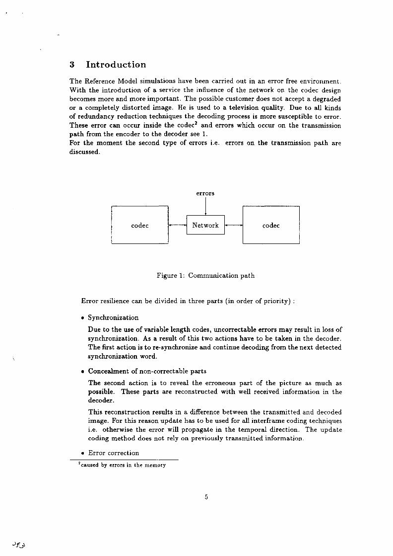
3 Introduction
The Reference Model simulations have been carried out in an error free environment.With the introduction of a service the influence of the network on the codec designbecomes more and more important. The possible customer does not accept a degradedor a completely distorted image. He is used to a television quality. Due to all kindsof redundancy reduction techniques the decoding process is more susceptible to error.These error can occur inside the codec2 and errors which occur on the transmissionpath from the encoder to the decoder see 1.For the moment the second type of errors i.e. errors on the transmission path arediscussed.
errors
codec Network codec
Figure 1: Communication path
Error resilience can be divided in three parts (in order of priority) :
• SynchronizationDue to the use of variable length codes, uncorrectable errors may result in loss ofsynchronization. As a result of this two actions have to be taken in the decoder.The first action is to re- synchronize and continue decoding from the next detectedsynchronization word.
• Concealment of non-correctable partsThe second action is to reveal the erroneous part of the picture as much aspossible,decoder.
These parts are reconstructed with well received information in the
This reconstruction results in a difference between the transmitted and decodedimage. For this reason update has to be used for all interframe coding techniquesi.e. otherwise the error will propagate in the temporal direction. The updatecoding method does not rely on previously transmitted information.
• Error correction2 caused by errors in the memory

Applying error correcting codes (ECC) results in the correction of (generallyspeaking) most of the channel errors, leaving a small probability of uncorrectableerrors.
In this contribution we will examine in which way the overall performance of thecodec could be improved by using error correction. Important in making a choice whichtechnique should be recommended is, what type of errors are to be expected. In thenext section the used terminology is given. In section 5 and section 6 the capabilitiesof the BCH code and the RS code are explained. In section 7 the tradeoff between thetwo solutions are given.
3.1 Used Terminology
In general if C is a linear code, we say that a matrix H is a £arity-check matrix for Cif it has the property that x 6 C when and only when xH T = Q
Suppose H is a parity check matrix for C, that b is the transmitted codeword andthat t = b + e is received. Than the Syndrome of r, is defined as :
s = rHT (1)
The RS codes are sub codes of the BCH codes.If C is an (n,k) linear code over GF(qm) with minimum distance dmin, then its GF(q)subcode is an (n',k') linear code over GF(q) with minimum distance dLmin where:
and''mtn — "mm
Where k denotes the number of information bits, n - k the number of parity bits.Therefor n is the number of bits in the block to be protected. The number of errorswhich can be corrected denoted with t is t — ^ .
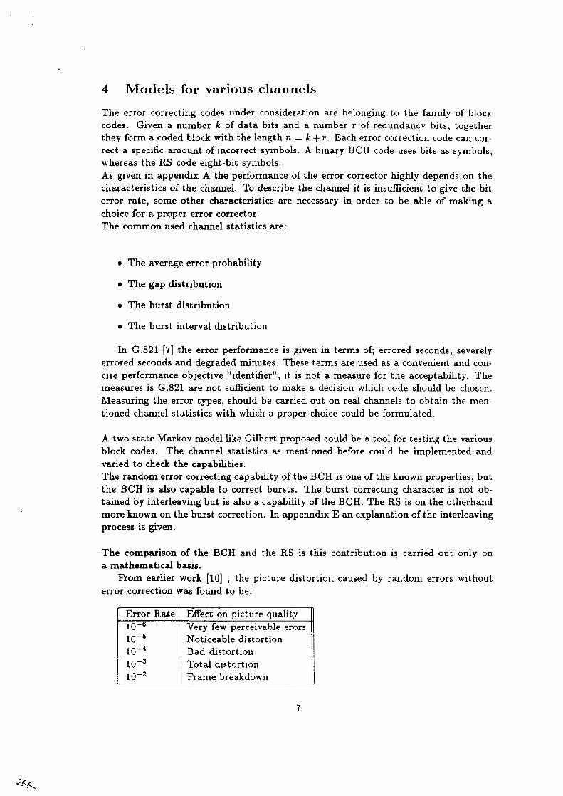
4 Models for various channels
The error correcting codes under consideration are belonging to the family of blockcodes. Given a number k of data bits and a number r of redundancy bits, togetherthey form a coded block with the length n = k + r. Each error correction code can cor-rect a specific amount of incorrect symbols. A binary BCH code uses bits as symbols,whereas the RS code eight-bit symbols.As given in appendix A the performance of the error corrector highly depends on thecharacteristics of the channel. To describe the channel it is insufficient to give the biterror rate, some other characteristics are necessary in order to be able of making achoice for a proper error corrector.The common used channel statistics are:
• The average error probability
• The gap distribution
• The burst distribution
• The burst interval distribution
In G.821 [7] the error performance is given in terms of; errored seconds, severelyerrored seconds and degraded minutes. These terms are used as a convenient and con-cise performance objective "identifier", it is not a measure for the acceptability. Themeasures is G.821 are not sufficient to make a decision which code should be chosen.Measuring the error types, should be carried out on real channels to obtain the men-tioned channel statistics with which a proper choice could be formulated.
A two state Markov model like Gilbert proposed could be a tool for testing the variousblock codes. The channel statistics as mentioned before could be implemented andvaried to check the capabilities.The random error correcting capability of the BCH is one of the known properties, butthe BCH is also capable to correct bursts. The burst correcting character is not ob-tained by interleaving but is also a capability of the BCH. The RS is on the otherhandmore known on the burst correction. In appenndix E an explanation of the interleavingprocess is given.
The comparison of the BCH and the RS is this contribution is carried out only ona mathematical basis.
From earlier work [10] , the picture distortion caused by random errors withouterror correction was found to be:
Error Rateid-6
1CT5
10~4
1(T3
io-2
Effect on picture qualityVery few perceivable erorsNoticeable distortionBad distortionTotal distortionFrame breakdown

5 The Bose-Chaudhuri-Hochquenghem (BCH) codes
The BCH code is a very powerful random error corrector. Modifying the number ofparities give the BCH also a burst correcting ability. At the moment it is not possibleto correct random as well as bursts.
Characteristics:
n = 2m - 1 (2)k > n - mt (3)
d > It + 1 (4)
(5)
The encoding is simple due to its cyclic propertiesThe Decoding is carried out in four steps:
1. calculate syndromes s(j) = r(aj) (j = 1,.. .,2t)
2. determine error location polynomial3
3. Determine4 the error locations polynomial.
4. correct the received pattern by f(x) = r(x) - e(x)
3Berlekamp-Massey or Euclides4 using e.g. the Chien search
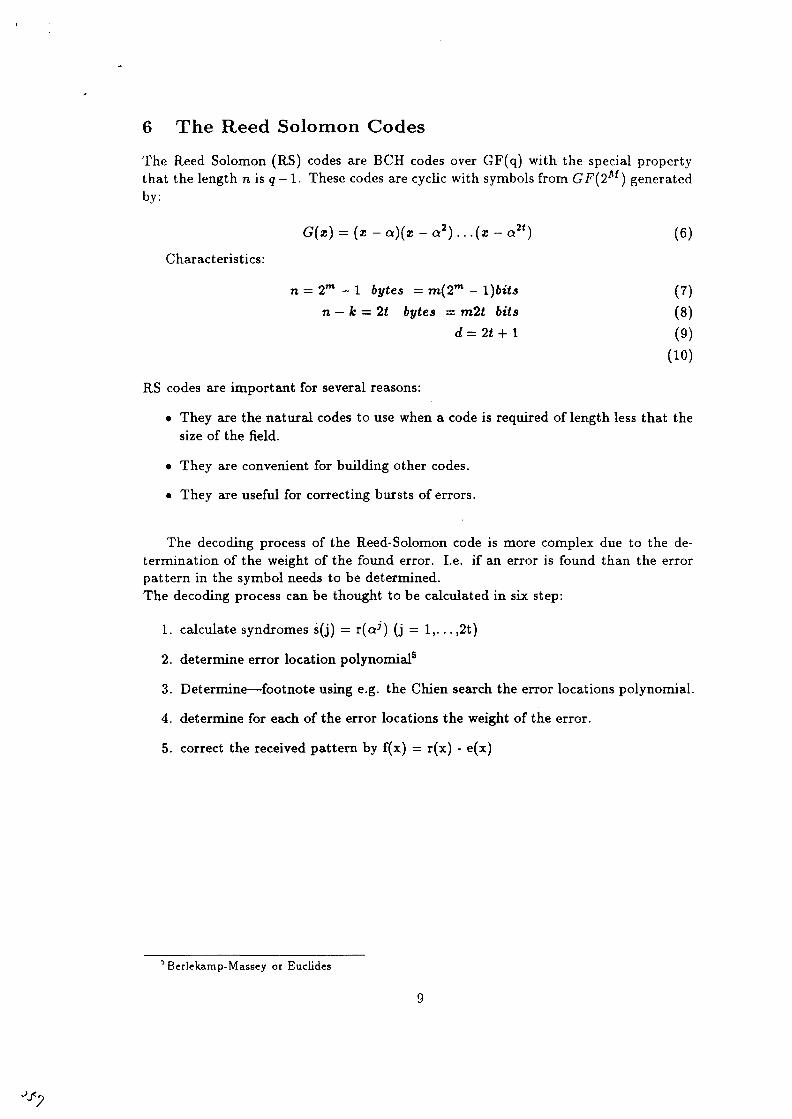
6 The Reed Solomon Codes
The Reed Solomon (RS) codes are BCH codes over GF(q) with the special propertythat the length n is q - 1. These codes are cyclic with symbols from GF(2M) generatedby:
G(x) = (x-a)(x-a*)...(z-a2t) (6)
Characteristics:
n - 2m - 1 bytes = m(2m - l)bits (7)n - k =. It bytes - m2t bits (8)
d=2t + l (9)(10)
RS codes are important for several reasons:
• They are the natural codes to use when a code is required of length less that thesize of the field.
• They are convenient for building other codes.
• They are useful for correcting bursts of errors.
The decoding process of the Reed-Solomon code is more complex due to the de-termination of the weight of the found error. I.e. if an error is found than the errorpattern in the symbol needs to be determined.The decoding process can be thought to be calculated in six step:
1. calculate syndromes s(j) = r(aj) (j = 1,.. .,2t)
2. determine error location polynomial5
3. Determine—footnote using e.g. the Chien search the error locations polynomial.
4. determine for each of the error locations the weight of the error.
5. correct the received pattern by f(x) = r(x) - e(x)
'Berlekamp-Massey or Euclides
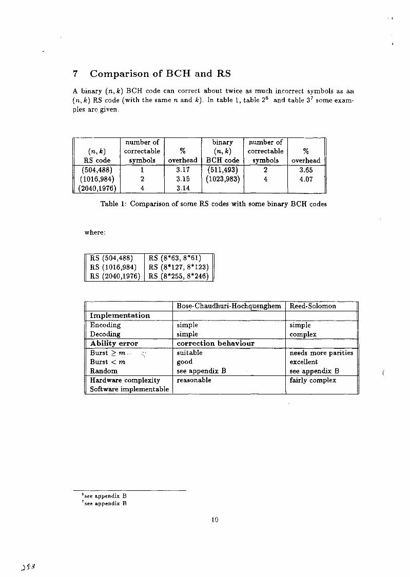
7 Comparison of BCH and RS
A binary (n, k) BCH code can correct about twice as much incorrect symbols as an(n, k) RS code (with the same n and k). In table 1, table 26 and table 37 some exam-ples are given.
(n,*)RS code
(504,488)(1016,984)(2040,1976)
number ofcorrectable
symbols124
%overhead
3.173.153.14
binary(n,*)
[ BCH code(511,493)(1023,983)
number ofcorrectable
symbols24
%overhead
3.654.07
Table 1: Comparison of some RS codes with some binary BCH codes
where:
RS (504,488)RS (1016,984)RS (2040,1976)
RS (8*63, 8*61)RS (8*127, 8*123)RS (8*255, 8*246)
ImplementationEncodingDecodingAbility errorBurst > m.--- cBurst < mRandomHardware complexitySoftware implement able
Bose-Chaudhuri-Hochquenghem
simplesimplecorrection behavioursuitablegoodsee appendix Breasonable
Reed-Solomon
simplecomplex
needs more paritiesexcellentsee appendix Bfairly complex
8 see appendix Bsee appendix B
10
References[1] "A double Error Correction BCH Encoder/Decoder LSI CCITT SGXV/1, Docu-
ment # 325, March 1988.
[2] Data Sheets Reed-Solomon Code Generator CXD1037G
[3] Data Sheets Reed-Solomon Decoder CXD1038G
[4] F.J.MacWilliams N.J.A.Sloan, " The Theory of error-correcting Codes, North-Holland Mathematical Library, 1988 ISBN 0 444 85193 3
[5] G.C.Clark, J.B.Cain, Error-Correct ion coding for Digital Communications,Plenum Press, 1982, ISBN 0 306 40615 2
[6] R.J.McEliece, The theory of information and coding, Addison-Wesley Publ. Com-pany, Massachussets, 1977, 2nd ed.
[7] Error performance of an international digital connection forming part of an inte-grated services digital network. CCITT Recommendation G.821
[8] Ralf Hinz, Forward error correction for p * 64 kbps video codecs internal AEG FI33-UL.
[9] Error Protection by Reed-Solomon Codes for Video Telephony, source: PhilipsKommunications Industrie AG.
[10] Status field trials error correction hardware H.261 codecs, source: The Nether-lands, BTRL Doc 421 CCITT SG XV/1/Q4 Dec. 1988
11
*7

A List of requirements for Error-Control selection
To meet the requirements for a good error corrector one should bear in mind the listeditems.
1. The required information throughput rate,
2. The allowed throughput delay for channel encoding and decoding,
3. The acceptable bandwidth expansion.
4. The modem modulation, symbol-rate, tracking-accuracy, phase-ambiguity andbit-slip characteristics.
5. The characteristics of the burst on bursty channels in terms of duration and atten-uation of the bursts. Their periodic or random nature, the guard space betweenbursts or their duty cycle, and the availability and reliability of information onthe occurrence of a burst that could be given to the decoder.
6. The burst rate and duty cycle of the received data and the suitability of using adecoder at the smoothed average rate, rather than the burst rate.
7. Decoder synchronization time and loss-of sync requirements.
8. The allowed rate of accepting incorrect messages.
9. The vulnerability of the destination data sink to bursts of errors from the decoder.
10. The costs, size, weight, and power restrictions.
12
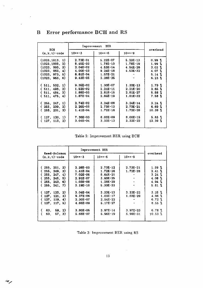
B Error performance BCH and RS
BCH(n,k, t) -code
(1023,1013, 1)(1023,1003. 2)(1023. 993. 3)(1023. 983. 4)(1023. 973. 5)(1023. 963. 6)
( 511. 502. 1)( 511. 493. 2)( 511. 484. 3)( 511. 475, 4)
( 255. 247. 1)( 255. 239, 2)( 255. 231. 3)
( 127, 120. 1)( 127. 113. 2)
Improvement BER
10**-3
2.73E-018.45E-022.04E-024.00E-036.61E-049.43E-05
9.35E-021 . 52E-021 . 88E-031.87E-04
2.74E-022 . 26E-031.41E-04
7.36E-033.04E-04
10**-6
5 . 22E-071.78E-104.53E-149.24E-181.57E-212.28E-25
1.30E-072.21E-112.81E-152.85E-19
3 . 24E-082.73E-121.72E-16
8 . OOE-093.33E-13
10**-9
5.23E-131.78E-194 . 54E-264.53E-32
1.30E-132.21E-202.81E-271.81E-32
3.24E-142.73E-211.72E-28
8.00E-153.33E-22
overhead
0.99 %1.99 I3.02 %4.07 %5.14 I6.23 f.
1.79 %3.65 %5.58 \7.58 %
3.24 %6.69 %10.39 %
5.83 %12.39 %
Table 2: Improvement BER using BCH
Reed-Solomon(n,k, t)-code
( 255, 251, 2)( 255, 249. 3)( 255. 247. 4)( 255. 245. 5)( 255. 243. 6)( 255. 241. 7)
( 127. 123. 2)( 127. 121. 3)( 127. 119. 4)( 127. 117, 5)
( 63. 59. 2)( 63. 57, 3)
Improvement BER
10**-3
2 . 26E-031.41E-047.02E-062.91E-071.03E-083.19E-10
3.04E-049.37E-062 . 30E-074.66E-09
3.80E-055.68E-07
10**-6
2.73E-121.72E-168.64E-213 . 60E-251.28E-295.30E-33
3.33E-131.03E-172.S4E-225.17E-27
3.97E-145.96E-19
10**-9
2.73E-211.72E-28
3.33E-221.03E-29
3.97E-235.98E-31
overhead
1.59 %2.41 %3.24 %4.08 %4.94 *5.81 I
3.25 I4.96 '/,6.72 V,8.55 y,6.78 I10.53 '/,
Table 3: Improvement BER using RS
13

C Chip set for the BCH solutionFeatures Encoder/Decoder
• Four selectable polynomials
• Programable Shortened length
• High Speed operation (max 6.3 Mbps)
• I/O direct TTL compatible
• Uncorrectable Error indicator and Bit Error monitor Functions
C.I Basics of BCH chip set
The user can choose among 4 basic code formats:
Code (n,k)(63,51)
(127,113)(255,239)(511,493)
ECC12141618
t2222
overhead19%11%6 %
3.5 %
Each of these code formats (n,k) can be shortened to (n — shl, k - shl} with shl < k.To make the word length equal to a power of 2 a frame bit can be added to the codeword.
(11)(12)
(13)
(14)
14
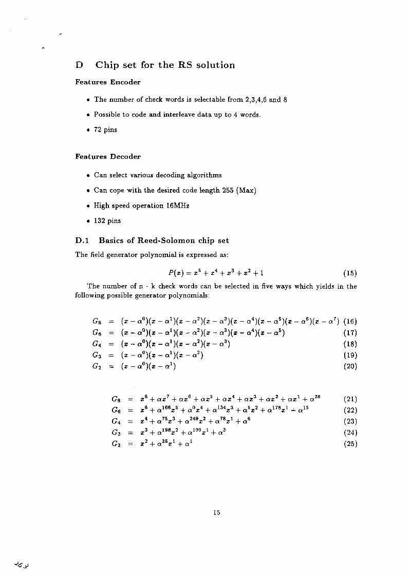
D Chip set for the RS solution
Features Encoder
• The number of check words is selectable from 2,3,4,6 and 8
• Possible to code and interleave data up to 4 words.
• 72 pins
Features Decoder
• Can select various decoding algorithms
• Can cope with the desired code length 255 (Max)
• High speed operation 16MHz
• 132 pins
D.I Basics of Reed-Solomon chip set
The field generator polynomial is expressed as:
P(z) = zs + z4 + z 3 - f - z 2 + l (15)
The number of n - k check words can be selected in five ways which yields in thefollowing possible generator polynomials:
G8 = (x- a°)(x - al)(x - a2)(x - a3)(z - a4)(z - a5)(x - ae)(x - a7) (16)G6 = (x - a°)(x - al)(x - a2)(x - a3)(x - a4)(z - a5) (17)£4 = (x - a°)(i - al)(x - a2)(z - a3) (18)G3 = (x - a°)(* - al)(* - a*) (19)G2 = (z -e^Xz-a 1 ) (20)
GB = x8 + ax7 + ax6 + ax5 + ax4 - fax 3 + ax2 + ax1 + a28 (21)G6 = xVa16V+aV W3V + a5x2 + a17V + a15 (22)G4 - z4 + a78*3 + a24 V + a7V + a6 (23)G3 = x3 + a19V + a19V + a3 (24)G2 = x2 + a25x1 + a1 (25)
15
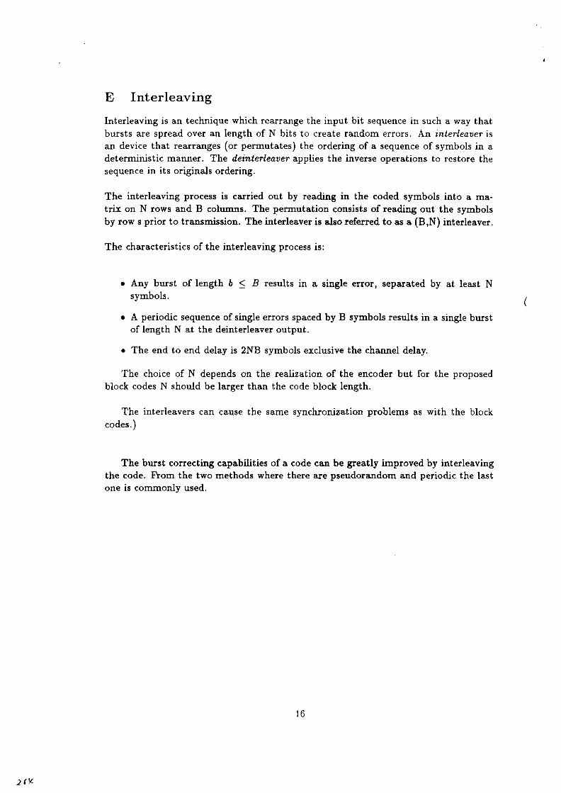
E Interleaving
Interleaving is an technique which rearrange the input bit sequence in such a way thatbursts are spread over an length of N bits to create random errors. An interleaver isan device that rearranges (or permutates) the ordering of a sequence of symbols in adeterministic manner. The deinterleaver applies the inverse operations to restore thesequence in its originals ordering.
The interleaving process is carried out by reading in the coded symbols into a ma-trix on N rows and B columns. The permutation consists of reading out the symbolsby row s prior to transmission. The interleaver is also referred to as a (B,N) interleaver.
The characteristics of the interleaving process is:
• Any burst of length b < B results in a single error, separated by at least Nsymbols. ,
• A periodic sequence of single errors spaced by B symbols results in a single burstof length N at the deinterleaver output.
• The end to end delay is 2NB symbols exclusive the channel delay.
The choice of N depends on the realization of the encoder but for the proposedblock codes N should be larger than the code block length.
The interleavers can cause the same synchronization problems as with the blockcodes.)
The burst correcting capabilities of a code can be greatly improved by interleavingthe code. From the two methods where there are pseudorandom and periodic the lastone is commonly used.
16
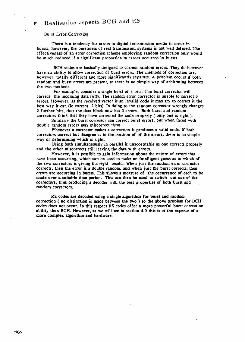
F Realisation aspects BCH and RS
Burst Error Correction
There is a tendency for errors in digital transmission media to occur inbursts, however, the burstiness of real transmission systems is not well defined. Theeffectiveness of an error correction scheme employing random correction only wouldbe much reduced if a significant proportion to errors occurred in bursts.
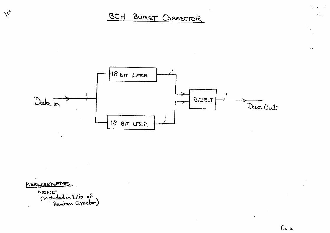
BCH codes are basically designed to correct random errors. They do howeverhave an ability to allow correction of burst errors. The methods of correction are,however, totally different and more significantly separate. A problem occurs if bothrandom and burst errors are present, as there is no simple way of arbitrating betweenthe two methods.
For example, consider a single burst of 3 bits. The burst corrector willcorrect the incoming data fully. The random error corrector is unable to correct 3errors. However, as the received vector is an invalid code it may try to correct it thebest way it can (ie correct 2 bits). In doing so the random corrector wrongly changes2 further bits, thus the data block now has 5 errors. Both burst and randomcorrectors think that they have corrected the code properly ( only one is right).
Similarly the burst corrector can correct burst errors, but when faced withdouble random errors may miscorrect them.
Whenever a corrector makes a correction it produces a valid code. If bothcorrectors correct but disagree as to the position of of the errors, there is no simpleway of determining which is right.
Using both simultaneously in parallel is unacceptable as one corrects properlyand the other miscorrects still leaving the data with errors.
However, it is possible to gain information about the nature of errors thathave been occurring, which can be used to make an intelligent guess as to which ofthe two correctors is giving the right results. When just the random error correctorcorrects, then the error is a double random, and when just the burst corrects, thenerrors are occurring in bursts. This allows a measure of the occurrance of each to bemade over a suitable time period. This can then be used to switch out one of thecorrectors, thus producing a decoder with the best properties of both burst andrandom correctors.
RS codes are decoded using a single algorithm for burst and randomcorrection ( no distinction is made between the two ) so the above problem for BCHcodes does not occur. In this respect RS codes offer a more powerful burst correctionability than BCH. However, as we will see in section 4.0 this is at the expense of amore complex algorithm and hardware.
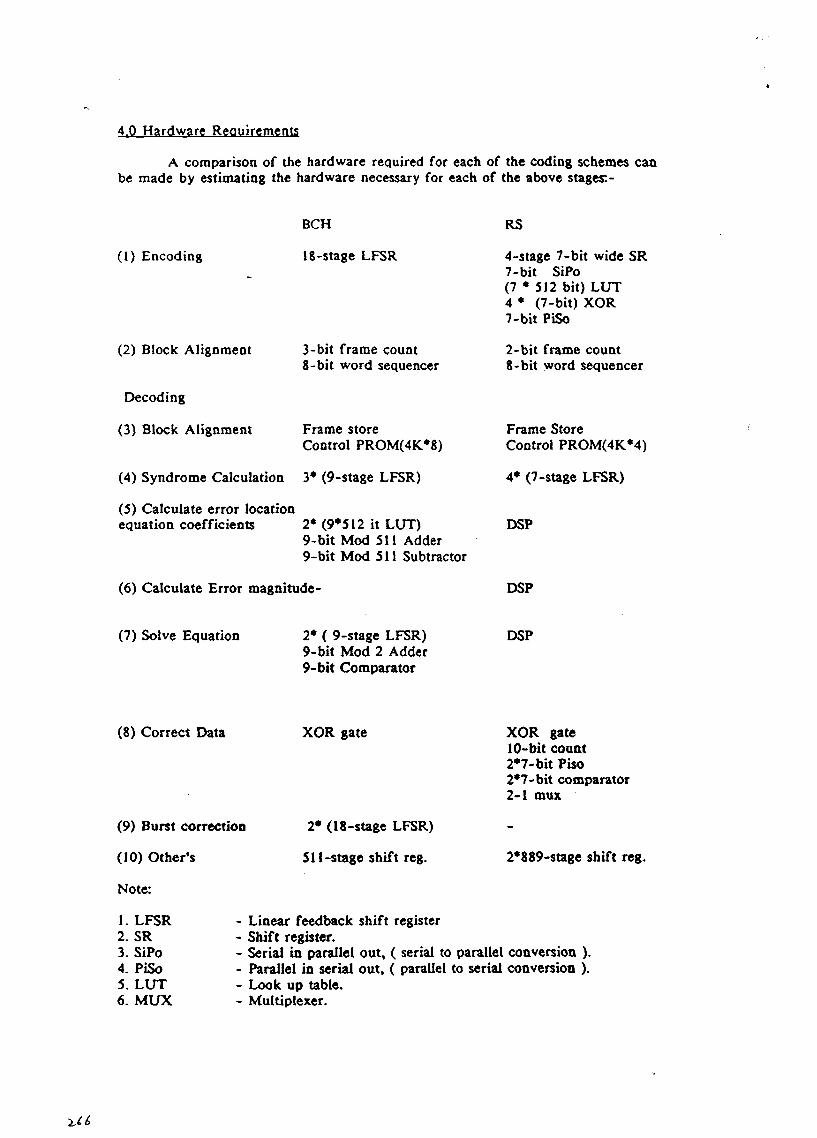
4.0 Hardware Requirements
A comparison of the hardware required for each of the coding schemes canbe made by estimating the hardware necessary for each of the above stages: -
(1) Encoding
(2) Block Alignment
Decoding
(3) Block Alignment
BCH
18-stage LFSR
3-bit frame count8-bit word sequencer
Frame storeControl PROM(4K*8)
(4) Syndrome Calculation 3* (9-stage LFSR)
(5) Calculate error locationequation coefficients 2* (9*512 it LUT)
9-bit Mod 511 Adder9-bit Mod 511 Subtracter
(6) Calculate Error magnitude -
RS
4-stage 7-bit wide SR7-bit SiPo(7 * 512 bit) LUT4 * (7-bit) XOR7-bit PiSo
2-bit frame count8-bit word sequencer
Frame StoreControl PROM(4K*4)
4* (7-stage LFSR)
DSP
DSP
(7) Solve Equation 2* ( 9-stage LFSR)9-bit Mod 2 Adder9-bit Comparator
DSP
(8) Correct Data XOR gate
(9) Burst correction
(10) Other's
Note:
2* (18-stage LFSR)
511-stage shift reg.
1. LFSR2. SR3. SiPo4. PiSo5. LUT6. MUX
XOR gate10-bit count2*7-bit Piso2*7-bit comparator2-1 mux
2*889-stage shift reg.
- Linear feedback shift register- Shift register.- Serial in parallel out, ( serial to parallel conversion ).- Parallel in serial out, ( parallel to serial conversion ).- Look up table.- Multiplexer.
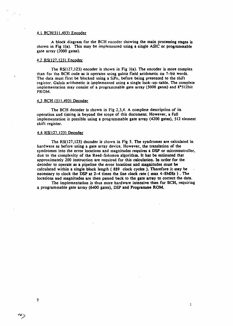
4.1 BCH(S11.493) Encoder
A block diagram for the BCH encoder showing the main processing stages isshown in Fig l(a). This may be implemented using a single ASIC or programmablegate array (2000 gates).
4.2 RSn 27.1231 Encoder
The RS(127,123) encoder is shown in Fig l(a). The encoder is more complexthan for the BCH code as it operates using galois field arithmetic on 7-bit words.The data must first be blocked using a SiPo, before being presented to the shiftregister. Galois arithmetic is implemented using a single look-up-table. The completeimplementation may consist of a programmable gate array (3000 gates) and 8*512bitPROM.
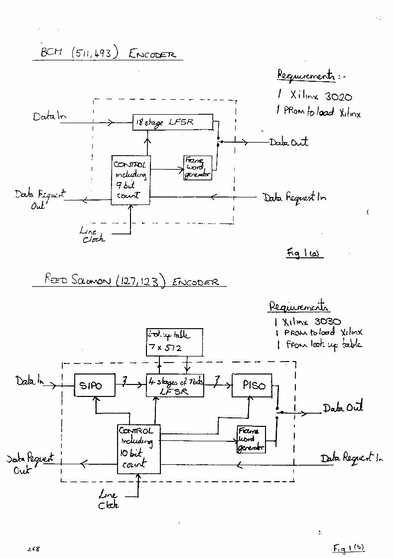
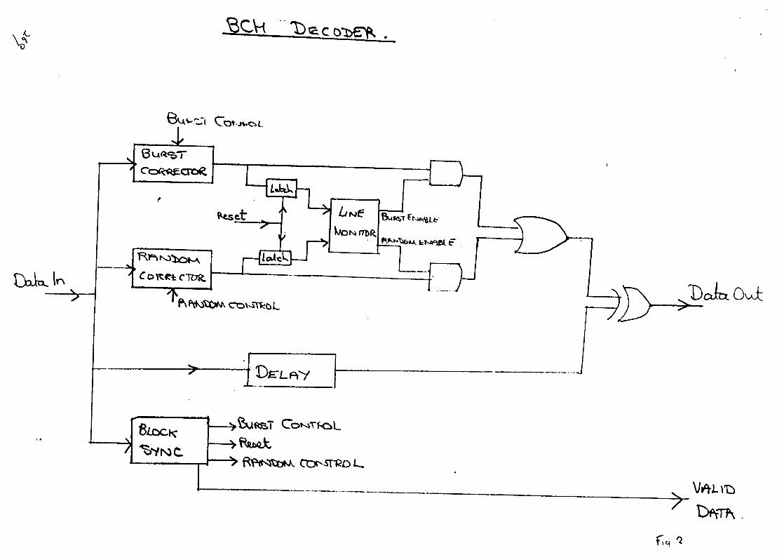
4.3 BCH (511.493) Decoder
The BCH decoder is shown in Fig 2,3,4. A complete description of itsoperation and timing is beyond the scope of this document. However, a fullimplementation is possible using a programmable gate array (4200 gates), 512 elementshift register.
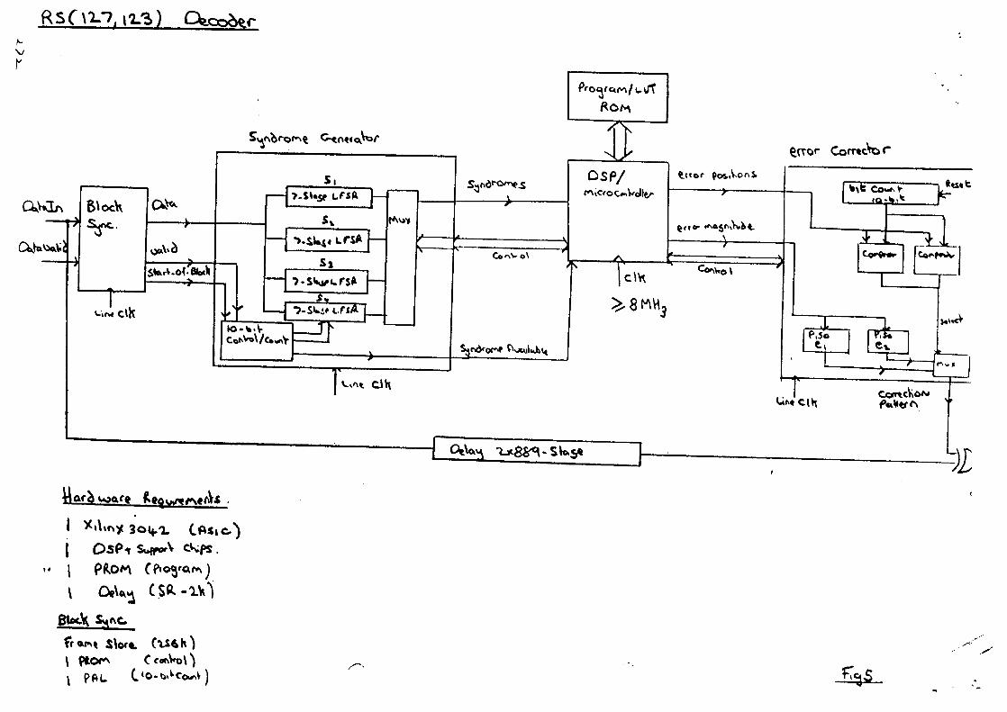
4.4 RSH27.123) Decoder
The RS(127,123) decoder is shown in Fig 5. The syndromes are calculated inhardware as before using a gate array device. However, the translation of thesyndromes into the error locations and magnitudes requires a DSP or microcontroller,due to the complexity of the Reed-Solomon algorithm. It has be estimated thatapproximately 200 instruction are required for this calculation. In order for thedecoder to operate as a pipeline the error locations and magnitudes must becalculated within a single block length ( 889 clock cycles ). Therefore it may benecessary to clock the DSP at 2-4 times the line clock rate ( max 4-8MHz ). Thelocations and magnitudes are then passed back to the gate array to correct the data.
The implementation is thus more hardware intensive than for BCH, requiringa programmable gate array (6400 gates), DSP and Programme ROM.
jte/>Au^^v>C/rwi : -
30BOtblooJ
ouU/Pa
T^10
lu2a1>o-i —
—• »ci£t.«?o-
T(p 1
. i
Jo-
c:\*t— jp-5o-
>v<r~..
t *
oD
O
^
yv t^
1 ——
— **- —
* — J
l ——
I? - A
< i
§ 1 —
——
L
* £ i»
vL ^
S
^*~
<p
1$ 9 ^
» <
10-X
o-
<? ^
"^2
-^ U
^TCH
^ v
I
/^
LATCH^»
(\ *\
si ^
r *i>
^ JJ j>
eq
^
-», ~J -* —
— . —
——
——
^*^
k ^*
31 —
* —
—C
lATChf
OJ
' — —
— 1
—
1
1$I!
/ ^ j V
^
2 *
| f
P
~J
2P
H
^ k
-
^
^J
ar
VC
T
ifl •*•
** Jk
4
1 J
5 *
§ J 1
|J
5^
O^
-^^
«
(X)cr>
o
6u
u.500
Qo
btuul(p
Qi'
tCD
cJ-oi'&21o i
a:
••
cje13L.Pt0>
J"- r / \
i. *• '
>f,S
^o<£
«»if0atQ
-?
tf
JJ3jii
>ACO1o.0VCOa
VI
I(A
1k.*
4 J3
9t9"•
j>1C>0C£
**
71ct•»14.J?«t
fi|
JC*« r — *rV
!L
•*
w/«tf>
ii
k
- 4
5
T |5«• »
" 5*?/
f -
3 (I 9
t—
r I <} 7~
1
-j 5
:
< 1
—— T
31 _jjt w -
J
S0
«7
—1
0- —
• •o*;a.
-'
w]07
X
?u
°°<—
—
A\
x
j"S
3
i
&
*
Ii*ftf
^r(
-*
ct
v» w
-""*-,- jo
ff•2
?I.
TT !
> 1
l—^
2-.1,
» ^uJC73
' — 2J
iTi
(1
%
i<v iiwv
0<tJET
. u?
— l J
<JbsCii81JB-
13•<J
— o
\
r^
«ov^% f
J>5i4r8f•M
C
X"*0
-$
£
M ^
V—
^_
«*
?<
•-
*;
c °?S I <^
^c^
1
^ S
'ci ^
-?-
< ^ 1 s».
s **
£ J £ ~ " *
0 </>
-
5 ' » i S T
j jj 432* *:u'J
X
vr
£ ii Si
S -
"} *
^« oa
w "