Nucleon decay searches with large liquid Argon TPC detectors at shallow depths: atmospheric...
26
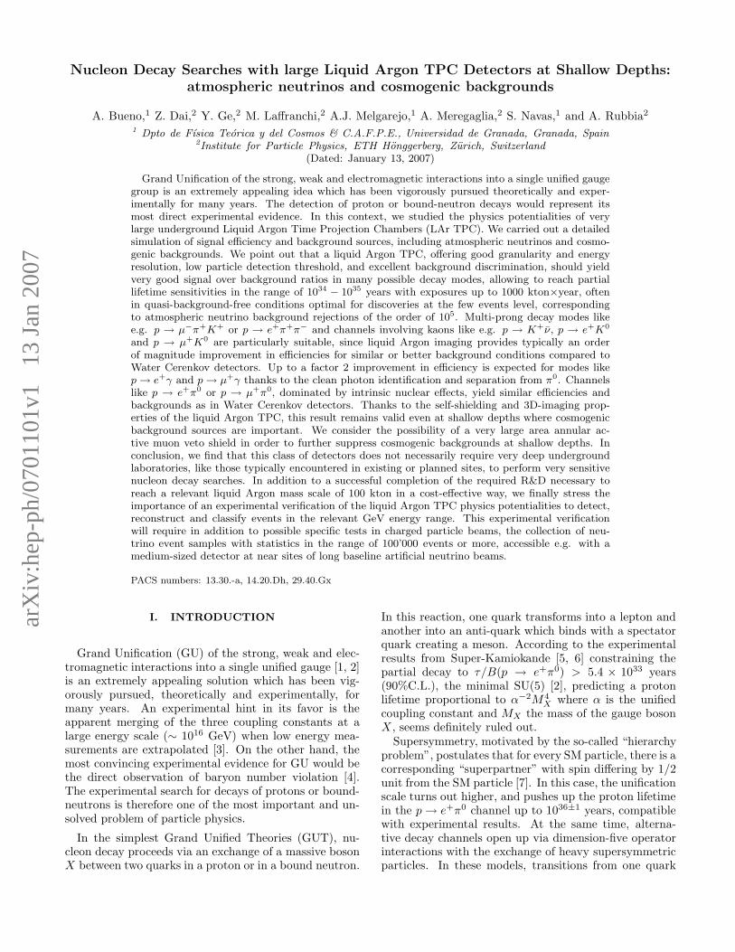
arXiv:hep-ph/0701101v1 13 Jan 2007 Nucleon Decay Searches with large Liquid Argon TPC Detectors at Shallow Depths: atmospheric neutrinos and cosmogenic backgrounds A. Bueno, 1 Z. Dai, 2 Y. Ge, 2 M. Laffranchi, 2 A.J. Melgarejo, 1 A. Meregaglia, 2 S. Navas, 1 and A. Rubbia 2 1 Dpto de F´ ısica Te´orica y del Cosmos & C.A.F.P.E., Universidad de Granada, Granada, Spain 2 Institute for Particle Physics, ETH H¨onggerberg, Z¨ urich, Switzerland (Dated: January 13, 2007) Grand Unification of the strong, weak and electromagnetic interactions into a single unified gauge group is an extremely appealing idea which has been vigorously pursued theoretically and exper- imentally for many years. The detection of proton or bound-neutron decays would represent its most direct experimental evidence. In this context, we studied the physics potentialities of very large underground Liquid Argon Time Projection Chambers (LAr TPC). We carried out a detailed simulation of signal efficiency and background sources, including atmospheric neutrinos and cosmo- genic backgrounds. We point out that a liquid Argon TPC, offering good granularity and energy resolution, low particle detection threshold, and excellent background discrimination, should yield very good signal over background ratios in many possible decay modes, allowing to reach partial lifetime sensitivities in the range of 10 34 − 10 35 years with exposures up to 1000 kton×year, often in quasi-background-free conditions optimal for discoveries at the few events level, corresponding to atmospheric neutrino background rejections of the order of 10 5 . Multi-prong decay modes like e.g. p → μ - π + K + or p → e + π + π - and channels involving kaons like e.g. p → K + ¯ ν , p → e + K 0 and p → μ + K 0 are particularly suitable, since liquid Argon imaging provides typically an order of magnitude improvement in efficiencies for similar or better background conditions compared to Water Cerenkov detectors. Up to a factor 2 improvement in efficiency is expected for modes like p → e + γ and p → μ + γ thanks to the clean photon identification and separation from π 0 . Channels like p → e + π 0 or p → μ + π 0 , dominated by intrinsic nuclear effects, yield similar efficiencies and backgrounds as in Water Cerenkov detectors. Thanks to the self-shielding and 3D-imaging prop- erties of the liquid Argon TPC, this result remains valid even at shallow depths where cosmogenic background sources are important. We consider the possibility of a very large area annular ac- tive muon veto shield in order to further suppress cosmogenic backgrounds at shallow depths. In conclusion, we find that this class of detectors does not necessarily require very deep underground laboratories, like those typically encountered in existing or planned sites, to perform very sensitive nucleon decay searches. In addition to a successful completion of the required R&D necessary to reach a relevant liquid Argon mass scale of 100 kton in a cost-effective way, we finally stress the importance of an experimental verification of the liquid Argon TPC physics potentialities to detect, reconstruct and classify events in the relevant GeV energy range. This experimental verification will require in addition to possible specific tests in charged particle beams, the collection of neu- trino event samples with statistics in the range of 100’000 events or more, accessible e.g. with a medium-sized detector at near sites of long baseline artificial neutrino beams. PACS numbers: 13.30.-a, 14.20.Dh, 29.40.Gx I. INTRODUCTION Grand Unification (GU) of the strong, weak and elec- tromagnetic interactions into a single unified gauge [1, 2] is an extremely appealing solution which has been vig- orously pursued, theoretically and experimentally, for many years. An experimental hint in its favor is the apparent merging of the three coupling constants at a large energy scale (∼ 10 16 GeV) when low energy mea- surements are extrapolated [3]. On the other hand, the most convincing experimental evidence for GU would be the direct observation of baryon number violation [4]. The experimental search for decays of protons or bound- neutrons is therefore one of the most important and un- solved problem of particle physics. In the simplest Grand Unified Theories (GUT), nu- cleon decay proceeds via an exchange of a massive boson X between two quarks in a proton or in a bound neutron. In this reaction, one quark transforms into a lepton and another into an anti-quark which binds with a spectator quark creating a meson. According to the experimental results from Super-Kamiokande [5, 6] constraining the partial decay to τ/B(p → e + π 0 ) > 5.4 × 10 33 years (90%C.L.), the minimal SU(5) [2], predicting a proton lifetime proportional to α −2 M 4 X where α is the unified coupling constant and M X the mass of the gauge boson X , seems definitely ruled out. Supersymmetry, motivated by the so-called “hierarchy problem”, postulates that for every SM particle, there is a corresponding “superpartner” with spin differing by 1/2 unit from the SM particle [7]. In this case, the unification scale turns out higher, and pushes up the proton lifetime in the p → e + π 0 channel up to 10 36±1 years, compatible with experimental results. At the same time, alterna- tive decay channels open up via dimension-five operator interactions with the exchange of heavy supersymmetric particles. In these models, transitions from one quark
-
Upload
umb-investigaciones -
Category
Documents
-
view
3 -
download
0
Transcript of Nucleon decay searches with large liquid Argon TPC detectors at shallow depths: atmospheric...
arX
iv:h
ep-p
h/07
0110
1v1
13
Jan
2007
Nucleon Decay Searches with large Liquid Argon TPC Detectors at Shallow Depths:
atmospheric neutrinos and cosmogenic backgrounds
A. Bueno,1 Z. Dai,2 Y. Ge,2 M. Laffranchi,2 A.J. Melgarejo,1 A. Meregaglia,2 S. Navas,1 and A. Rubbia2
1 Dpto de Fısica Teorica y del Cosmos & C.A.F.P.E., Universidad de Granada, Granada, Spain2Institute for Particle Physics, ETH Honggerberg, Zurich, Switzerland
(Dated: January 13, 2007)
Grand Unification of the strong, weak and electromagnetic interactions into a single unified gaugegroup is an extremely appealing idea which has been vigorously pursued theoretically and exper-imentally for many years. The detection of proton or bound-neutron decays would represent itsmost direct experimental evidence. In this context, we studied the physics potentialities of verylarge underground Liquid Argon Time Projection Chambers (LAr TPC). We carried out a detailedsimulation of signal efficiency and background sources, including atmospheric neutrinos and cosmo-genic backgrounds. We point out that a liquid Argon TPC, offering good granularity and energyresolution, low particle detection threshold, and excellent background discrimination, should yieldvery good signal over background ratios in many possible decay modes, allowing to reach partiallifetime sensitivities in the range of 1034
− 1035 years with exposures up to 1000 kton×year, oftenin quasi-background-free conditions optimal for discoveries at the few events level, correspondingto atmospheric neutrino background rejections of the order of 105. Multi-prong decay modes likee.g. p → µ−π+K+ or p → e+π+π− and channels involving kaons like e.g. p → K+ν, p → e+K0
and p → µ+K0 are particularly suitable, since liquid Argon imaging provides typically an orderof magnitude improvement in efficiencies for similar or better background conditions compared toWater Cerenkov detectors. Up to a factor 2 improvement in efficiency is expected for modes likep → e+γ and p → µ+γ thanks to the clean photon identification and separation from π0. Channelslike p → e+π0 or p → µ+π0, dominated by intrinsic nuclear effects, yield similar efficiencies andbackgrounds as in Water Cerenkov detectors. Thanks to the self-shielding and 3D-imaging prop-erties of the liquid Argon TPC, this result remains valid even at shallow depths where cosmogenicbackground sources are important. We consider the possibility of a very large area annular ac-tive muon veto shield in order to further suppress cosmogenic backgrounds at shallow depths. Inconclusion, we find that this class of detectors does not necessarily require very deep undergroundlaboratories, like those typically encountered in existing or planned sites, to perform very sensitivenucleon decay searches. In addition to a successful completion of the required R&D necessary toreach a relevant liquid Argon mass scale of 100 kton in a cost-effective way, we finally stress theimportance of an experimental verification of the liquid Argon TPC physics potentialities to detect,reconstruct and classify events in the relevant GeV energy range. This experimental verificationwill require in addition to possible specific tests in charged particle beams, the collection of neu-trino event samples with statistics in the range of 100’000 events or more, accessible e.g. with amedium-sized detector at near sites of long baseline artificial neutrino beams.
PACS numbers: 13.30.-a, 14.20.Dh, 29.40.Gx
I. INTRODUCTION
Grand Unification (GU) of the strong, weak and elec-tromagnetic interactions into a single unified gauge [1, 2]is an extremely appealing solution which has been vig-orously pursued, theoretically and experimentally, formany years. An experimental hint in its favor is theapparent merging of the three coupling constants at alarge energy scale (∼ 1016 GeV) when low energy mea-surements are extrapolated [3]. On the other hand, themost convincing experimental evidence for GU would bethe direct observation of baryon number violation [4].The experimental search for decays of protons or bound-neutrons is therefore one of the most important and un-solved problem of particle physics.
In the simplest Grand Unified Theories (GUT), nu-cleon decay proceeds via an exchange of a massive bosonX between two quarks in a proton or in a bound neutron.
In this reaction, one quark transforms into a lepton andanother into an anti-quark which binds with a spectatorquark creating a meson. According to the experimentalresults from Super-Kamiokande [5, 6] constraining thepartial decay to τ/B(p → e+π0) > 5.4 × 1033 years(90%C.L.), the minimal SU(5) [2], predicting a protonlifetime proportional to α−2M4
X where α is the unifiedcoupling constant and MX the mass of the gauge bosonX , seems definitely ruled out.
Supersymmetry, motivated by the so-called “hierarchyproblem”, postulates that for every SM particle, there is acorresponding “superpartner” with spin differing by 1/2unit from the SM particle [7]. In this case, the unificationscale turns out higher, and pushes up the proton lifetimein the p → e+π0 channel up to 1036±1 years, compatiblewith experimental results. At the same time, alterna-tive decay channels open up via dimension-five operatorinteractions with the exchange of heavy supersymmetricparticles. In these models, transitions from one quark

2
family in the initial state to the same family in the fi-nal state are suppressed. Since the only second or thirdgeneration quark which is kinematically allowed is thestrange quark, an anti-strange quark typically appearsin the final state for these interactions. The anti-strangequark binds with a spectator quark to form a K mesonin the final state [8]. The searches for decays p → νK+,n → νK0, p → µ+K0 and p → e+K0 modes were alsoperformed in Super-Kamiokande [9, 10] yielding countscompatible with background expectations, leading to lim-its on possible minimal SUSY SU(5) models [11, 12, 13].The theoretical predictions, however, vary widely, sincethere are many new unknown parameters introduced inthese models.
Other alternative models have been discussed in the lit-terature [14, 15, 16, 17, 18, 19, 20, 21, 22, 23, 24, 25, 26](see Table I). In addition to the above mentioned GUTs,other supersymmetric SUSY-GUT, SUGRA unified mod-els, unification based on extra dimensions, and string-M-theory models are also possible (see Ref. [27] for a recentreview). All these models predict nucleon instability atsome level. Finally, it is also worth noting that theo-ries without low-energy super-symmetry [23, 28] predictnucleon decay lifetimes in the range 1035±1 years.
Some experimental aspects of nucleon decay detectionwere discussed in Ref. [29]. Nucleon decay signals arecharacterized by (a) their topology and (b) their kine-matics. The presence of a lepton (electron, muon or neu-trino) in the final state is expected, and in general fewother particles (two body decays are kinematically fa-vored), and no other energetic nucleon. The total energyof the event should be close to the nucleon mass and thetotal momentum should be balanced, with the exceptionof the smearing introduced by Fermi motion and othernuclear effects (nuclear potential, re-scattering, absorp-tion, etc.) for bound decaying nucleons.
The search for nucleon decay therefore requires (1) ex-cellent tracking and calorimetric resolutions to constrainthe final state kinematics and suppress atmospheric neu-trino backgrounds, (2) particle identification (in partic-ular kaon tagging) for branching mode identification (3)very massive detectors and (4) underground locations toshield against cosmic-ray induced backgrounds, althoughthe exact required rock overburden depends on the cho-sen detection technology. Fine tracking in the low mo-mentum range (∼100–1000 MeV/c) is fundamental for(dE/dx) measurement, particle identification and vertexreconstruction.
In order to significantly improve current experimentalresults, next generation massive underground detectorssatisfying the above requirements have to be considered.Given the variety of predicted decay modes open by thenew theories, the ideal detectors should be as versatile aspossible, very good in background rejection, and at thesame time have the largest possible mass. The relevantfactor is in fact M×ǫ, where M is the detector mass and ǫthe signal detection efficiency after cuts to suppress back-grounds, which depends on the considered decay channel.
Hence large masses must be coupled to fine tracking andexcellent calorimetry, to suppress atmospheric neutrinoand cosmogenic backgrounds with a good signal selec-tion efficiency. Furthermore, the detector should be sen-sitive to several different channels in order to better un-derstand the nucleon decay mechanism. Since there areabout 6 × 1032 nucleons per kton of mass, the protonlifetime limit (90% CL) in case of absence of signal andbackgrounds is about τp/B > M (kton) × ǫ × T ×1032
years, where T is the exposure in years and B the as-sumed branching fraction for the searched mode. There-fore, the required effective mass M×ǫ to reach 1035 yearsis in the range of 100 kton assuming T=10 years.
Such massive underground detectors will be sort of ob-servatories for rare physics phenomena like astrophysi-cal neutrino detection and nucleon decay searches, withpossible synergies with existing or new artificial neutrinobeams for improved understanding of neutrino flavor os-cillations, including the possible identification of directCP-violation in the leptonic sector (see e.g. Ref. [30] andreferences therein).
Among the various options and technologies currentlythought of (see Ref. [31] and Refs. [32, 33, 34, 35,36, 37, 38]), the Liquid Argon Time Projection Cham-ber [39, 40, 41, 42, 43, 44, 45, 46, 47, 48] (LAr TPC) is apowerful detector for uniform and high accuracy imagingof massive active volumes. It is based on the fact that inhighly pure Argon, ionization tracks can be drifted overdistances of the order of meters. Imaging is providedby position-segmented electrodes at the end of the driftpath, continuously recording the signals induced. T0 isprovided by the prompt scintillation light.
Early work on the detection of nucleon decays in liquidArgon can be found in Ref. [49]. The liquid Argon TPC isa very promising detector option which satisfies at bestthe above mentioned requisites in terms of granularity,energy resolution and imaging capabilities if it can beextrapolated to the relevant mass scale.
In this paper we study the performance of a very mas-sive Liquid Argon TPC as a nucleon decay detector. Inthe present study, we address for the first time the ef-fect of the charged cosmic rays background as a functionof the depth (i.e. rock overburden) of the undergrounddetectors. In particular, we address the possibility toperform proton decay searches in “shallow depth” con-figurations [31]. Since the new large underground detec-tors will require either a new site to be excavated or theextension of an existing infrastructure, it is importantto understand if very-sensitive nucleon decay searchesdo necessarily require deep underground locations, likethose typically encountered in existing or planned labo-ratories [50].
The paper is organized as follows: some considerationsabout the conceptual design of the detector are outlinedin section II. The discussion of the assumed detector con-figuration and the simulated physics process for signaland background events are described in section III. Thedescription of the analysis cuts designed to suppress at-

3
Model Ref. Modes τN (years)
Minimal SU(5) Georgi, Glashow [2] p → e+π0 1030− 1031
Minimal SUSY SU(5) Dimopoulos, Georgi [11], Sakai [12] p → νK+
Lifetime Calculations: Hisano, n → νK0 1028− 1032
Murayama, Yanagida [13]
SUGRA SU(5) Nath, Arnowitt [14, 15] p → νK+ 1032− 1034
SUSY SO(10) Shafi, Tavartkiladze [16] p → νK+
with anomalous n → νK0 1032− 1035
flavor U(1) p → µ+K0
SUSY SO(10) Lucas, Raby [17], Pati [18] p → νK+ 1033− 1034
MSSM (std. d = 5) n → νK0 1032− 1033
SUSY SO(10) Pati [18] p → νK+ 1033− 1034
ESSM (std. d = 5) . 1035
SUSY SO(10)/G(224) Babu, Pati, Wilczek [19, 20, 21], p → νK+ . 2 · 1034
MSSM or ESSM Pati [18] p → µ+K0
(new d = 5) B ∼ (1 − 50)%
SUSY SU(5) or SO(10) Pati [18] p → e+π0∼ 1034.9±1
MSSM (d = 6)
Flipped SU(5) in CMSSM Ellis, Nanopoulos and Wlaker[22] p → e/µ+π0 1035− 1036
Split SU(5) SUSY Arkani-Hamed, et. al. [23] p → e+π0 1035− 1037
SU(5) in 5 dimensions Hebecker, March-Russell[24] p → µ+K0 1034− 1035
p → e+π0
SU(5) in 5 dimensions Alciati et.al.[25] p → νK+ 1036− 1039
option II
GUT-like models from Klebanov, Witten[26] p → e+π0∼ 1036
Type IIA string with D6-branes
TABLE I: Summary of the expected nucleon lifetime in different theoretical models.
mospheric neutrino and muon-induced backgrounds fromproton and neutron decay channels are given in sec-tion IV. Finally, the results obtained in terms of lifetimesensitivities for the considered decay modes are given insection V.
II. DETECTOR CONCEPT
Our analysis assumes the scalable concept of a liquidArgon TPC, as proposed in [51] (see Figure 1). Otherdesigns have been presented in Ref. [52]. An LOI basedon a more standard configuration and a surface detectorhas also been submitted to FNAL [53].
The design of Ref. [51] relies on (a) industrial tankersdeveloped by the petrochemical industry (no R&D re-quired, readily available, safe) and their extrapolationto underground or shallow depth LAr storage, (b) novelreadout methods with embedded charge chain for verylong drift paths, based on e.g. LEM readout, (c) newsolutions for very high drift voltage, (d) a modularityat the level of 100 kton and (e) the possibility to em-bed the LAr in a magnetic field [54]. Such a scalable,single LAr tanker design is the most attractive solutionfrom the point of view of physics, detector construction,
operation and cryogenics, and finally cost.
An R&D program is underway with the aim of opti-mizing the design [55]. Concerning the further consoli-dation of the technology, we point out that a test-beamdedicated to the reconstruction and separation of elec-trons from neutral pions has been discussed [56]. In ad-dition, a ≃ 100 ton liquid Argon TPC to complement the1 kton Water Cerenkov detector at the potential 2 kmsite 2.5o off-axis from the T2K beam has also been con-sidered [57]. If realized, this unique experimental setupwill allow to compare the performance of the liquid ArgonTPC to the Water Cerenkov ring imaging and to recon-struct neutrino events directly in the same beam with astatistics of more than 100’000 events per year, sufficientto extrapolate the atmospheric neutrino background in apotential 1000 kton×year exposure. ICARUS T600 [44],to be commissioned in the coming years, will detect toofew contained events to demonstrate the ultimate physicsperformance of the technology.
When operating TPCs with long drift paths and chargeamplification at the anode as the one considered here,one must pay attention to possible drift field distor-tions caused by the space charge created by the posi-tive ions slowly drifting towards the cathode. Indeed,it is well known that ion (and hole) mobility in liquid
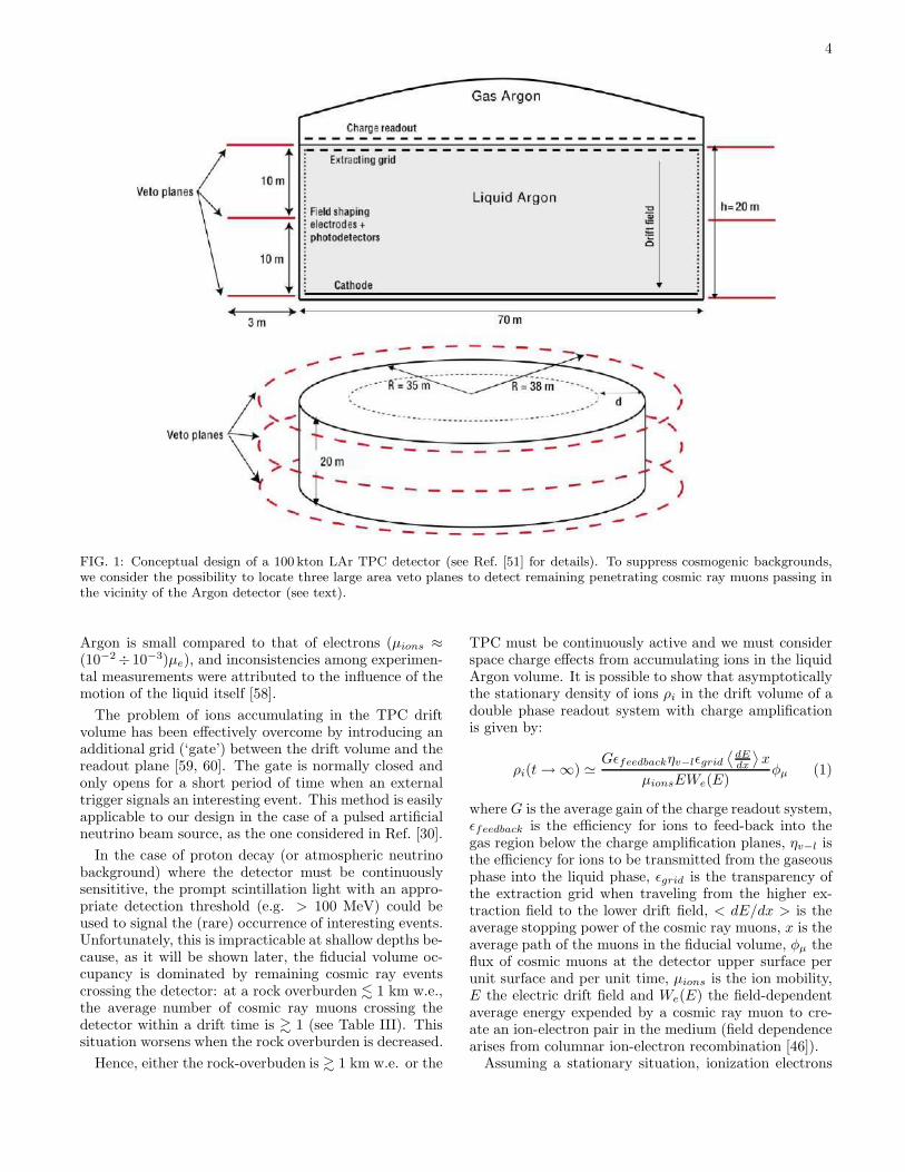
4
FIG. 1: Conceptual design of a 100 kton LAr TPC detector (see Ref. [51] for details). To suppress cosmogenic backgrounds,we consider the possibility to locate three large area veto planes to detect remaining penetrating cosmic ray muons passing inthe vicinity of the Argon detector (see text).
Argon is small compared to that of electrons (µions ≈(10−2÷ 10−3)µe), and inconsistencies among experimen-tal measurements were attributed to the influence of themotion of the liquid itself [58].
The problem of ions accumulating in the TPC driftvolume has been effectively overcome by introducing anadditional grid (‘gate’) between the drift volume and thereadout plane [59, 60]. The gate is normally closed andonly opens for a short period of time when an externaltrigger signals an interesting event. This method is easilyapplicable to our design in the case of a pulsed artificialneutrino beam source, as the one considered in Ref. [30].
In the case of proton decay (or atmospheric neutrinobackground) where the detector must be continuouslysensititive, the prompt scintillation light with an appro-priate detection threshold (e.g. > 100 MeV) could beused to signal the (rare) occurrence of interesting events.Unfortunately, this is impracticable at shallow depths be-cause, as it will be shown later, the fiducial volume oc-cupancy is dominated by remaining cosmic ray eventscrossing the detector: at a rock overburden . 1 km w.e.,the average number of cosmic ray muons crossing thedetector within a drift time is & 1 (see Table III). Thissituation worsens when the rock overburden is decreased.
Hence, either the rock-overbuden is & 1 km w.e. or the
TPC must be continuously active and we must considerspace charge effects from accumulating ions in the liquidArgon volume. It is possible to show that asymptoticallythe stationary density of ions ρi in the drift volume of adouble phase readout system with charge amplificationis given by:
ρi(t → ∞) ≃Gǫfeedbackηv−lǫgrid
⟨
dEdx
⟩
x
µionsEWe(E)φµ (1)
where G is the average gain of the charge readout system,ǫfeedback is the efficiency for ions to feed-back into thegas region below the charge amplification planes, ηv−l isthe efficiency for ions to be transmitted from the gaseousphase into the liquid phase, ǫgrid is the transparency ofthe extraction grid when traveling from the higher ex-traction field to the lower drift field, < dE/dx > is theaverage stopping power of the cosmic ray muons, x is theaverage path of the muons in the fiducial volume, φµ theflux of cosmic muons at the detector upper surface perunit surface and per unit time, µions is the ion mobility,E the electric drift field and We(E) the field-dependentaverage energy expended by a cosmic ray muon to cre-ate an ion-electron pair in the medium (field dependencearises from columnar ion-electron recombination [46]).
Assuming a stationary situation, ionization electrons
5
will drift in a medium homogeneously filled with theabove calculated density of ions. The resulting free elec-tron lifetime can be estimated as τe = 1/ (kr(E)ρi) wherekr is the electron-ion recombination rate (which dependson the electric field).
We note that ǫfeedback ≪ 1, because of electron diffu-sion in the amplification gap, as a result of which ionscan follow field lines ending up on the electrodes of theamplification system rather than on the external fieldlines; this is particularly true for the devices with multi-ple stages that we operate [61]. In addition, ǫgrid . 0.3since the extraction field is typ. 3 kV/cm and the driftfield is typ. 1 kV/cm.
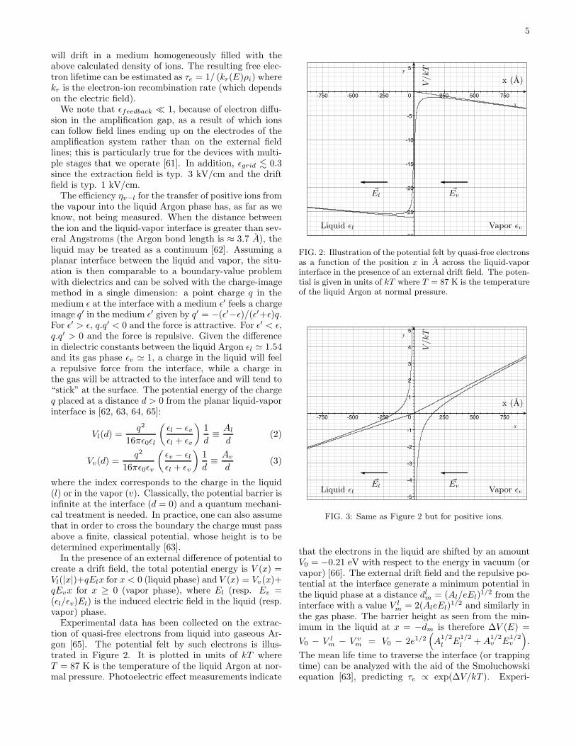
The efficiency ηv−l for the transfer of positive ions fromthe vapour into the liquid Argon phase has, as far as weknow, not being measured. When the distance betweenthe ion and the liquid-vapor interface is greater than sev-eral Angstroms (the Argon bond length is ≈ 3.7 A), theliquid may be treated as a continuum [62]. Assuming aplanar interface between the liquid and vapor, the situ-ation is then comparable to a boundary-value problemwith dielectrics and can be solved with the charge-imagemethod in a single dimension: a point charge q in themedium ǫ at the interface with a medium ǫ′ feels a chargeimage q′ in the medium ǫ′ given by q′ = −(ǫ′−ǫ)/(ǫ′+ǫ)q.For ǫ′ > ǫ, q.q′ < 0 and the force is attractive. For ǫ′ < ǫ,q.q′ > 0 and the force is repulsive. Given the differencein dielectric constants between the liquid Argon ǫl ≃ 1.54and its gas phase ǫv ≃ 1, a charge in the liquid will feela repulsive force from the interface, while a charge inthe gas will be attracted to the interface and will tend to“stick” at the surface. The potential energy of the chargeq placed at a distance d > 0 from the planar liquid-vaporinterface is [62, 63, 64, 65]:
Vl(d) =q2
16πǫ0ǫl
(
ǫl − ǫv
ǫl + ǫv
)
1
d≡
Al
d(2)
Vv(d) =q2
16πǫ0ǫv
(
ǫv − ǫl
ǫl + ǫv
)
1
d≡
Av
d(3)
where the index corresponds to the charge in the liquid(l) or in the vapor (v). Classically, the potential barrier isinfinite at the interface (d = 0) and a quantum mechani-cal treatment is needed. In practice, one can also assumethat in order to cross the boundary the charge must passabove a finite, classical potential, whose height is to bedetermined experimentally [63].
In the presence of an external difference of potential tocreate a drift field, the total potential energy is V (x) =Vl(|x|)+qElx for x < 0 (liquid phase) and V (x) = Vv(x)+qEvx for x ≥ 0 (vapor phase), where El (resp. Ev =(ǫl/ǫv)El) is the induced electric field in the liquid (resp.vapor) phase.
Experimental data has been collected on the extrac-tion of quasi-free electrons from liquid into gaseous Ar-gon [65]. The potential felt by such electrons is illus-trated in Figure 2. It is plotted in units of kT whereT = 87 K is the temperature of the liquid Argon at nor-mal pressure. Photoelectric effect measurements indicate
-750 -500 -250 0 250 500 750
-30
-25
-20
-15
-10
-5
5
x (A)V/kT
Liquid ǫl Vapor ǫv
�~El
�~Ev
FIG. 2: Illustration of the potential felt by quasi-free electronsas a function of the position x in A across the liquid-vaporinterface in the presence of an external drift field. The poten-tial is given in units of kT where T = 87 K is the temperatureof the liquid Argon at normal pressure.
-750 -500 -250 0 250 500 750
-5
-4
-3
-2
-1
1
2
3
4
5
x (A)
V/kT
Liquid ǫl Vapor ǫv
�~El
�~Ev
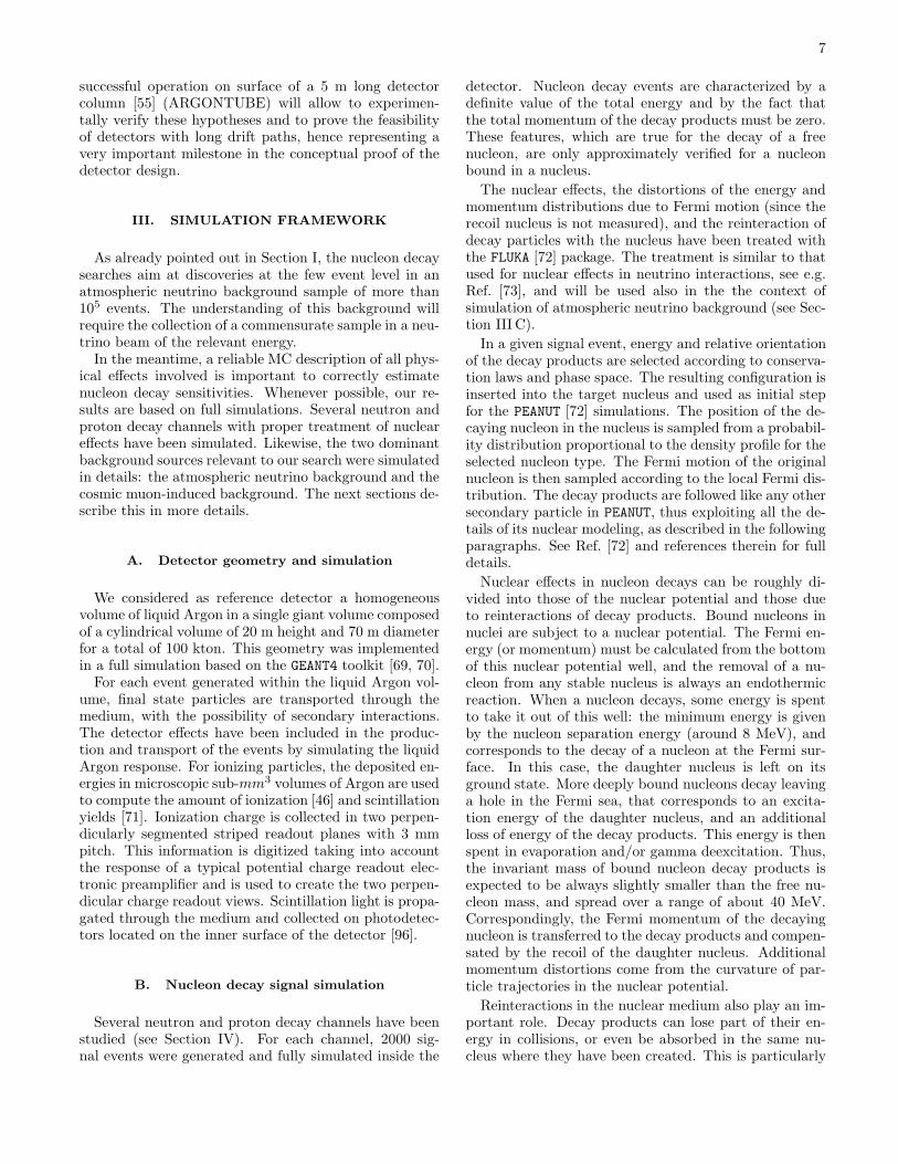
FIG. 3: Same as Figure 2 but for positive ions.
that the electrons in the liquid are shifted by an amountV0 = −0.21 eV with respect to the energy in vacuum (orvapor) [66]. The external drift field and the repulsive po-tential at the interface generate a minimum potential inthe liquid phase at a distance dl
m = (Al/eEl)1/2 from the
interface with a value V lm = 2(AleEl)
1/2 and similarly inthe gas phase. The barrier height as seen from the min-imum in the liquid at x = −dm is therefore ∆V (E) =
V0 − V lm − V v
m = V0 − 2e1/2
(
A1/2
l E1/2
l + A1/2v E
1/2v
)
.
The mean life time to traverse the interface (or trappingtime) can be analyzed with the aid of the Smoluchowskiequation [63], predicting τe ∝ exp(∆V/kT ). Experi-

6
mental data however indicate that the above-calculatedthermionic current is increased by a rate ∝ µE/λ1 whereλ1 is the momentum-transfer mean free path, as pre-dicted by the Shottky model of electric field enhancedthermionic emission [65], giving τe ∝ exp (∆V/kT ) /E,with a stronger influence of the drift field.
In the case of the ions, the potential for a positivecharge is illustrated in Figure 3. The ion is attracted verynear the interface and must tunnel through the repulsivepotential existing on the liquid side of the interface in or-der to enter the liquid. A semi-classical approach is notjustified. The transport of T l positive ions from xenonvapor to liquid was successfully reported with a ≃ 10%efficiency in Ref. [67]. There appears to be a differencein the behavior of positive ions between the liquid-to-gasand gas-to-liquid transition [62]. While electrons couldtraverse the liquid-vapor interface the positive ions couldnot. This is consistent with the fact that the ion mobilityin the liquid is too small to allow for the external field toenhance the thermionic emission. However, the transmis-sion of negative ions through the liquid-vapor interface ofneon has been observed with trapping time of the order of10–100 s at fields of 0.1–1 kV/cm [64]. This is explainedby the type of clustering around the different species ofparticles. If a sort of bubble surrounds negative chargesthen the breaking of the bubble at the surface could letthem escape. In conclusion, the phenomenon of transferof the ions through the interface is expected to be rathercomplicated, not well understood and has not been mea-sured. In the case relevant to this paper, it is likely thatsome fraction of the Argon ions will cross into the liquid,although possibly with long trapping times, and experi-mental studies are needed to assess how much. For safety,we will conservatively assume full transmission of Argonions across the interface.
We note that competing with the process of transferfrom the gas to liquid is the radial drifting of ions at thesurface of the liquid-gas interface towards the edges ofthe volume, until they reach the field shaping electrodes.There they are neutralized by the external power supply.
We now compute the free electron lifetime due to therecombination with the accumulating ions. In the worst
case considered in this paper corresponding to the “un-der the hill location” (see Table III), we contemplate≃ 1000 muons crossing the detector per second. We con-servatively assume that each of these muons will verti-cally cross the entire drift region, hence x ≃ h = 20 m,that the average charge gain is G ≃ 150 (see Ref. [51]),very conservatively that ǫfeedback ≃ 0.5, ηv−l ≃ 1 al-though we expect this to be a pessimistic assumption,ǫgrid ≃ 0.3 and that the ion mobility in the range(0.2 ÷ 1) × 10−3 cm2/V/s [58]. These assumptions yieldρi ≃ (0.7 ÷ 3.7) × 105 ions/cm3. Assuming a recombi-nation rate kr = 1 × 10⁻⁴ cm3/s, consistent with mea-surements at the relevant electric drift fields [68], impliesthat the electron lifetime due to ion accumulation in themedium is τe > 30÷140 ms, to be compared with a max-imum electron drift time ∼ 10 ms. We stress that actual
FIG. 4: Drift field map with an unrealistic ion charge densityof 2 × 10⁵ ions/cm3=4 × 10−8 C/m3 (see text). The fielddistortion is ±30%. Dark blue corresponds to 0.5 kV/cm andred to 1.5 kV/cm.
FIG. 5: Same as Figure 4 with a ion charge density of 2 ×
104 ions/cm3=4 × 10−9 C/m3. The field distortion is ±3%.
values of ǫfeedback and ηv−l are expected to increase thesevalues even further. We conclude that in all configura-tions considered in this paper, charge attenuation due torecombination with ions in the medium is expected to benegligible compared to other charge attenuating effects,like e.g. attachment to electronegative impurities in theArgon [45].
We now turn to the drift field map distortions. Theresults of numerical simulations for the electric field as-suming a homogeneous positive charge density distribu-tion in the liquid Argon fiducial volume of resp. ρi =2×10⁵ ions/cm3 and 2×10⁴ ions/cm3 and the contribu-tions of ions directly produced in the ionization processare shown in resp. Figures 4 and 5. The cathode is placedat −2 MV and the volume is enclosed by field shapingelectrodes. Dark blue corresponds to 0.5 kV/cm and redto 1.5 kV/cm. With an unrealistic ion charge density of2×105 ions/cm3=4×10−8 C/m3, the field is distorted by±30%. As expected, for a more realistic charge densityof 2× 10⁴ ions/cm3, field variations are ±3%. The effectof ions directly produced in the ionization is negligible.
We point out in this context that the realization and
7
successful operation on surface of a 5 m long detectorcolumn [55] (ARGONTUBE) will allow to experimen-tally verify these hypotheses and to prove the feasibilityof detectors with long drift paths, hence representing avery important milestone in the conceptual proof of thedetector design.
III. SIMULATION FRAMEWORK
As already pointed out in Section I, the nucleon decaysearches aim at discoveries at the few event level in anatmospheric neutrino background sample of more than105 events. The understanding of this background willrequire the collection of a commensurate sample in a neu-trino beam of the relevant energy.
In the meantime, a reliable MC description of all phys-ical effects involved is important to correctly estimatenucleon decay sensitivities. Whenever possible, our re-sults are based on full simulations. Several neutron andproton decay channels with proper treatment of nucleareffects have been simulated. Likewise, the two dominantbackground sources relevant to our search were simulatedin details: the atmospheric neutrino background and thecosmic muon-induced background. The next sections de-scribe this in more details.
A. Detector geometry and simulation
We considered as reference detector a homogeneousvolume of liquid Argon in a single giant volume composedof a cylindrical volume of 20 m height and 70 m diameterfor a total of 100 kton. This geometry was implementedin a full simulation based on the GEANT4 toolkit [69, 70].
For each event generated within the liquid Argon vol-ume, final state particles are transported through themedium, with the possibility of secondary interactions.The detector effects have been included in the produc-tion and transport of the events by simulating the liquidArgon response. For ionizing particles, the deposited en-ergies in microscopic sub-mm3 volumes of Argon are usedto compute the amount of ionization [46] and scintillationyields [71]. Ionization charge is collected in two perpen-dicularly segmented striped readout planes with 3 mmpitch. This information is digitized taking into accountthe response of a typical potential charge readout elec-tronic preamplifier and is used to create the two perpen-dicular charge readout views. Scintillation light is propa-gated through the medium and collected on photodetec-tors located on the inner surface of the detector [96].
B. Nucleon decay signal simulation
Several neutron and proton decay channels have beenstudied (see Section IV). For each channel, 2000 sig-nal events were generated and fully simulated inside the
detector. Nucleon decay events are characterized by adefinite value of the total energy and by the fact thatthe total momentum of the decay products must be zero.These features, which are true for the decay of a freenucleon, are only approximately verified for a nucleonbound in a nucleus.
The nuclear effects, the distortions of the energy andmomentum distributions due to Fermi motion (since therecoil nucleus is not measured), and the reinteraction ofdecay particles with the nucleus have been treated withthe FLUKA [72] package. The treatment is similar to thatused for nuclear effects in neutrino interactions, see e.g.Ref. [73], and will be used also in the the context ofsimulation of atmospheric neutrino background (see Sec-tion III C).
In a given signal event, energy and relative orientationof the decay products are selected according to conserva-tion laws and phase space. The resulting configuration isinserted into the target nucleus and used as initial stepfor the PEANUT [72] simulations. The position of the de-caying nucleon in the nucleus is sampled from a probabil-ity distribution proportional to the density profile for theselected nucleon type. The Fermi motion of the originalnucleon is then sampled according to the local Fermi dis-tribution. The decay products are followed like any othersecondary particle in PEANUT, thus exploiting all the de-tails of its nuclear modeling, as described in the followingparagraphs. See Ref. [72] and references therein for fulldetails.
Nuclear effects in nucleon decays can be roughly di-vided into those of the nuclear potential and those dueto reinteractions of decay products. Bound nucleons innuclei are subject to a nuclear potential. The Fermi en-ergy (or momentum) must be calculated from the bottomof this nuclear potential well, and the removal of a nu-cleon from any stable nucleus is always an endothermicreaction. When a nucleon decays, some energy is spentto take it out of this well: the minimum energy is givenby the nucleon separation energy (around 8 MeV), andcorresponds to the decay of a nucleon at the Fermi sur-face. In this case, the daughter nucleus is left on itsground state. More deeply bound nucleons decay leavinga hole in the Fermi sea, that corresponds to an excita-tion energy of the daughter nucleus, and an additionalloss of energy of the decay products. This energy is thenspent in evaporation and/or gamma deexcitation. Thus,the invariant mass of bound nucleon decay products isexpected to be always slightly smaller than the free nu-cleon mass, and spread over a range of about 40 MeV.Correspondingly, the Fermi momentum of the decayingnucleon is transferred to the decay products and compen-sated by the recoil of the daughter nucleus. Additionalmomentum distortions come from the curvature of par-ticle trajectories in the nuclear potential.
Reinteractions in the nuclear medium also play an im-portant role. Decay products can lose part of their en-ergy in collisions, or even be absorbed in the same nu-cleus where they have been created. This is particularly
8
true for pions, that have an important absorption crosssection on nucleon pairs, while kaons have smaller inter-action probability.
Nucleon-nucleon total cross sections, both elastic andinelastic, used in FLUKA are taken from available exper-imental data. Elastic scattering is explicitly performedaccording to the experimental differential cross sections.Pion induced reactions are more complex, mainly becauseof two- and three-nucleon absorption processes. Abovethe pion production threshold, the inelastic interactionsare handled by the resonance model. Other pion-nucleoninteractions proceed through the non-resonant channeland the p-wave channel with the formation of a ∆ res-onance, with modified resonance parameters taking intoaccount nuclear effects.
The conservation of strangeness leads to very differentinteractions of the K+, K0 and K−, K0 with nucleonsat low energies. K− have a large cross section for hy-peron production, with the Σπ and Λπ channels alwaysopen. A detailed treatment of K+ interactions has beendeveloped in PEANUT, whereby the K+ nucleon systemis described by phase shift analysis. This treatment wasused in the present analysis, where it was very relevantfor the nucleon decays involving kaons. In particular, K+
involved in proton decays are below 700 MeV/c, wherethe inelastic contributions are very small and elastic scat-tering does not affect strongly the efficiency. Charge ex-change K+ + n → K0 + p can lead to a loss of efficiency.In the simulations of p → νK+ decays, less than 4% ofthe kaons were lost due to nuclear processes (see Sec-tion IV). In comparison, in the simulated p → e+π0
decays, the neutral pion is absorbed within the nucleuswith a probability of ≃ 50 %.
In the treatment of nuclear reinteractions, the cross-sections are modified to avoid too short mean free pathsin nuclear matter by taking into account Pauli blocking,antisymmetrization of fermions, hard-core effects and for-mation zone or coherence length for non-fragmenting pro-cesses. The intra-nuclear cascade step goes on until allnucleons are below 50 MeV and is followed by a pre-equilibrium emission phase in which additional nucleonscan be emitted.
Many benchmarks showing good agreement betweenPEANUT results and nuclear reaction data can be found inthe main Ref. [72].
C. Atmospheric neutrino background
The atmospheric neutrino flux has been computed byseveral groups. We take results from the FLUKA group [74]and the HKKM 2004 [75] (Honda) models. The FLUKA
model is estimated to have a 7% uncertainty for the pri-mary spectrum, 15% for the interaction model, 1% for theatmosphere profile, 2% for the geomagnetic field and atotal 17% uncertainty. The HKKM model has about 10%uncertainty when the neutrino energy is below 10 GeV,but the uncertainties are still large when the neutrino
energy is above 10 GeV, due to the uncertainties of theprimary cosmic ray flux and the interaction model above100 GeV.
The neutrino-cross sections and the generation of neu-trino interactions are based on the NUX [76] code. Thiscode can be used in fixed target mode for incoming neu-trino energies from ≃ 20 MeV up to 10 TeV. NUX cangenerate neutral current (NC) and charged current (CC)processes, and includes all basic processes to properlydescribe neutrino interactions in different kinematicalregimes. In particular, a distinction is made among thefollowing processes: quasi-elastic process (QE), inelasticprocess (DIS) [97] and charm production. These pro-cesses are appropriately matched to reproduce the totalinclusive and existing exclusive experimental data to thebest of current experimental knowledge. The mass of theoutgoing lepton and of the target nucleon are taken intoaccount in the kinematics and in the differential cross-section. In order to take into account nuclear effects, aninterface with FLUKA was implemented, yielding the so-called NUX-FLUKA generator: a primary nucleon is cho-sen according to the density profile for the selected nu-cleon type and the Fermi motion of the original nucleonis sampled according to the local Fermi distribution, justas in the case of the nucleon decay simulation (see Sec-tion III B). A neutrino interaction is generated and thefinal state intra-nuclear cascade is taken into account bypropagating final state particles through the nucleus withPEANUT.
The NUX-FLUKA model was benchmarked with the dataof the NOMAD [77] experiment at high neutrino ener-gies (> 5 GeV), and was compared at low neutrino en-ergies (< 5 GeV) with other available generators likeNUANCE [78] and was shown to give very similar par-ticle multiplicities and distributions [79]. The produc-tion of strange particle at high energy was studied inNOMAD [80] and found to be properly described aftertuning of the JETSET [81] fragmentation parameters. Atlow energy, the production of kaons primarily proceedsthrough the decay chain of baryon resonances. In thisregime, the yield of kaon is very strongly suppressed com-pared to that of pions.
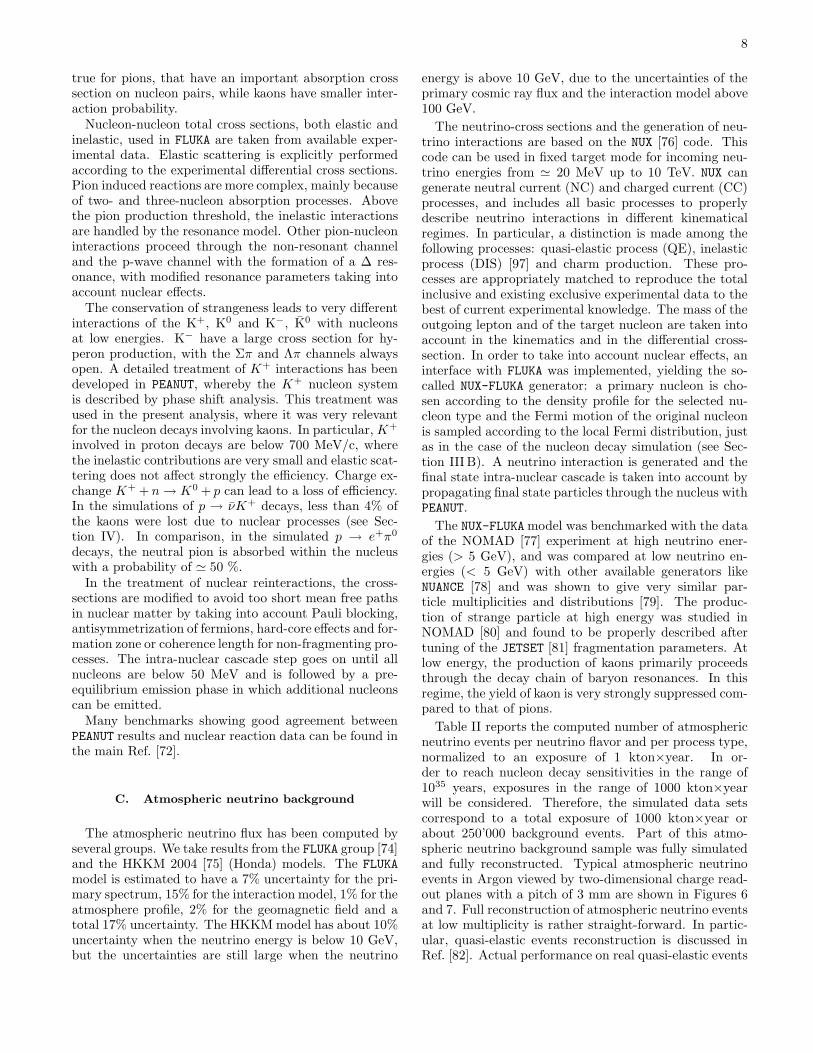
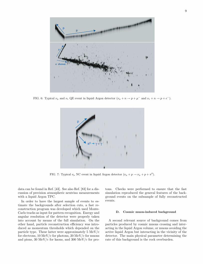
Table II reports the computed number of atmosphericneutrino events per neutrino flavor and per process type,normalized to an exposure of 1 kton×year. In or-der to reach nucleon decay sensitivities in the range of1035 years, exposures in the range of 1000 kton×yearwill be considered. Therefore, the simulated data setscorrespond to a total exposure of 1000 kton×year orabout 250’000 background events. Part of this atmo-spheric neutrino background sample was fully simulatedand fully reconstructed. Typical atmospheric neutrinoevents in Argon viewed by two-dimensional charge read-out planes with a pitch of 3 mm are shown in Figures 6and 7. Full reconstruction of atmospheric neutrino eventsat low multiplicity is rather straight-forward. In partic-ular, quasi-elastic events reconstruction is discussed inRef. [82]. Actual performance on real quasi-elastic events
9
FIG. 6: Typical νµ and νe QE event in liquid Argon detector (νµ + n → p + µ− and νe + n → p + e−).
FIG. 7: Typical νµ NC event in liquid Argon detector (νµ + p → νµ + p + π0).
data can be found in Ref. [43]. See also Ref. [83] for a dis-cussion of precision atmospheric neutrino measurementswith a liquid Argon TPC.
In order to have the largest sample of events to es-timate the backgrounds after selection cuts, a fast re-construction program was developed which used Monte-Carlo tracks as input for pattern recognition. Energy andangular resolution of the detector were properly takeninto account by means of the full simulation. On theother hand, particle reconstruction efficiency was intro-duced as momentum thresholds which depended on theparticle type. These latter were approximately 5 MeV/cfor electrons, 10 MeV/c for photons, 20 MeV/c for muonsand pions, 30 MeV/c for kaons, and 300 MeV/c for pro-
tons. Checks were performed to ensure that the fastsimulation reproduced the general features of the back-ground events on the subsample of fully reconstructedevents.
D. Cosmic muon-induced background
A second relevant source of background comes fromparticles produced by cosmic muons crossing and inter-acting in the liquid Argon volume, or muons avoiding theactive liquid Argon but interacting in the vicinity of thedetector. The main physical parameter determining therate of this background is the rock overburden.
10
Atmospheric νe CC (evts/kt/year) νe CC (evts/kt/year)
Flux Model DIS QE Tot DIS QE Tot
FLUKA 22.9 49.0 71.9 7.2 8.4 15.6
(E(GeV)) (2.83) (0.62) (3.12) (0.79)
HKKM 22.7 45.6 68.3 7.2 7.8 15.0
(E(GeV)) (3.01) (0.64) (3.42) (0.85)
Atmospheric νµ CC (evts/kt/year) νµ CC (evts/kt/year)
Flux Model DIS QE Tot DIS QE Tot
FLUKA 42.0 80.1 122.1 15.3 18.5 33.8
(E(GeV)) (4.53) (0.72) (4.89) (0.90)
HKKM 43.3 74.0 117.3 15.8 17.4 33.2
(E(GeV)) (4.78) (0.77) (5.19) (0.98)
Atmospheric ν NC (inelastic) ν NC (inelastic)
Flux Model (evts/kt/year) (evts/kt/year)
FLUKA 23.2 9.0
(E(GeV)) (3.73) (4.08)
HKKM 23.4 9.1
(E(GeV)) (3.97) (4.40)
TABLE II: QE, DIS event rates per kton per year, and averageenergies for FLUKA 2002 and HKKM 2004 flux models andNUX neutrino cross-sections. In order to reach nucleon decaysensitivities in the range of 1035 years, exposure in the rangeof 1000 kton× year will be considered.
The cosmic muon intensity as a function of under-ground depth is obtained from Crouch’s [84] fit to theworld data and further updated by the Particle DataGroup [85]. This parameterization agrees to better than6% with the most recent MACRO measurements [86] atGran Sasso. However, it cannot be applied to the case ofa shallow depth detector. For this purpose, we generatedcosmic µ+’s and µ−’s according to double differential dis-tributions found in Ref. [85] on a large hemisphere at thesurface of the Earth and transported them through rock.In the simulation, all physical processes were taken inaccount, including multiple scattering and energy losses.
We aimed at giving here the general trend and themagnitude of the background, while the precise deter-mination of the muon induced background will dependon many site-specific features: (a) rock chemical com-position, (b) exact distribution of rock overburden (c)detector configuration, cryostat, distance to rock, ...
Many relevant processes depend on rock chemical com-position. For example, the neutron production per unitof rock mass depends on the average atomic number.The expected dependence according to Ref. [87] is dN ∝A0.76, i.e., that means a difference of about 25% in neu-tron production going from standard rock (〈A〉 = 22) tothe salt rock (〈A〉 = 30). Particle propagation throughrock of secondary particles produced in muon interac-tions is also influenced by chemical composition, in firstapproximation with the same behaviour as the nuclearinteraction length.
The angular distribution of muons underground de-pends on the actual distribution of rock overburden. Ifthe Earth surface above the site is approximately flat,the muon intensity at an angle θ is given by the verticalintensity calculated at a depth h′ = h/ cos θ multipliedby a factor 1/ cos θ from the production probability inthe atmosphere [84]. If, however, the detector is locatedin a mountain or under a hill, the muon intensity is de-termined by the actual rock overburden along any givendirection. The most important effect is a different to-tal muon intensity with respect to the flat surface case,and a secondary effect is the difference in veto efficiency(see Section III E) due to the different muon direction-ality. Indeed, the deeper the rock overburden, the morevertical the surviving muons.
Since, as we will show in the following paragraphs, sec-ondary particles that enter the detector are produced inthe first one or two meters of material around it, theactual material distribution/composition of the LAr con-tainer may affect the background and the veto conditions.This effect has been neglected at this stage and we haveassumed rock composition around the fiducial liquid Ar-gon volume.
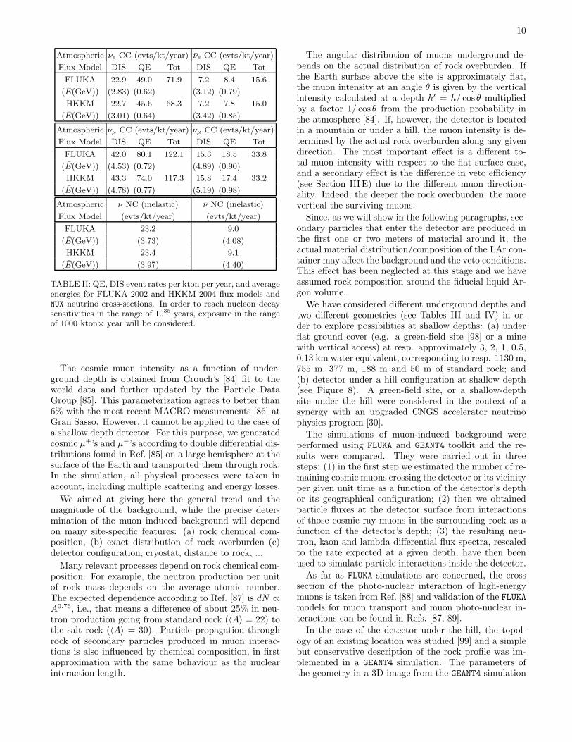
We have considered different underground depths andtwo different geometries (see Tables III and IV) in or-der to explore possibilities at shallow depths: (a) underflat ground cover (e.g. a green-field site [98] or a minewith vertical access) at resp. approximately 3, 2, 1, 0.5,0.13 km water equivalent, corresponding to resp. 1130 m,755 m, 377 m, 188 m and 50 m of standard rock; and(b) detector under a hill configuration at shallow depth(see Figure 8). A green-field site, or a shallow-depthsite under the hill were considered in the context of asynergy with an upgraded CNGS accelerator neutrinophysics program [30].
The simulations of muon-induced background wereperformed using FLUKA and GEANT4 toolkit and the re-sults were compared. They were carried out in threesteps: (1) in the first step we estimated the number of re-maining cosmic muons crossing the detector or its vicinityper given unit time as a function of the detector’s depthor its geographical configuration; (2) then we obtainedparticle fluxes at the detector surface from interactionsof those cosmic ray muons in the surrounding rock as afunction of the detector’s depth; (3) the resulting neu-tron, kaon and lambda differential flux spectra, rescaledto the rate expected at a given depth, have then beenused to simulate particle interactions inside the detector.
As far as FLUKA simulations are concerned, the crosssection of the photo-nuclear interaction of high-energymuons is taken from Ref. [88] and validation of the FLUKAmodels for muon transport and muon photo-nuclear in-teractions can be found in Refs. [87, 89].
In the case of the detector under the hill, the topol-ogy of an existing location was studied [99] and a simplebut conservative description of the rock profile was im-plemented in a GEANT4 simulation. The parameters ofthe geometry in a 3D image from the GEANT4 simulation
11
Depth Code All muons Eµ > 1 GeV Effective mass
Water equiv. Standard rock Particles/s Particles/10 ms Particles/s Particles/10 ms
Surface detector FLUKA 1700000 17000 1300000 13000 –
≃ 0.13 km w.e. 50 m FLUKA 11000 110 10000 100 50 kton
≃ 0.5 km w.e. 188 m FLUKA 330 3.3 320 3.2 98 kton
200 m GEANT4 – – 420 4.2 98 kton
≃ 1 km w.e. 377 m FLUKA 66 0.66 65 0.65 100 kton
≃ 2 km w.e. 755 m FLUKA 6.2 0.062 6.2 0.062 100 kton
≃ 3 km w.e. 1.13 km FLUKA 0.96 0.01 0.96 0.01 100 kton
Under the hill (see Figure 8) GEANT4 – – 960 9.6 96 kton
TABLE III: Computed average number of muons entering the detector per unit time for various geographical configurations.The effective mass corresponds to the mass of Argon that can be used when, in both 2D readout views, a slice of size 10 cmaround each crossing muon is vetoed.
FIG. 8: Under the hill detector configuration. The rock overburden at the vertical of the detector is 200 m and the shortestoverburden is 158 m. This geometry has been implemented in a full simulation based on GEANT4.
are shown in Figure 8. The assumed rock overburdenat the vertical of the detector is 200 m and the shortestoverburden is 158 m. Cosmic ray muons were simulatedon a circular area with a radius of 400 m at a height of200 m above the detector which corresponds to the topof the hill.
The first concern is the average number of muons en-tering the detector within a time interval of 10 ms, whichcorresponds to the assumed time for a full drift over 20 mat a field of 1kV/cm [51]. The results are summarized in
Table III.
The results from FLUKA and GEANT4 were comparedconsidering a flat Earth surface profile and a detector at≃ 200 m underground: muon rates agreed within a fac-tor of ∼ 1.3. At depths deeper than about 1 km w.e.the rate of crossing muons is less than 1 per 10 ms. Shal-lower depths e.g. at rock overburdens less than 200 m aredisfavored because of detector occupancy (at 50 m rockoverburden the average rate of muons with more than1 GeV crossing in 10 ms is 100). If we assumed that a
12
slice of size 10 cm in a 2D readout view of the detectoraround each crossing muon cannot be used for physics,then the rate at resp. 50 m, 188 m would correspond toan available Argon mass of resp. 50 kton, 98 kton. Wedo not at this stage consider surface operation, as pro-posed in Ref. [53]. For the under the hill configuration,more than a million muons, corresponding to 156 driftsof 10 ms, were simulated and it was found that on aver-age 9.6 muons enter the Argon volume in 10 ms. Thisis a factor ∼ 2 higher than at an equivalent depth underflat surface, which is still very tolerable.
We now focus on the second step where the rate andenergy spectrum of remaining cosmic ray muons at theunderground locations is used to study the number ofparticles entering the detector. We assume that events inwhich the parent muon enters (before or after the photo-nuclear interaction) the active LAr volume can be dis-carded thanks a veto based on the liquid Argon imag-ing. This leads us to restrict the background sourcesto neutral hadrons and, in particular, to neutrons, neu-
tral kaons and lambdas, produced either directly in muonphoto-nuclear interactions or as secondary products inhadronic showers in the materials (e.g. rock) surround-ing the detector. We have so far conservatively neglectedcorrelations between neutral hadrons penetrating insidethe LAr in conjunction with (visible) charged hadrons.
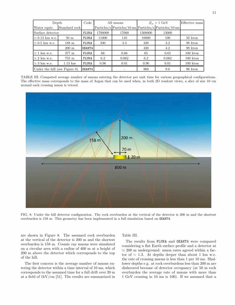
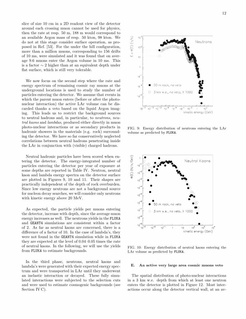
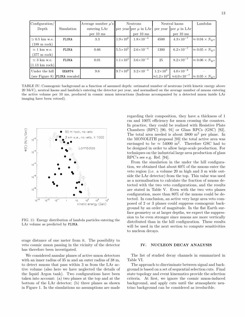
Neutral hadronic particles have been scored when en-tering the detector. The energy-integrated number ofparticles entering the detector per year of exposure atsome depths are reported in Table IV. Neutron, neutralkaon and lambda energy spectra on the detector surfaceare plotted in Figures 9, 10 and 11. Their shapes arepractically independent of the depth of rock overburden.Since low energy neutrons are not a background sourcefor nucleon decay searches, we will consider only neutronswith kinetic energy above 20 MeV.
As expected, the particle yields per muons enteringthe detector, increase with depth, since the average muonenergy increases as well. The neutrons yields in the FLUKAand GEANT4 simulations are consistent within a factorof 2. As far as neutral kaons are concerned, there is adifference of a factor of 10. In the case of lambda’s, theywere not found in the GEANT4 simulation while in FLUKA
they are expected at the level of 0.04–0.05 times the rateof neutral kaons. In the following, we will use the yieldsfrom FLUKA to estimate backgrounds.
In the third phase, neutrons, neutral kaons andlambda’s were generated with their expected energy spec-trum and were transported in LAr until they underwentan inelastic interaction or decayed. These fully simu-lated interactions were subjected to the selection cutsand were used to estimate cosmogenic backgrounds (seeSection IVC).
FIG. 9: Energy distribution of neutrons entering the LArvolume as predicted by FLUKA.
FIG. 10: Energy distribution of neutral kaons entering theLAr volume as predicted by FLUKA.
E. An active very large area cosmic muons veto
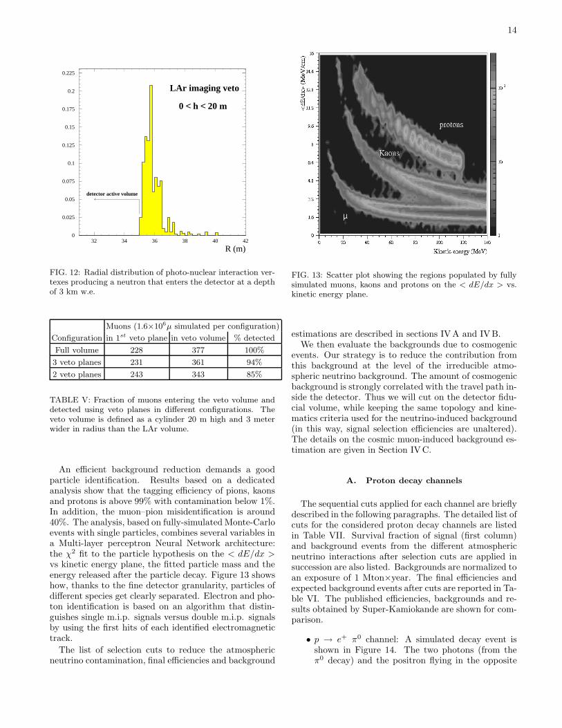
The spatial distribution of photo-nuclear interactionsin a 3 km w.e. depth from which at least one neutronenters the detector is plotted in Figure 12. Most inter-actions occur along the detector vertical wall, at an av-
13
Configuration/ Average number µ’s Neutrons Neutral kaons Lambdas
Depth Simulation entering LAr per year per µ in LAr per year per µ in LAr
per 10 ms per 10 ms per 10 ms
≃ 0.5 km w.e. FLUKA 3.3 1.9×10⁶ 1.8×10⁻⁴ 4500 4.3×10⁻⁷≈ 0.04 × NK0
(188 m rock)
≃ 1 km w.e. FLUKA 0.66 5.5×10⁵ 2.6×10⁻⁴ 1300 6.2×10⁻⁷≈ 0.05 × NK0
(377 m rock)
≃ 3 km w.e. FLUKA 0.01 1.1×10⁴ 3.6×10⁻⁴ 25 8.2×10⁻⁷≈ 0.06 × NK0
(1.13 km rock)
Under the hill GEANT4 9.6 9.7×10⁶ 3.2×10⁻⁴ 1.2×10³ 4.0×10⁻⁸ –
(see Figure 8) FLUKA rescaled ≈1.2×10⁴≈4.0×10⁻⁷
≈ 0.05 × NK0
TABLE IV: Cosmogenic background as a function of assumed depth: estimated number of neutrons (with kinetic energy above20 MeV), neutral kaons and lambda’s entering the detector per year, and normalised on the average number of muons enteringthe active volume per 10 ms, produced in cosmic muon interactions (hadrons accompanied by a detected muon inside LArimaging have been vetoed).
FIG. 11: Energy distribution of lambda particles entering theLAr volume as predicted by FLUKA.
erage distance of one meter from it. The possibility toveto cosmic muon passing in the vicinity of the detectorhas therefore been investigated.
We considered annular planes of active muon detectorswith an inner radius of 35 m and an outer radius of 38 m,to detect muons that pass within 3 m from the LAr ac-tive volume (also here we have neglected the details ofthe liquid Argon tank). Two configurations have beentaken into account: (a) two planes at the top and at thebottom of the LAr detector; (b) three planes as shownin Figure 1. In the simulations no assumptions are made
regarding their composition, they have a thickness of 1cm and 100% efficiency for muon crossing the counters.In practice, they could be realized with Resistive PlateChambers (RPC) [90, 91] or Glass RPCs (GSC) [92].The total area needed is about 3800 m2 per plane. Inthe MONOLITH proposal [93] the total active area wasenvisaged to be ≈ 54000 m2. Therefore GSC had tobe designed in order to allow large-scale production. Fortechniques on the industrial large area production of glassRPC’s see e.g. Ref. [94].
From the simulation in the under the hill configura-tion, we obtained that about 60% of the muons enter theveto region (i.e. a volume 20 m high and 3 m wide out-side the LAr detector) from the top. This value was usedas a normalisation to calculate the fraction of muons de-tected with the two veto configurations, and the resultsare stated in Table V. Even with the two veto planesconfiguration, more than 80% of the muons could be de-tected. In conclusion, an active very large area veto com-posed of 2 or 3 planes could suppress cosmogenic back-ground by an order of magnitude. In the flat Earth sur-face geometry or at larger depths, we expect the suppres-sion to be even stronger since muons are more verticallydistributed than in the hill configuration. These resultswill be used in the next section to compute sensitivitiesto nucleon decays.
IV. NUCLEON DECAY ANALYSIS
The list of studied decay channels in summarized inTable VI.
The approach to discriminate between signal and back-ground is based on a set of sequential selection cuts. Finalstate topology and event kinematics provide the selectioncriteria. At first, we ignore the cosmic muon-inducedbackground, and apply cuts until the atmospheric neu-trino background can be considered as irreducible.
14
0
0.025
0.05
0.075
0.1
0.125
0.15
0.175
0.2
0.225
32 34 36 38 40 42
LAr imaging veto
0 < h < 20 m
detector active volume
R (m)
FIG. 12: Radial distribution of photo-nuclear interaction ver-texes producing a neutron that enters the detector at a depthof 3 km w.e.
Muons (1.6×10⁶µ simulated per configuration)
Configuration in 1st veto plane in veto volume % detected
Full volume 228 377 100%
3 veto planes 231 361 94%
2 veto planes 243 343 85%
TABLE V: Fraction of muons entering the veto volume anddetected using veto planes in different configurations. Theveto volume is defined as a cylinder 20 m high and 3 meterwider in radius than the LAr volume.
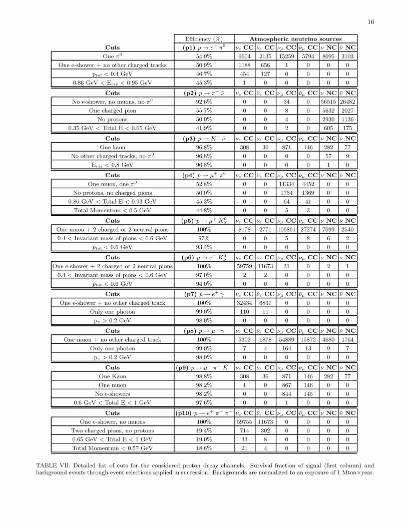
An efficient background reduction demands a goodparticle identification. Results based on a dedicatedanalysis show that the tagging efficiency of pions, kaonsand protons is above 99% with contamination below 1%.In addition, the muon–pion misidentification is around40%. The analysis, based on fully-simulated Monte-Carloevents with single particles, combines several variables ina Multi-layer perceptron Neural Network architecture:the χ2 fit to the particle hypothesis on the < dE/dx >vs kinetic energy plane, the fitted particle mass and theenergy released after the particle decay. Figure 13 showshow, thanks to the fine detector granularity, particles ofdifferent species get clearly separated. Electron and pho-ton identification is based on an algorithm that distin-guishes single m.i.p. signals versus double m.i.p. signalsby using the first hits of each identified electromagnetictrack.
The list of selection cuts to reduce the atmosphericneutrino contamination, final efficiencies and background
FIG. 13: Scatter plot showing the regions populated by fullysimulated muons, kaons and protons on the < dE/dx > vs.kinetic energy plane.
estimations are described in sections IVA and IVB.We then evaluate the backgrounds due to cosmogenic
events. Our strategy is to reduce the contribution fromthis background at the level of the irreducible atmo-spheric neutrino background. The amount of cosmogenicbackground is strongly correlated with the travel path in-side the detector. Thus we will cut on the detector fidu-cial volume, while keeping the same topology and kine-matics criteria used for the neutrino-induced background(in this way, signal selection efficiencies are unaltered).The details on the cosmic muon-induced background es-timation are given in Section IVC.
A. Proton decay channels
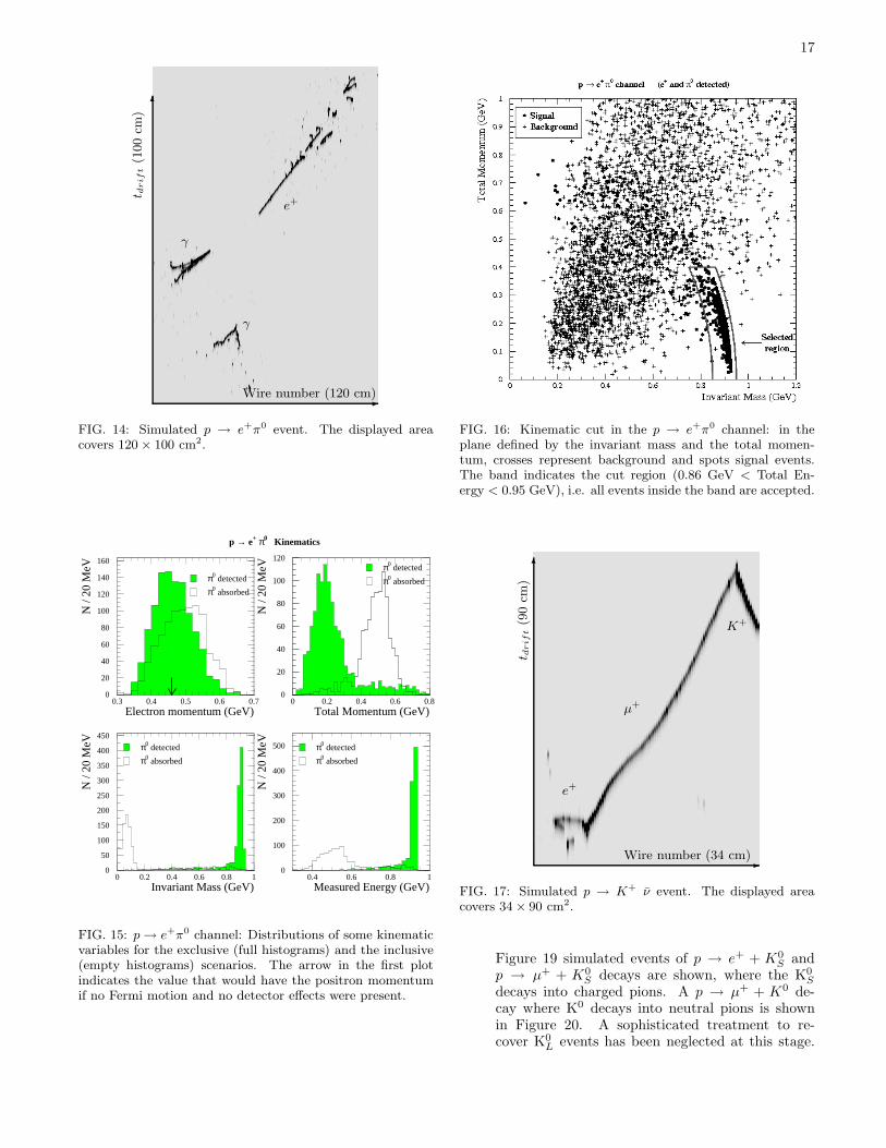
The sequential cuts applied for each channel are brieflydescribed in the following paragraphs. The detailed list ofcuts for the considered proton decay channels are listedin Table VII. Survival fraction of signal (first column)and background events from the different atmosphericneutrino interactions after selection cuts are applied insuccession are also listed. Backgrounds are normalized toan exposure of 1 Mton×year. The final efficiencies andexpected background events after cuts are reported in Ta-ble VI. The published efficiencies, backgrounds and re-sults obtained by Super-Kamiokande are shown for com-parison.
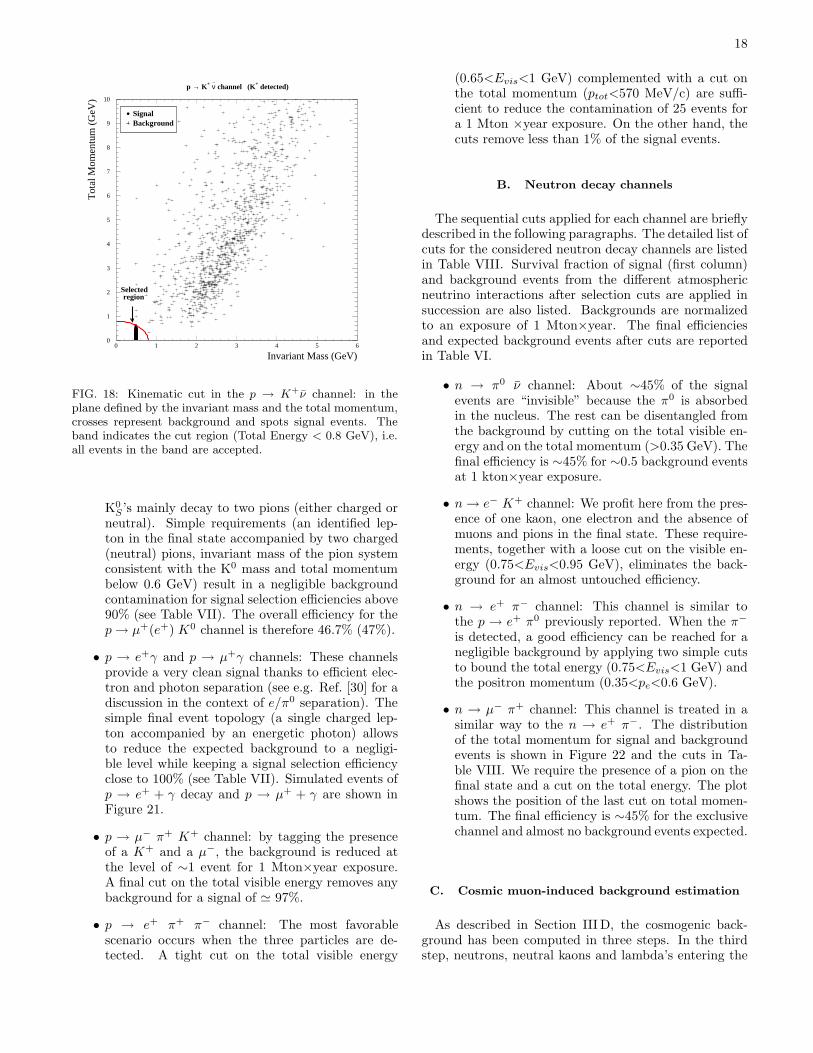
• p → e+ π0 channel: A simulated decay event isshown in Figure 14. The two photons (from theπ0 decay) and the positron flying in the opposite

15
This paper (LAr TPC) Super-Kamiokande results [5, 10]
Decay Efficiency Atmospheric ν Efficiency Atmospheric ν Published
mode (%) background (%) background limit
100 kton×year 92 kton×year 90% C.L.
(p1) p → e+ π0 45.3 0.1 40 0.2 1.6 ×1033
(p2) p → π+ ν 41.9 78.2
(p3) p → K+ ν 96.8 0.1 8.6 (prompt-γ) 0.7 2.3 ×1033
6.0 (K+→ π+π0) 0.6
(p4) p → µ+ π0 44.8 0.8 32 0.2
(p5) p → µ+ K0 46.7 < 0.2 5.4 (K0S → π0π0) 0.4
7.0 (K0S → π+π− method 1) 3.2 1.3 ×1033
2.8 (K0S → π+π− method 2) 0.3
(p6) p → e+ K0 47.0 < 0.2 9.2 (K0S → π0π0) 1.1 1.0 ×1033
7.9 (K0S → π+π− method 1) 3.6
1.3 (K0S → π+π− method 2) 0.04
(p7) p → e+ γ 98.0 < 0.2 73 0.1
(p8) p → µ+ γ 98.0 < 0.2 51 0.2
(p9) p → µ− π+ K+ 97.6 0.1
(p10) p → e+ π+ π− 18.6 2.5
(n1) n → π0 ν 45.1 47.4
(n2) n → e− K+ 96.0 < 0.2
(n3) n → e+ π− 44.4 0.8
(n4) n → µ− π+ 44.8 2.6
TABLE VI: Summary of studied decay modes: signal detection efficiency and expected atmospheric neutrino background(normalized to 100 kton×year exposure) after selection cuts. Where available, the efficiencies and background results of Super-Kamiokande are given for comparison. The published results obtained by Super-Kamiokande are shown for completeness [5, 10].
direction are clearly visible. In the chosen readoutview, the event spreads over about 120×100 cm2.Figure 15 shows the distributions of the follow-ing reconstructed kinematical quantities: the elec-tron momentum, the total momentum imbalance,the invariant mass and the total energy. The dis-tributions are split into the case where the pionleaves the nucleus (full histograms) and the casewhere it is absorbed (empty histograms). The elec-tron momentum histrogram has an arrow placed at460 MeV/c, the expected value without Fermi mo-tion and detector effects. It seems clear that twodifferent set of cuts could be implemented to opti-mize the signal over background ratio in both cases.However, an attempt to look for “inclusive” decaysp → e+(π0) without condition on the π0, yieldsorder of magnitudes worse background conditions,and was not considered further.
The list of cuts is presented in Table VII. Theidea is to have a balanced event, with all particlesidentified as such, and with a total visible energyclose to the proton mass (see Figure 16). Onlyone background event for 1 Mton×year exposuresurvives the cuts, for a signal efficiency of about45%.
• p → π+ ν channel: Almost 45% of the events that
belong to this channel can not be detected sincethe π+ gets absorbed by the nucleus. The cutsare based on the requirement of absence of chargedleptons, protons, neutral pions, the presence of onecharged pion and a total energy between 350 and650 MeV. The result is that, for a ∼42% efficiency,the expected background at 1 kton×year exposureis ∼0.8 events.
• p → K+ ν channel: this is a quite clean chan-nel due to the presence of a strange meson and noother particle in the final state (see Figure 17). Thekaon particle identification is performed and apply-ing the cuts listed in Table VII yields an efficiency∼97% for a negligible background. The correlationof the reconstructed invariant mass and total mo-mentum is shown in Figure 18.
• p → µ+ π0 channel: Almost 53% of the timesthe π0 is detected. In this case, cuts are similarto the e+π0 channel. The efficiency remains high(∼45%), while the background is ≃ 8 events for1 Mton×year.
• p → e+ K0 and p → µ+ K0 channels: We con-centrate on final states having a K0
S , since a largefraction of the K0
L will leave the detector withoutdecaying or will suffer hadronic interactions. In
16
Efficiency (%) Atmospheric neutrino sources
Cuts (p1) p → e+ π0 νe CC νe CC νµ CC νµ CC ν NC ν NC
One π0 54.0% 6604 2135 15259 5794 8095 3103
One e-shower + no other charged tracks 50.9% 1188 656 1 0 0 0
ptot < 0.4 GeV 46.7% 454 127 0 0 0 0
0.86 GeV < Evis < 0.95 GeV 45.3% 1 0 0 0 0 0
Cuts (p2) p → π+ ν νe CC νe CC νµ CC νµ CC ν NC ν NC
No e-shower, no muons, no π0 92.6% 0 0 34 0 56515 26482
One charged pion 55.7% 0 0 8 0 5632 2027
No protons 50.0% 0 0 4 0 2930 1136
0.35 GeV < Total E < 0.65 GeV 41.9% 0 0 2 0 605 175
Cuts (p3) p → K+ ν νe CC νe CC νµ CC νµ CC ν NC ν NC
One kaon 96.8% 308 36 871 146 282 77
No other charged tracks, no π0 96.8% 0 0 0 0 57 9
Evis < 0.8 GeV 96.8% 0 0 0 0 1 0
Cuts (p4) p → µ+ π0 νe CC νe CC νµ CC νµ CC ν NC ν NC
One muon, one π0 52.8% 0 0 11334 4452 0 0
No protons, no charged pions 50.0% 0 0 1754 1369 0 0
0.86 GeV < Total E < 0.93 GeV 45.3% 0 0 64 41 0 0
Total Momentum < 0.5 GeV 44.8% 0 0 5 3 0 0
Cuts (p5) p → µ+ K0S νe CC νe CC νµ CC νµ CC ν NC ν NC
One muon + 2 charged or 2 neutral pions 100% 8178 2771 106861 27274 7099 2540
0.4 < Invariant mass of pions < 0.6 GeV 97% 0 0 5 8 6 2
ptot < 0.6 GeV 93.4% 0 0 0 0 0 0
Cuts (p6) p → e+ K0S νe CC νe CC νµ CC νµ CC ν NC ν NC
One e-shower + 2 charged or 2 neutral pions 100% 59759 11673 31 0 2 1
0.4 < Invariant mass of pions < 0.6 GeV 97.0% 2 2 0 0 0 0
ptot < 0.6 GeV 94.0% 0 0 0 0 0 0
Cuts (p7) p → e+ γ νe CC νe CC νµ CC νµ CC ν NC ν NC
One e-shower + no other charged track 100% 32434 6837 0 0 0 0
Only one photon 99.0% 110 11 0 0 0 0
pγ > 0.2 GeV 98.0% 0 0 0 0 0 0
Cuts (p8) p → µ+ γ νe CC νe CC νµ CC νµ CC ν NC ν NC
One muon + no other charged track 100% 5302 1878 54889 15872 4680 1764
Only one photon 99.0% 7 4 164 13 9 7
pγ > 0.2 GeV 98.0% 0 0 0 0 0 0
Cuts (p9) p → µ− π+ K+ νe CC νe CC νµ CC νµ CC ν NC ν NC
One Kaon 98.8% 308 36 871 146 282 77
One muon 98.2% 1 0 867 146 0 0
No e-showers 98.2% 0 0 844 145 0 0
0.6 GeV < Total E < 1 GeV 97.6% 0 0 1 0 0 0
Cuts (p10) p → e+ π+ π− νe CC νe CC νµ CC νµ CC ν NC ν NC
One e-shower, no muons 100% 59755 11673 0 0 0 0
Two charged pions, no protons 19.4% 714 302 0 0 0 0
0.65 GeV < Total E < 1 GeV 19.0% 33 8 0 0 0 0
Total Momentum < 0.57 GeV 18.6% 21 4 0 0 0 0
TABLE VII: Detailed list of cuts for the considered proton decay channels. Survival fraction of signal (first column) andbackground events through event selections applied in succession. Backgrounds are normalized to an exposure of 1 Mton×year.
17
-Wire number (120 cm)
6
t drif
t(1
00
cm)
e+
γ
γ
FIG. 14: Simulated p → e+π0 event. The displayed areacovers 120 × 100 cm2.
p → e+ π0 Kinematics
0
20
40
60
80
100
120
140
160
0.3 0.4 0.5 0.6 0.7
π0 absorbed
π0 detected
Electron momentum (GeV)
N /
20 M
eV
0
20
40
60
80
100
120
0 0.2 0.4 0.6 0.8
π0 absorbed
π0 detected
Total Momentum (GeV)
N /
20 M
eV
0
50
100
150
200
250
300
350
400
450
0 0.2 0.4 0.6 0.8 1
π0 absorbed
π0 detected
Invariant Mass (GeV)
N /
20 M
eV
0
100
200
300
400
500
0.4 0.6 0.8 1
π0 absorbed
π0 detected
Measured Energy (GeV)
N /
20 M
eV
FIG. 15: p → e+π0 channel: Distributions of some kinematicvariables for the exclusive (full histograms) and the inclusive(empty histograms) scenarios. The arrow in the first plotindicates the value that would have the positron momentumif no Fermi motion and no detector effects were present.
FIG. 16: Kinematic cut in the p → e+π0 channel: in theplane defined by the invariant mass and the total momen-tum, crosses represent background and spots signal events.The band indicates the cut region (0.86 GeV < Total En-ergy < 0.95 GeV), i.e. all events inside the band are accepted.
-Wire number (34 cm)
6
t drif
t(9
0cm
)
K+
µ+
e+
FIG. 17: Simulated p → K+ ν event. The displayed areacovers 34 × 90 cm2.
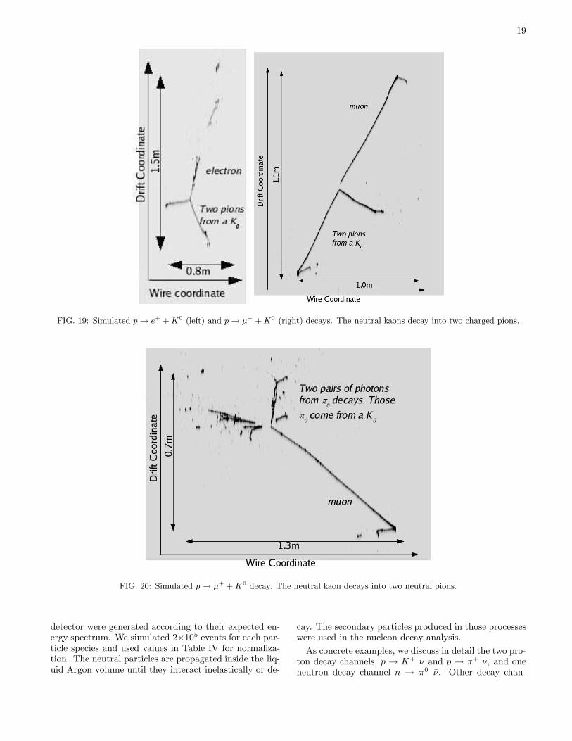
Figure 19 simulated events of p → e+ + K0S and
p → µ+ + K0S decays are shown, where the K0
S
decays into charged pions. A p → µ+ + K0 de-cay where K0 decays into neutral pions is shownin Figure 20. A sophisticated treatment to re-cover K0
L events has been neglected at this stage.
18
p → K+ ν– channel (K+ detected)
0
1
2
3
4
5
6
7
8
9
10
0 1 2 3 4 5 6
Invariant Mass (GeV)
Tot
al M
omen
tum
(G
eV)
SignalBackground
Selectedregion
FIG. 18: Kinematic cut in the p → K+ν channel: in theplane defined by the invariant mass and the total momentum,crosses represent background and spots signal events. Theband indicates the cut region (Total Energy < 0.8 GeV), i.e.all events in the band are accepted.
K0S’s mainly decay to two pions (either charged or
neutral). Simple requirements (an identified lep-ton in the final state accompanied by two charged(neutral) pions, invariant mass of the pion systemconsistent with the K0 mass and total momentumbelow 0.6 GeV) result in a negligible backgroundcontamination for signal selection efficiencies above90% (see Table VII). The overall efficiency for thep → µ+(e+) K0 channel is therefore 46.7% (47%).
• p → e+γ and p → µ+γ channels: These channelsprovide a very clean signal thanks to efficient elec-tron and photon separation (see e.g. Ref. [30] for adiscussion in the context of e/π0 separation). Thesimple final event topology (a single charged lep-ton accompanied by an energetic photon) allowsto reduce the expected background to a negligi-ble level while keeping a signal selection efficiencyclose to 100% (see Table VII). Simulated events ofp → e+ + γ decay and p → µ+ + γ are shown inFigure 21.
• p → µ− π+ K+ channel: by tagging the presenceof a K+ and a µ−, the background is reduced atthe level of ∼1 event for 1 Mton×year exposure.A final cut on the total visible energy removes anybackground for a signal of ≃ 97%.
• p → e+ π+ π− channel: The most favorablescenario occurs when the three particles are de-tected. A tight cut on the total visible energy
(0.65<Evis<1 GeV) complemented with a cut onthe total momentum (ptot<570 MeV/c) are suffi-cient to reduce the contamination of 25 events fora 1 Mton ×year exposure. On the other hand, thecuts remove less than 1% of the signal events.
B. Neutron decay channels
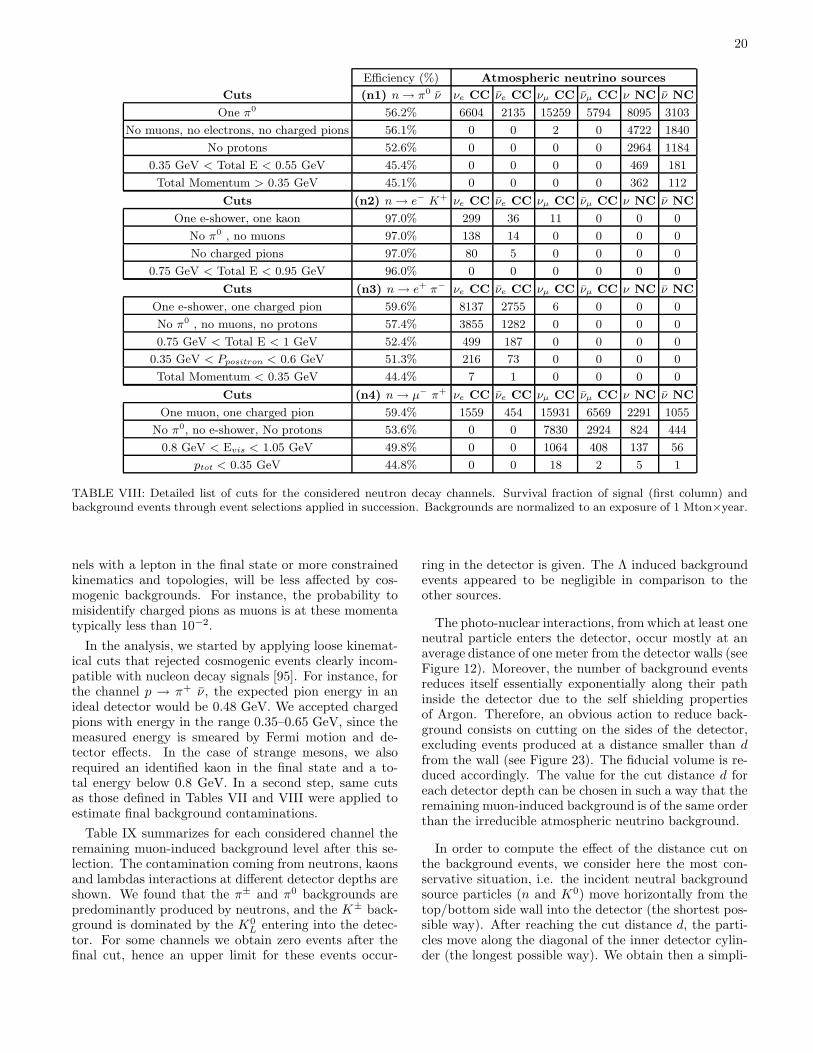
The sequential cuts applied for each channel are brieflydescribed in the following paragraphs. The detailed list ofcuts for the considered neutron decay channels are listedin Table VIII. Survival fraction of signal (first column)and background events from the different atmosphericneutrino interactions after selection cuts are applied insuccession are also listed. Backgrounds are normalizedto an exposure of 1 Mton×year. The final efficienciesand expected background events after cuts are reportedin Table VI.
• n → π0 ν channel: About ∼45% of the signalevents are “invisible” because the π0 is absorbedin the nucleus. The rest can be disentangled fromthe background by cutting on the total visible en-ergy and on the total momentum (>0.35 GeV). Thefinal efficiency is ∼45% for ∼0.5 background eventsat 1 kton×year exposure.
• n → e− K+ channel: We profit here from the pres-ence of one kaon, one electron and the absence ofmuons and pions in the final state. These require-ments, together with a loose cut on the visible en-ergy (0.75<Evis<0.95 GeV), eliminates the back-ground for an almost untouched efficiency.
• n → e+ π− channel: This channel is similar tothe p → e+ π0 previously reported. When the π−
is detected, a good efficiency can be reached for anegligible background by applying two simple cutsto bound the total energy (0.75<Evis<1 GeV) andthe positron momentum (0.35<pe<0.6 GeV).
• n → µ− π+ channel: This channel is treated in asimilar way to the n → e+ π−. The distributionof the total momentum for signal and backgroundevents is shown in Figure 22 and the cuts in Ta-ble VIII. We require the presence of a pion on thefinal state and a cut on the total energy. The plotshows the position of the last cut on total momen-tum. The final efficiency is ∼45% for the exclusivechannel and almost no background events expected.
C. Cosmic muon-induced background estimation
As described in Section III D, the cosmogenic back-ground has been computed in three steps. In the thirdstep, neutrons, neutral kaons and lambda’s entering the
19
FIG. 19: Simulated p → e+ + K0 (left) and p → µ+ + K0 (right) decays. The neutral kaons decay into two charged pions.
FIG. 20: Simulated p → µ+ + K0 decay. The neutral kaon decays into two neutral pions.
detector were generated according to their expected en-ergy spectrum. We simulated 2×10⁵ events for each par-ticle species and used values in Table IV for normaliza-tion. The neutral particles are propagated inside the liq-uid Argon volume until they interact inelastically or de-
cay. The secondary particles produced in those processeswere used in the nucleon decay analysis.
As concrete examples, we discuss in detail the two pro-ton decay channels, p → K+ ν and p → π+ ν, and oneneutron decay channel n → π0 ν. Other decay chan-
20
Efficiency (%) Atmospheric neutrino sources
Cuts (n1) n → π0 ν νe CC νe CC νµ CC νµ CC ν NC ν NC
One π0 56.2% 6604 2135 15259 5794 8095 3103
No muons, no electrons, no charged pions 56.1% 0 0 2 0 4722 1840
No protons 52.6% 0 0 0 0 2964 1184
0.35 GeV < Total E < 0.55 GeV 45.4% 0 0 0 0 469 181
Total Momentum > 0.35 GeV 45.1% 0 0 0 0 362 112
Cuts (n2) n → e− K+ νe CC νe CC νµ CC νµ CC ν NC ν NC
One e-shower, one kaon 97.0% 299 36 11 0 0 0
No π0 , no muons 97.0% 138 14 0 0 0 0
No charged pions 97.0% 80 5 0 0 0 0
0.75 GeV < Total E < 0.95 GeV 96.0% 0 0 0 0 0 0
Cuts (n3) n → e+ π− νe CC νe CC νµ CC νµ CC ν NC ν NC
One e-shower, one charged pion 59.6% 8137 2755 6 0 0 0
No π0 , no muons, no protons 57.4% 3855 1282 0 0 0 0
0.75 GeV < Total E < 1 GeV 52.4% 499 187 0 0 0 0
0.35 GeV < Ppositron < 0.6 GeV 51.3% 216 73 0 0 0 0
Total Momentum < 0.35 GeV 44.4% 7 1 0 0 0 0
Cuts (n4) n → µ− π+ νe CC νe CC νµ CC νµ CC ν NC ν NC
One muon, one charged pion 59.4% 1559 454 15931 6569 2291 1055
No π0, no e-shower, No protons 53.6% 0 0 7830 2924 824 444
0.8 GeV < Evis < 1.05 GeV 49.8% 0 0 1064 408 137 56
ptot < 0.35 GeV 44.8% 0 0 18 2 5 1
TABLE VIII: Detailed list of cuts for the considered neutron decay channels. Survival fraction of signal (first column) andbackground events through event selections applied in succession. Backgrounds are normalized to an exposure of 1 Mton×year.
nels with a lepton in the final state or more constrainedkinematics and topologies, will be less affected by cos-mogenic backgrounds. For instance, the probability tomisidentify charged pions as muons is at these momentatypically less than 10−2.
In the analysis, we started by applying loose kinemat-ical cuts that rejected cosmogenic events clearly incom-patible with nucleon decay signals [95]. For instance, forthe channel p → π+ ν, the expected pion energy in anideal detector would be 0.48 GeV. We accepted chargedpions with energy in the range 0.35–0.65 GeV, since themeasured energy is smeared by Fermi motion and de-tector effects. In the case of strange mesons, we alsorequired an identified kaon in the final state and a to-tal energy below 0.8 GeV. In a second step, same cutsas those defined in Tables VII and VIII were applied toestimate final background contaminations.
Table IX summarizes for each considered channel theremaining muon-induced background level after this se-lection. The contamination coming from neutrons, kaonsand lambdas interactions at different detector depths areshown. We found that the π± and π0 backgrounds arepredominantly produced by neutrons, and the K± back-ground is dominated by the K0
L entering into the detec-tor. For some channels we obtain zero events after thefinal cut, hence an upper limit for these events occur-
ring in the detector is given. The Λ induced backgroundevents appeared to be negligible in comparison to theother sources.
The photo-nuclear interactions, from which at least oneneutral particle enters the detector, occur mostly at anaverage distance of one meter from the detector walls (seeFigure 12). Moreover, the number of background eventsreduces itself essentially exponentially along their pathinside the detector due to the self shielding propertiesof Argon. Therefore, an obvious action to reduce back-ground consists on cutting on the sides of the detector,excluding events produced at a distance smaller than dfrom the wall (see Figure 23). The fiducial volume is re-duced accordingly. The value for the cut distance d foreach detector depth can be chosen in such a way that theremaining muon-induced background is of the same orderthan the irreducible atmospheric neutrino background.
In order to compute the effect of the distance cut onthe background events, we consider here the most con-servative situation, i.e. the incident neutral backgroundsource particles (n and K0) move horizontally from thetop/bottom side wall into the detector (the shortest pos-sible way). After reaching the cut distance d, the parti-cles move along the diagonal of the inner detector cylin-der (the longest possible way). We obtain then a simpli-
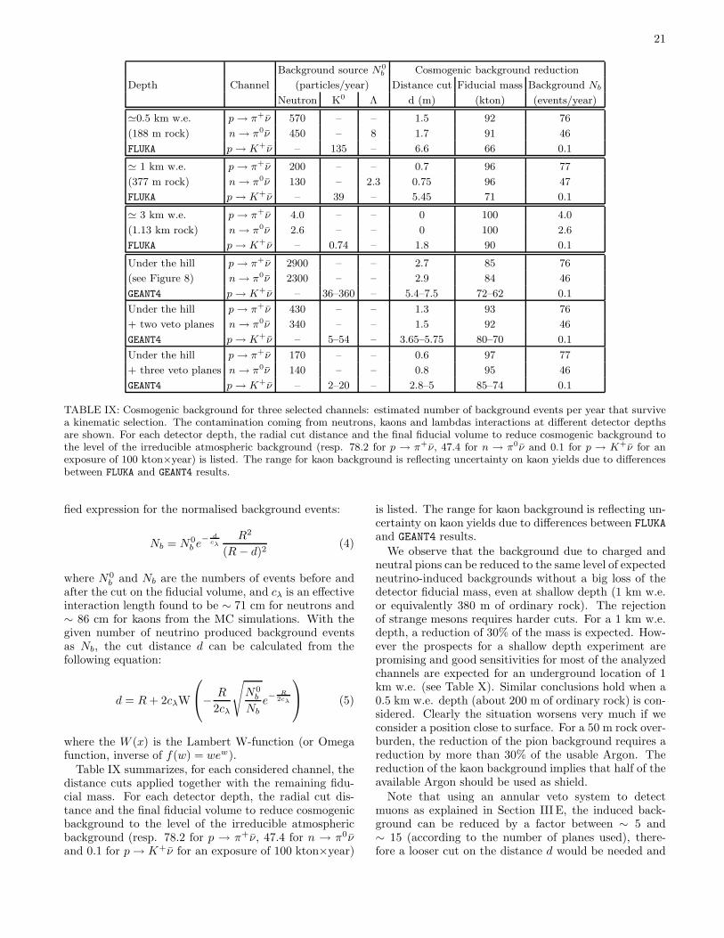
21
Background source N0b Cosmogenic background reduction
Depth Channel (particles/year) Distance cut Fiducial mass Background Nb
Neutron K0 Λ d (m) (kton) (events/year)
≃0.5 km w.e. p → π+ν 570 – – 1.5 92 76
(188 m rock) n → π0ν 450 – 8 1.7 91 46
FLUKA p → K+ν – 135 – 6.6 66 0.1
≃ 1 km w.e. p → π+ν 200 – – 0.7 96 77
(377 m rock) n → π0ν 130 – 2.3 0.75 96 47
FLUKA p → K+ν – 39 – 5.45 71 0.1
≃ 3 km w.e. p → π+ν 4.0 – – 0 100 4.0
(1.13 km rock) n → π0ν 2.6 – – 0 100 2.6
FLUKA p → K+ν – 0.74 – 1.8 90 0.1
Under the hill p → π+ν 2900 – – 2.7 85 76
(see Figure 8) n → π0ν 2300 – – 2.9 84 46
GEANT4 p → K+ν – 36–360 – 5.4–7.5 72–62 0.1
Under the hill p → π+ν 430 – – 1.3 93 76
+ two veto planes n → π0ν 340 – – 1.5 92 46
GEANT4 p → K+ν – 5–54 – 3.65–5.75 80–70 0.1
Under the hill p → π+ν 170 – – 0.6 97 77
+ three veto planes n → π0ν 140 – – 0.8 95 46
GEANT4 p → K+ν – 2–20 – 2.8–5 85–74 0.1
TABLE IX: Cosmogenic background for three selected channels: estimated number of background events per year that survivea kinematic selection. The contamination coming from neutrons, kaons and lambdas interactions at different detector depthsare shown. For each detector depth, the radial cut distance and the final fiducial volume to reduce cosmogenic background tothe level of the irreducible atmospheric background (resp. 78.2 for p → π+ν, 47.4 for n → π0ν and 0.1 for p → K+ν for anexposure of 100 kton×year) is listed. The range for kaon background is reflecting uncertainty on kaon yields due to differencesbetween FLUKA and GEANT4 results.
fied expression for the normalised background events:
Nb = N0b e
−d
cλ
R2
(R − d)2(4)
where N0b and Nb are the numbers of events before and
after the cut on the fiducial volume, and cλ is an effectiveinteraction length found to be ∼ 71 cm for neutrons and∼ 86 cm for kaons from the MC simulations. With thegiven number of neutrino produced background eventsas Nb, the cut distance d can be calculated from thefollowing equation:
d = R + 2cλW
−R
2cλ
√
N0b
Nbe−
R
2cλ
(5)
where the W (x) is the Lambert W-function (or Omegafunction, inverse of f(w) = wew).
Table IX summarizes, for each considered channel, thedistance cuts applied together with the remaining fidu-cial mass. For each detector depth, the radial cut dis-tance and the final fiducial volume to reduce cosmogenicbackground to the level of the irreducible atmosphericbackground (resp. 78.2 for p → π+ν, 47.4 for n → π0νand 0.1 for p → K+ν for an exposure of 100 kton×year)
is listed. The range for kaon background is reflecting un-certainty on kaon yields due to differences between FLUKA
and GEANT4 results.
We observe that the background due to charged andneutral pions can be reduced to the same level of expectedneutrino-induced backgrounds without a big loss of thedetector fiducial mass, even at shallow depth (1 km w.e.or equivalently 380 m of ordinary rock). The rejectionof strange mesons requires harder cuts. For a 1 km w.e.depth, a reduction of 30% of the mass is expected. How-ever the prospects for a shallow depth experiment arepromising and good sensitivities for most of the analyzedchannels are expected for an underground location of 1km w.e. (see Table X). Similar conclusions hold when a0.5 km w.e. depth (about 200 m of ordinary rock) is con-sidered. Clearly the situation worsens very much if weconsider a position close to surface. For a 50 m rock over-burden, the reduction of the pion background requires areduction by more than 30% of the usable Argon. Thereduction of the kaon background implies that half of theavailable Argon should be used as shield.
Note that using an annular veto system to detectmuons as explained in Section III E, the induced back-ground can be reduced by a factor between ∼ 5 and∼ 15 (according to the number of planes used), there-fore a looser cut on the distance d would be needed and
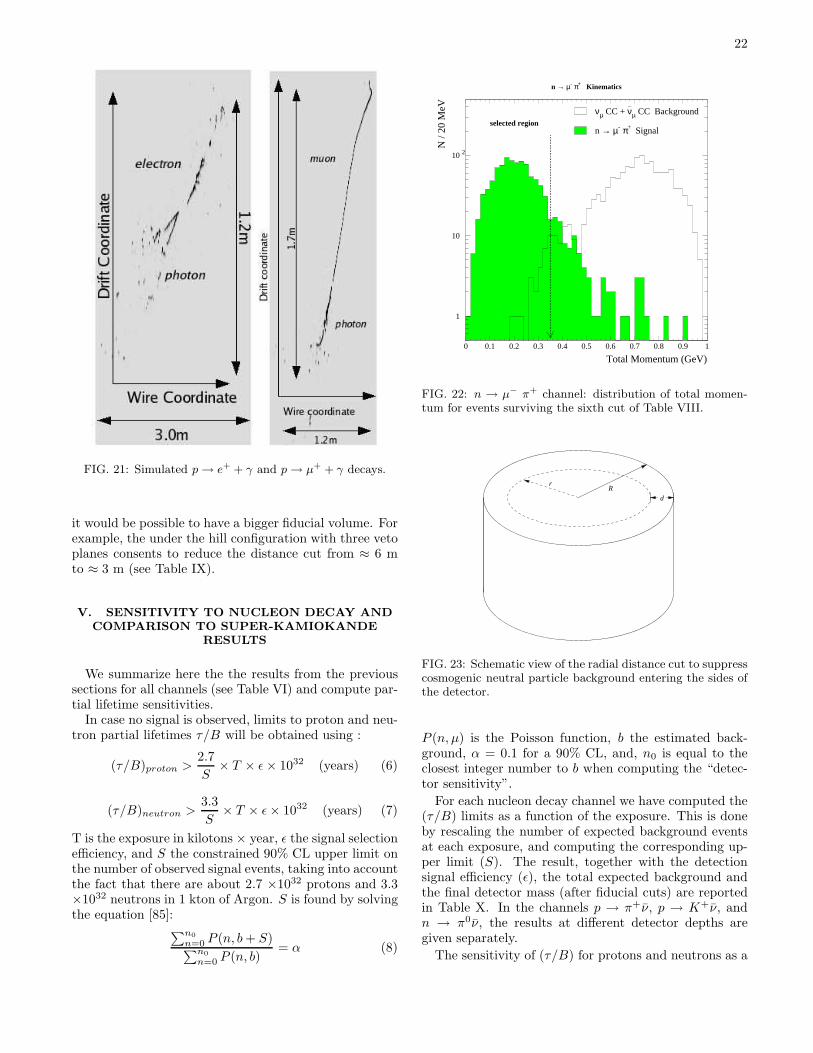
22
FIG. 21: Simulated p → e+ + γ and p → µ+ + γ decays.
it would be possible to have a bigger fiducial volume. Forexample, the under the hill configuration with three vetoplanes consents to reduce the distance cut from ≈ 6 mto ≈ 3 m (see Table IX).
V. SENSITIVITY TO NUCLEON DECAY ANDCOMPARISON TO SUPER-KAMIOKANDE
RESULTS
We summarize here the the results from the previoussections for all channels (see Table VI) and compute par-tial lifetime sensitivities.
In case no signal is observed, limits to proton and neu-tron partial lifetimes τ/B will be obtained using :
(τ/B)proton >2.7
S× T × ǫ × 1032 (years) (6)
(τ/B)neutron >3.3
S× T × ǫ × 1032 (years) (7)
T is the exposure in kilotons × year, ǫ the signal selectionefficiency, and S the constrained 90% CL upper limit onthe number of observed signal events, taking into accountthe fact that there are about 2.7 ×1032 protons and 3.3×1032 neutrons in 1 kton of Argon. S is found by solvingthe equation [85]:
∑n0
n=0P (n, b + S)
∑n0
n=0P (n, b)
= α (8)
n → µ- π+ Kinematics
1
10
10 2
0 0.1 0.2 0.3 0.4 0.5 0.6 0.7 0.8 0.9 1
selected region
νµ CC + ν–
µ CC Background
n → µ- π+ Signal
Total Momentum (GeV)
N /
20 M
eV
FIG. 22: n → µ− π+ channel: distribution of total momen-tum for events surviving the sixth cut of Table VIII.
rR
d
FIG. 23: Schematic view of the radial distance cut to suppresscosmogenic neutral particle background entering the sides ofthe detector.
P (n, µ) is the Poisson function, b the estimated back-ground, α = 0.1 for a 90% CL, and, n0 is equal to theclosest integer number to b when computing the “detec-tor sensitivity”.
For each nucleon decay channel we have computed the(τ/B) limits as a function of the exposure. This is doneby rescaling the number of expected background eventsat each exposure, and computing the corresponding up-per limit (S). The result, together with the detectionsignal efficiency (ǫ), the total expected background andthe final detector mass (after fiducial cuts) are reportedin Table X. In the channels p → π+ν, p → K+ν, andn → π0ν, the results at different detector depths aregiven separately.
The sensitivity of (τ/B) for protons and neutrons as a
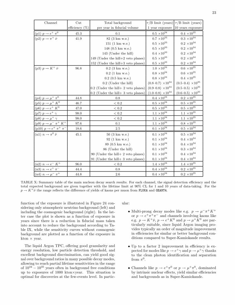
23
Channel Cut Total background τ/B limit (years) τ/B limit (years)
efficiency (%) per year in fiducial volume 1 year exposure 10 years exposure
(p1) p → e+ π0 45.3 0.1 0.5 ×1034 0.4 ×1035
(p2) p → π+ ν 41.9 82 (3 km w.e.) 0.7 ×1033 0.3 ×1034
151 (1 km w.e.) 0.5 ×1033 0.2 ×1034
148 (0.5 km w.e.) 0.5 ×1033 0.2 ×1034
143 (Under the hill) 0.4 ×1033 0.2 ×1034
149 (Under the hill+2 veto planes) 0.5 ×1033 0.2 ×1034
152 (Under the hill+3 veto planes) 0.5 ×1033 0.2 ×1034
(p3) p → K+ ν 96.8 0.2 (3 km w.e.) 1.0 ×1034 0.6 ×1035
0.2 (1 km w.e.) 0.8 ×1034 0.6 ×1035
0.2 (0.5 km w.e.) 0.8 ×1034 0.4 ×1035
0.2 (Under the hill) (0.8–0.7) ×1034 (0.5–0.4) ×1035
0.2 (Under the hill+ 2 veto planes) (0.9–0.8) ×1034 (0.5–0.5) ×1035
0.2 (Under the hill+ 3 veto planes) (1.0–0.8) ×1034 (0.6–0.5) ×1035
(p4) p → µ+ π0 44.8 0.8 0.4 ×1034 0.2 ×1035
(p5) p → µ+ K0 46.7 < 0.2 0.5 ×1034 0.5 ×1035
(p6) p → e+ K0 47.0 < 0.2 0.5 ×1034 0.5 ×1035
(p7) p → e+ γ 98.0 < 0.2 1.1 ×1034 1.1 ×1035
(p8) p → µ+ γ 98.0 < 0.2 1.1 ×1034 1.1 ×1035
(p9) p → µ− π+ K+ 97.6 0.1 1.1 ×1034 0.8 ×1035
(p10) p → e+ π+ π− 18.6 2.5 0.1 ×1034 0.5 ×1034
(n1) n → π0 ν 45.1 50 (3 km w.e.) 0.1 ×1034 0.5 ×1034
92 (1 km w.e.) 0.1 ×1034 0.4 ×1034
89 (0.5 km w.e.) 0.1 ×1034 0.4 ×1034
86 (Under the hill) 0.1 ×1034 0.3 ×1034
90 (Under the hill+ 2 veto planes) 0.1 ×1034 0.4 ×1034
91 (Under the hill+ 3 veto planes) 0.1 ×1034 0.4 ×1034
(n2) n → e− K+ 96.0 < 0.2 1.4 ×1034 1.4 ×1035
(n3) n → e+ π− 44.4 0.8 0.4 ×1034 0.2 ×1035
(n4) n → µ− π+ 44.8 2.6 0.4 ×1034 0.2 ×1035
TABLE X: Summary table of the main nucleon decay search results. For each channel, the signal detection efficiency and thetotal expected background are given together with the lifetime limit at 90% CL for 1 and 10 years of data-taking. For thep → K+ν the range reflects the difference of yields of kaons per muon from FLUKA and GEANT4.
function of the exposure is illustrated in Figure 24 con-sidering only atmospheric neutrino background (left) andincluding the cosmogenic background (right). In the lat-ter case the plot is shown as a function of exposure inyears since there is a reduction in fiducial mass takeninto account to reduce the background according to Ta-ble IX, while the sensitivity curves without cosmogenicbackground are plotted as a function of the exposure inkton × year.
The liquid Argon TPC, offering good granularity andenergy resolution, low particle detection threshold, andexcellent background discrimination, can yield good sig-nal over background ratios in many possible decay modes,allowing to reach partial lifetime sensitivities in the rangeof 1034 − 1035 years often in background free conditionsup to exposures of 1000 kton×year. This situation isoptimal for discoveries at the few-events level. In partic-
ular:
• Multi-prong decay modes like e.g. p → µ−π+K+
or p → e+π+π− and channels involving kaons likee.g. p → K+ν, p → e+K0 and p → µ+K0 are par-ticularly suitable, since liquid Argon imaging pro-vides typically an order of magnitude improvementin efficiencies for similar or better background con-ditions compared to Super-Kamiokande results.
• Up to a factor 2 improvement in efficiency is ex-pected for modes like p → e+γ and p → µ+γ thanksto the clean photon identification and separationfrom π0.
• Channels like p → e+π0 or p → µ+π0, dominatedby intrinsic nuclear effects, yield similar efficienciesand backgrounds as in Super-Kamiokande.

24
FIG. 24: Running of the nucleon partial lifetime sensitivity (τ/B at 90% C.L.) as a function of exposure (left) considering onlyatmospheric neutrino background (right) with cosmogenic background and corresponding reduction in fiducial mass taken intoaccount (see text).
Thanks to the self-shielding and 3D-imaging propertiesof the liquid Argon TPC, these results remains valid evenat shallow depths where cosmogenic background sourcesare important. A very large area annular active muonveto shield could be used in order to further suppresscosmogenic backgrounds at shallow depths. For exam-ple, our results show that a three plane active veto ata shallow depth of about 200 m rock overburden in theunder the hill configuration yields similar sensitivity forp → K+ν as a 3 km w.e. deep detector.
VI. CONCLUSIONS
The most direct sign for Grand Unification is the ex-perimental detection of proton or bound-neutron decays.In order to reach partial lifetime in the relevant range,new generation massive underground detectors with finetracking and excellent calorimetry are needed to suppressbackgrounds with a good signal selection efficiency. Fur-thermore, the detector should be sensitive to several dif-ferent channels in order to better understand the nucleondecay mechanism.
In this paper we have estimated the discovery poten-tial of liquid Argon TPC detectors and compared it tothe existing results of Super-Kamiokande. We have ana-lyzed many possible neutron and proton decay channelsand for the first time the two sources of background con-tamination: atmospheric neutrinos and cosmogenic back-grounds.
Our results indicate that a liquid Argon TPC, if scaledat the relevant mass scale of the order of 100 kton, offer-ing good granularity and energy resolution, low particle
detection threshold, and excellent background discrim-ination, can yield good signal over background ratiosin many possible decay modes, allowing to reach par-tial lifetime sensitivities in the range of 1034 − 1035 yearswith exposures up to 1000 kton×year, often in quasi-background-free conditions optimal for discoveries at thefew events level, corresponding to atmospheric neutrinobackground rejections of the order of 105.
Multi-prong decay modes like e.g. p → µ−π+K+
or p → e+π+π− and channels involving kaons like e.g.p → K+ν, p → e+K0 and p → µ+K0 are particularlysuitable, since liquid Argon imaging provides typically anorder of magnitude improvement in efficiencies for simi-lar or better background conditions compared to Super-Kamiokande.
Up to a factor 2 improvement in efficiency is expectedfor modes like p → e+γ and p → µ+γ thanks to the cleanphoton identification and separation from π0.
Channels like p → e+π0 or p → µ+π0, dominatedby intrinsic nuclear effects, yield similar efficiencies andbackgrounds as in Super-Kamiokande.
Thanks to the self-shielding and 3-D imaging proper-ties of the liquid Argon TPC, this result remains valideven at shallow depths where cosmogenic backgroundsources are important. We consider the possibility of avery large area annular active muon veto shield in orderto further suppress cosmogenic backgrounds at shallowdepths.
In conclusion, we find that this class of detectors doesnot necessarily require very deep underground labora-tories, like those typically encountered in existing orplanned sites, to perform very sensitive nucleon decaysearches. As a concrete example, we considered a three-

25
plane annular active veto surrounding a detector at ashallow depth of about 200 m rock overburden in an un-der the hill configuration and found that it yields similarsensitivities, in particular for p → K+ν, as for a 3 km w.e.deep detector.
In addition to a successful completion of the requiredtechnological R&D necessary to reach the relevant massscale of 100 kton in a cost-effective way, we point out theimportance of an experimental verification of the liquidArgon TPC physics potentialities to detect, reconstructand classify events in the relevant energy range. This ex-perimental verification will require in addition to possiblespecific tests in charged particle beams, the collection andstudy of neutrino events in GeV range with statistics of
the order of 100’000 events or more.
VII. ACKNOWLEDGMENTS
This work was in part supported by ETH and theSwiss National Foundation. AB, AJM and SN have beensupported by CICYT Grants FPA-2002-01835 and FPA-2005-07605-C02-01. SN acknowledges support from theRamon y Cajal Programme. We thank P. Sala for helpwith FLUKA while she was an ETH employee. We thankA. Marchionni for a careful reading of the manuscript.
[1] J. Pati and A. Salam, Phys. Rev. D8, 1240 (1973).[2] H. Georgi and S. L. Glashow, Phys. Rev. Lett. 32, 438
(1974).[3] U. Amaldi, W. de Boer and H. Furstenau, Phys. Lett. B
260, 447 (1991).[4] P. Langacker, Phys. Rept. 72, 185 (1981).[5] M. Shiozawa et al. [Super-Kamiokande Collaboration],
Phys. Rev. Lett. 81, 3319 (1998) [arXiv:hep-ex/9806014].[6] M. Shiozawa [Super-Kamiokande Collaboration], Pre-
pared for 28th International Cosmic Ray Conferences(ICRC 2003), Tsukuba, Japan, 31 Jul - 7 Aug 2003
[7] J.Wess and B.Zumino, Nucl. Phys. B70, 39 (1974).[8] K.S. Babu, J.C. Pati and F. Wilczek, Nucl. Phys. B566,
33 (2000).[9] Y. Hayato et al. [Super-Kamiokande Collaboration],
Phys. Rev. Lett. 83, 1529 (1999) [arXiv:hep-ex/9904020].[10] K. Kobayashi et al. [Super-Kamiokande Collaboration],
Phys. Rev. D 72, 052007 (2005) [arXiv:hep-ex/0502026].[11] S. Dimopoulos and H. Georgi, Nucl. Phys. B 193, 150
(1981).[12] N. Sakai and T. Yanagida, Nucl. Phys. B197, 533 (1982).[13] J. Hisano, H. Murayama, and T. Yanagida, Nucl. Phys.
B402, 46 (1993), hep-ph/9207279.[14] P. Nath, A. H. Chamseddine, and R. Arnowitt, Phys.
Rev. D32, 2348 (1985).[15] P. Nath and R. Arnowitt, (1998), hep-ph/9808465.[16] Q. Shafi and Z. Tavartkiladze, Phys. Lett. B473, 272
(2000), hep-ph/9911264.[17] V. Lucas and S. Raby, Phys. Rev. D55, 6986 (1997),
hep-ph/9610293.[18] J. C. Pati, Int. J. Mod. Phys. A18, 4135 (2003),
hep-ph/0305221.[19] K. S. Babu, J. C. Pati, and F. Wilczek, Phys. Lett.
B423, 337 (1998), hep-ph/9712307.[20] K. S. Babu, J. C. Pati, and F. Wilczek, Nucl. Phys.
B566, 33 (2000), hep-ph/9812538.[21] J. C. Pati, (2000), hep-ph/0005095.[22] J. R. Ellis, D. V. Nanopoulos, and J. Walker, Phys. Lett.
B550, 99 (2002), hep-ph/0205336.[23] N. Arkani-Hamed, S. Dimopoulos, G. F. Giudice
and A. Romanino, Nucl. Phys. B 709, 3 (2005)[arXiv:hep-ph/0409232].
[24] A. Hebecker and J. March-Russell, Phys. Lett. B539,119 (2002), hep-ph/0204037.
[25] M. L. Alciati, F. Feruglio, Y. Lin, and A. Varagnolo,JHEP 03, 054 (2005), hep-ph/0501086.
[26] I. R. Klebanov and E. Witten, Nucl. Phys. B664, 3(2003), hep-th/0304079.
[27] P. Nath and P. F. Perez, arXiv:hep-ph/0601023.[28] S. Wiesenfeldt, arXiv:hep-ph/0610273.[29] A. Rubbia, arXiv:hep-ph/0407297.[30] A. Meregaglia and A. Rubbia, JHEP 0611, 032 (2006)
[arXiv:hep-ph/0609106].[31] A. Rubbia, “LAGUNA - Large Apparatus for Grand
Unified and Neutrino Astrophysics”, Invited talk at the8th international workshop on Neutrino Factories, Super-beams and Betabeams NUFACT06, August 2006, Irvine(USA).
[32] K. Nakamura, Front. Phys. 35, 359 (2000).[33] Y. Suzuki et al. [TITAND Working Group],
arXiv:hep-ex/0110005.[34] C. K. Jung, AIP Conf. Proc. 533, 29 (2000)
[arXiv:hep-ex/0005046].[35] M. V. Diwan and C. K. Jung, Prepared for International
Workshop on Next Generation Nucleon Decay and Neu-trino Detector (NNN 99), Stony Brook, New York, 23-25Sep 1999
[36] A. de Bellefon et al., arXiv:hep-ex/0607026.[37] T. Marrodan Undagoitia, F. von Feilitzsch, M. Goger-
Neff, K. A. Hochmuth, L. Oberauer, W. Potzel andM. Wurm, Prog. Part. Nucl. Phys. 57, 290 (2006).
[38] T. Marrodan Undagoitia et al., J. Phys. Conf. Ser. 39,269 (2006).
[39] C. Rubbia, CERN-EP/77-08 (1977).[40] E. Aprile, K. L. Giboni and C. Rubbia, Nucl. Instrum.
Meth. A 241, 62 (1985).[41] P. Benetti et al., Nucl. Instrum. Meth. A 332 (1993) 395.[42] P. Cennini et al., Nucl. Instrum. Meth. A 345 (1994) 230.[43] F. Arneodo et al. [ICARUS-Milano Collaboration], Phys.
Rev. D 74, 112001 (2006) [arXiv:physics/0609205].[44] S. Amerio et al., Nucl. Instrum. Meth. A 527 (2004) 329
and references therein.[45] S. Amoruso et al., Nucl. Instrum. Meth. A 516 (2004)
68.[46] S. Amoruso et al. [ICARUS Collaboration], Nucl. In-
strum. Meth. A 523, 275 (2004).[47] A. Badertscher, M. Laffranchi, A. Meregaglia
and A. Rubbia, New J. Phys. 7, 63 (2005)
26
[arXiv:physics/0412080].[48] A. Badertscher, M. Laffranchi, A. Meregaglia, A. Muller
and A. Rubbia, Nucl. Instrum. Meth. A 555, 294 (2005)[arXiv:physics/0505151].
[49] A. Bueno, M. Campanelli, A. Ferrari and A. Rubbia, AIPConf. Proc. 533 (2000) 12.
[50] W. Haxton, “Underground laboratories”, Invited talk atthe 8th international workshop on Neutrino Factories,Superbeams and Betabeams NUFACT06, August 2006,Irvine (USA).
[51] A. Rubbia, arXiv:hep-ph/0402110.[52] D. B. Cline, F. Raffaelli and F. Sergiampietri, JINST
1 (2006) T09001 [arXiv:astro-ph/0604548]. D. B. Cline,F. Sergiampietri, J. G. Learned and K. McDon-ald, Nucl. Instrum. Meth. A 503, 136 (2003)[arXiv:astro-ph/0105442].
[53] L. Bartoszek et al., arXiv:hep-ex/0408121.[54] A. Ereditato and A. Rubbia, Nucl. Phys. Proc. Suppl.
155, 233 (2006) [arXiv:hep-ph/0510131].[55] A. Ereditato and A. Rubbia, Nucl. Phys. Proc. Suppl.
154, 163 (2006) [arXiv:hep-ph/0509022].[56] A. Rubbia, Talk given at the ISS meeting held on July
3rd, 2006.[57] E. Kearns et al., “A Proposal for a Detector 2 km Away
From the T2K Neutrino Source”, document submitted toDOE NuSAG, May 2005.
[58] T H Dey and T J Lewis, Brit. J. Appl. Phys., Ser 2, 1(8), 1968, 10191029.
[59] P. Nemethy, P. J. Oddone, N. Toge and A. Ishibashi,Nucl. Instrum. Meth. 212, 273 (1983).
[60] S. R. Amendolia et al., Nucl. Instrum. Meth. A 239(1985) 192.
[61] L. Kaufmann and A. Rubbia, arXiv:hep-ph/0611288.[62] L. Bruschi, B. Maraviglia, and F.E. Moss, Phys. Rev.
Lett. 17 (1966), 682.[63] G.W. Rayfield and W. Schoepe, Phys. Lett. A34 (1971)
133.[64] L. Bruschi, G. Mazzi, M. Santini, and G. Torzo,
J. Phys. C: Solid State Phys., Vol. 8 (1975), 1412 .[65] A.F. Borghesani, G. Carugno, M. Cavenago, and E.
Conti, Phys. Lett. A149 (1990), 481 .[66] W. Tauchert, H. Jungblut, W.F. Schmidt, Can. J. Chem.,
v.55, n.11 (1977) 1860.[67] A J Walters, J. Phys. D: Appl. Phys. 36 2743-2749.[68] K. Shinsaka, M. Codama, T. Srithanratana, M. Ya-
mamoto, Y. Hatano, J. Chem. Phys., vol.88, pp. 7529–7536, 1988.
[69] J. Allison et al., IEEE Trans. Nucl. Sci. 53 (2006) 270.[70] S. Agostinelli et al. [GEANT4 Collaboration], Nucl. In-
strum. Meth. A 506, 250 (2003).[71] P. Cennini et al., Nucl. Instrum. Meth. A 432, 240
(1999).[72] A. Ferrari, P. R. Sala, A. Fasso and J. Ranft, CERN-
2005-10 (2005), INFN/TC-05/11, SLAC-R-773 and ref-erences therein.
[73] G. Battistoni, P. R. Sala and A. Ferrari, Acta Phys.Polon. B 37, 2361 (2006).
[74] G. Battistoni, A. Ferrari, T. Montaruli and P. R. Sala,Astropart. Phys. 19, 269 (2003) [Erratum-ibid. 19, 291(2003)] [arXiv:hep-ph/0207035].
[75] M. Honda, T. Kajita, K. Kasahara and S. Mi-dorikawa, Phys. Rev. D 70, 043008 (2004)[arXiv:astro-ph/0404457].
[76] A. Rubbia, talk at the First International Workshop onNeutrino-Nucleus Interactions in the Few GeV Region(Nuint 01), December 2001, KEK, Tsukuba, Japan.
[77] J. Altegoer et al. [NOMAD Coll.], Nucl. Instrum. Meth.A404, 96 (1998).
[78] D. Casper, Nucl. Phys. Proc. Suppl. 112, 161 (2002)[arXiv:hep-ph/0208030].
[79] D. Kielcewska and P. Przewlocki, private communication.[80] P. Astier et al. [NOMAD Collaboration], Nucl. Phys. B
621, 3 (2002) [arXiv:hep-ex/0111057].[81] T. Sjostrand and M. Bengtsson, Comput. Phys. Com-
mun. 43, 367 (1987).[82] Y. Ge, PhD Thesis, No. 16894, ETH Zurich,
Switzerland (2006) [unpublished]. Available athttp://neutrino.ethz.ch.
[83] G. Battistoni, A. Ferrari, C. Rubbia, P. R. Sala andF. Vissani, arXiv:hep-ph/0604182.
[84] M. Crouch, in Proc. of the 20th International CosmicRay Conference (ICRC), Vol.6, p.165 (1987).
[85] W. M. Yao et al. [Particle Data Group], J. Phys. G 33,1 (2006).
[86] M. Ambrosio et al. [MACRO Collaboration.], Phys. Rev.D 52, 3793 (1995).
[87] V.A. Kudryavtsev et al., Nucl. Instr. Meth. A505, 688(2003).
[88] L.B. Bezrukov and E.V. Bugaev, Yad. Fiz. 33, 1195(1981).
[89] Y.F. Wang al., Phys. Rev. D 64, 013012 (2001).[90] R. Santonico and R. Cardarelli, Nucl. Instrum. Meth.
187, 377 (1981).[91] R. Bellazzini, C. Betti, A. Brez, E. Carboni, M. M. Mas-
sai and M. R. Torquati, Nucl. Instrum. Meth. A 247, 445(1986).
[92] C. Gustavino et al., Nucl. Instrum. Meth. A 315 (1992)507.
[93] MONOLITH Collaboration, “A Massive MagnetizedIron Detector for Neutrino Oscillation Studies, Exper-iment Proposal, LNGS P26/2000,CERN/SPSC 2000-031,SPSC/M657, August 15th, 2000.
[94] G. C. Trinchero, A. Giuliano and P. Picchi, Nucl. In-strum. Meth. A 508, 102 (2003).
[95] Z. Dai, PhD Thesis, No. 16133, ETH Zurich,Switzerland (2005) [unpublished]. Available athttp://neutrino.ethz.ch.
[96] The scintillation light signal has not being used in thepresent analysis, but will in the case of the actual exper-iment yield the T0 of the event, allowing to reconstructthe position of the event along the drift direction.
[97] The DIS process includes single-pion production viabaryon resonance excitation within a parton model for-malism, inspired from the concept of duality.
[98] If the rock is well known and of very good quality in agiven site, a new hole in virgin ground can be considered.See [31] and references therein.
[99] The geography of the chosen location was estimated withthe Google Earth tool. See http://earth.google.com.