NTPC LIMITED 4x250 MW BRBCL NABINAGAR TPP (FGD ...
116
NTPC LIMITED 4x250 MW BRBCL NABINAGAR TPP (FGD SYSTEM PACKAGE) TECHNICAL SPECIFICATION FOR HVAC SYSTEM SPECIFICATION NO.: - PE-TS-463- (571-13000-A)-A001 (REV-0) BHARAT HEAVY ELECTRICALS LIMITED POWER SECTOR PROJECT ENGINEERING MANAGEMENT POWER ENGINEERING INSTITUTE BUILDING SECTOR-16A, PLOT NO.-25, NOIDA, INDIA Page 1 of 523 38033/2020/PS-PEM-MAX 13
-
Upload
khangminh22 -
Category
Documents
-
view
6 -
download
0
Transcript of NTPC LIMITED 4x250 MW BRBCL NABINAGAR TPP (FGD ...
NTPC LIMITED
4x250 MW BRBCL NABINAGAR TPP
(FGD SYSTEM PACKAGE)
TECHNICAL SPECIFICATION
FOR
HVAC SYSTEM
SPECIFICATION NO.: - PE-TS-463- (571-13000-A)-A001 (REV-0)
BHARAT HEAVY ELECTRICALS LIMITED
POWER SECTOR PROJECT ENGINEERING MANAGEMENT
POWER ENGINEERING INSTITUTE BUILDING
SECTOR-16A, PLOT NO.-25, NOIDA, INDIA
Page 1 of 523
38033/2020/PS-PEM-MAX13

TITLE: 4x250 MW BRBCL NABINAGAR TPP (FGD
SYSTEM PACKAGE)
TECHNICAL SPECIFICATION FOR HVAC SYSTEM
SPECIFICATION No: PE-TS-463-(571-13000-A)-A001
SECTION
REV. 00
SHEET : 1 OF 2
CONTENTS
This Technical specification consists of two sections: SECTION - I
SUB- SECTIONS TITLE Page No
Sub-Section-A INTENT OF SPECIFICATION 5
Sub-Section-B PROJECT INFORMATION WITH WIND AND SEISMIC DESIGN CRITERIA 8
Sub-Section-C TECHNICAL SPECIFICATIONS 25
Sub Section-C1 SPECIFIC TECHNICAL REQUIREMENT 24
Sub Section-C2 CUSTOMER SPECIFICATION 57
C2 - A TECHNICAL REQUIREMENT 58
C2 - B PROJECT SPECIFIC GENERAL REQUIREMENTS INCLUDING:
96
GENERAL TECHNICAL REQUIREMENT 97
PERFROMANCE GUARANTEE TESTS 184
QUALITY ASSURANCE 188
C2 - C PAINTING SPECIFICATIONS (REFER SECTION C2-A)
192
Sub Section-C3 TECHNICAL SPECIFICATION (ELECTRICAL PORTION) 193
Sub Section-C4 TECHNICAL SPECIFICATION (C&I PORTION) 246
Sub Section-D STANDARD TECHNICAL SPECIFICATIONS 397
Sub Section-E ANNEXURE-I LIST OF MAKES OF SUB-VENDOR ITEMS 456
ANNEXURE-II MANDATORY SPARE LIST 471
ANNEXURE-III PAINTING & COLOUR SCHEME 477
ANNEXURE-IV LIST OF TOOLS & TACKLES 479
ANNEXURE-VI DRAWINGS / DOCUMENTS SUBMISSION PROCEDURE 480
ANNEXURE-VII MASTER DRAWING LIST WITH SCHEDULE OF SUBMISSION
481
ANNEXURE-VIII FORMAT FOR OPERATION AND MAINTENANCE MANUAL
486
ANNEXURE-IX SITE STORAGE AND PRESERVATION 490
ANNEXURE-X PACKING PROCEDURE (REFER SECTION C2-B) -
Page 2 of 523
38033/2020/PS-PEM-MAX14

TITLE: 4x250 MW BRBCL NABINAGAR TPP (FGD
SYSTEM PACKAGE)
TECHNICAL SPECIFICATION FOR HVAC SYSTEM
SPECIFICATION No: PE-TS-463-(571-13000-A)-A001
SECTION
REV. 00
SHEET : 2 OF 2
SECTION - II
SUB SECTIONS TITLE Page No
Sub Section-1 INSPECION AND TESTING WITH STANDARD QUALITY PLAN 507
Sub Section-2 LIST OF DOCUMENTS TO BE SUBMITTED WITH BID 511
Sub Section-3 COMPLIANCE CUM CONFIRMATION CERTIFICATE 512
Sub Section-4 PRE BID CLARIFICATION SCHEDULE 514
Sub Section-5 DEVIATION SHEET (COST OF WITHDRAWL) 515
Sub Section-6 GUARANTEED POWER CONSUMPTION 517
Sub Section-7 DRAWINGS 518
DRG TITLE
a P&ID FOR AIR COOLED CONDENSING UNIT FOR FGD 519
b P&ID FOR UAF FOR FGD 520
c SCHEME FOR HVAC MAKE UP WATER 521
d ELECTRICAL LAYOUT FOR FGD CONTROL ROOM BUILDING 522
e GA OF GYPSUM DEWATERING BUILDING 523
Page 3 of 523
38033/2020/PS-PEM-MAX15
4X250 MW BRBCL NABINAGAR TPP (FGD SYSTEM PACKAGE)
TECHNICAL SPECIFICATIONS FOR HVAC SYSTEM
SPECIFICATION No: PE-TS-463-(571-13000-A)-A001
SECTION: I
REV. 00
SECTION - I
Page 4 of 523
38033/2020/PS-PEM-MAX16

4X250 MW BRBCL NABINAGAR TPP
(FGD SYSTEM PACKAGE)
INTENT OF SPECIFICATION
SPECIFICATION No: PE-TS-463-(571-13000-A)-A001
SECTION : I
Sub Section: A
REV. 00
SHEET 1 OF 3
SECTION-I
SUB-SECTION-A
INTENT OF SPECIFICATION
Page 5 of 523
38033/2020/PS-PEM-MAX17

4X250 MW BRBCL NABINAGAR TPP
(FGD SYSTEM PACKAGE)
INTENT OF SPECIFICATION
SPECIFICATION No: PE-TS-463-(571-13000-A)-A001
SECTION : I
Sub Section: A
REV. 00
SHEET 1 OF 3
1.0 INTENT OF SPECIFICATION
1.1 The specification covers design, engineering, manufacture, supply / procurement, inspection and testing at vendor’s / sub vendor’s / manufacturer’s works, painting, forwarding, proper packing and shipment and delivery at site, unloading, handling & transportation, storage, preservation, security / safety at site, Erection & Commissioning, minor civil & structural (as applicable) works as required on FOR site basis, Performance and guarantee testing / demonstration testing and handing over to BHEL’s customer of HVAC SYSTEM as per details in different sections / volumes of this specification and various pre-award agreements for 4x250 MW NABINAGAR TPP (FGD SYSTEM PACKAGE).
1.2 The contractor shall be responsible for providing all material, equipment & services, which are required to fulfil the intent of ensuring operability, maintainability, reliability and complete safety of the complete work covered under this specification, irrespective of whether it has been specifically listed herein or not. Omission of specific reference to any component / accessory necessary for proper performance of the equipment shall not relieve the contractor of the responsibility of providing such facilities to complete the supply, erection and commissioning, performance and guarantee/demonstration testing of HVAC SYSTEM.
1.3 It is not the intent to specify herein all the details of design and manufacture. However, the equipment shall conform in all respects to highest standards of design, engineering and workmanship and shall be capable of performing the required duties in a manner acceptable to purchaser who will interpret the meaning of drawings and specifications and shall be entitled to reject any work or material which in his judgement is not in full accordance herewith.
1.4 The extent of supply under the contract includes all items shown in the drawings, notwithstanding the fact that such items may have been omitted from the specification or schedules. Similarly, the extent of supply also includes all items mentioned in the specification and /or schedules, notwithstanding the fact that such items may have been omitted in the drawing. Similarly, the extent of supply also includes all items required for completion of the system and not withstanding that they may have been omitted in drawings / specifications or schedules.
1.5 The general term and conditions, instructions to tenderers and other attachment
referred to elsewhere are made part of the tender specification. The equipment materials and works covered by this specification is subject to compliance to all attachments referred to in the specification. The bidder shall be responsible for and governed by all requirements stipulated herein.
1.6 While all efforts have been made to make the specification requirement complete &
unambiguous, it shall be bidders’ responsibility to ask for missing information, ensure completeness of specification, to bring out any contradictory / conflicting requirement in different sections of the specification and within a section itself to the notice of BHEL and to seek any clarification on specification requirement in the format enclosed under
Page 6 of 523
38033/2020/PS-PEM-MAX18

4X250 MW BRBCL NABINAGAR TPP
(FGD SYSTEM PACKAGE)
INTENT OF SPECIFICATION
SPECIFICATION No: PE-TS-463-(571-13000-A)-A001
SECTION : I
Sub Section: A
REV. 00
SHEET 1 OF 3
Vol-III of the specification within 10 days of receipt of tender documents. In absence of any such clarifications, in case of any contradictory requirement, the more stringent requirement as per interpretation of Purchaser / Customer shall prevail and shall be complied by the bidder without any commercial implication on account of the same. Further in case of any missing information in the specification not brought out by the prospective bidders as part of pre-bid clarification, the same shall be furnished by Purchaser/ Customer as and when brought to their notice either by the bidder or by purchaser/ customer themselves. However, such requirements shall be binding on the successful bidder without any commercial & delivery implication.
1.7 The bidder’s offer shall not carry any sections like clarification, interpretations and /or
assumptions. 1.8 Deviations, if any, should be very clearly brought out clause by clause along with cost of
withdrawal in the format attached with GCC (Annexure‐II Deviation sheet (Cost of withdraw), otherwise, it will be presumed that the vendor's offer is strictly in line with NIT specification.
1.9 In the event of any conflict between the requirements of two clauses of this specification
documents or requirements of different codes and standards specified, “Section - C shall prevail over section – D”, “section C1A (BHEL section C & C1B (Customer spec), later shall supersede, however more stringent requirement as per the interpretation of the owner shall apply.
1.10 In case all above requirements are not complied with, the offer may be considered as
incomplete and would become liable for rejection. 1.11 For definition of word like Contractor, bidder, supplier, vendor, Customer/ Purchaser
Employer, consultant, please referred relevant clause of GCC
Page 7 of 523
38033/2020/PS-PEM-MAX19

4X250 MW NABINAGAR TPP
(FGD SYSTEM PACKAGE)
HVAC SYSTEM PROJECT INFORMATION WITH WIND AND
SEISMIC DESIGN CRITERIA
SPECIFICATION No: PE-TS-463-(571-13000-A)-A001
SECTION : I
Sub Section : B
REV. 00
SECTION: I
SUB-SECTION: B
PROJECT INFORMATION WITH WIND AND SEISMIC DESIGN CRITERIA
Page 8 of 523
38033/2020/PS-PEM-MAX20

,-____________________________ -iI~e.L I NTPC I
SUB-SECTION-II-A 11
PROJECT INFORMATION- NABINAGAR 4X250 MW
LOT -IA PROJECTS FLUE GAS DESULPHURISATION (FGD) SYSTEM PACKAGE
TECHNICAL SPECIFICATION
SECTlON·VI
BID DOCUMENT NO.: CS-0011-109(1A)-2
Page 9 of 523
38033/2020/PS-PEM-MAX21
CLAUSE NO.
1.00.00
1.01.00
PROJECT INFORMATION I~MI NTPC
BACKGROUND
Details of proposed Stage I Units
Project name
No. of Units x capacity
Project setting up by
Nabinagar TPP
4 x 250MW
NTPC(FOR BHARTIYA RAIL BIJLEE
COMPANY LTD.)
The SG with ESP package and TG package of the subject project is being executed by Mis. BHEL.
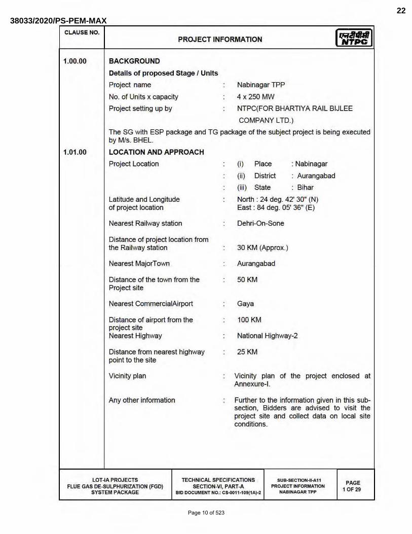
LOCATION AND APPROACH
Project Location
Latitude and Longitude of project location
Nearest Rai lway station
Distance of project location from the Railway station
Nearest MajorTow'l
Distance of the town from the Project site
Nearest CommercialAirport
Distance of airport from the project site Nearest Highway
Distance from nearest highway point to the site
Vicinity plan
Any other information
(i) Place
(ii ) District
: Nabinagar
Aurangabad
(iii) State Bihar
North: 24 deg. 42' 30" (N) East : 84 deg. OS' 36" (E)
Dehri-On-Sone
30 KM (Approx.)
Aurangabad
50KM
Gaya
100 KM
National Highway-2
25KM
Vicinity plan of the project enclosed at Annexure-I.
Further to the information given in this subsection, Bidders are advised to visit the project site and collect data on local site conditions.
LOT -IA PROJECTS TECHNICAL SPECIFICATIONS SUB-SECnoN-II-A11 PAGE 1 OF 29 FLUE GAS DE-SULPHURIZATION (FGD)
SYSTEM PACKAGE SECTION-VI, PART-A PROJECT INFORMATION
BID DOCUMENT NO.: CS-Il011·109(1A)-2 NABINAGAR TPP
Page 10 of 523
38033/2020/PS-PEM-MAX22

CLAUSE NO.
1.02.00
1.03.00
PROJECT INFORMATION I~MI NTPC
LAND REQUIREMENT
Total area of land acquired for the project
Any other information
WATER
Nearest Water Source
Proposed water requirement for the Stage
Proposed source I arrangement to the meet the water requirement
1700 Acres
Approximately 1700 acres of land has been identified near Dhundhua village for the Plant, Township and Ash Disposal Area. In principle commitment for the availability of land for Plant, Township and Ash Disposal Area has been obtained from Revenue Department, Govt. of Bihar vide letter dated 29.3.2003. Further, Central Coalfields Ltd. , (CCl) vide their letter dated 29.05.03 have indicated that Central Mine Planning & Design Institute Ltd (CMPDI) have confirmed that plant location along with its other allied infrastructure are not coming on coal bearing area.
The project site is located near the river Sone which is the only source of water for the project. Therefore, the make up water requirement for the project is proposed to be drawn from the pondage created by lndrapuri Barrage, which is about 3 kms from the proposed site.
60 Cusec
The project site is located near the river Sone which is the only source of water for the project. Therefore, the make up water requirement for the project is proposed to be drawn from the pondage created by lndrapuri Barrage, which is about 3 kms. from the proposed site.
The make up water requirement for the project operating on cooling towers is about 4300 cubic mlhr with ash water recirculation system and about 5900 cubic m/hr. with once through ash water system.
Water Resource Department, Govt. of Bihar, accorded in-principle clearance of 60 cusecs of consumptive water from upstream of Indrapuri Barrage vide their letter dated 06.03.03.
LOT -IA PROJECTS TECHNICAL SPECIFICATIONS SUB-SECnoN-II-A11 PAGE 20F 29 FLUE GAS DE-SULPHURIZATION (FGD)
SYSTEM PACKAGE SECTION-VI, PART-A PROJECT INFORMATION
BID DOCUMENT NO.: CS-0011·109(1A)-2 NABINAGAR TPP
Page 11 of 523
38033/2020/PS-PEM-MAX23

CLAUSE NO.
1.04.00
1.05.00
1.06.00
2.00.00
3.00.00
4.00.00
5.00.00
PROJECT INFORMATION
COAL and WATER, Utility details:
(i) Coal Quality Parameters and Fuel Oil Characteristics
Source:Pachra and Pachra south blocks in North Karanpura coalfields
Requirement: 5 MTPA
I~MI NTPC
The Coal quality parameters and Fuel Oil Characteristics are enclosed at Table-1, & Table-2A & 28 of this Sub-Section.
Water data
(ii ) Process water: Process water quality based on COC in Table-3.
(iii) Clarified water: Clarified water quality is indicated in Table-3.
(iv) OM water for Equipment cooling water system. OM water quality is indicated in Table-4.
Steam Generator and ESP data: refer Table-5
Drawings are enclosed as per Table-6 for initial overview to the Bidder.
NOT USED
RAILWAY SIDING
For bringing the equipment and material to the power house through rail, railway siding is proposed to be constructed from nearest railway station.
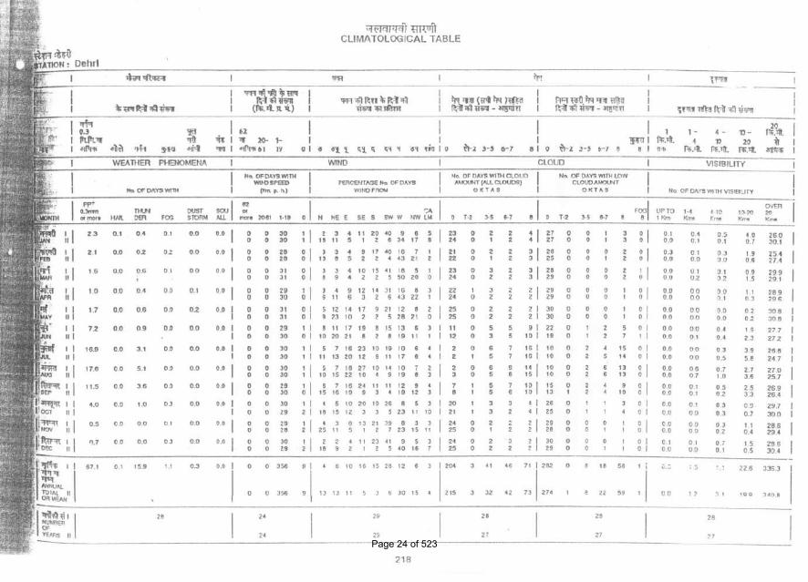
METEOROLOGICAL DATA
Meteorological data of the nearest observatory Dehri station is enclosed as Annexure-II to this subsection.
CRITERIA FOR EARTHQUAKE RESISTANT DESIGN OF STRUCTURES AND EQUIPMENT
All structures and equipment shall be designed for seismic forces adopting the site specific seismic information provided in this document and using the other provisions in accordance with IS:1893 (Part 1 to Part 4). Pending finalization of Part 5 of IS:1893, provisions of part 1 shall be read along with the relevant clauses of IS:1 893:1984, for embankments.
A site specific seismic study has been conducted for the project site. The peak ground horizontal acceleration for the project site , the site specific acceleration spectral coefficients (in units of gravity acceleration 'g' ) in the horizontal direction for
LOT -IA PROJECTS TECHNICAL SPECIFICATIONS SU8-SECnoN-U·A11 PAGE JOF 29 FLUE GAS DE-SULPHURIZATION (FGD)
SYSTEM PACKAGE SECTION-VI, PART-A PROJECT INFORMATION
810 DOCUMENT NO.: CS-0011·109(1A)-2 NABINAGAR Tl'P
Page 12 of 523
38033/2020/PS-PEM-MAX24
CLAUSE NO. PROJECT INFORMATION I q;UlM I NTPC
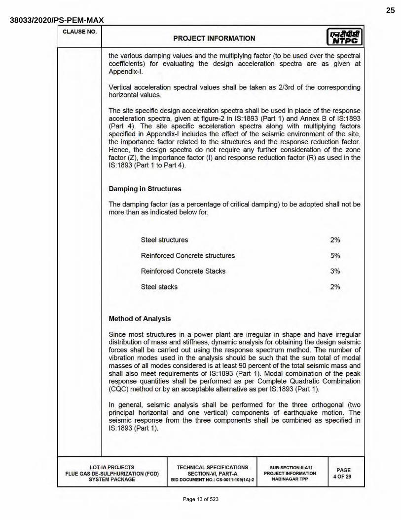
the various damping values and the multiplying factor (to be used over the spectral coefficients) for evaluating the design acceleration spectra are as given at Appendix-I.
Vertical acceleration spectral values shall be taken as 2I3rd of the corresponding horizontal values.
The site specific design acceleration spectra shall be used in place of the response acceleration spectra, given at figure-2 in IS:1893 (Part 1) and Annex B of IS:1 893 (Part 4 ). The site specific acceleration spectra along with multiplying factors specified in Appendix-I includes the effect of the seismic environment of the site, the importance factor related to the structures and the response reduction factor. Hence, the design spectra do not require any further consideration of the zone factor (Z), the importance factor (I) and response reduction factor (R) as used in the 18:1893 (Part 1 to Part 4).
Damping in Structures
The damping factor (as a percentage of critical damping) to be adopted shall not be more than as indicated below for:
Steel structures 2%
Reinforced Concrete structures 5%
Reinforced Concrete Stacks 3%
Steel stacks 2%
Method of Analysis
Since most structures in a power plant are irregular in shape and have irregular distribution of mass and stiffness, dynamic analysis for obtaining the design seismic forces shall be carried out using the response spectrum method. The number of vibration modes used in the analysis should be such that the sum total of modal masses of all modes considered is at least 90 percent of the total seismic mass and shall also meet requirements of IS:1893 (Part 1). Modal combination of the peak response quantities shall be perfonned as per Complete Quadratic Combination (CQC) method or by an acceptable alternative as per IS:1893 (Part 1).
In general, seismic analysis shall be perfonned for the three orthogonal (two principal horizontal and one vertical) components of earthquake motion. The seismic response from the three components shall be combined as specified in 18 :1893 (Part 1).
LOT -IA PROJECTS TECHNICAL SPECIFICATIONS SUB-SECnoN-II·A11 PAGE 40F 29 FLUE GAS DE-SULPHURIZATION (FGD)
SYSTEM PACKAGE SECTION-VI, PART-A PROJECT INFORMATION
BID DOCUMENT NO.: CS-II01 1·109(1A)-2 NABINAGAR TPP
Page 13 of 523
38033/2020/PS-PEM-MAX25
CLAUSE NO. PROJECT INFORMATION Iq;UlMI NTPC
The spectral acceleration coefficient shall get restricted to the peak spectral value if the fundamental natural period of the structure falls to the left of the peak in the spectral acceleration curve.
For buildings, if the de~gn base shear (VB) obtained from modal combination is less than the base shear ( VB) computed using the approximate fundamental period (Ta) given in 18:1893:Part 1 and using site specific acceleration spectra with appropriate multiplying factor, the response quantities (e.g. member forces, displacements, storey forces , storey shears and base reactions) shall be enhanced in the ratio of
- -
Val VB_ However, no reduction is permitted if VB is less than VB.
For regular buildings less than 12m in height, design seismic base shear and its distribution to different floor levels along the height of the building may be carried out as specified under clause 7.5, 7.6 & 7.7 of 18:1893 (Part 1) and using site specific design acceleration spectra. The design horizontal acceleration spectrum value (Ah) shall be computed for the fundamental natural period as per clause 7.6 of IS:1893 (Part 1) using site specific spectral acceleration coefficients with appropriate multiplying factor given in Appendix-I.
Design/Detailing for Ductility for Structures
The site specific design acceleration spectra is a reduced spectra and has an inbuilt allowance for ductility. Structures shall be engineered and detailed in accordance with relevant Indian/International standards to achieve ductility.
LOT -IA PROJECTS TECHN ICAL SPECIFICATIONS SUB-SECTION-II-All PAGE
50F 29 FLUE GAS DE-SULPHURIZATION (FGD) SYSTEM PACKAGE
SECTION-VI, PART-A PROJECT INFORMATION BID DOCUMENT NO.: CS-oOl 1·109(1A)-2 NABINAGAR TPP
Page 14 of 523
38033/2020/PS-PEM-MAX26
CLAUSE NO. PROJECT INFORMATION
APPENDIX-I
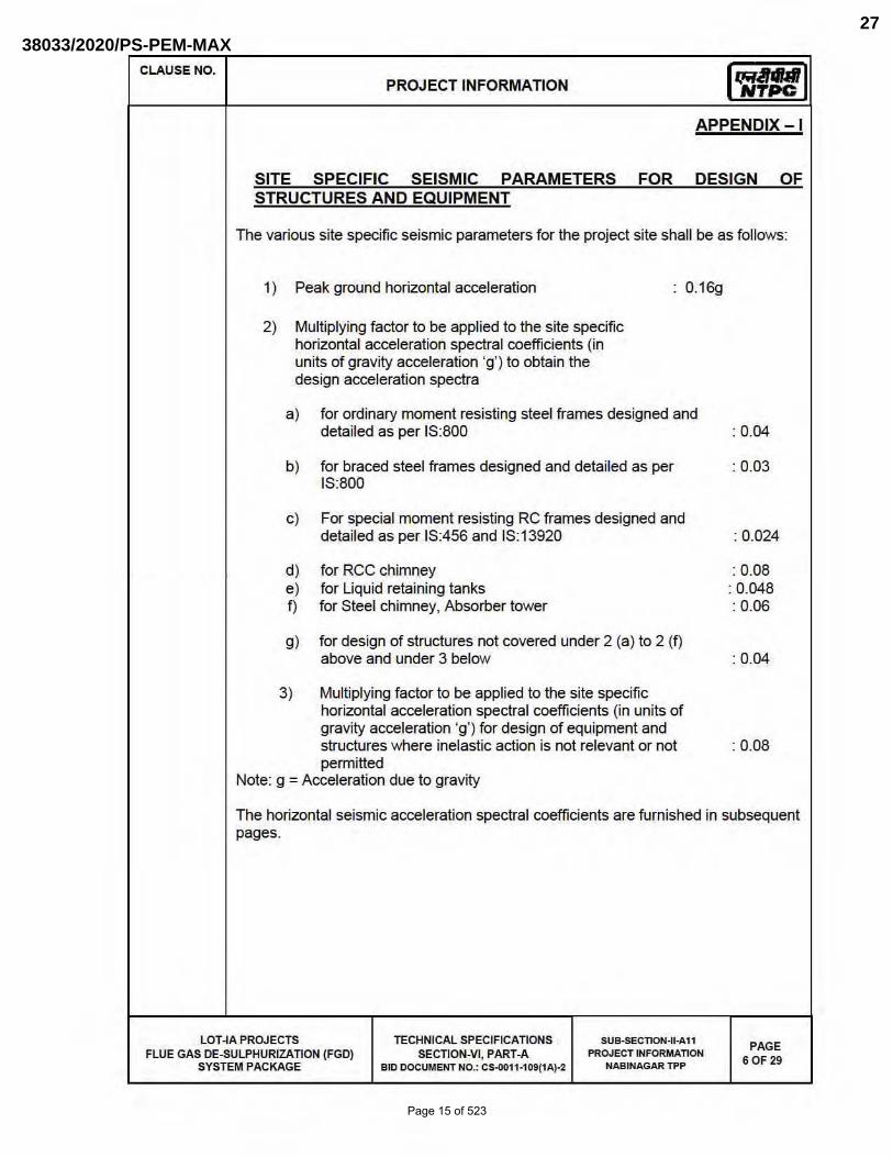
The various site specific seismic parameters for the project site shall be as follows:
1) Peak ground horizontal acceleration
2) Multiplying factor to be applied to the site specific horizontal acceleration spectral coefficients (in units of gravity acceleration 'g') to obtain the design acceleration spectra
0.16g
a) for ordinary moment resisting steel frames designed and detailed as per IS:800
b) for braced steel frames designed and detailed as per 18:800
c) For special moment resisting RC frames designed and detailed as per IS:456 and IS:13920
d) for RCC chimney e) for Uquid retaining tanks f) for Steel chimney, Absorber tower
g) for design of structures not covered under 2 (a) to 2 (f) above and under 3 below
3) Multiplying factor to be applied to the site specific horizontal acceleration spectral coefficients (in units of gravity acceleration 'g') for design of equipment and structures where inelastic action is not relevant or not permitted
Note: g = Acceleration due to gravity
: 0.04
:0.03
: 0.024
: 0.08 : 0.048 : 0.06
: 0 .04
: 0.08
The horizontal seismic acceleration spectral coefficients are furnished in subsequent pages.
LOT -IA PROJECTS TECHNICAL SPECIFICATIONS SUB-SECTION-II-Al1 PAGE
60F 29 FLUE GAS DE-SULPHURIZATION (FGD) SYSTEM PACKAGE
SECTION-VI, PART-A PROJECT INFORMATION BID DOCUMENT NO.: CS-oOll·109(lA)-2 NABINAGAR TPP
Page 15 of 523
38033/2020/PS-PEM-MAX27
CLAUSE NO. I q;UlU I PROJECT INFORMATION NTPC
APPENDLX I
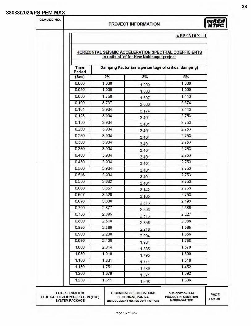
HORIZONTAL SEISMIC ACCELERATION SPECTRAL COEFFICIENTS In units of ' 'for New Nabina ar ro-ect
Time Damping Factor (as a percentage of critical damping) Period (Sec) 2% 3% 5%
0.000 1.000 1.000 1.000
0.030 1.000 1.000 1.000
0.050 1.750 1.607 1.443
0.100 3.737 3.060 2.374
0.104 3.904 3.174 2.443
0.123 3.904 3.401 2.753
0.150 3.904 3.401 2.753
0.200 3.904 3.401 2.753
0.250 3.904 3.401 2.753
0.300 3.904 3.401 2.753
0.350 3.904 3.401 2.753
0.400 3.904 3.401 2.753
0.450 3.904 3.401 2.753
0.500 3.904 3.401 2.753
0.516 3.904 3.401 2.753
0.550 3.662 3.401 2.753
0.600 3.357 3.142 2.753
0.607 3.320 3.105 2.753
0.670 3.006 2.813 2.493
0.700 2.877 2.693 2.386
0.750 2.685 2.513 2.227
0.800 2.518 2.356 2.088
0.850 2.369 2.218 1.965
0.900 2.238 2.094 1.856
0.950 2.120 1.984 1.758
1.000 2.014 1.885 1.670
1.050 1.918 1.795 1.590
1.100 1.831 1.714 1.518
1.150 1.751 1.639 1.452
1.200 1.678 1.571 1.392
1.250 1.611 1.508 1.336
LOT -IA PROJECTS TECHN ICAL SPECIFICATIONS SUB-SECnoN-II-A11 PAGE
FLUE GAS DE-SULPHURIZATION (FGD) SECTION-VI, PART-A PROJECT INFORMATION 70F 29
SYSTEM PACKAGE BID DOCUMENT NO.: CS-oOll ·109(1A)-2 NABINAGAR TPP
Page 16 of 523
38033/2020/PS-PEM-MAX28

CLAUSE NO. I q;UlU I PROJECT INFORMATION NTPC
APPENDLX I
HORIZONTAL SEISMIC ACCELERATION SPECTRAL COEFFICIENTS In units of ' 'for New Nabina ar ro-ect
Time Damping Factor (as a percentage of critical damping) Period (Sec) 2% 3% 5%
1.300 1.549 1.450 1.285
1.350 1.492 1.396 1.237
1.400 1.439 1.346 1.193
1.450 1.389 1.300 1.152
1.500 1.343 1.257 1.113
1.550 1.299 1.216 1.077
1.600 1.259 1.178 1.044
1.650 1.221 1.142 1.012
1.700 1.185 1.109 0.982
1.750 1.151 1.077 0.954
1.800 1.119 1.047 0.928
1.850 1.089 1.019 0.903
1.900 1.060 0.992 0.879
1.950 1.033 0.967 0.856
2.000 1.007 0.943 0.835
2.050 0.982 0.920 0.815
2.100 0.959 0.898 0.795
2.150 0.937 0.877 0.777
2.200 0.915 0.857 0.759
2.250 0.895 0.838 0.742
2.300 0.876 0.820 0.726
2.350 0.857 0.802 0.711
2.400 0.839 0.785 0.696
2.450 0.822 0.769 0.682
2.500 0.806 0.754 0.668
2.550 0.790 0.739 0.655
2.600 0.775 0.725 0.642
2.650 0.760 0.711 0.630
2.700 0.746 0.698 0.619
2.750 0.732 0.685 0.607
2.800 0.719 0.673 0.596
LOT -IA PROJECTS TECHNICAL SPECIFICATIONS SU8-SECnoN-U-Al1 PAGE
FLUE GAS DE-SULPHURIZATION (FGD) SECTION-VI , PART-A PROJECT INFORMATION 80F 29
SYSTEM PACKAGE 8 10 DOCUMENT NO.: CS-oOll ·109(lA)-2 NABINAGAR TPP
Page 17 of 523
38033/2020/PS-PEM-MAX29

CLAUSE NO. I q;UlU I PROJECT INFORMATION NTPC
APPENDLX I
HORIZONTAL SEISMIC ACCELERATION SPECTRAL COEFFICIENTS In units of ' 'for New Nabina ar ro-ect
Time Damping Factor (as a percentage of critical damping) Period (Sec) 2% 3% 5%
2.850 0.707 0.661 0.586
2.900 0.694 0.650 0.576
2.950 0.683 0.639 0.566
3.000 0.671 0.628 0.557
3.050 0.660 0.618 0.548
3. 100 0.650 0.608 0.539
3.150 0.639 0.598 0.530
3.200 0.629 0.589 0.522
3.250 0.620 0.580 0.514
3.300 0.610 0.571 0.506
3.350 0.601 0.563 0.499
3.400 0.592 0.554 0.491
3.450 0.584 0.546 0.484
3.500 0.575 0.539 0.477
3.550 0.567 0.531 0.470
3.600 0.559 0.524 0.484
3.650 0.552 0.516 0.458
3.700 0.544 0.509 0.451
3.750 0.537 0.503 0.445
3.800 0.530 0.496 0.439
3.825 0.527 0.493 0.437
3.850 0.523 0.490 0.434
3.900 0.516 0.483 0.428
3.950 0.510 0.477 0.423
4.000 0.504 0.471 0.418
LOT -IA PROJECTS TECHN ICAL SPECIFICATIONS SUB-SECTION-II-A11 PAGE
FLUE GAS DE-SULPHURIZATION (FGD) SECTION-VI , PART-A PROJECT INFORMATION 90F 29
SYSTEM PACKAGE 8 10 DOCUMENT NO.: CS-001 1·109(1A)-2 NABINAGAR TPP
Page 18 of 523
38033/2020/PS-PEM-MAX30

CLAUSE NO.
6.00.00
PROJECT INFORMATION
CRITERIA FOR WIND RESISTANT DESIGN OF STRUCTURES AND EQUIPMENT
All structures shall be designed for wind forces in accordance with IS:875 (Part-3) and as specified in this document. See Annexure - B for site specific information.
Along wind forces shall generally be computed by the Peak (i.e. 3 second gust) Wind Speed method as defined in the standard.
Along wind forces on slender and wind sensitive structures and structural elements shall also be computed, for dynamic effects, using the Gust Factor or Gust Effectiveness Factor Method as defined in the standard. The structures shall be designed for the higher of the forces obtained from Gust Factor method and the Peak Wind Speed method.
Analysis for dynamic effects of wind must be undertaken for any structure which has a height to minimum lateral dimension ratio greater than "5" and/or if the fundamental frequency of the structure is less than 1 Hz.
Susceptibility of structures to across-wind forces, galloping, flutter, ovalling etc. should be examined and designed/detailed accordingly following the recommendations of IS:875(Part-3) and other relevant Indian standards.
It should be estimated if size and relative position of other structures are likely to enhance the wind loading on the structure under consideration. Enhancement factor, if necessary, shall suitably be estimated and appl ied to the wind loading to account for the interference effects.
Damping in Structures
The damping factor (as a percentage of critical damping) to be adopted shall not be more than as indicated below for:
a) Welded steel structures
b) Bolted steel structures
c) Reinforced concrete structures
d) Steel stacks
: 1.0%
: 2.0%
: 1.6%
As per IS:6533 & CICIND Model Code whichever is more critical.
LOT -IA PROJECTS TECHNICAL SPECIFICATIONS SUB-SECnoN-II-A11 PAGE 10 OF 29 FLUE GAS DE-SULPHURIZATION (FGD)
SYSTEM PACKAGE SECTION-VI, PART-A PROJECT INFORMATION
BID DOCUMENT NO.: CS-Il011·109(1A)-2 NABINAGAR TPP
Page 19 of 523
38033/2020/PS-PEM-MAX31

CLAUSE NO.
7.00.0
7.00.01
7.00.02
7.00.03
7.00.04
PROJECT INFORMATION
ANNEXURE-B
SITE SPECIFIC DESIGN PARAMETERS
The various design parameters, as defined in IS: 875 (Part-3), to be adopted for the project site shall be as follows:
) The basic wind speed "Vb" at ten metres above the mean ground level : 47 metres/second
b) The risk coefficient "Kl" : 1.07
C) Category of terrain : Category-2
FOUNDATION SYSTEM AND GEOTECHNICAL DATA
Geotechnical data and foundation system for the respective project are enclosed at annexure-III. The corresponding bore logs are enclosed at annexure-IV.
The available soil data is of vicinity of proposed structures, therefore, bidder shall carryout his own detailed soil investigation for facilities under this package and shall be as per the scheme approved by owner. The scheme for geotechnical investigation shall be as given at Clause 7.07.00 and shall be approved by owner before execution.Geotechnical investigation work shall got executed by the Contractor through the agencies as mentioned in Clause No. 7.07.03. However, no time extension shall be given on account of soil investigation carried out by the Bidder. The geotechnical investigation report shall be prepared with detailed recommendations regarding type of foundation and allowable bearing pressure for various sl:n.Jcturesl facilities and other soil parameters. The report shall be submitted for Owner's approval prior to commencement of design of foundation.
The Bidder should note that nothing extra whatsoever on account of variation between soil data collected by ONner and that found by the Bidder during geotechnical investigation by him or during execution of works, shall be payable.
Tank Foundations
a) The tanks shall rest on flexible tank pad foundation, resting on sand with concrete ring wall to retain sand. Base of the concrete ring wall shall not rest on the expansive soil, if any.
b) Entire loosel soft soil inside the concrete ring wall shall be removed and shall be filled with sand. Sand for filling shall be clean and well graded conforming to IS 383 with grading Zone I to III.
c) Sand shall be spread in layers not exceeding 30cm compacted thickness over the area. Each layer shall be uniformly compacted by mechanical means like plate vibrators, small vibratory rollers,etc to achieve a relative density of not less than 80%.
d) Other requirements of tank foundations shall be as per IS 803 and as specified elsewhere in the specifications.
LOT -IA PROJECTS TECHNICAL SPECIFICATIONS SUB-SECnoN-I1-A11 PAGE 11 OF 29 FLUE GAS DE-SULPHURIZATION (FGD)
SYSTEM PACKAGE SECTION-VI, PART-A PROJECT INFORMATION
BID DOCUMENT NO.: CS-0011·109(1A)-2 NABINAGAR Tl'P
Page 20 of 523
38033/2020/PS-PEM-MAX32

CLAUSE NO. I q;UlU I PROJECT INFORMATION NTPC
Table-3
DESIGN CLARIFIED WATER ANALYSIS
S.No Constituent As mg/l (except pH & turb id ity)
1. Calcium CaC03 131
2. Magnesium CaC03 52
3. Sodium + Potassium CaC03 65
4. Total Cations CaC03 248
5. Chloride CaC03 20
6. Sulphate CaC03 93
7. Nitrate CaC03 10
8. Alkalinity CaC03 125
9. Total Anions CaC03 248
10. Iron(total ) Fe 0.3
11 . Total Silica Si02 22
12. pH value - 7.0-8.2
13. Turbid ity NTU 10
Note: Clarified water is used for CW system as make up & the CW system is expected to operate at about 5.0 - 5.5 Cydes of Concentration (COC) with suitable chemical treatment program using acid, sca le & corrosion inhibitor dozing. As CW blow down water is tapped from CW system, the water quality of CW blow down shall accordingly be arrived by the bidder.
Table-4
ANALYSIS OF DM WATER
SI.No. Characteristics Value
1. Silica (Max.) 0.02 ppm as Si02
2. Iron as Fe Nil
3. Total hardness Nil
4. pH value 6.8 to 7.2
5. Conductivity Not more than 0.1 ~Is/cm
LOT -IA PROJECTS TECHNICAL SPECIFICATIONS SUB-SECnoN-II-A11 PAGE
FLUE GAS DE-SULPHURIZATION (FGD) SECTION-VI, PART-A PROUECTINF~~ON 27 OF 29
SYSTEM PACKAGE 8 10 DOCUMENT NO.: CS-IlOll ·109(lA)-2 NABINAGAR TPP
Page 21 of 523
38033/2020/PS-PEM-MAX33
6043623
Text Box
FOR MAIN PLANT CONDENSER

Page 22 of 523
38033/2020/PS-PEM-MAX34

Page 23 of 523
38033/2020/PS-PEM-MAX35
Page 24 of 523
38033/2020/PS-PEM-MAX36

4X250 MW BRBCL NABINAGAR TPP
(FGD SYSTEM PACKAGE)
HVAC SYSTEM
TECHNICAL SPECIFICATION
SPECIFICATION No: PE-TS-463-(571-13000-A)-A001
SECTION : I
Sub Section : C
REV. 00
SECTION: I
SUB SECTION: C
TECHNICAL SPECIFICATIONS
Page 25 of 523
38033/2020/PS-PEM-MAX37

4X250 MW BRBCL NABINAGAR TPP
(FGD SYSTEM PACKAGE)
HVAC SYSTEM SPECIFIC TECHNICAL REQUIREMENT
SPECIFICATION No: PE-TS-463-(571-13000-A)-A001
SECTION : I
SUB-SECTION : C 1
REV. 00
SHEET 1 OF 17
SECTION: I
SUB-SECTION: C 1
SPECIFIC TECHNICAL REQUIREMENT
Page 26 of 523
38033/2020/PS-PEM-MAX38
4X250 MW BRBCL NABINAGAR TPP
(FGD SYSTEM PACKAGE)
HVAC SYSTEM SPECIFIC TECHNICAL REQUIREMENT
SPECIFICATION No: PE-TS-463-(571-13000-A)-A001
SECTION : I
SUB-SECTION : C 1
REV. 00
SHEET 2 OF 17
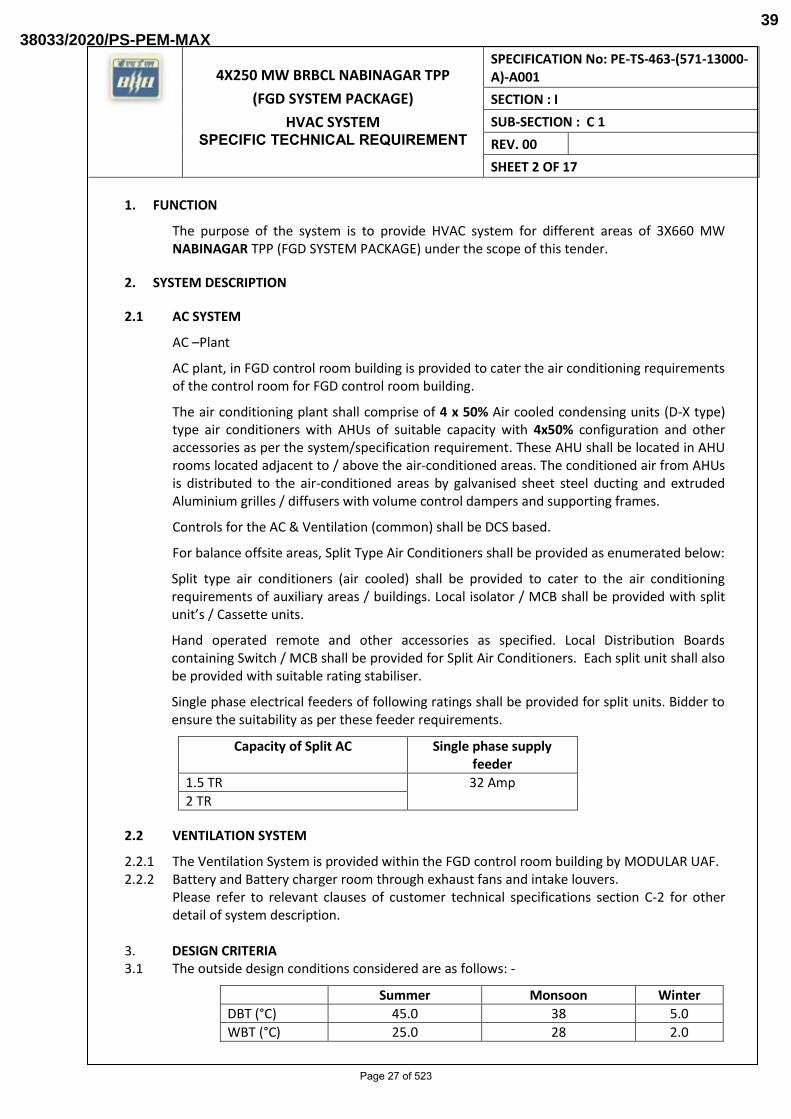
1. FUNCTION
The purpose of the system is to provide HVAC system for different areas of 3X660 MW NABINAGAR TPP (FGD SYSTEM PACKAGE) under the scope of this tender.
2. SYSTEM DESCRIPTION
2.1 AC SYSTEM
AC –Plant
AC plant, in FGD control room building is provided to cater the air conditioning requirements of the control room for FGD control room building.
The air conditioning plant shall comprise of 4 x 50% Air cooled condensing units (D-X type) type air conditioners with AHUs of suitable capacity with 4x50% configuration and other accessories as per the system/specification requirement. These AHU shall be located in AHU rooms located adjacent to / above the air-conditioned areas. The conditioned air from AHUs is distributed to the air-conditioned areas by galvanised sheet steel ducting and extruded Aluminium grilles / diffusers with volume control dampers and supporting frames.
Controls for the AC & Ventilation (common) shall be DCS based.
For balance offsite areas, Split Type Air Conditioners shall be provided as enumerated below:
Split type air conditioners (air cooled) shall be provided to cater to the air conditioning requirements of auxiliary areas / buildings. Local isolator / MCB shall be provided with split unit’s / Cassette units.
Hand operated remote and other accessories as specified. Local Distribution Boards containing Switch / MCB shall be provided for Split Air Conditioners. Each split unit shall also be provided with suitable rating stabiliser.
Single phase electrical feeders of following ratings shall be provided for split units. Bidder to ensure the suitability as per these feeder requirements.
Capacity of Split AC Single phase supply feeder
1.5 TR 32 Amp
2 TR
2.2 VENTILATION SYSTEM
2.2.1 The Ventilation System is provided within the FGD control room building by MODULAR UAF. 2.2.2 Battery and Battery charger room through exhaust fans and intake louvers.
Please refer to relevant clauses of customer technical specifications section C-2 for other detail of system description.
3. DESIGN CRITERIA 3.1 The outside design conditions considered are as follows: -
Summer Monsoon Winter
DBT (°C) 45.0 38 5.0
WBT (°C) 25.0 28 2.0
Page 27 of 523
38033/2020/PS-PEM-MAX39

4X250 MW BRBCL NABINAGAR TPP
(FGD SYSTEM PACKAGE)
HVAC SYSTEM SPECIFIC TECHNICAL REQUIREMENT
SPECIFICATION No: PE-TS-463-(571-13000-A)-A001
SECTION : I
SUB-SECTION : C 1
REV. 00
SHEET 3 OF 17
3.2 AC system: -
The inside design conditions for Air conditioned area to be maintained are as follows: -
Temperature 24°C ± 10C & RH 50% ± 5%
A minimum design margin of 10% shall be considered while designing the AC Plant capacity for each area.
Following safety factor to considered while designing the AC system
Minimum 12.5% in RSH
Minimum 10% in RLH
10% margin on dehumidified CFM
For winter heating load calculation, 50% of combined light load and eqpt. / panel load as available in the room shall be considered.
3.3 Ventilation System: -
The inside design conditions for Ventilated area to be maintained are as follows: -
In the areas ventilated by evaporative cooling units, the inside dry bulb temperature shall be restricted to 3°C less than the summer ambient temperature (DB).
In dry type forced (mechanical) ventilation system, the inside temperature shall be restricted about 3°C higher than the summer ambient (outside) temperature (DB).
The ventilation philosophy in various areas shall be as under
S.No. Area Type of Ventilation ACPH
1. FGD control room
building
Ventilation with modular UAF.
Motorized Fire dampers will be provided in
the supply air ducting of Cable Spreader
room/MCC
8
2. General areas, like pump
house, building etc.
Combination of Supply and exhaust fan 20
3. MCC / Switchgear rooms.
etc.
Supply fan & back draft dampers 30
4. Battery rooms & other
areas where gaseous
fumes/ vapors are
generated
Combination of intake louvers & Exhaust air/Roof extractor fans.
30
Page 28 of 523
38033/2020/PS-PEM-MAX40

4X250 MW BRBCL NABINAGAR TPP
(FGD SYSTEM PACKAGE)
HVAC SYSTEM SPECIFIC TECHNICAL REQUIREMENT
SPECIFICATION No: PE-TS-463-(571-13000-A)-A001
SECTION : I
SUB-SECTION : C 1
REV. 00
SHEET 4 OF 17
In addition to above, mechanical ventilation for other auxiliary buildings shall also be
provided.
3.4 All equipment shall be designed for continuous duty.
3.5 For other design parameters refer to section C2-A, customer specifications.
3. SYSTEM CAPACITY AND CONFIURATION:
a) For AC Plant: -
4x50 % (1W + 1S, minimum 55 TR Actual capacity) DX- type air cooled condensing unit shall be provided.
b) For Ventilation system: -
1 nos. each of minimum 1,40,000 CMH capacity (both working) MODULAR TYPE UAF shall be provided.
4. LAYOUT CONSIDERATIONS:
a) AC PLANT
I. Air cooled DX-type condensing units for AC Plant shall be housed at the roof of
FGD control room building.
II. The AHUs for this AC Plant would be located inside AHU room located on the
roof of FGD Control Room.
III. 1 T Capacity Chain pulley block with/without Monorail arrangement shall be
provided for the AHU for maintenance purpose.
b) Ventilation system
I. MODULAR UAF shall be placed at the roof of FGD control room building.
II. MODULAR UAF shall be placed in open, exposed to ambient conditions and no
masonry room shall be provided. Both pump and fan should be within the
casing.
III. The exhaust air from battery room shall be taken out through MS duct having
epoxy coating, if required and the air shall be released above roof of the
building.
For other design parameters refer to section C2-A, customer specifications
5. EQUIPMENT DETAILS:
6.1 AC EQUIPMENT DETAILS
6.1.1 Air cooled condensing unit
Refer to relevant clauses of section C2-A, customer specifications
Page 29 of 523
38033/2020/PS-PEM-MAX41

4X250 MW BRBCL NABINAGAR TPP
(FGD SYSTEM PACKAGE)
HVAC SYSTEM SPECIFIC TECHNICAL REQUIREMENT
SPECIFICATION No: PE-TS-463-(571-13000-A)-A001
SECTION : I
SUB-SECTION : C 1
REV. 00
SHEET 5 OF 17
6.1.2 AIR HANDLING UNIT (DOUBLE SKIN TYPE)
a) Motors shall be installed inside the AHU.
b) Accessories, valves, controls and instruments etc. shall be provided as per customer approved PID
c) Drain piping from the AHUs up to nearest drain point.
d) Serrated rubber pads for vibration isolation
e) For other details please refer to relevant clauses of section C2-A, customer specifications.
6.1.3 STRIP HEATER PACKAGE AND HUMIDIFICATION PACKAGE
a) One set of electrical strip heater package of suitable capacity shall be provided in supply air duct. Heater package shall be connected with thermostat / Humidistat which will be provided in return air path inside AHU Room.
Temp element shall also be provided and the same shall be hooked with DCS system. RH and temp sensor shall be provided and the same shall be hooked with DCS system.
b) One No. pan humidifier comprising heater, humidistat, water tank, low level switch over flow, draining, make up connection, float valves etc. for each AHU Room.
For other details please refer to relevant clause of section C2-A, customer specifications
6.1.4 Thermal and acoustic Insulation Please refer to relevant clause of section C2-A, customer specifications.
6.2 VENTILATION EQUIPMENT DETAILS 6.2.1 MODULAR UAF
Each MODULAR UAF shall comprise of: a) Centrifugal fan and pump. b) Pump along with fan and other accessories shall be housed in sheet metal body as
per Customer technical specification section C-2A c) Please refer to relevant clauses of Customer technical specification section C-2A for
MODULAR UAF construction.
6.2.2 CENTRIFUGAL FLOW FAN UNITS a) Please refer to relevant clauses of Customer technical specification section C-2A for
centrifugal fan. 6.2.3 WALL MOUNTED AXIAL FLOW FAN
a) Adjustable damper, vibration isolators, nuts and bolts, back draft dampers etc. Shall be provided.
b) These fans shall cater to the areas as indicated in the fan schedule of ventilation system
Page 30 of 523
38033/2020/PS-PEM-MAX42

4X250 MW BRBCL NABINAGAR TPP
(FGD SYSTEM PACKAGE)
HVAC SYSTEM SPECIFIC TECHNICAL REQUIREMENT
SPECIFICATION No: PE-TS-463-(571-13000-A)-A001
SECTION : I
SUB-SECTION : C 1
REV. 00
SHEET 6 OF 17
c) Please refer to relevant clauses of Customer technical specification section C-2A for detail construction of axial flow fan.
6.2.4 ROOF EXTRACTOR UNIT a) Each roof extractor unit shall be complete with foundation bolts including screen at
bottom. b) Please refer to relevant clauses of Customer technical specification section C-2A for
detail construction of RE Unit.
6.2.5 INSULATION a) Thermal insulation shall be provided for the duct exposed to sun / rain only. b) Please also refer to other relevant clauses of Customer technical specification
section C-2A for detail of insulation.
6.2.6 WATER PUMP SETS Each circulating water pump set for MODULAR UAF shall comprise of the following
a) Pump (as per the specification) of adequate capacity to match the system requirement MODULAR UAF spraying arrangement.
b) One no. adequately sized TEFC sq. cage induction motor suitable for 415V, 3 phase, 50 Hz AC supply.
c) One no. Pot type strainer at inlet complete with screen, drain arrangement etc. d) 150 mm dia. Dial Type pressure gauges one each at suction & discharge side of the
pump set. e) One no. non-return (check) valve at discharge side of pump set. f) One set of base plate, coupling, coupling guard, anti-vibration mountings,
foundation bolts etc. g) Rain protection canopy for the pumps and motors, if located at outdoor shall be
provided. h) Please also refer to other relevant clauses of Customer technical specification
section C-2A for detail construction of water pump.
6.3 COMMON FOR BOTH AC AND VENTILATION SYSTEM 6.3.1 SHEET METAL WORK
a) Air distribution would be done through ducting system, grilles and diffusers. All ducting shall be designed on equal friction method and fabricated as per IS: 655
b) Supply air diffusers / grilles (Frame and Louvers of Diffuser/Grilles shall be of extruded aluminium of 1.2 mm thick section, duly powder coated) with volume control dampers for AC and Ventilation System. Return air Diffusers will have no Volume Control Damper.
c) For other details please refer to relevant clauses of section C2-A, customer specifications
6.3.2 FIRE DAMPERS
a) Motorized fire damper shall be installed at supply and return air duct at suitable locations where duct pass through wall & floors for ease of isolation, maintenance and as well as for emergency operation. Fire damper in the supply and return air duct shall close on receiving fire signal from fire protection system and shall also be
Page 31 of 523
38033/2020/PS-PEM-MAX43

4X250 MW BRBCL NABINAGAR TPP
(FGD SYSTEM PACKAGE)
HVAC SYSTEM SPECIFIC TECHNICAL REQUIREMENT
SPECIFICATION No: PE-TS-463-(571-13000-A)-A001
SECTION : I
SUB-SECTION : C 1
REV. 00
SHEET 7 OF 17
possible manually from remote control panel. Necessary arrangement shall be incorporated in the duct for providing duct mounted multi- sensor detectors in the return air duct for all air conditioned areas. Also respective Air Handling Units / Modular UAFs shall trip on receiving fire signal from fire protection system.
b) For fire damper refer to relevant clauses of section C2-A, customer specifications.
6.3.3 PIPING VALVES ETC a) Refer to relevant clauses of section C2-A, customer specifications
6. ELECTRICAL ITEMS:
Refer to relevant clauses of section C2-A, customer specifications and section C-3, electrical portion of specifications.
7. CONTROL PHILOSPHY
A DCS based control system shall be provided for AC & Ventilation system. The DCS based control system shall cover the followings.
AC system for FGD control room building.
MODULAR UAF unit for FGD control room building.
Refer to clause of section, C-4 of specification (C&I Specification for HVAC).
8.1 SAFETY CONTROLS
All necessary measuring – control instruments & control system shall be provided. With following compressor & evaporator interlock in the control panel of the condensing unit.
a) High discharge pressure cut-out (HP) as applicable b) Low suction pressure cut out (LP) as applicable c) Oil pressure cut-out (OP) as applicable d) Anti-freeze thermostat (AFT) as applicable e) Any other essential safety control as per the OEM
8.2 OPERATING CONTROL
All operating control as necessary shall be provided. However following minimum control features / hardware shall be provided:-
a) Automatic capacity control system as applicable. b) Automatic unloaded starting device c) Operating Thermostat d) Unloading solenoid valves (if applicable) e) 3 way flow control valve at the AHU’s (if applicable) f) Operation / Sequence Interlock of the Air conditioning system shall be as under:
I. Condenser fan is started.
II. The Air Handling Unit is started.
III. Chilling unit is started
Page 32 of 523
38033/2020/PS-PEM-MAX44

4X250 MW BRBCL NABINAGAR TPP
(FGD SYSTEM PACKAGE)
HVAC SYSTEM SPECIFIC TECHNICAL REQUIREMENT
SPECIFICATION No: PE-TS-463-(571-13000-A)-A001
SECTION : I
SUB-SECTION : C 1
REV. 00
SHEET 8 OF 17
8.3 INTERFACE WITH DCS
Following hardwired signals shall be provided in the DCS for monitoring purpose for AC system
a) Temperature & Humidity. b) AC Plant On / Off Status. c) AHU Run / Trip. d) General AC Plant Warning.
8.4 INDICATIONS PROVIDED FOR MODULAR UAF IN LOCAL CONTROL PANEL
FAN RUNNING
FAN STOP
PUMP - RUNNING
PUMP - STOP
FAN MOTOR OVERLOAD.
PUMP - MOTOR OVERLOAD.
The water sump of each modular Unitary Air Filtration Units shall be provided with a level transmitter which will initiate an alarm and will trip the pump sets, in case the water level falls below the predetermined level.
8. SPECIFIC REQUIREMENT
Efficiency of centrifugal fan shall not be less than 70%. Pump selected should have the maximum available efficiency for given flow and head chosen.
All ventilation system shall operate on 100% fresh air.
MODULAR UAF shall have minimum 70% saturation efficiency.
Ventilation ducts shall be provided with motorized type fire dampers at the supply duct in electrical area like MCC / Switch gear room/ cable spreader room, as well as Electrical areas which will close in case of fire.
The fire damper shall close the air flow inside the duct on receiving fire alarm signal from FPS. Also respective fan shall trip once the fire damper is closed.
Air Velocity through different system equipment should be maintained as the specification.
Roof Exhausters and wall mounted Exhaust Fan motors shall be designed for a minimum 55-degree C ambient while the supply air fan motors shall be designed for a min.50-degree C.
All fans shall be selected with non-overloading characteristics as far as practicable and the respective drive motor shall have a rating more than the limit load of the fan or at least 20% higher than the brake horse power, which is higher.
Design margin shall be maintained as follows:
Page 33 of 523
38033/2020/PS-PEM-MAX45

4X250 MW BRBCL NABINAGAR TPP
(FGD SYSTEM PACKAGE)
HVAC SYSTEM SPECIFIC TECHNICAL REQUIREMENT
SPECIFICATION No: PE-TS-463-(571-13000-A)-A001
SECTION : I
SUB-SECTION : C 1
REV. 00
SHEET 9 OF 17
o For Pump a) Head-10% b) Flow-10%
RE / wall mounted fans shall be selected so as to have motor rating and wall / slab opening as under. Feeder suitable for following ratings only shall be provided by BHEL.
1. Roof extractor units with 15 mmwc static pressure.
Capacity Motor rating Roof / Slab opening
a. 40,000 CMH 5.5 KW 1320mm
b. 20,000 CMH 2.2 KW 1140mm
2 Axial flow supply fans with 30 mmwc static pressure.
Capacity Motor rating Wall opening
a. 10,000 CMH 2.2 KW 800mmx800mm
b. 7,500 CMH 1.5 KW 700mmx700mm
c. 6,000 CMH 1.1 KW 600mmx600mm
d. 4,000 CMH 0.75 KW 500mmx500mm
3 Axial flow supply fans with 20 mmwc static pressure.
Capacity Motor rating Wall opening
a. 10,000 CMH 1.5 KW 800mmx800mm
b. 7,500 CMH 1.1 KW 700mmx700mm
c. 6,000 CMH 1.1 KW 600mmx600mm
d. 4,000 CMH 0.75 KW 600mmx600mm
4 Axial flow exhaust fans (Bifurcated type) with 15 mmwc static pressure.
Capacity Motor rating Wall opening
a. 15,000 CMH 2.2 KW 900mmx900mm
b. 10,000 CMH 1.5 KW 800mmx800mm
c. 7,500 CMH 1.1 KW 700mmx700mm
d. 4,000 CMH 0.75 KW 600mmx600mm
Page 34 of 523
38033/2020/PS-PEM-MAX46

4X250 MW BRBCL NABINAGAR TPP
(FGD SYSTEM PACKAGE)
HVAC SYSTEM SPECIFIC TECHNICAL REQUIREMENT
SPECIFICATION No: PE-TS-463-(571-13000-A)-A001
SECTION : I
SUB-SECTION : C 1
REV. 00
SHEET 10 OF 17
e. 2,000 CMH 0.55 KW 500mmx500mm
5 Axial flow exhaust fans with 10 mmwc static pressure.
Capacity Motor rating Wall opening
a. 15,000 CMH 1.1 KW 900mmx900mm
b. 10,000 CMH 0.75 KW 800mmx800mm
c. 7,500 CMH 0.55 KW 700mmx700mm
d. 6,000 CMH 0.55 KW 600mmx600mm
e. 4,000 CMH 0.55 KW 600mmx600mm
f. 2,000 CMH 0.37 KW 500mmx500mm
6 Exhaust fan (propeller type) with 5 mmwc static pressure.
Capacity Motor rating Wall opening
a. 1000 CMH 100 W 330 mm circular
Page 35 of 523
38033/2020/PS-PEM-MAX47

4X250 MW BRBCL NABINAGAR TPP
(FGD SYSTEM PACKAGE)
HVAC SYSTEM SPECIFIC TECHNICAL REQUIREMENT
SPECIFICATION No: PE-TS-463-(571-13000-A)-A001
SECTION : I
SUB-SECTION : C 1
REV. 00
SHEET 11 OF 17
9. MATERIALS OF CONSTRUCTION
10.1 CENTRIFUGAL FAN
Fan Casing (side plates & stiffeners): Mild Steel Sheets with spray galvanized to IS: 2062 Gr.B
/ IS: 1079 /Eq. The minimum thickness of casing shall be 3.00 mm.
Impeller hub: Mild Steel
Impeller back plate blade & shroud: Mild Steel to IS: 2062 Gr.B.
Shaft: EN - 8 or eqv.
Shaft sleeve: EN - 8 or eqv.
Flexible connection at outlet/inlet: Fire resistant type plastic impregnated canvas with
M.S. flange and cleats (3 mm thick).
V Belt (matched sets): ISI marked (Reinforced rubber section to (IS: 4776)
Bolts & nuts: Galvanized / MS (Epoxy painted).
Vibration isolating cushy foot mountings, foundation bolts and nuts etc.
Please refer to relevant clauses of Customer technical specification section C-2A for MOC of
centrifugal fan.
10.2 AXIAL FAN
Hub: As per manufacturer std. (AL- LM6)
Neoprene rubber pads: As required.
Supporting frame for mounting: Required.
Protective screen at inlet: Yes (Min 14 SWG Galvanized wire knitted in 1" square mesh).
Mounting flange on casing: At inlet and outlet.
Painting / protecting coating – As per clause no. 8.00.00, Section C-2A
Please refer to relevant clauses of Customer technical specification section C-2A for MOC of
axial flow fan.
10.3 ROOF EXTRACTOR UNIT
Please refer to relevant clauses of Customer technical specification section C-2A for MOC of
RE Unit.
10.4 Modular Unitary Air Filtration
Piping: MS Heavy class Galvanised to IS: 1239 Part I / IS 3589 depending on size.
Please refer to relevant clauses of Customer technical specification section C-2A for MOC of
pipe.
Page 36 of 523
38033/2020/PS-PEM-MAX48

4X250 MW BRBCL NABINAGAR TPP
(FGD SYSTEM PACKAGE)
HVAC SYSTEM SPECIFIC TECHNICAL REQUIREMENT
SPECIFICATION No: PE-TS-463-(571-13000-A)-A001
SECTION : I
SUB-SECTION : C 1
REV. 00
SHEET 12 OF 17
10.5 Valves:
Valves shall have full sizes port and suitable for horizontal and as well as vertical installation.
Valves for regulating duty shall be of globe type suitable for controlling throughout its lift.
Gate, Globe and stop check valves shall have bonnet back seat to facilitate easy replacement
of packing with the valves in service.
All safety / relief valves shall be so constructed that the failure of any part does not obstruct
the free discharge.
Manual gear operators be provided for valves of size 200 NB and above.
Please refer to relevant clauses of Customer technical specification section C-2A for MOC of
valve.
10.6 CENTRIFUGAL PUMP
Impeller: Bronze as per Grade IS: 318 Grade 2
Pump shaft: SS 316
Casing: 2% Ni Cast iron to IS: 210 GR. FG-260.
Shaft Sleeve: SS 316.
Bolt and nuts: M.S. (Epoxy painted / Galvanised).
Type of seal: Mechanical
Pump motor coupling: Pin & bush type.
Please refer to relevant clauses of Customer technical specification section C-2A for MOC of
pump.
10. GENERAL
1) Basis of design all calculations including heat load calculations for summer seasons, equipment selection criterion, layout drawings/ schemes/G.A. dwg and documents like data sheet/ technical particulars etc are subject to Customer approval during detail engineering stage.
2) Vendor to furnish characteristic curves for all major equipment offered indicating duty point during detailed engineering.
3) All drawings and documents shall be computer based.
4) Vendor to include the Back wash arrangement of pot strainer with gate valve, piping etc for
the MODULAR UAF.
5) Vendor to include level gauge & level transmitter for each MODULAR UAF tank for alarm &
trip of the pumps. Also include one no. Pressure transmitter for each MODULAR UAF pump.
Page 37 of 523
38033/2020/PS-PEM-MAX49

4X250 MW BRBCL NABINAGAR TPP
(FGD SYSTEM PACKAGE)
HVAC SYSTEM SPECIFIC TECHNICAL REQUIREMENT
SPECIFICATION No: PE-TS-463-(571-13000-A)-A001
SECTION : I
SUB-SECTION : C 1
REV. 00
SHEET 13 OF 17
Temperature elements, electronic transmitters etc. are to be provided for all the cases.
Acceptance of use of process actuated switches is subject to customer approval.
6) All commissioning spares & consumables including refrigerant till handing over of the equipment for trouble free operation shall be provided.
7) Quality Requirements in the Technical Specification are indicating minimum requirements for inspection and testing. Vendor shall note that quality plan is subject to Customer & BHEL-approval during detail engineering stage. Standard QP format is enclosed in the technical specification.
8) Indicative list of makes is enclosed as per Annexure-I however these makes shall be subject to Customer & BHEL approval during detail engineering Stage.
9) Inserts or any support arrangement for fixing ducting, fans, piping etc. shall not be provided by BHEL. Necessary supports may be taken from nearest structure / walls / roofs / floors etc. by Vendor.
10) Fixing frame works for diffusers and grilles in the scope of Vendor.
11) Anchor fastener shall be used by vendor for fixing duct pipes etc. wherever applicable.
12) Necessary supports and structures / frames etc. as required for supporting the duct / piping / equipment’s etc. as lump-sum basis is in the scope of Vendor and no unit rates shall be applicable for these items. Beam between two columns, if required, for supporting the duct, shall be provided by BHEL. Vendor shall take secondary support (angle, channel, beam, bracket etc.) from main column/ beam provided by BHEL, as required for supporting the duct. Further, necessary structure required for duct support shall be in bidder's scope on lump sum basis and no unit rate for the same shall be applicable.
13) Drain piping within room up to the drain point to be provided by the Vendor.
14) Vendor to furnish schedule of power and control cables. Vendor to furnish cable termination details interconnection drawings etc. during detail engineering stage.
15) The tools and machine required for erection of equipment shall be arranged by Vendor.
16) Tools & tackles as required for regular maintenance shall be supplied by Vendor.
17) Instruments required for performance testing of various equipment / system of the package shall be arranged by Vendor at site.
18) Instrument for testing shall be calibrated by HVAC system supplier before taking up testing.
19) Pressure gauges shall have provision for air venting.
20) Matching sockets / stubs (weld type) for flow switches and other instruments shall be supplied (as per attached instrumentation installation diagram)
Page 38 of 523
38033/2020/PS-PEM-MAX50

4X250 MW BRBCL NABINAGAR TPP
(FGD SYSTEM PACKAGE)
HVAC SYSTEM SPECIFIC TECHNICAL REQUIREMENT
SPECIFICATION No: PE-TS-463-(571-13000-A)-A001
SECTION : I
SUB-SECTION : C 1
REV. 00
SHEET 14 OF 17
21) Bidders shall guarantee to maintain specified inside design conditions during summer, monsoon and winter and also even if the internal equipment load varies from 100% to 25%.
22) Besides the system performance as above, bidder shall guarantee major technical parameters of various equipment’s as per design basis / details furnished in different section of technical specification.
23) The guarantee tests shall cover but not limited to the following rated parameters for smooth operation of air conditioning and ventilation system.
Performance test of the HVAC system shall be carried out at site after proper installation. The site test shall include performance testing of equipment for minimum 72 continuous hours in summer or monsoon and minimum 24 continuous hours in winter. Bidder, as may be required to carry out site tests shall arrange all instruments, tools etc.
All calibrated instruments to be used for the tests at manufacturer's works/site shall be arranged by the bidder.
24) For group of motorized fire damper / motorised valves, single phase power supply shall be provided by BHEL in AHU room and near MODULAR UAF. Suitable transformer shall be provided by bidder (if required) to derive the power input. Further distribution through junction box / distribution board shall be in vendor scope and shall have provision for isolation of individual fire damper/ valves.
25) Tender drawings enclosed form the part of specification and the bidder shall check the space requirements for installing the equipment as per the specification and layout requirements given in the specifications.
26) Bidder should suitably group the signals coming from various instruments etc. & the same shall terminate in local JB, from Local JB common cable to DCS / panel / MCC shall be selected. Any Electrical / C&I item and accessories like junction box, glands etc. shall be included by vendor in his scope.
27) In the event of any conflict between the requirements of two clauses of this specification documents or requirements of different codes and standards specified, the more stringent requirement as per the interpretation of the owner shall apply.
28) Bidder to note that BHEL reserve the right for drg/doc submission through web based Document Management System. Bidder would be provided access to the DMS for drg/doc approval and adequate training for the same. Bidder to ensure proper internet connectivity at their end.
29) Quality requirements in the Technical specification are minimum requirements for inspection and testing. Vendor to note that quality plans are subject to Customer approval during detail engineering stage. Standard QP format is enclosed in the technical specification.
Page 39 of 523
38033/2020/PS-PEM-MAX51

4X250 MW BRBCL NABINAGAR TPP
(FGD SYSTEM PACKAGE)
HVAC SYSTEM SPECIFIC TECHNICAL REQUIREMENT
SPECIFICATION No: PE-TS-463-(571-13000-A)-A001
SECTION : I
SUB-SECTION : C 1
REV. 00
SHEET 15 OF 17
30) Sealing of duct opening, grouting of foundation / foundation bolts etc. including special type of grouting like GPX2 etc. are in the scope of Air-conditioning system vendor.
31) Flat, platform type RCC / PCC foundation shall be provided for installing DX Unit/ PUMP, AHU and FAN etc. Vendor shall fix the equipment using anchor fasteners to secure the equipment obtain parameters related to vibration and noise.
32) Bidder to note that the P&ID shows only the bare minimum requirement of valves and instruments. Any instrumentation & valves as required for the completion of the system in line with technical specification shall be provided by bidder during detailed engineering without any commercial implication.
33) Supplier to furnish drawings/ documents as per the dwg. / documents distribution as per project requirement.
34) Each motor terminal box shall be provided with cable gland and lugs for the size and type of power and control cable of respective motor.
35) All electrical equipment shall be suitable for the power supply fault levels and other climatic conditions indicated in project information / synopsis / specifications enclosed.
36) The bidder’s proposal shall be for equipment in accordance with the tech. Specification.
37) The bidder shall furnish complete tech. Particulars in data sheet and schedules as specified elsewhere in the specification during detail engineering
38) Motorized fire damper will be installed at supply air duct in electrical areas like MCC /
Switchgear room / cable spreader room etc. in FGD control building. Fire damper will close
on receiving fire signal from fire protection system and shall also be possible manually from
remote control panel. Also modular UAF shall trip on receiving fire signal from fire protection
system.
39) All openings required in brick wall for installing the axial supply and exhaust fans, propeller
fans, duct opening, louvers and damper openings etc shall be done by BHEL as per opening
sizes indicated under clause number 7. Any opening requirement on account of change in
size of equipment over and above the opening size indicated under clause number 7, same
shall be done by vendor along with finishing of opening and painting as per finished wall.
Grouting of fans along with anchor fasteners shall be done by vendor. The openings shall be
finished properly. In case openings are done once the wall have been painted, repainting, to
match with the existing wall paint shall also be done by the vendor. Sealing of duct opening,
grouting of foundation / foundation bolts etc. including special type of grouting like GPX2
etc. are in the scope of Ventilation system vendor.
40) Flat, platform type RCC / PCC foundation shall be provided for installing modular UAF and
UAF fan / pumps etc. Vendor shall fix the equipment using proper anchor fasteners to secure
the equipment and obtain parameter related to vibration and noise.
Page 40 of 523
38033/2020/PS-PEM-MAX52

4X250 MW BRBCL NABINAGAR TPP
(FGD SYSTEM PACKAGE)
HVAC SYSTEM SPECIFIC TECHNICAL REQUIREMENT
SPECIFICATION No: PE-TS-463-(571-13000-A)-A001
SECTION : I
SUB-SECTION : C 1
REV. 00
SHEET 16 OF 17
41) All codes and standards shall be as per contract specifications
42) Wherever air washer is mentioned (in the complete technical specification) same shall be
read as modular UAF and wherever chiller/chilling unit is mentioned (in the complete
technical specification) same shall be read as air cooled condensing unit.
43) Metallic ladder to be provided by the Vendor in the AHU Room for entering duct plenum.
44) Metallic stool to be provided by the vendor for operating / accessing valves provided over
man height.
11. EXCLUSIONS
Items of works listed below are excluded from scope of the HVAC system supplier.
a) Construction of air handling unit room, foundations for HVAC equipment’s.
b) False ceiling, drop ceiling.
c) Slab cut out for running ducts, pipes, cables, grilles/dampers. Underground masonry trenches and masonry risers. However minor civil work like making opening to suit / finishing of opening, sealing of duct opening, grouting of foundation bolts including special type of grouting like GPX2 etc. are in the scope of HVAC system vendor.
d) Provision of drain traps / points,
e) For Electrical scope, refer Electrical scope matrix sheet.
12. CODES AND STANDARDS
Design, manufacture, inspection and testing of the equipment covered by the specification shall unless otherwise specified conform to the latest edition of the standards and codes including all addenda mentioned below:
IS-659 : Safety code for air-conditioning
IS-660 : Safety code for mechanical refrigeration
ASHRAE-23 : Standard method of testing and rating [67 Standards] air conditioner.
ARI-450-6 : Standards for water cooled refrigerant Condenser.
ASME Sec. VII : Unfired pressure vessels
IS-4503 : Shell and tube type heat exchanger.
ASHRAE 22-72 : Method of testing for rating water cooled refrigerant condenser.
ASHRAE-15-2007 : Safe Standard for Refrigeration System
ASHRAE-30-1995 : Method of testing liquid chilling packages
ANSI-8-31.5 : Refrigeration piping.
ANSI-8-9.1 : Safety code for mechanical refrigeration.
AR1-410 : Standard for air cooling and air heating coils.
Page 41 of 523
38033/2020/PS-PEM-MAX53
4X250 MW BRBCL NABINAGAR TPP
(FGD SYSTEM PACKAGE)
HVAC SYSTEM SPECIFIC TECHNICAL REQUIREMENT
SPECIFICATION No: PE-TS-463-(571-13000-A)-A001
SECTION : I
SUB-SECTION : C 1
REV. 00
SHEET 17 OF 17
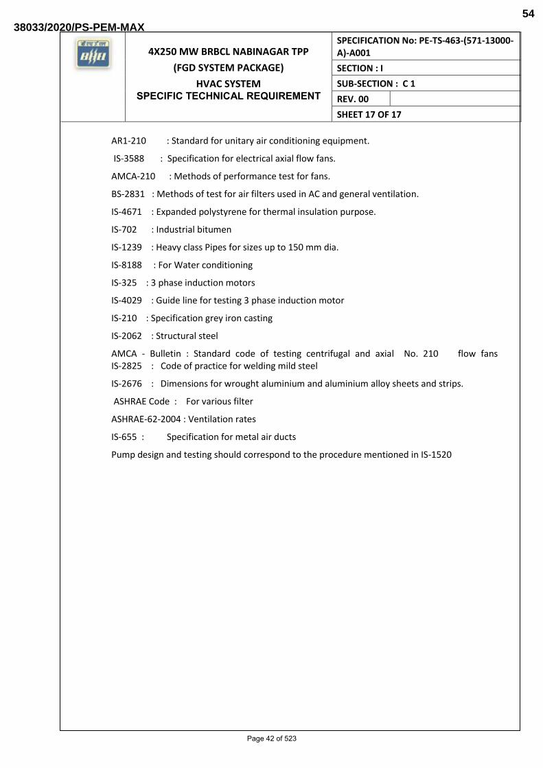
AR1-210 : Standard for unitary air conditioning equipment.
IS-3588 : Specification for electrical axial flow fans.
AMCA-210 : Methods of performance test for fans.
BS-2831 : Methods of test for air filters used in AC and general ventilation.
IS-4671 : Expanded polystyrene for thermal insulation purpose.
IS-702 : Industrial bitumen
IS-1239 : Heavy class Pipes for sizes up to 150 mm dia.
IS-8188 : For Water conditioning
IS-325 : 3 phase induction motors
IS-4029 : Guide line for testing 3 phase induction motor
IS-210 : Specification grey iron casting
IS-2062 : Structural steel
AMCA - Bulletin : Standard code of testing centrifugal and axial No. 210 flow fans IS-2825 : Code of practice for welding mild steel
IS-2676 : Dimensions for wrought aluminium and aluminium alloy sheets and strips.
ASHRAE Code : For various filter
ASHRAE-62-2004 : Ventilation rates
IS-655 : Specification for metal air ducts
Pump design and testing should correspond to the procedure mentioned in IS-1520
Page 42 of 523
38033/2020/PS-PEM-MAX54

TECHNICAL SPECIFICATION
4X250 MW BRBCL NABINAGAR STPP (FGD SYSTEM PACKAGE) CHAIN PULLEY BLOCK
Material Handling Equipments
Page 43 of 523
38033/2020/PS-PEM-MAX55

TECHNICAL SPECIFICATION
4X250 MW BRBCL NABINAGAR STPP (FGD SYSTEM PACKAGE) CHAIN PULLEY BLOCK
1.0 MANUAL HOIST (CHAIN PULLEY BLOCK)
Required number of manual hoist of adequate capacity, to meet the erection and maintenance requirements are to be provided for the various areas. DESIGN CRITERIA All necessary lifting equipment and hoists (hooks and provisions for chain blocks to be provided for repair work where loads exceed 50 kg, hoists to be provided for repair work where loads exceed 500 kg) i.e. for 50 kg to < 500kg - hooks and provisions for chain blocks to be provided for 500 kg to <= 2000 kg – Chain pulley block with travelling trolley Capacity of manual (Chain pulley block) hoists shall be decided keeping 25% margin over equipment to be handled. For hand operated hoists, the hoists shall be suitable for operation from floor level. Hand chain shall be provided for long travel of trolley and the Hoisting mechanism.
MINIMUM LIFTING REQUIREMENT
S.N. AREA DESCRIPTION
QTY(nos) CAPACITY (T)
MINIMUM LIFT
TYPE
1
Note: 1. Area, type, capacity mentioned are minimum requirement and shall be finalised during detail
engineering without any commercial implication. 2. Travel and Lift are layout dependent and shall be finalised during detail engineering without
any commercial implication 3. Additional manual hoist required during detail engineering shall be provided as per design
criteria given above without any commercial implication. 2.0 SCOPE OF SUPPLIES
Equipment and services to be furnished by the bidder for the MANUAL HOIST with accessories as per the details given in the technical specification and data sheet A. Any equipment / accessories not specified in the specification but required to make the MANUAL HOIST complete and efficient operation shall also be under the bidder’s scope of work.
Compliance with this specification shall not relieve the bidder of the responsibility of furnishing material and workmanship to meet the specified working/duty conditions.
3.0 Inspection and Testing
As per quality plan approved during detail engineering. Prime inspection agency shall be Consultant/ End Customer/ BHEL. Equipment supplied shall be strictly in accordance with nomenclature & technical specification. Any additional testing requirement/CHP (Customer
Page 44 of 523
38033/2020/PS-PEM-MAX56
TECHNICAL SPECIFICATION
4X250 MW BRBCL NABINAGAR STPP (FGD SYSTEM PACKAGE) CHAIN PULLEY BLOCK
Hold Point) at any stage of inspection deemed necessary by Consultant/ End Customer during detailed engineering shall be carried out without any commercial or technical implication.
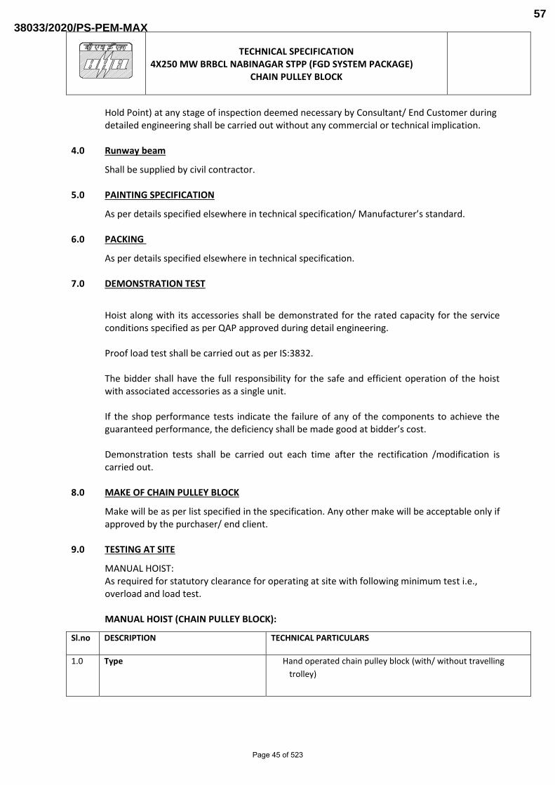
4.0 Runway beam
Shall be supplied by civil contractor.
5.0 PAINTING SPECIFICATION
As per details specified elsewhere in technical specification/ Manufacturer’s standard.
6.0 PACKING
As per details specified elsewhere in technical specification.
7.0 DEMONSTRATION TEST
Hoist along with its accessories shall be demonstrated for the rated capacity for the service conditions specified as per QAP approved during detail engineering. Proof load test shall be carried out as per IS:3832. The bidder shall have the full responsibility for the safe and efficient operation of the hoist with associated accessories as a single unit. If the shop performance tests indicate the failure of any of the components to achieve the guaranteed performance, the deficiency shall be made good at bidder’s cost. Demonstration tests shall be carried out each time after the rectification /modification is carried out.
8.0 MAKE OF CHAIN PULLEY BLOCK
Make will be as per list specified in the specification. Any other make will be acceptable only if approved by the purchaser/ end client.
9.0 TESTING AT SITE
MANUAL HOIST: As required for statutory clearance for operating at site with following minimum test i.e., overload and load test.
MANUAL HOIST (CHAIN PULLEY BLOCK):
Sl.no DESCRIPTION TECHNICAL PARTICULARS
1.0 Type Hand operated chain pulley block (with/ without travelling
trolley)
Page 45 of 523
38033/2020/PS-PEM-MAX57

TECHNICAL SPECIFICATION
4X250 MW BRBCL NABINAGAR STPP (FGD SYSTEM PACKAGE) CHAIN PULLEY BLOCK
2.0 Scope (Qty., Capacity, Lift,
Travel Length)
As per specification and layout requirement
3.0 Type of service As per specification & layout requirement (Indoor/ Outdoor)
4.0 Design Ambient temperature 50 Deg C
5.0 Design standards IS: 3832
6.0 Duty class Class II duty equivalent (Suitable for power plant operation)
7.0 Hoisting Mechanism
7.1 Type Hand operated gear transmission
7.2 Gears / pinion
i) Type Spur / Helical
ii) Material Alloy steel / carbon steel / high graded cast iron
iii) Type of bearing used Antifriction ball bearing / Roller
7.3 Load Chain
i) Type Link type
ii) Material As per IS:6216 grade 80
iii) Conforms to (Std./Code): IS:6216
7.4 Hand Chain
i) Type Link type
ii) Material Mild steel (grade 30 pitched and polished) as per IS 2429 Part I / II
7.5 Load Hook
i) Type of load hook Plain shank- Trapezoidal section with safety latch.
ii) Load hooks conforms to: IS: 8610 & with antifriction bearing
iii) Type of hook suspension Swiveling
iv) Type of make of bearing Thrust ball bearing of hook suspension
7.6 Sprockets
i) Type of bearings used Antifriction ball bearing / Roller
7.7 Load chain wheel
i) Material As per IS 3832
7.8 Hoisting effort Shall not exceed 30 kg
8.0 Trolley & Bridge Drive
8.1 Trolley
i) Type Geared (Manually operated)
Page 46 of 523
38033/2020/PS-PEM-MAX58
TECHNICAL SPECIFICATION
4X250 MW BRBCL NABINAGAR STPP (FGD SYSTEM PACKAGE) CHAIN PULLEY BLOCK
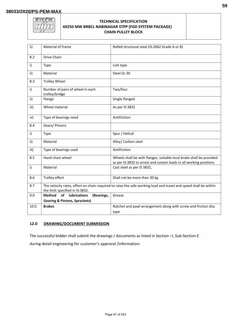
ii) Material of frame Rolled structural steel (IS:2062 Grade A or B)
8.2 Drive Chain
i) Type Link type
ii) Material Steel Gr.30
8.3 Trolley Wheel
i) Number of pairs of wheel in each trolley/bridge
Two/four
ii) Flange Single flanged
iii) Wheel material As per IS 3832
iv) Type of bearings need Antifriction
8.4 Gears/ Pinions
i) Type Spur / Helical
ii) Material Alloy/ Carbon steel
iii) Type of bearings used Antifriction
8.5 Hand chain wheel Wheels shall be with flanges, suitable local brake shall be provided as per IS:3832 to arrest and sustain loads in all working positions
i) Material Cast steel as per IS 3832,
8.6 Trolley effort Shall not be more than 30 kg
8.7 The velocity rates, effort on chain required to raise the safe working load and travel and speed shall be within the limit specified in IS:3832.
9.0 Method of lubrications (Bearings,
Gearing & Pinions, Sprockets)
Grease
10.0 Brakes Ratchet and pawl arrangement along with screw and friction disc
type
12.0 DRAWING/DOCUMENT SUBMISSION
The successful bidder shall submit the drawings / documents as listed in Section –I, Sub-Section-E
during detail engineering for customer’s approval /information:
Page 47 of 523
38033/2020/PS-PEM-MAX59

MANUFACTURER’S NAME & ADDRESS :
MANUFACTURING QUALITY PLAN
ITEM : Chain Pulley Block
QP No.: PE-V0-457-571-13000-A-A102
REV.: , Date.: , PAGE: 1 OF 4
PROJECT: 4X250 MW BRBCL NABINAGAR STPP
(FGD SYSTEM PACKAGE)
PACKAGE: CHAIN PULLEY BLOCK
Sr.
No.
1.
COMPONENT /
OPERATION
2.
CHARACTERISTICS
3.
CLAS
S
4.
TYPE OF CHECK
5.
QUANTU
M OF
CHECK
REFERENCE
DOCUMENT
7.
ACCEPTANCE
NORMS
8.
FORMAT
OF
RECORD
9.
AGENCY
REMARKS
11. M C N
M C/N
6.
10.
LEGEND: FOR CUSTOMER USE
** M : MANUFACTURER / SUB-SUPPLIER
MANUFACTURER / CONTRACTOR C : BHEL / NOMINATED INSPECTION AGENCY.
N : CUSTOMER/ NOMINATED INSPECTION AGENCY.
SUB-CONTRACTOR INDICATE “P” PERFORM “W” WITNESS AND “V” VERIFICATION
SIGNATURE REVIEWED BY NAME & SIGN OF APPROVING AUTHORITY & SEAL
1
RAW MATERIAL &
B/OUT ITEMS:
1.1 HOOKS CHEMICAL & MECH
MARK &
IDENTIFICATION
INTERNAL DEFECTS
PROOF LOAD TEST
NDT AFTER PROOF
LOAD TEST
MA
MA
MA
MA
MA
LAB
ANALYSIS
VISUAL
UT
REVIEW
DPT
ONE
SAMPLE
PER HEAT
100%
100%
100%
100%
MATERIAL SPECIFICATION AS
PER APPROVED DRAWINGS.
HOOK TC FROM COMPETENT
AUTHORITY
ASTM A-388 ( REFER NOTE I)
IS 15560
NO RELEVANT
ASTM E-165 INDICATTION
MTC.
TC
IR
TC
TC
P V V
P V V
P V V
P V V
P V V
1.2 LOAD CHAIN - DIMENSIONS
- BREAKING STR &
% ELONGATION
- PROOF LOAD
-HEAT TREATMENT
-GRADE
MA
MA
MA
MA
MA
MEASUREMENT
-TENSILE TEST
-TENSILE TEST
REVIEW
REVIEW
100%
1/LOT
100%
100%
1/BATCH
APPD. DRGS
-DO-
-DO-
-DO-
-DO-
APPD. DRGS.
-DO-
-DO-
-DO-
-DO-
IR
MTC
MTC
HT
CHRT
MTC
P V V
P V V
P V V
P V V
P V V
Page 48 of 523
38033/2020/PS-PEM-MAX60
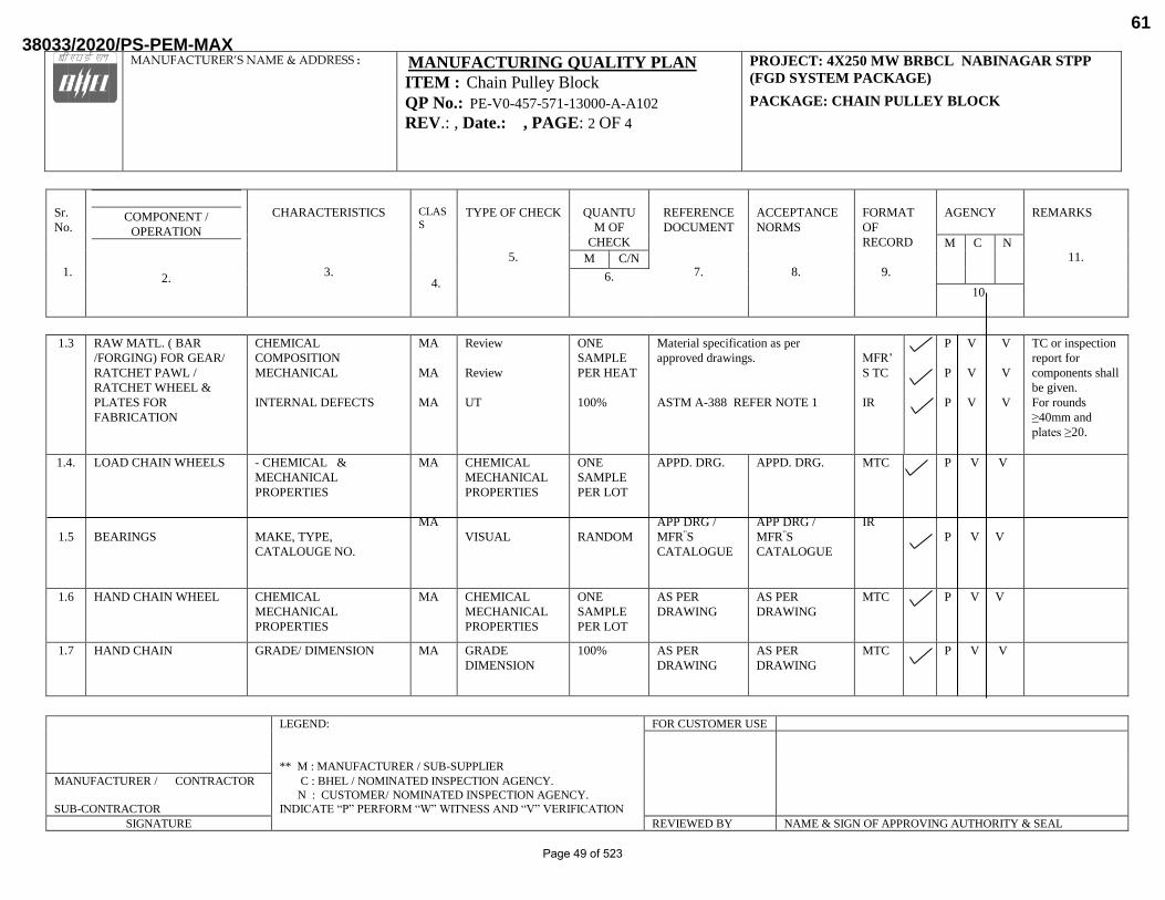
MANUFACTURER’S NAME & ADDRESS :
MANUFACTURING QUALITY PLAN
ITEM : Chain Pulley Block
QP No.: PE-V0-457-571-13000-A-A102
REV.: , Date.: , PAGE: 2 OF 4
PROJECT: 4X250 MW BRBCL NABINAGAR STPP
(FGD SYSTEM PACKAGE)
PACKAGE: CHAIN PULLEY BLOCK
Sr.
No.
1.
COMPONENT /
OPERATION
2.
CHARACTERISTICS
3.
CLAS
S
4.
TYPE OF CHECK
5.
QUANTU
M OF
CHECK
REFERENCE
DOCUMENT
7.
ACCEPTANCE
NORMS
8.
FORMAT
OF
RECORD
9.
AGENCY
REMARKS
11. M C N
M C/N
6.
10.
LEGEND: FOR CUSTOMER USE
** M : MANUFACTURER / SUB-SUPPLIER
MANUFACTURER / CONTRACTOR C : BHEL / NOMINATED INSPECTION AGENCY.
N : CUSTOMER/ NOMINATED INSPECTION AGENCY.
SUB-CONTRACTOR INDICATE “P” PERFORM “W” WITNESS AND “V” VERIFICATION
SIGNATURE REVIEWED BY NAME & SIGN OF APPROVING AUTHORITY & SEAL
1.3 RAW MATL. ( BAR
/FORGING) FOR GEAR/
RATCHET PAWL /
RATCHET WHEEL &
PLATES FOR
FABRICATION
CHEMICAL
COMPOSITION
MECHANICAL
INTERNAL DEFECTS
MA
MA
MA
Review
Review
UT
ONE
SAMPLE
PER HEAT
100%
Material specification as per
approved drawings.
ASTM A-388 REFER NOTE 1
MFR’
S TC
IR
P V V
P V V
P V V
TC or inspection
report for
components shall
be given.
For rounds
≥40mm and
plates ≥20.
1.4.
1.5
LOAD CHAIN WHEELS
BEARINGS
- CHEMICAL &
MECHANICAL
PROPERTIES
MAKE, TYPE,
CATALOUGE NO.
MA
MA
CHEMICAL
MECHANICAL
PROPERTIES
VISUAL
ONE
SAMPLE
PER LOT
RANDOM
APPD. DRG.
APP DRG /
MFR”S
CATALOGUE
APPD. DRG.
APP DRG /
MFR”S
CATALOGUE
MTC
IR
P V V
P V V
1.6 HAND CHAIN WHEEL CHEMICAL
MECHANICAL
PROPERTIES
MA CHEMICAL
MECHANICAL
PROPERTIES
ONE
SAMPLE
PER LOT
AS PER
DRAWING
AS PER
DRAWING
MTC P V V
1.7 HAND CHAIN GRADE/ DIMENSION MA GRADE
DIMENSION
100% AS PER
DRAWING
AS PER
DRAWING
MTC P V V
Page 49 of 523
38033/2020/PS-PEM-MAX61

MANUFACTURER’S NAME & ADDRESS :
MANUFACTURING QUALITY PLAN
ITEM : Chain Pulley Block
QP No.: PE-V0-457-571-13000-A-A102
REV.: , Date.: , PAGE: 3 OF 4
PROJECT: 4X250 MW BRBCL NABINAGAR STPP
(FGD SYSTEM PACKAGE)
PACKAGE: CHAIN PULLEY BLOCK
Sr.
No.
1.
COMPONENT /
OPERATION
2.
CHARACTERISTICS
3.
CLAS
S
4.
TYPE OF CHECK
5.
QUANTU
M OF
CHECK
REFERENCE
DOCUMENT
7.
ACCEPTANCE
NORMS
8.
FORMAT
OF
RECORD
9.
AGENCY
REMARKS
11. M C N
M C/N
6.
10.
LEGEND: FOR CUSTOMER USE
** M : MANUFACTURER / SUB-SUPPLIER
MANUFACTURER / CONTRACTOR C : BHEL / NOMINATED INSPECTION AGENCY.
N : CUSTOMER/ NOMINATED INSPECTION AGENCY.
SUB-CONTRACTOR INDICATE “P” PERFORM “W” WITNESS AND “V” VERIFICATION
SIGNATURE REVIEWED BY NAME & SIGN OF APPROVING AUTHORITY & SEAL
1.8 TROLLEY GEARS,
PINION,WHEELS, AXLE
CHEMICAL &
MECHANICAL
MA LAB ANALYSIS, 100% APPVD DRGS APPVD DRGS IR/TC P V V
2 IN PROCESS
2.1 RATCHET PAWL /
RATCHET WHEEL
-HARDNESS
-SURFACE CRACK
MA
MA
HARDNESS
DPT
100%
100 %
IS:3832/ APPD
DRG.
ASTM E165
IS:3832/
APPD. DRG.
NO DEFECT
IR
IR
P V V
P V V
2.2 GEARS AND PINIONS
AFTER MACHINING
HEAT TREATMENT
SURFACE HARDNESS
SURFACE CRACK
DIMENSION
MA
MA
MA
MA
HT CHART
HARDNESS
DPT FOR
SURFACE
CRACK
MEASURE
100%
10%
100%
10%
IS 1875/IS 4367/IS 3832
--DO--
ASTM E 165 NO DEFECT
IS 3832
IR
IR
IR
IR
P V V
P V V
P V V
P V V
3.0
FINAL INSPECTION
3.1 COMPLETE ASSEMBLY OVERALL DIMENSION
ENDURNACE TYPE TEST
OPERATIONAL PROOF
LOAD & LIGHT LOAD
TEST
CR
MA
CR
MEASUREMENT
TYPE TEST
LOAD TEST
100 %
1 PER SIZE
100%
IS:3832 /APPD
DRG
IS 3832
-DO-
IS:3832 /APPD
DRG
IS 3832
-DO-
IR
TC
IR
P W V
P V V
P W V
P W V
Page 50 of 523
38033/2020/PS-PEM-MAX62

MANUFACTURER’S NAME & ADDRESS :
MANUFACTURING QUALITY PLAN
ITEM : Chain Pulley Block
QP No.: PE-V0-457-571-13000-A-A102
REV.: , Date.: , PAGE: 4 OF 4
PROJECT: 4X250 MW BRBCL NABINAGAR STPP
(FGD SYSTEM PACKAGE)
PACKAGE: CHAIN PULLEY BLOCK
Sr.
No.
1.
COMPONENT /
OPERATION
2.
CHARACTERISTICS
3.
CLAS
S
4.
TYPE OF CHECK
5.
QUANTU
M OF
CHECK
REFERENCE
DOCUMENT
7.
ACCEPTANCE
NORMS
8.
FORMAT
OF
RECORD
9.
AGENCY
REMARKS
11. M C N
M C/N
6.
10.
LEGEND: FOR CUSTOMER USE
** M : MANUFACTURER / SUB-SUPPLIER
MANUFACTURER / CONTRACTOR C : BHEL / NOMINATED INSPECTION AGENCY.
N : CUSTOMER/ NOMINATED INSPECTION AGENCY.
SUB-CONTRACTOR INDICATE “P” PERFORM “W” WITNESS AND “V” VERIFICATION
SIGNATURE REVIEWED BY NAME & SIGN OF APPROVING AUTHORITY & SEAL
HEIGHT OF LIFT
SWIVELING OF HOOK
EFFORT
MA
MA
MA
VISUAL
VISUAL
PULL ON CHAIN
100 %
100%
100%
-DO-
APPROVED
DRG
-DO-
-DO-
APPROVED
DRG
-DO-
IR
IR
IR
P W V
P W V
3.2 PAINTING -CLEANING
- SHADE & DFT OF
PAINT
MA
MI
VISUAL
VISUAL
AT
RANDOM
AT
RANDOM
APPROVED
DRAWING/
SPECIFICATI
ON
APPROVED
DRAWING/
SPECIFICATI
ON
IR
IR
P --- --
-
p W ---
3.3 NAME PLATE VERIFICATION MA VISUAL 100% IR P V ---
3.4 PACKING -VERIFICATION
MI VISUAL 100% SPECS. SPECS. IR P --- ---
3.5
REVIEW OF QA
DOCUMENTATION
VERIFICATION MA VISUAL 100% APPD. QP APPD. QP V V V
CR – CRITICAL, MA – MAJOR , MI – MINOR
NOTE 1: WHEN BACK WALL ECHO ( BWE) IS SET AT 100% OF FULL SCREEN HEIGHT ( FSH) IN DEFECT FREE AREA THEN
(A) DEFECT ECHO SHALL NOT EXCEED 20% OF FSH &
(B) BWE SHOULD BE MINIMUM 80% OF FSH IN ANY AREA.
NOTE 2: RECORDS IDENTIFIED WITH TICK SHALL BE ESSENTIALLY INLCUDED IN QA DOCUMENTATION.
Page 51 of 523
38033/2020/PS-PEM-MAX63

4x250 MW NABINAGAR TPP
(FGD SYSTEM PACKAGE)
HVAC SYSTEM O&M SERVICES
SPECIFICATION No: PE-TS-463-(571-13000-A)-A001
SECTION : I
SUB-SECTION : C 1
REV. 00
SHEET 1 OF 5
OPERATION AND MAINTENANCE SERVICES FOR HVAC SYSTEM
Page 52 of 523
38033/2020/PS-PEM-MAX64

4x250 MW NABINAGAR TPP
(FGD SYSTEM PACKAGE)
HVAC SYSTEM O&M SERVICES
SPECIFICATION No: PE-TS-463-(571-13000-A)-A001
SECTION : I
SUB-SECTION : C 1
REV. 00
SHEET 2 OF 5
1.0 OPERATION AND MAINTENANCE SERVICES The bidder scope also covers the Operation and Maintenance (O&M) services for Preventive and Breakdown maintenance from the date of successful commissioning of HVAC System to end customer. However, actual date of start of O&M services shall be communicated to successful bidder by BHEL site personnel. Bidder to note that the spares and consumables required for maintenance of the equipment during this O&M period shall be in bidder’s scope of supply. Bidder shall use only genuine parts as mentioned in O&M Manual. Any damage or malfunction caused by the use of unauthentic parts or unqualified personnel shall be responsibility of bidder and as a consequence of above bidder is required to replenish the unauthorised part and abridge the qualified person without any commercial implication to BHEL. O&M Services scope also covers all regular maintenance by certified and trained service engineers and supply of genuine parts and lubricants as per the original equipment manufacturer’s recommendations in a pro-active manner. For the purpose of Operation of HVAC System, One-day shall be considered as 24 hours i.e. 3 shifts of 8 hours each. The HVAC System (along with related accessories) shall be operated on Round-the-clock basis on all the days of the year including Sundays and Public Holidays O & M Personnel should be acquainted with local language. Governmental / Statutory approval w.r.t. O&M service as applicable shall be in bidder's scope. Total duration of the Operation and Maintenance services by Bidder can be increased or decreased as per requirement and payment in such case shall be made on pro-rata basis. Depending on start of O&M services, there is a possibility that some period of O&M services and Warranty period may overlap. However, it is clarified that any maintenance required or any spare of HVAC System required to be replaced during Warranty period (as part of warranty clause requirement) shall not be made part of O&M Services. Bidder may take care of this fact while working out the prices of O&M services. Wherever AC system has been written in O&M Service Specification, the same shall be deemed as complete HVAC System.
The vendor shall deploy following minimum manpower for Operation of HVAC System.
i. One qualified and experienced AC operator per shift on "Round the Clock" basis throughout the year for all days of the year including Sundays & Public Holidays. There must be minimum 30 minutes overlapping between two shift operators to get familiarize with the status of HVAC System. Under normal circumstances one shift shall not be more than 8 hours.
ii. One Helper per shift on " Round the Clock" basis throughout the year for all the
days of the year including Sundays and Public Holidays. The helper shall assist the HVAC System Operator in day to day operation of HVAC System and accessories and shall assist him for keeping HVAC System equipment’s in neat
Page 53 of 523
38033/2020/PS-PEM-MAX65

4x250 MW NABINAGAR TPP
(FGD SYSTEM PACKAGE)
HVAC SYSTEM O&M SERVICES
SPECIFICATION No: PE-TS-463-(571-13000-A)-A001
SECTION : I
SUB-SECTION : C 1
REV. 00
SHEET 3 OF 5
and tidy condition. Under normal circumstances one shift shall not be more than 8 hours
1.1 Responsibility of HVAC System Operator
i. HVAC System operator shall be responsible for proper sequential operation of HVAC System (AC and Ventilation System) including operation of standby equipment in a predefined sequence and stopping the same (when necessary) as per the procedural practice. In case of any abnormality (like non availability of power supply at incomer of HVAC System), he shall immediately report the matter to BHEL site Engineer for further action. Similarly, any malfunctioning in the system shall be immediately reported by him to BHEL site Engineer for suitable corrective action irrespective of time of occurrence of malfunctioning / abnormality in the system. A log book of all such outrages shall be maintained by HVAC system operator, which shall be shared with BHEL site engineer on periodic basis.
ii. HVAC System operator shall take hourly readings of all the parameters of HVAC System / Equipment’s including reading on main electrical panel of HVAC System. Temperature & RH readings inside all AC areas shall be taken at least once in a day. All the readings shall be recorded in a logbook register.
1.2 Responsibility of Helper.
i. The HVAC System helper shall assist HVAC System operator for day to day smooth operation of HVAC System, like Checking of water levels of UAF Tank, cleaning of Tanks, cleaning of strainers, cleaning of AHU filters and other filters etc. as and when required. He shall be responsible for keeping all the equipment’s of HVAC System including DX Unit & AHU rooms in clean and tidy condition. He shall also carry out general cleaning of all AC equipment’s including Electrical Panels (Part of AC System), AHU's etc. on regular basis.
ii. The helper shall work under the control of HVAC System operator and shall always ensure that unusable junk materials are not allowed to be kept in HVAC System room or AHU rooms. Under such eventuality, he will report the matter to Plant Operator, who in turn will take suitable action including reporting the matter to BHEL site Engineer.
1.3 All the log book registers shall be arranged by vendor. Log book register duly paged and bounded will be maintained in good condition by vendor.
1.4 All the necessary tools and other materials, required for operation of HVAC System shall be kept by vendor under the control of HVAC System operator. Required testing instruments like refrigerant leak detector, Multi Meter (for Electrical portion of HVAC System), Sling pshycrometer, Line Tester, Tool Kit, Torch etc. should also be always available with Plant Operator.
1.5 In case of any operator / helper being on leave, vendor shall immediately take advance action and provide substitution so that minimum manpower as indicated above is not reduced on any day. In case a particular shift duty A/C Operator or helper
Page 54 of 523
38033/2020/PS-PEM-MAX66

4x250 MW NABINAGAR TPP
(FGD SYSTEM PACKAGE)
HVAC SYSTEM O&M SERVICES
SPECIFICATION No: PE-TS-463-(571-13000-A)-A001
SECTION : I
SUB-SECTION : C 1
REV. 00
SHEET 4 OF 5
does not turn up due to any reasons, the earlier duty person shall continue to make sure that HVAC System never remains unattended.
2.0 Maintenance of HVAC System
i. Maintenance work under scope of the vendor shall broadly include but in no way limited to the following:
a) Preventive maintenance of the plant.
b) Servicing of the plant at regular interval including cleaning of AHU filters etc., Strainer, UAF Tanks etc.
c) Attending to complaints.
d) Replacement of worn out or defective components
e) Replacing of refrigerant gas and oil as and when required.
No consumable or any other items of HVAC system shall be arranged by Customer and no extra payment shall be made by customer in this regard.
ii. Vendor shall be responsible at all time, during the entire period of contract for satisfactory performance of HVAC system (including accessories) with zero down time. During emergency or breakdown, vendor's Engineer along with related technicians shall be available immediately even though it may be beyond normal working hours or on public holidays till the HVAC System is restored back into normal satisfactory condition. Response time for attending breakdown complaints shall not exceed 2 hours.
iii. Defective / worn out components shall be replaced only by genuine and original parts. OEM or its authorized dealer's invoice shall be submitted as proof of using genuine parts. All common spares required for HVAC system shall normally be kept available in the plant by the vendor. However, for critical spares, the same shall be made available in not more than 72 hours from the time of break-down requiring such spare.
iv. Preventive Maintenance, servicing of HVAC System equipment’s and accessories etc. shall be done by vendor in a planned manner in consultation with concerned customer’s engineer. Preventive maintenance and service should be done as per the recommendations / guidelines of various OEMs
v. Major servicing & over handling of equipment’s like compressors, evaporators, condensers, pumps, AHU's, piping / ducting works, valves etc. shall be done by vendor once in a year.
vi. Painting of all equipment’s including base frames & accessories like piping, electrical panel boards etc. shall be done once in two years.
vii. In case any repair/services of particular equipment of system like chiller unit is to be carried out by vendor through OEM (or their authorized dealer), all the
Page 55 of 523
38033/2020/PS-PEM-MAX67
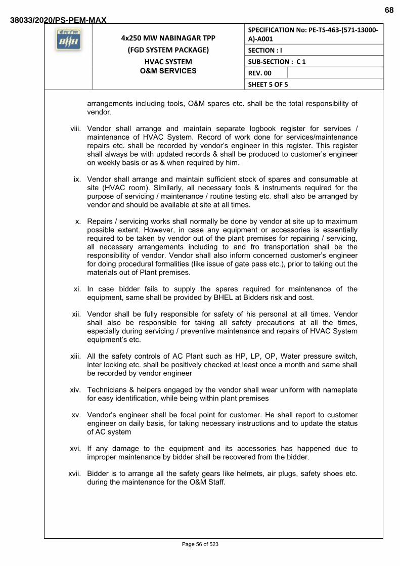
4x250 MW NABINAGAR TPP
(FGD SYSTEM PACKAGE)
HVAC SYSTEM O&M SERVICES
SPECIFICATION No: PE-TS-463-(571-13000-A)-A001
SECTION : I
SUB-SECTION : C 1
REV. 00
SHEET 5 OF 5
arrangements including tools, O&M spares etc. shall be the total responsibility of vendor.
viii. Vendor shall arrange and maintain separate logbook register for services / maintenance of HVAC System. Record of work done for services/maintenance repairs etc. shall be recorded by vendor’s engineer in this register. This register shall always be with updated records & shall be produced to customer’s engineer on weekly basis or as & when required by him.
ix. Vendor shall arrange and maintain sufficient stock of spares and consumable at site (HVAC room). Similarly, all necessary tools & instruments required for the purpose of servicing / maintenance / routine testing etc. shall also be arranged by vendor and should be available at site at all times.
x. Repairs / servicing works shall normally be done by vendor at site up to maximum possible extent. However, in case any equipment or accessories is essentially required to be taken by vendor out of the plant premises for repairing / servicing, all necessary arrangements including to and fro transportation shall be the responsibility of vendor. Vendor shall also inform concerned customer’s engineer for doing procedural formalities (like issue of gate pass etc.), prior to taking out the materials out of Plant premises.
xi. In case bidder fails to supply the spares required for maintenance of the equipment, same shall be provided by BHEL at Bidders risk and cost.
xii. Vendor shall be fully responsible for safety of his personal at all times. Vendor shall also be responsible for taking all safety precautions at all the times, especially during servicing / preventive maintenance and repairs of HVAC System equipment’s etc.
xiii. All the safety controls of AC Plant such as HP, LP, OP, Water pressure switch, inter locking etc. shall be positively checked at least once a month and same shall be recorded by vendor engineer
xiv. Technicians & helpers engaged by the vendor shall wear uniform with nameplate for easy identification, while being within plant premises
xv. Vendor's engineer shall be focal point for customer. He shall report to customer engineer on daily basis, for taking necessary instructions and to update the status of AC system
xvi. If any damage to the equipment and its accessories has happened due to improper maintenance by bidder shall be recovered from the bidder.
xvii. Bidder is to arrange all the safety gears like helmets, air plugs, safety shoes etc. during the maintenance for the O&M Staff.
Page 56 of 523
38033/2020/PS-PEM-MAX68
4X250 MW BRBCL NABINAGARTPP
(FGD SYSTEM PACKAGE)
HVAC SYSTEM
CUSTOMER SPECIFICATIONS
SPECIFICATION No: PE-TS-463-(571-13000-A)-A001
SECTION : I
SUB-SECTION : C 2
REV. 00
SECTION: I
SUB-SECTION: C 2
CUSTOMER SPECIFICATIONS
Page 57 of 523
38033/2020/PS-PEM-MAX69

4X250 MW BRBCL NABINAGARTPP
(FGD SYSTEM PACKAGE)
HVAC SYSTEM
CUSTOMER SPECIFICATIONS
TECHNICAL REQUIREMENT
SPECIFICATION No: PE-TS-463-(571-13000-A)-A001
SECTION : I
SUB-SECTION : C 2A
REV. 00
SECTION: I
SUB-SECTION: C 2A
CUSTOMER SPECIFICATIONS TECHNICAL REQUIREMENT
Page 58 of 523
38033/2020/PS-PEM-MAX70

CLAUSE NO.
1.00.00
SCOPE OF SUPPLY & SERVICES Iq;,Jral NTPC
AIR CONDITIONING SYSTEM
a) General
The scope includes Engineering, Supply, Construction, Erection, Testing and Commissioning for Complete Air conditioning system consisting of D-X units with refrigerant piping & valves, Air handling units, Hi-wall split air conditioner ICassette Air conditioners, Packaged Air Conditioners, Fresh air fans , air distribution system (ducting, filters, isolation dampers, motorized fire dampers, diffusers, grills, volume control dampers, etc.) etc., along with all electrical equipment and instrumentation as required for all the bu ildings which are in the scope of the bidder, as detailed out in Part-B of Section-VI.
b) Air-conditioning system for F.G.D Control Room Building and ZLD control room building (if provided)
Air cooled condensing units (D-X type) type air conditioners with AHU of suitable capacity with 100 % redundancy ( as per actual heat load calcu lation ) shall be provided.
c) S02 analyzer room (if required ) and other air conditioned offices/areas covered under this package shall be provided with Ductable/Non ductable Split air conditioners etc. as per Design criteria specified in Chapter Salient Design Data. Non ductable Split air conditioner shall confonn to minimum three (3) star (***) rating and above of latest version of Bureau of Energy Efficiency (BEE) HVAC code issued by Ministry of Power, Govt of India.
d) Supply of Mandatory spares as specified.
e) Any additional items required to make the system complete.
f) For Air cond itioning system, the Bidder shall provide all Instrumentation systems, accessories and associated equipment, wh ich are included in Bidder's scope, in a fully operational condition acceptable to the Employer. The Bidder sha ll also provide all material , equipment and services which may not be specifically stated in the specifications but are required for completeness of the equipment/systems furnished by the Contractor and for meeting the intent and requirements of these specifications.
g) Contractor shall provide microprocessor/PLC/GIU based control system for control and monitoring of air conditioning system as per manufacturer's standard practice. However relative humidity and temperature measurement of all control rooms and all major air-conditioned areas shall be made available in FGDI ZLD control system. Control and monitoring of air conditioning system from FGDIZLD control system is also acceptable.
h) Apart from the above, any area/build ing which are in the scope of the bidder and require air conditioning, the same shall be provided with air cond itioning system, as detailed out in Part-B of Technical Specification.
LOT 1A PROJECTS TECHNICAL SPECIFICATION
SECTION - VI, PART-A
SUB SEcnoN-III-A2 AIR CONDITIONING,
VENTILATION SYSTEM & COMPRESSED AIR
Page 10f4 FLUE GAS DESULPHURISATION SYSTEM
PACKAGE BID DOC. NO.:CS-0011-109(1A)-2 SYSTEM
Page 59 of 523
38033/2020/PS-PEM-MAX71
6043623
Text Box
6043623
Text Box
6043623
Text Box

CLAUSE NO.
1.02.00
2.00.00
SCOPE OF SUPPLY & SERVICES Iq;,Jral NTPC
Redundancies of equipments:
100% standby unit shall be kept for FGD/ZLD control room, S02 analyzer room (if required) and other air conditioned offices/areas.
VENTILATION SYSTEM
a) General
The scope includes Engineering, Supply, Construction, Erection, Testing and Commission ing for Complete Ventilation system consisting of Modular type Unitary air fi lteration Units, Supply air fans, water pumps, exhaust air fans, louvers, filters , ducting, diffusers, piping, instrumentation etc. , for all the build ings wh ich are in the scope of the bidder, as detailed out in Part-B of Section-VI.
b) Non-AIC areas of F.G.D Control Room Building and ZLD control room building (if provided)
Minimum One (1) nos. of Evaporative type Unitary Air Filtration (UAF) unit (of metall ic construction- modular type) of suitable capacity with all accessories, DIDW centrifugal fan (1 x 100%), circulating water pump (1 x 100%), etc. as detailed out in technical specification shall be provided.
c) Miscellaneous areas: All other areas like Limestone Grinding system build ing, Gypsum dewatering bu ilding, Recirculation pump & Oxidation blower/compressor bu ilding etc & all other non-air conditioned areas covered under this package shall be ventilated by a combination of supply/exhaust fans and fresh air in-take / back draft louvers. For ventilation of Battery rooms and Oil rooms, fans with flame proof motor shall be used. Further, toilets shall be provided with propeller type exhaust air fans.
d) Supply of Mandatory spares as specified.
e) Any additional items required to make the system complete.
f) For Ventilation system, the Bidder shall provide all Instrumentation systems, accessories and associated equipment, which are included in Bidder's scope, in a fully operational cond ition acceptable to the Employer. The Contractor shall also provide all material , equipment and services which may not be specifically stated in the specifications but are required for completeness of the equipment/systems furnished by the Contractor and for meeting the intent and requ irements of these specifications.
g) Contractor shall provide microprocessor/PLC/GIU based control system for control and monitoring of ventilation system as per manufacturer's standard practice. Control and monitoring of ventilation system from FGD /ZLD control system is also acceptable.
LOT 1A PROJECTS TECHNICAL SPECIFICATION
SECTION - VI, PART-A
SUB SEcnoN-III-A2 AIR CONDITIONING,
VENTILATION SYSTEM & COMPRESSED AIR
Page 20f4 FLUE GAS DESULPHURISATION SYSTEM
PACKAGE BID DOC. NO.:CS-0011-109(1A)-2 SYSTEM
Page 60 of 523
38033/2020/PS-PEM-MAX72
6043623
Text Box
6043623
Text Box
6043623
Text Box
6043623
Text Box

CLAUSE NO.
3.00.00
4.00.00
SCOPE OF SUPPLY & SERVICES Iq;,Jral NTPC
COMPRESSED AIR SYSTEM
a) Two (2) numbers (1 working+ 1 standby) oil free , rotary screw type air compressors for Instrument air and service air applications for FGD and ZLD plant (if provided) each of adequate capacity & adequate pressure, with their motor drives and other accessories as per equipment sizing criteria mentioned in Part A, Sub-section 'Salient design data' of techn ical specification. However, minimum capacity of each air compressor sha ll be 15Nm3/min at discharge pressure of 8.5 Kgf/cm2 (g).
b) Two (2) numbers (1 working+ 1 standby) Air Drying Plants (one for each air compressor) of adequate capacity with all interconnecting piping, valves, fittings, etc.
c) Two number Air Receiver each of capacity 2 m3 (nonnal) at the discharge of each Air compressor.
d) One number Air Receiver of capacity 2m3(nonnal) for ZLD plant if ZLD plant is far away from compressor location.
g) Monorail with Chain pulley block of minimum 2 tons or 125% of heaviest parts of equipment to be lifted whichever is more.
h) Complete instruments, control system with panels as required for compressed air system.
i) Complete compressed air and piping network for service air and instrument air application in FGD and ZLD system (if provided).
j) Supply of Mandatory spares as specified.
k) Any additional items required to make the system complete.
General
i. All associated Civil & structura l work for air condition ing and Ventilation system and compressed air system.
ii. Set of commissioning spares as may be required during erection and commissioning.
iii. One (1) set Special tools and tackles required for maintenance of all the Mechanical, Electrical and C & I equipment under the scope of bidder.
iv. All steel I cast iron inserts, plates, bolts, nuts, sleeves, metallic-fasteners etc. to be grouted in concrete work and used to holdl support the equipmenUpiping I ducting being supplied and erected under this specifications.
v. Any additional items required to make the system complete.
vi. Initial charge of all lubricants and grease, etc. Further, all consumables required for PG tests shall also be in Bidder's scope of supply. Grouting, dressing and final finishing of all foundations of various equipment, etc.
LOT 1A PROJECTS TECHNICAL SPECIFICATION
SECTION - VI, PART-A
SUB SEcnoN-III-A2 AIR CONDITIONING,
VENTILATION SYSTEM & COMPRESSED AIR
Page 30f4 FLUE GAS DESULPHURISATION SYSTEM
PACKAGE BID DOC. NO.:CS-0011-109(1A)-2 SYSTEM
Page 61 of 523
38033/2020/PS-PEM-MAX73
6043623
Text Box
6043623
Text Box
CLAUSE NO. SCOPE OF SUPPLY & SERVICES Iq;,Jral NTPC
vii. Repairing and making good/ sealing of cutouts / openings in floors, roofs and walls , for executing the works under this system and making them water tight as directed by the engineer.
Corrosion protection painting for all equipment / items by Bidder as detailed in relevant clauses of technical specification.
LOT 1A PROJECTS TECHNICAL SPECIFICATION
SECTION - VI, PART-A
SUB SECnON-III-A2 AIR CONDITIONING,
VENTILATION SYSTEM & COMPRESSED AIR
Page 40f4 FLUE GAS DESULPHURISATION SYSTEM
PACKAGE BID DOC. NO.:CS-0011-109(1A)-2 SYSTEM
Page 62 of 523
38033/2020/PS-PEM-MAX74
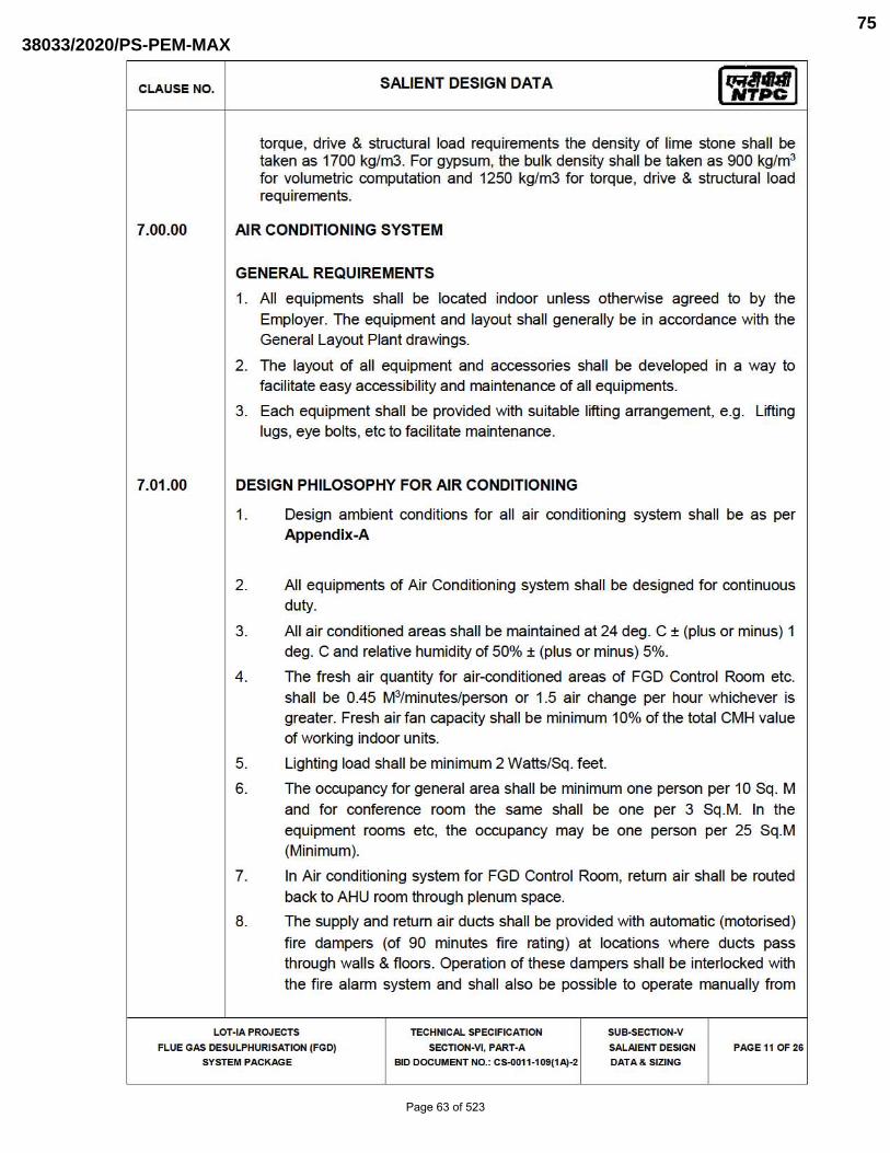
CLAUSE NO.
7.00.00
7.01.00
SALIENT DESIGN DATA
torque, drive & structural load requirements the density of lime stone shall be taken as 1700 kg/m3. For gypsum, the bulk density shall be taken as 900 kglm3
for volumetric computation and 1250 kg/m3 for torque, drive & structural load requirements.
AIR CONDITIONING SYSTEM
GENERAL REQUIREMENTS
1. All equipments shall be located indoor unless otherwise agreed to by the Employer. The equipment and layout shall generally be in accordance with the General Layout Plant drawings.
2. The layout of all equipment and accessories shall be developed in a way to faci litate easy accessibility and maintenance of all equipments.
3. Each equipment shall be provided with su itable lifting arrangement, e.g. Lifting lugs, eye bolts, etc to facilitate maintenance.
DESIGN PHILOSOPHY FOR AIR CONDITIONING
1. Design ambient conditions for all air condition ing system shall be as per Appendix-A
2. All equipments of Air Conditioning system shall be designed for continuous duty.
3. All air cond itioned areas shall be maintained at 24 deg. C ± (plus or minus) 1 deg. C and relative humidity of 50% ± (plus or minus) 5%.
4. The fresh air quantity for air-cond itioned areas of FGD Control Room etc. shall be 0.45 M3/minuteslperson or 1.5 air change per hour whichever is greater. Fresh air fan capacity shall be minimum 10% of the tota l CMH value of working indoor units.
5. Lighting load shall be minimum 2 Watts/Sq. feet.
6. The occupancy for general area shall be minimum one person per 10 Sq . M and for conference room the same shall be one per 3 Sq .M. In the equipment rooms etc, the occupancy may be one person per 25 Sq.M (Minimum).
7. In Air conditioning system for FGD Control Room, retum air shall be routed back to AHU room through plenum space.
8. The supply and return air ducts shall be provided with automatic (motorised)
fire dampers (of 90 minutes fire rating) at locations where ducts pass through walls & floors . Operation of these dampers shall be inte r10cked with the f ire alann system and shall also be possible to operate manually from
LOT-IA PROJECTS TECHNICAL SPECIFICATION
SECTION-VI. PART-A
SUB-SECTlON·V
SALAIENT DESIGN
DATA & SIZING
FLUE GAS DESULPHURISATION (FGD)
SYSTEM PACKAGE BID DOCUMENT NO.: C5-0011-109(1Aj·Z
PAGE 11 OF Z6
Page 63 of 523
38033/2020/PS-PEM-MAX75
6043623
Text Box
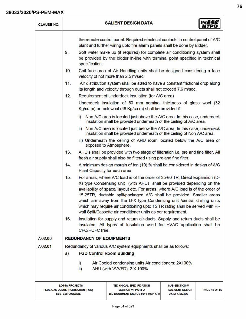
CLAUSE NO.
7.02.00
7.02.01
SALIENT DESIGN DATA
the remote control panel. Required electrical contacts in control panel of AlC plant and further wiring upto fire alann panels shall be done by Bidder.
9. Soft water make up (if required ) for complete air conditioning system shall be provided by the bidder in-line with terminal point specified in technical specification.
10. Coil face area of Air Handling units shall be designed considering a face ve locity of not more than 2.5 mlsec.
11. Air distribution system shall be sized to have a constant frictiona l drop along its length and velocity through ducts shall not exceed 7.6 m/sec.
12. Requ irement of Underdeck Insulation (for AlC area)
Underdeck insulation of 50 rnm nominal th ickness of glass wool (32 Kg/cu.m) or rock wool (48 Kg/cu.rn) shall be provided if
i) Non AlC area is located just above the AlC area. In this case, underdeck insulation shall be provided underneath of the ceiling of AlC area.
ii) Non AlC area is located just below the AlC area. In th is case, underdeck insulation shall be provided underneath of the ceiling of Non AlC area.
iii ) Underneath the ce iling of AHU room located below the AlC area or exposed to Atmosphere.
13. AHU's shall be provided with two stage of f ilteration i.e. pre and fine filter. All
fresh air supply sha ll also be fi ltered using pre and fine fi lter.
14. A minimum design margin of ten (10) % shall be considered in design of AlC Plant Capacity for each area.
15. For areas, where NC load is of the order of 25-60 TR, Direct Expansion (O
X) type Condensing unit (with AHU) shall be provided depending on the availability of space/ layout etc. For areas, where NC load is of the order of 15-25TR, ductable split/packaged AlC shall be provided. Smaller areas which are away from the O-X type Condensing unit /central ch ill ing units which may require air cond it ioning upto 15 TR rating shall be served with Hiwall Split/Cassette air cond it ioner units as per requirement.
16. Insulation for supply and return air ducts: Supply and return ducts shall be insulated. All types of Insulation used for HVAC application shall be CFC/HCFC free.
REDUNDANCY OF EQUIPMENTS
Redundancy of va rious NC system equipments shall be as follows:
a) FGD Control Room Building
i) Air Cooled condensing units Air cond itioners: 2X100% ii) AHU (with VWFD): 2 X 100%
LOT-IA PROJECTS TECHNICAL SPECIFICATION
SECTION-VI, PART-A
SUB-SECTlON·V
SALAIENT DESIGN
DATA & SIZING
FLUE GAS DESULPHURISATION (FGD)
SYSTEM PACKAGE BID DOCUMENT NO.: C5-0011-109(lAj·Z
PAGE 1Z OF Z6
Page 64 of 523
38033/2020/PS-PEM-MAX76
6043623
Text Box
4 Nos. (2W+2S)
6043623
Text Box
4 Nos. (2W+2S)
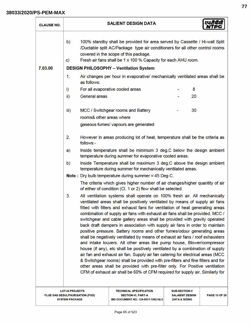
CLAUSE NO.
7.03.00
SALIENT DESIGN DATA
b) 100% standby shall be provided for area served by Cassette / Hi-wall Split
/Ductable split AC/Package type air conditioners for all other control rooms
covered in the scope of th is package. c) Fresh air fans shall be 1 x 100 % Capacity for each AHU room.
DESIGN PHILOSOPHY - Ventilation System
1. Air changes per hour in evaporative/ mechanically ventilated areas shall be as follows:
i)
ii)
iii)
For all evaporative cooled areas
General areas
MCC / Switchgear rooms and Battery
rooms& other areas where
gaseous fumes/ vapours are generated
B
20
30
2. However in areas producing lot of heat, temperature shall be the criteria as follows:-
a) Inside temperature shall be minimum 3 deg.C be low the design ambient temperature during summer for evaporative cooled areas.
b) Inside Temperature shall be maximum 3 deg.C above the design ambient temperature during summer for mechanically ventilated areas.
Note: Dry bu lb temperature during summer = 45 Deg C.
The criteria which gives higher number of air changes/h igher quantity of air of either of cond it ion (CI. 1 or 2) flow shall be selected.
3. All ventilation systems shall operate on 100% fresh air. All mechanically ventilated areas shall be positively ventilated by means of supply air fans fitted with f ilters and exhaust fans for ventilation of heat generating areas combination of supply air fans with exhaust air fans shall be provided. MCC / switchgear and cable gallery areas shall be provided with gravity operated back draft dampers in association with supply air fans in order to maintain positive pressure. Battery rooms and other fumes/odour generating areas shall be negatively ventilated by means of exhaust air fans / roof exhausters and intake louvers. All other areas like pump house, Blower/compressor house (if any), etc shall be positively ventilated by a combination of supply air fan and exhaust air fan. Supply air fan catering for electrical areas (MCC & Switchgear rooms) shall be provided with pre-filters and fine filters and for other areas shall be provided with pre-filter on ly. For Positive ventilation
CFM of exhaust air shall be 60% of CFM required for supply air. Similar1y for
LOT-IA PROJECTS TECHNICAL SPECIFICATION
SECTION-VI, PART-A
SUB-SECTlON·V
SALAIENT DESIGN
DATA & SIZING
FLUE GAS DESULPHURISATION (FGD)
SYSTEM PACKAGE BID DOCUMENT NO.: C5-0011-109(lAj ·Z
PAGE 13 OF Z6
Page 65 of 523
38033/2020/PS-PEM-MAX77

CLAUSE NO. SALIENT DESIGN DATA
negatively ventilated area, CFM of supply shall be 60% of total CFM exhaust.
4. All the equipments of Ventilation system shall be designed for continuous duty.
5. The supply air ducts of evaporative type ventilation system entering into switchgear room, cable galleries etc. shall be provided with automatic (motorised) fire dampers (of 90 minutes fire rating). Operation of these dampers shall be inter10cked with the fire alann system and shall also be possible to operate manually from the remote control panel. Requ ired electrical contacts in control panel of AlC plant and further wiring upto fire alann panels shall be done by Bidder.
6. Circulating water Capacity for Air washer units shall be minimum 0.7 Cu.M/hr per 1000 Cu.M Ihr of air flow. Velocity through piping shall be limited to 2.0 mlsec and for gravity flow the same shall be limited to 1.5 mlsec. Air distribution system shall be sized to have a constant frictional drop along its length and air velocity through ducts shall not exceed 12.5 mlsec.
7. For pumps, continuous motor rating (at 5QoC ambient) shall be atleast 10%
above the maximum load demand of the pump in the entire operating range.
For fans, compressors and blowers continuous motor rating (at 500C ambient) shall be atleast 10% above the maximum load demand at the design duty point.
8. Supply air fans, exhaust ai r fans & ventilations of each area shall be provided with local starter panels.
LOT-IA PROJECTS
FLUE GAS DESULPHURISATION (FGD)
SYSTEM PACKAGE
TECHNICAL SPECIFICATION
SECTION-VI. PART-A
BID DOCUMENT NO.: C5-0011-109(lAj·Z
SUB-SECTlON·V
SALAIENT DESIGN
DATA & SIZING
PAGE 140F Z6
Page 66 of 523
38033/2020/PS-PEM-MAX78

CLAUSE NO. SALIENT DESIGN DATA 1~n:1 Appendix-A
Outside Design Ambient condition to be considered for Air Conditioning system and ventilation System for various projecUstation are as under.
Location Season Dry Bulb Temp. Wet Bulb Temp. (Dog. C) (Dog. C)
Summer 42.0 21.6
Kudgi 32.6 26.6 Slg-1 Monsoon
(3x800) 16.2 12.4 Winter
Summer 44.0 25.5
LARA 31.0 27.7 Slg-1 Monsoon
(2x800) 12.2 6.6 Winter
Summer 44.0 25.5
Gadarwara 31.0 27.0 Slg-1 Monsoon
(2x800) 12.2 6.6 Winter
Summer 43.0 27.0
Oar1ipalli 34.0 28.0 Slg-1 Monsoon
(2x800) 11 .0 5.0 Winter
Summer 43.5 25.5
Mouda 38.0 27.5 81g-11 Monsoon
(2x660) 15.0 10.0 Winter
Solapur Summer 43.5 25.5
LOT·IA PROJECTS TECHNICAL SPECIFICATION SUS.SECTlON·V
FLUE GAS DESULPHURISATION (FGD) SECTlON·VI, PART·A SALAIENT DESIGN PAGE 150F Z6
SYSTEM PACKAGE BID DOCUMENT NO,: Cs.oo1 1·109(1Aj ·Z DATA & SIZING
Page 67 of 523
38033/2020/PS-PEM-MAX79
1895656
Rectangle
1895656
Line

CLAUSE NO. SALIENT DESIGN DATA 1~n:1 STg-1 Monsoon 38.0 27.5
(2x660)
Winter 15.0 10.0
Summer 44.0 23.5
Tanda-II 34 .0 28.5 STG-II Monsoon
(2x660) 8.0 7.0 Winter
Summer 45.0 25.0
Nabinagar JV STG-I Monsoon 34 .0 28.0
(2x660)
Winter 5.0 2.0
Summer 44 .0 23.5
Meja JV 34 .0 28.5 STG-I Monsoon
(2x660) 8.0 7.0 Winter
Summer 43.0 27.5
Barh 38.0 29.5 Slg-1 Monsoon
(3x660) 7.0 5.8 Winter
Summer 45.0 25.0 Nabinagar JV (RL Y)
Slg-1 Monsoon 38.0 28.0
(4x250)
Winter 5.0 2.0
Rihand Summer 43.9 25.6
STG-II&III 35 28.9 (2x500) Monsoon
LOT·IA PROJECTS TECHNICAL SPECIFICATION SUS.SECTlON·V
FLUE GAS DESULPHURISATION (FGD) SECTION·VI, PART·A SALAIENT DESIGN PAGE 160F Z6
SYSTEM PACKAGE BID DOCUMENT NO,: Cs.oo1 1·109(1Aj ·Z DATA & SIZING
Page 68 of 523
38033/2020/PS-PEM-MAX80
6043623
Rectangle
6043623
Rectangle
6043623
Line
6043623
Line
6043623
Line
6043623
Line

,-____________________________ -iI~~L I NTPC I
SUB-SECTION-I-M2
AIR CONDITIONING & VENTILATION SYSTEM
LOT -IA PROJECTS FLUE GAS DESULPHURISATION (FGD) SYSTEM PACKAGE
TECHNICAL SPECIFICATION
SECTlON·VI
BID DOCUMENT NO.: CS-0011-109(1A)-2
Page 69 of 523
38033/2020/PS-PEM-MAX81

CLAUSE NO.
1.00.00
1.01.00
2.00.00
2.01.00
3.00.00
3.01.00
3.02.00
TECHNICAL REQUIREMENTS Iq;,Jral NTPC
GENERAL
This section of specification covers details of system specifications, detailing the areas to be air conditioned, basis of design, brief description of the system, equipment and services to be furnished by bidder.
The Design, Engineering, Supply, Construction, Erection, and Testing & Commissioning of all the equipments & works listed here shall be on the basis of single point responsibility in bidder's scope of work for satisfactory completion of the system in all respect.
AREAS TO BE AIR CONDITIONED
The areas to be air-conditioned shall be as follows:
a) Ai r cooled condensing units (D-X type) type ai r conditioners with AHU of suitable capacity with 100 % redundancy ( as per actua l heat load calculation ) shall be provided for each FGD Control room build ing and ZLD control room bu ilding (if provided).
b) Cassette and Hi-wall Air-conditioners for Other auxiliary control room /control
room buildings not listed above but covered in the scope of Bidder.
AREAS TO BE VENTILATED
(i) Unitary Air Filtration (UAF) units of min. capacity 75,000 m3/hr or capacity calcu lated considering 8 air changes per hour whichever is higher, shall be provided for Non-Air Conditioned areas of FGD and ZLD (as provided) control building (e.g. Switch gear rooms, cable galleries, etc. )
(ii) Mechanical Ventilation (using Roof extractors/ Supply and/or Exhaust fans) shall be provided for various other areaslbuildings in the scope of bidder as under:
a) Grinding system building b) Gypsum dewatering building
c) Recirculation pump & Oxidation blower/compressor bu ilding.
(iii) Toilets etc in above build ing (i) & (ii). Any other area not listed above but covered in the scope of Bidder.
iv) For other miscellaneous areas/ build ings not listed above but covered in the scope of Bidder, mechanical type ventilation system using Supply and/or exhaust air fansl roof exhausters shall be provided.
All non-air cond itioned areas covered under this package shall be ventilated by a combination of supply/exhaust fans and fresh air in-take / back draft louvers as detailed below:
LOT-IA PROJECTS TECHNICAL SPECIFICATION
SECTION - VI, PART-B SUB SECTION-I-M2
AIR CONDITION ING & VENTILATION SYSTEM
Page 1 of 26 FLUE GAS DESULPHURISATION SYSTEM
PACKAGE BID DOC. NO:CS-0011-109(1A)-2
Page 70 of 523
38033/2020/PS-PEM-MAX82
6043623
Text Box
6043623
Text Box
6043623
Text Box
as mentioned in BOQ
6043623
Text Box
shall be provided for Non-Air Conditioned areas of FGD control building (e.g. Switchgear Rooms, Cable galleries etc.)
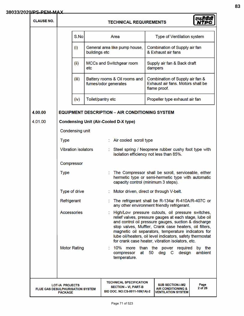
CLAUSE NO. TECHNICAL REQUIREMENTS Iq;,Jral NTPC
S.No Area Type of Ventilation system
(i) General area like pump house, Combination of Supply air fan buildings etc & Exhaust air fans
(ii) MCCs and Switchgear room Supply air fan & Back draft ele dampers
(iii) Battery rooms & Oil rooms and Combination of Supply air fan & fumes/odor generates Exhaust air fans. Motors shall be
flame proof.
(iv) T oileUpantry etc Propeller type exhaust air fan
4.00.00 EQUIPMENT DESCRIPTION - AIR CONDITIONING SYSTEM
4.01.00 Condensing Unit (Air-Cooled D-X type)
Condensing unit
Type Air cooled scroll type
Vibration isolators Steel spring / Neoprene rubber cushy foot type with isolation efficiency not less than 85%.
Compressor
Type The Compressor shall be scroll , serviceable, either hennetic type or semi-hermetic type with automatic capacity control (minimum 3 steps).
Type of drive Motor driven, direct or through V-belt.
Refrigerant The refrigerant shall be R-134a/ R410AlR407C or any other environment friendly refrigerant.
Accessories High/Low pressure cutouts, oil pressure switches, relief valves, pressure gauges at each stage, lube oil and control oil pressure gauges, suction & discharge stop valves, Muffler, Crank case heaters, oil fi lters, magnetic oil separators, temperature indicators for lube oil/heaters, oil level indicators, safety thermostat for crank case heater, vibration isolators, etc.
Motor Rating 10% more than Ihe power required by Ihe compressor at 50 deg C design ambient temperature.
TECHNICAL SPECIFICATION LOT-IA PROJECTS
SECTION - VI, PART-B SUB SECTION-I-M2 Page
FLUE GAS DESULPHURISATION SYSTEM AIR CONDITIONING & 2 of 26
PACKAGE BID DOC. NO:CS-0011-109(1A)-2 VENTILATION SYSTEM
Page 71 of 523
38033/2020/PS-PEM-MAX83

CLAUSE NO.
4.02.00
4.02.01
4.02.02
4.02.03
4.02.04
4.02.05
4.02.06
Capacity
Air Handling Unit (AHU)
TECHNICAL REQUIREMENTS Iq;,Jral NTPC
Minimum capacity shall be suitable for the identified/selected at evaporating temperature and condensing temperature and shall be indicated.
Each AHU shall consist of casing, fan impeller section, cooling coil section, damper section, steel frame with anti vibration mountings (AVMs) having minimum 85% vibration dampening efficiency and flame retardant, water proof neoprene impregnated flexible connection on fan discharge. Isolation dampers at the suction and discharge of each AHU shall be provided, in case return air duct is directly connected to AHU. However, in case AHU room is used for retum air, isolation dampers are required to be provided only at AHU discharge of each AHU. Pre-filter at the suction and fine (micro-vee type) and absolute (HEPA type) fi lters (wherever applicable) at the discharge of each individual AHU, and heater section in the common discharge of AHUs shall be provided.
The casing of AHUs sha ll be of double skin construction. Double skin sandwich panels (inside and outside) shall be fabricated using minimum 0.63 mm (24g) galvanized steel sheet (thickness of galvanization as per manufacturer's standard) , with 25mm thick polyurethane foam insulation of minimum 38 Kg/Cum density in between. Suitable reinforcements shall be provided to give structural strength to prevent any deformation/buckling.
Sloping condensate drain pan shall be made of minimum 1.2 mm thick Stainless Sheet Steel . It shall be isolated from bottom floor panel through 25mm thick heavy duty treated for Fire (TF) quality expanded polystyrene or polyurethane foam. Drain pan shall extend beyond the coil.
Cooling coil (min. 4 row deep) shall be made of seamless copper tubes with aluminium fins firmly bonded to copper tubes and shall be provided with suitable drains and vents connections.
All fi lter plenum shall be provided with a walking platform inside the plenum chamber for fi lter cleaning purpose. Inspection door shall be provided at the plenum chamber and a removable type ladder shall be attached to plenum.
Centrifugal fan for AHU
a) Fan Type
b) Fan impeller
c) Casing material
d) Impeller material
e) Shaft
Double Width Double Inlet (DWDI) Centrifugal Type
Backward curved blades
GI /Mild steel with minimum thickness of 3 mm.
Carbon steel
EN 8 Steel
LOT-IA PROJECTS TECHNICAL SPECIFICATION
SECTION - VI, PART-B SUB SECTION-I-M2
AIR CONDITION ING & VENTILATION SYSTEM
Page 3 of 26 FLUE GAS DESULPHURISATION SYSTEM
PACKAGE BID DOC. NO:CS-0011-109(1A)-2
Page 72 of 523
38033/2020/PS-PEM-MAX84

CLAUSE NO.
4.02.07
4.02.08
4.03.00
4.03.01
f) Fan bearings
g) Critical speed
h) Drive
i) Fans
Mixing Box:
TECHNICAL REQUIREMENTS Iq;,Jral NTPC
Self aligning type, permanently lubricated, heavy duty with a design life of 10,000 operating hours.
First critical speed of rotating assembly shall be at least 25% above the operating speed.
Motor driven with removable belt guard. Motor driven with removable belt guard. Motor rating (at 50 deg.C ambient) shall be atleast fifteen percent (15%) above the maximum load demand of drives at the design duty point.
For AHUs of capacity 50,000 CMH and above, Bidder may offer two (2) Nos. centrifugal fans of equal capacity for each AHU provided all such AHUs are accommodated within the space identified by the Employer.
Mixing box shall be complete with fresh and return air dampers. Mixing box shall be provided whenever the return air is ducted back to the AHU. Further, wherever return air is led back directly to AHU room, no mixing box is required .
Pan Humidifier:
Pan humidifier shall be made of 22 gauge SS 304 tank, duly insulated with 25 mm th ick resin bonded fiber glass insulation (min. 24 Kg/m3 density) with 0.5 mm GSS cladding. The humidifier shall be complete with stainless steel immersion heaters, safety thermostat, float valve with stainless steel ball , sight glass, overflow and drain connections, steam outlet nozzle and float switch. Step controller sha ll be provided for switch ing on / off heater banks as per system requirement.
HI-WALL SPLIT/CASSETTE AIR-CONDITIONERS
Hi-wall SpliVcassette air cond itioners shall in general consist of the following:
i) Casing
ii) Hermetically sea led rota ry/scroll Compressor
iii) Condenser and condenser cooling fan
iv) Evaporator along with fan
v) Cooling coil
vi) Filters
LOT-IA PROJECTS TECHNICAL SPECIFICATION
SECTION - VI, PART-B SUB SECTION-I-M2
AIR CONDITION ING & VENTILATION SYSTEM
Page 4 of 26 FLUE GAS DESULPHURISATION SYSTEM
PACKAGE BID DOC. NO:CS-0011-109(1A)-2
Page 73 of 523
38033/2020/PS-PEM-MAX85
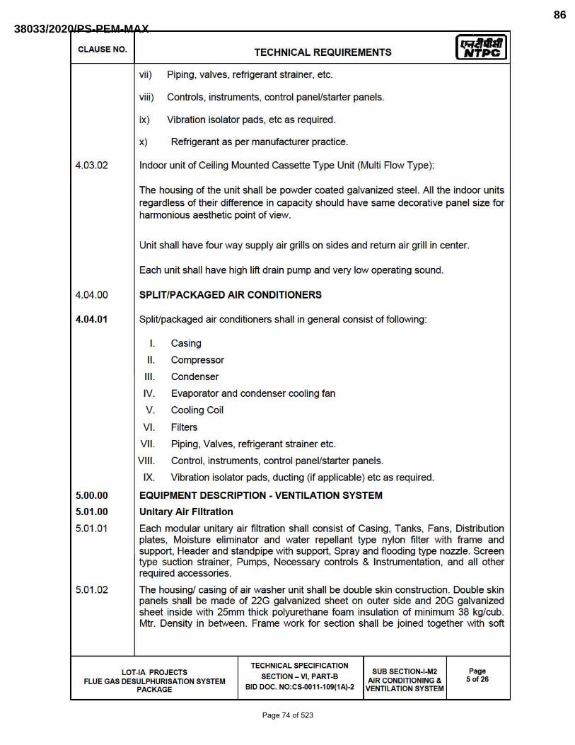
CLAUSE NO.
4.03.02
4.04.00
4.04.01
5.00.00
5.01.00
5.01.01
5.01.02
TECHNICAL REQUIREMENTS Iq;,Jral NTPC
vii) Piping, valves, refrigerant strainer, etc.
viii) Controls, instruments, control panel/starter panels.
ix) Vibration isolator pads, etc as required.
x) Refrigerant as per manufacturer practice.
Indoor unit of Ceiling Mounted Cassette Type Unit (Multi Flow Type):
The housing of the unit shall be powder coated galvanized steel. All the indoor units regardless of their difference in capacity should have same decorative panel size for hannonious aesthetic point of view.
Unit shall have four way supply air grills on sides and return air grill in center.
Each unit shall have high lift drain pump and very low operating sound.
SPLIT/PACKAGED AIR CONDITIONERS
SpliUpackaged air cond itioners shall in general consist of following:
I. Casing
II. Compressor
III. Condenser
IV. Evaporator and condenser cooling fan
V. Cooling Coil
VI. Filters
VII. Piping, Valves, refrigerant strainer etc.
VII I. Control , instruments, control panel/starter panels.
IX. Vibration isolator pads, ducting (if applicable) etc as required .
EQUIPMENT DESCRIPTION - VENTILATION SYSTEM
Unitary Ai r Filtration
Each modular unitary air filtration shall consist of Casing, Tanks, Fans, Distribution plates, Moisture eliminator and water repellant type nylon filter with frame and support, Header and standpipe with support, Spray and flooding type nozzle. Screen type suction stra iner, Pumps, Necessary controls & Instrumentation, and all other required accessories.
The housing! casing of air washer unit shall be double skin construction. Double skin panels shall be made of 22G galvanized sheet on outer side and 20G galvanized sheet inside with 25mm thick polyurethane foam insulation of minimum 38 kg/cub. Mtr. Density in between. Frame work for section shall be joined together with soft
LOT-IA PROJECTS TECHNICAL SPECIFICATION
SECTION - VI, PART-B SUB SECTION-I-M2
AIR CONDITIONING & VENTILATION SYSTEM
Page 5 of 26 FLUE GAS DESULPHURISATION SYSTEM
PACKAGE BID DOC. NO:CS-0011-109(1A)-2
Page 74 of 523
38033/2020/PS-PEM-MAX86

CLAUSE NO.
5.01.03
5.01.04
5.01.05
5.01.06
5.01.07
5.01.08
5.01.09
5.01.10
5.01.11
5.02.00
5.02.01
TECHNICAL REQUIREMENTS Iq;,Jral NTPC
rubber gasket in between to make the joints air tight. The entire fan section shall be mounted on rolled formed GSS channel frame work.
The unitary air filtration tank shall be fabricated from MS plate of minimum 6 mm th ick and inside and outside surface of the tank shall be spray galvanized (minimum 60 microns OFT). Minimum depth of the tank shall be 600 mm. Tank construction shall be such that the suction screen can be replaced while the unit is operating. Tank shall be provided with overflow, drain with valve, float valve makeup connection with a gate valve backup, quick fi ll connection with globe valve etc. The overflow pipe shall be connected to drain pipe after isolating valve on drain pipe.
The distribution plate shall be fabricated out of 18G galvanized steel sheets & galvanized steel angle supports with minimum 50% free area.
Unitary air filtration shall be one-bank construction. All header and stand pipes shall be galvanised. Cat walks of suitable width shall be provided for maintenance of nozzle, filter etc.
The spray nozzles shall be of brass or bronze with chrome plating and shall be self cleaning type. The nozzle shall be designed to produce fine atomised spray and shall be properly spaced to give a uniform coverage of the air washer section. The pressure drop through the nozzle should be in the range of 1.4 to 2.4 Kg/cm2.
The eliminator plates shall be of 24G thick GS sheets class 275 or from 100% virgin PVC of minimum fin ished thickness of 2 mm. The eliminator section made of GSS shall have minimum six bends. The PVC eliminators shall be UV stabilised using ntanium di-oxide and shall withstand the weathering test as per IS:4892 for 500 hrs. Type test report of the compound testing carried out in any reputed laboratory shall be submitted for approval. All supports, tie rods and space bar shall be of either galvanised steel or PVC construction and shall be complete with suitable drip tray and drain pipe.
Air tight inspection doors of su itable size shall be provided for suction chamber. Spray chamber and fan suction for easy accessibility and maintenance and a water marine light be provided for each unitary air filtration.
Suitable number of brass screen shall be provided in the air washer tank to arrest the dirt entering the circulating water pump suction. Suitable GI grid shall be used inside the screen for reinforcement.
The specification for centrifugal fans shall generally be as indicated below. However, the fan shall be of OIDW type for UAF unit.
Saturation efficiency of Unitary Air Filtration units shall be minimum 60%.
Centrifugal Fan
The casing shall be of welded construction fabricated with heavy gauge galvanised sheet steel or MS sheet with spray galvanization (minimum 60 micron OFT). The minimum th ickness of casing shall be 3 mm. It shall be rigidly reinforced and supported by structural angles. The seams shall be permanently sealed air-tight. Split casings shall be provided on larger sizes of fans. Casing drain with valves shall be provided wherever required .
The impeller shall have die-formed backward-curved blades tie welded to the rim and back plate to have a non overloading characteristic of the fan. Rim shall be spun to have a smooth contou r. If required intermediate stiffening rings shall be
LOT-IA PROJECTS TECHNICAL SPECIFICATION
SECTION - VI, PART-B SUB SECTION-I-M2
AIR CONDITION ING & VENTILATION SYSTEM
Page 6 of 26 FLUE GAS DESULPHURISATION SYSTEM
PACKAGE BID DOC. NO:CS-0011-109(1A)-2
Page 75 of 523
38033/2020/PS-PEM-MAX87
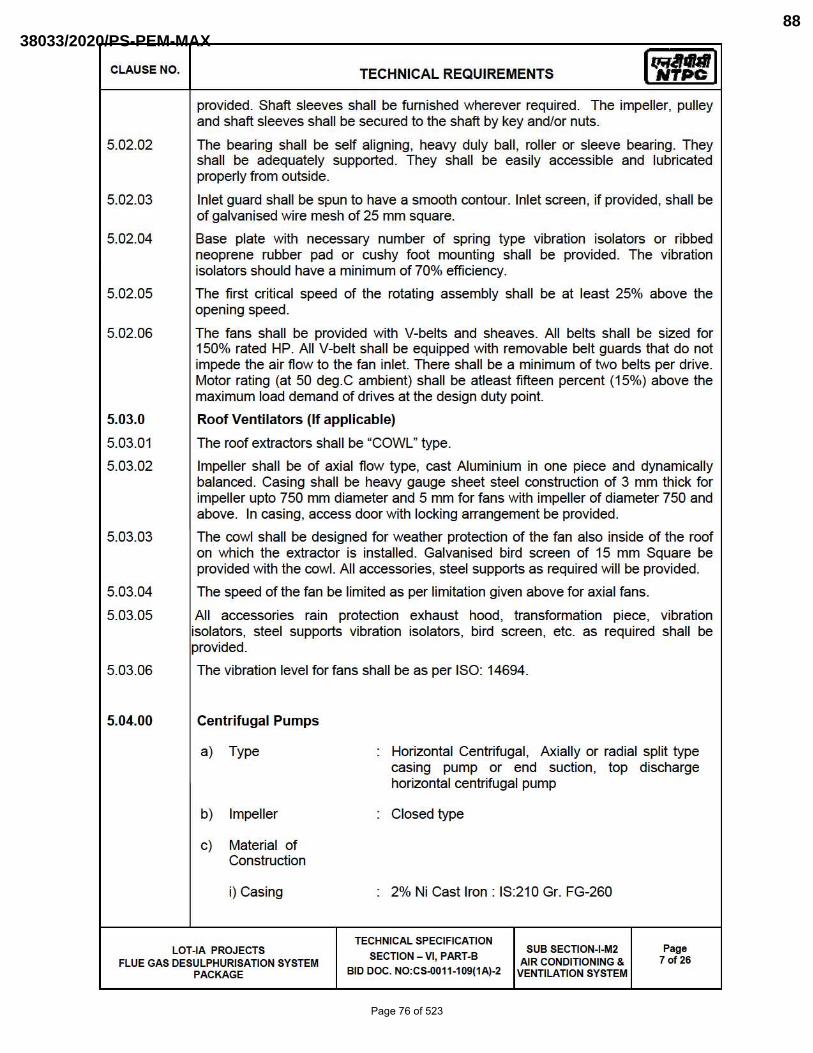
CLAUSE NO.
5.02.02
5.02.03
5.02.04
5.02.05
5.02.06
5.03.0
5.03.01
5.03.02
5.03.03
5.03.04
5.03.05
5.03.06
5.04.00
TECHNICAL REQUIREMENTS Iq;,Jral NTPC
provided. Shaft sleeves shall be furnished wherever required. The impeller, pulley and shaft sleeves shall be secured to the shaft by key and/or nuts.
The bearing shall be self aligning, heavy duly ball , roller or sleeve bearing. They shall be adequately supported. They shall be easily accessible and lubricated properly from outside.
Inlet guard shall be spun to have a smooth contour. Inlet screen, if provided, shall be of galvanised wire mesh of 25 mm square.
Base plate with necessary number of spring type vibration isolators or ribbed neoprene rubber pad or cushy foot mounting shall be provided. The vibration isolators should have a minimum of 70% efficiency.
The first critical speed of the rotating assembly shall be at least 25% above the opening speed.
The fans shall be provided with V-belts and sheaves. All belts shall be sized for 150% rated HP. All V-belt shall be equipped with removable belt guards that do not impede the air flow to the fan inlet. There shall be a minimum of two belts per drive. Motor rating (at 50 deg.C ambient) shall be atleast fifteen percent (15%) above the maximum load demand of drives at the design duty point.
Roof Ventilators (If applicable)
The roof extractors shall be "COWL" type.
Impeller shall be of axial flow type, cast Aluminium in one piece and dynamically ba lanced. Casing shall be heavy gauge sheet steel construction of 3 mm th ick for impeller upto 750 mm diameter and 5 mm for fans with impeller of diameter 750 and above. In casing, access door with locking arrangement be provided.
The cowl shall be designed for weather protection of the fan also inside of the roof on which the extractor is installed. Galvanised bird screen of 15 mm Square be provided with the cowl. All accessories, steel supports as required will be provided.
The speed of the fan be limited as per limitation given above for axial fans.
All accessories rain protection exhaust hood, transformation piece, vibration isolators, steel supports vibration isolators, bird screen, etc. as required shall be provided.
The vibration level for fans shall be as per ISO: 14694.
Centrifugal Pumps
a) Type
b) Impeller
c) Material of Construction
i) Casing
Horizontal Centrifugal, Axially or radial split type casing pump or end suction, top discharge horizontal centrifugal pump
Closed type
2% Ni Cast Iron: IS:210 Gr. FG-260
LOT-IA PROJECTS TECHNICAL SPECIFICATION
SECTION - VI, PART-B SUB SECTION-I-M2
AIR CONDITION ING & VENTILATION SYSTEM
Page 7 of 26 FLUE GAS DESULPHURISATION SYSTEM
PACKAGE BID DOC. NO:CS-0011-109(1A)-2
Page 76 of 523
38033/2020/PS-PEM-MAX88
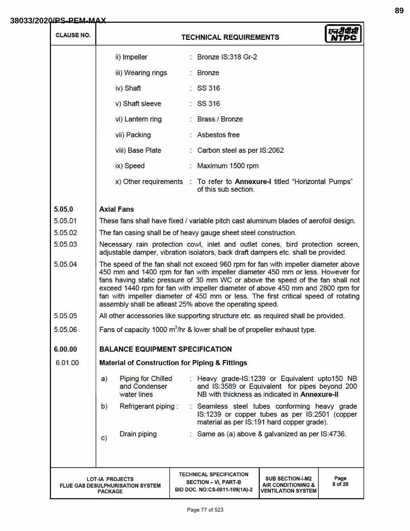
CLAUSE NO.
5.05.0
5.05.01
5.05.02
5.05.03
5.05.04
5.05.05
5.05.06
6.00.00
6.01.00
TECHNICAL REQUIREMENTS Iq;,Jral NTPC
ii) Impeller
iii) Wearing rings
iv) Shaft
v) Shaft sleeve
vi) Lantern ring
vii) Packing
viii) Base Plate
ix) Speed
x) Other requ irements
Axial Fans
Bronze IS:318 Gr-2
Bronze
88316
88316
Brass I Bronze
Asbestos free
Carbon steel as per IS:2062
Maximum 1500 rpm
To refer to Annexure-l titled "Horizontal Pumps" of this sub section.
These fans shall have fixed I va riable pitch cast aluminum blades of aerofoil design.
The fan casing shall be of heavy gauge sheet steel construction.
Necessary rain protection cowl, inlet and outlet cones, bird protection screen, adjustable damper, vibration isolators, back draft dampers etc. shall be provided.
The speed of the fan shall not exceed 960 rpm for fan with impeller diameter above 450 mm and 1400 rpm for fan with impeller diameter 450 mm or less. However for fans having static pressure of 30 mm WC or above the speed of the fan shall not exceed 1440 rpm for fan with impeller diameter of above 450 mm and 2800 rpm for fan with impeller diameter of 450 mm or less. The first critical speed of rotating assembly shall be atleast 25% above the operating speed.
All other accessories like supporting structure etc. as required shall be provided.
Fans of capacity 1000 m3/hr & lower shall be of propeller exhaust type.
BALANCE EQUIPMENT SPECIFICATION
Materi al of Constru cti on for Piping & Fittings
a)
b)
c)
Piping for Chilled and Condenser water lines
Refrigerant piping:
Dra in piping
Heavy grade-IS:1239 or Equivalent upto150 NB and IS:3589 or Equivalent for pipes beyond 200 NB with thickness as indicated in Annexure-ll
Seamless steel tubes conforming heavy grade IS:1239 or copper tubes as per IS:2501 (copper material as per IS:191 hard copper grade).
Same as (a) above & galvanized as per IS:4736.
LOT-IA PROJECTS TECHNICAL SPECIFICATION
SECTION - VI, PART-B SUB SECTION-I-M2
AIR CONDITION ING & VENTILATION SYSTEM
Page 8 of 26 FLUE GAS DESULPHURISATION SYSTEM
PACKAGE BID DOC. NO:CS-0011-109(1A)-2
Page 77 of 523
38033/2020/PS-PEM-MAX89

CLAUSE NO.
6.02.00
6.02.01
6.02.02
6.02.03
6.02.04
6.02.05
6.02.06
6.02.07
6.02.08
6.03.00
6.03.01
TECHNICAL REQUIREMENTS Iq;,Jral NTPC
d) Fittings
VALVES
1) The steel fittings shall conform to ASTM A234 Gr. WPB and dimensional standard to ANSI B 16.9/ANSI B16.11 1 equivalent for sizes 65 NB and above.
2) For sizes 50 NB and below, the material sha ll conform to ASTM A-1 05.
3) All steel flanges shall be of slip on type and shall conform to ANSI B 16.5
4) For pipe sizes above 350 NB, fabricated fittings from sheets of adequate thickness may be used. The bend radius in case of mitre bends shall be minimum 1.5 times the nominal pipe diameter and angle between two adjacent sections shall not be more than 22.5 deg and shall be as per BS:2633/BS:534.
5) Fittings , flanges and pipe joints of refrigerant piping shall conform to ANSI B31.5
Valves shall have full sizes port and su itable for horizontal and as well as vertical installation.
Valves for regulating duty shall be of globe type suitable for controlling throughout its lift.
All safety Irelief valves shall be so constructed that the failu re of any part does not obstruct the free discharge.
Valves shall be furnished with back seating arrangement for repacking while working under full working pressure.
Manual gear operators be provided for valves of size 200 NB and above.
All valves shall be supplied with companion flanges , nut, bolts & washers, etc.
The refrigerant line valves shall have steel or brass body with TEFLON gland packing. The construction of disc shall be either globe or angle type. The valve seat shall have white metal lining or equivalent.
Gate valves shall be of Cast Iron body (confirming to IS:210 Gr FG 220/equivalent) for sizes 65 NB and above conforming to flS :14846. Gun Metal construction for sizes less than 65NB shall be as per IS:778. Butterfly valves shall conform to latest revision of BS:5155 or equivalent standard of required class/rating.
AIR FILTERS
Pre Filter
1) Type : Flange 1 Cassette
2) Pre-filter shall contain washable non-woven synthetic fiber or High density Polyethylene (HDPE) media having 18G GSS 1 16G Al alloy frame. The filter media shall be supported with HOPE mesh on air inlet side & Aluminium
LOT-IA PROJECTS TECHNICAL SPECIFICATION
SECTION - VI, PART-B SUB SECTION-I-M2
AIR CONDITION ING & VENTILATION SYSTEM
Page 9 of 26 FLUE GAS DESULPHURISATION SYSTEM
PACKAGE BID DOC. NO:CS-0011-109(1A)-2
Page 78 of 523
38033/2020/PS-PEM-MAX90
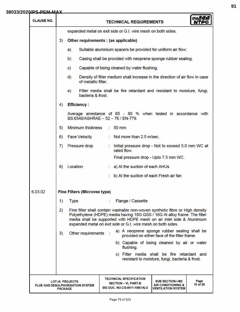
CLAUSE NO.
6.03.02
TECHNICAL REQUIREMENTS Iq;,Jral NTPC
expanded metal on exit side or G.!. wire mesh on both sides.
3) Other requirements: (as applicable)
a) Suitable aluminium spacers be provided for uniform air flow;
b) Casing shall be provided with neoprene sponge rubber sealing.
c) Capable of being cleaned by water flushing .
d) Density of filter medium shall increase in the direction of air flow in case of metallic filter.
e) Filter media shall be fire retardant and resistant to moisture, fungi , bacteria & frost.
4) Efficiency:
Average arrestance of 65 - 80 % when tested in accordance with BS:6540/ASHRAE - 52 - 76 1 EN-779.
5) Minimum thickness
6) Face Velocity
7) Pressure drop
8) Location
Fine Filters (Microvee type)
1) Type
50mm
Not more than 2.5 mlsec.
Initial pressure drop - Not to exceed 5.0 mm WC at rated flow.
Final pressure drop - Upto 7.5 mm WC.
a) At the suction of each AHUs
b) At the suction of each Fresh air fan
Flange I Cassette
2) Fine fi lter shall contain washable non-woven synthetic fi bre or High density Polyethylene (HOPE) media having 18G GSS 116G AI alloy frame. The filter media shall be supported with HOPE mesh on air inlet side & Aluminium expanded metal on exit side or G.!. wire mesh on both sides.
3) Other requirements a) A neoprene sponge rubber sealing shall be provided on either face of the fi lter frame.
b) Capable of being cleaned by air or water flushing .
c) Filter media shall be fire retardant and resistant to moisture, fungi, bacteria & frost.
LOT-IA PROJECTS TECHNICAL SPECIFICATION
SECTION - VI, PART-B SUB SECTION-I-M2
AIR CONDITION ING & VENTILATION SYSTEM
Page 10 of 26 FLUE GAS DESULPHURISATION SYSTEM
PACKAGE BID DOC. NO:CS-0011-109(1A)-2
Page 79 of 523
38033/2020/PS-PEM-MAX91

CLAUSE NO.
6.04.00
6.04.01
6.04.02
6.04.03
TECHNICAL REQUIREMENTS Iq;,Jral NTPC
4) Efficiency
5) Minimum thickness
6) Face Velocity
7) Pressure drop
8) Location
Average arrestance > 90% when tested in accordance with BS:6540/ASHRAE-52-76 J EN-779.
150 mm or 300 mm.
Not more than 1.2 mlsec for 150 mm and not more than 2.4 mlsec. for 300 mm.
Initial pressure drop - Not to exceed 10 mm we at rated flow; Fina l pressure drop-Up to 25 mm WC.
i) At the discharge of each individual AHU.
ii ) At the discharge of each Fresh air fan .
LOW PRESSURE AIR DISTRIBUTION SYSTEM
Material of air distribution system shall be through galvanized steel sheet (Confonning to Class 275 of IS :277) or Aluminium alloy (grade 19000 I SIC or 3100 J NS3 of IS:737). GI Sheets should be galvanized and galvanizing shall be of 275 gms/sq.m. (total coating on both sides) both for site fabricated and factory fabricated ducts.
Thickness of rectangular ducts shall be as follows:
Larger Dimension of duct (mm) Thickness of GI Thickness of Aluminium sheet(mm) sheet (mm)
upto 750 mm 0.63 (24 G) 0.80
751 to 1500 0.80 (22 G) 1.00
1501 to 2250 1.00 (20 G) 1.50
2251 & above 1.25 (18 G) 1.80
Thickness of round ducts shall be as follows:
Diameter of Round duct Thickness of GI Thickness of (mm) sheet(mm) Aluminium sheet (mm)
150 to 500 0.63 0.80
501 to 750 0.80 1.00
751 to 1000 0.80 1.00
1001 to 1250 1.00 1.50
1251 & above 1.25 1.80
LOT-IA PROJECTS TECHNICAL SPECIFICATION
SECTION - VI, PART-B SUB SECTION-I-M2
AIR CONDITION ING & VENTILATION SYSTEM
Page 11 of 26 FLUE GAS DESULPHURISATION SYSTEM
PACKAGE BID DOC. NO:CS-0011-109(1A)-2
Page 80 of 523
38033/2020/PS-PEM-MAX92

CLAUSE NO.
6.04.04
6.04.05
TECHNICAL REQUIREMENTS Iq;,Jral NTPC
Duct Fabrication and Supports:
a)
b)
c)
d)
e)
f)
g)
h)
Duct fabrication shall be as per the latest relevant BIS/SMACNA standard.
Ducts for AlC system may be site fabricated or factory fabricated.
The ducts routed inside the buildings with larger side greater than 2250 mm shall be supported by 16mm MS rods and 50x50x3 mm MS double Angles wh ile those below 2250 mm shall be supported by 10mm MS Rods and 40x40x3 MS angles. The duct supports shall be at a distance of not more than 2000 mm for AlC system. The MS rods for these ducts routed inside the bu ilding shall be hung from the existing floor beamslwall beams/roof beams/columns with provision of necessary auxiliary or special steel members or by hooks or can be provided by dash fasteners fixed to the ceiling slab. No supports shall be taken from horizontal/vertical bracings of the structures. All items of duct support including MS rods , MS angles and double angles, auxiliary or special steel members, hooks, dash fasteners coach screws and all other supporting material required shall be provided by the bidder. Where ever ducts are running outside the bu ilding and or at locations where it is not possible to support the ducts from ceiling/floor due to non-availability of the same, the base steel frame/truss work and other auxiliary steel members, hooks, rods, etc. for supporting the duct work shall also be provided by the Bidder.
Where the sheet metal duct connects to the intake or discharge of fan units a flexible connection of fire retarding, at least 150 mm width shall be provided of closely woven, rubber impregnated double layer asbestos/canvas or neoprene coated fibre glass.
All curves, bends, off-sets and other transformations shall be made for easy and noiseless flow of air. The throat of every branch duct shall be sized to have the same velocity as in the main duct to which the branch duct is connected.
Wherever duct passes through a wall , the opening between masonry and duct work shall be neatly caulked or sealed to prevent movement of air from one space to the adjoining space.
Wherever pipe hangers or rods pass through the ducts, light and streamline easement around the same shall be provided to maintain smooth flow of air.
Access doors shall be provided in the duct work or casing on the both sides of the equipment to be serviced. All access doors shall be of adequate size and shall be lined with substantial felt edging to prevent air leakage. Access doors shall be of bu ilt up construction, structurally strong and each shall have at least two hinges. Access doors shall have two rust proof window sash of approved type. All doors shall be set so as to flush with insulation or plaster finish on the duct.
Splitters and dampers shall be provided for equipment/area isolation and for proportional volume control of system. The same shall be minimum 16 gauge GS
LOT-IA PROJECTS TECHNICAL SPECIFICATION
SECTION - VI, PART-B SUB SECTION-I-M2
AIR CONDITION ING & VENTILATION SYSTEM
Page 12 of 26 FLUE GAS DESULPHURISATION SYSTEM
PACKAGE BID DOC. NO:CS-0011-109(1A)-2
Page 81 of 523
38033/2020/PS-PEM-MAX93
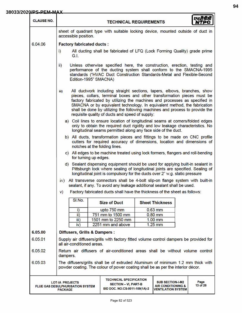
CLAUSE NO. TECHNICAL REQUIREMENTS Iq;,Jral NTPC
sheet of quadrant type with su itable locking device, mounted outside of duct in accessible position.
6.04.06 Factory fabricated ducts :
i) All ducting sha ll be fabricated of LFQ (Lock Forming Quality) grade prime G.I.
ii) Unless otherwise specified here, the construction, erection, testing and perfonnance of the ducting system shall confonn to the SMACNA-1995 standards r HVAC Duct Construction Standards-Metal and Flexible-Second Edil ion-1995" SMACNA)
iii) All ductwork including straight sections, tapers , elbows, branches, show pieces, collars , tenninal boxes and other transformation pieces must be factory fabricated by utilizing the machines and processes as specified in SMACNA or by equivalent technology . In equ ivalent method, the fabrication shall be done by utilizing the following machines and process to provide the requisite quality of ducts and speed of supply:
a) Coil l ines to ensure location of longitudinal seams at corners/folded edges only to obta in the required duct rig idity and low leakage characteristics. No longitud inal seams pennitted along any face side of the duct.
b) All ducts, transfonnation pieces and fi ttings to be made on CNC profile cutters for required accuracy of dimensions, location and dimensions of notches at the folding lines.
c) All edges to be machine treated using lock fonners, flangers and roll-bending for turning up edges.
d) Sealant dispensing equ ipment should be used for applying built-in sealant in Pittsburgh lock where sealing of longitudinal joints are specified. Sealing of longitud inal joint is compulsory for the ducts over 2" w.g. static pressure
iv) All transverse connectors shall be 4-bolt slip-on flange system with built-in sealant, if any. To avoid any leakage add itional sea lant shall be used.
v) Factory fabricated ducts shall have the th ickness of the sheet as follows:
SI.No. Size of Duct Sheet Thickness
i) upto 750 mm 0.63 mm ii) 751 mm to 1500 mm 0.80 mm iii) 1501 mm to 2250 mm 1.00 mm iv) 2251 mm and above 1.25 mm
6.05.00 Diffusers, Grills & Dampers:
6.05.01 Supply air diffusers/grills with factory fitted volume control dampers be provided for all air-conditioned areas.
6.05.02 Return air diffusers of air-conditioned areas shall be without volume control dampers.
6.05.03 The diffusers/grills shall be of extruded Aluminum of minimum 1.2 mm thick with powder coating. The colour of power coating shall be as per the interior decor.
TECHNICAL SPECIFICATION LOT-IA PROJECTS
SECTION - VI, PART-B SUB SECTION-I-M2 Page
FLUE GAS DESULPHURISATION SYSTEM AIR CONDITIONING & 13 of 26
PACKAGE BID DOC. NO:CS-0011-109(1A)-2 VENTILATION SYSTEM
Page 82 of 523
38033/2020/PS-PEM-MAX94
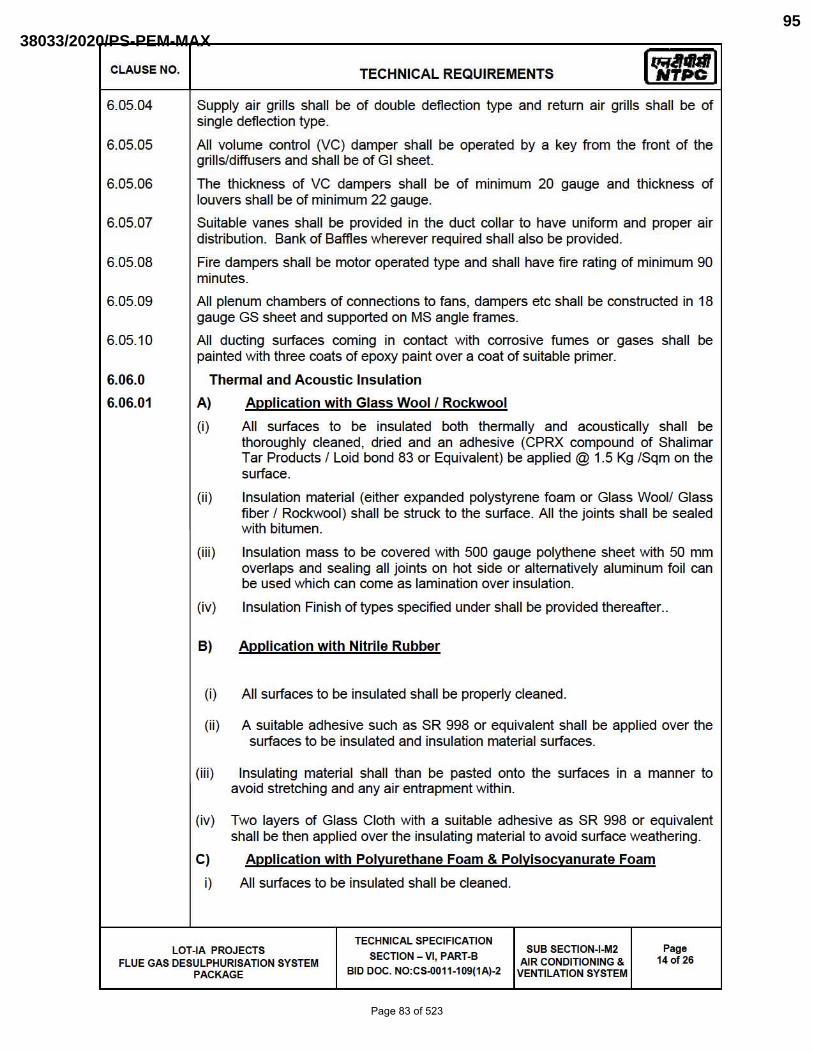
CLAUSE NO.
6.05.04
6.05.05
6.05.06
6.05.07
6.05.08
6.05.09
6.05.10
6.06.0
6.06.01
TECHNICAL REQUIREMENTS Iq;,Jral NTPC
Supply air grills shall be of double deflection type and return air grills shall be of single deflection type.
All volume control (VC) damper shall be operated by a key from the front of the grills/diffusers and shall be of GI sheet.
The thickness of VC dampers shall be of minimum 20 gauge and thickness of louvers shall be of minimum 22 gauge.
Suitable vanes shall be provided in the duct collar to have uniform and proper air distribution. Bank of Baffles wherever required shall also be provided.
Fire dampers shall be motor operated type and shall have fire rating of minimum 90 minutes.
All plenum chambers of connections to fans, dampers etc shall be constructed in 18 gauge GS sheet and supported on MS angle frames .
All ducting surfaces coming in contact with corrosive fumes or gases shall be pa inted with three coats of epoxy pa int over a coat of suitable primer.
Thermal and Acoustic Insulation
A) Application with Glass Wool f Rockwool
(i) All surfaces to be insulated both thermally and acoustically shall be thoroughly cleaned, dried and an adhesive (CPRX compound of Shalimar Tar Products f Loid bond 83 or Equivalent) be applied @ 1.5 Kg fSqm on the surface.
(ii ) Insulation material (either expanded polystyrene foam or Glass Woolf Glass fiber f Rockwool) shall be struck to the surface. All the joints shall be sealed with bitumen.
(iii) Insulation mass to be covered with 500 gauge polythene sheet with 50 mm overlaps and sealing all joints on hot side or alternatively aluminum foil can be used which can come as lamination over insulation.
(iv) Insulation Finish of types specified under shall be provided thereafter..
B) Application with Nitrile Rubber
(i) All surfaces to be insulated shall be properly cleaned.
(ii) A suitable adhesive such as SR 998 or equivalent shall be applied over the surfaces to be insulated and insulation material surfaces.
(iii) Insulating materia l shall than be pasted onto the surfaces in a manner to avoid stretching and any air entrapment with in.
(iv) Two layers of Glass Cloth with a suitable adhesive as SR 998 or equivalent shall be then applied over the insulating material to avoid surface weathering.
C) Application with Polyurethane Foam & Polyisocyanurate Foam
i) All surfaces to be insulated shall be cleaned.
LOT-IA PROJECTS TECHNICAL SPECIFICATION
SECTION - VI, PART-B SUB SECTION-I-M2
AIR CONDITION ING & VENTILATION SYSTEM
Page 14 of 26 FLUE GAS DESULPHURISATION SYSTEM
PACKAGE BID DOC. NO:CS-0011-109(1A)-2
Page 83 of 523
38033/2020/PS-PEM-MAX95

CLAUSE NO. TECHNICAL REQUIREMENTS Iq;,Jral NTPC
ii ) A suitable adhesive such as CPRX or Loid Bond 83 or equivalent shall be applied over the surface to be insulated and insulation material surfaces.
iii ) Insulating material with aluminum foil lamination shall then be pasted onto the surface in a manner to avoid stretching and any air entrapment within.
iv) Two layers of Glass Cloth with a suitable adhesive as Loid Bond 130 shall be then applied over the insulating material , to avoid surface weathering.
v) Insulation Finish of types specified under shall be provided thereafter.
6.06.02 Type of Insulation & Finish
51. Surface Insulation Insulation Thick Finish (mm) No. Material Form (mm)
1. Supply & Resin bonded Roll /Slab 50 F-3 return air duct glass wool of AC System or
Closed Cell sheet 19 As per Elastomeric manufacturer
Nitrile Rubber std.
or
Polyisocyanurate Slab 30 F-3 Foam
2. Refrigerant Closed Cell tube 19 As per (Suction and Elastomeric manufacturer
liquid lines) Nitrile Rubber std.
or
Rigid Pipe 50 F-1 (a) Polyurethane Section Foam
3. AHU drain Closed Cell tube 19 As per pipe Elastomeric manufacturer
Nitrile Rubber std.
or
Rigid Pipe 50 F-1 (a) Polyurethane Section Foam
4. AHU Mineral wool or Slab 25 As per condensate resin bonded manufacturer
pan (insulation glass wool std. if required)
TECHNICAL SPECIFICATION LOT-IA PROJECTS
SECTION - VI, PART-B SUB SECTION-I-M2 Page
FLUE GAS DESULPHURISATION SYSTEM AIR CONDITIONING & 15 of 26
PACKAGE BID DOC. NO:CS-0011-109(1A)-2 VENTILATION SYSTEM
Page 84 of 523
38033/2020/PS-PEM-MAX96
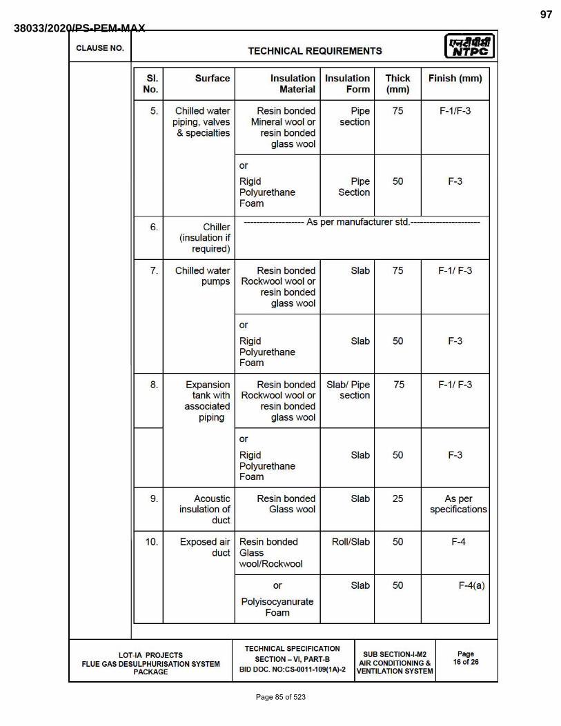
CLAUSE NO. TECHNICAL REQUIREMENTS Iq;,Jral NTPC
51. Surface Insulation Insulation Thick Finish (mm) No. Mater ial Form (mm)
5. Chilled water Resin bonded Pipe 75 F-l /F-3 piping, valves Mineral wool or section & specialties resin bonded
glass wool
or
Rigid Pipe 50 F-3 Polyurethane Section Foam
6. Chiller -------------- As per manufacturer std.-----------------
(insulation if required)
7. Chilled water Resin bonded Slab 75 F-l / F-3 pumps Rockwool wool or
resin bonded glass wool
or
Rigid Slab 50 F-3 Polyurethane Foam
8. Expansion Resin bonded Slabl Pipe 75 F-l / F-3 tank with Rockwool wool or section
associated resin bonded piping glass wool
or
Rigid Slab 50 F-3 Polyurethane Foam
9. Acoustic Resin bonded Slab 25 As per insulation of Glass wool specifications
duct
10. Exposed air Resin bonded Roll /Slab 50 F-4 duct Glass
wool/Rockwool
or Slab 50 F-4(a)
Polyisocyanurate Foam
TECHNICAL SPECIFICATION LOT-IA PROJECTS
SECTION - VI, PART-B SUB SECTION-I-M2 Page
FLUE GAS DESULPHURISATION SYSTEM AIR CONDITION ING & 16 of 26
PACKAGE BID DOC. NO:CS-0011-109(1A)-2 VENTILATION SYSTEM
Page 85 of 523
38033/2020/PS-PEM-MAX97

CLAUSE NO. TECHNICAL REQUIREMENTS Iq;,Jral NTPC
6.06.03 Specification for insulation shall be as follows : -
Insulation Material Code Thermal Density Kg/m3 conductivity
(w/mJOC
Resin bonded glass wool IS:8183 0.049 at 500 C i) 24 (For Glass wool)
ii ) 48 (For Rockwool )
0.043 at 500 C iii) 48(For acoustic insulation)
Mineral wool pipe IS:9842 0.043 at 500 e 144 section. Min.Gr.2
Closed Cell Elastomeric 0.036 at 200 e 40 60 Nitrile Rubber
Polyurethane Foam 0.03 at 50 °C 34~2 IS12436
Polyisocyanurate Foam 0.03 at 50 °C 34~2
Note: Insulation used for HVAC application shall be CFC/HCFC free
6.06.04 The specificati on for various fini shes shall be as fo llows
a) Finish F-1 ( wit h Resin Bonded Glass Wool/Resin Bonded Mineral Wool)
Slep-1 Wrapping of Poly-Bonded Hessain (PBH - to act as vapour seal) on outer surface of insulation with 50 mm overlap stitching and sea ling of overlap with synthetic adhesive like CPRX or Equivalent compound.
Slep-2 The surface then shall be wrapped with 19 mm mesh 24 SWG GI wire netting, butting all the joints and laced down with 22 SWG lacing wire.
Slep-3 Sand cement (4:1 ) plaster shall be applied in two layers totall ing to 12.5 mm th ick, the second layer being brought to a smooth fin ish. A water proofing compound shall be added to the cement before its application.
TECHNICAL SPECIFICATION LOT-IA PROJECTS
SECTION - VI, PART-B SUB SECTION-I-M2 Page
FLUE GAS DESULPHURISATION SYSTEM AIR CONDITION ING & 17 of 26
PACKAGE BID DOC. NO:CS-0011-109(1A)-2 VENTILATION SYSTEM
Page 86 of 523
38033/2020/PS-PEM-MAX98
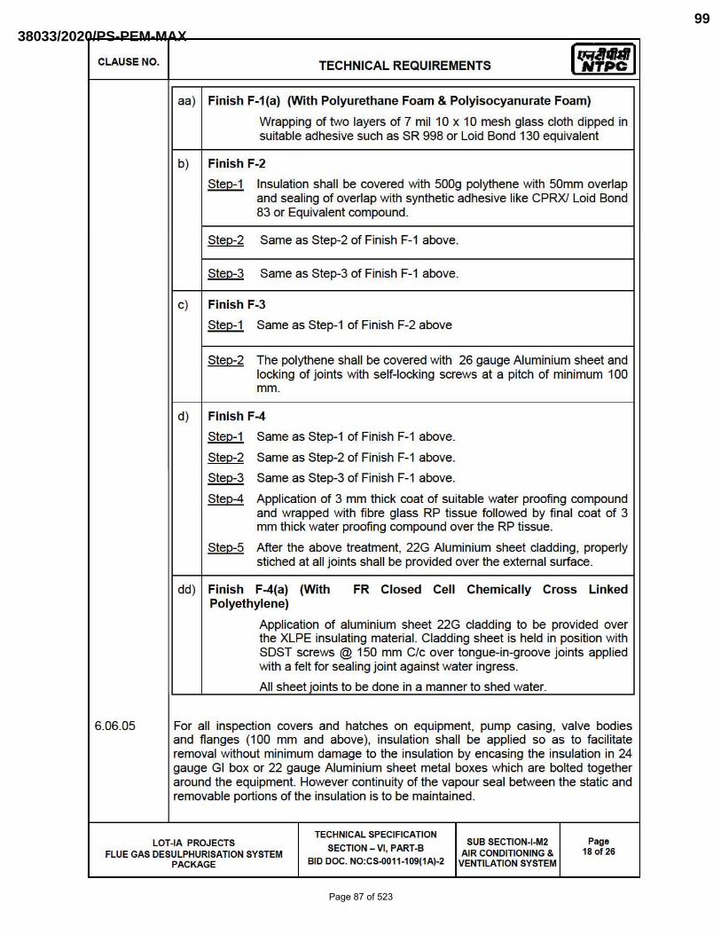
CLAUSE NO. TECHNICAL REQUIREMENTS Iq;,Jral NTPC
aa) Finish F-1(a) (With Polyurethane Foam & Polyisocyanurate Foam)
Wrapping of two layers of 7 mil 10 x 10 mesh glass cloth dipped in suitable adhesive such as SR 998 or Loid Bond 130 equivalent
b) Fin ish F-2
81ep-1 Insulation shall be covered with 500g polythene with 50mm overlap and sealing of overlap with synthetic adhesive like CPRXI Loid Bond 83 or Equivalent compound.
81ep-2 Same as Step-2 of Finish F-1 above.
81ep-3 Same as Step-3 of Finish F-1 above.
c) Finish F-3
81ep-1 Same as Step-1 of Finish F-2 above
81ep-2 The polythene shall be covered with 26 gauge Aluminium sheet and locking of joints with self-locking screws at a pitch of minimum 100 mm.
d) Finish F-4
81ep-1 Same as Step-1 of Finish F-1 above.
81ep-2 Same as Step-2 of Finish F-1 above.
81ep-3 Same as Step-3 of Finish F-1 above.
8lep-4 Application of 3 mm thick coat of su itable water proofing compound and wrapped with fibre glass RP tissue followed by final coat of 3 mm th ick water proofing compound over the RP tissue.
81ep-5 After the above treatment, 22G Aluminium sheet cladding, properly stiched at all joints shall be provided over the external surface.
dd ) Finish F-4(a) (With FR Closed Cell Chemically Cross Linked Polyethylene)
Application of aluminium sheet 22G cladding to be provided over the XLPE insulating material. Cladding sheet is held in position with SDST screws @ 150 mm C/c over tongue-in-groove joints applied with a felt for sea ling joint against water ingress.
All sheet joints to be done in a manner to shed water.
6.06.05 For all inspection covers and hatches on equipment, pump casing, valve bodies and flanges (100 mm and above), insulation shall be applied so as to facilitate removal without minimum damage to the insulation by encasing the insulation in 24 gauge GI box or 22 gauge Aluminium sheet metal boxes which are bolted together around the equipment. However continuity of the vapour seal between the static and removable portions of the insulation is to be maintained.
TECHNICAL SPECIFICATION LOT-IA PROJECTS
SECTION - VI, PART-B SUB SECTION-I-M2 Page
FLUE GAS DESULPHURISATION SYSTEM AIR CONDITION ING & 18 of 26
PACKAGE BID DOC. NO:CS-0011-109(1A)-2 VENTILATION SYSTEM
Page 87 of 523
38033/2020/PS-PEM-MAX99

CLAUSE NO.
6.06.06
7.00.00
7.01.00
7.02.00
7.02.01
7.03.00
7.05.00
7.06.00
TECHNICAL REQUIREMENTS Iq;,Jral NTPC
ACOUSTIC INSULATION
a) All ducts up to a distance of 5 meters from AHU shall be acoustically lined from inside with 25 mm thick resin bonded glass wool of 48 Kg/Cu.M. density and 30 gauge perforated aluminium sheet having 5 mm dia perforation at 8 to 10 mm centre-to-centre distance. Insulation shall be fixed on wooden frame of 600 x 600 mm dimension.
b) Fibre glass tissue sheet shall be applied over the outer surface of insulation before applying perforated aluminium sheet. Application of acoustic insulation shall be in line with the requirements specified above.
PLANT CONTROL
Brief scheme of controll ing the operation is descri bed below. Deta iled description of the control system for safe and efficient operation of the plant shall be elaborated, got approved from employer. The descriptions in the sub-sections of the control &
instrument sections shall also be referred to.
Control Scheme for Air-Conditioning System
Contractor shall provide microprocessor/PLC/GIU based control system for control and monitoring of air cond itioning and ventilation system as per manufacturer's standard practice. Control and monitoring of air cond itioning and ventilation system from FGD and ZLD (as provided) control system is also acceptable.
Air Handling Unit
a) Humidity sensor and gyserstat located in the retum air duct shall actuate the PAN humidifier to obta in the desired degree of humidification.
b) Humidity and temp. sensor shall be provided and interlocked in steps with winter heater / re-heater / strip heaters for monsoon and winter re-heating or heating as
the case may be.
c) Heater banks shall be interlocked with the running of AHU, temperature of return air, humidity of return air and safety thermostat (airstat - located in front of the
each heater in the supply air duct)
d) AHU shall be started either locally or from the main control room of AC system by means of Remote / Manual selection facility.
e) The closure of fire dampers, automatic tripping of AHU fans and fresh air fans shall be interlocked with Fire Detection System.
Cassette /Hi-wal1 Split Air Conditioners
Control and interlocks for these type of units shall be as per manufacturer's standard
practice.
Miscellaneous Control Requirements
a) The fans (both supply and exhaust fans) associated with mechanical ventilation system shall be operated locally.
LOT-IA PROJECTS TECHNICAL SPECIFICATION
SECTION - VI, PART-B SUB SECTION-I-M2
AIR CONDITION ING & VENTILATION SYSTEM
Page 19 of 26 FLUE GAS DESULPHURISATION SYSTEM
PACKAGE BID DOC. NO:CS-0011-109(1A)-2
Page 88 of 523
38033/2020/PS-PEM-MAX100
6043623
Line

CLAUSE NO.
8.00.00
8.Q1.00
8.02.00
8.03.00
8.04.00
8.05.00
8.06.00
9.00.00
9.01.00
9.02.00
TECHNICAL REQUIREMENTS Iq;,Jral NTPC
b) Relative humidity and temperature measurement of all control rooms and all major air-conditioned areas shall made be available in FGO and ZLO (as
provided) control system
PAINTING:
All the Equipments shall be protected against external corrosion by providing suitable painting.
The surfaces of sta inless steel , Galvanized steel , Gunmetal , brass, bronze and nonmetallic components shall not be applied with any pa inting. The Contractor shall clean the external surfaces and internal surfaces before Erection by wire brushing and air blowing. The steel surface to be applied with painting shall be thorough ly cleaned before applying painting by brushing, shot blasting, etc. as per the agreed procedure.
For all the steel surfaces (external) exposed to atmosphere (outdoor installation), one(1) coat of red oxide primer of th ickness 30 to 35 microns followed up with th ree (3) coats of synthetic enamel pa int, with 25 microns as thickness of each coat, shall be applied.
For all the steel surfaces inside the build ing (indoor installation), One (1) Coat of red oxide primer of thickness 30 to 35 microns followed up with two (2) coats synthetic enamel paint, with 25 microns as thickness of each coat shall be applied.
For centrifugal fans - Casing shall have hot dip! spray galvanization (minimum 60 micron OFT).
However, for all parts coming in contact with acid fumes (in Battery rooms), a coat of epoxy resin based zinc phosphate primer of minimum th ickness 30 to 35 microns followed up with undercoat of epoxy resin based pa int pigmented with Titanium dioxide of minimum thickness of 25 microns shall be applied and a top coat consisting of one coat of epoxy paint of approved shade and colour with glossy fin ish of minimum thickness of 25 microns.
CODES & STANDARDS
The design, manufacture and performance of equipment shall comply with all currently applicable statues, regulations and safety codes in the locality where the equipments are to be installed. Nothing in this specification shall be considered to relieve the bidder of this responsibility.
Unless otherwise specified , equipment shall conform to the latest appl icable Indian or IEC standard. Equipment complying with other authoritative standards such as British, USA, ASHRAE etc. will also be considered if it ensures performance equivalent or superior to Indian Standard.
LOT-IA PROJECTS TECHNICAL SPECIFICATION
SECTION - VI, PART-B SUB SECTION-I-M2
AIR CONDITION ING & VENTILATION SYSTEM
Page 20 of 26 FLUE GAS DESULPHURISATION SYSTEM
PACKAGE BID DOC. NO:CS-0011-109(1A)-2
Page 89 of 523
38033/2020/PS-PEM-MAX101

CLAUSE NO. TECHNICAL REQUIREMENTS Iq;,Jral NTPC
Annexure-I
GENERAL SPECIFICATION FOR HORIZONTAL PUMPS
1) SCOPE
Th is specification covers the design, material , construction features, manufacture, inspection, testing the performance at the Vendor'slSub-Vendor's Works and delivery to site of Horizontal Centrifugal Pumps.
2) CODES AND STANDARDS
The design, materia l, construction, manufacture inspection and performance testing of Horizontal Centrifugal Pumps shall comply with all currently applicable statutes, regulations and safety codes in the locality where the Equipment will be installed. Nothing in these specifications shall be construed to relieve the Vendor of this responsibility. The Equipment supplied shall comply with the latest applicable Indian Standards listed below. Other National Standards are acceptable, if they are established to be equal or superior to the Indian Standards.
3) List of Applicable Standards.
IS : 1520 : Horizontal Centrifugal Pumps for clear cold fresh water
IS : 5120
API: 610
IS : 5639
IS : 5659
HIS
: Techn ical requirements of roto dynamic special purpose pumps
: Centrifugal pumps for general refinery service.
: Pumps Handling Chemicals & corrosion liquids
: Pumps for process water
: Hydraulic Institute Standards, USA
ASTM-1-165-B5 Standards Methods for Liquid Penetration Inspection.
In case of any contradiction with aforesaid standards and the stipulations as per the techn ical specifications as specified hereinafter the stipulations of the techn ical specifications shall prevail.
4) DESIGN REQUIREMENTS
a) The Pump shall be capable of developing the required total head at rated capacity for continuous operation. Also the pumps shall be capable of being operated to give satisfactory performance at any point on the HQ characteristics curve. The operating range of the pump shall be 40% to 120% of the duty point unless otherwise mentioned elsewhere. The maximum efficiency of pump shall preferably be within ± 10% of the rated design flow as indicated in data sheets.
b) The tota l head capacity curve shall be continuously rising from the operating point towards shut-off without any zone of instability and with a minimum shut-off head of about 15% more than the design head.
LOT-IA PROJECTS FLUE GAS DESULPHURISATION SYSTEM
PACKAGE
TECHNICAL SPECIFICATION
SECTION - VI, PART-B
BID DOC. NO:CS-0011-109(1A)-2
SUB SECTION-I-M2 AIR CONDITION ING &
VENTILATION SYSTEM
Page 21 of 26
Page 90 of 523
38033/2020/PS-PEM-MAX102
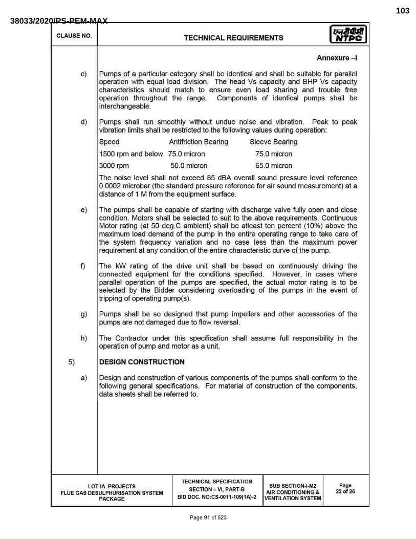
CLAUSE NO. TECHNICAL REQUIREMENTS Iq;,Jral NTPC
Annexure-I
C) Pumps of a particular category shall be identical and shall be suitable for parallel operation with equal load division. The head Vs capacity and BHP Vs capacity characteristics should match to ensure even load sharing and trouble free operation throughout the range. Components of identical pumps shall be interchangeable.
d) Pumps shall run smoothly without undue noise and vibration. Peak to peak vibration limits shall be restricted to the following values during operation:
Speed Antifriction Bearing Sleeve Bearing
1500 rpm and below 75.0 micron
3000 rpm 50.0 micron
75.0 micron
65.0 micron
The noise level shall not exceed 85 dBA overall sound pressure level reference 0.0002 microbar (the standard pressure reference for air sound measurement) at a distance of 1 M from the equipment surface.
e) The pumps shall be capable of starting with discharge valve fu lly open and close condition. Motors shall be selected to suit to the above requirements . Continuous Motor rating (at 50 deg.C ambient) shall be atleast ten percent (10%) above the maximum load demand of the pump in the entire operating range to take care of the system frequency variation and no case less than the maximum power requirement at any condition of the entire characteristic curve of the pump.
f) The kW rating of the drive unit shall be based on continuously driving the connected equipment for the conditions specified. However, in cases where parallel operation of the pumps are specified, the actual motor rating is to be selected by the Bidder considering overloading of the pumps in the event of tripping of operating pump(s).
g) Pumps shall be so designed that pump impellers and other accessories of the pumps are not damaged due to flow reversal.
h) The Contractor under th is specification shall assume full responsibility in the operation of pump and motor as a unit.
5) DESIGN CONSTRUCTION
a) Design and construction of various components of the pumps shall confonn to the following general specifications. For material of construction of the components, data sheets shall be referred to .
LOT-IA PROJECTS FLUE GAS DESULPHURISATION SYSTEM
PACKAGE
TECHNICAL SPECIFICATION
SECTION - VI, PART-B
BID DOC. NO:CS-0011-109(1A)-2
SUB SECTION-I-M2 AIR CONDITION ING &
VENTILATION SYSTEM
Page 22 of 26
Page 91 of 523
38033/2020/PS-PEM-MAX103

CLAUSE NO. TECHNICAL REQUIREMENTS Iq;,Jral NTPC
Annexure-I
b) Pump Casing
Pump casing shall have axially or radially split type construction as specified. The casing shall be designed to withstand the maximum shut-off pressure developed by the pump at the pumping temperature.
Pump casing shall be provided with a vent connection and piping with fittings & valves. Casing drain as required shall be provided complete with drain valves, piping and plugs. It shall be provided with a connection for suction and discharge pressure gauge as standard feature. It shall be structurally sound to provide housing for the pump assembly and shall be designed hydraulically to minimum radial load at part load operation.
c) Impeller
Impeller shall be closed, semi-closed or open type as specified elsewhere and designed in confonnance with the detailed analysis of the liquid being handled.
The impeller shall be secured to the shaft, and shall be retained against circumferential movement by keying, pinning or lock rings. On pumps with overhung shaft, impellers shall be secured to the shaft by a lockout or cap screw which tightness in the direction of nonnal rotation.
d) Impeller/Casing Wearing Rings
Replaceable type wearing rings shall be provided at suitable locations of pumps. Suitable method of locking the wearing ring shall be used. Wearing rings shall be provided in pump casing and/or impeller as per manufacturer's standard practice.
e) Shaft
The critical speed shall be well away from the operating speed and in no case less than 130% of the rated speed.
The shaft shall be ground and polished to final dimensions and shall be adequately sized to withstand all stresses from rotor weight, hydraulic loads, vibration and torques coming in during operation.
f) Shaft Sleeves
Renewable type fine finished shaft sleeves shall be provided at the stuffing boxes/mechanical seals. Length of the shaft sleeves must extend beyond the outer faces of gland packing of seal end plates so as to distinguish between the leakage between shaft and shaft sleeve and that past the sea ls/gland.
Shaft sleeves shall be fastened to the shaft to prevent any leakage or loosening. Shaft and shaft sleeve assembly should ensure concentric rotation.
LOT-IA PROJECTS FLUE GAS DESULPHURISATION SYSTEM
PACKAGE
TECHNICAL SPECIFICATION
SECTION - VI, PART-B
BID DOC. NO:CS-0011-109(1A)-2
SUB SECTION-I-M2 AIR CONDITION ING &
VENTILATION SYSTEM
Page 23 of 26
Page 92 of 523
38033/2020/PS-PEM-MAX104

CLAUSE NO. TECHNICAL REQUIREMENTS Iq;,Jral NTPC
Annexure-I
g) Bearings
Heavy duty bearings, adequately designed for the type of service specified in the enclosed pump data sheet and for long, trouble free operation shall be furn ished.
The bearings offered shall be capable of taking both the radial and axial thrust coming into play during operation. In case, sleeve bearings are offered additional thrust bearings shall be provided. Antifriction bearings of standard type, if provided, shall be selected for a minimum life 20,000 hrs. of continuous operation at maximum axial and rad ial loads and rated speed.
Proper lubricating arrangement for the bearings shall be provided. The design shall be such that the bearing lubricating element does not contaminate the liquid pumped. Where there is a possibility of liquid entering the bearings suitable arrangement in the form of deflectors or any other suitable arrangement must be provided ahead of bearings assembly.
Bearings shall be easily accessible without disturbing the pump assembly. A drain plug shall be provided at the bottom of each bearings housing.
h) Stuffing Boxes
Stuffing box design should pennit replacement of packing without removing any part other than the gland.
Stuffing boxes of packed ring construction type shall be provided wherever specified. Packed ring stuffing boxes shall be properly lubricated and sealed as per service requirements and manufacturer's standards. If external gland sealing is required , it shall be done from the pump discharge. The Bidder shall provide the necessary piping valves, fittings etc. for the gland sealing connection.
i) Mechanical Seals
Wherever specified in pump data sheet, mechanical seals shall be provided. Unless otherwi se recommended by the tenderer, mechanical seals shall be of single type with either sliding gasket or bellows between the axially moving face and shaft sleeves or any other suitable type. The sealing faces should be highly lapped surfaces of materials known for their low frictional coefficient and resistance to corrosion against the liquid being pumped.
j) The pump supplier shall coordinate with the seal maker in establishing the seal chamber of circulation rate for maintaining a stable film at the seal face. The seal piping system shall fonn an integral part of the pump assembly. For the seals under vacuum service, the seal design must ensure sealing against atmospheric pressure even when the pumps are not operating. Necessary provision for seal water supply along with complete piping fitt ings and valves as required shall fonn integral part of pump supply.
k) Pump Shaft Motor Shaft Coupling
The pump and motor shafts shall be connected with an adequately sized flexible coupling of proven design with a spacer to facilitate dismantling of the pump without disturbing the motor. Necessary coupling guards shall also be provided.
LOT-IA PROJECTS FLUE GAS DESULPHURISATION SYSTEM
PACKAGE
TECHNICAL SPECIFICATION
SECTION - VI, PART-B
BID DOC. NO:CS-0011-109(1A)-2
SUB SECTION-I-M2 AIR CONDITION ING &
VENTILATION SYSTEM
Page 24 of 26
Page 93 of 523
38033/2020/PS-PEM-MAX105

CLAUSE NO. TECHNICAL REQUIREMENTS Iq;,Jral NTPC
Annexure-I
I) Base Plate
A common base plate mounting both for the pump and motor shall be furnished . The base plate shall be fabricated steel and of rigid construction, suitably ribbed and reinforced. Base plate and pump supports shall be so constructed and the piping unit so mounted as to minimize misalignment caused by mechanical forces such as normal piping strain, internal differential thermal expansion and hydraulic piping thrust. Suitable drain troughs and drip lip shall be provided.
m) Assembly and Dismantling
Assembly and dismantling of each pump with drive motor shall be possible without disturbing the grouting base plate or alignment.
n) Drive Motor (Prime Mover)
The kW rating of the drive shall be based on continuously driving the connected equipment for the conditions specified. However, in cases where parallel operation of the pumps are specified, the actual motor rating is to be selected by the Bidder considering ovenoading of the pumps in the event of tripping of operating pump(s).
LOT-IA PROJECTS FLUE GAS DESULPHURISATION SYSTEM
PACKAGE
TECHNICAL SPECIFICATION
SECTION - VI, PART-B
BID DOC. NO:CS-0011-109(1A)-2
SUB SECTION-I-M2 AIR CONDITION ING &
VENTILATION SYSTEM
Page 25 of 26
Page 94 of 523
38033/2020/PS-PEM-MAX106
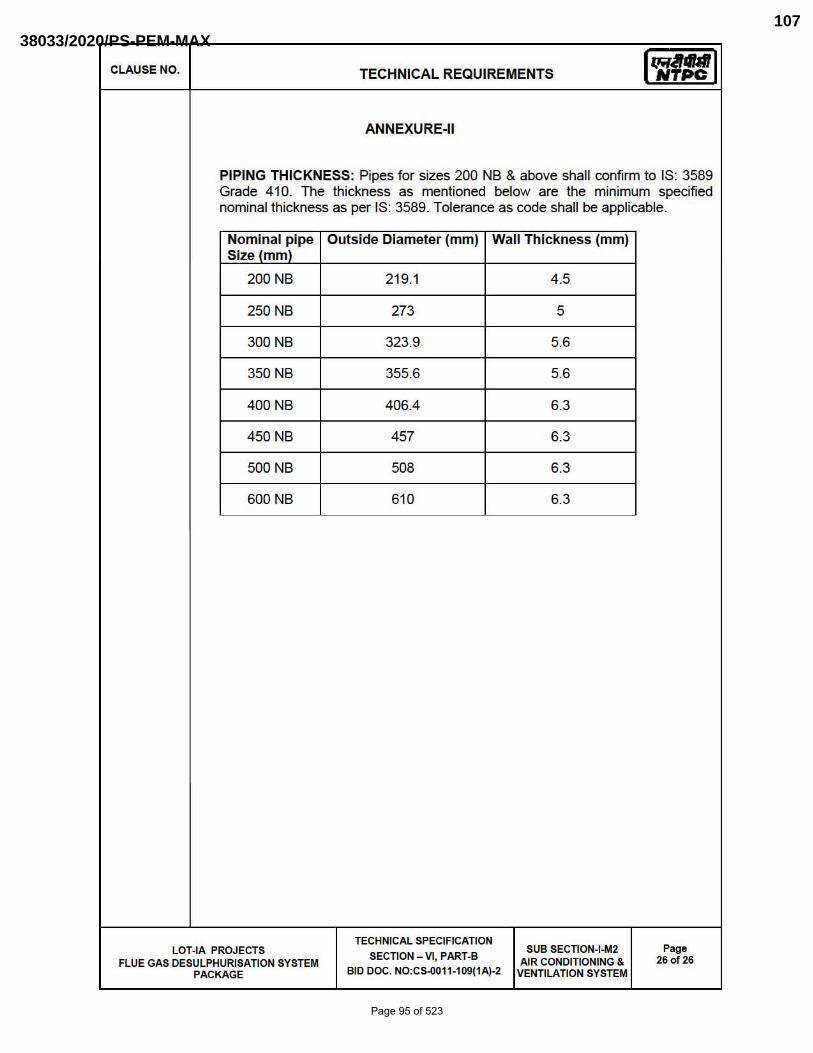
CLAUSE NO. TECHNICAL REQUIREMENTS Iq;,Jral NTPC
ANNEXURE-II
PIPING THICKNESS: Pipes for sizes 200 NB & above shall confirm to IS: 3589 Grade 410. The thickness as mentioned below are the minimum specified nominal thickness as per IS: 3589. Tolerance as code shall be applicable.
Nominal pipe Size (mm)
Outside Diameter (mm) Wall Thickness (mm)
200 NB 219.1 4.5
250 NB 273 5
300 NB 323.9 5.6
350 NB 355.6 5.6
400 NB 406.4 6.3
450 NB 457 6.3
500 NB 508 6.3
600 NB 610 6.3
TECHNICAL SPECIFICATION LOT-IA PROJECTS SECTION - VI , PART-B
SUB SECTION-I-M2 Page
FLUE GAS DESULPHURISATION SYSTEM AIR CONDITION ING & 26 of 26
PACKAGE BID DOC. NO:CS-0011-109(1A)-2 VENTILATION SYSTEM
Page 95 of 523
38033/2020/PS-PEM-MAX107
4X250 MW BRBCL NABINAGAR
(FGD SYSTEM PACKAGE)
HVAC SYSTEM
PROJECT SPECIFIC GENERAL REQUIREMENTS
SPECIFICATION No: PE-TS-463-(571-13000-A)-A001
SECTION : I
SUB-SECTION : C 2B
REV. 00
SECTION: I
SUB-SECTION: C 2B
CUSTOMER SPECIFICATIONS PROJECT SPECIFIC GENERAL REQUIREMENTS
Page 96 of 523
38033/2020/PS-PEM-MAX108

.-____________________________ --1I~~L I NTPC r
PART- C
GENERAL TECHNICAL REQUIREMENTS
LOT-fA PROJECTS
FLUE GAS DESULPHURISATION (FGD) SYSTEM PACKAGE
TECHN ICAL SPECIFICATION SECTION-VI , PART-C
BID DOC NO: CS-001 1-109(1A)-2
Page 97 of 523
38033/2020/PS-PEM-MAX109

.-____________________________ --1I~~L I NTPC r
GENERAL TECHNICAL REQUIREMENTS
PART- C
CONTENTS
Clause No. Description Page No.
1.00.00 Introduction
2.00.00 Brand Name
3.00.00 Base Offer & Alternate Proposals
4.00.00 Completeness of Facilities
5.00.00 Codes & Standards
6.00.00 Equipment Functional Guarantee
7.00.00 Design of Facilities! Maintenance & Availability Considerations
8.00.00 Documents, Data and Drawings to be furnished by Contractor
9.00.00 Technical Co-ordination Meeting
10.00.00 Design Improvements
11.00.00 Equipment Bases
12.00.00 Protective Guards
13.00.00 Lubricants , Servo fluids and Chemicals
14.00.00 Lubrication
15.00.00 Material of Construction
16.00.00 Rating Plates, Name Plates & Labels
17.00.00 Tools and Tackles
18.00.00 Welding
LOT-fA PROJECTS FLUE GAS DESULPHURISATION (FGD) SYSTEM PACKAGE
TECHN ICAL SPECIFICATION SECTION-VI , PART-C
BID DOC NO: CS-001 1-109(1A)-2
1
1
1
1
2
4
5
5
21
22
22
22
22
23
23
23
24
25
Page 98 of 523
38033/2020/PS-PEM-MAX110
IrRlltMr INTPC
Clause No. Description Page No.
19.00.00 Colour Code for All equipmentsiPipings/PlpeServices 25
20.00.00 Protection and Preserveative shop Coating 25
21.00.00 Quality Assurance Programme 26
22.00.00 General Requirements - Quality Assurance 27
23.00.00 Quality Assurance Documents 32
24.00.00 Project Manager's Supervision 34
25.00.00 Inspection, Testing and Inspection Certificates 35
26.00.00 Pre-commissioning and Commissioning Facilities 38
27.00.00 Taking over 41
28.00.00 Training of Employer's Personnel 41
29.00.00 Safety Aspects during Construction and Erection 42
30.00.00 Noise Level 42
31.00.00 Packaging and Transportation 42
32.00.00 Electrical EquipmentsJEnciosures 43
33.00.00 Instrumentation and Control 43
34.00.00 Electrical Noise Control 44
35.00.00 Surge protection for solid state equipment 44
36.00.00 Instrument Air System 44
37.00.00 Tapping Points for Measurements 45
38.00.00 System Documentation 45
39.00.00 Maintenance Manuals of Electronic Modules 45
LOT-IA PROJECTS FLUE GAS DESULPHURISATION (FGO) SYSTEM PACKAGE
TECHN ICAL SPECIFICATION SECTION-VI, PART-C
BID DOC NO: CS-001 1-1 09(1A)-2
Page 99 of 523
38033/2020/PS-PEM-MAX111
r(lil~t LNTPC
Clause No. Description Page No.
Annexure - I 76
Annexure - II 77
Annexure - III 78
Annxure -IV 79
Annexure - V 80
Annexure - VI 81
Annexure - VII 83
LOT-fA PROJECTS TECHN ICAL SPECIFICATION
FLUE GAS DESULPHURISATION (FGD) SYSTEM PACKAGE SECTION-VI, PART-C BID DOC NO: CS-001 1-109(1A)-2
Page 100 of 523
38033/2020/PS-PEM-MAX112

CLAUSE NO. GENERAL TECHNICAL REQUIREMENTS 1Q;J811b11
1.00.00
2.00.00
3.00.00
4.00.00
4.01.00
4.02.00
NTPC
INTRODUCTION
This part covers technical requirements wh ich will fonn an integral part of the Contract. The following provisions shall supplement all the detailed technical specifications and requirements brought out in Section-VI, the Technical Specification and the Technical Data Sheets.
BRAND NAME
Whenever a material or article is specified or described by the name of a particu lar brand, manufacturer or vendor, the specific item mentioned shall be understood to be indicative of the function and quality desired , and not restrictive; other manufacturers products may be considered provided sufficient infonnation is furnished to enable the Employer to determine that the products proposed are equiva lent to those named.
BASE OFFER & ALTERNATE PROPOSALS
The Bidders proposal shall be based upon the use of equipment and material complying fully with the requ irements specified herein. It is recogn ised that the Contractor may have standardized on the use of certain components, materials, processes or procedures different than those specified herein. Alternate proposals offering similar equipment based on the manufacturers standard practice will also be considered, provided the base offer is in line with technical specifications and such proposals meet the specified design standards and perfonnance requi rement and are acceptable to the Employer. Sufficient amount of infonnation for justifying such proposals shall be furnished to Employer alongwith the bid to enable the Employer to determine the acceptability of these proposals.
COMPLETENESS OF FACILITIES
Bidders may note that this is a contract inclusive of the scope as indicated elsewhere in the specification. Each of the plant shall be engineered and designed in accordance with the specification requ irement. All engineering and associated services are required to ensure a completely engineered plant shall be provided.
All equipments fumished by the Contractor shall be complete in every respect, with all mountings, fittings, fixtu res and standard accessories nonnally provided with such equipment and/or those needed for erection, completion and safe operation of the equipment and for the safety of the operating personnel , as required by applicable codes, though they may not have been specifically detailed in the respective specifications, unless included in the list of exclusions.
All same standard components! parts of same equipment provided, shall be interchangeable with one another.
LOT-IA PROJECTS TECHNICAL SPECIFICATION FLUE GAS DESULPHURISATION (FGD) SECTION _ VI, PART-C
GENERAL TECHNICAL REQUIREMENTS
PAGE 1 OF 83
SYSTEM PACKAGE BID DOC. NO. CS-0011-109(1A)-2
Page 101 of 523
38033/2020/PS-PEM-MAX113

CLAUSE NO. GENERAL TECHNICAL REQUIREMENTS 1Q;J811b11
4.03.00
5.00.00
5.01.00
NTPC
For the C&I systems, the Contractor shall be required to provide regular information about future upgrades and migration paths to the Employer.
RULES, REGULATIONS, CODES & STANDARDS
In addition to the codes and standards specifically mentioned in the relevant technical specifications for the equipment / plant / system, all equipment parts, systems and wor1<s covered under th is specification shall comply with all currently applicable statutory regulations and safety codes of the Republic of India, NTPC rules/codes of practices as well as of the locality where they will be installed, including the fol lowing :
a) Indian Electricity Act
b) Indian Electricity Rules
c) Indian Explosives Act
d) Indian Factories Act and State Factories Act
e) Indian Boiler Regulations (IBR)
f) Regu lations of the Central Pollution Control Board, India
g) Regu lations of the Ministry of Environment & Forest (MoEF), Government of India
h) Pollution Control Regulations of Department of Environment, Government of India
i) State Pollution Control Board.
(j.) Rules for Electrica l installation by Tariff Advisory Committee (TAC).
(k.) Build ing and other construction wor1<ers (Regulation of Employment and Conditions of services) Act, 1996
(I. ) Build ing and other construction wor1<ers (Regulation of Employment and Conditions of services) Centra l Ru les, 1998
(m.) Explosive Rules, 1983
(n.) Petroleum Act, 1984
(0 .) Petroleum Rules, 1976,
LOT-IA PROJECTS TECHNICAL SPECIFICATION FLUE GAS DESULPHURISATION (FGD) SECTION _ VI, PART-C
GENERAL TECHNICAL REQUIREMENTS
PAGE 20F 83
SYSTEM PACKAGE BID DOC. NO. CS-0011-109(1A)-2
Page 102 of 523
38033/2020/PS-PEM-MAX114
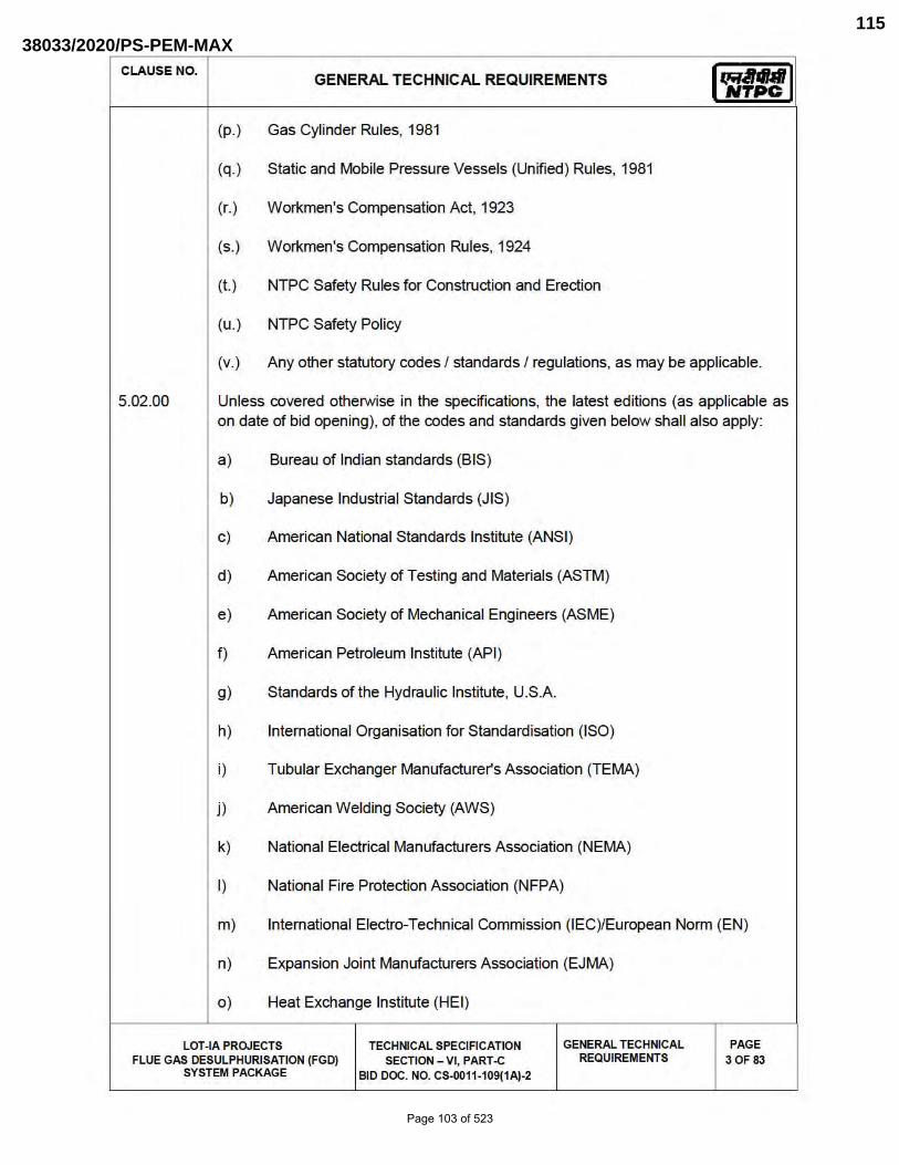
CLAUSE NO. GENERAL TECHNICAL REQUIREMENTS 1Q;J811b11
5.02.00
NTPC
(p.) Gas Cylinder Rules, 1981
(q.) Static and Mobile Pressure Vessels (Unified) Rules , 1981
(r. ) Workmen's Compensation Act, 1923
(s.) Workmen's Compensation Rules , 1924
(t. ) NTPC Safety Rules for Construction and Erection
(u.) NTPC Safety Policy
(v.) Any other statutory codes I standards I regulations, as may be applicable.
Unless covered otherwise in the specifications, the latest editions (as applicable as on date of bid opening), of the codes and standards given below shan also apply:
a) Bureau of Indian standards (BIS)
b) Japanese Industrial Standards (JIS)
c) American National Standards Institute (ANSI )
d) American Society of Testing and Materia ls (ASTM)
e) American Society of Mechanical Engineers (ASME)
f) American Petroleum Institute (API)
g) Standards of the Hydraulic Institute , U.S.A.
h) Internationa l Organisation for Standardisation (ISO)
i) Tubular Exchanger Manufacturer's Association (TEMA)
j ) American Welding Society (AWS)
k) National Electrica l Manufacturers Association (NEMA)
I) National Fire Protection Association (NFPA)
m) Internationa l Electro-Technical Commission (IEC)/European Nonn (EN)
n) Expansion Joint Manufacturers Association (EJMA)
0) Heat Exchange Institute (HEI)
LOT-IA PROJECTS TECHN[CAL SPEC[FICAT[ON FLUE GAS DESULPHUR[SATION (FGD) SECTION _ VI, PART-C
GENERAL TECHN[CAL REQUIREMENTS
PAGE 30F 83
SYSTEM PACKAGE B[D DOC. NO. CS-0011-109(1A)-2
Page 103 of 523
38033/2020/PS-PEM-MAX115
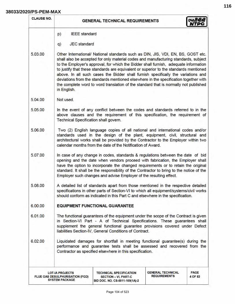
CLAUSE NO. GENERAL TECHNICAL REQUIREMENTS 1Q;J811b11
5.03.00
5.04.00
5.05.00
5.06.00
5.07.00
5.08.00
6.00.00
6.01.00
6.02.00
NTPC
p) IEEE standard
q) JEC standard
Other Intemationall National standards such as DIN, JIS, VOl , EN, BS, GOST etc. shall also be accepted for on ly material codes and manufacturing standards, subject to the Employer's approval , for which the Bidder shall fumish, adequate infonnation to justify that these standards are equivalent or superior to the standards mentioned above. In all such cases the Bidder shall furnish specifically the variations and deviations from the standards mentioned elsewhere in the specification together with the complete word to word translation of the standard that is nonnally not published in English.
Not used.
In the event of any confl ict between the codes and standards refe rred to in the above clauses and the requ irement of th is specification, the requirement of Technica l Specification shall govern.
Two (2) English language copies of all national and international codes and/or standards used in the design of the plant , equipment, civil, structural and architectural wor1<s shall be provided by the Contractor to the Employer within two calendar months from the date of the Notification of Award.
In case of any change in codes, standards & regu lations between the date of bid opening and the date when vendors proceed with fabrication, the Employer shall have the option to incorporate the changed requi rements or to reta in the original standard. It shall be the responsibility of the Contractor to bring to the notice of the Employer such changes and advise Employer of the resulting effect.
A detailed list of standards apart from those mentioned in the respective detailed specifications in other parts of Section-VI to which all equipmenUsystems/civil wor1<s should confonn as indicated in this Part C and elsewhere in the specification.
EQUIPMENT FUNCTIONAL GUARANTEE
The functional guarantees of the equipment under the scope of the Contract is given in Section-VI Part - A of Technical Specifications. These guarantees shall supplement the general functional guarantee provisions covered under Defect liabilities Section-IV, General Conditions of Contract.
Liquidated damages for shortfall in meeting functional guarantee(s) during the perfonnance and guarantee tests shall be assessed and recovered from the Contractor as specified elsewhere in th is specification.
LOT-IA PROJECTS TECHNICAL SPECIFICATION FLUE GAS DESULPHURISATION (FGD) SECTION _ VI, PART-C
GENERAL TECHNICAL REQUIREMENTS
PAGE 40F 83
SYSTEM PACKAGE BID DOC. NO. CS-0011-109(1A)-2
Page 104 of 523
38033/2020/PS-PEM-MAX116

CLAUSE NO. GENERAL TECHNICAL REQUIREMENTS 1Q;J811b11
7.00.00
7.01.00
7.02.00
8.00.00
8.01.00
NTPC
DESIGN OF FACILITIESI MAINTENANCE & AVAILABILITY CONSIDERATIONS
DESIGN OF FACILITIES
All the design procedures , systems and components proposed shall have already been adequately developed and shall have demonstrated good reliability under similar conditions elsewhere.
The Contractor shall be responsible for the selection and design of appropriate equipments to provide the best co-ord inated performance of the entire system. The basic requirements are detailed out in various clauses of the Technical Specifications. The design of various components , assemblies and subassemblies shall be done so that it facilitates easy f ield assembly and dismantling. All the rotating components shall be so selected that the natural frequency of the complete unit is not critical or close to the operating range of the unit.
MAINTENANCE AND AVILABILITY CONSIDERATIONS
Equipmentlwor1<s offered shall be designed for high availability, low maintenance and ease of maintenance. The Bidder shall specifically state the design features incorporated to achieve high degree of reliability/ availability and ease of maintenance. The Bidder shall also furnish details of availability records in the reference plants stated in his experience list.
Bidder shall state in his offer the various maintenance intervals, spare parts and man-hour requ irement during such operation. The intervals for each type of maintenance namely inspection of the furnace , inspection of the entire hot gas path and the minor and major overhauls shall be specified in tenns of f ired hours , clearly defin ing the spare parts and man-hour requirement for each stage.
Lifting devices i.e. hoists and chain pulley jacks ,etc. shall be provided by the contractor for handling of any equipment or any of its part having weight in excess of 500 Kgs during erection and maintenance activities.
Lifting devices like lifting tackles, slings, etc. to be connected to hook of the hoist / crane shall be provided by the contractor for lifting the equipment and accessories covered under the specification.
DOCUMENTS, DATA AND DRAWINGS TO BE FURNISHED BY CONTRACTOR
Bidders may note that this is a contract inclusive of the scope as indicated elsewhere in the specification. Each of the plant and equipment shall be fully integrated, engineered and designed to perfonn in accordance with the technical specification. All engineering and techn ical services required to ensure a completely
LOT-IA PROJECTS TECHNICAL SPECIFICATION FLUE GAS DESULPHURISATION (FGD) SECTION _ VI, PART-C
GENERAL TECHNICAL REQUIREMENTS
PAGE 50F 83
SYSTEM PACKAGE BID DOC. NO. CS-0011-109(1A)-2
Page 105 of 523
38033/2020/PS-PEM-MAX117
CLAUSE NO. GENERAL TECHNICAL REQUIREMENTS 1Q;J811b11
8.02.00
8.03.00
8.03.01
NTPC
engineered plant shall be provided in respect of mechanical, electrical, control & instrumentation, civil & structural works as per the scope.
Each main and auxiliary equipment/item of the plant including instruments shall be assigned a unique tag number. The assignment of tag numbers shall be in accordance with KKS system. In all drawings/documents/data sheet etc. KKS tag number of the equipment/item/instrument etc. shall be indicated.
The Contractor shall furnish engineering data /drawings in accordance with the schedule of information as specified in Technical Data Sheets and Technical Specification.
A comprehensive engg and quality coordination procedure shall be fina lized with the successful bidder covering salient features as described in th is section of specifications.
The number of copies!prints/CD-ROMs/manuals to be furnished for various types of document is given in Annexure-VI to th is Part-C, Section-VI of the Technical Specification.
The documentation that shall be provided by the Contractor is indicated in the various sections of specification. This documentation shall include but not be limited to the following:
A) BASIC ENGINEERING DOCUMENTATION
Prior to commencement of the detailed engineering work., the Contractor shall furnish a Plant Definition Manual within 12 weeks from the date of the Notification of Award. Th is manual shall contain the following as a minimum:
i) System description of all the mechanical, electrica l, control & instrumentation & civil systems.
ii ) Technology scan for each system / sub-system & equipment.
ii i) Selection of appropriate technology / schemes for various systems! subsystems including techno-economic studies between various options.
iv) Optimisation stud ies including thermal cycle optimisation.
v) Sizing criteria of all the systems, sub-systems! equipments/ structures/ equipment foundations alongwith all calculations justifying and identifying the sizing and the design margins.
vi) Schemes and Process & Instrumentation diagrams for the various systems! sub-system with functional write-ups.
LOT-IA PROJECTS TECHNICAL SPECIFICATION FLUE GAS DESULPHURISATION (FGD) SECTION _ VI, PART-C
GENERAL TECHNICAL REQUIREMENTS
PAGE 60F 83
SYSTEM PACKAGE BID DOC. NO. CS-0011-109(1A)-2
Page 106 of 523
38033/2020/PS-PEM-MAX118
CLAUSE NO. GENERAL TECHNICAL REQUIREMENTS 1Q;J811b11 NTPC
vii ) Operation Philosophy and the control philosophy of the equipments/system covered under the scope.
ix) General Layout plan of the FGD System incorporating all facilities in Bidders as well as those in the Employers scope. This drawing shall also be furnished in the form of CD-ROMs to the Employer for engineering of areas not included in bidders scope.
x) Basic layouts and cross sections of the main plant building (various floor elevations), boiler, fuel oil area and other areas included in the scope of the bidder.
xi) Documentation in respect of Quality Assurance System as listed out elsewhere in this specification.
The successful bidder shall fum ish within three (3) weeks from the date of Notification of Award, a list of contents of the Plant Defin ition Manual (PDMs) including techno-economic studies, which shall then be mutually discussed & finalised with the Employer.
8 ) DETAILED ENGINEERING DOCUMENTS
i) General layout plan of the FGD System.
ii ) Layouts, general arrangements, elevations and cross-sections drawings for all the equipment and facilit ies of the plant.
ii i) Flow diagram, process and instrumentation diagrams along with write up and system description.
iv) Performance curves for Absorber
v) Piping isometric, composite layout and fabrication drawings.
vi) Piping engineering diagrams, pipe and fitt ings schedules, valve schedules, hanger and support schedules, insulation schedules.
vii ) Technical data sheets for all bought out and manufactured items. Contractor shall use the Employer's specifications as a base for placement of orders on the ir sub vendors.
vii i) Detailed design ca lculations for components , system, piping etc. , wherever applicable including sizing calculations for all auxiliaries like mills, fans etc:- as per crite ria specified elsewhere in specification.
ix) Absorber sizing ca lculations. Absorber performance data.
LOT-IA PROJECTS TECHNICAL SPECIFICATION GENERAL TECHNICAL REQUIREMENTS
PAGE 70F 83 FLUE GAS DESULPHURISATION (FGD) SECTION _ VI, PART-C
SYSTEM PACKAGE BID DOC. NO. CS-0011-109(1A)-2
Page 107 of 523
38033/2020/PS-PEM-MAX119

CLAUSE NO. GENERAL TECHNICAL REQUIREMENTS 1Q;J811b11 NTPC
x) Mass Balance Diagram
xi) Characteristic Curves! Performance Correction Curves.
xii) Comprehensive list of all terminal points which interface with Employer's facilities, giving details of location, terminal pressure, temperature , fluid handled & end connection details, forces, moments etc.
xii i) Power supply single line diagram, block log ics, control schematics, electrica l schematics, etc.
xiv) Protection system diagrams and relay settings.
xv) Cables schedules and interconnection diagrams.
xvi i) Cable routing plan.
xvi ii) Instrument schedule, measuring point list, 1/0 list, Interconnection & wiring diagram, functional write-ups , and installation drawings for field mounted instruments, logic diagrams, control schematics, wiring and tubing diagrams of panels and enclosures etc. Drawings for open loop and close loop controls (both hardware and software). Motor list and valve schedule including type of actuator etc.
xix) Alarm and annunciationl Sequence of Event (SOE) list and alarms & trip set points.
xx) Sequence and protection inte r10ck schemes.
xxi) Type test reports , insulation co-ordination study report
xxi i) Control system configuration diagramsand card circuit diagrams and maintenance details.
xxi ii) Detailed Control system manuals.
xxiv) Detailed flow chart for digital control system.
xv) Mimic diagram layout, Assignment for other application engg.drawings and documents.
xxvi) Civil and Structural works drawings and documents for all structures, faci lities, arch itectural works, foundations underground and overground works and super-structural works as included in the
LOT-IA PROJECTS TECHNICAL SPECIFICATION GENERAL TECHNICAL REQUIREMENTS
PAGE 80F 83 FLUE GAS DESULPHURISATION (FGD) SECTION _ VI, PART-C
SYSTEM PACKAGE BID DOC. NO. CS-0011-109(1A)-2
Page 108 of 523
38033/2020/PS-PEM-MAX120

CLAUSE NO. GENERAL TECHNICAL REQUIREMENTS 1Q;J811b11
8 .03.02
NTPC
scope of the bidder civil ca lculation sheets including structural analysis and design alongwith output results.
xxvii) Underground facilities, levelling, sanitary, land scaping drawings.
xxviii) Geotechnical investigation and site survey reports (if and as applicable).
xxix) Model study reports wherever applicable.
xxx) Functional & guarantee test procedures and test reports .
xxxi) Documentation in respect of Quality Assurance System, and Documentation in respect of Commissioning, as listed out elsewhere in this specification.
xxxii ) Maintenance schedule for Absorber & auxiliaries clea r1y indicating interval, duration if shutdown required , manhours required and tools & tackles requ ired for maintenance.
The Contractor's while submitting the above documents! drawings for approvaV reference as the case may be, shall mark on each copy of submission the refe rence letter alongwith the date vide which the submissions are made.
INSTRUCTION MANUALS
The Contractor shall make first submission of instruction manual for all the equipments covered under the Contract as per agreed engineering information schedule. The Instruction manuals shall contain full details required for erection, commissioning, operation and maintenance of each equipment. The manual shall be specifica lly compiled for th is project. After finalisation and approval of the Employer the Instruction Manuals shall be submitted as indicated in Annexure-IV. The Contract shall not be considered to be completed for purposes of taking over until the final Instructions manuals have been supplied to the Employer. The Instruction Manuals shall comprise of the following.
A) ERECTION MANUALS
The erection manuals shall be submitted atleast three (3) months prior to the commencement of erection activities of particular equipment/system. The erection manual should contain the following as a minimum.
a) Erection strategy.
b) Sequence of erection .
LOT-IA PROJECTS TECHN[CAL SPEC[FICAT[ON FLUE GAS DESULPHUR[SATION (FGD) SECTION _ VI, PART-C
GENERAL TECHN[CAL REQUIREMENTS
PAGE 90F 83
SYSTEM PACKAGE B[D DOC. NO. CS-0011-109(1A)-2
Page 109 of 523
38033/2020/PS-PEM-MAX121
CLAUSE NO. GENERAL TECHNICAL REQUIREMENTS 1Q;J811b11 NTPC
c) Erection instructions.
d) Critical checks and permissible deviation/tolerances.
e) List of tool , tackles, heavy equipments like cranes, dozers, etc.
f) Bill of Materials
g) Procedure for erection and General Safety procedures to followed during erection/installation.
h) Procedure for initial checking after erection.
i) Procedure for testing and acceptance nonns.
j) Procedure / Check list for pre-commissioning activities.
k) Procedure / Check list for commissioning of the system.
I) Safety precautions to be followed in electrical supply distribution
during erection .
B) OPERATION & MAINTENANCE MANUALS
a) The manual shall be a two rim PVC bound stiff sided binder able to withstand constant usage or where a thicker type is required it shall have locking steel pins, the size of the manual shall not be larger than international size A3. The cover shall be printed with the Project Name, Services covered and Volume / Book number Each section of the manual shall be divided by a stiff divider of the same size as the holder. The dividers sha ll clear1y state the section number and title . All written instructions within the manual not provided by the manufacturers shall be typewritten with a margin on the left hand side.
b) The arrangement and contents of 0 & M manuals shall be as follows:
1) Chapter 1 - Plant Description: To conta in the following sections specific to the equipment/system supplied
(a) Description of operating principle of equipment / system with schematic drawing / Iayouts.
LOT-IA PROJECTS TECHNICAL SPECIFICATION GENERAL TECHNICAL REQUIREMENTS
PAGE 10 OF 83 FLUE GAS DESULPHURISATION (FGD) SECTION _ VI, PART-C
SYSTEM PACKAGE BID DOC. NO. CS-0011-109(1A)-2
Page 110 of 523
38033/2020/PS-PEM-MAX122
CLAUSE NO. GENERAL TECHNICAL REQUIREMENTS 1Q;J811b11 NTPC
(b) Functional description of associated accessories / controls. Control interlock protection write up.
(c) Integrated operation of the equipment alongwith the intended system. (This is to be given by the supplier of the Main equipment by taking into account the operating instruction given by the associated suppliers).
(d) Exploded view of the main equipment, associated accessories and auxilia ries with description. Schematic drawing of the equipment alongwith its accessories and auxiliaries.
(e) Design data against which the plant performance will be compared.
(f) Master list of equipments, Technical specification of the equipment! system and approved data sheets.
(g) Identification system adopted for the various components, (it will be of a simple process linked tagging system).
(h) Master list of drawings (as bui lt drawing - Drawings to be enclosed in a separate volume).
2) Chapter 2.0 - Plant Operation: To contain the following sections specific to the equipment supplied
(a) Protection logics provided for the equipment alongwith brief philosophy behind the logic, Drawings etc.
(b) Limiting values of all protection settings.
(c) Various settings of annunciationlinter1ocks provided.
(d) Startup and shut down procedure for equipment alongwith the associated systems in step mode.
(e) Do's and Don'ts related to operation of the equipment.
(f) Safety precautions to be take during normal operation. Emergency instruction on total power failure cond ition/lubrication failure/any other conditions.
(g) Parameters to be monitored with normal value and limiting values.
(h) Equipment isolating procedures.
LOT-IA PROJECTS TECHNICAL SPECIFICATION GENERAL TECHNICAL REQUIREMENTS
PAGE 11 OF 83 FLUE GAS DESULPHURISATION (FGD) SECTION _ VI, PART-C
SYSTEM PACKAGE BID DOC. NO. CS-0011-109(1A)-2
Page 111 of 523
38033/2020/PS-PEM-MAX123

CLAUSE NO. GENERAL TECHNICAL REQUIREMENTS 1Q;J811b11 NTPC
(i) Trouble shooting with causes and remedial measures.
(j) Routine testing procedure to ascertain healthiness of the safety devices alongwith schedule of testing.
(k) Routine Operational Checks, Recommended Logs and Records
(I) Change over schedule if more than one auxiliary for the same purpose is given.
(m) Preservation procedure on long shut down.
(n) System/plant commissioning procedure.
3) Chapter 3.0 - Plant Maintenance- To conta in the following sections specific to the equipment supplied.
(a) Exploded view of each of the equipments. Drawings alongwith bill of materials including name, code no. & population.
(b) Exploded view of the spare parts and critical components with dimensional drawings (In case of Electronic cards, the circuit diagram to be given) and spare parts catalogue for each equipment.
(c) List of Specia l T/ P requ ired for Overhauling !Trouble shooting including special testing equipment requ ired for calibration etc.
(d) Stepwise dismantling and assembly procedure clear1y specifying the tools to be used, checks to be made, records to be maintained etc. Clearance to be maintained etc.
(e) Preventive Maintenance schedules linked with runn ing hours/calendar period alongwith checks to be carried out.
(f) Overhauling schedules linked with running hours/ca lendar period alongwith checks to be done.
(g) Long term maintenance schedules
(h) Consumables list alongwith the estimated quantity required during normal running and during maintenance like Preventive Maintenance and Overhauling.
(i) List of lubricants with their Indian equivalent, Lubrication Schedule including charts showing lubrication checking, testing and replacement procedure to be carried daily, weekly, monthly & at
LOT-IA PROJECTS TECHNICAL SPECIFICATION GENERAL TECHNICAL REQUIREMENTS
PAGE 12 OF 83 FLUE GAS DESULPHURISATION (FGD) SECTION _ VI, PART-C
SYSTEM PACKAGE BID DOC. NO. CS-0011-109(1A)-2
Page 112 of 523
38033/2020/PS-PEM-MAX124

CLAUSE NO.
8.03.03
8.03.03
8.03.03.01
GENERAL TECHNICAL REQUIREMENTS 1Q;J811b11 NTPC
longer intervals to ensure trouble free operation and quantity required for complete replacement.
(j) Tolerance for frtment of various components.
(k) Details of sub vendors with their part no. in case of bought out items.
(I) List of spare parts with their Part No, tota l population, life expediency & the ir interchangeability with already supplied spares to NTPC.
(m) List of mandatory and recommended spare list along with manufacturing drawings, material specification & quality plan for fast moving consumable spares.
(n) Lead time required for ordering of spares from the equipment supplier, instructions for storage and preservation of spares.
(0) General information on the equipment such as modification carried out in the equipment from its inception, equipment population in the country I foreign country and list of utilities where similar equipments have been supplied.
After finalization and approval of the Employer, the 0 & M Manuals shall be submitted as indicated in Annexure-VI. The Contract shall not be considered to be completed for purposes of taking over until the final Instructions manuals (both erection and 0 & M manuals have been supplied to the Employer.
If after the commissioning and initial operation of the plant, the instruction manuals (Erection and lor 0 &M manuals) require modifications/additionsl changes, the same shall be incorporated and the updated final instruction manuals shall be submitted by the Contractor to the Employer for records and number of copies shall be as mentioned in Annexure-VI.
PLANT HANDBOOK AND PROJECT COMPLETION REPORT
PLANT HANDBOOK
The Contractor shall submit to the Employer a preliminary plant hand book preferably in A-4 size sheets which shall contain the design and performance data of various plants, equipments and systems covering the complete project including
i) Design and performance data.
ii ) Process & Instrumentation diagrams.
iii) Single line diagrams.
LOT-IA PROJECTS TECHNICAL SPECIFICATION GENERAL TECHNICAL REQUIREMENTS
PAGE 13 OF 83 FLUE GAS DESULPHURISATION (FGD) SECTION _ VI, PART-C
SYSTEM PACKAGE BID DOC. NO. CS-0011-109(1A)-2
Page 113 of 523
38033/2020/PS-PEM-MAX125

CLAUSE NO.
8.03.03.02
8.03.04
GENERAL TECHNICAL REQUIREMENTS 1Q;J811b11 NTPC
iv) Sequence & Protection Inter10ck Schemes.
v) Alarm and trip va lues.
vi) Performance Curves.
vii) General layout plan and layout of main plant building and auxiliary buildings
viii) Important Do's & Don't's
The plant handbook shall be submitted with in twelve (12) months from the date of award of contract. After the incorporation of Employer's comments, the fina l plant handbook complete in all respects shall be submitted three (3) months before startup and commissioning activities.
PROJECT COMPLETION REPORT
The Contractor shall submit a Project Completion Report at the time of handing over the plant.
DRAWINGS
a) i) All the FGD plant layouts shall be made in computerised 3D modelling system. The Employer reserves the right to review the 3D model at different stages during the progress of engineering. The layout drawings submitted for Employer's review shall be fully dimensioned and extracted from 3D model after interference check.
ii ) All documents submitted by the Contractor for Employer's review shall be in electronic fonn (soft copies) along with the desired number of hard copies as per Annexure-VI of Part-C. The soft copies shall be uploaded by the vendors in C-folders, a Web-based system of NTPC ERP, for which a usemame and password will be allotted to the new vendor by NTPC.
Similany, the vendor can download the drawings/documents, approved/ commented by NTPC, through above site.
The soft copies of identified drawings/documents shall be in pdf fonnat, whereas the attachments/reply to the submitted document(s) can be in .doc, .xls, .pdf, .dwg or .std formats.
ii i) Final copies of the approved drawings along with requisite number of hard copies shall be submitted as per Annexure-VI of Part-C.
iv) Contractor shall prepare the model of all the facilities located in FLUE GAS DESULPHURISATION (FGD) SYSTEM PACKAGE (including all
LOT-IA PROJECTS TECHNICAL SPECIFICATION GENERAL TECHNICAL REQUIREMENTS
PAGE 14 OF 83 FLUE GAS DESULPHURISATION (FGD) SECTION _ VI, PART-C
SYSTEM PACKAGE BID DOC. NO. CS-0011-109(1A)-2
Page 114 of 523
38033/2020/PS-PEM-MAX126

CLAUSE NO. GENERAL TECHNICAL REQUIREMENTS 1Q;J811b11 NTPC
facilities), and any other facility in an integrated & intelligent 3D software solution using rule-based, data centric 3D Design software with equipment drawings, data sheets, intelligent P&ID correlated with intell igent 3D Model, BOO, schematics and logic diagrams etc. attached to the respective equipment / systems in the aforesaid 3D model. Contractor shall make a presentation on 3D model every 3 months from LOA to enable NTPC to review the progress of engineering. After the completion of engineering the corresponding complete 3D review model shall be handed over to the employer for its reference.
Contractor shall provide 3D model (which shall include visual interference check, walk-through animation, video simulation for major equipment placement and removal , visual effect, photo realism etc), which is extracted from intelligent 3D model, for employer's review as & when desired by employer. However, all piping layouts, equipment layouts, floor plans, ducting layout (Air/flue gas, AlC, Ventilation etc.), General Arrangement drawings of major buildings, structural arrangement drawings and RCC layout drawings shall necessarily be extracted from the aforesaid 3D model and submitted for employer's review along with the 3D review model to enable NTPC to review and approve these drawings.
b) All documents/text infonnation shall be in latest version of MS Office / MS Excel / PDF FORMAT as applicable.
c) All drawings submitted by the Contractor including those submitted at the time of bid shall be in sufficient detail indicating the type, size, arrangement, weight of each component for packing and sh ipment, the external connection, fixing arrangement requ ired , the dimensions requ ired for installation and interconnections with other equipments and materials, clearance and spaces requi red between various portions of equipment and any other infonnation specifically requested in the drawing schedules.
d) Each drawing submitted by the Contractor (including those of subvendors) shall bear a title block at the right hand bottom comer with clear mention of the name of the Employer, the system designation, the specifications title, the specification number, the name of the Project, drawing number and revisions. If standard catalogue pages are submitted the applicable items shall be indicated therein. All titles , notings, markings and writings on the drawing shall be in English. All the dimensions should be in metric units.
e) The drawings submitted by the Contractor (or their subvendors) shall bear Employer's drawing number in addition to contractor's (their sub-vendor's) own drawing number. Employer's drawing numbering system shall be made available to the successful bidder so as to enable him to assign Employer's drawing numbers to the drawings to be submitted by him during the course of execution of the Contract.
LOT-IA PROJECTS TECHNICAL SPECIFICATION GENERAL TECHNICAL REQUIREMENTS
PAGE 15 OF 83 FLUE GAS DESULPHURISATION (FGD) SECTION _ VI, PART-C
SYSTEM PACKAGE BID DOC. NO. CS-0011-109(1A)-2
Page 115 of 523
38033/2020/PS-PEM-MAX127

CLAUSE NO. GENERAL TECHNICAL REQUIREMENTS 1Q;J811b11 NTPC
The Contractor shall also fumish a "Master Drawing List" which shall be a comprehensive list of all drawingsl documents! calculations envisaged to be fumished by him during the detai led engineering to the Employer. Such list should clear1y indicate the purpose of submission of these drawings i.e. "FOR APPROVAL" or "FOR INFORMATION ONLY" .
Similar1y, all the drawings! documents submitted by the Contractor during detailed engineering stage shall be marKed "FOR APPROVAL" or "FOR INFORMATION" prior to submission. Further, space shall be identified on each drawing for Approval stamp and electron ic signature.
f) The fum ishing of detailed engineering data and drawings by the Contractor shall be in accordance with the time schedule for the project. The review of these documents! data! drawings by the Employer will cover only general conformance of the data! drawingsl documents to the specifications and contract, interfaces with the equipments provided by others and extemal connections & dimensions wh ich might affect plant layout. The review by the Employer should not be construed to be a thorough review of all dimensions, quantities and details of the equipments, materials, any devices or items indicated or the accuracy of the infonnation submitted. The review and! or approval by the Employer! Project Manager shall not relieve the Contractor of any of his responsibilities and liabil ities under th is contract.
g) After the approval of the drawings, further work by the Contractor shall be in strict accordance with these approved drawings and no deviation sha ll be permitted without the written approval of the Employer.
h) All manufacturing, fabrication and execution of work in connection with the equipment ! system, prior to the approval of the drawings, shall be at the Contractors risk. The Contractor is expected not to make any changes in the design of the equipment !system, once they are approved by the Employer. However, if some changes are necessitated in the design of the equipment/system at a later date, the Contractor may do so, but such changes shall promptly be brought to the notice of the Employer indicating the reasons for the change and get the revised drawing approved again in strict confonnance to the provisions of the Technica l Specification.
i) Drawings shall include all installations and detailed piping layout drawings. Layout drawings for all piping of 65 mm and larger diameter shall be submitted for review! approval of Employer piror to erection. Small diameter pipes shall however be routed as per site cond itions in consu ltation with site authority! representative of Employer based on requirements of such piping indicated in approved! finalised Flow Scheme! Process & Instrumentation Diagrams and!or the requ irements cropping up for draining & venting of larger diameter piping or otherwise after their erection as per actual physica l condition for the entire scope of work of this package.
LOT-IA PROJECTS TECHN[CAL SPEC[FICAT[ON GENERAL TECHN[CAL REQUIREMENTS
PAGE 16 OF 83 FLUE GAS DESULPHUR[SATION (FGD) SECTION _ VI, PART-C
SYSTEM PACKAGE B[D DOC. NO. CS-0011-109(1A)-2
Page 116 of 523
38033/2020/PS-PEM-MAX128