Nortel Threat Protection System Troubleshooting Guide
62
Nortel Threat Protection System Troubleshooting Guide Release: 4.7 Document Revision: 01.02 www.nortel.com NN47240-700 324442-A .
-
Upload
khangminh22 -
Category
Documents
-
view
1 -
download
0
Transcript of Nortel Threat Protection System Troubleshooting Guide

Nortel Threat Protection System
Troubleshooting GuideRelease: 4.7Document Revision: 01.02
www.nortel.com
NN47240-700 324442-A.

Nortel Threat Protection SystemRelease: 4.7Publication: NN47240-700Document status: StandardDocument release date: 12 February 2008
Copyright © 2007–2008, Nortel Networks.All Rights Reserved.
Sourced in Canada and India
The information in this document is subject to change without notice. The statements, configurations, technicaldata, and recommendations in this document are believed to be accurate and reliable, but are presented withoutexpress or implied warranty. Users must take full responsibility for their applications of any products specified in thisdocument. The information in this document is proprietary to Nortel Networks.
ExportThis product, software and related technology is subject to U.S. export control and may be subject to export orimport regulations in other countries. Purchaser must strictly comply with all such laws and regulations. A license toexport or reexport may be required by the U.S. Department of Commerce.
LicensingThis product includes software developed by the OpenSSL Project for use in the OpenSSL Toolkit(http://www.openssl.org/).
This product includes cryptographic software written by Eric Young ([email protected]).
This product includes software written by Tim Hudson ([email protected]).
This product includes software developed by the Apache Software Foundation http://www.apache.org/.
This product includes a TAP-Win32 driver derived from the CIPE-Win32 kernel driver, Copyright © Damion K.Wilson, and is licensed under the GPL.
.
3.
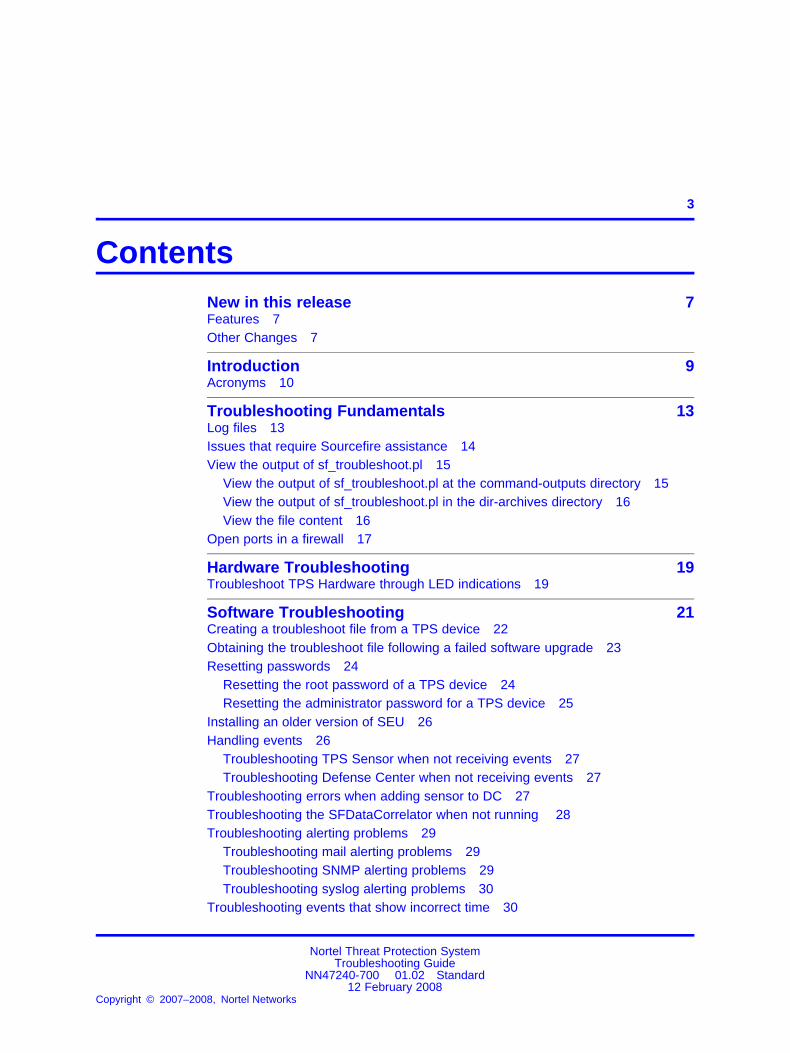
ContentsNew in this release 7Features 7Other Changes 7
Introduction 9Acronyms 10
Troubleshooting Fundamentals 13Log files 13Issues that require Sourcefire assistance 14View the output of sf_troubleshoot.pl 15
View the output of sf_troubleshoot.pl at the command-outputs directory 15View the output of sf_troubleshoot.pl in the dir-archives directory 16View the file content 16
Open ports in a firewall 17
Hardware Troubleshooting 19Troubleshoot TPS Hardware through LED indications 19
Software Troubleshooting 21Creating a troubleshoot file from a TPS device 22Obtaining the troubleshoot file following a failed software upgrade 23Resetting passwords 24
Resetting the root password of a TPS device 24Resetting the administrator password for a TPS device 25
Installing an older version of SEU 26Handling events 26
Troubleshooting TPS Sensor when not receiving events 27Troubleshooting Defense Center when not receiving events 27
Troubleshooting errors when adding sensor to DC 27Troubleshooting the SFDataCorrelator when not running 28Troubleshooting alerting problems 29
Troubleshooting mail alerting problems 29Troubleshooting SNMP alerting problems 29Troubleshooting syslog alerting problems 30
Troubleshooting events that show incorrect time 30
Nortel Threat Protection SystemTroubleshooting Guide
NN47240-700 01.02 Standard12 February 2008
Copyright © 2007–2008, Nortel Networks
.

4
Troubleshooting LDAP authentication failure 31Creating RUA 32Configuring snort through the user interface 32Verifying prohibit packet data on the DC 32Performing RNA IP/Port Exclusion 33Scanning the NMAP 33Remediating Nortel Equipment 34
Remediating NAS 34Remediating NSF 35Remediating SDM 36Remediating NSNA 36
Troubleshooting Global Faults 39Troubleshooting when no white list events are generated 40Troubleshooting an IS that does not generate events 40Troubleshooting an SDM IS that cannot be added to a DC 40Troubleshooting an IS that does not block traffic 41Validating the failopen function 41Troubleshooting an IS that does not send email 42Troubleshooting a DC that cannot push a policy to a sensor 42Troubleshooting a faulty OPSEC 42Troubleshooting a failed upgrade 43Troubleshooting a failed automatic SEU Update 43Troubleshooting when a customer cannot add a sensor to be managed by a
DC 44Troubleshooting a system crash 45Verify the ports to be opened in the firewall for 4.6 45Troubleshooting Snort 45Troubleshooting memory problems 45Deploying IPS mode cable—Scenarios 46
Deploying between two endpoints 46Deploying between two network switches 47Deploying between a switch and an endpoint 47Deploying between a switch and a router 47Deploying between a router and an endpoint 47Deploying between a firewall and an endpoint 48Deploying between two firewalls 48Deploying between a switch and a firewall 48Deploying between router and a firewall 48
Checking IPv6 configurations on the CLI 49Verification of Detection Resources on the CLI 49Viewing the enabled rules on the CLI 49Viewing remediation log 50Viewing the LDAP SSL certificate 50
Nortel Threat Protection SystemTroubleshooting Guide
NN47240-700 01.02 Standard12 February 2008
Copyright © 2007–2008, Nortel Networks
.

Licensing 5
Emergency recovery trees 51Navigation 51Lost access to the TPS DC/IS device—emergency recovery tree 52TPS DC/IS cannot receive events—emergency recovery tree 54
Reference to third party Application Guides 55
Contact Nortel technical support 57Navigation 57Gathering critical information 57Getting help from the Nortel web site 58Getting help over the phone from a Nortel solutions center 58Getting help from a specialist by using an Express Routing Code 59Getting help through a Nortel distributor or reseller 59
Nortel Threat Protection SystemTroubleshooting Guide
NN47240-700 01.02 Standard12 February 2008
Copyright © 2007–2008, Nortel Networks
.

6
Nortel Threat Protection SystemTroubleshooting Guide
NN47240-700 01.02 Standard12 February 2008
Copyright © 2007–2008, Nortel Networks
.
7.
New in this releaseThe following sections detail what’s new in the Nortel Threat ProtectionSystem—Troubleshooting Guide (NN47240-700) for Nortel ThreatProtection System Release 4.7. Refer to the Nortel TPS 4.7 softwareRelease Notes (NN47240-400) for the known issues.
FeaturesThis document is the first standard release.
Other ChangesThe Nortel Threat Protection System—Troubleshooting Guide(NN47240-700) is a new document for Threat Protection System Release4.7.
Nortel Threat Protection SystemTroubleshooting Guide
NN47240-700 01.02 Standard12 February 2008
Copyright © 2007–2008, Nortel Networks
.

8 New in this release
Nortel Threat Protection SystemTroubleshooting Guide
NN47240-700 01.02 Standard12 February 2008
Copyright © 2007–2008, Nortel Networks
.

9.
IntroductionThis chapter describes the prerequisites and various tools used totroubleshoot the Nortel Threat Protection System (TPS). Use thesetroubleshooting tools to improve the overall performance, resolve errormessages, and increase response time for a specific feature. Each tool isdescribed by purpose, usage procedures, and how to interpret the output.
The Nortel TPS is a fully integrated intrusion detection system that consistsof the following:
• TPS 2070 Defense Center, which manages intrusion sensors in thenetwork environment.
• TPS 2050 Intrusion Sensor and TPS 2070 Intrusion Sensor, whichdetect and track network intrusions, either independently or under themanagement of the TPS 2070 Defense Center.
• TPS 2150 Intrusion Sensor and TPS 2170 Intrusion Sensor, whichhave failopen functionality in inline mode.
PrerequisitesThe TPS Troubleshooting Guide is intended for use by personnel thatinstall and maintain the TPS products. Nortel recommends you to use oneor more of the following commercially available troubleshooting tools aswell as the tools described in this document:
• Capture and analyze HTTP and HTTPS with the HTTP Analyzer fromIE Inspector
• Capture and analyze HTTP and HTTPS with Tamper Data, a plug-inavailable for Mozilla Firefox
• Display the time to load Web pages with Faster Fox, a plug-in availablefor Mozilla Firefox
• Capture and analyze packets with either Sniffer or Wireshark fromNetwork General and
Nortel Threat Protection SystemTroubleshooting Guide
NN47240-700 01.02 Standard12 February 2008
Copyright © 2007–2008, Nortel Networks
.

10 Introduction
Navigation• “Troubleshooting Fundamentals” (page 13)
• “Hardware Troubleshooting” (page 19)
• “Software Troubleshooting” (page 21)
• “Troubleshooting Global Faults” (page 39)
• “Emergency recovery trees” (page 51)
• “Reference to third party Application Guides” (page 55)
• “Contact Nortel technical support” (page 57)
AcronymsThis troubleshooting guide uses the following acronyms.
Table 1Acronyms
ASOS Application Switch Operating System
ASEM Application Switch Element Manager
CLI Command Line Interface
CPU Central Processing Unit
DAM Direct Access Mode
DC Defense Center
DAM Direct Access Mode
DNS Domain Name Server
FDB Forwarding Database
FTP File Transfer Protocol
GUI Graphical User Interface
IDS Intrusion Detection System
IS Intrusion Sensor (now 3D Sensor)
LDAP Lightweight Directory Access Protocol
LED Light Emitting Diode
MAC Media Access Control
MIP IP Mapped IP address
MSTP Multiple Spanning Tree Protocol
Nortel Threat Protection SystemTroubleshooting Guide
NN47240-700 01.02 Standard12 February 2008
Copyright © 2007–2008, Nortel Networks
.

Acronyms 11
Table 1Acronyms (cont’d.)
NAS Nortel Application Switch
NSF Nortel Switched Firewall
NSNA Nortel Secure Network Access
NTP Nortel Technical Publication
SSH Secure Shell
STG Spanning Tree Group
TFTP Trivial File Transfer Protocol
TPS Threat Protection System
TSDMP Technical Support Dump
STP Spanning-Tree Potocol
OPSEC Operations Security
SEU Snort Engine Upgrade
SMP Symmetric Multiprocessing
SFTP SSH File Transfer Protocol
UTC Coordinated Universal Time
Nortel Threat Protection SystemTroubleshooting Guide
NN47240-700 01.02 Standard12 February 2008
Copyright © 2007–2008, Nortel Networks
.

12 Introduction
Nortel Threat Protection SystemTroubleshooting Guide
NN47240-700 01.02 Standard12 February 2008
Copyright © 2007–2008, Nortel Networks
.

13.
Troubleshooting FundamentalsThis chapter provides cptual information about the methods and tools thatyou can use to troubleshoot and isolate problems in the Nortel ThreatProtection System (TPS).
Navigation• “Log files” (page 13)
• “Issues that require Sourcefire assistance” (page 14)
• “View the output of sf_troubleshoot.pl” (page 15)
• “Open ports in a firewall” (page 17)
Log filesView the log files to see the history of system events.
This troubleshooting guide documents only the most common messagesfrom the log file ssl.log.
For example, enter the following command to view debuginformation./maint/debug/proxydebug [on|off|once]where:
Variable Value
on enable simpleproxy to print out debug message
off disable simpleproxy to print out debug message
once enable simpleproxy to print out only the debug message
ATTENTIONEnabling proxydebug uses more central processing unit (CPU) resources. Makesure to disable it after you finish debugging.
Nortel Threat Protection SystemTroubleshooting Guide
NN47240-700 01.02 Standard12 February 2008
Copyright © 2007–2008, Nortel Networks
.

14 Troubleshooting Fundamentals
Transmit the event log from the Nortel VPN Gateway to a file on a TrivialFile Transfer Protocol (TFTP), File Transfer Protocol (FTP), or SFTPserver. Specify the IP address or host name of the server as well as thefile name. The default value is TFTP.
The following table lists the log file types in a log dump.
Table 2Log file types in a log dump
Log filetype
Description
clierror This log provides information about the CLI engine and is usedby engineering to debug issues while in development.
erlerror This log provides information about the internal Erlang languageengine and SSL acceleration. It is used by Engineers to debugissues in development.
erlstart This log provides information about the internal Erstart languageengine and SSL acceleration. It is used by Engineers to debugissues in development.
conslog This log contains messages displayed on the console port ofthe device. These messages are generated during the bootsequence.
dmesg This log contains messages generated by the kernel.
ssl.log This log contains messages generated by the simpleproxyfeatures. The user needs to completely logoff and then close thebrowser; login and then activate the ssldump.
ikelog IPsec module related messages.
message This log contains standard syslog type of messages andcontains general information such as system-level status andnonapplication acceleration errors across the device.
Procomm Kernel panic message with debug information can be capturedfrom console directly. Use Procomm to capture those messages.
Issues that require Sourcefire assistanceContact Sourcefire for assistance on the following issues and request theprocess that was taken to restore the customer and update the document:
• If the DC cannot push a policy to the sensors re-image the box withassistance from Sourcefire.
• If the OPSEC is not working properly and the SFReactd does nottrigger the fw same dynamic rule check if the DC and the sensorsare configured correctly and trust is established between them. If not,re-image the box with Sorucefire’s assistance.
Nortel Threat Protection SystemTroubleshooting Guide
NN47240-700 01.02 Standard12 February 2008
Copyright © 2007–2008, Nortel Networks
.

View the output of sf_troubleshoot.pl 15
• If an upgrade fails, you can revert to a previous version of the code.However, note the following:
— Examine the problem on a case-by-case basis to determine theroot cause because the solution depends on where within theupgrade process, the upgrade failed.
— If the system is in a dubious state when an upgrade failed,reverting to the previous code exacerbates the problem. In thiscase report the problem to Sourcefire Support.
— The process for reverting to the previous version is documentedin the User Guides. However that process is recommended onlyin cases where the upgrade was successful but for one reason oranother it was deliberately chosen to revert to the previous version.
• If you cannot add a sensor to a DC.
View the output of sf_troubleshoot.plThis section describes the various commands used to view the output afterrunning the PERL script /usr/local/sf/bin/sf_troubleshoot.pl.
Navigation
• “View the output of sf_troubleshoot.pl at the command-outputsdirectory” (page 15)
• “View the output of sf_troubleshoot.pl in the dir-archives directory”(page 16)
• “View the file content” (page 16)
View the output of sf_troubleshoot.pl at the command-outputsdirectory
• Use the following commands to obtain information about the stateof the file system, because a full file system can cause unexpectedproblems.ps, top, df or du
• Use the following commands for information about hardware issues.lpsci, dmesg
• Use the following commands for information about database issues.mysql
• Use the following commands to compare the timestamp on the sensorand the DC. Time differences between these two devices can cause
Nortel Threat Protection SystemTroubleshooting Guide
NN47240-700 01.02 Standard12 February 2008
Copyright © 2007–2008, Nortel Networks
.

16 Troubleshooting Fundamentals
many problems.date
• Use the following command to find the snort version on the sensor.ls-Ralsh var-sf-detection_engines-.output
• Use the following commands to check network connections and IPconfiguration.netstat, ifconfig
View the output of sf_troubleshoot.pl in the dir-archives directoryView the following output files in the /etc/sf directory.
• The file ims.conf to confirm the version and the managementinterface.
• The licence file and the licence.d directory.
• The troubleshoot.conf file. If required, comment out the myisamchkline in the file.
• The sftunnel.conf file. This file is useful to review the peers. Obtainthe troubleshoot file with tunnel issues from both the DC and Sensorfor effective troubleshooting.
The following important log files can be viewed at the var-log directory.
• Message logs
• Cron logs
• Upgrade logsThese files are in the sf directory.
• Apache error logsThese files are in the httpd directory and contain policy relatedproblems.
View the file contentThis section describes the file content at various locations. The followingare the locations to view them.
• Directory var/sf/detection_engines:
— sensor DE data minus the log files
— active.rules
— snort.conf
— de.info
Nortel Threat Protection SystemTroubleshooting Guide
NN47240-700 01.02 Standard12 February 2008
Copyright © 2007–2008, Nortel Networks
.

Open ports in a firewall 17
— de.conf
— instance – 1(2) directories that are useful for statistics
Enter the commandcat nowThe 3rd column from left on the output is the speed in Mbps. On thesensor, use the perfstats utility, by entering the following commandcat now|perfstatsA syns vs syn-acks imbalance indicates asynchronous routing.
• Directory var/lib/mysql.Find information here on slow queries from mysql.
• Directory tmpFind the update.status file where the latest upgrade/patch redirectslogs are located. You can also find the update.lock file here.
Open ports in a firewallIf there are one or more firewalls in between the DC and IS open one ormore ports on the firewall, depending on the software version of the TPSdevices.For software release 4.5.x and later, the DC and the IS onlycommunicate on TCP port 8305, by default. However, the administratorcan change this port number.For software release 4.1.x and earlier,the DC and the IS communicate on the following TCP ports.
TCP Port Direction To/From DC Description
22 SSH Outbound from DC to Sensor DC uses this port to pushconfigurations, updates, & HA
8300 SSL Inbound from Sensor to DC Management functions
8301 SSL Inbound from Third Parties toDC
eStreamer API (event datastreams)
8302 SSL Inbound from Sensor to DC eStreamer from IntrusionSensors
8303 SSL Inbound from Sensor to DC Heartbeat Protocol
Nortel Threat Protection SystemTroubleshooting Guide
NN47240-700 01.02 Standard12 February 2008
Copyright © 2007–2008, Nortel Networks
.

18 Troubleshooting Fundamentals
Nortel Threat Protection SystemTroubleshooting Guide
NN47240-700 01.02 Standard12 February 2008
Copyright © 2007–2008, Nortel Networks
.

19.
Hardware TroubleshootingThis chapter provides information to troubleshoot problems related to theThreat Protection System (TPS) hardware.
Navigation• “Troubleshoot TPS Hardware through LED indications” (page 19)
Troubleshoot TPS Hardware through LED indicationsThis section provides information to troubleshoot hardware problemsrelated to the TPS 2050, TPS 2070, TPS 2150, and TPS 2170 devices.The following table describes the Front Panel LED indicators on the TPSdevice.
ATTENTIONCall Nortel for RMA if the Amber System status LED cannot be cleared.
Table 3Front Panel LEDs
LED Indicator (from left to right) Description
Amber system status LEDORSystem status LED
This LED lights up when the system needsattention due to a problem with power supplies,fans, CPU, or system temperature or harddrives.
Hard-disk drive activity LED This LED blinks when activity is detected on thehard-disk drive.
System power LED This LED is green when the power supply isturned on.
Overheat indicator LED This LED is red when the system overheats.
Nortel Threat Protection SystemTroubleshooting Guide
NN47240-700 01.02 Standard12 February 2008
Copyright © 2007–2008, Nortel Networks
.

20 Hardware Troubleshooting
Nortel Threat Protection SystemTroubleshooting Guide
NN47240-700 01.02 Standard12 February 2008
Copyright © 2007–2008, Nortel Networks
.
21.
Software TroubleshootingThis chapter describes the various procedures to troubleshoot the softwareon the Threat Protection System (TPS) devices.
The TPS 2070 Defense Center (DC), TPS 2050 Intrusion Sensor (IS),TPS 2070 Intrusion Sensor, TPS 2150 Intrusion Sensor, and TPS 2170Intrusion Sensor products are pre-loaded with version 4.7 of the software.The software is available on a CD-ROM that is shipped with the hardwareand is also available on the Nortel web site, for contracted customers.The following are the software file names for release 4.7:
• Nortel_TPS_Defense_Center_2070_v4.1.0-78-Restore.iso (TPS 2070Defense Center)
• Nortel_TPS_Intrusion_Sensor-2050-v4.1.0-78-Restore.iso (TPS 2050Intrusion Sensor)
• Nortel_TPS_Intrusion_Sensor-2150-v4.1.0-78-Restore.iso (TPS 2150Intrusion Sensor)
• Nortel_TPS_Intrusion_Sensor-2070-v4.1.0-78-Restore.iso (TPS 2070Intrusion Sensor)
• Nortel_TPS_Intrusion_Sensor-2170-v4.1.0-78-Restore.iso (TPS 2170Intrusion Sensor)
Navigation• “Creating a troubleshoot file from a TPS device” (page 22)
• “Obtaining the troubleshoot file following a failed software upgrade”(page 23)
• “Resetting passwords” (page 24)
• “Installing an older version of SEU” (page 26)
• “Handling events” (page 26)
• “Troubleshooting the SFDataCorrelator when not running ” (page 28)
Nortel Threat Protection SystemTroubleshooting Guide
NN47240-700 01.02 Standard12 February 2008
Copyright © 2007–2008, Nortel Networks
.

22 Software Troubleshooting
• “Troubleshooting alerting problems” (page 29)
• “Troubleshooting events that show incorrect time” (page 30)
• “Troubleshooting LDAP authentication failure” (page 31)
• “Creating RUA” (page 32)
• “Configuring snort through the user interface” (page 32)
• “Verifying prohibit packet data on the DC” (page 32)
• “Performing RNA IP/Port Exclusion” (page 33)
• “Scanning the NMAP” (page 33)
• “Remediating Nortel Equipment” (page 34)
Creating a troubleshoot file from a TPS deviceUse this procedure to create a compressed troubleshoot file from a TPSdevice to obtain critical information to troubleshoot it.
CAUTIONOnly authorized administrators must create a troubleshoot filefrom a TPS device.
Procedure 1Procedure steps
Step Action
1 Open a case with Nortel Enterprise Technical Support (NETS).
2 Enter the following command to go to the default location./usr/local/sf/bin
3 Run the script sf_troublshoot.pl
4 Enter the following command to obtain the default configurationfile troubleshoot.conf./etc/sf/troubleshoot.conf
5 Customize the troublshoot.conf file into a custom.conf file ifrequired.
ATTENTIONAlthough there is a predefined set of data to collect, defined introublshoot.conffile, you can specify acustom.conf file to customizewhat data is collected.
6 Enter the following command to obtain the default results file.FTP the SFTP client to obtain the file./var/tmp/results
Nortel Threat Protection SystemTroubleshooting Guide
NN47240-700 01.02 Standard12 February 2008
Copyright © 2007–2008, Nortel Networks
.

Obtaining the troubleshoot file following a failed software upgrade 23
The format of the results file is:results-mm-dd-yyyy--xxxxxxx.tag.gzYou can use the -t option to allow the case number to be placedwithin the name of the results file.
ATTENTIONWINSCP is a freeware SFTP client for windows and can bedownloaded from the location http://www.winscp.com/
--End--
Obtaining the troubleshoot file following a failed software upgradeUse this procedure to obtain a troubleshoot file from a TPS device in caseof a failed Nortel TPS Defense Center Upgrade. An upgrade on a TPSdevice is done by customers or support personnel.
CAUTIONRefer TPS 4.7 Release Notes (NN47240-400) for informationabout prerequisites, detailed steps and tips on performing acomplete and correct Nortel TPS DC 4.5.1 Upgrade on a TPSdevice.
Procedure 2Procedure steps
Step Action
1 Enter the following command to obtain the output file thatcontains the list of updates pushed to the TPS device./var/sf/updates/ls-alshL var-sf-updates.output
2 Verify that the correct upgrade script was used to upgrade theTPS device.
3 Enter the following command to obtain the troubleshoot log file.\results-dd-mm-yyyy--191127\dir-archives\var-log\sf\Nortel_TPS_DC_Upgrade-4.5.1\main_uograde_script.logThis log file is a complete account of the upgrade process.
ATTENTIONThe name of the folder in which the troubleshoot log file is extractedincludes the version of the software you upgrade to.
--End--
Nortel Threat Protection SystemTroubleshooting Guide
NN47240-700 01.02 Standard12 February 2008
Copyright © 2007–2008, Nortel Networks
.

24 Software Troubleshooting
Resetting passwordsThis section describes resetting passwords on TPS devices.
Navigation
• “Resetting the root password of a TPS device” (page 24)
• “Resetting the administrator password for a TPS device” (page 25)
Resetting the root password of a TPS deviceUse this procedure to reset the root password of a TPS device (2050model), if it is lost or forgotten.
Procedure 3Procedure steps
Step Action
1 Connect the TPS device (2050 model) to a PC or laptop, using aconsole cable.
ATTENTIONConnect the TPS device to a monitor and keyboard, if the device isa 2070 model.
2 Power cycle the TPS device.
3 Press any arrow key during the boot sequence at the LILO bootprompt.
ATTENTIONPress any arrow key during the boot sequence when the LILO bootmenu appears, if the device is a 2070 model.
4 Enter the following command at the LILO boot prompt to load thelinux operating system.LILO 22.2 boot:linux -s
System response:Loading linux...Linux version 2.4.26st.p4smp-13 ([email protected])(gcc version 2.95.320010315 (release)) #1SMP Fri Aug 12 16:37:04 UTC 2005
5 Enter the following command:LILO 22.2 boot: passwd rootAt the prompt, enter the new root password. Reenter to confirmthe root password.
Nortel Threat Protection SystemTroubleshooting Guide
NN47240-700 01.02 Standard12 February 2008
Copyright © 2007–2008, Nortel Networks
.

Resetting passwords 25
6 Enter the following command to reboot the 2050 TPS device.LILO 22.2 boot: reboot
7 Enter the following command to login to the 2050 TPS device:Nortel TPS 2X50 DC Series v4.1.0 (build 78)DC2050.ca.nortel.com login:rootEnter the password at the prompt:Password:<password here>
System response:Copyright 2007 Nortel Networks, Inc. andSourcefire, Inc.. All rights reserved.Sourcefire is a registered trademark of Sourcefire,Inc. All other trademarks are property of theirrespective owners.Nortel Linux OS v4.0.1 (build 21)Notel TPS 2X70 DC Series v4.1.0 (build 78)
Last login: Mon Oct 24 15:25:54 +0000 2005 onttyS0.No mail.
--End--
Resetting the administrator password for a TPS deviceUse this procedure to reset the administrator password for a TPS device ifit is lost or forgotten.
CAUTIONReset the administrator password, if and only if you know theroot password for the TPS device. Refer section “Resetting theroot password of a TPS device” (page 24), if you forget or losethe password, to reset the same.
Procedure 4Procedure steps
Step Action
1 Go to root prompt on the TPS device (2070 model).
2 Enter the following command:root@DC2070: ~#resetadmin
3 Enter the root login password at the password prompt.Please enter the root login password:<passwordhere>
Nortel Threat Protection SystemTroubleshooting Guide
NN47240-700 01.02 Standard12 February 2008
Copyright © 2007–2008, Nortel Networks
.

26 Software Troubleshooting
4 Enter the administrator login password at the password prompt.Please enter the admin login password:<passwordhere>
5 Reenter the administrator login password at the reenter loginpassword prompt.Please enter the admin login password again:<password here>System response:Password reset successfullyControl returns to the root prompt.
--End--
Installing an older version of SEUUse this procedure to install a lower version of Snort Engine Upgrade(SEU), for test purposes.
Procedure 5Procedure steps
Step Action
1 Enter the following command to query the versions of SEUscurrently installed.run rpm -qa
2 Enter the following sequence of commands to install an earlierversion of an SEU.rpm -e snort-#.#.#-##rpm -e Sourcefire_Module_Pack-#-devrpm -e Sourcefire_Rule_Pack-##-vrtrpm -e Sourcefire_Snort_Engine_Upgrade-##-###where the character # represents placeholders for the currentversion.
CAUTIONDo not enter any other rpm -e commands at thecommand prompt except the ones listed in step 2.
--End--
Handling eventsThis section describes the corrective steps to be taken when TPS devicesdo not handle events correctly.
Nortel Threat Protection SystemTroubleshooting Guide
NN47240-700 01.02 Standard12 February 2008
Copyright © 2007–2008, Nortel Networks
.

Troubleshooting errors when adding sensor to DC 27
Navigation
• “Troubleshooting TPS Sensor when not receiving events” (page 27)
• “Troubleshooting Defense Center when not receiving events” (page 27)
Troubleshooting TPS Sensor when not receiving eventsUse this procedure to take corrective action when the TPS sensor doesnot receive events.
1. Check if the time is set correctly.
2. Check if snort is running.
3. Enter the following command to check if the TPS Sensor has attained100% capacity./var
Troubleshooting Defense Center when not receiving eventsUse this procedure to take corrective action when the Defense Center(DC) does not receive events.
1. Enter the following command to check if the TPS DC has attained100% capacity./var
2. Check if the TPS sensor(s) is (are) receiving events. Refer section“Troubleshooting TPS Sensor when not receiving events” (page 27) formore information.
3. Check if the time is synchronized between the DC and sensor(s).
4. Check if the sensor(s) can reach the DC on ports 8300-8303.
5. Troubleshoot the SFDataCorrelator. Refer section “Troubleshooting theSFDataCorrelator when not running ” (page 28) for more information.
Troubleshooting errors when adding sensor to DCUse this procedure to troubleshoot errors that arise when adding a sensorto DC.
Procedure 6Procedure steps
Step Action
1 Check httpsd_error_log for errors on the DC.
2 Click Reset Comm in the Sensor GUI.
Nortel Threat Protection SystemTroubleshooting Guide
NN47240-700 01.02 Standard12 February 2008
Copyright © 2007–2008, Nortel Networks
.

28 Software Troubleshooting
3 SSH to the Sensor. Enter the following command to check forthe IP address of the DC/var/sf/managed/<DC_IP>
4 Delete the IP address of the DC, if it exists.
5 Enter the following command to find the size of theauthorized_keys and check if it is the same size asauthorized_keys.default/var/sf/snorty/.ssh/authorized_keys
6 If the sizes do not match, enter the following sequence ofcommands.cd /var/sf/snorty/.sshrm authorized_keysauthorized_keys.default authorized_keys
7 SSH to the Sensor. Enter the following command to check forthe IP address of the Sensor/var/sf/managed/<Sensor_IP>Delete the IP address of the Sensor, if it exists.
--End--
Table 4Variable Definitions
Variable Value
<DC_IP> IP address of the DC
<Sensor_IP> IP address of the Sensor
Troubleshooting the SFDataCorrelator when not runningUse this procedure to troubleshoot a SFDataCorrelator that is not running.
Procedure 7Procedure steps
Step Action
1 Enter the following command to check for error messages./var/log/messages
2 Enter the following command to run the initialization script./etc/rc.d/init.d/SFDataCorrelator start
3 If the SFDataCorrelator fails to start, repeat step 1 to check forerror messages.
4 If the SFDataCorrelator still fails to start, enter the followingcommand to delete the event table.mysql -uroot -padmin sfsnort -e "drop table event"
Nortel Threat Protection SystemTroubleshooting Guide
NN47240-700 01.02 Standard12 February 2008
Copyright © 2007–2008, Nortel Networks
.

Troubleshooting alerting problems 29
5 Enter the following command to rerun the initialization script.Wait for a minute after running the script./etc/rc.d/init.d/SFDataCorrelator restart
6 Enter the following commandps auxww|grep SFDSend the output to the respective development team.
--End--
Troubleshooting alerting problemsUse this procedure to troubleshoot alerting problems in mail, SNMP andSyslog.
Navigation
• “Troubleshooting mail alerting problems” (page 29)
• “Troubleshooting SNMP alerting problems” (page 29)
• “Troubleshooting syslog alerting problems” (page 30)
Troubleshooting mail alerting problemsUse this procedure to troubleshoot email alerting problems.
Procedure 8Procedure steps
Step Action
1 Check if the mailing application is configured and enabled foremail alerting.
2 Run the following shell script at the command prompt.sfmail.sh
3 Enter the following command to check for errors./var/log/messages
4 Ensure that the IP address of the Sensor or DC is reverseresolvable through the DNS.
5 Enter the following command to add hostname information./etc/hosts
--End--
Troubleshooting SNMP alerting problemsUse this procedure to troubleshoot SNMP alerting problems.
Nortel Threat Protection SystemTroubleshooting Guide
NN47240-700 01.02 Standard12 February 2008
Copyright © 2007–2008, Nortel Networks
.
30 Software Troubleshooting
Procedure 9Procedure steps
Step Action
1 Check if SNMP is running.
2 Restart the process if SNMP is not currently running.
--End--
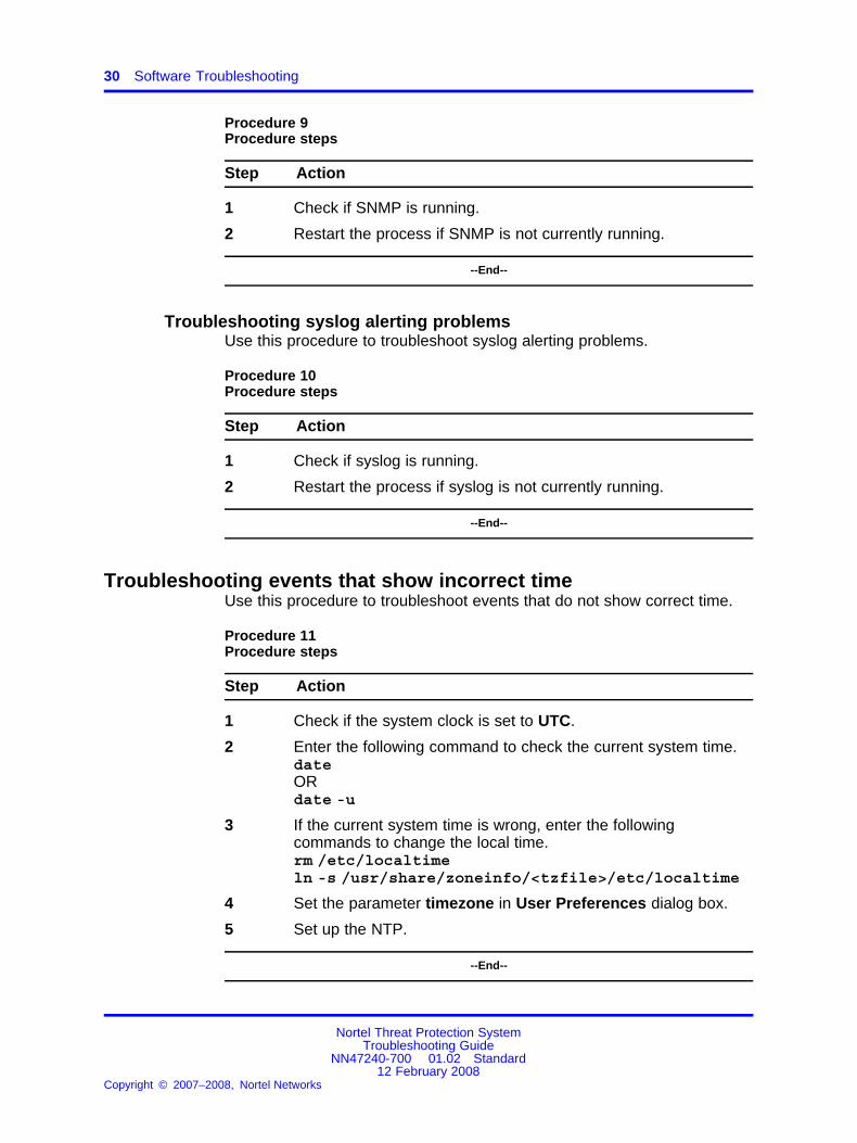
Troubleshooting syslog alerting problemsUse this procedure to troubleshoot syslog alerting problems.
Procedure 10Procedure steps
Step Action
1 Check if syslog is running.
2 Restart the process if syslog is not currently running.
--End--
Troubleshooting events that show incorrect timeUse this procedure to troubleshoot events that do not show correct time.
Procedure 11Procedure steps
Step Action
1 Check if the system clock is set to UTC.
2 Enter the following command to check the current system time.dateORdate -u
3 If the current system time is wrong, enter the followingcommands to change the local time.rm /etc/localtimeln -s /usr/share/zoneinfo/<tzfile>/etc/localtime
4 Set the parameter timezone in User Preferences dialog box.
5 Set up the NTP.
--End--
Nortel Threat Protection SystemTroubleshooting Guide
NN47240-700 01.02 Standard12 February 2008
Copyright © 2007–2008, Nortel Networks
.

Troubleshooting LDAP authentication failure 31
Troubleshooting LDAP authentication failureUse this procedure to troubleshoot LDAP authentication failure.
Procedure 12Procedure steps
Step Action
1 Ensure that the user test passes when creating the LDAP object.
2 If the user authentication fails do the following:
• Ensure that the LDAP server is working properly.
• Check if the DC can communicate with the LDAP server.
• Check if the LDAP server uses the correct port.
• Enter the following commands to check the correspondinguser name template:
— %[email protected] for MS Active Directory
— cn=%s,dc=xxx,dc=com for OpenLDAP
— uid=%s,dc=tps,dc=com for Sun Directory
3 Set the authentication status as enabled.
4 Activate the LDAP object under the system policy. Apply thesystem policy only after activating the LDAP object.
5 Ensure that the user for authentication is created using externalauthentication method.
6 If the MSAD Certification authentication fails do the following:Ensure that the MSAD certificate is in the following format:[Base-64 encoded data from pem file you exported onyour Active-Directory CA machine]-----END CERTIFICATE----------BEGIN CERTIFICATE-----[Base-64 encoded data from pem file that containsthe certificate from the AD mail server]-----END CERTIFICATE-----
7 Do the following steps if there is a certificate for SSL/TLS:
• Ensure that the hostname of LDAP server—at Server IPaddress field, is used instead of its IP address.
• Enter the hostname as the common name in the certificate.
8 Obtain the SSL certificate.
Nortel Threat Protection SystemTroubleshooting Guide
NN47240-700 01.02 Standard12 February 2008
Copyright © 2007–2008, Nortel Networks
.

32 Software Troubleshooting
9 Do the following to interact with the user interface when LDAPfails:
• Edit the following file on the appliance:/etc/sf/ims.conf
• Add the following to the end of the file:LDAP_INFO = 1Retry the connection from the Authentication Object page.Expand the check box that appears at the bottom of the pageto view the errors in greater detail.
--End--
Creating RUA• Obtain the RUA licence. It is mandatory.
• Create the RUA Detection Engine, because RUA requires it.
Configuring snort through the user interfaceUse this procedure to make Snort configuration user.conf through theuser interface editable. To support the dynamic features of Snort outsideof the core product releases, you can provide the raw snort configurationthrough the user.conf.
Procedure 13Procedure steps
Step Action
1 Manually add the following variable to provide raw snortconfiguration through the user interface.USER_CONF
2 Apply the policy to store data in the variable $USER_CONF atthe following location:/var/sf/detection_engines/[uuid]/user.conf
--End--
Verifying prohibit packet data on the DCUse this procedure to verify prohibit packet data on the DC.
Nortel Threat Protection SystemTroubleshooting Guide
NN47240-700 01.02 Standard12 February 2008
Copyright © 2007–2008, Nortel Networks
.

Scanning the NMAP 33
Procedure 14Procedure steps
Step Action
1 Register a 4.7 IS sensor to the DC.
2 Select the Prohibit Packet Data from Sensor option at theregistration screen.
3 On the managed sensor or IS, ensure that the following lineignore_packet_data 1is present in:/var/sf/peers/[DC UUID]/ids_forward.confIf the parameter ignore_packet_data is set to 1, it implies that theprohibit packet data on DC is done properly.
--End--
Performing RNA IP/Port ExclusionUse this procedure for RNA IP/Port Exclusion.
Procedure 15Procedure steps
Step Action
1 Configure the RNA detection policy and apply the policy.
2 Run the traffic to see the RNA events and flow events for theparticular ports and IPs.
3 Configure Exclusion of IP/Port pairs for the RNA DetectionPolicy.
4 Apply the detection policy.The traffic is still seen from the particular ports, which is theprevious traffic before exclusion of IP/Port.
5 Purge the RNA events and flow events. Wait for ten minutes forthe appliance to exclude the IP/Ports.
--End--
Scanning the NMAPUse this procedure to troubleshoot an NMAP scan failure.
Nortel Threat Protection SystemTroubleshooting Guide
NN47240-700 01.02 Standard12 February 2008
Copyright © 2007–2008, Nortel Networks
.

34 Software Troubleshooting
Procedure 16Procedure steps
Step Action
1 Ensure that the scanning host is reachable from DC and IS.
2 Ensure that the scanning host is A&R, RNA , and then Networkmap.
3 If the scanning host still fails the NMAP scan, enter the followingcommand to debug.Set sfmgrand sftunnel to debug.
4 Find the sfmgr and sftunnel processes at the followinglocation:/etc/sf/PM.conf
5 Scan the same host that failed again, by entering the followingseries of commands.option -doption -foption /etc/sf/sftunnel.confoption -D.
6 View the error details logged in the following files:/var/log/messages/var/log/httpd/httpsd_error_log
--End--
Remediating Nortel EquipmentThis section describes interaction with other Nortel equipment likeNortel Switched Firewall (NSF), Nortel Service Delivery Module 8600(SDM), Nortel Application Switch (NAS), and the Nortel Secure NetworkAccess (NSNA). Use the following procedures for the remediation of thisequipment.
Navigation
• “Remediating NAS” (page 34)
• “Remediating NSF” (page 35)
• “Remediating SDM” (page 36)
• “Remediating NSNA” (page 36)
Remediating NASUse this procedure to remediate NAS.
Nortel Threat Protection SystemTroubleshooting Guide
NN47240-700 01.02 Standard12 February 2008
Copyright © 2007–2008, Nortel Networks
.
Remediating Nortel Equipment 35
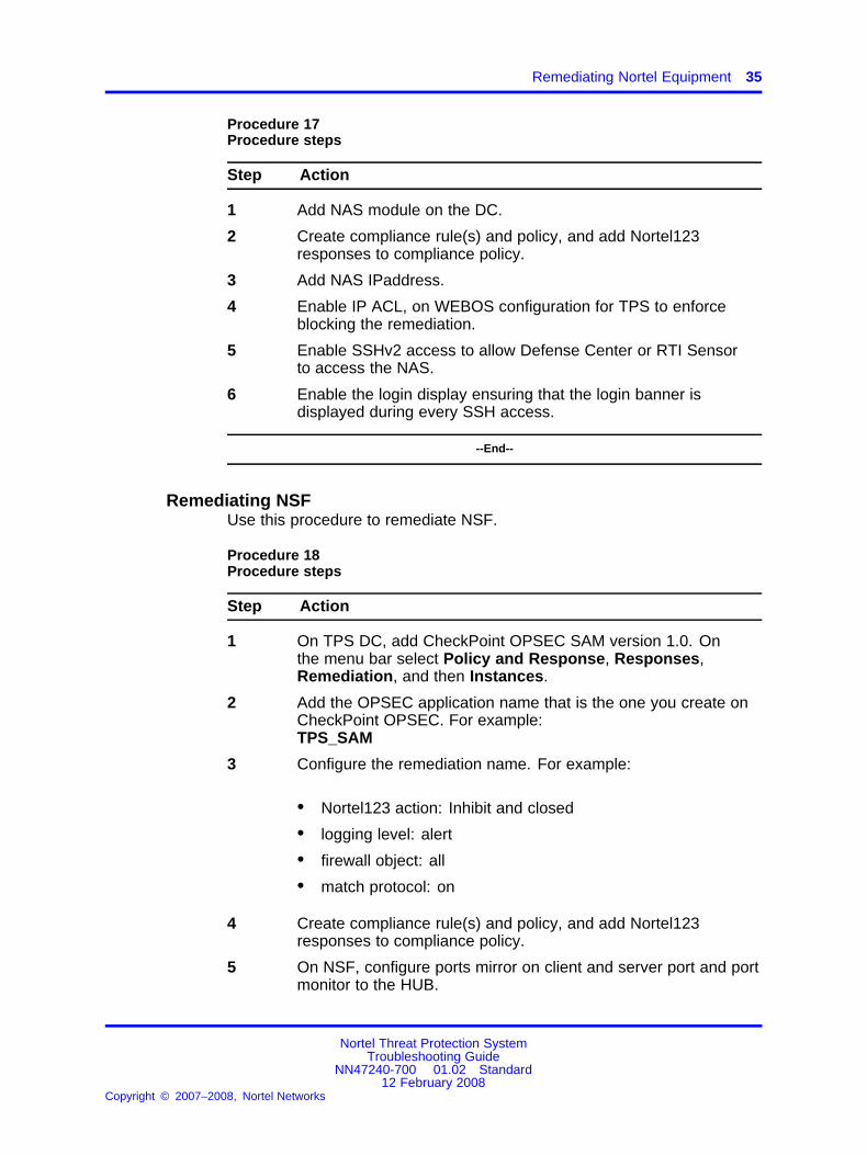
Procedure 17Procedure steps
Step Action
1 Add NAS module on the DC.
2 Create compliance rule(s) and policy, and add Nortel123responses to compliance policy.
3 Add NAS IPaddress.
4 Enable IP ACL, on WEBOS configuration for TPS to enforceblocking the remediation.
5 Enable SSHv2 access to allow Defense Center or RTI Sensorto access the NAS.
6 Enable the login display ensuring that the login banner isdisplayed during every SSH access.
--End--
Remediating NSFUse this procedure to remediate NSF.
Procedure 18Procedure steps
Step Action
1 On TPS DC, add CheckPoint OPSEC SAM version 1.0. Onthe menu bar select Policy and Response, Responses,Remediation, and then Instances.
2 Add the OPSEC application name that is the one you create onCheckPoint OPSEC. For example:TPS_SAM
3 Configure the remediation name. For example:
• Nortel123 action: Inhibit and closed
• logging level: alert
• firewall object: all
• match protocol: on
4 Create compliance rule(s) and policy, and add Nortel123responses to compliance policy.
5 On NSF, configure ports mirror on client and server port and portmonitor to the HUB.
Nortel Threat Protection SystemTroubleshooting Guide
NN47240-700 01.02 Standard12 February 2008
Copyright © 2007–2008, Nortel Networks
.

36 Software Troubleshooting
6 On TPS remediation result message, change the start date andend date. For example:
• start date: 12/12/07
• end date: 12/14/07
--End--
Remediating SDMUse this procedure to remediate SDM.
Procedure 19Procedure steps
Step Action
1 Create compliance rule(s) and policy, and add Nortel123responses to compliance policy.
2 Configure the port mirroring on PP8600. For example create:
• in-port in mode: 9/6
• out-port in mode: 3/15
Port 9/6 is SDM data port. Port 3/15 is the monitoring port to theHUB. Traffic is mirrored by both these ports.
--End--
Remediating NSNAUse this procedure to remediate NSNA.
Procedure 20Procedure steps
Step Action
1 Add NSNA module on the DC.
2 Add MIP IP address.
3 Create compliance rule(s) and policy, and add Nortel123responses to compliance policy.
4 Configure port mirror on the client port and port monitor withNSNA enable.
Nortel Threat Protection SystemTroubleshooting Guide
NN47240-700 01.02 Standard12 February 2008
Copyright © 2007–2008, Nortel Networks
.

Remediating Nortel Equipment 37
5 On TPS remediation result message, change the start date andend date. For example:
• start date: 12/12/07
• end date: 12/14/07
--End--
Nortel Threat Protection SystemTroubleshooting Guide
NN47240-700 01.02 Standard12 February 2008
Copyright © 2007–2008, Nortel Networks
.

38 Software Troubleshooting
Nortel Threat Protection SystemTroubleshooting Guide
NN47240-700 01.02 Standard12 February 2008
Copyright © 2007–2008, Nortel Networks
.

39.
Troubleshooting Global FaultsThis section describes global faults and how to troubleshoot them.
Navigation• “Troubleshooting when no white list events are generated” (page 40)
• “Troubleshooting an IS that does not generate events” (page 40)
• “Troubleshooting an SDM IS that cannot be added to a DC” (page 40)
• “Troubleshooting an IS that does not block traffic” (page 41)
• “Validating the failopen function” (page 41)
• “Troubleshooting an IS that does not send email” (page 42)
• “Troubleshooting a DC that cannot push a policy to a sensor” (page 42)
• “Troubleshooting a faulty OPSEC” (page 42)
• “Troubleshooting a failed upgrade” (page 43)
• “Troubleshooting a failed automatic SEU Update” (page 43)
• “Troubleshooting when a customer cannot add a sensor to bemanaged by a DC” (page 44)
• “Troubleshooting a system crash” (page 45)
• “Verify the ports to be opened in the firewall for 4.6” (page 45)
• “Troubleshooting Snort” (page 45)
• “Troubleshooting memory problems” (page 45)
• “Deploying IPS mode cable—Scenarios” (page 46)
• “Checking IPv6 configurations on the CLI” (page 49)
• “Verification of Detection Resources on the CLI” (page 49)
• “Viewing the enabled rules on the CLI” (page 49)
• “Viewing remediation log” (page 50)
• “Viewing the LDAP SSL certificate” (page 50)
Nortel Threat Protection SystemTroubleshooting Guide
NN47240-700 01.02 Standard12 February 2008
Copyright © 2007–2008, Nortel Networks
.

40 Troubleshooting Global Faults
Troubleshooting when no white list events are generatedUse this procedure to troubleshoot when no white list events are generatedfor disallowed operating systems, services or appliances.
Procedure 21Procedure steps
Step Action
1 Ensure that the RNA is monitoring the hosts in the network.
2 Ensure that the white list is created for the proper network.
3 Ensure that a policy is created and activated for the white list.
4 Ensure that the time range for showing white list events iscorrect.
--End--
Troubleshooting an IS that does not generate eventsUse this procedure to troubleshoot an IS that does not generate events.
Procedure 22Procedure steps
Step Action
1 Ensure that the correct policy is applied.
2 Ensure that the rules are configured properly.
3 Ensure that the rules are selected as Enable /Drop in the RuleState page.
4 Ensure that the Time Range is suitable.
--End--
Troubleshooting an SDM IS that cannot be added to a DCUse this procedure to troubleshoot an SDM IS to be managed by a DC,that cannot be added.
Procedure 23Procedure steps
Step Action
1 Fill in all the information in the fields marked required.
Nortel Threat Protection SystemTroubleshooting Guide
NN47240-700 01.02 Standard12 February 2008
Copyright © 2007–2008, Nortel Networks
.
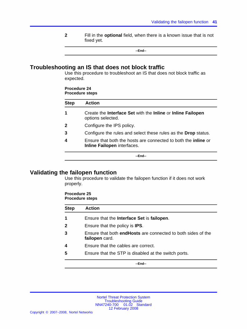
Validating the failopen function 41
2 Fill in the optional field, when there is a known issue that is notfixed yet.
--End--
Troubleshooting an IS that does not block trafficUse this procedure to troubleshoot an IS that does not block traffic asexpected.
Procedure 24Procedure steps
Step Action
1 Create the Interface Set with the Inline or Inline Failopenoptions selected.
2 Configure the IPS policy.
3 Configure the rules and select these rules as the Drop status.
4 Ensure that both the hosts are connected to both the inline orInline Failopen interfaces.
--End--
Validating the failopen functionUse this procedure to validate the failopen function if it does not workproperly.
Procedure 25Procedure steps
Step Action
1 Ensure that the Interface Set is failopen.
2 Ensure that the policy is IPS.
3 Ensure that both endHosts are connected to both sides of thefailopen card.
4 Ensure that the cables are correct.
5 Ensure that the STP is disabled at the switch ports.
--End--
Nortel Threat Protection SystemTroubleshooting Guide
NN47240-700 01.02 Standard12 February 2008
Copyright © 2007–2008, Nortel Networks
.

42 Troubleshooting Global Faults
Troubleshooting an IS that does not send emailUse this procedure to troubleshoot an IS that does not send email.
Procedure 26Procedure steps
Step Action
1 Check if the Host Address is correct.
2 Ensure that the system policy is applied.
--End--
Troubleshooting a DC that cannot push a policy to a sensorSelect the IS default detection engine when pushing a policy from the DCto a sensor that it is managing.
Troubleshooting a faulty OPSECUse this procedure to troubleshoot a faulty OPSEC. If the DC and sensorsare configured correctly, a trust is established between them. However,if for some reason, the SFReactd does not trigger the fw sam dynamicrule, stop reimaging the CheckPoint firewall PC to make it work.
Procedure 27Procedure steps
Step Action
1 Remove the CheckPoint firewall/vpn if installed on the local PC,so as to enable SFReactd to trigger the fw dynamic rule.
2 Enter the following command at the DOS command prompt, tocheck if the firewall policy is installed.fw statEnsure that no firewall/vpn is installed on the local CheckPointPC.
3 Ensure that the CheckPoint PC has policy options as any-any,except or allow.
4 Ensure that the https traffic is allowed between the TPS DC andthe CheckPoint firewall PC.
--End--
Nortel Threat Protection SystemTroubleshooting Guide
NN47240-700 01.02 Standard12 February 2008
Copyright © 2007–2008, Nortel Networks
.

Troubleshooting a failed automatic SEU Update 43
Troubleshooting a failed upgradeUse this procedure to revert back to the previous version of code if anupgrade fails. Downgrade is supported from version 4.6.0 (1145 builds) toversion 4.5.1.3.
CAUTIONOnly upgrade-revert-upgrade is supported, notupgrade-revert-upgrade-revert.
Procedure 28Procedure steps
Step Action
1 When an upgrade fails, enter the following command to revertback to the previous code.revert
2 Wait for the system to reboot completely.
3 Login to the Graphical User Interface (GUI). On the menu barchoose Operation, Help and then About to check the revertedsoftware version.
--End--
Troubleshooting a failed automatic SEU UpdateUse this procedure to troubleshoot an SEU update when the auto updatefeature is not working. The system responds with the following outputmessage:An error message occurred while running task
ATTENTIONThis issue is fixed by Sourcefire and Nortel IT team. Perform the steps in thefollowing procedure if a problem with downloading and importing the SEU stillpersists.
Procedure 29Procedure steps
Step Action
1 Configure the primary DNS server at the following location:Mgmt Interface/Netmask/Default NetworkGateway/Domain/Primary DNS Server
Nortel Threat Protection SystemTroubleshooting Guide
NN47240-700 01.02 Standard12 February 2008
Copyright © 2007–2008, Nortel Networks
.

44 Troubleshooting Global Faults
2 At the TPS IS/DC command line, ping the Nortel update web siteto see if the associated web page appears.www.nortel.autoupdates.com
3 Ensure that the time settings on both the TPS IS/DC and thelocal PC are the same. On the menu bar choose Operation,System settings, Time and then Set Time to check the time.For example:America/Los Angeles, Tuesday, December 12, 2006on the TPS. This must match the time on the local PC.
4 Ensure that the SEU downloading and importing are notscheduled to occur at the same time.
--End--
Troubleshooting when a customer cannot add a sensor to bemanaged by a DC
Use this procedure when you cannot add a sensor to be managed by DC.The system responds with the following output message:Could not establish a connection with sensor
Procedure 30Procedure steps
Step Action
1 Check if the registration keys on the IS and the DC match.
On the IS menu bar choose Operations, System Setting,Remote Manager , and then Add Manager to check theregistration key (for example: Nortel).On the DC menu bar choose Operations , Sensor, and thenAdd new sensor to check the registration key (for example:Nortel)
2 Ensure that the software version on Is 2x70 and DC 2x70 arethe same. On the IS and DC menu bar choose Operations,Help and then About to ensure that the software versions arecompatible.
3 Ensure that the IS and DC are on the same network and thenetwork is not blocking connection.
4 Check if the status changes from pending registration toregistered, indicating that the sensor x.x.x.x is successfullyadded to the DC.
--End--
Nortel Threat Protection SystemTroubleshooting Guide
NN47240-700 01.02 Standard12 February 2008
Copyright © 2007–2008, Nortel Networks
.
Troubleshooting memory problems 45
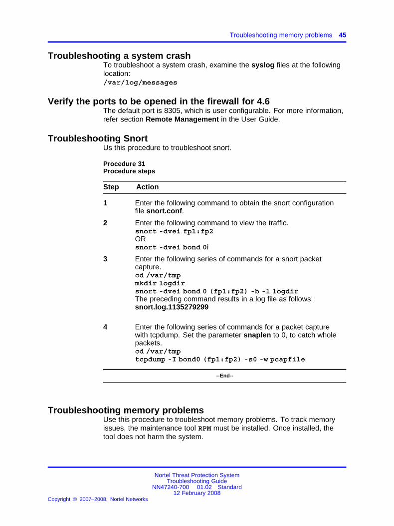
Troubleshooting a system crashTo troubleshoot a system crash, examine the syslog files at the followinglocation:/var/log/messages
Verify the ports to be opened in the firewall for 4.6The default port is 8305, which is user configurable. For more information,refer section Remote Management in the User Guide.
Troubleshooting SnortUs this procedure to troubleshoot snort.
Procedure 31Procedure steps
Step Action
1 Enter the following command to obtain the snort configurationfile snort.conf.
2 Enter the following command to view the traffic.snort -dvei fp1:fp2ORsnort -dvei bond 0i
3 Enter the following series of commands for a snort packetcapture.cd /var/tmpmkdir logdirsnort -dvei bond 0 (fp1:fp2) -b -l logdirThe preceding command results in a log file as follows:snort.log.1135279299
4 Enter the following series of commands for a packet capturewith tcpdump. Set the parameter snaplen to 0, to catch wholepackets.cd /var/tmptcpdump -I bond0 (fp1:fp2) -s0 -w pcapfile
--End--
Troubleshooting memory problemsUse this procedure to troubleshoot memory problems. To track memoryissues, the maintenance tool RPM must be installed. Once installed, thetool does not harm the system.
Nortel Threat Protection SystemTroubleshooting Guide
NN47240-700 01.02 Standard12 February 2008
Copyright © 2007–2008, Nortel Networks
.
46 Troubleshooting Global Faults
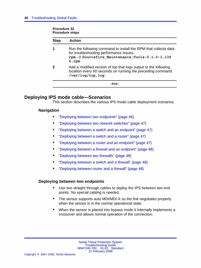
Procedure 32Procedure steps
Step Action
1 Run the following command to install the RPM that collects datafor troubleshooting performance issues.rpm -I Sourcefire_Maintenance_Tools-0.1.0-1.i386.rpm
2 Add a modified version of top that logs output to the followinglocation every 60 seconds on running the preceding command./var/log/top.log
--End--
Deploying IPS mode cable—ScenariosThis section describes the various IPS mode cable deployment scenarios.
Navigation
• “Deploying between two endpoints” (page 46)
• “Deploying between two network switches” (page 47)
• “Deploying between a switch and an endpoint” (page 47)
• “Deploying between a switch and a router” (page 47)
• “Deploying between a router and an endpoint” (page 47)
• “Deploying between a firewall and an endpoint” (page 48)
• “Deploying between two firewalls” (page 48)
• “Deploying between a switch and a firewall” (page 48)
• “Deploying between router and a firewall” (page 48)
Deploying between two endpoints
• Use two straight through cables to deploy the IPS between two endpoints. No special cabling is needed.
• The sensor supports auto MDI/MDI-X so the link negotiates properlywhen the sensor is in the normal operational state.
• When the sensor is placed into bypass mode it internally implements acrossover and allows normal operation of the connection.
Nortel Threat Protection SystemTroubleshooting Guide
NN47240-700 01.02 Standard12 February 2008
Copyright © 2007–2008, Nortel Networks
.

Deploying IPS mode cable—Scenarios 47
Deploying between two network switches
• Use two straight through cables to deploy the IPS between twonetwork switches. No special cabling is needed.
• The sensor supports auto MDI/MDI-X so the link is negotiated properlywhen the sensor is in the normal operational state.
• When the sensor is placed into bypass mode it internally implements acrossover and allows normal operation of the connection.
Deploying between a switch and an endpoint
• When the IPS is deployed between a switch and an endpoint a straightthrough cable must be used between the switch and the IPS. Acrossover cable must be used between the IPS and the endpoint.
• When the sensor is placed into bypass mode the internal crossoverand the crossover cable between the endpoint and the IPS combinesto create a straight through cable that allows normal operation of theconnection.
Deploying between a switch and a router
• When the IPS is deployed between a switch and a router a straightthrough cable must be used between the switch and the IPS. Acrossover cable must be used between the IPS and the router.
• The sensor supports auto MDI/MDI-X so the link between the IPSand the router negotiates properly when the sensor is in the normaloperational state.
• When the sensor is placed into bypass mode the internal crossoverand the crossover cable between the endpoint and the IPS, combines,to create a straight through cable. This allows normal operation of theconnection.
Deploying between a router and an endpoint
• When the IPS is deployed between a router and an endpoint no specialcabling is needed. Two straight through cables must be used.
• The sensor supports auto MDI/MDI-X so the link negotiates properlywhen the sensor is in the normal operational state.
• When the sensor is placed into bypass mode it internally implements acrossover and allows normal operation of the connection.
Nortel Threat Protection SystemTroubleshooting Guide
NN47240-700 01.02 Standard12 February 2008
Copyright © 2007–2008, Nortel Networks
.

48 Troubleshooting Global Faults
Deploying between a firewall and an endpoint
• When the IPS is deployed between a firewall and an endpoint nospecial cabling is needed. Two straight through cables must be used.
• The sensor supports auto MDI/MDI-X so the link negotiates properlywhen the sensor is in the normal operational state.
• When the sensor is placed into bypass mode it internally implements acrossover and allows normal operation of the connection.
Deploying between two firewalls
• When the IPS is deployed between two firewalls no special cabling isneeded. Two straight through cables must be used.
• The sensor supports auto MDI/MDI-X so the link negotiates properlywhen the sensor is in the normal operational state.
• When the sensor is placed into bypass mode it internally implements acrossover and allows normal operation of the connection.
Deploying between a switch and a firewall
• When the IPS is deployed between a switch and a firewall a straightthrough cable must be used between the switch and the IPS. Acrossover cable must be used between the IPS and the firewall.
• The sensor supports auto MDI/MDI-X so the link between the IPSand the firewall negotiates properly when the sensor is in the normaloperational state.
• When the sensor is placed into bypass mode the internal crossoverand the crossover cable between the firewall and the IPS combinestocreate a straight through cable. This allows normal operation of theconnection.
Deploying between router and a firewall
• When the IPS is deployed between a router and a firewall no specialcabling is needed. Two straight through cables must be used.
• The sensor supports auto MDI/MDI-X so the link negotiates properlywhen the sensor is in the normal operational state.
• When the sensor is placed into bypass mode it internally implements acrossover and allows normal operation of the connection.
Nortel Threat Protection SystemTroubleshooting Guide
NN47240-700 01.02 Standard12 February 2008
Copyright © 2007–2008, Nortel Networks
.

Viewing the enabled rules on the CLI 49
Checking IPv6 configurations on the CLIUse this procedure to check IPv6 configurations on the command lineinterface (CLI).
Procedure 33Procedure steps
Step Action
1 Enter the following command on the CLI/var/sf/detection_engines/[uuid]/
2 Disable SMTP globally in Detection and Prevention optionsfor a particular policy, when working on the IPv6 partial supportfeature.
--End--
Verification of Detection Resources on the CLIUse this procedure to verify the maximum and optimal number of detectionresources in CLI.
Procedure 34Procedure steps
Step Action
1 Enter the following command in the CLI to verify the maximumnumber of detection resources./etc/sf/ims.confand search for MAX_NUM_DR.
2 Enter the following command in the CLI to verify the maximumnumber of detection resources./etc/sf/ims.confand search for OPTIMAL_NUM_DR.
--End--
Viewing the enabled rules on the CLIUse this procedure to view enabled rules on the CLI.
Nortel Threat Protection SystemTroubleshooting Guide
NN47240-700 01.02 Standard12 February 2008
Copyright © 2007–2008, Nortel Networks
.

50 Troubleshooting Global Faults
Procedure 35Procedure steps
Step Action
1 Enter the following command in the CLI./var/sf/detection_engines/[de uuid]/active.rules.
2 Enter the following command to view the list of rules that areimported in the SEU./var/sf/rules/sid-msg.map
--End--
Viewing remediation logUse this procedure to view the remediation log for Nortel Secure NetworkAccess (NSNA) and Nortel VPN Gateway (NVG).
Procedure 36Procedure steps
Action
View the remediation log at the following location./tmp/<RemediationName>/<RemediationName.log>
Viewing the LDAP SSL certificateUse this procedure to view the LDAP SSL certificate after it is uploaded.
Procedure 37Procedure steps
Step Action
1 Load the LDAP SSL certificate.
2 Enter the following command to view the LDAP SSL certificate,after it is uploaded./var/sf/userauth/temp0.pembl
--End--
Nortel Threat Protection SystemTroubleshooting Guide
NN47240-700 01.02 Standard12 February 2008
Copyright © 2007–2008, Nortel Networks
.

51.
Emergency recovery treesThis chapter illustrates the emergency recovery tree flow diagrams thathelp recover from field outages as quickly as possible.
Navigation• “Lost access to the TPS DC/IS device—emergency recovery tree”
(page 52)
• “TPS DC/IS cannot receive events—emergency recovery tree” (page54)
Nortel Threat Protection SystemTroubleshooting Guide
NN47240-700 01.02 Standard12 February 2008
Copyright © 2007–2008, Nortel Networks
.

52 Emergency recovery trees
Lost access to the TPS DC/IS device—emergency recovery treeThe following flow diagram illustrates the recovery tree when access is lostto the TPS DC/IS Graphical User Interface (GUI).
Nortel Threat Protection SystemTroubleshooting Guide
NN47240-700 01.02 Standard12 February 2008
Copyright © 2007–2008, Nortel Networks
.

Lost access to the TPS DC/IS device—emergency recovery tree 53
Figure 1Recover lost access to a TPS DC/IS device
Nortel Threat Protection SystemTroubleshooting Guide
NN47240-700 01.02 Standard12 February 2008
Copyright © 2007–2008, Nortel Networks
.

54 Emergency recovery trees
TPS DC/IS cannot receive events—emergency recovery treeThe following flow diagram illustrates the recovery tree when TPS DC/IScannot receive events.
Nortel Threat Protection SystemTroubleshooting Guide
NN47240-700 01.02 Standard12 February 2008
Copyright © 2007–2008, Nortel Networks
.

55.
Reference to third party ApplicationGuides
This section contains reference to third party Application Guides for VPNproduct. You can refer to the following Application Guides available athttp://support.nortel.com/go/main.jsp:
• SSL VPN—Authentication using Steel Belted RADIUS server
• SSL VPN—NTML Authentication
• SSL VPN—CRL retrieval
• SSL VPN—Configuring NetDirect
• SSL VPN—Authentication using certificates
• SSL VPN—Authentication using Netegrity SiteMinder
• SSL VPN—Syslog and Traffic log
• SSL VPN—External Authentication using Remote AuthenticationDial-In User Service (RADIUS)
• SSL VPN—External LDAP Authentication using Active Directory
• SSL VPN—Configuring access rules
• SSL VPN—Adding links to a portal page
• SSL VPN—Configuring User Types SSL VPN - Configuring UserTypes
• Adding a Server Certificate and/or Private Key
• HTTP to HTTPS Redirect Service
• Using Netegrity SiteMinder with Nortel Networks SSL VPN
• Technical Configuration Guide Using Citrix with the Alteon SSL VPN
• SSL VPN and SafeWord for Nortel Technical Config Guide
Nortel Threat Protection SystemTroubleshooting Guide
NN47240-700 01.02 Standard12 February 2008
Copyright © 2007–2008, Nortel Networks
.

56 Reference to third party Application Guides
Nortel Threat Protection SystemTroubleshooting Guide
NN47240-700 01.02 Standard12 February 2008
Copyright © 2007–2008, Nortel Networks
.

57.
Contact Nortel technical supportThis section provides the information about Nortel technical support.
Navigation•••••
Gathering critical informationBefore contacting Nortel Technical Support, gather the followingcritical information that can help the technical support personnel whentroubleshooting.
You must attempt to resolve your problem using this troubleshooting guide.Contacting Nortel is a final step taken only when you cannot resolve theissue using the information and steps provided in this troubleshootingguide. Collecting this information helps Nortel analyze and address thereported issue:
• A detailed description of the problem.
• The date and time when the problem started.
• The frequency of the problem.
• Is this a new installation?
• Have you searched the solutions database? Were any relatedsolutions found? Is there currently a workaround for this issue?
• Have you recently changed or upgraded your system, your network,or a custom application? (For example, is any configuration or codechanged?)
Nortel Threat Protection SystemTroubleshooting Guide
NN47240-700 01.02 Standard12 February 2008
Copyright © 2007–2008, Nortel Networks
.

58 Contact Nortel technical support
If yes, when (date and time) were these changes made? Who madethese changes? Were the changes made by a partner or customer?Provide the names of the individuals who made the changes.
Also provide Nortel Technical Support with the following information:
• A copy of your configuration files.
• A detailed network topology diagram.
• The log files.
Getting help from the Nortel web siteThe best way to get technical support for Nortel products is from the NortelTechnical Support web site:
http://www.nortel.com/support
This site provides quick access to software, documentation, bulletins, andtools to address issues with Nortel products. More specifically, the website allows you to:
• download software, documentation, and product bulletins
• search the technical support web site and the Nortel knowledge basefor answers to technical issues
• sign up for automatic notification of new software and documentationfor Nortel equipment
• open and manage technical support cases
Getting help over the phone from a Nortel solutions centerIf you do not find the information you require on the Nortel technicalsupport web site, and have a Nortel support contract, you can also gethelp over the phone from a Nortel Solutions Center.
In North America, call 1-800-4NORTEL (1-800-466-7835).
Outside North America, go to the following web site to obtain the phonenumber for your region:
http://www.nortel.com/help/contact/global/index.html
Nortel Threat Protection SystemTroubleshooting Guide
NN47240-700 01.02 Standard12 February 2008
Copyright © 2007–2008, Nortel Networks
.

Getting help through a Nortel distributor or reseller 59
Getting help from a specialist by using an Express Routing CodeTo access some Nortel Technical Solutions Centers, you can use anExpress Routing Code (ERC) to quickly route your call to a specialist inyour Nortel product or service. To locate the ERC for your product orservice, go to:
http://www.nortel.com/help/contact/erc/
Getting help through a Nortel distributor or resellerIf you purchased a service contract for your Nortel product from adistributor or authorized reseller, contact the technical support staff for thatdistributor or reseller.
Nortel Threat Protection SystemTroubleshooting Guide
NN47240-700 01.02 Standard12 February 2008
Copyright © 2007–2008, Nortel Networks
.

60 Contact Nortel technical support
Nortel Threat Protection SystemTroubleshooting Guide
NN47240-700 01.02 Standard12 February 2008
Copyright © 2007–2008, Nortel Networks
.


Nortel Threat Protection System
Troubleshooting GuideCopyright © 2007–2008, Nortel Networks.All Rights Reserved.
Release: 4.7Publication: NN47240-700Document status: StandardDocument revision: 01.02Document release date: 12 February 2008
To provide feedback or to report a problem in this document, go to www.nortel.com/documentfeedback.
www.nortel.com
Sourced in Canada and India
The information in this document is subject to change without notice. The statements, configurations, technical data, andrecommendations in this document are believed to be accurate and reliable, but are presented without express or impliedwarranty. Users must take full responsibility for their applications of any products specified in this document. The information inthis document is proprietary to Nortel Networks.
ExportThis product, software and related technology is subject to U.S. export control and may be subject to export or import regulationsin other countries. Purchaser must strictly comply with all such laws and regulations. A license to export or reexport may berequired by the U.S. Department of Commerce.
LicensingThis product includes software developed by the OpenSSL Project for use in the OpenSSL Toolkit (http://www.openssl.org/).
This product includes cryptographic software written by Eric Young ([email protected]).
This product includes software written by Tim Hudson ([email protected]).
This product includes software developed by the Apache Software Foundation http://www.apache.org/.
This product includes a TAP-Win32 driver derived from the CIPE-Win32 kernel driver, Copyright © Damion K. Wilson, andis licensed under the GPL.